2. modeling with uml - cs.sjtu.edu.cnjdyu/teaching/se/handouts/2... · software engineering 3.2 uml...
TRANSCRIPT
2. Modeling with UML
Software Engineering
Outline
! History of Object Oriented Method ! More Object Oriented Concepts ! Modeling Concepts ! An Overview of UML ! UML Diagrams ! Case Study
Software Engineering
1. History of Object Oriented Method
Software Engineering
1.1The Growth of OO Methods
! In 1965 the first object-oriented (OO) programming language, Simula I, was introduced.
! Almost immediately interest in OO design began to rapidly grow.
! This led to the emergence of numerous competing OO design methods.
Software Engineering
OO Analysis vs. OO Design
! Analysis refers to understanding the problem. ! Design refers to coming up with the solution. ! Don’t confuse with broader use of word “design”
Software Engineering
! With all these design methods came numerous modeling languages.
! By the early 90’s there were 50+ distinct OO modeling languages.
! Darwinian forces in the marketplace led to three dominate methods, each having its own modeling language.
Software Engineering
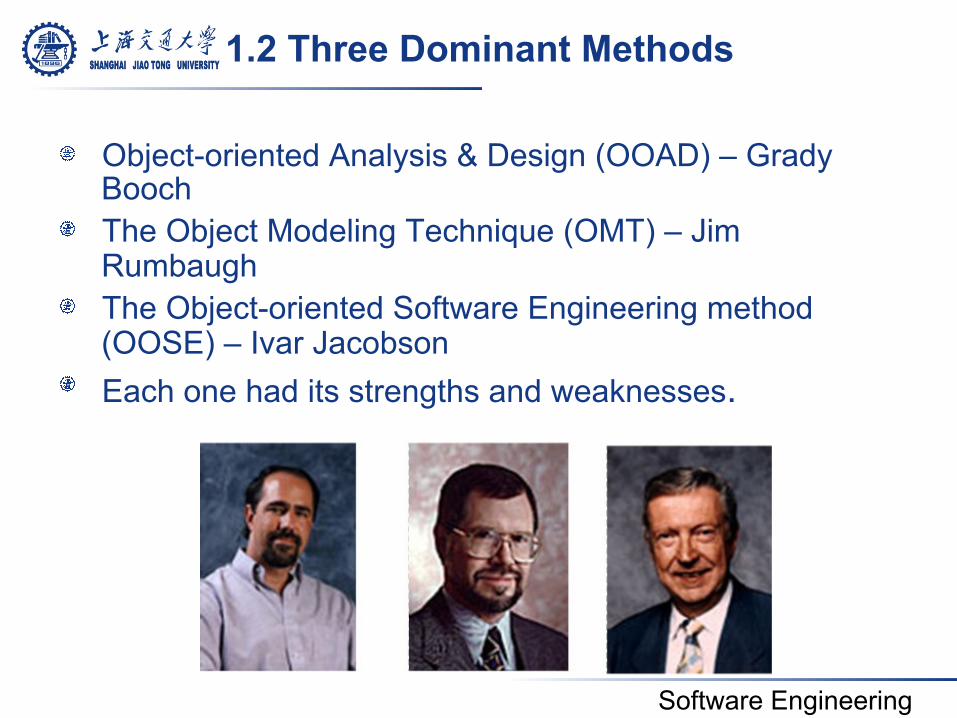
1.2 Three Dominant Methods
! Object-oriented Analysis & Design (OOAD) – Grady Booch
! The Object Modeling Technique (OMT) – Jim Rumbaugh
! The Object-oriented Software Engineering method (OOSE) – Ivar Jacobson
! Each one had its strengths and weaknesses.
Software Engineering
(1) Booch (OOAD)
! Very complex ! The modeling language contained a formidable
number of diagrams and resulting symbols ! Allowed for effective low-level design and its
fine grain detail was even useful for documenting code.
! Good at OO design, weak at OO analysis
Software Engineering
(2) Rumbaugh (OMT)
! OMT had a simpler modeling language ! It was better at higher-level designs than Booch
Method. ! Good at OO analysis, weak at OO design
Software Engineering
(3) Jacobson (OOSE)
! Major feature was “use classes” ! Use classes model how a system interacts with
users (which might be other systems or end users)
! Viewing things from the user’s perspective drove the design process
! This made it good at very high-level design.
Software Engineering
Coming Together
! Booch (OOAD) good at low-level design ! Jacobson (OOSE) good at high-level design ! Rumbaugh (OMT) good at the middle ground
Software Engineering
! Booch’s and Rumbaugh’s methods seemed to be evolving in a similar direction
! In 1994 they joined forces in effort to merge their two methods
! They both wanted to include use cases, so soon Jacobson joined them
Software Engineering
! It became too difficult to successfully merge all three methods.
! At same time, the software engineering community wanted an effective and standardized modeling language
! The three then focused their efforts on unifying their three modeling languages
Software Engineering
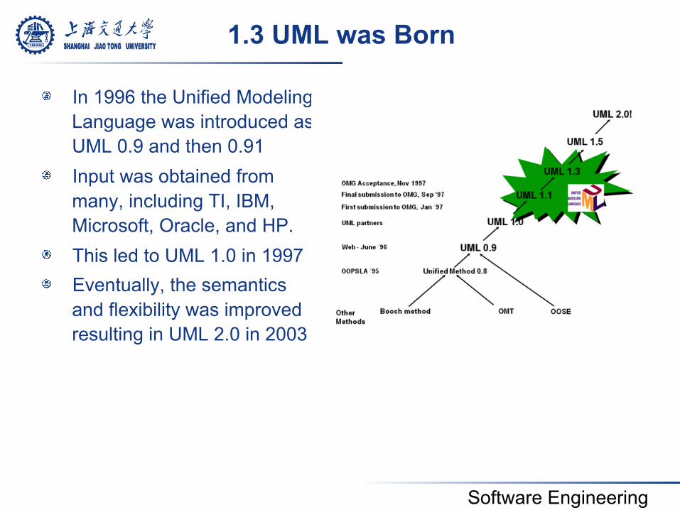
1.3 UML was Born
! In 1996 the Unified Modeling Language was introduced as UML 0.9 and then 0.91
! Input was obtained from many, including TI, IBM, Microsoft, Oracle, and HP.
! This led to UML 1.0 in 1997 ! Eventually, the semantics
and flexibility was improved resulting in UML 2.0 in 2003
Software Engineering
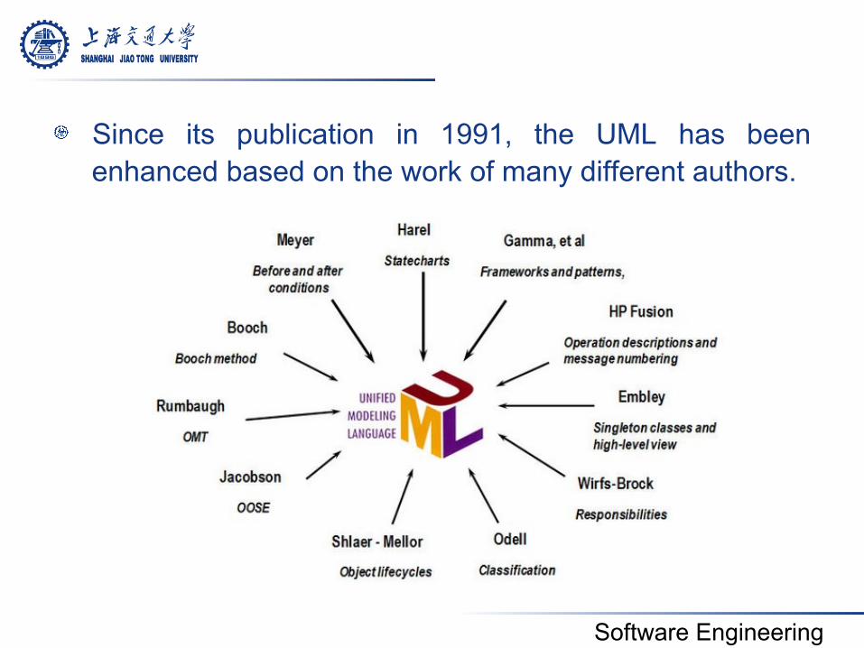
! Since its publication in 1991, the UML has been enhanced based on the work of many different authors.
Software Engineering
2. Modeling Concept
Software Engineering
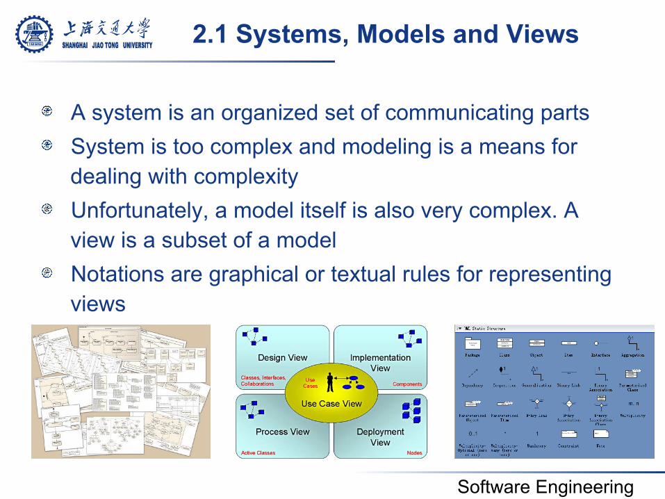
2.1 Systems, Models and Views
! A system is an organized set of communicating parts ! System is too complex and modeling is a means for
dealing with complexity ! Unfortunately, a model itself is also very complex. A
view is a subset of a model ! Notations are graphical or textual rules for representing
views
Software Engineering
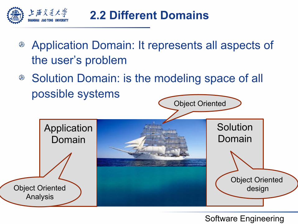
2.2 Different Domains
! Application Domain: It represents all aspects of the user’s problem
! Solution Domain: is the modeling space of all possible systems
Application Domain
Solution Domain
Object Oriented
Object Oriented design Object Oriented
Analysis
Software Engineering
3. An Overview of UML
Software Engineering
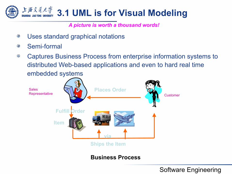
3.1 UML is for Visual Modeling
Business Process
Places Order
Item
Ships the Item
! Uses standard graphical notations ! Semi-formal ! Captures Business Process from enterprise information systems to
distributed Web-based applications and even to hard real time embedded systems
A picture is worth a thousand words!
via
Fulfill Order
Customer Sales Representative
Software Engineering
3.2 UML is also for …
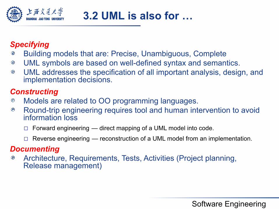
Specifying ! Building models that are: Precise, Unambiguous, Complete ! UML symbols are based on well-defined syntax and semantics. ! UML addresses the specification of all important analysis, design, and
implementation decisions. Constructing ! Models are related to OO programming languages. ! Round-trip engineering requires tool and human intervention to avoid
information loss ¨ Forward engineering — direct mapping of a UML model into code.
¨ Reverse engineering — reconstruction of a UML model from an implementation. Documenting
! Architecture, Requirements, Tests, Activities (Project planning, Release management)
Software Engineering
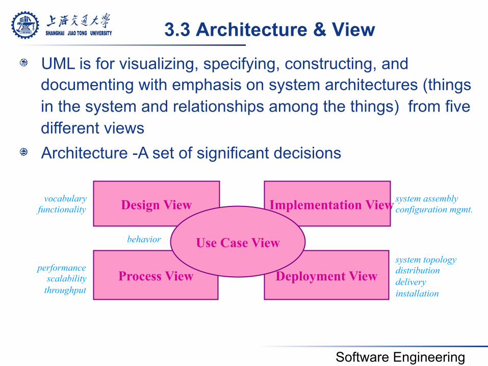
3.3 Architecture & View
Deployment View Process View
Design View Implementation View
Use Case View
vocabulary functionality
performance scalability
throughput
behavior
system assembly configuration mgmt.
system topology distribution delivery installation
! UML is for visualizing, specifying, constructing, and documenting with emphasis on system architectures (things in the system and relationships among the things) from five different views
! Architecture -A set of significant decisions
Software Engineering
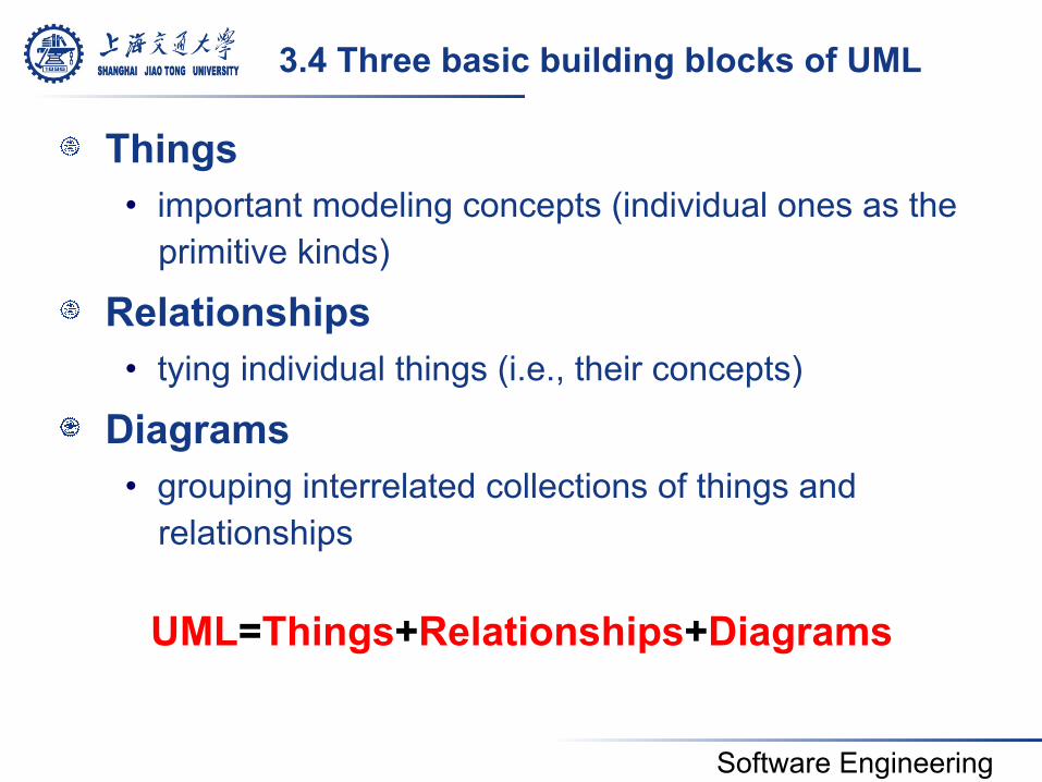
3.4 Three basic building blocks of UML
! Things • important modeling concepts (individual ones as the
primitive kinds)
! Relationships • tying individual things (i.e., their concepts)
! Diagrams • grouping interrelated collections of things and
relationships
UML=Things+Relationships+Diagrams
Software Engineering
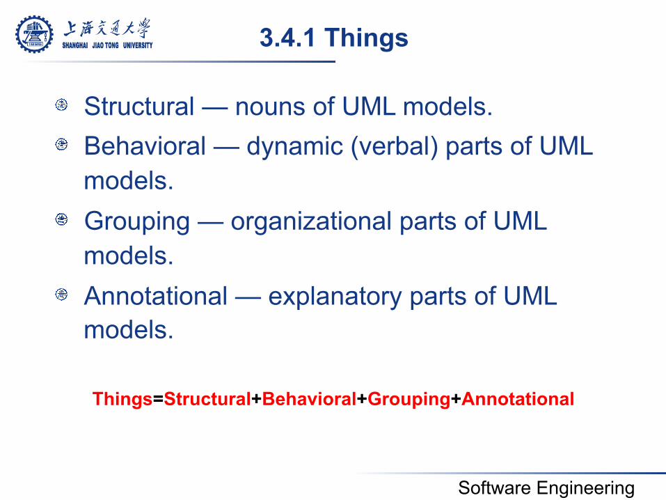
! Structural — nouns of UML models. ! Behavioral — dynamic (verbal) parts of UML
models. ! Grouping — organizational parts of UML
models. ! Annotational — explanatory parts of UML
models.
3.4.1 Things
Things=Structural+Behavioral+Grouping+Annotational
Software Engineering
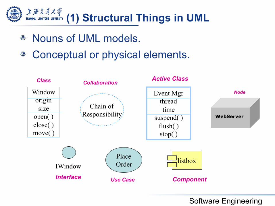
! Nouns of UML models. ! Conceptual or physical elements.
(1) Structural Things in UML
Window origin size
open( ) close( ) move( )
IWindow
Chain of Responsibility
Place Order
Event Mgr thread time
suspend( ) flush( ) stop( )
listbox
Class
Interface
Collaboration
Use Case
Active Class
Component
Node
WebServer
Software Engineering
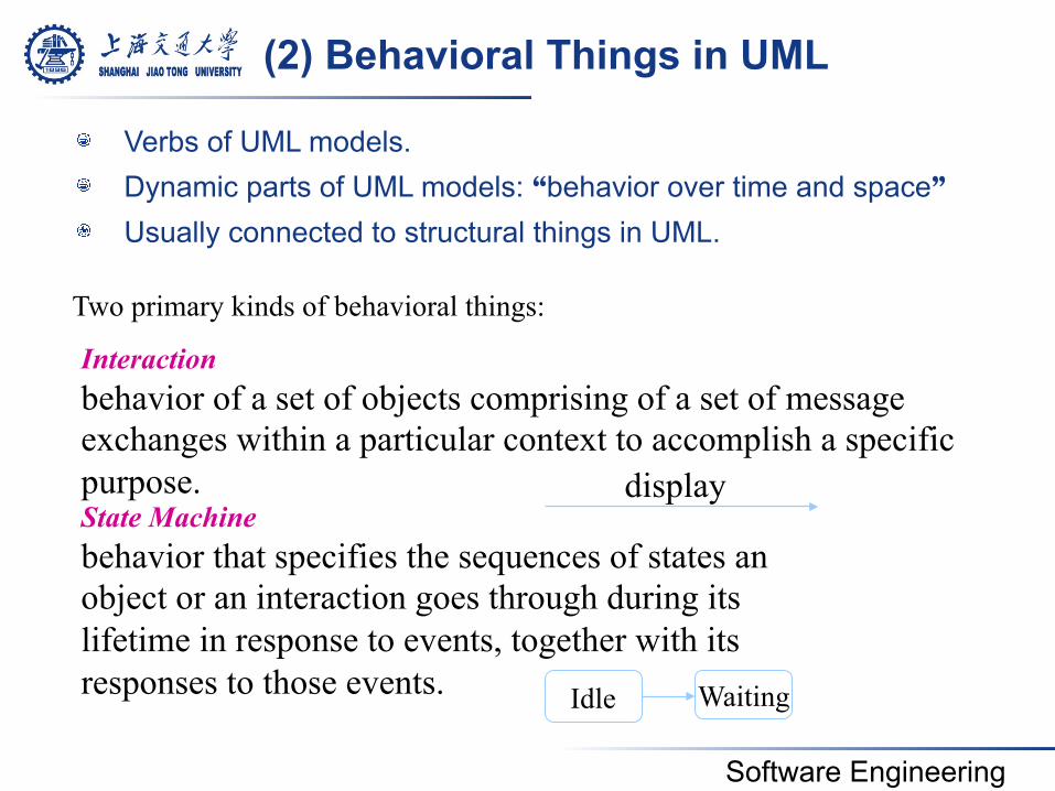
(2) Behavioral Things in UML
Two primary kinds of behavioral things:
! Verbs of UML models. ! Dynamic parts of UML models: “behavior over time and space” ! Usually connected to structural things in UML.
Interaction behavior of a set of objects comprising of a set of message exchanges within a particular context to accomplish a specific purpose.
display State Machine behavior that specifies the sequences of states an object or an interaction goes through during its lifetime in response to events, together with its responses to those events.
Waiting Idle
Software Engineering
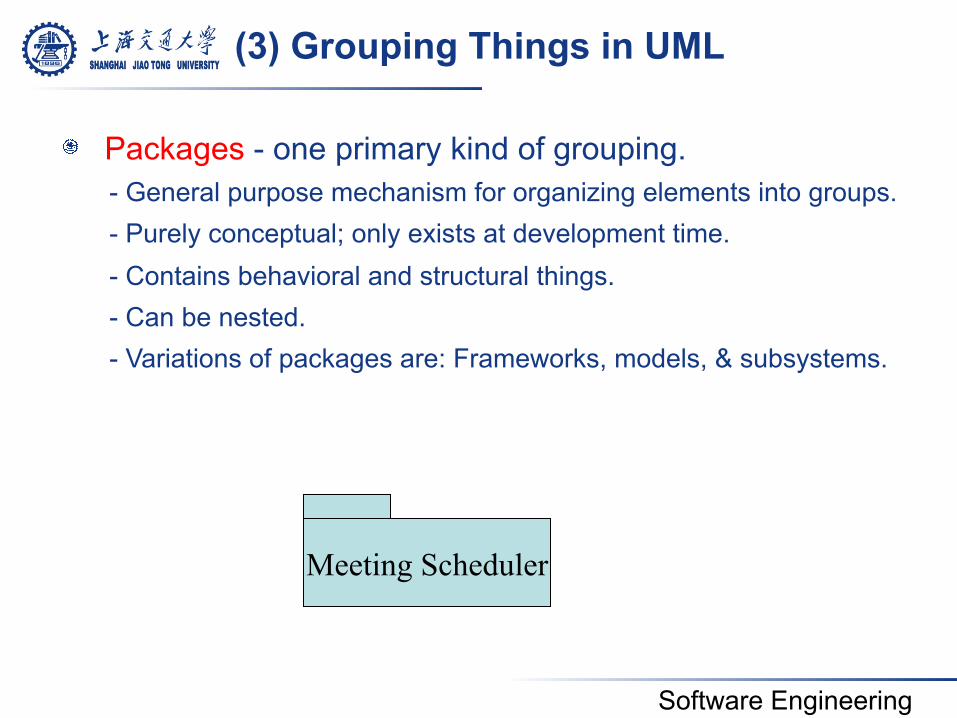
! Packages - one primary kind of grouping. - General purpose mechanism for organizing elements into groups. - Purely conceptual; only exists at development time. - Contains behavioral and structural things. - Can be nested. - Variations of packages are: Frameworks, models, & subsystems.
Meeting Scheduler
(3) Grouping Things in UML
Software Engineering
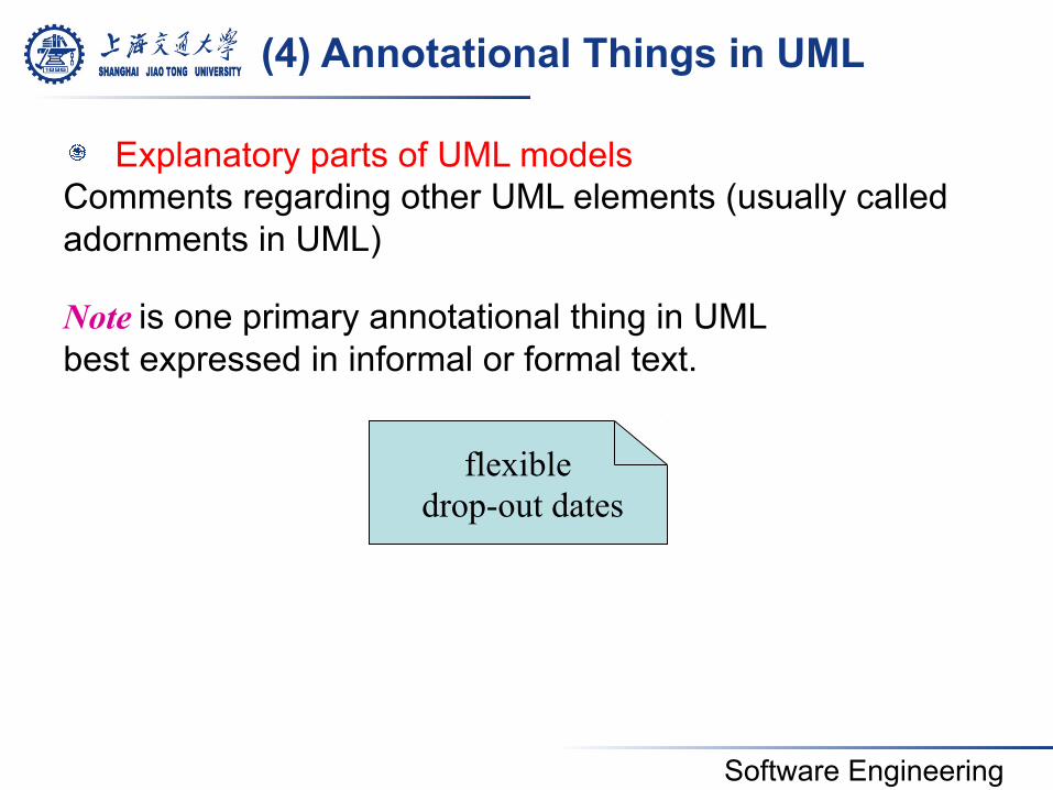
(4) Annotational Things in UML
flexible drop-out dates
! Explanatory parts of UML models Comments regarding other UML elements (usually called adornments in UML) Note is one primary annotational thing in UML best expressed in informal or formal text.
Software Engineering
3.4.2 Relationships
! Dependency ! Association ! Generalization ! Realization
Software Engineering
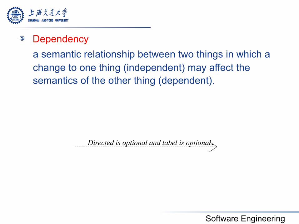
! Dependency a semantic relationship between two things in which a change to one thing (independent) may affect the semantics of the other thing (dependent).
Directed is optional and label is optional.
Software Engineering
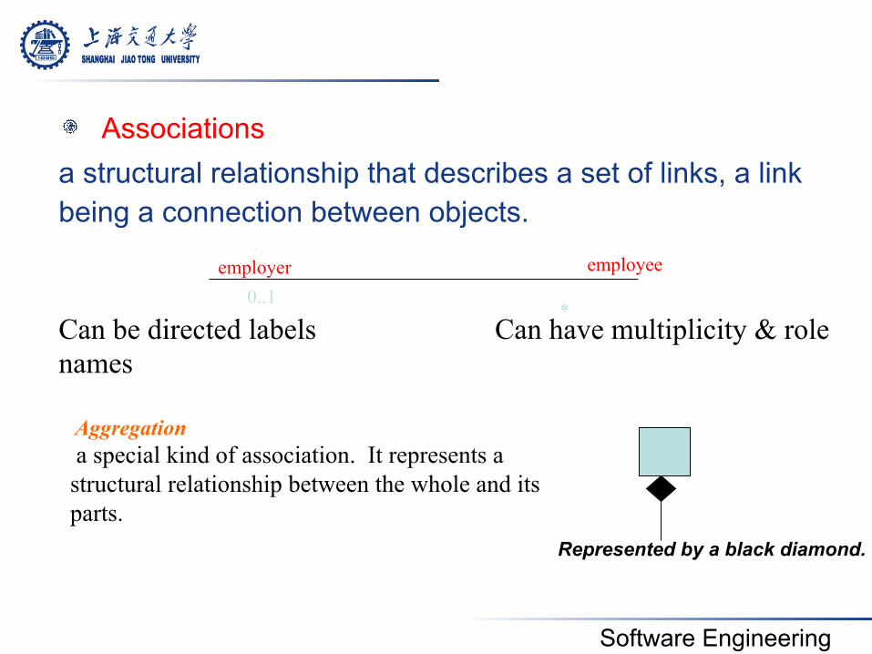
! Associations a structural relationship that describes a set of links, a link being a connection between objects. Can be directed labels Can have multiplicity & role names
0..1 employer
*
employee
Aggregation a special kind of association. It represents a structural relationship between the whole and its parts.
Represented by a black diamond.
Software Engineering
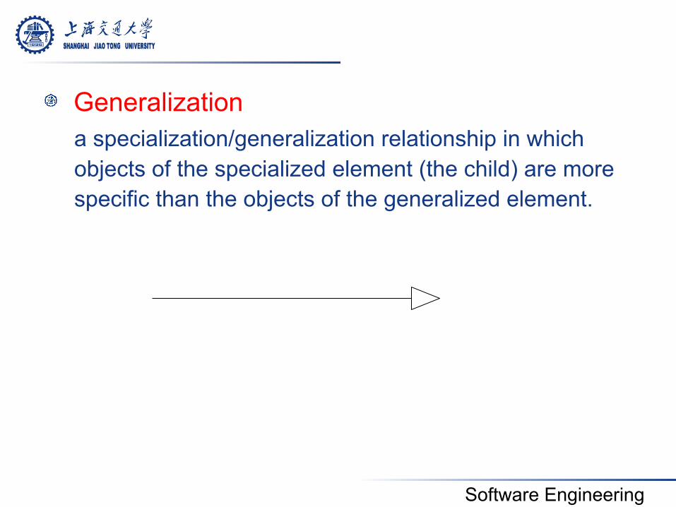
! Generalization a specialization/generalization relationship in which objects of the specialized element (the child) are more specific than the objects of the generalized element.
Software Engineering
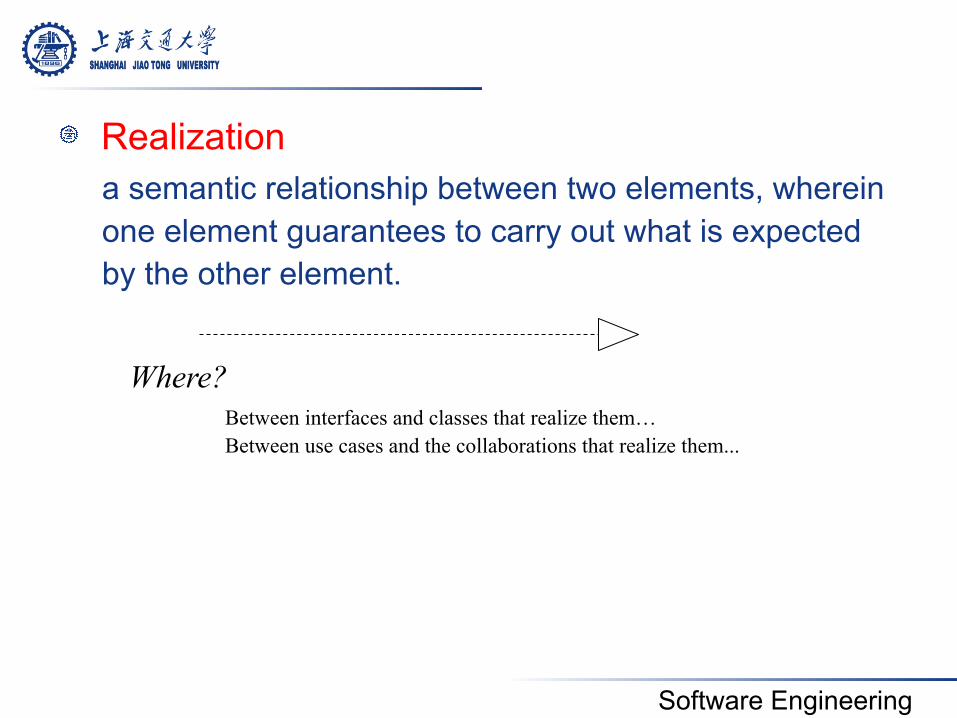
! Realization a semantic relationship between two elements, wherein one element guarantees to carry out what is expected by the other element.
Where? Between interfaces and classes that realize them… Between use cases and the collaborations that realize them...
Software Engineering
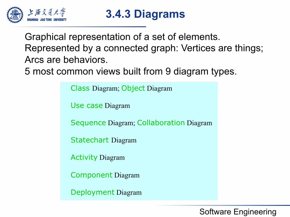
3.4.3 Diagrams
Class Diagram; Object Diagram Use case Diagram Sequence Diagram; Collaboration Diagram Statechart Diagram Activity Diagram Component Diagram Deployment Diagram
Graphical representation of a set of elements. Represented by a connected graph: Vertices are things; Arcs are behaviors. 5 most common views built from 9 diagram types.
Software Engineering
! Diagrams and System Model: • Functional model: Use case diagram • Object model: Class diagram • Dynamic model: Sequence diagrams,
statechart, activity diagrams
Software Engineering
4. UML Diagrams
Software Engineering
Diagrams covered in this talk
! Use case diagrams • Describe the functional behavior of the system as seen by the user
! Class diagrams • Describe the static structure of the system: Objects, attributes,
associations
! Interaction diagrams • Describe the dynamic behavior between objects of the system
! Statechart diagrams • Describe the dynamic behavior of an individual object
! Activity diagrams • Describe the dynamic behavior of a system, in particular the workflow.
! Package Diagrams • Describe the groupings of elements
Software Engineering
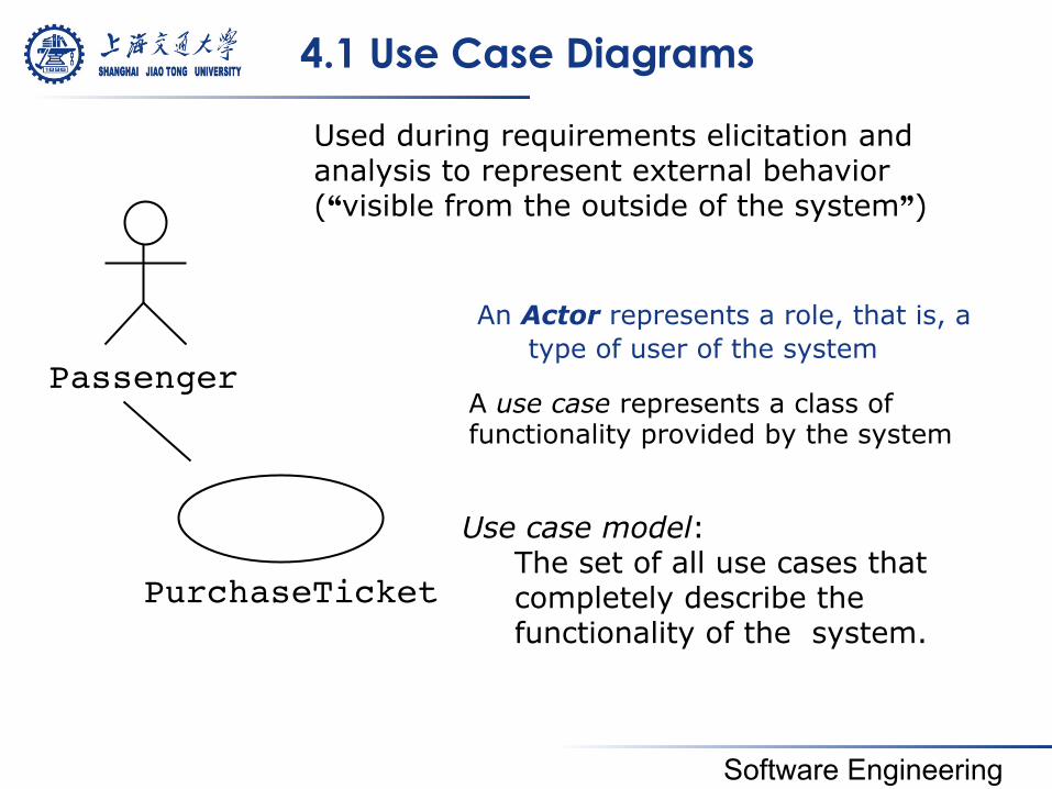
4.1 Use Case Diagrams
An Actor represents a role, that is, a type of user of the system
Passenger
PurchaseTicket
Used during requirements elicitation and analysis to represent external behavior (“visible from the outside of the system”)
Use case model: The set of all use cases that completely describe the functionality of the system.
A use case represents a class of functionality provided by the system
Software Engineering
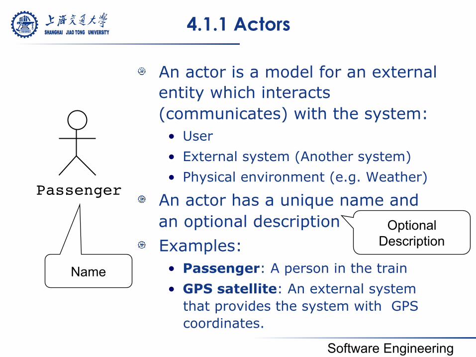
4.1.1 Actors
! An actor is a model for an external entity which interacts (communicates) with the system: • User • External system (Another system) • Physical environment (e.g. Weather)
! An actor has a unique name and an optional description
! Examples: • Passenger: A person in the train • GPS satellite: An external system
that provides the system with GPS coordinates.
Passenger
Name
Optional Description
Software Engineering
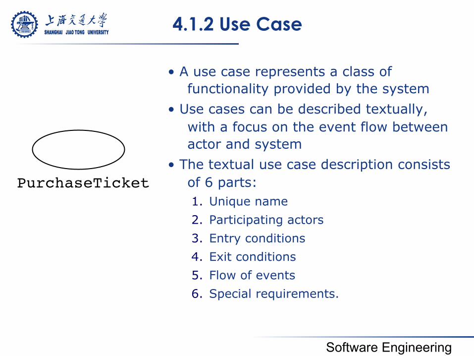
4.1.2 Use Case
• A use case represents a class of functionality provided by the system
• Use cases can be described textually, with a focus on the event flow between actor and system
• The textual use case description consists of 6 parts: 1. Unique name 2. Participating actors 3. Entry conditions 4. Exit conditions 5. Flow of events 6. Special requirements.
PurchaseTicket
Software Engineering
4.1.3 Communication Relationships
! Actors and use cases communicate when information is exchanged between them
Software Engineering
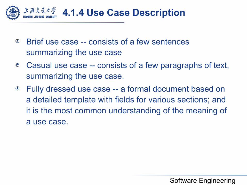
4.1.4 Use Case Description
! Brief use case -- consists of a few sentences summarizing the use case
! Casual use case -- consists of a few paragraphs of text, summarizing the use case.
! Fully dressed use case -- a formal document based on a detailed template with fields for various sections; and it is the most common understanding of the meaning of a use case.
Software Engineering
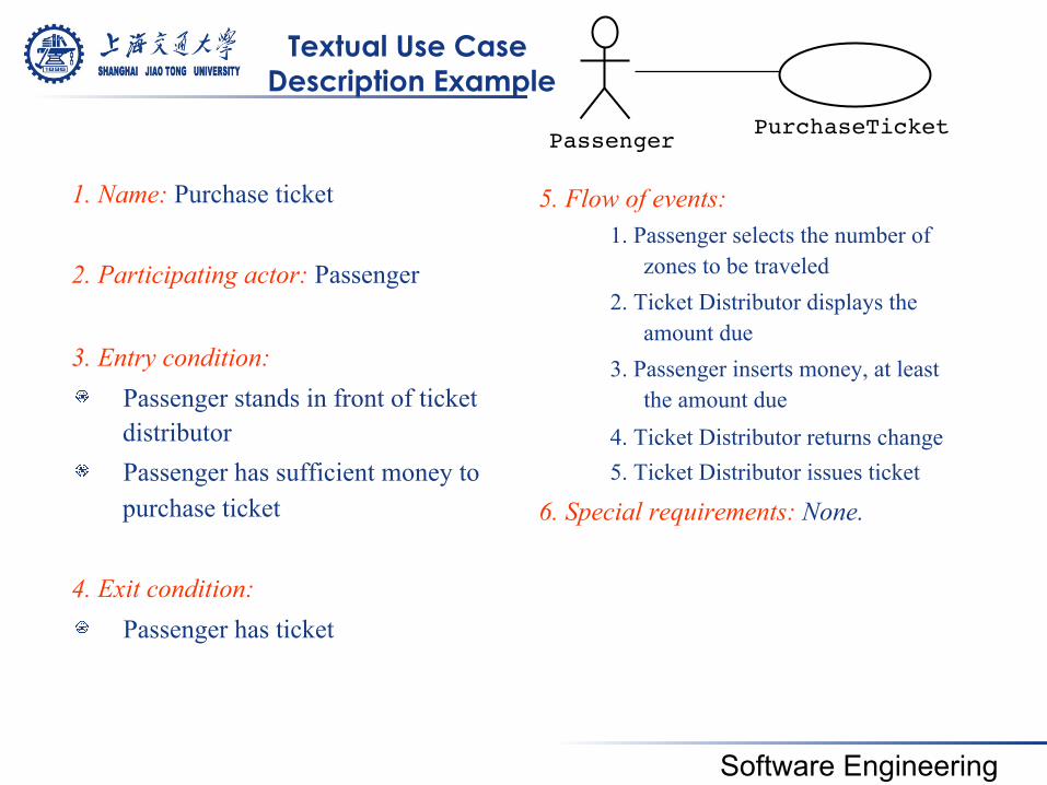
Textual Use Case Description Example
1. Name: Purchase ticket 2. Participating actor: Passenger 3. Entry condition: ! Passenger stands in front of ticket
distributor ! Passenger has sufficient money to
purchase ticket
4. Exit condition: ! Passenger has ticket
5. Flow of events: 1. Passenger selects the number of
zones to be traveled 2. Ticket Distributor displays the
amount due 3. Passenger inserts money, at least
the amount due 4. Ticket Distributor returns change 5. Ticket Distributor issues ticket
6. Special requirements: None.
Passenger PurchaseTicket
Software Engineering
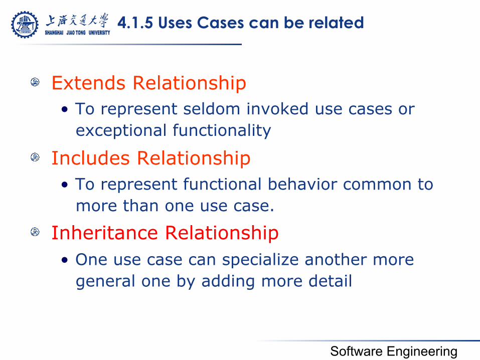
4.1.5 Uses Cases can be related
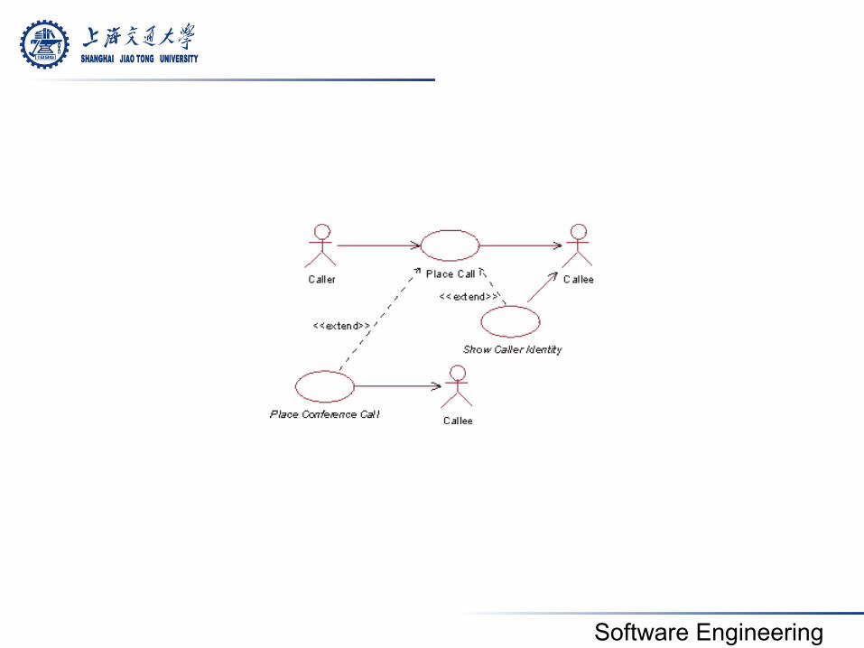
! Extends Relationship • To represent seldom invoked use cases or
exceptional functionality
! Includes Relationship • To represent functional behavior common to
more than one use case.
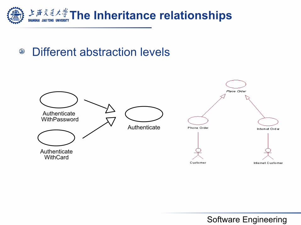
! Inheritance Relationship • One use case can specialize another more
general one by adding more detail
Software Engineering
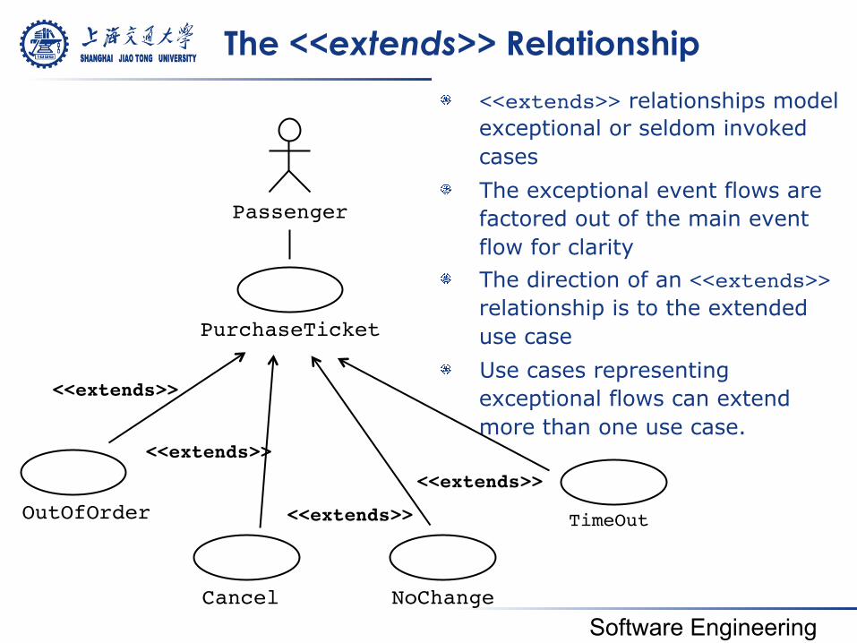
The <<extends>> Relationship
! <<extends>> relationships model exceptional or seldom invoked cases
! The exceptional event flows are factored out of the main event flow for clarity
! The direction of an <<extends>> relationship is to the extended use case
! Use cases representing exceptional flows can extend more than one use case.
Passenger
PurchaseTicket
TimeOut
<<extends>>!
NoChange
<<extends>>!OutOfOrder
<<extends>>!
Cancel
<<extends>>!
Software Engineering
Software Engineering
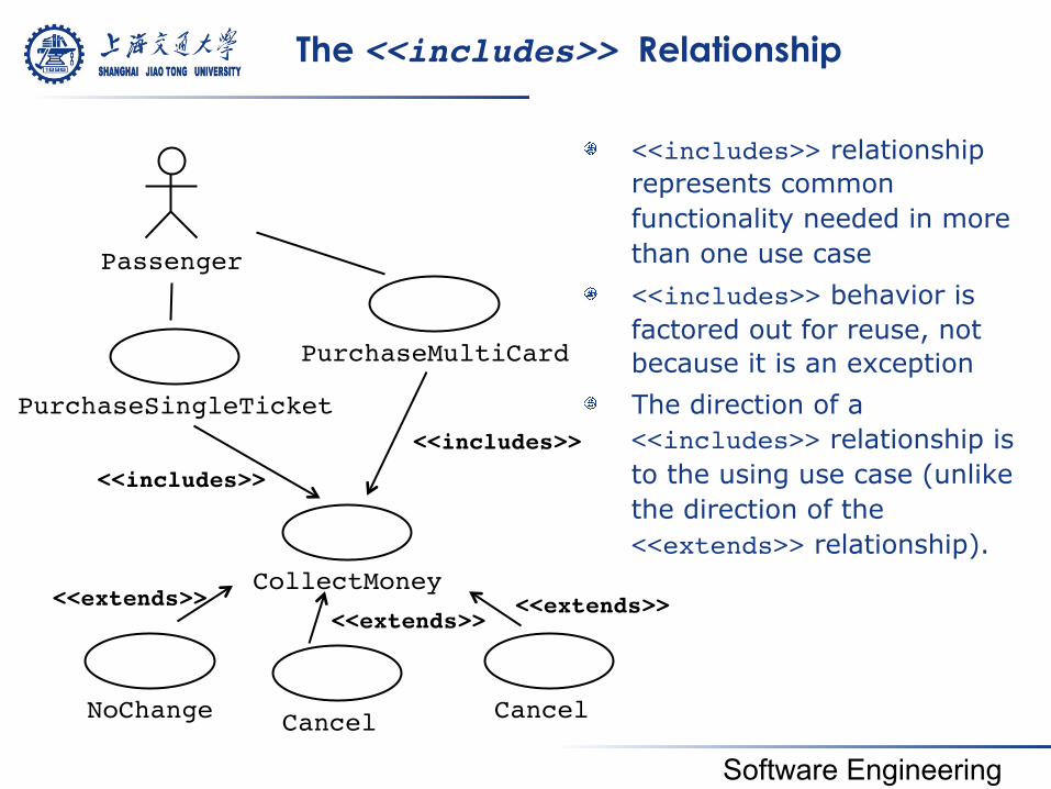
The <<includes>> Relationship
! <<includes>> relationship represents common functionality needed in more than one use case
! <<includes>> behavior is factored out for reuse, not because it is an exception
! The direction of a <<includes>> relationship is to the using use case (unlike the direction of the <<extends>> relationship).
Passenger
PurchaseSingleTicket
PurchaseMultiCard
<<includes>>!
CollectMoney
<<includes>>!
NoChange
<<extends>>!
Cancel
<<extends>>!
Cancel
<<extends>>!
Software Engineering
The Inheritance relationships
! Different abstraction levels
Authenticate
Authenticate
Authenticate WithPassword
WithCard
Software Engineering
4.1.6 Scenarios
! A use case describes all possible scenarios involving the described functionalities
! A scenario is an instance of a use case describing a concrete set of actions.
• Name • Participating actor instances • Flow of events
Software Engineering
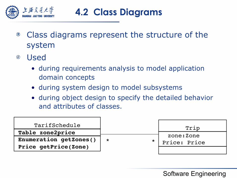
4.2 Class Diagrams
! Class diagrams represent the structure of the system
! Used • during requirements analysis to model application
domain concepts • during system design to model subsystems • during object design to specify the detailed behavior
and attributes of classes.
Table zone2price!Enumeration getZones()!Price getPrice(Zone)!
TarifSchedule!
*! *!
Trip!zone:Zone!
Price: Price!
Software Engineering
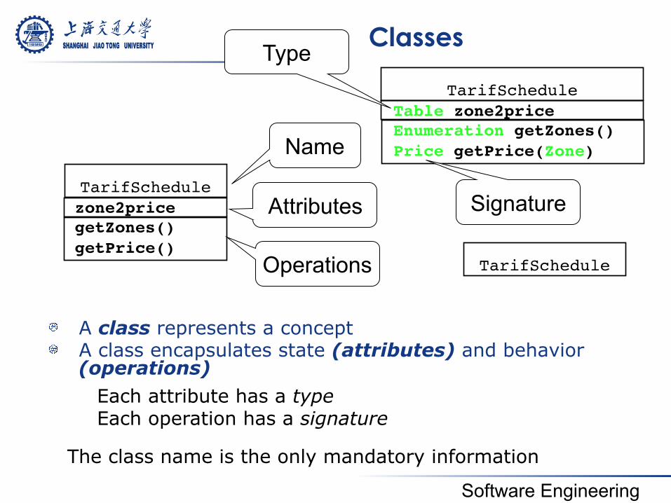
Classes
! A class represents a concept ! A class encapsulates state (attributes) and behavior
(operations)
Table zone2price!Enumeration getZones()!Price getPrice(Zone)!
TarifSchedule!
zone2price!getZones()!getPrice()!
TarifSchedule!
Name
Attributes
Operations
Signature
TarifSchedule!
The class name is the only mandatory information
Each attribute has a type Each operation has a signature
Type
Software Engineering
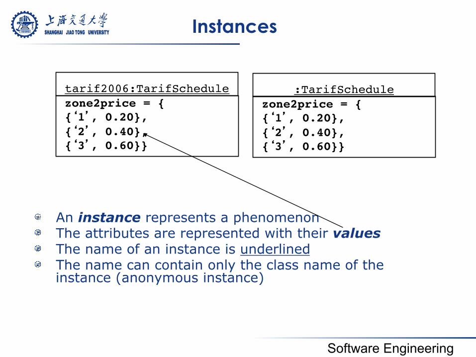
Instances
! An instance represents a phenomenon ! The attributes are represented with their values ! The name of an instance is underlined ! The name can contain only the class name of the
instance (anonymous instance)
zone2price = {!{‘1’, 0.20}, {‘2’, 0.40},!{‘3’, 0.60}}!
tarif2006:TarifSchedule!zone2price = {!{‘1’, 0.20}, {‘2’, 0.40},!{‘3’, 0.60}}!
:TarifSchedule!

Software Engineering
Actor vs Class vs Object
! Actor • An entity outside the system to be modeled,
interacting with the system (“Passenger”)
! Class • An abstraction modeling an entity in the application or
solution domain • The class is part of the system model (“User”, “Ticket
distributor”, “Server”)
! Object • A specific instance of a class (“Joe, the passenger who
is purchasing a ticket from the ticket distributor”).
Software Engineering
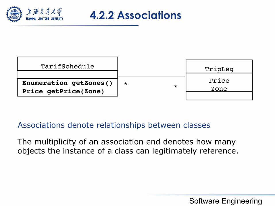
4.2.2 Associations
Associations denote relationships between classes
Price Zone!!
!Enumeration getZones()!Price getPrice(Zone)!
TarifSchedule! TripLeg!
*! *!
The multiplicity of an association end denotes how many objects the instance of a class can legitimately reference.
Software Engineering
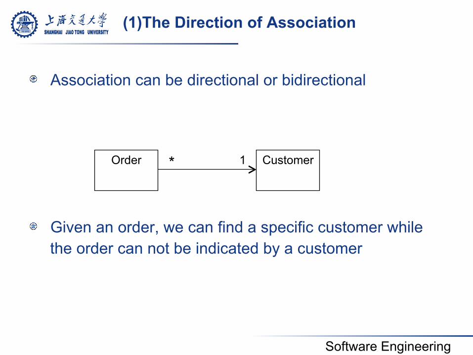
(1)The Direction of Association
! Association can be directional or bidirectional
! Given an order, we can find a specific customer while the order can not be indicated by a customer
Order
Customer
* 1
Software Engineering
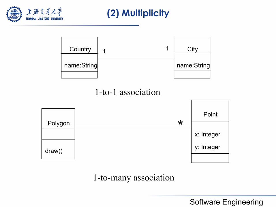
(2) Multiplicity
1-to-1 association
1-to-many association
Polygon
draw()
Point
x: Integer
y: Integer
*
Country
name:String
City
name:String
1 1
Software Engineering
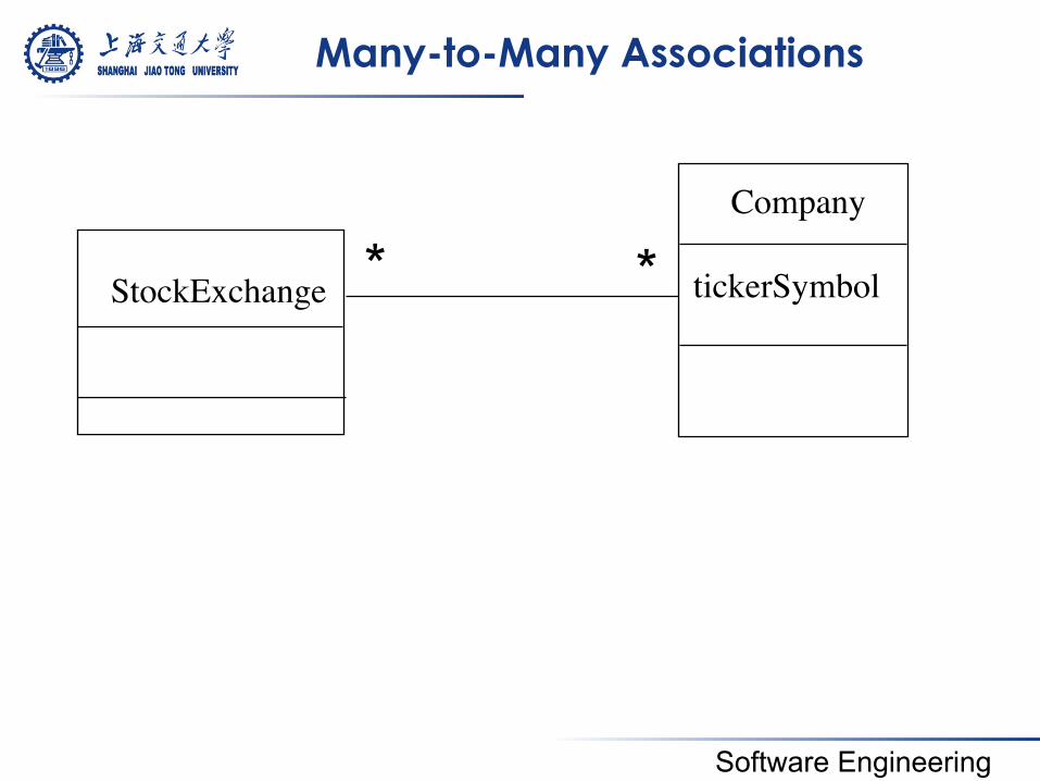
Many-to-Many Associations
StockExchange
Company
tickerSymbol * *
Software Engineering
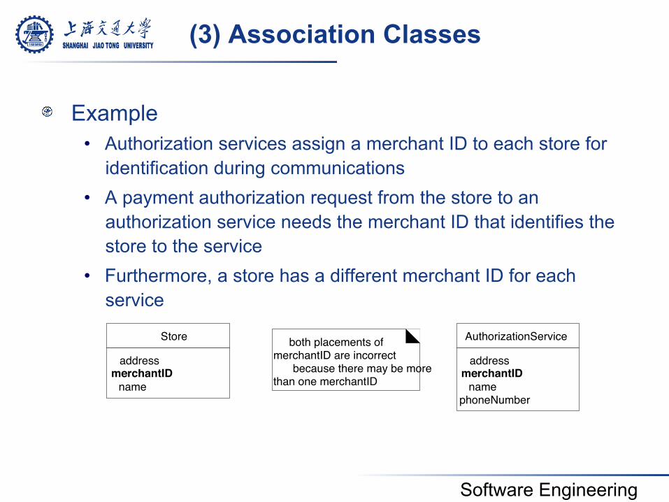
(3) Association Classes
! Example • Authorization services assign a merchant ID to each store for
identification during communications • A payment authorization request from the store to an
authorization service needs the merchant ID that identifies the store to the service
• Furthermore, a store has a different merchant ID for each service
address merchantID
name phoneNumber
AuthorizationService address
merchantID name
Store both placements of merchantID are incorrect
because there may be more than one merchantID
Software Engineering
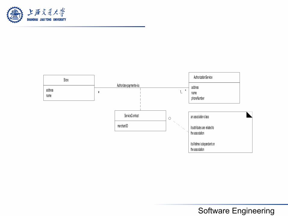
addressnamephoneNumber
AuthorizationService
addressname
Store
merchant ID
ServiceContract an association cl ass
it s att ri butes are related tothe association
it s li fetime i s dependent onthe association
Authorizes-payments-vi a1.. **
Software Engineering
! Guidelines • An attribute is related to an association • Instances of the association class have a life-time
dependency on the association • There is a many-to-many association between two
concepts, and information associated with the association itself
Software Engineering
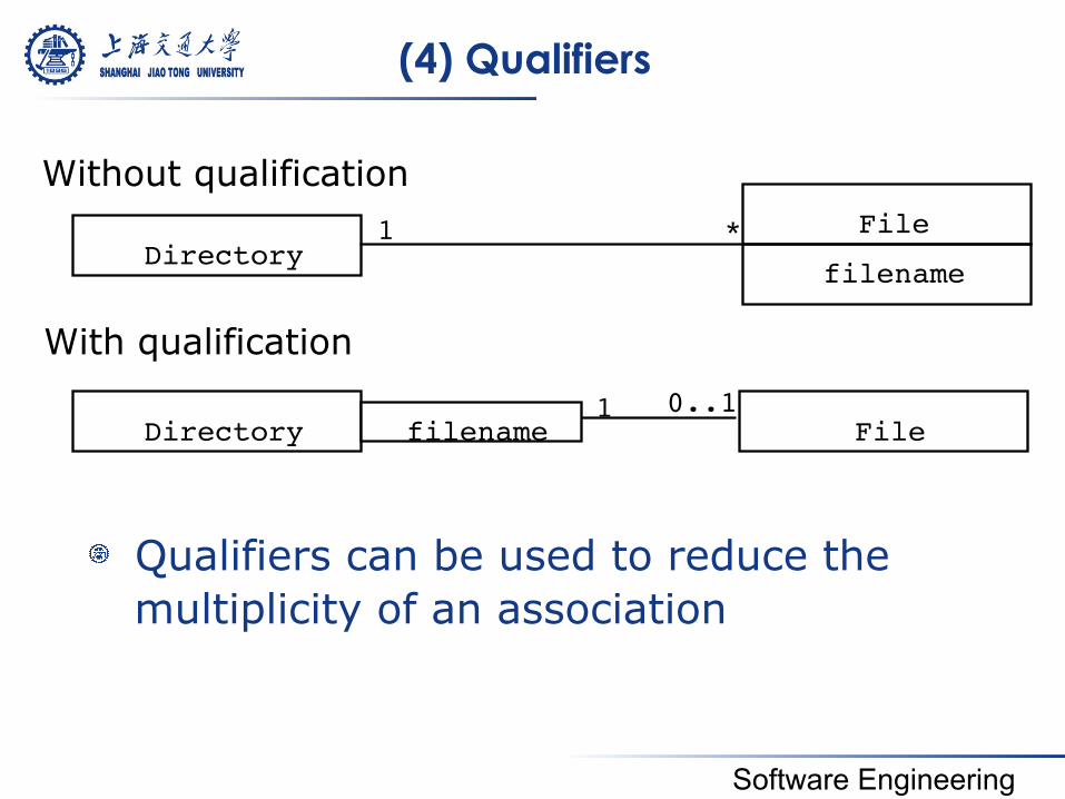
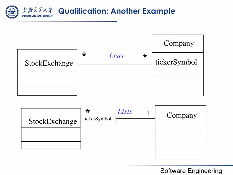
(4) Qualifiers
! Qualifiers can be used to reduce the multiplicity of an association
Directory File
filename
Without qualification 1 *
With qualification 0..1
Directory File 1 filename
Software Engineering
Qualification: Another Example
* StockExchange Company Lists * tickerSymbol
1
StockExchange
Company
tickerSymbol Lists * *
Software Engineering
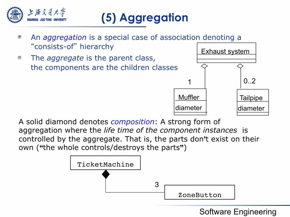
(5) Aggregation
! An aggregation is a special case of association denoting a “consists-of” hierarchy
! The aggregate is the parent class, the components are the children classes
Exhaust system
Muffler diameter
Tailpipe diameter
1 0..2
TicketMachine!
ZoneButton!3!
A solid diamond denotes composition: A strong form of aggregation where the life time of the component instances is controlled by the aggregate. That is, the parts don’t exist on their own (“the whole controls/destroys the parts”)
Software Engineering
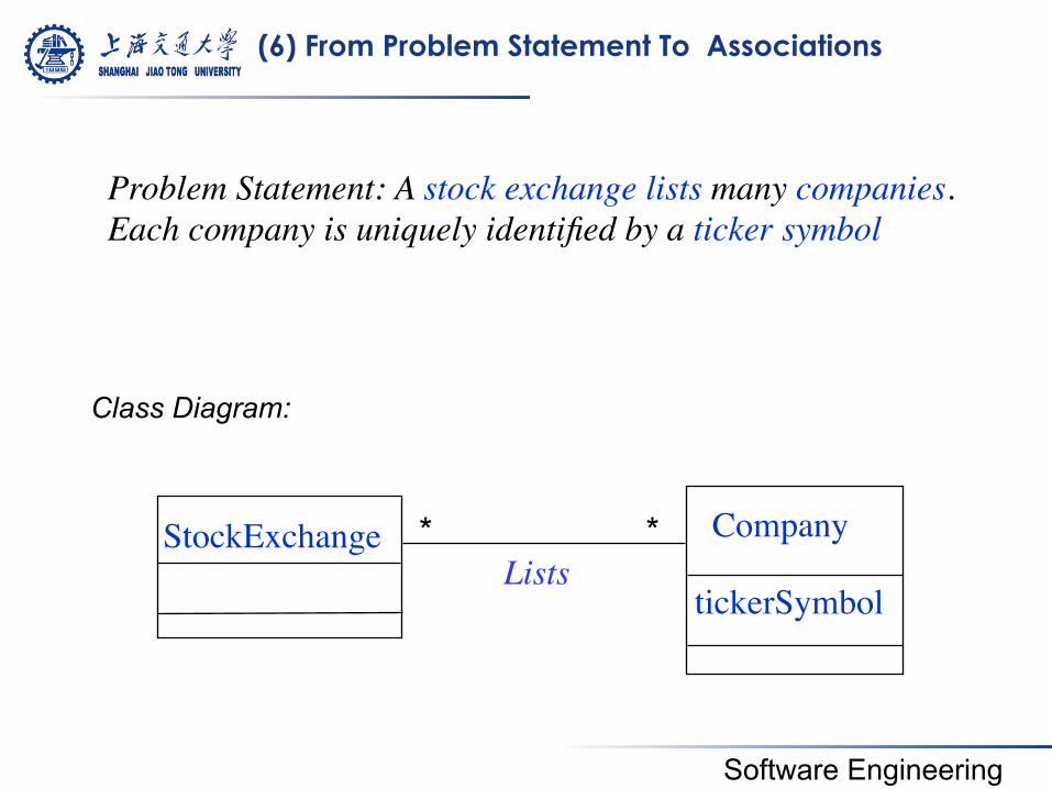
(6) From Problem Statement To Associations
Class Diagram:
StockExchange Company
tickerSymbol Lists
* *
Problem Statement: A stock exchange lists many companies. Each company is uniquely identified by a ticker symbol
Software Engineering
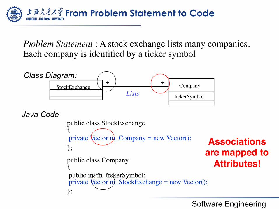
From Problem Statement to Code
Pr oblem Statement : A stock exchange lists many companies. Each company is identified by a ticker symbol
Class Diagram:
private Vector m_Company = new Vector();
public int m_tickerSymbol; private Vector m_StockExchange = new Vector();
public class StockExchange {
};
public class Company {
};
Java Code
StockExchange Company
tickerSymbol Lists * *
Associations!are mapped to !
Attributes!!
Software Engineering
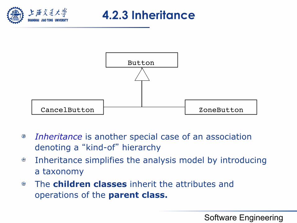
4.2.3 Inheritance
! Inheritance is another special case of an association denoting a “kind-of” hierarchy
! Inheritance simplifies the analysis model by introducing a taxonomy
! The children classes inherit the attributes and operations of the parent class.
Button!
ZoneButton!CancelButton!
Software Engineering
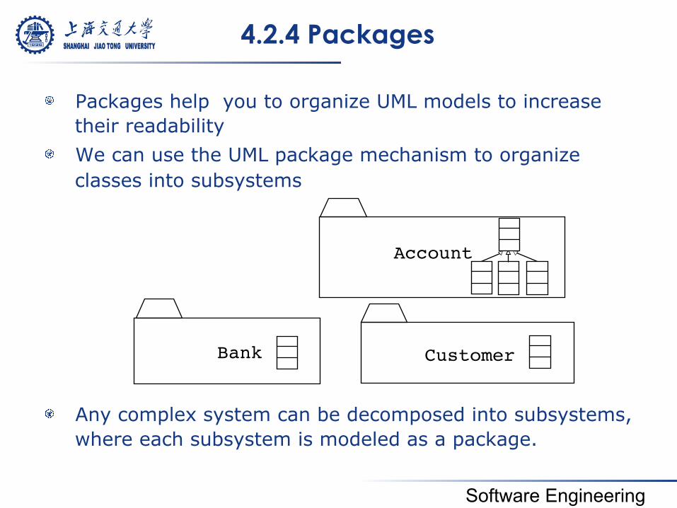
4.2.4 Packages
! Packages help you to organize UML models to increase their readability
! We can use the UML package mechanism to organize classes into subsystems
! Any complex system can be decomposed into subsystems, where each subsystem is modeled as a package.
Account
Customer Bank
Software Engineering
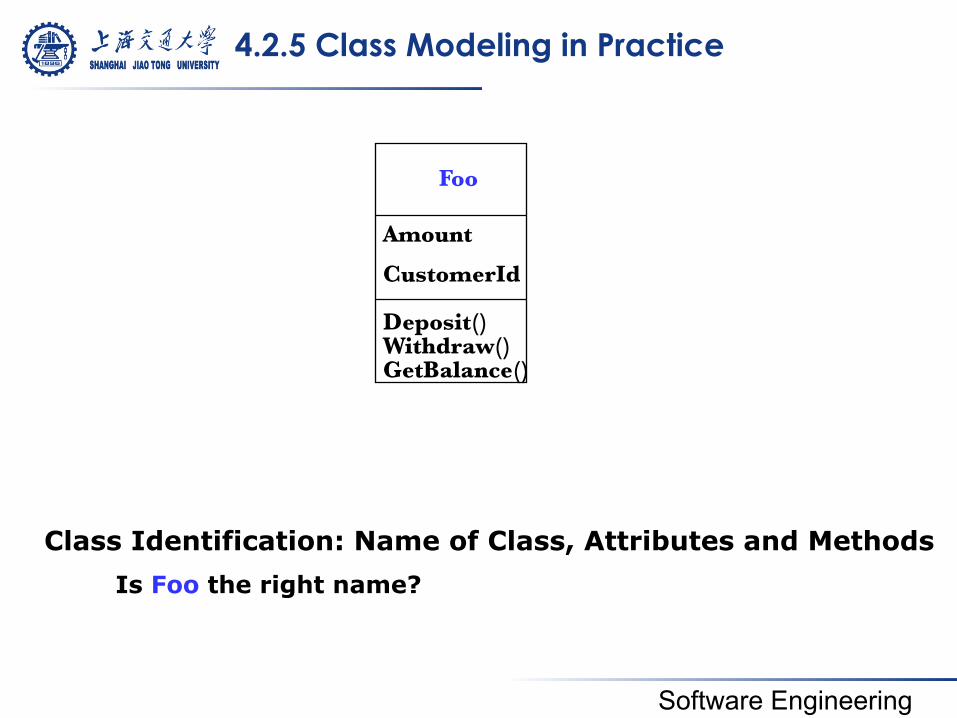
4.2.5 Class Modeling in Practice
Class Identification: Name of Class, Attributes and Methods Is Foo the right name?
Foo
Amount
CustomerId
Deposit() Withdraw() GetBalance()
Software Engineering
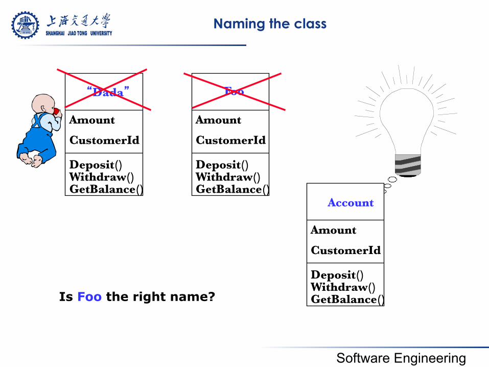
Naming the class
Foo
Amount
CustomerId
Deposit() Withdraw() GetBalance()
Account
Amount
CustomerId
Deposit() Withdraw() GetBalance()
Is Foo the right name?
“Dada”
Amount
CustomerId
Deposit() Withdraw() GetBalance()
Software Engineering
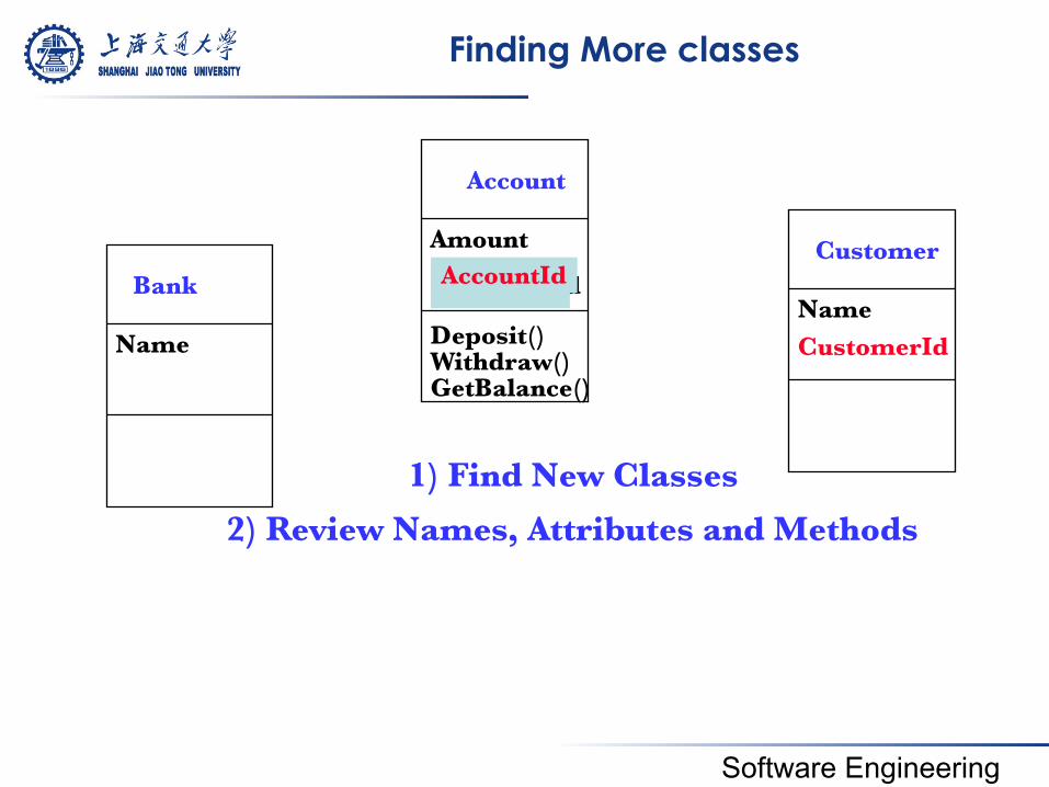
Finding More classes
Account
Amount
Deposit() Withdraw() GetBalance()
Customer
Name CustomerId
CustomerId AccountId Bank
Name
1) Find New Classes
2) Review Names, Attributes and Methods
Software Engineering
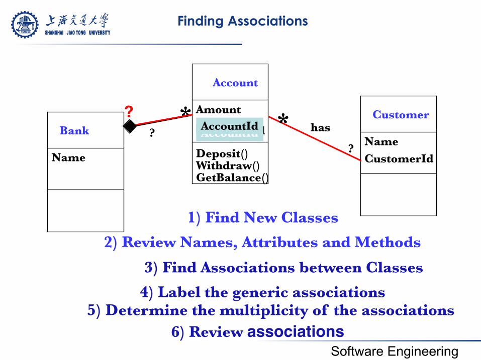
Finding Associations
Account
Amount
Deposit() Withdraw() GetBalance()
Customer
Name CustomerId
CustomerId AccountId AccountId Bank
Name
1) Find New Classes
2) Review Names, Attributes and Methods
3) Find Associations between Classes
has
4) Label the generic associations
6) Review associations!
* ?
*?!?
5) Determine the multiplicity of the associations
Software Engineering
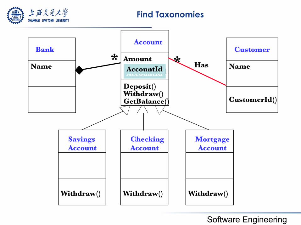
Find Taxonomies
Savings Account
Withdraw()
Checking Account
Withdraw()
Mortgage Account
Withdraw()
Account
Amount
Deposit() Withdraw() GetBalance()
CustomerId AccountId AccountId
Customer
Name
CustomerId()
Has * Bank
Name *
Software Engineering
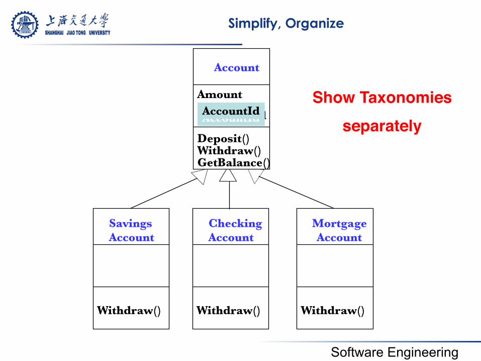
Simplify, Organize
Savings Account
Withdraw()
Checking Account
Withdraw()
Mortgage Account
Withdraw()
Account
Amount
Deposit() Withdraw() GetBalance()
CustomerId AccountId AccountId
Show Taxonomies!separately!
Software Engineering
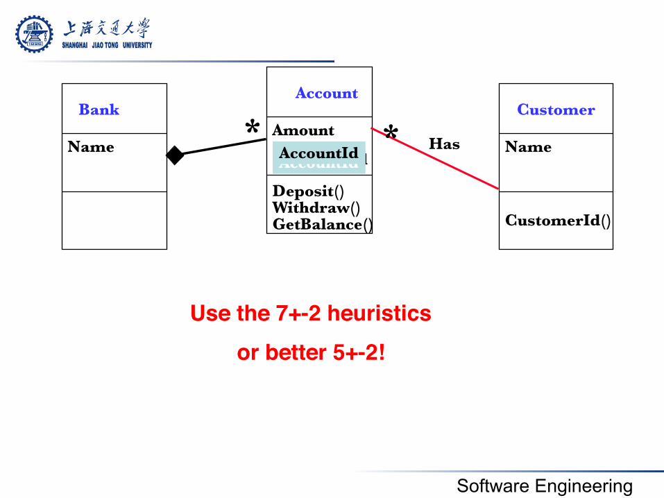
Customer
Name
CustomerId()
Account
Amount
Deposit() Withdraw() GetBalance()
CustomerId AccountId AccountId
Bank
Name Has * *
Use the 7+-2 heuristics!or better 5+-2!!
Software Engineering
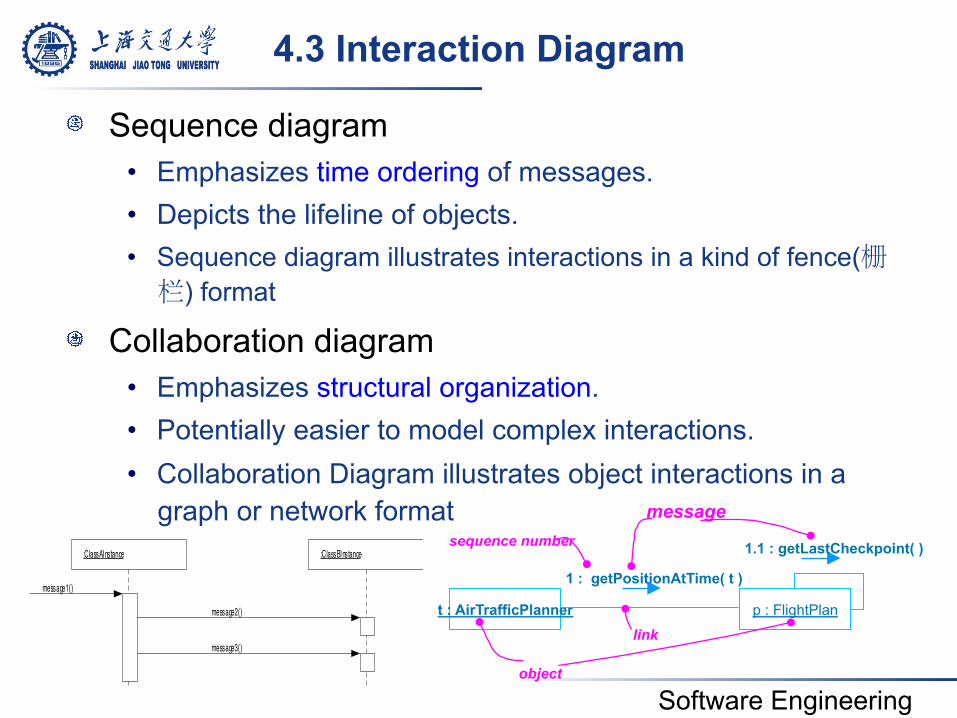
4.3 Interaction Diagram
! Sequence diagram • Emphasizes time ordering of messages. • Depicts the lifeline of objects. • Sequence diagram illustrates interactions in a kind of fence(栅栏) format
! Collaboration diagram • Emphasizes structural organization. • Potentially easier to model complex interactions. • Collaboration Diagram illustrates object interactions in a
graph or network format
t : AirTrafficPlanner p : FlightPlan
1 : getPositionAtTime( t )
object
link
sequence number 1.1 : getLastCheckpoint( )
message
:ClassAInstance :ClassBInstance
message2()
message1()
message3()
Software Engineering
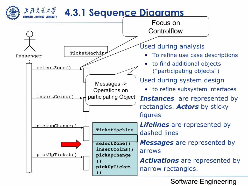
4.3.1 Sequence Diagrams
! Used during analysis • To refine use case descriptions • to find additional objects
(“participating objects”)
! Used during system design • to refine subsystem interfaces
! Instances are represented by rectangles. Actors by sticky figures
! Lifelines are represented by dashed lines
! Messages are represented by arrows
! Activations are represented by narrow rectangles.
selectZone()
pickupChange()
pickUpTicket()
insertCoins()
TicketMachine Passenger
Focus on Controlflow
Messages -> Operations on
participating Object
zone2price!selectZone()!insertCoins()!pickupChange()!pickUpTicket()!
TicketMachine!
Software Engineering
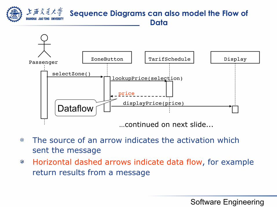
Sequence Diagrams can also model the Flow of Data
! The source of an arrow indicates the activation which sent the message
! Horizontal dashed arrows indicate data flow, for example return results from a message
Passenger selectZone()
ZoneButton TarifSchedule Display
lookupPrice(selection)
displayPrice(price) price
Dataflow
…continued on next slide...!
Software Engineering
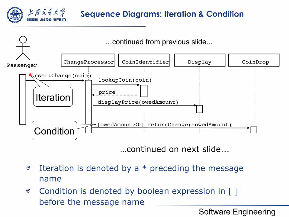
Sequence Diagrams: Iteration & Condition
! Iteration is denoted by a * preceding the message name
! Condition is denoted by boolean expression in [ ] before the message name
Passenger ChangeProcessor insertChange(coin)
CoinIdentifier Display CoinDrop
displayPrice(owedAmount)
lookupCoin(coin) price
[owedAmount<0] returnChange(-owedAmount)
Iteration
Condition
…continued on next slide...
…continued from previous slide...!
*!
Software Engineering
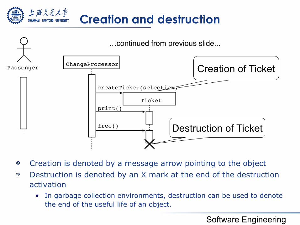
Creation and destruction
! Creation is denoted by a message arrow pointing to the object ! Destruction is denoted by an X mark at the end of the destruction
activation • In garbage collection environments, destruction can be used to denote
the end of the useful life of an object.
Passenger ChangeProcessor
…continued from previous slide...!
Ticket createTicket(selection)
free()
Creation of Ticket
Destruction of Ticket
print()
Software Engineering
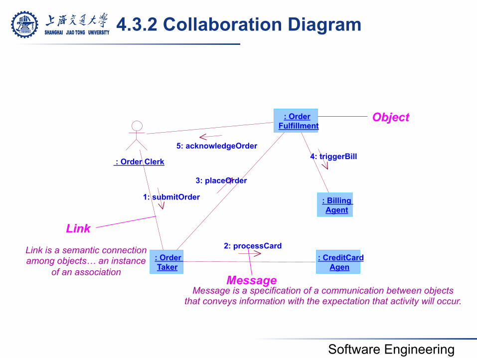
4.3.2 Collaboration Diagram
Message is a specification of a communication between objects that conveys information with the expectation that activity will occur.
Link is a semantic connection among objects… an instance
of an association
Object
Link
Message
: Order Clerk
: Order Taker
: Order Fulfillment
: CreditCard Agen
: Billing Agent
1: submitOrder 3: placeOrder
2: processCard
5: acknowledgeOrder 4: triggerBill
Software Engineering
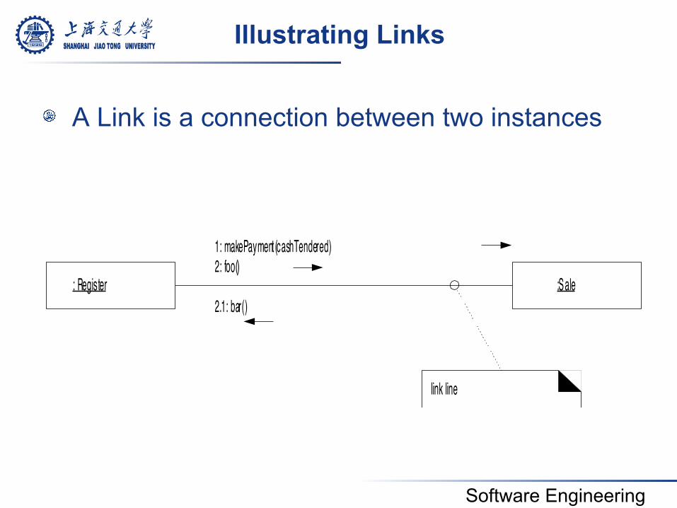
Illustrating Links
! A Link is a connection between two instances
1: makePayment(cashTendered)2: foo()
2.1: bar(): Register :Sale
link line
Software Engineering
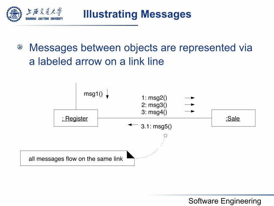
Illustrating Messages
! Messages between objects are represented via a labeled arrow on a link line
1: msg2() 2: msg3() 3: msg4() 3.1: msg5()
: Register :Sale
all messages flow on the same link
msg1()
Software Engineering
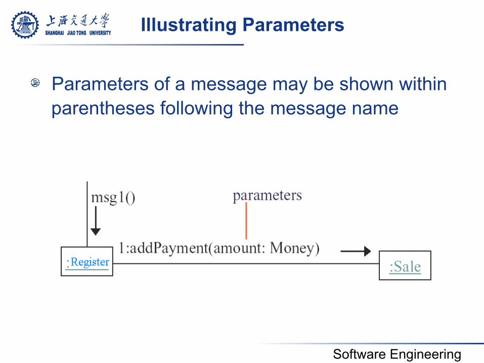
Illustrating Parameters
! Parameters of a message may be shown within parentheses following the message name
Software Engineering
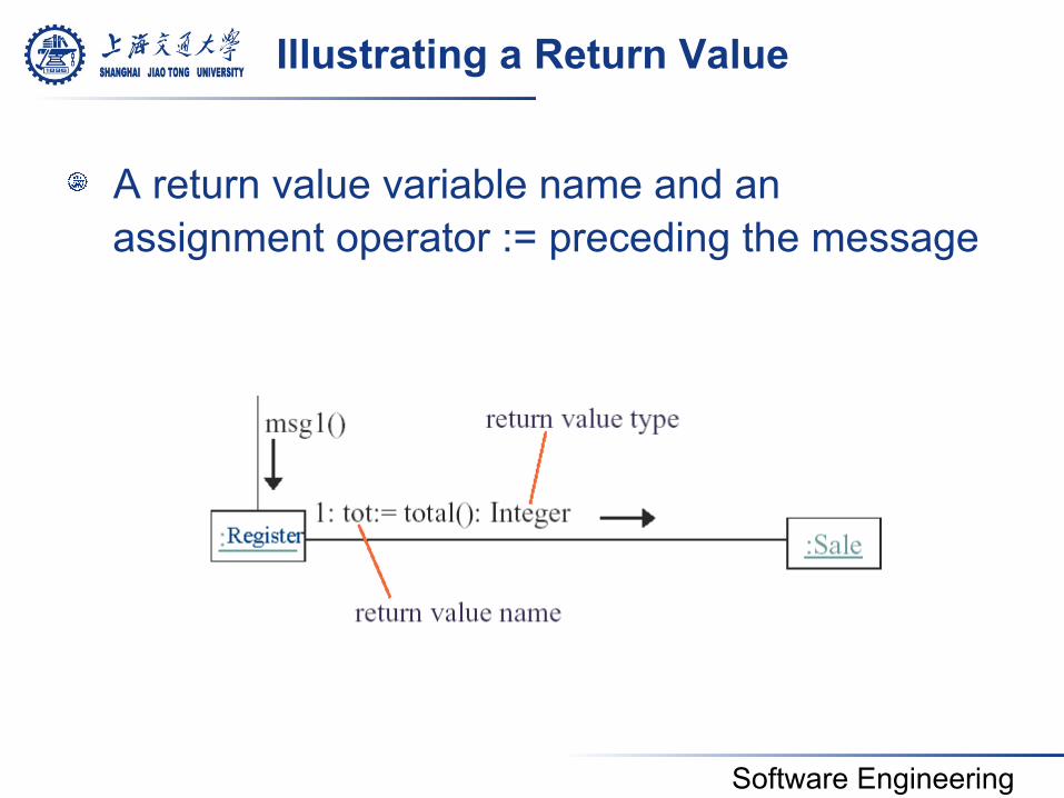
Illustrating a Return Value
! A return value variable name and an assignment operator := preceding the message
Software Engineering
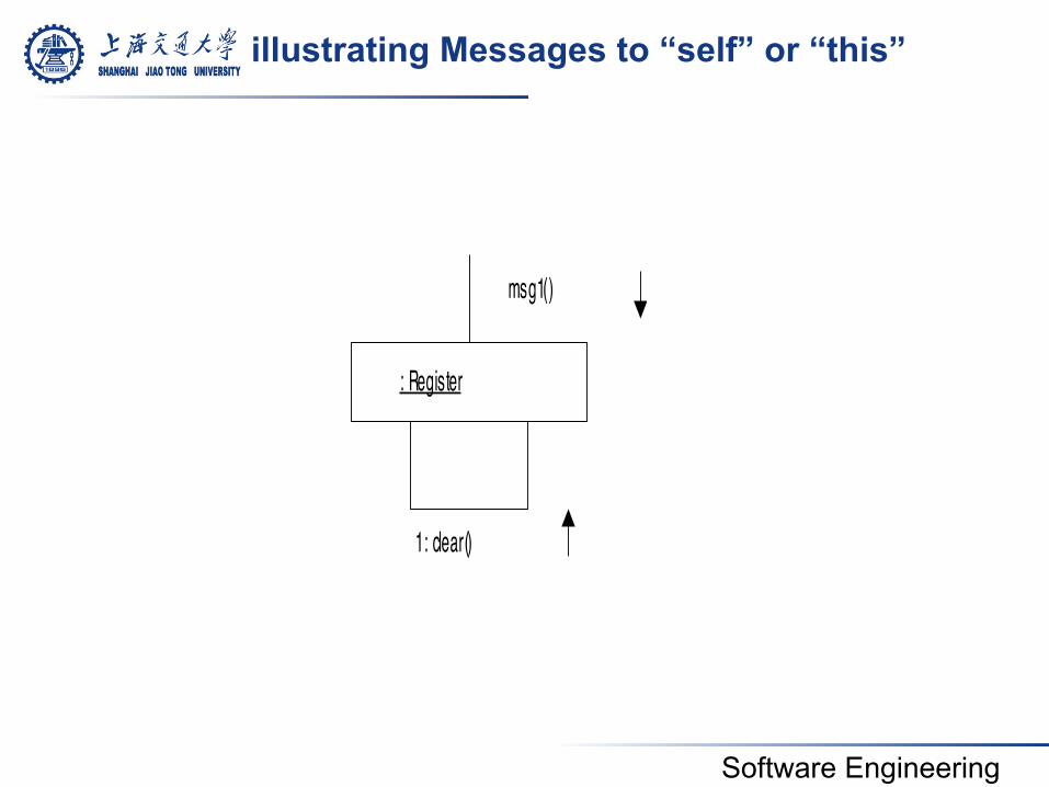
illustrating Messages to “self” or “this”
: Register
msg1()
1: clear()
Software Engineering
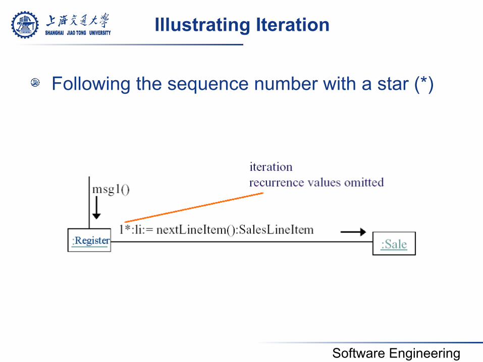
Illustrating Iteration
! Following the sequence number with a star (*)
Software Engineering
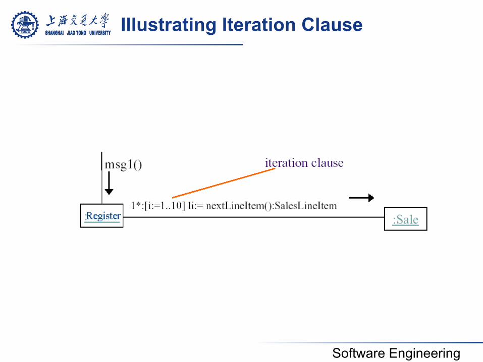
Illustrating Iteration Clause
Software Engineering
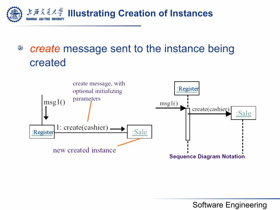
Illustrating Creation of Instances
! create message sent to the instance being created
Software Engineering
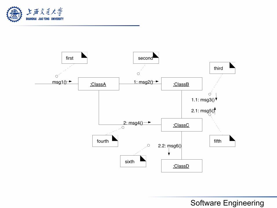
Illustrating Message Number Sequencing
! The first message is not numbered ! The order and nesting of subsequent messages
is shown with a legal numbering scheme in which nested messages have appended to them a number.
Nesting is denoted by prepending the incoming message
! number to the outgoing message number.
Software Engineering
;ClassA msg1() :ClassB 1: msg2()
:ClassC
1.1: msg3() 2.1: msg5()
2: msg4()
:ClassD
2.2: msg6()
first second
fourth
sixth
fifth
third
Software Engineering
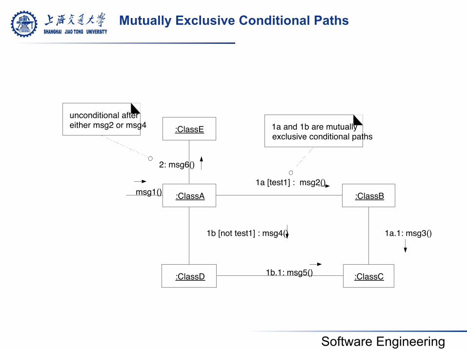
Mutually Exclusive Conditional Paths
1a [test1] : msg2() :ClassA :ClassB
:ClassC
1a.1: msg3()
msg1()
:ClassD
1b [not test1] : msg4()
1b.1: msg5()
:ClassE
2: msg6()
unconditional after either msg2 or msg4 1a and 1b are mutually
exclusive conditional paths
Software Engineering
Interaction Diagram Properties
! UML interaction diagram represent behavior in terms of interactions
! Useful to identify or find missing objects ! Time consuming to build, but worth the
investment ! Complement the class diagrams (which
represent structure).
Software Engineering
4.4 State Machine Diagrams
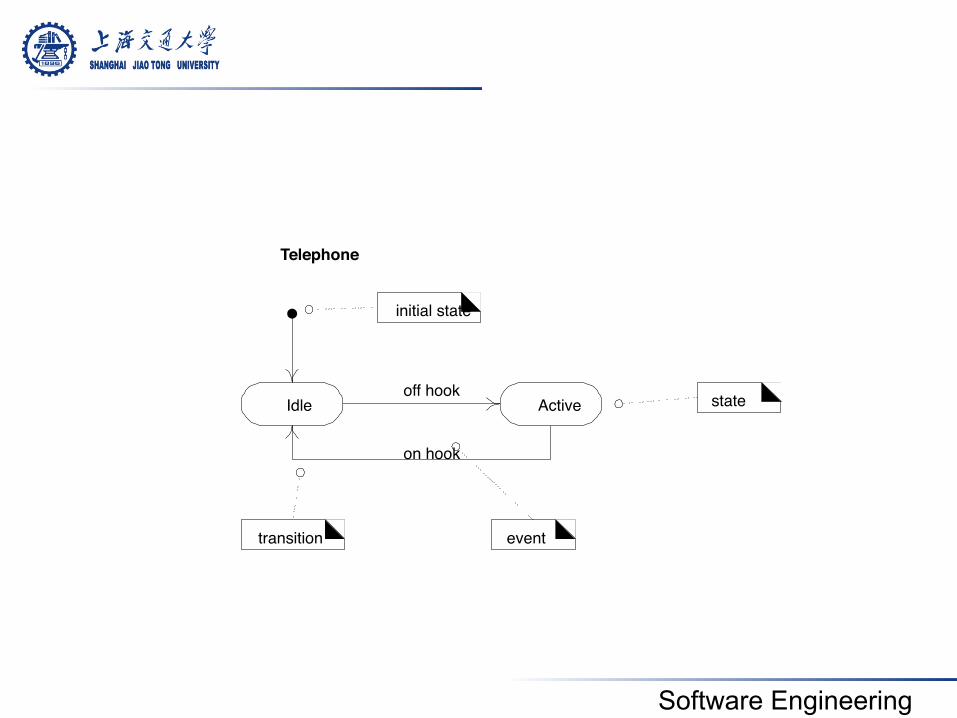
! A UML state machine is a notation for describing the sequence of states an object goes through in response to external events
! State: it is a condition satisfied by the attributes of an object • A telephone is in the sate of being “idle”
! Transition: it represents a change of state triggered by events, conditions, or time • Event “off hook”, “idle” to “active” state transition �
Software Engineering
off hook Idle Active
on hook
Telephone
state
transition event
initial state
Software Engineering
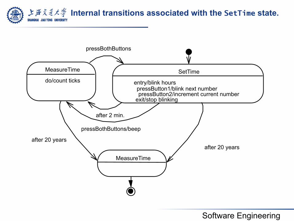
Internal transitions associated with the SetTime state.
SetTime
entry/blink hours
exit/stop blinking
pressButton1/blink next number pressButton2/increment current number
MeasureTime
do/count ticks
MeasureTime
pressBothButtons
pressBothButtons/beep
after 2 min.
after 20 years after 20 years
Software Engineering
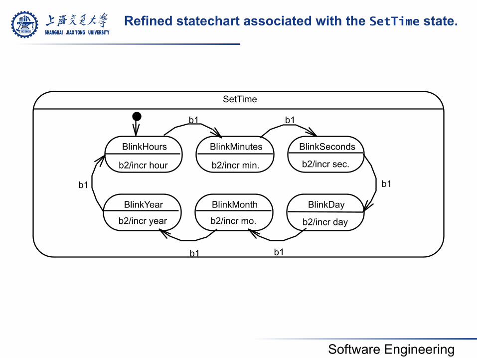
SetTime
BlinkHours BlinkMinutes BlinkSeconds
BlinkYear BlinkMonth BlinkDay
b2/incr hour b2/incr min. b2/incr sec.
b2/incr year b2/incr mo. b2/incr day
b1
b1
b1
b1
b1 b1
Refined statechart associated with the SetTime state.
Software Engineering
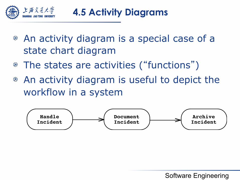
4.5 Activity Diagrams
! An activity diagram is a special case of a state chart diagram
! The states are activities (“functions”) ! An activity diagram is useful to depict the
workflow in a system
HandleIncident
DocumentIncident
ArchiveIncident
Software Engineering
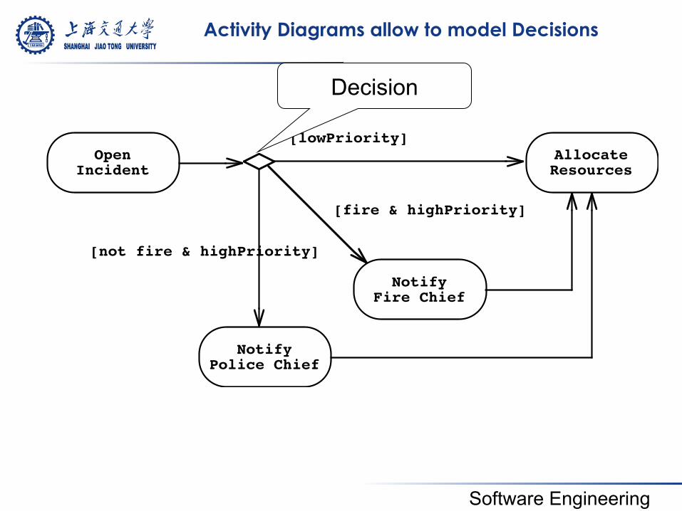
Activity Diagrams allow to model Decisions
OpenIncident
NotifyPolice Chief
NotifyFire Chief
AllocateResources
[fire & highPriority]
[not fire & highPriority]
[lowPriority]
Decision
Software Engineering
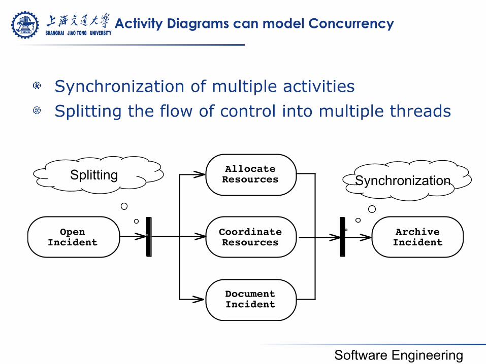
Activity Diagrams can model Concurrency
! Synchronization of multiple activities ! Splitting the flow of control into multiple threads
OpenIncident
AllocateResources
CoordinateResources
DocumentIncident
ArchiveIncident
Synchronization Splitting
Software Engineering
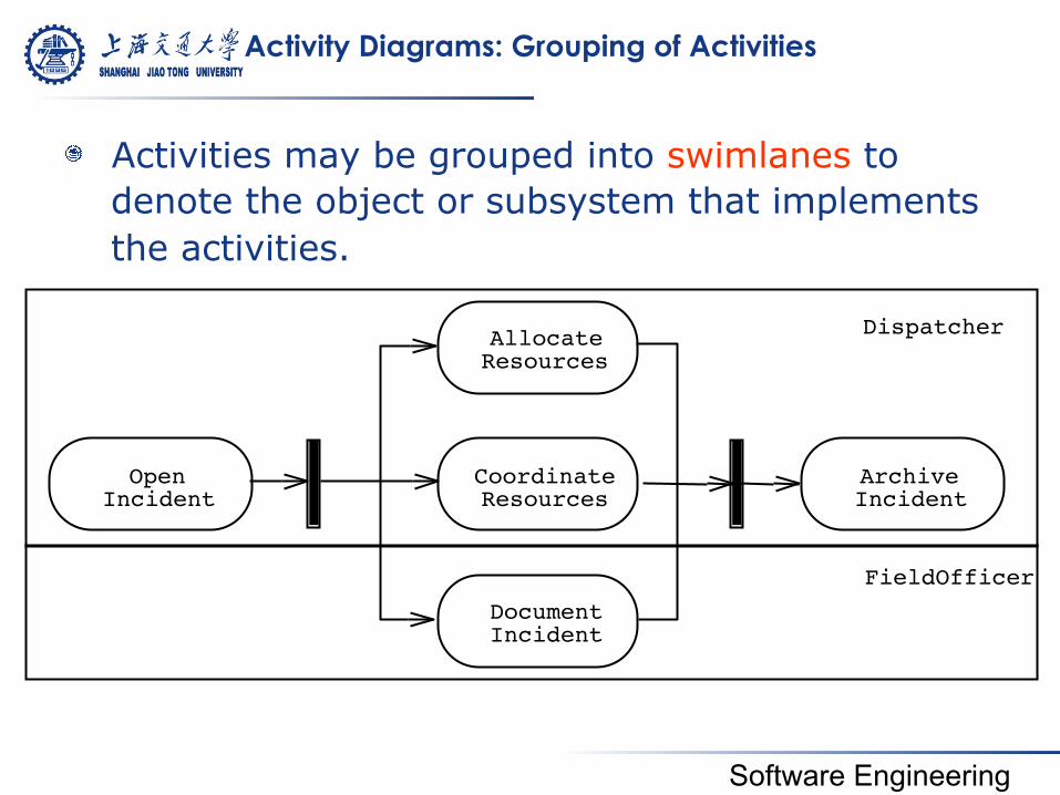
Activity Diagrams: Grouping of Activities
! Activities may be grouped into swimlanes to denote the object or subsystem that implements the activities.
Open Incident
Allocate Resources
Coordinate Resources
Document Incident
Archive Incident
Dispatcher
FieldOfficer
Software Engineering
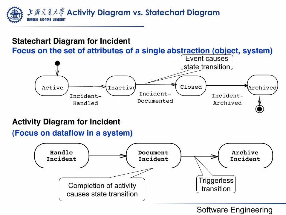
Activity Diagram vs. Statechart Diagram
HandleIncident
DocumentIncident
ArchiveIncident
Active Inactive Closed Archived Incident-!Handled
Incident-!Documented Incident-!
Archived
Statechart Diagram for Incident!Focus on the set of attributes of a single abstraction (object, system)!
Activity Diagram for Incident !(Focus on dataflow in a system) !
Triggerless transition Completion of activity
causes state transition
Event causes state transition
Software Engineering
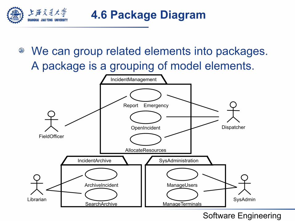
4.6 Package Diagram
! We can group related elements into packages. A package is a grouping of model elements.
Report Emergency
FieldOfficer
Dispatcher OpenIncident
AllocateResources
ArchiveIncident
SearchArchive
ManageUsers
ManageTerminals Librarian SysAdmin
SysAdministration IncidentArchive
IncidentManagement
Software Engineering
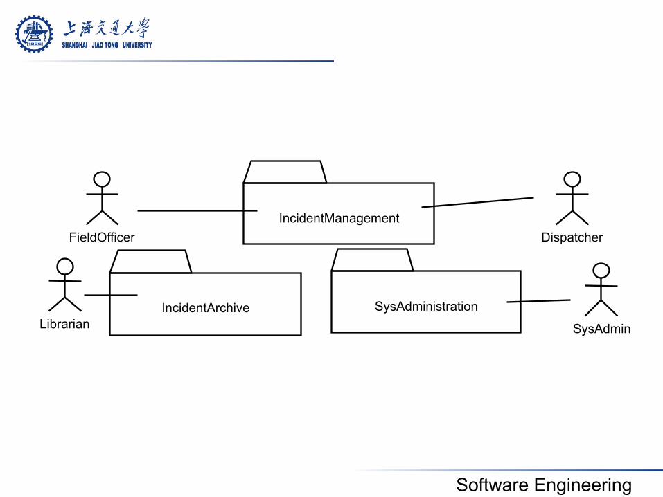
FieldOfficer Dispatcher
Librarian SysAdmin IncidentArchive SysAdministration
IncidentManagement
Software Engineering
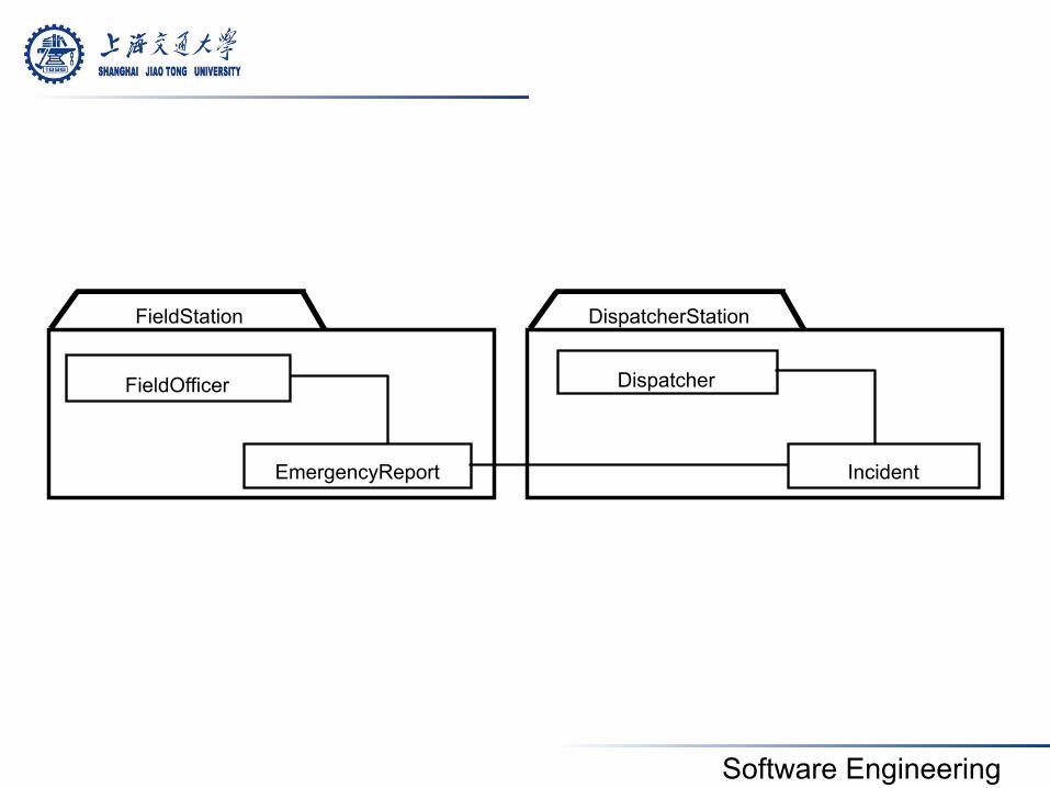
DispatcherStation
EmergencyReport Incident
FieldOfficer Dispatcher
FieldStation
Software Engineering
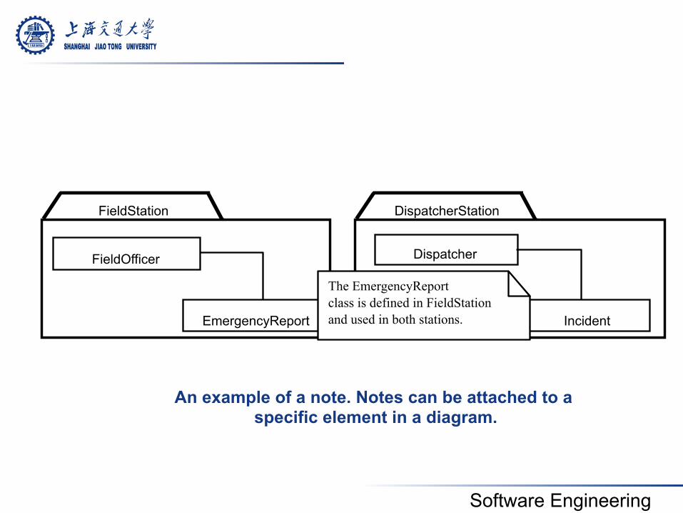
EmergencyReport
DispatcherStation
Incident
FieldOfficer Dispatcher
FieldStation
The Emer gencyReport class is defined in FieldStation and used in both stations.
An example of a note. Notes can be attached to a specific element in a diagram.
Software Engineering
4.7 Diagram Extensions
! UML provides a number of extension mechanisms enabling the modeler to extend the language
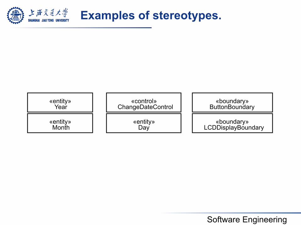
! Stereotype: It allows developers to classify model elements in UML
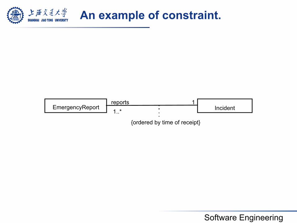
! Constraint: it is a rule that is attached to a UML model element restricting its semantics
Software Engineering
«entity»
«entity»
«boundary»
«boundary»
«control» Year
Month
ChangeDateControl
LCDDisplayBoundary
ButtonBoundary «entity»
Day
Examples of stereotypes.
Software Engineering
EmergencyReport Incident reports 1..*
{ordered by time of receipt}
An example of constraint.
1
Software Engineering
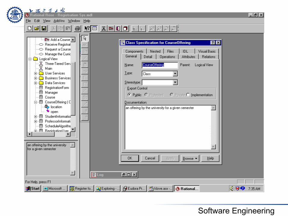
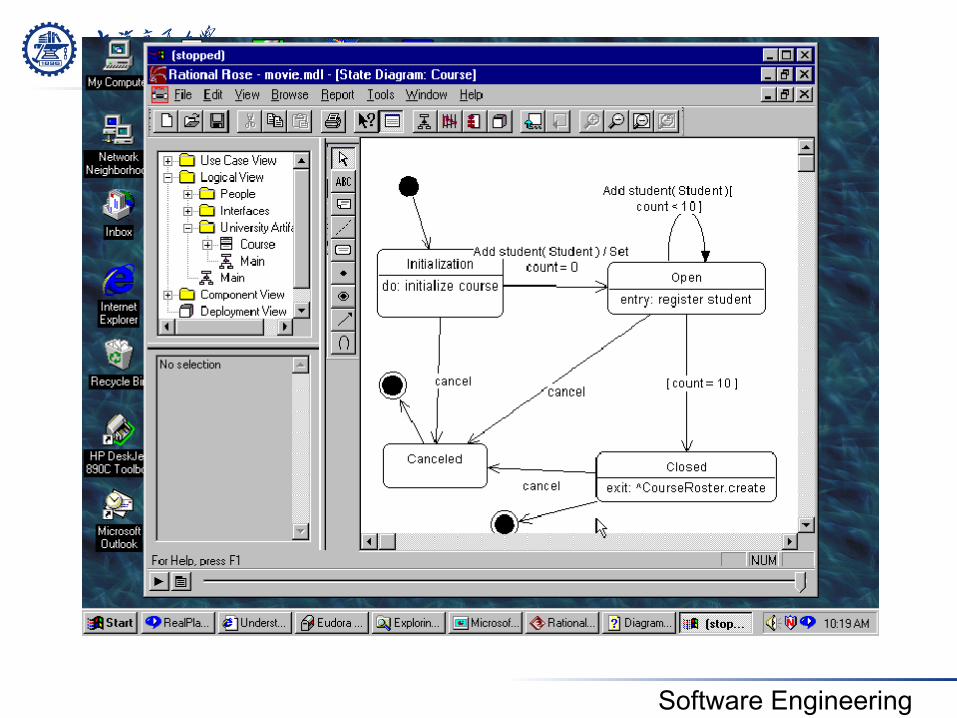
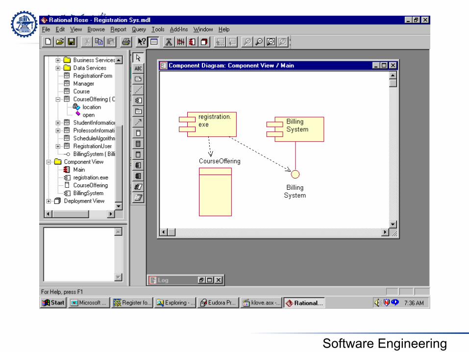
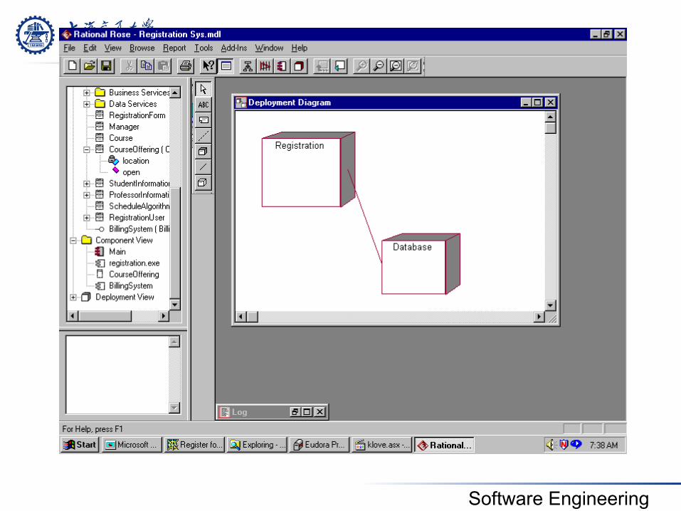
5. Case Study
Software Engineering
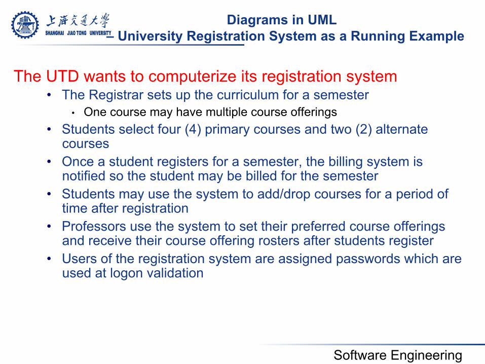
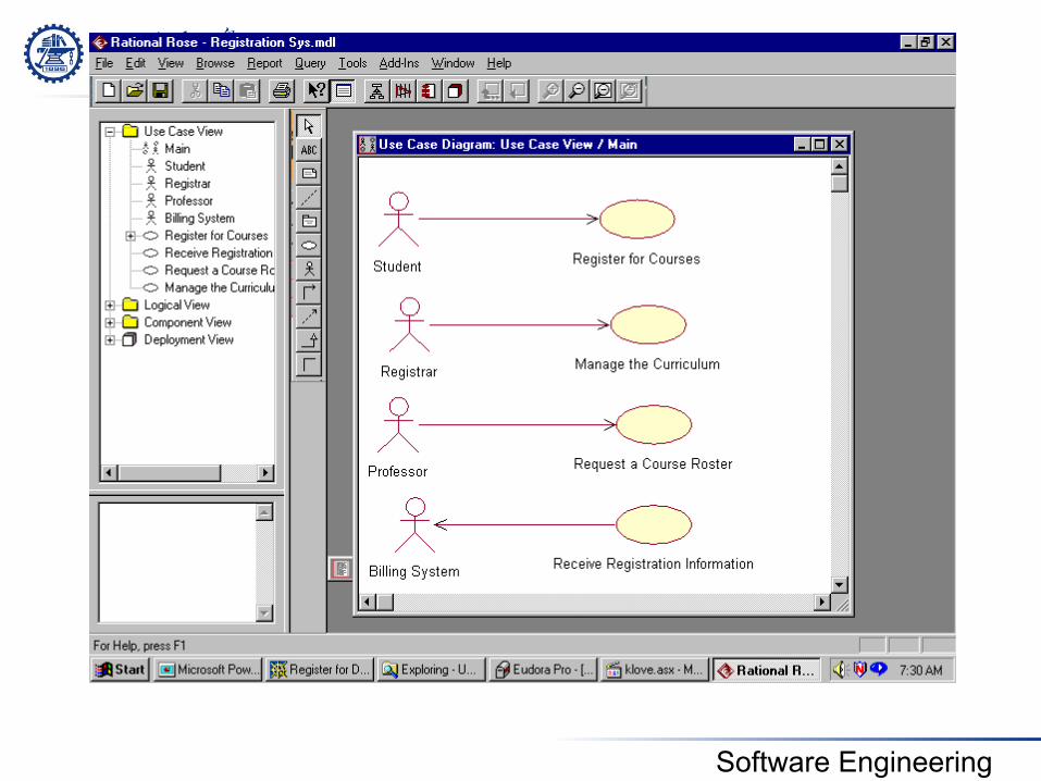
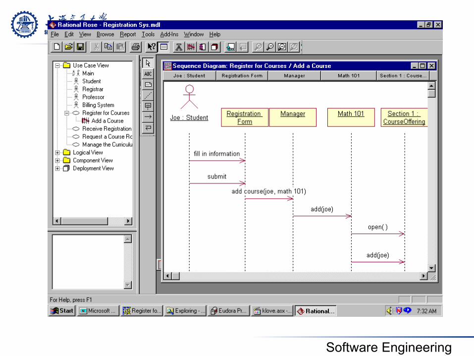
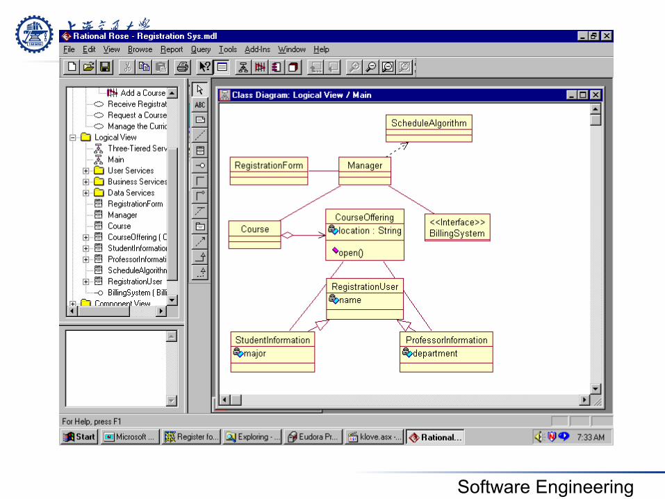
Diagrams in UML – University Registration System as a Running Example
The UTD wants to computerize its registration system • The Registrar sets up the curriculum for a semester
• One course may have multiple course offerings • Students select four (4) primary courses and two (2) alternate
courses • Once a student registers for a semester, the billing system is
notified so the student may be billed for the semester • Students may use the system to add/drop courses for a period of
time after registration • Professors use the system to set their preferred course offerings
and receive their course offering rosters after students register • Users of the registration system are assigned passwords which are
used at logon validation
Software Engineering
Software Engineering
Software Engineering
Software Engineering
Software Engineering
Software Engineering
Software Engineering
Software Engineering
Summary
! UML is for visualizing, specifying, constructing, and documenting with emphasis on system architectures (things in the system and relationships among the things) from five different views
! UML as a standard language to represent the O-O model is widely accepted.
Thanks
• Some materials come from Lawrence Chung’s CS6358 PPT, Ronald J. Norman’S IDS306 PPT
and others from Internet