2 modeling with uml - pearson
TRANSCRIPT

29
2Modeling with UML
Every mechanic is familiar with the problem of the part you can’t buy because you can’t find it because the manufacturer considers it a part of something else.
—Robert Pirsig, in Zen and the Art of Motorcycle Maintenance
Notations enable us to articulate complex ideas succinctly and precisely. In projects
involving many participants, often of different technical and cultural backgrounds, accuracy and
clarity are critical as the cost of miscommunication increases rapidly.
For a notation to enable accurate communication, it must come with a well-defined
semantics, it must be well suited for representing a given aspect of a system, and it must be well
understood among project participants. In the latter lies the strength of standards and
conventions: when a notation is used by a large number of participants, there is little room for
misinterpretation and ambiguity. Conversely, when many dialects of a notation exists, or when a
very specialized notation is used, the notation users are prone to misunderstandings as each user
imposes its own interpretation. We selected UML (Unified Modeling Language, [OMG, 2009])
as a primary notation for this book because it provides a spectrum of notations for representing
different aspects of a system and has been accepted as a standard notation in the industry.
In this chapter, we first describe the concepts of modeling in general and object-oriented
modeling in particular. We then describe five fundamental notations of UML that we use
throughout the book: use case diagrams, class diagrams, interaction diagrams, state machine
diagrams, and activity diagrams. For each of these notations, we describe its basic semantics and
provide examples. We revisit these notations in detail in later chapters as we describe the
activities that use them. Specialized notations that we use in only one chapter are introduced
later, such as UML
and deployment diagrams in Chapter 6, System Design: Decomposing the System, and
PERT charts in Chapter 14, Project Management.
OOSE.book Page 29 Sunday, February 1, 2009 9:29 PM

30 Chapter 2 • Modeling with UML
2.1 Introduction
UML is a notation that resulted from the unification of OMT (Object Modeling Technique[Rumbaugh et al., 1991]), Booch [Booch, 1994], and OOSE (Object-Oriented SoftwareEngineering [Jacobson et al., 1992]). UML has also been influenced by other object-orientednotations, such as those introduced by Shlaer and Mellor [Mellor & Shlaer, 1998], Coad andYourdon [Coad et al., 1995], Wirfs-Brock [Wirfs-Brock et al., 1990], and Martin and Odell[Martin & Odell, 1992].
The goal of UML is to provide a standard notation that can be used by all object-orientedmethods and to select and integrate the best elements of precursor notations. For example, UMLincludes the use case diagrams introduced by OOSE and uses many features of the OMT classdiagrams. UML also includes new concepts that were not present in other major methods at thetime, such as extension mechanisms and a constraint language. UML has been designed for abroad range of applications. Hence, it provides constructs for a broad range of systems andactivities (e.g., distributed systems, analysis, system design, deployment). System developmentfocuses on three different models of the system (see Figure 1-2):
• The functional model, represented in UML with use case diagrams, describes thefunctionality of the system from the user’s point of view.
• The object model, represented in UML with class diagrams, describes the structure ofthe system in terms of objects, attributes, associations, and operations. Duringrequirements and analysis, the object model starts as the analysis object model anddescribes the application concepts relevant to the system. During system design, theobject model is refined into the system design object model and includes descriptions ofthe subsystem interfaces. During object design, the object model is refined into theobject design model and includes detailed descriptions of solution objects.
• The dynamic model, represented in UML with interaction diagrams, state machinediagrams, and activity diagrams, describes the internal behavior of the system.Interaction diagrams describe behavior as a sequence of messages exchanged among aset of objects, whereas state machine diagrams describe behavior in terms of states ofan individual object and the possible transitions between states. Activity diagramsdescribe behavior in terms control and data flows.
In this chapter, we describe UML diagrams for representing these models. Introducingthese notations represents an interesting challenge: understanding the purpose of a notationrequires some familiarity with the activities that use it. However, it is necessary to understandthe notation before describing the activities. To address this issue, we introduce UML iteratively.In the next section, we first provide an overview of the five basic notations of UML. InSection 2.3, we introduce the fundamental ideas of modeling. In Section 2.4, we revisit the fivebasic notations of UML in light of modeling concepts. In subsequent chapters, we discuss thesenotations in even greater detail when we introduce the activities that use them.
OOSE.book Page 30 Sunday, February 1, 2009 9:29 PM

An Overview of UML 31
2.2 An Overview of UML
In this section, we briefly introduce five UML notations:
• Use Case Diagrams (Section 2.2.1)
• Class Diagrams (Section 2.2.2)
• Interaction Diagrams (Section 2.2.3)
• State Machine Diagrams (Section 2.2.4)
• Activity Diagrams (Section 2.2.5).
2.2.1 Use Case Diagrams
Use cases are used during requirements elicitation and analysis to represent thefunctionality of the system. Use cases focus on the behavior of the system from an external pointof view. A use case describes a function provided by the system that yields a visible result for anactor. An actor describes any entity that interacts with the system (e.g., a user, another system,the system’s physical environment). The identification of actors and use cases results in thedefinition of the boundary of the system, that is, in differentiating the tasks accomplished by thesystem and the tasks accomplished by its environment. The actors are outside the boundary ofthe system, whereas the use cases are inside the boundary of the system.
For example, Figure 2-1 depicts a use case diagram for a simple watch. The WatchUseractor may either consult the time on their watch (with the ReadTime use case) or set the time(with the SetTime use case). However, only the WatchRepairPerson actor can change thebattery of the watch (with the ChangeBattery use case).
Figure 2-1 A UML use case diagram describing the functionality of a simple watch. The WatchUser actormay either consult the time on her watch (with the ReadTime use case) or set the time (with the SetTime usecase). However, only the WatchRepairPerson actor can change the battery of the watch (with theChangeBattery use case). Actors are represented with stick figures, use cases with ovals, and the boundaryof the system with a box enclosing the use cases.
WatchUser WatchRepairPerson
ReadTime
SetTime
ChangeBattery
SimpleWatch
OOSE.book Page 31 Sunday, February 1, 2009 9:29 PM

32 Chapter 2 • Modeling with UML
2.2.2 Class Diagrams
Class diagrams are used to describe the structure of the system. Classes are abstractionsthat specify the common structure and behavior of a set of objects. Objects are instances ofclasses that are created, modified, and destroyed during the execution of the system. An objecthas state that includes the values of its attributes and its links with other objects.
Class diagrams describe the system in terms of objects, classes, attributes, operations, andtheir associations. For example, Figure 2-2 is a class diagram describing the elements of all thewatches of the SimpleWatch class. These watch objects all have an association to an object of thePushButton class, an object of the Display class, an object of the Time class, and an object ofthe Battery class. The numbers on the ends of associations denote the number of links eachSimpleWatch object can have with an object of a given class. For example, a SimpleWatch hasexactly two PushButtons, one Display, two Batteries, and one Time. Similarly, allPushButton, Display, Time, and Battery objects are associated with exactly one SimpleWatchobject.
At the analysis level, associations represent existence relationships. For example, aSimpleWatch requires the correct number of PushButtons, Displays, Batteries, and Time. Inthis example, the association is symmetrical: PushButton cannot perform its function without aSimpleWatch. UML also allows for one-directional relationships, which we describe inSection 2.4.2. At the implementation level, associations are realized as references (i.e., pointers)to objects.
2.2.3 Interaction Diagrams
Interaction diagrams are used to formalize the dynamic behavior of the system and tovisualize the communication among objects. They are useful for identifying additional objectsthat participate in the use cases. We call objects involved in a use case participating objects. Aninteraction diagram represents the interactions that take place among these objects. For example,Figure 2-3 is a special form of interaction diagram, called a sequence diagram, for the SetTimeuse case of our simple watch. The left-most column represents the WatchUser actor who initiatesthe use case. Labeled arrows represent stimuli that an actor or an object sends to other objects. Inthis case, the WatchUser presses button 1 twice and button 2 once to set her watch a minute
Figure 2-2 A UML class diagram describing the elements of a simple watch.
SimpleWatch
Display Battery
1
2
TimePushButton
1
1
1
1
1
2
OOSE.book Page 32 Sunday, February 1, 2009 9:29 PM

An Overview of UML 33
ahead. The SetTime use case terminates when the WatchUser presses both buttonssimultaneously.
2.2.4 State Machine Diagrams
State machine diagrams describe the dynamic behavior of an individual object as anumber of states and transitions between these states. A state represents a particular set of valuesfor an object. Given a state, a transition represents a future state the object can move to and theconditions associated with the change of state. For example, Figure 2-4 is a state machinediagram for the Watch. Note that this diagram represents different information than the sequencediagram of Figure 2-3. The sequence diagram focuses on the messages exchanged betweenobjects as a result of external events created by actors. The state machine diagram focuses on thetransitions between states as a result of external events for an individual object.
2.2.5 Activity Diagrams
An activity diagram describes the behavior of a system in terms of activities. Activities aremodeling elements that represent the execution of a set of operations. The execution of anactivity can be triggered by the completion of other activities, by the availability of objects, or byexternal events. Activity diagrams are similar to flowchart diagrams in that they can be used torepresent control flow (i.e., the order in which operations occur) and data flow (i.e., the objectsthat are exchanged among operations). For example, Figure 2-5 is an activity diagramrepresenting activities related to managing an Incident. Rounded rectangles representactivities; arrows between activities represent control flow; thick bars represent the
Figure 2-3 A UML sequence diagram for the Watch. The left-most column represents the timeline of theWatchUser actor who initiates the use case. The other columns represent the timeline of the objects thatparticipate in this use case. Object names are underlined to denote that they are instances (as opposed toclasses). Labeled arrows are stimuli that an actor or an object sends to other objects.
:Watch :Time:Display
pressButton1() blinkHours()
blinkMinutes()
pressButton2() incrementMinutes()
refresh()
pressButtons1And2() commitNewTime()
stopBlinking()
pressButton1()
:WatchUser
OOSE.book Page 33 Sunday, February 1, 2009 9:29 PM

34 Chapter 2 • Modeling with UML
synchronization of the control flow. The activity diagram of Figure 2-5 depicts that theAllocateResources, CoordinateResources, and DocumentIncident can be initiated only afterthe OpenIncident activity has been completed. Similarly, the ArchiveIncident activity can beinitiated only after the completion of AllocateResources, Coordinate–Resources, andDocumentIncident. These latter three activities, however, can occur concurrently.
This concludes our first walkthrough of the five basic notations of UML. Now, we go intomore detail: In Section 2.3, we introduce basic modeling concepts, including the definition of
Figure 2-4 A UML state machine diagram for SetTime use case of the Watch.
Figure 2-5 An example of a UML activity diagram. Activity diagrams represent behavior in terms ofactivities and their precedence constraints. The completion of an activity triggers an outgoing transition,which in turn may initiate another activity.
BlinkHours
BlinkMinutes
Increment
Increment
BlinkSeconds IncrementStopBlinking
button1&2Pressed
button1Pressed
button2Pressed
button2Pressed
button2Pressed
button1Pressed
button1&2Pressed
button1&2Pressed
Hours
Minutes
Seconds
OpenIncident
AllocateResources
CoordinateResources
DocumentIncident
ArchiveIncident
OOSE.book Page 34 Sunday, February 1, 2009 9:29 PM

Modeling Concepts 35
systems, models, types, and instances, abstraction, and falsification. In Sections 2.4.1–2.4.5, wedescribe in detail use case diagrams, class diagrams, sequence diagrams, state machinediagrams, and activity diagrams. We illustrate their use with a simple example. Section 2.4.6describes miscellaneous constructs, such as packages and notes, that are used in all types ofdiagrams. We use these five notations throughout the book to describe software systems, workproducts, activities, and organizations. By the consistent and systematic use of a small set ofnotations, we hope to provide the reader with an operational knowledge of UML.
2.3 Modeling Concepts
In this section, we describe the basic concepts of modeling. We first define the terms system andmodel and discuss the purpose of modeling. We explain their relationship to programminglanguages and terms such as data types, classes, instances, and objects. Finally, we describehow object-oriented modeling focuses on building an abstraction of the system environment as abasis for the system model.
2.3.1 Systems, Models, and Views
A system is an organized set of communicating parts. We focus here on engineeredsystems, which are designed for a specific purpose, as opposed to natural systems, such as aplanetary system, whose ultimate purpose we may not know. A car, composed of four wheels, achassis, a body, and an engine, is designed to transport people. A watch, composed of a battery,a circuit, wheels, and hands, is designed to measure time. A payroll system, composed of amainframe computer, printers, disks, software, and the payroll staff, is designed to issue salarychecks for employees of a company. Parts of a system can in turn be considered as simplersystems called subsystems. The engine of a car, composed of cylinders, pistons, an injectionmodule, and many other parts, is a subsystem of the car. Similarly, the integrated circuit of awatch and the mainframe computer of the payroll system are subsystems. This subsystemdecomposition can be recursively applied to subsystems. Objects represent the end of thisrecursion, when each piece is simple enough that we can fully comprehend it without furtherdecomposition.
Many systems are made of numerous subsystems interconnected in complicated ways,often so complex that no single developer can manage its entirety. Modeling is a means fordealing with this complexity. Complex systems are generally described by more than one model,each focusing on a different aspect or level of accuracy. Modeling means constructing anabstraction of a system that focuses on interesting aspects and ignores irrelevant details. What isinteresting or irrelevant varies with the task at hand. For example, assume we want to build anairplane. Even with the help of field experts, we cannot build an airplane from scratch and hopethat it will function correctly on its maiden flight. Instead, we first build a scale model of the airframe to test its aerodynamic properties. In this scale model, we only need to represent theexterior surface of the airplane. We can ignore details such as the instrument panel or the engine.In order to train pilots for this new airplane, we also build a flight simulator. The flight simulator
OOSE.book Page 35 Sunday, February 1, 2009 9:29 PM

36 Chapter 2 • Modeling with UML
needs to accurately represent the layout and behavior of flight instruments. In this case, however,details about the exterior of the plane can be ignored. Both the flight simulator and the scalemodel are much less complex than the airplane they represent. Modeling allows us to deal withcomplexity through a divide-and-conquer approach: For each type of problem we want to solve(e.g., testing aerodynamic properties, training pilots), we build a model that only focuses on theissues relevant to the problem. Generally, modeling focuses on building a model that is simpleenough for a person to grasp completely. A rule of thumb is that each entity should contain atmost 7 ± 2 parts [Miller, 1956].
Modeling also helps us deal with complexity by enabling us to incrementally refine simplemodels into more detailed ones that are closer to reality. In software engineering, as in allengineering disciplines, the model usually precedes the system. During analysis, we first build amodel of the environment and of the common functionality that the system must provide, at alevel that is understandable by the client. Then we refine this model, adding more details aboutthe forms that the system should display, the layout of the user interface, and the response of thesystem to exceptional cases. The set of all models built during development is called the systemmodel. If we did not use models, but instead started coding the system right away, we wouldhave to specify all the details of the user interface before the client could provide us withfeedback (and, thus, lose much time and resources when the client then introduces changes).
Unfortunately, even a model may become so complex that it is not easily understandable.We can continue to use the divide-and-conquer method to refine a complex model into simplermodels. A view focuses on a subset of a model to make it understandable (Figure 2-6). Forexample, all the blueprints necessary to construct an airplane constitute a model. Excerptsnecessary to explain the functioning of the fuel system constitute the fuel system view. Viewsmay overlap: a view of the airplane representing the electrical wiring also includes the wiring forthe fuel system.
Figure 2-6 A model is an abstraction describing a subset of a system. A view depicts selected aspects ofa model. Views and models of a single system may overlap each other.
AirplaneAll blueprints
Scale model
Electrical
Fuel
Flight simulator
OOSE.book Page 36 Sunday, February 1, 2009 9:29 PM

Modeling Concepts 37
Notations are graphical or textual rules for representing views. A UML class diagram is agraphical view of the object model. In wiring diagrams, each connected line represents adifferent wire or bundle of wires. In UML class diagrams, a rectangle with a title represents aclass. A line between two rectangles represents a relationship between the two correspondingclasses. Note that different notations can be used to represent the same view (Figure 2-7).
In software engineering, there are many other notations for modeling systems. UMLdescribes a system in terms of classes, events, states, interactions, and activities. Data flowdiagrams [De Marco, 1978] depict how data is retrieved, processed, and stored. Z Schemes[Spivey, 1992] represent the system in terms of invariants (conditions that never change) and interms of what is true before and after the execution of an operation. Each notation is tailored fora different problem.
In the next sections, we focus in more detail on the process of modeling.
2.3.2 Data Types, Abstract Data Types, and Instances
A data type is an abstraction in the context of a programming language. A data type has aunique name that distinguishes it from other data types. It denotes a set of values that aremembers of the data type (i.e., the instances of the data type) and defines the structure and theoperations valid in all instances of the data type. Data types are used in typed languages toensure that only valid operations are applied to specific instances.
For example, the name int in Java corresponds to all the signed integers between –232 and232 – 1. The valid operations on this type are all the integer arithmetic operations (e.g., addition,subtraction, multiplication, division) and all the functions and methods that have parameters oftype int (e.g., mod). The Java run-time environment throws an exception if a floating pointoperation is applied to an instance of the int data type (e.g., trunc or floor).
Figure 2-7 Example of describing a model with two different notations. The model includes two classes,Book and Chapter, with the relationship, Book is composed of Chapters. In UML, classes are depictedby rectangles and aggregation associations by a line terminated with a diamond. In the Booch notation,classes are depicted by clouds, and aggregation associations are depicted with a line terminated with a solidcircle.
Book Chaptercomposed-of
Book ChapterN
composed-of
UML
Booch
1 *
OOSE.book Page 37 Sunday, February 1, 2009 9:29 PM

38 Chapter 2 • Modeling with UML
An abstract data type is a data type defined by an implementation-independentspecification. Abstract data types enable developers to reason about a set of instances withoutlooking at a specific implementation of the abstract data type. Examples of abstract data typesare sets and sequences, which can be mathematically defined. A system may provide differentimplementations of the set abstract data type, each optimizing different criteria (e.g., memoryconsumption, insertion time). However, a developer using a set only needs to understand itssemantics and need not be aware of the internal representation of the set. For example, theabstract data type Person may define the operations getName(),1 getSocialSecurityNumber(),and getAddress(). The fact that the social security number of the person is stored as a numberor as a string is not visible to the rest of the system. Such decisions are called implementationdecisions.
2.3.3 Classes, Abstract Classes, and Objects
A class is an abstraction in object-oriented modeling and in object-oriented programminglanguages. Like abstract data types, a class encapsulates both structure and behavior. Unlikeabstract data types, classes can be defined in terms of other classes by using inheritance. Assumewe have a watch that also can function as a calculator. The class CalculatorWatch can then beseen as a refinement of the class Watch. This type of relationship between a base class and arefined class is called inheritance. The generalization class (e.g., Watch) is called thesuperclass, the specialized class (e.g., CalculatorWatch) is called the subclass. In aninheritance relationship, the subclass refines the superclass by defining new attributes andoperations. In Figure 2-8, CalculatorWatch defines functionality for performing simplearithmetic that regular Watches do not have. Superclass and subclass are relative terms. Thesame class can be a subclass with respect to one class and a superclass with respect to anotherclass.
When an inheritance relationship serves only to model shared attributes and operations,that is, if the generalization is not meant to be instantiated, the resulting class is called anabstract class. Abstract classes often represent generalized concepts in the application domain,and their names are italicized. For example, in chemistry, Benzene can be considered a class ofmolecules that belongs to the abstract class OrganicCompound (Figure 2-9). OrganicCompound isa generalization and does not correspond to any one molecule; that is, it does not have anyinstances. In Java, Collection is an abstract class providing a generalization for all collectionclasses. However, there are no instances of the class Collection. Rather, all collection objectsare instances of one of the subclasses of Collection, such as LinkedList, ArrayList, orHashMap. Note that not all generalizations are abstract classes. For example, in Figure 2-8 theWatch class is not an abstract class as it has instances. When modeling software systems,
1. We refer to an operation by its name followed by its arguments in parentheses. If the arguments are not specified, we suffix the name of the operation by a pair of empty parentheses. We describe operations in detail in the next section.
OOSE.book Page 38 Sunday, February 1, 2009 9:29 PM

Modeling Concepts 39
abstract classes sometimes do not correspond to an existing application domain concept, butrather are introduced to reduce complexity in the model or to promote reuse.
A class defines the operations that can be applied to its instances. Operations of asuperclass can be inherited and applied to the objects of the subclass as well. For example, inFigure 2-8, the operation SetDate(d), setting the current date of a Watch, is also applicable toCalculatorWatches. The operation EnterCalcMode(), however, defined in theCalculatorWatch class, is not applicable in the Watch class.
A class defines the attributes that apply to all its instances. An attribute is a named slot inthe instance where a value is stored. Attributes have a unique name within the class and the type.Watches have a time and a date attribute. CalculatorWatches have a calculatorStateattribute.
An object is an instance of a class. An object has an identity and stores attribute values.Each object belongs to exactly one class. In UML, an instance is depicted by a rectangle with itsname underlined. This convention is used throughout UML to distinguish between instances and
Figure 2-8 A UML class diagram depicting two classes, Watch and CalculatorWatch.CalculatorWatch is a refinement of Watch, providing calculator functionality not found in normal watches.In a UML class diagram, classes and objects are represented as boxes with three compartments: the firstcompartment depicts the name of the class, the second depicts its attributes, the third its operations. Thesecond and third compartments can be omitted for brevity. An inheritance relationship is displayed by a linewith a triangle. The triangle points to the superclass, and the other end is attached to the subclass.
Figure 2-9 An example of abstract class (UML class diagram). OrganicCompound is never instantiatedand only serves as a generalization class. The names of abstract classes are italicized.
Watch
timedate
CalculatorWatchSetDate(d)
EnterCalcMode()InputNumber(n)
calculatorState
OrganicCompound
Benzene
OOSE.book Page 39 Sunday, February 1, 2009 9:29 PM

40 Chapter 2 • Modeling with UML
classes.2 In Figure 2-10, simpleWatch1291 is an instance of Watch, and calculatorWatch1515is an instance of CalculatorWatch. Note that, although the operations of Watch are applicable tocalculatorWatch1515, calculatorWatch1515 is not an instance of the class Watch. Theattributes of an object can be visible to other parts of the system in some programminglanguages. For example, Java allows the implementor to specify in great detail which attributesare visible and which are not.
2.3.4 Event Classes, Events, and Messages
Event classes are abstractions representing a kind of event for which the system has acommon response. An event, an instance of an event class, is a relevant occurrence in thesystem. For example, an event can be a stimuli from an actor (e.g., “the WatchUser presses theleft button”), a time-out (e.g., “after 2 minutes”), or the sending of a message between twoobjects. Sending a message is the mechanism by which the sending object requests theexecution of an operation in the receiving object. The message is composed of a name and anumber of arguments. The receiving object matches the name of the message to one of itsoperations and passes the arguments to the operation. Any results are returned to the sender.
For example, in Figure 2-11, the :Watch object computes the current time by getting theGreenwich time from the :Time object and the time difference from the :TimeZone object bysending the getTime() and the getTimeDelta() messages, respectively. Note that :Watchdenotes an undesignated object of class Watch.
Events and messages are instances: they represent concrete occurrences in the system.Event classes are abstractions describing groups of events for which the system has a commonresponse. In practice, the term “event” can refer to instances or classes. This ambiguity isresolved by examining the context in which the term is used.
2. Underlined strings are also used for representing Uniform Resource Locators (URLs). To improve readability, we do not use an underlined font in the text, but rather, we use the same font to denote instances and classes. In general, this ambiguity can be resolved by examining the context. In UML diagrams, however, we always use an underlined font to distinguish instances from classes.
Figure 2-10 A UML class diagram depicting instances of two classes. simpleWatch1291 is an instanceof Watch. calculatorWatch1515 is an instance of CalculatorWatch. Although the operations of Watchare also applicable to calculatorWatch1515, the latter is not an instance of the former.
Watch
CalculatorWatch
simpleWatch1291:Watch
calculatorWatch1515
«instanceOf»
«instanceOf»:CalculatorWatch
OOSE.book Page 40 Sunday, February 1, 2009 9:29 PM

Modeling Concepts 41
2.3.5 Object-Oriented Modeling
The application domain represents all aspects of the user’s problem. This includes thephysical environment, the users and other people, their work processes, and so on. It is criticalfor analysts and developers to understand the application domain for a system to accomplish itsintended task effectively. Note that the application domain changes over time, as work processesand people change.3
The solution domain is the modeling space of all possible systems. Modeling in thesolution domain represents the system design and object design activities of the developmentprocess. The solution domain model is much richer and more volatile than the applicationdomain model. This is because the system is usually modeled in much more detail than theapplication domain. Emerging technologies (also called technology enablers), deeperunderstanding of implementation technology by the developers, and changes in requirementstrigger changes to the solution domain models. Note that the deployment of the system canchange the application domain as users develop new work processes to accommodate thesystem.
Object-oriented analysis is concerned with modeling the application domain.Object-oriented design is concerned with modeling the solution domain. Both modelingactivities use the same representations (i.e., classes and objects). In object-oriented analysis and
Figure 2-11 Examples of message sends (UML sequence diagram). The Watch object sends thegetTime() message to a Time object to query the current Greenwich time. It then sends thegetTimeDelta() message to a TimeZone object to query the difference to add to the Greenwich time. Thedashed arrows represent the replies (i.e., message results that are sent back to the sender).
3. The application domain is sometimes further divided into a user domain and a client domain. The client domain includes the issues relevant to the client, such as, operation cost of the system, impact of the system on the rest of the organization. The user domain includes the issues relevant to the end user, such as, functionality, ease of learning and of use.
:Watch :TimeZone:Time
pressButton2() getTime()
getTimeDelta()
:WatchUser
GMTTime
GMTTime
OOSE.book Page 41 Sunday, February 1, 2009 9:29 PM

42 Chapter 2 • Modeling with UML
design, the application domain model is also part of the system model. For example, an air
traffic control system has a TrafficController class to represent individual users, their
preferences, and log information. The system also has an Aircraft class to represent
information associated with the tracked aircraft. TrafficController and Aircraft are
application domain concepts that are encoded into the system (Figure 2-12).
Modeling the application domain and the solution domain with a single notation has
advantages and disadvantages. On the one hand, it can be powerful: solution domain classes that
represent application concepts can be traced back to the application domain. Moreover, these
classes can be encapsulated into subsystems independent of other implementation concepts
(e.g., user interface and database technology) and be packaged into a reusable toolkit of domain
classes. On the other hand, using a single notation can introduce confusion because it removes
the distinction between the real world and the model of it. The solution domain is bound to be
simpler and biased toward the solution. To address this issue, we use a single notation and, in
cases of ambiguity, we distinguish between the two domains. In most cases, we are referring to
the model (e.g., “an Aircraft is associated with a FlightPlan” is a statement about the model).
Figure 2-12 The application domain model represents entities of the environment that are relevant to anair traffic control system (e.g., aircraft, traffic controllers). The system model represents entities that are partof the system (e.g., map display, flight plan database). Note that in object-oriented analysis and design, theapplication domain model is part of the system model. The system model refines the application domainmodel to include solution domain concepts, such as SummaryDisplay, MapDisplay, and FightPlan–Database. (For more details, see Chapter 5, Analysis.)
Application Domain Solution Domain
Application Domain Model System Model
AircraftTrafficController
FlightPlan Airport
MapDisplay
FlightPlanDatabase
SummaryDisplay
TrafficControl
TrafficControl
OOSE.book Page 42 Sunday, February 1, 2009 9:29 PM

A Deeper View into UML 43
2.3.6 Falsification and Prototyping
A model is a simplification of reality in the sense that irrelevant details are ignored.Relevant details, however, need to be represented. Falsification [Popper, 1992] is the process ofdemonstrating that relevant details have been incorrectly represented or not represented at all;that is, the model does not correspond to the reality it is supposed to represent.
The process of falsification is well known in other sciences: researchers propose differentmodels of a reality, which are gradually accepted as an increasing amount of data supports themodel, then rejected once a counterexample is found. Near the end of the 18th century, forexample, it was discovered that the orbit of the planet Mercury did not exactly match the orbitpredicted by Newton’s theory of gravity. Later, Einstein’s general theory of relativity predicted aslightly different orbit that better matched the results. In other words, Newton’s theory wasfalsified in favor of Einstein’s. Note, however, that we still use Newton’s theory for practicalapplications on Earth, because the differences predicted by both theories are small in thesesituations and Newton’s theory is much simpler. In other words, the details ignored by Newton’stheory are not relevant for the scales we are accustomed to.
We can apply falsification to software system development as well. For example, atechnique for developing a system is prototyping: when designing the user interface, developersconstruct a prototype that only simulates the user interface of a system. The prototype is thenpresented to potential users for evaluation—that is, falsification—and modified subsequently. Inthe first iterations of this process, developers are likely to throw away the initial prototype as aresult of feedback from the users. In other terms, users falsify the initial prototype, a model ofthe future system, because it does not accurately represent relevant details.
Note that it is only possible to demonstrate that a model is incorrect. Although in somecases, it is possible to show mathematically that two models are equivalent, it is not possible toshow that either of them correctly represents reality. For example, formal verification techniquescan enable developers to show that a specific software implementation is consistent with aformal specification. However, only field testing and extended use can indicate that a systemmeets the needs of the client. At any time, system models can be falsified due to changes in therequirements, in the implementation technology, or in the environment.
2.4 A Deeper View into UML
We now describe in detail the five main UML diagrams we use in this book.
• Use case diagrams represent the functionality of the system from a user’s point ofview. They define the boundaries of the system (Section 2.4.1).
• Class diagrams represent the static structure of a system in terms of objects, theirattributes, operations, and relationships (Section 2.4.2).
• Interaction diagrams represent the system’s behavior in terms of interactions among aset of objects. They are used to identify objects in the application and implementationdomains (Section 2.4.3).
OOSE.book Page 43 Sunday, February 1, 2009 9:29 PM

44 Chapter 2 • Modeling with UML
• State machine diagrams represent the behavior of nontrivial objects (Section 2.4.4).
• Activity diagrams are flow diagrams used to represent the data flow or the controlflow through a system (Section 2.4.5).
2.4.1 Use Case Diagrams
Use cases and actors
Actors are external entities that interact with the system. Examples of actors include auser role (e.g., a system administrator, a bank customer, a bank teller) or another system (e.g., acentral database, a fabrication line). Actors have unique names and descriptions.
Use cases describe the behavior of the system as seen from an actor’s point of view.Behavior described by use cases is also called external behavior. A use case describes afunction provided by the system as a set of events that yields a visible result for the actors.Actors initiate a use case to access system functionality. The use case can then initiate other usecases and gather more information from the actors. When actors and use cases exchangeinformation, they are said to communicate. We will see later that we represent these exchangeswith communication relationships.
For example, in an accident management system, field officers, such as a police officer ora fire fighter, have access to a wireless computer that enables them to interact with a dispatcher.The dispatcher in turn can visualize the current status of all its resources, such as police cars ortrucks, on a computer screen and dispatch a resource by issuing commands from a workstation.In this example, field officer and dispatcher can be modeled as actors.
Figure 2-13 depicts the actor FieldOfficer who invokes the use case ReportEmergencyto notify the actor Dispatcher of a new emergency. As a response, the Dispatcher invokes the
Figure 2-13 An example of a UML use case diagram for First Responder Interactive EmergencyNavigational Database (FRIEND), an accident management system. Associations between actors and usecases denote information flows. These associations are bidirectional: they can represent the actor initiatinga use case (FieldOfficer initiates ReportEmergency) or a use case providing information to an actor(ReportEmergency notifies Dispatcher). The box around the use cases represents the system boundary.
ReportEmergency
FieldOfficerDispatcherOpenIncident
AllocateResources
FRIEND
OOSE.book Page 44 Sunday, February 1, 2009 9:29 PM

A Deeper View into UML 45
OpenIncident use case to create an incident report and initiate the incident handling. TheDispatcher enters preliminary information from the FieldOfficer in the incident database andorders additional units to the scene with the AllocateResources use case.
For the textual description of a use case, we use a template composed of six fields (seeFigure 2-14) adapted from [Constantine & Lockwood, 2001]:
• The name of the use case is unique across the system so that developers (and projectparticipants) can unambiguously refer to the use case.
• Participating actors are actors interacting with the use case.
• Entry conditions describe the conditions that need to be satisfied before the use case isinitiated.
Use case name ReportEmergency
Participating actors
Initiated by FieldOfficerCommunicates with Dispatcher
Flow of events 1. The FieldOfficer activates the “Report Emergency” function of her terminal.
2. FRIEND responds by presenting a form to the FieldOfficer.
3. The FieldOfficer fills out the form by selecting the emergency level, type, location, and brief description of the situation. The FieldOfficer also describes possible responses to the emergency situation. Once the form is completed, the FieldOfficer submits the form.
4. FRIEND receives the form and notifies the Dispatcher.
5. The Dispatcher reviews the submitted information and creates an Incident in the database by invoking the OpenIncident use case. The Dispatcher selects a response and acknowledges the report.
6. FRIEND displays the acknowledgment and the selected response to the FieldOfficer.
Entry condition • The FieldOfficer is logged into FRIEND.
Exit condition • The FieldOfficer has received an acknowledgment and the selected response from the Dispatcher, OR
• The FieldOfficer has received an explanation indicating why the transaction could not be processed.
Quality requirements
• The FieldOfficer’s report is acknowledged within 30 seconds. • The selected response arrives no later than 30 seconds after it is sent by the
Dispatcher.
Figure 2-14 An example of a use case, ReportEmergency.
OOSE.book Page 45 Sunday, February 1, 2009 9:29 PM

46 Chapter 2 • Modeling with UML
• The flow of events describes the sequence of interactions of the use case, which are tobe numbered for reference. The common case (i.e., cases that are expected by the user)and the exceptional cases (i.e., cases unexpected by the user, such as errors and unusualconditions) are described separately in different use cases for clarity. We organize thesteps in the flow of events in two columns, the left column representing stepsaccomplished by the actor, the right column representing steps accomplished by thesystem. Each pair of actor–system steps represents an interaction.
• Exit conditions describe the conditions satisfied after the completion of the use case.
• Quality requirements are requirements that are not related to the functionality of thesystem. These include constraints on the performance of the system, itsimplementation, the hardware platforms it runs on, and so on. Quality requirements aredescribed in detail in Chapter 4, Requirements Elicitation.
Use cases are written in natural language. This enables developers to use them forcommunicating with the client and the users, who generally do not have an extensive knowledgeof software engineering notations. The use of natural language also enables participants fromother disciplines to understand the requirements of the system. The use of the natural languageallows developers to capture things, in particular special requirements, that cannot easily becaptured in diagrams.
Use case diagrams can include four types of relationships: communication, inclusion,extension, and inheritance. We describe these relationships in detail next.
Communication relationships
Actors and use cases communicate when information is exchanged between them.Communication relationships are depicted by a solid line between the actor and use casesymbol. In Figure 2-13, the actors FieldOfficer and Dispatcher communicate with theReportEmergency use case. Only the actor Dispatcher communicates with the use casesOpenIncident and AllocateResources. Communication relationships between actors and usecases can be used to denote access to functionality. In the case of our example, a FieldOfficerand a Dispatcher are provided with different interfaces to the system and have access todifferent functionality.
Include relationships
When describing a complex system, its use case model can become quite complex and cancontain redundancy. We reduce the complexity of the model by identifying commonalities indifferent use cases. For example, assume that the Dispatcher can press at any time a key toaccess a street map. This can be modeled by a use case ViewMap that is included by the use casesOpenIncident and AllocateResources (and any other use cases accessible by the Dispatcher).The resulting model only describes the ViewMap functionality once, thus reducing complexity of
OOSE.book Page 46 Sunday, February 1, 2009 9:29 PM

A Deeper View into UML 47
the overall use case model. Two use cases are related by an include relationship if one of themincludes the second one in its flow of events. In use case diagrams, include relationships aredepicted by a dashed open arrow originating from the including use case (see Figure 2-15).Include relationships are labeled with the string «include».
We represent include relationships in the textual description of the use case with one oftwo ways. If the included use case can be included at any point in the flow of events (e.g., theViewMap use case), we indicate the inclusion in the Quality requirements section of the use case(Figure 2-16). If the included use case is invoked during an event, we indicate the inclusion inthe flow of events.
Extend relationships
Extend relationships are an alternate means for reducing complexity in the use casemodel. A use case can extend another use case by adding events. An extend relationshipindicates that an instance of an extended use case may include (under certain conditions) the
Figure 2-15 An example of an «include» relationship (UML use case diagram).
Use case name AllocateResources
Participating actor Initiated by Dispatcher
Flow of events . . .
Entry condition • The Dispatcher opens an Incident.
Exit condition • Additional Resources are assigned to the Incident.• Resources receives notice about their new assignment.• FieldOfficer in charge of the Incident receives notice about the new
Resources.
Quality requirements At any point during the flow of events, this use case can include the ViewMapuse case. The ViewMap use case is initiated when the Dispatcher invokes themap function. When invoked within this use case, the system scrolls the mapso that location of the current Incident is visible to the Dispatcher.
Figure 2-16 Textual representation of include relationships of Figure 2-15. “Include” in bold for clarity.
OpenIncident
AllocateResources
ViewMap«include»
«include»
OOSE.book Page 47 Sunday, February 1, 2009 9:29 PM

48 Chapter 2 • Modeling with UML
behavior specified by the extending use case. A typical application of extend relationships is thespecification of exceptional behavior. For example (Figure 2-17), assume that the networkconnection between the Dispatcher and the FieldOfficer can be interrupted at any time. (e.g.,if the FieldOfficer enters a tunnel). The use case ConnectionDown describes the set of eventstaken by the system and the actors while the connection is lost. ConnectionDown extends the usecases OpenIncident and AllocateResources. Separating exceptional behavior from commonbehavior enables us to write shorter and more focused use cases. In the textual representation ofa use case, we represent extend relationships as entry conditions of the extending use case. Forexample, the extend relationships depicted in Figure 2-17 are represented as an entry conditionof the ConnectionDown use case (Figure 2-18).
The difference between the include and extend relationships is the location of thedependency. Assume that we add several new use cases for the actor Dispatcher, such asUpdateIncident and ReallocateResources. If we modeled the ConnectionDown use case withinclude relationships, the authors of UpdateIncident and ReallocateResources use cases needto know about and include the ConnectionDown use case. If we used extend relationshipsinstead, only the ConnectionDown use case needs to be modified to extend the additional usecases. In general, exception cases, such as help, errors, and other unexpected conditions, aremodeled with extend relationships. Use cases that describe behavior commonly shared by alimited set of use cases are modeled with include relationships.
Figure 2-17 An example of an «extend» relationship (UML use case diagram).
Use case name ConnectionDown
Participating actor Communicates with FieldOfficer and Dispatcher.
Flow of events . . .
Entry condition This use case extends the OpenIncident and the AllocateResources use cases. It is initiated by the system whenever the network connection between the FieldOfficer and Dispatcher is lost.
Exit condition . . .
Figure 2-18 Textual representation of extend relationships of Figure 2-17. “Extends” in bold for clarity.
OpenIncident
AllocateResources
ConnectionDown«extend»
«extend»
OOSE.book Page 48 Sunday, February 1, 2009 9:29 PM
A Deeper View into UML 49
Inheritance relationships
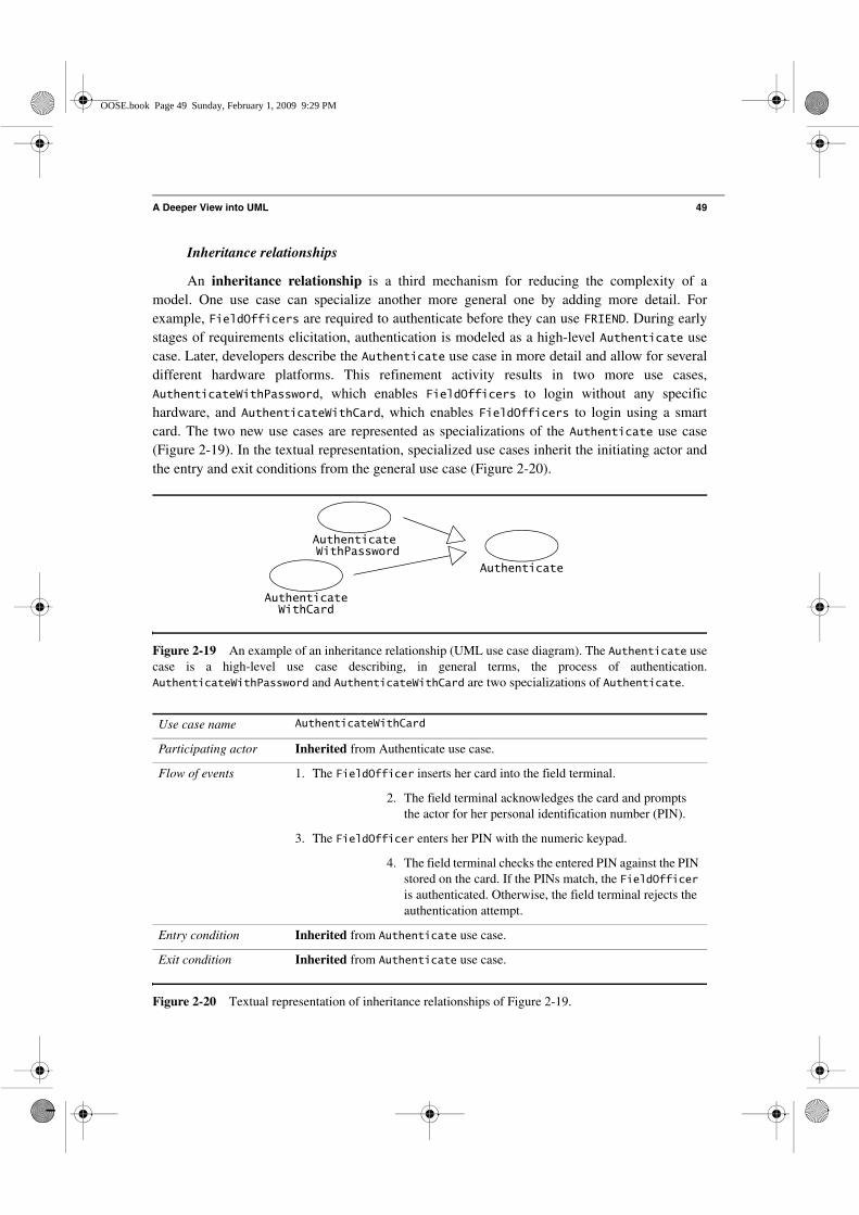
An inheritance relationship is a third mechanism for reducing the complexity of amodel. One use case can specialize another more general one by adding more detail. Forexample, FieldOfficers are required to authenticate before they can use FRIEND. During earlystages of requirements elicitation, authentication is modeled as a high-level Authenticate usecase. Later, developers describe the Authenticate use case in more detail and allow for severaldifferent hardware platforms. This refinement activity results in two more use cases,AuthenticateWithPassword, which enables FieldOfficers to login without any specifichardware, and AuthenticateWithCard, which enables FieldOfficers to login using a smartcard. The two new use cases are represented as specializations of the Authenticate use case(Figure 2-19). In the textual representation, specialized use cases inherit the initiating actor andthe entry and exit conditions from the general use case (Figure 2-20).
Figure 2-19 An example of an inheritance relationship (UML use case diagram). The Authenticate usecase is a high-level use case describing, in general terms, the process of authentication.AuthenticateWithPassword and AuthenticateWithCard are two specializations of Authenticate.
Use case name AuthenticateWithCard
Participating actor Inherited from Authenticate use case.
Flow of events 1. The FieldOfficer inserts her card into the field terminal.
2. The field terminal acknowledges the card and prompts the actor for her personal identification number (PIN).
3. The FieldOfficer enters her PIN with the numeric keypad.
4. The field terminal checks the entered PIN against the PIN stored on the card. If the PINs match, the FieldOfficer is authenticated. Otherwise, the field terminal rejects the authentication attempt.
Entry condition Inherited from Authenticate use case.
Exit condition Inherited from Authenticate use case.
Figure 2-20 Textual representation of inheritance relationships of Figure 2-19.
Authenticate
Authenticate
Authenticate WithPassword
WithCard
OOSE.book Page 49 Sunday, February 1, 2009 9:29 PM

50 Chapter 2 • Modeling with UML
Note that extend relationships and inheritance relationships are different. In an extendrelationship, each use case describes a different flow of events to accomplish a different task. InFigure 2-17, the OpenIncident use cases describes the actions that occur when the Dispatchercreates a new Incident, whereas the ConnectionDown use case describes the actions that occurduring network outages. In Figure 2-19, AuthenticateWithPassword and Authenticate bothdescribe the same task, each at different abstraction levels.
Scenarios
A use case is an abstraction that describes all possible scenarios involving the describedfunctionality. A scenario is an instance of a use case describing a concrete set of actions.Scenarios are used as examples for illustrating common cases; their focus is onunderstandability. Use cases are used to describe all possible cases; their focus is oncompleteness. We describe a scenario using a template with three fields:
• The name of the scenario enables us to refer to it unambiguously. The name of ascenario is underlined to indicate that it is an instance.
• The participating actor instances field indicates which actor instances are involved inthis scenario. Actor instances also have underlined names.
• The flow of events of a scenario describes the sequence of events step by step.
Note that there is no need for entry or exit conditions in scenarios. Entry and exitconditions are abstractions that enable developers to describe a range of conditions under whicha use case is invoked. Given that a scenario only describes one specific situation, such conditionsare unnecessary (Figure 2-21).
2.4.2 Class Diagrams
Classes and objects
Class diagrams describe the structure of the system in terms of classes and objects.Classes are abstractions that specify the attributes and behavior of a set of objects. A class is acollection of objects that share a set of attributes that distinguish the objects as members of thecollection. Objects are entities that encapsulate state and behavior. Each object has an identity:it can be referred individually and is distinguishable from other objects.
In UML, classes and objects are depicted by boxes composed of three compartments. Thetop compartment displays the name of the class or object. The center compartment displays itsattributes, and the bottom compartment displays its operations. The attribute and operationcompartments can be omitted for clarity. Object names are underlined to indicate that they areinstances. By convention, class names start with an uppercase letter. Objects in object diagramsmay be given names (followed by their class) for ease of reference. In that case, their name starts
OOSE.book Page 50 Sunday, February 1, 2009 9:29 PM

A Deeper View into UML 51
with a lowercase letter. In the FRIEND example (Figures 2-22 and 2-23), Bob and Alice are fieldofficers, represented in the system as FieldOfficer objects called bob:FieldOfficer andalice:FieldOfficer. FieldOfficer is a class describing all FieldOfficer objects, whereasBob and Alice are represented by two individual FieldOfficer objects.
In Figure 2-22, the FieldOfficer class has two attributes: a name and a badgeNumber. Thisindicates that all FieldOfficer objects have these two attributes. In Figure 2-23, thebob:FieldOfficer and alice:FieldOfficer objects have specific values for these attributes:“Bob. D.” and “Alice W.”, respectively. In Figure 2-22, the FieldOfficer.name attribute is oftype String, which indicates that only instances of String can be assigned to the
Scenario name warehouseOnFire
Participating actor instances
bob, alice:FieldOfficerjohn:Dispatcher
Flow of events 1. Bob, driving down main street in his patrol car, notices smoke coming out of a warehouse. His partner, Alice, activates the “Report Emergency” function from her FRIEND laptop.
2. Alice enters the address of the building, a brief description of its location (i.e., northwest corner), and an emergency level. In addition to a fire unit, she requests several paramedic units on the scene given that area appears to be relatively busy. She confirms her input and waits for an acknowledgment.
3. John, the Dispatcher, is alerted to the emergency by a beep of his workstation. He reviews the information submitted by Alice and acknowledges the report. He allocates a fire unit and two paramedic units to the Incident site and sends their estimated arrival time (ETA) to Alice.
4. Alice receives the acknowledgment and the ETA.
Figure 2-21 The warehouseOnFire scenario for the ReportEmergency use case.
Figure 2-22 An example of a UML class diagram: classes that participate in the ReportEmergency usecase. Detailed type information is usually omitted until object design (see Chapter 9, Object Design:Specifying Interfaces).
EmergencyReport Incident
FieldOfficer
name:StringbadgeNumber:Integer
Dispatcher
name:StringbadgeNumber:Integer
author
incidentsGeneratedreportsGenerated
initiator
reports
1
*
1
*1..*
1
OOSE.book Page 51 Sunday, February 1, 2009 9:29 PM

52 Chapter 2 • Modeling with UML
FieldOfficer.name attribute. The type of an attribute is used to specify the valid range ofvalues the attribute can take. Note that when attribute types are not essential to the definition ofthe system, attribute type decisions can be delayed until object design. This allows thedevelopers to concentrate on the functionality of the system and to minimize the number oftrivial changes when the functionality of the system is revised.
Associations and links
A link represents a connection between two objects. Associations are relationships betweenclasses and represent groups of links. Each FieldOfficer object also has a list ofEmergencyReports that has been written by the FieldOfficer. In Figure 2-22, the line between theFieldOfficer class and the EmergencyReport class is an association. In Figure 2-23, the linebetween the alice:FieldOfficer object and the report_1291:EmergencyReport object is a link.This link represents a state that is kept in the system to denote that alice:FieldOfficer generatedreport_1291:EmergencyReport.
In UML, associations can be symmetrical (bidirectional) or asymmetrical (unidirectional).All the associations in Figure 2-22 are symmetrical. Figure 2-24 depicts an example of one-directional association between Polygon and Point. The navigation arrow at the Point end ofthe association indicates that the system only supports navigation from the Polygon to thePoint. In other words, given a specific Polygon, it is possible to query all Points that make up
Figure 2-23 An example of a UML object diagram: objects that participate in warehouseOnFire.
Figure 2-24 Example of a one-directional association. Developers usually omit navigation during analysisand add navigation information during object design, when they make such decisions (see Chapter 8, ObjectDesign: Reusing Pattern Solutions, and Chapter 9, Object Design: Specifying Interfaces).
report_1291 incident_1515bob:FieldOfficer
name = “Bob D.”badgeNumber = 132
john:Dispatcher
name = “John D.”badgeNumber = 12alice:FieldOfficer
name = “Alice W.”badgeNumber = 23
Polygon Point**
OOSE.book Page 52 Sunday, February 1, 2009 9:29 PM

A Deeper View into UML 53
the Polygon. However, the navigation arrow indicates that, given a specific Point, it is notpossible to find which Polygons the Point is part of. UML allows navigation arrows to bedisplayed on both ends of an association. By convention, however, an association without arrowsindicates that navigation is supported in both directions.
Association class
Associations are similar to classes, in that they can have attributes and operations attachedto them. Such an association is called an association class and is depicted by a class symbol thatcontains the attributes and operations and is connected to the association symbol with a dashedline. For example, in Figure 2-25, the allocation of FieldOfficers to an Incident is modeled asan association class with attributes role and notificationTime.
Any association class can be transformed into a class and simple associations as shown inFigure 2-26. Although this representation is similar to Figure 2-25, the association class
representation is clearer in Figure 2-25: an association cannot exist without the classes it links.Similarly, the Allocation object cannot exist without a FieldOfficer and an Incident.Although Figure 2-26 carries the same information, this diagram requires careful examination ofthe association multiplicity. We examine such modeling trade-offs in Chapter 5, Analysis.
Figure 2-25 An example of an association class (UML class diagram).
Figure 2-26 Alternative model for Allocation (UML class diagram).
IncidentFieldOfficer
name:StringbadgeNumber:Integer
Allocates
role:StringnotificationTime:Time
resourcesincident
1
1..*
Incident
FieldOfficer
name:StringbadgeNumber:Integer
Allocation
role:StringnotificationTime:Time
resources
incident 1
1..*
11
OOSE.book Page 53 Sunday, February 1, 2009 9:29 PM

54 Chapter 2 • Modeling with UML
Roles
Each end of an association can be labeled by a role. In Figure 2-22, the roles of theassociation between EmergencyReport and FieldOfficer are author and reportsGenerated.Labeling the end of associations with roles allows us to distinguish among the multipleassociations originating from a class. Moreover, roles clarify the purpose of the association.
Multiplicity
Each end of an association can be labeled by a set of integers indicating the number oflinks that can legitimately originate from an instance of the class connected to the associationend. This set of integers is called the multiplicity of the association end. In Figure 2-22, theassociation end author has a multiplicity of l. This means that all EmergencyReports arewritten by exactly one FieldOfficer. In other terms, each EmergencyReport object has exactlyone link to an object of class FieldOfficer. The multiplicity of the association endreportsGenerated role is “many,” shown as a star. The “many” multiplicity is shorthand for0..n. This means that any given FieldOfficer may be the author of zero or moreEmergencyReports.
In UML, an association end can have an arbitrary set of integers as a multiplicity. Forexample, an association could allow only a prime number of links and, thus, would have amultiplicity 1, 2, 3, 5, 7, 11, 13, and so forth. In practice, however, most of the associations weencounter belong to one of the following three types (see Figure 2-27).
• A one-to-one association has a multiplicity 1 on each end. A one-to-one associationbetween two classes (e.g., PoliceOfficer and BadgeNumber) means that exactly onelink exists between instances of each class (e.g., a PoliceOfficer has exactly oneBadgeNumber, and a BadgeNumber denotes exactly one PoliceOfficer).
• A one-to-many association has a multiplicity 1 on one end and 0..n (also representedby a star) or 1..n on the other. A one-to-many association between two classes (e.g.,FireUnit and FireTruck) denotes composition (e.g., a FireUnit owns one or moreFireTrucks, a FireTruck is owned exactly by one FireUnit).
• A many-to-many association has a multiplicity 0..n or 1..n on both ends. A many-to-many association between two classes (e.g., FieldOfficer and IncidentReport)denotes that an arbitrary number of links can exist between instances of the two classes(e.g., a FieldOfficer can write many IncidentReports, an IncidentReport can bewritten by many FieldOfficers). This is the most complex type of association.
Adding multiplicity to associations increases the amount of information we capture fromthe application or the solution domain. Specifying the multiplicity of an association becomescritical when we determine which use cases are needed to manipulate the application domainobjects. For example, consider a file system made of Directories and Files. A Directory can
OOSE.book Page 54 Sunday, February 1, 2009 9:29 PM

A Deeper View into UML 55
contain any number of FileSystemElements. A FileSystemElement is a concept that denoteseither a Directory or a File. In case of a strictly hierarchical system, a FileSystemElement ispart of exactly one Directory, which we denote with a one-to-many multiplicity (Figure 2-28).
If, however, a File or a Directory can be simultaneously part of more than oneDirectory, we need to represent the aggregation of FileSystemElement into Directories as amany-to-many association (see Figure 2-29).
Figure 2-27 Examples of multiplicity (UML class diagram). The association between PoliceOfficerand BadgeNumber is one-to-one. The association between FireUnit and FireTruck is one-to-many. Theassociation between FieldOfficer and IncidentReport is many-to-many.
Figure 2-28 Example of a hierarchical file system. A Directory can contain any number ofFileSystemElements (a FileSystemElement is either a File or a Directory). A givenFileSystemElement, however, is part of exactly one Directory.
Figure 2-29 Example of a nonhierarchical file system. A Directory can contain any number ofFileSystemElements (a FileSystemElement is either a File or a Directory). A givenFileSystemElement can be part of many Directories.
FieldOfficer IncidentReport**
FireUnit FireTruck*1
PoliceOfficer11
owner property
author report
BadgeNumber
1
*
FileDirectory
FileSystemElement
*
*
FileDirectory
FileSystemElement
OOSE.book Page 55 Sunday, February 1, 2009 9:29 PM

56 Chapter 2 • Modeling with UML
This discussion may seem to be considering detailed issues that could be left for lateractivities in the development process. The difference between a hierarchical file system and anonhierarchical one, however, is also in the functionality it offers. If a system allows a givenFile to be part of multiple Directories, we need to define a use case describing how a useradds an existing File to existing Directories (e.g., the Unix link command or the MacintoshMakeAlias menu item). Moreover, use cases removing a File from a Directory must specifywhether the File is removed from one Directory only or from all Directories that referenceit. Note that a many-to-many association can result in a substantially more complex system.
Aggregation
Associations are used to represent a wide range of connections among a set of objects. Inpractice, a special case of association occurs frequently: aggregation. For example, a Statecontains many Counties, which in turn contain many Townships. A PoliceStation iscomposed of PoliceOfficers. A Directory contains a number of Files. Such relationshipscould be modeled using a one-to-many association. Instead, UML provides the concept of anaggregation, denoted by a simple line with a diamond at the container end of the association (seeFigures 2-28 and 2-30). One-to-many associations and aggregations, although similar, cannot beused interchangeably: aggregations denote hierarchical aspects of the relationship and can haveeither one-to-many or many-to-many multiplicity, whereas one-to-many associations imply apeer relationship. For example, in Figure 2-30, the PoliceOfficers are part of thePoliceStation. In Figure 2-22, a FieldOfficer writes zero or many EmergencyReports.However, the FieldOfficer is not composed EmergencyReports. Consequently, we use anassociation in the later case and an aggregation in the former case.
Qualification
Qualification is a technique for reducing multiplicity by using keys. Associations with a0..1 or 1 multiplicity are easier to understand than associations with a 0..n or 1..n multiplicity.Often, in the case of a one-to-many association, objects on the “many” side can be distinguished
Figure 2-30 Examples of aggregations (UML class diagram). A State contains many Counties, whichin turn contains many Townships. A PoliceStation has many PoliceOfficers. A file system Directorycontains many Files.
State County Township* *
PoliceStation PoliceOfficer*
Directory File*
1
1
1
1
OOSE.book Page 56 Sunday, February 1, 2009 9:29 PM

A Deeper View into UML 57
from one another using a name. For example, in a hierarchical file system, each file belongs toexactly one directory. Each file is uniquely identified by a name in the context of a directory.Many files can have the same name in the context of the file system; however, two files cannotshare the same name within the same directory. Without qualification (see top of Figure 2-31),the association between Directory and File has a one multiplicity on the Directory side and azero-to-many multiplicity on the File side. We reduce the multiplicity on the File side by usingthe filename attribute as a key, also called a qualifier (see top of Figure 2-31). The relationshipbetween Directory and File is called a qualified association.
Reducing multiplicity is always preferable, as the model becomes clearer and fewer caseshave to be taken into account. Developers should examine each association that has a one-to-many or many-to-many multiplicity to see if a qualifier can be added. Often, these associationscan be qualified with an attribute of the target class (e.g., filename in Figure 2-31).
Inheritance
Inheritance is the relationship between a general class and one or more specializedclasses. Inheritance enables us to describe all the attributes and operations that are common to aset of classes. For example, FieldOfficer and Dispatcher both have name and badgeNumberattributes. However, FieldOfficer has an association with EmergencyReport, whereasDispatcher has an association with Incident. The common attributes of FieldOfficer andDispatcher can be modeled by introducing a PoliceOfficer class that is specialized by theFieldOfficer and the Dispatcher classes (see Figure 2-32). PoliceOfficer, thegeneralization, is called a superclass. FieldOfficer and Dispatcher, the specializations, arecalled the subclasses. The subclasses inherit the attributes and operations from their parentclass. Abstract classes (defined in Section 2.3.3) are distinguished from concrete classes byitalicizing the name of abstract classes. In Figure 2-32, PoliceOfficer is an abstract class.Abstract classes are used in object-oriented modeling to classify related concepts, thus reducingthe overall complexity of the model.
Figure 2-31 Example of how a qualified association reduces multiplicity (UML class diagram). Adding aqualifier clarifies the class diagram and increases the conveyed information. In this case, the modelincluding the qualification denotes that the name of a file is unique within a directory.
Directory Filefilename
DirectoryFile
filename
1Without qualification
With qualification
*
0..11
OOSE.book Page 57 Sunday, February 1, 2009 9:29 PM

58 Chapter 2 • Modeling with UML
Object behavior is specified by operations. An object requests the execution of anoperation from another object by sending it a message. The message is matched up with amethod defined by the class to which the receiving object belongs or by any of its superclasses.The methods of a class in an object-oriented programming language are the implementations ofthese operations.
The distinction between operations and methods allows us to distinguish between thespecification of behavior (i.e., an operation) and its implementation (i.e., a set of methods thatare possibly defined in different classes in the inheritance hierarchy). For example, the classIncident in Figure 2-33 defines an operation, called assignResource(), which, given aFieldOfficer, creates an association between the receiving Incident and the specifiedResource. The assignResource() operation may also have a side effect such as sending anotification to the newly assigned Resource. The close() operation of Incident is responsible
for closing the Incident. This includes going over all the resources that have been assigned tothe incident over time and collecting their reports. Although UML distinguishes operations frommethods, in practice, developers usually do not and simply refer to methods.
Figure 2-32 An example of an inheritance (UML class diagram). PoliceOfficer is an abstract classwhich defines the common attributes and operations of the FieldOfficer and Dispatcher classes.
Figure 2-33 Examples of operations provided by the Incident class (UML class diagram).
EmergencyReport Incident
FieldOfficer Dispatcherauthor initiator
reportsGenerated incidents
1
*1
*
1..*1
PoliceOfficer
name:StringbadgeNumber:Integer
Incident
assignResource()close()
OOSE.book Page 58 Sunday, February 1, 2009 9:29 PM

A Deeper View into UML 59
Applying class diagrams
Class diagrams are used for describing the structure of a system. During analysis, softwareengineers build class diagrams to formalize application domain knowledge. Classes representparticipating objects found in use cases and interaction diagrams, and describe their attributes andoperations. The purpose of analysis models is to describe the scope of the system and discover itsboundaries. For example, using the class diagram pictured in Figure 2-22, an analyst could examinethe multiplicity of the association between FieldOfficer and EmergencyReport (i.e., oneFieldOfficer can write zero or more EmergencyReports, but each EmergencyReport is writtenby exactly one FieldOfficer) and ask the user whether this is correct. Can there be more than oneauthor of an EmergencyReport? Can there be anonymous reports? Depending on the answer fromthe user, the analyst would then change the model to reflect the application domain. Thedevelopment of analysis models is described in Chapter 5, Analysis.
Analysis models do not focus on implementation. Concepts such as interface details,network communication, and database storage are not represented. Class diagrams are refinedduring system design and object design to include classes representing the solution domain. Forexample, the developer adds classes representing databases, user interface windows, adaptersaround legacy code, optimizations, and so on. The classes are also grouped into subsystems withwell-defined interfaces. The development of design models is described in Chapter 6, SystemDesign: Decomposing the System, Chapter 8, Object Design: Reusing Pattern Solutions,Chapter 9, Object Design: Specifying Interfaces, and Chapter 10, Mapping Models to Code.
2.4.3 Interaction Diagrams
Interaction diagrams describe patterns of communication among a set of interactingobjects. An object interacts with another object by sending messages. The reception of amessage by an object triggers the execution of a method, which in turn may send messages toother objects. Arguments may be passed along with a message and are bound to the parametersof the executing method in the receiving object. In UML, interaction diagrams can take one oftwo forms: sequence diagrams or communication diagrams.
Sequence diagrams represent the objects participating in the interaction horizontally andtime vertically. For example, consider a watch with two buttons (hereafter called 2Bwatch).Setting the time on 2Bwatch requires the actor 2BWatchOwner to first press both buttonssimultaneously, after which 2Bwatch enters the set time mode. In the set time mode, 2Bwatchblinks the number being changed (e.g., the hours, minutes, seconds, day, month, or year).Initially, when the 2BWatchOwner enters the set time mode, the hours blink. If the actor pressesthe first button, the next number blinks (e.g, if the hours are blinking and the actor presses thefirst button, the hours stop blinking and the minutes start blinking). If the actor presses thesecond button, the blinking number is incremented by one unit. If the blinking number reachesthe end of its range, it is reset to the beginning of its range (e.g., assume the minutes are blinkingand its current value is 59, its new value is set to 0 if the actor presses the second button). Theactor exits the set time mode by pressing both buttons simultaneously. Figure 2-34 depicts a
OOSE.book Page 59 Sunday, February 1, 2009 9:29 PM

60 Chapter 2 • Modeling with UML
sequence diagram for an actor setting his 2Bwatch one minute ahead. Each column represents anobject that participates in the interaction. Messages are shown by solid arrows. Labels on solidarrows represent message names and may contain arguments. Activations (i.e., executingmethods) are depicted by vertical rectangles. The actor who initiates the interaction is shown inthe left-most column. The messages coming from the actor represent the interactions describedin the use case diagrams. If other actors communicate with the system during the use case, theseactors are represented on the right-hand side and can receive messages. Although for simplicity,interactions among objects and actors are uniformly represented as messages, the modelershould keep in mind that interactions between actors and the system are of a different naturethan interactions among objects.
Sequence diagrams can be used to describe either an abstract sequence (i.e., all possibleinteractions) or concrete sequences (i.e., one possible interaction, as in Figure 2-34). Whendescribing all possible interactions, sequence diagrams provide notations for iterations andconditionals. An iteration is denoted by a combined fragment labeled with the loop operator (seeFigure 2-35). An alternative is denoted by a combined fragment containing a partition for eachalternative. The alternatives are selected by guards on the first message of the partition ([i>0]and [else] in Figure 2-35). If i is positive, the top alternative of the alt combined fragment isexecuted and the op1() message is sent. Otherwise, the bottom alternative is executed and theop2() message is sent.
Figure 2-34 Example of a sequence diagram: setting the time on 2Bwatch.
:2BwatchInput :2BwatchTime:2BwatchDisplay
pressButtons1And2()blinkHours()
pressButton1() blinkMinutes()
pressButton2() incrementMinutes()
refresh()
pressButtons1And2() commitNewTime()
stopBlinking()
Time
:2BwatchOwner
OOSE.book Page 60 Sunday, February 1, 2009 9:29 PM

A Deeper View into UML 61
Communication diagrams depict the same information as sequence diagrams.Communication diagrams represent the sequence of messages by numbering the interactions.On one hand, this removes the need for geometrical constraints on the objects and results in amore compact diagram. On the other hand, the sequence of messages becomes more difficult tofollow. Figure 2-36 depicts the communication diagram that is equivalent to the sequencediagram of Figure 2-34.
Figure 2-35 Examples of conditions and iterators in sequence diagrams.
Figure 2-36 Example of a communication diagram: setting the time on 2Bwatch. This diagram representsthe same use case as the sequence diagram of Figure 2-34.
a b c
[i>0] op1()
[else] op2()
op3()
alt
loop
:2BwatchInput
:2BwatchTime
:2BwatchDisplay
1:pressButtons1And2()
1.1:blinkHours()
3.1:incrementMinutes()
3.2:refresh()
4.1:commitNewTime()
:2BwatchOwner
2:pressButton1()3:pressButton2()4:pressButtons1And2()
2.1:blinkMinutes()4.2:stopBlinking()
OOSE.book Page 61 Sunday, February 1, 2009 9:29 PM

62 Chapter 2 • Modeling with UML
Applying interaction diagrams
Interaction diagrams describe interactions among several objects. One of the main reasonsfor constructing an interaction diagram is to uncover the responsibilities of the classes in theclass diagrams and to discover even new classes. In other words, the interaction diagram helpsthe developer in deciding which objects require particular operations. Typically, there is aninteraction diagram for every use case with focus on the event flow. The developer identifies theobjects that participate in the use case, and assigns pieces of the use case behavior to the objectsin the form of operations.
The class diagram and the associated interaction diagrams are usually constructed intandem after the initial class diagram has been defined. This process often also leads torefinements in the use case (e.g., correcting ambiguous descriptions, adding missing behavior)and, consequently, the discovery of more objects and more services. We describe in detail theuse of interaction diagrams in Chapter 5, Analysis.
2.4.4 State Machine Diagrams
A UML state machine is a notation for describing the sequence of states an object goesthrough in response to external events. UML state machines are extensions of the finite statemachine model. On one hand, state machines provide notation for nesting states and statemachines (i.e., a state can be described by a state machine). On the other hand, state machinesprovide notation for binding transitions with message sends and conditions on objects. UML statemachines are largely based on Harel’s statecharts [Harel, 1987] and have been adapted for use withobject models [Douglass, 1999]. UML state machines can be used to represent any Mealy orMoore state machine.
A state is a condition satisfied by the attributes of an object. For example, an Incidentobject in FRIEND can exist in four states: Active, Inactive, Closed, and Archived (seeFigure 2-37). An active Incident denotes a situation that requires a response (e.g., an ongoingfire, a traffic accident). An inactive Incident denotes a situation that was handled, but for whichreports are yet to be written (e.g., the fire has been put out, but damage estimates have not yetbeen completed). A closed Incident denotes a situation that has been handled and documented.An archived Incident is a closed Incident whose documentation has been moved to off-sitestorage. In this example, we can represent these four states with a single attribute in theIncident class—a status attribute that can take any of four values: Active, Inactive, Closed,and Archived. In general, a state can be computed from the values of several attributes.
A transition represents a change of state triggered by events, conditions, or time. Forexample, Figure 2-37 depicts three transitions: from the Active state into the Inactivestate, from the Inactive state to the Closed state, and from the Closed state to the Archivedstate.
A state is depicted by a rounded rectangle. A transition is depicted by an open arrowconnecting two states. States are labeled with their name. A small solid black circle indicates theinitial state. A circle surrounding a small solid black circle indicates a final state.
OOSE.book Page 62 Sunday, February 1, 2009 9:29 PM

A Deeper View into UML 63
Figure 2-38 displays another example, a state machine for the 2Bwatch (for which weconstructed a sequence diagram in Figure 2-34). At the highest level of abstraction, 2Bwatch hastwo states, MeasureTime and SetTime. 2Bwatch changes states when the user presses andreleases both buttons simultaneously. During the transition from the SetTime state to theMeasureTime state, 2Bwatch beeps. This is indicated by the action /beep on the transition. When2Bwatch is first powered on, it is in the SetTime state. This is modeled by making SetTime theinitial state. When the battery of the watch runs out, the 2Bwatch is permanently out of order.This is indicated with a final state. In this example, transitions can be triggered by an event (e.g.,pressBothButtons) or by the passage of time (e.g., after 2 min.).
Figure 2-39 depicts a refined state machine diagram for the 2Bwatch depicted inFigure 2-38 using actions to denote the behavior within the states. Actions are fundamental unitsof processing that can take a set of inputs, produce a set of outputs, and can change the state ofthe system. Actions normally take a short amount of time to execute and are not interruptable.
Figure 2-37 A UML state machine diagram for the Incident class.
Figure 2-38 State machine diagram for 2Bwatch set time function.
Active Inactive Closed Archived
incidentHandled incidentDocumented incidentArchived
MeasureTime SetTime
pressBothButtons
pressBothButtons/beep
after 2 min.
DeadBattery
batteryEmptybatteryEmpty
OOSE.book Page 63 Sunday, February 1, 2009 9:29 PM

64 Chapter 2 • Modeling with UML
For example, an action can be realized by an operation call. Actions can occur in three places ina state machine:
• when a transition is taken (e.g., beep when the transition between SetTime andMeasureTime is fired on the pressBothButtons event)
• when a state is entered (e.g., blink hours in the SetTime state in Figure 2-39)• when a state is exited (e.g., stop blinking in the SetTime state in Figure 2-39).
During a transition, the exit actions of the source state are executed first, then the actionsassociated with the transition are executed, then the entry actions of the destination state areexecuted. The exit and entry actions are always executed when a state is exited or entered,respectively. They do not depend on the specific transition that was used to exit or enter the state.
An internal transition is a transition that does not leave the state. Internal transitions aretriggered by events and can have actions associated with them. However, the firing of an internaltransition does not result in the execution of any exit or entry actions. For example, inFigure 2-39, the SetTime state has two internal transitions, one associated with pressing button 1and one associated with pressing the right button.
An activity is a coordinated set of actions. A state can be associated an activity that isexecuted as long as an object resides in this state. While an action is short and non-interruptable,an activity can take a substantial amount of time and is interrupted when a transition exiting thestate is fired. Activities are associated with state using the do label and are placed inside the statewhere they executed. For example, in Figure 2-39, count ticks is an activity associated withthe MeasureTime state.
Nested state machines reduce complexity. They can be used instead of internaltransitions. In Figure 2-40, the current number is modeled as a nested state, whereas actionscorresponding to modifying the current number are modeled using internal transitions. Note thateach state could be modeled as a nested state machine. For example, the BlinkHours statemachine would have 24 substates that correspond to the hours in the day; transitions betweenthese states would correspond to pressing the second button.
Applying state machine diagrams
State machine diagrams are used to represent nontrivial behavior of a subsystem or anobject. Unlike interaction diagrams that focus on the events impacting the behavior of a set ofobjects, state machine diagrams make explicit which attribute or set of attributes have an impacton the behavior of a single object. State machines are used to identify object attributes and torefine the behavior description of an object, and interaction diagrams are used to identifyparticipating objects and the services they provide. State machine diagrams can also be usedduring system and object design to describe solution domain objects with interesting behavior.We describe the use of state machine diagrams in detail in Chapter 5, Analysis, and Chapter 6,System Design: Decomposing the System.
OOSE.book Page 64 Sunday, February 1, 2009 9:29 PM

A Deeper View into UML 65
2.4.5 Activity Diagrams
UML activity diagrams represent the sequencing and coordination of lower levelbehaviors. An activity diagram denotes how a behavior is realized in terms of one or severalsequences of activities and the object flows needed for coordinating the activities. Activity
Figure 2-39 Internal transitions associated with the SetTime state (UML state machine diagram).
Figure 2-40 Refined state machine associated with the SetTime state (UML state machine diagram). lBand rB correspond to pressing the left and right button, respectively.
SetTime
entry/blink hours
exit/stop blinking
pressLeftButton/blink next numberpressRightButton/increment current number
MeasureTime
do/count ticks
DeadBattery
pressBothButtons
pressBothButtons/beep
after 2 min.
batteryEmptybatteryEmpty
SetTime
BlinkHours BlinkMinutes BlinkSeconds
BlinkYear BlinkMonth BlinkDay
rB/incr hour rB/incr min. rB/incr sec.
rB/incr year rB/incr mo. rB/incr day
lB
lB
lB
lB
lBlB
OOSE.book Page 65 Sunday, February 1, 2009 9:29 PM

66 Chapter 2 • Modeling with UML
diagrams are hierarchical: an activity is made out of either an action or a graph of subactivitiesand their associated object flow. Figure 2-41 is an activity diagram corresponding to the statediagram in Figure 2-37. Rounded rectangles represent actions and activities. Edges betweenactivities represent control flow. An activity can be executed only after all predecessor activitiescompleted.
Control nodes coordinate control flows in an activity diagram, providing mechanisms forrepresenting decisions, concurrency, and synchronization. The main control nodes we use aredecisions, fork nodes, and join nodes.
Decisions are branches in the control flow. They denote alternatives based on a conditionof the state of an object or a set of objects. Decisions are depicted by a diamond with one ormore incoming open arrows and two or more outgoing arrows. The outgoing edges are labeledwith the conditions that select a branch in the control flow. The set of all outgoing edges from adecision represents the set of all possible outcomes. In Figure 2-42, a decision after theOpenIncident action selects between three branches: If the incident is of high priority and if it isa fire, the FireChief is notified. If the incident is of high priority and is not a fire, thePoliceChief is notified. Finally, if neither condition is satisfied, that is, if the Incident is of lowpriority, no superior is notified and the resource allocation proceeds.
Fork nodes and join nodes represent concurrency. Fork nodes denotes the splitting of theflow of control into multiple threads while join nodes denotes the synchronization of multiplethreads and their merging of the flow of control into a single thread. For example, inFigure 2-43, the actions AllocateResources, Coordinate–Resources, and DocumentIncidentmay all occur in parallel. However, they can only be initiated after the OpenIncident action, andthe ArchiveIncident action may only be initiated after all other activities have been completed.
Activities may be grouped into swimlanes (also called activity partitions) to denote theobject or subsystem that implements the actions. Swimlanes are represented as rectanglesenclosing a group of actions. Transitions may cross swimlanes. In Figure 2-44, the Dispatcherswimlane groups all the actions that are performed by the Dispatcher object. TheFieldOfficer swimlane denotes that the FieldOfficer object is responsible for theDocumentIncident action.
Figure 2-41 A UML activity diagram for Incident. During the action HandleIncident, the Dispatcherreceives reports and allocates resources. Once the Incident is closed, the Incident moves to theDocumentIncident activity during which all participating FieldOfficers and Dispatchers document theIncident. Finally, the ArchiveIncident activity represents the archival of the Incident relatedinformation onto slow access medium.
HandleIncident
DocumentIncident
ArchiveIncident
OOSE.book Page 66 Sunday, February 1, 2009 9:29 PM

A Deeper View into UML 67
Figure 2-42 Example of decision in the OpenIncident process. If the Incident is a fire and is of highpriority, the Dispatcher notifies the FireChief. If it is a high-priority Incident that is not a fire, thePoliceChief is notified. In all cases, the Dispatcher allocates resources to deal with the Incident.
Figure 2-43 An example of fork and join nodes in a UML activity diagram.
Figure 2-44 An example of swimlanes in a UML activity diagram.
OpenIncident
NotifyPolice Chief
NotifyFire Chief
AllocateResources
[fire & highPriority]
[not fire & highPriority]
[lowPriority]
OpenIncident
AllocateResources
CoordinateResources
DocumentIncident
ArchiveIncident
OpenIncident
AllocateResources
CoordinateResources
DocumentIncident
ArchiveIncident
Dispatcher
FieldOfficer
OOSE.book Page 67 Sunday, February 1, 2009 9:29 PM

68 Chapter 2 • Modeling with UML
Applying activity diagrams
Activity diagrams provide a task-centric view of the behavior of a set of objects. They canbe used, for example, to describe sequencing constraints among use cases, sequential activitiesamong a group of objects, or the tasks of a project. In this book, we use activity diagrams todescribe the activities of software development in Chapter 14, Project Management, andChapter 15, Software Life Cycle.
2.4.6 Diagram Organization
Models of complex systems quickly become complex as developers refine them. Thecomplexity of models can be dealt with by grouping related elements into packages. A packageis a grouping of model elements, such as use cases or classes, defining scopes of understanding.
For example, Figure 2-45 depicts use cases of the FRIEND system, grouped by actors.Packages are displayed as rectangles with a tab attached to their upper-left corner. Use casesdealing with incident management (e.g., creating, resource allocation, documentation) are groupedin the IncidentManagement package. Use cases dealing with incident archive (e.g., archiving anincident, generating reports from archived incidents) are grouped in the IncidentArchivepackage. Use cases dealing with system administration (e.g., adding users, registering end stations)are grouped in the SysAdministration package. This enables the client and the developers toorganize use cases into related groups and to focus on only a limited set of use cases at a time.
Figure 2-45 Example of packages: use cases of FRIEND organized by actors (UML use case diagram).
Report Emergency
FieldOfficer
DispatcherOpenIncident
AllocateResources
ArchiveIncident
SearchArchive
ManageUsers
ManageTerminalsLibrarian SysAdmin
SysAdministrationIncidentArchive
IncidentManagement
OOSE.book Page 68 Sunday, February 1, 2009 9:29 PM

A Deeper View into UML 69
Figures 2-46 and 2-47 are examples of class diagrams using packages. Classes from theReportEmergency use case are organized according to the site where objects are created.FieldOfficer and EmergencyReport are part of the FieldStation package, and Dispatcherand Incident are part of the DispatcherStation. Figure 2-47 displays the packages with themodel elements they contain, and Figure 2-46 displays the same information without thecontents of each package. Figure 2-46 is a higher-level picture of the system and can be used fordiscussing system-level issues, whereas Figure 2-47 is a more detailed view that can be used todiscuss the content of specific packages.
Packages are used to deal with complexity in the same way a user organizes files andsubdirectories into directories. However, packages are not necessarily hierarchical: the sameclass may appear in more than one package. To reduce inconsistencies, classes (more generallymodel elements) are owned by exactly one package, whereas the other packages are said to referto the modeling element. Note that packages are organizing constructs, not objects. They haveno associated behavior and cannot send and receive messages.
A note is a comment attached to a diagram. Notes are used by developers for attachinginformation to models and model elements. This is an ideal mechanism for recording
Figure 2-46 Example of packages. This figure displays the same packages as Figure 2-45 except that thedetails of each packages are suppressed (UML use case diagram).
Figure 2-47 Example of packages. The FieldOfficer and EmergencyReport classes are located in theFieldStation package, and the Dispatcher and Incident classes are located on the DispatcherStationpackage.
FieldOfficer Dispatcher
Librarian SysAdmin
IncidentArchive SysAdministration
IncidentManagement
DispatcherStation
EmergencyReport Incident
FieldOfficer Dispatcher
FieldStation
OOSE.book Page 69 Sunday, February 1, 2009 9:29 PM

70 Chapter 2 • Modeling with UML
outstanding issues relevant to a model, clarifying a complex point, or recording to-dos orreminders. Although notes have no semantics per se, they are sometimes used to expressconstraints that cannot otherwise be expressed in UML. Figure 2-48 is an example of a note.
2.4.7 Diagram Extensions
The goal of the UML designers was to provide a set of notations to model a broad class ofsoftware systems. They also recognized that a fixed set of notations could not achieve this goal,because it is impossible to anticipate the needs encountered in all application and solutiondomains. For this reason, UML provides a number of extension mechanisms enabling themodeler to extend the language. In this section, we describe two such mechanisms, stereotypesand constraints.
A stereotype is an extension mechanism that allows developers to classify modelelements in UML. A stereotype is represented by string enclosed by guillemets (e.g.,«boundary») and attached to the model element to which it applies, such as a class or anassociation. Formally, attaching a stereotype to a model element is semantically equivalent tocreating a new class in the UML meta-model (i.e., the model that represents the constructs ofUML). This enables modelers to create new kinds of building blocks that are needed in theirdomain. For example, during analysis, we classify objects into three types: entity, boundary, andcontrol. Entity, boundary, and control objects have the same structure (i.e., they have attributes,operations, and associations), but serve different purposes. The base UML language onlyincludes one type of object. To represent these three types, we use the stereotypes «entity»,«boundary», and «control» (Figure 2-49). The «entity», «boundary», and «control»
stereotypes are described in Chapter 5, Analysis. Another example is the relationships amonguse cases. As we saw in Section 2.4.1, include relationships in use case diagrams are denotedwith a dashed open arrow and the «include» stereotype.
A constraint is a rule that is attached to a UML model element restricting its semantics.This allows us to represent phenomena that cannot otherwise be expressed with UML. Forexample, in Figure 2-50, an Incident may be associated with one or more EmergencyReportsfrom the field. However, it is important that the Dispatchers are able to view the reportschronologically. We represent the chronological ordering of EmergencyReport to Incident with
Figure 2-48 An example of a note. Notes can be attached to a specific element in a diagram.
EmergencyReport
DispatcherStation
Incident
FieldOfficer Dispatcher
FieldStation
The EmergencyReportclass is defined in FieldStationpackage and used in both stations.
OOSE.book Page 70 Sunday, February 1, 2009 9:29 PM

Further Readings 71
the constraint {ordered by time of receipt}. Constraints can be expressed as an informalstring or by using a formal language such as OCL (Object Constraint Language, [OMG, 2009]).We describe OCL and the use of constraints in Chapter 9, Object Design: Specifying Interfaces.
2.5 Further Readings
The historic roots of modeling notations can be traced back to structured analysis [De Marco,1978] and structured design [Yourdon & Constantine, 1975], which is based on functionaldecomposition. These methods were based data flow diagrams [De Marco, 1978]. Data flowdiagrams are quite important for software engineers who need to maintain legacy systemsdesigned with structured analysis techniques.
UML came out of the teachings and efforts of many researchers and practitioners, some ofwhom we cited earlier in this chapter. The efforts of Booch, Jacobson, and Rumbaugh enabled abroadly accepted unified notation. Their earlier works [Booch, 1994], [Jacobson et al., 1992],[Rumbaugh et al., 1991] give much insight into the roots of object-oriented analysis and designand still provide valuable knowledge about object-oriented modeling.
Because it was designed to address a broad range of systems and concern, UML is acomplex standard. In this chapter, we focused on the basic elements of UML that you need tounderstand before proceeding with the next chapters. For further information on UML, refer tothe following books:
UML Distilled [Fowler, 2003] is a brief introduction to UML and illustrated with manyexamples. For readers without any knowledge of UML, this book is a useful overview to get intothe notation quickly.
The Unified Modeling Language User Guide [Booch et al., 2005] is a comprehensivepresentation of UML by its principal designers. It covers much more material than UMLDistilled and is more appropriate for the advanced modeler. As the UML User Guide has fewerexamples, UML Distilled is more appropriate for novices.
Figure 2-49 Examples of stereotypes (UML class diagram).
Figure 2-50 An example of constraint (UML class diagram).
«entity»
«entity»
«boundary»
«boundary»
«control»Year
Month
ChangeDateControl
LCDDisplay
Button
«entity»Day
EmergencyReport Incidentreports1..*
1
{ordered by time of receipt}
OOSE.book Page 71 Sunday, February 1, 2009 9:29 PM

72 Chapter 2 • Modeling with UML
The OMG Unified Modeling Language Superstructure [OMG, 2009] is the officialspecification of UML. It is continuously maintained by a revision task force that is responsiblefor clarifying ambiguities, correcting errors, and resolving inconsistencies found by the UMLcommunity.
2.6 Exercises
2-1 Consider an ATM system. Identify at least three different actors that interact with thissystem.
2-2 Can the system under consideration be represented as an actor? Justify your answer.
2-3 What is the difference between a scenario and a use case? When do you use eachconstruct?
2-4 Draw a use case diagram for a ticket distributor for a train system. The system includestwo actors: a traveler who purchases different types of tickets, and a central computersystem that maintains a reference database for the tariff. Use cases should includeBuyOneWayTicket, BuyWeeklyCard, BuyMonthlyCard, and UpdateTariff. Also includethe following exceptional cases: TimeOut (i.e., traveler took too long to insert the rightamount), TransactionAborted (i.e., traveler selected the cancel button withoutcompleting the transaction), DistributorOutOfChange, and DistributorOutOfPaper.
2-5 Write the flow of events and specify all fields for the use case UpdateTariff that youdrew in Exercise 2-4. Do not forget to specify any relationships.
2-6 Draw a class diagram representing a book defined by the following statement: “A bookis composed of a number of parts, which in turn are composed of a number of chapters.Chapters are composed of sections.” Focus only on classes and relationships.
2-7 Add multiplicity to the class diagram you produced in Exercise 2-6.
2-8 Draw an object diagram representing the first part of this book (i.e., Part I, GettingStarted). Make sure that the object diagram you draw is consistent with the classdiagram of Exercise 2-6.
2-9 Extend the class diagram of Exercise 2-6 to include the following attributes:
• a book includes a publisher, publication date, and an ISBN • a part includes a title and a number• a chapter includes a title, a number, and an abstract• a section includes a title and a number.
2-10 Consider the class diagram of Exercise 2-9. Note that the Part, Chapter, and Sectionclasses all include title and number attributes. Add an abstract class and an inheritancerelationship to factor out these two attributes into the abstract class.
2-11 Draw a class diagram representing the relationship between parents and children. Takeinto account that a person can have both a parent and a child. Annotate associationswith roles and multiplicities.
OOSE.book Page 72 Sunday, February 1, 2009 9:29 PM

Exercises 73
2-12 Draw a class diagram for bibliographic references. Use the references in Appendix C,Bibliography, to test your class diagram. Your class diagram should be as detailed aspossible.
2-13 Draw a sequence diagram for the warehouseOnFire scenario of Figure 2-21. Includethe objects bob, alice, john, FRIEND, and instances of other classes you may need.Draw only the first five message sends.
2-14 Draw a sequence diagram for the ReportIncident use case of Figure 2-14. Draw onlythe first five message sends. Make sure it is consistent with the sequence diagram ofExercise 2-13.
2-15 Consider the process of ordering a pizza over the phone. Draw an activity diagramrepresenting each step of the process, from the moment you pick up the phone to thepoint where you start eating the pizza. Do not represent any exceptions. Includeactivities that others need to perform.
2-16 Add exception handling to the activity diagram you developed in Exercise 2-15.Consider at least three exceptions (e.g., delivery person wrote down wrong address,delivery person brings wrong pizza, store out of anchovies).
2-17 Consider the software development activities which we described in Section 1.4 inChapter 1, Introduction to Software Engineering. Draw an activity diagram depictingthese activities, assuming they are executed strictly sequentially. Draw a second activitydiagram depicting the same activities occurring incrementally (i.e., one part of thesystem is analyzed, designed, implemented, and tested completely before the next partof the system is developed). Draw a third activity diagram depicting the same activitiesoccurring concurrently.
OOSE.book Page 73 Sunday, February 1, 2009 9:29 PM

74 Chapter 2 • Modeling with UML
References
[Booch, 1994] G. Booch, Object-Oriented Analysis and Design with Applications, 2nd ed.,Benjamin/Cummings, Redwood City, CA, 1994.
[Booch et al., 2005] G. Booch, J. Rumbaugh, & I. Jacobson, The Unified Modeling Language User Guide, Addison-Wesley, Reading, MA, 2005.
[Coad et al., 1995] P. Coad, D. North, & M. Mayfield, Object Models: Strategies, Patterns, & Applications, Prentice Hall, Englewood Cliffs, NJ, 1995.
[Constantine & Lockwood, 2001] L.L. Constantine & L.A.D. Lockwood, “Structure and style in use cases for user interface design,” in M. van Harmelen (ed.), Object-Oriented User Interface Design, 2001.
[De Marco, 1978] T. De Marco, Structured Analysis and System Specification, Yourdon, New York, 1978.
[Douglass, 1999] B.P. Douglass, Doing Hard Time: Using Object Oriented Programming and Software Patterns in Real Time Applications, Addison-Wesley, Reading, MA, 1999.
[Fowler, 2003] M. Fowler, UML Distilled: A Brief Guide To The Standard Object Modeling Language, 3rd ed., Addison-Wesley, Reading, MA, 2003.
[Harel, 1987] D. Harel, “Statecharts: A visual formalism for complex systems,” Science of Computer Programming, pp. 231–274, 1987.
[Jacobson et al., 1992] I. Jacobson, M. Christerson, P. Jonsson, & G. Overgaard, Object-Oriented Software Engineering—A Use Case Driven Approach, Addison-Wesley, Reading, MA, 1992.
[Martin & Odell, 1992] J. Martin & J. J. Odell, Object-Oriented Analysis and Design, Prentice Hall, Englewood Cliffs, NJ, 1992.
[Mellor & Shlaer, 1998] S. Mellor & S. Shlaer, Recursive Design Approach, Prentice Hall, Upper Saddle River, NJ, 1998.
[Miller, 1956] G.A. Miller, “The magical number seven, plus or minus two: Some limits on our capacity for processing information,” Psychological Review, Vol. 63, pp. 81–97, 1956.
[OMG, 2009] Object Management Group, OMG Unified Modeling Language Superstructure. Version 2.2, http://www.omg.org.
[Popper, 1992] K. Popper, Objective Knowledge: An Evolutionary Approach, Clarendon, Oxford, 1992.
[Rumbaugh et al., 1991] J. Rumbaugh, M. Blaha, W. Premerlani, F. Eddy, & W. Lorensen, Object-Oriented Modeling and Design, Prentice Hall, Englewood Cliffs, NJ, 1991.
[Spivey, 1992] J. M. Spivey, The Z Notation, A Reference Manual. 2nd ed., Prentice Hall International, Hertfordshire, U.K., 1992.
[Wirfs-Brock et al., 1990] R. Wirfs-Brock, B. Wilkerson, & L. Wiener, Designing Object-Oriented Software, Prentice Hall, Englewood Cliffs, NJ, 1990.
[Yourdon & Constantine, 1975] E. Yourdon & L. Constantine, Structured Design, Prentice Hall, Englewood Cliffs, NJ, 1975.
OOSE.book Page 74 Sunday, February 1, 2009 9:29 PM

OOSE.book Page 75 Sunday, February 1, 2009 9:29 PM