2 operation 2.2 getting started
TRANSCRIPT

2 OPERATION2.1 Functional elements
key
Pass/Fail'
RESET
Batteries
.
.',
Vipdens C5/C5L T H
2.2 Getting startedSlide the lock on the left side to the back to release the measuring head. Whenthe instrument is powered-up the first time or after a reset, the start-up screenappears.
~-;O012;SC --'~t/:~;~~~01.00b vipt':6lli6
sn:198537BLvS1.G3a
Start-up screen of Vip dens C5LTStart-up screen of Vip dens C5
The bottom left part of the screen lists the serial number and the firmwareversion of the instrument This information is important for troubleshooting.
The factory default settings of the Vipdens C5/C5LT have all automaticfunctions enabled. For most users, these are the preferred options. It is also set toright hand use with the pass/fail indicator disabled.
Use the Factory Presets function ~ to reset the instnunent to its original statewhenever required. All configuration settings like reference values, tolerancesand slope and function options are reset to the factory defaults.
2.2.1 Power saving mode
EJ The instrument utilizes a power saving mode to conserve batterylife. After approximately 30 seconds of inactivity, the VipdensC5/C5LT goes into power saving mode. The power saving modeis indicated on screen with the Sleep symbol after which thedisplay fades out. A key press, measurement, power connection (ifnot connected), or USB connection will wakeup the instrument.The instrument returns to the last active screen .
2.2.2 Toolbar
IThe toolbar appears on the right of the display and shows theavailable functions using symbols. Use the UP and DOWN keysto hi.ghlight the buttons. A black frame indicates which functionis currently highlighted. Press the ENTER key to use tbecorresponding function.
Vipdens C5/C5'LT 9
III"

2.2.3 The main tool bar
The functionality of the main tool bar depends on the configuration in the setupmode:
Selects the measurement function (zeroing, solid density,halftone, balance, etc.)
Mll Pre-selects the filter for the next measurement (only available ifauto color detection is off)
.1' Toggles Pass/Fail indicator and switches between paper relativeand delta density (only available if a reference set is selected)
~I Activates the setup mode
2.2.4 Symbols and Functions
2.2.4.1 General functions
Vipdens C5/C5LT
Next display
Previous display
Open next tab (set-up group)Select next item inside the tab
Modify status of bighlighted itemEdit reference values and tolerances
Increase highlighted valueDecrease highlighted valueGo to settings display
Restore factory defaults
"
10
2.2.4.2 Measurement functions
Auto-detect next measurementr..il Measure default patch (Solid if all auto-functions are switched~oft)rCJ~Measure paper~ Measure halftone (Dol Gain)
~ Measure balanceMeasure Color Match (4 density display)
Measure Cyan, Magenta, Yellow, or Black
2.2.4.3 Setup groups
• Automatic functions ON/OFF
• Solid references and tolerance• Shadow halftone references and tolerances
• Midtone halftone references and tolerancesHighlight halftone references and tolerances
to Balance references and tolerancesA Slope settings
Vipdens C5fC5LT 11

2.2.4.4 Automatic functions
2.2.4.5
Vipdens C5/C5L T
D Automatic zeroing (paper recognition)Automatic halftone patch recognition (shadow, midtone,highlight)•
tc. Automatic balance patch recognition
Automatic trapping patch recognition
PFI (pass fail) function OFF9
m
II234t
PFI on with Reference set 1,2,3, or 4
Switch between right hand usage and left band usage
User advise symbols
eJ.~Q
.<>
Density or dot gain too low. Open ink keyDensity or dot gain too high. Close ink key
Instrument is busy• lnstrument is going into power saving mode..n:::} Low Battery~ USB interface connected to Host
"
12
2.3 Quick StartWith the automatic functions of Vip dens C5/C5L T you can immediate start towork. for many jobs, there is no need to select modes, settings etc. or press ameasurement key. In this mode, the following settings are activated:
• Automatic paper recognition (measure paper white to zero theinstrument)
• Automatic color recognition (CMYK)
• Automatic patch type recognitionVipdens C5: solid, shadow dol gain, mid tone dot gain, highlight dotgain, gray balance, trapping patch with primary recognition and printsequence determinationVipdens C5LT: solid and gray balance recognition
• Automatic tolerance check with Pass/Fail indicator and correction advice
After a measurement, the Vipdens C5/C5L T shows zero, solid density or a dotgain value (for halftone patches). This depends on the patch type that has beendetected.
M 8ep~ 76"1. ~M 40"1. 14"1.M 25"1. 113"1.M 1.450
~
I~~I M 1.4550.000
I~
Below, you can see the measurement history. The most recent measurement ison lop.
A balance measurement shows three density values, and the color that is mostout of balance appears in bold.
C t l.)~M 1.455( l / In
For trapping patches, you can measure solid patches in no specific order. Aftermeasuring tbe patcbes, the display shows the trapping value and the printsequence.
~~
Vipdens C5/C5L T 13
i~1I

If you are only interested in density values, you can set the instrument to display
density only. Use the UP/DOWN ke~o highlight the auto icon ~ and press
ENTER. The icon changes to Solid ~ and all subsequent measurements aredensity measurements or zero if paper is measured.
M 1.455 ~
I L\lIf you would like to return to the automatic mode again, use the UP/DOWN
keys to highlight the Solid icon [i]and press ENTER. The instrument is resetto full automatic mode.
The Vipdens C5/C5L T can be configured to show density/dot gain as absolutevalues or as difference values. Use the UP/DOWN keys to highlight the Setup
icon [S]] and press ENTER to change the settings.
"
Vipdens C5/C5L T 14
2.4 Adjusting instrument settings2.4.1
~
Restore factory settings
Use the UP/DOWN keys to highlight the Factory defaults icon andpress ENTER
While tbe instrument resets, it displays a Busy symbol for about 2seconds. Afterward the factory defaults are restored and you can startmeasuring.
2.4.2 Enter setup mode
~The default setting for the Vipdens C5/C5L T is the full automaticmodc. Select the Next icon to change the instrument settings.
~ ,
A rY,O-Ho.....
i~Settings of Vip dens C5 Settings of Vipdens C5L T
There are 7 groups of settings for references and tolerances. Clickon tbe tab to access the individual sections:~ Automatic functions ON/OFF. Selected functions will be
available in the main tool bar.Reference and tolerance settings for:
• Solid• Shadow halftone
• Midtone halftoneHighlight halftone
tb BalanceA. Slope settings
Vipdens C5/C5LT 15

2.4.3 Enable/disable auto functions
Use the toolbar on the right for the following functions:
Open the next tab
Select an item from the selected tabModify the status of the currently selected item
~ Previous display
An arrow indicates the cunently active item. A disabled auto-function is markedwith a black frame. If you want to use disabled auto functions, you can manuallyaccess them from the main tool bar.
2.4.4 Enable/disable Pass/Fail 'Indicator
The Pass/Fail-Indicator (PFI) m is multi-state and has several options areavailable:
e Pass/Fail Indicator is disabled
L2J Pass/Fail Indicator is enabled and reference set 1 is used
~ Pass/Faillndicator is enabled and reference set 2 is used
121 Pass/Fail Indicator is enabled and reference set 3 is used
~ Pass/Fail Indicator is enabled and reference set 4 is used
After changing these settings, you can start your measurement right away. Theinstrument will automatically switch to the main measurement screen.
...~After you enable a reference set and exit the setup mode, thetoolbar shows PFI enabled and the main tool bar displays theselected reference set. All subseq uent measurements will bedisplayed as difference to the reference.
n--e. 215 Q
I I.6.1
Vipdens C5/C5L T 16
Use the UP/DOWN keys to select the Reference icon BlI. PressENTER to turn PFI off and display paper relative densities.
M 1.455
Use the UP/DOWN keys to select the PFI icon lEJI. Press ENTERto turn PFI on and display delta density display.
2.4.5 Setup references and tolerances
The reference set 1 can be modified. The reference sets 2 to 4 are locked and usepredefined values. Use the reference sets for the following application cases:
• Reference set 1: in-house standard - editable• Reference set 2: glossy coated paper• Reference set 3: matt coated paper• Reference set 4: un-coated paper
You can modify reference set 1 if PFI is disabled ( 'ID ) or ifreference set L is selected d~IJ).If reference sets 2 to 4 areselected, the tab sheets display the corresponding references andtolerances, and the Modify function is disabled.
A reference set consists of references and tolerances for the.following patches:
• Solid• Shadow halftone• Midtone halftone
Highlight halftoneIf?:, Balance
~
Vipdens C5/C5L T 17

2.4.5.1 Solid references and tolerances
The sheet displays the current reference and tolerance values for
densities. Select Edit mand press ENTER to access the Edit mode.The first value is active and the toolbar shows the navigation andvalue editing functions.
± e.Hl± e.le± e.le± 0.10
Y 1.45K 1.45
Use E:!]J to increase orB1 to decrease the acti ve value.
Use Next to move to the next item.
You can also create reference values by measuring a reference patch.Measure the-substrate first followed by the reference patches forCYAN, MAOENTA, YELLOW and BLACK (if available). Theinstrument identifies the measured color and the proper value ishighlighted. The measured density value is displayed and can bemodified if necessary. The tolerance is set automatically to 7% of thecorresponding solid density.
Use Previous to exit the edit mode.
Vipdens C5/C5L T 18
2.4.5.2 Dot gain references and tolerances
'Use Next lQd.ll until the Dot gain reference tab is highlighted.
sax D. HI% ±Y 80% i:. 10% ±K 80% h. 10% ±
The sheet displays the current reference values for nominal, dot gain,
and tolerance. Select Edit mand press ENTER to enter the Editmode. The first value is active and the tool bar shows the navigationand value editing functions.
1c80% A 10% ± 3%M 80% A 10% ± 3%Y 80% b 10% ± 3%K 80% A 10% ± 3%
Use r±lI to increase or [3] to decrease the active value.
~Use Next E.::Jl to move to the next item.
:::::IIUse Previous to exit the edit mode.
2.4.5.3 Balance references and tolerances
The sheet displays the current reference and tolerance values. Select
Editmand press ENTER to enter the Edit mode. The first value isactive and the toolbar shows the navigation and value editingfunctions.
Vipdens C5/C5L T 19

1c 1.45 ±H 1.45 ±Y 1.45 ±
Use EEl to increase orBl to decrease the active value.
Use Next to move to the next item.
You can also create reference values by measuring a reference patch.Measure the substrate first followed by the reference patch forBalance. The instrument identifies the measured color and the propervalue is highlighted. The measured value is displayed and can bemodified if necessary. The tolerance is set automatically to 7% of thecorresponding solid density.
Use Previous [~IIto exit the edit mode.
2.4.6 Slope setup
rrrUse Next
~ ..C 1000M 1000 0.00Y 1000 0.00K 1000 0.00
The sheet d.is.plays the current slope settings and all densities are
zero. Select Edit !Ill and press ENTER to enter the Edit mode. Thefirst value is active and the toolbar shows the navigation and valueediting functions.
2.4.6.1 Manually entering slope values
l~ '-~'-'-'--~r~1c 1000 0.013M 1000 0.00Y 1000 0.00K 10013 0.00
Vipdens C5/C5L T 20
J2.4.6.2
1
Usem to increase or Ell to decrease the active value. The value isincreased or decreased by 5.
Use Next to proceed to the next item.
Slope adjustment by measurement
You can also adjust slope by taking measurements on referencepatches. Measure white paper first to zero the instrument. Next,measure the reference patch. The instrument identities themeasured color and displays the density value.
C 1000M 1000 __Y 10130 13.1313K 113130 0.013
Use tEl] to increase or8to decrease the active value. The value isincreased or decreased by 0.01 D and the slope will be adjustedaccordingly.
Use Next L..:.:.lI to move to the next item. If you now measure adensity, the proper slope value is applied and the instrument displaysthe adjusted density value.
Use Previous to exit the edit mode.
Vipdens C5/C5L T 21
2.5 Measuring2.5.1 General
Important: For best results, make sure that sample and instrument arepositioned securely on a flat and stable surface.
To take a measurement, use the target to position the instrument on the patch.Lower the measuring head and hold it down until the instrument displays themeasurement value.
After a successful measurement, tbe instrument displays tbe measurementvalues.
2.5.2 Measuring in automatic mode
Accurate measurements right o lit of the box
in the automatic mode, you can take measurements withoutpressing any keys. In this mode, the Vipdens C5/C5L T offers thefollowing automated functions:
• Automatic paper recognition (measure paper white to zero theins trurnen t)
Automatic color recognition (CMYK)
Automatic patcb type recognition (solid, shadow dot gain,midtone dot gain, bighlight dot gain, gray balance, trappingpatcb with primary recognition and print sequencedetermination)
• Automatic tolerance check with Pass/Fail indicator and
••
correction advice.'f,
Vipdens C5/C5LT 22
--_.
I
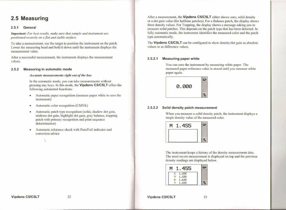
After a measurement, tbe Vipdens C5/C5LT eitber shows zero, solid densityor a dot gain value (for halftone patches). For a Balance patch, the display showsthree density values. For Trapping, the display shows a message asking you tomeasure solid patches. This depends on the patch type tbat has been detected. Infully automatic mode, the instrument identifies the measured color and the patchtype automatically.
The Vipdens C5/C5LT can be configured to show density/dot gain as absolutevalues or as difference values.
2.5.2.1 Measuring paper white
You can zero the instrument by measuring white paper. Themeasured paper reference value is stored until you measure whitepaper again.
rreI0.000
I~2.5.2.2 Solid density patch measurement
Wben you measure a solid density patch, the instrument displays asingle density value of tbe measured color.
M 1.455 Iil
I~
The instrument keeps a history of the density measurement data.The most recent measurement is displayed on top and the previousdensity readings are displayed below.
M 1.455 ~c 1.325y 1.225K 1.625 I roy 1.225
Vipdens C5/C5L T 23

2.5.2.3 Halftone patch measurement
When you measure a solid first and then the halftone patches of thesame color, the instrument displays the dot gain values.
M a'2F 76%
M 1.450
~
The instrument determines the nominal of the patch (shadow,midtone, highlight) and displays it as a reference value. The dotgain value is displayed on the right.
The instrument keeps a history of the halftone measurement data.The most recent measurement is displayed on top and the previoushalftone readings are displayed below.
M se- 76%
M 40% 14%t1 25% 10;';M 1.450
2.5.2.4 Balance patch measurement
When you measure a balance patch, the instrument displays threedensity values. The color that is most out of balance appears inbold. This out of balance value should be corrected first.
1 '235M 1~&.455Y 1.230
The instrument "knows" that changing magenta will affect theyeUow density. If yellow and magenta are both out of balance,magenta wil.l be indicated as the out of balance color.
Vipdens C5/C5L T 24
2.5.2.5 Trapping patch measurement
When you measure a trapping patch, the instrument displays thetrapping color (red, green, blue) and the two composing primarycolors:
~
Afterwards, measure one of the primary solid color patches. Themeasured patch is displayed with gray background.
Now measure the other primary solid color patch. The instrumentdetermines the first printed color and the second printed color anddisplays the trapping value.
~
2.5.3 Measuring density only
Many applications require just density values and automaticzeroing. Use the UP/DOWN keys to select the automatic function
and press ENTER. The instrument goes into density onlymode. The automatic zeroing function is still active, but all othermeasurements are density only.
M 1.455 .',='~
0.000IL..·
reUse the UPIDOWN keys to select solid density ~ and pressENTER. The instrument returns to full automatic mode.
Vipdens C5/C5L T 25

2.5.4 Measuring in semiautomatic mode
You can use the setup mode to enable or disable the followingautomatic functions:
Paper: disable this function to enable the instrument to measure[j bright colors. If you turn this function off, then you have to zero
by selecting the function manually/::(_"Color: disable this function to pre-select the density filter on spotC-M colors
Dot Gain: disable this function to measure density over a sheet if• there are big deviations in density. When measuring a halftone
patch, the instrument displays density valuesn. Grey Balance: disable this function to show black density values~.... after measuring a balance patch
~ping: disable this function to show the color match function
9 ~ on the main toolbar, Use the color match function to comparespot colors
-at Tolerance Check: disables the tolerance check, the Pass/FailIl:!;I indicator and the correction advices
In semi-automatic mode, you can take measurements withoutpressing a key. The buttons are only used to pre-select the type ofmeasurement, if it differs from the standard solid patchmeasurement
• White paper measurement for zeroing
• Halftone measurement of the most recently measured solid ofthe same color
• Balan~e measurement and simultaneously displays 3 densities
• Cyan, Magenta, Yellow, Or Black.
This mode allows the measurement of color balance and printcurve.
If you disable an automatic function, it will appear on the tool barand you can select it manually.
M 1.455
~
Vipdens C5/C5LT 26
2.5.5
Select the patch type function f .11 to use one of the disabledfunctions for the next measurement. The symbol changes to the~bol of the next patch:
~ Default patch. [f all auto-functions are disabled, this is a solid=hUdlJ White paper measurement for zeroing
[i]Halftone measurement for dot gain
~ Balance measurement
~Use the color function ~ to select the color of the nextmeasurement.
~ ~ [!iI~ Next measurement is made with Cyan, Magenta,Yellow or Black.
Measuring with PFI (pass fail indicator) enabled
The Vipdens C5/C5L T has an integrated Pass/Fail indicator. [fyou take a measurement, the measurement values are compared toreferences and tolerances, and the display shows the difference. Ared light flashes if the measurement is out of tolerance while agreen light indicates the measurement is OK.
M6-0.21So.
.~
If the measurement is out of tolerance, a little hand symbolindicates the type of corrective action:
eJ. The measured value is too low. Open ink key.
'Q The measured value is too high. Close ink key.
If the instrument is in PFI mode, a delta symbol is displayed nextto the color. A grey rectangle around a color value indicates thatthe color is out of tolerance.
Vipdens C5/C5L T 27

The instrument keeps a history of the density measurement data.The most recent measurement is displayed on top and the previousdensity readings are displayed below.
M6_0. 215 ~[T33~
Y 0.235K 0.005
I Y -0.125 I
.'..
Vipdens C5/C5LT 28
3 Application cases3.1 Special functions (FAQ)3.1.1 Zeroing on 'dark' paper
The instrument is zeroed if:
• Automatic paper recognition is enabled and the densitydifference between the most recent white papermeasurement and the current measurement is less then0.140 for all colors.
• White paper is selected as the next measurement (seesection "Measuring density only").
If you want to zero on a dark paper, you have to first zero theinstrument on an intermediate dark paper and afterwards on tiledark paper. You can also zero the instrument in semi automaticmode.
• Enter setup and disable paper recognition
Exit setup and select the paper function [j (see section"Measuring density only")
Measure the dark paper. The instrument is now properlyzeroed
•
•
• Enter setup and enable paper recognition again
. The instrument will zero on this dark paper even in automaticmode, until zeroing on a bright substrate .
3.1.2 Measure density only (similar to manual mode in previousinstruments)
Use the UPIDOWN keys to select the automatic function ~ andpress ENTER. The instrument now measures density or white paperonly. Measurements on trapping or balance patches will result indensity readings. Use the UP/DOWN keys to select the solid button
~ and press ENTER. The instrument is reset to full automatic mode.
In some jobs, the measurement values may show a large deviationacross the control strip due to specific conditions of the job. In this casein full automatic mode, the instrument would display halftone values on
Vipdens C5/C5l T 29

a solid patch with low density. To read density only, disable the
automatic halftone function • . Trapping and balance patches areread as trapping or balance readings.
3.1.3 Measure spot color density with preselected filter
Open setup and disable the color function and zero the instrument,.-y..e
Select the color function 0-11 from the tool bar and press ENTER untilthe proper filter is selected. Measure the patch.
3.1.4 Measure density difference
Open setup, disable the color and the automatic zero function, and exit,-Yj
setup. Select the color function 0-11 and press ENTER until the proper
filter is selected. Select the patch type function D and press ENTERuntil the zeroing symbol is displayed. Measure the reference patch. Thedensity is stored as a reference value and the following measurementsare compare against this reference. The instrument displays differencevalues.
3.1.5 Measure dot area and print curve
In order to measure dol area other than the three default references(highlight, mid-tone, and shadow), deactivate the automatic halftonefunction. In order to avoid zeroing on highlights below 20%, disablealso the auto-paper function.
• Select the patch type function • and press ENTER until
the paper symbol [j is displayed, Then measure paper tozero the instrument.
• After zeroing, measure the solid patch of the color. Thedensity value is displayed.
• Select the patch type function again and press ENTER untiltbe dot symbol is displayed.
Now measure the halftone patches. The dot area of the patch will bedisplayed.
Vipdens C5/C5L T 30
',I
I
~;1
-~- -
3.1.6 Measure color balance
[i] To measure color balance, you have to disable the auto trappingrecognition. Open setup and select the functions se~ card. Select
the Trapping icon 9 and select the edit function ~. The status
of this function changes to color match ~ . The color matchfunction is now available on tbe main toolbar.
First zero the instrument on paper. Select the patch type functionand press ENTER until the color balance function symbol isselected. Now measure any type of color. The densities for cyan,magenta, yellow, and black are displayed.
C 1.235 Ir~M 1.455
'I Y 1.230 I
I K 1.435 ~I
To compare spot colors, you need to disable the auto paperfunction in the setup. Select the patch type function and press
ENTER until the paper symbol [j is selected. Measure thereference color. Select the patch type function and press ENTERuntil the color balance is displayed. Next, measure the sample. Theinstrument displays the density differences for C, M, Y and K.
C-0. 235 r~M 0.455Y-0.230K 0.435 IN
Vipdens C5/C5L T 31