2 project description 2.1 introduction - rio tinto group · 2.2.2 the rail route as illustrated in...
TRANSCRIPT

Simandou SEIA Volume II Rail Chapter 2: Project Description
2-1
2 Project Description 2.1 Introduction This chapter describes the new Simandou Railway which will link the Simandou Mine in southeastern Guinea with the Simandou Port facility on the Guinean coast approximately 70 km south of the capital Conakry. The railway will transport mined iron ore from the mine to the port for export. The railway will comprise a single track, heavy haul rail system, designed to carry around 95 million tonnes of ore per year (95 mtpa) over a distance of approximately 670 km, with a design life of 35 years. To allow trains to pass, approximately thirteen passing loops will be located at intervals along the proposed alignment. There will also be loading and unloading facilities at either end of the line, three tunnels carrying the railway beneath steep terrain, numerous river and road crossings, a railhead yard near the port, support facilities within a rail yard near the mine and at a midpoint servicing facility near Faranah, as well as signalling and telecommunications services. The remainder of this chapter is structured as follows: Section 2.2 describes the route of the railway and identifies the locations of principal features along the
route; Section 2.3 provides further details on the design of specific elements including the track, tunnels and
bridges, drainage, signalling and communications, railhead yard and maintenance facilities, and the trains;
Section 2.4 describes how the railway will be constructed including the schedule, methods and resource
requirements; Section 2.5 describes the planned operation of the railway; and Section 2.6 outlines the long term plans for the railway upon completion of the Simandou Project. An overview of the alternatives considered during development of the proposals to date is set out in Chapter 3: Alternatives. 2.2 The Proposed Railway Alignment 2.2.1 Proposed Alignment Selection The proposed alignment presented in this report has been developed over a period of several years since start of work on planning for the Simandou Project. This process is described in Chapter 3: Alternatives which presents a review of how the design has evolved, the alternatives that have been considered, and the environmental, social and other factors that have influenced decisions on the current proposals. At the present stage in the design of the railway, a proposed alignment corridor has been defined within which the railway will be located. This corridor is illustrated in Figure 2.1 and will form the basis for the Declaration of a Project of National Interest (PIN declaration) that will be made to provide powers for expropriation of land for the Project. For the purposes of the assessment reported here, the railway is assumed to follow an alignment within the PIN Corridor that is illustrated in Figure 2.1.

N ' Z É R É K O R É
K I S S I D O U G O U
B E Y L AGUÉCKÉDOU
KÉROUANÉ
COYAH
F A R A N A HK I N D I A
FRIA
K A N K A N
DABOLADALABAP I TATÉLIMÉLÉ KOUROUSSA
MANDIANA
DUBRÉKA
M A C E N T A
M A M O U
S i e r r aS i e r r aL e o n eL e o n e
L i b e r i aL i b e r i a
BalziaCentre
Kouankan
Manfran
Moribaya
Mamouroudou
Baténafadji 1
BeindouSibiribaro
Komodou
Soromayah
Niala
PassayaVillage
Heremakono
Sérédou
Vasérédou
WatankaCentre
Koule
Pale
WomeyN'Zebela
Babila-Centre
Linko
Kérouané
Faranah
Banankoro
Binikala
Albadariah
Sangardo
Damaro
Nionsomoridou
Kounsankoro
Baguinet-Centre
BentyFarmoréah
Souguéta
MolotaCentre
Kolente
Friguiagbé
Badi
Sandenia
Sikhourou
MambiaCentre
Kindia
Marella
BangouyaCentre
KégnékoCentre
Allassoya
Maférinyah
Madina-Oula
Forécariah
Mamou
OuréKaba
Kounkouré
Moussayah
Soyah
Macenta
Tokounou
Douako
Guéckédou
Kissidougou
Kankan
9°0'0"W
9°0'0"W
10°0'0"W
10°0'0"W
11°0'0"W
11°0'0"W
12°0'0"W
12°0'0"W
13°0'0"W
13°0'0"W
10°0
'0"N
10°0
'0"N
9°0
'0"N
9°0
'0"N
8°0
'0"N
8°0
'0"N
0
0
100000
100000
200000
200000
300000
300000
400000
400000
500000
500000
9000
00
9000
00
1000
000
1000
000
1100
000
1100
000
Client: Taille: Titre:Légende:Section de voie ferrée numéro / Rail Section Number
1
2
3
4
5
6
7
8
9
Tunnel ferroviaire / Rail Tunnel
Limite du projet d'intérêt national / PIN Corridor
Limite de la concession minière /Mine Concession Boundary
Contour de mine / Mine Outline
Terril de stériles / Waste Emplacement
Forêt classée / Classified Forest
Limite de la préfecture / Prefecture Boundary
Frontière entre états / National Boundary
File
: 01
3129
9Sim
and
ouG
IS_
IG_C
K\M
aps
\ER
M\R
ailw
ay\P
rojD
esc
rFig
ure
s\M
ay2
012_
revi
sio
ns\r
w_
Rai
lAlig
nmen
t.mxd
Date: 14/06/2012
Vérifié par: SD
Projet: 0131299Dessiné par: WB
Approuvé par: KR Echelle: Comme barre d'échelle
Figure 2.1
Corridor de la voie ferrée / Rail Alignment Corridor0 50
kilomètres
Projection: WGS 1984 UTM Zone 29N
A4
G u i n e aG u i n e a
M a l iM a l i
S i e r r aS i e r r aL e o n eL e o n e
G u i n e a - B i s s a uG u i n e a - B i s s a u
S e n e g a lS e n e g a l
L i b e r i aL i b e r i a

Simandou SEIA Volume II Rail Chapter 2: Project Description
2-3
The final horizontal and vertical alignment of the track will be developed within the PIN Corridor during completion of detailed design, taking into account environmental and social factors alongside engineering and other requirements, and may vary from the alignment presented here. If the final detailed alignment differs in any substantial respect from the alignment assessed in this report the assessment will be revised and a supplement to the SEIA Report will be produced and made available for government and stakeholder consideration. In finalising the alignment, the Project will continue to apply the environmental and social design principles explained in Chapter 3: Alternatives with a view to keeping the impacts of the Project as low as reasonably practicable. Within this alignment corridor, a construction corridor of approximately 120 m on average will be established for the railway, narrowing in areas where there are physical, social or environmental constraints, and increasing in locations where passing loops, cuttings, embankments, structures and other facilities are required. During operation the working area will be reduced to an operational corridor of some 40 m, again widening in areas where particular works are required (such as where the railway is in cutting), but allowing other land uses to be reintroduced in the remainder of the operational corridor. The width of the construction and operational corridors is illustrated in Figure 2.2. Figure 2.2 Rail Corridor Widths
2.2.2 The Rail Route As illustrated in Figure 2.1, the rail corridor has been divided into nine sections for the purposes of design and assessment, each of which is defined according to the distance from the western end of the route (note that whilst the SEIA describes the route from the mine in the east to the port in the west, it is standard practice for railway engineering to define distance, or chainage, from west to east.

Simandou SEIA Volume II Rail Chapter 2: Project Description
2-4
Section 9 (616 – 670 km); Section 8 (553 – 616 km); Section 7 (439 – 553 km); Section 6 (336 – 439 km) Section 5 (270 – 336 km); Section 4 (220 – 270 km); Section 3 (150 – 220 km); Section 2 (75 – 150 km); and Section 1 (0 – 75 km).
These sections are shown in further detail in Figure 2.3 together with indicative locations of major structures and facilities. Each section is briefly described in the following paragraphs and further details on the design of specific features are provided in Section 2.3. A summary of the main structure, facilities and key features of the railway are shown in Table 2.1 below. Table 2.1 Summary of Main Structure, Facilities and Key Features along the Railway Alignment
Corridor
Rail Length 670 km
Number of Sections 9
Corridor Width (approximate average width) Construction 120 m, Operation 40 m
Maintenance Facilities
Mine rail yard
Midpoint servicing facility at Faranah,
railhead yard at the port
Passing Loops 13
Tunnels 3 (1.4, 12 & 11.6 km)
Number of trains 13
Bridges over Rivers 34
Bridges over Roads 9
Culverts 900 at 600 locations
Major Culverts 80
Land Uses within the 120 m Construction Corridor
Cultivated Land & Grassland 55%
Open Woodland 25%
Dense Forest 20%
Settlements within 1 000 m of the centreline 607
Main Population Centres along the route Kérouané, Tokonou,
Faranah, Mamou, Kindia & Forécariah
An overview of the design alternatives that were considered in the course of design development is set out in Chapter 3: Alternatives. Further details on the land use in each of these sections are provided in Chapter 5: Geology, Soils and Mineral Waste and Chapter 18: Land Use and Land-Based Livelihoods. Further details on habitats in each section are included in Chapter 11: Biodiversity.

KISSIDOUGOU
B E Y L A
K É R O U A N ÉKANKAN
M A C E N TA
N.1
N.1
N.10
N.33
N.1
Kouankan
Moribadou
Beyla
Mamouroudou
Sibiribaro
Mamouroudou
Mamouroudou
Soromayah
Vasérédou
Kérouané
Banankoro Moribadou
Banankoro
Damaro
NionsomoridouKounsankoro
Banankoro
Heremakono
Mamouroudou
Client: Taille:
Titre:
Date: 13/07/2012
Dessiné par: WB
Vérifié par: SD
Approuvé par: KR
Projet: 0131299
Echelle: 1:1,250,000
Légende:
A4
Figure 2.3
Sections de rail indicatif et fonctionnalités clés / Rail Sections and Indicative Locationsof Key Features
PROJECTION: WGS 1984 UTM Zone 29N
File
: 0
1312
99S
ima
ndou
GIS
_IG
_CK
\Map
s\E
RM
\Ra
ilway
\Pro
jDe
scrF
igur
es\
Ma
y20
12_r
evis
ion
s\rw
_R
ailS
ectio
nsK
eyF
eatu
res.
mxd
K I S S I D O U G O UKÉROUANÉ
F A R A N A H
K A N K A NK O U R O U S S A
MAMOU
S i e r r aS i e r r aL e o n eL e o n e
N.29
N.14N.31
N.33
N.6
N.2
Heremakono
Manfran
Banankoro
Moribaya
Mamouroudou
Banankoro
Soromayah
Niala
PassayaVillage
Heremakono
Douako-Centre
Faranah
BanankoroAlbadariah
Sanouya
Marella
Boussoura TokounouDouako
MamouroudouDantiliya
Banankoro
0 20
kilomètres
0 20
kilomètres
G u i n e aG u i n e a
S i e r r aS i e r r aL e o n eL e o n e
L i b e r i aL i b e r i a
F O R É C A R I A H
COYAH K I N D I AC O N A K R Y
DUB RÉ KA
M A M O U
S i e r r aS i e r r aL e o n eL e o n e
N.1
N.2
Dandaya
Tassendi
MolotaCentre
KolenteFriguiagbé
Hérémakono
YomayaLimban
Sikhourou
MambiaCentre
Kindia
Allassoyah
Madina-Oula
Forécariah
OuréKaba
Moussayah
Soyah
0 20
kilomètres
Section de voie ferrée numéro / Rail Section Number1
2
3
4
5
6
7
8
9
Tunnel ferroviaire / Rail Tunnel
Poste de service intermédiaire (indicatif) / Midpoint Servicing Facility (Indicative)
Dépôt ferroviaire au niveau de la mine / Mine Rail Yard
Depôt terminus (localisation indicative) /Railhead Yard (Indicative Location)
Base de vie projetée / Proposed Camp
Pont routier / Road Bridge
Pont fluvial / River Bridge
Boucle de contournement (tracé indicatif) / Passing Loop (Indicative)
Limite de la concession minière /Mine Concession Boundary
Agglomération / SettlementChef lieu de préfecture / Prefecture Chief Town
Chef lieu de sous-préfecture / Sub-Prefecture Chief Town
Autre agglomération importante /Other Significant Settlement
Route principale / Primary Road
Route secondaire / Secondary Road
Cours d'eau / Watercourse
Forêt classée / Classified Forest
Frontière entre états / National Boundary

Simandou SEIA Volume II Rail Chapter 2: Project Description
2-6
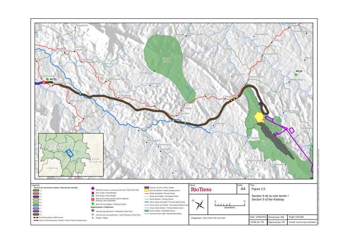
2.2.3 Section 9 (616 – 670 km) The railway starts at the mine with a rail loop located to the east of the Simandou Range between Moribadou and Nionsomoridou. This ‘balloon loop’ is shown in Figure 2.5. Trains will travel around the loop passing through the ore loaders before leaving to travel to the port. A small mine rail yard and maintenance facility will be established immediately to the northwest of the loop for freight and fuel trains servicing the mine. From the loop the proposed alignment runs north towards Nionsomoridou, but passing south of the town and then west through a saddle in the Simandou Range between the Ouéléba Ridge and the Pic de Tibé Ridge. A short tunnel of approximately 1.4 km will be constructed in this location to cross the ridge approximately 3 km west of the town of Nionsomoridou. After crossing the ridge the line turns north through a savanna landscape towards Kounsankoro. Table 2.2 identifies the key features of Section 9 of the railway. Table 2.2 Section 9 Features
Rail Length 48 km
Facilities Mine rail yard
Cultivated Land / Grassland (% of construction corridor) 77%
Open Woodland (% of construction corridor) 17%
Dense Forest (% of construction corridor) 6%
Bridges 3 over rivers
Culverts 34 locations
Tunnel 1 (1.4 Km)
Settlements within 500 m of the centreline 12
Settlements within 1 000 m of the centreline 22
Within this section, cultivated land and grassland covers approximately 77% of the land area in the 120 m rail construction corridor, with the remainder covered by open woodland (17%) and dense forest (6%). Land cover is broadly similar within the 40 m operational corridor and is approximately 78% cultivated land and grassland, 17% open woodland and 5% dense forest. Further details on land use are set out in Chapter 18: Land Use and Land-Based Livelihoods. Typical landscapes are illustrated in Figure 2.4. The first photo was taken from Kérouané town looking east towards the Simandou ridge. It shows scrubland used for grazing which is common to the area. The second was taken on the east side of the Simandou Ridge south of the proposed rail loop. The photos underneath were taken during the dry season south of the town of Kounsankoro.

Simandou SEIA Volume II Rail Chapter 2: Project Description
2-7
Figure 2.4 Typical Landscapes in Section 9
There will be three bridges in Section 9 each over the River Milo and approximately 34 locations where culverts are required. The proposed rail alignment in this section cuts through the northernmost tip and slightly cuts across the eastern boundary of the Pic de Fon Classified Forest as it turns westward through the saddle in the Simandou Ridge (see Figure 2.5 and Chapter 11: Biodiversity).
Pic deTibé
Pic deFon
Milo
Loya
Loya
N.1
N.10
N.1
Moribadou
Traoréla
Lamandou
Sibiridou
Kissiboula
Carrefour -Damaro -30
Sondou
Faraba
Korèla
Wataférédou II
Piyaro
Bangalydou
Boutédo
Sangolomè
Lokpo
Kasssiadou
Kénégbébaro
Nionsomoridou
Kamandou
Soumailadou
Kamiandou
Sossava
Niamadou
Tiékouradou
Fassinédou
Kouwandala
Gbagbadou
Wataférédou I
Bobaro
Morisangarédou
Nialessou
Kignènkouda
Yendédou
Matimbaladou
Fereboridou-Centre
Baro
Camaradou
Kotoulenda
Boula
Moribiendou
Mamouroudou
RC15
RC13
Client: Taille: Titre:Légende:
File
: 01
3129
9Sim
and
ouG
IS_
IG_C
K\M
aps
\ER
M\R
ailw
ay\P
rojD
esc
rFig
ure
s\M
ay2
012_
revi
sio
ns\r
w_
sect
ion9
.mxd
Date: 14/05/2012
Vérifié par: SD
Projet: 0131299Dessiné par: WB
Approuvé par: KR Echelle: Comme barre d'échelle
Figure 2.5
Section 9 de la voie ferrée /Section 9 of the Railway
0 5
kilomètres
Projection: WGS 1984 UTM Zone 29N
A4Section de voie ferrée numéro / Rail Section Number 1
2
3
4
5
6
7
8
9
Tunnel ferroviaire / Rail Tunnel
Usine et infrastructures minières / Mine Plant & Infrastructure
Dépôt ferroviaire au niveau de la mine / Mine Rail Yard
Pont routier / Road Bridge
Pont fluvial / River Bridge
Boucle de contournement (tracé indicatif) /Passing Loop (Indicative)
Base de vie projetée / Proposed Camp
Agglomération / Settlement
Chef lieu de préfecture / Prefecture Chief Town
Chef lieu de sous-préfecture / Sub-Prefecture Chief Town
Village / Village
Contour de mine / Mine Outline
Terril de stériles / Waste Emplacement
Route principale / Primary Road
Route secondaire / Secondary Road
Route tertiaire / Tertiary Route
Cours d'eau principale / Primary Watercourse
Cours d'eau secondaire / Secondary Watercourse
Cours d'eau tertiaire / Tertiary Watercourse
Forêt classée / Classified Forest
Frontière entre états / National Boundary
G u i n e aG u i n e a
C o t eC o t ed ' I v o i r ed ' I v o i r e
L i b e r i aL i b e r i a

Simandou SEIA Volume II Rail Chapter 2: Project Description
2-9
2.2.4 Section 8 (553-616 km) This section runs for 63 km from the end of Section 9 and ends southeast of the town of Madina (see Figure 2.7). It crosses the main plateau that covers much of eastern Guinea, running parallel to the Milo River for some distance and passes approximately 2 km west of the town of Kérouané (population approximately 36 000). There is likely to be one passing loop in this section. Table 2.3 identifies the key features of Section 8 of the railway. Table 2.3 Section 8 Features
Rail Length 63 km
Facilities & Passing Loops 1 Passing Loop
Cultivated Land / Grassland (% of construction corridor) 64%
Woodland (% of construction corridor) 27%
Dense Forest (% of construction corridor) 9%
Bridges 2 over rivers and 2 over roads
Culverts 97 locations
Tunnel 0
Settlements within 500 m of the centreline 6
Settlements within 1 000 m of the centreline 15
Cultivated land and grassland covers around 64% of the 120 m construction corridor, with open woodland covering around 27% and dense forest 9%. Land cover within the 40 m operational corridor is broadly similar at approximately 64% cultivated land and grassland, open woodland 28% and dense forest 8%. The photos in Figure 2.6 show typical landscapes in Section 8 of the alignment southwest of the town of Kérouané during both the wet and dry seasons. The first photo was taken from west of the Simandou Ridge looking eastward and shows forested areas with human settlement. The second is an aerial image and was taken just east of the Simandou ridge towards Kérouané. The two photo’s underneath show the same area during the dry season.

Simandou SEIA Volume II Rail Chapter 2: Project Description
2-10
Figure 2.6 Typical Landscape in Section 8
There will be two bridges over rivers in this section, one across the River Baoula (Sonamba) and the other across a tributary of the Milo. There will also be two road bridges over the railway for the N10 and the N33 national roads. In addition, there are approximately 97 locations where culverts will be required. Fifteen tertiary roads have also been identified, most running from the N10 leading to small settlements that lie to the south of the proposed alignment. There are numerous settlements within 1 000 m of the centreline, and one small settlement to the southeast of Kérouané (approximately two buildings in total) has been identified within the construction corridor which is expected to be displaced. There are no known areas designated for importance or biodiversity in this section (see Figure 2.7 and Chapter 11: Biodiversity).

Bou ro uma
Milo
Baoula
(Sonamba)
Bourouma
Baoula
(Sonamba)
N.1
Sacédou
Gbènikoro
Kérouané
Férédou
SiridouGbenkoro
DiafelaGbagbadou
Tabakoro
Lalinso
FilabaladouSoninkè-Baladou
Korombadou
Sackodou
Karako
Siguirikoura 1
Tankonfouga
LokpoFounoukouroudou
Sokoro
Boulakaninkan
Tèninmaoussoudou
Tèninwoulèndou
Kérouané
Banankoro
Temimbaro
DevantureHèrèmakonon
Massano
Djiradoukoro
Doumou
Sirigbèdou
Dania
Oamaya
Famorodou
Karfaya
Fanifadou
Waramoufé
Kono
Damaro
Kounsankoro
Sokodou
Mamadidou
Bafouro
TolomassoBoromoridou
Gnantoumandou
Koyafé
Fereboridou-Centre
BoulaMoussaya
Niantoumandou
Kedjandou
Wassako
ManifadouCentre
Banako
Kouloubadou
Souloukou-DenkaDjidou
Sandjadou
Mycou Baro
Camaradou
Fadjiya
Woussouma
Madina
Diraya
DialaCentre
A9
LSC4a
RC13
RC12
Client: Taille: Titre:Légende:
File
: 01
3129
9Sim
and
ouG
IS_
IG_C
K\M
aps
\ER
M\R
ailw
ay\P
rojD
esc
rFig
ure
s\M
ay2
012_
revi
sio
ns\r
w_
sect
ion8
.mxd
Date: 18/06/2012
Vérifié par: SD
Projet: 0131299Dessiné par: WB
Approuvé par: KR Echelle: Comme barre d'échelle
Figure 2.7
Section 8 de la voie ferrée /Section 8 of the Railway
0 5
kilomètres
Projection: WGS 1984 UTM Zone 29N
A4Section de voie ferrée numéro / Rail Section Number 1
2
3
4
5
6
7
8
9
Pont routier / Road Bridge
Pont fluvial / River Bridge
Boucle de contournement (tracé indicatif) /Passing Loop (Indicative)
Base de vie projetée / Proposed Camp
Agglomération / SettlementChef lieu de préfecture /Prefecture Chief Town
Chef lieu de sous-préfecture /Sub-Prefecture Chief Town
Village / Village
Route principale / Primary Road
Route secondaire / Secondary Road
Route tertiaire / Tertiary Route
Cours d'eau principale / Primary Watercourse
Cours d'eau secondaire / Secondary Watercourse
Cours d'eau tertiaire / Tertiary Watercourse
SIERRA LEONE
G u i n e aG u i n e a
M a l iM a l i
S i e r r aS i e r r aL e o n eL e o n e
C o t eC o t e
d ' I v o i r ed ' I v o i r e
L i b e r i aL i b e r i a

Simandou SEIA Volume II Rail Chapter 2: Project Description
2-12
2.2.5 Section 7 (439 - 553 km) This section of the route is 114 km in length and continues through the eastern plateau ending just east of the town of Douako (see Figure 2.9). There are likely to be three passing loops at approximately 50 km intervals along this part of the route. Table 2.4 identifies the key features of Section 7 of the railway. Table 2.4 Section 7 Features
Rail Length 114 km
Facilities & Passing Loops 3 Passing Loops
Cultivated Land / Grassland (% of construction corridor) 47%
Woodland (% of construction corridor) 36%
Dense Forest (% of construction corridor) 17%
Bridges 4 over rivers and 1 over a road
Culverts 80 locations
Tunnel 0
Settlements within 500 m of the centreline 0
Settlements within 1 000 m of the centreline 6
Cultivated land and grassland covers approximately 47% of the 120 m construction corridor, with open woodland accounting for around 36% and dense forest 17%, the same as for the operational corridor. The photos in Figure 2.8 show typical landscapes in Section 7. The first shows an area of bas fonds (lowland agriculture) close to the town of Tokounou. The second shows typical dense vegetation common along the N2 close to the town of Tokounou. The two photos at the bottom show landscapes in the dry season close to the town of Tokounou.

Simandou SEIA Volume II Rail Chapter 2: Project Description
2-13
Figure 2.8 Typical Landscapes in Section 7
There will be four bridges constructed over the rivers Kouya, Niadan, Balé and Mira. One road bridge will be constructed over the railway for the N6 national road north of Tokounou. Culverts will be required at around 80 points along the proposed alignment in this section. Five other roads will be crossed at grade. Two of these lead between the sub-prefectural towns of Banankoro and Mamouroudou. The proposed alignment in this section runs approximately 15.5 km through the southern area of the Haut Niger National Park, within the Park’s buffer zone, so avoiding core areas of the Park. Within this buffer zone, local people are permitted to use natural resources in a sustainable manner, where farming and collection of non timber products is allowed. The park is categorised as an “exceptionally important priority area” for chimpanzee conservation in the Regional Action Plan for the Conservation of Chimpanzees in West Africa and is a priority area for West African chimpanzee populations (refer to Chapter 11: Biodiversity). The proposed rail alignment then exits this site and runs along outside the southern boundary for another 15 km before turning southwest away from the site (see Figure 2.9 and Chapter 11: Biodiversity).

Yardo
Kouya
Haut Niger/ UpperNiger
Bal
é
Nia
ndan
Mi lo
Kouya
Kou
ya
Bal é
M agba
Magba
Nia
nda
n
Balé
Ras sékér
é
Niand an
Kouya
N.31
N.6
N.33
Heremakono
Morodou
DouassaliaDouassalia
Tindikan
Morodou OuMaradou
Manaboriah
Sibirikoya
Niataya
Yomadou
Moussaya
Niamana
Kiniéko
Banankoro
Dialadougou
TinkonkoroSanankoro
Fassoumakoya
Korakoro
Famoria
Fankono
Foulouni
Kodjoulou
Solidou
Sanankoroni
Kankandalav.c.
NiamanaFérédou
Fasineya
Ouloukoro
Mamouroudou
Morisindou
Kssourou
Sansanbaya
Dankola
Férémamoria
Fissankoro
TotalaKouhoudou
Bouroukav.c.
Féredékorov.c.
DélédougouNoukankoudou
Tonlkaralav.c.
Massamayan
Farawoya
Kolako-Moussaya(Farawana)
Kolonbabayav.c.
Fodéya
ManKoulonbafénianv.c.
Woélla
MamouriaDinko
Kouya-Laya
Kouya-Siria
Silamana
BabilaKonkèDakörö
Banamoridou
Mandoukoro
Tissinkoro
Soromayah
Konèya
Karako
Nonkoro
Banankoroni
Sitaya
Balléya
Forèsssadou
NonkowaNongowa
Léro
SIradou
Maka
KossiriaTeguefa
Kérèya
Massoumaya
Dar-Es-Salam 2
Kémokoroya
Gueafari
Kountaya
TelikayaSirakoro
Dankav.c.Nomomoria
Fatoumaya
Bananko
Tindikanv.c.
Sangbanianv.c.
ManissaliaMomora
Kouman
Koumav.c.Farantoya
Sirakoro
Télikoro
Konténinv.c.Danka
v.c.Manfara
Alianbalé
Fessév.c.
Souramaya
KoundiLimbana
Semandou
Nafadji
ToumaniaTénéziria
DjiradoukoroYaladou
Djilimalö
Simbo
Farabana
Sérisséla
Sidikourouma
Siriardou
Siria
Konélav.c.
Kokoédouv.c.
Missabada
Tongbav.c.
Sirigbèdou
Oulouhouriv.c.
Nialékoumandou
Tonkolon
Toubav.c.
Dania
Baladou
KossiriaBanankoro
Diomadou
Kariaradou
Dabadou
Doussoukoya
Kazabia
Sèldou
Mamouria
Lanséniav.c.
Sabaléav.c.Orondo v.c.
Ourofé
Tellikaya
TénéforiaOuorokoro
Yradou
Albadariah
NialinkoDiarabadou
Samadou
Massagnana
Nafadji
Tokounou
Founkouran
Gbalako
Soukourala
Guiranbalé
Gninantamba-Centre
Karvayav.c.
Madina
DirayaKiredou
Damandou
Diankoya
KassourouKouloudou
BissiliyakoroBalakoyaBissaliaba
MouguebeyaRadoula
Merna
Missadou
Séngbèdou-MamouriaMorigbedou
KalamandohMamouroudou
Madina
Ouroubékoro
Samba
Biradou
Kanangbanan
Kigneko
FamayaKassaya
Morwaya
SoloyaFadama
Gnalemoriya
Fabassia
Mamouria
RC9 (A6)
A9RC10 (A7)
RC11(A8)
Client: Taille: Titre:Légende:
File
: 01
3129
9Sim
and
ouG
IS_
IG_C
K\M
aps
\ER
M\R
ailw
ay\P
rojD
esc
rFig
ure
s\M
ay2
012_
revi
sio
ns\r
w_
sect
ion7
.mxd
Date: 18/06/2012
Vérifié par: SD
Projet: 0131299Dessiné par: WB
Approuvé par: KR Echelle: Comme barre d'échelle
Figure 2.9
Section 7 de la voie ferrée /Section 7 of the Railway
0 10
kilomètres
Projection: WGS 1984 UTM Zone 29N
A4Section de voie ferrée numéro / Rail Section Number 1
2
3
4
5
6
7
8
9
Pont routier / Road Bridge
Pont fluvial / River Bridge
Boucle de contournement (tracé indicatif) /Passing Loop (Indicative)
Base de vie projetée / Proposed Camp
Agglomération / SettlementChef lieu de préfecture /Prefecture Chief Town
Chef lieu de sous-préfecture /Sub-Prefecture Chief Town
Village / Village
Route principale / Primary Road
Route secondaire / Secondary Road
Route tertiaire / Tertiary Route
Cours d'eau principale / Primary Watercourse
Cours d'eau secondaire / Secondary Watercourse
Cours d'eau tertiaire / Tertiary Watercourse
Forêt classée / Classified Forest
Parc national / National Park
G u i n e aG u i n e aM a l iM a l i
S i e r r aS i e r r aL e o n eL e o n e
L i b e r i aL i b e r i a

Simandou SEIA Volume II Rail Chapter 2: Project Description
2-15
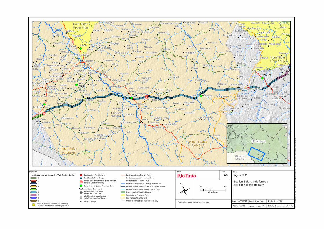
2.2.6 Section 6 (336 - 439 km) This section continues through the eastern plateau, and runs approximately 20 km south of the town of Faranah to end near Dantiliya, 334 km from the mine (see Figure 2.11). Faranah is the largest city between the mine and the mountainous region of Mamou, with a population of approximately 87 000. A midpoint servicing facility is currently planned to be located in this section (see Section 2.3.7) at approximately the 354 km mark, south of the settlement of Sonkonia and the town of Faranah. There are likely to be three passing loops in this section. Table 2.5 identifies the key features of Section 6 of the railway. Table 2.5 Section 6 Features
Rail Length 103 km
Facilities & Passing Loops Midpoint servicing facility,
3 Passing Loops
Cultivated Land /Grassland (% of construction corridor) 63%
Woodland (% of construction corridor) 33%
Dense Forest (% of construction corridor) 4%
Bridges 3 over rivers and 2 over roads
Culverts 51 locations
Tunnel 0
Settlements within 500 m of the centreline 1
Settlements within 1 000 m of the centreline 9
Cultivated land and grassland accounts for 63% of land cover in Section 6, with open woodland accounting for around 33% and dense forest 4% in both the 120 m construction and 40 m operational corridors. The photos in Figure 2.10 show typical land uses in Section 6. The first shows an area of bas fonds close to the proposed railway south of the town of Faranah. The second shows an area of cultivated land south of the town of Faranah. The first photo on the bottom row shows an aerial view of the landscape southwest of the town of Faranah and the second shows a landscape southwest of Faranah.

Simandou SEIA Volume II Rail Chapter 2: Project Description
2-16
Figure 2.10 Typical Landscapes in Section 6
There will be three bridges required over the Mafou, Niger and Tintarba rivers. Two road bridges will be required for the railway to pass over the grade separated N31 national road and the N29 to the east of the section. One secondary and three tertiary roads will be crossed, at grade, by the railway. Culverts will be required at 51 locations throughout the section. The proposed alignment in this section runs through the Niger-Mafou Ramsar wetland site for the majority of its length, from southwest of the town of Douako to east of the town of Hèrèmakono (see Figure 2.11 and Chapter 11: Biodiversity).
Niger-SourceRAMSAR
Niger-MafouRAMSAR
Kouya
Haut Niger /Upper Niger
Haut Niger /Upper Niger
Ma fou
Mafou
Niger Kouya
Ras
séké
ré
Balé
Bal é
Kouya
Sér indé
Mafou
Niger
M
afou
Faliko
Nig er
N.14
N.29
N.31
N.2
Belenkoro
Kambia
Karako
YaraFoulouaro
Banayan
Farko
TénémamouriaHerako Farendou /Fansambou II
Sangbanbaya
Goumball
Méssira
Woélla
Dinko
Faramoria
Kouya-Laya
Kosidia
Kouya-Siria
Silamana
Sérékoro
Boussouran
Lébadyangna
SaranWaliya
Faramoria
Miraya
Tindo
Faroro
Banankoro
Barsan
Bouroumourian
Bossoboria
Koulawa
Guinkoura
Banamoridou
Sidakoro
Forodou-Koura 1
Faraousa
Sélia
Farakonko
SafaraHérako
Bangalya
Bangalya
Kougnaya
Kaarin
Bokhora
Kondondou
Gbeninkoro
KaméréKounia
Maradou
Dionfala
Siriman
Morsira
Famaoulia
Arpela
Firiko
Niala
Karaolia
LayaDoula
Silémi
Soumanbo
Biri-Doula
Dansoa
Kaniko
DabidianaBankouno
Sandankoro
Karakolin
Koumana 2
Farawandou
Korakoro
Sossokoro
Bombodou
Tonkélén
Tèdou
Soundia-Demba
Kobiya
Damadou
Bakaria
Denguédou
Linko
Tolly
Kaoro
SeredouKountaya
Farko
Oulimai
Mano
Tomba
Tangoltö
Kondero
Yomadou Goole
WondeBeindou
Gbayan
Manian
Dalafilany
Mambouriah
Niona KoindouDèya
Souramaya
Koundi
Limbana
Semandou
Nafadji
Faranah
Nérékoro
Hadja Andre TouréKouakörö
Bakaria
Koumandi-Barnatou
Dalamara
Tindo
Kansiraya
KabayaKoro
DjilimalöSimbo
Kanda
TombaKobila
Gbangadou
KouliaSokourala
GrandeFarako
Tédou 1
Wabengou
Balakofé
Ourofé
Ouorokoro
Albadariah
Damendougou
Farakofé
Irla
Morissiria
Ténenkofé
Mamouria
Tinéfaranfé
Bélinkoro
Kourankou
Dafiladou
Tanbakounda
Bantoun
Bilankofé
Morobolia
Fadoya
Bordou
Safaran
TimbissoDoussoumoria
Sidakoro
Tiro
Milidala
Kondéboun-Karfa
Dalékofé
Famarahya
Bécouria
Salémako
Fokoro
Méliboun
Sarafinaya
G Bénikoro
Namakaya
Bourédou
Pouria
Laya-Sando
G'Dininkoro ??
Kalanco
Balia
Dabolani
Kaléa
SonikiriaSoulémania
Sirakémoya
Santiguia
Damania
Morowa
MarabereteyaDouako
Maharnadi
KoléaKomola-Koura Centre
Fansan
Yarawalia
Kémodou
Kassaya
Morwaya
GbenenkoroMategoan
Nimoya
Gnalemoriya
Dantiliya
Tandala
Dansakoré
Banankoro
M.Soulankölo
KankanKoura
KabèlèyaKoyléa
Sonkonia
Walia
Bindouni
KèbalyBassangbafé
G'Banhouria
Gamara
Sanankoro
SangaréKéma
Saourou Boyo
Farakonko
RC8(A2/3)
LSC3
A1
RC9 (A6)
A5A4
Client: Taille: Titre:Légende:
File
: 01
3129
9Sim
and
ouG
IS_
IG_C
K\M
aps
\ER
M\R
ailw
ay\P
rojD
esc
rFig
ure
s\M
ay2
012_
revi
sio
ns\r
w_
sect
ion6
.mxd
Date: 18/06/2012
Vérifié par: SD
Projet: 0131299Dessiné par: WB
Approuvé par: KR Echelle: Comme barre d'échelle
Figure 2.11
Section 6 de la voie ferrée /Section 6 of the Railway
0 10
kilomètres
Projection: WGS 1984 UTM Zone 29N
A4Section de voie ferrée numéro / Rail Section Number 1
2
3
4
5
6
7
8
9
Poste de service intermédiaire (indicatif) /Mid-Point Maintenance Facility (Indicative)
Pont routier / Road Bridge
Pont fluvial / River Bridge
Boucle de contournement (tracé indicatif) /Passing Loop (Indicative)
Base de vie projetée / Proposed Camp
Agglomération / SettlementChef lieu de préfecture /Prefecture Chief Town
Chef lieu de sous-préfecture /Sub-Prefecture Chief Town
Village / Village
Route principale / Primary Road
Route secondaire / Secondary Road
Route tertiaire / Tertiary Route
Cours d'eau principale / Primary Watercourse
Cours d'eau secondaire / Secondary Watercourse
Cours d'eau tertiaire / Tertiary Watercourse
Forêt classée / Classified Forest
Parc national / National Park
Site Ramsar / Ramsar Site
Frontière entre états / National Boundary
G u i n e aG u i n e a
M a l iM a l i
S i e r r aS i e r r aL e o n eL e o n e

Simandou SEIA Volume II Rail Chapter 2: Project Description
2-18
2.2.7 Section 5 (270 - 336 km) This section continues for a further 66 km through the eastern plateau to end south of the town of Marella, approximately 400 km from the mine (see Figure 2.13). One passing loop is likely in this section. Table 2.6 identifies the key features of Section 5 of the railway. Table 2.6 Section 5 Features
Rail Length 66 km
Facilities & Passing Loops 1 Passing Loop
Cultivated Land / Grassland (% of construction corridor) 57%
Woodland (% of construction corridor) 18%
Dense Forest (% of construction corridor) 25%
Bridges 1 over a river and 2 over roads
Culverts 52 locations
Tunnel 0
Settlements within 500 m of the centreline 46
Settlements within 1000 m of the centreline 93
Land cover in the construction corridor is estimated to be 57% cultivated land and grassland, around 18% open woodland and 25% dense forest. Within the 40 m operational corridor, land cover is broadly similar, estimated at 56% cultivated land and grassland, 18% open woodland and 26% dense forest. The photos in Figure 2.12 show typical landscape in Section 5 during the wet season (on top) and during the dry season (on bottom). The land is generally densely vegetated with patches of bas fonds and fallow land.

Simandou SEIA Volume II Rail Chapter 2: Project Description
2-19
Figure 2.12 Typical Landscapes in Section 5
There will be one river bridge required in this section, over the Mongo River and culverts will be required at 52 locations throughout the section. The proposed rail alignment crosses the N14 once and there are a further four tertiary roads crossed by the railway, one of which links the sub-prefectural town of Hèrèmakono with Dantiliya, the N2 road and ultimately the prefectural town of Faranah. The proposed alignment in this section does not run through any designated biodiversity sites (see Figure 2.13 and Chapter 11: Biodiversity).

S i e r r aS i e r r aL e o n eL e o n e
Mo
ngo
Balé
N.14
N.2
KhamayaKadi
Boun
SenkounyaKofan
BambayaTakoude
Laya-Solima
Soumanbo
BaldouDogbodou
Nialia Centre
Heremakono
Sélen
Kouby-Bhouria
Kobiya Damadou
Bakaria
Denguédou
Kamakaléa
LeyaSando
Ngouahou
Tongolo
Kalanko
BalladouWongoéni
Mambouriah
NionaKoindou
KhimbeSindeSowadouPölouma
Wabengou
Bogoréto
Gninagbé
GoulouyaDansaya
Malankhan Kaleya
TambikhoudeKhatiya
Yalaya
Bombodi
Liti
SolonyereyaCentre
LabataraCentreTomata
Centre
MongodiCentre
MansaDounki
Lolin
Telico HeracoFadougou CentreHafia
GadaMongo
Sandenia
TambayaCentre
Farabana 1
Kolma Tamba
KalliaGninantamba-Centre
Boketo
Marella
Mardjougouya
Mansarenko
Koria-Koro
Soloya
SandanfaraDiakanan 1
BambayaSantiguia
Kofan
Bakariya
Firghia
KombonyadiBeindounin
HéllayabhèLey
Kambaya
Liti /Dounkéto Yenguissa
Alia
Nguidonya HermakononFoulbe
Thiampiringui
Boussoura Madina
Kelefaya
KambadouMadoufa
KambabouBayingueTourekoude
Moungata
Sonya-Diabakania
DogholMamoudoua
Sokourala
Gnatagbassy
Doguia
Saliah-KoudayaBayingue-Hermakonondé
Milida
Batebeki
Komola-KouraCentre
NiaiaForita
Dantiliya
Tandala
A1
RC7
Client: Taille: Titre:Légende:
File
: 01
3129
9Sim
and
ouG
IS_
IG_C
K\M
aps
\ER
M\R
ailw
ay\P
rojD
esc
rFig
ure
s\M
ay2
012_
revi
sio
ns\r
w_
sect
ion5
.mxd
Date: 18/06/2012
Vérifié par: SD
Projet: 0131299Dessiné par: WB
Approuvé par: KR Echelle: Comme barre d'échelle
Figure 2.13
Section 5 de la voie ferrée /Section 5 of the Railway
0 5
kilomètres
Projection: WGS 1984 UTM Zone 29N
A4Section de voie ferrée numéro / Rail Section Number 1
2
3
4
5
6
7
8
9
Pont routier / Road Bridge
Pont fluvial / River Bridge
Boucle de contournement (tracé indicatif) /Passing Loop (Indicative)
Base de vie projetée / Proposed Camp
Agglomération / SettlementChef lieu de préfecture /Prefecture Chief Town
Chef lieu de sous-préfecture /Sub-Prefecture Chief Town
Village / Village
Route principale / Primary Road
Route secondaire / Secondary Road
Route tertiaire / Tertiary Route
Cours d'eau principale / Primary Watercourse
Cours d'eau secondaire / Secondary Watercourse
Cours d'eau tertiaire / Tertiary Watercourse
Site Ramsar / Ramsar Site
Frontière entre états / National Boundary
G u i n e aG u i n e a
M a l iM a l i
S i e r r aS i e r r aL e o n eL e o n e

Simandou SEIA Volume II Rail Chapter 2: Project Description
2-21
2.2.8 Section 4 (220 - 270 km) In this 50 km section starting a few kilometres south of Marella, the route passes approximately 2 km north of the town of Ouré Kaba, and leaves the eastern plateau to approach the more mountainous Mamou section near the town of Yomaya Limban, 450 km from the mine and 220 km from the coast (see Figure 2.15). The proposed alignment runs parallel to the Pinselli River for some distance through this section. One passing loop is likely to be located in this section. Table 2.7 identifies the key features of Section 4 of the railway. Table 2.7 Section 4 Features
Rail Length 50 km
Facilities & Passing Loops 1 Passing Loop
Cultivated Land / Grassland (% of construction corridor) 51%
Woodland (% of construction corridor) 18%
Dense Forest (% of construction corridor) 31%
Bridges 7 over rivers and 1 over a road
Culverts 80 locations
Tunnel 0
Settlements within 500 m of the centreline 63
Settlements within 1 000 m of the centreline 127
Land cover in the section within both the 120 m and 40 m corridors is estimated at 51% cultivated land and grassland, 18% open woodland and 31% dense forest. In Figure 2.14 the first photo shows corn farming near the town of Mamou in the northern Mamou area. The second shows an unnamed river near the town of Mamou. The photo on the bottom left shows a typical landscape in the section near the town of Oure Kaba during the dry season. The bottom left shows the same river as the photo above during the dry season near the town of Mamou.

Simandou SEIA Volume II Rail Chapter 2: Project Description
2-22
Figure 2.14 Typical Landscapes in Section 4
There will be seven river bridges in this section with one over the Kaba and six over the Pinselli. Culverts will be required at approximately 80 locations along this stretch of the proposed alignment. A road bridge will be required where the railway crosses the N2 to the north of Ouré Kaba. The section also crosses one tertiary road. The first 15 km of the proposed alignment in this section are outside any designated biodiversity areas, but it then enters the Sustainable and Thriving Environments for West African Regional Development (STEWARD) proposed Transboundary Park for approximately 5 km and then into the Pinselli Classified Forest, through which it runs for approximately 10 km (with a slight deviation outside for approximately 2 km). After exiting the Pinselli Forest it travels through the STEWARD proposed Transboundary Park for the remainder of this section. (See Figure 2.15 and Chapter 11: Biodiversity). This proposed Transboundary Park contains some of the less disturbed parts of the Upper Guinean Forest Ecosystem (part of the Guinean Forests of West Africa Biodiversity Hotspot, which is a high global priority for biodiversity conservation).

Soyah
Pinselli
Kaba
Kaba
N.2
Fodéa
Sébécoto
Bogoréto
Tonfili
Sogoroya
Portofita
KègnèbèCentre
SelèyaCentre
Salia
Kolia
Senguèferènya
Bantanfèrènya
Kounta
Sitakoto
BanirèDionson
Katiri
KouïanFadougou
Sarouia
mangoua
Kansa
Banekoto
OuréKaba
Dramefita
Fodedougou
Fougougnéto
SènguerènWorowilantoAlphaya
DiatayaSémounèko
Kouloundala
Bairoia
Kourbon
Berteya
Kissia
Bantamaya
LahiyaMadinaCentre
Liti /Dounkéto
Diandian
Banihoye
Tyewereya
RC6
Client: Taille: Titre:Légende:
File
: 01
3129
9Sim
and
ouG
IS_
IG_C
K\M
aps
\ER
M\R
ailw
ay\P
rojD
esc
rFig
ure
s\M
ay2
012_
revi
sio
ns\r
w_
sect
ion4
.mxd
Date: 18/06/2012
Vérifié par: SD
Projet: 0131299Dessiné par: WB
Approuvé par: KR Echelle: Comme barre d'échelle
Figure 2.15
Section 4 de la voie ferrée /Section 4 of the Railway
0 5
kilomètres
Projection: WGS 1984 UTM Zone 29N
A4Section de voie ferrée numéro / Rail Section Number 1
2
3
4
5
6
7
8
9
Pont routier / River Bridge
Pont fluvial / River Bridge
Boucle de contournement (tracé indicatif) /Passing Loop (Indicative)
Base de vie projetée / Proposed Camp
Agglomération / SettlementChef lieu de préfecture /Prefecture Chief Town
Chef lieu de sous-préfecture /Sub-Prefecture Chief Town
Village / Village
Route principale / Primary Road
Route secondaire / Secondary Road
Route tertiaire / Tertiary Route
Cours d'eau principale / Primary Watercourse
Cours d'eau secondaire / Secondary Watercourse
Cours d'eau tertiaire / Tertiary Watercourse
Forêt classée / Classified Forest
Parc transfrontalier de STEWARD (Proposée) /STEWARD Proposed Transboundary Park
Frontière entre états / National Boundary
G u i n e aG u i n e a
S i e r r aS i e r r aL e o n eL e o n e

Simandou SEIA Volume II Rail Chapter 2: Project Description
2-24
2.2.9 Section 3 (150 – 220 km) This section covers the mountainous Mamou region in the centre of Guinea and poses a significant engineering challenge. The planned route takes a southerly course through the Mamou mountain range running approximately 2.5 km from the international border with Sierra Leone, particularly at the eastern end and passing approximately 30 km south of Soya and 50 km south of Mamou (see Figure 2.17). The section includes two long tunnels: an eastern tunnel approximately 12 km in length and a western tunnel of approximately 11.6 km. There is likely to be one passing loop between the two tunnels in this section and another near the junction with Section 2. Table 2.8 identifies the key features of Section 3 of the railway. Table 2.8 Section 3 Features
Rail Length 70 km
Facilities & Passing Loops 2 passing loops
Cultivated Land / Grassland (% of construction corridor) 29%
Woodland (% of construction corridor) 32%
Dense Forest (% of construction corridor) 38%
Bridges 5 over rivers
Culverts 78 locations
Tunnel 2 (12 & 11.6 km)
Settlements within 500 m of the centreline 14
Settlements within 1 000 m of the centreline 25
A number of options were considered for the proposed rail alignment in this section prior to agreeing the final proposed alignment presented in this chapter. A northern (north of the Mamou mountain range) and a southern (south of the Mamou mountain range) option were considered, along with an optimised southern option. The objective was to minimise impacts on areas of high biodiversity value whilst meeting the technical challenges of building a railway through mountainous terrain and maintaining a reasonable distance from the Sierra Leonean border. Further details on options considered in this section are set out in Chapter 3: Alternatives. Land cover in the 120 m construction corridor of Section 3 consists of around 29% cultivated land and grassland, 32% open woodland and 38% dense forest with similar figures for the operational corridor at 30% cultivated land and grassland, 31% open woodland and 39% dense forest. The photos in Figure 2.16 show typical terrain and landscape in the Section 3 area illustrating the hill and valley topography and dense vegetation cover. The photo on the bottom left shows an aerial image of the landscape in the Mamou area. The bottom right shows a typical landscape near the western tunnel.

Simandou SEIA Volume II Rail Chapter 2: Project Description
2-25
Figure 2.16 Typical Landscapes in Section 3
There will be five bridges over rivers in this section, one over the Kaba, one over the Lolo and three over the Niomolo. There will be around 78 locations where culverts will be required. There are no major road crossings, though there is one unnamed tertiary road that crosses the alignment at the western end of this section which runs north eventually meeting the N1. The proposed alignment runs through the STEWARD proposed Transboundary Park and the overlapping Priority Site for Populations of West African chimpanzees for the entire length of this section (see Figure 2.17 and Chapter 11: Biodiversity).

Pinselli
Monts Kuru/ KuruHills
S i e r r aS i e r r aL e o n eL e o n e
Kab
a
Kita
Lo lo
Kaba
Kora
Lolo
Lo lo
Kaba
Outamba-Kilimi
Kansema etSiminkounsi
Kebegueya
Donia
Sekhousoriya
Dar-Es-Salam
Famaya
Saféré
AlkaleaKarimouya
Simbaraya
Ouossou
Kourédjéli
FarintaCentre
Kambia-Tafori
Sabouya
Fodéa
Bombia
SiléKhouréFofoko
GanyahSilimanfili
Koule
Bokhigueya
NéribounWolia
Souraya
SakonaYémindéSassira
YomayaLimban
Salifouya
Kondekhoure
Khambigadi
Kolakhouré
Komboya
Lambanta
Konsale
KounataMarla
Kambaia
BombokhouréTaniya
KirbaBoudougoulou
Souloudji
Saki-Labe
Faata
Tanene
MBendiya
Limbitira
Télibala BhoundouBona Nèdi
Mansonia
YabaraKabeleya
Mélico
Bokoba
KoobènKanouma
Toumania
YambagaSangoyah
Kambalia
Mamaia
Mamou
Koulékouré
Commandanya
Guèrèmè
Léïdi
Moussaya
RC5
RC4
TC1a
TC3
TC3a
TC1
TC2
TC4
Client: Taille: Titre:Légende:
File
: 01
3129
9Sim
and
ouG
IS_
IG_C
K\M
aps
\ER
M\R
ailw
ay\P
rojD
esc
rFig
ure
s\M
ay2
012_
revi
sio
ns\r
w_
sect
ion3
.mxd
Date: 18/06/2012
Vérifié par: SD
Projet: 0131299Dessiné par: WB
Approuvé par: KR Echelle: Comme barre d'échelle
Figure 2.17
Section 3 de la voie ferrée /Section 3 of the Railway
0 5
kilomètres
Projection: WGS 1984 UTM Zone 29N
A4Section de voie ferrée numéro / Rail Section Number 1
2
3
4
5
6
7
8
9
Tunnel ferroviaire / Rail Tunnel
Pont routier / Road Bridge
Pont fluvial / River Bridge
Boucle de contournement (tracé indicatif) /Passing Loop (Indicative)
Base de vie projetée / Proposed Camp
Agglomération / SettlementChef lieu de préfecture /Prefecture Chief Town
Chef lieu de sous-préfecture /Sub-Prefecture Chief Town
Village / Village
Route principale / Primary Road
Route secondaire / Secondary Road
Route tertiaire / Tertiary Route
Cours d'eau principale / Primary Watercourse
Cours d'eau secondaire / Secondary Watercourse
Cours d'eau tertiaire / Tertiary Watercourse
Forêt classée / Classified Forest
Parc national / National Park
Parc transfrontalier de STEWARD (Proposée) /STEWARD Proposed Transboundary Park
Frontière entre états / National Boundary
G u i n e aG u i n e a
S i e r r aS i e r r aL e o n eL e o n e

Simandou SEIA Volume II Rail Chapter 2: Project Description
2-27
2.2.10 Section 2 (75 – 150 km) After the mountains the route enters the lower lying coastal plain near the town of Madina Oula, to run through Kindia Prefecture to Tassindi (south of the town of Sikhourou), 595 km from the mine and 75 km inland from the port (see Figure 2.19). The city of Kindia is located approximately 50 km to the north and is Guinea’s third largest city with a population of approximately 181 000. There is likely to be one passing loop in this section. Table 2.9 identifies the key features of Section 2 of the railway. Table 2.9 Section 2 Features
Rail Length 75 km
Facilities & Passing Loops 1 Passing Loop
Cultivated Land / Grassland (% of construction corridor) 62%
Woodland (% of construction corridor) 27%
Dense Forest (% of construction corridor) 11%
Bridges 6 over rivers
Culverts 59 locations
Tunnel 0
Settlements within 500 m of the centreline 43
Settlements within 1 000 m of the centreline 111
Land cover in this section is estimated at 62% cultivated land and grassland, 27% open woodland and 11% dense forest for both the construction and operational corridors. The photos in Figure 2.18 show the landscapes of Section 2. The photo on the top right shows a typical landscape in the Section 2 area. It is mostly undulating with dense vegetation and scrubland. The photo on the top left shows the landscape near the town of Madina Oula in the wet season, whilst the bottom photos show the same area during the dry season.

Simandou SEIA Volume II Rail Chapter 2: Project Description
2-28
Figure 2.18 Typical Landscapes in Section 2
There will be six bridges over rivers in this section crossing the Kora, Kolente, Santa, and Kitoumi Rivers and two over the Kilissi. Culverts will also be required at around 59 locations. The proposed alignment does not cross any national roads and so no road bridges are required, although the proposed alignment crosses one secondary and seven tertiary roads which will be crossed at grade. The proposed alignment runs through the Priority Site for Populations of West African chimpanzees and STEWARD proposed Transboundary Park for approximately 25 km before exiting into the Coastal Plain area where there are no biodiversity designations (see Figure 2.19 and in Chapter 11: Biodiversity).

S i e r r aS i e r r aL e o n eL e o n e
Monts Kuru/ KuruHills
Kolenté
Kora
Ki llissi
Kora
Ko ra
Kolent
é
Kolenté
Outamba-Kilimi
Siafou
DafiraTambékhouré
Kolotoyah
Dalonyah
Sikhourou-Hogo
Oualia
Sakoya
Dar-Es-Salam
Daoudaya
Doubayah
Mambia
YèmberingBalisso
Tayiré
Kalékhouré
Mamou
Kourétéli
Kérendé
Hermakono
KholbaTinka Kansema et
Siminkounsi
Kebegueya
Gombokori
Dokhötö
YalévaDambaya
Dansayakoré
BayenCentre
Takhory
Founsounia
Kombokoré
SendaraYefori
Kagbelen
El HadjKemeko
Cisse
FereyaFonfodi
KoundèKouré
Wolia
SorigbéliaHafiaKomboè
HalikoutounyaSaléguéré
Wondelaya
Diminkon
Bako
KalakoFélayiré
Tenkhèfili
Teteffa
DafouGanyah
Guamata
Khambilayah
Khoundinde
Kounkoyah
Tinekhouré
Foundeyah
Debaya
Fikhèmah
Kantè Firè
Dirabary
Dounkounyan Förèyah
Kalokhoyah
Kindanfori
Silémodouya
Tassen
Hadjièyah
KatafoKondeboun
BambayaBarekariBilide
SimbarayaHoguè
Dambata
Kélémou
Linsenyah
Nissoukouré
Soryah
Tandonya
Tassakhouré
Dandayah
Fansiga
Léfouré
Toli
Gbelima
Sakoya
SanikhouréKalentou
Founsounia
Simbaraya
Konkoyah
Kolakhouré
KoudéKhouré
Sanikhoure
Fammah
Konsouma
Dragnaki
KankanTinko
Guinésokode
SeribaYaléya
Balancougou-Koyandima
Ouassessou
Soutidé
Sidiria
Madina-Oula
Dokota Taguefilé
Basya TalaTanene
Tougoudaré Morfoudéa
Samyenkhoure
Balimanka
KandeSorriyah /Kani-Soriah
Lamani
Kaledi
Kenende
KaledyKhoureKhoun
Madina
Santiguiya-Centre
Yerelande
Bériko
Koumbaya-Centre
Wolia
Bambaya-Centre
Kalema
KoubiKomboya
YibamaKitaforo
Lakhayire
Dounkola
Mangakounsi
Yombofari
Tashé Baïombo
BadéKanti
RC3
Client: Taille: Titre:Légende:
File
: 01
3129
9Sim
and
ouG
IS_
IG_C
K\M
aps
\ER
M\R
ailw
ay\P
rojD
esc
rFig
ure
s\M
ay2
012_
revi
sio
ns\r
w_
sect
ion2
.mxd
Date: 18/06/2012
Vérifié par: SD
Projet: 0131299Dessiné par: WB
Approuvé par: KR Echelle: Comme barre d'échelle
Figure 2.19
Section 2 de la voie ferrée /Section 2 of the Railway
0 5
kilomètres
Projection: WGS 1984 UTM Zone 29N
A4Section de voie ferrée numéro / Rail Section Number 1
2
3
4
5
6
7
8
9
Pont routier / Road Bridge
Pont fluvial / River Bridge
Boucle de contournement (tracé indicatif) /Passing Loop (Indicative)
Base de vie projetée / Proposed Camp
Agglomération / SettlementChef lieu de préfecture /Prefecture Chief Town
Chef lieu de sous-préfecture /Sub-Prefecture Chief Town
Village / Village
Route principale / Primary Road
Route secondaire / Secondary Road
Route tertiaire / Tertiary Route
Cours d'eau principale / Primary Watercourse
Cours d'eau secondaire / Secondary Watercourse
Cours d'eau tertiaire / Tertiary Watercourse
Forêt classée / Classified Forest
Parc national / National Park
Parc transfrontalier de STEWARD (Proposée) /STEWARD Proposed Transboundary Park
Frontière entre états / National Boundary
G u i n e aG u i n e a
S i e r r aS i e r r aL e o n eL e o n e

Simandou SEIA Volume II Rail Chapter 2: Project Description
2-30
2.2.11 Section 1 (0 - 75 km) The final 75 km section of the proposed alignment runs approximately 5 km north of the town of Forécariah to the proposed railhead yard and unloading facility (see Figure 2.21). A rail maintenance facility will be established at the railhead yard around 10 km west of Dandaya. The railhead yard is described further in Section 2.3. The railhead yard will occupy some 247 ha. There is likely to be a passing loop near the eastern end of the section, north of Moussayah. Table 2.10 identifies the key features of Section 1 of the railway. Table 2.10 Section 1 Features
Rail Length 75 km
Facilities & Passing Loops Railhead Yard and 1 Passing Loop
Cultivated Land / Grassland (% of construction corridor) 45%
Woodland (% of construction corridor) 14%
Dense Forest & Mangrove (% of construction corridor) 41%
Bridges 3 over rivers and 1 over a road
Culverts 69 locations
Tunnel 0
Settlements within 500 m of the centreline 55
Settlements within 1 000 m of the centreline 99
Land cover in this section is estimated to be 45% cultivated land and grassland, 14% open woodland 41% dense forest and mangrove (0.4% mangrove) within the construction corridor. Within the 40 m operational corridor land cover is broadly similar and approximately 49% will be cultivated land and grassland, 11% open woodland and 40% dense forest and 0.4% mangrove. Figure 2.20 shows an aerial view and a landscape close to the proposed railhead yard in Section 1. The bottom photo on the right shows the landscape to the northeast of Moussayah and the one on the left shows landscape south of the town of Maférinyah, close to the proposed site for the railhead yard.

Simandou SEIA Volume II Rail Chapter 2: Project Description
2-31
Figure 2.20 Typical Landscapes in Section 1
There will be three bridges over rivers required in this section, over the Bofon, Koulete and Bombokoure rivers. Culverts will be required at approximately 69 locations. In addition, a road bridge will be required for the N4 to cross the railway just north of Dandaya and a further 1 secondary and 19 tertiary roads will be crossed, at grade, in this section. There are no designated areas of biodiversity in this section though the rail does run close (less than 1 km) to the Kounounkan Classified Forest north of the town of Moussayah (see Figure 2.21 and in Chapter 11: Biodiversity).

Kounounkan
Foréc
ari a
h
Bere
yir
é
Kol
enté
Sa
ngb
on
N.4
Samaya
Kolotoyah
Sikhourou-Hogo
Kaméléya
Gbara
Kondottoyah-Sory
Foungban
Fansiga
Bokariah
SouguéSenni
Fodeya
Morifindian
Ynde
BéréïréLécindiya
Borboff
FandiéTambayadi
Seydouya
Kalémodiabé
Bérika
Dara
Kitérin
Kolayiré
Sambaya
Hogai
Sandenya
Dansaya
Wondima
Kaledi
GuemedoulaBoukariah Tanènè
Kafoufori
Boundoukaya
Kolairé
Kalefodeyah
Kondéyiré
Yemouna
Morifinyah
Katabé
Sabakouré
Dandaya
Modiya
Sory-WoulaCarréfour
Sory-Woula Centre
Silémanya
Kondoukhouré
Safiya
Tanéné
SaliyaMomokalé
NoumakhouréAmaraya
Barari
Koboto Fodéah
Wondima
Mémélaya
Souleymania
Tafori
BandalafindiyaDakhi Babiya
Meliboun
Dalaba
ModiaSamataya
KoutabassiaBilidi
Wondi
Gbaya
Fansiga
Bassia
Tayiré
IyawoliBolebalé
Filidè
Kanda
KapossèSolonMadinè
Kouliyiré
YongosamayaTanènèColongaya
Gbberedabou
YogboyaDiforya
FindéModya
Gbomilon
Darakhouré
Tamouya
Salifouya
Tonokhouré
Lamana
Sambalya
Wondi
Fayimaya
SansanyiSimitia
Baya
Cissékeyah
Kolakhouré
Tambayagbé
Dantiliya
Yaya
Sourakataya
Dougayah
Bériakhori
Guémétaye
KobératoKolata
Kondébounyi
Souguébounyi
MadinaKondebounyi
Waliah
Bembenyi
Kindimiya
Sikhourou
Fodéyadi Dalonyah
GbèssèKhimbéli
Nintekhouredi
Hermakono
Bambakhoure
Lambagni
Kambaya Kabaya
Satandembaya
Tougouboum
Fendéfodéyah
Momidiya
Wondokhouré
Botèya
GbéréKhereré
Wongaelou
Soorè
Boubouyah
Fodéssoriya
KhimbéliKouréguéli
Kourekoré Koudéboun
Kundé
Kolakhouré 1
Kolakhouré 2
Kobéléla
Lambanyi
Togna
Korogbaya
Siraya
Soory
WoulaGbokoudè
Koudindi
MaliguiyahMakhemekhen
Wondikhambi
Denkhodokhoya
AlyCoyahDougoufou
Kimbaya
Kabaya Kindobya
SouguekounsouSyllaya
Yafodéyah
Yataya
Dalobambayah
Hérico
Sanayah
Bintikaboya
Dafou Ganyah
KhoundindeKondekhouré
Dirabary
Bambaya
Alpha Boaria
BarekariBilide
Simbaraya Hoguè
M'MahPamalapouyah
Kabouya
NsiraNabiya(Détruit)
Sinkinet
SimitiyaKouriyaKimokoya
KibanyaFalaba
Simmè Lambaye
Konnagbé
Fossi
Missira
Tonkoya
AllassoyaKènèndé
Koutaya
Tiron
Kotengbè
Kolakhouré
Hériko
Mangué
Bambaya Hérimakono
Dembaya Kimbely
Bonko
Baréna
Matiguiyafori
Allassoyah
Doto
Katonko
Maférinyah
Bendougou
Robompa
Sinkinin
Alemaniya
Rabomba
Dinoouaya
Youmbouyéli
Laya
Kountigui
Woula
Roboto
TikonkoBossimiya
Mérékhounyi
Béta
YmbayaMéyenkhouré
NafayaKofibaya
Khaliya
Fodéya
Dalomodya
Yiliyaya
Tadi
Lamikhoure
Dokaya
Forécariah
Moussayah
Sinky
Friguia
Kounbali
KandeSorriyah /
Kani-Soriah
Kalako
Bouboudet
Wany
Fodeyah
Dembayah
Kabayanene
Toumania
Bokaria-Centre
Morbayadi
Bassiady
BarebombonFofokhoure
HeremakonogbeKourakhoure
UikouiBouramayah
Maferenyadi
Dotto
Wani
Boto
DotoPatoyah
Fandjeyireye
Limbaya-Nene
FodeyaGorede
Gangan
Kolakhoure
KorebounyiSéfary
Manfikhe
Kofiou
Kouéah
Mokhoradi
Kalabouya
Madina
Gbokoma
Kamodiah
YembetaDembayah
Santi Khouré(Plantation)
Komboya
Ouankifondi
Mokhoragbe
Yibama
Kitaforo
Lakhayire
Dounkola
SoromakéFandie
Kalekhoure
Koumbaly-Fougue
MellibounTantouyah
Bendougou
BokoyahSabouyah
Walia
Saraboli
KondeyireKobeletaTambayah
Madinagbé
Yindi
FesseMadina
RC1
LSC1
RC2
Client: Taille: Titre:Légende:
File
: 01
3129
9Sim
and
ouG
IS_
IG_C
K\M
aps
\ER
M\R
ailw
ay\P
rojD
esc
rFig
ure
s\M
ay2
012_
revi
sio
ns\r
w_
sect
ion1
.mxd
Date: 18/06/2012
Vérifié par: SD
Projet: 0131299Dessiné par: WB
Approuvé par: KR Echelle: Comme barre d'échelle
Figure 2.21
Section 1 de la voie ferrée /Section 1 of the Railway
0 5
kilomètres
Projection: WGS 1984 UTM Zone 29N
A4Section de voie ferrée numéro / Rail Section Number 1
2
3
4
5
6
7
8
9
Depôt terminus (localisation indicative) /Railhead Yard (Indicative Location)
Pont routier / Road Bridge
Pont fluvial / River Bridge
Boucle de contournement (tracé indicatif) /Passing Loop (Indicative)
Base de vie projetée / Proposed Camp
Agglomération / SettlementChef lieu de préfecture /Prefecture Chief Town
Chef lieu de sous-préfecture /Sub-Prefecture Chief Town
Village / Village
Route principale / Primary Road
Route secondaire / Secondary Road
Route tertiaire / Tertiary Route
Cours d'eau principale / Primary Watercourse
Cours d'eau secondaire / Secondary Watercourse
Cours d'eau tertiaire / Tertiary Watercourse
Forêt classée / Classified Forest
G u i n e aG u i n e a
S i e r r aS i e r r aL e o n eL e o n e

Simandou SEIA Volume II Rail Chapter 2: Project Description
2-33
2.3 Design of the Railway and Associated Infrastructure 2.3.1 Introduction The following section provides further information on the various elements making up the rail system including: the trains; the track; passing loops; the mine maintenance facility and yard; the railhead yard; other maintenance and crew facilities; tunnels; bridges and other structures; track drainage; and power, signalling and telecommunications. 2.3.2 Simandou Ore Trains The trains running on the Simandou Railway will be heavy ore trains each consisting of 240 wagons with six locomotives, and having a total length of 2 823 m. The proposed configuration is two locomotives at the front, middle and rear of the train with two halves (rakes) of 120 wagons in between each pair of locomotives. There will be no crew cars on the trains. All crew will be located on locomotives and can be deployed and managed in accordance with Simfer hours of service limitations. The total Simandou fleet is expected to consist of approximately 80 locomotives and 3 500 ore wagons. The locomotives will be diesel electrics with a power rating in the order of 3.3 megawatt. The diesel engine drives an electrical generator which provides power to the traction motors located on the wheels. Each locomotive will be approximately 5 m high, 22.3 m long and have six axles with 32 tonnes per axle. The ore wagons will be 11 m long rotary dumper wagons with open tops. Empty wagons will weigh 21 tonnes and be capable of a 40 tonne axle load when laden (total weight on the railway track for all wheels connected to a single axle). Each full wagon will carry 139 tonnes of iron ore and weigh approximately 160 tonnes. Examples of typical ore trains and wagons are illustrated in Figures 2.22 and 2.23. Figure 2.22 Typical Long Haul Trains
Simandou SEIA Volume II Rail Chapter 2: Project Description
2-34
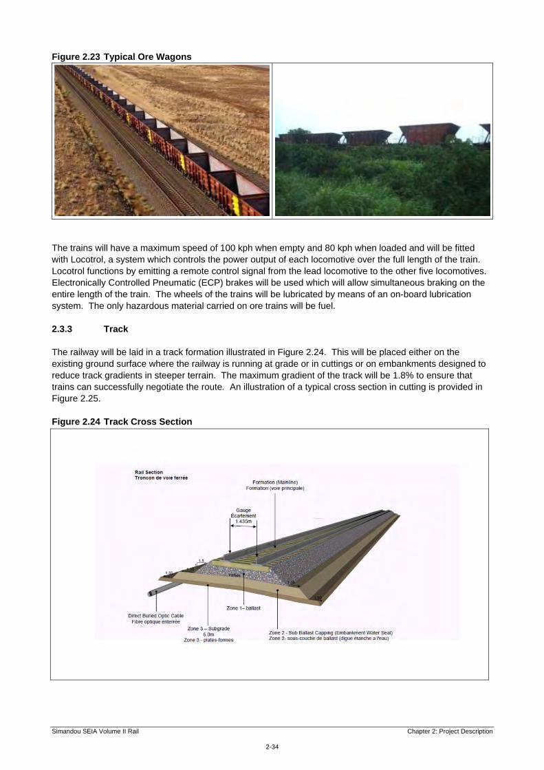
Figure 2.23 Typical Ore Wagons
The trains will have a maximum speed of 100 kph when empty and 80 kph when loaded and will be fitted with Locotrol, a system which controls the power output of each locomotive over the full length of the train. Locotrol functions by emitting a remote control signal from the lead locomotive to the other five locomotives. Electronically Controlled Pneumatic (ECP) brakes will be used which will allow simultaneous braking on the entire length of the train. The wheels of the trains will be lubricated by means of an on-board lubrication system. The only hazardous material carried on ore trains will be fuel. 2.3.3 Track The railway will be laid in a track formation illustrated in Figure 2.24. This will be placed either on the existing ground surface where the railway is running at grade or in cuttings or on embankments designed to reduce track gradients in steeper terrain. The maximum gradient of the track will be 1.8% to ensure that trains can successfully negotiate the route. An illustration of a typical cross section in cutting is provided in Figure 2.25. Figure 2.24 Track Cross Section

Simandou SEIA Volume II Rail Chapter 2: Project Description
2-35
Figure 2.25 Typical Cutting Formation
The base of the track formation will be made up of suitable material to a depth of approximately 420 mm and stone ballast laid to a depth of 230 mm, although the depth will be dependent on formation requirements at a particular location. Ballast will be placed at a rate of 1.67 m3/m requiring a total quantity of approximately 1.6 million cubic metres. The rails will be continuously-welded, steel rails weighing 68 kg per metre with a standard separation distance of 1 435 mm. A total of approximately 1.6 million metres of rail weighing around 112 000 tonnes will be imported into Guinea. The rails will be laid on 2 590 mm long concrete sleepers spaced at approximately 650 mm. Approximately 1 500 sleepers will be required per kilometre making a total of 1.2 million along the length of the railway, weighing approximately 0.58 million tonnes. As illustrated in Figure 2.24, a continuous fibre optic cable will be laid for signalling and communications. This will have a total length of 700 kilometres. Access to the railway for maintenance will be provided predominantly on the railway track. However, in some locations a road track may be located alongside the railway for limited stretches. There will not be a continuous road route alongside the track. 2.3.4 Passing Loops The locations of the passing loops are shown indicatively in Figure 2.3 and they will be spaced at approximately 30 - 60 km intervals along the route. Their final locations will be decided taking into account various factors including the train speeds, gradients and geographic conditions, but also the location of

Simandou SEIA Volume II Rail Chapter 2: Project Description
2-36
environmental and social constraints such as areas of high biodiversity value and heavily populated areas. The role of environmental and social criteria in developing the detailed design of the proposed alignment including the positions of passing loops is discussed in Chapter 3: Alternatives. The layout of a typical passing loop is illustrated in Figure 2.26 and the track formation at passing loops is shown in Figure 2.27. Figure 2.26 Schematic of a Standard Passing Loop
Figure 2.27 Track Cross Section for Passing Loops

Simandou SEIA Volume II Rail Chapter 2: Project Description
2-37
Each passing loop will be 3 km long so that a full length train can pull off the main line and allow another train to pass. The gap between the main line and passing tracks will be at least 7 m. Trains will stop in the passing loops and the average time trains will spend stationary is estimated at approximately 70 minutes. Each passing loop will also have an extra length of track (a back track) on the outside approximately 600 m long into which broken wagons can be pulled to avoid delaying other trains. The space between the passing loop and back track will be 8 m. The passing loops will have a corridor width of 300 m for permanent access. This allows for space for the mainline, passing loop, back track and maintenance vehicle storage with enough space for accommodation units for maintenance gangs. The passing loop at the midpoint service facility (see Section 2.3.7) will require sufficient space for the construction of a temporary welding facility. 2.3.5 Mine Rail Yard As described in Section 2.2.3 and illustrated in Figure 2.5, the railway starts at the mine with a continuous loop running through the ore loading facilities, which allow loading at a rate of 18 500 tonnes per hour. These are described and assessed in Volume I of the SEIAs relating to the Simandou Mine and are not therefore described further here. There is a track maintenance facility planned adjacent to the loop which will occupy approximately 16.5 ha and will include a number of tracks (for arrival / departure, fuel and container unloading, maintenance of way (MOW) support and general freight) as well as a support building, turning wye (or triangular junction) and security gatehouse. 2.3.6 Railhead Yard At the western end of the railway the line ends at the ore unloading facility which is equipped with rotary dumpers, located to the west of the railhead yard. At this location the track will branch into two unloading areas where ‘car dumpers’ will rotate and empty each ore wagon as the train progresses through. Whilst the wagons are being emptied the locomotives will be sent to a trip servicing facility to be refuelled. Once the wagons are empty, they will be returned to the railhead yard where a visual inspection will be undertaken and the rakes will be re-attached to the locomotives. The train will then be ready to return to the mine. From the rotary car dumpers the ore will be transferred to the stockyard and on to the port. The port railhead and ore unloading facilities are not described further here or assessed in this SEIA as they are addressed in Volume III of the SEIA relating to the Simandou Port. Just to the east of the ore unloading facility, a railhead yard will be developed north of the railway near Dandaya, south of Bembenyi as shown in Figure 2.28. It will occupy a site some 5.5 km long and up to 700 m wide with a total area of approximately 247 ha. The yard will provide the principal maintenance facilities for the railway, supplemented by intermediate installations along the route as described in Section 2.3.7. The layout of the yard is shown schematically in Figure 2.29 and its main functions will be: locomotive provisioning; locomotive and ore wagon maintenance; rolling stock inspection and maintenance; rail signalling and communications; and rail welding. The site will include several buildings:
a small security building at the entrance gate; a large locomotive and ore wagon repair building; administrative offices located in the main repair building; trip servicing facility used for sanding, cleaning and re-fuelling trains;

Simandou SEIA Volume II Rail Chapter 2: Project Description
2-38
train wash facilities including a toilet wastewater treatment facility; track maintenance facility; rail welding facility (required for welding sections of rail together); materials storage area (for construction materials wheelsets, rail, sleepers and structural steel, and for
spare parts during operation); and rail freight facility for shipment of fuels, supplies and spare parts to the mine.
The site will include wastewater and stormwater systems for: collection and treatment of workshop area drainage and process effluents by sediment and oil
interceptors; sewage collection; and collection of storm drainage. These will be designed taking into account forecast rainfall intensity of 1 in 10 years (for minor catchments) and 1 in 100 years (for major watercourses). Train washes, process water and toilets will be supplied from the treated potable water supplies.

Sangbon
Sangbon
Sangbon Sangbon
Morebaya
Bereyiré
SeydouyaBonfi
TironYnde
Bonko
Tonkoya
Senguelen ManguéBarariFandiema
Dembaya Laya
YindiBamboukhounKobérato
Kholata Dougayah
Sounganyah
Bériakhori
Modiya
LécindiyaMadinagbéBéréïré
Fodeya
DandayaBendougou Walia
Niérékaya Dofonté
TambaadiTambayagbéKindimiyah Kantibounyi Fandié
Sangbon
Touguiyiré
Sourima
Kiban
Alamemiya
Yassao
Fokou-Fokou
KaléaSini
Maligya
Morifinya
Bembenyi
Binty
SouguéSenni
Moufoufanye
Sèrah
FesseMadina
N.4
13°12'0"W
13°12'0"W
13°14'0"W
13°14'0"W
13°16'0"W
13°16'0"W
13°18'0"W
13°18'0"W
13°20'0"W
13°20'0"W
13°22'0"W
13°22'0"W
13°24'0"W
13°24'0"W
9°30'0
"N
9°30'0
"N
9°28'0
"N
9°28'0
"N
9°26'0
"N
9°26'0
"N
9°24'0
"N
20000
20000
25000
25000
30000
30000
35000
35000
1045
000
1045
000
1050
000
1050
000
1055
000
1055
000
Client: Taille: Titre:A4 Figure 2.28
Depôt terminus (localisation indicative) / Railhead Yard (Indicative Location)
Tracé indicatif de la voie ferrée / Indicative Rail AlignmentDepôt terminus (localisation indicative) / Railhead Yard (Indicative Location)Agglomération / SettlementRoute principale / Primary RoadRoute secondaire / Secondary RoadRoute tertiaire / Tertiary Route
Projection: WGS 1984 UTM Zone 29N
File:
0131
299S
iman
douG
IS_IG
_CK\M
aps\E
RM\R
ailwa
y\Proj
Desc
rFigu
res\M
ay20
12_re
vision
s\rw_
PortR
ailHe
ad.m
xd
0 2
kilomètres
Légende:
Vérifié par: SD
Approuvé par: KR
Projet: 0131299
Echelle: Comme Barre d’échelle
Date: 18/06/2012
Dessiné par: WB
S i e r r a L e o n eS i e r r a L e o n e
G u i n e aG u i n e a

Simandou SEIA Volume II Rail Chapter 2: Project Description
2-40
Figure 2.29 Schematic of the Railhead Yard
2.3.7 Other Maintenance and Crew Facilities In addition to the Railhead Yard near the port and the mine rail yard, an additional midpoint servicing facility will be provided. The facility is likely to be located close to the midpoint near the town of Faranah at approximately the 354 km mark. The facility will consist of: support tracks for maintenance and crew change; possible concrete sleeper manufacturing with storage area (for local supply); equipment laydown; train crew booking-in facility; and a waste management facility with possible hazardous waste treatment facilities. The area of this facility is estimated to be approximately 10 ha. 2.3.8 Tunnels There will be two main tunnels in Section 3 of the rail corridor and a third short tunnel near the mine (Section 2.9). The locations of these tunnels are shown in Figure 2.30 below. The east and west Section 3 tunnels will be approximately 12 km and 11.6 km and they will be separated by approximately 30 km. There will also be smaller ‘adit’ tunnels constructed to allow for the excavation of each tunnel from the centre points outwards effectively creating four work fronts per tunnel along the main proposed alignment. The length of these will be approximately 2 km for the west tunnel and 1.2 km for the east tunnel. The third tunnel of approximately 1.4 km will be constructed through the Simandou Ridge north of the mine.

S i e r r aS i e r r aL e o n eL e o n e
N.2
N.1
Souguéta
YomayaLimban
Madina-Oula
OuréKaba
KounkouréSoyah
11°40'0"W
11°40'0"W
11°50'0"W
11°50'0"W
12°0'0"W
12°0'0"W
12°10'0"W
12°10'0"W
12°20'0"W
12°20'0"W
12°30'0"W
12°30'0"W
10°20
'0"N
10°20
'0"N
10°10
'0"N
10°10
'0"N
10°0'
0"N
10°0'
0"N
9°50'0
"N
9°50'0
"N
120000
120000
140000
140000
160000
160000
180000
180000
200000
200000
220000
220000
1100
000
1100
000
1120
000
1120
000
1140
000
1140
000
Client: Taille: Titre:A4 Figure 2.30
Location tunnel ferroviaire / Rail Tunnel Locations
Agglomération / SettlementChef lieu de préfecture / Prefecture Chief TownChef lieu de sous-préfecture / Sub-Prefecture Chief TownAutre agglomération importante / Other Significant SettlementTracé indicatif de la voie ferrée /Indicative Rail AlignmentTunnel / TunnelTunnel Adit / Adit Tunnel
Usine et infrastructures minières /Mine Plant & InfrastructureContour de mine / Mine OutlineTerril de stériles / Waste EmplacementRoute principale / Primary RoadRoute secondaire / Secondary RoadRoute tertiaire / Tertiary RouteFrontière entre états / National Boundary Projection: WGS 1984 UTM Zone 29N
File:
0131
299S
iman
douG
IS_IG
_CK\M
aps\E
RM\R
ailwa
y\Proj
Desc
rFigu
res\M
ay20
12_re
vision
s\rw_
Tunn
els.m
xd
0 10
kilomètres
Légende:
Vérifié par: SD
Approuvé par: KR
Projet: 0131299
Echelle: Comme Barre d’échelle
Date: 14/05/2012
Dessiné par: WB
Tunnel Ouest / West Tunnel - 11.6km
Tunnel Est / East Tunnel - 12km
Tunnel Adit Est / East Adit Tunnel - 1.2km
Tunnel Adit Ouest / West Adit Tunnel - 2km
NionsomoridouN.1
Tunnel à proximité de la mine / Tunnel at Mine
S i e r r a L e o n eS i e r r a L e o n e
G u i n e aG u i n e a

Simandou SEIA Volume II Rail Chapter 2: Project Description
2-43
The tunnels will be constructed by drilling and blasting directly into the rock face. The tunnels will be horseshoe shaped and will be 8 m high (8.75 m in areas with jet fans) and 6 m wide as shown in Figure 2.31. Figure 2.31 Tunnel Cross Section
The tunnels will be ventilated for train operation, health and safety, fire and emergency reasons using jet fans. Jet fans are illustrated in Figure 2.32. Figure 2.32 Typical Jet Fans

Simandou SEIA Volume II Rail Chapter 2: Project Description
2-44
2.3.9 Bridges and Structures A large number of rivers will be crossed by the rail route, ranging from the major rivers such as the Tintarba and Niadan Rivers which are approximately 55 m and 50 m wide respectively at the points where the railway will cross, to a multitude of small and often seasonal watercourses. Some 34 river bridges are currently planned as shown in Figure 2.3. Where the watercourse to be crossed is more than 8 m wide steel and / or concrete bridges will be installed of the type illustrated in Figure 2.33. All bridges over rivers are being designed to meet a 1:100 year flood event and have factored in potential for the effects of future climatic change on flooding. For smaller watercourses culverts will be used. It is expected that a total of approximately 900 culverts will be required of varying sizes in an estimated 600 locations. These will be corrugated steel pipes or reinforced concrete box culverts (depending on the hydrology encountered in each area). If culverts are close to the track it is more likely that concrete box culverts will be used as these have greater capacity. Figure 2.33 Typical Bridge Installations
There will be an estimated 80 major culverts (designed for a catchment of between 10 km2 and 100 km2) as illustrated in Figure 2.34, and banks of culverts where the route crosses areas susceptible to flooding. In marshy areas rock fill and other geotechnical materials will be used to provide a stable base for the railway during the wet season. Where possible, the railway will avoid wetlands to reduce impacts on biodiversity. Figure 2.34 Typical Large Culvert

Simandou SEIA Volume II Rail Chapter 2: Project Description
2-45
The current design envisages nine road bridges crossing primary roads, as shown on Figure 2.3. All other roads suitable for motorised vehicles will cross the railway at grade using level crossings. There will be a variety of safety controls at the grade crossings which may include manual gates and watchmen, signage and whistle boards. The type of control implemented will be based on a risk assessment at each crossing and will depend upon traffic density. Other crossings of the railway for local tracks and paths used by non-motorised vehicles, pedestrians, livestock, and wildlife, are not provided for in the basic design specification, but will be covered during detailed design. Measures to mitigate impacts on access by severance of these routes are addressed in the assessment of impacts and included in the Social and Environmental Management Plan for the Project. 2.3.10 Track Drainage The railway track will be naturally drained along most of the route through the installation of drainage ditches. Where necessary, diversion drains will be installed to maintain natural drainage patterns and, as noted in Section 2.3.9, where the track is located in areas susceptible to flooding the formation will be elevated and culverts provided through the embankments to maintain flows and flood capacity. Again, potential future climatic change has been factored into the design. Where the track is running in a cutting, cut-off drains will be located at the top of the cutting to intercept water flows as required by hydrotechnical conditions. Operational measures to counter the risk of water pollution caused by spills of diesel fuel from trains into track drainage are discussed in Section 2.5. 2.3.11 Power, Signalling and Telecommunications A continuous optical fibre link will be installed directly alongside the track (as shown in Figure 2.24) to enable communications along the rail route, but provision of continuous electrical power along the proposed alignment is not proposed. Electricity will be provided at maintenance facilities either by drawing upon the facilities for electricity generation at the mine and port or by use of solar panels at intermediate locations with diesel generators as backup. High-availability voice and data radio coverage will be available for rail operations, maintenance and emergency crew use along the whole length of the rail corridor, including tunnels. Continuous voice radio coverage will be provided in the single line sections between passing loops where practicable and backup voice and data radio coverage will be provided by microwave links. To facilitate communications, up to 100 radio towers of 20-40 m in height (depending on topography) will be installed at intervals along the route. The area required for each towers will be approximately 600 m2. The majority will be located within the construction corridor but depending on the terrain in certain areas, they may need to be located outside the corridor (possibly up to 10 km away) to achieve the requisite radio coverage. Towers may require access tracks and will be powered by either solar power or generators. At present the sites for these facilities have yet to be identified and their impacts are addressed at a general level, together with other ancillary facilities along the rail route. Once specific locations are identified consideration will be given to the need for site-specific mitigation. European standards for rail signalling and control will be applied using the European Rail Traffic Management System or European Train Control System (ERTMS / ETCS) and Communications Based Train Control (CBTC). These systems are considered appropriate because they meet a number of criteria for: reliability; availability; safety standards in terms of maintenance; software requirements; vital and non-vital communications; safety integrity level;

Simandou SEIA Volume II Rail Chapter 2: Project Description
2-46
environmental performance; and electromagnetic compatibility. The ERTMS / ETCS application provides four levels of communication systems. The first is track to train communications (Level 1) and the second is continuous communications between the train and a Radio Block Centre (RBC) without lineside signals (Level 2). Train movement is communicated directly from the RBC to a unit on board the train including details such as location, gradient and speed limit. The driver is informed of rail line conditions and signals on the route ahead, so allowing trains to reach their optimal speeds whilst maintaining a safe braking distance. Level 2 reduces maintenance by not having line side signalling and allows trains to operate at higher speeds and reduced headways (distances / times between trains). Safety Integrity Level 4 (SIL4) will be used to prevent conflicting movements at rail junctions and crossings. The signalling system as outlined above has been designed to have a positive clearance time / distance between a train and the following train thus providing absolute protection of trains in any one section. All lineside facilities for power supply and radio communications will be securely fenced. 2.4 Construction 2.4.1 Construction Schedule The indicative schedule for construction of the railway is set out in Figure 2.35 and extends over approximately 30 months (Quarter 1 to Quarter 10). Following relevant approvals, and completion of appropriate management plans work should commence in Q1 which is expected to start around the end of 2012. The export of the first ore from the mine is scheduled for Q10 according to the indicative schedule in Figure 2.35. To achieve this, work will proceed on multiple concurrent work fronts throughout the whole proposed alignment to minimise the overall timeframe for completion. An estimated 73 earthwork work fronts and 28 bridge work fronts are needed for the construction phase, these work fronts will emanate from the work camps located along the proposed alignment. Works will commence in Sections 6 and 7 and will be progressively rolled out throughout the whole proposed alignment. This phase will continue over the course of two to three years and will also include track installation and systems commissioning, in time for the commissioning of the railway. There will be three work shifts each operating for six days per week with construction taking place during daylight hours over a typical workday of ten hours, seven days per week, except in the tunnels locations where work will continue 24 hours a day seven days a week. Night time working may also take place on an exceptional basis for other construction activities. The following sections describe the main sequence of activities in above ground sections: 2.4.2 – construction camps and associated infrastructure; 2.4.3 – site clearance and levelling; 2.4.4 – earthworks; 2.4.5 – tunnelling; 2.4.6 – bridges and structures; and 2.4.7 – tracklaying.
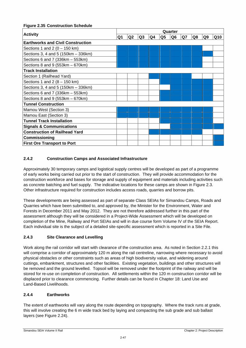
Simandou SEIA Volume II Rail Chapter 2: Project Description
2-47
Figure 2.35 Construction Schedule
Activity Quarter
Q1 Q2 Q3 Q4 Q5 Q6 Q7 Q8 Q9 Q10Earthworks and Civil Construction Sections 1 and 2 (0 – 150 km) Sections 3, 4 and 5 (150km – 336km) Sections 6 and 7 (336km – 553km) Sections 8 and 9 (553km – 670km) Track Installation Section 1 (Railhead Yard) Sections 1 and 2 (8 – 150 km) Sections 3, 4 and 5 (150km – 336km) Sections 6 and 7 (336km – 553km) Sections 8 and 9 (553km – 670km) Tunnel Construction Mamou West (Section 3) Mamou East (Section 3) Tunnel Track Installation Signals & Communications Construction of Railhead Yard Commissioning First Ore Transport to Port 2.4.2 Construction Camps and Associated Infrastructure Approximately 30 temporary camps and logistical supply centres will be developed as part of a programme of early works being carried out prior to the start of construction. They will provide accommodation for the construction workforce and bases for storage and supply of equipment and materials including activities such as concrete batching and fuel supply. The indicative locations for these camps are shown in Figure 2.3. Other infrastructure required for construction includes access roads, quarries and borrow pits. These developments are being assessed as part of separate Class SEIAs for Simandou Camps, Roads and Quarries which have been submitted to, and approved by, the Minister for the Environment, Water and Forests in December 2011 and May 2012. They are not therefore addressed further in this part of the assessment although they will be considered in a Project-Wide Assessment which will be developed on completion of the Mine, Railway and Port SEIAs and will in due course form Volume IV of the SEIA Report. Each individual site is the subject of a detailed site-specific assessment which is reported in a Site File. 2.4.3 Site Clearance and Levelling Work along the rail corridor will start with clearance of the construction area. As noted in Section 2.2.1 this will comprise a corridor of approximately 120 m along the rail centreline, narrowing where necessary to avoid physical obstacles or other constraints such as areas of high biodiversity value, and widening around cuttings, embankment, structures and other facilities. Existing vegetation, buildings and other structures will be removed and the ground levelled. Topsoil will be removed under the footprint of the railway and will be stored for re-use on completion of construction. All settlements within the 120 m construction corridor will be displaced prior to clearance commencing. Further details can be found in Chapter 18: Land Use and Land-Based Livelihoods. 2.4.4 Earthworks The extent of earthworks will vary along the route depending on topography. Where the track runs at grade, this will involve creating the 6 m wide track bed by laying and compacting the sub grade and sub ballast layers (see Figure 2.24).

Simandou SEIA Volume II Rail Chapter 2: Project Description
2-48
Where the ground is not level, cuttings and embankments of varying size will be needed to meet the gradient requirements of the railway. These will involve bulk excavations of soils and in some locations, rock excavation and the use of drilling and blasting. Across the route it is estimated that a total of just over 45 million cubic metres of fill will be needed and marginally less cut material will be generated. Design has minimised the amount of surplus material generated and any surplus material will be used for the creation of berms along the trackside where needed to control erosion, to provide access tracks, and to screen neighbouring settlements and other sensitive land areas from noise and other disturbance, taking flood risk into account in design of these structures. As such, no spoil will be removed from site. 2.4.5 Tunnelling The tunnels in Section 3 are planned to be constructed over a 21 month period with the main construction starting in Q1. Tunnelling for all three tunnels will be carried out using drilling and blasting. The alternative of tunnel boring was considered, but the drill and blast method was selected on the grounds of costs and scheduling. Using the drill and blast method, a temporary construction tunnel or ‘adit’ will be developed to access the centre point of each tunnel and four work fronts will then be deployed: one from each end and two working outwards from the midpoint of the tunnel to minimise the time to completion. The process includes the drilling holes in a rock face and then using explosives to blast away the rock. There are three steps involved in this process. Firstly, small holes are drilled into the rock face. Explosives are then placed into the holes and detonated. Finally, after the blast, the loose material is removed from the tunnel. The process is repeated for the length of tunnel required. After the spoil is removed from the tunnel, temporary tunnel supports are installed in order to support the ground and facilitate working as required. These supports can take a number of forms: rock bolts, rock bolts and mesh, and steel sets or lattice girders. Shotcrete (sprayed concrete) is commonly used in conjunction with rock bolt and lattice girders to form the final tunnel lining depending on the local ground conditions. In the region of 2.5 million m3 of spoil will be produced during tunnel construction. Surplus spoil will be re used on site wherever possible for the creation of trackbed, embankments and noise and visual screening barriers for neighbouring settlements and other sensitive land areas. Excess spoil which cannot be used on site will be considered for use in the construction of other aspects of the Project. Where it cannot practicably be used or is unsuitable for use because of its qualities, the surplus and unsuitable material (spoil) will need to deposited in appropriate locations. Further details on resources and waste can be found in Chapter 5: Geology, Soils and Mineral Waste and Chapter 10: Resources and Non-Mineral Waste Management. The tunnelling workforce will operate on a 24 hours a day, seven days a week schedule, with two ten hour shifts and a four hour maintenance period each day. It is estimated that a total of 2 600 tonnes of explosives will be required to blast the railway’s three tunnels. Explosives will also be needed elsewhere along the rail route to create cuttings through hard rock and will be transported along the roads to blasting locations as necessary. 2.4.6 Bridges and Structures Construction of bridges and culverts will proceed alongside earthworks and will require large quantities of materials including structural bridge steel, concrete steel reinforcing, and corrugated steel culverts. Bridges will be installed using cranes and / or mechanical jacking set ups. Where temporary crossings are required Bailey Bridges (prefabricated truss bridges) or ferries will be used to maintain access during construction. 2.4.7 Tracklaying Once the track bed is laid, tracklaying will follow involving the placing of rail ballast, tamping (or compacting of ballast) and the laying of concrete sleepers, rail pads, rails and rail fasteners. A Track Laying Machine

Simandou SEIA Volume II Rail Chapter 2: Project Description
2-49
(TLM) will likely be used to lay the sleepers and track progressively along the route from an anticipated three concurrent work-fronts, one operating from the railhead yard, and two working from the midpoint servicing facility near Faranah. TLMs will be fed with rail sleepers from two material staging areas, one at the railhead yard and the other at Faranah where primary rail welding depots will be established. Ballast tamping will be carried out by hydraulic jacks to level the ballast material around and under the sleepers and provide support for the rails. A typical TLM and a ballast tamper are illustrated in Figure 2.36. Figure 2.36 Typical Track Laying Machine and Ballast Tamper
Source: With permission of the Plasser Group (www.plasser.com.au).
Five specialist turnout teams will assemble the passing loops, one attached to each tracklaying team, and two working from the Railhead Yard to Faranah Junction. These teams will assemble and install all track other than the mainline track. Track construction is planned to progress at a rate of 1.5 km per day from each work-front. 2.4.8 Temporary Land Use Land will be required temporarily during construction to provide a working corridor along the proposed rail alignment. This is assumed to occupy an area equivalent to a corridor of on average width of 120 m along the entire length of the railway. This will include wider areas in some locations (passing loops, laydown areas at major structures, tunnel portals, large embankments and cuttings) and narrower areas where the route passes through flat open land. It is anticipated that each major bridge abutment will have a laydown area of about 4 ha (200 x 200 m) and the tunnel portals will have a lay down area of around 1 ha for rock storage (with a capacity of 250 000–300 000 m3) and 2 ha for vehicles and construction equipment. 2.4.9 Construction Resources and Waste Management Materials and equipment required during construction will include: construction fill, including earth, sand, and gravel; crushed rock, stone ballast and large rocks for bridge abutments (rip rap); cement and aggregates for concrete; concrete batching plants; pre-fabricated steel and precast concrete bridges; pre-fabricated buildings, storage tanks and treatment units; reinforcing steel bar; water; fuel; workforce supplies; and

Simandou SEIA Volume II Rail Chapter 2: Project Description
2-50
fencing. Construction equipment will include earthmoving machinery for site preparation, graders and trucks. Buildings, storage tanks and treatment units will be delivered as pre-fabricated units. Construction fill material will be sourced from within the 120 m rail corridor where possible, from temporary borrow pits established for the Project, and from existing and new quarries. The specifications for subgrade, sub ballast and ballast will be developed to maximise the suitability of locally available materials. Estimated total quantities over the three year construction period are set out in Table 2.11. Table 2.11 Materials Use During Construction
Item / Resource Total Quantity (approximate) Unit
Rail 1 592 000 m
Sleepers 1 225 000 no. of sleepers
Cement for Sleepers 29 000 tonnes
Sand for Sleepers (25%) 70 000 tonnes
Volume of Water for Sleepers 250 Mega (M) litres
Aggregates for Sleepers 121 800 tonnes
Ballast 1 320 000 m3
Sub-ballast 1 480 000 m3
Concrete 123 900 m3
Reinforcement 14 000 tonnes
Structural Sheet 5 900 tonnes
Spoil from Tunnel Construction (will be re-used on site where practicable)
2 500 000 m3
Concrete-making plants will be located at Logistical Supply Centres and at construction work-fronts as required for construction. A number of borrow pits will be required along the route of the railway. These borrow pits will be sources of earth or similar soft fill material that can be extracted by simple excavation, without the need for blasting or significant processing. The pits will be excavated using mobile excavators brought in via access roads and will not involve processing (crushing, sorting, washing etc). Borrow pits and spoil disposal sites will be closed as soon as possible after completion of works, and rehabilitated taking into account public safety, restoration of natural habitats and future beneficial use. Further information can be found in Chapter 5: Geology, Soils and Mineral Waste. A range of wastes will be generated during construction including cleared vegetation, excavated material that is unsuitable for use, demolition waste from structures that cannot be used, workforce and administration waste, and occasional hazardous waste from equipment maintenance and accidental spills. As discussed in Section 2.4.4 the majority of spoil from excavations and tunnelling will be used within the rail corridor. Some other waste will be handled at waste processing facilities provided at workforce camps and Logistical Supply Centres as detailed in the Class SEIA for these early works. In addition, four long term secure storage / landfill facilities will be required by the Project. The locations of these are yet to be determined but it is anticipated that these will be located close to the port and mine and two will be located close to proposed camps along the rail alignment close to the rail alignment or planned roads. These facilities may include capacity for both hazardous and non-hazardous waste management and storage. Further information on resource use and waste can be found in Chapter 10: Resources and Non-Mineral Waste Management. Fuel used during construction of the track and related structures is estimated at 140 mega litres (Ml) with an average of 3.2 Ml per month. In addition, tunnel construction is anticipated at 84 Ml in total, an average of 2.6 Ml per month. Therefore, total fuel consumption for activities directly related to the railway can be estimated at approximately 225 Ml with an average monthly usage of almost 6 Ml. Refer to Chapter 9: Greenhouse Gas Assessment and Chapter 10: Resources and Non-Mineral Waste Management.

Simandou SEIA Volume II Rail Chapter 2: Project Description
2-51
2.4.10 Water Use Water use during construction will vary over the period of activity. However, it is anticipated to reach 12 000 m3 per day during the peak year of construction of the railway between Q 5 and Q 10. Abstraction will take place over the entire length of the railway at approximately 10 km intervals with precise locations identified during detailed design stage. Detailed information on water use is included in Chapter 6: Water Environment. 2.4.11 Construction Employment Employment for construction of the railway is estimated to reach an average of around 7 000 people (with a peak of 9 100), comprising approximately 5 500 construction workers and approximately 1 500 support positions providing security services, drivers, consultants etc. Employees will be a mix of professionals, skilled and semi-skilled technicians and labourers. Employees will be hired from within Guinea to the extent possible and the aim is for the construction workforce to comprise approximately 50% Guinean employees, of which around 60% will be skilled and semi-skilled and 40% unskilled. The balance will be foreign workers of whom 80% are expected to be skilled workers and 20% management staff. It is estimated that approximately 60 000 indirect jobs will be created during construction. The majority of construction personnel (at least 80%) are anticipated to be non-local and will be housed in secure, temporary camps established along the route as shown in Figure 2.3. As noted in Section 2.4.2, the impacts of these camps are addressed in a separate early works Class SEIA. Unskilled workers will be hired locally as far as possible and will be expected to live in their own homes. The size of camps will vary between locations, but a typical camp will accommodate: 250 construction workers; 20 security staff; 15 medical and firefighting staff; 50 staff providing camp services and management; 10 construction supervisors; 5 quality assurance staff; 3 engineers and vendor representatives; 12 environmental, communities and government personnel; and 10 drivers and truckstop employees. Larger Logistical Supply Centres will also accommodate 125 warehouse and communications staff. 2.4.12 Traffic Construction related traffic will arise principally from the movement of supplies and materials with only a low level of traffic for construction workers (mainly buses to and from nearby towns and the work-fronts). Construction phase traffic will include the following: rock and ballast movements, which will be largely ‘local’ movements (generally less than 100 km)
between quarries developed along the proposed alignment and individual work fronts;
materials movements (ie sleepers and rail, from the Marine Offloading Facility (MOF) at the port or the Conakry container port to the railhead yard and Faranah, and from there to Logistical Supply Centres and individual work fronts);
fuel deliveries, from the fuel import facility at the Marine Offloading Facility to Logistical Supply centres and work-fronts;
localised transport of workers between camps and work-fronts; and
occasional abnormal load movements (ie generators and other oversize equipment).

Simandou SEIA Volume II Rail Chapter 2: Project Description
2-52
Preliminary estimates of the likely construction traffic levels have been derived from the forecasts of the requirement for materials. These logistics forecasts will evolve as the detailed design develops, however the currently estimated levels are presented below. Traffic movements have been based on the assumption of no night time construction traffic movements (a 10 hour working day), a standard 26 day working month for general construction and a 30 day working month for rock (ballast) movements. Across the entire Simandou Project the current construction phase traffic estimates include approximately: 600 000 rock and ballast movements; 10 000 fuel tanker movements; 5 000 container movements; and 42 000 other general truck movements. Excluding ballast movements this results in a monthly average of approximately 6 000 truck movements (delivery of one load to the Project entails two movements, one outward and one return) between the coast and points along the railway corridor as far as the mine. Over a 26 day working month and 10 hour day this results in an average of 23 truck movements per hour. The average flow will start at 23 per hour in the west and decrease to the east as materials are delivered along the corridor. In addition there will be an average of approximately 6 ballast truck movements per hour in each rail section delivering rock and ballast from local quarries. Mean traffic flows do not generally indicate high traffic loads at any one time or place; however there will be peaks within this traffic flow and some points of heavier aggregated load. The peak number of traffic flows is likely to occur in Q4 (see Section 2.4.1 for construction schedule). Roads along the construction workfront will have restricted access which will be controlled by the individual contractors. There will be no restrictions on other roads. In addition to the construction traffic associated with the railway, early ore production may start from Ouéléba in 2013 and an option is currently being investigated to transport ore to the port by truck until the opening of the railway and start of full operations in 2015. . This could result in an additional ten trucks per day in each direction, adding 20 trips per day to the construction traffic along the railway outlined above. These additional numbers of truck movements are incorporated into the traffic flows and impacts are included in relevant chapters. 2.5 Operations 2.5.1 Introduction This section provides an overview of the operation of the railway including: the train timetable; maintenance activities; security and emergency planning; resource use and waste management; and operational employment. 2.5.2 Train Timetable Each ore train travelling to the port will carry between 30 000 and 37 000 tonnes of ore and will take approximately 36 hours to load at the mine, travel to the port, unload and return to the mine. There will be an average of nine loaded ore train trips from the mine to the port per day, and nine empty return trips, making a total of eighteen movements per day (approximately one every 80 minutes), for 355 days per year. The average travel time will be 12.8 hours for the outbound journey and 11.2 hours for the return. Loading at the mine rail yard will take approximately 3.5 hours. On arrival at the port railhead, the ore wagons will be pulled through the rotary car dumpers by permanently stationed locomotives, whilst the ore locomotives are

Simandou SEIA Volume II Rail Chapter 2: Project Description
2-53
serviced. The average unloading cycle will take approximately 3.3 hours. The remaining time will be needed for refuelling, servicing, changing locos and wagons for planned and unplanned maintenance, attachment of fuel transport wagons etc. Trains can be grouped to provide sufficient time to perform preventative track maintenance and bridge inspections and permit recovery in case of accidents. In addition to the ore trains one freight train will carry fuel from the port to the mine and intermediate locations every two days making an average of nineteen train movements per day. This train will carry approximately 2.4 million litres of diesel (2 400 m3) to the mine each week by 24 rail tankers and approximately 1.08 million litres of aviation fuel carried in special ISO tankers (storage tank in a frame). Trains will run at a maximum speed of 80 kph for loaded trains and 100 kph for unloaded and fuel trains, although for large sections of the route this will not be achieved owing to gradients and curves, or because of the proximity of sensitive land uses. The average speed is expected to be approximately 84 kph for unloaded trains and 58 kph for loaded trains and the minimum speed on the main line will be 25 kph. Trains will stop in passing loops for a period of around 70 minutes. 2.5.3 Tunnels Operation The tunnels will have jet fans to ensure ventilation in the tunnels and help prevent fires. Security gates will be used at the entrances to tunnels to ensure that they cannot be used by pedestrians as a thoroughfare. Fuel and water storage tanks will be located on site and deliveries will be via access roads. Power for the jet fans will be provided by a small 5 MW diesel fuelled power plant. There will be water and fuel storage for tunnel operations on site. The access roads in place will be used for maintenance and resupply. 2.5.4 Maintenance Operations Track maintenance activities will be split into as many as three zones led from the maintenance facilities at the railhead yard, the mine, and Faranah. Work will be carefully planned and coordinated to avoid downtime on the railway by placing work equipment at the nearest passing loop ready to be rolled out once a train has passed. Minor track maintenance will be done on-track and will include safety inspections, track grinding, ballast cleaning, ultrasonic testing of rail for wear, spot sleeper renewal, clip replacement, drainage maintenance, field welding, brush cutting and general housekeeping. Some of the machines for more major maintenance operations such as ballast cleaning and track welding are illustrated in Figure 2.37. Train maintenance will be undertaken at the railhead yard at the western end of the route. Locomotives will be serviced whilst the ore wagons are unloaded. Ore wagons will be inspected at the railhead yard prior to their return journey to identify any maintenance and repair requirements. Repair activities such as maintenance and replacement of brakes and wheels will take place in parallel to minimise cycle times. The operational corridor will be kept clear of vegetation through regular spraying of herbicides either side of the track.
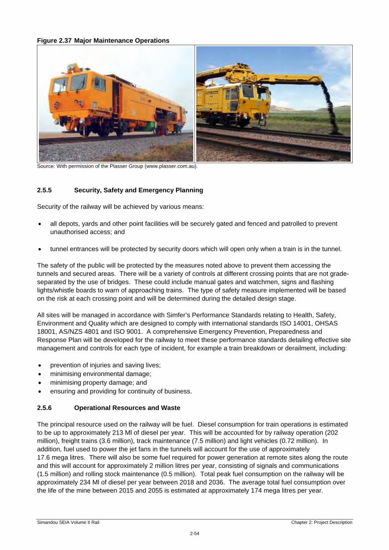
Simandou SEIA Volume II Rail Chapter 2: Project Description
2-54
Figure 2.37 Major Maintenance Operations
Source: With permission of the Plasser Group (www.plasser.com.au).
2.5.5 Security, Safety and Emergency Planning Security of the railway will be achieved by various means: all depots, yards and other point facilities will be securely gated and fenced and patrolled to prevent
unauthorised access; and
tunnel entrances will be protected by security doors which will open only when a train is in the tunnel. The safety of the public will be protected by the measures noted above to prevent them accessing the tunnels and secured areas. There will be a variety of controls at different crossing points that are not grade-separated by the use of bridges. These could include manual gates and watchmen, signs and flashing lights/whistle boards to warn of approaching trains. The type of safety measure implemented will be based on the risk at each crossing point and will be determined during the detailed design stage. All sites will be managed in accordance with Simfer’s Performance Standards relating to Health, Safety, Environment and Quality which are designed to comply with international standards ISO 14001, OHSAS 18001, AS/NZS 4801 and ISO 9001. A comprehensive Emergency Prevention, Preparedness and Response Plan will be developed for the railway to meet these performance standards detailing effective site management and controls for each type of incident, for example a train breakdown or derailment, including: prevention of injuries and saving lives; minimising environmental damage; minimising property damage; and ensuring and providing for continuity of business. 2.5.6 Operational Resources and Waste The principal resource used on the railway will be fuel. Diesel consumption for train operations is estimated to be up to approximately 213 Ml of diesel per year. This will be accounted for by railway operation (202 million), freight trains (3.6 million), track maintenance (7.5 million) and light vehicles (0.72 million). In addition, fuel used to power the jet fans in the tunnels will account for the use of approximately 17.6 mega litres. There will also be some fuel required for power generation at remote sites along the route and this will account for approximately 2 million litres per year, consisting of signals and communications (1.5 million) and rolling stock maintenance (0.5 million). Total peak fuel consumption on the railway will be approximately 234 Ml of diesel per year between 2018 and 2036. The average total fuel consumption over the life of the mine between 2015 and 2055 is estimated at approximately 174 mega litres per year.

Simandou SEIA Volume II Rail Chapter 2: Project Description
2-55
Other resources will include relatively small quantities of maintenance equipment and materials and administration supplies. Solid and liquid waste generation on the railway will also be at a low level, with main sources being maintenance operations, and workforce and office wastes. There may be occasional hazardous wastes from maintenance including oily wastes from trains and contaminated materials from accidental spills. All wastes will be transported to dedicated waste processing facilities to be provided at the mine and port. Further details are provided in Chapter 10: Resources and Non-Mineral Waste Management. 2.5.7 Operational Employment Employment will increase over the early years of rail operations so that by the time the railway is fully operational the railway will employ approximately 1 650 people. The Project is committed to training and employing Guineans, so that over time the large majority of employees will be recruited from the local area and the remainder of Guinea, with a small number of expatriate staff providing specialised skills and experience. These jobs will comprise in the region of 55-60% trade and professional positions, 1-2% managerial and the balance unskilled labour. 2.5.8 Employee Housing and Other Associated Developments The Project has developed an approach to housing its employees that is designed to minimise social and economic disruption in nearby settlements. The approach aims to deliver the following objectives. Facilitate the integration of the workforce into the community. This includes balancing the expectations
of employees in terms of housing with specific Project needs (particularly in terms of logistics and access to the work sites), as well as planning housing developments in line with the capacity of local communities to integrate new residents. Any housing provided specifically for this Project is assessed where appropriate in later chapters.
Coordinate locations and construction schedules to integrate employee housing with existing
infrastructure, and with the urban development plans of existing towns, specifically Forécariah and to a lesser extent Faranah. Employee housing will also be required in Beyla to service workers for the mine. This is discussed in Volume I, Chapter 2: Project Description.
Encourage local ownership: Employees’ focus groups indicate that housing ownership is an appealing
concept to employees. Based on these principles, the resulting approach consists of a hybrid model to house Project employees combining three different approaches. Maximise hiring from existing communities, therefore limiting the needs for new housing development
and to encourage renting where existing market solutions are available. Managing new home construction to meet demand arising from Project workforce originating from
outside of the local community. Providing accommodation for shift workers and expatriates working on rotation in camps located near
the port and the mine. Under this approach, it is the intention that the Project will construct a number of new houses in Beyla, Faranah and Forécariah in the early years but that provision will transition to the private sector in the medium term. Employees living at Beyla and Forécariah will include mine and port employees and only a small number are expected to live in Faranah (working at Faranah rail yard). Construction will be gradual to allow communities to absorb the new entrants, and provide flexibility to adapt to the adjusting demands. Where housing is provided specifically for this Project it is assessed where appropriate in later chapters.

Simandou SEIA Volume II Rail Chapter 2: Project Description
2-56
Associated facilities such as provision of electricity, healthcare, education, water and sanitation for employees will be delivered by third parties on a fee for service basis. Railway employees living in Forécariah will thus constitute the base customers for private operators to gradually expand these services to the rest of the community. This approach recognises the need to facilitate a solution for both employees and the broader community. In addition, there are plans for the upgrading of the existing airfield at Faranah which will be used to transfer operational personnel. There will be limited opportunities for direct employment along the proposed rail alignment outside of Forécariah, Faranah and Beyla. However, it is likely that people will migrate into the area (either newcomers or returnees) seeking work and other opportunities. This may lead to pressure for urban development and conversion of land to agriculture. The potential for in-migration is discussed in Chapter 17: In-Migration, and the impacts of resulting developments are addressed in this SEIA. 2.6 Plans on Completion of Mining The railway will be owned by a special purpose infrastructure company owned jointly by the Republic of Guinea and Simfer’s other shareholders, with the Government holding a 51% stake. Between twenty five and thirty years after construction completion, when the total investment cost of the railway has been fully recovered, it will transfer to full Government ownership. Whilst the mine is in operation, Simfer will have priority access as a foundation customer. There is no plan to remove the infrastructure once the Simandou Project has ended and on completion of mining the railway will become available for local use.