2. project description - ntepa · pdf filethe mine site is located approximately 235 km...
TRANSCRIPT

2-1 Chapter 2 – Project Description
Mount Peake Project Draft Environmental Impact Statement
2. Project Description
2.1 Project Overview
2.1.1 Introduction
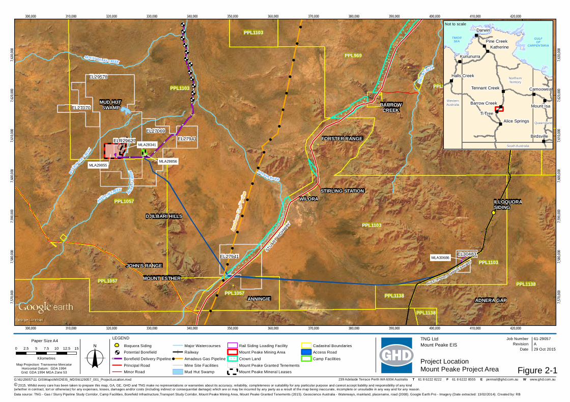
The mine site is located approximately 235 km north-northwest of Alice Springs and approximately 50 km west of the Stuart Highway (Figure 2-1).
The Mount Peake Project will comprise:
the mining of a polymetallic ore body through an open-pit truck and shovel operation;
processing of the ore to produce a magnetite concentrate;
road haulage of the concentrate to a new railway siding and loadout facility on the Alice Springs to Darwin railway near Adnera; and
rail transport of the concentrate to TNG’s proposed Darwin Refinery located at Middle Arm, Darwin.
2.1.2 Product
The Project will mine at a rate of up to 8.4 million tonnes per annum (Mtpa) and, following processing, will produce up to 1.8 Mtpa of magnetite concentrate.
Concentrate will be processed at TNG’s proposed Darwin Refinery to produce 19,700 tpa of vanadium pentoxide (V2O5) flake, 292,000 tpa of pigment grade titanium dioxide (TiO2) and 856,000 tpa of pig iron ingots. Processing of the magnetite concentrate in Darwin does not form part of this assessment.
2.1.3 Key Project Components
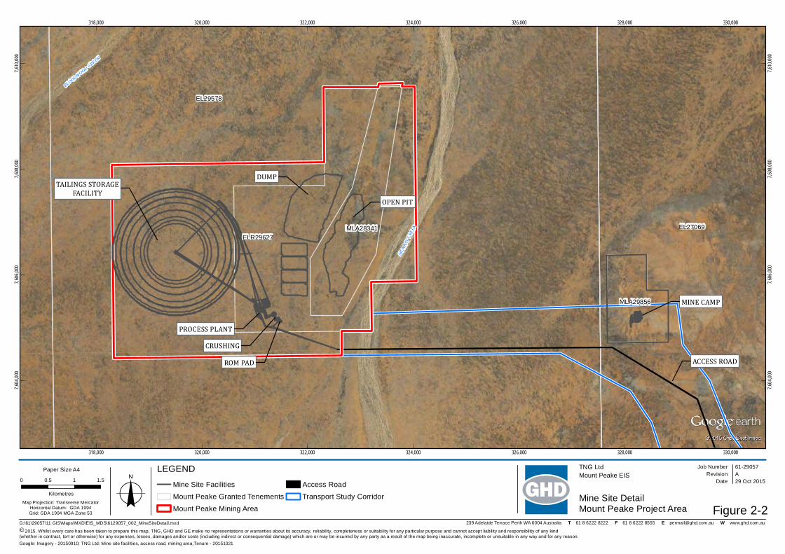
New facilities associated with the Mount Peake Project include (Figure 2-2):
open cut mine;
waste rock dump (WRD) with up to 70 Mt capacity;
run of mine (ROM) pad;
four long term stockpiles of up to 4 Mt capacity each;
process plant;
tailings storage facility (TSF) with up to 63.41 Mt capacity;
access road between the mine site and Adnera Loadout Facility including an underpass of Stuart Highway (for concentrate trucks) and intersections with Stuart Highway (for mine site access);
borefield and associated water pipeline;
concentrate stockpiles;
water and sewage treatment plants;
gas fired power station;
explosives and detonator magazines;
accommodation village;
2-2 Chapter 2 – Project Description
Mount Peake Project Draft Environmental Impact Statement
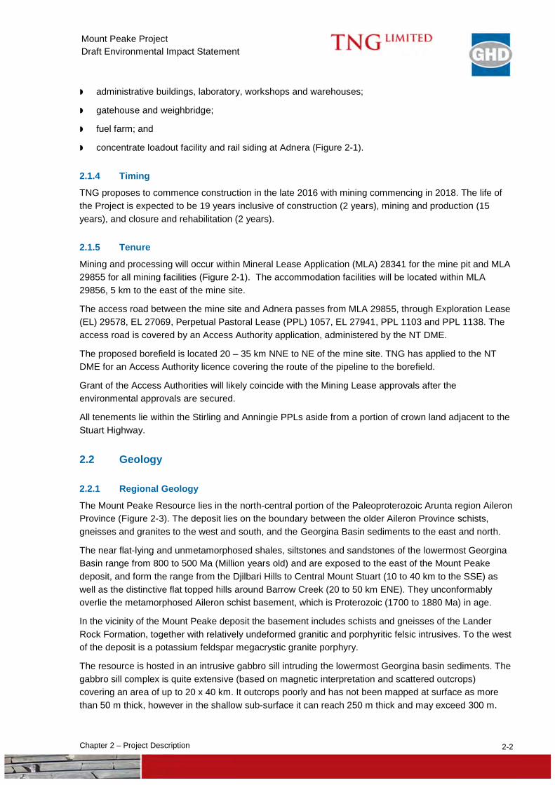
administrative buildings, laboratory, workshops and warehouses;
gatehouse and weighbridge;
fuel farm; and
concentrate loadout facility and rail siding at Adnera (Figure 2-1).
2.1.4 Timing
TNG proposes to commence construction in the late 2016 with mining commencing in 2018. The life of the Project is expected to be 19 years inclusive of construction (2 years), mining and production (15 years), and closure and rehabilitation (2 years).
2.1.5 Tenure
Mining and processing will occur within Mineral Lease Application (MLA) 28341 for the mine pit and MLA 29855 for all mining facilities (Figure 2-1). The accommodation facilities will be located within MLA 29856, 5 km to the east of the mine site.
The access road between the mine site and Adnera passes from MLA 29855, through Exploration Lease (EL) 29578, EL 27069, Perpetual Pastoral Lease (PPL) 1057, EL 27941, PPL 1103 and PPL 1138. The access road is covered by an Access Authority application, administered by the NT DME.
The proposed borefield is located 20 – 35 km NNE to NE of the mine site. TNG has applied to the NT DME for an Access Authority licence covering the route of the pipeline to the borefield.
Grant of the Access Authorities will likely coincide with the Mining Lease approvals after the environmental approvals are secured.
All tenements lie within the Stirling and Anningie PPLs aside from a portion of crown land adjacent to the Stuart Highway.
2.2 Geology
2.2.1 Regional Geology
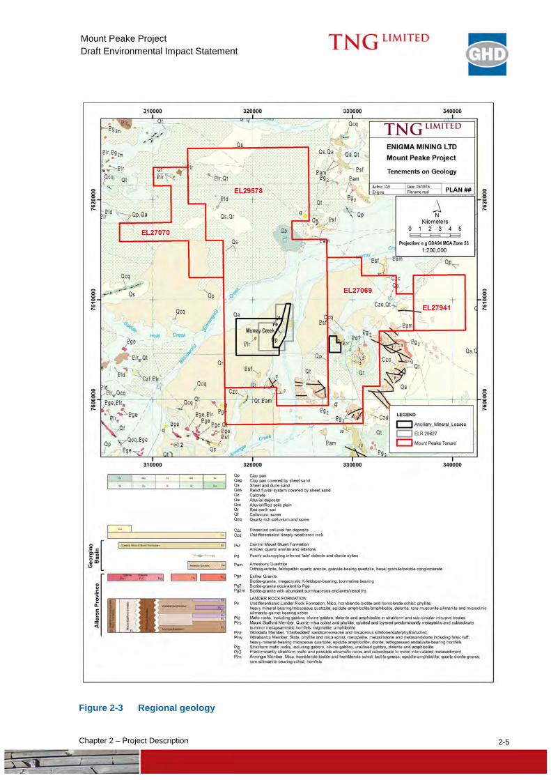
The Mount Peake Resource lies in the north-central portion of the Paleoproterozoic Arunta region Aileron Province (Figure 2-3). The deposit lies on the boundary between the older Aileron Province schists, gneisses and granites to the west and south, and the Georgina Basin sediments to the east and north.
The near flat-lying and unmetamorphosed shales, siltstones and sandstones of the lowermost Georgina Basin range from 800 to 500 Ma (Million years old) and are exposed to the east of the Mount Peake deposit, and form the range from the Djilbari Hills to Central Mount Stuart (10 to 40 km to the SSE) as well as the distinctive flat topped hills around Barrow Creek (20 to 50 km ENE). They unconformably overlie the metamorphosed Aileron schist basement, which is Proterozoic (1700 to 1880 Ma) in age.
In the vicinity of the Mount Peake deposit the basement includes schists and gneisses of the Lander Rock Formation, together with relatively undeformed granitic and porphyritic felsic intrusives. To the west of the deposit is a potassium feldspar megacrystic granite porphyry.
The resource is hosted in an intrusive gabbro sill intruding the lowermost Georgina basin sediments. The gabbro sill complex is quite extensive (based on magnetic interpretation and scattered outcrops) covering an area of up to 20 x 40 km. It outcrops poorly and has not been mapped at surface as more than 50 m thick, however in the shallow sub-surface it can reach 250 m thick and may exceed 300 m.
!!
!
!
!
!
!
!
!
!
!
!
!
!
!! !
!
!
!
!
!
!
!
!
!
!
!
!
!
!
!
!
!
!
!
!
!
!
!
!
!
!
!
!
!
!
!
!
!
!
!
!
!
!
!
!
!
!
!!
!!
!
!
!
!
!
!
!
!
!
!
!
!
!!
!!
!!
!
!
!
!
!
!
!
!
!
!
!
!
!
!
!
!
!!
!!
!!
!!
!!
!!
!!
!!
!!
!!
!!
!!
!!
!!
!
!
+U+U+U+U+U
+U
+U
+U
+U
+U
+U
+U
ALICE SPRINGS DARWINRAILW
AY
PPL1103
PPL1139
PPL1103
PPL1103
PPL1103
PPL1138
PPL1138
PPL1057
PPL1057
PPL1057
PPL1138
PPL969
PPL969
PPL969EL27069
EL27070
ILLOQUORASIDING
EL27941
EL29578
EL30483
ELR29627
BLOO
DWOOD CREEK
HANSON RIVER
MOUNT PEAKE CREEK
ANNINGIE CREEK
TAYL
ORCREEK
MURRA Y
CREE
K
300,000
300,000
310,000
310,000
320,000
320,000
330,000
330,000
340,000
340,000
350,000
350,000
360,000
360,000
370,000
370,000
380,000
380,000
390,000
390,000
400,000
400,000
410,000
410,000
420,000
420,000
7,570,
000
7,570,
000
7,580,
000
7,580,
000
7,590,
000
7,590,
000
7,600,
000
7,600,
000
7,610,
000
7,610,
000
7,620,
000
7,620,
000
7,630,
000
7,630,
000
Figure 2-1
Job NumberRevision A
61-29057
G:\61\29057\11 GIS\Maps\MXD\EIS_MDS\6129057_001_ProjectLocation.mxd
Map Projection: Transverse MercatorHorizontal Datum: GDA 1994Grid: GDA 1994 MGA Zone 53
0 2.5 5 7.5 10 12.5 15
Kilometres o© 2015. Whilst every care has been taken to prepare this map, GA, GE, GHD and TNG make no representations or warranties about its accuracy, reliability, completeness or suitability for any particular purpose and cannot accept liability and responsibility of any kind (whether in contract, tort or otherwise) for any expenses, losses, damages and/or costs (including indirect or consequential damage) which are or may be incurred by any party as a result of the map being inaccurate, incomplete or unsuitable in any way and for any reason.
Date 29 Oct 2015
TNG LtdMount Peake EIS
Project LocationMount Peake Project Area
Data source: TNG - Gas / Slurry Pipeline Study Corridor, Camp Facilities, Borefield Infrastructure,Transport Study Corridor, Mount Peake Mining Area, Mount Peake Granted Tenements (2015). Geoscience Australia - Waterways, mainland, placename, road (2008). Google Earth Pro - Imagery (Date extracted: 13/02/2014). Created by: RB
239 Adelaide Terrace Perth WA 6004 Australia T 61 8 6222 8222 F 61 8 6222 8555 E [email protected] W www.ghd.com.au
Paper Size A4
"
"
"
"
"
"
"
"
"
"
"
"
Katherine
Alice Springs
Mount Isa
Darwin
Pine Creek
Halls Creek
Kununurra
Camooweal
Birdsville
Tennant Creek
Ti Tree
Barrow CreekWesternAustralia
NorthernTerritory
Queensland
South Australia
Not to scale
TIMORSEA GULF
OFCARPENTARIA
Amad
eus
Gas
Pip
elin
e
FORSTER RANGE
STIRLING STATIONWILORA
DJILBARI HILLS
JOHN'S RANGE
MOUNT ESTHER
ADNERA GAP
STUART
HIGHW
AY
BARROWCREEK
LEGEND
Illoquora Siding
+U Potential Borefield
Borefield Delivery Pipeline
Principal RoadMinor Road
Major WatercoursesRailway
! Amadeus Gas Pipeline
Mine Site FacilitiesMud Hut Swamp
Rail Siding Loading FacilityMount Peake Mining Area
Crown Land
Mount Peake Granted TenementsMount Peake Mineral Leases
Cadastral BoundariesAccess Road
Camp Facilities
MUD HUT SWAMP
ANNINGIE
MLA29855
MLA28341
MLA29856
EL27941
MLA30686
EL29578
ELR29627MLA28341
MLA29856
EL27069
BLOODWOOD CREEK
MURRA
Y CRE
EK
318,000
318,000
320,000
320,000
322,000
322,000
324,000
324,000
326,000
326,000
328,000
328,000
330,000
330,000
7,604,
000
7,604,
000
7,606,
000
7,606,
000
7,608,
000
7,608,
000
7,610,
000
7,610,
000
Figure 2-2
Job NumberRevision A
61-29057
G:\61\29057\11 GIS\Maps\MXD\EIS_MDS\6129057_002_MineSiteDetail.mxd
Map Projection: Transverse MercatorHorizontal Datum: GDA 1994Grid: GDA 1994 MGA Zone 53
0 0.5 1 1.5
Kilometres o© 2015. Whilst every care has been taken to prepare this map, TNG, GHD and GE make no representations or warranties about its accuracy, reliability, completeness or suitability for any particular purpose and cannot accept liability and responsibility of any kind (whether in contract, tort or otherwise) for any expenses, losses, damages and/or costs (including indirect or consequential damage) which are or may be incurred by any party as a result of the map being inaccurate, incomplete or unsuitable in any way and for any reason.
Date 29 Oct 2015
TNG LtdMount Peake EIS
Mine Site DetailMount Peake Project Area
Google: Imagery - 20150910; TNG Ltd: Mine site facilities, access road, mining area,Tenure - 20151021
239 Adelaide Terrace Perth WA 6004 Australia T 61 8 6222 8222 F 61 8 6222 8555 E [email protected] W www.ghd.com.au
Paper Size A4 LEGENDMine Site Facilities
Mount Peake Granted Tenements
Mount Peake Mining Area
Access Road
Transport Study Corridor
OPEN PIT
DUMPTAILINGS STORAGE
FACILITY
PROCESS PLANTCRUSHING
ROM PAD ACCESS ROAD
MINE CAMP
2-5 Chapter 2 – Project Description
Mount Peake Project Draft Environmental Impact Statement
Figure 2-3 Regional geology
2-6 Chapter 2 – Project Description
Mount Peake Project Draft Environmental Impact Statement
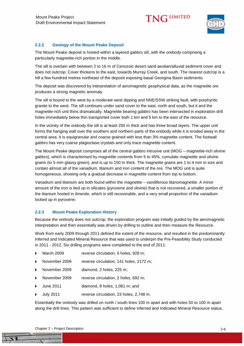
2.2.2 Geology of the Mount Peake Deposit
The Mount Peake deposit is hosted within a layered gabbro sill, with the orebody comprising a particularly magnetite-rich portion in the middle.
The sill is overlain with between 2 to 16 m of Cenozoic desert sand aeolian/alluvial sediment cover and does not outcrop. Cover thickens to the east, towards Murray Creek, and south. The nearest outcrop is a hill a few hundred metres northeast of the deposit exposing basal Georgina Basin sediments.
The deposit was discovered by interpretation of aeromagnetic geophysical data, as the magnetite ore produces a strong magnetic anomaly.
The sill is bound to the west by a moderate west dipping and NNE/SSW striking fault, with porphyritic granite to the west. The sill continues under sand cover to the east, north and south, but it and the magnetite-rich unit thins dramatically. Magnetite bearing gabbro has been intersected in exploration drill holes immediately below thin transported cover both 1 km and 5 km to the east of the resource.
In the vicinity of the orebody the sill is at least 250 m thick and has three broad layers. The upper unit forms the hanging wall over the southern and northern parts of the orebody while it is eroded away in the central area. It is equigranular and coarse grained with less than 3% magnetite content. The footwall gabbro has very coarse plagioclase crystals and only trace magnetite content.
The Mount Peake deposit comprises all of the central gabbro intrusive unit (MOG – magnetite-rich olivine gabbro), which is characterised by magnetite contents from 5 to 45%, cumulate magnetite and olivine grains (to 5 mm glassy green), and is up to 150 m thick. The magnetite grains are 1 to 4 mm in size and contain almost all of the vanadium, titanium and iron content of the ore. The MOG unit is quite homogeneous, showing only a gradual decrease in magnetite content from top to bottom.
Vanadium and titanium are both found within the magnetite – vandiferous titanomagnetite. A minor amount of the iron is tied up in silicates (pyroxene and olivine) that is not recovered, a smaller portion of the titanium hosted in ilmenite, which is still recoverable, and a very small proportion of the vanadium locked up in pyroxene.
2.2.3 Mount Peake Exploration History
Because the orebody does not outcrop, the exploration program was initially guided by the aeromagnetic interpretation and then essentially was driven by drilling to outline and then measure the Resource.
Work from early 2009 through 2011 defined the extent of the resource, and resulted in the predominantly Inferred and Indicated Mineral Resource that was used to underpin the Pre-Feasibility Study conducted in 2011 - 2012. Six drilling programs were completed to the end of 2011:
March 2009 reverse circulation, 6 holes, 928 m;
November 2009 reverse circulation, 141 holes, 2172 m;
November 2009 diamond, 2 holes, 225 m;
November 2009 reverse circulation, 2 holes, 692 m;
June 2011 diamond, 8 holes, 1,081 m; and
July 2011 reverse circulation, 23 holes, 2,748 m.
Essentially the orebody was drilled on north / south lines 100 m apart and with holes 50 to 100 m apart along the drill lines. This pattern was sufficient to define Inferred and Indicated Mineral Resource status.
2-7 Chapter 2 – Project Description
Mount Peake Project Draft Environmental Impact Statement
In late 2012 additional resource drilling was conducted:
December 2012 reverse circulation, 59 holes, 2,748 m; and
December 2012 diamond, 14 holes, 1,892 m.
Hole depths ranged from 65 m to 405.8 m, with most being between 100 and 180 m deep. Most holes intersected mineralisation and towards the centre of the orebody it was up to 166 m thick.
Drilling in 2012 was to upgrade the resource to predominantly Indicated and Measured Resource status, which would allow the publishing of a Measured Resource that could, in the Feasibility Study, be in part converted to Mineral Reserves, once mining and financial considerations had been taken into consideration. The program also generated over 20 tonnes of sample for metallurgical testwork.
Other than infill drilling of the current deposit, there are no plans to expand the mine outside of its currently delineated extent.
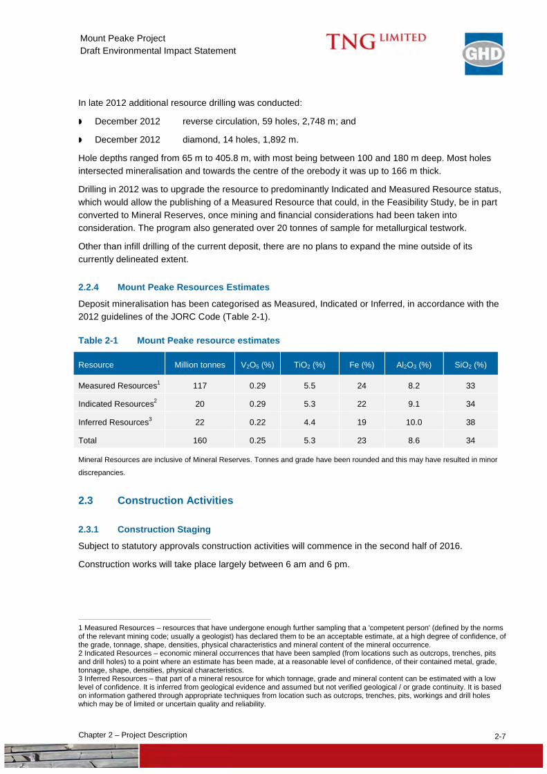
2.2.4 Mount Peake Resources Estimates
Deposit mineralisation has been categorised as Measured, Indicated or Inferred, in accordance with the 2012 guidelines of the JORC Code (Table 2-1).
Table 2-1 Mount Peake resource estimates
Resource Million tonnes V2O5 (%) TiO2 (%) Fe (%) Al2O3 (%) SiO2 (%)
Measured Resources1 117 0.29 5.5 24 8.2 33
Indicated Resources2 20 0.29 5.3 22 9.1 34
Inferred Resources3 22 0.22 4.4 19 10.0 38
Total 160 0.25 5.3 23 8.6 34
Mineral Resources are inclusive of Mineral Reserves. Tonnes and grade have been rounded and this may have resulted in minor
discrepancies.
2.3 Construction Activities
2.3.1 Construction Staging
Subject to statutory approvals construction activities will commence in the second half of 2016.
Construction works will take place largely between 6 am and 6 pm.
1 Measured Resources – resources that have undergone enough further sampling that a 'competent person' (defined by the norms of the relevant mining code; usually a geologist) has declared them to be an acceptable estimate, at a high degree of confidence, of the grade, tonnage, shape, densities, physical characteristics and mineral content of the mineral occurrence. 2 Indicated Resources – economic mineral occurrences that have been sampled (from locations such as outcrops, trenches, pits and drill holes) to a point where an estimate has been made, at a reasonable level of confidence, of their contained metal, grade, tonnage, shape, densities, physical characteristics. 3 Inferred Resources – that part of a mineral resource for which tonnage, grade and mineral content can be estimated with a low level of confidence. It is inferred from geological evidence and assumed but not verified geological / or grade continuity. It is based on information gathered through appropriate techniques from location such as outcrops, trenches, pits, workings and drill holes which may be of limited or uncertain quality and reliability.
2-8 Chapter 2 – Project Description
Mount Peake Project Draft Environmental Impact Statement
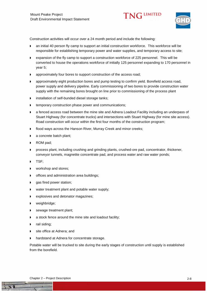
Construction activities will occur over a 24 month period and include the following:
an initial 40 person fly camp to support an initial construction workforce. This workforce will be responsible for establishing temporary power and water supplies, and temporary access to site;
expansion of the fly camp to support a construction workforce of 225 personnel. This will be converted to house the operations workforce of initially 125 personnel expanding to 170 personnel in year 5;
approximately four bores to support construction of the access road;
approximately eight production bores and pump testing to confirm yield. Borefield access road, power supply and delivery pipeline. Early commissioning of two bores to provide construction water supply with the remaining bores brought on line prior to commissioning of the process plant
installation of self-bunded diesel storage tanks;
temporary construction phase power and communications;
a fenced access road between the mine site and Adnera Loadout Facility including an underpass of Stuart Highway (for concentrate trucks) and intersections with Stuart Highway (for mine site access). Road construction will occur within the first four months of the construction program;
flood ways across the Hanson River, Murray Creek and minor creeks;
a concrete batch plant;
ROM pad;
process plant, including crushing and grinding plants, crushed-ore pad, concentrator, thickener, conveyor tunnels, magnetite concentrate pad, and process water and raw water ponds;
TSF;
workshop and stores;
offices and administration area buildings;
gas fired power station;
water treatment plant and potable water supply;
explosives and detonator magazines;
weighbridge;
sewage treatment plant;
a stock fence around the mine site and loadout facility;
rail siding;
site office at Adnera; and
hardstand at Adnera for concentrate storage.
Potable water will be trucked to site during the early stages of construction until supply is established from the borefield.
2-9 Chapter 2 – Project Description
Mount Peake Project Draft Environmental Impact Statement
Pre-production mine preparation works will also commence during this stage. Selected materials from the pit area will be stockpiled and placed to build bases for the HPGR, ROM ramp and pad, TSF perimeter bund and central access ramp, access road and other site roads. Excess material will be trucked to the WRD.
2.3.2 General Site Works
Earthworks will involve clearing, grubbing, cut and fill, preparation of unsealed roads and hardstands and basic drainage works. Areas will be levelled and compacted prior to construction of infrastructure.
Toward the end of the construction program a second phase of earthworks will be initiated. This work will involve trimming to final level, constructing final drainage profiles and installing culverts.
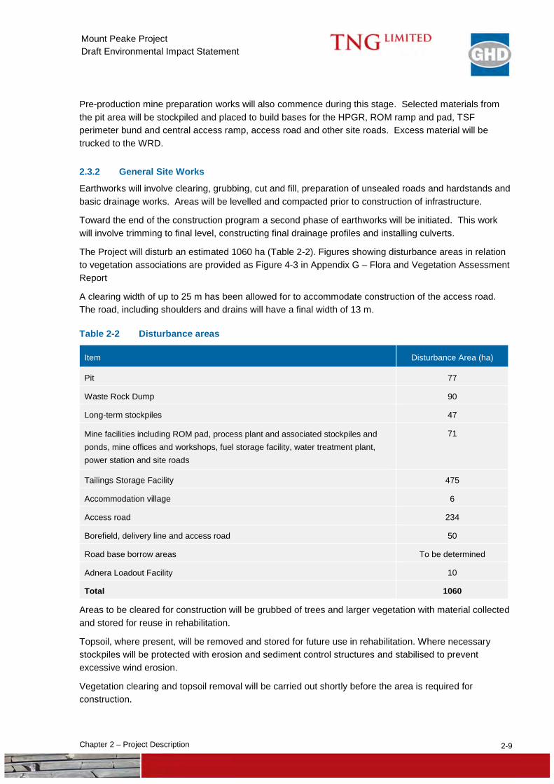
The Project will disturb an estimated 1060 ha (Table 2-2). Figures showing disturbance areas in relation to vegetation associations are provided as Figure 4-3 in Appendix G – Flora and Vegetation Assessment Report
A clearing width of up to 25 m has been allowed for to accommodate construction of the access road. The road, including shoulders and drains will have a final width of 13 m.
Table 2-2 Disturbance areas
Item Disturbance Area (ha)
Pit 77
Waste Rock Dump 90
Long-term stockpiles 47
Mine facilities including ROM pad, process plant and associated stockpiles and ponds, mine offices and workshops, fuel storage facility, water treatment plant, power station and site roads
71
Tailings Storage Facility 475
Accommodation village 6
Access road 234
Borefield, delivery line and access road 50
Road base borrow areas To be determined
Adnera Loadout Facility 10
Total 1060
Areas to be cleared for construction will be grubbed of trees and larger vegetation with material collected and stored for reuse in rehabilitation.
Topsoil, where present, will be removed and stored for future use in rehabilitation. Where necessary stockpiles will be protected with erosion and sediment control structures and stabilised to prevent excessive wind erosion.
Vegetation clearing and topsoil removal will be carried out shortly before the area is required for construction.
2-10 Chapter 2 – Project Description
Mount Peake Project Draft Environmental Impact Statement
2.3.3 Construction Materials
It is proposed to use up to 5 Mt of non-acid forming waste from pre-production for Project construction requirements (ROM Pad, construction pads, site roads, sedimentation ponds etc).
It is not expected that clay will be required at site.
Construction materials (steel, plate work, piping, cable, timber, cement, aggregate etc) will be trucked to site from Stuart Highway via the access road. Materials will be sourced locally where available
Transportation vehicles will be a combination of standard and oversize loads. It is estimated that up to 30 heavy vehicle deliveries will occur per day. Final trucking numbers will be established by contractors involved in the construction phase.
Larger plant and equipment that cannot be assembled on-site will be transported under appropriate permits.
Once the Adnera rail siding is established, some construction materials may be imported by rail.
Concrete will be supplied from an onsite batch plant.
Borrow pits will be established along the alignment of the access road to provide road base course and maintenance materials. The location and size of these borrow pits still needs to be determined. Alternatively road base could be imported to site.
2.3.4 Construction Equipment
Construction activities will use standard construction machinery, general trade equipment and specialised equipment including excavators, scrapers, front-end loaders, graders, cranes, water tankers, concrete trucks / pumps, dozers, dump trucks, forklifts, busses and light vehicles.
Fuel consumption during construction is estimated to be 3.5 megalitres (ML). Fuel will be delivered to site by tanker on a weekly basis and stored in self-bunded storage tanks.
2.3.5 Access Road
The access road connecting the mine site with the Adnera Loadout Facility will be approximately 100 km long and constructed with two 5 m traffic lanes with two 0.5 m shoulders. Table drains will be constructed adjacent to the road. The key steps in construction are:
establish borrow pits;
clear and grub vegetation and stockpile as required (to be used for remediation works);
cut to fill where necessary;
rip and scarify subgrade;
condition and compact subgrade material;
compaction testing;
place and compact 300 mm layer of 75 mm base course material;
final grade and trim of road surface and batters including cutting of drainage swale; and
installation of road furniture (signs, guide posts, etc.).
Several bores will be established along the access road to provide construction water.
2-11 Chapter 2 – Project Description
Mount Peake Project Draft Environmental Impact Statement
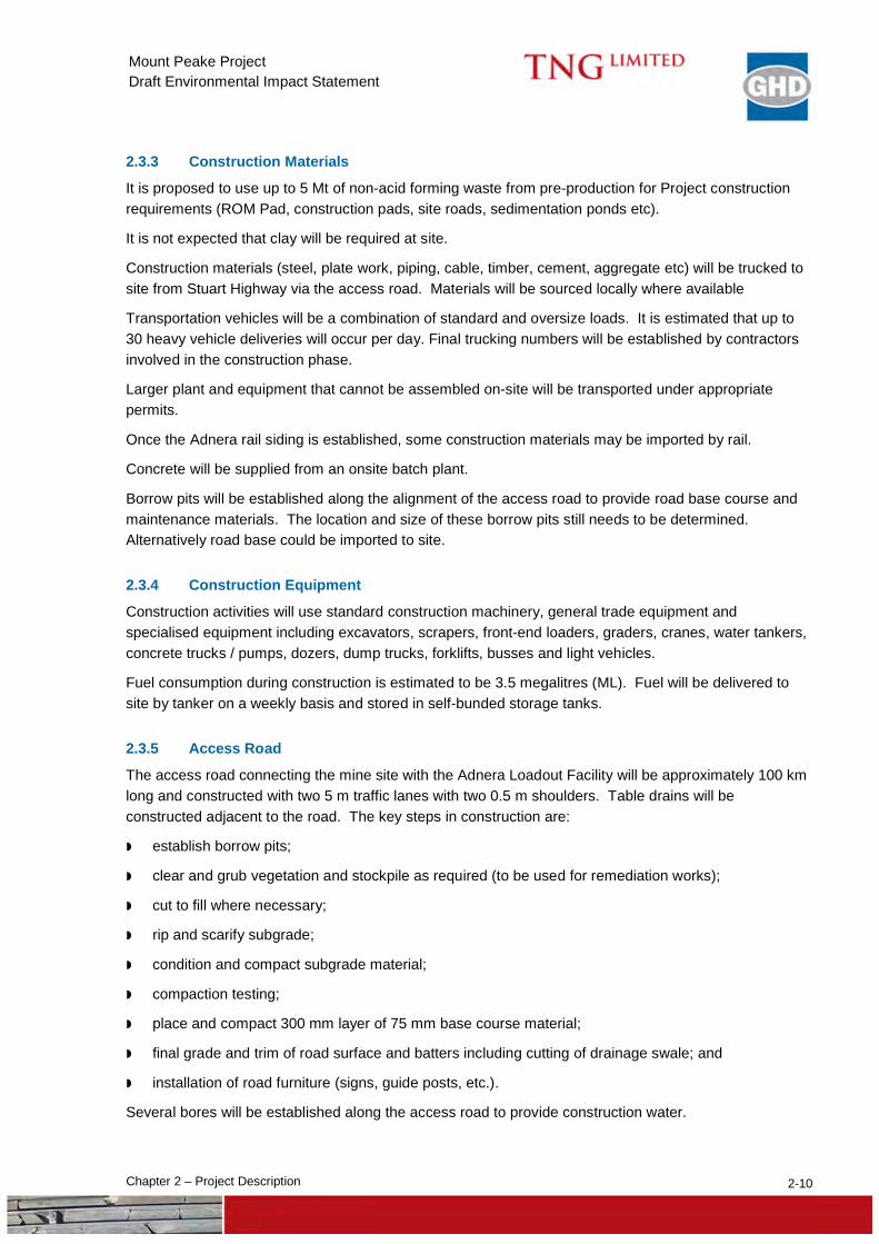
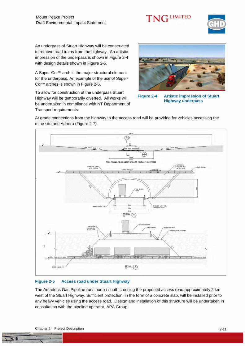
An underpass of Stuart Highway will be constructed to remove road trains from the highway. An artistic impression of the underpass is shown in Figure 2-4 with design details shown in Figure 2-5.
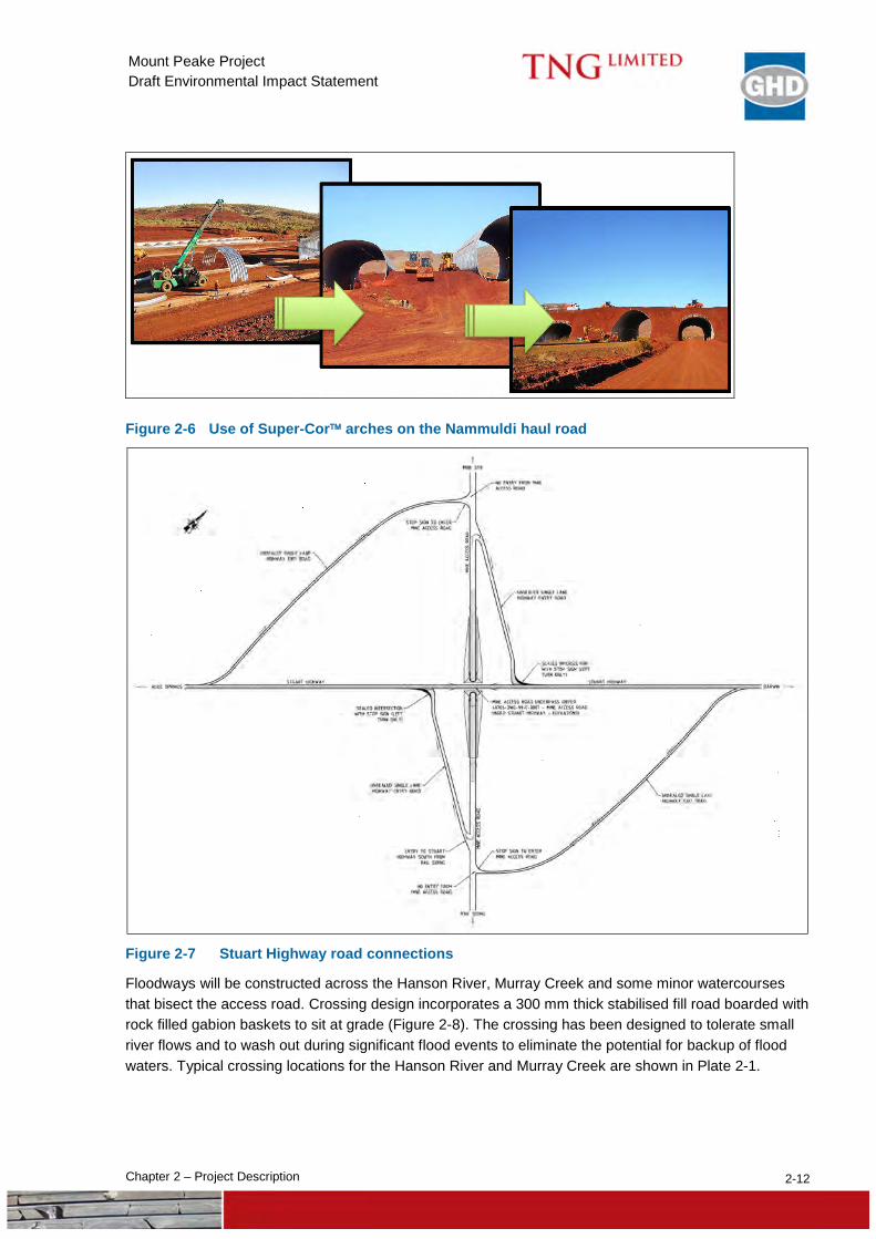
A Super-Cor arch is the major structural element for the underpass. An example of the use of Super-Cor arches is shown in Figure 2-6.
To allow for construction of the underpass Stuart Highway will be temporarily diverted. All works will be undertaken in compliance with NT Department of Transport requirements.
At grade connections from the highway to the access road will be provided for vehicles accessing the mine site and Adnera (Figure 2-7).
Figure 2-5 Access road under Stuart Highway
The Amadeus Gas Pipeline runs north / south crossing the proposed access road approximately 2 km west of the Stuart Highway. Sufficient protection, in the form of a concrete slab, will be installed prior to any heavy vehicles using the access road. Design and installation of this structure will be undertaken in consultation with the pipeline operator, APA Group.
Figure 2-4 Artistic impression of Stuart
Highway underpass
2-12 Chapter 2 – Project Description
Mount Peake Project Draft Environmental Impact Statement
Figure 2-6 Use of Super-Cor arches on the Nammuldi haul road
Figure 2-7 Stuart Highway road connections
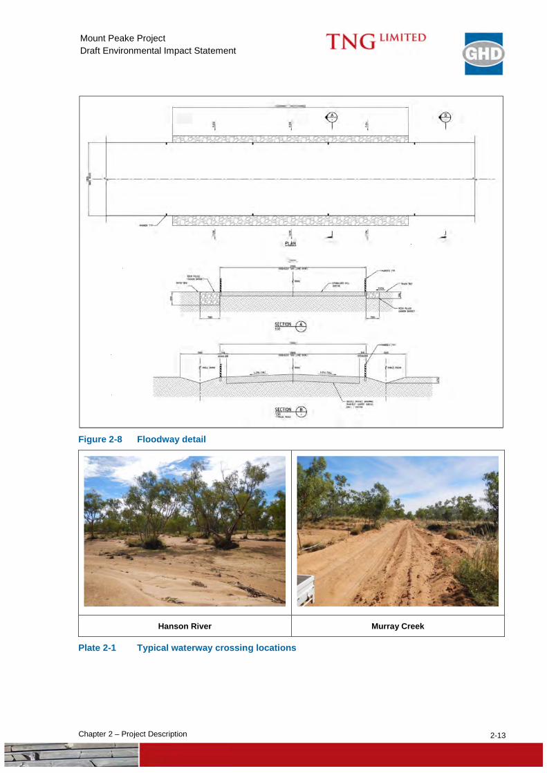
Floodways will be constructed across the Hanson River, Murray Creek and some minor watercourses that bisect the access road. Crossing design incorporates a 300 mm thick stabilised fill road boarded with rock filled gabion baskets to sit at grade (Figure 2-8). The crossing has been designed to tolerate small river flows and to wash out during significant flood events to eliminate the potential for backup of flood waters. Typical crossing locations for the Hanson River and Murray Creek are shown in Plate 2-1.
2-13 Chapter 2 – Project Description
Mount Peake Project Draft Environmental Impact Statement
Figure 2-8 Floodway detail
Hanson River Murray Creek
Plate 2-1 Typical waterway crossing locations
2-14 Chapter 2 – Project Description
Mount Peake Project Draft Environmental Impact Statement
2.4 Mining, Processing and Product Export
2.4.1 Mine Plan and Pit Development
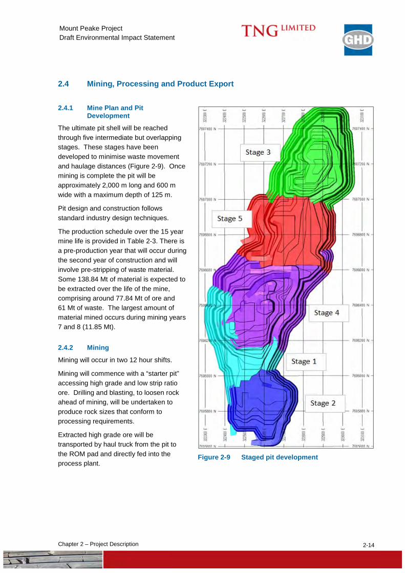
The ultimate pit shell will be reached through five intermediate but overlapping stages. These stages have been developed to minimise waste movement and haulage distances (Figure 2-9). Once mining is complete the pit will be approximately 2,000 m long and 600 m wide with a maximum depth of 125 m.
Pit design and construction follows standard industry design techniques.
The production schedule over the 15 year mine life is provided in Table 2-3. There is a pre-production year that will occur during the second year of construction and will involve pre-stripping of waste material. Some 138.84 Mt of material is expected to be extracted over the life of the mine, comprising around 77.84 Mt of ore and 61 Mt of waste. The largest amount of material mined occurs during mining years 7 and 8 (11.85 Mt).
2.4.2 Mining
Mining will occur in two 12 hour shifts.
Mining will commence with a “starter pit” accessing high grade and low strip ratio ore. Drilling and blasting, to loosen rock ahead of mining, will be undertaken to produce rock sizes that conform to processing requirements.
Extracted high grade ore will be transported by haul truck from the pit to the ROM pad and directly fed into the process plant.
Figure 2-9 Staged pit development
2-15 Chapter 2 – Project Description
Mount Peake Project Draft Environmental Impact Statement
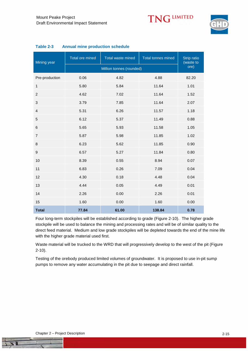
Table 2-3 Annual mine production schedule
Mining year Total ore mined Total waste mined Total tonnes mined Strip ratio
(waste to ore) Million tonnes (rounded)
Pre-production 0.06 4.82 4.88 82.20
1 5.80 5.84 11.64 1.01
2 4.62 7.02 11.64 1.52
3 3.79 7.85 11.64 2.07
4 5.31 6.26 11.57 1.18
5 6.12 5.37 11.49 0.88
6 5.65 5.93 11.58 1.05
7 5.87 5.98 11.85 1.02
8 6.23 5.62 11.85 0.90
9 6.57 5.27 11.84 0.80
10 8.39 0.55 8.94 0.07
11 6.83 0.26 7.09 0.04
12 4.30 0.18 4.48 0.04
13 4.44 0.05 4.49 0.01
14 2.26 0.00 2.26 0.01
15 1.60 0.00 1.60 0.00
Total 77.84 61.00 138.84 0.78
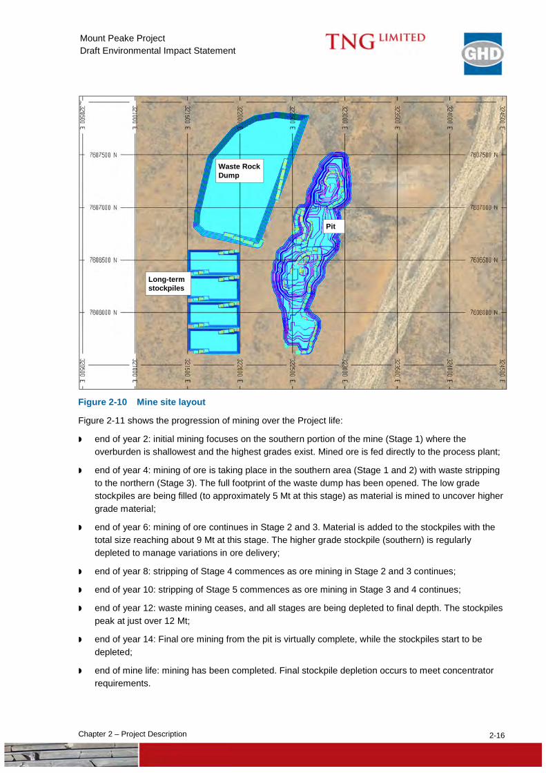
Four long-term stockpiles will be established according to grade (Figure 2-10). The higher grade stockpile will be used to balance the mining and processing rates and will be of similar quality to the direct feed material. Medium and low grade stockpiles will be depleted towards the end of the mine life with the higher grade material used first.
Waste material will be trucked to the WRD that will progressively develop to the west of the pit (Figure 2-10).
Testing of the orebody produced limited volumes of groundwater. It is proposed to use in-pit sump pumps to remove any water accumulating in the pit due to seepage and direct rainfall.
2-16 Chapter 2 – Project Description
Mount Peake Project Draft Environmental Impact Statement
Figure 2-10 Mine site layout
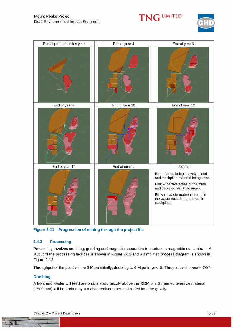
Figure 2-11 shows the progression of mining over the Project life:
end of year 2: initial mining focuses on the southern portion of the mine (Stage 1) where the overburden is shallowest and the highest grades exist. Mined ore is fed directly to the process plant;
end of year 4: mining of ore is taking place in the southern area (Stage 1 and 2) with waste stripping to the northern (Stage 3). The full footprint of the waste dump has been opened. The low grade stockpiles are being filled (to approximately 5 Mt at this stage) as material is mined to uncover higher grade material;
end of year 6: mining of ore continues in Stage 2 and 3. Material is added to the stockpiles with the total size reaching about 9 Mt at this stage. The higher grade stockpile (southern) is regularly depleted to manage variations in ore delivery;
end of year 8: stripping of Stage 4 commences as ore mining in Stage 2 and 3 continues;
end of year 10: stripping of Stage 5 commences as ore mining in Stage 3 and 4 continues;
end of year 12: waste mining ceases, and all stages are being depleted to final depth. The stockpiles peak at just over 12 Mt;
end of year 14: Final ore mining from the pit is virtually complete, while the stockpiles start to be depleted;
end of mine life: mining has been completed. Final stockpile depletion occurs to meet concentrator requirements.
Waste Rock Dump
Long-term stockpiles
Pit
2-17 Chapter 2 – Project Description
Mount Peake Project Draft Environmental Impact Statement
End of pre-production year End of year 4 End of year 6
End of year 8 End of year 10 End of year 12
End of year 14 End of mining Legend
Red – areas being actively mined and stockpiled material being used.
Pink – inactive areas of the mine and depleted stockpile areas.
Brown – waste material stored in the waste rock dump and ore in stockpiles.
Figure 2-11 Progression of mining through the project life
2.4.3 Processing
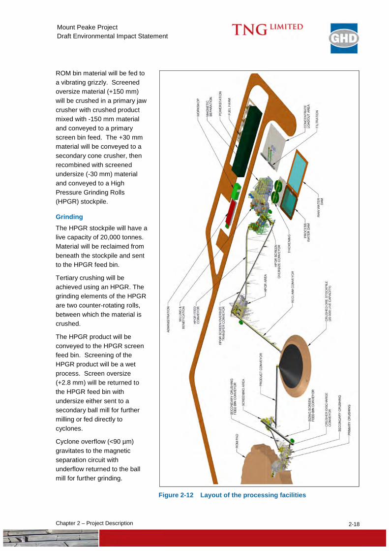
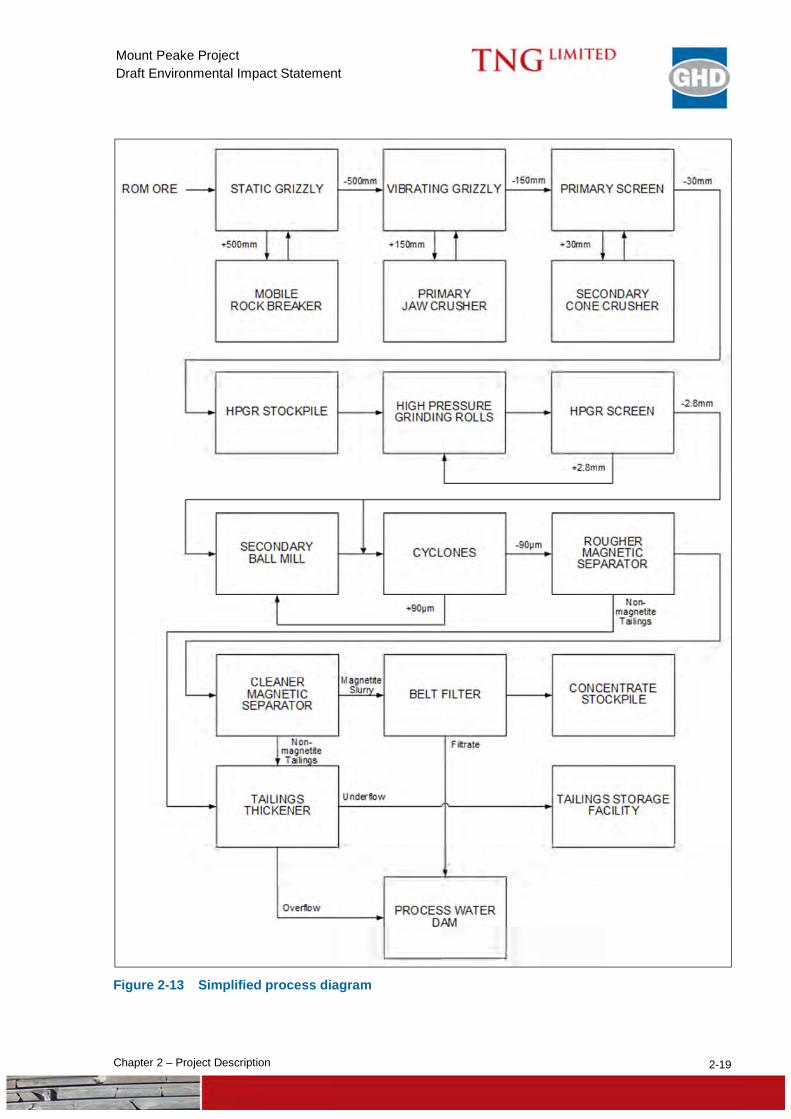
Processing involves crushing, grinding and magnetic separation to produce a magnetite concentrate. A layout of the processing facilities is shown in Figure 2-12 and a simplified process diagram is shown in Figure 2-13.
Throughput of the plant will be 3 Mtpa initially, doubling to 6 Mtpa in year 5. The plant will operate 24/7.
Crushing A front end loader will feed ore onto a static grizzly above the ROM bin. Screened oversize material (+500 mm) will be broken by a mobile rock crusher and re-fed into the grizzly.
2-18 Chapter 2 – Project Description
Mount Peake Project Draft Environmental Impact Statement
ROM bin material will be fed to a vibrating grizzly. Screened oversize material (+150 mm) will be crushed in a primary jaw crusher with crushed product mixed with -150 mm material and conveyed to a primary screen bin feed. The +30 mm material will be conveyed to a secondary cone crusher, then recombined with screened undersize (-30 mm) material and conveyed to a High Pressure Grinding Rolls (HPGR) stockpile.
Grinding The HPGR stockpile will have a live capacity of 20,000 tonnes. Material will be reclaimed from beneath the stockpile and sent to the HPGR feed bin.
Tertiary crushing will be achieved using an HPGR. The grinding elements of the HPGR are two counter-rotating rolls, between which the material is crushed.
The HPGR product will be conveyed to the HPGR screen feed bin. Screening of the HPGR product will be a wet process. Screen oversize (+2.8 mm) will be returned to the HPGR feed bin with undersize either sent to a secondary ball mill for further milling or fed directly to cyclones.
Cyclone overflow (<90 µm) gravitates to the magnetic separation circuit with underflow returned to the ball mill for further grinding.
Figure 2-12 Layout of the processing facilities
2-19 Chapter 2 – Project Description
Mount Peake Project Draft Environmental Impact Statement
Figure 2-13 Simplified process diagram
2-20 Chapter 2 – Project Description
Mount Peake Project Draft Environmental Impact Statement
Magnetic separation Cyclone overflow gravitates to a bank of Rougher Magnetic Separators (RMS) to remove entrained highly magnetic material (magnetite).
RMS concentrate then gravitates to bank of Cleaner Magnetic Separators (CMS) to increase the final concentrate grade. The CMS concentrate gravitates into the Magnetite stock feed tank.
Non-magnetic tailings streams will be pumped to a tailings thickener where the solids density is increased to approximately 65%. Overflow from the thickener will gravitate to the process water dam whilst underflow will be pumped to the TSF.
Magnetite concentration The magnetite slurry is filtered to achieve a moisture content of 10% w/w which is required to minimise transport costs. Filter cake is then stockpiled in a concentrate storage area.
2.4.4 Product Transfer
Concentrate will be loaded into trucks using a front end loader. A concentrate weighbridge will record the tonnage that is trucked off site.
The concentrate will be trucked via the access road to a new rail siding and loadout facility at Adnera. Trucks will be triple side tippers with 140 tonne capacity. Loads will be covered to prevent dust generation and product loss. Up to 50 loads of concentrate will be delivered to Adnera per day (up to 100 return truck movements or four per hour).
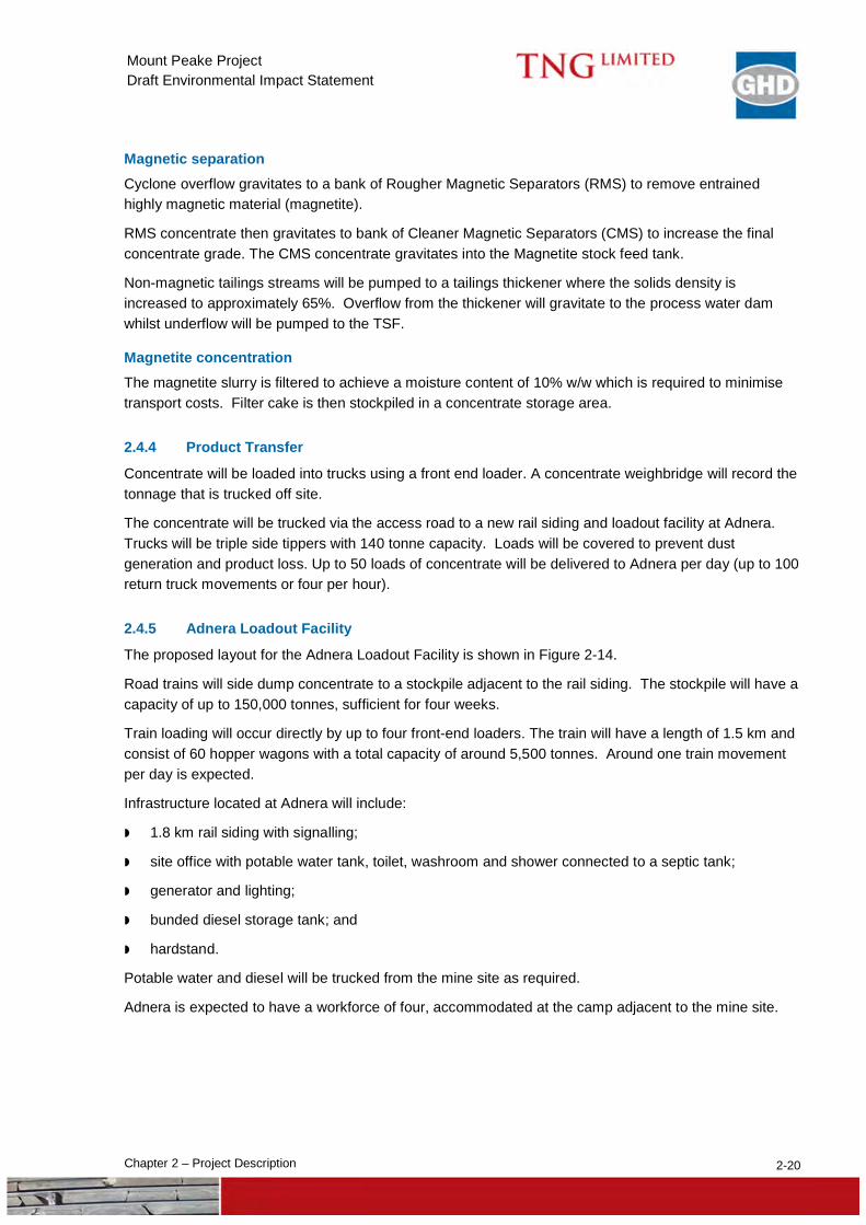
2.4.5 Adnera Loadout Facility
The proposed layout for the Adnera Loadout Facility is shown in Figure 2-14.
Road trains will side dump concentrate to a stockpile adjacent to the rail siding. The stockpile will have a capacity of up to 150,000 tonnes, sufficient for four weeks.
Train loading will occur directly by up to four front-end loaders. The train will have a length of 1.5 km and consist of 60 hopper wagons with a total capacity of around 5,500 tonnes. Around one train movement per day is expected.
Infrastructure located at Adnera will include:
1.8 km rail siding with signalling;
site office with potable water tank, toilet, washroom and shower connected to a septic tank;
generator and lighting;
bunded diesel storage tank; and
hardstand.
Potable water and diesel will be trucked from the mine site as required.
Adnera is expected to have a workforce of four, accommodated at the camp adjacent to the mine site.
2-21 Chapter 2 – Project Description
Mount Peake Project Draft Environmental Impact Statement
Figure 2-14 Adnera loadout facility
2.4.6 Reagents and Consumables
Reagents and consumables expected to be used at Mount Peake include:
Nalco 83372 (or similar) as a flocculant in the process plant – 300 tpa;
sodium hypochlorite (or similar) for disinfection in the water treatment plant – 5 tpa;
antiscalent for use in the water treatment plant – 1 tpa;
primary and secondary mill balls – 15,000 units; and
operating consumables associated with wear in the apron feeders, vibrating grizzly, crushing circuit, crusher screens, HPGR screens and HPGR liners.
Reagents and consumables will be delivered by truck. It is estimated that up to four deliveries per day will occur.
2.4.7 Site Vehicle
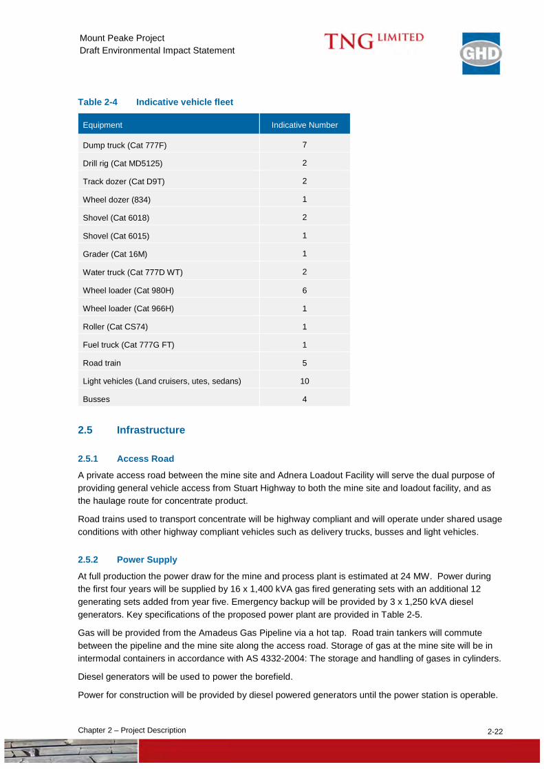
Vehicles at Mount Peake will undertake a variety of functions including mining, stockpile management, plant feeding, road maintenance, dust suppression, general personnel movement etc. The expected vehicle fleet is provided in Table 2-4.
2-22 Chapter 2 – Project Description
Mount Peake Project Draft Environmental Impact Statement
Table 2-4 Indicative vehicle fleet
Equipment Indicative Number
Dump truck (Cat 777F) 7
Drill rig (Cat MD5125) 2
Track dozer (Cat D9T) 2
Wheel dozer (834) 1
Shovel (Cat 6018) 2
Shovel (Cat 6015) 1
Grader (Cat 16M) 1
Water truck (Cat 777D WT) 2
Wheel loader (Cat 980H) 6
Wheel loader (Cat 966H) 1
Roller (Cat CS74) 1
Fuel truck (Cat 777G FT) 1
Road train 5
Light vehicles (Land cruisers, utes, sedans) 10
Busses 4
2.5 Infrastructure
2.5.1 Access Road
A private access road between the mine site and Adnera Loadout Facility will serve the dual purpose of providing general vehicle access from Stuart Highway to both the mine site and loadout facility, and as the haulage route for concentrate product.
Road trains used to transport concentrate will be highway compliant and will operate under shared usage conditions with other highway compliant vehicles such as delivery trucks, busses and light vehicles.
2.5.2 Power Supply
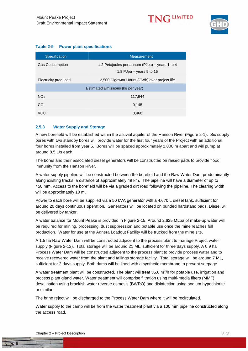
At full production the power draw for the mine and process plant is estimated at 24 MW. Power during the first four years will be supplied by 16 x 1,400 kVA gas fired generating sets with an additional 12 generating sets added from year five. Emergency backup will be provided by 3 x 1,250 kVA diesel generators. Key specifications of the proposed power plant are provided in Table 2-5.
Gas will be provided from the Amadeus Gas Pipeline via a hot tap. Road train tankers will commute between the pipeline and the mine site along the access road. Storage of gas at the mine site will be in intermodal containers in accordance with AS 4332-2004: The storage and handling of gases in cylinders.
Diesel generators will be used to power the borefield.
Power for construction will be provided by diesel powered generators until the power station is operable.
2-23 Chapter 2 – Project Description
Mount Peake Project Draft Environmental Impact Statement
Table 2-5 Power plant specifications
Specification Measurement
Gas Consumption 1.2 Petajoules per annum (PJpa) – years 1 to 4
1.8 PJpa – years 5 to 15
Electricity produced 2,500 Gigawatt Hours (GWh) over project life
Estimated Emissions (kg per year)
NOX 117,944
CO 9,145
VOC 3,468
2.5.3 Water Supply and Storage
A new borefield will be established within the alluvial aquifer of the Hanson River (Figure 2-1). Six supply bores with two standby bores will provide water for the first four years of the Project with an additional four bores installed from year 5. Bores will be spaced approximately 1,800 m apart and will pump at around 8.5 L/s each.
The bores and their associated diesel generators will be constructed on raised pads to provide flood immunity from the Hanson River.
A water supply pipeline will be constructed between the borefield and the Raw Water Dam predominantly along existing tracks, a distance of approximately 49 km. The pipeline will have a diameter of up to 450 mm. Access to the borefield will be via a graded dirt road following the pipeline. The clearing width will be approximately 10 m.
Power to each bore will be supplied via a 50 kVA generator with a 4,670 L diesel tank, sufficient for around 20 days continuous operation. Generators will be located on bunded hardstand pads. Diesel will be delivered by tanker.
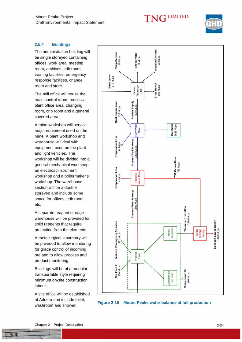
A water balance for Mount Peake is provided in Figure 2-15. Around 2,625 MLpa of make-up water will be required for mining, processing, dust suppression and potable use once the mine reaches full production. Water for use at the Adnera Loadout Facility will be trucked from the mine site.
A 1.5 ha Raw Water Dam will be constructed adjacent to the process plant to manage Project water supply (Figure 2-12). Total storage will be around 21 ML, sufficient for three days supply. A 0.9 ha Process Water Dam will be constructed adjacent to the process plant to provide process water and to receive recovered water from the plant and tailings storage facility. Total storage will be around 7 ML, sufficient for 2 days supply. Both dams will be lined with a synthetic membrane to prevent seepage.
A water treatment plant will be constructed. The plant will treat 35.6 m3/h for potable use, irrigation and process plant gland water. Water treatment will comprise filtration using multi-media filters (MMF), desalination using brackish water reverse osmosis (BWRO) and disinfection using sodium hypochlorite or similar.
The brine reject will be discharged to the Process Water Dam where it will be recirculated.
Water supply to the camp will be from the water treatment plant via a 100 mm pipeline constructed along the access road.
2-24 Chapter 2 – Project Description
Mount Peake Project Draft Environmental Impact Statement
2.5.4 Buildings
The administration building will be single storeyed containing offices, work area, meeting room, archives, crib room, training facilities, emergency response facilities, change room and store.
The mill office will house the main control room, process plant office area, changing room, crib room and a general covered area.
A mine workshop will service major equipment used on the mine. A plant workshop and warehouse will deal with equipment used on the plant and light vehicles. The workshop will be divided into a general mechanical workshop, an electrical/instrument workshop and a boilermaker’s workshop. The warehouse section will be a double storeyed and include some space for offices, crib room, etc.
A separate reagent storage warehouse will be provided for solid reagents that require protection from the elements.
A metallurgical laboratory will be provided to allow monitoring for grade control of incoming ore and to allow process and product monitoring.
Buildings will be of a modular transportable style requiring minimum on-site construction labour.
A site office will be established at Adnera and include toilet, washroom and shower.
Figure 2-15 Mount Peake water balance at full production
Proc
ess
Tank
Mak
eup
TSF
Ret
urn
Flow
Proc
ess
Wat
er M
akeu
pPr
oces
s W
ater
Dam
Raw
Wat
er
Dam
Pota
ble
Supp
lyW
ater
Tr
eatm
ent
Plan
t
Seep
age
& E
vapo
ratio
n
Mak
eup
Con
tinge
ncy
& L
osse
sEv
apor
atio
n Lo
ssEv
apor
atio
n Lo
ss17
5 M
Lpa
Gla
nd W
ater
3 M
Lpa
Dus
t Sup
pres
sion
Cam
p D
eman
d20
6 M
Lpa
271
MLp
a4
MLp
a14
MLp
a43
8 M
Lpa
16 M
Lpa
Proc
ess
Plan
t
Ore
Fee
d In
2605
MLp
a18
53 M
Lpa
320
MLp
aSi
te D
eman
d
Con
cent
rate
Be
lt Fi
lter
Tailin
gs
Thic
kene
rB
oref
ield
26
25 M
Lpa
Brin
e R
ejec
tIrr
igat
ion
Dem
and
105
MLp
a20
MLp
a
756
MLp
a
Con
cent
rate
Out
Thic
kene
r Und
erflo
w19
6 M
Lpa
2519
MLp
a
Tailin
gs
Sto
rage
Fa
cilit
y
1763
MLp
a
2-25 Chapter 2 – Project Description
Mount Peake Project Draft Environmental Impact Statement
2.5.5 Sewage
Two pump stations will be installed to collect sewage and wastewater for treatment in a Sewage Treatment Plant. One station will service the mine site with a second station servicing the accommodation village.
Treated waste water will be used around the site for landscaping purposes.
The untreatable solids will be collected and disposed of offsite by a licensed waste transporter.
Sewage at the Adnera Loadout Facility will be treated by septic tank and leach drains.
2.5.6 Communications
A line of microwave repeater stations runs between Alice Springs and Tennant Creek, approximately 50 km from the mine site. It is planned to establish a repeater station on-site to tie into this network in combination with a two way satellite system to meet all site communications demands.
A two way radio network will be used for operational communications on site.
2.5.7 Chemical and Hydrocarbon Storage
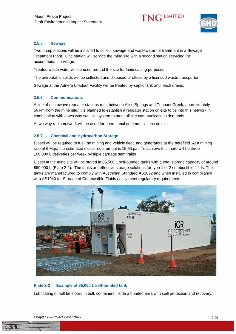
Diesel will be required to fuel the mining and vehicle fleet, and generators at the borefield. At a mining rate of 6 Mtpa the estimated diesel requirement is 15 MLpa. To achieve this there will be three 100,000 L deliveries per week by triple carriage semitrailer.
Diesel at the mine site will be stored in 85,500 L self-bunded tanks with a total storage capacity of around 850,000 L (Plate 2-2). The tanks are effective storage solutions for type 1 or 2 combustible fluids. The tanks are manufactured to comply with Australian Standard AS1692 and when installed in compliance with AS1940 for Storage of Combustible Fluids easily meet regulatory requirements.
Plate 2-2 Example of 85,000 L self-bunded tank
Lubricating oil will be stored in bulk containers inside a bunded area with spill protection and recovery.
2-26 Chapter 2 – Project Description
Mount Peake Project Draft Environmental Impact Statement
Waste hydrocarbons will be stored in a tank within a bunded area to be held for collection by a contractor for reprocessing and recycling.
The Project will not use any hazardous chemicals that require special storage and handling.
2.5.8 Explosives Magazine
A total of 24,000 tonnes of explosives is estimated to be required over the life of mine peaking at 2,200 tpa. Around 55% of the explosive required is emulsion for use in fresh material with the balance being ammonium nitrate / fuel oil.
Explosives will be stored in a dedicated magazine.
2.5.9 Ti Tree Airstrip
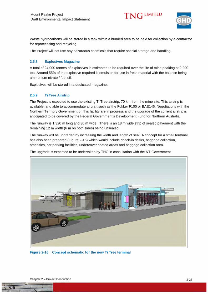
The Project is expected to use the existing Ti Tree airstrip, 70 km from the mine site. This airstrip is available, and able to accommodate aircraft such as the Fokker F100 or BAE146. Negotiations with the Northern Territory Government on this facility are in progress and the upgrade of the current airstrip is anticipated to be covered by the Federal Government’s Development Fund for Northern Australia.
The runway is 1,320 m long and 30 m wide. There is an 18 m wide strip of sealed pavement with the remaining 12 m width (6 m on both sides) being unsealed.
The runway will be upgraded by increasing the width and length of seal. A concept for a small terminal has also been prepared (Figure 2-16) which would include check-in desks, baggage collection, amenities, car parking facilities, undercover seated areas and baggage collection area.
The upgrade is expected to be undertaken by TNG in consultation with the NT Government.
Figure 2-16 Concept schematic for the new Ti Tree terminal
2-27 Chapter 2 – Project Description
Mount Peake Project Draft Environmental Impact Statement
2.6 Workforce and Accommodation
2.6.1 Workforce
The construction and operations workforces are estimated to peak at 225 and 170 personnel respectively.
The workforces will be largely fly-in fly-out due to low population numbers in the local area.
Workers will fly to Ti Tree and then bus to the accommodation village for the duration of their roster. Peak workforce transport will occur in the morning and evenings at the beginning and end of the rosters.
Construction workforce traffic is expected to peak at six return bus trips and 30 light vehicle trips per day with operation workforce traffic expected to peak at five return bus trips and 20 light vehicle trips per day.
The workforce will comprise personnel typical of this type of mine and include mine manager, pit supervisor, site administration officers, plant operators (excavators, trucks, dozers, graders, water carts, front-end loaders), drillers, environmental staff and maintenance personnel. Environmental staff will comprise a tertiary qualified environmental manager and 2 to 3 support personnel including aboriginal rangers.
2.6.2 Accommodation
The accommodation village will be established within the new camp Ancillary Lease to the east of the mine site (Figure 2-2) to facilitate ease of access to the operation and crew rotations to and from the site. An adequate distance between the village and operations has been allowed for to minimise the exposure to site noise, vibration and dust emissions.
An initial 40 person “fly camp“ will be established to allow for early construction works. This will consist of separate 4 room en-suited accommodation units together with kitchen / diner, laundry units, wet mess, and office / administration building.
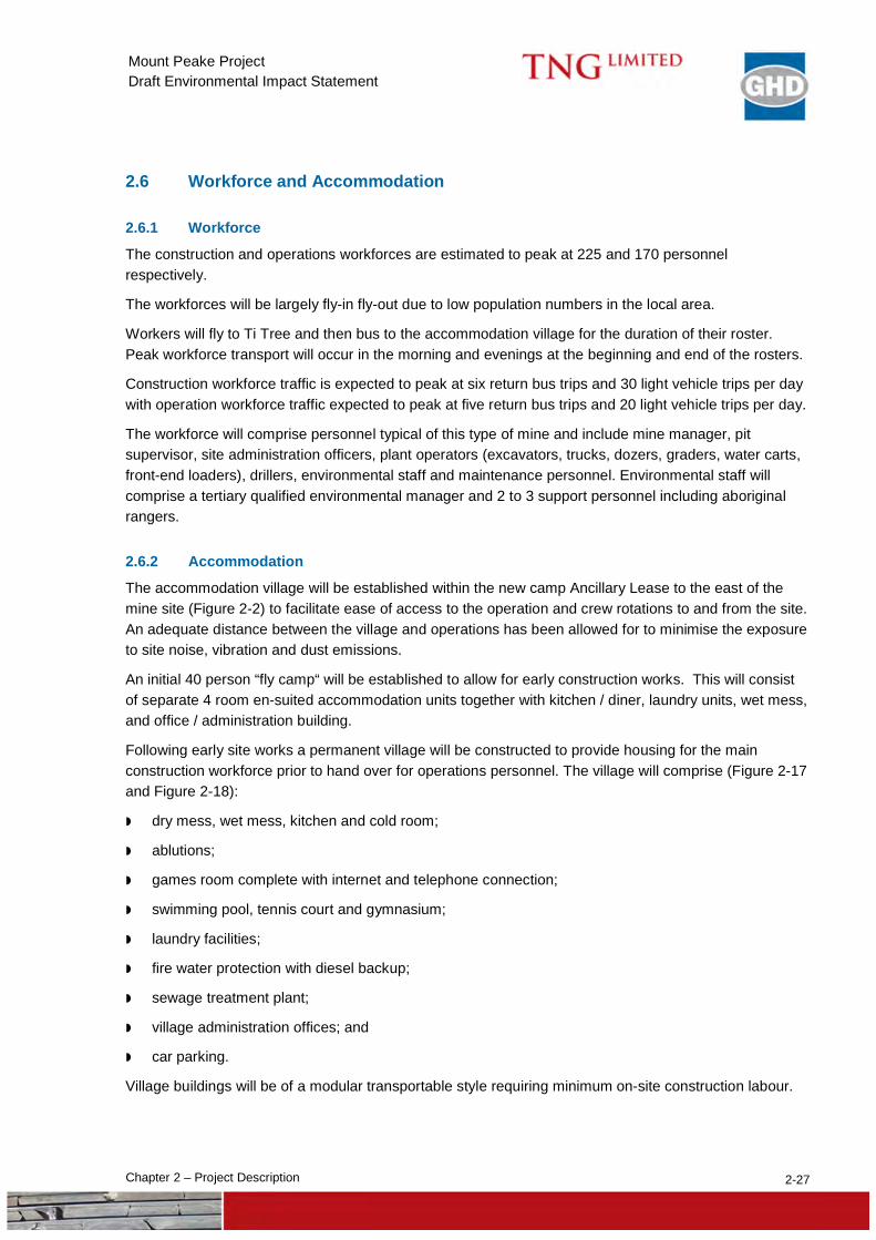
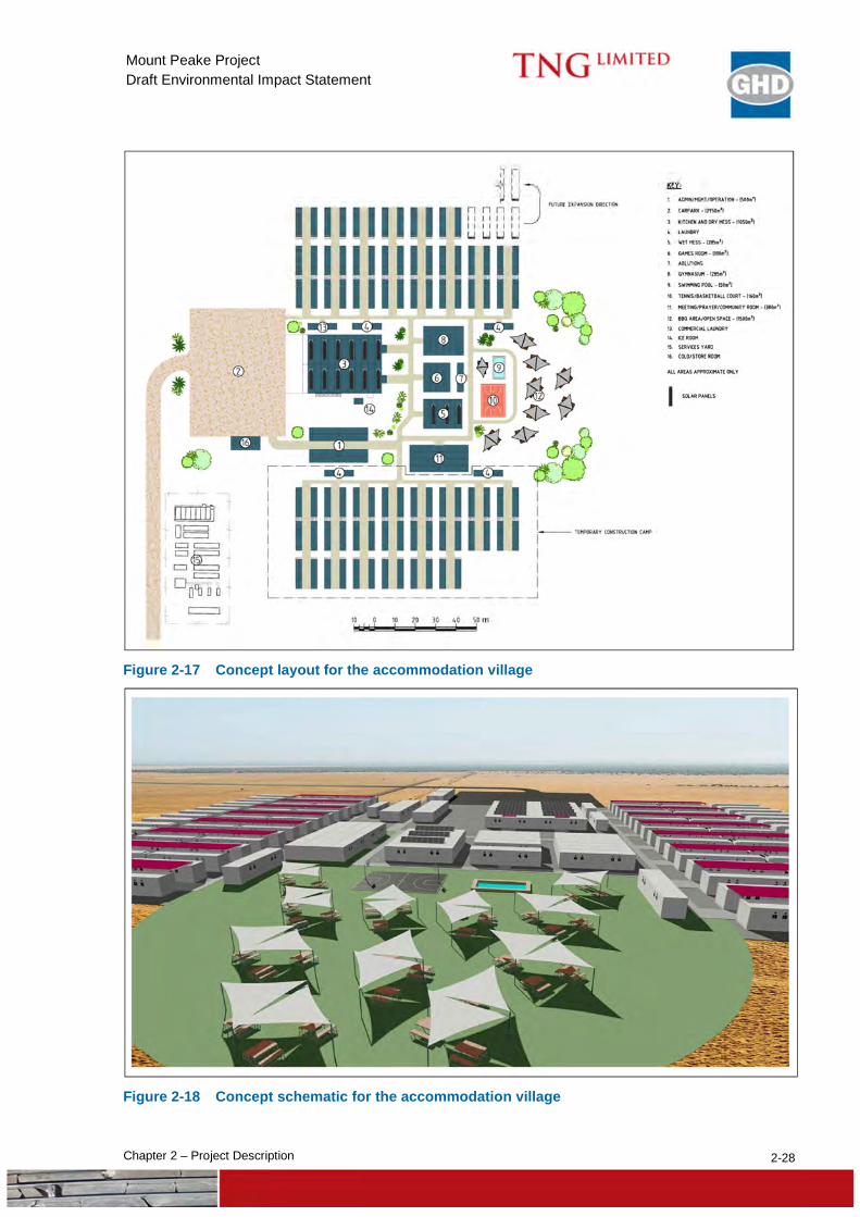
Following early site works a permanent village will be constructed to provide housing for the main construction workforce prior to hand over for operations personnel. The village will comprise (Figure 2-17 and Figure 2-18):
dry mess, wet mess, kitchen and cold room;
ablutions;
games room complete with internet and telephone connection;
swimming pool, tennis court and gymnasium;
laundry facilities;
fire water protection with diesel backup;
sewage treatment plant;
village administration offices; and
car parking.
Village buildings will be of a modular transportable style requiring minimum on-site construction labour.
2-28 Chapter 2 – Project Description
Mount Peake Project Draft Environmental Impact Statement
Figure 2-17 Concept layout for the accommodation village
Figure 2-18 Concept schematic for the accommodation village
2-29 Chapter 2 – Project Description
Mount Peake Project Draft Environmental Impact Statement
2.7 Waste Management
2.7.1 Waste Rock Dump
Ore and Waste Rock Characterisation The Mineral Resource is hosted by a mafic intrusive rock, a gabbro sill, up to 250 m thick with gabbro rocks both below and above the ore zones. The orebody comprises the magnetite-rich portion of the sill, which forms a flat-lying body oriented north/south. All of the intrusive is oxidised so there is no magmatic sulphide within this material. What sulphide is seen in the ore/intrusive was introduced by hydrothermal fluids within structural zones. The intrusive has only minor alteration and structural disruption and very little sulphides. Other rock types that will contribute to the waste dump also have a low sulphide content.
Mining will involve movement of a moderate amount of waste, both from above (surface overburden “pre-strip”) and adjacent to the ore material. A significant component (ca. 30%) of the overburden material is aeolian sand and colluvial/alluvial sediment. All of this material is weathered, as it formed at surface under strongly oxidising conditions, and so will not contain significant sulphides. Un-mineralised gabbro comprises a significant component (>30%) of the waste rock, which is either weathered or fresh. All of this material contains some magnetite indicating oxidising conditions for the intrusive magma and hence no significant sulphide is present. Adjacent to the orebody some of the waste material to be removed comprises granite (10 - 20%) from along the western wall of the pit, which has a low sulphide content.
Geological logging of all drilling on the resource has only rarely encountered visible sulphides. Rarely do they comprise more than a few percent of the sample over a few metres. Generally the sulphides seen are associated with structural zones and faults/fractures. The majority of fracture zones are less than one metre thick, irregularly developed, and not able to be correlated between holes. The only significant fault (both width and extent) follows the western side of the gabbro body and will dip into the western pit wall.
An Acid Mine Drainage (AMD) assessment was undertaken on a comprehensive dataset of XRF data obtained during various drilling and targeted waste sampling programs (Appendix O). The combined dataset included over 6000 samples within and immediately surrounding the pit shell. Geochemical relationships were formulated from the data to build an understanding of the AMD risk at Mount Peake. The approach was based on industry guidelines (DITR 2007, INAP 2009).
The assessment confirmed that sulfur concentrations are generally low and not widespread. 99.35% of the samples analysed for sulfur returned values of below 0.3% total sulfur. This equates to 99.35% of the samples having a Maximum Potential Acidity (MPA) of less than 10 kg of H2SO4 per tonne. This assumes that all sulfur is present as reactive pyrite and it is therefore an inherently conservative assessment as it discounts non-acid forming sulfur species or any inherent neutralising capacity.
The Acid Neutralising Capacity (ANC) was found to be relatively high indicating that any acid forming waste would likely to be neutralised. From the Maximum Potential Acidity and the Acid Neutralising Capacity, the Net Acid Producing Potential (NAPP) was calculated for each lithological unit. This indicated that approximately 99.7% of the samples had a NAPP value of less than 10 kg of H2SO4 per tonne indicating the material is largely Non-acid Forming (NAF).
Although the geochemistry indicates a low risk of AMD, a management plan was developed to take into consideration the highest AMD risk material observed. The key aspect of the management plan is early identification of Potentially Acid Forming (PAF) material through additional analyses and ongoing monitoring. The results of these tests will be reviewed to develop a revised potential acidity assessment of the ore and waste. In addition to pre-production testing, a program of regular testing as part of ongoing grade control and regular updating of the AMD model will be undertaken.
2-30 Chapter 2 – Project Description
Mount Peake Project Draft Environmental Impact Statement
No sources of radiation have been identified from the ore body or waste material.
Waste Rock Dump A WRD will be constructed to contain waste rock from mining operations. The dump will have an ultimate height of 40 m and a footprint of 90 ha with capacity to store up to 70 Mt of waste (Figure 2-10). It is proposed to use up to 5 Mt of non-acid forming waste from pre-production for Project construction requirements.
The parameters used for waste dump design are:
batter height: 10 m;
ramp width: 27 m; and
ramp gradient: 1 in 10.
There are no specific strategies to manage waste placement in the dump as the waste rock is benign.
Stormwater drainage, erosion and sediment controls will be designed and constructed to minimise erosion and channel scour. A concept is presented in the Drainage, Erosion and Sediment Control Plan (Appendix N). Stormwater collected on dump benches will be conveyed to a sedimentation basin on the toe of the WRD through engineered channels located on the benches. After settling of any sediment load, water will be either used around the site, for example in dust suppression, or allowed to discharge to natural drainage lines.
2.7.2 Tailings Storage Facility
The TSF will be located west of the process plant (Figure 2-2).
Tailings will be produced following the magnetic separation of the crushed and screened ore and will consist of non-magnetic silts and sands. Geochemical characterisation of ore and waste samples show a very low percentage of sulphur within the ore body and AMD is not expected to be an issue. No chemical process is required in the beneficiation plant. Therefore, the tailings solids are considered to be chemically stable and will not contain any contaminants.
Central Thickened Discharge (CTD) was selected as the preferred method for tailings disposal based on balancing water recovery, environmental risk, the relatively flat nature of the site, ease of closure, and construction and operating costs.
The tailings disposal system comprises:
cone tailings thickener;
tailings pumps;
tailings delivery pipeline;
access ramp to a central discharge area;
perimeter earth-filled embankment;
surface water drainage and seepage recovery systems;
recovery water pond;
emergency spillway; and
monitoring wells.
2-31 Chapter 2 – Project Description
Mount Peake Project Draft Environmental Impact Statement
The initial processing rate of 3 Mtpa will be doubled to 6 Mtpa from year five. The tailings thickener and the tailings discharge system will be duplicated in line with the duplication of the process plant.
The key parameters of the TSF are:
height of the CTD cone: 32 m;
CTD cone slope: 3%;
diameter of the CTD cone: 2,134 m;
active TSF footprint area: 357 ha; and
TSF storage capacity: 63.41 Mt (38.13 Mm3).
The various components of the tailings disposal system are described below.
Tailings thickening The tailings streams from the process plant will be combined in a tailings thickener where flocculant will be added to settle the fine solids. Thickener underflow, with a solids content of 65%, will be pumped to the TSF with overflow reused within the process plant.
Tailings deposition Thickened tailings will be pumped from the thickener to a central discharge area along the access ramp through an approximately 1.5 km long main delivery pipeline.
The access ramp is an earth fill structure constructed initially using mine pre-strip and overburden material and later on using mine waste.
The ramp embankment connects the perimeter wall with the central deposition area and will be constructed in stages. The first section of the ramp will be horizontal and it will change to a 3% slope to reach the Stage 1 deposition platform, 14 m above natural ground level. In later stages, the sloping section of the access ramp will be progressively raised by centreline construction according to the staged development schedule (Table 2-6).
Table 2-6 Staged development of TSF
Stage Cone height (m) Cone radius (m) Cumulative cone volume (Mm3)
1 14 467 3.19
2 18 600 6.79
3 22 733 12.39
4 25 833 18.18
5 28 933 25.54
6 30 1,000 31.42
7 32 1,067 38.13
Tailings deposition will be via outlet spigots placed around the perimeter of the central discharge area. The spigots will open and close progressively to form an even beach that will allow effective draining and drying of the tailings. Discharged tailings will form a cone shape tailings beach creating a roughly circular storage area.
2-32 Chapter 2 – Project Description
Mount Peake Project Draft Environmental Impact Statement
In addition to the main delivery pipeline, an emergency pipeline will be installed with a single discharge point. This pipeline will run from the thickener to a discharge point close to the perimeter embankment.
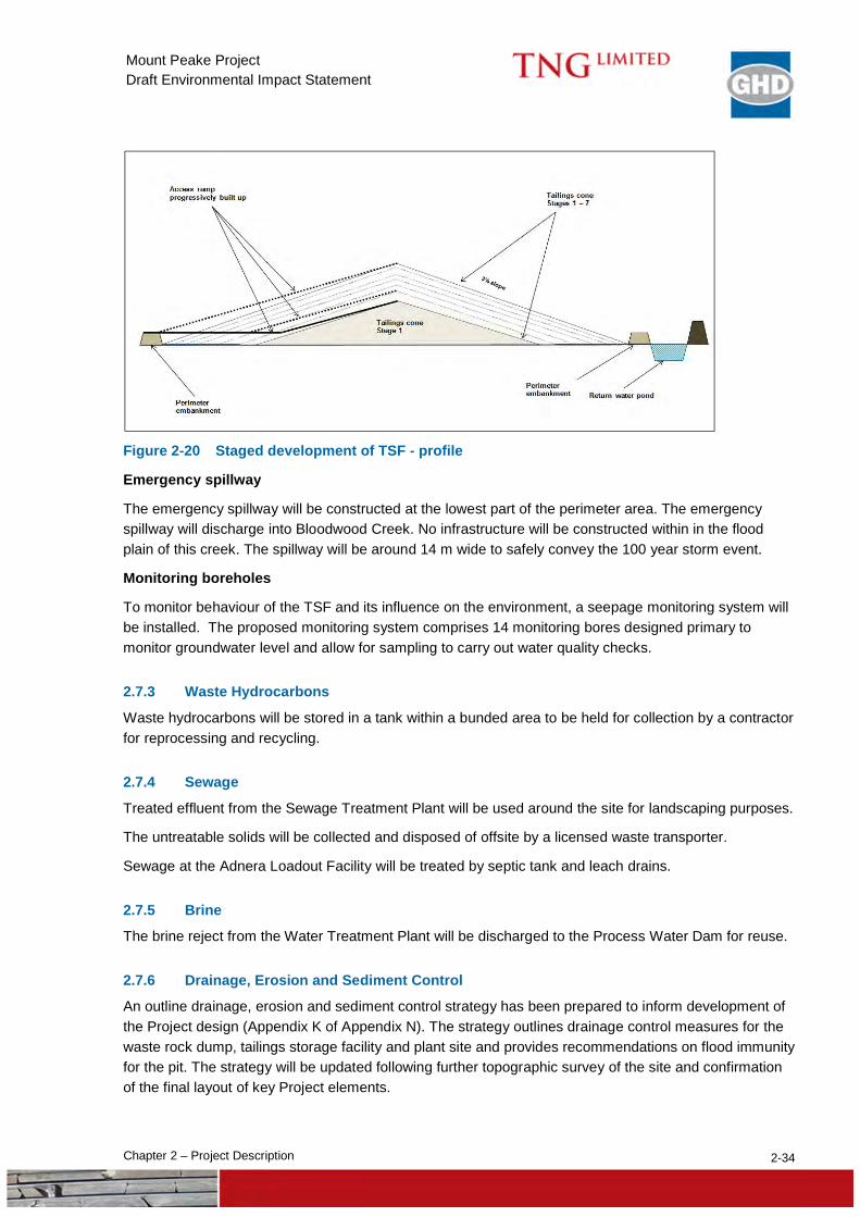
TSF staging The TSF will develop in stages related to the incremental raising of the central access ramp. This will reduce the volume of construction materials required as access ramp raises will be constructed partly on the tailings itself. The proposed TSF staging is provided in Table 2-6. Staged development is presented in plan in Figure 2-19 and profile in Figure 2-20.
The rate of raise of the TSF gradually decreases, reducing to less than 1 m per year in the final stages of the design life. This slow rate of raise also allows for drying and densification of the tailing surface which is important for tailings to achieve a high density.
Given that the tailings do not contain contaminants, the TSF will not be lined.
Perimeter embankment
The perimeter embankment will be constructed in stages to nominal height of 2 m. It is expected that due to minor slope change across the site, the height of the embankment will vary between 1 m and 4 m across the site. The final shape, size and capacity of the facility will depend on the beach slope. The 2 m high perimeter embankment is sufficient for a beach angle of 3% and this will be confirmed during the initial years of tailings deposition after the beach slope is well understood.
The perimeter embankment will have a 6 m wide crest with side slopes at 1V:2H. The crest will be covered by road base material and will be used as a maintenance road.
The perimeter embankment will be constructed using selected material from the mine pre-strip or from materials borrowed from within the storage facility.
Drainage management
Implementation of a drainage system is important to maximise functionality for the TSF and to maximise water recovery from the tailings.
The drainage system will comprise drains placed at radii of 600 m, 850 m and 1100 m from the central discharge area. These drains will collect water from the entire area and flow to the central main collector drain connected to the recovery water pond. The drains will be constructed using free draining rockfill materials with flow areas of 3 m2 and 5 m2, for radial drains and the main collector drain, respectively.
A seepage recovery trench will be constructed along the upstream toe of the perimeter embankment to recover seepage that would otherwise pass under the embankment.
To control surface runoff and avoid erosion of the perimeter embankment, surface runoff collector drains will be constructed along the downstream toe of the perimeter embankment. These drains will collect clean surface runoff and direct the flow away from the TSF.
Recovery water pond
Excess water from the deposited tailings will be collected in a recovery water pond located at the north-east part of the TSF.
Shortly after discharge, the tailings will settle and release excess water. The expected initial settlement of the 65% solid content of the slurry to a 75% solid content at the beach, will result in the release of about 70 m3 of water per hour. This water, together with rainfall collected within the TSF, will flow to a lined 20,000 m3 recovery water pond and returned to the process water dam for use in the process plant.

317,000
317,000
318,000
318,000
319,000
319,000
320,000
320,000
321,000
321,000
322,000
322,000
7,605,
000
7,605,
000
7,606,
000
7,606,
000
7,607,
000
7,607,
000
7,608,
000
7,608,
000
Figure 2-19
Job NumberRevision A
61-29057
G:\61\29057\11 GIS\Maps\MXD\EIS_MDS\6129057_003_TailingsStorageFacility.mxd
Map Projection: Transverse MercatorHorizontal Datum: GDA 1994Grid: GDA 1994 MGA Zone 53
0 200 400 600
Meters o© 2015. Whilst every care has been taken to prepare this map, GE, GHD and TNG make no representations or warranties about its accuracy, reliability, completeness or suitability for any particular purpose and cannot accept liability and responsibility of any kind (whether in contract, tort or otherwise) for any expenses, losses, damages and/or costs (including indirect or consequential damage) which are or may be incurred by any party as a result of the map being inaccurate, incomplete or unsuitable in any way and for any reason.
Date 29 Oct 2015
TNG LtdMount Peake EIS
Tailings Storage FacilityMount Peake
Google: Imagery - 20151021; TNG Ltd: Drams, Mine Layout - 20151021
239 Adelaide Terrace Perth WA 6004 Australia T 61 8 6222 8222 F 61 8 6222 8555 E [email protected] W www.ghd.com.au
Paper Size A4 LEGEND
SURFACE RUNOFF DRAINS
MAINCOLLECTOR
DRAIN
RADIALCOLLECTOR
DRAINS
CENRAL ACCESSRAMP
CREST WITH 10M
EMERGENCY SPILLWAY
RECOVERY WATER POND
PERIMETER EMBANKMENT
RETURN WATER PIPELINE
ACCESS ROAD
RETURN WATERPOWER LINE
(BURIED)
CENTRAL DISCHARGEPLATFORM 25M
DIAMETER
12
34
56
7
Mine Layout
Drams
1 - 7 : TSF Stages
2-34 Chapter 2 – Project Description
Mount Peake Project Draft Environmental Impact Statement
Figure 2-20 Staged development of TSF - profile
Emergency spillway
The emergency spillway will be constructed at the lowest part of the perimeter area. The emergency spillway will discharge into Bloodwood Creek. No infrastructure will be constructed within in the flood plain of this creek. The spillway will be around 14 m wide to safely convey the 100 year storm event.
Monitoring boreholes
To monitor behaviour of the TSF and its influence on the environment, a seepage monitoring system will be installed. The proposed monitoring system comprises 14 monitoring bores designed primary to monitor groundwater level and allow for sampling to carry out water quality checks.
2.7.3 Waste Hydrocarbons
Waste hydrocarbons will be stored in a tank within a bunded area to be held for collection by a contractor for reprocessing and recycling.
2.7.4 Sewage
Treated effluent from the Sewage Treatment Plant will be used around the site for landscaping purposes.
The untreatable solids will be collected and disposed of offsite by a licensed waste transporter.
Sewage at the Adnera Loadout Facility will be treated by septic tank and leach drains.
2.7.5 Brine
The brine reject from the Water Treatment Plant will be discharged to the Process Water Dam for reuse.
2.7.6 Drainage, Erosion and Sediment Control
An outline drainage, erosion and sediment control strategy has been prepared to inform development of the Project design (Appendix K of Appendix N). The strategy outlines drainage control measures for the waste rock dump, tailings storage facility and plant site and provides recommendations on flood immunity for the pit. The strategy will be updated following further topographic survey of the site and confirmation of the final layout of key Project elements.
2-35 Chapter 2 – Project Description
Mount Peake Project Draft Environmental Impact Statement
2.8 Closure and Rehabilitation A conceptual Mine Closure Plan has been prepared for the Project (Appendix M) consistent with Western Australian Department of Mines and Petroleum and Environmental Protection Authority Guidelines for Preparing Mine Closure Plans (2015).
The principal domains for closure and rehabilitation are:
open pit;
waste rock dump and run of mine pad;
tailings storage facility;
processing plant and power station;
rail siding;
access road;
bore field;
pipelines and power lines; and
ancillary infrastructure, hardstand areas, site roads etc.
The following sections provide a brief overview of how each of these domains will be managed with a more detailed description provided in Chapter 16.
2.8.1 Open Pit
The pit will cover approximately 77 ha and be approximately 2,000 m long, 600 m wide and 125 m deep. The pit will remain at the conclusion of mining. The following objectives have been developed:
entry into the pit is restricted by the presence of landforms and abandonment bunds; and
clean water catchments are excluded from the pit.
2.8.2 Waste Rock Dump and Run of Mine Pad
This domain includes the WRD and the ROM pad. The latter has been included in this domain as the structure itself is usually made from mine waste. At closure, rehabilitation principles of the WRD are similar to those of the ROM pad. The WRD will have an ultimate height of 40 m and a footprint of 90 ha with capacity to store up to 70 Mt of mine waste. The following objectives have been developed:
final landform is geotechnically stable and safe;
surface and outer slopes of the waste rock dumps resist erosion;
drainage from the WRD and ROM pad does not cause significant contamination of local surface waters or harm to local vegetation;
there are no mass vegetation deaths caused by AMD or salt in the vicinity of the landform.
landform is safe, stable and rehabilitated; and
rehabilitation monitoring results trending upwards or above minimum analogue values.
2-36 Chapter 2 – Project Description
Mount Peake Project Draft Environmental Impact Statement
2.8.3 Tailings Storage Facility
Tailings will be produced from the magnetic separation of the crushed and screened ore and will consist of non-magnetic silt and sand. Central Thickened Discharge was selected for tailings disposal based on balancing water recovery, environmental risk, the relatively flat nature of the site, ease of closure, and construction and operating costs. Beach slopes have shallow slope angles (about 3%). The storage area is bounded with a low perimeter embankment (nominal height of 2 m) which reduces the likelihood of any instability and failure. The TSF will have a diameter of approximately 2.1 kilometres, a maximum height at the central cone of 32 m and total area inclusive of drainage works and a perimeter bund of approximately 475 ha. The following objectives have been developed:
final landform is stable and safe;
surface of the TSF resists erosion;
drainage or seepage from the TSF does not cause significant contamination of local surface waters or harm to local vegetation;
erosion of any waste rock cap does not liberate tailings material;
water quality parameters in groundwater monitoring bores do not exceed values representative of analogue sites or baseline data;
there are no mass vegetation deaths in the vicinity of the landform; and
rehabilitation monitoring results trending upward or above minimum analogue values.
2.8.4 Processing Plant and Power Station
This domain includes the main power generation and ore processing infrastructure on site. The processing plant includes the plant site, water storage dams, power station, product stockpile storage and load-out area. The following objectives have been developed:
all infrastructure that is not subject to a sequential use agreement is removed from site;
hazardous material is remediated, encapsulated or contained to prevent off-site environmental impact;
contaminated sites are appropriately remediated. Contaminated sites not able to be remediated or removed are properly defined and registered;
no rubbish remains onsite; and
disturbed areas rehabilitated.
2.8.5 Rail Siding
A 1.8 km rail siding will be constructed at the Adnera Loadout Facility. The following objectives have been developed:
all infrastructure not subject to a sequential use agreement is removed; and
disturbed areas rehabilitated.
2-37 Chapter 2 – Project Description
Mount Peake Project Draft Environmental Impact Statement
2.8.6 Access Road
The 100 km access road connects the mine site with the Adnera Loadout Facility. The following objectives have been developed:
the access road, unless the subject of a sequential use agreement, will be removed;
natural drainage lines re-instated;
vehicular access required for monitoring purposes is maintained; and
rehabilitated road areas are stable and non-eroding.
2.8.7 Bore Field
This domain includes the bore field with around 12 production and standby bores, diesel generators and fuel storage tanks. The following objectives have been developed:
all pumps, pump stations and pipeline control infrastructure are removed (unless the subject of a sequential use agreement) and recycled if feasible or disposed of to an appropriate landfill; and
disturbed areas rehabilitated.
2.8.8 Pipelines and Power Lines
Like haul roads and access roads, pipelines and power lines are linear infrastructure. However, due to the specific nature of their infrastructure, they have been placed in a separate domain rather than include them with access roads. The following objectives have been developed:
above ground pipelines are removed, recycled if feasible, or disposed of to an appropriate landfill;
below ground pipelines are grouted at openings and any surface obtrusions are buried more than 600 mm below the surface;
all power infrastructure and power controls are recycled if feasible or disposed of to an appropriate landfill; and
underground services are left in situ and any surface obtrusions are removed or buried at least 600 mm below the surface.
2.8.9 Ancillary infrastructure, hardstand areas, site roads etc
The following objectives have been developed:
infrastructure that is beneficial to sequential land users will be transferred to the new owner via a sequential use agreement;
all mobile plant, transportable structures and consumables are reused, recycled, removed or disposed of appropriately;
permanent structures are demolished and recycled if economically feasible, disposed of to an onsite landfill, or removed from site and disposed of appropriately; and
all concrete pads and footings are broken up and buried at least 1 m below the surface or disposed of to landfill.
2-38 Chapter 2 – Project Description
Mount Peake Project Draft Environmental Impact Statement
2.9 Environmental Offsets The Terms of Reference (NT EPA 2014) require the consideration of offsets where there is a significant residual impact to a Matter of National Environmental Significance (MNES).
Chapter 8 Biodiversity and Chapter 15 Matters of National Environmental Significance identify the presence or possible presence in the Project area of one flora species and 20 fauna species listed as MNES under the EPBC Act. The assessment concluded that there was no significant residual impact to any of these species.
No offsets are proposed.