2. system based design descriptions and itaac ap1000
TRANSCRIPT

2. System Based Design Descriptions and ITAAC AP1000 Design Control Document
Tier 1 Material 2.2.1-1 Revision 19
2.2 Nuclear Safety Systems
2.2.1 Containment System
Design Description
The containment system (CNS) is the collection of boundaries that separates the containment atmosphere from the outside environment during design basis accidents.
The CNS is as shown in Figure 2.2.1-1 and the component locations of the CNS are as shown in Table 2.2.1-4.
1. The functional arrangement of the CNS and associated systems is as described in the Design Description of this Section 2.2.1.
2. a) The components identified in Table 2.2.1-1 as ASME Code Section III are designed and constructed in accordance with ASME Code Section III requirements.
b) The piping identified in Table 2.2.1-2 as ASME Code Section III is designed and constructed in accordance with ASME Code Section III requirements.
3. a) Pressure boundary welds in components identified in Table 2.2.1-1 as ASME Code Section III meet ASME Code Section III requirements.
b) Pressure boundary welds in piping identified in Table 2.2.1-2 as ASME Code Section III meet ASME Code Section III requirements.
4. a) The components identified in Table 2.2.1-1 as ASME Code Section III retain their pressure boundary integrity at their design pressure.
b) The piping identified in Table 2.2.1-2 as ASME Code Section III retains its pressure boundary integrity at its design pressure.
5. The seismic Category I equipment identified in Table 2.2.1-1 can withstand seismic design basis loads without loss of structural integrity and safety function.
6. a) The Class 1E equipment identified in Table 2.2.1-1 as being qualified for a harsh environment can withstand the environmental conditions that would exist before, during, and following a design basis accident without loss of safety function for the time required to perform the safety function.
b) The Class 1E components identified in Table 2.2.1-1 are powered from their respective Class 1E division.
c) Separation is provided between CNS Class 1E divisions, and between Class 1E divisions and non-Class 1E cable.
2. System Based Design Descriptions and ITAAC AP1000 Design Control Document
Tier 1 Material 2.2.1-2 Revision 19
d) The non-Class 1E electrical penetrations identified in Table 2.2.1-1 as being qualified for a harsh environment can withstand the environmental conditions that would exist before, during, and following a design basis accident without loss of containment pressure boundary integrity.
7. The CNS provides the safety-related function of containment isolation for containment boundary integrity and provides a barrier against the release of fission products to the atmosphere.
8. Containment electrical penetration assemblies are protected against currents that are greater than the continuous ratings.
9. Safety-related displays identified in Table 2.2.1-1 can be retrieved in the main control room (MCR).
10. a) Controls exist in the MCR to cause those remotely operated valves identified in Table 2.2.1-1 to perform active functions.
b) The valves identified in Table 2.2.1-1 as having protection and safety monitoring system (PMS) control perform an active function after receiving a signal from the PMS.
c) The valves identified in Table 2.2.1-1 as having diverse actuation system (DAS) control perform an active function after receiving a signal from the DAS.
11. a) The motor-operated and check valves identified in Table 2.2.1-1 perform an active safety-related function to change position as indicated in the table.
b) After loss of motive power, the remotely operated valves identified in Table 2.2.1-1 assume the indicated loss of motive power position.
Inspections, Tests, Analyses, and Acceptance Criteria
Table 2.2.1-3 specifies the inspections, tests, analyses, and associated acceptance criteria for the CNS.

2. System Based Design Descriptions and ITAAC AP1000 Design Control Document
Tier 1 Material 2.2.1-3 Revision 19
Table 2.2.1-1
Equipment Name Tag No.
ASME Code
Section III
Seismic Cat. I
Remotely Operated
Valve
Class 1E/ Qual. for
Harsh Envir.
Safety-Related Display
Control PMS/DAS
Active Function
Loss of Motive Power
Position
Service Air Supply Outside Containment Isolation Valve
Service Air Supply Inside Containment Isolation Check Valve
CAS-PL-V204
CAS-PL-V205
Yes
Yes
Yes
Yes
No
No
-/-
-/-
No
No
-/-
-/-
None
Transfer Closed
-
-
Instrument Air Supply Outside Containment Isolation Valve
Instrument Air Supply Inside Containment Isolation Check Valve
CAS-PL-V014
CAS-PL-V015
Yes
Yes
Yes
Yes
Yes
No
Yes/No
-/-
Yes (Valve
Position)
-
Yes/No
-/-
Transfer Closed
Transfer Closed
Closed
-
Component Cooling Water System (CCS) Containment Isolation Motor-operated Valve (MOV) – Inlet Line Outside Reactor Containment (ORC)
CCS Containment Isolation Check Valve – Inlet Line Inside Reactor Containment (IRC)
CCS-PL-V200
CCS-PL-V201
Yes
Yes
Yes
Yes
Yes
No
Yes/No
-/-
Yes (Valve
Position)
No
Yes/No
-/-
Transfer Closed
Transfer Closed
As Is
-
Note: Dash (-) indicates not applicable.

2. System Based Design Descriptions and ITAAC AP1000 Design Control Document
Tier 1 Material 2.2.1-4 Revision 19
Table 2.2.1-1 (cont.)
Equipment Name Tag No.
ASME Code
Section III
Seismic Cat. I
Remotely Operated
Valve
Class 1E/ Qual. for
Harsh Envir.
Safety-Related Display
Control PMS/DAS
Active Function
Loss of Motive Power
Position
CCS Containment Isolation MOV – Outlet Line IRC
CCS Containment Isolation MOV – Outlet Line ORC
CCS Containment Isolation Relief Valve – Outlet Line IRC
CCS-PL-V207
CCS-PL-V208
CCS-PL-220
Yes
Yes
Yes
Yes
Yes
Yes
Yes
Yes
No
Yes/Yes
Yes/No
-/-
Yes (Valve Position)
Yes (Valve Position)
No
Yes/No
Yes/No
-/-
Transfer Closed
Transfer Closed
Transfer Closed/ Transfer
Open
As Is
As Is
-
Demineralized Water Supply Containment Isolation Valve ORC
Demineralized Water Supply Containment Isolation Check Valve IRC
DWS-PL-V244
DWS-PL-V245
Yes
Yes
Yes
Yes
No
No
-/-
-/-
No
No
-/-
-/-
None
Transfer Closed
-
-
Fuel Transfer Tube FHS-FT-001 Yes Yes - -/- - -/- - - Fuel Transfer Tube Isolation Valve
FHS-PL-V001 Yes Yes - -/- - -/- Transfer Closed
-
Fire Water Containment Supply Isolation Valve – Outside
Fire Water Containment Isolation Supply Check Valve – Inside
FPS-PL-V050
FPS-PL-V052
Yes
Yes
Yes
Yes
No
No
-/-
-/-
No
No
-/-
-/-
None
Transfer Closed
-
-
Note: Dash (-) indicates not applicable.

2. System Based Design Descriptions and ITAAC AP1000 Design Control Document
Tier 1 Material 2.2.1-5 Revision 19
Table 2.2.1-1 (cont.)
Equipment Name Tag No.
ASME Code
Section III
Seismic Cat. I
Remotely Operated
Valve
Class 1E/ Qual. for
Harsh Envir.
Safety-Related Display
Control PMS/DAS
Active Function
Loss of Motive Power
Position
Spent Fuel Pool Cooling System (SFS) Discharge Line Containment Isolation Check Valve – IRC
SFS Discharge Line Containment Isolation MOV – ORC
SFS-PL-V037
SFS-PL-V038
Yes
Yes
Yes
Yes
No
Yes
-/-
Yes/No
No
Yes (Valve
Position)
-/-
Yes/No
Transfer Closed
Transfer Closed
-
As Is
SFS Suction Line Containment Isolation MOV – IRC
SFS Suction Line Containment Isolation MOV – ORC
SFS Suction Line Containment Isolation Relief Valve – IRC
SFS-PL-V034
SFS-PL-V035
SFS-PL-V067
Yes
Yes
Yes
Yes
Yes
Yes
Yes
Yes
No
Yes/Yes
Yes/No
-/-
Yes (Valve
Position)
Yes (Valve
Position)
No
Yes/No
Yes/No
-/-
Transfer Closed
Transfer Closed
Transfer Closed/ Transfer
Open
As Is
As Is
-
Containment Purge Inlet Containment Isolation Valve – ORC
Containment Purge Inlet Containment Isolation Valve – IRC
VFS-PL-V003
VFS-PL-V004
Yes
Yes
Yes
Yes
Yes
Yes
Yes/No
Yes/Yes
Yes (Valve
Position)
Yes (Valve
Position)
Yes/Yes
Yes/Yes
Transfer Closed
Transfer Closed
Closed
Closed
Note: Dash (-) indicates not applicable.

2. System Based Design Descriptions and ITAAC AP1000 Design Control Document
Tier 1 Material 2.2.1-6 Revision 19
Table 2.2.1-1 (cont.)
Equipment Name Tag No.
ASME Code
Section III
Seismic Cat. I
Remotely Operated
Valve
Class 1E/ Qual. for
Harsh Envir.
Safety-Related Display
Control PMS/DAS
Active Function
Loss of Motive Power
Position Integrated Leak Rate Testing Vent Discharge Containment Isolation Valve – ORC
Containment Purge Discharge Containment Isolation Valve – IRC
Containment Purge Discharge Containment Isolation Valve – ORC
VFS-PL-V008
VFS-PL-V009
VFS-PL-V010
Yes
Yes
Yes
Yes
Yes
Yes
No
Yes
Yes
-/-
Yes/Yes
Yes/No
No
Yes (Valve
Position)
Yes (Valve
Position)
-/-
Yes/Yes
Yes/Yes
None
Transfer Closed
Transfer Closed
-
Closed
Closed
Vacuum Relief Containment Isolation A – ORC Vacuum Relief Containment Isolation B – ORC Vacuum Relief Containment Isolation Check Valve A – IRC Vacuum Relief Containment Isolation Check Valve B – IRC
VFS-PL-V800A VFS-PL-V800B VFS-PL-V803A VFS-PL-V803B
Yes
Yes
Yes
Yes
Yes
Yes
Yes
Yes
Yes
Yes
No
No
Yes/No
Yes/No
-/-
-/-
Yes (Valve
Position)
Yes (Valve
Position)
No
No
Yes/No
Yes/No
-/-
-/-
Transfer Closed/ Transfer
Open
Transfer Closed/ Transfer
Open
Transfer Closed/ Transfer
Open
Transfer Closed/ Transfer
Open
As Is
As Is - -
Note: Dash (-) indicates not applicable.

2. System Based Design Descriptions and ITAAC AP1000 Design Control Document
Tier 1 Material 2.2.1-7 Revision 19
Table 2.2.1-1 (cont.)
Equipment Name Tag No.
ASME Code
Section III
Seismic Cat. I
Remotely Operated
Valve
Class 1E/ Qual. for
Harsh Envir.
Safety-Related Display
Control PMS/ DAS
Active Function
Loss of Motive Power
Position Fan Coolers Return Containment Isolation Valve – IRC
Fan Coolers Return Containment Isolation Valve – ORC
Fan Coolers Return Containment Isolation Relief Valve – IRC
VWS-PL-V082
VWS-PL-V086
VWS-PL-V080
Yes
Yes
Yes
Yes
Yes
Yes
Yes
Yes
No
Yes/Yes
Yes/No
-/-
Yes (Valve
Position)
Yes (Valve
Position)
No
Yes/No
Yes/No
-/-
Transfer Closed
Transfer Closed
Transfer Closed/ Transfer
Open
Closed
Closed
-
Fan Coolers Supply Containment Isolation Valve – ORC
Fan Coolers Supply Containment Isolation Check Valve – IRC
VWS-PL-V058
VWS-PL-V062
Yes
Yes
Yes
Yes
Yes
No
Yes/No
-/-
Yes (Valve
Position)
No
Yes/No
-/-
Transfer Closed
Transfer Closed
Closed
-
Reactor Coolant Drain Tank (RCDT) Gas Outlet Containment Isolation Valve – IRC
RCDT Gas Outlet Containment Isolation Valve – ORC
WLS-PL-V067
WLS-PL-V068
Yes
Yes
Yes
Yes
Yes
Yes
Yes/Yes
Yes/No
Yes (Valve
Position)
Yes (Valve
Position)
Yes/No
Yes/No
Transfer Closed
Transfer Closed
Closed
Closed
Note: Dash (-) indicates not applicable.
2. System Based Design Descriptions and ITAAC AP1000 Design Control Document
Tier 1 Material 2.2.1-8 Revision 19
Table 2.2.1-1 (cont.)
Equipment Name Tag No.
ASME Code
Section III
Seismic Cat. I
Remotely Operated
Valve
Class 1E/ Qual. for
Harsh Envir.
Safety-Related Display
Control PMS/ DAS
Active Function
Loss of Motive Power
Position
Sump Discharge Containment Isolation Valve – IRC
Sump Discharge Containment Isolation Valve – ORC
Sump Discharge Containment Isolation Relief Valve – IRC
WLS-PL-V055
WLS-PL-V057
WLS-PL-V058
Yes
Yes
Yes
Yes
Yes
Yes
Yes
Yes
No
Yes/Yes
Yes/No
-/-
Yes (Valve
Position)
Yes (Valve
Position)
No
Yes/Yes
Yes/Yes
-/-
Transfer Closed
Transfer Closed
Transfer Closed/ Transfer
Open
Closed
Closed
-
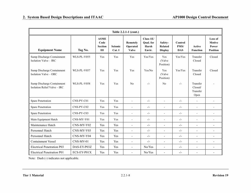
Spare Penetration CNS-PY-C01 Yes Yes - -/- - -/- - - Spare Penetration CNS-PY-C02 Yes Yes - -/- - -/- - - Spare Penetration CNS-PY-C03 Yes Yes - -/- - -/- - - Main Equipment Hatch CNS-MY-Y01 Yes Yes - -/- - -/- - - Maintenance Hatch CNS-MY-Y02 Yes Yes - -/- - -/- - - Personnel Hatch CNS-MY-Y03 Yes Yes - -/- - -/- - - Personnel Hatch CNS-MY-Y04 Yes Yes - -/- - -/- - - Containment Vessel CNS-MV-01 Yes Yes - -/- - -/- - - Electrical Penetration P03 DAS-EY-P03Z Yes Yes - No/Yes - -/- - -
Electrical Penetration P01 ECS-EY-P01X Yes Yes - No/Yes - -/- - - Note: Dash (-) indicates not applicable.

2. System Based Design Descriptions and ITAAC AP1000 Design Control Document
Tier 1 Material 2.2.1-9 Revision 19
Table 2.2.1-1 (cont.)
Equipment Name Tag No.
ASME Code
Section III
Seismic Cat. I
Remotely Operated
Valve
Class 1E/ Qual. for
Harsh Envir.
Safety-Related Display
Control PMS/ DAS
Active Function
Loss of Motive Power
Position Electrical Penetration P02 ECS-EY-P02X Yes Yes - No/Yes - -/- - - Electrical Penetration P06 ECS-EY-P06Y Yes Yes - No/Yes - -/- - - Electrical Penetration P09 ECS-EY-P09W Yes Yes - No/Yes - -/- - - Electrical Penetration P10 ECS-EY-P10W Yes Yes - No/Yes - -/- - - Electrical Penetration P11 IDSA-EY-P11Z Yes Yes - Yes/Yes - -/- - - Electrical Penetration P12 IDSA-EY-P12Y Yes Yes - Yes/Yes - -/- - - Electrical Penetration P13 IDSA-EY-P13Y Yes Yes - Yes/Yes - -/- - - Electrical Penetration P14 IDSD-EY-P14Z Yes Yes - Yes/Yes - -/- - - Electrical Penetration P15 IDSD-EY-P15Y Yes Yes - Yes/Yes - -/- - - Electrical Penetration P16 IDSD-EY-P16Y Yes Yes - Yes/Yes - -/- - - Electrical Penetration P18 ECS-EY-P18X Yes Yes - No/Yes - -/- - - Electrical Penetration P21 EDS-EY-P21Z Yes Yes - No/Yes - -/- - - Electrical Penetration P22 ECS-EY-P22X Yes Yes - No/Yes - -/- - - Electrical Penetration P23 ECS-EY-P23X Yes Yes - No/Yes - -/- - -
Electrical Penetration P24 ECS-EY-P24 Yes Yes - No/Yes - -/- - - Electrical Penetration P25 ECS-EY-P25W Yes Yes - No/Yes - -/- - - Electrical Penetration P26 ECS-EY-P26W Yes Yes - No/Yes - -/- - - Electrical Penetration P27 IDSC-EY-P27Z Yes Yes - Yes/Yes - -/- - -
Note: Dash (-) indicates not applicable.
2. System Based Design Descriptions and ITAAC AP1000 Design Control Document
Tier 1 Material 2.2.1-10 Revision 19
Table 2.2.1-1 (cont.)
Equipment Name Tag No.
ASME Code
Section III
Seismic Cat. I
Remotely Operated
Valve
Class 1E/ Qual. for
Harsh Envir.
Safety-Related Display
Control PMS/ DAS
Active Function
Loss of Motive Power
Position
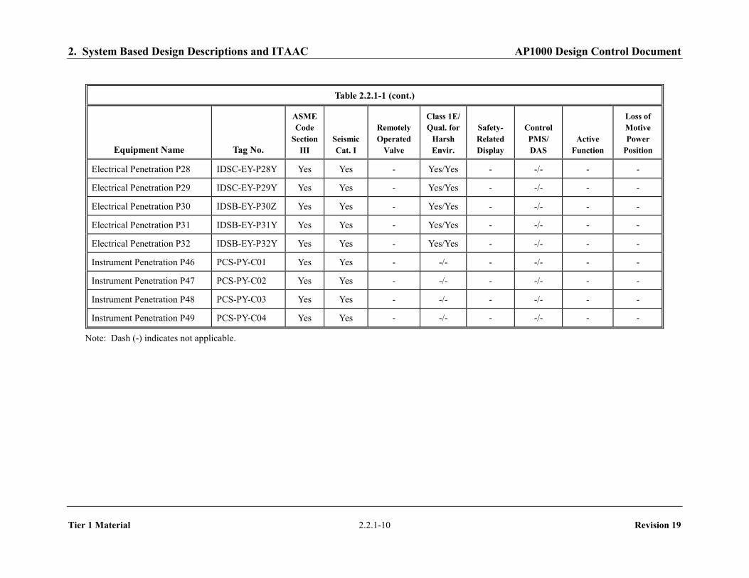
Electrical Penetration P28 IDSC-EY-P28Y Yes Yes - Yes/Yes - -/- - - Electrical Penetration P29 IDSC-EY-P29Y Yes Yes - Yes/Yes - -/- - - Electrical Penetration P30 IDSB-EY-P30Z Yes Yes - Yes/Yes - -/- - - Electrical Penetration P31 IDSB-EY-P31Y Yes Yes - Yes/Yes - -/- - - Electrical Penetration P32 IDSB-EY-P32Y Yes Yes - Yes/Yes - -/- - - Instrument Penetration P46 PCS-PY-C01 Yes Yes - -/- - -/- - -
Instrument Penetration P47 PCS-PY-C02 Yes Yes - -/- - -/- - -
Instrument Penetration P48 PCS-PY-C03 Yes Yes - -/- - -/- - -
Instrument Penetration P49 PCS-PY-C04 Yes Yes - -/- - -/- - -
Note: Dash (-) indicates not applicable.

2. System Based Design Descriptions and ITAAC AP1000 Design Control Document
Tier 1 Material 2.2.1-11 Revision 19
Table 2.2.1-2
Line Name Line Number ASME Code Section III
Instrument Air In CAS-PL-L015 Yes Service Air In CAS-PL-L204 Yes Component Cooling Water Supply to Containment CCS-PL-L201 Yes Component Cooling Water Outlet from Containment CCS-PL-L207 Yes Demineralized Water In DWS-PL-L245, L230 Yes Fire Protection Supply to Containment FPS-PL-L107 Yes Spent Fuel Pool Cooling Discharge SFS-PL-L017 Yes Spent Fuel Pool Cooling Suction from Containment SFS-PL-L038 Yes Containment Purge Inlet to Containment VFS-PL-L104, L105, L106 Yes Containment Purge Discharge from Containment VFS-PL-L203, L204, L205,
L800, L801A/B, L803, L804, L805A/B
Yes
Fan Cooler Supply Line to Containment VWS-PL-L032 Yes Fan Cooler Return Line from Containment VWS-PL-L055 Yes RCDT Gas Out WLS-PL-L022 Yes Waste Sump Out WLS-PL-L073 Yes

2. System Based Design Descriptions and ITAAC AP1000 Design Control Document
Tier 1 Material 2.2.1-12 Revision 19
Table 2.2.1-3
Inspections, Tests, Analyses, and Acceptance Criteria
Design Commitment Inspections, Tests, Analyses Acceptance Criteria
1. The functional arrangement of the CNS and associated systems is as described in the Design Description of this Section 2.2.1.
Inspection of the as-built system will be performed.
The as-built CNS conforms with the functional arrangement as described in the Design Description of this Section 2.2.1.
2.a) The components identified in Table 2.2.1-1 as ASME Code Section III are designed and constructed in accordance with ASME Code Section III requirements.
Inspection will be conducted of the as-built components as documented in the ASME design reports.
The ASME Code Section III design reports exist for the as-built components identified in Table 2.2.1-1 as ASME Code Section III.
2.b) The piping identified in Table 2.2.1-2 as ASME Code Section III is designed and constructed in accordance with ASME Code Section III requirements.
Inspection will be conducted of the as-built piping as documented in the ASME design reports.
The ASME Code Section III design reports exist for the as-built piping identified in Table 2.2.1-2 as ASME Code Section III.
3.a) Pressure boundary welds in components identified in Table 2.2.1-1 as ASME Code Section III meet ASME Code Section III requirements.
Inspection of the as-built pressure boundary welds will be performed in accordance with the ASME Code Section III.
A report exists and concludes that the ASME Code Section III requirements are met for non-destructive examination of pressure boundary welds.
3.b) Pressure boundary welds in piping identified in Table 2.2.1-2 as ASME Code Section III meet ASME Code Section III requirements.
Inspection of the as-built pressure boundary welds will be performed in accordance with the ASME Code Section III.
A report exists and concludes that the ASME Code Section III requirements are met for non-destructive examination of pressure boundary welds.

2. System Based Design Descriptions and ITAAC AP1000 Design Control Document
Tier 1 Material 2.2.1-13 Revision 19
Table 2.2.1-3 (cont.)
Inspections, Tests, Analyses, and Acceptance Criteria
Design Commitment Inspections, Tests, Analyses Acceptance Criteria
4.a) The components identified in Table 2.2.1-1 as ASME Code Section III retain their pressure boundary integrity at their design pressure.
i) A hydrostatic or pressure test will be performed on the components required by the ASME Code Section III to be tested.
ii) Impact testing will be performed on the containment and pressure-retaining penetration materials in accordance with the ASME Code Section III, Subsection NE, to confirm the fracture toughness of the materials.
i) A report exists and concludes that the results of the pressure test of the components identified in Table 2.2.1-1 as ASME Code Section III conform with the requirements of the ASME Code Section III.
ii) A report exists and concludes that the containment and pressure-retaining penetration materials conform with fracture toughness requirements of the ASME Code Section III.
4.b) The piping identified in Table 2.2.1-2 as ASME Code Section III retains its pressure boundary integrity at its design pressure.
A hydrostatic or pressure test will be performed on the piping required by the ASME Code Section III to be pressure tested.
A report exists and concludes that the results of the pressure test of the piping identified in Table 2.2.1-2 as ASME Code Section III conform with the requirements of the ASME Code Section III.
5. The seismic Category I equipment identified in Table 2.2.1-1 can withstand seismic design basis loads without loss of structural integrity and safety function.
i) Inspection will be performed to verify that the seismic Category I equipment and valves identified in Table 2.2.1-1 are located on the Nuclear Island.
ii) Type tests, analyses, or a combination of type tests and analyses of seismic Category I equipment will be performed.
iii) Inspection will be performed for the existence of a report verifying that the as-built equipment including anchorage is seismically bounded by the tested or analyzed conditions.
i) The seismic Category I equipment identified in Table 2.2.1-1 is located on the Nuclear Island.
ii) A report exists and concludes that the seismic Category I equipment can withstand seismic design basis dynamic loads without loss of structural integrity and safety function.
iii) The as-built equipment including anchorage is seismically bounded by the tested or analyzed conditions.

2. System Based Design Descriptions and ITAAC AP1000 Design Control Document
Tier 1 Material 2.2.1-14 Revision 19
Table 2.2.1-3 (cont.) Inspections, Tests, Analyses, and Acceptance Criteria
Design Commitment Inspections, Tests, Analyses Acceptance Criteria
6.a) The Class 1E equipment identified in Table 2.2.1-1 as being qualified for a harsh environment can withstand the environmental conditions that would exist before, during, and following a design basis accident without loss of safety function for the time required to perform the safety function.
i) Type tests, analyses, or a combination of type tests and analyses will be performed on Class 1E equipment located in a harsh environment.
ii) Inspection will be performed of the as-built Class 1E equipment and the associated wiring, cables, and terminations located in a harsh environment.
i) A report exists and concludes that the Class 1E equipment identified in Table 2.2.1-1 as being qualified for a harsh environment can withstand the environmental conditions that would exist before, during, and following a design basis accident without loss of safety function for the time required to perform the safety function.
ii) A report exists and concludes that the as-built Class 1E equipment and the associated wiring, cables, and terminations identified in Table 2.2.1-1 as being qualified for a harsh environment are bounded by type tests, analyses, or a combination of type tests and analyses.
6.b) The Class 1E components identified in Table 2.2.1-1 are powered from their respective Class 1E division.
Testing will be performed by providing a simulated test signal in each Class 1E division.
A simulated test signal exists at the Class 1E equipment identified in Table 2.2.1-1 when the assigned Class 1E division is provided the test signal.
6.c) Separation is provided between CNS Class 1E divisions, and between Class 1E divisions and non-Class 1E cable.
See Tier 1 Material, Table 3.3-6, item 7.d.
See Tier 1 Material, Table 3.3-6, item 7.d.
6.d) The non-Class 1E electrical penetrations identified in Table 2.2.1-1 as being qualified for a harsh environment can withstand the environmental conditions that would exist before, during, and following a design basis accident without loss of containment pressure boundary integrity.
i) Type tests, analyses, or a combination of type tests and analyses will be performed on non-Class 1E electrical penetrations located in a harsh environment.
ii) Inspection will be performed of the as-built non-Class 1E electrical penetrations located in a harsh environment.
i) A report exists and concludes that the non-Class 1E electrical penetrations identified in Table 2.2.1-1 as being qualified for a harsh environment can withstand the environmental conditions that would exist before, during, and following a design basis accident without loss of containment pressure boundary integrity.
ii) A report exists and concludes that the as-built non-Class 1E electrical penetrations identified in Table 2.2.1-1 as being qualified for a harsh environment are bounded by type tests, analyses, or a combination of type tests and analyses.

2. System Based Design Descriptions and ITAAC AP1000 Design Control Document
Tier 1 Material 2.2.1-15 Revision 19
Table 2.2.1-3 (cont.) Inspections, Tests, Analyses, and Acceptance Criteria
Design Commitment Inspections, Tests, Analyses Acceptance Criteria
7. The CNS provides the safety-related function of containment isolation for containment boundary integrity and provides a barrier against the release of fission products to the atmosphere.
i) A containment integrated leak rate test will be performed.
ii) Testing will be performed to demonstrate that remotely operated containment isolation valves close within the required response times.
i) The leakage rate from containment for the integrated leak rate test is less than La.
ii) The containment purge isolation valves (VFS-PL-V003, -V004, -V009, and -V010) close within 20 seconds, containment vacuum relief isolation valves (VFS-PL-V800A and -V800B) close within 30 seconds, SGS valves SGS-PL-V040A/B and SGS-PL-V057A/B are covered in Tier 1 Material, subsection 2.2.4, Table 2.2.4-4 (item 11.b.ii) and all other containment isolation valves close within 60 seconds upon receipt of an actuation signal.
8. Containment electrical penetration assemblies are protected against currents that are greater than the continuous ratings.
An analysis for the as-built containment electrical penetration assemblies will be performed to demonstrate (1) that the maximum current of the circuits does not exceed the continuous rating of the containment electrical penetration assembly, or (2) that the circuits have redundant protection devices in series and that the redundant current protection devices are coordinated with the containment electrical penetration assembly’s rated short circuit thermal capacity data and prevent current from exceeding the continuous current rating of the containment electrical penetration assembly.
Analysis exists for the as-built containment electrical penetration assemblies and concludes that the penetrations are protected against currents which are greater than their continuous ratings.
9. Safety-related displays identified in Table 2.2.1-1 can be retrieved in the MCR.
Inspection will be performed for retrievability of the safety-related displays in the MCR.
Safety-related displays identified in Table 2.2.1-1 can be retrieved in the MCR.
10.a) Controls exist in the MCR to cause those remotely operated valves identified in Table 2.2.1-1 to perform active functions.
Stroke testing will be performed on remotely operated valves identified in Table 2.2.1-1 using the controls in the MCR.
Controls in the MCR operate to cause remotely operated valves identified in Table 2.2.1-1 to perform active safety functions.

2. System Based Design Descriptions and ITAAC AP1000 Design Control Document
Tier 1 Material 2.2.1-16 Revision 19
Table 2.2.1-3 (cont.) Inspections, Tests, Analyses, and Acceptance Criteria
Design Commitment Inspections, Tests, Analyses Acceptance Criteria
10.b) The valves identified in Table 2.2.1-1 as having PMS control perform an active safety function after receiving a signal from the PMS.
Testing will be performed on remotely operated valves listed in Table 2.2.1-1 using real or simulated signals into the PMS.
The remotely operated valves identified in Table 2.2.1-1 as having PMS control perform the active function identified in the table after receiving a signal from PMS.
10.c) The valves identified in Table 2.2.1-1 as having DAS control perform an active safety function after receiving a signal from DAS.
Testing will be performed on remotely operated valves listed in Table 2.2.1-1 using real or simulated signals into the DAS.
The remotely operated valves identified in Table 2.2.1-1 as having DAS control perform the active function identified in the table after receiving a signal from DAS.
11.a) The motor-operated and check valves identified in Table 2.2.1-1 perform an active safety-related function to change position as indicated in the table.
i) Tests or type tests of motor-operated valves will be performed to demonstrate the capability of each valve to operate under design conditions.
ii) Inspection will be performed for the existence of a report verifying that the as-built motor-operated valves are bounded by the tests or type tests.
iii) Tests of the motor-operated valves will be performed under preoperational flow, differential pressure, and temperature conditions.
iv) Exercise testing of the check valves with active safety functions identified in Table 2.2.1-1 will be performed under preoperational test pressure, temperature and fluid flow conditions.
i) A test report exists and concludes that each motor-operated valve changes position as indicated in Table 2.2.1-1 under design conditions.
ii) A report exists and concludes that the as-built motor-operated valves are bounded by the tests or type tests.
iii) Each motor-operated valve changes position as indicated in Table 2.2.1-1 under pre-operational test conditions.
iv) Each check valve changes position as indicated in Table 2.2.1-1.
11.b) After loss of motive power, the remotely operated valves identified in Table 2.2.1-1 assume the indicated loss of motive power position.
Testing of the remotely operated valves will be performed under the conditions of loss of motive power.
After loss of motive power, each remotely operated valve identified in Table 2.2.1-1 assumes the indicated loss of motive power position.

2. System Based Design Descriptions and ITAAC AP1000 Design Control Document
Tier 1 Material 2.2.1-17 Revision 19
Table 2.2.1-4
Component Name Tag. No. Component Location Containment Vessel CNS-MV-01 Shield Building

2. System Based Design Descriptions and ITAAC AP1000 Design Control Document
Tier 1 Material 2.2.1-18 Revision 19
[This page intentionally blank]

2. System Based Design Descriptions and ITAAC AP1000 Design Control Document
Tier 1 Material 2.2.1-19 Revision 19
Figure 2.2.1-1 Containment System

2. System Based Design Descriptions and ITAAC AP1000 Design Control Document
Tier 1 Material 2.2.2-1 Revision 19
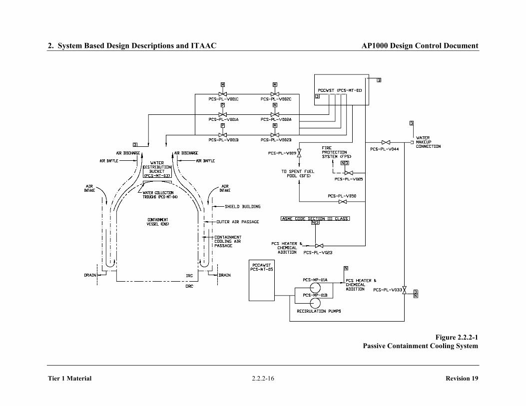
2.2.2 Passive Containment Cooling System
Design Description
The passive containment cooling system (PCS) removes heat from the containment during design basis events.
The PCS is as shown in Figure 2.2.2-1 and the component locations of the PCS are as shown in Table 2.2.2-4.
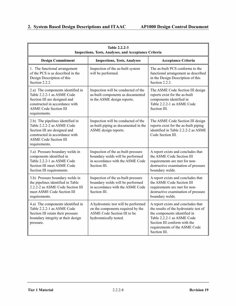
1. The functional arrangement of the PCS is as described in the Design Description of this Section 2.2.2.
2. a) The components identified in Table 2.2.2-1 as ASME Code Section III are designed and constructed in accordance with ASME Code Section III requirements.
b) The pipelines identified in Table 2.2.2-2 as ASME Code Section III are designed and constructed in accordance with ASME Code Section III requirements.
3. a) Pressure boundary welds in components identified in Table 2.2.2-1 as ASME Code Section III meet ASME Code Section III requirements.
b) Pressure boundary welds in the pipelines identified in Table 2.2.2-2 as ASME Code Section III meet ASME Code Section III requirements.
4. a) The components identified in Table 2.2.2-1 as ASME Code Section III retain their pressure boundary integrity at their design pressure.
b) The pipelines identified in Table 2.2.2-2 as ASME Code Section III retain their pressure boundary integrity at their design pressure.
5. a) The seismic Category I components identified in Table 2.2.2-1 can withstand seismic design basis loads without loss of safety function.
b) Each of the pipelines identified in Table 2.2.2-2 for which functional capability is required is designed to withstand combined normal and seismic design basis loads without a loss of its functional capability.
c) The passive containment cooling ancillary water storage tank (PCCAWST) can withstand a seismic event.
6. a) The Class 1E components identified in Table 2.2.2-1 as being qualified for a harsh environment can withstand the environmental conditions that would exist before, during, and following a design basis accident without loss of safety function for the time required to perform the safety function.
b) The Class 1E components identified in Table 2.2.2-1 are powered from their respective Class 1E division.

2. System Based Design Descriptions and ITAAC AP1000 Design Control Document
Tier 1 Material 2.2.2-2 Revision 19
c) Separation is provided between PCS Class 1E divisions, and between Class 1E divisions and non-Class 1E cable.
7. The PCS performs the following safety-related functions:
a) The PCS delivers water from the PCCWST to the outside, top of the containment vessel.
b) The PCS wets the outside surface of the containment vessel. The inside and outside of the containment vessel above the operating deck are coated with an inorganic zinc coating.
c) The PCS provides air flow over the outside of the containment vessel by a natural circulation air flow path from the air inlets to the air discharge structure.
d) The PCS drains the excess water from the outside of the containment vessel through the two upper annulus drains.
e) The PCS provides a flow path for long-term water makeup to the passive containment cooling water storage tank (PCCWST).
f) The PCS provides a flow path for long-term water makeup from the PCCWST to the spent fuel pool.
8. The PCS performs the following nonsafety-related functions:
a) The PCCAWST contains an inventory of cooling water sufficient for PCS containment cooling from hour 72 through day 7.
b) The PCS delivers water from the PCCAWST to the PCCWST and spent fuel pool simultaneously.
c) The PCCWST includes a water inventory for the fire protection system.
9. Safety-related displays identified in Table 2.2.2-1 can be retrieved in the main control room (MCR).
10. a) Controls exist in the MCR to cause the remotely operated valves identified in Table 2.2.2-1 to perform active functions.
b) The valves identified in Table 2.2.2-1 as having protection and safety monitoring system (PMS) control perform an active safety function after receiving a signal from the PMS.
c) The valves identified in Table 2.2.2-1 as having diverse actuation system (DAS) control perform an active safety function after receiving a signal from the DAS.
11. a) The motor-operated valves identified in Table 2.2.2-1 perform an active safety-related function to change position as indicated in the table.
b) After loss of motive power, the remotely operated valves identified in Table 2.2.2-1 assume the indicated loss of motive power position.

2. System Based Design Descriptions and ITAAC AP1000 Design Control Document
Tier 1 Material 2.2.2-3 Revision 19
Inspections, Tests, Analyses, and Acceptance Criteria
Table 2.2.2-3 specifies the inspections, tests, analyses, and associated acceptance criteria for the PCS.

2. System Based Design Descriptions and ITAAC AP1000 Design Control Document
Tier 1 Material 2.2.2-4 Revision 19
Table 2.2.2-1
Component Name Tag No.
ASME Code
Section III Seismic Cat. I
Remotely Operated
Valve
Class 1E/ Qual.
for Harsh Envir.
Safety-Related Display
Control PMS/ DAS
Active Function
Loss of Motive Power
Position PCCWST PCS-MT-01 No Yes - - - - - - Water Distribution Bucket PCS-MT-03 No Yes - - - - - - Water Distribution Wiers PCS-MT-04 No Yes - - - - - - PCCWST Isolation Valve PCS-PL-V001A Yes Yes Yes Yes/No Yes
(Valve Position)
Yes/Yes Transfer Open
Open
PCCWST Isolation Valve PCS-PL-V001B Yes Yes Yes Yes/No Yes (Valve
Position)
Yes/Yes Transfer Open
Open
PCCWST Isolation Valve PCS-PL-V001C Yes Yes Yes Yes/No Yes (Valve
Position)
Yes/Yes Transfer Open
As Is
PCCWST Isolation Block MOV
PCS-PL-V002A Yes Yes Yes Yes/No Yes (Valve
Position)
Yes/No Transfer Open
As Is
PCCWST Isolation Block MOV
PCS-PL-V002B Yes Yes Yes Yes/No Yes (Valve
Position)
Yes/No Transfer Open
As Is
PCCWST Isolation Block MOV
PCS-PL-V002C Yes Yes Yes Yes/No Yes (Valve
Position)
Yes/No Transfer Open
As Is
PCS Recirculation Return Isolation Valve
PCS-PL-V023 Yes Yes - -/No No - Transfer Close
-
PCCWST Supply to Fire Protection System Isolation Valve
PCS-PL-V005 Yes Yes - -/No No - Transfer Close
-
Note: Dash (-) indicates not applicable.

2. System Based Design Descriptions and ITAAC AP1000 Design Control Document
Tier 1 Material 2.2.2-5 Revision 19
Table 2.2.2-1 (cont.)
Component Name Tag No.
ASME Code
Section III Seismic Cat. I
Remotely Operated
Valve
Class 1E/ Qual.
for Harsh Envir.
Safety-Related Display
Control PMS/ DAS
Active Function
Loss of Motive Power
Position PCS Makeup to SFS Isolation Valve
PCS-PL-V009 Yes Yes - -/No No - Transfer Open/
Transfer Close
-
Water Makeup Isolation Valve
PCS-PL-V044 Yes Yes - -/No No - Transfer Open
-
Water Bucket Makeup Line Drain Valve
PCS-PL-V015 Yes Yes - -/No No - Transfer Close
-
Water Bucket Makeup Line Isolation Valve
PCS-PL-V020 Yes Yes - -/No No - Transfer Open
-
PCCWST Long-Term Makeup Line Check Valve
PCS-PL-V039 Yes Yes - -/No No - Transfer Open
-
PCCWST Long-Term Makeup Drain Isolation
PCS-PL-V042 Yes Yes - -/No No - Transfer Close
-
PCS Discharge to SFS Pool Isolation Valve
PCS-PL-V045 Yes Yes - -/No No - Transfer Open
-
Recirc Header Discharge to PCCWST Isolation Valve
PCS-PL-V046 Yes Yes - -/No No - Transfer Close
-
PCCWST Drain Isolation Valve
PCS-PL-V049 Yes Yes - -/No No - Transfer Close
-
Recirc Header Discharge to SFS Pool Isolation Valve
PCS-PL-V050 Yes Yes - -/No No - Transfer Open/Close
-
PCCWST Discharge to SFS Pool Isolation Valve
PCS-PL-V051 Yes Yes - -/No No - Transfer Open/Close
-
PCS Water Delivery Flow Sensor
PCS-001 No Yes - Yes/No Yes - - -

2. System Based Design Descriptions and ITAAC AP1000 Design Control Document
Tier 1 Material 2.2.2-6 Revision 19
Table 2.2.2-1 (cont.)
Component Name Tag No.
ASME Code
Section III Seismic Cat. I
Remotely Operated
Valve
Class 1E/ Qual.
for Harsh Envir.
Safety-Related Display
Control PMS/ DAS
Active Function
Loss of Motive Power
Position PCS Water Delivery Flow Sensor
PCS-002 No Yes - Yes/No Yes - - -
PCS Water Delivery Flow Sensor
PCS-003 No Yes - Yes/No Yes - - -
PCS Water Delivery Flow Sensor
PCS-004 No Yes - Yes/No Yes - - -
Containment Pressure Sensor
PCS-005 No Yes - Yes/Yes Yes - - -
Containment Pressure Sensor
PCS-006 No Yes - Yes/Yes Yes - - -
Containment Pressure Sensor
PCS-007 No Yes - Yes/Yes Yes - - -
Containment Pressure Sensor
PCS-008 No Yes - Yes/Yes Yes - - -
PCCWST Water Level Sensor
PCS-010 No Yes - Yes/No Yes - - -
PCCWST Water Level Sensor
PCS-011 No Yes - Yes/No Yes - - -
High-range Containment Pressure Sensor
PCS-012 No Yes - Yes/Yes Yes - - -
High-range Containment Pressure Sensor
PCS-013 No Yes - Yes/Yes Yes - - -
High-range Containment Pressure Sensor
PCS-014 No Yes - Yes/Yes Yes - - -
Note: Dash (-) indicates not applicable.

2. System Based Design Descriptions and ITAAC AP1000 Design Control Document
Tier 1 Material 2.2.2-7 Revision 19
Table 2.2.2-2
Pipeline Name Line Number ASME Code Section III
Functional Capability Required
PCCWST Discharge Lines PCS-PL-L001A/B/C/D Yes Yes PCCWST Discharge Cross-connect Line
PCS-PL-L002 Yes Yes
PCCWST Discharge Header Lines PCS-PL-L003A/B PCS-PL-L005
Yes Yes
Post-72-hour Supply Line Connection PCS-PL-L051 PCS-PL-L054 PCS-PL-L065
Yes Yes
Post-72-hour Containment Cooling Makeup From Supply Line Connections
PCS-PL-L004 PCS-PL-L007 PCS-PL-L008 PCS-PL-L023 PCS-PL-L050
Yes Yes
Post-72-hour SFS Makeup From PCCWST
PCS-PL-L011 PCS-PL-L017 PCS-PL-L018 PCS-PL-L030* PCS-PL-L073
Yes Yes
Post-72-hour SFS Makeup From Supply Line Connection
PCS-PL-L025 PCS-PL-L029 PCS-PL-L030* PCS-PL-L048 PCS-PL-L049
Yes Yes
* Line PCS-PL-L030 is a common makeup line from both sources.
Note:
2. System Based Design Descriptions and ITAAC AP1000 Design Control Document
Tier 1 Material 2.2.2-8 Revision 19
Table 2.2.2-3
Inspections, Tests, Analyses, and Acceptance Criteria
Design Commitment Inspections, Tests, Analyses Acceptance Criteria
1. The functional arrangement of the PCS is as described in the Design Description of this Section 2.2.2.
Inspection of the as-built system will be performed.
The as-built PCS conforms to the functional arrangement as described in the Design Description of this Section 2.2.2.
2.a) The components identified in Table 2.2.2-1 as ASME Code Section III are designed and constructed in accordance with ASME Code Section III requirements.
Inspection will be conducted of the as-built components as documented in the ASME design reports.
The ASME Code Section III design reports exist for the as-built components identified in Table 2.2.2-1 as ASME Code Section III.
2.b) The pipelines identified in Table 2.2.2-2 as ASME Code Section III are designed and constructed in accordance with ASME Code Section III requirements.
Inspection will be conducted of the as-built piping as documented in the ASME design reports.
The ASME Code Section III design reports exist for the as-built piping identified in Table 2.2.2-2 as ASME Code Section III.
3.a) Pressure boundary welds in components identified in Table 2.2.2-1 as ASME Code Section III meet ASME Code Section III requirements.
Inspection of the as-built pressure boundary welds will be performed in accordance with the ASME Code Section III.
A report exists and concludes that the ASME Code Section III requirements are met for non-destructive examination of pressure boundary welds.
3.b) Pressure boundary welds in the pipelines identified in Table 2.2.2-2 as ASME Code Section III meet ASME Code Section III requirements.
Inspection of the as-built pressure boundary welds will be performed in accordance with the ASME Code Section III.
A report exists and concludes that the ASME Code Section III requirements are met for non-destructive examination of pressure boundary welds.
4.a) The components identified in Table 2.2.2-1 as ASME Code Section III retain their pressure boundary integrity at their design pressure.
A hydrostatic test will be performed on the components required by the ASME Code Section III to be hydrostatically tested.
A report exists and concludes that the results of the hydrostatic test of the components identified in Table 2.2.2-1 as ASME Code Section III conform with the requirements of the ASME Code Section III.

2. System Based Design Descriptions and ITAAC AP1000 Design Control Document
Tier 1 Material 2.2.2-9 Revision 19
Table 2.2.2-3 (cont.)
Inspections, Tests, Analyses, and Acceptance Criteria
Design Commitment Inspections, Tests, Analyses Acceptance Criteria
4.b) The pipelines identified in Table 2.2.2-2 as ASME Code Section III retain their pressure boundary integrity at their design pressure.
A hydrostatic test will be performed on the piping required by the ASME Code Section III to be hydrostatically tested.
A report exists and concludes that the results of the hydrostatic test of the piping identified in Table 2.2.2-2 as ASME Code Section III conform with the requirements of the ASME Code Section III.
5.a) The seismic Category I components identified in Table 2.2.2-1 can withstand seismic design basis loads without loss of safety function.
i) Inspection will be performed to verify that the seismic Category I components and valves identified in Table 2.2.2-1 are located on the Nuclear Island.
ii) Type tests, analyses, or a combination of type tests and analyses of seismic Category I components will be performed.
iii) Inspection will be performed for the existence of a report verifying that the as-built components including anchorage are seismically bounded by the tested or analyzed conditions.
i) The seismic Category I components identified in Table 2.2.2-1 are located on the Nuclear Island.
ii) A report exists and concludes that the seismic Category I components can withstand seismic design basis loads without loss of safety function.
iii) The report exists and concludes that the as-built components including anchorage are seismically bounded by the tested or analyzed conditions.
5.b) Each of the pipelines identified in Table 2.2.2-2 for which functional capability is required is designed to withstand combined normal and seismic design basis loads without a loss of its functional capability.
Inspection will be performed for the existence of a report concluding that the as-built pipelines meet the requirements for functional capability.
A report exists and concludes that each of the as-built pipelines identified in Table 2.2.2-2 for which functional capability is required meets the requirements for functional capability.
5.c) The PCCAWST can withstand a seismic event.
Inspection will be performed for the existence of a report verifying that the as-built PCCAWST and its anchorage are designed using seismic Category II methods and criteria.
A report exists and concludes that the as-built PCCAWST and its anchorage are designed using seismic Category II methods and criteria.

2. System Based Design Descriptions and ITAAC AP1000 Design Control Document
Tier 1 Material 2.2.2-10 Revision 19
Table 2.2.2-3 (cont.)
Inspections, Tests, Analyses, and Acceptance Criteria
Design Commitment Inspections, Tests, Analyses Acceptance Criteria
6.a) The Class 1E components identified in Table 2.2.2-1 as being qualified for a harsh environment can withstand the environmental conditions that would exist before, during, and following a design basis accident without loss of safety function for the time required to perform the safety function.
i) Type tests or a combination of type tests and analyses will be performed on Class 1E components located in a harsh environment.
ii) Inspection will be performed of the as-built Class 1E components and the associated wiring, cables, and terminations located in a harsh environment.
i) A report exists and concludes that the Class 1E components identified in Table 2.2.2-1 as being qualified for a harsh environment can withstand the environmental conditions that would exist before, during, and following a design basis accident without loss of safety function for the time required to perform the safety function.
ii) A report exists and concludes that the as-built Class 1E components and the associated wiring, cables, and terminations identified in Table 2.2.2-1 as being qualified for a harsh environment are bounded by type tests, analyses, or a combination of type tests and analyses.
6.b) The Class 1E components identified in Table 2.2.2-1 are powered from their respective Class 1E division.
Testing will be performed by providing a simulated test signal in each Class 1E division.
A simulated test signal exists at the Class 1E components identified in Table 2.2.2-1 when the assigned Class 1E division is provided the test signal.
6.c) Separation is provided between PCS Class 1E divisions, and between Class 1E divisions and non-Class 1E cable.
See Tier 1 Material, Table 3.3-6, item 7.d.
See Tier 1 Material, Table 3.3-6, item 7.d.

2. System Based Design Descriptions and ITAAC AP1000 Design Control Document
Tier 1 Material 2.2.2-11 Revision 19
Table 2.2.2-3 (cont.)
Inspections, Tests, Analyses, and Acceptance Criteria
Design Commitment Inspections, Tests, Analyses Acceptance Criteria
7.a) The PCS delivers water from the PCCWST to the outside, top of the containment vessel.
i) Testing will be performed to measure the PCCWST delivery rate from each one of the three parallel flow paths.
i) When tested, each one of the three flow paths delivers water at greater than or equal to:
– 469.1 gpm at a PCCWST water level of 27.4 ft + 0.2, - 0.0 ft above the tank floor
– 226.6 gpm when the PCCWST water level uncovers the first (i.e. tallest) standpipe
– 176.3 gpm when the PCCWST water level uncovers the second tallest standpipe
– 144.2 gpm when the PCCWST water level uncovers the third tallest standpipe
ii) Testing and or analysis will be performed to demonstrate the PCCWST inventory provides 72 hours of adequate water flow.
ii) When tested and/or analyzed with all flow paths delivering and an initial water level at 27.4 + 0.2, - 0.00 ft, the PCCWST water inventory provides greater than or equal to 72 hours of flow, and the flow rate at 72 hours is greater than or equal to 100.7 gpm.
iii) Inspection will be performed to determine the PCCWST standpipes elevations.
iii) The elevations of the standpipes above the tank floor are:
– 16.8 ft ± 0.2 ft – 20.3 ft ± 0.2 ft – 24.1 ft ± 0.2 ft

2. System Based Design Descriptions and ITAAC AP1000 Design Control Document
Tier 1 Material 2.2.2-12 Revision 19
Table 2.2.2-3 (cont.)
Inspections, Tests, Analyses, and Acceptance Criteria
Design Commitment Inspections, Tests, Analyses Acceptance Criteria
7.b) The PCS wets the outside surface of the containment vessel. The inside and the outside of the containment vessel above the operating deck are coated with an inorganic zinc material.
i) Testing will be performed to measure the outside wetted surface of the containment vessel with one of the three parallel flow paths delivering water to the top of the containment vessel.
i) A report exists and concludes that when the water in the PCCWST uncovers the standpipes at the following levels, the water delivered by one of the three parallel flow paths to the containment shell provides coverage measured at the spring line that is equal to or greater than the stated coverages. - 24.1 ± 0.2 ft above the tank
floor; at least 90% of the perimeter is wetted.
- 20.3 ± 0.2 ft above the tank floor; at least 72.9% of the perimeter is wetted.
- 16.8 ± 0.2 ft above the tank floor; at least 59.6% of the perimeter is wetted.
ii) Inspection of the containment vessel exterior coating will be conducted.
ii) A report exists and concludes that the containment vessel exterior surface is coated with an inorganic zinc coating above elevation 135'-3".
iii) Inspection of the containment vessel interior coating will be conducted.
iii) A report exists and concludes that the containment vessel interior surface is coated with an inorganic zinc coating above 7' above the operating deck.
7.c) The PCS provides air flow over the outside of the containment vessel by a natural circulation air flow path from the air inlets to the air discharge structure.
Inspections of the air flow path segments will be performed.
Flow paths exist at each of the following locations:
– Air inlets – Base of the outer annulus – Base of the inner annulus – Discharge structure
7.d) The PCS drains the excess water from the outside of the containment vessel through the two upper annulus drains.
Testing will be performed to verify the upper annulus drain flow performance.
With a water level within the upper annulus 10" + 1" above the annulus drain inlet, the flow rate through each drain is greater than or equal to 525 gpm.
2. System Based Design Descriptions and ITAAC AP1000 Design Control Document
Tier 1 Material 2.2.2-13 Revision 19
Table 2.2.2-3 (cont.)
Inspections, Tests, Analyses, and Acceptance Criteria
Design Commitment Inspections, Tests, Analyses Acceptance Criteria
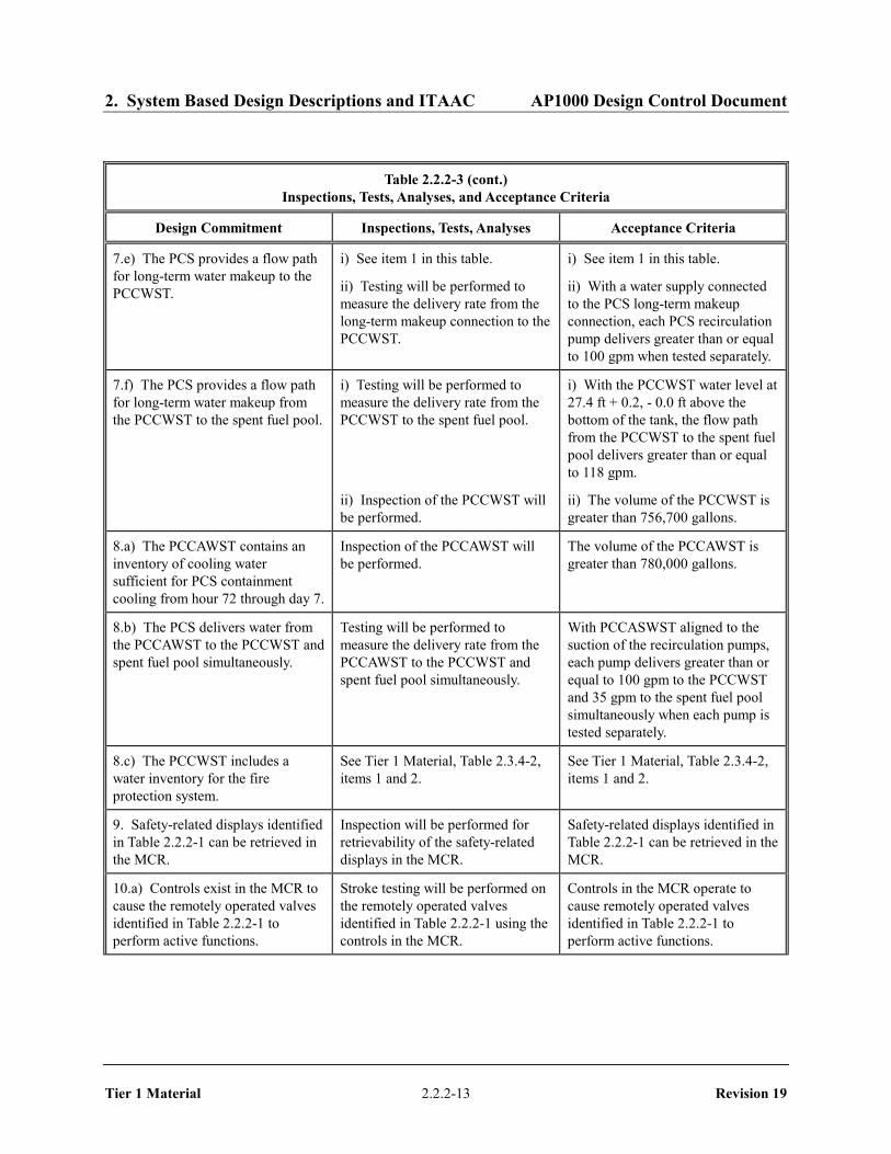
7.e) The PCS provides a flow path for long-term water makeup to the PCCWST.
i) See item 1 in this table.
ii) Testing will be performed to measure the delivery rate from the long-term makeup connection to the PCCWST.
i) See item 1 in this table.
ii) With a water supply connected to the PCS long-term makeup connection, each PCS recirculation pump delivers greater than or equal to 100 gpm when tested separately.
7.f) The PCS provides a flow path for long-term water makeup from the PCCWST to the spent fuel pool.
i) Testing will be performed to measure the delivery rate from the PCCWST to the spent fuel pool.
ii) Inspection of the PCCWST will be performed.
i) With the PCCWST water level at 27.4 ft + 0.2, - 0.0 ft above the bottom of the tank, the flow path from the PCCWST to the spent fuel pool delivers greater than or equal to 118 gpm.
ii) The volume of the PCCWST is greater than 756,700 gallons.
8.a) The PCCAWST contains an inventory of cooling water sufficient for PCS containment cooling from hour 72 through day 7.
Inspection of the PCCAWST will be performed.
The volume of the PCCAWST is greater than 780,000 gallons.
8.b) The PCS delivers water from the PCCAWST to the PCCWST and spent fuel pool simultaneously.
Testing will be performed to measure the delivery rate from the PCCAWST to the PCCWST and spent fuel pool simultaneously.
With PCCASWST aligned to the suction of the recirculation pumps, each pump delivers greater than or equal to 100 gpm to the PCCWST and 35 gpm to the spent fuel pool simultaneously when each pump is tested separately.
8.c) The PCCWST includes a water inventory for the fire protection system.
See Tier 1 Material, Table 2.3.4-2, items 1 and 2.
See Tier 1 Material, Table 2.3.4-2, items 1 and 2.
9. Safety-related displays identified in Table 2.2.2-1 can be retrieved in the MCR.
Inspection will be performed for retrievability of the safety-related displays in the MCR.
Safety-related displays identified in Table 2.2.2-1 can be retrieved in the MCR.
10.a) Controls exist in the MCR to cause the remotely operated valves identified in Table 2.2.2-1 to perform active functions.
Stroke testing will be performed on the remotely operated valves identified in Table 2.2.2-1 using the controls in the MCR.
Controls in the MCR operate to cause remotely operated valves identified in Table 2.2.2-1 to perform active functions.

2. System Based Design Descriptions and ITAAC AP1000 Design Control Document
Tier 1 Material 2.2.2-14 Revision 19
Table 2.2.2-3 (cont.)
Inspections, Tests, Analyses, and Acceptance Criteria
Design Commitment Inspections, Tests, Analyses Acceptance Criteria
10.b) The valves identified in Table 2.2.2-1 as having PMS control perform an active safety function after receiving a signal from the PMS.
Testing will be performed on the remotely operated valves in Table 2.2.2-1 using real or simulated signals into the PMS.
The remotely operated valves identified in Table 2.2.2-1 as having PMS control perform the active function identified in the table after receiving a signal from the PMS.
10.c) The valves identified in Table 2.2.2-1 as having DAS control perform an active safety function after receiving a signal from the DAS.
Testing will be performed on the remotely operated valves listed in Table 2.2.2-1 using real or simulated signals into the DAS.
The remotely operated valves identified in Table 2.2.2-1 as having DAS control perform the active function identified in the table after receiving a signal from the DAS.
11.a) The motor-operated valves identified in Table 2.2.2-1 perform an active safety-related function to change position as indicated in the table.
i) Tests or type tests of motor-operated valves will be performed to demonstrate the capability of the valve to operate under its design conditions.
ii) Inspection will be performed for the existence of a report verifying that the capability of the as-built motor-operated valves bound the tested conditions.
iii) Tests of the motor-operated valves will be performed under preoperational flow, differential pressure, and temperature conditions.
i) A test report exists and concludes that each motor-operated valve changes position as indicated in Table 2.2.2-1 under design conditions.
ii) A report exists and concludes that the capability of the as-built motor-operated valves bound the tested conditions.
iii) Each motor-operated valve changes position as indicated in Table 2.2.2-1 under preoperational test conditions.
11.b) After loss of motive power, the remotely operated valves identified in Table 2.2.2-1 assume the indicated loss of motive power position.
Testing of the remotely operated valves will be performed under the conditions of loss of motive power.
After loss of motive power, each remotely operated valve identified in Table 2.2.2-1 assumes the indicated loss of motive power position.

2. System Based Design Descriptions and ITAAC AP1000 Design Control Document
Tier 1 Material 2.2.2-15 Revision 19
Table 2.2.2-4
Component Name Tag No. Component Location
PCCWST PCS-MT-01 Shield Building PCCAWST PCS-MT-05 Yard
Recirculation Pump A PCS-MP-01A Auxiliary Building Recirculation Pump B PCS-MP-01B Auxiliary Building
2. System Based Design Descriptions and ITAAC AP1000 Design Control Document
Tier 1 Material 2.2.2-16 Revision 19
Figure 2.2.2-1 Passive Containment Cooling System

2. System Based Design Descriptions and ITAAC AP1000 Design Control Document
Tier 1 Material 2.2.3-1 Revision 19
2.2.3 Passive Core Cooling System
Design Description
The passive core cooling system (PXS) provides emergency core cooling during design basis events.
The PXS is as shown in Figure 2.2.3-1 and the component locations of the PXS are as shown in Table 2.2.3-5.
1. The functional arrangement of the PXS is as described in the Design Description of this Section 2.2.3.
2. a) The components identified in Table 2.2.3-1 as ASME Code Section III are designed and constructed in accordance with ASME Code Section III requirements.
b) The piping identified in Table 2.2.3-2 as ASME Code Section III is designed and constructed in accordance with ASME Code Section III requirements.
3. a) Pressure boundary welds in components identified in Table 2.2.3-1 as ASME Code Section III meet ASME Code Section III requirements.
b) Pressure boundary welds in piping identified in Table 2.2.3-2 as ASME Code Section III meet ASME Code Section III requirements.
4. a) The components identified in Table 2.2.3-1 as ASME Code Section III retain their pressure boundary integrity at their design pressure.
b) The piping identified in Table 2.2.3-2 as ASME Code Section III retains its pressure boundary integrity at its design pressure.
5. a) The seismic Category I equipment identified in Table 2.2.3-1 can withstand seismic design basis loads without loss of safety function.
b) Each of the lines identified in Table 2.2.3-2 for which functional capability is required is designed to withstand combined normal and seismic design basis loads without a loss of its functional capability.
6. Each of the as-built lines identified in Table 2.2.3-2 as designed for leak before break (LBB) meets the LBB criteria, or an evaluation is performed of the protection from the dynamic effects of a rupture of the line.
7. a) The Class 1E equipment identified in Table 2.2.3-1 as being qualified for a harsh environment can withstand the environmental conditions that would exist before, during, and following a design basis accident without loss of safety function for the time required to perform the safety function.
b) The Class 1E components identified in Table 2.2.3-1 are powered from their respective Class 1E division.

2. System Based Design Descriptions and ITAAC AP1000 Design Control Document
Tier 1 Material 2.2.3-2 Revision 19
c) Separation is provided between PXS Class 1E divisions, and between Class 1E divisions and non-Class 1E cable.
8. The PXS provides the following safety-related functions:
a) The PXS provides containment isolation of the PXS lines penetrating the containment.
b) The PRHR HX provides core decay heat removal during design basis events.
c) The CMTs, accumulators, in-containment refueling water storage tank (IRWST) and containment recirculation provide reactor coolant system (RCS) makeup, boration, and safety injection during design basis events.
d) The PXS provides pH adjustment of water flooding the containment following design basis accidents.
9. The PXS has the following features:
a) The PXS provides a function to cool the outside of the reactor vessel during a severe accident.
b) The accumulator discharge check valves (PXS-PL-V028A/B and V029A/B) are of a different check valve type than the CMT discharge check valves (PXS-PL-V016A/B and V017A/B).
c) The equipment listed in Table 2.2.3-6 has sufficient thermal lag to withstand the effects of identified hydrogen burns associated with severe accidents.
10. Safety-related displays of the parameters identified in Table 2.2.3-1 can be retrieved in the main control room (MCR).
11. a) Controls exist in the MCR to cause the remotely operated valves identified in Table 2.2.3-1 to perform their active function(s).
b) The valves identified in Table 2.2.3-1 as having protection and safety monitoring system (PMS) control perform their active function after receiving a signal from the PMS.
c) The valves identified in Table 2.2.3-1 as having diverse actuation system (DAS) control perform their active function after receiving a signal from the DAS.
12. a) The squib valves and check valves identified in Table 2.2.3-1 perform an active safety-related function to change position as indicated in the table.
b) After loss of motive power, the remotely operated valves identified in Table 2.2.3-1 assume the indicated loss of motive power position.
13. Displays of the parameters identified in Table 2.2.3-3 can be retrieved in the MCR.
2. System Based Design Descriptions and ITAAC AP1000 Design Control Document
Tier 1 Material 2.2.3-3 Revision 19
Inspection, Tests, Analyses, and Acceptance Criteria
Table 2.2.3-4 specifies the inspections, tests, analyses, and associated acceptance criteria for the PXS.

2. System Based Design Descriptions and ITAAC AP1000 Design Control Document
Tier 1 Material 2.2.3-4 Revision 19
Table 2.2.3-1
Equipment Name Tag No.
ASME Code
Section III
Seismic Cat. I
Remotely Operated
Valve
Class 1E/ Qual. Harsh Envir.
Safety-Related Display
Control PMS/ DAS
Active Function
Loss of Motive Power
Position
Passive Residual Heat Removal Heat Exchanger (PRHR HX)
PXS-ME-01 Yes Yes - - / - - - / - - -
Accumulator Tank A PXS-MT-01A Yes Yes - - / - - - / - - - Accumulator Tank B PXS-MT-01B Yes Yes - - / - - - / - - - Core Makeup Tank (CMT) A
PXS-MT-02A Yes Yes - - / - - - / - - -
CMT B PXS-MT-02B Yes Yes - - / - - - / - - - IRWST PXS-MT-03 No Yes - - / - - - / - - - IRWST Screen A PXS-MY-Y01A No Yes - - / - - - / - - - IRWST Screen B PXS-MY-Y01B No Yes - - / - - - / - - - IRWST Screen C PXS-MY-Y01C No Yes - - / - - - / - - - Containment Recirculation Screen A
PXS-MY-Y02A No Yes - - / - - - / - - -
Containment Recirculation Screen B
PXS-MY-Y02B No Yes - - / - - - / - - -
pH Adjustment Basket 3A PXS-MY-Y03A No Yes - - / - - - / - - - pH Adjustment Basket 3B PXS-MY-Y03B No Yes - - / - - - / - - - pH Adjustment Basket 4A PXS-MY-Y04A No Yes - / - - / - pH Adjustment Basket 4B PXS-MY-Y04B No Yes - / - - / - CMT A Inlet Isolation Motor-operated Valve
PXS-PL-V002A Yes Yes Yes Yes/Yes Yes (Position)
Yes/No None As Is
CMT B Inlet Isolation Motor-operated Valve
PXS-PL-V002B Yes Yes Yes Yes/Yes Yes (Position)
Yes/No None As Is
Note: Dash (-) indicates not applicable.

2. System Based Design Descriptions and ITAAC AP1000 Design Control Document
Tier 1 Material 2.2.3-5 Revision 19
Table 2.2.3-1 (cont.)
Equipment Name Tag No.
ASME Code
Section III
Seismic Cat. I
Remotely Operated
Valve
Class 1E/ Qual. Harsh Envir.
Safety-Related Display
Control PMS/ DAS
Active Function
Loss of Motive Power
Position
CMT A Discharge Isolation Valve
PXS-PL-V014A Yes Yes Yes Yes/Yes Yes (Position)
Yes/Yes Transfer Open
Open
CMT B Discharge Isolation Valve
PXS-PL-V014B Yes Yes Yes Yes/Yes Yes (Position)
Yes/Yes Transfer Open
Open
CMT A Discharge Isolation Valve
PXS-PL-V015A Yes Yes Yes Yes/Yes Yes (Position)
Yes/Yes Transfer Open
Open
CMT B Discharge Isolation Valve
PXS-PL-V015B Yes Yes Yes Yes/Yes Yes (Position)
Yes/Yes Transfer Open
Open
CMT A Discharge Check Valve
PXS-PL-V016A Yes Yes No - / - No - / - Transfer Open/
Transfer Closed
-
CMT B Discharge Check Valve
PXS-PL-V016B Yes Yes No - / - No - / - Transfer Open/
Transfer Closed
-
CMT A Discharge Check Valve
PXS-PL-V017A Yes Yes No - / - No - / - Transfer Open/
Transfer Closed
-
CMT B Discharge Check Valve
PXS-PL-V017B Yes Yes No - / - No - / - Transfer Open/
Transfer Closed
-
Note: Dash (-) indicates not applicable.

2. System Based Design Descriptions and ITAAC AP1000 Design Control Document
Tier 1 Material 2.2.3-6 Revision 19
Table 2.2.3-1 (cont.)
Equipment Name Tag No.
ASME Code
Section III
Seismic Cat. I
Remotely Operated
Valve
Class 1E/ Qual. Harsh Envir.
Safety-Related Display
Control PMS/ DAS
Active Function
Loss of Motive Power
Position
Accumulator A Pressure Relief Valve
PXS-PL-V022A Yes Yes No - / - No - / - Transfer Open/
Transfer Closed
-
Accumulator B Pressure Relief Valve
PXS-PL-V022B Yes Yes No - / - No - / - Transfer Open/
Transfer Closed
-
Accumulator A Discharge Isolation Valve
PXS-PL-V027A Yes Yes Yes - / - Yes - /No None As Is
Accumulator B Discharge Isolation Valve
PXS-PL-V027B Yes Yes Yes - / - Yes - /No None As Is
Accumulator A Discharge Check Valve
PXS-PL-V028A Yes Yes No - / - No - / - Transfer Open/ Close
-
Accumulator B Discharge Check Valve
PXS-PL-V028B Yes Yes No - / - No - / - Transfer Open/ Close
-
Accumulator A Discharge Check Valve
PXS-PL-V029A Yes Yes No - / - No - / - Transfer Open/ Close
-
Accumulator B Discharge Check Valve
PXS-PL-V029B Yes Yes No - / - No - / - Transfer Open/ Close
-
Note: Dash (-) indicates not applicable.

2. System Based Design Descriptions and ITAAC AP1000 Design Control Document
Tier 1 Material 2.2.3-7 Revision 19
Table 2.2.3-1 (cont.)
Equipment Name Tag No.
ASME Code
Section III
Seismic Cat. I
Remotely Operated
Valve
Class 1E/ Qual. Harsh Envir.
Safety-Related Display
Control PMS/ DAS
Active Function
Loss of Motive Power
Position
Nitrogen Supply Containment Isolation Valve
PXS-PL-V042 Yes Yes Yes Yes/No Yes (position)
Yes/No Transfer Closed
Close
Nitrogen Supply Containment Isolation Check Valve
PXS-PL-V043 Yes Yes No - / - No - / - Transfer Closed
-
PRHR HX Inlet Isolation Motor-operated Valve
PXS-PL-V101 Yes Yes Yes Yes/Yes Yes (position)
Yes/No None As Is
PRHR HX Control Valve PXS-PL-V108A Yes Yes Yes Yes/Yes Yes (Position)
Yes/Yes Transfer Open
Open
PRHR HX Control Valve PXS-PL-V108B Yes Yes Yes Yes/Yes Yes (Position)
Yes/Yes Transfer Open
Open
Containment Recirculation A Isolation Motor-operated Valve
PXS-PL-V117A Yes Yes Yes Yes/Yes Yes (position)
Yes/Yes None As Is
Containment Recirculation B Isolation Motor-operated Valve
PXS-PL-V117B Yes Yes Yes Yes/Yes Yes (position)
Yes/Yes None As Is
Containment Recirculation A Squib Valve
PXS-PL-V118A Yes Yes Yes Yes/Yes Yes (Position)
Yes/Yes Transfer Open
As Is
Containment Recirculation B Squib Valve
PXS-PL-V118B Yes Yes Yes Yes/Yes Yes (Position)
Yes/Yes Transfer Open
As Is
Note: Dash (-) indicates not applicable.
2. System Based Design Descriptions and ITAAC AP1000 Design Control Document
Tier 1 Material 2.2.3-8 Revision 19
Table 2.2.3-1 (cont.)
Equipment Name Tag No.
ASME Code
Section III
Seismic Cat. I
Remotely Operated
Valve
Class 1E/ Qual. Harsh Envir.
Safety-Related Display
Control PMS/ DAS
Active Function
Loss of Motive Power
Position
Containment Recirculation A Check Valve
PXS-PL-V119A Yes Yes No - / - No - / - Transfer Open/
Transfer Closed
-
Containment Recirculation B Check Valve
PXS-PL-V119B Yes Yes No - / - No - / - Transfer Open/
Transfer Closed
-
Containment Recirculation A Squib Valve
PXS-PL-V120A Yes Yes Yes Yes/Yes Yes (Position)
Yes/Yes Transfer Open
As Is
Containment Recirculation B Squib Valve
PXS-PL-V120B Yes Yes Yes Yes/Yes Yes (Position)
Yes/Yes Transfer Open
As Is
IRWST Injection A Check Valve
PXS-PL-V122A Yes Yes No - / - No - / - Transfer Open/
Transfer Closed
-
IRWST Injection B Check Valve
PXS-PL-V122B Yes Yes No - / - No - / - Transfer Open/
Transfer Closed
-
IRWST Injection A Squib Valve
PXS-PL-V123A Yes Yes Yes Yes/Yes Yes (Position)
Yes/Yes Transfer Open
As Is
IRWST Injection B Squib Valve
PXS-PL-V123B Yes Yes Yes Yes/Yes Yes (Position)
Yes/Yes Transfer Open
As Is
Note: Dash (-) indicates not applicable.
2. System Based Design Descriptions and ITAAC AP1000 Design Control Document
Tier 1 Material 2.2.3-9 Revision 19
Table 2.2.3-1 (cont.)
Equipment Name Tag No.
ASME Code
Section III
Seismic Cat. I
Remotely Operated
Valve
Class 1E/ Qual. Harsh Envir.
Safety-Related Display
Control PMS/ DAS
Active Function
Loss of Motive Power
Position
IRWST Injection A Check Valve
PXS-PL-V124A Yes Yes No - / - No - / - Transfer Open/
Transfer Closed
-
IRWST Injection B Check Valve
PXS-PL-V124B Yes Yes No - / - No - / - Transfer Open/
Transfer Closed
-
IRWST Injection A Squib Valve
PXS-PL-V125A Yes Yes Yes Yes/Yes Yes (Position)
Yes/Yes Transfer Open
As Is
IRWST Injection B Squib Valve
PXS-PL-V125B Yes Yes Yes Yes/Yes Yes (Position)
Yes/Yes Transfer Open
As Is
IRWST Gutter Isolation Valve
PXS-PL-V130A Yes Yes Yes Yes/Yes Yes (Position)
Yes/Yes Transfer Closed
Closed
IRWST Gutter Isolation Valve
PXS-PL-V130B Yes Yes Yes Yes/Yes Yes (Position)
Yes/Yes Transfer Closed
Closed
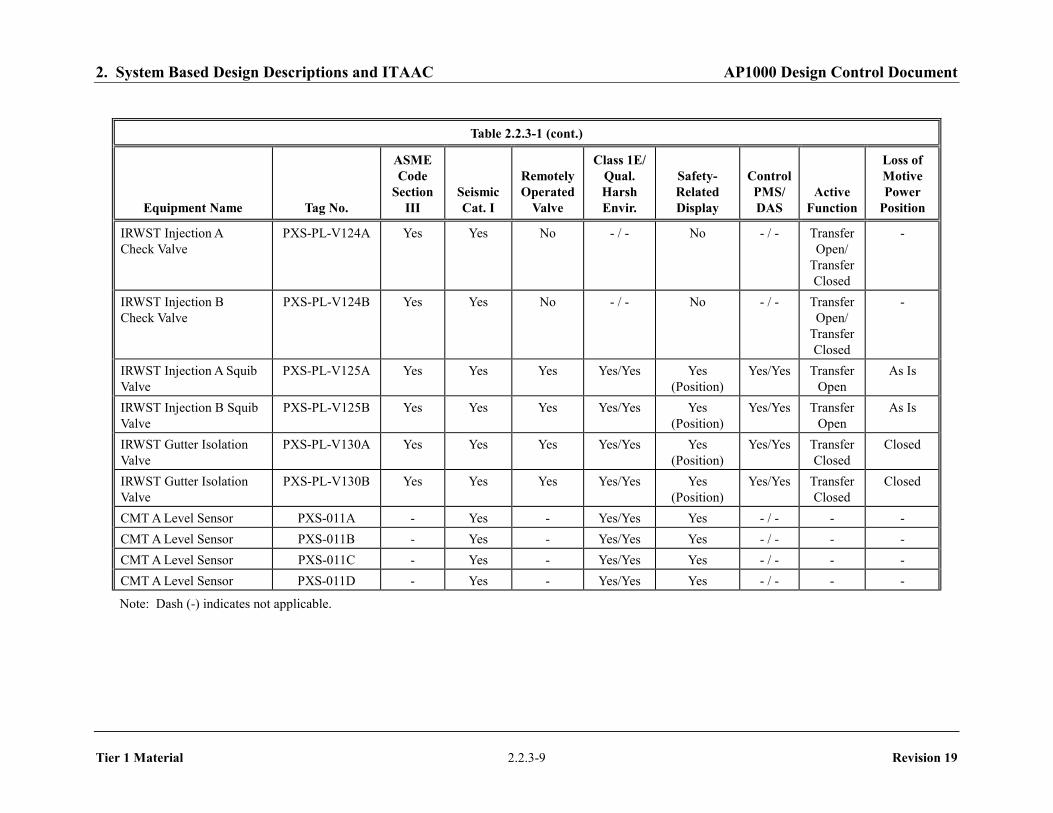
CMT A Level Sensor PXS-011A - Yes - Yes/Yes Yes - / - - - CMT A Level Sensor PXS-011B - Yes - Yes/Yes Yes - / - - - CMT A Level Sensor PXS-011C - Yes - Yes/Yes Yes - / - - - CMT A Level Sensor PXS-011D - Yes - Yes/Yes Yes - / - - -
Note: Dash (-) indicates not applicable.

2. System Based Design Descriptions and ITAAC AP1000 Design Control Document
Tier 1 Material 2.2.3-10 Revision 19
Table 2.2.3-1 (cont.)
Equipment Name Tag No.
ASME Code
Section III
Seismic Cat. I
Remotely Operated
Valve
Class 1E/ Qual. Harsh Envir.
Safety-Related Display
Control PMS/ DAS
Active Function
Loss of Motive Power
Position
CMT B Level Sensor PXS-012A - Yes - Yes/Yes Yes -/- - -
CMT B Level Sensor PXS-012B - Yes - Yes/Yes Yes -/- - -
CMT B Level Sensor PXS-012C - Yes - Yes/Yes Yes -/- - -
CMT B Level Sensor PXS-012D - Yes - Yes/Yes Yes -/- - -
CMT A Level Sensor PXS-013A - Yes - Yes/Yes Yes -/- - -
CMT A Level Sensor PXS-013B - Yes - Yes/Yes Yes -/- - -
CMT A Level Sensor PXS-013C - Yes - Yes/Yes Yes -/- - -
CMT A Level Sensor PXS-013D - Yes - Yes/Yes Yes -/- - -
CMT B Level Sensor PXS-014A - Yes - Yes/Yes Yes - / - - -
CMT B Level Sensor PXS-014B - Yes - Yes/Yes Yes - / - - -
CMT B Level Sensor PXS-014C - Yes - Yes/Yes Yes - / - - -
CMT B Level Sensor PXS-014D - Yes - Yes/Yes Yes - / - - -
IRWST Level Sensor PXS-045 - Yes - Yes/Yes Yes - / - - -
IRWST Level Sensor PXS-046 - Yes - Yes/Yes Yes - / - - -
IRWST Level Sensor PXS-047 - Yes - Yes/Yes Yes - / - - -
IRWST Level Sensor PXS-048 - Yes - Yes/Yes Yes - / - - -
PRHR HX Flow Sensor PXS-049A - Yes - Yes/Yes Yes - / - - -
PRHR HX Flow Sensor PXS-049B - Yes - Yes/Yes Yes - / - - -
Note: Dash (-) indicates not applicable.

2. System Based Design Descriptions and ITAAC AP1000 Design Control Document
Tier 1 Material 2.2.3-11 Revision 19
Table 2.2.3-1 (cont.)
Equipment Name Tag No.
ASME Code
Section III
Seismic Cat. I
Remotely Operated
Valve
Class 1E/ Qual. Harsh Envir.
Safety-Related Display
Control PMS/ DAS
Active Function
Loss of Motive Power
Position
Containment Flood-up Level Sensor
PXS-050 - Yes - Yes/Yes Yes -/- - -
Containment Flood-up Level Sensor
PXS-051 - Yes - Yes/Yes Yes -/- - -
Containment Flood-up Level Sensor
PXS-052 - Yes - Yes/Yes Yes -/- - -
RNS Suction Leak Test Valve
PXS-PL-V208A Yes Yes No - / - No -/- - -
Note: Dash (-) indicates not applicable.
2. System Based Design Descriptions and ITAAC AP1000 Design Control Document
Tier 1 Material 2.2.3-12 Revision 19
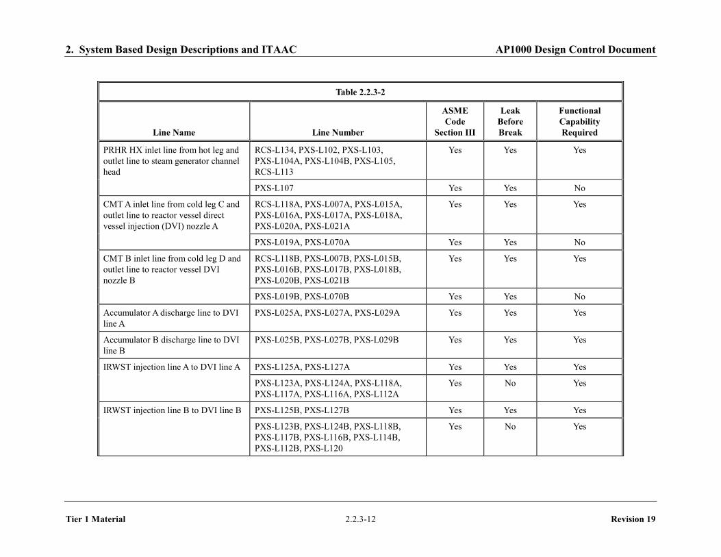
Table 2.2.3-2
Line Name Line Number
ASME Code
Section III
Leak Before Break
Functional Capability Required
PRHR HX inlet line from hot leg and outlet line to steam generator channel head
RCS-L134, PXS-L102, PXS-L103, PXS-L104A, PXS-L104B, PXS-L105, RCS-L113
Yes Yes Yes
PXS-L107 Yes Yes No
CMT A inlet line from cold leg C and outlet line to reactor vessel direct vessel injection (DVI) nozzle A
RCS-L118A, PXS-L007A, PXS-L015A, PXS-L016A, PXS-L017A, PXS-L018A, PXS-L020A, PXS-L021A
Yes Yes Yes
PXS-L019A, PXS-L070A Yes Yes No
CMT B inlet line from cold leg D and outlet line to reactor vessel DVI nozzle B
RCS-L118B, PXS-L007B, PXS-L015B, PXS-L016B, PXS-L017B, PXS-L018B, PXS-L020B, PXS-L021B
Yes Yes Yes
PXS-L019B, PXS-L070B Yes Yes No
Accumulator A discharge line to DVI line A
PXS-L025A, PXS-L027A, PXS-L029A Yes Yes Yes
Accumulator B discharge line to DVI line B
PXS-L025B, PXS-L027B, PXS-L029B Yes Yes Yes
IRWST injection line A to DVI line A PXS-L125A, PXS-L127A Yes Yes Yes
PXS-L123A, PXS-L124A, PXS-L118A, PXS-L117A, PXS-L116A, PXS-L112A
Yes No Yes
IRWST injection line B to DVI line B PXS-L125B, PXS-L127B Yes Yes Yes
PXS-L123B, PXS-L124B, PXS-L118B, PXS-L117B, PXS-L116B, PXS-L114B, PXS-L112B, PXS-L120
Yes No Yes

2. System Based Design Descriptions and ITAAC AP1000 Design Control Document
Tier 1 Material 2.2.3-13 Revision 19
Table 2.2.3-2 (cont.)
Line Name Line Number
ASME Code
Section III
Leak Before Break
Functional Capability Required
IRWST screen cross-connect line PXS-L180A, PXS-L180B Yes No Yes
Containment recirculation line A PXS-L113A, PXS-L131A, PXS-L132A Yes No Yes
Containment recirculation line B PXS-L113B, PXS-L131B, PXS-L132B Yes No Yes
IRWST gutter drain line PXS-L142A, PXS-L142B Yes No Yes
PXS-L141A, PXS-L141B Yes No No

2. System Based Design Descriptions and ITAAC AP1000 Design Control Document
Tier 1 Material 2.2.3-14 Revision 19
Table 2.2.3-3
Equipment Tag No. Display Control Function
CMT A Discharge Isolation Valve (Position) PXS-PL-V014A Yes (Position) -
CMT B Discharge Isolation Valve (Position) PXS-PL-V014B Yes (Position) -
CMT A Discharge Isolation Valve (Position) PXS-PL-V015A Yes (Position) -
CMT B Discharge Isolation Valve (Position) PXS-PL-V015B Yes (Position) -
Accumulator A Nitrogen Vent Valve (Position)
PXS-PL-V021A Yes (Position) -
Accumulator B Nitrogen Vent Valve (Position)
PXS-PL-V021B Yes (Position) -
Accumulator A Discharge Isolation Valve (Position)
PXS-PL-V027A Yes (Position) -
Accumulator B Discharge Isolation Valve (Position)
PXS-PL-V027B Yes (Position) -
PRHR HX Control Valve (Position) PXS-PL-V108A Yes (Position) -
PRHR HX Control Valve (Position) PXS-PL-V108B Yes (Position) -
Containment Recirculation A Isolation Valve PXS-PL-V017A Yes (Position) -
Containment Recirculation B Isolation Valve
PXS-PL-V017B Yes (Position) -
Containment Recirculation A Isolation Valve (Position)
PXS-PL-V118A Yes (Position) -
Containment Recirculation B Isolation Valve (Position)
PXS-PL-V118B Yes (Position) -
Containment Recirculation A Isolation Valve (Position)
PXS-PL-V120A Yes (Position) -
Containment Recirculation B Isolation Valve (Position)
PXS-PL-V120B Yes (Position) -
IRWST Line A Isolation Valve (Position) PXS-PL-V121A Yes (Position) -
IRWST Line B Isolation Valve (Position) PXS-PL-V121B Yes (Position) -
IRWST Injection A Isolation Squib (Position)
PXS-PL-V123A Yes (Position) -
Note: Dash (-) indicates not applicable.

2. System Based Design Descriptions and ITAAC AP1000 Design Control Document
Tier 1 Material 2.2.3-15 Revision 19
Table 2.2.3-3 (cont.)
Equipment Tag No. Display Control Function
IRWST Injection B Isolation Squib (Position)
PXS-PL-V123B Yes (Position) -
IRWST Injection A Isolation Squib (Position)
PXS-PL-V125A Yes (Position) -
IRWST Injection B Isolation Squib (Position)
PXS-PL-V125B Yes (Position) -
IRWST Gutter Bypass Isolation Valve (Position)
PXS-PL-V130A Yes (Position) -
IRWST Gutter Bypass Isolation Valve (Position)
PXS-PL-V130B Yes (Position) -
Accumulator A Level Sensor PXS-JE-L021 Yes -
Accumulator B Level Sensor PXS-JE-L022 Yes -
Accumulator A Level Sensor PXS-JE-L023 Yes -
Accumulator B Level Sensor PXS-JE-L024 Yes -
PRHR HX Inlet Temperature Sensor PXS-JE-T064 Yes -
IRWST Surface Temperature Sensor PXS-JE-T041 Yes -
IRWST Surface Temperature Sensor PXS-JE-T042 Yes -
IRWST Bottom Temperature Sensor PXS-JE-T043 Yes -
IRWST Bottom Temperature Sensor PXS-JE-T044 Yes -
Note: Dash (-) indicates not applicable.

2. System Based Design Descriptions and ITAAC AP1000 Design Control Document
Tier 1 Material 2.2.3-16 Revision 19
Table 2.2.3-4
Inspections, Tests, Analyses, and Acceptance Criteria
Design Commitment Inspections, Tests, Analyses Acceptance Criteria
1. The functional arrangement of the PXS is as described in the Design Description of this Section 2.2.3.
Inspection of the as-built system will be performed.
The as-built PXS conforms with the functional arrangement as described in the Design Description of this Section 2.2.3.
2.a) The components identified in Table 2.2.3-1 as ASME Code Section III are designed and constructed in accordance with ASME Code Section III requirements.
Inspection will be conducted of the as-built components as documented in the ASME design reports.
The ASME Code Section III design reports exist for the as-built components identified in Table 2.2.3-1 as ASME Code Section III.
2.b) The piping identified in Table 2.2.3-2 as ASME Code Section III is designed and constructed in accordance with ASME Code Section III requirements.
Inspection will be conducted of the as-built piping as documented in the ASME design reports.
The ASME Code Section III design reports exist for the as-built piping identified in Table 2.2.3-2 as ASME Code Section III.
3.a) Pressure boundary welds in components identified in Table 2.2.3-1 as ASME Code Section III meet ASME Code Section III requirements.
Inspection of the as-built pressure boundary welds will be performed in accordance with the ASME Code Section III.
A report exists and concludes that the ASME Code Section III requirements are met for non-destructive examination of pressure boundary welds.
3.b) Pressure boundary welds in piping identified in Table 2.2.3-2 as ASME Code Section III meet ASME Code Section III requirements.
Inspection of the as-built pressure boundary welds will be performed in accordance with the ASME Code Section III.
A report exists and concludes that the ASME Code Section III requirements are met for non-destructive examination of pressure boundary welds.
4.a) The components identified in Table 2.2.3-1 as ASME Code Section III retain their pressure boundary integrity at their design pressure.
A hydrostatic test will be performed on the components required by the ASME Code Section III to be hydrostatically tested.
A report exists and concludes that the results of the hydrostatic test of the components identified in Table 2.2.3-1 as ASME Code Section III conform with the requirements of the ASME Code Section III.
4.b) The piping identified in Table 2.2.3-2 as ASME Code Section III retains its pressure boundary integrity at its design pressure.
A hydrostatic test will be performed on the piping required by the ASME Code Section III to be hydrostatically tested.
A report exists and concludes that the results of the hydrostatic test of the piping identified in Table 2.2.3-2 as ASME Code Section III conform with the requirements of the ASME Code Section III.

2. System Based Design Descriptions and ITAAC AP1000 Design Control Document
Tier 1 Material 2.2.3-17 Revision 19
Table 2.2.3-4 (cont.)
Inspections, Tests, Analyses, and Acceptance Criteria
Design Commitment Inspections, Tests, Analyses Acceptance Criteria
5.a) The seismic Category I equipment identified in Table 2.2.3-1 can withstand seismic design basis loads without loss of safety function.
i) Inspection will be performed to verify that the seismic Category I equipment and valves identified in Table 2.2.3-1 are located on the Nuclear Island.
i) The seismic Category I equipment identified in Table 2.2.3-1 is located on the Nuclear Island.
ii) Type tests, analyses, or a combination of type tests and analyses of seismic Category I equipment will be performed.
ii) A report exists and concludes that the seismic Category I equipment can withstand seismic design basis dynamic loads without loss of safety function. For the PXS containment recirculation and IRWST screens, a report exists and concludes that the screens can withstand seismic dynamic loads and also post-accident operating loads, including head loss and debris weights.
iii) Inspection will be performed for the existence of a report verifying that the as-built equipment including anchorage is seismically bounded by the tested or analyzed conditions.
iii) A report exists and concludes that the as-built equipment including anchorage is seismically bounded by the tested or analyzed conditions. For the PXS containment recirculation and IRWST screens, a report exists and concludes that the as-built screens including their anchorage are bounded by the seismic loads and also post-accident operating loads, including head loss and debris weights.
5.b) Each of the lines identified in Table 2.2.3-2 for which functional capability is required is designed to withstand combined normal and seismic design basis loads without a loss of its functional capability.
Inspection will be performed verifying that the as-built piping meets the requirements for functional capability.
A report exists and concludes that each of the as-built lines identified in Table 2.2.3-2 for which functional capability is required meets the requirements for functional capability.

2. System Based Design Descriptions and ITAAC AP1000 Design Control Document
Tier 1 Material 2.2.3-18 Revision 19
Table 2.2.3-4 (cont.) Inspections, Tests, Analyses, and Acceptance Criteria
Design Commitment Inspections, Tests, Analyses Acceptance Criteria
6. Each of the as-built lines identified in Table 2.2.3-2 as designed for LBB meets the LBB criteria, or an evaluation is performed of the protection from the dynamic effects of a rupture of the line.
Inspection will be performed for the existence of an LBB evaluation report or an evaluation report on the protection from dynamic effects of a pipe break. Tier 1 Material, Section 3.3, Nuclear Island Buildings, contains the design descriptions and inspections, tests, analyses, and acceptance criteria for protection from the dynamic effects of pipe rupture.
An LBB evaluation report exists and concludes that the LBB acceptance criteria are met by the as-built RCS piping and piping materials, or a pipe break evaluation report exists and concludes that protection from the dynamic effects of a line break is provided.
7.a) The Class 1E equipment identified in Table 2.2.3-1 as being qualified for a harsh environment can withstand the environmental conditions that would exist before, during, and following a design basis accident without loss of safety function for the time required to perform the safety function.
i) Type tests, analyses, or a combination of type tests and analyses will be performed on Class 1E equipment located in a harsh environment.
ii) Inspection will be performed of the as-built Class 1E equipment and the associated wiring, cables, and terminations located in a harsh environment.
i) A report exists and concludes that the Class 1E equipment identified in Table 2.2.3-1 as being qualified for a harsh environment can withstand the environmental conditions that would exist before, during, and following a design basis accident without loss of safety function for the time required to perform the safety function.
ii) A report exists and concludes that the as-built Class 1E equipment and the associated wiring, cables, and terminations identified in Table 2.2.3-1 as being qualified for a harsh environment are bounded by type tests, analyses, or a combination of type tests and analyses.
7.b) The Class 1E components identified in Table 2.2.3-1 are powered from their respective Class 1E division.
Testing will be performed by providing a simulated test signal in each Class 1E division.
A simulated test signal exists at the Class 1E equipment identified in Table 2.2.3-1 when the assigned Class 1E division is provided the test signal.
7.c) Separation is provided between PXS Class 1E divisions, and between Class 1E divisions and non-Class 1E cable.
See Tier 1 Material, Table 3.3-6, item 7.d.
See Tier 1 Material, Table 3.3-6, item 7.d.
8.a) The PXS provides containment isolation of the PXS lines penetrating the containment.
See Tier 1 Material, Table 2.2.1-3, items 1 and 7.
See Tier 1 Material, Table 2.2.1-3, items 1 and 7.
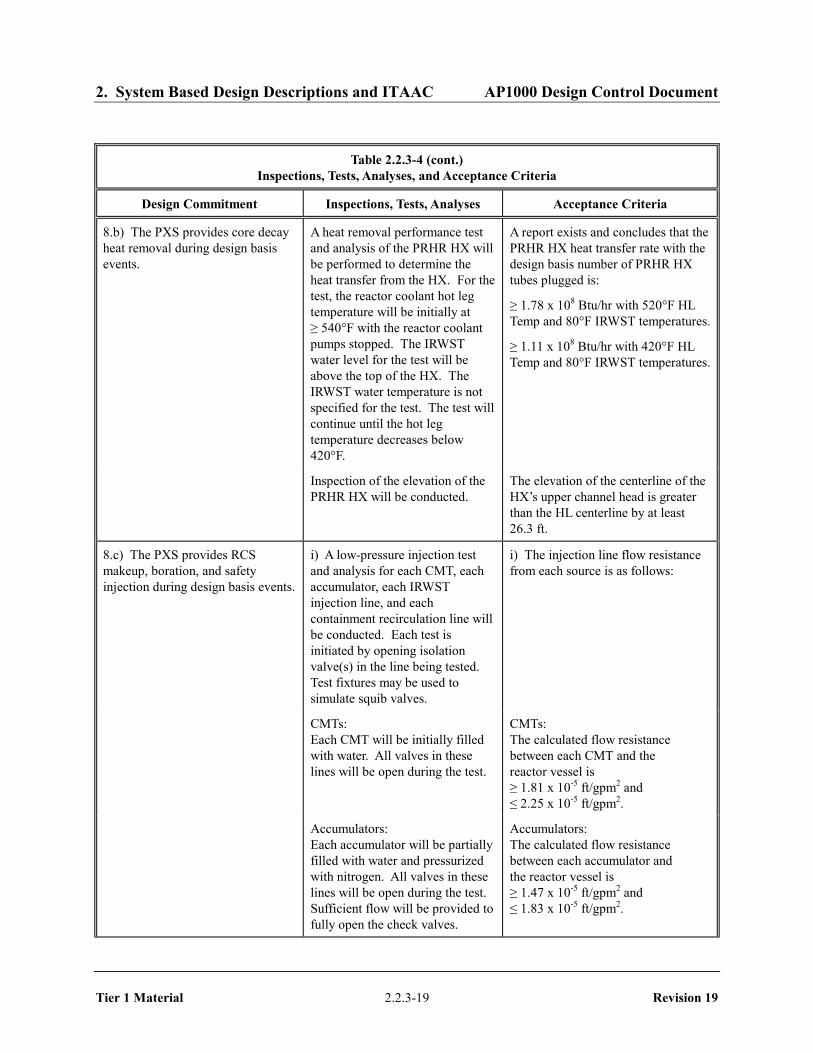
2. System Based Design Descriptions and ITAAC AP1000 Design Control Document
Tier 1 Material 2.2.3-19 Revision 19
Table 2.2.3-4 (cont.) Inspections, Tests, Analyses, and Acceptance Criteria
Design Commitment Inspections, Tests, Analyses Acceptance Criteria
8.b) The PXS provides core decay heat removal during design basis events.
A heat removal performance test and analysis of the PRHR HX will be performed to determine the heat transfer from the HX. For the test, the reactor coolant hot leg temperature will be initially at ≥ 540°F with the reactor coolant pumps stopped. The IRWST water level for the test will be above the top of the HX. The IRWST water temperature is not specified for the test. The test will continue until the hot leg temperature decreases below 420°F.
A report exists and concludes that the PRHR HX heat transfer rate with the design basis number of PRHR HX tubes plugged is:
≥ 1.78 x 10⁸ Btu/hr with 520°F HL Temp and 80°F IRWST temperatures.
≥ 1.11 x 10⁸ Btu/hr with 420°F HL Temp and 80°F IRWST temperatures.
Inspection of the elevation of the PRHR HX will be conducted.
The elevation of the centerline of the HX’s upper channel head is greater than the HL centerline by at least 26.3 ft.
8.c) The PXS provides RCS makeup, boration, and safety injection during design basis events.
i) A low-pressure injection test and analysis for each CMT, each accumulator, each IRWST injection line, and each containment recirculation line will be conducted. Each test is initiated by opening isolation valve(s) in the line being tested. Test fixtures may be used to simulate squib valves.
i) The injection line flow resistance from each source is as follows:
CMTs: Each CMT will be initially filled with water. All valves in these lines will be open during the test.
CMTs: The calculated flow resistance between each CMT and the reactor vessel is ≥ 1.81 x 10⁻⁵ ft/gpm2 and ≤ 2.25 x 10⁻⁵ ft/gpm2.
Accumulators: Each accumulator will be partially filled with water and pressurized with nitrogen. All valves in these lines will be open during the test. Sufficient flow will be provided to fully open the check valves.
Accumulators: The calculated flow resistance between each accumulator and the reactor vessel is ≥ 1.47 x 10⁻⁵ ft/gpm2 and ≤ 1.83 x 10⁻⁵ ft/gpm2.

2. System Based Design Descriptions and ITAAC AP1000 Design Control Document
Tier 1 Material 2.2.3-20 Revision 19
Table 2.2.3-4 (cont.) Inspections, Tests, Analyses, and Acceptance Criteria
Design Commitment Inspections, Tests, Analyses Acceptance Criteria
IRWST Injection: The IRWST will be partially filled with water. All valves in these lines will be open during the test. Sufficient flow will be provided to fully open the check valves.
IRWST Injection: The calculated flow resistance for each IRWST injection line between the IRWST and the reactor vessel is: Line A: ≥ 5.53 x 10⁻⁶ ft/gpm2 and ≤ 9.20 x 10⁻⁶ ft/gpm2 and Line B: ≥ 6.21 x 10⁻⁶ ft/gpm2 and ≤ 1.03 x 10⁻⁵ ft/gpm2.
Containment Recirculation: A temporary water supply will be connected to the recirculation lines. All valves in these lines will be open during the test. Sufficient flow will be provided to fully open the check valves.
Containment Recirculation: The calculated flow resistance for each containment recirculation line between the containment and the reactor vessel is: Line A: ≤ 1.11 x 10⁻⁵ ft/gpm2 and Line B: ≤ 1.04 x 10⁻⁵ ft/gpm2.
ii) A low-pressure test and analysis will be conducted for each CMT to determine piping flow resistance from the cold leg to the CMT. The test will be performed by filling the CMT via the cold leg balance line by operating the normal residual heat removal pumps.
ii) The flow resistance from the cold leg to the CMT is ≤ 7.21 x 10⁻⁶ ft/gpm2.
iii) Inspections of the routing of the following pipe lines will be conducted:
– CMT inlet line, cold leg to high point
– PRHR HX inlet line, hot leg to high point
iii) These lines have no downward sloping sections between the connection to the RCS and the high point of the line.

2. System Based Design Descriptions and ITAAC AP1000 Design Control Document
Tier 1 Material 2.2.3-21 Revision 19
Table 2.2.3-4 (cont.) Inspections, Tests, Analyses, and Acceptance Criteria
Design Commitment Inspections, Tests, Analyses Acceptance Criteria
iv) Inspections of the elevation of the following pipe lines will be conducted:
– IRWST injection lines; IRWST connection to DVI nozzles
– Containment recirculation lines; containment to IRWST lines
– CMT discharge lines to DVI connection
– PRHR HX outlet line to SG connection
iv) The maximum elevation of the top inside surface of these lines is less than the elevation of:
– IRWST bottom inside surface
– IRWST bottom inside surface
– CMT bottom inside surface
– PRHR HX lower channel head top inside surface
v) Inspections of the elevation of the following tanks will be conducted:
– CMTs – IRWST
v) The elevation of the bottom inside tank surface is higher than the direct vessel injection nozzle centerline by the following:
– CMTs ≥ 7.5 ft – IRWST ≥ 3.4 ft
vi) Inspections of each of the following tanks will be conducted:
– CMTs – Accumulators – IRWST
vi) The calculated volume of each of the following tanks is as follows:
– CMTs ≥ 2487 ft3 – Accumulators ≥ 2000 ft3 – IRWST > 73,900 ft3 between the
tank outlet connection and the tank overflow
vii) Inspection of the as-built components will be conducted for plates located above the containment recirculation screens.
vii) Plates located above each containment recirculation screen are no more than 1 ft above the top of the screen and extend out at least 10 ft perpendicular to and at least 7 ft to the side of the screen surface.

2. System Based Design Descriptions and ITAAC AP1000 Design Control Document
Tier 1 Material 2.2.3-22 Revision 19
Table 2.2.3-4 (cont.)
Inspections, Tests, Analyses, and Acceptance Criteria
Design Commitment Inspections, Tests, Analyses Acceptance Criteria
viii) Inspections of the IRWST and containment recirculation screens will be conducted. The inspections will include measurements of the pockets and the number of pockets used in each screen. The pocket frontal face area is based on a width times a height. The width is the distance between pocket centerlines for pockets located beside each other. The height is the distance between pocket centerlines for pockets located above each other. The pocket screen area is the total area of perforated plate inside each pocket; this area will be determined by inspection of the screen manufacturing drawings.
viii) The screens utilize pockets with a frontal face area of ≥ 6.2 in2 and a screen surface area ≥ 140 in2 per pocket. IRWST Screens A and B each have a sufficient number of pockets to provide a frontal face area ≥ 20 ft2, a screen surface area ≥ 500 ft2, and a screen mesh size of ≤ 0.0625 inch. IRWST Screen C has a sufficient number of pockets to provide a frontal face area ≥ 40 ft2, a screen surface area ≥ 1000 ft2, and a screen mesh size ≤ 0.0625 inch. Each containment recirculation screen has a sufficient number of pockets to provide a frontal face area ≥ 105 ft2, a screen surface area ≥ 2500 ft2, and a screen mesh size ≤ 0.0625 inch.
A debris curb exists in front of the containment recirculation screens which is > 2 ft above the loop compartment floor. The bottoms of the IRWST screens are located ≥ 6 in above the bottom of the IRWST.
ix) Inspections will be conducted of the insulation used inside the containment on the ASME Class 1 lines, reactor vessel, reactor coolant pumps, pressurizer and steam generators.
Inspections will be conducted of other insulation used inside the containment within the zone of influence (ZOI).
ix) The type of insulation used on these lines and equipment is a metal reflective type or a suitable equivalent. If an insulation other than metal reflective insulation is used, a report must exist and conclude that the insulation is a suitable equivalent.
The type of insulation used on these lines and equipment is a metal reflective type or a suitable equivalent. If an insulation other than metal reflective insulation is used, a report must exist and conclude that the insulation is a suitable equivalent.
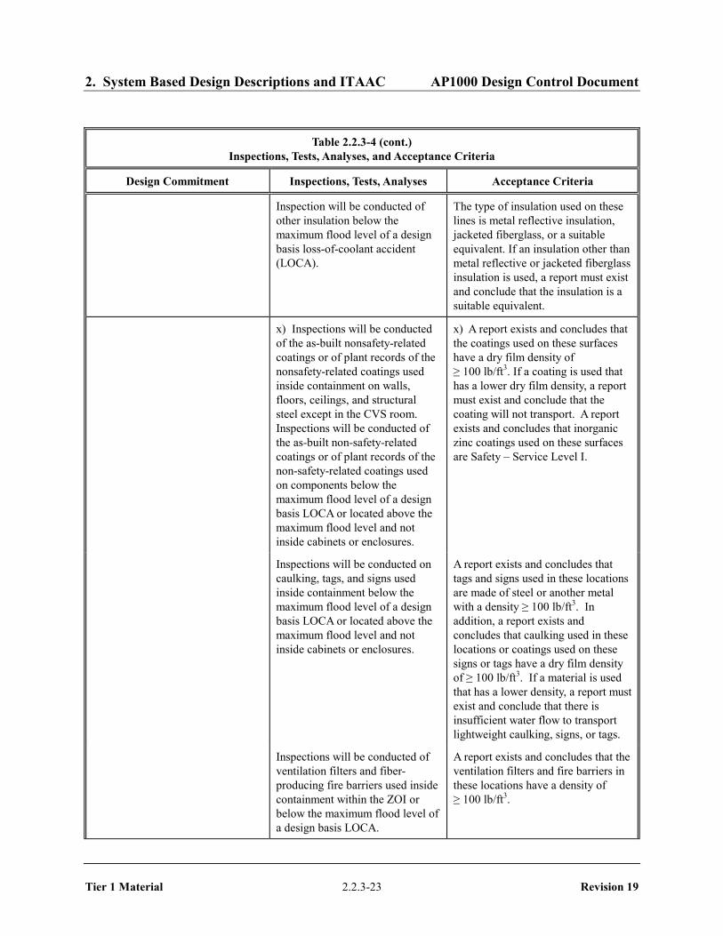
2. System Based Design Descriptions and ITAAC AP1000 Design Control Document
Tier 1 Material 2.2.3-23 Revision 19
Table 2.2.3-4 (cont.) Inspections, Tests, Analyses, and Acceptance Criteria
Design Commitment Inspections, Tests, Analyses Acceptance Criteria
Inspection will be conducted of other insulation below the maximum flood level of a design basis loss-of-coolant accident (LOCA).
The type of insulation used on these lines is metal reflective insulation, jacketed fiberglass, or a suitable equivalent. If an insulation other than metal reflective or jacketed fiberglass insulation is used, a report must exist and conclude that the insulation is a suitable equivalent.
x) Inspections will be conducted of the as-built nonsafety-related coatings or of plant records of the nonsafety-related coatings used inside containment on walls, floors, ceilings, and structural steel except in the CVS room. Inspections will be conducted of the as-built non-safety-related coatings or of plant records of the non-safety-related coatings used on components below the maximum flood level of a design basis LOCA or located above the maximum flood level and not inside cabinets or enclosures.
x) A report exists and concludes that the coatings used on these surfaces have a dry film density of ≥ 100 lb/ft3. If a coating is used that has a lower dry film density, a report must exist and conclude that the coating will not transport. A report exists and concludes that inorganic zinc coatings used on these surfaces are Safety – Service Level I.
Inspections will be conducted on caulking, tags, and signs used inside containment below the maximum flood level of a design basis LOCA or located above the maximum flood level and not inside cabinets or enclosures.
A report exists and concludes that tags and signs used in these locations are made of steel or another metal with a density ≥ 100 lb/ft3. In addition, a report exists and concludes that caulking used in these locations or coatings used on these signs or tags have a dry film density of ≥ 100 lb/ft3. If a material is used that has a lower density, a report must exist and conclude that there is insufficient water flow to transport lightweight caulking, signs, or tags.
Inspections will be conducted of ventilation filters and fiber-producing fire barriers used inside containment within the ZOI or below the maximum flood level of a design basis LOCA.
A report exists and concludes that the ventilation filters and fire barriers in these locations have a density of ≥ 100 lb/ft3.

2. System Based Design Descriptions and ITAAC AP1000 Design Control Document
Tier 1 Material 2.2.3-24 Revision 19
Table 2.2.3-4 (cont.) Inspections, Tests, Analyses, and Acceptance Criteria
Design Commitment Inspections, Tests, Analyses Acceptance Criteria
xi) Inspection of the as-built CMT inlet diffuser will be conducted.
xi) The CMT inlet diffuser has a flow area ≥ 165 in2.
xii) Inspections will be conducted of the CMT level sensors (PSX-11A/B/D/C, - 12A/B/C/D, - 13A/B/C/D, - 14A/B/C/D) upper level tap lines.
xii) Each upper level tap line has a downward slope of ≥ 2.4 degrees from the centerline of the connection to the CMT to the centerline of the connection to the standpipe.
xiii) Inspections will be conducted of the surfaces in the vicinity of the containment recirculation screens. The surfaces in the vicinity of the containment recirculation screens are the surfaces located above the bottom of the recirculation screens up to and including the bottom surface of the plate discussed in Table 2.2.3-4, item 8.c.vii, out at least 10 feet perpendicular to and at least 7 feet perpendicular to the side of the screen face.
xiii) These surfaces are stainless steel.
xiv) Inspections will be conducted of the exposed surfaces of the source range, intermediate range, and power range detectors.
xiv) These surfaces are made of stainless steel or titanium.
8.d) The PXS provides pH adjustment of water flooding the containment following design basis accidents.
Inspections of the pH adjustment baskets will be conducted.
pH adjustment baskets exist, with a total calculated volume ≥ 560 ft3.
The pH baskets are located below plant elevation 107 ft, 2 in.
9.a) The PXS provides a function to cool the outside of the reactor vessel during a severe accident.
i) A flow test and analysis for each IRWST drain line to the containment will be conducted. The test is initiated by opening isolation valves in each line. Test fixtures may be used to simulate squib valves.
i) The calculated flow resistance for each IRWST drain line between the IRWST and the containment is ≤ 4.07 x 10⁻⁶ ft/gpm2.
ii) Inspections of the as-built reactor vessel insulation will be performed.
ii) The combined total flow area of the water inlets is not less than 6 ft2. The combined total flow area of the steam outlet(s) is not less than 12 ft2.
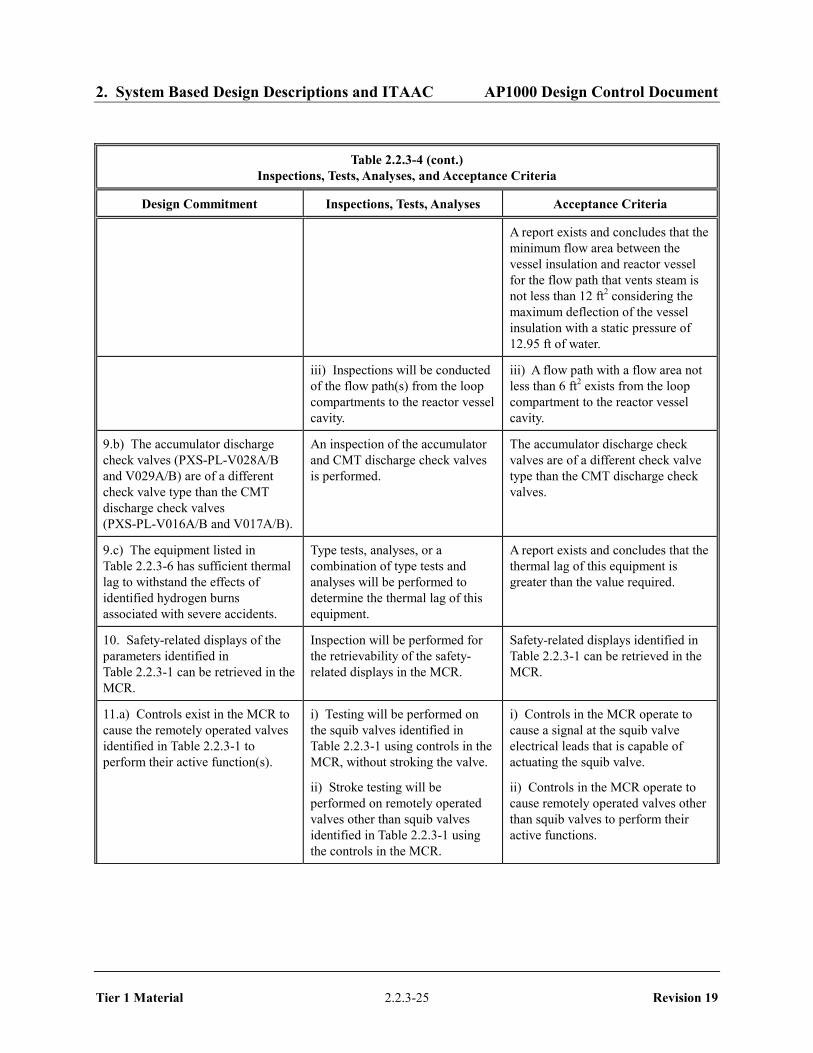
2. System Based Design Descriptions and ITAAC AP1000 Design Control Document
Tier 1 Material 2.2.3-25 Revision 19
Table 2.2.3-4 (cont.) Inspections, Tests, Analyses, and Acceptance Criteria
Design Commitment Inspections, Tests, Analyses Acceptance Criteria
A report exists and concludes that the minimum flow area between the vessel insulation and reactor vessel for the flow path that vents steam is not less than 12 ft2 considering the maximum deflection of the vessel insulation with a static pressure of 12.95 ft of water.
iii) Inspections will be conducted of the flow path(s) from the loop compartments to the reactor vessel cavity.
iii) A flow path with a flow area not less than 6 ft2 exists from the loop compartment to the reactor vessel cavity.
9.b) The accumulator discharge check valves (PXS-PL-V028A/B and V029A/B) are of a different check valve type than the CMT discharge check valves (PXS-PL-V016A/B and V017A/B).
An inspection of the accumulator and CMT discharge check valves is performed.
The accumulator discharge check valves are of a different check valve type than the CMT discharge check valves.
9.c) The equipment listed in Table 2.2.3-6 has sufficient thermal lag to withstand the effects of identified hydrogen burns associated with severe accidents.
Type tests, analyses, or a combination of type tests and analyses will be performed to determine the thermal lag of this equipment.
A report exists and concludes that the thermal lag of this equipment is greater than the value required.
10. Safety-related displays of the parameters identified in Table 2.2.3-1 can be retrieved in the MCR.
Inspection will be performed for the retrievability of the safety-related displays in the MCR.
Safety-related displays identified in Table 2.2.3-1 can be retrieved in the MCR.
11.a) Controls exist in the MCR to cause the remotely operated valves identified in Table 2.2.3-1 to perform their active function(s).
i) Testing will be performed on the squib valves identified in Table 2.2.3-1 using controls in the MCR, without stroking the valve.
i) Controls in the MCR operate to cause a signal at the squib valve electrical leads that is capable of actuating the squib valve.
ii) Stroke testing will be performed on remotely operated valves other than squib valves identified in Table 2.2.3-1 using the controls in the MCR.
ii) Controls in the MCR operate to cause remotely operated valves other than squib valves to perform their active functions.

2. System Based Design Descriptions and ITAAC AP1000 Design Control Document
Tier 1 Material 2.2.3-26 Revision 19
Table 2.2.3-4 (cont.) Inspections, Tests, Analyses, and Acceptance Criteria
Design Commitment Inspections, Tests, Analyses Acceptance Criteria
11.b) The valves identified in Table 2.2.3-1 as having PMS control perform their active function after receiving a signal from the PMS.
i) Testing will be performed on the squib valves identified in Table 2.2.3-1 using real or simulated signals into the PMS without stroking the valve.
i) Squib valves receive an electrical signal at the valve electrical leads that is capable of actuating the valve after a signal is input to the PMS.
ii) Testing will be performed on the remotely operated valves other than squib valves identified in Table 2.2.3-1 using real or simulated signals into the PMS.
ii) Remotely operated valves other than squib valves perform the active function identified in the table after a signal is input to the PMS.
iii) Testing will be performed to demonstrate that remotely operated PXS isolation valves PXS-V014A/B, V015A/B, V108A/B open within the required response times.
iii) These valves open within 20 seconds after receipt of an actuation signal.
11.c) The valves identified in Table 2.2.3-1 as having DAS control perform their active function after receiving a signal from the DAS.
i) Testing will be performed on the squib valves identified in Table 2.2.3-1 using real or simulated signals into the DAS without stroking the valve.
i) Squib valves receive an electrical signal at the valve electrical leads that is capable of actuating the valve after a signal is input to the DAS.
ii) Testing will be performed on the remotely operated valves other than squib valves identified in Table 2.2.3-1 using real or simulated signals into the DAS.
ii) Remotely operated valves other than squib valves perform the active function identified in Table 2.2.3-1 after a signal is input to the DAS.

2. System Based Design Descriptions and ITAAC AP1000 Design Control Document
Tier 1 Material 2.2.3-27 Revision 19
Table 2.2.3-4 (cont.) Inspections, Tests, Analyses, and Acceptance Criteria
Design Commitment Inspections, Tests, Analyses Acceptance Criteria
12.a) The squib valves and check valves identified in Table 2.2.3-1 perform an active safety-related function to change position as indicated in the table.
i) Tests or type tests of squib valves will be performed that demonstrate the capability of the valve to operate under its design condition.
i) A test report exists and concludes that each squib valve changes position as indicated in Table 2.2.3-1 under design conditions.
ii) Inspection will be performed for the existence of a report verifying that the as-built squib valves are bounded by the tests or type tests.
ii) A report exists and concludes that the as-built squib valves are bounded by the tests or type tests.
iii) Deleted iii) Deleted
iv) Exercise testing of the check valves with active safety functions identified in Table 2.2.3-1 will be performed under preoperational test pressure, temperature, and fluid flow conditions.
iv) Each check valve changes position as indicated in Table 2.2.3-1
12.b) After loss of motive power, the remotely operated valves identified in Table 2.2.3-1 assume the indicated loss of motive power position.
Testing of the remotely operated valves will be performed under the conditions of loss of motive power.
After loss of motive power, each remotely operated valve identified in Table 2.2.3-1 assumes the indicated loss of motive power position.
13. Displays of the parameters identified in Table 2.2.3-3 can be retrieved in the MCR.
Inspection will be performed for retrievability of the displays identified in Table 2.2.3-3 in the MCR.
Displays identified in Table 2.2.3-3 can be retrieved in the MCR.

2. System Based Design Descriptions and ITAAC AP1000 Design Control Document
Tier 1 Material 2.2.3-28 Revision 19
Table 2.2.3-5
Component Name Tag No. Component Location
Passive Residual Heat Removal Heat Exchanger (PRHR HX)
PXS-ME-01 Containment Building
Accumulator Tank A PXS-MT-01A Containment Building
Accumulator Tank B PXS-MT-01B Containment Building
Core Makeup Tank (CMT) A PXS-MT-02A Containment Building
CMT B PXS-MT-02B Containment Building
IRWST PXS-MT-03 Containment Building
IRWST Screen A PXS-MY-Y01A Containment Building
IRWST Screen B PXS-MY-Y01B Containment Building
IRWST Screen C PXS-MY-Y01C Containment Building
Containment Recirculation Screen A PXS-MY-Y02A Containment Building
Containment Recirculation Screen B PXS-MY-Y02B Containment Building
pH Adjustment Basket 3A PXS-MY-Y03A Containment Building
pH Adjustment Basket 3B PXS-MY-Y03B Containment Building
pH Adjustment Basket 4A PXS-MY-Y04A Containment Building
pH Adjustment Basket 4B PXS-MY-Y04B Containment Building

2. System Based Design Descriptions and ITAAC AP1000 Design Control Document
Tier 1 Material 2.2.3-29 Revision 19
Table 2.2.3-6
Equipment Tag No. Function
Hot Leg Sample Isolation Valves PSS-PL-V001A/B Transfer open
Liquid Sample Line Containment Isolation Valves IRC
PSS-PL-V010A/B Transfer open
Containment Pressure Sensors PCS-012, 013, 014 Sense pressure
RCS Wide Range Pressure Sensors RCS-191A, B, C, D Sense pressure
SG1 Wide Range Level Sensors SGS-011, 012, 015, 016 Sense level
SG2 Wide Range Level Sensors SGS-013, 014, 017, 018 Sense level
Hydrogen Monitors VLS-001, 002, 003 Sense concentration
Hydrogen Igniters VLS-EH-01 through 64 Ignite hydrogen
Containment Electrical Penetrations P01, P02, P03, P06, P09, P10, P11, P12, P13, P14, P15, P16, P18, P21, P22, P23, P24, P25, P26, P27, P28, P29, P30, P31, P32
Maintain containment boundary

2. System Based Design Descriptions and ITAAC AP1000 Design Control Document
Tier 1 Material 2.2.3-30 Revision 19
Figure 2.2.3-1 (Sheet 1 of 2) Passive Core Cooling System

2. System Based Design Descriptions and ITAAC AP1000 Design Control Document
Tier 1 Material 2.2.3-31 Revision 19
Figure 2.2.3-1 (Sheet 2 of 2) Passive Core Cooling System

2. System Based Design Descriptions and ITAAC AP1000 Design Control Document
Tier 1 Material 2.2.4-1 Revision 19
2.2.4 Steam Generator System
Design Description
The steam generator system (SGS) and portions of the main and startup feedwater system (FWS) transport and control feedwater from the condensate system to the steam generators during normal operation. The SGS and portions of the main steam system (MSS) and turbine system (MTS) transport and control steam from the steam generators to the turbine generator during normal operations. These systems also isolate the steam generators from the turbine generator and the condensate system during design basis accidents.
The SGS is as shown in Figure 2.2.4-1, sheets 1 and 2, and portions of the FWS, MSS, and MTS are as shown in Figure 2.2.4-1, sheet 3, and the locations of the components in these systems is as shown in Table 2.2.4-5.
1. The functional arrangement of the SGS and portions of the FWS, MSS, and MTS are as described in the Design Description of this Section 2.2.4.
2. a) The components identified in Table 2.2.4-1 as ASME Code Section III are designed and constructed in accordance with ASME Code Section III requirements.
b) The piping identified in Table 2.2.4-2 as ASME Code Section III is designed and constructed in accordance with ASME Code Section III requirements.
3. a) Pressure boundary welds in components identified in Table 2.2.4-1 as ASME Code Section III meet ASME Code Section III requirements.
b) Pressure boundary welds in piping identified in Table 2.2.4-2 as ASME Code Section III meet ASME Code Section III requirements.
4. a) The components identified in Table 2.2.4-1 as ASME Code Section III retain their pressure boundary integrity at their design pressure.
b) The piping identified in Table 2.2.4-2 as ASME Code Section III retains its pressure boundary integrity at its design pressure.
5. a) The seismic Category I equipment identified in Table 2.2.4-1 can withstand seismic design basis loads without loss of safety function.
b) Each of the lines identified in Table 2.2.4-2 for which functional capability is required is designed to withstand combined normal and seismic design basis loads without a loss of its functional capability.
6. Each of the as-built lines identified in Table 2.2.4-2 as designed for leak before break (LBB) meets the LBB criteria, or an evaluation is performed of the protection from the dynamic effects of a rupture of the line.

2. System Based Design Descriptions and ITAAC AP1000 Design Control Document
Tier 1 Material 2.2.4-2 Revision 19
7. a) The Class 1E equipment identified in Table 2.2.4-1 as being qualified for a harsh environment can withstand the environmental conditions that would exist before, during, and following a design basis accident without loss of safety function for the time required to perform the safety function.
b) The Class 1E components identified in Table 2.2.4-1 are powered from their respective Class 1E division.
c) Separation is provided between SGS Class 1E divisions, and between Class 1E divisions and non-Class 1E cable.
8. The SGS provides the following safety-related functions:
a) The SGS provides a heat sink for the reactor coolant system (RCS) and provides overpressure protection.
b) During design basis events, the SGS limits steam generator blowdown and feedwater flow to the steam generator.
c) The SGS preserves containment integrity by isolation of the SGS lines penetrating the containment. The inside containment isolation function (isolating the RCS and containment atmosphere from the environment) is provided by the steam generator, tubes, and SGS lines inside containment while isolation outside containment is provided by manual and automatic valves.
9. The SGS provides the following nonsafety-related functions:
a) Components within the main steam system, main and startup feedwater system, and the main turbine system identified in Table 2.2.4-3 provide backup isolation of the SGS to limit steam generator blowdown and feedwater flow to the steam generator.
b) During shutdown operations, the SGS removes decay heat by delivery of startup feedwater to the steam generator and venting of steam from the steam generators to the atmosphere.
10. Safety-related displays identified in Table 2.2.4-1 can be retrieved in the main control room (MCR).
11. a) Controls exist in the MCR to cause the remotely operated valves identified in Table 2.2.4-1 to perform active functions.
b) The valves identified in Table 2.2.4-1 as having PMS control perform an active safety function after receiving a signal from PMS.
12. a) The motor-operated valves identified in Table 2.2.4-1 perform an active safety-related function to change position as indicated in the table.
b) After loss of motive power, the remotely operated valves identified in Table 2.2.4-1 assume the indicated loss of motive power position.

2. System Based Design Descriptions and ITAAC AP1000 Design Control Document
Tier 1 Material 2.2.4-3 Revision 19
Inspections, Tests, Analyses, and Acceptance Criteria
Table 2.2.4-4 specifies the inspections, tests, analyses, and associated acceptance criteria for the SGS.

2. System Based Design Descriptions and ITAAC AP1000 Design Control Document
Tier 1 Material 2.2.4-4 Revision 19
Table 2.2.4-1
Equipment Name Tag No.
ASME Code
Section III Seismic Cat. I
Remotely Operated
Valve
Class 1E/ Qual. for
Harsh Envir.
Safety-Related Display
Control PMS
Active Function
Loss of Motive Power
Position
Main Steam Safety Valve SG01
SGS-PL-V030A Yes Yes - -/- No - Transfer Open/
Transfer Closed
-
Main Steam Safety Valve SG02
SGS-PL-V030B Yes Yes - -/- No - Transfer Open/
Transfer Closed
-
Main Steam Safety Valve SG01
SGS-PL-V031A Yes Yes - -/- No - Transfer Open/
Transfer Closed
-
Main Steam Safety Valve SG02
SGS-PL-V031B Yes Yes - -/- No - Transfer Open/
Transfer Closed
-
Main Steam Safety Valve SG01
SGS-PL-V032A Yes Yes - -/- No - Transfer Open/
Transfer Closed
-
Main Steam Safety Valve SG02
SGS-PL-V032B Yes Yes - -/- No - Transfer Open/
Transfer Closed
-
Note: Dash (-) indicates not applicable.

2. System Based Design Descriptions and ITAAC AP1000 Design Control Document
Tier 1 Material 2.2.4-5 Revision 19
Table 2.2.4-1 (cont.)
Equipment Name Tag No.
ASME Code
Section III Seismic Cat. I
Remotely Operated
Valve
Class 1E/ Qual. for
Harsh Envir.
Safety-Related Display
Control PMS
Active Function
Loss of Motive Power
Position Main Steam Safety Valve SG01
SGS-PL-V033A Yes Yes - -/- No - Transfer Open/
Transfer Closed
-
Main Steam Safety Valve SG02
SGS-PL–V033B Yes Yes - -/- No - Transfer Open/
Transfer Closed
-
Main Steam Safety Valve SG01
SGS-PL–V034A Yes Yes - -/- No - Transfer Open/
Transfer Closed
-
Main Steam Safety Valve SG02
SGS-PL–V034B Yes Yes - -/- No - Transfer Open/
Transfer Closed
-
Main Steam Safety Valve SG01
SGS-PL–V035A Yes Yes - -/- No - Transfer Open/
Transfer Closed
-
Main Steam Safety Valve SG02
SGS-PL–V035B Yes Yes - -/- No - Transfer Open/
Transfer Closed
-
Note: Dash (-) indicates not applicable.

2. System Based Design Descriptions and ITAAC AP1000 Design Control Document
Tier 1 Material 2.2.4-6 Revision 19
Table 2.2.4-1 (cont.)
Equipment Name Tag No.
ASME Code
Section III Seismic Cat. I
Remotely Operated
Valve
Class 1E/ Qual. for
Harsh Envir.
Safety-Related Display
Control PMS
Active Function
Loss of Motive Power
Position Power-operated Relief Valve Block Motor-operated Valve Steam Generator 01
SGS-PL-V027A Yes Yes Yes Yes/Yes Yes (Valve
Position)
Yes Transfer Closed
As Is
Power-operated Relief Valve Block Motor-operated Valve Steam Generator 02
SGS-PL-V027B Yes Yes Yes Yes/Yes Yes (Valve
Position)
Yes Transfer Closed
As Is
Steam Line Condensate Drain Isolation Valve
SGS-PL-V036A Yes Yes Yes Yes/Yes Yes (Valve
Position)
Yes Transfer Closed
Closed
Steam Line Condensate Drain Isolation Valve
SGS-PL-V036B Yes Yes Yes Yes/Yes Yes (Valve
Position)
Yes Transfer Closed
Closed
Main Steam Line Isolation Valve
SGS-PL-V040A Yes Yes Yes Yes/Yes Yes (Valve
Position)
Yes Transfer Closed
As Is
Main Steam Line Isolation Valve
SGS-PL-V040B Yes Yes Yes Yes/Yes Yes (Valve
Position)
Yes Transfer Closed
As Is
Steam Line Condensate Drain Control Valve
SGS-PL-V086A Yes Yes Yes Yes/Yes No Yes Transfer Closed
Closed
Steam Line Condensate Drain Control Valve
SGS-PL-V086B Yes Yes Yes Yes/Yes No Yes Transfer Closed
Closed

2. System Based Design Descriptions and ITAAC AP1000 Design Control Document
Tier 1 Material 2.2.4-7 Revision 19
Table 2.2.4-1 (cont.)
Equipment Name Tag No.
ASME Code
Section III Seismic Cat. I
Remotely Operated
Valve
Class 1E/ Qual. for
Harsh Envir.
Safety-Related Display
Control PMS
Active Function
Loss of Motive Power
Position
Main Feedwater Isolation Valve
SGS-PL-V057A Yes Yes Yes Yes/Yes Yes (Valve Position)
Yes Transfer Closed
As Is
Main Feedwater Isolation Valve
SGS-PL-V057B Yes Yes Yes Yes/Yes Yes (Valve Position)
Yes Transfer Closed
As Is
Startup Feedwater Isolation Motor-operated Valve
SGS-PL-V067A Yes Yes Yes Yes/Yes Yes (Valve Position)
Yes Transfer Closed
As Is
Startup Feedwater Isolation Motor-operated Valve
SGS-PL-V067B Yes Yes Yes Yes/Yes Yes (Valve Position)
Yes Transfer Closed
As Is
Steam Generator Blowdown Isolation Valve
SGS-PL-V074A Yes Yes Yes Yes/Yes Yes (Valve Position)
Yes Transfer Closed
Closed
Steam Generator Blowdown Isolation Valve
SGS-PL-V074B Yes Yes Yes Yes/Yes Yes (Valve Position)
Yes Transfer Closed
Closed
Steam Generator Blowdown Isolation Valve
SGS-PL-V075A Yes Yes Yes Yes/Yes No Yes Transfer Closed
Closed
Steam Generator Blowdown Isolation Valve
SGS-PL-V075B Yes Yes Yes Yes/Yes No Yes Transfer Closed
Closed

2. System Based Design Descriptions and ITAAC AP1000 Design Control Document
Tier 1 Material 2.2.4-8 Revision 19
Table 2.2.4-1 (cont.)
Equipment Name Tag No.
ASME Code
Section III Seismic Cat. I
Remotely Operated
Valve
Class 1E/ Qual. for
Harsh Envir.
Safety-Related Display
Control PMS
Active Function
Loss of Motive Power
Position
Power-operated Relief Valve
SGS-PL-V233A Yes Yes Yes Yes/Yes Yes (Valve Position)
Yes Transfer Closed
Closed
Power-operated Relief Valve
SGS-PL-V233B Yes Yes Yes Yes/Yes Yes (Valve Position)
Yes Transfer Closed
Closed
Main Steam Isolation Valve Bypass Isolation
SGS-PL-V240A Yes Yes Yes Yes/Yes Yes (Valve Position)
Yes Transfer Closed
Closed
Main Steam Isolation Valve Bypass Isolation
SGS-PL-V240B Yes Yes Yes Yes/Yes Yes (Valve Position)
Yes Transfer Closed
Closed
Main Feedwater Control Valve
SGS-PL-V250A Yes Yes Yes Yes/Yes Yes (Valve Position)
Yes Transfer Closed
Closed
Main Feedwater Control Valve
SGS-PL-V250B Yes Yes Yes Yes/Yes Yes (Valve Position)
Yes Transfer Closed
Closed
Startup Feedwater Control Valve
SGS-PL-V255A Yes Yes Yes Yes/Yes Yes (Valve Position)
Yes Transfer Closed
Closed
Startup Feedwater Control Valve
SGS-PL-V255B Yes Yes Yes Yes/Yes Yes (Valve Position)
Yes Transfer Closed
Closed

2. System Based Design Descriptions and ITAAC AP1000 Design Control Document
Tier 1 Material 2.2.4-9 Revision 19
Table 2.2.4-1 (cont.)
Equipment Name Tag No.
ASME Code
Section III Seismic Cat. I
Remotely Operated
Valve
Class 1E/ Qual. for
Harsh Envir.
Safety-Related Display
Control PMS
Active Function
Loss of Motive Power
Position
Steam Generator 1 Narrow Range Level Sensor
SGS-001 No Yes - Yes/Yes Yes - - -
Steam Generator 1 Narrow Range Level Sensor
SGS–002 No Yes - Yes/Yes Yes - - -
Steam Generator 1 Narrow Range Level Sensor
SGS–003 No Yes - Yes/Yes Yes - - -
Steam Generator 1 Narrow Range Level Sensor
SGS–004 No Yes - Yes/Yes Yes - - -
Steam Generator 2 Narrow Range Level Sensor
SGS–005 No Yes - Yes/Yes Yes - - -
Steam Generator 2 Narrow Range Level Sensor
SGS–006 No Yes - Yes/Yes Yes - - -
Steam Generator 2 Narrow Range Level Sensor
SGS–007 No Yes - Yes/Yes Yes - - -
Note: Dash (-) indicates not applicable.

2. System Based Design Descriptions and ITAAC AP1000 Design Control Document
Tier 1 Material 2.2.4-10 Revision 19
Table 2.2.4-1 (cont.)
Equipment Name Tag No.
ASME Code
Section III Seismic Cat. I
Remotely Operated
Valve
Class 1E/ Qual. for
Harsh Envir.
Safety-Related Display
Control PMS
Active Function
Loss of Motive Power
Position
Steam Generator 2 Narrow Range Level Sensor
SGS-008 No Yes - Yes/Yes Yes - - -
Steam Generator 1 Wide Range Level Sensor
SGS-011 No Yes - Yes/Yes Yes - - -
Steam Generator 1 Wide Range Level Sensor
SGS-012 No Yes - Yes/Yes Yes - - -
Steam Generator 2 Wide Range Level Sensor
SGS-013 No Yes - Yes/Yes Yes - - -
Steam Generator 2 Wide Range Level Sensor
SGS-014 No Yes - Yes/Yes Yes - - -
Steam Generator 1 Wide Range Level Sensor
SGS-015 No Yes - Yes/Yes Yes - - -
Steam Generator 1 Wide Range Level Sensor
SGS-016 No Yes - Yes/Yes Yes - - -
Steam Generator 2 Wide Range Level Sensor
SGS-017 No Yes - Yes/Yes Yes - - -
Note: Dash (-) indicates not applicable.

2. System Based Design Descriptions and ITAAC AP1000 Design Control Document
Tier 1 Material 2.2.4-11 Revision 19
Table 2.2.4-1 (cont.)
Equipment Name Tag No.
ASME Code
Section III Seismic Cat. I
Remotely Operated
Valve
Class 1E/ Qual. for
Harsh Envir.
Safety-Related Display
Control PMS
Active Function
Loss of Motive Power
Position
Steam Generator 2 Wide Range Level Sensor
SGS-018 No Yes - Yes/Yes Yes - - -
Main Steam Line Steam Generator 1 Pressure Sensor
SGS-030 No Yes - Yes/Yes Yes - - -
Main Steam Line Steam Generator 1 Pressure Sensor
SGS-031 No Yes - Yes/No Yes - - -
Main Steam Line Steam Generator 1 Pressure Sensor
SGS-032 No Yes - Yes/Yes Yes - - -
Main Steam Line Steam Generator 1 Pressure Sensor
SGS-033 No Yes - Yes/No Yes - - -
Main Steam Line Steam Generator 2 Pressure Sensor
SGS-034 No Yes - Yes/Yes Yes - - -
Main Steam Line Steam Generator 2 Pressure Sensor
SGS-035 No Yes - Yes/No Yes - - -
Main Steam Line Steam Generator 2 Pressure Sensor
SGS-036 No Yes - Yes/Yes Yes - - -
Note: Dash (-) indicates not applicable.

2. System Based Design Descriptions and ITAAC AP1000 Design Control Document
Tier 1 Material 2.2.4-12 Revision 19
Table 2.2.4-1 (cont.)
Equipment Name Tag No.
ASME Code
Section III Seismic Cat. I
Remotely Operated
Valve
Class 1E/ Qual. for
Harsh Envir.
Safety-Related Display
Control PMS
Active Function
Loss of Motive Power
Position
Main Steam Line Steam Generator 2 Pressure Sensor
SGS-037 No Yes - Yes/No Yes - - -
Steam Generator 1 Startup Feedwater Flow Sensor
SGS-55A No Yes - Yes/No Yes - - -
Steam Generator 1 Startup Feedwater Flow Sensor
SGS-55B No Yes - Yes/No Yes - - -
Steam Generator 2 Startup Feedwater Flow Sensor
SGS-56A No Yes - Yes/No Yes - - -
Steam Generator 2 Startup Feedwater Flow Sensor
SGS-56B No Yes - Yes/No Yes - - -
Note: Dash (-) indicates not applicable.
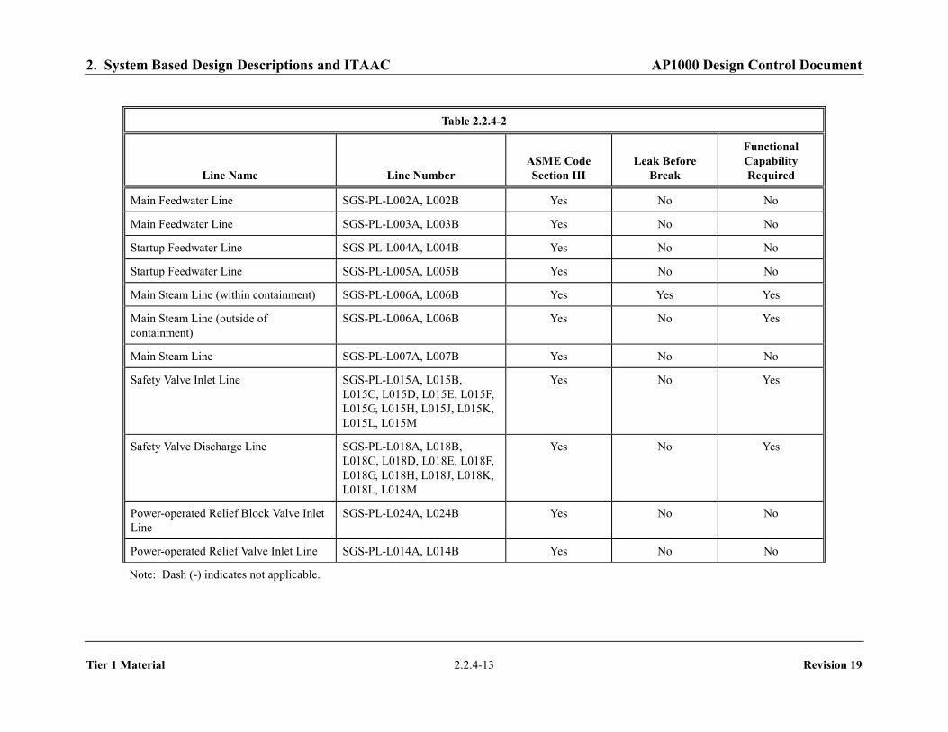
2. System Based Design Descriptions and ITAAC AP1000 Design Control Document
Tier 1 Material 2.2.4-13 Revision 19
Table 2.2.4-2
Line Name Line Number ASME Code Section III
Leak Before Break
Functional Capability Required
Main Feedwater Line SGS-PL-L002A, L002B Yes No No Main Feedwater Line SGS-PL-L003A, L003B Yes No No Startup Feedwater Line SGS-PL-L004A, L004B Yes No No Startup Feedwater Line SGS-PL-L005A, L005B Yes No No Main Steam Line (within containment) SGS-PL-L006A, L006B Yes Yes Yes Main Steam Line (outside of containment)
SGS-PL-L006A, L006B Yes No Yes
Main Steam Line SGS-PL-L007A, L007B Yes No No Safety Valve Inlet Line SGS-PL-L015A, L015B,
L015C, L015D, L015E, L015F, L015G, L015H, L015J, L015K, L015L, L015M
Yes No Yes
Safety Valve Discharge Line SGS-PL-L018A, L018B, L018C, L018D, L018E, L018F, L018G, L018H, L018J, L018K, L018L, L018M
Yes No Yes
Power-operated Relief Block Valve Inlet Line
SGS-PL-L024A, L024B Yes No No
Power-operated Relief Valve Inlet Line SGS-PL-L014A, L014B Yes No No Note: Dash (-) indicates not applicable.

2. System Based Design Descriptions and ITAAC AP1000 Design Control Document
Tier 1 Material 2.2.4-14 Revision 19
Table 2.2.4-2
Line Name Line Number ASME Code Section III
Leak Before Break
Functional Capability Required
Main Steam Isolation Valve Bypass Inlet Line
SGS-PL-L022A, L022B Yes No No
Main Steam Isolation Valve Bypass Outlet Line
SGS-PL-L023A, L023B Yes No No
Main Steam Condensate Drain Line SGS-PL-L021A, L021B Yes No No Steam Generator Blowdown Line SGS-PL-L009A, L009B Yes No No Steam Generator Blowdown Line SGS-PL-L027A, L027B Yes No No Steam Generator Blowdown Line SGS-PL-L010A, L010B Yes No No
Note: Dash (-) indicates not applicable.

2. System Based Design Descriptions and ITAAC AP1000 Design Control Document
Tier 1 Material 2.2.4-15 Revision 19
Table 2.2.4-3
Equipment Name Tag No. Control Function
Turbine Stop Valve MTS-PL-V001A Close Turbine Stop Valve MTS-PL-V001B Close Turbine Control Valve MTS-PL-V002A Close Turbine Control Valve MTS-PL-V002B Close Turbine Stop Valve MTS-PL-V003A Close Turbine Stop Valve MTS-PL-V003B Close Turbine Control Valve MTS-PL-V004A Close Turbine Control Valve MTS-PL-V004B Close Turbine Bypass Control Valve MSS-PL-V001 Close Turbine Bypass Control Valve MSS-PL-V002 Close Turbine Bypass Control Valve MSS-PL-V003 Close Turbine Bypass Control Valve MSS-PL-V004 Close Turbine Bypass Control Valve MSS-PL-V005 Close
Turbine Bypass Control Valve MSS-PL-V006 Close
Moisture Separator Reheater 2nd Stage Steam Isolation Valve MSS-PL-V015A Close
Moisture Separator Reheater 2nd Stage Steam Isolation Valve MSS-PL-V015B Close
Main Feedwater Pump FWS-MP-02A Trip Main Feedwater Pump FWS-MP-02B Trip Main Feedwater Pump FWS-MP-02C Trip
Startup Feedwater Pump FWS-MP-03A Trip Startup Feedwater Pump FWS-MP-03B Trip

2. System Based Design Descriptions and ITAAC AP1000 Design Control Document
Tier 1 Material 2.2.4-16 Revision 19
Table 2.2.4-4
Inspections, Tests, Analyses, and Acceptance Criteria
Design Commitment Inspections, Tests, Analyses Acceptance Criteria
1. The functional arrangement of the SGS and portions of the FWS, MSS, and MTS are as described in the Design Description of this Section 2.2.4.
Inspection of the as-built system will be performed.
The as-built SGS and portions of the FWS, MSS, and MTS conform with the functional arrangement as defined in the Design Description of this Section 2.2.4.
2.a) The components identified in Table 2.2.4-1 as ASME Code Section III are designed and constructed in accordance with ASME Code Section III requirements.
Inspection will be conducted of the as-built components as documented in the ASME design reports.
The ASME Code Section III design reports exist for the as-built components identified in Table 2.2.4-1 as ASME Code Section III.
2.b) The piping identified in Table 2.2.4-2 as ASME Code Section III is designed and constructed in accordance with ASME Code Section III requirements.
Inspection will be conducted of the as-built piping as documented in the ASME design reports.
The ASME Code Section III design reports exist for the as-built piping identified in Table 2.2.4-2 as ASME Code Section III.
3.a) Pressure boundary welds in components identified in Table 2.2.4-1 as ASME Code Section III meet ASME Code Section III requirements.
Inspection of the as-built pressure boundary welds will be performed in accordance with the ASME Code Section III.
A report exists and concludes that the ASME Code Section III requirements are met for non-destructive examination of pressure boundary welds.
3.b) Pressure boundary welds in piping identified in Table 2.2.4-2 as ASME Code Section III meet ASME Code Section III requirements.
Inspection of the as-built pressure boundary welds will be performed in accordance with the ASME Code Section III.
A report exists and concludes that the ASME Code Section III requirements are met for non-destructive examination of pressure boundary welds.
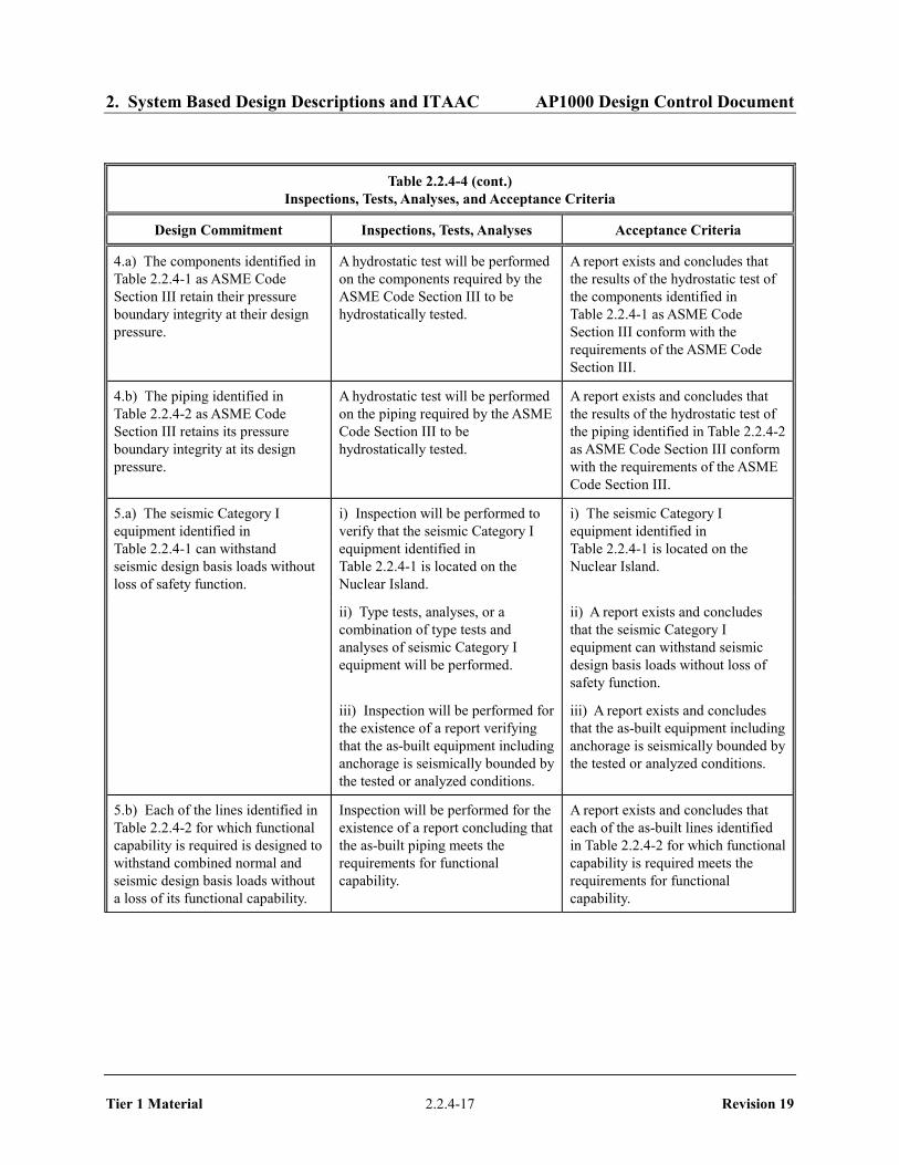
2. System Based Design Descriptions and ITAAC AP1000 Design Control Document
Tier 1 Material 2.2.4-17 Revision 19
Table 2.2.4-4 (cont.)
Inspections, Tests, Analyses, and Acceptance Criteria
Design Commitment Inspections, Tests, Analyses Acceptance Criteria
4.a) The components identified in Table 2.2.4-1 as ASME Code Section III retain their pressure boundary integrity at their design pressure.
A hydrostatic test will be performed on the components required by the ASME Code Section III to be hydrostatically tested.
A report exists and concludes that the results of the hydrostatic test of the components identified in Table 2.2.4-1 as ASME Code Section III conform with the requirements of the ASME Code Section III.
4.b) The piping identified in Table 2.2.4-2 as ASME Code Section III retains its pressure boundary integrity at its design pressure.
A hydrostatic test will be performed on the piping required by the ASME Code Section III to be hydrostatically tested.
A report exists and concludes that the results of the hydrostatic test of the piping identified in Table 2.2.4-2 as ASME Code Section III conform with the requirements of the ASME Code Section III.
5.a) The seismic Category I equipment identified in Table 2.2.4-1 can withstand seismic design basis loads without loss of safety function.
i) Inspection will be performed to verify that the seismic Category I equipment identified in Table 2.2.4-1 is located on the Nuclear Island.
i) The seismic Category I equipment identified in Table 2.2.4-1 is located on the Nuclear Island.
ii) Type tests, analyses, or a combination of type tests and analyses of seismic Category I equipment will be performed.
ii) A report exists and concludes that the seismic Category I equipment can withstand seismic design basis loads without loss of safety function.
iii) Inspection will be performed for the existence of a report verifying that the as-built equipment including anchorage is seismically bounded by the tested or analyzed conditions.
iii) A report exists and concludes that the as-built equipment including anchorage is seismically bounded by the tested or analyzed conditions.
5.b) Each of the lines identified in Table 2.2.4-2 for which functional capability is required is designed to withstand combined normal and seismic design basis loads without a loss of its functional capability.
Inspection will be performed for the existence of a report concluding that the as-built piping meets the requirements for functional capability.
A report exists and concludes that each of the as-built lines identified in Table 2.2.4-2 for which functional capability is required meets the requirements for functional capability.

2. System Based Design Descriptions and ITAAC AP1000 Design Control Document
Tier 1 Material 2.2.4-18 Revision 19
Table 2.2.4-4 (cont.) Inspections, Tests, Analyses, and Acceptance Criteria
Design Commitment Inspections, Tests, Analyses Acceptance Criteria
6. Each of the as-built lines identified in Table 2.2.4-2 as designed for LBB meets the LBB criteria, or an evaluation is performed of the protection from the dynamic effects of a rupture of the line.
Inspection will be performed for the existence of an LBB evaluation report or an evaluation report on the protection from effects of a pipe break. Tier 1 Material, Section 3.3, Nuclear Island Buildings, contains the design descriptions and inspections, tests, analyses, and acceptance criteria for protection from the dynamic effects of pipe rupture.
An LBB evaluation report exists and concludes that the LBB acceptance criteria are met by the as-built RCS piping and piping materials, or a pipe break evaluation report exists and concludes that protection from the dynamic effects of a line break is provided.
7.a) The Class 1E equipment identified in Table 2.2.4-1 as being qualified for a harsh environment can withstand the environmental conditions that would exist before, during, and following a design basis accident without loss of safety function for the time required to perform the safety function.
i) Type tests, analyses, or a combination of type tests and analyses will be performed on Class 1E equipment located in a harsh environment.
ii) Inspection will be performed of the as-built Class 1E equipment and the associated wiring, cables, and terminations located in a harsh environment.
i) A report exists and concludes that the Class 1E equipment identified in Table 2.2.4-1 as being qualified for a harsh environment can withstand the environmental conditions that would exist before, during, and following a design basis accident without loss of safety function for the time required to perform the safety function.
ii) A report exists and concludes that the as-built Class 1E equipment and the associated wiring, cables, and terminations identified in Table 2.2.4-1 as being qualified for a harsh environment are bounded by type tests, analyses, or a combination of type tests and analyses.
7.b) The Class 1E components identified in Table 2.2.4-1 are powered from their respective Class 1E division.
Testing will be performed by providing a simulated test signal in each Class 1E division.
A simulated test signal exists at the Class 1E equipment identified in Table 2.2.4-1 when the assigned Class 1E division is provided the test signal.
7.c) Separation is provided between SGS Class 1E divisions, and between Class 1E divisions and non-Class 1E cable.
See Tier 1 Material, Table 3.3-6, item 7.d.
See Tier 1 Material, Table 3.3-6, item 7.d.

2. System Based Design Descriptions and ITAAC AP1000 Design Control Document
Tier 1 Material 2.2.4-19 Revision 19
Table 2.2.4-4 (cont.)
Inspections, Tests, Analyses, and Acceptance Criteria
Design Commitment Inspections, Tests, Analyses Acceptance Criteria
8.a) The SGS provides a heat sink for the RCS and provides overpressure protection in accordance with Section III of the ASME Boiler and Pressure Vessel Code.
i) Inspections will be conducted to confirm that the value of the vendor code plate rating of the steam generator safety valves is greater than or equal to system relief requirements.
ii) Testing and analyses in accordance with ASME Code Section III will be performed to determine set pressure.
i) The sum of the rated capacities recorded on the valve vendor code plates of the steam generator safety valves exceeds 8,240,000 lb/hr per steam generator.
ii) A report exists to indicate the set pressure of the valves is less than 1305 psig.
8.b) During design basis events, the SGS limits steam generator blowdown and feedwater flow to the steam generator.
i) Testing will be performed to confirm isolation of the main feedwater, startup feedwater, blowdown, and main steam lines. See item 11 in this table.
ii) Inspection will be performed for the existence of a report confirming that the area of the flow limiting orifice within the SG main steam outlet nozzle will limit releases to the containment.
See item 11 in this table.
ii) A report exists to indicate the installed flow limiting orifice within the SG main steam line discharge nozzle does not exceed 1.4 sq. ft.
8.c) The SGS preserves containment integrity by isolation of the SGS lines penetrating the containment.
See Tier 1 Material, Table 2.2.1-3, item 7.
See Tier 1 Material, Table 2.2.1-3, item 7.
9.a) Components within the main steam system, main and startup feedwater system, and the main turbine system identified in Table 2.2.4-3 provide backup isolation of the SGS to limit steam generator blowdown and feedwater flow to the steam generator.
i) Testing will be performed to confirm closure of the valves identified in Table 2.2.4-3.
ii) Testing will be performed to confirm the trip of the pumps identified in Table 2.2.4-3.
i) The valves identified in Table 2.2.4-3 close after a signal is generated by the PMS.
ii) The pumps identified in Table 2.2.4-3 trip after a signal is generated by the PMS.
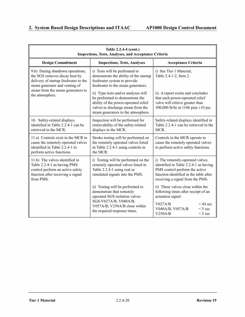
2. System Based Design Descriptions and ITAAC AP1000 Design Control Document
Tier 1 Material 2.2.4-20 Revision 19
Table 2.2.4-4 (cont.)
Inspections, Tests, Analyses, and Acceptance Criteria
Design Commitment Inspections, Tests, Analyses Acceptance Criteria
9.b) During shutdown operations, the SGS removes decay heat by delivery of startup feedwater to the steam generator and venting of steam from the steam generators to the atmosphere.
i) Tests will be performed to demonstrate the ability of the startup feedwater system to provide feedwater to the steam generators.
ii) Type tests and/or analyses will be performed to demonstrate the ability of the power-operated relief valves to discharge steam from the steam generators to the atmosphere.
i) See Tier 1 Material, Table 2.4.1-2, Item 2.
ii) A report exists and concludes that each power-operated relief valve will relieve greater than 300,000 lb/hr at 1106 psia ±10 psi.
10. Safety-related displays identified in Table 2.2.4-1 can be retrieved in the MCR.
Inspection will be performed for retrievability of the safety-related displays in the MCR.
Safety-related displays identified in Table 2.2.4-1 can be retrieved in the MCR.
11.a) Controls exist in the MCR to cause the remotely operated valves identified in Table 2.2.4-1 to perform active functions.
Stroke testing will be performed on the remotely operated valves listed in Table 2.2.4-1 using controls in the MCR.
Controls in the MCR operate to cause the remotely operated valves to perform active safety functions.
11.b) The valves identified in Table 2.2.4-1 as having PMS control perform an active safety function after receiving a signal from PMS.
i) Testing will be performed on the remotely operated valves listed in Table 2.2.4-1 using real or simulated signals into the PMS.
ii) Testing will be performed to demonstrate that remotely operated SGS isolation valves SGS-V027A/B, V040A/B, V057A/B, V250A/B close within the required response times.
i) The remotely-operated valves identified in Table 2.2.4-1 as having PMS control perform the active function identified in the table after receiving a signal from the PMS.
ii) These valves close within the following times after receipt of an actuation signal:
V027A/B < 44 sec V040A/B, V057A/B < 5 sec V250A/B < 5 sec

2. System Based Design Descriptions and ITAAC AP1000 Design Control Document
Tier 1 Material 2.2.4-21 Revision 19
Table 2.2.4-4 (cont.)
Inspections, Tests, Analyses, and Acceptance Criteria
Design Commitment Inspections, Tests, Analyses Acceptance Criteria
12.a) The motor-operated valves identified in Table 2.2.4-1 perform an active safety-related function to change position as indicated in the table.
i) Tests or type tests of motor-operated valves will be performed to demonstrate the capability of the valve to operate under its design conditions.
i) A test report exists and concludes that each motor-operated valve changes position as indicated in Table 2.2.4-1 under design conditions.
ii) Inspection will be performed for the existence of a report verifying that the as-built motor-operated valves are bounded by the tests or type tests.
iii) Tests of the motor-operated valves will be performed under pre-operational flow, differential pressure, and temperature conditions.
ii) A report exists and concludes that the as-built motor-operated valves are bounded by the tests or type tests.
iii) Each motor-operated valve changes position as indicated in Table 2.2.4-1 under pre-operational test conditions.
12.b) After loss of motive power, the remotely operated valves identified in Table 2.2.4-1 assume the indicated loss of motive power position.
Testing of the remotely operated valves will be performed under the conditions of loss of motive power.
After loss of motive power, each remotely operated valve identified in Table 2.2.4-1 assumes the indicated loss of motive power position. Motive power to SGS-PL-V040A/B and SGS-PL-V057A/B is electric power to the actuator from plant services.

2. System Based Design Descriptions and ITAAC AP1000 Design Control Document
Tier 1 Material 2.2.4-22 Revision 19
Table 2.2.4-5
Component Name Tag No. Component Location
Main Steam Line Isolation Valve SGS-PL-V040A Auxiliary Building
Main Steam Line Isolation Valve SGS-PL-V040B Auxiliary Building
Main Feedwater Isolation Valve SGS-PL-V057A Auxiliary Building
Main Feedwater Isolation Valve SGS-PL-V057B Auxiliary Building
Main Feedwater Control Valve SGS-PL-V250A Auxiliary Building
Main Feedwater Control Valve SGS-PL-V250B Auxiliary Building
Turbine Stop Valves MTS-PL-V001A MTS-PL-V001B MTS-PL-V003A MTS-PL-V003B
Turbine Building
Turbine Control Valves MTS-PL-V002A MTS-PL-V002B MTS-PL-V004A MTS-PL-V004B
Turbine Building
Main Feedwater Pumps FWS-MP-02A FWS-MP-02B FWS-MP-02C
Turbine Building
Feedwater Booster Pumps FWS-MP-01A FWS-MP-01B FWS-MP-01C
Turbine Building

2. System Based Design Descriptions and ITAAC AP1000 Design Control Document
Tier 1 Material 2.2.4-23 Revision 19
Figure 2.2.4-1 (Sheet 1 of 3) Steam Generator System

2. System Based Design Descriptions and ITAAC AP1000 Design Control Document
Tier 1 Material 2.2.4-24 Revision 19
Figure 2.2.4-1 (Sheet 2 of 3) Steam Generator System
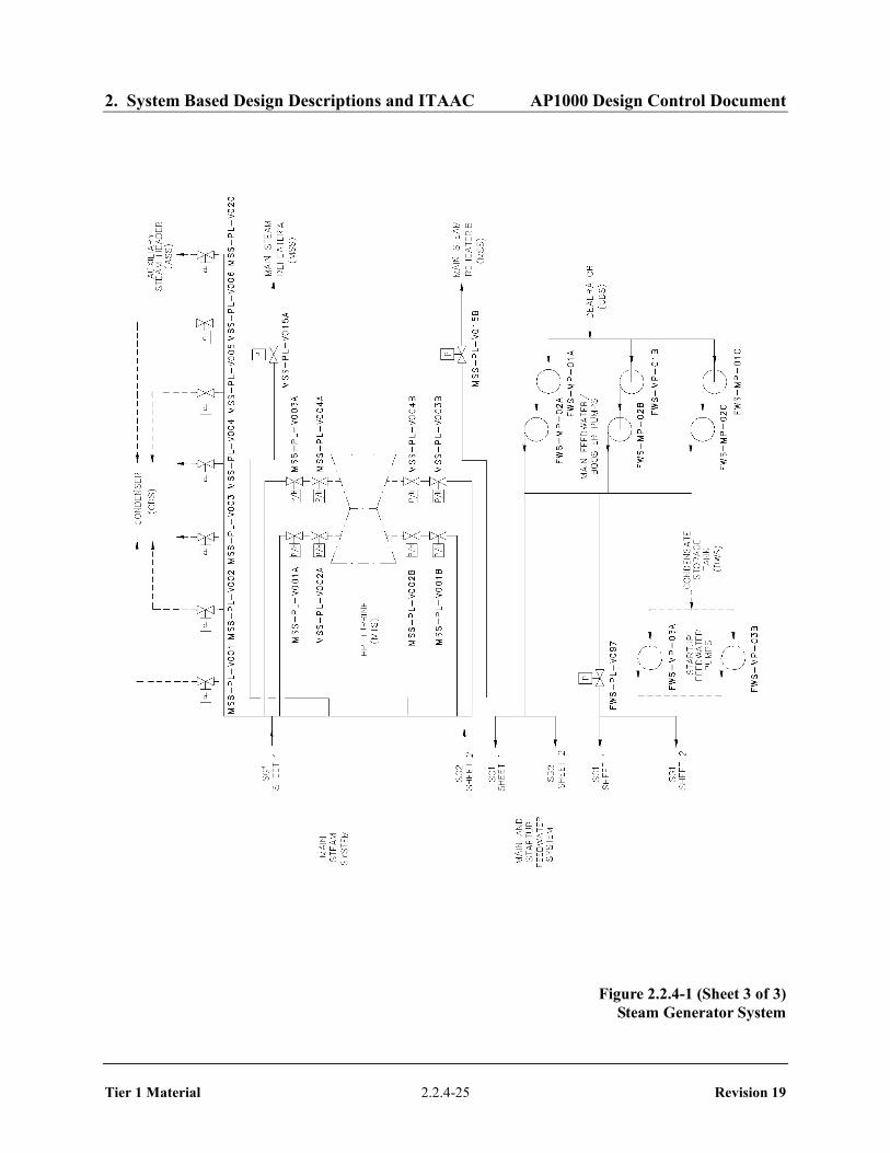
2. System Based Design Descriptions and ITAAC AP1000 Design Control Document
Tier 1 Material 2.2.4-25 Revision 19
Figure 2.2.4-1 (Sheet 3 of 3) Steam Generator System

2. System Based Design Descriptions and ITAAC AP1000 Design Control Document
Tier 1 Material 2.2.5-1 Revision 19
2.2.5 Main Control Room Emergency Habitability System
Design Description
The main control room emergency habitability system (VES) provides a supply of breathable air for the main control room (MCR) occupants and maintains the MCR at a positive pressure with respect to the surrounding areas whenever ac power is not available to operate the nuclear island nonradioactive ventilation system (VBS) or high radioactivity is detected in the MCR air supply. (See Tier 1 material, Section 3.5 for Radiation Monitoring). The VES also limits the heatup of the MCR, the 1E instrumentation and control (I&C) equipment rooms, and the Class 1E dc equipment rooms by using the heat capacity of surrounding structures.
The VES is as shown in Figure 2.2.5-1 and the component locations of the VES are as shown in Table 2.2.5-6.
1. The functional arrangement of the VES is as described in the Design Description of this Section 2.2.5.
2. a) The components identified in Table 2.2.5-1 as ASME Code Section III are designed and constructed in accordance with ASME Code Section III requirements.
b) The piping identified in Table 2.2.5-2 as ASME Code Section III is designed and constructed in accordance with ASME Code Section III requirements.
3. a) Pressure boundary welds in components identified in Table 2.2.5-1 as ASME Code Section III meet ASME Code Section III requirements.
b) Pressure boundary welds in piping identified in Table 2.2.5-2 as ASME Code Section III meet ASME Code Section III requirements.
4. a) The components identified in Table 2.2.5-1 as ASME Code Section III retain their pressure boundary integrity at their design pressure.
b) The piping identified in Table 2.2.5-2 as ASME Code Section III retains its pressure boundary integrity at its design pressure.
5. a) The seismic Category I equipment identified in Table 2.2.5-1 can withstand seismic design basis loads without loss of safety function.
b) Each of the lines identified in Table 2.2.5-2 for which functional capability is required is designed to withstand combined normal and seismic design basis loads without a loss of its functional capability.
6. a) The Class 1E components identified in Table 2.2.5-1 are powered from their respective Class 1E division.
b) Separation is provided between VES Class 1E divisions, and between Class 1E divisions and non-Class 1E cable.

2. System Based Design Descriptions and ITAAC AP1000 Design Control Document
Tier 1 Material 2.2.5-2 Revision 19
7. The VES provides the following safety-related functions:
a) The VES provides a 72-hour supply of breathable quality air for the occupants of the MCR.
b) The VES maintains the MCR pressure boundary at a positive pressure with respect to the surrounding areas. There is a discharge of air through the MCR vestibule.
c) The heat loads within the MCR, the I&C equipment rooms, and the Class 1E dc equipment rooms are within design basis assumptions to limit the heatup of the rooms identified in Table 2.2.5-4.
d) The system provides a passive recirculation flow of MCR air to maintain main control room dose rates below an acceptable level during VES operation.
8. Safety-related displays identified in Table 2.2.5-1 can be retrieved in the MCR.
9. a) Controls exist in the MCR to cause those remotely operated valves identified in Table 2.2.5-1 to perform their active functions.
b) The valves identified in Table 2.2.5-1 as having protection and safety monitoring system (PMS) control perform their active safety function after receiving a signal from the PMS.
10. After loss of motive power, the remotely operated valves identified in Table 2.2.5-1 assume the indicated loss of motive power position.
11. Displays of the parameters identified in Table 2.2.5-3 can be retrieved in the MCR.
12. The background noise level in the MCR does not exceed 65 dB(A) at the operator workstations when the VES is operating.
Inspections, Tests, Analyses, and Acceptance Criteria
Table 2.2.5-5 specifies the inspections, tests, analyses, and associated acceptance criteria for the VES.
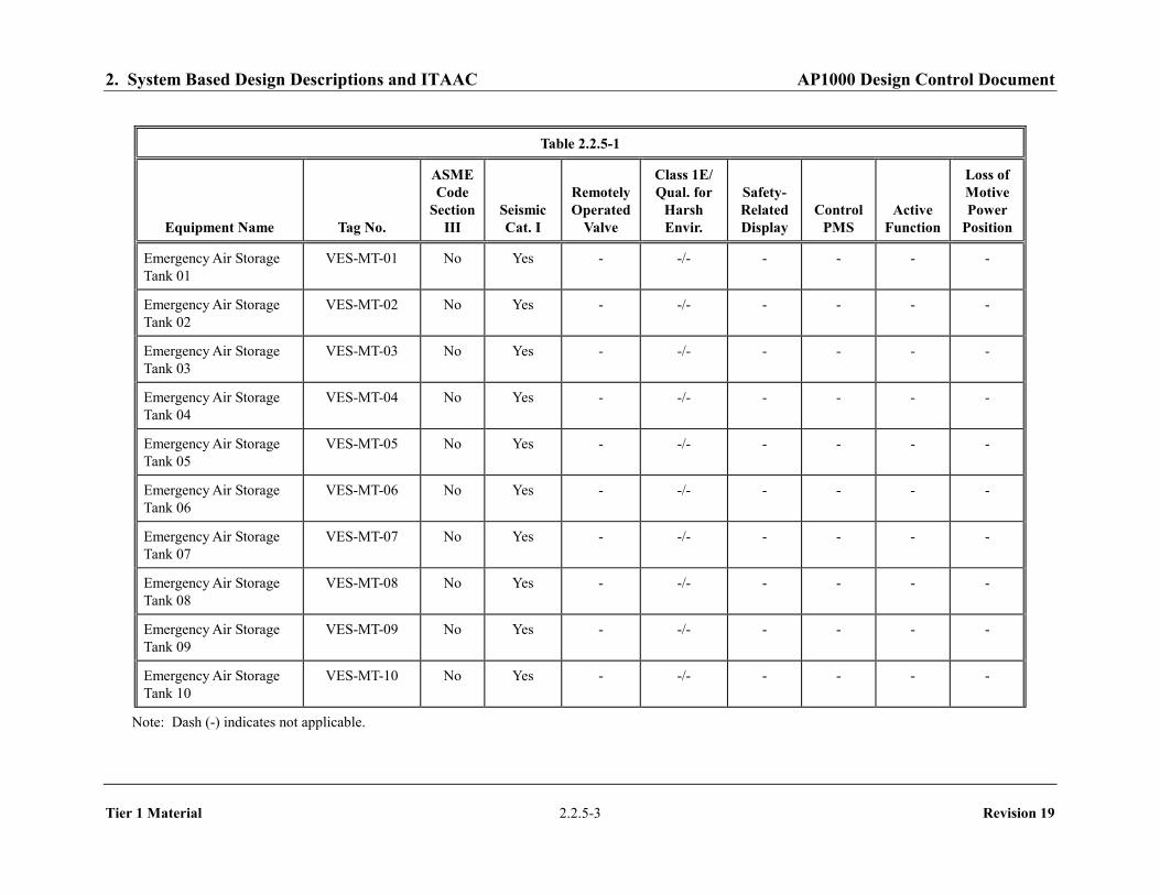
2. System Based Design Descriptions and ITAAC AP1000 Design Control Document
Tier 1 Material 2.2.5-3 Revision 19
Table 2.2.5-1
Equipment Name Tag No.
ASME Code
Section III
Seismic Cat. I
Remotely Operated
Valve
Class 1E/ Qual. for
Harsh Envir.
Safety-Related Display
Control PMS
Active Function
Loss of Motive Power
Position
Emergency Air Storage Tank 01
VES-MT-01 No Yes - -/- - - - -
Emergency Air Storage Tank 02
VES-MT-02 No Yes - -/- - - - -
Emergency Air Storage Tank 03
VES-MT-03 No Yes - -/- - - - -
Emergency Air Storage Tank 04
VES-MT-04 No Yes - -/- - - - -
Emergency Air Storage Tank 05
VES-MT-05 No Yes - -/- - - - -
Emergency Air Storage Tank 06
VES-MT-06 No Yes - -/- - - - -
Emergency Air Storage Tank 07
VES-MT-07 No Yes - -/- - - - -
Emergency Air Storage Tank 08
VES-MT-08 No Yes - -/- - - - -
Emergency Air Storage Tank 09
VES-MT-09 No Yes - -/- - - - -
Emergency Air Storage Tank 10
VES-MT-10 No Yes - -/- - - - -
Note: Dash (-) indicates not applicable.

2. System Based Design Descriptions and ITAAC AP1000 Design Control Document
Tier 1 Material 2.2.5-4 Revision 19
Table 2.2.5-1 (cont.)
Equipment Name Tag No.
ASME Code
Section III
Seismic Cat. I
Remotely Operated
Valve
Class 1E/ Qual. for
Harsh Envir.
Safety-Related Display
Control PMS
Active Function
Loss of Motive Power
Position
Emergency Air Storage Tank 11
VES-MT-11 No Yes - -/- - - - -
Emergency Air Storage Tank 12
VES-MT-12 No Yes - -/- - - - -
Emergency Air Storage Tank 13
VES-MT-13 No Yes - -/- - - - -
Emergency Air Storage Tank 14
VES-MT-14 No Yes - -/- - - - -
Emergency Air Storage Tank 15
VES-MT-15 No Yes - -/- - - - -
Emergency Air Storage Tank 16
VES-MT-16 No Yes - -/- - - - -
Emergency Air Storage Tank 17
VES-MT-17 No Yes - -/- - - - -
Emergency Air Storage Tank 18
VES-MT-18 No Yes - -/- - - - -
Emergency Air Storage Tank 19
VES-MT-19 No Yes - -/- - - - -
Emergency Air Storage Tank 20
VES-MT-20 No Yes - -/- - - - -
Note: Dash (-) indicates not applicable.

2. System Based Design Descriptions and ITAAC AP1000 Design Control Document
Tier 1 Material 2.2.5-5 Revision 19
Table 2.2.5-1 (cont.)
Equipment Name Tag No.
ASME Code
Section III
Seismic Cat. I
Remotely Operated
Valve
Class 1E/ Qual. for
Harsh Envir.
Safety-Related Display
Control PMS
Active Function
Loss of Motive Power
Position
Emergency Air Storage Tank 21
VES-MT-21 No Yes - -/- - - - -
Emergency Air Storage Tank 22
VES-MT-22 No Yes - -/- - - - -
Emergency Air Storage Tank 23
VES-MT-23 No Yes - -/- - - - -
Emergency Air Storage Tank 24
VES-MT-24 No Yes - -/- - - - -
Emergency Air Storage Tank 25
VES-MT-25 No Yes - -/- - - - -
Emergency Air Storage Tank 26
VES-MT-26 No Yes - -/- - - - -
Emergency Air Storage Tank 27
VES-MT-27 No Yes - -/- - - - -
Emergency Air Storage Tank 28
VES-MT-28 No Yes - -/- - - - -
Emergency Air Storage Tank 29
VES-MT-29 No Yes - -/- - - - -
Emergency Air Storage Tank 30
VES-MT-30 No Yes - -/- - - - -
Note: Dash (-) indicates not applicable.

2. System Based Design Descriptions and ITAAC AP1000 Design Control Document
Tier 1 Material 2.2.5-6 Revision 19
Table 2.2.5-1 (cont.)
Equipment Name Tag No.
ASME Code
Section III
Seismic Cat. I
Remotely Operated
Valve
Class 1E/ Qual. for
Harsh Envir.
Safety-Related Display
Control PMS
Active Function
Loss of Motive Power
Position
Emergency Air Storage Tank 31
VES-MT-31 No Yes - -/- - - - -
Emergency Air Storage Tank 32
VES-MT-32 No Yes - -/- - - - -
Air Delivery Alternate Isolation Valve
VES-PL-V001 Yes Yes No -/- No - Transfer Open
-
Eductor Flow Path Isolation Valve
VES-PL-V045 Yes Yes No -/- No - Transfer Close
-
Eductor Bypass Isolation Valve
VES-PL-V046 Yes Yes No -/- No - Transfer Open
-
Pressure Regulating Valve A
VES-PL-V002A Yes Yes No -/- No - Throttle Flow
-
Pressure Regulating Valve B
VES-PL-V002B Yes Yes No -/- No - Throttle Flow
-
MCR Air Delivery Isolation Valve A
VES-PL-V005A Yes Yes Yes Yes/No No Yes Transfer Open
Open
MCR Air Delivery Isolation Valve B
VES-PL-V005B Yes Yes Yes Yes/No No Yes Transfer Open
Open
MCR Pressure Relief Isolation Valve A
VES-PL-V022A Yes Yes Yes Yes/No No Yes Transfer Open
Open
MCR Pressure Relief Isolation Valve B
VES-PL-V022B Yes Yes Yes Yes/No No Yes Transfer Open
Open
Note: Dash (-) indicates not applicable.

2. System Based Design Descriptions and ITAAC AP1000 Design Control Document
Tier 1 Material 2.2.5-7 Revision 19
Table 2.2.5-1 (cont.)
Equipment Name Tag No.
ASME Code
Section III
Seismic Cat. I
Remotely Operated
Valve
Class 1E/ Qual. for
Harsh Envir.
Safety-Related Display
Control PMS
Active Function
Loss of Motive Power
Position
Air Tank Safety Relief Valve A
VES-PL-V040A Yes Yes No -/- No - Transfer Open
-
Air Tank Safety Relief Valve B
VES-PL-V040B Yes Yes No -/- No - Transfer Open
-
Air Tank Safety Relief Valve C
VES-PL-V040C Yes Yes No -/- No - Transfer Open
-
Air Tank Safety Relief Valve D
VES-PL-V040D Yes Yes No -/- No - Transfer Open
-
Main Air Flow Path Isolation Valve
VES-PL-V044 Yes Yes No -/- No - Transfer Close
-
MCR Air Filtration Line Eductor
VES-PY-N01 Yes Yes - - - - - -
MCR Air Filtration Line Charcoal Filter
VES-MY-F01 No Yes - - - - - -
MCR Air Filtration Line HEPA Filter
VES-MY-F02 No Yes - - - - - -
MCR Air Filtration Line Postfilter
VES-MY-F03 No Yes - - - - - -
MCR Gravity Relief Dampers
VES-MD-D001A No Yes - - - - - -
Note: Dash (-) indicates not applicable.
186

2. System Based Design Descriptions and ITAAC AP1000 Design Control Document
Tier 1 Material 2.2.5-8 Revision 19
Table 2.2.5-1 (cont.)
Equipment Name Tag No.
ASME Code
Section III
Seismic Cat. I
Remotely Operated
Valve
Class 1E/ Qual. for
Harsh Envir.
Safety-Related Display
Control PMS
Active Function
Loss of Motive Power
Position
MCR Gravity Relief Dampers
VES-MD-D001B No Yes - - - - - -
MCR Air Filtration Line Supply Damper
VES-MD-D002 No Yes - - - - - -
MCR Air Filtration Line Supply Damper
VES-MD-D003 No Yes - - - - - -
MCR Air Filtration Line Silencer
VES-MY-Y01 No Yes - - - - - -
MCR Air Filtration Line Silencer
VES-MY-Y02 No Yes - - - - - -
MCR Air Delivery Line Flow Sensor
VES-003A No Yes - Yes/No Yes - - -
MCR Air Delivery Line Flow Sensor
VES-003B No Yes - Yes/No Yes - - -
MCR Differential Pressure Sensor A
VES-004A No Yes - Yes/No Yes - - -
MCR Differential Pressure Sensor B
VES-004B No Yes - Yes/No Yes - - -
Note: Dash (-) indicates not applicable.
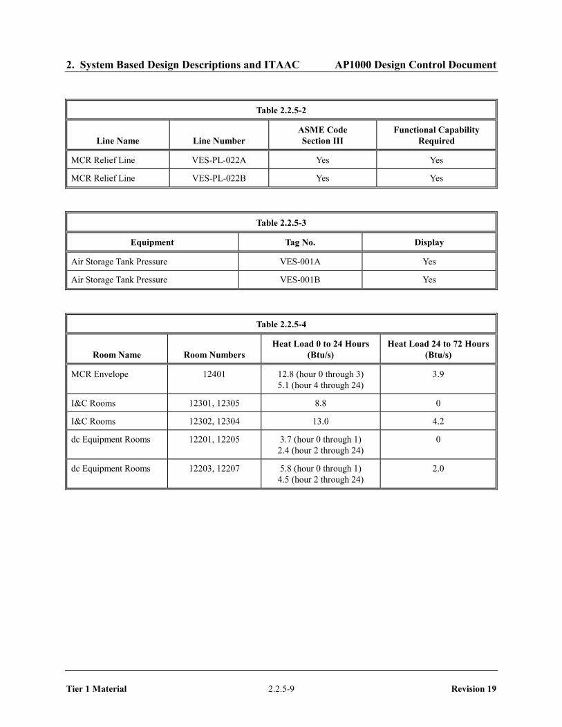
2. System Based Design Descriptions and ITAAC AP1000 Design Control Document
Tier 1 Material 2.2.5-9 Revision 19
Table 2.2.5-2
Line Name Line Number ASME Code Section III
Functional Capability Required
MCR Relief Line VES-PL-022A Yes Yes MCR Relief Line VES-PL-022B Yes Yes
Table 2.2.5-3
Equipment Tag No. Display
Air Storage Tank Pressure VES-001A Yes Air Storage Tank Pressure VES-001B Yes
Table 2.2.5-4
Room Name Room Numbers Heat Load 0 to 24 Hours
(Btu/s) Heat Load 24 to 72 Hours
(Btu/s)
MCR Envelope 12401 12.8 (hour 0 through 3) 5.1 (hour 4 through 24)
3.9
I&C Rooms 12301, 12305 8.8 0 I&C Rooms 12302, 12304 13.0 4.2 dc Equipment Rooms 12201, 12205 3.7 (hour 0 through 1)
2.4 (hour 2 through 24) 0
dc Equipment Rooms 12203, 12207 5.8 (hour 0 through 1) 4.5 (hour 2 through 24)
2.0

2. System Based Design Descriptions and ITAAC AP1000 Design Control Document
Tier 1 Material 2.2.5-10 Revision 19
Table 2.2.5-5
Inspections, Tests, Analyses, and Acceptance Criteria
Design Commitment Inspections, Tests, Analyses Acceptance Criteria
1. The functional arrangement of the VES is as described in the Design Description of this Section 2.2.5.
Inspection of the as-built system will be performed.
The as-built VES conforms with the functional arrangement described in the Design Description of this Section 2.2.5.
2.a) The components identified in Table 2.2.5-1 as ASME Code Section III are designed and constructed in accordance with ASME Code Section III requirements.
Inspection will be conducted of the as-built components as documented in the ASME design reports.
The ASME Code Section III design reports exist for the as-built components identified in Table 2.2.5-1 as ASME Code Section III.
2.b) The piping identified in Table 2.2.5-2 as ASME Code Section III is designed and constructed in accordance with ASME Code Section III requirements.
Inspection will be conducted of the as-built piping as documented in the ASME design reports.
The ASME Code Section III design reports exist for the as-built piping identified in Table 2.2.5-2 as ASME Code Section III.
3.a) Pressure boundary welds in components identified in Table 2.2.5-1 as ASME Code Section III meet ASME Code Section III requirements.
Inspection of the as-built pressure boundary welds will be performed in accordance with the ASME Code Section III.
A report exists and concludes that the ASME Code Section III requirements are met for non-destructive examination of pressure boundary welds.
3.b) Pressure boundary welds in piping identified in Table 2.2.5-2 as ASME Code Section III meet ASME Code Section III requirements.
Inspection of the as-built pressure boundary welds will be performed in accordance with the ASME Code Section III.
A report exists and concludes that the ASME Code Section III requirements are met for non-destructive examination of pressure boundary welds.
4.a) The components identified in Table 2.2.5-1 as ASME Code Section III retain their pressure boundary integrity at their design pressure.
A hydrostatic test will be performed on the components required by the ASME Code Section III to be hydrostatically tested.
A report exists and concludes that the results of the hydrostatic test of the components identified in Table 2.2.5-1 as ASME Code Section III conform with the requirements of the ASME Code Section III.
4.b) The piping identified in Table 2.2.5-2 as ASME Code Section III retains its pressure boundary integrity at its design pressure.
A hydrostatic test will be performed on the piping required by the ASME Code Section III to be hydrostatically tested.
A report exists and concludes that the results of the hydrostatic test of the piping identified in Table 2.2.5-2 as ASME Code Section III conform with the requirements of the ASME Code Section III.

2. System Based Design Descriptions and ITAAC AP1000 Design Control Document
Tier 1 Material 2.2.5-11 Revision 19
Table 2.2.5-5 (cont.)
Inspections, Tests, Analyses, and Acceptance Criteria
Design Commitment Inspections, Tests, Analyses Acceptance Criteria
5.a) The seismic Category I equipment identified in Table 2.2.5-1 can withstand seismic design basis loads without loss of safety function.
i) Inspection will be performed to verify that the seismic Category I equipment and valves identified in Table 2.2.5-1 are located on the Nuclear Island.
i) The seismic Category I equipment identified in Table 2.2.5-1 is located on the Nuclear Island.
ii) Type tests, analyses, or a combination of type tests and analyses of seismic Category I equipment will be performed.
ii) A report exists and concludes that the seismic Category I equipment can withstand seismic design basis loads without loss of safety function.
iii) Inspection will be performed for the existence of a report verifying that the as-built equipment including anchorage is seismically bounded by the tested or analyzed conditions.
iii) A report exists and concludes that the as-built equipment including anchorage is seismically bounded by the tested or analyzed conditions.
5.b) Each of the lines identified in Table 2.2.5-2 for which functional capability is required is designed to withstand combined normal and seismic design basis loads without a loss of its functional capability.
Inspection will be performed for the existence of a report verifying that the as-built piping meets the requirements for functional capability.
A report exists and concludes that each of the as-built lines identified in Table 2.2.5-2 for which functional capability is required meets the requirements for functional capability.
6.a) The Class 1E components identified in Table 2.2.5-1 are powered from their respective Class 1E division.
Testing will be performed by providing a simulated test signal in each Class 1E division.
A simulated test signal exists at the Class 1E equipment identified in Table 2.2.5-1 when the assigned Class 1E division is provided the test signal.
6.b) Separation is provided between VES Class 1E divisions, and between Class 1E divisions and non-Class 1E cable.
See Tier 1 Material, Table 3.3-6, item 7.d.
See Tier 1 Material, Table 3.3-6, item 7.d.

2. System Based Design Descriptions and ITAAC AP1000 Design Control Document
Tier 1 Material 2.2.5-12 Revision 19
Table 2.2.5-5 (cont.)
Inspections, Tests, Analyses, and Acceptance Criteria
Design Commitment Inspections, Tests, Analyses Acceptance Criteria
7.a) The VES provides a 72-hour supply of breathable quality air for the occupants of the MCR.
i) Testing will be performed to confirm that the required amount of air flow is delivered to the MCR.
ii) Analysis of storage capacity will be performed based on manufacturers data.
iii) MCR air samples will be taken during VES testing and analyzed for quality.
i) The air flow rate from the VES is at least 60 scfm and not more than 70 scfm.
ii) The calculated storage capacity is greater than or equal to 327,574 scf.
iii) The MCR air is of breathable quality.
7.b) The VES maintains the MCR pressure boundary at a positive pressure with respect to the surrounding areas.
i) Testing will be performed with VES flow rate between 60 and 70 scfm to confirm that the MCR is capable of maintaining the required pressurization of the pressure boundary.
ii) Air leakage into the MCR will be measured during VES testing using a tracer gas.
i) The MCR pressure boundary is pressurized to greater than or equal to 1/8-in. water gauge with respect to the surrounding area.
ii) Air leakage into the MCR is less than or equal to 10 cfm.
7.c) The heat loads within the MCR, the I&C equipment rooms, and the Class 1E dc equipment rooms are within design basis assumptions to limit the heatup of the rooms identified in Table 2.2.5-4.
An analysis will be performed to determine that the heat loads from as-built equipment within the rooms identified in Table 2.2.5-4 are less than or equal to the design basis assumptions.
A report exists and concludes that: the heat loads within rooms identified in Table 2.2.5-4 are less than or equal to the specified values or that an analysis report exists that concludes:
– The temperature and humidity in the MCR remain within limits for reliable human performance for the 72-hour period.
– The maximum temperature for the 72-hour period for the I&C rooms is less than or equal to 120°F.
– The maximum temperature for the 72-hour period for the Class 1E dc equipment rooms is less than or equal to 120°F.

2. System Based Design Descriptions and ITAAC AP1000 Design Control Document
Tier 1 Material 2.2.5-13 Revision 19
Table 2.2.5-5 (cont.)
Inspections, Tests, Analyses, and Acceptance Criteria
Design Commitment Inspections, Tests, Analyses Acceptance Criteria
7d) The system provides a passive recirculation flow of MCR air to maintain main control room dose rates below an acceptable level during VES operation.
Testing will be performed to confirm that the required amount of air flow circulates through the MCR passive filtration system,
The air flow rate at the outlet of the MCR passive filtration system is at least 600 cfm greater than the flow measured by VES-003A/B.
8. Safety-related displays identified in Table 2.2.5-1 can be retrieved in the MCR.
Inspection will be performed for retrievability of the safety-related displays in the MCR.
Safety-related displays identified in Table 2.2.5-1 can be retrieved in the MCR.
9.a) Controls exist in the MCR to cause remotely operated valves identified in Table 2.2.5-1 to perform their active functions.
Stroke testing will be performed on remotely operated valves identified in Table 2.2.5-1 using the controls in the MCR.
Controls in the MCR operate to cause remotely operated valves identified in Table 2.2.5-1 to perform their active safety functions.
9.b) The valves identified in Table 2.2.5-1 as having PMS control perform their active safety function after receiving a signal from the PMS.
Testing will be performed on remotely operated valves listed in Table 2.2.5-1 using real or simulated signals into the PMS.
The remotely operated valves identified in Table 2.2.5-1 as having PMS control perform the active safety function identified in the table after receiving a signal from the PMS.
10. After loss of motive power, the remotely operated valves identified in Table 2.2.5-1 assume the indicated loss of motive power position.
Testing of the remotely operated valves will be performed under the conditions of loss of motive power.
After loss of motive power, each remotely operated valve identified in Table 2.2.5-1 assumes the indicated loss of motive power position.
11. Displays of the parameters identified in Table 2.2.5-3 can be retrieved in the MCR.
Inspection will be performed for retrievability of the parameters in the MCR.
The displays identified in Table 2.2.5-3 can be retrieved in the MCR.
12. The background noise level in the MCR does not exceed 65 dB(A) at the operator workstations when VES is operating.
The as-built VES will be operated, and background noise levels in the MRC will be measured at the operator work stations with the plant not operating.
The background noise level in the MCR does not exceed 65 dB(A) at the operator work stations when the VES is operating.
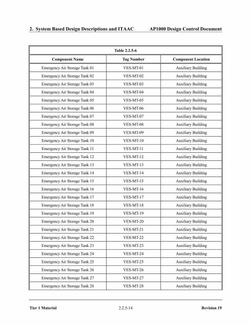
2. System Based Design Descriptions and ITAAC AP1000 Design Control Document
Tier 1 Material 2.2.5-14 Revision 19
Table 2.2.5-6
Component Name Tag Number Component Location
Emergency Air Storage Tank 01 VES-MT-01 Auxiliary Building Emergency Air Storage Tank 02 VES-MT-02 Auxiliary Building Emergency Air Storage Tank 03 VES-MT-03 Auxiliary Building Emergency Air Storage Tank 04 VES-MT-04 Auxiliary Building Emergency Air Storage Tank 05 VES-MT-05 Auxiliary Building Emergency Air Storage Tank 06 VES-MT-06 Auxiliary Building Emergency Air Storage Tank 07 VES-MT-07 Auxiliary Building Emergency Air Storage Tank 08 VES-MT-08 Auxiliary Building Emergency Air Storage Tank 09 VES-MT-09 Auxiliary Building Emergency Air Storage Tank 10 VES-MT-10 Auxiliary Building Emergency Air Storage Tank 11 VES-MT-11 Auxiliary Building Emergency Air Storage Tank 12 VES-MT-12 Auxiliary Building Emergency Air Storage Tank 13 VES-MT-13 Auxiliary Building Emergency Air Storage Tank 14 VES-MT-14 Auxiliary Building Emergency Air Storage Tank 15 VES-MT-15 Auxiliary Building Emergency Air Storage Tank 16 VES-MT-16 Auxiliary Building Emergency Air Storage Tank 17 VES-MT-17 Auxiliary Building Emergency Air Storage Tank 18 VES-MT-18 Auxiliary Building Emergency Air Storage Tank 19 VES-MT-19 Auxiliary Building Emergency Air Storage Tank 20 VES-MT-20 Auxiliary Building Emergency Air Storage Tank 21 VES-MT-21 Auxiliary Building Emergency Air Storage Tank 22 VES-MT-22 Auxiliary Building Emergency Air Storage Tank 23 VES-MT-23 Auxiliary Building Emergency Air Storage Tank 24 VES-MT-24 Auxiliary Building Emergency Air Storage Tank 25 VES-MT-25 Auxiliary Building Emergency Air Storage Tank 26 VES-MT-26 Auxiliary Building Emergency Air Storage Tank 27 VES-MT-27 Auxiliary Building Emergency Air Storage Tank 28 VES-MT-28 Auxiliary Building

2. System Based Design Descriptions and ITAAC AP1000 Design Control Document
Tier 1 Material 2.2.5-15 Revision 19
Table 2.2.5-6 (cont.)
Component Name Tag Number Component Location
Emergency Air Storage Tank 29 VES-MT-29 Auxiliary Building Emergency Air Storage Tank 30 VES-MT-30 Auxiliary Building Emergency Air Storage Tank 31 VES-MT-31 Auxiliary Building Emergency Air Storage Tank 32 VES-MT-32 Auxiliary Building

2. System Based Design Descriptions and ITAAC AP1000 Design Control Document
Tier 1 Material 2.2.5-16 Revision 19
Figure 2.2.5-1 Main Control Room Emergency Habitability System