2-way cartridge valve, actively controllable · switching point behavior and overlap 31 mating...
TRANSCRIPT

RE 21040 edition 2016-12 Bosch Rexroth AG
2-way cartridge valve actively controllable
Features
Actively controllable 22 directional cartridge valve (two-level active logics)
Modular design flexible circuit set-up Installation bore according to ISO 7368 Energy efficiency due to flow-optimized geometry Leakage-free due to integrated shaft sealing Spool position monitoring closed andor open or
analog (can also be retrofitted) BG certification Increased operating pressure 450 bar upon request
Contents
Features 1Ordering code 2 hellip 4Symbols 4Assignment of the active area 5Orifice assignments 5Function section 6Technical data 7 8Characteristic curves 9 hellip 14Characteristic curves for selecting the orifices 15Dimensions 16 hellip 21Installation bore and connection dimensions 22 23Circuit examples 24 hellip 28Inductive position switch 29 30Switching point behavior and overlap 31Mating connectors for inductive position switch 31Further information 32
Size 16 hellip 125 Component series 1X Maximum operating pressure 420 bar Maximum flow 17000 lmin (∆p = 10 bar)
RE 21040thinspEdition 2016-12Replaces 2013-06
H7697+7694
Type LC2A
Inhalt
Features 1Contents 1Ordering code 2Ordering code 3Ordering code 4Symbols (① = component side ② = plate side) 4Assignment of the active area A4 (① = component side ② = plate side) 5Orifice assignment (① = component side ② = plate side) 5Function section 6Technical data (For applications outside these parameters please consult us) 7Technical data (For applications outside these parameters please consult us) 8Characteristic curves without damping nose E A rarr B (simulated with HLP46 ϑOil = 40 plusmn5 degC) 9Characteristic curves without damping nose E B rarr A (simulated with HLP46 ϑOil = 40 plusmn5 degC) 10Characteristic curves with damping nose D A rarr B (simulated with HLP46 ϑOil = 40 plusmn5 degC) 11Characteristic curves with damping nose D B rarr A (simulated with HLP46 ϑOil = 40 plusmn5 degC) 12Characteristic curves with overlap F A rarr B (simulated with HLP46 ϑOil = 40 plusmn5 degC) 13Characteristic curves with overlap F B rarr A (simulated with HLP46 ϑOil = 40 plusmn5 degC) 14Characteristic curves for selecting the orifices 15Dimensions NG16 hellip 63 (dimensions in mm) 16Dimensions NG16 hellip 32 (dimensions in mm) 17Dimensions NG40 hellip 63 (dimensions in mm) 18Dimensions NG80 hellip 125 (dimensions in mm) 19Dimensions NG80 hellip 125 (dimensions in mm) 20Dimensions 21Installation bore and connection dimensions according to DIN ISO 7368 (dimensions in mm) 22Installation bore and connection dimensions according to DIN ISO 7368 (dimensions in mm) 23Circuit examples (schematic diagram function must be checked with the application) 24Circuit examples (schematic diagram function must be checked with the application) 25Circuit examples (schematic diagram function must be checked with the application) 26Circuit examples (schematic diagram function must be checked with the application) 27Circuit examples (schematic diagram function must be checked with the application) 28Inductive position switch type Q7 Electrical connection 29Inductive position switch type Q8 Electrical connection 30Inductive position switch type Q9 Electrical connection 30Switching point behavior and overlap Valve poppet with damping nose D or overlap nose F and position overlap closed 31Mating connectors for inductive position switch (dimensions in mm) 31Further information 32
232 LC2A | 2-way cartridge valve
Bosch Rexroth AG RE 21040 edition 2016-12
Ordering code
01 Logic Cartridge LC
02 2-level active 2A
03 Size 16 016Size 25 025Size 32 032Size 40 040Size 50 050Size 63 063Size 80 080Size 100 100Size 125 (only version F valve poppet with overlap) 125
Control spool design (area ratio see section on page 6)04 A1 A2 = 2 1 (A2 = 50 ) A
A1 A2 = 143 1 (A2 = 7 ) (preferred with version F valve poppet with overlap) BA1 A2 = 1 0 (A2 = 0 ) D
05 Without spring 00With spring cracking pressure approx 4 bar (referring to control spool design A) 40
06 Valve poppet without damping nose EValve poppet with damping nose DValve poppet with overlap (preferred with version with spool position monitoring) F
07 Component series 10 hellip 19 (10 hellip 19 unchanged installation and connection dimensions) 1X
Active area 1) connected to port (see also page 5)08 Z1 Z1
Z2 Z2Z1 and Z2 UX XY Y
Spool position monitoring 2) (position switch 1 = 1 position switch 2 = 2)09 ndash Position monitoring closed
Without position switch (1 on side Y ndash can be retrofitted) no codeWith 1 position switch (1 on side Y ndash mounted) Q7With 2 position switches 1 on side Y ndash mounted attachment side of 2 NG-dependent ndash mounted) Q7Q7With 1 position switch and 2nd installation bore (1 on side Y ndash not fitted attachment side of 2 NG-dependent ndash mounted)
QQ7
Without position switch with 2 installation bores (1 on side Y ndash not fitted attachment side of 2 NG-dependent ndash not fitted)
ndash Combined position monitoring 1 (closed) and 2 (open) 3)
With 2 position switches 1 on side Y ndash mounted attachment side of 2 NG-dependent ndash mounted) Q7Q7TWithout position switch with 2 installation bores (1 on side Y ndash not fitted attachment side of 2 NG-dependent ndash not fitted)
QQT
With 1 position switch and 2nd installation bore (1 on side Y ndash not fitted attachment side of 2 NG-dependent ndash mounted)
QQ7T
ndash Position monitoring closed NAMUR 4)
With 1 position switch (1 on side Y ndash mounted) Q8ndash Analog position sensingAnalog sensor voltage output (1 hellip 10 V) Q9Combination analog and digital upon request
01 02 03 04 05 06 07 08 09 10 11 12 13 14 15 16 17 18 19 20 21 22 23
LC 2A ndash 1X
2-way cartridge valve | LC2A 332
RE 21040 edition 2016-12 Bosch Rexroth AG
Ordering code
Electrical connection for position switch 5)
10 Without position switch no codeUB = 24 V DC (standard only with version Q7 and Q9) G24UB = 8 V DC (NAMUR only with version Q8) G08
Pilot oil bore in the control spool 6)
11 Without pilot oil bore no codendash Pilot oil bore A rarr spring chamber (only NG25 to 100)NG25 ndash Maximum pilot oil bore Oslash 100 mm A100NG32 ndash Maximum pilot oil bore Oslash 130 mm A130NG40 ndash Maximum pilot oil bore Oslash 160 mm A160NG50 ndash Maximum pilot oil bore Oslash 200 mm A200NG63 ndash Maximum pilot oil bore Oslash 260 mm A260NG80 ndash Maximum pilot oil bore Oslash 320 mm A320NG100 ndash Maximum pilot oil bore Oslash 400 mm A400
12
Ori
fice
fitti
ng (
orde
r ex
ampl
e se
e pa
ge 4
)
Without orifice no codeWith orifice in channel X ndash ① X
13 Without orifice no codeWith orifice in channel F ndash to the active area F
14 Without orifice no codeWith orifice in channel Z1 ndash ② (not with version X and Y) D
15 Without orifice no codeWith orifice in channel Z1 ndash ① Z
16 Without orifice no codeWith orifice in channel Y ndash ① Y
17 Without orifice no codeWith orifice in channel Z2 ndash ② (not with version X and Y) S
18 Without orifice no codeWith orifice in channel Z2 ndash ① W
19 Without orifice no codeWith orifice in channel X ndash ② (not with version Z1 Z2 and U) H
20 Without orifice no codeWith orifice in channel X ndash ② (not with version Z1 Z2 and U) L
Corrosion resistance21 None no code
Improved corrosion protection (240 h salt spray test according to EN ISO 9227) J3
Seal material 7)
22 FKM seals (other seals upon request) F
23 For further information see the plain text
① = component side② = plate side
Footnotes see page 4
01 02 03 04 05 06 07 08 09 10 11 12 13 14 15 16 17 18 19 20 21 22 23
LC 2A ndash 1X
432 LC2A | 2-way cartridge valve
Bosch Rexroth AG RE 21040 edition 2016-12
Ordering code
1) Due to the construction the active area (A4) can always only be combined with one of the two pilot oil pairs Z1Z2 or XY Any subsequent change from Z1Z2 to XY is only possible with NG125
2) BG certificate see page 293) Not for NG16 25 and 32 4) Only with version G08 Evaluation electronics designed and
approved of for NAMUR interfaces are standard 5) Mating connectors separate order see page 316) Only with type LC2A D40E-1Xhellip for check valve function the
maximum pilot oil bore Oslash has been determined according to the size
7) The selection of the seal material depends on the operating parameters (fluid temperature etc)
Order example orifice fitting = specification in mm x 10 eg Orifice Oslash12 mm in channel X ndash ① = X12
99 = blanking plug eg Blanking plug in channel Z2 ndash ① = W99
Symbols (① = component side ② = plate side)
Examples of control spool forms and circuitries of the active areaType LC2A B40E-1XZ1 Type LC2A A40D-1XZ1Q7G24hellip
X Z1 Z2 Y
A
B
1
2 X Z1 Z2 Y
A
B
1
2
Type LC2A B40D-1XZ2hellip Type LC2A A40D-1XYQ7G24hellip
X Z1 Z2 Y
A
B
1
2 X Z1 Z2 Y
A
B
1
2
Type LC2A D40D-1XXhellip Type LC2A D40E-1XZ1Ahellip
X Z1 Z2 Y
A
B
1
2 X Z1 Z2 Y
A
B
1
2
2-way cartridge valve | LC2A 532
RE 21040 edition 2016-12 Bosch Rexroth AG
Assignment of the active area A4 (① = component side ② = plate side)
Orifice assignment (① = component side ② = plate side)
Type LC2A hellip-1XZ1hellip (F1 not fitted) Type LC2A hellip-1XZ2 hellip (F2 not fitted)
X Z1 Z2 Y
1
2
F1
X Z1 Z2 Y
1
2
F2
Type LC2A hellip-1XU hellip (F1 and F2 not fitted) Type LC2A hellip-1XY hellip (F2 not fitted)
X Z1 Z2 Y
1
2
F1 F2
X Z1 Z2 Y
1
2
F2
Type LC2A hellip-1XX hellip (F1 not fitted) For details regarding the open or closed circuitry of channels F1 and F2 (control of the active area) refer to the Dimensions page 16 hellip 19 and Ordering code page 2 and 3 Depending on the Active area ordering code the number of possible orifice fittings is different in the continuous pilot oil guides see Orifice assignments below
X Z1 Z2 Y
1
2
F1
Orifice fitting of the pilot oil guides in the cover
bdquoSldquo bdquoLldquo
bdquoWldquo bdquoYldquo
bdquoDldquobdquoHldquo
bdquoZldquo
X Z1 Z2 Y
1
2
bdquoXldquo
F2F1
The fitting and assignment of the active area is not shown here (see Assignment of the active area above)
For details on the dimensions of the orifice installation bores X to L see Dimensions page 16 hellip 19On the component side the orifice installation bores are always completely available on the plate side only the combinations of versions H and L or D and S are possible see Ordering code page 2 and 3
NoticeWith control channels that are not required you must either use a blanking plug 99 or the corresponding cover
X Z1 Z2 Y
A
B
1
2
A5
A3(A1 + A2)A1 A2 A4
(A1+A2)
1
6
4
3
2A5
A4
A3
A2
A1
5
632 LC2A | 2-way cartridge valve
Bosch Rexroth AG RE 21040 edition 2016-12
Function section
The spring chamber area A5 of the control spool (3) consists of the individual areas A1 + A2 + A4 Compared to passive logics without control area A4 this results in excess area which with suitable hydraulic circuitry offers advantages during closing and keeping closed (excessive force closing velocity)In generalArea total A5 = A1 + A2 +A4 = A3 + A4
The areas A1 A2 and A4 are effective in the opening direction area A5 (and the spring force) in closing direction So the resulting effective force determines the position and movement of the control spool (3) Usually there are no interim positions in the directional function variants The direction of flow is free and can thus be perfectly adjusted to the application Active logics type LC2A are generally equipped with spool sealing and are therefore leakage-free inside The seat area is hydraulically tightActive logics for directional functionDepending on the task different control spool versions are possible The active area can be connected with the available pilot oil guides in almost any way and in this way most different functions can be realized with only 1 basic assemblyInstallation boreThe active logics type LC2A can be directly installed in a standard installation bore according to ISO 7368 (see page 22) Thus it is also suitable as retrofitting for existing passive logics that must be leakage-free inside or require position monitoring or faster closing times
General The 2-way cartridge valves type LC2A (hereinafter referred to as active logics (2)) are designed in compact modular design and basically consist of cartridge (control spool (3) and socket (4)) intermediate cover (5) as fixed functional unit and a control cover type LFA (1) that is part of the Rexroth standard logics program This control cover (separate order see data sheet 21010 or 21050) establishes the connection with the pilot control valves andor other hydraulic elements and thus integrates the most different functions - irrespective of the basic assembly Virtually all standard and special control covers type LFA can be mountedOptionally the active logics (2) is available with position switch (6) By default the closed position of the control spool (3) is recorded The receiving hole for the position switch is provided as a standard This means that the position switch Q7 can be retrofitted at any time without requiring adjustmentsIn contrast to the logic assemblies with only one control area in the spring chamber (passive logics) the name active logics significantly stands for a version with differential spool with at least one additional control area A4 (two-level active logics) This area allows for the opening and keeping open of the active logics (2) by means of pilot pressure (without the necessity of pressure in the main ports A or B)
Type LC2A 025 -1XQ7G24hellip (with control cover type LFA Dhellip and monitoring of the closed position of the valve poppet)
2-way cartridge valve | LC2A 732
RE 21040 edition 2016-12 Bosch Rexroth AG
Technical data (For applications outside these parameters please consult us)
1) The cleanliness classes specified for the components must be adhered to in hydraulic systems Effective filtration prevents faults and simultaneously increases the life cycle of the components
For the selection of the filters see wwwboschrexrothcomfilter
hydraulic
Maximum operating pressure bar 420 (450 bar upon request)Maximum flow lmin 17000Hydraulic fluid See table belowHydraulic fluid temperature range (at the valve working ports)
degC ndash20 hellip +80
Viscosity range mm2s 28 hellip 500Maximum admissible degree of contamination of the hydraulic fluid cleanliness class according to ISO 4406 (c)
Class 201815 1)
generalAmbient temperature range degC ndash20 hellip +80MTTFd values according to EN ISO 13849 years 150 (for further details see data sheet 08012)
Hydraulic fluid Classification Suitable sealing materials
Standards Data sheet
Mineral oils HL HLP NBR FKM DIN 51524 90220Bio-degradable Insoluble in water HETG FKM
ISO 1538090221HEES FKM
Soluble in water HEPG FKM ISO 15380Flame-resistant Water-free HFDU (glycol base) FKM
ISO 12922 90222HFDU (ester base) FKMHFDR FKM
Containing water HFC (Fuchs Hydrotherm 46M Petrofer Ultra Safe 620)
NBR ISO 12922 90223
Important information on hydraulic fluids For further information and data on the use of other hydraulic fluids please refer to the data sheets above or contact us
There may be limitations regarding the technical valve data (temperature pressure range life cycle maintenance intervals etc)
Flame-resistant ndash containing water ndash Life cycle as compared to operation with mineral oil HL HLP 30 hellip 100
ndash Maximum hydraulic fluid temperature 60 degC Bio-degradable and flame-resistant If this hydraulic fluid is used small amounts of dissolved zinc may get into the hydraulic system
832 LC2A | 2-way cartridge valve
Bosch Rexroth AG RE 21040 edition 2016-12
2) When determining the orifice diameters for influencing the switching time please observe the area ratio A5 A4 (inflowing and outflowing hydraulic fluid in the control chambers A5 and A4) In case of non-compliance pressure intensification possible
Size of the annulus area
Area in cm2 Type
Size
16 25 32 40 50 63 80 100 125A1 LC2A Ahellip 189 426 679 111 1963 302 379 636 ndash
LC2A Bhellip 266 573 951 1555 2642 4128 528 891 1337LC2A Dhellip 284 616 1018 1662 2827 442 5674 950 ndash
A2 LC2A Ahellip 095 189 339 552 864 140 1884 314 ndashLC2A Bhellip 018 043 067 107 185 290 394 59 93LC2A Dhellip ndash ndash ndash ndash ndash ndash ndash ndash ndash
A3 LC2A ABDhellip 284 616 1018 1662 2827 442 5674 950 143A4 062 139 239 381 594 875 112 191 220A5 346 755 126 204 342 528 679 1140 165Area ratio A5 A4 2) 558 543 527 535 576 603 606 597 75
Technical data (For applications outside these parameters please consult us)
3) Quantity indications refer to a theoretical switching time of t = 50 ms (control chamber A5)
4) With direction of flow B rarr A the control spool version D (0) has no immediately effective control open area (A2 = 0) For this direction of flow the active area is to be controlled We recommend a minimum pressure of 30 bar The cracking pressure of the control spool version D almost corresponds to version B (A rarr B)
Control spool formType Size
16 25 32 40 50 63 80 100 125Stroke cm LC2A Ehellip 09 117 14 17 21 23 24 30 ndash
LC2A Dhellip 09 117 14 19 23 28 30 38 48LC2A Fhellip 09 117 14 19 23 28 30 38 48
Pilot volume cm3 LC2A Ehellip 31 88 176 347 718 1214 1630 3390 ndashLC2A Dhellip 31 88 176 388 787 1478 2037 4294 792LC2A Fhellip 31 88 176 388 787 1478 2037 4294 792
Theoretical pilot flow 3) lmin LC2A Ehellip 37 106 211 416 866 1457 1956 4068 ndashLC2A Dhellip 37 106 211 466 944 1774 2444 5153 9504LC2A Fhellip 37 106 211 466 944 1774 2444 5153 9504
Weight kg LC2A hellip 22 26 39 103 165 305 525 920 167
Cracking pressure in barDirection of flow A to B 4) LC2A Ahellip 350 390 380 40 411 38 313 304 ndash
LC2A Bhellip 248 290 270 286 305 28 225 217 145Direction of flow B to A 4) LC2A Ahellip 696 874 76 805 934 815 63 62 ndash
LC2A Bhellip 366 383 386 415 436 394 302 325 207Control open with active area Version 40 gt30
Without spring gt12
0 200 400 600 800 1000 1200
2
4
6
8
101 2
0 1000 2000 3000 4000 4750
2
4
6
8
1043 5
72716 81 82
0 4000 8000 12000
2
4
6
8
10
2-way cartridge valve | LC2A 932
RE 21040 edition 2016-12 Bosch Rexroth AG
Characteristic curves without damping nose E A rarr B (simulated with HLP46 ϑOil = 40 plusmn5 degC)
Pres
sure
diff
eren
tial i
n ba
r rarr
1 Size 16
2 Size 25
3 Size 32
4 Size 40
5 Size 50
6 Size 63
71 Size 80 control spool design A
72 Size 80 control spool design B and D
81 Size 100 control spool design A
82 Size 100 control spool design B and D
NoticeThe specified characteristic curves were determined without inserted springs with aligned socket and in channel B with installation geometry optimized according to DIN ISO 7368 (see sketch on the right)
Flow in lmin rarrFlow in lmin rarrPr
essu
re d
iffer
entia
l in
bar rarr
Flow in lmin rarr
Pres
sure
diff
eren
tial i
n ba
r rarr
Recommended socket alignmentNG16 hellip 32 NG40 hellip 125
Bore on bore Bar on bore
0 200 400 600 800 1000 1200
2
4
6
8
101 2 3
0 1000 2000 3000 4000 4750
2
4
6
8
104 5 6
7271 81 82
0 4000 8000 12000
2
4
6
8
10
1032 LC2A | 2-way cartridge valve
Bosch Rexroth AG RE 21040 edition 2016-12
Characteristic curves without damping nose E B rarr A (simulated with HLP46 ϑOil = 40 plusmn5 degC)
Pres
sure
diff
eren
tial i
n ba
r rarr
1 Size 16
2 Size 25
3 Size 32
4 Size 40
5 Size 50
6 Size 63
71 Size 80 control spool design A
72 Size 80 control spool design B and D
81 Size 100 control spool design A
82 Size 100 control spool design B and D
NoticeThe specified characteristic curves were determined without inserted springs with aligned socket and in channel B with installation geometry optimized according to DIN ISO 7368 (see sketch on page 9)
Flow in lmin rarrFlow in lmin rarrPr
essu
re d
iffer
entia
l in
bar rarr
Flow in lmin rarr
Pres
sure
diff
eren
tial i
n ba
r rarr
0 200 400 600 800 1000 1200
2
4
6
8
101 2 3
0 500 1000 1500 2000 2500 35003000
2
4
6
8
104 5
7 86
0 4000 8000 12000
2
4
6
8
10
2-way cartridge valve | LC2A 1132
RE 21040 edition 2016-12 Bosch Rexroth AG
Characteristic curves with damping nose D A rarr B (simulated with HLP46 ϑOil = 40 plusmn5 degC)
Pres
sure
diff
eren
tial i
n ba
r rarr
Flow in lmin rarrFlow in lmin rarrPr
essu
re d
iffer
entia
l in
bar rarr
Flow in lmin rarr
Pres
sure
diff
eren
tial i
n ba
r rarr
1 Size 16
2 Size 25
3 Size 32
4 Size 40
5 Size 50
6 Size 63
7 Size 80
8 Size 100
NoticeThe specified characteristic curves were determined without inserted springs with aligned socket and in channel B with installation geometry optimized according to DIN ISO 7368 (see sketch on page 9)
0 200 400 600 800 1000 1200
2
4
6
8
101 2 3
0 500 1000 1500 2000 2500 35003000
2
4
6
8
104 5
7
8
6
0 4000 8000 12000
2
4
6
8
10
1232 LC2A | 2-way cartridge valve
Bosch Rexroth AG RE 21040 edition 2016-12
Characteristic curves with damping nose D B rarr A (simulated with HLP46 ϑOil = 40 plusmn5 degC)
Pres
sure
diff
eren
tial i
n ba
r rarr
Flow in lmin rarrFlow in lmin rarrPr
essu
re d
iffer
entia
l in
bar rarr
Flow in lmin rarr
Pres
sure
diff
eren
tial i
n ba
r rarr
1 Size 16
2 Size 25
3 Size 32
4 Size 40
5 Size 50
6 Size 63
7 Size 80
8 Size 100
NoticeThe specified characteristic curves were determined without inserted springs with aligned socket and in channel B with installation geometry optimized according to DIN ISO 7368 (see sketch on page 9)
0 200 400 600 800 1000 1200
2
4
6
8
101 2 3
0 1000 2000 3000 4000 4750
2
4
6
8
104 5
6
0 4000 8000 12000 16000
2
4
6
8
10
8
7
9
2-way cartridge valve | LC2A 1332
RE 21040 edition 2016-12 Bosch Rexroth AG
Characteristic curves with overlap F A rarr B (simulated with HLP46 ϑOil = 40 plusmn5 degC)
Pres
sure
diff
eren
tial i
n ba
r rarr
Flow in lmin rarrFlow in lmin rarrPr
essu
re d
iffer
entia
l in
bar rarr
Flow in lmin rarr
Pres
sure
diff
eren
tial i
n ba
r rarr
NoticeThe specified characteristic curves were determined without inserted springs with aligned socket and in channel B with installation geometry optimized according to DIN ISO 7368 (see sketch on page 9)
1 Size 16
2 Size 25
3 Size 32
4 Size 40
5 Size 50
6 Size 63
7 Size 80
8 Size 100
9 Size 125
0 200 400 600 800 1000 1200
2
4
6
8
101 2 3
0 1000 2000 3000 4000 4750
2
4
6
8
104 5 6
0 4000 8000 12000 16000
2
4
6
8
108 97
1432 LC2A | 2-way cartridge valve
Bosch Rexroth AG RE 21040 edition 2016-12
Characteristic curves with overlap F B rarr A (simulated with HLP46 ϑOil = 40 plusmn5 degC)
Pres
sure
diff
eren
tial i
n ba
r rarr
Flow in lmin rarrFlow in lmin rarrPr
essu
re d
iffer
entia
l in
bar rarr
Flow in lmin rarr
Pres
sure
diff
eren
tial i
n ba
r rarr
NoticeThe specified characteristic curves were determined without inserted springs with aligned socket and in channel B with installation geometry optimized according to DIN ISO 7368 (see sketch on page 9)
1 Size 16
2 Size 25
3 Size 32
4 Size 40
5 Size 50
6 Size 63
7 Size 80
8 Size 100
9 Size 125
05 06 07 08 10 12 15 18 20 25 30
40
50
60
80
35
005025
0507
114
2345
10
20304050
100
200300400
01 02 05 2 3 4 5 10 15 20 30 40 50 100
035
2-way cartridge valve | LC2A 1532
RE 21040 edition 2016-12 Bosch Rexroth AG
Characteristic curves for selecting the orifices
Orifice Oslash in mm
Flow in lmin rarr
Pres
sure
diff
eren
tial i
n ba
r rarr
Plug screws
Thread Tightening torque MA in Nm plusmn10
G18 12G14 30G38 55G12 80G34 135G1 225
OrificesThread Orifice Oslash in mm Tightening torque MA
in Nm plusmn10 M6 conical 05 hellip 30 4M8 x 1 conical 05 hellip 45 14G18 05 hellip 50 16G14 05 hellip 60 44G12 08 hellip 70 65G34 20 hellip 120 80
11
12
22
1632 LC2A | 2-way cartridge valve
Bosch Rexroth AG RE 21040 edition 2016-12
Dimensions NG16 hellip 63 (dimensions in mm)
NG 16 25 32 40 50 63L1 80 85 100 125 140 180L2 67 67 65 58 58 45L3 15 95 2 ndash ndash ndashL4 7 10 7 ndash ndash ndashL5 345 37 45 56 635 825L6 455 48 55 69 635 825H1 40 40 50 80 100 110H2 115 115 135 295 425 455OslashD1 M6 M6 M8 x 1 G18 G18 G14OslashD2 G18 G18 G18 G14 G14 G38OslashD3 85 135 19 22 24 26+1
View Version X or YView Version Z1 Z2 or U
With spool position monitoring (1 position switch Q7 position monitoring closed)
Without spool position monitoring (blind plug)
11
12
22
2-way cartridge valve | LC2A 1732
RE 21040 edition 2016-12 Bosch Rexroth AG
Dimensions NG16 hellip 32 (dimensions in mm)
View Version X or Y
With spool position monitoring (2 position switches Q7 position monitoring closed)
View Version Z1 Z2 or U
NG 16 25 32L1 80 85 100L2 67 67 65L3 15 95 2L5 345 37 45L6 455 48 55H1 40 40 50H2 115 115 135OslashD1 M6 M6 M8 x 1OslashD2 G18 G18 G18OslashD3 85 135 19
Item explanations see page 21
8
7
6
3
Z1 Z1
XX
Y Y
1
2
6Z2 Z2
4
5
H1 H2
6 x OslashD1 2 x OslashD2 4 x OslashD3
55
L1
2 2L5L1 L1
L2
L2 5 5
L6
L5
L2
15OslashD2
1
21
2
1832 LC2A | 2-way cartridge valve
Bosch Rexroth AG RE 21040 edition 2016-12
Dimensions NG40 hellip 63 (dimensions in mm)
NG 40 50 63L1 125 140 180L2 58 58 45L5 56 635 825L6 69 635 82H1 80 100 110H2 1) 295 425 455H2 2) 23 35 36OslashD1 G18 G18 G14OslashD2 G14 G14 G38OslashD3 22 24 26+1
With spool position monitoring (2 position switches Q7 position monitoring closed and open)
1) Position monitoring closed2) Position monitoring open
Item explanations see page 21
View Version X or YView Version Z1 Z2 or U
8 x OslashD4
OslashD5 OslashD5
8 x OslashD4
2 x OslashD3
2 x OslashD2
2 x OslashD3
2-way cartridge valve | LC2A 1932
RE 21040 edition 2016-12 Bosch Rexroth AG
Dimensions NG80 hellip 125 (dimensions in mm)
View Version Z1 Z2 or U View Version X or Y
NG 80 100 125OslashD1 G12 G12 G34OslashD2 G12 G12 G12OslashD3 G1 G1 G34OslashD4 26+1 33+05 40OslashD5 250 300 380L1 37 26 ndashH1 120 140 160H2 48 552 652
With spool position monitoring (1 position switch Q7 position monitoring closed)
Item explanations see page 21
OslashD5 OslashD5
8 x OslashD4
8 x OslashD4
2 x OslashD3
2 x OslashD2
2 x OslashD3
21
9
2032 LC2A | 2-way cartridge valve
Bosch Rexroth AG RE 21040 edition 2016-12
Dimensions NG80 hellip 125 (dimensions in mm)
View Version Z1 or Z2
With spool position monitoring (2 position switches Q7 position monitoring closed and open)
NG 80 100 125OslashD1 G12 G12 G34OslashD2 G12 G12 G12OslashD3 G1 G1 G34OslashD4 26+1 33+05 40OslashD5 250 300 380L1 37 26 ndashH1 120 140 160H2 1) 48 552 652H2 2) 373 447 545
1) Position monitoring closed2) Position monitoring open
Item explanations see page 21
View Version X or Y
2-way cartridge valve | LC2A 2132
RE 21040 edition 2016-12 Bosch Rexroth AG
1 Name plate11 Name plate NG16 and 2512 Name plate NG32 hellip 63
2 Position switch (optional) or blind plug21 Position switch open (Q7T)
3 Mating connector (separate order see page 31)4 Space required for removing the mating connector5 Sealing by the factory6 Transport lock for control spool (marking K)
Dont remove Loosening or removal and installation only admissible in case of servicerepair
7 Standard endcontrol cover type LFAhellip (separate order depends on the basic hydraulic function)
8 Valve mounting screws (separate order see table below)9 Connection possibility for a 3rd position switch closed
(optional only NG125)
Dimensions
Valve mounting screws (separate order)NG Control cover
type LFAHexagon socket head cap screws ISO 4762-109-flZn
Quantity Dimension Material number (preferred)
Tightening torque MA 2) in Nm plusmn10
16WE GW
4M8 x 85 R913004145
30WEM M8 x 110 R9130157921) M8 x 80 R913015803
25HWM
4M12 x 140 R913015593
1001) M12 x 90 R913015617
32
H1 H2
4
M16 x 130 R913014713
240H3 H4 M16 x 120 R913014711HWM M16 x 160 R913015647
1) M16 x 110 R913015642
40H1 H2 HWM
4M20 x 190 R913015680
4801) M20 x 150 R913015676
50 H2 H4 HWM
4M20 x 220 R913014716
4801) M20 x 180 R913014714
63H2 H4 HWM
4M30 x 260 R913015758
16001) M30 x 210 R913015754
80H2 H4
8M24 x 240 R913015721
8002) M24 x 220 R913015719
100D WE
8M30 x 260 R913015758
16001) M30 x 280 R913015760
125 D WE 8 M36 x 320 R913050473 2300
1) More available series control covers2) Calculated with total friction coefficient micro = 009 014 adjust in
case of modified surfaces
NoticeThe length of the valve mounting screws of the active logics (intermediate cover) must be selected according to the related control cover type LFAhellip Screw type screw length and tightening torque are to be adjusted to the conditions depending on the applicationFor reasons of stability exclusively the valve mounting screws listed above may be used
D7H13 10
8 x D5 H4
D6 max L2plusmn0
3L1X Y
Z2
Z15
(X Y Z1 Z2)
35 22545
Rz1max 4x =
Rz1max 8y =
00025- Pt max 16z =
45deg
45deg
225deg
165plusmn
0216
5plusmn02
300plusmn
03
45plusmn02
30plusmn02
Oslash32 max
5
X Y
5
Z1
Z2
Oslash9 10
Oslash9 10
(X Y Z1 Z2)
8 x M36 62
380
L1L2plusmn02
L5plusmn02D7H13 10 4 x D5 H4
L2plusmn0
2L3plusmn0
2
L4plusmn0
2
L1L4
plusmn02
L4plusmn02L4plusmn02 D6 max(X Y Z1 Z2)
X Y
Z1
Z2
5
OslashD2
OslashD1H7
OslashD3
(OslashD3
)H1 (H
1)
H9H8
H7H6
H5H2
+01
H3plusmn0
3
R1
R2
15deg
15deg
OslashD4H7y
xy
z
z
WA
005 A
1
1
A
B
3 2 4
2232 LC2A | 2-way cartridge valve
Bosch Rexroth AG RE 21040 edition 2016-12
Installation bore and connection dimensions according to DIN ISO 7368 (dimensions in mm)
NG80 and 100NG16 hellip 63
1 Depth of fit2 Control dimension3 With a different diameter OslashD3 or OslashD3 the distance H1 or
H1 has to be adjusted4 Port B can be positioned around the central axis of port A
However it must be observed that the mounting bores and the pilot oil bores are not damaged
5 Bore for locking pin
Notes All information on the mounting bore D5 is based on the use of hexagon socket head cap screws according to ISO 4762
Installation see assembly instructions 21040-MON
Dimensions see page 23
NG125
2-way cartridge valve | LC2A 2332
RE 21040 edition 2016-12 Bosch Rexroth AG
Installation bore and connection dimensions according to DIN ISO 7368 (dimensions in mm)
1) Dimension OslashD3 refers to dimension H12) Maximum dimension
NG 16 25 32 40 50 63 80 100 125OslashD1H7 32 45 60 75 90 120 145 180 225
OslashD2 16 25 32 40 50 63 80 100 150OslashD3 16 25 32 40 50 63 80 100 125
OslashD3 1) 25 32 40 50 63 80 100 125 150OslashD4H7 25 34 45 55 68 90 110 135 200
OslashD5 M8 M12 M16 M20 M20 M30 M24 M30 ndashOslashD6 4 6 8 10 10 12 16 20 ndash
OslashD7H13 4 6 6 6 8 8 10 10 ndashH1 34 44 52 64 72 95 130 155 192
H1 1) 295 405 48 59 655 865 120 142 180H2 56+01 72+01 85+01 105+01 122+01 155+01 205+01 245+01 300+015
H3 43plusmn02 58plusmn02 70plusmn02 87plusmn03 100plusmn03 130plusmn03 175plusmn04 210plusmn04 257plusmn05
H4 20 25 35 45 45 65 50 63 ndashH5 11 12 13 15 17 20 25 29 31H6 2 25 25 3 3 4 5 5 7plusmn05
H7 20 30 30 30 35 40 40 50 50H8 2 25 25 3 4 4 5 5 55plusmn02
H9 05 1 15 25 25 3 45 45 2L1 80 85 102 125 140 180 250 300 ndashL2 46 58 70 85 100 125 200 245 ndashL3 23 29 35 425 50 625 ndash ndash ndashL4 25 33 41 50 58 75 ndash ndash ndashL5 105 16 17 23 30 38 ndash ndash ndashW 005 005 01 01 01 01 01 01 01
R1 2) 1 1 1 1 1 1 1 1 1R2 2) 2 2 2 4 4 4 4 4 4
2432 LC2A | 2-way cartridge valve
Bosch Rexroth AG RE 21040 edition 2016-12
Check valve releasable
X Z1 Z2 Y
A
B
1
2B
X Z1 Z2 Y
A B
P T
TPF
B
Type M-3SEW 6 U420
Type LFA WEMAhellip
Type LC2A A40E-1XXhellip
Pressure-supported closing by excess area function (eg with control cover type D)
1
2
X Z1 Z2 Y
X Z1 Z2 Y
A
B
X Type LFA Dhellip
Type LC2A A40D-1XhellipY99
Passive logics with piston seal and spool position monitoring function (Closing with spring force without excess area here with control cover type D) ideal for the retrofitting of existing circuits
1
2
X Z1 Z2 Y
X Z1 Z2 Y
A
B
X Type LFA Dhellip
Type LC2A A40D-1XXQ7hellip Y99
Circuit examples (schematic diagram function must be checked with the application)
NoticeIt has to be ensured that pilot oil ports that are not required (blanking plugs) and all pressurized transitions between LFA and LC2A (R-rings) are sealed This is particularly true for variants marked with
2-way cartridge valve | LC2A 2532
RE 21040 edition 2016-12 Bosch Rexroth AG
Circuit examples (schematic diagram function must be checked with the application)
Self-closing or Open basic position (e g with control cover type WEMA)
X Z1 Z2 Y
A
B
1
2
X Z1 Z2 Y
A B
P T
TPF
1)
Type M-3SEW U420
Type LFA WEMAhellip
Type LC2A D40E-1XZ2hellipW99
Control spool remains open as long as FZ2 ge FA + 30 barIn case of failure or drop of the pilot pressure the logic element closes hydraulically Irrespective thereof the logic element can be opened by unloading the spring chamber (minimum pilot pressure required)
Pulling and Safe keeping closed function
1
2
X Z1 Z2 Y
X Z1 Z2 Y
A
B
P T
2)
X Type LFA Dhellip
Type LC2A B40F-1XZ2Q7G24FY99W99
The control spool of the active logics can be opened or closed dependent on the two pilot oil pressures X and Z2 Thus free flow is possible in both directions irrespective of the pressure level in port B
1) Pilot pressure2) Actuator
2632 LC2A | 2-way cartridge valve
Bosch Rexroth AG RE 21040 edition 2016-12
Passive logics with spool sealing function spool position monitoring and stroke limitation
X Z1 Z2 Y
A
B
1
2B
X Z1 Z2 Y
A
P T
TPF
B
Type M-3SEW U420
Type LFA HWMAhellip
Type LC2A A40D-1XYQ7hellip
Advantages Retrofitting for existing installation using the existing control cover type LFA and pilot control valves
Leakage-free locking Position monitoring Shortened closing time
Closed basic position function safe locking increased closing force
X Z1 Z2 Y
A
B
1
2
X Z1 Z2 Y
A
P T
TP A B
Type M-3SEW 6 U420
Type LFA GWMAhellip
Type LC2A D40E-1XYhellip (W99)
Advantages Safe locking in both directions Control spool cannot be controlled open from side B (version DE)
Position switch retrofittable Shortened switching time
Circuit examples (schematic diagram function must be checked with the application)
2-way cartridge valve | LC2A 2732
RE 21040 edition 2016-12 Bosch Rexroth AG
Separation between both pilot pressures and hydraulic keeping open in case of pilot pressure failure function
A B
P
A
B
X Z1 Z2 Y
X Z1 Z2 Y
P A
T
1
2
Type M-4SEW D420
Type LFA GWMA20hellip
Type LC2A B40F-1XZ2Q7hellip
Advantages Leakage-free separation of the two pilot pressures X and Z1 Function of a hydraulic detent (Keeping open also in case of pilot pressure failure)
Permits complete pressure compensation of both main ports
Check valve and Safe locking function increased closing force
A B
P
A
B
X Z1
Z1 Y
Z2 Y
X Z1 Z2 Y
T
1
2
Type M-4SEW D420
Type LFA KWMAhellip
Type LC2A B40F-1XZ2Q7hellip
Advantages Leakage-free locking Increased closing force (shortened closing time)
Circuit examples (schematic diagram function must be checked with the application)
2832 LC2A | 2-way cartridge valve
Bosch Rexroth AG RE 21040 edition 2016-12
Check valve (releasable) and Safe locking function Keeping open additional function
A B
P
A
B
X Z1
Z1 Y
Z2 Y
X Z1 Z2 Y
T
1
2
T
P
Type M-4SEW D420
Type LFA KWMAhellip
Type LC2A B40F-1XZ2Q7Q7Thellip
Advantages Safe locking in both directions Check valve function that can be switched off Leakage-free locking Monitoring of the open and closed position
Check valve circuit function self-locking fast-closing
A B
P
A
B
X Z1
Z1X
Z2Y
Z2 Y
X Z1 Z2 Y
T
1
2
Type M-4SEW D420
Type LFA 40 WEMBhellipF99
Type LC2A 040 D40E-1XZ2Q9G24A160D99S99F
Advantages Maximum load pressure in channel A 500 bar (condition maximum pressure in channel B 250 bar)
Very fast closing by internal spring chamber filling (eg NG63 lt 20 ms)
High locking force Analog position sensing (optional)
Circuit examples (schematic diagram function must be checked with the application)
2-way cartridge valve | LC2A 2932
RE 21040 edition 2016-12 Bosch Rexroth AG
The electrical connection is realized via a 4-pole mating connector with connection thread M12 x 1 (separate order see page 31) The inductive position switch can be connected as normally closed or normally open contact
Features Adjustment-free assembly due to fixed stop Certification according to CE and cULus
Notes The closed spool position is adjusted to and optimized for a condition at operating temperature Considerably deviating operating temperatures thus influence the absolute switching position as well as its hysteresis
The position switch type Q7 has no connection for protective earthing conductors
Assembly tool for position switch type Q7 or blind plug upon request
BG certificate (only size 16 hellip 100 and valve poppet version D and F) The respectively valid MHHW 10014 certificate for using the active logics type LC2A with position switch type Q7 in hydraulic security locks in injection molding machines according to the manufacturers installation instructions is available upon request
Inductive position switch type Q7 Electrical connection
Connection voltage 12 hellip 30 V direct voltageAdmissible residual ripple lt 15Load capacity 200 mA short-circuit-proofTightening torque MA 10+5 NmSwitching outputs PNP transistor outputs load between switching outputs and GND
4
2
3
1 +
ndash GND
Pinout 1 +UB
4
1 2
3 2 Normally closed contact3 L04 Normally open contact
3032 LC2A | 2-way cartridge valve
Bosch Rexroth AG RE 21040 edition 2016-12
Inductive position switch type Q8 Electrical connection
The electric connection is realized via a 4-pole mating connector (separate order see page 31) with connection thread M12 x 1
Connection voltage 82 V +9-6 direct voltageMaximum current consumption dampened 1 mAMaximum current consumption not damped 4 mATightening torque MA 10+5 NmSwitching outputs NAMUR evaluation electronics necessary
3
1 +
ndash GND
Pinout 1 Current source
4
1 2
3 2 ndash3 0 V GND4 ndash
The electrical connection is realized via a 4-pole mating connector with connection thread M12 x 1 (separate order see page 31)
Inductive position switch type Q9 Electrical connection
Connection voltage 15 hellip 30 V direct voltageAdmissible residual ripple lt 15Load capacity 200 mA short-circuit-proofTightening torque MA 10+5 NmSwitching outputs PNP transistor outputs load between switching outputs and GND
4
3
1 +
ndash GND
Pinout 1 +UB
4
1 2
3 2 ndash3 L04 0 hellip 10 V DC
Features Certification according to CE Explosion protection according to Ex II 2G Ex ia IIC T6
Features Certification according to CE
54
M12 x
1macr1
96
M12 x
1macr1
9635
40
2-way cartridge valve | LC2A 3132
RE 21040 edition 2016-12 Bosch Rexroth AG
Mating connectors for inductive position switch (dimensions in mm)
Mating connector suitable for K24 4-pole M12 x 1 with screw connection cable gland Pg 9
Material no R900031155
Mating connector suitable for K24 4-pole (only up to NG80) M12 x 1 with screw connection cable gland Pg 9 angledHousing can be rotated by 4 x 90deg in relation to the contact insert
Material no R900082899
For further information refer to data sheet 08006
Switching point behavior and overlap Valve poppet with damping nose D or overlap nose F and position overlap closed
Stroke
h Overlap stroke (mechanical)s Switching point window (electrical)qV0 Maximum flow until h min
Characteristic curve position switch type Q7
NoticeWith pre-assembled mating connectors the alignment of the cable outlet may vary depending on the installation position of the sensor and cause assembly problems
Hysteresis (max 03 mm) rarr
Stroke in mm rarr
Flow
in l
min
rarr
PIN 410
PIN 210
0
qV0
0 s0smin smax
hmin
3232 LC2A | 2-way cartridge valve
Bosch Rexroth AG RE 21040 edition 2016-12
Further information
2-way cartridge valves directional functions (passive logics) Data sheet 21010 2-way cartridge valves pressure function (passive logics) Data sheet 21050 Hydraulic fluids on mineral oil basis Data sheet 90220 Environmentally compatible hydraulic fluids Data sheet 90221 Flame-resistant water-free hydraulic fluids Data sheet 90222 Flame-resistant hydraulic fluids - containing water (HFAE HFAS HFB HFC) Data sheet 90223 Reliability characteristics according to EN ISO 13849 Data sheet 08012 Hydraulic valves for industrial applications Data sheet 07600-B 2-way cartridge valve actively controllable Assembly instructions 21040-MON Selection of the filters wwwboschrexrothcomfilter Information on available spare parts wwwboschrexrothcomspc
- Features
- Contents
- Ordering code
- Symbols
- Assignment of the active area A4
- Orifice assignment
- Function section
- Technical
- Characteristic curves
- Characteristic curves for selecting the orifices
- Dimensions
- Installation bore and connection dimensions
- Circuit examples
- Inductive position switch
- Switching point behavior and overlap
- Mating connectors for inductive position switch
- Further information
-

X Z1 Z2 Y
A
B
1
2
A5
A3(A1 + A2)A1 A2 A4
(A1+A2)
1
6
4
3
2A5
A4
A3
A2
A1
5
632 LC2A | 2-way cartridge valve
Bosch Rexroth AG RE 21040 edition 2016-12
Function section
The spring chamber area A5 of the control spool (3) consists of the individual areas A1 + A2 + A4 Compared to passive logics without control area A4 this results in excess area which with suitable hydraulic circuitry offers advantages during closing and keeping closed (excessive force closing velocity)In generalArea total A5 = A1 + A2 +A4 = A3 + A4
The areas A1 A2 and A4 are effective in the opening direction area A5 (and the spring force) in closing direction So the resulting effective force determines the position and movement of the control spool (3) Usually there are no interim positions in the directional function variants The direction of flow is free and can thus be perfectly adjusted to the application Active logics type LC2A are generally equipped with spool sealing and are therefore leakage-free inside The seat area is hydraulically tightActive logics for directional functionDepending on the task different control spool versions are possible The active area can be connected with the available pilot oil guides in almost any way and in this way most different functions can be realized with only 1 basic assemblyInstallation boreThe active logics type LC2A can be directly installed in a standard installation bore according to ISO 7368 (see page 22) Thus it is also suitable as retrofitting for existing passive logics that must be leakage-free inside or require position monitoring or faster closing times
General The 2-way cartridge valves type LC2A (hereinafter referred to as active logics (2)) are designed in compact modular design and basically consist of cartridge (control spool (3) and socket (4)) intermediate cover (5) as fixed functional unit and a control cover type LFA (1) that is part of the Rexroth standard logics program This control cover (separate order see data sheet 21010 or 21050) establishes the connection with the pilot control valves andor other hydraulic elements and thus integrates the most different functions - irrespective of the basic assembly Virtually all standard and special control covers type LFA can be mountedOptionally the active logics (2) is available with position switch (6) By default the closed position of the control spool (3) is recorded The receiving hole for the position switch is provided as a standard This means that the position switch Q7 can be retrofitted at any time without requiring adjustmentsIn contrast to the logic assemblies with only one control area in the spring chamber (passive logics) the name active logics significantly stands for a version with differential spool with at least one additional control area A4 (two-level active logics) This area allows for the opening and keeping open of the active logics (2) by means of pilot pressure (without the necessity of pressure in the main ports A or B)
Type LC2A 025 -1XQ7G24hellip (with control cover type LFA Dhellip and monitoring of the closed position of the valve poppet)
2-way cartridge valve | LC2A 732
RE 21040 edition 2016-12 Bosch Rexroth AG
Technical data (For applications outside these parameters please consult us)
1) The cleanliness classes specified for the components must be adhered to in hydraulic systems Effective filtration prevents faults and simultaneously increases the life cycle of the components
For the selection of the filters see wwwboschrexrothcomfilter
hydraulic
Maximum operating pressure bar 420 (450 bar upon request)Maximum flow lmin 17000Hydraulic fluid See table belowHydraulic fluid temperature range (at the valve working ports)
degC ndash20 hellip +80
Viscosity range mm2s 28 hellip 500Maximum admissible degree of contamination of the hydraulic fluid cleanliness class according to ISO 4406 (c)
Class 201815 1)
generalAmbient temperature range degC ndash20 hellip +80MTTFd values according to EN ISO 13849 years 150 (for further details see data sheet 08012)
Hydraulic fluid Classification Suitable sealing materials
Standards Data sheet
Mineral oils HL HLP NBR FKM DIN 51524 90220Bio-degradable Insoluble in water HETG FKM
ISO 1538090221HEES FKM
Soluble in water HEPG FKM ISO 15380Flame-resistant Water-free HFDU (glycol base) FKM
ISO 12922 90222HFDU (ester base) FKMHFDR FKM
Containing water HFC (Fuchs Hydrotherm 46M Petrofer Ultra Safe 620)
NBR ISO 12922 90223
Important information on hydraulic fluids For further information and data on the use of other hydraulic fluids please refer to the data sheets above or contact us
There may be limitations regarding the technical valve data (temperature pressure range life cycle maintenance intervals etc)
Flame-resistant ndash containing water ndash Life cycle as compared to operation with mineral oil HL HLP 30 hellip 100
ndash Maximum hydraulic fluid temperature 60 degC Bio-degradable and flame-resistant If this hydraulic fluid is used small amounts of dissolved zinc may get into the hydraulic system
832 LC2A | 2-way cartridge valve
Bosch Rexroth AG RE 21040 edition 2016-12
2) When determining the orifice diameters for influencing the switching time please observe the area ratio A5 A4 (inflowing and outflowing hydraulic fluid in the control chambers A5 and A4) In case of non-compliance pressure intensification possible
Size of the annulus area
Area in cm2 Type
Size
16 25 32 40 50 63 80 100 125A1 LC2A Ahellip 189 426 679 111 1963 302 379 636 ndash
LC2A Bhellip 266 573 951 1555 2642 4128 528 891 1337LC2A Dhellip 284 616 1018 1662 2827 442 5674 950 ndash
A2 LC2A Ahellip 095 189 339 552 864 140 1884 314 ndashLC2A Bhellip 018 043 067 107 185 290 394 59 93LC2A Dhellip ndash ndash ndash ndash ndash ndash ndash ndash ndash
A3 LC2A ABDhellip 284 616 1018 1662 2827 442 5674 950 143A4 062 139 239 381 594 875 112 191 220A5 346 755 126 204 342 528 679 1140 165Area ratio A5 A4 2) 558 543 527 535 576 603 606 597 75
Technical data (For applications outside these parameters please consult us)
3) Quantity indications refer to a theoretical switching time of t = 50 ms (control chamber A5)
4) With direction of flow B rarr A the control spool version D (0) has no immediately effective control open area (A2 = 0) For this direction of flow the active area is to be controlled We recommend a minimum pressure of 30 bar The cracking pressure of the control spool version D almost corresponds to version B (A rarr B)
Control spool formType Size
16 25 32 40 50 63 80 100 125Stroke cm LC2A Ehellip 09 117 14 17 21 23 24 30 ndash
LC2A Dhellip 09 117 14 19 23 28 30 38 48LC2A Fhellip 09 117 14 19 23 28 30 38 48
Pilot volume cm3 LC2A Ehellip 31 88 176 347 718 1214 1630 3390 ndashLC2A Dhellip 31 88 176 388 787 1478 2037 4294 792LC2A Fhellip 31 88 176 388 787 1478 2037 4294 792
Theoretical pilot flow 3) lmin LC2A Ehellip 37 106 211 416 866 1457 1956 4068 ndashLC2A Dhellip 37 106 211 466 944 1774 2444 5153 9504LC2A Fhellip 37 106 211 466 944 1774 2444 5153 9504
Weight kg LC2A hellip 22 26 39 103 165 305 525 920 167
Cracking pressure in barDirection of flow A to B 4) LC2A Ahellip 350 390 380 40 411 38 313 304 ndash
LC2A Bhellip 248 290 270 286 305 28 225 217 145Direction of flow B to A 4) LC2A Ahellip 696 874 76 805 934 815 63 62 ndash
LC2A Bhellip 366 383 386 415 436 394 302 325 207Control open with active area Version 40 gt30
Without spring gt12
0 200 400 600 800 1000 1200
2
4
6
8
101 2
0 1000 2000 3000 4000 4750
2
4
6
8
1043 5
72716 81 82
0 4000 8000 12000
2
4
6
8
10
2-way cartridge valve | LC2A 932
RE 21040 edition 2016-12 Bosch Rexroth AG
Characteristic curves without damping nose E A rarr B (simulated with HLP46 ϑOil = 40 plusmn5 degC)
Pres
sure
diff
eren
tial i
n ba
r rarr
1 Size 16
2 Size 25
3 Size 32
4 Size 40
5 Size 50
6 Size 63
71 Size 80 control spool design A
72 Size 80 control spool design B and D
81 Size 100 control spool design A
82 Size 100 control spool design B and D
NoticeThe specified characteristic curves were determined without inserted springs with aligned socket and in channel B with installation geometry optimized according to DIN ISO 7368 (see sketch on the right)
Flow in lmin rarrFlow in lmin rarrPr
essu
re d
iffer
entia
l in
bar rarr
Flow in lmin rarr
Pres
sure
diff
eren
tial i
n ba
r rarr
Recommended socket alignmentNG16 hellip 32 NG40 hellip 125
Bore on bore Bar on bore
0 200 400 600 800 1000 1200
2
4
6
8
101 2 3
0 1000 2000 3000 4000 4750
2
4
6
8
104 5 6
7271 81 82
0 4000 8000 12000
2
4
6
8
10
1032 LC2A | 2-way cartridge valve
Bosch Rexroth AG RE 21040 edition 2016-12
Characteristic curves without damping nose E B rarr A (simulated with HLP46 ϑOil = 40 plusmn5 degC)
Pres
sure
diff
eren
tial i
n ba
r rarr
1 Size 16
2 Size 25
3 Size 32
4 Size 40
5 Size 50
6 Size 63
71 Size 80 control spool design A
72 Size 80 control spool design B and D
81 Size 100 control spool design A
82 Size 100 control spool design B and D
NoticeThe specified characteristic curves were determined without inserted springs with aligned socket and in channel B with installation geometry optimized according to DIN ISO 7368 (see sketch on page 9)
Flow in lmin rarrFlow in lmin rarrPr
essu
re d
iffer
entia
l in
bar rarr
Flow in lmin rarr
Pres
sure
diff
eren
tial i
n ba
r rarr
0 200 400 600 800 1000 1200
2
4
6
8
101 2 3
0 500 1000 1500 2000 2500 35003000
2
4
6
8
104 5
7 86
0 4000 8000 12000
2
4
6
8
10
2-way cartridge valve | LC2A 1132
RE 21040 edition 2016-12 Bosch Rexroth AG
Characteristic curves with damping nose D A rarr B (simulated with HLP46 ϑOil = 40 plusmn5 degC)
Pres
sure
diff
eren
tial i
n ba
r rarr
Flow in lmin rarrFlow in lmin rarrPr
essu
re d
iffer
entia
l in
bar rarr
Flow in lmin rarr
Pres
sure
diff
eren
tial i
n ba
r rarr
1 Size 16
2 Size 25
3 Size 32
4 Size 40
5 Size 50
6 Size 63
7 Size 80
8 Size 100
NoticeThe specified characteristic curves were determined without inserted springs with aligned socket and in channel B with installation geometry optimized according to DIN ISO 7368 (see sketch on page 9)
0 200 400 600 800 1000 1200
2
4
6
8
101 2 3
0 500 1000 1500 2000 2500 35003000
2
4
6
8
104 5
7
8
6
0 4000 8000 12000
2
4
6
8
10
1232 LC2A | 2-way cartridge valve
Bosch Rexroth AG RE 21040 edition 2016-12
Characteristic curves with damping nose D B rarr A (simulated with HLP46 ϑOil = 40 plusmn5 degC)
Pres
sure
diff
eren
tial i
n ba
r rarr
Flow in lmin rarrFlow in lmin rarrPr
essu
re d
iffer
entia
l in
bar rarr
Flow in lmin rarr
Pres
sure
diff
eren
tial i
n ba
r rarr
1 Size 16
2 Size 25
3 Size 32
4 Size 40
5 Size 50
6 Size 63
7 Size 80
8 Size 100
NoticeThe specified characteristic curves were determined without inserted springs with aligned socket and in channel B with installation geometry optimized according to DIN ISO 7368 (see sketch on page 9)
0 200 400 600 800 1000 1200
2
4
6
8
101 2 3
0 1000 2000 3000 4000 4750
2
4
6
8
104 5
6
0 4000 8000 12000 16000
2
4
6
8
10
8
7
9
2-way cartridge valve | LC2A 1332
RE 21040 edition 2016-12 Bosch Rexroth AG
Characteristic curves with overlap F A rarr B (simulated with HLP46 ϑOil = 40 plusmn5 degC)
Pres
sure
diff
eren
tial i
n ba
r rarr
Flow in lmin rarrFlow in lmin rarrPr
essu
re d
iffer
entia
l in
bar rarr
Flow in lmin rarr
Pres
sure
diff
eren
tial i
n ba
r rarr
NoticeThe specified characteristic curves were determined without inserted springs with aligned socket and in channel B with installation geometry optimized according to DIN ISO 7368 (see sketch on page 9)
1 Size 16
2 Size 25
3 Size 32
4 Size 40
5 Size 50
6 Size 63
7 Size 80
8 Size 100
9 Size 125
0 200 400 600 800 1000 1200
2
4
6
8
101 2 3
0 1000 2000 3000 4000 4750
2
4
6
8
104 5 6
0 4000 8000 12000 16000
2
4
6
8
108 97
1432 LC2A | 2-way cartridge valve
Bosch Rexroth AG RE 21040 edition 2016-12
Characteristic curves with overlap F B rarr A (simulated with HLP46 ϑOil = 40 plusmn5 degC)
Pres
sure
diff
eren
tial i
n ba
r rarr
Flow in lmin rarrFlow in lmin rarrPr
essu
re d
iffer
entia
l in
bar rarr
Flow in lmin rarr
Pres
sure
diff
eren
tial i
n ba
r rarr
NoticeThe specified characteristic curves were determined without inserted springs with aligned socket and in channel B with installation geometry optimized according to DIN ISO 7368 (see sketch on page 9)
1 Size 16
2 Size 25
3 Size 32
4 Size 40
5 Size 50
6 Size 63
7 Size 80
8 Size 100
9 Size 125
05 06 07 08 10 12 15 18 20 25 30
40
50
60
80
35
005025
0507
114
2345
10
20304050
100
200300400
01 02 05 2 3 4 5 10 15 20 30 40 50 100
035
2-way cartridge valve | LC2A 1532
RE 21040 edition 2016-12 Bosch Rexroth AG
Characteristic curves for selecting the orifices
Orifice Oslash in mm
Flow in lmin rarr
Pres
sure
diff
eren
tial i
n ba
r rarr
Plug screws
Thread Tightening torque MA in Nm plusmn10
G18 12G14 30G38 55G12 80G34 135G1 225
OrificesThread Orifice Oslash in mm Tightening torque MA
in Nm plusmn10 M6 conical 05 hellip 30 4M8 x 1 conical 05 hellip 45 14G18 05 hellip 50 16G14 05 hellip 60 44G12 08 hellip 70 65G34 20 hellip 120 80
11
12
22
1632 LC2A | 2-way cartridge valve
Bosch Rexroth AG RE 21040 edition 2016-12
Dimensions NG16 hellip 63 (dimensions in mm)
NG 16 25 32 40 50 63L1 80 85 100 125 140 180L2 67 67 65 58 58 45L3 15 95 2 ndash ndash ndashL4 7 10 7 ndash ndash ndashL5 345 37 45 56 635 825L6 455 48 55 69 635 825H1 40 40 50 80 100 110H2 115 115 135 295 425 455OslashD1 M6 M6 M8 x 1 G18 G18 G14OslashD2 G18 G18 G18 G14 G14 G38OslashD3 85 135 19 22 24 26+1
View Version X or YView Version Z1 Z2 or U
With spool position monitoring (1 position switch Q7 position monitoring closed)
Without spool position monitoring (blind plug)
11
12
22
2-way cartridge valve | LC2A 1732
RE 21040 edition 2016-12 Bosch Rexroth AG
Dimensions NG16 hellip 32 (dimensions in mm)
View Version X or Y
With spool position monitoring (2 position switches Q7 position monitoring closed)
View Version Z1 Z2 or U
NG 16 25 32L1 80 85 100L2 67 67 65L3 15 95 2L5 345 37 45L6 455 48 55H1 40 40 50H2 115 115 135OslashD1 M6 M6 M8 x 1OslashD2 G18 G18 G18OslashD3 85 135 19
Item explanations see page 21
8
7
6
3
Z1 Z1
XX
Y Y
1
2
6Z2 Z2
4
5
H1 H2
6 x OslashD1 2 x OslashD2 4 x OslashD3
55
L1
2 2L5L1 L1
L2
L2 5 5
L6
L5
L2
15OslashD2
1
21
2
1832 LC2A | 2-way cartridge valve
Bosch Rexroth AG RE 21040 edition 2016-12
Dimensions NG40 hellip 63 (dimensions in mm)
NG 40 50 63L1 125 140 180L2 58 58 45L5 56 635 825L6 69 635 82H1 80 100 110H2 1) 295 425 455H2 2) 23 35 36OslashD1 G18 G18 G14OslashD2 G14 G14 G38OslashD3 22 24 26+1
With spool position monitoring (2 position switches Q7 position monitoring closed and open)
1) Position monitoring closed2) Position monitoring open
Item explanations see page 21
View Version X or YView Version Z1 Z2 or U
8 x OslashD4
OslashD5 OslashD5
8 x OslashD4
2 x OslashD3
2 x OslashD2
2 x OslashD3
2-way cartridge valve | LC2A 1932
RE 21040 edition 2016-12 Bosch Rexroth AG
Dimensions NG80 hellip 125 (dimensions in mm)
View Version Z1 Z2 or U View Version X or Y
NG 80 100 125OslashD1 G12 G12 G34OslashD2 G12 G12 G12OslashD3 G1 G1 G34OslashD4 26+1 33+05 40OslashD5 250 300 380L1 37 26 ndashH1 120 140 160H2 48 552 652
With spool position monitoring (1 position switch Q7 position monitoring closed)
Item explanations see page 21
OslashD5 OslashD5
8 x OslashD4
8 x OslashD4
2 x OslashD3
2 x OslashD2
2 x OslashD3
21
9
2032 LC2A | 2-way cartridge valve
Bosch Rexroth AG RE 21040 edition 2016-12
Dimensions NG80 hellip 125 (dimensions in mm)
View Version Z1 or Z2
With spool position monitoring (2 position switches Q7 position monitoring closed and open)
NG 80 100 125OslashD1 G12 G12 G34OslashD2 G12 G12 G12OslashD3 G1 G1 G34OslashD4 26+1 33+05 40OslashD5 250 300 380L1 37 26 ndashH1 120 140 160H2 1) 48 552 652H2 2) 373 447 545
1) Position monitoring closed2) Position monitoring open
Item explanations see page 21
View Version X or Y
2-way cartridge valve | LC2A 2132
RE 21040 edition 2016-12 Bosch Rexroth AG
1 Name plate11 Name plate NG16 and 2512 Name plate NG32 hellip 63
2 Position switch (optional) or blind plug21 Position switch open (Q7T)
3 Mating connector (separate order see page 31)4 Space required for removing the mating connector5 Sealing by the factory6 Transport lock for control spool (marking K)
Dont remove Loosening or removal and installation only admissible in case of servicerepair
7 Standard endcontrol cover type LFAhellip (separate order depends on the basic hydraulic function)
8 Valve mounting screws (separate order see table below)9 Connection possibility for a 3rd position switch closed
(optional only NG125)
Dimensions
Valve mounting screws (separate order)NG Control cover
type LFAHexagon socket head cap screws ISO 4762-109-flZn
Quantity Dimension Material number (preferred)
Tightening torque MA 2) in Nm plusmn10
16WE GW
4M8 x 85 R913004145
30WEM M8 x 110 R9130157921) M8 x 80 R913015803
25HWM
4M12 x 140 R913015593
1001) M12 x 90 R913015617
32
H1 H2
4
M16 x 130 R913014713
240H3 H4 M16 x 120 R913014711HWM M16 x 160 R913015647
1) M16 x 110 R913015642
40H1 H2 HWM
4M20 x 190 R913015680
4801) M20 x 150 R913015676
50 H2 H4 HWM
4M20 x 220 R913014716
4801) M20 x 180 R913014714
63H2 H4 HWM
4M30 x 260 R913015758
16001) M30 x 210 R913015754
80H2 H4
8M24 x 240 R913015721
8002) M24 x 220 R913015719
100D WE
8M30 x 260 R913015758
16001) M30 x 280 R913015760
125 D WE 8 M36 x 320 R913050473 2300
1) More available series control covers2) Calculated with total friction coefficient micro = 009 014 adjust in
case of modified surfaces
NoticeThe length of the valve mounting screws of the active logics (intermediate cover) must be selected according to the related control cover type LFAhellip Screw type screw length and tightening torque are to be adjusted to the conditions depending on the applicationFor reasons of stability exclusively the valve mounting screws listed above may be used
D7H13 10
8 x D5 H4
D6 max L2plusmn0
3L1X Y
Z2
Z15
(X Y Z1 Z2)
35 22545
Rz1max 4x =
Rz1max 8y =
00025- Pt max 16z =
45deg
45deg
225deg
165plusmn
0216
5plusmn02
300plusmn
03
45plusmn02
30plusmn02
Oslash32 max
5
X Y
5
Z1
Z2
Oslash9 10
Oslash9 10
(X Y Z1 Z2)
8 x M36 62
380
L1L2plusmn02
L5plusmn02D7H13 10 4 x D5 H4
L2plusmn0
2L3plusmn0
2
L4plusmn0
2
L1L4
plusmn02
L4plusmn02L4plusmn02 D6 max(X Y Z1 Z2)
X Y
Z1
Z2
5
OslashD2
OslashD1H7
OslashD3
(OslashD3
)H1 (H
1)
H9H8
H7H6
H5H2
+01
H3plusmn0
3
R1
R2
15deg
15deg
OslashD4H7y
xy
z
z
WA
005 A
1
1
A
B
3 2 4
2232 LC2A | 2-way cartridge valve
Bosch Rexroth AG RE 21040 edition 2016-12
Installation bore and connection dimensions according to DIN ISO 7368 (dimensions in mm)
NG80 and 100NG16 hellip 63
1 Depth of fit2 Control dimension3 With a different diameter OslashD3 or OslashD3 the distance H1 or
H1 has to be adjusted4 Port B can be positioned around the central axis of port A
However it must be observed that the mounting bores and the pilot oil bores are not damaged
5 Bore for locking pin
Notes All information on the mounting bore D5 is based on the use of hexagon socket head cap screws according to ISO 4762
Installation see assembly instructions 21040-MON
Dimensions see page 23
NG125
2-way cartridge valve | LC2A 2332
RE 21040 edition 2016-12 Bosch Rexroth AG
Installation bore and connection dimensions according to DIN ISO 7368 (dimensions in mm)
1) Dimension OslashD3 refers to dimension H12) Maximum dimension
NG 16 25 32 40 50 63 80 100 125OslashD1H7 32 45 60 75 90 120 145 180 225
OslashD2 16 25 32 40 50 63 80 100 150OslashD3 16 25 32 40 50 63 80 100 125
OslashD3 1) 25 32 40 50 63 80 100 125 150OslashD4H7 25 34 45 55 68 90 110 135 200
OslashD5 M8 M12 M16 M20 M20 M30 M24 M30 ndashOslashD6 4 6 8 10 10 12 16 20 ndash
OslashD7H13 4 6 6 6 8 8 10 10 ndashH1 34 44 52 64 72 95 130 155 192
H1 1) 295 405 48 59 655 865 120 142 180H2 56+01 72+01 85+01 105+01 122+01 155+01 205+01 245+01 300+015
H3 43plusmn02 58plusmn02 70plusmn02 87plusmn03 100plusmn03 130plusmn03 175plusmn04 210plusmn04 257plusmn05
H4 20 25 35 45 45 65 50 63 ndashH5 11 12 13 15 17 20 25 29 31H6 2 25 25 3 3 4 5 5 7plusmn05
H7 20 30 30 30 35 40 40 50 50H8 2 25 25 3 4 4 5 5 55plusmn02
H9 05 1 15 25 25 3 45 45 2L1 80 85 102 125 140 180 250 300 ndashL2 46 58 70 85 100 125 200 245 ndashL3 23 29 35 425 50 625 ndash ndash ndashL4 25 33 41 50 58 75 ndash ndash ndashL5 105 16 17 23 30 38 ndash ndash ndashW 005 005 01 01 01 01 01 01 01
R1 2) 1 1 1 1 1 1 1 1 1R2 2) 2 2 2 4 4 4 4 4 4
2432 LC2A | 2-way cartridge valve
Bosch Rexroth AG RE 21040 edition 2016-12
Check valve releasable
X Z1 Z2 Y
A
B
1
2B
X Z1 Z2 Y
A B
P T
TPF
B
Type M-3SEW 6 U420
Type LFA WEMAhellip
Type LC2A A40E-1XXhellip
Pressure-supported closing by excess area function (eg with control cover type D)
1
2
X Z1 Z2 Y
X Z1 Z2 Y
A
B
X Type LFA Dhellip
Type LC2A A40D-1XhellipY99
Passive logics with piston seal and spool position monitoring function (Closing with spring force without excess area here with control cover type D) ideal for the retrofitting of existing circuits
1
2
X Z1 Z2 Y
X Z1 Z2 Y
A
B
X Type LFA Dhellip
Type LC2A A40D-1XXQ7hellip Y99
Circuit examples (schematic diagram function must be checked with the application)
NoticeIt has to be ensured that pilot oil ports that are not required (blanking plugs) and all pressurized transitions between LFA and LC2A (R-rings) are sealed This is particularly true for variants marked with
2-way cartridge valve | LC2A 2532
RE 21040 edition 2016-12 Bosch Rexroth AG
Circuit examples (schematic diagram function must be checked with the application)
Self-closing or Open basic position (e g with control cover type WEMA)
X Z1 Z2 Y
A
B
1
2
X Z1 Z2 Y
A B
P T
TPF
1)
Type M-3SEW U420
Type LFA WEMAhellip
Type LC2A D40E-1XZ2hellipW99
Control spool remains open as long as FZ2 ge FA + 30 barIn case of failure or drop of the pilot pressure the logic element closes hydraulically Irrespective thereof the logic element can be opened by unloading the spring chamber (minimum pilot pressure required)
Pulling and Safe keeping closed function
1
2
X Z1 Z2 Y
X Z1 Z2 Y
A
B
P T
2)
X Type LFA Dhellip
Type LC2A B40F-1XZ2Q7G24FY99W99
The control spool of the active logics can be opened or closed dependent on the two pilot oil pressures X and Z2 Thus free flow is possible in both directions irrespective of the pressure level in port B
1) Pilot pressure2) Actuator
2632 LC2A | 2-way cartridge valve
Bosch Rexroth AG RE 21040 edition 2016-12
Passive logics with spool sealing function spool position monitoring and stroke limitation
X Z1 Z2 Y
A
B
1
2B
X Z1 Z2 Y
A
P T
TPF
B
Type M-3SEW U420
Type LFA HWMAhellip
Type LC2A A40D-1XYQ7hellip
Advantages Retrofitting for existing installation using the existing control cover type LFA and pilot control valves
Leakage-free locking Position monitoring Shortened closing time
Closed basic position function safe locking increased closing force
X Z1 Z2 Y
A
B
1
2
X Z1 Z2 Y
A
P T
TP A B
Type M-3SEW 6 U420
Type LFA GWMAhellip
Type LC2A D40E-1XYhellip (W99)
Advantages Safe locking in both directions Control spool cannot be controlled open from side B (version DE)
Position switch retrofittable Shortened switching time
Circuit examples (schematic diagram function must be checked with the application)
2-way cartridge valve | LC2A 2732
RE 21040 edition 2016-12 Bosch Rexroth AG
Separation between both pilot pressures and hydraulic keeping open in case of pilot pressure failure function
A B
P
A
B
X Z1 Z2 Y
X Z1 Z2 Y
P A
T
1
2
Type M-4SEW D420
Type LFA GWMA20hellip
Type LC2A B40F-1XZ2Q7hellip
Advantages Leakage-free separation of the two pilot pressures X and Z1 Function of a hydraulic detent (Keeping open also in case of pilot pressure failure)
Permits complete pressure compensation of both main ports
Check valve and Safe locking function increased closing force
A B
P
A
B
X Z1
Z1 Y
Z2 Y
X Z1 Z2 Y
T
1
2
Type M-4SEW D420
Type LFA KWMAhellip
Type LC2A B40F-1XZ2Q7hellip
Advantages Leakage-free locking Increased closing force (shortened closing time)
Circuit examples (schematic diagram function must be checked with the application)
2832 LC2A | 2-way cartridge valve
Bosch Rexroth AG RE 21040 edition 2016-12
Check valve (releasable) and Safe locking function Keeping open additional function
A B
P
A
B
X Z1
Z1 Y
Z2 Y
X Z1 Z2 Y
T
1
2
T
P
Type M-4SEW D420
Type LFA KWMAhellip
Type LC2A B40F-1XZ2Q7Q7Thellip
Advantages Safe locking in both directions Check valve function that can be switched off Leakage-free locking Monitoring of the open and closed position
Check valve circuit function self-locking fast-closing
A B
P
A
B
X Z1
Z1X
Z2Y
Z2 Y
X Z1 Z2 Y
T
1
2
Type M-4SEW D420
Type LFA 40 WEMBhellipF99
Type LC2A 040 D40E-1XZ2Q9G24A160D99S99F
Advantages Maximum load pressure in channel A 500 bar (condition maximum pressure in channel B 250 bar)
Very fast closing by internal spring chamber filling (eg NG63 lt 20 ms)
High locking force Analog position sensing (optional)
Circuit examples (schematic diagram function must be checked with the application)
2-way cartridge valve | LC2A 2932
RE 21040 edition 2016-12 Bosch Rexroth AG
The electrical connection is realized via a 4-pole mating connector with connection thread M12 x 1 (separate order see page 31) The inductive position switch can be connected as normally closed or normally open contact
Features Adjustment-free assembly due to fixed stop Certification according to CE and cULus
Notes The closed spool position is adjusted to and optimized for a condition at operating temperature Considerably deviating operating temperatures thus influence the absolute switching position as well as its hysteresis
The position switch type Q7 has no connection for protective earthing conductors
Assembly tool for position switch type Q7 or blind plug upon request
BG certificate (only size 16 hellip 100 and valve poppet version D and F) The respectively valid MHHW 10014 certificate for using the active logics type LC2A with position switch type Q7 in hydraulic security locks in injection molding machines according to the manufacturers installation instructions is available upon request
Inductive position switch type Q7 Electrical connection
Connection voltage 12 hellip 30 V direct voltageAdmissible residual ripple lt 15Load capacity 200 mA short-circuit-proofTightening torque MA 10+5 NmSwitching outputs PNP transistor outputs load between switching outputs and GND
4
2
3
1 +
ndash GND
Pinout 1 +UB
4
1 2
3 2 Normally closed contact3 L04 Normally open contact
3032 LC2A | 2-way cartridge valve
Bosch Rexroth AG RE 21040 edition 2016-12
Inductive position switch type Q8 Electrical connection
The electric connection is realized via a 4-pole mating connector (separate order see page 31) with connection thread M12 x 1
Connection voltage 82 V +9-6 direct voltageMaximum current consumption dampened 1 mAMaximum current consumption not damped 4 mATightening torque MA 10+5 NmSwitching outputs NAMUR evaluation electronics necessary
3
1 +
ndash GND
Pinout 1 Current source
4
1 2
3 2 ndash3 0 V GND4 ndash
The electrical connection is realized via a 4-pole mating connector with connection thread M12 x 1 (separate order see page 31)
Inductive position switch type Q9 Electrical connection
Connection voltage 15 hellip 30 V direct voltageAdmissible residual ripple lt 15Load capacity 200 mA short-circuit-proofTightening torque MA 10+5 NmSwitching outputs PNP transistor outputs load between switching outputs and GND
4
3
1 +
ndash GND
Pinout 1 +UB
4
1 2
3 2 ndash3 L04 0 hellip 10 V DC
Features Certification according to CE Explosion protection according to Ex II 2G Ex ia IIC T6
Features Certification according to CE
54
M12 x
1macr1
96
M12 x
1macr1
9635
40
2-way cartridge valve | LC2A 3132
RE 21040 edition 2016-12 Bosch Rexroth AG
Mating connectors for inductive position switch (dimensions in mm)
Mating connector suitable for K24 4-pole M12 x 1 with screw connection cable gland Pg 9
Material no R900031155
Mating connector suitable for K24 4-pole (only up to NG80) M12 x 1 with screw connection cable gland Pg 9 angledHousing can be rotated by 4 x 90deg in relation to the contact insert
Material no R900082899
For further information refer to data sheet 08006
Switching point behavior and overlap Valve poppet with damping nose D or overlap nose F and position overlap closed
Stroke
h Overlap stroke (mechanical)s Switching point window (electrical)qV0 Maximum flow until h min
Characteristic curve position switch type Q7
NoticeWith pre-assembled mating connectors the alignment of the cable outlet may vary depending on the installation position of the sensor and cause assembly problems
Hysteresis (max 03 mm) rarr
Stroke in mm rarr
Flow
in l
min
rarr
PIN 410
PIN 210
0
qV0
0 s0smin smax
hmin
3232 LC2A | 2-way cartridge valve
Bosch Rexroth AG RE 21040 edition 2016-12
Further information
2-way cartridge valves directional functions (passive logics) Data sheet 21010 2-way cartridge valves pressure function (passive logics) Data sheet 21050 Hydraulic fluids on mineral oil basis Data sheet 90220 Environmentally compatible hydraulic fluids Data sheet 90221 Flame-resistant water-free hydraulic fluids Data sheet 90222 Flame-resistant hydraulic fluids - containing water (HFAE HFAS HFB HFC) Data sheet 90223 Reliability characteristics according to EN ISO 13849 Data sheet 08012 Hydraulic valves for industrial applications Data sheet 07600-B 2-way cartridge valve actively controllable Assembly instructions 21040-MON Selection of the filters wwwboschrexrothcomfilter Information on available spare parts wwwboschrexrothcomspc
- Features
- Contents
- Ordering code
- Symbols
- Assignment of the active area A4
- Orifice assignment
- Function section
- Technical
- Characteristic curves
- Characteristic curves for selecting the orifices
- Dimensions
- Installation bore and connection dimensions
- Circuit examples
- Inductive position switch
- Switching point behavior and overlap
- Mating connectors for inductive position switch
- Further information
-
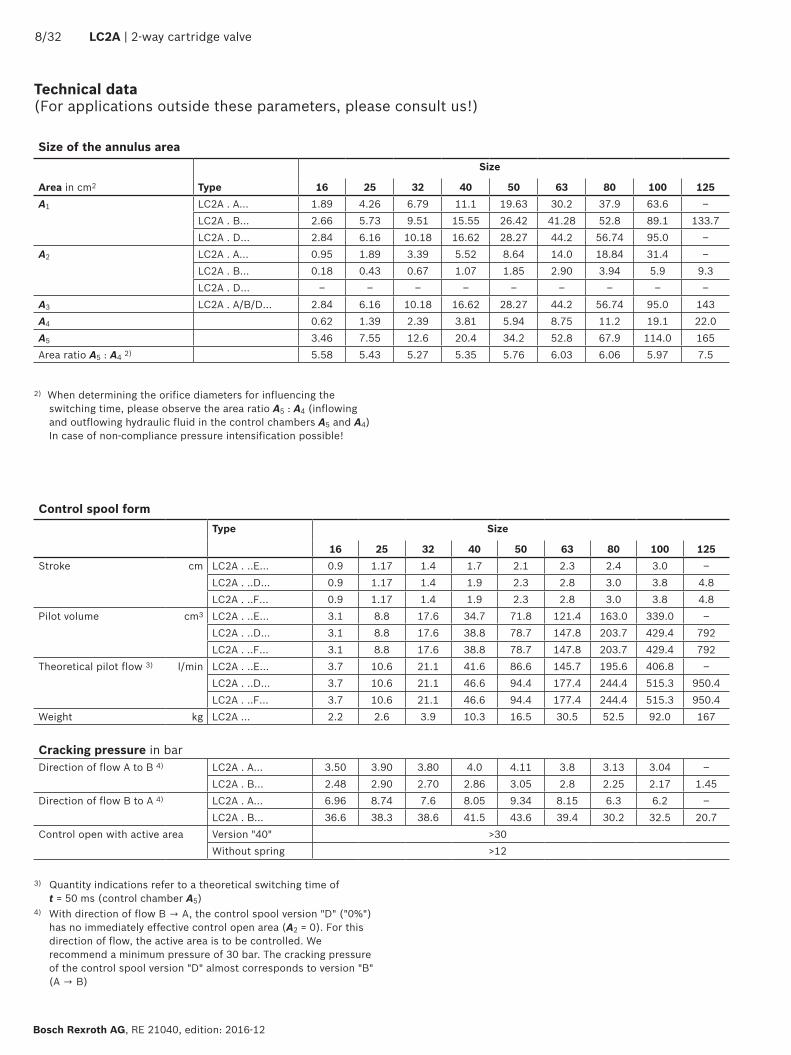

0 200 400 600 800 1000 1200
2
4
6
8
101 2 3
0 1000 2000 3000 4000 4750
2
4
6
8
104 5 6
7271 81 82
0 4000 8000 12000
2
4
6
8
10
1032 LC2A | 2-way cartridge valve
Bosch Rexroth AG RE 21040 edition 2016-12
Characteristic curves without damping nose E B rarr A (simulated with HLP46 ϑOil = 40 plusmn5 degC)
Pres
sure
diff
eren
tial i
n ba
r rarr
1 Size 16
2 Size 25
3 Size 32
4 Size 40
5 Size 50
6 Size 63
71 Size 80 control spool design A
72 Size 80 control spool design B and D
81 Size 100 control spool design A
82 Size 100 control spool design B and D
NoticeThe specified characteristic curves were determined without inserted springs with aligned socket and in channel B with installation geometry optimized according to DIN ISO 7368 (see sketch on page 9)
Flow in lmin rarrFlow in lmin rarrPr
essu
re d
iffer
entia
l in
bar rarr
Flow in lmin rarr
Pres
sure
diff
eren
tial i
n ba
r rarr
0 200 400 600 800 1000 1200
2
4
6
8
101 2 3
0 500 1000 1500 2000 2500 35003000
2
4
6
8
104 5
7 86
0 4000 8000 12000
2
4
6
8
10
2-way cartridge valve | LC2A 1132
RE 21040 edition 2016-12 Bosch Rexroth AG
Characteristic curves with damping nose D A rarr B (simulated with HLP46 ϑOil = 40 plusmn5 degC)
Pres
sure
diff
eren
tial i
n ba
r rarr
Flow in lmin rarrFlow in lmin rarrPr
essu
re d
iffer
entia
l in
bar rarr
Flow in lmin rarr
Pres
sure
diff
eren
tial i
n ba
r rarr
1 Size 16
2 Size 25
3 Size 32
4 Size 40
5 Size 50
6 Size 63
7 Size 80
8 Size 100
NoticeThe specified characteristic curves were determined without inserted springs with aligned socket and in channel B with installation geometry optimized according to DIN ISO 7368 (see sketch on page 9)
0 200 400 600 800 1000 1200
2
4
6
8
101 2 3
0 500 1000 1500 2000 2500 35003000
2
4
6
8
104 5
7
8
6
0 4000 8000 12000
2
4
6
8
10
1232 LC2A | 2-way cartridge valve
Bosch Rexroth AG RE 21040 edition 2016-12
Characteristic curves with damping nose D B rarr A (simulated with HLP46 ϑOil = 40 plusmn5 degC)
Pres
sure
diff
eren
tial i
n ba
r rarr
Flow in lmin rarrFlow in lmin rarrPr
essu
re d
iffer
entia
l in
bar rarr
Flow in lmin rarr
Pres
sure
diff
eren
tial i
n ba
r rarr
1 Size 16
2 Size 25
3 Size 32
4 Size 40
5 Size 50
6 Size 63
7 Size 80
8 Size 100
NoticeThe specified characteristic curves were determined without inserted springs with aligned socket and in channel B with installation geometry optimized according to DIN ISO 7368 (see sketch on page 9)
0 200 400 600 800 1000 1200
2
4
6
8
101 2 3
0 1000 2000 3000 4000 4750
2
4
6
8
104 5
6
0 4000 8000 12000 16000
2
4
6
8
10
8
7
9
2-way cartridge valve | LC2A 1332
RE 21040 edition 2016-12 Bosch Rexroth AG
Characteristic curves with overlap F A rarr B (simulated with HLP46 ϑOil = 40 plusmn5 degC)
Pres
sure
diff
eren
tial i
n ba
r rarr
Flow in lmin rarrFlow in lmin rarrPr
essu
re d
iffer
entia
l in
bar rarr
Flow in lmin rarr
Pres
sure
diff
eren
tial i
n ba
r rarr
NoticeThe specified characteristic curves were determined without inserted springs with aligned socket and in channel B with installation geometry optimized according to DIN ISO 7368 (see sketch on page 9)
1 Size 16
2 Size 25
3 Size 32
4 Size 40
5 Size 50
6 Size 63
7 Size 80
8 Size 100
9 Size 125
0 200 400 600 800 1000 1200
2
4
6
8
101 2 3
0 1000 2000 3000 4000 4750
2
4
6
8
104 5 6
0 4000 8000 12000 16000
2
4
6
8
108 97
1432 LC2A | 2-way cartridge valve
Bosch Rexroth AG RE 21040 edition 2016-12
Characteristic curves with overlap F B rarr A (simulated with HLP46 ϑOil = 40 plusmn5 degC)
Pres
sure
diff
eren
tial i
n ba
r rarr
Flow in lmin rarrFlow in lmin rarrPr
essu
re d
iffer
entia
l in
bar rarr
Flow in lmin rarr
Pres
sure
diff
eren
tial i
n ba
r rarr
NoticeThe specified characteristic curves were determined without inserted springs with aligned socket and in channel B with installation geometry optimized according to DIN ISO 7368 (see sketch on page 9)
1 Size 16
2 Size 25
3 Size 32
4 Size 40
5 Size 50
6 Size 63
7 Size 80
8 Size 100
9 Size 125
05 06 07 08 10 12 15 18 20 25 30
40
50
60
80
35
005025
0507
114
2345
10
20304050
100
200300400
01 02 05 2 3 4 5 10 15 20 30 40 50 100
035
2-way cartridge valve | LC2A 1532
RE 21040 edition 2016-12 Bosch Rexroth AG
Characteristic curves for selecting the orifices
Orifice Oslash in mm
Flow in lmin rarr
Pres
sure
diff
eren
tial i
n ba
r rarr
Plug screws
Thread Tightening torque MA in Nm plusmn10
G18 12G14 30G38 55G12 80G34 135G1 225
OrificesThread Orifice Oslash in mm Tightening torque MA
in Nm plusmn10 M6 conical 05 hellip 30 4M8 x 1 conical 05 hellip 45 14G18 05 hellip 50 16G14 05 hellip 60 44G12 08 hellip 70 65G34 20 hellip 120 80
11
12
22
1632 LC2A | 2-way cartridge valve
Bosch Rexroth AG RE 21040 edition 2016-12
Dimensions NG16 hellip 63 (dimensions in mm)
NG 16 25 32 40 50 63L1 80 85 100 125 140 180L2 67 67 65 58 58 45L3 15 95 2 ndash ndash ndashL4 7 10 7 ndash ndash ndashL5 345 37 45 56 635 825L6 455 48 55 69 635 825H1 40 40 50 80 100 110H2 115 115 135 295 425 455OslashD1 M6 M6 M8 x 1 G18 G18 G14OslashD2 G18 G18 G18 G14 G14 G38OslashD3 85 135 19 22 24 26+1
View Version X or YView Version Z1 Z2 or U
With spool position monitoring (1 position switch Q7 position monitoring closed)
Without spool position monitoring (blind plug)
11
12
22
2-way cartridge valve | LC2A 1732
RE 21040 edition 2016-12 Bosch Rexroth AG
Dimensions NG16 hellip 32 (dimensions in mm)
View Version X or Y
With spool position monitoring (2 position switches Q7 position monitoring closed)
View Version Z1 Z2 or U
NG 16 25 32L1 80 85 100L2 67 67 65L3 15 95 2L5 345 37 45L6 455 48 55H1 40 40 50H2 115 115 135OslashD1 M6 M6 M8 x 1OslashD2 G18 G18 G18OslashD3 85 135 19
Item explanations see page 21
8
7
6
3
Z1 Z1
XX
Y Y
1
2
6Z2 Z2
4
5
H1 H2
6 x OslashD1 2 x OslashD2 4 x OslashD3
55
L1
2 2L5L1 L1
L2
L2 5 5
L6
L5
L2
15OslashD2
1
21
2
1832 LC2A | 2-way cartridge valve
Bosch Rexroth AG RE 21040 edition 2016-12
Dimensions NG40 hellip 63 (dimensions in mm)
NG 40 50 63L1 125 140 180L2 58 58 45L5 56 635 825L6 69 635 82H1 80 100 110H2 1) 295 425 455H2 2) 23 35 36OslashD1 G18 G18 G14OslashD2 G14 G14 G38OslashD3 22 24 26+1
With spool position monitoring (2 position switches Q7 position monitoring closed and open)
1) Position monitoring closed2) Position monitoring open
Item explanations see page 21
View Version X or YView Version Z1 Z2 or U
8 x OslashD4
OslashD5 OslashD5
8 x OslashD4
2 x OslashD3
2 x OslashD2
2 x OslashD3
2-way cartridge valve | LC2A 1932
RE 21040 edition 2016-12 Bosch Rexroth AG
Dimensions NG80 hellip 125 (dimensions in mm)
View Version Z1 Z2 or U View Version X or Y
NG 80 100 125OslashD1 G12 G12 G34OslashD2 G12 G12 G12OslashD3 G1 G1 G34OslashD4 26+1 33+05 40OslashD5 250 300 380L1 37 26 ndashH1 120 140 160H2 48 552 652
With spool position monitoring (1 position switch Q7 position monitoring closed)
Item explanations see page 21
OslashD5 OslashD5
8 x OslashD4
8 x OslashD4
2 x OslashD3
2 x OslashD2
2 x OslashD3
21
9
2032 LC2A | 2-way cartridge valve
Bosch Rexroth AG RE 21040 edition 2016-12
Dimensions NG80 hellip 125 (dimensions in mm)
View Version Z1 or Z2
With spool position monitoring (2 position switches Q7 position monitoring closed and open)
NG 80 100 125OslashD1 G12 G12 G34OslashD2 G12 G12 G12OslashD3 G1 G1 G34OslashD4 26+1 33+05 40OslashD5 250 300 380L1 37 26 ndashH1 120 140 160H2 1) 48 552 652H2 2) 373 447 545
1) Position monitoring closed2) Position monitoring open
Item explanations see page 21
View Version X or Y
2-way cartridge valve | LC2A 2132
RE 21040 edition 2016-12 Bosch Rexroth AG
1 Name plate11 Name plate NG16 and 2512 Name plate NG32 hellip 63
2 Position switch (optional) or blind plug21 Position switch open (Q7T)
3 Mating connector (separate order see page 31)4 Space required for removing the mating connector5 Sealing by the factory6 Transport lock for control spool (marking K)
Dont remove Loosening or removal and installation only admissible in case of servicerepair
7 Standard endcontrol cover type LFAhellip (separate order depends on the basic hydraulic function)
8 Valve mounting screws (separate order see table below)9 Connection possibility for a 3rd position switch closed
(optional only NG125)
Dimensions
Valve mounting screws (separate order)NG Control cover
type LFAHexagon socket head cap screws ISO 4762-109-flZn
Quantity Dimension Material number (preferred)
Tightening torque MA 2) in Nm plusmn10
16WE GW
4M8 x 85 R913004145
30WEM M8 x 110 R9130157921) M8 x 80 R913015803
25HWM
4M12 x 140 R913015593
1001) M12 x 90 R913015617
32
H1 H2
4
M16 x 130 R913014713
240H3 H4 M16 x 120 R913014711HWM M16 x 160 R913015647
1) M16 x 110 R913015642
40H1 H2 HWM
4M20 x 190 R913015680
4801) M20 x 150 R913015676
50 H2 H4 HWM
4M20 x 220 R913014716
4801) M20 x 180 R913014714
63H2 H4 HWM
4M30 x 260 R913015758
16001) M30 x 210 R913015754
80H2 H4
8M24 x 240 R913015721
8002) M24 x 220 R913015719
100D WE
8M30 x 260 R913015758
16001) M30 x 280 R913015760
125 D WE 8 M36 x 320 R913050473 2300
1) More available series control covers2) Calculated with total friction coefficient micro = 009 014 adjust in
case of modified surfaces
NoticeThe length of the valve mounting screws of the active logics (intermediate cover) must be selected according to the related control cover type LFAhellip Screw type screw length and tightening torque are to be adjusted to the conditions depending on the applicationFor reasons of stability exclusively the valve mounting screws listed above may be used
D7H13 10
8 x D5 H4
D6 max L2plusmn0
3L1X Y
Z2
Z15
(X Y Z1 Z2)
35 22545
Rz1max 4x =
Rz1max 8y =
00025- Pt max 16z =
45deg
45deg
225deg
165plusmn
0216
5plusmn02
300plusmn
03
45plusmn02
30plusmn02
Oslash32 max
5
X Y
5
Z1
Z2
Oslash9 10
Oslash9 10
(X Y Z1 Z2)
8 x M36 62
380
L1L2plusmn02
L5plusmn02D7H13 10 4 x D5 H4
L2plusmn0
2L3plusmn0
2
L4plusmn0
2
L1L4
plusmn02
L4plusmn02L4plusmn02 D6 max(X Y Z1 Z2)
X Y
Z1
Z2
5
OslashD2
OslashD1H7
OslashD3
(OslashD3
)H1 (H
1)
H9H8
H7H6
H5H2
+01
H3plusmn0
3
R1
R2
15deg
15deg
OslashD4H7y
xy
z
z
WA
005 A
1
1
A
B
3 2 4
2232 LC2A | 2-way cartridge valve
Bosch Rexroth AG RE 21040 edition 2016-12
Installation bore and connection dimensions according to DIN ISO 7368 (dimensions in mm)
NG80 and 100NG16 hellip 63
1 Depth of fit2 Control dimension3 With a different diameter OslashD3 or OslashD3 the distance H1 or
H1 has to be adjusted4 Port B can be positioned around the central axis of port A
However it must be observed that the mounting bores and the pilot oil bores are not damaged
5 Bore for locking pin
Notes All information on the mounting bore D5 is based on the use of hexagon socket head cap screws according to ISO 4762
Installation see assembly instructions 21040-MON
Dimensions see page 23
NG125
2-way cartridge valve | LC2A 2332
RE 21040 edition 2016-12 Bosch Rexroth AG
Installation bore and connection dimensions according to DIN ISO 7368 (dimensions in mm)
1) Dimension OslashD3 refers to dimension H12) Maximum dimension
NG 16 25 32 40 50 63 80 100 125OslashD1H7 32 45 60 75 90 120 145 180 225
OslashD2 16 25 32 40 50 63 80 100 150OslashD3 16 25 32 40 50 63 80 100 125
OslashD3 1) 25 32 40 50 63 80 100 125 150OslashD4H7 25 34 45 55 68 90 110 135 200
OslashD5 M8 M12 M16 M20 M20 M30 M24 M30 ndashOslashD6 4 6 8 10 10 12 16 20 ndash
OslashD7H13 4 6 6 6 8 8 10 10 ndashH1 34 44 52 64 72 95 130 155 192
H1 1) 295 405 48 59 655 865 120 142 180H2 56+01 72+01 85+01 105+01 122+01 155+01 205+01 245+01 300+015
H3 43plusmn02 58plusmn02 70plusmn02 87plusmn03 100plusmn03 130plusmn03 175plusmn04 210plusmn04 257plusmn05
H4 20 25 35 45 45 65 50 63 ndashH5 11 12 13 15 17 20 25 29 31H6 2 25 25 3 3 4 5 5 7plusmn05
H7 20 30 30 30 35 40 40 50 50H8 2 25 25 3 4 4 5 5 55plusmn02
H9 05 1 15 25 25 3 45 45 2L1 80 85 102 125 140 180 250 300 ndashL2 46 58 70 85 100 125 200 245 ndashL3 23 29 35 425 50 625 ndash ndash ndashL4 25 33 41 50 58 75 ndash ndash ndashL5 105 16 17 23 30 38 ndash ndash ndashW 005 005 01 01 01 01 01 01 01
R1 2) 1 1 1 1 1 1 1 1 1R2 2) 2 2 2 4 4 4 4 4 4
2432 LC2A | 2-way cartridge valve
Bosch Rexroth AG RE 21040 edition 2016-12
Check valve releasable
X Z1 Z2 Y
A
B
1
2B
X Z1 Z2 Y
A B
P T
TPF
B
Type M-3SEW 6 U420
Type LFA WEMAhellip
Type LC2A A40E-1XXhellip
Pressure-supported closing by excess area function (eg with control cover type D)
1
2
X Z1 Z2 Y
X Z1 Z2 Y
A
B
X Type LFA Dhellip
Type LC2A A40D-1XhellipY99
Passive logics with piston seal and spool position monitoring function (Closing with spring force without excess area here with control cover type D) ideal for the retrofitting of existing circuits
1
2
X Z1 Z2 Y
X Z1 Z2 Y
A
B
X Type LFA Dhellip
Type LC2A A40D-1XXQ7hellip Y99
Circuit examples (schematic diagram function must be checked with the application)
NoticeIt has to be ensured that pilot oil ports that are not required (blanking plugs) and all pressurized transitions between LFA and LC2A (R-rings) are sealed This is particularly true for variants marked with
2-way cartridge valve | LC2A 2532
RE 21040 edition 2016-12 Bosch Rexroth AG
Circuit examples (schematic diagram function must be checked with the application)
Self-closing or Open basic position (e g with control cover type WEMA)
X Z1 Z2 Y
A
B
1
2
X Z1 Z2 Y
A B
P T
TPF
1)
Type M-3SEW U420
Type LFA WEMAhellip
Type LC2A D40E-1XZ2hellipW99
Control spool remains open as long as FZ2 ge FA + 30 barIn case of failure or drop of the pilot pressure the logic element closes hydraulically Irrespective thereof the logic element can be opened by unloading the spring chamber (minimum pilot pressure required)
Pulling and Safe keeping closed function
1
2
X Z1 Z2 Y
X Z1 Z2 Y
A
B
P T
2)
X Type LFA Dhellip
Type LC2A B40F-1XZ2Q7G24FY99W99
The control spool of the active logics can be opened or closed dependent on the two pilot oil pressures X and Z2 Thus free flow is possible in both directions irrespective of the pressure level in port B
1) Pilot pressure2) Actuator
2632 LC2A | 2-way cartridge valve
Bosch Rexroth AG RE 21040 edition 2016-12
Passive logics with spool sealing function spool position monitoring and stroke limitation
X Z1 Z2 Y
A
B
1
2B
X Z1 Z2 Y
A
P T
TPF
B
Type M-3SEW U420
Type LFA HWMAhellip
Type LC2A A40D-1XYQ7hellip
Advantages Retrofitting for existing installation using the existing control cover type LFA and pilot control valves
Leakage-free locking Position monitoring Shortened closing time
Closed basic position function safe locking increased closing force
X Z1 Z2 Y
A
B
1
2
X Z1 Z2 Y
A
P T
TP A B
Type M-3SEW 6 U420
Type LFA GWMAhellip
Type LC2A D40E-1XYhellip (W99)
Advantages Safe locking in both directions Control spool cannot be controlled open from side B (version DE)
Position switch retrofittable Shortened switching time
Circuit examples (schematic diagram function must be checked with the application)
2-way cartridge valve | LC2A 2732
RE 21040 edition 2016-12 Bosch Rexroth AG
Separation between both pilot pressures and hydraulic keeping open in case of pilot pressure failure function
A B
P
A
B
X Z1 Z2 Y
X Z1 Z2 Y
P A
T
1
2
Type M-4SEW D420
Type LFA GWMA20hellip
Type LC2A B40F-1XZ2Q7hellip
Advantages Leakage-free separation of the two pilot pressures X and Z1 Function of a hydraulic detent (Keeping open also in case of pilot pressure failure)
Permits complete pressure compensation of both main ports
Check valve and Safe locking function increased closing force
A B
P
A
B
X Z1
Z1 Y
Z2 Y
X Z1 Z2 Y
T
1
2
Type M-4SEW D420
Type LFA KWMAhellip
Type LC2A B40F-1XZ2Q7hellip
Advantages Leakage-free locking Increased closing force (shortened closing time)
Circuit examples (schematic diagram function must be checked with the application)
2832 LC2A | 2-way cartridge valve
Bosch Rexroth AG RE 21040 edition 2016-12
Check valve (releasable) and Safe locking function Keeping open additional function
A B
P
A
B
X Z1
Z1 Y
Z2 Y
X Z1 Z2 Y
T
1
2
T
P
Type M-4SEW D420
Type LFA KWMAhellip
Type LC2A B40F-1XZ2Q7Q7Thellip
Advantages Safe locking in both directions Check valve function that can be switched off Leakage-free locking Monitoring of the open and closed position
Check valve circuit function self-locking fast-closing
A B
P
A
B
X Z1
Z1X
Z2Y
Z2 Y
X Z1 Z2 Y
T
1
2
Type M-4SEW D420
Type LFA 40 WEMBhellipF99
Type LC2A 040 D40E-1XZ2Q9G24A160D99S99F
Advantages Maximum load pressure in channel A 500 bar (condition maximum pressure in channel B 250 bar)
Very fast closing by internal spring chamber filling (eg NG63 lt 20 ms)
High locking force Analog position sensing (optional)
Circuit examples (schematic diagram function must be checked with the application)
2-way cartridge valve | LC2A 2932
RE 21040 edition 2016-12 Bosch Rexroth AG
The electrical connection is realized via a 4-pole mating connector with connection thread M12 x 1 (separate order see page 31) The inductive position switch can be connected as normally closed or normally open contact
Features Adjustment-free assembly due to fixed stop Certification according to CE and cULus
Notes The closed spool position is adjusted to and optimized for a condition at operating temperature Considerably deviating operating temperatures thus influence the absolute switching position as well as its hysteresis
The position switch type Q7 has no connection for protective earthing conductors
Assembly tool for position switch type Q7 or blind plug upon request
BG certificate (only size 16 hellip 100 and valve poppet version D and F) The respectively valid MHHW 10014 certificate for using the active logics type LC2A with position switch type Q7 in hydraulic security locks in injection molding machines according to the manufacturers installation instructions is available upon request
Inductive position switch type Q7 Electrical connection
Connection voltage 12 hellip 30 V direct voltageAdmissible residual ripple lt 15Load capacity 200 mA short-circuit-proofTightening torque MA 10+5 NmSwitching outputs PNP transistor outputs load between switching outputs and GND
4
2
3
1 +
ndash GND
Pinout 1 +UB
4
1 2
3 2 Normally closed contact3 L04 Normally open contact
3032 LC2A | 2-way cartridge valve
Bosch Rexroth AG RE 21040 edition 2016-12
Inductive position switch type Q8 Electrical connection
The electric connection is realized via a 4-pole mating connector (separate order see page 31) with connection thread M12 x 1
Connection voltage 82 V +9-6 direct voltageMaximum current consumption dampened 1 mAMaximum current consumption not damped 4 mATightening torque MA 10+5 NmSwitching outputs NAMUR evaluation electronics necessary
3
1 +
ndash GND
Pinout 1 Current source
4
1 2
3 2 ndash3 0 V GND4 ndash
The electrical connection is realized via a 4-pole mating connector with connection thread M12 x 1 (separate order see page 31)
Inductive position switch type Q9 Electrical connection
Connection voltage 15 hellip 30 V direct voltageAdmissible residual ripple lt 15Load capacity 200 mA short-circuit-proofTightening torque MA 10+5 NmSwitching outputs PNP transistor outputs load between switching outputs and GND
4
3
1 +
ndash GND
Pinout 1 +UB
4
1 2
3 2 ndash3 L04 0 hellip 10 V DC
Features Certification according to CE Explosion protection according to Ex II 2G Ex ia IIC T6
Features Certification according to CE
54
M12 x
1macr1
96
M12 x
1macr1
9635
40
2-way cartridge valve | LC2A 3132
RE 21040 edition 2016-12 Bosch Rexroth AG
Mating connectors for inductive position switch (dimensions in mm)
Mating connector suitable for K24 4-pole M12 x 1 with screw connection cable gland Pg 9
Material no R900031155
Mating connector suitable for K24 4-pole (only up to NG80) M12 x 1 with screw connection cable gland Pg 9 angledHousing can be rotated by 4 x 90deg in relation to the contact insert
Material no R900082899
For further information refer to data sheet 08006
Switching point behavior and overlap Valve poppet with damping nose D or overlap nose F and position overlap closed
Stroke
h Overlap stroke (mechanical)s Switching point window (electrical)qV0 Maximum flow until h min
Characteristic curve position switch type Q7
NoticeWith pre-assembled mating connectors the alignment of the cable outlet may vary depending on the installation position of the sensor and cause assembly problems
Hysteresis (max 03 mm) rarr
Stroke in mm rarr
Flow
in l
min
rarr
PIN 410
PIN 210
0
qV0
0 s0smin smax
hmin
3232 LC2A | 2-way cartridge valve
Bosch Rexroth AG RE 21040 edition 2016-12
Further information
2-way cartridge valves directional functions (passive logics) Data sheet 21010 2-way cartridge valves pressure function (passive logics) Data sheet 21050 Hydraulic fluids on mineral oil basis Data sheet 90220 Environmentally compatible hydraulic fluids Data sheet 90221 Flame-resistant water-free hydraulic fluids Data sheet 90222 Flame-resistant hydraulic fluids - containing water (HFAE HFAS HFB HFC) Data sheet 90223 Reliability characteristics according to EN ISO 13849 Data sheet 08012 Hydraulic valves for industrial applications Data sheet 07600-B 2-way cartridge valve actively controllable Assembly instructions 21040-MON Selection of the filters wwwboschrexrothcomfilter Information on available spare parts wwwboschrexrothcomspc
- Features
- Contents
- Ordering code
- Symbols
- Assignment of the active area A4
- Orifice assignment
- Function section
- Technical
- Characteristic curves
- Characteristic curves for selecting the orifices
- Dimensions
- Installation bore and connection dimensions
- Circuit examples
- Inductive position switch
- Switching point behavior and overlap
- Mating connectors for inductive position switch
- Further information
-

0 200 400 600 800 1000 1200
2
4
6
8
101 2 3
0 500 1000 1500 2000 2500 35003000
2
4
6
8
104 5
7
8
6
0 4000 8000 12000
2
4
6
8
10
1232 LC2A | 2-way cartridge valve
Bosch Rexroth AG RE 21040 edition 2016-12
Characteristic curves with damping nose D B rarr A (simulated with HLP46 ϑOil = 40 plusmn5 degC)
Pres
sure
diff
eren
tial i
n ba
r rarr
Flow in lmin rarrFlow in lmin rarrPr
essu
re d
iffer
entia
l in
bar rarr
Flow in lmin rarr
Pres
sure
diff
eren
tial i
n ba
r rarr
1 Size 16
2 Size 25
3 Size 32
4 Size 40
5 Size 50
6 Size 63
7 Size 80
8 Size 100
NoticeThe specified characteristic curves were determined without inserted springs with aligned socket and in channel B with installation geometry optimized according to DIN ISO 7368 (see sketch on page 9)
0 200 400 600 800 1000 1200
2
4
6
8
101 2 3
0 1000 2000 3000 4000 4750
2
4
6
8
104 5
6
0 4000 8000 12000 16000
2
4
6
8
10
8
7
9
2-way cartridge valve | LC2A 1332
RE 21040 edition 2016-12 Bosch Rexroth AG
Characteristic curves with overlap F A rarr B (simulated with HLP46 ϑOil = 40 plusmn5 degC)
Pres
sure
diff
eren
tial i
n ba
r rarr
Flow in lmin rarrFlow in lmin rarrPr
essu
re d
iffer
entia
l in
bar rarr
Flow in lmin rarr
Pres
sure
diff
eren
tial i
n ba
r rarr
NoticeThe specified characteristic curves were determined without inserted springs with aligned socket and in channel B with installation geometry optimized according to DIN ISO 7368 (see sketch on page 9)
1 Size 16
2 Size 25
3 Size 32
4 Size 40
5 Size 50
6 Size 63
7 Size 80
8 Size 100
9 Size 125
0 200 400 600 800 1000 1200
2
4
6
8
101 2 3
0 1000 2000 3000 4000 4750
2
4
6
8
104 5 6
0 4000 8000 12000 16000
2
4
6
8
108 97
1432 LC2A | 2-way cartridge valve
Bosch Rexroth AG RE 21040 edition 2016-12
Characteristic curves with overlap F B rarr A (simulated with HLP46 ϑOil = 40 plusmn5 degC)
Pres
sure
diff
eren
tial i
n ba
r rarr
Flow in lmin rarrFlow in lmin rarrPr
essu
re d
iffer
entia
l in
bar rarr
Flow in lmin rarr
Pres
sure
diff
eren
tial i
n ba
r rarr
NoticeThe specified characteristic curves were determined without inserted springs with aligned socket and in channel B with installation geometry optimized according to DIN ISO 7368 (see sketch on page 9)
1 Size 16
2 Size 25
3 Size 32
4 Size 40
5 Size 50
6 Size 63
7 Size 80
8 Size 100
9 Size 125
05 06 07 08 10 12 15 18 20 25 30
40
50
60
80
35
005025
0507
114
2345
10
20304050
100
200300400
01 02 05 2 3 4 5 10 15 20 30 40 50 100
035
2-way cartridge valve | LC2A 1532
RE 21040 edition 2016-12 Bosch Rexroth AG
Characteristic curves for selecting the orifices
Orifice Oslash in mm
Flow in lmin rarr
Pres
sure
diff
eren
tial i
n ba
r rarr
Plug screws
Thread Tightening torque MA in Nm plusmn10
G18 12G14 30G38 55G12 80G34 135G1 225
OrificesThread Orifice Oslash in mm Tightening torque MA
in Nm plusmn10 M6 conical 05 hellip 30 4M8 x 1 conical 05 hellip 45 14G18 05 hellip 50 16G14 05 hellip 60 44G12 08 hellip 70 65G34 20 hellip 120 80
11
12
22
1632 LC2A | 2-way cartridge valve
Bosch Rexroth AG RE 21040 edition 2016-12
Dimensions NG16 hellip 63 (dimensions in mm)
NG 16 25 32 40 50 63L1 80 85 100 125 140 180L2 67 67 65 58 58 45L3 15 95 2 ndash ndash ndashL4 7 10 7 ndash ndash ndashL5 345 37 45 56 635 825L6 455 48 55 69 635 825H1 40 40 50 80 100 110H2 115 115 135 295 425 455OslashD1 M6 M6 M8 x 1 G18 G18 G14OslashD2 G18 G18 G18 G14 G14 G38OslashD3 85 135 19 22 24 26+1
View Version X or YView Version Z1 Z2 or U
With spool position monitoring (1 position switch Q7 position monitoring closed)
Without spool position monitoring (blind plug)
11
12
22
2-way cartridge valve | LC2A 1732
RE 21040 edition 2016-12 Bosch Rexroth AG
Dimensions NG16 hellip 32 (dimensions in mm)
View Version X or Y
With spool position monitoring (2 position switches Q7 position monitoring closed)
View Version Z1 Z2 or U
NG 16 25 32L1 80 85 100L2 67 67 65L3 15 95 2L5 345 37 45L6 455 48 55H1 40 40 50H2 115 115 135OslashD1 M6 M6 M8 x 1OslashD2 G18 G18 G18OslashD3 85 135 19
Item explanations see page 21
8
7
6
3
Z1 Z1
XX
Y Y
1
2
6Z2 Z2
4
5
H1 H2
6 x OslashD1 2 x OslashD2 4 x OslashD3
55
L1
2 2L5L1 L1
L2
L2 5 5
L6
L5
L2
15OslashD2
1
21
2
1832 LC2A | 2-way cartridge valve
Bosch Rexroth AG RE 21040 edition 2016-12
Dimensions NG40 hellip 63 (dimensions in mm)
NG 40 50 63L1 125 140 180L2 58 58 45L5 56 635 825L6 69 635 82H1 80 100 110H2 1) 295 425 455H2 2) 23 35 36OslashD1 G18 G18 G14OslashD2 G14 G14 G38OslashD3 22 24 26+1
With spool position monitoring (2 position switches Q7 position monitoring closed and open)
1) Position monitoring closed2) Position monitoring open
Item explanations see page 21
View Version X or YView Version Z1 Z2 or U
8 x OslashD4
OslashD5 OslashD5
8 x OslashD4
2 x OslashD3
2 x OslashD2
2 x OslashD3
2-way cartridge valve | LC2A 1932
RE 21040 edition 2016-12 Bosch Rexroth AG
Dimensions NG80 hellip 125 (dimensions in mm)
View Version Z1 Z2 or U View Version X or Y
NG 80 100 125OslashD1 G12 G12 G34OslashD2 G12 G12 G12OslashD3 G1 G1 G34OslashD4 26+1 33+05 40OslashD5 250 300 380L1 37 26 ndashH1 120 140 160H2 48 552 652
With spool position monitoring (1 position switch Q7 position monitoring closed)
Item explanations see page 21
OslashD5 OslashD5
8 x OslashD4
8 x OslashD4
2 x OslashD3
2 x OslashD2
2 x OslashD3
21
9
2032 LC2A | 2-way cartridge valve
Bosch Rexroth AG RE 21040 edition 2016-12
Dimensions NG80 hellip 125 (dimensions in mm)
View Version Z1 or Z2
With spool position monitoring (2 position switches Q7 position monitoring closed and open)
NG 80 100 125OslashD1 G12 G12 G34OslashD2 G12 G12 G12OslashD3 G1 G1 G34OslashD4 26+1 33+05 40OslashD5 250 300 380L1 37 26 ndashH1 120 140 160H2 1) 48 552 652H2 2) 373 447 545
1) Position monitoring closed2) Position monitoring open
Item explanations see page 21
View Version X or Y
2-way cartridge valve | LC2A 2132
RE 21040 edition 2016-12 Bosch Rexroth AG
1 Name plate11 Name plate NG16 and 2512 Name plate NG32 hellip 63
2 Position switch (optional) or blind plug21 Position switch open (Q7T)
3 Mating connector (separate order see page 31)4 Space required for removing the mating connector5 Sealing by the factory6 Transport lock for control spool (marking K)
Dont remove Loosening or removal and installation only admissible in case of servicerepair
7 Standard endcontrol cover type LFAhellip (separate order depends on the basic hydraulic function)
8 Valve mounting screws (separate order see table below)9 Connection possibility for a 3rd position switch closed
(optional only NG125)
Dimensions
Valve mounting screws (separate order)NG Control cover
type LFAHexagon socket head cap screws ISO 4762-109-flZn
Quantity Dimension Material number (preferred)
Tightening torque MA 2) in Nm plusmn10
16WE GW
4M8 x 85 R913004145
30WEM M8 x 110 R9130157921) M8 x 80 R913015803
25HWM
4M12 x 140 R913015593
1001) M12 x 90 R913015617
32
H1 H2
4
M16 x 130 R913014713
240H3 H4 M16 x 120 R913014711HWM M16 x 160 R913015647
1) M16 x 110 R913015642
40H1 H2 HWM
4M20 x 190 R913015680
4801) M20 x 150 R913015676
50 H2 H4 HWM
4M20 x 220 R913014716
4801) M20 x 180 R913014714
63H2 H4 HWM
4M30 x 260 R913015758
16001) M30 x 210 R913015754
80H2 H4
8M24 x 240 R913015721
8002) M24 x 220 R913015719
100D WE
8M30 x 260 R913015758
16001) M30 x 280 R913015760
125 D WE 8 M36 x 320 R913050473 2300
1) More available series control covers2) Calculated with total friction coefficient micro = 009 014 adjust in
case of modified surfaces
NoticeThe length of the valve mounting screws of the active logics (intermediate cover) must be selected according to the related control cover type LFAhellip Screw type screw length and tightening torque are to be adjusted to the conditions depending on the applicationFor reasons of stability exclusively the valve mounting screws listed above may be used
D7H13 10
8 x D5 H4
D6 max L2plusmn0
3L1X Y
Z2
Z15
(X Y Z1 Z2)
35 22545
Rz1max 4x =
Rz1max 8y =
00025- Pt max 16z =
45deg
45deg
225deg
165plusmn
0216
5plusmn02
300plusmn
03
45plusmn02
30plusmn02
Oslash32 max
5
X Y
5
Z1
Z2
Oslash9 10
Oslash9 10
(X Y Z1 Z2)
8 x M36 62
380
L1L2plusmn02
L5plusmn02D7H13 10 4 x D5 H4
L2plusmn0
2L3plusmn0
2
L4plusmn0
2
L1L4
plusmn02
L4plusmn02L4plusmn02 D6 max(X Y Z1 Z2)
X Y
Z1
Z2
5
OslashD2
OslashD1H7
OslashD3
(OslashD3
)H1 (H
1)
H9H8
H7H6
H5H2
+01
H3plusmn0
3
R1
R2
15deg
15deg
OslashD4H7y
xy
z
z
WA
005 A
1
1
A
B
3 2 4
2232 LC2A | 2-way cartridge valve
Bosch Rexroth AG RE 21040 edition 2016-12
Installation bore and connection dimensions according to DIN ISO 7368 (dimensions in mm)
NG80 and 100NG16 hellip 63
1 Depth of fit2 Control dimension3 With a different diameter OslashD3 or OslashD3 the distance H1 or
H1 has to be adjusted4 Port B can be positioned around the central axis of port A
However it must be observed that the mounting bores and the pilot oil bores are not damaged
5 Bore for locking pin
Notes All information on the mounting bore D5 is based on the use of hexagon socket head cap screws according to ISO 4762
Installation see assembly instructions 21040-MON
Dimensions see page 23
NG125
2-way cartridge valve | LC2A 2332
RE 21040 edition 2016-12 Bosch Rexroth AG
Installation bore and connection dimensions according to DIN ISO 7368 (dimensions in mm)
1) Dimension OslashD3 refers to dimension H12) Maximum dimension
NG 16 25 32 40 50 63 80 100 125OslashD1H7 32 45 60 75 90 120 145 180 225
OslashD2 16 25 32 40 50 63 80 100 150OslashD3 16 25 32 40 50 63 80 100 125
OslashD3 1) 25 32 40 50 63 80 100 125 150OslashD4H7 25 34 45 55 68 90 110 135 200
OslashD5 M8 M12 M16 M20 M20 M30 M24 M30 ndashOslashD6 4 6 8 10 10 12 16 20 ndash
OslashD7H13 4 6 6 6 8 8 10 10 ndashH1 34 44 52 64 72 95 130 155 192
H1 1) 295 405 48 59 655 865 120 142 180H2 56+01 72+01 85+01 105+01 122+01 155+01 205+01 245+01 300+015
H3 43plusmn02 58plusmn02 70plusmn02 87plusmn03 100plusmn03 130plusmn03 175plusmn04 210plusmn04 257plusmn05
H4 20 25 35 45 45 65 50 63 ndashH5 11 12 13 15 17 20 25 29 31H6 2 25 25 3 3 4 5 5 7plusmn05
H7 20 30 30 30 35 40 40 50 50H8 2 25 25 3 4 4 5 5 55plusmn02
H9 05 1 15 25 25 3 45 45 2L1 80 85 102 125 140 180 250 300 ndashL2 46 58 70 85 100 125 200 245 ndashL3 23 29 35 425 50 625 ndash ndash ndashL4 25 33 41 50 58 75 ndash ndash ndashL5 105 16 17 23 30 38 ndash ndash ndashW 005 005 01 01 01 01 01 01 01
R1 2) 1 1 1 1 1 1 1 1 1R2 2) 2 2 2 4 4 4 4 4 4
2432 LC2A | 2-way cartridge valve
Bosch Rexroth AG RE 21040 edition 2016-12
Check valve releasable
X Z1 Z2 Y
A
B
1
2B
X Z1 Z2 Y
A B
P T
TPF
B
Type M-3SEW 6 U420
Type LFA WEMAhellip
Type LC2A A40E-1XXhellip
Pressure-supported closing by excess area function (eg with control cover type D)
1
2
X Z1 Z2 Y
X Z1 Z2 Y
A
B
X Type LFA Dhellip
Type LC2A A40D-1XhellipY99
Passive logics with piston seal and spool position monitoring function (Closing with spring force without excess area here with control cover type D) ideal for the retrofitting of existing circuits
1
2
X Z1 Z2 Y
X Z1 Z2 Y
A
B
X Type LFA Dhellip
Type LC2A A40D-1XXQ7hellip Y99
Circuit examples (schematic diagram function must be checked with the application)
NoticeIt has to be ensured that pilot oil ports that are not required (blanking plugs) and all pressurized transitions between LFA and LC2A (R-rings) are sealed This is particularly true for variants marked with
2-way cartridge valve | LC2A 2532
RE 21040 edition 2016-12 Bosch Rexroth AG
Circuit examples (schematic diagram function must be checked with the application)
Self-closing or Open basic position (e g with control cover type WEMA)
X Z1 Z2 Y
A
B
1
2
X Z1 Z2 Y
A B
P T
TPF
1)
Type M-3SEW U420
Type LFA WEMAhellip
Type LC2A D40E-1XZ2hellipW99
Control spool remains open as long as FZ2 ge FA + 30 barIn case of failure or drop of the pilot pressure the logic element closes hydraulically Irrespective thereof the logic element can be opened by unloading the spring chamber (minimum pilot pressure required)
Pulling and Safe keeping closed function
1
2
X Z1 Z2 Y
X Z1 Z2 Y
A
B
P T
2)
X Type LFA Dhellip
Type LC2A B40F-1XZ2Q7G24FY99W99
The control spool of the active logics can be opened or closed dependent on the two pilot oil pressures X and Z2 Thus free flow is possible in both directions irrespective of the pressure level in port B
1) Pilot pressure2) Actuator
2632 LC2A | 2-way cartridge valve
Bosch Rexroth AG RE 21040 edition 2016-12
Passive logics with spool sealing function spool position monitoring and stroke limitation
X Z1 Z2 Y
A
B
1
2B
X Z1 Z2 Y
A
P T
TPF
B
Type M-3SEW U420
Type LFA HWMAhellip
Type LC2A A40D-1XYQ7hellip
Advantages Retrofitting for existing installation using the existing control cover type LFA and pilot control valves
Leakage-free locking Position monitoring Shortened closing time
Closed basic position function safe locking increased closing force
X Z1 Z2 Y
A
B
1
2
X Z1 Z2 Y
A
P T
TP A B
Type M-3SEW 6 U420
Type LFA GWMAhellip
Type LC2A D40E-1XYhellip (W99)
Advantages Safe locking in both directions Control spool cannot be controlled open from side B (version DE)
Position switch retrofittable Shortened switching time
Circuit examples (schematic diagram function must be checked with the application)
2-way cartridge valve | LC2A 2732
RE 21040 edition 2016-12 Bosch Rexroth AG
Separation between both pilot pressures and hydraulic keeping open in case of pilot pressure failure function
A B
P
A
B
X Z1 Z2 Y
X Z1 Z2 Y
P A
T
1
2
Type M-4SEW D420
Type LFA GWMA20hellip
Type LC2A B40F-1XZ2Q7hellip
Advantages Leakage-free separation of the two pilot pressures X and Z1 Function of a hydraulic detent (Keeping open also in case of pilot pressure failure)
Permits complete pressure compensation of both main ports
Check valve and Safe locking function increased closing force
A B
P
A
B
X Z1
Z1 Y
Z2 Y
X Z1 Z2 Y
T
1
2
Type M-4SEW D420
Type LFA KWMAhellip
Type LC2A B40F-1XZ2Q7hellip
Advantages Leakage-free locking Increased closing force (shortened closing time)
Circuit examples (schematic diagram function must be checked with the application)
2832 LC2A | 2-way cartridge valve
Bosch Rexroth AG RE 21040 edition 2016-12
Check valve (releasable) and Safe locking function Keeping open additional function
A B
P
A
B
X Z1
Z1 Y
Z2 Y
X Z1 Z2 Y
T
1
2
T
P
Type M-4SEW D420
Type LFA KWMAhellip
Type LC2A B40F-1XZ2Q7Q7Thellip
Advantages Safe locking in both directions Check valve function that can be switched off Leakage-free locking Monitoring of the open and closed position
Check valve circuit function self-locking fast-closing
A B
P
A
B
X Z1
Z1X
Z2Y
Z2 Y
X Z1 Z2 Y
T
1
2
Type M-4SEW D420
Type LFA 40 WEMBhellipF99
Type LC2A 040 D40E-1XZ2Q9G24A160D99S99F
Advantages Maximum load pressure in channel A 500 bar (condition maximum pressure in channel B 250 bar)
Very fast closing by internal spring chamber filling (eg NG63 lt 20 ms)
High locking force Analog position sensing (optional)
Circuit examples (schematic diagram function must be checked with the application)
2-way cartridge valve | LC2A 2932
RE 21040 edition 2016-12 Bosch Rexroth AG
The electrical connection is realized via a 4-pole mating connector with connection thread M12 x 1 (separate order see page 31) The inductive position switch can be connected as normally closed or normally open contact
Features Adjustment-free assembly due to fixed stop Certification according to CE and cULus
Notes The closed spool position is adjusted to and optimized for a condition at operating temperature Considerably deviating operating temperatures thus influence the absolute switching position as well as its hysteresis
The position switch type Q7 has no connection for protective earthing conductors
Assembly tool for position switch type Q7 or blind plug upon request
BG certificate (only size 16 hellip 100 and valve poppet version D and F) The respectively valid MHHW 10014 certificate for using the active logics type LC2A with position switch type Q7 in hydraulic security locks in injection molding machines according to the manufacturers installation instructions is available upon request
Inductive position switch type Q7 Electrical connection
Connection voltage 12 hellip 30 V direct voltageAdmissible residual ripple lt 15Load capacity 200 mA short-circuit-proofTightening torque MA 10+5 NmSwitching outputs PNP transistor outputs load between switching outputs and GND
4
2
3
1 +
ndash GND
Pinout 1 +UB
4
1 2
3 2 Normally closed contact3 L04 Normally open contact
3032 LC2A | 2-way cartridge valve
Bosch Rexroth AG RE 21040 edition 2016-12
Inductive position switch type Q8 Electrical connection
The electric connection is realized via a 4-pole mating connector (separate order see page 31) with connection thread M12 x 1
Connection voltage 82 V +9-6 direct voltageMaximum current consumption dampened 1 mAMaximum current consumption not damped 4 mATightening torque MA 10+5 NmSwitching outputs NAMUR evaluation electronics necessary
3
1 +
ndash GND
Pinout 1 Current source
4
1 2
3 2 ndash3 0 V GND4 ndash
The electrical connection is realized via a 4-pole mating connector with connection thread M12 x 1 (separate order see page 31)
Inductive position switch type Q9 Electrical connection
Connection voltage 15 hellip 30 V direct voltageAdmissible residual ripple lt 15Load capacity 200 mA short-circuit-proofTightening torque MA 10+5 NmSwitching outputs PNP transistor outputs load between switching outputs and GND
4
3
1 +
ndash GND
Pinout 1 +UB
4
1 2
3 2 ndash3 L04 0 hellip 10 V DC
Features Certification according to CE Explosion protection according to Ex II 2G Ex ia IIC T6
Features Certification according to CE
54
M12 x
1macr1
96
M12 x
1macr1
9635
40
2-way cartridge valve | LC2A 3132
RE 21040 edition 2016-12 Bosch Rexroth AG
Mating connectors for inductive position switch (dimensions in mm)
Mating connector suitable for K24 4-pole M12 x 1 with screw connection cable gland Pg 9
Material no R900031155
Mating connector suitable for K24 4-pole (only up to NG80) M12 x 1 with screw connection cable gland Pg 9 angledHousing can be rotated by 4 x 90deg in relation to the contact insert
Material no R900082899
For further information refer to data sheet 08006
Switching point behavior and overlap Valve poppet with damping nose D or overlap nose F and position overlap closed
Stroke
h Overlap stroke (mechanical)s Switching point window (electrical)qV0 Maximum flow until h min
Characteristic curve position switch type Q7
NoticeWith pre-assembled mating connectors the alignment of the cable outlet may vary depending on the installation position of the sensor and cause assembly problems
Hysteresis (max 03 mm) rarr
Stroke in mm rarr
Flow
in l
min
rarr
PIN 410
PIN 210
0
qV0
0 s0smin smax
hmin
3232 LC2A | 2-way cartridge valve
Bosch Rexroth AG RE 21040 edition 2016-12
Further information
2-way cartridge valves directional functions (passive logics) Data sheet 21010 2-way cartridge valves pressure function (passive logics) Data sheet 21050 Hydraulic fluids on mineral oil basis Data sheet 90220 Environmentally compatible hydraulic fluids Data sheet 90221 Flame-resistant water-free hydraulic fluids Data sheet 90222 Flame-resistant hydraulic fluids - containing water (HFAE HFAS HFB HFC) Data sheet 90223 Reliability characteristics according to EN ISO 13849 Data sheet 08012 Hydraulic valves for industrial applications Data sheet 07600-B 2-way cartridge valve actively controllable Assembly instructions 21040-MON Selection of the filters wwwboschrexrothcomfilter Information on available spare parts wwwboschrexrothcomspc
- Features
- Contents
- Ordering code
- Symbols
- Assignment of the active area A4
- Orifice assignment
- Function section
- Technical
- Characteristic curves
- Characteristic curves for selecting the orifices
- Dimensions
- Installation bore and connection dimensions
- Circuit examples
- Inductive position switch
- Switching point behavior and overlap
- Mating connectors for inductive position switch
- Further information
-

0 200 400 600 800 1000 1200
2
4
6
8
101 2 3
0 1000 2000 3000 4000 4750
2
4
6
8
104 5 6
0 4000 8000 12000 16000
2
4
6
8
108 97
1432 LC2A | 2-way cartridge valve
Bosch Rexroth AG RE 21040 edition 2016-12
Characteristic curves with overlap F B rarr A (simulated with HLP46 ϑOil = 40 plusmn5 degC)
Pres
sure
diff
eren
tial i
n ba
r rarr
Flow in lmin rarrFlow in lmin rarrPr
essu
re d
iffer
entia
l in
bar rarr
Flow in lmin rarr
Pres
sure
diff
eren
tial i
n ba
r rarr
NoticeThe specified characteristic curves were determined without inserted springs with aligned socket and in channel B with installation geometry optimized according to DIN ISO 7368 (see sketch on page 9)
1 Size 16
2 Size 25
3 Size 32
4 Size 40
5 Size 50
6 Size 63
7 Size 80
8 Size 100
9 Size 125
05 06 07 08 10 12 15 18 20 25 30
40
50
60
80
35
005025
0507
114
2345
10
20304050
100
200300400
01 02 05 2 3 4 5 10 15 20 30 40 50 100
035
2-way cartridge valve | LC2A 1532
RE 21040 edition 2016-12 Bosch Rexroth AG
Characteristic curves for selecting the orifices
Orifice Oslash in mm
Flow in lmin rarr
Pres
sure
diff
eren
tial i
n ba
r rarr
Plug screws
Thread Tightening torque MA in Nm plusmn10
G18 12G14 30G38 55G12 80G34 135G1 225
OrificesThread Orifice Oslash in mm Tightening torque MA
in Nm plusmn10 M6 conical 05 hellip 30 4M8 x 1 conical 05 hellip 45 14G18 05 hellip 50 16G14 05 hellip 60 44G12 08 hellip 70 65G34 20 hellip 120 80
11
12
22
1632 LC2A | 2-way cartridge valve
Bosch Rexroth AG RE 21040 edition 2016-12
Dimensions NG16 hellip 63 (dimensions in mm)
NG 16 25 32 40 50 63L1 80 85 100 125 140 180L2 67 67 65 58 58 45L3 15 95 2 ndash ndash ndashL4 7 10 7 ndash ndash ndashL5 345 37 45 56 635 825L6 455 48 55 69 635 825H1 40 40 50 80 100 110H2 115 115 135 295 425 455OslashD1 M6 M6 M8 x 1 G18 G18 G14OslashD2 G18 G18 G18 G14 G14 G38OslashD3 85 135 19 22 24 26+1
View Version X or YView Version Z1 Z2 or U
With spool position monitoring (1 position switch Q7 position monitoring closed)
Without spool position monitoring (blind plug)
11
12
22
2-way cartridge valve | LC2A 1732
RE 21040 edition 2016-12 Bosch Rexroth AG
Dimensions NG16 hellip 32 (dimensions in mm)
View Version X or Y
With spool position monitoring (2 position switches Q7 position monitoring closed)
View Version Z1 Z2 or U
NG 16 25 32L1 80 85 100L2 67 67 65L3 15 95 2L5 345 37 45L6 455 48 55H1 40 40 50H2 115 115 135OslashD1 M6 M6 M8 x 1OslashD2 G18 G18 G18OslashD3 85 135 19
Item explanations see page 21
8
7
6
3
Z1 Z1
XX
Y Y
1
2
6Z2 Z2
4
5
H1 H2
6 x OslashD1 2 x OslashD2 4 x OslashD3
55
L1
2 2L5L1 L1
L2
L2 5 5
L6
L5
L2
15OslashD2
1
21
2
1832 LC2A | 2-way cartridge valve
Bosch Rexroth AG RE 21040 edition 2016-12
Dimensions NG40 hellip 63 (dimensions in mm)
NG 40 50 63L1 125 140 180L2 58 58 45L5 56 635 825L6 69 635 82H1 80 100 110H2 1) 295 425 455H2 2) 23 35 36OslashD1 G18 G18 G14OslashD2 G14 G14 G38OslashD3 22 24 26+1
With spool position monitoring (2 position switches Q7 position monitoring closed and open)
1) Position monitoring closed2) Position monitoring open
Item explanations see page 21
View Version X or YView Version Z1 Z2 or U
8 x OslashD4
OslashD5 OslashD5
8 x OslashD4
2 x OslashD3
2 x OslashD2
2 x OslashD3
2-way cartridge valve | LC2A 1932
RE 21040 edition 2016-12 Bosch Rexroth AG
Dimensions NG80 hellip 125 (dimensions in mm)
View Version Z1 Z2 or U View Version X or Y
NG 80 100 125OslashD1 G12 G12 G34OslashD2 G12 G12 G12OslashD3 G1 G1 G34OslashD4 26+1 33+05 40OslashD5 250 300 380L1 37 26 ndashH1 120 140 160H2 48 552 652
With spool position monitoring (1 position switch Q7 position monitoring closed)
Item explanations see page 21
OslashD5 OslashD5
8 x OslashD4
8 x OslashD4
2 x OslashD3
2 x OslashD2
2 x OslashD3
21
9
2032 LC2A | 2-way cartridge valve
Bosch Rexroth AG RE 21040 edition 2016-12
Dimensions NG80 hellip 125 (dimensions in mm)
View Version Z1 or Z2
With spool position monitoring (2 position switches Q7 position monitoring closed and open)
NG 80 100 125OslashD1 G12 G12 G34OslashD2 G12 G12 G12OslashD3 G1 G1 G34OslashD4 26+1 33+05 40OslashD5 250 300 380L1 37 26 ndashH1 120 140 160H2 1) 48 552 652H2 2) 373 447 545
1) Position monitoring closed2) Position monitoring open
Item explanations see page 21
View Version X or Y
2-way cartridge valve | LC2A 2132
RE 21040 edition 2016-12 Bosch Rexroth AG
1 Name plate11 Name plate NG16 and 2512 Name plate NG32 hellip 63
2 Position switch (optional) or blind plug21 Position switch open (Q7T)
3 Mating connector (separate order see page 31)4 Space required for removing the mating connector5 Sealing by the factory6 Transport lock for control spool (marking K)
Dont remove Loosening or removal and installation only admissible in case of servicerepair
7 Standard endcontrol cover type LFAhellip (separate order depends on the basic hydraulic function)
8 Valve mounting screws (separate order see table below)9 Connection possibility for a 3rd position switch closed
(optional only NG125)
Dimensions
Valve mounting screws (separate order)NG Control cover
type LFAHexagon socket head cap screws ISO 4762-109-flZn
Quantity Dimension Material number (preferred)
Tightening torque MA 2) in Nm plusmn10
16WE GW
4M8 x 85 R913004145
30WEM M8 x 110 R9130157921) M8 x 80 R913015803
25HWM
4M12 x 140 R913015593
1001) M12 x 90 R913015617
32
H1 H2
4
M16 x 130 R913014713
240H3 H4 M16 x 120 R913014711HWM M16 x 160 R913015647
1) M16 x 110 R913015642
40H1 H2 HWM
4M20 x 190 R913015680
4801) M20 x 150 R913015676
50 H2 H4 HWM
4M20 x 220 R913014716
4801) M20 x 180 R913014714
63H2 H4 HWM
4M30 x 260 R913015758
16001) M30 x 210 R913015754
80H2 H4
8M24 x 240 R913015721
8002) M24 x 220 R913015719
100D WE
8M30 x 260 R913015758
16001) M30 x 280 R913015760
125 D WE 8 M36 x 320 R913050473 2300
1) More available series control covers2) Calculated with total friction coefficient micro = 009 014 adjust in
case of modified surfaces
NoticeThe length of the valve mounting screws of the active logics (intermediate cover) must be selected according to the related control cover type LFAhellip Screw type screw length and tightening torque are to be adjusted to the conditions depending on the applicationFor reasons of stability exclusively the valve mounting screws listed above may be used
D7H13 10
8 x D5 H4
D6 max L2plusmn0
3L1X Y
Z2
Z15
(X Y Z1 Z2)
35 22545
Rz1max 4x =
Rz1max 8y =
00025- Pt max 16z =
45deg
45deg
225deg
165plusmn
0216
5plusmn02
300plusmn
03
45plusmn02
30plusmn02
Oslash32 max
5
X Y
5
Z1
Z2
Oslash9 10
Oslash9 10
(X Y Z1 Z2)
8 x M36 62
380
L1L2plusmn02
L5plusmn02D7H13 10 4 x D5 H4
L2plusmn0
2L3plusmn0
2
L4plusmn0
2
L1L4
plusmn02
L4plusmn02L4plusmn02 D6 max(X Y Z1 Z2)
X Y
Z1
Z2
5
OslashD2
OslashD1H7
OslashD3
(OslashD3
)H1 (H
1)
H9H8
H7H6
H5H2
+01
H3plusmn0
3
R1
R2
15deg
15deg
OslashD4H7y
xy
z
z
WA
005 A
1
1
A
B
3 2 4
2232 LC2A | 2-way cartridge valve
Bosch Rexroth AG RE 21040 edition 2016-12
Installation bore and connection dimensions according to DIN ISO 7368 (dimensions in mm)
NG80 and 100NG16 hellip 63
1 Depth of fit2 Control dimension3 With a different diameter OslashD3 or OslashD3 the distance H1 or
H1 has to be adjusted4 Port B can be positioned around the central axis of port A
However it must be observed that the mounting bores and the pilot oil bores are not damaged
5 Bore for locking pin
Notes All information on the mounting bore D5 is based on the use of hexagon socket head cap screws according to ISO 4762
Installation see assembly instructions 21040-MON
Dimensions see page 23
NG125
2-way cartridge valve | LC2A 2332
RE 21040 edition 2016-12 Bosch Rexroth AG
Installation bore and connection dimensions according to DIN ISO 7368 (dimensions in mm)
1) Dimension OslashD3 refers to dimension H12) Maximum dimension
NG 16 25 32 40 50 63 80 100 125OslashD1H7 32 45 60 75 90 120 145 180 225
OslashD2 16 25 32 40 50 63 80 100 150OslashD3 16 25 32 40 50 63 80 100 125
OslashD3 1) 25 32 40 50 63 80 100 125 150OslashD4H7 25 34 45 55 68 90 110 135 200
OslashD5 M8 M12 M16 M20 M20 M30 M24 M30 ndashOslashD6 4 6 8 10 10 12 16 20 ndash
OslashD7H13 4 6 6 6 8 8 10 10 ndashH1 34 44 52 64 72 95 130 155 192
H1 1) 295 405 48 59 655 865 120 142 180H2 56+01 72+01 85+01 105+01 122+01 155+01 205+01 245+01 300+015
H3 43plusmn02 58plusmn02 70plusmn02 87plusmn03 100plusmn03 130plusmn03 175plusmn04 210plusmn04 257plusmn05
H4 20 25 35 45 45 65 50 63 ndashH5 11 12 13 15 17 20 25 29 31H6 2 25 25 3 3 4 5 5 7plusmn05
H7 20 30 30 30 35 40 40 50 50H8 2 25 25 3 4 4 5 5 55plusmn02
H9 05 1 15 25 25 3 45 45 2L1 80 85 102 125 140 180 250 300 ndashL2 46 58 70 85 100 125 200 245 ndashL3 23 29 35 425 50 625 ndash ndash ndashL4 25 33 41 50 58 75 ndash ndash ndashL5 105 16 17 23 30 38 ndash ndash ndashW 005 005 01 01 01 01 01 01 01
R1 2) 1 1 1 1 1 1 1 1 1R2 2) 2 2 2 4 4 4 4 4 4
2432 LC2A | 2-way cartridge valve
Bosch Rexroth AG RE 21040 edition 2016-12
Check valve releasable
X Z1 Z2 Y
A
B
1
2B
X Z1 Z2 Y
A B
P T
TPF
B
Type M-3SEW 6 U420
Type LFA WEMAhellip
Type LC2A A40E-1XXhellip
Pressure-supported closing by excess area function (eg with control cover type D)
1
2
X Z1 Z2 Y
X Z1 Z2 Y
A
B
X Type LFA Dhellip
Type LC2A A40D-1XhellipY99
Passive logics with piston seal and spool position monitoring function (Closing with spring force without excess area here with control cover type D) ideal for the retrofitting of existing circuits
1
2
X Z1 Z2 Y
X Z1 Z2 Y
A
B
X Type LFA Dhellip
Type LC2A A40D-1XXQ7hellip Y99
Circuit examples (schematic diagram function must be checked with the application)
NoticeIt has to be ensured that pilot oil ports that are not required (blanking plugs) and all pressurized transitions between LFA and LC2A (R-rings) are sealed This is particularly true for variants marked with
2-way cartridge valve | LC2A 2532
RE 21040 edition 2016-12 Bosch Rexroth AG
Circuit examples (schematic diagram function must be checked with the application)
Self-closing or Open basic position (e g with control cover type WEMA)
X Z1 Z2 Y
A
B
1
2
X Z1 Z2 Y
A B
P T
TPF
1)
Type M-3SEW U420
Type LFA WEMAhellip
Type LC2A D40E-1XZ2hellipW99
Control spool remains open as long as FZ2 ge FA + 30 barIn case of failure or drop of the pilot pressure the logic element closes hydraulically Irrespective thereof the logic element can be opened by unloading the spring chamber (minimum pilot pressure required)
Pulling and Safe keeping closed function
1
2
X Z1 Z2 Y
X Z1 Z2 Y
A
B
P T
2)
X Type LFA Dhellip
Type LC2A B40F-1XZ2Q7G24FY99W99
The control spool of the active logics can be opened or closed dependent on the two pilot oil pressures X and Z2 Thus free flow is possible in both directions irrespective of the pressure level in port B
1) Pilot pressure2) Actuator
2632 LC2A | 2-way cartridge valve
Bosch Rexroth AG RE 21040 edition 2016-12
Passive logics with spool sealing function spool position monitoring and stroke limitation
X Z1 Z2 Y
A
B
1
2B
X Z1 Z2 Y
A
P T
TPF
B
Type M-3SEW U420
Type LFA HWMAhellip
Type LC2A A40D-1XYQ7hellip
Advantages Retrofitting for existing installation using the existing control cover type LFA and pilot control valves
Leakage-free locking Position monitoring Shortened closing time
Closed basic position function safe locking increased closing force
X Z1 Z2 Y
A
B
1
2
X Z1 Z2 Y
A
P T
TP A B
Type M-3SEW 6 U420
Type LFA GWMAhellip
Type LC2A D40E-1XYhellip (W99)
Advantages Safe locking in both directions Control spool cannot be controlled open from side B (version DE)
Position switch retrofittable Shortened switching time
Circuit examples (schematic diagram function must be checked with the application)
2-way cartridge valve | LC2A 2732
RE 21040 edition 2016-12 Bosch Rexroth AG
Separation between both pilot pressures and hydraulic keeping open in case of pilot pressure failure function
A B
P
A
B
X Z1 Z2 Y
X Z1 Z2 Y
P A
T
1
2
Type M-4SEW D420
Type LFA GWMA20hellip
Type LC2A B40F-1XZ2Q7hellip
Advantages Leakage-free separation of the two pilot pressures X and Z1 Function of a hydraulic detent (Keeping open also in case of pilot pressure failure)
Permits complete pressure compensation of both main ports
Check valve and Safe locking function increased closing force
A B
P
A
B
X Z1
Z1 Y
Z2 Y
X Z1 Z2 Y
T
1
2
Type M-4SEW D420
Type LFA KWMAhellip
Type LC2A B40F-1XZ2Q7hellip
Advantages Leakage-free locking Increased closing force (shortened closing time)
Circuit examples (schematic diagram function must be checked with the application)
2832 LC2A | 2-way cartridge valve
Bosch Rexroth AG RE 21040 edition 2016-12
Check valve (releasable) and Safe locking function Keeping open additional function
A B
P
A
B
X Z1
Z1 Y
Z2 Y
X Z1 Z2 Y
T
1
2
T
P
Type M-4SEW D420
Type LFA KWMAhellip
Type LC2A B40F-1XZ2Q7Q7Thellip
Advantages Safe locking in both directions Check valve function that can be switched off Leakage-free locking Monitoring of the open and closed position
Check valve circuit function self-locking fast-closing
A B
P
A
B
X Z1
Z1X
Z2Y
Z2 Y
X Z1 Z2 Y
T
1
2
Type M-4SEW D420
Type LFA 40 WEMBhellipF99
Type LC2A 040 D40E-1XZ2Q9G24A160D99S99F
Advantages Maximum load pressure in channel A 500 bar (condition maximum pressure in channel B 250 bar)
Very fast closing by internal spring chamber filling (eg NG63 lt 20 ms)
High locking force Analog position sensing (optional)
Circuit examples (schematic diagram function must be checked with the application)
2-way cartridge valve | LC2A 2932
RE 21040 edition 2016-12 Bosch Rexroth AG
The electrical connection is realized via a 4-pole mating connector with connection thread M12 x 1 (separate order see page 31) The inductive position switch can be connected as normally closed or normally open contact
Features Adjustment-free assembly due to fixed stop Certification according to CE and cULus
Notes The closed spool position is adjusted to and optimized for a condition at operating temperature Considerably deviating operating temperatures thus influence the absolute switching position as well as its hysteresis
The position switch type Q7 has no connection for protective earthing conductors
Assembly tool for position switch type Q7 or blind plug upon request
BG certificate (only size 16 hellip 100 and valve poppet version D and F) The respectively valid MHHW 10014 certificate for using the active logics type LC2A with position switch type Q7 in hydraulic security locks in injection molding machines according to the manufacturers installation instructions is available upon request
Inductive position switch type Q7 Electrical connection
Connection voltage 12 hellip 30 V direct voltageAdmissible residual ripple lt 15Load capacity 200 mA short-circuit-proofTightening torque MA 10+5 NmSwitching outputs PNP transistor outputs load between switching outputs and GND
4
2
3
1 +
ndash GND
Pinout 1 +UB
4
1 2
3 2 Normally closed contact3 L04 Normally open contact
3032 LC2A | 2-way cartridge valve
Bosch Rexroth AG RE 21040 edition 2016-12
Inductive position switch type Q8 Electrical connection
The electric connection is realized via a 4-pole mating connector (separate order see page 31) with connection thread M12 x 1
Connection voltage 82 V +9-6 direct voltageMaximum current consumption dampened 1 mAMaximum current consumption not damped 4 mATightening torque MA 10+5 NmSwitching outputs NAMUR evaluation electronics necessary
3
1 +
ndash GND
Pinout 1 Current source
4
1 2
3 2 ndash3 0 V GND4 ndash
The electrical connection is realized via a 4-pole mating connector with connection thread M12 x 1 (separate order see page 31)
Inductive position switch type Q9 Electrical connection
Connection voltage 15 hellip 30 V direct voltageAdmissible residual ripple lt 15Load capacity 200 mA short-circuit-proofTightening torque MA 10+5 NmSwitching outputs PNP transistor outputs load between switching outputs and GND
4
3
1 +
ndash GND
Pinout 1 +UB
4
1 2
3 2 ndash3 L04 0 hellip 10 V DC
Features Certification according to CE Explosion protection according to Ex II 2G Ex ia IIC T6
Features Certification according to CE
54
M12 x
1macr1
96
M12 x
1macr1
9635
40
2-way cartridge valve | LC2A 3132
RE 21040 edition 2016-12 Bosch Rexroth AG
Mating connectors for inductive position switch (dimensions in mm)
Mating connector suitable for K24 4-pole M12 x 1 with screw connection cable gland Pg 9
Material no R900031155
Mating connector suitable for K24 4-pole (only up to NG80) M12 x 1 with screw connection cable gland Pg 9 angledHousing can be rotated by 4 x 90deg in relation to the contact insert
Material no R900082899
For further information refer to data sheet 08006
Switching point behavior and overlap Valve poppet with damping nose D or overlap nose F and position overlap closed
Stroke
h Overlap stroke (mechanical)s Switching point window (electrical)qV0 Maximum flow until h min
Characteristic curve position switch type Q7
NoticeWith pre-assembled mating connectors the alignment of the cable outlet may vary depending on the installation position of the sensor and cause assembly problems
Hysteresis (max 03 mm) rarr
Stroke in mm rarr
Flow
in l
min
rarr
PIN 410
PIN 210
0
qV0
0 s0smin smax
hmin
3232 LC2A | 2-way cartridge valve
Bosch Rexroth AG RE 21040 edition 2016-12
Further information
2-way cartridge valves directional functions (passive logics) Data sheet 21010 2-way cartridge valves pressure function (passive logics) Data sheet 21050 Hydraulic fluids on mineral oil basis Data sheet 90220 Environmentally compatible hydraulic fluids Data sheet 90221 Flame-resistant water-free hydraulic fluids Data sheet 90222 Flame-resistant hydraulic fluids - containing water (HFAE HFAS HFB HFC) Data sheet 90223 Reliability characteristics according to EN ISO 13849 Data sheet 08012 Hydraulic valves for industrial applications Data sheet 07600-B 2-way cartridge valve actively controllable Assembly instructions 21040-MON Selection of the filters wwwboschrexrothcomfilter Information on available spare parts wwwboschrexrothcomspc
- Features
- Contents
- Ordering code
- Symbols
- Assignment of the active area A4
- Orifice assignment
- Function section
- Technical
- Characteristic curves
- Characteristic curves for selecting the orifices
- Dimensions
- Installation bore and connection dimensions
- Circuit examples
- Inductive position switch
- Switching point behavior and overlap
- Mating connectors for inductive position switch
- Further information
-

11
12
22
2-way cartridge valve | LC2A 1732
RE 21040 edition 2016-12 Bosch Rexroth AG
Dimensions NG16 hellip 32 (dimensions in mm)
View Version X or Y
With spool position monitoring (2 position switches Q7 position monitoring closed)
View Version Z1 Z2 or U
NG 16 25 32L1 80 85 100L2 67 67 65L3 15 95 2L5 345 37 45L6 455 48 55H1 40 40 50H2 115 115 135OslashD1 M6 M6 M8 x 1OslashD2 G18 G18 G18OslashD3 85 135 19
Item explanations see page 21
8
7
6
3
Z1 Z1
XX
Y Y
1
2
6Z2 Z2
4
5
H1 H2
6 x OslashD1 2 x OslashD2 4 x OslashD3
55
L1
2 2L5L1 L1
L2
L2 5 5
L6
L5
L2
15OslashD2
1
21
2
1832 LC2A | 2-way cartridge valve
Bosch Rexroth AG RE 21040 edition 2016-12
Dimensions NG40 hellip 63 (dimensions in mm)
NG 40 50 63L1 125 140 180L2 58 58 45L5 56 635 825L6 69 635 82H1 80 100 110H2 1) 295 425 455H2 2) 23 35 36OslashD1 G18 G18 G14OslashD2 G14 G14 G38OslashD3 22 24 26+1
With spool position monitoring (2 position switches Q7 position monitoring closed and open)
1) Position monitoring closed2) Position monitoring open
Item explanations see page 21
View Version X or YView Version Z1 Z2 or U
8 x OslashD4
OslashD5 OslashD5
8 x OslashD4
2 x OslashD3
2 x OslashD2
2 x OslashD3
2-way cartridge valve | LC2A 1932
RE 21040 edition 2016-12 Bosch Rexroth AG
Dimensions NG80 hellip 125 (dimensions in mm)
View Version Z1 Z2 or U View Version X or Y
NG 80 100 125OslashD1 G12 G12 G34OslashD2 G12 G12 G12OslashD3 G1 G1 G34OslashD4 26+1 33+05 40OslashD5 250 300 380L1 37 26 ndashH1 120 140 160H2 48 552 652
With spool position monitoring (1 position switch Q7 position monitoring closed)
Item explanations see page 21
OslashD5 OslashD5
8 x OslashD4
8 x OslashD4
2 x OslashD3
2 x OslashD2
2 x OslashD3
21
9
2032 LC2A | 2-way cartridge valve
Bosch Rexroth AG RE 21040 edition 2016-12
Dimensions NG80 hellip 125 (dimensions in mm)
View Version Z1 or Z2
With spool position monitoring (2 position switches Q7 position monitoring closed and open)
NG 80 100 125OslashD1 G12 G12 G34OslashD2 G12 G12 G12OslashD3 G1 G1 G34OslashD4 26+1 33+05 40OslashD5 250 300 380L1 37 26 ndashH1 120 140 160H2 1) 48 552 652H2 2) 373 447 545
1) Position monitoring closed2) Position monitoring open
Item explanations see page 21
View Version X or Y
2-way cartridge valve | LC2A 2132
RE 21040 edition 2016-12 Bosch Rexroth AG
1 Name plate11 Name plate NG16 and 2512 Name plate NG32 hellip 63
2 Position switch (optional) or blind plug21 Position switch open (Q7T)
3 Mating connector (separate order see page 31)4 Space required for removing the mating connector5 Sealing by the factory6 Transport lock for control spool (marking K)
Dont remove Loosening or removal and installation only admissible in case of servicerepair
7 Standard endcontrol cover type LFAhellip (separate order depends on the basic hydraulic function)
8 Valve mounting screws (separate order see table below)9 Connection possibility for a 3rd position switch closed
(optional only NG125)
Dimensions
Valve mounting screws (separate order)NG Control cover
type LFAHexagon socket head cap screws ISO 4762-109-flZn
Quantity Dimension Material number (preferred)
Tightening torque MA 2) in Nm plusmn10
16WE GW
4M8 x 85 R913004145
30WEM M8 x 110 R9130157921) M8 x 80 R913015803
25HWM
4M12 x 140 R913015593
1001) M12 x 90 R913015617
32
H1 H2
4
M16 x 130 R913014713
240H3 H4 M16 x 120 R913014711HWM M16 x 160 R913015647
1) M16 x 110 R913015642
40H1 H2 HWM
4M20 x 190 R913015680
4801) M20 x 150 R913015676
50 H2 H4 HWM
4M20 x 220 R913014716
4801) M20 x 180 R913014714
63H2 H4 HWM
4M30 x 260 R913015758
16001) M30 x 210 R913015754
80H2 H4
8M24 x 240 R913015721
8002) M24 x 220 R913015719
100D WE
8M30 x 260 R913015758
16001) M30 x 280 R913015760
125 D WE 8 M36 x 320 R913050473 2300
1) More available series control covers2) Calculated with total friction coefficient micro = 009 014 adjust in
case of modified surfaces
NoticeThe length of the valve mounting screws of the active logics (intermediate cover) must be selected according to the related control cover type LFAhellip Screw type screw length and tightening torque are to be adjusted to the conditions depending on the applicationFor reasons of stability exclusively the valve mounting screws listed above may be used
D7H13 10
8 x D5 H4
D6 max L2plusmn0
3L1X Y
Z2
Z15
(X Y Z1 Z2)
35 22545
Rz1max 4x =
Rz1max 8y =
00025- Pt max 16z =
45deg
45deg
225deg
165plusmn
0216
5plusmn02
300plusmn
03
45plusmn02
30plusmn02
Oslash32 max
5
X Y
5
Z1
Z2
Oslash9 10
Oslash9 10
(X Y Z1 Z2)
8 x M36 62
380
L1L2plusmn02
L5plusmn02D7H13 10 4 x D5 H4
L2plusmn0
2L3plusmn0
2
L4plusmn0
2
L1L4
plusmn02
L4plusmn02L4plusmn02 D6 max(X Y Z1 Z2)
X Y
Z1
Z2
5
OslashD2
OslashD1H7
OslashD3
(OslashD3
)H1 (H
1)
H9H8
H7H6
H5H2
+01
H3plusmn0
3
R1
R2
15deg
15deg
OslashD4H7y
xy
z
z
WA
005 A
1
1
A
B
3 2 4
2232 LC2A | 2-way cartridge valve
Bosch Rexroth AG RE 21040 edition 2016-12
Installation bore and connection dimensions according to DIN ISO 7368 (dimensions in mm)
NG80 and 100NG16 hellip 63
1 Depth of fit2 Control dimension3 With a different diameter OslashD3 or OslashD3 the distance H1 or
H1 has to be adjusted4 Port B can be positioned around the central axis of port A
However it must be observed that the mounting bores and the pilot oil bores are not damaged
5 Bore for locking pin
Notes All information on the mounting bore D5 is based on the use of hexagon socket head cap screws according to ISO 4762
Installation see assembly instructions 21040-MON
Dimensions see page 23
NG125
2-way cartridge valve | LC2A 2332
RE 21040 edition 2016-12 Bosch Rexroth AG
Installation bore and connection dimensions according to DIN ISO 7368 (dimensions in mm)
1) Dimension OslashD3 refers to dimension H12) Maximum dimension
NG 16 25 32 40 50 63 80 100 125OslashD1H7 32 45 60 75 90 120 145 180 225
OslashD2 16 25 32 40 50 63 80 100 150OslashD3 16 25 32 40 50 63 80 100 125
OslashD3 1) 25 32 40 50 63 80 100 125 150OslashD4H7 25 34 45 55 68 90 110 135 200
OslashD5 M8 M12 M16 M20 M20 M30 M24 M30 ndashOslashD6 4 6 8 10 10 12 16 20 ndash
OslashD7H13 4 6 6 6 8 8 10 10 ndashH1 34 44 52 64 72 95 130 155 192
H1 1) 295 405 48 59 655 865 120 142 180H2 56+01 72+01 85+01 105+01 122+01 155+01 205+01 245+01 300+015
H3 43plusmn02 58plusmn02 70plusmn02 87plusmn03 100plusmn03 130plusmn03 175plusmn04 210plusmn04 257plusmn05
H4 20 25 35 45 45 65 50 63 ndashH5 11 12 13 15 17 20 25 29 31H6 2 25 25 3 3 4 5 5 7plusmn05
H7 20 30 30 30 35 40 40 50 50H8 2 25 25 3 4 4 5 5 55plusmn02
H9 05 1 15 25 25 3 45 45 2L1 80 85 102 125 140 180 250 300 ndashL2 46 58 70 85 100 125 200 245 ndashL3 23 29 35 425 50 625 ndash ndash ndashL4 25 33 41 50 58 75 ndash ndash ndashL5 105 16 17 23 30 38 ndash ndash ndashW 005 005 01 01 01 01 01 01 01
R1 2) 1 1 1 1 1 1 1 1 1R2 2) 2 2 2 4 4 4 4 4 4
2432 LC2A | 2-way cartridge valve
Bosch Rexroth AG RE 21040 edition 2016-12
Check valve releasable
X Z1 Z2 Y
A
B
1
2B
X Z1 Z2 Y
A B
P T
TPF
B
Type M-3SEW 6 U420
Type LFA WEMAhellip
Type LC2A A40E-1XXhellip
Pressure-supported closing by excess area function (eg with control cover type D)
1
2
X Z1 Z2 Y
X Z1 Z2 Y
A
B
X Type LFA Dhellip
Type LC2A A40D-1XhellipY99
Passive logics with piston seal and spool position monitoring function (Closing with spring force without excess area here with control cover type D) ideal for the retrofitting of existing circuits
1
2
X Z1 Z2 Y
X Z1 Z2 Y
A
B
X Type LFA Dhellip
Type LC2A A40D-1XXQ7hellip Y99
Circuit examples (schematic diagram function must be checked with the application)
NoticeIt has to be ensured that pilot oil ports that are not required (blanking plugs) and all pressurized transitions between LFA and LC2A (R-rings) are sealed This is particularly true for variants marked with
2-way cartridge valve | LC2A 2532
RE 21040 edition 2016-12 Bosch Rexroth AG
Circuit examples (schematic diagram function must be checked with the application)
Self-closing or Open basic position (e g with control cover type WEMA)
X Z1 Z2 Y
A
B
1
2
X Z1 Z2 Y
A B
P T
TPF
1)
Type M-3SEW U420
Type LFA WEMAhellip
Type LC2A D40E-1XZ2hellipW99
Control spool remains open as long as FZ2 ge FA + 30 barIn case of failure or drop of the pilot pressure the logic element closes hydraulically Irrespective thereof the logic element can be opened by unloading the spring chamber (minimum pilot pressure required)
Pulling and Safe keeping closed function
1
2
X Z1 Z2 Y
X Z1 Z2 Y
A
B
P T
2)
X Type LFA Dhellip
Type LC2A B40F-1XZ2Q7G24FY99W99
The control spool of the active logics can be opened or closed dependent on the two pilot oil pressures X and Z2 Thus free flow is possible in both directions irrespective of the pressure level in port B
1) Pilot pressure2) Actuator
2632 LC2A | 2-way cartridge valve
Bosch Rexroth AG RE 21040 edition 2016-12
Passive logics with spool sealing function spool position monitoring and stroke limitation
X Z1 Z2 Y
A
B
1
2B
X Z1 Z2 Y
A
P T
TPF
B
Type M-3SEW U420
Type LFA HWMAhellip
Type LC2A A40D-1XYQ7hellip
Advantages Retrofitting for existing installation using the existing control cover type LFA and pilot control valves
Leakage-free locking Position monitoring Shortened closing time
Closed basic position function safe locking increased closing force
X Z1 Z2 Y
A
B
1
2
X Z1 Z2 Y
A
P T
TP A B
Type M-3SEW 6 U420
Type LFA GWMAhellip
Type LC2A D40E-1XYhellip (W99)
Advantages Safe locking in both directions Control spool cannot be controlled open from side B (version DE)
Position switch retrofittable Shortened switching time
Circuit examples (schematic diagram function must be checked with the application)
2-way cartridge valve | LC2A 2732
RE 21040 edition 2016-12 Bosch Rexroth AG
Separation between both pilot pressures and hydraulic keeping open in case of pilot pressure failure function
A B
P
A
B
X Z1 Z2 Y
X Z1 Z2 Y
P A
T
1
2
Type M-4SEW D420
Type LFA GWMA20hellip
Type LC2A B40F-1XZ2Q7hellip
Advantages Leakage-free separation of the two pilot pressures X and Z1 Function of a hydraulic detent (Keeping open also in case of pilot pressure failure)
Permits complete pressure compensation of both main ports
Check valve and Safe locking function increased closing force
A B
P
A
B
X Z1
Z1 Y
Z2 Y
X Z1 Z2 Y
T
1
2
Type M-4SEW D420
Type LFA KWMAhellip
Type LC2A B40F-1XZ2Q7hellip
Advantages Leakage-free locking Increased closing force (shortened closing time)
Circuit examples (schematic diagram function must be checked with the application)
2832 LC2A | 2-way cartridge valve
Bosch Rexroth AG RE 21040 edition 2016-12
Check valve (releasable) and Safe locking function Keeping open additional function
A B
P
A
B
X Z1
Z1 Y
Z2 Y
X Z1 Z2 Y
T
1
2
T
P
Type M-4SEW D420
Type LFA KWMAhellip
Type LC2A B40F-1XZ2Q7Q7Thellip
Advantages Safe locking in both directions Check valve function that can be switched off Leakage-free locking Monitoring of the open and closed position
Check valve circuit function self-locking fast-closing
A B
P
A
B
X Z1
Z1X
Z2Y
Z2 Y
X Z1 Z2 Y
T
1
2
Type M-4SEW D420
Type LFA 40 WEMBhellipF99
Type LC2A 040 D40E-1XZ2Q9G24A160D99S99F
Advantages Maximum load pressure in channel A 500 bar (condition maximum pressure in channel B 250 bar)
Very fast closing by internal spring chamber filling (eg NG63 lt 20 ms)
High locking force Analog position sensing (optional)
Circuit examples (schematic diagram function must be checked with the application)
2-way cartridge valve | LC2A 2932
RE 21040 edition 2016-12 Bosch Rexroth AG
The electrical connection is realized via a 4-pole mating connector with connection thread M12 x 1 (separate order see page 31) The inductive position switch can be connected as normally closed or normally open contact
Features Adjustment-free assembly due to fixed stop Certification according to CE and cULus
Notes The closed spool position is adjusted to and optimized for a condition at operating temperature Considerably deviating operating temperatures thus influence the absolute switching position as well as its hysteresis
The position switch type Q7 has no connection for protective earthing conductors
Assembly tool for position switch type Q7 or blind plug upon request
BG certificate (only size 16 hellip 100 and valve poppet version D and F) The respectively valid MHHW 10014 certificate for using the active logics type LC2A with position switch type Q7 in hydraulic security locks in injection molding machines according to the manufacturers installation instructions is available upon request
Inductive position switch type Q7 Electrical connection
Connection voltage 12 hellip 30 V direct voltageAdmissible residual ripple lt 15Load capacity 200 mA short-circuit-proofTightening torque MA 10+5 NmSwitching outputs PNP transistor outputs load between switching outputs and GND
4
2
3
1 +
ndash GND
Pinout 1 +UB
4
1 2
3 2 Normally closed contact3 L04 Normally open contact
3032 LC2A | 2-way cartridge valve
Bosch Rexroth AG RE 21040 edition 2016-12
Inductive position switch type Q8 Electrical connection
The electric connection is realized via a 4-pole mating connector (separate order see page 31) with connection thread M12 x 1
Connection voltage 82 V +9-6 direct voltageMaximum current consumption dampened 1 mAMaximum current consumption not damped 4 mATightening torque MA 10+5 NmSwitching outputs NAMUR evaluation electronics necessary
3
1 +
ndash GND
Pinout 1 Current source
4
1 2
3 2 ndash3 0 V GND4 ndash
The electrical connection is realized via a 4-pole mating connector with connection thread M12 x 1 (separate order see page 31)
Inductive position switch type Q9 Electrical connection
Connection voltage 15 hellip 30 V direct voltageAdmissible residual ripple lt 15Load capacity 200 mA short-circuit-proofTightening torque MA 10+5 NmSwitching outputs PNP transistor outputs load between switching outputs and GND
4
3
1 +
ndash GND
Pinout 1 +UB
4
1 2
3 2 ndash3 L04 0 hellip 10 V DC
Features Certification according to CE Explosion protection according to Ex II 2G Ex ia IIC T6
Features Certification according to CE
54
M12 x
1macr1
96
M12 x
1macr1
9635
40
2-way cartridge valve | LC2A 3132
RE 21040 edition 2016-12 Bosch Rexroth AG
Mating connectors for inductive position switch (dimensions in mm)
Mating connector suitable for K24 4-pole M12 x 1 with screw connection cable gland Pg 9
Material no R900031155
Mating connector suitable for K24 4-pole (only up to NG80) M12 x 1 with screw connection cable gland Pg 9 angledHousing can be rotated by 4 x 90deg in relation to the contact insert
Material no R900082899
For further information refer to data sheet 08006
Switching point behavior and overlap Valve poppet with damping nose D or overlap nose F and position overlap closed
Stroke
h Overlap stroke (mechanical)s Switching point window (electrical)qV0 Maximum flow until h min
Characteristic curve position switch type Q7
NoticeWith pre-assembled mating connectors the alignment of the cable outlet may vary depending on the installation position of the sensor and cause assembly problems
Hysteresis (max 03 mm) rarr
Stroke in mm rarr
Flow
in l
min
rarr
PIN 410
PIN 210
0
qV0
0 s0smin smax
hmin
3232 LC2A | 2-way cartridge valve
Bosch Rexroth AG RE 21040 edition 2016-12
Further information
2-way cartridge valves directional functions (passive logics) Data sheet 21010 2-way cartridge valves pressure function (passive logics) Data sheet 21050 Hydraulic fluids on mineral oil basis Data sheet 90220 Environmentally compatible hydraulic fluids Data sheet 90221 Flame-resistant water-free hydraulic fluids Data sheet 90222 Flame-resistant hydraulic fluids - containing water (HFAE HFAS HFB HFC) Data sheet 90223 Reliability characteristics according to EN ISO 13849 Data sheet 08012 Hydraulic valves for industrial applications Data sheet 07600-B 2-way cartridge valve actively controllable Assembly instructions 21040-MON Selection of the filters wwwboschrexrothcomfilter Information on available spare parts wwwboschrexrothcomspc
- Features
- Contents
- Ordering code
- Symbols
- Assignment of the active area A4
- Orifice assignment
- Function section
- Technical
- Characteristic curves
- Characteristic curves for selecting the orifices
- Dimensions
- Installation bore and connection dimensions
- Circuit examples
- Inductive position switch
- Switching point behavior and overlap
- Mating connectors for inductive position switch
- Further information
-

8 x OslashD4
OslashD5 OslashD5
8 x OslashD4
2 x OslashD3
2 x OslashD2
2 x OslashD3
2-way cartridge valve | LC2A 1932
RE 21040 edition 2016-12 Bosch Rexroth AG
Dimensions NG80 hellip 125 (dimensions in mm)
View Version Z1 Z2 or U View Version X or Y
NG 80 100 125OslashD1 G12 G12 G34OslashD2 G12 G12 G12OslashD3 G1 G1 G34OslashD4 26+1 33+05 40OslashD5 250 300 380L1 37 26 ndashH1 120 140 160H2 48 552 652
With spool position monitoring (1 position switch Q7 position monitoring closed)
Item explanations see page 21
OslashD5 OslashD5
8 x OslashD4
8 x OslashD4
2 x OslashD3
2 x OslashD2
2 x OslashD3
21
9
2032 LC2A | 2-way cartridge valve
Bosch Rexroth AG RE 21040 edition 2016-12
Dimensions NG80 hellip 125 (dimensions in mm)
View Version Z1 or Z2
With spool position monitoring (2 position switches Q7 position monitoring closed and open)
NG 80 100 125OslashD1 G12 G12 G34OslashD2 G12 G12 G12OslashD3 G1 G1 G34OslashD4 26+1 33+05 40OslashD5 250 300 380L1 37 26 ndashH1 120 140 160H2 1) 48 552 652H2 2) 373 447 545
1) Position monitoring closed2) Position monitoring open
Item explanations see page 21
View Version X or Y
2-way cartridge valve | LC2A 2132
RE 21040 edition 2016-12 Bosch Rexroth AG
1 Name plate11 Name plate NG16 and 2512 Name plate NG32 hellip 63
2 Position switch (optional) or blind plug21 Position switch open (Q7T)
3 Mating connector (separate order see page 31)4 Space required for removing the mating connector5 Sealing by the factory6 Transport lock for control spool (marking K)
Dont remove Loosening or removal and installation only admissible in case of servicerepair
7 Standard endcontrol cover type LFAhellip (separate order depends on the basic hydraulic function)
8 Valve mounting screws (separate order see table below)9 Connection possibility for a 3rd position switch closed
(optional only NG125)
Dimensions
Valve mounting screws (separate order)NG Control cover
type LFAHexagon socket head cap screws ISO 4762-109-flZn
Quantity Dimension Material number (preferred)
Tightening torque MA 2) in Nm plusmn10
16WE GW
4M8 x 85 R913004145
30WEM M8 x 110 R9130157921) M8 x 80 R913015803
25HWM
4M12 x 140 R913015593
1001) M12 x 90 R913015617
32
H1 H2
4
M16 x 130 R913014713
240H3 H4 M16 x 120 R913014711HWM M16 x 160 R913015647
1) M16 x 110 R913015642
40H1 H2 HWM
4M20 x 190 R913015680
4801) M20 x 150 R913015676
50 H2 H4 HWM
4M20 x 220 R913014716
4801) M20 x 180 R913014714
63H2 H4 HWM
4M30 x 260 R913015758
16001) M30 x 210 R913015754
80H2 H4
8M24 x 240 R913015721
8002) M24 x 220 R913015719
100D WE
8M30 x 260 R913015758
16001) M30 x 280 R913015760
125 D WE 8 M36 x 320 R913050473 2300
1) More available series control covers2) Calculated with total friction coefficient micro = 009 014 adjust in
case of modified surfaces
NoticeThe length of the valve mounting screws of the active logics (intermediate cover) must be selected according to the related control cover type LFAhellip Screw type screw length and tightening torque are to be adjusted to the conditions depending on the applicationFor reasons of stability exclusively the valve mounting screws listed above may be used
D7H13 10
8 x D5 H4
D6 max L2plusmn0
3L1X Y
Z2
Z15
(X Y Z1 Z2)
35 22545
Rz1max 4x =
Rz1max 8y =
00025- Pt max 16z =
45deg
45deg
225deg
165plusmn
0216
5plusmn02
300plusmn
03
45plusmn02
30plusmn02
Oslash32 max
5
X Y
5
Z1
Z2
Oslash9 10
Oslash9 10
(X Y Z1 Z2)
8 x M36 62
380
L1L2plusmn02
L5plusmn02D7H13 10 4 x D5 H4
L2plusmn0
2L3plusmn0
2
L4plusmn0
2
L1L4
plusmn02
L4plusmn02L4plusmn02 D6 max(X Y Z1 Z2)
X Y
Z1
Z2
5
OslashD2
OslashD1H7
OslashD3
(OslashD3
)H1 (H
1)
H9H8
H7H6
H5H2
+01
H3plusmn0
3
R1
R2
15deg
15deg
OslashD4H7y
xy
z
z
WA
005 A
1
1
A
B
3 2 4
2232 LC2A | 2-way cartridge valve
Bosch Rexroth AG RE 21040 edition 2016-12
Installation bore and connection dimensions according to DIN ISO 7368 (dimensions in mm)
NG80 and 100NG16 hellip 63
1 Depth of fit2 Control dimension3 With a different diameter OslashD3 or OslashD3 the distance H1 or
H1 has to be adjusted4 Port B can be positioned around the central axis of port A
However it must be observed that the mounting bores and the pilot oil bores are not damaged
5 Bore for locking pin
Notes All information on the mounting bore D5 is based on the use of hexagon socket head cap screws according to ISO 4762
Installation see assembly instructions 21040-MON
Dimensions see page 23
NG125
2-way cartridge valve | LC2A 2332
RE 21040 edition 2016-12 Bosch Rexroth AG
Installation bore and connection dimensions according to DIN ISO 7368 (dimensions in mm)
1) Dimension OslashD3 refers to dimension H12) Maximum dimension
NG 16 25 32 40 50 63 80 100 125OslashD1H7 32 45 60 75 90 120 145 180 225
OslashD2 16 25 32 40 50 63 80 100 150OslashD3 16 25 32 40 50 63 80 100 125
OslashD3 1) 25 32 40 50 63 80 100 125 150OslashD4H7 25 34 45 55 68 90 110 135 200
OslashD5 M8 M12 M16 M20 M20 M30 M24 M30 ndashOslashD6 4 6 8 10 10 12 16 20 ndash
OslashD7H13 4 6 6 6 8 8 10 10 ndashH1 34 44 52 64 72 95 130 155 192
H1 1) 295 405 48 59 655 865 120 142 180H2 56+01 72+01 85+01 105+01 122+01 155+01 205+01 245+01 300+015
H3 43plusmn02 58plusmn02 70plusmn02 87plusmn03 100plusmn03 130plusmn03 175plusmn04 210plusmn04 257plusmn05
H4 20 25 35 45 45 65 50 63 ndashH5 11 12 13 15 17 20 25 29 31H6 2 25 25 3 3 4 5 5 7plusmn05
H7 20 30 30 30 35 40 40 50 50H8 2 25 25 3 4 4 5 5 55plusmn02
H9 05 1 15 25 25 3 45 45 2L1 80 85 102 125 140 180 250 300 ndashL2 46 58 70 85 100 125 200 245 ndashL3 23 29 35 425 50 625 ndash ndash ndashL4 25 33 41 50 58 75 ndash ndash ndashL5 105 16 17 23 30 38 ndash ndash ndashW 005 005 01 01 01 01 01 01 01
R1 2) 1 1 1 1 1 1 1 1 1R2 2) 2 2 2 4 4 4 4 4 4
2432 LC2A | 2-way cartridge valve
Bosch Rexroth AG RE 21040 edition 2016-12
Check valve releasable
X Z1 Z2 Y
A
B
1
2B
X Z1 Z2 Y
A B
P T
TPF
B
Type M-3SEW 6 U420
Type LFA WEMAhellip
Type LC2A A40E-1XXhellip
Pressure-supported closing by excess area function (eg with control cover type D)
1
2
X Z1 Z2 Y
X Z1 Z2 Y
A
B
X Type LFA Dhellip
Type LC2A A40D-1XhellipY99
Passive logics with piston seal and spool position monitoring function (Closing with spring force without excess area here with control cover type D) ideal for the retrofitting of existing circuits
1
2
X Z1 Z2 Y
X Z1 Z2 Y
A
B
X Type LFA Dhellip
Type LC2A A40D-1XXQ7hellip Y99
Circuit examples (schematic diagram function must be checked with the application)
NoticeIt has to be ensured that pilot oil ports that are not required (blanking plugs) and all pressurized transitions between LFA and LC2A (R-rings) are sealed This is particularly true for variants marked with
2-way cartridge valve | LC2A 2532
RE 21040 edition 2016-12 Bosch Rexroth AG
Circuit examples (schematic diagram function must be checked with the application)
Self-closing or Open basic position (e g with control cover type WEMA)
X Z1 Z2 Y
A
B
1
2
X Z1 Z2 Y
A B
P T
TPF
1)
Type M-3SEW U420
Type LFA WEMAhellip
Type LC2A D40E-1XZ2hellipW99
Control spool remains open as long as FZ2 ge FA + 30 barIn case of failure or drop of the pilot pressure the logic element closes hydraulically Irrespective thereof the logic element can be opened by unloading the spring chamber (minimum pilot pressure required)
Pulling and Safe keeping closed function
1
2
X Z1 Z2 Y
X Z1 Z2 Y
A
B
P T
2)
X Type LFA Dhellip
Type LC2A B40F-1XZ2Q7G24FY99W99
The control spool of the active logics can be opened or closed dependent on the two pilot oil pressures X and Z2 Thus free flow is possible in both directions irrespective of the pressure level in port B
1) Pilot pressure2) Actuator
2632 LC2A | 2-way cartridge valve
Bosch Rexroth AG RE 21040 edition 2016-12
Passive logics with spool sealing function spool position monitoring and stroke limitation
X Z1 Z2 Y
A
B
1
2B
X Z1 Z2 Y
A
P T
TPF
B
Type M-3SEW U420
Type LFA HWMAhellip
Type LC2A A40D-1XYQ7hellip
Advantages Retrofitting for existing installation using the existing control cover type LFA and pilot control valves
Leakage-free locking Position monitoring Shortened closing time
Closed basic position function safe locking increased closing force
X Z1 Z2 Y
A
B
1
2
X Z1 Z2 Y
A
P T
TP A B
Type M-3SEW 6 U420
Type LFA GWMAhellip
Type LC2A D40E-1XYhellip (W99)
Advantages Safe locking in both directions Control spool cannot be controlled open from side B (version DE)
Position switch retrofittable Shortened switching time
Circuit examples (schematic diagram function must be checked with the application)
2-way cartridge valve | LC2A 2732
RE 21040 edition 2016-12 Bosch Rexroth AG
Separation between both pilot pressures and hydraulic keeping open in case of pilot pressure failure function
A B
P
A
B
X Z1 Z2 Y
X Z1 Z2 Y
P A
T
1
2
Type M-4SEW D420
Type LFA GWMA20hellip
Type LC2A B40F-1XZ2Q7hellip
Advantages Leakage-free separation of the two pilot pressures X and Z1 Function of a hydraulic detent (Keeping open also in case of pilot pressure failure)
Permits complete pressure compensation of both main ports
Check valve and Safe locking function increased closing force
A B
P
A
B
X Z1
Z1 Y
Z2 Y
X Z1 Z2 Y
T
1
2
Type M-4SEW D420
Type LFA KWMAhellip
Type LC2A B40F-1XZ2Q7hellip
Advantages Leakage-free locking Increased closing force (shortened closing time)
Circuit examples (schematic diagram function must be checked with the application)
2832 LC2A | 2-way cartridge valve
Bosch Rexroth AG RE 21040 edition 2016-12
Check valve (releasable) and Safe locking function Keeping open additional function
A B
P
A
B
X Z1
Z1 Y
Z2 Y
X Z1 Z2 Y
T
1
2
T
P
Type M-4SEW D420
Type LFA KWMAhellip
Type LC2A B40F-1XZ2Q7Q7Thellip
Advantages Safe locking in both directions Check valve function that can be switched off Leakage-free locking Monitoring of the open and closed position
Check valve circuit function self-locking fast-closing
A B
P
A
B
X Z1
Z1X
Z2Y
Z2 Y
X Z1 Z2 Y
T
1
2
Type M-4SEW D420
Type LFA 40 WEMBhellipF99
Type LC2A 040 D40E-1XZ2Q9G24A160D99S99F
Advantages Maximum load pressure in channel A 500 bar (condition maximum pressure in channel B 250 bar)
Very fast closing by internal spring chamber filling (eg NG63 lt 20 ms)
High locking force Analog position sensing (optional)
Circuit examples (schematic diagram function must be checked with the application)
2-way cartridge valve | LC2A 2932
RE 21040 edition 2016-12 Bosch Rexroth AG
The electrical connection is realized via a 4-pole mating connector with connection thread M12 x 1 (separate order see page 31) The inductive position switch can be connected as normally closed or normally open contact
Features Adjustment-free assembly due to fixed stop Certification according to CE and cULus
Notes The closed spool position is adjusted to and optimized for a condition at operating temperature Considerably deviating operating temperatures thus influence the absolute switching position as well as its hysteresis
The position switch type Q7 has no connection for protective earthing conductors
Assembly tool for position switch type Q7 or blind plug upon request
BG certificate (only size 16 hellip 100 and valve poppet version D and F) The respectively valid MHHW 10014 certificate for using the active logics type LC2A with position switch type Q7 in hydraulic security locks in injection molding machines according to the manufacturers installation instructions is available upon request
Inductive position switch type Q7 Electrical connection
Connection voltage 12 hellip 30 V direct voltageAdmissible residual ripple lt 15Load capacity 200 mA short-circuit-proofTightening torque MA 10+5 NmSwitching outputs PNP transistor outputs load between switching outputs and GND
4
2
3
1 +
ndash GND
Pinout 1 +UB
4
1 2
3 2 Normally closed contact3 L04 Normally open contact
3032 LC2A | 2-way cartridge valve
Bosch Rexroth AG RE 21040 edition 2016-12
Inductive position switch type Q8 Electrical connection
The electric connection is realized via a 4-pole mating connector (separate order see page 31) with connection thread M12 x 1
Connection voltage 82 V +9-6 direct voltageMaximum current consumption dampened 1 mAMaximum current consumption not damped 4 mATightening torque MA 10+5 NmSwitching outputs NAMUR evaluation electronics necessary
3
1 +
ndash GND
Pinout 1 Current source
4
1 2
3 2 ndash3 0 V GND4 ndash
The electrical connection is realized via a 4-pole mating connector with connection thread M12 x 1 (separate order see page 31)
Inductive position switch type Q9 Electrical connection
Connection voltage 15 hellip 30 V direct voltageAdmissible residual ripple lt 15Load capacity 200 mA short-circuit-proofTightening torque MA 10+5 NmSwitching outputs PNP transistor outputs load between switching outputs and GND
4
3
1 +
ndash GND
Pinout 1 +UB
4
1 2
3 2 ndash3 L04 0 hellip 10 V DC
Features Certification according to CE Explosion protection according to Ex II 2G Ex ia IIC T6
Features Certification according to CE
54
M12 x
1macr1
96
M12 x
1macr1
9635
40
2-way cartridge valve | LC2A 3132
RE 21040 edition 2016-12 Bosch Rexroth AG
Mating connectors for inductive position switch (dimensions in mm)
Mating connector suitable for K24 4-pole M12 x 1 with screw connection cable gland Pg 9
Material no R900031155
Mating connector suitable for K24 4-pole (only up to NG80) M12 x 1 with screw connection cable gland Pg 9 angledHousing can be rotated by 4 x 90deg in relation to the contact insert
Material no R900082899
For further information refer to data sheet 08006
Switching point behavior and overlap Valve poppet with damping nose D or overlap nose F and position overlap closed
Stroke
h Overlap stroke (mechanical)s Switching point window (electrical)qV0 Maximum flow until h min
Characteristic curve position switch type Q7
NoticeWith pre-assembled mating connectors the alignment of the cable outlet may vary depending on the installation position of the sensor and cause assembly problems
Hysteresis (max 03 mm) rarr
Stroke in mm rarr
Flow
in l
min
rarr
PIN 410
PIN 210
0
qV0
0 s0smin smax
hmin
3232 LC2A | 2-way cartridge valve
Bosch Rexroth AG RE 21040 edition 2016-12
Further information
2-way cartridge valves directional functions (passive logics) Data sheet 21010 2-way cartridge valves pressure function (passive logics) Data sheet 21050 Hydraulic fluids on mineral oil basis Data sheet 90220 Environmentally compatible hydraulic fluids Data sheet 90221 Flame-resistant water-free hydraulic fluids Data sheet 90222 Flame-resistant hydraulic fluids - containing water (HFAE HFAS HFB HFC) Data sheet 90223 Reliability characteristics according to EN ISO 13849 Data sheet 08012 Hydraulic valves for industrial applications Data sheet 07600-B 2-way cartridge valve actively controllable Assembly instructions 21040-MON Selection of the filters wwwboschrexrothcomfilter Information on available spare parts wwwboschrexrothcomspc
- Features
- Contents
- Ordering code
- Symbols
- Assignment of the active area A4
- Orifice assignment
- Function section
- Technical
- Characteristic curves
- Characteristic curves for selecting the orifices
- Dimensions
- Installation bore and connection dimensions
- Circuit examples
- Inductive position switch
- Switching point behavior and overlap
- Mating connectors for inductive position switch
- Further information
-