2-way flow control valve replaces: 02 - comar fluid power · 2016. 4. 7. · 2/12 bosch rexroth ag...
TRANSCRIPT
1/12
Information on available spare parts: www.boschrexroth.com/spc
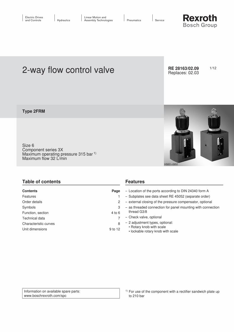
2-way flow control valve
Type 2FRM
Size 6Component series 3XMaximum operating pressure 315 bar 1)
Maximum flow 32 L/min
RE 28163/02.09Replaces: 02.03
Table of contents Features
– Location of the ports according to DIN 24340 form A– Subplates see data sheet RE 45052 (separate order)– external closing of the pressure compensator, optional– as threaded connection for panel mounting with connection
thread G3/8– Check valve, optional– 2 adjustment types, optional:
• Rotary knob with scale • lockable rotary knob with scale
Contents PageFeatures 1Order details 2Symbols 3Function, section 4 to 6Technical data 7Characteristic curves 8Unit dimensions 9 to 12
H5851+5852
1) For use of the component with a rectifier sandwich plate up to 210 bar
InhaltTable of contents 1Features 1Order details: 2-way flow control valve 2Order details: Rectifier sandwich plate (only for version “B”) 2Symbols: 2-way flow control valves 3Symbol: Rectifier sandwich plate (① = component side, ② = plate side) 3Function, section: Type 2FRM 6 B… 4Function, section: Type 2FRM 6 SB… 5Function, section, sample circuit: Type 2FRM 6 A… 6Technical data: 2-way flow control valve(For applications of the component outside the specified values, please contact us!) 7Technical data: Rectifier sandwich plate(For applications of the component outside the specified values, please contact us!) 7Characteristic curves (measured with HLP46, ϑoil = 40 ± 5°C) 8Unit dimensions: Subplate mounting – Version “A” and “B” (dimensions in mm) 9Unit dimensions: Threaded connection for panel mounting – version “SB”(dimensions in mm) 10Unit dimensions 11Unit dimensions: Adapter plate HSE 05 G06A001-3X/V00 (dimensions in mm) 11Unit dimensions: Rectifier sandwich plate type Z4S 6-1X/V (dimensions in mm) 12

2/12 Bosch Rexroth AG Hydraulics 2FRM RE 28163/02.09
Order details: 2-way flow control valve
Order details: Rectifier sandwich plate (only for version “B”)
2-way flow control valveSize 6 = 6With closing of the pressure compensator = A (suppression of the start-up jump)Without closing of the pressure compensator = BWithout closing of the pressure compensator = SB For panel mountingAdjustment typeLockable rotary knob with scale 1) = 3Rotary knob with scale = 7Zero position of the marking at port P = 6Component series 30 to 39 = 3X (30 to 39: unchanged installation and connection dimensions)
Rectifier sandwich plateSize 6 = 6Component series 10 to 19 = 1X (10 to 19: unchanged installation and connection dimensions)
Further details in the clear textSeal material
V = FKM seals(other seals upon request)
Attention! Observe compatibility of seals with the
hydraulic fluid used!R = With check valve M = Without check valve
Flow (A → B)0.2Q = up to 0.2 l/min0.6Q = up to 0.6 l/min1.5Q = up to 1.5 l/min3Q = up to 3.0 l/min6Q = up to 6.0 l/min10Q = up to 10.0 l/min16Q = up to 16.0 l/min25Q = up to 25.0 l/min32Q = up to 32.0 l/min
Further details in the clear textSeal material
V = FKM seals(other seals upon request)
Attention! Observe compatibility of seals with the hydraulic fluid
used!
2FRM 6 6 3X V *
Z4S 6 1X V *
Preferred types and standard units are contained in the EPS (standard price list).
1) Key with the material no. R900008158 is included in the delivery.
1
2 TP A B
Hydraulics Bosch Rexroth AGRE 28163/02.09 2FRM 3/12
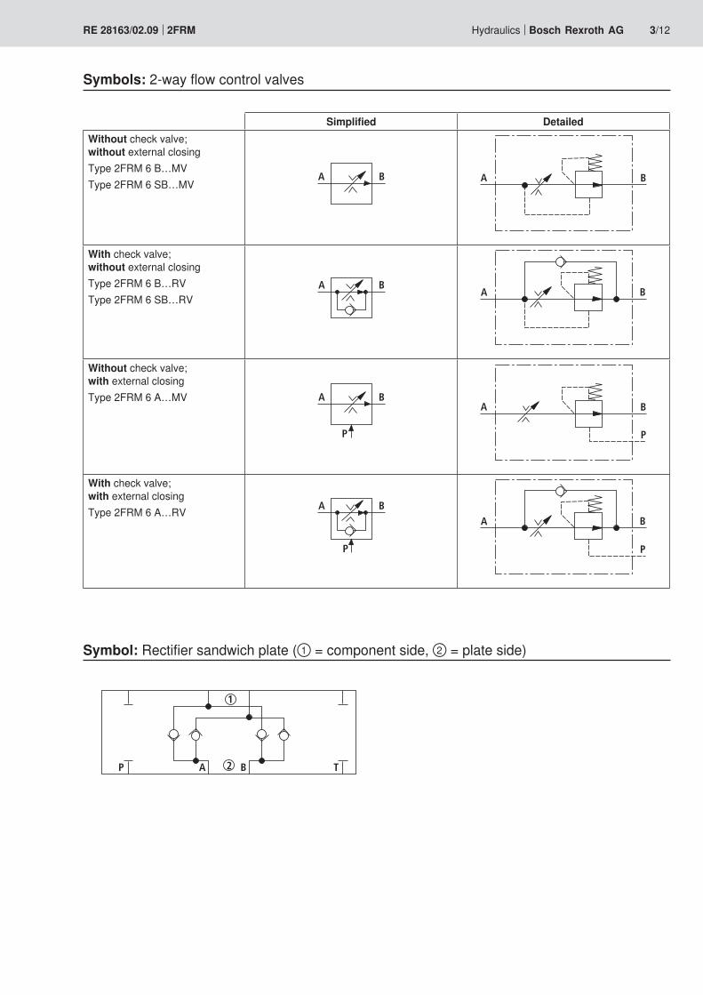
Symbols: 2-way flow control valves
Simplified DetailedWithout check valve; without external closingType 2FRM 6 B…MVType 2FRM 6 SB…MV
A B BA
With check valve; without external closingType 2FRM 6 B…RVType 2FRM 6 SB…RV
A BBA
Without check valve; with external closingType 2FRM 6 A…MV A B
P
BA
P
With check valve; with external closingType 2FRM 6 A…RV A B
P
BA
P
Symbol: Rectifier sandwich plate (① = component side, ② = plate side)

A B
2
1
3
6
4
7
5
4/12 Bosch Rexroth AG Hydraulics 2FRM RE 28163/02.09
Function, section: Type 2FRM 6 B…
GeneralThe flow control valve type 2 FRM is a 2-way flow control valve.It is used for maintaining a constant flow, independent of pressure and temperature.The valve basically comprises of a housing (1), a rotary knob (2), orifice bush (3), pressure compensator (4) and an option-al check valve.
Flow control valve type 2FRM 6 B…MV (without external closing, without check valve)The flow from channel A to channel B is throttled at the throt-tling point (5). The throttle cross-section is set by turning the rotary knob (2).In order to keep the flow in channel B constant, independent of the pressure, a pressure compensator (4) is fitted down-stream of the throttling point (5).The compression spring (6) presses the pressure compen-sator (4) downwards against its stop and keeps the pres-sure compensator (4) in the open position when there is no flow through the valve. When fluid flows through the valve, the pressure present in port A applies a force to the pressure compensator (4) via orifice (7).The pressure compensator (4) moves to the control position until the forces are in balance. When the pressure in channel A rises, the pressure compensator (4) moves in the closing direction until a balance of forces is once again attained. Due to this continuous compensation of the pressure compensator (4), a constant flow is obtained.In order to control a flow through the valve in both directions, a rectifier sandwich plate type Z4S 6 may be fitted below this flow control valve. Type 2FRM 6 B76-3X/.MV

A B
2
1
3
6
4
8
7
5
Hydraulics Bosch Rexroth AGRE 28163/02.09 2FRM 5/12
Function, section: Type 2FRM 6 SB…
GeneralThe flow control valve type 2 FRM is a 2-way flow control valve.It is used for maintaining a constant flow, independent of pressure and temperature.The valve basically comprises of a housing (1), a rotary knob (2), orifice bush (3), pressure compensator (4) and an option-al check valve (8).
Flow control valve type 2FRM 6 SB…RV (without external closing, with check valve, with threaded connection for panel mounting)The flow from channel A to channel B is throttled at the throt-tling point (5). The throttle cross-section is set by turning the rotary knob (2).In order to keep the flow in channel B constant, independent of the pressure, a pressure compensator (4) is fitted down-stream of the throttling point (5).The compression spring (6) presses the pressure compen-sator (4) downwards against its stop and keeps the pres-sure compensator (4) in the open position when there is no flow through the valve. When fluid flows through the valve, the pressure present in port A applies a force to the pressure compensator (4) via orifice (7).The pressure compensator (4) moves to the control position until the forces are in balance. When the pressure in channel A rises, the pressure compensator (4) moves in the closing direction until a balance of forces is once again attained. Due to this continuous compensation of the pressure compensator (4), a constant flow is obtained.The free return flow from channel B to channel A is directed via the check valve (8).
Type 2FRM 6 SB76-3X/..RV

A B
2
1
3
6
4
8
10P
9
5
A B
P T
11
A B
P
6/12 Bosch Rexroth AG Hydraulics 2FRM RE 28163/02.09
Function, section, sample circuit: Type 2FRM 6 A…
GeneralThe flow control valve type 2 FRM is a 2-way flow control valve.It is used for maintaining a constant flow, independent of pressure and temperature.The valve basically comprises of a housing (1), a rotary knob (2), orifice bush (3), pressure compensator (4) and an option-al check valve (8).
Flow control valve type 2FRM 6 A…RV (with external closing, with check valve)The function of this valve is basically the same as that of valve type 2FRM 6 B...MV.However, the flow control valve features external closing of the pressure compensator (4) via channel P (9). The exter-nal pressure acting in channel P (9) via orifice (10), holds the pressure compensator (4) closed against the compression spring (6). When the connected directional valve (11) is ac-tuated to permit flow from P to B, control is achieved as with type 2 FRM 6 B. Thus, a start-up jump is avoided.The version with closing of the pressure compensator can only be used for meter-in control.The free return flow from channel B to channel A is directed via the check valve (8).
Attention!The pressure loss of port P upstream of the directional valve to port A upstream of the flow control valve makes itself felt by a reduced flow.
Type 2FRM 6 A76-3X/..RV
Actuator

Hydraulics Bosch Rexroth AGRE 28163/02.09 2FRM 7/12
Technical data: 2-way flow control valve (For applications of the component outside the specified values, please contact us!)
Technical data: Rectifier sandwich plate (For applications of the component outside the specified values, please contact us!)
generalWeight – Version “A” and “B” kg ca. 1.3
– Version “SB” kg ca. 1.5Installation position AnyAmbient temperature range °C –20 to +50
generalWeight kg ca. 0.9
hydraulicMaximum operating pressure (port A) bar 315Pressure differential ∆p with free return flow B → A bar See characteristic curves page 8Minimum pressure differential bar 6 to 14Pressure stability up to ∆p = 315 bar % ±2 (qV max)Maximum flow l/min 0.2 0.6 1.5 3.0 6.0 10.0 16.0 25.0 32.0Minimum flow – up 100 bar cm3/min 15 15 15 15 25 50 70 100 250
– up 315 bar cm3/min 25 25 25 25 25 50 70 100 250Hydraulic fluid Mineral oil (HL, HLP) according to DIN51524;
other hydraulic fluids upon requestHydraulic fluid temperature range °C –20 to +80Viscosity range mm2/s 10 to 800Maximum permitted degree of contamination of the hydraulic fluid - cleanliness class according to ISO 4406 (c)
Class 20/18/15 1)
hydraulicMaximum operating pressure bar 210Cracking pressure bar 0.7Maximum flow l/min 32
1) The cleanliness classes specified for the components must be adhered to in hydraulic systems. Efficient filtration prevents malfunctions and at the same time prolongs the service life of components.
For the selection of the filters, see data sheets RE 50070, RE 50076, RE 50081, RE 50086, RE 50087, and RE 50088.
0
0,5
11,5
2
3
4
5
6
0 1 2 3 4 5 6 7 8 9 10
0,2Q0,6Q
1,5Q
3Q
6Q
0 1 2 3 4 5 6 7 8 9 10
10Q
16Q
32Q
25Q
02468
101214161820222426283032
10 20 30 40 50
2
4
8
6
10
12
14
1617
00
500
600
400
0
100
200
20 30 40 50 60 7010
1300
1400
1500
20 30 40 50 6010
20 30 40 50 6010
70
70
20040 80 120 160 240 280 320
0,2
0,5
1
2
345
10
15202530
32Q25Q
16Q
10Q
6Q
3Q
1,5Q
0,6Q
0,2Q
00
10
123456
51 15 20 25 30 32
8/12 Bosch Rexroth AG Hydraulics 2FRM RE 28163/02.09
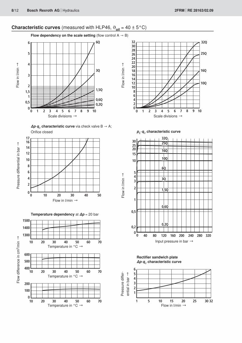
Characteristic curves (measured with HLP46, ϑoil = 40 ± 5°C)
Scale divisions →
Flow in l/min →
Input pressure in bar →
Temperature in °C → Flow in l/min →
Temperature in °C →
Temperature in °C →
Scale divisions →
Flow
in l/
min
→Pr
essu
re d
iffer
entia
l in b
ar →
Flow
diff
eren
ce in
cm
3 /min
→
Flow
in l/
min
→Fl
ow in
l/m
in →
Pres
sure
diff
er-
entia
l in b
ar →
Flow dependency on the scale setting (flow control A → B)
∆p-qV characteristic curve via check valve B → A;Orifice closed pE-qV characteristic curve
Rectifier sandwich plate ∆p-qV characteristic curve
Temperature dependency at ∆p = 20 bar

47
T
31
3
1
4
7
2
A B
P
2
0
8
60
45
A B
P
9,75
7
12,6
8
4 x 5,5
5
1913
411
1
38
2267
“X”6
40
Rt 4
0,01/100
Hydraulics Bosch Rexroth AGRE 28163/02.09 2FRM 9/12
Unit dimensions: Subplate mounting – Version “A” and “B” (dimensions in mm)
Required surface quality of the valve mounting face
For explanation of items, subplates, and valve mounting bolts, see page 11.
View “X”

62
9
1
4
10
2
60
B
1913
911
6
38
“X”
401
M5
8 11
A
48±0,1
6048±0
,1
15,5 15,5
55
6
G3/828
A
B
72
31
2
0
10/12 Bosch Rexroth AG Hydraulics 2FRM RE 28163/02.09
Unit dimensions: Threaded connection for panel mounting – version “SB” (dimensions in mm)
For explanation of items and valve mounting bolts, see page 11.
View “X”

A
B
A
B
B
9,8
48 660
13,8
648 60
830
9
5,3
10; 12
16,7; 1,9
1347
1941
12 14
11
13
Hydraulics Bosch Rexroth AGRE 28163/02.09 2FRM 11/12
Unit dimensions
1 Adjustment type “3” (lockable rotary knob with scale)2 Adjustment type “7” (rotary knob with scale)3 Identical seal rings for ports A, B, P, and T4 Space required to remove the key5 Ø3 bore in version “B” not bored
(without external closing)6 Nameplate7 Position of the marking at port P8 Porting pattern according to DIN 24340 form A9 Connection thread G3/8 according to ISO 228-1
10 Position of the marking vis-à-vis nameplate
Panel mounting (version “SB”):Valve mounting screws (separate order)4 hexagon socket head cap screws ISO 4762 - M5 - 8.8-flZn-240h-L with friction coefficient µtotal = 0.09 to 0.14, tightening torque MA = 7 Nm ±10%, (minimum useable thread depth = 6.5 mm)
Subplate mounting (version “A” and “B”):Subplates according to data sheet RE 45052 (separate order)Type G 341/01 (G1/4) Type G 342/01 (G3/8) Type G 502/01 (G1/2)
Valve mounting screws (separate order)– without rectifier sandwich plate
4 hexagon socket head cap screws ISO 4762 - M5 x 30 - 10.9-flZn-240h-L with friction coefficient µtotal = 0.09 to 0.14, tightening torque MT = 7 Nm ±10%, Material no. R913000316
– with rectifier sandwich plate 4 hexagon socket head cap screws ISO 4762 - M5 x 70 - 10.9-flZn-240h-L with friction coefficient µtotal = 0.09 to 0.14, tightening torque MT = 7 Nm ±10%, Material no. R913000325
Unit dimensions: Adapter plate HSE 05 G06A001-3X/V00 (dimensions in mm)
11 Connection surface for flow control valve type 2FRM 612 Connection surface for flow control valve type 2FRM 513 Seal ring14 Mounting screws for adapter plate,
4 cylinder bolts ISO 4762 - M5 x 30 - 10.9-flZn-240h-L with friction coefficient µtotal = 0.09 to 0.14, tightening torque MT = 7 Nm ±10%,are included in the delivery.
Note!The adapter plate (Material no. R900496121) is required for mounting a flow control valve type 2FRM 6 B..-3X/.. to an ex-isting flow control valve type 2FRM 5 -3X/...

0,01/100
Rzmax 4
A B
40m
ax 3
5
8
12,5; 1,3
31 32,5
40,5
15
16
17 18
48 660
486
60
Bosch Rexroth AG HydraulicsZum Eisengießer 197816 Lohr am Main, Germany Phone +49 (0) 93 52 / 18-0 Fax +49 (0) 93 52 / 18-23 [email protected] www.boschrexroth.de
© This document, as well as the data, specifications and other informa-tion set forth in it, are the exclusive property of Bosch Rexroth AG. It may not be reproduced or given to third parties without its consent.The data specified above only serve to describe the product. No state-ments concerning a certain condition or suitability for a certain applica-tion can be derived from our information. The information given does not release the user from the obligation of own judgment and verification. It must be remembered that our products are subject to a natural process of wear and aging.
12/12 Bosch Rexroth AG Hydraulics 2FRM RE 28163/02.09
Unit dimensions: Rectifier sandwich plate type Z4S 6-1X/V (dimensions in mm)
Attention!The rectifier sandwich plate type Z4S 6 -1X/V can only be used in connection with the flow control valve type 2FRM 6 B..-3X/.. (without closing of the pressure com-pensator)!
15 2-way flow control valve16 Rectifier sandwich plate17 Subplate according to data sheet RE 45052 and valve
mounting screws, see page 11.18 Seal ring
Required surface quality of the valve mounting face
Electric Drivesand Controls Hydraulics
Linear Motion andAssembly Technologies Pneumatics Service
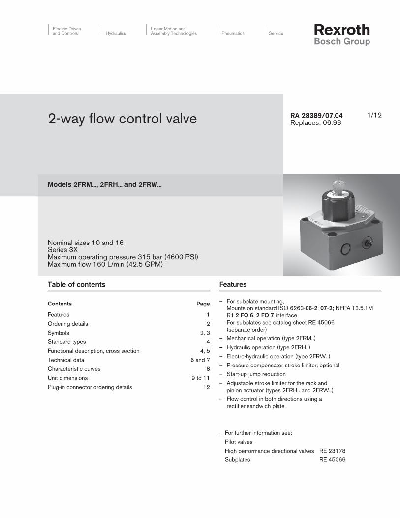
2-way flow control valve
Models 2FRM..., 2FRH... and 2FRW...
Nominal sizes 10 and 16Series 3XMaximum operating pressure 315 bar (4600 PSI)Maximum flow 160 L/min (42.5 GPM)
RA 28389/07.04Replaces: 06.98
Table of contents
Contents Page
Features 1
Ordering details 2
Symbols 2, 3
Standard types 4
Functional description, cross-section 4, 5
Technical data 6 and 7
Characteristic curves 8
Unit dimensions 9 to 11
Plug-in connector ordering details 12
Features
– For subplate mounting,
Mounts on standard ISO 6263-06-2, 07-2; NFPA T3.5.1M
R1 2 FO 6, 2 FO 7 interface
For subplates see catalog sheet RE 45066
(separate order)
– Mechanical operation (type 2FRM..)
– Hydraulic operation (type 2FRH..)
– Electro-hydraulic operation (type 2FRW..)
– Pressure compensator stroke limiter, optional
– Start-up jump reduction
– Adjustable stroke limiter for the rack and
pinion actuator (types 2FRH.. and 2FRW..)
– Flow control in both directions using a
rectifi er sandwich plate
– For further information see:
Pilot valves
High performance directional valves RE 23178
Subplates RE 45066
1/12

A B
1
2
Ordering details: 2-way flow control valve
2-way flow control valve
Mechanical operation = M
Hydraulic operation = H
Electro-hydraulic operation = W
Nominal size 10 = 10
Nominal size 16 = 16
Series 30 to 39 = 3X
(30 to 39: unchanged installation
and connection dimensions)
Flow range A to B
NS 10, linear
Up to 110 L/min
Up to 116 L/min
Up to 125 L/min
Up to 150 L/min
= 10L
= 16L
= 25L
= 50L
NS 16, linear
Up to 60 L/min
Up to 100 L/min
Up to 160 L/min
= 60L
= 100L
= 160L
Without pressure compensator stroke limiter = No code
With pressure compensator stroke limiter = B
Without actual value potentiometer = No code
With actual value potentiometer = P
(not availabale for type 2FRM)
Directional valve NS 6 with wet pin solenoid = 6E
Further details in clear text
No code =
V =
NBR seals
FKM seals
(other seals on request)
Attention!
The compatibility of the seals
and pressure fluid has to be
taken into account!
Electrical connections
K4 2) = Without plug-in connector
with component plug
DIN EN 175 301-803
No code = Without hand override
N9 = With protected hand override
N = With hand override
G24 = 24 DC
W230 = 230 V AC 50 Hz
(for other voltages and frequencies
see RE 23178)
Symbols with
cross-over position
Symbols (switching
characteristics)
J =
A B
P T
A B
P T
Y =
A B
P T
A B
P T
2FR 3X 1) 1) 1) 1) 1)*
Ordering details: rectifier sandwich plate
Symbol: rectifier sandwich plate ( 1 = component side, 2 = subplate side)
1) These ordering details only have to be entered for the
electro-hydraulic operation type 2FRW!
2) Plug-in connectors must be ordered separately
(see page 12)
Nominal size 10 = 10
Nominal size 16 = 16
Series 30 to 39 (NS 10) = 3X
(30 to 39: unchanged installation and connection dimensions)
Series 20 to 29 (NS 16) = 2X
(20 to 29: unchanged installation and connection dimensions)
Further details in clear text
No code = NBR seals
V = FKM seals
(other seals on request)
Attention!
The compatibility of the seals and pressure fluid has
to be taken into account!
Z4S *
2/12 Bosch Rexroth Corp. | Industrial Hydraulics 2FRM, 2FRH, and 2FRW | RA 28389/07.04

Simplified Detailed
Typ
e 2
FR
M
BA BA
Typ
e 2
FR
M
L
B
Y
A
X
L
Y
B
X
A
Typ
e 2
FR
M
L
B
Y
A
X
L
Y
B
X
A
Solenoid "a" energized flow controller qV min
Typ
e 2
FR
M
L
B
Y
A
X
L
B
T
P
y (B)
x (A)
A
L
B
Y
A
X
Solenoid "a" energized flow controller qV min
Typ
e 2
FR
M
ab
L
B
T
P
y (B)
x (A)
A
Symbols: 2-way flow control valve
AB
PT
Solenoid "b" energized
flow controller qV max
Symbol J
Symbol Y
optional
AB
PT
Solenoid "b" energized
flow controller qV max
Symbol J
Symbol Y
optional
RA 28389/07.04 | 2FRM, 2FRH, and 2FRW Industrial Hydraulics | Bosch Rexroth Corp. 3/12

1
10
9
2
5
X X
433.1
Functional description, cross-section
Flow control valves of types 2FRM.., 2FRH.. and 2FRW.. are
2-way flow control valves. They are used to maintain a flow
constant virtually independent of pressure and temperature.
The valves basically consist of the housing (1), orifice bush (2),
pressure compensator (3) with optional stroke limiter (3.1),
check valve (4), adjustment element (5) for type 2FRM.. as
well as a rack and pinion actuator (6), directional valve (7) and
actual value potentiometer (8) for types 2FRH... and 2FRW...
The flow from port A to port B is throttled at the orifice (9).
On type 2FRM.. the throttling area is adjusted by rotating
the curved pin (10) mechanically by means of the adjustment
element (5), for types 2FRH.. and 2FRW.. hydraulically via a
rack and pinion actuator (6), which is controlled by a built-on
electrically operated directional valve (7). The control speed
can be set by means of throttle check valves (6.3 and 6.4). In
order to limit the required actuating range, the rack and pinion
actuator (6) is fitted with adjustable stroke limiters on both
ends (6.1 and 6.2). In order to to maintain the flow across
the orifice (9) constant, a pressure compensator is connected
upstream of the orifice (3).
The flow is maintained largely independent of temperature due
to the orifice design.
Free return flow from port B to port A is via the check valve (4).
In order to permit the orifice position in valve types 2FRH..
and 2FRW.. to be continuously monitored, an actual value
potentiometer (8) can be fitted. Suitable electrical control
components are available for electrical command value pre-
selection.
The flow is only controlled from A to B. In order to control the
flow in both directions a rectifier sandwich plate type Z4S
(supply and return) can be installed under the flow control
valve.
Standard types
Type 2 FRM...
Section X–X
Type Material No.
2FRM 10-3X/10L R900424887
2FRM 10-3X/10LB R900423250
2FRM 10-3X/16L R900423251
2FRM 10-3X/16LB R900423252
2FRM 10-3X/25L R900423255
2FRM 10-3X/25LB R900423256
2FRM 10-3X/50L R900420286
2FRM 10-3X/50LB R900423261
Type Material No.
2FRM 16-3X/100L R900424905
2FRM 16-3X/100LB R900420287
2FRM 16-3X/160L R900424906
2FRM 16-3X/160LB R900424902
2FRM 16-3X/160LV R900427777
2FRM 16-3X/60L R900423271
2FRM 16-3X/60LB R900424903
4/12 Bosch Rexroth Corp. | Industrial Hydraulics 2FRM, 2FRH, and 2FRW | RA 28389/07.04

X X
Y Y
1
10
6
9
2
7
8
6.16.2
6
6.3 6.4
Functional description, cross-section
Section Y–Y (rotated through 90°)
Type 2FRW...P...
RA 28389/07.04 | 2FRM, 2FRH, and 2FRW Industrial Hydraulics | Bosch Rexroth Corp. 5/12

Technical data (for applications outside these parameters, please consult us!)
General
Weight NS 10 NS 16
Type 2FRM kg (lbs) 5.6 (12.3) 11.3 (24.9)
Type 2FRH kg (lbs) 9.2 (20.3) 14.9 (32.8)
Type 2FRH..P kg (lbs) 10.3 (22.7) 16 (35.3)
Type 2FRW kg (lbs) 11.3 (24.9) 17 (37)
Type 2FRW..P kg (lbs) 12.4 (27.3) 18.1 (39.8)
Rectifi er sandwich plate kg (lbs) 3.0 (6.6) 8.1 (17.8)
Installation Type 2FRM Installation
Types 2FRH and 2FRW Actuator horizontal (rack and pinion)
Pressure fl uid Mineral oil (HL, HLP) to DIN 51 524 1);
Fast bio-degradable pressure fl uids to VDMA 24 568
(also see RE 90221); HETG (rape seed oil) 1);
HEPG (polyglycole) 2); HEES (Synthetic ester) 2);
other pressure fl uids on request
Ambient temperature range NBR seals °C (°F) –30 to 80 (–22 to 176) [–30 to 50 (–22 to 122) for type 2FRW]
FKM seals °C (°F) –20 to 80 (–4 to 176) [–20 to 50 (–4 to 122) for type 2FRW]
Pressure fl uid temperature range NBR seals °C (°F) –30 to +80 (–22 to 176)
FKM seals °C (°F) –20 to +80 (–4 to 176)
Viscosity range mm2/s (SUS) 10 to 800 (60 to 3710)
ISO code cleanliness class Maximum permissible degree of contamination of the pressure
fl uid is to ISO 4406 (C) class 20/18/15 3)
1) Suitable for NBR and FKM seals
2) Only suitable for FKM seals
3) The cleanliness class stated for the components must be
adhered too in hydraulic systems. Effective fi ltration pre-
vents faults from occurring and at the same time increases
the component service life.
For the selection of fi lters see catalogue sheets RE 50070,
RE 50076 and RE 50081.
6/12 Bosch Rexroth Corp. | Industrial Hydraulics 2FRM, 2FRH, and 2FRW | RA 28389/07.04

Technical data (for applications outside these parameters, please consult us!)
2-way fl ow control valves types 2FRM..., 2FRH... and 2FRW...
NS 10 NS 16
Maximum fl ow L/min
(GPM)
10
(2.64)
16
(4.23)
25
(6.60)
50
(13.21)
60
(15.85)
100
(26.41)
160
(42.27)
Pressure differential with free-fl ow from B to A,
qV dependent
bar
(PSI)
2
(29.0)
2.5
(36.3)
3.5
(50.8)
6
(87.0)
2.8
(40.6)
4.3
(62.4)
7.3
(105.9)
Minimum pressure differential bar (PSI) 3 to 7 (43 to101) 5 to 12 (72 to 174)
Flow control • Temperature, stable,
–20 to +80 °C (–4 to +176 °F)
± 2 % (qV max) ± 2 % (qV max)
• Pressure, stable,
up to Dp = 315 bar (4568 PSI)
± 2 % (qV max) < ± 5 % (qV max)
Maximum operating pressure, port A bar (PSI) 315 (4600)
2-way fl ow control valves types 2FRH... and 2FRW...
Pilot volume for the max. adjustment range cm3 (in3) 22 (1.34) at 300°
Pilot pressure range bar (PSI) 10 to 100 (145 to 1450) (max. value must not be exceeded!)
Adjustment speed (dependent on the pilot pressure) Without potentiometer With potentiometer
(Dependent on the pilot pressure) 5 to 2000°/s 5 to 300°/s
Maximum fl ow (directional valve) L/min (GPM) 10 (2.64) See RE 23178
Maximum operating pressure (directional
valve)
bar (PSI) Up to 315 (4600) See RE 23178
Potentiometer
Actual value potentiometer
Resistance Ω 1000
Loadability W 5
Maximum wiper current A 0.12
Protection to DIN 40 050 IP 65
Adjustment end position error
(dependent on the adjustment speed)
±1.5° at 10°/s
Rectifi er sandwich plate Z4S...
Flow, max. L/min (GPM) 50 (13.2) 160 (42.27)
Operating pressure, max. bar (PSI) 315 (4600)
Opening pressure bar (PSI) 1.5 (22)
RA 28389/07.04 | 2FRM, 2FRH, and 2FRW Industrial Hydraulics | Bosch Rexroth Corp. 7/12

0 2 4 6 8 10
20(5.28)
30(7.92)
40(10.5)
50(13.2)
10 L
16 L
25 L
50 L
10(2.64)
0 20 40 60 80
2 (29)
4 (58)
6 (87)
8 (116)
10 (145)
1 (14.5)
3 (43.5)
5 (72.5)
7 (101.5)
9 (130.5)
(5.28) (10.5) (15.8) (21.1)
0 2 4 6 8 10
50
(13.2)
100
(26.4)
150
(39.6)
60 L
100 L
160 L
0 12040 16080 180
2 (29)
4 (58)
6 (87)
8 (116)
10 (145)
1 (14.5)
3 (43.5)
5 (72.5)
7 (101.5)
9 (130.5)
(14.5) (21.1) (31.7) (42.2) (47.5)
0 10 20 30 40 50
2 (29)
4 (58)
6 (87)
8 (116)
10 (145)
(2.64) (5.28) (7.92) (10.5) (13.2)
12 (174)
0 40 80 120 160
2 (29)
4 (58)
6 (87)
8 (116)
10 (145)
12 (145)
14 (145)
(10.5) (21.1) (31.7) (42.2)
Characteristic curves – measured with HLP46, ϑoil = 40 °C ±5 °C (104 °F ±41 °F)
Scale division →
Pressure differential Δp is the same for both directions of flow qV from A to B (B to A)
NS 10 NS 16
Flo
w in L
/min
(G
PM
) →
NS 10 – Free return flow (B → A)NS 10 – Flow control (A → B)
Flow in L/min (GPM) →
Pre
ssure
diffe
rential in
bar
(PS
I) →
Flo
w in L
/min
(G
PM
) →
Pre
ssure
diffe
rential in
bar
(PS
I) →
Scale division →Flow in L/min (GPM) →
Pre
ssure
diffe
rential in
bar
(PS
I) →
Pre
ssure
diffe
rential in
bar
(PS
I) →
Flow in L/min (GPM) → Flow in L/min (GPM) →
Characteristic curves: rectifier sandwich plate –
measured with HLP46, ϑoil = 40 °C ± 5 °C (104 °F ±41 °F)
NS 16 – Flow control (A → B) NS 16 – Free return flow (B → A)
8/12 Bosch Rexroth Corp. | Industrial Hydraulics 2FRM, 2FRH, and 2FRW | RA 28389/07.04

H2
H1
20
(0
.79
)
H3
H4 H
54
(0
.15
7)D3
B6
B5B
2
B1
B3
B4
Ø43 (1.69)
L2L3
B
A
L4
0.8(0.03)
L111 (0.43)Ø D2; T1
Ø D1
B A
10.2 10.1
1
6
2
18
19
8 9 7
0.0004/4.0 in
0.01/100 mm
(Rmax 4)
1 Pressure compenstor stroke limiter, optional
2 Adjustment element, lockable rotary knob
(may be locked in any position)
Turning range 300° = 10 scale divisions
Md ≈ 0.7 Nm (6.2 lb-in)
6 Name plate
7 Input "A"
8 Output "B"
9 Seal ring
10.1 Locating pin (NS 10 and 16)
10.2 Locating pin (NS 16)
18 Hexagon 10A/F
19 Internal hexagon 3A/F
NS B1 B2 B3 B4 B5 B6 Ø D1 Ø D2 D3 H1 H2 H3 H4 H5 L1 L2 L3 L4 T1
10 101.5
(4)
82.5
(3.24)
9.5
(0.37)
68
(2.67)
58.7
(2.31)
35.5
(1.39)
9
(0.354)
15
(0.590)
6
(.24)
125
(4.92)
95
(3.74)
26
(1.02)
51
(2.0)
60
(2.3)
95
(3.74)
76
(2.99)
9.5
(0.37)
79.4
(3.12)
13
(0.52)
16 123.5
(4.86)
101.5
(3.99)
11
(0.43)
81.5
(3.2)
72.9
(2.87)
41.5
(1.63)
11
(0.434)
18
(0.708)
6
(.24)
147
(5.79)
117
(4.61)
34
(1.33)
72
(2.8)
82
(3.2)
123.5
(4.86)
101.5
(3.99)
11
(0.43)
102.4
(4.0)
12
(0.47)
Unit dimensions: 2-way flow control valve type 2FRM – dimensions in millimeters (inches)
Required surface finish
of the mating piece
Subplates for:
Nominal size 10:
BSP SAE Ports
G 279 (G 1/2) (SAE-8; 3/4“-16)
G 280 (G 3/4) (SAE-12; 1 1/16“-12)
Nominal size 16: G 281 (G 1) (SAE-16; 1 5/16“-12)
G 282 (G 1 1/4) (SAE-20; 5/8“-12)
to catalogue sheet RE 45066 and
Valve fixing screws
Nominal size 10
M8 x 50 DIN 912-10.9 (5/16-18 UNC x 2”);
MA = 37 Nm (27.3 lb-ft)
Nominal size 16
M10 x 80 DIN 912-10.9 (3/8-16 UNC x 3”;
MA = 75 Nm (55.3 lb-ft)
Must be ordered separately.
RA 28389/07.04 | 2FRM, 2FRH, and 2FRW Industrial Hydraulics | Bosch Rexroth Corp. 9/12

10/12 Bosch Rexroth Corp. | Industrial Hydraulics 2FRM, 2FRH, and 2FRW | RA 28389/07.04
P T
P T
X Y
XY
L
AB
H4
H3
36 (1.417)
65 (2.56)
105 (4.13)15 (0.59)
65 (2.56)
105 (4.13) 15 (0.59)
Pg 9
258 (10.16)40 (1.58)
16 (0.63)
H6
H7
H8
H9 H
10
H9
Ø20 (0.787)
15 (0.591) deep
G1/4
Pg 9
11
H5
H2
H1
4 (
0.1
57
)
8
4
5
12.212.1
4.1
4
31
0
6
7
9
10
82
5
B
A
L1
B5
B3
B4
B1
B2
2.5
(0.0
98)
70 (2.76)
45 (
1.7
72)
10
1.5
(4
)
B6
5
19
1
18
10.110.2 96 7 3.23.1 20
11.211.1 13 8 4
40 (1.58)
1 Pressure compensator stroke limiter, optional
2 Flow indicator, rotation range 300° = 10 scale divisions
3.1 Rack and pinion actuator stroke limiter for min. flow 1 turn = approx. 12° (of 300°)
3.2 Rack and pinion actuator stroke limiter for max. flow 1 turn = approx. 12° (of 300°)
4 Directional valve NS 6, symbols J or Y (Y de-energized = qV min) For detailed dimensions of the directional valve, see RE 23178
4.1 Cover for valve type Y
5 Actual value potentiometer
6 Name plate
7 Input "A"
8 Output "B"
9 Seal ring
10.1 Locating pin (NS 10 and 16)
10.2 Locating pin (NS 16)
11.1 Speed adjustment throttle towards min. flow (v0 to vmax. = 5 turns); Internal hexagon 6A/F
11.2 Speed adjustment throttle towards max. flow (v0 to vmax. = 5 turns); Internal hexagon 6A/F
12.1 Pressure in X = opening of the orifice
12.2 Pressure in Y = closing of the orifice
13 Scale disc
18 Hexagon 10A/F
19 Internal hexagon 3A/F
20 Hexagon 13A/F
For subplates and valve fixing screws and
valve connection dimensions see page 9.
Unit dimensions: 2-way flow control valve types 2FRW, 2FRH – dimensions in mm (inches)
1) Type 2FRH2) Type 2FRW3) Dimension with plug-in connection without
circuitry to DIN EN 175 301–802 and ISO 44004) Dimension with plug-in connector with
circuitry to DIN EN 175 301–802 and ISO 4400
NS B1 B2 B3 B4 B5 B6 H1 H2 H3 H4 H5 H6 H71) H72) H8 H9 H103) H104) L1
10 101.5
(4)
146
(5.74)
9.5
(0.37)
68
(2.67)
35.5
(1.38)
54.5
(2.14)
125.5
(4.94)
84
(3.3)
26
(1.02)
51
(2)
58
(2.2)
70
(2.7)
89
(3.5)
87
(3.4)
179
(7.0)
203
(7.99)
201
(7.91)
206
(8.11)
95
(3.74)
16 123.5
(4.86)
160.5
(6.3)
11
(0.43)
81.5
(3.2)
41.5
(1.63)
60.5
(2.38)
147.5
(5.81)
106
(4.17)
34
(1.33)
72
(2.8)
80
(3.1)
92
(3.6)
111
(4.37)
109
(4.29)
201
(7.9)
225
(8.86)
223
(8.7)
228
(8.98)
123.5
(0.47)
Required surface finish of
the mating piece
Type 2FRH..P
Type 2FRH
Type 2FRW
Type 2FRW..P
0.0004/4.0 in
0.01/100 mm
(Rmax 4)

Nominal size 10
M8 x 50 DIN 912-10.9 (5/16-18 UNC x 2”);
MA = 37 Nm (27.3 lb-ft)
Nominal size 16
M10 x 80 DIN 912-10.9 (3/8-16 UNC x 3”;
MA = 75 Nm (55.3 lb-ft)
Nominal size 10
M8 x 50 DIN 912-10.9 (5/16-18 UNC x 2”);
MA = 37 Nm (27.3 lb-ft)
Nominal size 16
M10 x 80 DIN 912-10.9 (3/8-16 UNC x 3”;
MA = 75 Nm (55.3 lb-ft)
RA 28389/07.04 | 2FRM, 2FRH, and 2FRW Industrial Hydraulics | Bosch Rexroth Corp. 11/12
H1
1H
12
3
14
15
16
17
14 15
5
4
5
3 Rack and pinion actuator
4 Directional valve NS 6
5 Actual value potentiometer
6 Name plate (NS 10)
6.1 Name plate (NS 16)
7 Input "A"
8 Output "B"
9 Seal ring
10.1 Locating pin (NS 10 and 16)
10.2 Locating pin (NS 16)
14 2-way flow control valve
15 Rectifier sandwich plate
16 Subplates, see page 6
17 Valve fixing screws
Nominal size 10:
M8 x 100 DIN 912-10.9 (5/16-18 UNC x 4”);
MA = 37 Nm (27.3 lb-ft)
Nominal size 16:
M10 x 160 DIN 912-10.9 (3/8-16 UNC x 6-1/4”);
MA = 75 Nm (55.3 lb-ft)
Valve fixing screws for inserting a rectifier sandwich plate between the flow control valve and subplate must be ordered separately.
Required surface finish
of the mating piece
Unit dimensions: rectifier sandwich plate Z4S... – dimensions in mm (inches)
NS B1 B2 B3 B5 Ø D1 H11 H12 L1 L2 L3 L4
10 101.5
(4)
82.5
(3.248)
9.5
(0.374)
58.7
(2.31)
9
(0.354)
50
(1.97)
30
(1.18)
95
(3.74)
76
(2.992)
9.5
(0.374)
79.4
(3.12)
16 123.5
(4.86)
101.5
(3.996)
11
(0.433)
72.9
(2.81)
11
(0.433)
85
(3.35)
40
(1.57)
123.5
(4.86)
101.5
(3.996)
11
(0.433)
102.4
(4.03)
Type 2FRW..P
Type 2FRW
Type 2FRH..P
Type 2FRH
0.0004/4.0 in
0.01/100 mm
(Rmax 4)
L2
B1
L4
L10.8 (0.03)
L3
B2
B5
B3
ØD1H
11
4 (
0.1
57
)
B1
A1
B2 A2
10.2 10.19 7 6
8 6.1 Type 2FRM

12/12 Bosch Rexroth Corp. | Industrial Hydraulics 2FRM, 2FRH, and 2FRW | RA 28389/07.04
Ordering details: plug-in connectors to DIN EN 175 301-803 and ISO 4400
for component plug "K4"
For further
plug-in
connectors
see RE 08006
Material No.
Valve
side Color Without circuitry
With indicator light
12 … 240 V
With rectifier
12 … 240 V
With indicator light and
Z-diode protective circuitry
24 V
a Grey R901017010 – – –
b Black R901017011 – – –
a/b Black – R901017022 R901017025 R901017026
Bosch Rexroth Corp.
Industrial Hydraulics
2315 City Line Road
Bethlehem, PA 18017-2131
USA
Telephone (610) 684-8300
Facsimile (610) 694-8467
www.boschrexroth-us.com
© This document, as well as the data, specifi cations and other
information set forth in it, are the exclusive property of Bosch Rexroth
Corporation. Without their consent it may not be reproduced or given to
third parties.
The data specifi ed above only serve to describe the product. No
statements concerning a certain condition or suitability for a certain
application can be derived from our information. The information given
does not release the user from the obligation of own judgment and
verifi cation. It must be remembered that our products are subject to a
natural process of wear and aging.

1/8
Information on available spare parts: www.boschrexroth.com/spc
2-way flow control valve
Type 2FRM
Sizes 6 and 10Component series 1XMaximum operating pressure 315 barMaximum flow 60 l/min
RE 28155/11.10Replaces: 11.02
Overview of contents Features
– Cartridge valve– Adjustment element with internal hexagon– With built-in check valve– Low start-up jump
Contents PageFeatures 1Ordering code 2Standard types 2Symbols 2Function, section 3Technical data 4Characteristic curves 5Unit dimensions, cavities 6
H5012
InhaltOverview of contents 1Features 1Ordering code 2Symbols (detailed and simplified) 2Function, section 3Technical data (for applications outside these parameters, please consult us!) 4
Characteristic curves (measured with HLP46, oil = 40 °C ±5 °C) 5Dimensions (dimensions in mm) 6Cavities to DIN ISO 7789 (dimensions in mm) 7Notes 8

2/8 Bosch Rexroth AG Hydraulics 2FRM RE 28155/11.10
Ordering code
2-way flow control valve Size 6 = 6Size 10 = 10Cartridge valve = KAdjustment element Internal hexagon = 2Series 10 to 19 = 1X (10 to 19: unchanged installation and connection dimensions)
Further details in clear textSeal material
V = FKM seals(Other seals on request)
Attention! Observe compatibility of seals with
hydraulic fluid used!R = With check valve
Flow(A→B) 6Q = up to 6.0 l/min (size 6) 32Q = up to 32.0 l/min (size 6) 60Q = up to 60.0 l/min (size 10)
2FRM K 2 1X R V *
Symbols (detailed and simplified)
Preferred types and standard components can be found in the EPS (Standard Price List).
Detailed Simplified
BA
BA

2
1 4 3 7 6 5 8
B
A
Hydraulics Bosch Rexroth AGRE 28155/11.10 2FRM 3/8
Function, sectionThe pressure compensator (5) is pressed against the plug (8) by the compression spring (7) and so stays in the open posi-tion as long as there is no flow through the valve. When flow takes place through the valve the pressure, which is present in port A, applies a force onto the pressure compensator (5). The pressure compensator moves into the compensating po-sition until the forces are balanced. If the pressure increases in port A, then the pressure compensator (5) moves towards its closed position until the forces are balanced. Due to this continuous compensating action a constant flow is obtained.FreereturnflowfromportBtoportAisobtainedviathecheck valve (6).
Flow control valves type 2FRM . K are 2-way flow control valves suitable for fitting into manifold systems. They are used for maintaining a constant flow, independent of pressure and temperature.The valve basically consists of the housing (1), adjustment element (2), throttling area (3), throttle bolt (4), pressure com-pensator (5) and check valve (6).ThrottlingoftheflowfromportAtoportBoccursatthethrot-tle area (3). The throttle cross-section is changed by turn-ing the adjustment element (2). This takes place between the throttle area (3) and the throttle bolt (4).In order to hold the flow constant, independent from the pres-sure,inportBapressurecompensator(5)isfitteddown-stream of the throttle area (3).

4/8 Bosch Rexroth AG Hydraulics 2FRM RE 28155/11.10
Technical data (for applications outside these parameters, please consult us!)
GeneralSize NG6 NG10Weight kg 0.19 0.6Installation OptionalAmbient temperature range °C –20 to +50
HydraulicMaximum operating pressure – Port A bar 315 210Pressure differential ∆pforfreereturnflowB→A bar See characteristic curves on page 5Minimum pressure differential bar 18Pressure stable up to ∆p = 315 bar / 210 bar % ±3 (pV max)Flow – pV max l/min 6.0 32 60
– pV min cm3/min 50 250 500Pressure fluid Mineral oil (HL, HLP) to DIN 51524; Fast bio-degradable
pressure fluids to VDMA 24568 (also see data sheet 90221); HETG (rape seed oil); HEPG (polyglycols); HEES (synthetic ester); Other pressure fluids on request
Pressure fluid temperature range °C –20 to +80Viscosity range mm2/s 10 to 800Permissible max. degree of contamination of the hydraulic fluid - cleanliness class to ISO 4406 (c)
Class 20/18/15 1)
1) The cleanliness class stated for the components must be adhered too in hydraulic systems. Effective filtration pre-vents faults from occurring and at the same time increases the component service life.
For the selection of the filters see www.boschrexroth.com/filter.
Hydraulics Bosch Rexroth AGRE 28155/11.10 2FRM 5/8
Pressuredifferentialin
bar→
Pressuredifferentialin
bar→
Flowinl/min→
Flowinl/min→
Flow
inl/min→
Flow
inl/min→
Inletpressureinbar→
Inletpressureinbar→
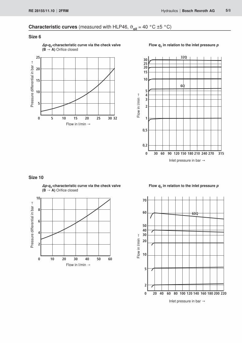
∆p-qV-characteristic curve via the check valve (B → A) Orifice closed
∆p-qV-characteristic curve via the check valve (B → A) Orifice closed
Flow qV in relation to the inlet pressure p
Flow qV in relation to the inlet pressure p
Size 6
Size 10
25
20
15
10
5
0 10 30205 15 25 32
10
8
6
4
2
0 20 604010 30 50
30252015
10
543
2
1
0,5
0,2
0 30 60 90 120 150 180 210 240 270 315
6Q
32Q
60
504030
20
10
5
2
0 20 40 60 80 100 120 140 160 180 200 220
70
60Q
Characteristic curves (measured with HLP46, oil = 40 °C ±5 °C)

D1
L1L2
L3L4
1
2
6/8 Bosch Rexroth AG Hydraulics 2FRM RE 28155/11.10
Dimensions (dimensions in mm)
1 Internal hexagon 3A/F2 – NG6: Hexagon 27A/F; MA = 40 Nm
– NG10: Hexagon 41A/F; MA = 120 Nm
Size L1 L2 L3 L4 ØD16 25 29 33,5 77 610 36 41 45,5 109 6

B
A
D1
D2
D3
90
D4
D5
L1 L2
L3
L4
L5
L6 1
)
min
L7
30
A0,1
A
x15
A0,1
z
y
A0,05
1
Hydraulics Bosch Rexroth AGRE 28155/11.10 2FRM 7/8
Cavities to DIN ISO 7789 (dimensions in mm)
Size 6
Rz 8y =
Rmax 8x =
Rz 16z =
Size 10
Rz 8y =
Rz 8x =
Rz 25z =
1 to DIN 3852-W
1) Depth of fit
Size L1 L2 L3 L4 L5 L6 1) L7 ØD1 ØD2 D3 ØD4 ØD56 0,5 2,4+0,4 17 24–4 28±0,1 38,5 45+0,2 34 23,8±0,1 M22 x 1,5 19H7 710 0,5 3,1+0,4 23 32–4 39+0,4 55 65 46 35,4±0,1 M33 x 2 29H8 11

8/8 Bosch Rexroth AG Hydraulics 2FRM RE 28155/11.10
BoschRexrothAG HydraulicsZum Eisengießer 197816 Lohr am Main, Germany Phone +49 (0) 93 52 / 18-0 Fax +49 (0) 93 52 / 18-23 [email protected] www.boschrexroth.de
© This document, as well as the data, specifications and other informa-tionsetforthinit,aretheexclusivepropertyofBoschRexrothAG.Itmay not be reproduced or given to third parties without its consent.The data specified above only serve to describe the product. No state-ments concerning a certain condition or suitability for a certain applica-tion can be derived from our information. The information given does not release the user from the obligation of own judgment and verifica-tion. It must be remembered that our products are subject to a natural process of wear and aging.
Notes

1/8
Information on available spare parts: www.boschrexroth.com/spc
Twin throttle check valve
Type Z2FS
RE 27506/05.11Replaces: 02.03
Table of contents Features
– Sandwich plate valve– Porting pattern according to DIN 24340 form A– Porting pattern according to ISO 4401-03-02-0-05
(with locating hole)– For the main or pilot flow limitation of 2 actuator ports– 4 adjustment types: •Setscrewwithlocknutandprotectivecap •Lockablerotaryknobwithscale •Spindlewithinternalhexagonandscale •Rotaryknobwithscale
– For supply or discharge throttling
Contents PageFeatures 1Ordering code 2Symbols 2Function, section 3Technical data 4Characteristic curves 5Unit dimensions 6, 7
H5556
Size 6Component series 4XMaximum operating pressure 315 barMaximum flow 80 l/min
InhaltTable of contents 1Features 1Ordering code 2Symbols (① = component side, ② = plate side) 2Function, section 3Technical Data (For applications outside these parameters, please consult us!) 4Characteristic curves(measuredwithHLP46,ϑoil = 40 ± 5 °C) 5Unit dimensions (dimensions in mm) 6Unit dimensions 7Notes 8

2/8 Bosch Rexroth AG Hydraulics Z2FS RE 27506/05.11
Ordering code
Twin throttle check valve; sandwich plate design
Size 6 = 6Throttle check valve side A and B = – 1) Throttle check valve side A = A Throttle check valve side B = BAdjustment type Setscrew with lock nut and protective cap = 2Lockablerotaryknobwithscale = 3 2)
Spindle with internal hexagon and scale = 5Rotary knob with scale = 7
Further details in the plain textNo code = Without locating hole/60 3) = With locating hole
Seal materialNo code = NBR seals V = FKM seals
(other seals upon request) Attention! Observe compatibility of seals with hydraulic fluid
used!1Q = With fine adjustment 2Q = Standard design
4X = Component series 40 to 49 (40 to 49: unchanged installation and connection
dimensions)
Z2FS 6 4X *
1) Identical adjustment types on the A and B side.2) H key with material no. R900008158 is included in the de-
livery.3) LocatingpinISO8752-3x8-St,materialno.R900005694
(separate order)
Symbols (① = component side, ② = plate side)
Standard types and standard units are contained in the EPS (standard price list).
Supp
ly th
rottl
ing
Type Z2FS 6 –… Type Z2FS 6 B…
TP A B
1
2 TP A B
1
2
Disc
harg
e th
rottl
ing Type Z2FS 6 –… Type Z2FS 6 A…
TP A B
1
2 TP A B
1
2

5 A B4 2
3 1
1
2
A B
Hydraulics Bosch Rexroth AGRE 27506/05.11 Z2FS 3/8
Function, sectionThehydraulicfluidflowingbackfromtheactuatorA②movesthe valve seat (2) against the spring (5) in the direction of the throttle spool (3) and thus allows for the unhindered flow as check valve. Depending on the installation position, the throt-tling effect may be directly in the supply or in the discharge. Main flow limitation (version "2Q")For changing the velocity of an actuator (main flow limitation), the twin throttle check valve is installed between the direction-al valve and the subplate. Pilot flow limitation (version "1Q")With pilot operated directional valves, the twin throttle check valve can be used as switching time adjustment (pilot flow limitation). Then, it is installed between pilot control and main valve.
The valve type Z2FS is a twin throttle check valve in sand-wich plate design. It is used for the main or pilot flow limitation of one or two actuator ports. Two throttle check valves aligned symmetrically to each other limit flows in one direction and allow free return flow in the op-posite direction. In the supply throttling, the hydraulic fluid reaches actua-torA②throughchannel①viathethrottlingpoint(1)createdby the valve seat (2) and the throttle spool (3). The throttle spool (3) can be axially adjusted by means of a setscrew (4) and thus allows for the setting of the throttling point (1).
Type Z2FS 6 –2… (supply throttling)
①=componentside②=plateside

4/8 Bosch Rexroth AG Hydraulics Z2FS RE 27506/05.11
Technical Data (For applications outside these parameters, please consult us!)
generalWeight kg Approx. 0.8Installation position AnyAmbient temperature range °C –20 to +80
hydraulicMaximum operating pressure bar 315Maximum flow l/min 80Hydraulic fluid See table belowHydraulic fluid temperature range °C –20 to +80Viscosity range mm2/s 10 to 800Maximum permitted degree of contamination of the hydraulic fluid - cleanliness class according to ISO 4406 (c)
Class 20/18/15 1)
1) The cleanliness classes specified for the components must be adhered to in hydraulic systems. Effective filtration pre-vents faults and at the same time increases the service life of the components.
For the selection of the filters see www.boschrexroth.com/filter.
Hydraulic fluid Classification Suitable sealing materials StandardsMineral oils and related hydrocarbons HL,HLP,HLPD NBR, FKM DIN 51524
Environmentally compatible
– Insoluble in waterHETG NBR, FKM
ISO 15380HEES FKM
– Soluble in water HEPG FKM ISO 15380
Flame-resistant– Water-free HFDU, HFDR FKM ISO 12922
– Water-containing HFC (Fuchs Hydrotherm 46M, Petrofer Ultra Safe 620) NBR ISO 12922
Important information on hydraulic fluids!– For more information and data on the use of other hydrau-
lic fluids refer to data sheet 90220 or contact us!– There may be limitations regarding the technical valve
data (temperature, pressure range, service life, mainte-nance intervals, etc.)!
– Flame-resistant – water-containing: •Maximumoperatingpressure210bar•Maximumhydraulicfluidtemperature60°C• ExpectedservicelifeascomparedtoHLPhydraulicoil
30 % to 100 %

2 3 4 5 6 7 8
9
10
11
250
200
150
100908070605040
30
20
10
5
0 10 20 30 40 50 60 70 80
11,5
2 3 4 5 6 7 8250
200
150
100908070605040
30
20
10
5
0 10 20 30 40 50 60 70 80
9 10 11 11,5
15
10
5
0 10 20 30 40 50 60 70 80
Hydraulics Bosch Rexroth AGRE 27506/05.11 Z2FS 5/8
∆p-qV characteristic curves (via check valve; throttle closed)
∆p-qV characteristic curves (version "2Q") ∆p-qV characteristic curves (version "1Q")
Pres
sure
diff
eren
tial in
bar
→Pr
essu
re d
iffere
ntial
in b
ar →
Pres
sure
diff
eren
tial in
bar
→
Flowinl/min→
Flowinl/min→
Throttle position in rotations Throttle position in rotations
Characteristic curves(measuredwithHLP46,ϑoil = 40 ± 5 °C)

0,01/100
Rzmax 4
3
82
0
61 x 401,4
75
81
38,6
22,6
35
64
18 4 x 5,4
45 81 45
46
8
32
82
90
1
75 24 20
91
3
A
T
BP
13 5; 1211
110
15
6
133; 12
19; 12 4 29; 12 2 13 4 9; 12
1314 14
7
"X" "X"
"X" "X"
"X"
38,6 "X"
7
81 7
1
15
832
61 x 401,4
11
10
46
8
61 x 401,4
11
10
F1 F2
F3F4 G
45
7
1
2
1
2
1
2
6/8 Bosch Rexroth AG Hydraulics Z2FS RE 27506/05.11
Unit dimensions (dimensions in mm)
Item explanations and valve mounting screws see page 7.
Required surface quality of the valve mounting face

Hydraulics Bosch Rexroth AGRE 27506/05.11 Z2FS 7/8
Unit dimensions
① Component side – porting pattern according to ISO 4401-03-02-0-05 (with locating hole Ø3 x 5 mm deep)
② Plate side – porting pattern according to DIN 24340 form A (without locating hole), or ISO 4401-03-02-0-05 (with locating hole for locating pin ISO 8752-3x8-St; version "/60")
1 Name plate2 Adjustment type "2"3 Adjustment type "3"4 Adjustment type "5"5 Adjustment type "7"6 Space required to remove the key7 Valve mounting bores8 LocknutSW109 Set screw/spindle for changing the flow cross-section
(internal hexagon SW5)10 Identical seal rings for ports A, B, P, and T11 Seal ring plate12 With all adjustment types:
Counterclockwise rotation = larger flow Clockwise rotation = smaller flow
13 The unit is converted from supply to discharge throt-tling by rotating it around the "X"–"X" axis
14 Stroke15 Plug screw SW22
Valve mounting screws (separate order)4 hexagon socket head cap screws ISO 4762 - M5 - 10.9
Note! Lengthandtighteningtorqueofthevalvemountingscrewsmust be calculated according to the components mounted un-der and over the sandwich plate valve.

Bosch Rexroth AG HydraulicsZum Eisengießer 197816LohramMain,Germany Phone +49 (0) 93 52 / 18-0 Fax +49 (0) 93 52 / 18-23 [email protected] www.boschrexroth.de
© This document, as well as the data, specifications and other informa-tion set forth in it, are the exclusive property of Bosch Rexroth AG. It may not be reproduced or given to third parties without its consent.The data specified above only serve to describe the product. No state-ments concerning a certain condition or suitability for a certain applica-tion can be derived from our information. The information given does not release the user from the obligation of own judgment and verification. It must be remembered that our products are subject to a natural process of wear and aging.
8/8 Bosch Rexroth AG Hydraulics Z2FS RE 27506/05.11
Notes

InhaltTable of contents 1Features 1Ordering code 2Symbols (① = component side, ② = plate side) 2Function, section 3Technical data (for applications outside these parameters, please consult us!) 4Characteristic curves (measured with HLP46, ϑoil ( = 190 SUS) = 40 °C ± 5 °C [104 °F ± 9 °F]) 5Unit dimensions: Variant “–“ (dimensions in mm) 6Unit dimensions: Variants “A“ and “B“ (dimensions in mm) 7Unit dimensions 8
1/8
Information on available spare parts: www.boschrexroth.com/spc
Throttle check valve
Type Z2FS
Size 10Component series 3XMaximum operating pressure 315 bar [4569 psi]Maximum flow 160 l/min [42.3 US gpm]
RE 27518/10.07Replaces: 02.03
Table of contents Features
– Sandwich plate valve– Porting pattern to ISO 4401-05-04-0-05,
NFPA T3.5.1 R2 and ANSI B93-7 D05– For limiting the main or pilot oil flow of 2 actuator ports– 3 adjustment elements:
• Lockable rotary knob with scale • Spindle with hexagon socket and scale • Rotary knob with scale
– For meter-in and meter-out throttling
Content PageFeatures 1Ordering code 2Symbols 2Function, section 3Technical data 4Characteristic curves 5Unit dimensions 6 to 8
H5556

2/8 Bosch Rexroth AG Hydraulics Z2FS RD 27518/10.07
Ordering code
Throttle check valve, sandwich plate design
Size 10 = 10Throttle check valve, sides A and B = – 1) Throttle check valve, side A = A Throttle check valve, side B = BAdjustment element Lockable rotary knob with scale = 3 2) Spindle with hexagon socket and scale = 5 Rotary knob with scale = 7
Further details in clear textSeal material
V = FKM seals(other seals on request)
Attention! Observe compatibility of seals with hydraulic
fluid used!No code = With two throttle check valves,
meter-in or meter-out throttling (valve can be rotated)
S = (…A.–3X/S) meter-in throttling on side A (…B.–3X/S) meter-in throttling on side B
S2 = (…A.–3X/S2) meter-out throttling on side A (…B.–3X/S2) meter-out throttling on side B
3X = Component series 30 to 39 (30 to 39: unchanged installation and connection dimensions)
Z2FS 10 3X V *
Standard types and components can be found in the EPS (standard price list).
1) Identical adjustment elements on sides A and B.2) H-key, Material no. R900008158, included in the scope of
supply.
Symbols (① = component side, ② = plate side)
Meter-in throttling “S“ Meter-out throttling “S2“
Varia
nt “–
“
TA TBP A B
1
2 TA TBP A B
1
2
Varia
nt “A
“
TA TBP A B
1
2 TA TBP A B
1
2
Varia
nt “B
“
TA TBP A B
1
2 TA TBP A B
1
2

A B
A B
5
4 6 3.1 2 3.2 7
1
1
2
Hydraulics Bosch Rexroth AGRD 27518/10.07 Z2FS 3/8
Function, sectionThe hydraulic fluid returning from actuator B2 shifts throttling spool (3.2) against spring (7), thus allowing an unrestricted flow like with a check valve. Depending on the installation po-sition, throttling can be effective in the supply or return line. Main flow limitationTo change the velocity of an actuator (main flow limitation), the throttle check valve must be installed between the direc-tional valve and the subplate. Pilot oil flow limitationIn conjunction with pilot operated directional valves, the throt-tle check valve can be used for adjusting the actuating time (pilot oil flow limitation). In this case, it is installed between the pilot and the main valve.
Valves of type Z2FS 10 are throttle check valves of sandwich plate design. They are used to limit the main or pilot oil flow of one or two actuator ports. Two throttle check valves, which are arranged symmetrically to each other, limit flows in one direction and allow a free re-turn flow in the opposite direction. With meter-in throttling, hydraulic fluid flows through channel A1 via throttling point (1), which is formed by control land (2) and throttling spool (3.1), to actuator A2. Throttling spool (3.1) can be axially adjusted by means of spindle (4), thus allowing throttling point (1) to be adjusted.At the same time, hydraulic fluid present in channel A1 flows through bore (5) to the opposite spool side (6). Together with the spring force, the pressure applied holds throttling spool (3.1) in the throttling position.
Meter-in throttling

4/8 Bosch Rexroth AG Hydraulics Z2FS RD 27518/10.07
Technical data (for applications outside these parameters, please consult us!)
GeneralWeight kg [lbs] ca. 3.1 [6.8]
Installation position OptionalAmbient temperature range °C [°F] –20 to +80 [–4 to +176]
HydraulicMaximum operating pressure bar [psi] 315 [4569] Maximum flow l/min [US gpm] 160 [42.2]
Hydraulic fluid Mineral oil (HL, HLP) to DIN 51524; fast bio-degradable hydraulic fluids to VDMA 24568 (see also RE 90221); HETG (rape seed oil); HEPG (polyglycols); HEES (syn-thetic esters); other hydraulic fluids on request
Hydraulic fluid temperature range °C [°F] –20 to +80 [–4 to +176]
Viscosity range mm2/s [SUS] 10 to 800 [60 to 3710]
Permissible max. degree of contamination of the hydraulic fluid - cleanliness class to ISO 4406 (c)
Class 20/18/15 1)
1) The cleanliness classes specified for components must be adhered to in hydraulic systems. Effective filtration prevents malfunction and, at the same time, prolongs the service life of components.
For the selection of filters, see data sheets RE 50070, RE 50076, RE 50081, RE 50086, RE 50087 and RE 50088.

8
6
4
2
0 20 40 60 80 100 120
2
1
140 160[0]
[20]
[100]
[116]
[5][0] [10] [15] [20] [25] [30] [42.3][35]
[40]
[60]
[80]
0 20 40 60 100 120 140 160
[5][0] [10] [15] [20] [25] [30] [42.3][35]
[0]
[14.5]
[2176]
[2611]
[72.5][145]
[1450]
180
100
150
50
105
1
80
3 4 5 6 6,5 7 7,5 8 8,5 9
9,5
10
10,5
1111,5
[725]
Hydraulics Bosch Rexroth AGRD 27518/10.07 Z2FS 5/8
1 Throttle closed2 Throttle open
∆p-qV characteristic curves (via check valve)
Characteristic curves (measured with HLP46, ϑoil ( = 190 SUS) = 40 °C ± 5 °C [104 °F ± 9 °F])Pr
essu
re d
iffer
entia
l in
bar
[psi
] →
Flow in l/min [US gpm] →
∆p-qV characteristic curves (constant throttling position)
Pres
sure
diff
eren
tial in
bar
[psi
] →
Flow in l/min [US gpm] →
Thro
ttlin
g po
sitio
n in
turn
s

184
160153 2
48,5
345
3
20
82
90
1
32
3
82
90
1
306
49,5
“X”
“X”
12
4012
,7
10
8 (A, B)
7,5 (TA, TB)4 x 6,7
TA TB
A B
P
88
80 x 70
1,5
4 x 6,7 5 x 16
3; 4 3; 4
9 1 9
27
5 8
6
[1.
26]
[0.79] [13.58] 20
32[
1.26
]
[0.79]
[6.02]
[6.3]
[7.24]
[1.9
1]
[0.079]
[3.15 x 2.76][ 0.264]
[3.47]
[1.95]
[0.4
7]
F1 F2
F3F4
[1.5
8]
[0.5
]
[ 0.394]
[ 0.315]
[ 0.295][ 0.264]
[0.0
59]
[ 0.63]
[12.05]
10
70 [2.76]
0,01/100[0.0004/4.0]
Rzmax 4
6/8 Bosch Rexroth AG Hydraulics Z2FS RD 27518/10.07
Unit dimensions: Variant “–“ (dimensions in mm)
Required surface quality of the valve mounting face
Attention!If bores are required for X- and Y-port (e.g. for pilot operated directional valve size 10) variant SO30 must be selected!
For explanations of items and valve mounting screws, see page 8.

3
82
90
1
1,5
38
29
01
225252
225252
153
20
20
TA TB
A B
P
88
70
156,5165
156,5165184
5
2
3; 4
3; 4 7
9 1
9
6
[9.92]
[4.53]
[9.92][4.53]
4 x 6,7 5 x 16[ 0.264]
[0.0
59]
[ 0.63]
1,5
7
64 x 6,7 5 x 16[ 0.264]
[0.0
59]
[ 0.63]
[6.02]
[7.24]
[6.5][6.16]
[6.5]
[6.16][3.47]
[2.7
6]
4012
,7
10
8 (A, B)
7,5 (TA, TB)4 x 6,7
[1.5
8]
[0.5
]
[ 0.394]
[ 0.315]
[ 0.295][ 0.264]
10
[0.79]
[0.79]
32[
1.26
]
48,5
[1.9
1]
49,5
12
80 x 70 [3.15 x 2.76]
[1.95]
[0.4
7]
80 x 70 [3.15 x 2.76]
0,01/100[0.0004/4.0]
Rzmax 4
Hydraulics Bosch Rexroth AGRD 27518/10.07 Z2FS 7/8
Unit dimensions: Variants “A“ and “B“ (dimensions in mm)
Required surface quality of the valve mounting face
Attention!If bores are required for X- and Y-port (e.g. for pilot operated directional valve size 10) variant SO30 must be selected!
For explanations of items and valve mounting screws, see page 8.

Bosch Rexroth AG HydraulicsZum Eisengießer 197816 Lohr am Main, Germany Phone +49 (0) 93 52 / 18-0 Fax +49 (0) 93 52 / 18-23 [email protected] www.boschrexroth.de
© This document, as well as the data, specifications and other informa-tion set forth in it, are the exclusive property of Bosch Rexroth AG. It may not be reproduced or given to third parties without its consent.The data specified above only serve to describe the product. No statements concerning a certain condition or suitability for a certain application can be derived from our information. The information given does not release the user from the obligation of own judgment and verification. It must be remembered that our products are subject to a natural process of wear and aging.
8/8 Bosch Rexroth AG Hydraulics Z2FS RD 27518/10.07
Unit dimensions
1 Nameplate2 Adjustment element “5“
Spindle for adjusting the flow cross-section (hexagon socket 8 A/F) • Turning counter-clockwise = larger flow • Turning clockwise = smaller flow
3 Adjustment element “3“4 Adjustment element “7“5 4 through-bores for valve mounting6 Identical seal rings for ports A, B, P, TA, TB7 R-ring plate8 To change over from meter-in to meter-out throttling,
turn the device about the axis “X“–“X“ (only with vari-ant “–“)
9 Space required to remove key10 Porting pattern to ISO 4401-05-04-0-05,
NFPA T3.5.1 R2 and ANSI B93-7 D05
Valve mounting screws (separate order)4 hexagon socket head cap screws ISO 4762 - M6 - 10.94 hexagon socket head cap screws 1/4-20 UNC
Note! The length and tightening torque of the valve mounting screws must be calculated taking account of the components mounted above and below the sandwich plate valve.

1/8
Information on available spare parts: www.boschrexroth.com/spc
Throttle check valve
Type Z2FS
Size 16Component series 3XMaximum operating pressure 350 bar [5076 psi]Maximum flow 250 l/min [66 US gpm]
RE 27526/04.08Replaces: 11.02
Table of contents Features
– Sandwich plate valve– Porting pattern to ISO 4401-07-07-0-05 and
NFPA T3.5.1 R2-D07– For limiting the flow in 2 actuator ports– Adjustment element: Spindle with hexagon socket– For meter-in or meter-out throttling
Content PageFeatures 1Ordering code 2Symbols 2Function, section 3Technical data 4Characteristic curves 5Unit dimensions 6
tb0221
InhaltTable of contents 1Features 1Ordering code 2Symbols (① = component side, ② = plate side) 2Function, section 3Technical data (for applications outside these parameters, please consult us!) 4Characteristic curves (measured with HLP46, ϑoil ( = 190 SUS) = 40 °C ±5 °C [104 °F ± 9 °F]) 5Unit dimensions (dimensions in mm [inch]) 6Notes 7Notes 8

2/8 Bosch Rexroth AG Hydraulics Z2FS RE 27526/04.08
Ordering code
Symbols (① = component side, ② = plate side)
Meter-in throttling “S“ Meter-out throttling “S2“
Varia
nt “–
“
X TP A B
1
2L Y P A B
1
2X TL Y
Varia
nt “A
“
P A B
1
2X TL Y P A B
1
2X TL Y
Varia
nt “B
“
P A B
1
2X TL Y P A B
1
2X TL Y
Throttle check valve, sandwich plate design
Size 16 = 16Throttle check valve Side A and B = – Throttle check valve Side A = A Throttle check valve Side B = BAdjustment element Spindle with hexagon socket = 8Component series 30 to 39 = 3X (30 to 39: unchanged installation and connection dimensions)
Further details in clear textSeal material
No code = NBR sealsV = FKM seals
(other seals on request) Attention!
Observe compatibility of seals with hydraulic fluid used
S = (…A8–3X/S) meter-in throttling on side A (…B8–3X/S) meter-in throttling on side B
(…–8–3X/S) meter-in throttling on sides A and BS2 = (…A8–3X/S2) meter-out throttling on side A
(…B8–3X/S2) meter-out throttling on side B (…–8–3X/S2) meter-out throttling on sides A and B
Z2FS 16 8 3X *
Standard types and components are given in the EPS (standard price list).

TA
PB
X YL
3 4 2.1 2.215
1
2
Hydraulics Bosch Rexroth AGRE 27526/04.08 Z2FS 3/8
Function, sectionThe hydraulic fluid returning from actuator B2 shifts throttle spool (2.2). The valve then acts as check valve with free flow. Depending on the variant (“S“ or “S2“) throttling can be effec-tive in the inflow or outflow. Flow limitationTo change the velocity of an actuator, the throttle check valve is to be installed between the directional valve and the sub-plate.
Valves of type Z2FS are throttle check valves of sandwich plate design. They are used to limit the flow in one or two ac-tuator ports. Two throttle check valves, which are arranged symmetrically to each other, limit flows (through adjustable throttle spools) in one direction and allow free return flow in the opposite di-rection. In the case of meter-in throttling the hydraulic fluid is fed through channel A1 via throttling point (1) to actuator A2. The throttle spool (2.1) can be axially adjusted by means of spin-dle (3), thus allowing throttling point (1) to be adjusted.At the same time, the hydraulic fluid present in channel A1 gets via bore (4) to spool side (5). Together with the spring force, the applied pressure holds the throttle spool (2.1) in the throttling position.
Meter-in throttling
① = component side② = plate side
4/8 Bosch Rexroth AG Hydraulics Z2FS RE 27526/04.08
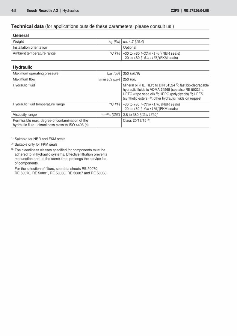
Technical data (for applications outside these parameters, please consult us!)
GeneralWeight kg [lbs] ca. 4.7 [10.4]
Installation orientation OptionalAmbient temperature range °C [°F] –30 to +80 [–22 to +176] (NBR seals)
–20 to +80 [–4 to +176] (FKM seals)
HydraulicMaximum operating pressure bar [psi] 350 [5076] Maximum flow l/min [US gpm] 250 [66]
Hydraulic fluid Mineral oil (HL, HLP) to DIN 51524 1); fast bio-degradable hydraulic fluids to VDMA 24568 (see also RE 90221); HETG (rape seed oil) 1); HEPG (polyglycols) 2); HEES (synthetic esters) 2); other hydraulic fluids on request
Hydraulic fluid temperature range °C [°F] –30 to +80 [–22 to +176] (NBR seals)–20 to +80 [–4 to +176] (FKM seals)
Viscosity range mm2/s [SUS] 2.8 to 380 [13 to 1760]
Permissible max. degree of contamination of the hydraulic fluid - cleanliness class to ISO 4406 (c)
Class 20/18/15 3)
1) Suitable for NBR and FKM seals2) Suitable only for FKM seals3) The cleanliness classes specified for components must be
adhered to in hydraulic systems. Effective filtration prevents malfunction and, at the same time, prolongs the service life of components.
For the selection of filters, see data sheets RE 50070, RE 50076, RE 50081, RE 50086, RE 50087 and RE 50088.

0[0]
[20]
[100]
[116]
[5][0] [10] [15] [20] [25] [30] [66][35]
[40]
[60]
[80]
200
8
4
50 15025 100 12575 175
6
2
225 250
[40] [45] [50] [55] [60]
0 50
[5][0] [10] [15] [20] [25] [30] [66][35]
[0]
[2900]
[3626]
[72.5][145]
[2175]
[1450]
100 150 200 250
4 5 6 6,5 7 7,5 8
8,5
9
10
1214165
10
50
100
150
200
250
[725]
[40] [45] [50] [55] [60]
Hydraulics Bosch Rexroth AGRE 27526/04.08 Z2FS 5/8
∆p-qV characteristic curves (through check valve, with closed throttle)
Characteristic curves (measured with HLP46, ϑoil ( = 190 SUS) = 40 °C ±5 °C [104 °F ± 9 °F])Pr
essu
re d
iffere
ntial
in b
ar [p
si] →
Flow in l/min [US gpm] →
∆p-qV characteristic curves (throtlte position constant)
Pres
sure
diff
eren
tial in
bar
[psi
] →
Flow in l/min [US gpm] →
Thro
ttle
posit
ion
in tu
rns

0,01/100[0.0004/4.0]
Rzmax 4
L A
max 294
min 224max 248
min 224max 248
min 246
56,5
91
513
LT
AP
B
X
Y
F1 F2
F3F4
G1F5
F6G2
4 x 132 x 9,5
3
35,5
10,5
3 3
6
9.1 9.21
2 5 4 2
7 7
8[Ø0.118]
[0.11
8][2
.01]
[2.22]
[3.58]
[Ø0.374] [Ø0.512]
[9.76]
[8.82]
[11.57]
[9.68]
[1.40][0.4
1]
[9.76]
[8.82]
6/8 Bosch Rexroth AG Hydraulics Z2FS RE 27526/04.08
Unit dimensions (dimensions in mm [inch])
Required surface quality of valve mounting face
1 Nameplate2 Type of adjustment “8“
Spindle for adjusting the flow cross-section (hexagon socket 6 A/F) • Turning counter-clockwise = larger flow • Turning clockwise = smaller flow
3 Through-bores for valve mounting4 Identical seal rings for ports A, B, P, T5 Identical seal rings for ports X, Y, L6 Locating pin (included in the sope of supply)7 Hexagon 19 A/F, tightening torque MT = 25 Nm
[18.4 ft-lbs]
8 Porting pattern to ISO 4401-07-07-0-05 and NFPA T3.5.1 R2-D07
9.1 Plug screw on variant “B“9.2 Plug screw on variant “A“
Valve mounting screws (separate order)– Metric
4 hexagon socket head cap screws ISO 4762 - M10 - 10.9-flZn-240h-L
2 hexagon socket head cap screws ISO 4762 - M6 - 10.9-flZn-240h-L
– UNC 4 hexagon socket head cap screws 3/8-16 UNC
2 hexagon socket head cap screws 1/4-20 UNC
Note! The length and tightening torque of valve mounting screws must be calculated taking account of the components mount-ed above and below the sandwich plate valve.

Bosch Rexroth AG HydraulicsZum Eisengießer 197816 Lohr am Main, Germany Phone +49 (0) 93 52 / 18-0 Fax +49 (0) 93 52 / 18-23 [email protected] www.boschrexroth.de
© This document, as well as the data, specifications and other informa-tion set forth in it, are the exclusive property of Bosch Rexroth AG. It may not be reproduced or given to third parties without its consent.The data specified above only serve to describe the product. No statements concerning a certain condition or suitability for a certain application can be derived from our information. The information given does not release the user from the obligation of own judgment and verification. It must be remembered that our products are subject to a natural process of wear and aging.
Hydraulics Bosch Rexroth AGRE 27526/04.08 Z2FS 7/8
Notes

Bosch Rexroth AG HydraulicsZum Eisengießer 197816 Lohr am Main, Germany Phone +49 (0) 93 52 / 18-0 Fax +49 (0) 93 52 / 18-23 [email protected] www.boschrexroth.de
© This document, as well as the data, specifications and other informa-tion set forth in it, are the exclusive property of Bosch Rexroth AG. It may not be reproduced or given to third parties without its consent.The data specified above only serve to describe the product. No statements concerning a certain condition or suitability for a certain application can be derived from our information. The information given does not release the user from the obligation of own judgment and verification. It must be remembered that our products are subject to a natural process of wear and aging.
8/8 Bosch Rexroth AG Hydraulics Z2FS RE 27526/04.08
Notes

1/8
Information on available spare parts:www.boschrexroth.com/spc
Throttle check valve
Type Z2FS
Size 25Component series 3XMaximum operating pressure 350 bar [5076 psi]Maximum flow 360 l/min [95 US gpm]
RE 27536/05.08Replaces: 04.02
Table of contents Features– Sandwich plate valve– Porting pattern to ISO 4401-08-08-0-05 and
NFPA T3.5.1 R2-D08– For limiting the flow of 2 actuator ports– Adjustment element: Spindle with hexagon socket– For meter-in or meter-out throttling
Content PageFeatures 1Ordering code 2Symbols 2Function, section 3Technical data 4Characteristic curves 5Unit dimensions 6
tb0222
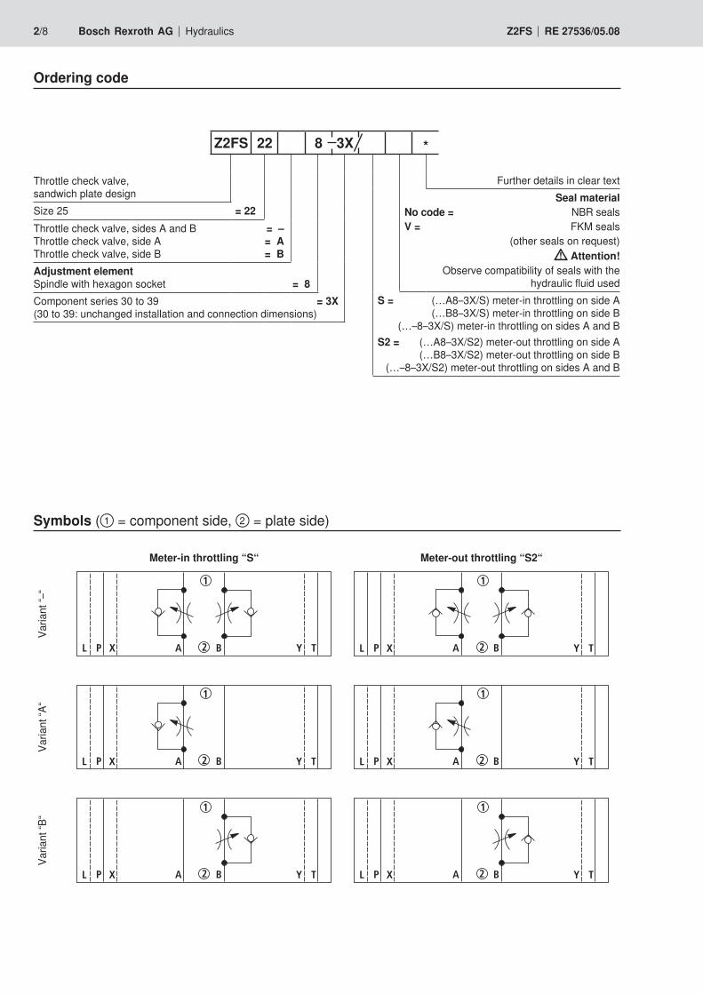
2/8 Bosch Rexroth AG Hydraulics Z2FS RE 27536/05.08
Ordering code
Throttle check valve, sandwich plate design
Size 25 = 22Throttle check valve, sides A and B = – Throttle check valve, side A = A Throttle check valve, side B = BAdjustment element Spindle with hexagon socket = 8Component series 30 to 39 = 3X (30 to 39: unchanged installation and connection dimensions)
Further details in clear textSeal material
No code = NBR sealsV = FKM seals
(other seals on request) Attention!
Observe compatibility of seals with the hydraulic fluid used
S = (…A8–3X/S) meter-in throttling on side A (…B8–3X/S) meter-in throttling on side B
(…–8–3X/S) meter-in throttling on sides A and BS2 = (…A8–3X/S2) meter-out throttling on side A
(…B8–3X/S2) meter-out throttling on side B (…–8–3X/S2) meter-out throttling on sides A and B
Z2FS 22 8 3X *
Symbols (① = component side, ② = plate side)
Meter-in throttling “S“ Meter-out throttling “S2“
Varia
nt “–
“
X TP A B
1
2L Y P A B
1
2X TL Y
Varia
nt “A
“
P A B
1
2X TL Y P A B
1
2X TL Y
Varia
nt “B
“
P A B
1
2X TL Y P A B
1
2X TL Y

AP
BX YL
1
2
3 5 2.1 1 2.24
Hydraulics Bosch Rexroth AGRE 27536/05.08 Z2FS 3/8
Function, sectionThe hydraulic fluid returning from actuator B2 shifts throttle spool (2.2) and thus provides an unhindered flow as with a check valve. Depending on the variant (“S“ or “S2“) throttling can be effective on the supply or return side. Flow limitationTo change the velocity of an actuator, the throttle check valve can be installed between the directional valve and the sub-plate.
Valves of type Z2FS are throttle check valves of sandwich plate design. They are used to limit the flow of one or two ac-tuator ports. Two throttle check valves, which are symmetrically arranged to each other, limit the flow (by means of adjustable throttle spools) in one direction and allow a free flow in the opposite direction. In the case of meter-in throttling the hydraulic fluid is fed through channel A1 via throttling point (1) to actuator A2. Throttle spool (2.1) can be axially adjusted by means of spin-dle (3), thus allowing throttling point (1) to be adjusted.At the same time, the hydraulic fluid present in channel A1 is fed via bore (4) to spool side (5). In addition to the spring force, the applied pressure holds throttle spool (2.1) in the throttling position.
Meter-in throttling
① = component side② = plate side

4/8 Bosch Rexroth AG Hydraulics Z2FS RE 27536/05.08
Technical data (for applications outside these parameters, please consult us!)
GeneralWeight kg [lbs] ca. 8 [17.6]
Installation orientation OptionalAmbient temperature range °C [°F] –30 to +50 [–22 to +122] (NBR seals)
–20 to +50 [–4 to +122] (FKM seals)
HydraulicMaximum operating pressure bar [psi] 350 [5076] Maximum flow l/min [US gpm] 360 [95]
Hydraulic fluid Mineral oil (HL, HLP) to DIN 51524 1); fast bio-de-gradable hydraulic fluids to VDMT 24568 (see also RE 90221); HETG (rape seed oil) 1); HEPG (polygly-cols) 2); HEES (synthetic esters) 2); other hydraulic fluids on request
Hydraulic fluid temperature range °C [°F] –30 to +80 [–22 to +176] (NBR seals)–20 to +80 [–4 to +176] (FKM seals)
Viscosity range mm2/s [SUS] 2.8 to 380 [13 to 1760]
Permissible max. degree of contamination of the hydraulic fluid - cleanliness class to ISO 4406 (c)
Class 20/18/15 3)
1) Suitable for NBR and FKM seals2) Suitable for FKM seals only3) The cleanliness classes specified for components must be
adhered to in hydraulic systems. Effective filtration prevents malfunction and, at the same time, prolongs the service life of components.
For the selection of filters, see data sheets RE 50070, RE 50076, RE 50081, RE 50086, RE 50087 and RE 50088.

0[0]
[10]
[50]
[58]
[20]
[30]
[40]
[0] [10] [20] [30]
24060 18030 120 15090 210 270 300
[40] [50] [60]
1
2
3
4
330 360
[95.1][70] [80] [90]
[0]
[2900]
[3626]
[72.5]
[145]
[2175]
[1450]
[14.5]
0
[0] [10] [20] [30]
24060 18030 120 15090 210 270 300
[40] [50] [60]
330 360
[95.1][70] [80] [90]
510
60
100
150
200
250
1
20
40
80
[290]
[580]
[870]
[1160]
4 5 6 7 8
10
11
12
131517
9
Hydraulics Bosch Rexroth AGRE 27536/05.08 Z2FS 5/8
∆p-qV characteristic curves (via check valve, with closed throttle)
Characteristic curves (measured with HLP46, ϑoil ( = 190 SUS) = 40 °C ±5 °C [104 °F ± 9 °F])Pr
essu
re d
iffer
entia
l in b
ar
[psi
] →
Flow in l/min [US gpm] →
∆p-qV characteristic curves (constant throttling position)
Pres
sure
diff
eren
tial in
bar
[psi
] →
Flow in l/min [US gpm] →
Thro
ttlin
g po
sitio
n in
turn
s

188
min 268max 320
X P
L X
T P Y
A B
F1 F2
F3F4
G1F5
F6G2
17,2
12,6
6 x 11
76,6
554 6
117
2 7 5 8 4 7 2
3
6
[12.50]
[10.55]
[7.40]
[4.61]
[3.02]
[2.17
][0
.16]
[Ø0.24]
[Ø0.433][0.68]
[0.5
0] 2 x 6,5 [Ø0.256]
9.1 9.21
min 245,3 [9.66]
max 271,3 [10.68]
max 271,3 [10.68]
min 245,3 [9.66]
0,01/100[0.0004/4.0]
Rz1max 4
6/8 Bosch Rexroth AG Hydraulics Z2FS RE 27536/05.08
Unit dimensions (dimensions in mm [inch])
Required surface quality of valve mounting face
1 Nameplate2 Adjustment element “8“
Spindle for adjusting the flow cross-section (hexagon socket 6 A/F) • Turning counter-clockwise = greater flow • Turning clockwise = smaller flow
3 Through-bores for valve mounting4 Identical seal rings for ports A, B, P, T5 Identical seal rings for ports X, Y, L6 Locating pin (included in the scope of supply)7 Hexagon 22 A/F, tightening torque MT = 25 Nm
[18.4 ft-lbs]
8 Porting pattern to ISO 4401-08-08-0-05 and NFPA T3.5.1 R2-D08
9.1 Plug screw for variant “B“9.2 Plug screw for variant “A“
Valve mounting screws (separate order)– Metric
6 hexagon socket head cap screws ISO 4762 - M12 - 10.9-flZn-240h-L
– UNC 6 hexagon socket head cap screws 5/8-11 UNC
Note! The length and tightening torque of valve mounting screws must be calculated taking account of the components mount-ed above and below the sandwich plate valve.

Bosch Rexroth AG HydraulicsZum Eisengießer 197816 Lohr am Main, Germany Phone +49 (0) 93 52 / 18-0 Fax +49 (0) 93 52 / 18-23 [email protected] www.boschrexroth.de
© This document, as well as the data, specifications and other informa-tion set forth in it, are the exclusive property of Bosch Rexroth AG. It may not be reproduced or given to third parties without its consent.The data specified above only serve to describe the product. No state-ments concerning a certain condition or suitability for a certain applica-tion can be derived from our information. The information given does not release the user from the obligation of own judgment and verifica-tion. It must be remembered that our products are subject to a natural process of wear and aging.
Hydraulics Bosch Rexroth AGRE 27536/05.08 Z2FS 7/8
Notes

Bosch Rexroth AG HydraulicsZum Eisengießer 197816 Lohr am Main, Germany Phone +49 (0) 93 52 / 18-0 Fax +49 (0) 93 52 / 18-23 [email protected] www.boschrexroth.de
© This document, as well as the data, specifications and other informa-tion set forth in it, are the exclusive property of Bosch Rexroth AG. It may not be reproduced or given to third parties without its consent.The data specified above only serve to describe the product. No state-ments concerning a certain condition or suitability for a certain applica-tion can be derived from our information. The information given does not release the user from the obligation of own judgment and verifica-tion. It must be remembered that our products are subject to a natural process of wear and aging.
8/8 Bosch Rexroth AG Hydraulics Z2FS RE 27536/05.08
Notes

1/4
Information on available spare parts:www.boschrexroth.com/spc
Double throttle check valve
Type Z2FSK 6
Size 6Component series 1XMaximum operating pressure 210 barMaximum flow 40 l/min
RE 27510/05.06Replaces: 11.02
Table of contents
Contents Page
Features 1 and 2
Ordering code, symbols 2
Function, section 2
Technical data 3
Characteristic curves 3
Unit dimensions 4
– Sandwich plate valve
– Porting pattern to ISO 4401-03-02-0-05
– Type of adjustment:Hexagon socket head cap screw with locknut and protective cap
– For limiting the flow in 2 actuator ports
– For meter-in or meter-out throttling
H4083_d
Features

A2 B2
A1 B11 5
4 33 2 2
2/4 Bosch Rexroth AG Hydraulics Z2FSK 6 RE 27510/05.06
Ordering code, symbols ( 1 = component side, 2 = plate side)
Function, section
Valves of type Z2FSK 6 are double throttle check valves of sandwich plate design.
They are used for limiting the flow in two actuator ports.
Two symmetrically arranged throttle check valves limit the flow in one direction and allow free flow in the reverse direction.
In the case of meter-in throttling, the hydraulic fluid is fed through channel A1 via throttling point (1), which is formed by valve seat (2) and throttling spool (3), to actuator A2. Throttling spool (3) can be axially adjusted by means of set screw (4) and therefore allows throttling point (1) to be adjusted.
The hydraulic fluid returning from actuator B2 shifts valve seat (2) against spring (5) towards throttling spool (3) and thus al-lows a free flow of the fluid. Depending on the installation ori-entation, the throttling effect can be implemented for the sup-ply or the return flow.
Type Z2FSK 6-2-X/2QV
(meter-in throttle)
Material no. R900564521
Type designation: Z2FSK 6-2-1X/2QV
Symbol
Meter-in throttle Meter-out throttle
TP A B
1
2 TP A B
1
2

200
150
100908070605040
30
20
10
5
0 10 20 30 40
10
9
8
7
654330
20
10
0 10 20 30 40
Hydraulics Bosch Rexroth AGRE 27510/05.06 Z2FSK 6 3/4
Technical data (for applications outside these parameters, please consult us!)
GeneralWeight kg approx. 0.5
Installation orientation Optional
Ambient and storage temperature range °C –20 to +80 (FKM seals)
HydraulicMaximum operating pressure bar 210
Maximum flow l/min 40
Hydraulic fluid Mineral oil (HL, HLP) to DIN 51524; fast bio-degradable hydraulic fluids to VDMA 24568 (see also RE 90221); HETG (rape seed oil); HEPG (polyglycols); HEES (synthetic esters); other hydraulic fluids on enquiry
Hydraulic fluid temperature range °C –20 to +80 (FKM seals)
Viscosity range mm2/s 10 to 800
Max. permissible degree of contamination of the hydraulic fluid - cleanliness class to ISO 4406 (c)
Class 20/18/15 1)
Characteristic curves (measured at ν = 41mm2, ϑoil = 40 °C ±5 °C)
1) The cleanliness classes specified for components must be adhered to in hydraulic systems. Effective filtration prevents malfunction and, at the same time, prolongs the service life of components. For the selection of filters, see data sheets RE 50070, RE 50076, RE 50081, RE 50086 and RE 50088.
Δp-qv characteristic curves Δp-qvcharacteristic curves (throttle closed)
Pre
ssur
e di
ffere
ntia
l in
bar →
Flow in l/min →
Throttle position in turns
Pre
ssur
e di
ffere
ntia
l in
bar →
Flow in l/min →

T
P
BA
22,638
,6
5 42 1 2
61 x 401,4
6
7
"X"
44
98
"X"
4 x Ø5,472
160
314,5
6,5
F1
F2
F3F4
G
0,01/100mm
Rzmax 4
Bosch Rexroth AGHydraulicsZum Eisengießer 197816 Lohr am Main, GermanyPhone +49 (0) 93 52 / 18-0Fax +49 (0) 93 52 / 18-23 [email protected]
© This document, as well as the data, specifications and other information set forth in it, are the exclusive property of Bosch Rexroth AG. It may not be reproduced or given to third parties without its consent.The data specifi ed above only serve to describe the product. No statements concerning a certain condition or suitability for a certain application can be derived from our information. The information given does not release the user from the obligation of own judgment and verifi cation. It must be remembered that our products are subject to a natural process of wear and aging.
4/4 Bosch Rexroth AG Hydraulics Z2FSK 6 RE 27510/05.06
Unit dimensions (nominal dimensions in mm)
1 Nameplate
2 Adjustment element (hexagon socket head cap screw with locknut and protective cap)
3 Valve mounting bores
4 Locknut A/F 10
5 Setscrew for changing the flow cross-section (hexagon A/F 5)
6 Identical seal rings for ports A, B, P, T
7 R-ring plate
8 The meter-in throttle can be converted into a meter-out throttle by turning the component around the axis “X”–”X”
9 Porting pattern to ISO 4401-03-02-0-05 (with locating bore Ø3 for locating pin ISO 8752-3x8-St, Material no. R900005694, separate order)
Required surface quality of the valve mounting face
Valve fixing screws (separate order)
4 socket head cap screws ISO 4762 – M5 - 10.9-flZn-240h-LFriction coefficient μtotal = 0.09 to 0.14
Note!
The length of the fixing screws of the sandwich plate valve (screw-in depth ≥ 10 mm) must be selected to suit the com-ponents installed above and below the double throttle check valve. The type of screw and the tightening torque must be adapted to the individual requirements.Please inquire screws of the required length from Bosch Rexroth.

1/6
Information on available spare parts: www.boschrexroth.com/spc
Throttle and throttle check valve
Types MG and MK
Size 6 to 30Component series 1XMaximum operating pressure 315 barMaximum flow 400 l/min
RE 27219/01.09Replaces: 03.06
Table of contents
– Suitable for direct in-line installation– Pressure and viscosity-dependent
K3564-1
Features
Contents PageFeatures 1Ordering code 2Standard types 2Symbols 2Function, section 3Technical data 4Characteristic curves 5Unit dimensions 6
InhaltTable of contents 1Features 1Ordering code 2Symbols 2Function, section 3Technical data (For applications outside these parameters, please consult us!) 4Characteristic curves (measured with HLP46, ϑoil = 40 °C ± 5 °C) 5Unit dimensions (dimensions in mm) 6Notes 7Notes 8

2/6 Bosch Rexroth AG Hydraulics MG and MK RE 27219/01.09
Ordering code
Throttle valve = MGThrottle check valve = MK
Size 6 = 6Size 8 = 8Size 10 = 10Size 15 = 15Size 20 = 20Size 25 = 25Size 30 = 30For threaded connection = G
Further details in the clear textSeal material
No code = NBR seals V = FKM seals
(other seals upon request) Attention!
Observe compatibility of seals with hydraulic fluid used!
1X = Component series 10 to 19(10 to 19: unchanged installation and connection dimensions)
G 1X *
Symbols
Type MG Type MK
Standard types and components are contained in the EPS (standard price list).

1 2 4 3 1 24 3 65
Hydraulics Bosch Rexroth AGRE 27219/01.09 MG and MK 3/6
Function, sectionThe valve types MG and MK are pressure- and viscosity-de-pendent throttle and throttle check valves.
Type MG (throttle valve)Throttling occurrs in both flow directions. The pressure fluid reaches the throttling point (4) via the lateral bores (3). The throttling point is formed between the housing (2) and the ad-justable sleeve (1). By rotating the sleeve (1), the cross-sec-tion of the throttling point (4) can be changed infinitely.
Throttle valve type MG Throttle check valve type MK
Type MK (throttle check valve)When fluid flows through the valve in throttling direction, spring (6) and the pressure fluid press the poppet (5) onto the seat , thus blocking the connection. The pressure fluid uses the lateral bores (3) to reach the throttling point (4), which is formed between the housing (2) and the adjustable sleeve (1).In the opposite direction, the pressure acts on the front face of the poppet (5), lifts the same from the seat, and allows the fluid to flow The pressure fluid flows through the valve without being throttled. At the same time, a part of the pressure fluid flows through the annular gap, which results in the desired self cleaning effect.

4/6 Bosch Rexroth AG Hydraulics MG and MK RE 27219/01.09
Technical data (For applications outside these parameters, please consult us!)
1) The cleanliness classes specified for the components must be adhered to in hydraulic systems. Efficient filtration prevents malfunctions and at the same time prolongs the service life of components.
For the selection of the filters, see data sheets RE 50070, RE 50076, RE 50081, RE 50086, RE 50087 und RE 50088.
generalSize 6 8 10 15 20 25 30Weight kg 0.3 0.4 0.7 1.1 1.9 3.2 4.1Installation position AnyAmbient temperature range °C –30 to +80 (NBR seals)
–20 to +80 (FKM seals)
hydraulicMaximum operating pressure bar 315Cracking pressure (type MK) bar 0.5Maximum volume flow L/min See characteristic curves page 5Pressure fluid Mineral oil (HL, HLP) according to DIN51524, other hydraulic
fluids upon requestPressure fluid temperature range °C –30 to +80 (NBR seals)
–20 to +80 (FKM seals)Viscosity range mm2/s 10 to 800Maximum permitted degree of contamination of the pressure fluid - cleanliness class according to ISO 4406 (c)
Class 20/18/15 1)

400
0,1
0,51
2
34
6
8
10
20 60 80 100 120
1 23
4
1000
0,1
0,5
1
234
6
8
10
200 300 400
5
6 7
0 10 20 4030 50
1
2
3
1 2
3
0 50 100 200150
1
2
34 5
0 100 200 400300
1
2
3
6
7
Hydraulics Bosch Rexroth AGRE 27219/01.09 MG and MK 5/6
Characteristic curves (measured with HLP46, ϑoil = 40 °C ± 5 °C)
Flow in l/min →
Pres
sure
diff
eren
tial in
bar
→
∆p-qV characteristic curves with open check valve and closed throttle (type MK)
1 NG62 NG83 NG104 NG155 NG206 NG257 NG30
Flow in l/min →
Pres
sure
diff
eren
tial in
bar
→
Flow in l/min →
Pres
sure
diff
eren
tial in
bar
→
Flow in l/min →
Pres
sure
diff
eren
tial in
bar
→
Pres
sure
diff
eren
tial in
bar
→
∆p-qV characteristic curves with open throttle (types MK and MG)
Flow in l/min →

05
1
D1
L
T
D1
SW1
ØD
2
SW2T
6/6 Bosch Rexroth AG Hydraulics MG and MK RE 27219/01.09
Bosch Rexroth AG HydraulicsZum Eisengießer 197816 Lohr am Main, Germany Phone +49 (0) 93 52 / 18-0 Fax +49 (0) 93 52 / 18-23 [email protected] www.boschrexroth.de
© This document, as well as the data, specifications and other informa-tion set forth in it, are the exclusive property of Bosch Rexroth AG. It may not be reproduced or given to third parties without its consent.The data specified above only serve to describe the product. No state-ments concerning a certain condition or suitability for a certain applica-tion can be derived from our information. The information given does not release the user from the obligation of own judgment and verification. It must be remembered that our products are subject to a natural process of wear and aging.
Unit dimensions (dimensions in mm)
Size D1 ØD2 L SW1 SW2 T6 G1/4 34 65 22 32 128 G3/8 38 65 24 36 12
10 G1/2 48 80 30 46 1415 G3/4 58 100 41 55 1620 G1 72 110 46 70 1825 G1 1/4 87 130 55 85 2030 G1 1/2 93 150 60 90 22

Hydraulics Bosch Rexroth AGRE 27219/01.09 MG and MK 7/6
Bosch Rexroth AG HydraulicsZum Eisengießer 197816 Lohr am Main, Germany Phone +49 (0) 93 52 / 18-0 Fax +49 (0) 93 52 / 18-23 [email protected] www.boschrexroth.de
© This document, as well as the data, specifications and other informa-tion set forth in it, are the exclusive property of Bosch Rexroth AG. It may not be reproduced or given to third parties without its consent.The data specified above only serve to describe the product. No state-ments concerning a certain condition or suitability for a certain applica-tion can be derived from our information. The information given does not release the user from the obligation of own judgment and verification. It must be remembered that our products are subject to a natural process of wear and aging.
Notes

8/6 Bosch Rexroth AG Hydraulics MG and MK RE 27219/01.09
Bosch Rexroth AG HydraulicsZum Eisengießer 197816 Lohr am Main, Germany Phone +49 (0) 93 52 / 18-0 Fax +49 (0) 93 52 / 18-23 [email protected] www.boschrexroth.de
© This document, as well as the data, specifications and other informa-tion set forth in it, are the exclusive property of Bosch Rexroth AG. It may not be reproduced or given to third parties without its consent.The data specified above only serve to describe the product. No state-ments concerning a certain condition or suitability for a certain applica-tion can be derived from our information. The information given does not release the user from the obligation of own judgment and verification. It must be remembered that our products are subject to a natural process of wear and aging.
Notes

IndustrialHydraulics
Electric Drivesand Controls
Linear Motion andAssembly Technologies Pneumatics
ServiceAutomation
MobileHydraulics
Nominal size 12...32Series 2XMax. Operating pressure 350 barMax. Flow 560 L/min
Features
– For installation in manifolds (cartridge valve),
– With SAE flanged ports,
– For subplate mounting,porting pattern to DIN 24 340, form D,ISO 5781 and CETOP–RP 121 H,subplates to catalogue sheet RE 45 062(separate order),
– Use subplate version when valve panel mounting.
Type FD
RE 27 551/06.03 1/10Replaces: 09.97
Overview of contents
Contents Page
Features 1
Functions 1
Ordering details 2
Symbols 2
Function desctription, section 3
Circuit examples 4
Technical data 5
Characteristic curves 5
Unit dimensions 6 to 9
Check-Q-meter
K2791/2
Functions
– Pilot operated check valve, leak-free,
– The check-Q-meter controls the returning flow qV2 in relationto the flow being directed into the opposite side of theactuater qV1. With cylinders the area tratio (qV2 = qV1 • ϕ )has to be taken into account,
– By-pass valve, free-flow in opposite direction,
– Optional built-on secondary pressure relief valve (only forvalve with flange connections).

2/10 Bosch Rexroth AG | Mobile Hydraulics FD | RE 27 551/06.03
M
T
B
A
X
MB
A
X
B
A
X
Ordering details
Valve type:
FD 12 KA 2X/B03..FD 16 KA 2X/B03..FD 25 KA 2X/B04..FD 32 KA 2X/B06..
Valve type:
FD 12 FB 2X/.B03..FD 16 FB 2X/.B03..FD 25 FB 2X/.B04..FD 32 FB 2X/.B06..
Valve type:
FD 12 PA 2X/B03.. FD 12 FA 2X/B03..FD 16 PA 2X/B03.. FD 16 FA 2X/B03..FD 25 PA 2X/B04.. FD 25 FA 2X/B04..FD 32 PA 2X/B06.. FD 32 FA 2X/B06..
WithoutWithoutWithoutWithoutWithout secondary pressure relief valve
FD 2X/ V *Nominal size 12 = 12= 12= 12= 12= 12Nominal size 16 = 16= 16= 16= 16= 16Nominal size 25 = 25= 25= 25= 25= 25Nominal size 32 = 32= 32= 32= 32= 32
For manifold mounting (cartridge valve) = KA= KA= KA= KA= KAFor sub-plate mounting withoutwithoutwithoutwithoutwithout secondary DBV = PA= PA= PA= PA= PAFor SAE flange connections without without without without without secondary DBV = FA= FA= FA= FA= FAFor SAE flange connections withwithwithwithwith secondary DBV = FB= FB= FB= FB= FB
Series 20 to 29 = 2X= 2X= 2X= 2X= 2X(20 to 29: unchanged installation and connection dimensions)
Further details in clear text
V =V =V =V =V = FKM seals, suitable for mineral oilto DIN 51 524 (HL, HLP)
and phosphate ester (HFD-R)
B00 =B00 =B00 =B00 =B00 = WithoutWithoutWithoutWithoutWithout orificeB03 =B03 =B03 =B03 =B03 = Orifice Ø 0.30 mm (sizes 12 and 16)B04 =B04 =B04 =B04 =B04 = Orifice Ø 0.40 mm (size 25)B06 =B06 =B06 =B06 =B06 = Orifice Ø 0.60 mm (size 32)
(other orifice diameters on request)
Pressure range of the secondary pressure relief valvePressure range of the secondary pressure relief valvePressure range of the secondary pressure relief valvePressure range of the secondary pressure relief valvePressure range of the secondary pressure relief valveValve with SAE flange connections
(onlyonlyonlyonlyonly for version "FB")200 =200 =200 =200 =200 = Pressure setting up to 200 bar300 =300 =300 =300 =300 = Pressure setting up to 300 bar400 =400 =400 =400 =400 = Pressure setting up to 400 bar
Symbols
WithWithWithWithWith secondary pressure relief valve

RE 27 551/06.03 | FD Mobile Hydraulics | Bosch Rexroth AG 3/10
A M T
X
B
rr
Functional description, section
Check-Q-meters are used in hydraulic systems to influence thespeeds of hydraulic motors and cylinders independent of theload (prevents running away). In addition there is an isolatorfunction for pipe burst safety.
The check-Q-meter comprises basically of the housing (1),main poppet (2), pilot part (3), pilot spool (4), damping spool(5) and pilot damping (6).
Lifting the loadLifting the loadLifting the loadLifting the loadLifting the load
With free-flow from A to B the main spool (2) is opened. If theload pressure fails (e.g. pipe break between the directionalvalve and port A) then the main spool (2) immediately closes.This function is achieved by the connection of the load side (7)with chamber (8).
Lowering the load Lowering the load Lowering the load Lowering the load Lowering the load (circuit examples)
The direction of flow is from B to A. Port A is connected totank via the directional valve. The piston rod side of the cylinderhas a flow applied which corresponds to the workingconditions. The relationship between the control pressure atport X and the load pressure at port B = 1 : 20.
When the control pressure is reached the pre-opening of themain spool takes place. Via the control spool (4) the pilot stage(3) is lifted off its seat and chamber (8) is de-compressed viathis drilling and port A to tank. At the same time the loadpressure in port B is no longer applied to chamber (8), this isdue to the longitudinal movement of the pilot stage (3) withinthe main spool. The main poppet (2) is thereby unloaded. Thereverse side of the control spool (4) at the main poppet (2),lies against the collar of the damping spool (5).
The pressure required at port X to open B to A is now onlyinfluenced by the spring in chamber (9). The pressure requiredto begin opening the connection B to A is 20 bar; to fully openthe connection 50 bar is required.
The opening cross-section for flow control increasesprogressively. It is created by the successive opeining of radialdrillings in the bush and the main poppet (2) land.
The relationship between the control pressure, crackingpressure and differential pressure determines the flow to theactuator via the connection of B to A. Thus uncontrolledrunning away of the actuator is prevented.
The controlled lowering procedure is not affected even if thereis a pipe burst between the directional valve and port A.
Guidelines for influencing the opening and closing times of theGuidelines for influencing the opening and closing times of theGuidelines for influencing the opening and closing times of theGuidelines for influencing the opening and closing times of theGuidelines for influencing the opening and closing times of thecheck-Q-meter.check-Q-meter.check-Q-meter.check-Q-meter.check-Q-meter.
– Throttling of the opening sequence is via orifice (6) in thecontrol spool (4) and both sides of the damping spool (5).The orifice (6) is protected by sieves.
– The closing movement of the check-Q-meter is virtually un-throttled.
– When being used in conjunction with cylinders the controlline to port X can be fitted with a throttle check valve (meter-out control) to influence the closing sequence.
– When being used in conjunction with motors a throttle checkvalve should not be fitted in the control line to port X. In thiscase it is recommended that the control times of thedirectional valve are influenced.
8 145
3296
7
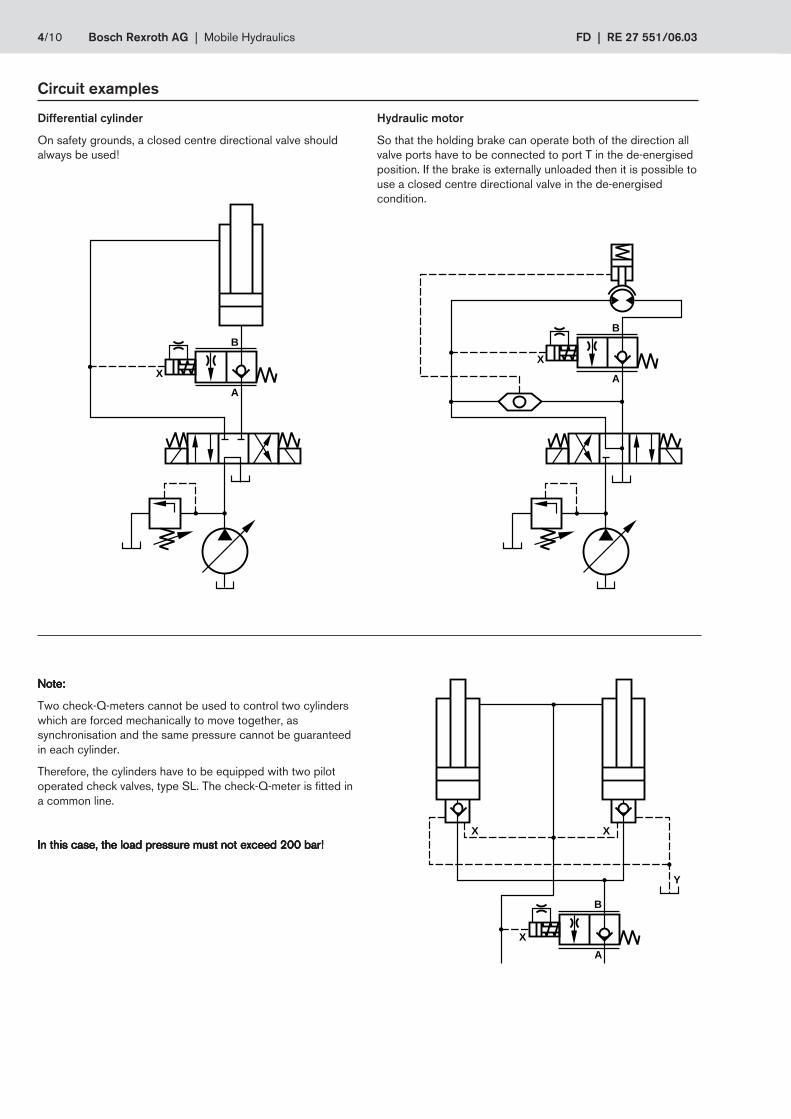
4/10 Bosch Rexroth AG | Mobile Hydraulics FD | RE 27 551/06.03
B
X
A
Y
X X
B
X
A
B
X
A
Hydraulic motor
So that the holding brake can operate both of the direction allvalve ports have to be connected to port T in the de-energisedposition. If the brake is externally unloaded then it is possible touse a closed centre directional valve in the de-energisedcondition.
Differential cylinder
On safety grounds, a closed centre directional valve shouldalways be used!
Note:Note:Note:Note:Note:
Two check-Q-meters cannot be used to control two cylinderswhich are forced mechanically to move together, assynchronisation and the same pressure cannot be guaranteedin each cylinder.
Therefore, the cylinders have to be equipped with two pilotoperated check valves, type SL. The check-Q-meter is fitted ina common line.
In this case, the load pressure must not exceed 200 bar!In this case, the load pressure must not exceed 200 bar!In this case, the load pressure must not exceed 200 bar!In this case, the load pressure must not exceed 200 bar!In this case, the load pressure must not exceed 200 bar!
Circuit examples

RE 27 551/06.03 | FD Mobile Hydraulics | Bosch Rexroth AG 5/10
40
35
30
25
20
15
10
5
0 80 160 240 320 400 480 560
12
10
8
6
4
0 80 160 240 320 400 480 560
2
=
Pressure differential ∆pin relation to flow qv,measured at throttleposition:
Throttle fully open( px = 50 bar)
B to AB to AB to AB to AB to A
Flow in L/min
Pressure differential ∆pin in relation to flow qv,measured over thecheck valve
A to B
Flow in L/min
Pre
ssur
e di
ffere
ntia
l in
bar
Pre
ssur
e di
ffere
ntia
l in
bar
321 4
1 2 3 4
1 = size size size size size 12
2 = size size size size size 16
3 = size size size size size 25
4 = size size size size size 32
qv
∆p
qv
∆p
Characteristic curves (measured at ν = 41 mm2 and ϑ = 50 °C)
Operating pressure, ports A, X bar up to 350
port B bar up to 420
Pilot pressure, port X (flow control range) bar min. 20 to 50, max. 350
Cracking pressure, A to B bar 2
Setting pressure for secondary pressure relief valve bar up to 400
Flow L/min 80 (size 12), 200 (size 16), 320 (size 25), 560 (size 32)
Area ratio of the pre-opening poppet seat area 1area of pilot spool 20
Pressure fluid mineral oil to DIN 51524 (HL,HLP);phosphate ester (HFD-R)
Pressure fluid temperature range °C – 20 to + 80
Viscosity range mm2/s 10 to 800
Degree of contamination (maximum permissible ISO 4406 (C) class 20/18/15
Technical Data (For application outside these parameters, please consult us!)

6/10 Bosch Rexroth AG | Mobile Hydraulics FD | RE 27 551/06.03
G 1/4
Ø 25,1
B2
X
L12
L11
D3
Ø D2+0,1
Ø D1+0,2
30°
25°
L1 –
0,3
L10
+0,1
L2+0
,4
L3 –
0,4
Ø D
8
L7
L5±
0,2
L8
L9
L6±
0,2
L4
Ø D
8 B
B1±
0,2
B1±0,2
D9; T1
x
20°
25°Ø D6
x
R2,5
Ø D5
x
R 2,5
Ø D7+0,2
Ø D4H8AØ 0,05
A
Ay
y
x = Rz16
y = Rz8
11111 Control port
22222 Name plate
Tightening torque MA of cartridge valve:
for size 12: 65 Nm size 25: 110 Nmsize 16: 65 Nm size 32: 270 Nm
Ports A and B can be optionally arranged about the circumference.Attention!The valve fixing holes must not be damaged.
1 2
Pipe threads “G” to ISO 228/1
Unit dimensions: valve for assembly into manifolds (cartridge valve) (Dimensions in mm)
TypeTypeTypeTypeType L7L7L7L7L7 L8L8L8L8L8 L9L9L9L9L9 L10L10L10L10L10 L11L11L11L11L11 L12L12L12L12L12 Valve fixing screws/tightening torqueValve fixing screws/tightening torqueValve fixing screws/tightening torqueValve fixing screws/tightening torqueValve fixing screws/tightening torque MMMMMAAAAA in Nm in Nm in Nm in Nm in Nm WeightWeightWeightWeightWeight
FD 12 KA 2X/...FD 12 KA 2X/...FD 12 KA 2X/...FD 12 KA 2X/...FD 12 KA 2X/... 3 78 128 2,3 191 65 4 off M10 x 70 DIN 912-10.9 69 2,8 kg
FD 16 KA 2X/...FD 16 KA 2X/...FD 16 KA 2X/...FD 16 KA 2X/...FD 16 KA 2X/... 3 78 128 2,3 191 65 4 off M10 x 70 DIN 912-10.9 69 2,8 kg
FD 25 KA 2X/...FD 25 KA 2X/...FD 25 KA 2X/...FD 25 KA 2X/...FD 25 KA 2X/... 4 105 182 2,3 253 75 4 off M12 x 80 DIN 912-10.9 120 5,6 kg
FD 32 KA 2X/...FD 32 KA 2X/...FD 32 KA 2X/...FD 32 KA 2X/...FD 32 KA 2X/... 4 105 198 2,3 289 94 4 off M16 x 100 DIN 912-10.9 295 7,5 kg
TypeTypeTypeTypeType B1B1B1B1B1 B2B2B2B2B2 D1D1D1D1D1 D2D2D2D2D2 D3D3D3D3D3 D4D4D4D4D4 D5D5D5D5D5 D6D6D6D6D6 D7D7D7D7D7 D8D8D8D8D8 D9D9D9D9D9 T1T1T1T1T1 L1L1L1L1L1 L2L2L2L2L2 L3L3L3L3L3 L4L4L4L4L4 L5L5L5L5L5 L6L6L6L6L6
FD 12 KA 2X/...FD 12 KA 2X/...FD 12 KA 2X/...FD 12 KA 2X/...FD 12 KA 2X/... 48 70 54 46 M42x2 38 34 46 38,6 16 M10 16 39 16 32 15,5 50,5 60
FD 16 KA 2X/...FD 16 KA 2X/...FD 16 KA 2X/...FD 16 KA 2X/...FD 16 KA 2X/... 48 70 54 46 M42x2 38 34 46 38,6 16 M10 16 39 16 32 15,5 50,6 60
FD 25 KA 2X/...FD 25 KA 2X/...FD 25 KA 2X/...FD 25 KA 2X/...FD 25 KA 2X/... 56 80 60 54 M52x2 48 40 60 48,6 25 M12 19 50 19 39 22 65 80
FD 32 KA 2X/...FD 32 KA 2X/...FD 32 KA 2X/...FD 32 KA 2X/...FD 32 KA 2X/... 66 95 72 65 M64x2 58 52 74 58,6 30 M16 23 52 19 40 25 71 85

RE 27 551/06.03 | FD Mobile Hydraulics | Bosch Rexroth AG 7/10
G 1/4
Ø 25;1
Ø D2
Ø D1; T1
G 1
/4
Ø 2
5;1
H1
B1
H2
L6
L2 Ø D3 Ø D4
B3 B
4
L1
L5
B1
L4
Ø D5; T2
B2
L2
L3
A M
BX
M
B
(B)AX
SAE flange connection:Operating pressure 6000 PSI (420 bar)
Flange mounting screws and blankingflange are included within the scope ofsupply.
1
6
2
7
5
3
4
7
5
11111 Control port22222 Measuring port33333 Flange fixing screws44444 Blanking flange
Unit dimensions: for SAE flange connections, without secondary pressure relief valve (Dimensions in mm)
55555 Optional port B66666 Name plate77777 O-ring
Pipe thread "G" to ISO 228/1
TypeTypeTypeTypeType B1B1B1B1B1 B2B2B2B2B2 B3B3B3B3B3 B4B4B4B4B4 D1D1D1D1D1 D2D2D2D2D2 D3D3D3D3D3 D4D4D4D4D4 D5D5D5D5D5 H1H1H1H1H1 H2H2H2H2H2
FD 12 FA 2X/...FD 12 FA 2X/...FD 12 FA 2X/...FD 12 FA 2X/...FD 12 FA 2X/... 50,8 16,5 72 110 43 18 10,5 18 M10 36 72
FD 16 FA 2X/...FD 16 FA 2X/...FD 16 FA 2X/...FD 16 FA 2X/...FD 16 FA 2X/... 50,8 16,5 72 110 43 18 10,5 18 M10 36 72
FD 25 FA 2X/...FD 25 FA 2X/...FD 25 FA 2X/...FD 25 FA 2X/...FD 25 FA 2X/... 57,2 14,5 90 132 50 25 13,5 25 M12 45 90
FD 32 FA 2X/...FD 32 FA 2X/...FD 32 FA 2X/...FD 32 FA 2X/...FD 32 FA 2X/... 66,7 20 105 154 56 30 15 30 M14 50 105
TypeTypeTypeTypeType L1L1L1L1L1 L2L2L2L2L2 L3L3L3L3L3 L4L4L4L4L4 L5L5L5L5L5 L6L6L6L6L6 T1T1T1T1T1 T2T2T2T2T2 WeightWeightWeightWeightWeight O-ring (7)O-ring (7)O-ring (7)O-ring (7)O-ring (7)
FD 12 FA 2X/...FD 12 FA 2X/...FD 12 FA 2X/...FD 12 FA 2X/...FD 12 FA 2X/... 39 23,8 105 65 140 78 0,1 15 7 kg 25 x 3,5
FD 16 FA 2X/...FD 16 FA 2X/...FD 16 FA 2X/...FD 16 FA 2X/...FD 16 FA 2X/... 39 23,8 105 65 140 78 0,1 15 7 kg 25 x 3,5
FD 25 FA 2X/...FD 25 FA 2X/...FD 25 FA 2X/...FD 25 FA 2X/...FD 25 FA 2X/... 50 27,8 148 75 200 105 0,1 18 16 kg 32,92 x 3,53
FD 32 FA 2X/...FD 32 FA 2X/...FD 32 FA 2X/...FD 32 FA 2X/...FD 32 FA 2X/... 52 31,6 155 94 215 115 0,1 21 21 kg 37,7 x 3,53
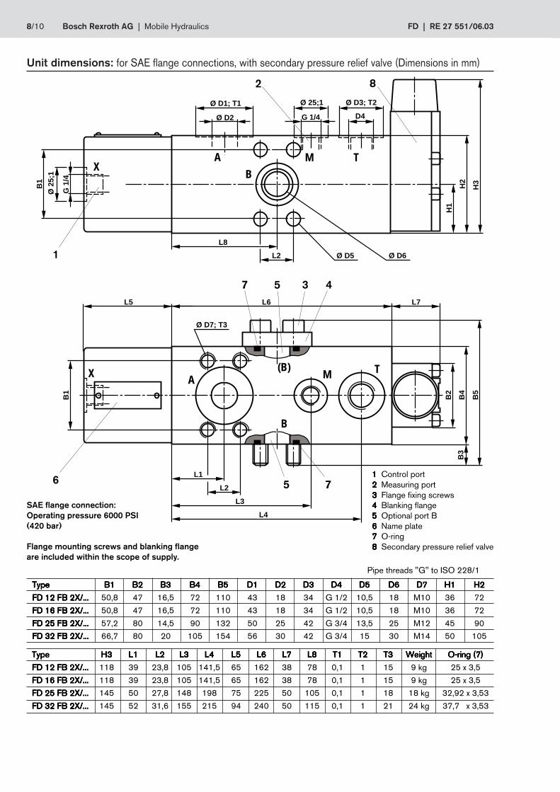
8/10 Bosch Rexroth AG | Mobile Hydraulics FD | RE 27 551/06.03
G 1/4
Ø 25;1
Ø D2
Ø D1; T1
G 1
/4
Ø 2
5;1
H1
H2
H3
L8
L2 Ø D5 Ø D6
B2
B4
L1
L6
B1
L5
Ø D7; T3
L2
L3
B1
D4
Ø D3; T2
B3
B5
L7
L4
A MB
X
M
B
(B)AX
T
T
1
6
2
4357
75
Pipe threads "G" to ISO 228/1
8
TypeTypeTypeTypeType B1B1B1B1B1 B2B2B2B2B2 B3B3B3B3B3 B4B4B4B4B4 B5B5B5B5B5 D1D1D1D1D1 D2D2D2D2D2 D3D3D3D3D3 D4D4D4D4D4 D5D5D5D5D5 D6D6D6D6D6 D7D7D7D7D7 H1H1H1H1H1 H2H2H2H2H2
FD 12 FB 2X/...FD 12 FB 2X/...FD 12 FB 2X/...FD 12 FB 2X/...FD 12 FB 2X/... 50,8 47 16,5 72 110 43 18 34 G 1/2 10,5 18 M10 36 72
FD 16 FB 2X/...FD 16 FB 2X/...FD 16 FB 2X/...FD 16 FB 2X/...FD 16 FB 2X/... 50,8 47 16,5 72 110 43 18 34 G 1/2 10,5 18 M10 36 72
FD 25 FB 2X/...FD 25 FB 2X/...FD 25 FB 2X/...FD 25 FB 2X/...FD 25 FB 2X/... 57,2 80 14,5 90 132 50 25 42 G 3/4 13,5 25 M12 45 90
FD 32 FB 2X/...FD 32 FB 2X/...FD 32 FB 2X/...FD 32 FB 2X/...FD 32 FB 2X/... 66,7 80 20 105 154 56 30 42 G 3/4 15 30 M14 50 105
TypeTypeTypeTypeType H3H3H3H3H3 L1L1L1L1L1 L2L2L2L2L2 L3L3L3L3L3 L4L4L4L4L4 L5L5L5L5L5 L6L6L6L6L6 L7L7L7L7L7 L8L8L8L8L8 T1T1T1T1T1 T2T2T2T2T2 T3T3T3T3T3 WeightWeightWeightWeightWeight O-ring (7)O-ring (7)O-ring (7)O-ring (7)O-ring (7)
FD 12 FB 2X/...FD 12 FB 2X/...FD 12 FB 2X/...FD 12 FB 2X/...FD 12 FB 2X/... 118 39 23,8 105 141,5 65 162 38 78 0,1 1 15 9 kg 25 x 3,5
FD 16 FB 2X/...FD 16 FB 2X/...FD 16 FB 2X/...FD 16 FB 2X/...FD 16 FB 2X/... 118 39 23,8 105 141,5 65 162 38 78 0,1 1 15 9 kg 25 x 3,5
FD 25 FB 2X/...FD 25 FB 2X/...FD 25 FB 2X/...FD 25 FB 2X/...FD 25 FB 2X/... 145 50 27,8 148 198 75 225 50 105 0,1 1 18 18 kg 32,92 x 3,53
FD 32 FB 2X/...FD 32 FB 2X/...FD 32 FB 2X/...FD 32 FB 2X/...FD 32 FB 2X/... 145 52 31,6 155 215 94 240 50 115 0,1 1 21 24 kg 37,7 x 3,53
SAE flange connection:Operating pressure 6000 PSI(420 bar)
Flange mounting screws and blanking flangeare included within the scope of supply.
11111 Control port22222 Measuring port33333 Flange fixing screws44444 Blanking flange55555 Optional port B66666 Name plate77777 O-ring88888 Secondary pressure relief valve
Unit dimensions: for SAE flange connections, with secondary pressure relief valve (Dimensions in mm)

RE 27 551/06.03 | FD Mobile Hydraulics | Bosch Rexroth AG 9/10
G 1/4
Ø 25;1
G 1
/4
Ø 2
5;1
4
Ø 6
B1
B2
L1
L8
B3
L7
Ø 11L3
L4
H1
H2
H3
L5
L2
L6L1
M
B
X
MBAX
A
Pipe threads “G” to ISO 228/1
Unit dimensions: for subplate mounting (Dimensions in mm)
5
1 347
2
6
0,01/100mm
R 4max
Required surface finishof mating piece
Subplates to catalogue sheet RE 45 062must be ordered separately.
Subplates for:Subplates for:Subplates for:Subplates for:Subplates for:sizes 12 and 16sizes 12 and 16sizes 12 and 16sizes 12 and 16sizes 12 and 16 size 25size 25size 25size 25size 25 size 32size 32size 32size 32size 32G 460/01 (G 3/8) G 412/01 (G 3/4) G 414/01 (G 1 1/4)G 461/01 (G 1/2) G 413/01 (G 1) G 415/01 (G 1 1/2)
Note!Note!Note!Note!Note!Only use a sub-plate mounting valve for panel mounting!
11111 Control port22222 Measuring port33333 Locating pin
TypeTypeTypeTypeType B1B1B1B1B1 B2B2B2B2B2 B3B3B3B3B3 H1H1H1H1H1 H2H2H2H2H2 H3H3H3H3H3 L1L1L1L1L1 L2L2L2L2L2 L3L3L3L3L3 L4L4L4L4L4 L5L5L5L5L5 L6L6L6L6L6
FD 12 PA 2X/...FD 12 PA 2X/...FD 12 PA 2X/...FD 12 PA 2X/...FD 12 PA 2X/... 66,7 85 70 85 42,5 70 31,8 7,2 – 35,8 42,9 73,2
FD 16 PA 2X/...FD 16 PA 2X/...FD 16 PA 2X/...FD 16 PA 2X/...FD 16 PA 2X/... 66,7 85 70 85 42,5 70 31,8 7,2 – 35,8 42,9 73,2
FD 25 PA 2X/...FD 25 PA 2X/...FD 25 PA 2X/...FD 25 PA 2X/...FD 25 PA 2X/... 79,4 100 80 100 50 80 38,9 11,1 – 49,2 60,3 109,1
FD 32 PA 2X/...FD 32 PA 2X/...FD 32 PA 2X/...FD 32 PA 2X/...FD 32 PA 2X/... 96,8 120 95 120 60 95 35,3 16,7 42,1 67,5 84,2 119,7
TypeTypeTypeTypeType L7L7L7L7L7 L8L8L8L8L8 Valve fixing screws/tightening torqueValve fixing screws/tightening torqueValve fixing screws/tightening torqueValve fixing screws/tightening torqueValve fixing screws/tightening torque MMMMMAAAAA in Nm in Nm in Nm in Nm in Nm WeightWeightWeightWeightWeight O-ring (7)O-ring (7)O-ring (7)O-ring (7)O-ring (7)
FD 12 PA 2X/...FD 12 PA 2X/...FD 12 PA 2X/...FD 12 PA 2X/...FD 12 PA 2X/... 65 140 4 off M10 x 100 DIN 912-10.9 75 9 kg 21,3 x 2,4
FD 16 PA 2X/...FD 16 PA 2X/...FD 16 PA 2X/...FD 16 PA 2X/...FD 16 PA 2X/... 65 140 4 off M10 x 100 DIN 912-10.9 75 9 kg 21,3 x 2,4
FD 25 PA 2X/...FD 25 PA 2X/...FD 25 PA 2X/...FD 25 PA 2X/...FD 25 PA 2X/... 75 200 4 off M10 x 120 DIN 912-10.9 75 18 kg 29,82 x 2,62
FD 32 PA 2X/...FD 32 PA 2X/...FD 32 PA 2X/...FD 32 PA 2X/...FD 32 PA 2X/... 94 215 6 off M10 x 140 DIN 912-10.9 75 24 kg 38 x 3
44444 Not for sizes 12,16 and 2555555 4 valve fixing holes for sizes 12, 16 and 25.
6 valve fixing holes for size 3266666 Name plate

10/10 Bosch Rexroth AG | Mobile Hydraulics FD | RE 27 551/06.03
© 2003 by Bosch Rexroth AG, Mobile Hydraulics, D-97813 Lohr am MainAll rights reserved. No part of this document may be reproduced or stored,processed, duplicated or circulated using electronic systems, in any form or byany means, without the prior written authorisation of Bosch Rexroth AG.In the event of contravention of the above provisions, the contravening party isobliged to pay compensation.The data specified above only serves to describe the product. No statementsconcerning a certain condition or suitability for a certain application can bederived from our information.The details stated do not release you from theresponsibility for carrying out your own assessment and verification. It must beremembered that our products are subject to a natural process of wear andageing.
Bosch Rexroth AGMobile HydraulicsZum Eisengießer 197816 Lohr am Main, GermanyTelefon +49 (0) 93 52-18 0Telefax +49 (0) 93 52-18 23 [email protected]
Notes