20-25 h.p. rolls-royce car - · pdf filerolls-royce car chassis series ... motor trade,...
TRANSCRIPT
HANDBOOKFOR
20-25 H.P.ROLLS-ROYCE CAR
CHASSIS SERIES(In order of Issue)
GXO GOS GHW GTZ GNC GFE GOH GGP GPS GRW GYZ GRC GAF GEH GDP GFT GAW GBA GKC GSF GBJ GWP GBT GEX GGA GED GRF GLJ GLR GKT GWX GHA GMD GLG GCJ GSR GAU GDX GXB GYD GPG GXK GTR GMU GSY GUB GAE GHG GBK GNS GZU GLZ GLB GWE GYH GTK
Liable to alteration without notice
PRICE £1. 5. 0
PUBLISHED BY
ROLLS-ROYCE, LIMITED
DERBY, CREWE,AND AT 14 AND 15, CONDUIT STREET, LONDON
CONDENSED EDITIONCombining NOs. 9, X, XI, XII, XIV, XV, XVI editions
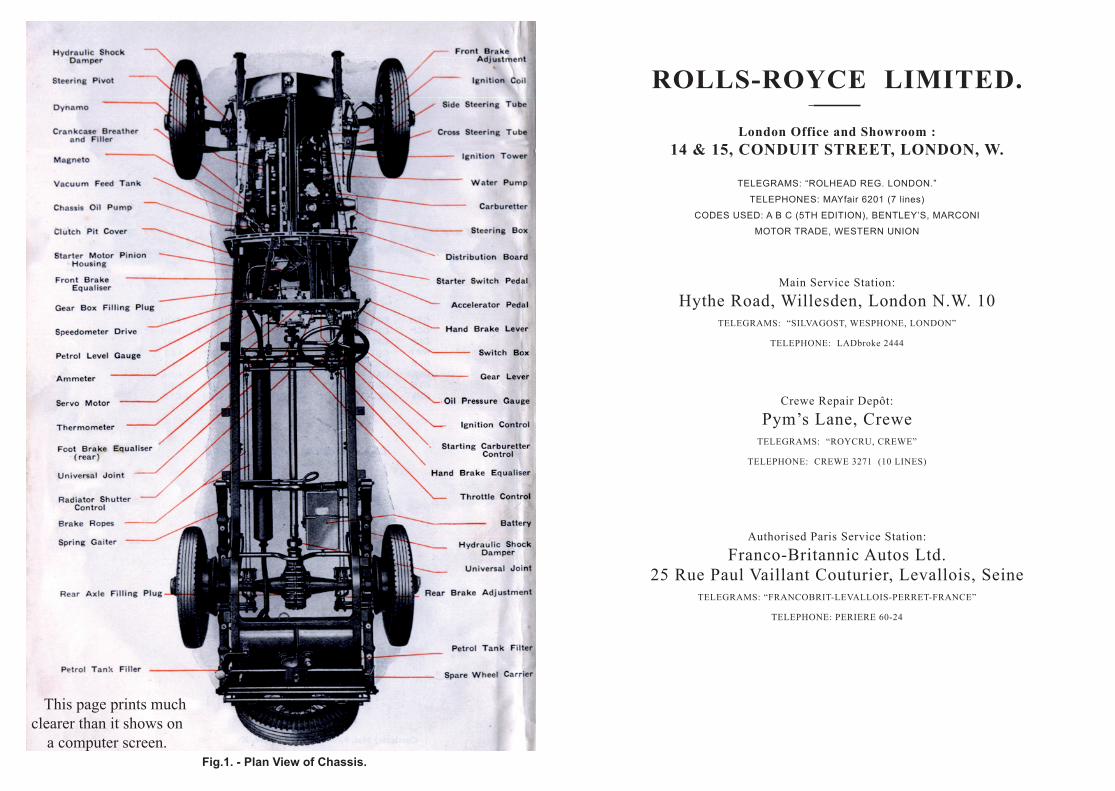
Fig.1. - Plan View of Chassis.
This page prints much clearer than it shows on
a computer screen.
ROLLS-ROYCE LIMITED.
London Office and Showroom :14 & 15, CONDUIT STREET, LONDON, W.
TELEGRAMS: “ROLHEAD REG. LONDON.”
TELEPHONES: MAYfair 6201 (7 lines)
CODES USED: A B C (5TH EDITION), BENTLEY’S, MARCONI
MOTOR TRADE, WESTERN UNION
Main Service Station:
Hythe Road, Willesden, London N.W. 10TELEGRAMS: “SILVAGOST, WESPHONE, LONDON”
TELEPHONE: LADbroke 2444
Crewe Repair Depôt:
Pym’s Lane, CreweTELEGRAMS: “ROYCRU, CREWE”
TELEPHONE: CREWE 3271 (10 LINES)
Authorised Paris Service Station:
Franco-Britannic Autos Ltd.25 Rue Paul Vaillant Couturier, Levallois, Seine
TELEGRAMS: “FRANCOBRIT-LEVALLOIS-PERRET-FRANCE”
TELEPHONE: PERIERE 60-24
THESECRET OF SUCCESSFUL
RUNNING.
Before a Rolls-Royce chassis is sold it is very carefully tested and adjusted by experts. It will run best if no attempt be made to unnecessarily interfere with adjustments.
An owner would do well to instruct his driver as follows:-
Lubricate effectively, in strict accordance with the advice given in this Handbook, and do not neglect any part.
Use only those oils which are recommended by Rolls-Royce Limited, who have made prolonged and searching tests on oils. Considerable harm and expense may result from the use of unsuitable oils.
Inspect all parts regularly, but take care not to alter any adjustments unless really necessary.
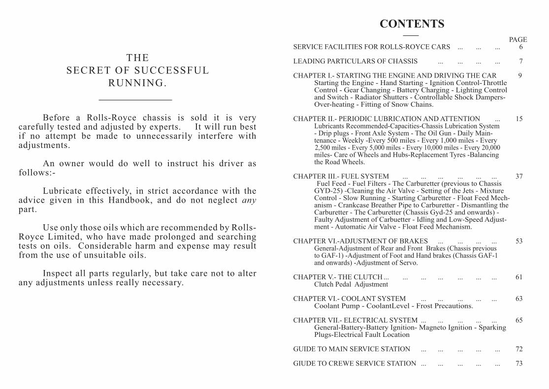
CONTENTS
PAGESERVICE FACILITIES FOR ROLLS-ROYCE CARS ... ... ... 6
LEADING PARTICULARS OF CHASSIS ... ... ... ... 7
CHAPTER I.- STARTING THE ENGINE AND DRIVING THE CAR 9 Starting the Engine - Hand Starting - Ignition Control-Throttle Control - Gear Changing - Battery Charging - Lighting Control and Switch - Radiator Shutters - Controllable Shock Dampers- Over-heating - Fitting of Snow Chains.
CHAPTER II.- PERIODIC LUBRICATION AND ATTENTION ... 15 Lubricants Recommended-Capacities-Chassis Lubrication System - Drip plugs - Front Axle System - The Oil Gun - Daily Main- tenance - Weekly -Every 500 miles - Every 1,000 miles - Every 2,500 miles - Every 5,000 miles - Every 10,000 miles - Every 20,000 miles- Care of Wheels and Hubs-Replacement Tyres -Balancing the Road Wheels.
CHAPTER III.- FUEL SYSTEM ... ... ... ... ... ... 37 Fuel Feed - Fuel Filters - The Carburetter (previous to Chassis GYD-25) -Cleaning the Air Valve - Setting of the Jets - Mixture Control - Slow Running - Starting Carburetter - Float Feed Mech- anism - Crankcase Breather Pipe to Carburetter - Dismantling the Carburetter - The Carburetter (Chassis Gyd-25 and onwards) - Faulty Adjustment of Carbuetter - Idling and Low-Speed Adjust- ment - Automatic Air Valve - Float Feed Mechanism. CHAPTER VI.-ADJUSTMENT OF BRAKES ... ... ... ... 53 General-Adjustment of Rear and Front Brakes (Chassis previous to GAF-1) -Adjustment of Foot and Hand brakes (Chassis GAF-1 and onwards) -Adjustment of Servo.
CHAPTER V.- THE CLUTCH ... ... ... ... ... ... ... 61 Clutch Pedal Adjustment CHAPTER VI.- COOLANT SYSTEM ... ... ... ... ... 63 Coolant Pump - CoolantLevel - Frost Precautions.
CHAPTER VII.- ELECTRICAL SYSTEM ... ... ... ... ... 65 General-Battery-Battery Ignition- Magneto Ignition - Sparking Plugs-Electrical Fault Location
GUIDE TO MAIN SERVICE STATION ... ... ... ... ... 72
GIUDE TO CREWE SERVICE STATION ... ... ... ... ... 73
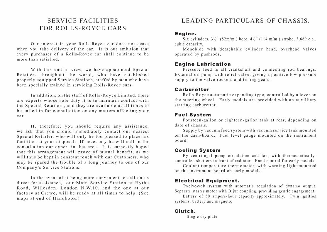
SERVICE FACILITIESFOR ROLLS-ROYCE CARS
Our interest in your Rol ls-Royce car does not cease when you take del ivery of the car. I t i s our ambit ion that every purchaser of a Rol ls-Royce car shal l cont inue to be more than sat isf ied.
With this end in view, we have appaointed Special Retai lers throughout the world, who have establ ished properly equipped Service Stat ions, s taffed by men who have been special ly t ra ined in servicing Rolls-Royce cars .
In addi t ion, on the s taff of Rol ls-Royce Limited, there are experts whose sole duty i t i s to maintain contact with the Special Retai lers , and they are avai lable a t a l l t imes to be cal led in for consul ta t ion on any matters affect ing your car.
I f , therefore , you should require any assis tance, we ask that you should immediately contact our nearest Special Retai ler, who wil l only be too pleased to place his faci l i t ies a t your disposal . I f necessary he wil l cal l in for consul ta t ion our expert in that area. I t i s earnest ly hoped that this arrangement wil l prove of mutual benefi t , as we wil l thus be kept in constant touch with our Customers , who may be spared the t rouble of a long journey to one of our Company’s Service Stat ions.
In the event of i t being more convenient to cal l on us direct for ass is tance, our Main Service Stat ion at Hythe Road, Wil lesden, London N.W.10, and the one at our factory at Crewe, wil l be ready at a l l t imes to help. (See maps at end of Handbook.)
LEADING PARTICULARS OF CHASSIS.
Engine. Six cyl inders , 3½” (82m/m.) bore, 4½” (114 m/m.) s t roke, 3 ,669 c .c . , cubic capaci ty. Monobloc with detachable cyl inder head, overhead valves operated by pushrods,
Engine Lubrication Pressure feed to a l l crankshaft and connect ing rod bear ings. External oi l pump with rel ief valve, giving a posi t ive low pressure supply to the valve rockers and t iming gears .
Carburetter Rol ls-Royce automatic expanding type, control led by a lever on the s teer ing wheel . Ear ly models are provided with an auxi l l iary s tar t ing carburet ter.
Fuel System Fourteen-gal lon or e ighteen-gal lon tank at rear, depending on date of chassis . Supply by vacuum feed system with vacuum service tank mounted on the dash-board. Fuel level gauge mounted on the instrument board
Cooling System By centr i fugal pump circulat ion and fan, with thermostat ical ly-control led shut ters in f ront of radiator. Hand control for ear ly models . Coolant temperature thermometer, with warning l ight mounted on the instrument board on ear ly models .
Electrical Equipment. Twelve-vol t system with automatic regulat ion of dynamo output . Separate s tar ter motor with Bijur coupl ing, providing gent le engagement . Bat tery of 50 ampere-hour capaci ty approximately. Twin igni t ion systems, bat tery and magneto.
Clutch. Single dry plate .
Gearbox. Four forward speeds and reverse , synchromesh or non-synchromesh depending on date of chassis . Right-hand control lever.
Rear Axle. Ful l f loat ing type. Spiral bevel dr ive.Road Springs. Semi-el ipt ic f ront and rear.
Brakes. Internal expanding, servo operated, on al l four wheels . Independent hand brake operat ing on rear wheels .
Road Wheels. Dunlop detachable wel l -base wire wheels , with Dunlop cord, wired type tyres , 6” for 19” r im.
Chassis Lubrication. Central ised chassis system. Separate axle systems on ear ly models .
Dimensions. Wheelbase . . . . . . . . . . . . . . . . . .132” or 129” Track - Front . . . . . . . . . . . . . . . 56 5/16” or 56” Rear . . . . . . . . . . . . . . . 56 5/16” or 56”
STARTING THE ENGINE AND DRIVING THE CAR 9
CHAPTER I
Starting the Engine and Driving the Car Starting the Engine - Hand Starting - Ignition Control-Throttle Control - Gear Changing - Battery Charging - Lighting Control and Switch - Radiator Shutters - Controllable Shock Dampers- Overheating - Fitting of Snow Chains.
Starting the Engine. For chassis series previous to GYD-25, first check that the change gear lever is in neutral, turn fuel tap on dashboard On, and close the radiator shutters by moving the control lever on the instrument board: this control is deleted on chassis after GBT-22, as the shutters are thermostatically operated. Next, switch on the ignition by moving the right hand thumb lever on the switchbox to position marked I (Ignition); retard the ignition and close the throttle by bringing both the levers on the steering column to their bottom positions; next open the starting carburetter by pushing the lever on the instrument board to the position marked Starting or On and set the mixture control lever over to Strong. Now depress the small pedal situated low down in the centre of the dashboard; this closes the main switch of the starter motor, and the latter will start up the engine. As soon as the engine commences to run regularly, move the throttle control lever on the steering colimn about half-way up its quadrant and turn back the starting carburetter control lever to the position marked Running or Off. The starting carburetter should not be used for more than half a minute before changing over to the main carburetter, and it should only be used when the engine is cold. Excessive use may lead to failure of the cylinder lubrication owing to dilution of the oil by petrol. When the engine has been warmed slightly, the mixture control should be set half-way between Strong and Weak. For chassis GYD-25 and onwards, first check that the gear lever is in neutral and turn fuel tap on dashboard to M (Main); then switch on the ignition by moving the right-hand thumb lever on the switchbox to position marked I & C, set mixture control thumb lever on dashboard to Start, fully retard the ignition and move the hand throttle lever half-way up its quadrant.
10 ROLLS-ROYCE 20-25 H.P. CAR
Depress the starter button firmly, and to its fullest extent. As soon as possible after the engine starts, move the mixture cintrol thunb lever to Normal or Run, and leave it there, and advance the ignition. Nornally the ignition lever should stand about three-quarters along its quadrant. The mixture control lever is only intended for use when starting from cold; when making a start with a warm engine, leave the thumb lever at Normal or Run. It is not intended for varying the mixture strength under running conditions. Difficult starting may be due to dampness in the H.T. distributor caused by condensation. the distributor should be removed under such circumstancesand wiped out with a clean dry rag. The rotor should also be wiped dry. The trouble is only likely to arise when the car has been standing. The warmth of the engine will prevent such condensation normally. When the engine is cold a high oil presure will be shown on the gauge, due to the greater viscosity of oil at low temperatures. The pressure will fall to the niormal 15 to 20 lbs., as soon as the oil becomes warmer.Hand Starting. A starting handle is carried in the tool kit. In the event of it being used, it should be removed afterwards from the bracket and returned to the tool kit. The ignition must be fully retarded when starting by hand.Ignition Control. Under normal circumstances, the ignition lever should be advanced about three-quarters along its quadrant. The actual amount of advance is controlled partly by hand, and partly automatically by means of a centrifugal governor operating on the distributor drive. This is capable of meeting 90 per cent. of the conditions due to varying road speeds, leaving only extreme conditions to be met by moving the hand control on the steering wheel.Throttle Control. Under normal running conditions, the hand throttle control should be carried right back in the closed position. An adjustable stop is provided on the carburetter for the throttle lever, which is so adjusted that the engine will idle reliably in these circumstances when the accelerator pedal is released. On the earlier models, the throttle lever should be set to a position on the quadrant at which the engine will run as slowly as possible without risk of stopping when the clutch is withdrawn.
STARTING THE ENGINE AND DRIVING THE CAR 11
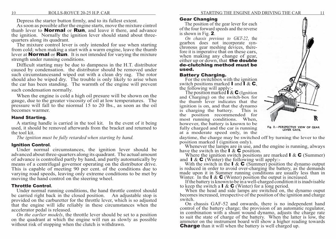
Gear Changing The position of the gear lever for each
of the four forward speeds and the reverse is shown in Fig. 2.
On chassis previous to GKT-22, the gearbox does not incorporate syn-chronous gear meshing devices, there-fore it is imperative that on these cars, when making any change of gear, either up or down, that the double de-clutching method must be used.Battery Charging.
For the switchbox with the ignition switch positions marked I and I & C, the following will apply:-
The position marked I & C (Ignition and Charging) on the switch-box for the thumb lever indicates that the ignition is on, and that the dynamo is charging the battery. This is the position recommended for most running conditions. When, however, the battery is known to be fully charged and the car is running at a moderate speed only, in the daytime, the charge may be switched off by turning the lever to the position marked I (ignition only).
Whenever the lamps are in use, and the engine is running, always have the switch in the I & C position.
Where the ignition switch positions are marked I & C (Summer) and I & C (Winter) the following will apply:-
With the switch in the I & C (Summer) position the dynamo output is reduced in order to avoid over-charging the battery, as the demands made upon it in Summer running conditions are usually less than in Winter. In the I & C (Winter) position the output is increased.
If the battery is known to be in a well-charged condition it is inadvisable to keep the switch a I & C (Winter) for a long period.
When the head and side lamps are switched on, the dynamo ouput becomes increased, irrespective of the position of the ignition and charge switch.
On chassis GAF-52 and onwards, there is no independent hand control of the battery charge; the provision of an automatic regulator, in combination with a shunt wound dynamo, adjusts the charge rate to suit the state of charge of the battery. When the latter is low, the ammeter on the instrument board will show a higher reading towards Charge than it will when the battery is well charged up.
12 ROLLS-ROYCE 20-25 H.P. CAR Whenever the switch is at I & C and the engine is running above
idling speed, the battey is being charged at a rate to suit its state of charge at that particular moment. This can be checked by reference to the ammeter.
Lighting Control and SwitchAdjacent to the ignition is the lighting control switch, for which
alternative On positions are provided, viz.:- OFF ... ... No circuit in action. S and T ... Side and tail lamps on. H, S and T ... Head, side and tail lamps on.
This switch may be locked in either the or position, and the key withdrawn. Do not attempt to lock the switch in any other position. Radiator Shutters.
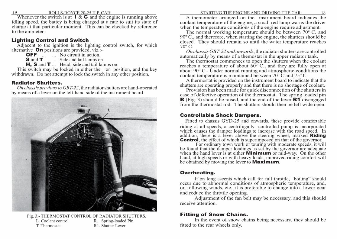
On chassis previous to GBT-22, the radiator shutters are hand-operated by means of a lever on the left-hand side of the instrument board.
Fig. 3.- THERMOSTAT CONTROL OF RADIATOR SHUTTERS. L. Coolant control R. Spring-loaded Pin. T. Thermostat R1. Shutter Lever
STARTING THE ENGINE AND DRIVING THE CAR 13A themometer arranged on the instrument board indicates the
coolant temperature of the engine, a small red lamp warns the driver when the temperature conditions of the engine require adjustment.
The normal working temperature should be between 70º C. and 90º C., and therefore, when starting the engine, the shutters should be closed. They should remain so until the water temperature reaches 70º C.
On chassis GBT-22 and onwards, the radiator shutters are controlled automatically by means of a themostat in the upper radiator tank.
The thermostat commences to open the shutters when the coolant reaches a temperature of about 60º C., and they are fully open at about 90º C. Under normal running and atmospheric conditions the coolant temperature is maintained between 70º C and 75º C.
A thermostat is provided on the instrument board to indicate that the shutters are operating properly and that there is no shortage of coolant.
Provision has been made for quick disconnection of the shutters in case of defective operation of the thermostat. The spring loaded pin R (Fig. 3) should be raised, and the end of the lever R1 disengaged from the thermostat rod. The shutters should then be left wide open.
Controllable Shock Dampers.Fitted to chassis GYD-25 and onwards, these provide comfortable
riding at all speeds, a centrifugally -controlled pump is incorporated which causes the damper loadings to increase with the road speed. In addition, there is a lever above the steering wheel, marked Riding Control, the effect of which is superimposed on that of the governor.
For ordinary town work or touring with moderate speeds, it will be found that the damper loadings as set by the governor are adequate when the hand lever is at either Minimum or mid-way. On the other hand, at high speeds or with heavy loads, improved riding comfort will be obtained by moving the lever to Maximum.
Overheating. If on long ascents which call for full throttle, “boiling” should occur due to abnormal conditions of atmospheric temperature, and, or, following winds, etc., it is preferable to change into a lower gear and reduce the throttle opening. Adjustment of the fan belt may be necessary, and this should receive attention.
Fitting of Snow Chains. In the event of snow chains being necessary, they should be fitted to the rear wheels only.
14 ROLLS-ROYCE 20-25 H.P. CAR
A Parsons’ chain, known as the “Special Rolls-Royce Type”, is available. It is recommended that these be obtained through Messrs. Rolls-Royce Ltd., or one of their “Special Retailers”, in order to ensure the supply of the correct type. When fitting these special chains, it is essential to commence by fastening the one hook on the inside of the wheel and always to take up the adjustment on the outside, where two fastening clips are provided. The tensioning springs which are supplied to go on the outside of the wheel must always be fitted.