20 es generator set - twinslan digital amateur radio …n0nas/manuals/onan/928-0601 ona… · ·...
TRANSCRIPT
Printed in U.S.A. 928�0601 5�95
20 ESGENERATOR SET

i
Table of Contents
SECTION TITLE PAGE
SAFETY PRECAUTIONS iii, iv. . . . . . . . . . . . . . . . . . . . . . . . . . . . . . . . . . . . . . . . .
1 INTRODUCTION 1-1. . . . . . . . . . . . . . . . . . . . . . . . . . . . . . . . . . . . . . . . . . . . . . . . . .
About This Manual 1-1. . . . . . . . . . . . . . . . . . . . . . . . . . . . . . . . . . . . . . . . . . . . . . . Installation Overview 1-1. . . . . . . . . . . . . . . . . . . . . . . . . . . . . . . . . . . . . . . . . . . . .
2 SPECIFICATIONS 2-1. . . . . . . . . . . . . . . . . . . . . . . . . . . . . . . . . . . . . . . . . . . . . . . . .
3 MOUNTING THE GENERATOR SET 3-1. . . . . . . . . . . . . . . . . . . . . . . . . . . . . . . .
General 3-1. . . . . . . . . . . . . . . . . . . . . . . . . . . . . . . . . . . . . . . . . . . . . . . . . . . . . . . . Location 3-1. . . . . . . . . . . . . . . . . . . . . . . . . . . . . . . . . . . . . . . . . . . . . . . . . . . . . . . . Mounting 3-2. . . . . . . . . . . . . . . . . . . . . . . . . . . . . . . . . . . . . . . . . . . . . . . . . . . . . . . Access to Set 3-4. . . . . . . . . . . . . . . . . . . . . . . . . . . . . . . . . . . . . . . . . . . . . . . . . . . Vibration Isolators 3-4. . . . . . . . . . . . . . . . . . . . . . . . . . . . . . . . . . . . . . . . . . . . . . .
4 MECHANICAL CONNECTIONS 4-1. . . . . . . . . . . . . . . . . . . . . . . . . . . . . . . . . . . .
General 4-1. . . . . . . . . . . . . . . . . . . . . . . . . . . . . . . . . . . . . . . . . . . . . . . . . . . . . . . . Fuel System 4-1. . . . . . . . . . . . . . . . . . . . . . . . . . . . . . . . . . . . . . . . . . . . . . . . . . . . Exhaust System 4-5. . . . . . . . . . . . . . . . . . . . . . . . . . . . . . . . . . . . . . . . . . . . . . . . . Ventilation and Cooling 4-6. . . . . . . . . . . . . . . . . . . . . . . . . . . . . . . . . . . . . . . . . . .
5 ELECTRICAL CONNECTIONS 5-1. . . . . . . . . . . . . . . . . . . . . . . . . . . . . . . . . . . . .
General 5-1. . . . . . . . . . . . . . . . . . . . . . . . . . . . . . . . . . . . . . . . . . . . . . . . . . . . . . . . Transfer Switch 5-1. . . . . . . . . . . . . . . . . . . . . . . . . . . . . . . . . . . . . . . . . . . . . . . . . AC Wiring 5-2. . . . . . . . . . . . . . . . . . . . . . . . . . . . . . . . . . . . . . . . . . . . . . . . . . . . . . DC Wiring 5-3. . . . . . . . . . . . . . . . . . . . . . . . . . . . . . . . . . . . . . . . . . . . . . . . . . . . . .
6 PRESTART PREPARATIONS 6-1. . . . . . . . . . . . . . . . . . . . . . . . . . . . . . . . . . . . . .
General 6-1. . . . . . . . . . . . . . . . . . . . . . . . . . . . . . . . . . . . . . . . . . . . . . . . . . . . . . . . Lubrication 6-1. . . . . . . . . . . . . . . . . . . . . . . . . . . . . . . . . . . . . . . . . . . . . . . . . . . . . . Coolant 6-1. . . . . . . . . . . . . . . . . . . . . . . . . . . . . . . . . . . . . . . . . . . . . . . . . . . . . . . . Fuel 6-1. . . . . . . . . . . . . . . . . . . . . . . . . . . . . . . . . . . . . . . . . . . . . . . . . . . . . . . . . . . Ventilation 6-1. . . . . . . . . . . . . . . . . . . . . . . . . . . . . . . . . . . . . . . . . . . . . . . . . . . . . . Exhaust System 6-1. . . . . . . . . . . . . . . . . . . . . . . . . . . . . . . . . . . . . . . . . . . . . . . . . Electrical System 6-1. . . . . . . . . . . . . . . . . . . . . . . . . . . . . . . . . . . . . . . . . . . . . . . . Mechanical Checks 6-1. . . . . . . . . . . . . . . . . . . . . . . . . . . . . . . . . . . . . . . . . . . . . .

ii
SECTION TITLE PAGE
7 INITIAL START AND CHECKS 7-1. . . . . . . . . . . . . . . . . . . . . . . . . . . . . . . . . . . . .
Starting 7-1. . . . . . . . . . . . . . . . . . . . . . . . . . . . . . . . . . . . . . . . . . . . . . . . . . . . . . . . Engine Gauges 7-2. . . . . . . . . . . . . . . . . . . . . . . . . . . . . . . . . . . . . . . . . . . . . . . . . . AC Meters (If Equipped) 7-2. . . . . . . . . . . . . . . . . . . . . . . . . . . . . . . . . . . . . . . . . . Exhaust System 7-2. . . . . . . . . . . . . . . . . . . . . . . . . . . . . . . . . . . . . . . . . . . . . . . . . Engine Monitor Indicator Lamps 7-2. . . . . . . . . . . . . . . . . . . . . . . . . . . . . . . . . . . Fuel System 7-3. . . . . . . . . . . . . . . . . . . . . . . . . . . . . . . . . . . . . . . . . . . . . . . . . . . . DC Electrical System 7-3. . . . . . . . . . . . . . . . . . . . . . . . . . . . . . . . . . . . . . . . . . . . . Cooling System 7-3. . . . . . . . . . . . . . . . . . . . . . . . . . . . . . . . . . . . . . . . . . . . . . . . . Lubrication System 7-3. . . . . . . . . . . . . . . . . . . . . . . . . . . . . . . . . . . . . . . . . . . . . .
8 INSTALLATION CHECKLIST 8-1. . . . . . . . . . . . . . . . . . . . . . . . . . . . . . . . . . . . . . .
General 8-1. . . . . . . . . . . . . . . . . . . . . . . . . . . . . . . . . . . . . . . . . . . . . . . . . . . . . . . . Genset Support 8-1. . . . . . . . . . . . . . . . . . . . . . . . . . . . . . . . . . . . . . . . . . . . . . . . . Cooling Air Flow 8-1. . . . . . . . . . . . . . . . . . . . . . . . . . . . . . . . . . . . . . . . . . . . . . . . . Fuel System 8-1. . . . . . . . . . . . . . . . . . . . . . . . . . . . . . . . . . . . . . . . . . . . . . . . . . . . Exhaust System 8-2. . . . . . . . . . . . . . . . . . . . . . . . . . . . . . . . . . . . . . . . . . . . . . . . . AC and DC Wiring 8-2. . . . . . . . . . . . . . . . . . . . . . . . . . . . . . . . . . . . . . . . . . . . . . . Genset Prestart 8-2. . . . . . . . . . . . . . . . . . . . . . . . . . . . . . . . . . . . . . . . . . . . . . . . .

LS-11aiii
Safety Precautions
Before operating the generator set, read the Op-erator’s Manual and become familiar with it and theequipment. Safe and efficient operation can beachieved only if the equipment is properly oper-ated and maintained. Many accidents are causedby failure to follow fundamental rules and precau-tions.
The following symbols, found throughout thismanual, alert you to potentially dangerous condi-tions to the operator, service personnel, or theequipment.
This symbol warns of immediatehazards which will result in severe personal in-jury or death.
WARNING This symbol refers to a hazard or un-safe practice which can result in severe person-al injury or death.
CAUTION This symbol refers to a hazard or un-safe practice which can result in personal injuryor product or property damage.
FUEL AND FUMES ARE FLAMMABLE
Fire, explosion, and personal injury or death can re-sult from improper practices.
• DO NOT fill fuel tanks while engine is running,unless tanks are outside the engine compart-ment. Fuel contact with hot engine or exhaustis a potential fire hazard.
• DO NOT permit any flame, cigarette, pilot light,spark, arcing equipment, or other ignitionsource near the generator set or fuel tank.
• Fuel lines must be adequately secured andfree of leaks. Fuel connection at the engineshould be made with an approved flexible line.Do not use copper piping on flexible lines ascopper will become brittle if continuously vi-brated or repeatedly bent.
• Be sure all fuel supplies have a positive shutoffvalve.
• Be sure battery area has been well-ventilatedprior to servicing near it. Lead-acid batteriesemit a highly explosive hydrogen gas that canbe ignited by arcing, sparking, smoking, etc..
EXHAUST GASES ARE DEADLY
• Provide an adequate exhaust system to prop-erly expel discharged gases away from en-closed or sheltered areas and areas where in-dividuals are likely to congregate. Visually andaudibly inspect the exhaust daily for leaks perthe maintenance schedule. Ensure that ex-haust manifolds are secured and not warped.Do not use exhaust gases to heat a compart-ment.
• Be sure the unit is well ventilated.
• Engine exhaust and some of its constituentsare known to the state of California to causecancer, birth defects, and other reproductiveharm.
MOVING PARTS CAN CAUSE SEVEREPERSONAL INJURY OR DEATH
• Keep your hands, clothing, and jewelry awayfrom moving parts.
• Before starting work on the generator set, dis-connect battery charger from its AC source,then disconnect starting batteries, negative (-)cable first. This will prevent accidental starting.
• Make sure that fasteners on the generator setare secure. Tighten supports and clamps,keep guards in position over fans, drive belts,etc.
• Do not wear loose clothing or jewelry in the vi-cinity of moving parts, or while working on elec-trical equipment. Loose clothing and jewelrycan become caught in moving parts. Jewelrycan short out electrical contacts and causeshock or burning.
• If adjustment must be made while the unit isrunning, use extreme caution around hot man-ifolds, moving parts, etc.

iv
ELECTRICAL SHOCK CAN CAUSESEVERE PERSONAL INJURY OR DEATH
• Remove electric power before removing pro-tective shields or touching electrical equip-ment. Use rubber insulative mats placed ondry wood platforms over floors that are metal orconcrete when around electrical equipment.Do not wear damp clothing (particularly wetshoes) or allow skin surface to be damp whenhandling electrical equipment.
• Use extreme caution when working on electri-cal components. High voltages can cause inju-ry or death. DO NOT tamper with interlocks.
• Follow all applicable state and local electricalcodes. Have all electrical installations per-formed by a qualified licensed electrician. Tagand lock open switches to avoid accidental clo-sure.
• DO NOT CONNECT GENERATOR SET DI-RECTLY TO ANY BUILDING ELECTRICALSYSTEM. Hazardous voltages can flow fromthe generator set into the utility line. Thiscreates a potential for electrocution or propertydamage. Connect only through an approvedisolation switch or an approved paralleling de-vice.
HIGH VOLTAGE GENERATOR SETS
(1.9kV to 15kV)
• High voltage acts differently than low voltage.Special equipment and training is required towork on or around high voltage equipment. Op-eration and maintenance must be done only bypersons trained and qualified to work on suchdevices. Improper use or procedures will resultin severe personal injury or death.
• Do not work on energized equipment. Unau-thorized personnel must not be permitted nearenergized equipment. Due to the nature of highvoltage electrical equipment, induced voltageremains even after the equipment is discon-nected from the power source. Plan the time formaintenance with authorized personnel so thatthe equipment can be de-energized and safelygrounded.
GENERAL SAFETY PRECAUTIONS
• Coolants under pressure have a higher boilingpoint than water. DO NOT open a radiator orheat exchanger pressure cap while the engineis running. Allow the generator set to cool andbleed the system pressure first.
• Benzene and lead, found in some gasoline,have been identified by some state and federalagencies as causing cancer or reproductivetoxicity. When checking, draining or addinggasoline, take care not to ingest, breathe thefumes, or contact gasoline.
• Used engine oils have been identified by somestate or federal agencies as causing cancer orreproductive toxicity. When checking orchanging engine oil, take care not to ingest,breathe the fumes, or contact used oil.
• Provide appropriate fire extinguishers andinstall them in convenient locations. Consultthe local fire department for the correct type ofextinguisher to use. Do not use foam on electri-cal fires. Use extinguishers rated ABC byNFPA.
• Make sure that rags are not left on or near theengine.
• Remove all unnecessary grease and oil fromthe unit. Accumulated grease and oil cancause overheating and engine damage whichpresent a potential fire hazard.
• Keep the generator set and the surroundingarea clean and free from obstructions. Re-move any debris from the set and keep the floorclean and dry.
• Do not work on this equipment when mentallyor physically fatigued, or after consuming anyalcohol or drug that makes the operation ofequipment unsafe.
• Substances in exhaust gases have been iden-tified by some state or federal agencies ascausing cancer or reproductive toxicity. Takecare not to breath or ingest or come into contactwith exhaust gases.
KEEP THIS MANUAL NEAR THE GENSET FOR EASY REFERENCE

1-1
1. Introduction
ABOUT THIS MANUAL
This manual provides installation instructions forthe ES generator set. This includes the following in-formation:
Mounting Recommendations - Provides in-structions for fastening generator set to baseand space requirements for normal operationand service.Mechanical Connections - Shows location ofconnection points for fuel, exhaust, ventilation,and cooling.Electrical Connections – Shows location ofelectrical connection points for the control,generator, and starting system.Prestart – Provides checklist of items or proce-dures needed to prepare generator set for op-eration.Initial Startup – Describes test complete sys-tem to confirm proper installation, satisfactoryperformance, and proper operation. Refer toOperators Manual for troubleshooting infor-mation.
Installation Checklist - Provides referencechecks upon completion of installation.
This manual DOES NOT provide application infor-mation for selecting a generator set or designing thecomplete installation. If it is necessary to design thevarious integrated systems (fuel, exhaust, cooling,etc.), review standard installation practices, orspecify system materials, additional information isrequired. For engineering data specific to the gen-erator set, refer to the specification and productdata sheets. For application information, refer toApplication Manual T-030, ”Liquid Cooled Genera-tor Sets”, available from Onan.
INSTALLATION OVERVIEW
These installation recommendations apply to typi-cal installations with standard model generatorsets. Whenever possible, these recommendationsalso cover factory designed options or modifica-tions. However, because of the many variables inany installation, it is not possible to provide specificrecommendations for every situation. If there areany questions not answered by this manual, contact
your nearest Cummins/Onan dealer or distributorfor assistance.
Application and Installation
A standby power system must be carefully plannedand correctly installed for proper operation. This in-volves two essential elements: application andinstallation.
Application (as it applies to generator set installa-tions) refers to the design of the complete standbypower system that usually includes power distribu-tion equipment, transfer switches, ventilation equip-ment, mounting pads, and cooling, exhaust, andfuel systems. Each component must be correctlydesigned so the complete system will function as in-tended. Application and design is an engineeringfunction generally done by specifying engineers orother trained specialists. Specifying engineers areresponsible for the design of the complete standbysystem and for selecting the materials and productsrequired.
Installation refers to the actual set-up and assem-bly of the standby power system. The installers setup and connect the various components of the sys-tem as specified in the system design plan. Thecomplexity of the standby system normally requiresthe special skills of qualified electricians, plumbers,sheetmetal workers, etc. to complete the varioussegments of the installation. This is necessary soall components are assembled using standardmethods and practices.
Safety Considerations
The generator set has been carefully designed toprovide safe and efficient service when properlyinstalled and operated. However, the overall safetyand reliability of the complete system is dependenton many factors outside the control of the generatorset manufacturer. To avoid possible safety haz-ards, make all mechanical and electrical connec-tions to the generator set exactly as specified in thismanual. All systems external to the generator (fuel,exhaust, electrical, etc.) must comply with all appli-cable codes. Make certain all required inspectionsand tests have been completed and all code re-quirements have been satisfied before certifyingthe installation is complete and ready for service.

1-2

2-1
2. Specifications
ENGINE Onan Modified Ford, 4-cylinder, LRG-423. . . . . . . . . . . . . . . . . . . . . . . . . . . . . . . . .
FUEL
Fuel Natural gas, Propane, Unleaded Gasoline, or a combination of two fuels. . . . . . . . . .
Natural Gas Consumption at Full Load
60 Hz 301 cfh (8.5 m/h). . . . . . . . . . . . . . . . . . . . . . . . . . . . . . . . . . . . . . . . . . . . . . . . . . . . . .
50 Hz 250 cfh (7.1 m/h). . . . . . . . . . . . . . . . . . . . . . . . . . . . . . . . . . . . . . . . . . . . . . . . . . . . . .
Propane (Vapor) Consumption at Full Load
60 Hz 103 cfh (2.9 m/h). . . . . . . . . . . . . . . . . . . . . . . . . . . . . . . . . . . . . . . . . . . . . . . . . . . . . .
50 Hz 85 cfh (2.4 m/h). . . . . . . . . . . . . . . . . . . . . . . . . . . . . . . . . . . . . . . . . . . . . . . . . . . . . . . .
Gasoline Consumption at Full Load
60 Hz 2.7 US gph (10.2 L/h). . . . . . . . . . . . . . . . . . . . . . . . . . . . . . . . . . . . . . . . . . . . . . . . . .
50 Hz 2.5 US gph (9.5 L/h). . . . . . . . . . . . . . . . . . . . . . . . . . . . . . . . . . . . . . . . . . . . . . . . . . . .
Maximum Natural Gas or LPG Supply Pressure 12 inches (305 mm) Water Column. . . .
Natural Gas Supply Connection 3/4 inch NPT. . . . . . . . . . . . . . . . . . . . . . . . . . . . . . . . . . . . .
Propane Vapor Supply Connection 3/4 inch NPT. . . . . . . . . . . . . . . . . . . . . . . . . . . . . . . . . . .
LPG Liquid Supply Connection 1/4 inch NPT. . . . . . . . . . . . . . . . . . . . . . . . . . . . . . . . . . . . . .
Maximum Gasoline Fuel Pump Lift 3 feet (0.9 m). . . . . . . . . . . . . . . . . . . . . . . . . . . . . . . . . . .
Gasoline Supply Hose I. D. 5/16 inch. . . . . . . . . . . . . . . . . . . . . . . . . . . . . . . . . . . . . . . . . . . .
BATTERY
Required Battery Voltage 12 VDC. . . . . . . . . . . . . . . . . . . . . . . . . . . . . . . . . . . . . . . . . . . . . . . .
Recommended Battery Rating - Cold Cranking Amps 660. . . . . . . . . . . . . . . . . . . . . . . . . .
OIL AND COOLANT CAPACITY
Engine Oil Capacity (Includes Filter) 4.5 U.S. quarts (4.0 L). . . . . . . . . . . . . . . . . . . . . . . . . .
Engine Coolant Capacity 11.5 U.S. quarts (11.0 L). . . . . . . . . . . . . . . . . . . . . . . . . . . . . . . . .
TUNE-UP SPECS
Spark Plug Gap 0.032 to 0.036 inches (0.8 to 0.9 mm). . . . . . . . . . . . . . . . . . . . . . . . . . . . .
IMPORTANT!
DEPENDING ON YOUR LOCATION AND INTENDED USE, FEDERAL, STATE OR LOCAL LAWSAND REGULATIONS MAY REQUIRE YOU TO OBTAIN AN AIR QUALITY EMISSIONS PERMITBEFORE BEGINNING INSTALLATION OF YOUR GENERATOR SET. BE SURE TO CONSULTLOCAL POLLUTION CONTROL OR AIR QUALITY AUTHORITIES BEFORE COMPLETINGYOUR CONSTRUCTION PLANS.

2-2

3-1
3. Mounting the Generator Set
GENERAL
Most generator set installations must beengineered so the generator set will functionproperly under the expected load conditions. Usethese instructions as a general guide only. Followthe instructions of the consulting engineer whenlocating or installing any components. Thecomplete installation must comply with all local andstate building codes, fire ordinances, and otherapplicable regulations.
Requirements to be considered prior to installation:
• Level mounting surface
• Adequate cooling air
• Adequate fresh induction air
• Discharge of circulated air
• Discharge of exhaust gases
• Electrical connections
• Accessibility for operation and servicing
• Noise levels
• Vibration isolation
LOCATION
Generator set location is decided mainly by relatedsystems such as ventilation, wiring, fuel, andexhaust. The set should be located as near aspossible to the main power fuse box.
Provide a location away from extreme ambienttemperatures and protect the generator set fromadverse weather conditions. An optional housing isavailable for outside operation.

3-2
MOUNTING
Generator sets are mounted on a steel skid thatprovides proper support. The engine-generatorassembly is isolated from the skid frame by rubbermounts that provide adequate vibration isolation fornormal installations. For critical installations, installvibration isolators between the skid base andfoundation.
Mount the genset on a substantial and level basesuch as a concrete pad.
Use 3/4-inch diameter, anchored mounting bolts tosecure the generator set skid to the floor to preventmovement. Secure the skid using a flat washer anda hex nut for each bolt (Figure 3-1).
M1627
HEX NUTFLAT WASHER
12 INCH
(305 mm)
MOUNTING BOLT
SKID
FIGURE 3-1. BOLT DIAGRAM

3-3
M-1896s
FRESHAIR FLOW
FLEXIBLEEXHAUST
TUBE
FLEXIBLEGAS SUPPLY
HOSE
CRANKINGBATTERY
TRANSFERSWITCH
GASFILTER
MANUAL GASSUPPLY SHUTOFF
VALVE
RADIATORDISCHARGE
AIR DUCT
AN EXHAUST THIMBLE IS USEDTO PASS THE EXHAUST PIPE
THROUGH A COMBUSTIBLE WALL
THE MUFFLER IS SUPPORTEDINDEPENDENTLY OF THE ENGINE
POWER SUPPLY ANDCONTROL WIRING AREROUTED SEPARATELY
CONTROLPANEL
LINECIRCUIT
BREAKER
FIGURE 3-2. TYPICAL INSTALLATION
3-4
ACCESS TO SET
Plan for access to the genset for servicing andprovide adequate lighting around the unit. Forconvenience in general servicing such as theradiator, fan belt and changing the crankcase oil,the surface of the mounting base should be at least6 inches (152 mm) above the floor.
VIBRATION ISOLATORS
Installation and Adjustment Procedure
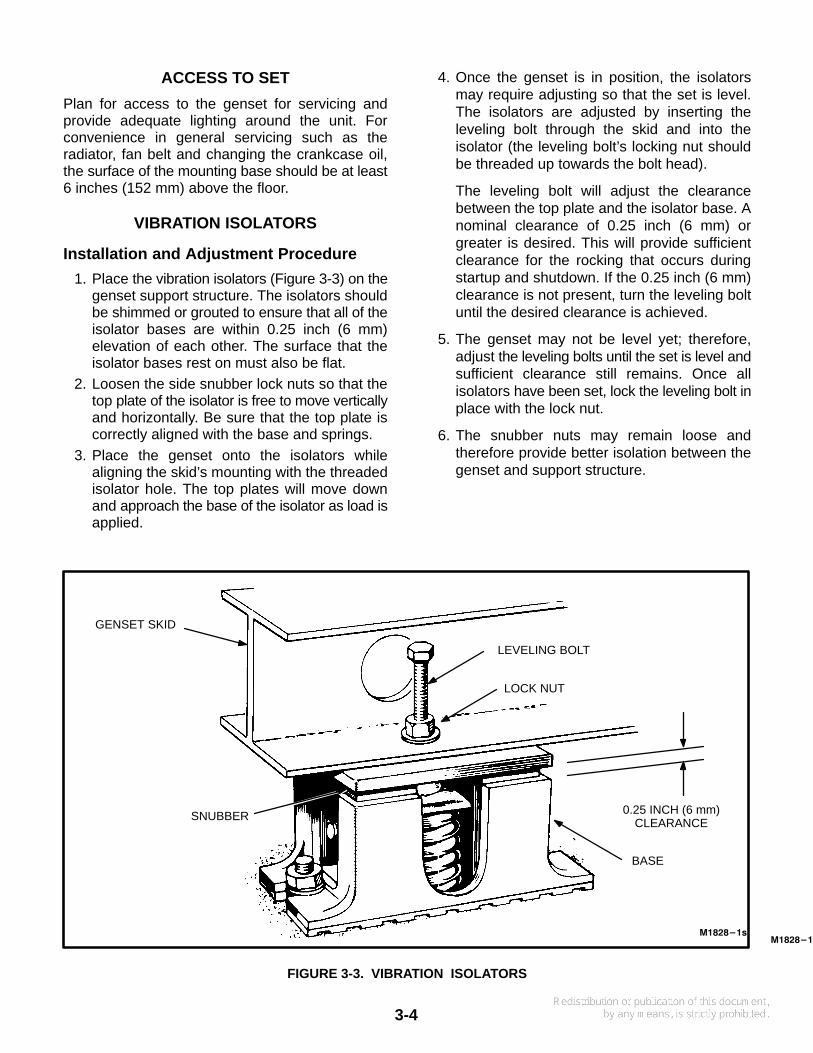
1. Place the vibration isolators (Figure 3-3) on thegenset support structure. The isolators shouldbe shimmed or grouted to ensure that all of theisolator bases are within 0.25 inch (6 mm)elevation of each other. The surface that theisolator bases rest on must also be flat.
2. Loosen the side snubber lock nuts so that thetop plate of the isolator is free to move verticallyand horizontally. Be sure that the top plate iscorrectly aligned with the base and springs.
3. Place the genset onto the isolators whilealigning the skid’s mounting with the threadedisolator hole. The top plates will move downand approach the base of the isolator as load isapplied.
4. Once the genset is in position, the isolatorsmay require adjusting so that the set is level.The isolators are adjusted by inserting theleveling bolt through the skid and into theisolator (the leveling bolt’s locking nut shouldbe threaded up towards the bolt head).
The leveling bolt will adjust the clearancebetween the top plate and the isolator base. Anominal clearance of 0.25 inch (6 mm) orgreater is desired. This will provide sufficientclearance for the rocking that occurs duringstartup and shutdown. If the 0.25 inch (6 mm)clearance is not present, turn the leveling boltuntil the desired clearance is achieved.
5. The genset may not be level yet; therefore,adjust the leveling bolts until the set is level andsufficient clearance still remains. Once allisolators have been set, lock the leveling bolt inplace with the lock nut.
6. The snubber nuts may remain loose andtherefore provide better isolation between thegenset and support structure.
M1828-1s
GENSET SKID
SNUBBER
LEVELING BOLT
LOCK NUT
BASE
M1828-1s
0.25 INCH (6 mm)CLEARANCE
FIGURE 3-3. VIBRATION ISOLATORS

4-1
4. Mechanical Connections
GENERAL
The generator set mechanical system installationincludes connecting the fuel, exhaust, ventilationand cooling systems. Before starting any type offuel installation, all pertinent state and local codesmust be complied with and the installation must beinspected before the unit is put in service.
FUEL SYSTEM
Sets can be equipped to operate on gasoline only,LPG (propane), gasoline/natural gas, gasoline/LPG and LPG/natural gas combinations. Figures4-1 and 4-2 illustrate the fuel system componentsfor various generator set configurations. A fuel se-lector switch may be provided for fuel changeover.(The position of the switch determines which fuelvalve will open when the set is operated.)
The following items should be considered wheninstalling a fuel supply system:
• Install an approved flexible fuel line at the fuelinlet to allow the set to rock on its mounts. Donot use copper tubing as a flexible fuel line - itwill crack and spill gasoline.
• The highest fuel level in the fuel tank must belower than the inlet of the fuel pump to preventspillage of fuel if a leak occurs (because of afaulty connection, ruptured pump diaphragm,etc.).
• Provide a separate fuel line for each set servedby the same fuel tank to prevent either set frombeing starved for fuel.
• Install a manual fuel shut-off valve at the outletof an above-ground fuel tank to facilitate ser-vice.
• For a combination gas/gasoline set, provide amanual shut-off valve in each fuel line. Plugunused fuel inlet. The air/fuel ratio will be upsetif both fuels are available at the same time or ifair enters an unused fuel inlet, resulting in poorperformance.
• Do not use galvanized piping, fittings or tanks.The zinc coating reacts with elements in thefuel, resulting in contamination of the fuel.
Gasoline Fuel
WARNING Fuel presents the hazard of fire orexplosion which can result in severe personalinjury or death. Do not smoke or allow anyflame, spark, pilot light, arc–producing equip-ment, or switch, or other ignition sourcesaround fuel or fuel components, or in the instal-lation area or areas with shared ventilation.Keep a type ABC fire extinguisher nearby.
The gasoline-carbureted fuel system delivers amixture of fuel and air to the combustion chamber.The system draws fuel from a tank, delivers itthrough a filter and fuel pump, to the carburetor floatchamber. Air passing through the carburetor venturidraws fuel from the the float chamber.
See Specifications section for gasoline inlet size.Fuel lift should not exceed 3 feet (0.9 m). The rec-ommendations in Onan publication T030, the Ap-plication Manual for Liquid-Cooled Generator Sets,should be followed in regard to fuel supply systempipe sizes and manual shutoff valves.
4-2
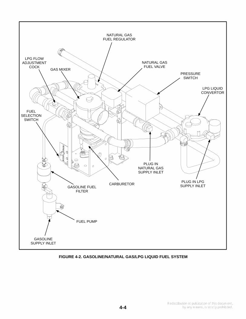
Natural Gas/LPG Vapor/LPG Liquid FuelSystem
WARNING Natural gas and LPG vapor arehighly flammable. LPG vapor is heavier than air.Do not bleed lines so fumes can collect in lowareas. Do not smoke or allow any flame, spark,arcing switch or equipment, pilot light, or othersource of ignition around fuel lines.
A combination gasoline-gaseous fuel carburetor orstraight gaseous fuel carburetors are available foruse with gaseous fuels. A gaseous fuel systemuses a fuel regulator to control the flow of gas fromthe lines to the carburetor. At the carburetor, thegaseous fuel is mixed with the incoming air.
Gaseous-fuel supply system design, materials,components, fabrication, assembly, installation,testing, inspection, operation and maintenancemust comply with the applicable codes. See MFPAStandards No. 37, No. 54 and No. 58.
See Specifications section for natural gas/LPG fuelinlet size. The recommendations in Onan publica-tion T030, the Application Manual for Liquid-CooledGenerator Sets, should be followed in regard to fuelsupply system pipe sizes,manual shutoff valves,fuel filters and gas pressure regulators.
Gas Pressure: The fuel regulators in each line pro-vide constant gas pressure at the gas mixer undervarying load conditions (approximately 5 inchesWC for natural gas and –1.5 inches WC for LPG).There is a pressure test port on the supply side ofthe gas mixer for measuring fuel inlet pressure.
The maximum permissible fuel supply pressureis 20 inches WC (water column) and the mini-mum is 10 inches WC. This applies to LPG as wellas to natural gas. The minimum pressure refers tosupply pressure under rated load (maximum gasflow). There is a pressure test port on the supplyside of each fuel regulator for measuring fuel supplypressure.

4-3
GAS MIXER
LPG FLOWADJUSTMENT
COCK
LPG FUELREGULATOR
LPG FUELVALVE
FUELSELECTION
SWITCH
GASOLINE FUELFILTER
FUEL PUMP
GASOLINESUPPLY INLET
PLUG IN LPGSUPPLY INLET
CARBURETOR
PLUG INNATURAL GASSUPPLY INLET
PRESSURESWITCH
NATURAL GASFUEL VALVE
NATURAL GASFUEL REGULATOR
FIGURE 4-1. GASOLINE/NATURAL GAS/LPG VAPOR FUEL SYSTEM
4-4
GAS MIXER
LPG FLOWADJUSTMENT
COCK
FUELSELECTION
SWITCH
GASOLINE FUELFILTER
FUEL PUMP
GASOLINESUPPLY INLET
PLUG IN LPGSUPPLY INLETCARBURETOR
PLUG INNATURAL GASSUPPLY INLET
PRESSURESWITCH
NATURAL GASFUEL VALVE
NATURAL GASFUEL REGULATOR
LPG LIQUIDCONVERTOR
FIGURE 4-2. GASOLINE/NATURAL GAS/LPG LIQUID FUEL SYSTEM

4-5
EXHAUST SYSTEM
Pipe exhaust gases to the outside of any enclosure.Locate the exhaust outlets away from any air inletsto avoid gases re-entering the enclosure. Exhaustinstallations are subject to various detrimental con-ditions such as extreme heat, infrequent operationand light loads. Regularly inspect the exhaust sys-tem both visually and audibly to see that the entiresystem remains fume tight and safe for operation.
WARNING Inhalation of exhaust gases can re-sult in severe personal injury or death. Use ex-treme care during installation to provide a tightexhaust system. Terminate exhaust pipe awayfrom enclosed areas, windows, doors andvents.
Use an approved thimble (Figure 4-3) where ex-haust pipes pass through wall or partitions. Refer toNFPA 37, Section 6-3. ”Stationary Combustion En-gines and Gas Turbines” for accepted design prac-tices. Build according to the code requirements ineffect at the installation site.
WARNING Inhalation of exhaust gases can re-sult in severe personal injury or death. Do notuse exhaust heat to warm a room, compartmentor storage area.
Rain caps are available for the discharge end of ver-tical exhaust pipes. The rain cap clamps onto theend of the pipe and opens due to exhaust dischargeforce from the generator set. When the generatorset is stopped, the rain cap automatically closes,protecting the exhaust system from rain, snow, etc.Check the rain cap periodically for proper operation(cap is not stuck closed).
Use a section of flexible exhaust pipe between theengine and remainder of exhaust system. Supportexhaust system to eliminate weight applied to en-gine exhaust outlet elbow/turbocharger connec-tion.
CAUTION Weight applied to the engine man-ifold can result in turbocharger damage. Sup-port the muffler and exhaust piping so noweight or stress is applied to engine exhaust el-bow.
EXS1036
DRIP CAPRAIN CAP
ROOF
9 INCH MIN(230 mm)
9 INCH MIN(230 mm)
WALL OR PARTITION
HORIZONTAL
VERTICAL
HOLES INEND OF
INNER SLEEVE
FIGURE 4-3. MOUNTING EXHAUST THIMBLE

4-6
Avoid sharp bends by using sweeping, long radiuselbows and provide adequate support for mufflerand tailpipe. Pitch a horizontal run of exhaust pipeDOWNWARD to allow any moisture condensationto drain away from the engine. If an exhaust pipemust be turned upward, install a condensation trapat the point where the rise begins (Figure 4-4).
Shield or insulate exhaust lines if there is danger ofpersonal contact. Allow at least 12 inches (305 mm)of clearance if the pipes pass close to a combustiblewall or partition.
WARNING Exhaust pipes are very hot and theycan cause severe personal injury or death fromdirect contact or from fire hazard. Shield or in-sulate exhaust pipes if there is danger of per-sonal contact or when routed through walls ornear other combustible materials.
VENTILATION AND COOLING
Generator sets create considerable heat that mustbe removed by proper ventilation. Outdoor installa-tions rely on natural air circulation but indoor instal-lations need properly sized and positioned vents forrequired airflow.
Vents and Ducts
For indoor installations, locate vents so incoming airpasses through the immediate area of the installa-tion before exhausting. Install the air outlet higherthan the air inlet to allow for convection air move-ment.
Size the vents and ducts so they are large enough toallow the required flow rate of air. The ”free area” ofducts must be as large as the exposed area of theradiator. Refer to the ES series Product DataSheets for the airflow requirements.
Wind will restrict free airflow if it blows directly intothe air outlet vent. Locate the outlet vent so the ef-fects of wind are eliminated. See Figure 4-5.
EXS1046s
DRAIN CONDENSATIONTRAP PERIODICALLY
AVOIDSHARPBENDS
IF EXHAUST LINE MUST BEPITCHED UPWARD, CONSTRUCT
A TRAP AT POINT OF RISE
FIGURE 4-4. CONDENSATION TRAP
CS1366
FIGURE 4-5. WIND BARRIER

4-7
Dampers
Dampers or louvres protect the genset and equip-ment room from the outside environment. Their op-eration of opening and closing should be controlledby operation of the genset.
In cooler climates movable or discharge dampersare used. These dampers allow the air to be recircu-lated back to the equipment room. This enables theequipment room to be heated by the generator setwhen operating.
Radiator Set Requirements
Radiator set cooling air is drawn past the rear of theset by a pusher fan that blows air through the radia-tor (Figure 4-6). Locate the air inlet to the rear of theset. Make the inlet vent opening 1-1/2 times largerthan the radiator area. It is important that the inletand outlet (louvers) do not restrict the coolingair flow beyond the capability of the enginecooling fan. If this capability is exceeded, en-gine will overheat.
Locate the cooling air outlet directly in front of the ra-diator and as close as possible. The outlet openingmust be at least as large as the radiator area.Length and shape of the air outlet duct should offerminimum restriction to airflow.
The radiator has an air discharge duct adapterflange. Attach a canvas or sheet metal duct to theflange and the air outlet opening using screws andnuts so duct can be removed for maintenance pur-poses. The duct prevents recirculation of heated air.Before installing the duct, remove the radiator coreguard.
Standard Radiator Cooling uses a set mountedradiator and engine pusher fan to cool engine waterjacket. Air travels from the generator end of the set,across the engine and out through the radiator. Anintegral discharge duct adapter flange surroundsthe radiator grille.
Set Mounted Heat Exchanger Cooling uses a liq-uid-to-liquid heat exchanger that requires a connec-tion to a supply of pressurized cold water and to adrain to discharge the water when it has passedthrough the heat exchanger. The engine coolantpump pumps coolant through the closed, pressur-ized loop between the engine and heat exchanger.
The cold water supply line should have a manualshutoff valve, water strainer and 12 VDC water sole-noid valve to shut off the water supply when the en-gine is not running. A thermostatic water flow valveis also recommended. See Application ManualT-030 for more information.
A powered ceiling vent will probable be required forventilating the generator room.
Remote Radiator Cooling (Optional) substitutesa remote mounted radiator and an electrically driv-en fan for the set mounted components. Removal ofthe radiator and the fan from the set reduces noiselevels without forcing dependence on a continuouscooling water supply. The remote radiator installa-tion must be completely protected against freezing.
Remote radiator plumbing will vary with installation.Follow recommendations given in ApplicationManual T-030. See product data sheet for frictionhead and static head limits.
Before filling cooling system, check all hardware forsecurity. This includes hose clamps, capscrews, fit-tings and connections. Use flexible coolant lineswith heat exchanger, standpipe or remote mountedradiator.

4-8
COOLAIR
INLETAIR
DAMPER
RADIATOR
HOTAIR
WIND/NOISE
BARRIER
D
* Louvers should close whenroom ambient is above 60° F
(16° C)
DISTANCE SHOULD NOTBE LESS THAN HEIGHT
OF RADIATOR
THERMOSTATICAIR RECIRCULATING
DAMPER*
FLEXIBLEDUCT
CONNECTOR
FIGURE 4-6. TYPICAL RADIATOR SET INSTALLATION

5-1
5. Electrical Connections
GENERAL
The genset electrical system includes connectingthe load, installing the control wiring and connectingthe batteries. Connect the batteries last to avoid ac-cidental starting of the unit during installation.
CAUTION To prevent arcing, always discon-nect a battery charger from its AC source beforedisconnecting the battery cables. Otherwise,disconnecting the cables can result in voltagespikes high enough to damage the DC controlcircuits of the set.
WARNING Accidental starting of the generatorset while working on it can cause severe per-sonal injury or death. Prevent accidental start-ing by disconnecting the starting battery cables(negative [–] first).
Arcing can ignite the explosive hydrogen gasgiven off by batteries, causing severe personalinjury. Arcing can occur if the negative (–) bat-tery cable is connected and a tool being used toconnect or disconnect the positive (+) batterycable accidentally touches the frame or othergrounded metal part of the set. To prevent arc-ing, always remove the negative (–) cable first,and reconnect it last.
Most local regulations require that wiring connec-tions be made by a licensed electrician and theinstallation be inspected and approved before op-eration. All connections, wire sizes, etc. must con-form to the requirements of all electrical codes in ef-fect at the installation site.
WARNING Improper wiring can cause a fire orelectrocution, resulting in severe personal inju-ry or death and/or property and equipment dam-age.
TRANSFER SWITCH
If the installation is for standby service, a transferswitch is required for switching the load from thenormal power source to the generator set (Figure5-1). Either a manual or automatic switch can beused. Follow the installation instructions providedwith the transfer switch when connecting the loadand control wiring.
LOAD
GENSETNORMALSOURCE
NOTE: SHOWN WITH LINECONNECTED TO LOAD
FIGURE 5-1. TYPICAL LOAD TRANSFER SWITCH
5-2
AC WIRING
Generator Voltage Connections
The generator output voltage and maximum currentrating are specified on the generator set nameplate.Line-to-neutral voltage is always the lower voltageshown and line-to-line voltage is the higher rating.
These generators can be configured for the volt-ages shown in the Reconnection Diagram. Most ofthese voltages must be reconnected by the installerto give the voltage required by the installation. Be-fore shipping, the factory tests the generator setoutput by connecting the generator to produce aparticular test voltage. The generator may be con-nected at the factory to produce a specified voltageper customer order. The installer must alwayscheck the stator lead terminal connections and per-form any necessary reconnect to obtain the voltagedesired. Note that some voltages are available onlyon certain specific generators.
Refer to Reconnection Diagram when reviewing thevoltage connection information and use the electri-cal schematic supplied with your generator setwhen actually performing load connections.
CAUTION Reconnecting factory connectedgenerator sets to lower voltages can reduce setratings, and also render line circuit breakers toosmall. Consult with your distributor before per-forming reconnection for a different voltage.
Load Connections
Flexible conduit and stranded conductors must beused for connections to take up movement of theset.
When installing sets with AC meters, the generatoroutput leads must be routed through current trans-formers for proper meter operation. The transform-ers are labeled CT21, CT22 and CT23. Refer to Re-
connection Diagram to identify the output leads thatmust be routed through each current transformer,and also appropriate transformer post selection formeter sensing leads.
Load Balancing
When connecting loads to the generator set, bal-ance the loads so the current flow from each line ter-minal (L1, L2 and L3) is about the same. This is es-pecially important if both single phase and threephase loads are connected. Any combination ofsingle phase and three phase loading can be usedas long as each line current is within 10 percent ofmedian value and no line current exceeds thenameplate rating of the generator. Check the cur-rent flow from each line by observing the controlpanel ammeter.
Grounding
Grounding involves making a conducting connec-tion between the metal parts of the generator set orone of its electrical circuits and the earth. The de-sign and installation of a grounding system is af-fected by many factors such as the use of multipletransformers, ground fault protection requirementsand physical location of the generator. Follow therecommendations of the consulting engineer wheninstalling the grounding system.
WARNING Contact with electrical equipmentcan result in severe personal injury or death. Itis extremely important that bonding and equip-ment grounding be properly done. All metallicparts that could become energized under ab-normal conditions must be properly grounded.
Typical requirements for bonding and groundingare given in the National Electrical Code, Article250. All connections, wire sizes, etc. must conformto the requirements of the electrical codes in effectat the installation site.

5-3
DC WIRING
Remote Control Connections
Provisions are made inside the control box for add-ing optional remote starting stations, alarms and re-mote monitoring of genset. Refer to DC wiring dia-gram shipped with genset for remote connections.
If the distance between the generator set and re-mote stations is less than 1000 feet (305 m), use 18
gauge stranded copper wire. If the distance is 1000to 2000 feet (305 to 610 m), use 16 gauge strandedcopper wire. Always run control circuit wiring in aseparate conduit from the AC power cables to avoidinducing currents that could cause problems withinthe control.
CAUTION Do not install DC control wiring inthe same conduit as the AC power. AC voltageinduced currents can create operational prob-lems with electronic solid-state devices.
REMSTARTB+
PREHET
PRELOP
FAULTALARMRUN LET OSHET LOPOC GND
REMOTESWITCH
REMOTELIGHTS
(OPTIONAL)
5ACOMMON
ALARM
COMMONGROUND
FIGURE 5-1. CONNECTIONS FOR REMOTE CONTROL AND ANNUNCIATION

5-4
Battery Connections
Starting the unit requires 12 volt battery current.Necessary battery cables and rack are on the unit.Service batteries as necessary. Infrequent use (asin emergency standby service), may allow batteryto self-discharge to the point where it cannot startthe unit. If installing an automatic transfer switchthat has no built-in charge circuit, connect a sepa-
rate trickle charger. Onan automatic transferswitches include such a battery charging circuit.
WARNING Ignition of explosive battery gasescan cause severe personal injury. Always con-nect battery negative (-) last to prevent arcing.
WARNING Do not smoke while servicing thebatteries. Explosive gases are emitted from bat-teries in operation. Ignition of these gases cancause severe personal injury.

6-1
6. Prestart Preparations
GENERAL
Before attempting the initial start of the generatorset, be sure it is serviced and ready for operation.Refer to the Maintenance section of the Operator’sManual for the recommended procedures for add-ing oil, coolant or fuel.
Gensets are shipped with oil and coolant added. Besure to check these systems to make sure they are atproper operating levels before starting.
LUBRICATION
Before starting, check engine dipstick and if re-quired, fill the crankcase with the recommended oil.
COOLANT
Before starting, check the coolant level in the radia-tor and if required, fill the radiator with the recom-mended coolant.
FUEL
Open all manual shutoff valves. Be sure manualchangeover switch is moved to desired fuel. Checkfor leaks. If any are suspected, do not start set untilfixed.
VENTILATION
Verify all air vents and ducts are open and free fromany obstructions.
EXHAUST SYSTEM
Check the exhaust system for proper installation.Verify there is at least 12 inches (305 mm) clear-ance between exhaust pipes and combustible ma-terials. Check for leaks. If any are suspected, do notstart set until fixed.
ELECTRICAL SYSTEM
Verify all electrical connections are secure and allwiring is complete and inspected. Replace and se-cure any access panels that may have been re-moved during installation.
Battery Connections
The battery is connected for a negative (–) groundsystem. Connect positive (+) battery cable beforeconnecting negative (–) battery cable to preventarcing. Verify that battery connections are secure
Service the battery as necessary.
MECHANICAL CHECKS
Check the generator set for loose or damaged com-ponents and repair or replace as required.

6-2
7-1
7. Initial Start and Checks
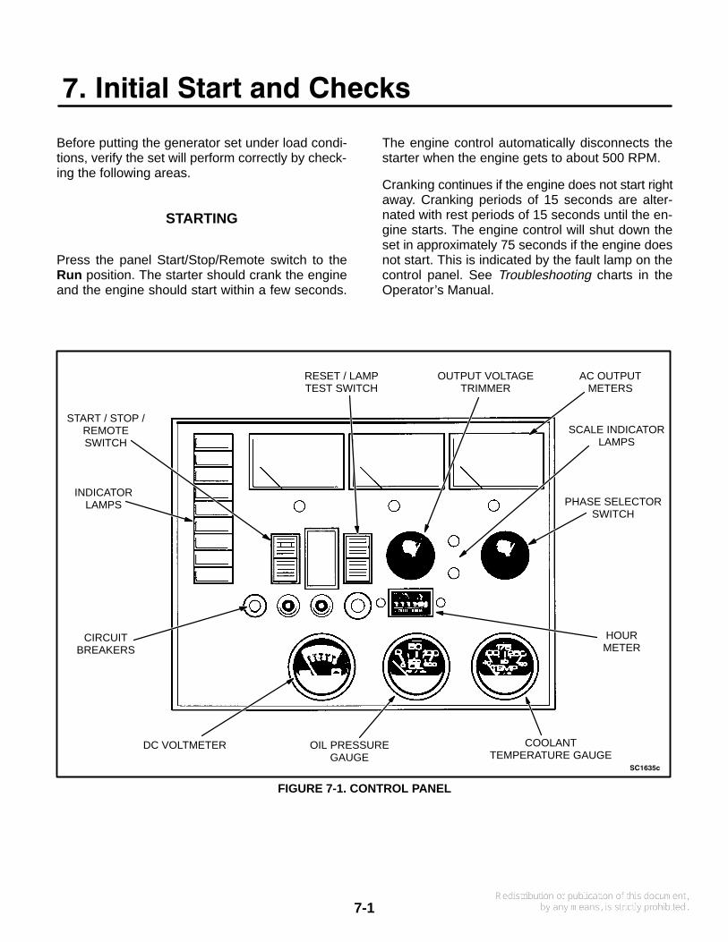
Before putting the generator set under load condi-tions, verify the set will perform correctly by check-ing the following areas.
STARTING
Press the panel Start/Stop/Remote switch to theRun position. The starter should crank the engineand the engine should start within a few seconds.
The engine control automatically disconnects thestarter when the engine gets to about 500 RPM.
Cranking continues if the engine does not start rightaway. Cranking periods of 15 seconds are alter-nated with rest periods of 15 seconds until the en-gine starts. The engine control will shut down theset in approximately 75 seconds if the engine doesnot start. This is indicated by the fault lamp on thecontrol panel. See Troubleshooting charts in theOperator’s Manual.
SC1635c
START / STOP /REMOTESWITCH
INDICATORLAMPS
CIRCUITBREAKERS
DC VOLTMETER OIL PRESSUREGAUGE
COOLANTTEMPERATURE GAUGE
HOURMETER
PHASE SELECTORSWITCH
SCALE INDICATORLAMPS
AC OUTPUTMETERS
OUTPUT VOLTAGETRIMMER
RESET / LAMPTEST SWITCH
FIGURE 7-1. CONTROL PANEL
7-2
ENGINE GAUGES
Check the following while the genset is operating:
Oil Pressure Gauge
The oil pressure should be in the range of 40 to 65psi (275 to 448 kPa) when the engine is at operatingtemperature.
Water Temperature Gauge
The water temperature should be in the range of180° to 195°F (83° to 91°C) depending on the loadand ambient temperature.
DC Ammeter/DC Voltmeter
The maximum charge rate for the set mounted bat-tery charging alternator is 65 amperes. Charge rateshould taper to zero following start-up as battery be-comes charged. The DC voltmeter should read be-tween 12 and 14 volts.
AC METERS (IF EQUIPPED)
Note the AC instruments on the control panel. Thefrequency meter and voltmeter should indicaterated nameplate frequency and voltage at no load.Turn the control panel Output Voltage Trimmer (ifequipped) for nameplate voltage. Use the PhaseSelector Switch to read each of the line-to-line volt-ages.
Frequency Meter
The generator frequency should be stable and thereading should be the same as the nameplate rat-ing.
AC Voltmeter
Turn the phase selector switch to each line-to-linephase selection shown on the volts scale (L1-L2 on
single phase sets; L1-L2, L2-L3 and L3-L1 on threephase sets). Read the AC voltmeter using the upperor lower scale as indicated by the scale indicatorlight. At no load, the line-to-line voltage should bethe same as the set nameplate rating.
AC Ammeter
Turn the phase selector switch to each phase selec-tion shown on the amperes scale (L1and L2 onsingle phase sets; L1, L2 and L3 on three phasesets). Read the ammeter using the upper or lowerscale as indicated by the scale indicator light. At noload, the current readings should be zero. With aload applied, each line current should be approxi-mately the same and no line current should exceedthe set nameplate reading
EXHAUST SYSTEM
With the genset operating, inspect the entire ex-haust system including the exhaust manifold, muf-fler and exhaust pipe. Visually and audibly check forleaks at all connections, welds, gaskets and joints.Make sure exhaust pipes are not heating surround-ing areas excessively. If any leaks are detected,have them corrected immediately.
WARNING Inhalation of exhaust gases can re-sult in severe injury or death. Inspect exhaustsystem visually and audibly for leaks daily. Shutdown generator set and repair any leaks imme-diately.
ENGINE MONITOR INDICATOR LAMPS
Move the Run/Stop/Remote switch on the enginepanel to the Stop position. Hold the Reset/LampTest switch in the Test position. All indicator lampsshould light. Verify all the lamps are on and then re-lease the switch. Contact your authorized servicecenter if any lamps require replacement.

7-3
FUEL SYSTEM
With the genset operating, inspect the fuel supplylines, filters and fittings for leaks. Check any flexiblesections for cuts, cracks and abrasions and makesure they are not rubbing against any sharp, abra-sive or hot surface.
WARNING Leaking fuel creates a fire hazardthat can result in severe personal injury ordeath. Shut off set and repair any leaks immedi-ately.
DC ELECTRICAL SYSTEM
With the generator set off, check the terminals onthe battery for clean and tight connections. Loose orcorroded connections create resistance that canhinder starting. Turn off the battery charger beforeremoving battery cables. Clean and reconnect thebattery cables if loose. Always connect the negativebattery cable last.
WARNING Ignition of explosive gases cancause severe personal injury. Do not smokewhile servicing the batteries.
COOLING SYSTEM
With the generator stopped, check for loose beltsand fittings, leaking gaskets and hoses, or anysigns of mechanical damage. Before removing anyfan guards or safety guards, turn off the batterycharger (if equipped) and remove battery cables toprevent accidental startup. If any problems or cool-ant leaks are found, have them corrected immedi-ately.
With the set running, listen for any unusual noisesthat can indicate mechanical problems. Refer toOperator’s or Service Manual for required adjust-ments.
LUBRICATION SYSTEM
Open access doors and inspect entire engine for oilleaks. When engine has been stopped for at least10 minutes, check the oil level.

7-4

8-1
8. Installation Checklist
GENERALGenSet wattage capacity is sufficient to handle maximum anticipated load.
At least 3 feet of clearance is provided around entire genset for servicing and ventilation.
GenSet is located in an area not subject to flooding.
All operating personnel have read and are familiar with Operator’s Manual.
All operators have been thoroughly briefed on correct operation and exercise procedures.
All operators have been thoroughly briefed on preventive maintenance procedures.
GENSET SUPPORTFloor, roof or earth on which the genset rests is strong enough and will not allow shiftingor movement. Observe local codes on soil bearing capacity due to freezing and thawing.
GenSet is properly supported and retained to approved base which is separate and independentof the surface on which it sits. Vibration isolators are installed between base and set.
Supporting base is large enough - extends 12-inches all around set.
All operators have read and understand all Safety Precautions in Operator’s Manual.
COOLING AIR FLOW
GenSet air inlet is faced into direction of strongest, prevailing winds.
Air inlet openings are unrestricted and at least 1-1/2 times larger than air outlet area.
Cooling air outlet is on downwind side of building (if not, wind barrier is constructed).
Proper ducting material (sheet metal, canvas) is used between radiator and air outlet.
FUEL SYSTEM
Fuel tanks meet or exceed all Local, State or National codes.
Fuel lines are properly installed, supported and protected against damage.
Flexible fuel line is installed between main fuel supply line and genset to protect againstvibration, expansion and contraction.
Fuel line shutoff valves are installed to prevent fuel flow in case of leaks.
External fuel pumps are connected and operated to be turned On when genset is startedand turned Off when genset is shut down.
No fuel leaks are found in supply line or engine fuel system.

8-2
EXHAUST SYSTEM
Operators are thoroughly briefed on the dangers of carbon monoxide gas, preventingthe buildup of this gas in inhabited areas.
Areas around set are well ventilated. No possibility of exhaust fumes entering buildingdoors, windows, or intake fans.
Exhaust gases are piped safely outside and away from building.
The correct length of approved rigid pipe is connected to the genset flexible pipe usingapproved securing methods with no weight resting on engine exhaust components.There are no bends in flex section.
Condensation drain is provided in lowest section of exhaust piping.
Exhaust piping is insulated to guard against burns to personnel.
Exhaust piping passing through walls or ceilings have approved fire-proof materials andare in compliance with all codes.
Exhaust piping is large enough in diameter to prevent back pressure on engine.
AC AND DC WIRING
Wire sizes, insulation, conduits and connection methods all meet applicable codes.
AC and DC wires are separated in their own conduit to prevent electrical induction.
All load, line and generator connections are proper and correct.
GENSET PRESTART
GenSet engine is properly serviced with oil and coolant.
Batteries are properly installed, serviced and charged.
Battery charger and engine coolant heater are connected and operational.
All genset covers and safety shields are installed properly.
All fuel and coolant shutoff valves are operational.
Fuel system is primed.

Cummins Power Generation1400 73rd Avenue N.E.Minneapolis, MN 554321-800-888-6626763-574-5000 International UseFax: 763-528-7229
Cummins is a registered trademark of Cummins Inc.