20’ predator operator’s...
TRANSCRIPT

120’ Predator
Operator’s Manual
YOU'RE ALWAYS AHEAD...WITH A MODERN BEHIND.
20' PREDATORRR CUTTER
P.O. BOX 790 • BEAUMONT, TX 77704409.833.2665 • 1.800.231.8198 FAX: 409.726.8333www.modernusa.com
Go Galvanized!
Operator’s Manual20’ PREDATOR

2 20’ Predator
INTRODUCTION
Your heavy-duty cutter is designed primarily for weed, grass and brush to 2” diameter. With proper maintenance as described in the manual, your cutter will provide you with years of dependable service with a minimum of repairs.
It is recommended that all operators of this implement read this manual or be instructed of its contents as to safety, proper operation, and maintenance before beginning operation.
Your cutter has been assembled for operation with a tractor PTO input speed of either 540 or 1000 RPM. Should you desire to change PTO input speed, contact you local dealer. This machine is recommended for use with tractors rated at 50 HP (37 KW) to 120 HP (75 KW) for 540 RPM drive and 50 HP (37KW) to 140 HP (104KW) for 1000 RPM drive.
When ordering parts for the gear boxes and the drivelines, be sure to specify the serial number. The serial number is located outside the right tongue attaching plate on the center mainframe section.
all times.
information, and mail promptly. Be sure to give the serial number of this cutter.

320’ Predator
assembly, maintenance, and operating practices, as described in this manual, will help the owner/operator get years of satisfactory service from the machine.
The purpose of this manual is to familiarize, instruct, and train. The Assembly Section instructs the
The Parts Listing section is designed to familiarize the owner/operator with replaceable parts on the Mower. This section provides exploded assembly drawings of each mower component illustrating each piece and the corresponding part number.
Careful use and timely service save extensive repairs and costly downtime losses. The Operation
correctly and attend to appropriate maintenance. The Trouble Shooting Guide helps diagnose
of this manual includes a list of Safety Messages, that, if followed, will help protect the operator and bystanders from injury or death. Many of the Safety Messages will be repeated throughout
and be aware of the hazards of operating this blade during assembly, use, and maintenance. The Safety Alert Symbol combined with a Signal Word, as seen below, is intended to warn the owner/operator of impending hazards and the degree of possible injury faced when operating this machine.
Indicates an imminently hazardous situation that, if not avoided, WILL result in DEATH ORVERY SERIOUS INJURY.
Indicates an imminently hazardous situation that, if not avoided, COULD result in DEATHOR SERIOUS INJURY.
Indicates an imminently hazardous situation that, if not avoided, MAY result in MINORINJURY.
damage to, or destruction of the machine, attachments or the environment.
CAUTION
WARNING
DANGER
INTRODUCTION

4 20’ Predator
SAFETY SECTION

520’ Predator
A safe and careful operator is the best operator. Safety is of primary importance to the manufacturer and should be to the owner/operator. Most accidents can be avoided by being
section of this manual includes a list of guidelines that, if followed, will help protect the operator and bystanders from injury or death. READ, UNDERSTAND, and FOLLOW the following safety guidelines before assembling, operating or servicing this implement. Serious injury or death may
to YOU. Only YOU can prevent serious injury or death from unsafe practices.
General Safety Guidelines
• Never operate the tractor or implement until you have read and completely understand this manual and the tractor operator’s manual. Learn how to stop the tractor engine suddenly in an emergency. Never allow inexperienced or untrained personnel to operate the tractor and
manuals prior to operation.
• The operator and all support personnel should wear hard hats, safety shoes, safety glasses, and proper hearing protection at all times for protection from injury including injury from items that
• Never allow children to operate, ride on, play on or around, or come close to the tractor or
year-old children who are mature and responsible can operate the implement with adult supervision, if they have read and understand the operator’s manuals, been trained in proper operation of the tractor and implement, and are physically large enough to reach and operate the controls easily.
• NEVER use drugs or alcohol immediately before or while operating the tractor and implement. Drugs and alcohol will affect an operator’s alertness and coordination and therefore affect the
an operator on prescription or over-the-counter medication must consult a medical professional regarding any side effects of the medication that would hinder their ability to operate the
alertness or coordination is impaired. Serious injury or death to the operator or others could
SAFETY SECTION

6 20’ Predator
• Prolonged tractor operation may cause operator boredom and fatigue affecting safe operation.
Never operate the implement and tractor in a fatigued or bored mental state which impairs proper and safe operation.
• Tractors with or without an implement attached can often be noisy enough to cause permanent hearing loss. We recommend that you always wear hearing protection if the noise in the operator’s position exceeds 80db. Noise over 85db over an extended period of time will cause severe hearing loss. Noise over 90db adjacent to the Operator over an extended period of time will cause permanent or total hearing loss.
Note: Hearing loss from loud noise [from tractors, chain saws, radios, and other such sources close to the ear] is cumulative over a lifetime without hope of natural recovery.
General Safety – Rotating Equipment
• The rotating parts of this machine continue to rotate even after the PTO has been turned off.
disengaged, the tractor turned off, and all evidence of rotation has ceased.
clothing with the rotating elements can result in serious injury or even death. KEEP AWAY FROM ROTATING ELEMENTS to prevent entanglement and possible serious injury or death.
General Safety – Hot Surfaces & Fire Safety
servicing, and repairing the tractor and/or implement:
· Do Not operate the implement on a tractor with an underframe exhaust.
· Do Not drive into burning debris or freshly burnt areas.· Ensure slip clutches are properly adjusted to prevent excessive slippage and plate heating.· Never allow clippings or debris to collect near drivelines, slip clutches, and gearboxes.
repairs. Use gloves and eye protection when servicing hot components. Contact with a hot
SAFETY SECTION

720’ Predator
Equipment Operation Safety
Guards, Steel Guards, Gearbox Shields, PTO integral shields, and Retractable Door Shields should
replaced with NEW blades to reduce the possibility of injury or death from thrown objects, entanglement, or blade contact. NEVER ATTEMPT TO STRAIGHTEN, WELD, OR WELD HARDFACING ON BLADES SINCE THIS WILL LIKELY CRACK OR OTHERWISE DAMAGE THE BLADE WITH SUBSEQUENT FAILURE AND POSSIBLE SERIOUS INJURY FROM THROWN BLADES.
• Operate the tractor and/or implement controls only while seated in the tractor seat with the seat belt securely fastened around you. Inadvertent movement of the tractor or implement may cause serious injury or death. Do not mount/dismount the tractor while the tractor or implement parts are moving. Mount the tractor only when the tractor and all moving parts are completely stopped.
rolling. Never dismount a tractor that is moving or while the engine is running.
• Never leave the tractor and implement unattended while the implement is in the lifted position. Accidental operation of lifting lever or a hydraulic failure may cause sudden drop of unit possibly resulting in injury or death by crushing. Lower the implement carefully to the ground. Do not put hands or feet under lifted components.
• Do not exceed the rated PTO speed for the implement. Excessive PTO speeds can cause implement driveline or blade failures resulting in serious injury or death.
• DO NOT operate this implement on a tractor that is not properly maintained. In case of
until all rotating motion has stop before dismounting and perform repairs before resuming operation. Serious injury and possible death could occur from not maintaining this implement and tractor in good operating condition.
• Do not operate implement if excessive vibration exists. Shut down PTO and the tractor engine. Inspect the implement to determine the source of the vibration. If implement blades are missing
SAFETY SECTION

8 20’ Predator
or damaged replace them immediately. Do not operate the implement until the blades have been replaced and the implement operates smoothly. Operating the implement with excessive
velocities. To reduce the possibility of property damage, serious injury, or even death, never allow the implement to be operated with blades missing.
procedure. Always read carefully and comply fully with the manufacturer’s instructions when handling oil, solvents, cleansers, and any other chemical agent.
• Mow at the speed that you can safely operate and control the tractor and implement. Safe mowing speed depends on terrain condition and grass type, density, and height of cut. Normal ground speed range is from 2 to 5 mph. Use slow mowing speeds when operating on or near steep slopes, ditches, drop-offs, overhead obstructions, power lines, or when debris and foreign objects are to be avoided.
behind the implement and use extreme care when mowing in reverse. Mow only at a slow ground speed where you can safely operate and control the tractor and implement. Never mow an area that you have not inspected and removed debris or foreign material.
implement to cut vegetation above the implement’s rated capacity or to cut any type of non-
Operating this implement in an application for which it is not designed and/or operating the
failure resulting in possible serious injury or death.
• Do not operate or pull the implement into standing water. When uplift or fan type implement
resulting in serious boldly injury to the operator or bystanders.
• Do not mow with two machines in the same area except with cab tractors with the windows closed.
SAFETY SECTION

920’ Predator
• Do Not attempt to raise or lower the implement wing unless the implement tongue is securely
and possible serious injury or death. Raise or lower the implement wing only while seated in the tractor operator’s seat with the seat belt securely fastened.
possible injury from the separated Driveline sections.
• Periodically shut down the tractor and implement and clean clippings and collected debris from
motion has ceased.
• Never crawl under a raised implement supported solely by the tractor 3-Point hitch. Release of the control lever or mechanical failure will result in the implement falling and possible injury or
supported.
Equipment Operation Safety – Clearances and Obstructions
• Rotary implements are capable under adverse conditions of throwing objects for great distances (300 feet or more) and causing serious injury or death. Follow safety guidelines carefully.
• STOP MOWING IF PASSERSBY ARE WITHIN 100 YARDS
obstructions and consult local utility providers for a safe code of operation.
and identify passersby, steep slopes, ditches, drop-offs, overhead obstructions, power lines, debris and foreign objects. If you are unable to clearly see these types of items discontinue mowing.
• This implement is wider than the tractor. Be careful when operating or transporting this
concrete abutments or other solid objects. Such an impact could cause the implement and tractor to pivot violently resulting in loss of steering control, serious injury, or even death. Never allow the implement to contact obstacles.
SAFETY SECTION

10 20’ Predator
are close by or underneath the wings. Allow ample clearance around the implement when folding or unfolding the wings.
• The rotating parts of this machine have been designed and tested for rugged use. However, the blades could fail upon impact with heavy, solid objects such as metal guard rails and concrete
velocities. To reduce the possibility of property damage, serious injury, or even death, never allow the cutting blades to contact such obstacles.
and other debris. Inspect the area before mowing. Foreign objects should be removed from the site to prevent machine damage and/or bodily injury or even death. Any objects that cannot
carrier is balanced before resuming mowing.
• This machine is often operated in heavy brush and in heavy weeds. The blades of this implement can throw objects if shields are not properly installed and maintained. Serious injury or even
passersby in the area. Do not operate this machine with anyone in the immediate area. Stop mowing if anyone is within 100 yards of implement.
Note: Where there are grass and weeds high enough to hide debris that could be struck by the blades, the area should be: inspected and large debris removed, mowed at an intermediate height, inspected, closely with
required to mow, reduce wear and tear on the implement drivetrain, spread cut material better, eliminate
• Many varied objects, such as wire, cable, rope, or chains, can become entangled in the operating parts of the implement head. These items could then swing outside the housing at greater velocities than the blades. Such a situation is extremely hazardous and could result in serious
object from the site. Never allow the cutting blades to contact such items.
serious hazard and could cause serious injury or even death from objects thrown from the blades.
SAFETY SECTION

1120’ Predator
an enclosed cab and close the windows to prevent insects from entering. If a tractor cab is not available, wear suitable clothing including head, face, and hand protection to shield you from the
injury or death to you or bystanders. Never dismount a moving tractor.
Connecting or Disconnecting implement Safety
hitches.
• DO NOT use a PTO adapter to attach a non-matching implement driveline to a tractor PTO. Use of an adapter can double the operating speed of the implement resulting in excessive vibration, thrown objects, and blade and implement failure. Adapter use will also change the
assistance if the implement driveline does not match the tractor PTO.
• When attaching the implement input driveline to the tractor PTO, it is important that the
securely in the groove on the tractor PTO shaft. A driveline not attached correctly to the tractor PTO shaft could come loose and result in personal injury and damage to the implement.
bottom out or become disengaged. Bottoming out occurs when the inner shaft penetrates the outer housing until the assembly becomes solid-it can shorten no more. Bottoming out can cause serious damage to the tractor PTO by pushing the PTO into the tractor and through the
personal injury.
• On a fully-assembled unit, do not remove the Wing Retaining Strap until hoses are attached to
bystanders away during operations.
injury or even death.
SAFETY SECTION

12 20’ Predator
• To prevent tipping of implement when stored in folded position, use carrying wheels or
Transporting Safety
vehicle. Never tow the implement and another implement connected in tandem. Never tow the implement at speeds over 20 MPH.
• Secure the implement for transport before traveling on public roads. For pull-type implements, secure the center axle using cylinder stops or transport pin and properly attach a safety chain between the implement and tractor. Secure wings in upright position on folding implements
a way as to be clearly visible and legible. When transporting the implement use the tractor
• Your driving vision may be reduced or impaired by the tractor, cab, or implement. Before driving
position, mirrors, and the implement transport position so that you can clearly see the area
• Understand the tractor and implement and how it handles before transporting on streets and
sure you abide by the following rules:
determine the stopping characteristics of the tractor and implement. As you increase the speed of the tractor the stopping distance increases. Determine the maximum transport speed not to
you determine that it is safe to operate at a higher speed. Use extreme care and reduce your speed when turning sharply to prevent the tractor and implement from turning over. Determine
ground.
SAFETY SECTION

1320’ Predator
out for the other guy.
• Turn curves or go up hills only at a low speed and using a gradual steering angle. Rear mounted implements move the center of gravity to the rear and remove weight from the front wheels.
wheels to prevent rearing up, loss of steering control or tractor tip-over.
• When the wings are folded for transport, the center of gravity is raised and the possibility of overturn is increased. Drive slowly and use extreme caution when turning on hillsides. Overturning the implement could cause the implement to overturn the tractor and vice versa resulting in serious injury or even death. Never fold wings on a hillside...the implement may overturn.
• Slow down on rough or uneven surfaces to prevent loss of steering control which could result in property damage or possible injury. Do not transport unless 3-Point lift lever is fully raised and in the latched transport position. Dropping implement in transport can cause serious damage to
certain that excess material is removed before traveling on public roadways.
obstructions and electrical power lines. The implement wing can be over 10 feet high. Never allow the implement wing to come within 10 feet of any power line.
Maintenance and Service Safety
• Periodically inspect all moving parts for wear and replace when necessary with authorized
sure all pins have cotter pins and washers. Serious injury may occur from not maintaining this
SAFETY SECTION
14 20’ Predator
• Perform service, repairs and lubrication according to the maintenance section. Ensure the
condition could cause component failure and possible serious injury or even death. • Use extreme caution when getting onto the implement to perform repairs, maintenance and
Use a ladder or raised stand to access high spots which cannot be reached from ground level. Slipping and falling can cause serious injury or death.
serious injury or even death.
• Never attempt to lubricate, adjust, or remove material from the implement while it is in motion
tractor engine. Push and pull the Remote Cylinder lever in and out several times prior to starting
• Never interfere with factory-set hydraulic calibrations. Any change in calibration could cause a
• Always disconnect the main PTO Driveline from the tractor before performing service on
running. Rotating Parts, blades or drivelines could turn without warning and cause immediate entanglement, injury or death.
• DO NOT weld or repair rotating implement components. Welds and other repairs may cause severe vibration and/or component failure resulting in part being thrown from the implement causing serious bodily injury. See your Authorized Dealer for proper repairs.
material may release fumes which can be harmful to your health.
• Do not modify or alter this implement. Do not permit anyone to modify or alter this implement, any of its components or any implement function.
SAFETY SECTION

1520’ Predator
Parts Information
• Modern Ag implements use balanced and matched system components for blade carriers,
warranties, and present a safety hazard. Use genuine Modern Ag implement parts for economy and safety.
Safety Signs/Decals
• Modern Ag supplies safety decals on this product to promote safe operation. Damage to the decals may occur while in shipping, use, or reconditioning. Always maintain the safety signs in good readable condition. If the safety signs are missing, damaged, or unreadable, obtain and install replacement safety signs immediately.
Concluding Safety Instructions and Practices
prudence, and proper training of personnel involved in the operation, transport, maintenance, and storage of the machine. Refer also to safety guidelines and operation instruction in each of
SAFETY SECTION

16 20’ Predator
ITEM PART NO. DESCRIPTION QTY.. . . . . . . 490-9000 . . . . . . . . . . COMPLETE DECAL SHEET . . . . . . . . . .11 . . . . . . . . . . . . . . . . . . . . . . . . DO NOT ATTACH . . . . . . . . . . . . . . . . .12 . . . . . . . . . . . . . . . . . . . . . . . . LUBRICATE GEARBOX . . . . . . . . . . . . .13 . . . . . . . . . . . . . . . . . . . . . . . . THROWN OBJECTS . . . . . . . . . . . . . . .14 . . . . . . . . . . . . . . . . . . . . . . . . ROTATING BLADES . . . . . . . . . . . . . . . .15 . . . . . . . . . . . . . . . . . . . . . . . . ROTATING DRIVELINE . . . . . . . . . . . . .26 . . . . . . . . . . . . . . . . . . . . . . . . WARNING TO PREVENT INJURY . . . .1ADDITIONAL SAFETY DECALS BELOW7 . . . . . 490-1024 . . . . . . . . . . KEEP HANDS CLEAR . . . . . . . . . . . . . .18 . . . . . 490-GALVCOAT . . . . CAUTION: GALV COATING . . . . . . . . .19 . . . . . 490-5009 . . . . . . . . . . REPLACE SHIELDS . . . . . . . . . . . . . . . .110 . . . . 490-2010 . . . . . . . . . . RETORQUE GEARBOX . . . . . . . . . . . . .111 . . . . 490-1022 . . . . . . . . . . CAUTION REPLACE SHIELDS . . . . . . .1MORE DECALS ON NEXT PAGE
12
7
77
13
10
15
12
12
13
1
1
1
9
6
7
7
9
10
5
4
3
2
1
RE-TORQUEGEARBOX NUTS
EVERY 40 HOURS
8
8 8
Galvanized Units Only
11
* Safety decals item #1 - 6 are sold in complete sets only. Additional safety decals item #7-10 can be purchased separately. See next page for additional cutter decals.
13
10
13
14
10
14
SAFETY DECAL PLACEMENT

1720’ Predator
20490-1120
490-9000 Decal Sheet contains:(1) Warning: To Prevent Injury(2) Rotating Blades Keep Away(1) Rotating Driveline Hazard(1) Danger: Read Operator Manual(1) Thrown Object Hazard(1) Lubricate Gearbox
Cutter Size Decals
Modern Attachments800-231-8198
490-2003
490-FEMA
490-1031
490-1023
490-EAGLE490 EAGLE
BLUE
ITEM PART NO. DESCRIPTION QTY.12 . . . . 490-1501 . . . . . . . . . . . .DANGER: LOWERING WING . . . . . .213 . . . . 490-1018 . . . . . . . . . . . .WARNING: NO LUBE. . . . . . . . . . . . .314 . . . . 490-4100 . . . . . . . . . . . .1000 RPM . . . . . . . . . . . . . . . . . . . . . .115 . . . . 490-9020 . . . . . . . . . . . .TYPICAL SET-UP . . . . . . . . . . . . . . . .1
490-1000
ADDITIONAL CUTTER DECALS

18 20’ Predator
OPERATION SECTION

1920’ Predator
OPERATION
OPERATION INSTRUCTIONSOur rotary cutters are manufactered with quality material by skilled workers. These cutters are designed to cut grass, weeds, coop stalks, brush and other vegetation up to 4” diameter. The cutter is equipped with protective defectors and/or chain guards to prevent objects being thrown from the cutter by the blades, however, no shielding is 100% effective. All shields, guards, defl ectors and chains equipped on the unit must be maintained on the cutter in good operational condition.
It is the operator’s responsibility to be knowlegable of all potential operating hazards and to take every reasonable precaution to ensure oneself, others, animals and property are not injured or damaged by the cutter, tractor or a thrown object. Do not operate the cutter if passersby, pets, livestock, or property are within 300 feet of the unit.
This section of the Operator’s Manual is designed to familiarize, instruct, and educate safe and proper cutter use to the operator. Pictures contained in this section are intended to be used as a visual aid to assist in explaining the operation of a fl ex-wing rotary cutter and are not necessarily of all cutters. Some pictures may show shields removed for picture clarity. NEVER OPERATE this implement without all shields in place and in good operational condition. The operator must be familiar with the cutter and tractor operation and all associated safety practices before operating the cutter and tractor. Proper operation of the cutter, as detailed in this manual, will help ensure years of safe and satisfactory use of the cutter.
IMPORTANT: To avoid cutter damage, retorque all bolts after the fi rst 10 hours of operation. Retighten blade carrier retaining nut on lower shafts to 450 ft. lbs.
READ AND UNDERSTAND THE ENTIRE OPERATING INSTRUCTIONS AND SAFETY SECTION OF THIS MANUAL AND THE TRACTOR MANUAL BEFORE ATTEMPTING TO USE THE TRACTOR AND CUTTER. If you do not understand any of the instructions, contact your nearest authorized dealer for a full explanation. Pay close attention to all safety signs and safetymessages contained in this manual and those affi xed to the cutter and tractor.
READ, UNDERSTAND, and FOLLOW the following Safety Messages, Serious injury or death may occur unless care is taken to follow the warnings and instructions stated in the Safety Messages. Always use good common sense to avoid hazards.
PELIGRO
Si no lee ingles, pida ayuda a alguien que si lo lea para que le traduzca las medidas de seguridad.
PELIGRO

20 20’ Predator
20 FT DRAGON PREDATORRR & SUPER PREDATORRR STANDARD EQUIPMENT AND SPECIFICATIONS
Front chains and rear rubber guards are standard equipment. Single and rear chain guards are available as extra
purposes.
Cutting Width . . . . . . . . . . . . . . . . . . . . . . . .238”Transport Width . . . . . . . . . . . . . . . . . . . . . .105” Overall Width . . . . . . . . . . . . . . . . . . . . . . . .246”Overall Length . . . . . . . . . . . . . . . . . . . . . . .204”Cutting Height . . . . . . . . . . . . . . . . . . . . . . .2”-15”Blade Overlap . . . . . . . . . . . . . . . . . . . . . . . .5”Wing Lift Hydraulics . . . . . . . . . . . . . . . . . . .StandardWing Flex . . . . . . . . . . . . . . . . . . . . . . . . . . . .90° Up/22° Down
. . . . . . . . . . . . . . . . . . . . . . . . . . . .StandardHitch . . . . . . . . . . . . . . . . . . . . . . . . . . . . . . . .Swivel ClevisBlade Carrier . . . . . . . . . . . . . . . . . . . . . . . . .Pan Stump Jumpers
. . . . . . . . . . . .100 hpGearbox Rating:Main Gearbox or Divider Box . . . . . . . . . . .255 hpOutboard Gearbox or Center & Wings . . . . . . . . . . . . . . . . . . . .210 hpOutput Shaft Diameter . . . . . . . . . . . . . . . .2”Cut Capacity . . . . . . . . . . . . . . . . . . . . . . . . .3”Blade Tip Speed:Main or Center . . . . . . . . . . . . . . . . . . . . . .540 . . . . . . . . . 15,992 FPM. . . . . . . . . . . . . . . . . . . . . . . . . . . . . . . . . . . . .1000 . . . . . . . 16,052 FPMWings . . . . . . . . . . . . . . . . . . . . . . . . . . . . . . .540 . . . . . . . . . 15,384 FPM. . . . . . . . . . . . . . . . . . . . . . . . . . . . . . . . . . . . .1000 . . . . . . . 15,484 FPMDriveline Size:Main . . . . . . . . . . . . . . . . . . . . . . . . . . . . . . . .Cat. 5 Constant Veloc.Outboard Center or Wings . . . . . . . . . . . . .Cat. 4 w/Slip Clutch
. . . . . . . . . . . . . . . . . . . . . . .3/16” . . . . . . . . . . . . . . . . . . . . . . . . . . . .1/4” x 10 1/4”
. . . . . . . . . . . . . . . StandardSafety Chains . . . . . . . . . . . . . . . . . . . . . . . .Standard (Front & Rear)Weight (Approx) . . . . . . . . . . . . . . . . . . . . . .6700 lbs. • 5500 lbs. (Dragon)
. . . . . . . . . . . . . StandardStandard Tires . . . . . . . . . . . . . . . . . . . . . . . .Used Aircraft Tires (Super) • Laminate (Dragon)Dual Tailwheels . . . . . . . . . . . . . . . . . . . . . . .StandardHydraulic Level Lift . . . . . . . . . . . . . . . . . . . .Standard (Super) • Option (Dragon)
. . . . . . . . . . . . Standard
OPERATION

2120’ Predator
OPERATOR REQUIREMENTS
read and understands the implement and tractor Operator’s Manuals and is experienced in implement and tractor operation and all associated safety practices. In addition to the safety
authorized dealer for a complete explanation.
If the operator cannot read the manuals for themselves or does not completely understand the
manuals, safety practices, and operating instructions to the operator.
designed toprovide operator protection and includes the following safety wear:
PERSONAL PROTECTIVE EQUIPMENT (PPE)• Protective Eye Glasses, Goggles,
or Face Shield• Hard Hat• Steel Toe Safety Footwear• Gloves• Hearing Protections• Close Fitting Clothing
conditions)
NEVER use drugs or alcohol immediately before or while operating the Tractor and Implement. Drugs and alcohol will affect an operator’s alertness and coordination and
the Tractor or Implement, an operator on prescription or over-the-counter medication must consult a medical professional regarding any side effects of the medication that
Serious injury or death to the operator or others could result if the operator is under
DANGER
OPERATION

22 20’ Predator
TRACTOR REQUIREMENTSThe tractor used to operate the cutter must have the power capacity to lift, pull, and operate the Power
cutter damage and be a potential danger to the operator and passersby.
Tractor Requirements and Capabilities
• ASAE approved Roll-Over Protective Structure (ROPS) or ROPS cab and seat belt.• Tractor Safety Devices .................... Slow Moving Vehicle (SMV) emblem, lighting, PTO master shield• Tractor Horsepower -Minimum ........ FL10M 40HP; FL15M 50HP• Maximum ........................................ 540 RPM Unit-120 HP; 1000 RPM Unit 140 HP• Drawbar............................................ Set length according to operating speed of the cutter and driveline
type, rated to carry weight of the cutter, safety chain attachment point
2 ports, 3 ports recommended if additional,3-spool control valve is not used.• Front End Weights............................ As needed to maintain 20% weight on front axle
driveline type of the cutter.
• Tire Wheel Spacing .......................... Set tires minimum width of 60” from inside to inside of tires.
ROPS and Seat Belt
seat belt to protect the operator from falling off the tractor, especially during a roll over where the driver
installed by an authorized dealer.
system (ROPS). Always wear seat belts. Serious injury or even death could result from falling off the tractor--particularly during a turnover when the operator could be pinned under the ROPS.
3.2 Tractor Safety Deviceswith proper warning lighting and a Slow Moving Vehicle (SMV) emblem which are clearly visible from the
Always replace shields and guards that were removed for access to connect, service, or repair the tractor or cutter. Never operate the tractor PTO with the PTO master shield missing or in the raised position.
WARNING
OPERATION

2320’ Predator
Tractor Horsepowervegetation to be cut, terrain condition, operator experience, condition of the cutter and tractor, and
drive and 140 HP for a 1000 RPM drive may cause cutter damage by overpowering the unit in heavy cutting conditions.
DrawbarConstant Velocity and Standard Driveline.
Position the length of the drawbar from the end of thetractor PTO shaft to the drawbar hitch hole accordingto the operating speed of the cutter. If the cutter isa 540 RPM unit, position the drawbar length fromshaft end to hitch hole at 14”. For 1000 RPMcutters, set the drawbar length at 16” for 21 spline1-3/8” cutters and at 20” for 1-3/4” 20 splinecutters.
Equal Angle Driveline Adjustment Procedure
(Not available on 1000 RPM 1-3/4”-20 cutters)
Set drawbar length measured from PTO shaft end to hitch hole at 14” for 540 and 16” for 1000 RPM
otherwise the drivelines will not phase properly, possibly causing damage to your machine.
OPERATION

24 20’ Predator
Tractor HydraulicsThe cutter center section and each wing are positioned with hydraulic cylinders that are operated by the tractor hydraulic pump. The tractor must have a minimum of 2 hydraulic control valves devoted
for those with two valves so that the center section and each wing can be controlled independent of
hydraulic ports and a 3-spool control valve is not used, the wings cannot be operated independently and will raise and lower at different speeds.
Front End WeightA minimum of 20% total tractor weight must be maintained on the tractor front end at all times. Front end weight is critical to maintain steering control and to prevent the tractor from rearing up while driving. If the front end is too light, add weight until a minimum of 20% total weight is reached on the front tires. Front weights and weight carriers can be purchased through an authorized tractor dealership.
Power Take Off (PTO)Depending on the unit, the cutter is designed to operate at a PTO speed of 540 or 1000 RPM. Most tractors operate at either 540, or a combination of 540 and 1000 RPM PTO speeds. The operating
and PTO output shaft. Those operating at 540 RPM will have a 6-spline shaft and those operating at 1000 RPM will have a 21-spline shaft.
If operating an older model tractor where the tractor’s transmission and PTO utilize one master clutch, an over-running clutch must be used between the PTO output shaft and the driveline of the cutter. An authorized tractor dealer can provide the over-running clutch and its installation if needed.
OPERATION

2520’ Predator
DO NOT use a PTO adapter to attach a non-matching Implement driveline to a Tractor PTO. Use of an adapter can double the operating speed of the Cutter resulting in excessive vibration, thrown
using a PTO adapter. Consult an authorized dealer for assistance if the Implement driveline does not match the Tractor PTO.
Never operate the Tractor and Cutter if the Implement input driveline is directly connected to the
of the rotating Cutter blades driving the Tractor transmission even though the Tractor clutch has been disengaged. Install an over running clutch between the Tractor PTO and the Cutter driveline to prevent this potentially dangerous situation.
Tire SpacingTractor tires should be set a minimum of 60” apart measured from inside of tire to inside of tire. Refer to the tractor Operator’s Manual or consult an authorized dealer for instructions to change tractor tire spacing.
GETTING ON AND OFF THE TRACTORBefore getting onto the tractor, the operator must read and completely understand the implement and tractor operator manuals. If any part of either manual is not completely understood, consult an authorized dealer for a complete explanation.
Do not mount the Tractor while the tractor is moving. Mount the Tractoronly when the Tractor and all moving parts are completely stopped. (SG-12)
WARNING
WARNING
DANGER
OPERATION

26 20’ Predator
Boarding the Tractor
control levers for support when mounting the tractor. Seat yourself in the operator’s seat and secure the seat belt around you.
is the operator’s responsibility to forbid all extra riders at all times.
Never allow children to operate, ride on, or come close to the Tractor or Implement. Usually, 16-17 year-old children who are mature and responsible can operate the implement with adult supervision, if they have read and understand the Operator’s Manuals, been trained in proper operation of the tractor and Implement, and are physically large enough to reach and operate the controls easily.
Never allow children or other persons to ride on the Tractor or Implement. Falling off can result in serious injury or death.
Dismounting the Tractor
completely stop. Never leave the seat until the tractor, its engine and all moving parts have come to a complete stop.
Use hand rails and steps when exiting the tractor. Be careful of your step and use extra caution when mud, ice, snow or other matter has accumulated on the steps or hand rails. Use all handrails and steps for support and never rush or jump off the tractor.
and wait for all moving parts to stop. Place the tractor shift lever into a low range
is moving or while the engine is running. Operate the Tractor controls from the tractor seat only.
N ll hild t
DANGER
DANGER
DANGER
OPERATION

2720’ Predator
STARTING THE TRACTORThe operator must have a complete understanding of the placement, function, and operational use of all tractor controls before starting the tractor. Review the tractor operator’s manual and consult an authorized dealer for tractor operation instructions if needed.
Essential Tractor Controls:• Locate the light control lever.• Locate the engine shut off control.
• Locate the PTO control.• Locate the 3-point hitch control lever.• Locate the hydraulic remote control levers.
Before starting the tractor ensure the following:• Conduct all pre-start operation inspection and service according to the tractor operator’s manual.
• The PTO control lever is disengaged.• The 3-point hitch control lever is in the lowered position.• The hydraulic remote control levers are in the neutral position.
Refer to the tractor owner’s manual for tractor starting procedures. Only start the tractor while seated and belted in the tractor operator’s seat. Never bypass the ignition switch by short circuiting the starter solenoid. After the tractor engine is running, avoid accidental contact with the tractor transmission to prevent sudden and unexpected tractor movement.
The exhaust fumes can be hazardous to your health.
Start tractor only when properly seated in the Tractor seat. Starting a tractor in gear can result in injury or death. Read the Tractor operators manual for proper starting instructions. (SG-13)
CONNECTING THE Cutter TO THE TRACTORUse extreme caution when connecting the cutter to the tractor. The cutter should be securely resting at
points between the tractor hitch arms and cutter pins.
you or anyone else attempts to connect or disconnect the Implement and Tractor hitches. (S3PT-15)
DANGER
DANGER
OPERATION

28 20’ Predator
Connecting the Cutter Tongue to the Tractor
PTO shaft and the drawbar is set at the correct length.
to the height of the tractor drawbar. Adjust the cutter tongue to be level and parallel with the tractor drawbar using the control rod connecting
tractor to the cutter aligning the drawbar hitch hole with the cutter tongue clevis. Turn off the
positioned under top lip of tongue clevis and to
between the bottom of drawbar and bottom lip
grade 5 or 8 bolt through clevis and drawbar
the cutter to the tractor with a pin not having a nut.
5. Securely attach the cutter safety chain to the tractor drawbar or drawbar support frame.
Safety Tow Chain
gross weight of the cutter must be connected between the tractor and cutter. This will help control the implement in the event the tongue becomes disconnected from the drawbar. After connecting both ends
Connecting Cutter Hydraulic Lines to the TractorWith the tractor shut down and secured in position, relieve hydraulic pressure from the tractor by moving the
Never leave a disconnected hose end open and cap the tractor hydraulic outlet ports when not in use. If the tractor ports or cutter hydraulic hose ends become contaminated, wipe clean with a rag before connecting.
kr
OPERATION

2920’ Predator
Operating Cutter Hydraulics with Three Tractor Hydraulic PortsConnect one hose into each hydraulic port. Connect lines to correspond with position of hydraulic control levers.
Operating Cutter Hydraulics with Two Tractor Hydraulic PortsThe lines that operate the wings must be plumbed together and will be controlled using one hydraulic control valve and the center section with the remaining control valve. Ensure that the operator is aware that each wing cannot be controlled independently nor will they raise and lower simultaneously.
Operating the Cutter Hydraulics with a 3-Spool Hydraulic Control Valve (Extra Equipment)Ensure the valve matches the hydraulic operating system of the tractor (open or closed center). Refer
valve.
and outlet lines to outlets of the same tractor hydraulic port. Connect the cutter hydraulics to the
the control valve positioned to correspond with the left and right wing.
OPERATION

30 20’ Predator
Hydraulic Line Support
Hydraulic Cylinder Priming
in the raised position until the cylinders fully retract (wing cylinders) and extend (center cylinder).
supported by the cylinders before removing the transport braces. NEVER drive out bar pins and NEVER remove braces that have tension on them.
SETTING THE Cutter
Always avoid operating the cutter at a height which causes the blades to contact the ground.
or inadvertent falling which could cause serious injury or even death. (SG- 14)
Setting Deck Height
LEVELING DECK CENTER SECTION1. Place the tractor and cutter on a level surface and lower both wings.2. Using the center section hydraulic cylinder, position
are approximately 2” off the ground.3. Shut down the tractor, place the transmission in
DANGER
OPERATION

3120’ Predator
tension. Improper adjustments may cause rods to snap or bend.6. Place split collar assemblies on the center axle hydraulic cylinder rod to maintain a set cutting height each time the cutter is raised and lowered.
7.2 Setting Deck Pitch
3/4” LOWER IN THE FRONT THAN THE REAR.
Operating the cutter at this pitch will allow the cutter
from the tractor. In addition, a more even distribution of the clippings from the rear of the cutter will be
rear axle until the front of the cutter is at least 3/4” lower in the front that than the rear. To lower the front, lengthen the leveling rods and to raise the front shorten the leveling rods. IMPORTANT: Adjust
OPERATION

32 20’ Predator
DRIVELINE ATTACHMENT
shaft must be dirt free and greased for attachment.
To connect the cutter driveline to the tractor PTO output shaft, pull the driveline
collar balls are seated onto the PTO shaft.
forth several times to ensure a secure attachment.
When attaching the Implement input driveline to the Tractor PTO, it is important that the connecting
groove on the Tractor PTO shaft. A driveline not attached correctly to the Tractor PTO shaft could come loose and result in personal injury and damage to the Implement. (S3PT-17)
WARNING
OPERATION

3320’ Predator
Driveline Length Check
out or become disengaged. Bottoming out occurs when the inner shaft penetrates the outer housing until the assembly becomes solid-it can shorten no more. Bottoming out can cause serious damage to the Tractor PTO by pushing the PTO into the Tractor and through the support bearings or downward
Constant Velocity (CV) tube type driveline and a minimum engagement of 6” for non-CV solid shaft drivelines.
“Bottoming Out” Check Procedure
• Disconnect driveline from the tractor and slide the
the end of the outer shield and reattach the driveline to the PTO shaft.
• With the PTO NOT TURNING, slowly drive the tractor with cutter attached through the sharpest turn possible and watch shaft movement. With the PTO NOT TURNING, slowly drive the tractor with the cutter attached through the most severe terrain conditions expected and watch shaft movement.
shield becomes less than 2” at any point thereis a potential problem bottoming out the driveline and the driveline should be shortened.
WARNING
OPERATION

34 20’ Predator
• Remove the driveline from the tractor.• Position the cutter to the point with the shortest distance between the tractor PTO shaft and cutter gearbox. Shut down
in this position.
PTO shaft.• Hold driveline sections parallel to one
site section. Cut this length off with a saw.• Round off all sharp edges and debur.• Thoroughly grease then reinstall the driveline.
Engagement Check Procedure• With the driveline attached, position the cutter to the point where the telescoping driveline is at its maximum extension. Completely shut down the tractor and secure in position.
• Disconnect the driveline from the tractor and separate the two driveline halves.
• If the engaged length is less than 12” for a CV driveline and less than 6” for a non-CV driv eline, the shaft is considered too short and should be replaced with a longer shaft. Consult an
be made aware of terrain conditions and avoid situations which pose a potential problem to avoid damaging the driveline.
t th i t h th t l i d i li i t it i
OPERATION

3520’ Predator
Constant Velocity (CV) Driveline
the tractor and cutter must be determined to ensure the joint angle does not over-extend which can cause CV joint damage. Constant Velocity joints enable the driveline to operate smoothly with no vibrations and clattering at angles up to 70°. Angles greater than 80° can result in mechanical damage to the CV joint and cutter driveline.
Maintenance Section. Failure to properly lubricate the joint will result in accelerated wear and joint component failure.
CV Driveline Maximum Angle Check Procedure• With the cutter attached to the tractor and the driveline disconnected from the tractor PTO
tractor tire and cutter frame or tongue.
PTO shaft andthen angle the CV joint to its maximum angle. A minimum difference of 10
sure the joint will not be over angled. If the joint cannot be angled at least 10°, there is a po
cutter.
Move the tractor rear tires wider apart to limit the tractor turning radius.Position the cutter at multiple angles and perform the above procedure. Determine the sharpest turning radius that maintains a safe operating angle and note this position to the operator.
OPERATION
36 20’ Predator
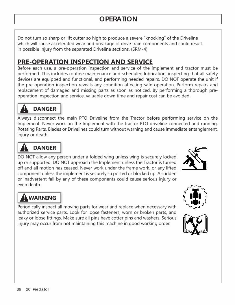
in possible injury from the separated Driveline sections. (SRM-4)
PRE-OPERATION INSPECTION AND SERVICEBefore each use, a pre-operation inspection and service of the implement and tractor must be performed. This includes routine maintenance and scheduled lubrication, inspecting that all safety
the pre-operation inspection reveals any condition affecting safe operation. Perform repairs and replacement of damaged and missing parts as soon as noticed. By performing a thorough pre-operation inspection and service, valuable down time and repair cost can be avoided.
Always disconnect the main PTO Driveline from the Tractor before performing service on the
Rotating Parts, Blades or Drivelines could turn without warning and cause immediate entanglement, injury or death.
up or supported. DO NOT approach the Implement unless the Tractor is turned
or inadvertent fall by any of these components could cause serious injury or even death.
Periodically inspect all moving parts for wear and replace when necessary with P i di ll i t ll
WARNING
DANGER
Al di h
DANGER
OPERATION

3720’ Predator
Tractor Pre-Operation Inspection/Service
Refer to the tractor operator’s manual to ensure a complete pre-operation inspection and scheduled service is performed according to the manufacturers recommendations. The following are some of the
inspection:
• Tire condition/air pressure• Wheel lug bolts
• PTO shield• SMV sign is clean and visible• Tractor’s lights are clean and functional• Tractor Seat belt is in good condition• Tractor ROPS is in good condition• ROPS is in the raised position
• Radiator free of debris• Engine oil level and condition• Engine coolant level and condition
• Fuel condition and level
Cutter Pre-Operation Inspection/Service
To ensure the cutter is ready for operation, conduct the following.
All Safety Shields, Guards and Safety devices including (but not limited to) - the
condition. All safety devices should be inspected carefully at least daily for
possibility of injury or death from thrown objects, entanglement, or blade contact. (SGM-3)
HARDFACING ON BLADES SINCE THIS WILL LIKELY CRACK OR OTHERWISE DAMAGE THE BLADE WITH SUBSEQUENT FAILURE AND POSSIBLE SERIOUS INJURY FROM THROWN BLADES. (SGM-10) New blade bolts must be used when blades are removed.
ll f h ld d
DANGER
OPERATION

38 20’ Predator
good condition to ensure the information is available to the operator at all times.
• Ensure all decals are in place and legible. Replace missing, damaged, and illegible decals.
• Ensure the cutter hitch is securely attached to the tractor drawbar with a proper size bolt and secured nut.
seated in the groove of the PTO shaft.• Ensure the divider drivelines are secure at both ends.
• Ensure the driveline integral shields are in good condition and rotate freely.
• Ensure the tractor PTO master shield is in place, lowered and in good condition.• Ensure each cutter slip clutch shield is secured in place and in good condition.• Ensure the driveline slip clutches are properly adjusted and the friction plates are not frozen
together. Reference the Maintenance Section for proper slip clutch maintenance.
• Inspect each gearbox oil level and replenish if needed. A low oil level is a warning sign that the
• Ensure all gearbox vents are in place and free from clogs.
as complete sets to maintain rotary balance.
• Ensure carrier hub nuts are tightened with the cotter pin inserted and spread.
OPERATION

3920’ Predator
Cutting Component Inspection
Inspect blade pan and blade assembly for the following:
Inspect the Blades daily for abnormal wear. REPLACE BOTH BLADES on that carrier IMMEDIATELY if either blade has:
• Become bent or deformed from it’s original shape or
• Deep gouges in the blade’s surface are persent, or• Gouges or chipped areas in the cutting edge are larger than 1/2”, or• The material on the leading edge has been worn away by more than 1/2”Failure to replace abnormally worn blades may lead to catastrophic failure of the blades and ejec-
OPS-U-0031
DANGER
OPERATION

40 20’ Predator
Rotary Cutter PRE-OPERATION Inspection
Date: ________________ Shift ____________________
Before conducting the inspection, make sure the tractor engine is off, all rotation has stopped and the tractor is in park with the parking brake engaged. Make sure the cutter is resting on the ground or securely blocked up and all hydraulic pressure has been relieved.
The Operator’s Manual is in the canister on the cutterAll safety decals are in place and legibleThe tongue/hitch connection bolts & pins are tight
The tow chain is secured to the tractor & cutterThe hydraulic cylinders pins are tight
Driveline/gearbox shields are in good conditionDriveline clutches are in good condition; not frozenDriveline telescoping members & U-joints are lubricated
Gearbox mounting bolts are tightGearbox oil is at the proper levelBlade carrier retaining nut is tight
Blade bolts are tightWheel lug nuts are tight
Operator’s Signature:
DO NOT OPERATE an UNSAFE TRACTOR or Cutter
Item Condition at Start of Shift if not O.K.
OPERATION

4120’ Predator
Rotary Cutter PRE-OPERATION Inspection
Date: ________________ Shift ____________________
Before conducting the inspection, make sure the tractor engine is off, all rotation has stopped and the tractor is in park with the parking brake engaged. Make sure the cutter is resting on the ground or securely blocked up and all hydraulic pressure has been relieved.
The SMV Sign is clean and visibleThe tires are in good condition with proper pressureThe wheel lug bolts are tight
The hydraulic controls function properlyThe ROPS or ROBS Cab is in good conditionThe seatbelt is in place and in good conditionThe 3-point hitch is in good conditionThe drawbar pins are securely in placeThe PTO master shield is in placeThe engine oil level is full
The radiator is free of debris
Operator’s Signature:
DO NOT OPERATE an UNSAFE TRACTOR or Cutter
Item Condition at Start of Shift if not O.K.
OPERATION

42 20’ Predator
DRIVING THE TRACTOR AND IMPLEMENT
the capacity to handle the weight of the implement and the tractor operating controls are set for safe transport. To ensure safety while driving the tractor with an attached implement, review the following.
or other solid objects. Such an impact could cause the Implement and Tractor to pivot violently resulting in loss of steering control, serious injury, or even death. Never allow the Implement to contact obstacles.
high speeds. Understand the Tractor and Implement and how it handles before
Before transporting the Tractor and Implement, determine the proper transport speeds for
• Test the tractor at a slow speed and increase the speed slowly. Apply the
Implement. As you increase the speed of the Tractor the stopping distance increases. Determine the maximum transport speed not to exceed 20 mph
turn only after you determine that it is safe to operate at a higher speed. Use extreme care and reduce your speed when turning sharply to prevent the tractor and implement from turning over.
roads or uneven ground.• Only transport the Tractor and Implement at the speeds which allow you to properly control
and watch out for the other guy. (SG-19)
DANGER
WARNING
OPERATION

4320’ Predator
Starting the Tractor
procedures for your particular tractor. Consult an authorized dealer if the starting procedure isunclear. Ensure the 3-point control lever is in the lowered position and the PTO is disengaged before starting the tractor.
Brake and Differential Lock Setting
SHOULD BE LOCKED TOGETHER TO PROVIDE THE MOST EFFECTIVE BRAKING ACTION.
other guy.
Operating the Cutter Wings
with three hydraulic ports or a 3-spool control valve be used so that each section can be controlled
levers in the raised position until the cylinders fully retract (wings) and extend (center). Only operate the cutter with both wings fully lowered, NEVER operate the cutter with a raised wing. Wait until the blades are at a complete stop before raising wings.
WARNING
OPERATION

44 20’ Predator
Transport PositionTo raise cutter wings, drive the unit to a level area and retract the wing hydraulic cylinders. DO NOT
cutter wings and remove rod end of cylinder and adjust the rod clevis in or out to match the transport brace length.
The center of gravity is raised and the cutter more prone to tipping when the wings are in the raised position. When transporting, only raise the center section high enough to clear ground obstacles.
When the Wings are folded for transport, the center of gravity is raised and the possibility of overturn is increased. Drive slowly and use extreme caution when turning on hillsides. Overturning the Implement could cause the Implement to overturn the Tractor and vice versa resulting in serious injury or even death. Never fold wings on a hillside...the Implement may overturn.
Operating Position
drive out transport brace pins. The wing cylinder may need to be retracted to remove tension for brace removal. After removing brace bars, extend wing hydraulic cylinders and fully lower wings.
cutter to follow the contour of uneven terrain and to prevent the wings from creeping up. Whenextending a wing over a ditch for mowing, place the control valve lever detents in the center position. This will give the cutter more stability and prevent the opposite wing from raising. DO NOT operate
damage.
close by or underneath the wings. Allow ample clearance around the implement when folding or unfolding the wings. Use extreme caution around buildings or overhead power lines.
DANGER
WARNING
OPERATION

4520’ Predator
Driving the Tractor and Cutter
Start off driving at a slow speed and gradually increase your speed while maintaining complete
and loss of steering control. The tractor should never be operated at speeds that cannot be safely
control.
transport detent position to prevent damage to the cutter driveline and tongue when turning.
Perform turns with the tractor and cutter at slow speeds to determine how the tractor with an attached cutter handles a turn. Determine the safe speed to maintain proper control of the tractor
increased. Allow additional clearance for the cutter when turning.
To avoid overturns, drive the tractor with care and at safe speeds, especially when operating over rough ground, crossing ditches or slopes, and turning corners. Tractor wheel tread spacing should
extreme caution when operating on steep slopes. Keep the tractor in a low gear when going downhill. DO NOT coast or free-wheel downhill.
OPERATION

46 20’ Predator
Crossing Ditches and Steep Inclines
sharp inclines, it is possible that the main driveline
to its maximum depth until the assembly becomes solid (driveline is at its extreme shortest length). This type of abusive operation can cause serious damage to the tractor and cutter drive by pushing the PTO into the tractor and through the support bearings or
the driveline to come loose from the Tractor which could cause bodily injury to the operator or bystanders and/or extensive damage to the Tractor or Implement. When confronted with an incline or ditch, do not approach from an angle which is perpendicular or straight on as damaged to over collapse of the driveline may occur.
When crossing such terrain, the wings should be fully lowered for a lower center of gravity and added stability.
INCORRECT: DO NOT approach ditch straight on.
OPERATION

4720’ Predator
Inclines and ditches should be approached along a line which is at an angle as shown. This type of path will reduce the possibility of over-collapse of the driveline and resulting damage. If the gradient is so steep that such an approach increases the possibility of a tractor roll-over, select an alternate crossing path.
When operating the tractor and cutter acrossslopes and inclines, through ditches, and other uneven terrain conditions, it is important to
other debris to be thrown out from under the cutter resulting in possible injury and/or property damage.
on the cutter drive and to the cutter blades resulting in possible damage and premature wear.
OPERATING THE TRACTOR AND IMPLEMENT
THE OPERATOR MUST COMPLETELY UNDERSTAND HOW TO OPERATE THE TRACTOR AND IMPLEMENT AND ALL CONTROLS BEFORE ATTEMPTING TO OPERATE. The operator must read and understand the Safety and Operation Sections of the implement and tractor operator’s manuals. These manuals must be read and explained to any operator who cannot read. Never allow someone to operate the implement and tractor without complete operating instructions.
Special attention should be paid to foreign debris, rough terrain, steep slopes, and passersby and animals in the area.
wire, and other debris. Inspect the area before mowing. Foreign objects should be removed from the site to prevent machine damage and/or bodily injury or even death.
WARNING
OPERATION

48 20’ Predator
Many varied objects, such as wire, cable, rope, or chains, can become entangled in the operating parts of the cutter head. These items could then swing outside the housing at greater velocities than the blades. Such a situation is extremely hazardous and could result in serious injury or even death.
allow the cutting blades to contact such items. (SGM-6)
Foreign Debris Hazards
could hit or become entangled with. Remove all foreign objects and debris. If objects are too big to
If you hit a solid object or foreign debris, stop the cutter and tractor at once. Immediately idle theengine speed and disengage the PTO. Wait for all cutter rotating motion to stop, then raise the cut-
Always wear your seat belt securely fastened and only operate the tractor and cutter with the ROPS
could throw you off of the seat and under the tractor and/or cutter. The seat belt is your best protec-tion from falling off the tractor and the ROPS provides protection from being crushed during atractor roll-over.
Bystanders/Passersby PrecautionsIf a bystander comes within 300 feet of the tractor while the cutter is being operated, stop the trac-tor at once, idle the engine and disengage the PTO. Do not engage the PTO again until all bystand-ers are well past the 300 foot distance.
OPERATION

4920’ Predator
Rotary Cutters are capable under adverse conditions of throwing objects for great distances (300 feet or more) and causing serious injury or death. Follow safety messages carefully.
STOP MOWING IF PASSERSBY ARE WITHIN 100 YARDS UNLESS:
condition;
- Cutter sections or Wings are running close to and parallel to the ground without exposed Blades;
-Passersby are outside the existing thrown-object zone;
glass, and general debris has been removed.
blades, the area should be: inspected and large debris removed, mowed at an intermediate height, inspected, closely with any remaining debris being removed, and mowed again at
Engaging the Power Take Off (PTO)
with the implement in the raised position.Set the tractor engine speed at approximately 1,000 RPM before engaging the PTO. Shift the PTO control to the on position, and slowly increase the engine speed until the PTO is operating at the rated speed. If you hear unusual noises or see or feel abnormal vibrations, disengage the PTO immediately. Inspect the implement to determine the cause of the noise or vibration and repair the abnormality.
and could cause serious injury or even death from objects thrown from the Blades. (SRM-7)
WARNING
WARNING
OPERATION

50 20’ Predator
PTO RPM and Ground SpeedGround speed for mowing will depend upon the height, type, and density of vegetation to be cut.
its full rated PTO speed to maintain blade speed for a clean cut. Refer to the tractor operator’s manual
-tion to be cut. If it becomes necessary to temporarily regulate engine speed, increase or decrease the throttle gradually.
Ground speed is achieved by transmission gear selection and not by the engine operating speed. The
operation. As the severity of cutting conditions increase, the ground speed should be decreased by se-lecting a lower gear to maintain the proper operating PTO speed.
Do not exceed the rated PTO speed for the Implement. Excessive PTO speeds can cause mplement driv-eline or blade failures resulting in serious injury or death.
Mow at the speed that you can safely operate and control the tractor and cutter. Safe mowing speed depends on terrain condition and grass type, density, and height of cut. Normal ground speed range is from 2 to 5 mph. Use slow mowing speeds when operating on or near steep slopes, ditches, drop-offs, overhead obstructions, power lines, or when debris and foreign objects are to be avoided. (SGM-7)
Operating the CutterOnly operate the cutter from the tractor operator’s seat with the seatbelt securely fastened. The tractor
The cutter is designed to cut vegetation up to 4” in diameter. Sharp blades will produce a cleaner cut and
and maintain the PTO operating speed to prevent overloading the cutter and tractor. Choose a driving pattern that provides the maximum pass length and minimizes turning.Under certain conditions, tractor tires may roll some grasses down preventing them from being cut at the same height as the surrounding area. When this occurs, reduce the tractor ground speed while main-taining the operating speed of the cutter. A slower ground speed will permit grasses to at least partially
a cleaner cut.
mowing in reverse. When mowing in reverse, operate the tractor and cutter at a reduced ground speed to ensure tractor and cutter control is maintained.
WARNING
WARNING
OPERATION

5120’ Predator
Do not mow with two machines in the same area except with Cab tractors with the windows closed. (SGM-11)
steep slopes, ditches, drop-offs, overhead obstructions, power lines, debris and foreign objects. If you are unable to clearly see these type of items discontinue mowing. (SGM-1)
the cutter and use extreme care when mowing in reverse. Mow only at a slow ground speed where you can safely operate and control the tractor and cutter. Never mow an area that you have not inspected and removed debris or foreign material. (SGM-8)
while operating, servicing, and repairing the Cutter and Tractor:
-Do Not operate the Cutter on a Tractor with an underframe exhaust.
-Do Not drive into burning debris or freshly burnt areas.
-Ensure slip clutches are properly adjusted to prevent excessive slippage and plate heating.
-Never allow clippings or debris to collect near drivelines, slip clutches, and gearboxes.Periodically shut down the Tractor and Cutter and clean clippings and collected debris from
WARNING
WARNING
WARNING
WARNING
OPERATION

52 20’ Predator
When you get to the end of a pass, slightly raise the cutter (2-4”) before turning. Never raise the cutter entirely while the blades are turning. If the cutter must be raised higher than 12” from ground level, disengage the tractor PTO and wait for all cutter rotation to come to a complete stop before proceeding to raise the cutter. NEVER raise the cutter wings while the blades are turning.
When turning, the angle between the tractor and cutter should not be so great that a clattering of the U-joints occurs. Sharp turns can cause premature failure of the joints and place pressureon the tractor PTO shaft and could cause extensive mechanical damage to the cutter and tractor.
driveline to be angled safely up to 80 degrees with no damage to the cutter or driveline.
creates a potentially serious hazard and could cause serious injury or even death from objects thrown from the Blades.
Stay alert and watch for trees, low hanging limbs, power lines, and other overhead obstacles and solid ground objects while you are operating. Use care to avoid hitting these items.
When mowing across uneven areas such as road shoulders, ditch edges, and other uneven terrain, position cutter so that one support wheel is near the highest point to prevent blades from cutting
drivetrain resulting in rapid wear or damage to these components. Blades contacting the ground
at a height or position which may cause the blades to contact the ground. Cutting into the berm or edge of the ditch will cause abnormal and accelerated blade wear and possible blade component failure.
WARNING
OPERATION

5320’ Predator
Shutting Down the Implement
implement by reducing the engine speed before disengaging the PTO. Wait for all motion to stop before proceeding to drive or shut down the tractor.
wait for all motion to come to a complete stop before exiting the tractor.
DISCONNECTING THE Cutter FROM THE TRACTOR
Before disconnecting the cutter, the PTO must be disengaged and blade rotation at a complete stop. Move the cutter to a level storage location and lower the center section and both wings to the ground. If the cutter will be stored with the wings in the raised position, install both wing transport
attempting to disconnect it from the tractor.
before you or anyone else attempts to connect or disconnect the Implement and Tractor hitches.
DANGER
OPERATION

54 20’ Predator
or even death. (STI-4)
When disconnecting the cutter the tractor should be completely shut down and secured in position.
secure to the cutter to prevent contact with dirt.
After disconnecting the cutter hitch, remove the cutter driveline from the tractor PTO shaft. Place
the universal joint bearings and shorten the life of thedriveline.
operating position.
DANGER
OPERATION

5520’ Predator
Cutter STORAGE
It is recommended that the cutter be stored with the center section and both wings fully lowered to ground level. If the cutter is stored with the wings in the raised position, select a level area and install wing transport braces to prevent the wings from falling BEFORE disconnecting the cutter hitch from the tractor.
Properly preparing and storing the cutter at the end of the season is critical to maintaining its appearance and to help ensure years of dependable service. The following are suggested storage procedures:
• Thoroughly clean all debris off the cutter to prevent damage from rotting grass and stand ing water.
section.
immediately so that the cutter will be ready for use at the start of the next season.
at ground level.
• Use spray touch-up enamel where necessary to prevent rust and maintain the appearance of the cutter.
It is critical that driveline clutches slip when an obstacle or heavy load is encountered to avoid cutter and/or tractor damage. If the cutter sits outside for an extended period of time or is exposed to rain and/or humid air, the clutch lining plates must be inspected to ensure they are not frozen together from rust or corrosion. If the cutter has been exposed to such conditions, at the start of each mowing season, and any time it is suspected that the slip clutch plates may be frozen together, readjust the slip clutch as detailed in Seasonal Clutch Maintenance of the maintenance section in this manual.
Never allow children to play on or around Tractor or Implement. Children can slip or fall off the
themselves or others.
DANGER
OPERATION

56 20’ Predator
TRANSPORTING THE TRACTOR AND IMPLEMENT
Inherent dangers of operating the tractor and implement and the possibility of accidents are not left
and safe operation practices when transporting the tractor and implement between locations. By using good judgement and following safe transport procedures, the possibility of accidents while moving between locations can be substantially minimized.
Never allow children or other persons to ride on the Tractor or Implement. Falling off can result in serious injury or death.
Before transporting the tractor and cutter, idle the tractor engine, disengage the PTO and wait for all cutter moving parts to come to a complete stop. Raise the cutter wings and secure in position with
obstacles to prevent tipping, especially when traveling through rough terrain.
If the tractor’s hydraulic pump is not independent of the tractor PTO, or if the tractor PTO has to be run to have hydraulic power, disconnect the cutter driveline from the tractor PTO output shaft.
DANGER
OPERATION

5720’ Predator
Before transporting the tractor on a public roadway or boarding a trailer for transport, the
Use extreme caution and avoid hard applications
road speeds. Never tow the implement at speeds greater than 20 MPH.
Tire and Wheels
and the cutter will not be transported for long distances on roadways. Transport speed for laminated tires should not exceed 10 MPH. Excessive speed can cause damage to the machine and tire sections. Sectional tires must be installed such that the rubber segments lay with the ground.
Foam Filled used Airplane Tires are ideal for conditions where a puncture proof tire is needed and
puncture proof and are not recommended for mowing brushy areas or other conditions that could
OPERATION

58 20’ Predator
Transporting on Public Roadways
Extreme caution should be used when transporting the tractor and cutter on public roadways.
lane of the road.
entering a public road. Secure the center section at a safe transport height by placing additional
the weight of the Implement by at least 20%. DO NOT tow the Implement behind
connected in tandem. Never tow the Implement at speeds over 20 MPH. (STI-6)
Never allow children or other persons to ride on the Tractor or Implement. Falling off can result in serious injury or death.
sign is installed in such a way as to be clearly visible
The SMV (Slow-Moving Vehicle) emblem is universal symbol used to alert drivers of the
a slow speed. SMV signs are a triangular bright
transporting the tractor and implement on a public roadway. Replace the SMV emblem if faded,
WARNING
WARNING
DANGER
OPERATION

5920’ Predator
properly before proceeding onto public roads. While newer model tractors have plenty of lighting to provide warning signals and operating lighting,
operating lights. Consult an authorized tractor
to upgrade the lighting on older tractor models.
When operating on public roads, have consideration for other road users. Pull to the side of the road occasionally to allow all following
set in your country for agricultural tractors. Always stayalert when transporting the tractor and implement on public roads. Use caution and reduce speed ifother vehicles or pedestrians are in the area.
Reduce speed before turning or applying the
together when operating on public roads.
OPERATION

60 20’ Predator
Hauling the Tractor and Implement
Before transporting a loaded tractor and implement, measure the height and width dimensions and gross weight of the complete loaded unit. Ensure that the load will be in compliance with the legal limits set for the areas that will be traveled through.
Consult an authorized dealer to determine the proper
chains, heavy duty straps, cables and/or binders, securely tie down both the front and rear of the tractor utilizing the proper tie down locations as
Arrange the chains so that when tightened, the chains are pulling downward and against themselves. Carefully tighten the securing chains or other fasteners using boomers or binders to apply maximum tension. Use extreme care when attaching and removing the securing devices as the extreme tension involved when released has
implement have not moved or shifted and that the securing chains have maintained tension. If
location to inspect the security of the load.
r
r
OPERATION

6120’ Predator
TROUBLE SHOOTING GUIDE
Problem Possible Cause Remedy
bladeholder and blades
If shaft is bent oil will normally
free swinging.
blade tip. Were both blades within 1 oz. Always replace both changed at the same time? blades
Blade carrier bent. Replace carrier. Blade hub not properly seated on shaft shaft, clean and replace. New Blade or bolts matched Replace blades or bolts in sets with worn blade or bolts. Drivelines not phased correctly. Replace Drivelines.
be in line.
Gearbox Overheating Low on lubricant. Fill to level plug. Improper type lubricant. Replace with NLGI 000 lubricant. Excessive trash build-up Remove trash. around gear box Bearing or gears set up improperly Consult your dealer.Gearbox Noisy Rough gears. Run in or change gears. Worn bearing. Replace bearing
Bent shaft. Replace oil seal and shaft. Shaft rough in oil seal area. Replace or repair shaft. Oil seal installed wrong. Replace seal. Oil seal not sealing in the housing. Replace seal or use a sealant on OD of seal. Oil level too high. Drain oil to proper level. Sand hole in casting. Replace castings or gear box.
Bolts loose. Tighten bolts.
OPERATION
62 20’ Predator
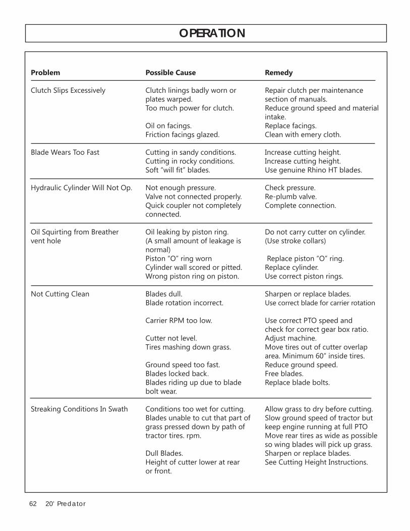
Problem Possible Cause Remedy
Clutch Slips Excessively Clutch linings badly worn or Repair clutch per maintenance plates warped. section of manuals. Too much power for clutch. Reduce ground speed and material
Oil on facings. Replace facings. Friction facings glazed. Clean with emery cloth.
Blade Wears Too Fast Cutting in sandy conditions. Increase cutting height.
Valve not connected properly. Re-plumb valve.
connected.
normal) Piston “O” ring worn Replace piston “O” ring. Cylinder wall scored or pitted. Replace cylinder. Wrong piston ring on piston. Use correct piston rings.
Not Cutting Clean Blades dull. Sharpen or replace blades. Blade rotation incorrect. Use correct blade for carrier rotation
Carrier RPM too low. Use correct PTO speed and
Cutter not level. Adjust machine. Tires mashing down grass. Move tires out of cutter overlap area. Minimum 60” inside tires. Ground speed too fast. Reduce ground speed.
Blades riding up due to blade Replace blade bolts. bolt wear.
Blades unable to cut that part of Slow ground speed of tractor but
tractor tires. rpm. Move rear tires as wide as possible
Dull Blades. Sharpen or replace blades. Height of cutter lower at rear See Cutting Height Instructions. or front.
OPERATION

6320’ Predator
provide long life and trouble free operation.
Lubrication information:Do not let excess grease collect on or around parts, particularly when ordering in sandy areas. The
thoroughly before using grease gun. Daily lubrication of the wing driveline slip joint is necessary.Failure to maintain proper lubrication will result in damage to U-joint, gearbox, and/or driveshaft.
FIGURE 11. U-Joint 8 hours
4. Axle Adjustment 8 hours5. Tongue Pivot 8 hours
MAINTENANCE

64 20’ Predator
a SAE 90 or SAE 80W90 with EP additives for extreme pressure and temperature, with an API-G1-5 Service rating.
DrivelinesThe drivelines and U-Joints should be inspected each morning before the cutter is started. FIGURE 5 & 6
The U-Joint and CV Joint on the driveline undergo extreme forces when the unit is turning or when the wings are being raised. It is important that the U-Joints and CV Joints be greased each day before the unit is started. The U-Joint and CV Joint assemblies are located at each end of the Center and wing drivelines. The CV joint is located at the end of the main driveline. The U-Joint and the CV joint are accessible by rotating the driveline safety shield until the hole in the shield matches up with
movement in the driveline, replace the U-Joint before it causes severe damage to the driveline.
FIGURE 5 FIGURE 6
GREASE EVERY 8 HOURS
GREASE EVERY 8 HOURS
MAINTENANCE
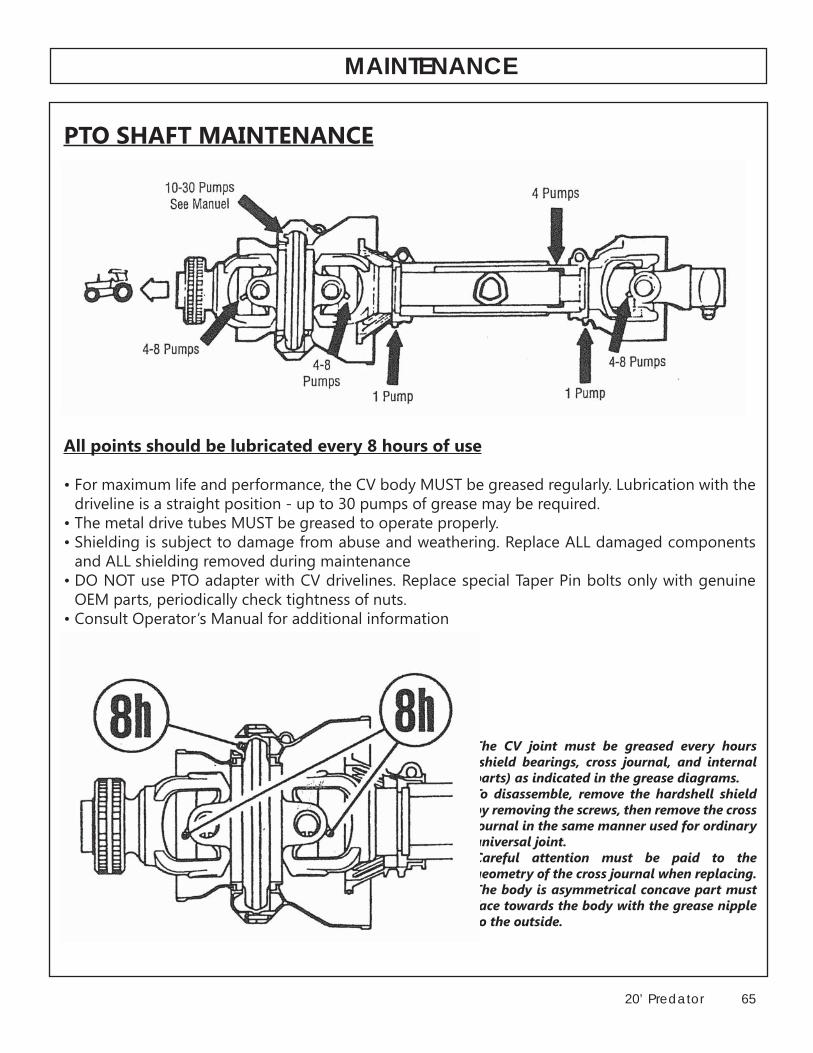
6520’ Predator
PTO SHAFT MAINTENANCE
All points should be lubricated every 8 hours of use
• For maximum life and performance, the CV body MUST be greased regularly. Lubrication with the
• The metal drive tubes MUST be greased to operate properly.• Shielding is subject to damage from abuse and weathering. Replace ALL damaged components
and ALL shielding removed during maintenance• DO NOT use PTO adapter with CV drivelines. Replace special Taper Pin bolts only with genuine
• Consult Operator’s Manual for additional information
by removing the screws, then remove the cross
Careful attention must be paid to the
face towards the body with the grease nipple to the outside.
MAINTENANCE

66 20’ Predator
SLIP CLUTCH ADJUSTMENTS & MAINTENANCE
The clutch will not operate properly, and damage to the internal components may occur if the following procedure is not followed .
Disengage the PTO, turn off the tractor engine and remove
Ensure that all driveline, tractor and implement shielding are functional and in place before operation. Damaged or missing parts must be replaced.
clutch or after periods of storage.
- If the edges of the clutch plates are exposed the clutch is type FV – measure and record the spring height. If the clutch plates are covered by the metal band the clutch is type FT.
shipped with the spring pressure relieved.
not allow the clutch slip for more than 2 or 3 seconds at a time to prevent damage to the linings. If the clutch does not slip after the third attempt, disassemble the clutch, clean up all contact surfaces and replace any damaged components.
MAINTENANCE

6720’ Predator
the spring pressure to the original value. For FT clutches, tighten the hex head bolt until the spring barely touches the metal ring – do not over tighten – this clutch is not adjustable, and
and could possibly cause damage to the tractor, implement, or driveline. Following seasonal use,
manufacturer, or your local Bondioli & Pavesi Representative.
glasses, safety shoes and gloves.
MAINTENANCE

68 20’ Predator
BLADE SERVICINGInspect blade before each use to determine that they are properly installed and in good condition.
Blade Sharping
Always sharpen both blades at same time to maintain balance. Follow original sharpening pattern as shown in FIGURE 3. Always sharpen blades by grinding. DO NOT heat and pound out edge. Do not
IMPORTANT:When sharpening blades, grind each blade the same amount to maintain balance. The difference in blade weights should not exceed 1 ounce. Unbalanced blades will cause excessive vibration which
must be serviced while in the raised position.
FOLLOW ORIGINAL PATTERN
MAINTAIN CORNER
MAINTENANCE

6920’ Predator
BLADE REMOVAL
or nylon insert are damaged. Always replace nut when replacing bolt. When installing blades, be
to 300 ft. lbs.
Avoid personal injury. Blade and/or bade carrier removal should be done only with the tractor
in the raised position.
BLADE CARRIER REMOVALRemove cotter pin and loosen slotted nut on gear box shaft. Loosen but do not remove the nut until the blade carrier is loosened. Use a suitable two-jaw gear puller to pull carrier tapered gear box shaft. If gear puller is not available use long bar inserted through blade bolt access hole with end
and repeat process.
Note: After a few hours of operation, always recheck blade carrier retaining nut torque.
WARNING
WARNING
MAINTENANCE

70 20’ Predator
HYDRAULIC HOSES
SKID SHOES
WHEELS BEARINGSEvery six months, the wheel hubs should be removed. Remove, clean, and inspect the bearings
problems exist, the cups and cones in the wheel hub should be replaced. Replace the cups and cones as a set. This prevents a continuation of the original problem. If the bearings are in good
and replace the hub. Tighten the adjusting nut until there is noticeable drag while turning the
cap. Fill the hub completely with #2 bearing grease.
HARDWARE
hardware regularly. Loose hardware is easily lost, cause increased wear on parts, and increase
potential hazards which could result in personal injury to the operator, support personnel and
tightening bolted connections.
BOLT PLAIN THREE SIX DIAMETER HEAD DASHES DASHES
1/4 . . . . . not used . . . . . . . 10 (14) . . . . . . . . . . 14 (19)5/16 . . . not used . . . . . . . .20(27) . . . . . . . . . . 30(41)3/8 . . . . not used . . . . . . . .35(47) . . . . . . . . . . 50(68)7/16 . . . . . .35(47) . . . . . . . .55(75) . . . . . . . . . 80(108)1/2 . . . . . . . .55(75) . . . . . . 85(115) . . . . . . . . 120(163)9/16 . . . . 75(102) . . . . . 130(176) . . . . . . . . 175(237)5/8 . . . . . 105(142) . . . . . 170(230) . . . . . . . . 240(325)3/4 . . . . . 185(2510 . . . . . 300(407) . . . . . . . . 425(576)7/8 . . . . . 160(217) . . . . . 445(603) . . . . . . . . 685(929)1 . . . . . . 250(339) . . . . . 670(906) . . . . . . 1030(1396)1 1/8 . . . 330(447) . . . . 910(1234) . . . . . . 1460(1979)1 1/4 . . . 480(651) . . . 1250(1695) . . . . . . 2060(2793)
2 (B) 5 (D) 8 (F)
RECOMMENDED TORQUE IN FT-LBS (NM)
COARSE AND FINE THREADS
MAINTENANCE

7120’ Predator
ASSEMBLY/PARTS SECTION
20 FT PREDATOR PARTS SECTION

72 20’ Predator
20 FT PREDATOR PARTS SECTION

7320’ Predator
20’ Predatorrr Center Deck Parts SectionItem Part Number Description Qty
1..............101-2920-B ............... 20’ Bondiolli Center Deck Body .............12..............610-0006 .................. Driveline (Bond) Splitter Shield ...............1 3..............116-1687 .................. Center Deck Skid Shoe ...........................2 4..............116-1500 .................. Leveling Rod ............................................25..............401-2070 .................. Blade Carrier Weldment, Cen/Wing .....16..............610-1608 .................. Hydraulic Line Holder ..............................27..............116-9040 .................. Transport Bar, 37-1/2 ................................28..............610-0007 .................. Driveline Guard Bracket .........................19..............415-0016-21 ............. Divider Gearbox, 540 RPM ......................1 415-0016-20BW ....... Divider Gearbox, 1000 RPM ....................110............415-001220BW ......... Center Immediate PTO ...........................111............415-0014-21 ............. Gearbox 540 RPM ....................................1 415-0014-20BW ....... Divider Gearbox, 1000 RPM ....................112............159-1542 .................. Ratchet Jack & Handle .........................2 13............750-1 ........................ SMV Emblem ............................................114............116-1656 .................. Mower Deck Plug ....................................1 15............415-0017-20BW ....... Safety Cone .............................................1 16............412-9099 .................. Owner Manual Holder ............................117............101-1554 .................. Defl ector Strap .........................................118............104-1905 .................. Defl ector Shield ........................................119............412-0057-01 ............. Blade Bolt .................................................220............401-1003-21 ............. Blade, Cen/Right Hand CCW ................221............830-1018NH ............. Washer W/ Keyway .................................222............515-1011 .................. Castle Nut, 36MM ....................................123............515-1010 .................. Cotter Pin ..................................................124............515-1016 .................. Washer ......................................................125............900-8871 .................. Lock Washer, 1-1/8” ................................226............125-925 .................... Jam Nut, 1-1/8” ........................................227............412-15310 ................ Bolt, 5/8-11 X 1-3/4” ................................428............412-0076-01 ............. Flat Washer, 5/8” .....................................229............412-5284 .................. Nylock Nut, 5/8-11 ...................................630............412-0009 .................. Bolt, ¼” x 1-1/4” .......................................431............412-0083-B ............... Lock Washer, 1/4” ...................................432............412-0082-B ............... Hex Nut, 1/4” ............................................433............412-0023-02 ............. Tap Bolt, 5/8” x 2” Gr5 ZP ........................234............412-15367 ................ Bolt, ¾” x 3-1/2” ........................................235............412-37041 ................ Jam Nylock Nut, 3/4-10 ...........................236............412-4965-01 ............. Bolt, 5/8-11 x 1-1/2” Gr8 ..........................437............412-0076-01 ............. Flat Washer, 5/8” Gr8 SAE .......................1438............415-0010-21 ............. Main PTO 540 RPM 1-3/8”-6 ....................1 415-0010-22 ............. Main PTO 1000 RPM 1-3/4”-20 ................1 415-0010-20BW ....... Main PTO 1000 RPM 1-3/8”-21 ................139............412-0058 .................. Hex Nut, 1/2” ............................................440............412-0075 .................. Flat Washer, 3/8” .....................................841............412-2004 .................. Bolt, 5/16” x 3/4” ......................................442............412-0042-02 ............. Bolt, 1/2” x 1-1/2” NC ..............................443............412-3243 .................. Nylock Nut, 1/2” .......................................1044............412-0072-01 ............. Flat Washer, 1/2” .....................................1045............412-2083 .................. Bolt, 1/2-13 x 2” Gr5 .................................646............412-0024 .................. Bolt, 5/8” x 2-1/2” NF Gr8 ........................647............412-3500 .................. Top Lock Nut, 5/8-18 (Double Nut) ........1248............415-1/4X23RD .......... Galvanized Rod .......................................249............415-1/4X34RD .......... Galvanized Rod .......................................150............154-1533 .................. Lynch Pin, 7/16” .......................................251............412-6298-6L ............. 1/4” Safety Chain ....................................AR52............415-1/4X78RD .......... Galvanized Rod .......................................153............101-CDGD ............... Rear Center Deck Chain Guard ............1*54 ..........101-6816 .................. Rear Chain Assembly (Option Only) .....1
20 FT PREDATOR PARTS SECTION

74 20’ Predator
20FT PREDATOR PARTS SECTION

7520’ Predator
Batwing Wing Deck Parts SectionItem Part Number Description Qty
1..............101-2003L ................. 20’ Bondiolli Wing - Left ............................................... 1 101-2003R ................ 20’ Bondiolli Wing- Right.............................................. 12..............108-2000 .................. 15’/20 Wing Axle .......................................................... 13..............108-3030A ................ 15’/20 Single Spindle & Hub Assembly ...................... 1 108-3030 .................. 15’/20’ Wing Axle Single Spindle Weldment ............ 1 415-0050-00 ............. Hub Package ............................................................... 1 415-0051 .................. Single Spindle ............................................................... 14..............116-1833 .................. 15’/20’ Hinge Rod Weldment .................................... 15..............401-2070 .................. Stump Jumper, Cen/Wing .......................................... 16..............116-9010L ................. 15’/20’ Wing Skirt- Left ................................................. 1
116-9010R ................ 15’/20’ Wing Skirt-Right ............................................... 17..............415-0013-21BW ....... Gearbox 540 RPM (Right Wing) ................................. 1 415-0015-21BW ....... Gearbox 540 RPM (Left Wing) .................................... 1 415-0013-20BW ....... Gearbox 1000 RPM (Right Wing) ............................... 1 415-0015-20BW ....... Gearbox 1000 RPM (Left Wing) .................................. 18..............116-1656 .................. Mower Deck Plug ........................................................ 19..............415-0007 .................. Safety Cone ................................................................. 110............159-1542 .................. Ratchet Jack & Handle ............................................. 111............457-1609 .................. Jack, Top Wind-5000 lb ............................................... 112............415-0011-20BW ....... Wing PTO ...................................................................... 1 13............108-6065 .................. 7’ HWY, 15’ & 20’ Skid (401-SKID7HWY) .................... 114............401-1003-20 ............. Blade, LH Wing CW...................................................... 2 401-1003-21 ............. Blade, CEN/Right Hand Wing CCW .......................... 2 15............108-7000 .................. Spring Locator .............................................................. 2 16............415-0025 .................. Compression Spring ..................................................... 217............415-2001 .................. Spring Suppressor Plug ................................................ 218............104-1905-WR ........... Wing Rubber Guard - Right ........................................ 1 104-1905-WL ............ Wing Rubber Guard - Left .......................................... 119............104-2025 .................. Defl ector Strap ............................................................. 120............412-2083 .................. Bolt, ½”-13 x 2” ZP Gr5 ................................................. 1721............412-0072-01 ............. Flat washer, ½” ............................................................. 1722............412-3243 .................. Nylock Nut, ½” ............................................................ 1723............900-8614-01 ............. Jam Nut ........................................................................ 224............900-8771 .................. Lock Washer ................................................................. 225............830-1018NH ............. Washer W/Keyway ...................................................... 226............515-1011 .................. Nut, 36MM .................................................................... 127............515-1016 .................. Washer .......................................................................... 128............515-1010 .................. Cotter Pin ...................................................................... 129............412-0057-01 ............. Blade Bolt, 1-1/8” ......................................................... 230............412-0657 .................. Hex Nut, 3/8” NC ......................................................... 431............412-0071 .................. Lock washer, 3/8” ........................................................ 432............412-0075 .................. Flat washer, 3/8” .......................................................... 433............412-03229 ................ Plow Bolt, 3/8” x 1-1/2” GR5 ....................................... 434............412-15479-G ............ Bolt, 1x8 Gr 8 w/ Grease Zerk ..................................... 135............415-0068 .................. Nylock Nut, 1” .............................................................. 236............412-15477-G ............ Bolt, 1x7 Gr 8 w/ Grease Zerk .................................... 137............412-0076-01 ............. Flat Washer, 5/8 Gr8 SAE ............................................. 638............412-3500 .................. Top Lock Nut, 5/8-18 .................................................... 1239............412-0024 .................. Bolt, 5/8-18 x 2-1/2” NF ................................................ 640............105-114X78RD ......... Galvanized Rod ........................................................... 141............412-6298-6L ............. ¼” Safety Chain ........................................................... AR---------------------------------- Option Only ---------------------------------------42............BWREARCH-W20L ... Batwing Wing Rear Chain Guard, Left ...................... 1................BWREARCH-W20R ... Batwing Wing Rear Chain Guard, Right ................... 143............108-5030A ................ 15’/20 Double Spindle & Hub Assembly ................... 1 108-5030 .................. 15’/20’ Double Axle Single Spindle Weldment ........ 1 415-0050-00 ............. Hub Package ............................................................... 1 415-0052 .................. Double Spindle ............................................................ 1
20 FT PREDATOR PARTS SECTION

76 20’ Predator
20 FT PREDATOR PARTS SECTION

7720’ Predator
Center Axle & Double Spindle Assembly Parts Section
Item Part Number Description Qty
1..............108-4000-20 ............. 20’ Center Axle ...................................................12..............108-5030A ................ Center Axle Leg Double Spindle w/Hubs ........3 108-5030 .................. Double Axle Leg Spindle (No Hubs) .................3 415-0050-00 ............. Hub Assembly......................................................6 415-0052 .................. Double Spindle Only ..........................................33..............108-7000 .................. Spring Locator .....................................................94..............415-0025 .................. Compression Spring ............................................95..............415-2001 .................. Spring Suppressor Plug .......................................96..............412-15477-G ............ Bolt, 1-8 x 7” Gr8 W/ Grease Zerk ......................37..............412-15479-G ............ Bolt, 1-8 x 8” Gr8 W/ Grease Zerk .....................28..............415-0068 .................. Nylock Nut, 1” .....................................................5
20 FT PREDATOR PARTS SECTION
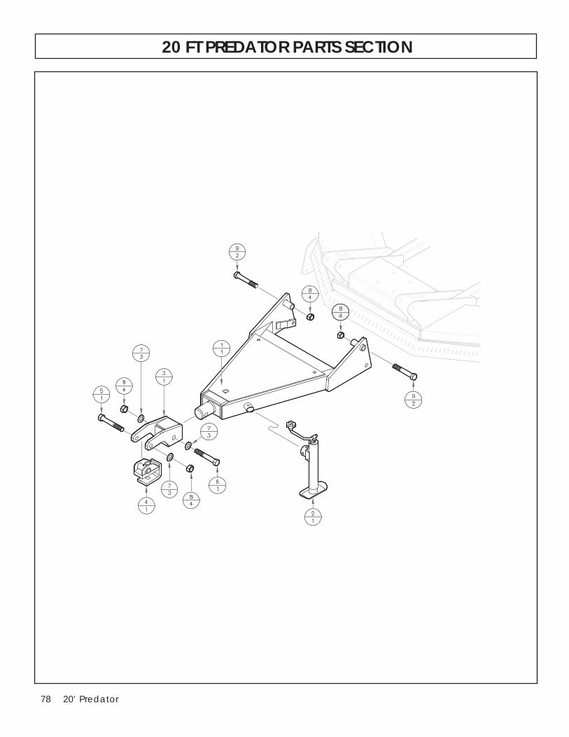
78 20’ Predator
20 FT PREDATOR PARTS SECTION

7920’ Predator
15’/20’ Predatorrr Tongue Parts Section
Item Part Number Description Qty
1..............108-1000 .................. Welded Tongue .......................................12..............457-1609 .................. Jack, Top wind #5000 LB ........................1 3..............108-9000 .................. Tongue Clevis ...........................................14..............108-9010 .................. Drawbar Clevis .........................................15..............412-15477 ................ Bolt, 1-8 x 7” .............................................16..............412-15479 ................ Bolt, 1-8 x 8” ..............................................17..............412-7975 .................. Flat Washer, 1” .........................................38..............412-0068 .................. Nylock Nut, 1-8 .........................................49..............412-0586 .................. Bolt, 1-8 x 6-1/2” .......................................2
20 FT PREDATOR PARTS SECTION

80 20’ Predator
20 FT PREDATOR PARTS SECTION

8120’ Predator
20’ Predatorrr Standard Hydraulics Parts Section
Item Part Number Description Qty
1..............263-3524 .................. Wing Cylinder ...........................................22..............415-1600 .................. Center Deck Cylinder .............................1 3..............415-0041 .................. Hose Assembly 195” ................................14..............415-0228 .................. Hose Assembly 228” ................................25..............800-0203 .................. 90 Degree Elbow .....................................16..............800-0202 .................. 90 Degree Elbow .....................................27..............150-6306 .................. Cylinder Pin ..............................................48..............154-1533 .................. Lynch Pin, 7/16” .......................................89..............412-7975 .................. Flat Washer, 1” .........................................810............261-700 .................... Cylinder Pin ..............................................2 154-208 .................... Hair Pin Clip ..............................................211............97-2 .......................... Breather Plug ............................................3
20 FT PREDATOR PARTS SECTION

82 20’ Predator
20 FT PREDATOR PARTS SECTION

8320’ Predator
20 FT PREDATOR PARTS SECTION
20’ Predatorrr Self Leveling Hydraulics Parts Section
Item Part Number Description Qty
1..............263-3224 .................. Wing Cylinder ...........................................22..............AM2564 ................... Phasing Cylinder 3-1/2” x 12 ...................1 3..............AM2576 ................... Phasing Cylinder 3” x 12 .........................14..............AM2570 ................... Phasing Cylinder 3-1/4” x 12 ...................15..............415-0228 .................. Hose Assembly 228” ................................26..............415-0215 .................. Hose Assembly 215” ................................27..............415-0045 .................. Hose Assembly 110” ................................18..............415-0249 .................. Hose Assembly 249” ................................19..............800-0202 .................. 90 Degree Restrictor ................................210............800-0207 .................. 90 Degree Elbow .....................................211............800-0206 .................. Straight Adaptor ......................................412............261-700 .................... Cylinder Pin ..............................................613............150-6306 .................. Cylinder Pin ..............................................414............412-5115 .................. Lynch Pin ...................................................815............412-7975 .................. Flatwasher 1” ...........................................816............97-2 .......................... Breather Plug ............................................2

84 20’ Predator
20 FT PREDATOR PARTS SECTION
Wheel Hub Assembly 415-0050-00Item Part Number Description Qty
1A ...........415-0050-00 ............. Hub complete less spindle .....................11..............415-0050-01 ............. Hub w/races, studs & zerk ......................12..............501-0219 .................. Bearing cone (outside) ...........................13..............501-0218 .................. Bearing cup (outside) .............................14..............900-602406 .............. Bearing cup (inside) ................................15..............900-602416 .............. Bearing cone (inside) ..............................16..............415-0050-03 ............. Seal ............................................................17..............325-2122 .................. Nut .............................................................58..............412-0072 .................. Washer, 1/2” .............................................59..............325-2112 .................. Stud ...........................................................510............415-0051 .................. Spindle, Single Wheel ..............................1 415-0052 .................. Spindle, Double Wheel ...........................111............415-0050-05 ............. Dust Cap ...................................................112............415-0050-02 ............. Slotted Nut ................................................113............415-0050-04 ............. Washer ......................................................114............900-8686 .................. Cotter Pin ..................................................115............423-1121 .................. Grease Zerk ..............................................116............103-211 .................... Laminated Tire, 600 x 9 ............................1OP ..........401-8812 .................. Aircraft Tire 26 x 6.6 x 14 (Optional) .......1

8520’ Predator
20 FT PREDATOR PARTS SECTION
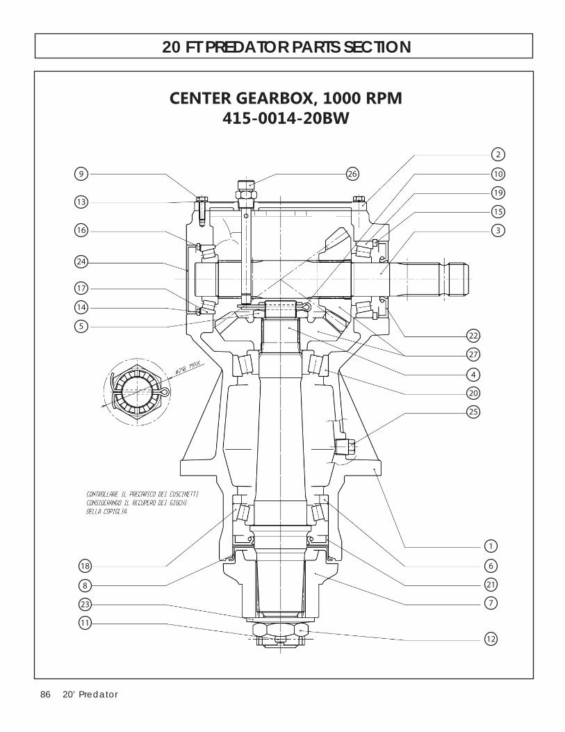
86 20’ Predator
CENTER GEARBOX, 1000 RPM415-0014-20BW
269
13
16
24
17
14
5
2
10
19
15
3
22
27
4
20
25
18
8
23
11
1
6
21
7
12
20 FT PREDATOR PARTS SECTION

8720’ Predator
1. HOUSING . . . . . . . . . . . . . . . (1) . . . . . . . . . . . . . . . . . . . . . . . . . 515-10032. COVER . . . . . . . . . . . . . . . . . . (1) . . . . . . . . . . . . . . . . . . . . . . . . . 515-10003. INPUT SHAFT . . . . . . . . . . . . (1) . . . . . . . . . . . . . . . . . . . . . . . . . 515-10044. OUTPUT SHAFT . . . . . . . . . . (1) . . . . . . . . . . . . . . . . . . . . . . . . . 515-10055. RING NUT . . . . . . . . . . . . . . . (1) . . . . . . . . . . . . . . . . . . . . . . . . . 515-10066. SPACER . . . . . . . . . . . . . . . . . (1) . . . . . . . . . . . . . . . . . . . . . . . . . 515-10077. SPLINED HUB . . . . . . . . . . . . (1) . . . . . . . . . . . . . . . . . . . . . . . . . 501-07038. SEAL PROTECTOR . . . . . . . . (1) . . . . . . . . . . . . . . . . . . . . . . . . . 501-07069. SCREW . . . . . . . . . . . . . . . . . (6) . . . . . . . . . . . . . . . . . . . . . . . . . 515-100810. COTTER PIN . . . . . . . . . . . . (1) . . . . . . . . . . . . . . . . . . . . . . . . . 515-100911. COTTER PIN . . . . . . . . . . . . (1) . . . . . . . . . . . . . . . . . . . . . . . . . 515-101012. NUT . . . . . . . . . . . . . . . . . . . (1) . . . . . . . . . . . . . . . . . . . . . . . . . 515-101113. WASHER . . . . . . . . . . . . . . . (6) . . . . . . . . . . . . . . . . . . . . . . . . . 515-101214. SNAP RING . . . . . . . . . . . . (1) . . . . . . . . . . . . . . . . . . . . . . . . . 501-071315. SNAP RING . . . . . . . . . . . . . (1) . . . . . . . . . . . . . . . . . . . . . . . . . 501-0733-0616. SHIM KIT . . . . . . . . . . . . . . . (1) . . . . . . . . . . . . . . . . . . . . . . . . . 515-101317. TAPERED R. BEARING . . . . (1) . . . . . . . . . . . . . . . . . . . . . . . . . 515-1014 18. TAPERED R. BEARING . . . . (1) . . . . . . . . . . . . . . . . . . . . . . . . . 501-071519. BEARING . . . . . . . . . . . . . . . (1) . . . . . . . . . . . . . . . . . . . . . . . . . 501-071620. BEARING . . . . . . . . . . . . . . . (1) . . . . . . . . . . . . . . . . . . . . . . . . . 515-101521. OIL SEAL . . . . . . . . . . . . . . . (1) . . . . . . . . . . . . . . . . . . . . . . . . . 501-071722. OIL SEAL . . . . . . . . . . . . . . . (1) . . . . . . . . . . . . . . . . . . . . . . . . . 501-071823. WASHER . . . . . . . . . . . . . . . (1) . . . . . . . . . . . . . . . . . . . . . . . . . 515-101624. CAP . . . . . . . . . . . . . . . . . . . (1) . . . . . . . . . . . . . . . . . . . . . . . . . 501-071925. OIL DRAIN . . . . . . . . . . . . . . (1) . . . . . . . . . . . . . . . . . . . . . . . . . 515-102026. PLUG . . . . . . . . . . . . . . . . . . (1) . . . . . . . . . . . . . . . . . . . . . . . . . 515-101727. SET GEAR . . . . . . . . . . . . . . (1) . . . . . . . . . . . . . . . . . . . . . . . . . 515-1018
CENTER GEARBOX, 1000 RPM415-0014-20BW
20 FT PREDATOR PARTS SECTION

88 20’ Predator
20
22
23
25
26
27
19
18
15
12
11
10
8
7
6
4
3
2
1
LH WING GEARBOX, 1000 RPM415-0015-20BW
21
24
17
16
14
13
5
9
20 FT PREDATOR PARTS SECTION

8920’ Predator
1. HOUSING . . . . . . . . . . . . . . . (1) . . . . . . . . . . . . . . . . . . . . . . . . . 515-10032. TOP COVER . . . . . . . . . . . . . . (1) . . . . . . . . . . . . . . . . . . . . . . . . . 515-10003. INPUT SHAFT . . . . . . . . . . . . (1) . . . . . . . . . . . . . . . . . . . . . . . . . 515-10044. OUTPUT SHAFT . . . . . . . . . . (1) . . . . . . . . . . . . . . . . . . . . . . . . . 515-10055. RING NUT . . . . . . . . . . . . . . . (1) . . . . . . . . . . . . . . . . . . . . . . . . . 515-10066. SPACER . . . . . . . . . . . . . . . . . (1) . . . . . . . . . . . . . . . . . . . . . . . . . 515-10077. SPLINED HUB . . . . . . . . . . . . (1) . . . . . . . . . . . . . . . . . . . . . . . . . 501-07038. SEALING PROTECTOR . . . . . (1) . . . . . . . . . . . . . . . . . . . . . . . . . 501-07069. SCREW . . . . . . . . . . . . . . . . . (6) . . . . . . . . . . . . . . . . . . . . . . . . . 515-100810. SPLIT PIN . . . . . . . . . . . . . . (1) . . . . . . . . . . . . . . . . . . . . . . . . . 515-100911. SPLIT PIN . . . . . . . . . . . . . . (1) . . . . . . . . . . . . . . . . . . . . . . . . . 515-101012. NUT . . . . . . . . . . . . . . . . . . . (1) . . . . . . . . . . . . . . . . . . . . . . . . . 515-101113. WASHER . . . . . . . . . . . . . . . (6) . . . . . . . . . . . . . . . . . . . . . . . . . 515-101214. SNAP RING . . . . . . . . . . . . (1) . . . . . . . . . . . . . . . . . . . . . . . . . 501-071315. SNAP RING . . . . . . . . . . . . . (1) . . . . . . . . . . . . . . . . . . . . . . . . . 501-0733-0616. SHIM KIT . . . . . . . . . . . . . . . (1) . . . . . . . . . . . . . . . . . . . . . . . . . 515-101317. TAPERED R. BEARING . . . . (1) . . . . . . . . . . . . . . . . . . . . . . . . . 515-101418. TAPERED R. BEARING . . . . (1) . . . . . . . . . . . . . . . . . . . . . . . . . 501-071519. BEARING . . . . . . . . . . . . . . . (1) . . . . . . . . . . . . . . . . . . . . . . . . . 501-071620. BEARING . . . . . . . . . . . . . . . (1) . . . . . . . . . . . . . . . . . . . . . . . . . 515-101521. OIL SEAL . . . . . . . . . . . . . . . (1) . . . . . . . . . . . . . . . . . . . . . . . . . 501-071722. OIL SEAL . . . . . . . . . . . . . . . (1) . . . . . . . . . . . . . . . . . . . . . . . . . 501-071823. WASHER . . . . . . . . . . . . . . . (1) . . . . . . . . . . . . . . . . . . . . . . . . . 515-101624. CAP . . . . . . . . . . . . . . . . . . . (1) . . . . . . . . . . . . . . . . . . . . . . . . . 501-071925. OIL DRAIN . . . . . . . . . . . . . . (1) . . . . . . . . . . . . . . . . . . . . . . . . . 515-102026. PLUG . . . . . . . . . . . . . . . . . . (1) . . . . . . . . . . . . . . . . . . . . . . . . . 515-101727. BEVEL GEAR . . . . . . . . . . . . (1) . . . . . . . . . . . . . . . . . . . . . . . . . 515-1019
LH WING GEARBOX, 1000 RPM415-0015-20BW
20 FT PREDATOR PARTS SECTION

90 20’ Predator
20
22
23
24
25
26
27
19
18
17
16
15
14
13
12
11
10
8
7
6
5
3
4
2
1
9
21
RH WING GEARBOX, 1000 RPM415-0013-20BW
20 FT PREDATOR PARTS SECTION

9120’ Predator
RH WING GEARBOX, 1000 RPM415-0013-20BW
1. HOUSING . . . . . . . . . . . . . . . (1) . . . . . . . . . . . . . . . . . . . . . . . . . 515-10032. COVER . . . . . . . . . . . . . . . . . . (1) . . . . . . . . . . . . . . . . . . . . . . . . . 515-10003. SHAFT . . . . . . . . . . . . . . . . . . (1) . . . . . . . . . . . . . . . . . . . . . . . . . 515-10044. SHAFT . . . . . . . . . . . . . . . . . . (1) . . . . . . . . . . . . . . . . . . . . . . . . . 515-10055. RING NUT . . . . . . . . . . . . . . . (1) . . . . . . . . . . . . . . . . . . . . . . . . . 515-10066. SPACER . . . . . . . . . . . . . . . . . . (1) . . . . . . . . . . . . . . . . . . . . . . . . . 515-10077. SPLINED HUB . . . . . . . . . . . . (1) . . . . . . . . . . . . . . . . . . . . . . . . . 501-07038. SEAL PROTECTOR . . . . . . . . (1) . . . . . . . . . . . . . . . . . . . . . . . . . 501-07069. SCREW . . . . . . . . . . . . . . . . . . (6) . . . . . . . . . . . . . . . . . . . . . . . . . 515-100810. COTTER PIN . . . . . . . . . . . . (1) . . . . . . . . . . . . . . . . . . . . . . . . . 515-100911. SPLIT PIN . . . . . . . . . . . . . . (1) . . . . . . . . . . . . . . . . . . . . . . . . . 515-101012. NUT . . . . . . . . . . . . . . . . . . . (1) . . . . . . . . . . . . . . . . . . . . . . . . . 515-101113. WASHER . . . . . . . . . . . . . . . (6) . . . . . . . . . . . . . . . . . . . . . . . . . 515-101214. SNAP RING . . . . . . . . . . . . (1) . . . . . . . . . . . . . . . . . . . . . . . . . 501-071315. SNAP RING . . . . . . . . . . . . (1) . . . . . . . . . . . . . . . . . . . . . . . . . 501-0733-0616. SHIM KIT . . . . . . . . . . . . . . . (1) . . . . . . . . . . . . . . . . . . . . . . . . . 515-101317. TAPERED R. BEARING . . . . (1) . . . . . . . . . . . . . . . . . . . . . . . . . 515-101418. TAPERED R. BEARING . . . . (1) . . . . . . . . . . . . . . . . . . . . . . . . . 501-071519. BEARING . . . . . . . . . . . . . . . (1) . . . . . . . . . . . . . . . . . . . . . . . . . 501-071620. BEARING . . . . . . . . . . . . . . . (1) . . . . . . . . . . . . . . . . . . . . . . . . . 515-101521. OIL SEAL . . . . . . . . . . . . . . . (1) . . . . . . . . . . . . . . . . . . . . . . . . . 501-071722. OIL SEAL . . . . . . . . . . . . . . . (1) . . . . . . . . . . . . . . . . . . . . . . . . . 501-077223. WASHER . . . . . . . . . . . . . . . (1) . . . . . . . . . . . . . . . . . . . . . . . . . 515-101624. CAP . . . . . . . . . . . . . . . . . . . (1) . . . . . . . . . . . . . . . . . . . . . . . . . 501-071925. OIL DRAIN PLUG . . . . . . . . (1) . . . . . . . . . . . . . . . . . . . . . . . . . 501-073026. PLUG . . . . . . . . . . . . . . . . . . (1) . . . . . . . . . . . . . . . . . . . . . . . . . 515-101727. BEVEL GEAR SET . . . . . . . . . (1) . . . . . . . . . . . . . . . . . . . . . . . . . 515-1019
20 FT PREDATOR PARTS SECTION

92 20’ Predator
20
21
22
18
1717
1616
15
14
11
1010
9
9
8
7
66
55
44
33
1
2 19
19
19
13
13
12
12
DIVIDER GEARBOX, 540 RPM415-0016-21
20 FT PREDATOR PARTS SECTION

9320’ Predator
DIVIDER GEARBOX, 540 RPM415-0016-21
1. HOUSING . . . . . . . . . . . . . . . (1) . . . . . . . . . . . . . . . . . . . . . . . . . 501-0731-012. INPUT SHAFT . . . . . . . . . . . . (1) . . . . . . . . . . . . . . . . . . . . . . . . . 515-10013. OUTPUT SHAFT . . . . . . . . . . (2) . . . . . . . . . . . . . . . . . . . . . . . . . 515-10024. SPACE RING . . . . . . . . . . . . . (2) . . . . . . . . . . . . . . . . . . . . . . . . . 501-0733-025. SPACER . . . . . . . . . . . . . . . . . (2) . . . . . . . . . . . . . . . . . . . . . . . . . 501-0733-056. SPACER . . . . . . . . . . . . . . . . . (2) . . . . . . . . . . . . . . . . . . . . . . . . . 501-0733-037. COVER . . . . . . . . . . . . . . . . . . (1) . . . . . . . . . . . . . . . . . . . . . . . . . 501-07358. SNAP RING . . . . . . . . . . . . . . (2) . . . . . . . . . . . . . . . . . . . . . . . . . 501-07369. SNAP RING . . . . . . . . . . . . . . (2) . . . . . . . . . . . . . . . . . . . . . . . . . 501-073810. SNAP RING . . . . . . . . . . . . (2) . . . . . . . . . . . . . . . . . . . . . . . . . 501-0733-0411. SNAP RING . . . . . . . . . . . . (1) . . . . . . . . . . . . . . . . . . . . . . . . . 501-073912. SNAP RING . . . . . . . . . . . . (2) . . . . . . . . . . . . . . . . . . . . . . . . . 501-0733-0613. SHIM KIT . . . . . . . . . . . . . . (2) . . . . . . . . . . . . . . . . . . . . . . . . . 501-0733-0714. BALL BEARING . . . . . . . . . . (1) . . . . . . . . . . . . . . . . . . . . . . . . . 501-002515. BALL BEARING . . . . . . . . . . (1) . . . . . . . . . . . . . . . . . . . . . . . . . 501-075116. BEARING . . . . . . . . . . . . . . . (2) . . . . . . . . . . . . . . . . . . . . . . . . . 501-075217. BEARING . . . . . . . . . . . . . . . (2) . . . . . . . . . . . . . . . . . . . . . . . . . 501-071618. OIL SEAL . . . . . . . . . . . . . . . (1) . . . . . . . . . . . . . . . . . . . . . . . . . 501-075319. OIL SEAL . . . . . . . . . . . . . . . (3) . . . . . . . . . . . . . . . . . . . . . . . . . 501-071820. OIL PLUG . . . . . . . . . . . . . . (1) . . . . . . . . . . . . . . . . . . . . . . . . . 501-072221. OIL PLUG . . . . . . . . . . . . . . (1) . . . . . . . . . . . . . . . . . . . . . . . . . 501-075422. SET GEAR . . . . . . . . . . . . . . (1) . . . . . . . . . . . . . . . . . . . . . . . . . 501-0755SS
20 FT PREDATOR PARTS SECTION

94 20’ Predator
CENTER GEARBOX, 540 RPM415-0014-21
269
13
16
24
17
14
5
2
10
19
15
3
22
27
4
20
25
18
8
23
11
1
6
21
7
12
20 FT PREDATOR PARTS SECTION

9520’ Predator
1. HOUSING . . . . . . . . . . . . . . . (1) . . . . . . . . . . . . . . . . . . . . . . . . . 515-10032. COVER . . . . . . . . . . . . . . . . . . (1) . . . . . . . . . . . . . . . . . . . . . . . . . 515-10003. INPUT SHAFT . . . . . . . . . . . . (1) . . . . . . . . . . . . . . . . . . . . . . . . . 515-10044. OUTPUT SHAFT . . . . . . . . . . (1) . . . . . . . . . . . . . . . . . . . . . . . . . 515-10055. RING NUT . . . . . . . . . . . . . . . (1) . . . . . . . . . . . . . . . . . . . . . . . . . 515-10066. SPACER . . . . . . . . . . . . . . . . . (1) . . . . . . . . . . . . . . . . . . . . . . . . . 515-10077. SPLINED HUB . . . . . . . . . . . . (1) . . . . . . . . . . . . . . . . . . . . . . . . . 501-07038. SEAL PROTECTOR . . . . . . . . (1) . . . . . . . . . . . . . . . . . . . . . . . . . 501-07069. SCREW . . . . . . . . . . . . . . . . . (6) . . . . . . . . . . . . . . . . . . . . . . . . . 515-100810. COTTER PIN . . . . . . . . . . . . (1) . . . . . . . . . . . . . . . . . . . . . . . . . 515-100911. COTTER PIN . . . . . . . . . . . . (1) . . . . . . . . . . . . . . . . . . . . . . . . . 515-101012. NUT . . . . . . . . . . . . . . . . . . . (1) . . . . . . . . . . . . . . . . . . . . . . . . . 515-101113. WASHER . . . . . . . . . . . . . . . (6) . . . . . . . . . . . . . . . . . . . . . . . . . 515-101214. SNAP RING . . . . . . . . . . . . (1) . . . . . . . . . . . . . . . . . . . . . . . . . 501-071315. SNAP RING . . . . . . . . . . . . . (1) . . . . . . . . . . . . . . . . . . . . . . . . . 501-0733-0616. SHIM KIT . . . . . . . . . . . . . . . (1) . . . . . . . . . . . . . . . . . . . . . . . . . 515-101317. TAPERED R. BEARING . . . . (1) . . . . . . . . . . . . . . . . . . . . . . . . . 515-1014 18. TAPERED R. BEARING . . . . (1) . . . . . . . . . . . . . . . . . . . . . . . . . 501-071519. BEARING . . . . . . . . . . . . . . . (1) . . . . . . . . . . . . . . . . . . . . . . . . . 501-071620. BEARING . . . . . . . . . . . . . . . (1) . . . . . . . . . . . . . . . . . . . . . . . . . 515-101521. OIL SEAL . . . . . . . . . . . . . . . (1) . . . . . . . . . . . . . . . . . . . . . . . . . 501-071722. OIL SEAL . . . . . . . . . . . . . . . (1) . . . . . . . . . . . . . . . . . . . . . . . . . 501-071823. WASHER . . . . . . . . . . . . . . . (1) . . . . . . . . . . . . . . . . . . . . . . . . . 515-101624. CAP . . . . . . . . . . . . . . . . . . . (1) . . . . . . . . . . . . . . . . . . . . . . . . . 501-071925. OIL DRAIN . . . . . . . . . . . . . . (1) . . . . . . . . . . . . . . . . . . . . . . . . . 515-102026. PLUG . . . . . . . . . . . . . . . . . . (1) . . . . . . . . . . . . . . . . . . . . . . . . . 515-101727. SET GEAR . . . . . . . . . . . . . . (1) . . . . . . . . . . . . . . . . . . . . . . . . . 515-1018
CENTER GEARBOX, 540 RPM415-0014-21
20 FT PREDATOR PARTS SECTION

96 20’ Predator
20
22
23
24
25
26
27
19
18
17
1615
14
13
12
11
10
8
7
6
5
3
4
2
1
9
21
RH WING GEARBOX, 540 RPM415-0013-21
20 FT PREDATOR PARTS SECTION

9720’ Predator
RH WING GEARBOX, 540 RPM415-0013-21
1. HOUSING . . . . . . . . . . . . . . . (1) . . . . . . . . . . . . . . . . . . . . . . . . . 515-10032. COVER . . . . . . . . . . . . . . . . . . (1) . . . . . . . . . . . . . . . . . . . . . . . . . 515-10003. SHAFT . . . . . . . . . . . . . . . . . . (1) . . . . . . . . . . . . . . . . . . . . . . . . . 515-10044. SHAFT . . . . . . . . . . . . . . . . . . (1) . . . . . . . . . . . . . . . . . . . . . . . . . 515-10055. RING NUT . . . . . . . . . . . . . . . (1) . . . . . . . . . . . . . . . . . . . . . . . . . 515-10066. SPACER . . . . . . . . . . . . . . . . . . (1) . . . . . . . . . . . . . . . . . . . . . . . . . 515-10077. SPLINED HUB . . . . . . . . . . . . (1) . . . . . . . . . . . . . . . . . . . . . . . . . 501-07038. SEAL PROTECTOR . . . . . . . . (1) . . . . . . . . . . . . . . . . . . . . . . . . . 501-07069. SCREW . . . . . . . . . . . . . . . . . . (6) . . . . . . . . . . . . . . . . . . . . . . . . . 515-100810. COTTER PIN . . . . . . . . . . . . (1) . . . . . . . . . . . . . . . . . . . . . . . . . 515-100911. SPLIT PIN . . . . . . . . . . . . . . (1) . . . . . . . . . . . . . . . . . . . . . . . . . 515-101012. NUT . . . . . . . . . . . . . . . . . . . (1) . . . . . . . . . . . . . . . . . . . . . . . . . 515-101113. WASHER . . . . . . . . . . . . . . . (6) . . . . . . . . . . . . . . . . . . . . . . . . . 515-101214. SNAP RING . . . . . . . . . . . . (1) . . . . . . . . . . . . . . . . . . . . . . . . . 501-071315. SNAP RING . . . . . . . . . . . . (1) . . . . . . . . . . . . . . . . . . . . . . . . . 501-0733-0616. SHIM KIT . . . . . . . . . . . . . . . (1) . . . . . . . . . . . . . . . . . . . . . . . . . 515-101317. TAPERED R. BEARING . . . . (1) . . . . . . . . . . . . . . . . . . . . . . . . . 515-101418. TAPERED R. BEARING . . . . (1) . . . . . . . . . . . . . . . . . . . . . . . . . 501-071519. BEARING . . . . . . . . . . . . . . . (1) . . . . . . . . . . . . . . . . . . . . . . . . . 501-071620. BEARING . . . . . . . . . . . . . . . (1) . . . . . . . . . . . . . . . . . . . . . . . . . 515-101521. OIL SEAL . . . . . . . . . . . . . . . (1) . . . . . . . . . . . . . . . . . . . . . . . . . 501-071722. OIL SEAL . . . . . . . . . . . . . . . (1) . . . . . . . . . . . . . . . . . . . . . . . . . 501-077223. WASHER . . . . . . . . . . . . . . . (1) . . . . . . . . . . . . . . . . . . . . . . . . . 515-101624. CAP . . . . . . . . . . . . . . . . . . . (1) . . . . . . . . . . . . . . . . . . . . . . . . . 501-071925. OIL DRAIN PLUG . . . . . . . . (1) . . . . . . . . . . . . . . . . . . . . . . . . . 501-073026. PLUG . . . . . . . . . . . . . . . . . . (1) . . . . . . . . . . . . . . . . . . . . . . . . . 515-101727. BEVEL GEAR SET . . . . . . . . . (1) . . . . . . . . . . . . . . . . . . . . . . . . . 515-1019
20 FT PREDATOR PARTS SECTION

98 20’ Predator
MAIN-2 PTO (540 RPM • 1 3/8 -6)415-0010-21
20 FT PREDATOR PARTS SECTION

9920’ Predator
MAIN-2 PTO (540 RPM • 1 3/8 -6)415-0010-21
1. YOKE S8/1R8 RT EL 80°CV 1-3/8”Z21 (WR8) . . . . . . . (1) . . . . 515-20552. CROSS KIT SFT S8 80CV . . . . . . . . . . . . . . . . . . . . . . . . (2) . . . . 515-20205. YOKE H8 80° CV OUTER TUBE . . . . . . . . . . . . . . . . . . . (1) . . . . 515-20216. CENTRAL BODY SFT S6 80CV . . . . . . . . . . . . . . . . . . . (1) . . . . 515-20228. FLEXIBLE ROLL PIN 10X95 DIN1481 . . . . . . . . . . . . . . (1) . . . . 34105400012. OUTER TUBE CV SFT 8 . . . . . . . . . . . . . . . . . . . . . . . . (1) . . . . 515-202313. INNER TUBE CV SFT 8 RILSON . . . . . . . . . . . . . . . . . (1) . . . . 515-202416. FLEXIBLE ROLL PIN #6/7 OUTER 10X75MM . . . . . . (1) . . . . 343-150517. YOKE H8 I. TUBE YOKE 4-LOBE . . . . . . . . . . . . . . . . . (1) . . . . 515-200521. YOKE SFT S8 1 3/4Z20 TAPER PIN . . . . . . . . . . . . . . (1) . . . . 515-202522. CROSS KIT S8 34.9 X 93.5 . . . . . . . . . . . . . . . . . . . . . (1) . . . . 515-200123. GREASE FITTING M6X1 SPECIAL SHORT . . . . . . . . (1) . . . . 515-204325. SAFETY SHIELD SFT CV BELL ASSY . . . . . . . . . . . . . (1) . . . . 515-204426. SHIELD SUPPORT SFT S6-S7-S8 OUTER . . . . . . . . . (6) . . . . 515-204527. SHIELD SUPPORT SFT EL CV80 S8 . . . . . . . . . . . . . . (1) . . . . 515-204628. SELF TAPPING SHIELDING SCREW . . . . . . . . . . . . . . (1) . . . . 515-204729. INNER SHIELD TUBE CV SFT 8 . . . . . . . . . . . . . . . . . . (1) . . . . 515-204830. OUTER SHIELD TUBE CV SFT 8 . . . . . . . . . . . . . . . . . (1) . . . . 515-204931. SAFETY SHIELD SFT S8-N9 . . . . . . . . . . . . . . . . . . . . (1) . . . . 515-201832. SHIELD SUPPORT SFT S6-S7-S8 INNER . . . . . . . . . . (1) . . . . 515-201734. WASHER M5 ISO7093 . . . . . . . . . . . . . . . . . . . . . . . . . (6) . . . . 515-205040. SHIELD CHAINS S6-SO L=524 . . . . . . . . . . . . . . . . . (2) . . . . 515-205151. BALL COLLAR KIT 1-3/4” GO-RT . . . . . . . . . . . . . . . (1) . . . . 515-2054 61. TAPER PIN KIT 1-3/4” Z6 & Z20 - 3 PINS . . . . . . . . . (1) . . . . 501-053197. COMPLETE SAFETY SHIELD KIT . . . . . . . . . . . . . . . . . (1) . . . . 515-2052
20 FT PREDATOR PARTS SECTION

100 20’ Predator
MAIN-2 PTO (1000 RPM • 1 3/4 -20)415-0010-22
20 FT PREDATOR PARTS SECTION

10120’ Predator
MAIN-2 PTO (1000 RPM • 1 3/4 -20)415-0010-22
1. YOKE S8/1R8 RT EL 80°CV 1-3/8”Z21 (WR8) . . . . . . . (1) . . . . 515-20532. CROSS KIT SFT S8 80CV . . . . . . . . . . . . . . . . . . . . . . . . (2) . . . . 515-20205. YOKE H8 80° CV OUTER TUBE . . . . . . . . . . . . . . . . . . . (1) . . . . 515-20216. CENTRAL BODY SFT S6 80CV . . . . . . . . . . . . . . . . . . . (1) . . . . 515-20228. FLEXIBLE ROLL PIN 10X95 DIN1481 . . . . . . . . . . . . . . (1) . . . . 34105400012. OUTER TUBE CV SFT 8 . . . . . . . . . . . . . . . . . . . . . . . . (1) . . . . 515-202313. INNER TUBE CV SFT 8 RILSON . . . . . . . . . . . . . . . . . (1) . . . . 515-202416. FLEXIBLE ROLL PIN #6/7 OUTER 10X75MM . . . . . . (1) . . . . 343-150517. YOKE H8 I. TUBE YOKE 4-LOBE . . . . . . . . . . . . . . . . . (1) . . . . 515-200521. YOKE SFT S8 1 3/4Z20 TAPER PIN . . . . . . . . . . . . . . (1) . . . . 515-202522. CROSS KIT S8 34.9 X 93.5 . . . . . . . . . . . . . . . . . . . . . (1) . . . . 515-200123. GREASE FITTING M6X1 SPECIAL SHORT . . . . . . . . (1) . . . . 515-204325. SAFETY SHIELD SFT CV BELL ASSY . . . . . . . . . . . . . (1) . . . . 515-204426. SHIELD SUPPORT SFT S6-S7-S8 OUTER . . . . . . . . . (6) . . . . 515-204527. SHIELD SUPPORT SFT EL CV80 S8 . . . . . . . . . . . . . . (1) . . . . 515-204628. SELF TAPPING SHIELDING SCREW . . . . . . . . . . . . . . (1) . . . . 515-204729. INNER SHIELD TUBE CV SFT 8 . . . . . . . . . . . . . . . . . . (1) . . . . 515-204830. OUTER SHIELD TUBE CV SFT 8 . . . . . . . . . . . . . . . . . (1) . . . . 515-204931. SAFETY SHIELD SFT S8-N9 . . . . . . . . . . . . . . . . . . . . (1) . . . . 515-201832. SHIELD SUPPORT SFT S6-S7-S8 INNER . . . . . . . . . . (1) . . . . 515-201734. WASHER M5 ISO7093 . . . . . . . . . . . . . . . . . . . . . . . . . (6) . . . . 515-205040. SHIELD CHAINS S6-SO L=524 . . . . . . . . . . . . . . . . . (2) . . . . 515-205151. BALL COLLAR KIT 1-3/4” GO-RT . . . . . . . . . . . . . . . (1) . . . . 515-2054 61. TAPER PIN KIT 1-3/4” Z6 & Z20 - 3 PINS . . . . . . . . . (1) . . . . 501-053197. COMPLETE SAFETY SHIELD KIT . . . . . . . . . . . . . . . . . (1) . . . . 515-2052
20 FT PREDATOR PARTS SECTION

102 20’ Predator
MAIN-1 PTO NEW STYLE (1000 RPM • 1 3/8 -21)415-0010-20BW
20 FT PREDATOR PARTS SECTION

10320’ Predator
MAIN-1 PTO NEW STYLE (1000 RPM • 1 3/8 -21)415-0010-20BW
1. YOKE S8/1R8 RT EL 80°CV 1-3/8”Z21 (WR8) . . . . . . . (1) . . . . 515-20192. CROSS KIT SFT S8 80CV . . . . . . . . . . . . . . . . . . . . . . . . (2) . . . . 515-20205. YOKE H8 80° CV OUTER TUBE . . . . . . . . . . . . . . . . . . . (1) . . . . 515-20216. CENTRAL BODY SFT S6 80CV . . . . . . . . . . . . . . . . . . . (1) . . . . 515-20228. FLEXIBLE ROLL PIN 10X95 DIN1481 . . . . . . . . . . . . . . (1) . . . . 34105400012. OUTER TUBE CV SFT 8 . . . . . . . . . . . . . . . . . . . . . . . . (1) . . . . 515-202313. INNER TUBE CV SFT 8 RILSON . . . . . . . . . . . . . . . . . (1) . . . . 515-202416. FLEXIBLE ROLL PIN #6/7 OUTER 10X75MM . . . . . . (1) . . . . 343-150517. YOKE H8 I. TUBE YOKE 4-LOBE . . . . . . . . . . . . . . . . . (1) . . . . 515-200521. YOKE SFT S8 1 3/4Z20 TAPER PIN . . . . . . . . . . . . . . (1) . . . . 515-202522. CROSS KIT S8 34.9 X 93.5 . . . . . . . . . . . . . . . . . . . . . (1) . . . . 515-200123. GREASE FITTING M6X1 SPECIAL SHORT . . . . . . . . (1) . . . . 515-204325. SAFETY SHIELD SFT CV BELL ASSY . . . . . . . . . . . . . (1) . . . . 515-204426. SHIELD SUPPORT SFT S6-S7-S8 OUTER . . . . . . . . . (6) . . . . 515-204527. SHIELD SUPPORT SFT EL CV80 S8 . . . . . . . . . . . . . . (1) . . . . 515-204628. SELF TAPPING SHIELDING SCREW . . . . . . . . . . . . . . (1) . . . . 515-204729. INNER SHIELD TUBE CV SFT 8 . . . . . . . . . . . . . . . . . . (1) . . . . 515-204830. OUTER SHIELD TUBE CV SFT 8 . . . . . . . . . . . . . . . . . (1) . . . . 515-204931. SAFETY SHIELD SFT S8-N9 . . . . . . . . . . . . . . . . . . . . (1) . . . . 515-201832. SHIELD SUPPORT SFT S6-S7-S8 INNER . . . . . . . . . . (1) . . . . 515-201734. WASHER M5 ISO7093 . . . . . . . . . . . . . . . . . . . . . . . . . (6) . . . . 515-205040. SHIELD CHAINS S6-SO L=524 . . . . . . . . . . . . . . . . . (2) . . . . 515-205151. BALL COLLAR KIT 1-3/4” GO-RT . . . . . . . . . . . . . . . (1) . . . . 515-205461. TAPER PIN KIT 1-3/4” Z6 & Z20 - 3 PINS . . . . . . . . . (1) . . . . 501-053197. COMPLETE SAFETY SHIELD KIT . . . . . . . . . . . . . . . . . (1) . . . . 515-2052
20 FT PREDATOR PARTS SECTION

104 20’ Predator
PTO WING • 415-0011-20BW
20 FT PREDATOR PARTS SECTION

10520’ Predator
PTO WING • 415-0011-20BW
1. YOKE SFT S8 1 3/8Z21 TAPER PIN . . . . . . . . . . . . . . . . (1) . . . . 515-20092. CROSS JOURNAL . . . . . . . . . . . . . . . . . . . . . . . . . . . . . . (2) . . . . 515-20015. TUBE YOKE S8 OUTER 4-LOBE . . . . . . . . . . . . . . . . . . . (1) . . . . 515-20108. FLEXIBLE ROLL PIN #6/7 OUTER 10X75MM . . . . . . . (1) . . . . 343-150512. OUTER TUBE WING SFT 8 . . . . . . . . . . . . . . . . . . . . . . (1) . . . . 515-201113. INNER TUBE WING SFT 8 . . . . . . . . . . . . . . . . . . . . . . (1) . . . . 515-201216. FLEXIBLE ROLL PIN #5 OUTER 10X70MM . . . . . . . . (1) . . . . 3410530017. TUBE YOKE S8 INNER 4-LOBE . . . . . . . . . . . . . . . . . . (1) . . . . 515-200521. FT34R CLUTCH S8 1-3/8” Z21 . . . . . . . . . . . . . . . . . . (1) . . . . 515-201325. SAFETY SHIELD SFT S8-N9 . . . . . . . . . . . . . . . . . . . . . (1) . . . . 515-201826. SHIELD SUPPORT SFT S6-S7-S8 OUTER . . . . . . . . . (1) . . . . 515-201628. SELF TAPPING SHIELDING SCREW . . . . . . . . . . . . . . (6) . . . . 515-204729. OUTER SHIELD TUBE . . . . . . . . . . . . . . . . . . . . . . . . . . (1) . . . . 515-201430. INNER SHIELD TUBE . . . . . . . . . . . . . . . . . . . . . . . . . . (1) . . . . 515-201532. SHIELD SUPPORT SFT S6-S7-S8 INNER . . . . . . . . . . (1) . . . . 515-201740. SHIELD CHAINS S6-SO L=524 . . . . . . . . . . . . . . . . . . (1) . . . . 515-205161. PIVOT . . . . . . . . . . . . . . . . . . . . . . . . . . . . . . . . . . . . . . (1) . . . . 501-048471. SCREW BOLT-NUT M10X70 CL8.8 PKG-8 . . . . . . . . (1) . . . . 515-203372. FLANGED YOKE . . . . . . . . . . . . . . . . . . . . . . . . . . . . . . (1) . . . . 515-203474. FRICTION DISC . . . . . . . . . . . . . . . . . . . . . . . . . . . . . . (1) . . . . 501-0552-0173. BUSHING FF1/FF2/FF3/FF4/CLUTCH . . . . . . . . . . . . (1) . . . . 501-048775. DISC DRIVING PLATE FT34 CLUTCH . . . . . . . . . . . . (1) . . . . 515-203676. INNER PLATE FT34 170X78.5X4 . . . . . . . . . . . . . . . . (1) . . . . 515-203777. HUB FT34 1-3/8”Z21 W/TAPER PIN . . . . . . . . . . . . . (1) . . . . 515-203880. SET SCREW M10X40 FT/R RELEASE . . . . . . . . . . . . . (1) . . . . 515-203583. THRUST BACKING PLATE FT34 170X78.5X8 . . . . . . (1) . . . . 515-203985 BELLEVILLE SPRING . . . . . . . . . . . . . . . . . . . . . . . . . . . (1) . . . . 515-204288. SPACER BAND FT34 177 X 37.9 X 2 MM . . . . . . . . . (1) . . . . 515-204097. COMPLETE SAFETY SHIELD KIT . . . . . . . . . . . . . . . . . (1) . . . . 515-2055
20 FT PREDATOR PARTS SECTION

106 20’ Predator
PTO INTERMEDIATE • 415-001220BW
20 FT PREDATOR PARTS SECTION

10720’ Predator
PTO INTERMEDIATE • 415-001220BW
1. YOKE SFT S8 1 3/8Z21 TAPER PIN . . . . . . . . . . . . . . . . (1) . . . . 515-20092. CROSS JOURNAL . . . . . . . . . . . . . . . . . . . . . . . . . . . . . . (2) . . . . 515-200113. INNER TUBE WING SFT 8 . . . . . . . . . . . . . . . . . . . . . . (1) . . . . 515-200214. TUBE & YOKE, OUTER . . . . . . . . . . . . . . . . . . . . . . . . . (1) . . . . 515-200316. FLEXIBLE ROLL PIN #5 OUTER 10X70MM . . . . . . . . (1) . . . . 3410530017. TUBE YOKE S8 INNER 4-LOBE . . . . . . . . . . . . . . . . . . (1) . . . . 515-200521. FT34R CLUTCH S8 1-3/8” Z21 . . . . . . . . . . . . . . . . . . (1) . . . . 515-200625. SAFETY SHIELD SFT S8-N9 . . . . . . . . . . . . . . . . . . . . . (1) . . . . 515-201826. SHIELD SUPPORT SFT S6-S7-S8 OUTER . . . . . . . . . (1) . . . . 515-201628. SELF TAPPING SHIELDING SCREW . . . . . . . . . . . . . . (6) . . . . 515-204729. OUTER SHIELD TUBE . . . . . . . . . . . . . . . . . . . . . . . . . . (1) . . . . 515-200730. INNER SHIELD TUBE . . . . . . . . . . . . . . . . . . . . . . . . . . (1) . . . . 515-200832. SHIELD SUPPORT SFT S6-S7-S8 INNER . . . . . . . . . . (1) . . . . 515-201740. SHIELD CHAINS S6-SO L=524 . . . . . . . . . . . . . . . . . . (1) . . . . 515-205161. PIVOT . . . . . . . . . . . . . . . . . . . . . . . . . . . . . . . . . . . . . . (1) . . . . 501-048471. SCREW BOLT-NUT M10X70 CL8.8 PKG-8 . . . . . . . . (1) . . . . 515-203372. FLANGED YOKE . . . . . . . . . . . . . . . . . . . . . . . . . . . . . . (1) . . . . 515-203473. BUSHING FF1/FF2/FF3/FF4/CLUTCH . . . . . . . . . . . . (1) . . . . 501-048775. DISC DRIVING PLATE FT34 CLUTCH . . . . . . . . . . . . (1) . . . . 515-203676. INNER PLATE FT34 170X78.5X4 . . . . . . . . . . . . . . . . (1) . . . . 515-203777. HUB FT34 1-3/8”Z21 W/TAPER PIN . . . . . . . . . . . . . (1) . . . . 515-203880. SET SCREW M10X40 FT/R RELEASE . . . . . . . . . . . . . (1) . . . . 515-203583. THRUST BACKING PLATE FT34 170X78.5X8 . . . . . . (1) . . . . 515-203985 BELLEVILLE SPRING . . . . . . . . . . . . . . . . . . . . . . . . . . . (1) . . . . 515-204188. SPACER BAND FT34 177 X 37.9 X 2 MM . . . . . . . . . (1) . . . . 515-204097. COMPLETE SAFETY SHIELD KIT . . . . . . . . . . . . . . . . . (1) . . . . 515-2056
20 FT PREDATOR PARTS SECTION

108 20’ Predator
for new Modern ManufacturingGalvanized 20’ Predator Rotary Cutter
A. Limited WarrantiesModern Manufacturing warrants any new Modern Manufacturing implement, purchased from an authorized Modern Manufacturing dealer, to theoriginal non-commercial, state or municipal purchaser (“Purchaser”) for a period not to exceed one (1) year from original purchase date, to be freefrom defects in material and workmanship.Further, the Modern Manufacturing Galvanized 20’ Predator (“Cutter”) rotary cutter will be covered by the Double-Diamond Limited Warranty. This warranty provides a fi ve (5) year limited gearbox warranty and a ten (10) year limited “deck rust thru”warranty. Painted cutters are covered with a three(3) year limited gearbox warranty only. Under these warranties, Modern Manufacturing’s obligation to the original purchaser is limited to the repair or replacement of any parts found to be defective in material or workmanship under normal use and service during the applicable warranty term. Warranty services must be performed by a dealer or service center authorized by Modern Manufacturing using only new or remanufactured parts or components furnished by Modern Manufacturing. Modern Manufacturing reserves the right to inspect any and all parts which are claimed to have been defective in material and workmanship. Modern Manufacturing makes no warranty as to the design, capability, capacity or suitability for the use of the implement.
B. Limited Warranty Service To receive warranty service, the Purchaser must return the Registration and Warranty Card to Modern Manufacturing within 30 days of originalpurchase. Purchaser must report claim, in writing, to the authorized Modern Manufacturing dealer from whom the Purchaser purchased the implement originally or an approved Modern Manufacturing dealer within 30 days after the Purchaser discovers the circumstance for the basis of the claim. The purchaser (“at his expense”) will be responsible for any service call and/or the return to and from the dealer’s or service center’s place of business. After examination of claim, if Modern Manufacturing fi nds the part(s) or workmanship to be defective, Modern Manufacturing will repair or replace defective goods or part(s) or reimburse Purchaser for the cost of the part(s) and reasonable labor charges. The choice will be solely decided by Modern Manufacturing.
C. Not Covered By WarrantyThe limited warranty does not cover any goods or part(s) that have been subjected to improper or abnormal use, fi re, negligence, abuse, alteration, modifi cation, accident, lack of or improper maintenance, use of wrong oil or lubricants. This limited warranty does not apply to expendable items such as blades, shields, guards, pneumatic tires or any normal maintenance parts or service. The Double-Diamond Limited Gearbox Warranty does not cover wear items such as teeth, chains, sprockets, belts, springs, gearbox lubricant, hydraulic fl uid or any other items that in the company’s sole judgement is a wear item. The Double-Diamond Limited “deck rust thru” Warranty does not cover surface rust caused by loss of galvanizing due to external forces such as scrapes, dents, extreme friction and/or wear, deformity due to accidents or abuse. Except as provided herein, no employee, agent, Dealer, or other person is authorized to give any warranties of any nature on behalf of Modern Manufacturing.
D. Disclaimer Of Implied Warranties & Consequential Damages To the extent permitted by law, neither Modern Manufacturing or any other company affi liated with it makes any warranties, representations or promises as to the quality, performance or freedom from defect of the implements covered by this warranty. THIS INCLUDES IMPLIED WARRANTIES OF MERCHANTABILITY AND FITNESS FOR A PARTICULAR PURPOSE. TO THE EXTENT APPLICABLE, SHALL BE LIMITED IN DURATION TO THE APPLICABLE PERIOD OF WARRANTY SET FORTH ON THIS PAGE. THE PURCHASER’ S ONLY REMEDIES IN CONNECTION WITH THE BREACH OR PERFORMANCE OF ANY WARRANTY ON THE MODERN MANUFACTURING IMPLEMENTS ARE THOSE SET FORTH ON THIS PAGE. IN NO EVENT WILL MODERN MANUFACTURING, THE DEALER OR ANY COMPANY AFFILIATED WITH MODERN MANUFACTURING BE LIABLE FOR INCIDENTAL OR CONSEQUENTIAL DAMAGES. Such incidental and consequential damages shall include but not be limited to: transportation charges other than normal freight charges; cost of installation other than cost approved by Modern Manufacturing ; duty; taxes; charges for normal service or loss of crops or any other loss of income; rental of substitute equipment, expenses due to loss, damage, detention or delay in the delivery of equipment or parts resulting from acts beyond Modern Manufacturing’s control.
E. MiscellaneousProper venue for any lawsuits arising from or related to this limited warranty shall be only in Jefferson County, Texas. Applicable law may provide rights and benefi ts to the Purchaser in addition to those provided herein. If any provision of this limited warranty shall violate any applicable law and is held to be unenforceable, then the invalidity of such provision shall not invalidate any other provisions herein.
Modern Manufacturing may waive compliance with any of the terms of this limited warranty, but no waiver of any terms shall be deemed to be a waiver of any other term.
MODEL_________________________________ SERIAL # _______________________________________
DEALER_________________________________ DATE DELIVERED ______________________________
DOUBLE DIAMOND LIMITED WARRANTY

10920’ Predator
All Modern Ag Products implements carry a non-transferable one-year manufacturing defects warranty, which covers any latent defect in parts and/or workmanship. Our exclusive DOUBLE DIAMOND LIMITED WARRANTY SYSTEM additionally covers gearboxes and deck rust thru on all galvanized cutters for varying periods of time. See explanation below.
RED DOUBLE DIAMOND Provides a 5 year limited warranty on gearbox and 10 year limited warranty on deck rust thru. Galvanized Predatorrr series only.
LIMITED WARRANTY POLICY & REGISTRATIONModern Inc. warrants its products for a period of one year after date of sale by authorized dealer to be free from defects in material and workman-ship, and will replace at its factory, any parts that will be returned, with shipping charges prepaid, and when examined by us, will disclose it to be defective. This warranty will not apply to implements or parts that have been subjected to misuse, negligence, accident, or that have been altered or repaired.
1. Parts may not be returned without authorization by ModernAg Products2. All products returned under warranty inspection claim must be returned PREPAID to our factory.3. Our obligation under the above warranty is limited to repair or replacement at our factory of any part or parts which Modern Inc. decides to be defective.4. Products or parts that have been examined by Modern Inc. and determined to be improperly operated, damaged by accident or negligence, fi eld repaired or altered are not covered by this warranty.5. Modern Inc. reserves the right to change our specifi cation and designs at any time.6. This warranty will not obligate Modern Inc. to bear any cost of labor fi eld replacement, testing or adjustment.
DEALER: I hereby certify that:
1. The machine has been correctly assembled in accordance with manufacturers instructions.2. All bolts have been checked and tighted.3 . All other pre-delivery checks have been completed as per operators manual.4. Purchaser was given operators manual and instructed in safe and correct usage of machine and on limitation of warranty.5. Machine was tested and operates correctly.
PURCHASER: I hereby certify that:
1. The machine is correctly assembled.2. Receipt of the operators manual which I have read and clearly understood.3. I have a clear understanding of the warranty limitations.4. I have a clear understanding on the correct and safe operation of the machine.5. That the machine needs regular maintenance as per instructions in operators manual.6. I have a clear understanding on the capacity of this machine and am aware of its limitations.
MODEL_________________________________ SERIAL # _______________________________________
DEALER_________________________________ DATE DELIVERED ______________________________
DEALER’S STAMP
MAIL TO:
PURCHASERS’ ADDRESS:
(On painted cutters, the extended limited warranties only cover gearboxes. The warranties do not cover deck rust thru.)
DOUBLE DIAMOND LIMITED WARRANTY