2001 - volume 2 - journal of engineered fibers and fabrics
TRANSCRIPT
A Science and Technology Publication
Volume 10 No 2 Summer 2001
Wet Process Drainage mdash Effects of White Water Chemistryand Forming Wire Structures
Effects of Water On Processing and Properties ofThermally Bonded CottonCellulose Acetate Nonwovens
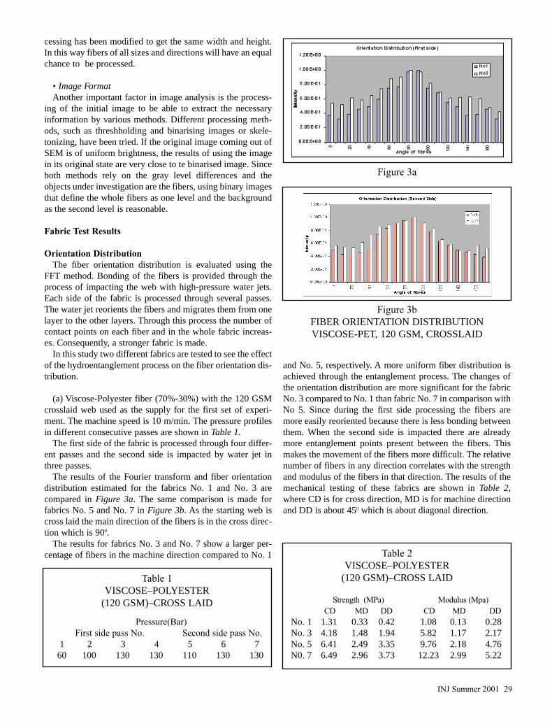
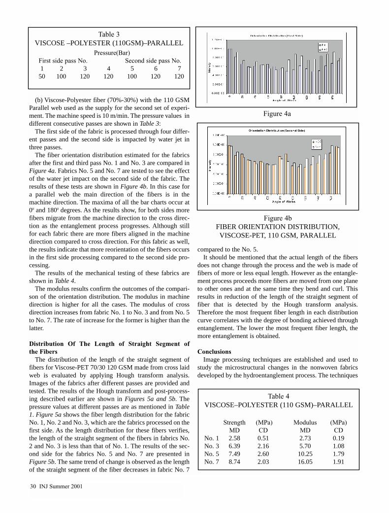
Microstructural Analysis of Fiber Segments In Nonwoven FabricsUsing SEM and Image Processing
The Role of Structure On Mechanical Properties of Nonwoven Fabrics
Studies on the Process of Ultrasonic Bonding of NonwovensPart 1 mdash Theoretical Analysis
Pira Abstracts Patent Review Researcherrsquos Notebook Technology Watch Directorrsquos Corner The Association Page
I N T E R N A T I O N A L
NonwovensJ o u r n a l
Sponsored By
Joint INDA-TAPPI Conference
Please complete and return to INTC or fax to 919-233-1282
Yes please send me more information on Attending TabletopsName __________________________________________________________ Title _________________________
Company _____________________________________________________________________________________
Address ______________________________________________________________________________________
City _________________________________________________________________________________________
State _________________________________ Country ________________ ZipPostal Code ____________________
Telephone ________________________ Fax ________________________ e-mail ___________________________
Return To INDA PO Box 1288 Cary NC 27512-1288 919-233-1210 Ext 0 Fax 919-233-1282 wwwindaorg
Major MergerBig SuccessAt the request of theindustry INDA andTAPPI combined theirtechnical conference toproduce the largestnonwovens technicalconference in the worldA total of 550 peoplefrom around the worldattended INTC-2000
Leading EdgeInformationbull Polymers amp Fibersbull Properties amp Performancebull Process Technologiesbull Filtrationbull End-usesbull Binders amp Additivesbull Wetlaidbull Absorbentsbull Barriersbull Melt Extrusionsbull Hydroentanglingbull Airlaidbull Matsbull Biodegradable Polymersbull Sustainable Polymersbull Multi-component Fibersbull Microfibersbull Composites amp Laminatesbull State of the Art Information
For Managers withResponsibility forbull New Product Development
bull Research amp Development
bull Technical Marketing amp Sales
bull Testing amp Quality Control
Executives fromAround the WorldWill Attend INTC The Placeto Networkbull Nonwoven Fabric
Producers
bull Converters of NonwovenFabrics
bull Suppliers to NonwovenFabric Producers
INJ Spring 2001 1
A Science and Technology PublicationVol 10 No 2 Summer 2001
PublisherTed WirtzPresidentINDA Association of theNonwoven Fabrics Industry
SponsorsWayne GrossExecutive DirectorCOOTAPPI Technical Association ofthe Pulp and Paper IndustryTeruo YoshimuraSecretary GeneralANIC Asia Nonwoven FabricsIndustry Conference
EditorsRob Johnson856-256-1040rjnonwovenaolcomDK Smith480-924-0813nonwovenaolcom
Association EditorsCosmo Camelio INDADV Parikh TAPPI Teruo Yoshimura ANIC
Production EditorMichael JacobsenINDA Director of Publicationsmikejacorpubcom
Wet Process Drainage mdash Effects of White Water Chemistryand Forming Wire StructuresOriginal Paper by Daojie Dong Owens Corning Science and Technology Center 14Effects of Water On Processing and Properties of Thermally BondedCottonCellulose Acetate NonwovensOriginal Paper by Xiao Gao KE Duckett G Bhat and Haoming Ron University of Tennessee 21Microstructural Analysis of Fiber Segments In Nonwoven FabricsUsing SEM and Image ProcessingOriginal Paper by E Ghassemieh HK Versteeg and M Acar Wolfson Schoolof Mechanical and Manufacturing Engineering Loughborough University 26The Role of Structure on Mechanical Properties of Nonwoven FabricsOriginal Paper by HS Kim and B Pourdeyhimi Nonwovens CooperativeResearch Center College of Textiles North Carolina State University 32Studies on the Process of Ultrasonic Bonding of NonwovensPart 1 mdash Theoretical AnalysisOriginal Paper by Zhentao Mao and Bhuvenesh Goswami School of Textiles Clemson University 38
Guest Editorial 3Researcherrsquos Toolbox 4Directorrsquos Corner 7Technology Watch 10Nonwovens Web 12
Nonwovens Patents 48Worldwide Abstracts 53The Association Page 56Meetings 57
NonwovensI N T E R N A T I O N A L
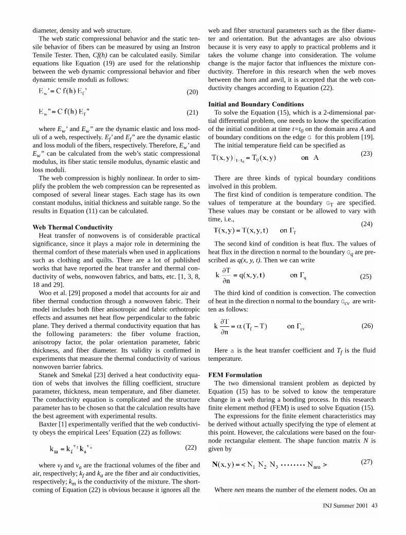
NonwovensJ o u r n a l
DEPARTMENTS
ORIGINAL PAPERS
The International Nonwovens Journal Mission To publish the best peer reviewed research journal with broadappeal to the global nonwovens community that stimulates and fosters the advancement of nonwoven technology
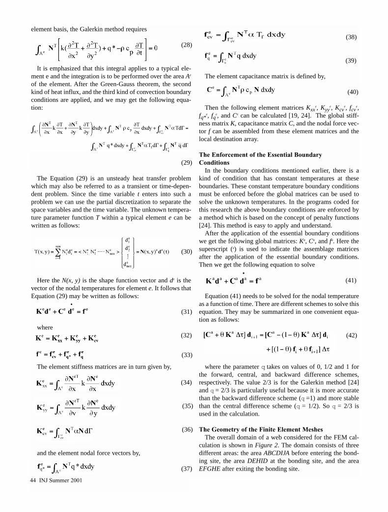
EDITORIAL ADVISORY BOARDCosmo Camelio INDARoy Broughton Auburn UniversityRobin Dent Albany InternationalEd Engle FibervisionsTushar Ghosh NCSUBhuvenesh Goswami ClemsonDale Grove Owens Corning
Frank Harris HDK IndustriesAlbert Hoyle Hoyle AssociatesMarshall Hutten Hollingsworth amp VoseHyun Lim EI duPont de NemoursJoe Malik AQF TechnologiesAlan Meierhoefer Dexter NonwovensMichele Mlynar Rohm and HaasGraham Moore PIRA
DV Parikh USDAndashSRRCBehnam Pourdeyhimi NCSUArt Sampson Polymer Group IncRobert Shambaugh Univ of Oklahoma Ed Thomas BBA NonwovensAlbin Turbak RetiredLarry Wadsworth Univ of TennesseeJ Robert Wagner Consultant
The International Nonwovens Journal is brought to you from
Associations from around the world This critical technical publi-
cation is provided as a complimentary service to the membership
of the Associations that provided
the funding and hard work
PUBLISHER
INDA ASSOCIATION OF THE NONWOVEN FABRICS INDUSTRYTED WIRTZPRESIDENT
PO BOX 1288 CARY NC 27511wwwindaorg
SPONSOR
TAPPI TECHNICAL ASSOCIATION OF THE PULP AND PAPER INDUSTRYWAYNE H GROSS
EXECUTIVE DIRECTORCOOPO BOX 105113
ATLANTA GA 30348-5113wwwtappiorg
Conventional wisdom suggests thatResearch and Development is essen-
tial to the creation and ongoing success ofan industry as well as individual compa-nies within an industry The nonwovenindustry is a prime example of the rolethat RampD has played in nonwovenrsquos brief
history of some60 years
I have spentalmost 50 yearsassociated withnonwovens andhave had a ring-side seat in thedynamic growthof the business
from its infancy to a major business seg-ment It is my intent to hit some of thehighlights of this growth with a specialemphasis on the role that RampD playedMy use of the term RampD is in its broad-est sense which includes process inven-tion modification and control productinvention and modification and marketresearch and sales development Perhapsnonwoven technology growth is a betterterm than RampD since I look at the wholechain of events as the end result of tech-nical development
My introduction to nonwovens came atCallaway Mills La Grange GA in 1953I was happily involved in RampD with abroadly diversified textile firm when theboss called me to his office and informedme that ldquoWe are going into nonwovensand you have the projectrdquo I knew nothingof nonwovens beyond the word but with-in a year submitted a proposition toinstall a pilot line using Rando Webbersto produce industrial nonwoven fabrics I
was then ldquothrown outrdquo of RampD and trans-ferred to a production unit that grew tofour lines Our plans centered on automo-tive products (backing for vinyl coat-ings) chaffer fabrics for tires shoe find-ings and interlinings
At this time in history there were fouror five nonwoven producers in the coun-try (Pellon Chicopee and West Point-Pepperell being the major players) allwere using proprietary technologyinvented and modified for specific mar-kets Total sales were around $5 millionGreat secrecy surrounded the ldquobusinessrdquoAs Technical Director of a small produc-tion unit I found that I had to invent theproduct develop the process and then goout and sell the product since our indus-trial sales force was unable to handle thisldquonew productrdquo In fact we had to inventthe market and then invent the customers
In 1960 I joined Kendall in Bostonwhich had been a pioneer in nonwovensfor over 20 years Their output came fromthree proprietary lines making specialtyproducts for the electrical graphic artsand dairy industries A ldquoNonwovenDivisionrdquo was formed in 1960 with totalsales of a little over $3 million By 1970this ldquonewrdquo division was approaching$100 million in sales
So what happened to make this sleepylittle business explode during the 1960sand rsquo70s Major new products wereinvented and marketed using nonwo-vens Prime examples include dispos-able diapers by PampG followed by manyimitators surgical packs and gowns plusa host of other hospital products fromKimberly-Clark JampJ DuPont andKendall and major new industrial fabric
markets created by DuPont and othersThese new markets were a direct result
of a bewildering array of new technolo-gies introduced by companies both out-side and inside the textile industry Itseemed that everyone was getting into theact The paper industry introduced bothwet and dry nonwovens Kimberly-Clarkbrought forth Kaycel and KimlonDuPont developed flash spun and spun-bond nonwovens Monsanto developedchemical spun products and Exxoninvented melt blown nonwovens Itbecame obvious that hundreds of mil-lions of dollars were being spent bydiverse industries to get a piece of theburgeoning nonwovens industry In 1968we established a trade association(INDA) to encompass this wide array ofinterests to promote the business
The slow simple inexpensive textileequipment that started the nonwovenbusiness underwent massive technicalinnovation to stay in the game in face ofthe assault from outside In 1962 Kendallhelped PampG invent the disposable diapertopsheet We used a 40-inch card linerunning 20 yardsminute By 1964 wewere ldquostretchingrdquo a 40-inch card web to60 inches and running at 60 yardsminBy 1966 we ldquostretchedrdquo a 40-inch cardweb to 90 inches and ran at 90 yardsminThis stretched web was an innovationthat forecast the high-speed randomizingcards specifically designed for nonwo-vens Today reportedly there are five-meter wide card lines capable of operat-ing speeds up to 1000 meters per minute
Since I entered the industry the non-wovens business in North America hasgrown from approximately $5 million tothe current $38 billion and 256 billionyards (INDA 2000 Estimates) Vast tech-nology changes have occurred
So is it all over Of course not Fiftyyears from now the industry will be asdifferent and advanced from today astoday is from when I started in 1953Leading the charge to make this happenwill be the hundreds of RampD people cur-rently working on nonwovens and thehundreds that will follow to keep the rev-olution going
Have a nice journey mdash Wayne Hays
CONTINUE THEJOURNEYBy Wayne HaysFormer INDA Chairman and Recipient of theIDEA 01 Lifetime Achievement Award
GUEST EDITORIAL
INJ Summer 2001 3
Useful Microwave TechnologyIn a few short years the handy
microwave oven has become very ubiq-uitous (ubiquitous adj seeming to bepresent everywhere) In view of itsspeed economy efficiency and conve-nience it is not too surprising that thistool has made its way out the kitcheninto a wide variety of other applica-tions
The adaptation of microwave tech-nology to applications within the textileand nonwovens industries has beensomewhat slow and still rather limitedThrough the efforts of several groupshowever this situation is changing andthe microwave system is finding its wayinto numerous uses in the productionplant and also in the laboratory
The first commercial use ofmicrowave heating for a textile dryingunit operation was probably the appli-cation to drying rayon filament yarnbobbins In this application the wetfreshly spun and washed filament bob-bin was placed on a conveyor that slow-ly passed through a zone of microwaveradiation Each individual bobbin wasrotated on its axis as it slowly traversedits path through the drying zoneBobbins of dry filament were removedfrom the unit
The first use of a microwave systemin the laboratory was undoubtedly thedrying of small textile fabric samples asa part of the determination of moisturecontent For this application the speedand convenience were unparalleled byother methods However this methodand other similar trial efforts highlight-ed a major problem with the microwave
systems available mdash uniformity of thetreatment In the kitchen microwaveoven the target is often on a turntable toprovide multiple passes in front of thesource to hopefully even out randomlyoccurring hotspots Unless the treat-ment is done uniformly hotspots candevelop resulting in over-heating insome areas and under-heating in others
To correct this problem recent workhas focused on the use of ldquowaveguidesrdquoto serpentine the microwave energyback and forth across whatever materialis being treated With proper design ofthe waveguides and supporting equip-ment a specific environment for theparticular wavelengths can be created toprovide a controlled distribution of themicrowave energy making it possible toachieve uniform exposure to any mater-ial moved though a channel or space Insome designs the waveguide itself actsas the treatment space and the position-ing (top bottom middle) of the materi-al as it travels through the space canprovide additional control over theenergy picked up by the material
With this improved uniformity in dis-tribution some amazing results can beachieved Two different fabrics can bepassed through a carefully designedchannel or oven plenum the one fabricentering wet and the other being dry Onemerging both of the fabrics are at anequal level of dryness with no over-heating of the dry fabric This is thetype of result that technologists havehoped for from microwave technologyand now it appears to be available
One company that has been a leaderin this work is Industrial Microwave
Systems (IMS) of Morrisville NC(IMS 3000 Perimeter Park DriveMorrisville NC 919-462-9200wwwindustrialmicrowavecom) Theirpatented design concept is called theldquoPlanar Drying Systemrdquo and it usesmicrowave energy focused at specificangles to achieve various treatment pos-sibilities Some of their applicationshave involved treating tubular knitssheets of individual yarns in yarn sizingapplications and others In a systemdesigned for terry towel drying fasterproduction speeds were possible withthe uniform treatment An additionalbenefit in this case was that the fabrichad good softness even though a chem-ical fabric softener was not employed
This method has also ben applied tothe drying of carpet tile In this applica-tion uniform drying can be achievedwithout damaging the backing or sub-strates and there was no heat degrada-tion of the carpet materialSignificantly substantially increaseddrying speeds can also be achievedInstallations have been made up to 30-feet wide and material can be treated ina thickness up to two inches
This company has recently becomeinvolved in several nonwoven applica-tions one of which has been assisted bya grant from the federal Department ofEnergy which is interested in the ener-gy saving possibilities with this type ofsystem This has involved direct dryingdrying of printed webs and coatedwebs as well as treatment and drying ofcomposite and laminated structures
The system has also been applied tothermosol dyeing in this case the excel-lent uniformity has virtually eliminatedthe usual liquor migration in the treatedfabric resulting in more uniform dyedistribution With a suitable designmicrowave drying in a dye beck or jetdyeing unit can be achieved with a tem-perature variation within the fabric ropeof only 010C
The beauty of the microwave systemis the fact that the energy absorption canbe controlled to a rather fine degreeThe oscillating microwave energy is notabsorbed to any degree by nonpolarmaterials This includes most polymeric
RESEARCHERrsquoS
TOOLBOX
INJ DEPARTMENTS
4 INJ Summer 2001
INJ Summer 2001 5
materials and most fibers of interest tothe textile and nonwoven industriesThe polar water molecules held within anonpolar matrix do absorb the energyvery efficiently as they attempt to oscil-late in a synchronous manner to themicrowave oscillations Because of thevelocity of the oscillations the watermolecules become heated putting themin an ideal condition to be evaporatedfrom the substrate
As soon as the substrate has lost itswater content no further absorption ofthe microwave energy occurs and sothe substrate does not heat up but canactually begin to cool As a conse-quence the energy absorption can bevery specific to water if the proper sys-tem is employed
Other molecules in addition to waterwill absorb microwave radiation soapplications beyond drying are alsopossible Metals absorb energy from amicrowave source This feature resultsin some limitations but also in someunique applications For example finemetal powder can be suspended in aninactive medium which is printed ontoa substrate Only the printed pattern isheated as the substrate traverses a treat-ing system Many other variations havebeen conceived for exploitation of thesystem
Numerous laboratory uses formicrowave treatment are evolving andfinding utility in a variety of applica-tions These will be discussed further ina subsequent issue of the InternationalNonwovens Journal
Nonwoven Processing Equipment atTexas Tech
A frequently encountered problem innonwoven development work A goodconcept needs further work and somepilot trials but the necessary equipmentis not available
One of the most effective solutions tothis dilemma is to seek the necessaryequipment elsewhere and to makearrangements to use the equipment on atemporary basis In these circum-stances the facilities at various univer-sities is often the answer Such facilities
can generally be leased or otherwise bemade available on a fee basis This canfrequently be accomplished with theadded bonus that skilled operating per-
sonnel can also be obtained When theright location is identified this can bean elegant solution to the problem
A few years ago INDA organized a
RESEARCHERrsquoS TOOLBOX
PORTABLE SPECTROSCOPY OFFERS A SOLUTION
TO AN AGE-OLD RESEARCH PROBLEM
Every now and then laboratory scientists are given a problem where theywished they could take their laboratory into the plant the customerrsquos opera-
tion or some other remote location to study a particular situation The scientisthas often been convinced that if only they could get the infrared unit or someother equipment into a particular location the answer could be easily obtained
A sizeable step forward in making that wish come true is the advent andadvances associated with portable spectroscopy units Feature articles in thisDepartment in previous issues of the International Nonwovens Journal havedwelt with the advances being made in equipment to assist in identifying plasticmaterials slated for recycling efforts Now further powerful equipment and capa-bilities have advanced beyond with the development of portable spectrometerswith broad capabilities and even portable FTIR equipment
The Tristan line of spectroments typifies some of these advances This partic-ular product line is the development of an alliance of three German companiesthat brought their specific talents together to develop this sophisticated systemThe company m-u-t GmbH brings their engineering and development experienceon RampD operations to the alliance Photon Technology International Inc (PTI)has broad experience in spectroscopy as does PhotoMed GmbH with specialskills in applications
Together the group has developed the portable and versatile Tristan unit whichcan measure absorption reflection transmission and fluorescence by measuringthe wavelengths and intensities of light emission It can rapidly and simultane-ously detect the entire spectral output of light from ultraviolet to the near infraredalong with an extended-red sensitive version The unit includes the light sourcesprobes sample handling accessories optics system computer for control andrecording of spectra Developed applications include analysis of ingredients andraw materials textile color control identification of plastics glass and other recy-clates A power source allows eight hours of remote operation (PhotonTechnology International 1009 Lenox Drive Suite 104 Lawrenceville NJ08648 609-896-0310 Fax 609-896-0365 wwwtristan-homecom)
Portable FTIR technology has been used for a wide variety of analyses includ-ing organic chemicals inorganic materials clays soils paints and other coatingmaterials petrochemicals petroleum products adhesives plastics and others Aninteresting application that has quite fully exploited the potential of this portableequipment is in connection with the examination of paintings sculpture andother art objects
In this case the on-site capabilities as well as the non-destructive characterand the adaptability to extremely small sample size have been significant advan-tages This has allowed art conservators and experts to authenticate art objectsand also to eliminate fraud and counterfeit items Further this technique hasbeen very useful in examining deterioration and guiding restoration efforts Oneadditional interesting use for portable FTIR has been in examining petroglyphson stone walls and in caves at some remote archeological sites
Maybe that difficult problem out in the plant can be studied and solved withFTIR analysis after all
survey of the nonwoven process andtesting equipment available at the majoruniversities in the US a report of thefacilities available at that time was pre-pared Material from this report is cur-rently available at wwwindaorg
With an announcement coming out ofTexas Tech a new location and theirnew process equipment now needs to beadded to this roster Texas TechUniversity in Lubbock TX has recentlyadded some advanced needling equip-ment which puts them in a potent posi-tion to become deeply involved in non-woven technology This equipment isbeing added to the International TextileCenter at Texas Tech under the direc-
tion of Dr Seshadri Ramkumar AdjunctProfessor at Texas Tech
The Nonwoven Laboratory at theInternational Textile Center will be thefirst facility in the US to have thisneedling capability It is based on thestate-of-the-art Fehrer H1 Technologyneedlepunch loom The principle of theH1 Technology and of this equipment isthe special properties that can beobtained by oblique angled needle pen-etration This unique capability isachieved by means of an asymmetrical-ly curved needling zone accompaniedby a straight needle movement Becauseof this design some fibers are punchedor inserted at an angle rather than in a
vertical direction According to thedesign developer the advantages of thisnew technology include the following
1 The longer needle path results inbetter fiber orientation and fiber entan-glement than the conventional needlemachine
2 Superior web properties can beobtained with fewer needle penetra-tions
3 It greatly enhances the constructionof composite and hybrid products
4 It delivers increased productivityversus conventional needlepunchlooms
The processing line includes units forcomplete processing from bale to fin-ished fabric A Tatham Card fitted witha three-rollerseven-roller design is fedby a Tatham Single Automatic FeederModel 503 this latter unit is equippedwith a volumetric delivery system AMicrofeed 2000 unit is included in theline to monitor the fiber delivery fromthe chute section of the volumetric hop-per and to speed of the card feed rollersthis compensates for any discrepancybetween the pre-programmed ldquotargetrdquoweight and the continuously monitoredldquoactualrdquo weight Thus the Microfeedunit ensures extremely accurate fiberdelivery into the card unit The webfrom the card is delivered from the sin-gle doffer section of the card to aTatham conventional design crosslap-per The line is equipped with an ACInverter-controlled drive system
A research program focusing on thisnew line has been supported by aresearch contract from the Soldier andBiological Chemical Command of theUS Department of Defense The majorobjective of this research program is todevelop special protective fabrics thatcan be used by the Command to provideadvanced textile materials to all branchesof the military
Additional information can be obtainedfrom Dr Seshadri S RamkumarTexas TechUniversity International Textile Center Box45019 Lubbock TX 79409 806-747-3790ext 518 Fax 806-747-3796 sramku-marttuedu wwwitcttueduramhtm
mdash INJ
6 INJ Summer 2001
RESEARCHERrsquoS TOOLBOX
INTC 2001 A GREAT TOOL FOR BOTH THE
INDA AND TAPPI TECHNICAL COMMUNITY
The 2nd Annual International Nonwovens Technical Conference(INTC) 2001 co-sponsored by TAPPI amp INDA will be held
September 5-7 2001 at the Renaissance Harborplace Hotel in BaltimoreMaryland Over 80 technical papers will be presented in 14 sessionsmaking INTC 2001 one of the largest technical conferences ever in thenonwovens industry
Combining the TAPPI Nonwovens and INDA technical conferenceshas worked out for the better of the technical nonwovens community Oneexample is found in the Properties and Performance session NormLifshutz will present results on the development of a fiber length testmethod conducted in a TAPPI Fiber Length task force while MikeThomason will present INDA test methods on behalf of the INDA TestMethods Committee
Other sessions of focus are Absorbents Barrier Binders amp AdditivesFiltration Finishes amp Surfaces Mats amp Insulation On-Line MeasurementsPolymers amp Fibers Properties amp Performances Sustainability and four ses-sions have been devoted to new process technologies
INTC 2001 will once again offer attendees the nonwoven tutorialtaught by industry veterans Roy Broughton of Auburn University TerryYoung Procter amp Gamble and Alan Meierhoefer Ahlstrom Fibers Otherreturning favorites include the Student Paper session the NewTechnologies Showcase and the evening tabletop event and reception
The six technical committees of the TAPPI Nonwovens Division mdashProperties and Performance Process Technology Building and IndustrialMat Binders and Additives Polymers and Fibers and Filtration mdash willmeet during the lunch sessions on September 5th and 6th
Written papers are due to INDA by June 26 and presentations in elec-tronic form are due to TAPPI by August 1
For conference or registration information regarding INTC 2001 visitINDArsquos website at wwwindaorg or call 919-233-1210
Success In Innovation ProjectsA research center within the Wharton
School of Business at the University ofPennsylvania focuses on innovation andentrepreneurship The Sol C SniderEntrepreneurial Research Center isstaffed with world-renown scholars andresearchers and has done some far-reaching research in the correlation ofinnovation with other business and eco-nomic factors
A recent study was directed towardthe effects on innovation team perfor-mance of three underlying elements ofmanagement organization and opera-tion The three elements studied indetail were as follows
bull Task Structure The physical organi-zation of the innovation team
bull Project Framing Delineation of theproject goals and methodology
bull Team Deftness Team effectivenessas assessed by past performance andother factors
The study used a total of 138 innova-tion projects for analysis projects inwhich the ultimate success and effec-tiveness could be quantified
The results of this study suggestedthat the absence of Project Framing interms of clearly specified goals andresponsibilities had a negative correla-tion with team performance Clearlydefined goals and clean-cut responsibil-ities are critically vital to the innovativesuccess of the team Any uncertainly inthese two factors were manifestly oper-ative in detracting from the perfor-mance of the innovation team
The factor of ldquoTeam Deftnessrdquo corre-lated with performance of the team andalso had an impact on Project FramingThe researchers suggested that this fac-tor had a moderating effect on the totalperformance and could help to modify
some of the problems associated withProject Framing This suggested thatexperienced and capable innovatorscould overcome to a certain extent theshortcomings of management in notclearly defining the goals and teamassignments In essence the experi-enced innovators sensed the need andfilled this missing factor themselves
The researchers concluded that theoften-assumed positive relationsbetween organization of the team andits success is valid but only for relative-ly high levels of organization and oncomplex projects
The message Organize your teamwell provide very clear-cut objectivesand responsibilities and use capableand experienced people on your innova-tion team
Attracting Laboratory TechniciansSome concerted thinking and action
is being devoted to the position of labo-ratory technician In the past many ofthe individuals who are lab technicianshave come into the laboratory withoutexperience it often has been the respon-sibility of the employer to train suchindividuals and to equip them for theresponsibilities they will eventually begiven
Such ldquohome-grownrdquo talent may havesufficed in the past Certainly someoutstanding people have come upthrough the ranks in this fashion Morethan a few patents covering nonwoventechnologies have the name of an out-standing lab technician as a co-inventor
However training of laboratory tech-nicians is being done more and more bytrade schools community colleges andeven universities A capable lab techni-cian can be a real asset to a RampD estab-lishment Consequently more thought
is being given to the proper training anddevelopment of such talent ThePartnership for the Advancement ofChemical Technology recently conduct-ed a Research Profile Study to assessthe personality traits attitudes learningstyles and values of quality lab techni-cians The study sponsored by theNational Science Foundation coverednot only such individuals but also stu-dents studying for such a career as wellas instructors involved in their training
The study found these individuals tobe highly collaborative and only moder-ately independent or competitive Thestudents also tend to be more introvert-ed than the general class of studentsand they are nontraditional with manyolder than 30
In focusing on the ideal instructionfor these individuals the study revealedthat curriculum designers should con-sider including group problem-solvingactivities and roundtable discussions intheir courses for lab technicians Theseare the skills and environmental fea-tures involved in this type of work andso appropriate training should be pro-vided
Also the study showed that almosthalf of the technician students have afriend who works in a laboratory orsimilar job suggesting that current labworkers are a good conduit for gettingthe word out to prospective studentsFurther greater efforts should be madeto assure these students that the careersavailable put them in a good position totruly become professional researchers
RampD Return On InvestmentA sizeable portion of the industries
throughout the world would considerthemselves to be a part of a vastresearch-driven enterprise Certainlythose in the nonwovens industry wouldconsider their activities to fit into thisclassification (Note the message in theeditorial in this issue)
Such research-driven companiesalmost invariably believe or at least paylip service to the concept that moneyinvested in RampD activities provide apayback Proof of such a return howev-er is always difficult to establish espe-
DIRECTORrsquoS
CORNER
INJ DEPARTMENTS
INJ Summer 2001 7
8 INJ Summer 2001
cially if inadequate accounting practicesare employed Too frequently the evi-dence is ephemeral a ldquogut feelingrdquo oranecdotal in nature Many businessleaders want a more precise and defend-able basis for the annual agonizing deci-sions involved in approving the RampDbudget
Surely the $419 billion chemicalsindustry in the US is a research-drivenaffair And yet even this business seg-ment struggles with the Return OnInvestment for the RampD budgetNoteworthy is the fact that the chemicalindustry portion of the total US RampDinvestment has been declining for yearsfrom 11 in 1956 to about 8 in thepast decade
The exact reason for this decline isuncertain perhaps the percentages areskewed by the fact that the computerand related research-oriented industrieshave grown so much in the past decadeand chemicals are just a smaller piece ofthe whole Undoubtedly another factoris that no one has exactly quantifiedwhat kind of bang these companies getfor their research buck
A new report from the Council forChemical Research (CCR) addressesthis problem by analyzing data frommore than 80 publicly traded chemicalcompanies From this study the conclu-sion was drawn that on the averageevery dollar invested in chemical RampDtoday yields $2 in operating incomeover six years This has apparently con-firmed many of those gut feelings
In the next phase being pursued bythis program CCR will evaluate resultsfrom specific types of RampD It is hopedthis study will lead to techniques topicsand evidence that will further validatethese concepts This should materiallyhelp to further sharpen the businesscommunities view of RampD expenses inthe chemical industry It is sincerelyhoped that similar forces are actingwithin the nonwovens industry
Getting the Message OutOne of the most difficult responsibili-
ties for a Research Director is to get outthe numerous messages associated with
DIRECTORrsquoS CORNER
MEETING STAFFING NEEDS WITH SENIORS
Although conditions change quite rapidly there does seem to be continuingproblems with research organizations filling all of their staff needs The
Research Administrator feels this is especially true when it comes to filling theempty slots with ldquogood peoplerdquo
One potential source that may be overlooked in this search is the labor pool ofolder workers and even senior citizens Of course most of these slots requirespecial skills However such special skills are not unknown amongst the reser-voir of such older people
Some universities have done an excellent job with this approach enlisting theservices of experienced and seasoned professionals Sometimes the position iscreated with a specific individual in mind perhaps to teach a special course orassist with a special project The position of ldquoAdjunct Professorrdquo ldquoAdjunctResearch Scientistrdquo or similar is often used to designate and exploit such talentThere are several notable examples of this approach within academe at the pre-sent time in both the practical as well as the theoretical domain
However virtually all levels of technical scientific and business activities canbe considered for this approach A second career even at a lower level and asomewhat different arena may be attractive to individuals with talent skills andexperience The old wisecrack about the person who retired and then went seek-ing a job after six weeks likely has a solid basis in fact
This is borne out by data from the recent US Census The number ofAmericans 65 and older working or seeking work increased 10 between March1999 and March 2000 to 45 million the Census Bureau said in a recent reportThese data indicated that there was a 22 increase in seniors in administrativesupport positions including clerical jobs and an 18 increase in sales job
The Alliance for Retired Americans in pointing to these increases indicatesthere are 326 million in the age group over 65 1 more than in the previousyear Not all of these people want to work obviously but an increasing portionapparently do want to continue to work
It is interesting that a recent Wall Street Journal article (May 23 2001)described an effort by the American Association of Retired People This organi-zation wanted to select the ldquoBest employers for workers over 50rdquo They mailedinvitations to 10000 companies to provide information to assist in the selectionOnly 14 companies responded
Many companies indicated they had not given that aspect of their HumanResources efforts any consideration It seemed to be an area where the averageemployer was largely out of step with the aging of the work force
There are some companies that are exceptions of course they obviously areexceptional At CVS drugstore chain for example 15 of the employees areover 55 CVS actively recruits older workers It says they stay with the compa-ny longer and show more commitment
There are obstacles to some of these practices including phased-retirementwhere an employee goes from a full-time status to employment that is less thanfull-time Some of the obstacles are related to retirement taxation pension bene-fits etc These obstacles may require federal legislation to correct Working con-ditions flexibility and a desire for autonomy may be other factors to consider
Overall however this is an employee pool that will receive more considera-tion by managers in the future After all during the year of 2001 the number ofworkers who are 40 and above will surpass those under 40 for the first timeGood Hunting
safety accident prevention pollutioncontrol and the like It is a task that isnever finished it has so many aspectsand yet can be critically importantespecially in retrospect following anldquoeventrdquo
Pity the plight of the poor SafetyManagerIndustrial HygienistEnviron-mental Manager who must deal withsuch motivational things all the time
The problem is to continuously getthe messages out to all personnel getthem to read or study the materials atregular intervals and then repeat andreinforce the messages unceasinglyThatrsquos quite a challenge
One enterprising Safety and Hygieneofficer within the Procter amp Gambleorganization chose a rather unusualapproach that has proved to be quiteeffective He acknowledges that he didnot get prior management approval forthe technique undoubtedly because hewas rather confident that such approvalwould not be forthcoming Neverthe-less he moved ahead with determina-tion by regularly posting his safety mes-sages in the bathroom stalls at the PampGHealth Care Research Center in MasonOhio To ensure sufficient time for theentire message to be read and studiedthe postings were made adjacent to thetoilet commode where they would beeasily available to every occupant
The safety-related items were soonreferred to as ldquopotty postingsrdquo alsocalled ldquotoilet tabloidsrdquo The managerconfessed that there was a certainamount of resistance to the approach atfirst but the message was getting outOne associate complained that ldquoOur lastbit of privacy is being invaded by safetymessagesrdquo Another asked the questionldquoIs no place sacredrdquo
Undaunted Allan Bayless the SafetyManager persevered in the program andwas rewarded within a few weeks whenthe grousing subsided and some positivecomments began to emerge He reportedthat some colleagues even began tooffer suggestions and to request newpostings if the current ones stayed uptoo long
He now has management approval
and reports that the approach is beingtried at other PampG locations His expe-rience has shown that popular topicsinclude a range of rather violent eventsApparently everyone loves an accidenta flood a fire or a reaction gone crazyHe always tries to exploit the describedevent by discussing what went wrongand what should be done to correct thesituation Bayless found this approachto be much more effective than simplee-mailing individuals After all an e-mail can be discarded with a key stroke
If this approach sounds useful andfurther information in desired Baylesscan be contacted via e-mail atbaylessavpgcom
An Environmental PolicyThe peoples of this earth have come a
long way in developing an environmen-tal conscience and doing the ldquorightthingrdquo The past 40 years have seen alarge portion of the population growfrom disinterest into a strong concern forthe worldrsquos environment and the legacythat will pass to future generations
The effort has had its distracters ofcourse On the one side there have beenthe adamant resisters and the obscenepolluters On the other side have beenthe eco-extremists and eco-thugsDespite this situation progress has beenachieved
An interesting policy statement on theenvironment and their relationship to ithas recently come from one of the non-woven industryrsquos major members mdashJW Suominen Oy Nakkila Finland
While Suominenrsquos EnvironmentalPolicy statement is simple and straight-forward it clearly provides a basis fordecisions both large and small It can bereadily understood by top managementboard members middle managers andemployees at all levels as well as bycustomers competitors and the generalpublic It would seem that all sectors ofthe industry would benefit from a simi-lar simple statement or credo thatwould guide all phases of a companyrsquosoperations
An example of SuominenrsquosEnvironmental Policy statement appears
in the box on this page To decrease environmental loading
JWS uses BATNEEC (Best AvailableTechnology Not Entailing ExcessiveCosts) minimizes the waste and recy-cles where feasible JWS commits tofulfill relevant environmental legisla-tion regulations and other obligations
Top management establishes the envi-ronmental objectives and appropriateresources for their implementation andmonitors their performanceSupervisors are responsible for imple-mentation of environmental targetsrelated to their area of responsibility andcontinually aim to consider theimprovement of environmental perfor-mance while developing activities andworking practices
Personnelrsquos commitment as well asthe recognition of their own responsibil-ity is ensured by systematic trainingcommunication and encouragement
While it may not be perfect it is con-cise and understandable mdash INJ
INJ Summer 2001 9
DIRECTORrsquoS CORNER
ENVIRONMENTAL POLICY
JW Suominen develops producesand supplies nonwovens profitablyaccording to customersrsquo needs such
that the activityrsquos adverse environmen-tal impacts are as slight as possible
JWSrsquos key environmental aspects are
bull Prevention of pollution
bull Continual improvement so thatenvironmental loading in relation to
production volume decreases annually
bull Environmental loading is moni-tored and measured comprehensively
and the results are public
Tracing Water Pollution SourcesIn the past water polluters have benefit-
ted from the fact that water pollution can beclearly identified but the source of pollu-tion is much more difficult That situationmay be changing somewhat with theadvent of a DNA ldquofingerprintingrdquo test totrace the source of water pollution
This test which was developed at theUniversity of Missouri-Columbia is basedon tracing the water pollution back to itssources by using the DNA from bacteriaThe presence of fecal E coli bacteria mdashmicrobes that live in the intestines of theirhost until they are excreted mdash commonlyis employed to establish if the pollution isdue to human or animal wastes Whilethese organisms of themselves are non-pathogenic their presence in a water givesa warning of the potential presence of otherdisease-producing strains of E coli salmo-nella or hepatitis virus that can also befound in human and animal waste
The method utilizes a technique knownas DNA pattern recognition or ribotypingThis novel approach takes advantage of thefact that each host species harbors specifictypes of E coli in the intestinal tract thathave specific DNA patterns or ldquofinger-printsrdquo The DNA results are then com-pared to known DNA patterns from knownhost species This then gives an indicationof possible sources of the contamination
At the present time the method can beused to clearly identify contaminationcoming from eight common hostshumans cows pigs horses dogs chick-ens turkeys and migratory geese Furtherwork is being carried out to expand theDNA database of hosts and to furtherrefine the technique to identifying charac-teristics of pollution sources Currentchemical analysis of course can providevery precise information on the presence oforganic and inorganic pollutants thesedates coupled with water flow and move-ment patterns can generally pinpoint thesources with convincing results
Active AntibacterialsThe use of antibacterial agents in a host
of consumer medical and industrial prod-ucts has exploded in the past few yearsSeven times as many antibacterial prod-ucts were produced in 1998 than in 1992Antibacterial finish has become the stan-dard finish in some textile product cate-gories Nonwoven products have partici-pated in this action is a significant wayespecially in nonwoven wipes
The practice has become sufficientlywidespread that consideration has beengiven to legislation to stiffen controls onthe use of such materials Some warningshave been put forth by the medical pro-fession arising from the concern that suchmaterials can kill beneficial germs as wellas deleterious ones Also there is concernthat resistance to such agents can developand could lead to a range of super-germs
Despite such concerns the use of theseagents is proliferating
Most such agents act by leaching fromthe material to which they are originallyapplied and then contact the microorgan-isms and kill them by such contact Theseare the ldquoleachingrdquo type agents
Their effectiveness diminishes as theleaching continues of course and theleaching can lead to excessive skin con-tact or even to the crossing of the skin bar-rier such behavior can lead to a variety ofproblems
Another class of antibacterial agents isactually bound to the substrate by molec-ular or other forces Such ldquoboundrdquo mate-rials usually have hydrophilic or othergroups in the molecule which can pene-trate the microorganism allowing quater-nary ammonium groups or other groupsto rupture the organismrsquos cell wall lead-ing to expiration This bound type ofmaterial can kill when the organismresides on the substrate hence it is morelimited in scope
An interesting class of durable agentswas recently described with the added
feature of being capable of regenerationof the active chemical moiety In thisagent one functional group is used toattach the molecule permanently to cellu-lose fiber via a molecular bond The func-tional group also contains a cyclic hydan-toin group which can be easily chlorinat-ed to form the reactive cyclic chloro-hydantoin group This latter group is aneffective disinfecting agent that is widelyused in swimming pools and other simi-lar applications As the disinfectingaction continues the chloro-group is con-verted back into the unsubstituted hydan-toin group This latter group can be easi-ly converted back into the active chloro-hydantoin form such chlorination can bedone simply by treating the fabric with achlorine bleach Hence the regenerablefeature
Very recently a special polymer hasbeen developed at MassachusettsInstitute of Technology that is claimedto have special germicidal propertiesWhen the polymer is coated onto a hardsurface the developers claim that it isthere permanently and can guard againstinfections commonly spread by sneezesand dirty hands The materials isdescribed as hexyl-PVP (PVP-polyvinylpyridine)
The PVP portion has been known to beactive in solution but attempts to immo-bilize the material on a surface seemed torender the polymers totally inactive Theresearchers found that the addition of thealkyl chain (3-6 carbon atoms) eliminatedthe inactivation It is claimed that thismaterial in a coating form is able to kill upto 99 of Staphylococcus Pseudomonasand E coli all common disease-causingorganisms The killing action is stated tobe via a powerful chemical-electricalaction The researchers have hypothesizedthat the addition of the polymer side chainof the right length provides flexibility forthe coating material to penetrate the bac-terial cell wall envelope on contact and doits job These are the first engineered sur-faces that have been shown to kill air-borne microbes in the absence of any liq-uid medium This work suggests a newpossible approach to engineer a solid sur-face to provide bacteria-killing action
The major markets for most types of
TECHNOLOGY
WATCH
INJ DEPARTMENTS
10 INJ Summer 2001
INJ Summer 2001 11
biocides is for water treatment paint pro-tection wood preservation and similarapplications Use in textile and fiber mate-rials is significant however and is contin-uing at a fast pace
Another somewhat related develop-ment in chemicalbiological activity oftextile fibers concerns cotton wipes thatcan be used to decontaminate nerveagents on contact This work involvescovalently linking an enzyme to cottonfiber The enzyme organophosphorushydroxylase from Pseudomonas diminu-ta is the only enzyme known to detoxifya wide range of nerve agents The modi-fied fabric rapidly hydrolyzes the agentParaoxan (a nitrophenyl ester) indicatingthe immobilized enzyme retains it activi-ties The fabric can also convert the infa-mous nerve gas Sarin along with othersas well as the toxic insecticides parathionand methylparathion to harmless by-products The fabric doesnrsquot irritatehuman skin and retains 70 of its originalenzyme activity after two months eitherrefrigerated or stored at room tempera-ture
Modified fibers and fabrics can obvi-ously be made to do wondrous feats
More Chemical ScaresA recent action by a government-spon-
sored panel of scientists and environmen-talists has the potential of creating a super-abundance of chemical scares in the futureIf the course outlined by this panel is fol-lowing research administrators are in for arough ride ahead
The problem centers around a report bya National Toxicology Program panelwhich concluded in May 2001 that somechemicals can affect laboratory animals atvery low levels well below the ldquono effectrdquolevels
This rather shocking self-contradictoryconclusion violates a fundamental princi-ple of toxicology mdash namely that ldquothe dosemakes the poisonrdquo This principle assertsthat all substances can act as poisons in suf-ficiently high amounts even such benignsubstances as water sugar and salt youname it However below their ldquotoxicdosesrdquo such substances are considered notto be poisons
The government panel concluded thatthere is ldquocredible evidencerdquo of the effect ofsome chemicals on laboratory animals atsuch very low levels The evidence seemsto flow from concern with so-called
endocrine disruptors also referred to asenvironmental estrogens These materialsare described as hormone-like chemicals inthe environment that can disrupt normalhormonal processes and cause everythingfrom cancer to reproductive problems toattention-deficit disorder
The public concern with these possi-bilities began with claims based onresearch work by the University ofMissouri researcher Frederick vom Saaland a book he published entitled ldquoOurStolen Futurerdquo He carried out experi-ments on laboratory mice that purported-ly showed that very low doses of somechemicals increased prostrate weight inmale mice and advanced puberty infemale mice The doses employed werethousands of times lower than currentsafe standards
Reportedly no other laboratory has beenable to reproduce vom Saalrsquos work repro-ducibility of experiments is necessary ofcourse before a conclusion can be accept-ed However vom Saal all but guaranteedthat his work will never be reproduced Hisexperiments involved a unique strain ofmice that he inbred in his laboratory forabout 20 years When the mice stoppedproducing the results he wanted he killedthem
However the results he promoted wereembraced by others who felt they matchedtheir environmental and political agendaThe panel given the assignment to assessthis situation was apparently loaded withsuch individuals
In any event the panel recommendedthat the EPA consider changing its guide-lines for assessing risk of reproductive anddevelopmental effects from chemicalsAccording to some experts this recom-mendation is likely to spread to othernational and international regulatory agen-cies
The low-dose theory could put virtuallyevery industrial chemical and many con-sumer products at risk of being stringentlyregulated or banned without a scientificbasis This development bears watching byanyone concerned with chemicals andproducts Further information can beobtained at several websites includingwwwjunksciencecom mdash INJ
TECHNOLOGY WATCH
SYNTHETIC PAPER SHOWING EXCEPTIONAL GROWTH
Originally introduced into Japan several years ago synthetic paper is startingto show exceptional growth in a variety of markets and applications
This product consists of thin plastic sheet material containing a filler or a spe-cial coating to give it the printing characteristics of conventional paper The basefor a synthetic paper may be polyethylene polypropylene polystyrene or poly-ethylene terephthalate suitable fillers are titanium dioxide calcium carbonate orvarious silicas typical paper coatings based on clay calcium carbonate or othermaterials can be employed to provide a good printing surface
The growth of this type of material is expected to be in excess of 8 per yearfrom a current base of about $200 million this will result in a 166 million poundmarket by the year 2005 according to one recent study
The use in specialty label applications is the largest current market for thesematerials However it is anticipated that growth in other related markets willexceed the growth in labels these other market applications include commercialprinted products such as greeting cards menus maps books and covers signageand point-of-purchase displays In the label market segment significant applica-tions include pressure sensitive labels in-mold labels and unsupported tags
At the present time major producers include PPG Oji Paper (Japan) throughtheir subsidiary Yupo Nan Ya Plastics ExxonMobil and Arjobex (a three-wayjoint venture of BP Arjo Wiggins (London) and Appleton Papers) Some ofthese properties and markets suggest possible usage of nonwoven materials
Distance LearningIt used to be that a remote location pre-
cluded a number of activities for a per-son who was so unfortunate An oppor-tunity to study and continue onersquos educa-tion was certainly one of those factorsthat had to be sacrificed No More
If the men and women serving in theUS Navy aboard a ship at sea anywherein the world can continue their graduateeducation location is no longer an insur-mountable barrier The solution is whatis referred to as ldquoDistance LearningrdquoThat is not learning about how far ldquofarrdquois but rather it signifies learning that canbe done at virtually any distance fromthe source of the teaching
A growing number of universities andcolleges are beginning to offer anexpanding selection of courses that arepresented via the Internet This arrange-ment is not the same as a correspondencecourse as the student can virtually bepresent in the usual class setting andhave direct and instantaneous contactwith the instructor and fellow studentsall by means of a computer terminal anda communications link
Many universities are working to con-vert their classroom materials into a formmost suitable for this mediumProfessors and teachers are learning howthe usual teaching methods can be mosteffectively converted into the cyberspaceclassroom Some adaptation of methodsand materials must be made of coursebut the transition is being mastered
At the government level the SmallBusiness Administration (SBA) hasintroduced the new SBA Small BusinessClassroom which brings electronic busi-ness courses to anyone with a standardInternet connection This virtual class-room provides interactive easily accessi-ble courses on the topics most in demandby small-business owners Typical class-
es include ldquoThe Business Planrdquo (inEnglish and Spanish) or ldquoHow to RaiseCapital For a Small Businessrdquo At the endof each lesson students can participate ina scheduled chat room or call a toll-freenumber to talk with a counselor(wwwsbagov and then select SBAClassroom)
Not a part of Distance Learning therewere recent press reports on several cam-puses involving enterprising studentsputting todayrsquos lecture notes on the webfor the benefit of friends who missed theclass Some professors objected strenu-ously to this practice even claiming thatnotes from their lectures were akin tocopyrighted material In direct contrastto that attitude is the recent announce-ment by Massachusetts Institute ofTechnology (MIT) that over the next 10years the university will post materialsfor almost all of its courses on the WorldWide Web accessible to one and all at nocharge Materials posted will include
course outlines reading lists lecturenotes and assignments
As ambitious as this approach is (esti-mated cost is $10 million per year) it isprobably not the same as getting an MITeducation for free Unlike DistanceLearning programs which involve regu-lar exchanges between faculty and stu-dents there will be no course credit ordegrees offered to people who accessOpen-CourseWare as it is being called
Nevertheless the early response to theMIT move has been very positive Notonly in developing countries but inadvanced nations as well the benefits ofDistance Learning are being appreciatedand used This activity will undoubtedlyfurther increase concern with theldquoDigital Dividerdquo which separates thosewho do not have access to the Internetfrom those who do
Some professional societies arebecoming involved in the process TheSociety of Dyers and Colourists in theUK has presented a Distance Learningmodule on ldquoPrinciples of Engineeringrdquoand ldquoColoration Theoryrdquo Future planscall for additional modules on ColorPhysics Colorant and PolymerChemistry Coloration Technology andOrganization and Management
Within the nonwoven technology sec-tor some steps in this direction have been
THE NONWOVEN
WEB
INJ DEPARTMENTS
12 INJ Summer 2001
SPAM VS spam
Even a novice on the Internet is familiar with the junk E-mail that virtuallyabounds on the net and goes under the name of ldquospamrdquo Such unsolicited
mail is a fact of life on the Internet and it is a rare netizen who hasnrsquot experiencedit
On the other hand there is a well-known spiced lunch meat made of porkshoulders and ham that is known worldwide and considered a choice delicacy inmany parts of the world This product of Hormel Foods Corporation goes by abrand name that is considered a very valuable piece of intellectual property mdashldquoSPAMrdquo registered trade mark for the meat product
For several years Hormel fought against the use of the word ldquospamrdquo to desig-nate the wrong kind of e-mail They worked diligently to protect their name andto police the mounting misuses After this valiant effort the company has final-ly acquiesced to a compromise as outlined on their official SPAM website(wwwspamcomcici-inhtml) Hormel says it no longer objects to that otherdesignation as long as it is spelled in small letters mdash spam that is However forthis concession they expect their trademarked product to be spelled in capitalletters mdash SPAM brand of meat product
Seems like a reasonable compromise
INJ Summer 2001 13
made and more are being taken Accessto specific nonwoven technology trainingis becoming available from some univer-sities Problems still exist such as thematter of oversight and quality controlas expressed by some committees withinvarious universities Also there is thequestion of the more subtle interactionsbetween student and teacher which natu-rally arise from questions and answersand by other means
However as more experience isgained the processes will undoubtedlyimprove After all a telephone call to acolleague can be a form of DistanceLearning
Electronic SignaturesThe electronic signature law went into
effect in June of 2000 This law givesdigitally signed documents the samelegal weight as those with physical sig-natures In essence this allows a personto simply click a box and accomplish thesame results as signing a document withpen and ink
It may come as no surprise howeverto learn that individuals and companieshave been slow to stamp their signatureon business transactions via electronicmeans Even with companies that coulduse this method to a great extent such asfinancial services and legal firms therehas been a reluctance to use the method
One roadblock to the acceptance ofelectronic signatures is obviously theproblem with the ability to verify thesignerrsquos identity in court It is rather dif-ficult for an individual to deny a signa-ture when it is there in ink on a docu-ment it is considerably easier to deny itwhen done by an electronic keystrokeespecially if there was no one around atthe time
There have been attempts to useadvanced technology to eliminate thisfactor and companies are offering secu-rity means to eliminate this uncertaintyUnfortunately these means are ratherexpensive especially for a single or onlya few signatures
Where there are repetitive transactionsbetween two companies that have a con-tinuing relationship or transactions with-
in a small closed trading community theconcept may be very viable
Some of these problems are very simi-lar to those encountered on the Internetwhere a great deal of effort has beenexpended to establish secure boundariesaround business transactions Anonymityis an inherent feature of the net and elec-tronic space This characteristic isacceptable for some interactions but cer-tainly not for others For now most com-panies are taking a ldquowait-and-seerdquo atti-tude toward the electronic signature
SciTech Web Awards 2001One of the very interesting websites on
the Internet is that of the science journalScientific American (wwwscientifi-camericancom) The site provides aTable of Contents of current and pastissues and even posts the full text ofsome of the articles
The publication also conducts an annu-al search of scientific sites and selectsfive sites from 10 different categories toreceive their ldquoSciTech Web Award2001rdquo The sites are selected for a varietyof reasons as the selections are ldquoaneclectic mix mdash from the practical to theacademic to the downright sillyrdquo
The categories covered by their searchinclude Archaeology and PaleontologyEarth and Environment Astronomy andAstrophysics Engineering andTechnology Biology MathematicsChemistry Medicine ComputerScience and Physics
Some very interesting websites arisefrom the list of their selections There isa site that gives a listing of a vast numberof acronyms listed alphabetically or bytopic along with definitions for thou-sands of the most current IT-relatedwords (wwwwhatiscom) The medicalcategory has an online version of theclassic reference book Grayrsquos Anatomywith 1247 engravings from the original1918 publication (wwwbartlebycom)The Engineering and Technology catego-ry offers an interesting web page thathighlights bad product designs resultingin items that are hard to use because theydo not follow human factors principles(wwwbaddesignscom )
The variety in the sites selected for theaward gives an appreciation of the diver-sity of material that is posted on the web
Computer VirusesA new version of the computer virus
has struck the Internet This recent viruscalled ldquosulfnbkrdquo doesnrsquot do much harmto your system but it sends you on a wildgoose chase to find and eradicate anobscure and innocuous utility file (sulfn-bkexe) in Windows 98Me before a sup-posed expirationexplosion date
When dealing with such matters it isvery helpful to be able to call on someexpert advice and help Again theInternet comes up with the answer Onesource of such assistance is a computerinformation resource (wwwgeekcom)This site has a variety of useful informa-tion including a consumer warning areathat can be of real help in a situation ofthis type
Also another site can be a usefulresource when it comes to ldquocomputervirus myths hoaxes urban legends hys-teriardquo and such This site(wwwvmythscom) is dedicated to pro-viding the truth about computer virusmyths and hoaxes This site includesinformation on new viruses as well as oldones as it points out that ldquoOld hoaxesnever die they just get a new life cyclerdquo
Relatively New StuffThis phrase is the byword for a website
that is an online marketplace for used anddiscounted scientific equipment The site(wwweinsteinsgaragecom) offers usedand still-in-the-box brand-name instru-ments equipment supplies chemicalssafety apparatus protective clothingteaching aids and more Their motto isldquoThe theory of relatively new stuffrdquo atake-off from the original Einstein
The items offered cover a range ofproducts from well-known equipmentmanufacturers They are offered on anauction basis although users can sellauction and advertise surplus equip-ment as well Einsteinsgarage is amember of Alchematrix a whollyowned e-commerce subsidiary ofFisher Scientific mdash INJ
THE NONWOVEN WEB
AbstractThis paper reports the effects of white water characteristics
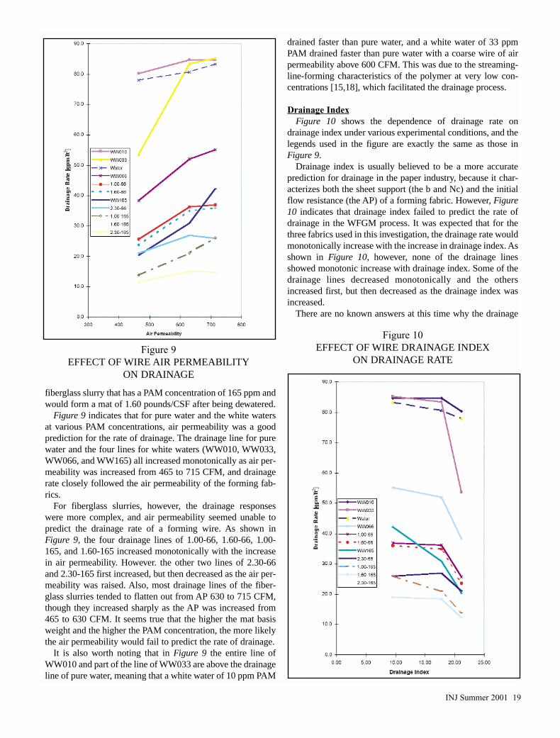
and forming wire parameters on wet process drainage Byemploying a recently developed lab tester the present investi-gation conducted drainage experiments of long (32 mm)fiberglass in polyacrylamide (PAM)-based white water with areal (commercial) forming fabric in position The formingwires under investigation cover air permeability from 465 to715 CFM and drainage index from 95 to 22
Drainage experiments show that both PAM concentrationand shearing (mixing) effect can strongly affect wet processdrainage So white water of fixed composition but with a dif-ferent mixing history may behave very differently and anincrease in input mixing energy usually results in a substantialincrease in drainage
Mat basis weight also strongly influences wet processdrainage Although an increase in basis weight always reducesthe rate of drainage regardless of wire structure its impact ismuch stronger on the wires with a high air permeability and alow drainage index than the ones with a low air permeabilityand a high drainage index
Another important finding of this study was that drainageindex did not predict the performance of a forming wire andthe main causes were believed to be the fundamental differ-ences between the wet-formed glass mat (WFGM) andpapermaking processes Also correlation between air per-meability and wet process drainage was found very complexwhile air permeability may be used as an empirical parame-ter to predict drainage for light weight mats at low PAM con-centrations however the higher the web basis weight and thehigher the PAM concentration the more likely it would fail
Key Words
Wet process drainage forming wire drainage index airpermeability polyacrylamide basis weight shearing effect
IntroductionDrainage is one of the critical process variables in a wet
process (the wet-formed glass mat process or the WFGMprocess) Wet process uses higher viscosity white water andoperates at low slurry consistencies Its drainage operation isusually more challenging than in a typical papermakingprocess which is the primary reason that an inclined delta for-mer instead of a Fourdrinier machine is normally used in awet process to dewater fiberglass slurries
Wet process drainage is a complex process depending onboth the physical characteristics of a fiber slurry and thedetailed structure of a forming fabric The slurry characteris-tics encompass fiber content fiber length and diameter andwhite water chemistry etc The wire parameters may includeat least air permeability and drainage index etc Sincedrainage has great influence on both the sheet properties [1-4]and the mill performance the paper industry has consistentlydevoted a great deal of resources to gain fundamental under-standings in this area [5-12] Several experimental methods [613 14] have been developed to measure the drainage or free-ness of papermaking furnishes among which the CanadianStandard Freeness (CSF) test [14] is the most common one
Though various lab drainage testers have been successfullyused to characterize the drainage characteristics of papermak-ing furnishes they are generally not applicable to the fiber-glass slurries used in a wet process [15] It is also worth not-ing that these lab drainage testers are limited to estimate onlythe drainage characteristics of furnishes and are not capable ofevaluating the effects of forming wire parameters [15] In real-ity a drainage process is controlled by the combination ofwhite water characteristics and the parameters of a formingfabric Therefore it would be very important to measure thedrainage rate under the combined conditions of all these para-
Wet Process Drainage mdash Effects of
White Water Chemistry and
Forming Wire StructuresBy Daojie Dong Senior Scientist Owens Corning Science amp Technology CenterGranville OH 43023
ORIGINAL PAPERPEER-REVIEWED
14 INJ Summer 2001
The author is currently a Senior Engineer with DecillionLLC Granville Ohio
INJ Summer 2001 15
metersRecently a wet process mimic device (WPMD) has been
developed at the Owens Corning Science and TechnologyCenter that is capable of measuring the drainage rate of wetprocess slurries with real (commercial) forming fabrics inposition The detailed information about the WPMD structureand developmental work can be found elsewhere [15]
In the present investigation the WPMD was used as a toolto study the effects of both fiberglass slurry characteristics andforming wire parameters on wet process drainage The rate ofdrainage was measured under a simulated line speed and cor-related to various parameters such as PAM concentration ofwhite water mixing effect web basis weight fabric air per-meability and wire drainage index The approaches used werevery practical and the reported results are expected to haveclose correlation to real wet process operations Theoreticalmodeling of the drainage process is out of the scope of thispaper but might be addressed in the future
ExperimentalApparatus
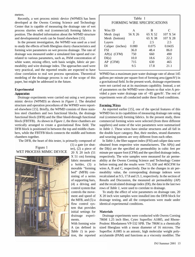
Drainage experiments were carried out using a wet processmimic device (WPMD) as shown in Figure 1 The detailedstructure and operation procedures of the WPMD were report-ed elsewhere [15] Briefly the WPMD consists of three stain-less steel chambers and two functional blocks the drainagefunctional block (DFB) and the fiber bleed-through functionalblock (FBTFB) As shown in Figure 1 the three chambers arevertically arranged to create a gravitational flow field TheDFB block is positioned in between the top and middle cham-bers while the FBTFB block connects the middle and bottomchambers together
The DFB the heart of this tester is primarily composed of(1) a gate (or shut-ter) (2) a piece of20 X 20 inch (51X 51 cm) formingfabric mounted ona holder (3) amovable ldquoformingbedrdquo (MFB) con-sisting of a seriesof supporting bars(4) a driving andcontrol system thatcontrols the move-ment and speed ofthe MFB and (5) aflow control sys-tem that providesinitial settings fordrainage experi-mentsWith forming wireA (as defined inTable 1) in posi-tion the reported
WPMD has a maximum pure water drainage rate of about 145gallons per minute per square foot of forming area (gpmft2) ina gravitational field In the present work drainage experimentswere not carried out at its maximum capability Instead a setof parameters on the WPMD were chosen so that wire A pro-vided a pure water drainage rate of ~85 gpmft2 The rest ofexperiments were all conducted under these fixed conditions
Forming WiresAs reported earlier [15] one of the special features of this
WPMD lies in its capabilities of measuring drainage rate usingreal (commercial) forming fabrics In the present study threecommercial forming wires were selected (from three differentsuppliers) and some of the wire parameters were summarizedin Table 1 These wires have similar structures and all fall inthe double layer category But their meshes strand diametersand weaving patterns are very different from each other
In Table 1 the fiber support index (FSI) and caliper data wereobtained from respective wire manufacturers The AP(s) andthe DI(s) are the specified air permeability in cubic feet perminute per square foot (CFM) and the specified drainage indexrespectively The wire samples were measured for air perme-ability at the Owens Corning Science and Technology Centerbefore testing and the results were 715 630 and 465CFM forwires A B and C respectively Due to the changes in air per-meability value the corresponding drainage indexes wererecalculated as 95 178 and 211 respectively In the section ofResults and Discussion the measured air permeability (AP)and the recalculated drainage index (DI) the data in the last tworows of Table 1 were used to correlate to drainage
To study the effect of wire parameters on drainage rate 20X 20 inch wire samples were installed into the DFB block fordrainage testing and all the comparisons were made underidentical experimental conditions
MaterialsDrainage experiments were conducted with Owens Corning
786M 125 inch fiber Cytec Superfloc A1885 and Rhone-Poulenc Rhodameen VP-532 SPB The 786M is a chemicallysized fiberglass with a mean diameter of 16 microns TheSuperfloc A1885 is an anionic high molecular weight poly-acrylamide (PAM) and functions as a viscosity modifier The
Figure 1WET PROCESS MIMIC DEVICE
Table 1FORMING WIRE SPECIFICATIONS
Wire ID A B CMesh (top) 56 X 26 65 X 52 107 X 54Mesh (bottom) 65 X 38 107 X 28Layers 2 25 25Caliper (inches) 0080 0075 00435FSI 360 484 860AP(s) (CFM) 750 660 490DI(s) 100 186 222AP (CFM) 715 630 465DI 95 178 211
Rhodameen VP-532 SPB is an ethoxylated fatty amine a sur-face active molecule and functions as a dispersant In addi-tion a small amount of defoamer was also used to controlfoam and assist the experiments
DrainageIt is known that the PAM viscosity modifier is sensitive to a
shearing effect The received PAM was first diluted to 05wt and agitated for 30 minutes The same batch of dilutedPAM was used for the entire experimental work to avoid pos-sible variations in raw material and in dilution procedure
The drainage volume was fixed as 20 gallons (of pure wateror white water or fiber slurry) For white water (withoutfibers) testing 20 gallons of water was fed into the top cham-ber followed by a predetermined amount of PAM and 5 dropsof defoamer The formulated white water was then agitatedunder specified experimental conditions before drainage
A two step procedure similar to a thick-thin stock proce-dure was used in the preparation of fiberglass slurries First10 gallons of water were charged into the top chamber fol-lowed by 10 drops of dispersant and 5 drops of defoamerThen the mixer (agitator) was turned on and a pre-weighedamount of fiberglass was added immediately In the mean-time a timer was started to record mixing time After oneminute of mixing a predetermined amount of PAM wasadded and additional water was fed to make up a total volumeof 20 gallons
While the slurry (or white water) being prepared the movableforming bed (MFB) was set in motion at a desired speed andother drainage parameters were also set at desired values Whenthe slurry was ready for testing the gate (or shutter) was openedinstantly and the drainage process began The time duration ofdrainage was recorded and the average drainage rate was calcu-lated based on the known parameters of the WPMD In thiswork a unit of gallons per minute per square foot forming area(gpmft2) was selected for the rate of drainage
A dual-propeller mixer driven by an air motor wasemployed for agitation The mixer was positioned at the cen-ter of the chamber with its lower and higher propellers 2 38rdquo(6 cm) and 11 58rdquo (295 cm) above the top surface of theforming fabric The mixing (shearing) effect was controlled bythe inlet pressure of compressed air to the air motor
ViscosityWhite water viscosity was measured with a Brookfield
Model DV-II+ viscometer
Results and DiscussionPAM Effect
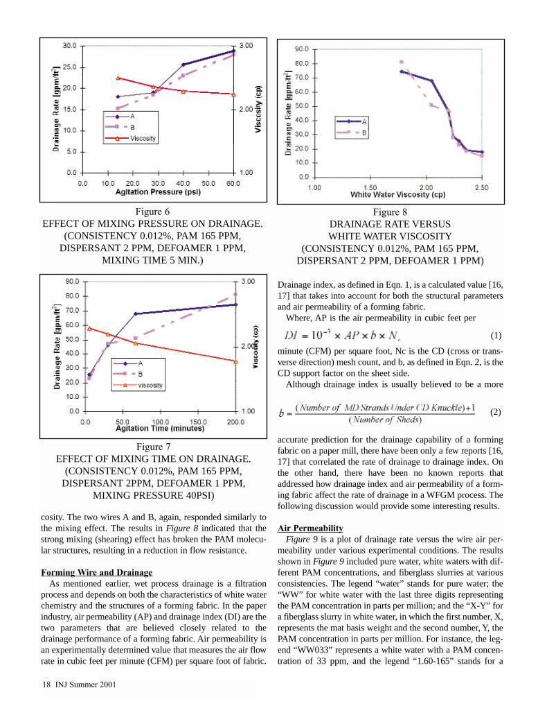
Figure 2 shows the influence of polyacrylamide concentra-tion on the drainage of white water (without fibers) All thewhite waters used in Figure 2 were mixed for 5 minutes witha compressed air setting of 28 psig So PAM concentrationwas the only variable which ranged from 0 to 165 ppm withldquo0rdquo representing pure water
As indicated in Figure 2 the presence of PAM significantlyreduced the rate of drainage For wires A and B the drainage
rate of pure water was ~83 gpmft2 and the presence of 66 and165 ppm PAM has reduced the drainage rate by ~35 and55 respectively For wire C the presence of 66 and 165 ppmPAM has reduced the drainage rate of pure water by ~50 and74 respectively
The presence of PAM also significantly reduced thedrainage rate of fiberglass slurries as shown in Figure 3 Thenine data points used in the figure had a same consistency of0012 and each slurry was agitated for 5 minutes with apressure setting of 28 psig on the driving air motor
Interestingly the three wires responded similarly to the changesin PAM concentration The drainage rate dropped sharply whenthe PAM concentration was increased from 10 to 65 ppm As thePAM concentration was further raised to 165 ppm the drainagerate continued decreasing but with a much lower slope
Basis Weight
16 INJ Summer 2001
Figure 2
EFFECT OF PAM CONCENTRATION ONWHITE WATER DRAINAGE
Figure 3
EFFECT OF PAM CONCENTRATION ONFIBERGLASS SLURRY DRAINAGE
INJ Summer 2001 17
Gravity drainage in essence is a filtration process with thepressure defined by the gravity head of suspension over aformed web [9] supported on the forming wire It is obviousthat the web thickness and its degree of compression willaffect the rate of drainage Since the primary focus of thispaper is to deal with the practical aspects of drainage in wetprocess the web effect on drainage rate was treated withrespect to mat basis weight in pounds per hundred square feet(poundsCSF)
Three consistency values of 0008 0012 and 0018were purposely designed to study the web effect on drainagerate These values based on the particular parameters of theWPMD correspond to the formed webs with ldquofiber basisweightrdquo of 081 130 and 186 pounds per hundred square feet(poundsCSF) respectively If a 19 of loss on ignition (LOI)a typical number for fiberglass roofing mats is also accountedfor the three consistency values would correspond to the fin-ished wet process mats with basis weight of 100 160 and230 poundsCSF In Figures 4 and 5 drainage rate was plot-ted with respect to mat basis weight for the convenience ofreaders in the nonwovens industry The fiberglass slurries usedin Figure 4 were all prepared at a fixed PAM concentration of165 ppm and in Figure 5 at a fixed PAM concentration of 66ppm
As indicated in Figures 4 and 5 the rate of drainage wasreduced as the basis weight was increased from 10 to 160 and230 poundsCSF However the degrees of change were dif-ferent among the three wires For example at a fixed PAMconcentration of 165 ppm (Figure 4) the drainage line forwire A has the highest slope the line for wire B is less steepand the line for wire C has the lowest slope As a result wireB has reached comparable drainage rates to wire A at basisweights above 160 poundsCSF though its rate of drainagewas ~20 lower than wire A at a basis weight of 10poundsCSF Figure 4 also indicated that the difference indrainage rate between wire C and the others was gradually
reduced as the increase in mat basis weightAt a fixed PAM concentration of 66 ppm (Figure 5) the
same trend seemed to hold Wires A and B had similardrainage rates at all three basis weights Wire C again neverreached comparable drainage rates to wires A and B thoughthe difference was gradually reduced as the basis weight wasincreased
Shearing (Mixing) EffectFigures 6 and 7 show that the PAM-based white water was
very sensitive to shearing (mixing) effect All the slurries usedin the two figures had exactly the same composition 165 ppmof PAM ~2 ppm dispersant ~1 ppm defoamer and a fiberglassconsistency of 0012 The variations in drainage rate werecaused solely by different shearing (mixing) history In Figure6 all the slurries were prepared with a fixed mixing time of 5minutes but mixing pressure on the air motor was variedfrom 14 to 60 psig In Figure 7 all the slurries were preparedwith a fixed mixing pressure of 40 psig but mixing time wasvaried from 5 to 200 minutes
Figure 6 indicates that as mixing pressure was increasedfrom 14 to 60 psig the viscosity of white water was reducedslightly (from 25 to 224 cps ~10 reduction) however therate of drainage was increased by ~70 Both wires A and Bresponded to the shearing effect similarly
At a fixed mixing pressure of 40 psig as illustrated inFigure 7 the prolonged mixing dramatically increased the rateof drainage As the mixing time was extended from 5 to 3067 and 200 minutes the rate of drainage was increased by~90 130 and 220 respectively In the meantime thewhite water viscosity was reduced from 229 to 220 205 and178 cps respectively
In Figure 8 all the data points in Figures 6 and 7 were com-bined and replotted against the viscosity of white water Itclearly indicates that the two sets of data (from Figures 6 and7) followed a similar trend with respect to the white water vis-
Figure 4EFFECT OF BASIS WEIGHT ON DRAINAGE RATE
(PAM = 165 PPM DISPERSANT = 2 PPMAND DEFOAMER = 1 PPM)
Figure 5EFFECT OF BASIS WEIGHT ON DRAINAGE RATE
(PAM = 66 PPM DISPERSANT = 2 PPMAND DEFOAMER = 1 PPM)
cosity The two wires A and B again responded similarly tothe mixing effect The results in Figure 8 indicated that thestrong mixing (shearing) effect has broken the PAM molecu-lar structures resulting in a reduction in flow resistance
Forming Wire and DrainageAs mentioned earlier wet process drainage is a filtration
process and depends on both the characteristics of white waterchemistry and the structures of a forming fabric In the paperindustry air permeability (AP) and drainage index (DI) are thetwo parameters that are believed closely related to thedrainage performance of a forming fabric Air permeability isan experimentally determined value that measures the air flowrate in cubic feet per minute (CFM) per square foot of fabric
Drainage index as defined in Eqn 1 is a calculated value [1617] that takes into account for both the structural parametersand air permeability of a forming fabric
Where AP is the air permeability in cubic feet per
minute (CFM) per square foot Nc is the CD (cross or trans-verse direction) mesh count and b as defined in Eqn 2 is theCD support factor on the sheet side
Although drainage index is usually believed to be a more
accurate prediction for the drainage capability of a formingfabric on a paper mill there have been only a few reports [1617] that correlated the rate of drainage to drainage index Onthe other hand there have been no known reports thataddressed how drainage index and air permeability of a form-ing fabric affect the rate of drainage in a WFGM process Thefollowing discussion would provide some interesting results
Air PermeabilityFigure 9 is a plot of drainage rate versus the wire air per-
meability under various experimental conditions The resultsshown in Figure 9 included pure water white waters with dif-ferent PAM concentrations and fiberglass slurries at variousconsistencies The legend ldquowaterrdquo stands for pure water theldquoWWrdquo for white water with the last three digits representingthe PAM concentration in parts per million and the ldquoX-Yrdquo fora fiberglass slurry in white water in which the first number Xrepresents the mat basis weight and the second number Y thePAM concentration in parts per million For instance the leg-end ldquoWW033rdquo represents a white water with a PAM concen-tration of 33 ppm and the legend ldquo160-165rdquo stands for a
18 INJ Summer 2001
Figure 6EFFECT OF MIXING PRESSURE ON DRAINAGE
(CONSISTENCY 0012 PAM 165 PPMDISPERSANT 2 PPM DEFOAMER 1 PPM
MIXING TIME 5 MIN)
Figure 8DRAINAGE RATE VERSUS WHITE WATER VISCOSITY
(CONSISTENCY 0012 PAM 165 PPMDISPERSANT 2 PPM DEFOAMER 1 PPM)
Figure 7EFFECT OF MIXING TIME ON DRAINAGE
(CONSISTENCY 0012 PAM 165 PPMDISPERSANT 2PPM DEFOAMER 1 PPM
MIXING PRESSURE 40PSI)
(1)
(2)
INJ Summer 2001 19
fiberglass slurry that has a PAM concentration of 165 ppm andwould form a mat of 160 poundsCSF after being dewatered
Figure 9 indicates that for pure water and the white watersat various PAM concentrations air permeability was a goodprediction for the rate of drainage The drainage line for purewater and the four lines for white waters (WW010 WW033WW066 and WW165) all increased monotonically as air per-meability was increased from 465 to 715 CFM and drainagerate closely followed the air permeability of the forming fab-rics
For fiberglass slurries however the drainage responseswere more complex and air permeability seemed unable topredict the drainage rate of a forming wire As shown inFigure 9 the four drainage lines of 100-66 160-66 100-165 and 160-165 increased monotonically with the increasein air permeability However the other two lines of 230-66and 230-165 first increased but then decreased as the air per-meability was raised Also most drainage lines of the fiber-glass slurries tended to flatten out from AP 630 to 715 CFMthough they increased sharply as the AP was increased from465 to 630 CFM It seems true that the higher the mat basisweight and the higher the PAM concentration the more likelythe air permeability would fail to predict the rate of drainage
It is also worth noting that in Figure 9 the entire line ofWW010 and part of the line of WW033 are above the drainageline of pure water meaning that a white water of 10 ppm PAM
drained faster than pure water and a white water of 33 ppmPAM drained faster than pure water with a coarse wire of airpermeability above 600 CFM This was due to the streaming-line-forming characteristics of the polymer at very low con-centrations [1518] which facilitated the drainage process
Drainage IndexFigure 10 shows the dependence of drainage rate on
drainage index under various experimental conditions and thelegends used in the figure are exactly the same as those inFigure 9
Drainage index is usually believed to be a more accurateprediction for drainage in the paper industry because it char-acterizes both the sheet support (the b and Nc) and the initialflow resistance (the AP) of a forming fabric However Figure10 indicates that drainage index failed to predict the rate ofdrainage in the WFGM process It was expected that for thethree fabrics used in this investigation the drainage rate wouldmonotonically increase with the increase in drainage index Asshown in Figure 10 however none of the drainage linesshowed monotonic increase with drainage index Some of thedrainage lines decreased monotonically and the othersincreased first but then decreased as the drainage index wasincreased
There are no known answers at this time why the drainage
Figure 9EFFECT OF WIRE AIR PERMEABILITY
ON DRAINAGE
Figure 10EFFECT OF WIRE DRAINAGE INDEX
ON DRAINAGE RATE
index failed to predict the rate of drainage of fiberglass slur-ries It is believed that the fundamental differences betweenthe WFGM and the papermaking processes are among theprobable causes assuming that drainage index correlates wellin a papermaking process A paper furnish typically uses shortcellulose fibers with high content particulate fillers at relative-ly high consistencies while a wet process slurry usually con-sists of very long glass fibers with nearly zero percent partic-ulate substances at very low consistencies A high concentra-tion of long molecular chain polyacrylamide in the whitewater also makes the wet process different from the paper-making processes Johnson conducted [16] simulated experi-ments with fiber lengths of 1 to 4 mm and reported that [17]drainage was proportional to the fabric drainage index in apapermaking process In this study the input materials were~100 125 inch (~32 mm) glass fibers with no particulateadditives at all The PAM concentration was also higher thanin a papermaking process
ConclusionWet process drainage is a complex filtration process
depending on both the characteristics of a fiberglass slurry andthe structures of a forming fabric By employing a recentlydeveloped wet process mimic device a lab tester the presentinvestigation has successfully conducted drainage experi-ments of fiberglass slurries under simulated dynamic condi-tions with a real (commercial) forming fabric in position Theeffects of wire parameters and white water characteristicswere examined
The drainage experiments have shown that in a typical poly-acrylamide (PAM) white water a higher PAM concentrationsignificantly reduced the rate of drainage presumably due toa higher viscosity The PAM-based white water was also verysensitive to shearing (mixing) effect So an increase in inputmixing energy either by a higher mixing speed (RPM) or bya prolonged mixing time has reduced the white water viscos-ity and resulted in a substantial increase in wet processdrainage
Mat basis weight also had a strong impact on wet processdrainage Although an increase in mat basis weight has alwaysreduced the rate of drainage its influence was stronger on thewires with a higher air permeability and a lower drainageindex than on the wires with a lower air permeability and ahigher drainage index
Another important conclusion of the study was thatdrainage index did not predict wet process drainage and themain causes are believed to lie in the fundamental differencesbetween the WFGM and papermaking processes
This investigation has also showed that the correlationbetween air permeability and wet process drainage was com-plex While the drainage rate of pure water and of the wetprocess white water (without fibers) correlated well to the ini-tial flow resistance (the air permeability) of a forming fabricfor fiberglass slurries however the correlation failed undersome circumstances It is generally true that while air perme-ability may be used as an empirical parameter for light weightmats at lower PAM concentrations the higher the web basis
weight and the higher the PAM concentration the more likelyit would fail to predict wet process drainage
AcknowledgementsThe author would like to acknowledge Howard Ruble for
his assistance on the drainage experiments He also wishes tothank David Mirth Thomas Miller Robert Houston DavidGaul and Warren Wolf for their support to publish this work
References1 Hergert RE and JW Harwood Tappi J 71(3) 63
(1988)2 McDonald JD and II Pikulik Tappi J 72(10) 95
91989)3 Robertson AA Pulp Paper Mag Can 57(4) 119
(1956)4 Williams GA and LE Foss Pulp Paper Mag Can
62(12) T519 (1961)5 Kerekes RJ and DM Harvey Tappi J 63(5) 89
(1980)6 Unbehend JE 1990 Papermakers Conference Proc
Tappi Press Atlanta p3637 Estridge R Tappi J 45(4) 285 (1962)8 Clos RJ and LL Edwards Tappi J 78(7) 107 (1995)9 Ramarao BV and P Kumar Nordic Pulp and Paper
Research J No 2 86 (1996)10 Gess JM Tappi J 67(3) 70 (1984)11 11Han ST Tappi J 45(4) 292 (1962)12 Trepanier RJ Tappi J 75(5) 139 (1992)13 Tappi ldquoTappi Test Methodsrdquo T221 ommdash93 Tappi
Press Atlanta 199614 Tappi ldquoTappi Test Methodsrdquo T227 om-94 Tappi Press
Atlanta 199615 Dong D ldquoDevelopment of Wet Process Mimic Devicerdquo
Tappi Proc 1999 Nonwovens Conference Orlando FloridaMarch 15-17 1999
16 Johnson DB Pulp Paper Canada 85(6) T167 (1984)17 Johnson DB Pulp Paper Canada 87(5) T185 (1986)18 Bird RB RC Armstrong and O Hassager
ldquoDynamics of Polymeric Liquidsrdquo 2nd Ed Wiley-Interscience New York 1987 mdash INJ
20 INJ Summer 2001
AbstractEnvironmentally friendly nonwoven fabrics can be formed
through thermal bonding of cotton and cellulose acetate fiberblends at reduced bonding temperature with the aid of a plasti-cizer Water has been introduced as an external plasticizer tolower the softening temperature of cellulose acetate fibers andto enhance the tensile strength of cottoncellulose acetate webIt has been found that water can significantly increase the ten-sile strength of cottoncellulose acetate thermally-bonded websat reasonable bonding temperatures In addition water canenhance web bonding to essentially the same degree as an ace-tone treatment does The mechanisms of water effect are con-sidered and optimal processing conditions are proposed
IntroductionMore and more nonwovens are used in everyday life but the
environmental impact of disposable products remains a majorconcern [1 2] Manufacturers are seeking ways to producebiodegradable textile products by using biodegradable fiber andcotton becomes an obvious choice for the nonwoven industrybecause of its biodegradability softness absorbency and vaportransport properties [13] However cotton is a non-thermoplas-tic fiber and requires the addition of a thermoplastic binder fiberfor the fusion of the fibers at relatively low temperature Mostcotton-based nonwovens products are processed with binderfibers using thermal calendering which is a clean and an eco-nomical process Synthetic fibers such as low melting polyesterpolyester copolymer polypropylene and polyethylene can beused as binder fibers [3-7] Cellulose acetate fiber also has beenused as the biodegradable binder fiber since it is a thermoplas-tic hydrophilic and a biodegradable fiber A solvent treatmenthas been introduced in order to modify the softening tempera-ture of cellulose acetate fiber and to lower the calendering tem-perature while maintaining enhanced tensile properties
Duckett Bhat and colleagues [8 9] have examined the effect ofacetone vapor pre-treatment and of 20 acetone solution pre-treatment on cottoncellulose acetate thermally bonded websThe results showed that these solvent treatments could decreasethe softening temperature of cellulose acetate fiber and producecomparatively stronger webs However from a practical stand-point manufacturers do not like a process involving the use ofacetone because acetone evaporates easily and is flammableand toxic These detrimental factors create major problems inmanufacturing and pollute the working environment Also con-sumers may prefer not to buy acetone-treated products whichthey think may contain toxic substances In our research thedesire was to decrease the softening temperature of celluloseacetate without the aid of acetone treatment by applying watertreatment ndash a treatment noted previously at Celanaese Acetate[10] ndash prior to thermal bonding Additionally an industriallymodified (plasticized) cellulose acetate fiber was studied as analternative choice as binder fiber
Experimental ProceduresThe cotton fiber used in this research is a scoured and
bleached cotton fiber provided by Cotton IncorporatedProperties include a 52 moisture regain value 54 micron-aire value and an upper-half-mean fiber length at 244 cmCelanese Corporation provided both ordinary cellulose acetate(OCA) and plasticized cellulose acetate (PCA) An ultra-lightfabric with basis weight around 35 gm2 (1 ozyd2) was chosenfor this research
The experiment was a four-factor design with two replica-tions The factors included were
CA type Ordinary CA (OCA) and Plasticized CA (PCA)Temperature 1500C 1700C 1900CBlend Ratio 7525 and 5050 (by weight) CottonCellulose
Acetate
Effects of Water On Processing
and Properties of Thermally
Bonded CottonCellulose
Acetate NonwovensBy Xiao Gao KE Duckett G Bhat Haoming Rong University of Tenessee Knoxville TN
ORIGINAL PAPERPEER-REVIEWED
INJ Summer 2001 21
22 INJ Summer 2001
Pre-treatment Without Water Treatment (nw)Water Dip-Nip Treatment (dn)20 Aqueous-Acetone Dip-Nip Treatment
A Saco-Lowell carding machine with a collector drum cir-cumference of 1422 cm (56 in) and a drum width of 222 cm(875 in) was used to form the webs The carded webs were cutaway from the drum and placed between two sheets of paper toawait pretreatment and thermal calendering An HWButterworth amp Sons padding machine was used for the dip-nippretreatment The carded webs were placed between two finemesh screens and passed through a tray containing water oracetone solution prior to going through padding rolls tosqueeze out excess liquid Following this procedure the webswere ready to be thermally calendered using a RamischKleinewefers 60 cm (236 in) wide five-roll calender Only theupper two rolls were used The top calender roll had anengraved diamond pattern resulting in 166 bonding area andthe bottom roll was smooth Both were made of stainless steelThe rolls were heated by circulating oil and the nip roll pres-sure was set at 25 KN Roll feed speed was fixed at 10 mmin
All pretreated webs were placed in a standard atmosphere for24 hours before testing Five 1 X 10 inch test specimens werecut from the web along the machine direction and the tensileproperties were obtained using ASTM D 1117ndash 80 StandardTest Method for Tensile Testing of Nonwoven Materials AHitachi S-800 SEM provided information on bond structureand fiber morphology The SEM was set at 1 Kev 7 mm work-ing distance and magnification of 80X and 250X respectively
Results and DiscussionIn previous studies [11-13] a water spray treatment had been
used and there resulted a gradual increase in the peak strengthwith each increasing bonding temperature compared with thosehaving no water spray treatment This suggested the possibilitythat water will act as a plasticizer to enhance fabric tensileproperties at reduced bonding temperature
Treatment EffectThe effect of three different treatments on the tensile strength
of cottonordinary cellulose acetate (COCA) is shown inFigure 1 for a 5050 blend ratio
From statistical analyses and visual observation it is clearthat a water dip-nip treatment can significantly increase thebonding strength of cottoncellulose acetate thermally bondedwebs Possible mechanisms that are responsible for thisstrength enhancement are
1 Water molecules penetrate the whole web with the assis-tance of the padding machine and are attracted to the celluloseacetate molecules by hydrogen bonding Thus the intermolec-ular forces of cellulose acetate are reduced and the mobility ofthe polymer chains is improved The polymer becomes elasticand more flexible with the result of a lowered softening tem-perature Hence the softening temperature can be lowered bythe external plasticizer-water dip-nip treatment providingincreased cellulose acetate molecular mobility and reducing thenecessary thermal energy required to bond the fibers at fibercontact points This makes it possible to bond at a lower tem-
perature with the aid of a water dip-nip pre-treatment 2 Due to the hydrophilic nature of the partially crystalline
structure of cellulose acetate it can take up substantial waterAbove the softening temperature the fiber swells as a result ofmolecular chain relaxation and becomes sufficiently tacky toprovide some bonding with other binder fibers and with thebase fiber The swelling which provides greater free volumefor the polymer will increase the surface area and enhance con-tact with the other fibers This might be expected to increasebonding strength by providing more bonding area at the bond-ing point
3 When the web is passed through the nip of the pattern andsmooth rolls of the thermal calender heat and pressure areapplied to the web The web at that time is composed of cottonfiber cellulose acetate fiber and water Water has very goodthermal conductivity ndash about 10 times that of either cotton orcellullose acetate ndash and this enables additional heat transfer inthe short interval of time when web and rolls are in contactThus enhanced heating produces more polymer flow and bet-ter bonding
The external plasticizer-water bonds physically to the poly-mer rather than chemically (covalently) which lowers the soft-ening temperature of cellulose acetate In combination thisenables more heat and polymer flow at the cross-over points offibers in the bonding region providing enhanced tensile prop-erties to the web under lower bonding temperature
From the graph it can be clearly seen that there is no signifi-cant difference between the two different kinds of external plas-ticizer ndash water or 20 aqueous solution of acetone when appliedto the web by dip-nip pretreatment Both plasticizations how-ever do increase the bonding strength of cottoncellulose acetatethermally bonded webs These results suggest that water canreplace a 20 acetone concentration and can be used as theexternal plasticizer in the pre-treatment of cottoncelluloseacetate web without a reduction in web strength
Cellulose Acetate Type EffectThe effect of an internal plasticizer on the peak strength of
Figure 1TREATMENT EFFECT ON THE
PEAK STRENGTH OF COCA WEBS
CottonPCA blend was examined also The results are shownin Figure 2 separately by blend ratio and without any externaltreatment
It is clearly observed that the web containing plasticized cel-lulose acetate (PCA) binder fibers has a significantly higherpeak strength than those comprising ordinary cellulose acetate(OCA) binder fibers The tensile strength rises uniformly to900mNtex for CPCA-5050 webs This is to be compared to085mNtex for COCA-5050 webs at the upper temperature of1900C This clearly demonstrates that the internal plasticizerenhances the bonding and strength of a thermally bonded cot-toncellulose acetate web
All webs using PCA as binder fiber have significantly high-er peak strengths than those using OCA as binder fiber exceptfor the 7525 CCA web bonded at 1500C That may be due tothe low number of binder fibers (inhomogeneous fiber distrib-ution) and the lower bonding temperature whereby the webcould not get sufficient heat flow and polymer flow to causesuitable bonding The effect may also be a statistical or pro-cessing fluctuation since the differences are so small
Combination of PCA and Water Treatment EffectWhen the water treatment is applied to CottonPlasticized
Cellulose Acetate (PCA) webs the results are as shown inFigure 3
It is seen from the two figures that the cottonplasticized cel-lulose acetate webs have higher peak strength when treatedwith an external plasticizer-water than those cottonplasticizedcellulose acetate webs without water dip-nip treatment Thepossible exception may be for CPCA-5050-190ordmC webswhere there is little difference between the two treatments at thehighest bonding temperature
The combination of internal and external plasticizer has asignificant effect in lowering the bonding temperature forimproved peak strength of cottoncellulose acetate webs com-pared to cottonplasticized cellulose acetate webs aloneHowever when the bonding temperature reaches 1900C theexternal plasticizer offers no significant benefit to the webstrength compared to the internal plasticizer effect alone Thereasoning is that at lower temperature the internal plasticizerhelps decrease the softening temperature of cellulose acetate byincreasing the polymer chain mobility The interaction betweenneighboring polymer chains is still very high at low tempera-ture and more polymer chain flexibility and polymer flow arerequired for effective bonding When the external plasticizer ndashwater ndash is introduced into the web it can decrease the interac-tion between polymer chains giving more mobility of the poly-mer chain thereby increasing the bonding surface area andconducting more heat to induce the polymer flow to achievebetter bond strength
When the bonding temperature reaches 1900C the heat trans-fer from the calender roll is sufficient for the polymer flowaround the other binder fiber or cotton fiber If water is appliedat this time the thermal dynamics of water may change con-siderably More heat may be taken away by evaporation thanthe heat being conducted by water through the web In this sit-uation the water may not be as helpful to web bonding as at
INJ Summer 2001 23
Figure 2CELLULOSE ACETATE FIBER EFFECT ON THE
PEAK STRENGTH OF CCA WEBS
Figure 3THE EFFECT OF COMBINATION OF PCA WITH
WATER ON THE PEAK STRENGTH OF WEBS
24 INJ Summer 2001
lower temperature The web peak strength may decrease as aresult
Temperature EffectThe bonding temperature is one of the most important fac-
tors that directly affect bonding behavior For COCA webswithout an external plasticizing treatment the temperature hasno significant effect on web peak strength Because the tem-perature in the experimental range has not reached the soften-ing temperature (around 2000C) of ordinary cellulose acetatethere is limited motion among segments in the polymer chainThe mobility of polymer chains is simply not enough to moveout of the intermolecularly constrained structure to bond withsurrounding fibers
When the water dip-nip treatment is applied to the COCAweb there is no significant difference in the tensile strength inthe range of 1500C and 1700C The peak strength increases sub-stantially only after the bonding temperature approaches1900C Water brings down the softening temperature of the cel-lulose acetate But at the higher temperature the water increas-es the heat flow into the bonding points and enhances bonding
The same trend is observed when there is only an internalplasticizer The higher the bonding temperature the stronger isthe web When the CPCA webs have been thermally bondedwith the aid of water pre-treatment the softening temperatureof cellulose acetate can be further reduced by decreasing theintermolecular forces in the polymer and increasing the mobil-ity of the polymer chain Good bonding strength can beachieved even at 1700C
Blend Ratio EffectThe flow of heat into the fiber blend matrix is affected by
fiber distribution and blend ratio However based on statisticalanalysis there is no significant blend ratio effect on the COCAweb peak strength when other factors are kept the same
For CPCA webs bonded at 1500C and 1700C there is a sig-nificant blend ratio effect on the peak strength of the web thatis treated by the 20 aqueous solution of acetone The reasonis apparently that the acetone treatment plays a much moreimportant role on increasing polymer chain mobility in cellu-lose acetate at lower temperature when compared to the tem-perature effect This goes along with the larger portion of
binder fibers that are available thus the polymer chain move-ment and bonding effects are enhanced At 1900C significantdifferences in peak strength are observed for different blendratios of CPCA webs when there is no water treatment Thebonding is enhanced as the binder fiber content is increasedwhen the temperature is appropriate
Bond StructureBonding points taken from CPCA-5050 webs were exam-
ined and the effect of water treatment on bonding morphologywas characterized From the SEM photos taken on CPCA-5050 web bond areas (Figure 4) it is clearly seen that at thesame bonding temperature the integrity of bonding points wasenhanced with water dip-nip treatment The edges of the bond-ing points became much sharper and the fibers became muchflatter thereby increasing the surface contact area and con-tributing to better bonding Solvent treatment improves the webbonding structure at lower temperature also
In Figure 4 A3 and A4 show bonding points taken fromCPCA-5050 webs bonded at 1900C These two bondingpoints show less difference between treatment than those bond-ed at 1500C Both bonds are quite good and clearly visible Thereason for the similarity is that the temperature is already highenough for the CA fiber to stick to the surrounding fibers irre-spective of treatment or no treatment
The same conclusions can be drawn from examining thefiber morphology inside the bonding areas at higher magnifi-cation (Figure 5)
The fibers inside the bonding points without treatment lookrounder and less altered However the fibers inside the bond-ing points which have been water pretreated look much flat-ter and the edge of the fiber is not very clear They have beenwell integrated with surrounding fibers The fibers became flat-ter and softer with the water treatment In the photo taken fromacetone treated bonding points it is difficult to distinguish thefiber inside the bonding point because the acetone treatmenthas caused part of the cellulose acetate fiber to dissolve there-by preventing the fiber to retain its integrity The fibers are wellbonded but the previous comments help explain why acetonetreatment did not surpass water treatment as expected That issome of the binder fibers were dissolved therefore the webstrength is decreased
Figure 4
SEM PHOTOGRAPHS OF BOND POINTS
A1 1500C-No Water A2 1500C-Water DN A3 1900C-No Water A4 1900C-Water DN
When SEM photos at different temperatures are compared(Figure 4) it is observed that the bonding points become muchbetter defined with temperature increase and the bondingpoints look more uniform along the edge It is easier to accountfor the differences caused by the temperature especially whenone compares the photos showing bonds at 1500C with those at1900C
Conclusions1 Water as an external plasticizer when applied to the web
by a dip-nip pretreatment can significantly increase the tensilestrength of cottoncellulose acetate thermally bonded webs atreduced calender-roll temperatures
2 Water can enhance the cottoncellulose acetate web bond-ing to essentially the same degree as an aqueous acetone treat-ment and provide a good safe and more economical choice forindustrial manufacturing of nonwovens
3 The higher the calender roll temperature the greater thetensile strength of cottoncellulose acetate thermally bondedwebs
4 Plasticized cellulose acetate as binder fiber provides sig-nificantly higher tensile strength to the cottoncellulose acetatethermally bonded webs than those incorporating ordinary cel-lulose acetate as binder fiber
5 The use of internal andor external plasticizer can providechoices of binder fiber and plasticizing treatment for betterbonding with acceptable physical properties Two choices are
bull CottonPlasticized Cellulose Acetate-5050-1700C ndash withwater treatment
bull CottonPlasticized Cellulose Acetate-5050-1900C ndash with-out water treatment
References1 John W Bornhoeft ldquoThe Development of Nonwoven
Fabrics and Products that are Friendly to the EnvironmentrdquoTAPPI Proceedings 1990 Nonwovens Conference p1
2 A F Turbak ldquoNonwovens Theory Process Performanceand Testingrdquo TAPPI Atlanta GA 1993
3 KE Duckett Larry Wadsworth ldquoTensile Properties of
CottonPolyester Staple FiberNonwovensrdquo TAPPI Proceed-ings 1987 Nonwoven Confer-ence 1987 p121-1274 KE Duckett and LCWadworth ldquoPhysicalCharacterization of ThermallyP o i n t - B o n d e dCottonPolyester NonwovensrdquoProceedings of the 1988 TAPPINonwovens Conference 1988p99-1075 Jerry P Moreau ldquoCottonFiber for Nonwovensrdquo June1990 TAPPI Journal 1990p179-1846 KE Duckett and LCWadworth and V Sharma
ldquoComparison of Layered and Homogeneously Blended Cottonand Thermally Bonding Bicomponent Fiber Websrdquo TAPPIJournal 1995 p169-174
7 Hsu-Yeh Huang and Xiao Gao ldquoSpunbond Technologyrdquohttptrcsheutkedutextilenonwovensspunbondhtml 1999
8 Greta Marie Heismeyer ldquoBiodegradable Staple FiberNonwovens Calendered with the Assistance of An AqueousSolvent Their Fabrication Properties and StructuralCharacteristicsrdquo Thesis University of Tennessee December1997
9 KE Duckett G Bhat H Suh ldquoCompostable NonwovensFrom CottonCellulose Acetate Blendsrdquo TAPPI Proceedings1995 Nonwovens Conference p89-96
10 E J Powers Celanese Acetate private communication11 Gajannan Bhat Kermit Duckett and Xiao Gao
ldquoProcessing and Properties of Cotton-Based NonwovensrdquoProceedings of the Ninth Annual TANDEC Conference Univof Tenn-Knoxville (Nov 11 1999)
12 KE Duckett GS Bhat X Gao H Rong and ECMcLean ldquoCharacterization of CottonCellulose AcetateNonwovens of Untreated and Aqueous Pretreated Webs Priorto Thermal Bondingrdquo Proceeding of INDATAPPI 2000
13 KE Duckett GS Bhat X Gao H Rong ldquoAdvances inthe Thermal Bonding of CottonCellulose Acetate Nonwovensof Untreated and Aqueous Pre-treated Websrdquo Proceeding of2nd International Conference on Metrology in TextileEngineering Lodz Poland Nov 23-24 2000
14 Glenn P Morton RL McGill ldquoThermally BondablePolyester Fiber Effect of Calendering Temperaturerdquo TAPPIProceedings 1987 Nonwovens Conference p129-135 mdash INJ
INJ Summer 2001 25
Figure 5
FIBER MORPHOLOGY OF CPCA-5050-1500C WEBSBONDED UNDER DIFFERENT TREATMENTS
No Water Water Dip-Nip 20 Acetone Solution
AbstractIn this paper image analyzing methods are established and
presented to study the microstructural changes of the nonwo-vens made by hydroentanglement process Fast Fourier trans-form is used to obtain the orientation distribution of thefibers The distribution of the length of the straight segmentsof the fibers is evaluated by application of Hough TransformThe microstructural changes are correlated with the testedmechanical properties of the nonwoven fabrics
KeywordsNonwoven Fast Fourier Transform Hough Transform
Microstructure Scanning Electron Microscope
IntroductionHydroentanglement is a nonwoven fabric bonding technol-
ogy It uses very fine high-velocity jets of water that drive thefibers into the thickness of a web resulting in reorientationand entangling of the fibers Hydraulic drag forces cause thefibers to twist bend and rotate around themselves and otherfibers to form a series of small interlocking entanglementThus the structure is bonded by friction resulting in a softyet relatively strong fabric In this way through this energytransfer process the microstructure of the fiber assemblychanges and its mechanical properties are improved conse-quently
The measurable characteristics of fiber segments includelength thickness curl and orientation The distribution ofstructural characteristics such as orientation and curl of fibersegments in a nonwoven is very important when determiningthe mechanical properties of the fabric The response of the
fabric to the load its modulus and strength directly dependfirst on the physical properties of the fiber such as fiber mod-ulus diameter length and cross section shape and secondlyon the arrangement of the fibers in the fiber assembly such asthe orientation the curl and the friction of the fibers at thepoints of the contact
The initial fabric extension is mainly due to the taking upof curled or slacked segments The stress-strain property of anonwoven fabric is dictated by the orientation distribution offiber segments and the degree of slackness in the fiber net-work as well Fiber orientation distribution can also be usedas a measure of the anisotropy of the fabric The length of thestraight segment of fibers is related to the level of the entan-glement As the entanglement proceeds more knots and curlsand shorter lengths of free segments of the fibers are expect-ed The energy of the water jet required to restructure the ini-tial web depends on the microstructure of the initial web thatgoes under the process
Therefore measuring the microstructural parameters of thefiber assembly can be of advantage in two different aspectsThe structural parameters resulted from image analysis of theweb can be used to identify the amount of energy needed toentangle the fibers Image analysis of the fabric estimates themicrostructural variables that can be applied to predict itsmechanical properties
In this study we have investigated the microstructuralchanges and mechanical property improvements in the fiberassembly created by hydroentanglement SEM micrographsand the two dimensional Fourier analysis of the image is usedto estimate the fiber orientation distribution In order to findthe distribution of the length of the straight segment of the
Microstructural Analysis of Fiber
Segments In Nonwoven Fabrics
Using SEM and Image ProcessingBy E Ghassemieh HK Versteeg and M Acar Wolfson School of Mechanical and ManufacturingEngineering Loughborough University Loughborough UK
ORIGINAL PAPERPEER-REVIEWED
26 INJ Summer 2001
INJ Summer 2001 27
fibers the Hough transform of the image is evaluated Themechanical properties of the fabric are measured as well Therelation of these microstructural variables and the mechanicalproperties are analyzed
Method Description
Estimation Of Fiber Orientation Using Fast FourierTransform
A Fourier transform decomposes an image from its spatialdomain of intensities into frequency domain with appropriatemagnitude and phase values A higher rate of change in grayscale intensity will be reflected in higher amplitudes The fre-quency form of the image is also shown as an image wherethe gray scale intensities represent the magnitude of the vari-ous frequency components [1] A sample of the image of thenonwoven fabric structure made by scanning electron micro-scope is shown in Figure 1a The two-dimensional Fouriertransform of this image results in a spectrum of Figure 1b
A number of Fourier transform techniques are routinelyused in the field of image analysis The most commonmethod is discrete Fourier transform The Fourier transformis useful in determining the rate at which intensity transitionoccurs in a given direction in the image Thus if the fibersare predominantly oriented in a given direction in a nonwo-ven fabric the spatial frequencies in that direction will below and the spatial frequencies in the perpendicular directionwill be high We use this property of the Fourier transform toobtain information on fiber orientation distribution in a non-woven fabric
The transform is implemented by processing all rows one ata time followed by all columns one at a time The result is atwo dimensional set of values each having a magnitude and aphase By shifting the Fourier transform results the zero fre-quency component is shifted to the center of the spectrumThe quadrants one and three are swapped with quadrant twoand four The image of the magnitude spectrum is then sym-metrical about the center of the image and the center repre-sents the zero frequency The magnitude of each frequency isindicated by the intensity of the pixel at that location Brighterareas show higher magnitudes Since the center of the spec-trum contains mostly the noise in the image the magnitudevalues of this section are zeroed and eliminated from the con-sequent calculations
In order to find the fiber orientation distribution we firstselect an annulus of width W at a radius r from the center ofthe image The cut-off size (the size of the central part that iseliminated) and the width of the annulus W affect the resultsand should be optimized
The annulus is discretised to slices of about 10 degree Ineach slice the energy or power spectrum is integrated to findthe total energy of the spectrum resulted from the fibers withthe orientation 900 degree offset in the range of that 100 Sincethe fiber orientation is limited to a range of 0-1800 the calcu-lations are in this range
In integration process both the original slice and its sym-metric part are taken into account
Estimation Of Distribution Of Straight Segment of FibersUsing Hough Transform
Hough transform is one of the most effective methods thatcan be used in object detection in an image Because it requiresthat the desired features be specified in some parametric formthe classical Hough transform is most commonly used for thedetection of regular curves such as lines circles ellipses etcHere we use the Hough transform in detecting the straight seg-ments of the fibers in the fabric The transform projects eachstraight line in the image to a single point and any part of thestraight line is projected to the same point [1]
A brief description of the procedure of applying the methodto our fabrics is followed First the pixel lines of the fibers aredetected by edge detection and then all the pixels with edgemagnitude higher than some threshold are considered as fiberpixels A binarised image is made of the original image withmaximum gray scale at the related fiber pixels and minimumgray scale of the background A sample of binarised image ofthe fabric structure image is shown in Figure 2a
The Hough space is discretised in both directionsDescritisation of the new space parameters change the con-
Figure 1a
Figure 1bA SAMPLE OF SEM IMAGE OF THE FABRIC
AND ITS FFT SPECTRUM
tinuous Hough space to a rectangular structure of cells calledaccumulator array Lines of fibers detected in the image causea high value of the corresponding cell in the accumulatorarray The cell values depend on the number of pixels or thelength of the line of fiber that relates to that cell Thereforethe line of the image can be detected by finding the maximain the accumulator space The values of the cells can be cor-related to the length of the fibers The number of the fibers inthe same range of length is counted and a histogram of thefiber length distribution is obtained The resultant Houghtransform analysis is presented in Figure 2b
The main advantage of the Hough transform is that it is tol-erant of gaps in feature boundary descriptions and is relative-ly unaffected by image noise
Validation of the Method
In order to validate the developed method of estimatingfiber orientation distribution using Fast Fourier Transformswe have made some test samples The test samples are imagesmade from simple lines with one of the graphic packages Inthese tests we investigated the effect of the orientation length
thickness and number of the fibersThe results of the test samples show that our FFT (Fast
Fourier Transform) and post-processing method is able toidentify the fiber orientation distribution The Hough trans-form results of the test samples prove the validity of themethod in estimation of the length of the lines
Test Results amp Discussion
Tests On Image Formation and Pre-processing
The scanning electron microscope is used to make images ofthe microstructure of the fabrics The advantage of using SEMin making the images is that SEM has a high depth of fieldeven at higher magnification In some cases the depth of fieldof the SEM can be considerably higher than an optical micro-scope Therefore applying SEM has the advantage of bringingmore fibers in the fabric in focus This results in includingmore fibers of the depth of the fabric in the primary image [2]
Different processing stages were tested to prepare theimages obtained from SEM for the FFT and Hough transformanalysis
Several parameters in making the images at the stage ofusing electron microscope and afterwards affect the imageprocessing analysis Magnification and brightness are themost important factors that are decided at the stage of makingSEM images The frame shape dimension and the format ofthe image are factors that should be carefully chosen beforethe transfer of the image to the processing stage Each of theseparameters is studied and optimized through several tests
The main parameters are described briefly as follows
bull Magnification-SamplingThe magnification and area covered in an image is an
important factor that can affect the results These parametersshould be optimized to get an image which is representativeof the whole fabric and at the same time is recognizable to theimage processing methods In our research we have tried touse comparatively high magnification and for each fabricmore sample images have to be made and processed The finalorientation distribution for each fabric is evaluated by sum-ming and averaging all the samples In this practice each sam-ple result needs to be evaluated The samples significantly dif-ferent from the average should be discarded
bull Image brightnessOur tests show whenever the brightness of the image is not
uniform there is considerable error in the outcome of the pro-cessing Uneven brightness of the original image made bySEM can occur because of overcharging of some parts of thesamples by long exposure to electron impact or by nonuni-form coating of the samples A nonuniform brightness of theimage results in unequal contribution of different part of theimage in the image processing outcome Therefore it is essen-tial to make the SEM images with uniform brightness
bull The image dimension and frameThe dimension of the image sent to the image analysis pro-
28 INJ Summer 2001
Figure 2a
Figure 2b
A SAMPLE OF BINARISED IMAGE AND ITS HOUGH TRANSFORM SPACE
INJ Summer 2001 29
cessing has been modified to get the same width and heightIn this way fibers of all sizes and directions will have an equalchance to be processed
bull Image FormatAnother important factor in image analysis is the process-
ing of the initial image to be able to extract the necessaryinformation by various methods Different processing meth-ods such as threshholding and binarising images or skele-tonizing have been tried If the original image coming out ofSEM is of uniform brightness the results of using the imagein its original state are very close to te binarised image Sinceboth methods rely on the gray level differences and theobjects under investigation are the fibers using binary imagesthat define the whole fibers as one level and the backgroundas the second level is reasonable
Fabric Test Results
Orientation DistributionThe fiber orientation distribution is evaluated using the
FFT method Bonding of the fibers is provided through theprocess of impacting the web with high-pressure water jetsEach side of the fabric is processed through several passesThe water jet reorients the fibers and migrates them from onelayer to the other layers Through this process the number ofcontact points on each fiber and in the whole fabric increas-es Consequently a stronger fabric is made
In this study two different fabrics are tested to see the effectof the hydroentanglement process on the fiber orientation dis-tribution
(a) Viscose-Polyester fiber (70-30) with the 120 GSMcrosslaid web used as the supply for the first set of experi-ment The machine speed is 10 mmin The pressure profilesin different consecutive passes are shown in Table 1
The first side of the fabric is processed through four differ-ent passes and the second side is impacted by water jet inthree passes
The results of the Fourier transform and fiber orientationdistribution estimated for the fabrics No 1 and No 3 arecompared in Figure 3a The same comparison is made forfabrics No 5 and No 7 in Figure 3b As the starting web iscross laid the main direction of the fibers is in the cross direc-tion which is 900
The results for fabrics No 3 and No 7 show a larger per-centage of fibers in the machine direction compared to No 1
and No 5 respectively A more uniform fiber distribution isachieved through the entanglement process The changes ofthe orientation distribution are more significant for the fabricNo 3 compared to No 1 than fabric No 7 in comparison withNo 5 Since during the first side processing the fibers aremore easily reoriented because there is less bonding betweenthem When the second side is impacted there are alreadymore entanglement points present between the fibers Thismakes the movement of the fibers more difficult The relativenumber of fibers in any direction correlates with the strengthand modulus of the fibers in that direction The results of themechanical testing of these fabrics are shown in Table 2where CD is for cross direction MD is for machine directionand DD is about 450 which is about diagonal direction
Table 1VISCOSEndashPOLYESTER
(120 GSM)ndashCROSS LAID
Pressure(Bar)First side pass No Second side pass No
1 2 3 4 5 6 760 100 130 130 110 130 130
Table 2VISCOSEndashPOLYESTER
(120 GSM)ndashCROSS LAID
Strength (MPa) Modulus (Mpa)CD MD DD CD MD DD
No 1 131 033 042 108 013 028No 3 418 148 194 582 117 217No 5 641 249 335 976 218 476N0 7 649 296 373 1223 299 522
Figure 3a
Figure 3bFIBER ORIENTATION DISTRIBUTION VISCOSE-PET 120 GSM CROSSLAID
(b) Viscose-Polyester fiber (70-30) with the 110 GSMParallel web used as the supply for the second set of experi-ment The machine speed is 10 mmin The pressure values indifferent consecutive passes are shown in Table 3
The first side of the fabric is processed through four differ-ent passes and the second side is impacted by water jet inthree passes
The fiber orientation distribution estimated for the fabricsafter the first and third pass No 1 and No 3 are compared inFigure 4a Fabrics No 5 and No 7 are tested to see the effectof the water jet impact on the second side of the fabric Theresults of these tests are shown in Figure 4b In this case fora parallel web the main direction of the fibers is in themachine direction The maxima of all the bar charts occur at00 and 1800 degrees As the results show for both sides morefibers migrate from the machine direction to the cross direc-tion as the entanglement process progresses Although stillfor each fabric there are more fibers aligned in the machinedirection compared to cross direction For this fabric as wellthe results indicate that more reorientation of the fibers occursin the first side processing compared to the second side pro-cessing
The results of the mechanical testing of these fabrics areshown in Table 4
The modulus results confirm the outcomes of the compari-son of the orientation distribution The modulus in machinedirection is higher for all the cases The modulus of crossdirection increases from fabric No 1 to No 3 and from No 5to No 7 The rate of increase for the former is higher than thelatter
Distribution Of The Length of Straight Segment of the Fibers
The distribution of the length of the straight segment offibers for Viscose-PET 7030 120 GSM made from cross laidweb is evaluated by applying Hough transform analysisImages of the fabrics after different passes are provided andtested The results of the Hough transform and post-process-ing described earlier are shown in Figures 5a and 5b Thepressure values at different passes are as mentioned in Table1 Figure 5a shows the fiber length distribution for the fabricNo 1 No 2 and No 3 which are the fabrics processed on thefirst side As the length distribution for these fibers verifiesthe length of the straight segment of the fibers in fabrics No2 and No 3 is less than that of No 1 The results of the sec-ond side for the fabrics No 5 and No 7 are presented inFigure 5b The same trend of change is observed as the lengthof the straight segment of the fiber decreases in fabric No 7
compared to the No 5It should be mentioned that the actual length of the fibers
does not change through the process and the web is made offibers of more or less equal length However as the entangle-ment process proceeds more fibers are moved from one planeto other ones and at the same time they bend and curl Thisresults in reduction of the length of the straight segment offiber that is detected by the Hough transform analysisTherefore the most frequent fiber length in each distributioncurve correlates with the degree of bonding achieved throughentanglement The lower the most frequent fiber length themore entanglement is obtained
ConclusionsImage processing techniques are established and used to
study the microstructural changes in the nonwoven fabricsdeveloped by the hydroentanglement process The techniques
30 INJ Summer 2001
Table 4VISCOSEndashPOLYESTER (110 GSM)ndashPARALLEL
Strength (MPa) Modulus (MPa)MD CD MD CD
No 1 258 051 273 019No 3 639 216 570 108No 5 749 260 1025 179No 7 874 203 1605 191
Figure 4a
Figure 4bFIBER ORIENTATION DISTRIBUTIONVISCOSE-PET 110 GSM PARALLEL
Table 3VISCOSE ndashPOLYESTER (110GSM)ndashPARALLEL
Pressure(Bar)First side pass No Second side pass No1 2 3 4 5 6 7
50 100 120 120 100 120 120
INJ Summer 2001 31
have been validated by applying the method to sample imageswith known properties The key parameters at the stage ofmaking SEM images and afterwards that affect the imageanalysis results are discussed The distributions of the ori-entation and length of straight segments of fibers are estimat-ed for Viscose-PET fabrics Both parallel and cross laid websare tested The results are in good correlation with themechanical properties of these fabrics
Since the scanning electron microscope with a high depthof field is used to make the images of the microstructure themethods can be applied to the heavy fiber assemblies of highthickness However the image analysis methods establishedcan also be applied to the images of fibers obtained by othermicroscopic techniques
AcknowlegdementsThe authors would like to acknowledge the financial sup-
port that they received from EPSRC for this research
References1 Image Processing Analysis and Machine Vision M
Sonka V Hlavac R Boyle 1999 BrooksCole PublishingCo
2 Introduction to Electron Microscopy CE Hall 1966Mc-Graw Hill mdash INJ
Figure 5aa
Figure 5bDISTRIBUTION OF THE STRAIGHT LENGTH OF
FIBERS VISCOSE-PET 120 GSM CROSSLAID
AbstractThe mechanical properties namely tensile modulus max-
imum stress in tension and elongation at maximum stress ofthermally point-bonded nonwoven fabrics with differentbonding temperature have been evaluated Image acquisitionand analysis techniques have been used to quantify structuralparameters such as fiber orientation distribution functionbond-region strain and unit cell strain during controlled-deformation experiments and to identify failure mechanismsWe have shown that an in situ experimental visualization andmeasurement of the structural changes occurring during con-trolled-deformation experiments can help establish linksbetween mechanical properties and the structure properties ofnonwoven fabrics
IntroductionThe high rate of growth in nonwovens has led to a substan-
tial increase in research aimed at establishing links betweenstructure [1-2] and desired macroscopic properties of thesematerials [3-6] However few attempts have been carried outat the macro scale without a sufficient insight into the mech-anisms responsible for the deformation characteristics ofthese fabrics [7]
We recently developed a new device for in situ monitoringof the changes in the structure of a nonwoven fabric during itsdeformation [8] In this study these structural and deforma-tion parameters such as fiber orientation distribution functionbond-region strain unit cell strain etc under tensile defor-mation of the nonwoven fabric were explored to providedirections for establishing appropriate constitutive relationsfor mechanical behaviors as well as failure criteria In thissummary paper we outline the role of structure on themechanical properties of nonwovens
Material and MethodsThe nonwoven fabric was made from staple carded
polypropylene webs The temperature of calendar rolls for
bonding the fibers was varied from 1400C to 1800C in incre-ments of 100C at a constant calendar roll pressure of 40 psiThe nonwovens produced had a final weight of 24 gm2
Tensile Testing Each nonwoven tensile-test sample measured 15 cm X 25
cm The samples were tested on an Instron tensile testingmachine at an extension rate of 100min The clamps usedwere 5 cm wide and 254 cm high The gage length used was10 cm Testing was carried out on samples cut at ten-degreeazimuthal intervals The data represent the averages and thestandard deviations obtained from five measurements in eachcase The maximum stress the elongation at maximum stressand the secant modulus at 10 elongation were obtainedfrom the load-elongation data
Image Acquisition During Tensile Testing The components of the concurrent tensile testing and image
acquisition instrument are shown in Figure 1 The tensile unit
The Role of Structure OnMechanical Properties of Nonwoven FabricsBy HS Kim and B Pourdeyhimi Nonwovens Cooperative Research Center College of TextilesNorth Carolina State University Raleigh NC
ORIGINAL PAPERPEER-REVIEWED
32 INJ Summer 2001
Figure 1THE DEVICE FOR CHARACTERIZING
STRUCTURAL CHANGES IN NONWOVENS DUR-ING LOAD-DEFORMATION EXPERIMENTS
LoadCell
INJ Summer 2001 33
has been designed such that for each strain increment the jawsmove by an equal distance in opposite directions This arrange-ment is necessary to monitor the structural changes as a func-tion of deformation in the same test zone The light source forilluminating the structure employs a special directional trans-mitted lighting similar to the one described previously [3] Fora complete description of the instrument refer to our earlierpaper [8] The results reported here were obtained with imagesthat were digitized at 5 strain increments
The properties of most nonwoven fabrics especially thoseproduced from carded webs are anisotropic ie they varyaccording to the direction in which the fabric is tested Inorder to establish the efficacy of the current instrument in thisregard tensile testing was performed at 00 (machine direc-tion) plusmn340 (bond pattern stagger angles) and 900 (cross direc-tion) for all nonwovens produced at bonding temperatures140 150 160 170 and 1800C In the point-bonded nonwovenfabric of the present study these directions allow easy identi-fication of the repeating unit of the bond pattern (see Figure2) The fiber orientation distribution function (ODF) was
determined by using the Fourier method previously discussed[5] A typical ODF is presented in Figure 3
Results and Discussion
Tensile PropertiesThe tensile moduli obtained from these measurements are
summarized in Figure 4 It is clear that the properties changesignificantly with the bonding roll temperature As expectedthe azimuthal tensile properties exhibit a symmetry that isconsistent with the fiber orientation distribution (Figure 3)regardless of the bonding temperature Bonding temperaturehowever is expected to influence the mechanical properties ofthe nonwoven This is the expected consequence of the high-er degree of melting and fusing of filaments at the higher tem-peratures evident in the images displayed in Figure 5 These
Figure 2DETAILS OF UNIT CELL DESCRIPTIONS
Figure 4TENSILE SECANT MODULUS AS A FUNCTION
OF THE TEST STRIP DIRECTION
Figure 5CONFOCAL IMAGES OF BOND SITE
Figure 3TYPICAL FIBER ORIENTATION DISTRIBUTION
24um
180o C
140o C
40 um
a = 050 mmb = 101 mmc = 226 mmd = 151 mmq = 340
58 spotscm2
Orientation Angle
Load Direction (Angle)
Seca
nt M
odul
us(a
t 10
Elo
ngat
ion
(Nm
m)
Machine Direction
Fr
eque
ncy
images were obtained at different depths by using a laser con-focal microscope The stiffness of the bonded domains andthus the fabric would be expected to increase with bondingtemperature primarily due to the reduced freedom of inter-fiber motions
Two aspects can contribute together to the embrittlementthat results from bonding at the higher temperatures one thatcorresponds to the aforementioned changes within the bondregions and the other to the changes that occur at the periph-ery of these regions especially the significant flattening of theinterface Figure 6 shows the maximum tensile stressobtained from all the azimuthal tests The tensile strengthincreases to a maximum with partial melting and recrystal-lization and the consequent inter-fiber fusion when bondingis carried out in the lower temperature region of the meltingrange of polypropylene However it decreases with the onsetof large-scale melting that would occur at the higher bondingtemperatures It should be noted here that the mechanism offailure also changes around the bonding temperature thatyields maximum strength At temperatures below this transi-tion failure is almost always caused by inter-fiber disintegra-tion within the bond region At higher temperatures failureoccurs primarily at the periphery of the bond spot where thefibers break at the interfaces of the non-bonded and bondeddomains At high bonding temperatures a sharp morphologi-cal gradient would be established at these interfaces due therigid bond domains that result from almost complete fusion ofthe filaments and the non-bonded regions that remain essen-tially unchanged from their original structure Such a steepgradient has been observed by micro-Raman spectroscopicmeasurement [9] The consequently sharp gradient in proper-ties should lead to high stress concentrations and prematurefailure at this interface
As seen in Figure 7 the strain at maximum stress does notmirror the results obtained for the previous graph The lack ofa simply correlated behavior of the two arises from the factthat while the critical condition for failure is most likely to bea stress-based criterion the corresponding strain would be
dictated by the combination of the stress and the complianceof the material at this critical point
Orientation Distribution Function (ODF) From the images digitized during tensile testing at 00 +340
900 and -340 directions the fiber orientation distribution func-tion (ODF) bond spot strain and unit-cell strain in themachine (length) and cross (width) directions as well asPoissonrsquos Ratio were measured For a description of theseparameters refer to Figure 2 The fiber orientation distribu-tions were obtained from the images by using the FourierTransform methods described by Pourdeyhimi et al [5]
The ODF was measured from a series of such images cap-tured at regular intervals of deformation at each test directionThe ODF results are summarized in Figure 8 for samples test-ed in the machine and cross directions The orientation angleis with respect to the angle between sample axis and loadingdirection When the samples are tested in the cross direction(900) the dominant orientation angle changes from its
34 INJ Summer 2001
Figure 6
MAXIMUM TENSILE STRESS AS A FUNCTIONOF THE AZIMUTHAL TEST STRIP DIRECTION
Figure 7
ELONGATION AT MAXIMUM TENSILE STRESSAS A FUNCTION OF THE AZIMUTHAL TEST
STRIP DIRECTION
Figure 8
ODF AS A FUNCTION OF THE FABRIC STRAINFOR SAMPLES TESTED AT 90O
(CROSS DIRECTION) LEFT AND 0O
(MACHINE DIRECTION) RIGHT
Max
imum
Str
ess
(Nm
m)
Elo
ngat
ion
at
Max
imum
Str
ess
(mm
)
Load Direction (Angle) Load Direction (Angle)
INJ Summer 2001 35
tions and fiber deformations would be different The reorien-tation appears to be dictated by the anisotropy of the structureand the bond pattern and may be responsible for the differentcompliance values observed as shown in Figure 4
The reorientation due to the test deformations imposed at340 and -340 also show similar changes in the dominant ori-entation angle but of a much smaller magnitude than thatobtained at 900
It may be noted that the reorientation is similar for the fab-rics produced at different bonding temperature except that thefailure points are different A rigid bond will result in prema-ture failure partly because of the high stress concentrationand thermal damage of fibers at the bond fiber interface whilelow bonding temperatures yield more flexible bonds Asshown in Figure 9 in the case of a flexible bond site thestrain Dl comes from the strain of bond site However in thecase of a rigid bond site the strain Dl mainly comes from thestrain of fiber This phenomenon will be significant withrespect to the mechanical properties of the material but itdoes not significantly contribute to the structure changesbecause of relatively lower stain of bond site than fibersthemselvesChanges at the Bond Site
In the fabrics used in the present study the diamond bondgeometry and the bonding pattern are such that the longdimension (width) of the bond is along the cross direction andthe short dimension (height) is along the machine directionthe preferred direction in the fiber ODF The strains in thebond along various directions are shown in Figure 10 as afunction of the fabric strain for all samples
It is evident that when the sample is tested in the machinedirection (00) the bond shape (width) changes significantlyThis occurs because
(1) The compression or tensile stiffness of bond site in themachine direction where the fibers are mainly oriented ismuch higher than that in the cross direction
(2) In the case of samples tested in the cross direction (900)many of the fibers in the bond site are under little or no loadin the machine direction because both repositioning of thebond sites and reorientation of the fibers towards the loaddirection (cross direction) occur with relative ease
Consequently the bond site appears to be much more com-pliant in the cross direction than along the machine directionat all bonding temperatures Changes in the Unit Cell
The strains in the unit cell along the cross and machinedirections which result from macroscopic tensile deforma-tion are reported as a function of macroscopic fabric strain inFigure 11 As noted earlier the significant fiber reorientationand a substantially higher degree of compliance of the bondsite in the cross direction result in higher strains in the unitcell in the cross direction Bonding temperature appeared tohave little or no effect on this behavior
The propensity for shear deformation along the direction ofpreferred fiber orientation is also manifested in these testsThe unit-cell shear deformation results are shown in Figure12 It is clear that application of a macroscopic tensile strainproduces a significant shear deformation along the initiallypreferred direction in fiber ODF except when the two direc-tions are either parallel or normal to each other for all non-wovens produced at different bonding temperatures Thesamples subjected to tensile testing at 340 and -340 exhibitsubstantial shear deformation An important consequence ofthis effect is in the failure process which shows a propensity
Figure 9SCHEMATIC DEMONSTRATING STRAINS DUE
TO BOND SITE STRAIN AND FIBER STRAIN
Figure 10BOND WIDTH STRAIN AS FUNCTION OF
FABRIC STRAIN (LEFT) AND BOND HEIGHTSTRAIN AS A FUNCTION
OF FABRIC STRAIN (RIGHT)
Figure 11UNIT WIDTH STRAIN AS FUNCTION OF FABRICSTRAIN (LEFT) AND UNIT HEIGHT STRAIN AS
A FUNCTION OF FABRIC STRAIN (RIGHT)
Bon
d W
idth
Str
ain
)
Uni
t Cel
l Wid
th S
trai
n
)
Uni
t Cel
l Hei
ght S
trai
n
)B
ond
Hei
ght S
trai
n
)
for its propagation inthe shear mode alongthe dominant fiber ori-entation directionunless the macroscopictensile stress is appliedalong or close to 00 or900 (Figure 13) Thelatter cases lead to fail-ure in the tensile modeSimilar to other datapresented above thebonding temperaturehas little or no effect onthe shear behaviorAgain the effect of thestructure is dominant The Poissonrsquos Ratiocalculated from the unitcell strains of all fabricsproduced at differentbonding temperature isreported in Figure 14 Itmay be noted that thePoissonrsquos Ratio for thesamples tested in thecross direction (900)appears to reach a max-imum followed by aplateau while thePoissonrsquos Ratio for thesamples tested in themachine direction (00)goes through a maxi-mum followed by a
decrease When the samples are tested in the machine direc-tion the structure reorientation in the machine direction
reaches a maximum rapidly and little or no change in thetransverse direction occurs thereafter When the samples aretested in the cross direction however the large deformationoccurring in the cross direction is accompanied by muchsmaller strains in the transverse direction The structure reori-entation as well as bond strain contributes to the total struc-ture deformation Much of the transverse strain is related tothe compressible mobile structure of nonwovens with spatialregions not occupied by fibers In the case of samples testedin the machine direction the relatively high compressionforces and high stiffness in the cross direction result in struc-ture jamming at low levels of strain This is demonstrated inFigure 15Conclusion
The symmetry in the fiber ODF is as expected reflected inthe mechanical properties of nonwovens However thedependence of these properties on the azimuthal angle maynot be a weighted function of the fiber ODF It is important torecognize that the ultimate properties of a nonwoven wouldbe dictated not only by the structural features and propertiesof the pre-bonded fabric but also by the conditions of thebonding process
The data suggest that failure of thermally bonded nonwo-ven structures is likely to be governed by critical-stress basedcriteria They also point to a change in the failure mechanismfrom fiberfiber interfacial failure within the bonds at lowerbonding temperatures to failure initiated at the bondednon-bonded interfaces at higher bonding temperatures It has alsobeen revealed that while failure can follow different modesit is likely to be dictated under most conditions by shearalong the preferred direction of fiber orientation
A substantial deformation-induced reorientation occurs inthe fiber ODF especially when deformation of the fabric iscarried out normal to the direction of preferred fiber orienta-tion This reorientation-assisted deformation requiring rela-tively low forces also results in a high overall strain-to-fail-ure even when failure occurs at a relatively low stress To that
36 INJ Summer 2001
Figure 12SHEAR ANGLE AS FUNCTION
OF FABRIC STRAIN
Figure 14POISSONrsquoS RATIO AS FUNCTION OF FABRIC
STRAIN AND LOADING DIRECTION
Figure 13IMAGES CAPTURED DUR-ING TENSILE TESTING IN
THE -34O DIRECTIONSHOWING SHEAR FAILURE
Shea
r Ang
le (
Deg
ree)
Pois
sonrsquo
s R
atio
(Fabric Strain )Fabric Strain )
425
1mm
475
525
INJ Summer 2001 37
bonded interfaces at higher bonding temperatures It has alsobeen revealed that while failure can follow different modesit is likely to be dictated under most conditions by shearalong the preferred direction of fiber orientation
A substantial deformation-induced reorientation occurs inthe fiber ODF especially when deformation of the fabric iscarried out normal to the direction of preferred fiber orienta-tion This reorientation-assisted deformation requiring rela-tively low forces also results in a high overall strain-to-fail-ure even when failure occurs at a relatively low stress To thatend it has been shown that bonding temperature (a mostimportant processing parameter) has little or no effect on thestructure reorientation
AcknowledgementsThis work was supported by a grant from the Nonwovens
Cooperative Research Center (NCRC) North Carolina StateUniversity Their generous support of this project is grateful-ly acknowledged
References1 Kim HS Pourdeyhimi B Abhiraman AS and Desai
P ldquoAngular Mechanical Properties in Thermally Point-Bonded Nonwovens Part I Experimental ObservationsrdquoTextile Research Journal In Press
2 Lee SM and AS Argon ldquoThe Mechanics of theBending of Nonwoven Fabrics Part I Spunbonded Fabric(Cerex)rdquo Journal of the Textile Institute No 1 1-11 (1983)
3 Pourdeyhimi B and B Xu ldquoCharacterizing Pore Size inNonwoven Fabrics Shape Considerationsrdquo InternationalNonwovens Journal 6 (1) 26-30 (1994)
4 Pourdeyhimi B R Ramanathan and R DentldquoMeasuring Fiber Orientation in Nonwovens Part II DirectTrackingrdquo Textile Research Journal 66 747-753 (1996)
5 Pourdeyhimi B R Dent and H Davis ldquoMeasuringFiber Orientation in Nonwovens Part III FourierTransformrdquo Textile Research Journal 67 143-151 (1997)
6 Pourdeyhimi B R Dent A Jerbi S Tanaka and ADeshpande ldquoMeasuring Fiber Orientation in NonwovensPart V Real Fabricsrdquo Textile Research Journal 69 185-92(1999)
7 Thorr F JY Drean and D Adolphe ldquoImage AnalysisTools to Study Nonwovensrdquo Textile Research Journal 69162-168 (1999)
8 Kim HS Deshpande A Pourdeyhimi B AbhiramanAS and Desai P ldquoCharacterization of Structural Changes inPoint-Bonded Nonwoven Fabrics During Load-DeformationExperimentsrdquo Textile Research Journal In Press
9 Michielsen S NCRC Semi-Annual Report October2000 mdash INJ
Figure 15IMAGES CAPTURED AT 50 FABRIC TENSILE
STRAIN WITH A SAMPLE TESTED IN THECROSS DIRECTION (LEFT) ANDMACHINE DIRECTION (RIGHT)
AbstractA model has been developed to predict the bonding behav-
ior of nonwovens during the ultrasonic bonding process Themodel includes the following subprocesses mechanics andvibrations of the web and horn viscoelastic behavior of websand heat generation and heat transfer Each subprocess wasmodeled first and then combined together with the boundaryconditions to develop an overall process model The com-pressional behavior and thermal conductivity of webs will bediscussed and their appropriate equations have been chosenfor model A Finite Element Method (FEM) was used to solvethe above coupled model Subsequently the heat generationrate and the temperature change during the bonding processwere calculated
IntroductionUltrasonic bonding of nonwoven fabrics is accomplished
by applying high frequency vibrations to the webs to be weld-ed together Thermal energy can be generated in a web thatcan cause the web temperature to rise so high that it can besufficient to soften and weld the fibers at the bonding sitesand to cause molecular diffusions and entanglements conse-quently the fibers fuse together and form bonds when theycool down The important components of a nonwoven ultra-sonic bonding machine are the power supply converterbooster horn pneumatic pressure system anvil and weldand hold time controllers
The generation of ultrasonic energy starts with the conver-sion of simple 50 or 60 Hz electrical power to high-frequen-cy (usually 20 KHz) electrical energy High-frequency elec-trical energy is conducted to an electro-mechanical converter
or a transducer where high frequency electrical oscillationsare transformed into mechanical vibrations The heart of theconverter is an electrostrictive element which expands andcontracts when subjected to an alternating voltage Thesemechanical vibrations are transferred to the web via a wave-guide assembly The horn is pressed against the web by apneumatic pressure system so that vibrations are introducedto the web under the action of forces The direction of thesehorn vibrations is perpendicular to the web The anvils aremade to have various patterns to produce fabrics with differ-ent bond designs The weld time and hold time controllers areadjusted for different types of fibers and webs The frequen-cy most commonly used is 20000 Hz for ultrasonic bondingof nonwovens A line diagram of the head of an ultrasonicunit is shown in Figure 1
There are only three ultrasonic process variables amplitudepressure and time These process variables are roughly estab-lished by trial and error and then finally adjusted to meet theneeds of a specific application In actual production these vari-ables are easily controlled Amplitude is determined by theselection of the booster and the horn design Pressure is usu-ally generated by a pneumatic pressure system and can be eas-ily adjusted and regulated Time is the function of the through-put speed which determines the dwell time of the web (fibers)under the ultrasonically vibrating horn Other variables forexample are the weld area fiber type and web unit area
In ultrasonic bonding only energy and pressure are neededwhich are applied at the precise areas of the bond sites Heatenergy is generated within the fibers which can minimize thedegradation of the material that may occur possibly due toexcessive heating Since the ultrasonic process does notdepend on thermal conduction to get the thermal energy as inthe calender thermal bonding the horn and anvil stay rela-tively cool It is much easier to maintain bonding energywithin the desired sites There is little or no web damage out-
Studies on the Process of Ultrasonic Bonding of NonwovensPart 1 mdash Theoretical AnalysisBy Zhentao Mao1 and Bhuvenesh C Goswami2 School of Textiles Fiber amp Polymer ScienceClemson University Clemson South Carolina USA
ORIGINAL PAPERPEER-REVIEWED
38 INJ Summer 2001
1 Current address Broadband Communications Sector MotorolaInc Duluth GA 30096 USA2 Address all correspondence
INJ Summer 2001 39
side of the bond areas from hot areas such as in the calenderthermal bonding process Moreover ultrasonic bonding ismore efficient than the calender bonding There is little heatloss in the ultrasonic method There is no pre-heating requiredfor ultrasonic bonding and the products can be made as soonas the machine is turned on But in the calender thermal bond-ing the calender must be pre-heated to a certain high temper-ature which may take several hours before production beginsAfter production ends it still takes several hours for the cal-ender to cool off
Ultrasonic bonding is used to produce such products asmattress pads and bedspreads This bonding technique is effi-cient in manufacturing these products because it eliminatesthe costs associated with the needles and threads as in theconventional sewing methods and it allows making differentpatterns without lowering the productivity or quality
Literature ReviewComputer-based literature retrieval in the area of nonwo-
vens ultrasonic bonding revealed that there were no publishedresearch papers that studied the fundamental mechanism ofultrasonic bonding of nonwovens in details Most of the pub-lished work relates to empirical studies where the effects ofvarious process parameters on the physical and mechanicalproperties of nonwovens have been described
Flood [9 10 and 11] published some general articles that
reviewed the patents equipment and development of theultrasonic bonding machines for nonwovens These papersalso discussed the benefits and applications of this particularbonding technique Rust [20] reported some experiments todetermine the effect of clearance of the concentrator (calledhorn) and anvil and concentrator load on selected nonwovenfabric properties But only a qualitative description of themechanism of the ultrasonic bonding was given Floyd andOzsanlav [12] studied the ultrasonic bonding of various typesof fibers which for example included polypropylene andnylon 6 6 They found that an impressive feature of manyfabrics produced was their superior softness over comparableproducts produced by calender bonding They also found thatthe high melting point fibers such as polyester and nylon 6 6were difficult to bond
Due to the scarcity of available literature about the mecha-nism of ultrasonic bonding of nonwovens a search of the lit-erature about the mechanism of the ultrasonic bonding ofthermoplastics was made There are a few research paperspublished in open literature in this field This is probably dueto the fact that the ultrasonic bonding method of thermoplas-tics finds more extensive and important utilization in the plas-tic industry rather than in the textile industry
In one of the earlier investigations Matsyuk andBogdashevskii [16] carried out a study of lap joining of poly-meric materials with ultrasonic welding A frequency of 20kHz amplitudes of 005 to 007 mm and weld time rangingfrom one to five seconds were used The materials used in thisstudy were bulk polymethylmethacrylate (PMMA) plasti-cised polyvinylchloride (PVC) polytetrafluoroethylene andpolyethylene While studying the rate of temperatureincrease the researchers observed a change in the heatingrate which correlated with the changes of the material from aglass-like highly elastic state to a viscous state Also theeffect of the dimensions of the support holding the weldedparts was examined It was observed that the pressure used topress the parts together during welding has a considerableeffect on the strength of the weld However in almost allcases the welded joints were found to be as strong as the orig-inal material Also it was observed that the treatment of thesurface of thermally plasticised PVC with emery paper dou-bled the shear strength of the welds
Tolunay Dawson and Wang [25] studied the ultrasonicwelding of polystyrene parts They used dish-shaped poly-styrene specimens that were welded with ultrasonic vibrationsof 20 kHz frequency and 0076 mm amplitude Temperaturesat the weld interface and at two locations inside the energydirector were measured Power input and horn displacementwas also measured during welding Different welding forcesand times were used to simulate a wide range of welding con-ditions They found that increasing the static pressure result-ed in consumption of higher power levels although bondstrength did not differ substantially They also developed aone-dimensional heat conduction model for an infinite slaband combined it with a viscoelastic heating model The infi-nite slab model overestimated the interface temperature andunderpredicted the bulk temperature (when compared to the
Figure 1(A) WELDING SYSTEM (B) A SERIES OF
VOIGT-KELVIN MODELS OF A WEB
experimental measurements) Their paper also discussedintermolecular diffusion Based on the work of Wool andOConnor [30] Tolunay et al [25] concluded that even foramorphous polystyrene the interdiffusion time is one to twoorders of magnitude shorter than the weld time
Land [15] used a high-speed camera to make the processvisible and gain some understanding of the melting and flowof the material that occurred They filmed the ultrasonic weld-ing of polycarbonate glass reinforced polycarbonate (30 byweight) ABS nylon 6 glass-reinforced nylon 6 (30 byweight) and polybutylene terephthalate They noticed that thewelding process occurs in stages rather than continuously forall of the materials examined The gap between the parts alter-nately decreases for a short time duration and then becomesstationary The number and durations of these gaps decreaseand stationary cycles vary for different materials
Benatar and Gutoski [2] modeled the ultrasonic weldingThe model predicted that melting and flow occur in stepswhich was confirmed by experiments Their paper also point-ed out that estimates of the healing time for semicrystallinepolymers are of the order of 10-7s which are at least 6 ordersof magnitude less than the weld time for ultrasonic bondingThis means that intermolecular diffusion presents no timelimitation to the welding process and it does not need to bemodeled For all practical purposes it can be assumed thatintermolecular diffusion occurs almost immediately aftermelting and achieving the intimate contact at the interfaceThey welded PEEK and graphite APC-2 composites andobserved excellent bond strength
Chernyak et al [6] modeled heat generation and tempera-ture change in a polyethylene rod during ultrasonic weldingThe assumption has been made that hysteresis losses are thesource of heat generation in the ultrasonic welding of plasticsThe temperature change obtained theoretically by solving theproblem of the heating of soft plastics on the basis of theassumed mechanism of heat formation is in good agreementwith experimental results
Theoretical ModelA model of the mechanics and vibrations of the horn the
web and the rotary anvil is necessary for evaluating the vibra-tions induced within the web From the vibrations of the webit is possible to determine heat generation in the web Andfrom the heat generated the temperature change during thebonding process can be predicted To form a good bond rapid-ly it is necessary to concentrate the ultrasonic energy withinthe web
In order to clarify concepts of batts and webs in this paperbatts mean the bulky material made by the Random Webberas described later in Part 2 and they almost do not have anystrength Webs mean the batts covered by spunbonded fabricson top and bottom surfaces Webs here are referred to thematerials ready to be bonded After bonding webs becomenonwoven fabrics
In the development of a model for the vibration of the hornthe web and the rotary anvil certain underlying assumptionshave to be made These assumptions are
1 Web is assumed to be a viscoelastic material that can berepresented by a series of Voigt-Kelvin models as shown inFigure 1
2 Web properties such as the spring constant k and thedamping coefficient h are assumed to be constant independentof temperature
3 Rotary anvil is assumed to be rigid and experiences novibrations
4 The effect of gravity on the web elements is negligiblewhen compared to the external forces exerted during vibrationby the horn
The following symbols have been usedF0 the force applied to the web element 1 by the horn (N)fmi the net force on the web element i (N)fki the spring force on the web element i (N)fhi the damping force on the web element i (N)vmi the speed of the web element i (ms)vki the speed of the spring of the web element i (ms)vhi the speed of the dashpot of the web element i (ms)vp the anvil vertical speed at the web element n (ms)i 1 2 n and n is the total number of the web elementsThe elemental equations can be derived from the Newtonrsquos
Second Law These elemental equations are combined to getthe state equations for the whole model The state equationsare represented in Equations (1) through (9) There are total-ly 2n equations with 2n unknowns The unknowns are Fofk1 vm2 fk2 vmi fki vmn and fkn These equations canbe solved by the Runge-Kutta method From the vibrationtheory vibrations are transient at first and then they will cometo steady states We only need to calculate the results up to thesteady states and then the remaining vibrations are the sameas the calculated steady states
One can get the following state equations
So
40 INJ Summer 2001
(1)
(2)
(3)
(4)
(5)
(6)
INJ Summer 2001 41
We need to know the initial conditions of the followingunknowns fk1 vm2 fk2 hellip vmi fki vmn and fkn Though Fois also an unknown we do not need to know its initial valueThis is easily seen from Equation (2) It does not involve thederivative of Fo and it can be simply calculated From the the-ory of vibrations we know that the vibrations of the elementare transient at first and then they come to steady states
In the calculations the web is assumed to be moved for-ward by the anvil step by step instead of continuously So theweb is assumed to stay at a fixed position for a little while andthen jump forward to another fixed position and the jump dis-tance is just the assumed web moving step The steady statevibrations are the same regardless of the different practicalinitial conditions for a given set of conditions such as the ini-tial force Fo which is determined by the gauge setting andpressure the vibration amplitude and frequency of the hornWe can use the following initial conditions
Here the web is assumed to be divided into the same equiv-alent elements with the same height The total number of theweb elements is n And ho is the hypothetical height of theweb and h is the distance between the horn and the anvil iethe gauge A is the area of the elements
A viscoelastic material dissipates some energy through theintermolecular frictional mechanism when it is subjected to asinusoidal strain The storage modulus for a viscoelasticmaterial is the in-phase modulus and it is a measure of theability to store energy The loss modulus is the out-of-phasemodulus and it is a measure of the energy dissipated If thematerial is subjected to a sinusoidal strain i e e= e0 coswtthen the average heat generation rate per unit volume can beexpressed as follows
In a computer program it is not necessary to use Equation (12)for calculations because one can use the following Equation (13)to get the heat dissipated by each element in time Dt
In the calculations one only needs to calculate until the sys-tem reaches the steady state In the steady state the energygenerated in each cycle should be the same So one can thenuse the energy generated in each cycle to see whether thesteady state has been achieved or not When the steady statehas been reached the energy generated in one cycle is con-verted into the heat generation rate per unit volume q
As the energy is dissipated in the web when the hornvibrates the web will get hotter and heat is conducted fromthe hotter web to the relatively cooler horn the anvil and thesurrounding air Heat conduction is much greater than theconvective heat loss to the air This is due to the greater heatconductivity of the horn and anvil as compared with the lowheat transfer coefficient of air
From the theory of heat transfer one can get the followinggeneral heat conduction Equation (14)
where r (kgm3) is the density of the material cp (Jkg-oC)is the heat capacity k (WmoC) is the conductivity q (Wm3)is the internal heat generation rate per unit volume T (oC) isthe temperature and t (s) is the time
In this problem one should simplify the heat conductionequation so that one can get reasonable solutions easily Inpractical productions the anvil pattern has a certain widthwhich is at least a few millimeters long along the anvil longi-tudinal direction The pattern width is about ten times largerthan the gauge between the horn and anvil Consequently theend effects of the z direction which is in the longitudinaldirection of the anvil can be neglected Therefore we can justconsider the 2-dimensional problems as depicted by Equation(15) and Figure 2
The Compressional Behavior of Fiber WebsThe batt made by the Rando Webber Processor is quite
lofty In order to calculate the initial force applied to the webone should know the dynamic moduli and hypothetical heightho of a web The compressional behavior of fibrous masseshas been studied by several investigators [4 7 13 22 26 28]They have attempted to characterize the behavior throughsimple mathematical models
Van Wyk [28] proposed a relationship of pressure versusvolume (inverse-cube of volume) based on some fundamentalconsiderations of web structure and beam bending theory Heconsidered fiber mass as a ldquosystem of bending unitsrdquo where-in the constituent fibers are straight randomly oriented elas-tic beams (or rods) Deformation of the system is assumed to
(7) (13)
(14)
(15)
(8)
(9)
(10)
(11)
(12)
result from the bending of the units no other modes of defor-mation were considered He derived the relationship betweenstress and volume of the fiber mass as follows
where K is a dimensionless constant determined by thestructure of the fiber mass Ef is the fiber elastic modulus rfis the fiber density m is the fiber mass in volume V0 V0 is theinitial volume r0 is the initial bulk density Vc is the com-pressed volume and rc is the bulk compressed density of thefibrous assembly
During compression the area of fibrous assembly can beassumed to be constant The initial height and the heightunder compression are ho and hc respectively If hf is theheight and if the web had the same density as its componentfibers then the elastic modulus Ew of the web can be derivedas follows
Therefore the elastic modulus of the web is proportional toits fiber elastic modulus The webrsquos elastic modulus is alsorelated to the structure constant K and the web initial andcompressed heights
Experimental studies based on the van Wyk model havebeen attempted by several investigators Dunlop [7] studiedthe compression behavior of different wools The compres-sion characteristics in the van Wyks model are governed bythe parameters KEf and r0 In case of samples examined byDunlop the parameter KEf showed a much stronger effect onthe compression characteristics of fiber webs
Schoppee developed a new relatively simple predictivemodel of the relationship between compressive stress andthickness of fiber assembly for thick nonwoven materials thathave previously been consolidated at a high level of stress[21] The model assumes that the nonwoven fabric was orig-inally formed by a Poisson process in which individual fiberswere deposited on the plane independently and at randomFrom the mathematics of the Poisson distribution the proba-bility of n fibers overlapping or stacking in the thicknessdirection of the fiber assembly can be defined at any point inthe plane in terms of the fiber dimensions fiber density andaverage weight per unit area of the assembly When theassembly is uniaxially compressed those local areas wherethe largest number of fibers overlap contribute first to thetotal resistive force offered by the nonwoven The total forcerequired to compress the assembly to a given thickness can beexpressed as the sum of the forces needed to reduce the thick-ness of each individual stack of overlapping fiber mass to thethickness of the assembly The stress s(t) of the nonwoven atany given thickness t can be written as
Where Efc is the fiber transverse compression modulus A0is the cross sectional area of each column and it is assumed tobe very much smaller than the area of intersection betweentwo overlapping fibers (A0ltltd2) N is the number of columnswithin the total area A and N=AA0 The length of the columnat the kth position of the array is lk and lk=nka nk is the num-ber of fibers in the kth stack and a is the average flattenedfiber dimension in the thickness direction of the nonwovenN(lk) is the total number of columns of a particular originallength lk within the total web area A to is the original thick-ness and t is the thickness under compression
The stressthickness behavior predicted by Schoppeersquosmodel is compared to the measured compression characteris-tics of nylon Spectrareg Kevlarreg and fiberglass needled battsThe measured and predicted behavior agrees well enough inmost cases to validate this model So the result that the com-pressive modulus of batts in the Schoppeersquos model is propor-tional to its fiber transverse compressional modulus is quitevalid The fiber transverse compressional modulus is propor-tional to the longitudinal elastic modulus Therefore the com-pressive modulus of the batt is also proportional to its longi-tudinal modulus of the constituent fiber and is similar to theresult obtained in the van Wykrsquos model
From the investigations of compressional behavior of fiberassembly discussed above it can be well assumed that the webcompressional elastic modulus is proportional to its fiber lon-gitudinal elastic modulus This relationship can be expressedas follows
where Ew is the web compressional elastic modulus and Efis its fiber tensile elastic modulus f(h) is a function of the webthickness and C is a constant which is related to the fiber
42 INJ Summer 2001
Figure 2THE OVERALL FINITE ELEMENT
DOMAIN OF A WEB
(16)
(18)
(17)
(19)
Rh The radius of the small corner ofthe horn It is 196X10-3(m)Ra The radius of the anvil It is4397X10-3 (m)Wsh The width of the middle smoothpart of the horn tip 896X10-3 (m)h The gauge between the horn andanvil (m)Tw The thickness of a web (m)Tff The thickness of a nonwoven fab-ric at point F (m)
xlth The x coordinate of the pointD where the web begins to touchthe horn (m)xrth The x coordinate of the pointE where the web ends to touchthe horn (m)w The anvil angular speed(radsec)
INJ Summer 2001 43
diameter density and web structureThe web static compressional behavior and the static ten-
sile behavior of fibers can be measured by using an InstronTensile Tester Then Cf(h) can be calculated easily Similarequations like Equation (19) are used for the relationshipbetween the web dynamic compressional behavior and fiberdynamic tensile moduli as follows
where Ewrsquo and Ewrdquo are the dynamic elastic and loss mod-uli of a web respectively Efrsquo and Efrdquo are the dynamic elasticand loss moduli of the fibers respectively Therefore Ewrsquo andEwrdquo can be calculated from the webrsquos static compressionalmodulus its fiber static tensile modulus dynamic elastic andloss moduli
The web compression is highly nonlinear In order to sim-plify the problem the web compression can be represented ascomposed of several linear stages Each stage has its ownconstant modulus initial thickness and suitable range So theresults in Equation (11) can be calculated
Web Thermal ConductivityHeat transfer of nonwovens is of considerable practical
significance since it plays a major role in determining thethermal comfort of these materials when used in applicationssuch as clothing and quilts There are a lot of publishedworks that have reported the heat transfer and thermal con-ductivity of webs nonwoven fabrics and batts etc [1 3 818 and 29]
Woo et al [29] proposed a model that accounts for air andfiber thermal conduction through a nonwoven fabric Theirmodel includes both fiber anisotropic and fabric orthotropiceffects and assumes net heat flow perpendicular to the fabricplane They derived a thermal conductivity equation that hasthe following parameters the fiber volume fractionanisotropy factor the polar orientation parameter fabricthickness and fiber diameter Its validity is confirmed inexperiments that measure the thermal conductivity of variousnonwoven barrier fabrics
Stanek and Smekal [23] derived a heat conductivity equa-tion of webs that involves the filling coefficient structureparameter thickness mean temperature and fiber diameterThe conductivity equation is complicated and the structureparameter has to be chosen so that the calculation results havethe best agreement with experimental results
Baxter [1] experimentally verified that the web conductivi-ty obeys the empirical Leesrsquo Equation (22) as follows
where vf and va are the fractional volumes of the fiber andair respectively kf and ka are the fiber and air conductivitiesrespectively km is the conductivity of the mixture The short-coming of Equation (22) is obvious because it ignores all the
web and fiber structural parameters such as the fiber diame-ter and orientation But the advantages are also obviousbecause it is very easy to apply to practical problems and ittakes the volume change into consideration The volumechange is the major factor that influences the mixture con-ductivity Therefore in this research when the web movesbetween the horn and anvil it is accepted that the web con-ductivity changes according to Equation (22)
Initial and Boundary ConditionsTo solve the Equation (15) which is a 2-dimensional par-
tial differential problem one needs to know the specificationof the initial condition at time t=t0 on the domain area A andof boundary conditions on the edge G for this problem [19]
The initial temperature field can be specified as
There are three kinds of typical boundary conditionsinvolved in this problem
The first kind of condition is temperature condition Thevalues of temperature at the boundary GT are specifiedThese values may be constant or be allowed to vary withtime ie
The second kind of condition is heat flux The values ofheat flux in the direction n normal to the boundary Gq are pre-scribed as q(x y t) Then we can write
The third kind of condition is convection The convectionof heat in the direction n normal to the boundary Gcv are writ-ten as follows
Here a is the heat transfer coefficient and Tf is the fluidtemperature
FEM FormulationThe two dimensional transient problem as depicted by
Equation (15) has to be solved to know the temperaturechange in a web during a bonding process In this researchfinite element method (FEM) is used to solve Equation (15)
The expressions for the finite element characteristics maybe derived without actually specifying the type of element atthis point However the calculations were based on the four-node rectangular element The shape function matrix N isgiven by
Where nen means the number of the element nodes On an
(20)
(21)
(23)
(24)
(25)
(26)
(27)
(22)
element basis the Galerkin method requires
It is emphasized that this integral applies to a typical ele-ment e and the integration is to be performed over the area Ae
of the element After the Green-Gauss theorem the secondkind of heat influx and the third kind of convection boundaryconditions are applied and we may get the following equa-tion
The Equation (29) is an unsteady heat transfer problemwhich may also be referred to as a transient or time-depen-dent problem Since the time variable t enters into such aproblem we can use the partial discretization to separate thespace variables and the time variable The unknown tempera-ture parameter function T within a typical element e can bewritten as follows
Here the N(x y) is the shape function vector and de is thevector of the nodal temperatures for element e It follows thatEquation (29) may be written as follows
where
The element stiffness matrices are in turn given by
and the element nodal force vectors by
The element capacitance matrix is defined by
Then the following element matrices Kxxe Kyy
e Kcve fcv
efq
e fqe and Ce can be calculated [19 24] The global stiff-
ness matrix K capacitance matrix C and the nodal force vec-tor f can be assembled from these element matrices and thelocal destination array
The Enforcement of the Essential Boundary Conditions
In the boundary conditions mentioned earlier there is akind of condition that has constant temperatures at theseboundaries These constant temperature boundary conditionsmust be enforced before the global matrices can be used tosolve the unknown temperatures In the programs coded forthis research the above boundary conditions are enforced bya method which is based on the concept of penalty functions[24] This method is easy to apply and understand
After the application of the essential boundary conditionswe get the following global matrices Ka Ca and fa Here thesuperscript (a) is used to indicate the assemblage matricesafter the application of the essential boundary conditionsThen we get the following equation to solve
Equation (41) needs to be solved for the nodal temperatureas a function of time There are different schemes to solve thisequation They may be summarized in one convenient equa-tion as follows
where the parameter q takes on values of 0 12 and 1 forthe forward central and backward difference schemesrespectively The value 23 is for the Galerkin method [24]and q = 23 is particularly useful because it is more accuratethan the backward difference scheme (q =1) and more stablethan the central difference scheme (q = 12) So q = 23 isused in the calculation
The Geometry of the Finite Element MeshesThe overall domain of a web considered for the FEM cal-
culation is shown in Figure 2 The domain consists of threedifferent areas the area ABCDIJA before entering the bond-ing site the area DEHID at the bonding site and the areaEFGHE after exiting the bonding site
44 INJ Summer 2001
(28)(38)
(39)
(40)
(41)
(42)
(29)
(30)
(31)
(32)
(33)
(34)
(35)
(36)
(37)
y
INJ Summer 2001 45
The horn and anvil used in this research need to bedescribed first in order to calculate the sizes of the aforemen-tioned different areas Figure 3 shows the front and side viewsof the horn and anvil respectively The anvil pattern is quitesimple and is just a protruded ring over a roller The radius ofthe anvil for bonding Ra the radius of the small corner of thehorn Rh and the width of the middle smooth part of the hornWsh are known as their values are shown in Figures 2 and 3The gauge g changes with the web unit area weight and pro-cessing parameters such as pressure and speed The webthickness Tw changes with the web unit area weight
In the theoretical model there is an assumption that the webproperties such as the spring constant k and the damping coef-ficient h are assumed to be constant and are independent oftemperature So the web spring and damping coefficients donot change at the bonding site Therefore the thickness of theweb at the exit of bonding site (the thickness at points E andH as shown in Figure 2) does not change either and is the sameas the web thickness Tw Practically the bonded web (fabric)thickness at the exit of bonding site is smaller than the thick-ness at the entry of the bonding site because the web is underthe horn vibration and pressure and bonding can occur withinthe web Therefore the web properties can change and itsthickness can also change at the bonding site After exitingfrom the bonding site the bonded web cools down graduallyand the thickness also changes The thickness of the fabric atthe wrapping roller of the ultrasonic machine is assumed to bethe same as the final thickness of the fabric i e the thicknessof the fabric will not change after it reaches the wrappingroller Between the exit of the bonding site at point E and thewrapping roller the fabric thickness is assumed to reduce lin-early due to draw (winding tension)The distance from the exitof bonding at point E to the wrapping roller is 0368 m
The origin of the domain coordinate is the middle positionof the bonding site as shown in Figure 2 Then all the positionsof the edges ABCDEFGHIJA in Figure 2 can be calculated
For the y coordinates of element nodes within the bondingsite DEHID are a bit complicated because the web is underpressure and deformed Right now one can just assume thatthe moduli of the spunbonded fabric and batt are Es and Ebrespectively their initial heights are Hs and Hb their heightsafter deformation are hs and hb The distance between theanvil and horn is h Then one can get the following two equa-tions
From the above two equations hs and hb can be calculatedBecause the height hs of the spunbonded fabric and hb of thebatt under deformation are divided evenly by their corre-sponding element number Nehs and Nehb respectively onecan calculate the y coordinate for each node when one knowsthe distance h between the anvil and horn Therefore all the ycoordinates of the nodes within the bonding site DEHID canbe calculated
One now needs to calculate the y coordinates of the nodeswithin the area EFGHE As previously mentioned the fabricthickness decreases linearly due to draw with the distancefrom the exit of the bonding site At the exit EF of the bond-ing site the heights hs and hb of the spunbonded fabric andthe batt are known After exiting from the bonding site theirheights are assumed to decrease linearly same as the bondedfabric Therefore one can calculate the heights of the spun-bonded fabric and the batt of the nonwoven fabric at any dis-tance from the position EH
It can be easily shown that the vertical speed vp of the anvilat the x coordinate x of the bonding site is
where wo is the circular speed of the anvil (rads)
Details of the Initial and Boundary ConditionsAs previously mentioned one needs to know the specifica-
tion of the initial condition at time t=t0 on the domain area Aand of the boundary condition on the edge G to solveEquation (15) The initial conditions of the whole domain asshown in Figure 2 are that the temperatures of all the nodesare at room temperature 20oC at time t=0 and can beexpressed by the following equation
The boundary conditions are described below in detailsThe boundary G1 (edge AB) is the leftmost edge of the
whole domain Because of the low thermal conductivity ofthe spunbonded fabric and the batt and the low temperature at
Figure 3HORN AND ANVIL SIZE (MM)
(A) FRONT VIEW (B) SIDE VIEW
A B
(43)
(44)
(45)
(46)
46 INJ Summer 2001
the position DI the temperature at G1 is not affected by thebonding process Therefore the temperature at the boundaryG1 stays at room temperature ie
The boundaries G2 (edge BCD) and G8 (edge AJ) have theconvection type condition i e
In this case Tf is the room temperature again which is 20oCa is 15 [5]
The boundary G5 (edge FG) has the heat flux type condi-tion In this research the length Lfl from the exit (position EH)to the edge FG used for the calculation is about 0063m Fromthe experimental measurements the temperature change nor-mal to the edge FG is rather small So it is assumed that thereis no heat loss at this position ie
The boundaries G4 (edge EF) and G6 (edge GH) have theconvection type condition i e
In this case Tf is the room temperature and is 20oC alsoBut a is a bit complicated because it is related to the airspeed the thickness of the fabric and the temperature of thebonded fabric The fan behind the horn was turned on to helpget rid of heat to keep the horn cool So the air speed close tothe horn was affected by the fan and changed with the dis-tance from the bonding site The thickness of the fabric andtemperature of the bonded fabric also changed with the dis-tance from the bonding site All of those changes would causea to change with the distance from the exit of the bondingsite Therefore a constant value for a was not a good choiceSo a was calculated from the experimental measurements oftemperature It was found that a could be approximated bytwo linear lines with the distance from the exit of the bondingsites for G4 and G6 There were specific values for a that arereported in Part 2 of this paper
The boundary conditions for G3 and G7 were a bit difficultThe simple insulator or the infinite conductivities of the hornand anvil did not give good results A close look at the exper-imental results showed that the temperatures could be approx-imated by several line segments and their temperature relatedto temperature Tk of the middle point K at the bonding exitFigure 4 shows the approximation for G3 and G7 Both the ycoordinates were normalized by Tk The x coordinates werenormalized by the distance of DE and JH for G3 and G7 respectively The position labeled 1 was the same as the ori-gin 0 of the coordinate system in Figure 4 The position 1 and4 in Figure 4 (A) corresponded to D and E in Figure 2 Theposition 1 and 5 in Figure 4 (B) corresponded to J and H inFigure 2 The specific values for TT2 TT3 XT2 and XT3 etc
are given in Part 2 of this paperMatlab was the language chosen for computer code The
overall procedures to solve this problem are as follows Theelement node coordinates were calculated first The elementstiffness matrix force matrix and capacitance matrix werethen calculated Subsequently their corresponding globalmatrices were assembled
The heat generation was calculated Every node was givenits initial temperature condition Then the temperature typeboundary conditions were applied by the penalty methodEquation (41) was solved After some time at one position theweb moved one small step forward Then the boundary con-ditions were updated and Equation (41) was solved again Atthe end of each step the final result was compared to the finalresult of the last step This process was continued until theerror limits between the results of the last two steps werewithin a certain limit In this research the limit was set at01
(47)
(48)
(49)
(50)
Figure 4THE TEMPERATURE APPROXIMATION
FOR (A)G3 (B) G7
INJ Summer 2001 47
Verification of the model and the experimental results ofheat generation during ultrasonic bonding are discussed inPart 2 of this paper
Literature Cited 1 Baxer S ldquoThermal Conductivity of Textilesrdquo
Proceedings of Physical Society London Vol 58 1946p105
2 Benatar A and Gutoski T ldquoUltrasonic Welding ofPEEK Graphite APC-2 Compositesrdquo Polymer Engineeringand Science Vol29 No23 1989 p1705
3 Bomberg M and Klarsfeld S ldquoSemi-Empirical Modelof Heat Transfer in Dry Mineral Fiber Insulationsrdquo Journalof Thermal Insulation Vol 6 1993 p156
4 Carnaby GA ldquoThe Compression of FibrousAssemblies with Applications to Yarn MechanicsrdquoMechanics of Flexible Fiber Assemblies Sijthoff andNoordhoff Alphen aan den Rijn The NetherlandsGermantown Maryland U S A 1980
5 Chapman AJ Fundamentals of Heat Transfer NewYork Macmillan Publishing Company 1987
6 Chernyak B Ya et al ldquoThe Process of Heat Formationin the Ultrasonic Welding of Plasticsrdquo Welding ProductionVol 2 August 1973 p 87
7 Dunlop JI ldquoCharacterizing the CompressionProperties of Fiber Massesrdquo Journal of Textile Institute Vol65 532 1974 p532
8 Epps HH ldquoEffect of Fabric Structure on InsulationProperties of Multiple Layers of Thermally BondedNonwovensrdquo INDA Journal of Nonwovens Research Vol 3No 2 1991 p16
9 Flood G ldquoUltrasonic Bonding of Nonwovensrdquo TappiJournal May 1989 p165
10 Flood G ldquoUltrasonic Energy a Process forLaminating Bonding Nonwoven Web Structurerdquo Journal ofCoated Fabrics vol 14 Oct 1984 p71
11 Flood G ldquoUltrasonic Bonding of Nonwovensrdquo 1988Nonwovens Conference p75
12 Floyd K and Ozsanlav V ldquoApplication ofUltrasonics in the Nonwoven Industryrdquo EDANAs 1988Nordic Nonwovens Symposium p120
13 Hearne ER and Nossar MS ldquoBehavior of LooseFibrous Beds During Centrifuging Part I Compressibility ofFibrous Beds Subjected to Centrifugal Forcesrdquo TextileResearch Journal Vol 52 October 1982 p609
14 Huang H and Usmani Finite Element Analysis forHeat Transfer Springer-Verlag London Limited 1994
15 Leverkusen W Land ldquoInvestigations into the Process ofUltrasonic Weldingrdquo Kunststoffe Vol 68 No 4 1978 pp 16-18
16 Matsyuk LN and Bigdashevskii AV ldquoUltrasonicWelding of Polymeric Materialsrdquo Soviet Plastics Vol 21960 p 70
17 Mueller D and Klocker S ldquoDevelopment of aComplete Process Model for Nonwovens Thermal BondingrdquoInternational Nonwovens Journal Vol 6 No 1 1994 p47
18 Obendorf SK and Smith JP ldquoHeat Transfer
Characteristics of Nonwoven Insulating Materialsrdquo TextileResearch Journal Vol 56 1986 p691
19 Reddy JN An Introduction to the Finite ElementMethod McGraw-Hill Inc 1993
20 Rust JP ldquoEffect of Production Variables onProperties of Ultrasonically Bonded Nonwovensrdquo MSThesis School of Textiles Fiber and Polymer ScienceClesmon University 1985
21 Schoppee MM ldquoA Poission Model of NonwovenFiber Assemblies in Compression at High Stressrdquo TextileResearch Journal Vol 68 1998 p371
22 Sebestyen E and Hickie T S ldquoThe Effect of CertainFiber Parameters on the Compressibility of Woolrdquo Journal ofTextile Institute Vol 62 1971 p545
23 Stanek LH and Smekal J ldquoTheoretical andExperimental Analysis of Heat Conductivity for NonwovenFabricsrdquo INDA Journal of Nonwovens Research Vol 3No3 1991 p30
24 Stasa FL Applied Finite Element Analysis forEngineers New York Holt Rinehart and Winston1985
25 Tolunay MN Dawson PR and Wang KKldquoHeating and Bonding Mechanisms in Ultrasonic Welding ofThermoplasticsrdquo Polymer Engineering and Science Vol 23No 13 Sept 1983 pp726-733
26 Udomkichdecha W ldquoOn the Compressional Behaviorof Bulky-fiber Webs (Nonwovens)rdquo Dissertation NCSU1986
27 Volterra E and Zachmanoglou EC Dynamics ofVibrations Ohio Charles E Merrill Books Inc 1965
28 Van Wyk CM ldquoNote on the Compressibility ofWoolrdquo Journal of Textile Institute Vol 37 1946 T285
29 Woo SS Shalev I and Barker R ldquoHeat MoistureTransfer Through Nonwoven Fabrics Part I Heat TransferrdquoTextile Research Journal Vol 64 1994 p149
30 Wool RP and OrsquoConnor KM ldquoA Theory of CrackHealing in Polymersrdquo Journal of Applied Physics Vol 52No 10 Oct 1981 mdash INJ
Jeopardizing the Patent Application
Early in the career of every goodproduct development researcher animportant lesson is learned This lessoncenters on the rule of law that ldquoa newpatentable product must not be offeredor sold in commerce until the patentapplication is filedrdquo
The basis for this rule is known asSection 102 of the Patent Act The ruleprecludes an inventor from obtaining apatent if the invention was on sale oroffered for sale in the United Statesmore than one year before a patentapplication is filed The justification forrsquo102 is the premise that prompt andwidespread disclosure is basic to theconcept of granting a monopoly Thetime provided the inventor is deemed tobe adequate and reasonable for deter-mining whether seeking a patent isworthwhile
The problem arises in defining thespecifics of the ldquoon-sale barrdquo Is oneoffer of sale sufficient Does the sale ofan experimental sample start the clockDoes showing a sample and discussingeventual production constitute an offer-ing
In a decision by the US SupremeCourt more concrete guidelines havebeen provided for precisely determiningwhen the one-year clock is started Thisdecision [Pfaff v Wells ElectronicsInc 119 S Ct 304 (1998)] outlined anew test for determining when an appli-cation must be filed if the concept is tobe patented
The previous ruling was that a con-cept must be ldquosubstantially completerdquoat the moment that the one-year periodbegins Again this standard can be sub-ject to a great deal of uncertainty As aresult the Court ruled that (1) the inven-
tion must be complete as indicated bythe fact that the invention if ready forpatenting (2) the invention must be thesubject of a commercial offer for saleEstablishing that the invention is readyfor patenting depends on one of twopotential tests
bull Reduction to practice as indicatedby a physical embodiment of the inven-tion
bull Showing that more than one yearbefore filing a patent application theinventor had prepared drawings andother description of the invention thatwere sufficiently specific to enable aperson skilled in the art to practice theinvention
The Court also stated that an inventoris entitled to perfect the inventionthrough experimentation without loss ofthe right to obtain a patent If an activi-ty was actually experimental rather thancommercial a patent can be sought
As usual carefully documented andtimely records that establish the pro-gression of the experimental stage arevery important to obtaining the protec-tion of the ruling The US Patent andTrademark Office requires disclosure ofany information that may be deemedmaterial to the patentability of theinvention If this is not fully carried outa patent may be unenforceable on thegrounds that all relevant material infor-mation was not disclosed to the PTOThis is a case where you must testifyagainst yourself if there was anythingthat can be construed as a commercialoffering
Consequently to build a strong patentestate a company and the inventor mustpay close attention to the followingguidelines
bull File the application as early as pos-
NONWOVEN
PATENT REVIEW
INJ DEPARTMENTS
48 INJ Summer 2001
YOUTHFUL INVENTORS
How old does a person have to be to become an inventor One group con-vinced that innovative talents exist even within young children is the US
Patent Model Foundation a non-profit organization based in Alexandria VAThis group of educators inventors parents and others feel that with a littleencouragement school-age children can do a remarkable job of meeting needswith new inventions
The organization conducts a broad spectrum of activities ranging from sup-plying school teachers and parents with ideas and materials to foster innovationamongst children to sponsoring an annual contest for youthful inventors Thecontest is conducted according to the age of the participants Selection of thewinners is made by a panel of high-ranking executives of major companies aswell as scientists and educators Last yearrsquos panel included a Nobel PrizeLaureate
Recent inventions that won monetary awards for the youthful participantsincluded a mobile rabbit house a snorerrsquos solution pick-up truck rails a pawcleaner and self-extinguishing safety candles A fifth-grader won a prize for acircular device that fits at the bottom of a beverage cooler so that elusive lastdrop in the container can be obtained
This effort was initiated in the 1980rsquos to rekindle the American inventive spir-it Take a look at their website (wwwinventamericaorg) Also the USPTO nowhas a special page for youthful inventors that provides some help and insight totheir interests (wwwusptogovgokids) Further a website devoted to debunk-ing commercial groups that profess to aid would-be inventors at a rather extrav-agant fee also has a section devoted to kid inventors (wwwinventoredorg)
INJ Summer 2001 49
sible ensure that no commercial offer-ing is made more than one year beforeapplication if the invention is ready forpatenting
bull Experimentation done to perfect theinvention must be carefully document-ed
bull Any improvements or modificationsafter the offer to sell should be thor-oughly documented also suchimprovements should be claimed in thepatent application
bull Fully disclose to the USPTO anycommercial activities involving theinvention that occurred before the one-year period commenced
bull Carefully coordinate the activities ofthe RampD Department and the MarketingDepartment to ensure that no breachesof the one-year ruling occur
NONWOVEN PATENTS
Disposable PLA Composition withGood Processability
Easy disposability of sanitary person-al care products is a product feature thathas been sought for many years Withthe growing concern for solid wastemanagement and the increasing influ-ence of sound ecological practices thissearch has been intensified
Easy disposability can mean differentconcepts to differing groups It maymean realistic flushability in some areasand with some products Acceleratedbiodegradation may be the goal in somecases Acceptable compostability underthe appropriate conditions may be ade-quate in some quarters
Polylactic acid (PLA) polymers havebeen viewed as an answer to these needsand considerable RampD work has beenand is currently being expended on thispolymer system Problems have beenencountered with such degradablemono-component fibers and materialshowever As pointed out by the patentdisclosure such known degradablefibers typically do not have good ther-mal dimensional stability such that thefibers usually undergo severe heat-shrinkage due to the polymer chain
relaxation during downstream heattreatment processes such as thermalbonding or lamination
PLA polymers are known to have arelatively slow crystallization rate ascompared to polyolefin polymers there-by often resulting in poor processabilityof the aliphatic polyester polymers dueto the relaxation of the polymer chainduring such downstream heat treatmentprocesses An additional heat settingstep can be used but this often limits theuse of the fiber for integrated nonwovenprocesses This patent provides a ther-moplastic composition which exhibitsdesired fiber and nonwoven processabil-ity liquid wettability and thermaldimensional-stability properties Theinvention is claimed to also provide afiber or nonwoven structure that is read-ily degradable in the environment
The thermoplastic composition dis-closed consists of a mixture of a firstcomponent a second component and athird component comprising an unre-acted mixture of a poly(lactic acid)polymer a polybutylene succinate poly-mer or a polybutylene succinate adipatepolymer or a mixture of the two latterpolymers plus a wetting agent for thethree constituent polymers or mixturesIt has been discovered that by using thisthermoplastic composition fibers andnonwovens are obtainable that are sub-stantially degradable yet the composi-tion is easily processed into fibers andnonwoven structures that exhibit effec-tive fibrous mechanical properties
The PLA polymer can be prepared byeither the polymerization of lactic acid(various enantiomorphs) or from the cor-responding lactide By modifying thestereochemistry of the PLA polymer it ispossible to control the melting tempera-ture melt rheology and crystallinity ofthe polymer By being able to controlsuch properties it is possible to prepare athermoplastic composition and a multi-component fiber exhibiting desired meltstrength mechanical properties softnessand processability properties so as to beable to make attenuated heat-set andcrimped fibers and nonwoven fabrics
The second component in the thermo-
plastic composition is a polybutylenesuccinate polymer a polybutylene suc-cinate adipate polymer or a mixture ofsuch polymers A linear version ratherthan a long-chain branched version ofthis component is desired The PLApolymer is best used in an amountbetween 15 weight to about 85weight The amount of the other twopolymers used in the unreactive mixtureis selected to provide a compositionexhibiting the desired processing andend-use properties Further the amountand composition of the wetting agent isselected to provided adequate rewettingproperties to the fiber or nonwovenwithout detracting from the processabil-ity of the composition It is indicatedthat the composition is very suitable fornonwoven extrusion processes such asthe spunbond or meltblown processes
US 6211294 (April 3 2001) filedDecember 29 1998 ldquoMulticomponentfiber prepared from a thermoplasticcompositionrdquo Assignee Kimberly-Clark Worldwide Inc Inventors Fu-Jya Tsai Brian T Etzel
Insulation Panel with MeltblownMicrofiber Acoustical AbsorbingFabric
Various materials and structure havebeen developed to reduce sound trans-fer The sound absorption characteristicsof porous insulation materials is a func-tion of the acoustic impedance of thematerial
Acoustic impedance consists of fre-quency dependent components includ-ing acoustic resistance and acousticreactance Acoustic reactance dependslargely on the thickness of the productand material and to a lesser extent onthe mass per unit area of an air perme-able facing or film which may beapplied over the surface of the porousinsulation material On the other handacoustic resistance depends on the airflow resistance of the porous insulationmaterial
As indicated these components ofacoustic impedance are dependent uponthe frequency of the sound
A variety of materials and configura-
PATENT REVIEW
tions have been proposed to obtain theappropriate acoustical insulation prop-erties and to control such propertiesPrior patent art covers a broad selectionof such materials and configurations toenhance the sound absorption perfor-mance of various products and systems
The present invention comprises aninner core including a plurality of cellswith an outer membrane disposed on atleast one side of the inner core to form anumber of sound attenuating chambersThe inner core can be formed from suchcellular materials as a honeycomb oregg-crate material or open-celled foamof appropriate composition The outermembrane or covering of the cellularlayer comprises an inner substrate ofnonwoven meltblown microfiberacoustical absorbing fabric and anouter layer of a decorative fabric or filmto also protect the inner substrate ofmeltblown fabric
The meltblown layer comprises alayer of fine or superfine thermoplasticfibers which extend into the cellularinner core Bonding of the outer mem-brane to the inner core is accomplishedunder pressure and temperature forminga plurality of tuft-and-fabric elements orbuttons in each cell which provides thesuperior sound absorbing feature
So fabricated the acoustical insula-tion panel is suitable for use as acousti-cal wall panels ceiling panels and officepartitions automotive headliners andhoodliners liners for heating ventilat-ing and air conditioning systems appli-ance insulation and similar such appli-cations
US 6220388 (April 24 2001) filedJanuary 27 2000 ldquoAcoustical insula-tion panelrdquo Assignee StrandtekInternational Inc Inventor David MSanborn
Nonwoven Triboelectric FilterMedium
With the increasing demands forclean air under a widening variety ofconditions and environments pressureis mounting on air filter technologists tosolve increasingly difficult filtrationproblems Concern with ever-decreas-
ing particle size into the submicronrange along with the demand for verylow pressure drop performance coupledwith limited fan capabilities and highlylimiting space constraints all propel therequirements to ever greater levels ofperformance
Typically this has meant certain per-formance trade-offs One of the mostfundamental of filtration trade-offs isbetween particle capture efficiency onthe one hand and pressure drop on theother It is well recognized that the lessobtrusive the filtration media is to airflow the higher the flow output fromthe system into which the filter isinstalled Filtration efficiency mustoften be compromised to keep flowwithin acceptable limits to obtain satis-factory air system performance
The use of electrostatics has providedsome improvement in air filter mediaWith the fiber carrying an electrostaticcharge of opposite polarity to that com-monly carried by fine dust particleselectrostatic charge forces can act toattract the fine particles to the fibers andto impact capture In practice thesemedia have been found to lose theireffectiveness as a function of time
In certain instances this can occurrapidly in the space of just days orweeks particularly on exposure to ele-vated humidity and temperature or onexposure to certain classes of aerosolssuch as oily aerosols
The use of very thin media of lowbasis weight comprising fine fibers inthe range of 1 to 5 microns can signifi-cantly lower this tendency while stillrespecting the pressure drop demandbut at the expense of low loading capac-ity and thus much shortened filter liferelative to the coarse fiber approach
A composite nonwoven filtrationmedium which provides for improvedcapacity with stable filtration character-istics is disclosed in this patent Thecomposite comprises a blended fiberweb prepared from two different fibersselected to be of substantially differenttriboelectric nature the triboelectricnature of a fiber is dependent uponwhether the fiber normally carries a sur-
face rich in electrons or protons Fibers(synthetic and natural) can be arrangedin a spectrum of varying polarity fromvery positive to very negative as to theirtriboelectric nature By selecting fibersof substantially different triboelectricnature a maximum of electrostaticcharge force is obtained
In the disclosed composite filter medi-um the web of mixed fibers with wide-ly differing triboelectric potential pro-vides excellent electrostatic capture ofthe very fine particles This mixed fiberweb is combined with a layer of SMmaterial having meltblown fibers onone side and spunbond fibers on theother The SM fabric is positioned withthe meltblown fiber side next to themixed fiber web A plastic netting mate-rial is positioned between the two websand then the entire composite is subject-ed to needlepunch bonding Alternatelythe mixed fiber web can be laid on themeltblown side of the SM web the com-bination can be needled and the thiscombined web can be laid on the plasticnetting with the mixed fiber triboelectricmaterial side contacting the netting fol-lowed by entangling the material vianeedling to combine the combination
The base materials employed in themanufacture of the composite filtrationmedium includes a first layer of themixed fiber material formed from anapproximately 5050 mixture ofmodacrylic and polypropylene fiberspreferably having 15 to 20 micronsaverage fiber diameter The fiber ratiocan actually from 4060 to 7030 Thisfirst layer has a weight of 35 to 100gramsquare meter Prior to mixing thefibers are scoured to remove all surfacecontamination to enable formation of astable triboelectric charge This mixtureprovides a high stable positive chargeand a high stable negative charge on amicroscopic level along with overallelectrical neutrality The mixture of thetwo materials becomes electricallycharged during the nonwoven manufac-turing process Filtration efficiency isparticularly enhanced by electricalcharges on the fiber for capturing sub-micron sized particles Other fibers of
50 INJ Summer 2001
PATENT REVIEW
INJ Summer 2001 51
widely differing triboelectric potentialmay also be employed including poly-olefinpolyvinyl chloride fiber as wellas others
The SM fabric used in the manufac-ture of the composite filter media is apolypropylene meltblown web having aweight of between 5 to 10 gramsquaremeter (gsm) and an average fiber size inthe range of 1 to 5 microns A spunbondfabric in this layer preferably comprisesa polyester or polypropylene spunbondmaterial having a weight of approxi-mately 10 to 16 gsm
The plastic netting in the compositemedium comprises an extrudedpolypropylene netting although poly-ethylene or nylon plastic netting canalso be employed Various net configu-rations can be employed good resultshave been observed with a 0033 inchthick netting having filaments arrayedin a diamond shaped pattern with a fila-ment intersection angle of 85 to 88degrees and 19 to 20 strands per inchfilament count in either direction
As preferably carried out the nettingis located in the middle of the compos-
ite with the spunbond sheet on oneside and the mixed fiber and a portionof the meltblown needled through onthe other side of the netting
The needling step not only joins thematerials but also further increases thepermeability of the finished mediaAfter the first needling operation aFrazier permeability rating in the orderof 170-220 CFM is observed whencombining 70 gsm of mixed fiber mate-rial with a 5 gsm web of meltblownHowever after the second needlingoperation the Frazier permeability rat-ing is observed to improve to 330-350CFM At the same time the netting hasimparted to the composite media theability to be pleated as well as addedtensile strength to the media
US 6211100 (April 3 2001) filedApril 30 1996 ldquoSynthetic filter mediardquoAssignee Minnesota Mining andManufacturing Company InventorPierre Legare
Nonwoven loop material for hook-and-loop fastener
Hook-and-loop fasteners are used whenit is desirable to create a refastenable bondbetween two or more surfaces such as inclothing or disposable absorbent articlesThese fasteners are used in place of but-tons snaps or zippers
In general hook-and-loop fastenershave a male component and femalecomponent The female componentcontains numerous upstanding loops onits surface while the male componentcontains hooks that mechanicallyengage the female loops thereby creat-ing a refastenable bond
The male component contains a plu-rality of resilient upstanding hook-shaped elements When the male com-ponent and the female component arepressed together in a face-to-face rela-tionship to close the fastening devicethe male component hooks entangle thefemale component loops forming a plu-rality of mechanical bonds between theindividual hooks and loops When thesebonds have been created the compo-nents will not generally disengageunder normal conditions This is
because it is very difficult to separatethe components by attempting to disen-gage all the hooks at once Howeverwhen a gradual peeling force is appliedto the components disengagement canbe easily effected Under a peelingforce since the hooks are comprised ofa resilient material they will readilyopen to release the loops
The manufacture of this type of clo-sure device is relatively costlyConventional hook-and-loop compo-nents are typically formed by making awoven fabric with a number of wovenloops extending outwardly from a back-ing The loops may be provided byweaving a base fabric containing sup-plementary threads to form the loops orby knitting the loops into a fabric Inother hook-and-loop components theloops may be formed by pleating or cor-rugating processes The male compo-nents of such fastening devices are typ-ically formed by inserting stiff resilientmonofilaments into the male compo-nent and then subsequently cutting theloops The cut loops of the resilientmaterial serve as the hooks of the malecomponent
These processes generally producecostly hook and loop fastening materi-als because they are relatively slowAlso the hook-and-loop components ofsuch fastening devices are usually madeout of relatively expensive material
Further the loops tend to have adirectional preference thereby makinginsertion of the hooks into the loopsmore difficult as the loops manufac-tured using conventional methods maytend to lay in one direction such thathooks that point in a different directionwill be less likely to engage the loops
This patent discloses a generalizedprocess for making the female loopcomponent of this type of mechanicalfastener via a nonwoven process Thetechnique is to stretch the nonwovenweb in the machine direction (MD)which causes a majority of the fibers inthe web to orient in the MD The web isthen stretched in the cross direction(CD) The fibers aligned in the MD arecaused to buckle somewhat and tend to
PATENT REVIEW
PATENT GUIDELINES
Anyone who works with patentsand the patenting process knows thatthis arena is complex and confusingIn an attempt to provide some clari-ty if not succinctness the USPTOhas published the finalized versionof its ldquoUtility ExaminationGuidelinesrdquo This is being used byPTO examiners to check applica-tions for compliance with patentstatues Applicable to all areas oftechnology the new guidelines areespecially relevant in areas ofemerging technologies such asgene-related technologies This is anarea along with Internet patentswere the PTO has been severely crit-icized for granting allowance onclaims that many feel are complete-ly outside the purview of innovation
The full text of the Guidelines canbe reviewed at the USPTO website(wwwusptogov)
form a loop The nonwoven web is thensubjected to a flow of hot air throughthe web which tends to heat-set theloops on the side of the fabric awayfrom the entering air
The process can be applied to variousnonwoven webs such as spunbondhydroentangled needled webs and lam-inated combinations of these Howeverthe inventor prefers to use meltblownnonwoven webs especially meltblownwebs that are fuse bonded during prepa-ration or by fiber entanglement duringformation or by thermal point calender-ing techniques
In the method disclosed the nonwo-ven web is first stretched in the MDapproximately 30 to 80 The web isthen stretched in the CD in a stretchrange of 70 to 150 The inventor alsopoints out that the stretching can beskewed The web is then treated to highvelocity air (50 to 120 psi) blownthrough the back of the nonwoven webthis causes the looped fibers to protrudein the ldquozrdquo direction and also stabilizesthat configuration
Another variation of the disclosedgeneralized process can involve a spun-bond nonwoven fabric give the two-stepstretching process followed by the highvelocity hot air stabilization and loop-ing step the inventor then points out thatsuch a loop fabric can be furtherimproved and stabilized by coating thenon-loop side of the fabric with a melt-blown layer Also this coating treatmentcan be done following the stretchingstep and before the hot air loop-raisingstep Other variations of the process arealso revealed in the patent disclosure
US 6214693 (April 17 2001) filedJuly 30 1999 Assignee YKKCorporation of America InventorMatthew C Pelham
Thermal Wound DressingFor many years the presence of
warmth at a wound site has been knownto have beneficial effects in the healingof the wound It is well known and doc-umented that raising tissue temperaturecauses dilation of the arterial blood ves-sels that pervade wounds which in turn
results in increased oxygen delivery tothese wounds thus accelerating therepair of the tissues In particular thepresence of controlled heat (preferablyaround 50C above body core tempera-ture) seems to enhance the quality andrate of wound healing in various woundtypes This appears to be true for partialthickness types to full thicknesswounds in either a clean or infectedstate
Unfortunately heat therapy for thetreatment of wounds either infected orclean is extremely difficult to achieve inpractice Devices of various forms havebeen used but these can result in wounddrying or dessication and consequentretardation of the healing mechanismsBurning of wound sites can also occur
Efforts have been made over the yearsto provide devices to control moreclosely the necessary elevated tempera-tures required for optimum wound heal-ing A variety of devices have been pro-posed but these devices are all fairlycomplex and not compatible withwound care in a healthcare facility orthe like Furthermore such devices areexpensive and not fully proven to beeffective in promoting good woundrepair Also such devices purelyaddress the wound site Vascular dila-tion the essence of heated woundrepair needs to take place where bloodvessels enter and leave the wound site
The current disclosure involves theuse of a ldquorubefacientrdquo or material thatmay cause reddening of the skin andgive the feeling of warmth Such amaterial can permeate through the epi-dermis and act to dilate the blood ves-sels leading to and from the wound siteThis action simulates an elevated tem-perature leading to enhanced bloodflow Such increased flow stimulateshealing and also helps to removes cata-bolic products thus further contributingto the wound healing process
A suitable rubefacient is applied byway of a nonwoven dressing matrixThe nonwoven dressing must be of aspecial configuration to avoid the pres-ence of rubefacient in the wound itselfas such would be extremely painful to
the patient if this material enters thewould area
A variety of nonwoven wound dress-ing configurations is suggested to sur-round the wound site with the rubefa-cient to obtain the beneficial effectwhile ensuring that none of the materialgets onto the wound itself
The choice of rubefacient is impor-tant in optimizing the dilation of theblood vessels leading to and from thewoundsite A well known rubefacient ismethyl salicylate (oil of wintergreen)which is safe and well proven A furtheradvantage to this substance is its resis-tance without deterioration to steamautoclaving and other sterilization tech-niques Other appropriate rubefacientscan include but are not limited to cap-saicin Cayenne pepper nonivamide orbenzyl nicotinate
As already stressed it is important toavoid rubefacient migration into thewound site This can be achieved bythe design of the nonwoven dressingor the use of baffles to retain the rube-facient away from the wound site or tomaintain a ldquofree areardquo between therubefacient and the wound site of suf-ficient size to prevent migration duringdressing application or during its peri-od of patient use Incorporation of therubefacient within the nonwovendressing or adhesive can secure itspositioning
Another version of a suitable dressingallows for the incorporation of rubefa-cient within an adhesive matrix bymicro-encapsulation technology suchthat during dressing application therubefacient is released and hence canpermeate the epidermal tissue and facil-itate vascular dilation A further versionof this approach allows for timedrelease of the rubefacient by using dif-ferent microencapsulating polymerswithin the nonwoven dressing such thatrelease of the rubefacient occurs over acontrolled period of time
EP 1097682 (May 9 2001) filedNovember 30 2000 ldquoWoundDressingrdquo Assignee Lohmann GMBHamp Co KG Inventors Arno MaxBasedow Edmund Hugh Carus mdash INJ
52 INJ Summer 2001
PATENT REVIEW
Paper and nonwoven teabagsThe development of teabags since
1908 is reviewed Teabag papers andnonwoven tissues are now produced onMaschinenfabrik Fleissner machinesusing wet-laid techniques on inclinedwires Initial 300-400 moisture lev-els are reduced on screen drum dryersfollowed by steam-heated cylinders Thefiber layer in teabag papers is sealed onair flow I-drum dryers Water jet bondednonwovens now used for larger portionteabags are produced on FleissnerAquaJet Spunlace equipment Author AnonSource Allg Vliesstoff-RepIssue no 6 2000 p 39 (P) (InGerman)
Natural thermosetsCrosslinked materials based on gela-
tine can now be made which have theproperties of existing thermosettingpolymers and are biologically degrad-able Blends of gelatine with linseed oilhave been investigated to achieve newhardening possibilities and decrease thewater absorption of gelatine The blendsare compatibilised using a phase media-tor such as vegetable lecithinGelatinelinseed oil blends can be madeinto composites with fiber reinforce-ments such as flax In tests the biologi-cal degradability of gelatine based ther-moplastics has been shown to reachDIN54900 standards (3 fig) Author Braun D Braun ASource Kunstst Plast EurIssue vol 91 no 2 Feb 2001 pp 36-38
Aerodynamic web formation for thecreation of new nonwoven structures
A new procedure has been devised foraerodynamic web formation which ischaracterised by intensive fiber openingreduced flow velocities and an increasedsurface for fiber collection To test theprinciple a discontinuous operating lab-oratory unit has been built at the Institutfur Textiltechnik der RWTH AachenGermany Flow data and velocity distri-bution measurements are made andmanufactured web samples investigatedregarding mass per unit thickness elas-ticity air permeability and fiber orienta-tion The web evennness is improved byincreasing the opening degree anddecreasing electrostatic charge Furthertests show the procedure to be suitablefor making prefabricated webs sand-wich and composite structures (4 fig 7ref) Author Paschen A Wulfhorst BSource Tech TextIssue vol 44 no 1 Feb 2001 pp 13-14 15
Hygiene and care nonwovens asproblem solvers
Overall global cellulose fiber produc-tion has swung around 27tpy since1991 according to speakers at the 15thHof Nonwovens seminar Nonwovensrsquoshare of the West European market hasincreased steadily over the period In1999 polypropylene accounted for 46of the West European drylaid nonwo-vens sector with 26 for polyester The70200t demand for viscose amounted to19 of this sector Viscose has a small
share of the growing diaper inconti-nence and feminine hygiene marketwith stronger representation in thehousehold and medical wet wipes sec-tor currently growing at 15 a yearTechnical developments in the spunlacewater jet interspun and dry laminationprocesses are reviewed (2 fig) Author AnonSource Allg Vliesstoff-RepIssue no 1 2001 pp 24-25 (InGerman)
Production and processing of TencelThe development processes proper-
ties and advantages of Tencel lyocellfiber are described Tencel a syntheticcellulose fiber is manufactured by a sol-vent-spinning method using N-methyl-morpholine-N-oxide (NMMO) Themethod is described It is environmen-tally safe and allows total recycling ofthe solvent Primary fibrillation enzymecleaning and secondary fibrillation pro-duce the peach skin effect characteristicof the finished fabric Chemical process-es pre-treatments and dyeing methodsare outlined Tencel combines the com-fort of natural fibers with the strength ofsynthetics and can withstand rigorousprocessing It is suitable for hydroentan-gled and thermal bonded nonwovensand works well in blends with naturaland manmade fibers The fiber isbiodegradable (37 ref) Author Teli MD Paul R Pardeshi P DSource Indian Text JIssue vol 110 no 12 Sept 2000 pp13-21
Trends in environmental measuresfor air filters
Switching to environmentally con-scious filters for business use air condi-tioning is increasing in Japan and chlo-rine-free washable or volume reductiontypes are available Such demand is par-ticularly strong among factories andcompanies implementing environmentalmanagement systems Replacing metalor glass fiber air filters for ovens withorganic fiber types or simplifying air fil-ter structures for clean rooms are alsovery effective in improving safety pro-ductivity and quality Halogen-contain-
WORLDWIDE
ABSTRACTS AND
REVIEWSA sampling of Nonwovens Abstracts from Pira International mdashA unique intelligence service for the nonwovens industry
INJ DEPARTMENTS
INJ Summer 2001 53
54 INJ Summer 2001
ing material has been used to add fireresistance but concerns about dioxincreation means air filters free from halo-gen or chlorine are sought Cleaningused air filters with supersonic wave hasbeen highlighted as new businessStandards must be clarified to assure thesafety and performance of cleaned filtersfor reuse (11 fig 3 tab 3 ref) Author Tomioka TSource Nonwovens RevIssue vol 11 no 4 Dec 2000 pp 1-7(In Japanese)
Prospect of development of medicalnonwovens products
Ease of putting on or off permeabili-ty and water and alcohol repellent prop-erties are essential for surgical gownsLint creation must be minimized toavoid affecting micro-surgery and fireresistance is required where electrical orhigh frequency tools are usedKimberly-Clarkrsquos SMS (spunbondmelt-blowspunbond) is excellent for gownsand drapes and a shift to SMS from wetnonwovens or spunlace is underway inthe US The Japanese market is 10 yearsbehind but the recognition of medicalnonwovens is increasing due to its effec-tiveness in preventing surgical site infec-tion Developing set products of nonwo-ven items or kit products including phar-maceuticals and tools per surgery typehas become popular They are consid-ered to improve efficiency in surgicaloperations but require huge investmentfor manufacturing equipment and licens-ing procedure (7 fig 5 tab 1 ref) Author Yamamoto HSource Nonwovens RevIssue vol 11 no 4 Dec 2000 pp 8-14 (In Japanese)
Today defines the futureDetails of the rise of the production of
polyester in Asia North America WestEurope Africa Middle East SouthAmerica and East Europe the worldsupply of polyester the general demandfor fibers in the world and dynamics ofthe price changes profit on polyesterstaple fiber and pre-oriented thread inEast Europe are all outlined China and
other Asiatic countries understand thathaving an enormous volume of produc-tion and consumers for chemical fiber(polyester included) they cannot co-exist with the raising of their pricesAnother approach practiced unfortunate-ly by many enterprises in Russia andBelarus has an especially competitiveand temporary character which isfraught with the possibility of a return tothe days of the shuttle Author Eisenstein ESource Text IndIssue no 6 2000 pp 35-38 (InRussian)
Cellulosic microfibers from a synthet-ic matrix
Applications for microfibers areincreasing as production processesevolve Suitable spinning processes fornatural polymer microfibers finer than05 dtex are now being developed Amethod of manufacturing cellulosemicrofibers is described which is basedon the lyocell NMMNO process A cel-luloseNMMNO solution is mixed withan inert fiber forming viscous polymersolution or melt using static mixers andan ldquoisland in the seardquo matrix-fibril-fiber(MFF) obtained after removal of thepolymer solvent and NMMNOCommercially available copolyamidesand plasticized polystyrene are suitablematrix polymers for the limited range ofprocessing temperatures Further work isneeded to control fineness and shape ofMMFs (6 fig 3 ref) Author Riedel B Taeger E Riediger WSource Tech TextIssue vol 44 no 1 Feb 2001 pp 7-8
Voluminous compressible nonwovenswith isotropic strength and elongationcharacteristics
Maliknit and Kunit webs andMultiknit nonwovens produced by theMalimo stitch-bonding technique aremainly used as sub-upholstery in car seatcover composite systems The volumi-nous stitch-bonded materials havealmost isotropic strength and low initialelongation values while being com-pressible Experiments are described
which assess the effects of processingparameters such as fiber propertiesnumber of doubled layers of the cross-laid web weight per unit area of weblift of brush bar and stitch length Byusing cross-laid webs and applying ther-mal treatment the same tensile strengthvalues can be almost achieved in length-wise and crosswise directions whichfacilitates handling and further process-ing (6 fig 4 tab 3 ref) Author Erth HSource Tech TextIssue vol 44 no 1 Feb 2001 pp 17-20
Evolon - a new generation of technicaltextiles
Evolon nonwovens by FreudenbergVliesstoffe KG Weinheim Germanyare made of microfilaments spun direct-ly from the polymer The continuousmanufacturing process spins splits andbonds the filaments by high-pressurewater jet The resultant high tenacityisotropic fabrics have high density andrelatively low air permeability and canbe finished according to specific endrequirements Titer range of the fila-ments is between 005-015 Propertiesof the primary material and the diversefinishing possibilities open up wideranging potential applications Theseinclude automotive and household tex-tiles shoes and clothing The propertiesand advantages for each sector are tabu-lated (4 fig 1 tab) Author Schuster MSource Tech TextIssue vol 44 no 1 Feb 2001 p 21
Interaction between protection andphysiological parameters in firefight-ers protective clothing
The interactions between protectionand comfort parameters in heat protec-tive clothing especially between heatand mass transfer are analysed Whileoptimal heat and moisture transport arerequired so are barrier properties againstexternal hazards which usually result inincreased bulk of clothing The test meth-ods are repeatable and reproducible butassess different parameters separately
NONWOVENS ABSTRACTS
using small samples which cannot givean overall reflection of a complete cloth-ing system The categories of conditionsto which firefighters are exposed duringa fire the influence of humidity on heatprotection and protection against hotsteam are discussed with reference to thetests conducted on sample materials andtheir results (7 fig 9 ref) Author Rossi RSource Tech TextIssue vol 44 no 1 Feb 2001 pp 2224-25
Current trends in automotive textilesA discussion is reported with the
director of JH Ziegler of AchernGermany about Techtextil 2001 inFrankfurt The automotive industryforms the core market for the technicalnonwovens and webfoam compositesdeveloped as alternatives to foam forupholstery materials A polyester andwool web is used instead of backingfoam under fabric for Mercedes C andE class cars and laminated nonwovenshave replaced wadding under leatherseats in the Audi 4 Nonwovens arelikely to continue their growth in thissector as they can be recycled are eas-ily processed and have air and watervapor permeability JH Ziegler is activein other markets such as office furni-ture building glass fiber reinforcedplastic and fire blockers (Short article) Author AnonSource Tech TextIssue vol 44 no 1 Feb 2001 p 36
Geotextiles packed with potentialThe present and future use of geotex-
tiles in India is considered Varying soiltypes and climatic conditions presentpotential applications for repair and newconstructions and an abundance of nat-ural fibers could provide cost-effectivematerial solutions The different typesof geotextiles and their applications aredescribed Since the first IndianGeotextiles Conference in Mumbai in1988 the government has sponsoredvarious research projects and demandis increasing for high performance civilengineering structures The Super
Express Highway Scheme involves con-structing a six lane road covering 7000km Other geotextile installationsinclude those in river beds and canalsfor erosion control railway reinforce-ment filtration and drainage and pre-vention of pavement cracks (5 fig 1tab 10 ref) Author Patel P C Vasavada D ASource Indian Text JIssue vol 111 no 1 Oct 2000 pp 35-42
Do you know that nylon carpets canbe depolymerised
Feasibility tests were carried out toinvestigate the potential of an environ-mentally friendly method of producingcaprolactam Pelletized nylon carpet wastreated in the presence of steam undermedium pressure for eight runs Thebest run at 3400C 6gmin steam at 1500kPa for three hours yielded 95 capro-lactam with a purity of 944 giving atotal output of 897 A computer modelwas constructed from the laboratory datafor batch and continuous flow stirredreactors (1ref) (Short article) Author Shenai V ASource Indian Text JIssue vol 111 no 1 Oct 2000 p 64
Material recycling of thermoplasticFPC
The IVW GmbH KaiserslauternGermany has used GMT scrap forassessing the cost benefits to processorsof recycling fiber-reinforced plastics(FRP) with a thermoplastic matrix Themechanical recycling process is com-pared with conventional waste disposalThird party recycling is considered andin-house recycling for an existing andnew process taking into account theinvestments required Data used to cal-culate recycling costs are tabulated Therecycling of non-contaminated produc-tion scrap and of used parts is discussed(5 fig 3 tab) Author Mattus V Beresheim G Neitzel MSource Kunstst Plast EurIssue vol 90 no 12 Dec 2000 pp23-25
Latest trends of nonwovens process-ing equipment
Since spunlace types appeared inJapanese wiper market around 1990various features including packagingform folding style or combination ofpharmaceuticals have been added toproducts requiring more complex tech-nology for finishing Controlling lintfrom cut ends is essential for use in cleanrooms or high-level hygienic areasKishi Seisakusho KK has developed aclean-cut system with lint suction func-tion Kishi has also succeeded in modi-fying inter folder and multi folder forpaper to nonwovens use and developinga face mask manufacturing machinefrom wiper folder High-speed rotaryheat-sealing is carried out to make bagsof PP spunbond or thermalbond nonwo-vens but sometimes poor sealing occursKishi has developed a repetitive sealingsystem for the same location to ensurecorrect sealing (14 fig) Author Kishi YSource Nonwovens RevIssue vol 11 no 4 Dec 2000 pp 15-19 (In Japanese)
Filter removes contaminants from liq-uids and gases
A patented filter material to enableenvironmentally friendly disposal ofcontaminants contained in industrialexhaust water has been developed byChelest Corp and Chubu Chelest Co LtdOsaka Japan The difficulties of remov-ing metal ions from exhaust water areexplained The new product is an easilydisposed of fibrous chelate-formingmaterial which captures metal ions moreeffectively than conventional chelateresin and can be used with various fluidswhich are listed Full company contactdetails are supplied (Short article) Author AnonSource New Mater JpnIssue Mar 2001 p 6 mdash INJ
INJ Summer 2001 55
NONWOVENS ABSTRACTS
New Technical Director for INDAWith the departure of Chuck Allen
from the position of INDArsquos TechnicalDirector at the end of 2000 a search fora replacement was initiated The posi-tion was filled this Spring with theannouncement that Cos Camilio wouldbe the new Technical Director
In this assignment ldquoCosrdquo will contin-ue to important role that the TechnicalDirector has played in the operation ofINDA This will entail direction andmanagement of all technical activitieswithin the associationrsquos operationalteam He will be a member of INDArsquosseveral committees playing a majorrole with TAB (Technical AdvisoryBoard) He will also serve asAssociation Editor of InternationalNonwovens Journal as well as repre-sent the association in contacts withother trade associations worldwide andwith various industry and governmentalgroups
Cos Camilio has a long-term associa-tion with the nonwovens industry Hebegan his career with the ChicopeeDivision of Johnson amp Johnson fol-lowing graduation from TuftsUniversity with a BS degree inChemical Engineering After 20 yearswith Chicopee and a variety of increas-ingly responsible positions he joinedthe Freudenberg group inMassachusetts At this subsidiary ofCarl Freudenberg in Germany heserved in a number of positions At onepoint he was Senior Vice President-Manufacturing with responsibility forOperations Research and Engineering
Camilio was President and CEO ofFreudenbergrsquos Staple Fiber Division inChelmsford MA and later at the com-panyrsquos Durham NC Operation At this
location he also was the ChiefOperating Officer ofPellonFreudenberg Nonwovens LtdPartnership (FNLP) In all of theseassignments Cos had close associationwith many members and operations ofthe Freudenberg family which hasplants in several countries throughoutthe world and is the worldrsquos largestnonwovens company
In addition to his degree in ChemicalEngineering Cos earned an MBA inBusiness Administration from WesternNew England College
Welcome to your new assignmentsCos and good luck
Journal on Textiles and ApparelA new technical journal has been
inaugurated to serve professionals in
the area of textiles and apparel Thisjournal The Journal of Textile andApparel Technology and Management(JTATM) is an on-line publication andis available at wwwtxscsuedujtatm
JTATM is being coordinated by theDepartment of Textile and ApparelTechnology and Management withinthe College of Textiles at NorthCarolina State University
The goal of the publication is to pre-sent the latest in theoretical and empiri-cal research in the field of textile andapparel technology and management toan audience comprised of academiciansindustry executives and consultantsThe Journal will focus on all activities inthe science technology design andmanagement aspects in the developmentof products fabricated from fibers Thecontact for the new publication is DrNancy Cassill Professor College ofTextiles NCSU Raleigh NC 27695919-513-4180 Fax 919-515-3733Nancy_Cassillncsuedu
The forthcoming issue of JTATM willcarry the abstracts of the 2001 SpringMeeting of the Fiber Society whichwas held at the College of Textiles atNCSU mdash INJ
THE WORLD OF
ASSOCIATIONS
INJ DEPARTMENTS
56 INJ Summer 2001
ANALYSIS AND FORECAST OF THE
NORTH AMERICAN NONWOVENS BUSINESS
An updated edition of the report entitled ldquoThe Nonwovens Industry in NorthAmerica ndash 2000 Analysisrdquo has been prepared and is being offered for sale
by INDA This report has been prepared from detailed industry research as wellas input from industry members It probably represents the most complete andauthoritative report ever on the North American industry The first of this seriesMarch 200 Analysis The Nonwovens Industry in North America was complet-ed and issued over a year ago
The current report covers the following categoriesbull Overview ndash over 2 billion pounds 9 annual growth ratebull Roll Goods Markets By End Use ndash dollars square yards poundsbull Short-Life Marketsbull Long-Life Marketsbull Process Volumesbull Review of Top 10 Roll Goods ProducersThe report was discussed in detail by Martec representatives the marketing
organization that prepared it in a recent seminar that allowed participants toquestion and discuss the contents Copies of the report can be purchased fromINDA 1300 Crescent Green Suite 135 Cary NC 27511 919-233-1210 Fax919-233-1282 wwwindaorg
July 2001July 10-12 INDA Nonwovens
Training Course INDA HeadquartersCary NC INDA 1300 Crescent GreenSuite 135 Cary NC 27511 919-233-1210 wwwindaorg
July 12-18 Introduction to TextileTesting AATCC Technical CenterResearch Triangle Park NC 27709American Association of TextileChemists and Colorists 919-549-3526Fax 919-549-8933
July 19-22 Clean lsquo01 TheEducational Congress for Launderingand Drycleaning New OrleansLouisiana USA Ann Howell Riddle ampAssociates 1874 Piedmont Rd Suite360-C Atlanta GA 30324 404-876-1988 Fax 404876-5121 annjrid-dlecom wwwcleanshowcom
August 2001Aug 16-19 Bobbin World 2001
Orange County Convention CenterOrlando FL USA BillCommunications PO Box 61278Dallas TX 75261 972-906-6800 800-789-2223 wwwbobbincom
September 2001
Sept 19-21 EDANA OUTLOOKConference on New Personal CareProducts Hotel de Paris Monte-CarloPhilip Preest Marketing DirectorEDANA 157 avenue Eugegravene Plasky
Bte 4 1030 Brussels Belgium Tel32+2734-9310 Fax 32+2733-3518wwwedanaorg
Sept 20-21 9th InternationalActivated Carbon ConferencePittsburgh PA PACS Coraopolis PA800-367-2587 Fax 727-457-1214
Sept 24-26 Shanghai InternationalNonwovens Conference and Exhibition(SINCE) and Expo Nonwovens Asia(ENA) Hong Kong 65+294 3366
Sept 25-27 2001 EDANANonwovens Training Course BrusselsBelgium Cathy Riguelle EDANA 157avenue Eugegravene Plasky Bte 4 1030Brussels Belgium 011+32+2734-9310 Fax +32-2733-3518wwwedanaorg
Sept 27-28 International Conferencefor Manufacturing of AdvancedComposites Ireland Lisa Bromley orAngela Douglas 44+207451-7302 or7304 wwwglobalcompositescom
Sept 30-Oct 4 2001 EasternAnalytical Symposium Atlantic CityNJ Major conference on analytical andthe allied sciences Eastern AnalyticalSymposium PO Box 633Montchanin DE 19710 610-485-4633Fax 610-485-9467 wwweasorg
October 2001Oct 8-13 OTEMAS 7th Osaka
International Textile Machinery ShowIntex Osaka Japan Naad International+81-6-945-0004 800716-9338 Fax+81-6-945-0006 wwwtextileworldcom
Oct 9-11 INDA NonwovensTraining Course INDA HeadquartersCary NC INDA 1300 Crescent GreenSuite 135 Cary NC 27511 919-233-1210 wwwindaorg
Oct 15-19 ITMA Asia 2001Singapore Exposition SingaporeITMA Asia 2001 Organizer 20 Kallang
Avenue 2nd Floor Pico CreativeCentre Singapore 339411 Tel 65-297-2822 Fax 65-296-2670292-7577mpgrouppacificnetsg wwwitma-asia2001com
Oct 16-18 EDANA AbsorbentHygiene Products Training CourseBrussels Belgium Cathy RiguelleEDANA 157 avenue Eugegravene PlaskyBte 4 1030 Brussels Belgium011+32+2734-9310 Fax +32-2733-3518 wwwedanaorg
Oct 18-20 IFAI Expo 2001Nashville TN USA For more informa-tion contact Jill Rutledge IFAI 1801County Roseville MN 55113 Tel651225-6981 800225-4324 Fax651631-9334 jmrutledgeifaicom
Oct 21-24 American Association ofTextile Chemists and ColoristsInternational Conference andExhibition Palmetto Expo CenterGreenville SC USA AATCC 919-549-8141 wwwaatccorg
Oct 25-Nov 1 K2001-15thInternational Trade Fair for Plastics andRubber Dusseldorf Germany MesseDusseldorf Tel +49-211-4560-01 Fax+49-211-4560-669 infomesse-dus-selforfde
November 2001Nov 6-8 11th Annual TANDEC
Conference University of TennesseeKnoxville TN 37996 Dr Dong ZhangConference Chairman Textiles andNonwovens Development Center 865-974-3573 Fax 865-974-3580 tan-conutkuxutkedu
December 2001December 4-6 Filtration 2001
International Conference amp Exposition
Navy Pier Chicago IL INDA PO
Box 1288 Cary NC 919-233-1210
Fax 919-233-1282 wwwindaorg
Dec 4-6 EDANA NonwovensTraining Course Brussels BelgiumCathy Riguelle EDANA EuropeanDisposables amp Nonwovens Association157 avenue Eugegravene Plasky Bte 4 1030Brussels Belgium 011+32+2734-9310 Fax +32-2733-3518wwwedanaorg mdash INJ
NONWOVENS
CALENDAR
INJ DEPARTMENTS
INJ Summer 2001 57
Sept 5-7 INTC International
Nonwovens Technical Conference
Renaissance Harborplace Hotel
Baltimore MD USA INDA PO
Box 1288 Cary NC 27512-1288
Tel 919-233-1210 Fax 919-233-
1282 or Karen Van Duren TAPPI
770-209-7291
Send me more information about Attending Exhibiting
Name ____________________________________________ Title ________________________________________________
Company ______________________________________________________________________________________________
Address _______________________________________________________________________________________________
City _________________________________________________
State ____________________________ Country _____________________ ZipPostal Code ______________________
Telephone _______________________ Fax _________________________ e-mail ______________________________
Please complete and return to Filtration 2001 or fax to 919-233-1282
DECEMBER 4-6 2001 bull NAVY PIER bull CHICAGO IL
bull 950 Companies Represented
bull 2000 Attendees
bull 250 International Attendees
bull 30 Countries Represented
bull 43 States Represented
bull 175 Exhibitors
bull 43 of Attendees were
Key-Decision Makers
bull 72 of Attendees were Non-Membersand Customers for Exhibitors
Filtration 2000Big Success
Worlds LargestFiltration
Event
Get theGet theGet theGet theGet the
CompetitiCompetitiCompetitiCompetitiCompetitivvvvveeeee
EdgeEdgeEdgeEdgeEdge
ExhibitExhibitExhibitExhibitExhibit
AttendAttendAttendAttendAttend
Return To Filtration 2001 INDA PO Box 1288 Cary NC 27512-1288 919-233-1210 Ext 0 Fax 919-233-1282
bull 2500 Professionals from around theworld expected to attend
bull Exhibit to increase by 35
bull AirGas and Liquid Sessions
Discounts for theAmerican Filtration ampSeparations SocietyAmerican Institute ofChemical EngineersFilter ManufacturersCouncil FiltrationSociety of EuropeAsiaGEO-Institute ofAmerican Society of CivilEngineers INDANational Air FiltrationAssociation andTechnical Association ofthe Pulp and PaperIndustry

Joint INDA-TAPPI Conference
Please complete and return to INTC or fax to 919-233-1282
Yes please send me more information on Attending TabletopsName __________________________________________________________ Title _________________________
Company _____________________________________________________________________________________
Address ______________________________________________________________________________________
City _________________________________________________________________________________________
State _________________________________ Country ________________ ZipPostal Code ____________________
Telephone ________________________ Fax ________________________ e-mail ___________________________
Return To INDA PO Box 1288 Cary NC 27512-1288 919-233-1210 Ext 0 Fax 919-233-1282 wwwindaorg
Major MergerBig SuccessAt the request of theindustry INDA andTAPPI combined theirtechnical conference toproduce the largestnonwovens technicalconference in the worldA total of 550 peoplefrom around the worldattended INTC-2000
Leading EdgeInformationbull Polymers amp Fibersbull Properties amp Performancebull Process Technologiesbull Filtrationbull End-usesbull Binders amp Additivesbull Wetlaidbull Absorbentsbull Barriersbull Melt Extrusionsbull Hydroentanglingbull Airlaidbull Matsbull Biodegradable Polymersbull Sustainable Polymersbull Multi-component Fibersbull Microfibersbull Composites amp Laminatesbull State of the Art Information
For Managers withResponsibility forbull New Product Development
bull Research amp Development
bull Technical Marketing amp Sales
bull Testing amp Quality Control
Executives fromAround the WorldWill Attend INTC The Placeto Networkbull Nonwoven Fabric
Producers
bull Converters of NonwovenFabrics
bull Suppliers to NonwovenFabric Producers
INJ Spring 2001 1
A Science and Technology PublicationVol 10 No 2 Summer 2001
PublisherTed WirtzPresidentINDA Association of theNonwoven Fabrics Industry
SponsorsWayne GrossExecutive DirectorCOOTAPPI Technical Association ofthe Pulp and Paper IndustryTeruo YoshimuraSecretary GeneralANIC Asia Nonwoven FabricsIndustry Conference
EditorsRob Johnson856-256-1040rjnonwovenaolcomDK Smith480-924-0813nonwovenaolcom
Association EditorsCosmo Camelio INDADV Parikh TAPPI Teruo Yoshimura ANIC
Production EditorMichael JacobsenINDA Director of Publicationsmikejacorpubcom
Wet Process Drainage mdash Effects of White Water Chemistryand Forming Wire StructuresOriginal Paper by Daojie Dong Owens Corning Science and Technology Center 14Effects of Water On Processing and Properties of Thermally BondedCottonCellulose Acetate NonwovensOriginal Paper by Xiao Gao KE Duckett G Bhat and Haoming Ron University of Tennessee 21Microstructural Analysis of Fiber Segments In Nonwoven FabricsUsing SEM and Image ProcessingOriginal Paper by E Ghassemieh HK Versteeg and M Acar Wolfson Schoolof Mechanical and Manufacturing Engineering Loughborough University 26The Role of Structure on Mechanical Properties of Nonwoven FabricsOriginal Paper by HS Kim and B Pourdeyhimi Nonwovens CooperativeResearch Center College of Textiles North Carolina State University 32Studies on the Process of Ultrasonic Bonding of NonwovensPart 1 mdash Theoretical AnalysisOriginal Paper by Zhentao Mao and Bhuvenesh Goswami School of Textiles Clemson University 38
Guest Editorial 3Researcherrsquos Toolbox 4Directorrsquos Corner 7Technology Watch 10Nonwovens Web 12
Nonwovens Patents 48Worldwide Abstracts 53The Association Page 56Meetings 57
NonwovensI N T E R N A T I O N A L
NonwovensJ o u r n a l
DEPARTMENTS
ORIGINAL PAPERS
The International Nonwovens Journal Mission To publish the best peer reviewed research journal with broadappeal to the global nonwovens community that stimulates and fosters the advancement of nonwoven technology
EDITORIAL ADVISORY BOARDCosmo Camelio INDARoy Broughton Auburn UniversityRobin Dent Albany InternationalEd Engle FibervisionsTushar Ghosh NCSUBhuvenesh Goswami ClemsonDale Grove Owens Corning
Frank Harris HDK IndustriesAlbert Hoyle Hoyle AssociatesMarshall Hutten Hollingsworth amp VoseHyun Lim EI duPont de NemoursJoe Malik AQF TechnologiesAlan Meierhoefer Dexter NonwovensMichele Mlynar Rohm and HaasGraham Moore PIRA
DV Parikh USDAndashSRRCBehnam Pourdeyhimi NCSUArt Sampson Polymer Group IncRobert Shambaugh Univ of Oklahoma Ed Thomas BBA NonwovensAlbin Turbak RetiredLarry Wadsworth Univ of TennesseeJ Robert Wagner Consultant
The International Nonwovens Journal is brought to you from
Associations from around the world This critical technical publi-
cation is provided as a complimentary service to the membership
of the Associations that provided
the funding and hard work
PUBLISHER
INDA ASSOCIATION OF THE NONWOVEN FABRICS INDUSTRYTED WIRTZPRESIDENT
PO BOX 1288 CARY NC 27511wwwindaorg
SPONSOR
TAPPI TECHNICAL ASSOCIATION OF THE PULP AND PAPER INDUSTRYWAYNE H GROSS
EXECUTIVE DIRECTORCOOPO BOX 105113
ATLANTA GA 30348-5113wwwtappiorg
Conventional wisdom suggests thatResearch and Development is essen-
tial to the creation and ongoing success ofan industry as well as individual compa-nies within an industry The nonwovenindustry is a prime example of the rolethat RampD has played in nonwovenrsquos brief
history of some60 years
I have spentalmost 50 yearsassociated withnonwovens andhave had a ring-side seat in thedynamic growthof the business
from its infancy to a major business seg-ment It is my intent to hit some of thehighlights of this growth with a specialemphasis on the role that RampD playedMy use of the term RampD is in its broad-est sense which includes process inven-tion modification and control productinvention and modification and marketresearch and sales development Perhapsnonwoven technology growth is a betterterm than RampD since I look at the wholechain of events as the end result of tech-nical development
My introduction to nonwovens came atCallaway Mills La Grange GA in 1953I was happily involved in RampD with abroadly diversified textile firm when theboss called me to his office and informedme that ldquoWe are going into nonwovensand you have the projectrdquo I knew nothingof nonwovens beyond the word but with-in a year submitted a proposition toinstall a pilot line using Rando Webbersto produce industrial nonwoven fabrics I
was then ldquothrown outrdquo of RampD and trans-ferred to a production unit that grew tofour lines Our plans centered on automo-tive products (backing for vinyl coat-ings) chaffer fabrics for tires shoe find-ings and interlinings
At this time in history there were fouror five nonwoven producers in the coun-try (Pellon Chicopee and West Point-Pepperell being the major players) allwere using proprietary technologyinvented and modified for specific mar-kets Total sales were around $5 millionGreat secrecy surrounded the ldquobusinessrdquoAs Technical Director of a small produc-tion unit I found that I had to invent theproduct develop the process and then goout and sell the product since our indus-trial sales force was unable to handle thisldquonew productrdquo In fact we had to inventthe market and then invent the customers
In 1960 I joined Kendall in Bostonwhich had been a pioneer in nonwovensfor over 20 years Their output came fromthree proprietary lines making specialtyproducts for the electrical graphic artsand dairy industries A ldquoNonwovenDivisionrdquo was formed in 1960 with totalsales of a little over $3 million By 1970this ldquonewrdquo division was approaching$100 million in sales
So what happened to make this sleepylittle business explode during the 1960sand rsquo70s Major new products wereinvented and marketed using nonwo-vens Prime examples include dispos-able diapers by PampG followed by manyimitators surgical packs and gowns plusa host of other hospital products fromKimberly-Clark JampJ DuPont andKendall and major new industrial fabric
markets created by DuPont and othersThese new markets were a direct result
of a bewildering array of new technolo-gies introduced by companies both out-side and inside the textile industry Itseemed that everyone was getting into theact The paper industry introduced bothwet and dry nonwovens Kimberly-Clarkbrought forth Kaycel and KimlonDuPont developed flash spun and spun-bond nonwovens Monsanto developedchemical spun products and Exxoninvented melt blown nonwovens Itbecame obvious that hundreds of mil-lions of dollars were being spent bydiverse industries to get a piece of theburgeoning nonwovens industry In 1968we established a trade association(INDA) to encompass this wide array ofinterests to promote the business
The slow simple inexpensive textileequipment that started the nonwovenbusiness underwent massive technicalinnovation to stay in the game in face ofthe assault from outside In 1962 Kendallhelped PampG invent the disposable diapertopsheet We used a 40-inch card linerunning 20 yardsminute By 1964 wewere ldquostretchingrdquo a 40-inch card web to60 inches and running at 60 yardsminBy 1966 we ldquostretchedrdquo a 40-inch cardweb to 90 inches and ran at 90 yardsminThis stretched web was an innovationthat forecast the high-speed randomizingcards specifically designed for nonwo-vens Today reportedly there are five-meter wide card lines capable of operat-ing speeds up to 1000 meters per minute
Since I entered the industry the non-wovens business in North America hasgrown from approximately $5 million tothe current $38 billion and 256 billionyards (INDA 2000 Estimates) Vast tech-nology changes have occurred
So is it all over Of course not Fiftyyears from now the industry will be asdifferent and advanced from today astoday is from when I started in 1953Leading the charge to make this happenwill be the hundreds of RampD people cur-rently working on nonwovens and thehundreds that will follow to keep the rev-olution going
Have a nice journey mdash Wayne Hays
CONTINUE THEJOURNEYBy Wayne HaysFormer INDA Chairman and Recipient of theIDEA 01 Lifetime Achievement Award
GUEST EDITORIAL
INJ Summer 2001 3
Useful Microwave TechnologyIn a few short years the handy
microwave oven has become very ubiq-uitous (ubiquitous adj seeming to bepresent everywhere) In view of itsspeed economy efficiency and conve-nience it is not too surprising that thistool has made its way out the kitcheninto a wide variety of other applica-tions
The adaptation of microwave tech-nology to applications within the textileand nonwovens industries has beensomewhat slow and still rather limitedThrough the efforts of several groupshowever this situation is changing andthe microwave system is finding its wayinto numerous uses in the productionplant and also in the laboratory
The first commercial use ofmicrowave heating for a textile dryingunit operation was probably the appli-cation to drying rayon filament yarnbobbins In this application the wetfreshly spun and washed filament bob-bin was placed on a conveyor that slow-ly passed through a zone of microwaveradiation Each individual bobbin wasrotated on its axis as it slowly traversedits path through the drying zoneBobbins of dry filament were removedfrom the unit
The first use of a microwave systemin the laboratory was undoubtedly thedrying of small textile fabric samples asa part of the determination of moisturecontent For this application the speedand convenience were unparalleled byother methods However this methodand other similar trial efforts highlight-ed a major problem with the microwave
systems available mdash uniformity of thetreatment In the kitchen microwaveoven the target is often on a turntable toprovide multiple passes in front of thesource to hopefully even out randomlyoccurring hotspots Unless the treat-ment is done uniformly hotspots candevelop resulting in over-heating insome areas and under-heating in others
To correct this problem recent workhas focused on the use of ldquowaveguidesrdquoto serpentine the microwave energyback and forth across whatever materialis being treated With proper design ofthe waveguides and supporting equip-ment a specific environment for theparticular wavelengths can be created toprovide a controlled distribution of themicrowave energy making it possible toachieve uniform exposure to any mater-ial moved though a channel or space Insome designs the waveguide itself actsas the treatment space and the position-ing (top bottom middle) of the materi-al as it travels through the space canprovide additional control over theenergy picked up by the material
With this improved uniformity in dis-tribution some amazing results can beachieved Two different fabrics can bepassed through a carefully designedchannel or oven plenum the one fabricentering wet and the other being dry Onemerging both of the fabrics are at anequal level of dryness with no over-heating of the dry fabric This is thetype of result that technologists havehoped for from microwave technologyand now it appears to be available
One company that has been a leaderin this work is Industrial Microwave
Systems (IMS) of Morrisville NC(IMS 3000 Perimeter Park DriveMorrisville NC 919-462-9200wwwindustrialmicrowavecom) Theirpatented design concept is called theldquoPlanar Drying Systemrdquo and it usesmicrowave energy focused at specificangles to achieve various treatment pos-sibilities Some of their applicationshave involved treating tubular knitssheets of individual yarns in yarn sizingapplications and others In a systemdesigned for terry towel drying fasterproduction speeds were possible withthe uniform treatment An additionalbenefit in this case was that the fabrichad good softness even though a chem-ical fabric softener was not employed
This method has also ben applied tothe drying of carpet tile In this applica-tion uniform drying can be achievedwithout damaging the backing or sub-strates and there was no heat degrada-tion of the carpet materialSignificantly substantially increaseddrying speeds can also be achievedInstallations have been made up to 30-feet wide and material can be treated ina thickness up to two inches
This company has recently becomeinvolved in several nonwoven applica-tions one of which has been assisted bya grant from the federal Department ofEnergy which is interested in the ener-gy saving possibilities with this type ofsystem This has involved direct dryingdrying of printed webs and coatedwebs as well as treatment and drying ofcomposite and laminated structures
The system has also been applied tothermosol dyeing in this case the excel-lent uniformity has virtually eliminatedthe usual liquor migration in the treatedfabric resulting in more uniform dyedistribution With a suitable designmicrowave drying in a dye beck or jetdyeing unit can be achieved with a tem-perature variation within the fabric ropeof only 010C
The beauty of the microwave systemis the fact that the energy absorption canbe controlled to a rather fine degreeThe oscillating microwave energy is notabsorbed to any degree by nonpolarmaterials This includes most polymeric
RESEARCHERrsquoS
TOOLBOX
INJ DEPARTMENTS
4 INJ Summer 2001
INJ Summer 2001 5
materials and most fibers of interest tothe textile and nonwoven industriesThe polar water molecules held within anonpolar matrix do absorb the energyvery efficiently as they attempt to oscil-late in a synchronous manner to themicrowave oscillations Because of thevelocity of the oscillations the watermolecules become heated putting themin an ideal condition to be evaporatedfrom the substrate
As soon as the substrate has lost itswater content no further absorption ofthe microwave energy occurs and sothe substrate does not heat up but canactually begin to cool As a conse-quence the energy absorption can bevery specific to water if the proper sys-tem is employed
Other molecules in addition to waterwill absorb microwave radiation soapplications beyond drying are alsopossible Metals absorb energy from amicrowave source This feature resultsin some limitations but also in someunique applications For example finemetal powder can be suspended in aninactive medium which is printed ontoa substrate Only the printed pattern isheated as the substrate traverses a treat-ing system Many other variations havebeen conceived for exploitation of thesystem
Numerous laboratory uses formicrowave treatment are evolving andfinding utility in a variety of applica-tions These will be discussed further ina subsequent issue of the InternationalNonwovens Journal
Nonwoven Processing Equipment atTexas Tech
A frequently encountered problem innonwoven development work A goodconcept needs further work and somepilot trials but the necessary equipmentis not available
One of the most effective solutions tothis dilemma is to seek the necessaryequipment elsewhere and to makearrangements to use the equipment on atemporary basis In these circum-stances the facilities at various univer-sities is often the answer Such facilities
can generally be leased or otherwise bemade available on a fee basis This canfrequently be accomplished with theadded bonus that skilled operating per-
sonnel can also be obtained When theright location is identified this can bean elegant solution to the problem
A few years ago INDA organized a
RESEARCHERrsquoS TOOLBOX
PORTABLE SPECTROSCOPY OFFERS A SOLUTION
TO AN AGE-OLD RESEARCH PROBLEM
Every now and then laboratory scientists are given a problem where theywished they could take their laboratory into the plant the customerrsquos opera-
tion or some other remote location to study a particular situation The scientisthas often been convinced that if only they could get the infrared unit or someother equipment into a particular location the answer could be easily obtained
A sizeable step forward in making that wish come true is the advent andadvances associated with portable spectroscopy units Feature articles in thisDepartment in previous issues of the International Nonwovens Journal havedwelt with the advances being made in equipment to assist in identifying plasticmaterials slated for recycling efforts Now further powerful equipment and capa-bilities have advanced beyond with the development of portable spectrometerswith broad capabilities and even portable FTIR equipment
The Tristan line of spectroments typifies some of these advances This partic-ular product line is the development of an alliance of three German companiesthat brought their specific talents together to develop this sophisticated systemThe company m-u-t GmbH brings their engineering and development experienceon RampD operations to the alliance Photon Technology International Inc (PTI)has broad experience in spectroscopy as does PhotoMed GmbH with specialskills in applications
Together the group has developed the portable and versatile Tristan unit whichcan measure absorption reflection transmission and fluorescence by measuringthe wavelengths and intensities of light emission It can rapidly and simultane-ously detect the entire spectral output of light from ultraviolet to the near infraredalong with an extended-red sensitive version The unit includes the light sourcesprobes sample handling accessories optics system computer for control andrecording of spectra Developed applications include analysis of ingredients andraw materials textile color control identification of plastics glass and other recy-clates A power source allows eight hours of remote operation (PhotonTechnology International 1009 Lenox Drive Suite 104 Lawrenceville NJ08648 609-896-0310 Fax 609-896-0365 wwwtristan-homecom)
Portable FTIR technology has been used for a wide variety of analyses includ-ing organic chemicals inorganic materials clays soils paints and other coatingmaterials petrochemicals petroleum products adhesives plastics and others Aninteresting application that has quite fully exploited the potential of this portableequipment is in connection with the examination of paintings sculpture andother art objects
In this case the on-site capabilities as well as the non-destructive characterand the adaptability to extremely small sample size have been significant advan-tages This has allowed art conservators and experts to authenticate art objectsand also to eliminate fraud and counterfeit items Further this technique hasbeen very useful in examining deterioration and guiding restoration efforts Oneadditional interesting use for portable FTIR has been in examining petroglyphson stone walls and in caves at some remote archeological sites
Maybe that difficult problem out in the plant can be studied and solved withFTIR analysis after all
survey of the nonwoven process andtesting equipment available at the majoruniversities in the US a report of thefacilities available at that time was pre-pared Material from this report is cur-rently available at wwwindaorg
With an announcement coming out ofTexas Tech a new location and theirnew process equipment now needs to beadded to this roster Texas TechUniversity in Lubbock TX has recentlyadded some advanced needling equip-ment which puts them in a potent posi-tion to become deeply involved in non-woven technology This equipment isbeing added to the International TextileCenter at Texas Tech under the direc-
tion of Dr Seshadri Ramkumar AdjunctProfessor at Texas Tech
The Nonwoven Laboratory at theInternational Textile Center will be thefirst facility in the US to have thisneedling capability It is based on thestate-of-the-art Fehrer H1 Technologyneedlepunch loom The principle of theH1 Technology and of this equipment isthe special properties that can beobtained by oblique angled needle pen-etration This unique capability isachieved by means of an asymmetrical-ly curved needling zone accompaniedby a straight needle movement Becauseof this design some fibers are punchedor inserted at an angle rather than in a
vertical direction According to thedesign developer the advantages of thisnew technology include the following
1 The longer needle path results inbetter fiber orientation and fiber entan-glement than the conventional needlemachine
2 Superior web properties can beobtained with fewer needle penetra-tions
3 It greatly enhances the constructionof composite and hybrid products
4 It delivers increased productivityversus conventional needlepunchlooms
The processing line includes units forcomplete processing from bale to fin-ished fabric A Tatham Card fitted witha three-rollerseven-roller design is fedby a Tatham Single Automatic FeederModel 503 this latter unit is equippedwith a volumetric delivery system AMicrofeed 2000 unit is included in theline to monitor the fiber delivery fromthe chute section of the volumetric hop-per and to speed of the card feed rollersthis compensates for any discrepancybetween the pre-programmed ldquotargetrdquoweight and the continuously monitoredldquoactualrdquo weight Thus the Microfeedunit ensures extremely accurate fiberdelivery into the card unit The webfrom the card is delivered from the sin-gle doffer section of the card to aTatham conventional design crosslap-per The line is equipped with an ACInverter-controlled drive system
A research program focusing on thisnew line has been supported by aresearch contract from the Soldier andBiological Chemical Command of theUS Department of Defense The majorobjective of this research program is todevelop special protective fabrics thatcan be used by the Command to provideadvanced textile materials to all branchesof the military
Additional information can be obtainedfrom Dr Seshadri S RamkumarTexas TechUniversity International Textile Center Box45019 Lubbock TX 79409 806-747-3790ext 518 Fax 806-747-3796 sramku-marttuedu wwwitcttueduramhtm
mdash INJ
6 INJ Summer 2001
RESEARCHERrsquoS TOOLBOX
INTC 2001 A GREAT TOOL FOR BOTH THE
INDA AND TAPPI TECHNICAL COMMUNITY
The 2nd Annual International Nonwovens Technical Conference(INTC) 2001 co-sponsored by TAPPI amp INDA will be held
September 5-7 2001 at the Renaissance Harborplace Hotel in BaltimoreMaryland Over 80 technical papers will be presented in 14 sessionsmaking INTC 2001 one of the largest technical conferences ever in thenonwovens industry
Combining the TAPPI Nonwovens and INDA technical conferenceshas worked out for the better of the technical nonwovens community Oneexample is found in the Properties and Performance session NormLifshutz will present results on the development of a fiber length testmethod conducted in a TAPPI Fiber Length task force while MikeThomason will present INDA test methods on behalf of the INDA TestMethods Committee
Other sessions of focus are Absorbents Barrier Binders amp AdditivesFiltration Finishes amp Surfaces Mats amp Insulation On-Line MeasurementsPolymers amp Fibers Properties amp Performances Sustainability and four ses-sions have been devoted to new process technologies
INTC 2001 will once again offer attendees the nonwoven tutorialtaught by industry veterans Roy Broughton of Auburn University TerryYoung Procter amp Gamble and Alan Meierhoefer Ahlstrom Fibers Otherreturning favorites include the Student Paper session the NewTechnologies Showcase and the evening tabletop event and reception
The six technical committees of the TAPPI Nonwovens Division mdashProperties and Performance Process Technology Building and IndustrialMat Binders and Additives Polymers and Fibers and Filtration mdash willmeet during the lunch sessions on September 5th and 6th
Written papers are due to INDA by June 26 and presentations in elec-tronic form are due to TAPPI by August 1
For conference or registration information regarding INTC 2001 visitINDArsquos website at wwwindaorg or call 919-233-1210
Success In Innovation ProjectsA research center within the Wharton
School of Business at the University ofPennsylvania focuses on innovation andentrepreneurship The Sol C SniderEntrepreneurial Research Center isstaffed with world-renown scholars andresearchers and has done some far-reaching research in the correlation ofinnovation with other business and eco-nomic factors
A recent study was directed towardthe effects on innovation team perfor-mance of three underlying elements ofmanagement organization and opera-tion The three elements studied indetail were as follows
bull Task Structure The physical organi-zation of the innovation team
bull Project Framing Delineation of theproject goals and methodology
bull Team Deftness Team effectivenessas assessed by past performance andother factors
The study used a total of 138 innova-tion projects for analysis projects inwhich the ultimate success and effec-tiveness could be quantified
The results of this study suggestedthat the absence of Project Framing interms of clearly specified goals andresponsibilities had a negative correla-tion with team performance Clearlydefined goals and clean-cut responsibil-ities are critically vital to the innovativesuccess of the team Any uncertainly inthese two factors were manifestly oper-ative in detracting from the perfor-mance of the innovation team
The factor of ldquoTeam Deftnessrdquo corre-lated with performance of the team andalso had an impact on Project FramingThe researchers suggested that this fac-tor had a moderating effect on the totalperformance and could help to modify
some of the problems associated withProject Framing This suggested thatexperienced and capable innovatorscould overcome to a certain extent theshortcomings of management in notclearly defining the goals and teamassignments In essence the experi-enced innovators sensed the need andfilled this missing factor themselves
The researchers concluded that theoften-assumed positive relationsbetween organization of the team andits success is valid but only for relative-ly high levels of organization and oncomplex projects
The message Organize your teamwell provide very clear-cut objectivesand responsibilities and use capableand experienced people on your innova-tion team
Attracting Laboratory TechniciansSome concerted thinking and action
is being devoted to the position of labo-ratory technician In the past many ofthe individuals who are lab technicianshave come into the laboratory withoutexperience it often has been the respon-sibility of the employer to train suchindividuals and to equip them for theresponsibilities they will eventually begiven
Such ldquohome-grownrdquo talent may havesufficed in the past Certainly someoutstanding people have come upthrough the ranks in this fashion Morethan a few patents covering nonwoventechnologies have the name of an out-standing lab technician as a co-inventor
However training of laboratory tech-nicians is being done more and more bytrade schools community colleges andeven universities A capable lab techni-cian can be a real asset to a RampD estab-lishment Consequently more thought
is being given to the proper training anddevelopment of such talent ThePartnership for the Advancement ofChemical Technology recently conduct-ed a Research Profile Study to assessthe personality traits attitudes learningstyles and values of quality lab techni-cians The study sponsored by theNational Science Foundation coverednot only such individuals but also stu-dents studying for such a career as wellas instructors involved in their training
The study found these individuals tobe highly collaborative and only moder-ately independent or competitive Thestudents also tend to be more introvert-ed than the general class of studentsand they are nontraditional with manyolder than 30
In focusing on the ideal instructionfor these individuals the study revealedthat curriculum designers should con-sider including group problem-solvingactivities and roundtable discussions intheir courses for lab technicians Theseare the skills and environmental fea-tures involved in this type of work andso appropriate training should be pro-vided
Also the study showed that almosthalf of the technician students have afriend who works in a laboratory orsimilar job suggesting that current labworkers are a good conduit for gettingthe word out to prospective studentsFurther greater efforts should be madeto assure these students that the careersavailable put them in a good position totruly become professional researchers
RampD Return On InvestmentA sizeable portion of the industries
throughout the world would considerthemselves to be a part of a vastresearch-driven enterprise Certainlythose in the nonwovens industry wouldconsider their activities to fit into thisclassification (Note the message in theeditorial in this issue)
Such research-driven companiesalmost invariably believe or at least paylip service to the concept that moneyinvested in RampD activities provide apayback Proof of such a return howev-er is always difficult to establish espe-
DIRECTORrsquoS
CORNER
INJ DEPARTMENTS
INJ Summer 2001 7
8 INJ Summer 2001
cially if inadequate accounting practicesare employed Too frequently the evi-dence is ephemeral a ldquogut feelingrdquo oranecdotal in nature Many businessleaders want a more precise and defend-able basis for the annual agonizing deci-sions involved in approving the RampDbudget
Surely the $419 billion chemicalsindustry in the US is a research-drivenaffair And yet even this business seg-ment struggles with the Return OnInvestment for the RampD budgetNoteworthy is the fact that the chemicalindustry portion of the total US RampDinvestment has been declining for yearsfrom 11 in 1956 to about 8 in thepast decade
The exact reason for this decline isuncertain perhaps the percentages areskewed by the fact that the computerand related research-oriented industrieshave grown so much in the past decadeand chemicals are just a smaller piece ofthe whole Undoubtedly another factoris that no one has exactly quantifiedwhat kind of bang these companies getfor their research buck
A new report from the Council forChemical Research (CCR) addressesthis problem by analyzing data frommore than 80 publicly traded chemicalcompanies From this study the conclu-sion was drawn that on the averageevery dollar invested in chemical RampDtoday yields $2 in operating incomeover six years This has apparently con-firmed many of those gut feelings
In the next phase being pursued bythis program CCR will evaluate resultsfrom specific types of RampD It is hopedthis study will lead to techniques topicsand evidence that will further validatethese concepts This should materiallyhelp to further sharpen the businesscommunities view of RampD expenses inthe chemical industry It is sincerelyhoped that similar forces are actingwithin the nonwovens industry
Getting the Message OutOne of the most difficult responsibili-
ties for a Research Director is to get outthe numerous messages associated with
DIRECTORrsquoS CORNER
MEETING STAFFING NEEDS WITH SENIORS
Although conditions change quite rapidly there does seem to be continuingproblems with research organizations filling all of their staff needs The
Research Administrator feels this is especially true when it comes to filling theempty slots with ldquogood peoplerdquo
One potential source that may be overlooked in this search is the labor pool ofolder workers and even senior citizens Of course most of these slots requirespecial skills However such special skills are not unknown amongst the reser-voir of such older people
Some universities have done an excellent job with this approach enlisting theservices of experienced and seasoned professionals Sometimes the position iscreated with a specific individual in mind perhaps to teach a special course orassist with a special project The position of ldquoAdjunct Professorrdquo ldquoAdjunctResearch Scientistrdquo or similar is often used to designate and exploit such talentThere are several notable examples of this approach within academe at the pre-sent time in both the practical as well as the theoretical domain
However virtually all levels of technical scientific and business activities canbe considered for this approach A second career even at a lower level and asomewhat different arena may be attractive to individuals with talent skills andexperience The old wisecrack about the person who retired and then went seek-ing a job after six weeks likely has a solid basis in fact
This is borne out by data from the recent US Census The number ofAmericans 65 and older working or seeking work increased 10 between March1999 and March 2000 to 45 million the Census Bureau said in a recent reportThese data indicated that there was a 22 increase in seniors in administrativesupport positions including clerical jobs and an 18 increase in sales job
The Alliance for Retired Americans in pointing to these increases indicatesthere are 326 million in the age group over 65 1 more than in the previousyear Not all of these people want to work obviously but an increasing portionapparently do want to continue to work
It is interesting that a recent Wall Street Journal article (May 23 2001)described an effort by the American Association of Retired People This organi-zation wanted to select the ldquoBest employers for workers over 50rdquo They mailedinvitations to 10000 companies to provide information to assist in the selectionOnly 14 companies responded
Many companies indicated they had not given that aspect of their HumanResources efforts any consideration It seemed to be an area where the averageemployer was largely out of step with the aging of the work force
There are some companies that are exceptions of course they obviously areexceptional At CVS drugstore chain for example 15 of the employees areover 55 CVS actively recruits older workers It says they stay with the compa-ny longer and show more commitment
There are obstacles to some of these practices including phased-retirementwhere an employee goes from a full-time status to employment that is less thanfull-time Some of the obstacles are related to retirement taxation pension bene-fits etc These obstacles may require federal legislation to correct Working con-ditions flexibility and a desire for autonomy may be other factors to consider
Overall however this is an employee pool that will receive more considera-tion by managers in the future After all during the year of 2001 the number ofworkers who are 40 and above will surpass those under 40 for the first timeGood Hunting
safety accident prevention pollutioncontrol and the like It is a task that isnever finished it has so many aspectsand yet can be critically importantespecially in retrospect following anldquoeventrdquo
Pity the plight of the poor SafetyManagerIndustrial HygienistEnviron-mental Manager who must deal withsuch motivational things all the time
The problem is to continuously getthe messages out to all personnel getthem to read or study the materials atregular intervals and then repeat andreinforce the messages unceasinglyThatrsquos quite a challenge
One enterprising Safety and Hygieneofficer within the Procter amp Gambleorganization chose a rather unusualapproach that has proved to be quiteeffective He acknowledges that he didnot get prior management approval forthe technique undoubtedly because hewas rather confident that such approvalwould not be forthcoming Neverthe-less he moved ahead with determina-tion by regularly posting his safety mes-sages in the bathroom stalls at the PampGHealth Care Research Center in MasonOhio To ensure sufficient time for theentire message to be read and studiedthe postings were made adjacent to thetoilet commode where they would beeasily available to every occupant
The safety-related items were soonreferred to as ldquopotty postingsrdquo alsocalled ldquotoilet tabloidsrdquo The managerconfessed that there was a certainamount of resistance to the approach atfirst but the message was getting outOne associate complained that ldquoOur lastbit of privacy is being invaded by safetymessagesrdquo Another asked the questionldquoIs no place sacredrdquo
Undaunted Allan Bayless the SafetyManager persevered in the program andwas rewarded within a few weeks whenthe grousing subsided and some positivecomments began to emerge He reportedthat some colleagues even began tooffer suggestions and to request newpostings if the current ones stayed uptoo long
He now has management approval
and reports that the approach is beingtried at other PampG locations His expe-rience has shown that popular topicsinclude a range of rather violent eventsApparently everyone loves an accidenta flood a fire or a reaction gone crazyHe always tries to exploit the describedevent by discussing what went wrongand what should be done to correct thesituation Bayless found this approachto be much more effective than simplee-mailing individuals After all an e-mail can be discarded with a key stroke
If this approach sounds useful andfurther information in desired Baylesscan be contacted via e-mail atbaylessavpgcom
An Environmental PolicyThe peoples of this earth have come a
long way in developing an environmen-tal conscience and doing the ldquorightthingrdquo The past 40 years have seen alarge portion of the population growfrom disinterest into a strong concern forthe worldrsquos environment and the legacythat will pass to future generations
The effort has had its distracters ofcourse On the one side there have beenthe adamant resisters and the obscenepolluters On the other side have beenthe eco-extremists and eco-thugsDespite this situation progress has beenachieved
An interesting policy statement on theenvironment and their relationship to ithas recently come from one of the non-woven industryrsquos major members mdashJW Suominen Oy Nakkila Finland
While Suominenrsquos EnvironmentalPolicy statement is simple and straight-forward it clearly provides a basis fordecisions both large and small It can bereadily understood by top managementboard members middle managers andemployees at all levels as well as bycustomers competitors and the generalpublic It would seem that all sectors ofthe industry would benefit from a simi-lar simple statement or credo thatwould guide all phases of a companyrsquosoperations
An example of SuominenrsquosEnvironmental Policy statement appears
in the box on this page To decrease environmental loading
JWS uses BATNEEC (Best AvailableTechnology Not Entailing ExcessiveCosts) minimizes the waste and recy-cles where feasible JWS commits tofulfill relevant environmental legisla-tion regulations and other obligations
Top management establishes the envi-ronmental objectives and appropriateresources for their implementation andmonitors their performanceSupervisors are responsible for imple-mentation of environmental targetsrelated to their area of responsibility andcontinually aim to consider theimprovement of environmental perfor-mance while developing activities andworking practices
Personnelrsquos commitment as well asthe recognition of their own responsibil-ity is ensured by systematic trainingcommunication and encouragement
While it may not be perfect it is con-cise and understandable mdash INJ
INJ Summer 2001 9
DIRECTORrsquoS CORNER
ENVIRONMENTAL POLICY
JW Suominen develops producesand supplies nonwovens profitablyaccording to customersrsquo needs such
that the activityrsquos adverse environmen-tal impacts are as slight as possible
JWSrsquos key environmental aspects are
bull Prevention of pollution
bull Continual improvement so thatenvironmental loading in relation to
production volume decreases annually
bull Environmental loading is moni-tored and measured comprehensively
and the results are public
Tracing Water Pollution SourcesIn the past water polluters have benefit-
ted from the fact that water pollution can beclearly identified but the source of pollu-tion is much more difficult That situationmay be changing somewhat with theadvent of a DNA ldquofingerprintingrdquo test totrace the source of water pollution
This test which was developed at theUniversity of Missouri-Columbia is basedon tracing the water pollution back to itssources by using the DNA from bacteriaThe presence of fecal E coli bacteria mdashmicrobes that live in the intestines of theirhost until they are excreted mdash commonlyis employed to establish if the pollution isdue to human or animal wastes Whilethese organisms of themselves are non-pathogenic their presence in a water givesa warning of the potential presence of otherdisease-producing strains of E coli salmo-nella or hepatitis virus that can also befound in human and animal waste
The method utilizes a technique knownas DNA pattern recognition or ribotypingThis novel approach takes advantage of thefact that each host species harbors specifictypes of E coli in the intestinal tract thathave specific DNA patterns or ldquofinger-printsrdquo The DNA results are then com-pared to known DNA patterns from knownhost species This then gives an indicationof possible sources of the contamination
At the present time the method can beused to clearly identify contaminationcoming from eight common hostshumans cows pigs horses dogs chick-ens turkeys and migratory geese Furtherwork is being carried out to expand theDNA database of hosts and to furtherrefine the technique to identifying charac-teristics of pollution sources Currentchemical analysis of course can providevery precise information on the presence oforganic and inorganic pollutants thesedates coupled with water flow and move-ment patterns can generally pinpoint thesources with convincing results
Active AntibacterialsThe use of antibacterial agents in a host
of consumer medical and industrial prod-ucts has exploded in the past few yearsSeven times as many antibacterial prod-ucts were produced in 1998 than in 1992Antibacterial finish has become the stan-dard finish in some textile product cate-gories Nonwoven products have partici-pated in this action is a significant wayespecially in nonwoven wipes
The practice has become sufficientlywidespread that consideration has beengiven to legislation to stiffen controls onthe use of such materials Some warningshave been put forth by the medical pro-fession arising from the concern that suchmaterials can kill beneficial germs as wellas deleterious ones Also there is concernthat resistance to such agents can developand could lead to a range of super-germs
Despite such concerns the use of theseagents is proliferating
Most such agents act by leaching fromthe material to which they are originallyapplied and then contact the microorgan-isms and kill them by such contact Theseare the ldquoleachingrdquo type agents
Their effectiveness diminishes as theleaching continues of course and theleaching can lead to excessive skin con-tact or even to the crossing of the skin bar-rier such behavior can lead to a variety ofproblems
Another class of antibacterial agents isactually bound to the substrate by molec-ular or other forces Such ldquoboundrdquo mate-rials usually have hydrophilic or othergroups in the molecule which can pene-trate the microorganism allowing quater-nary ammonium groups or other groupsto rupture the organismrsquos cell wall lead-ing to expiration This bound type ofmaterial can kill when the organismresides on the substrate hence it is morelimited in scope
An interesting class of durable agentswas recently described with the added
feature of being capable of regenerationof the active chemical moiety In thisagent one functional group is used toattach the molecule permanently to cellu-lose fiber via a molecular bond The func-tional group also contains a cyclic hydan-toin group which can be easily chlorinat-ed to form the reactive cyclic chloro-hydantoin group This latter group is aneffective disinfecting agent that is widelyused in swimming pools and other simi-lar applications As the disinfectingaction continues the chloro-group is con-verted back into the unsubstituted hydan-toin group This latter group can be easi-ly converted back into the active chloro-hydantoin form such chlorination can bedone simply by treating the fabric with achlorine bleach Hence the regenerablefeature
Very recently a special polymer hasbeen developed at MassachusettsInstitute of Technology that is claimedto have special germicidal propertiesWhen the polymer is coated onto a hardsurface the developers claim that it isthere permanently and can guard againstinfections commonly spread by sneezesand dirty hands The materials isdescribed as hexyl-PVP (PVP-polyvinylpyridine)
The PVP portion has been known to beactive in solution but attempts to immo-bilize the material on a surface seemed torender the polymers totally inactive Theresearchers found that the addition of thealkyl chain (3-6 carbon atoms) eliminatedthe inactivation It is claimed that thismaterial in a coating form is able to kill upto 99 of Staphylococcus Pseudomonasand E coli all common disease-causingorganisms The killing action is stated tobe via a powerful chemical-electricalaction The researchers have hypothesizedthat the addition of the polymer side chainof the right length provides flexibility forthe coating material to penetrate the bac-terial cell wall envelope on contact and doits job These are the first engineered sur-faces that have been shown to kill air-borne microbes in the absence of any liq-uid medium This work suggests a newpossible approach to engineer a solid sur-face to provide bacteria-killing action
The major markets for most types of
TECHNOLOGY
WATCH
INJ DEPARTMENTS
10 INJ Summer 2001
INJ Summer 2001 11
biocides is for water treatment paint pro-tection wood preservation and similarapplications Use in textile and fiber mate-rials is significant however and is contin-uing at a fast pace
Another somewhat related develop-ment in chemicalbiological activity oftextile fibers concerns cotton wipes thatcan be used to decontaminate nerveagents on contact This work involvescovalently linking an enzyme to cottonfiber The enzyme organophosphorushydroxylase from Pseudomonas diminu-ta is the only enzyme known to detoxifya wide range of nerve agents The modi-fied fabric rapidly hydrolyzes the agentParaoxan (a nitrophenyl ester) indicatingthe immobilized enzyme retains it activi-ties The fabric can also convert the infa-mous nerve gas Sarin along with othersas well as the toxic insecticides parathionand methylparathion to harmless by-products The fabric doesnrsquot irritatehuman skin and retains 70 of its originalenzyme activity after two months eitherrefrigerated or stored at room tempera-ture
Modified fibers and fabrics can obvi-ously be made to do wondrous feats
More Chemical ScaresA recent action by a government-spon-
sored panel of scientists and environmen-talists has the potential of creating a super-abundance of chemical scares in the futureIf the course outlined by this panel is fol-lowing research administrators are in for arough ride ahead
The problem centers around a report bya National Toxicology Program panelwhich concluded in May 2001 that somechemicals can affect laboratory animals atvery low levels well below the ldquono effectrdquolevels
This rather shocking self-contradictoryconclusion violates a fundamental princi-ple of toxicology mdash namely that ldquothe dosemakes the poisonrdquo This principle assertsthat all substances can act as poisons in suf-ficiently high amounts even such benignsubstances as water sugar and salt youname it However below their ldquotoxicdosesrdquo such substances are considered notto be poisons
The government panel concluded thatthere is ldquocredible evidencerdquo of the effect ofsome chemicals on laboratory animals atsuch very low levels The evidence seemsto flow from concern with so-called
endocrine disruptors also referred to asenvironmental estrogens These materialsare described as hormone-like chemicals inthe environment that can disrupt normalhormonal processes and cause everythingfrom cancer to reproductive problems toattention-deficit disorder
The public concern with these possi-bilities began with claims based onresearch work by the University ofMissouri researcher Frederick vom Saaland a book he published entitled ldquoOurStolen Futurerdquo He carried out experi-ments on laboratory mice that purported-ly showed that very low doses of somechemicals increased prostrate weight inmale mice and advanced puberty infemale mice The doses employed werethousands of times lower than currentsafe standards
Reportedly no other laboratory has beenable to reproduce vom Saalrsquos work repro-ducibility of experiments is necessary ofcourse before a conclusion can be accept-ed However vom Saal all but guaranteedthat his work will never be reproduced Hisexperiments involved a unique strain ofmice that he inbred in his laboratory forabout 20 years When the mice stoppedproducing the results he wanted he killedthem
However the results he promoted wereembraced by others who felt they matchedtheir environmental and political agendaThe panel given the assignment to assessthis situation was apparently loaded withsuch individuals
In any event the panel recommendedthat the EPA consider changing its guide-lines for assessing risk of reproductive anddevelopmental effects from chemicalsAccording to some experts this recom-mendation is likely to spread to othernational and international regulatory agen-cies
The low-dose theory could put virtuallyevery industrial chemical and many con-sumer products at risk of being stringentlyregulated or banned without a scientificbasis This development bears watching byanyone concerned with chemicals andproducts Further information can beobtained at several websites includingwwwjunksciencecom mdash INJ
TECHNOLOGY WATCH
SYNTHETIC PAPER SHOWING EXCEPTIONAL GROWTH
Originally introduced into Japan several years ago synthetic paper is startingto show exceptional growth in a variety of markets and applications
This product consists of thin plastic sheet material containing a filler or a spe-cial coating to give it the printing characteristics of conventional paper The basefor a synthetic paper may be polyethylene polypropylene polystyrene or poly-ethylene terephthalate suitable fillers are titanium dioxide calcium carbonate orvarious silicas typical paper coatings based on clay calcium carbonate or othermaterials can be employed to provide a good printing surface
The growth of this type of material is expected to be in excess of 8 per yearfrom a current base of about $200 million this will result in a 166 million poundmarket by the year 2005 according to one recent study
The use in specialty label applications is the largest current market for thesematerials However it is anticipated that growth in other related markets willexceed the growth in labels these other market applications include commercialprinted products such as greeting cards menus maps books and covers signageand point-of-purchase displays In the label market segment significant applica-tions include pressure sensitive labels in-mold labels and unsupported tags
At the present time major producers include PPG Oji Paper (Japan) throughtheir subsidiary Yupo Nan Ya Plastics ExxonMobil and Arjobex (a three-wayjoint venture of BP Arjo Wiggins (London) and Appleton Papers) Some ofthese properties and markets suggest possible usage of nonwoven materials
Distance LearningIt used to be that a remote location pre-
cluded a number of activities for a per-son who was so unfortunate An oppor-tunity to study and continue onersquos educa-tion was certainly one of those factorsthat had to be sacrificed No More
If the men and women serving in theUS Navy aboard a ship at sea anywherein the world can continue their graduateeducation location is no longer an insur-mountable barrier The solution is whatis referred to as ldquoDistance LearningrdquoThat is not learning about how far ldquofarrdquois but rather it signifies learning that canbe done at virtually any distance fromthe source of the teaching
A growing number of universities andcolleges are beginning to offer anexpanding selection of courses that arepresented via the Internet This arrange-ment is not the same as a correspondencecourse as the student can virtually bepresent in the usual class setting andhave direct and instantaneous contactwith the instructor and fellow studentsall by means of a computer terminal anda communications link
Many universities are working to con-vert their classroom materials into a formmost suitable for this mediumProfessors and teachers are learning howthe usual teaching methods can be mosteffectively converted into the cyberspaceclassroom Some adaptation of methodsand materials must be made of coursebut the transition is being mastered
At the government level the SmallBusiness Administration (SBA) hasintroduced the new SBA Small BusinessClassroom which brings electronic busi-ness courses to anyone with a standardInternet connection This virtual class-room provides interactive easily accessi-ble courses on the topics most in demandby small-business owners Typical class-
es include ldquoThe Business Planrdquo (inEnglish and Spanish) or ldquoHow to RaiseCapital For a Small Businessrdquo At the endof each lesson students can participate ina scheduled chat room or call a toll-freenumber to talk with a counselor(wwwsbagov and then select SBAClassroom)
Not a part of Distance Learning therewere recent press reports on several cam-puses involving enterprising studentsputting todayrsquos lecture notes on the webfor the benefit of friends who missed theclass Some professors objected strenu-ously to this practice even claiming thatnotes from their lectures were akin tocopyrighted material In direct contrastto that attitude is the recent announce-ment by Massachusetts Institute ofTechnology (MIT) that over the next 10years the university will post materialsfor almost all of its courses on the WorldWide Web accessible to one and all at nocharge Materials posted will include
course outlines reading lists lecturenotes and assignments
As ambitious as this approach is (esti-mated cost is $10 million per year) it isprobably not the same as getting an MITeducation for free Unlike DistanceLearning programs which involve regu-lar exchanges between faculty and stu-dents there will be no course credit ordegrees offered to people who accessOpen-CourseWare as it is being called
Nevertheless the early response to theMIT move has been very positive Notonly in developing countries but inadvanced nations as well the benefits ofDistance Learning are being appreciatedand used This activity will undoubtedlyfurther increase concern with theldquoDigital Dividerdquo which separates thosewho do not have access to the Internetfrom those who do
Some professional societies arebecoming involved in the process TheSociety of Dyers and Colourists in theUK has presented a Distance Learningmodule on ldquoPrinciples of Engineeringrdquoand ldquoColoration Theoryrdquo Future planscall for additional modules on ColorPhysics Colorant and PolymerChemistry Coloration Technology andOrganization and Management
Within the nonwoven technology sec-tor some steps in this direction have been
THE NONWOVEN
WEB
INJ DEPARTMENTS
12 INJ Summer 2001
SPAM VS spam
Even a novice on the Internet is familiar with the junk E-mail that virtuallyabounds on the net and goes under the name of ldquospamrdquo Such unsolicited
mail is a fact of life on the Internet and it is a rare netizen who hasnrsquot experiencedit
On the other hand there is a well-known spiced lunch meat made of porkshoulders and ham that is known worldwide and considered a choice delicacy inmany parts of the world This product of Hormel Foods Corporation goes by abrand name that is considered a very valuable piece of intellectual property mdashldquoSPAMrdquo registered trade mark for the meat product
For several years Hormel fought against the use of the word ldquospamrdquo to desig-nate the wrong kind of e-mail They worked diligently to protect their name andto police the mounting misuses After this valiant effort the company has final-ly acquiesced to a compromise as outlined on their official SPAM website(wwwspamcomcici-inhtml) Hormel says it no longer objects to that otherdesignation as long as it is spelled in small letters mdash spam that is However forthis concession they expect their trademarked product to be spelled in capitalletters mdash SPAM brand of meat product
Seems like a reasonable compromise
INJ Summer 2001 13
made and more are being taken Accessto specific nonwoven technology trainingis becoming available from some univer-sities Problems still exist such as thematter of oversight and quality controlas expressed by some committees withinvarious universities Also there is thequestion of the more subtle interactionsbetween student and teacher which natu-rally arise from questions and answersand by other means
However as more experience isgained the processes will undoubtedlyimprove After all a telephone call to acolleague can be a form of DistanceLearning
Electronic SignaturesThe electronic signature law went into
effect in June of 2000 This law givesdigitally signed documents the samelegal weight as those with physical sig-natures In essence this allows a personto simply click a box and accomplish thesame results as signing a document withpen and ink
It may come as no surprise howeverto learn that individuals and companieshave been slow to stamp their signatureon business transactions via electronicmeans Even with companies that coulduse this method to a great extent such asfinancial services and legal firms therehas been a reluctance to use the method
One roadblock to the acceptance ofelectronic signatures is obviously theproblem with the ability to verify thesignerrsquos identity in court It is rather dif-ficult for an individual to deny a signa-ture when it is there in ink on a docu-ment it is considerably easier to deny itwhen done by an electronic keystrokeespecially if there was no one around atthe time
There have been attempts to useadvanced technology to eliminate thisfactor and companies are offering secu-rity means to eliminate this uncertaintyUnfortunately these means are ratherexpensive especially for a single or onlya few signatures
Where there are repetitive transactionsbetween two companies that have a con-tinuing relationship or transactions with-
in a small closed trading community theconcept may be very viable
Some of these problems are very simi-lar to those encountered on the Internetwhere a great deal of effort has beenexpended to establish secure boundariesaround business transactions Anonymityis an inherent feature of the net and elec-tronic space This characteristic isacceptable for some interactions but cer-tainly not for others For now most com-panies are taking a ldquowait-and-seerdquo atti-tude toward the electronic signature
SciTech Web Awards 2001One of the very interesting websites on
the Internet is that of the science journalScientific American (wwwscientifi-camericancom) The site provides aTable of Contents of current and pastissues and even posts the full text ofsome of the articles
The publication also conducts an annu-al search of scientific sites and selectsfive sites from 10 different categories toreceive their ldquoSciTech Web Award2001rdquo The sites are selected for a varietyof reasons as the selections are ldquoaneclectic mix mdash from the practical to theacademic to the downright sillyrdquo
The categories covered by their searchinclude Archaeology and PaleontologyEarth and Environment Astronomy andAstrophysics Engineering andTechnology Biology MathematicsChemistry Medicine ComputerScience and Physics
Some very interesting websites arisefrom the list of their selections There isa site that gives a listing of a vast numberof acronyms listed alphabetically or bytopic along with definitions for thou-sands of the most current IT-relatedwords (wwwwhatiscom) The medicalcategory has an online version of theclassic reference book Grayrsquos Anatomywith 1247 engravings from the original1918 publication (wwwbartlebycom)The Engineering and Technology catego-ry offers an interesting web page thathighlights bad product designs resultingin items that are hard to use because theydo not follow human factors principles(wwwbaddesignscom )
The variety in the sites selected for theaward gives an appreciation of the diver-sity of material that is posted on the web
Computer VirusesA new version of the computer virus
has struck the Internet This recent viruscalled ldquosulfnbkrdquo doesnrsquot do much harmto your system but it sends you on a wildgoose chase to find and eradicate anobscure and innocuous utility file (sulfn-bkexe) in Windows 98Me before a sup-posed expirationexplosion date
When dealing with such matters it isvery helpful to be able to call on someexpert advice and help Again theInternet comes up with the answer Onesource of such assistance is a computerinformation resource (wwwgeekcom)This site has a variety of useful informa-tion including a consumer warning areathat can be of real help in a situation ofthis type
Also another site can be a usefulresource when it comes to ldquocomputervirus myths hoaxes urban legends hys-teriardquo and such This site(wwwvmythscom) is dedicated to pro-viding the truth about computer virusmyths and hoaxes This site includesinformation on new viruses as well as oldones as it points out that ldquoOld hoaxesnever die they just get a new life cyclerdquo
Relatively New StuffThis phrase is the byword for a website
that is an online marketplace for used anddiscounted scientific equipment The site(wwweinsteinsgaragecom) offers usedand still-in-the-box brand-name instru-ments equipment supplies chemicalssafety apparatus protective clothingteaching aids and more Their motto isldquoThe theory of relatively new stuffrdquo atake-off from the original Einstein
The items offered cover a range ofproducts from well-known equipmentmanufacturers They are offered on anauction basis although users can sellauction and advertise surplus equip-ment as well Einsteinsgarage is amember of Alchematrix a whollyowned e-commerce subsidiary ofFisher Scientific mdash INJ
THE NONWOVEN WEB
AbstractThis paper reports the effects of white water characteristics
and forming wire parameters on wet process drainage Byemploying a recently developed lab tester the present investi-gation conducted drainage experiments of long (32 mm)fiberglass in polyacrylamide (PAM)-based white water with areal (commercial) forming fabric in position The formingwires under investigation cover air permeability from 465 to715 CFM and drainage index from 95 to 22
Drainage experiments show that both PAM concentrationand shearing (mixing) effect can strongly affect wet processdrainage So white water of fixed composition but with a dif-ferent mixing history may behave very differently and anincrease in input mixing energy usually results in a substantialincrease in drainage
Mat basis weight also strongly influences wet processdrainage Although an increase in basis weight always reducesthe rate of drainage regardless of wire structure its impact ismuch stronger on the wires with a high air permeability and alow drainage index than the ones with a low air permeabilityand a high drainage index
Another important finding of this study was that drainageindex did not predict the performance of a forming wire andthe main causes were believed to be the fundamental differ-ences between the wet-formed glass mat (WFGM) andpapermaking processes Also correlation between air per-meability and wet process drainage was found very complexwhile air permeability may be used as an empirical parame-ter to predict drainage for light weight mats at low PAM con-centrations however the higher the web basis weight and thehigher the PAM concentration the more likely it would fail
Key Words
Wet process drainage forming wire drainage index airpermeability polyacrylamide basis weight shearing effect
IntroductionDrainage is one of the critical process variables in a wet
process (the wet-formed glass mat process or the WFGMprocess) Wet process uses higher viscosity white water andoperates at low slurry consistencies Its drainage operation isusually more challenging than in a typical papermakingprocess which is the primary reason that an inclined delta for-mer instead of a Fourdrinier machine is normally used in awet process to dewater fiberglass slurries
Wet process drainage is a complex process depending onboth the physical characteristics of a fiber slurry and thedetailed structure of a forming fabric The slurry characteris-tics encompass fiber content fiber length and diameter andwhite water chemistry etc The wire parameters may includeat least air permeability and drainage index etc Sincedrainage has great influence on both the sheet properties [1-4]and the mill performance the paper industry has consistentlydevoted a great deal of resources to gain fundamental under-standings in this area [5-12] Several experimental methods [613 14] have been developed to measure the drainage or free-ness of papermaking furnishes among which the CanadianStandard Freeness (CSF) test [14] is the most common one
Though various lab drainage testers have been successfullyused to characterize the drainage characteristics of papermak-ing furnishes they are generally not applicable to the fiber-glass slurries used in a wet process [15] It is also worth not-ing that these lab drainage testers are limited to estimate onlythe drainage characteristics of furnishes and are not capable ofevaluating the effects of forming wire parameters [15] In real-ity a drainage process is controlled by the combination ofwhite water characteristics and the parameters of a formingfabric Therefore it would be very important to measure thedrainage rate under the combined conditions of all these para-
Wet Process Drainage mdash Effects of
White Water Chemistry and
Forming Wire StructuresBy Daojie Dong Senior Scientist Owens Corning Science amp Technology CenterGranville OH 43023
ORIGINAL PAPERPEER-REVIEWED
14 INJ Summer 2001
The author is currently a Senior Engineer with DecillionLLC Granville Ohio
INJ Summer 2001 15
metersRecently a wet process mimic device (WPMD) has been
developed at the Owens Corning Science and TechnologyCenter that is capable of measuring the drainage rate of wetprocess slurries with real (commercial) forming fabrics inposition The detailed information about the WPMD structureand developmental work can be found elsewhere [15]
In the present investigation the WPMD was used as a toolto study the effects of both fiberglass slurry characteristics andforming wire parameters on wet process drainage The rate ofdrainage was measured under a simulated line speed and cor-related to various parameters such as PAM concentration ofwhite water mixing effect web basis weight fabric air per-meability and wire drainage index The approaches used werevery practical and the reported results are expected to haveclose correlation to real wet process operations Theoreticalmodeling of the drainage process is out of the scope of thispaper but might be addressed in the future
ExperimentalApparatus
Drainage experiments were carried out using a wet processmimic device (WPMD) as shown in Figure 1 The detailedstructure and operation procedures of the WPMD were report-ed elsewhere [15] Briefly the WPMD consists of three stain-less steel chambers and two functional blocks the drainagefunctional block (DFB) and the fiber bleed-through functionalblock (FBTFB) As shown in Figure 1 the three chambers arevertically arranged to create a gravitational flow field TheDFB block is positioned in between the top and middle cham-bers while the FBTFB block connects the middle and bottomchambers together
The DFB the heart of this tester is primarily composed of(1) a gate (or shut-ter) (2) a piece of20 X 20 inch (51X 51 cm) formingfabric mounted ona holder (3) amovable ldquoformingbedrdquo (MFB) con-sisting of a seriesof supporting bars(4) a driving andcontrol system thatcontrols the move-ment and speed ofthe MFB and (5) aflow control sys-tem that providesinitial settings fordrainage experi-mentsWith forming wireA (as defined inTable 1) in posi-tion the reported
WPMD has a maximum pure water drainage rate of about 145gallons per minute per square foot of forming area (gpmft2) ina gravitational field In the present work drainage experimentswere not carried out at its maximum capability Instead a setof parameters on the WPMD were chosen so that wire A pro-vided a pure water drainage rate of ~85 gpmft2 The rest ofexperiments were all conducted under these fixed conditions
Forming WiresAs reported earlier [15] one of the special features of this
WPMD lies in its capabilities of measuring drainage rate usingreal (commercial) forming fabrics In the present study threecommercial forming wires were selected (from three differentsuppliers) and some of the wire parameters were summarizedin Table 1 These wires have similar structures and all fall inthe double layer category But their meshes strand diametersand weaving patterns are very different from each other
In Table 1 the fiber support index (FSI) and caliper data wereobtained from respective wire manufacturers The AP(s) andthe DI(s) are the specified air permeability in cubic feet perminute per square foot (CFM) and the specified drainage indexrespectively The wire samples were measured for air perme-ability at the Owens Corning Science and Technology Centerbefore testing and the results were 715 630 and 465CFM forwires A B and C respectively Due to the changes in air per-meability value the corresponding drainage indexes wererecalculated as 95 178 and 211 respectively In the section ofResults and Discussion the measured air permeability (AP)and the recalculated drainage index (DI) the data in the last tworows of Table 1 were used to correlate to drainage
To study the effect of wire parameters on drainage rate 20X 20 inch wire samples were installed into the DFB block fordrainage testing and all the comparisons were made underidentical experimental conditions
MaterialsDrainage experiments were conducted with Owens Corning
786M 125 inch fiber Cytec Superfloc A1885 and Rhone-Poulenc Rhodameen VP-532 SPB The 786M is a chemicallysized fiberglass with a mean diameter of 16 microns TheSuperfloc A1885 is an anionic high molecular weight poly-acrylamide (PAM) and functions as a viscosity modifier The
Figure 1WET PROCESS MIMIC DEVICE
Table 1FORMING WIRE SPECIFICATIONS
Wire ID A B CMesh (top) 56 X 26 65 X 52 107 X 54Mesh (bottom) 65 X 38 107 X 28Layers 2 25 25Caliper (inches) 0080 0075 00435FSI 360 484 860AP(s) (CFM) 750 660 490DI(s) 100 186 222AP (CFM) 715 630 465DI 95 178 211
Rhodameen VP-532 SPB is an ethoxylated fatty amine a sur-face active molecule and functions as a dispersant In addi-tion a small amount of defoamer was also used to controlfoam and assist the experiments
DrainageIt is known that the PAM viscosity modifier is sensitive to a
shearing effect The received PAM was first diluted to 05wt and agitated for 30 minutes The same batch of dilutedPAM was used for the entire experimental work to avoid pos-sible variations in raw material and in dilution procedure
The drainage volume was fixed as 20 gallons (of pure wateror white water or fiber slurry) For white water (withoutfibers) testing 20 gallons of water was fed into the top cham-ber followed by a predetermined amount of PAM and 5 dropsof defoamer The formulated white water was then agitatedunder specified experimental conditions before drainage
A two step procedure similar to a thick-thin stock proce-dure was used in the preparation of fiberglass slurries First10 gallons of water were charged into the top chamber fol-lowed by 10 drops of dispersant and 5 drops of defoamerThen the mixer (agitator) was turned on and a pre-weighedamount of fiberglass was added immediately In the mean-time a timer was started to record mixing time After oneminute of mixing a predetermined amount of PAM wasadded and additional water was fed to make up a total volumeof 20 gallons
While the slurry (or white water) being prepared the movableforming bed (MFB) was set in motion at a desired speed andother drainage parameters were also set at desired values Whenthe slurry was ready for testing the gate (or shutter) was openedinstantly and the drainage process began The time duration ofdrainage was recorded and the average drainage rate was calcu-lated based on the known parameters of the WPMD In thiswork a unit of gallons per minute per square foot forming area(gpmft2) was selected for the rate of drainage
A dual-propeller mixer driven by an air motor wasemployed for agitation The mixer was positioned at the cen-ter of the chamber with its lower and higher propellers 2 38rdquo(6 cm) and 11 58rdquo (295 cm) above the top surface of theforming fabric The mixing (shearing) effect was controlled bythe inlet pressure of compressed air to the air motor
ViscosityWhite water viscosity was measured with a Brookfield
Model DV-II+ viscometer
Results and DiscussionPAM Effect
Figure 2 shows the influence of polyacrylamide concentra-tion on the drainage of white water (without fibers) All thewhite waters used in Figure 2 were mixed for 5 minutes witha compressed air setting of 28 psig So PAM concentrationwas the only variable which ranged from 0 to 165 ppm withldquo0rdquo representing pure water
As indicated in Figure 2 the presence of PAM significantlyreduced the rate of drainage For wires A and B the drainage
rate of pure water was ~83 gpmft2 and the presence of 66 and165 ppm PAM has reduced the drainage rate by ~35 and55 respectively For wire C the presence of 66 and 165 ppmPAM has reduced the drainage rate of pure water by ~50 and74 respectively
The presence of PAM also significantly reduced thedrainage rate of fiberglass slurries as shown in Figure 3 Thenine data points used in the figure had a same consistency of0012 and each slurry was agitated for 5 minutes with apressure setting of 28 psig on the driving air motor
Interestingly the three wires responded similarly to the changesin PAM concentration The drainage rate dropped sharply whenthe PAM concentration was increased from 10 to 65 ppm As thePAM concentration was further raised to 165 ppm the drainagerate continued decreasing but with a much lower slope
Basis Weight
16 INJ Summer 2001
Figure 2
EFFECT OF PAM CONCENTRATION ONWHITE WATER DRAINAGE
Figure 3
EFFECT OF PAM CONCENTRATION ONFIBERGLASS SLURRY DRAINAGE
INJ Summer 2001 17
Gravity drainage in essence is a filtration process with thepressure defined by the gravity head of suspension over aformed web [9] supported on the forming wire It is obviousthat the web thickness and its degree of compression willaffect the rate of drainage Since the primary focus of thispaper is to deal with the practical aspects of drainage in wetprocess the web effect on drainage rate was treated withrespect to mat basis weight in pounds per hundred square feet(poundsCSF)
Three consistency values of 0008 0012 and 0018were purposely designed to study the web effect on drainagerate These values based on the particular parameters of theWPMD correspond to the formed webs with ldquofiber basisweightrdquo of 081 130 and 186 pounds per hundred square feet(poundsCSF) respectively If a 19 of loss on ignition (LOI)a typical number for fiberglass roofing mats is also accountedfor the three consistency values would correspond to the fin-ished wet process mats with basis weight of 100 160 and230 poundsCSF In Figures 4 and 5 drainage rate was plot-ted with respect to mat basis weight for the convenience ofreaders in the nonwovens industry The fiberglass slurries usedin Figure 4 were all prepared at a fixed PAM concentration of165 ppm and in Figure 5 at a fixed PAM concentration of 66ppm
As indicated in Figures 4 and 5 the rate of drainage wasreduced as the basis weight was increased from 10 to 160 and230 poundsCSF However the degrees of change were dif-ferent among the three wires For example at a fixed PAMconcentration of 165 ppm (Figure 4) the drainage line forwire A has the highest slope the line for wire B is less steepand the line for wire C has the lowest slope As a result wireB has reached comparable drainage rates to wire A at basisweights above 160 poundsCSF though its rate of drainagewas ~20 lower than wire A at a basis weight of 10poundsCSF Figure 4 also indicated that the difference indrainage rate between wire C and the others was gradually
reduced as the increase in mat basis weightAt a fixed PAM concentration of 66 ppm (Figure 5) the
same trend seemed to hold Wires A and B had similardrainage rates at all three basis weights Wire C again neverreached comparable drainage rates to wires A and B thoughthe difference was gradually reduced as the basis weight wasincreased
Shearing (Mixing) EffectFigures 6 and 7 show that the PAM-based white water was
very sensitive to shearing (mixing) effect All the slurries usedin the two figures had exactly the same composition 165 ppmof PAM ~2 ppm dispersant ~1 ppm defoamer and a fiberglassconsistency of 0012 The variations in drainage rate werecaused solely by different shearing (mixing) history In Figure6 all the slurries were prepared with a fixed mixing time of 5minutes but mixing pressure on the air motor was variedfrom 14 to 60 psig In Figure 7 all the slurries were preparedwith a fixed mixing pressure of 40 psig but mixing time wasvaried from 5 to 200 minutes
Figure 6 indicates that as mixing pressure was increasedfrom 14 to 60 psig the viscosity of white water was reducedslightly (from 25 to 224 cps ~10 reduction) however therate of drainage was increased by ~70 Both wires A and Bresponded to the shearing effect similarly
At a fixed mixing pressure of 40 psig as illustrated inFigure 7 the prolonged mixing dramatically increased the rateof drainage As the mixing time was extended from 5 to 3067 and 200 minutes the rate of drainage was increased by~90 130 and 220 respectively In the meantime thewhite water viscosity was reduced from 229 to 220 205 and178 cps respectively
In Figure 8 all the data points in Figures 6 and 7 were com-bined and replotted against the viscosity of white water Itclearly indicates that the two sets of data (from Figures 6 and7) followed a similar trend with respect to the white water vis-
Figure 4EFFECT OF BASIS WEIGHT ON DRAINAGE RATE
(PAM = 165 PPM DISPERSANT = 2 PPMAND DEFOAMER = 1 PPM)
Figure 5EFFECT OF BASIS WEIGHT ON DRAINAGE RATE
(PAM = 66 PPM DISPERSANT = 2 PPMAND DEFOAMER = 1 PPM)
cosity The two wires A and B again responded similarly tothe mixing effect The results in Figure 8 indicated that thestrong mixing (shearing) effect has broken the PAM molecu-lar structures resulting in a reduction in flow resistance
Forming Wire and DrainageAs mentioned earlier wet process drainage is a filtration
process and depends on both the characteristics of white waterchemistry and the structures of a forming fabric In the paperindustry air permeability (AP) and drainage index (DI) are thetwo parameters that are believed closely related to thedrainage performance of a forming fabric Air permeability isan experimentally determined value that measures the air flowrate in cubic feet per minute (CFM) per square foot of fabric
Drainage index as defined in Eqn 1 is a calculated value [1617] that takes into account for both the structural parametersand air permeability of a forming fabric
Where AP is the air permeability in cubic feet per
minute (CFM) per square foot Nc is the CD (cross or trans-verse direction) mesh count and b as defined in Eqn 2 is theCD support factor on the sheet side
Although drainage index is usually believed to be a more
accurate prediction for the drainage capability of a formingfabric on a paper mill there have been only a few reports [1617] that correlated the rate of drainage to drainage index Onthe other hand there have been no known reports thataddressed how drainage index and air permeability of a form-ing fabric affect the rate of drainage in a WFGM process Thefollowing discussion would provide some interesting results
Air PermeabilityFigure 9 is a plot of drainage rate versus the wire air per-
meability under various experimental conditions The resultsshown in Figure 9 included pure water white waters with dif-ferent PAM concentrations and fiberglass slurries at variousconsistencies The legend ldquowaterrdquo stands for pure water theldquoWWrdquo for white water with the last three digits representingthe PAM concentration in parts per million and the ldquoX-Yrdquo fora fiberglass slurry in white water in which the first number Xrepresents the mat basis weight and the second number Y thePAM concentration in parts per million For instance the leg-end ldquoWW033rdquo represents a white water with a PAM concen-tration of 33 ppm and the legend ldquo160-165rdquo stands for a
18 INJ Summer 2001
Figure 6EFFECT OF MIXING PRESSURE ON DRAINAGE
(CONSISTENCY 0012 PAM 165 PPMDISPERSANT 2 PPM DEFOAMER 1 PPM
MIXING TIME 5 MIN)
Figure 8DRAINAGE RATE VERSUS WHITE WATER VISCOSITY
(CONSISTENCY 0012 PAM 165 PPMDISPERSANT 2 PPM DEFOAMER 1 PPM)
Figure 7EFFECT OF MIXING TIME ON DRAINAGE
(CONSISTENCY 0012 PAM 165 PPMDISPERSANT 2PPM DEFOAMER 1 PPM
MIXING PRESSURE 40PSI)
(1)
(2)
INJ Summer 2001 19
fiberglass slurry that has a PAM concentration of 165 ppm andwould form a mat of 160 poundsCSF after being dewatered
Figure 9 indicates that for pure water and the white watersat various PAM concentrations air permeability was a goodprediction for the rate of drainage The drainage line for purewater and the four lines for white waters (WW010 WW033WW066 and WW165) all increased monotonically as air per-meability was increased from 465 to 715 CFM and drainagerate closely followed the air permeability of the forming fab-rics
For fiberglass slurries however the drainage responseswere more complex and air permeability seemed unable topredict the drainage rate of a forming wire As shown inFigure 9 the four drainage lines of 100-66 160-66 100-165 and 160-165 increased monotonically with the increasein air permeability However the other two lines of 230-66and 230-165 first increased but then decreased as the air per-meability was raised Also most drainage lines of the fiber-glass slurries tended to flatten out from AP 630 to 715 CFMthough they increased sharply as the AP was increased from465 to 630 CFM It seems true that the higher the mat basisweight and the higher the PAM concentration the more likelythe air permeability would fail to predict the rate of drainage
It is also worth noting that in Figure 9 the entire line ofWW010 and part of the line of WW033 are above the drainageline of pure water meaning that a white water of 10 ppm PAM
drained faster than pure water and a white water of 33 ppmPAM drained faster than pure water with a coarse wire of airpermeability above 600 CFM This was due to the streaming-line-forming characteristics of the polymer at very low con-centrations [1518] which facilitated the drainage process
Drainage IndexFigure 10 shows the dependence of drainage rate on
drainage index under various experimental conditions and thelegends used in the figure are exactly the same as those inFigure 9
Drainage index is usually believed to be a more accurateprediction for drainage in the paper industry because it char-acterizes both the sheet support (the b and Nc) and the initialflow resistance (the AP) of a forming fabric However Figure10 indicates that drainage index failed to predict the rate ofdrainage in the WFGM process It was expected that for thethree fabrics used in this investigation the drainage rate wouldmonotonically increase with the increase in drainage index Asshown in Figure 10 however none of the drainage linesshowed monotonic increase with drainage index Some of thedrainage lines decreased monotonically and the othersincreased first but then decreased as the drainage index wasincreased
There are no known answers at this time why the drainage
Figure 9EFFECT OF WIRE AIR PERMEABILITY
ON DRAINAGE
Figure 10EFFECT OF WIRE DRAINAGE INDEX
ON DRAINAGE RATE
index failed to predict the rate of drainage of fiberglass slur-ries It is believed that the fundamental differences betweenthe WFGM and the papermaking processes are among theprobable causes assuming that drainage index correlates wellin a papermaking process A paper furnish typically uses shortcellulose fibers with high content particulate fillers at relative-ly high consistencies while a wet process slurry usually con-sists of very long glass fibers with nearly zero percent partic-ulate substances at very low consistencies A high concentra-tion of long molecular chain polyacrylamide in the whitewater also makes the wet process different from the paper-making processes Johnson conducted [16] simulated experi-ments with fiber lengths of 1 to 4 mm and reported that [17]drainage was proportional to the fabric drainage index in apapermaking process In this study the input materials were~100 125 inch (~32 mm) glass fibers with no particulateadditives at all The PAM concentration was also higher thanin a papermaking process
ConclusionWet process drainage is a complex filtration process
depending on both the characteristics of a fiberglass slurry andthe structures of a forming fabric By employing a recentlydeveloped wet process mimic device a lab tester the presentinvestigation has successfully conducted drainage experi-ments of fiberglass slurries under simulated dynamic condi-tions with a real (commercial) forming fabric in position Theeffects of wire parameters and white water characteristicswere examined
The drainage experiments have shown that in a typical poly-acrylamide (PAM) white water a higher PAM concentrationsignificantly reduced the rate of drainage presumably due toa higher viscosity The PAM-based white water was also verysensitive to shearing (mixing) effect So an increase in inputmixing energy either by a higher mixing speed (RPM) or bya prolonged mixing time has reduced the white water viscos-ity and resulted in a substantial increase in wet processdrainage
Mat basis weight also had a strong impact on wet processdrainage Although an increase in mat basis weight has alwaysreduced the rate of drainage its influence was stronger on thewires with a higher air permeability and a lower drainageindex than on the wires with a lower air permeability and ahigher drainage index
Another important conclusion of the study was thatdrainage index did not predict wet process drainage and themain causes are believed to lie in the fundamental differencesbetween the WFGM and papermaking processes
This investigation has also showed that the correlationbetween air permeability and wet process drainage was com-plex While the drainage rate of pure water and of the wetprocess white water (without fibers) correlated well to the ini-tial flow resistance (the air permeability) of a forming fabricfor fiberglass slurries however the correlation failed undersome circumstances It is generally true that while air perme-ability may be used as an empirical parameter for light weightmats at lower PAM concentrations the higher the web basis
weight and the higher the PAM concentration the more likelyit would fail to predict wet process drainage
AcknowledgementsThe author would like to acknowledge Howard Ruble for
his assistance on the drainage experiments He also wishes tothank David Mirth Thomas Miller Robert Houston DavidGaul and Warren Wolf for their support to publish this work
References1 Hergert RE and JW Harwood Tappi J 71(3) 63
(1988)2 McDonald JD and II Pikulik Tappi J 72(10) 95
91989)3 Robertson AA Pulp Paper Mag Can 57(4) 119
(1956)4 Williams GA and LE Foss Pulp Paper Mag Can
62(12) T519 (1961)5 Kerekes RJ and DM Harvey Tappi J 63(5) 89
(1980)6 Unbehend JE 1990 Papermakers Conference Proc
Tappi Press Atlanta p3637 Estridge R Tappi J 45(4) 285 (1962)8 Clos RJ and LL Edwards Tappi J 78(7) 107 (1995)9 Ramarao BV and P Kumar Nordic Pulp and Paper
Research J No 2 86 (1996)10 Gess JM Tappi J 67(3) 70 (1984)11 11Han ST Tappi J 45(4) 292 (1962)12 Trepanier RJ Tappi J 75(5) 139 (1992)13 Tappi ldquoTappi Test Methodsrdquo T221 ommdash93 Tappi
Press Atlanta 199614 Tappi ldquoTappi Test Methodsrdquo T227 om-94 Tappi Press
Atlanta 199615 Dong D ldquoDevelopment of Wet Process Mimic Devicerdquo
Tappi Proc 1999 Nonwovens Conference Orlando FloridaMarch 15-17 1999
16 Johnson DB Pulp Paper Canada 85(6) T167 (1984)17 Johnson DB Pulp Paper Canada 87(5) T185 (1986)18 Bird RB RC Armstrong and O Hassager
ldquoDynamics of Polymeric Liquidsrdquo 2nd Ed Wiley-Interscience New York 1987 mdash INJ
20 INJ Summer 2001
AbstractEnvironmentally friendly nonwoven fabrics can be formed
through thermal bonding of cotton and cellulose acetate fiberblends at reduced bonding temperature with the aid of a plasti-cizer Water has been introduced as an external plasticizer tolower the softening temperature of cellulose acetate fibers andto enhance the tensile strength of cottoncellulose acetate webIt has been found that water can significantly increase the ten-sile strength of cottoncellulose acetate thermally-bonded websat reasonable bonding temperatures In addition water canenhance web bonding to essentially the same degree as an ace-tone treatment does The mechanisms of water effect are con-sidered and optimal processing conditions are proposed
IntroductionMore and more nonwovens are used in everyday life but the
environmental impact of disposable products remains a majorconcern [1 2] Manufacturers are seeking ways to producebiodegradable textile products by using biodegradable fiber andcotton becomes an obvious choice for the nonwoven industrybecause of its biodegradability softness absorbency and vaportransport properties [13] However cotton is a non-thermoplas-tic fiber and requires the addition of a thermoplastic binder fiberfor the fusion of the fibers at relatively low temperature Mostcotton-based nonwovens products are processed with binderfibers using thermal calendering which is a clean and an eco-nomical process Synthetic fibers such as low melting polyesterpolyester copolymer polypropylene and polyethylene can beused as binder fibers [3-7] Cellulose acetate fiber also has beenused as the biodegradable binder fiber since it is a thermoplas-tic hydrophilic and a biodegradable fiber A solvent treatmenthas been introduced in order to modify the softening tempera-ture of cellulose acetate fiber and to lower the calendering tem-perature while maintaining enhanced tensile properties
Duckett Bhat and colleagues [8 9] have examined the effect ofacetone vapor pre-treatment and of 20 acetone solution pre-treatment on cottoncellulose acetate thermally bonded websThe results showed that these solvent treatments could decreasethe softening temperature of cellulose acetate fiber and producecomparatively stronger webs However from a practical stand-point manufacturers do not like a process involving the use ofacetone because acetone evaporates easily and is flammableand toxic These detrimental factors create major problems inmanufacturing and pollute the working environment Also con-sumers may prefer not to buy acetone-treated products whichthey think may contain toxic substances In our research thedesire was to decrease the softening temperature of celluloseacetate without the aid of acetone treatment by applying watertreatment ndash a treatment noted previously at Celanaese Acetate[10] ndash prior to thermal bonding Additionally an industriallymodified (plasticized) cellulose acetate fiber was studied as analternative choice as binder fiber
Experimental ProceduresThe cotton fiber used in this research is a scoured and
bleached cotton fiber provided by Cotton IncorporatedProperties include a 52 moisture regain value 54 micron-aire value and an upper-half-mean fiber length at 244 cmCelanese Corporation provided both ordinary cellulose acetate(OCA) and plasticized cellulose acetate (PCA) An ultra-lightfabric with basis weight around 35 gm2 (1 ozyd2) was chosenfor this research
The experiment was a four-factor design with two replica-tions The factors included were
CA type Ordinary CA (OCA) and Plasticized CA (PCA)Temperature 1500C 1700C 1900CBlend Ratio 7525 and 5050 (by weight) CottonCellulose
Acetate
Effects of Water On Processing
and Properties of Thermally
Bonded CottonCellulose
Acetate NonwovensBy Xiao Gao KE Duckett G Bhat Haoming Rong University of Tenessee Knoxville TN
ORIGINAL PAPERPEER-REVIEWED
INJ Summer 2001 21
22 INJ Summer 2001
Pre-treatment Without Water Treatment (nw)Water Dip-Nip Treatment (dn)20 Aqueous-Acetone Dip-Nip Treatment
A Saco-Lowell carding machine with a collector drum cir-cumference of 1422 cm (56 in) and a drum width of 222 cm(875 in) was used to form the webs The carded webs were cutaway from the drum and placed between two sheets of paper toawait pretreatment and thermal calendering An HWButterworth amp Sons padding machine was used for the dip-nippretreatment The carded webs were placed between two finemesh screens and passed through a tray containing water oracetone solution prior to going through padding rolls tosqueeze out excess liquid Following this procedure the webswere ready to be thermally calendered using a RamischKleinewefers 60 cm (236 in) wide five-roll calender Only theupper two rolls were used The top calender roll had anengraved diamond pattern resulting in 166 bonding area andthe bottom roll was smooth Both were made of stainless steelThe rolls were heated by circulating oil and the nip roll pres-sure was set at 25 KN Roll feed speed was fixed at 10 mmin
All pretreated webs were placed in a standard atmosphere for24 hours before testing Five 1 X 10 inch test specimens werecut from the web along the machine direction and the tensileproperties were obtained using ASTM D 1117ndash 80 StandardTest Method for Tensile Testing of Nonwoven Materials AHitachi S-800 SEM provided information on bond structureand fiber morphology The SEM was set at 1 Kev 7 mm work-ing distance and magnification of 80X and 250X respectively
Results and DiscussionIn previous studies [11-13] a water spray treatment had been
used and there resulted a gradual increase in the peak strengthwith each increasing bonding temperature compared with thosehaving no water spray treatment This suggested the possibilitythat water will act as a plasticizer to enhance fabric tensileproperties at reduced bonding temperature
Treatment EffectThe effect of three different treatments on the tensile strength
of cottonordinary cellulose acetate (COCA) is shown inFigure 1 for a 5050 blend ratio
From statistical analyses and visual observation it is clearthat a water dip-nip treatment can significantly increase thebonding strength of cottoncellulose acetate thermally bondedwebs Possible mechanisms that are responsible for thisstrength enhancement are
1 Water molecules penetrate the whole web with the assis-tance of the padding machine and are attracted to the celluloseacetate molecules by hydrogen bonding Thus the intermolec-ular forces of cellulose acetate are reduced and the mobility ofthe polymer chains is improved The polymer becomes elasticand more flexible with the result of a lowered softening tem-perature Hence the softening temperature can be lowered bythe external plasticizer-water dip-nip treatment providingincreased cellulose acetate molecular mobility and reducing thenecessary thermal energy required to bond the fibers at fibercontact points This makes it possible to bond at a lower tem-
perature with the aid of a water dip-nip pre-treatment 2 Due to the hydrophilic nature of the partially crystalline
structure of cellulose acetate it can take up substantial waterAbove the softening temperature the fiber swells as a result ofmolecular chain relaxation and becomes sufficiently tacky toprovide some bonding with other binder fibers and with thebase fiber The swelling which provides greater free volumefor the polymer will increase the surface area and enhance con-tact with the other fibers This might be expected to increasebonding strength by providing more bonding area at the bond-ing point
3 When the web is passed through the nip of the pattern andsmooth rolls of the thermal calender heat and pressure areapplied to the web The web at that time is composed of cottonfiber cellulose acetate fiber and water Water has very goodthermal conductivity ndash about 10 times that of either cotton orcellullose acetate ndash and this enables additional heat transfer inthe short interval of time when web and rolls are in contactThus enhanced heating produces more polymer flow and bet-ter bonding
The external plasticizer-water bonds physically to the poly-mer rather than chemically (covalently) which lowers the soft-ening temperature of cellulose acetate In combination thisenables more heat and polymer flow at the cross-over points offibers in the bonding region providing enhanced tensile prop-erties to the web under lower bonding temperature
From the graph it can be clearly seen that there is no signifi-cant difference between the two different kinds of external plas-ticizer ndash water or 20 aqueous solution of acetone when appliedto the web by dip-nip pretreatment Both plasticizations how-ever do increase the bonding strength of cottoncellulose acetatethermally bonded webs These results suggest that water canreplace a 20 acetone concentration and can be used as theexternal plasticizer in the pre-treatment of cottoncelluloseacetate web without a reduction in web strength
Cellulose Acetate Type EffectThe effect of an internal plasticizer on the peak strength of
Figure 1TREATMENT EFFECT ON THE
PEAK STRENGTH OF COCA WEBS
CottonPCA blend was examined also The results are shownin Figure 2 separately by blend ratio and without any externaltreatment
It is clearly observed that the web containing plasticized cel-lulose acetate (PCA) binder fibers has a significantly higherpeak strength than those comprising ordinary cellulose acetate(OCA) binder fibers The tensile strength rises uniformly to900mNtex for CPCA-5050 webs This is to be compared to085mNtex for COCA-5050 webs at the upper temperature of1900C This clearly demonstrates that the internal plasticizerenhances the bonding and strength of a thermally bonded cot-toncellulose acetate web
All webs using PCA as binder fiber have significantly high-er peak strengths than those using OCA as binder fiber exceptfor the 7525 CCA web bonded at 1500C That may be due tothe low number of binder fibers (inhomogeneous fiber distrib-ution) and the lower bonding temperature whereby the webcould not get sufficient heat flow and polymer flow to causesuitable bonding The effect may also be a statistical or pro-cessing fluctuation since the differences are so small
Combination of PCA and Water Treatment EffectWhen the water treatment is applied to CottonPlasticized
Cellulose Acetate (PCA) webs the results are as shown inFigure 3
It is seen from the two figures that the cottonplasticized cel-lulose acetate webs have higher peak strength when treatedwith an external plasticizer-water than those cottonplasticizedcellulose acetate webs without water dip-nip treatment Thepossible exception may be for CPCA-5050-190ordmC webswhere there is little difference between the two treatments at thehighest bonding temperature
The combination of internal and external plasticizer has asignificant effect in lowering the bonding temperature forimproved peak strength of cottoncellulose acetate webs com-pared to cottonplasticized cellulose acetate webs aloneHowever when the bonding temperature reaches 1900C theexternal plasticizer offers no significant benefit to the webstrength compared to the internal plasticizer effect alone Thereasoning is that at lower temperature the internal plasticizerhelps decrease the softening temperature of cellulose acetate byincreasing the polymer chain mobility The interaction betweenneighboring polymer chains is still very high at low tempera-ture and more polymer chain flexibility and polymer flow arerequired for effective bonding When the external plasticizer ndashwater ndash is introduced into the web it can decrease the interac-tion between polymer chains giving more mobility of the poly-mer chain thereby increasing the bonding surface area andconducting more heat to induce the polymer flow to achievebetter bond strength
When the bonding temperature reaches 1900C the heat trans-fer from the calender roll is sufficient for the polymer flowaround the other binder fiber or cotton fiber If water is appliedat this time the thermal dynamics of water may change con-siderably More heat may be taken away by evaporation thanthe heat being conducted by water through the web In this sit-uation the water may not be as helpful to web bonding as at
INJ Summer 2001 23
Figure 2CELLULOSE ACETATE FIBER EFFECT ON THE
PEAK STRENGTH OF CCA WEBS
Figure 3THE EFFECT OF COMBINATION OF PCA WITH
WATER ON THE PEAK STRENGTH OF WEBS
24 INJ Summer 2001
lower temperature The web peak strength may decrease as aresult
Temperature EffectThe bonding temperature is one of the most important fac-
tors that directly affect bonding behavior For COCA webswithout an external plasticizing treatment the temperature hasno significant effect on web peak strength Because the tem-perature in the experimental range has not reached the soften-ing temperature (around 2000C) of ordinary cellulose acetatethere is limited motion among segments in the polymer chainThe mobility of polymer chains is simply not enough to moveout of the intermolecularly constrained structure to bond withsurrounding fibers
When the water dip-nip treatment is applied to the COCAweb there is no significant difference in the tensile strength inthe range of 1500C and 1700C The peak strength increases sub-stantially only after the bonding temperature approaches1900C Water brings down the softening temperature of the cel-lulose acetate But at the higher temperature the water increas-es the heat flow into the bonding points and enhances bonding
The same trend is observed when there is only an internalplasticizer The higher the bonding temperature the stronger isthe web When the CPCA webs have been thermally bondedwith the aid of water pre-treatment the softening temperatureof cellulose acetate can be further reduced by decreasing theintermolecular forces in the polymer and increasing the mobil-ity of the polymer chain Good bonding strength can beachieved even at 1700C
Blend Ratio EffectThe flow of heat into the fiber blend matrix is affected by
fiber distribution and blend ratio However based on statisticalanalysis there is no significant blend ratio effect on the COCAweb peak strength when other factors are kept the same
For CPCA webs bonded at 1500C and 1700C there is a sig-nificant blend ratio effect on the peak strength of the web thatis treated by the 20 aqueous solution of acetone The reasonis apparently that the acetone treatment plays a much moreimportant role on increasing polymer chain mobility in cellu-lose acetate at lower temperature when compared to the tem-perature effect This goes along with the larger portion of
binder fibers that are available thus the polymer chain move-ment and bonding effects are enhanced At 1900C significantdifferences in peak strength are observed for different blendratios of CPCA webs when there is no water treatment Thebonding is enhanced as the binder fiber content is increasedwhen the temperature is appropriate
Bond StructureBonding points taken from CPCA-5050 webs were exam-
ined and the effect of water treatment on bonding morphologywas characterized From the SEM photos taken on CPCA-5050 web bond areas (Figure 4) it is clearly seen that at thesame bonding temperature the integrity of bonding points wasenhanced with water dip-nip treatment The edges of the bond-ing points became much sharper and the fibers became muchflatter thereby increasing the surface contact area and con-tributing to better bonding Solvent treatment improves the webbonding structure at lower temperature also
In Figure 4 A3 and A4 show bonding points taken fromCPCA-5050 webs bonded at 1900C These two bondingpoints show less difference between treatment than those bond-ed at 1500C Both bonds are quite good and clearly visible Thereason for the similarity is that the temperature is already highenough for the CA fiber to stick to the surrounding fibers irre-spective of treatment or no treatment
The same conclusions can be drawn from examining thefiber morphology inside the bonding areas at higher magnifi-cation (Figure 5)
The fibers inside the bonding points without treatment lookrounder and less altered However the fibers inside the bond-ing points which have been water pretreated look much flat-ter and the edge of the fiber is not very clear They have beenwell integrated with surrounding fibers The fibers became flat-ter and softer with the water treatment In the photo taken fromacetone treated bonding points it is difficult to distinguish thefiber inside the bonding point because the acetone treatmenthas caused part of the cellulose acetate fiber to dissolve there-by preventing the fiber to retain its integrity The fibers are wellbonded but the previous comments help explain why acetonetreatment did not surpass water treatment as expected That issome of the binder fibers were dissolved therefore the webstrength is decreased
Figure 4
SEM PHOTOGRAPHS OF BOND POINTS
A1 1500C-No Water A2 1500C-Water DN A3 1900C-No Water A4 1900C-Water DN
When SEM photos at different temperatures are compared(Figure 4) it is observed that the bonding points become muchbetter defined with temperature increase and the bondingpoints look more uniform along the edge It is easier to accountfor the differences caused by the temperature especially whenone compares the photos showing bonds at 1500C with those at1900C
Conclusions1 Water as an external plasticizer when applied to the web
by a dip-nip pretreatment can significantly increase the tensilestrength of cottoncellulose acetate thermally bonded webs atreduced calender-roll temperatures
2 Water can enhance the cottoncellulose acetate web bond-ing to essentially the same degree as an aqueous acetone treat-ment and provide a good safe and more economical choice forindustrial manufacturing of nonwovens
3 The higher the calender roll temperature the greater thetensile strength of cottoncellulose acetate thermally bondedwebs
4 Plasticized cellulose acetate as binder fiber provides sig-nificantly higher tensile strength to the cottoncellulose acetatethermally bonded webs than those incorporating ordinary cel-lulose acetate as binder fiber
5 The use of internal andor external plasticizer can providechoices of binder fiber and plasticizing treatment for betterbonding with acceptable physical properties Two choices are
bull CottonPlasticized Cellulose Acetate-5050-1700C ndash withwater treatment
bull CottonPlasticized Cellulose Acetate-5050-1900C ndash with-out water treatment
References1 John W Bornhoeft ldquoThe Development of Nonwoven
Fabrics and Products that are Friendly to the EnvironmentrdquoTAPPI Proceedings 1990 Nonwovens Conference p1
2 A F Turbak ldquoNonwovens Theory Process Performanceand Testingrdquo TAPPI Atlanta GA 1993
3 KE Duckett Larry Wadsworth ldquoTensile Properties of
CottonPolyester Staple FiberNonwovensrdquo TAPPI Proceed-ings 1987 Nonwoven Confer-ence 1987 p121-1274 KE Duckett and LCWadworth ldquoPhysicalCharacterization of ThermallyP o i n t - B o n d e dCottonPolyester NonwovensrdquoProceedings of the 1988 TAPPINonwovens Conference 1988p99-1075 Jerry P Moreau ldquoCottonFiber for Nonwovensrdquo June1990 TAPPI Journal 1990p179-1846 KE Duckett and LCWadworth and V Sharma
ldquoComparison of Layered and Homogeneously Blended Cottonand Thermally Bonding Bicomponent Fiber Websrdquo TAPPIJournal 1995 p169-174
7 Hsu-Yeh Huang and Xiao Gao ldquoSpunbond Technologyrdquohttptrcsheutkedutextilenonwovensspunbondhtml 1999
8 Greta Marie Heismeyer ldquoBiodegradable Staple FiberNonwovens Calendered with the Assistance of An AqueousSolvent Their Fabrication Properties and StructuralCharacteristicsrdquo Thesis University of Tennessee December1997
9 KE Duckett G Bhat H Suh ldquoCompostable NonwovensFrom CottonCellulose Acetate Blendsrdquo TAPPI Proceedings1995 Nonwovens Conference p89-96
10 E J Powers Celanese Acetate private communication11 Gajannan Bhat Kermit Duckett and Xiao Gao
ldquoProcessing and Properties of Cotton-Based NonwovensrdquoProceedings of the Ninth Annual TANDEC Conference Univof Tenn-Knoxville (Nov 11 1999)
12 KE Duckett GS Bhat X Gao H Rong and ECMcLean ldquoCharacterization of CottonCellulose AcetateNonwovens of Untreated and Aqueous Pretreated Webs Priorto Thermal Bondingrdquo Proceeding of INDATAPPI 2000
13 KE Duckett GS Bhat X Gao H Rong ldquoAdvances inthe Thermal Bonding of CottonCellulose Acetate Nonwovensof Untreated and Aqueous Pre-treated Websrdquo Proceeding of2nd International Conference on Metrology in TextileEngineering Lodz Poland Nov 23-24 2000
14 Glenn P Morton RL McGill ldquoThermally BondablePolyester Fiber Effect of Calendering Temperaturerdquo TAPPIProceedings 1987 Nonwovens Conference p129-135 mdash INJ
INJ Summer 2001 25
Figure 5
FIBER MORPHOLOGY OF CPCA-5050-1500C WEBSBONDED UNDER DIFFERENT TREATMENTS
No Water Water Dip-Nip 20 Acetone Solution
AbstractIn this paper image analyzing methods are established and
presented to study the microstructural changes of the nonwo-vens made by hydroentanglement process Fast Fourier trans-form is used to obtain the orientation distribution of thefibers The distribution of the length of the straight segmentsof the fibers is evaluated by application of Hough TransformThe microstructural changes are correlated with the testedmechanical properties of the nonwoven fabrics
KeywordsNonwoven Fast Fourier Transform Hough Transform
Microstructure Scanning Electron Microscope
IntroductionHydroentanglement is a nonwoven fabric bonding technol-
ogy It uses very fine high-velocity jets of water that drive thefibers into the thickness of a web resulting in reorientationand entangling of the fibers Hydraulic drag forces cause thefibers to twist bend and rotate around themselves and otherfibers to form a series of small interlocking entanglementThus the structure is bonded by friction resulting in a softyet relatively strong fabric In this way through this energytransfer process the microstructure of the fiber assemblychanges and its mechanical properties are improved conse-quently
The measurable characteristics of fiber segments includelength thickness curl and orientation The distribution ofstructural characteristics such as orientation and curl of fibersegments in a nonwoven is very important when determiningthe mechanical properties of the fabric The response of the
fabric to the load its modulus and strength directly dependfirst on the physical properties of the fiber such as fiber mod-ulus diameter length and cross section shape and secondlyon the arrangement of the fibers in the fiber assembly such asthe orientation the curl and the friction of the fibers at thepoints of the contact
The initial fabric extension is mainly due to the taking upof curled or slacked segments The stress-strain property of anonwoven fabric is dictated by the orientation distribution offiber segments and the degree of slackness in the fiber net-work as well Fiber orientation distribution can also be usedas a measure of the anisotropy of the fabric The length of thestraight segment of fibers is related to the level of the entan-glement As the entanglement proceeds more knots and curlsand shorter lengths of free segments of the fibers are expect-ed The energy of the water jet required to restructure the ini-tial web depends on the microstructure of the initial web thatgoes under the process
Therefore measuring the microstructural parameters of thefiber assembly can be of advantage in two different aspectsThe structural parameters resulted from image analysis of theweb can be used to identify the amount of energy needed toentangle the fibers Image analysis of the fabric estimates themicrostructural variables that can be applied to predict itsmechanical properties
In this study we have investigated the microstructuralchanges and mechanical property improvements in the fiberassembly created by hydroentanglement SEM micrographsand the two dimensional Fourier analysis of the image is usedto estimate the fiber orientation distribution In order to findthe distribution of the length of the straight segment of the
Microstructural Analysis of Fiber
Segments In Nonwoven Fabrics
Using SEM and Image ProcessingBy E Ghassemieh HK Versteeg and M Acar Wolfson School of Mechanical and ManufacturingEngineering Loughborough University Loughborough UK
ORIGINAL PAPERPEER-REVIEWED
26 INJ Summer 2001
INJ Summer 2001 27
fibers the Hough transform of the image is evaluated Themechanical properties of the fabric are measured as well Therelation of these microstructural variables and the mechanicalproperties are analyzed
Method Description
Estimation Of Fiber Orientation Using Fast FourierTransform
A Fourier transform decomposes an image from its spatialdomain of intensities into frequency domain with appropriatemagnitude and phase values A higher rate of change in grayscale intensity will be reflected in higher amplitudes The fre-quency form of the image is also shown as an image wherethe gray scale intensities represent the magnitude of the vari-ous frequency components [1] A sample of the image of thenonwoven fabric structure made by scanning electron micro-scope is shown in Figure 1a The two-dimensional Fouriertransform of this image results in a spectrum of Figure 1b
A number of Fourier transform techniques are routinelyused in the field of image analysis The most commonmethod is discrete Fourier transform The Fourier transformis useful in determining the rate at which intensity transitionoccurs in a given direction in the image Thus if the fibersare predominantly oriented in a given direction in a nonwo-ven fabric the spatial frequencies in that direction will below and the spatial frequencies in the perpendicular directionwill be high We use this property of the Fourier transform toobtain information on fiber orientation distribution in a non-woven fabric
The transform is implemented by processing all rows one ata time followed by all columns one at a time The result is atwo dimensional set of values each having a magnitude and aphase By shifting the Fourier transform results the zero fre-quency component is shifted to the center of the spectrumThe quadrants one and three are swapped with quadrant twoand four The image of the magnitude spectrum is then sym-metrical about the center of the image and the center repre-sents the zero frequency The magnitude of each frequency isindicated by the intensity of the pixel at that location Brighterareas show higher magnitudes Since the center of the spec-trum contains mostly the noise in the image the magnitudevalues of this section are zeroed and eliminated from the con-sequent calculations
In order to find the fiber orientation distribution we firstselect an annulus of width W at a radius r from the center ofthe image The cut-off size (the size of the central part that iseliminated) and the width of the annulus W affect the resultsand should be optimized
The annulus is discretised to slices of about 10 degree Ineach slice the energy or power spectrum is integrated to findthe total energy of the spectrum resulted from the fibers withthe orientation 900 degree offset in the range of that 100 Sincethe fiber orientation is limited to a range of 0-1800 the calcu-lations are in this range
In integration process both the original slice and its sym-metric part are taken into account
Estimation Of Distribution Of Straight Segment of FibersUsing Hough Transform
Hough transform is one of the most effective methods thatcan be used in object detection in an image Because it requiresthat the desired features be specified in some parametric formthe classical Hough transform is most commonly used for thedetection of regular curves such as lines circles ellipses etcHere we use the Hough transform in detecting the straight seg-ments of the fibers in the fabric The transform projects eachstraight line in the image to a single point and any part of thestraight line is projected to the same point [1]
A brief description of the procedure of applying the methodto our fabrics is followed First the pixel lines of the fibers aredetected by edge detection and then all the pixels with edgemagnitude higher than some threshold are considered as fiberpixels A binarised image is made of the original image withmaximum gray scale at the related fiber pixels and minimumgray scale of the background A sample of binarised image ofthe fabric structure image is shown in Figure 2a
The Hough space is discretised in both directionsDescritisation of the new space parameters change the con-
Figure 1a
Figure 1bA SAMPLE OF SEM IMAGE OF THE FABRIC
AND ITS FFT SPECTRUM
tinuous Hough space to a rectangular structure of cells calledaccumulator array Lines of fibers detected in the image causea high value of the corresponding cell in the accumulatorarray The cell values depend on the number of pixels or thelength of the line of fiber that relates to that cell Thereforethe line of the image can be detected by finding the maximain the accumulator space The values of the cells can be cor-related to the length of the fibers The number of the fibers inthe same range of length is counted and a histogram of thefiber length distribution is obtained The resultant Houghtransform analysis is presented in Figure 2b
The main advantage of the Hough transform is that it is tol-erant of gaps in feature boundary descriptions and is relative-ly unaffected by image noise
Validation of the Method
In order to validate the developed method of estimatingfiber orientation distribution using Fast Fourier Transformswe have made some test samples The test samples are imagesmade from simple lines with one of the graphic packages Inthese tests we investigated the effect of the orientation length
thickness and number of the fibersThe results of the test samples show that our FFT (Fast
Fourier Transform) and post-processing method is able toidentify the fiber orientation distribution The Hough trans-form results of the test samples prove the validity of themethod in estimation of the length of the lines
Test Results amp Discussion
Tests On Image Formation and Pre-processing
The scanning electron microscope is used to make images ofthe microstructure of the fabrics The advantage of using SEMin making the images is that SEM has a high depth of fieldeven at higher magnification In some cases the depth of fieldof the SEM can be considerably higher than an optical micro-scope Therefore applying SEM has the advantage of bringingmore fibers in the fabric in focus This results in includingmore fibers of the depth of the fabric in the primary image [2]
Different processing stages were tested to prepare theimages obtained from SEM for the FFT and Hough transformanalysis
Several parameters in making the images at the stage ofusing electron microscope and afterwards affect the imageprocessing analysis Magnification and brightness are themost important factors that are decided at the stage of makingSEM images The frame shape dimension and the format ofthe image are factors that should be carefully chosen beforethe transfer of the image to the processing stage Each of theseparameters is studied and optimized through several tests
The main parameters are described briefly as follows
bull Magnification-SamplingThe magnification and area covered in an image is an
important factor that can affect the results These parametersshould be optimized to get an image which is representativeof the whole fabric and at the same time is recognizable to theimage processing methods In our research we have tried touse comparatively high magnification and for each fabricmore sample images have to be made and processed The finalorientation distribution for each fabric is evaluated by sum-ming and averaging all the samples In this practice each sam-ple result needs to be evaluated The samples significantly dif-ferent from the average should be discarded
bull Image brightnessOur tests show whenever the brightness of the image is not
uniform there is considerable error in the outcome of the pro-cessing Uneven brightness of the original image made bySEM can occur because of overcharging of some parts of thesamples by long exposure to electron impact or by nonuni-form coating of the samples A nonuniform brightness of theimage results in unequal contribution of different part of theimage in the image processing outcome Therefore it is essen-tial to make the SEM images with uniform brightness
bull The image dimension and frameThe dimension of the image sent to the image analysis pro-
28 INJ Summer 2001
Figure 2a
Figure 2b
A SAMPLE OF BINARISED IMAGE AND ITS HOUGH TRANSFORM SPACE
INJ Summer 2001 29
cessing has been modified to get the same width and heightIn this way fibers of all sizes and directions will have an equalchance to be processed
bull Image FormatAnother important factor in image analysis is the process-
ing of the initial image to be able to extract the necessaryinformation by various methods Different processing meth-ods such as threshholding and binarising images or skele-tonizing have been tried If the original image coming out ofSEM is of uniform brightness the results of using the imagein its original state are very close to te binarised image Sinceboth methods rely on the gray level differences and theobjects under investigation are the fibers using binary imagesthat define the whole fibers as one level and the backgroundas the second level is reasonable
Fabric Test Results
Orientation DistributionThe fiber orientation distribution is evaluated using the
FFT method Bonding of the fibers is provided through theprocess of impacting the web with high-pressure water jetsEach side of the fabric is processed through several passesThe water jet reorients the fibers and migrates them from onelayer to the other layers Through this process the number ofcontact points on each fiber and in the whole fabric increas-es Consequently a stronger fabric is made
In this study two different fabrics are tested to see the effectof the hydroentanglement process on the fiber orientation dis-tribution
(a) Viscose-Polyester fiber (70-30) with the 120 GSMcrosslaid web used as the supply for the first set of experi-ment The machine speed is 10 mmin The pressure profilesin different consecutive passes are shown in Table 1
The first side of the fabric is processed through four differ-ent passes and the second side is impacted by water jet inthree passes
The results of the Fourier transform and fiber orientationdistribution estimated for the fabrics No 1 and No 3 arecompared in Figure 3a The same comparison is made forfabrics No 5 and No 7 in Figure 3b As the starting web iscross laid the main direction of the fibers is in the cross direc-tion which is 900
The results for fabrics No 3 and No 7 show a larger per-centage of fibers in the machine direction compared to No 1
and No 5 respectively A more uniform fiber distribution isachieved through the entanglement process The changes ofthe orientation distribution are more significant for the fabricNo 3 compared to No 1 than fabric No 7 in comparison withNo 5 Since during the first side processing the fibers aremore easily reoriented because there is less bonding betweenthem When the second side is impacted there are alreadymore entanglement points present between the fibers Thismakes the movement of the fibers more difficult The relativenumber of fibers in any direction correlates with the strengthand modulus of the fibers in that direction The results of themechanical testing of these fabrics are shown in Table 2where CD is for cross direction MD is for machine directionand DD is about 450 which is about diagonal direction
Table 1VISCOSEndashPOLYESTER
(120 GSM)ndashCROSS LAID
Pressure(Bar)First side pass No Second side pass No
1 2 3 4 5 6 760 100 130 130 110 130 130
Table 2VISCOSEndashPOLYESTER
(120 GSM)ndashCROSS LAID
Strength (MPa) Modulus (Mpa)CD MD DD CD MD DD
No 1 131 033 042 108 013 028No 3 418 148 194 582 117 217No 5 641 249 335 976 218 476N0 7 649 296 373 1223 299 522
Figure 3a
Figure 3bFIBER ORIENTATION DISTRIBUTION VISCOSE-PET 120 GSM CROSSLAID
(b) Viscose-Polyester fiber (70-30) with the 110 GSMParallel web used as the supply for the second set of experi-ment The machine speed is 10 mmin The pressure values indifferent consecutive passes are shown in Table 3
The first side of the fabric is processed through four differ-ent passes and the second side is impacted by water jet inthree passes
The fiber orientation distribution estimated for the fabricsafter the first and third pass No 1 and No 3 are compared inFigure 4a Fabrics No 5 and No 7 are tested to see the effectof the water jet impact on the second side of the fabric Theresults of these tests are shown in Figure 4b In this case fora parallel web the main direction of the fibers is in themachine direction The maxima of all the bar charts occur at00 and 1800 degrees As the results show for both sides morefibers migrate from the machine direction to the cross direc-tion as the entanglement process progresses Although stillfor each fabric there are more fibers aligned in the machinedirection compared to cross direction For this fabric as wellthe results indicate that more reorientation of the fibers occursin the first side processing compared to the second side pro-cessing
The results of the mechanical testing of these fabrics areshown in Table 4
The modulus results confirm the outcomes of the compari-son of the orientation distribution The modulus in machinedirection is higher for all the cases The modulus of crossdirection increases from fabric No 1 to No 3 and from No 5to No 7 The rate of increase for the former is higher than thelatter
Distribution Of The Length of Straight Segment of the Fibers
The distribution of the length of the straight segment offibers for Viscose-PET 7030 120 GSM made from cross laidweb is evaluated by applying Hough transform analysisImages of the fabrics after different passes are provided andtested The results of the Hough transform and post-process-ing described earlier are shown in Figures 5a and 5b Thepressure values at different passes are as mentioned in Table1 Figure 5a shows the fiber length distribution for the fabricNo 1 No 2 and No 3 which are the fabrics processed on thefirst side As the length distribution for these fibers verifiesthe length of the straight segment of the fibers in fabrics No2 and No 3 is less than that of No 1 The results of the sec-ond side for the fabrics No 5 and No 7 are presented inFigure 5b The same trend of change is observed as the lengthof the straight segment of the fiber decreases in fabric No 7
compared to the No 5It should be mentioned that the actual length of the fibers
does not change through the process and the web is made offibers of more or less equal length However as the entangle-ment process proceeds more fibers are moved from one planeto other ones and at the same time they bend and curl Thisresults in reduction of the length of the straight segment offiber that is detected by the Hough transform analysisTherefore the most frequent fiber length in each distributioncurve correlates with the degree of bonding achieved throughentanglement The lower the most frequent fiber length themore entanglement is obtained
ConclusionsImage processing techniques are established and used to
study the microstructural changes in the nonwoven fabricsdeveloped by the hydroentanglement process The techniques
30 INJ Summer 2001
Table 4VISCOSEndashPOLYESTER (110 GSM)ndashPARALLEL
Strength (MPa) Modulus (MPa)MD CD MD CD
No 1 258 051 273 019No 3 639 216 570 108No 5 749 260 1025 179No 7 874 203 1605 191
Figure 4a
Figure 4bFIBER ORIENTATION DISTRIBUTIONVISCOSE-PET 110 GSM PARALLEL
Table 3VISCOSE ndashPOLYESTER (110GSM)ndashPARALLEL
Pressure(Bar)First side pass No Second side pass No1 2 3 4 5 6 7
50 100 120 120 100 120 120
INJ Summer 2001 31
have been validated by applying the method to sample imageswith known properties The key parameters at the stage ofmaking SEM images and afterwards that affect the imageanalysis results are discussed The distributions of the ori-entation and length of straight segments of fibers are estimat-ed for Viscose-PET fabrics Both parallel and cross laid websare tested The results are in good correlation with themechanical properties of these fabrics
Since the scanning electron microscope with a high depthof field is used to make the images of the microstructure themethods can be applied to the heavy fiber assemblies of highthickness However the image analysis methods establishedcan also be applied to the images of fibers obtained by othermicroscopic techniques
AcknowlegdementsThe authors would like to acknowledge the financial sup-
port that they received from EPSRC for this research
References1 Image Processing Analysis and Machine Vision M
Sonka V Hlavac R Boyle 1999 BrooksCole PublishingCo
2 Introduction to Electron Microscopy CE Hall 1966Mc-Graw Hill mdash INJ
Figure 5aa
Figure 5bDISTRIBUTION OF THE STRAIGHT LENGTH OF
FIBERS VISCOSE-PET 120 GSM CROSSLAID
AbstractThe mechanical properties namely tensile modulus max-
imum stress in tension and elongation at maximum stress ofthermally point-bonded nonwoven fabrics with differentbonding temperature have been evaluated Image acquisitionand analysis techniques have been used to quantify structuralparameters such as fiber orientation distribution functionbond-region strain and unit cell strain during controlled-deformation experiments and to identify failure mechanismsWe have shown that an in situ experimental visualization andmeasurement of the structural changes occurring during con-trolled-deformation experiments can help establish linksbetween mechanical properties and the structure properties ofnonwoven fabrics
IntroductionThe high rate of growth in nonwovens has led to a substan-
tial increase in research aimed at establishing links betweenstructure [1-2] and desired macroscopic properties of thesematerials [3-6] However few attempts have been carried outat the macro scale without a sufficient insight into the mech-anisms responsible for the deformation characteristics ofthese fabrics [7]
We recently developed a new device for in situ monitoringof the changes in the structure of a nonwoven fabric during itsdeformation [8] In this study these structural and deforma-tion parameters such as fiber orientation distribution functionbond-region strain unit cell strain etc under tensile defor-mation of the nonwoven fabric were explored to providedirections for establishing appropriate constitutive relationsfor mechanical behaviors as well as failure criteria In thissummary paper we outline the role of structure on themechanical properties of nonwovens
Material and MethodsThe nonwoven fabric was made from staple carded
polypropylene webs The temperature of calendar rolls for
bonding the fibers was varied from 1400C to 1800C in incre-ments of 100C at a constant calendar roll pressure of 40 psiThe nonwovens produced had a final weight of 24 gm2
Tensile Testing Each nonwoven tensile-test sample measured 15 cm X 25
cm The samples were tested on an Instron tensile testingmachine at an extension rate of 100min The clamps usedwere 5 cm wide and 254 cm high The gage length used was10 cm Testing was carried out on samples cut at ten-degreeazimuthal intervals The data represent the averages and thestandard deviations obtained from five measurements in eachcase The maximum stress the elongation at maximum stressand the secant modulus at 10 elongation were obtainedfrom the load-elongation data
Image Acquisition During Tensile Testing The components of the concurrent tensile testing and image
acquisition instrument are shown in Figure 1 The tensile unit
The Role of Structure OnMechanical Properties of Nonwoven FabricsBy HS Kim and B Pourdeyhimi Nonwovens Cooperative Research Center College of TextilesNorth Carolina State University Raleigh NC
ORIGINAL PAPERPEER-REVIEWED
32 INJ Summer 2001
Figure 1THE DEVICE FOR CHARACTERIZING
STRUCTURAL CHANGES IN NONWOVENS DUR-ING LOAD-DEFORMATION EXPERIMENTS
LoadCell
INJ Summer 2001 33
has been designed such that for each strain increment the jawsmove by an equal distance in opposite directions This arrange-ment is necessary to monitor the structural changes as a func-tion of deformation in the same test zone The light source forilluminating the structure employs a special directional trans-mitted lighting similar to the one described previously [3] Fora complete description of the instrument refer to our earlierpaper [8] The results reported here were obtained with imagesthat were digitized at 5 strain increments
The properties of most nonwoven fabrics especially thoseproduced from carded webs are anisotropic ie they varyaccording to the direction in which the fabric is tested Inorder to establish the efficacy of the current instrument in thisregard tensile testing was performed at 00 (machine direc-tion) plusmn340 (bond pattern stagger angles) and 900 (cross direc-tion) for all nonwovens produced at bonding temperatures140 150 160 170 and 1800C In the point-bonded nonwovenfabric of the present study these directions allow easy identi-fication of the repeating unit of the bond pattern (see Figure2) The fiber orientation distribution function (ODF) was
determined by using the Fourier method previously discussed[5] A typical ODF is presented in Figure 3
Results and Discussion
Tensile PropertiesThe tensile moduli obtained from these measurements are
summarized in Figure 4 It is clear that the properties changesignificantly with the bonding roll temperature As expectedthe azimuthal tensile properties exhibit a symmetry that isconsistent with the fiber orientation distribution (Figure 3)regardless of the bonding temperature Bonding temperaturehowever is expected to influence the mechanical properties ofthe nonwoven This is the expected consequence of the high-er degree of melting and fusing of filaments at the higher tem-peratures evident in the images displayed in Figure 5 These
Figure 2DETAILS OF UNIT CELL DESCRIPTIONS
Figure 4TENSILE SECANT MODULUS AS A FUNCTION
OF THE TEST STRIP DIRECTION
Figure 5CONFOCAL IMAGES OF BOND SITE
Figure 3TYPICAL FIBER ORIENTATION DISTRIBUTION
24um
180o C
140o C
40 um
a = 050 mmb = 101 mmc = 226 mmd = 151 mmq = 340
58 spotscm2
Orientation Angle
Load Direction (Angle)
Seca
nt M
odul
us(a
t 10
Elo
ngat
ion
(Nm
m)
Machine Direction
Fr
eque
ncy
images were obtained at different depths by using a laser con-focal microscope The stiffness of the bonded domains andthus the fabric would be expected to increase with bondingtemperature primarily due to the reduced freedom of inter-fiber motions
Two aspects can contribute together to the embrittlementthat results from bonding at the higher temperatures one thatcorresponds to the aforementioned changes within the bondregions and the other to the changes that occur at the periph-ery of these regions especially the significant flattening of theinterface Figure 6 shows the maximum tensile stressobtained from all the azimuthal tests The tensile strengthincreases to a maximum with partial melting and recrystal-lization and the consequent inter-fiber fusion when bondingis carried out in the lower temperature region of the meltingrange of polypropylene However it decreases with the onsetof large-scale melting that would occur at the higher bondingtemperatures It should be noted here that the mechanism offailure also changes around the bonding temperature thatyields maximum strength At temperatures below this transi-tion failure is almost always caused by inter-fiber disintegra-tion within the bond region At higher temperatures failureoccurs primarily at the periphery of the bond spot where thefibers break at the interfaces of the non-bonded and bondeddomains At high bonding temperatures a sharp morphologi-cal gradient would be established at these interfaces due therigid bond domains that result from almost complete fusion ofthe filaments and the non-bonded regions that remain essen-tially unchanged from their original structure Such a steepgradient has been observed by micro-Raman spectroscopicmeasurement [9] The consequently sharp gradient in proper-ties should lead to high stress concentrations and prematurefailure at this interface
As seen in Figure 7 the strain at maximum stress does notmirror the results obtained for the previous graph The lack ofa simply correlated behavior of the two arises from the factthat while the critical condition for failure is most likely to bea stress-based criterion the corresponding strain would be
dictated by the combination of the stress and the complianceof the material at this critical point
Orientation Distribution Function (ODF) From the images digitized during tensile testing at 00 +340
900 and -340 directions the fiber orientation distribution func-tion (ODF) bond spot strain and unit-cell strain in themachine (length) and cross (width) directions as well asPoissonrsquos Ratio were measured For a description of theseparameters refer to Figure 2 The fiber orientation distribu-tions were obtained from the images by using the FourierTransform methods described by Pourdeyhimi et al [5]
The ODF was measured from a series of such images cap-tured at regular intervals of deformation at each test directionThe ODF results are summarized in Figure 8 for samples test-ed in the machine and cross directions The orientation angleis with respect to the angle between sample axis and loadingdirection When the samples are tested in the cross direction(900) the dominant orientation angle changes from its
34 INJ Summer 2001
Figure 6
MAXIMUM TENSILE STRESS AS A FUNCTIONOF THE AZIMUTHAL TEST STRIP DIRECTION
Figure 7
ELONGATION AT MAXIMUM TENSILE STRESSAS A FUNCTION OF THE AZIMUTHAL TEST
STRIP DIRECTION
Figure 8
ODF AS A FUNCTION OF THE FABRIC STRAINFOR SAMPLES TESTED AT 90O
(CROSS DIRECTION) LEFT AND 0O
(MACHINE DIRECTION) RIGHT
Max
imum
Str
ess
(Nm
m)
Elo
ngat
ion
at
Max
imum
Str
ess
(mm
)
Load Direction (Angle) Load Direction (Angle)
INJ Summer 2001 35
tions and fiber deformations would be different The reorien-tation appears to be dictated by the anisotropy of the structureand the bond pattern and may be responsible for the differentcompliance values observed as shown in Figure 4
The reorientation due to the test deformations imposed at340 and -340 also show similar changes in the dominant ori-entation angle but of a much smaller magnitude than thatobtained at 900
It may be noted that the reorientation is similar for the fab-rics produced at different bonding temperature except that thefailure points are different A rigid bond will result in prema-ture failure partly because of the high stress concentrationand thermal damage of fibers at the bond fiber interface whilelow bonding temperatures yield more flexible bonds Asshown in Figure 9 in the case of a flexible bond site thestrain Dl comes from the strain of bond site However in thecase of a rigid bond site the strain Dl mainly comes from thestrain of fiber This phenomenon will be significant withrespect to the mechanical properties of the material but itdoes not significantly contribute to the structure changesbecause of relatively lower stain of bond site than fibersthemselvesChanges at the Bond Site
In the fabrics used in the present study the diamond bondgeometry and the bonding pattern are such that the longdimension (width) of the bond is along the cross direction andthe short dimension (height) is along the machine directionthe preferred direction in the fiber ODF The strains in thebond along various directions are shown in Figure 10 as afunction of the fabric strain for all samples
It is evident that when the sample is tested in the machinedirection (00) the bond shape (width) changes significantlyThis occurs because
(1) The compression or tensile stiffness of bond site in themachine direction where the fibers are mainly oriented ismuch higher than that in the cross direction
(2) In the case of samples tested in the cross direction (900)many of the fibers in the bond site are under little or no loadin the machine direction because both repositioning of thebond sites and reorientation of the fibers towards the loaddirection (cross direction) occur with relative ease
Consequently the bond site appears to be much more com-pliant in the cross direction than along the machine directionat all bonding temperatures Changes in the Unit Cell
The strains in the unit cell along the cross and machinedirections which result from macroscopic tensile deforma-tion are reported as a function of macroscopic fabric strain inFigure 11 As noted earlier the significant fiber reorientationand a substantially higher degree of compliance of the bondsite in the cross direction result in higher strains in the unitcell in the cross direction Bonding temperature appeared tohave little or no effect on this behavior
The propensity for shear deformation along the direction ofpreferred fiber orientation is also manifested in these testsThe unit-cell shear deformation results are shown in Figure12 It is clear that application of a macroscopic tensile strainproduces a significant shear deformation along the initiallypreferred direction in fiber ODF except when the two direc-tions are either parallel or normal to each other for all non-wovens produced at different bonding temperatures Thesamples subjected to tensile testing at 340 and -340 exhibitsubstantial shear deformation An important consequence ofthis effect is in the failure process which shows a propensity
Figure 9SCHEMATIC DEMONSTRATING STRAINS DUE
TO BOND SITE STRAIN AND FIBER STRAIN
Figure 10BOND WIDTH STRAIN AS FUNCTION OF
FABRIC STRAIN (LEFT) AND BOND HEIGHTSTRAIN AS A FUNCTION
OF FABRIC STRAIN (RIGHT)
Figure 11UNIT WIDTH STRAIN AS FUNCTION OF FABRICSTRAIN (LEFT) AND UNIT HEIGHT STRAIN AS
A FUNCTION OF FABRIC STRAIN (RIGHT)
Bon
d W
idth
Str
ain
)
Uni
t Cel
l Wid
th S
trai
n
)
Uni
t Cel
l Hei
ght S
trai
n
)B
ond
Hei
ght S
trai
n
)
for its propagation inthe shear mode alongthe dominant fiber ori-entation directionunless the macroscopictensile stress is appliedalong or close to 00 or900 (Figure 13) Thelatter cases lead to fail-ure in the tensile modeSimilar to other datapresented above thebonding temperaturehas little or no effect onthe shear behaviorAgain the effect of thestructure is dominant The Poissonrsquos Ratiocalculated from the unitcell strains of all fabricsproduced at differentbonding temperature isreported in Figure 14 Itmay be noted that thePoissonrsquos Ratio for thesamples tested in thecross direction (900)appears to reach a max-imum followed by aplateau while thePoissonrsquos Ratio for thesamples tested in themachine direction (00)goes through a maxi-mum followed by a
decrease When the samples are tested in the machine direc-tion the structure reorientation in the machine direction
reaches a maximum rapidly and little or no change in thetransverse direction occurs thereafter When the samples aretested in the cross direction however the large deformationoccurring in the cross direction is accompanied by muchsmaller strains in the transverse direction The structure reori-entation as well as bond strain contributes to the total struc-ture deformation Much of the transverse strain is related tothe compressible mobile structure of nonwovens with spatialregions not occupied by fibers In the case of samples testedin the machine direction the relatively high compressionforces and high stiffness in the cross direction result in struc-ture jamming at low levels of strain This is demonstrated inFigure 15Conclusion
The symmetry in the fiber ODF is as expected reflected inthe mechanical properties of nonwovens However thedependence of these properties on the azimuthal angle maynot be a weighted function of the fiber ODF It is important torecognize that the ultimate properties of a nonwoven wouldbe dictated not only by the structural features and propertiesof the pre-bonded fabric but also by the conditions of thebonding process
The data suggest that failure of thermally bonded nonwo-ven structures is likely to be governed by critical-stress basedcriteria They also point to a change in the failure mechanismfrom fiberfiber interfacial failure within the bonds at lowerbonding temperatures to failure initiated at the bondednon-bonded interfaces at higher bonding temperatures It has alsobeen revealed that while failure can follow different modesit is likely to be dictated under most conditions by shearalong the preferred direction of fiber orientation
A substantial deformation-induced reorientation occurs inthe fiber ODF especially when deformation of the fabric iscarried out normal to the direction of preferred fiber orienta-tion This reorientation-assisted deformation requiring rela-tively low forces also results in a high overall strain-to-fail-ure even when failure occurs at a relatively low stress To that
36 INJ Summer 2001
Figure 12SHEAR ANGLE AS FUNCTION
OF FABRIC STRAIN
Figure 14POISSONrsquoS RATIO AS FUNCTION OF FABRIC
STRAIN AND LOADING DIRECTION
Figure 13IMAGES CAPTURED DUR-ING TENSILE TESTING IN
THE -34O DIRECTIONSHOWING SHEAR FAILURE
Shea
r Ang
le (
Deg
ree)
Pois
sonrsquo
s R
atio
(Fabric Strain )Fabric Strain )
425
1mm
475
525
INJ Summer 2001 37
bonded interfaces at higher bonding temperatures It has alsobeen revealed that while failure can follow different modesit is likely to be dictated under most conditions by shearalong the preferred direction of fiber orientation
A substantial deformation-induced reorientation occurs inthe fiber ODF especially when deformation of the fabric iscarried out normal to the direction of preferred fiber orienta-tion This reorientation-assisted deformation requiring rela-tively low forces also results in a high overall strain-to-fail-ure even when failure occurs at a relatively low stress To thatend it has been shown that bonding temperature (a mostimportant processing parameter) has little or no effect on thestructure reorientation
AcknowledgementsThis work was supported by a grant from the Nonwovens
Cooperative Research Center (NCRC) North Carolina StateUniversity Their generous support of this project is grateful-ly acknowledged
References1 Kim HS Pourdeyhimi B Abhiraman AS and Desai
P ldquoAngular Mechanical Properties in Thermally Point-Bonded Nonwovens Part I Experimental ObservationsrdquoTextile Research Journal In Press
2 Lee SM and AS Argon ldquoThe Mechanics of theBending of Nonwoven Fabrics Part I Spunbonded Fabric(Cerex)rdquo Journal of the Textile Institute No 1 1-11 (1983)
3 Pourdeyhimi B and B Xu ldquoCharacterizing Pore Size inNonwoven Fabrics Shape Considerationsrdquo InternationalNonwovens Journal 6 (1) 26-30 (1994)
4 Pourdeyhimi B R Ramanathan and R DentldquoMeasuring Fiber Orientation in Nonwovens Part II DirectTrackingrdquo Textile Research Journal 66 747-753 (1996)
5 Pourdeyhimi B R Dent and H Davis ldquoMeasuringFiber Orientation in Nonwovens Part III FourierTransformrdquo Textile Research Journal 67 143-151 (1997)
6 Pourdeyhimi B R Dent A Jerbi S Tanaka and ADeshpande ldquoMeasuring Fiber Orientation in NonwovensPart V Real Fabricsrdquo Textile Research Journal 69 185-92(1999)
7 Thorr F JY Drean and D Adolphe ldquoImage AnalysisTools to Study Nonwovensrdquo Textile Research Journal 69162-168 (1999)
8 Kim HS Deshpande A Pourdeyhimi B AbhiramanAS and Desai P ldquoCharacterization of Structural Changes inPoint-Bonded Nonwoven Fabrics During Load-DeformationExperimentsrdquo Textile Research Journal In Press
9 Michielsen S NCRC Semi-Annual Report October2000 mdash INJ
Figure 15IMAGES CAPTURED AT 50 FABRIC TENSILE
STRAIN WITH A SAMPLE TESTED IN THECROSS DIRECTION (LEFT) ANDMACHINE DIRECTION (RIGHT)
AbstractA model has been developed to predict the bonding behav-
ior of nonwovens during the ultrasonic bonding process Themodel includes the following subprocesses mechanics andvibrations of the web and horn viscoelastic behavior of websand heat generation and heat transfer Each subprocess wasmodeled first and then combined together with the boundaryconditions to develop an overall process model The com-pressional behavior and thermal conductivity of webs will bediscussed and their appropriate equations have been chosenfor model A Finite Element Method (FEM) was used to solvethe above coupled model Subsequently the heat generationrate and the temperature change during the bonding processwere calculated
IntroductionUltrasonic bonding of nonwoven fabrics is accomplished
by applying high frequency vibrations to the webs to be weld-ed together Thermal energy can be generated in a web thatcan cause the web temperature to rise so high that it can besufficient to soften and weld the fibers at the bonding sitesand to cause molecular diffusions and entanglements conse-quently the fibers fuse together and form bonds when theycool down The important components of a nonwoven ultra-sonic bonding machine are the power supply converterbooster horn pneumatic pressure system anvil and weldand hold time controllers
The generation of ultrasonic energy starts with the conver-sion of simple 50 or 60 Hz electrical power to high-frequen-cy (usually 20 KHz) electrical energy High-frequency elec-trical energy is conducted to an electro-mechanical converter
or a transducer where high frequency electrical oscillationsare transformed into mechanical vibrations The heart of theconverter is an electrostrictive element which expands andcontracts when subjected to an alternating voltage Thesemechanical vibrations are transferred to the web via a wave-guide assembly The horn is pressed against the web by apneumatic pressure system so that vibrations are introducedto the web under the action of forces The direction of thesehorn vibrations is perpendicular to the web The anvils aremade to have various patterns to produce fabrics with differ-ent bond designs The weld time and hold time controllers areadjusted for different types of fibers and webs The frequen-cy most commonly used is 20000 Hz for ultrasonic bondingof nonwovens A line diagram of the head of an ultrasonicunit is shown in Figure 1
There are only three ultrasonic process variables amplitudepressure and time These process variables are roughly estab-lished by trial and error and then finally adjusted to meet theneeds of a specific application In actual production these vari-ables are easily controlled Amplitude is determined by theselection of the booster and the horn design Pressure is usu-ally generated by a pneumatic pressure system and can be eas-ily adjusted and regulated Time is the function of the through-put speed which determines the dwell time of the web (fibers)under the ultrasonically vibrating horn Other variables forexample are the weld area fiber type and web unit area
In ultrasonic bonding only energy and pressure are neededwhich are applied at the precise areas of the bond sites Heatenergy is generated within the fibers which can minimize thedegradation of the material that may occur possibly due toexcessive heating Since the ultrasonic process does notdepend on thermal conduction to get the thermal energy as inthe calender thermal bonding the horn and anvil stay rela-tively cool It is much easier to maintain bonding energywithin the desired sites There is little or no web damage out-
Studies on the Process of Ultrasonic Bonding of NonwovensPart 1 mdash Theoretical AnalysisBy Zhentao Mao1 and Bhuvenesh C Goswami2 School of Textiles Fiber amp Polymer ScienceClemson University Clemson South Carolina USA
ORIGINAL PAPERPEER-REVIEWED
38 INJ Summer 2001
1 Current address Broadband Communications Sector MotorolaInc Duluth GA 30096 USA2 Address all correspondence
INJ Summer 2001 39
side of the bond areas from hot areas such as in the calenderthermal bonding process Moreover ultrasonic bonding ismore efficient than the calender bonding There is little heatloss in the ultrasonic method There is no pre-heating requiredfor ultrasonic bonding and the products can be made as soonas the machine is turned on But in the calender thermal bond-ing the calender must be pre-heated to a certain high temper-ature which may take several hours before production beginsAfter production ends it still takes several hours for the cal-ender to cool off
Ultrasonic bonding is used to produce such products asmattress pads and bedspreads This bonding technique is effi-cient in manufacturing these products because it eliminatesthe costs associated with the needles and threads as in theconventional sewing methods and it allows making differentpatterns without lowering the productivity or quality
Literature ReviewComputer-based literature retrieval in the area of nonwo-
vens ultrasonic bonding revealed that there were no publishedresearch papers that studied the fundamental mechanism ofultrasonic bonding of nonwovens in details Most of the pub-lished work relates to empirical studies where the effects ofvarious process parameters on the physical and mechanicalproperties of nonwovens have been described
Flood [9 10 and 11] published some general articles that
reviewed the patents equipment and development of theultrasonic bonding machines for nonwovens These papersalso discussed the benefits and applications of this particularbonding technique Rust [20] reported some experiments todetermine the effect of clearance of the concentrator (calledhorn) and anvil and concentrator load on selected nonwovenfabric properties But only a qualitative description of themechanism of the ultrasonic bonding was given Floyd andOzsanlav [12] studied the ultrasonic bonding of various typesof fibers which for example included polypropylene andnylon 6 6 They found that an impressive feature of manyfabrics produced was their superior softness over comparableproducts produced by calender bonding They also found thatthe high melting point fibers such as polyester and nylon 6 6were difficult to bond
Due to the scarcity of available literature about the mecha-nism of ultrasonic bonding of nonwovens a search of the lit-erature about the mechanism of the ultrasonic bonding ofthermoplastics was made There are a few research paperspublished in open literature in this field This is probably dueto the fact that the ultrasonic bonding method of thermoplas-tics finds more extensive and important utilization in the plas-tic industry rather than in the textile industry
In one of the earlier investigations Matsyuk andBogdashevskii [16] carried out a study of lap joining of poly-meric materials with ultrasonic welding A frequency of 20kHz amplitudes of 005 to 007 mm and weld time rangingfrom one to five seconds were used The materials used in thisstudy were bulk polymethylmethacrylate (PMMA) plasti-cised polyvinylchloride (PVC) polytetrafluoroethylene andpolyethylene While studying the rate of temperatureincrease the researchers observed a change in the heatingrate which correlated with the changes of the material from aglass-like highly elastic state to a viscous state Also theeffect of the dimensions of the support holding the weldedparts was examined It was observed that the pressure used topress the parts together during welding has a considerableeffect on the strength of the weld However in almost allcases the welded joints were found to be as strong as the orig-inal material Also it was observed that the treatment of thesurface of thermally plasticised PVC with emery paper dou-bled the shear strength of the welds
Tolunay Dawson and Wang [25] studied the ultrasonicwelding of polystyrene parts They used dish-shaped poly-styrene specimens that were welded with ultrasonic vibrationsof 20 kHz frequency and 0076 mm amplitude Temperaturesat the weld interface and at two locations inside the energydirector were measured Power input and horn displacementwas also measured during welding Different welding forcesand times were used to simulate a wide range of welding con-ditions They found that increasing the static pressure result-ed in consumption of higher power levels although bondstrength did not differ substantially They also developed aone-dimensional heat conduction model for an infinite slaband combined it with a viscoelastic heating model The infi-nite slab model overestimated the interface temperature andunderpredicted the bulk temperature (when compared to the
Figure 1(A) WELDING SYSTEM (B) A SERIES OF
VOIGT-KELVIN MODELS OF A WEB
experimental measurements) Their paper also discussedintermolecular diffusion Based on the work of Wool andOConnor [30] Tolunay et al [25] concluded that even foramorphous polystyrene the interdiffusion time is one to twoorders of magnitude shorter than the weld time
Land [15] used a high-speed camera to make the processvisible and gain some understanding of the melting and flowof the material that occurred They filmed the ultrasonic weld-ing of polycarbonate glass reinforced polycarbonate (30 byweight) ABS nylon 6 glass-reinforced nylon 6 (30 byweight) and polybutylene terephthalate They noticed that thewelding process occurs in stages rather than continuously forall of the materials examined The gap between the parts alter-nately decreases for a short time duration and then becomesstationary The number and durations of these gaps decreaseand stationary cycles vary for different materials
Benatar and Gutoski [2] modeled the ultrasonic weldingThe model predicted that melting and flow occur in stepswhich was confirmed by experiments Their paper also point-ed out that estimates of the healing time for semicrystallinepolymers are of the order of 10-7s which are at least 6 ordersof magnitude less than the weld time for ultrasonic bondingThis means that intermolecular diffusion presents no timelimitation to the welding process and it does not need to bemodeled For all practical purposes it can be assumed thatintermolecular diffusion occurs almost immediately aftermelting and achieving the intimate contact at the interfaceThey welded PEEK and graphite APC-2 composites andobserved excellent bond strength
Chernyak et al [6] modeled heat generation and tempera-ture change in a polyethylene rod during ultrasonic weldingThe assumption has been made that hysteresis losses are thesource of heat generation in the ultrasonic welding of plasticsThe temperature change obtained theoretically by solving theproblem of the heating of soft plastics on the basis of theassumed mechanism of heat formation is in good agreementwith experimental results
Theoretical ModelA model of the mechanics and vibrations of the horn the
web and the rotary anvil is necessary for evaluating the vibra-tions induced within the web From the vibrations of the webit is possible to determine heat generation in the web Andfrom the heat generated the temperature change during thebonding process can be predicted To form a good bond rapid-ly it is necessary to concentrate the ultrasonic energy withinthe web
In order to clarify concepts of batts and webs in this paperbatts mean the bulky material made by the Random Webberas described later in Part 2 and they almost do not have anystrength Webs mean the batts covered by spunbonded fabricson top and bottom surfaces Webs here are referred to thematerials ready to be bonded After bonding webs becomenonwoven fabrics
In the development of a model for the vibration of the hornthe web and the rotary anvil certain underlying assumptionshave to be made These assumptions are
1 Web is assumed to be a viscoelastic material that can berepresented by a series of Voigt-Kelvin models as shown inFigure 1
2 Web properties such as the spring constant k and thedamping coefficient h are assumed to be constant independentof temperature
3 Rotary anvil is assumed to be rigid and experiences novibrations
4 The effect of gravity on the web elements is negligiblewhen compared to the external forces exerted during vibrationby the horn
The following symbols have been usedF0 the force applied to the web element 1 by the horn (N)fmi the net force on the web element i (N)fki the spring force on the web element i (N)fhi the damping force on the web element i (N)vmi the speed of the web element i (ms)vki the speed of the spring of the web element i (ms)vhi the speed of the dashpot of the web element i (ms)vp the anvil vertical speed at the web element n (ms)i 1 2 n and n is the total number of the web elementsThe elemental equations can be derived from the Newtonrsquos
Second Law These elemental equations are combined to getthe state equations for the whole model The state equationsare represented in Equations (1) through (9) There are total-ly 2n equations with 2n unknowns The unknowns are Fofk1 vm2 fk2 vmi fki vmn and fkn These equations canbe solved by the Runge-Kutta method From the vibrationtheory vibrations are transient at first and then they will cometo steady states We only need to calculate the results up to thesteady states and then the remaining vibrations are the sameas the calculated steady states
One can get the following state equations
So
40 INJ Summer 2001
(1)
(2)
(3)
(4)
(5)
(6)
INJ Summer 2001 41
We need to know the initial conditions of the followingunknowns fk1 vm2 fk2 hellip vmi fki vmn and fkn Though Fois also an unknown we do not need to know its initial valueThis is easily seen from Equation (2) It does not involve thederivative of Fo and it can be simply calculated From the the-ory of vibrations we know that the vibrations of the elementare transient at first and then they come to steady states
In the calculations the web is assumed to be moved for-ward by the anvil step by step instead of continuously So theweb is assumed to stay at a fixed position for a little while andthen jump forward to another fixed position and the jump dis-tance is just the assumed web moving step The steady statevibrations are the same regardless of the different practicalinitial conditions for a given set of conditions such as the ini-tial force Fo which is determined by the gauge setting andpressure the vibration amplitude and frequency of the hornWe can use the following initial conditions
Here the web is assumed to be divided into the same equiv-alent elements with the same height The total number of theweb elements is n And ho is the hypothetical height of theweb and h is the distance between the horn and the anvil iethe gauge A is the area of the elements
A viscoelastic material dissipates some energy through theintermolecular frictional mechanism when it is subjected to asinusoidal strain The storage modulus for a viscoelasticmaterial is the in-phase modulus and it is a measure of theability to store energy The loss modulus is the out-of-phasemodulus and it is a measure of the energy dissipated If thematerial is subjected to a sinusoidal strain i e e= e0 coswtthen the average heat generation rate per unit volume can beexpressed as follows
In a computer program it is not necessary to use Equation (12)for calculations because one can use the following Equation (13)to get the heat dissipated by each element in time Dt
In the calculations one only needs to calculate until the sys-tem reaches the steady state In the steady state the energygenerated in each cycle should be the same So one can thenuse the energy generated in each cycle to see whether thesteady state has been achieved or not When the steady statehas been reached the energy generated in one cycle is con-verted into the heat generation rate per unit volume q
As the energy is dissipated in the web when the hornvibrates the web will get hotter and heat is conducted fromthe hotter web to the relatively cooler horn the anvil and thesurrounding air Heat conduction is much greater than theconvective heat loss to the air This is due to the greater heatconductivity of the horn and anvil as compared with the lowheat transfer coefficient of air
From the theory of heat transfer one can get the followinggeneral heat conduction Equation (14)
where r (kgm3) is the density of the material cp (Jkg-oC)is the heat capacity k (WmoC) is the conductivity q (Wm3)is the internal heat generation rate per unit volume T (oC) isthe temperature and t (s) is the time
In this problem one should simplify the heat conductionequation so that one can get reasonable solutions easily Inpractical productions the anvil pattern has a certain widthwhich is at least a few millimeters long along the anvil longi-tudinal direction The pattern width is about ten times largerthan the gauge between the horn and anvil Consequently theend effects of the z direction which is in the longitudinaldirection of the anvil can be neglected Therefore we can justconsider the 2-dimensional problems as depicted by Equation(15) and Figure 2
The Compressional Behavior of Fiber WebsThe batt made by the Rando Webber Processor is quite
lofty In order to calculate the initial force applied to the webone should know the dynamic moduli and hypothetical heightho of a web The compressional behavior of fibrous masseshas been studied by several investigators [4 7 13 22 26 28]They have attempted to characterize the behavior throughsimple mathematical models
Van Wyk [28] proposed a relationship of pressure versusvolume (inverse-cube of volume) based on some fundamentalconsiderations of web structure and beam bending theory Heconsidered fiber mass as a ldquosystem of bending unitsrdquo where-in the constituent fibers are straight randomly oriented elas-tic beams (or rods) Deformation of the system is assumed to
(7) (13)
(14)
(15)
(8)
(9)
(10)
(11)
(12)
result from the bending of the units no other modes of defor-mation were considered He derived the relationship betweenstress and volume of the fiber mass as follows
where K is a dimensionless constant determined by thestructure of the fiber mass Ef is the fiber elastic modulus rfis the fiber density m is the fiber mass in volume V0 V0 is theinitial volume r0 is the initial bulk density Vc is the com-pressed volume and rc is the bulk compressed density of thefibrous assembly
During compression the area of fibrous assembly can beassumed to be constant The initial height and the heightunder compression are ho and hc respectively If hf is theheight and if the web had the same density as its componentfibers then the elastic modulus Ew of the web can be derivedas follows
Therefore the elastic modulus of the web is proportional toits fiber elastic modulus The webrsquos elastic modulus is alsorelated to the structure constant K and the web initial andcompressed heights
Experimental studies based on the van Wyk model havebeen attempted by several investigators Dunlop [7] studiedthe compression behavior of different wools The compres-sion characteristics in the van Wyks model are governed bythe parameters KEf and r0 In case of samples examined byDunlop the parameter KEf showed a much stronger effect onthe compression characteristics of fiber webs
Schoppee developed a new relatively simple predictivemodel of the relationship between compressive stress andthickness of fiber assembly for thick nonwoven materials thathave previously been consolidated at a high level of stress[21] The model assumes that the nonwoven fabric was orig-inally formed by a Poisson process in which individual fiberswere deposited on the plane independently and at randomFrom the mathematics of the Poisson distribution the proba-bility of n fibers overlapping or stacking in the thicknessdirection of the fiber assembly can be defined at any point inthe plane in terms of the fiber dimensions fiber density andaverage weight per unit area of the assembly When theassembly is uniaxially compressed those local areas wherethe largest number of fibers overlap contribute first to thetotal resistive force offered by the nonwoven The total forcerequired to compress the assembly to a given thickness can beexpressed as the sum of the forces needed to reduce the thick-ness of each individual stack of overlapping fiber mass to thethickness of the assembly The stress s(t) of the nonwoven atany given thickness t can be written as
Where Efc is the fiber transverse compression modulus A0is the cross sectional area of each column and it is assumed tobe very much smaller than the area of intersection betweentwo overlapping fibers (A0ltltd2) N is the number of columnswithin the total area A and N=AA0 The length of the columnat the kth position of the array is lk and lk=nka nk is the num-ber of fibers in the kth stack and a is the average flattenedfiber dimension in the thickness direction of the nonwovenN(lk) is the total number of columns of a particular originallength lk within the total web area A to is the original thick-ness and t is the thickness under compression
The stressthickness behavior predicted by Schoppeersquosmodel is compared to the measured compression characteris-tics of nylon Spectrareg Kevlarreg and fiberglass needled battsThe measured and predicted behavior agrees well enough inmost cases to validate this model So the result that the com-pressive modulus of batts in the Schoppeersquos model is propor-tional to its fiber transverse compressional modulus is quitevalid The fiber transverse compressional modulus is propor-tional to the longitudinal elastic modulus Therefore the com-pressive modulus of the batt is also proportional to its longi-tudinal modulus of the constituent fiber and is similar to theresult obtained in the van Wykrsquos model
From the investigations of compressional behavior of fiberassembly discussed above it can be well assumed that the webcompressional elastic modulus is proportional to its fiber lon-gitudinal elastic modulus This relationship can be expressedas follows
where Ew is the web compressional elastic modulus and Efis its fiber tensile elastic modulus f(h) is a function of the webthickness and C is a constant which is related to the fiber
42 INJ Summer 2001
Figure 2THE OVERALL FINITE ELEMENT
DOMAIN OF A WEB
(16)
(18)
(17)
(19)
Rh The radius of the small corner ofthe horn It is 196X10-3(m)Ra The radius of the anvil It is4397X10-3 (m)Wsh The width of the middle smoothpart of the horn tip 896X10-3 (m)h The gauge between the horn andanvil (m)Tw The thickness of a web (m)Tff The thickness of a nonwoven fab-ric at point F (m)
xlth The x coordinate of the pointD where the web begins to touchthe horn (m)xrth The x coordinate of the pointE where the web ends to touchthe horn (m)w The anvil angular speed(radsec)
INJ Summer 2001 43
diameter density and web structureThe web static compressional behavior and the static ten-
sile behavior of fibers can be measured by using an InstronTensile Tester Then Cf(h) can be calculated easily Similarequations like Equation (19) are used for the relationshipbetween the web dynamic compressional behavior and fiberdynamic tensile moduli as follows
where Ewrsquo and Ewrdquo are the dynamic elastic and loss mod-uli of a web respectively Efrsquo and Efrdquo are the dynamic elasticand loss moduli of the fibers respectively Therefore Ewrsquo andEwrdquo can be calculated from the webrsquos static compressionalmodulus its fiber static tensile modulus dynamic elastic andloss moduli
The web compression is highly nonlinear In order to sim-plify the problem the web compression can be represented ascomposed of several linear stages Each stage has its ownconstant modulus initial thickness and suitable range So theresults in Equation (11) can be calculated
Web Thermal ConductivityHeat transfer of nonwovens is of considerable practical
significance since it plays a major role in determining thethermal comfort of these materials when used in applicationssuch as clothing and quilts There are a lot of publishedworks that have reported the heat transfer and thermal con-ductivity of webs nonwoven fabrics and batts etc [1 3 818 and 29]
Woo et al [29] proposed a model that accounts for air andfiber thermal conduction through a nonwoven fabric Theirmodel includes both fiber anisotropic and fabric orthotropiceffects and assumes net heat flow perpendicular to the fabricplane They derived a thermal conductivity equation that hasthe following parameters the fiber volume fractionanisotropy factor the polar orientation parameter fabricthickness and fiber diameter Its validity is confirmed inexperiments that measure the thermal conductivity of variousnonwoven barrier fabrics
Stanek and Smekal [23] derived a heat conductivity equa-tion of webs that involves the filling coefficient structureparameter thickness mean temperature and fiber diameterThe conductivity equation is complicated and the structureparameter has to be chosen so that the calculation results havethe best agreement with experimental results
Baxter [1] experimentally verified that the web conductivi-ty obeys the empirical Leesrsquo Equation (22) as follows
where vf and va are the fractional volumes of the fiber andair respectively kf and ka are the fiber and air conductivitiesrespectively km is the conductivity of the mixture The short-coming of Equation (22) is obvious because it ignores all the
web and fiber structural parameters such as the fiber diame-ter and orientation But the advantages are also obviousbecause it is very easy to apply to practical problems and ittakes the volume change into consideration The volumechange is the major factor that influences the mixture con-ductivity Therefore in this research when the web movesbetween the horn and anvil it is accepted that the web con-ductivity changes according to Equation (22)
Initial and Boundary ConditionsTo solve the Equation (15) which is a 2-dimensional par-
tial differential problem one needs to know the specificationof the initial condition at time t=t0 on the domain area A andof boundary conditions on the edge G for this problem [19]
The initial temperature field can be specified as
There are three kinds of typical boundary conditionsinvolved in this problem
The first kind of condition is temperature condition Thevalues of temperature at the boundary GT are specifiedThese values may be constant or be allowed to vary withtime ie
The second kind of condition is heat flux The values ofheat flux in the direction n normal to the boundary Gq are pre-scribed as q(x y t) Then we can write
The third kind of condition is convection The convectionof heat in the direction n normal to the boundary Gcv are writ-ten as follows
Here a is the heat transfer coefficient and Tf is the fluidtemperature
FEM FormulationThe two dimensional transient problem as depicted by
Equation (15) has to be solved to know the temperaturechange in a web during a bonding process In this researchfinite element method (FEM) is used to solve Equation (15)
The expressions for the finite element characteristics maybe derived without actually specifying the type of element atthis point However the calculations were based on the four-node rectangular element The shape function matrix N isgiven by
Where nen means the number of the element nodes On an
(20)
(21)
(23)
(24)
(25)
(26)
(27)
(22)
element basis the Galerkin method requires
It is emphasized that this integral applies to a typical ele-ment e and the integration is to be performed over the area Ae
of the element After the Green-Gauss theorem the secondkind of heat influx and the third kind of convection boundaryconditions are applied and we may get the following equa-tion
The Equation (29) is an unsteady heat transfer problemwhich may also be referred to as a transient or time-depen-dent problem Since the time variable t enters into such aproblem we can use the partial discretization to separate thespace variables and the time variable The unknown tempera-ture parameter function T within a typical element e can bewritten as follows
Here the N(x y) is the shape function vector and de is thevector of the nodal temperatures for element e It follows thatEquation (29) may be written as follows
where
The element stiffness matrices are in turn given by
and the element nodal force vectors by
The element capacitance matrix is defined by
Then the following element matrices Kxxe Kyy
e Kcve fcv
efq
e fqe and Ce can be calculated [19 24] The global stiff-
ness matrix K capacitance matrix C and the nodal force vec-tor f can be assembled from these element matrices and thelocal destination array
The Enforcement of the Essential Boundary Conditions
In the boundary conditions mentioned earlier there is akind of condition that has constant temperatures at theseboundaries These constant temperature boundary conditionsmust be enforced before the global matrices can be used tosolve the unknown temperatures In the programs coded forthis research the above boundary conditions are enforced bya method which is based on the concept of penalty functions[24] This method is easy to apply and understand
After the application of the essential boundary conditionswe get the following global matrices Ka Ca and fa Here thesuperscript (a) is used to indicate the assemblage matricesafter the application of the essential boundary conditionsThen we get the following equation to solve
Equation (41) needs to be solved for the nodal temperatureas a function of time There are different schemes to solve thisequation They may be summarized in one convenient equa-tion as follows
where the parameter q takes on values of 0 12 and 1 forthe forward central and backward difference schemesrespectively The value 23 is for the Galerkin method [24]and q = 23 is particularly useful because it is more accuratethan the backward difference scheme (q =1) and more stablethan the central difference scheme (q = 12) So q = 23 isused in the calculation
The Geometry of the Finite Element MeshesThe overall domain of a web considered for the FEM cal-
culation is shown in Figure 2 The domain consists of threedifferent areas the area ABCDIJA before entering the bond-ing site the area DEHID at the bonding site and the areaEFGHE after exiting the bonding site
44 INJ Summer 2001
(28)(38)
(39)
(40)
(41)
(42)
(29)
(30)
(31)
(32)
(33)
(34)
(35)
(36)
(37)
y
INJ Summer 2001 45
The horn and anvil used in this research need to bedescribed first in order to calculate the sizes of the aforemen-tioned different areas Figure 3 shows the front and side viewsof the horn and anvil respectively The anvil pattern is quitesimple and is just a protruded ring over a roller The radius ofthe anvil for bonding Ra the radius of the small corner of thehorn Rh and the width of the middle smooth part of the hornWsh are known as their values are shown in Figures 2 and 3The gauge g changes with the web unit area weight and pro-cessing parameters such as pressure and speed The webthickness Tw changes with the web unit area weight
In the theoretical model there is an assumption that the webproperties such as the spring constant k and the damping coef-ficient h are assumed to be constant and are independent oftemperature So the web spring and damping coefficients donot change at the bonding site Therefore the thickness of theweb at the exit of bonding site (the thickness at points E andH as shown in Figure 2) does not change either and is the sameas the web thickness Tw Practically the bonded web (fabric)thickness at the exit of bonding site is smaller than the thick-ness at the entry of the bonding site because the web is underthe horn vibration and pressure and bonding can occur withinthe web Therefore the web properties can change and itsthickness can also change at the bonding site After exitingfrom the bonding site the bonded web cools down graduallyand the thickness also changes The thickness of the fabric atthe wrapping roller of the ultrasonic machine is assumed to bethe same as the final thickness of the fabric i e the thicknessof the fabric will not change after it reaches the wrappingroller Between the exit of the bonding site at point E and thewrapping roller the fabric thickness is assumed to reduce lin-early due to draw (winding tension)The distance from the exitof bonding at point E to the wrapping roller is 0368 m
The origin of the domain coordinate is the middle positionof the bonding site as shown in Figure 2 Then all the positionsof the edges ABCDEFGHIJA in Figure 2 can be calculated
For the y coordinates of element nodes within the bondingsite DEHID are a bit complicated because the web is underpressure and deformed Right now one can just assume thatthe moduli of the spunbonded fabric and batt are Es and Ebrespectively their initial heights are Hs and Hb their heightsafter deformation are hs and hb The distance between theanvil and horn is h Then one can get the following two equa-tions
From the above two equations hs and hb can be calculatedBecause the height hs of the spunbonded fabric and hb of thebatt under deformation are divided evenly by their corre-sponding element number Nehs and Nehb respectively onecan calculate the y coordinate for each node when one knowsthe distance h between the anvil and horn Therefore all the ycoordinates of the nodes within the bonding site DEHID canbe calculated
One now needs to calculate the y coordinates of the nodeswithin the area EFGHE As previously mentioned the fabricthickness decreases linearly due to draw with the distancefrom the exit of the bonding site At the exit EF of the bond-ing site the heights hs and hb of the spunbonded fabric andthe batt are known After exiting from the bonding site theirheights are assumed to decrease linearly same as the bondedfabric Therefore one can calculate the heights of the spun-bonded fabric and the batt of the nonwoven fabric at any dis-tance from the position EH
It can be easily shown that the vertical speed vp of the anvilat the x coordinate x of the bonding site is
where wo is the circular speed of the anvil (rads)
Details of the Initial and Boundary ConditionsAs previously mentioned one needs to know the specifica-
tion of the initial condition at time t=t0 on the domain area Aand of the boundary condition on the edge G to solveEquation (15) The initial conditions of the whole domain asshown in Figure 2 are that the temperatures of all the nodesare at room temperature 20oC at time t=0 and can beexpressed by the following equation
The boundary conditions are described below in detailsThe boundary G1 (edge AB) is the leftmost edge of the
whole domain Because of the low thermal conductivity ofthe spunbonded fabric and the batt and the low temperature at
Figure 3HORN AND ANVIL SIZE (MM)
(A) FRONT VIEW (B) SIDE VIEW
A B
(43)
(44)
(45)
(46)
46 INJ Summer 2001
the position DI the temperature at G1 is not affected by thebonding process Therefore the temperature at the boundaryG1 stays at room temperature ie
The boundaries G2 (edge BCD) and G8 (edge AJ) have theconvection type condition i e
In this case Tf is the room temperature again which is 20oCa is 15 [5]
The boundary G5 (edge FG) has the heat flux type condi-tion In this research the length Lfl from the exit (position EH)to the edge FG used for the calculation is about 0063m Fromthe experimental measurements the temperature change nor-mal to the edge FG is rather small So it is assumed that thereis no heat loss at this position ie
The boundaries G4 (edge EF) and G6 (edge GH) have theconvection type condition i e
In this case Tf is the room temperature and is 20oC alsoBut a is a bit complicated because it is related to the airspeed the thickness of the fabric and the temperature of thebonded fabric The fan behind the horn was turned on to helpget rid of heat to keep the horn cool So the air speed close tothe horn was affected by the fan and changed with the dis-tance from the bonding site The thickness of the fabric andtemperature of the bonded fabric also changed with the dis-tance from the bonding site All of those changes would causea to change with the distance from the exit of the bondingsite Therefore a constant value for a was not a good choiceSo a was calculated from the experimental measurements oftemperature It was found that a could be approximated bytwo linear lines with the distance from the exit of the bondingsites for G4 and G6 There were specific values for a that arereported in Part 2 of this paper
The boundary conditions for G3 and G7 were a bit difficultThe simple insulator or the infinite conductivities of the hornand anvil did not give good results A close look at the exper-imental results showed that the temperatures could be approx-imated by several line segments and their temperature relatedto temperature Tk of the middle point K at the bonding exitFigure 4 shows the approximation for G3 and G7 Both the ycoordinates were normalized by Tk The x coordinates werenormalized by the distance of DE and JH for G3 and G7 respectively The position labeled 1 was the same as the ori-gin 0 of the coordinate system in Figure 4 The position 1 and4 in Figure 4 (A) corresponded to D and E in Figure 2 Theposition 1 and 5 in Figure 4 (B) corresponded to J and H inFigure 2 The specific values for TT2 TT3 XT2 and XT3 etc
are given in Part 2 of this paperMatlab was the language chosen for computer code The
overall procedures to solve this problem are as follows Theelement node coordinates were calculated first The elementstiffness matrix force matrix and capacitance matrix werethen calculated Subsequently their corresponding globalmatrices were assembled
The heat generation was calculated Every node was givenits initial temperature condition Then the temperature typeboundary conditions were applied by the penalty methodEquation (41) was solved After some time at one position theweb moved one small step forward Then the boundary con-ditions were updated and Equation (41) was solved again Atthe end of each step the final result was compared to the finalresult of the last step This process was continued until theerror limits between the results of the last two steps werewithin a certain limit In this research the limit was set at01
(47)
(48)
(49)
(50)
Figure 4THE TEMPERATURE APPROXIMATION
FOR (A)G3 (B) G7
INJ Summer 2001 47
Verification of the model and the experimental results ofheat generation during ultrasonic bonding are discussed inPart 2 of this paper
Literature Cited 1 Baxer S ldquoThermal Conductivity of Textilesrdquo
Proceedings of Physical Society London Vol 58 1946p105
2 Benatar A and Gutoski T ldquoUltrasonic Welding ofPEEK Graphite APC-2 Compositesrdquo Polymer Engineeringand Science Vol29 No23 1989 p1705
3 Bomberg M and Klarsfeld S ldquoSemi-Empirical Modelof Heat Transfer in Dry Mineral Fiber Insulationsrdquo Journalof Thermal Insulation Vol 6 1993 p156
4 Carnaby GA ldquoThe Compression of FibrousAssemblies with Applications to Yarn MechanicsrdquoMechanics of Flexible Fiber Assemblies Sijthoff andNoordhoff Alphen aan den Rijn The NetherlandsGermantown Maryland U S A 1980
5 Chapman AJ Fundamentals of Heat Transfer NewYork Macmillan Publishing Company 1987
6 Chernyak B Ya et al ldquoThe Process of Heat Formationin the Ultrasonic Welding of Plasticsrdquo Welding ProductionVol 2 August 1973 p 87
7 Dunlop JI ldquoCharacterizing the CompressionProperties of Fiber Massesrdquo Journal of Textile Institute Vol65 532 1974 p532
8 Epps HH ldquoEffect of Fabric Structure on InsulationProperties of Multiple Layers of Thermally BondedNonwovensrdquo INDA Journal of Nonwovens Research Vol 3No 2 1991 p16
9 Flood G ldquoUltrasonic Bonding of Nonwovensrdquo TappiJournal May 1989 p165
10 Flood G ldquoUltrasonic Energy a Process forLaminating Bonding Nonwoven Web Structurerdquo Journal ofCoated Fabrics vol 14 Oct 1984 p71
11 Flood G ldquoUltrasonic Bonding of Nonwovensrdquo 1988Nonwovens Conference p75
12 Floyd K and Ozsanlav V ldquoApplication ofUltrasonics in the Nonwoven Industryrdquo EDANAs 1988Nordic Nonwovens Symposium p120
13 Hearne ER and Nossar MS ldquoBehavior of LooseFibrous Beds During Centrifuging Part I Compressibility ofFibrous Beds Subjected to Centrifugal Forcesrdquo TextileResearch Journal Vol 52 October 1982 p609
14 Huang H and Usmani Finite Element Analysis forHeat Transfer Springer-Verlag London Limited 1994
15 Leverkusen W Land ldquoInvestigations into the Process ofUltrasonic Weldingrdquo Kunststoffe Vol 68 No 4 1978 pp 16-18
16 Matsyuk LN and Bigdashevskii AV ldquoUltrasonicWelding of Polymeric Materialsrdquo Soviet Plastics Vol 21960 p 70
17 Mueller D and Klocker S ldquoDevelopment of aComplete Process Model for Nonwovens Thermal BondingrdquoInternational Nonwovens Journal Vol 6 No 1 1994 p47
18 Obendorf SK and Smith JP ldquoHeat Transfer
Characteristics of Nonwoven Insulating Materialsrdquo TextileResearch Journal Vol 56 1986 p691
19 Reddy JN An Introduction to the Finite ElementMethod McGraw-Hill Inc 1993
20 Rust JP ldquoEffect of Production Variables onProperties of Ultrasonically Bonded Nonwovensrdquo MSThesis School of Textiles Fiber and Polymer ScienceClesmon University 1985
21 Schoppee MM ldquoA Poission Model of NonwovenFiber Assemblies in Compression at High Stressrdquo TextileResearch Journal Vol 68 1998 p371
22 Sebestyen E and Hickie T S ldquoThe Effect of CertainFiber Parameters on the Compressibility of Woolrdquo Journal ofTextile Institute Vol 62 1971 p545
23 Stanek LH and Smekal J ldquoTheoretical andExperimental Analysis of Heat Conductivity for NonwovenFabricsrdquo INDA Journal of Nonwovens Research Vol 3No3 1991 p30
24 Stasa FL Applied Finite Element Analysis forEngineers New York Holt Rinehart and Winston1985
25 Tolunay MN Dawson PR and Wang KKldquoHeating and Bonding Mechanisms in Ultrasonic Welding ofThermoplasticsrdquo Polymer Engineering and Science Vol 23No 13 Sept 1983 pp726-733
26 Udomkichdecha W ldquoOn the Compressional Behaviorof Bulky-fiber Webs (Nonwovens)rdquo Dissertation NCSU1986
27 Volterra E and Zachmanoglou EC Dynamics ofVibrations Ohio Charles E Merrill Books Inc 1965
28 Van Wyk CM ldquoNote on the Compressibility ofWoolrdquo Journal of Textile Institute Vol 37 1946 T285
29 Woo SS Shalev I and Barker R ldquoHeat MoistureTransfer Through Nonwoven Fabrics Part I Heat TransferrdquoTextile Research Journal Vol 64 1994 p149
30 Wool RP and OrsquoConnor KM ldquoA Theory of CrackHealing in Polymersrdquo Journal of Applied Physics Vol 52No 10 Oct 1981 mdash INJ
Jeopardizing the Patent Application
Early in the career of every goodproduct development researcher animportant lesson is learned This lessoncenters on the rule of law that ldquoa newpatentable product must not be offeredor sold in commerce until the patentapplication is filedrdquo
The basis for this rule is known asSection 102 of the Patent Act The ruleprecludes an inventor from obtaining apatent if the invention was on sale oroffered for sale in the United Statesmore than one year before a patentapplication is filed The justification forrsquo102 is the premise that prompt andwidespread disclosure is basic to theconcept of granting a monopoly Thetime provided the inventor is deemed tobe adequate and reasonable for deter-mining whether seeking a patent isworthwhile
The problem arises in defining thespecifics of the ldquoon-sale barrdquo Is oneoffer of sale sufficient Does the sale ofan experimental sample start the clockDoes showing a sample and discussingeventual production constitute an offer-ing
In a decision by the US SupremeCourt more concrete guidelines havebeen provided for precisely determiningwhen the one-year clock is started Thisdecision [Pfaff v Wells ElectronicsInc 119 S Ct 304 (1998)] outlined anew test for determining when an appli-cation must be filed if the concept is tobe patented
The previous ruling was that a con-cept must be ldquosubstantially completerdquoat the moment that the one-year periodbegins Again this standard can be sub-ject to a great deal of uncertainty As aresult the Court ruled that (1) the inven-
tion must be complete as indicated bythe fact that the invention if ready forpatenting (2) the invention must be thesubject of a commercial offer for saleEstablishing that the invention is readyfor patenting depends on one of twopotential tests
bull Reduction to practice as indicatedby a physical embodiment of the inven-tion
bull Showing that more than one yearbefore filing a patent application theinventor had prepared drawings andother description of the invention thatwere sufficiently specific to enable aperson skilled in the art to practice theinvention
The Court also stated that an inventoris entitled to perfect the inventionthrough experimentation without loss ofthe right to obtain a patent If an activi-ty was actually experimental rather thancommercial a patent can be sought
As usual carefully documented andtimely records that establish the pro-gression of the experimental stage arevery important to obtaining the protec-tion of the ruling The US Patent andTrademark Office requires disclosure ofany information that may be deemedmaterial to the patentability of theinvention If this is not fully carried outa patent may be unenforceable on thegrounds that all relevant material infor-mation was not disclosed to the PTOThis is a case where you must testifyagainst yourself if there was anythingthat can be construed as a commercialoffering
Consequently to build a strong patentestate a company and the inventor mustpay close attention to the followingguidelines
bull File the application as early as pos-
NONWOVEN
PATENT REVIEW
INJ DEPARTMENTS
48 INJ Summer 2001
YOUTHFUL INVENTORS
How old does a person have to be to become an inventor One group con-vinced that innovative talents exist even within young children is the US
Patent Model Foundation a non-profit organization based in Alexandria VAThis group of educators inventors parents and others feel that with a littleencouragement school-age children can do a remarkable job of meeting needswith new inventions
The organization conducts a broad spectrum of activities ranging from sup-plying school teachers and parents with ideas and materials to foster innovationamongst children to sponsoring an annual contest for youthful inventors Thecontest is conducted according to the age of the participants Selection of thewinners is made by a panel of high-ranking executives of major companies aswell as scientists and educators Last yearrsquos panel included a Nobel PrizeLaureate
Recent inventions that won monetary awards for the youthful participantsincluded a mobile rabbit house a snorerrsquos solution pick-up truck rails a pawcleaner and self-extinguishing safety candles A fifth-grader won a prize for acircular device that fits at the bottom of a beverage cooler so that elusive lastdrop in the container can be obtained
This effort was initiated in the 1980rsquos to rekindle the American inventive spir-it Take a look at their website (wwwinventamericaorg) Also the USPTO nowhas a special page for youthful inventors that provides some help and insight totheir interests (wwwusptogovgokids) Further a website devoted to debunk-ing commercial groups that profess to aid would-be inventors at a rather extrav-agant fee also has a section devoted to kid inventors (wwwinventoredorg)
INJ Summer 2001 49
sible ensure that no commercial offer-ing is made more than one year beforeapplication if the invention is ready forpatenting
bull Experimentation done to perfect theinvention must be carefully document-ed
bull Any improvements or modificationsafter the offer to sell should be thor-oughly documented also suchimprovements should be claimed in thepatent application
bull Fully disclose to the USPTO anycommercial activities involving theinvention that occurred before the one-year period commenced
bull Carefully coordinate the activities ofthe RampD Department and the MarketingDepartment to ensure that no breachesof the one-year ruling occur
NONWOVEN PATENTS
Disposable PLA Composition withGood Processability
Easy disposability of sanitary person-al care products is a product feature thathas been sought for many years Withthe growing concern for solid wastemanagement and the increasing influ-ence of sound ecological practices thissearch has been intensified
Easy disposability can mean differentconcepts to differing groups It maymean realistic flushability in some areasand with some products Acceleratedbiodegradation may be the goal in somecases Acceptable compostability underthe appropriate conditions may be ade-quate in some quarters
Polylactic acid (PLA) polymers havebeen viewed as an answer to these needsand considerable RampD work has beenand is currently being expended on thispolymer system Problems have beenencountered with such degradablemono-component fibers and materialshowever As pointed out by the patentdisclosure such known degradablefibers typically do not have good ther-mal dimensional stability such that thefibers usually undergo severe heat-shrinkage due to the polymer chain
relaxation during downstream heattreatment processes such as thermalbonding or lamination
PLA polymers are known to have arelatively slow crystallization rate ascompared to polyolefin polymers there-by often resulting in poor processabilityof the aliphatic polyester polymers dueto the relaxation of the polymer chainduring such downstream heat treatmentprocesses An additional heat settingstep can be used but this often limits theuse of the fiber for integrated nonwovenprocesses This patent provides a ther-moplastic composition which exhibitsdesired fiber and nonwoven processabil-ity liquid wettability and thermaldimensional-stability properties Theinvention is claimed to also provide afiber or nonwoven structure that is read-ily degradable in the environment
The thermoplastic composition dis-closed consists of a mixture of a firstcomponent a second component and athird component comprising an unre-acted mixture of a poly(lactic acid)polymer a polybutylene succinate poly-mer or a polybutylene succinate adipatepolymer or a mixture of the two latterpolymers plus a wetting agent for thethree constituent polymers or mixturesIt has been discovered that by using thisthermoplastic composition fibers andnonwovens are obtainable that are sub-stantially degradable yet the composi-tion is easily processed into fibers andnonwoven structures that exhibit effec-tive fibrous mechanical properties
The PLA polymer can be prepared byeither the polymerization of lactic acid(various enantiomorphs) or from the cor-responding lactide By modifying thestereochemistry of the PLA polymer it ispossible to control the melting tempera-ture melt rheology and crystallinity ofthe polymer By being able to controlsuch properties it is possible to prepare athermoplastic composition and a multi-component fiber exhibiting desired meltstrength mechanical properties softnessand processability properties so as to beable to make attenuated heat-set andcrimped fibers and nonwoven fabrics
The second component in the thermo-
plastic composition is a polybutylenesuccinate polymer a polybutylene suc-cinate adipate polymer or a mixture ofsuch polymers A linear version ratherthan a long-chain branched version ofthis component is desired The PLApolymer is best used in an amountbetween 15 weight to about 85weight The amount of the other twopolymers used in the unreactive mixtureis selected to provide a compositionexhibiting the desired processing andend-use properties Further the amountand composition of the wetting agent isselected to provided adequate rewettingproperties to the fiber or nonwovenwithout detracting from the processabil-ity of the composition It is indicatedthat the composition is very suitable fornonwoven extrusion processes such asthe spunbond or meltblown processes
US 6211294 (April 3 2001) filedDecember 29 1998 ldquoMulticomponentfiber prepared from a thermoplasticcompositionrdquo Assignee Kimberly-Clark Worldwide Inc Inventors Fu-Jya Tsai Brian T Etzel
Insulation Panel with MeltblownMicrofiber Acoustical AbsorbingFabric
Various materials and structure havebeen developed to reduce sound trans-fer The sound absorption characteristicsof porous insulation materials is a func-tion of the acoustic impedance of thematerial
Acoustic impedance consists of fre-quency dependent components includ-ing acoustic resistance and acousticreactance Acoustic reactance dependslargely on the thickness of the productand material and to a lesser extent onthe mass per unit area of an air perme-able facing or film which may beapplied over the surface of the porousinsulation material On the other handacoustic resistance depends on the airflow resistance of the porous insulationmaterial
As indicated these components ofacoustic impedance are dependent uponthe frequency of the sound
A variety of materials and configura-
PATENT REVIEW
tions have been proposed to obtain theappropriate acoustical insulation prop-erties and to control such propertiesPrior patent art covers a broad selectionof such materials and configurations toenhance the sound absorption perfor-mance of various products and systems
The present invention comprises aninner core including a plurality of cellswith an outer membrane disposed on atleast one side of the inner core to form anumber of sound attenuating chambersThe inner core can be formed from suchcellular materials as a honeycomb oregg-crate material or open-celled foamof appropriate composition The outermembrane or covering of the cellularlayer comprises an inner substrate ofnonwoven meltblown microfiberacoustical absorbing fabric and anouter layer of a decorative fabric or filmto also protect the inner substrate ofmeltblown fabric
The meltblown layer comprises alayer of fine or superfine thermoplasticfibers which extend into the cellularinner core Bonding of the outer mem-brane to the inner core is accomplishedunder pressure and temperature forminga plurality of tuft-and-fabric elements orbuttons in each cell which provides thesuperior sound absorbing feature
So fabricated the acoustical insula-tion panel is suitable for use as acousti-cal wall panels ceiling panels and officepartitions automotive headliners andhoodliners liners for heating ventilat-ing and air conditioning systems appli-ance insulation and similar such appli-cations
US 6220388 (April 24 2001) filedJanuary 27 2000 ldquoAcoustical insula-tion panelrdquo Assignee StrandtekInternational Inc Inventor David MSanborn
Nonwoven Triboelectric FilterMedium
With the increasing demands forclean air under a widening variety ofconditions and environments pressureis mounting on air filter technologists tosolve increasingly difficult filtrationproblems Concern with ever-decreas-
ing particle size into the submicronrange along with the demand for verylow pressure drop performance coupledwith limited fan capabilities and highlylimiting space constraints all propel therequirements to ever greater levels ofperformance
Typically this has meant certain per-formance trade-offs One of the mostfundamental of filtration trade-offs isbetween particle capture efficiency onthe one hand and pressure drop on theother It is well recognized that the lessobtrusive the filtration media is to airflow the higher the flow output fromthe system into which the filter isinstalled Filtration efficiency mustoften be compromised to keep flowwithin acceptable limits to obtain satis-factory air system performance
The use of electrostatics has providedsome improvement in air filter mediaWith the fiber carrying an electrostaticcharge of opposite polarity to that com-monly carried by fine dust particleselectrostatic charge forces can act toattract the fine particles to the fibers andto impact capture In practice thesemedia have been found to lose theireffectiveness as a function of time
In certain instances this can occurrapidly in the space of just days orweeks particularly on exposure to ele-vated humidity and temperature or onexposure to certain classes of aerosolssuch as oily aerosols
The use of very thin media of lowbasis weight comprising fine fibers inthe range of 1 to 5 microns can signifi-cantly lower this tendency while stillrespecting the pressure drop demandbut at the expense of low loading capac-ity and thus much shortened filter liferelative to the coarse fiber approach
A composite nonwoven filtrationmedium which provides for improvedcapacity with stable filtration character-istics is disclosed in this patent Thecomposite comprises a blended fiberweb prepared from two different fibersselected to be of substantially differenttriboelectric nature the triboelectricnature of a fiber is dependent uponwhether the fiber normally carries a sur-
face rich in electrons or protons Fibers(synthetic and natural) can be arrangedin a spectrum of varying polarity fromvery positive to very negative as to theirtriboelectric nature By selecting fibersof substantially different triboelectricnature a maximum of electrostaticcharge force is obtained
In the disclosed composite filter medi-um the web of mixed fibers with wide-ly differing triboelectric potential pro-vides excellent electrostatic capture ofthe very fine particles This mixed fiberweb is combined with a layer of SMmaterial having meltblown fibers onone side and spunbond fibers on theother The SM fabric is positioned withthe meltblown fiber side next to themixed fiber web A plastic netting mate-rial is positioned between the two websand then the entire composite is subject-ed to needlepunch bonding Alternatelythe mixed fiber web can be laid on themeltblown side of the SM web the com-bination can be needled and the thiscombined web can be laid on the plasticnetting with the mixed fiber triboelectricmaterial side contacting the netting fol-lowed by entangling the material vianeedling to combine the combination
The base materials employed in themanufacture of the composite filtrationmedium includes a first layer of themixed fiber material formed from anapproximately 5050 mixture ofmodacrylic and polypropylene fiberspreferably having 15 to 20 micronsaverage fiber diameter The fiber ratiocan actually from 4060 to 7030 Thisfirst layer has a weight of 35 to 100gramsquare meter Prior to mixing thefibers are scoured to remove all surfacecontamination to enable formation of astable triboelectric charge This mixtureprovides a high stable positive chargeand a high stable negative charge on amicroscopic level along with overallelectrical neutrality The mixture of thetwo materials becomes electricallycharged during the nonwoven manufac-turing process Filtration efficiency isparticularly enhanced by electricalcharges on the fiber for capturing sub-micron sized particles Other fibers of
50 INJ Summer 2001
PATENT REVIEW
INJ Summer 2001 51
widely differing triboelectric potentialmay also be employed including poly-olefinpolyvinyl chloride fiber as wellas others
The SM fabric used in the manufac-ture of the composite filter media is apolypropylene meltblown web having aweight of between 5 to 10 gramsquaremeter (gsm) and an average fiber size inthe range of 1 to 5 microns A spunbondfabric in this layer preferably comprisesa polyester or polypropylene spunbondmaterial having a weight of approxi-mately 10 to 16 gsm
The plastic netting in the compositemedium comprises an extrudedpolypropylene netting although poly-ethylene or nylon plastic netting canalso be employed Various net configu-rations can be employed good resultshave been observed with a 0033 inchthick netting having filaments arrayedin a diamond shaped pattern with a fila-ment intersection angle of 85 to 88degrees and 19 to 20 strands per inchfilament count in either direction
As preferably carried out the nettingis located in the middle of the compos-
ite with the spunbond sheet on oneside and the mixed fiber and a portionof the meltblown needled through onthe other side of the netting
The needling step not only joins thematerials but also further increases thepermeability of the finished mediaAfter the first needling operation aFrazier permeability rating in the orderof 170-220 CFM is observed whencombining 70 gsm of mixed fiber mate-rial with a 5 gsm web of meltblownHowever after the second needlingoperation the Frazier permeability rat-ing is observed to improve to 330-350CFM At the same time the netting hasimparted to the composite media theability to be pleated as well as addedtensile strength to the media
US 6211100 (April 3 2001) filedApril 30 1996 ldquoSynthetic filter mediardquoAssignee Minnesota Mining andManufacturing Company InventorPierre Legare
Nonwoven loop material for hook-and-loop fastener
Hook-and-loop fasteners are used whenit is desirable to create a refastenable bondbetween two or more surfaces such as inclothing or disposable absorbent articlesThese fasteners are used in place of but-tons snaps or zippers
In general hook-and-loop fastenershave a male component and femalecomponent The female componentcontains numerous upstanding loops onits surface while the male componentcontains hooks that mechanicallyengage the female loops thereby creat-ing a refastenable bond
The male component contains a plu-rality of resilient upstanding hook-shaped elements When the male com-ponent and the female component arepressed together in a face-to-face rela-tionship to close the fastening devicethe male component hooks entangle thefemale component loops forming a plu-rality of mechanical bonds between theindividual hooks and loops When thesebonds have been created the compo-nents will not generally disengageunder normal conditions This is
because it is very difficult to separatethe components by attempting to disen-gage all the hooks at once Howeverwhen a gradual peeling force is appliedto the components disengagement canbe easily effected Under a peelingforce since the hooks are comprised ofa resilient material they will readilyopen to release the loops
The manufacture of this type of clo-sure device is relatively costlyConventional hook-and-loop compo-nents are typically formed by making awoven fabric with a number of wovenloops extending outwardly from a back-ing The loops may be provided byweaving a base fabric containing sup-plementary threads to form the loops orby knitting the loops into a fabric Inother hook-and-loop components theloops may be formed by pleating or cor-rugating processes The male compo-nents of such fastening devices are typ-ically formed by inserting stiff resilientmonofilaments into the male compo-nent and then subsequently cutting theloops The cut loops of the resilientmaterial serve as the hooks of the malecomponent
These processes generally producecostly hook and loop fastening materi-als because they are relatively slowAlso the hook-and-loop components ofsuch fastening devices are usually madeout of relatively expensive material
Further the loops tend to have adirectional preference thereby makinginsertion of the hooks into the loopsmore difficult as the loops manufac-tured using conventional methods maytend to lay in one direction such thathooks that point in a different directionwill be less likely to engage the loops
This patent discloses a generalizedprocess for making the female loopcomponent of this type of mechanicalfastener via a nonwoven process Thetechnique is to stretch the nonwovenweb in the machine direction (MD)which causes a majority of the fibers inthe web to orient in the MD The web isthen stretched in the cross direction(CD) The fibers aligned in the MD arecaused to buckle somewhat and tend to
PATENT REVIEW
PATENT GUIDELINES
Anyone who works with patentsand the patenting process knows thatthis arena is complex and confusingIn an attempt to provide some clari-ty if not succinctness the USPTOhas published the finalized versionof its ldquoUtility ExaminationGuidelinesrdquo This is being used byPTO examiners to check applica-tions for compliance with patentstatues Applicable to all areas oftechnology the new guidelines areespecially relevant in areas ofemerging technologies such asgene-related technologies This is anarea along with Internet patentswere the PTO has been severely crit-icized for granting allowance onclaims that many feel are complete-ly outside the purview of innovation
The full text of the Guidelines canbe reviewed at the USPTO website(wwwusptogov)
form a loop The nonwoven web is thensubjected to a flow of hot air throughthe web which tends to heat-set theloops on the side of the fabric awayfrom the entering air
The process can be applied to variousnonwoven webs such as spunbondhydroentangled needled webs and lam-inated combinations of these Howeverthe inventor prefers to use meltblownnonwoven webs especially meltblownwebs that are fuse bonded during prepa-ration or by fiber entanglement duringformation or by thermal point calender-ing techniques
In the method disclosed the nonwo-ven web is first stretched in the MDapproximately 30 to 80 The web isthen stretched in the CD in a stretchrange of 70 to 150 The inventor alsopoints out that the stretching can beskewed The web is then treated to highvelocity air (50 to 120 psi) blownthrough the back of the nonwoven webthis causes the looped fibers to protrudein the ldquozrdquo direction and also stabilizesthat configuration
Another variation of the disclosedgeneralized process can involve a spun-bond nonwoven fabric give the two-stepstretching process followed by the highvelocity hot air stabilization and loop-ing step the inventor then points out thatsuch a loop fabric can be furtherimproved and stabilized by coating thenon-loop side of the fabric with a melt-blown layer Also this coating treatmentcan be done following the stretchingstep and before the hot air loop-raisingstep Other variations of the process arealso revealed in the patent disclosure
US 6214693 (April 17 2001) filedJuly 30 1999 Assignee YKKCorporation of America InventorMatthew C Pelham
Thermal Wound DressingFor many years the presence of
warmth at a wound site has been knownto have beneficial effects in the healingof the wound It is well known and doc-umented that raising tissue temperaturecauses dilation of the arterial blood ves-sels that pervade wounds which in turn
results in increased oxygen delivery tothese wounds thus accelerating therepair of the tissues In particular thepresence of controlled heat (preferablyaround 50C above body core tempera-ture) seems to enhance the quality andrate of wound healing in various woundtypes This appears to be true for partialthickness types to full thicknesswounds in either a clean or infectedstate
Unfortunately heat therapy for thetreatment of wounds either infected orclean is extremely difficult to achieve inpractice Devices of various forms havebeen used but these can result in wounddrying or dessication and consequentretardation of the healing mechanismsBurning of wound sites can also occur
Efforts have been made over the yearsto provide devices to control moreclosely the necessary elevated tempera-tures required for optimum wound heal-ing A variety of devices have been pro-posed but these devices are all fairlycomplex and not compatible withwound care in a healthcare facility orthe like Furthermore such devices areexpensive and not fully proven to beeffective in promoting good woundrepair Also such devices purelyaddress the wound site Vascular dila-tion the essence of heated woundrepair needs to take place where bloodvessels enter and leave the wound site
The current disclosure involves theuse of a ldquorubefacientrdquo or material thatmay cause reddening of the skin andgive the feeling of warmth Such amaterial can permeate through the epi-dermis and act to dilate the blood ves-sels leading to and from the wound siteThis action simulates an elevated tem-perature leading to enhanced bloodflow Such increased flow stimulateshealing and also helps to removes cata-bolic products thus further contributingto the wound healing process
A suitable rubefacient is applied byway of a nonwoven dressing matrixThe nonwoven dressing must be of aspecial configuration to avoid the pres-ence of rubefacient in the wound itselfas such would be extremely painful to
the patient if this material enters thewould area
A variety of nonwoven wound dress-ing configurations is suggested to sur-round the wound site with the rubefa-cient to obtain the beneficial effectwhile ensuring that none of the materialgets onto the wound itself
The choice of rubefacient is impor-tant in optimizing the dilation of theblood vessels leading to and from thewoundsite A well known rubefacient ismethyl salicylate (oil of wintergreen)which is safe and well proven A furtheradvantage to this substance is its resis-tance without deterioration to steamautoclaving and other sterilization tech-niques Other appropriate rubefacientscan include but are not limited to cap-saicin Cayenne pepper nonivamide orbenzyl nicotinate
As already stressed it is important toavoid rubefacient migration into thewound site This can be achieved bythe design of the nonwoven dressingor the use of baffles to retain the rube-facient away from the wound site or tomaintain a ldquofree areardquo between therubefacient and the wound site of suf-ficient size to prevent migration duringdressing application or during its peri-od of patient use Incorporation of therubefacient within the nonwovendressing or adhesive can secure itspositioning
Another version of a suitable dressingallows for the incorporation of rubefa-cient within an adhesive matrix bymicro-encapsulation technology suchthat during dressing application therubefacient is released and hence canpermeate the epidermal tissue and facil-itate vascular dilation A further versionof this approach allows for timedrelease of the rubefacient by using dif-ferent microencapsulating polymerswithin the nonwoven dressing such thatrelease of the rubefacient occurs over acontrolled period of time
EP 1097682 (May 9 2001) filedNovember 30 2000 ldquoWoundDressingrdquo Assignee Lohmann GMBHamp Co KG Inventors Arno MaxBasedow Edmund Hugh Carus mdash INJ
52 INJ Summer 2001
PATENT REVIEW
Paper and nonwoven teabagsThe development of teabags since
1908 is reviewed Teabag papers andnonwoven tissues are now produced onMaschinenfabrik Fleissner machinesusing wet-laid techniques on inclinedwires Initial 300-400 moisture lev-els are reduced on screen drum dryersfollowed by steam-heated cylinders Thefiber layer in teabag papers is sealed onair flow I-drum dryers Water jet bondednonwovens now used for larger portionteabags are produced on FleissnerAquaJet Spunlace equipment Author AnonSource Allg Vliesstoff-RepIssue no 6 2000 p 39 (P) (InGerman)
Natural thermosetsCrosslinked materials based on gela-
tine can now be made which have theproperties of existing thermosettingpolymers and are biologically degrad-able Blends of gelatine with linseed oilhave been investigated to achieve newhardening possibilities and decrease thewater absorption of gelatine The blendsare compatibilised using a phase media-tor such as vegetable lecithinGelatinelinseed oil blends can be madeinto composites with fiber reinforce-ments such as flax In tests the biologi-cal degradability of gelatine based ther-moplastics has been shown to reachDIN54900 standards (3 fig) Author Braun D Braun ASource Kunstst Plast EurIssue vol 91 no 2 Feb 2001 pp 36-38
Aerodynamic web formation for thecreation of new nonwoven structures
A new procedure has been devised foraerodynamic web formation which ischaracterised by intensive fiber openingreduced flow velocities and an increasedsurface for fiber collection To test theprinciple a discontinuous operating lab-oratory unit has been built at the Institutfur Textiltechnik der RWTH AachenGermany Flow data and velocity distri-bution measurements are made andmanufactured web samples investigatedregarding mass per unit thickness elas-ticity air permeability and fiber orienta-tion The web evennness is improved byincreasing the opening degree anddecreasing electrostatic charge Furthertests show the procedure to be suitablefor making prefabricated webs sand-wich and composite structures (4 fig 7ref) Author Paschen A Wulfhorst BSource Tech TextIssue vol 44 no 1 Feb 2001 pp 13-14 15
Hygiene and care nonwovens asproblem solvers
Overall global cellulose fiber produc-tion has swung around 27tpy since1991 according to speakers at the 15thHof Nonwovens seminar Nonwovensrsquoshare of the West European market hasincreased steadily over the period In1999 polypropylene accounted for 46of the West European drylaid nonwo-vens sector with 26 for polyester The70200t demand for viscose amounted to19 of this sector Viscose has a small
share of the growing diaper inconti-nence and feminine hygiene marketwith stronger representation in thehousehold and medical wet wipes sec-tor currently growing at 15 a yearTechnical developments in the spunlacewater jet interspun and dry laminationprocesses are reviewed (2 fig) Author AnonSource Allg Vliesstoff-RepIssue no 1 2001 pp 24-25 (InGerman)
Production and processing of TencelThe development processes proper-
ties and advantages of Tencel lyocellfiber are described Tencel a syntheticcellulose fiber is manufactured by a sol-vent-spinning method using N-methyl-morpholine-N-oxide (NMMO) Themethod is described It is environmen-tally safe and allows total recycling ofthe solvent Primary fibrillation enzymecleaning and secondary fibrillation pro-duce the peach skin effect characteristicof the finished fabric Chemical process-es pre-treatments and dyeing methodsare outlined Tencel combines the com-fort of natural fibers with the strength ofsynthetics and can withstand rigorousprocessing It is suitable for hydroentan-gled and thermal bonded nonwovensand works well in blends with naturaland manmade fibers The fiber isbiodegradable (37 ref) Author Teli MD Paul R Pardeshi P DSource Indian Text JIssue vol 110 no 12 Sept 2000 pp13-21
Trends in environmental measuresfor air filters
Switching to environmentally con-scious filters for business use air condi-tioning is increasing in Japan and chlo-rine-free washable or volume reductiontypes are available Such demand is par-ticularly strong among factories andcompanies implementing environmentalmanagement systems Replacing metalor glass fiber air filters for ovens withorganic fiber types or simplifying air fil-ter structures for clean rooms are alsovery effective in improving safety pro-ductivity and quality Halogen-contain-
WORLDWIDE
ABSTRACTS AND
REVIEWSA sampling of Nonwovens Abstracts from Pira International mdashA unique intelligence service for the nonwovens industry
INJ DEPARTMENTS
INJ Summer 2001 53
54 INJ Summer 2001
ing material has been used to add fireresistance but concerns about dioxincreation means air filters free from halo-gen or chlorine are sought Cleaningused air filters with supersonic wave hasbeen highlighted as new businessStandards must be clarified to assure thesafety and performance of cleaned filtersfor reuse (11 fig 3 tab 3 ref) Author Tomioka TSource Nonwovens RevIssue vol 11 no 4 Dec 2000 pp 1-7(In Japanese)
Prospect of development of medicalnonwovens products
Ease of putting on or off permeabili-ty and water and alcohol repellent prop-erties are essential for surgical gownsLint creation must be minimized toavoid affecting micro-surgery and fireresistance is required where electrical orhigh frequency tools are usedKimberly-Clarkrsquos SMS (spunbondmelt-blowspunbond) is excellent for gownsand drapes and a shift to SMS from wetnonwovens or spunlace is underway inthe US The Japanese market is 10 yearsbehind but the recognition of medicalnonwovens is increasing due to its effec-tiveness in preventing surgical site infec-tion Developing set products of nonwo-ven items or kit products including phar-maceuticals and tools per surgery typehas become popular They are consid-ered to improve efficiency in surgicaloperations but require huge investmentfor manufacturing equipment and licens-ing procedure (7 fig 5 tab 1 ref) Author Yamamoto HSource Nonwovens RevIssue vol 11 no 4 Dec 2000 pp 8-14 (In Japanese)
Today defines the futureDetails of the rise of the production of
polyester in Asia North America WestEurope Africa Middle East SouthAmerica and East Europe the worldsupply of polyester the general demandfor fibers in the world and dynamics ofthe price changes profit on polyesterstaple fiber and pre-oriented thread inEast Europe are all outlined China and
other Asiatic countries understand thathaving an enormous volume of produc-tion and consumers for chemical fiber(polyester included) they cannot co-exist with the raising of their pricesAnother approach practiced unfortunate-ly by many enterprises in Russia andBelarus has an especially competitiveand temporary character which isfraught with the possibility of a return tothe days of the shuttle Author Eisenstein ESource Text IndIssue no 6 2000 pp 35-38 (InRussian)
Cellulosic microfibers from a synthet-ic matrix
Applications for microfibers areincreasing as production processesevolve Suitable spinning processes fornatural polymer microfibers finer than05 dtex are now being developed Amethod of manufacturing cellulosemicrofibers is described which is basedon the lyocell NMMNO process A cel-luloseNMMNO solution is mixed withan inert fiber forming viscous polymersolution or melt using static mixers andan ldquoisland in the seardquo matrix-fibril-fiber(MFF) obtained after removal of thepolymer solvent and NMMNOCommercially available copolyamidesand plasticized polystyrene are suitablematrix polymers for the limited range ofprocessing temperatures Further work isneeded to control fineness and shape ofMMFs (6 fig 3 ref) Author Riedel B Taeger E Riediger WSource Tech TextIssue vol 44 no 1 Feb 2001 pp 7-8
Voluminous compressible nonwovenswith isotropic strength and elongationcharacteristics
Maliknit and Kunit webs andMultiknit nonwovens produced by theMalimo stitch-bonding technique aremainly used as sub-upholstery in car seatcover composite systems The volumi-nous stitch-bonded materials havealmost isotropic strength and low initialelongation values while being com-pressible Experiments are described
which assess the effects of processingparameters such as fiber propertiesnumber of doubled layers of the cross-laid web weight per unit area of weblift of brush bar and stitch length Byusing cross-laid webs and applying ther-mal treatment the same tensile strengthvalues can be almost achieved in length-wise and crosswise directions whichfacilitates handling and further process-ing (6 fig 4 tab 3 ref) Author Erth HSource Tech TextIssue vol 44 no 1 Feb 2001 pp 17-20
Evolon - a new generation of technicaltextiles
Evolon nonwovens by FreudenbergVliesstoffe KG Weinheim Germanyare made of microfilaments spun direct-ly from the polymer The continuousmanufacturing process spins splits andbonds the filaments by high-pressurewater jet The resultant high tenacityisotropic fabrics have high density andrelatively low air permeability and canbe finished according to specific endrequirements Titer range of the fila-ments is between 005-015 Propertiesof the primary material and the diversefinishing possibilities open up wideranging potential applications Theseinclude automotive and household tex-tiles shoes and clothing The propertiesand advantages for each sector are tabu-lated (4 fig 1 tab) Author Schuster MSource Tech TextIssue vol 44 no 1 Feb 2001 p 21
Interaction between protection andphysiological parameters in firefight-ers protective clothing
The interactions between protectionand comfort parameters in heat protec-tive clothing especially between heatand mass transfer are analysed Whileoptimal heat and moisture transport arerequired so are barrier properties againstexternal hazards which usually result inincreased bulk of clothing The test meth-ods are repeatable and reproducible butassess different parameters separately
NONWOVENS ABSTRACTS
using small samples which cannot givean overall reflection of a complete cloth-ing system The categories of conditionsto which firefighters are exposed duringa fire the influence of humidity on heatprotection and protection against hotsteam are discussed with reference to thetests conducted on sample materials andtheir results (7 fig 9 ref) Author Rossi RSource Tech TextIssue vol 44 no 1 Feb 2001 pp 2224-25
Current trends in automotive textilesA discussion is reported with the
director of JH Ziegler of AchernGermany about Techtextil 2001 inFrankfurt The automotive industryforms the core market for the technicalnonwovens and webfoam compositesdeveloped as alternatives to foam forupholstery materials A polyester andwool web is used instead of backingfoam under fabric for Mercedes C andE class cars and laminated nonwovenshave replaced wadding under leatherseats in the Audi 4 Nonwovens arelikely to continue their growth in thissector as they can be recycled are eas-ily processed and have air and watervapor permeability JH Ziegler is activein other markets such as office furni-ture building glass fiber reinforcedplastic and fire blockers (Short article) Author AnonSource Tech TextIssue vol 44 no 1 Feb 2001 p 36
Geotextiles packed with potentialThe present and future use of geotex-
tiles in India is considered Varying soiltypes and climatic conditions presentpotential applications for repair and newconstructions and an abundance of nat-ural fibers could provide cost-effectivematerial solutions The different typesof geotextiles and their applications aredescribed Since the first IndianGeotextiles Conference in Mumbai in1988 the government has sponsoredvarious research projects and demandis increasing for high performance civilengineering structures The Super
Express Highway Scheme involves con-structing a six lane road covering 7000km Other geotextile installationsinclude those in river beds and canalsfor erosion control railway reinforce-ment filtration and drainage and pre-vention of pavement cracks (5 fig 1tab 10 ref) Author Patel P C Vasavada D ASource Indian Text JIssue vol 111 no 1 Oct 2000 pp 35-42
Do you know that nylon carpets canbe depolymerised
Feasibility tests were carried out toinvestigate the potential of an environ-mentally friendly method of producingcaprolactam Pelletized nylon carpet wastreated in the presence of steam undermedium pressure for eight runs Thebest run at 3400C 6gmin steam at 1500kPa for three hours yielded 95 capro-lactam with a purity of 944 giving atotal output of 897 A computer modelwas constructed from the laboratory datafor batch and continuous flow stirredreactors (1ref) (Short article) Author Shenai V ASource Indian Text JIssue vol 111 no 1 Oct 2000 p 64
Material recycling of thermoplasticFPC
The IVW GmbH KaiserslauternGermany has used GMT scrap forassessing the cost benefits to processorsof recycling fiber-reinforced plastics(FRP) with a thermoplastic matrix Themechanical recycling process is com-pared with conventional waste disposalThird party recycling is considered andin-house recycling for an existing andnew process taking into account theinvestments required Data used to cal-culate recycling costs are tabulated Therecycling of non-contaminated produc-tion scrap and of used parts is discussed(5 fig 3 tab) Author Mattus V Beresheim G Neitzel MSource Kunstst Plast EurIssue vol 90 no 12 Dec 2000 pp23-25
Latest trends of nonwovens process-ing equipment
Since spunlace types appeared inJapanese wiper market around 1990various features including packagingform folding style or combination ofpharmaceuticals have been added toproducts requiring more complex tech-nology for finishing Controlling lintfrom cut ends is essential for use in cleanrooms or high-level hygienic areasKishi Seisakusho KK has developed aclean-cut system with lint suction func-tion Kishi has also succeeded in modi-fying inter folder and multi folder forpaper to nonwovens use and developinga face mask manufacturing machinefrom wiper folder High-speed rotaryheat-sealing is carried out to make bagsof PP spunbond or thermalbond nonwo-vens but sometimes poor sealing occursKishi has developed a repetitive sealingsystem for the same location to ensurecorrect sealing (14 fig) Author Kishi YSource Nonwovens RevIssue vol 11 no 4 Dec 2000 pp 15-19 (In Japanese)
Filter removes contaminants from liq-uids and gases
A patented filter material to enableenvironmentally friendly disposal ofcontaminants contained in industrialexhaust water has been developed byChelest Corp and Chubu Chelest Co LtdOsaka Japan The difficulties of remov-ing metal ions from exhaust water areexplained The new product is an easilydisposed of fibrous chelate-formingmaterial which captures metal ions moreeffectively than conventional chelateresin and can be used with various fluidswhich are listed Full company contactdetails are supplied (Short article) Author AnonSource New Mater JpnIssue Mar 2001 p 6 mdash INJ
INJ Summer 2001 55
NONWOVENS ABSTRACTS
New Technical Director for INDAWith the departure of Chuck Allen
from the position of INDArsquos TechnicalDirector at the end of 2000 a search fora replacement was initiated The posi-tion was filled this Spring with theannouncement that Cos Camilio wouldbe the new Technical Director
In this assignment ldquoCosrdquo will contin-ue to important role that the TechnicalDirector has played in the operation ofINDA This will entail direction andmanagement of all technical activitieswithin the associationrsquos operationalteam He will be a member of INDArsquosseveral committees playing a majorrole with TAB (Technical AdvisoryBoard) He will also serve asAssociation Editor of InternationalNonwovens Journal as well as repre-sent the association in contacts withother trade associations worldwide andwith various industry and governmentalgroups
Cos Camilio has a long-term associa-tion with the nonwovens industry Hebegan his career with the ChicopeeDivision of Johnson amp Johnson fol-lowing graduation from TuftsUniversity with a BS degree inChemical Engineering After 20 yearswith Chicopee and a variety of increas-ingly responsible positions he joinedthe Freudenberg group inMassachusetts At this subsidiary ofCarl Freudenberg in Germany heserved in a number of positions At onepoint he was Senior Vice President-Manufacturing with responsibility forOperations Research and Engineering
Camilio was President and CEO ofFreudenbergrsquos Staple Fiber Division inChelmsford MA and later at the com-panyrsquos Durham NC Operation At this
location he also was the ChiefOperating Officer ofPellonFreudenberg Nonwovens LtdPartnership (FNLP) In all of theseassignments Cos had close associationwith many members and operations ofthe Freudenberg family which hasplants in several countries throughoutthe world and is the worldrsquos largestnonwovens company
In addition to his degree in ChemicalEngineering Cos earned an MBA inBusiness Administration from WesternNew England College
Welcome to your new assignmentsCos and good luck
Journal on Textiles and ApparelA new technical journal has been
inaugurated to serve professionals in
the area of textiles and apparel Thisjournal The Journal of Textile andApparel Technology and Management(JTATM) is an on-line publication andis available at wwwtxscsuedujtatm
JTATM is being coordinated by theDepartment of Textile and ApparelTechnology and Management withinthe College of Textiles at NorthCarolina State University
The goal of the publication is to pre-sent the latest in theoretical and empiri-cal research in the field of textile andapparel technology and management toan audience comprised of academiciansindustry executives and consultantsThe Journal will focus on all activities inthe science technology design andmanagement aspects in the developmentof products fabricated from fibers Thecontact for the new publication is DrNancy Cassill Professor College ofTextiles NCSU Raleigh NC 27695919-513-4180 Fax 919-515-3733Nancy_Cassillncsuedu
The forthcoming issue of JTATM willcarry the abstracts of the 2001 SpringMeeting of the Fiber Society whichwas held at the College of Textiles atNCSU mdash INJ
THE WORLD OF
ASSOCIATIONS
INJ DEPARTMENTS
56 INJ Summer 2001
ANALYSIS AND FORECAST OF THE
NORTH AMERICAN NONWOVENS BUSINESS
An updated edition of the report entitled ldquoThe Nonwovens Industry in NorthAmerica ndash 2000 Analysisrdquo has been prepared and is being offered for sale
by INDA This report has been prepared from detailed industry research as wellas input from industry members It probably represents the most complete andauthoritative report ever on the North American industry The first of this seriesMarch 200 Analysis The Nonwovens Industry in North America was complet-ed and issued over a year ago
The current report covers the following categoriesbull Overview ndash over 2 billion pounds 9 annual growth ratebull Roll Goods Markets By End Use ndash dollars square yards poundsbull Short-Life Marketsbull Long-Life Marketsbull Process Volumesbull Review of Top 10 Roll Goods ProducersThe report was discussed in detail by Martec representatives the marketing
organization that prepared it in a recent seminar that allowed participants toquestion and discuss the contents Copies of the report can be purchased fromINDA 1300 Crescent Green Suite 135 Cary NC 27511 919-233-1210 Fax919-233-1282 wwwindaorg
July 2001July 10-12 INDA Nonwovens
Training Course INDA HeadquartersCary NC INDA 1300 Crescent GreenSuite 135 Cary NC 27511 919-233-1210 wwwindaorg
July 12-18 Introduction to TextileTesting AATCC Technical CenterResearch Triangle Park NC 27709American Association of TextileChemists and Colorists 919-549-3526Fax 919-549-8933
July 19-22 Clean lsquo01 TheEducational Congress for Launderingand Drycleaning New OrleansLouisiana USA Ann Howell Riddle ampAssociates 1874 Piedmont Rd Suite360-C Atlanta GA 30324 404-876-1988 Fax 404876-5121 annjrid-dlecom wwwcleanshowcom
August 2001Aug 16-19 Bobbin World 2001
Orange County Convention CenterOrlando FL USA BillCommunications PO Box 61278Dallas TX 75261 972-906-6800 800-789-2223 wwwbobbincom
September 2001
Sept 19-21 EDANA OUTLOOKConference on New Personal CareProducts Hotel de Paris Monte-CarloPhilip Preest Marketing DirectorEDANA 157 avenue Eugegravene Plasky
Bte 4 1030 Brussels Belgium Tel32+2734-9310 Fax 32+2733-3518wwwedanaorg
Sept 20-21 9th InternationalActivated Carbon ConferencePittsburgh PA PACS Coraopolis PA800-367-2587 Fax 727-457-1214
Sept 24-26 Shanghai InternationalNonwovens Conference and Exhibition(SINCE) and Expo Nonwovens Asia(ENA) Hong Kong 65+294 3366
Sept 25-27 2001 EDANANonwovens Training Course BrusselsBelgium Cathy Riguelle EDANA 157avenue Eugegravene Plasky Bte 4 1030Brussels Belgium 011+32+2734-9310 Fax +32-2733-3518wwwedanaorg
Sept 27-28 International Conferencefor Manufacturing of AdvancedComposites Ireland Lisa Bromley orAngela Douglas 44+207451-7302 or7304 wwwglobalcompositescom
Sept 30-Oct 4 2001 EasternAnalytical Symposium Atlantic CityNJ Major conference on analytical andthe allied sciences Eastern AnalyticalSymposium PO Box 633Montchanin DE 19710 610-485-4633Fax 610-485-9467 wwweasorg
October 2001Oct 8-13 OTEMAS 7th Osaka
International Textile Machinery ShowIntex Osaka Japan Naad International+81-6-945-0004 800716-9338 Fax+81-6-945-0006 wwwtextileworldcom
Oct 9-11 INDA NonwovensTraining Course INDA HeadquartersCary NC INDA 1300 Crescent GreenSuite 135 Cary NC 27511 919-233-1210 wwwindaorg
Oct 15-19 ITMA Asia 2001Singapore Exposition SingaporeITMA Asia 2001 Organizer 20 Kallang
Avenue 2nd Floor Pico CreativeCentre Singapore 339411 Tel 65-297-2822 Fax 65-296-2670292-7577mpgrouppacificnetsg wwwitma-asia2001com
Oct 16-18 EDANA AbsorbentHygiene Products Training CourseBrussels Belgium Cathy RiguelleEDANA 157 avenue Eugegravene PlaskyBte 4 1030 Brussels Belgium011+32+2734-9310 Fax +32-2733-3518 wwwedanaorg
Oct 18-20 IFAI Expo 2001Nashville TN USA For more informa-tion contact Jill Rutledge IFAI 1801County Roseville MN 55113 Tel651225-6981 800225-4324 Fax651631-9334 jmrutledgeifaicom
Oct 21-24 American Association ofTextile Chemists and ColoristsInternational Conference andExhibition Palmetto Expo CenterGreenville SC USA AATCC 919-549-8141 wwwaatccorg
Oct 25-Nov 1 K2001-15thInternational Trade Fair for Plastics andRubber Dusseldorf Germany MesseDusseldorf Tel +49-211-4560-01 Fax+49-211-4560-669 infomesse-dus-selforfde
November 2001Nov 6-8 11th Annual TANDEC
Conference University of TennesseeKnoxville TN 37996 Dr Dong ZhangConference Chairman Textiles andNonwovens Development Center 865-974-3573 Fax 865-974-3580 tan-conutkuxutkedu
December 2001December 4-6 Filtration 2001
International Conference amp Exposition
Navy Pier Chicago IL INDA PO
Box 1288 Cary NC 919-233-1210
Fax 919-233-1282 wwwindaorg
Dec 4-6 EDANA NonwovensTraining Course Brussels BelgiumCathy Riguelle EDANA EuropeanDisposables amp Nonwovens Association157 avenue Eugegravene Plasky Bte 4 1030Brussels Belgium 011+32+2734-9310 Fax +32-2733-3518wwwedanaorg mdash INJ
NONWOVENS
CALENDAR
INJ DEPARTMENTS
INJ Summer 2001 57
Sept 5-7 INTC International
Nonwovens Technical Conference
Renaissance Harborplace Hotel
Baltimore MD USA INDA PO
Box 1288 Cary NC 27512-1288
Tel 919-233-1210 Fax 919-233-
1282 or Karen Van Duren TAPPI
770-209-7291
Send me more information about Attending Exhibiting
Name ____________________________________________ Title ________________________________________________
Company ______________________________________________________________________________________________
Address _______________________________________________________________________________________________
City _________________________________________________
State ____________________________ Country _____________________ ZipPostal Code ______________________
Telephone _______________________ Fax _________________________ e-mail ______________________________
Please complete and return to Filtration 2001 or fax to 919-233-1282
DECEMBER 4-6 2001 bull NAVY PIER bull CHICAGO IL
bull 950 Companies Represented
bull 2000 Attendees
bull 250 International Attendees
bull 30 Countries Represented
bull 43 States Represented
bull 175 Exhibitors
bull 43 of Attendees were
Key-Decision Makers
bull 72 of Attendees were Non-Membersand Customers for Exhibitors
Filtration 2000Big Success
Worlds LargestFiltration
Event
Get theGet theGet theGet theGet the
CompetitiCompetitiCompetitiCompetitiCompetitivvvvveeeee
EdgeEdgeEdgeEdgeEdge
ExhibitExhibitExhibitExhibitExhibit
AttendAttendAttendAttendAttend
Return To Filtration 2001 INDA PO Box 1288 Cary NC 27512-1288 919-233-1210 Ext 0 Fax 919-233-1282
bull 2500 Professionals from around theworld expected to attend
bull Exhibit to increase by 35
bull AirGas and Liquid Sessions
Discounts for theAmerican Filtration ampSeparations SocietyAmerican Institute ofChemical EngineersFilter ManufacturersCouncil FiltrationSociety of EuropeAsiaGEO-Institute ofAmerican Society of CivilEngineers INDANational Air FiltrationAssociation andTechnical Association ofthe Pulp and PaperIndustry
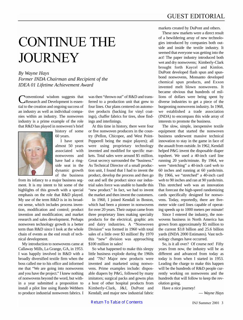