2003 forester service manual quick reference index ... · 2003 forester service manual quick...
TRANSCRIPT

2003 FORESTER SERVICE MANUAL QUICK REFERENCE INDEX
TRANSMISSION SECTION
This service manual has been preparedto provide SUBARU service personnelwith the necessary information and datafor the correct maintenance and repairof SUBARU vehicles.This manual includes the proceduresfor maintenance, disassembling, reas-sembling, inspection and adjustment ofcomponents and diagnostics for guid-ance of experienced mechanics.Please peruse and utilize this manualfully to ensure complete repair work forsatisfying our customers by keepingtheir vehicle in optimum condition.When replacement of parts duringrepair work is needed, be sure to useSUBARU genuine parts.
All information, illustration and specifi-cations contained in this manual arebased on the latest product informationavailable at the time of publicationapproval.
FUJI HEAVY INDUSTRIES LTD.
CONTROL SYSTEMS CS
AUTOMATIC TRANSMISSION AT
AUTOMATIC TRANSMISSION (DIAGNOSTICS)
AT
MANUAL TRANSMISSION AND DIFFERENTIAL
MT
CLUTCH SYSTEM CL
G8070GE4


CONTROL SYSTEMS
CS
Page1. General Description ....................................................................................22. Select Lever ................................................................................................73. Select Cable................................................................................................94. MT Gear Shift Lever..................................................................................125. MT Drive Select Lever...............................................................................186. Drive Select Cable ....................................................................................207. General Diagnostic....................................................................................21

CONTROL SYSTEMSGENERAL DESCRIPTION
1. General DescriptionA: SPECIFICATIONS
Item Specification
Vibration torque of rod against lever N (kgf, lb) 3.7 (0.38, 0.83) or less
CS-2

CONTROL SYSTEMSGENERAL DESCRIPTION
B: COMPONENT1. AT SELECT LEVER
(1) Bulb (11) Spacer (21) Nut A
(2) Detent arm (12) Grip (22) Clip
(3) Detent spring (13) Indicator cover
(4) Lever (14) Blind Tightening torque: N·m (kgf-m, ft-lb)(5) Spring pin (15) Cushion plate T1: 7.5 (0.76, 5.5)(6) Arm COMPL (16) Guide plate T2: 13 (1.3, 9.4)(7) Bush COMPL (17) Snap pin T3: 18 (1.8, 13.0)(8) Base plate (18) Washer T4: 18 (1.8, 13.0)(9) Grommet (19) Select cable
(10) Packing (20) Nut B
CS-00166
T4
T2
T3
T1
(10)
(22)(9)
(8) (7)
(6)
(5)
(4)
(2)
(3)
(1)
(22)
(12)
(13)
(15)
(16)
(21)
(20)
(19)
(17)
(14)
(11)
(18)
CS-3
CONTROL SYSTEMSGENERAL DESCRIPTION
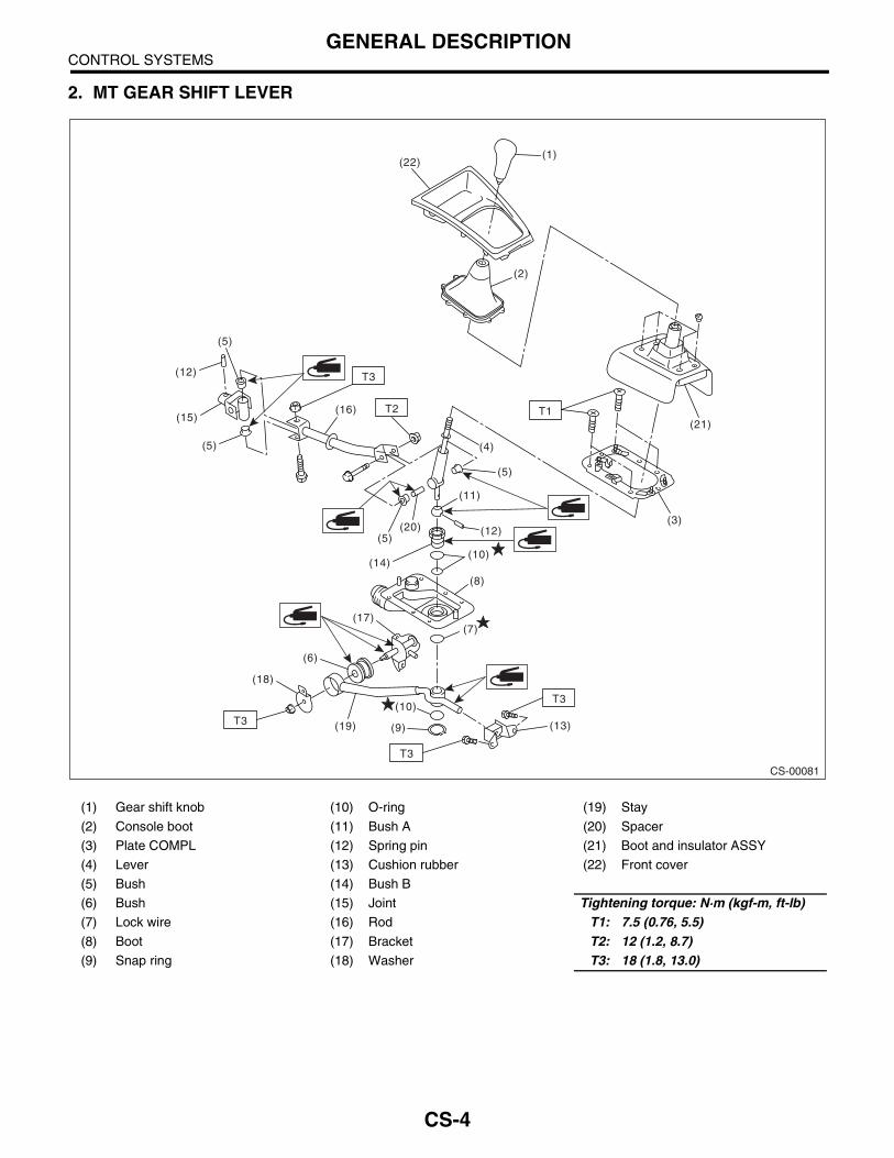
2. MT GEAR SHIFT LEVER
(1) Gear shift knob (10) O-ring (19) Stay
(2) Console boot (11) Bush A (20) Spacer
(3) Plate COMPL (12) Spring pin (21) Boot and insulator ASSY
(4) Lever (13) Cushion rubber (22) Front cover
(5) Bush (14) Bush B
(6) Bush (15) Joint Tightening torque: N·m (kgf-m, ft-lb)(7) Lock wire (16) Rod T1: 7.5 (0.76, 5.5)(8) Boot (17) Bracket T2: 12 (1.2, 8.7)(9) Snap ring (18) Washer T3: 18 (1.8, 13.0)
CS-00081
T2
(5)
(5)
(5)
(5) (4)
(6)
(3)
(2)
(1)
(18)
(21)
(22)
(20)
(19)
(17)
T1
(14)
(13)
(16)(15)
(12)
(12)
(11)
(10)
(10)
(9)
(8)
(7)
T3
T3
T3
T3
CS-4

CONTROL SYSTEMSGENERAL DESCRIPTION
3. DRIVE SELECT LEVER
(1) Knob (6) Spring Tightening torque: N·m (kgf-m, ft-lb)(2) Cushion (7) Lever COMPL T1: 1.6 (0.16, 1.2)(3) Plate COMPL (8) Clip T2: 18 (1.8, 13.0)(4) Bush (9) Clevis pin
(5) Cable (10) Snap pin
CS-00004
(4)(3)
(2)
(1)
(7)
(9)
(10)
(6)
(5)
(8)
T2
T1T2
CS-5

CONTROL SYSTEMSGENERAL DESCRIPTION
C: CAUTION• Wear working clothing, including a cap, protec-tive goggles, and protective shoes during opera-tion.• Remove contamination including dirt and corro-sion before removal, installation or disassembly.• Keep the disassembled parts in order and pro-tect them from dust or dirt.• Before removal, installation or disassembly, besure to clarify the failure. Avoid unnecessary re-moval, installation, disassembly, and replacement.• Use SUBARU genuine grease etc. or the equiv-alent. Do not mix grease etc. with that of anothergrade or from other manufacturers.• Be sure to tighten fasteners including bolts andnuts to the specified torque.• Place shop jacks or safety stands at the specifiedpoints.• Apply grease onto sliding or revolution surfacesbefore installation.• Before installing O-rings or snap rings, apply suf-ficient amount of grease to avoid damage and de-formation.• Before securing a part on a vise, place cushion-ing material such as wood blocks, aluminum plate,or shop cloth between the part and the vise.• Before disconnecting electrical connectors, besure to disconnect the ground cable from battery.
CS-6
CONTROL SYSTEMSSELECT LEVER
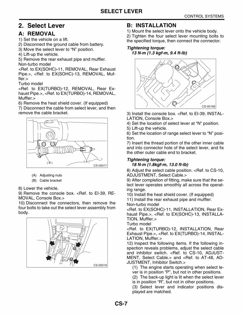
2. Select LeverA: REMOVAL1) Set the vehicle on a lift.2) Disconnect the ground cable from battery.3) Move the select lever to “N” position.4) Lift-up the vehicle.5) Remove the rear exhaust pipe and muffler.Non-turbo model<Ref. to EX(SOHC)-11, REMOVAL, Rear ExhaustPipe.>, <Ref. to EX(SOHC)-13, REMOVAL, Muf-fler.>Turbo model<Ref. to EX(TURBO)-12, REMOVAL, Rear Ex-haust Pipe.>, <Ref. to EX(TURBO)-14, REMOVAL,Muffler.>6) Remove the heat shield cover. (If equipped)7) Disconnect the cable from select lever, and thenremove the cable bracket.
8) Lower the vehicle.9) Remove the console box. <Ref. to EI-39, RE-MOVAL, Console Box.>10) Disconnect the connectors, then remove thefour bolts to take out the select lever assembly frombody.
B: INSTALLATION1) Mount the select lever onto the vehicle body.2) Tighten the four select lever mounting bolts tothe specified torque, then connect the connector.
Tightening torque:13 N·m (1.3 kgf-m, 9.4 ft-lb)
3) Install the console box. <Ref. to EI-39, INSTAL-LATION, Console Box.>4) Set the location of select lever at “N” position.5) Lift-up the vehicle.6) Set the location of range select lever to “N” posi-tion.7) Insert the thread portion of the other inner cableand into connector hole of the select lever, and fixthe other outer cable end to bracket.
Tightening torque:18 N·m (1.8kgf-m, 13.0 ft-lb)
8) Adjust the select cable position. <Ref. to CS-10,ADJUSTMENT, Select Cable.>9) After completion of fitting, make sure that the se-lect lever operates smoothly all across the operat-ing range.10) Install the heat shield cover. (If equipped)11) Install the rear exhaust pipe and muffler.Non-turbo model<Ref. to EX(SOHC)-11, INSTALLATION, Rear Ex-haust Pipe.>, <Ref. to EX(SOHC)-13, INSTALLA-TION, Muffler.>Turbo model<Ref. to EX(TURBO)-12, INSTALLATION, RearExhaust Pipe.>, <Ref. to EX(TURBO)-14, INSTAL-LATION, Muffler.>12) Inspect the following items. If the following in-spection reveals problems, adjust the select cableand inhibitor switch. <Ref. to CS-10, ADJUST-MENT, Select Cable.> and <Ref. to AT-48, AD-JUSTMENT, Inhibitor Switch.>
(1) The engine starts operating when select le-ver is in position “P”, but not in other positions.(2) The back-up light is lit when the select leveris in position “R”, but not in other positions.(3) Select lever and indicator positions dis-played are matched.
(A) Adjusting nuts
(B) Cable bracket
CS-00017( A )( B )
CS-00018
CS-00168
CS-7

CONTROL SYSTEMSSELECT LEVER
C: DISASSEMBLY1) Remove the grip.2) Remove the indicator light, and then remove theindicator cover.
NOTE:Be careful not to break the indicator light during re-moval.
3) Remove the blind.4) Remove the clips, and then remove the guideplate.
5) Remove the grommet, and then extract thespring pin.
6) Remove the arm COMPL, and then take awaythe select lever COMPL from base plate.
D: ASSEMBLY1) Clean all parts before assembly.2) Apply grease [SUNLIGHT No. 2 (Part No.003602010) or equivalent] to each parts. <Ref. toCS-3, AT Select Lever.>3) Assembly is in the reverse order of disassembly.4) After completion of fitting, transfer the select le-ver to range “P” — “1”, then check whether the in-dicator and select lever agree, whether the pointerand position mark agree and what the operatingforce is.
E: INSPECTION1) Inspect the removed parts by comparing withnew ones for deformation, damage and wear. Cor-rect or replace if defective.2) Confirm select lever COMPL for operating con-dition before assembly. It is operating normally if itmoves smoothly.
(A) Grip
(B) Indicator cover
(C) Indicator light
(A) Clips
(B) Guide plate
CS-00020
( A )
( B )
( C )
CS-00021
( A )
( A )
( B )
(A) Spring pin
(B) Arm COMPL
(A) Arm COMPL
(B) Select lever COMPL
(C) Base plate
CS-00027
( A )
( B )
CS-00109
( A )
( B )
( C )
CS-8
CONTROL SYSTEMSSELECT CABLE
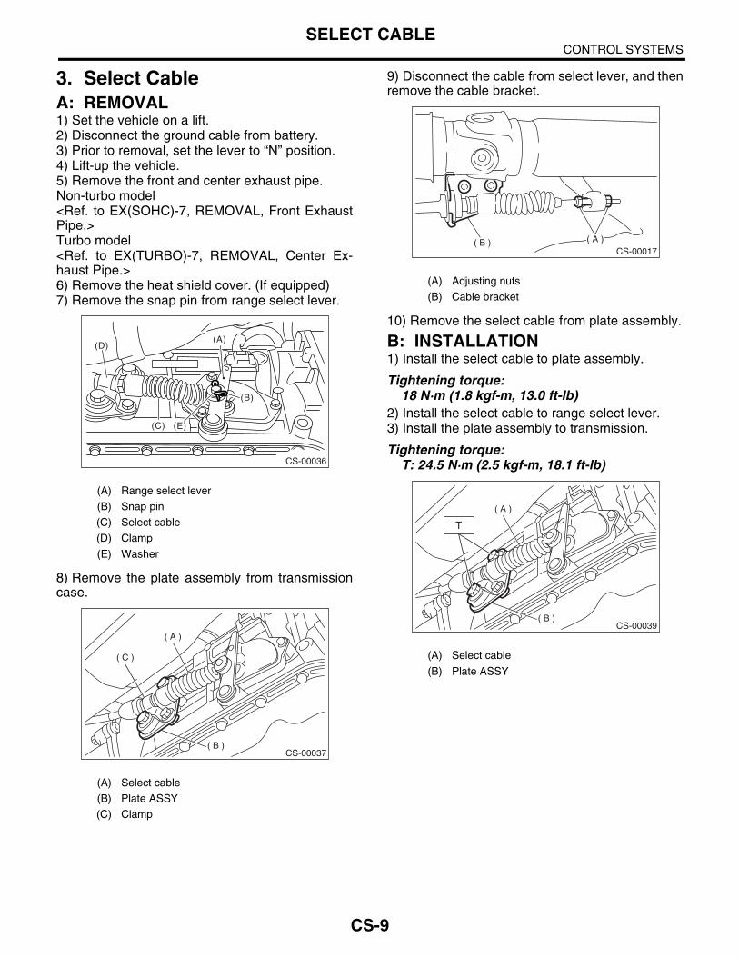
3. Select CableA: REMOVAL1) Set the vehicle on a lift.2) Disconnect the ground cable from battery.3) Prior to removal, set the lever to “N” position.4) Lift-up the vehicle.5) Remove the front and center exhaust pipe.Non-turbo model<Ref. to EX(SOHC)-7, REMOVAL, Front ExhaustPipe.>Turbo model<Ref. to EX(TURBO)-7, REMOVAL, Center Ex-haust Pipe.>6) Remove the heat shield cover. (If equipped)7) Remove the snap pin from range select lever.
8) Remove the plate assembly from transmissioncase.
9) Disconnect the cable from select lever, and thenremove the cable bracket.
10) Remove the select cable from plate assembly.
B: INSTALLATION1) Install the select cable to plate assembly.
Tightening torque:18 N·m (1.8 kgf-m, 13.0 ft-lb)
2) Install the select cable to range select lever.3) Install the plate assembly to transmission.
Tightening torque:T: 24.5 N·m (2.5 kgf-m, 18.1 ft-lb)
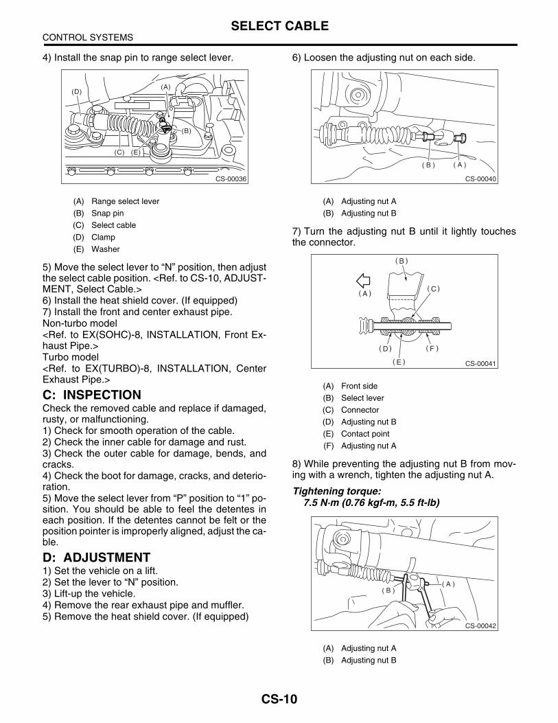
(A) Range select lever
(B) Snap pin
(C) Select cable
(D) Clamp
(E) Washer
(A) Select cable
(B) Plate ASSY
(C) Clamp
CS-00036
(C)
(B)
(A)
(E)
(D)
CS-00037
( A )
( B )
( C )
(A) Adjusting nuts
(B) Cable bracket
(A) Select cable
(B) Plate ASSY
CS-00017( A )( B )
CS-00039
( A )
( B )
T
CS-9
CONTROL SYSTEMSSELECT CABLE
4) Install the snap pin to range select lever.
5) Move the select lever to “N” position, then adjustthe select cable position. <Ref. to CS-10, ADJUST-MENT, Select Cable.>6) Install the heat shield cover. (If equipped)7) Install the front and center exhaust pipe.Non-turbo model<Ref. to EX(SOHC)-8, INSTALLATION, Front Ex-haust Pipe.>Turbo model<Ref. to EX(TURBO)-8, INSTALLATION, CenterExhaust Pipe.>
C: INSPECTIONCheck the removed cable and replace if damaged,rusty, or malfunctioning.1) Check for smooth operation of the cable.2) Check the inner cable for damage and rust.3) Check the outer cable for damage, bends, andcracks.4) Check the boot for damage, cracks, and deterio-ration.5) Move the select lever from “P” position to “1” po-sition. You should be able to feel the detentes ineach position. If the detentes cannot be felt or theposition pointer is improperly aligned, adjust the ca-ble.
D: ADJUSTMENT1) Set the vehicle on a lift.2) Set the lever to “N” position.3) Lift-up the vehicle.4) Remove the rear exhaust pipe and muffler.5) Remove the heat shield cover. (If equipped)
6) Loosen the adjusting nut on each side.
7) Turn the adjusting nut B until it lightly touchesthe connector.
8) While preventing the adjusting nut B from mov-ing with a wrench, tighten the adjusting nut A.
Tightening torque:7.5 N·m (0.76 kgf-m, 5.5 ft-lb)
(A) Range select lever
(B) Snap pin
(C) Select cable
(D) Clamp
(E) Washer
CS-00036
(C)
(B)
(A)
(E)
(D)
(A) Adjusting nut A
(B) Adjusting nut B
(A) Front side
(B) Select lever
(C) Connector
(D) Adjusting nut B
(E) Contact point
(F) Adjusting nut A
(A) Adjusting nut A
(B) Adjusting nut B
CS-00040
( A )( B )
CS-00041
CS-00042
( A )( B )
CS-10

CONTROL SYSTEMSSELECT CABLE
9) After completion of fitting, make sure that the se-lect lever operates smoothly all across the operat-ing range.10) Install the removed parts in the reverse order ofremoval.
CS-11
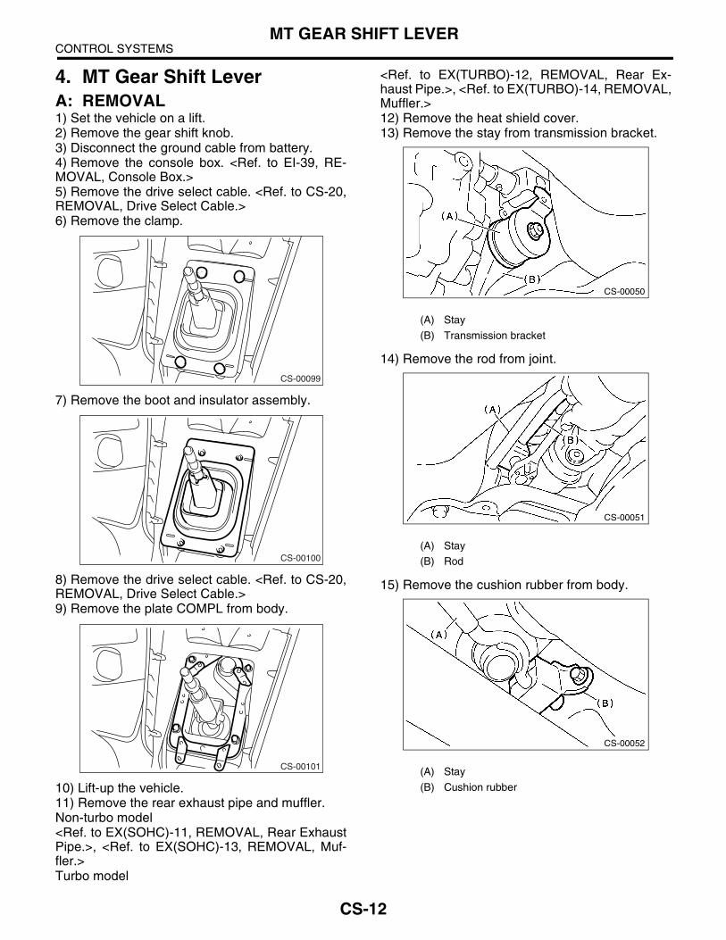
CONTROL SYSTEMSMT GEAR SHIFT LEVER
4. MT Gear Shift LeverA: REMOVAL1) Set the vehicle on a lift.2) Remove the gear shift knob.3) Disconnect the ground cable from battery.4) Remove the console box. <Ref. to EI-39, RE-MOVAL, Console Box.>5) Remove the drive select cable. <Ref. to CS-20,REMOVAL, Drive Select Cable.>6) Remove the clamp.
7) Remove the boot and insulator assembly.
8) Remove the drive select cable. <Ref. to CS-20,REMOVAL, Drive Select Cable.>9) Remove the plate COMPL from body.
10) Lift-up the vehicle.11) Remove the rear exhaust pipe and muffler.Non-turbo model<Ref. to EX(SOHC)-11, REMOVAL, Rear ExhaustPipe.>, <Ref. to EX(SOHC)-13, REMOVAL, Muf-fler.>Turbo model
<Ref. to EX(TURBO)-12, REMOVAL, Rear Ex-haust Pipe.>, <Ref. to EX(TURBO)-14, REMOVAL,Muffler.>12) Remove the heat shield cover.13) Remove the stay from transmission bracket.
14) Remove the rod from joint.
15) Remove the cushion rubber from body.
CS-00099
CS-00100
CS-00101
(A) Stay
(B) Transmission bracket
(A) Stay
(B) Rod
(A) Stay
(B) Cushion rubber
CS-00050
CS-00051
CS-00052
CS-12

CONTROL SYSTEMSMT GEAR SHIFT LEVER
16) Remove the spring pin, and then extract thejoint.
17) Lower the vehicle.18) Remove the gear shift lever.
B: INSTALLATION1) Insert the gear shift lever from room side.
NOTE:After inserting the rod and stay, temporarily putthem onto transmission mount.
2) Install the joint to transmission and secure withthe spring pin.
3) Lift-up the vehicle.4) Install the joint to shifter arm.5) Mount the cushion rubber on the body.
Tightening torque:18 N·m (1.8 kgf-m, 13.0 ft-lb)
6) Connect the rod to the joint.
Tightening torque:18 N·m (1.8 kgf-m, 13.0 ft-lb)
(A) Joint
(B) Spring pin
CS-00053
CS-00054
CS-00054
(A) Joint
(B) Spring pin
(A) Stay
(B) Cushion rubber
(A) Stay
(B) Rod
CS-00053
CS-00052
CS-00051
CS-13

CONTROL SYSTEMSMT GEAR SHIFT LEVER
7) Connect the stay to transmission bracket.
Tightening torque:18 N·m (1.8 kgf-m, 13.0 ft-lb)
8) Install the heat shield cover. (If equipped)9) Install the rear exhaust pipe and muffler.Non-turbo model<Ref. to EX(SOHC)-11, REMOVAL, Rear ExhaustPipe.>, <Ref. to EX(SOHC)-13, INSTALLATION,Muffler.>Turbo model<Ref. to EX(TURBO)-12, INSTALLATION, RearExhaust Pipe.>, <Ref. to EX(TURBO)-14, INSTAL-LATION, Muffler.>10) Lower the vehicle.11) Install the plate COMPL to body.
Tightening torque:7.5 N·m (0.76 kgf-m, 5.5 ft-lb)
12) Install the drive select cable. <Ref. to CS-20,INSTALLATION, Drive Select Cable.>
13) Install the boot and insulator assembly to vehi-cle in proper direction.
14) Install the clamp.15) Install the drive select cable. (Dual-range mod-el) <Ref. to CS-20, INSTALLATION, Drive SelectCable.>16) Install the console box. <Ref. to EI-39, INSTAL-LATION, Console Box.>
C: DISASSEMBLY1) Disassemble the lock wire.
2) Remove the rod from lever.
(A) Stay
(B) Transmission bracket
CS-00050
CS-00101
(A) Lock wire
(B) Stay
(A) Rod
(B) Lever
(C) Stay
CS-00100
CS-00055
CS-00056
CS-14

CONTROL SYSTEMSMT GEAR SHIFT LEVER
3) Remove the snap ring from bush B, and thendisconnect the stay.
4) Remove the boot from gear shift lever.5) Remove the bush and cushion rubber from stay.
6) Remove the O-ring, and then disconnect thebush B.
7) Draw out the spring pin, and then remove thebush A from gear shift lever.
D: ASSEMBLY1) Clean all parts before assembly.2) Mount the bush and cushion rubber on the stay.
3) Mount each part; boot, O-ring, bush A, spacer,bush B, bush and spring pin on the gear shift lever.
(A) Snap ring
(B) Bush B
(C) Stay
(A) Bush
(B) Stay
(C) Cushion rubber
(A) O-ring
(B) O-ring
(C) Bush B
CS-00057
CS-00058
CS-00059
(A) Spring pin
(B) Bush A
(A) Bush
(B) Cushion rubber
CS-00060
CS-00061
CS-15

CONTROL SYSTEMSMT GEAR SHIFT LEVER
NOTE:• Always use new O-rings.• Apply grease [SUNLIGHT No. 2 part (No.003602010) or equivalent] to the inner and sidesurfaces of the bush when installing the spacer.
4) Insert the gear shift lever into boot hole.5) Install the stay to bush B and secure it with snapring.
6) Tighten with a new lock wire to the extent thatthe boot will not come off.
7) Insert the rod into boot hole.8) Connect the rod to gear shift lever.
Tightening torque:11.8 N·m (1.2 kgf-m, 8.7 ft-lb)
(A) Boot
(B) O-ring
(C) Bush
(D) Spacer
(E) Bush A
(F) Bush B
(G) Spring pin
(H) O-ring
(A) Snap ring
(B) Bush B
CS-00062
CS-00165
( A )
( B )
(A) Lock wire
(B) Stay
(A) Rod
(B) Lever
(C) Stay
CS-00055
CS-00056
CS-16

CONTROL SYSTEMSMT GEAR SHIFT LEVER
E: INSPECTION1) Check each part (bush, cushion rubber, spacer,boot, stay and rod, etc.) for deformation, damageand wear. Repair or replace any defective part. De-termine defective parts by comparing with newparts.
2) Check the swing torque of the rod in relation ofgear shift lever.If the torque exceeds specification, replace thebush or retighten nuts.
Swing torque: 3.7 N (0.38 kgf, 0.83 lb) or less
3) Check that there is no excessive play and thatparts move smoothly.
(A) Bush
(B) Cushion rubber
(C) Spacer
(D) Boot
(E) Stay
(F) Rod
CS-00064
(A) Center of rotation
(B) Swing torque
CS-00065
(A)(B)
CS-17

CONTROL SYSTEMSMT DRIVE SELECT LEVER
5. MT Drive Select LeverA: REMOVAL1) Apply parking brake and place chocks to holdthe wheels.2) Disconnect the ground cable from battery.3) Set the drive select lever to HI position.4) Remove the knob.5) Remove the console box. <Ref. to EI-39, Con-sole Box.>6) Remove the bolt installing drive select lever as-sembly on body.
7) Remove the flange nut, clip and then disconnectthe cable from lever assembly.
B: INSTALLATION1) Install the drive select cable to lever COMPL,and then fasten it with a clip.
2) Install the drive select lever.
Tightening torque:18 N·m (1.8 kgf-m, 13.0 ft-lb)
3) Set the drive select lever to HI position.
4) Be sure to insert the cable eye end bolt into leverarm slit.
(A) Flange nut
(B) Lever COMPL
(C) Clip
CS-00102
CS-00067
(A) Flange nut
(B) Lever COMPL
(C) Clip
(A) HI position
(A) Cable eye end bolt
(B) Lever arm
CS-00067
CS-00068
CS-00069
CS-18

CONTROL SYSTEMSMT DRIVE SELECT LEVER
5) Tighten the nut where cable eye end bolt comesto a stop.
Tightening torque:18 N·m (1.8 kgf-m, 13.0 ft-lb)
6) Install in the reverse order of removal.
C: DISASSEMBLY1) Remove the spring.
2) Remove the lever, cushion and bush.
D: ASSEMBLY1) Assemble in the reverse order of disassembly.
Tightening torque:18 N·m (1.8 kgf-m, 13.0 ft-lb)
2) Make sure the select lever moves smoothly.
E: INSPECTION1) Make sure the select lever moves smoothly. If itdoes not move smoothly, repair or replace it.2) Make sure the drive select lever is not damaged.If it is damaged, repair or replace it.
(A) Spring
(A) Washer
(B) Bush
(C) Plate COMPL
(D) Cushion
(E) Lever COMPL
CS-00070
CS-00071
CS-19

CONTROL SYSTEMSDRIVE SELECT CABLE
6. Drive Select CableA: REMOVAL1) Remove the drive select lever. <Ref. to CS-18,REMOVAL, MT Drive Select Lever.>2) Remove the intake duct. <Ref. to IN(SOHC)-7,Air Intake Duct.>3) Remove the air cleaner case. <Ref. to IN(SO-HC)-6, Air Cleaner Case.>4) Remove the snap pin and clevis pin.5) Loosen the nut and disconnect the cable fromcable bracket.
6) Disconnect the cable from transmission clamp.7) Remove the cable from the under side of vehi-cle.
B: INSTALLATION1) Install in the reverse order of removal.2) Make sure the drive select lever operates prop-erly.
C: INSPECTION1) Make sure to shift the transmission to HI or LOposition by moving the drive select lever. If it doesnot move, adjust the cable.<Ref. to CS-20, AD-JUSTMENT, Drive Select Cable.>2) Make sure the cable operates smoothly. If itcatches or fails to work properly, repair or replaceit.3) Check the cable for damage.
D: ADJUSTMENT1) Set the drive select lever to HI position.2) Remove the drive select lever knob.3) Remove the console box. <Ref. to EI-39, Con-sole Box.>4) Loosen the nut.
5) Make sure the transmission is in HI position. If isnot, pull on the cable to put transmission in HI posi-tion.6) Tighten the nut in the location where cable endbolt stops naturally.
Tightening torque:18 N·m (1.8 kgf-m, 13.0 ft-lb)
7) Make sure to shift the transmission to HI or LOposition by moving the drive select lever. If it doesnot move, readjust the cable.
(A) Snap pin
(B) Clevis pin
(C) Nut
CS-00103(A)
(B)
(C)
CS-00073
CS-00104
CS-00104
CS-20

CONTROL SYSTEMSGENERAL DIAGNOSTIC
7. General DiagnosticA: INSPECTION
Symptom Possible cause Remedy
1. Select lever (1) Starter does not run. Adjust the select cable and inhibitor switch, or inspect circuit.
(2) Back-up light does not light up. Adjust the select cable and inhibitor switch, or inspect circuit.
CS-21

CONTROL SYSTEMSGENERAL DIAGNOSTIC
CS-22