2004 impreza service manual quick reference …ken-gilbert.com/wrx/04impreza/imp04_chas_11-2.pdf ·...
TRANSCRIPT

2004 IMPREZA SERVICE MANUAL QUICK REFERENCE INDEX
CHASSIS SECTION
This service manual has been preparedto provide SUBARU service personnelwith the necessary information and datafor the correct maintenance and repairof SUBARU vehicles.This manual includes the proceduresfor maintenance, disassembling, reas-sembling, inspection and adjustment ofcomponents and diagnostics for guid-ance of experienced mechanics.Please peruse and utilize this manualfully to ensure complete repair work forsatisfying our customers by keepingtheir vehicle in optimum condition.When replacement of parts duringrepair work is needed, be sure to useSUBARU genuine parts.
All information, illustration and specifi-cations contained in this manual arebased on the latest product informationavailable at the time of publicationapproval.
FUJI HEAVY INDUSTRIES LTD.
FRONT SUSPENSION FS
REAR SUSPENSION RS
WHEEL AND TIRE SYSTEM WT
DIFFERENTIALS DI
TRANSFER CASE TC
DRIVE SHAFT SYSTEM DS
ABS ABS
ABS (DIAGNOSTICS) ABS(diag)
BRAKE BR
PARKING BRAKE PB
POWER ASSISTED SYSTEM (POWER STEERING)
PS
G1870GE5

POWER ASSISTED SYSTEM (POWER STEERING)
PS
Page1. General Description ....................................................................................22. Steering Wheel..........................................................................................233. Universal Joint...........................................................................................244. Tilt Steering Column..................................................................................265. Steering Gearbox [LHD MODEL] ..............................................................296. Steering Gearbox [RHD MODEL] .............................................................477. Pipe Assembly [LHD MODEL] ..................................................................648. Pipe Assembly [RHD MODEL]..................................................................729. Oil Pump ...................................................................................................80
10. Reservoir Tank..........................................................................................8511. Power Steering Fluid.................................................................................8612. General Diagnostic Table..........................................................................87

POWER ASSISTED SYSTEM (POWER STEERING)Steering Gearbox [RHD MODEL]
6. Steering Gearbox [RHD MOD-EL]
A: REMOVAL1) Set the vehicle on a lift.2) Disconnect the ground cable from battery.3) Loosen the front wheel nut.4) Lift-up the vehicle, and then remove the frontwheels.5) Remove the under cover.6) Remove the sub frame.7) Remove the front exhaust pipe assembly. (Non-turbo model)<Ref. to EX(H4SO)-6, REMOVAL, Front ExhaustPipe.>
WARNING:Be careful, the exhaust pipe is hot.8) Using a puller, remove the tie-rod end fromknuckle arm after pulling off cotter pin and remov-ing castle nut.
9) Remove the jack-up plate and front stabilizer.
10) Remove the one pipe joint at center of gearbox,and connect vinyl hose to pipe and joint. Dischargefluid by turning the steering wheel fully clockwiseand counterclockwise. Discharge fluid similarlyfrom the other pipe.
11) Remove the universal joint. <Ref. to PS-24,REMOVAL, Universal Joint.> 12) Disconnect the lower pipe C from gear box first,and upper pipe D second.
13) Remove the clamp bolts securing the gearboxto crossmember, and then remove the gearbox.
(1) Castle nut
(2) Tie-rod end
(3) Knuckle arm
(1) Jack-up plate
PS-00043
PS-00044
(1) Pipe A
(2) Pipe B
(1) Pipe C
(2) Pipe D
(1) Clamp
PS-00045
PS-00046
PS-00047
PS-47

POWER ASSISTED SYSTEM (POWER STEERING)Steering Gearbox [RHD MODEL]
B: INSTALLATION1) Insert the gearbox into crossmember, beingcareful not to damage the gearbox boot.2) Tighten the gearbox to crossmember bracket viaclamp with bolts to specified torque.
Tightening torque:60 N·m (6.1 kgf-m, 44.1 ft-lb)
3) Connect the pipe D first to gear box, and pipe Csecond.
Tightening torque:T: 15 N·m (1.5 kgf-m, 10.8 ft-lb)
4) Install the universal joint. <Ref. to PS-24, IN-STALLATION, Universal Joint.>5) Connect the tie-rod end and knuckle arm, andtighten with castle nut.
Castle nut tightening torque:27 N·m (2.75 kgf-m, 19.9 ft-lb)
CAUTION:When connecting, do not hit the cap at bottom of tie-rod end with hammer.
6) After tightening the castle nut to the specifiedtightening torque, tighten it further within 60° untilcotter pin hole is aligned with slot in the nut. Fit thecotter pin into nut, and then bend the pin to lock.
7) Install the front stabilizer to vehicle.8) Install the front exhaust pipe assembly. 9) Install the sub frame. 10) Install the under cover. 11) Align the center of roll connector. <Ref. to AB-18, ADJUSTMENT, Roll Connector.>12) Install the steering wheel. <Ref. to PS-23, IN-STALLATION, Steering Wheel.>13) Install the front wheels.14) Tighten the wheel nuts to specified torque.
Tightening torque:90 N·m (9.1 kgf-m, 65.8 ft-lb)
15) Connect the battery ground cable to battery.16) Pour fluid into the oil tank, and bleed air. <Ref. to PS-86, Power Steering Fluid.>17) Check for fluid leaks.18) Install the jack-up plate.19) Lower the vehicle.20) Check the fluid level in oil tank.
(1) Clamp
(1) Pipe C
(2) Pipe D
PS-00047
PS-00049
(A) Cotter pin
(B) Castle nut
(C) Tie-rod
DS-00042
(C)
(B)
(A)
PS-48

POWER ASSISTED SYSTEM (POWER STEERING)Steering Gearbox [RHD MODEL]
21) After adjusting the toe-in and steering angle,tighten the lock nut on tie-rod end.
Tightening torque:83 N·m (8.5 kgf-m, 61.5 ft-lb)
NOTE:When adjusting the toe-in, hold boot as shown toprevent it from being rotated or twisted. If twisted,straighten it.
C: DISASSEMBLY1) Secure the gearbox removed from vehicle invise using the ST.ST 926200000 STAND
CAUTION:Secure the gearbox assembly in a vise using the ST as shown. Do not attempt to secure it without this ST.
2) Remove the tie-rod end and lock nut from gear-box.
3) Remove the clip on outside of boot using pliers,and then slide the boot to tie-rod end side.
4) Using flat tip screwdriver, remove the band fromboot.
NOTE:Check the boot for crack, damage or deterioration.Replace the boot with a new one if necessary.
5) Using the ST, loosen lock nut.ST 926230000 SPANNER
(1) Clamp
PS-00051
PS-00052
(1) Clip
(1) Band
(1) Lock nut
PS-00053
PS-00054
PS-00056
PS-49

POWER ASSISTED SYSTEM (POWER STEERING)Steering Gearbox [RHD MODEL]
6) Tighten the adjusting screw until it no longertightens.
7) Using a wrench (32 mm (1.26 in) width acrossflats) or adjustable wrench with cinching boot, re-move the tie-rod.
8) Loosen the adjusting screw, and then removethe spring and sleeve.9) Disconnect the pipes A and B from steering bodyand control valve housing.
10) Clean the dirt of input shaft. Remove the dustcover taking care not to scratch the housing or in-put shaft and allow foreign matter to enter gear boxinterior.
11) Align the ST pin to plug hole to install. Rotatethe ST counterclockwise to remove plug.ST 34199AE090 PLUG WRENCH
(1) Adjusting screw
(1) Tie-rod
(1) Pipe A
(2) Pipe B
PS-00057
PS-00058
PS-00059
(1) Dust cover
(1) Plug
PS-00060
PS-00061
PS-50

POWER ASSISTED SYSTEM (POWER STEERING)Steering Gearbox [RHD MODEL]
12) Remove the valve assembly taking care not toscratch seal ring and valve housing inner surface.
13) Remove the holder using a wrench (32 mm(1.26 in) width across flats) or adjustable wrench.
14) Install the ST on valve side of rack and pressouter side oil seal out taking care not to contactrack with steering body inner surface.ST 34099FA030 INSTALLER & REMOVER
NOTE:Block the pipe connection of steering body to pre-vent fluid from flowing out.
(1) Valve ASSY
(2) Seal ring
PS-00062
PS-00063
(1) Rack piston
(2) Outer side oil seal
PS-00064
PS-51

POWER ASSISTED SYSTEM (POWER STEERING)Steering Gearbox [RHD MODEL]
15) Insert the ST from valve side and press back-up ring and oil seal out.ST 927580000 REMOVER
16) Using the ST1 and ST2, repair the cylinder’sclinched sections.ST1 34099FA080 PUNCHST2 34099FA070 BASE
17) If the cylinder edge is deformed in a convexshape, repair using an oil stone.
18) Remove the oil seal using ST and press fromplug. ST 34199AE100 PLUG OIL SEAL REMOVER
NOTE:Do not apply force on the plug edge surface.
19) Set the ST on drawing dimension.ST 34199AE120 GEARBOX OIL SEAL RE-
MOVER
(1) Cylinder
PS-00065
PS-00066
(1) Oil seal
(2) O-ring
(1) 70 mm (2.76 in)
PS-00067
PS-00068
PS-00069
PS-52

POWER ASSISTED SYSTEM (POWER STEERING)Steering Gearbox [RHD MODEL]
20) Set the stopper to gear box, and then insert thetip of ST to gear box.
21) By fixing the 2-surface width, press in by rotat-ing the rod and attach to oil seal.
22) While fixing the 2-surface width, pull out the oilseal by rotating nut.
CAUTION:Take care not to scratch the gear box inner sur-face.
D: ASSEMBLY1) Apply a coat of grease to inside and outside ofnew oil seal.
Specified steering grease:VALIANT GREASE M2 (Part No. 003608001)
2) Verify the oil seal direction and installation posi-tion. Using the ST and press, press fit the oil seal togear box.ST 34199AE130 GEARBOX OIL SEAL IN-
STALLER
(1) Stopper
(2) Oil seal
(1) Rod
(2) 2-surface width
PS-00070
PS-00071
(1) 2-surface width
(2) Nut
(1) Oil seal
PS-00072
PS-00073
PS-53

POWER ASSISTED SYSTEM (POWER STEERING)Steering Gearbox [RHD MODEL]
3) Attach the steering body to ST as shown in thefigure. Apply a coat of grease to needle bearing.ST 926200000 STAND
CAUTION:Ensure the needle bearing is free from defects. If it is faulty, replace the steering body with a new one.
4) Using the ST·B and ST·C, attach the oil seal toST·A.ST 927490000 INSTALLER A, B, C
NOTE:Face the oil seal in direction shown in the figure.
5) Insert the ST·A with oil seal assembled, throughgear side of rack. Remove the oil seal from ST·Anear piston, and then remove the ST·A from rack.
6) Install the back-up washer from gear side ofrack.(1) Steering body
(A) Oil seal
PS-00074
PS-00075
ST AST BST C
(A)
(A) Oil seal
(B) Rack
(C) Piston
(1) Oil seal
(2) Back-up washer
(3) Rack
PS-00076
ST A(A)
(B)
(C)
PS-00077
PS-54
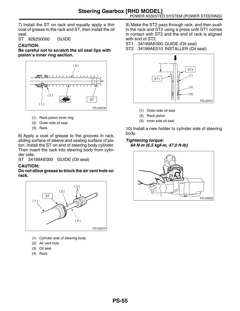
POWER ASSISTED SYSTEM (POWER STEERING)Steering Gearbox [RHD MODEL]
7) Install the ST on rack and equally apply a thincoat of grease to the rack and ST, then install the oilseal.ST 926250000 GUIDE
CAUTION:Be careful not to scratch the oil seal lips with piston’s inner ring section.
8) Apply a coat of grease to the grooves in rack,sliding surface of sleeve and sealing surface of pis-ton. Install the ST on end of steering body cylinder.Then insert the rack into steering body from cylin-der side.ST 34199AE000 GUIDE (Oil seal)
CAUTION:Do not allow grease to block the air vent hole on rack.
9) Make the ST2 pass through rack, and then pushin the rack and ST2 using a press until ST1 comesin contact with ST2 and the end of rack is alignedwith end of ST2.ST1 34199AE000 GUIDE (Oil seal)ST2 34199AE010 INSTALLER (Oil seal)
10) Install a new holder to cylinder side of steeringbody.
Tightening torque:64 N·m (6.5 kgf-m, 47.0 ft-lb)
(1) Rack piston inner ring
(2) Outer side oil seal
(3) Rack
(1) Cylinder side of steering body
(2) Air vent hole
(3) Oil seal
(4) Rack
PS-00078
PS-00079
(1) Outer side oil seal
(2) Rack piston
(3) Inner side oil seal
PS-00431
(1)
(2)
(3)
ST2
ST1
PS-00063
PS-55

POWER ASSISTED SYSTEM (POWER STEERING)Steering Gearbox [RHD MODEL]
11) Using the ST, clinch steering body cylinder at apoint less than 3 mm (0.12 in) from holder.
CAUTION:Be careful not to deform the holder.ST 34099FA060 PUNCH HOLDER
12) Roll the vinyl tape on serration part of valve as-sembly, and then apply grease on the tape surface.
13) Apply a coat of grease on the gear teeth ofvalve assembly, and then attach the valve assem-bly taking care not to scratch oil seal and seal ring.
14) Apply grease on the oil seal circumference, andthen press into the plug using ST and a press. Re-place the plug circumference O-rings with newones.ST 34199AE110 PLUG OIL SEAL INSTALLER
CAUTION:Pay attention to the oil seal direction, and at-taching position.
(A) Holder
(B) 3 mm (0.1 in)
(1) Vinyl tape
PS-00084
(A)
(B)
ST
ST
PS-00085
(1) Seal ring
(2) Oil seal
(1) Plug
(2) O-ring
(3) Oil seal
PS-00086
PS-00087
PS-56

POWER ASSISTED SYSTEM (POWER STEERING)Steering Gearbox [RHD MODEL]
15) Using the ST, install plug. ST 34199AE090 PLUG WRENCH
Tightening torque:64 N·m (6.5 kgf-m, 47.0 ft-lb)
16) Install the dust cover. Remove the vinyl tape.
17) Temporarily install the rack, and then operate itfrom lock to lock two or three times to make it fit in.Remove the grease blocking air vent hole.
CAUTION:If operating the rack from lock to lock without installing tie-rod, it may damage the oil seal. Al-ways install the tie-rods LH and RH.
18) Apply a coat of grease to the sliding surface ofseat pad, sleeve and seating surface of spring, andthen insert sleeve into steering body.Charge the adjusting screw with grease, and theninsert the spring into adjusting screw and install onsteering body.
19) Tighten the adjusting screw to specified torque.
Tightening torque:7.4 N·m (0.75 kgf-m, 5.4 ft-lb)
20) After tightening to the specified tighteningtorque, loosen it by 25°.21) Remove the tie-rod.22) Verify that play is within specified value. <Ref.to PS-61, SERVICE LIMIT, INSPECTION, SteeringGearbox [RHD MODEL].>23) Loosen the adjusting screw, and then apply liq-uid gasket to at least 1/3 of the entire perimeter ofadjusting screw thread.
Liquid gasket:THREE BOND 1141
(1) Plug
(1) Dust cover
PS-00088
PS-00060
(1) Seat pad
(2) Sleeve
(3) Spring
(4) Adjusting screw
(5) Lock nut
(1) Apply liquid gasket to at least 1/3 of entire perimeter.
PS-00090
PS-00092
PS-57
POWER ASSISTED SYSTEM (POWER STEERING)Steering Gearbox [RHD MODEL]
24) Tighten the adjusting screw.
Tightening torque:9.8 N·m (10.0 kgf-m, 7.2 ft-lb)
25) After tightening to the specified tighteningtorque, loosen it.26) Tighten the adjusting screw.
Tightening torque:4.8 N·m (0.49 kgf-m, 3.5 ft-lb)
27) After tightening to the specified tighteningtorque, loosen it.28) Tighten the adjusting screw.
Tightening torque:4.8 N·m (0.49 kgf-m, 3.5 ft-lb)
29) After tightening to the specified tighteningtorque, loosen it by 25°.30) Install the lock nut. While holding the adjustingscrew with a wrench, tighten lock nut using ST.ST 926230000 SPANNER
Tightening torque (Lock nut):39 N·m (4.0 kgf-m, 28.9 ft-lb)
NOTE:Hold the adjusting screw with a wrench to prevent itfrom turning while tightening lock nut.31) Install the tie-rod into rack.
Tightening torque:90 N·m (9.0 kgf-m, 65.1 ft-lb)
NOTE:Check the mating face of rack and tie-rod for for-eign material, dirt, dust and etc.If required, clean the mating face.32) Apply a coat of grease to the tie-rod groove,and then install the boot to housing.
NOTE:Make sure that the boot is installed without unusualinflation or deflation.
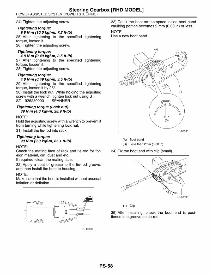
33) Caulk the boot so the space inside boot bandcaulking portion becomes 2 mm (0.08 in) or less.
NOTE:Use a new boot band.
34) Fix the boot end with clip (small).
35) After installing, check the boot end is posi-tioned into groove on tie-rod.
PS-00094
(A) Boot band
(B) Less than 2mm (0.08 in)
(1) Clip
PS-00095
(A)
(B)
PS-00096
PS-58

POWER ASSISTED SYSTEM (POWER STEERING)Steering Gearbox [RHD MODEL]
36) If the tie-rod end was removed, screw in thelock nut and tie-rod end to screwed portion of tie-rod, and then tighten the lock nut temporarily in aposition as shown in the figure.
Installed tie-rod length: LSedan:
25 mm (0.98 in)Wagon:
15 mm (0.59 in)
37) Inspect the gearbox as follows:“A” Holding the tie-rod end, repeat lock to lock twoor three times as quickly as possible.“B” Holding the tie-rod end, turn it slowly at a radiusone or two times as large as possible.After all, make sure that the boot is installed inspecified position without deflation.
38) Remove the gearbox from ST.ST 926200000 STAND
PS-00097
L
PS-00098
BA
PS-59

POWER ASSISTED SYSTEM (POWER STEERING)Steering Gearbox [RHD MODEL]
E: INSPECTION1. BASIC INSPECTION1) Clean all disassembled parts, and check for wear, damage, or any other faults, then repair or replace asnecessary.2) When disassembling, check the inside of gearbox for water. If any water is found, carefully check the bootfor damage, input shaft dust seal, adjusting screw and boot clips for poor sealing. If faulty, replace with newparts.
No. Parts Inspection Corrective action
1 Input shaft(1) Bend of input shaft(2) Damage on serration
If the bend or damage is excessive, replace the entire gearbox.
2 Dust seal(1) Crack or damage(2) Wear
If the outer wall slips, lip is worn out or damage is found, replace it with a new one.
3 Rack and pinion Poor mating of rack with pinion
(1) Adjust the backlash properly. By measuring the turning torque of gearbox and sliding resistance of rack, check if rack and pinion engage uni-formly and smoothly with each other. (Refer to “Service limit”.)(2) Keeping the rack pulled out all the way so that all teeth emerge, check teeth for damage. Even if abnormality is found in either (1) or (2), replace the entire gearbox.
4 Gearbox unit
(1) Bend of rack shaft(2) Bend of cylinder portion(3) Crack or damage on cast iron portion
Replace the gearbox with a new one.
(4) Wear or damage on rack bushIf the free play of rack shaft in radial direction is out of the specified range, replace the gearbox with a new one. (Refer to “Service limit”.)
(5) Wear on input shaft bearingIf the free plays of input shaft in radial and axial directions are out of the specified ranges, replace the gearbox with a new one. (Refer to “Service limit”.)
5 Boot Crack, damage or deterioration Replace with a new one.
6 Tie-rod(1) Looseness of ball joint(2) Bend of tie-rod
Replace with a new one.
7 Tie-rod endDamage or deterioration on dust seal
Replace with a new one.
8Adjusting screw spring
Deterioration Replace with a new one.
9 Boot clip Deterioration Replace with a new one.
10 Sleeve Damage Replace with a new one.
11 Pipes(1) Damage to flared surface(2) Damage to flare nut(3) Damage to pipe
Replace with a new one.
PS-60
POWER ASSISTED SYSTEM (POWER STEERING)Steering Gearbox [RHD MODEL]
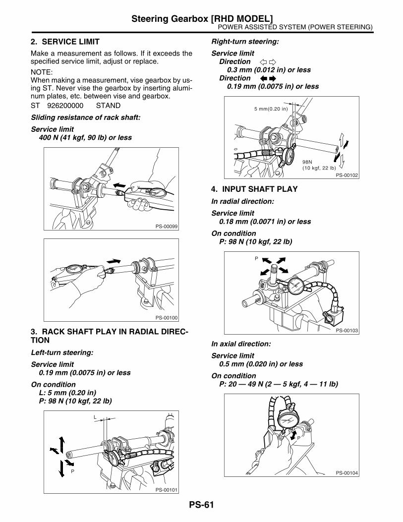
2. SERVICE LIMITMake a measurement as follows. If it exceeds thespecified service limit, adjust or replace.
NOTE:When making a measurement, vise gearbox by us-ing ST. Never vise the gearbox by inserting alumi-num plates, etc. between vise and gearbox.ST 926200000 STAND
Sliding resistance of rack shaft:
Service limit400 N (41 kgf, 90 lb) or less
3. RACK SHAFT PLAY IN RADIAL DIREC-TION
Left-turn steering:
Service limit0.19 mm (0.0075 in) or less
On conditionL: 5 mm (0.20 in)P: 98 N (10 kgf, 22 lb)
Right-turn steering:
Service limitDirection
0.3 mm (0.012 in) or lessDirection
0.19 mm (0.0075 in) or less
4. INPUT SHAFT PLAY
In radial direction:
Service limit0.18 mm (0.0071 in) or less
On conditionP: 98 N (10 kgf, 22 lb)
In axial direction:
Service limit0.5 mm (0.020 in) or less
On conditionP: 20 — 49 N (2 — 5 kgf, 4 — 11 lb)
PS-00099
PS-00100
PS-00101
P
L
PS-00102
5 mm(0.20 in)
98N(10 kgf, 22 lb)
PS-00103
P
PS-00104
P
PS-61

POWER ASSISTED SYSTEM (POWER STEERING)Steering Gearbox [RHD MODEL]
5. TURNING RESISTANCE OF GEARBOXUsing the ST, measure gearbox turning resistance.ST 34099PA100 SPANNER
Service limitMaximum allowable resistance
10.5 N (1.1 kgf, 2.4 lb) or less
Difference between right and left turning resis-tance:
Less than 20%
6. OIL LEAKING
PS-00105
(1) Power cylinder (3) Rack piston (5) Input shaft
(2) Cylinder (4) Rack (6) Valve housing
PS-00106
ab
d c c
d d
PS-62
POWER ASSISTED SYSTEM (POWER STEERING)Steering Gearbox [RHD MODEL]
1) Lift up the vehicle.2) Even if the location of leak can be easily foundby observing leaking condition, it is necessary tothoroughly remove the oil from suspected portionand turn steering wheel from lock to lock about thir-ty to forty times with engine running, then reinspectthe suspected portion between immediately afterand several hours after this operation.3) Inspect leakage from “a”.The oil seal is damaged. Replace the valve assem-bly with a new one.4) Inspect leakage from “b”.The torsion bar O-ring is damaged. Replace thevalve assembly with a new one.5) Inspect leakage from “c”.The oil seal is damaged. Replace the oil seal with anew one.6) Inspect leakage from “d”.The pipe is damaged. Replace the faulty pipe or O-ring with a new one.
F: ADJUSTMENT1) Adjust the front toe. <Ref. to FS-10, FRONTWHEEL TOE-IN, INSPECTION, Wheel Align-ment.>
Standard of front toe:IN 3 — OUT 3 mm (IN 0.12 — OUT 0.12 in)
2) Adjust the steering angle of wheels. <Ref. to FS-10, STEERING ANGLE, INSPECTION, WheelAlignment.>
Standard of steering angle:
3) If the steering wheel spokes are not horizontalwhen wheels are set in the straight ahead position,and error is more than 5° on the periphery of steer-ing wheel, correctly re-install the steering wheel.
4) If the steering wheel spokes are not horizontalwith vehicle set in the straight ahead position afterthis adjustment, correct it by turning the right andleft tie-rods in the opposite direction each other bythe same angle.
(1) Lock nut
ModelTURBO, 2.5 L and
OUTBACKOthers
Inner wheel 34.5°±°±°±°±1.5°°°° 37.3°±°±°±°±1.5°°°°Outer wheel 30.3°±°±°±°±1.5°°°° 32.4°±°±°±°±1.5°°°°
PS-00107
(1) Within 5°
PS-00564
(1)
PS-63

POWER ASSISTED SYSTEM (POWER STEERING)Pipe Assembly [LHD MODEL]
7. Pipe Assembly [LHD MODEL]A: REMOVAL1) Disconnect the ground cable from battery.2) Lift-up the vehicle, and then remove the jack-upplate.
3) Remove the one pipe joint at the center of gear-box, and then connect the vinyl hose to pipe andjoint. Discharge fluid by turning steering wheel fullyclockwise and counterclockwise. Discharge fluidsimilarly from the other pipe.
4) Remove the clamp E from pipes C and D.
5) Disconnect the pipe C and D from gear box.
(1) Jack-up plate
(1) Pipe A
(2) Pipe B
PS-00044
(1)
(2)
PS-00026
(1) Return hose
(2) Pressure hose
(3) Clamp E
(4) Pipe C
(5) Pipe D
(1) Pipe C
(2) Pipe D
(5)
(2)
(1)
(4)
PS-00176
(3)
(2)(1)
PS-00027
PS-64

POWER ASSISTED SYSTEM (POWER STEERING)Pipe Assembly [LHD MODEL]
6) NON-TURBO MODEL(1) Remove the air intake duct. <Ref. toIN(H4SO)-6, REMOVAL, Air Intake Duct.>(2) Remove the bolt A.(3) Disconnect the pipe C from oil pump. Dis-connect the pipe D from return hose.
CAUTION:• Do not allow fluid from the hose end to comeinto contact with pulley belt.• To prevent foreign matter from entering thehose and pipe, cover the open ends of themwith a clean cloth.
7) TURBO MODEL(1) Remove the air cleaner.<Ref. to IN(H4DOTC)-7, REMOVAL, Air Clean-er.>(2) Remove the coolant filler tank.
(3) Remove the two bolts fixing pipe C and D.(4) Disconnect the pipe C from oil pump. Dis-connect the pipe D from return hose.
CAUTION:• Do not allow fluid from the hose end to comeinto contact with pulley belt.• To prevent foreign matter from entering thehose and pipe, cover the open ends of themwith a clean cloth.
(1) Bolt A
(2) Pipe C
(3) Pipe D
PS-00432
(3)
(2)
(1)
(1) Bolt
(2) Pipe C
(3) Pipe D
PS-00114
(3)(1) PS-00433
(2)
PS-65
POWER ASSISTED SYSTEM (POWER STEERING)Pipe Assembly [LHD MODEL]
B: INSTALLATION1) Temporarily tighten the two bolts fixing pipe Cand D. (bolt A)
NOTE:Visually check that the hose between tank and pipeD is free from bending or twisting.• NON-TURBO MODEL
• TURBO MODEL
(1) Connect the pipe D to oil tank.(2) Using a new gasket, connect the pipe C tooil pump.
Tightening torque:39 N·m (4.0 kgf-m, 28.9 ft-lb)(3) Tighten the two bolts fixing pipe C and D.(bolt A)
Tightening torque:13 N·m (1.3 kgf-m, 9.4 ft-lb)
2) Install the coolant filler tank. (Turbo model)
Tightening torque:T1: 19 N·m (1.9 kgf-m, 13.7 ft-lb)T2: 21 N·m (2.1 kgf-m, 15.2 ft-lb)
(1) Bolt A
(2) Pipe C
(3) Pipe D
(1) Bolt A
(2) Pipe C
(3) Pipe D
PS-00432
(3)
(2)
(1)
(3)(1) PS-00433
(2)
PS-00114
PS-66
POWER ASSISTED SYSTEM (POWER STEERING)Pipe Assembly [LHD MODEL]
3) Temporarily connect the pipe C and D to gearbox.
4) Temporarily install the clamp E on pipes C andD.
NOTE:Ensure the letter “8” on each clamp are diagonallyopposite each other as shown in the figure.
5) Tighten the clamp E firmly.
Tightening torque:7.4 N·m (0.75 kgf-m, 5.4 ft-lb)
6) Tighten the joint nut.
Tightening torque:15 N·m (1.5 kgf-m, 10.8 ft-lb)
7) Connect the pipes A and B to four pipe joints ofgearbox. Connect the upper pipe B first, and lowerpipe A second.
Tightening torque:13 N·m (1.3 kgf-m, 9.4 ft-lb)
8) Install the jack-up plate.9) Install the air intake duct. <Ref. to IN(H4SO)-6,INSTALLATION, Air Intake Duct.>10) Install the air intake duct, air cleaner upper cov-er and air intake boot.<Ref. to IN(H4DOTC)-7, INSTALLATION, AirCleaner.> and <Ref. to IN(H4SO)-6, INSTALLA-TION, Air Intake Duct.>11) Connect the battery ground cable to battery.12) Feed the specified fluid.
CAUTION:Never start the engine before feeding the fluid; otherwise vane pump might be seized up.
(1) Return hose
(2) Pressure hose
(3) Approx. 30 mm (1.18 in)
(4) Clamp E
(5) Pipe C
(6) Pipe D
(7) Pipe (Gear box side)
(1) Clamp E
(2) Pipe C
(6)
(4)
(2)
(1)
(3)
(5)
(7)
PS-00178
PS-00196
(1)
(2)
(1) Pipe A
(2) Pipe B
(1)
(2)
PS-00026
PS-67
POWER ASSISTED SYSTEM (POWER STEERING)Pipe Assembly [LHD MODEL]
13) Finally check clearance between pipes and/or hoses, as shown above.If cruise control actuator-to-power steering hose clearance is less than 10 mm (0.39 in), move the portion (A)secured by clamp to other portion, or bend portion (B) to adjust.
(1) High pressure hose (2) No interference is allowed between hoses.
(3) Clearance between crossmember and pipe: 3 — 8 mm (0.12 — 0.31 in)
PS-00179
(A)
(2)
(3)
(1)
(B)
PS-68

POWER ASSISTED SYSTEM (POWER STEERING)Pipe Assembly [LHD MODEL]
C: INSPECTIONCheck all disassembled parts for wear, damage or other abnormalities. Repair or replace faulty parts as re-quired.
CAUTION:Although the surface layer materials of rubber hoses have excellent weathering resistance, heat re-sistance and resistance for low temperature brittleness, they are likely to be damaged chemically by brake fluid, battery electrolyte, engine oil and automatic transmission fluid and their service lives are to be very shortened. It is very important to keep the hoses free from before mentioned fluids and to wipe out immediately when the hoses are adhered with the fluids.Since the resistances for heat or low temperature brittleness are gradually declining according totime accumulation of hot or cold conditions for the hoses and their service lives are shortening ac-cordingly, it is necessary to perform the careful inspection frequently when the vehicle is used in hotweather areas, cold weather area and a driving condition in which many steering operations are re-quired in short time.Particularly, continuous work of relief valve over 5 seconds causes to reduce service lives of the hos-es, the oil pump, the fluid, etc. due to over heat.
Part name Inspection Remedy
Pipe• O-ring fitting surface for damage• Nut for damage• Pipe for damage
Replace with a new one.
Clamp • Clamps for weak clamping force Replace with a new one.
Hose
• Flared surface for damage• Flare nut for damage• Outer surface for cracks• Outer surface for wear• Clip for damage• End coupling or adapter for degradation
Replace with a new one.
Trouble Possible cause Corrective action
Pressure hose burst
Excessive holding time of relief status Instruct the customers.
Malfunction of relief valve Replace the oil pump.
Poor cold characteristic of fluid Replace the fluid.
Forced out return hose
Poor connection Correct.
Poor holding of clip Retighten.
Poor cold characteristic of fluid Replace the fluid.
Fluid bleeding out of hose slightly
Wrong layout, tensioned Replace the hose.
Excessive play of engine due to deterioration of engine mounting rubber
Replace the defective parts.
Improper stop position of pitching stopper Replace the defective parts.
Crack on hose
Excessive holding time of relief statusReplace.Instruct customer.
Excessive tightening torque for return hose clip Replace.
Power steering fluid, brake fluid, engine oil, electro-lyte adhere on the hose surface
Replace.Pay attention on service work.
Too many times use in extremely cold weatherReplace.Instruct the customers.
PS-69

POWER ASSISTED SYSTEM (POWER STEERING)Pipe Assembly [LHD MODEL]
NOTE:It is likely that although one judges fluid leakage, there is actually no leakage. This is because the fluid spiltduring the last maintenance was not completely wiped off. Be sure to wipe off spilt fluid thoroughly after main-tenance.
PS-00022
(9)
(1)
(12)
(12)
(19)
(14)
(15)
(11) (16) (18)
(17)
(13)
(21)
(20)
(8)
(8)
(5)
(7)
(4)
(6)
(3)
(2)
(10)
PS-70
POWER ASSISTED SYSTEM (POWER STEERING)Pipe Assembly [LHD MODEL]
Fluid leaking area Possible cause Corrective action
Leakage from connecting portions of pipes and hoses, numbered with (1) through (10) in figure
Insufficient tightening of flare nut, catching dirt or the like, damage to flare or flare nut or eye bolt
Loosen and retighten, if ineffective, replace.
Poor insertion of hose, poor clamping Retighten or replace the clamp.
Damaged O-ring or gasketReplace the O-ring or gasket pipe or hose with new one, if ineffective, replace gearbox also.
Leakage from hose (11), (12) and (13) in figure
Crack or damage in hose Replace with a new one.
Crack or damage in hose hardware Replace with a new one.
Leakage from surrounding of cast iron portion of oil pump (14) and (15) in figure
Damaged O-ring Replace the oil pump.
Damaged gasket Replace the oil pump.
Leakage from oil tank (16) and (17) in figure
Crack in oil tank Replace the oil tank.
Leakage from filler neck (18)
Damaged cap packing Replace the cap.
Crack in root of filler neck Replace the oil tank.
High fluid level Adjust the fluid level.
Leakage from surrounding of power cylinder of gearbox (19) in figure
Damaged oil seal Replace the oil seal.
Leakage from control valve of gear-box (20) and (21) in figure
Damaged packing or oil seal Replace the problem parts.
Damage in control valve Replace the control valve.
PS-71

POWER ASSISTED SYSTEM (POWER STEERING)Pipe Assembly [RHD MODEL]
8. Pipe Assembly [RHD MODEL]A: REMOVAL1) Disconnect the ground cable from battery.2) Lift-up the vehicle, and then remove the jack-upplate.
3) Remove the one pipe joint at the center of gear-box, and then connect the vinyl hose to pipe andjoint. Discharge fluid by turning steering wheel fullyclockwise and counterclockwise. Discharge fluidsimilarly from the other pipe.
4) Remove the clamp E from pipes C and D.
5) Disconnect the pipe C and D from gear box.
(1) Jack-up plate
(1) Pipe A
(2) Pipe B
PS-00044
PS-00045
(1) Return hose
(2) Pressure hose
(3) Clamp E
(1) Pipe C
(2) Pipe D
PS-00111
PS-00112
PS-72

POWER ASSISTED SYSTEM (POWER STEERING)Pipe Assembly [RHD MODEL]
6) Non-turbo model(1) Remove the air cleaner.(2) Remove the bolt A.(3) Disconnect the pipe C from oil pump. Dis-connect the pipe D from return hose.
CAUTION:• Do not allow fluid from the hose end to comeinto contact with pulley belt.• To prevent foreign matter from entering thehose and pipe, cover the open ends of themwith a clean cloth.
7) Turbo model(1) Remove the air cleaner.<Ref. to IN(H4DOTC)-7, REMOVAL, Air Clean-er.>(2) Remove the coolant filler tank.
(3) Remove the two bolts fixing pipe C and D.(4) Disconnect the pipe C from oil pump. Dis-connect pipe D from return hose.
CAUTION:• Do not allow fluid from the hose end to comeinto contact with pulley belt.• To prevent foreign matter from entering thehose and pipe, cover the open ends of themwith a clean cloth.
(1) Bolt A
(2) Pipe C
(3) Pipe D
PS-00432
(3)
(2)
(1)
(1) Bolt
(2) Pipe C
(3) Pipe D
PS-00114
(3)(1) PS-00433
(2)
PS-73
POWER ASSISTED SYSTEM (POWER STEERING)Pipe Assembly [RHD MODEL]
B: INSTALLATION1) Temporarily tighten the two bolts fixing pipe Cand D. (bolt A for Non-turbo model.)
NOTE:Visually check that the hose between tank and pipeD is free from bending or twisting.• NON-TURBO MODEL
• TURBO MODEL
(1) Connect the pipe D to oil tank.(2) Using a new gasket, connect the pipe C tooil pump.
Tightening torque:39 N·m (4.0 kgf-m, 28.9 ft-lb)(3) Tighten the two bolts fixing pipe C and D.(bolt A for Non-turbo model.)
Tightening torque:13 N·m (1.3 kgf-m, 9.4 ft-lb)
2) Install the coolant filler tank. (Turbo model)
Tightening torque:T1: 19 N·m (1.9 kgf-m, 13.7 ft-lb)T2: 21 N·m (2.1 kgf-m, 15.2 ft-lb)
(1) Bolt A
(2) Pipe C
(3) Pipe D
(1) Bolt
(2) Pipe C
(3) Pipe D
PS-00432
(3)
(2)
(1)
(3)(1) PS-00433
(2)
T2
T1
PS-00118
PS-74

POWER ASSISTED SYSTEM (POWER STEERING)Pipe Assembly [RHD MODEL]
3) Temporarily connect the pipe C and D to gearbox.
4) Temporarily install the clamp E on pipes C andD.
NOTE:Ensure the letter “8” on each clamp are oppositeeach other as shown in the figure.
5) Tighten the clamp E firmly.
Tightening torque:7.4 N·m (0.75 kgf-m, 5.4 ft-lb)
6) Tighten the joint nut.
Tightening torque:15 N·m (1.5 kgf-m, 10.8 ft-lb)
7) Connect the pipes A and B to four pipe joints ofgearbox. Connect the upper pipe B first, and lowerpipe A second.
Tightening torque:24 N·m (2.4 kgf-m, 17.4 ft-lb)
8) Install the jack-up plate.9) Install the air intake duct, air cleaner upper coverand air intake boot.<Ref. to IN(H4DOTC)-7, INSTALLATION, AirCleaner.> and <Ref. to IN(H4SO)-6, REMOVAL,Air Intake Duct.>10) Connect the battery ground cable to battery.11) Feed the specified fluid.
CAUTION:Never start the engine before feeding the fluid; otherwise vane pump might be seized up.
(1) Return hose
(2) Pressure hose
(3) Approx. 30 mm (1.18 in)
(4) Clamp E
(1) Clamp E
(2) Pipe C
PS-00119
PS-00563
(1)
(2)
(1) Pipe A
(2) Pipe B
PS-00045
PS-75

POWER ASSISTED SYSTEM (POWER STEERING)Pipe Assembly [RHD MODEL]
12) Finally check clearance between pipes and/or hoses, as shown in the figure.
PS-00122
(2)
(1)
(3)
(4)
(5)
(1) Clearance between blow-by hose and pipe: 3 — 5 mm (0.12 — 0.20 in)
(3) Clearance between side frame and hose: 15 mm (0.59 in) or more
(5) Steering gearbox
(2) No interference is allowed between hoses.
(4) Clearance between crossmember and pipe: 5 — 13 mm (0.20 — 0.51 in)
PS-76

POWER ASSISTED SYSTEM (POWER STEERING)Pipe Assembly [RHD MODEL]
C: INSPECTIONCheck all disassembled parts for wear, damage or other abnormalities. Repair or replace faulty parts as re-quired.
CAUTION:Although the surface layer materials of rubber hoses have excellent weathering resistance, heat re-sistance and resistance for low temperature brittleness, they are likely to be damaged chemically by brake fluid, battery electrolyte, engine oil and automatic transmission fluid and their service lives are to be very shortened. It is very important to keep the hoses free from before mentioned fluids and to wipe out immediately when the hoses are adhered with the fluids.Since the resistances for heat or low temperature brittleness are gradually declining according totime accumulation of hot or cold conditions for the hoses and their service lives are shortening ac-cordingly, it is necessary to perform the careful inspection frequently when the vehicle is used in hotweather areas, cold weather area and a driving condition in which many steering operations are re-quired in short time.Particularly, continuous work of relief valve over 5 seconds causes to reduce service lives of the hos-es, the oil pump, the fluid, etc. due to over heat.
Part name Inspection Remedy
Pipe• O-ring fitting surface for damage• Nut for damage• Pipe for damage
Replace with a new one.
Clamp • Clamps for weak clamping force Replace with a new one.
Hose
• Flared surface for damage• Flare nut for damage• Outer surface for cracks• Outer surface for wear• Clip for damage• End coupling or adapter for degradation
Replace with a new one.
Trouble Possible cause Corrective action
Pressure hose burst
Excessive holding time of relief status Instruct the customers.
Malfunction of relief valve Replace the oil pump.
Poor cold characteristic of fluid Replace the fluid.
Forced out return hose
Poor connection Correct.
Poor holding of clip Retighten.
Poor cold characteristic of fluid Replace the fluid.
Fluid bleeding out of hose slightly
Wrong layout, tensioned Replace the hose.
Excessive play of engine due to deterioration of engine mounting rubber
Replace the defective parts.
Improper stop position of pitching stopper Replace the defective parts.
Crack on hose
Excessive holding time of relief statusReplace.Instruct customer.
Excessive tightening torque for return hose clip Replace.
Power steering fluid, brake fluid, engine oil, electro-lyte adhere on the hose surface
Replace.Pay attention on service work.
Too many times use in extremely cold weatherReplace.Instruct the customers.
PS-77

POWER ASSISTED SYSTEM (POWER STEERING)Pipe Assembly [RHD MODEL]
NOTE:It is likely that although one judges fluid leakage, there is actually no leakage. This is because the fluid spiltduring the last maintenance was not completely wiped off. Be sure to wipe off spilt fluid thoroughly after main-tenance.
PS-00187
(1)
(12)
(10)
(15)(9)
(17)
(16) (18)(11)
(12)
(13)
(21)(8)
(5)
(7)
(4)
(6)
(3)
(2)
(8)(19)(20)
(14)
PS-78

POWER ASSISTED SYSTEM (POWER STEERING)Pipe Assembly [RHD MODEL]
Fluid leaking area Possible cause Corrective action
Leakage from connecting portions of pipes and hoses, numbered with (1) through (10) in figure
Insufficient tightening of flare nut, catching dirt or the like, damage to flare or flare nut or eye bolt
Loosen and retighten, if ineffective, replace.
Poor insertion of hose, poor clamping Retighten or replace the clamp.
Damaged O-ring or gasketReplace the O-ring or gasket pipe or hose with new one, if ineffective, replace gearbox also.
Leakage from hose (11), (12) and (13) and oil cooler (22) in figure
Crack or damage in hose Replace with a new one.
Crack or damage in hose hardware Replace with a new one.
Leakage from surrounding of cast iron portion of oil pump (14) and (15) in figure
Damaged O-ring Replace the oil pump.
Damaged gasket Replace the oil pump.
Leakage from oil tank (16) and (17) in figure
Crack in oil tank Replace the oil tank.
Leakage from filler neck (18)
Damaged cap packing Replace the cap.
Crack in root of filler neck Replace the oil tank.
High fluid level Adjust the fluid level.
Leakage from surrounding of power cylinder of gearbox (19) in figure
Damaged oil seal Replace the oil seal.
Leakage from control valve of gear-box (20) and (21) in figure
Damaged packing or oil seal Replace the problem parts.
Damage in control valve Replace the control valve.
PS-79

POWER ASSISTED SYSTEM (POWER STEERING)Oil Pump
9. Oil PumpA: REMOVAL1) Disconnect the ground cable from battery.2) Remove the pulley belt cover.3) Loosen the belt tension adjusting bolt and gen-erator securing bolt, and then remove the powersteering pump V-belt.
4) Disconnect the connector from power steeringpump switch.5) Disconnect the pipe C and suction hose from oilpump.
CAUTION:• Do not allow fluid from the hose end to comeinto contact with pulley belt.• To prevent foreign matter from entering thehose, cover the open ends of them with a cleancloth.
6) Remove the bolts which install the power steer-ing pump bracket.
7) Place the oil pump bracket in a vise, remove thetwo bolts from front side of oil pump.
CAUTION:Do not place the oil pump bracket directly in the vise; use soft pads and hold oil pump lightly to protect the pump.
8) Remove the bolt from the rear side of oil pump.9) Disassemble the oil pump and bracket by insert-ing a flat tip screwdriver as shown in the figure.
(1) Suction hose
(2) Pipe C
PS-00125
(2)
(1)
PS-00434
PS-00188
PS-00128
PS-00129
PS-80

POWER ASSISTED SYSTEM (POWER STEERING)Oil Pump
B: INSTALLATION1) Install the oil pump to bracket.
(1) Place the oil pump bracket in a vise. Tightenthe bushing using a 12.7 mm (1/2″) type 14 mmand 21 mm box wrench until it is in contact withthe oil pump mounting surface.
CAUTION:Do not place the oil pump bracket directly in the vise; use soft pads and hold oil pump lightly to protect the pump.
(2) Tighten the bolts which install the oil pumpto bracket.
Tightening torque:15.7 N·m (1.6 kgf-m, 11.6 ft-lb)
Tightening torque:37.3 N·m (3.8 kgf-m, 27.5 ft-lb)
2) Tighten the bolts which install the power steeringpump bracket.
3) Interconnect the pipe C and suction hose.
Tightening torque:Eye bolt
39 N·m (4.0 kgf-m, 28.9 ft-lb)
CAUTION:If a hose is twisted at this step, the hose may come into contact with some other parts.
4) Connect the connector to power steering pumpswitch.5) Install the pulley belt to oil pump.6) Check the pulley belt tension.<Ref. to ME(H4SO)-44, INSPECTION, V-belt.>
(1) Bush
(2) Nut
(3) 21 mm
(4) 14 mm
(5) Bolt
PS-00135
PS-00128
(1) Suction hose
(2) Pipe C
PS-00137
PS-00188
(2)
(1)
PS-00434
PS-81

POWER ASSISTED SYSTEM (POWER STEERING)Oil Pump
7) Tighten the bolt of belt tension.
Tightening torque:25 N·m (2.5 kgf-m, 18.1 ft-lb)
8) Install the pulley belt cover.9) Connect the battery ground cable to battery.10) Feed the specified power steering fluid. <Ref.to PS-86, Power Steering Fluid.>
CAUTION:Never start the engine before feeding the fluid; otherwise vane pump might be seized up.
C: INSPECTION1. BASIC INSPECTIONPerform the following inspection procedures and repair or replace defective parts.
2. SERVICE LIMITMake a measurement as follows. If it exceeds thespecified service limit, replace the parts with newones.
CAUTION:• Fix the oil pump on a vise to make a measure-ment. At this time, hold the oil pump with leastpossible force between two wood pieces.• Do not set outside of flow control valve orpulley on a vise; otherwise outside or pulleymight be deformed. Select properly sized woodpieces.
1) Play of the pulley shaft
Condition:P: When applying the force of 9.8 N (1.0 kgf, 2.2 lb)
Service limit:Radial play (Direction )
0.4 mm (0.016 in) or less
No. Parts Inspection Corrective action
1 Oil pump (Exterior)
(1) Crack, damage or oil leakage Replace the oil pump with a new one.
(2) Play of pulley shaftMeasure the radial play and axial play.If any of these exceeds the service limit, replace the oil pump with a new one.
2 Pulley
(1) Damage Replace it with a new one.
(2) BendMeasure the V ditch deflection.If it exceeds the service limit, replace the pulley with a new one.
3 Oil pump (Interior)
(1) Defect or burning of vane pumpCheck the resistance to rotation of pulley.If it is past the service limit, replace the oil pump with a new one.
(2) Bend in the shaft or damage to bearing
Oil pump emits a noise that is markedly different in tone and loudness from a sound of a new oil pump when turning with a string put around its pulley, replace the oil pump with a new one.
4 O-ring Crack or deterioration Replace it with a new one.
5 Bracket Crack Replace it with a new one.
(1) Dial indicator
PS-00145P
(1)
PS-82

POWER ASSISTED SYSTEM (POWER STEERING)Oil Pump
Axial play (Direction )0.9 mm (0.035 in) or less
2) Ditch deflection of pulley
Service limit:1.0 mm (0.039 in) or less
NOTE:Read the value for one surface of V ditch, and thenthe value for another off the dial.
3) Resistance to rotation of pulley
Service limit:Maximum load; 9.22 N (0.94 kgf, 2.07 lb) or less
NOTE:• A rather higher value may be indicated when pul-ley starts turning.
• Measure the load during rotation and make ajudgment.
3. HYDRAULIC PRESSURE
NOTE:• Be sure to complete all items aforementioned in“INSPECTION”, prior to measuring hydraulic pres-sure. Otherwise, pressure can not be measuredcorrectly. <Ref. to PS-87, INSPECTION, GeneralDiagnostic Table.>• Do not leave the valve of pressure gauge closedor hold the steering wheel at stop end for 5 secondsor more in any case, as the oil pump may be dam-aged due to long keep of these conditions.• Put a cotton cloth waste at a place where fluiddrops before the pressure gauge is installed. Wipeoff split fluid thoroughly after the measurement.1) REGULAR PRESSURE MEASUREMENT
(1) Connect the ST1, ST2 and ST3.ST1 92511000 PRESSURE GAUGEST2 34099AC020 ADAPTER HOSE BST3 34099AC010 ADAPTER HOSE A
(2) Remove the air intake duct.(3) Disconnect the pipe C from the pump.(4) Using the gasket (Part No. 34621AC021)and bolt (Part No. 34620AC010), install the ST2to the pump instead of pipe C.
(1) Dial indicator
(1) Dial indicator
PS-00146P
(1)
PS-00147
(1) Spring balance
(1) Bolt A
(2) Pipe C
(3) Pipe D
PS-00148
PS-00432
(3)
(2)
(1)
PS-83

POWER ASSISTED SYSTEM (POWER STEERING)Oil Pump
(5) Install the ST3 to end of pipe C removedfrom pump.(6) Replenish power steering fluid up to thespecified level.(7) Open the valve, and start the engine.(8) Measure the regular pressure.
ST1 925711000 PRESSURE GAUGEST2 34099AC020 ADAPTER HOSE BST3 34099AC010 ADAPTER HOSE A
Service limit:981 kPa (10 kg/cm2, 142 psi) or less(9) If it is not within the specified value, replacethe troubled part caused by the following symp-toms; pipe or hose clogged, leaks from fluid line,and mix of foreign objects in fluid line.
2) Measure the relief pressure.(1) Using the STs, measure the relief pressure.(2) Close the valve.(3) Measure the relief pressure.
ST1 925711000 PRESSURE GAUGEST2 34099AC020 ADAPTER HOSE BST3 34099AC010 ADAPTER HOSE A
Service limit:1.6 L model:
6,174 — 6,860 kPa (63 — 70 kg/cm2, 896 — 994 psi)
2.0 L Non-turbo model, 2.5 L model:6,767 — 7,453 kPa (69 — 76 kg/cm2, 981 — 1,081 psi)
2.0 L Turbo model:7,350 — 8,036 kPa (75 — 82 kg/cm2, 1,067 — 1,165 psi)
(4) If it is not within the specified value, replacethe oil pump.
3) Measure the working pressure.(1) Using the STs, measure the working pres-sure.(2) Open the valve.(3) Measure the working pressure of controlvalve by turning wheel from stop to stop.
ST1 925711000 PRESSURE GAUGEST2 34099AC020 ADAPTER HOSE BST3 34099AC010 ADAPTER HOSE A
Service limit:1.6 L model:
6,174 — 6,860 kPa (63 — 70 kg/cm2, 896 — 994 psi)
2.0 L Non-turbo model, 2.5 L model:6,767 — 7,453 kPa (69 — 76 kg/cm2, 981 — 1,081 psi)
2.0 L Turbo model:7,350 — 8,036 kPa (75 — 82 kg/cm2, 1,067 — 1,165 psi)
(4) If it is within the specified value, measurethe steering effort. <Ref. to PS-90, MEASURE-MENT OF STEERING EFFORT, INSPECTION,General Diagnostic Table.> If it is not withinspecified value, replace the control valve itself orcontrol valve and pinion as a single unit with newones.
PS-00152
PS-00153
PS-00152
PS-84

POWER ASSISTED SYSTEM (POWER STEERING)Reservoir Tank
10.Reservoir TankA: REMOVAL1) Remove the air intake duct. <Ref. to IN(H4SO)-6, REMOVAL, Air Intake Duct.>2) Drain fluid from the reservoir tank.3) Disconnect the pipe D from return hose and suc-tion hose from oil pump.
CAUTION:• Do not allow fluid from the hose end to comeinto contact with pulley belt.• To prevent foreign matter from entering thehose and pipe, cover the open ends of themwith a clean cloth.
4) Remove the reservoir tank from bracket by pull-ing it upwards.
B: INSTALLATION1) Install the reservoir tank to bracket.2) Connect the pipes D to return hose and suctionhose to oil pump.
3) Feed the power steering fluid to the specifiedlevel. <Ref. to PS-86, Power Steering Fluid.>
C: INSPECTIONCheck the reservoir tank for cracks, breakage, ordamage. If any cracks, breakage, or damage isfound, replace the reservoir tank.
(1) Suction hose
(2) Pipe D
(3) Return hose
(1) Suction hose
(2) Pipe D
(3) Return hose
PS-00182
(3)
(1)
(2)
PS-00182
(3)
(1)
(2)
PS-85

POWER ASSISTED SYSTEM (POWER STEERING)Power Steering Fluid
11.Power Steering FluidA: SPECIFICATION
B: INSPECTION1) Check the power steering fluid for deteriorationor contamination. If the fluid is highly deterioratedor contaminated, drain it and refill with new fluid.2) Check the joints and units for oil leakage. If anyoil leaks are found, repair or replace the applicablepart. 3) Inspect the fluid level on flat and level surfacewith engine “OFF” by indicator of reservoir tank.If the level is at MIN. point or below, add fluid tokeep the level in the specified range of the indica-tor. If at MAX. point or above, drain fluid by using asyringe or the like.
(1) Check at power steering fluid temperature20°C (68°F); read the fluid level on the “COLD”side.(2) Check at power steering fluid temperature80°C (176°F); read the fluid level on the “HOT”side.
C: REPLACEMENT1) Lift up the vehicle.2) Remove the jack up plate.3) Remove the pipe joint in center of gear box, andthen install the vinyl hose to pipe and joint. Drainthe fluid while turning steering wheel.4) Set the ST on top of reservoir tank and fill itabout half way with the specified fluid.ST 34199AE040 OIL CHARGE
5) Continue to turn the steering wheel slowly fromlock to lock until bubbles stop appearing on oil sur-face while keeping the fluid at that level.6) If turning the steering wheel in low fluid levelcondition, air will be sucked in pipe. In this case,leave it about half an hour and then do the step 5)again.7) Lift up the vehicle, start the engine and let it idle.8) Continue to turn the steering wheel slowly fromlock to lock again until bubbles stop appearing onoil surface while keeping the fluid at that level.It is normal that bubbles stop appearing after threetimes turning of steering wheel from lock to lock.9) In case the bubbles do not stop appearing in thetank, leave it about half an hour and then do thestep 4) all over again.10) Lower the vehicle, and then idle the engine.11) Continue to turn the steering wheel from lock tolock until bubbles stop appearing and change of thefluid level is within 3 mm (0.12 in).12) In case the following happens, leave it abouthalf an hour and then do step 8) to 11) again.
(1) The fluid level changes over 3 mm (0.12 in).(2) Bubbles remain on the upper surface of thefluid.(3) Grinding noise is generated from oil pump.
13) Check the fluid leakage after turning steeringwheel from lock to lock with engine running.
Recommended power steering fluid Manufacturer
DEXRON III or equivalent
B.P.
CALTEX
CASTROL
MOBIL
SHELL
TEXACO
PS-00159
COLD MAX.
COLD MIN.
HOT MAX.
HOT MIN.
PS-00160
PS-86

POWER ASSISTED SYSTEM (POWER STEERING)General Diagnostic Table
12.General Diagnostic TableA: INSPECTION
*1 If tires and/or wheels are wider, the load to power steering system is the more. Accordingly, in a condition, for example beforefluid warms-up, relief valve may work before maximum turning angle. In this case, steering effort may be heavy. When measuredhydraulic pressure is normal, there is no abnormal thing.*2 In cold weather, steering effort may be heavy due to increased flow resistance of cold fluid. After warming-up engine, turnsteering wheel from stop to stop several times to warm-up fluid. Then if steering effort reduces normally, there is no abnormalthing.*3 In cold weather or with insufficient warm-up of engine, steering effort may be heavy due to excessive drop of idling when turn-ing steering wheel. In this case, it is recommended to start the vehicle with increasing engine speed than usual. Then if steeringeffort reduces normally, there is no abnormal thing.
Trouble Possible cause Corrective action
• Heavy steering effort in all ranges• Heavy steering effort at stand still• Steering wheel surges when turning.
1. Pulley belt• Unequal length of pulley belts• Adhesion of oil and grease• Loose or damage of pulley belt• Poor uniformity of pulley belt cross section• Pulley belt touches to pulley bottom• Poor revolution of pulleys (except oil pump pulley)• Poor revolution of oil pump pulley
Adjust or replace.
2. Tire and wheel• Improper tires out of specification• Improper wheels out of specification• Tires not properly inflated *1
Replace or reinflate.
3. Fluid• Low fluid level• Aeration• Dust mix• Deterioration of fluid• Poor warming-up of fluid *2
Refill, bleed air, replace or instruct the customer.
4. Idle speed• Lower idle speed• Excessive drop of idle speed at start or at turning steering wheel *3
Adjust or instruct the customer.
5. Measure hydraulic pressure. <Ref. to PS-82, INSPECTION, Oil Pump.>
Replace the problem parts.
6. Measure steering effort. <Ref. to PS-87, INSPECTION, General Diagnostic Table.>
Adjust or replace.
• Vehicle leads to one side or the other.• Poor return of steering wheel to center• Steering wheel surges when turning.
1. Fluid line• Folded hose• Flattened pipe
Reform or replace.
2. Tire and wheel• Flat tire • Mix use of different tires• Mix use of different wheels• Abnormal wear of tire• Unbalance of remained grooves• Unbalance of tire pressure
Adjust, fix or replace.
3. Front alignment• Improper or unbalance caster• Improper or unbalance toe-in• Loose connection of suspension
Adjust or retighten.
4. Others• Damaged joint assembly• Unbalanced height• One-sided weight
Replace, adjust or instruct the customer.
5. Measure steering effort. <Ref. to PS-87, INSPECTION, General Diagnostic Table.>
Adjust or replace.
PS-87

POWER ASSISTED SYSTEM (POWER STEERING)General Diagnostic Table
1. NOISE AND VIBRATION
CAUTION:Don’t keep the relief valve operated over 5 seconds at any time or inner parts of the oil pump may be damaged due to rapid increase of fluid temperature.
NOTE:• Grinding noise may be heard immediately after the engine start in extremely cold condition. In this case,if the noise goes off during warm-up there is no abnormal function in the system. This is due to the fluid char-acteristic in extremely cold condition.• Oil pump makes whine or growl noise slightly due to its mechanism. Even if the noise can be heard whensteering wheel is turned at stand still there is no abnormal function in the system provided that the noise elim-inates when the vehicle is running.• When turning the steering wheel with service brake and/or parking brake applied, the noise is generatedby creaking between disk and pads. However this does not indicate abnormal function in system.• There may be a little vibration around the steering devices when turning steering wheel at standstill, eventhough the component parts have no defects.Hydraulic systems are likely to generate this kind of vibration as well as working noise and fluid noise be-cause of combined conditions, i.e., road surface and tire surface, engine speed and turning speed of steeringwheel, fluid temperature and braking condition.This phenomena does not indicate there is some abnormal function in the system.The vibration can be known when steering wheel is turned repeatedly at various speeds from slow to rapidstep by step with parking brake applied on concrete road and in “D” range for automatic transmission vehicle.
Trouble Possible cause Corrective action
Hiss noise (continuous) While engine is running.
Relief valve emits operating sound when steering wheel is completely turned in either direction. (Don’t keep this con-dition over 5 seconds.)
Normal
Relief valve emits operating sound when steering wheel is not turned. This means that the relief valve is faulty.
DefectiveReplace the oil pump.
Rattling noise (intermittent) While engine is running.
Interference with adjacent parts
Check the clearance.Correct if necessary.<Ref. to PS-69, INSPECTION, Pipe Assembly [LHD MODEL].>
Loosened installation of oil pump, oil tank, pump bracket, gearbox or crossmember
Retighten.
Loosened installation of oil pump pulley or other pulley(s) Retighten.
Loosened linkage or play of steering or suspension Loos-ened tightening of joint or steering column
Retighten or replace.
Sound generates from the inside of gearbox or oil pump.Replace the faulty parts of gear-box or oil pump.
KnockingWhen turning steering wheel in both direction with small angle repeatedly at engine ON or OFF.
Excessive backlashLoosened lock nut for adjusting backlash
Adjust and retighten.
Loosened tightening or play of tie-rod, or tie-rod end Retighten or replace.
Grinding noise (continuous)While engine is running.
Vane pump aerationInspect and retighten the fluid line connection.Refill fluid and vent air.
Vane pump seizing Replace the oil pump.
Pulley bearing seizing of oil pump Replace the oil pump.
Folded hose, flat pipe Replace.
Squeal, squeak (intermittent or continuous)While engine is running.
Maladjustment of pulley beltDamaged or charged pulley beltUnequal length of pulley belts
Adjust or replace.(Replace two belts as a set.)
Run out or soilage of V-groove surface of oil pump pulley Clean or replace.
PS-88
POWER ASSISTED SYSTEM (POWER STEERING)General Diagnostic Table
Sizzling noise (continuous)While engine is running.
Fluid aerationFix the wrong part causing aera-tion.Replace the fluid and vent air.
Damaged pipe of gearbox Replace the pipe.
Abnormal inside of hose or pipeFlat hose or pipe
Rectify or replace.
Abnormal inside of oil tank Replace.
Removed oil tank cap Install the cap.
Whistle (continuous)While engine is running.
Abnormal pipe of gearbox or abnormal inside of hoseReplace the faulty parts of gear-box or hose.
Whine or growl (continuous or intermittent)While engine is running with/ without steering turned.
Loosened installation of oil pump, oil pump bracket Retighten.
Abnormal inside of oil pump, hoseReplace the oil pump, hose, if the noise can be heard when running as well as stand still.
Torque converter growl, air conditioner compression growlRemove the power steering pul-ley belt and confirm.
Creaking noise (intermittent)While engine is running with steering turned.
Abnormal inside of gearboxReplace the faulty parts of gear-box.
Abnormal bearing for steering shaft Apply grease or replace.
Generates when turning steering wheel with brake (ser-vice or parking) applied.
If the noise goes off when brake is released, it is normal.
VibrationWhile engine is running with/ without steering turned.
Too low engine speed Adjust and instruct customers.
Vane pump aerationFix the wrong part.Vent air.
Damaged valve in oil pump, gearboxReplace the oil pump, faulty parts of gearbox.
Looseness of play of steering, suspension parts Retighten.
Trouble Possible cause Corrective action
PS-89

POWER ASSISTED SYSTEM (POWER STEERING)General Diagnostic Table
2. MEASUREMENT OF STEERING EFFORT
Step Check Yes No1 CHECK STEERING EFFORT.
1)Stop the vehicle on a concrete road.2)Start the engine.3)Idle the engine.4)Install the spring scale on the steering wheel.5)Pull the spring scale at an right angle to steering wheel, and measure both right and left steering wheel effort.
NOTE:When turning the steering more quickly thannecessary from a direction to the other directionat an engine speed over 2,000 rpm, steering ef-fort may be heavy. This is caused by flow char-acteristic of oil pump and is not a problem.
Is the steering effort less than 29.4 N (3.0 kgf, 6.6 lb)?
Go to step 2. Adjust the back-lash.
2 CHECK STEERING EFFORT.1)Stop the engine.2)Pull the spring scale at an right angle to the steering wheel, and measure both right and left steering wheel effort.
Is the steering effort less than 400 N (41 kgf, 90 lb)?
Go to step 3. Perform adjust-ment.
3 CHECK STEERING WHEEL EFFORT.1)Remove the universal joint.2)Measure the steering wheel effort.
Is the maximum steering effort less than 2.26 N (0.23 kgf, 0.51 lb)?
Go to step 4. Check, adjust and replace if neces-sary.
4 CHECK STEERING WHEEL EFFORT.Measure the steering wheel effort.
Is the difference of steering effort between clockwise and counterclockwise less than 20%?
Go to step 5. Check, adjust and replace if neces-sary.
5 CHECK UNIVERSAL JOINT.Measure the folding torque of the joint (yoke of steering column side). <Ref. to PS-24, INSPECTION, Universal Joint.>
Is the folding torque less than 7.3 N (0.74 kgf, 1.64 lb)?
Go to step 6. Replace with new one.
6 CHECK UNIVERSAL JOINT.Measure the folding torque of the joint (yoke of gearbox side). <Ref. to PS-24, INSPECTION, Universal Joint.>
Is the folding torque less than 3.8 N (0.39 kgf, 0.86 lb)?
Go to step 7. Replace with new one.
7 CHECK FRONT WHEEL.Check the front wheel.
Are the front wheels for unsteady revolution or rattling and brake for dragging?
Inspect, readjust and replace if nec-essary.
Go to step 8.
8 CHECK TIE-ROD ENDS.Remove the tie-rod ends.
Are the tie-rod ends of suspen-sion for unsteady revolution or rattling?
Inspect and replace if neces-sary.
Go to step 9.
9 CHECK BALL JOINT.Remove the ball joint.
Are the ball joints of suspen-sion for unsteady revolution or rattling?
Inspect and replace if neces-sary.
Go to step 10.
10 CHECK GEARBOX.Measure the rotating of gearbox. <Ref. to PS-45, TURNING RESISTANCE OF GEARBOX, INSPECTION, Steering Gearbox [LHD MODEL].> or <Ref. to PS-62, TURNING RESISTANCE OF GEARBOX, INSPECTION, Steering Gearbox [RHD MODEL].>
Is the rotating resistance of gear box less than 10.5 N (1.1 kgf, 2.4 lb)?Is the difference between clockwise and counterclock-wise 20%?
Go to step 11. Readjust the back-lash, and if ineffec-tive, replace the faulty parts.
11 CHECK GEARBOX.Measure the sliding of gearbox. <Ref. to PS-44, SERVICE LIMIT, INSPEC-TION, Steering Gearbox [LHD MODEL].> or <Ref. to PS-61, SERVICE LIMIT, INSPEC-TION, Steering Gearbox [RHD MODEL].>
Is the sliding resistance of gear box less than 400 N (41 kgf, 90 lb)?Is the difference between right and left 20%?
Steering effort is normal.
Readjust the back-lash, and if ineffec-tive, replace the faulty parts.
PS-90