2005 designers guide to en 1993-1-1 ec3
TRANSCRIPT

Delivered by ICEVirtualLibrary.com to:
IP: 95.42.11.157
On: Sun, 11 Jul 2010 21:34:30
DESIGNERS’ GUIDES TO THE EUROCODES
DESIGNERS’ GUIDE TO EN 1993-1-1EUROCODE 3: DESIGN OF STEELSTRUCTURES
GENERAL RULES AND RULES FORBUILDINGS
1Guide to Eurocode 1993 - CRC02 December 2004 11:53:41
Color profile: DisabledComposite Default screen

Delivered by ICEVirtualLibrary.com to:
IP: 95.42.11.157
On: Sun, 11 Jul 2010 21:34:30
Eurocode Designers’ Guide Series
Designers’ Guide to EN 1990. Eurocode: Basis of Structural Design. H. Gulvanessian, J.-A. Calgaro andM. Holický. 0 7277 3011 8. Published 2002.
Designers’ Guide to EN 1994-1-1. Eurocode 4: Design of Composite Steel and Concrete Structures. Part 1.1:General Rules and Rules for Buildings. R. P. Johnson and D. Anderson. 0 7277 3151 3. Published 2004.
Designers’ Guide to EN 1997-1. Eurocode 7: Geotechnical Design – General Rules. R. Frank, C. Bauduin,R. Driscoll, M. Kavvadas, N. Krebs Ovesen, T. Orr and B. Schuppener. 0 7277 3154 8. Published 2004.
Designers’ Guide to EN 1993-1-1. Eurocode 3: Design of Steel Structures. General Rules and Rules for Buildings.L. Gardner and D. Nethercot. 0 7277 3163 7. Published 2004.
Designers’ Guide to EN 1995-1-1. Eurocode 5: Design of Timber Structures. Common Rules and for Rules andBuildings. C. Mettem. 0 7277 3162 9. Forthcoming: 2005 (provisional).
Designers’ Guide to EN 1991-4. Eurocode 1: Actions on Structures. Wind Actions. N. Cook. 0 7277 3152 1.Forthcoming: 2005 (provisional).
Designers’ Guide to EN 1996. Eurocode 6: Part 1.1: Design of Masonry Structures. J. Morton. 0 7277 3155 6.Forthcoming: 2005 (provisional).
Designers’ Guide to EN 1992-1-1. Eurocode 2: Design of Concrete Structures. Common Rules for Buildings andCivil Engineering Structures. A. Beeby and R. Narayanan. 0 7277 3105 X. Forthcoming: 2005 (provisional).
Designers’ Guide to EN 1991-1-2, 1992-1-2, 1993-1-2 and EN 1994-1-2. Eurocode 1: Actions on Structures.Eurocode 3: Design of Steel Structures. Eurocode 4: Design of Composite Steel and Concrete Structures. FireEngineering (Actions on Steel and Composite Structures). Y. Wang, C. Bailey, T. Lennon and D. Moore.0 7277 3157 2. Forthcoming: 2005 (provisional).
Designers’ Guide to EN 1998-1 and EN 1998-5. Eurocode 8: Design Provisions for Earthquake ResistantStructures. General Rules, Seismic Actions and Rules for Buildings. M. Fardis, E. Carvalho, A. Elnashai,E. Faccioli, P. Pinto and A. Plumier. 0 7277 3153 X. Forthcoming: 2005 (provisional).
Designers’ Guide to EN 1992-2. Eurocode 2: Design of Concrete Structures. Bridges. D. Smith and C. Hendy.0 7277 3159 9. Forthcoming: 2005 (provisional).
Designers’ Guide to EN 1993-2. Eurocode 3: Design of Steel Structures. Bridges. C. Murphy and C. Hendy.0 7277 3160 2. Forthcoming: 2005 (provisional).
Designers’ Guide to EN 1994-2. Eurocode 4: Design of Composite Steel and Concrete Structures. Bridges.R. Johnson and C. Hendy. 0 7277 3161 0. Forthcoming: 2005 (provisional).
Designers’ Guide to EN 1991-2, 1991-1-1, 1991-1-3 and 1991-1-5 to 1-7. Eurocode 1: Actions on Structures.Traffic Loads and Other Actions on Bridges. J.-A. Calgaro, M. Tschumi, H. Gulvanessian and N. Shetty.0 7277 3156 4. Forthcoming: 2005 (provisional).
Designers’ Guide to EN 1991-1-1, EN 1991-1-3 and 1991-1-5 to 1-7. Eurocode 1: Actions on Structures. GeneralRules and Actions on Buildings (not Wind). H. Gulvanessian, J.-A. Calgaro, P. Formichi and G. Harding.0 7277 3158 0. Forthcoming: 2005 (provisional).
www. eurocodes.co.uk
2Guide to Eurocode 1993 - CRC02 December 2004 11:53:41
Color profile: DisabledComposite Default screen

Delivered by ICEVirtualLibrary.com to:
IP: 95.42.11.157
On: Sun, 11 Jul 2010 21:34:30
DESIGNERS’ GUIDES TO THE EUROCODES
DESIGNERS’ GUIDE TO EN 1993-1-1EUROCODE 3: DESIGN OF STEELSTRUCTURES
GENERAL RULES AND RULES FORBUILDINGS
L. GARDNER and D. A. NETHERCOT
Series editorH. Gulvanessian
3Guide to Eurocode 1993 - CRC02 December 2004 11:53:41
Color profile: DisabledComposite Default screen

Delivered by ICEVirtualLibrary.com to:
IP: 95.42.11.157
On: Sun, 11 Jul 2010 21:34:30
Published by Thomas Telford Publishing, Thomas Telford Ltd, 1 Heron Quay, London E14 4JDURL: http://www.thomastelford.com
Distributors for Thomas Telford books areUSA: ASCE Press, 1801 Alexander Bell Drive, Reston, VA 20191-4400Japan: Maruzen Co. Ltd, Book Department, 3–10 Nihonbashi 2-chome, Chuo-ku, Tokyo 103Australia: DA Books and Journals, 648 Whitehorse Road, Mitcham 3132, Victoria
First published 2005
A catalogue record for this book is available from the British Library
ISBN: 0 7277 3163 7
© The authors and Thomas Telford Limited 2005
All rights, including translation, reserved. Except as permitted by the Copyright, Designs and PatentsAct 1988, no part of this publication may be reproduced, stored in a retrieval system or transmitted inany form or by any means, electronic, mechanical, photocopying or otherwise, without the prior writtenpermission of the Publishing Director, Thomas Telford Publishing, Thomas Telford Ltd, 1 Heron Quay,London E14 4JD
This book is published on the understanding that the authors are solely responsible for the statementsmade and opinions expressed in it and that its publication does not necessarily imply that suchstatements and/or opinions are or reflect the views or opinions of the publishers. While every effort hasbeen made to ensure that the statements made and the opinions expressed in this publication provide asafe and accurate guide, no liability or responsibility can be accepted in this respect by the authors orpublishers
Typeset by Helius, Brighton and RochesterPrinted and bound in Great Britain by MPG Books, Bodmin
Eurocodes Expert
Structural Eurocodes offer the opportunity of harmonized design standards for the Europeanconstruction market and the rest of the world. To achieve this, the construction industry needs tobecome acquainted with the Eurocodes so that the maximum advantage can be taken of theseopportunities
Eurocodes Expert is a new ICE and Thomas Telford initiative set up to assist in creating a greaterawareness of the impact and implementation of the Eurocodes within the UK construction industry
Eurocodes Expert provides a range of products and services to aid and support the transition toEurocodes. For comprehensive and useful information on the adoption of the Eurocodes and theirimplementation process please visit our website or email [email protected]
4Guide to Eurocode 1993 - CRC02 December 2004 11:53:41
Color profile: DisabledComposite Default screen
Delivered by ICEVirtualLibrary.com to:
IP: 95.42.11.157
On: Sun, 11 Jul 2010 21:34:30
Preface
With the UK poised to adopt the set of structural Eurocodes it is timely to produce a series ofguides based on their technical content. For the design of steel structures, Eurocode 3: Designof Steel Structures, Part 1.1: General Rules and Rules for Buildings (EN 1993-1-1) is the masterdocument. It is, however, complemented by several other parts, each of which deals with aparticular aspect of the design of structural steelwork.
GeneralThis text concentrates on the main provisions of Part 1.1 of the code, but deals withsome aspects of Part 1.3 (cold-formed sections), Part 1.5 (plated structures) and Part 1.8(connections). It does this by presenting and discussing the more important technicalprovisions, often by making specific reference to actual sections of the code documents. Inaddition, it makes comparisons with the equivalent provisions in BS 5950, and illustrates theapplication of certain of the design procedures with a series of worked examples. Whendealing with loads and load combinations it makes appropriate reference to the companionEurocodes EN 1990 and EN 1991.
Layout of this guideThe majority of the text relates to the most commonly encountered design situations. Thus,the procedures for design at the cross-sectional, member and frame level for varioussituations are covered in some detail. Chapters 1–11 directly reflect the arrangement of thecode (i.e. section numbers and equation numbers match those in EN 1993-1-1), and it is forthis reason that the chapters vary greatly in length. Guidance on design for the ultimate limitstate dominates Part 1.1; this is mirrored herein. In the case of Chapters 12–14, the sectionnumbering does not match the code, and the arrangement adopted is explained at the start ofeach of these chapters.
All cross-references in this guide to sections, clauses, subclauses, paragraphs, annexes,figures, tables and expressions of EN 1993-1-1 are in italic type, which is also used where textfrom EN 1993-1-1 has been directly reproduced (conversely, quotations from other sources,including other Eurocodes, and cross-references to sections, etc., of this guide, are in romantype). Expressions repeated from EN 1993-1-1 retain their numbering; other expressionshave numbers prefixed by D (for Designers’ Guide), e.g. equation (D5.1) in Chapter 5.
The Eurocode format specifically precludes reproduction of material from one part toanother. The ‘basic rules’ of the EN 1993-1-1 therefore provide insufficient coverage for thecomplete design of a structure (e.g. Part 1.1 contains no material on connections, all of whichis given in Part 1.8). Thus, in practice, designers will need to consult several parts of the code.
5Guide to Eurocode 1993 - CRC02 December 2004 11:53:41
Color profile: DisabledComposite Default screen

Delivered by ICEVirtualLibrary.com to:
IP: 95.42.11.157
On: Sun, 11 Jul 2010 21:34:30
It is for this reason that we have elected to base the content of the book on more than justPart 1.1. Readers will also find several references to the National Annex, normally withoutstating quite what is given there. This is necessary because the timetable for producingNational Annexes is such that they cannot be written until after the relevant Eurocode hasbeen published (by CEN) – specifically they should appear no later than 2 years from theso-called date of availability. Since the Eurocode is not regarded as complete for use inactual practice until its National Annex is available – indeed, countries are required topublish the code plus its companion National Annex as a single document – full transfer tothe use of Eurocode 3 within the UK will not be immediate. However, Eurocode 3 willbecome increasingly dominant in the next few years, and appropriate preparation for itsusage (and for the withdrawal of BS 5950) should now be underway.
AcknowledgementsIn preparing this text the authors have benefited enormously from discussions and advicefrom many individuals and groups involved with the Eurocode operation. To each of thesewe accord our thanks. We are particularly grateful to Charles King of the SCI, who hasprovided expert advice on many technical matters throughout the production of the book.
L. GardnerD. A. Nethercot
DESIGNERS’ GUIDE TO EN 1993-1-1
vi
6Guide to Eurocode 1993 - CRC02 December 2004 11:53:42
Color profile: DisabledComposite Default screen

Delivered by ICEVirtualLibrary.com to:
IP: 95.42.11.157
On: Sun, 11 Jul 2010 21:34:30
Contents
Preface vGeneral vLayout of this guide vAcknowledgements vi
Introduction 1Background to the Eurocode programme 1Status and field of application of Eurocodes 2National standards implementing Eurocodes 2Links between Eurocodes and product-harmonized technicalspecifications (ENs and ETAs) 2Additional information specific to EN 1993-1 2UK National Annex for EN 1993-1-1 3
Chapter 1 General 51.1. Scope 51.2. Normative references 61.3. Assumptions 61.4. Distinction between Principles and Application Rules 61.5. Terms and definitions 61.6. Symbols 71.7. Conventions for member axes 7
Chapter 2 Basis of design 92.1. Requirements 92.2. Principles of limit state design 102.3. Basic variables 102.4. Verification by the partial factor method 102.5. Design assisted by testing 11
Chapter 3 Materials 133.1. General 133.2. Structural steel 133.3. Connecting devices 153.4. Other prefabricated products in buildings 15
Chapter 4 Durability 17
7Guide to Eurocode 1993 - CRC02 December 2004 11:53:42
Color profile: DisabledComposite Default screen

Delivered by ICEVirtualLibrary.com to:
IP: 95.42.11.157
On: Sun, 11 Jul 2010 21:34:30
Chapter 5 Structural analysis 215.1. Structural modelling for analysis 225.2. Global analysis 22
5.2.1. Effects of deformed geometry on the structure 225.2.2. Structural stability of frames 23
5.3. Imperfections 255.4. Methods of analysis considering material non-linearities 265.5. Classification of cross-sections 26
5.5.1. Basis 265.5.2. Classification of cross-sections 26
Example 5.1: cross-section classification under combined bendingand compression 325.6. Cross-section requirements for plastic global analysis 34
Chapter 6 Ultimate limit states 356.1. General 356.2. Resistance of cross-sections 36
6.2.1. General 366.2.2. Section properties 366.2.3. Tension 42
Example 6.1: tension resistance 426.2.4. Compression 43
Example 6.2: cross-section resistance in compression 446.2.5. Bending moment 45
Example 6.3: cross-section resistance in bending 466.2.6. Shear 48
Example 6.4: shear resistance 506.2.7. Torsion 516.2.8. Bending and shear 52
Example 6.5: cross-section resistance under combined bendingand shear 53
6.2.9. Bending and axial force 55Example 6.6: cross-section resistance under combined bendingand compression 57
6.2.10. Bending, shear and axial force 606.3. Buckling resistance of members 61
6.3.1. Uniform members in compression 61Example 6.7: buckling resistance of a compression member 66
6.3.2. Uniform members in bending 68Example 6.8: lateral torsional buckling resistance 74
6.3.3. Uniform members in bending and axial compression 80Example 6.9: member resistance under combined major axis bendingand axial compression 81Example 6.10: member resistance under combined bi-axial bendingand axial compression 89
6.3.4. General method for lateral and lateral torsionalbuckling of structural components 97
6.3.5. Lateral torsional buckling of members with plastic hinges 976.4. Uniform built-up compression members 98
6.4.1. General 996.4.2. Laced compression members 1006.4.3. Battened compression members 1016.4.4. Closely spaced built-up members 101
DESIGNERS’ GUIDE TO EN 1993-1-1
viii
8Guide to Eurocode 1993 - CRC02 December 2004 11:53:42
Color profile: DisabledComposite Default screen

Delivered by ICEVirtualLibrary.com to:
IP: 95.42.11.157
On: Sun, 11 Jul 2010 21:34:30
Chapter 7 Serviceability limit states 1037.1. General 1037.2. Serviceability limit states for buildings 104
7.2.1. Vertical deflections 104Example 7.1: vertical deflection of beams 105
7.2.2. Horizontal deflections 1067.2.3. Dynamic effects 106
Chapter 8 Annex A (informative) – Method 1: interaction factors kij forinteraction formula in clause 6.3.3(4) 107
Chapter 9 Annex B (informative) – Method 2: interaction factors kij forinteraction formula in clause 6.3.3(4) 111
Chapter 10 Annex AB (informative) – additional design provisions 11510.1. Structural analysis taking account of material non-linearities 11510.2. Simplified provisions for the design of continuous floor beams 115
Chapter 11 Annex BB (informative) – buckling of components of buildingsstructures 11711.1. Flexural buckling of members in triangulated and lattice
structures 11711.2. Continuous restraints 11811.3. Stable lengths of segment containing plastic hinges for
out-of-plane buckling 118
Chapter 12 Design of joints 12112.1. Background 12112.2. Introduction 12112.3. Basis of design 12212.4. Connections made with bolts, rivets or pins 122
12.4.1. General 12212.4.2. Design resistance 12312.4.3. Slip-resistant connections 12412.4.4. Block tearing 12512.4.5. Prying forces 12512.4.6. Force distributions at ultimate limit state 12612.4.7. Connections made with pins 126
12.5. Welded connections 12612.5.1. General 12612.5.2. Fillet welds 12712.5.3. Butt welds 12812.5.4. Force distribution 12812.5.5. Connections to unstiffened flanges 12812.5.6. Long joints 12812.5.7. Angles connected by one leg 129
12.6. Analysis, classification and modelling 12912.6.1. Global analysis 129
12.7. Structural joints connecting H or I sections 13112.7.1. General 131
12.8. Structural joints connecting hollow sections 13112.8.1. General 131
CONTENTS
ix
9Guide to Eurocode 1993 - CRC02 December 2004 11:53:42
Color profile: DisabledComposite Default screen

Delivered by ICEVirtualLibrary.com to:
IP: 95.42.11.157
On: Sun, 11 Jul 2010 21:34:30
Chapter 13 Cold-formed design 13313.1. Introduction 13313.2. Scope of Eurocode 3, Part 1.3 13513.3. Material properties 13513.4. Rounded corners and the calculation of geometric properties 13513.5. Local buckling 137Example 13.1: calculation of section properties for local buckling 13713.6. Distortional buckling 140
13.6.1. Background 14013.6.2. Outline of the design approach 14013.6.3. Linear spring stiffness K 14013.6.4. Design procedure 141
Example 13.2: cross-section resistance to distortional buckling 14413.7. Torsional and torsional–flexural buckling 146Example 13.3: member resistance in compression (checking flexural,torsional and torsional–flexural buckling) 14913.8. Shear lag 15013.9. Flange curling 15013.10. Web crushing, crippling and buckling 151
Chapter 14 Actions and combinations of actions 15314.1. Introduction 15314.2. Actions 15314.3. Fundamental combinations of actions 154
14.3.1. General 15414.3.2. Buildings 155
Example 14.1: combinations of actions for buildings 158
References 161
Index 163
DESIGNERS’ GUIDE TO EN 1993-1-1
x
10Guide to Eurocode 1993 - CRC02 December 2004 11:53:42
Color profile: DisabledComposite Default screen

Delivered by ICEVirtualLibrary.com to:
IP: 95.42.11.157
On: Sun, 11 Jul 2010 21:34:31
Introduction
The material in this introduction relates to the foreword to the European standardEN 1993-1-1, Eurocode 3: Design of Steel Structures, Part 1.1: General Rules and Rules forBuildings. The following aspects are covered:
• Background to the Eurocode programme• Status and field of application of Eurocodes• National standards implementing Eurocodes• Links between Eurocodes and product-harmonized technical specifications (ENs and
ETAs)• Additional information specific to EN 1993-1• National Annex for EN 1993-1-1.
Background to the Eurocode programmeWork began on the set of structural Eurocodes in 1975. For structural steelwork, theresponsible committee, under the chairmanship of Professor Patrick Dowling of ImperialCollege London, had the benefit of the earlier European Recommendations for the Design ofStructural Steelwork, prepared by the European Convention for Constructional Steelwork in1978.1 Apart from the obvious benefit of bringing together European experts, preparation ofthis document meant that some commonly accepted design procedures already existed, e.g.the European column curves. Progress was, however, rather slow, and it was not until themid-1980s that the official draft documents, termed ENVs, started to appear. The original,and unchanged, main grouping of Eurocodes, comprises 10 documents: EN 1990, coveringthe basis of structural design, EN 1991, covering actions on structures, and eight furtherdocuments essentially covering each of the structural materials (concrete, steel, masonryetc). The full suite of Eurocodes is:
EN 1990 Eurocode: Basis of Structural DesignEN 1991 Eurocode 1: Actions on StructuresEN 1992 Eurocode 2: Design of Concrete StructuresEN 1993 Eurocode 3: Design of Steel StructuresEN 1994 Eurocode 4: Design of Composite Steel and Concrete StructuresEN 1995 Eurocode 5: Design of Timber StructuresEN 1996 Eurocode 6: Design of Masonry StructuresEN 1997 Eurocode 7: Geotechnical DesignEN 1998 Eurocode 8: Design of Structures for Earthquake ResistanceEN 1999 Eurocode 9: Design of Aluminium Structures
11Guide to Eurocode 1993 - CRC02 December 2004 11:53:42
Color profile: DisabledComposite Default screen
Delivered by ICEVirtualLibrary.com to:
IP: 95.42.11.157
On: Sun, 11 Jul 2010 21:34:31
Status and field of application of EurocodesGenerally, the Eurocodes provide structural design rules that may be applied to completestructures and structural components and other products. Rules are provided for commonforms of construction, and it is recommended that specialist advice is sought when consideringunusual structures. More specifically, the Eurocodes serve as reference documents that arerecognized by the EU member states for the following purposes:
• as a means to prove compliance with the essential requirements of Council Directive89/106/EEC
• as a basis for specifying contracts for construction or related works• as a framework for developing harmonized technical specifications for construction
products.
National standards implementing EurocodesThe National Standard implementing Eurocodes (e.g. BS EN 1993-1-1) must comprise thefull, unaltered text of that Eurocode, including all annexes (as published by CEN). This maythen be preceded by a National Title Page and National Foreword, and, importantly, may befollowed by a National Annex.
The National Annex may only include information on those parameters (known asNationally Determined Parameters (NDPs)) within clauses that have been left open fornational choice; these clauses are listed later in this chapter.
Links between Eurocodes and product-harmonized technicalspecifications (ENs and ETAs)The clear need for consistency between the harmonized technical specifications forconstruction products and the technical rules for work is highlighted. In particular,information accompanying such products should clearly state which, if any, NDPs have beentaken into account.
Additional information specific to EN 1993-1As with the Eurocodes for the other structural materials, Eurocode 3 for steel structures isintended to be used in conjunction with EN 1990 and EN 1991, where basic requirements,along with loads (actions) and action combinations are specified. An introduction to theprovisions of EN 1990 and EN 1991 may be found in Chapter 14 of this guide. EN 1993-1is split into 11 parts, listed in Chapter 1 of this guide, each addressing specific steelcomponents, limit states or materials. EN 1993-1 is intended for use by designers andconstructors, clients, committees drafting design-related product, testing and executionstandards and relevant authorities, and this guide is intended to provide interpretation andguidance on the application of its contents.
2
DESIGNERS’ GUIDE TO EN 1993-1-1
12Guide to Eurocode 1993 - CRC02 December 2004 11:53:42
Color profile: DisabledComposite Default screen

Delivered by ICEVirtualLibrary.com to:
IP: 95.42.11.157
On: Sun, 11 Jul 2010 21:34:31
UK National Annex for EN 1993-1-1National choice is allowed in EN 1993-1-1 in the following clauses of the code:
3
INTRODUCTION
Clause Comment
2.3.1(1) Actions for particular regional or climatic or accidental situations3.1(2) Material properties3.2.1(1) Material properties – use of Table 3.1 or product standards3.2.2(1) Ductility requirements3.2.3(1) Fracture toughness3.2.3(3)B Fracture toughness for buildings3.2.4(1)B Through thickness properties5.2.1(3) Limit on αcr for analysis type5.2.2(8) Scope of application5.3.2(3) Value for relative initial local bow imperfections e0/L5.3.2(11) Scope of application5.3.4(3) Numerical value for factor k6.1(1)B Numerical values for partial factors γMi for buildings6.1(1) Other recommended numerical values for partial factors γMi
6.3.2.2(2) Imperfection factor αLT for lateral torsional buckling6.3.2.3(1) Numerical values for and β and geometric limitations for the method6.3.2.3(2) Values for parameter f6.3.2.4(1)B Value for the slenderness limit6.3.2.4(2)B Value for the modification factor kfl
6.3.3(5) Choice between alternative methods 1 and 2 for bending and compression6.3.4(1) Limits of application of general method7.2.1(1)B Vertical deflection limits7.2.2(1)B Horizontal deflection limits7.2.3(1)B Floor vibration limitsBB.1.3(3)B Buckling lengths Lcr
LT, 0l
c0l
13Guide to Eurocode 1993 - CRC02 December 2004 11:53:42
Color profile: DisabledComposite Default screen

Delivered by ICEVirtualLibrary.com to:
IP: 95.42.11.157
On: Sun, 11 Jul 2010 21:34:37
CHAPTER 1
General
This chapter discusses the general aspects of EN 1993-1-1, as covered in Section 1 of thecode. The following clauses are addressed:
• Scope Clause 1.1• Normative references Clause 1.2• Assumptions Clause 1.3• Distinction between Principles and Application Rules Clause 1.4• Terms and definitions Clause 1.5• Symbols Clause 1.6• Conventions for member axes Clause 1.7
1.1. ScopeFinalization of the Eurocodes, the so-called conversion of ENVs into ENs, has seen each ofthe final documents subdivided into a number of parts, some of which have then been furthersubdivided. Thus, Eurocode 3 now comprises six parts:
EN 1993-1 General Rules and Rules for BuildingsEN 1993-2 Steel BridgesEN 1993-3 Towers, Masts and ChimneysEN 1993-4 Silos, Tanks and PipelinesEN 1993-5 PilingEN 1993-6 Crane Supporting Structures.
Part 1 itself consists of 12 sub-parts:
EN 1993-1-1 General Rules and Rules for BuildingsEN 1993-1-2 Structural Fire DesignEN 1993-1-3 Cold-formed Members and SheetingEN 1993-1-4 Stainless SteelsEN 1993-1-5 Plated Structural ElementsEN 1993-1-6 Strength and Stability of Shell StructuresEN 1993-1-7 Strength and Stability of Planar Plated Structures Transversely LoadedEN 1993-1-8 Design of JointsEN 1993-1-9 Fatigue Strength of Steel StructuresEN 1993-1-10 Selection of Steel for Fracture Toughness and Through-thickness PropertiesEN 1993-1-11 Design of Structures with Tension Components Made of SteelEN 1993-1-12 Additional Rules for the Extension of EN 1993 up to Steel Grades S700.
15Guide to Eurocode 1993 - CRC02 December 2004 11:53:43
Color profile: DisabledComposite Default screen
Delivered by ICEVirtualLibrary.com to:
IP: 95.42.11.157
On: Sun, 11 Jul 2010 21:34:37
Part 1.1 of Eurocode 3 is the basic document on which this text concentrates, but designerswill need to consult other sub-parts, for example Part 1.8, for information on bolts andwelds, and Part 1.10, for guidance on material selection, since no duplication of content ispermitted between codes. It is for this reason that it seems likely that designers in the UK willturn first to simplified and more restricted design rules, for example SCI guides and manualsproduced by the Institutions of Civil and Structural Engineers, whilst referring to theEurocode documents themselves when further information is required. Given that somereference to the content of EN 1990 on load combinations and to EN 1991 on loading willalso be necessary when conducting design calculations, working directly from the Eurocodesfor even the simplest of steel structures requires the simultaneous use of several lengthydocuments.
It is worth noting that EN 1993-1-1 is primarily intended for hot-rolled sections withmaterial thickness greater than 3 mm. For cold-formed sections and for material thickness ofless than 3 mm, reference should be made to EN 1993-1-3 and to Chapter 13 of this guide.An exception is that cold-formed rectangular and circular hollow sections are also coveredby Part 1.1.
Clause numbers in EN 1993-1-1 that are followed by the letter ‘B’ indicate supplementaryrules intended specifically for the design of buildings.
1.2. Normative referencesInformation on design related matters is provided in a set of reference standards, of whichthe most important are:
EN 10025 (in six parts) Hot-rolled Steel ProductsEN 10210 Hot Finished Structured Hollow SectionsEN 10219 Cold-formed Structural Hollow SectionsEN 1090 Execution of Steel Structures (Fabrication and Erection)EN ISO 12944 Corrosion Protection by Paint Systems.
1.3. AssumptionsThe general assumptions of EN 1990 relate principally to the manner in which the structureis designed, constructed and maintained. Emphasis is given to the need for appropriatelyqualified designers, appropriately skilled and supervised contractors, suitable materials, andadequate maintenance. Eurocode 3 states that all fabrication and erection should complywith EN 1090.
1.4. Distinction between Principles and Application RulesEN 1990 explicitly distinguishes between Principles and Application Rules; clause numbersthat are followed directly by the letter ‘P’ are principles, whilst omission of the letter ‘P’indicates an application rule. Essentially, Principles are statements for which there is noalternative, whereas Application Rules are generally acceptable methods, which follow theprinciples and satisfy their requirements. EN 1993-1-1 does not use this notation.
1.5. Terms and definitions
Clause 1.5
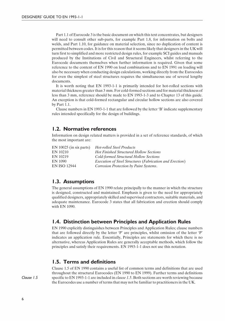
Clause 1.5 of EN 1990 contains a useful list of common terms and definitions that are usedthroughout the structural Eurocodes (EN 1990 to EN 1999). Further terms and definitionsspecific to EN 1993-1-1 are included in clause 1.5. Both sections are worth reviewing becausethe Eurocodes use a number of terms that may not be familiar to practitioners in the UK.
6
DESIGNERS’ GUIDE TO EN 1993-1-1
16Guide to Eurocode 1993 - CRC02 December 2004 11:53:43
Color profile: DisabledComposite Default screen
Delivered by ICEVirtualLibrary.com to:
IP: 95.42.11.157
On: Sun, 11 Jul 2010 21:34:37
1.6. SymbolsClause 1.6A useful listing of the majority of symbols used in EN 1993-1-1 is provided in clause 1.6.
Other symbols are defined where they are first introduced in the code. Many of thesesymbols, especially those with multiple subscripts, will not be familiar to UK designers.However, there is generally good consistency in the use of symbols throughout the Eurocodes,which makes transition between the documents more straightforward.
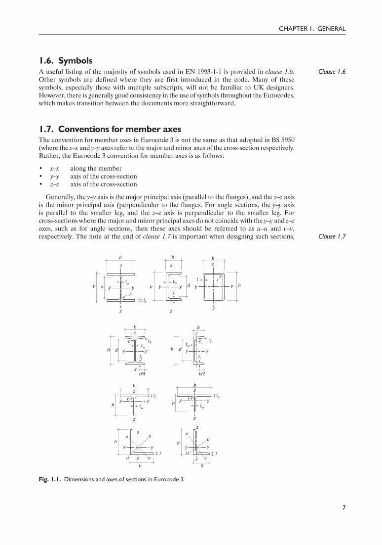
1.7. Conventions for member axesThe convention for member axes in Eurocode 3 is not the same as that adopted in BS 5950(where the x–x and y–y axes refer to the major and minor axes of the cross-section respectively.Rather, the Eurocode 3 convention for member axes is as follows:
• x–x along the member• y–y axis of the cross-section• z–z axis of the cross-section.
Clause 1.7
Generally, the y–y axis is the major principal axis (parallel to the flanges), and the z–z axisis the minor principal axis (perpendicular to the flanges. For angle sections, the y–y axisis parallel to the smaller leg, and the z–z axis is perpendicular to the smaller leg. Forcross-sections where the major and minor principal axes do not coincide with the y–y and z–zaxes, such as for angle sections, then these axes should be referred to as u–u and v–v,respectively. The note at the end of clause 1.7 is important when designing such sections,
7
CHAPTER 1. GENERAL
h v
v
u
u
y y
z
z
h
t t
h
v
vu
u
y y
z
zb
bz
z
y yr
tw
t f
h h
z
tw
rt f
y y
zb
b/2
h dtw
t f
y y
r1r2
zbb
z
r2tw
r1
y yt f
zb/4
h d
h d y y
z
z
tw
rt f
bb
z
twy yh
t f
z
t r
bz
y y
z
hd
Fig. 1.1. Dimensions and axes of sections in Eurocode 3
17Guide to Eurocode 1993 - CRC02 December 2004 11:53:43
Color profile: DisabledComposite Default screen

Delivered by ICEVirtualLibrary.com to:
IP: 95.42.11.157
On: Sun, 11 Jul 2010 21:34:37
because it states that ‘All rules in this Eurocode relate to the principal axis properties, which aregenerally defined by the axes y-y and z-z but for sections such as angles are defined by the axes u-uand v-v’ (i.e. for angles and similar sections, the u–u and v–v axes properties should be used inplace of the y–y and z–z axes properties).
Figure 1.1 defines the important dimensions and axes for the common types of structuralsteel cross-section. Note that many of the symbols are different to those adopted in BS 5950.
8
DESIGNERS’ GUIDE TO EN 1993-1-1
18Guide to Eurocode 1993 - CRC02 December 2004 11:53:43
Color profile: DisabledComposite Default screen
Delivered by ICEVirtualLibrary.com to:
IP: 95.42.11.157
On: Sun, 11 Jul 2010 21:34:56
CHAPTER 2
Basis of design
This chapter discusses the basis of design, as covered in Section 2 of EN 1993-1-1 and Section2 of EN 1990. The following clauses are addressed:
• Requirements Clause 2.1• Principles of limit state design Clause 2.2• Basic variables Clause 2.3• Verification by the partial factor method Clause 2.4• Design assisted by testing Clause 2.5
2.1. RequirementsThe general approach of Eurocode 3 is essentially the same as that of BS 5950, being basedon limit state principles using partial safety factors. The approach is set down in detail inEN 1990, with additional explanation to be found in the Designers’ Guide to EN 1990,Eurocode: Basis of Structural Design.2 Chapter 14 of this guide gives some introductoryrecommendations on the use of EN 1990 and EN 1991, including the specification of loadingand the development of load combinations. Further references to EN 1990 are madethroughout the guide.
The basic requirements of EN 1990 state that a structure shall be designed to haveadequate:
• structural resistance• serviceability• durability• fire resistance (for a required period of time)• robustness (to avoid disproportionate collapse due to damage from events such as
explosion, impact and consequences of human error).
Clause 2.1.1(2)Clause 2.1.1(2) states that these ‘basic requirements shall be deemed to be satisfied wherelimit state design is used in conjunction with the partial factor method and the load combinationsgiven in EN 1990 together with the actions given in EN 1991’.
Clause 2.1.3Outline notes on the design working life, durability and robustness of steel structures are
given in clause 2.1.3. Design working life is defined in Section 1 of EN 1990 as the ‘assumedperiod for which a structure or part of it is to be used for its intended purpose withanticipated maintenance but without major repair being necessary’. The design working lifeof a structure will generally be determined by its application (and may be specified by theclient). Indicative design working lives are given in Table 2.1 (Table 2.1 of EN 1990), whichmay be useful, for example, when considering time-dependent effects such as fatigue andcorrosion.
19Guide to Eurocode 1993 - CRC02 December 2004 11:53:43
Color profile: DisabledComposite Default screen

Delivered by ICEVirtualLibrary.com to:
IP: 95.42.11.157
On: Sun, 11 Jul 2010 21:34:56
Clause 2.1.3.1Durability is discussed in more detail in Chapter 4 of this guide, but the general guidance
of clause 2.1.3.1 explains that steel structures should be designed (protected) againstcorrosion, detailed for sufficient fatigue life, designed for wearing, designed for accidentalactions, and inspected and maintained at appropriate intervals, (with consideration given inthe design to ensure that parts susceptible to these effects are easily accessible).
2.2. Principles of limit state designClause 2.2 General principles of limit state design are set out in Section 3 of EN 1990. Clause 2.2
reminds the designer of the importance of ductility. It states that the cross-section andmember resistance models given in Eurocode 3 assume that the material displays sufficientductility. In order to ensure that these material requirements are met, reference should bemade to Section 3 (and Chapter 3 of this guide).
2.3. Basic variablesGeneral information regarding basic variables is set out in Section 4 of EN 1990. Loads,referred to as actions in the structural Eurocodes, should be taken from EN 1991, whilstpartial factors and the combination of actions are covered in EN 1990. Some preliminaryguidance on actions and their combination is given in Chapter 14 of this guide.
2.4. Verification by the partial factor methodThroughout EN 1993-1-1, material properties and geometrical data are required in orderto calculate the resistance of structural cross-sections and members. The basic equationgoverning the resistance of steel structures is given by equation (2.1):
(2.1)
where Rd is the design resistance, Rk is the characteristic resistance and γM is a partial factorwhich accounts for material, geometric and modelling uncertainties (and is the product of γm
and γRd).However, for practical design purposes, and to avoid any confusion that may arise from
terms such as ‘nominal values’, ‘characteristic values’ and ‘design values’, the followingguidance is provided:
10
DESIGNERS’ GUIDE TO EN 1993-1-1
Table 2.1. Indicative design working life
Design workinglife category
Indicative designworking life (years) Examples
1 10 Temporary structures (not those that can bedismantled with a view to being reused)
2 10–25 Replaceable structural parts, e.g. gantry girders andbearings
3 15–30 Agricultural and similar structures
4 50 Building structures and other common structures
5 100 Monumental building structures, bridges and othercivil engineering structures
kd
M
RR
γ=
20Guide to Eurocode 1993 - CRC02 December 2004 11:53:43
Color profile: DisabledComposite Default screen

Delivered by ICEVirtualLibrary.com to:
IP: 95.42.11.157
On: Sun, 11 Jul 2010 21:34:56
Clause 2.4.1(1)Clause 3.1(1)
• For material properties, the nominal values given in Table 3.1 may be used (ascharacteristic values) for design (see clauses 2.4.1(1) and 3.1(1)). It should be noted,however, that the UK National Annex may state that material properties should betaken as the minimum specified values from product standards, such as EN 10025, whichessentially means a reversion to the BS 5950 values.
Clause 2.4.2(1)
• For cross-section and system geometry, dimensions may be taken from product standardsor drawings for the execution of the structure to EN 1090 and treated as nominalvalues – these values may also be used in design (clause 2.4.2(1)).
Clause 2.4.2(2)Clause 2.4.2(2) highlights that the design values of geometric imperfections, used primarilyfor structural analysis and member design (see Section 5), are equivalent geometricimperfections that take account of actual geometric imperfections (e.g. initial out-of-straightness), structural imperfections due to fabrication and erection (e.g. misalignment),residual stresses and variation in yield strength throughout the structural component.
2.5. Design assisted by testing
Clause 2.5An important feature of steel design in the UK is the reliance on manufacturers’ designinformation for many products, such as purlins and metal decking. Clause 2.5 authorizes thisprocess, with the necessary detail being given in Annex D of EN 1990.
11
CHAPTER 2. BASIS OF DESIGN
21Guide to Eurocode 1993 - CRC02 December 2004 11:53:43
Color profile: DisabledComposite Default screen

Delivered by ICEVirtualLibrary.com to:
IP: 95.42.11.157
On: Sun, 11 Jul 2010 21:34:57
CHAPTER 3
Materials
This chapter is concerned with the guidance given in EN 1993-1-1 for materials, as covered inSection 3 of the code. The following clauses are addressed:
• General Clause 3.1• Structural steel Clause 3.2• Connecting devices Clause 3.3• Other prefabricated products in buildings Clause 3.4
3.1. GeneralIn general, the nominal values of material properties provided in Section 3 of EN 1993-1-1may be used in the design expressions given throughout the code. However, the UK NationalAnnex may specify exceptions to this, as explained in the following section.
3.2. Structural steelClause 3.2.1Clause 3.2.1 states that values for yield strength fy and ultimate tensile strength fu may be be
taken from Table 3.1 or direct from the product standard (EN 10025 for hot-rolled sections).The UK National Annex is likely to insist that the minimum specified values for yieldstrength, designated ReH, and specified values for tensile strength, designated Rm, fromproduct standards are used for fy and fu, respectively.
Values of yield strength for the most common grades of non-alloy structural steel hot-rolled sections (S235, S275 and S355) from Table 3.1 of EN 1993-1-1 and from the productstandard EN 10025-2 are given in Table 3.1 for comparison. It should be noted that whereasTable 3.1 of EN 1993-1-1 contains two thickness categories (t ≥ 40 mm and 40 mm < t ≥ 80mm), EN 10025-2 contains eight categories, up to a maximum thickness of 250 mm (thoughonly thicknesses up to 100 mm are given in Table 3.1). For further information, referenceshould be made to the product standards. Although not explicitly stated in EN 1993-1-1, it isrecommended that, for rolled sections, the thickness of the thickest element is used to definea single yield strength to be applied to the entire cross-section.
Clause 3.2.2(1)In order to ensure structures are designed to EN 1993-1-1 with steels that possess
adequate ductility, clause 3.2.2(1) sets the following requirements:
• fu/fy ≥ 1.10• elongation at failure > 15% (on a gauge length of 5.65÷A0, where A0 is the original
cross-sectional area)• εu ≥ 15εy, where εu is the ultimate strain and εy is the yield strain.
23Guide to Eurocode 1993 - CRC02 December 2004 11:53:44
Color profile: DisabledComposite Default screen

Delivered by ICEVirtualLibrary.com to:
IP: 95.42.11.157
On: Sun, 11 Jul 2010 21:34:57
All steel grades listed in Table 3.1 meet these criteria, so do not have to be explicitlychecked. However, the UK National Annex may set slightly more strict requirements, inwhich case the grades given in Table 3.1 should be checked. In any case, it is only thehigher-strength grades that may fail to meet the ductility requirements.
In order to avoid brittle fracture, materials need sufficient fracture toughness at the lowestservice temperature expected to occur within the intended design life of the structure. In theUK the lowest service temperature should normally be taken as –5°C for internal steelworkand –15°C for external steelwork. Fracture toughness and design against brittle fracture iscovered in detail in Eurocode 3 – Part 1.10.
Clause 3.2.6 Design values of material coefficients to be used in EN 1993-1-1 are given in clause 3.2.6 asfollows:
• modulus of elasticity:
E = 210 000 N/mm2
• shear modulus:
G =E
2 1( )+νª 81 000 N/mm2
• Poisson’s ratio:
ν = 0.3
• coefficient of thermal expansion:
a = 12 × 10–6/°C
(for temperatures below 100°C).
Those familiar with design to British Standards will notice a marginal (approximately2%) difference in the value of Young’s modulus adopted in EN 1993-1-1, which is210 000 N/mm2, compared with 205 000 N/mm2.
14
DESIGNERS’ GUIDE TO EN 1993-1-1
Table 3.1. Values for yield strength fy
Steel grade
EN 1993-1-1 EN 10025-2
Thickness range(mm)
Yield strength, fy
(N/mm2)Thickness range(mm)
Yield strength, fy
(N/mm2)
S235 t £ 40 235 t £ 16 23516 < t £ 40 225
40 < t £ 80 215 40 < t £ 63 21563 < t £ 80 21580 < t< £ 100 215
S275 t £ 40 275 t £ 16 27516 < t £ 40 265
40 < t £ 80 255 40 < t £ 63 25563 < t £ 80 24580 < t £ 100 235
S355 t £ 40 355 t £ 16 35516 < t £ 40 345
40 < t £ 80 335 40 < t £ 63 33563 < t £ 80 32580 < t £ 100 315
24Guide to Eurocode 1993 - CRC02 December 2004 11:53:44
Color profile: DisabledComposite Default screen

Delivered by ICEVirtualLibrary.com to:
IP: 95.42.11.157
On: Sun, 11 Jul 2010 21:34:57
3.3. Connecting devicesRequirements for fasteners, including bolts, rivets and pins, and for welds and weldingconsumables are given in Eurocode 3 – Part 1.8, and are discussed in Chapter 12 of thisguide.
3.4. Other prefabricated products in buildingsClause 3.4(1)BClause 3.4(1)B simply notes that any semi-finished or finished structural product used in the
structural design of buildings must comply with the relevant EN product standard or ETAG(European Technical Approval Guideline) or ETA (European Technical Approval).
15
CHAPTER 3. MATERIALS
25Guide to Eurocode 1993 - CRC02 December 2004 11:53:44
Color profile: DisabledComposite Default screen

Delivered by ICEVirtualLibrary.com to:
IP: 95.42.11.157
On: Sun, 11 Jul 2010 21:35:02
CHAPTER 4
Durability
This short chapter concerns the subject of durability and covers the material set out inSection 4 of EN 1993-1-1, with brief reference to EN 1990.
Durability may be defined as the ability of a structure to remain fit for its intended orforeseen use throughout its design working life, with an appropriate level of maintenance.
For basic durability requirements, Eurocode 3 directs the designer to Section 2.4 ofEN 1990, where it is stated that ‘the structure shall be designed such that deterioration overits design working life does not impair the performance of the structure below that intended,having due regard to its environment and the anticipated level of maintenance’.
The following factors are included in EN 1990 as ones that should be taken into account inorder to achieve an adequately durable structure:
• the intended or foreseeable use of the structure• the required design criteria• the expected environmental conditions• the composition, properties and performance of the materials and products• the properties of the soil• the choice of the structural system• the shape of members and structural detailing• the quality of workmanship and level of control• the particular protective measures• the intended maintenance during the design working life.
A more detailed explanation of the basic Eurocode requirements for durability has beengiven by Gulvanessian et al.,2 and a general coverage of the subject of durability in steel(bridge) structures is available.3
Of particular importance for steel structures are the effects of corrosion, mechanical wearand fatigue. Therefore, parts susceptible to these effects should be easily accessible forinspection and maintenance.
In buildings, a fatigue assessment is not generally required. However, EN 1993-1-1highlights several cases where fatigue should be considered, including where cranes orvibrating machinery are present, or where members may be subjected to wind- orcrowd-induced vibrations.
Corrosion would generally be regarded as the most critical factor affecting the durabilityof steel structures, and the majority of points listed above influence the matter. Particularconsideration has to be given to the environmental conditions, the intended maintenanceschedule, the shape of members and structural detailing, the corrosion protection measures,and the material composition and properties. For aggressive environments, such as coastalsites, and where elements cannot be easily inspected, extra attention is required. Corrosionprotection does not need to be applied to internal building structures, if the internal relativehumidity does not exceed 80%.
27Guide to Eurocode 1993 - CRC02 December 2004 11:53:44
Color profile: DisabledComposite Default screen

Delivered by ICEVirtualLibrary.com to:
IP: 95.42.11.157
On: Sun, 11 Jul 2010 21:35:02
18
DESIGNERS’ GUIDE TO EN 1993-1-1
Sharpcorners
Rounded corners,weld l ineoff bot tom
Spot weld Fi l l crevice
Fig. 4.1. Poor and good design features for durability (from SCI publication P-2914)
28Guide to Eurocode 1993 - CRC02 December 2004 11:53:44
Color profile: DisabledComposite Default screen

Delivered by ICEVirtualLibrary.com to:
IP: 95.42.11.157
On: Sun, 11 Jul 2010 21:35:02
In addition to suitable material choice, a designer can significantly influence the durabilityof the steel structure through good detailing. Poor (left-hand column) and good (right-hand column) design features are shown in Fig. 4.1. Additionally, corrosion cannot takeplace without the presence of an electrolyte (e.g. water) – suitable drainage and goodthermal insulation to prevent cold-bridging (leading to condensation) are therefore of keyimportance.
19
CHAPTER 4. DURABILITY
29Guide to Eurocode 1993 - CRC02 December 2004 11:53:44
Color profile: DisabledComposite Default screen

Delivered by ICEVirtualLibrary.com to:
IP: 95.42.11.157
On: Sun, 11 Jul 2010 21:35:21
CHAPTER 5
Structural analysis
This chapter concerns the subject of structural analysis and classification of cross-sectionsfor steel structures. The material in this chapter is covered in Section 5 of EN 1993-1-1, andthe following clauses are addressed:
• Structural modelling for analysis Clause 5.1• Global analysis Clause 5.2• Imperfections Clause 5.3• Methods of analysis considering material non-linearities Clause 5.4• Classification of cross-sections Clause 5.5• Cross-section requirements for plastic global analysis Clause 5.6
Before the strength of cross-sections and the stability of members can be checked againstthe requirements of the code, the internal (member) forces and moments within thestructure need to be determined from a global analysis. Four distinct types of global analysisare possible:
(1) first-order elastic – initial geometry and fully linear material behaviour(2) second-order elastic – deformed geometry and fully linear material behaviour(3) first-order plastic – initial geometry and non-linear material behaviour(4) second-order plastic – deformed geometry and non-linear material behaviour.
Typical predictions of load–deformation response for the four types of analysis are shownin Fig. 5.1.
Load
Deformation
Elastic buckling load
(2) Second-order elastic analysis
(3) First-order plastic analysis
(1) First-order elastic analysis
(4) Second-order plastic analysis
Fig. 5.1. Prediction of load–deformation response from structural analysis
31Guide to Eurocode 1993 - CRC02 December 2004 11:53:44
Color profile: DisabledComposite Default screen

Delivered by ICEVirtualLibrary.com to:
IP: 95.42.11.157
On: Sun, 11 Jul 2010 21:35:21
Clause 5.2
Clause 5.3Clause 5.4
Clause 5.2 explains how a second-order analysis (i.e. one in which the effect of deformationssignificantly altering the member forces or moments or the structural behaviour is explicitlyallowed for) should be conducted. Clause 5.3 deals with the inclusion of geometricalimperfections both for the overall structure and for individual members, whilst clause 5.4covers the inclusion of material non-linearity (i.e. plasticity) in the various types of analysis.
5.1. Structural modelling for analysisClause 5.1 Clause 5.1 outlines the fundamentals and basic assumptions relating to the modelling of
structures and joints. It states that the chosen (calculation) model must be appropriate andmust accurately reflect the structural behaviour for the limit state under consideration. Ingeneral, an elastic global analysis would be used when the performance of the structure isgoverned by serviceability criteria.
Elastic analysis is also routinely used to obtain member forces for subsequent use inthe member checks based on the ultimate strength considerations of Section 6. This iswell accepted, can be shown to lead to safe solutions and has the great advantage thatsuperposition of results may be used when considering different load cases. For certain typesof structure, e.g. portal frames, a plastic hinge form of global analysis may be appropriate;very occasionally, for checks on complex or particularly sensitive configurations, a fullmaterial and geometrical non-linear approach may be required.
The choice between a first- and a second-order analysis should be based upon theflexibility of the structure; in particular, the extent to which ignoring second-order effectsmight lead to an unsafe approach due to underestimation of some of the internal forces andmoments.
Eurocode 3 recognizes the same three types of joint, in terms of their effect on thebehaviour of the frame structure, as BS 5950: Part 1. However, the Eurocode uses the term‘semi-continuous’ for behaviour between ‘simple’ and ‘continuous’, and covers this form ofconstruction in Part 1.8. Consideration of this form of construction and the design ofconnections in general is covered in Chapter 12 of this guide. Examples of beam-to-columnjoints that exhibit nominally simple, semi-continuous and continuous behaviour are shown inFig. 5.2.
5.2. Global analysis5.2.1. Effects of deformed geometry on the structure
Clause 5.2.1Guidance on the choice between using a first- or second-order global analysis is given inclause 5.2.1. The clause states that a first-order analysis may be used provided that theeffects of deformations (on the internal member forces or moments and on the structuralbehaviour) are negligible. This may be assumed to be the case provided that equation (5.1) issatisfied:
22
DESIGNERS’ GUIDE TO EN 1993-1-1
(a) (b) (c)
Fig. 5.2. Typical beam-to-column joints. (a) Simple joint. (b) Semi-continuous joint. (c) Rigid joint
32Guide to Eurocode 1993 - CRC02 December 2004 11:53:45
Color profile: DisabledComposite Default screen

Delivered by ICEVirtualLibrary.com to:
IP: 95.42.11.157
On: Sun, 11 Jul 2010 21:35:21

Delivered by ICEVirtualLibrary.com to:
IP: 95.42.11.157
On: Sun, 11 Jul 2010 21:35:21
24
DESIGNERS’ GUIDE TO EN 1993-1-1
Fig. 5.3. External diagonal bracing system (Sanomatalo Building, Helsinki)
Fig. 5.4. Swiss Re Building, London
34Guide to Eurocode 1993 - CRC02 December 2004 11:53:49
Color profile: DisabledComposite Default screen

Delivered by ICEVirtualLibrary.com to:
IP: 95.42.11.157
On: Sun, 11 Jul 2010 21:35:21
Clause 6.3
Clause 5.2.2(5)Clause 5.2.2(6)
and moments directly; they can then be used with the member checks of clause 6.3.Alternatively, it may be possible to enhance the moments and forces calculated by a linearanalysis so as to approximate the second-order values using clauses 5.2.2(5) and 5.2.2(6). Asa further alternative, the method of ‘substitutive members’ is also permitted. This requiresthe determination of a ‘buckling length’ for each member, ideally extracted from the resultsof a global buckling analysis, i.e. the method used to determine Fcr for the frame. Conceptually,it is equivalent to the well-known effective length approach used in conjunction with aninteraction formula, in which an approximation to the effect of the enhanced momentswithin the frame is made by using a reduced axial resistance for the compression membersbased on considerations of their conditions of restraint. Whilst this approach may be shownto be reasonable for relatively simple, standard cases, it becomes increasingly less accurate asthe complexity of the arrangement being considered increases.
5.3. ImperfectionsAccount should be taken of two types of imperfection:
• global imperfections for frames and bracing systems• local imperfections for members.
The former require explicit consideration in the overall structural analysis; the latter can beincluded in the global analysis, but will usually be treated implicitly within the procedures forchecking individual members.
Clause 5.3.2Clause 5.3.3
Details of the exact ways in which global imperfections should be included are provided inclauses 5.3.2 and 5.3.3 for frames and bracing systems respectively. Essentially, one of twoapproaches may be used:
• defining the geometry of the structure so that it accords with the imperfect shape, e.g.allowing for an initial out-of-plumb when specifying the coordinates of the frame
• representing the effects of the geometrical imperfections by a closed system of equivalentfictitious forces (replacement of initial imperfections by equivalent horizontal forces isshown in Fig. 5.5).
For the former, it is suggested that the initial shape be based on the mode shape associatedwith the lowest elastic critical buckling load. For the latter, a method to calculate thenecessary loads is provided.
25
CHAPTER 5. STRUCTURAL ANALYSIS
Initial sway imperfections Initial bow imperfections
f
NEd
NEd
NEd
NEd
fNEd
fNEd
NEd
NEd
e0, d L
8NEde0, d
L2
4NEde0, d
L
NEd
NEd
4NEde0, d
L
Fig. 5.5. Replacement of initial imperfections by equivalent horizontal forces
35Guide to Eurocode 1993 - CRC02 December 2004 11:53:49
Color profile: DisabledComposite Default screen
Delivered by ICEVirtualLibrary.com to:
IP: 95.42.11.157
On: Sun, 11 Jul 2010 21:35:21
5.4. Methods of analysis considering material non-linearities
Clause 5.4.2
Clause 5.4.3
This section sets out in rather more detail than is customary in codes the basis on which thepattern of the internal forces and moments in a structure necessary for the checking ofindividual member resistances should be calculated. Thus, clause 5.4.2 permits the use oflinear elastic analysis, including use in combination with member checks on an ultimatestrength basis. Clause 5.4.3 distinguishes between three variants of plastic analysis:
• elastic–plastic, using plastic hinge theory – likely to be available in only a few specializedpieces of software
• non-linear plastic zone – essentially a research or investigative tool• rigid–plastic – simple plastic hinge analysis using concepts such as the collapse mechanism;
commonly used for portal frames and continuous beams.
Various limitations on the use of each approach are listed. These align closely withUK practice, particularly the restrictions on the use of plastic analysis in terms of therequirement for restraints against out-of-plane deformations, the use of at least singlysymmetrical cross-sections and the need for rotation capacity in the plastic hinge regions.
5.5. Classification of cross-sections5.5.1. Basis
Clause 5.5.1Clause 6.2
Clause 5.5Clause 6.2
Determining the resistance (strength) of structural steel components requires the designerto consider firstly the cross-sectional behaviour and secondly the overall member behaviour.Clauses 5.5.1 and 6.2 cover the cross-sectional aspects of the design process. Whether in theelastic or inelastic material range, cross-sectional resistance and rotation capacity arelimited by the effects of local buckling. As in BS 5950, Eurocode 3 accounts for the effects oflocal buckling through cross-section classification, as described in clause 5.5. Cross-sectionalresistances may then be determined from clause 6.2.
In Eurocode 3, cross-sections are placed into one of four behavioural classes dependingupon the material yield strength, the width-to-thickness ratios of the individual compressionparts (e.g. webs and flanges) within the cross-section, and the loading arrangement. Theclassifications from BS 5950 of plastic, compact, semi-compact and slender are replaced inEurocode 3 with Class 1, Class 2, Class 3 and Class 4, respectively.
5.5.2. Classification of cross-sectionsDefinition of classes
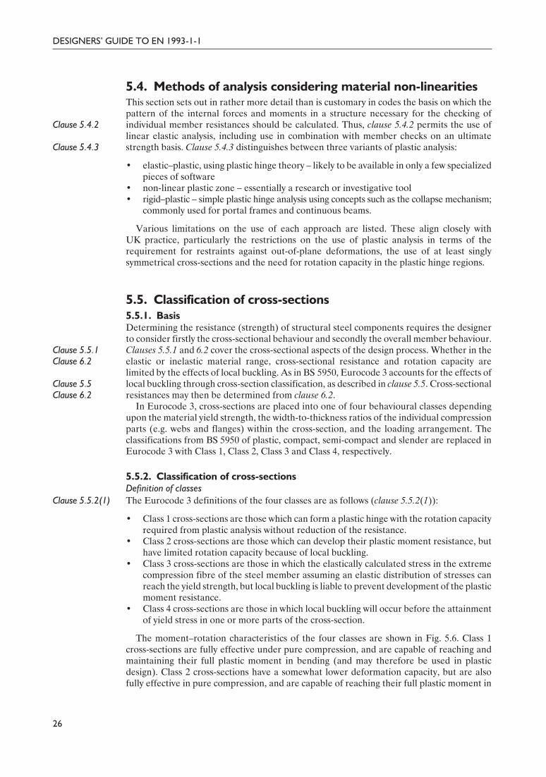
Clause 5.5.2(1) The Eurocode 3 definitions of the four classes are as follows (clause 5.5.2(1)):
• Class 1 cross-sections are those which can form a plastic hinge with the rotation capacityrequired from plastic analysis without reduction of the resistance.
• Class 2 cross-sections are those which can develop their plastic moment resistance, buthave limited rotation capacity because of local buckling.
• Class 3 cross-sections are those in which the elastically calculated stress in the extremecompression fibre of the steel member assuming an elastic distribution of stresses canreach the yield strength, but local buckling is liable to prevent development of the plasticmoment resistance.
• Class 4 cross-sections are those in which local buckling will occur before the attainmentof yield stress in one or more parts of the cross-section.
The moment–rotation characteristics of the four classes are shown in Fig. 5.6. Class 1cross-sections are fully effective under pure compression, and are capable of reaching andmaintaining their full plastic moment in bending (and may therefore be used in plasticdesign). Class 2 cross-sections have a somewhat lower deformation capacity, but are alsofully effective in pure compression, and are capable of reaching their full plastic moment in
26
DESIGNERS’ GUIDE TO EN 1993-1-1
36Guide to Eurocode 1993 - CRC02 December 2004 11:53:50
Color profile: DisabledComposite Default screen
Delivered by ICEVirtualLibrary.com to:
IP: 95.42.11.157
On: Sun, 11 Jul 2010 21:35:21
bending. Class 3 cross-sections are fully effective in pure compression, but local bucklingprevents attainment of the full plastic moment in bending; bending moment resistance istherefore limited to the (elastic) yield moment. For Class 4 cross-sections, local bucklingoccurs in the elastic range. An effective cross-section is therefore defined based on thewidth-to-thickness ratios of individual plate elements, and this is used to determine thecross-sectional resistance. In hot-rolled design the majority of standard cross-sections will beClass 1, 2 or 3, where resistances may be based on gross section properties obtained fromsection tables. Effective width formulations are not contained in Part 1.1 of Eurocode 3, butare instead to be found in Part 1.5; these are discussed later in this section.
For cold-formed cross-sections, which are predominantly of an open nature (e.g. achannel section) and of light-gauge material, design will seldom be based on the grosssection properties; the design requirements for cold-formed members are covered inEurocode 3 – Part 1.3 and in Chapter 14 of this guide.
Assessment of individual partsEach compressed (or partially compressed) element is assessed individually against thelimiting width-to-thickness ratios for Class 1, 2 and 3 elements defined in Table 5.2 (seeTable 5.1). An element that fails to meet the Class 3 limits should be taken as Class 4. Table5.2 contains three sheets. Sheet 1 is for internal compression parts, defined as thosesupported along each edge by an adjoining flange or web. Sheet 2 is for outstand flanges,where one edge of the part is supported by an adjoining flange or web and the other end isfree. Sheet 3 deals with angles and tubular (circular hollow) sections.
The limiting width-to-thickness ratios are modified by a factor ε that is dependent uponthe material yield strength. (For circular hollow members the width-to-thickness ratios aremodified by ε2.) ε is defined as
(D5.2)
where fy is the nominal yield strength of the steel as defined in Table 3.1. Clearly, increasingthe nominal material yield strength results in stricter classification limits. It is worth notingthat the definition of ε in Eurocode 3 (equation (D5.2)) utilizes a base value of 235 N/mm2,simply because grade S235 steel is regarded as the normal grade throughout Europe, and isthus expected to be the most widely used. In comparison, BS 5950 and BS 5400 use 275 and355 N/mm2 as base values, respectively.
The nominal yield strength depends upon the steel grade, the standard to which the steelis produced, and the nominal thickness of the steel element under consideration. Two
27
CHAPTER 5. STRUCTURAL ANALYSIS
Rotation, q
App
lied
mom
ent,
M
Mpl
Mel
Class 1 – highrotation capacity
Class 2 – limitedrotation capacity
Class 3 – local buckling preventsattainment of full plastic moment
Class 4 – local buckling preventsattainment of yield moment
Fig. 5.6. The four behavioural classes of cross-section defined by Eurocode 3
y235/fε =
37Guide to Eurocode 1993 - CRC02 December 2004 11:53:50
Color profile: DisabledComposite Default screen

Delivered by ICEVirtualLibrary.com to:
IP: 95.42.11.157
On: Sun, 11 Jul 2010 21:35:21
thickness categories are defined in Table 3.1 of EN 1993-1-1. The first is up to and including40 mm, and the second greater than 40 mm and less than 80 mm (for hot-rolled structuralsteel) or less than 65 mm (for structural hollow sections). However, the UK National Annexis likely to specify that material properties are taken from the relevant product standard, asdescribed in Section 3.2 of this guide; essentially this results in a reversion to thicknesscategories as adopted in BS 5950.
Clause 5.5.2(9)Clause 5.5.2(10)Clause 5.3
The classification limits provided in Table 5.2 assume that the cross-section is stressed toyield, though where this is not the case, clauses 5.5.2(9) and 5.5.2(10) may allow somerelaxation of the Class 3 limits. For cross-sectional checks and when buckling resistances aredetermined by means of a second-order analysis, using the member imperfections of clause5.3, Class 4 cross-sections may be treated as Class 3 if the width-to-thickness ratios are lessthan the limiting proportions for Class 3 sections when ε is increased by a factor to give thedefinition of equation (D5.3):
(D5.3)
where σcom, Ed should be taken as the maximum design compressive stress that occurs in themember.
Clause 6.3For conventional member design, whereby buckling resistances are determined using the
buckling curves defined in clause 6.3, no modification to the basic definition of ε (given byequation (D5.2)) is permitted, and the limiting proportions from Table 5.2 should always beapplied.
Notes on Table 5.2 of EN 1993-1-1The purpose of this subsection is to provide notes of clarification on Table 5.2 (reproducedhere as Table 5.1) and to contrast the approach and slenderness limits with those set out inSection 3.5 of BS 5950: Part 1 (2000).
In general, the Eurocode 3 approach to section classification is more rational than that ofBS 5950, but perhaps less practical in some cases. The following points are worth noting:
(1) For sheets 1 and 2 of Table 5.2, all classification limits are compared with c/t ratios(compressive width-to-thickness ratios), with the appropriate dimensions for c and ttaken from the accompanying diagrams.
(2) The compression widths c defined in sheets 1 and 2 always adopt the dimensions of theflat portions of the cross-sections, i.e. root radii and welds are explicitly excluded fromthe measurement, as emphasized by Fig. 5.7. This was not the case in the ENV version ofEurocode 3 or BS 5950, where generally more convenient measures were adopted (suchas for the width of an outstand flange of an I section, taken as half the total flange width).
28
DESIGNERS’ GUIDE TO EN 1993-1-1
y M0y
com, Ed
/235/
ff
γε
σ=
c
(a) (b)
c
c
Rolled
Welded c
Rolled
Welded
Fig. 5.7. Definition of compression width c for common cases. (a) Outstand flanges. (b) Internalcompression parts
38Guide to Eurocode 1993 - CRC02 December 2004 11:53:50
Color profile: DisabledComposite Default screen

Delivered by ICEVirtualLibrary.com to:
IP: 95.42.11.157
On: Sun, 11 Jul 2010 21:35:21
(3) Implementation of point 2 and re-analysis of test results has enabled Eurocode 3 to offerthe same classification limits for both rolled and welded cross-sections.
(4) For rectangular hollow sections where the value of the internal corner radius is notknown, it may be assumed that the compression width c can be taken as equal to b – 3t.
The factor kσ that appears in sheet 2 of Table 5.2 is a buckling factor, which depends on thestress distribution and boundary conditions in the compression element. Calculation of kσ isdescribed in Section 6.2.2 of this guide, and should be carried out with reference to Part 1.5of the code.
29
CHAPTER 5. STRUCTURAL ANALYSIS
Table 5.1 (sheet 1 of 3). Maximum width-to-thickness ratios for compression parts (Table 5.2 ofEN 1993-1-1)
ClassPart subject tobending
Part subject tocompression Part subject to bending and compression
Stress distributionin parts(compressionpositive)
1 c/t £ 72e c/t £ 33e when a > 0.5: c/t £ 39613 1
ea −
when a £ 0.5: c/t £ 36ea
2 c/t £ 83e c/t £ 38e when a > 0.5: c/t £ 45613 1
ea −
when a £ 0.5: c/t £ 41.5ea
Stress distributionin parts(compressionpositive)
3 c/t £ 124e c/t £ 42e when y > –1: c/t £ 420.67 + 0.33
ey
when y £ –1*): c/t £ 62e(1 – y) ( )-y
e = 235 / f y
fy 235 275 355 420 460
e 1.00 0.92 0.81 0.75 0.71
*) y £ –1 applies where either the compression stress s < fy or the tensile strain ey > fy /E
Internal compression parts
t
c
t
c c
t
c
t
Axis ofbending
t
t t t
c
Axis ofbending
+
fy
-fy
c+
fy
-
fy
cac+
fy
-
fy
c
+
fy
-
fy
cc/2 +
fy
c
+
fy
-yfy
c
39Guide to Eurocode 1993 - CRC02 December 2004 11:53:51
Color profile: DisabledComposite Default screen

Delivered by ICEVirtualLibrary.com to:
IP: 95.42.11.157
On: Sun, 11 Jul 2010 21:35:21
Overall cross-section classificationOnce the classification of the individual parts of the cross-section is determined, Eurocode 3allows the overall cross-section classification to be defined in one of two ways:
Clause 6.2.2.4
(1) The overall classification is taken as the highest (least favourable) class of its componentparts, with the exceptions that (i) cross-sections with Class 3 webs and Class 1 or 2flanges may be classified as Class 2 cross-sections with an effective web (defined in clause6.2.2.4) and (ii) in cases where the web is assumed to carry shear force only (and not tocontribute to the bending or axial resistance of the cross-section), the classification maybe based on that of the flanges (but Class 1 is not allowed).
(2) The overall classification is defined by quoting both the flange and the web classification.
Class 4 cross-sectionsClause 6.2.2.5 Class 4 cross-sections (see clause 6.2.2.5) contain slender elements that are susceptible to
local buckling in the elastic material range. Allowance for the reduction in resistance of Class4 cross-sections as a result of local buckling is made by assigning effective widths to the Class4 compression elements. The formulae for calculating effective widths are not contained inPart 1.1 of Eurocode 3; instead, the designer is directed to Part 1.3 for cold-formed sections,to Part 1.5 for hot-rolled and fabricated sections, and to Part 1.6 for circular hollow sections.
30
DESIGNERS’ GUIDE TO EN 1993-1-1
Table 5.1 (sheet 2 of 3). Maximum width-to-thickness ratios for compression parts (Table 5.2 ofEN 1993-1-1)
ClassPart subject tocompression
Part subject to bending and compression
Tip in compression Tip in tension
Stress distribution inparts (compressionpositive)
1 c/t £ 9e c/t £ 9ea
c/t £ 9ea a
2 c/t £ 10e c/t £ 10ea
c/t £ 10ea a
Stress distribution inparts (compressionpositive)
3 c/t £ 14e c/t £ 21e ks
For ks see EN 1993-1-5
e = 235 / f y
fy 235 275 355 420 460
e 1.00 0.92 0.81 0.75 0.71
Outstand flanges
t
c
t
c
t
c
tc
Rolled sections Welded sections
ac
+
c-
+
c
ac
+
c-
+
c
+
c
-+
-
c
40Guide to Eurocode 1993 - CRC02 December 2004 11:53:52
Color profile: DisabledComposite Default screen

Delivered by ICEVirtualLibrary.com to:
IP: 95.42.11.157
On: Sun, 11 Jul 2010 21:35:21
The calculation of effective properties for Class 4 cross-sections is described in detail inSection 6.2.2 of this guide.
Classification under combined bending and axial forceCross-sections subjected to combined bending and compression should be classified basedon the actual stress distribution of the combined loadings. For simplicity, an initial checkmay be carried under the most severe loading condition of pure axial compression; if theresulting section classification is either Class 1 or Class 2, nothing is to be gained byconducting additional calculations with the actual pattern of stresses. However, if theresulting section classification is Class 3 or 4, it is advisable for economy to conduct a moreprecise classification under the combined loading.
For checking against the Class 1 and 2 cross-section slenderness limits, a plastic distributionof stress may be assumed, whereas an elastic distribution may be assumed for the Class 3limits. To apply the classification limits from Table 5.2 for a cross-section under combinedbending and compression first requires the calculation of α (for Class 1 and 2 limits) and ψ(for Class 3 limits), where α is the ratio of the compressed width to the total width of an
31
CHAPTER 5. STRUCTURAL ANALYSIS
Table 5.1 (sheet 3 of 3). Maximum width-to-thickness ratios for compression parts (Table 5.2 ofEN 1993-1-1)
Does not apply to angles inRefer also to “Outstand flanges” continuous contact with other(see sheet 2 of 3) components
Class Section in compression
Stress distributionacross section(compression positive)
3 h/t £ 15e:b h
2t11.5
+ ≤ e
Class Section in bending and/or compression
1 d/t £ 50e 2
2 d/t £ 70e 2
3 d/t £ 90e 2
NOTE For d/t >90e 2 see EN 1993-1-6
e = 235 / f y
fy 235 275 355 420 460
e 1.00 0.92 0.81 0.75 0.71
e2 1.00 0.85 0.66 0.56 0.51
Angles
t
h
b
Tubular sections
t d
+
+
fy
41Guide to Eurocode 1993 - CRC02 December 2004 11:53:52
Color profile: DisabledComposite Default screen
Delivered by ICEVirtualLibrary.com to:
IP: 95.42.11.157
On: Sun, 11 Jul 2010 21:35:21
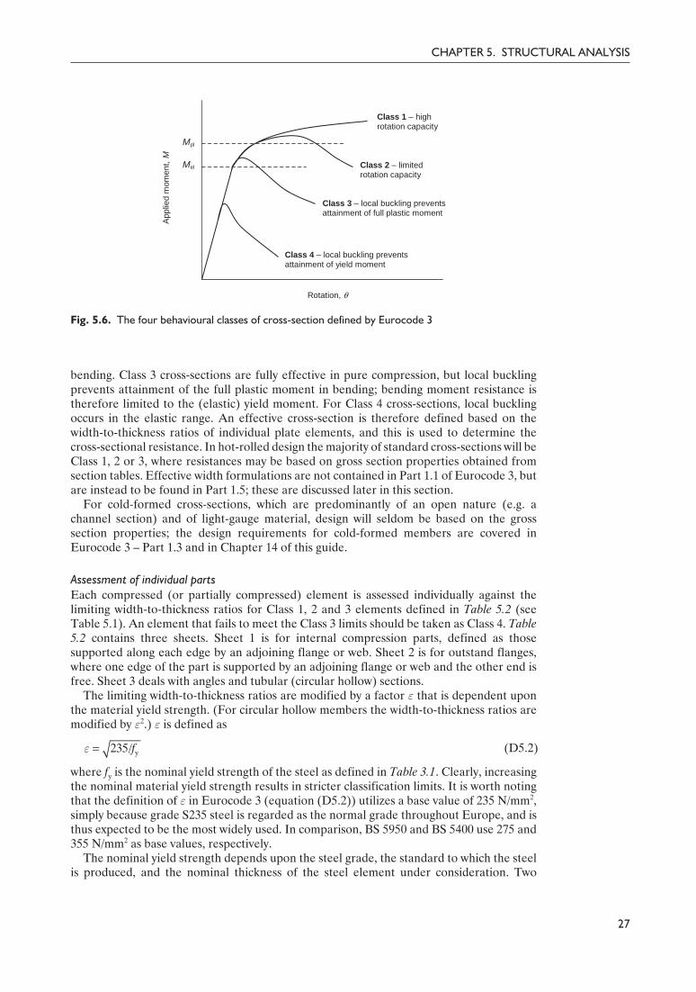
element and ψ is the ratio of end stresses (Fig. 5.8). The topic of section classification undercombined loading is covered in detail elsewhere.5 For the common case of an I or H sectionsubjected to compression and major axis bending, where the neutral axis lies within the web,α, the ratio of the compressed width to the total width of the element, can be calculated usingthe equation
(D5.4)
where c is the compression width (see Fig. 5.8) and NEd is the axial compression force; use ofthe plastic stress distribution also requires that the compression flange is at least Class 2. Theratio of end stresses ψ (required for checking against the Class 3 limits) may be determinedby superimposing the elastic bending stress distribution with the uniform compression stressdistribution.
Clause 6.2.9Clause 6.3.3
Design rules for verifying the resistance of structural components under combined bendingand axial compression are given in clause 6.2.9 for cross-sections and clause 6.3.3 formembers. An example demonstrating cross-section classification for a section undercombined bending and compression is given below.
Example 5.1: cross-section classification under combined bending andcompressionA member is to be designed to carry combined bending and axial load. In the presenceof a major axis (y–y) bending moment and an axial force of 300 kN, determine thecross-section classification of a 406 × 178 × 54 UB in grade S275 steel (Fig. 5.9).
For a nominal material thickness (tf = 10.9 mm and tw = 7.7 mm) of less than or equal to40 mm the nominal value of yield strength fy for grade S275 steel (to EN 10025-2) is foundfrom Table 3.1 to be 275 N/mm2. Note that reference should be made to the UK NationalAnnex for the nominal material strength (see Section 3.2 of this guide).
Clause 3.2.6 From clause 3.2.6: E = 210 000 N/mm2
Section propertiesFirst, classify the cross-section under the most severe loading condition of pure compressionto determine whether anything is to be gained by more precise calculations.
Clause 5.5.2 Cross-section classification under pure compression (clause 5.5.2)
Outstand flanges (Table 5.2, sheet 2):
32
DESIGNERS’ GUIDE TO EN 1993-1-1
f y
f y
f y
ac cc
+
–
y f y
+
–
(a) (b)
Fig. 5.8. Definitions of α and ψ for classification of cross-sections under combined bending andcompression. (a) Class 1 and 2 cross-sections. (b) Class 3 cross-sections
Edf
w y
1 1( ) 1
2 2Nh
t rc t f
αÊ ˆ
= + - + £Á ˜Ë ¯
y235/ 235/275 0.92fε = = =
42Guide to Eurocode 1993 - CRC02 December 2004 11:53:53
Color profile: DisabledComposite Default screen

Delivered by ICEVirtualLibrary.com to:
IP: 95.42.11.157
On: Sun, 11 Jul 2010 21:35:21

Delivered by ICEVirtualLibrary.com to:
IP: 95.42.11.157
On: Sun, 11 Jul 2010 21:35:21
\ limit for a Class 2 web =456
13 1ε
α−= 52.33
52.33 > 46.81 \ web is Class 2
Overall cross-section classification under the combined loading is therefore Class 2.
ConclusionFor this cross-section, a maximum axial force of 411 kN may be sustained in combinationwith a major axis bending moment, whilst remaining within the limits of a Class 2 section.
Cross-section and member resistance to combined bending and axial force is covered inSections 6.2.9 and 6.3.3 of this guide, respectively.
5.6. Cross-section requirements for plastic global analysisFor structures designed on the basis of a plastic global analysis, a series of requirements areplaced upon the cross-sections of the constituent members, to ensure that the structuralbehaviour accords with the assumptions of the analysis. For cross-sections, in essence, thisrequires the provision of adequate rotation capacity at the plastic hinges.
Clause 5.6 Clause 5.6 deems that, for a uniform member, a cross-section has sufficient rotationcapacity provided both of the following requirements are satisfied:
(1) the member has a Class 1 cross-section at the plastic hinge location(2) web stiffeners are provided within a distance along the member of h/2 from the plastic
hinge location, in cases where a transverse force that exceeds 10% of the shear resistanceof the cross-section is applied at the plastic hinge location.
Clause 5.6(3)
Clause 5.6(4)
Additional criteria are specified in clause 5.6(3) for non-uniform members, where thecross-section varies along the length. Allowance for fastener holes in tension should be madewith reference to clause 5.6(4). Guidance on member requirements for plastically designedstructures is given in Chapter 11 of this guide.
34
DESIGNERS’ GUIDE TO EN 1993-1-1
44Guide to Eurocode 1993 - CRC02 December 2004 11:53:53
Color profile: DisabledComposite Default screen
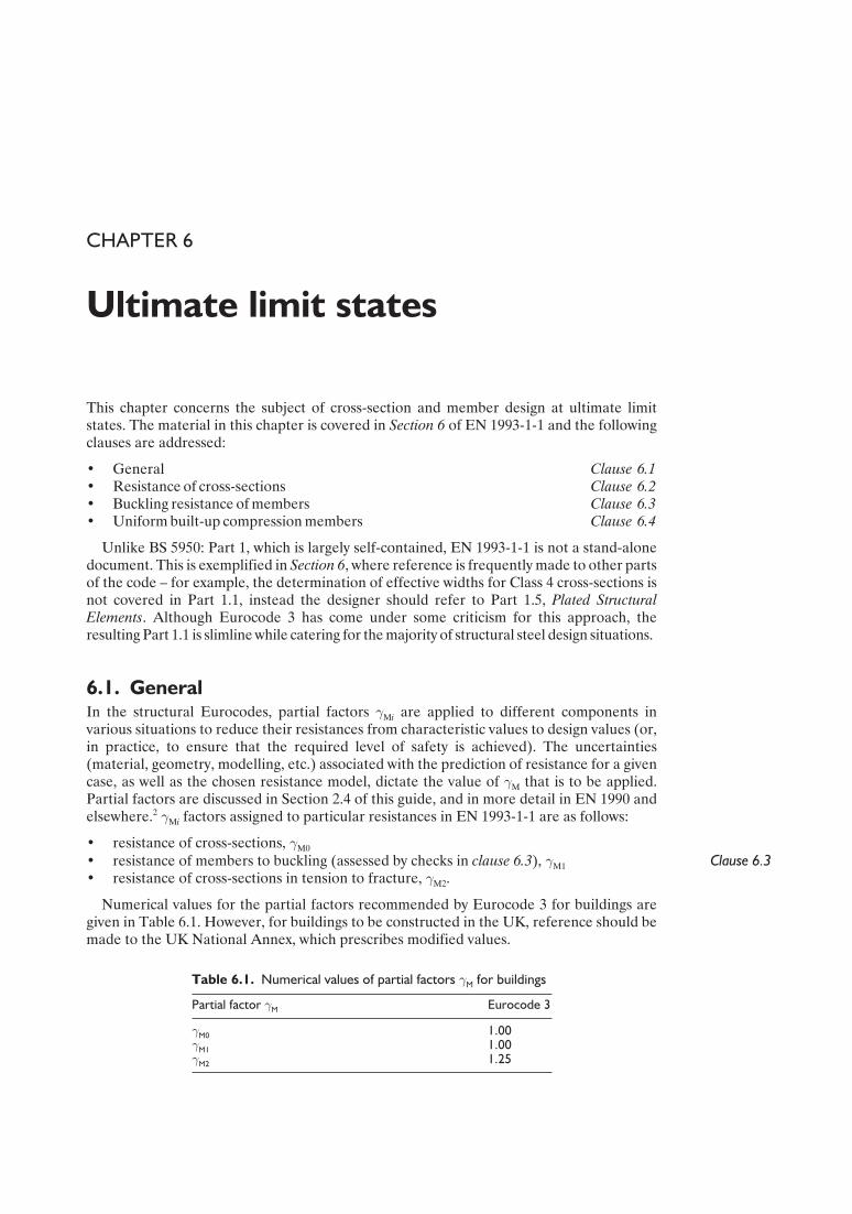
Delivered by ICEVirtualLibrary.com to:
IP: 95.42.11.157
On: Sun, 11 Jul 2010 21:35:24
CHAPTER 6
Ultimate limit states
This chapter concerns the subject of cross-section and member design at ultimate limitstates. The material in this chapter is covered in Section 6 of EN 1993-1-1 and the followingclauses are addressed:
• General Clause 6.1• Resistance of cross-sections Clause 6.2• Buckling resistance of members Clause 6.3• Uniform built-up compression members Clause 6.4
Unlike BS 5950: Part 1, which is largely self-contained, EN 1993-1-1 is not a stand-alonedocument. This is exemplified in Section 6, where reference is frequently made to other partsof the code – for example, the determination of effective widths for Class 4 cross-sections isnot covered in Part 1.1, instead the designer should refer to Part 1.5, Plated StructuralElements. Although Eurocode 3 has come under some criticism for this approach, theresulting Part 1.1 is slimline while catering for the majority of structural steel design situations.
6.1. GeneralIn the structural Eurocodes, partial factors γMi are applied to different components invarious situations to reduce their resistances from characteristic values to design values (or,in practice, to ensure that the required level of safety is achieved). The uncertainties(material, geometry, modelling, etc.) associated with the prediction of resistance for a givencase, as well as the chosen resistance model, dictate the value of γM that is to be applied.Partial factors are discussed in Section 2.4 of this guide, and in more detail in EN 1990 andelsewhere.2 γMi factors assigned to particular resistances in EN 1993-1-1 are as follows:
• resistance of cross-sections, γM0
Clause 6.3• resistance of members to buckling (assessed by checks in clause 6.3), γM1
• resistance of cross-sections in tension to fracture, γM2.
Numerical values for the partial factors recommended by Eurocode 3 for buildings aregiven in Table 6.1. However, for buildings to be constructed in the UK, reference should bemade to the UK National Annex, which prescribes modified values.
Table 6.1. Numerical values of partial factors γM for buildings
Partial factor γM Eurocode 3
γM0 1.00γM1 1.00γM2 1.25
45Guide to Eurocode 1993 - CRC02 December 2004 11:53:53
Color profile: DisabledComposite Default screen
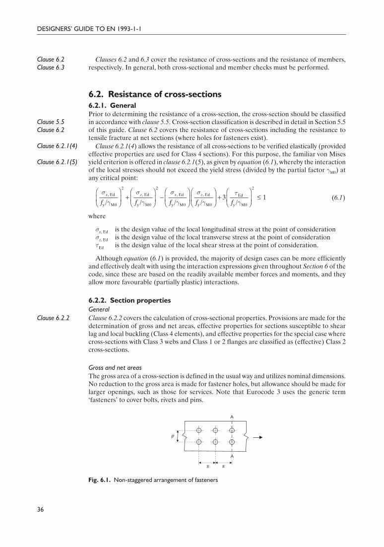
Delivered by ICEVirtualLibrary.com to:
IP: 95.42.11.157
On: Sun, 11 Jul 2010 21:35:24
Clause 6.2Clause 6.3
Clauses 6.2 and 6.3 cover the resistance of cross-sections and the resistance of members,respectively. In general, both cross-sectional and member checks must be performed.
6.2. Resistance of cross-sections6.2.1. General
Clause 5.5Clause 6.2
Prior to determining the resistance of a cross-section, the cross-section should be classifiedin accordance with clause 5.5. Cross-section classification is described in detail in Section 5.5of this guide. Clause 6.2 covers the resistance of cross-sections including the resistance totensile fracture at net sections (where holes for fasteners exist).
Clause 6.2.1(4)
Clause 6.2.1(5)
Clause 6.2.1(4) allows the resistance of all cross-sections to be verified elastically (providedeffective properties are used for Class 4 sections). For this purpose, the familiar von Misesyield criterion is offered in clause 6.2.1(5), as given by equation (6.1), whereby the interactionof the local stresses should not exceed the yield stress (divided by the partial factor γM0) atany critical point:
(6.1)
where
σx, Ed is the design value of the local longitudinal stress at the point of considerationσz, Ed is the design value of the local transverse stress at the point of considerationτEd is the design value of the local shear stress at the point of consideration.
Although equation (6.1) is provided, the majority of design cases can be more efficientlyand effectively dealt with using the interaction expressions given throughout Section 6 of thecode, since these are based on the readily available member forces and moments, and theyallow more favourable (partially plastic) interactions.
6.2.2. Section propertiesGeneral
Clause 6.2.2 Clause 6.2.2 covers the calculation of cross-sectional properties. Provisions are made for thedetermination of gross and net areas, effective properties for sections susceptible to shearlag and local buckling (Class 4 elements), and effective properties for the special case wherecross-sections with Class 3 webs and Class 1 or 2 flanges are classified as (effective) Class 2cross-sections.
Gross and net areasThe gross area of a cross-section is defined in the usual way and utilizes nominal dimensions.No reduction to the gross area is made for fastener holes, but allowance should be made forlarger openings, such as those for services. Note that Eurocode 3 uses the generic term‘fasteners’ to cover bolts, rivets and pins.
36
DESIGNERS’ GUIDE TO EN 1993-1-1
2 2 2
, Ed , Ed , Ed , Ed Ed
y M0 y M0 y M0 y M0 y M0
3 1/ / / / /x z x z
f f f f f
σ σ σ σ τγ γ γ γ γ
Ê ˆ Ê ˆ Ê ˆ Ê ˆ Ê ˆ+ - + £Á ˜ Á ˜ Á ˜ Á ˜ Á ˜
Ë ¯ Ë ¯ Ë ¯ Ë ¯ Ë ¯
p
s s
A
A
Fig. 6.1. Non-staggered arrangement of fasteners
46Guide to Eurocode 1993 - CRC02 December 2004 11:53:54
Color profile: DisabledComposite Default screen

Delivered by ICEVirtualLibrary.com to:
IP: 95.42.11.157
On: Sun, 11 Jul 2010 21:35:24
The method for calculating the net area of a cross-section in EN 1993-1-1 is essentially thesame as that described in BS 5950: Part 1, with marginally different rules for sections such asangles with fastener holes in both legs. In general, the net area of the cross-section is taken asthe gross area less appropriate deductions for fastener holes and other openings.
For a non-staggered arrangement of fasteners, for example as shown in Fig. 6.1, the totalarea to be deducted should be taken as the sum of the sectional areas of the holes on any line(A–A) perpendicular to the member axis that passes through the centreline of the holes.
For a staggered arrangement of fasteners, for example as shown in Fig. 6.2, the total areato be deducted should be taken as the greater of:
(1) the maximum sum of the sectional areas of the holes on any line (A–A) perpendicular tothe member axis
(2)
measured on any diagonal or zig-zag line (A–B), where
s is the staggered pitch of two consecutive holes (see Fig. 6.2)p is the spacing of the centres of the same two holes measured perpendicular to the
member axis (see Fig. 6.2)n is the number of holes extending in any diagonal or zig-zag line progressively across
the sectiond0 is the diameter of the hole.
Clause 6.2.2.2(5)Clause 6.2.2.2(5) states that for angles or other members with holes in more than oneplane, the spacing p should be measured along the centre of thickness of the material (asshown in Fig. 6.3).
With reference to Fig. 6.3, the spacing p therefore comprises two straight portions and onecurved portion of radius equal to the root radius plus half the material thickness. BS 5950:Part 1 defines the spacing p as the sum of the back marks, which results in marginally highervalues.
37
CHAPTER 6. ULTIMATE LIMIT STATES
Ê ˆ-Á ˜Ë ¯Â
2
0 4s
t ndp
p
s s
A
AB
Fig. 6.2. Staggered arrangement of fastener holes
p
Fig. 6.3. Angle with holes in both legs
47Guide to Eurocode 1993 - CRC02 December 2004 11:53:54
Color profile: DisabledComposite Default screen

Delivered by ICEVirtualLibrary.com to:
IP: 95.42.11.157
On: Sun, 11 Jul 2010 21:35:24
Effective areas to account for shear lag and local buckling effectsEurocode 3 employs an effective area concept to take account of the effects of shear lag (forwide compression flanges with low in-plane stiffness) and local plate buckling (for slendercompression elements).
To distinguish between loss of effectiveness due to local plate buckling and due to shearlag (and indeed due to a combination of the two effects), Eurocode 3 applies the following(superscript) convention to the word ‘effective’:
• ‘effectivep’ is used in relation to local plate buckling effects• ‘effectives’ is used in relation to shear lag effects• ‘effective’ is used in relation to combined local plate buckling and shear lag effects.
This convention is described in Eurocode 3, Part 1.5, clause 1.3.4.
Shear lagThe calculation of effective widths for wide flanges susceptible to shear lag is covered inEurocode 3 – Part 1.5, for hot-rolled and fabricated sections, and Part 1.3, for cold-formedmembers (though the designer is immediately directed to Part 1.5).
Part 1.5 states that shear lag effects in flanges may be neglected provided that the flangewidth b0 < Le /50, where Le is the length between points of zero bending moment. The flangewidth b0 is defined as either the outstand width (measured from the centreline of the web tothe flange tip) or half the width of an internal element (taken as half of the width between thecentrelines of the webs). At the ultimate limit state, the limits are relaxed since there will besome plastic redistribution of stresses across the flange, and shear lag may be neglected ifb0 < Le /20. Since shear lag effects rarely arise in conventional building structures, no furtherdiscussion on the subject will be given herein.
Local (plate) buckling – Class 4 cross-sections
Clause 6.2.2.5Preliminary information relating to the effective properties of Class 4 cross-sections toaccount for local buckling (and in some instances shear lag effects) is set out in clause 6.2.2.5.The idea of additional bending moment due to a possible shift in neutral axis from the grosssection to the effective section is also introduced; this is examined in more detail in Section6.2.4 of this guide.
Effective areas for Class 4 compression elements may be determined from Eurocode 3 –Part 1.5, for hot-rolled sections and plate girders, from Part 1.3, for cold-formed sections,and from Part 1.6, for circular hollow sections. The required expressions for hot-rolledsections and plate girders are set out and described below. For the majority of cold-formedsections, reference is also made (from Part 1.3) to Part 1.5 and so the expressions given below
DESIGNERS’ GUIDE TO EN 1993-1-1
38
_b/t
0.0
0.2
0.4
0.6
0.8
1.0
1.2
0 20 40 60 80 100
Red
uctio
n fa
ctor
, r
Internal
Outstand
Fig. 6.4. Relationship between reduction factor ρ and the b /t ratio
48Guide to Eurocode 1993 - CRC02 December 2004 11:53:54
Color profile: DisabledComposite Default screen

Delivered by ICEVirtualLibrary.com to:
IP: 95.42.11.157
On: Sun, 11 Jul 2010 21:35:24
also apply. For cold-formed cross-sections of more complex geometry Eurocode 3 – Part 1.3provides alternative rules; these are described in Chapter 13 of this guide.
The effective area of a flat compression element Ac, eff is defined in clause 4.4 ofEN 1993-1-5 as the gross area of the compression element Ac multiplied by a reduction factorρ (where ρ must be less than or equal to unity), as given below:
Ac, eff = ρAc (D6.1)
For internal compression elements:
but £ 1.0 (D6.2)
And for outstand compression elements:
but £ 1.0 (D6.3)
where
ψ is the ratio of end stresses acting on the compression element (in accordance withclauses 4.4(3) and 4.4(4) of EN 1993-1-5).
b is the appropriate width as follows:bw for webs, taken as the clear width between welds or filletsb for internal flange elements, taken as ‘c’ from Table 5.2 (sheet 1)b – 3t for flanges of rectangular hollow sectionc for outstand flanges, taken as the clear width from the weld or fillet to the
flange tiph for equal and unequal leg angles – see Table 5.2 (sheet 3).
kσ is the buckling factor, which depends on the stress distribution in the compressionelement and on the boundary conditions (discussed below).
t is the thickness.σcr is the elastic critical plate buckling stress.
Note that equations (D6.2) and (D6.3) are to be applied to slender compression elements.The form of the equations is such that for very stocky elements, values for the reductionfactor ρ of less than unity are found; this is clearly not intended. The relationships betweenthe reduction factor ρ and the b/t ratio for an internal element and an outstand elementsubjected to pure compression (for fy = 275 N/mm2) are illustrated in Fig. 6.4.
The general definition of plate slenderness λp includes a buckling factor kσ, which makesallowance for different applied compressive stress distributions and different boundaryconditions of the element.
The first step to determine kσ is to consider the boundary conditions of the element underconsideration (i.e. whether it is internal or an outstand compression element). For internalcompression elements, kσ should be found from Table 6.2 (Table 4.1 of EN 1993-1-5); andfor outstand compression elements, kσ should be found from Table 6.3 (Table 4.2 ofEN 1993-1-5).
Secondly, consideration has to be given to the stress distribution within the element,defined by ψ, which is the ratio of the end stresses σ2 /σ1. The most common cases are that ofpure compression, where the end stresses are equal (i.e. σ2 = σ1), and hence ψ = 1.0, and thatof pure bending, where the end stresses are equal in magnitude but of opposite sign (i.e.σ2 = –σ1), and hence ψ = –1.0. Buckling factors kσ for intermediate values of ψ (and valuesdown to ψ = –3) are also given in Tables 6.2 and 6.3.
39
CHAPTER 6. ULTIMATE LIMIT STATES
yp
cr
/28.4
f b t
kσ
λσ ε
= =
y235/fε =
p2
p
0.055(3 )λ ψρ
λ
- +=
p2
p
0.188λρ
λ
-=
49Guide to Eurocode 1993 - CRC02 December 2004 11:53:55
Color profile: DisabledComposite Default screen

Delivered by ICEVirtualLibrary.com to:
IP: 95.42.11.157
On: Sun, 11 Jul 2010 21:35:24
40
DESIGNERS’ GUIDE TO EN 1993-1-1
Table 6.2. Determination of kσ for internal compression elements (Table 4.1 of EN 1993-1-5)
Stress distribution (compression positive) Effectivep width beff
ψ = 1:
beff = ρb
be1 = 0.5beff be2 = 0.5beff
1 > ψ > 0:
beff = ρb
be1 = 25 − ψ
beff be2 = beff – be1
ψ < 0:
beff = ρbc = ρb/(1 – ψ)
be1 = 0.4beff be2 = 0.6beff
ψ = σ2 /σ1 1 1 > ψ > 0 0 0 > ψ > –1 –1 –1 > ψ > –3
Buckling factor kσ 4.0 8.2/(1.05 + ψ) 7.8 7.81 – 6.29ψ + 9.78ψ2 23.9 5.98(1 – ψ)2
s1 s2
be1 be2
b
b
s1 s2
be1 be2
s1
s2be1
bc bt
be2
b
Table 6.3. Determination of kσ for outstand compression elements (Table 4.2 of EN 1993-1-5)
Stress distribution (compression positive) Effectivep width beff
1 > ψ > 0:
beff = ρc
ψ < 0:
beff = ρbc = ρc/(1 – ψ)
ψ = σ2 /σ1 1 0 –1 1 > ψ > –3
Buckling factor kσ 0.43 0.57 0.85 0.57 – 0.21ψ + 0.07ψ2
1 > ψ 0:
beff = ρc
ψ < 0:
beff = ρbc = ρc/(1 – ψ)
ψ = σ2 /σ1 1 1 > ψ > 0 0 0 > ψ > –1 –1
Buckling factor kσ 0.43 0.578/(ψ + 0.34) 1.70 1.7 – 5ψ + 17.1ψ2 23.8
beff
c
s2
s1
beff
bt bc
s2
s1
beff
c
s1 s2
s1
s2
beff
bc bt
50Guide to Eurocode 1993 - CRC02 December 2004 11:53:55
Color profile: DisabledComposite Default screen

Delivered by ICEVirtualLibrary.com to:
IP: 95.42.11.157
On: Sun, 11 Jul 2010 21:35:24
There are additional rules given in clause 4.4 of EN 1993-1-5 that relate to elements of Isections and box girders:
• for flange elements, the stress ratio ψ should be based on the properties of the grosscross-section (with any due allowance for shear lag)
• for web elements, the stress ratio ψ should be found using a stress distribution obtainedwith the effective area of the compression flange and the gross area of the web (as shownin Fig. 6.5).
Effective properties of cross-sections with Class 3 webs and Class 1 or 2 flangesThe previous subsection describes how effective properties for Class 4 cross-sections shouldbe determined. This subsection describes special rules for cross-sections with Class 3 websand Class 1 or 2 flanges.
Clause 5.5.2(11)Clause 6.2.2.4
Generally, a Class 3 cross-section (where the most slender element is Class 3) wouldassume an elastic distribution of stresses, and its bending resistance would be calculatedusing the elastic modulus Wel. However, Eurocode 3 (clauses 5.5.2(11) and 6.2.2.4) makesspecial allowances for cross-sections with Class 3 webs and Class 1 or 2 flanges by permittingthe cross-sections to be classified as effective Class 2 cross-sections. Accordingly, part of thecompressed portion of the web is neglected, and plastic section properties for the remainderof the cross-section are determined. The effective section is prescribed without the use of aslenderness-dependent reduction factor ρ, and is therefore relatively straightforward.
Clause 6.2.2.4Clause 6.2.2.4 states that the compressed portion of the web should be replaced by a partof 20εtw adjacent to the compression flange (measured from the base of the root radius), withanother part of 20εtw adjacent to the plastic neutral axis of the effective cross-section inaccordance with Fig. 6.6. A similar distribution may be applied to welded sections with thepart of 20εtw adjacent to the compression flange measured from the base of the weld.
41
CHAPTER 6. ULTIMATE LIMIT STATES
s1
s2
s1
s2
(a) (b)
Fig. 6.5. Determination of the stress ratio ψ in webs: (a) based on the gross cross-section; (b) usingthe effective area of compression, as prescribed by EN 1993-1-5
b
h
(a) (b)
tw
20etw
20etw
fy
fy
Tension
Compression
–
–
+Plastic neutral axis
Neglectedineffective area
z
Fig. 6.6. Effective Class 2 web. (a) Cross-section. (b) Stress distribution
51Guide to Eurocode 1993 - CRC02 December 2004 11:53:56
Color profile: DisabledComposite Default screen

Delivered by ICEVirtualLibrary.com to:
IP: 95.42.11.157
On: Sun, 11 Jul 2010 21:35:24
Example 6.3 demonstrates calculation of the bending resistance of a cross-section with aClass 1 flange and a Class 3 web. Also, comparison is made between the bending resistanceusing elastic section properties (i.e. assuming a Class 3 cross-section) and using the effectiveplastic properties described above.
6.2.3. TensionClause 6.2.3 The resistance of tension members is covered in clause 6.2.3. The design tensile force is
denoted by NEd (axial design effect). In Eurocode 3, similarly to BS 5950: Part 1, design tensileresistance Nt, Rd is limited either by yielding of the gross cross-section (to prevent excessivedeformation of the member) or ultimate failure of the net cross-section (at holes forfasteners), whichever is the lesser.
The Eurocode 3 design expression for yielding of the gross cross-section (plastic resistance)is therefore given as
(6.6)
Clause 6.2.2.2 And for the ultimate resistance of the net cross-section (defined in clause 6.2.2.2), theEurocode 3 design expression is
(6.7)
The design tensile resistance is taken as the smaller of the above two results. For ductility(capacity design), the design plastic resistance of the gross cross-section should be less thanthe design ultimate resistance of the net cross-section.
The 0.9 factor was included in the strength model of equation (6.7) following a statisticalevaluation of a large number of test results for net section failure of plates.6 Inclusion of the0.9 factor enabled the partial γM factor to be harmonized with that applied to the resistanceof other connection parts (bolts or welds). The partial factor of γM2 = 1.25 is thereforeemployed for the ultimate resistance of net cross-sections.
The tensile resistance of a lap splice is determined in Example 6.1. The subject of jointsand the provisions of EN 1993-1-8 are covered in Chapter 12 of this guide.
Example 6.1: tension resistanceA flat bar, 200 mm wide and 25 mm thick, is to be used as a tie. Erection conditionsrequire that the bar be constructed from two lengths connected together with a lap spliceusing six M20 bolts, as shown in Fig. 6.7. Calculate the tensile strength of the bar,assuming grade S275 steel.
Clause 6.2.3Clause 6.2.2
Cross-section resistance in tension is covered in clause 6.2.3, with reference to clause6.2.2 for the calculation of cross-section properties.
For a nominal material thickness (t = 25 mm) of less than or equal to 40 mm thenominal values of yield strength, fy, and ultimate tensile strength, fu, are found from Table3.1 to be 275 and 430 N/mm2, respectively. Note that reference should be made to the UKNational Annex for the nominal material strength (see Section 3.2 of this guide).
The numerical values of the required partial factors recommended by EN 1993-1-1 areγM0 = 1.00 and γM2 = 1.25 (though for buildings to be constructed in the UK, referenceshould be made to the National Annex).
Gross area of cross-section
A = 25 × 200 = 5000 mm2
In determining the net area, Anet, the total area to be deducted is taken as the larger of:
42
DESIGNERS’ GUIDE TO EN 1993-1-1
ypl, Rd
M0
AfN
γ=
= net uu, Rd
M2
0.9A fN
γ
52Guide to Eurocode 1993 - CRC02 December 2004 11:53:56
Color profile: DisabledComposite Default screen

Delivered by ICEVirtualLibrary.com to:
IP: 95.42.11.157
On: Sun, 11 Jul 2010 21:35:24
(1) the deduction for non-staggered holes (A–A) = 22 × 25 = 550 mm2
(2) (> 550 mm2)
Therefore, the net area of the cross-section
Anet = 5000 – 594 = 4406 mm2
The design plastic resistance of the gross cross-section
The design ultimate resistance of the net cross-section
The tensile resistance, Nt, Rd, is taken as the smaller of Npl, Rd (1375 kN) and Nu, Rd
(1364 kN).
\ Nt, Rd = 1364 kN
Note that for the same arrangement, BS 5950: Part 1 gives a tensile resistance of1325 kN.
6.2.4. CompressionClause 6.2.4
Clause 6.3
Cross-section resistance in compression is covered in clause 6.2.4. This of course ignoresoverall member buckling effects, and therefore may only be applied as the sole check tomembers of low slenderness (λ £ 0.2). For all other cases, checks also need to be made formember buckling as defined in clause 6.3.
The design compressive force is denoted by NEd (axial design effect). The design resistanceof a cross-section under uniform compression, Nc, Rd is determined in a similar manner toBS 5950: Part 1. The Eurocode 3 design expressions for cross-section resistance underuniform compression are as follows:
for Class 1, 2 or 3 cross-sections (6.10)
for Class 4 cross-sections (6.11)
43
CHAPTER 6. ULTIMATE LIMIT STATES
yc, Rd
M0
AfN
γ=
u, Rd0.9 4406 430
1364 kN1.25
N¥ ¥
= =
pl, Ed5000 275
1375 kN1.00
N¥
= =
Ê ˆ Ê ˆ- = ¥ ¥ - =Á ˜ Á ˜¥Ë ¯ Ë ¯Â
2 22
090
25 2 22 594 mm4 4 100s
t ndp
T
50 mm
50 mm
100 mmT
5 at 90 mm
A
AB
T
T
Fig. 6.7. Lap splice in tension member with a staggered bolt arrangement
eff yc, Rd
M0
A fN
γ=
53Guide to Eurocode 1993 - CRC02 December 2004 11:53:56
Color profile: DisabledComposite Default screen

Delivered by ICEVirtualLibrary.com to:
IP: 95.42.11.157
On: Sun, 11 Jul 2010 21:35:24
For Class 1, 2 and 3 cross-sections, the design compression resistance is taken as the grosscross-sectional area multiplied by the nominal material yield strength and divided by thepartial factor γM0, and likewise for Class 4 cross-sections with the exception that effectivesection properties are used in place of the gross properties. In calculating cross-sectionalareas for compression resistance, no allowance need be made for fastener holes (wherefasteners are present) except for oversize or slotted holes.
Example 6.2: cross-section resistance in compressionA 254 × 254 × 73 UC is to be used as a short (λ £ 0.2) compression member. Calculatethe resistance of the cross-section in compression, assuming grade S355 steel.
Section propertiesThe section properties are given in Fig. 6.8.
Clause 6.2.4Clause 5.5.2
Cross-section resistance in compression is covered in clause 6.2.4, with cross-sectionclassification covered in clause 5.5.2.
For a nominal material thickness (tf = 14.2 mm and tw = 8.6 mm) of less than or equal to40 mm, the nominal values of yield strength fy for grade S355 steel (to EN 10025-2) isfound from Table 3.1 to be 355 N/mm2. Note that reference should be made to the UKNational Annex for the nominal material strength (see Section 3.2 of this guide).
Clause 5.5.2 Cross-section classification (clause 5.5.2)
Outstand flanges (Table 5.2, sheet 2):
c = (b – tw – 2r)/2 = 110.3 mm
c/tf = 110.3/14.2 = 7.77
Limit for Class 2 flange = 10ε = 8.14
8.14 > 7.77 \ flanges are Class 2
Web – internal compression part (Table 5.2, sheet 1):
c = h – 2tf – 2r = 200.3 mm
c/tw = 200.3/8.6 = 23.29
Limit for Class 1 web = 33ε = 26.85
26.85 > 23.29 \ web is Class 1
Overall cross-section classification is therefore Class 2.
44
DESIGNERS’ GUIDE TO EN 1993-1-1
y235/ 235/355 0.81fε = = =
b
h d
tw
tf
r
y y
z
z
h = 254.1 mm
b = 254.6 mm
tw = 8.6 mm
tf = 14.2 mm
r = 12.7 mm
A = 9310 mm2
Fig. 6.8. Section properties for a 254 × 254 × 73 UC
54Guide to Eurocode 1993 - CRC02 December 2004 11:53:57
Color profile: DisabledComposite Default screen
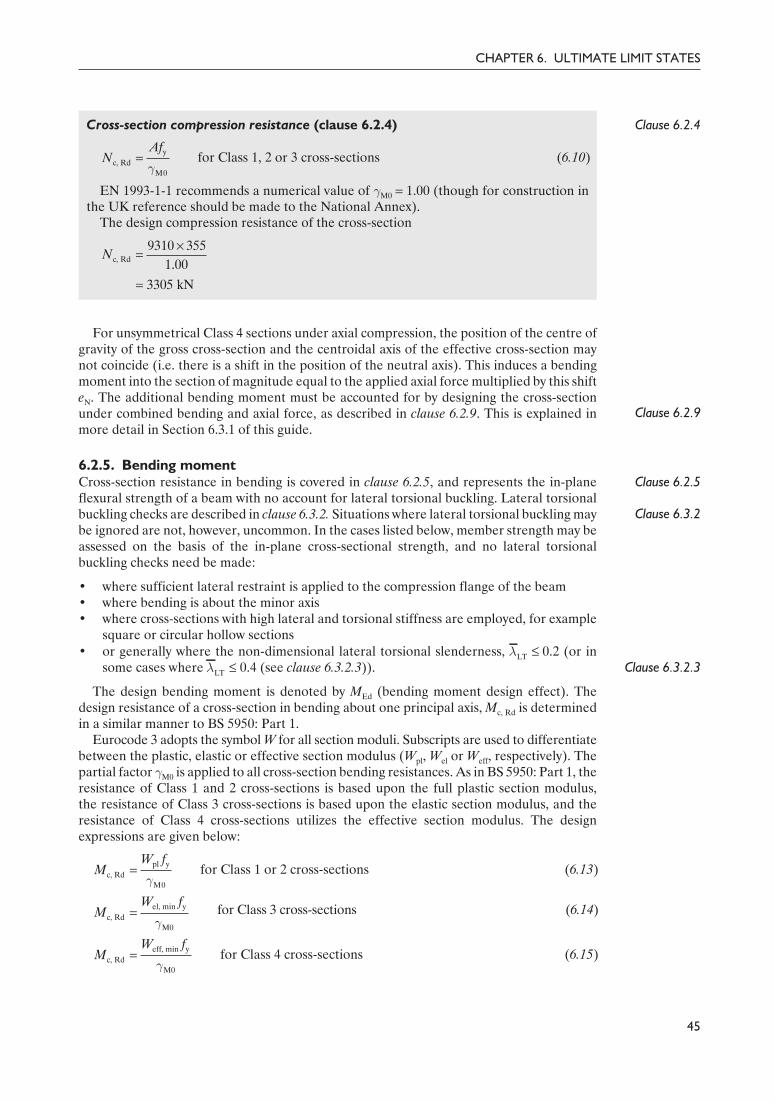
Delivered by ICEVirtualLibrary.com to:
IP: 95.42.11.157
On: Sun, 11 Jul 2010 21:35:24
Clause 6.2.4Cross-section compression resistance (clause 6.2.4)
for Class 1, 2 or 3 cross-sections (6.10)
EN 1993-1-1 recommends a numerical value of γM0 = 1.00 (though for construction inthe UK reference should be made to the National Annex).
The design compression resistance of the cross-section
Clause 6.2.9
For unsymmetrical Class 4 sections under axial compression, the position of the centre ofgravity of the gross cross-section and the centroidal axis of the effective cross-section maynot coincide (i.e. there is a shift in the position of the neutral axis). This induces a bendingmoment into the section of magnitude equal to the applied axial force multiplied by this shifteN. The additional bending moment must be accounted for by designing the cross-sectionunder combined bending and axial force, as described in clause 6.2.9. This is explained inmore detail in Section 6.3.1 of this guide.
6.2.5. Bending momentClause 6.2.5
Clause 6.3.2
Cross-section resistance in bending is covered in clause 6.2.5, and represents the in-planeflexural strength of a beam with no account for lateral torsional buckling. Lateral torsionalbuckling checks are described in clause 6.3.2. Situations where lateral torsional buckling maybe ignored are not, however, uncommon. In the cases listed below, member strength may beassessed on the basis of the in-plane cross-sectional strength, and no lateral torsionalbuckling checks need be made:
• where sufficient lateral restraint is applied to the compression flange of the beam• where bending is about the minor axis• where cross-sections with high lateral and torsional stiffness are employed, for example
square or circular hollow sections
Clause 6.3.2.3• or generally where the non-dimensional lateral torsional slenderness, λLT £ 0.2 (or in
some cases where λLT £ 0.4 (see clause 6.3.2.3)).
The design bending moment is denoted by MEd (bending moment design effect). Thedesign resistance of a cross-section in bending about one principal axis, Mc, Rd is determinedin a similar manner to BS 5950: Part 1.
Eurocode 3 adopts the symbol W for all section moduli. Subscripts are used to differentiatebetween the plastic, elastic or effective section modulus (Wpl, Wel or Weff, respectively). Thepartial factor γM0 is applied to all cross-section bending resistances. As in BS 5950: Part 1, theresistance of Class 1 and 2 cross-sections is based upon the full plastic section modulus,the resistance of Class 3 cross-sections is based upon the elastic section modulus, and theresistance of Class 4 cross-sections utilizes the effective section modulus. The designexpressions are given below:
for Class 1 or 2 cross-sections (6.13)
for Class 3 cross-sections (6.14)
for Class 4 cross-sections (6.15)
45
CHAPTER 6. ULTIMATE LIMIT STATES
pl yc, Rd
M0
W fM
γ=
el, min yc, Rd
M0
W fM
γ=
yc, Rd
M0
AfN
γ=
¥=
=
c, Rd9310 355
1.003305 kN
N
eff, min yc, Rd
M0
W fM
γ=
55Guide to Eurocode 1993 - CRC02 December 2004 11:53:57
Color profile: DisabledComposite Default screen

Delivered by ICEVirtualLibrary.com to:
IP: 95.42.11.157
On: Sun, 11 Jul 2010 21:35:24
where the subscript ‘min’ indicates that the minimum value of Wel or Weff should be used; i.e.the elastic or effective modulus should be based on the extreme fibre that reaches yield first.
Example 6.3: cross-section resistance in bendingA welded I section is to be designed in bending. The proportions of the section have beenselected such that it may be classified as an effective Class 2 cross-section, as described inSection 6.2.2 of this guide. The chosen section is of grade S275 steel, and has two200 × 20 mm flanges and a 600 × 6 mm web. The weld size (leg length) s is 6.0 mm.Assuming full lateral restraint, calculate the bending moment resistance.
Section propertiesThe cross-sectional dimensions are shown in Fig. 6.9.For a nominal material thickness (tf = 20.0 mm and tw = 6.0 mm) of less than or equal to40 mm the nominal values of yield strength fy for grade S275 steel (to EN 10025-2) isfound from Table 3.1 to be 275 N/mm2. Note that reference should be made to the UKNational Annex for the nominal material strength (see Section 3.2 of this guide).
Clause 3.2.6 From clause 3.2.6:
E = 210 000 N/mm2
Clause 5.5.2 Cross-section classification (clause 5.5.2)
Outstand flanges (Table 5.2, sheet 2):
c = (b – tw – 2s)/2 = 91.0 mm
c/tf = 91.0/20.0 = 4.55
Limit for Class 1 flange = 9ε = 8.32
8.32 > 4.55 \ flange is Class 1
Web – internal part in bending (Table 5.2, sheet 1):
c = h – 2tf – 2s = 548.0 mm
c/tw = 548.0/6.0 = 91.3
Limit for Class 3 web = 124ε = 114.6
114.6 > 91.3 \ web is Class 3
46
DESIGNERS’ GUIDE TO EN 1993-1-1
y235/ 235/275 0.92fε = = =
b
h d
tw
tf
s
y y
z
z
hw
b = 200.0 mm
tf = 20.0 mm
hw = 600.0 mm
tw = 6.0 mm
s = 6.0 mm
Wel, y = 2 536 249 mm3
Fig. 6.9. Dimensions for a welded I section with 200 × 20 mm flanges and a 600 × 6 mm web
56Guide to Eurocode 1993 - CRC02 December 2004 11:53:57
Color profile: DisabledComposite Default screen

Delivered by ICEVirtualLibrary.com to:
IP: 95.42.11.157
On: Sun, 11 Jul 2010 21:35:24
Overall cross-section classification is therefore Class 3.Clause 6.2.2.4However, as stated in clause 6.2.2.4, a cross-section with a Class 3 web and Class 1 or 2
flanges may be classified as an effective Class 2 cross-section.
Clause 6.2.2.4Effective Class 2 cross-section properties (clause 6.2.2.4)Plastic neutral axis of effective sectionThe depth to the plastic neutral axis of the effective section, as indicated by z in Fig. 6.10,may be shown (based on equal areas above and below the plastic neutral axis) to be
z = h – tf – s – (2 × 20εtw) (D6.4)= 600.0 – 20.0 – 6.0 – (2 × 20 × 0.92 × 6.0)= 352.1 mm
Plastic modulus of effective section
Wpl, y, eff = btf(h – tf) + tw{(20εtw + s)[z – tf – (20εtw + s)/2]}+ tw(20εtw × 20εtw /2) + tw[(h – tf – z)(h – tf – z)/2]
= 2 704 682 mm3
Clause 6.2.5Bending resistance of cross-section (clause 6.2.5)
Based on the elastic section modulus Wel, y = 2 536 249 mm3, the bending resistance ofthe cross-section would have been 697.5 kN m. Therefore, for the chosen section, use ofthe effective Class 2 plastic properties results in an increase in bending moment resistanceof approximately 7%.
Other examples of cross-section bending resistance checks are also included in Examples6.5, 6.8, 6.9 and 6.10.
Clause 6.2.9For combined bending and axial force, of which bi-axial bending is a special case (with the
applied axial force NEd = 0), the designer should refer to clause 6.2.9.
Clause 6.2.5(4)Clause 6.2.5(5)
In the compression zone of cross-sections in bending, (as for cross-sections under uniformcompression), no allowance need be made for fastener holes (where fasteners are present)except for oversize or slotted holes. Fastener holes in the tension flange and the tensile zoneof the web need not be allowed for, provided clause 6.2.5(4) and 6.2.5(5) are satisfied.
47
CHAPTER 6. ULTIMATE LIMIT STATES
pl, , eff yc, , Rd
M0
for effective class 2 sectionsyy
W fM
γ=
c, , Rd62 704 682 275
743.8 10 N mm 743.8 kN m1.0yM
¥= = ¥ =
b
h
(a) (b)
tw
20etw
20etw
fy
fy
Tension
Compression
–
–
+Plastic neutral axis
Neglectedineffective area
z
Fig. 6.10. Effective Class 2 properties for a welded I section. (a) Cross-section. (b) Stressdistribution
57Guide to Eurocode 1993 - CRC02 December 2004 11:53:58
Color profile: DisabledComposite Default screen

Delivered by ICEVirtualLibrary.com to:
IP: 95.42.11.157
On: Sun, 11 Jul 2010 21:35:24
6.2.6. ShearClause 6.2.6 The resistance of cross-sections to shear is covered in clause 6.2.6. The design shear force is
denoted by VEd (shear force design effect). The design shear resistance of a cross-section isdenoted by Vc, Rd, and may be calculated based on a plastic (Vpl, Rd) or an elastic distribution ofshear stress. The shear stress distribution in a rectangular section and in an I section, basedon purely elastic behaviour, is shown in Fig. 6.11.
In both cases in Fig. 6.11, the shear stress varies parabolically with depth, with themaximum value occurring at the neutral axis. However, for the I section (and similarlyfor the majority of conventional structural steel cross-sections), the difference betweenmaximum and minimum values for the web, which carries almost all the vertical shear force,is relatively small. Consequently, by allowing a degree of plastic redistribution of shearstress, design can be simplified to working with average shear stress, defined as the totalshear force VEd divided by the area of the web (or equivalent shear area Av).
Clause 6.2.6(2)Since the yield stress of steel in shear is approximately 1/÷3 of its yield stress in tension,
clause 6.2.6(2) therefore defines the plastic shear resistance as
(6.18)
and it is the plastic shear resistance that will be used in the vast majority of practical designsituations.
Clause 6.2.6(3)
The shear area Av is in effect the area of the cross-section that can be mobilized to resistthe applied shear force with a moderate allowance for plastic redistribution, and, for sectionswhere the load is applied parallel to the web, this is essentially the area of the web (with someallowance for the root radii in rolled sections). Expressions for the determination of sheararea Av for general structural cross-sections are given in clause 6.2.6(3). The most commonones are repeated below:
48
DESIGNERS’ GUIDE TO EN 1993-1-1
v ypl, Rd
M0
( / 3)A fV
γ=
tmax =ht2
V3 Ed
t
h
b
tmax = +b4
h1
I2
hbVEd
tmax =I2
hbVEd
h
(a) (b)
Fig. 6.11. Distribution of shear stresses in beams subjected to a shear force VEd. (a) Cross-section.(b) Shear stress distribution
58Guide to Eurocode 1993 - CRC02 December 2004 11:53:58
Color profile: DisabledComposite Default screen

Delivered by ICEVirtualLibrary.com to:
IP: 95.42.11.157
On: Sun, 11 Jul 2010 21:35:24
• Rolled I and H sections, load parallel to the web:
Av = A – 2btf + (tw + 2r)tf but ≥ ηhwtw
• Rolled channel sections, load parallel to the web:
Av = A – 2btf + (tw + r)tf
• Welded I, H and box sections, load parallel to the web:
Av = ηÂhw tw
• Welded I, H, channel and box sections, load parallel to the flanges:
Av = A – Âhw tw
• Rolled rectangular hollow section of uniform thickness, load parallel to the depth:
Av = Ah/(b + h)
• Rolled rectangular hollow section of uniform thickness, load parallel to the width:
Av = Ab/(b + h)
• Circular hollow section and tubes of uniform thickness:
Av = 2A/π
where
A is the cross-sectional areab is the overall section breadthh is the overall section depthhw is the overall web depth (measured between the flanges)r is the root radiustf is the flange thicknesstw is the web thickness (taken as the minimum value if the web is not of constant
thickness)η is the shear area factor – see clause 5.1 of EN 1993-1-5 (and the discussion on p. 50
of this guide).
Clause 6.2.6(4)
Clause 6.2.6(2)
The code also provides expressions in clause 6.2.6(4) for checking the elastic shearresistance of a cross-section, where the distribution of shear stresses is calculated assumingelastic material behaviour (see Fig. 6.11). This check need only be applied to unusualsections that are not addressed in clause 6.2.6(2), or in cases where plasticity is to be avoided,such as where repeated load reversal occurs.
The resistance of the web to shear buckling should also be checked, though this is unlikelyto affect cross-sections of standard hot-rolled proportions. Shear buckling need not beconsidered provided:
for unstiffened webs (D6.5)
for webs with intermediate stiffeners (D6.6)
where
kτ is a shear buckling coefficient defined in Annex A.3 of EN 1993-1-5.
49
CHAPTER 6. ULTIMATE LIMIT STATES
w
w
72ht
εη
£
w
w
31h
kt τ
εη
£
y
235f
ε =
59Guide to Eurocode 1993 - CRC02 December 2004 11:53:58
Color profile: DisabledComposite Default screen

Delivered by ICEVirtualLibrary.com to:
IP: 95.42.11.157
On: Sun, 11 Jul 2010 21:35:24
It is recommended in clause 5.1 of EN 1993-1-5 that η be taken as 1.20 (except for steelgrades higher than S460, where η = 1.00 is recommended). However, numerical values for ηare given in the National Annexes, and designers should refer to these for specific guidance,though a conservative value of 1.00 may be used in all cases.
Clause 6.2.7(9)
For cross-sections that fail to meet the criteria of equations (D6.5) and (D6.6), referenceshould be made to clause 5.2 of EN 1993-1-5, to determine shear buckling resistance. Rulesfor combined shear force and torsion are provided in clause 6.2.7(9).
Example 6.4: shear resistanceDetermine the shear resistance of a 229 × 89 rolled channel section in grade S275 steelloaded parallel to the web.
Section propertiesThe section properties are given in Fig. 6.12.
For a nominal material thickness (tf = 13.3 mm and tw = 8.6 mm) of less than or equal to40 mm the nominal values of yield strength fy for grade S275 steel (to EN 10025-2) isfound from Table 3.1 to be 275 N/mm2.
Clause 6.2.6 Shear resistance (clause 6.2.6)Shear resistance is determined according to clause 6.2.6:
(6.18)
EN 1993-1-1 recommends a numerical value of γM0 = 1.00 (though for buildings to beconstructed in the UK, reference should be made to the National Annex).
Shear area Av
For a rolled channel section, loaded parallel to the web, the shear area is given by
Av = A – 2btf + (tw + r)tf
Av = 4160 – (2 × 88.9 × 13.3) + (8.6 + 13.7) × 13.3Av = 2092 mm2
Shear bucklingShear buckling need not be considered, provided:
for unstiffened webs
50
DESIGNERS’ GUIDE TO EN 1993-1-1
pl, Rd
2092 (275/ 3)332 000 N 332 kN
1.00V
¥\ = = =
v ypl, Rd
M0
( / 3)A fV
γ=
h
tw
t f
r
y y
z
z
h = 228.6 mm
b = 88.9 mm
tw = 8.6 mm
tf = 13.3 mm
r = 13.7 mm
A = 4160 mm2
Fig. 6.12. Section properties for a 229 × 89 mm rolled channel section
w
w
72ht
εη
£
60Guide to Eurocode 1993 - CRC02 December 2004 11:53:58
Color profile: DisabledComposite Default screen

Delivered by ICEVirtualLibrary.com to:
IP: 95.42.11.157
On: Sun, 11 Jul 2010 21:35:24
η = 1.2
(η from EN 1993-1-5, though the UK National Annex may specify an alternative value).
Actual hw /tw = (h – 2tf)/tw = [228.6 – (2 × 13.3)]/8.6 = 23.5
23.5 £ 55.5 \ no shear buckling check required
ConclusionThe shear resistance of a 229 × 89 rolled channel section in grade S275 steel loadedparallel to the web is 332 kN. For the same cross-section, BS 5950 (2000) gives a shearresistance of 324 kN.
6.2.7. TorsionClause 6.2.7
Clause 6.2.7Clause 6.2.8
Clause 6.2.10
The resistance of cross-sections to torsion is covered in clause 6.2.7. Torsional loading canarise in two ways: either due to an applied torque (pure twisting) or due to transverse loadapplied eccentrically to the shear centre of the cross-section (twisting plus bending). Inengineering structures it is the latter that is the most common, and pure twisting is relativelyunusual. Consequently clauses 6.2.7, 6.2.8 and 6.2.10 provide guidance for torsion acting incombination with other effects (bending, shear and axial force).
The torsional moment design effect TEd is made up of two components: the Saint Venanttorsion Tt, Ed and the warping torsion Tw, Ed.
Saint Venant torsion is the uniform torsion that exists when the rate of change of the angleof twist along the length of a member is constant. In such cases, the longitudinal warpingdeformations (that accompany twisting) are also constant, and the applied torque is resistedby a single set of shear stresses, distributed around the cross-section.
Warping torsion exists where the rate of change of the angle of twist along the length of amember is not constant; in which case, the member is said to be in a state of non-uniformtorsion. Such non-uniform torsion may occur either as a result of non-uniform loading (i.e.varying torque along the length of the member) or due to the presence of longitudinalrestraint to the warping deformations. For non-uniform torsion, longitudinal direct stressesand an additional set of shear stresses arise.
Clause 6.2.7(4)Therefore, as noted in clause 6.2.7(4), there are three sets of stresses that should beconsidered:
• shear stresses τt, Ed due to the Saint Venant torsion• shear stresses τw, Ed due to the warping torsion• longitudinal direct stresses σw, Ed due to the warping.
Clause 6.2.7(6)Clause 6.2.1(5)
Depending on the cross-section classification, torsional resistance may be verifiedplastically with reference to clause 6.2.7(6), or elastically by adopting the yield criterion ofequation (6.1) (see clause 6.2.1(5)). Detailed guidance on the design of members subjected totorsion is available.11
Clause 6.2.7(7)Clause 6.2.7(7) allows useful simplifications for the design of torsion members. Forclosed-section members (such as cylindrical and rectangular hollow sections), whosetorsional rigidities are very large, Saint Venant torsion dominates, and warping torsion maybe neglected. Conversely, for open sections, such as I or H sections, whose torsional rigiditiesare low, Saint Venant torsion may be neglected.
Clause 6.2.7(9)For the case of combined shear force and torsional moment, clause 6.2.7(9) defines areduced plastic shear resistance Vpl, T, Rd, which must be demonstrated to be greater than thedesign shear force VEd.
51
CHAPTER 6. ULTIMATE LIMIT STATES
y235/ 235/275 0.92fε = = =
0.9272 72 55.5
1.2εη
= ¥ =
61Guide to Eurocode 1993 - CRC02 December 2004 11:53:59
Color profile: DisabledComposite Default screen

Delivered by ICEVirtualLibrary.com to:
IP: 95.42.11.157
On: Sun, 11 Jul 2010 21:35:24
Vpl, T, Rd may be derived from equations (6.26) to (6.28):
• for an I or H section
(6.26)
• for a channel section
(6.27)
• for a structural hollow section:
(6.28)
Clause 6.2.6 where τt, Ed and τw, Ed are defined above and Vpl, Rd is obtained from clause 6.2.6.
6.2.8. Bending and shear
Clause 6.2.8(2)
Bending moments and shear forces acting in combination on structural members iscommonplace. However, in the majority of cases (and particularly when standard rolledsections are adopted) the effect of shear force on the moment resistance is negligible andmay be ignored – clause 6.2.8(2) states that provided the applied shear force is less than halfthe plastic shear resistance of the cross-section its effect on the moment resistance may beneglected. The exception to this is where shear buckling reduces the resistance of thecross-section, as described in Section 6.2.6 of this guide.
For cases where the applied shear force is greater than half the plastic shear resistance ofthe cross-section, the moment resistance should be calculated using a reduced designstrength for the shear area, given by equation (6.29):
fyr = (1 – ρ)fy (6.29)
where ρ is defined by equation (D6.7),
(for VEd > 0.5Vpl, Rd) (D6.7)
Clause 6.2.6Clause 6.2.7
Vpl, Rd may be obtained from clause 6.2.6, and when torsion is present Vpl, Rd should bereplaced by Vpl, T, Rd, obtained from clause 6.2.7.
An alternative to the reduced design strength for the shear area, defined by equation(6.29), which involves somewhat tedious calculations, is equation (6.30). Equation (6.30) maybe applied to the common situation of an I section (with equal flanges) subjected to bendingabout the major axis. In this case the reduced design plastic resistance moment allowing forshear is given by
but My, V, Rd £ My, C, Rd (6.30)
Clause 6.2.5 where ρ is defined by equation (D6.7), My, c, Rd may be obtained from clause 6.2.5 andAw = hw tw.
An example of the application of the cross-section rules for combined bending and shearforce is given in Example 6.5.
52
DESIGNERS’ GUIDE TO EN 1993-1-1
Ê ˆ= -Á ˜
Ë ¯t, Ed
pl, T, Rd pl, Rdy 0
1( / 3)/ M
V Vf
τ
γ
2
Ed
pl, Rd
21
VV
ρÊ ˆ
= -Á ˜Ë ¯
2pl, w w y
, V, RdM0
( /4 )yy
W A t fM
ρ
γ
-=
t, Ed w, Edpl, T, Rd pl, Rd
y M0 y M0
11.25( / 3)/ ( / 3)/
V Vf f
τ τ
γ γ
Ê ˆ= - -Á ˜Á ˜Ë ¯
t, Edpl, T, Rd pl, Rd
y M0
11.25( / 3)/
V Vf
τ
γ= -
62Guide to Eurocode 1993 - CRC02 December 2004 11:53:59
Color profile: DisabledComposite Default screen

Delivered by ICEVirtualLibrary.com to:
IP: 95.42.11.157
On: Sun, 11 Jul 2010 21:35:24
Example 6.5: cross-section resistance under combined bending and shearA short-span (1.4 m), simply supported, laterally restrained beam is to be designed tocarry a central point load of 1050 kN, as shown in Fig. 6.13.
The arrangement of Fig. 6.13 results in a maximum design shear force VEd of 525 kNand a maximum design bending moment MEd of 367.5 kN m.
In this example a 406 × 178 × 74 UB in grade S275 steel is assessed for its suitabilityfor this application.
Section propertiesThe section properties are set out in Fig. 6.14.
For a nominal material thickness (tf = 16.0 mm and tw = 9.5 mm) of less than or equal to40 mm the nominal values of yield strength fy for grade S275 steel (to EN 10025-2) isfound from Table 3.1 to be 275 N/mm2. Note that reference should be made to the UKNational Annex for the nominal material strength (see Section 3.2 of this guide).
Clause 3.2.6From clause 3.2.6:
E = 210 000 N/mm2
Clause 5.5.2Cross-section classification (clause 5.5.2)
Outstand flange in compression (Table 5.2, sheet 2):
c = (b – tw – 2r)/2 = 74.8 mm
c/tf = 74.8/16.0 = 4.68
Limit for Class 1 flange = 9ε = 8.32
8.32 > 4.68 \ flange is Class 1
53
CHAPTER 6. ULTIMATE LIMIT STATES
y235/ 235/275 0.92fε = = =
A B
0.7 m 0.7 m
1050 kN
Fig. 6.13. General arrangement and loading
b
h d
tw
tf
r
y y
z
z
h = 412.8 mm
b = 179.5 mm
tw = 9.5 mm
tf = 16.0 mm
r = 10.2 mm
A = 9450 mm2
Wpl, y = 1 501 000 mm3
Fig. 6.14. Section properties for a 406 × 178 × 74 UB
63Guide to Eurocode 1993 - CRC02 December 2004 11:53:59
Color profile: DisabledComposite Default screen

Delivered by ICEVirtualLibrary.com to:
IP: 95.42.11.157
On: Sun, 11 Jul 2010 21:35:24
Web – internal part in bending (Table 5.2, sheet 1):
c = h – 2tf – 2r = 360.4 mm
c/tw = 360.4/9.5 = 37.94
Limit for Class 1 web = 72ε = 66.56
66.56 > 37.94 \ web is Class 1
Therefore, the overall cross-section classification is Class 1.
Clause 6.2.5 Bending resistance of cross-section (clause 6.2.5)
for Class 1 or 2 cross-sections (6.13)
The design bending resistance of the cross-section
412 kN m > 367.5 kN m \ cross-section resistance in bending is acceptable
Clause 6.2.6 Shear resistance of cross-section (clause 6.2.6)
(6.18)
For a rolled I section, loaded parallel to the web, the shear area Av is given by
Av = A – 2btf + (tw + r)tf (but not less than ηhw tw)
η = 1.2 (from EN 1993-1-5, though the UK National Annex may specify an alternativevalue).
hw = (h – 2tf) = 412.8 – (2 × 16.0) = 380.8 mm
\ Av = 9450 – (2 × 179.5 × 16.0) + (9.5 + 10.2) × 16.0\ Av = 4184 mm2 (but not less than 1.2 × 380.8 × 9.5 = 4341 mm2)
\
Shear buckling need not be considered, provided
for unstiffened webs
Actual hw /tw = 380.8/9.5 = 40.1
40.1 £ 55.5 \ no shear buckling check required
689.2 > 525 kN \ shear resistance is acceptable
Clause 6.2.8 Resistance of cross-section to combined bending and shear (clause 6.2.8)
Clause 6.2.8(5)
The applied shear force is greater than half the plastic shear resistance of the cross-section, therefore a reduced moment resistance My, V, Rd must be calculated. For an Isection (with equal flanges) and bending about the major axis, clause 6.2.8(5) andequation (6.30) may be utilized.
54
DESIGNERS’ GUIDE TO EN 1993-1-1
pl, Rd
4341 (275/ 3)689 200 N 689.2 kN
1.00V
¥= = =
v ypl, Rd
M0
( / 3)A fV
γ=
36
c, , Rd1501 10 275
412 10 N mm 412 kN m1.00yM
¥ ¥= = ¥ =
pl, yc, , Rd
M0
yy
W fM
γ=
w
w
72ht
εη
£
= ¥ =0.92
72 72 55.51.2
εη
64Guide to Eurocode 1993 - CRC02 December 2004 11:54:00
Color profile: DisabledComposite Default screen

Delivered by ICEVirtualLibrary.com to:
IP: 95.42.11.157
On: Sun, 11 Jul 2010 21:35:24
but My, V, Rd £ My, c, Rd (6.30)
(D6.7)
Aw = hwtw = 380.8 × 9.5 = 3617.6 mm2
fi
386.8 kN m > 367.5 kN m \ cross-section resistance to combined bendingand shear is acceptable
ConclusionA 406 × 178 × 74 UB in grade S275 steel is suitable for the arrangement and loadingshown by Fig. 6.13.
6.2.9. Bending and axial force
Clause 6.2.9The design of cross-sections subjected to combined bending and axial force is described inclause 6.2.9. Bending may be about one or both principal axes, and the axial force may betensile or compressive (with no difference in treatment). In dealing with the combinedeffects, Eurocode 3 prescribes different methods for designing Class 1 and 2, Class 3, andClass 4 cross-sections.
As an overview to the codified approach, for Class 1 and 2 sections, the basic principle isthat the design moment should be less than the reduced moment capacity, reduced, that is, totake account of the axial load. For Class 3 sections, the maximum longitudinal stress due tothe combined actions must be less than the yield stress, while for Class 4 sections the samecriterion is applied but to a stress calculated based on effective cross-section properties.
Clause 6.2.1(7)
As a conservative alternative to the methods set out in the following subsections, a simplelinear interaction given below and in equation (6.2) may be applied to all cross-sections(clause 6.2.1(7)), though Class 4 cross-section resistances must be based on effective sectionproperties (and any additional moments arising from the resulting shift in neutral axis shouldbe allowed for). These additional moments necessitate the extended linear interactionexpression given by equation (6.44) and discussed later.
(6.2)
Clause 6.2.8where NRd, My, Rd and Mz, Rd are the design cross-sectional resistances and should include anynecessary reduction due to shear effects (clause 6.2.8). The intention of equation (6.2) issimply to allow a designer to generate a quick, approximate and safe solution, perhaps forthe purposes of initial member sizing, with the opportunity to refine the calculations for finaldesign.
Class 1 and 2 cross-sections: mono-axial bending and axial force
Clause 6.2.9.1(5)Clause 6.2.9.1(6)
The design of Class 1 and 2 cross-sections subjected to mono-axial bending (i.e. bendingabout a single principal axis) and axial force is covered in clause 6.2.9.1(5), while bi-axialbending (with or without axial forces) is covered in clause 6.2.9.1(6).
In general, for Class 1 and 2 cross-sections (subjected to bending and axial forces),Eurocode 3 requires the calculation of a reduced plastic moment resistance MN, Rd to accountfor the presence of an applied axial force NEd. It should then be checked that the appliedbending moment MEd is less than this reduced plastic moment resistance.
55
CHAPTER 6. ULTIMATE LIMIT STATES
, Ed , EdEd
Rd , Rd , Rd
1y z
y z
M MNN M M
+ + £
2
, V, Rd
(1 501 000 0.27 3617.6 /4 9.5) 275386.8 kN
1.0yM- ¥ ¥ ¥
= =
2 2Ed
pl, Rd
2 2 5251 1 0.27
689.2V
Vρ
Ê ˆ ¥Ê ˆ= - = - =Á ˜Á ˜ Ë ¯Ë ¯
2pl, w w y
, V, RdM0
( /4 )yy
W A t fM
ρ
γ
-=
65Guide to Eurocode 1993 - CRC02 December 2004 11:54:00
Color profile: DisabledComposite Default screen

Delivered by ICEVirtualLibrary.com to:
IP: 95.42.11.157
On: Sun, 11 Jul 2010 21:35:24
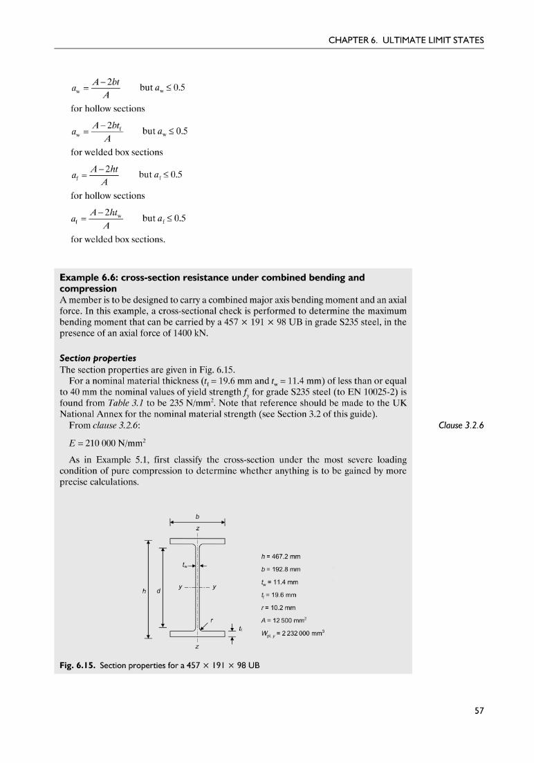
Delivered by ICEVirtualLibrary.com to:
IP: 95.42.11.157
On: Sun, 11 Jul 2010 21:35:24

Delivered by ICEVirtualLibrary.com to:
IP: 95.42.11.157
On: Sun, 11 Jul 2010 21:35:24

Delivered by ICEVirtualLibrary.com to:
IP: 95.42.11.157
On: Sun, 11 Jul 2010 21:35:24
= 524.5 kN m
fi
ConclusionClause 6.2.9In order to satisfy the cross-sectional checks of clause 6.2.9, the maximum bending
moment that can be carried by a 457 × 191 × 98 UB in grade S235 steel, in the presenceof an axial force of 1400 kN is 342.2 kN m.
Class 1 and 2 cross-sections: bi-axial bending with or without axial force
Clause 6.2.9.1(6)
As in BS 5950: Part 1, EN 1993-1-1 treats bi-axial bending as a subset of the rules forcombined bending and axial force. Checks for Class 1 and 2 cross-sections subjected tobi-axial bending, with or without axial forces, are set out in clause 6.2.9.1(6). Althoughthe simple linear interaction expression of equation (6.2) may be used, equation (6.41)represents a more sophisticated convex interaction expression, which can result in significantimprovements in efficiency:
(6.41)
Clause 6.2.9(6)in which α and β are constants, as defined below. Clause 6.2.9(6) allows α and β to be taken asunity, thus reverting to a conservative linear interaction.
For I and H sections:
α = 2 and β = 5n but β ≥ 1
For circular hollow sections:
α = 2 and β = 2
For rectangular hollow sections:
but α = β £ 6
Figure 6.16 shows the bi-axial bending interaction curves (for Class 1 and 2 cross-sections)for some common cases.
59
CHAPTER 6. ULTIMATE LIMIT STATES
, Ed , Ed
N, , Rd N, , Rd
1y z
y z
M M
M M
α βÊ ˆ Ê ˆ+ £Á ˜ Á ˜Ë ¯Ë ¯
N, , Rd1 0.48
524.5 342.2 kN m1 (0.5 0.40)yM
-= ¥ =
- ¥
pl ypl, , Rd
M0
2 232 000 2351.0y
W fM
γ¥
= =
0.0
0.2
0.4
0.6
0.8
1.0
1.2
0.0 0.2 0.4 0.6 0.8 1.0 1.2
Linear interaction
I and H sections (n = 0.2)
I and H sections (n = 0.4) and CHS
I and H sections (n = 0.6)
My, Ed/MN, y, Rd
Mz, Ed/MN, z, Rd
Fig. 6.16. Bi-axial bending interaction curves
2
1.661 1.13n
α β= =-
69Guide to Eurocode 1993 - CRC02 December 2004 11:54:01
Color profile: DisabledComposite Default screen

Delivered by ICEVirtualLibrary.com to:
IP: 95.42.11.157
On: Sun, 11 Jul 2010 21:35:24
Class 3 cross-sections: generalClause 6.2.9.2 For Class 3 cross-sections, clause 6.2.9.2 permits only a linear interaction of stresses arising
from combined bending moments and axial force, and limits the maximum fibre stress (in thelongitudinal x-direction of the member) to the yield stress, fy divided by the partial factor γM0,as below:
(6.42)
As when considering compression and bending in isolation, allowances for fastener holesshould be made in the unusual cases of slotted or oversized holes or where there are holesthat contain no fasteners.
Class 4 cross-sections: general
Clause 6.2.9.3As for Class 3 cross-sections, Class 4 sections subjected to combined bending and axial force(clause 6.2.9.3) are also designed based on a linear interaction of stresses, with the maximumfibre stress (in the longitudinal x-direction of the member) limited to the yield stress fy
divided by the partial factor γM0, as given by equation (6.42).
Clause 6.2.2.5(4)
However, for Class 4 cross-sections the stresses must be calculated on the basis of theeffective properties of the section, and allowance must be made for the additional stressesresulting from the shift in neutral axis between the gross cross-section and the effectivecross-section (see Fig. 6.17, clause 6.2.2.5(4) and Chapter 13 of this guide).
The resulting interaction expression that satisfies equation (6.42), and includes the bendingmoments induced as a result of the shift in neutral axis is given by equation (6.44):
(6.44)
where
Aeff is the effective area of the cross-section under pure compressionWeff, min is the effective section modulus about the relevant axis, based on the extreme fibre
that reaches yield firsteN is the shift in the relevant neutral axis.
6.2.10. Bending, shear and axial force
Clause 6.2.10Clause 6.2.6
Clause 6.2.9
The design of cross-sections subjected to combined bending, shear and axial force is coveredin clause 6.2.10. However, provided the shear force VEd is less than 50% of the design plasticshear resistance Vpl, Rd (clause 6.2.6), and provided shear buckling is not a concern (seeSection 6.2.8 of this guide and clause 5.1 of EN 1993-1-5), then the cross-section need onlysatisfy the requirements for bending and axial force (clause 6.2.9).
Clause 6.2.8Clause 6.2.9
In cases where the shear force does exceed 50% of the design plastic shear resistance ofthe cross-section, then a reduced yield strength should be calculated for the shear area (asdescribed in clause 6.2.8); the cross-section, with a reduced strength shear area, maysubsequently be checked for bending and axial force according to clause 6.2.9. As an
60
DESIGNERS’ GUIDE TO EN 1993-1-1
, Ed Ed N , Ed Ed NEd
eff y M0 eff, , min y M0 eff, , min y M0
1/ / /
y y z z
y z
M N e M N eNA f W f W fγ γ γ
+ ++ + £
y, Ed
M0x
fσ
γ=
eN
(a) (b)
G
G¢
G
Fig. 6.17. Shift in neutral axis from (a) gross to (b) effective cross-section
70Guide to Eurocode 1993 - CRC02 December 2004 11:54:01
Color profile: DisabledComposite Default screen

Delivered by ICEVirtualLibrary.com to:
IP: 95.42.11.157
On: Sun, 11 Jul 2010 21:35:24
alternative to reducing the strength of the shear area, an equivalent reduction to thethickness is also allowed; this may simplify calculations.
6.3. Buckling resistance of membersClause 6.3
Clause 6.3.1Clause 6.3.2Clause 6.3.3
Clause 6.3 covers the buckling resistance of members. Guidance is provided for uniformcompression members susceptible to flexural, torsional and torsional–flexural buckling (seeclause 6.3.1), uniform bending members susceptible to lateral torsional buckling (see clause6.3.2), and uniform members subjected to a combination of bending and axial compression(see clause 6.3.3). For member design, no account need be taken for fastener holes at themember ends.
Clauses 6.3.1to 6.3.3
Clause 5.3.4
Clauses 6.3.1 to 6.3.3 are applicable to uniform members, defined as those with a constantcross-section along the full length of the member (and additionally, in the case of compressionmembers, the load should be applied uniformly). For non-uniform members, such as thosewith tapered sections, or for members with a non-uniform distribution of compression forcealong their length (which may arise, for example, where framing-in members apply forcesbut offer no significant lateral restraint), Eurocode 3 provides no design expressions forcalculating buckling resistances; it is, however, noted that a second-order analysis using themember imperfections according to clause 5.3.4 may be used to directly determine memberbuckling resistances.
6.3.1. Uniform members in compressionGeneralThe Eurocode 3 approach to determining the buckling resistance of compression members isbased on the same principles as that of BS 5950. Although minor technical differences exist,the primary difference between the two codes is in the presentation of the method.
Buckling resistance
Clause 6.3.3
The design compression force is denoted by NEd (axial design effect). This must be shown tobe less than or equal to the design buckling resistance of the compression member, Nb, Rd
(axial buckling resistance). Members with non-symmetric Class 4 cross-sections have to bedesigned for combined bending and axial compression because of the additional bendingmoments, DMEd, that result from the shift in neutral axis from the gross cross-section to theeffective cross-section (multiplied by the applied compression force). The design of uniformmembers subjected to combined bending and axial compression is covered in clause 6.3.3.
Clause 6.3.1Compression members with Class 1, 2 and 3 cross-sections and symmetrical Class 4
cross-sections follow the provisions of clause 6.3.1, and the design buckling resistance shouldbe taken as
for Class 1, 2 and 3 cross-sections (6.47)
for (symmetric) Class 4 cross-sections (6.48)
where χ is the reduction factor for the relevant buckling mode (flexural, torsional ortorsional flexural). These buckling modes are discussed later in this section.
Buckling curvesThe buckling curves defined by EN 1993-1-1 are equivalent to those set out in BS 5950: Part 1in tabular form in Table 24 (with the exception of buckling curve a0, which does not appear inBS 5950). Regardless of the mode of buckling, the basic formulations for the buckling curvesremain unchanged, and are as given below:
61
CHAPTER 6. ULTIMATE LIMIT STATES
yb, Rd
M1
AfN
χ
γ=
eff yb, Rd
M1
A fN
χ
γ=
71Guide to Eurocode 1993 - CRC02 December 2004 11:54:02
Color profile: DisabledComposite Default screen

Delivered by ICEVirtualLibrary.com to:
IP: 95.42.11.157
On: Sun, 11 Jul 2010 21:35:24
but χ £ 1.0 (6.49)
where
for Class 1, 2 and 3 cross-sections
for Class 4 cross-sections
α is an imperfection factorNcr is the elastic critical buckling force for the relevant buckling mode based on the
gross properties of the cross-section.
The non-dimensional slendernessλ , as defined above, is in a generalized format requiringthe calculation of the elastic critical force Ncr for the relevant buckling mode. The relevantbuckling mode that governs design will be that with the lowest critical buckling force Ncr.Calculation of Ncr, and hence λ , for the various buckling modes is described in the followingsection.
Clause 6.3.1.2(3)
As shown in Fig. 6.18, EN 1993-1-1 defines five buckling curves, labelled a0, a, b, c and d.The shapes of these buckling curves are altered through the imperfection factor α; the fivevalues of the imperfection factor α for each of these curves are given in Table 6.1 of the code(reproduced here as Table 6.4). It is worth noting that as an alternative to using the bucklingcurve formulations described above, clause 6.3.1.2(3) allows the buckling reduction factor tobe determined graphically directly from Fig. 6.4 of the code (reproduced here as Fig. 6.18).
Clause 6.2
From the shape of the buckling curves given in Fig. 6.18 it can be seen, in all cases, that forvalues of non-dimensional slendernessλ £ 0.2 the buckling reduction factor is equal to unity.This means that for compression members of stocky proportions (λ £ 0.2, or, in terms ofelastic critical forces, for NEd /Ncr £ 0.04) there is no reduction to the basic cross-sectionresistance. In this case, buckling effects may be ignored and only cross-sectional checks(clause 6.2) need be applied.
62
DESIGNERS’ GUIDE TO EN 1993-1-1
eff y
cr
A f
Nλ =
20.5[1 ( 0.2) ]Φ α λ λ= + - +
y
cr
Af
Nλ =
2 2
1χ
Φ Φ λ=
+ -
0.0
0.2
0.4
0.6
0.8
1.0
1.2
0.0 0.5 1.0 1.5 2.0 2.5
Curve a0
Curve a
Curve b
Curve c
Curve d
Red
uctio
n fa
ctor
, c
Non-dimensional slenderness, l
Fig. 6.18. EN 1993-1-1 buckling curves
72Guide to Eurocode 1993 - CRC02 December 2004 11:54:02
Color profile: DisabledComposite Default screen

Delivered by ICEVirtualLibrary.com to:
IP: 95.42.11.157
On: Sun, 11 Jul 2010 21:35:24
63
CHAPTER 6. ULTIMATE LIMIT STATES
Table 6.4. Imperfection factors for buckling curves (Table 6.1 of EN 1993-1-1)
Buckling curve a0 a b c d
Imperfection factor α 0.13 0.21 0.34 0.49 0.76
Table 6.5. Selection of buckling curve for a cross-section (Table 6.2 of EN 1993-1-1)
Cross section Limits
Bucklingaboutaxis
Buckling curve
S 235S 275S 355S 420 S 460
tf £ 40 mm y – yz – z
ab
a0
a0
40 mm < tf £ 100 y – yz – z
bc
aa
tf £ 100 mm y – yz – z
bc
aa
tf > 100 mm y – yz – z
dd
cc
tf £ 40 mm y – yz – z
bc
bc
tf > 40 mm y – yz – z
cd
cd
hot finished any a a0
cold formed any c c
generally (except asbelow)
any b b
thick welds: a > 0.5tf
b/tf < 30h/tw <30
any c c
any c c
any b b
h/b
£1.
2h/
b>
1.2
Wel
ded
I-se
ctio
nsRo
lled
sect
ions
Hol
low
sect
ions
Wel
ded
box
sect
ions
L-se
ctio
nsU
-,T-
and
solid
sect
ions
tt ff
y y y y
z z
z z
t
t
f
b
h yy
z
z
w
h y y
ztf
b
z
73Guide to Eurocode 1993 - CRC02 December 2004 11:54:03
Color profile: DisabledComposite Default screen

Delivered by ICEVirtualLibrary.com to:
IP: 95.42.11.157
On: Sun, 11 Jul 2010 21:35:24
The choice as to which buckling curve (imperfection factor) to adopt is dependent uponthe geometry and material properties of the cross-section and upon the axis of buckling. Theappropriate buckling curve should be determined from Table 6.5 (Table 6.2 of EN 1993-1-1),which is equivalent to the ‘allocation of strut curve’ table (Table 23) of BS 5950: Part 1.
Non-dimensional slenderness for various buckling modesClause 6.3.1.3Clause 6.3.1.4
EN 1993-1-1 provides guidance for flexural (clause 6.3.1.3), torsional (clause 6.3.1.4) andflexural–torsional (clause 6.3.1.4) buckling modes. For standard hot-rolled and weldedstructural cross-sections, flexural buckling is the predominant buckling mode, and hencegoverns design in the vast majority of cases.
Buckling modes with torsional components are generally limited to cold-formed membersfor two principal reasons:
• cold-formed cross-sections contain relatively thin material, and torsional stiffness isassociated with the material thickness cubed
• the cold-forming process gives a predominance of open sections because these can beeasily produced from flat sheet. Open sections have inherently low torsional stiffness.
Clause 6.3.1.3
Flexural buckling of a compression member is characterized by excessive lateral deflectionsin the plane of the weaker principal axis of the member. As the slenderness of the columnincreases, the load at which failure occurs reduces. Calculation of the non-dimensionalslenderness for flexural buckling is covered in clause 6.3.1.3.
The non-dimensional slenderness λ is given by
for Class 1, 2 and 3 cross-sections (6.50)
for Class 4 cross-sections (6.51)
where
Lcr is the buckling length of the compression member in the plane under consideration,and is equivalent to the effective length LE in BS 5950 (buckling lengths arediscussed in the next section)
i is the radius of gyration about the relevant axis, determined using the grossproperties of the cross-section (assigned the symbols rx and ry in BS 5950 for theradius of gyration about the major and minor axes, respectively)
(fy in N/mm2)
Clearly, the BS 5950 definition of slenderness (λ = LE/ry) is already ‘non-dimensional’, butthe advantage of the Eurocode 3 definition of ‘non-dimensional slenderness’ λ , whichincludes the material properties of the compression member through λ1, is that all variablesaffecting the theoretical buckling load of a perfect pin-ended (Euler) column are nowpresent. This allows a more direct comparison of susceptibility to flexural buckling to bemade for columns with varying material strength. Further,λ is useful for relating the columnslenderness to the theoretical point at which the squash load and the Euler critical bucklingload coincide, which always occurs at the value of non-dimensional slenderness λ equalto 1.0.
As stated earlier, flexural buckling is by far the most common buckling mode forconventional hot-rolled structural members. However, particularly for thin-walled and opensections, the designer should also check for the possibility that the torsional or torsional–flexural buckling resistance of a member may be less than the flexural buckling resistance.Torsional and torsional–flexural buckling are discussed further in Section 13.7 of this guide.
64
DESIGNERS’ GUIDE TO EN 1993-1-1
y cr
cr 1
1Af LN i
λλ
= =
eff y effcr
cr 1
/A f A ALN i
λλ
= =
1y y
23593.9 and
Ef f
λ π ε ε= = =
74Guide to Eurocode 1993 - CRC02 December 2004 11:54:03
Color profile: DisabledComposite Default screen

Delivered by ICEVirtualLibrary.com to:
IP: 95.42.11.157
On: Sun, 11 Jul 2010 21:35:24
Clause 6.3.1.4Calculation of the non-dimensional slenderness λT for torsional and torsional–flexural
buckling is covered in clause 6.3.1.4, and should be taken as
for Class 1, 2 and 3 cross-sections (6.52)
for Class 4 cross-sections (6.53)
where
Ncr = Ncr, TF but Ncr £ Ncr, T
Ncr, TF is the elastic critical torsional–flexural buckling force (see Section 13.7 of thisguide)
Ncr, T is the elastic critical torsional buckling force (see Section 13.7 of this guide).
The generic definition ofλT is the same as the definition ofλT for flexural buckling, exceptthat now the elastic critical buckling force is that for torsional–flexural buckling (with theproviso that this is less than that for torsional buckling). Formulae for determining Ncr, T andNcr, TF are not provided in EN 1993-1-1, but may be found in Part 1.3 of the code, and inSection 13.7 of this guide. Buckling curves for torsional and torsional–flexural buckling maybe selected on the basis of Table 6.5 (Table 6.2 of EN 1993-1-1), and by assuming buckling tobe about the minor (z–z) axis.
Buckling lengths Lcr
Comprehensive guidance on buckling lengths for compression members with different endconditions is not provided in Eurocode 3, partly because no common consensus betweenthe contributing countries could be reached. Some guidance on buckling lengths forcompression members in triangulated and lattice structures is given in Annex BB ofEurocode 3. The provisions of Annex BB are discussed in Chapter 11 of this guide.
Typically, UK designers have been uncomfortable with the assumption of fully fixed endconditions, on the basis that there is inevitably a degree of flexibility in the connections.BS 5950: Part 1 therefore generally offers effective (or buckling) lengths that are lessoptimistic than the theoretical values. In the absence of Eurocode 3 guidance, it is thereforerecommended that the BS 5950 buckling lengths be adopted. Table 6.6 contains the buckling
65
CHAPTER 6. ULTIMATE LIMIT STATES
yT
cr
Af
Nλ =
eff yT
cr
A f
Nλ =
Table 6.6. Nominal buckling lengths Lcr for compression members
End restraint (in the plane under consideration) Buckling length, Lcr
Effectively held in position atboth ends
Effectively restrained in direction atboth ends
0.7L
Partially restrained in direction atboth ends
0.85L
Restrained in direction at one end 0.85L
Not restrained in direction at either end 1.0L
One end Other end Buckling length, Lcr
Effectively held in positionand restrained in direction
Not held in position Effectively restrained indirection
1.2L
Partially restrained indirection
1.5L
Not restrained in direction 2.0L
75Guide to Eurocode 1993 - CRC02 December 2004 11:54:03
Color profile: DisabledComposite Default screen

Delivered by ICEVirtualLibrary.com to:
IP: 95.42.11.157
On: Sun, 11 Jul 2010 21:35:24
lengths provided in clause 4.7.3 of BS 5950: Part 1; these buckling lengths are not to beapplied to angles, channels or T sections, for which reference should be made to clause 4.7.10of BS 5950: Part 1. The boundary conditions and corresponding buckling lengths areillustrated in Fig. 6.19, where L is equal to the system length.
Example 6.7: buckling resistance of a compression memberA circular hollow section (CHS) member is to be used as an internal column in amulti-storey building. The column has pinned boundary conditions at each end, and theinter-storey height is 4 m, as shown in Fig. 6.20. The critical combination of actions resultsin a design axial force of 1630 kN. Assess the suitability of a hot-rolled 244.5 × 10 CHS ingrade S275 steel for this application.
Section propertiesThe section properties are given in Fig. 6.21.
66
DESIGNERS’ GUIDE TO EN 1993-1-1
Fixed
Fixed Partialrestraintin direction
Partialrestraintin direction
Fixed Pinned Fixed Fixed Fixed
Pinned PinnedFree inposition Free
0.7L 0.85L 0.85L 1.0L 1.2L 1.5L 2.0L
Fig. 6.19. Nominal buckling lengths Lcr for compression members
4.0 m
NEd = 1630 kN
Fig. 6.20. General arrangement and loading
t
d
d = 244.5 mm
t = 10.0 mm
A = 7370 mm2
Wel, y = 415 000 mm3
Wpl, y = 550 000 mm3
I = 50 730 000 mm4
Fig. 6.21. Section properties for 244.5 × 10 CHS
76Guide to Eurocode 1993 - CRC02 December 2004 11:54:04
Color profile: DisabledComposite Default screen

Delivered by ICEVirtualLibrary.com to:
IP: 95.42.11.157
On: Sun, 11 Jul 2010 21:35:24

Delivered by ICEVirtualLibrary.com to:
IP: 95.42.11.157
On: Sun, 11 Jul 2010 21:35:24
Buckling curves
Φ = 0.5[1 + 0.21 × (0.56 – 0.2) + 0.562] = 0.69
\
1836.5 > 1630 kN \ buckling resistance is acceptable
ConclusionThe chosen cross-section, 244.5 × 10 CHS, in grade S275 steel is acceptable.
6.3.2. Uniform members in bendingGeneral
Clause 6.3.2
Laterally unrestrained beams subjected to bending about their major axis have to be checkedfor lateral torsional buckling (as well as for cross-sectional resistance), in accordance withclause 6.3.2. As described in Section 6.2.5 of this guide, there are a number of commonsituations where lateral torsional buckling need not be considered, and member strengthsmay be assessed on the basis of the in-plane cross-sectional strength.
EN 1993-1-1 contains three methods for checking the lateral torsional stability of astructural member:
Clause 6.3.2.2Clause 6.3.2.3
• The primary method adopts the lateral torsional buckling curves given by equations(6.56) and (6.57), and is set out in clause 6.3.2.2 (general case) and clause 6.3.2.3 (forrolled sections and equivalent welded sections). This method is discussed later in thissection of the guide.
Clause 6.3.2.4• The second is a simplified assessment method for beams with restraints in buildings, and
is set out in clause 6.3.2.4. This method is discussed later in this section of the guide.
Clause 6.3.4• The third is a general method for lateral and lateral torsional buckling of structural
components, given in clause 6.3.4 and discussed in the corresponding section of thisguide.
Designers familiar with BS 5950 will be accustomed to simplified calculations, wheredetermination of the elastic critical moment for lateral torsional buckling Mcr is aided, forexample, by inclusion of the geometric quantities ‘u’ and ‘v’ in section tables. Such simplificationsdo not appear in the primary Eurocode method; calculation of Mcr is discussed later in thissection of the guide.
Lateral restraintClause 6.3.2.1(2) Clause 6.3.2.1(2) deems that ‘beams with sufficient lateral restraint to the compression flange
are not susceptible to lateral torsional buckling’, though there is little guidance on what is to beregarded as ‘sufficient’. Annex BB offers some guidance on the level of lateral restraint thatmay be provided by trapezoidal sheeting; Annex BB is discussed in Chapter 11 of this guide.
In order to be effective, lateral restraints need to possess adequate stiffness and strengthto inhibit lateral deflection of the compression flange. In the absence of explicit Eurocodeguidance, it is recommended that the provisions of clauses 4.3.2 and 4.3.3 of BS 5950: Part 1be followed, whereby intermediate lateral restraints are required to be capable of resisting atotal force of not less than 2.5% of the maximum design axial force in the compression flangewithin the relevant span, divided between the intermediate lateral restraints in proportion totheir spacing. Further guidance on lateral restraint is available.7
68
DESIGNERS’ GUIDE TO EN 1993-1-1
2 2
1
0.69 0.69 0.56χ =
+ -
3b, Rd
0.91 7370 2751836.5 10 N 1836.5 kN
1.0N
¥ ¥= = ¥ =
78Guide to Eurocode 1993 - CRC02 December 2004 11:54:04
Color profile: DisabledComposite Default screen

Delivered by ICEVirtualLibrary.com to:
IP: 95.42.11.157
On: Sun, 11 Jul 2010 21:35:24
Lateral torsional buckling resistanceThe design bending moment is denoted by MEd (bending moment design effect), and thelateral torsional buckling resistance by Mb, Rd (buckling resistance moment). Clearly, MEd
must be shown to be less than Mb, Rd, and checks should be carried out on all unrestrainedsegments of beams (between the points where lateral restraint exists).
The design buckling resistance of a laterally unrestrained beam (or segment of beam)should be taken as
(6.55)
where Wy is the section modulus appropriate for the classification of the cross-section, asgiven below. In determining Wy, no account need be taken for fastener holes at the beamends.
Wy = Wpl, y for Class 1 or 2 cross-sections
Wy = Wel, y for Class 3 cross-sections
Wy = Weff, y for Class 4 cross-sections
χLT is the reduction factor for lateral torsional buckling.From equation (6.55), a clear analogy between the treatment of the buckling of bending
members and the buckling of compression members can be seen. In both cases, the bucklingresistance comprises a reduction factor (χ for compression; χLT for bending) multiplied bythe cross-section strength (Afy /γM1 for compression; Wy fy /γM1 for bending).
Lateral torsional buckling curvesThe lateral torsional buckling curves defined by EN 1993-1-1 are equivalent to (but not thesame as) those set out in BS 5950: Part 1 in tabular form in Tables 16 and 17. Eurocode 3provides four lateral torsional buckling curves (selected on the basis of the overall height-to-width ratio of the cross-section, the type of cross-section and whether the cross-section isrolled or welded), whereas BS 5950 offers only two curves (only making a distinctionbetween rolled and welded sections).
Eurocode 3 defines lateral torsional buckling curves for two cases:Clause 6.3.2.2• the general case (clause 6.3.2.2)Clause 6.3.2.3• rolled sections or equivalent welded sections (clause 6.3.2.3).
Clause 6.3.2.2Clause 6.3.2.3
Clause 6.3.2.2, the general case, may be applied to all common section types, includingrolled sections, but, unlike clause 6.3.2.3, it may also be applied outside the standard range ofrolled sections. For example, it may be applied to plate girders (of larger dimensions thanstandard rolled sections) and to castellated and cellular beams.
Clause 6.3.2.2Lateral torsional buckling curves for the general case (clause 6.3.2.2) are describedthrough equation (6.56):
but χLT £ 1.0 (6.56)
where
αLT is an imperfection factor from Table 6.7 (Table 6.3 of EN 1993-1-1)Mcr is the elastic critical moment for lateral torsional buckling (see the following
subsection).
69
CHAPTER 6. ULTIMATE LIMIT STATES
yb, Rd LT
M1y
fM Wχ
γ=
LT 2 2LT LT LT
1χ
Φ Φ λ=
+ -
2LT LT LT LT0.5[1 ( 0.2) ]Φ α λ λ= + - +
yLT
cr
yW f
Mλ =
79Guide to Eurocode 1993 - CRC02 December 2004 11:54:04
Color profile: DisabledComposite Default screen

Delivered by ICEVirtualLibrary.com to:
IP: 95.42.11.157
On: Sun, 11 Jul 2010 21:35:24

Delivered by ICEVirtualLibrary.com to:
IP: 95.42.11.157
On: Sun, 11 Jul 2010 21:35:24
National choice is also allowed for the values of the two parameters λLT, 0 and β, thoughEN 1993-1-1 indicates that λLT, 0 may not be taken as greater than 0.4, and β not less than0.75. For UK construction, reference should be made to the UK National Annex.
Clause 6.3.2.3The method of clause 6.3.2.3 also includes an additional factor f that is used to modify χLT
(as shown by equation (6.58)),
but χLT, mod £ 1 (6.58)
offering further enhancement in lateral torsional buckling resistance.The factor f was derived on the basis of a numerical study, as
f = 1 – 0.5(1 – kc)[1 – 2.0(λLT, 0 – 0.8)2] (D6.8)
and is dependent upon the shape of the bending moment diagram between lateral restraints(Table 6.10 – Table 6.6 of EN 1993-1-1). It is yet to be universally accepted, and it is thereforelikely that the UK National Annex will set f equal to unity.
Clause 6.3.2.2Clause 6.3.2.3
Figure 6.22 compares the lateral torsional buckling curves of the general case (clause6.3.2.2) and the case for rolled sections or equivalent welded sections (clause 6.3.2.3). Theimperfection factor αLT for buckling curve b has been used for the comparison. Overall, itmay be seen that the curve for the rolled and equivalent welded case is more favourable thanthat for the general case, but of particular interest is the plateau length of the curves. Sinceno lateral torsional buckling checks are required within this plateau length (and resistancemay simply be based on the in-plane cross-section strength), clause 6.3.2.3 may offersignificant savings in calculation effort for some arrangements.
Elastic critical moment for lateral torsional buckling Mcr
Clause 6.3.2.2(2)
As shown in the previous section, determination of the non-dimensional lateral torsionalbuckling slenderness λLT first requires calculation of the elastic critical moment for lateraltorsional buckling Mcr. However, Eurocode 3 offers no formulations and gives no guidanceon how Mcr should be calculated, except to say that Mcr should be based on gross cross-sectional properties and should take into account the loading conditions, the real momentdistribution and the lateral restraints (clause 6.3.2.2(2)). Reasons for the omission of suchformulations include the complexity of the subject and a lack of consensus between thecontributing nations; by many, it is regarded as ‘textbook material’.
71
CHAPTER 6. ULTIMATE LIMIT STATES
LTLT, mod f
χχ =
Table 6.10. Correction factors kc (Table 6.6 of EN 1993-1-1)
Moment distribution kc
1.0
11.33 0.33− y
0.94
0.90
0.91
0.86
0.77
0.82
–1 £ y £ 1
y = 1
81Guide to Eurocode 1993 - CRC02 December 2004 11:54:06
Color profile: DisabledComposite Default screen

Delivered by ICEVirtualLibrary.com to:
IP: 95.42.11.157
On: Sun, 11 Jul 2010 21:35:24
The elastic critical moment for lateral torsional buckling of a beam of uniformsymmetrical cross-section with equal flanges, under standard conditions of restraint at eachend, loaded through the shear centre and subject to uniform moment is given by equation(D6.9):
(D6.9)
where
IT is the torsion constantIw is the warping constantIz is the second moment of area about the minor axisLcr is the length of the beam between points of lateral restraint.
The standard conditions of restraint at each end of the beam are: restrained against lateralmovement, restrained against rotation about the longitudinal axis and free to rotate on plan.Equation (D6.9) was provided in ENV 1993-1-1 (1992) in an informative Annex, and hasbeen shown, for example by Timoshenko and Gere,8 to represent the exact analyticalsolution to the governing differential equation.
Numerical solutions have also been calculated for a number of other loading conditions.For uniform doubly symmetric cross-sections, loaded through the shear centre at the level ofthe centroidal axis, and with the standard conditions of restraint described above, Mcr may becalculated through equation (D6.10):
(D6.10)
where C1 may be determined from Table 6.11 for end moment loading and from Table 6.12for transverse loading. The C1 factor is used to modify Mcr, 0 (i.e. Mcr = C1Mcr, 0) to takeaccount of the shape of the bending moment diagram, and performs a similar function to the‘m’ factor adopted in BS 5950.
72
DESIGNERS’ GUIDE TO EN 1993-1-1
0.52 2w cr T
cr, 0 2 2cr
z
z z
EI I L GIM
IL EI
Ê ˆ= +Á ˜Ë ¯
ππ
2(1 )E
Gυ
=+
0.00
0.20
0.40
0.60
0.80
1.00
1.20
0.0 0.5 1.0 1.5 2.5
cLT
lLT
General case
Rolled and equivalentwelded case
2.0
Fig. 6.22. Lateral torsional buckling curves for the general case and for rolled sections or equivalentwelded sections
0.52 2w cr T
cr 1 2 2cr
z
z z
EI I L GIM C
IL EI
Ê ˆ= +Á ˜Ë ¯
ππ
82Guide to Eurocode 1993 - CRC02 December 2004 11:54:06
Color profile: DisabledComposite Default screen

Delivered by ICEVirtualLibrary.com to:
IP: 95.42.11.157
On: Sun, 11 Jul 2010 21:35:24
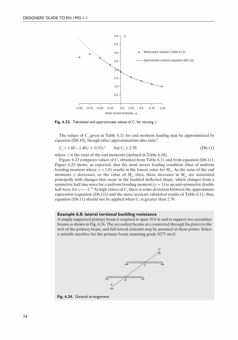
Delivered by ICEVirtualLibrary.com to:
IP: 95.42.11.157
On: Sun, 11 Jul 2010 21:35:24
The values of C1 given in Table 6.11 for end moment loading may be approximated byequation (D6.10), though other approximations also exist:9
C1 = 1.88 – 1.40ψ + 0.52ψ2 but C1 £ 2.70 (D6.11)
where ψ is the ratio of the end moments (defined in Table 6.10).Figure 6.23 compares values of C1 obtained from Table 6.11 and from equation (D6.11).
Figure 6.23 shows, as expected, that the most severe loading condition (that of uniformbending moment where ψ = 1.0) results in the lowest value for Mcr. As the ratio of the endmoments ψ decreases, so the value of Mcr rises; these increases in Mcr are associatedprincipally with changes that occur in the buckled deflected shape, which changes from asymmetric half sine wave for a uniform bending moment (ψ = 1) to an anti-symmetric doublehalf wave for ψ = –1.10 At high values of C1 there is some deviation between the approximateexpression (equation (D6.11)) and the more accurate tabulated results of Table 6.11; thus,equation (D6.11) should not be applied when C1 is greater than 2.70.
Example 6.8: lateral torsional buckling resistanceA simply supported primary beam is required to span 10.8 m and to support two secondarybeams as shown in Fig. 6.24. The secondary beams are connected through fin plates to theweb of the primary beam, and full lateral restraint may be assumed at these points. Selecta suitable member for the primary beam assuming grade S275 steel.
74
DESIGNERS’ GUIDE TO EN 1993-1-1
0.5
1.0
1.5
2.0
2.5
3.0
3.5
4.0
–1.00 –0.75 –0.50 –0.25 0.0 0.25 0.5 0.75 1.00
Ratio of end moments, y
C1
'More exact' solution (Table 6.11)
Approximate solution (equation (D6.11))
Fig. 6.23. Tabulated and approximate values of C1 for varying ψ
D
C
B
A
Fig. 6.24. General arrangement
84Guide to Eurocode 1993 - CRC02 December 2004 11:54:08
Color profile: DisabledComposite Default screen

Delivered by ICEVirtualLibrary.com to:
IP: 95.42.11.157
On: Sun, 11 Jul 2010 21:35:24
The loading, shear force and bending moment diagrams for the arrangement of Fig.6.24 are shown in Fig. 6.25.
Clause 6.3.2.2For the purposes of this worked example, lateral torsional buckling curves for the
general case (clause 6.3.2.2) will be utilized.Lateral torsional buckling checks will be carried out on segments BC and CD. By
inspection, segment AB is not critical.Consider a 762 × 267 × 173 UB in grade S275 steel.
Section propertiesThe section properties are shown in Fig. 6.26.
75
CHAPTER 6. ULTIMATE LIMIT STATES
(a)
(b)
(c)
A D
1194 kN m 1362 kN m
B C
BM
A D
477.6 kN
267.1 kN
B
C
SF
52.5 kN
AB C
D
2.5 m 3.2 m 5.1 m
425.1 kN 319.6 kN
Fig. 6.25. (a) Loading, (b) shear forces and (c) bending moments
b
h d
tw
tf
r
yy
z
z
h = 762.2 mm
b = 266.7 mm
tw = 14.3 mm
tf = 21.6 mm
r = 16.5 mm
A = 22 000 mm2
Wy, pl = 6198 × 103 mm3
Iz = 68.50 × 106 mm4
It = 2670 × 103 mm4
Iw = 9390 × 109 mm6
Fig. 6.26. Section properties for a 762 × 267 × 173 UB
85Guide to Eurocode 1993 - CRC02 December 2004 11:54:08
Color profile: DisabledComposite Default screen

Delivered by ICEVirtualLibrary.com to:
IP: 95.42.11.157
On: Sun, 11 Jul 2010 21:35:24

Delivered by ICEVirtualLibrary.com to:
IP: 95.42.11.157
On: Sun, 11 Jul 2010 21:35:24

Delivered by ICEVirtualLibrary.com to:
IP: 95.42.11.157
On: Sun, 11 Jul 2010 21:35:24
Select buckling curve and imperfection factor αLT
Using Table 6.8 (Table 6.4 of EN 1993-1-1),
h/b = 762.2/266.7 = 2.85
Therefore, for a rolled I section with h/b > 2, use buckling curve b.For curve buckling curve b, αLT = 0.34 from Table 6.7 (Table 6.3 of EN 1993-1-1).
Calculate reduction factor for lateral torsional buckling, χLT: segment BC
but χLT £ 1.0 (6.56)
where
\
Lateral torsional buckling resistance: segment BC
(6.55)
Mb, Rd = 0.86 × 6198 × 103 × (275/1.0)Mb, Rd = 1469 × 106 N mm = 1469 kN m
0.93 £ 1.0 \ segment BC is acceptable
Clause 6.3.2.2 Lateral torsional buckling check (clause 6.3.2.2): segment CD
MEd = 1362 kN m
Determine Mcr: segment CD (Lcr = 5100 mm)
(D6.10)
Determine C1 from Table 6.11 (or approximate from equation (D6.11)):
ψ is the ratio of end moments = 0/1362 = 0
fi C1 = 1.879 from Table 6.11
\
Non-dimensional lateral torsional slenderness λ LT : segment CD
The buckling curve and imperfection factor αLT are as for segment BC.
78
DESIGNERS’ GUIDE TO EN 1993-1-1
LT 2 2
10.86
0.71 0.71 0.55χ = =
+ -
b, Rd LT yM1
yfM Wχγ
=
Ed
b, Rd
13620.93
1469M
M= =
LT 2 2LT LT LT
1χ
Φ Φ λ=
+ -
2LT LT LT LT
2
[1 ( 0.2) ]
0.5 [1 0.34 (0.55 0.2) 0.55 ] 0.71
Φ α λ λ= + - +
= ¥ + ¥ - + =
0.52 2w cr T
cr 1 2 2cr
z
z z
EI I L GIM C
IL EI
Ê ˆ= +Á ˜Ë ¯
ππ
0.52 6 2 39
cr 2 6 2 6
6
210 000 68.5 10 5100 81 000 2670 109390 101.879
5100 68.5 10 210 000 68.5 10
4311 10 N mm 4311 kN m
MÊ ˆ¥ ¥ ¥ ¥ ¥ ¥¥
= ¥ +Á ˜¥ ¥ ¥ ¥Ë ¯
= ¥ =
ππ
¥ ¥= = =
¥
3y
LT 6cr
6198 10 2750.63
4311 10yW f
Mλ
88Guide to Eurocode 1993 - CRC02 December 2004 11:54:09
Color profile: DisabledComposite Default screen
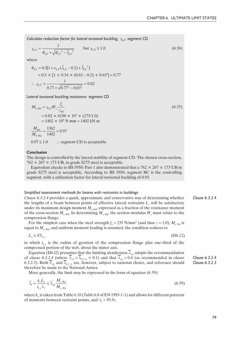
Delivered by ICEVirtualLibrary.com to:
IP: 95.42.11.157
On: Sun, 11 Jul 2010 21:35:24
Calculate reduction factor for lateral torsional buckling, χLT: segment CD
but χLT £ 1.0 (6.56)
where
ΦLT = 0.5 × [1 + 0.34 × (0.63 – 0.2) + 0.632] = 0.77
\
Lateral torsional buckling resistance: segment CD
(6.55)
Mb, Rd = 0.82 × 6198 × 103 × (275/1.0)Mb, Rd = 1402 × 106 N mm = 1402 kN m
0.97 £ 1.0 \ segment CD is acceptable
ConclusionThe design is controlled by the lateral stability of segment CD. The chosen cross-section,762 × 267 × 173 UB, in grade S275 steel is acceptable.
Equivalent checks to BS 5950: Part 1 also demonstrated that a 762 × 267 × 173 UB ingrade S275 steel is acceptable. According to BS 5950, segment BC is the controllingsegment, with a utilization factor for lateral torsional buckling of 0.93.
Simplified assessment methods for beams with restraints in buildingsClause 6.3.2.4Clause 6.3.2.4 provides a quick, approximate and conservative way of determining whether
the lengths of a beam between points of effective lateral restraints Lc will be satisfactoryunder its maximum design moment My, Ed, expressed as a fraction of the resistance momentof the cross-section Mc, Rd. In determining Mc, Rd, the section modulus Wy must relate to thecompression flange.
For the simplest case when the steel strength fy = 235 N/mm2 (and thus ε = 1.0), My, Ed isequal to Mc, Rd, and uniform moment loading is assumed, the condition reduces to
Lc £ 47if, z (D6.12)
in which if, z is the radius of gyration of the compression flange plus one-third of thecompressed portion of the web, about the minor axis.
Clause 6.3.2.4Clause 6.3.2.3
Equation (D6.l2) presumes that the limiting slenderness λc0 adopts the recommendationof clause 6.3.2.4 (where λc0 = λLT, 0 + 0.1) and that λc0 = 0.4 (as recommended in clause6.3.2.3). Both λc0 and λLT, 0 are, however, subject to national choice, and reference shouldtherefore be made to the National Annex.
More generally, the limit may be expressed in the form of equation (6.59):
(6.59)
where kc is taken from Table 6.10 (Table 6.6 of EN 1993-1-1) and allows for different patternsof moments between restraint points, and λ1 = 93.9ε.
CHAPTER 6. ULTIMATE LIMIT STATES
79
= =Ed
b, Rd
13620.97
1402M
M
LT 2 2LT LT LT
1χ
Φ Φ λ=
+ -
2LT LT LT LT0.5[1 ( 0.2) ]Φ α λ λ= + - +
LT 2 2
10.82
0.77 0.77 0.63χ = =
+ -
yb, Rd LT
M1y
fM Wχ
γ=
c, Rdc cf c0
f, 1 , Rdz y
Mk Li M
λ λλ
= £
89Guide to Eurocode 1993 - CRC02 December 2004 11:54:10
Color profile: DisabledComposite Default screen

Delivered by ICEVirtualLibrary.com to:
IP: 95.42.11.157
On: Sun, 11 Jul 2010 21:35:24
Clearly, if the required level of moment My, Ed is less than Mc, Rd, then the value of λf , andhence Lc, will increase pro rata.
6.3.3. Uniform members in bending and axial compressionMembers subjected to bi-axial bending and axial compression (beam–columns) exhibitcomplex structural behaviour. First-order bending moments about the major and minor axes(My, Ed and Mz,Ed, respectively) are induced by lateral loading and/or end moments. Theaddition of axial loading NEd clearly results in axial force in the member, but also amplifiesthe bending moments about both principal axes (second-order bending moments). Since, ingeneral, the bending moment distributions about both principal axes will be non-uniform(and hence the most heavily loaded cross-section can occur at any point along the length ofthe member), plus there is a coupling between the response in the two principal planes,design treatment is necessarily complex. The behaviour and design of beam–columns iscovered thoroughly by Chen and Atsuta.12
Clause 6.3.3
Clause 6.2
Although there is a coupling between the member response in the two principal planes,this is generally safely disregarded in design. Instead, a pair of interaction equations, whichessentially check member resistance about each of the principal axes (y–y and z–z) isemployed. In clause 6.3.3 such a pair of interaction equations is provided (see equations(6.61) and (6.62)) to check the resistance of individual lengths of members betweenrestraints, subjected to known bending moments and axial forces. Both interaction equationsmust be satisfied. Second-order sway effects (P–∆ effects) should be allowed for, either byusing suitably enhanced end moments or by using appropriate buckling lengths. It is alsospecifically noted that the cross-section resistance at each end of the member should bechecked against the requirements of clause 6.2.
Two classes of problem are recognized:
• members not susceptible to torsional deformation• members susceptible to torsional deformation.
The former is for cases where no lateral torsional buckling is possible, for example wheresquare or circular hollow sections are employed, as well as arrangements where torsionaldeformation is prevented, such as open sections restrained against twisting. Most I and Hsection columns in building frames are likely to fall within the second category.
At first sight, equations (6.61) and (6.62) appear similar to the equations given in clause4.8.3.3 of BS 5950: Part 1. However, determination of the interaction or k factors issignificantly more complex. Omitting the terms required only to account for the shift inneutral axis (from the gross to the effective section) for Class 4 cross-sections, the formulaeare
(6.61)
(6.62)
in which
NEd, My, Ed, Mz, Ed are the design values of the compression force and the maximummoments about the y–y and z–z axes along the member, respectively
NRk, My, Rk, Mz, Rk are the characteristic values of the compression resistance of thecross-section and the bending moment resistances of the cross-section about they–y and z–z axes, respectively
Clause 6.3.1 χy, χz are the reduction factors due to flexural buckling from clause 6.3.1Clause 6.3.2 χLT is the reduction factor due to lateral torsional buckling from clause 6.3.2, taken as
unity for members that are not susceptible to torsional deformationkyy, kyz, kzy, kzz are the interaction factors kij.
80
DESIGNERS’ GUIDE TO EN 1993-1-1
+ + £, Ed , EdEd
Rk M1 LT , Rk 1 , Rk MI
1/ / /
y zyy yz
y y M z
M MNk k
N M Mχ γ χ γ γ
, Ed , EdEd
Rk M1 LT , Rk M1 , Rk M1
1/ / /
y zzy zz
z y z
M MNk k
N M Mχ γ χ γ γ+ + £
90Guide to Eurocode 1993 - CRC02 December 2004 11:54:10
Color profile: DisabledComposite Default screen

Delivered by ICEVirtualLibrary.com to:
IP: 95.42.11.157
On: Sun, 11 Jul 2010 21:35:24
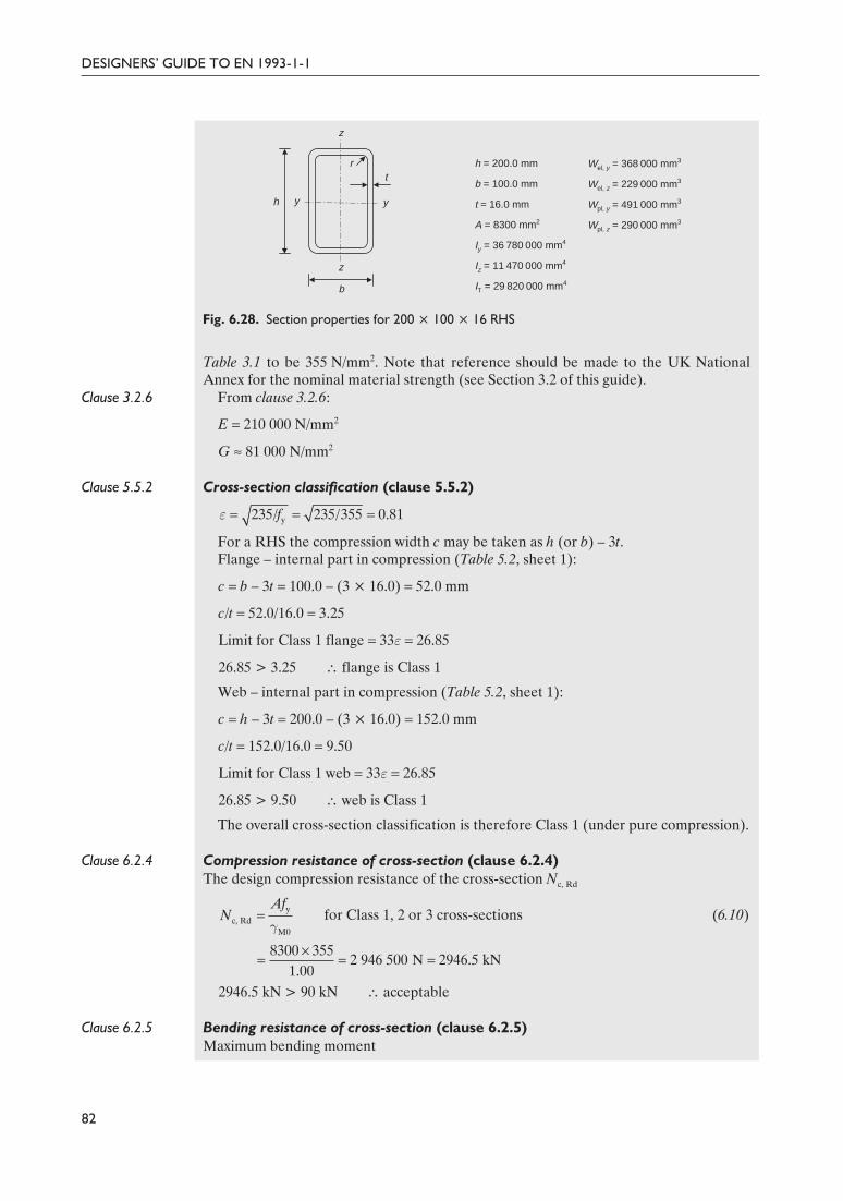
Delivered by ICEVirtualLibrary.com to:
IP: 95.42.11.157
On: Sun, 11 Jul 2010 21:35:24
Table 3.1 to be 355 N/mm2. Note that reference should be made to the UK NationalAnnex for the nominal material strength (see Section 3.2 of this guide).
Clause 3.2.6 From clause 3.2.6:
E = 210 000 N/mm2
G ª 81 000 N/mm2
Clause 5.5.2 Cross-section classification (clause 5.5.2)
For a RHS the compression width c may be taken as h (or b) – 3t.Flange – internal part in compression (Table 5.2, sheet 1):
c = b – 3t = 100.0 – (3 × 16.0) = 52.0 mm
c/t = 52.0/16.0 = 3.25
Limit for Class 1 flange = 33ε = 26.85
26.85 > 3.25 \ flange is Class 1
Web – internal part in compression (Table 5.2, sheet 1):
c = h – 3t = 200.0 – (3 × 16.0) = 152.0 mm
c/t = 152.0/16.0 = 9.50
Limit for Class 1 web = 33ε = 26.85
26.85 > 9.50 \ web is Class 1
The overall cross-section classification is therefore Class 1 (under pure compression).
Clause 6.2.4 Compression resistance of cross-section (clause 6.2.4)The design compression resistance of the cross-section Nc, Rd
for Class 1, 2 or 3 cross-sections (6.10)
2946.5 kN > 90 kN \ acceptable
Clause 6.2.5 Bending resistance of cross-section (clause 6.2.5)Maximum bending moment
DESIGNERS’ GUIDE TO EN 1993-1-1
82
= = =y235/ 235/355 0.81fε
t
b
r
h y y
z
z
h = 200.0 mm
b = 100.0 mm
t = 16.0 mm
A = 8300 mm2
Iy = 36 780 000 mm4
Iz = 11 470 000 mm4
IT = 29 820 000 mm4
Wel, y = 368 000 mm3
Wel, z = 229 000 mm3
Wpl, y = 491 000 mm3
Wpl, z = 290 000 mm3
Fig. 6.28. Section properties for 200 × 100 × 16 RHS
yc, Rd
M0
AfN
γ=
¥= = =c, Rd
8300 3552 946 500 N 2946.5 kN
1.00N
92Guide to Eurocode 1993 - CRC02 December 2004 11:54:11
Color profile: DisabledComposite Default screen

Delivered by ICEVirtualLibrary.com to:
IP: 95.42.11.157
On: Sun, 11 Jul 2010 21:35:24
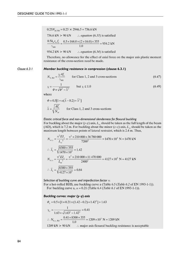
Delivered by ICEVirtualLibrary.com to:
IP: 95.42.11.157
On: Sun, 11 Jul 2010 21:35:24
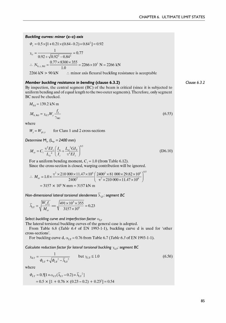
Delivered by ICEVirtualLibrary.com to:
IP: 95.42.11.157
On: Sun, 11 Jul 2010 21:35:24

Delivered by ICEVirtualLibrary.com to:
IP: 95.42.11.157
On: Sun, 11 Jul 2010 21:35:24
\
Lateral torsional buckling resistance: segment BC
(6.55)
Mb, Rd = 0.97 × 491 × 103 × (355/1.0)Mb, Rd = 169.5 × 10⁶ N mm = 169.5 kN m
0.82 £ 1.0 \ acceptable
Clause 6.3.3 Member buckling resistance in combined bending and axial compression(clause 6.3.3)Members subjected to combined bending and axial compression must satisfy bothequations (6.61) and (6.62).
(6.61)
(6.62)
Determination of interaction factors kij (Annex A)For this example, alternative method 1 (Annex A) will be used for the determination of theinteraction factors kij. There is no need to consider kyz and kzz in this case, since Mz, Ed = 0.
For Class 1 and 2 cross-sections
Non-dimensional slendernessesFrom the flexural buckling check:
λ y = 1.42 and λ z = 0.84 \ λmax = 1.42
From the lateral torsional buckling check:
λLT = 0.23 and λ0 = 0.23
Equivalent uniform moment factors Cmi
Torsional deformation is possible (λ0 > 0).From the bending moment diagram, ψy = 1.0.Therefore, from Table A.2,
86
DESIGNERS’ GUIDE TO EN 1993-1-1
Ed
b, Rd
139.20.82
169.5M
M= =
, Ed , EdEd
Rk M1 LT , Rk M1 , Rk MI
1/ / /
y zyy yz
y y z
M MNk k
N M Mχ γ χ γ γ+ + £
LT 2 2
10.97
0.54 0.54 0.23χ = =
+ -
yb, Rd LT
M1y
fM Wχ
γ=
, Ed , EdEd
Rk M1 LT , Rk M1 , Rk M1
1/ / /
y zzy zz
z y z
M MNk k
N M Mχ γ χ γ γ+ + £
m mLTEd cr,
11 /
yyy y
y yy
k C CN N C
µ=
-
m mLTEd cr,
10.6
1 /y y
zy yy zy z
wk C C
N N C w
µ=
-
Edm , 0
cr,
0.79 0.21 0.36( 0.33)y y yy
NC
Nψ ψ= + + -
m , 090
0.79 (0.21 1.0) 0.36 (1.0 0.33) 1.011470yC = + ¥ + ¥ - =
96Guide to Eurocode 1993 - CRC02 December 2004 11:54:12
Color profile: DisabledComposite Default screen
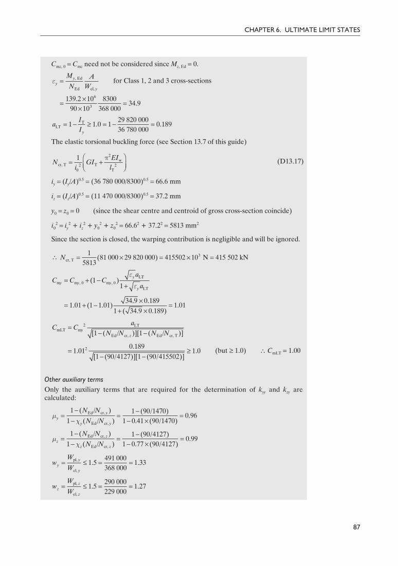
Delivered by ICEVirtualLibrary.com to:
IP: 95.42.11.157
On: Sun, 11 Jul 2010 21:35:24
Cmz, 0 = Cmz need not be considered since Mz, Ed = 0.
for Class 1, 2 and 3 cross-sections
The elastic torsional buckling force (see Section 13.7 of this guide)
(D13.17)
iy = (Iy/A)0.5 = (36 780 000/8300)0.5 = 66.6 mm
iz = (Iz/A)0.5 = (11 470 000/8300)0.5 = 37.2 mm
y0 = z0 = 0 (since the shear centre and centroid of gross cross-section coincide)
i02 = iy
2 + iz2 + y0
2 + z02 = 66.62 + 37.22 = 5813 mm2
Since the section is closed, the warping contribution is negligible and will be ignored.
\
(but ≥ 1.0) \ CmLT = 1.00
Other auxiliary termsOnly the auxiliary terms that are required for the determination of kyy and kzy arecalculated:
87
CHAPTER 6. ULTIMATE LIMIT STATES
2w
cr, T T2 20 T
1 EIN GI
i lÊ ˆ
= +Á ˜Ë ¯π
, Ed
Ed el,
yy
y
M AN W
ε =
6
3
139.2 10 830034.9
90 10 368 000yε¥
= =¥
TLT
29 820 0001 1.0 1 0.189
36 780 000y
Ia
I= - ≥ = - =
3cr, T
1(81 000 29 820 000) 415502 10 N 415 502 kN
5813N = ¥ = ¥ =
LTm m , 0 m , 0
LT
(1 )1
yy y y
y
aC C C
a
ε
ε= + -
+
m34.9 0.189
1.01 (1 1.01) 1.011 ( 34.9 0.189)yC
¥= + - =
+ ¥
2 LTmLT m
Ed cr, Ed cr, T[1 ( / )][1 ( / )]yz
aC C
N N N N=
- -
2mLT
0.1891.01 1.0
[1 (90/4127)][1 (90/415502)]C = ≥
- -
Ed cr,
Ed cr,
1 ( / ) 1 (90/1470)0.96
1 ( / ) 1 0.41 (90/1470)y
yy y
N N
N Nµ
χ
- -= = =
- - ¥
Ed cr,
Ed cr,
1 ( / ) 1 (90/4127)0.99
1 ( / ) 1 0.77 (90/4127)z
zz z
N N
N Nµ
χ- -
= = =- - ¥
pl,
el,
491 0001.5 1.33
368 000y
yy
Ww
W= £ = =
pl,
el,
290 0001.5 1.27
229 000z
zz
Ww
W= £ = =
97Guide to Eurocode 1993 - CRC02 December 2004 11:54:13
Color profile: DisabledComposite Default screen
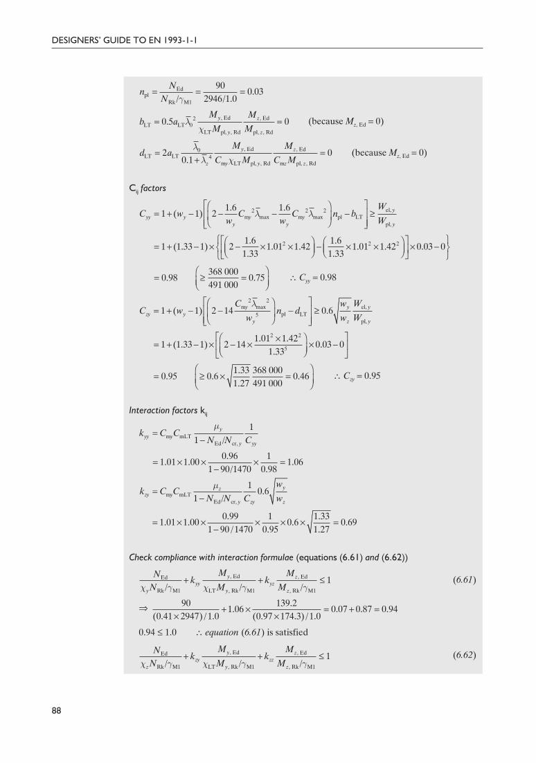
Delivered by ICEVirtualLibrary.com to:
IP: 95.42.11.157
On: Sun, 11 Jul 2010 21:35:24
(because Mz, Ed = 0)
(because Mz, Ed = 0)
Cij factors
\ Cyy = 0.98
\ Czy = 0.95
Interaction factors kij
Check compliance with interaction formulae (equations (6.61) and (6.62))
(6.61)
fi
0.94 £ 1.0 \ equation (6.61) is satisfied
(6.62)
88
DESIGNERS’ GUIDE TO EN 1993-1-1
2 2 21.6 1.61 (1.33 1) 2 1.01 1.42 1.01 1.42 0.03 0
1.33 1.33yyCÏ ¸È ˘Ê ˆ Ê ˆ= + - ¥ - ¥ ¥ - ¥ ¥ ¥ -Ì ˝Á ˜ Á ˜Í ˙Ë ¯ Ë ¯Î ˚Ó ˛
368 0000.98 0.75
491 000yyCÊ ˆ
= ≥ =Á ˜Ë ¯
el,2 2 2m max m max pl LT
pl,
1.6 1.61 ( 1) 2 y
yy y y yy y y
WC w C C n b
w w Wλ λ
È ˘Ê ˆ= + - - - - ≥Í ˙Á ˜
Ë ¯Í ˙Î ˚
, Ed , Ed2LT LT 0
LT pl, , Rd pl, , Rd
0.5 0y z
y z
M Mb a
M Mλ
χ= =
, Ed , Ed0LT LT 4
m LT pl, , Rd m pl, , Rd
2 00.1
y z
y y z zz
M Md a
C M C Mλ
χλ= =
+
Edpl
Rk M1
900.03
/ 2946/1.0N
nN γ
= = =
2 2m max el,
pl LT5pl,
1 ( 1) 2 14 0.6y y yzy y
y z y
C w WC w n d
w w W
λÈ ˘Ê ˆ= + - - - ≥Í ˙Á ˜
Ë ¯Í ˙Î ˚2 2
5
1.01 1.421 (1.33 1) 2 14 0.03 0
1.33zyCÈ ˘Ê ˆ¥
= + - ¥ - ¥ ¥ -Í ˙Á ˜Ë ¯Î ˚
1.33 368 0000.95 0.6 0.46
1.27 491 000zyCÊ ˆ
= ≥ ¥ =Á ˜Ë ¯
m mLTEd cr,
11 /
yyy y
y yy
k C CN N C
µ=
-
0.96 11.01 1.00 1.06
1 90/1470 0.98yyk = ¥ ¥ ¥ =-
m mLTEd cr,
10.6
1 /yz
zy yy zy z
wk C C
N N C wµ
=-
0.99 1 1.331.01 1.00 0.6 0.69
1 90 /1470 0.95 1.27zyk = ¥ ¥ ¥ ¥ ¥ =-
, Ed , EdEd
Rk M1 LT , Rk M1 , Rk M1
1/ / /
y zyy yz
y y z
M MNk k
N M Mχ γ χ γ γ+ + £
+ ¥ = + =¥ ¥
90 139.21.06 0.07 0.87 0.94
(0.41 2947) /1.0 (0.97 174.3) /1.0
, Ed , EdEd
Rk M1 LT , Rk M1 , Rk M1
1/ / /
y zzy zz
z y z
M MNk k
N M Mχ γ χ γ γ+ + £
98Guide to Eurocode 1993 - CRC02 December 2004 11:54:13
Color profile: DisabledComposite Default screen
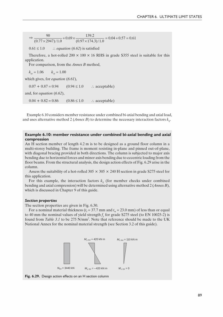
Delivered by ICEVirtualLibrary.com to:
IP: 95.42.11.157
On: Sun, 11 Jul 2010 21:35:24
fi
0.61 £ 1.0 \ equation (6.62) is satisfied
Therefore, a hot-rolled 200 × 100 × 16 RHS in grade S355 steel is suitable for thisapplication.
For comparison, from the Annex B method,
kyy = 1.06 kzy = 1.00
which gives, for equation (6.61),
0.07 + 0.87 = 0.94 (0.94 £ 1.0 \ acceptable)
and, for equation (6.62),
0.04 + 0.82 = 0.86 (0.86 £ 1.0 \ acceptable)
Example 6.10 considers member resistance under combined bi-axial bending and axial load,and uses alternative method 2 (Annex B) to determine the necessary interaction factors kij.
Example 6.10: member resistance under combined bi-axial bending and axialcompressionAn H section member of length 4.2 m is to be designed as a ground floor column in amulti-storey building. The frame is moment resisting in-plane and pinned out-of-plane,with diagonal bracing provided in both directions. The column is subjected to major axisbending due to horizontal forces and minor axis bending due to eccentric loading from thefloor beams. From the structural analysis, the design action effects of Fig. 6.29 arise in thecolumn.
Assess the suitability of a hot-rolled 305 × 305 × 240 H section in grade S275 steel forthis application.
For this example, the interaction factors kij (for member checks under combinedbending and axial compression) will be determined using alternative method 2 (Annex B),which is discussed in Chapter 9 of this guide.
Section propertiesThe section properties are given in Fig. 6.30.
For a nominal material thickness (tf = 37.7 mm and tw = 23.0 mm) of less than or equalto 40 mm the nominal values of yield strength fy for grade S275 steel (to EN 10025-2) isfound from Table 3.1 to be 275 N/mm2. Note that reference should be made to the UKNational Annex for the nominal material strength (see Section 3.2 of this guide).
89
CHAPTER 6. ULTIMATE LIMIT STATES
NEd = 3440 kN My, Ed = –420 kN m Mz, Ed = 0
Mz, Ed = 110 kN mMy, Ed = 420 kN m
Fig. 6.29. Design action effects on an H section column
90 139.20.69 0.04 0.57 0.61
(0.77 2947) /1.0 (0.97 174.3) /1.0+ ¥ = + =
¥ ¥
99Guide to Eurocode 1993 - CRC02 December 2004 11:54:13
Color profile: DisabledComposite Default screen

Delivered by ICEVirtualLibrary.com to:
IP: 95.42.11.157
On: Sun, 11 Jul 2010 21:35:24
Clause 3.2.6From clause 3.2.6:
E = 210 000 N/mm2
G ª 81 000 N/mm2
Clause 5.5.2 Cross-section classification (clause 5.5.2)
Outstand flanges (Table 5.2, sheet 2):
c = (b – tw – 2r)/2 = 132.5 mm
c/tf = 132.5/37.7 = 3.51
Limit for Class 1 flange = 9ε = 8.32
8.32 > 3.51 \ flanges are Class 1
Web – internal compression part (Table 5.2, sheet 1):
c = h – 2tf – 2r = 246.7 mm
c/tw = 246.7/23.0 = 10.73
Limit for Class 1 web = 33ε = 30.51
30.51 > 10.73 \ web is Class 1
The overall cross-section classification is therefore Class 1.
Clause 6.2.4 Compression resistance of cross-section (clause 6.2.4)The design compression resistance of the cross-section
for Class 1, 2 or 3 cross-sections (6.10)
8415 kN > 3440 kN \ acceptable
Clause 6.2.5 Bending resistance of cross-section (clause 6.2.5)Major (y–y) axisMaximum bending moment
My, Ed = 420.0 kN m
90
DESIGNERS’ GUIDE TO EN 1993-1-1
b
h d
tw
tf
r
y y
z
z
h = 352.5 mm
b = 318.4 mm
tw = 23.0 mm
tf = 37.7 mm
r = 15.2 mm
A = 30 600 mm2
ly = 642.0 × 106 mm4
lz = 203.1 × 106 mm4
IT = 12.71 × 106 mm4
Iw = 5.03 × 1012 mm6
Wel, y = 3 643 000 mm3
Wel, z = 1 276 000 mm3
Wpl, y = 4 247 000 mm3
Wpl, z = 1 951 000 mm3
Fig. 6.30. Section properties for a 305 × 305 × 240 H section
y235/ 235/275 0.92fε = = =
yc, Rd
M0
AfN
γ=
c, Rd30 600 275
8 415 000 N 8415 kN1.00
N¥
= = =
100Guide to Eurocode 1993 - CRC02 December 2004 11:54:14
Color profile: DisabledComposite Default screen
Delivered by ICEVirtualLibrary.com to:
IP: 95.42.11.157
On: Sun, 11 Jul 2010 21:35:24
Delivered by ICEVirtualLibrary.com to:
IP: 95.42.11.157
On: Sun, 11 Jul 2010 21:35:24
\
3847 kN > 26.2 kN \ acceptable
Shear bucklingShear buckling need not be considered, provided
for unstiffened webs
η = 1.2 (from Eurocode 3 – Part 1.5, though the UK National Annex may specify analternative value).
Actual hw/tw = 277.1/23.0 = 12.0
12.0 £ 55.5 \ no shear buckling check required
Clause 6.2.10 Cross-section resistance under bending, shear and axial force (clause 6.2.10)
Clause 6.2.9
Provided the shear force VEd is less than 50% of the design plastic shear resistance Vpl, Rd
and provided shear buckling is not a concern, then the cross-section need only satisfy therequirements for bending and axial force (clause 6.2.9).
In this case, VEd < 0.5 Vpl, Rd for both axes, and shear buckling is not a concern (seeabove). Therefore, the cross-section need only be checked for bending and axial force.
No reduction to the major axis plastic resistance moment due to the effect of axial forceis required when both of the following criteria are satisfied:
NEd £ 0.25 Npl, Rd (6.33)
(6.34)
0.25Npl, Rd = 0.25 × 8415 = 2104 kN
3440 kN > 2104 kN \ equation (6.33) is not satisfied
3440 kN > 876.3 kN \ equation (6.34) is not satisfied
Therefore, allowance for the effect of axial force on the major axis plastic momentresistance of the cross-section must be made.
No reduction to the minor axis plastic resistance moment due to the effect of axial forceis required when the following criterion is satisfied:
(6.35)
3440 kN > 1752.7 kN \ equation (6.35) is not satisfied
Therefore, allowance for the effect of axial force on the minor axis plastic momentresistance of the cross-section must be made.
92
DESIGNERS’ GUIDE TO EN 1993-1-1
0.9272 72 55.5
1.2εη
= ¥ =
w
w
72ht
εη
£
3pl, Rd
24 227 (275/ 3)3847 10 N 3847 kN
1.00V
¥= = ¥ =
w w yEd
M0
0.5h t fN
γ£
w w y 3
M0
0.5 0.5 277.1 23.0 275876.3 10 N 876.3 kN
1.0
h t f
γ¥ ¥ ¥
= = ¥ =
w w yEd
M0
h t fN
γ£
w w y 3
M0
277.1 23.0 2751752.7 10 N 1752.7 kN
1.0
h t f
γ¥ ¥
= = ¥ =
102Guide to Eurocode 1993 - CRC02 December 2004 11:54:14
Color profile: DisabledComposite Default screen

Delivered by ICEVirtualLibrary.com to:
IP: 95.42.11.157
On: Sun, 11 Jul 2010 21:35:24
Clause 6.2.9.1(5)Reduced plastic moment resistances (clause 6.2.9.1(5))Major (y–y) axis:
(but MN, y, Rd £ Mpl, y, Rd) (6.36)
where
n = NEd/Npl, Rd = 3440/8415 = 0.41
a = (A – 2btf)/A = [30 600 – (2 × 318.4 × 37.7)]/30 600 = 0.22
fi
773.8 kN m > 420 kN m \ acceptable
Minor (z–z) axis:
For n > a (6.38)
fi
503.9 kN m > 110 kN m \ acceptable
Cross-section check for bi-axial bending (with reduced moment resistances)
(6.41)
For I and H sections:
α = 2 and β = 5n (but β ≥ 1) = (5 × 0.41) = 2.04
fi
0.33 £ 1 \ acceptable
Clause 6.3.1Member buckling resistance in compression (clause 6.3.1)
for Class 1, 2 and 3 cross-sections (6.47)
but χ £ 1.0 (6.49)
where
for Class 1, 2 and 3 cross-sections
Elastic critical force and non-dimensional slenderness for flexural bucklingFor buckling about the major (y–y) axis:
Lcr = 0.7L = 0.7 × 4.2 = 2.94 m (see Table 6.6)
93
CHAPTER 6. ULTIMATE LIMIT STATES
N, , Rd pl, , Rd1
1 0.5y y
nM M
a-
=-
N, , Rd1 0.41
1168 773.8 kN m1 (0.5 0.22)yM
-= ¥ =
- ¥
2
N, , Rd pl, , Rd 11z z
n aM M
a
È ˘-Ê ˆ= -Í ˙Á ˜Ë ¯-Í ˙Î ˚2
N, , Rd0.41 0.22
536.5 1 503.9 kN m1 0.22zM
È ˘-Ê ˆ= ¥ - =Í ˙Á ˜Ë ¯-Í ˙Î ˚
, Ed , Ed
N, , Rd N, , Rd
1y z
y z
M M
M M
α βÊ ˆ Ê ˆ+ £Á ˜ Á ˜Ë ¯Ë ¯
2 2.04420 1100.33
773.8 536.5Ê ˆ Ê ˆ+ =Á ˜ Á ˜Ë ¯ Ë ¯
yb, Rd
M1
AfN
χ
γ=
2 2
1χ
Φ Φ λ=
+ -
20.5[1 ( 0.2) ]Φ α λ λ= + - +
y
cr
Af
Nλ =
103Guide to Eurocode 1993 - CRC02 December 2004 11:54:15
Color profile: DisabledComposite Default screen

Delivered by ICEVirtualLibrary.com to:
IP: 95.42.11.157
On: Sun, 11 Jul 2010 21:35:24
For buckling about the minor (z–z) axis:
Lcr = 1.0L = 1.0 × 4.2 = 4.20 m (see Table 6.6)
\
\
Selection of buckling curve and imperfection factor αFor a hot-rolled H section (with h/b £ 1.2, tf £ 100 mm and S275 steel):
• for buckling about the y–y axis, use curve b (Table 6.5 (Table 6.2 of EN 1993-1-1))• for buckling about the z–z axis, use curve c (Table 6.5 (Table 6.2 of EN 1993-1-1))• for curve b, α = 0.34 and for curve c, α = 0.49 (Table 6.4 (Table 6.1 of EN 1993-1-1)).
Buckling curves: major (y–y) axis
Φy = 0.5 × [1 + 0.34 × (0.23 – 0.2) + 0.232] = 0.53
\
8314 kN > 3440 kN \ major axis flexural buckling resistance is acceptable
Buckling curves: minor (z–z) axis
Φz = 0.5 × [1 + 0.49 × (0.59 – 0.2) + 0.592] = 0.77
\
6640 kN > 3440 kN \ minor axis flexural buckling resistance is acceptable
Clause 6.3.2 Member buckling resistance in bending (clause 6.3.2)The 4.2 m column is unsupported along its length with no torsional or lateral restraints.Equal and opposite design end moments of 420 kN m are applied about the major axis.The full length of the column will therefore be checked for lateral torsional buckling.
MEd = 420.0 kN m
(6.55)
where Wy = Wpl, y for Class 1 and 2 cross-sections.
94
DESIGNERS’ GUIDE TO EN 1993-1-1
2 2 63
cr, 2 2cr
210 000 642.0 10153 943 10 N 153 943 kN
2940y
y
EIN
L¥ ¥ ¥
= = = ¥ =π π
3
30 600 2750.23
153 943 10yλ¥
= =¥
2 2 63
cr, 2 2cr
210 000 203.1 1023 863 10 N 23 863 kN
4200z
z
EIN
L¥ ¥ ¥
= = = ¥ =π π
3
30 600 2750.59
23 863 10zλ¥
= =¥
= =+ -2 2
10.99
0.53 0.53 0.23yχ
3b, , Rd
0.99 30 600 2758314 10 N 8314 kN
1.0yN¥ ¥
= = ¥ =
= =+ -2 2
10.79
0.77 0.77 0.59zχ
3b, , Rd
0.79 30 600 2756640 10 N 6640 kN
1.0zN¥ ¥
= = ¥ =
yb, Rd LT
M1y
fM Wχ
γ=
104Guide to Eurocode 1993 - CRC02 December 2004 11:54:15
Color profile: DisabledComposite Default screen

Delivered by ICEVirtualLibrary.com to:
IP: 95.42.11.157
On: Sun, 11 Jul 2010 21:35:24

Delivered by ICEVirtualLibrary.com to:
IP: 95.42.11.157
On: Sun, 11 Jul 2010 21:35:24
(6.61)
(6.62)
Determination of interaction factors kij (Annex B)For this example, alternative method 2 (Annex B) will be used for the determination of theinteraction factors kij. For axial compression and bi-axial bending, all four interactioncoefficients kyy, kyz, kzy and kzz are required.
The column is laterally and torsionally unrestrained, and is therefore susceptible totorsional deformations. Accordingly, the interaction factors should be determined withinitial reference to Table B.2.
Equivalent uniform moment factors Cmi (Table B.3)Since there is no loading between restraints, all three equivalent uniform moment factorsCmy, Cmz and CmLT may be determined from the expression given in the first row of TableB.3, as follows:
Cmi = 0.6 + 0.4ψ ≥ 0.4
Considering y–y bending and in-plane supports:
ψ = –1, Cmy = 0.6 + (0.4 × –1) = 0.2 (but ≥ 0.4) \ Cmy = 0.40
Considering z–z bending and in-plane supports:
ψ = 0, Cmz = 0.6 + (0.4 × 0) = 0.6 \ Cmz = 0.60
Considering y–y bending and out-of-plane supports:
ψ = –1, CmLT = 0.6 + [0.4 × (–1)] = 0.2 (but ≥ 0.4) \ CmLT = 0.40
Interaction factors kij (Table B.2 (and Table B.1))For Class 1 and 2 I sections:
\ kyy = 0.41
\ kzz = 0.78
kyz = 0.6 kzz = 0.6 × 0.72 = 0.47 \ kyz = 0.47
96
DESIGNERS’ GUIDE TO EN 1993-1-1
, Ed , EdEd
Rk M1 LT , Rk M1 , Rk MI
1/ / /
y zzy zz
z y z
M MNk k
N M Mχ γ χ γ γ+ + £
Ed Edm m
Rk M1 Rk M1
1 ( 0.2) 1 0.8/ /yy y y y
y y
N Nk C C
N Nλ
χ γ χ γ
Ê ˆ Ê ˆ= + - £ +Á ˜ Á ˜
Ë ¯ Ë ¯
34400.40 1 (0.23 0.2) 0.41
(0.99 8415) /1.0yykÊ ˆ
= ¥ + - =Á ˜¥Ë ¯
34400.40 1 0.8 0.53
0.99 8415 /1.0yyk Ê ˆ£ ¥ + =Á ˜Ë ¯¥
Ed Edm m
Rk M1 Rk M1
1 (2 0.6) 1 1.4/ /zz z z y
z z
N Nk C C
N Nλ
χ γ χ γÊ ˆ Ê ˆ
= + - £ +Á ˜ Á ˜Ë ¯ Ë ¯
34400.60 1 [(2 0.59) 0.6] 0.78
(0.79 8415)/1.0zzkÊ ˆ
= ¥ + ¥ - =Á ˜¥Ë ¯
34400.60 1 1.4 1.04
0.79 8415/1.0zzk Ê ˆ£ ¥ + =Á ˜Ë ¯¥
Ed
mLT Rk M1
0.11
0.25 /z
zyz
Nk
C Nλ
χ γ= -
-
, Ed , EdEd
Rk M1 LT , Rk M1 , Rk MI
1/ / /
y zyy yz
y y z
M MNk k
N M Mχ γ χ γ γ+ + £
106Guide to Eurocode 1993 - CRC02 December 2004 11:54:16
Color profile: DisabledComposite Default screen

Delivered by ICEVirtualLibrary.com to:
IP: 95.42.11.157
On: Sun, 11 Jul 2010 21:35:24

Delivered by ICEVirtualLibrary.com to:
IP: 95.42.11.157
On: Sun, 11 Jul 2010 21:35:24
• restraint at plastic hinges• stable lengths for segments between plastic hinges.
Since the design objective is now to ensure that load carrying of the frame is controlledby the formation of a plastic collapse mechanism, any premature failure due to lateralinstability must be prevented. This may be achieved by providing a suitable system ofrestraints – lateral and/or torsional.
Clause 6.3.5.2 Clause 6.3.5.2 states where restraints are required and the performance necessary fromeach of them. The rules are very similar to the equivalent provision of BS 5950: Part 1.
A simple check for stable length of member with end moments M and ψM (and negligibleaxial load) is provided by equation (6.68) as
Lstable ≯ 35εiz for 0.625 £ ψ £ 1(6.68)
Lstable ≯ (60 – 40ψ)εiz for –1 £ ψ £ 0.625
Clause BB.3More detailed rules covering tapered haunches (with two or three flanges) are provided in
clause BB.3, and are discussed in Chapter 11 of this guide. These are closely modelled on theprovisions of BS 5950: Part 1.
6.4. Uniform built-up compression membersClause 6.4 Clause 6.4 covers the design of uniform built-up compression members. The principal
difference between the design of built-up columns and the design of conventional (solid)columns is in their response to shear. In conventional column buckling theory, lateraldeflections are assessed (with a suitable level of accuracy) on the basis of the flexuralproperties of the member, and the effects of shear on deflections are ignored. For built-upcolumns, shear deformations are far more significant (due to the absence of a solid web), andtherefore have to be evaluated and accounted for in the development of design procedures.
There are two distinct types of built-up member (laced and battened), characterized bythe layout of the web elements, as shown in Fig. 6.31. Laced columns contain diagonal webelements with or without additional horizontal web elements; these web elements aregenerally assumed to have pinned end conditions and therefore to act in axial tension orcompression. Battened columns (see Fig. 6.32) contain horizontal web elements only andbehave in the same manner as Vierendeel trusses, with the battens acting in flexure.Battened struts are generally more flexible in shear than laced struts.
98
DESIGNERS’ GUIDE TO EN 1993-1-1
Battens
Laces
Chords
Module
(a) (b)
Fig. 6.31. Types of built-up compression member. (a) Laced column. (b) Battened column
108Guide to Eurocode 1993 - CRC02 December 2004 11:54:16
Color profile: DisabledComposite Default screen

Delivered by ICEVirtualLibrary.com to:
IP: 95.42.11.157
On: Sun, 11 Jul 2010 21:35:24
Clause 6.4Clause 6.4 also provides guidance for closely spaced built-up members such as back-to-back channels. Background to the analysis and design of built-up structures has beenreported by Galambos9 and Narayanan.13
In terms of material consumption, built-up members can offer much greater efficiencythan single members. However, with the added expenses of the fabrication process, and therather unfashionable aesthetics (often containing corrosion traps), the use of built-upmembers is less popular nowadays in the UK than in the past. Consequently, BS 5950: Part 1offers less detailed guidance on the subject than Eurocode 3. The basis of the BS 5950method is also different from the Eurocode approach, with BS 5950 using a modified Eulerbuckling theory,14 whereas the Eurocode opts for a second-order analysis with a specifiedinitial geometric imperfection.
6.4.1. General
Clause 6.4Designing built-up members based on calculations of the discontinuous structure isconsidered too time-consuming for practical design purposes. Clause 6.4 offers a simplifiedmodel that may be applied to uniform built-up compression members with pinned endconditions (though the code notes that appropriate modifications may be made for other endconditions). Essentially the model replaces the discrete (discontinuous) elements of thebuilt-up column with an equivalent continuous (solid) column, by ‘smearing’ the propertiesof the web members (lacings or battens). Design then comprises two steps:
(1) Analyse the full ‘equivalent’ member (with smeared shear stiffness) using second ordertheory, as described in the following sub-section, to determine maximum design forcesand moments.
(2) Check critical chord and web members under design forces and moments. Joints mustalso be checked – see Chapter 12 of this guide.
Clause 6.4.1The following rules regarding the application of the model are set out in clause 6.4.1:
(1) The chord members must be parallel.(2) The lacings or battens must form equal modules (i.e. uniform-sized lacings or battens
and regular spacing).(3) The minimum number of modules in a member is three.(4) The method is applicable to built-up members with lacings in one or two directions, but
is only recommended for members battened in one direction.(5) The chord members may be solid members or themselves built-up (with lacings or
battens in the perpendicular plane).
99
CHAPTER 6. ULTIMATE LIMIT STATES
Fig. 6.32. Battened columns
109Guide to Eurocode 1993 - CRC02 December 2004 11:54:18
Color profile: DisabledComposite Default screen

Delivered by ICEVirtualLibrary.com to:
IP: 95.42.11.157
On: Sun, 11 Jul 2010 21:35:24
Clause 6.4.1(6)
For global structural analysis purposes a member (bow) imperfection of magnitudee0 = L/500 may be adopted. This magnitude of imperfection is also employed in the designformulations of clause 6.4.1(6), and has an empirical basis.
Design forces in chords and web membersClause 6.4.1(6)Clause 6.4.1(7)
Evaluation of the design forces to apply to chord and web members is covered in clauses6.4.1(6) and 6.4.1(7), respectively. The maximum design chord forces Nch, Ed are determinedfrom the applied compression forces NEd and applied bending moments MEd
I . Theformulations were derived from the governing differential equation of a column and byconsidering second-order effects, resulting in the occurrence of the maximum design chordforce at the mid-length of the column.
For a member with two identical chords the design force Nch, Ed should be determined from
(6.69)
where
is the effective critical force of the built-up member
NEd is the design value of the applied compression for on the built-up memberMEd is the design value of the maximum moment at the mid-length of the built-up
member including second-order effectsMEd
I is the design value of the applied moment at the mid-length of the built-up member(without second-order effects)
h0 is the distance between the centroids of the chordsAch is the cross-sectional area of one chordIeff is the effective second moment of area of the built-up member (see the following
sections)Sv is the shear stiffness of the lacings or battened panel (see the following sections)e0 is the assumed imperfection magnitude and may be taken as L/500.
It should be noted that although the formulations include an allowance for appliedmoments MEd
I , these are intended to cover small incidental bending moments, such as thosearising from load eccentricities.
The lacings and battens should be checked at the end panels of the built-up member,where the maximum shear forces occur. The design shear force VEd should be taken as
(6.70)
where MEd has been defined above.
6.4.2. Laced compression members
Clause 6.3.1Clause 6.4.2.2
The chords and diagonal lacings of a built-up laced compression member should be checkedfor buckling in accordance with clause 6.3.1. Various recommendations on constructiondetails for laced members are provided in clause 6.4.2.2.
ChordsThe design compression force Nch, Ed in the chords is determined as described in the previoussection. This should be shown to be less than the buckling resistance of the chords, based on abuckling length measured between the points of connection of the lacing system.
100
DESIGNERS’ GUIDE TO EN 1993-1-1
Ed 0 chch, Ed Ed
eff
0.52
M h AN N
I=
IEd 0 Ed
EdEd cr Ed v1 / /
N e MM
N N N S+
=- -
2eff
cr 2
EIN
L=
π
EdEd
MV
L= π
110Guide to Eurocode 1993 - CRC02 December 2004 11:54:18
Color profile: DisabledComposite Default screen

Delivered by ICEVirtualLibrary.com to:
IP: 95.42.11.157
On: Sun, 11 Jul 2010 21:35:24
For lacings in one direction only, the buckling length of the chord Lch may generally betaken as the system length (though reference should be made to Annex BB). For lacings intwo directions, buckling lengths are defined in the three-dimensional illustrations of Fig. 6.8of EN 1993-1-1.
LacingsThe design compression force in the lacings may be easily determined from the designshear force VEd (described in the previous section) by joint equilibrium. Again, this designcompressive force should be shown to be less than the buckling resistance. In general, thebuckling length of the lacing may be taken as the system length (though, as for chords,reference should be made to Annex BB).
Shear stiffness and effective second moment of area
Clause 6.4.2.1(3)Clause 6.4.2.1(4)
The shear stiffness and effective second moment of area of the lacings required for thedetermination of the design forces in the chords and lacings are defined in clauses 6.4.2.1(3)and 6.4.2.1(4).
The shear stiffness Sv of the lacings depends upon the lacing layout, and, for the threecommon arrangements, reference should be made to Fig. 6.9 of EN 1993-1-1.
For laced built-up members, the effective second moment of area may be taken as
Ieff = 0.5h02Ach (6.72)
6.4.3. Battened compression members
Clause 6.4.3.2
The chords, battens and joints of battened compression members should be checkedunder the design forces and moments at mid-length and in an end panel. Variousrecommendations on design details for battened members are provided in clause 6.4.3.2.
Clause 6.4.3.1(2)The shear stiffness Sv of a battened built-up member is given in clause 6.4.3.1(2), andshould be taken as
but (6.73)
whereIch is the in-plane second moment of area of one chord (about its own neutral axis)Ib is the in-plane second moment of area of one batten (about its own neutral axis).
Clause 6.4.3.1(3)The effective second moment of area Ieff of a battened built-up member is given in clause6.4.3.1(3), and may be taken as
Ieff = 0.5h02Ach + 2µIch (6.74)
where µ is a so-called efficiency factor, taken from Table 6.8 of EN 1993-1-1. The second partof the right-hand side of equation (6.74), 2µIch, represents the contribution of the momentsof inertia of the chords to the overall bending stiffness of the battened member. Thiscontribution is not included for laced columns (see equation (6.72)); the primary reasonbehind this is that the spacing of the chords in battened built-up members is generally ratherless than that for laced members, and it can therefore become uneconomical to neglect thechord contribution.
The efficiency factor µ, the value of which may range between zero and unity, controls thelevel of chord contribution that may be exploited. The recommendations of Table 6.8of EN 1993-1-1 were made to ensure ‘safe side’ theoretical predictions of a series ofexperimental results.13
6.4.4. Closely spaced built-up membersClause 6.4.4Clause 6.4.4 covers the design of closely spaced built-up members. Essentially, provided the
chords of the built-up members are either in direct contact with one another or closely
101
CHAPTER 6. ULTIMATE LIMIT STATES
[ ]ch
v 2ch b 0
241 (2 / )( / )
EIS
a I nI h a=
+
2ch
2
2 EIa
£π
111Guide to Eurocode 1993 - CRC02 December 2004 11:54:18
Color profile: DisabledComposite Default screen

Delivered by ICEVirtualLibrary.com to:
IP: 95.42.11.157
On: Sun, 11 Jul 2010 21:35:24
Clause 6.3Clause 6.4
spaced and connected through packing plates, and the conditions of Table 6.9 ofEN 1993-1-1 are met, the built-up members may be designed as integral members (ignoringshear deformations) following the provisions of clause 6.3; otherwise the provisions of theearlier parts of clause 6.4 apply.
102
DESIGNERS’ GUIDE TO EN 1993-1-1
112Guide to Eurocode 1993 - CRC02 December 2004 11:54:19
Color profile: DisabledComposite Default screen

Delivered by ICEVirtualLibrary.com to:
IP: 95.42.11.157
On: Sun, 11 Jul 2010 21:35:26
CHAPTER 7
Serviceability limit states
This chapter concerns the subject of serviceability limit states. The material in this chapter iscovered in Section 7 of Eurocode 3 Part 1.1, and the following clauses are addressed:
• General Clause 7.1• Serviceability limit states for buildings Clause 7.2
Overall, the coverage of serviceability considerations in EN 1993-1-1 is very limited,with little explicit guidance provided. However, as detailed below, for further informationreference should be made to EN 1990, on the basis that many serviceability criteria areindependent of the structural material. For serviceability issues that are material-specific,reference should be made to EN 1992 to EN 1999, as appropriate. Clauses 3.4, 6.5 and A1.4of EN 1990 contain guidance relevant to serviceability; clause A1.4 of EN 1990 (as with theremainder of Annex A1 of EN 1990) is specific to buildings.
7.1. GeneralServiceability limit states are defined in Clause 3.4 of EN 1990 as those that concern:
• the functionality of the structure or structural members under normal use• the comfort of the people• the appearance of the structure.
For buildings, the primary concerns are horizontal and vertical deflections and vibrations.According to clause 3.4 of EN 1990, a distinction should be made between reversible and
irreversible serviceability limit states. Reversible serviceability limit states are those thatwould be infringed on a non-permanent basis, such as excessive vibration or high elasticdeflections under temporary (variable) loading. Irreversible serviceability limit states arethose that would remain infringed even when the cause of infringement was removed (e.g.permanent local damage or deformations).
Further, three categories of combinations of loads (actions) are specified in EN 1990 forserviceability checks: characteristic, frequent and quasi-permanent. These are given byequations (6.14) to (6.16) of EN 1990, and summarized in Table 7.1 (Table A1.4 ofEN 1990), where each combination contains a permanent action component (favourable orunfavourable), a leading variable component and other variable components. Where apermanent action is unfavourable, which is generally the case, the upper characteristic valueof a permanent action Gkj, sup should be used; where an action is favourable (such as apermanent action reducing uplift due to wind loading), the lower characteristic value of apermanent action Gkj, inf should be used.
Unless otherwise stated, for all combinations of actions in a serviceability limit statethe partial factors should be taken as unity (i.e. the loading should be unfactored). An
113Guide to Eurocode 1993 - CRC02 December 2004 11:54:19
Color profile: DisabledComposite Default screen

Delivered by ICEVirtualLibrary.com to:
IP: 95.42.11.157
On: Sun, 11 Jul 2010 21:35:26
introduction to EN 1990 is contained in Chapter 14 of this guide, where combinations ofactions are discussed in more detail.
The characteristic combination of actions would generally be used when considering thefunction of the structure and damage to structural and non-structural elements; the frequentcombination would be applied when considering the comfort of the user, the functioningof machinery and avoiding the possibility of ponding of water; the quasi-permanentcombination would be used when considering the appearance of the structure and long-termeffects (e.g. creep).
The purpose of the ψ factors (ψ0, ψ1 and ψ2) that appear in the load combinations of Table7.1 is to modify characteristic values of variable actions to give representative values fordifferent situations. Numerical values of the ψ factors are given in Table 14.1 of this Guide.Further discussion of the ψ factors may also be found in Chapter 14 of this guide and inCorus.3
7.2. Serviceability limit states for buildingsIt is emphasized in both EN 1993-1-1 and EN 1990 that serviceability limits (e.g. fordeflections and vibrations) should be specified for each project and agreed with the client.Numerical values for these limits are not provided in either document.
7.2.1. Vertical deflectionsTotal vertical deflections wtot are defined in EN 1990 by a number of components (wc, w1, w2
and w3), as shown in Fig. 7.1 (Fig. A1.1 of EN 1990), where
wc is the precamber in the unloaded structural memberw1 initial part of the deflection under permanent loadsw2 long term part of the deflection under permanent loadsw3 additional part of the deflection due to variable loadswtot total deflection (w1 + w2 + w3)wmax remaining total deflection taking into account the precamber (wtot – wc).
In the absence of prescribed deflection limits, those provided in Table 7.2 may be used forserviceability verifications based on the characteristic combination of actions. In general, thedeflection limits should be checked against the total deflection wtot.
104
DESIGNERS’ GUIDE TO EN 1993-1-1
Table 7.1. Design values of actions for use in the combination of actions (Table A1.4 of EN 1990)
Combination
Permanent action Gd Variable actions Qd
Unfavourable Favourable Leading Others
Characteristic Gkj,sup Gkj,inf Qk,1 ψ0,iQk,i
Frequent Gkj,sup Gkj,inf ψ1,1Qk,1 ψ2,iQk,i
Quasi-permanent Gkj,sup Gkj,inf ψ2,1Qk,1 ψ2,iQk,i
wc w1
w2
w3wmax
wtot
Fig. 7.1. Definitions of vertical deflections
114Guide to Eurocode 1993 - CRC02 December 2004 11:54:19
Color profile: DisabledComposite Default screen
Delivered by ICEVirtualLibrary.com to:
IP: 95.42.11.157
On: Sun, 11 Jul 2010 21:35:26
The UK National Annex may define similar limits to those given in Table 7.2, and is likelyto propose that permanent actions be taken as zero in serviceability checks, essentiallyreverting to the practice in BS 5950, which is to check deflections under unfactored imposedloading. In this case w1 and w2 would be zero, so wtot would be equal to w3. Example 7.1illustrates the calculation of vertical deflections in beams.
Example 7.1: vertical deflection of beamsA simply supported roof beam of span 5.6 m is subjected to the following (unfactored)loading:
• dead load: 8.6 kN/m• imposed roof load: 20.5 kN/m• snow load: 1.8 kN/m.
Choose a suitable UB such that the vertical deflection limits of Table 7.2 are notexceeded.
Clause 3.2.6From clause 3.2.6:
E = 210 000 N/mm2
Using the characteristic combination of actions of Table 7.2, where the permanent actionis unfavourable, and by inspection, taking the imposed roof load as the leading variableaction is critical, we have serviceability loading
w = Gk ‘+’ Qk, 1 ‘+’ ψ0, 2Qk, 2
From Table 14.1 (Table A1.1 of EN 1990), for snow loads (at altitudes > 1000 m),ψ0 = 0.7.
\ w = 8.6 + 20.5 + (0.7 × 1.8) = 30.36 kN/m
Under a uniformly distributed load, the maximum deflection δ of a simply supportedbeam may be taken as
For a deflection limit of span/200:
From section tables 356 × 127 × 33 has a second moment of area (about the major axis)Iy of 82.49 × 106 mm4:
82.49×10⁶ > 66.1×10⁶ \ 356 × 127 × 33 is acceptable
Setting the dead load equal to zero in the serviceability loading gives w = 21.76 kN/m, anda required second moment of area of 47.4 × 106 mm4.
105
CHAPTER 7. SERVICEABILITY LIMIT STATES
45384
wLEI
δ =
45384required
wLI
Eδfi =
4 46 45 5 30.36 5600
66.1 10 mm384 384 210 000 (5600/200)required
wLI
Eδ¥
fi = = ¥ = ¥¥
Table 7.2. Vertical deflection limits
Design situation Deflection limit
Cantilevers Length/180Beams carrying plaster or other brittle finish Span/360Other beams (except purlins and sheeting rails) Span/200Purlins and sheeting rails To suit cladding
115Guide to Eurocode 1993 - CRC02 December 2004 11:54:19
Color profile: DisabledComposite Default screen
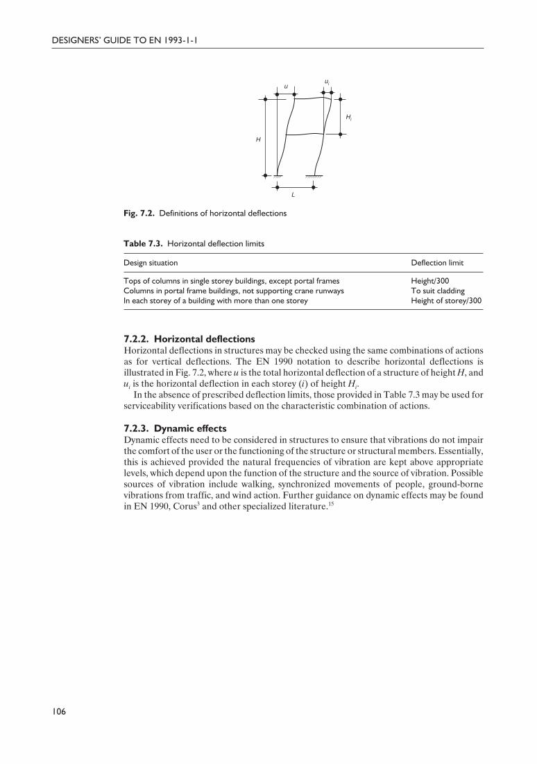
Delivered by ICEVirtualLibrary.com to:
IP: 95.42.11.157
On: Sun, 11 Jul 2010 21:35:26
7.2.2. Horizontal deflectionsHorizontal deflections in structures may be checked using the same combinations of actionsas for vertical deflections. The EN 1990 notation to describe horizontal deflections isillustrated in Fig. 7.2, where u is the total horizontal deflection of a structure of height H, andui is the horizontal deflection in each storey (i) of height Hi.
In the absence of prescribed deflection limits, those provided in Table 7.3 may be used forserviceability verifications based on the characteristic combination of actions.
7.2.3. Dynamic effectsDynamic effects need to be considered in structures to ensure that vibrations do not impairthe comfort of the user or the functioning of the structure or structural members. Essentially,this is achieved provided the natural frequencies of vibration are kept above appropriatelevels, which depend upon the function of the structure and the source of vibration. Possiblesources of vibration include walking, synchronized movements of people, ground-bornevibrations from traffic, and wind action. Further guidance on dynamic effects may be foundin EN 1990, Corus3 and other specialized literature.15
106
DESIGNERS’ GUIDE TO EN 1993-1-1
H
L
uui
Hi
Fig. 7.2. Definitions of horizontal deflections
Table 7.3. Horizontal deflection limits
Design situation Deflection limit
Tops of columns in single storey buildings, except portal frames Height/300Columns in portal frame buildings, not supporting crane runways To suit claddingIn each storey of a building with more than one storey Height of storey/300
116Guide to Eurocode 1993 - CRC02 December 2004 11:54:19
Color profile: DisabledComposite Default screen
Delivered by ICEVirtualLibrary.com to:
IP: 95.42.11.157
On: Sun, 11 Jul 2010 21:35:49
CHAPTER 8
Annex A (informative) –Method 1: interaction factors kij
for interaction formula inclause 6.3.3(4)
Clause 6.3.3(4)For uniform members subjected to combined bending and axial compression, clause 6.3.3(4)provides two interaction formulae, both of which must be satisfied. Each of the interactionformulae contains two interaction factors: kyy and kyz for equation (6.61) and kzy and kzz forequation (6.62).
Two alternative methods to determine these four interaction factors (kyy, kyz, kzy and kzz)are given by EN 1993-1-1; Method 1 is contained within Annex A, and is described in thischapter, and Method 2 is contained within Annex B, and described in Chapter 9 of this guide.
The choice of which method to adopt may be prescribed by the National Annex; the UKNational Annex is expected to allow either method to be used, but may limit the scope ofapplication of Method 1 to bi-symmetrical sections. Of the two methods, Method 1 generallyrequires more calculation effort, due to the large number of auxiliary terms, while Method 2is more straightforward. However, Method 1 will generally offer more competitive solutions.
Method 1 is based on second-order in-plane elastic stability theory, and maintains consistencywith the theory, as far as possible, in deriving the interaction factors. Development of themethod has involved an extensive numerical modelling programme. Emphasis has beenplaced on achieving generality as well as consistency with the individual member checks andcross-section verifications. Inelastic behaviour has been allowed for when considering Class1 and 2 cross-sections by incorporating plasticity factors that relate the elastic and plasticsection moduli. Further details of the method, developed at the Universities of Liege andClermont-Ferrand, have been reported in Boissonnade et al.16
The basic formulations for determining the interaction factors using Method 1 are given inTable 8.1 (Table A.1 of EN 1993-1-1), along with the extensive set of auxiliary terms. Theequivalent uniform moment factors Cmi, 0 that depend on the shape of the applied bendingmoment diagram about each axis together with the support and out-of-plane restraintconditions, are given in Table 8.2 (Table A.2 of EN 1993-1-1). A distinction is made betweenmembers susceptible or not susceptible to lateral–torsional buckling in calculating thefactors Cmy, Cmz (both of which represent in-plane behaviour) and CmLT (which representsout-of-plane behaviour).
Method 1 is applied in Example 6.9 to assess the resistance of a rectangular hollow sectionmember under combined axial load and major axis bending.
117Guide to Eurocode 1993 - CRC02 December 2004 11:54:20
Color profile: DisabledComposite Default screen
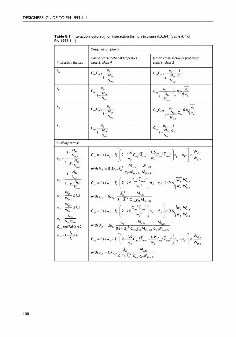
Delivered by ICEVirtualLibrary.com to:
IP: 95.42.11.157
On: Sun, 11 Jul 2010 21:35:49

Delivered by ICEVirtualLibrary.com to:
IP: 95.42.11.157
On: Sun, 11 Jul 2010 21:35:49

Delivered by ICEVirtualLibrary.com to:
IP: 95.42.11.157
On: Sun, 11 Jul 2010 21:35:52
CHAPTER 9
Annex B (informative) –Method 2: interaction factors kij
for interaction formula inclause 6.3.3(4)
Clause 6.3.3(4)As described in the previous chapter, for uniform members subjected to combined bendingand axial compression, clause 6.3.3(4) provides two interaction formulae, both of which mustbe satisfied. Each of the interaction formulae contains two interaction factors: kyy and kyz forequation (6.61) and kzy and kzz for equation (6.62). Two alternative methods to determinethese four interaction factors (kyy, kyz, kzy and kzz) are given by EN 1993-1-1; Method 1 iscontained within Annex A, and described in the previous chapter, and Method 2 is containedwithin Annex B, and described in this chapter.
Method 2 is more straightforward than Method 1, and is generally more user-friendly. Thebackground to the method, developed at the Technical Universities of Graz and Berlin, hasbeen described in Lindner.17
The basic formulations for determining the interaction factors using Method 2 are given inTable 9.1 (Table B.1 of EN 1993-1-1) for members not susceptible to lateral–torsionalbuckling, and in Table 9.2 (Table B.2 of EN 1993-1-1) for members that are susceptible tolateral–torsional buckling.
The equivalent uniform moment factors Cmy, Cmz and CmLT may be determined from Table9.3 (Table B.3 of EN 1993-1-1). Cmy relates to in-plane major axis bending; Cmz relates toin-plane minor axis bending; and CmLT relates to out-of-plane buckling. When referring toTable 9.3 (Table B.3 of EN 1993-1-1):
• for no loading between points of restraint, the top row of Table 9.3 applies, which givesCmi = 0.6 + 0.4ψ (but a minimum value of 0.4 is prescribed)
• for uniform loading between restraints (indicated by unbroken lines in the momentdiagrams), the second and third rows of Table 9.3 apply, with Cmi factors derived fromthe left-hand section of the final column
• for concentrated loading between restraints (indicated by dashed lines in the momentdiagrams), the second and third rows of Table 9.3 apply, with Cmi factors derived fromthe right-hand section of the final column.
In structures that rely on the flexural stiffness of the columns for stability (i.e. unbracedframes), Table 9.3 (Table B.3 of EN 1993-1-1) indicates that the equivalent uniform momentfactor (Cmy or Cmz) should be taken as 0.9.
121Guide to Eurocode 1993 - CRC02 December 2004 11:54:21
Color profile: DisabledComposite Default screen

Delivered by ICEVirtualLibrary.com to:
IP: 95.42.11.157
On: Sun, 11 Jul 2010 21:35:52
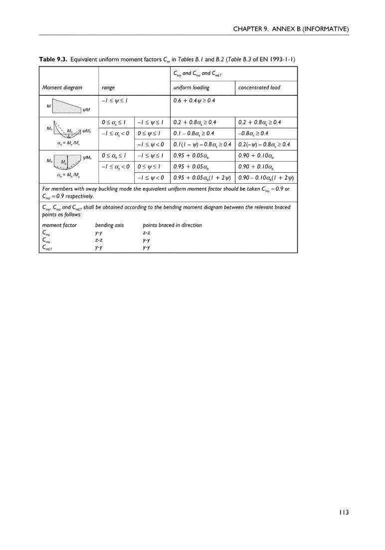
Delivered by ICEVirtualLibrary.com to:
IP: 95.42.11.157
On: Sun, 11 Jul 2010 21:35:52
Delivered by ICEVirtualLibrary.com to:
IP: 95.42.11.157
On: Sun, 11 Jul 2010 21:35:59
CHAPTER 10
Annex AB (informative) –additional design provisions
Annex AB of EN 1993-1-1 is split into two short sections containing additional informationfor taking account of material non-linearities in structural analysis and simplified provisionsfor the design of continuous floor beams. It is noted that this annex is intended to betransferred to EN 1990 in future revisions of the codes.
Clause AB.1Clause AB.2
Sections 10.1 and 10.2 of this guide relate to clauses AB.1 and AB.2 of EN 1993-1-1,respectively.
10.1. Structural analysis taking account of materialnon-linearities
Clause AB.1Clause AB.1 states that, in the case of material non-linearities, the action effects in astructure (i.e. the internal members forces and moments) may be determined using anincremental approach. Additionally, for each relevant design situation (or combination ofactions), each permanent and variable action should be increased proportionally.
10.2. Simplified provisions for the design of continuous floorbeams
Clause AB.2Clause AB.2 provides two simplified loading arrangements for the design of continuous floorbeams with slabs in buildings. The guidance is applicable when uniformly distributed loadsare dominant, but may not be applied where cantilevers are present.
The two loading arrangements to be considered are as follows:
(1) for maximum sagging moments, alternative spans carrying the design permanent andvariable loads, and other spans carrying only the design permanent load
(2) for maximum hogging moments, any two adjacent spans carrying the design permanentand variable loads, all other spans carrying only the design permanent load.
125Guide to Eurocode 1993 - CRC02 December 2004 11:54:22
Color profile: DisabledComposite Default screen

Delivered by ICEVirtualLibrary.com to:
IP: 95.42.11.157
On: Sun, 11 Jul 2010 21:36:14
CHAPTER 11
Annex BB (informative) –buckling of components ofbuildings structures
Clauses BB.1to BB.3
This chapter is concerned with the supplementary guidance given in EN 1993-1-1 for thebuckling of components of buildings, as covered in Annex BB. Sections 11.1, 11.2 and 11.3 ofthis guide relate to clauses BB.1, BB.2 and BB.3 of EN 1993-1-1, respectively.
Annex BB provides specific guidance on three aspects of member stability for use whendetermining the resistance of individual members acting as parts of a frame structure:
• buckling lengths for chord or web members in triangulated and lattice structures – Lcr
values• stiffness requirements for trapezoidal sheeting to fully restrain a beam against lateral–
torsional instability – S or Cv, k values• maximum stable lengths between adjacent lateral or torsional restraints for members
containing plastic hinges – Lm or Lk values.
While the first and third of these provisions will be familiar to those used to BS 5950:Part 1, the material on sheeting restraint is new.
11.1. Flexural buckling of members in triangulated and latticestructures
Clause BB.1Clause BB.1 provides Lcr values for a series of situations covering structures composed ofeither angle or hollow section members. For the former it largely follows the BS 5950: Part 1approach of combining end restraint and the effect of eccentricities in the line of forcetransfer into a single design provision, i.e. the recommended Lcr values also recognize thepresence of eccentricities and include allowances for it so that the members can be designedas if axially loaded. Behaviour both in the plane of the truss and out of plane are covered,with some recognition being taken of the rotational restraint available to either brace orchord members when the adjacent components possess greater stiffness. In all cases, morecompetitive values, i.e. smaller buckling lengths, may be used when these can be justified onthe basis of either tests or a more rigorous analysis.
127Guide to Eurocode 1993 - CRC02 December 2004 11:54:22
Color profile: DisabledComposite Default screen

Delivered by ICEVirtualLibrary.com to:
IP: 95.42.11.157
On: Sun, 11 Jul 2010 21:36:14
11.2. Continuous restraintsExpressions are provided for both the shear stiffness S and the torsional restraint stiffnessCv, k in terms of beam properties such that the sheeting may be assumed to provide full lateralor torsional restraint, with the result that χLT may be taken as 1.0 in equation (6.55). Thedetermination of appropriate values of S and Cv, k for a particular arrangement should followthe provisions given in Part 1.3 of Eurocode 3.
Clause BB2.1 Although reference is made to Part 1.3 (through clause BB.2.1), that document does notprovide explicit guidance on the determination of appropriate values of S for particulararrangements of sheeting and fastening. Thus, reference to other sources is necessary, forexample Bryan and Davies.18
In contrast, clause 10.1.5.2 of Part 1.3 sets out a detailed procedure for calculating thetotal rotational stiffness CD as a combination of the flexural stiffness of the sheeting and therotational stiffness of the interconnection between the sheeting and the beam. However, thespecific formulae for this latter effect presume the beam to be a light purlin with appropriatesheet/purlin fastening arrangements. It is therefore suggested that these need to be appliedwith caution when considering arrangements of different proportions, e.g. sheetingsupported by hot-rolled beams.
It is, of course, possible for sheeting to provide a combination of both lateral and torsionalrestraint. This has been studied, and a design procedure developed,19 but it is not coveredexplicitly by Eurocode 3.
11.3. Stable lengths of segment containing plastic hinges forout-of-plane bucklingThe use of plastic design methods requires that the resistance of the structure be governed bythe formation of a plastic collapse mechanism. Premature failure due to any form ofinstability must therefore be prevented. It is for this reason that only cross-sections whoseproportions meet the Class 1 limits may be used for members required to participate in aplastic hinge action. Similarly, member buckling must not impair the ability of such membersto deliver adequate plastic hinge rotation. Thus, restrictions on the slenderness of individualmembers are required. Limits covering a variety of conditions are provided in this section:
• stable lengths of uniform members subject to axial compression and uniform momentbetween adjacent lateral restraints – Lm
• stable lengths of uniform members subject to axial compression and either constant,linearly varying or non-linearly varying moment between points of torsional restraint –Lk or Ls
• stable lengths of haunched or tapered members between adjacent lateral restraints – Lm
• stable lengths of haunched or tapered members between torsional restraints – Ls.
In addition, modification factors are given to allow for the presence of a continuous lateralrestraint along the tension flange of both uniform and non-uniform members subjected toeither linear or non-linear moment gradients.
Figure 11.1 illustrates the nature of the situation under consideration. The overall designpremise of failure of the frame being due to the formation of the plastic collapse mechanismrequires that a plastic hinge forms as shown at the toe of the rafter (point 6 in Fig. 11.1). Boththe haunch between this point and the rafter–column joint and the length of the rafter onthe opposite side of the plastic hinge extending to the braced location 7 must not failprematurely by lateral–torsional buckling. For the haunch, depending on the preciseconditions of restraint assumed at the brace locations (lateral or torsional) and whether thehaunch has three flanges (as illustrated in Fig 11.1) or only two, the maximum stable lengthmay be obtained from one of equations (BB.9) to (BB.12). If the additional benefit ofcontinuous tension flange restraint is to be included then the modification of either equation
118
DESIGNERS’ GUIDE TO EN 1993-1-1
128Guide to Eurocode 1993 - CRC02 December 2004 11:54:22
Color profile: DisabledComposite Default screen

Delivered by ICEVirtualLibrary.com to:
IP: 95.42.11.157
On: Sun, 11 Jul 2010 21:36:14
(BB.13) or (BB.14) should be added. For the uniform length rafter between points 6 and 7,equations (BB.5) to (BB.8), as appropriate, should be used.
Much of this material is very similar to the treatment of the same topic in Appendix G ofBS 5950: Part 1. It is, of course, aimed principally at the design of pitched roof portal framestructures, especially when checking stability of the haunched rafter in the eaves region.
119
CHAPTER 11. ANNEX BB (INFORMATIVE)
£ Lm
A
B–B
8
6
2
7
9
4
B
A
B
1
£ Lm
5
A–A3
1
Mp
9
10 11 12
Fig. 11.1. Member with a three flange haunch. 1, tension flange; 2, elastic section (see Clause 6.3);3, plastic stable length (see Clause BB.3.2.1) or elastic (see Clause 6.3.5.3(2)B); 4, plastic stablelength (see Clause BB.3.1.1); 5, elastic section (see Clause 6.3); 6, plastic hinge; 7, restraints; 8,bending moment diagram; 9, compression flange; 10, plastic stable length (see Clause BB.3.2) orelastic (see Clause 6.3.5.3(2)B); 11, plastic stable length (see Clause BB.3.1.2); 12, elastic section (seeClause 6.3), χ and χLT from Ncr and Mcr, including tension flange restraint
129Guide to Eurocode 1993 - CRC02 December 2004 11:54:23
Color profile: DisabledComposite Default screen

Delivered by ICEVirtualLibrary.com to:
IP: 95.42.11.157
On: Sun, 11 Jul 2010 21:36:17

Delivered by ICEVirtualLibrary.com to:
IP: 95.42.11.157
On: Sun, 11 Jul 2010 21:36:17
more than just the usual list of notation due to the need to define numerous geometricalparameters associated with the detailed arrangements for various forms of joint.
12.3. Basis of designIn Section 2 of EN 1993-1-8, partial factors γM for the various components present in jointsare listed (see Table 2.1 of EN 1993-1-8), of which the most common are:
• resistance of bolts, pins, welds and plates in bearing – γM2
• slip resistance – γM3
• resistance of joints in hollow section lattice girders – γM5.
The numerical values for these partial factors, as defined by Eurocode 3, are given inTable 12.1.
Either linear elastic or elastic–plastic analysis may be used to determine the forces in thecomponent parts of a joint subject to the set of basic design concepts listed in clause 2.5 ofEN 1993-1-8. These accord with the usual principles adopted when designing joints.25 Theeffects of eccentricity in the line of action of forces should be allowed for using the principleslisted in clause 2.7 of EN 1993-1-8.
Section 2 of EN 1993-1-8 concludes with an extensive list of reference standards coveringthe usual components typically found in joints, e.g. bolts, nuts and washers, or needed toconstruct joints, e.g. welding consumables.
12.4. Connections made with bolts, rivets or pins12.4.1. GeneralTable 3.1 of EN 1993-1-8 lists five grades of bolts, ranging from 4.6 to 10.9 and including theUK norm of 8.8. Only appropriate grade 8.8 or 10.9 bolts may be designed as preloaded.
Three situations for bolts designed to operate in shear are defined in clause 3.4.1 ofEN 1993-1-8:
• bearing type – the most usual arrangement• slip-resistant at serviceability limit state – ultimate condition governed by strength in
shear or bearing• slip-resistant at ultimate limit state – ultimate condition governed by slip.
Similarly, two categories for bolts used in tension are defined:
• non-preloaded – the most usual category• preloaded – when controlled tightening is employed.
Table 3.2 of EN 1993-1-8 lists the design checks needed for each of these above fivearrangements.
Information on geometrical restrictions on the positioning of bolt holes is provided inTable 3.3 of EN 1993-1-8. This generally accords with the provisions of BS 5950: Part 1. Itincludes the usual provisions for regular and staggered holes in tension members; this topicis covered in Section 6.2.2 of this guide, with reference to the provision of EN 1993-1-1.
122
DESIGNERS’ GUIDE TO EN 1993-1-1
Table 12.1. Numerical values of partial factors γM relevant toconnections
Partial factor, γM Eurocode 3
γM2 1.25γM3 1.25 (or 1.1)γM5 1.0
132Guide to Eurocode 1993 - CRC02 December 2004 11:54:23
Color profile: DisabledComposite Default screen
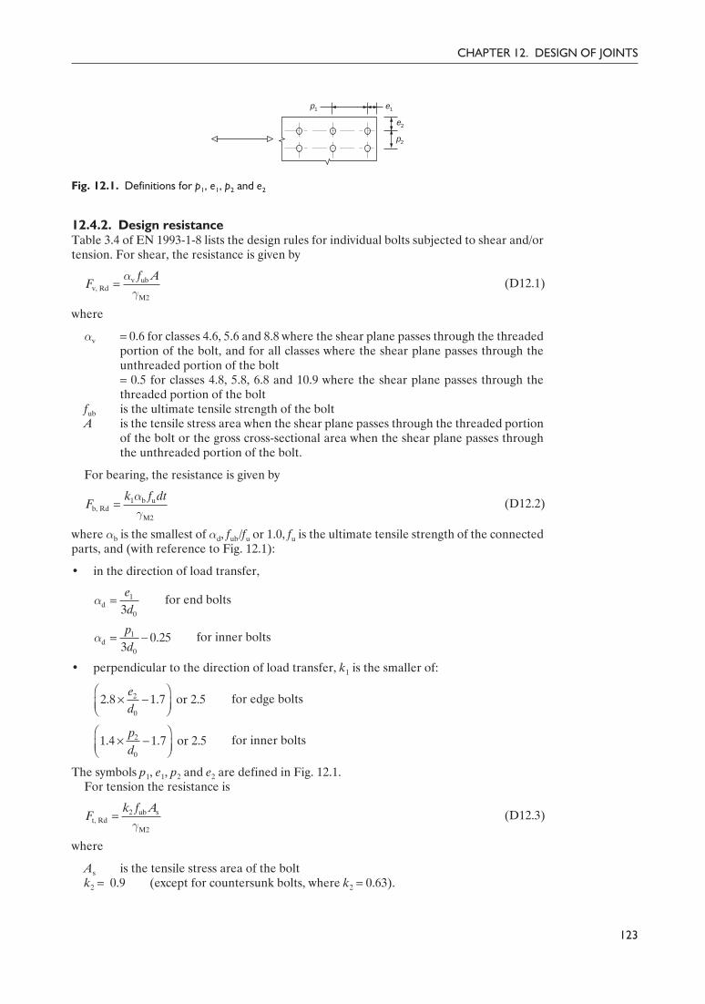
Delivered by ICEVirtualLibrary.com to:
IP: 95.42.11.157
On: Sun, 11 Jul 2010 21:36:17
12.4.2. Design resistanceTable 3.4 of EN 1993-1-8 lists the design rules for individual bolts subjected to shear and/ortension. For shear, the resistance is given by
(D12.1)
where
αv = 0.6 for classes 4.6, 5.6 and 8.8 where the shear plane passes through the threadedportion of the bolt, and for all classes where the shear plane passes through theunthreaded portion of the bolt= 0.5 for classes 4.8, 5.8, 6.8 and 10.9 where the shear plane passes through thethreaded portion of the bolt
fub is the ultimate tensile strength of the boltA is the tensile stress area when the shear plane passes through the threaded portion
of the bolt or the gross cross-sectional area when the shear plane passes throughthe unthreaded portion of the bolt.
For bearing, the resistance is given by
(D12.2)
where αb is the smallest of αd, fub/fu or 1.0, fu is the ultimate tensile strength of the connectedparts, and (with reference to Fig. 12.1):
• in the direction of load transfer,
for end bolts
for inner bolts
• perpendicular to the direction of load transfer, k1 is the smaller of:
for edge bolts
for inner bolts
The symbols p1, e1, p2 and e2 are defined in Fig. 12.1.For tension the resistance is
(D12.3)
where
As is the tensile stress area of the boltk2 = 0.9 (except for countersunk bolts, where k2 = 0.63).
123
CHAPTER 12. DESIGN OF JOINTS
= 1 b ub, Rd
M2
k f dtF
αγ
= 1d
03ed
α
= -1d
0
0.253pd
α
Ê ˆ¥ -Á ˜Ë ¯
2
0
2.8 1.7 or 2.5ed
Ê ˆ¥ -Á ˜Ë ¯
2
0
1.4 1.7 or 2.5pd
= 2 ub st, Rd
M2
k f AF
γ
= v ubv, Rd
M2
f AF
αγ
p1 e1
e2
p2
Fig. 12.1. Definitions for p1, e1, p2 and e2
133Guide to Eurocode 1993 - CRC02 December 2004 11:54:23
Color profile: DisabledComposite Default screen

Delivered by ICEVirtualLibrary.com to:
IP: 95.42.11.157
On: Sun, 11 Jul 2010 21:36:17
For combined shear and tension the resistance is covered by the formula
(D12.4)
Special provisions are made when using oversize or slotted holes or countersunk bolts.Where bolts transmit load in shear and bearing, and pass through packing of total
thickness tp (Fig. 12.2), the design shear resistance should be reduced by a factor βp, given by
but βp £ 1.0 (D12.5)
For preloaded bolts the design value of preload Fp, Cd is given by
(D12.6)
Provisions are also given for injection bolts (clause 3.6.2 of EN 1993-1-8), bolt groups(clause 3.7 of EN 1993-1-8) in bearing and long joints (clause 3.8 of EN 1993-1-8). For longjoints, the design shear resistance of all fasteners should be reduced by multiplying by thereduction factor βLf, given by
but 0.75 £ βLf £ 1.0 (D12.7)
where Lj is the distance between the centres of the end bolts in the joint.
12.4.3. Slip-resistant connectionsSlip-resistant connections should be designed using the provisions of clause 3.9 ofEN 1993-1-8, which gives the design slip resistance as
(D12.8)
where
n is the number of friction surfacesFp, C = 0.7 × 800As (subject to conformity with standards).
Values for the factor ks as well as a set of the slip factor µ corresponding to four classes ofplate surface are provided in Tables 3.6 and 3.7 of EN 1993-1-8, respectively.
For situations involving combined tension and shear for which the connection is designedas ‘slip-resistant at serviceability’, the slip resistance is given by
(D12.9)
124
DESIGNERS’ GUIDE TO EN 1993-1-1
-= - j
Lf
151
200
L d
dβ
= ss, Rd p, C
M3
k nF F
µγ
-s p, C t, Ed, servs, Rd, serv
M3
( 0.8 )=
k n F FF
µ
γ
= ub sp, Cd
M7
0.7 f AF
γ
=+p
p
98 3
dd t
β
Packing plates
Figure 12.2. Fasteners through packing
+ £v, Ed t, Ed
v, Rd t, Rd
1.01.4
F F
F F
134Guide to Eurocode 1993 - CRC02 December 2004 11:54:24
Color profile: DisabledComposite Default screen

Delivered by ICEVirtualLibrary.com to:
IP: 95.42.11.157
On: Sun, 11 Jul 2010 21:36:17
12.4.4. Block tearingSeveral cases of block tearing, in which shear failure along one row of bolts in associationwith tensile rupture along another line of bolts results in the detachment of a piece ofmaterial, and thus separation of the connection, are illustrated in Fig. 12.3 (Fig. 3.8 ofEN 1993-1-8).
Equations to cover concentrically and eccentrically loaded situations are provided byequations (D12.10) and (D12.11), respectively:
(D12.10)
(D12.11)
where
Ant is the net area subject to tensionAnv is the net area subject to shear.
These equations differ from those of the earlier ENV document in using net area for bothshear and tension. Recent work in Canada that paralleled criticism of the American Instituteof Steel Construction (AISC) treatment26 has suggested that the original ENV concept wasboth physically more representative of the behaviour obtained in tests and gave clear yet stillsafe side predictions of the relevant experimented data.
Both variants are conceptually similar to the treatment given in BS 5950: Part 1, althoughthe form of presentation is different.
Rules are also provided for the tensile resistance of angles connected through one leg thatadopt the usual practice of treating it as concentrically loaded but with a correction factorapplied to the area.
12.4.5. Prying forcesAlthough clause 3.11 of EN 1993-1-8 specifically requires that prying forces in bolts loadedin tension be allowed for ‘where this can occur’, no information on how to recognize suchsituations or what procedure to use to determine their values is provided. Thus, theinteraction equation given in Table 3.4 of EN 1993-1-8 should be treated similarly to thesecond formula in clause 6.3.4.4 of BS 5950: Part 1. In the absence of specific guidance it
125
CHAPTER 12. DESIGN OF JOINTS
= + y nvu nteff, 1, Rd
M2 M0
(1/ 3) f Af AV
γ γ
= + y nvu nteff, 2, Rd
M2 M0
(1/ 3)0.5 f Af AV
γ γ
NSd
NSd
NSd
NSd
Fig. 12.3. Block tearing
135Guide to Eurocode 1993 - CRC02 December 2004 11:54:24
Color profile: DisabledComposite Default screen

Delivered by ICEVirtualLibrary.com to:
IP: 95.42.11.157
On: Sun, 11 Jul 2010 21:36:17
seems reasonable to use the procedure of clause 6.3.4.3 of BS 5950: Part 1 to determine thetotal tensile bolt load Ft, Ed.
12.4.6. Force distributions at ultimate limit stateA plastic distribution of bolt forces may be used except:
• for connections designed as ‘slip-resistant at ultimate’• when shear (rather than bearing) is the governing condition• in cases where the connection must be designed to resist the effects of impact, vibration
and load reversal (except that caused solely by wind loading).
It is stated that any plastic approach is acceptable providing it satisfies equilibrium andthat the resistance and ductility of individual bolts is not exceeded.
12.4.7. Connections made with pinsFor connections made with pins (Fig. 12.4), two cases are recognized:
• where no rotation is required, and the pin may be designed as if it were a single bolt• all other arrangements for which the procedures given in clause 3.13.2 of EN 1993-1-8
should be followed.
Table 3.10 of EN 1993-1-8 lists the design requirements for pins for shear, bearing (pinand plates), bending and combined shear and bending. A further limit on the contact bearingstress is applied if the pin is to be designed as replaceable. Apart from changes to some of thenumerical coefficients, these rules are essentially similar to those in BS 5950: Part 1.
12.5. Welded connections12.5.1. GeneralDesign information is provided for welds covering material thicknesses in excess of 4 mm,although for welds in structural hollow sections this limit is reduced to 2.5 mm, with specificguidance being provided in Section 7 of EN 1993-1-8. For thinner materials, referenceshould normally be made to Part 1.3 of the code. Information on fatigue aspects of weld
126
DESIGNERS’ GUIDE TO EN 1993-1-1
Fig. 12.4. Pin connection
136Guide to Eurocode 1993 - CRC02 December 2004 11:54:26
Color profile: DisabledComposite Default screen

Delivered by ICEVirtualLibrary.com to:
IP: 95.42.11.157
On: Sun, 11 Jul 2010 21:36:17
design is provided in Part 1.9, and on fracture in Part 1.10. It is generally assumed that theproperties of the weld metal will be at least the equivalent in terms of strength, ductility andtoughness to those of the parent material.
All major types of structural weld are covered, as listed in clause 4.3.1 of EN 1993-1-8.
12.5.2. Fillet weldsThe usual geometrical restrictions that the included angle be between 60 and 120° applies,although ways of designing outside these limits are suggested. Intermittent fillet welds mustmeet the requirements of Fig. 4.1 of EN 1993-1-8 in terms of the ratio of hit/miss lengths. Aminimum length of 30 mm or six times the throat thickness is required before the weld can beconsidered as load-carrying. Figure 4.3 of EN 1993-1-8 indicates how the effective weldthickness should be measured; this should not be less than 3 mm. For deep-penetration filletwelds, as defined by Fig. 4.4 of EN 1993-1-8, testing is necessary to demonstrate that therequired degree of penetration can be achieved consistently.
Two methods are permitted for the design of fillet welds:
• the directional method, in which the forces transmitted by a unit length of weld areresolved into parallel and perpendicular components
• the simplified method, in which only longitudinal shear is considered.
These approaches broadly mirror those used in the 2000 and 1990 versions, respectively, ofBS 5950: Part 1.
Directional methodNormal and shear stresses of the form shown in Fig. 12.5 (Fig. 4.5 of EN 1993-1-8) areassumed, in which:
• σ^ is the normal stress perpendicular to the throat• σ|| is the normal stress parallel to the axis of the throat• τ^ is the shear stress perpendicular to the axis of the weld• τ|| is the shear stress parallel to the axis of the weld.
σ|| is assumed not to influence the design resistance, while σ^, τ^ and τ|| must satisfy thepair of conditions given by equations (D12.12a) and (D12.12b):
(D12.12a)
(D12.12b)
where
127
CHAPTER 12. DESIGN OF JOINTS
2 2 2 0.5 u||
w M2
[ 3( )]f
σ τ τβ γ^ ^+ + £
t
t
ss
Fig. 12.5. Stresses on the throat section of a fillet weld
^ £ u
M2
fσ
γ
137Guide to Eurocode 1993 - CRC02 December 2004 11:54:26
Color profile: DisabledComposite Default screen

Delivered by ICEVirtualLibrary.com to:
IP: 95.42.11.157
On: Sun, 11 Jul 2010 21:36:17
fu is the nominal ultimate strength of the weaker part joinedβw is a factor (between 0.8 and 1.0) depending on the steel type (see Table 4.1 of
EN 1993-1-8).
Simplified methodAt all points along its length, the resultant of all forces per unit length transmitted by theweld (Fw, Ed) must not exceed the design weld resistance per unit length (Fw, Rd), where this issimply the product of the design shear strength fvw. d and the throat thickness a. The value offvw. d should be taken as
(D12.13)
12.5.3. Butt weldsFor full-penetration butt welds the design resistance is simply taken as the strength of theweaker parts connected. This presumes the use of welding consumables that deliver allweld-tensile specimens of greater strength than the parent metal. Partial-penetration buttwelds should be designed as deep-penetration fillet welds. Providing the nominal throatthickness of a T-butt weld exceeds the thickness t of the plate forming the stem of the T jointand any unwelded gap does not exceed t/5, such arrangements may be designed as if theywere full-penetration welds.
12.5.4. Force distributionEither elastic or plastic methods may be used to determine the distribution of forces in awelded connection. Ductility should be ensured.
12.5.5. Connections to unstiffened flangesThe provisions of this section need to be read in association with the later material inSections 6 and 7 when dealing with plates attached to I or H or to rectangular hollowsections. Specific rules are given for the determination of an effective width of plate beff asdefined in Fig. 12.6 (Fig. 4.8 of EN 1993-1-8) for use in the design expression
(D12.14)
12.5.6. Long jointsApart from arrangements in which the stress distribution along the weld corresponds to thatin the adjacent parts, e.g. web-to-flange girder welds, joints with lengths greater than 150a
128
DESIGNERS’ GUIDE TO EN 1993-1-1
= eff, b, fc tb y, fbfc, Rd
M0
b t fF
γ
= uvw.d
w M2
/ 3ff
β γ
tw
tw
r
t f
t pt p
t fbeff bp
0.5beff
0.5beff
Fig. 12.6. Effective width of an unstiffened T joint
138Guide to Eurocode 1993 - CRC02 December 2004 11:54:26
Color profile: DisabledComposite Default screen

Delivered by ICEVirtualLibrary.com to:
IP: 95.42.11.157
On: Sun, 11 Jul 2010 21:36:17
for lap joints or 1.7 m for joints connecting transverse stiffeners to web plates should bedesigned by reducing the basic design resistance by a factor βLw given respectively by
βLw.1 = 1.2 – 0.2Lj /150a but βLw.1 £ 1.0 (D12.15)
and
βLw.2 = 1.1 – Lw /17 but βLw.2 £ 1.0βLw.2 ≥ 0.6 (D12.16)
where
Lj is the overall length of the lap in the direction of the force transfer (in metres)Lw is the length of the weld (in metres).
12.5.7. Angles connected by one legGood practice rules are provided to define situations for which tension at the root of a weldmust be explicitly considered and for determining the effective area for angles connected byonly one leg so that they may be treated as concentrically loaded. In both cases the provisionsare essentially similar to normal UK practice.
12.6. Analysis, classification and modelling12.6.1. Global analysisReaders accustomed to the rather cursory linkage between the properties of joints and theirinfluence on the performance of a structure provided in BS 5950 will be surprised at the levelof detail devoted to this topic in Eurocode 3. Although British codes BS 5950 and itsforerunner BS 449 have always recognized three types of framing,
• simple construction• semi-rigid construction (termed ‘semi-continuous’ in Eurocode 3)• continuous construction,
Eurocode 3 links each type of framing to each of the three methods of global analysis,
• plastic• rigid–plastic• elastic–plastic,
in a far more explicit and detailed fashion. It does this via the process of classification of jointtypes in terms of their strength (moment resistance) and their (rotational) stiffness. Table12.2 (Table 5.1 of EN 1993-1-8) summarizes this process. Central to it is the concept of the
129
CHAPTER 12. DESIGN OF JOINTS
Table 12.2. Type of joint model
Method of globalanalysis Classification of joint
Elastic Nominally pinned Rigid Semi-rigid
Rigid–plastic Nominally pinned Full strength Partial strength
Elastic–plastic Nominally pinned Rigid and full strength Semi-rigid and partialstrength
Semi-rigid and fullstrength
Rigid and partialstrength
Type of joint model Simple Continuous Semi-continuous
139Guide to Eurocode 1993 - CRC02 December 2004 11:54:26
Color profile: DisabledComposite Default screen

Delivered by ICEVirtualLibrary.com to:
IP: 95.42.11.157
On: Sun, 11 Jul 2010 21:36:17
moment–rotation characteristic of the joint, i.e. the relationship between the momentthe joint can transmit and the corresponding joint rotation. Figure 12.7 illustrates thisschematically for a series of idealized joint types.
Clauses 5.1.2 to 5.1.4 of EN 1993-1-8 set out the requirements in terms of joint propertiesnecessary for the use of each of the three types of global analysis. Reading these inassociation with clause 5.2 of EN 1993-1-8 on the classification of joints permits the followingstraightforward options to be identified:
• joints defined as ‘nominally pinned’, i.e. incapable of transmitting significant momentsand capable of accepting the resulting rotations under the design loads – design frameaccording to the principles of ‘simple construction’
• joints defined as ‘rigid and full strength’, i.e. having sufficient stiffness to justify ananalysis based on full continuity and a strength at least equal to that of the connectedmembers – design frame according to the principles of ‘continuous construction’ usingeither of elastic, elastic–plastic or rigid–plastic analysis.
For stiffness, clause 5.2.2.1 of EN 1993-1-8 states that joint classification may be on thebasis of one of:
• experimental evidence• experience of previous satisfactory performance• calculation.
Interestingly, the equivalent clause for joint strength, clause 5.2.3.1 of EN 1993-1-8, doesnot contain similar wording, and thus might be interpreted as allowing only the calculation-based approach, i.e. comparing its design moment resistance Mj, Rd with the design momentresistance of the members it connects. Given the amount of attention devoted to improvingthe design of both ‘simple’ and ‘moment’ connections in the UK during the past 15 years andthe volume of underpinning knowledge27 of the actual behaviour of the types commonly usedin the UK embodied within the BCSA/SCI Green Books,20,21 it is reasonable to presume that‘experience of previous satisfactory performance’ would also be accepted as the basis forclassifying these types as either nominally pinned or full strength.
Clause 5.1.5 of EN 1993-1-8 provides a similarly detailed treatment of secondary momentscaused by the rotational stiffness of the joints and moments resulting from eccentricitiesand/or loading between panel points for lattice girders.
Designers wishing to adopt the semi-continuous option should ensure that they areproperly acquainted with the subject; this will require study of far more than just theprovisions of Eurocode 3. Suitable background texts include Anderson28 and Faella et al.29
These texts explain the background to the concept of joint modelling (clause 5.3 of
130
DESIGNERS’ GUIDE TO EN 1993-1-1
Mom
ent,
M
Rotation, f
Rigid and full strength
Nominally pinned
Semi-rigid and partial strength
Mp
Fig. 12.7. Moment–rotation characteristics of joints
140Guide to Eurocode 1993 - CRC02 December 2004 11:54:27
Color profile: DisabledComposite Default screen

Delivered by ICEVirtualLibrary.com to:
IP: 95.42.11.157
On: Sun, 11 Jul 2010 21:36:17
EN 1993-1-8) necessary for the explicit inclusion of joint stiffness and partial strengthproperties when conducting a frame analysis.
12.7. Structural joints connecting H or I sections12.7.1. GeneralSection 6 of EN 1993-1-8 explains the principles and application of the concept known as the‘component method’. Since it does this in the context of the determination of
• design moment resistance Mj, Rd
• rotational stiffener Sj
• rotation capacity ϕcd
it is essentially oriented towards semi-continuous construction, i.e. the material has littlerelevance to joints in simple construction.
The joint is regarded as a rotational spring located at the intersection of the centrelinesof the beam and column that it connects and possessing a design moment–rotationrelationship. Figure 6.1 of EN 1993-1-8 illustrates the concept: Fig. 6.1c of EN 1993-1-8represents the behaviour that would be expected from a physical test of the arrangement ofFig 6.1a of EN 1993-1-8. In order to obtain the three key measures of performance, Mj, Rd, Sj
and ϕcd, the joint is ‘broken down’ into its basic components, e.g. shear in the web panel of thecolumn, or tension in the bolts, and expressions or calculation procedures for determiningits contribution to each of the three performance measures are given in Table 6.1 ofEN 1993-1-8. The remaining clauses of Section 6 then define and explain those expressionsand procedures.
Readers intending to implement the material of this chapter are strongly advised toprepare themselves by studying the relevant part of the BCSA/SCI guide on momentconnections,21 since this provides a simplified and more familiar introduction to the subject.
12.8. Structural joints connecting hollow sections12.8.1. GeneralSection 7 of EN 1993-1-8 covers the design of structural joints connecting hollow sections(Fig. 12.8). Readers already familiar with the CIDECT series of design guides for structuralhollow sections will find much of Section 7 of EN 1993-1-8 familiar. It is, however, limited to
131
CHAPTER 12. DESIGN OF JOINTS
Fig. 12.8. Structural joints connecting hollow sections (The London Eye)
141Guide to Eurocode 1993 - CRC02 December 2004 11:54:28
Color profile: DisabledComposite Default screen
Delivered by ICEVirtualLibrary.com to:
IP: 95.42.11.157
On: Sun, 11 Jul 2010 21:36:17
the design of welded connections for static loading, though guidance for fatigue loadingdoes exist elsewhere.30 It covers both uniplanar and multiplanar joints, i.e. two and threedimensions, in lattice structures and deals with circular and rectangular hollow sectionarrangements. It also contains some provisions for uniplanar joints involving combinationsof open and closed sections.
In addition to certain geometrical restrictions, the detailed application rules are limited tojoints in which the compression elements of all the members are Class 2 or better. Figure 7.1of EN 1993-1-8 contains all the geometrical arrangements covered, while Figures 7.2 to 7.4of EN 1993-1-8 illustrate all the potential failure modes. Six specific modes, defined byclause 7.2.2 of EN 1993-1-8, are covered for the cases of both axial load and moment loadingin the brace member.
Clauses 7.4 to 7.7 of EN 1993-1-8 provide, largely in tabular form, the detailed expressionsand procedures for checking the adequacy of each arrangement. Readers intending toimplement these would be well advised to first consult the relevant CIDECT material toobtain the basis and background to the specific provisions.
132
DESIGNERS’ GUIDE TO EN 1993-1-1
142Guide to Eurocode 1993 - CRC02 December 2004 11:54:29
Color profile: DisabledComposite Default screen

Delivered by ICEVirtualLibrary.com to:
IP: 95.42.11.157
On: Sun, 11 Jul 2010 21:36:25
CHAPTER 13
Cold-formed design
This chapter concerns the subject of cold-formed member design, which is covered inEN 1993-1-3 – General Rules: Supplementary Rules for Cold-formed Thin Gauge Members andSheeting. The purpose of this chapter is to provide an overview of the behavioural features ofcold-formed structural components and to describe the important aspects of the code.Unlike Chapters 1–11 of this guide, where the section numbers in the guide corresponddirectly to those in Part 1.1 of the code, section numbers in this chapter do not relateto the code.
13.1. IntroductionCold-formed, thin-walled construction used to be limited to applications where weightsavings were of primary concern, such as the aircraft and automotive industries. However,following improvements in manufacturing techniques, corrosion protection, productavailability, understanding of the structural response and sophistication of design codesfor cold-formed sections, light-gauge construction has become increasingly widespread.Light-gauge sections used in conjunction with hot-rolled steelwork is now commonplace(Fig. 13.1).
Fig. 13.1. Light-gauge (cold-formed) sections in conjunction with hot-rolled steelwork. (Courtesyof Metsec)
143Guide to Eurocode 1993 - CRC02 December 2004 11:54:30
Color profile: DisabledComposite Default screen

Delivered by ICEVirtualLibrary.com to:
IP: 95.42.11.157
On: Sun, 11 Jul 2010 21:36:25
The use of thin, cold-formed material brings about a number of special design problemsthat are not generally encountered when using ordinary hot-rolled sections. These include:
• non-uniform distribution of material properties due to cold-working• rounded corners and the calculation of geometric properties• local buckling• distortional buckling• torsional and flexural torsional buckling• shear lag• flange curling• web crushing, crippling and buckling.
These effects, and their codified treatment, will be outlined in the remainder of this chapter.Further general guidance, covering areas such as connections of cold-formed sections,serviceability considerations, modular construction, durability and fire resistance, may befound in Grubb et al.,31 Gorgolewski et al.32 and Rhodes and Lawson.33
134
DESIGNERS’ GUIDE TO EN 1993-1-1
Table 13.1. Maximum width-to-thickness ratios covered by EN 1993-1-3
Element of cross section Maximum value
b/t £ 50
b/t £ 60c/t £ 50
b/t £ 90c/t £ 60d/t £ 50
b/t £ 500
45° £ f £ 90°c/t £ 500 sin f
b
t
b
b b
t
c c
b b
tc c
d d
b b
t
h h
ff
144Guide to Eurocode 1993 - CRC02 December 2004 11:54:31
Color profile: DisabledComposite Default screen

Delivered by ICEVirtualLibrary.com to:
IP: 95.42.11.157
On: Sun, 11 Jul 2010 21:36:25
13.2. Scope of Eurocode 3, Part 1.3EN 1993-1-3 is limited in scope by the maximum width-to-thickness ratios set out in Table13.1. Use of cross-sections with elements exceeding these proportions must be justified bytesting. Interestingly, EN 1993-1-3 also states that its provisions are not to be applied to thedesign of cold-formed circular and rectangular hollow sections; consequently, bucklingcurves are not provided for such cross-section types, and reference should be made toEN 1993-1-1.
13.3. Material propertiesAll cold-forming operations that involve plastic deformation result in changes to the basicmaterial properties; essentially producing increased yield strengths, but with correspondingreductions in ductility (ultimate strain). EN 1993-1-3 allows for strength enhancements dueto cold-forming by defining an average (enhanced) yield strength fya that may be used insubsequent calculations in place of the basic yield strength fyb (with some limitations whichare discussed later). The EN 1993-1-3 expression for average yield strength is given by
(D13.1)
where
t is the material thickness (mm)Ag is the gross cross-sectional area (in square millimetres)k is a numerical coefficient that depends on the forming process (k = 7 for cold-rolling
and k = 5 for other forming methods)n is the number of 90o bends in the cross-section with an internal radius less than or
equal to five times the material thickness (fractions of 90° bends should be countedas fractions of n).
The code also allows the average yield strength to be determined on the basis of full-scalelaboratory testing.
The code states that the average (enhanced) yield strength may not be used for Class 4cross-sections (where the section is not fully effective) or where the members have beensubjected to heat treatment after forming.
13.4. Rounded corners and the calculation of geometricpropertiesCold-formed cross-sections contain rounded corners that make calculation of geometricproperties less straightforward than for the case of sharp corners. In such cross-sections,EN 1993-1-3 states that notional flat widths bp (used as a basis for the calculation of effectivesection properties) should be measured to the midpoints of adjacent corner elements, asshown in Fig. 13.2.
For small internal radii the effect of the rounded corners is small and may be neglected.EN 1993-1-3 allows cross-section properties to be calculated based on an idealizedcross-section that comprises flat elements concentrated along the mid-lines of the actualelements, as illustrated in Fig. 13.3, provided r £ 5t and r £ 0.10bp (where r is the internalcorner radius, t is the material thickness and bp is the flat width of a plane element).
It should be noted that section tables and design software will generally conductcalculations that incorporate rounded corners, so there may be small discrepancies withhand calculations based on the idealized properties. Examples 13.1 and 13.2 showcalculation of the gross and effective sections properties of a lipped channel section, basedon the idealizations described.
135
CHAPTER 13. COLD-FORMED DESIGN
2u yb
ya yb u yb yag
( ) but2
f fkntf f f f f
A
+= + + £
145Guide to Eurocode 1993 - CRC02 December 2004 11:54:31
Color profile: DisabledComposite Default screen

Delivered by ICEVirtualLibrary.com to:
IP: 95.42.11.157
On: Sun, 11 Jul 2010 21:36:25
136
DESIGNERS’ GUIDE TO EN 1993-1-1
grbp
bp
bp
bp
bp
bp bp
b
b
X
Pt
r
f /2
f
f /2X is the intersection of midlinesP is the midpoint of a cornerrm = r + t /2gr = rm[tan(f /2) – sin(f /2)]
(a)
bp = sw
sw
hw h
(c)
(d)(b)
bp, c
bp, d
c
bp, cc
d
Fig. 13.2. Notional widths of plane elements bp allowing for corner radii. (a) Mid-point of corner orbend. (b) Notional flat width bp of plane elements b, c and d. (c) Notional flat width bp for a web (bp
= slant height sw). (d) Notional flat width bp of plane elements adjacent to stiffeners
h
t
c
b b – t
h – t
c – t /2
Fig. 13.3. Idealized cross-section properties
146Guide to Eurocode 1993 - CRC02 December 2004 11:54:31
Color profile: DisabledComposite Default screen

Delivered by ICEVirtualLibrary.com to:
IP: 95.42.11.157
On: Sun, 11 Jul 2010 21:36:25

Delivered by ICEVirtualLibrary.com to:
IP: 95.42.11.157
On: Sun, 11 Jul 2010 21:36:25

Delivered by ICEVirtualLibrary.com to:
IP: 95.42.11.157
On: Sun, 11 Jul 2010 21:36:25
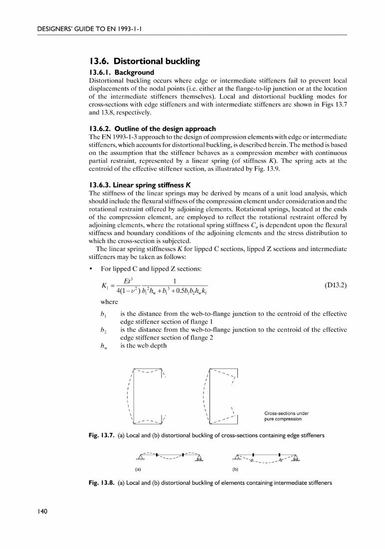
Delivered by ICEVirtualLibrary.com to:
IP: 95.42.11.157
On: Sun, 11 Jul 2010 21:36:25

Delivered by ICEVirtualLibrary.com to:
IP: 95.42.11.157
On: Sun, 11 Jul 2010 21:36:25

Delivered by ICEVirtualLibrary.com to:
IP: 95.42.11.157
On: Sun, 11 Jul 2010 21:36:25
for 0.35 £ bp, c/bp £ 0.60 (D13.5)
(b) For a double-fold edge stiffener, ceff should be obtained by taking kσ as that for a doublysupported element, and deff should be obtained by taking kσ as that for an outstandelement; both values of kσ are defined in EN 1993-1-5 and in Tables 6.2 and 6.3 of thisguide.
Step 2In the second step, the initial edge or intermediate stiffener section is considered inisolation. The flexural buckling reduction factor of this section (allowing for the linear springrestraint) is then calculated, on the assumption that flexural buckling of the stiffener sectionrepresents distortional buckling of the full stiffened element.
The elastic critical buckling stress for the stiffener section is calculated using
(D13.6)
where
K is the linear spring stiffness, discussed in Section 13.6.3 of this guideIs is the second moment of area of the effective stiffener section about its centroidal
axis a–aAs is the cross-sectional area of the effective stiffener section.
The reduction factor χd may hence be obtained using the non-dimensional slenderness λd
through the expressions given in equations (D13.7)–(D13.9):
χd = 1.0 for λd £ 0.65 (D13.7)
χd = 1.47 – 0.723λd for 0.65 < λd < 1.38 (D13.8)
χd = 0.66/λd for λd ≥ 1.38 (D13.9)
where
Based on the reduction factor χd, a reduced area for the effective stiffener section iscalculated. The reduced area is calculated from
but As, red £ As (D13.10)
142
DESIGNERS’ GUIDE TO EN 1993-1-1
d yb cr, s/fλ σ=
scr, s
s
2 KEI
Aσ =
23p, c p0.5 0.83 [( / ) 0.35]k b bσ = + ¥ -
b
bp
be2be1
b1
As, Is
ceff bp, c c
b
a a
(a)
b
K
b/t £ 60
b
bp
be2be1
b1
As, Is
ce1
deff
bp, d
d
ce2
bp, c c
b
a a
(b)
b
K
b/t £ 90
Fig. 13.10. Initial values of effective widths. (a) Single edge fold. (b) Double edge fold
= yb M0s, red d s
com, Ed
/fA A
γχ
σ
152Guide to Eurocode 1993 - CRC02 December 2004 11:54:33
Color profile: DisabledComposite Default screen

Delivered by ICEVirtualLibrary.com to:
IP: 95.42.11.157
On: Sun, 11 Jul 2010 21:36:25

Delivered by ICEVirtualLibrary.com to:
IP: 95.42.11.157
On: Sun, 11 Jul 2010 21:36:25

Delivered by ICEVirtualLibrary.com to:
IP: 95.42.11.157
On: Sun, 11 Jul 2010 21:36:25
As = (29.16 + 14.2) × 1.56 = 67.6 mm2
Is = (29.16 × 1.563)/12 + (1.56 × 14.23)/12 + (29.16 × 1.56 × 2.32) +[14.2 × 1.56 × (14.2/2 – 2.3)2]
Is = 1132.4 mm4
Calculation of linear spring stiffness KFrom equation (D13.2)
b1 = b2 = 63.4 – 9.8 = 53.6 mm
kf = 1.0 for a symmetric section under pure compression
ν = 0.3
hw = 198.4 mm
\ K1 = 0.22 N/mm (per unit length)
Elastic critical buckling stress for the effective stiffener sectionFrom equation (D13.6)
Reduction factor χd for distortional bucklingNon-dimensional slenderness
\ 0.65 < λd < 1.38
so, from equation (D9.11),
χd = 1.47 – 0.723λd = 0.64
Reduced area (and thickness) of effective stiffener section
\ tred = tAs, red /As = 1.56 × (43.3/67.6) = 1.00 mm
145
CHAPTER 13. COLD-FORMED DESIGN
d yb cr, s/ 280/212 1.15fλ σ= = =
s 2cr, s
s
2 2 0.22 210 000 1132.5212 N/mm
67.6
KEI
Aσ
¥ ¥= = =
3
1 2 2 31 w 1 1 2 w f
14(1 ) 0.5
EtK
b h b b b h kν=
- + +
yb
ya
beff, s = 29.16 mm
ceff, s = 14.2 mmaa
b
b
Fig. 13.12. Effective edge stiffener section
yb M0 2s, red d s
com, Ed
/ 280/1.00.64 67.6 43.3 mm
280
fA A
γχ
σ= = ¥ ¥ =
155Guide to Eurocode 1993 - CRC02 December 2004 11:54:34
Color profile: DisabledComposite Default screen

Delivered by ICEVirtualLibrary.com to:
IP: 95.42.11.157
On: Sun, 11 Jul 2010 21:36:25
Calculation of effective section properties for distortional bucklingEffective area
Aeff = (73.87 × 1.56) + (2 × 29.16 × 1.56) + [2 × (29.16+14.2) × 1.00]Aeff = 292.8 mm2 (compared with 341.5 mm2 for local buckling alone)
The horizontal position of the neutral axis from the centreline of the web for the effectivesection is
yeff = {[2 × (29.16 × 1.56) × 29.16/2] + [2 × (29.16 × 1.00) × (63.4 – 29.16/2)] +[2 × (14.2 × 1.00) × 63.4]}/292.8
= 20.38 mm
The horizontal shift in the neutral axis from the gross section to the effective section is
eNy = 20.38 – 16.46 = 3.92 mm
Step 3: optionally iterateχd may be refined iteratively using modified values of ρ obtained by taking σcom, Ed equal toχd fyb /γM0 in Step 1 for each iteration. Subsequent steps are as shown in this example.
The compressive resistance of the cross-section, accounting for distortional buckling, istherefore as follows:
Nc, Rd = Aeff fyb = 292.8 × 280 × 10–3 = 82.0 kN
There is, however, a shift in the neutral axis of 3.92 mm (from the centroid of the grosssection to the centroid of the effective section), and the cross-section should strictlytherefore also be checked for combined axial compression plus bending, with the bendingmoment equal to the applied axial load multiplied by the shift in neutral axis.
13.7. Torsional and torsional–flexural bucklingFlexural buckling is the predominant buckling mode for compression members in typicalbuilding structures using conventional hot-rolled sections. In light-gauge construction,flexural buckling also governs many design cases, but torsional and torsional–flexural modesmust also be checked. The code provisions for flexural buckling in Part 1.3 of the code areessentially the same as those of Part 1.1, though different cross-section types are covered, asshown in Table 13.2.
Torsional buckling is pure twisting of a cross-section, and only occurs in centrally loadedstruts which are point symmetric and have low torsional stiffness (e.g. a cruciform section).Torsional–flexural buckling is a more general response that occurs for centrally loaded strutswith cross-sections that are singly symmetric and where the centroid and the shear centre donot coincide (e.g. a channel section).
Whatever the mode of buckling of a member (i.e. flexural, torsional or torsional–flexural)the generic buckling curve formulations and the method for determining member resistancesare common. The only difference is in the calculation of the elastic critical buckling force,which is particular to the mode of buckling, and is used to define λ .
The non-dimensional slenderness λ is defined by equation (D13.12) for Class 1, 2 and 3cross-sections, and by equation (D13.13) for Class 4 cross-sections; a subscript T is added toλ to indicate when the buckling mode includes a torsional component:
for Class 1, 2 and 3 cross-sections (D13.12)
for Class 4 cross-sections (D13.13)
146
DESIGNERS’ GUIDE TO EN 1993-1-1
yT
cr
Af
Nλ λ= =
eff yT
cr
A f
Nλ λ= =
156Guide to Eurocode 1993 - CRC02 December 2004 11:54:34
Color profile: DisabledComposite Default screen

Delivered by ICEVirtualLibrary.com to:
IP: 95.42.11.157
On: Sun, 11 Jul 2010 21:36:25
where, for torsional and torsional–flexural buckling,
Ncr = Ncr, TF but Ncr £ Ncr, T
Ncr, TF is the elastic critical torsional–flexural buckling forceNcr, T is the elastic critical torsional buckling force.
The elastic critical buckling forces for torsional and torsional–flexural buckling for cross-sections that are symmetrical about the y–y axis (i.e. where z0 = 0) are given by equations(D13.14) and (D13.15), respectively:
(D13.14)
where
i02 = iy
2 + iz2 + y0
2 + z02
G is the shear modulus
147
CHAPTER 13. COLD-FORMED DESIGN
Table 13.2. Buckling curve selection table from EN 1993-1-3
Type of cross-section
Bucklingaboutaxis
Bucklingcurve
If fyb is used Any b
If fya is used *) Any c
y - y
z - z
a
b
Any b
Any c
*) the average yield strength fya should not be used unless Aeff = Ag
z
z
y y
z
z
y y
or othercross-section
2w
cr, T t2 20 T
1 EIN GI
i l
Ê ˆ= +Á ˜Ë ¯
π
157Guide to Eurocode 1993 - CRC02 December 2004 11:54:35
Color profile: DisabledComposite Default screen

Delivered by ICEVirtualLibrary.com to:
IP: 95.42.11.157
On: Sun, 11 Jul 2010 21:36:25
It is the torsion constant of the gross cross-sectionIw is the warping constant of the gross cross-sectioniy is the radius of gyration of the gross cross-section about the y–y axisiz is the radius of gyration of the gross cross-section about the z–z axislT is the buckling length of the member for torsional bucklingy0 is the distance from the shear centre to the centroid of the gross cross-section along
the y axisz0 is the distance from the shear centre to the centroid of the gross cross-section along
the z axis.
(D13.15)
where
Ncr, y is the critical force for flexural buckling about the y–y axis
Guidance is provided in EN 1993-1-3 on buckling lengths for components with differentdegrees of torsional and warping restraint. It is stated that for practical connections at eachend, lT /LT (the effective buckling length divided by the system length) should be taken as
1.0 for connections that provide partial restraint against torsion and warping (Fig. 13.13a)0.7 for connections that provide significant restraint against torsion and warping
(Fig. 13.13b).
148
DESIGNERS’ GUIDE TO EN 1993-1-1
Web Web
Column to be considered(a)
(b) Column to be considered
WebHollow sections or sections with bolts passing throughtwo webs per member
Fig. 13.13. (a) Partial and (b) significant torsional and warping restraint from practical connections
22
cr, cr, T cr, T cr, T0cr, TF
cr, cr, 0 cr,
1 1 42
y
y y y
N N N NyN
N N i Nβ
Ê ˆÊ ˆÊ ˆÁ ˜= + - - + Á ˜Á ˜Á ˜Ë ¯ Ë ¯Ë ¯
2
0
0
1yi
βÊ ˆ
= - Á ˜Ë ¯
158Guide to Eurocode 1993 - CRC02 December 2004 11:54:35
Color profile: DisabledComposite Default screen

Delivered by ICEVirtualLibrary.com to:
IP: 95.42.11.157
On: Sun, 11 Jul 2010 21:36:25
Delivered by ICEVirtualLibrary.com to:
IP: 95.42.11.157
On: Sun, 11 Jul 2010 21:36:25

Delivered by ICEVirtualLibrary.com to:
IP: 95.42.11.157
On: Sun, 11 Jul 2010 21:36:25
t is the flange thicknessz is the distance of the flange under consideration to the neutral axisr is the radius of curvature of an arched beamσa is the mean stress in the flange.
If the stress has been calculated over the effective cross-section, the mean stress is obtainedby multiplying the stress for the effective cross-section by the ratio of the effective cross-section by the ratio of the effective flange area to the gross flange area.
If the magnitude of flange curling is found to be greater than 5% of the depth of thecross-section, then a reduction in load-bearing capacity due, for example, to the effectivereduction in depth of the section or due to possible bending of the web, should be made.
13.10. Web crushing, crippling and bucklingTransversely loaded webs of slender proportions, which are common in cold-formed sections,are susceptible to a number of possible forms of failure, including web crushing, webcrippling and web buckling. Web crushing involves yielding of the web material directlyadjacent to the flange. Web crippling describes a form of failure whereby localized bucklingof the web beneath the transversely loaded flange is accompanied by web crushing andplastic deformation of the flange. Transversely loaded webs can also fail as a result of overallweb buckling, with the web acting as a strut. This form of failure requires that the transverseload is carried from the loaded flange through the web to a reaction at the other flange.
Calculation of the transverse resistance of a web Rw, Rd involves categorization of thecross-section and determination of a number of constants relating to the properties of thecross-section and loading details. Three categories are defined: cross-sections with a singleunstiffened web; cross-sections or sheeting with two or more unstiffened webs; and stiffenedwebs. Web resistance is specified by a number of expressions, selection of which is basedprincipally on the position and nature of loading and reactions, including the proximity ofthe loading or reactions to free ends.
151
CHAPTER 13. COLD-FORMED DESIGN
161Guide to Eurocode 1993 - CRC02 December 2004 11:54:36
Color profile: DisabledComposite Default screen

Delivered by ICEVirtualLibrary.com to:
IP: 95.42.11.157
On: Sun, 11 Jul 2010 21:36:40
CHAPTER 14
Actions and combinations ofactions
14.1. IntroductionAs noted in Chapter 1 of this guide, EN 1993-1-1 is not a self-contained document for thedesign of steel structures, but rather provides the rules that are specific to steel structures.Actions (or loads) and combinations of actions, for example, are (other than self-weights)broadly independent of the structural material and are thus contained elsewhere.
This chapter contains a brief review of the guidance provided by EN 1990 and parts ofEN 1991 relating to actions and combinations of actions for steel structures.
The basic requirements of EN 1990 state that a structure shall have adequate structuralresistance (ultimate limit states), serviceability (serviceability limit states), durability, fireresistance and robustness. For ultimate limit states, checks should be carried out for thefollowing, as relevant:
• EQU – loss of static equilibrium of the structure or any part of the structure• STR – internal failure or excessive deformation of the structure or structural members• GEO – failure or excessive deformation of the ground• FAT – fatigue failure of the structure or structural members.
EN 1990 also emphasizes, in Section 3, that all relevant design situations must beexamined. It states that
the selected design situations shall be sufficiently severe and varied so as to encompass allconditions that can reasonably be foreseen to occur during execution and use of the structure.
Design situations are classified as follows:
• persistent design situations, which refer to conditions of normal use• transient design situations, which refer to temporary conditions, such as during execution
or repair• accidental design situations, which refer to exceptional conditions such as fire, explosion
or impact• seismic design situations, which refer to conditions where the structure is subjected to
seismic events.
14.2. ActionsIn EN 1990, actions are classified by their variation with time, as permanent, variable oraccidental. Permanent actions (G) are those that essentially do not vary with time, such as
163Guide to Eurocode 1993 - CRC02 December 2004 11:54:36
Color profile: DisabledComposite Default screen

Delivered by ICEVirtualLibrary.com to:
IP: 95.42.11.157
On: Sun, 11 Jul 2010 21:36:40
the self-weight of a structure and fixed equipment; these have generally been referred to asdead loads in British Standards. Variable actions (Q) are those that can vary with time, suchas imposed loads, wind loads and snow loads; these have generally been referred to as liveloads in British Standards. Accidental actions (A) are usually of short duration, but highmagnitude, such as explosions and impacts. Actions should also be classified by their origin,spatial variation and nature, as stated in clause 4.1.1 of EN 1990. Classification by variationwith time is important for the establishment of combinations of actions, while the otherclassifications are necessary for the evaluation of representative values of actions.
Actions on structures may be determined with reference to the appropriate part ofEN 1991, Eurocode 1: Actions on Structures. EN 1991 contains the following parts:
• Part 1.1, General Actions – Densities, Self-weight, Imposed Loads for Buildings• Part 1.2, General Actions – Actions on Structures Exposed to Fire• Part 1.3, General Actions – Snow Loads• Part 1.4, General Actions – Wind Actions• Part 1.5, General Actions – Thermal Actions• Part 1.6, General Actions – Actions During Execution• Part 1.7, General Actions – Accidental Actions from Impact and Explosions.
14.3. Fundamental combinations of actions14.3.1. GeneralClause 6.4.3.2 of EN 1990 provides two options for the fundamental combination ofactions at ultimate limit states. ‘Fundamental’ refers to the persistent or transient designsituations, rather than accidental or seismic design situations. The first of the options isgiven by equation (D14.1) (equation (6.10) of EN 1990), and the second is given in twoparts by equations (D14.2a) and (D14.2b) (equations (6.10a) and (6.10b) of EN 1990,respectively).
For each of the selected design situations, combinations of actions for persistent ortransient design situations (fundamental combinations) at ultimate limit state may beexpressed either by
(D14.1)
or, alternatively for STR and GEO limit states, by the less favourable of the two followingexpressions:
(D14.2a)
(D14.2b)
where
‘+’ implies ‘to be combined with’Â implies ‘the combined effect of’ψ0 is a combination factor, discussed belowξ is a reduction factor for unfavourable permanent actions G, discussed belowγG is a partial factor for permanent actionsγQ is a partial factor for variable actionsP represents actions due to prestressing.
The National Annex will dictate which of the two load combination options should beadopted. Combinations of actions for serviceability limit states are discussed in Chapter 7 ofthis guide.
154
DESIGNERS’ GUIDE TO EN 1993-1-1
≥ >
+ + +Â Â1 1
, ,1 , 0,k, k, 1 k,‘ ’ ‘ ’ ‘ ’j i
PG j Q Q i ij iG P Q Qγ γ γ γ ψ
, k, , 1 0, 1 k, 1 , 0, k,1 1
‘ ’ ‘ ’ ‘ ’G j j P Q Q i i ij i
G P Q Qγ γ γ ψ γ ψ≥ >
+ + +Â Â
, k, , 1 k, 1 , 0, k,1 1
‘ ’ ‘ ’ ‘ ’j G j j P Q Q i i ij i
G P Q Qξ γ γ γ γ ψ≥ >
+ + +Â Â
164Guide to Eurocode 1993 - CRC02 December 2004 11:54:36
Color profile: DisabledComposite Default screen

Delivered by ICEVirtualLibrary.com to:
IP: 95.42.11.157
On: Sun, 11 Jul 2010 21:36:40
The combination factor ψ0 is one of three ψ factors (ψ0, ψ1 and ψ2) used in EN 1990.The purpose of the ψ factors is to modify characteristic values of variable actions togive representative values for different situations. The combination factor ψ0 is intendedspecifically to take account of the reduced probability of the simultaneous occurrence of twoor more variable actions, and hence appears in each of equations (D14.1), (D14.2a) and(D14.2b). ψ factors are discussed in Section 4.1.3 of EN 1990.
ξ appears in equation (D14.2b) (equation (6.10b) of EN 1990), and is a reduction factorfor unfavourable permanent actions G. Guidance on values for the ξ factor is given in AnnexA1 of EN 1990, but the National Annex may specify alternative values.
Ignoring prestressing actions, which are generally absent in conventional steel structures,each of the combination expressions contains:
• persistent actions Gk, j
• a leading variable action Qk, 1
• other variable actions Qk, i.
In general, unless it is clearly not a critical combination, each variable action should beconsidered as the leading variable action, in turn. Clause 6.1 (2) of EN 1990 states thatactions that cannot occur simultaneously, for example due to physical reasons, should not beconsidered together in combination.
In clause 6.4.3.1(4) of EN 1990 a distinction is made between favourable and unfavourableactions (where the upper characteristic value of a permanent action Gkj, sup should be usedwhen that action is unfavourable, and the lower characteristic value of a permanent actionGkj, inf should be used when that action is favourable). This clause allows the designerto consider a permanent action as either favourable or unfavourable, in separate loadcombinations. Upper and lower characteristic values of permanent actions may be determinedas described in Gulvanessian et al.2 As stated in EN 1990, this approach is only necessarywhere the results of a verification are sensitive to variations in the magnitude of a permanentaction from place to place in a structure. This idea is considered in more detail in Reference2 with a continuous beam example.
For serviceability limit states, guidance on combinations of actions is given in clauses 6.5.3and A1.4 of EN 1990. Further interpretation of the guidance may be found in Chapter 7 ofthis guide and elsewhere.2 It should be noted, however, that simplified rules and deflectionslimits may be given in the National Annex to EN 1993-1-1.
14.3.2. BuildingsMethods for establishing combinations of actions for buildings are given in Annex A1 ofEN 1990. To simplify building design, note 1 to clause A.1.2.1(1) of EN 1990 allows thecombination of actions to be based on not more than two variable actions. This simplificationis intended only to apply to common cases of building structures.2
Recommended values of ψ factors for buildings are given in Table 14.1 (Table A1.1 ofEN 1990). For load combinations at ultimate limit state, ψ0 is the factor of interest. Note thatthe UK National Annex sets ψ0 for wind loads on buildings to 0.5 (compared with 0.6 inEN 1990).
The design values of actions for ultimate limit states in the persistent and transient designsituations are given in Tables 14.2(A)–(C) (Tables A1.2(A)–(C) of EN 1990). Table 14.2(A)provides design values of actions for verifying the static equilibrium (EQU) of buildingstructures. Table 14.2(B) provides design values of actions for the verification of structuralmembers (STR) in buildings, not involving geotechnical action. For the design of structuralmembers (STR) involving geotechnical actions (GEO), three approaches are outlined inclause A1.3.1(5), and reference should be made to Tables 14.2(B) and 14.2(C).
It should be noted that different values for both the ψ factors and the γ factors may bespecified by the National Annex.
Example 14.1 demonstrates how combinations of actions for a simple building structuremay be determined for persistent and transient design situations at ultimate limit state.
155
CHAPTER 14. ACTIONS AND COMBINATIONS OF ACTIONS
165Guide to Eurocode 1993 - CRC02 December 2004 11:54:37
Color profile: DisabledComposite Default screen

Delivered by ICEVirtualLibrary.com to:
IP: 95.42.11.157
On: Sun, 11 Jul 2010 21:36:40
156
DESIGNERS’ GUIDE TO EN 1993-1-1
Table 14.1. Recommended values of ψ factors for buildings (Table A1.1 of EN 1990)
Action ψ0 ψ1 ψ2
Imposed loads in buildings, category (see EN 1991-1-1)Category A: domestic, residential areasCategory B: office areasCategory C: congregation areasCategory D: shopping areasCategory E: storage areas
0.70.70.70.71.0
0.50.50.70.70.9
0.30.30.60.60.8
Category F: traffic area,vehicle weight £ 30kN
Category G:traffic area,30kN < vehicle weight £ 160kN
Category H: roofs
0.7
0.7
0
0.7
0.5
0
0.6
0.3
0
Snow loads on buildings (see EN 1991-1-3)*Finland, Iceland, Norway, Sweden 0.70 0.50 0.20Remainder of CEN Member States, for sites located at altitudeH > 1000 m a.s.l.
0.70 0.50 0.20
Remainder of CEN Member States, for sites located at altitudeH £ 1000 m a.s.l.
0.50 0.20 0
Wind loads on buildings (see EN 1991-1-4) 0.6 0.2 0
Temperature (non-fire) in buildings (see EN 1991-1-5) 0.6 0.5 0
NOTE The ψ values may be set by the National Annex.
(*) For countries not mentioned below, see relevant local conditions.
Table 14.2(A). Design values of actions (EQU) (set A) (Table A1.2(A) of EN 1990)
Persistent and transientdesign situations
Permanent actions Leadingvariableaction (*)
Accompanying variableactions
Unfavourable Favourable Main (if any) Others
(Eq. 6.10) γGj,supGkj,sup γGj,infGkj,inf γQ,1Qk,1 γQ,iψ0,iQk,i
(*) Variable actions are those considered in Table A1.1
NOTE 1 The γ values may be set by the National Annex. The recommended set of values for γ are:γGj,sup = 1.10γGj,inf = 0.90γQ,1 = 1.50 where unfavourable (0 where favourable)γQ,i = 1.50 where unfavourable (0 where favourable)
NOTE 2 In cases where the verification of static equilibrium also involves the resistance of structuralmembers, as an alternative to two separate verifications based on Tables A1.2(A) and A1.2(B), acombined verification, based on Table A1.2(A), may be adopted, if allowed by the National annex,with the following set of recommended values. The recommended values may be altered by theNational annex.γGj,sup = 1.35γGj,inf = 1.15γQ,1 = 1.50 where unfavourable (0 where favourable)γQ,i = 1.50 where unfavourable (0 where favourable)provided that applying γGj,inf = 1.00 both to the favourable part and to the unfavourable part ofpermanent actions does not give a more unfavourable effect.
166Guide to Eurocode 1993 - CRC02 December 2004 11:54:37
Color profile: DisabledComposite Default screen

Delivered by ICEVirtualLibrary.com to:
IP: 95.42.11.157
On: Sun, 11 Jul 2010 21:36:40
157
CHAPTER 14. ACTIONS AND COMBINATIONS OF ACTIONS
Tab
le14
.2(B
).D
esig
nva
lues
ofac
tions
(ST
R/G
EO)(
setB
)(T
able
A1.
2(B)
ofEN
1990
)
Pers
iste
ntan
dtr
ansi
ent
desi
gnsi
tuat
ions
Perm
anen
tact
ions
Lead
ing
vari
able
actio
n(*
)
Acco
mpa
nyin
gva
riabl
eac
tions
(*)
Pers
iste
ntan
dtr
ansi
ent
desi
gnsi
tuat
ions
Perm
anen
tact
ions
Lead
ing
vari
able
actio
n(*
)A
ccom
pany
ing
vari
able
actio
ns(*
)
Unf
avou
rabl
eFa
vour
able
Mai
n(if
any)
Oth
ers
Unf
avou
rabl
eFa
vour
able
Act
ion
Mai
nO
ther
s
(Eq.
6.10
)γ G
j,sup
Gkj
,sup
γ Gj,i
nfG
kj,in
fγ Q
,1Q
k,1
γ Q,iψ
0,iQ
k,i
(Eq.
6.10
a)γ G
j,sup
Gkj
,sup
γ Gj,i
nfG
kj,in
fγ Q
,1ψ
0,1Q
k,1
γ Q,iψ
0,iQ
k,i
(Eq.
6.10
b)ξγ
Gj,s
upG
kj,s
upγ G
j,infG
kj,in
fγ Q
,1Q
k,1
γ Q,iψ
0,iQ
k,i
(*)V
aria
ble
actio
nsar
eth
ose
cons
ider
edin
Tab
leA
1.1
NO
TE
1T
hech
oice
betw
een
6.10
,or
6.10
aan
d6.
10b
will
bein
the
Nat
iona
lAnn
ex.I
nca
seof
6.10
aan
d6.
10b,
the
Nat
iona
lAnn
exm
ayin
addi
tion
mod
ify6.
10a
toin
clud
epe
rman
enta
ctio
nson
ly.
NO
TE
2T
heγ
and
ξva
lues
may
bese
tby
the
Nat
iona
lann
ex.T
hefo
llow
ing
valu
esfo
rγ
and
ξar
ere
com
men
ded
whe
nus
ing
expr
essi
ons
6.10
,or
6.10
aan
d6.
10b.
γ Gj,s
up=
1.35
γ Gj,i
nf=
1.00
γ Q,1
=1.
50w
here
unfa
vour
able
(0w
here
favo
urab
le)
γ Q,i
=1.
50w
here
unfa
vour
able
(0w
here
favo
urab
le)
ξ=
0.85
(so
that
ξγG
j,sup
=0.
85×
1.35
@1.
15).
See
also
EN19
91to
ENV
1999
for
γva
lues
tobe
used
for
impo
sed
defo
rmat
ions
.
NO
TE
3T
hech
arac
teri
stic
valu
esof
allp
erm
anen
tact
ions
from
one
sour
cear
em
ultip
lied
byγ G
,sup
ifth
eto
talr
esul
ting
actio
nef
fect
isun
favo
urab
lean
dγ G
,infif
the
tota
lre
sulti
ngac
tion
effe
ctis
favo
urab
le.F
orex
ampl
e,al
lact
ions
orig
inat
ing
from
the
self
wei
ghto
fthe
stru
ctur
em
aybe
cons
ider
edas
com
ing
from
one
sour
ce;t
his
also
appl
ies
ifdi
ffere
ntm
ater
ials
are
invo
lved
.
NO
TE
4Fo
rpa
rtic
ular
veri
ficat
ions
,the
valu
esfo
rγ G
and
γ Qm
aybe
subd
ivid
edin
toγ g
and
γ qan
dth
em
odel
unce
rtai
nty
fact
orγ S
d.A
valu
eof
γ Sd
inth
era
nge
1.05
to1.
15ca
nbe
used
inm
ostc
omm
onca
ses
and
can
bem
odifi
edin
the
Nat
iona
lAnn
ex.
167Guide to Eurocode 1993 - CRC02 December 2004 11:54:38
Color profile: DisabledComposite Default screen

Delivered by ICEVirtualLibrary.com to:
IP: 95.42.11.157
On: Sun, 11 Jul 2010 21:36:40
Example 14.1: combinations of actions for buildingsConsider a simple building structure subjected to a permanent action and two variableactions (an imposed load (Category A) and a wind load). Assume that the permanentaction is always unfavourable.
The fundamental combinations of actions for the STR ultimate limit state may bedetermined using either equation (D14.1) or equations (D14.2a) and (D14.2b). Again, itshould be stressed that the National Annex will specify which of the two options to use.
Using equation (D14.1) (equation (6.10) of EN 1990)
(D14.1)
• Combination 1: imposed load as the leading variable action• Combination 2: wind load as the leading variable action
From Table 14.1:
• ψ0 for the wind loads equals 0.6 (0.5 in the UK National Annex)• ψ0 for the imposed loads equals 0.7.
From Table 14.2(B):
• for unfavourable permanent actions, γG = 1.35• for the leading variable action, γQ, 1 = 1.50• for non-leading variable actions, γQ, i = 1.50.
Since γQ, i (for the non-leading variable) is to be multiplied ψ0, the following twocombinations of actions given in Table 14.3 result from equation (D14.1) (equation (6.10)of EN 1990).
Using equations (D14.2a) and (D14.2b) (equations (6.10a) and (6.10b) of EN 1990)
(D14.2a)
(D14.2b)
For equation (D14.2a) (equation (6.10a) of EN 1990), both the leading and thenon-leading variable action are multiplied by ψ0, so only one load combination emerges.
158
DESIGNERS’ GUIDE TO EN 1993-1-1
Table 14.2(C). Design values of actions (STR/GEO) (set C) (Table A1.2(C) of EN 1990)
Persistent andtransient designsituation
Permanent actions Leadingvariable action(*)
Accompanying variableactions (*)
Unfavourable Favourable Main (if any) Others
(Eq. 6.10) γGj,supGkj,sup γGj,infGkj,inf γQ,1Qk,1 γQ,iψ0,iQk,i
(*) Variable actions are those considered in Table A1.1
NOTE The γ values may be set by the National annex. The recommended set of values for γ are:γGj,sup = 1.00γGj,inf = 1.00γQ,1 = 1.30 where unfavourable (0 where favourable)γQ,i = 1.30 where unfavourable (0 where favourable)
≥ >
+ + +Â Â1 1
, ,1 , 0,k, k, 1 k,‘ ’ ‘ ’ ‘ ’j i
PG j Q Q i ij iG P Q Qγ γ γ γ ψ
, k, , 1 0, 1 k, 1 , 0, k,1 1
‘ ’ ‘ ’ ‘ ’G j j P Q Q i i ij i
G P Q Qγ γ γ ψ γ ψ≥ >
+ + +Â Â
, k, , 1 k, 1 , 0, k,1 1
‘ ’ ‘ ’ ‘ ’j G j j P Q Q i i ij i
G P Q Qξ γ γ γ γ ψ≥ >
+ + +Â Â
168Guide to Eurocode 1993 - CRC02 December 2004 11:54:38
Color profile: DisabledComposite Default screen
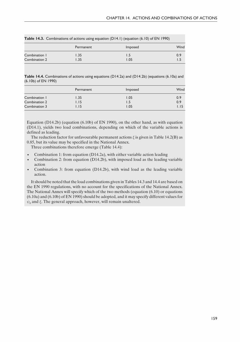
Delivered by ICEVirtualLibrary.com to:
IP: 95.42.11.157
On: Sun, 11 Jul 2010 21:36:40
Equation (D14.2b) (equation (6.10b) of EN 1990), on the other hand, as with equation(D14.1), yields two load combinations, depending on which of the variable actions isdefined as leading.
The reduction factor for unfavourable permanent actions ξ is given in Table 14.2(B) as0.85, but its value may be specified in the National Annex.
Three combinations therefore emerge (Table 14.4):
• Combination 1: from equation (D14.2a), with either variable action leading• Combination 2: from equation (D14.2b), with imposed load as the leading variable
action• Combination 3: from equation (D14.2b), with wind load as the leading variable
action.
It should be noted that the load combinations given in Tables 14.3 and 14.4 are based onthe EN 1990 regulations, with no account for the specifications of the National Annex.The National Annex will specify which of the two methods (equation (6.10) or equations(6.10a) and (6.10b) of EN 1990) should be adopted, and it may specify different values forψ0 and ξ. The general approach, however, will remain unaltered.
159
CHAPTER 14. ACTIONS AND COMBINATIONS OF ACTIONS
Table 14.3. Combinations of actions using equation (D14.1) (equation (6.10) of EN 1990)
Permanent Imposed Wind
Combination 1 1.35 1.5 0.9Combination 2 1.35 1.05 1.5
Table 14.4. Combinations of actions using equations (D14.2a) and (D14.2b) (equations (6.10a) and(6.10b) of EN 1990)
Permanent Imposed Wind
Combination 1 1.35 1.05 0.9Combination 2 1.15 1.5 0.9Combination 3 1.15 1.05 1.15
169Guide to Eurocode 1993 - CRC02 December 2004 11:54:38
Color profile: DisabledComposite Default screen

Delivered by ICEVirtualLibrary.com to:
IP: 95.42.11.157
On: Sun, 11 Jul 2010 21:36:43
References
1. ECCS (1978) European Recommendations for the Steel Structures. European Conventionfor Constructional Steelwork, Brussels.
2. Gulvanessian, H., Calgaro J.-A. and Holický, M. (2002) Designers’ Guide to EN 1990,Eurocode: Basis of Structural Design. Thomas Telford, London.
3. Corus (2002) Corrosion Protection of Steel Bridges. Corus Construction Centre,Scunthorp.
4. Baddoo, N. R. and Burgan, B. A. (2001) Structural Design of Stainless Steel. SteelConstruction Institute, Ascot, P291.
5. Davison, B., Owens, G. W. and SCI (2003) The Steel Designers’ Manual, 6th edn. SteelConstruction Institute, Ascot, and Blackwell, Oxford.
6. ECCS (1990) Background Documentation to Eurocode 3: Part 1.1. European Conventionfor Constructional Steelwork, Brussels.
7. Nethercot, D. A. and Lawson, R. M. (1992) Lateral Stability of Steel Beams andColumns – Common Cases of Restraint. Steel Construction Institute, Ascot, P093.
8. Timoshenko, S. P. and Gere, J. M. (1961) Theory of Elastic Stability, 2nd edn.McGraw-Hill, New York.
9. Galambos, T. V. (ed.) (1998) Guide to Stability Design Criteria for Metal Structures, 5thedn. Wiley, New York.
10. Trahair, N. S. (1993) Flexural–torsional Buckling of Structures. Chapman and Hall,London.
11. Trahair, N. S. Bradford, M. A. and Nethercot, D. A. (2001). The Behaviour and Designof Steel Structures to BS 5950, 3rd edn. Spon, London.
12. Chen, W. F. and Atsuta, T. (1977) Theory of Beam Columns. McGraw-Hill, New York.13. Narayanan, R. (ed.) (1982) Axially Compressed Structures – Stability and Strength.
Applied Science, Amsterdam.14. Engessor, F. (1909) Über die Knickfestigkeit von Rahmenstäben. Zentralblatt der
Bauverwaltung, 29, 136 [in German].15. Wyatt, T. A (1989) Design Guide on the Vibration of Floors. Steel Construction Institute,
Ascot, P076.16. Boissonnade, N., Jaspart, J.-P., Muzeau, J.-P. and Villette, M. (2002) Improvement of
the interaction formulae for beam columns in Eurocode 3. Computers and Structures,80, 2375–2385.
17. Lindner, J. (2003) Design of beams and beam columns. Progress in Structural Engineeringand Materials, 5, 38–47.
18. Davies, J. M. and Bryan, E. R. (1982) Manual of Stressed Skin Diaphragm Design.London: Granada.
19. Nethercot, D. A. and Trahair, N. S. (1975) Design of diaphragm braced I-beams.Journal of Structural Engineering of the ASCE, 101, 2045–2061.
171Guide to Eurocode 1993 - CRC02 December 2004 11:54:38
Color profile: DisabledComposite Default screen

Delivered by ICEVirtualLibrary.com to:
IP: 95.42.11.157
On: Sun, 11 Jul 2010 21:36:43
20. BCSA/SCI (2002) Joints in Steel Construction – Simple Connections. Steel ConstructionInstitute, Ascot, P212.
21. BCSA/SCI (1995) Joints in Steel Construction – Moment Connections. Steel ConstructionInstitute, Ascot, P207.
22. CIDECT (1992) Design Guide for Rectangular Hollow Section (RHS) Joints UnderPredominantly Static Loading. Comité International pour le Développement et l'Étudede la Construction Tubulaire, Cologne.
23. CIDECT (1991) Design Guide for Circular Hollow Section (CHS) Joints UnderPredominantly Static Loading. Comité International pour le Développement et l'Étudede la Construction Tubulaire, Cologne.
24. Jaspart, J. P., Renkin, S. and Guillaume, M. L. (2003) European Recommendations forthe Design of Simple Joints in Steel Structures . University of Liège, Liège[1st draft of aforthcoming publication of the Technical Committee 10 “Joints and Connections” ofthe European Convention of Constructional Steelwork (ECCS TC10)].
25. Owens, G. W. and Cheal, B. D. (1988) Structural Steelwork Connections. Butterworth,London.
26. Driver, R. G., Grondin, G. Y. and Kulak, G. L. (2004) A unified approach to designfor block shear. In: Connections in Steel Structures V: Innovative Steel Connections.ECCS-AISC Workshop, Amsterdam.
27. Nethercot, D. A. (1998) Towards a standardisation of the design and detailing ofconnections. Journal of Constructional Steel Research, 46, 3–4.
28. Anderson, D. (ed.) (1996) Semi-rigid Behaviour of Civil Engineering Structural Connections.COST-C1, Brussels.
29. Faella, C., Piluso, V. and Rizzano, G. (2000) Structural Steel Semi-rigid Connections.CRC Press, Boca Raton.
30. CIDECT (1982) Cidect Monograph No. 7. Fatigue Behaviour of Welded Hollow SectionJoints. Comité International pour le Développement et l'Étude de la ConstructionTubulaire, Cologne.
31. Grubb, P. J., Gorgolewski, M. T. and Lawson, R. M. (2001) Building Design Using ColdFormed Steel Sections. Steel Construction Institute, Ascot, P301.
32. Gorgolewski, M. T., Grubb, P. J. and Lawson, R. M. (2001) Modular Construction UsingLight Steel Framing. Steel Construction Institute, Ascot, P302.
33. Rhodes, J. and Lawson, R. M. (1992) Design of Structures Using Cold Formed SteelSections. Steel Construction Institute, Ascot, P089.
162
DESIGNERS’ GUIDE TO EN 1993-1-1
172Guide to Eurocode 1993 - CRC02 December 2004 11:54:38
Color profile: DisabledComposite Default screen

Delivered by ICEVirtualLibrary.com to:
IP: 95.42.11.157
On: Sun, 11 Jul 2010 21:36:53
Index
accidental actions 154actions 153–4
combinations, for buildings 155–9design values 156, 157fundamental combinations 154–9
allocation of strut curve 64axial buckling resistance 61axial compression force 32axial design effect 42, 43, 61
battened columns 98, 99battened compression members 101beams with restraints, assessment methods for
79–80bending
axial force and 55–60shear and 52–5shear and axial force 60–1uniform members in 68–80
bending/axial compression, uniform members in79–97
bending moment design effect 45, 69bending moment, resistance 45–7
cross-section classification 46–7cross-section properties 46
bi-axial bending 47cross-section check for 93interaction curves 59with or without axial force 59
block tearing 125brittle fracture 14buckling curve selection table 147buckling curves 61–4, 67, 68, 150
imperfection factors 63, 64, 67, 78, 84, 85, 94,95
selection table 63buckling factor 39buckling lengths 25, 65–6buckling of components of buildings structures
117–19continuous restraints 118
buckling resistance in bending 68–79, 85–6, 94–5
buckling resistance in combined bending/axialcompression 79–97
equivalent uniform factors 96interaction factors 96–7interaction formulae 97
buckling resistance moment 69buckling resistance of compression member 35,
66–8, 93–4, 149–50built-up compression members 98–101butt welds 128–9
angles connected by one leg 129connections to unstiffened flanges 128force distribution 128long joints 128–9
characteristic resistance 10characteristic values 10Cij factors 88cold-formed design 133–51
material properties 135rounded corners and geometric properties
and 135–6combination factor 155combined bi-axial bending/axial compression
89–97component method 131compression resistance 43–5, 61–8
combined bi-axial bending/axial compression90
cross-section classification 44cross-section compression resistance 43–5
continuous construction, principles of 130conventions for member axes 7–8corrosion 17, 19critical buckling loads 149cross-section resistance 35, 36–61, 81
bending resistance 54under bending, shear and axial force 83–4to combined bending and shear 54–5cross-section classification 53–4distortional buckling 144–6gross and net areas 36–7
173Guide to Eurocode 1993 - CRC02 December 2004 11:54:38
Color profile: DisabledComposite Default screen

Delivered by ICEVirtualLibrary.com to:
IP: 95.42.11.157
On: Sun, 11 Jul 2010 21:36:53
properties 36–42, 53, 57section properties 53shear resistance 54in tension to fracture 35under combined bending/compression 57under combined bending/shear 53
cross-sectionsClass 4 30–1classes 26–7classification of 26–34plastic global analysis 34under combined bending and axial force 31–2under combined bending/compression 32–4
combined loading 33–4pure compression 32–3section properties 32, 33
design assisted by testing 11design working life 9, 10diagonal bracing system 23, 24distortional buckling 140–6
calculation of effective section properties for146
calculation of reduced thickness for effectiveedge stiffener section 144–6
cross-section resistance to 144–6elastic critical buckling stress for effective
stiffener section 145linear spring stiffness 140–1, 145outline of design approach 140reduced area of effective stiffener section 145reduction factor 142, 145
durability 10, 17–19
edge stiffener 141, 143calculation of reduced thickness for 144–6elastic critical buckling stress for 145geometric properties of 144–5reduced area of 145
effective area concept 38to account for shear lag and local buckling 38flat compression element 39
elastic critical plate buckling stress 39elastic critical torsional–flexural buckling force
65elastic torsional buckling force 87elastic shear resistance of cross-section 49end moment loading 73, 74end stresses, ratio of 32equivalent uniform moment factors 86–7, 111,
113
fastener holes 47, 60, 61fasteners
non-staggered arrangement 36, 37staggered arrangement 37
fatigue 17fillet welds 127–8
directional method 127–8
simplified method 128flange curling 150–1flexural buckling 61–8
of members in triangulated and latticestructures 117
elastic critical force and non-dimensionalslenderness for 67, 84
flexural buckling resistance 64fracture toughness 14
general method for lateral and lateral torsionbuckling 97
geometric imperfections 11, 22global analysis 21, 22–5
effects of deformed geometry on structure22–3
structural stability of frames 23–5global buckling analysis 25
imperfection factor 150buckling curves 63, 64, 67, 78, 94, 95member buckling resistance in bending 85member buckling resistance in compression
84imperfections 25imposed loads 154interaction factors 81
Annex A 107–9Annex B 111–13member buckling resistance in bending/axial
compression 86member buckling resistance in bending 85non-dimensional slendernesses 88buckling resistance in combined bending/axial
compression 95–7interaction formulae 88–9intermediate stiffener 141internal compression elements 40
joint design 121–32analysis, classification and modelling 129–31basis of design 122connections made with bolts, rivets or pins
122–6connections made with pins 126design resistance 123–4force distributions at ultimate limit state
126prying forces 125–6slip-resistant connections 124
global analysis 129–31design moment resistance 130rigid and full strength joints 130H or I sections 131hollow sections 131–2
joint modelling 130–1
laced compression members 100–1chords 100–1
164
DESIGNERS’ GUIDE TO EN 1993-1-1
174Guide to Eurocode 1993 - CRC02 December 2004 11:54:39
Color profile: DisabledComposite Default screen

Delivered by ICEVirtualLibrary.com to:
IP: 95.42.11.157
On: Sun, 11 Jul 2010 21:36:53
lacings 101shear stiffness and effective second moment
of area 101lateral torsional buckling 45, 68–79, 85–6, 94–5,
97check for 77–8, 78–9elastic critical moment for 71–5for members with plastic hinges 97–8general method 97reduction factor for 78, 79, 85–6, 95
lateral torsional buckling curve 69–71correction factors 71imperfection factors for 70, 71
lateral torsional buckling resistance 68–79, 97lateral torsional slenderness, non-dimensional
77, 78, 85light-gauge sections 133limit state design 10live loads 154local (plate) buckling 38–41, 137–9
material non-linearities, analysis 26mechanical wear 17member buckling resistance 61–101, 146–50
in bending 68–79in bending/axial compression 79–97in compression 61–8
mono-axial bending and axial force 55–7
National Annex 2, 3, 13, 35, 70Nationally Determined Parameters (NDPs) 2nominal yield strength of steel 27non-dimensional lateral torsional slenderness
77, 78, 95non-dimensional slendernesses 86–9
for buckling modes 64–5, 150
out-of-plane buckling, segment containingplastic hinges for 118–19
outstand compression elements 40
partial factors 10–11, 35, 42, 44, 60, 122permanent actions 153, 155plastic analysis, variants of 26plastic modulus of effective section 47plastic moment resistance 55, 56, 93plastic neutral axis of effective section 47plastic shear resistance 48Principles 9
reduced plastic moment resistance 58–9reduction factor 38, 39, 41
distortional buckling 142, 145lateral torsional buckling 78, 79, 85–6, 95
rigid–plastic analysis 26
Saint Venant torsion 51serviceability limit states 103–6, 155
definition 103dynamic effects 106for buildings 104–6horizontal deflections 106irreversible 103reversible 103vertical deflections 104–6
shear area 50shear buckling 50–1, 60, 92
resistance of web to 49shear lag 38, 150shear resistance 48–51, 52–5
section properties 50shear stiffness 118slenderness, non-dimensional 86–9
for buckling 64–5, 150slip resistance 124smeared shear stiffness 99snow loads 154stress ratio 41structural analysis 21–34
taking account of material non-linearities 115structural modelling for analysis 22structural steel 13–14substitutive members 25
tensile resistance 42–3of lap splice 42, 43
torsion, resistance to 51–2torsional buckling 61, 64, 65, 146–50torsional–flexural buckling 61, 64, 65, 146–50torsional resistance 51–2torsional restraint stiffness 118
ultimate limit states 35–102, 153ultimate tensile strength 13uniform built-up compression members 98–102
battened compression members 101closely spaced built-up members 101–2design forces in chords and web members 100laced compression members 100–1
uniform membersin bending 68–80in bending/axial compression 79–97in compression 61–8
variable actions 154von Mises yield criterion 36
warping torsion 51web crushing, crippling and buckling 151welded connections 126–9width-to-thickness ratios 27, 29, 30, 31, 134wind loads 154
yield strength 13, 14Young's modulus 14
165
INDEX
175Guide to Eurocode 1993 - CRC02 December 2004 11:54:39
Color profile: DisabledComposite Default screen