2005 - ijamt - davim - optimisation of surface roughness on turning fibre-reinforced plastics (frps)...
TRANSCRIPT

8/9/2019 2005 - IJAMT - Davim - Optimisation of Surface Roughness on Turning Fibre-reinforced Plastics (FRPs) With Diamond…
http://slidepdf.com/reader/full/2005-ijamt-davim-optimisation-of-surface-roughness-on-turning-fibre-reinforced 1/5
DOI 10.1007/s00170-003-2006-2
O R I G I N A L A RT I C L E
Int J Adv Manuf Technol (2005) 26: 319–323
J. Paulo Davim · Francisco Mata
Optimisation of surface roughness on turning bre-reinforced plastics (FRPs)
with diamond cutting tools
Received: 04 August 2003 / Accepted: 23 October 2003 / Published online: 24 November 2004Springer-Verlag London Limited 2004
Abstract Fibre-reinforced plastics (FRPs) are used in struc-tural components in various elds of application of mechanicalengineering, such as automobile, biomechanics and aerospaceindustries. Their own properties, particularly the high strengthand stiffness and simultaneously low weight, allows the substitu-tion of the metallic materials in many cases. As a result of theseproperties and potential applications, exist a great necessity toinvestigate the machining of these composite materials.This paper presents an optimisation study of surface roughnessin turning FRPs tubes manufacturing by lament winding andhand lay-up, using polycrystalline diamond cutting tools. A planof experiments was performed with cutting parameters prexedin the FRP tubes. The objective was establishing the optimal cut-ting parameters to obtain a certain surface roughness ( Ra and Rt / Rmax ), corresponding to international dimensional precision(ISO) IT7 and IT8 in the FRP workpieces, using multiple an-alysis regression (MRA). Additionally, the optimal material re-
moval rates have been obtained.
Keywords Fibre-reinforced plastics (FRPs) · Optimisation ·Surface roughness · Turning
1 Introduction
In modern-day engineering, high demands are being placed oncomponents made of bre-reinforced plastics (FRPs) in rela-tion to their dimensional precision as well as to their surfaceroughness [1]. The exact degree of surface roughness can be of
J.P. Davim ( )Department of Mechanical Engineering,University of Aveiro,Campus Santiago, 3810-193 Aveiro, PortugalE-mail: [email protected]
F. MataPolytechnical School of Almaden,University of Castilla-La Mancha,Plaza Manuel Meca 1, 13412 Almaden, Spain
considerable importance, because it affect the functionality of the component [2].
Surface roughness is a great inuence on the performanceof the mechanical pieces and on the production costs. For thesereasons research developments have been carried out with theobjective of optimizing the cutting parameters, to obtain a deter-mined surface roughness [2, 3].
It was found that surface roughness and prole are highly de-pendent on the bre orientation (45 ◦ or 180 ◦ ) [4], the type of bres [5] and the measurement direction [6]. The roughness of the machining surface of lament-wound tubes is more sensitiveto increasing the winding angle than to increasing the tool feedrate [1].
The surface roughness is normally characterized by the Ra(arithmetic average roughness) and Rt / Rmax (maximum peak-to-valley height) parameters. Figure 1 presents the denition of Ra and Rt / Rmax according to the international norms.
For achieving the desired surface roughness, it is necessaryto understand the mechanisms of the material removal, and thekinetics of machining processes affecting the performance of thecutting tools [7].
The rst investigation on machining FRPs was presented in1971 by Everstine and Rogers [8], since then most of the re-
Fig.1. Denition of Ra (according DIN 4768 and ISO 4287/1) and Rt / Rmax(according DIN 4762)
8/9/2019 2005 - IJAMT - Davim - Optimisation of Surface Roughness on Turning Fibre-reinforced Plastics (FRPs) With Diamond…
http://slidepdf.com/reader/full/2005-ijamt-davim-optimisation-of-surface-roughness-on-turning-fibre-reinforced 2/5
320
search within this area has been based on experimental inves-tigations. Spur and Wunsch [1] studied turning of glass bre-reinforced (GFR) polyester and epoxy and found an increasingsurface roughness for an increase in the feed rate but no depen-dence on the cutting velocity. In contrast, Santhanakrishman etal. [9] and Ramulu et al. [10] obtained a better surface roughnesswith an increasing of the cutting velocity, so the machining of FRPs is an area still full of open questions.
Sreejith et al. [7] have evaluated the polycrystalline diamondtools (PCD) performance during machining and analyzing the in-uence of the material in the state of the machining surfaces.They observed a critical velocity of 300 m / min and a range of critical temperature of 300–350 ◦ C. Based on the tool wear tests,it has been established that PCD can be economically applied forthe turning of FRPs.
The purpose of this study was establishing the optimal cut-ting parameters to obtain a certain surface roughness ( Ra and Rt / Rmax ), corresponding to international dimensional precision(ISO) IT7 and IT8 in the FRP workpieces, using multiple an-alysis regression (MRA). Additionally, the optimal material re-moval rates (MRR) have been obtained.
2 Experimental procedure
In order to achieve the objective of this experimental work, ma-chining issues were effectuated with different cutting parame-ters. FRPs tubes of type GFRP (propoxylated bisphenol-A fu-mate polyester matrix reinforced with 65% of glass bre) wereused for tests. Table 1 shows the usual characteristics of the typeGFRP.
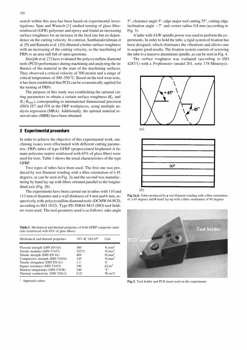
Two types of tubes have been used. The rst one was pro-duced by wet lament winding with a bre orientation of ± 45degrees, as can be seen in Fig. 2a and the second was manufac-turing by hand lay-up with bres oriented parallel to the longitu-dinal axis (Fig. 2b).
The experiments have been carried out in tubes with 110 and113 mm of diameter and a wall thickness of 4 mm and 6 mm, re-spectively, with polycrystalline diamond tools (DCMW 04-PCD,according to ISO 1832). Type PD JNR44 M15 (ISO) tool hold-ers were used. The tool geometry used is as follows: rake angle
Table 1. Mechanical and thermal properties of both GFRP composite mate-rials (reinforced with 65% of glass bers)
Mechanical and thermal properties ATLAC 382-05 ∗ Unit
Flexural strength (DIN EN 63) 380 N / mm 2
Tensile modulus (DIN 53457) 25275 N / mm 2
Tensile strength (DIN EN 61) 404 N / mm 2
Compressive strength (DIN 53454) 145 N / mm 2
Tensile elongation (DIN EN 61) 1.3 %Impact resistance (DIN 53453) 190 kJ / m2
Martens temperature (DIN 53458) 240 ◦ CThermal conductivity (DIN 52612) 0.22 W / m ◦ C
∗ Approach values
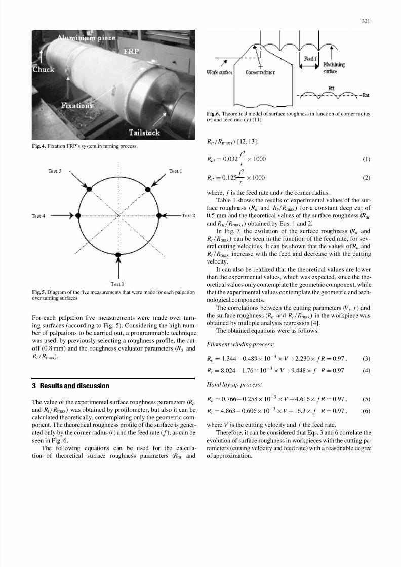
5◦ , clearance angle 5 ◦ , edge major tool cutting 55 ◦ , cutting edgeinclination angle − 7◦ and corner radius 0 .8 mm (according toFig. 3).
A lathe with 4 kW spindle power was used to perform the ex-periments. In order to hold the tube, a rigid system of xation hasbeen designed, which eliminates the vibrations and allows oneto acquire good results. The xation system consists of screwingthe tube to a massive aluminium spindle, as can be seen in Fig. 4.
The surface roughness was evaluated (according to ISO4287/1) with a Prolometer (model 201, serie 178 Mitutoyo).
Fig.2a,b. Tubes produced by a wet lament winding with a ber orientationof ± 45 degrees and b hand lay-up with a ber orientation of 90 degrees
Fig.3. Tool holder and PCD insert used on the experiments
8/9/2019 2005 - IJAMT - Davim - Optimisation of Surface Roughness on Turning Fibre-reinforced Plastics (FRPs) With Diamond…
http://slidepdf.com/reader/full/2005-ijamt-davim-optimisation-of-surface-roughness-on-turning-fibre-reinforced 3/5
321
Fig. 4. Fixation FRP’s system in turning process
Fig. 5. Diagram of the ve measurements that were made for each palpationover turning surfaces
For each palpation ve measurements were made over turn-ing surfaces (according to Fig. 5). Considering the high num-ber of palpations to be carried out, a programmable techniquewas used, by previously selecting a roughness prole, the cut-off (0 .8 mm) and the roughness evaluator parameters ( Ra and Rt / Rmax ) .
3 Results and discussion
The value of the experimental surface roughness parameters ( Raand Rt / Rmax ) was obtained by prolometer, but also it can becalculated theoretically, contemplating only the geometric com-ponent. The theoretical roughness prole of the surface is gener-ated only by the corner radius ( r ) and the feed rate ( f ), as can beseen in Fig. 6.
The following equations can be used for the calcula-tion of theoretical surface roughness parameters ( Rat and
Fig.6. Theoretical model of surface roughness in function of corner radius(r ) and feed rate ( f ) [11]
Rtt / Rmax t ) [12, 13]:
Rat = 0.032 f 2
r × 1000 (1)
Rtt = 0.125 f 2
r × 1000 (2)
where, f is the feed rate and r the corner radius.Table 1 shows the results of experimental values of the sur-
face roughness ( Ra and Rt / Rmax ) for a constant deep cut of 0.5 mm and the theoretical values of the surface roughness ( Rat
and Rtt / Rmax t ) obtained by Eqs. 1 and 2.In Fig. 7, the evolution of the surface roughness ( Ra and
Rt / Rmax ) can be seen in the function of the feed rate, for sev-eral cutting velocities. It can be shown that the values of Ra and Rt / Rmax increase with the feed and decrease with the cuttingvelocity.
It can also be realized that the theoretical values are lowerthan the experimental values, which was expected, since the the-oretical values only contemplate the geometric component, whilethat the experimental values contemplate the geometric and tech-nological components.
The correlations between the cutting parameters ( V , f ) andthe surface roughness ( Ra and Rt / Rmax ) in the workpiece wasobtained by multiple analysis regression [4].
The obtained equations were as follows:
Filament winding process:
Ra = 1.344 − 0.489 × 10− 3 × V + 2.230 × f R = 0.97 , (3)
Rt = 8.024 − 1.76 × 10− 3 × V + 9.448 × f R = 0.97 (4)
Hand lay-up process:
Ra = 0.766 − 0.258 × 10− 3 × V + 4.616 × f R = 0.97 , (5)
Rt = 4.863 − 0.606 × 10− 3 × V + 16 .3 × f R = 0.97 , (6)
where V is the cutting velocity and f the feed rate.Therefore, it can be considered that Eqs. 3 and 6 correlate the
evolution of surface roughness in workpieces with the cutting pa-rameters (cutting velocity and feed rate) with a reasonable degreeof approximation.

8/9/2019 2005 - IJAMT - Davim - Optimisation of Surface Roughness on Turning Fibre-reinforced Plastics (FRPs) With Diamond…
http://slidepdf.com/reader/full/2005-ijamt-davim-optimisation-of-surface-roughness-on-turning-fibre-reinforced 4/5
322
Fig.7a–d. Evolution of the surface rough-ness ( Ra and Rt / Rmax ) in function of thefeed, for several cutting velocities. a Ra ,Filament winding b Ra , Hand lay-upc R t / Rmax , Filament winding d R t / Rmax ,Hand lay-up
The theoretical relation between Rtt and Rat can be calcu-lated from Eqs. 1 and 2:
Rtt
Rat =
0.125 f 2r x 1000
0.032 f 2r x 1000
=0.1250.032
= 3.91 (7)
Rtt = 3.91 Rat (8)
From Table 1, the experimental relations between Rt and Rahave been obtained, and the average value for both processesstudied has been nally calculated, according to Table 2. As itcan be observed, the mean experimental value for the two pro-cesses ( Rt / Ra = 5.81) differs signicantly from the theoreticalvalue ( Rtt / Rat = 3.91). This was expected, because the theoret-ical relation does not consider the particularities of the turningoperations, the direction of bres, etc. Therefore, the optimiza-tion of Ra and Rt / Rmax was made based on the relation obtainedexperimentally ( Rt / Ra = 5.81).
With this experimental relation and using Eqs. 3–6, optimalvalues of cutting velocity and feed rate for a reference roughnessvalue can be obtained.
Table 2. Values of Rt / Ra obtained experimentally
Relation Rt / Ra
Test FW HLU Average
1 6.41 6.22 6.31
2 6.27 4.88 5.573 5.31 5.05 5.184 5.86 6.20 6.035 6.21 5.68 5.946 5.58 4.99 5.287 5.85 6.28 6.068 6.32 6.08 6.209 6.28 5.17 5.72
Mean 5.81
FW: Filament winding, HLU: Hand lay-up
Considering the ISO IT8 quality for the lament windingprocess, ISO IT7 for the hand lay-up process and the relation R
t / R
a = 5.81, it can be written:
Filament winding process:
Ra ≤ 1.6(µ m)( ISOIT 8) and Rt ≤ 1.6 × 5.81 ≤ 9.29(µ m)
1.6 ≥ 1.344 − 0.489 × 10− 3 × V + 2.230 × f (9)
9.29 ≥ 8.024 − 1.76 × 10− 3 × V + 9.448 × f (10)
The solution of Eqs. 9 and 10 allows one to obtain the follow-ing results for the cutting parameters: V [349–571] (m / min) and f [0.16–0.05] (mm / rev). Hand lay-up process:
Ra ≤ 1.0(µ m)( ISOIT 7)andR t ≤ 1.0 × 5.81 ≤ 5.81(µ m )
1.0 ≥ 0.766 − 0.258 × 10− 3 × V + 4.616 × f (11)
5.81 ≥ 4.863 − 0.606 × 10− 3 × V + 16 .3 × f (12)
The solution of Eqs. 11 and 12 allows one to obtain the fol-lowing results for the cutting parameters: V [396–571] (m / min)and f [0.07–0.05] (mm / rev).
As it can be observed, the previous solutions correspond tothe closed intervals constituted by sets of pairs of values (Vand f), corresponding to the optimal cutting parameters, for bothprocesses. Figure 8 presents the work dominion of cutting pa-rameters and the optimal regions for the two processes studied,lament winding and hand lay-up.
The value of the material removal rate (MRR) can be ob-tained by the following equation [14]:
MRR = V × f × d , (13)
where V is the cutting velocity, f the feed rate and d the depth of cut.
Using the cutting parameters previously calculated by Eqs. 9and 10 and a depth cut of 0 .5 mm, the value of the optimal MRR

8/9/2019 2005 - IJAMT - Davim - Optimisation of Surface Roughness on Turning Fibre-reinforced Plastics (FRPs) With Diamond…
http://slidepdf.com/reader/full/2005-ijamt-davim-optimisation-of-surface-roughness-on-turning-fibre-reinforced 5/5
323
Fig.8a,b. Work dominion and optimal regions of cutting parameters.a Filament winding b Hand lay-up
by a lament winding process is included between [27.88–14.27](cm 3 / min). The same procedure allows one to obtain an intervalbetween [13.84–14.27] (cm 3 / min) for the hand lay-up process.
4 Conclusions
For the experimental results presented on the optimisation of surface roughness in turning FRPs manufacturing by lamentwinding and hand lay-up processes, the following conclusionscan be mentioned:
• With these cutting parameters ( V and f ) it was possibleto obtain surfaces with 0 .80–1 .75 µ m of arithmetic averageroughness ( Ra ).
• The surface roughness ( Ra and Rt / Rmax ) increases with thefeed rate and decreases with the cutting velocity.
• By the hand lay-up process it is possible to obtain smallervalues of surface roughness than by lament winding.
• The model developed using multiple analysis regression(MRA), allows one to obtain the optimal cutting parametersand to calculate the material removal rate, according to inter-national dimensional precision ISO 7 and ISO 8.
Acknowledgement The authors wish to acknowledge the research project“Optimisation of the Machining of Polymeric Matrix Composite based onNumerical and Experimental Models”, for providing the composite mate-rial to be used in the turning tests. They would also like to acknowledge theengineer Pedro Reis for his participation in the experimental work.
References
1. Spur G, Wunsch UE (1988) Turning of ber-reinforced plastics. Manuf Rev 1(2):124–129
2. Abouelatta OB, M adl J (2001)Surface roughness prediction based oncutting parameters and tool vibrations in turning operations. J MaterProcess Technol 118:269–277
3. Erisken E (1999) Inuence from production parameters on the surfaceroughness of a machine short bre reinforced thermoplastic. Int J MachTools Manuf 39:1611–1618
4. Mata F, Davim JP (2003) An investigation about the precision turningber reinforced plastics (FRP’s) with diamond cutting tools using mul-tiple analysis regression. II Iberian Conference of Tribology, Valencia,pp 117–124
5. Jahanmir S, Ramulu M, Koshy P (1998) Machining of ceramics andcomposites. Dekker, New York, pp 238–243
6. Ramulu M, Wern CW , Garbini JL (1993) Effect of the direction on sur-face roughness measurements of machined graphite /epoxy composite.Compos Manuf 4(1):39–51
7. Sreejith PS, Krishnamurthy R, Malhota SK, Narayanasamy K (2000),Evaluation of PCD tool performance during machining of car-bon/phenolic ablative composites J Mater Process Technol 104:53–58
8. Everstine GC, Rogers TG (1971) A theory of machining of reinforcedmaterials. J Compos Mater 5:94–106
9. Santhanakrishman G, Krishnamurthy R, Malhota SK (1988) Machin-ability characteristics of bre reinforced plastics composites J Mech
Work Technol 17:195–20410. Ramulu M, Arola D, Colligan K (1994) Preliminary investigation of ef-fects on the surface integrity of ber reinforced plastics. PD-Vol-64-2.Engineering Systems Design and Analysis 2 ASME, pp 93–101
11. Boothroy G, Knight W (1989) Fundamentals of machining and machinetools. Dekker, New York, pp 155–173
12. Davim JP, Reis P (2004) Dimensional precision and surface rough-ness on turning tubes in bre reinforced plastics based on the designexperiment. Int J Mater Prod Technol 20(4):268–279
13. Shaw MC (1984) Metal cutting principles. Oxford Science Publica-tions, New York, pp 487–543
14. Groover MP (1996) Fundamentals of modern manufacturing materials,process and systems. Prentice-Hall, New York, pp 386–388