20060614014 - dtic. · pdf filei report documentation page afrl-sr-ar-tr-06_0165 public...
TRANSCRIPT
I
REPORT DOCUMENTATION PAGE AFRL-SR-AR-TR-06_01 6 5Public reporting burden for this collection of information is estimated to average 1 hour per response. including the time for reviewingmaintaining the data needed, and completing and reviewing this collection of information. Send comments regarding this burden estsuggestions for reducing this burden to Washington Headquarters Services. Directorate for Information Operations and Reports. 121to the Ofce of Manag~ement and Budget, Paperwork Reduction Proe-ct (0704-0188), Washington, DC 20503
1. AGENCY USE ONLY (Leave 2. REPORT DATE 3. REPORT TYPE ANL u, •, ..blank) March 2006 Final Report - Jul 1, 2002 to December 31, 20054. TITLE AND SUBTITLE 5. FUNDING NUMBERSCarbon Nanotube-Based Composites for Future Air Force and Aerospace AFOSR GRANT F49620-02-1-0328Systems
6. AUTHOR(S)Erik T. Thostenson and Tsu-Wei Chou
7. PERFORMING ORGANIZATION NAME(S) AND ADDRESS(ES) 8. PERFORMING ORGANIZATIONREPORT NUMBER
University of Delaware Chou-AFOSR-2006210 Hullihen HallNewark DE 19716
9. SPONSORING I MONITORING AGENCY NAME(S) AND ADDRESS(ES) 10. SPONSORING I MONITORING
AGENCY REPORT NUMBERAir Force Office of Scientific ResearchDr. Byung-Lip Lee, Program Manager875 North Randolph Street, Suite 325Arlington, Virginia 22203-1768
11. SUPPLEMENTARY NOTES 2006061401412a. DISTRIBUTION I AVAILABILITY STATEMENT
lppi'ov~ed toi pikIiti -k ,g*diStr1bution unlimtited
13. ABSTRACT (Maximum 200 Words)
Nanotubes have been targeted for potential applications ranging from the next generation of computers and flat-paneldisplays to structural and functional materials. In addition to their well-known stiffness (> 1 TPa) and strength (-30 GPa)properties, carbon nanotubes also possess exceptionally high electrical and thermal conductivities, with the axial thermalconductivity near that of crystalline diamond. The unique mechanical and physical properties of nanotubes offertremendous opportunity for the development of multi-functional composites. Under this research program an integratedeffort to processing, characterization, and analysis/modeling of nanotube-based composites was undertaken. Throughthis research work a fundamental understanding of the processing/structure/property relations in carbon nanotube-reinforced composites has evolved. Ultimately, the establishment of these basic relationships will enable the nanoscaledesign of nanotube-reinforced materials for Air Force and aerospace systems.
14. SUBJECT TERMS 15. NUMBER OF PAGESCarbon Nanotubes, Nanocomposites, Nanocomposite Processing, 16Structure/Property Relations 16. PRICE CODE
17. SECURITY CLASSIFICATION 18. SECURITY CLASSIFICATION SECURITY CLASSIFICATION 20. LIMITATION OF ABSTRACTOF REPORT OF THIS PAGE OF ABSTRACT UL
NSN 7540-01-280-5500 Standard Form 298 (Rev. 2-89)Prescribed by ANSI Std. Z39-18298-102

Carbon Nanotube-Based Composites for Future Air Force and Aerospace Systems Tsu-Wel Chou
MOTIVATION AND SCOPEIn composite materials, where distinct phases are combined together for
reinforcement, the opportunity exists to design composites for specific properties atvarious levels of scale. For example, in traditional fibrous composites the engineer notonly designs the geometric shape of the part but can prescribe the ply stackingsequence for lay-up, utilize different fibers to create hybrid composites, or bend and twistfibers together using textile techniques. At the microscopic scale, we are tailoring thelocal stiffness, strength, toughness and other properties through controlling the fiberorientation, type, and volume fraction. Recent advances in producing nanostructuredmaterials with novel material properties have stimulated research to create macroscopicengineering materials by designing the structure at the nanoscale.
Since their observation in 1991 by lijima [11, carbon nanotubes have been thefocus of considerable research. At the nanometer scale, this unique form of carbonshows exceptional mechanical and physical properties with predicted elastic moduli ofabout 1 TPa (1000 GPa), strengths in the range of 30 GPa, and exceptional resilience,showing large nonlinear elastic deformation before fracture. Carbon nanotubes possessnovel electronic properties, where they can be conducting or semi-conducting dependingon the atomic structure, and have axial thermal conductivity that is predicted to be higherthan diamond, the highest thermal conductivity of any known material. These properties,combined with their low density, fiber-like structure and high aspect ratio, havestimulated the development of nanotube-based composites. With potential applicationsranging from molecular electronics and field-emission displays to nanocomposites,carbon nanotubes offer tremendous opportunity in the development ofnanotechnologies.
As scientists and engineers seek to make practical materials and devices fromnanostructures, understanding material behavior across length scales from the atomisticto macroscopic levels is required. Knowledge of how the nanoscale structure influencesthe nanotube properties as well as how nanotubes interact when embedded in acomposite is needed to realize the potential for carbon nanotubes as reinforcement incomposites. The change in reinforcement scale from microns of traditional fiberreinforcements to nanometers poses fundamentally new challenges in the processing,characterization and modeling of these materials.
In traditional fiber-reinforced composites, the properties of the constituentmaterials are first understood separately and then the materials are combined toexamine the synergy [2]. Unlike traditional fibers, where the stiffness, statisticalstrength, and transport properties can be readily investigated with experimentaltechniques, obvious difficulties are encountered in testing nanotubes because of theirsize. In addition, the properties of carbon nanotubes, and nanostructured materials ingeneral, are highly size/structure dependent and traditional continuum assumptions fornanotube and composite mechanical properties are not valid.
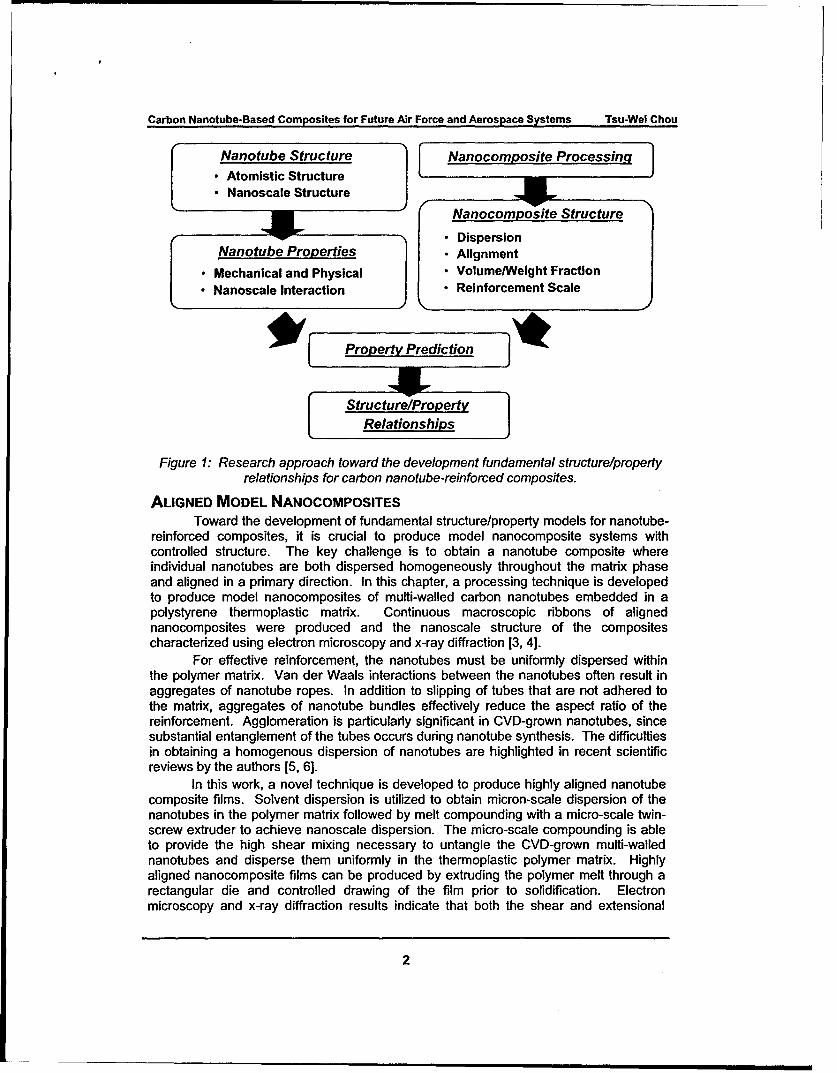
The objective of this research program was to obtain a fundamental understanding ofthe processinglstructurelproperty relations in carbon nanotube-reinforced compositesthrough integrated research on processing and characterization of modelnanocomposite systems as well as development of predictive models for thenanocomposite properties. Our Integrated research approach is Illustrated in Figure 1.Ultimately, the establishment of these basic relationships will enable the nanoscaledesign of nanotube-reinforced materials.
SUT 'JTION STATEMENT AApproved for Public Release
Distribution Unlimited
Carbon Nanotube-Based Composites for Future Air Force and Aerospace Systems Tsu-Wel Chou
Nanotube Structure Nanocomposite Processing
*Atomistic Structure*Nanoscale Structure
Nanocomposite Structure
DispersionNanotube Properties - Alignment
"I .Mechanical and Physical * Volume/Weight Fraction" Nanoscale Interaction - Reinforcement Scale
* [ Property Prediction
StructurelPropertyRelationships
Figure 1: Research approach toward the development fundamental structure/property
relationships for carbon nanotube-reinforced composites.
ALIGNED MODEL NANOCOMPOSITESToward the development of fundamental structure/property models for nanotube-
reinforced composites, it is crucial to produce model nanocomposite systems withcontrolled structure. The key challenge is to obtain a nanotube composite whereindividual nanotubes are both dispersed homogeneously throughout the matrix phaseand aligned in a primary direction. In this chapter, a processing technique is developedto produce model nanocomposites of multi-walled carbon nanotubes embedded in apolystyrene thermoplastic matrix. Continuous macroscopic ribbons of alignednanocomposites were produced and the nanoscale structure of the compositescharacterized using electron microscopy and x-ray diffraction [3, 4].
For effective reinforcement, the nanotubes must be uniformly dispersed withinthe polymer matrix. Van der Waals interactions between the nanotubes often result inaggregates of nanotube ropes. In addition to slipping of tubes that are not adhered tothe matrix, aggregates of nanotube bundles effectively reduce the aspect ratio of thereinforcement. Agglomeration is particularly significant in CVD-grown nanotubes, sincesubstantial entanglement of the tubes occurs during nanotube synthesis. The difficultiesin obtaining a homogenous dispersion of nanotubes are highlighted in recent scientificreviews by the authors [5, 6].
In this work, a novel technique is developed to produce highly aligned nanotubecomposite films. Solvent dispersion is utilized to obtain micron-scale dispersion of thenanotubes in the polymer matrix followed by melt compounding with a micro-scale twin-screw extruder to achieve nanoscale dispersion. The micro-scale compounding is ableto provide the high shear mixing necessary to untangle the CVD-grown multi-wallednanotubes and disperse them uniformly in the thermoplastic polymer matrix. Highlyaligned nanocomposite films can be produced by extruding the polymer melt through arectangular die and controlled drawing of the film prior to solidification. Electronmicroscopy and x-ray diffraction results indicate that both the shear and extensional
2
Carbon Nanotube-Based Composites for Future Air Force and Aerospace Systems Tsu-Wei Chou
flows result in significant process-induced alignment of the nanocomposite structure.The method of extruding and drawing the molten polymer creates a continuous ribbon ofaligned nanocomposite that may then be laminated using traditional compositesprocessing methods, such as autoclave molding or tape placement, to create macro-scale aligned nanocomposites.
The model nanocomposite system is composed of a polystyrene polymer matrixreinforced with CVD-grown multi-walled carbon nanotubes. The polystyrene used in thiswork is a commercially available thermoplastic with an average molecular weight of280,000 (Scientific Polymer, Inc - Ontario, NY). The multi-walled carbon nanotubesused for the model nanotube-reinforced polymer composites were synthesized usingconventional chemical vapor deposition (CVD) techniques. For the growth of carbonnanotubes, iron nanoparticles embedded in silica were used as the catalyst and the CVDprocess was carried out in a tube furnace [7]. The catalyst was heated under vacuum toa processing temperature of 7000C and nanotubes were grown for two hours under aflowing gas mixture of approximately 66% nitrogen (N2), 27% ammonia (NH 3) and 7%acetylene (C2H2) at a pressure of 0.6 Torr [8]. The growth temperature and pressureswere chosen so that the amounts of bamboo-like defects, where interior walls of thenanotube form internal caps along the length of the carbon nanotube, were minimized.After acid purification to remove residual impurities, the nanotubes were rinsed withdistilled water and dried under vacuum for two hours at 120°C.
To achieve a homogeneous distribution of nanotubes in the polystyrene matrix, aprocessing method was developed that combines solvent-assisted dispersion ofnanotubes in the polymer followed by shear mixing of the polymer melt using a micro-scale twin-screw extruder. Aligned nanocomposite films were formed by subsequentlydrawing the molten polymer prior to solidification and the extensional flow from drawingresults in significant flow-induced alignment of nanotubes. Optimum processingparameters (mixing time, shear stress, draw ratio) to achieve a high degree of dispersionand alignment were determined experimentally by processing nanocomposite films usingthe micro-scale extruder and investigating the micro and nano-scale structure usingtransmission electron microscopy.
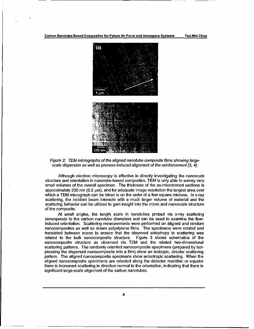
To examine the nanoscale structure of the aligned nanotube composites,samples were taken from along the length of the extruded ribbons for examination usingTEM. Once samples were sectioned from the extruded nanocomposite, the films wereembedded in an epoxy support and an ultramicrotome (Leica Ultracut UCT) with adiamond knife was used to cut slices for observation in the TEM. Figure 2 shows brightfield TEM micrographs of the aligned nanocomposite films, and the arrows indicate theflow/drawing direction of the films. The gray lines visible in the TEM micrographs areartifacts from the cutting process caused by the diamond knife and indicate that the filmwas cut normal to the direction of nanotube orientation. The TEM micrographs showexcellent dispersion of nanotubes within the polymer matrix. In addition, drawing the filmfrom the melt resulted in substantial alignment of the nanotubes. Figure 2a shows large-scale dispersion and overall alignment of the carbon nanotubes and Figure 2b showsnanoscale tube alignment, particularly of the smaller diameter nanotubes not visible atlower magnifications.
3
Carbon Nanotube-Based Composites for Future Air Force and Aerospace Systems Tsu-Wei Chou
Figure 2: TEM micrographs of the aligned nanotube composite films showing large-scale dispersion as well as process-induced alignment of the reinforcement [3, 4].
Although electron microscopy is effective in directly investigating the nanoscalestructure and orientation in nanotube-based composites, TEM is only able to survey verysmall volumes of the overall specimen. The thickness of the as-microtomed sections isapproximately 200 nm (0.2 pm), and for adequate image resolution the largest area overwhich a TEM micrograph can be taken is on the order of a few square microns. In x-rayscattering, the incident beam interacts with a much larger volume of material and thescattering behavior can be utilized to gain insight into the micro and nanoscale structureof the composite.
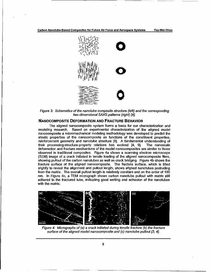
At small angles, the length scale in nanotubes probed via x-ray scatteringcorresponds to the carbon nanotube diameters and can be used to examine the flow-induced orientation. Scattering measurements were performed on aligned and randomnanocomposites as well as drawn polystyrene films. The specimens were rotated andtranslated between scans to ensure that the observed anisotropy in scattering wasrelated to the bulk nanocomposite structure. Figure 3 shows schematics of thenanocomposite structure as observed via TEM and the related two-dimensionalscattering patterns. The randomly oriented nanocomposite specimens (prepared by hot-pressing the dispersed nanocomposite into a film) show an isotropic, circular scatteringpattern. The aligned nanocomposite specimens show anisotropic scattering. When thealigned nanocomposite specimens are oriented along the detector meridian or equatorthere is increased scattering in direction normal to the orientation, indicating that there issignificant large-scale alignment of the carbon nanotubes.
4
Carbon Nanotube-Based Composites for Future Air Force and Aerospace Systems Tsu-Wei Chou
A >
Allllll'~',
Figure 3: Schematics of the nanotube composite structure (left) and the corresponding
two-dimensional SAXS patterns (right) [4].
NANOCOMPOSITE DEFORMATION AND FRACTURE BEHAVIORThe aligned nanocomposite system forms a basis for our characterization and
modeling research. Based on experimental characterization of the aligned modelnanocomposite a micromechanical modeling methodology was developed to predict theelastic properties of the nanocomposite as functions of the constituent properties,reinforcement geometry and nanotube structure [9]. A fundamental understanding oftheir processing-structure-property relations has evolved [4, 9]. The nanoscaledeformation and fracture mechanisms of the model nanocomposites are similar to thoseobserved in traditional composites. Figure 4a shows a scanning electron microscope(SEM) image of a crack initiated in tensile loading of the aligned nanocomposite films,showing pullout of the carbon nanotubes as well as crack bridging. Figure 4b shows thefracture surface of the aligned nanocomposite. The fracture surface, which is tiltedslightly to reveal the alignment and pullout length, shows aligned nanotubes protrudingfrom the matrix. The overall pullout length is relatively constant and on the order of 100nm. In Figure 4c, a TEM micrograph shows carbon nanotube pullout with matrix stilladhered to the fractured tube, indicating good wetting and adhesion of the nanotubeswith the matrix.
Figure 4: Micrographs of (a) a crack initiated during tensile fracture (b) the fracturesurface of the aligned model nanocomposite and (c) nanotube pullout [3, 41.
5

Carbon Nanotube-Based Composites for Future Air Force and Aerospace Systems Tsu-Wel Chou
A Figure 5: TEM micrographs of nanotubebuckling in an aligned composite, (a) localnanotube buckling/kinking of a large
'1 idiameter carbon nanotube and (b)Ssegmental nanoscale buckling of a large
diameter carbon nanotube at higherstrain, indicating continued transfer of load
S to the nanotube after initial buckling [10].
While carbon nanotubes exhibit extraordinary resilience and flexibility at thenanoscale, it is not clear that these novel properties can translate to the macroscopicscales. To elucidate the nanoscale deformation behavior of carbon nanotubes in apolymer composite loaded in compression, a specimen geometry was developed todeform the aligned nanocomposites in axial compression. When loaded in compression,nanotubes show a transformation between Euler-type buckling for small nanotubes andlocal kinking for larger diameter nanotubes [10]. Critical nanoscale buckling wasobserved for the first time in this research work. Figure 5 shows TEM micrographs oflarge-diameter nanotubes deformed in compression, and, in some cases, large-diameternanotubes buckle in multiple segments, indicating that the nanotube continues to carryload in compression after initial buckling.
STRUCTURE/PROPERTY MODELING OF NANOTUBE-BASED COMPOSITES
For modeling nanotube-based composites, it is important to consider the nano-scale structure of multi-walled carbon nanotubes as well as the load transferring from thematrix to the nanotube via shear stresses at the nanotube/matrix interface. A molecularstructural mechanics approach developed for modeling carbon nanotubes [11] has beenextended to model the effect of interfacial load transfer on the stress distribution incarbon nanotube/polymer composites using a multi-scale simulation [12]. For modelingof carbon nanotube-reinforced composites, the nanotube is modeled by the molecularstructural mechanics method at the atomistic level and the matrix is modeled by the finiteelement method. The nanotube/matrix interface is assumed bonded either perfectly orby van der Waals interactions. The fundamental issues examined include the interfacialshear stress distribution, stress concentration in the matrix in the vicinity of nanotubeends, axial stress profile in the nanotube, and the effect of nanotube aspect ratio on loadtransfer.
To develop a fundamental understanding of the structure/size influence of carbonnanotubes on the elastic properties of nanotube-based composites, a micromechanicalapproach for modeling of short fiber composites was modified to account for thestructure of the nanotube reinforcement to predict the elastic modulus of thenanocomposite as a function of the constituent properties, reinforcement geometry andnanotube structure. The micromechanics are then applied to the model system of multi-walled carbon nanotubes embedded in a polystyrene polymer matrix. The nanoscalestructure and elastic properties of a model composite system of aligned multi-walledcarbon nanotubes embedded in a polystyrene matrix were characterized and theexperimental characterization results compared with numerical predictions that highlight
6
Carbon Nanotube-Based Composites for Future Air Force and Aerospace Systems Tsu-Wei Chou
the structure/size influence of the nanotube reinforcement on the properties of thenanocomposite. The nanocomposite elastic properties are particularly sensitive to thenanotube diameter, since larger diameter nanotubes show a lower effective modulusand occupy a greater volume fraction in the composite relative to smaller diameternanotubes.
We can express the nanocomposite elastic modulus in terms of the properties ofthe polymer matrix and the nanotube reinforcement [9]:
El =E4 1+2(4"E.U 4~t VN 1 j E.= (1)Vý E. 2t E. 2t
where, following standard notation used for traditional fibrous composites, Ell is theelastic modulus in the principal material direction, which is the direction of nanotubeorientation, E, is the matrix modulus, EN is the nanotube modulus, VNT is the nanotubevolume fraction, t is the nanotube wall thickness, t is the length and d is the nanotubediameter. Equation (1) is valid for I > d > 4t. Unlike traditional fibrous composites, wherethe aspect ratio completely describes the reinforcement in dimensionless terms, thenanotube diameter must be known since the reinforcement efficiency of the nanotubechanges with diameter.
The distribution of nanotube diameters for a specific nanotube sample can bedetermined by measuring the outside diameter of a statistically large sample ofnanotubes and then using the experimental data to determine the probability distributionof nanotubes ý(d). For the purpose of modeling the composite elastic properties, we
are interested in the volume fraction of carbon nanotubes within the composite. Fromthe diameter distribution we can then define the volume distribution of nanotubes perunit length xI(d):
d2ý(d)(=(d)d= (2)
0
The above volume distribution will need to be considered when calculating the overallnanocomposite properties. Accurate modeling of the composite elastic modulusrequires knowledge of the distribution of nanotube diameters and the volume fractionthat tubes of a specific diameter occupy within the composite. If nanotubes areuniformly dispersed and aligned throughout the matrix phase, the contribution of eachnanotube diameter can be considered to act in parallel. Therefore, the elastic modulusof the composite can be calculated as a summation of parallel composites over therange of nanotube diameters.
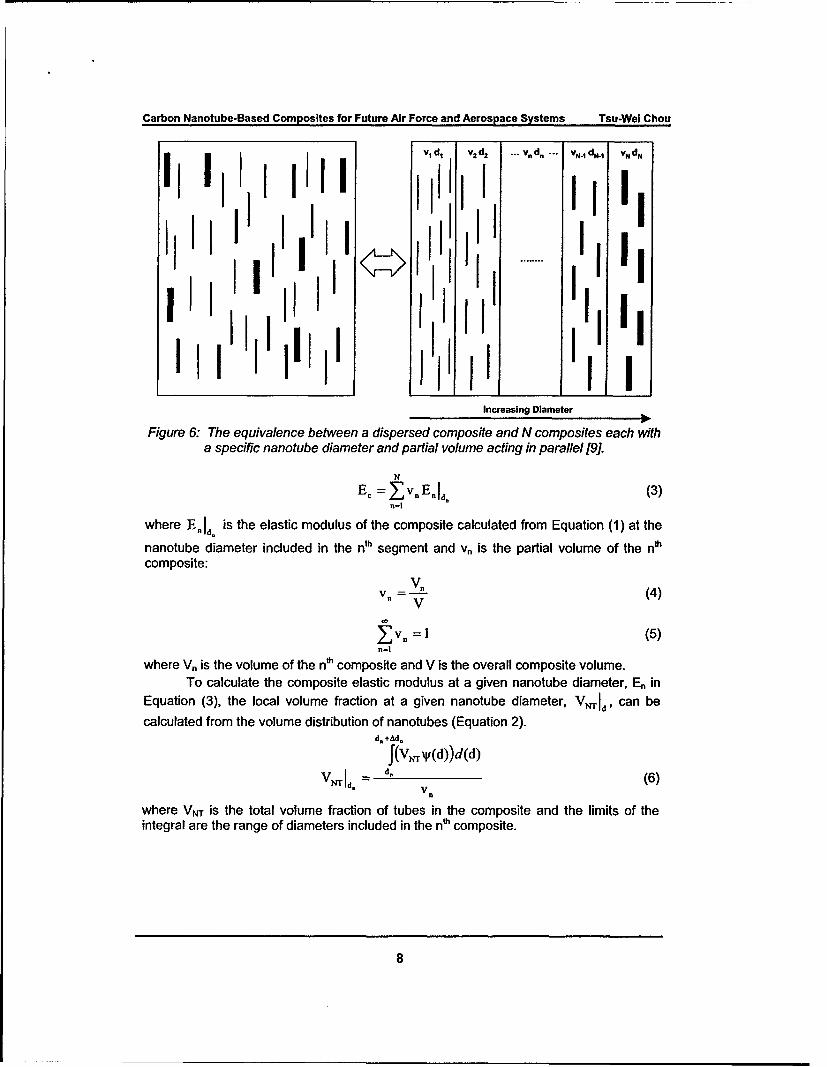
The concept of parallel composites is illustrated in Figure 6. Within the entirevolume of the composite the volume can be divided into N individual compositescontaining a specific nanotube diameter. Each of the N individual composites will have aspecific elastic modulus that depends on the local volume fraction of nanotubes at agiven diameter. With the assumption of iso-strain, the elastic modulus of the compositecan expressed as a summation of the moduli scaled by the partial volume of each nthcomposite:
7
Carbon Nanotube-Based Composites for Future Air Force and Aerospace Systems Tsu-Wei Chou
I~d V~2 ... VA . N~4ddV H vNdN
I 111III II JI~~I__ 11Increasing Diameter
Figure 6: The equivalence between a dispersed composite and N composites each witha specific nanotube diameter and partial volume acting in parallel [9].
N
E= ZvnEnId. (3)n=|
where E. Id. is the elastic modulus of the composite calculated from Equation (1) at the
nanotube diameter included in the nth segment and vn is the partial volume of the nIh
composite:
vn = V (4)V
oZv. = 1 (5)n=l
where V, is the volume of the nh composite and V is the overall composite volume.To calculate the composite elastic modulus at a given nanotube diameter, En in
Equation (3), the local volume fraction at a given nanotube diameter, VNId, can becalculated from the volume distribution of nanotubes (Equation 2).
d.+Ad.f'(vNWr(d))d(d)
V Id. = d. (6)Vn
where VN is the total volume fraction of tubes in the composite and the limits of theintegral are the range of diameters included in the nt composite.
8
Carbon Nanotube-Based Composites for Future Air Force and Aerospace Systems Tsu-Wei Chou
d. d.+Ad
!I'
Diameter
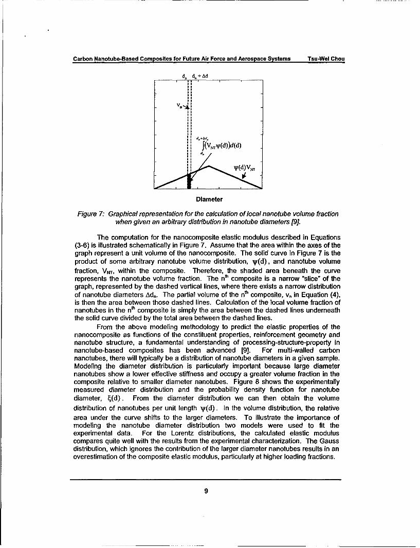
Figure 7. Graphical representation for the calculation of local nanotube volume fractionwhen given an arbitrary distribution in nanotube diameters [9].
The computation for the nanocomposite elastic modulus described in Equations(3-6) is illustrated schematically in Figure 7. Assume that the area within the axes of thegraph represent a unit volume of the nanocomposite. The solid curve in Figure 7 is theproduct of some arbitrary nanotube volume distribution, 'W(d), and nanotube volumefraction, VNT, within the composite. Therefore, the shaded area beneath the curverepresents the nanotube volume fraction. The nth composite is a narrow 'slice" of thegraph, represented by the dashed vertical lines, where there exists a narrow distributionof nanotube diameters Adn. The partial volume of the nth composite, v, in Equation (4),is then the area between those dashed lines. Calculation of the local volume fraction ofnanotubes in the nth composite is simply the area between the dashed lines underneaththe solid curve divided by the total area between the dashed lines.
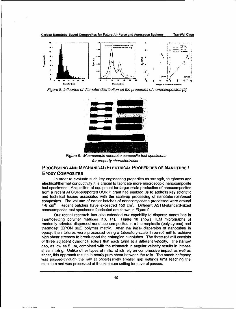
From the above modeling methodology to predict the elastic properties of thenanocomposite as functions of the constituent properties, reinforcement geometry andnanotube structure, a fundamental understanding of processing-structure-property innanotube-based composites has been advanced [9]. For mufti-walled carbonnanotubes, there will typically be a distribution of nanotube diameters in a given sample.Modeling the diameter distribution is particularly important because large diameternanotubes show a lower effective stiffness and occupy a greater volume fraction in thecomposite relative to smaller diameter nanotubes. Figure 8 shows the experimentallymeasured diameter distribution and the probability density function for nanotubediameter, ý(d). From the diameter distribution we can then obtain the volumedistribution of nanotubes per unit length xV(d). In the volume distribution, the relativearea under the curve shifts to the larger diameters. To illustrate the importance ofmodeling the nanotube diameter distribution two models were used to fit theexperimental data. For the Lorentz distributions, the calculated elastic moduluscompares quite well with the results from the experimental characterization. The Gaussdistribution, which ignores the contribution of the larger diameter nanotubes results in anoverestimation of the composite elastic modulus, particularly at higher loading fractions.
9
Carbon Nanotube-Based Composites for Future Air Force and Aerospace Systems Tsu-Wel Chou
"12 '• ....... .. ...
14 ~ ~.... ad, 4bl~~,vd)i. ..
125 6 s 3s 4 5s 6s 1 10 20 30 so so 2 1o 0 Is
DIa1 2 ~4 5 ( 5M ) Diame0e2 I -) We lo1t % C0rbon N owheea1
Figure 8: Influence of diameter distribution on the properties of nanocomposites [5].
Figure 9: Macroscopic nanotube composite test specimens
for property characterization.
PROCESSING AND MECHANICALIELECTRICAL PROPERTIES OF NANOTUBE IEpoxY COMPOSITES
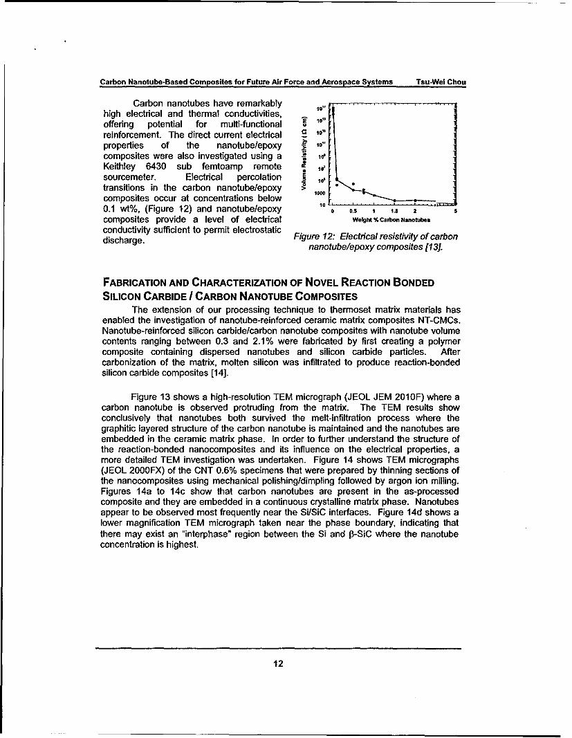
In order to evaluate such key engineering properties as strength, toughness andelectrical/thermal conductivity it is crucial to fabricate more macroscopic nanocompositetest specimens. Acquisition of equipment for larger-scale production of nanocompositesfrom a recent AFOSR-supported DURIP grant has enabled us to address key scientificand technical issues associated with the scale-up processing of nanotube-reinforcedcomposites. The volume of earlier batches of nanocomposites processed were around4-6 cm 3. Recent batches have exceeded 150 cm3 . Different ASTM-standard-sizednanocomposite test specimens fabricated are shown in Figure 9.
Our recent research has also extended our capability to disperse nanotubes inthermosetting polymer matrices [13, 14]. Figure 10 shows TEM micrographs ofrandomly oriented dispersed nanotube composites in a thermoplastic (polystyrene) andthermoset (EPON 862) polymer matrix. After the initial dispersion of nanotubes inepoxy, the mixtures were processed using a laboratory-scale three-roll mill to achievehigh shear stresses to break-apart the entangled nanotubes. The three-roll mill consistsof three adjacent cylindrical rollers that each turns at a different velocity. The narrowgap, as low as 5 pm, combined with the mismatch in angular velocity results in intenseshear mixing. Unlike other types of mills, which rely on compressive impact as well asshear, this approach results in nearly pure shear between the rolls. The nanotube/epoxywas passed-through the mill at progressively smaller gap settings until reaching theminimum and was processed at the minimum setting for several passes.
10

Carbon Nanotube-Based Composites for Future Air Force and Aerospace Systems Tsu-Wei Chou
Figure 10: TEM micrographs showing nanotubes randomly dispersed in a polystyrenematrix (left) and EPON 862 epoxy matrix (right) [13].
1.4 . . .
'1.2
E 0.6
0.6
0.4 I .19h Aspect RiUo I
0.2 Reduced Aspect Ratio0.2 d ~
0 L . . . . i. . . . i .. . .. . . . . . .i ,
0 1 2 3 4 5
Weight % Carbon Nanotubes
Figure 11: SENB fracture toughness results showing the influence nanotube contentand morphology on the fracture toughness [13].
In order to evaluate the influence of multi-walled carbon nanotubes on thefracture toughness of epoxy nanocomposites we fabricated composites with nanotubecontents ranging between 0.1 wt% and 5 wt% in an EPON 862 epoxy matrix. Thenanotubes were first dispersed in the epoxy resin and the curing agent (Epi-Cure W)was added. The nanocomposites were then placed in a mold and cured for 6 hours at1300C. Fracture toughness measurements were conducted using the single-edge-notchbending (SENB) method. Specimens were notched with a tapered diamond blade and apre-crack was introduced by tapping with an ultra-sharp carbon steel razor blade. Figure11 gives the fracture toughness results, showing significant increases in the fracturetoughness with the addition of carbon nanotubes. This indicates that nanotubes providea reinforcing effect in improving the fracture toughness through crack deflection ornanotube fracture and pullout. SEM micrographs of the composite fracture surfacesshow a change in the micron-scale surface roughness and also the presence ofnanotube pullout [13].
11
Carbon Nanotube-Based Composites for Future Air Force and Aerospace Systems Tsu-Wei Chou
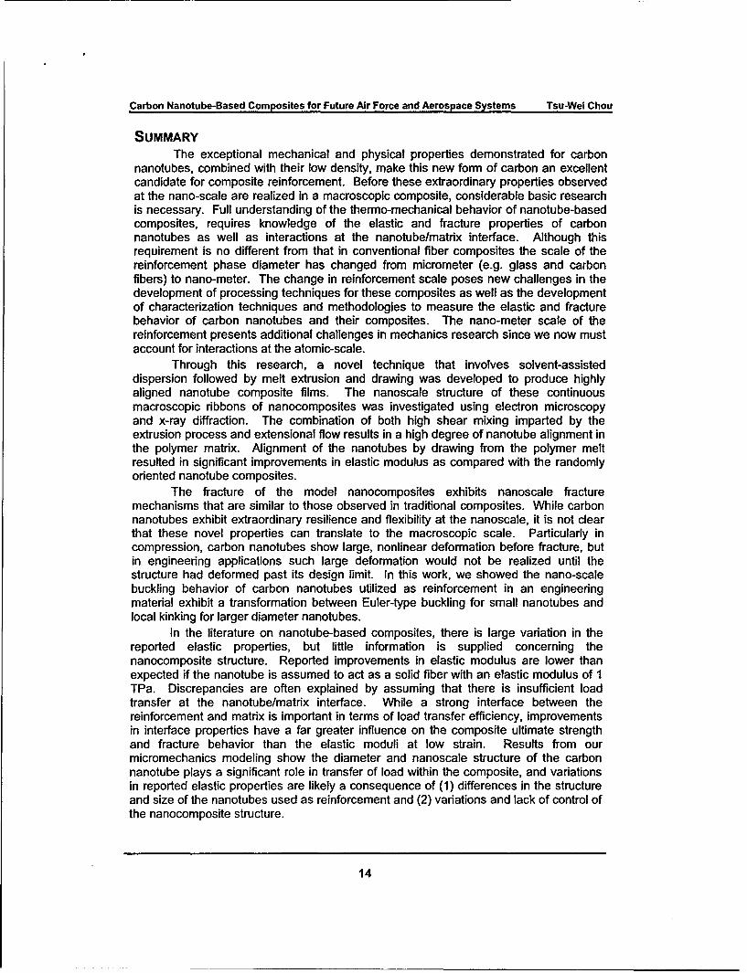
Carbon nanotubes have remarkablyhigh electrical and thermal conductivities,offering potential for multi-functional 0reinforcement. The direct current electrical 10
properties of the nanotube/epoxy • 10"
composites were also investigated using a 1 0'Keithley 6430 sub femtoamp remote • 10'
sourcemeter. Electrical percolation otransitions in the carbon nanotube/epoxy I,composites occur at concentrations below L0.1 wt%, (Figure 12) and nanotube/epoxy 00 0.5 1 1.5 5composites provide a level of electrical Weght % Carbon Nanotubes
conductivity sufficient to permit electrostatic Figure 12: Electrical resistivity of carbondischarge. nanotube/epoxy composites [13].
FABRICATION AND CHARACTERIZATION OF NOVEL REACTION BONDED
SILICON CARBIDE / CARBON NANOTUBE COMPOSITESThe extension of our processing technique to thermoset matrix materials has
enabled the investigation of nanotube-reinforced ceramic matrix composites NT-CMCs.Nanotube-reinforced silicon carbide/carbon nanotube composites with nanotube volumecontents ranging between 0.3 and 2.1% were fabricated by first creating a polymercomposite containing dispersed nanotubes and silicon carbide particles. Aftercarbonization of the matrix, molten silicon was infiltrated to produce reaction-bondedsilicon carbide composites [14].
Figure 13 shows a high-resolution TEM micrograph (JEOL JEM 2010F) where acarbon nanotube is observed protruding from the matrix. The TEM results showconclusively that nanotubes both survived the melt-infiltration process where thegraphitic layered structure of the carbon nanotube is maintained and the nanotubes areembedded in the ceramic matrix phase. In order to further understand the structure ofthe reaction-bonded nanocomposites and its influence on the electrical properties, amore detailed TEM investigation was undertaken. Figure 14 shows TEM micrographs(JEOL 2000FX) of the CNT 0.6% specimens that were prepared by thinning sections ofthe nanocomposites using mechanical polishing/dimpling followed by argon ion milling.Figures 14a to 14c show that carbon nanotubes are present in the as-processedcomposite and they are embedded in a continuous crystalline matrix phase. Nanotubesappear to be observed most frequently near the Si/SiC interfaces. Figure 14d shows alower magnification TEM micrograph taken near the phase boundary, indicating thatthere may exist an "interphase" region between the Si and P3-SiC where the nanotubeconcentration is highest.
12

Carbon Nanotube-Based Composites for Future Air Force and Aerospace Systems Tsu-Wei Chou
Figure 13. High-resolution TEM Figure 14: TEM micrographs showingmicrograph showing nanotubes in the nanotubes embedded in the continuous
reaction-bonded ceramic and the graphitic matrix and near the Si/SiC interfaces [14].structure of the nanotube intact [14].
1.6
:. 'IK
0.4$02
0.6t
Figure 15: Influence of nanotube concentration on volume resistivity, showing asubstantial decrease in resistivity with increased nanotube volume content [14].
There is a remarkable decrease in the electrical resistivity at these smallnanotube loadings. With a volume content of just 0.3% carbon nanotubes there is a75% decrease in electrical resistivity (Figure 15). At the highest nanotube volumecontent of 2.1%, there is a 96% decrease in electrical resistivity, which represents a 16-fold increase in electrical conductivity. While local variation in the micro-scale structureof the reaction-bonded ceramics results in some scatter of the resistivity data, theinfluence of adding carbon nanotubes on the electrical properties is unmistakable.
13
Carbon Nanotube-Based Composites for Future Air Force and Aerospace Systems Tsu-Wel Chou
SUMMARYThe exceptional mechanical and physical properties demonstrated for carbon
nanotubes, combined with their low density, make this new form of carbon an excellentcandidate for composite reinforcement. Before these extraordinary properties observedat the nano-scale are realized in a macroscopic composite, considerable basic researchis necessary. Full understanding of the thermo-mechanical behavior of nanotube-basedcomposites, requires knowledge of the elastic and fracture properties of carbonnanotubes as well as interactions at the nanotube/matrix interface. Although thisrequirement is no different from that in conventional fiber composites the scale of thereinforcement phase diameter has changed from micrometer (e.g. glass and carbonfibers) to nano-meter. The change in reinforcement scale poses new challenges in thedevelopment of processing techniques for these composites as well as the developmentof characterization techniques and methodologies to measure the elastic and fracturebehavior of carbon nanotubes and their composites. The nano-meter scale of thereinforcement presents additional challenges in mechanics research since we now mustaccount for interactions at the atomic-scale.
Through this research, a novel technique that involves solvent-assisteddispersion followed by melt extrusion and drawing was developed to produce highlyaligned nanotube composite films. The nanoscale structure of these continuousmacroscopic ribbons of nanocomposites was investigated using electron microscopyand x-ray diffraction. The combination of both high shear mixing imparted by theextrusion process and extensional flow results in a high degree of nanotube alignment inthe polymer matrix. Alignment of the nanotubes by drawing from the polymer meltresulted in significant improvements in elastic modulus as compared with the randomlyoriented nanotube composites.
The fracture of the model nanocomposites exhibits nanoscale fracturemechanisms that are similar to those observed in traditional composites. While carbonnanotubes exhibit extraordinary resilience and flexibility at the nanoscale, it is not clearthat these novel properties can translate to the macroscopic scale. Particularly incompression, carbon nanotubes show large, nonlinear deformation before fracture, butin engineering applications such large deformation would not be realized until thestructure had deformed past its design limit. In this work, we showed the nano-scalebuckling behavior of carbon nanotubes utilized as reinforcement in an engineeringmaterial exhibit a transformation between Euler-type buckling for small nanotubes andlocal kinking for larger diameter nanotubes.
In the literature on nanotube-based composites, there is large variation in thereported elastic properties, but little information is supplied concerning thenanocomposite structure. Reported improvements in elastic modulus are lower thanexpected if the nanotube is assumed to act as a solid fiber with an elastic modulus of 1TPa. Discrepancies are often explained by assuming that there is insufficient loadtransfer at the nanotube/matrix interface. While a strong interface between thereinforcement and matrix is important in terms of load transfer efficiency, improvementsin interface properties have a far greater influence on the composite ultimate strengthand fracture behavior than the elastic moduli at low strain. Results from ourmicromechanics modeling show the diameter and nanoscale structure of the carbonnanotube plays a significant role in transfer of load within the composite, and variationsin reported elastic properties are likely a consequence of (1) differences in the structureand size of the nanotubes used as reinforcement and (2) variations and lack of control ofthe nanocomposite structure.
14

Carbon Nanotube-Based Composites for Future Air Force and Aerospace Systems Tsu-Wel Chou
Our recent research on nanotube-reinforced epoxy composites hasdemonstrated enhanced fracture toughness at relatively low carbon nanotube loadingcontents. Furthermore, the electrical percolation threshold in these composites occursat extremely low carbon nanotube concentrations. We have also recently fabricatednovel silicon carbide/carbon nanotube ceramic composites using a thermosetting resinas a precursor. Substantial decreases in electrical resistivity at low nanotubeconcentrations were also observed in the nanotube-reinforced ceramics. Microscopyresults indicate that the graphitic structure of the carbon nanotubes remain intact afterthe high temperature processing.
PERSONNEL SUPPORTED
Principal Investigator: Tsu-Wei ChouStudent/Postdoctoral Fellow/Research Associate: Erik T. ThostensonPostdoctoral FellowlResearch Associate: Chunyu LiUndergraduate Student: Stephen Koellhoffer
Undergraduate Student: James Powell
PUBLICATIONS: 1 Ph.D. Dissertation [4]; 6 Journal Publications Published [3, 5, 9, 10,12, 13]; 2 Journal Publications in Preparation or Submitted.
REFERENCES1. S. lijima, "Helical microtubules of graphitic carbon," Nature, 354: 56-58 (1991).
2. T-W. Chou, Microstructural Design of Fiber Composites, Cambridge University Press,Cambridge, UK (1992).
3. E. T. Thostenson, and T-W. Chou "Aligned Multi-Walled Carbon Nanotube-ReinforcedComposites: Processing and Mechanical Characterization," Journal of Physics D: AppliedPhysics, 35(16) L77-L80 (2002).
4. E. T. Thostenson Carbon Nanotube-Reinforced Composites: Processing, Characterizationand Modeling, Ph.D. Dissertation, Department of Materials Science and Engineering,University of Delaware (2004).
5. E. T. Thostenson, C. Y. Li and T-W. Chou, "Nanocomposites in Context," CompositesScience and Technology, 65(3-4) 491-516 (2005).
6. E. T. Thostenson, Z.F. Ren and T-W. Chou "Advances in the Science and Technology ofCarbon Nanotubes and their Composites: A Review," Composites Science and Technology,61, 1899-1912 (2001).
7. W.Z. Li, S.S. Xie, L.X. Qian, B.H. Chang, B.S. Zou, W.Y. Zhou, R.A. Zhao and G. Wang,"Large-Scale Synthesis of Aligned Carbon Nanotubes," Science, 274:1701 (1996).
8. W.Z. Li, J.G. Wen and Z.F. Ren, "Effect of Temperature on Growth and Structure of CarbonNanotubes by Chemical Vapor Deposition," Applied Physics A, 73: 259-264 (2001).
9. E. T. Thostenson, and T-W. Chou, "On the Elastic Properties of Carbon Nanotube-BasedComposites: Modeling and Characterization," Journal of Physics D: Applied Physics, 36(5)573-582 (2003).
10. E. T. Thostenson, and T-W. Chou, "Nanotube Buckling in Aligned Multi-Wall CarbonNanotube Composites," Carbon, 42(14) 3015-3018 (2004).
11. C. Li and T-W. Chou "A Structural Mechanics Approach for the Analysis of CarbonNanotubes," Int. J. Solids Struct., 40, 2487 (2003).
12. C. Li and T-W. Chou "A Multiscale Modeling of the Interfacial Load Transfer in CarbonNanotube/Polymer Composites," J. Nanoscience & Nanotechnology, 3, 423 (2003).
15
Carbon Nanotube-Based Composites for Future Air Force and Aerospace Systems Tsu-Wei Chou
13. E. T. Thostenson and T-W. Chou, "Processing and Mechanical/Electrical Characterization ofCarbon Nanotube-Reinforced Epoxy Composites, Submitted (2006).
14. E. T. Thostenson, P. G. Karandikar and T-W. Chou, "Fabrication and Characterization ofSilicon Carbide/Carbon Nanotube Composites," Journal of Physics D: Applied Physics,38(21) 3962-3965 (2005).
16