2006file3 a.xls - 2006 lp9 2.8l when used with aisin af40 ...2006file3_a.xls - 2006 lp9 2.8l when...
TRANSCRIPT

2006file3_a.xls - 2006 LP9 2.8L when used with Aisin AF40-6 TransmissionIn these Vehicles: Saab 9-3
Engine Diagnostic Parameters
Component/ Fault Monitor Strategy Primary Malfunction Threshold Threshold Threshold Threshold Secondary Enable Enable Enable Threshold Time Frequency Criteria MIL
System Code Description Signal and Criteria Logic Value Units Conditions Parameters Logic Value Units Conditions Required of Checks for Code Illum.
Catalyst Bank 1 P0420 oxygen storage of catalyst
normalized oxygen storage
< 1 factor <1factor exhaust gas mass flow
> 8.33 g/sec >8.33g/sec approx. 0.01 sec 0.4 sec two driving
less than normalized oxygen storage
exhaust gas mass flow
< 27.78 g/sec <27.78g/sec 1000 sec continuous cycles each
of a limit catalyst catalyst temp. model
< 700 ° C <700° C during one or 4 sec with: 0.4 sec
catalyst temp. model
> 390 ° C >390° C active completed cumulative continuous
engine speed > 1000 rpm >1040rpm driving test per or 4 secengine speed < 3520 rpm <3520rpm driving cumulativeengine load > 14 …. 17 % >14 …. 17% one test cycleengine load < 42….55 % <42….55%modeled catalyst temp. gradient
< 2.5 ° C / sec <2.5° C / sec ( average
exhaust gas mass flow gradient
< 8.33 g/sec² <8.33g/sec² of 4
fuel system closed loop
active - - active-- checks )
time after engine start
> 235 sec >235sec per driving
ambient temperature
> -48 ° C >-48° C cycle
scheduled by System Manager
TRUE - - TRUE--
secondary O2 sensor
ready ready
fuel adaptation fault
FALSE FALSE
short term fuel trim ( < max )
< 1.25 factor <1.25factor
short term fuel trim ( > min )
> 0.75 factor >0.75factor
transient fuel control
FALSE FALSE
critical misfire rate detected
FALSE FALSE
cat. damaging misfire rate exceeded
FALSE FALSE
cat oxygen storage neutralization
FALSE FALSE
Misfire crankshaft speed emissions relevant misfire rate
> 1.3 % >1.3% (emission relevant misfire
rate = 1.5%)
engine speed > 450 rpm >450rpm 1000 revs cylinder immediate Fault during
Emission Level fluctuation cylinder 1 to
engine speed < 6500 rpm <6500rpm firing 1st interval:
Multiple Cylinder P0300 cylinder 6 indicated torque (idle, no drive)
> 3.91 % >3.91% frequency 2 faults in
Cylinder #1 P0301 indicated torque (drive) (MISALUN)
> 3.91 . . . 17.19 % >3.91 . . . 17.19% After 2 different
Cylinder #2 P0302 engine speed gradient
< 12800 rpm/sec <12800rpm/sec(not active)
continuous detection, drive cycles.
NOTE: Printing this file may require 8.5" x 14" (legal size) paper, depending on your printer setup.
2006file3_a.xls 147

2006file3_a.xls - 2006 LP9 2.8L when used with Aisin AF40-6 TransmissionIn these Vehicles: Saab 9-3
Engine Diagnostic Parameters
Component/ Fault Monitor Strategy Primary Malfunction Threshold Threshold Threshold Threshold Secondary Enable Enable Enable Threshold Time Frequency Criteria MIL
System Code Description Signal and Criteria Logic Value Units Conditions Parameters Logic Value Units Conditions Required of Checks for Code Illum.
Cylinder #3 P0303 volumetric efficiency gradient
< 768 %/rev <768%/rev (not active)
the
Cylinder #4 P0304 cylinder events after engine start
> 6 ignitions >6ignitions diagnostic Fault during
Cylinder #5 P0305 air temperature > -30 ° C >-30° C can only remainingCylinder #6 P0306 rough road not detected - - not detected-- pass if intervals:
traction control off - - off-- similar 8 faults in 2clutch switch press / release
off - - transitionFALSE- conditions different
leak detection off - - off-- are drive cyclesactive handling not active not active encountered with at leastABS not active - - not active-- 4 faults in engine drag control not active - - not active-- each.
fuel cut off not active - - not active--fuel level > 5.9 % > 5.93 % OR fuel level < 5.9 % > 5.93 % AND solid misfire MIL
on - - on--
OR fuel level error
set - - set--
error: throttle position
not set - - not set--
error: crankshaft sensor
not set - - not set--
error: ref.mark of crank sensor
not set - - not set--
- - --- - --- - --- - --
ORCatalyst Damaging Level
Catalyst damaging misfire rate
> 16.2 . . . 6.8 % >16.2 . . . 6.8% Includes all the above with the
1000 revs First
Multiple Cylinder P0300 see Misfire see Misfire following exceptions:
First interval occurance:
Cylinder #1 P0301 supplemental supplemental First interval extention
200 revs immediate
Cylinder #2 P0302 data data engine coolant temperature
< -48 °C <-48°C all remaining flashing
Cylinder #3 P0303 (h) (2.5.1) (h) (2.5.1) fuel level >= 6.19 % > 6.19 % intervals while errorCylinder #4 P0304 OR fuel level < 6.19 % > 6.19 % present, thenCylinder #5 P0305 AND blinking
MILblinking - - blinking-- no MIL
Cylinder #6 P0306 AND NOT first blink event
- - - --- with no error.
Secondoccurance:immediate
flashingwhile error
present, thensolid MIL
with no error.
evaporative systemcanister ventilation valve (AAV)
P0446 monitoring of tank pressure while
tank pressure too low because
< -10.50049 hPa < -10.50049 hPaambient temperature
>= -9.8 °C >= -9.8 °C < 20 sec once per dcy 2,6 secs 2 dcy
2006file3_a.xls 247

2006file3_a.xls - 2006 LP9 2.8L when used with Aisin AF40-6 TransmissionIn these Vehicles: Saab 9-3
Engine Diagnostic Parameters
Component/ Fault Monitor Strategy Primary Malfunction Threshold Threshold Threshold Threshold Secondary Enable Enable Enable Threshold Time Frequency Criteria MIL
System Code Description Signal and Criteria Logic Value Units Conditions Parameters Logic Value Units Conditions Required of Checks for Code Illum.
AAV is open and CPV is closed
canister vent. defective & closed
ambient temperature
<= 45 °C <= 45 °C
ambient pressure >= 680.00 hPa >= 680.00 hPa
vehicle speed <= 1,86 mph <= 1,86 mph engine is in idle
modetrue true
unfiltered tank pressure
>= -18.00 hPa >= -18.00 hPa
and unfiltered tank pressure
<= 10.00 hPa <= 10.00 hPa
canister purge valve (CPV)
P0496 monitoring of tank pressure while
final pressure too low because
<
-1.00098
hPa < -1.00098 hPa battery voltage >= 10.45 V >= 10.45 V ca. 10 sec once per dcy
CPV and AAV are closed
CPV defective and open
and battery voltage <= 18.00 V <= 18.00 V
lambda control is active
true true
secondary air pump inactive
true true
secondary air diagnosis inactive
true true
air bag hasn't been triggered
true true
no torque reduction (e.g. resulting from switched-off cylinder)
true true
P0497 monitoring of tank pressure while
purge control stuck closed
critical misfire rate false false
CPV and AAV are closed
ratio intake manifold pressure /ambient pressure
< 0.602 < 0.602
fault of canister purge valve in actual driving cycle
false false
tank leak large P0455 AAV is closed and CPV is open
vacuum pressure built up gradient too low
< 0.450039 ...0.750065
hPa/s =CONCATENATE(E93," ",F93,"
",G93)
fault of canister ventilation valve in actual driving cycle
false false ca. 18 sec once per dcy
because of large tank leakage
tank fuel level >= 3.900 l >= 3.900 l
(for example: open gas filler cap)
and tank fuel level <= 55.100 l <= 55.100 l
enabled by diagnostic scheduler
true true
fuel system adaptation has completed
true true
or time since engine start exceeds threshold
> 600 sec > 600 sec
2006file3_a.xls 347

2006file3_a.xls - 2006 LP9 2.8L when used with Aisin AF40-6 TransmissionIn these Vehicles: Saab 9-3
Engine Diagnostic Parameters
Component/ Fault Monitor Strategy Primary Malfunction Threshold Threshold Threshold Threshold Secondary Enable Enable Enable Threshold Time Frequency Criteria MIL
System Code Description Signal and Criteria Logic Value Units Conditions Parameters Logic Value Units Conditions Required of Checks for Code Illum.
Fuel Evaporative System
P0456 Monitor fuel tank's pressure after engine shutdown
Engine off natural vacuum diagnosis has not been performed in this driving cyle.
true 100ms in once per dcy 2.6 secs 2dcy
Fuel evaporative system monitor (at engine on) didn't run nor detect large leak nor a tight system.
true afterrun
Engine coolant temperature at start.
<= 42.0 °C true
engine coolant temp. At start - intake air temp.
<= 6.8 °C true
intake air temperature
<= 35.3 °C true
intake air temperature
>= 3.8 °C true
ambient air temperature
< 36.8 °C true
ambient air temperature
> 2.3 °C true
engine has been running for a cal. min. time
> 600.00 s true
engine coolant temp. at engine stop
> 59.3 °C true
driving distance (in current dcy) covered
>= 8100.0 m true
charcoal canister load factor
< 10.00 - true
ambient pressure >= 680.0 hPa true
driving distance (for vehicle lifetime) covered
> 20 Km true
the fuel tank's level isn't at its minimum
true
the fuel tank's level isn't at ist maximum
true
battery's voltage > 11.00 V true no refueling activity true
the fuel tank pressure is within cal. range
true
no intake air temperature faults
true
no the purge control system faults
true
2006file3_a.xls 447

2006file3_a.xls - 2006 LP9 2.8L when used with Aisin AF40-6 TransmissionIn these Vehicles: Saab 9-3
Engine Diagnostic Parameters
Component/ Fault Monitor Strategy Primary Malfunction Threshold Threshold Threshold Threshold Secondary Enable Enable Enable Threshold Time Frequency Criteria MIL
System Code Description Signal and Criteria Logic Value Units Conditions Parameters Logic Value Units Conditions Required of Checks for Code Illum.
no faults of the purge control valve's power stage
true
no vehicle speed sensor faults
true
no engine coolant temperature sensor faults
true
no tank pressure sensor rationality faults
true
no tank pressure sensor range faults
true
no power supply voltage faults
true
no main load sensor faults
true
no canister vent valve faults
true
no canister ventilation valve's power stage faults
true
no ambient pressure sensor faults
true
Close canister ventilation
valve. Look for maximum pressure.
Abort if: - max. pressure >=
threshold. max. pressure >= volume & ambient temperature dependent
hPa
- max. pressure - current
pressure >= threshold.
max. pressure - current pressure
>=0.30029
hPa >= 0.30029 hPa
- pressure stays in range
pressure >=-0.69946
hPa >= -0.69946 hPa
near zero for pressure <= 0.69946 hPa <= 0.69946 hPaa specific time. 500 s 500 s- pressure <= threshold pressure <= -0.74951 hPa <= -0.74951 hPafor a specific time 30.00 s 30.00 s
(vacuum build-up instead
of pressure build-up)
- pressure-phase-time
>= threshold. pressure phase time >= 2400.00 s >= 2400.00 s
2006file3_a.xls 547

2006file3_a.xls - 2006 LP9 2.8L when used with Aisin AF40-6 TransmissionIn these Vehicles: Saab 9-3
Engine Diagnostic Parameters
Component/ Fault Monitor Strategy Primary Malfunction Threshold Threshold Threshold Threshold Secondary Enable Enable Enable Threshold Time Frequency Criteria MIL
System Code Description Signal and Criteria Logic Value Units Conditions Parameters Logic Value Units Conditions Required of Checks for Code Illum.
- diagnostic-time >=
threshold diagnostic time >= 2900.00 s >= 2900.00 s
correct max. pressure.
open canister ventilation
valve for a calibrated time.
400.00 s 400.00 s
Look for minimum pressure
Abort if: - min pressure <= threshold min. pressure <= <=
- diagnostic time >=
threshold diagnostic time >= 2900.00 s >= 2900.00 s
current pressure - min.
- pressure >= threshold
current pressure - min. pressure
>=0.30029
hPa >= 0.30029 hPa
AND min. pressure <= threshold min. pressure <= -0.69946 hPa <= -0.69946 hPa
- pressure stays in pressure >=
-0.69946hPa >= -0.69946 hPa
ambient range for a
pressure <=0.69946
hPa <= 0.69946 hPa
specific time 500.00 s 500.00 s
- canister vent valve re-
opened for a more than N times
no. canister vent valve openings
> 2 > 2
because the pressure
exceeds a threshold
pressure0.74951
hPa 0.74951 hPa
Calculate difference
between corrected max.
pressure and min.
pressure.
Calculate normalized
result. First divide the
pressure difference by a
2006file3_a.xls 647

2006file3_a.xls - 2006 LP9 2.8L when used with Aisin AF40-6 TransmissionIn these Vehicles: Saab 9-3
Engine Diagnostic Parameters
Component/ Fault Monitor Strategy Primary Malfunction Threshold Threshold Threshold Threshold Secondary Enable Enable Enable Threshold Time Frequency Criteria MIL
System Code Description Signal and Criteria Logic Value Units Conditions Parameters Logic Value Units Conditions Required of Checks for Code Illum.
parameter. Then subtract
volume & ambient temperature dependent
this result from 1.
Filter the normalized
result with an EWMA
filter.
Compare filtered result
Filtered result >0.399994
> 0.399994
with threshold. N results will be taken
4 4
into account in order to
determine a pass.
A fault will be indicated
immediately.
secondary air system
P0411 passive functional check
relative secondary air mass flow. Ratio from
< 0.273 < 0.273 start with catalyst heating
active < 5s one 2.6 sec 2 dcy
calculated secondary air mass by oxygen
secondary air system
active
sensor signal and secondary air mass model
HO2S sensor specific values
active complete
intake air temperature
> 0 °C > 0 °C test per dcy
intake air temperature
< 80.3 °C < 80.3 °C (only, if
engine coolant temperature
> 5.3 °C > 5.3 °C secondary-
engine coolant temperature
< 120 °C < 120 °C air-system
ratio: ( MAP Model / Baro )
< 0.7 < 0.7 was active)
no error on altitude detection
avtive
fuel trim error falsemisfire falseerror: multiple misfire
false
error: HFM falseerror: intake air falseerror: motor temperature
false
error: secondary air pump (power stage)
false
2006file3_a.xls 747

2006file3_a.xls - 2006 LP9 2.8L when used with Aisin AF40-6 TransmissionIn these Vehicles: Saab 9-3
Engine Diagnostic Parameters
Component/ Fault Monitor Strategy Primary Malfunction Threshold Threshold Threshold Threshold Secondary Enable Enable Enable Threshold Time Frequency Criteria MIL
System Code Description Signal and Criteria Logic Value Units Conditions Parameters Logic Value Units Conditions Required of Checks for Code Illum.
error: canister purge system diagnosis
false
error: canister purge valve power stage
false
error: power supplyvoltage UB
false
error: lambda sensor heating upstream cat
false
error: fault from diagnostics of fuel supply system
false
error: lambda sensor upstream catalyst
false
condition for basic mixture adaptation disabled
false
enabled by the diagnostic scheduler
true
fuel cut off false mixture adaptation
for secondary air diagnosis is in
active
steady statemass airflow > 6 kg/h > 6 kg/hmass airflow < 150 kg/h < 150 kg/hchange in air charge per working cycle
<= 7 % <= 7 %
active flow check relative secondary
air mass flow. Ratio from
< 0.555 - 0.531 < 0.555 - 0.531 all other enabling conditions
< 10s
seperate/additional enable conditions,
calculated secondary air mass by oxygen
as for passive functional check
different threshold sensor signal and secondary air mass model
mass airflow < 6 kg/h < 6 kg/hmass airflow > 100 kg/h > 100 kg/hchange in air charge per working cycle
>= -7 % >= -7 %
change in air charge per working cycle
<= 7 % <= 7 %
engine idle true vehicle speed < 2.5 km/h < 2.5 km/h
2006file3_a.xls 847

2006file3_a.xls - 2006 LP9 2.8L when used with Aisin AF40-6 TransmissionIn these Vehicles: Saab 9-3
Engine Diagnostic Parameters
Component/ Fault Monitor Strategy Primary Malfunction Threshold Threshold Threshold Threshold Secondary Enable Enable Enable Threshold Time Frequency Criteria MIL
System Code Description Signal and Criteria Logic Value Units Conditions Parameters Logic Value Units Conditions Required of Checks for Code Illum.
integrated air mass flow from engine start to max. value
> 0.499 kg > 0.499 kg
time counter at endof start
> 143.5 sec > 143.5 sec
condition filter frm deviation inside theallowed area
> -0.119 > -0.119
< 0.119 < 0.119 release of active diagnosis from permitted numbers of active
active
diagnosis
Fuel System Rich/Lean
P2191 fuel trim limits exceeded
delta lambda correction
> 1.175 factor >1.175factor fuel system status closed loop - - closed loop-- approx. 0.1 sec 0.4 sec two driving
Multiplicative P2192 range - multiplicative
or delta lambda correction
< 0.825 factor <0.825factor long term fuel trim status
active - - active-- 300 sec continuous continuous cycles each
and Additive ( load > threshold and air flow > threshold )
engine coolant temperature
> 50.3 °C >50.3°C from engine or 4 sec with: 0.4 sec
P2187 range - additive delta fuel load correction
> 5.25 % >5.25% purge control not active - - not active-- start ( after cumulative continuous
P2188 low speed and low load
or delta fuel load correction
< -5.25 % <-5.25% intake air temperature
<= 65.3 °C <=65.3°C adaptation or 4 sec
fuel level > 6.19 % > 5.92 % has After cumulativeor fuel level error set - - set-- stabilized ) detection,integrated air mass >= 2800 g >=2800g diagnostic
can onlypass ifsimilar
conditionsare
encountered
demand controlled fuel supply
(DECOS) P0088 difference between measured
fuel rail pressure difference
< - 150 kPa < - 150 kPa DECOS fuel pump is active
true true 5 sec continuous 0.2 sec 2 dcy
and set-point fuel rail pressure
DECOS fuel control is enabled
true true
time after engine start
> 1 sec > 1 sec
P0089 difference between actual duty cycle difference
< -25 % < -25 % time after hot start > 6 sec > 6 sec
necessary and pre-control
no fault of
duty cycle - fuel pressure sensor
(DECOS) true true - power stage of demand
controlled fuel pump
true true
2006file3_a.xls 947

2006file3_a.xls - 2006 LP9 2.8L when used with Aisin AF40-6 TransmissionIn these Vehicles: Saab 9-3
Engine Diagnostic Parameters
Component/ Fault Monitor Strategy Primary Malfunction Threshold Threshold Threshold Threshold Secondary Enable Enable Enable Threshold Time Frequency Criteria MIL
System Code Description Signal and Criteria Logic Value Units Conditions Parameters Logic Value Units Conditions Required of Checks for Code Illum.
P0087 difference between
measured fuel rail pressure difference
> 150 kPa > 150 kPa DECOS fuel pump is active
true true
and set-point fuel rail pressure
DECOS fuel control is enabled
true true
time after engine start
> 1 sec > 1 sec
P0089 difference between actual duty cycle difference
> 25 % > 25 % time after hot start > 6 sec > 6 sec
necessary and pre-control
no fault of
duty cycle - low pressure fuel sensor
(DECOS) true true - power stage of demand
controlled fuel pump
true true
no empty or almost empty fuel tank
true true
fuel pressure sensor (DECOS)
P0193 cirtcuit continuity - high or open
measured sensor voltage
> 4.7 V > 4.7 V fuel supply system is active
true true 0.5 sec continuous 0.2 sec 2 dcy
P0192 cirtcuit continuity - low
measured sensor voltage
< 0.3 V < 0.3 V
P0193 range check - high measured fuel
pressure> 680 kPa > 680 kPa 5 sec
P0192 range check - low measured fuel pressure
< 60 kPa < 60 kPa fuel supply system is active
true true 5 sec
time after power fail
>= 360 sec >= 360 sec
Diagnosis of Power Control Module
general enabling conditions
0.6 sec continuous 0.2 sec 2 dcy
battery voltage < 18 V < 18 V> 10 V > 10 V
locking request immobilizer
false false
P0092 diagnosis short circuit to battery voltage
special enabling condition
only active if powerstage on
backward powerstage voltage of
> 3.9014 V > 3.9014 V condition output duty cycle PCM
true true
fuel pump diagnosis
for power on diagnosis
and backward powerstage voltage of >
2.7979 V > 2.7979 V
2006file3_a.xls 1047

2006file3_a.xls - 2006 LP9 2.8L when used with Aisin AF40-6 TransmissionIn these Vehicles: Saab 9-3
Engine Diagnostic Parameters
Component/ Fault Monitor Strategy Primary Malfunction Threshold Threshold Threshold Threshold Secondary Enable Enable Enable Threshold Time Frequency Criteria MIL
System Code Description Signal and Criteria Logic Value Units Conditions Parameters Logic Value Units Conditions Required of Checks for Code Illum.
fuel pump diagnosis
and duty cycle PCM < 100 % < 100 %
diagnosis short circuit to battery voltage
condition output duty cycle PCM
false false
only active if powerstage off
backward powerstage voltage of
> 3.9014 V > 3.9014 V for power off diagnosis
fuel pump diagnosis
P0091 diagnosis short circiut to ground
condition output duty cycle PCM
true true
only active if powerstage on
backward powerstage voltage of
<= 2.3486 V <= 2.3486 V for power on diagnosis
fuel pump diagnosis
and duty cycle PCM > 0 % > 0 %
P0090 diagnosis wire interruption
condition output duty cycle PCM
true true
only active if powerstage on
backward powerstage voltage of
> 2.4414 V > 2.4414 V for power on diagnosis
fuel pump diagnosis
and duty cycle PCM < 100 % < 100 % and max-fault; powerstage diagnosis
false false
diagnosis wire interruption
backward powerstage voltage of
> 2.4414 V > 2.4414 V condition output duty cycle PCM
false false
only active if powerstage off
fuel pump diagnosis
for power off diagnosis
and backward powerstage voltage of
< 3.9014 V < 3.9014 V
fuel pump diagnosis
P0090 powerstage locked condition fault message of PCM
true true
powerstage is locked
Air / Fuel Ratio Sensor (primary A/F)sensor voltage A/F sensor voltage A/F sensor voltage > 3.7 V >3.7V A/F sensor heater TRUE - - TRUE-- 10 sec 0.1 sec 0.4 sec two driving
bank 1 sensor 1 P0130 exceeds threshold and at operating temperature
continuous continuous cycles each
but not out of full range
A/F sensor voltage < 4.81 V <4.81V engine starting complete - - complete-- additional or 4 sec with: 0.4 sec
desired A/F < 1.6 lambda <1.6lambda time if cumulative continuous
orall injectors activated
TRUE - - TRUE-- fuel level or 4 sec
2006file3_a.xls 1147

2006file3_a.xls - 2006 LP9 2.8L when used with Aisin AF40-6 TransmissionIn these Vehicles: Saab 9-3
Engine Diagnostic Parameters
Component/ Fault Monitor Strategy Primary Malfunction Threshold Threshold Threshold Threshold Secondary Enable Enable Enable Threshold Time Frequency Criteria MIL
System Code Description Signal and Criteria Logic Value Units Conditions Parameters Logic Value Units Conditions Required of Checks for Code Illum.
scheduled by System Manager
TRUE - - TRUE-- is low and cumulative
AF sensor voltage> 2.5 V >2.5V not failed
and 600 secA/F sensor voltage < 3.06 V <3.06V
( if using rich calibrationcurve characteristic )
Air / Fuel Ratio Sensor (primary A/F)integrated circuit interfacebank 1 P0130 A/F sensor voltage A/F sensor voltage
IC corrective value> 0.1 V >0.1V battery voltage < 18 V <18V 10 sec 0.1 sec 0.4 sec two driving
IC correction too high
battery voltage > 10.7 V >10.7V continuous continuous cycles each
engine running - - running-- or 4 sec with: 0.4 secengine starting complete - - complete-- cumulative continuous
or 4 seccumulative
A/F sensor IC operating voltage
low voltage = TRUE - =TRUE- battery voltage > 10.7 V >10.7V 10 sec
too low battery voltage < 18 V <18V- - engine running - - running--
- - engine starting complete - - complete--
A/F sensor IC SPI interface
communication error = TRUE =TRUE > 10.7 V >10.7V
communication error
< 18 V <18V
A/F sensor IC circuit write error
write error = TRUE =TRUE running - - running--
at INIT registercomplete - - complete--
Air / Fuel Ratio Sensor (primary A/F)pumping current circuit open
lambda control factor change
absolute value of lambda control factor
> 0.025 lambda >0.025lambda battery voltage < 18 V <18V 1.5 sec 0.1 sec 0.4 sec two driving
bank 1 sensor 1 P2239 above threshold change from the point when the
battery voltage > 10.7 V >10.7V continuous continuous cycles each
secondary conditions are met
engine running - - running-- or 4 sec with: 0.4 sec
engine starting complete - - complete-- cumulative continuousA/F sensor voltage < 1.51 V <1.51V or 4 sec
A/F sensor voltage > 1.49 V >1.49V cumulative
2006file3_a.xls 1247

2006file3_a.xls - 2006 LP9 2.8L when used with Aisin AF40-6 TransmissionIn these Vehicles: Saab 9-3
Engine Diagnostic Parameters
Component/ Fault Monitor Strategy Primary Malfunction Threshold Threshold Threshold Threshold Secondary Enable Enable Enable Threshold Time Frequency Criteria MIL
System Code Description Signal and Criteria Logic Value Units Conditions Parameters Logic Value Units Conditions Required of Checks for Code Illum.
A/F sensor electrical trimming
not active - - not active--
A/F sensor heater at op.temp.
TRUE - - TRUE--
A/F sensor warm up control
complete - - complete--
lambda closed loop control
TRUE - - TRUE--
forced fuel trim amplitude
TRUE - - TRUE--
| fuel trim forced amplitude |
> 0.015 lambda >0.015lambda
catalyst warm up control
stable - - stable--
sec. O2 sensor proportional trim
stable - - stable--
lean mixture inhibit stable - - stable--
lambda closed loop control init
FALSE - - FALSE--
closed loop control startup
FALSE - - FALSE--
Air / Fuel Ratio Sensor (primary A/F)pumping current circuit open
A/F sensor voltage within upper
A/F sensor voltage < 1.51 V <1.51V battery voltage < 18 V <18V approx. 0.1 sec 0.4 sec two driving
bank 1 sensor 1 P2237 and lower thresholds
and A/F sensor voltage
> 1.49 V >1.49V battery voltage > 10.7 V >10.7V 8 sec continuous continuous cycles each
and desired lambda is outside
engine running - - running-- once the or 4 sec with: 0.4 sec
of upper or lower threshold
engine starting complete - - complete-- driving cumulative continuous
target lambda above upper limit
> 1.01 lambda >1.01lambda condition or 4 sec
or below lower limit < 0.99 lambda <0.99lambda is met cumulative
closed loop control TRUE - - TRUE--
A/F sensor heater TRUE - - TRUE--
at operating temperatureA/F sensor electrical trimming
not active - - not active--
A/F sensor dynamic response
not slow - - not slow--
error: A/F sensor heating
not set - - not set--
integrated exhaust gas mass
> 400 g >400g
Air / Fuel Ratio Sensor (primary A/F)
2006file3_a.xls 1347

2006file3_a.xls - 2006 LP9 2.8L when used with Aisin AF40-6 TransmissionIn these Vehicles: Saab 9-3
Engine Diagnostic Parameters
Component/ Fault Monitor Strategy Primary Malfunction Threshold Threshold Threshold Threshold Secondary Enable Enable Enable Threshold Time Frequency Criteria MIL
System Code Description Signal and Criteria Logic Value Units Conditions Parameters Logic Value Units Conditions Required of Checks for Code Illum.
pumping current circuit open
A/F sensor not lean enough
A/F sensor voltage < 1.7 V <1.7V battery voltage < 18 V <18V 5 sec 0.1 sec 0.4 sec two driving
bank 1 sensor 1 P2238 during fuel shut off operation
battery voltage > 10.7 V >10.7V continuous continuous cycles each
engine running - - running-- or 4 sec with: 0.4 secengine starting complete - - complete-- cumulative continuoustime after fuel shut off
> 3 sec >3sec or 4 sec
A/F sensor heater TRUE - - TRUE-- cumulative
at operating temperature
Air / Fuel Ratio Sensor (primary A/F)reference voltage circuit open
A/F sensor voltage A/F sensor voltage < 0.2 V <0.2V battery voltage < 18 V <18V 2 sec 0.1 sec 0.4 sec two driving
bank 1 sensor 1 P2243 above upper threshold
A/F sensor voltage > 4.7 V >4.7V battery voltage > 10.7 V >10.7V continuous continuous cycles each
or below lower threshold
engine running - - running-- or 4 sec with: 0.4 sec
engine starting complete - - complete-- cumulative continuousfor time > 1 sec >1sec A/F sensor heating
normal> 10 sec >10sec or 4 sec
operation range for time
cumulative
error: A/F sensor heater circuit
not set - - not set--
A/F sensor internal resistance
> 1500 Ohms >1500Ohms
Air / Fuel Ratio Sensor (primary A/F)reference ground circuit open
measured A/F sensor internal
A/F sensor internal resistance
> 1500 Ohms >1500Ohms battery voltage < 18 V <18V 5 sec 0.1 sec 0.4 sec two driving
bank 1 sensor 1 P2251 resistance above upper threshold
battery voltage > 10.7 V >10.7V continuous continuous cycles each
engine running - - running-- or 4 sec with: 0.4 secfor time > 5 sec >5sec engine starting complete - - complete-- cumulative continuous
A/F sensor voltage < 1.48 V <1.48V
A/F sensor voltage > 1.36 V >1.36V
error: A/F sensor heater circuit
not set not set
A/F sensor pump voltage shut off
FALSE - - FALSE--
A/F sensor warm up control
complete - - complete--
A/F sensor heater operation time
> 28 sec >28sec
engine run time > 28 sec >28secbattery voltage below heater switch off voltage for time
> 28 sec >28sec
fuel cut in time > 28 sec >28sec
2006file3_a.xls 1447

2006file3_a.xls - 2006 LP9 2.8L when used with Aisin AF40-6 TransmissionIn these Vehicles: Saab 9-3
Engine Diagnostic Parameters
Component/ Fault Monitor Strategy Primary Malfunction Threshold Threshold Threshold Threshold Secondary Enable Enable Enable Threshold Time Frequency Criteria MIL
System Code Description Signal and Criteria Logic Value Units Conditions Parameters Logic Value Units Conditions Required of Checks for Code Illum.
for a fuel cut off time
> 10 sec >10sec
battery voltage exceed 11V time
> 28 sec >28sec
Air / Fuel Ratio Sensor (primary A/F)measuring (trim) current
A/F sensor voltage A/F sensor voltage > 4.81 V >4.81V battery voltage < 18 V <18V 2 sec 0.1 sec 0.4 sec two driving
circuit open above threshold battery voltage > 10.7 V >10.7V continuous continuous cycles eachbank 1 sensor 1 P2626 engine running - - running-- additional or 4 sec with: 0.4 sec
engine starting complete - - complete-- time if cumulative continuousfuel cut off TRUE - - TRUE-- fuel level or 4 secmodeled exhaust temp
< 750 ° C <750° C is low and cumulative
in front of catalyst not failedA/F sensor heater TRUE - - TRUE--
at operating temperature
600 sec
Air / Fuel Ratio Sensor (primary A/F)general error P0130 general A/F sensor
electrical faultA/F sensor internal resistance
> 1500 Ohms >1500Ohms A/F sensor heater operation time
> 15 sec >15sec 15 sec 0.1 sec immediate two driving
causing open loop fuel cut in time > 15 sec >15sec continuous cycles
for a fuel cut off time
> 3 sec >3sec
battery voltage > 10.7 V >10.7Vbattery voltage < 18 V <18VA/F sensor ready readyA/F sensor heater pwr. stage err.
FALSE FALSE
A/F sensor IC internal error
FALSE FALSE
A/F sensor pin short circuit error
FALSE FALSE
modeled exhaust gas temp. invalid
FALSE FALSE
modeled exhaust gas temperature
> 0 °C >0°C
calculated A/F sensor temperature
< 640 °C <640°C A/F sensor heater operation time
> 15 sec >15sec 15 sec
fuel cut in time > 15 sec >15sec for a fuel cut off time
> 3 sec >3sec
battery voltage > 10.7 V >10.7Vbattery voltage < 18 V <18VA/F sensor ready readyA/F sensor heater pwr. stage err.
FALSE FALSE
A/F sensor IC internal error
FALSE FALSE
2006file3_a.xls 1547

2006file3_a.xls - 2006 LP9 2.8L when used with Aisin AF40-6 TransmissionIn these Vehicles: Saab 9-3
Engine Diagnostic Parameters
Component/ Fault Monitor Strategy Primary Malfunction Threshold Threshold Threshold Threshold Secondary Enable Enable Enable Threshold Time Frequency Criteria MIL
System Code Description Signal and Criteria Logic Value Units Conditions Parameters Logic Value Units Conditions Required of Checks for Code Illum.
A/F sensor pin short circuit error
FALSE FALSE
modeled exhaust gas temp. invalid
FALSE FALSE
modeled exhaust gas temperature
> 0 °C >0°C
A/F sensor pin UN error set
= TRUE =TRUE
= TRUE =TRUE
A/F sensor pin VM error set
= TRUE =TRUE
= TRUE =TRUE
A/F sensor heater error set by
= TRUE =TRUE
after engine start diagnosis
= TRUE =TRUE
A/F sensor heater error set by
= TRUE =TRUE
maximum heater output diagnosis
= TRUE =TRUE
Air / Fuel Ratio Sensor (primary A/F)reference ground circuit; reference voltage circuit; or measuring current circuitbank 1 sensor 1 - low volt
P0131 A/F sensor signal at VM
IC Circuit Status shorted low
= TRUE - =TRUE- battery voltage < 18 V <18V 25 sec 0.1 sec 0.4 sec two driving
( reference ground ) below lower limit
battery voltage > 10.7 V >10.7V continuous continuous cycles each
or A/F sensor signal at UN
IC Circuit Status shorted low
= TRUE - =TRUE- engine running - - running-- or 4 sec with: 0.4 sec
( reference voltage [Nernst voltage] ) below lower limit
engine starting complete - - complete-- cumulative continuous
or A/F sensor signal at IA
IC Circuit Status shorted low
= TRUE - =TRUE- or 4 sec
( measuring current trim circuit ) below lower limit
cumulative
bank 1 sensor 1 - high volt
P0132 A/F sensor signal at VM
IC Circuit Status shorted high
= TRUE - =TRUE-
( reference ground ) above upper limit
or A/F sensor signal at UN
IC Circuit Status shorted high
= TRUE - =TRUE-
2006file3_a.xls 1647

2006file3_a.xls - 2006 LP9 2.8L when used with Aisin AF40-6 TransmissionIn these Vehicles: Saab 9-3
Engine Diagnostic Parameters
Component/ Fault Monitor Strategy Primary Malfunction Threshold Threshold Threshold Threshold Secondary Enable Enable Enable Threshold Time Frequency Criteria MIL
System Code Description Signal and Criteria Logic Value Units Conditions Parameters Logic Value Units Conditions Required of Checks for Code Illum.
( reference voltage [Nernst voltage] ) above upper limit
or A/F sensor signal at IA
IC Circuit Status shorted high
= TRUE - =TRUE-
( measuring current trim circuit ) above upper limit
Air / Fuel Ratio Sensor (primary A/F)response dynamic response A/F sensor dynamic
value< 0,2 ratio < 0.2ratio fuel trim forced
amplitudeactive - - active--
Bank 1 Sensor 1 P0133 slow or low amplitude
A/F sensor ready - - ready-- dynamic 0.01 sec 0.4 sec two driving
( versus ( versus short term fuel trim (o.k.)
< MAX 1.25 factor < MAX1.25factor test continuous continuous cycles each
reference reference short term fuel trim (o.k.)
> MIN 0.75 factor > MIN0.75factor sample or 4 sec with: 0.4 sec
sensor ) sensor ) measured A/F minus integral
< 1,05 lambda <1.05lambda count cumulative continuous
control of secondary O2
or 4 sec
measured A/F minus integral
> 0,95 lambda >0.95lambda > cumulative
control of secondary O2engine speed < 2800 rpm <2800rpm 35engine speed > 1160 rpm >1160rpm samplesvolumetric efficiency
< 45 % <45%
volumetric efficiency
> 17.25 % >17.25% then
volumetric efficiency gradient
< 30 %/sec <30%/sec 2 sec
A/F sensor housing model temp
< 570 °C <570°C
filtered purge HC conc. factor
< 15 factor <15factor total time
or evap purge not active not active = approx.all fuel injectors active
TRUE TRUE 600 sec
evap purge high HC conc.
FALSE - - FALSE--
A/F pumping current circuit
checked OK - - checked OK--
error: evap purge valve
not set - - not set--
error: evap purge valve circuit
not set - - not set--
scheduled by System Manager
TRUE - - TRUE--
forced amplitude > 0.01 lambda >0.01lambda
2006file3_a.xls 1747

2006file3_a.xls - 2006 LP9 2.8L when used with Aisin AF40-6 TransmissionIn these Vehicles: Saab 9-3
Engine Diagnostic Parameters
Component/ Fault Monitor Strategy Primary Malfunction Threshold Threshold Threshold Threshold Secondary Enable Enable Enable Threshold Time Frequency Criteria MIL
System Code Description Signal and Criteria Logic Value Units Conditions Parameters Logic Value Units Conditions Required of Checks for Code Illum.
Oxygen Sensor (secondary O2) Trim of Air / Fuel Ratio Sensor (primary A/F)primary A/F signal RICH / secondary O2 signal LEAN
Bank 1 P2096 A/F sensor long term secondary
secondary O2 sensor trim
< -0.03 lambda <-0.03lambda engine starting complete - - complete- - 2 sec 0.1 sec 0.4 sec two driving
trim - rich shift integral control secondary O2 trim active
TRUE - - TRUE-- continuous continuous cycles each
- correction below threshold
and secondary O2 oscillation
TRUE - - TRUE- - or 4 sec with: 0.4 sec
check finished cumulative continuousprimary A/F signal LEAN / secondary O2 signal RICH
then timer > 25 sec >25sec or 4 sec
Bank 1 P2097 A/F sensor long term secondary
secondary O2 sensor trim
> 0.03 lambda >0.03lambda scheduled by System Manager
TRUE TRUE cumulative
trim - lean shift integral control sec. O2 trim - fast lean correction
FALSE FALSE
- correction above threshold
sec. O2 trim - fast rich correction
FALSE FALSE
suspicion A/F sensor lean shift
FALSE FALSE
secondary O2 oscillation test
checked OK checked OK
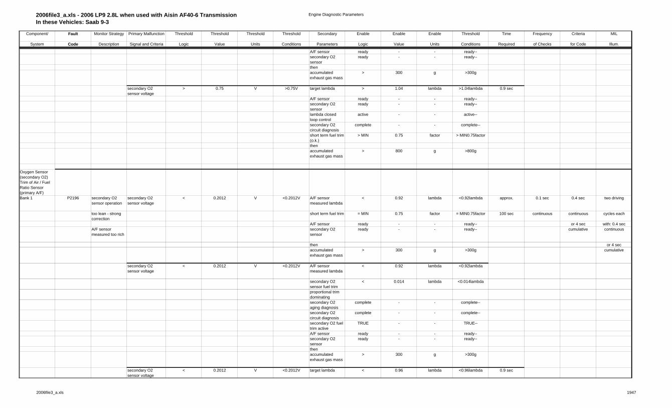
Oxygen Sensor (secondary O2) Trim of Air / Fuel Ratio Sensor (primary A/F)Bank 1 P2195 secondary O2
sensor operationsecondary O2 sensor voltage
> 0.75 V >0.75V A/F sensor measured lambda
> 1.08008 lambda >1.08008lambda approx. 0.1 sec 0.4 sec two driving
too rich - strong correction
short term fuel trim = MAX 1.25 factor = MAX1.25factor 100 sec continuous continuous cycles each
A/F sensor ready - - ready-- or 4 sec with: 0.4 secA/F sensor measured too lean
or secondary O2 sensor
ready - - ready-- cumulative continuous
then or 4 secaccumulated exhaust gas mass
> 300 g >300g cumulative
secondary O2 sensor voltage
> 0.75 V >0.75V A/F sensor measured lambda
> 1.08008 lambda >1.08008lambda
secondary O2 sensor fuel trim
> 0.014008 lambda >0.014008lambda
proportional trim dominatingsecondary O2 aging diagnosis
complete - - complete--
secondary O2 circuit diagnosis
complete - - complete--
secondary O2 fuel trim active
TRUE - - TRUE--
2006file3_a.xls 1847
2006file3_a.xls - 2006 LP9 2.8L when used with Aisin AF40-6 TransmissionIn these Vehicles: Saab 9-3
Engine Diagnostic Parameters
Component/ Fault Monitor Strategy Primary Malfunction Threshold Threshold Threshold Threshold Secondary Enable Enable Enable Threshold Time Frequency Criteria MIL
System Code Description Signal and Criteria Logic Value Units Conditions Parameters Logic Value Units Conditions Required of Checks for Code Illum.
A/F sensor ready - - ready--secondary O2 sensor
ready - - ready--
thenaccumulated exhaust gas mass
> 300 g >300g
secondary O2 sensor voltage
> 0.75 V >0.75V target lambda > 1.04 lambda >1.04lambda 0.9 sec
A/F sensor ready - - ready--secondary O2 sensor
ready - - ready--
lambda closed loop control
active - - active--
secondary O2 circuit diagnosis
complete - - complete--
short term fuel trim (o.k.)
> MIN 0.75 factor > MIN0.75factor
thenaccumulated exhaust gas mass
> 800 g >800g
Oxygen Sensor (secondary O2) Trim of Air / Fuel Ratio Sensor (primary A/F)Bank 1 P2196 secondary O2
sensor operationsecondary O2 sensor voltage
< 0.2012 V <0.2012V A/F sensor measured lambda
< 0.92 lambda <0.92lambda approx. 0.1 sec 0.4 sec two driving
too lean - strong correction
short term fuel trim = MIN 0.75 factor = MIN0.75factor 100 sec continuous continuous cycles each
A/F sensor ready - - ready-- or 4 sec with: 0.4 secA/F sensor measured too rich
secondary O2 sensor
ready - - ready-- cumulative continuous
then or 4 secaccumulated exhaust gas mass
> 300 g >300g cumulative
secondary O2 sensor voltage
< 0.2012 V <0.2012V A/F sensor measured lambda
< 0.92 lambda <0.92lambda
secondary O2 sensor fuel trim
< 0.014 lambda <0.014lambda
proportional trim dominatingsecondary O2 aging diagnosis
complete - - complete--
secondary O2 circuit diagnosis
complete - - complete--
secondary O2 fuel trim active
TRUE - - TRUE--
A/F sensor ready - - ready--secondary O2 sensor
ready - - ready--
thenaccumulated exhaust gas mass
> 300 g >300g
secondary O2 sensor voltage
< 0.2012 V <0.2012V target lambda < 0.96 lambda <0.96lambda 0.9 sec
2006file3_a.xls 1947

2006file3_a.xls - 2006 LP9 2.8L when used with Aisin AF40-6 TransmissionIn these Vehicles: Saab 9-3
Engine Diagnostic Parameters
Component/ Fault Monitor Strategy Primary Malfunction Threshold Threshold Threshold Threshold Secondary Enable Enable Enable Threshold Time Frequency Criteria MIL
System Code Description Signal and Criteria Logic Value Units Conditions Parameters Logic Value Units Conditions Required of Checks for Code Illum.
A/F sensor ready - - ready--secondary O2 sensor
ready - - ready--
lambda closed loop control
active - - active--
secondary O2 circuit diagnosis
complete - - complete--
short term fuel trim (o.k.)
< MAX 1.25 factor < MAX1.25factor
thenaccumulated exhaust gas mass
> 800 g >800g
Air / Fuel Ratio Sensor (primary A/F)electricalwire to wire short circuit
sensor short to heater
filtered maximum pump current variation
> 0.00019 A >0.00019A all injectors activated
TRUE - - TRUE-- 15 sec 0.01 sec 0.4 sec two driving
bank 1 sensor 1 P2231 within every 10ms
battery voltage < 18 V <18V continuous continuous cycles each
battery voltage > 10,7 V >10.7V or 4 sec with: 0.4 secA/F sensor IC diagnosis
complete - - complete-- cumulative continuous
error: A/F sensor IC
not set - - not set-- or 4 sec
engine rpm < 1800 rpm <1800rpm cumulativemodeled exhaust gas temperature
< 800 ° C <800° C
heater duty cycle > 20 % >20%heater duty cycle < 80 % <80%A/F sensor heater at op.temp.
TRUE TRUE
after A/F sensor curve switching for time > 0.06 sec >0.06sec
Diagnosis of Heater upstream HO2S
P0032 short circuit to battery voltage
Voltage IC internal IC internal for time > 5 sec > 5 sec 5 sec continous 0.2 sec 2 dcy
battery voltage via main relay
<=18 V
<= 18 V
P0031 short circiut to ground
battery voltage via main relay
>= 10,7 V >= 10,7 V
condition end of start True True
P0030 wire interruption condition engine speed: n > NMIN True True
A/F Sensor Heatingheater performance (primary A/F)
2006file3_a.xls 2047

2006file3_a.xls - 2006 LP9 2.8L when used with Aisin AF40-6 TransmissionIn these Vehicles: Saab 9-3
Engine Diagnostic Parameters
Component/ Fault Monitor Strategy Primary Malfunction Threshold Threshold Threshold Threshold Secondary Enable Enable Enable Threshold Time Frequency Criteria MIL
System Code Description Signal and Criteria Logic Value Units Conditions Parameters Logic Value Units Conditions Required of Checks for Code Illum.
bank 1 sensor 1 P0135 A/F sensor calculated temperature
A/F sensor temperature calculation
< 715 ° C <715° C battery voltage > 10,7 V >10.7V 35 sec 0.1 sec 0.4 sec two driving
too low battery voltage < 18 V <18V continuous continuous cycles eachinternal resistance measurement
valid - - valid-- or 4 sec with: 0.4 sec
all injectors activated
TRUE - - TRUE-- cumulative continuous
A/F sensor internal resistance
FALSE - - FALSE-- or 4 sec
excessive correction required
cumulative
engine stop time > 5400 sec >5400secengine temperature at start
> -9,8 ° C >-9.8° C
A/F sensor heating ready
TRUE - - TRUE--
A/F heater control shut off
FALSE - - FALSE--
scheduled by System Manager
TRUE - - TRUE--
heater performance (primary A/F)bank 1 sensor 1 (primary)
P0135 A/F sensor calculated
A/F sensor temperature calculation
< 715 ° C <715° C A/F Heater at Maximum Power
TRUE TRUE 60 sec 0.1 sec 0.4 sec two driving
temperature below threshold
modeled exhaust temp. at sensor
> 300 ° C >300° C continuous continuous cycles each
timer expires after either:
> 50 sec >50sec or 4 sec with: 0.4 sec
fuel shut off >= 3 sec dur. ends
- - - --- cumulative continuous
or initial A/F heater turn on
- - - --- or 4 sec
battery voltage > 10,7 V >10.7V cumulativebattery voltage < 18 V <18VA/F heater control shut off
FALSE - - FALSE--
modeled exhaust temp. valid
TRUE TRUE
scheduled by System Manager
TRUE - - TRUE--
A/F Sensor Heatingheater performance (secondary O2)bank 1 sensor 1 P0053 correction value for
A/F sensorabsolute value of correction value for
> 45 Ohms >45Ohms battery voltage > 10.7 V >10.7V 40 sec 0.1 sec 0.4 sec two driving
bank 2 sensor 1 internal resistance measurement
A/F sensor internal resistance
battery voltage < 18 V <18V continuous continuous cycles each
too much engine starting complete - - complete-- or 4 sec with: 0.4 seccumulative continuous
2006file3_a.xls 2147

2006file3_a.xls - 2006 LP9 2.8L when used with Aisin AF40-6 TransmissionIn these Vehicles: Saab 9-3
Engine Diagnostic Parameters
Component/ Fault Monitor Strategy Primary Malfunction Threshold Threshold Threshold Threshold Secondary Enable Enable Enable Threshold Time Frequency Criteria MIL
System Code Description Signal and Criteria Logic Value Units Conditions Parameters Logic Value Units Conditions Required of Checks for Code Illum.
or 4 seccumulative
Oxygen Sensorsensor circuit (secondary O2)bank 1 sensor 2 P0137 short circuit to
groundsecondary O2 sensor voltage
< 0.06 V <0.06V secondary O2 heating stable
> 10 sec > 10sec 0.1 sec 0.1 sec 0.4 sec two driving
and mod. exhaust gas temp.
> 250 ° C >250° C continuous continuous cycles each
for time > 90 sec >90sec or 4 sec with: 0.4 secengine running TRUE - - TRUE-- cumulative continuousbattery voltage > 10.7 V >10.7V or 4 secmod. exhaust-gas temp.
< 800 ° C <800° C cumulative
time after start < 1 sec <1secengine temp at stop
> 60 ° C >60° C
engine temp < 40 ° C <40° Cerror: engine coolant temp
not set - - not set--
bank 1 sensor 2 P0138 short circuit to battery voltage
secondary O2 sensor voltage >
> 1.08 V >1.08V secondary O2 heating stable
> 10 sec > 10sec 5.1 sec
and mod. Exhaust-gas temp.
> 250 ° C >250° C
for time > 90 sec >90secengine running TRUE - - TRUE--battery voltage > 10.7 V >10.7Vmod. exhaust-gas temp.
< 800 ° C <800° C
bank 1 sensor 2 P0140 sensor line disconnection
secondary O2 sensor voltage
> 0.401 V >0.401V secondary O2 heating stable
> 10 sec > 10sec 600 sec
and secondary O2 sensor voltage
< 0.499 V <0.499V and mod. Exhaust-gas temp.
> 250 ° C >250° C
for time > 90 sec >90secor engine running TRUE - - TRUE--secondary O2 sensor internal resistance
> 40000 Ohm >40000Ohm battery voltage > 10.7 V >10.7V
when modeled exhaust gas temperature
> 600 ° C >600° C mod. exhaust-gas temp.
< 800 ° C <800° C
Oxygen Sensorsensor circuit (secondary O2)bank 1 sensor 2 P2232 sensor line short
circuitsecondary O2 sensor
secondary O2 heating stable
> 10 sec > 10sec 10 sec 0.01 sec 0.4 sec two driving
to heater output line
voltage gradient > 2 V >2V and mod. Exhaust-gas temp.
> 250 ° C >250° C continuous continuous cycles each
within time after heater turn off
< 0.04 sec <0.04sec for time > 90 sec >90sec or 4 sec with: 0.4 sec
for occurrences > 4 count >4count engine running TRUE - - TRUE-- cumulative continuousout of heater turn offs
= 6 count =6count battery voltage > 10.7 V >10.7V or 4 sec
mod. exhaust-gas temp.
< 800 ° C <800° C cumulative
time after dew point exceeded
> 10 sec >10sec
2006file3_a.xls 2247

2006file3_a.xls - 2006 LP9 2.8L when used with Aisin AF40-6 TransmissionIn these Vehicles: Saab 9-3
Engine Diagnostic Parameters
Component/ Fault Monitor Strategy Primary Malfunction Threshold Threshold Threshold Threshold Secondary Enable Enable Enable Threshold Time Frequency Criteria MIL
System Code Description Signal and Criteria Logic Value Units Conditions Parameters Logic Value Units Conditions Required of Checks for Code Illum.
Oxygen Sensor Heatingheater performance (secondary O2)bank 1 sensor 2 (secondary)
P0141 secondary O2 sensor
measured secondary O2 sensor internal
battery voltage > 10,7 V >10.7V 6 sec 0.1 sec 0.4 sec two driving
internal resistance resistance battery voltage < 18 V <18V continuous continuous cycles each
above threshold nominal internal resistance
> 88 . . . 408 Ohms >88 . . . 408Ohms engine running TRUE - - TRUE-- or 4 sec with: 0.4 sec
KFRINH KFRINH engine starting complete - - complete-- cumulative continuousmultipy times degradation factor
> 3 . . . 20 factor >3 . . . 20factor fuel cut off FALSE - - FALSE-- or 4 sec
FRINH FRINH sec. O2 internal resistance
valid - - valid-- cumulative
for time > 6 sec >6sec intake air temperature
> -9,8 C >-9.8C
engine off soak time
> 120 sec >120sec
modeled exhaust temp.
in range 350 . . . 550 C in range350 . . . 550C
at secondary O2 sensorsuspicion of secondary
FALSE FALSE
O2 sensor open circuitsecondary O2 voltage supply
ON ON
scheduled by System Manager for time > 120 sec >120sec
sensor response (secondary O2)bank 1 sensor 2 P2270 oscillation check
lowsecondary O2 sensor voltage
< 0.499 . . . 0.603 V <0.499 . . . 0.603V secondary O2 sensor
ready - - ready - - approx. 0.1 sec 0.4 sec two driving
for time > 5 sec >5sec for time > 10 sec >10sec 600 sec continuous continuous cycles eachthen secondary O2
closed loop controlactive - - active - - or 4 sec with: 0.4 sec
ramping in enrichment by
= 0.25 lambda =0.25lambda all injectors activated
TRUE - - TRUE - - additional cumulative continuous
at gradient = 0.0513 l / sec 0,0513 l / sec engine air flow (intrusive test)
> 9.72 g/sec 9.72g/sec time if or 4 sec
for time (after enrichment limit reached)
> 7 sec >7sec and engine air flow
< 33.33 g/sec 33.33g/sec fuel level cumulative
for time > 3 sec >3sec is low andengine air flow (passive monitor)
> 9.72 g/sec 9.72g/sec not failed
sec. O2 trim - fast lean correction
FALSE FALSE 600 sec
sec. O2 trim - fast rich correction
FALSE FALSE
engine running runningscheduled by System Manager
TRUE TRUE
2006file3_a.xls 2347

2006file3_a.xls - 2006 LP9 2.8L when used with Aisin AF40-6 TransmissionIn these Vehicles: Saab 9-3
Engine Diagnostic Parameters
Component/ Fault Monitor Strategy Primary Malfunction Threshold Threshold Threshold Threshold Secondary Enable Enable Enable Threshold Time Frequency Criteria MIL
System Code Description Signal and Criteria Logic Value Units Conditions Parameters Logic Value Units Conditions Required of Checks for Code Illum.
bank 1 sensor 2 P2271 oscillation check high
secondary O2 sensor voltage
> 0.499 . . . 0.603 V >0.499 . . . 0.603V secondary O2 sensor
ready - - ready - - approx. 0.1 sec 0.4 sec two driving
for time > 5 sec >5sec for time > 10 sec >10sec 600 sec continuous continuous cycles each
then
secondary O2 closed loop control
active active or 4 sec with: 0.4 sec
ramping in enleanment by
= 0.07 lambda =0.07lambda all injectors activated
TRUE TRUE cumulative continuous
at gradient = 0,0513 l / sec 0,0513 l / sec engine air flow (intrusive test)
> 9.72 g/sec 9.72g/sec or 4 sec
for time (after enleanment limit reached)
> 7 sec >7sec and engine air flow
< 33.33 g/sec 33.33g/sec cumulative
for time > 3 sec >3secengine air flow (passive monitor)
> 9.72 g/sec 9.72g/sec
sec. O2 trim - fast lean correction
FALSE FALSE
sec. O2 trim - fast rich correction
FALSE FALSE
engine running runningscheduled by System Manager
TRUE TRUE
bank 1 sensor 2 P2271 fuel cut off check high
secondary O2 sensor voltage
> 0.202 V >0.202V secondary O2 heating stable
> 10 sec > 10sec 0.2 sec 0.1 sec 0.4 sec two driving
time after fuel cut off > 2,5 sec >2,5sec secondary O2 dew point exceeded
TRUE - - TRUE - - continuous continuous cycles each
for time > 30 sec >30sec or 4 sec with: 0.4 secair passed after fuel cut off
> 15 g >15g cumulative continuous
modeled exhaust temp
> 350 ° C >350° C or 4 sec
at secondary O2 sensor
cumulative
scheduled by System Manager
TRUE - - TRUE - -
error: cam sensor not set - - not set - -
error: evap canister purge sys.
not set - - not set - -
error: evap purge valve ckt
not set - - not set - -
error: battery voltage
not set - - not set - -
Camshaft ControlSystem - Locking Pin
two driving
Bank 1 Intake P0011 rationality high average of actual angle measurements
> 10 degrees >10degrees engine speed > 560 rpm >560rpm 10 sec 0.01 sec 0.4 sec cycles each
Bank 2 Intake P0021 versus locked position angle
engine run time > 1 sec >1sec continuous with: 0.4 sec
camshaft control circuit test
complete - - complete-- or 4 sec continuous
error: camshaft control circuit
not set - - not set-- cumulative or 4 sec cum
System - Control P000A rationality low / high
difference to start test (filtered actual
> 6 degrees > 6degrees engine speed > 560 rpm >560rpm approx. 0.01 sec 0.4 sec two driving
2006file3_a.xls 2447

2006file3_a.xls - 2006 LP9 2.8L when used with Aisin AF40-6 TransmissionIn these Vehicles: Saab 9-3
Engine Diagnostic Parameters
Component/ Fault Monitor Strategy Primary Malfunction Threshold Threshold Threshold Threshold Secondary Enable Enable Enable Threshold Time Frequency Criteria MIL
System Code Description Signal and Criteria Logic Value Units Conditions Parameters Logic Value Units Conditions Required of Checks for Code Illum.
Bank 1 Intake P000C angle versus filtered desired angle)
KFDWNWDMXE / 2
KFDWNWDMXE / 2
engine run time > 1 sec >1sec 20 sec continuous continuous cycles each
Bank 2 Intake (desired must remain above value
camshaft control circuit test
complete - - complete-- or 4 sec with: 0.4 sec
to test to complete the evaluation)
error: camshaft control circuit
not set - - not set-- (4 times cumulative continuous
same as above, but offset added to the
+ 0 degrees +0degrees coolant temperature
< 143 ° C < 143° C for 4 sec or 4 sec
difference, during cold start only:
coolant temperature
> -48 ° C >-48° C each ) cumulative
filtered actual angle remains
< < engine oil temperature
< 143 ° C <143° C
filtered desired angle from test start
engine oil temperature
> -48 ° C >-48° C
within time = 2 sec =2sec cam-crank alignment adaptation
complete - - complete--
(detects 5 sec slow [time constant])
for multiple activation occurrences
> 4 count >4count
(decrements upon activations where
( same as stated in "time required"
column )no difference is seen between desired
and actual)same as above, but during cold start only:
> 2 count >2count
difference (filtered actual angle max
> 3 degrees >3degrees
versus actual at test start)( to detect slow response versus stuck cam if above this limit )at time = 4 sec =4sec(overlaps with time to detect above)
(passes after multiple good activations in both cam phase rotation directions)
System - Cam - Crank Alignment
2006file3_a.xls 2547

2006file3_a.xls - 2006 LP9 2.8L when used with Aisin AF40-6 TransmissionIn these Vehicles: Saab 9-3
Engine Diagnostic Parameters
Component/ Fault Monitor Strategy Primary Malfunction Threshold Threshold Threshold Threshold Secondary Enable Enable Enable Threshold Time Frequency Criteria MIL
System Code Description Signal and Criteria Logic Value Units Conditions Parameters Logic Value Units Conditions Required of Checks for Code Illum.
Bank 1 Intake P0016 cam-crank adapted angle
adapted angle > 18 degrees >18degrees engine run time > > 2 sec >2sec approx. 0.2 sec 0.4 sec two driving
limit check or adapted angle
< -10 degrees <-10degrees engine coolant temp >
> 9.8 ° C >9.8° C 600 sec continuous continuous cycles each
Bank 2 Intake P0018 (applies for each camshaft)
or actual angle with parked cams
> 20 degrees >20degrees engine coolant temp <
< 105 ° C <105° C or 4 sec with: 0.4 sec
and < 25 degrees <25degrees model: engine oil temp <
< 140 ° C <140° C fail after cumulative continuous
Bank 1 / Idler Sprocket
P0008 adapted angle for both cams
> 18 degrees >18degrees error: camshaft sensor
not set - - not set-- 2 adaptation or 4 sec
Bank 2 / Idler Sprocket
P0009 adapted angle for both cams
< -10 degrees <-10degrees error: camshaft control circuit
not set - - not set-- cycles - cumulative
required
Engine coolant P0117 range check high coolant temperature > 138.8 ° C >138.8° C hot restart timer after engine start
>= 60 sec >=60sec 0.1 sec 0.1 sec 0.4 sec two driving
temperature sensor
P0118 range check low coolant temperature < -38.3 ° C <-38.3° C If Startup ECT+O155
< -38.3 ° C <-38.3° C continuous cycles each
| ECT-Startup ECT | (abs value)
<= 2.3 ° C <=2.3° C or 4 sec with: 0.4 sec
integrated air mass increases
>= 0 g >=0g cumulative cont. or 4
and air mass timer >= 30 sec >=30sec sec cum.
P0119 intermittent ( discontinuity )
delta coolant temperature
< -20.25 ° C <-20.25° C ignition = ON =ON approx. 0.01 sec immediate
or 150 sec continuousdelta coolant temperature
> 20.25 ° C >20.25° C
(between A/D read sample count offset)
= 3 count =3count
Engine coolant P0116 plausibility check (low side check)
calculated coolant temperature model
> 9.8 ° C >9.8° C the model temperature increases
or 0.4 sec two driving
temperature sensor
minus measured temperature
depending on air flow
continuous cycles each
plausibility check (high side check)
measured temperature
9.8 ° C measured temperature
< 93.8 ° C <93.8° C
minus calculated coolant temperature model
engine speed > 520 rpm >520rpm or 4 sec with: 0.4 sec
integrated air mass > 3000 g > 3000g cumulative continuous
no error engine speed
or 4 sec
no error air mass flow meter
cumulative
Engine coolant P050C difference from intake air
filtered difference key up IAT - previous min IAT
< 1.5 ° C <1.5° C 160 sec 0.2 sec immediate two driving
2006file3_a.xls 2647

2006file3_a.xls - 2006 LP9 2.8L when used with Aisin AF40-6 TransmissionIn these Vehicles: Saab 9-3
Engine Diagnostic Parameters
Component/ Fault Monitor Strategy Primary Malfunction Threshold Threshold Threshold Threshold Secondary Enable Enable Enable Threshold Time Frequency Criteria MIL
System Code Description Signal and Criteria Logic Value Units Conditions Parameters Logic Value Units Conditions Required of Checks for Code Illum.
temperature sensor
temperature after soaking
( ECT at key on - IAT at key on )
> 15 ° C >15° C key up IAT - previous min IAT
> -24.75 ° C >-24.75° C for block continuous additional cycles each
previous accumulated air mass
> 2000 g >2000g heating after block with: 0.4 sec
previous accumulated air mass
> 4000 g >4000g heater cumulative
orprevious engine run time
> 500 sec >500sec check
or
filtered differenceECT at shut down > 84.75 ° C >84.75° C
( ECT at key on - IAT at key on )
< -10 ° C <-10° C Controller Shut Down at end of
last cycle - - last cycle--
Strong Wind / Open Hood
not detected - - not detected--
based on IAT rise at shut downBlock Heater not detected - - not detected--
Engine Coolant P0128 Coolant Temperature Below
(calculated referencemodel coolant temp
> 5.3 ° C >5.3° C debouncing time > 15 sec >15sec approx. 0.1 sec 0.4 sec two driving
Thermostat Monitoring
Thermostat Regulating
minus measured coolant temperature)
error: engine coolant temp
not set - - not set-- 900 sec continuous continuous cycles each
Temperature (plausibility check)
error: vehicle speed sensor
not set - - not set-- or 4 sec with: 0.4 sec
reference model calculation limit
74,3 ... 75,8 ° C 74,3 ... 75.8° C est. ambient temperature
> -39.8 °C > -39.8°C cumulative continuous
est. ambient temperature
< 140 °C <140°C or 4 sec
( development vehicles indicated
vehicle speed >= 3.125 mph >=3.125mph cumulative
steady thermostat regulating
engine speed > 640 rpm >640rpm
temperatures of 89°C, as measured
coolant temperature at start
< 69.8 °C < 69.8°C
by the engine coolant temp. sensor.
integrated air mass flow
> 1000 g > 1000g
The thermostat opening temp. is 82°C. The thermostat is fully open by 95°C. All critical OBD and emission functions are enabled
above 60°C. )
Intake air temperature
P0111 response check max intake air temperature -
drive period - count
>= 5 count >=5count 2 sec 0.1 sec 0.4 sec two driving
sensor min intake air temperature
> 2.3 ° C >2.3° C each with continuous continuous cycles each
2006file3_a.xls 2747

2006file3_a.xls - 2006 LP9 2.8L when used with Aisin AF40-6 TransmissionIn these Vehicles: Saab 9-3
Engine Diagnostic Parameters
Component/ Fault Monitor Strategy Primary Malfunction Threshold Threshold Threshold Threshold Secondary Enable Enable Enable Threshold Time Frequency Criteria MIL
System Code Description Signal and Criteria Logic Value Units Conditions Parameters Logic Value Units Conditions Required of Checks for Code Illum.
vehicle speed >= 56.25 mph >=56.25mph or 4 sec with: 0.4 sec mass flow < 250 g / sec <250g / sec cumulative continuous mass flow > 25.6 g / sec > 25.6g/sec or 4 seccoolant temperature at start
<= 120 ° C <=120° C cumulative
no fuel shut-offidle period - count >= 4 count >=4count
each withvehicle speed <= 1.5625 mph <=1.5625mphcoolant temperature at start
<= 120 ° C <=120° C
coolant temperature
> 64.5 ° C >64.5° C
ECT decrease since prior shutdown
> 0 ° C >0° C
P0112 range check low intake air temperature
> 125.3 ° C >125.3° C
P0113 range check high intake air temperature
< -35.3 ° C <-35.3° C time after start > 15 sec > 15sec
then time in idle > 3 sec >3secand intake air temperature
< -35.3 ° C <-35.3° C
then | IAT change | (abs value)
<= 2.3 ° C <=2.3° C
whileintegrated air mass increases
>= 0 g >=0g
Mass air flow sensor
P0101 range check low mass air flow < 1.83 . . . 78.9 g/sec <1.83 . . . 78.9 g/sec
battery voltage > 10.5 V >10.5V 0.40 sec 0.01 sec 0.4 sec two driving
or and KFMLDMN KFMLDMN time after start > 0.4 sec >0.4sec continuous continuous cycles eachfuel trim limits exceded
delta lambda correction
> 0,16 factor >0.16factor crankshaft revolution counter
> 150 rev >150rev or 4 sec with: 0.4 sec
range - multiplicative
error: throttle position sensor
not set - - not set -- cumulative continuous
and 0 0 00 or 4 seccorrection factor (modeled air
correction factor air mass
< 0.83 factor <0.83factor 0 g/s 0g/s cumulative
mass at throttle / air mass
ratio: MAP to Baro < 1 - <1 -
measured by air mass flow meter)
air mass flow > 8.3 g/sec
time after start > 1 secrange check high mass air flow > 26.9 . . . 312.5 g/sec > 26.9 . . . 312.5
g/secerrors: not set
or and KFMLDMX KFMLDMX throttle body --fuel trim limits exceded
delta lambda correction
< -0.175 factor <-0.175factor Leak upstream throttle
- -
range - multiplicative
and correction factor (modeled air
correction factor air mass
> 1.1699 factor >1.1699factor
mass at throttle / air mass
2006file3_a.xls 2847

2006file3_a.xls - 2006 LP9 2.8L when used with Aisin AF40-6 TransmissionIn these Vehicles: Saab 9-3
Engine Diagnostic Parameters
Component/ Fault Monitor Strategy Primary Malfunction Threshold Threshold Threshold Threshold Secondary Enable Enable Enable Threshold Time Frequency Criteria MIL
System Code Description Signal and Criteria Logic Value Units Conditions Parameters Logic Value Units Conditions Required of Checks for Code Illum.
measured by air mass flow meter)
P0102 circuit check low mass air flow < -10.3 g/sec >10.3g/sec battery voltage > 7.5 V >7.5V 0.2 sec
P0103 circuit check high mass air flow > 333.3 g/sec >33.3g/sec
pressure sensor upstream throttle valve
P0238 cirtcuit continuity - high or open
measured sensor voltage
> 4.65 V > 4.65 V 0.5 sec continuous 0.2 sec 2 dcy
P0237 cirtcuit continuity - low
measured sensor voltage
< 0.45 V < 0.45 V
P0238 range check - high
measured pressure> 300 kPa > 300 kPa enabled by
diagnostic 2 sec
P0237 range check - lowmeasured pressure
< 50 kPa < 50 kPa scheduler true true
P0236 rationality -measured fuel pressure lies below
comparison between measured expected minimum
pressure
true true
pressure and expected
(calculated) pressure
P0236 rationality - ('measured')
compression ratio exceeds
comparison between ('measured') expected maximum
compression ratio
true true
compression ratio and expected
(calculated) compression ratio
boost pressure control
P2281 comparison between
ratio between > 0.098 > 0.098 engine speed > 1520 rpm > 1520 rpm 1 sec continuous 0.2 sec 2 dcy
MAF based pressure ratio
MAF based pressure ratio
to to time after engine start
> 10 sec > 10 sec
over the throttle valve
over the throttle valve
1.25 1.25 no fault of
and and - pressure sensor
throttle body based pressure ratio
throttle body based pressure ratio
upstream throttle valve
true true
over the throttle valve
over the throttle valve
- throttle position sensors
true true
- MAF sensor true true (detection of leakage)
(fine leakage) boost pressure control
2006file3_a.xls 2947

2006file3_a.xls - 2006 LP9 2.8L when used with Aisin AF40-6 TransmissionIn these Vehicles: Saab 9-3
Engine Diagnostic Parameters
Component/ Fault Monitor Strategy Primary Malfunction Threshold Threshold Threshold Threshold Secondary Enable Enable Enable Threshold Time Frequency Criteria MIL
System Code Description Signal and Criteria Logic Value Units Conditions Parameters Logic Value Units Conditions Required of Checks for Code Illum.
is active true true
ratio between > 0.101 > 0.101 1 sec MAF based pressure ratio
to to
over the throttle valve
1.297 1.297
and throttle body based pressure ratio
over the throttle valve
(coarse leakage)
ratio between > 0.109 > 0.109 engine speed > 1520 rpm > 1520 rpm 1.8 sec MAF based pressure ratio
to to time after engine start
> 10 sec > 10 sec
over the throttle valve
1.398 1.398 no fault of
and - pressure sensor
throttle body based pressure ratio
upstream throttle valve
true true
over the throttle valve
- throttle position sensors
true true
- MAF sensor true true (coarse leakage) - canister purge
systemtrue true
boost pressure control
is not active true true for time > > cruise control not
activetrue true
setpoint canister purge rate
< 0.03 < 0.03
no dynamic engine condition
true
P0299 comparison
between difference (positive) between
> 12 kPa > 12 kPa boost pressure control
6 sec
desired boost pressure
set-point boost pressure
is active true true
and and engine speed > 2000 rpm > 2000 rpm current boost pressure
current boost pressure
or or
2800 rpm 2800 rpm(boost pressure to low)
atmospheric pressure
> 66 kPa > 66 kPa
setpoint boost pressure
> base > base
boost boost pressure pressure + + 5 kPa 5 kPa
2006file3_a.xls 3047

2006file3_a.xls - 2006 LP9 2.8L when used with Aisin AF40-6 TransmissionIn these Vehicles: Saab 9-3
Engine Diagnostic Parameters
Component/ Fault Monitor Strategy Primary Malfunction Threshold Threshold Threshold Threshold Secondary Enable Enable Enable Threshold Time Frequency Criteria MIL
System Code Description Signal and Criteria Logic Value Units Conditions Parameters Logic Value Units Conditions Required of Checks for Code Illum.
P0234 comparison between difference (negative)
between
> 32 kPa > 32 kPa pressure upstream throttle
0.8 sec
desired boost pressure
set-point boost pressure
to to valve is valid true true
and and 127.5 kPa 127.5 kPa current boost pressure
current boost pressure
(boost pressure to high)
(Remark: for comparison the negative
value is converted to an absolute value)
dump valveP2261 counting of
increased pulsation
normalized difference between
engine coolant temperature
> 50.3 °C > 50.3 °C 0.48 sec continuous 0.2 sec 2 dcy
in the intake manifold
measured MAF sensor value and
intake air temperature
> -10.5 °C > -10.5 °C
modeled value > 0,352 > 0,352 pressure in front of
(increased pulsation may occure
throttle valve > 60 kPa > 60 kPa
when dump valve is jammed
for supervision phase is active
true true
in closed position)
number of times > 4 counts > 4 counts conditions for an active
supervision phase are
- negative load gradient
detected true true - ratio of pressure in front of
> 1.05 > 1.05
throttle valve to minimum
to to
pressure after air filter
3.12 3.12
- dump valve is active
true true
Barometric Pressure Sensor
P2227 rationality difference between barometric pressure
3 sec 0.1 sec 0.4 sec two driving
( ambient air pressure sensor )
signal discontinuity signal pressure and pressure in front of throttle
> 15 kPa >15kPa plausible pressure signal pressure sensor
TRUE TRUE continuous cycles each
in front of throttle or 4 sec with: 0.4 secand cumulative continuous
2006file3_a.xls 3147

2006file3_a.xls - 2006 LP9 2.8L when used with Aisin AF40-6 TransmissionIn these Vehicles: Saab 9-3
Engine Diagnostic Parameters
Component/ Fault Monitor Strategy Primary Malfunction Threshold Threshold Threshold Threshold Secondary Enable Enable Enable Threshold Time Frequency Criteria MIL
System Code Description Signal and Criteria Logic Value Units Conditions Parameters Logic Value Units Conditions Required of Checks for Code Illum.
throttle angle < 5 % <5% or 4 secand cumulativeengine speed < 1000 rpm <1000rpm
or enabled by scheduler for time
> 3 sec >3sec
barometric pressure signal pressure
jump from previous key off
> 10 kPa >10kPa Baro from previous drive
valid - - valid--
difference: Baro substitute
> 15 kPa >15kPa
and model versus sensorengine speed lower
< 621 rpm < 621 rpm
difference between barometric pressure
> 10 kPa >10kPa and
signal pressure and pressure in front of throttle
throttle angle < 5 % < 5%
both for time > 3 sec >3sec
P2228 range check low sensor signal < 45 kPa <45kPa enabled by scheduler for time
> 1 sec >1sec 2 sec
sensor voltage < 0.45 V < 0,45V 0.5 sec
P2229 range check high sensor signal > 115 kPa >115kPa enabled by scheduler for time
> 1 sec >1sec 2 sec
sensor voltage > 4.8 V >4,8V 0.5 sec
Idle Speed System
(disabled during cold start)
P0506 functional check desired rpm - actual rpm
> 100 rpm >100rpm load (for underspeed only)
< 39.75 % <39.75% 10 sec 0.1 sec 0.4 sec two driving
coolant temp. > 64.5 ° C >64.5° C continuous continuous cycles eachP0507 desired rpm - actual
rpm< -200 rpm <-200rpm intake air temp > -10.5 ° C >-10.5° C or 4 sec with: 0.4 sec
or vehicle at idle at idle cumulative continuousfuel cut off due to overspeed
> 3 count >3count altitude factor ( sea level = 1.0 )
> 0.703 factor >0.703factor or 4 sec
during this idle time after engine start
> 0 sec >0sec cumulative
cold start idle speed control
FALSE FALSE
intrusive evap test not active not active
Idle Speed System
(enabled during cold start)
P0506 functional check desired rpm - actual rpm
> 100 rpm >100rpm load (for underspeed only)
< 39.75 % <39.75% 5 sec 0.1 sec 0.4 sec two driving
2006file3_a.xls 3247

2006file3_a.xls - 2006 LP9 2.8L when used with Aisin AF40-6 TransmissionIn these Vehicles: Saab 9-3
Engine Diagnostic Parameters
Component/ Fault Monitor Strategy Primary Malfunction Threshold Threshold Threshold Threshold Secondary Enable Enable Enable Threshold Time Frequency Criteria MIL
System Code Description Signal and Criteria Logic Value Units Conditions Parameters Logic Value Units Conditions Required of Checks for Code Illum.
during catalyst heating on
Engine coolant start temp.
> -10 …. +40 ° C > -10 …. +40° C continuous continuous cycles each
P0507 desired rpm - actual rpm
< -200 rpm <-200rpm intake air temp > 40 ° C >40° C or 4 sec with: 0.4 sec
during catalyst heating on
vehicle at idle at idle cumulative continuous
altitude factor ( sea level = 1.0 )
> 0.703 factor >0.703factor or 4 sec
time after engine start
> 0 sec >0sec cumulative
idle speed control catalyst heating
TRUE TRUE
intrusive evap test not active not active
Vehicle speed sensor
P0500 rationality vehicle speed > 171.875 mph >171.875mph - - - - --- 2 sec 0.1 sec 0.4 sec two driving(high range check) continuous continuous with: 0.4 sec
rationality vehicle speed minus
= 0 mph =0mph vehicle speed > 0 mph >0mph or 4 sec continuous
(stuck check) previous vehicle speed
vehicle speed < 319.375 mph <319.375mph cumulative or 4 sec
time > 10 sec >10sec cumulativeCAN wheel speed message check
CAN wheel speed message corrupt
= corrupt =corrupt
or missing = missing =missing
Crankshaft Position Sensor
P0335 circuit continuity no engine signal = 0 rpm =0rpm camshaft revolutions detected
> 12 counts >12counts approx. 0.01 sec 0.4 sec two driving
but phase signals available
5 sec continuous continuous cycles each
rationality check reference gap missing
> 6 gaps >6gaps or 4 sec with: 0.4 sec
( sensor signal but no reference )
cumulative continuous
P0336 rationality check unexpected re-synchronization
> 6 count >6count or 4 sec
( loss of reference mark )
cumulative
rationality check intermittent loss of engine speed signal
> 14 count >14count
P0338 rationality check difference in counted teeth between
> 8 teeth >8teeth approx. 1 per rev
reference gap position events
2 sec continuous
Camshaft Position SensorBank 1 Intake P0341 plausibility check no cam position
sensor signal> 5 count >5count engine in
synchronized mode
TRUE - - TRUE-- 10 1 per rev 0.4 sec two driving
P0342 circuit low > > revolutions continuous continuous cycles each
2006file3_a.xls 3347

2006file3_a.xls - 2006 LP9 2.8L when used with Aisin AF40-6 TransmissionIn these Vehicles: Saab 9-3
Engine Diagnostic Parameters
Component/ Fault Monitor Strategy Primary Malfunction Threshold Threshold Threshold Threshold Secondary Enable Enable Enable Threshold Time Frequency Criteria MIL
System Code Description Signal and Criteria Logic Value Units Conditions Parameters Logic Value Units Conditions Required of Checks for Code Illum.
P0343 circuit continuity or high
> > or 4 sec with: 0.4 sec
cumulative continuouscumulative continuous
Bank 2 Intake P0345 plausibility check no cam position sensor signal
> 5 count >5count or 4 sec
P0347 circuit low > 5 count >5count cumulativeP0348 circuit continuity or
high > 5 count >5count
fuel tank pressure sensor
barometric pressure
>=68 kPa
>= 68 kPa 14 sec continous 0.4 sec 2 dcy
P0453 circuit continuity - high or open
fuel tank pressure > 3781 Pa > 3781 Pa vehicle speed = 0 mph = 0 mph
fuel level > 6,2 % > 6,2 % fuel level < 87 % < 87 %
P0452 circuit continuity - low
fuel tank pressure < -4000 Pa < -4000 Pa engine start finished
true true
enabled by diagnostic scheduler
truetrue
P0451 rationality - fuel tank pressure difference >= 813 Pa >= 813 Pa 25.5 sec continous 0.4 sec 2 dcy
sensor signal change within time
within = 1 sec = 1 sec canister vent valve open
truetrue
(oscillation check) for integrated time >= 25.5 sec >= 25.5 sec for time > 3 sec > 3 sec
vehicle speed <= 18.64 mph <= 18.64 mphenabled by diagnostic scheduler
truetrue
P0451 rationality - sensor signal stuck(incremental check)
max-min difference of canister purge valve duty cycle >= 39.84 % >= 39.84 %
vehicle speed
>= 6.22 mph >= 6.22 mph 25 sec continous 0.4 sec 2 dcy
and canister purge is active true true
max-min difference of fuel tank pressure signal < 80 Pa
< 80 Pa ratio of intake manifold pressure to atmospheric pressure
<= 0.477 - <= 0.477 -
for number of checks >= 2 counts >= 2 counts atmospheric
pressure>=
68 kPa>= 68 kPa
incremental check without result yet
truetrue
fuel level > 6,2 % > 6,2 % fuel level < 87 % < 87 % enabled by
diagnostic scheduler
truetrue
P0327Monitoring via knock-sensor- and
Cylinder individual signal value
< 0.7422 ... 6.8164 V < 0.7422 ... 6.8164 V
- Knock control is active.
true true 0,3 sec continuous 2.6 sec no MIL
2006file3_a.xls 3447

2006file3_a.xls - 2006 LP9 2.8L when used with Aisin AF40-6 TransmissionIn these Vehicles: Saab 9-3
Engine Diagnostic Parameters
Component/ Fault Monitor Strategy Primary Malfunction Threshold Threshold Threshold Threshold Secondary Enable Enable Enable Threshold Time Frequency Criteria MIL
System Code Description Signal and Criteria Logic Value Units Conditions Parameters Logic Value Units Conditions Required of Checks for Code Illum.
cylinder-based basic reference noise
(depends on engine speed)
- engine coolant tempetature
> 45 °C > 45 °C
P0328 signal (voltage). Cylinder individual signal value
> 57.8908 ... 72.7541
V > 57.8908 ... 72.7541 V
- load > 30 % > 30 %
(depends on engine speed)
- Engine speed for strong signals.
> 2520 rpm > 2520 rpm
- Engine speed for weak signals.
> 2520 rpm > 2520 rpm
- No phase sensor faults during
true true
engine start. - Engine speed
dynamics for false false
knock detection exist.
- Load dynamics for knock
false false
detection exist. - No ECM knock-
control ciruittrue true
error. - Engine stpeed
limp homefalse false
function is active.
P0332 Monitoring via knock-sensor- and
Cylinder individual signal value
< 0.7422 ... 6.8164 V < 0.7422 ... 6.8164 V
- Knock control is active.
true true 0,3 sec continuous 2.6 sec no MIL
cylinder-based basic reference noise
(depends on engine speed)
- engine coolant tempetature
> 45 °C > 45 °C
P0333 signal (voltage). Cylinder individual signal value
> 57.8908 ... 72.7541
V > 57.8908 ... 72.7541 V
- load > 30 % > 30 %
(depends on engine speed)
- Engine speed for strong signals.
> 2520 rpm > 2520 rpm
- Engine speed for weak signals
> 2520 rpm > 2520 rpm
- No phase sensor faults during
true true
engine start. - Engine speed
dynamics for false false
knock detection exist.
- Load dynamics for knock
false false
detection exist. - No ECM knock-
control ciruittrue true
error. - Engine speed
limp homefalse false
function is active.
2006file3_a.xls 3547

2006file3_a.xls - 2006 LP9 2.8L when used with Aisin AF40-6 TransmissionIn these Vehicles: Saab 9-3
Engine Diagnostic Parameters
Component/ Fault Monitor Strategy Primary Malfunction Threshold Threshold Threshold Threshold Secondary Enable Enable Enable Threshold Time Frequency Criteria MIL
System Code Description Signal and Criteria Logic Value Units Conditions Parameters Logic Value Units Conditions Required of Checks for Code Illum.
Knock control sensor's evaluation IC
250 working Zero and 2.6 s 2 dcy
Response to Zero Pulse
cylces Test pulse
P0324 monitor IC's integrator offset
integrator's value - 715mV
> 0.215 V > 0.215 V knock control active
true - - true - - alternate every
no dynamic condition on engine speed
true - - true - - 250 working
no dynamic condition on engine load
true - - true - - cycles.
no fault assumption from knock control
test pulse. true - - true - - the engine speed
is within a calibrated
range true - - true - -P0324 monitor IC's
integrator gradientintegrator gradient > measuring window
length dependentV/s same as for IC
integrator's offset monitoring
Response to Test Pulse
P0324 integrator value check
integrator value of test pulse
< 3.691 V < 3.691 V the engine coolant temperature > calibration
true true
no dynamic condition on engine speed
true true
no dynamic condition on engine load
true true
no fault assumption from the knock control zero test. true true
Transmission Control Module
P0700 OBD emission fault
signal input = TCM MIL FAULT =TCM MILFAULT - - - - --- 0.01 sec 0.01 sec immediate immediate
MIL Illumination Request
detected by the TCM
continuous
(Specific TCM DTC shown in freeze frame)
fuel injectorcylinder #1 P0201 circuit continuity -
openVoltage IC internal IC internal engine speed > 80 rpm > 80 rpm immediately continuous 0.2 sec 2 dcy
P0261 circuit continuity - ground
battery voltage > 9,99 V > 9,99 V
P0262 circuit continuity - voltage
battery voltage < 17,99 V < 17,99 V
cylinder #2 P0202 circuit continuity - open
output activated and
P0264 circuit continuity - ground
deactivated for complete
2006file3_a.xls 3647

2006file3_a.xls - 2006 LP9 2.8L when used with Aisin AF40-6 TransmissionIn these Vehicles: Saab 9-3
Engine Diagnostic Parameters
Component/ Fault Monitor Strategy Primary Malfunction Threshold Threshold Threshold Threshold Secondary Enable Enable Enable Threshold Time Frequency Criteria MIL
System Code Description Signal and Criteria Logic Value Units Conditions Parameters Logic Value Units Conditions Required of Checks for Code Illum.
P0265 circuit continuity - voltage
checking true true
cylinder #3 P0203 circuit continuity - open
P0267 circuit continuity - ground
P0268 circuit continuity - voltage
cylinder #4 P0204 circuit continuity - open
P0270 circuit continuity - ground
P0271 circuit continuity - voltage
cylinder #5 P0205 circuit continuity - open
P0273 circuit continuity - ground
P0274 circuit continuity - voltage
cylinder #6 P0206 circuit continuity - open
P0276 circuit continuity - ground
P0277 circuit continuity - voltage
canister ventilation valve
P0449 circuit continuity - open
Voltage IC internal IC internal engine speed > 80 rpm > 80 rpm immediately continuous 0.2 sec 2 dcy
P0498 circuit continuity - ground
battery voltage > 9,99 V > 9,99 V
P0499 circuit continuity - voltage
battery voltage < 17,99 V < 17,99 V
output activated and
deactivated for complete
checking true true
canister purge valve
P0443 circuit continuity - open
Voltage IC internal IC internal engine speed > 80 rpm > 80 rpm immediately continuous 0.2 sec 2 dcy
P0458 circuit continuity - ground
battery voltage > 9,99 V > 9,99 V
P0459 circuit continuity - voltage
battery voltage < 17,99 V < 17,99 V
output activated and
deactivated for complete
checking true true
downstream oxygen sensor heater
Bank #1 P0036 circuit continuity - open
Voltage IC internal IC internal engine speed > 80 rpm > 80 rpm immediately continuous 0.2 sec 2 dcy
2006file3_a.xls 3747

2006file3_a.xls - 2006 LP9 2.8L when used with Aisin AF40-6 TransmissionIn these Vehicles: Saab 9-3
Engine Diagnostic Parameters
Component/ Fault Monitor Strategy Primary Malfunction Threshold Threshold Threshold Threshold Secondary Enable Enable Enable Threshold Time Frequency Criteria MIL
System Code Description Signal and Criteria Logic Value Units Conditions Parameters Logic Value Units Conditions Required of Checks for Code Illum.
P0037 circuit continuity - ground
battery voltage > 9,99 V > 9,99 V
P0038 circuit continuity - voltage
battery voltage < 17,99 V < 17,99 V
output activated and
deactivated for complete
checking true true
secondary air pump
P0418 circuit continuity - open
Voltage IC internal IC internal engine speed > 80 rpm > 80 rpm immediately continuous 0.2 sec 2 dcy
P2445 circuit continuity - ground
battery voltage > 9,99 V > 9,99 V
P2444 circuit continuity - voltage
battery voltage < 17,99 V < 17,99 V
output activated and
deactivated for complete
checking true true
intake camshaft control
Intake Bank #1 P0010 circuit continuity - open
Voltage IC internal IC internal engine speed > 80 rpm > 80 rpm immediately continuous 0.2 sec 2 dcy
P2088 circuit continuity - ground
battery voltage > 9,99 V > 9,99 V
P2089 circuit continuity - voltage
battery voltage < 17,99 V < 17,99 V
Intake Bank #2 P0020 circuit continuity - open
output activated and
P2092 circuit continuity - ground
deactivated for complete
P2093 circuit continuity - voltage
checking true true
Dump valve turbo P0033 circuit continuity - open
Voltage IC internal IC internal engine speed > 80 rpm > 80 rpm immediately continuous 0.2 sec no MIL
P0034 circuit continuity - ground
battery voltage > 9,99 V > 9,99 V
P0035 circuit continuity - voltage
battery voltage < 17,99 V < 17,99 V
output activated and
deactivated for complete
checking true true
Boost control valve P0244 circuit continuity - open
Voltage IC internal IC internal engine speed > 80 rpm > 80 rpm immediately continuous 0.2 sec no MIL
P0245 circuit continuity - ground
battery voltage > 9,99 V > 9,99 V
P0246 circuit continuity - voltage
battery voltage < 17,99 V < 17,99 V
2006file3_a.xls 3847

2006file3_a.xls - 2006 LP9 2.8L when used with Aisin AF40-6 TransmissionIn these Vehicles: Saab 9-3
Engine Diagnostic Parameters
Component/ Fault Monitor Strategy Primary Malfunction Threshold Threshold Threshold Threshold Secondary Enable Enable Enable Threshold Time Frequency Criteria MIL
System Code Description Signal and Criteria Logic Value Units Conditions Parameters Logic Value Units Conditions Required of Checks for Code Illum.
output activated and
deactivated for complete
checking true true
Ignition Coilcircuit continuityCylinder #1 P0351 circuit continuity -
open or signal not plausible Voltage > during
20 revs >20revs engine speed > 600 rpm >600rpm approx. engine 0.4 sec two driving
or minimum two fault counters
> 3 engine speed < 5000 rpm <5000rpm 1 sec cycle continuous cycles each
P2300 circuit continuity - ground Voltage > during
20 revs >20revs battery voltage > 10 V >10V frequency or 4 sec with: 0.4 sec
P2301 circuit continuity - voltage Voltage > during
20 revs >20revs battery voltage < 18 V <18V cumulative continuous
Cylinder #2 P0352 circuit continuity - open or signal not plausible Voltage > during
20 revs >20revs continuous or 4 sec
or minimum two fault counters
> 3 cumulative
P2303 circuit continuity - ground Voltage > during
20 revs >20revs
P2304 circuit continuity - voltage Voltage > during
20 revs >20revs
Cylinder #3 P0353 circuit continuity - open Voltage > during
20 revs >20revs
or minimum two fault counters
> 3
P2306 circuit continuity - ground Voltage > during
20 revs >20revs
P2307 circuit continuity - voltage Voltage > during
20 revs >20revs
Cylinder #4 P0354 circuit continuity - open Voltage > during
20 revs >20revs
or minimum two fault counters
> 3
P2309 circuit continuity - ground Voltage > during
20 revs >20revs
P2310 circuit continuity - voltage Voltage > during
20 revs >20revs
Cylinder #5 P0355 circuit continuity - open Voltage > during
20 revs >20revs
or minimum two fault counters
> 3
P2312 circuit continuity - ground Voltage > during
20 revs >20revs
P2313 circuit continuity - voltage Voltage > during
20 revs >20revs
Cylinder #6 P0356 circuit continuity - open Voltage > during
20 revs >20revs
or minimum two fault counters
> 3
P2315 circuit continuity - ground Voltage > during
20 revs >20revs
P2316 circuit continuity - voltage Voltage > during
20 revs >20revs
Electronic Throttle Control
P0638 motor control range check
| powerstage duty cycle |
> 80 % >80% battery voltage > 7 V >7V 0.6 sec 0.01 sec immediate immediate
2006file3_a.xls 3947

2006file3_a.xls - 2006 LP9 2.8L when used with Aisin AF40-6 TransmissionIn these Vehicles: Saab 9-3
Engine Diagnostic Parameters
Component/ Fault Monitor Strategy Primary Malfunction Threshold Threshold Threshold Threshold Secondary Enable Enable Enable Threshold Time Frequency Criteria MIL
System Code Description Signal and Criteria Logic Value Units Conditions Parameters Logic Value Units Conditions Required of Checks for Code Illum.
short term ( absolute value ) > 80 % >80% (recoverable) continuous
motor control range check
5.0 sec
long term (latched)
Electronic Throttle Control
P1551 limp-home throttle position
throttle position < 1.8006 % <1.8006% vehicle speed <= 0 mph <=0mph 5 sec 0.01 sec immediate immediate
out of range OR engine speed < 40 rpm <40rpm at key onthrottle position > 13.0785 % >13.0785% engine coolant
temperature>= 5.25 ° C >=5.25° C
engine coolant temperature
<= 84.75 ° C <=84.75° C
intake air temperature
>= 5.25 ° C >=5.25° C
intake air temperature
<= 60 ° C <=60° C
battery voltage > 9.99 V >9.99Vaccelerator pedal position
< 14.9 % <14.9%
Electronic Throttle Control
P2100 powerstage circuit switch-off
output circuits not deactivated
= deactivation fault =deactivationfault - - - - --- 0.1 sec 0.01 sec immediate immediate
as commanded at key on
P2101 difference between set and
difference between set and
> 4 . . . 50 % >4 . . . 50% electronic throttle adaptation
not active - - not active-- 0.5 sec 0.01 sec immediate immediate
actual position of throttle blade
actual position of throttle blade
dep. on rate of change
dep. on rate of change
battery voltage > 7 V >7V continuous
P2107 amplifier adjustment of
amplification value < 3.9961 V <3.9961V vehicle speed <= 0 mph <=0mph < 6 sec 0.01 sec immediate immediate
throttle position or engine speed < 40 rpm <40rpm once per throttleAdaption
amplification value > 4.3242 V >4.3242V engine coolant temperature
>= 5.25 ° C >=5.25° C
or engine coolant temperature
<= 84.75 ° C <=84.75° C
offset value < -0.1501 V <-0.1501V intake air temperature
>= 5.25 ° C >=5.25° C
or intake air temperature
<= 60 ° C <=60° C
offset value > 0.1501 V >0.1501V battery voltage > 9.99 V >9.99Vaccelerator pedal position
< 14.9 % <14.9%
P2119 functionality of return spring
throttle blade return response
> 0.56 sec >0.56sec vehicle speed <= 0 mph <=0mph 0.56 sec 0.01 sec immediate immediate
engine speed < 40 rpm <40rpm at key onengine coolant temperature
>= 5.25 ° C >=5.25° C once
engine coolant temperature
<= 84.75 ° C <=84.75° C per
intake air temperature
>= 5.25 ° C >=5.25° C ignition
intake air temperature
<= 60 ° C <=60° C on
battery voltage > 9.99 V >9.99V
2006file3_a.xls 4047

2006file3_a.xls - 2006 LP9 2.8L when used with Aisin AF40-6 TransmissionIn these Vehicles: Saab 9-3
Engine Diagnostic Parameters
Component/ Fault Monitor Strategy Primary Malfunction Threshold Threshold Threshold Threshold Secondary Enable Enable Enable Threshold Time Frequency Criteria MIL
System Code Description Signal and Criteria Logic Value Units Conditions Parameters Logic Value Units Conditions Required of Checks for Code Illum.
accelerator pedal position
< 14.9 % <14.9%
Electronic Throttle Control
P2176 throttle exchange detection
range check poti1 value at lower stop
vehicle speed <= 0 mph <=0mph 1 sec 0.01 sec immediate immediate
learn fail throttle potentiometer 1 voltage
< 0.212 V <0.212V engine speed < 40 rpm <40rpm at key on
or or engine coolant temperature
>= 5.25 ° C >=5.25° C once
initial throttle learn failed
throttle potentiometer 1 voltage
> 0.865 V >0.865V engine coolant temperature
<= 84.75 ° C <=84.75° C per
or intake air temperature
>= 5.25 ° C >=5.25° C ignition
learning prohibited due to
range check poti2 value at lower stop
0 0 intake air temperature
<= 60 ° C <=60° C on
secondary parameters not met
throttle potentiometer 2 voltage
< 4.14 V <4.14V battery voltage > 9.99 V >9.99V
or or accelerator pedal position
< 14.9 % <14.9%
minimum throttle position
throttle potentiometer 2 voltage
> 4.84 >4.84
out of range
Throttle Position P0121 range check poti voltage
sensor difference > 9 % >9% battery voltage > 7 V >7V continuous 0.1 sec 0.4 sec two driving
Sensor 1 (primary) P0122 plausibility to other poti
sensor circuit low voltage
< 0.176 V <0.176V continuous continuous cycles each
P0123 sensor circuit high voltage
> 4.629 V >4.629V or 4 sec with: 0.4 sec
cumulative continuous
Sensor 2 (redundant)
P0221 range check poti voltage,
sensor difference > 9 % >9% battery voltage > 7 V >7V continuous 0.1 sec or 4 sec
P0222 plausibility to other poti
sensor circuit low voltage
< 0.156 V <0.156V continuous cumulative
P0223 sensor circuit high voltage
> 4.883 V >4.883V
function monitoring of microcontroller
P0606 torque comparison irreversible error of torque comparison
true true 5.5 sec continuous 0.2 sec 2 dcy
(PCM level 2 command check)
(current and maximum allowed engine torque out of range)
engine load comparison
irreversible error of engine load
2006file3_a.xls 4147

2006file3_a.xls - 2006 LP9 2.8L when used with Aisin AF40-6 TransmissionIn these Vehicles: Saab 9-3
Engine Diagnostic Parameters
Component/ Fault Monitor Strategy Primary Malfunction Threshold Threshold Threshold Threshold Secondary Enable Enable Enable Threshold Time Frequency Criteria MIL
System Code Description Signal and Criteria Logic Value Units Conditions Parameters Logic Value Units Conditions Required of Checks for Code Illum.
comparison true true
(calculated and measured engine load out of range)
engine speed comparison
irreversible error of engine speed
comparison true true
(calculated and measured engine speed out of range)
accelerator pedal signal comparison
irreversible error of accelerator pedal
signal comparison true true
(synchronism between the two pedal sensors out of range)
monitoring of AD converter queue
irreversible error of AD-converter queue
monitoring true true
(queue not running)
range check of lower mechanical
irreversible error of lower mechanical
throttle valve position throttle valve
position limit check
true true
(position out of range)
check of variant coding
irreversible error of variant coding
check true true
(coding is incorrect)
check of AD-converter signal
irreversible error of AD-converter signal
check true true
(converted low voltage test impuls
out of range)
2006file3_a.xls 4247

2006file3_a.xls - 2006 LP9 2.8L when used with Aisin AF40-6 TransmissionIn these Vehicles: Saab 9-3
Engine Diagnostic Parameters
Component/ Fault Monitor Strategy Primary Malfunction Threshold Threshold Threshold Threshold Secondary Enable Enable Enable Threshold Time Frequency Criteria MIL
System Code Description Signal and Criteria Logic Value Units Conditions Parameters Logic Value Units Conditions Required of Checks for Code Illum.
check of ignition timing
irreversible error of comparison of
ignition timing valuetrue true
(comparison of ignition timing value
with its one's complement is wrong)
verification of engine load value
irreversible error of engine load value
verification true true
(engine load value and verification
value are not identical)
function controller response check
monitoring module has detected a fault
of function controller
true true
watchdog output signal check
WDA signal activated
true true
overvoltage detection
internal supply voltage exceeded
true true
ECM MonitoringP0605 rationality check - wrong ROM
checksumtrue true PCM after-run time
of the last 30 sec at key off 2.6 sec immediataly
verification of ROM checksum
driving cycle completly
once per
finished true true dcy
P0605 rationality check - wrong cyclic ROM
checksum oftrue true 5 sec 0.04 sec 2.6 sec immediataly
verification of ROM checksum
critical regions continous
P0604 writeability check of RAM
RAM read and write test failed
true true PCM after-run time of the last
30 sec at key off 2.6 sec immediataly
driving cycle completly
once per
finished true true dcy
P0604 writeability check of RAM
cyclic RAM read and write test of
1 sec 0.04 sec 2.6 sec immediataly
critical regions failedtrue true continous
2006file3_a.xls 4347

2006file3_a.xls - 2006 LP9 2.8L when used with Aisin AF40-6 TransmissionIn these Vehicles: Saab 9-3
Engine Diagnostic Parameters
Component/ Fault Monitor Strategy Primary Malfunction Threshold Threshold Threshold Threshold Secondary Enable Enable Enable Threshold Time Frequency Criteria MIL
System Code Description Signal and Criteria Logic Value Units Conditions Parameters Logic Value Units Conditions Required of Checks for Code Illum.
P0606 rationality check -shut down of power stages not possible
true true 0.05 sec at key on 2.6 sec immediataly
programming incomplete
once per
dcy
P0606 writeability check of Time Processing
TPU parameter RAM read and write
true true 0.05 sec at key on 2.6 sec immediataly
Unit (TPU) parameter RAM test failed
once per
dcy
P0606 rationality check - wrong TPU code RAM checksum
true true 0.3 sec 0.1 sec 2.6 sec immediataly
verification of Time Processing
continous
Unit (TPU) code RAM checksum
P0606 rationality check - difference between
Time Processing Unit
0.3 sec 0.1 sec 2.6 sec immediataly
time difference check time and PCM time
> 0.001 sec > 0.001 sec continous
accelerator accelerator
Voltage accelerator position sensor
position sensor P 2123 range check high accelerator position
sensor voltage 1> 4.824 V > 4.824 V for time > 0.2 sec > 0.2 sec immediataly continuously 0.2 sec 0.4 sec
condition batterie voltage is sufficient for 5V accelerator sensor supply
true true
P 2122 range check low accelerator
sensor voltage 1< 0.898 V < 0.898 V for time > 0.2 sec > 0.2 sec
and accelerator sensor voltage 2
< 0.664 V < 0.664 V
or accelerator sensor voltage 1
< 0.898 V < 0.898 V for time > 0.2 sec > 0.2 sec
and
2006file3_a.xls 4447

2006file3_a.xls - 2006 LP9 2.8L when used with Aisin AF40-6 TransmissionIn these Vehicles: Saab 9-3
Engine Diagnostic Parameters
Component/ Fault Monitor Strategy Primary Malfunction Threshold Threshold Threshold Threshold Secondary Enable Enable Enable Threshold Time Frequency Criteria MIL
System Code Description Signal and Criteria Logic Value Units Conditions Parameters Logic Value Units Conditions Required of Checks for Code Illum.
synchronization between voltages 1 and 2 violated (see values of absolute difference in accelerator sensor voltages depending on ranges in FP1P absolute difference check below)
true true
and
error reaction accelerator-travel sensor limphome
false false
andhigh contact resistance at accelerator voltage 1 false false
P 2138 absolute difference check
absolute difference between both
condition lower limit voilated (see min fault path of FP1P)
false false
fault time accelerator sensor voltages in the range
condition lower limit voilated (see min fault path of FP2P)
false false
below 1.25 V > 0.215 V > 0.215 Verror reaction accelerator-travel sensor limphome
false false
or
condition batterie voltage is sufficient for 5V accelerator sensor supply
true true
absolute difference between both
accelerator sensor voltages in the range
from 1.25 V to 3.496 V > 0.273 V > 0.273 V
or
absolute difference between both
accelerator sensor voltages in the range
above 3.496 V > 1.035 V > 1.035 V and
fullfilled for the time > 0.24 sec > 0.24 sec
2006file3_a.xls 4547

2006file3_a.xls - 2006 LP9 2.8L when used with Aisin AF40-6 TransmissionIn these Vehicles: Saab 9-3
Engine Diagnostic Parameters
Component/ Fault Monitor Strategy Primary Malfunction Threshold Threshold Threshold Threshold Secondary Enable Enable Enable Threshold Time Frequency Criteria MIL
System Code Description Signal and Criteria Logic Value Units Conditions Parameters Logic Value Units Conditions Required of Checks for Code Illum.
P 2128 range check high accelerator sensor
voltage> 4.824 V > 4.824 V for time > 0.2 sec > 0.2 sec
fault time condition batterie voltage is sufficient for 5V accelerator sensor supply
true true
P 2127 range check low accelerator
sensor voltage 1< 0.898 V < 0.898 V for time > 0.2 sec > 0.2 sec
and accelerator sensor voltage 2
< 0.684 V < 0.684 V
or accelerator sensor voltage 2
< 0.684 V < 0.684 V for time > 0.2 sec > 0.2 sec
and
synchronization between potentiometers 1 and 2 violated (see values of absolute difference in accelerator sensor voltages depending on ranges in FP1P absolute difference check below)
true true
and
error reaction accelerator-travel sensor limphome
false false
andhigh contact resistance at accelerator voltage 2 false false
Diagnosis of CAN signal timeout –
instrument panel U0212 CAN signal missing
CAN message of Gateway ID 0x380/1 received
< 1.250 s < 1.250 s battery voltage > 10 V > 10 V continuous immediately immediately
battery voltage < 18 V < 18 Vcondition ignition switch on for time
> 3 s > 3 s 3 s
CAN-Status Enable normal message transmission
true true
2006file3_a.xls 4647

2006file3_a.xls - 2006 LP9 2.8L when used with Aisin AF40-6 TransmissionIn these Vehicles: Saab 9-3
Engine Diagnostic Parameters
Component/ Fault Monitor Strategy Primary Malfunction Threshold Threshold Threshold Threshold Secondary Enable Enable Enable Threshold Time Frequency Criteria MIL
System Code Description Signal and Criteria Logic Value Units Conditions Parameters Logic Value Units Conditions Required of Checks for Code Illum.
OBD ISO-15765 Communication Bus
U0001 ISO-15765 Bus Error
Invalid Message Received
= invalid =invalid CAN Bus initialized initialized 0.5 sec 0.01 sec immediately immediately
or Dual Port Ram Hardware Error;
= error =error consisting of: and ready and ready 0.01 sec continuous
or No Communication / Bus Off
= bus off =bus off ignition on for > 3 sec >3sec 0.03
battery voltage > 10 V >10Vbattery voltage < 18 V <18Vnormal bus communication
running - - running--
U0101 Communication with TCM
TCM Message Timeout
= message =message Automatic Transmission
equipped - - equipped-- 2.5 sec 0.01 sec immediately immediately
U0402 or Invalid Message Content
= missing, =missing, CAN Bus initialized - - initialized-- continuous
delayed, delayed, consisting of: and ready and readyor or ignition on for > 3 sec >3sec
invalid invalid battery voltage > 10 V >10Vcontent content battery voltage < 18 V <18V
normal bus communication
running - - running--
end
2006file3_a.xls 4747