2007-2008 u m canoe team - university of michigan concrete...
TRANSCRIPT
A PRODUCT OF THE 2007-2008 UNIVERSITY OF MICHIGAN CONCRETE CANOE TEAM
Executive Summary ......................................................................... i Hull Design ...................................................................................... 1 Analysis ........................................................................................... 2 Mix Development and Testing ......................................................... 3 Project Management and Construction ........................................... 5 Organizational Chart ....................................................................... 7 Project Schedule ............................................................................. 8 Formwork Design Drawing .............................................................. 9 Canoe Design Drawing ................................................................. 10 References ...................................................................................... A Mixture Proportions ......................................................................... B Gradation Curves and Tables .........................................................C
TABLE OF CONTENTS Report:
Appendices:
Since its inception in 1854, the University of Michigan’s Civil Engineering department has taught students to be on the cutting edge of technology and advancements, driv-ing young engineers to lead and achieve. As the first engineering department to be created, the University of Michigan’s Civil Engineering education has been refined to a nationally resound caliber. Participation in the A.S.C.E. North Regional Conference is the Michigan Concrete Canoe Team’s (MCCT) opportunity to exhibit this distinguished education. Though small, the team is dedicated and determined, comprised of leading individuals who enjoy the challenge of creating something paradoxical in nature. Presenting MCCT’s 2008 concrete creation, Maizin’ Race, named for our teams’ race-like enthusiasm. To ensure overall structural integrity, the hull design includes two thin layers of concrete encompassing a sheet of fiberglass mesh. In comparison with years past, the mix includes lesser amounts of Silica Fume and increased amounts of Fly Ash Types C and F. These changes were made to decrease the overall unit weight and increase the overall strength of the canoe. The resulting 57.9 pounds per cubic foot (pcf) mix has a 28-day compressive strength of 2200 pounds per square inch (psi) and has an average residual compressive strength of 1000 psi through a strain of 2.5 percent.
Table 1: Maizin’ Race
Weight 225 lbs.
Length 19' 9"
Maximum Width 30-1/4"
Maximum Depth 1' 1/2"
Average Thickness 3/4"
Color Blue, Maize, Grey
Fiberglass Mesh Thickness 0.023"
PVA Fiber Length 3/8"
EXECUTIVE SUMMARY
Maizin’ Race
Page i
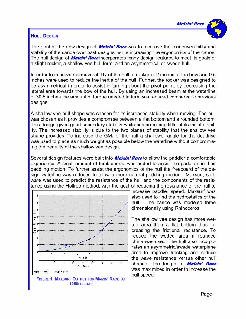
HULL DESIGN The goal of the new design of Maizin’ Race was to increase the maneuverability and stability of the canoe over past designs, while increasing the ergonomics of the canoe. The hull design of Maizin’ Race incorporates many design features to meet its goals of a slight rocker, a shallow vee hull form, and an asymmetrical or swede hull. In order to improve maneuverability of the hull, a rocker of 2 inches at the bow and 0.5 inches were used to reduce the inertia of the hull. Further, the rocker was designed to be asymmetrical in order to assist in turning about the pivot point, by decreasing the lateral area towards the bow of the hull. By using an increased beam at the waterline of 30.5 inches the amount of torque needed to turn was reduced compared to previous designs. A shallow vee hull shape was chosen for its increased stability when moving. The hull was chosen as it provides a compromise between a flat bottom and a rounded bottom. This design gives good secondary stability while compromising little of its initial stabil-ity. The increased stability is due to the two planes of stability that the shallow vee shape provides. To increase the GMT of the hull a shallower angle for the deadrise was used to place as much weight as possible below the waterline without compromis-ing the benefits of the shallow vee design. Several design features were built into Maizin’ Race to allow the paddler a comfortable experience. A small amount of tumblehome was added to assist the paddlers in their paddling motion. To further assist the ergonomics of the hull the freeboard of the de-sign waterline was reduced to allow a more natural paddling motion. Maxsurf, soft-ware was used to predict the resistance of the hull and the components of the resis-tance using the Holtrop method, with the goal of reducing the resistance of the hull to
increase paddler speed. Maxsurf was also used to find the hydrostatics of the hull. The canoe was modeled three dimensionally using Rhinoceros. The shallow vee design has more wet-ted area than a flat bottom thus in-creasing the frictional resistance. To reduce the wetted area a rounded chine was used. The hull also incorpo-rates an asymmetric/swede waterplane area to improve tracking and reduce the wave resistance versus other hull shapes. The length of Maizin’ Race was maximized in order to increase the hull speed.
FIGURE 1: MAXSURF OUTPUT FOR MAIZIN’ RACE AT
1050LB LOAD
Maizin’ Race
Page 1
ANALYSIS
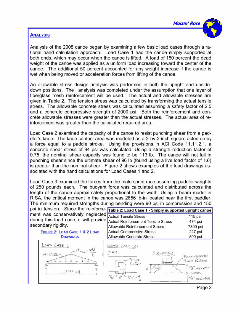
Analysis of the 2008 canoe began by examining a few basic load cases through a ra-tional hand calculation approach. Load Case 1 had the canoe simply supported at both ends, which may occur when the canoe is lifted. A load of 150 percent the dead weight of the canoe was applied as a uniform load increasing toward the center of the canoe. The additional 50 percent accounted for any weight increase if the canoe is wet when being moved or acceleration forces from lifting of the canoe.
An allowable stress design analysis was performed in both the upright and upside-down positions. The analysis was completed under the assumption that one layer of fiberglass mesh reinforcement will be used. The actual and allowable stresses are given in Table 2. The tension stress was calculated by transforming the actual tensile stress. The allowable concrete stress was calculated assuming a safety factor of 2.5 and a concrete compressive strength of 2000 psi. Both the reinforcement and con-crete allowable stresses were greater than the actual stresses. The actual area of re-inforcement was greater than the calculated required area.
Load Case 2 examined the capacity of the canoe to resist punching shear from a pad-dler’s knee. The knee contact area was modeled as a 2-by-2 inch square acted on by a force equal to a paddle stroke. Using the provisions in ACI Code 11.11.2.1, a concrete shear stress of 84 psi was calculated. Using a strength reduction factor of 0.75, the nominal shear capacity was found to be 113 lb. The canoe will not fail in punching shear since the ultimate shear of 96 lb (found using a live load factor of 1.6) is greater than the nominal shear. Figure 2 shows examples of the load drawings as-sociated with the hand calculations for Load Cases 1 and 2.
Load Case 3 examined the forces from the male sprint race assuming paddler weights of 250 pounds each. The buoyant force was calculated and distributed across the length of the canoe approximately proportional to the width. Using a beam model in RISA, the critical moment in the canoe was 2856 lb-in located near the first paddler. The minimum required strengths during bending were 90 psi in compression and 150 psi in tension. Since the reinforce-ment was conservatively neglected during this load case, it will provide secondary rigidity.
Maizin’ Race
Page 2
Table 2: Load Case 1 - Simply supported upright canoe
Actual Tensile Stress 115 psi
Actual Reinforcement Tensile Stress 474 psi
Allowable Reinforcement Stress 7800 psi
Actual Compressive Stress 227 psi
Allowable Concrete Stress 800 psi
FIGURE 2: LOAD CASE 1 & 2 LOAD
DRAWINGS
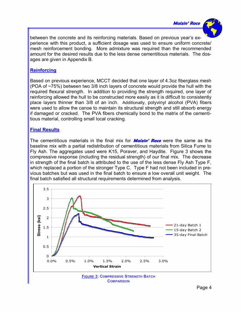
MIX DEVELOPMENT The baseline mix for the 2008 canoe was the mix used for the 2007 canoe, Rushin’ Blue. The baseline mix included the following items: Cementitious Material: Portland Cement Type I, Fly Ash Types C and F, Silica Fume Aggregates: 3M S38, 3M G3500, expanded polystyrene, Poraver Spheres 1-2 mm, Haydite A expanded slate The challenge of this year’s mix was to replace the large amount of expanded polysty-rene (EPS) that the MCCT used the previous two years with another comparably low-density material. Since EPS had a specific gravity of only 0.05, a small volumetric per-centage lowered the specific gravity of the concrete significantly. Another goal was to decrease the amount of silica fume since it partially attributed to last year’s stiff mix, and a less stiff mix was needed for this year’s male mold. To offset the removal of EPS, another gradation of Poraver was investigated. Batches were made using 0.5-1 mm and 1-2 mm. The specific gravity of the aggregate com-posite was reasonable, but a smoother gradation was desired. Previously, MCCT had selectively used only the Haydite collected on the No. 30 and 50 sieves. This year we added No. 100 sieve sized particles, and a combination of the three sizes was se-lected that provided the smoothest gradation curve. A balanced gradation was achieved according to ASTM C33 using a mix of three different sizes of Haydite and two different sizes of Poraver. Although the rule for proportioning aggregates accord-ing to ASTM C33 was deleted this year, MCCT still wanted to stay within these stan-dards to ensure quality finishing. This year’s mix was developed through testing several separate mixes with different combinations of cementitious material and aggregates. For example, identical batches were made varying only the use of either 3M K15 glass spheres or 3M S38 glass spheres. A decision was made to use K15 in the final mix because MCCT was willing to trade a slight decrease in crush strength for the lower specific gravity of K15. After each batch was mixed, cylinders were made according to ASTM C31. These cyl-inders were then tested for compressive strength according to ASTM C109. Examples of the compressive strength for two batches are shown in Figure 3. Batch 1 had larger percentages of Poraver than Haydite, whereas Batch 2 contained the opposite. The compressive strengths were comparable even though Batch 1 had more Poraver which has a lower crush strength (300 psi) than Haydite (2000psi). Admixtures In the creation of Maizin’ Race, MCCT used admixtures to help the concrete achieve the desired finishing characteristics. One of the admixtures used was superplasticizer to reduce water and help disperse fibers. More was used than the recommended amount of 18 floz/cwt to ensure a workable mix without increasing the required water. In addition, liquid latex modifier was used for its ability to provide strong adhesion
Maizin’ Race
Page 3
between the concrete and its reinforcing materials. Based on previous year’s ex-perience with this product, a sufficient dosage was used to ensure uniform concrete/mesh reinforcement bonding. More admixture was required than the recommended amount for the desired results due to the less dense cementitious materials. The dos-ages are given in Appendix B. Reinforcing
Based on previous experience, MCCT decided that one layer of 4.3oz fiberglass mesh (POA of ~75%) between two 3/8 inch layers of concrete would provide the hull with the required flexural strength. In addition to providing the strength required, one layer of reinforcing allowed the hull to be constructed more easily as it is difficult to consistently place layers thinner than 3/8 of an inch. Additionally, polyvinyl alcohol (PVA) fibers were used to allow the canoe to maintain its structural strength and still absorb energy if damaged or cracked. The PVA fibers chemically bond to the matrix of the cementi-tious material, controlling small local cracking. Final Results The cementitious materials in the final mix for Maizin’ Race were the same as the baseline mix with a partial redistribution of cementitious materials from Silica Fume to Fly Ash. The aggregates used were K15, Poraver, and Haydite. Figure 3 shows the compressive response (including the residual strength) of our final mix. The decrease in strength of the final batch is attributed to the use of the less dense Fly Ash Type F, which replaced a portion of the stronger Type C. Type F had not been included in pre-vious batches but was used in the final batch to ensure a low overall unit weight. The final batch satisfied all structural requirements determined from analysis.
Maizin’ Race
Page 4
0
0.5
1
1.5
2
2.5
3
3.5
0.0% 0.5% 1.0% 1.5% 2.0% 2.5% 3.0%
Vertical Strain
Com
pre
ssiv
e S
tress (
ksi)
21-day Batch 1
15-day Batch 2
35-day Final Batch
FIGURE 3: COMPRESSIVE STRENGTH BATCH
COMPARISON
Str
ess (
ksi)
PROJECT MANAGEMENT AND CONSTRUCTION The MCCT continued recruiting efforts in both the fall and winter semesters and accu-mulated nine active members. Breaking our team into sub-teams (hull-design, con-struction, and research and development) allowed members to display and develop their leadership skills while insuring that all members participated in activities that best suited their skills. The two team captains organized weekly team meetings, allowing the sub-teams the opportunity to update the team on progress, to ask questions, and to make suggestions. The smaller teams were led by second year students, who dele-gated tasks and ensured tasks were completed on schedule. During the team orientation phase, the team captains dispensed a rough timeline and budget sheet for the new year. The formwork, concrete components, team travel ex-penses, food, and miscellaneous were designated a target budget summing to $2500. Of this construction was estimated to cost $500 and aggregate was estimated to cost $500, and the actual prices were closely reflected by the estimates. Reuse of aggre-gates from the previous year maintained material procurement costs while use of male formwork decreased material costs. Critical Path Items Milestones for the year were set using the previous year’s schedule as a reference. MCCT’s goal to finish mix design was scheduled for beginning of January and was completed by the research and development team by that time. Another critical path item was the formwork routing because it had to be completed within the beginning of January due to scheduling constraints in the CNC routing lab. Formwork was cut January 15, and then assembled and finished by February 13. On the “big day”, Feb-ruary 16, the whole team gathered and poured Maizin’ Race. This critical path date was selected to assure adequate time for curing and finishing. The construction team followed up by sanding, staining and painting through out March, leaving time for prac-tice before the competition. Completing the canoe mid-March was a major goal in or-der for rowers to practice rowing. If facilities for rowing practice can be found, mem-bers will practice two weeks prior to competition. For the technical presentation the captains selected representatives, who practiced for two weeks up to the competition. The breakdown of man hours for the main project phases were 80 man-hours for mix design and development, 30 man-hours for hull design, 40 hours for formwork design, 30 hours for formwork construction, 60 man-hours for canoe pouring, 40 hours for fin-ishing and 10 hours for paddling practice (if practice facilities are found.) Construction MCCT’s canoe placement plan deviated from the previous year, as a male routed-foam mold was used rather than a female mold. This change was intended to reduce the overall cost of foam, as well as improve the ease of the pouring process. Last year a stiff concrete mix was required to pour in a female mold. We felt a smoother overall
Maizin’ Race
Page 5
Maizin’ Race
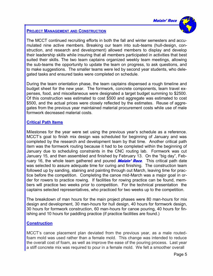
exterior would result with a less stiff mixture placed in a male mold because we would control the exterior surface finish during placement. Foam cutting and gluing tech-niques similar to previous years was followed, since the methods were effective and the required cost and time management was known. Once the final Maizin’ Race hull design was finished, the three dimensional file in Rhi-noceros was converted into two dimensional contours for CNC routing. The two di-mensional contours in Rhino were taken at 2 inches on center since the formwork would be constructed with 2 inch insulation board. To capture the complex contours of the ends, the last 18 inches of the stern and bow were cut into three dimensional two inch sections. To ensure the foam was used as efficiently as possible, the width of the formwork varied along the length of the canoe. Key holes were cut into the foam sec-tions and were fit with 2x4’s to maintain alignment during the gluing process. Sections of approximately equal width were glued together in three to four foot sections. Then, the entire form body was sanded until the formwork was acceptably smooth, and dry-wall mud was applied to the foam surface for a smooth finish. Four foot fiberglass reinforcing sheets were cut to fit the mold with 3 inches of overlap between sheets and 1-1/2 inches below the rough gunwale height. During pouring, concrete was placed in a 3/8 inch layer and finished from above by compacting by hand and with trowels. Reinforcement was then placed, and an additional crew fol-lowed behind, placing the final 3/8 inch layer of concrete. The exterior of the canoe was smoothed with damp towels and sponges. The canoe was covered by moist bur-lap and left to cure for two weeks. After demolding, the exterior and interior surfaces were coated with a slurry mix and the entire hull was thoroughly sanded. (Refer to pages 9 and 10 for formwork sections and gunwale finishing details.) The canoe was then sealed and stained according to manufacturer’s recom-mendations. Proper safety training was required before any work or research could be conducted in the U-M laboratory facilities. Each member of the team was responsible for attending safety train-ing by the beginning of October, so that he/she could proceed with individually assigned tasks. Furthermore, protective equipment, such as gloves, masks, and safety glasses, were used during the application of drywall mud, the sand-ing of the foam and concrete, and during con-crete mixing.
Page 6
FIGURES 4 & 5: CNC ROUTING OF THE FORMWORK
AND PLACEMENT OF MAIZIN’ RACE
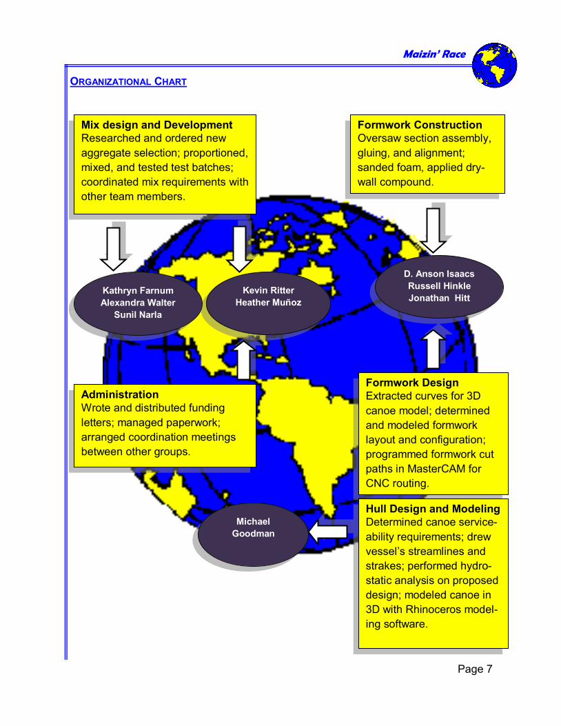
ORGANIZATIONAL CHART
Maizin’ Race
Mix design and Development
Researched and ordered new
aggregate selection; proportioned,
mixed, and tested test batches;
coordinated mix requirements with
other team members.
Administration
Wrote and distributed funding
letters; managed paperwork;
arranged coordination meetings
between other groups.
Formwork Construction
Oversaw section assembly,
gluing, and alignment;
sanded foam, applied dry-
wall compound.
Formwork Design
Extracted curves for 3D
canoe model; determined
and modeled formwork
layout and configuration;
programmed formwork cut
paths in MasterCAM for
CNC routing.
Hull Design and Modeling
Determined canoe service-
ability requirements; drew
vessel’s streamlines and
strakes; performed hydro-
static analysis on proposed
design; modeled canoe in
3D with Rhinoceros model-
ing software.
Kevin Ritter
Heather Muñoz
D. Anson Isaacs
Russell Hinkle
Jonathan Hitt Kathryn Farnum
Alexandra Walter
Sunil Narla
Michael
Goodman
Page 7
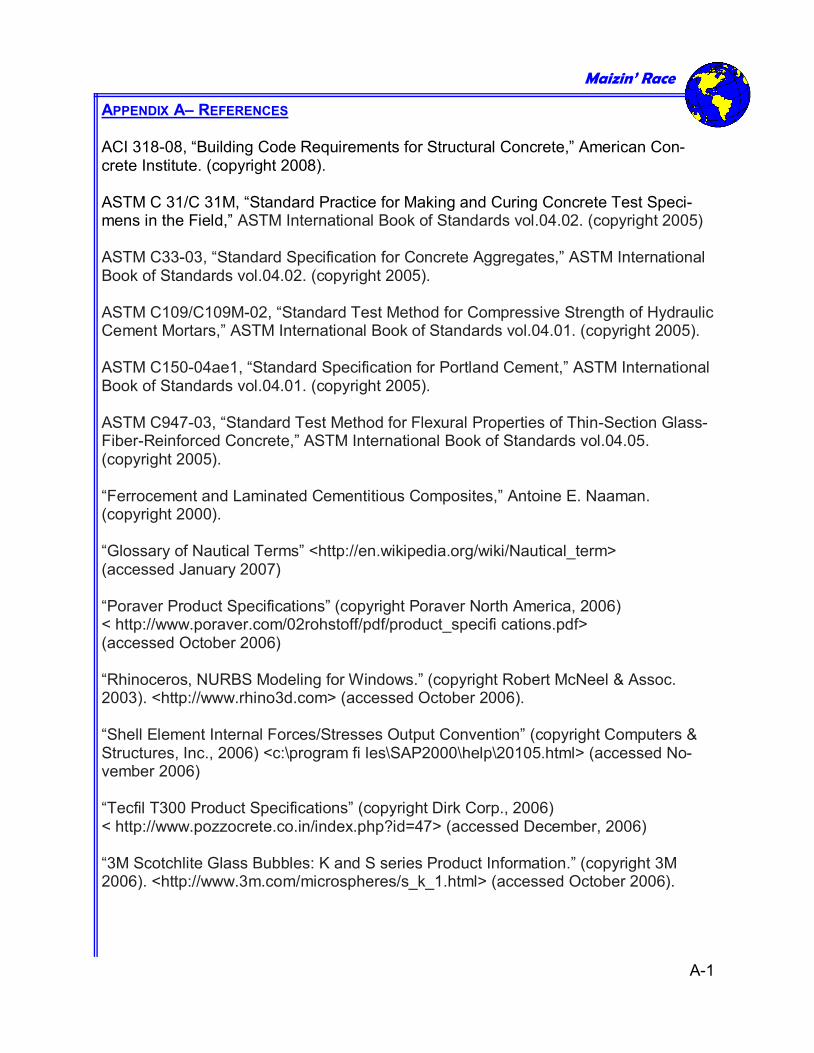
APPENDIX A– REFERENCES ACI 318-08, “Building Code Requirements for Structural Concrete,” American Con-crete Institute. (copyright 2008). ASTM C 31/C 31M, “Standard Practice for Making and Curing Concrete Test Speci-mens in the Field,” ASTM International Book of Standards vol.04.02. (copyright 2005) ASTM C33-03, “Standard Specification for Concrete Aggregates,” ASTM International Book of Standards vol.04.02. (copyright 2005). ASTM C109/C109M-02, “Standard Test Method for Compressive Strength of Hydraulic Cement Mortars,” ASTM International Book of Standards vol.04.01. (copyright 2005). ASTM C150-04ae1, “Standard Specification for Portland Cement,” ASTM International Book of Standards vol.04.01. (copyright 2005). ASTM C947-03, “Standard Test Method for Flexural Properties of Thin-Section Glass- Fiber-Reinforced Concrete,” ASTM International Book of Standards vol.04.05. (copyright 2005). “Ferrocement and Laminated Cementitious Composites,” Antoine E. Naaman. (copyright 2000). “Glossary of Nautical Terms” <http://en.wikipedia.org/wiki/Nautical_term> (accessed January 2007) “Poraver Product Specifications” (copyright Poraver North America, 2006) < http://www.poraver.com/02rohstoff/pdf/product_specifi cations.pdf> (accessed October 2006) “Rhinoceros, NURBS Modeling for Windows.” (copyright Robert McNeel & Assoc. 2003). <http://www.rhino3d.com> (accessed October 2006). “Shell Element Internal Forces/Stresses Output Convention” (copyright Computers & Structures, Inc., 2006) <c:\program fi les\SAP2000\help\20105.html> (accessed No-vember 2006) “Tecfil T300 Product Specifications” (copyright Dirk Corp., 2006) < http://www.pozzocrete.co.in/index.php?id=47> (accessed December, 2006) “3M Scotchlite Glass Bubbles: K and S series Product Information.” (copyright 3M 2006). <http://www.3m.com/microspheres/s_k_1.html> (accessed October 2006).
Maizin’ Race
A-1
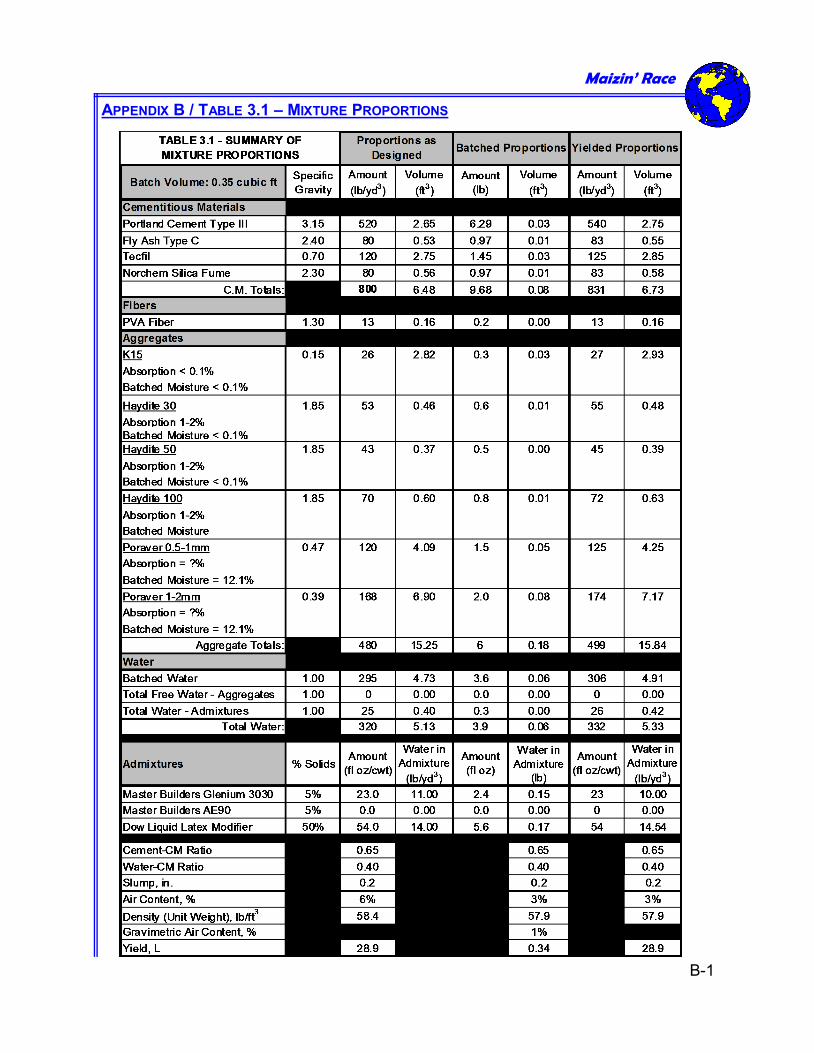
APPENDIX B / TABLE 3.1 – MIXTURE PROPORTIONS
Maizin’ Race
B-1
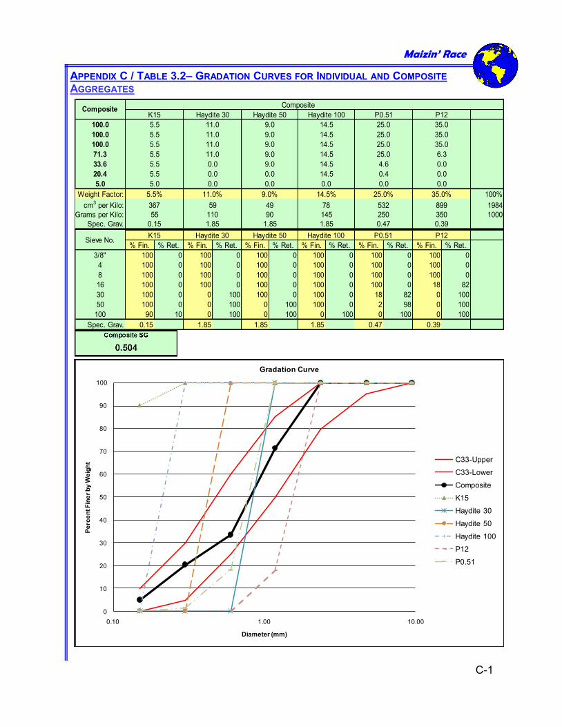
APPENDIX C / TABLE 3.2– GRADATION CURVES FOR INDIVIDUAL AND COMPOSITE AGGREGATES
100.0
100.0
100.0
71.3
33.6
20.4
5.0
Weight Factor: 100%
cm3 per Kilo: 1984
Grams per Kilo: 1000
Spec. Grav.
% Fin. % Ret. % Fin. % Ret. % Fin. % Ret. % Fin. % Ret. % Fin. % Ret. % Fin. % Ret.
3/8" 100 0 100 0 100 0 100 0 100 0 100 0
4 100 0 100 0 100 0 100 0 100 0 100 0
8 100 0 100 0 100 0 100 0 100 0 100 0
16 100 0 100 0 100 0 100 0 100 0 18 82
30 100 0 0 100 100 0 100 0 18 82 0 100
50 100 0 0 100 0 100 100 0 2 98 0 100
100 90 10 0 100 0 100 0 100 0 100 0 100
Spec. Grav. 0.15 1.85 1.85 1.85 0.47 0.39
14.5
14.5
0.0
14.5% 35.0%
899
350
0.391.85
K15
Composite
35.0
Haydite 100
14.5
14.5
0.47
78
145
14.5
14.5
4.6
0.4
0.0
35.0
35.0
6.3
0.0
59
25.0
25.0
25.0
25.0
110 90
25.0%
532
0.0
1.85
49
9.0%
P12
9.0
P0.51
0.0
0.00.0
250
0.0
0.0
0.0
11.0%
1.85
Haydite 50
9.0
9.0
9.0
9.0
5.0
5.5%
367
55
0.15
Haydite 30
11.0
11.0
11.0
11.0
CompositeK15
5.5
5.5
5.5
5.5
5.5
5.5
Haydite 50 Haydite 100 P0.51 P12Haydite 30Sieve No.
0
10
20
30
40
50
60
70
80
90
100
0.10 1.00 10.00
Pe
rce
nt F
ine
r b
y W
eig
ht
Diameter (mm)
Gradation Curve
C33-Upper
C33-Lower
Composite
K15
Haydite 30
Haydite 50
Haydite 100
P12
P0.51
Maizin’ Race
C-1