2007 orca sloper - tripod.comaugiemckibben.tripod.com/.../new_orca_2012_assembly... · orca is a...
TRANSCRIPT
1
ORCA 2012
By Harley Michaelis, LSF 023 (8/28/13 edition) e-mail: [email protected].
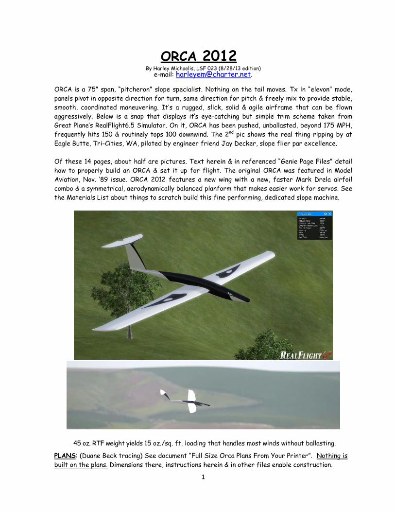
ORCA is a 75” span, “pitcheron” slope specialist. Nothing on the tail moves. Tx in “elevon” mode,
panels pivot in opposite direction for turn, same direction for pitch & freely mix to provide stable,
smooth, coordinated maneuvering. It’s a rugged, slick, solid & agile airframe that can be flown
aggressively. Below is a snap that displays it’s eye-catching but simple trim scheme taken from
Great Plane’s RealFlight6.5 Simulator. On it, ORCA has been pushed, unballasted, beyond 175 MPH,
frequently hits 150 & routinely tops 100 downwind. The 2nd pic shows the real thing ripping by at
Eagle Butte, Tri-Cities, WA, piloted by engineer friend Jay Decker, slope flier par excellence.
Of these 14 pages, about half are pictures. Text herein & in referenced “Genie Page Files” detail
how to properly build an ORCA & set it up for flight. The original ORCA was featured in Model
Aviation, Nov. ’89 issue. ORCA 2012 features a new wing with a new, faster Mark Drela airfoil
combo & a symmetrical, aerodynamically balanced planform that makes easier work for servos. See
the Materials List about things to scratch build this fine performing, dedicated slope machine.
45 oz. RTF weight yields 15 oz./sq. ft. loading that handles most winds without ballasting. PLANS: (Duane Beck tracing) See document “Full Size Orca Plans From Your Printer”. Nothing is
built on the plans. Dimensions there, instructions herein & in other files enable construction.

2
Foam core wing panels are skinned with 1/64” ply & can be built with or without vacuum bagging. The
procedures to install the pitcheron system & panels in precise alignment have been refined,
simplified & are well illustrated herein with pictures. An optional, new way of doing a LE with a
fine finish for painting is introduced. CORES: See CORES ADDENDUM, PG. 14. For strength & precision, superb 60# CNC cut cores
are available from Anker Berg-Sonne at [email protected]. (1) with LE intact or (2)
trimmed 5/16” for sub-LE & LE as plans show. Anker’s cores are uniquely made to preserve a fully
intact, thinly feathered TE area. See Genie construction file entitled “Initial Core Prep.”
Reference to Genie butted cores making a tip to tip straight TE line don’t apply to the ORCA.
Cut your own cores? Core panel span is 36”. Finished root chord is 7.75”. Projected tip chord
before rounding is 4.25”. There is no washout. Allowance for skin thickness is 1/64”.
Simple, effective pitcheron mechanics shown below are those reliably used many years by Ken Stuhr
in his Rotor, Xica & V-Max designs.
The ’89 version TE sweep
looked racy, but extra area
behind the wing pivot point
made hard work for the
servos at higher speeds.
This new wing has equal LE &
TE sweep. Pivoting at 45% of
chord, the aerodynamic
balancing makes lighter work
for servos. The new Mark
Drela airfoil combo optimizes
overall performance & handling.
Panels, fitted with 11/32” brass tubes,
rotate on a 5/16” steel rod. 1/8” drive
pins, notched for wheel collar setscrews,
protrude to enter slots in cams (lower
right) that pivot on a 1/8” wire shaft
across the fuselage. Servos & cams,
shimmed with washers to clear the sides,
are fitted with 2-56 ball links. Pushrods
are all-thread 2-56 steel. At their rears,
servos mount on a 1/8” ply crosspiece
secured to side rails. See next picture.
3
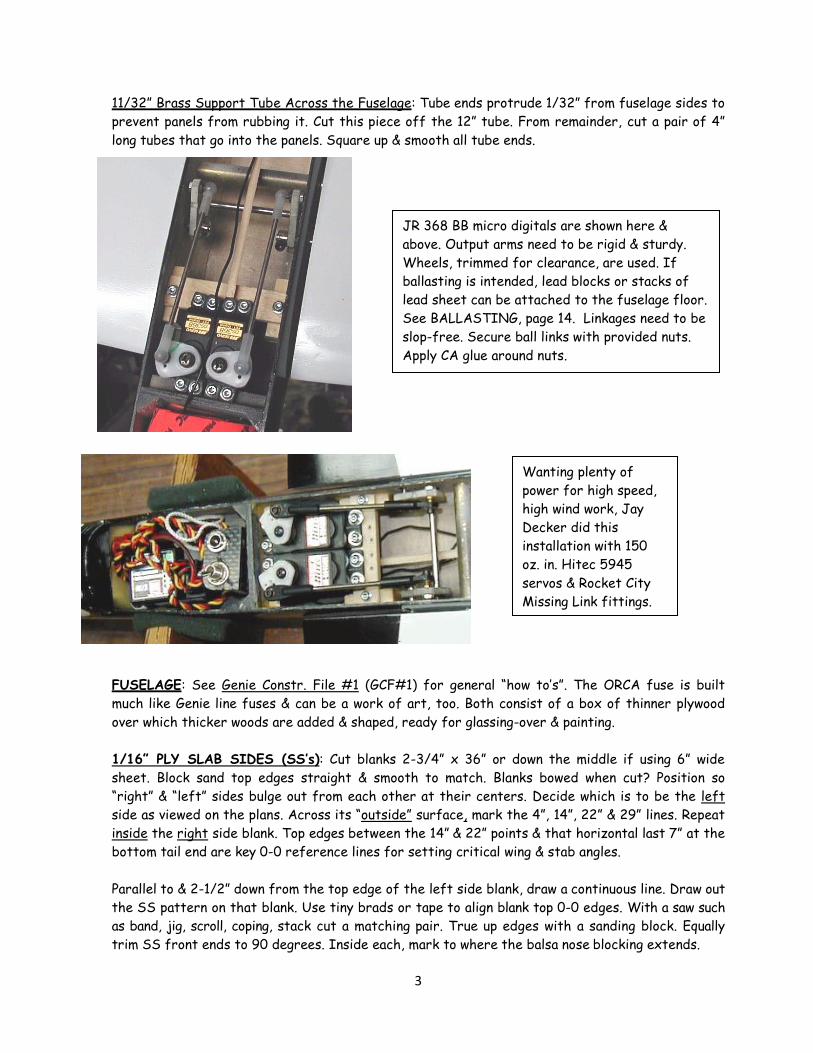
11/32” Brass Support Tube Across the Fuselage: Tube ends protrude 1/32” from fuselage sides to prevent panels from rubbing it. Cut this piece off the 12” tube. From remainder, cut a pair of 4”
long tubes that go into the panels. Square up & smooth all tube ends.
FUSELAGE: See Genie Constr. File #1 (GCF#1) for general “how to’s”. The ORCA fuse is built
much like Genie line fuses & can be a work of art, too. Both consist of a box of thinner plywood
over which thicker woods are added & shaped, ready for glassing-over & painting.
1/16” PLY SLAB SIDES (SS’s): Cut blanks 2-3/4” x 36” or down the middle if using 6” wide
sheet. Block sand top edges straight & smooth to match. Blanks bowed when cut? Position so
“right” & “left” sides bulge out from each other at their centers. Decide which is to be the left
side as viewed on the plans. Across its “outside” surface, mark the 4”, 14”, 22” & 29” lines. Repeat
inside the right side blank. Top edges between the 14” & 22” points & that horizontal last 7” at the
bottom tail end are key 0-0 reference lines for setting critical wing & stab angles.
Parallel to & 2-1/2” down from the top edge of the left side blank, draw a continuous line. Draw out
the SS pattern on that blank. Use tiny brads or tape to align blank top 0-0 edges. With a saw such
as band, jig, scroll, coping, stack cut a matching pair. True up edges with a sanding block. Equally
trim SS front ends to 90 degrees. Inside each, mark to where the balsa nose blocking extends.
Wanting plenty of
power for high speed,
high wind work, Jay
Decker did this
installation with 150
oz. in. Hitec 5945
servos & Rocket City
Missing Link fittings.
JR 368 BB micro digitals are shown here &
above. Output arms need to be rigid & sturdy.
Wheels, trimmed for clearance, are used. If
ballasting is intended, lead blocks or stacks of
lead sheet can be attached to the fuselage floor.
See BALLASTING, page 14. Linkages need to be
slop-free. Secure ball links with provided nuts.
Apply CA glue around nuts.

4
PITCHERON HOLES THROUGH THE SS’s: Bits need to be sharp to avoid tearing the work. Use
drill press or guide for accuracy. Use wood backing to get clean, intact holes.
WING PIVOT HOLE: 1” below the 14” to 22” line & parallel to it, draw a fine reference line in the
wing location. The 11/32” brass tube is to be centered vertically on that line. Horizontally, it’s
centered 2-1/4” ahead of the 14” mark. Drill precisely where lines intersect.
CAM PIVOT HOLE: The 1/8” pivot wire is centered 5/8” forward of the center of the 11/32”
hole. Locate cam hole vertically so the top edge of the hole will be just under the fine parallel reference line. To the SS’s, where plans show, add 1/8” balsa doublers, attaching with a thin coat of
epoxy. Keep all flat while curing. To make the hole in the 1/8” balsa doublers, serrate an end of
11/32” tubing. Add other doublers. Trim all doubler edges even with SS edges.
FORMERS: Make perfect rectangles. Cut 2” wide & to side height. Notch F1 for leads. Long
antenna? Drill hole in F2. Fasten to 1/8” stick. Loop excess back toward nose & tape to stick.
Glue triangular stock (TS) to
the front of F1 & both sides
of F2. Attach servo rail to F1.
With the right SS down flat,
glue on formers, upright.
DRIVE PIN SLOT GUIDE: Run
11/32” tubing through the stacked
sides. Make a guide as shown to drill
a 3/8” arc-shaped opening. If more
deflection is ever wanted, it can be
extended with a 1/8” round file.
Review next picture about
TS. To attach the fuse left
side, position the work
upright as shown here. Use
a carpenter’s square to
align the front ends. Use
weights or clamps to keep
things together as glue
dries. Keep flush to the
workbench from 0” to 14”
to align sides in profile.

5
As shown below, preferably glue TS to the SS edges before joining them to the formers, but
leave space on the left SS, as shown, to later fill in next to the TS on the formers.
Forward of the fin, the TS is to be trimmed to allow clamping it between the SS’s. Preferably, use
solid 5/16” very light sheet balsa for the fin. 3/8” is overkill. ¼” is too thin for the threaded
inserts. Alternatively with 3M77, laminate light 1/8” balsa sides to a 1/16” light balsa center.
FIN: Sweepback lengthens tail moment arm to contribute to directional & pitch stability without
the bulk & weight of a longer fuse. Set fin top at 0-0, not angled as on older plans.
SECURING THE STAB: Cut 2 bass blocks into ¾” cubes. Grain vertical, drill for thin-walled 6-32
threaded brass inserts. Trim blocks to fin thickness & to ½” fore-aft. Glue inserts into the blocks
& blocks into the fin to put the inserts on 1-3/4” centers. SUB-DECKING (S-D): Grain runs crosswise on all S-D. Cut all S-D pieces to extend over the TS
only to the outer edges of the 1/16” SS’s, not over the doublers. S-D edges make a dark
reference line to first sand down to when sculpting the fuse. Cut thin S-D with scissors.
Later, after mostly shaping
the fuselage, sand fin areas
above the SS top edges to
sort of a generic, symmetrical
airfoil without flat spots.
From a layer of 1/16” balsa &
1/16” ply, make the platform
with bolt holes aligned to the
brass inserts. Epoxy platform
in place, squared-up, balsa
side down. Strength & rigidity
are later imparted in filleting
& glassing-over. The bass
stab blocks referred to below
can be seen installed at the
top of the fin under the stab
platform.
6
BOTTOM 1/32” S-D, F1 to F2: Glue on. Then cut & taper the ¾”x 1-1/4” balsa block up front to
nicely fit between the sides. Apply glue & clamp together. To the rear of F2, top & bottom, even
with the SS’s, glue bits of TS. 1/64” PLY S-D: Preferably use scrap or cut exactly 2-1/8” off an
end of a 1’ x 4’ x 1/64” sheet. Center the fuse over a long, straight line. Shift sides & clamp against
fin to get SS’s symmetrical behind F2. On bottom, then glue S-D from the fin front to F2. On the
bottom, extend 1/32” ply S-D forward from F1 to the front edge of the 1-1/4” thick nose block to
yet be installed. Assemble that block from pieces of the ¾” sq. bass stick. At its rear, drill a ¾” x 1-
1/4” deep hole. Cut it to profile. Pack with lead shot & glue it in place to later final shape.
From the bass stick, shape pieces to profile to join for the thick front bottom. Pre-bevel the rear
ends where the hard balsa bottom splices to it. On page 10 see dowel tool used to check fin vertical
alignment. Fin clamped in, twist fuse to get it to look upright. Add top 1/64” S-D by the fin as
needed to keep it upright. Remove fin. Complete top 1/64” S-D. Before gluing on balsa blocks top &
bottom, roughly taper them in top & side views. Keep top 1” thick aft of the canopy. Keep the hard
balsa block bottom ¾” thick opposite the servos. Sand a step where the lighter bottom balsa
overlaps the 1/32” ply S-D. Stick to the plan lines to emulate the characteristic “orca” arch.
Glue fin to one SS first. Shift/glue/clamp to the other SS for no built-in turn. Fillet along fuse
edges with light spackle. Add 1/8” balsa cap under fin & fuse sides. IMPORTANT! Round cap edges,
but leave bottom flat as a critical 0-0 reference line. When final shaping the fuse & fin for glassing
over, use sanding blocks, razor plane & your eyes, making like Michelangelo, not Fred Flintstone.
1/32” PLY STAB CORE/1/8” BALSA TOP & BOTTOM: See next page. Trim & join stab plan
pieces to get a pattern for the 1/32” ply core. Cut core. Sand edges. Mark openings in this core to
leave a 2” wide center & 3/8” edge where the flat balsa “ribs” go. A jig, scroll or coping saw works
well to cut the openings.
Splice very light 1/8” balsa sheet for tops/bottoms. Cut a bit larger than the core. In the bottom
1/8” piece, make a squared-up opening to snugly fit over the platform. Make bolt holes in the core.
Position it on the bottom piece. Wick join along edges with instant CA glue. Trim to core edges.
Glue in the “ribs”. Glue on the balsa top. Trim & round along the perimeter. Open bolt holes &
reinforce them with CA glue. Block sand overall to sort of a generic symmetrical airfoil without
flat spots, ready for glassing-over as detailed on the next page.
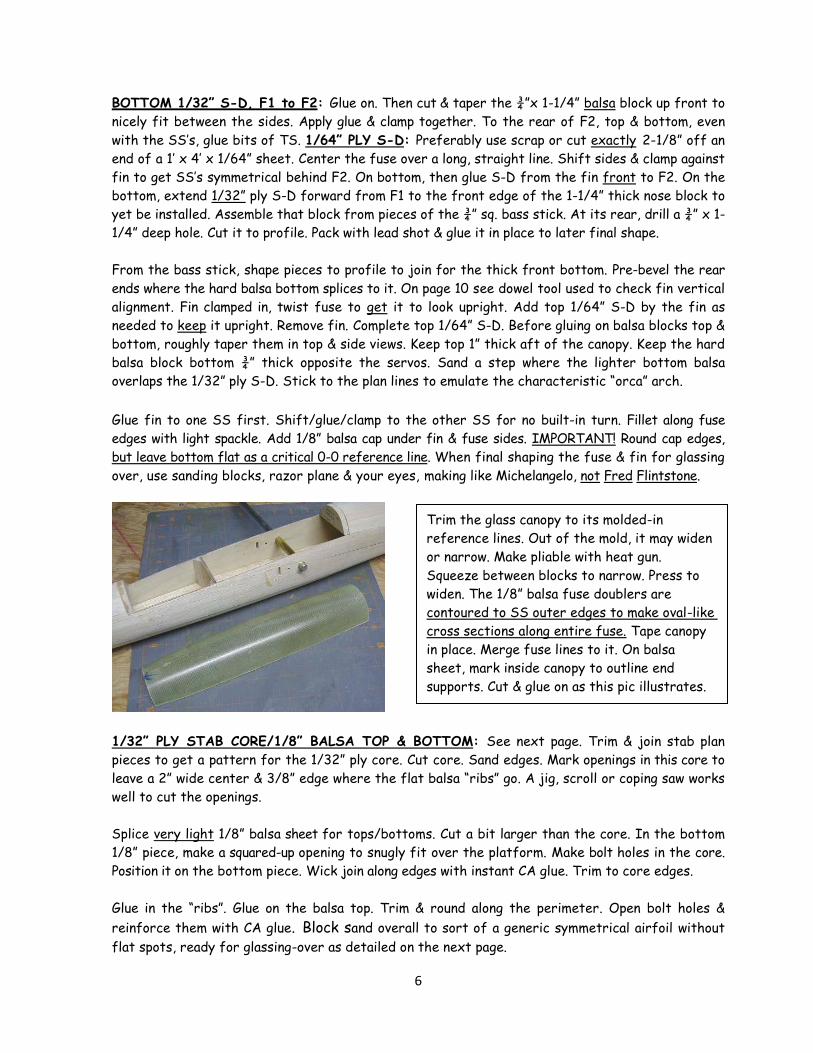
Trim the glass canopy to its molded-in
reference lines. Out of the mold, it may widen
or narrow. Make pliable with heat gun.
Squeeze between blocks to narrow. Press to
widen. The 1/8” balsa fuse doublers are
contoured to SS outer edges to make oval-like
cross sections along entire fuse. Tape canopy
in place. Merge fuse lines to it. On balsa
sheet, mark inside canopy to outline end
supports. Cut & glue on as this pic illustrates.

7
Optionally, apply the scratch filler mentioned in GCF #5. When cured, lightly wet sand this glass
smooth for painting. As a stab painting handle, glue a dowel into a block of balsa. With double
sticky foam tape, attach it to the stab recess. Support the work in a bottle to dry. Finished
weight? About 1.5 oz. with light balsa, light cloth & light lacquer based spray paint.
GLASSING-OVER THE FIN & FUSELAGE: Go to GCF#5. Review the procedure. First, coat the
SS edges the canopy long edges rest on. Let it cure & block sand it smooth. Apply 2 layers of 1.4
oz. glass overall on the fuselage proper, but use one of light glass on the fin, with an extra strip
over the spackle fillet area & in the corners where the stab platform joins the fin. Optionally, add
another layer on the underside from the nose back to F1.
WING: By pivoting 3-1/2” behind the LE at 45% of chord there’s just a bit more area aft. This
aerodynamic balancing eases work for servos. All linkages should be slop-free & servos should
have minimum gear slop, too. As a centerline reference for the brass wing tubes, mark a 9” long,
precisely squared-up line across the butted core panels.
The plan root airfoil shows the 1/64” ply skins. See page 11 about sizing the skins to extend some
ahead of the sub-LE when attached. A separate 3/16” LE attaches to the sub-LE & over the
blunted front end of the endcap, not as shown on pg. 10 for panel that was to be CF cloth skinned.
ENDCAP PATTERN: If using Anker’s cores, from 1/16” ply make a blunted root endcap pattern
that fits inside the 1/64” ply lines on the AG52 plan root airfoil. Note the chord line on the plan
pattern & also the reference line 1/8” above it.
ENDCAPS: Preferably from two layers of 5 ply, 1/8” ply, laminate up two 1” x 8-1/2” blanks,
keeping them flat. On one, draw the chord line & the line above it. Align the pattern chord line to the
endcap chord line. Mark a fine line around the pattern. Negligible wood would be left under a support
tube centered on the chord line. Instead, it & the drive pin are to be vertically centered on the
reference line above it.
The top picture shows the 1/32” ply
core glued to the 1/8” bottom, edges
trimmed to core. Next, the 1/8” top has
been glued on, & all surfaces gently
rounded, ready for glassing-over. To top
side, brush glass down smoothly & wrap
it around the edge & over the bottom a
little. Sop excess resin. Let this cure,
sand bottom glass edges smooth, & then
size a glass piece to fit the bottom &
brush it down. Sop excess. When cured,
sand the overlaps smooth.

8
Across the two pattern lines, draw an intersecting line 3-5/16” back from its blunted front end. 5/8”
forward of that line, mark the intersecting cam pivot rod line. Tape blanks & pattern temporarily
aligned together to simultaneously drill through all. For later critical use, store the ply pattern. Cut
the stacked endcaps a hair over width. Use disc sander or block sand edges to fit the cores. The
3-3/4” slots for wing tubes are faced with 1/16” balsa so are to be 15/32” wide. From thin ply, etc.
make a pattern, which when squared up & marked around over the butted cores will make a 7-1/2” x
15/32” outline. Also mark outlines for the drive pin blocks.
Size facings with grain running vertically to fit the core, top to bottom. Check fit with tube in
place. Epoxy facings in place over waxed paper to avoid gluing them to the workbench. After
tubes are later installed & endcaps attached, fill will be added to core level, top & bottom.
Miscellaneous pics from the RF Simulator
No band saw, etc. to cut precision slots in core ends? Do this: From ¼”
scrap, make a 2” long x 1-1/4” high guide as shown. Slide larger Exacto or
Zona razor saw out of its handle/backing. Core on bottom bed, butt guide
to bed. Saw slot sides through core. With #11 blade, cut the piece loose.

9
BUILDING IN 1 DEGREE OF DIHEDRAL
The above pic was taken of a non-symmetrical panel to be skinned overall with CF & glass cloth,
but the dihedral setting procedure is the same. The 2 endcaps are touching the workbench. The
steel rod is parallel to it & the bottom of the core. Size a shim of balsa (2 piece stack on the right)
to precisely fit between rod & workbench. A rise of 1/16” over 3-1/2” is essentially one degree. At
a point 3-1/2” from the endcap mark on masking tape. Lay a piece of 1/16” wood under the mark.
Move the shim between it & the rod or first glue the 1/16” piece to the shim. This angles the long tube
down 1 degree relative to the core bottom. Apply & polish a thin coat of paste wax on the rod. Top &
bottom, run a thin bead of epoxy along the tube & facings, avoiding ends where the rod or endcap
could get bonded. Let this cure well. Repeat on the other panel. Set rod & endcaps aside for now.

10
DRIVE PINS & BLOCKS: See next picture. Drive pins seat into blocks secured in the panels. Drill
blocks for drive pins. Notch pins to receive the collar setscrew with zero play. Rotate pin so
setscrew is accessible. Use ¼” socket head machine screws that can be conveniently seated with an
Allen wrench. Drive pin hole centered, trim blocks to 3/8” wide & a little thinner than the core.
Glued-in, smooth drive pins can be dislodged in landings in which panels hit brush hard, etc. To
better stay put, deeply score up what goes into the blocks. The pivot tube protrudes 1/32” out of
the fuse sides. The 4” wing tubes in the endcap butt it to keep the panels from rubbing. The last
two pictures below were also taken of a wing to be skinned with overall CF & glass cloth.
To get all clearances right, seat the 2-56 ball links in the cams. Slide the pivot wire through one
side, slip on a washer for cam clearance, then both cams & the other washer. Slide the pivot wire
into the other side. If all looks good, set these parts aside to install after glassing-over & painting.
SUB-LE: Attach & shape a sub-LE of 1/8” balsa. After the ply skins are attached & trimmed back
to the sub-LE, a 3/16” LE is attached that extends over the blunted end of the endcap. Epoxy
endcaps to cores, tubes & drive pins. Add fill over/under tubes & drive pin blocks to core level.
Internal 1/8” ply reinforcing plates go on the brass
tube. Drill 11/32” holes in them over wood backing &
size to not interfere with cam motion. Run tube
through one side, slip plates on. Slip tube through
other side. Coat plates outer surfaces with wood
glue. Jam a stick between them. When cured, wick
thin CA glue where tubes enter the plates.
Measure how much pin
should protrude to
eliminate play between
endcap & fuselage.
Accordingly, glue pin into
the block. Glue block into
the core. Fill over & under
it as needed.
The block &
dowel item is a
gauge to place
across the
canopy opening to
visually check fin
vertical alignment
to fuse when it’s
earlier attached.

11
1/64” PLY SKINS SIZING: This assumes cores are trimmed 5/16” along their LE’s for the 1/8”
sub-LE & the 3/16” LE that are not yet attached. Fine trim core TE’s so panels are mirror images.
Bottom Skins: Locate the sheet from which 2-1/8” was trimmed for sub-decking. At one end, make
a mark 8-1/16” down from a top corner. On the other end make one 8-1/16” up from the bottom
corner. Draw the diagonal. Cut precisely along the line so no ply is lost. Consider the cut as the TE
area. Skins are to extend from core tip end to over the ¼” thick endcap. Lay a skin with its TE by
your belly. Place a core on it so its TE is ½” ahead of the skin & so the endcap will be covered with
none to spare. Of that ½” of skin behind the core, ideally 3/8” of it can be trimmed from the root
to where the 3/8” raked tip starts. That would leave 1/8” of skin to be joined behind the core.
With things set at the TE as above, observe how much bottom skin extends ahead of the front of
the core. When a skin is attached there, 1/8” is to cover the shaped & attached sub-LE &
preferably extend beyond it a little to sand back flush to it. This then makes a nice surface for LE
attach. Only if necessary, reduce the rake to under 3/8” &/or amount of skin to join behind the
core. Sort it out, trim one bottom skin & use it as a pattern for the other one.
Top Skins: These require a bit more chord. Position bottom skins either end of the 4’ sheet to find
where to cut diagonally to get the most material to work with. Cut it. Mark & cut top skins using a
bottom as a pattern. Mark ID inside each skin so you know which goes where. Before attaching
them, cut the tip contour shown on plans. After attaching, unskinned core can be trimmed off. See
GCF#3 Part 1, page 15-16 about nicely rounding the raw edge with 2-part epoxy putty.
ATTACHING SKINS: No bagging equipment? Use “Southern’s Sorghum”. Google “Dave Brown
Products”. One 7 oz. bottle would do several wings. Place dowels or strips 2”-3” wide cut from
manila folders, etc. on the bottom skin, position the core & one by one, slip out to just tack on the
skin. Lay top bed inverted on a flat plane surface. Invert the core with sub-LE & endcap attached.
Roll or rub on the bottom skin to bond it. Repeat with the top skin, working in the bottom bed.
If you have bagging equipment, lay the skins inside out over newsprint. For a panel, mix 5-6 drams of
bagging epoxy. With plastic card, etc. spread thin coat overall on the skins. Position skin/core/skin.
Wrap masking tape front & rear in places to keep core in place. Use the beds outside of the bag,
weighted down to avoid unwanted twist being built in. .003” x 1” fiberglass tape brushed down
around the shaped sub-LE & LE with finishing resin, sanded smooth, feathered & painted is just
fine. Another pre-painting option is described below. The rather large tube of “Icing Putty” has
become too costly to be practical for occasional use in small quantities. You need just 1-2 oz.
Check auto body shop for some. Keep it sealed & buy a little tube of the Crème Hardener.
This shows the puttied LE smoothed
& ready for priming & painting.
Exaggerated drawing illustrates how LE strips (forward white area) can
be shaped to coat with Icing Putty (black). See Genie Fine Finishing file
#6 about the putty. See examples there of beautifully finished LE’s.
This shows 3/16” LE shaped to apply Icing Putty.
12
SCRATCH FILLER MIX: See GCF #5, page 4: Brush skinned panels overall with this light mix.
Cured, sand with progressively finer grits used dry to avoid raising the grain. This helps fill cracks
& crevices & make a glass smooth surface for priming & painting. PAINTING: Do bottoms first. Spray on a white, sandable primer. When dry, sand smooth. Brush
off well. At intervals, spray light, white top coats & then a “wet” coat to dry to high gloss. Mask to
add black “Orca” accents of your imagination & liking. Servos & pitcheron hardware can now be
installed. Secure ends of the cam pivot rod & main support tube with drops of thin CA glue.
WING 0-0 setting: Lacking an incidence meter, do this; Panels off, prop the fuse up so the 0-0
tail end bottom is parallel to the work bench & the fin is upright. Measure distance from the work
surface to the exact center of the main support tube. Trim a business card to match. To the fuse
sides, a little inside the wing LE & TE positions, vertically center & apply a stick-on “Post-It”,
tacky part vertical. Use the trimmed card as a guide to mark a fine horizontal line across each
Post-It. In so doing, you will have marked the ends of a 0-0 reference line for the wing panels.
Locate endcap pattern. Glue a scrap of business card on it to make it 3/16” longer. Extend the
chord line on it. Trim the card to a point at the chord line end. Slip the pattern over the 1/32” of
protruding support tube. Get the pattern’s chord line parallel to the 0-0 reference lines on the
Post-Its. Mark its LE entry line & TE exit line on the Post-Its. Mount panels. Adjust servo throws,
pushrod lengths, etc. so both panels are at 0-0 with stick & trim tabs neutral.
SETTING PANEL DEFLECTIONS: 1/16” in 3-1/2” is essentially one degree. It’s 3-1/2” from the
wing LE to its pivot point. If, on the Post-Its, you progressively rotate the pattern & at the LE
mark lines 1/16” apart above & below a 0-0 line at the LE, you are marking in 1 degree increments.
Stab fixed at 0-0, variables are wing incidence, CG placement & panel deflections. Ballasting
might come later. Common first flight procedures can be followed. See Initial Setup, below.
Ideal flight characteristics would include (1) track well on the intended flight path without (2)
dive/tuck or (3) balloon/stall at various airspeeds & (4) handle well upright or inverted.
If the CG is too far forward, positive incidence is required to keep a ship level. That creates drag
that hampers cruising speed & causes ballooning as airspeed increases. Response in the pitch axis
can be sluggish. The CG position on the plans avoids chance of tucking, but should be moved
rearward in small increments until hands off, it barely self-recovers, if at all, from an induced
shallow dive. This yields best handling, highest speeds & lowest sink rate.
In a conventional 2 stick Tx programmed to provide the “elevon” function, you’ll get turn & pitch on
the right stick. Elevator trim tab affects pitch. Aileron trim tab affects turn. Set servos & trim
tabs at neutral. Position output arms so the ball links point straight sideways.
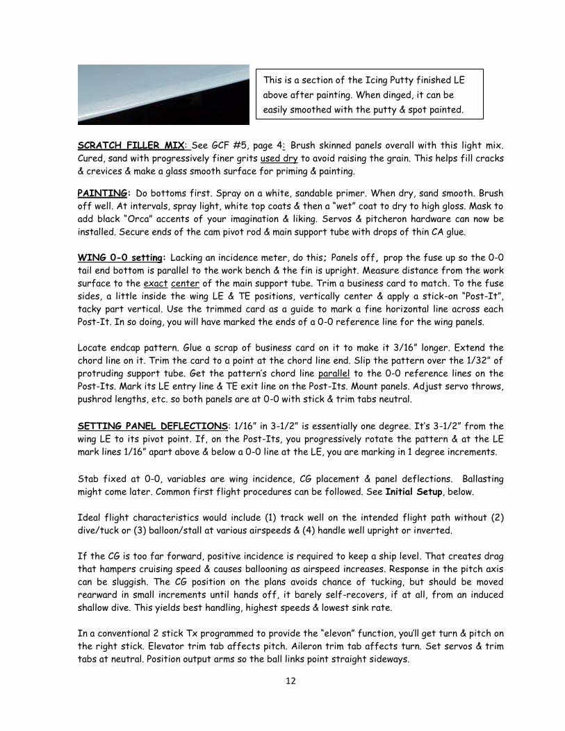
This is a section of the Icing Putty finished LE
above after painting. When dinged, it can be
easily smoothed with the putty & spot painted.
13
INITIAL SETUP: Intuitively, I’d go with the plan CG, wing at 0-0, max deflection set for 10
degrees both up & down & half that or even less in Low Rate. Use Low Rate. Tape canopy down
tight at its ends or you’ll likely lose it. Holding the stick for turn will result in unexpected rolls.
Instead, tap it, let it go neutral & tap again.
ORCA needs speed & lift to fly. A hand glide on the flat is like intentionally slamming it into the
ground. Instead, at the slope edge, if it wants to lift out of the hand, give it a hard heave slightly
pointed down & get on the stick to keep it level. Once sorted out, the ORCA should essentially
continue as pointed, hands off, with no tendency to dive/tuck & a slight tendency, if any, to self
recover from an induced shallow dive. As needed, land & incrementally balance further rearward
to get that. Then, at safe altitude, experiment with pitch, roll & speed in both Dual Rate positions.
High Rate is useful to do tight inside or outside loops or a series of fast spins or rolls, etc.
The long vertical tail moment arm & liberal fin area yield a high end “Vertical Tail Volume
Coefficient” The stab arm is even longer. This generates very stable & true tracking.
ORCA 2012 is too fast for my 92 year old reflexes. As others build & fly one, real world feedback
can be offered, but with the new wing, performance should way surpass that of the original, for
which this description (paraphrased) was given in the Nov. ’89 issue of MA:
“A terrific scratch-built project, Orca is a fearless, swift, dedicated slope machine capable
of high speed work in winds in which you can barely stand. It’s rock stable, handles easily &
responds beautifully to control input. Without ballast, penetration is excellent in winds up to
about 35 MPH. Acceleration in a dive is virtually unbridled, while in the pullout it will
skyrocket into loops over 200 feet in diameter. From high speeds, Orca will do several
vertical rolls as the momentum bleeds off. In level flight, it’s capable of continuous rolls.
Orca is just about as easy to fly inverted as it is upright. In skilled hands it will deliver a
broad array of maneuvers mixing roll & pitch functions. Maneuvers are generally large, wide,
smooth & above all. . . .fast! The stall characteristics are soft. Gradual flaring behind the
slope ridge will slow it well for landing. Orca isn’t for timid souls or slow reflexes. So swift
is this model that in those brisk, speed-generating gusts it can cover huge chunks of sky in
seconds, demanding your unwavering concentration. A close-in, eyeball level pass from a high
dive can strike terror in fainter hearts. Unless you relish the stimulation of living
dangerously, keeping it at a distance at such high speeds is only prudent. “
At steep Eagle Butte things began to really get interesting at about 25 MPH. There I flew a 45 oz.
original ORCA, unballasted, in 50 MPH wind. I could barely stand, but it remained rock solid &
extremely responsive. Tremendous chunks of sky were quickly covered, so strict attention was
required. I took my eyes off it a moment & it was gone, but fortunately had landed safely behind the
lift. Gigantic loops can be made by diving in lift to first gain airspeed & momentum. At safe
altitude, check the “down elevator” effect to be sure the ship will promptly invert & tuck under
inverted when intended, particularly when heading straight toward the slope at close range.
14
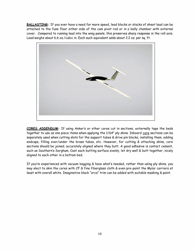
BALLASTING: If you ever have a need for more speed, lead blocks or stacks of sheet lead can be
attached to the fuse floor either side of the cam pivot rod or in a belly chamber with external
cover. Compared to running lead into the wing panels, this preserves sharp response in the roll axis.
Lead weighs about 6.6 oz./cubic in. Each such equivalent adds about 2.2 oz. per sq. ft.
CORES ADDENDUM: If using Anker’s or other cores cut in sections, externally tape the beds
together to use as one piece items when applying the 1/64” ply skins. Inboard core sections can be
separately used when cutting slots for the support tubes & drive pin blocks, installing them, adding
endcaps, filling over/under the brass tubes, etc. However, for cutting & attaching skins, core
sections should be joined, accurately aligned where they butt. A good adhesive is contact cement,
such as Southern’s Sorghum. Coat each butting surface evenly, let dry well & butt together, nicely
aligned to each other in a bottom bed.
If you’re experienced with vacuum bagging & have what’s needed, rather than using ply skins, you
may elect to skin the cores with CF & fine fiberglass cloth & even pre-paint the Mylar carriers at
least with overall white. Imaginative black “orca” trim can be added with suitable masking & paint.