2007 suspension systems
TRANSCRIPT
2007 W Series
SECTION
3PAGE
12007 W Series Chassis
Suspension Systems
© 2006 Workhorse Custom Chassis — All Rights Reserved
WORKHORSE CUSTOM CHASSISService Manual
WSM082106
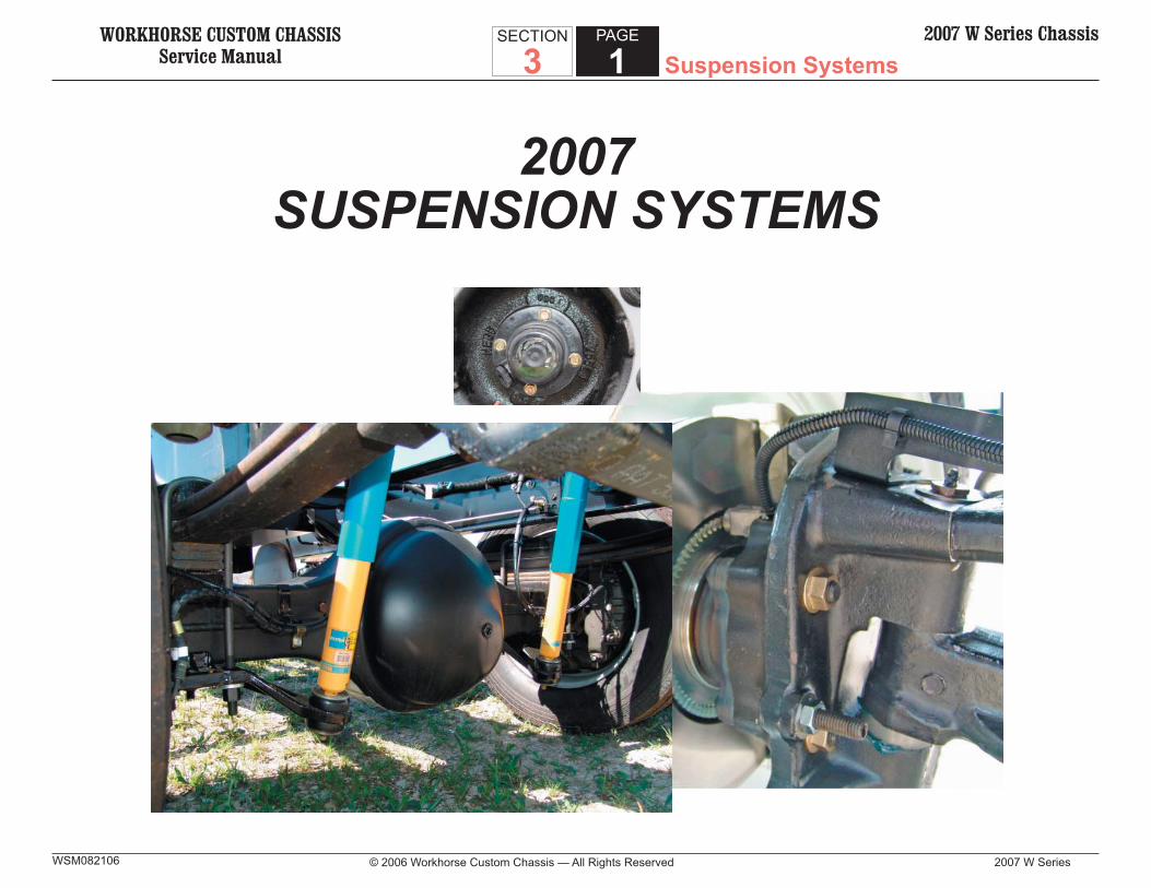
2007SUSPENSION SYSTEMS
WORKHORSE CUSTOM CHASSISService Manual
2007 W Series
SECTION
3PAGE
2 Suspension Systems2007 W Series Chassis
© 2006 Workhorse Custom Chassis — All Rights ReservedWSM082106
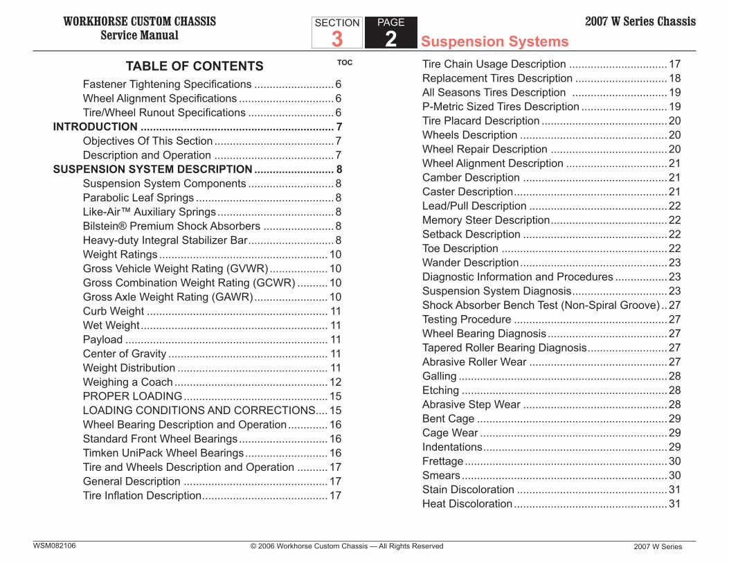
TOCTABLE OF CONTENTSFastener Tightening Specifi cations .......................... 6Wheel Alignment Specifi cations ............................... 6Tire/Wheel Runout Specifi cations ............................ 6
INTRODUCTION ............................................................... 7Objectives Of This Section ....................................... 7Description and Operation ....................................... 7
SUSPENSION SYSTEM DESCRIPTION .......................... 8Suspension System Components ............................ 8Parabolic Leaf Springs ............................................. 8Like-Air™ Auxiliary Springs ...................................... 8Bilstein® Premium Shock Absorbers ....................... 8Heavy-duty Integral Stabilizer Bar ............................ 8Weight Ratings .......................................................10Gross Vehicle Weight Rating (GVWR) ................... 10Gross Combination Weight Rating (GCWR) .......... 10Gross Axle Weight Rating (GAWR) ........................ 10Curb Weight ........................................................... 11Wet Weight ............................................................. 11Payload .................................................................. 11Center of Gravity .................................................... 11Weight Distribution ................................................. 11Weighing a Coach ..................................................12PROPER LOADING ...............................................15LOADING CONDITIONS AND CORRECTIONS .... 15Wheel Bearing Description and Operation ............. 16Standard Front Wheel Bearings ............................. 16Timken UniPack Wheel Bearings ........................... 16Tire and Wheels Description and Operation .......... 17General Description ...............................................17Tire Infl ation Description ......................................... 17
Tire Chain Usage Description ................................ 17Replacement Tires Description .............................. 18All Seasons Tires Description ............................... 19P-Metric Sized Tires Description ............................ 19Tire Placard Description ......................................... 20Wheels Description ................................................20Wheel Repair Description ...................................... 20Wheel Alignment Description ................................. 21Camber Description ...............................................21Caster Description ..................................................21Lead/Pull Description .............................................22Memory Steer Description ...................................... 22Setback Description ...............................................22Toe Description ......................................................22Wander Description ................................................23Diagnostic Information and Procedures ................. 23Suspension System Diagnosis ............................... 23Shock Absorber Bench Test (Non-Spiral Groove) .. 27Testing Procedure ..................................................27Wheel Bearing Diagnosis ....................................... 27Tapered Roller Bearing Diagnosis .......................... 27Abrasive Roller Wear .............................................27Galling ....................................................................28Etching ...................................................................28Abrasive Step Wear ...............................................28Bent Cage ..............................................................29Cage Wear .............................................................29Indentations ............................................................29Frettage ..................................................................30Smears ...................................................................30Stain Discoloration .................................................31Heat Discoloration ..................................................31

WORKHORSE CUSTOM CHASSISService Manual Suspension Systems
2007 W Series © 2006 Workhorse Custom Chassis — All Rights Reserved
SECTION
3PAGE
32007 W Series Chassis
WSM082106
Misalignment ..........................................................31Cracked Inner Race ...............................................32Fatigue Spalling .....................................................32Brinelling ................................................................32Timken Wheel Bearing Diagnosis .......................... 33Tire and Wheel Diagnosis ...................................... 33Wheel Mounting Surface Check ............................. 33Measuring Tire/Wheel Runout ................................ 34Radial Runout (Tire) ...............................................34Lateral Runout (Tire) ..............................................35Lateral Runout (Wheel) .......................................... 35Balancing the Tire/Wheel Assembly ....................... 36Preliminary Alignment Inspection ........................... 36Preliminary Alignment Inspection (Front Wheel Alignment Requirements) ............... 37Wheel Alignment Procedures ................................. 37
REPAIR INSTRUCTIONS ................................................ 37Suspension System Repairs .................................. 37Wheel Stud Replacement ...................................... 37Removal Procedure ...............................................37Installation Procedure ............................................ 37Front Wheel Hub, Bearing, and Seal Replacement (Standard Wheel Bearing) ............. 38Removal Procedure ...............................................38Installation Procedure ............................................ 40Front Wheel Hub, Bearing, and Seal Assembly Replacement (Timken UniPack) ............................. 41Removal Procedure ...............................................41Installation Procedure ............................................ 42Wheel Bearing Adjustment (Standard Bearings) .... 42Hex Slotted Nut .....................................................42Wheel Bearing Adjustment ..................................... 44
Pro-Torq Nut ...........................................................44Installation – Hub/Wheel & Rotor – Oil-Filled Hub ........................................................46Installation- Hub/Wheel & Rotor – Grease-Packed Bearings ..................................... 46Hub Cap Replacement ........................................... 47Removal Procedure ...............................................47Installation Procedure ............................................ 47Adding Lubricant to the Hub Caps ......................... 47Front Stabilizer Shaft Replacement ....................... 47Removal Procedure ...............................................47Installation Procedure ............................................ 47Rear Stabilizer Shaft Replacement ........................ 48Removal Procedure ...............................................48Installation Procedure ............................................ 48Steering Knuckle/King Pin Replacement ............... 48Removal Procedure ...............................................48Installation Procedure ............................................ 51Shock Absorber Replacement ................................ 52Installation Procedure ............................................ 53Like-Air Auxiliary Spring Replacement ................... 53Removal Procedure ...............................................53Installation Procedure ............................................ 53Front Leaf Spring Replacement ............................. 53Installation Procedure ............................................ 55Rear Leaf Spring Replacement .............................. 55Installation Procedure ............................................ 56Front Axle Replacement ......................................... 57Removal Procedure ...............................................57Installation Procedure ............................................ 57Tire and Wheel Repairs .......................................... 58Tire and Wheel Removal and Installation ............... 58

WORKHORSE CUSTOM CHASSISService Manual
2007 W Series
SECTION
3PAGE
4 Suspension Systems2007 W Series Chassis
© 2006 Workhorse Custom Chassis — All Rights ReservedWSM082106
Removal Procedure ...............................................58Installation Procedure ............................................ 59Tire Mounting and Dismounting ............................. 59Bias Ply Tire Mounting Procedure .......................... 60Radial Ply Tire Mounting Procedure ....................... 60
Tubeless Tire Mounting Procedure ........................ 60Tire Rotation ...........................................................61Wheel Alignment Adjustments ................................ 62Front Toe Adjustment .............................................62
WORKHORSE CUSTOM CHASSISService Manual Suspension Systems
2007 W Series © 2006 Workhorse Custom Chassis — All Rights Reserved
SECTION
3PAGE
52007 W Series Chassis
WSM082106
THIS PAGE LEFT BLANK INTENTIONALLY
WORKHORSE CUSTOM CHASSISService Manual
2007 W Series
SECTION
3PAGE
6 Suspension Systems2007 W Series Chassis
© 2006 Workhorse Custom Chassis — All Rights ReservedWSM082106
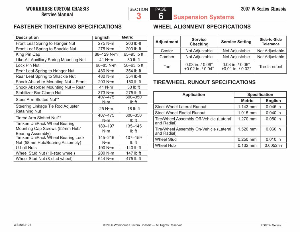
FASTENER TIGHTENING SPECIFICATIONS
Description English MetricFront Leaf Spring to Hanger Nut 275 N•m 203 lb-ftFront Leaf Spring to Shackle Nut 275 N•m 203 lb-ftKing Pin Cap 88–129 N•m 65–95 lb ftLike-Air Auxiliary Spring Mounting Nut 41 N•m 30 lb ftLock Pin Nut 68–85 N•m 50–63 lb ftRear Leaf Spring to Hanger Nut 480 N•m 354 lb-ftRear Leaf Spring to Shackle Nut 480 N•m 354 lb-ftShock Absorber Mounting Nut – Front 203 N•m 150 lb ftShock Absorber Mounting Nut – Rear 41 N•m 30 lb ftStabilizer Bar Clamp Nut 373 N•m 275 lb ftSteer Arm Slotted Nut** 407–475
N•m300–350
lb ftSteering Linkage Tie Rod Adjuster Retaining Nut 25 N•m 18 lb ft
Tierod Arm Slotted Nut** 407–475 N•m
300–350 lb ft
Timken UniPack Wheel Bearing Mounting Cap Screws (52mm Hub/Bearing Assembly)
183–197 N•m
135–145 lb ft
Timken UniPack Wheel Bearing Lock Nut (58mm Hub/Bearing Assembly)
145–216 N•m
107–159 lb ft
U-bolt Nuts 190 N•m 140 lb ftWheel Stud Nut (10-stud wheel) 200 N•m 147 lb ftWheel Stud Nut (8-stud wheel) 644 N•m 475 lb ft
WHEEL ALIGNMENT SPECIFICATIONS
Adjustment Service Checking Service Setting Side-to-Side
Tolerance
Caster Not Adjustable Not Adjustable Not AdjustableCamber Not Adjustable Not Adjustable Not Adjustable
Toe 0.03 in. / 0.06° ±0.02 in. / 0.04°
0.03 in. / 0.06° ±0.01 in. / 0.02° Toe-in equal
TIRE/WHEEL RUNOUT SPECIFICATIONS
Application SpecificationMetric English
Steel Wheel Lateral Runout 1.143 mm 0.045 inSteel Wheel Radial Runout 1.015 mm 0.040 inTire/Wheel Assembly Off-Vehicle (Lateral and Radial)
1.270 mm 0.050 in
Tire/Wheel Assembly On-Vehicle (Lateral and Radial)
1.520 mm 0.060 in
Wheel Stud 0.250 mm 0.010 inWheel Hub 0.132 mm 0.0052 in
WORKHORSE CUSTOM CHASSISService Manual Suspension Systems
2007 W Series © 2006 Workhorse Custom Chassis — All Rights Reserved
SECTION
3PAGE
72007 W Series Chassis
WSM082106
DESCRIPTION AND OPERATION
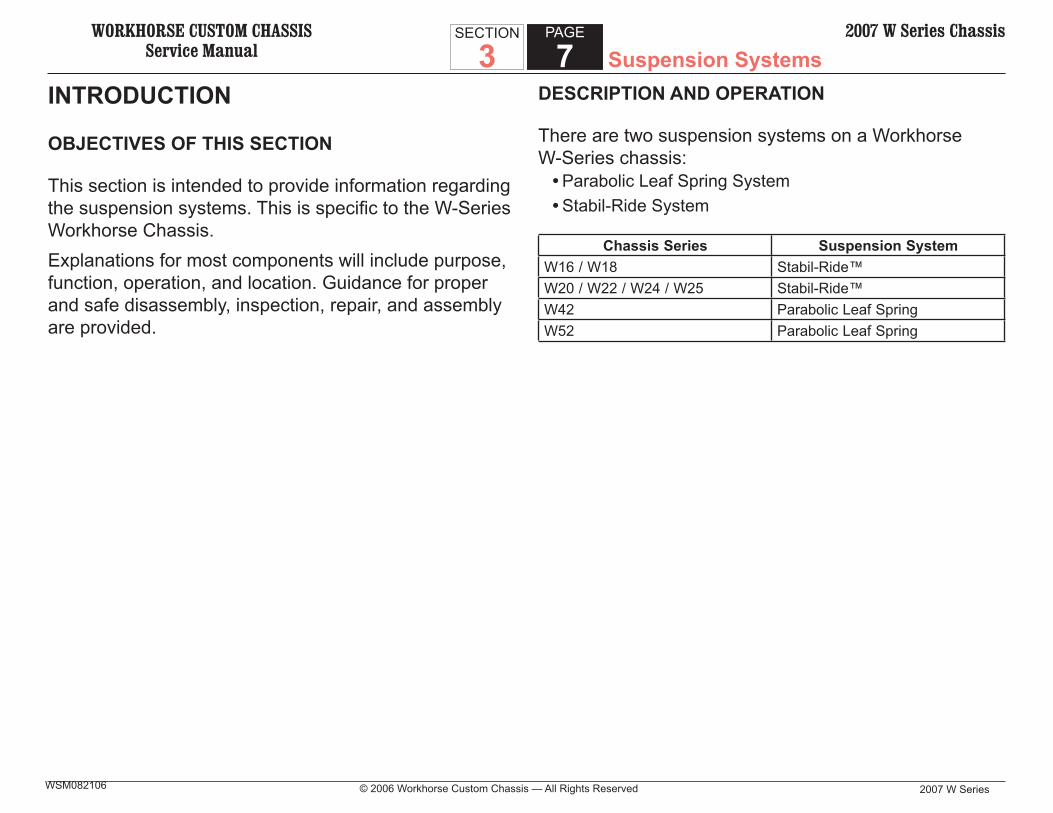
There are two suspension systems on a Workhorse W-Series chassis:
• Parabolic Leaf Spring System• Stabil-Ride System
Chassis Series Suspension SystemW16 / W18 Stabil-Ride™W20 / W22 / W24 / W25 Stabil-Ride™W42 Parabolic Leaf SpringW52 Parabolic Leaf Spring
INTRODUCTION
OBJECTIVES OF THIS SECTION
This section is intended to provide information regarding the suspension systems. This is specifi c to the W-Series Workhorse Chassis.Explanations for most components will include purpose, function, operation, and location. Guidance for proper and safe disassembly, inspection, repair, and assembly are provided.
WORKHORSE CUSTOM CHASSISService Manual
2007 W Series
SECTION
3PAGE
8 Suspension Systems2007 W Series Chassis
© 2006 Workhorse Custom Chassis — All Rights ReservedWSM082106
Bilstein® Premium Shock Absorbers
Premium Bilstein® shock absorbers keep the tires fi rmly on the road, absorbing impacts, so the operator enjoys greater control and comfort.NOTICE:
Prior to March 30, 2004, and VIN Prior to March 30, 2004, and VIN 5B4MP67G243392024, Monroe shock absorbers were 5B4MP67G243392024, Monroe shock absorbers were used.used.
Heavy-duty Integral Stabilizer Bar
The patented 2.5-inch stabilizer bar quickly controls body roll through integrated steel to steel mounting design - so there’s less roll on corners.
SUSPENSION SYSTEM DESCRIPTION
SUSPENSION SYSTEM COMPONENTS
The suspension system is made up of the following components:
• Parabolic Leaf Springs• Like-Air™ Auxiliary Springs• Bilstein® Premium Shock Absorbers• Heavy-duty Integral Stabilizer Bar
Parabolic Leaf Springs
New technology two-leaf parabolic constant rate springs provide excellent force defl ection with virtually no inter-leaf friction. This results in an incredibly smooth and stable ride.
Like-Air™ Auxiliary Springs
The unique Like-Air™ auxiliary spring has a three-stage autothane unit that traps air compressing, slowing and controlling the defl ection of the parabolic spring, for a smooth, compliant ride while adding side to side stability.

WORKHORSE CUSTOM CHASSISService Manual Suspension Systems
2007 W Series © 2006 Workhorse Custom Chassis — All Rights Reserved
SECTION
3PAGE
92007 W Series Chassis
WSM082106
Front Suspension Components
Rear Suspension Components

WORKHORSE CUSTOM CHASSISService Manual
2007 W Series
SECTION
3PAGE
10 Suspension Systems2007 W Series Chassis
© 2006 Workhorse Custom Chassis — All Rights ReservedWSM082106
WEIGHT RATINGS
Gross Vehicle Weight Rating (GVWR)
Gross Vehicle Weight Rating (GVWR) also known as GVW is the weight specifi ed by the chassis manufacturer as the maximum loaded weight of the vehicle (including driver and passengers). Sometimes a tag axle (a non-powered rear axle) is added to a chassis by the body manufacturer or by an aftermarket company. This usually is done to increase the GVWR of the chassis. When this is done, it becomes the responsibility of the party that installed the tag axle to post and certify the new GVWR. The addition of axles does not increase GCW.NOTICE:
Workhorse does not equip the W-Series chassis with Workhorse does not equip the W-Series chassis with tag axles. Any tag axle used would be installed by a tag axles. Any tag axle used would be installed by a body builder or aftermarket upfitter. Any concerns relat-body builder or aftermarket upfitter. Any concerns relat-ed to, or the result of the addition of a tag axle would be ed to, or the result of the addition of a tag axle would be the responsibility of the installer of the tag axle.the responsibility of the installer of the tag axle.
Gross Combination Weight Rating (GCWR)
Gross Combination Weight Rating is the maximum amount of combined weight of the chassis including cargo, fl uids and passengers as well as any item that is being towed (trailer, boat, vehicle, etc.).
Gross Axle Weight Rating (GAWR)
Gross axle weight rating is specifi ed by the chassis manufacturer as the load carrying capacity of a single-axle system, as measured at the tire-ground interface (in other words, at the place where the tire meets the ground). It is important to note that the GAWR is limited to the lowest individual rating of the tires, the wheels, the springs, or the axle (in other words, whichever component is the weakest link in the chain). Therefore, changing from load range D to load range E or F tires may or may not increase the GAWR, since this rating could be dependent upon other (weaker) components. The GAWR assumes that the weight is evenly distributed over the axle with 50 percent on the right side and 50 percent on the left side, not 70/30, for instance. In the case of an axle with GAWR of 6,000 pounds, the load distribution should be 3,000 pounds on one side and 3,000 pounds on the other.Axle weight is both the amount of weight carried by a single axle and the amount of weight transmitted to the highway by one axle. Shipping weight is the average weight of a specifi c vehicle as it leaves the assembly plant, including grease and oil plus regular production options but without any primary mover engine fuel (gasoline or diesel fuel). Empty weight is defi ned as the shipping weight of a specifi c vehicle plus the maximum weight of primary mover engine fuel (gasoline or diesel fuel).
WORKHORSE CUSTOM CHASSISService Manual Suspension Systems
2007 W Series © 2006 Workhorse Custom Chassis — All Rights Reserved
SECTION
3PAGE
112007 W Series Chassis
WSM082106
Curb Weight
Curb weight is the weight of the vehicle empty (without payload and driver) but including engine fuel, coolant, engine oil, tools, spare tire, and all other standard equipment. It is determined without water in the tanks or water heater, and with empty LP-gas containers.(Note: This defi nition, while accepted within the RV industry, may differ from defi nitions utilized by governmental regulatory agencies).
Wet Weight
Wet weight is the empty weight of a specifi c vehicle with the fresh water tanks, water heater, and LP-gas containers full with wastewater holding tanks empty. This weight is particularly signifi cant to vehicle owners, because when this fi gure is subtracted from the gross vehicle weight rating, a fairly accurate indication of the amount of weight that can be added to the vehicle, including driver and passengers, clothing, food, etc., is provided.
Payload
Payload is a term commonly used in the trucking industry. In the RV industry, the term carrying capacity also is used. Carrying capacity is defi ned as the average weight that can be added to a specifi c vehicle without exceeding the GVWR. Carrying capacity can be computed by subtracting the empty weight of the
vehicle from the GVWR fi gure. The addition of any other equipment or cargo and passengers adds to the vehicle from the GVWR fi gure. The addition of any other equipment or cargo and passengers adds to the vehicle weight and subtracts from the allowable carrying capacity. It is important to remember that the limiting factor in this rating could be the axles, springs, tires, transmission parking pawl, or any other equipment.
Center of Gravity
Center of gravity is the point where the weight of the chassis and/or body, and payload is concentrated. If the vehicle is suspended at that point, it would balance front-to-rear and side-to-side. Cornering, acceleration, and other forces are considered as acting on a vehicle’s center of gravity. Thus, it has a great infl uence on body lean and other handling characteristics. Even if all of the weights fall within the specifi cations, if they are not distributed properly, the coach could still suffer from excessive body lean or substandard handling characteristics. It should be noted that the center of gravity of a basement model coach would be higher than that of a traditionally designed motor home.
Weight Distribution
Weight distribution is the arrangement of body and payload weight on a vehicle’s chassis. It has a very defi nite bearing on the life of the tires, axles, springs, frame, and other parts. The fact that the total weight of the vehicle does not exceed the recommended

WORKHORSE CUSTOM CHASSISService Manual
2007 W Series
SECTION
3PAGE
12 Suspension Systems2007 W Series Chassis
© 2006 Workhorse Custom Chassis — All Rights ReservedWSM082106
maximum GVWR does not insure that the coach is not overloaded. Overloading can be due to improperly positioning heavy materials so that the load is centered over one rear tire or so far forward on the body that the front axle and tires are overloaded. An understanding of the proper methods of load placement will enable coach owners to prevent an overload condition. It should be noted also that the limiting factor is the weight rating, not the cubic foot capacity of the storage compartments. Some motor home owners may be under the space; it must be acceptable for them to fi ll each nook and cranny to capacity. This isn’t always the case, however. By providing varied and ample storage space, motor coach manufacturers are attempting to meet a multitude of needs.
Weighing a Coach
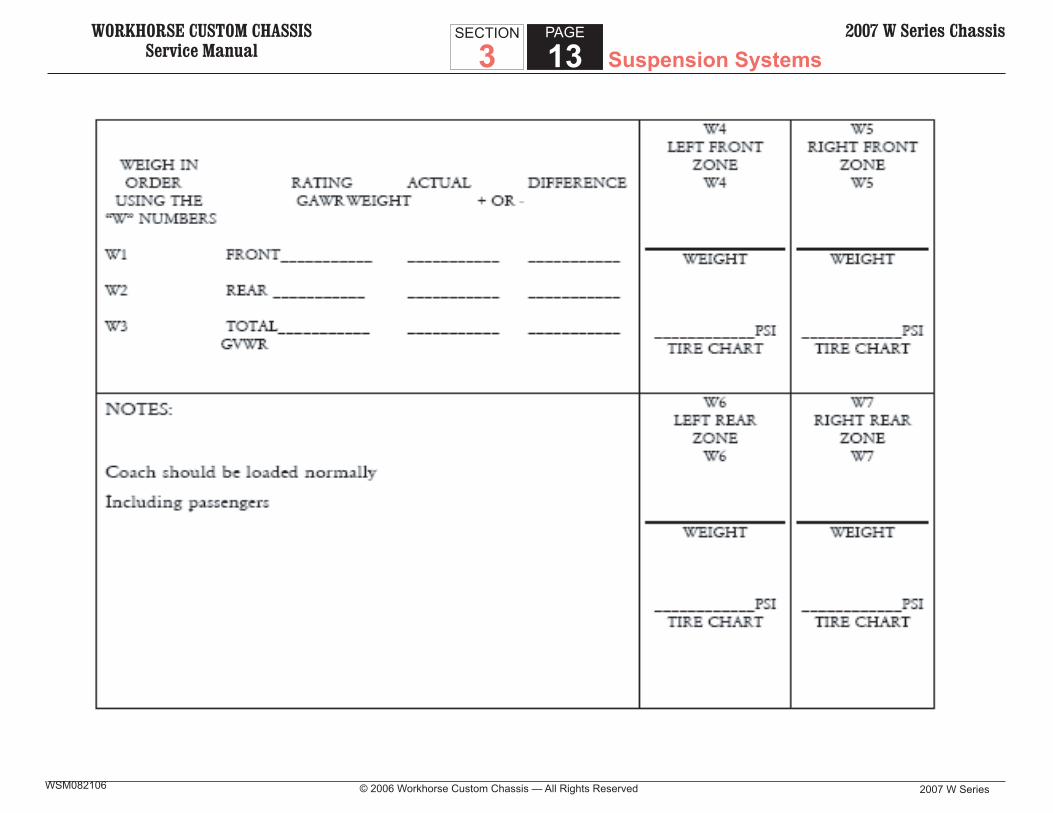
The only way to be sure to avoid an overload condition is to weigh the coach. To do so accurately, fi nd a scale that has a level area on the side, and develop an excellent rapport with the person doing the weighing. The level side area is very important, because it will be necessary to have 50 percent of the left and right sides of the coach off the scale during some of the weighing. If the side area is not level, side weights will be incorrect. Suitable scales might be found at truck stops, sand and gravel pit operations, or moving companies.
Make a photocopy of the coach weighing worksheet on the next page and use it as a reference at the scale. Weigh the vehicle at an off time, since the entire process can take up to one-half hour. Before weighing the vehicle, it needs to be loaded under normal operating conditions. For motor homes, include food, clothing, fuel, water, propane, etc. For commercial units, include the normal load, fuel, etc.The worksheet divides the vehicle into four sections. This is done by fi nding the halfway point between the front and rear tires (axles) and the halfway point between the front tires and then the halfway point between the rear tires. Do not simply use the distance between the front and rear of the coach body; be sure to use the axles as a reference point. Use tape to make the side to-side halfway points on the front bumper and on the rear bumper to make the reference points easily visible. Do the same for the front-to-rear halfway points by applying tape to the side of the coach. Drive the vehicle onto the scale to the point that the front-to-rear tape pieces indicate that one-half of wheelbase is on the scale and one-half is off. Referring to the worksheet, this will be weight number W1.Next, drive the entire vehicle onto the scale. This will be weight number W2. Then drive off the scale so that the side tape stripe indicates that the rear half of the chassis remains on.
WORKHORSE CUSTOM CHASSISService Manual Suspension Systems
2007 W Series © 2006 Workhorse Custom Chassis — All Rights Reserved
SECTION
3PAGE
132007 W Series Chassis
WSM082106

WORKHORSE CUSTOM CHASSISService Manual
2007 W Series
SECTION
3PAGE
14 Suspension Systems2007 W Series Chassis
© 2006 Workhorse Custom Chassis — All Rights ReservedWSM082106
This will be weight W3. It is important that one-half of the chassis, not the coach, rests on the scale during weighing.Weight number W1 should not exceed the GAWR for the front axle. Weight number W2 should not exceed the total GVWR. Weight number W3 should not exceed the rear axle GAWR.Now comes the time when rapport with the scale attendant and patience come in handy. To make these weights more meaningful, use the side-to-side and front-to-rear tape pieces to divide the chassis up into quarters and then weigh each section: front left, weight zone W4; rear left, weight zone W6; front right, weight zone W5; and fi nally rear right, weight zone W7.The weights for zone W4 and zone W5 should be about equal, as should the weights for zones W6 and W7. If this is not the case, try to move items inside the coach to bring the weights close.When comparing the total weight of the two front quarters to the total axle weight, the fi gures probably will not be exactly equal, but they should be close. The same applies to the rear axle. It is also possible that the front and rear GAWR when totaled will be more than the GVWR. This is because the limiting factor may be something such as the transmission parking pawl, braking capacity, or another component.
Since tire manufacturers determine pressure recommendations for each individual tire based on the weight that a particular tire is carrying, these quartered weights are very important. Use the front and rear axle weights on the work sheet to determine the proper air pressure by the consulting the tire manufacturer’s manual, which should be available at any tire store.One last word of caution: start with the weight the customer would normally carry when traveling. If the weight places the vehicle over GVWR, remove some weight and weigh the coach again. The importance of weight and weight distribution in terms of safety and the vehicle’s overall health cannot be overemphasized. Another term with which vehicle owners should be familiar is gross combination weight rating (GCWR), which is the value specifi ed by the chassis manufacturer as the maximum allowable total loaded weight of the tow vehicle and trailer combination. For our purposes the tow vehicle is the motor home, and the trailer ordinarily is a towed car. To determine what size car can be towed safely behind a motor home, subtract the actual motor home weight, which must be less than the GVWR, from the GCWR. Normally this weight will be approximately 3,000 pounds, in which case the towed car combination (including trailer, dolly or tow bar) should not exceed 3,000 pounds. Weigh the tow car as it is normally towed, and if it is overloaded, remove any weight necessary to bring it into specifi cations.
WORKHORSE CUSTOM CHASSISService Manual Suspension Systems
2007 W Series © 2006 Workhorse Custom Chassis — All Rights Reserved
SECTION
3PAGE
152007 W Series Chassis
WSM082106
PROPER LOADING
Workhorse suggests weighing the vehicle before loading to verify front axle, rear axle and side-to-side weights. Once armed with this information the operator will be able to load the vehicle within specifi cations of the chassis and possibly correct for any side-to-side weight differences.After loading Workhorse suggests that the vehicle be weighed again to verify it is within specifi cations and the weight is properly distributed throughout the coach.After verifying correct weight distribution of the fully loaded vehicle we suggest the vehicle wheel alignment is checked and adjusted if required. Although the vehicle is aligned at the body manufacturer’s assembly plant, the alignment can be affected by normal loading of the contents.
LOADING CONDITIONS AND CORRECTIONS
Unusual load conditions can affect the ride and handling of the vehicle. If unusual loading is apparent, it will usually become visible in the form of a lean and/or low suspension, or through poor handling characteristics.The importance of a near equal axle-to-frame side-to-side measurement and weights cannot be overstressed. As well as uniformed weight distribution front to rear. Workhorse recommends that the front axle be loaded at least the same percentage of capacity as the rear. For example, if the rear is loaded at 90 percent of rated capacity, the front should be loaded to a minimum of 90
percent of its capacity. A lower percentage of the weight distribution can cause unloading of the front suspension resulting in handling and braking concerns. Even with the preferred weight distribution it is not recommended to have large amounts of weight at the extreme front, rear, or top of the vehicle. A vehicle with an non-uniform weight distribution will directly affect desirable vehicle handling and an acceptable front-end alignment. If there is more weight toward one side of the vehicle, at the extreme rear or the front, repositioning of the load is required to obtain a more uniform weight distribution.If the vehicle is within the GAWR but heavier on one side having a tendency to lean and weight cannot be shifted due to vehicle build, adjustments may be able to be made.The addition of a spacer block of suffi cient thickness to equalize the left /right axle-to-frame measurement could be installed. Spacer blocks are positioned between the rear axle spring seat and spring pack, never install spacer blocks in the front axle. Spacer blocks are not sold as WCC parts but can generally be fabricated at a local repair facility. Installation of a spacer block and/or spring leaf is not covered by the WCC Limited Warranty and can resolve a lean/sag but may not correct a handling concern. NOTICE:
The addition of a spacer block/shim can correct for a The addition of a spacer block/shim can correct for a body lean and retain similar ride quality. These types of body lean and retain similar ride quality. These types of adjustments should only be considered if the side-to-adjustments should only be considered if the side-to-side weight variation is less than 600 lbs., if the varia-side weight variation is less than 600 lbs., if the varia-tion is higher it is recommended to adjust the weight.tion is higher it is recommended to adjust the weight.

WORKHORSE CUSTOM CHASSISService Manual
2007 W Series
SECTION
3PAGE
16 Suspension Systems2007 W Series Chassis
© 2006 Workhorse Custom Chassis — All Rights ReservedWSM082106
NOTICE:The addition of a spring leaf on chassis with Stabil-The addition of a spring leaf on chassis with Stabil-Ride spring system should never be considered. Take Ride spring system should never be considered. Take care when making any adjustment to the leaf springs to care when making any adjustment to the leaf springs to ensure axle positioning pins and axle U-Bolts are also ensure axle positioning pins and axle U-Bolts are also adjusted/replaced if needed.adjusted/replaced if needed.
CAUTION:In making any adjustments, vehicle own-ers should be cautioned in the use of cer-tain after-market suspension devices. These devices are merchandised as leveling devic-es to raise the “sagging” of the vehicle that may be caused by an overloading situation or a weight distribution problem. Verify the root cause of the concern prior to the instal-lation of additional suspension components. Also, some of these aftermarket devices can severely limit the wheel travel that was designed into the suspension. Limiting the wheel travel may cause undue stress on other components of the suspension causing premature wear or failure.
WHEEL BEARING DESCRIPTION AND OPERATION
There are two types of front wheel bearings that are used on the front ends of the W-Series chassis.
Standard Front Wheel Bearings
Standard front wheel bearings consist of two tapered roller bearings. The bearings are closed at the outer end by a cap and a gasket. The bearings are closed at the inner end by a seal. These bearings require periodic lubrication with either grease or oil.
Timken UniPack Wheel Bearings
Timken UniPack wheel bearings are only available on the W42 commercial chassis. The UniPack wheel bearings are maintenance free (no lubrication required).
WORKHORSE CUSTOM CHASSISService Manual Suspension Systems
2007 W Series © 2006 Workhorse Custom Chassis — All Rights Reserved
SECTION
3PAGE
172007 W Series Chassis
WSM082106
TIRE AND WHEELS DESCRIPTION AND OPERATION
General Description
This section details special service procedures that are not covered in the vehicle’s Owner’s Manual. For jacking instructions, basic tire changing and rotation instructions, and a detailed explanation of all other owner oriented information, refer to the vehicle’s Owner’s Manual.
Tire Infl ation Description
IMPORTANT: The use of wheels or tires with higher load capacity rat-The use of wheels or tires with higher load capacity rat-ings than originally equipped on the vehicle will not ings than originally equipped on the vehicle will not increase the gross axle weight rating (GAWR) or the increase the gross axle weight rating (GAWR) or the gross vehicle weight rating (GVWR) of the vehicle.gross vehicle weight rating (GVWR) of the vehicle.
The factory installed tires and wheels are designed to handle loads up to and including the rated load capacity, shown on the vehicle certifi cation label, when the tires are infl ated to the recommended infl ation pressures.Correct tire pressures and driving techniques affect tire life. Underinfl ated tires can cause the following conditions:
• Handling problems• Poor fuel economy• Shortened tire life• Tire overloading
The following actions can also increase tire wear:• Heavy cornering• Excessively rapid acceleration• Unnecessary braking
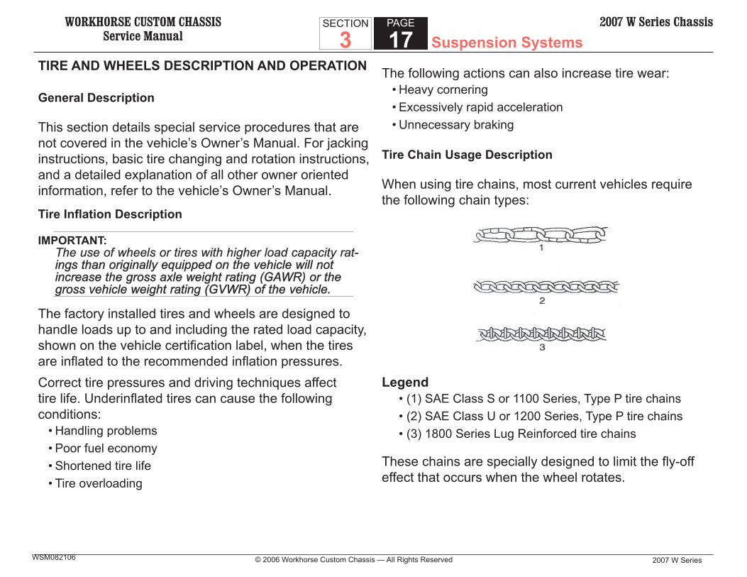
Tire Chain Usage Description
When using tire chains, most current vehicles require the following chain types:
Legend • (1) SAE Class S or 1100 Series, Type P tire chains • (2) SAE Class U or 1200 Series, Type P tire chains • (3) 1800 Series Lug Reinforced tire chains
These chains are specially designed to limit the fl y-off effect that occurs when the wheel rotates.

WORKHORSE CUSTOM CHASSISService Manual
2007 W Series
SECTION
3PAGE
18 Suspension Systems2007 W Series Chassis
© 2006 Workhorse Custom Chassis — All Rights ReservedWSM082106
Manufacturers of tire chains have a specifi c chain size for each tire size. These ensure a proper fi t when the chains are installed. Purchase the correct chains for the tires on which the chains will be used. Do not use rubber adjusters to take up slack in chains that are loose due to incorrect size. Always follow the chain manufacturer’s installation instructions.Use of chains may adversely affect handling. When using chains, remember the following information:
• Ensure that the vehicle is designed for chain clearance.• Adjust the speed to road conditions.• Avoid sharp turns.• Avoid locked-wheel braking in order to help prevent chain damage to the vehicle.
• Install the chains as tightly as possible on the drive tires. Tighten the chains again after driving 0.4-0.8 km (1/4 -1/2 mi). Do not use chains on the non-drive tires. These chains may contact and damage the vehicle. If tire chains are used on the non-drive tires, ensure that there is enough clearance.
• Do not exceed 70 km/h (45 mph). Do not exceed the chain manufacturer’s speed limit, if lower.
• Drive in a restrained manner. Avoid large bumps, potholes, severe turns, and other maneuvers that cause the tires to bounce up and down.
• Follow any other instructions from the chain manufacturer that do not disagree with the above.
Replacement Tires Description
CAUTION: Do not mix different types of tires on the same vehicle such as radial, bias, and bias-belted tires except in emergencies because vehicle handling may be seriously affected and may result in loss of control and possible serious injury.
IMPORTANT: Install new tires in pairs on the same axle. If only one Install new tires in pairs on the same axle. If only one tire requires replacement, the new tire should be paired tire requires replacement, the new tire should be paired with the tire that has the most tread.with the tire that has the most tread.
A Tire Performance Criteria (TPC) specifi cation number is molded in the sidewall near the tire size of all original equipment tires. This number ensures that the tire meets performance standards for traction, endurance, dimension, noise, handling, rolling resistance, and others. A specifi c TPC number usually is assigned to each tire size.Replacement tires should be the same size, load range, and construction as the original tires. Replace the original tires with tires that have the same TPC specifi cation number. Use of any other tire size or type may seriously affect the following items:
• Vehicle ride• Vehicle handling• Speedometer/odometer calibration• Vehicle ground clearance• Tire clearance to the body and chassis
WORKHORSE CUSTOM CHASSISService Manual Suspension Systems
2007 W Series © 2006 Workhorse Custom Chassis — All Rights Reserved
SECTION
3PAGE
192007 W Series Chassis
WSM082106
Replace tires when the following conditions are found:• The tires are worn to a point where 1.6 mm (1/16 in)
or less tread remains, or, the cord or fabric shows. The tires may have built-in tread wear indicators that appear between the tread grooves when the tread is 1.6 mm (1/16 in) or less. When the indicators appear in two or more adjacent grooves at three spots around the tire, replace the tire.
• The tread or sidewall is cracked, cut, or snagged deep enough to expose the cord or the fabric.
• The tire has a bump, bulge, or a split. Slight sidewall indentations are normal and this should not affect ride.
• The tire has a puncture, a cut, or other damage that cannot be repaired correctly because of the size or location of the damage.
All Seasons Tires Description
Some vehicles are equipped with all-season radial tires as standard equipment.These tires have a 37 percent higher average rating for snow traction than non ail-season radial tires previously used. For this reason, these qualify as snow tires. These tires are identifi ed by an M+S, M&S, or M–S molded in the tire sidewall after the size.
P-Metric Sized Tires Description
Most P-metric tires do not have exactly corresponding alphanumeric tire sizes. A P205/75R15 is not equal in size and load carrying capacity to an FR78-15.Because of this, replacement tires should be of the same TPC specifi cation number (size, load range, and construction) as those originally on the vehicle. If P-metric tires must be replaced with other sizes, consult a tire dealer. Tire companies can best recommend the closest match.Identify radial-ply by the letter R or Radial on the sidewall. Encoded on the side wall are the tire type, the tire size, and the aspect ratio (eg. P245/50R16).The following are the code designations:
• P is passenger car (LT is light trucks)• 245 is the section width (1) of the tire• R is the radial type design construction• 50 is the aspect ratio (2) (height to width ratio) • 16 is the rim diameter in inches.

WORKHORSE CUSTOM CHASSISService Manual
2007 W Series
SECTION
3PAGE
20 Suspension Systems2007 W Series Chassis
© 2006 Workhorse Custom Chassis — All Rights ReservedWSM082106
An all-season tire has either M+S, M&S, or M-S imprinted on the sidewall.
Tire Placard Description
The tire information label is on the rear face of the driver’s door. Refer to this label for tire information. The label lists the following items:
• Maximum vehicle load• Tire size• Cold infl ation pressure
WHEELS DESCRIPTION
Replace any wheel when the following conditions apply:• A bent wheel• A dented wheel• Wheels with excessive lateral or radial runout• The welds leak air• Elongated bolt holes• The wheel nuts will not stay tight
Wheels with runout greater than specifi ed may cause objectionable vibrations.
Wheel Repair Description
Do not use heating, welding, or peening to repair wheels. These methods are not approved. Do not use inner tubes to repair leaky wheels or tires. If leaks are found in a steel wheel, replace the wheel with a wheel of original equipment quality.
WORKHORSE CUSTOM CHASSISService Manual Suspension Systems
2007 W Series © 2006 Workhorse Custom Chassis — All Rights Reserved
SECTION
3PAGE
212007 W Series Chassis
WSM082106
WHEEL ALIGNMENT DESCRIPTION
Wheel alignment is not set at the Workhorse assembly plant. Due to weight distribution differences from body manufacturer to body manufacturer, each body manufacturer is required to set wheel alignment prior to delivery. When discussing wheel alignment it is important to understand basic terminology. The terms used are:
• Camber• Caster• Lead/Pull• Memory Steer• Setback• Toe• Wander
Camber Description
The tilting of the top of the wheels inward or outward from the vertical position (when viewed from the front of the vehicle) is called camber. If the wheels tilt outward at the top, then camber is positive (+). If the wheel tilts inward at the top, then camber is negative (-). Camber is measured in degrees from the vertical.Camber affects the directional control of the vehicle and tire wear.
• Excessive positive camber will result in premature wear on the outside of the tire and cause excessive wear on the suspension parts.
• Excessive negative camber will result in premature wear on the inside of the tire and cause excessive wear on the suspension parts.
• If camber varies wheel-to-wheel (side-to-side) 1 degree or more will result in the vehicle pulling or leading to the side with the most positive camber.
Caster Description
The tilting of the uppermost point of the steering axis either forward or backward, when viewed from the side of the vehicle, is called caster. When the steering axis is tilted rearward at the top, it is considered positive (+). When the steering axis is tilted forward at the top, it is considered negative (-). Caster infl uences directional control of the steering but does not affect the tire wear. Caster is affected by the vehicle height, therefore it is important to keep the body at its designed height. Overloading the vehicle or a weak or sagging rear spring will affect caster. When the rear of the vehicle is lower than its designated trim height, the front suspension moves to a more positive caster. If the rear of the vehicle is higher than its designated trim height, the front suspension moves to a less positive caster.With too little positive caster, steering may be touchy at
WORKHORSE CUSTOM CHASSISService Manual
2007 W Series
SECTION
3PAGE
22 Suspension Systems2007 W Series Chassis
© 2006 Workhorse Custom Chassis — All Rights ReservedWSM082106
high speed and wheel returnability may be diminished when coming out of a turn. If one wheel has more positive caster than the other, that wheel will pull toward the center of the vehicle. This condition will cause the vehicle to pull or lead to the side with the least amount of positive caster.
Lead/Pull Description
Lead/pull is described as the amount of effort required at the steering wheel to maintain the vehicle’s straight path, while driving at a constant highway speed on a typical straight road, IMPORTANT:
Vehicles will tend to lead/pull in the direction of the road Vehicles will tend to lead/pull in the direction of the road slope as part of normal operation.slope as part of normal operation.
Lead/pull is usually caused by the following factors:• Road slope• Variances in tire construction• Wheel alignment (front cross caster and camber)• Unbalanced steering gear
Memory Steer Description
If a vehicle wants to lead or pull in the direction the driver previously turned the vehicle, regardless of the direction turned, the condition is called memory steer.
Setback Description
Setback refers to the amount that one wheel may be aligned behind the other wheel on the same axle. Setback may be the result of a road hazard or a collision. The fi rst clue is a caster difference from side-to-side of more than 1 degree.
Toe Description
The front wheels will be turned in or out from a straight-ahead position. This is referred to as toe. When the front of the wheels are turned inward, toe is positive (+). When the front of the wheels are turned outward, toe is negative (-). The purpose of toe is to ensure that the wheels roll parallel.Toe will typically be set slightly positive with the vehicle at rest. As the vehicle starts rolling forward, road friction and movement of the front suspension/steering components will allow the wheels to defl ect so that they will be at 0 toe, or very slightly positive toeIf toe is adjusted incorrectly, premature tire wear and steering instability will be the result.Toe is measured in degrees and adjustments of toe are normally made in fractions of a degree.

WORKHORSE CUSTOM CHASSISService Manual Suspension Systems
2007 W Series © 2006 Workhorse Custom Chassis — All Rights Reserved
SECTION
3PAGE
232007 W Series Chassis
WSM082106
Wander Description
If the vehicle drifts or deviates from the desired straight path, while hand pressure is being applied to steady the steering wheel, this condition is called wander. Wander is a symptom of the vehicle’s sensitivity to external disturbances, such as road crown or crosswind. Wander is accentuated by poor on-center steering feel.
DIAGNOSTIC INFORMATION AND PROCEDURES
Suspension System Diagnosis
Vehicle Leads/Pulls (to one side – no braking)
Problem ActionTire pressure is low. Inflate the tires to the recommended pres-
sure.The front or rear brakes are dragging.
Adjust the brakes.
A front spring is broken or sagging.
Replace the spring.
Vehicle alignment is out of adjustment.
Align the vehicle as needed.
Vehicle Leads/Pulls (leads to either side)
Problem ActionWind or road conditions is the cause
Test the vehicle, driving in both directions, on a smooth, flat road, on a calm day.
Vehicle alignment is out of adjustment.
Align the vehicle as needed.
The steering gear is unbalanced (if this is the cause, steering effort will be very light in the direction of the lead, and very heavy in the opposite direction).
Replace the gear valve.
The steering shaft is rubbing the inside diam-eter of the shaft tube.
Align the steering column.If aligning the steering column does not fix the problem, replace the steering column.
Abnormal or Excessive Tire Wear (Excessive or Uneven)
Problem ActionTires are either over or under inflated.
Inflate the tires to the recommended pres-sure.
Toe setting is out of adjustment.
Align the vehicle as needed.
The wheel and tire are out of balance.
Balance the wheel/tire assembly.
The vehicle operator has used hard driving techniques.
Instruct the operator about proper driving techniques
The vehicle is or has been overloaded.
Weigh the vehicle (four corner weights are preferred). Educate the vehicle operator about proper loading techniques.

WORKHORSE CUSTOM CHASSISService Manual
2007 W Series
SECTION
3PAGE
24 Suspension Systems2007 W Series Chassis
© 2006 Workhorse Custom Chassis — All Rights ReservedWSM082106
Abnormal or Excessive Tire Wear (Cupped Tires)
Problem ActionThe front shock absorb-ers are worn.
Replace the front shock absorbers.
The wheel bearings are improperly adjusted or worn.
• If the wheel bearings are out of adjust-ment, adjust them.
* If the wheel bearings are worn, replace them.
The wheel/tire assembly are out of balance.
Balance the wheel/tire assembly.
The wheel/tire assembly has excessive runout.
Correct the condition if possible. If it is not possible, replace the wheel/tire assembly.
Abnormal or Excessive Tire Wear (General)
Problem ActionThe tires were not rotated.
Instruct the vehicle operator on proper tire rotation intervals and methods.
The front shock absorb-ers are worn.
Replace the front shock absorbers.
The tires are not inflated properly.
Inflate the tires to the recommended pres-sure.
The vehicle is or has been overloaded.
Weigh the vehicle (four corner weights are preferred). Educate the vehicle operator about proper loading techniques.
A spring is broken or sagging.
Replace the spring.
The stabilizer bushing is worn or damaged, or the brackets are loose.
Check the stabilizer bushings. • If the bushing brackets are loose, tight-
en them to specification. • If the bushing is worn or damaged,
replace the stabilizer bushing.
Abnormal or Excessive Tire Wear (Scuffed Tires)
Problem ActionToe setting is out of adjustment.
Align the vehicle as needed.
The operator uses excessive speed on turns.
Instruct the operator about proper driving techniques.
The tires are not inflated properly.
Inflate the tires to the recommended pres-sure.
A suspension compo-nent is damaged or worn.
Diagnose the suspension and repair as needed.
Wheel Tramp
Problem ActionDEFINITION: The wheel and tire bounce onto and off of the road in direct relation to vehicle speed.The wheel/tire assembly are out of balance.
Balance the wheel/tire assembly.
The tire is out of round. Replace the tire.There are blisters or bumps on the tire.
Replace the tire.
The shock absorber is not working correctly.
Replace the shock absorber.
The wheel/tire assembly has excessive runout.
Refer to Tire and Wheel Vibration Diagnosis and Correction.
The tire leads. Refer to Vehicle Leads/Pulls (to one side – no braking) or to Vehicle Leads/Pulls (leads to either side)

WORKHORSE CUSTOM CHASSISService Manual Suspension Systems
2007 W Series © 2006 Workhorse Custom Chassis — All Rights Reserved
SECTION
3PAGE
252007 W Series Chassis
WSM082106
Noisy Front Suspension
Problem ActionThe tie rod ends are worn.
Replace the tie rod ends.
The suspension bolts are loose.
Tighten the suspension bolts to specifica-tion.
The front suspension lacks proper lubrication.
Lubricate the front suspension to specifica-tion.
The shock absorbers are loose.
Tighten the shock absorber bolts.
The stabilizer shaft is loose.
Tighten the stabilizer shaft mounting bolts to specification.
The stabilizer shaft insu-lators are worn or dam-aged.
Replace the bushing.
Poor Directional Stability
Problem ActionThe steering linkage lacks lubrication.
Lubricate the steering linkage to specifica-tion.
Tire pressure is low. Inflate the tires to specification.The wheel bearings are improperly adjusted or worn.
• If the wheel bearings are out of adjust-ment, adjust them.
* If the wheel bearings are worn, replace them.
Vehicle alignment is out of adjustment.
Align the vehicle as needed.
A spring is broken or sagging.
Replace the spring.
A shock absorber is not functioning correctly.
Inspect the shock absorber. Replace the shock absorber as needed.
The stabilizer shaft is loose, damaged, or bro-ken.
Inspect the stabilizer shaft. • If the stabilizer shaft is loose, tighten
the bracket bolts. * If the stabilizer shaft is damaged or bro-
ken, replace it.
Noise Diagnosis – Front Suspension
Problem ActionThe steering linkage needs lubrication.
Lubricate the front suspension to specifica-tion.
The shock absorber is loose.
Tighten the shock absorber bolts to speci-fication.
The shock absorber bushings are worn.
Replace the shock absorber.
The wheel bearings are improperly adjusted or worn.
• If the wheel bearings are out of adjust-ment, adjust them.
* If the wheel bearings are worn, replace them.
The stabilizer shaft is loose, damaged, or bro-ken.
Inspect the stabilizer shaft. • If the stabilizer shaft is loose, tighten
the bracket bolts. * If the stabilizer shaft is damaged or bro-
ken, replace it.The wheel nuts are loose.
Tighten the wheel nuts to specification.
The spring is improperly positioned.
Reposition the spring.
The king pins and bush-ings are worn.
Replace the bushings and king pins.
Shock Absorbers Binding (Rear)
Problem ActionThe shock absorber has a scored rod.
Replace the shock absorber.
The shock absorber is dented.
Replace the shock absorber.
The shock absorber is leaking.
Replace the shock absorber.

WORKHORSE CUSTOM CHASSISService Manual
2007 W Series
SECTION
3PAGE
26 Suspension Systems2007 W Series Chassis
© 2006 Workhorse Custom Chassis — All Rights ReservedWSM082106
Shock Absorbers Noisy (Rear)
Problem ActionThe shock absorber has broken mounts.
Replace the shock absorber.
The shock absorber has extreme bushing wear.
Replace the shock absorber.
Spring Noise
Problem ActionThe spring has loose U-bolts
Tighten the U-bolts to specification.
The spring has loose or worn eye bushings.
Replace the eye bushings.
The spring lacks lubrica-tion.
Lubricate to specifications.
The shock absorbers are inoperative.
Replace the shock absorber.
Spring Sags or Bottoms (Rear)
Problem ActionThe shock absorbers are inoperative.
Replace the shock absorbers.
The spring has a broken leaf.
Replace the spring assembly.
The vehicle was used under severe operation or the vehicle has been overloaded.
Check the load capacity rating.
Spring Breakage (Rear)
Problem ActionThe spring has loose U-bolts.
Tighten the U-bolts to specification.
The spring shows nor-mal fatigue.
Replace the spring.
The vehicle is over-loaded.
Check the load capacity rating.
Front Wheel Shimmy
Problem ActionDEFINITION: Vehicle front wheel shimmy or shake while driving on a smooth road.The wheel/tire are out of balance.
Balance the tires.
The wheel/tire assembly are out of round.
Check the runout. Replace the wheel/tire as needed.
The wheel bearings are improperly adjusted or worn.
• If the wheel bearings are out of adjust-ment, adjust them.
* If the wheel bearings are worn, replace them.
The king pins and bush-ings are worn.
Replace the bushings and king pins.
A shock absorber is not functioning correctly.
Inspect the shock absorber. Replace the shock absorber as needed.
Low or Uneven Trim Height
Problem ActionThe springs are broken or sagging.
Replace the springs.
The vehicle is overload-ed or improperly loaded.
Instruct the vehicle operator on proper loading techniques.
WORKHORSE CUSTOM CHASSISService Manual Suspension Systems
2007 W Series © 2006 Workhorse Custom Chassis — All Rights Reserved
SECTION
3PAGE
272007 W Series Chassis
WSM082106
Shock Absorber Bench Test (Non-Spiral Groove)
Testing Procedure
It is not necessary to purge air from non-spiral groove shock absorbers. These shock absorbers contain a gas fi lled cell within the shocks reservoir. These shocks differ from spiral groove shocks. Spiral groove shocks contain an air fi lled cell within the reservoir.
1. Remove the shock absorber from the vehicle.NOTICE:
Do not clamp the vise jaws on the shock absorber res-Do not clamp the vise jaws on the shock absorber res-ervoir tube or shaft. Doing so could damage compo-ervoir tube or shaft. Doing so could damage compo-nent.nent.
2. Place the shock absorber in a vise. Clamp the jaws on the top mounting stud of the shock. Hold the shock vertically in the vise with the bottom end up.
3. Pump the shock at various rates of speed. Observe the rebound force. The rebound force normally is stronger than the compression force (approximately two to one). The rebound force should be smooth and constant for each stroke rate.
4. Compare this shock with a good shock absorber. 5. Pump the shock one full stroke in both directions.
If any of the following conditions occur, replace the shock absorber:
• A skip, or a lag, at reversal near mid-stroke.• A seizing (except at the extreme ends of travel).• A noise, a grunt or a squeal, after completing.• A clicking noise at fast reversal.
WHEEL BEARING DIAGNOSIS
Tapered Roller Bearing Diagnosis
Diagnosing wheel bearings is done using the following steps:
• Make note of the general condition of all parts during disassembly
• Classify the failure with the aid of the illustrations. • Determine the cause. • Make all repairs following recommended and inspection
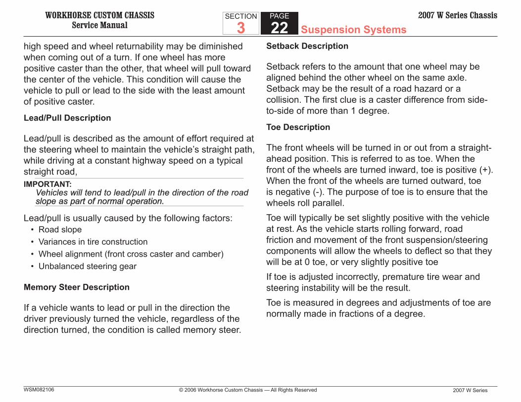
procedures.Abrasive Roller Wear
A pattern on the roller ends may be caused by fi ne abrasives. Clean all of the parts and the housings. Check the seals and the bearings. Replace any leaky, rough, or noisy bearings.
WORKHORSE CUSTOM CHASSISService Manual
2007 W Series
SECTION
3PAGE
28 Suspension Systems2007 W Series Chassis
© 2006 Workhorse Custom Chassis — All Rights ReservedWSM082106
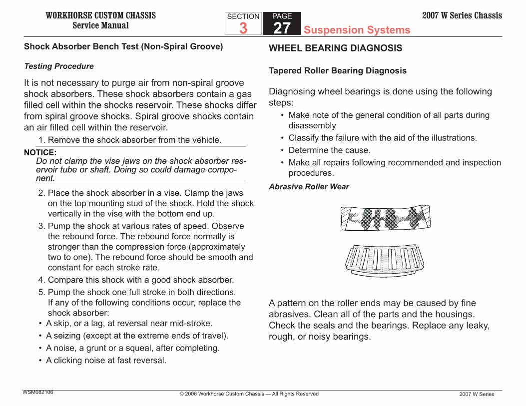
Galling
Metal smears on the roller ends may be due to overheating, lubricant failure, or lubricant overload. Replace the bearing. Check the seals. Check for proper lubrication. Etching
Bearing surfaces may appear gray or grayish black in color; with related etching away of material, usually at the roller spacing. Replace the bearings. Check the seals. Check for proper lubrication.
Abrasive Step Wear
A pattern on the roller ends may be caused by fi ne abrasives. Clean all of the parts and housings. Check the seals and the bearings. Replace the bearing if the bearing is leaking, rough, or noisy.
WORKHORSE CUSTOM CHASSISService Manual Suspension Systems
2007 W Series © 2006 Workhorse Custom Chassis — All Rights Reserved
SECTION
3PAGE
292007 W Series Chassis
WSM082106
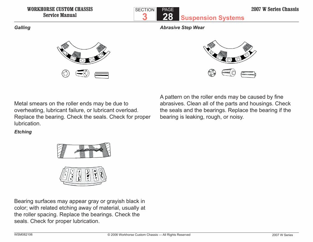
Bent Cage
The cage may be damaged due to improper handling or improper tool usage. Replace the bearing.
Cage Wear
Wear around the outside diameter of the cage and the roller pockets may be caused by abrasive material. Wear may be caused from ineffi cient lubrication. Clean the related parts and the housings. Check the seals. Replace the bearings.Indentations
Surface depressions on the race and the rollers may be caused by hard particles of foreign matter. Clean all the parts and the housings. Check the seals. Replace rough or noisy bearings.
WORKHORSE CUSTOM CHASSISService Manual
2007 W Series
SECTION
3PAGE
30 Suspension Systems2007 W Series Chassis
© 2006 Workhorse Custom Chassis — All Rights ReservedWSM082106
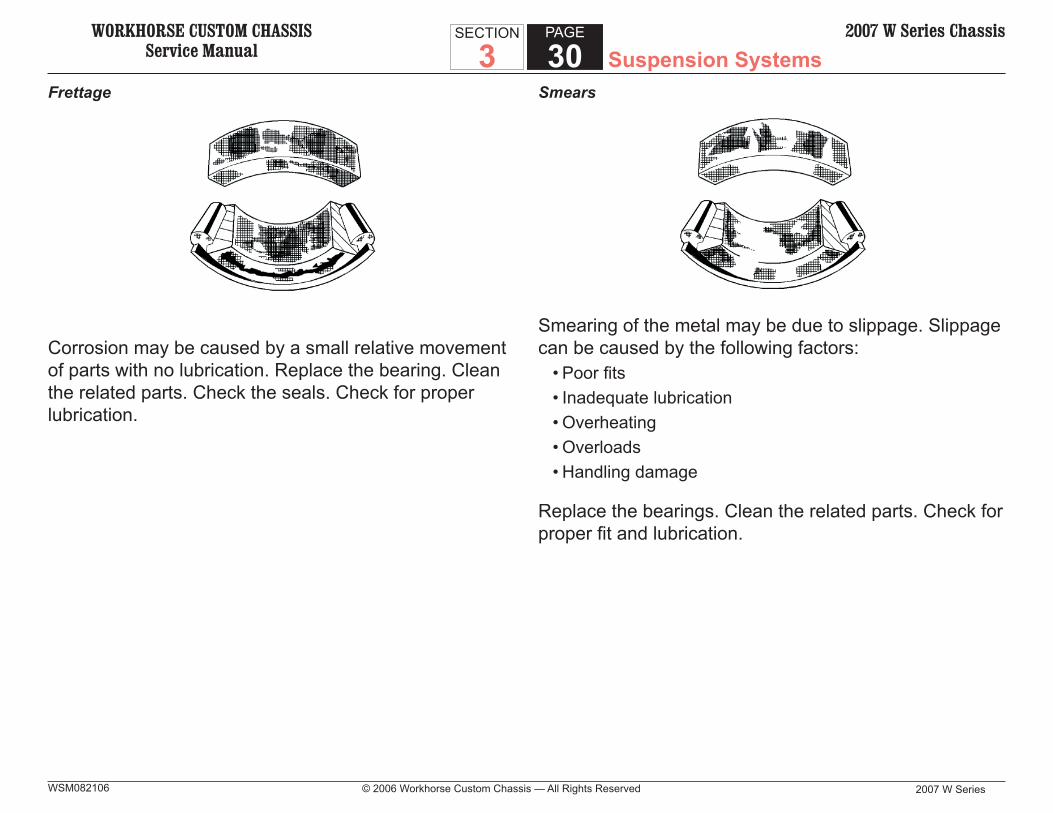
Frettage
Corrosion may be caused by a small relative movement of parts with no lubrication. Replace the bearing. Clean the related parts. Check the seals. Check for proper lubrication.
Smears
Smearing of the metal may be due to slippage. Slippage can be caused by the following factors:
• Poor fi ts• Inadequate lubrication• Overheating• Overloads• Handling damage
Replace the bearings. Clean the related parts. Check for proper fi t and lubrication.
WORKHORSE CUSTOM CHASSISService Manual Suspension Systems
2007 W Series © 2006 Workhorse Custom Chassis — All Rights Reserved
SECTION
3PAGE
312007 W Series Chassis
WSM082106
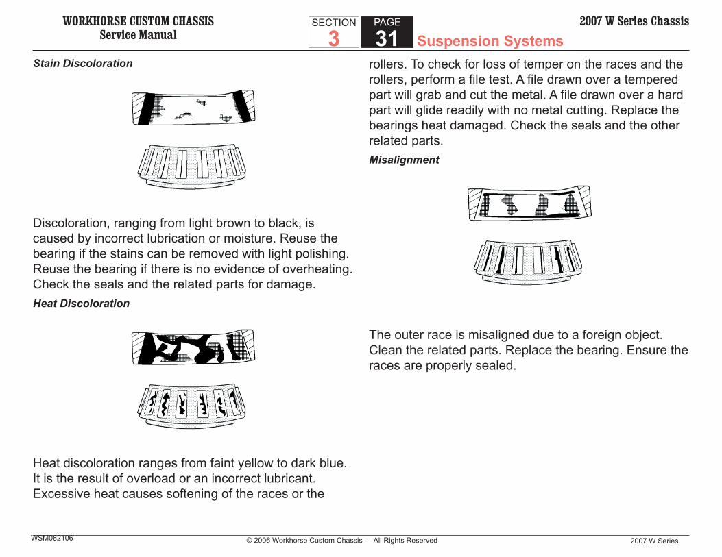
Stain Discoloration
Discoloration, ranging from light brown to black, is caused by incorrect lubrication or moisture. Reuse the bearing if the stains can be removed with light polishing. Reuse the bearing if there is no evidence of overheating. Check the seals and the related parts for damage.Heat Discoloration
Heat discoloration ranges from faint yellow to dark blue. It is the result of overload or an incorrect lubricant. Excessive heat causes softening of the races or the
rollers. To check for loss of temper on the races and the rollers, perform a fi le test. A fi le drawn over a tempered part will grab and cut the metal. A fi le drawn over a hard part will glide readily with no metal cutting. Replace the bearings heat damaged. Check the seals and the other related parts.Misalignment
The outer race is misaligned due to a foreign object. Clean the related parts. Replace the bearing. Ensure the races are properly sealed.
WORKHORSE CUSTOM CHASSISService Manual
2007 W Series
SECTION
3PAGE
32 Suspension Systems2007 W Series Chassis
© 2006 Workhorse Custom Chassis — All Rights ReservedWSM082106
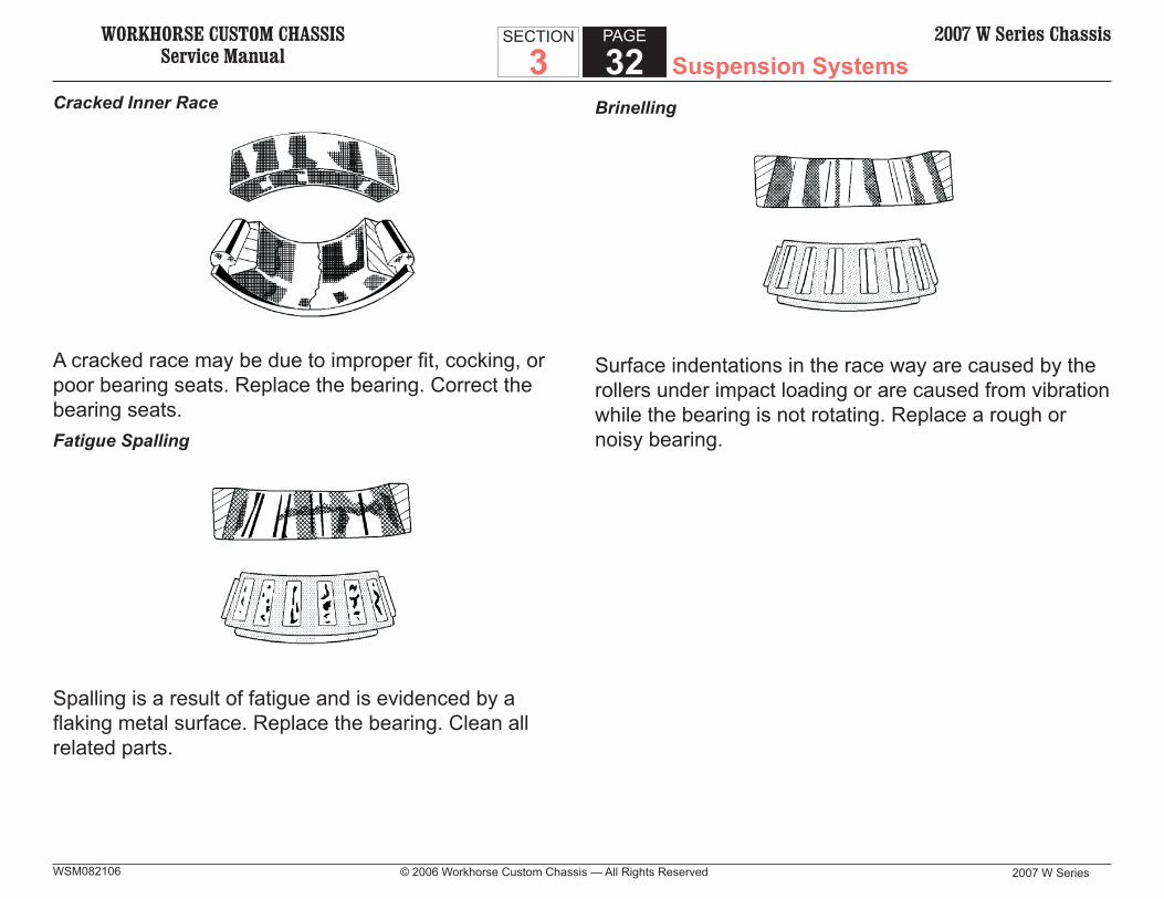
Cracked Inner Race
A cracked race may be due to improper fi t, cocking, or poor bearing seats. Replace the bearing. Correct the bearing seats.Fatigue Spalling
Spalling is a result of fatigue and is evidenced by a fl aking metal surface. Replace the bearing. Clean all related parts.
Brinelling
Surface indentations in the race way are caused by the rollers under impact loading or are caused from vibration while the bearing is not rotating. Replace a rough or noisy bearing.

WORKHORSE CUSTOM CHASSISService Manual Suspension Systems
2007 W Series © 2006 Workhorse Custom Chassis — All Rights Reserved
SECTION
3PAGE
332007 W Series Chassis
WSM082106
Timken Wheel Bearing Diagnosis
1. Lift and support the front of the vehicle. 2. Rotate the wheel to check for any binding or
roughness. If roughness or binding is felt, replace the hub assembly.
3. Remove the wheel and tire assembly. Check the hub assembly for looseness or endplay. If endplay exceeds 0.127 mm (0.005 in), replace the hub assembly.
4. Remove the tire and wheel assembly. Inspect the inboard and outboard seals. If damage is visible, replace the hub assembly.
IMPORTANT:The seals will likely have some purge grease on them. The seals will likely have some purge grease on them. DO NOT wipe this purge grease off of the seals. The DO NOT wipe this purge grease off of the seals. The purge grease acts as a secondary contamination block-purge grease acts as a secondary contamination block-er, effectively sealing out dirt and moisture.er, effectively sealing out dirt and moisture.
Tire and Wheel Diagnosis
Wheel Mounting Surface Check
1. Use a straight edge 203-229 mm (8-9 in) long. Place the straight edge on the wheel inboard mounting surface. Try to rock the straight edge up and down within the mounting surface.

WORKHORSE CUSTOM CHASSISService Manual
2007 W Series
SECTION
3PAGE
34 Suspension Systems2007 W Series Chassis
© 2006 Workhorse Custom Chassis — All Rights ReservedWSM082106
• A wheel of incorrect size or type may affect the following conditions:
– Wheel and hub-bearing life – Brake cooling – Speedometer/odometer calibration – Vehicle ground clearance – Tire clearance to the body and the chassis
4. Replace the wheel if the wheel is bent. Replace the wheel if the wheel nut boss area is cracked.
Identify steel wheels with a 2 or 3 letter code stamped into the rim near the valve stem.Measuring Tire/Wheel Runout
Excessive wheel runout can result in vibration. When discussing runout, it can take two forms.
• Radial runout• Lateral runout
Radial Runout (Tire)
When talking about radial runout, the typical method of measuring runout is with a roller tipped dial indicator.
1. Mount the dial indicator on a stationary component. Typically this is done using a magnetic dial indicator base.
2. Unlock the fl exible arm of the dial indicator. 3. Position the tip of the dial indicator on the tread of the
tire, with the roller running in the same direction as the tread of the tire.
4. Lock the fl exible arm of the dial indicator.
2. Repeat this procedure on at least 3 or 4 different positions on the inboard mounting surface.
• The outer ring of the mounting surface normally is raised above everything inside the mounting surface.
• The mounting surface is raised above the outer ring if the wheel mounting surface is bent on a tire changer.
3. Inspect the mounting wheel nut holes for damage caused from over-torquing the wheel nuts. Inspect for collapsed wheel nut bosses. Inspect for cracked wheel bosses.
NOTICE:The use of aftermarket reverse-type wheels, designed The use of aftermarket reverse-type wheels, designed to extend the wheel away from the body, will increase to extend the wheel away from the body, will increase the scrub radius. An increased scrub radius may greatly the scrub radius. An increased scrub radius may greatly increase steering effort and reduce hub bearing life.increase steering effort and reduce hub bearing life.
IMPORTANT:• Replacement wheels must be equivalent to the original equipment wheels in the following ways:
– Load capacity – Wheel diameter – Rim width – Wheel offset – Mounting confi guration

WORKHORSE CUSTOM CHASSISService Manual Suspension Systems
2007 W Series © 2006 Workhorse Custom Chassis — All Rights Reserved
SECTION
3PAGE
352007 W Series Chassis
WSM082106
5. Rotate the wheel while monitoring the gauge, until the lowest point is located. Stop rotating the wheel at this specifi c point.
6. Zero the gauge. 7. Rotate the wheel while monitoring the gauge, until the
highest point is located. Make note of this reading. 8. Compare the reading to the specifi cations. If the
reading exceeds specifi cation, replace the tire.Lateral Runout (Tire)
Lateral runout of a tire is measured using a dial indicator. Follow the steps below:
1. Mount the dial indicator on a stationary component. Typically this is done using a magnetic dial indicator base.
2. Unlock the fl exible arm of the dial indicator. 3. Position the tip of the dial indicator on the sidewall of
the tire, with the roller running in the same direction as the tire.
5. Lock the fl exible arm of the dial indicator. 6. Rotate the tire while monitoring the gauge, until the
lowest point is located. Stop rotating the tire at this specifi c point.
7. Zero the gauge. 8. Rotate the tire while monitoring the gauge, until the
highest point is located. Make note of this reading. 9. Compare the reading to the specifi cations. If the
reading exceeds specifi cation, replace the tire.
Lateral Runout (Wheel)
Lateral runout of a wheel can be measured using a dial indicator, or some computerized tire/wheel assembly balancers also have the capability to measure lateral runout.When measuring lateral runout using a computerized tire/wheel assembly balancer, make sure to follow the instruction manual provided with that balancer.When using a dial indicator, follow the steps below:
1. Remove any wheel weights on the wheel. 2. Mount the dial indicator on a stationary component.
Typically this is done using a magnetic dial indicator base.
3. Unlock the fl exible arm of the dial indicator. 4. Position the tip of the dial indicator on the bead of the
wheel, with the roller running in the same direction as the wheel.
5. Lock the fl exible arm of the dial indicator. 6. Rotate the wheel while monitoring the gauge, until the
lowest point is located. Stop rotating the wheel at this specifi c point.
7. Zero the gauge. 8. Rotate the wheel while monitoring the gauge, until the
highest point is located. Make note of this reading. 9. Compare the reading to the specifi cations. If the
reading exceeds specifi cation, replace the wheel.

WORKHORSE CUSTOM CHASSISService Manual
2007 W Series
SECTION
3PAGE
36 Suspension Systems2007 W Series Chassis
© 2006 Workhorse Custom Chassis — All Rights ReservedWSM082106
Balancing the Tire/Wheel Assembly
Workhorse balances all tire/wheel assemblies at the factory during the assembly process. The wheels have a tool mark (indentation) on the rim to indicate that specifi c wheel’s heaviest point. Conversely, the tires are delivered with a paint mark to indicate that specifi c tire’s lightest point. When the tire is mounted on the wheel, these two marks are lined up to help with the fi nal balance procedure.The only method recommended by Workhorse for balancing tire/wheel assemblies is dynamic balancing. Follow the instructions provided by the manufacturer of the balancer when balancing a tire/wheel assembly.
PRELIMINARY ALIGNMENT INSPECTION
IMPORTANT: Before making any adjustments affecting the caster, the Before making any adjustments affecting the caster, the camber, or the toe-in, inspect the front end thoroughly.camber, or the toe-in, inspect the front end thoroughly.
1. Inspect the front wheel bearing for proper adjustment. Refer to Wheel Bearing Adjustment
2. Inspect the following parts: • The tie rod ends • The relay rods
Correct excessive looseness before checking wheel alignment.
3. Inspect the tires and the wheels for runout. Refer to Tire and Wheel Vibration Diagnosis and Correction.
4. Inspect the steering gear for looseness at the frame. 5. Inspect the shock absorbers for leaks or any
noticeable noise. 6. Inspect the I-Beam or the stabilizer bar attachments
for looseness. 7. Inspect the alignment equipment. Follow the
manufacturer’s instructions. 8. Inspect the level of the vehicle. The vehicle must be
on a level surface fore and aft and transversely.

WORKHORSE CUSTOM CHASSISService Manual Suspension Systems
2007 W Series © 2006 Workhorse Custom Chassis — All Rights Reserved
SECTION
3PAGE
372007 W Series Chassis
WSM082106
PRELIMINARY ALIGNMENT INSPECTION (FRONT WHEEL ALIGNMENT REQUIREMENTS)
Satisfactory vehicle operation may occur over a wide range of front wheel alignment settings. Adjustments are necessary if the settings vary beyond certain tolerances. Refer to Wheel Alignment Specifi cations. Check the front and the rear weight for proper distribution. Set the front wheel alignment to specifi cations while the vehicle is in the normally loaded condition. Vehicles which are consistently operated with heavy loads should have alignment adjustments made with the vehicle under a heavy load. This procedure should result in longer tire life.
WHEEL ALIGNMENT PROCEDURES
When performing a wheel alignment, always follow the instructions provided by the manufacturer of the alignment equipment, using the specifi cations provided at the front of this section of the service manual.
REPAIR INSTRUCTIONS
SUSPENSION SYSTEM REPAIRS
Wheel Stud Replacement
Removal Procedure
TOOLS REQUIRED
• J 9746-02 Hub/Rotor Support
1. Raise the vehicle. Support the vehicle with suitable safety stands.
2. Remove the tire and wheel assembly. Refer to Tire and Wheel Removal and Installation.
3. Remove the hub/rotor assembly from the vehicle. Refer to Wheel Hub, Bearing, and Seal Replacement.
NOTICE: Place J 9746-02 between the press bars and the hub/Place J 9746-02 between the press bars and the hub/rotor to protect the rotor surfaces.rotor to protect the rotor surfaces.
4. Remove the wheel hub bolts using a press. Support the hub/rotor using the J 9746-02 and the press bars. Do not damage the wheel mounting surface on the hub/rotor fl ange.
Installation Procedure
1. Install the wheel hub bolts into the hub/rotor (using a press).
• Support the hub/rotor using the J 9746-02 and the press bars.
• Do not damage the wheel mounting surface on the hub/rotor fl ange.

WORKHORSE CUSTOM CHASSISService Manual
2007 W Series
SECTION
3PAGE
38 Suspension Systems2007 W Series Chassis
© 2006 Workhorse Custom Chassis — All Rights ReservedWSM082106
2. Install the hub/rotor on the vehicle. Refer to Wheel Hub, Bearing, and Seal Replacement.
3. Install the tire and wheel assembly. Refer to Tire and Wheel Removal and Installation.
4. Lower the vehicle.
Front Wheel Hub, Bearing, and Seal Replacement (Standard Wheel Bearing)
Removal Procedure
TOOLS REQUIRED
• J 8092 Driver Handle • J 6368 Outer Bearing Race Installer • J 9746-02 Hub/Rotor Support
1. Raise and suitably support the front end of the vehicle. 2. Remove the wheel and tire assembly. Refer to Tire
and Wheel Removal and Installation.NOTICE:
Support the brake caliper with a piece of wire to prevent Support the brake caliper with a piece of wire to prevent damage to the brake line.damage to the brake line.
3. Remove the brake caliper. Refer to Brake Caliper Replacement (Front).
4. Remove the drain plug from the hub cap (3) and allow the oil to drain into a suitable container, then replace the drain plug.
5. Remove the bolts, washers, hub cap, and gasket from the hub.
6. Remove the cotter pin, nut, and washer from the spindle.
7. Remove the hub/rotor.7.1. Pull the hub/rotor free from the spindle. Make sure
the outer bearing comes free.7.2. Be careful not to damage the steering knuckle
spindle threads.7.3. Pull the hub/rotor part way off, then remove the outer
bearing. 8. Remove the oil seal and inner bearing. Gently pry out
the oil seal. 9. Remove the bearing races using a brass drift.10. Remove the brake rotor mounting bolts, nuts, and
rotor from the hub. 11. Clean any gasket material from the hub cap and hub.12. Clean the oil from the hub and rotor.
NOTICE: Do not spin the wheel bearings with compressed air to Do not spin the wheel bearings with compressed air to dry them – the wheel bearings might be damaged.dry them – the wheel bearings might be damaged.
13. Clean the wheel bearings in a suitable solvent. Use a stiff brush with no loose bristles.
14. Inspect the wheel bearings and races for damage or wear. Refer to Wheel Bearings Diagnosis. If either the bearing or the race is worn, replace the bearing and the race.
15. Inspect the hub and rotor for the following conditions. Replace the hub or rotor as necessary.
• Out of round• Scored• Pitting or cracks
WORKHORSE CUSTOM CHASSISService Manual Suspension Systems
2007 W Series © 2006 Workhorse Custom Chassis — All Rights Reserved
SECTION
3PAGE
392007 W Series Chassis
WSM082106
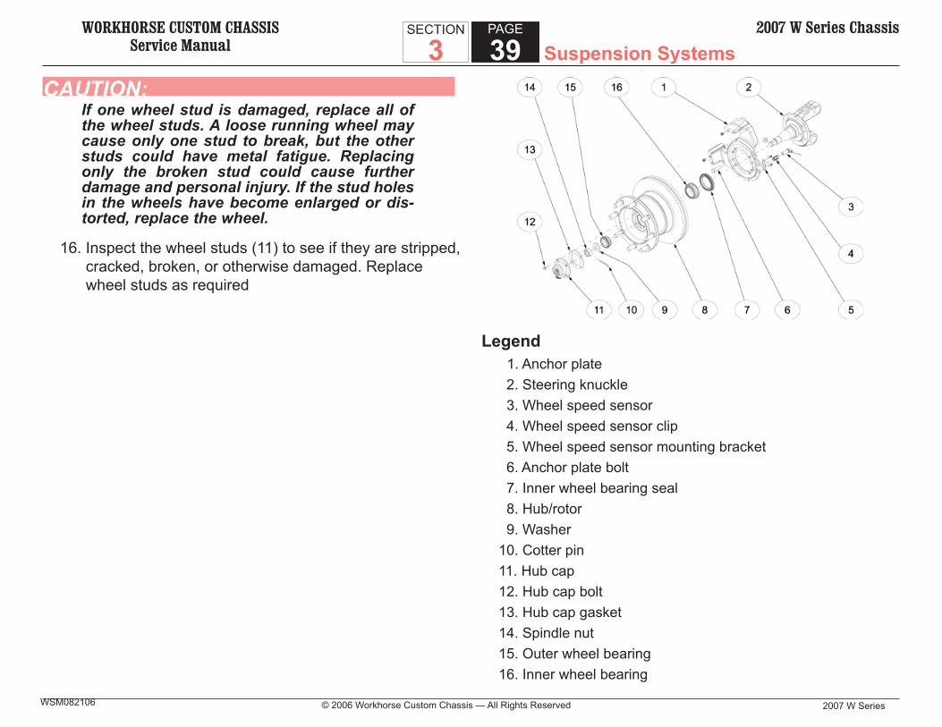
CAUTION:If one wheel stud is damaged, replace all of the wheel studs. A loose running wheel may cause only one stud to break, but the other studs could have metal fatigue. Replacing only the broken stud could cause further damage and personal injury. If the stud holes in the wheels have become enlarged or dis-torted, replace the wheel.
16. Inspect the wheel studs (11) to see if they are stripped, cracked, broken, or otherwise damaged. Replace wheel studs as required
Legend 1. Anchor plate 2. Steering knuckle 3. Wheel speed sensor 4. Wheel speed sensor clip 5. Wheel speed sensor mounting bracket 6. Anchor plate bolt 7. Inner wheel bearing seal 8. Hub/rotor 9. Washer10. Cotter pin11. Hub cap12. Hub cap bolt13. Hub cap gasket14. Spindle nut15. Outer wheel bearing16. Inner wheel bearing

WORKHORSE CUSTOM CHASSISService Manual
2007 W Series
SECTION
3PAGE
40 Suspension Systems2007 W Series Chassis
© 2006 Workhorse Custom Chassis — All Rights ReservedWSM082106
Installation Procedure
NOTICE:Refer to Fastener Notice in Cautions and Notices. Refer to Fastener Notice in Cautions and Notices.
1. Install the brake rotor mounting bolts (11), nuts (9), and rotor (12) to the hub (10).
2. Tighten hub to rotor nuts to 120 N•m (88 lb ft).NOTICE:
Start the races squarely inside the hub/rotor to avoid Start the races squarely inside the hub/rotor to avoid distortion and possible cracking.distortion and possible cracking.
3. Install the outer bearing race into the bearing hub (10).3.1. Place the hub/rotor on the J 9746-02 and rest the
assembly on the press bars.3.2. Use the J 6368 in order to drive the outer bearing
into position.3.3. Remove the J 9746-02.
NOTICE:Using a bar larger than 7.6 cm (3 in) may damage the Using a bar larger than 7.6 cm (3 in) may damage the bearing seal seat.bearing seal seat.
4. Use a 7.6 cm (3 in) diameter bar to drive the inner bearing race into position.
5. Install the inner bearing (14).IMPORTANT:
Face the seal lip towards the inside of the wheel. Face the seal lip towards the inside of the wheel. Provide enough clearance between the seal and the Provide enough clearance between the seal and the bearing so that the bearing can turn freely without rub-bearing so that the bearing can turn freely without rub-bing against the seal.bing against the seal.
6. Install a new oil seal (15).6.1. In order to ensure that the seal is fl ush with the hub/
rotor fl ange, use a fl at plate or block to install the seal.
6.2. Press the seal into the hub until it seats against the bearing race.
6.3. Lubricate the lip of the oil seal (15) with a light coat of grease.
NOTICE:Be careful not to damage the steering knuckle spindle Be careful not to damage the steering knuckle spindle threads or the oil seal (15).threads or the oil seal (15).
7. Install the hub/rotor (10, 12) by sliding the hub/rotor (10, 12) onto the spindle (16) until it seats.
8. Install the outer wheel bearing (8). Slide the bearing cone onto the spindle (16) until it seats against the outer bearing race.
9. Install the washer (7) and the castle nut (5). Do not fully tighten the nut (5) or install the new cotter pin (6).
10. Install the brake caliper. Refer to Brake Caliper Replacement (Front).
11. Install the wheel and tire assembly. Refer to Tire and Wheel Removal and Installation.
12. Adjust the wheel bearings. Refer to Wheel Bearing Adjustment.
13. Install the bolts (1), washers (2), hub cap (3), and new gasket (4) to the hub.
14. Tighten the hub cap mounting bolts (1) evenly to 13 N•m (115 lb in).
WORKHORSE CUSTOM CHASSISService Manual Suspension Systems
2007 W Series © 2006 Workhorse Custom Chassis — All Rights Reserved
SECTION
3PAGE
412007 W Series Chassis
WSM082106
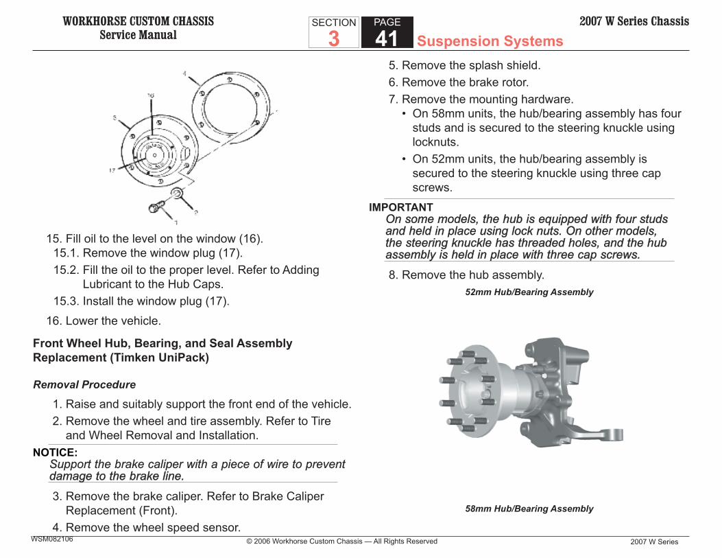
15. Fill oil to the level on the window (16).15.1. Remove the window plug (17).15.2. Fill the oil to the proper level. Refer to Adding
Lubricant to the Hub Caps.15.3. Install the window plug (17).
16. Lower the vehicle.
Front Wheel Hub, Bearing, and Seal Assembly Replacement (Timken UniPack)
Removal Procedure
1. Raise and suitably support the front end of the vehicle. 2. Remove the wheel and tire assembly. Refer to Tire
and Wheel Removal and Installation.NOTICE:
Support the brake caliper with a piece of wire to prevent Support the brake caliper with a piece of wire to prevent damage to the brake line.damage to the brake line.
3. Remove the brake caliper. Refer to Brake Caliper Replacement (Front).
4. Remove the wheel speed sensor.
5. Remove the splash shield. 6. Remove the brake rotor. 7. Remove the mounting hardware.
• On 58mm units, the hub/bearing assembly has four studs and is secured to the steering knuckle using locknuts.
• On 52mm units, the hub/bearing assembly is secured to the steering knuckle using three cap screws.
IMPORTANTOn some models, the hub is equipped with four studs On some models, the hub is equipped with four studs and held in place using lock nuts. On other models, and held in place using lock nuts. On other models, the steering knuckle has threaded holes, and the hub the steering knuckle has threaded holes, and the hub assembly is held in place with three cap screws.assembly is held in place with three cap screws.
8. Remove the hub assembly.52mm Hub/Bearing Assembly
58mm Hub/Bearing Assembly
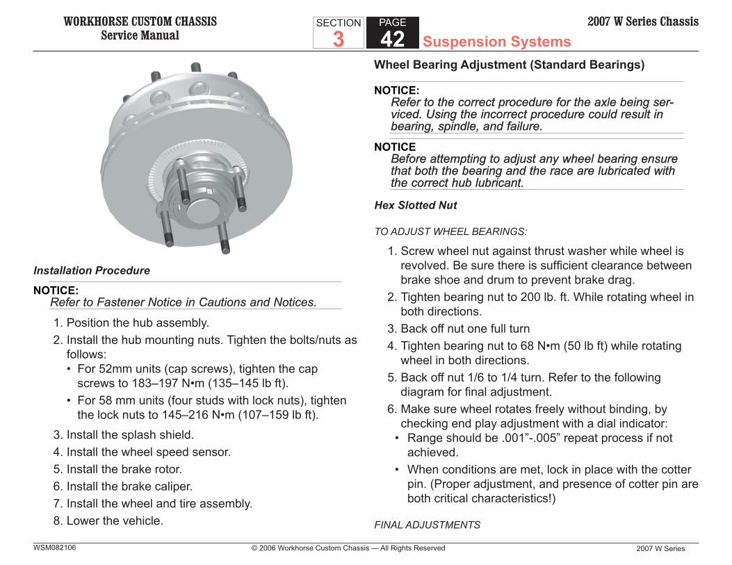
WORKHORSE CUSTOM CHASSISService Manual
2007 W Series
SECTION
3PAGE
42 Suspension Systems2007 W Series Chassis
© 2006 Workhorse Custom Chassis — All Rights ReservedWSM082106
Installation Procedure
NOTICE:Refer to Fastener Notice in Cautions and Notices. Refer to Fastener Notice in Cautions and Notices.
1. Position the hub assembly. 2. Install the hub mounting nuts. Tighten the bolts/nuts as
follows: • For 52mm units (cap screws), tighten the cap
screws to 183–197 N•m (135–145 lb ft). • For 58 mm units (four studs with lock nuts), tighten
the lock nuts to 145–216 N•m (107–159 lb ft). 3. Install the splash shield. 4. Install the wheel speed sensor. 5. Install the brake rotor. 6. Install the brake caliper. 7. Install the wheel and tire assembly. 8. Lower the vehicle.
Wheel Bearing Adjustment (Standard Bearings)
NOTICE:Refer to the correct procedure for the axle being ser-Refer to the correct procedure for the axle being ser-viced. Using the incorrect procedure could result in viced. Using the incorrect procedure could result in bearing, spindle, and failure.bearing, spindle, and failure.
NOTICEBefore attempting to adjust any wheel bearing ensure Before attempting to adjust any wheel bearing ensure that both the bearing and the race are lubricated with that both the bearing and the race are lubricated with the correct hub lubricant.the correct hub lubricant.
Hex Slotted Nut
TO ADJUST WHEEL BEARINGS:
1. Screw wheel nut against thrust washer while wheel is revolved. Be sure there is suffi cient clearance between brake shoe and drum to prevent brake drag.
2. Tighten bearing nut to 200 lb. ft. While rotating wheel in both directions.
3. Back off nut one full turn4. Tighten bearing nut to 68 N•m (50 lb ft) while rotating
wheel in both directions.5. Back off nut 1/6 to 1/4 turn. Refer to the following
diagram for fi nal adjustment.6. Make sure wheel rotates freely without binding, by
checking end play adjustment with a dial indicator: • Range should be .001”-.005” repeat process if not
achieved. • When conditions are met, lock in place with the cotter
pin. (Proper adjustment, and presence of cotter pin are both critical characteristics!)
FINAL ADJUSTMENTS
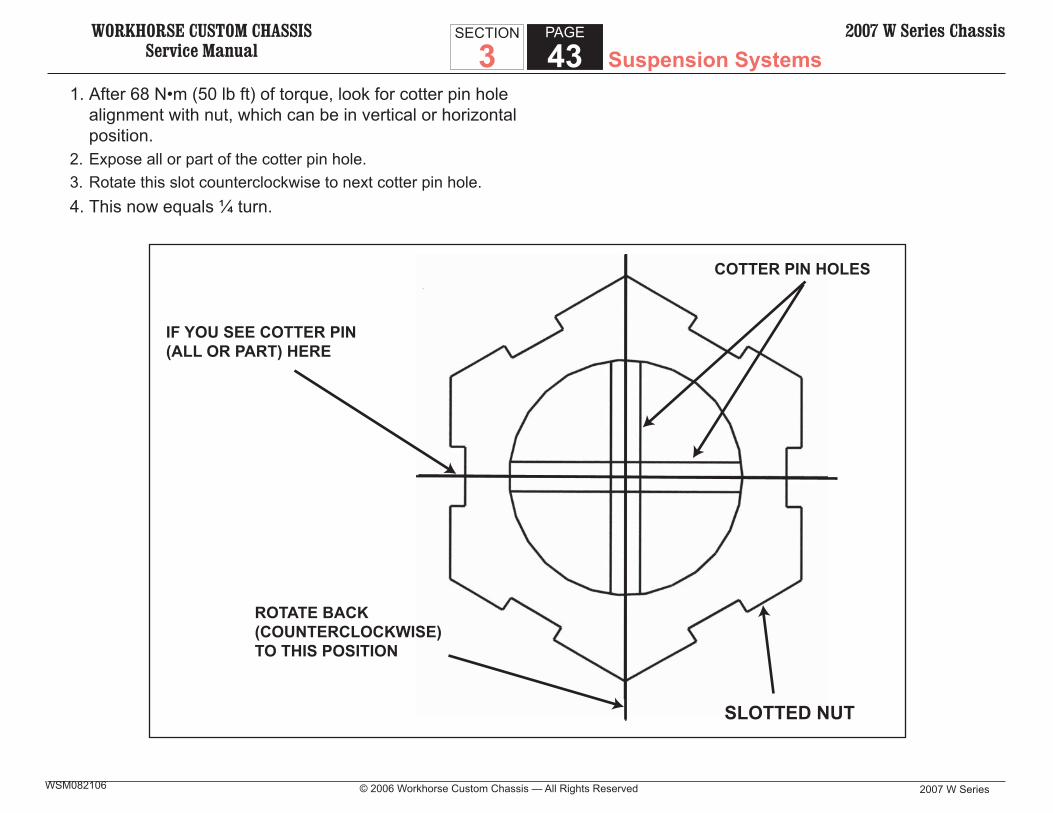
WORKHORSE CUSTOM CHASSISService Manual Suspension Systems
2007 W Series © 2006 Workhorse Custom Chassis — All Rights Reserved
SECTION
3PAGE
432007 W Series Chassis
WSM082106
1. After 68 N•m (50 lb ft) of torque, look for cotter pin hole alignment with nut, which can be in vertical or horizontal position.
2. Expose all or part of the cotter pin hole.3. Rotate this slot counterclockwise to next cotter pin hole.4. This now equals ¼ turn.
IF YOU SEE COTTER PIN(ALL OR PART) HERE
ROTATE BACK(COUNTERCLOCKWISE)TO THIS POSITION
COTTER PIN HOLES
SLOTTED NUT
WORKHORSE CUSTOM CHASSISService Manual
2007 W Series
SECTION
3PAGE
44 Suspension Systems2007 W Series Chassis
© 2006 Workhorse Custom Chassis — All Rights ReservedWSM082106
Wheel Bearing Adjustment
Pro-Torq Nut
NOTICEBefore attempting to adjust any wheel bearing ensure Before attempting to adjust any wheel bearing ensure that both the bearing and the race art lubricated with that both the bearing and the race art lubricated with the correct hub lubricant.the correct hub lubricant.
To adjust wheel bearings1. Remove keeper from nut, a small screwdriver may be
used to pry keeper from the nut2. Seat the bearing
A. Install nut into spindleB. Tighten the nut to 271 N•m (200 lb ft). Spin wheel at
least one full rotationC. Repeat BD. Tighten the nut to 271 N•m (200 lb ft).E. Back the nut off until it is loose
3. Adjust the bearingA. Tighten the nut to 136 N•m (100 lb ft). Spin wheel at
least one full rotation.B. Repeat A.C. Tighten the nut to 136 N•m (100 lb ft).D. Back the nut off one raised face mark, ¼ turn
4. Install KeeperA. Align fl at on keeper with the fl at on the spindle
B. Insert the single keeper tab into the undercut groove of the nut.
C. Orange side of the keeper must face outD. Engage mating teethE. Compress and insert the keeper arms, one at a
time, into the undercut groove of the nut. A small screwdriver may be used
5. Inspect installationA. Make sure the keeper tabs are fully seated into the
undercut of the nut.6. Verify end play.
A. Make sure wheel rotates freely without binding. Check end play with a dial indicator. Range should be between .001” -.003”. Repeat process if not achieved.
7. Warning:A. Do not install nut, loosen nut or tighten nut onto
spindle with keeper in place. Doing so may deform the keeper and allow the nut to unthread during operation
B. Failure to back off nut will cause the bearings to run hot and be damaged
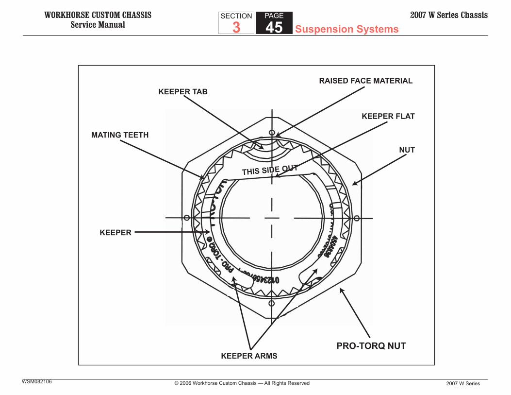
WORKHORSE CUSTOM CHASSISService Manual Suspension Systems
2007 W Series © 2006 Workhorse Custom Chassis — All Rights Reserved
SECTION
3PAGE
452007 W Series Chassis
WSM082106
THIS SIDE OUT
KEEPER TABRAISED FACE MATERIAL
MATING TEETH
KEEPER
KEEPER FLAT
NUT
KEEPER ARMSPRO-TORQ NUT
WORKHORSE CUSTOM CHASSISService Manual
2007 W Series
SECTION
3PAGE
46 Suspension Systems2007 W Series Chassis
© 2006 Workhorse Custom Chassis — All Rights ReservedWSM082106
Installation – Hub/Wheel & Rotor – Oil-Filled Hub
1. For Stemco Guardian seal, apply No. 2 sealant on O.D. of seal surface on the spindle
2. Install seal assembly with the words “Oil bearing side” facing installer. Remove excess sealant.
3. Apply a thin coat of oil to the outer diameter of the seal prior to installation of hub
4. Lubricated inner wheel bearing in oil and install on spindle.
5. Install hub assembly onto spindle. Do not force entirely on.
6. Lubricate outer wheel bearing in oil. Install bearing, thrust washer and nut, or unitized wheel nut on spindle end. Hand tighten to seat assembly.
7. Refer to proper wheel bearing adjustment procedure. 8. Install hub cap and gasket. Torque fasteners as shown
– star pattern. 9. Remove fi ll plug on hub cap, fi ll hub cavity with E.P.
SAE 90 oil (Westport part No. 143699-0018) to fi ll fi ne on hub cap face, -0.0/+.12 re-install fi ll plug.
10. Note! Do not mix petroleum base oil with synthetic base oil!
11. Before assembling wheel equipment make certain the spindle, spindle end thread, cotter pin hole, wheel nut, thrust washer, hub cavity, wheel bearings, and hub cap surface are free of dirt, debris chips, burrs, etc. Contamination can cause premature oil seal and or wheel bearing failure.
Installation- Hub/Wheel & Rotor – Grease-Packed Bearings
1. For Stemco Guardian seal, apply No. 2 sealant on O.D. of seal surface on the spindle
2. Install seal assembly with the words “Oil bearing side” facing installer. Remove excess sealant.
3. Pre-lube steal lip with small amount of grease prior to installation of hub
4. Pressure or hand pack inner and outer wheel bearings with E.P. NLG1 Grade 2 Grease (Westport part No.143699-0002)
5. Install inner wheel bearing on spindle 6. Pump of hand pack grease into hub cavity’s entire
circumference. Fill to level equal to outer bearing cup’s inner diameter.
7. Install hub assembly on to spindle. Do not force entirely on.
8. Install outer bearing, thrust washer, and nut, or unitized wheel nut on end of spindle. Hand tighten to seat assembly.
9. Refer to proper wheel bearing adjustment procedure10. Coat inside surface of metal hub cap with a thin fi lm of
grease. Do not pack!11. Install hub cap, gasket, and fasteners. Torque
fasteners as show – star pattern12. Before assembling wheel equipment make certain the
spindle, spindle end thread, cotter pin hole, wheel nut, thrust washer, hub cavity, wheel bearings, and hub cap surface are free of dirt, debris, chips, burrs, etc. Contamination can cause premature oil seal and or wheel bearing failure.

WORKHORSE CUSTOM CHASSISService Manual Suspension Systems
2007 W Series © 2006 Workhorse Custom Chassis — All Rights Reserved
SECTION
3PAGE
472007 W Series Chassis
WSM082106
Hub Cap Replacement
Removal Procedure
1. Remove the drain plug from the hub cap and allow the oil to drain into a suitable container, then replace the drain plug.
2. Remove the bolts, washers, hub cap, and gasket from the hub.
3. Clean any gasket material from the hub cap and hub.
Installation Procedure
NOTICE:Refer to Fastener Notice in Cautions and Notices.Refer to Fastener Notice in Cautions and Notices.
1. Install the bolts, washers, hub cap, and a new gasket to the hub.
2. Tighten the hub cap mounting bolts evenly to 13 N•m (115 lb in).
3. Fill oil to the level on the window.3.1. Remove the window plug.3.2. Fill the oil to the proper level. Refer to Adding
Lubricant to the Hub Caps in this supplement.3.3. Install the window plug.
Adding Lubricant to the Hub Caps
1. With the vehicle in a level position, the oil level should be at the oil level line.
2. If oil is required, do the following:2.1. Remove the window plug.2.2. Add lubricant until the fl uid is level with the oil level
line. Refer to Fluid and Lubricant Recommendations in this supplement.
2.3. Install the window plug.
Front Stabilizer Shaft Replacement
Removal Procedure
1. Raise the vehicle on a hoist. 2. Remove the nuts and washers from the stabilizer shaft
clamp and the right front leaf spring. 3. Remove the nuts and washers from the stabilizer shaft
clamp and the left front leaf spring, and remove the stabilizer shaft from the vehicle.
4. Remove the clamps from the stabilizer shaft. 5. Remove the insulators from the stabilizer shaft.
Installation Procedure
1. Install the insulators to the stabilizer shaft. 2. Install the clamps to the stabilizer shaft.
NOTICE: Refer to Fastener Notice in Cautions and Notices.Refer to Fastener Notice in Cautions and Notices.
3. Install the washers and nuts to the stabilizer shaft clamp and the left front leaf spring.
4. Install the washers and nuts to the stabilizer shaft clamp and the right front leaf spring.
WORKHORSE CUSTOM CHASSISService Manual
2007 W Series
SECTION
3PAGE
48 Suspension Systems2007 W Series Chassis
© 2006 Workhorse Custom Chassis — All Rights ReservedWSM082106
5. Tighten the stabilizer shaft clamp nuts to 373 N•m (275 lb ft).
6. Lower the vehicle.
Rear Stabilizer Shaft Replacement
Removal Procedure
1. Raise the vehicle on a hoist 2. Remove the nuts and washers from the stabilizer shaft
clamp and the right rear leaf spring. 3. Remove the nuts and washers from the stabilizer shaft
clamp and the left rear leaf spring, and remove the stabilizer shaft from the vehicle.
4. Remove the clamps from the stabilizer shaft. 5. Remove the insulators from the stabilizer shaft.
Installation Procedure
1. Install the insulators to the stabilizer shaft. 2. Install the clamps to the stabilizer shaft.
NOTICE: Refer to Fastener Notice in Cautions and Notices.Refer to Fastener Notice in Cautions and Notices.
3. Install the washers and nuts to the stabilizer shaft clamp and the left rear leaf spring.
4. Install the washers and nuts to the stabilizer shaft clamp and the right rear leaf spring.
5. Tighten the stabilizer shaft clamp nuts to 373 N•m (275 lb ft).
6. Lower the vehicle.
Steering Knuckle/King Pin Replacement
Removal Procedure
1. Raise and support the vehicle. 2. Remove the tire and wheel assembly. Refer to Tire
and Wheel Removal and Installation. 3. Remove the brake caliper. Refer to Brake Caliper
Replacement (Front). 4. Remove the hub/rotor assembly. Refer to Wheel Hub,
Bearing, and Seal Replacement. 5. Disconnect the wheel speed sensor from the torque
plate. 6. Remove the torque plate and the splash shield (if
equipped). 7. Disconnect the steering arm from the steering knuckle.
7.1 Remove the cotter pin.7.2 Loosen and remove the slotted nut.7.3 Strike the steering arm with a hammer to break the
steering arm loose from the steering knuckle. 8. Disconnect the tierod arm from the steering knuckle.
8.1 Remove the cotter pin.8.2 Loosen and remove the slotted nut.8.3 Strike the tierod arm with a hammer to break the
tierod arm loose from the steering knuckle. 9. Disconnect the brake hose bracket.10. Remove the brake hose bracket.11. Remove the caps from the ends of the king pin in the
steering knuckle.12. Remove the nut and washer from the lock pin and
remove the lock pin.

WORKHORSE CUSTOM CHASSISService Manual Suspension Systems
2007 W Series © 2006 Workhorse Custom Chassis — All Rights Reserved
SECTION
3PAGE
492007 W Series Chassis
WSM082106
13. Remove the king pin from the steering knuckle,13.1 Drive out the king pin using a drift.13.2 The spacers and the bushings will also come out.
14. Remove the steering knuckle from the axle.15. Remove the king pin seals, the thrust bearing, and the
shims from the axle.16. Remove the bushings from the steering knuckle.

WORKHORSE CUSTOM CHASSISService Manual
2007 W Series
SECTION
3PAGE
50 Suspension Systems2007 W Series Chassis
© 2006 Workhorse Custom Chassis — All Rights ReservedWSM082106
Legend: 1. Lock pin nut 2. Lock pin 3. Shims 4. King pin seal 5. Front axle 6. Lock pin nut 7. Lock pin 8. Thrust bearing 9. King pin seal10. Steering arm
11. Steering arm woodruff key12. Tierod arm slotted nut13. Cotter pin14. Tierod15. Tierod end adjustment clamp16. Tierod end17. Tierod arm18. Tierod arm woodruff key19. Kingpin cap20. Kingpin bushing21. Steering knuckle22. Tierod arm slotted nut23. Cotter pin24. Steering arm slotted nut25. Cotter pin26. Kingpin bushing27. Kingpin28. Kingpin cap

WORKHORSE CUSTOM CHASSISService Manual Suspension Systems
2007 W Series © 2006 Workhorse Custom Chassis — All Rights Reserved
SECTION
3PAGE
512007 W Series Chassis
WSM082106
Installation Procedure
1. Position the steering knuckle. 2. Install the thrust bearing, the shim, and the dust
seal. Make sure dust seal is facing outward toward I-beam. Prelube the thrust bearing. Refer to Fluid and Lubricant Recommendations in Maintenance and Lubrication.
3. Install the king pin and the lock pin. 3.1. Prelube the king pin. 3.2. Insert the spacers in the proper order.
4. Install the grease cap on each end of the king pin. Tighten the caps to 88-129 N•m (65-95 lb. ft).
5. Install the lock pin, washer, and nut. Tighten the nut to 68-85 N•m (50-63 lb. ft.).
6. Position the brake hose bracket. Install the washer and bolts. Tighten the bolts to 7 N•m (60 lb in).
7. Make sure the woodruff key is installed in the keyway of the steering arm.
8. Insert the end of the steering arm into the steering arm hole in the steering knuckle. Line up the woodruff key with the slot in the steering knuckle.
9. Install the slotted nut on the steering arm. Tighten the nut to 407-475 N•m (300-350 lb. ft.).
10. Make sure the woodruff key is installed in the keyway of the tierod arm.
11. Insert the end of the tierod arm into the tierod arm hole in the steering knuckle. Line up the woodruff key with the slot in the steering knuckle.
12. Install the slotted nut on the tierod arm. Tighten the nut to 407-475 N•m (300-350 lb. ft.).
13. Install the splash shield (if equipped) and the anchor plate. Install the washers and bolts. Tighten the splash shield bolts to 16 N•m (12 lb ft). Tighten the anchor plate bolts to 16 N•m (12 lb ft).
14. Install the hub/rotor assembly, Refer to Wheel Hub, Bearing, and Seal Replacement.
15. Adjust the wheel bearings. Refer to Wheel Bearing Adjustment.
16. Install the caliper. Refer to Brake Caliper Replacement (Front).
17. Install the tire and wheel assembly. Refer to Tire and Wheel Removal and Installation.
18. Lower the vehicle.19. Check the front wheel alignment. Refer to Wheel
Alignment Specifi cations.

WORKHORSE CUSTOM CHASSISService Manual
2007 W Series
SECTION
3PAGE
52 Suspension Systems2007 W Series Chassis
© 2006 Workhorse Custom Chassis — All Rights ReservedWSM082106
Shock Absorber Replacement
REMOVAL PROCEDURE
1. If necessary, raise and support the vehicle. 2. Remove the nut and washer from the lower shock
absorber mounting bolt or stud. 3. Depending on the type of shock absorber, do the
following: • Remove the lower shock absorber mounting bolt
and washer. or • Slightly compress the shock so the mounting stud
can be pulled free from the lower shock mount. 4. Depending on the type of shock absorber, do the
following: • While holding the shock absorber, remove the upper
shock absorber mounting nut and washer. or • Remove the nut and washer from the upper shock
absorber mounting stud. 5. Remove the shock absorber.
Front Shock Mounts
Rear Shock Mounts (13.5K Rear Axle Shown)

WORKHORSE CUSTOM CHASSISService Manual Suspension Systems
2007 W Series © 2006 Workhorse Custom Chassis — All Rights Reserved
SECTION
3PAGE
532007 W Series Chassis
WSM082106
Rear Shock Mounts (15K Rear Axle Shown)
Installation Procedure
1. Position the shock absorber so the upper shock mounting hole is lined up with the holes in the upper shock mount.
2. Install the upper shock mount bolt, washer, and nut. Tighten the nut to 203 N•m (150 lb ft)
3. Position the shock absorber so the lower shock mounting hole is lined up with the hole in the lower shock mount.
4. Install the lower shock absorber mounting bolt, washer, and nut. Tighten the lower shock absorber mounting nut to 203 N•m (150 lb ft).
5. Lower the vehicle.
Like-Air Auxiliary Spring Replacement
Removal Procedure
1. If necessary, raise and support the vehicle. 2. Remove the nut and washer from the Like-Air Auxiliary
Spring mounting bolt. 3. Remove the Like-Air Auxiliary Spring.
Installation Procedure
1. Position the Like-Air Auxiliary Spring. 2. Install the washer and nut on the Like-Air Auxiliary
Spring mounting bolt. 3. Tighten the nut to 41 N•m (30 lb ft).
Front Leaf Spring Replacement
Removal Procedure 1. Lift and support the front of the vehicle by the frame
rails. 2. Place a support under each end of the front axle, just
inside of the U-bolts. This is done to eliminate any load on the springs.
3. Remove the tire/wheel assembly on the side where the spring is being removed.
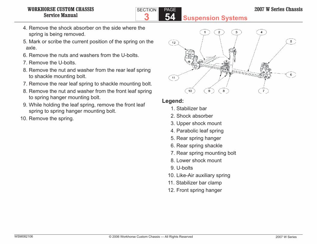
WORKHORSE CUSTOM CHASSISService Manual
2007 W Series
SECTION
3PAGE
54 Suspension Systems2007 W Series Chassis
© 2006 Workhorse Custom Chassis — All Rights ReservedWSM082106
4. Remove the shock absorber on the side where the spring is being removed.
5. Mark or scribe the current position of the spring on the axle.
6. Remove the nuts and washers from the U-bolts. 7. Remove the U-bolts. 8. Remove the nut and washer from the rear leaf spring
to shackle mounting bolt. 7. Remove the rear leaf spring to shackle mounting bolt. 8. Remove the nut and washer from the front leaf spring
to spring hanger mounting bolt. 9. While holding the leaf spring, remove the front leaf
spring to spring hanger mounting bolt.10. Remove the spring.
Legend: 1. Stabilizer bar 2. Shock absorber 3. Upper shock mount 4. Parabolic leaf spring 5. Rear spring hanger 6. Rear spring shackle 7. Rear spring mounting bolt 8. Lower shock mount 9. U-bolts10. Like-Air auxiliary spring11. Stabilizer bar clamp12. Front spring hanger

WORKHORSE CUSTOM CHASSISService Manual Suspension Systems
2007 W Series © 2006 Workhorse Custom Chassis — All Rights Reserved
SECTION
3PAGE
552007 W Series Chassis
WSM082106
Installation Procedure
1. If a new spring is being installed, lay it on a bench side-by-side with the spring that was just removed. Transfer the marks that were made on the old spring in Step 3 of the removal procedure to the new spring.
2. Position the leaf spring on the axle. 3. Install a washer on the front and rear leaf spring
mounting bolts. 4. Line up the front of the spring with the front leaf spring
hanger and insert the mounting bolt. 5. Install the washer and nut on the front leaf spring
mounting bolt. DO NOT tighten at this time. 6. Line up the rear of the spring with the rear leaf spring
shackle and insert the mounting bolt. 7. Install the washer and nut on the rear leaf spring to
shackle mounting bolt. DO NOT tighten at this time. 7. Install the U-bolts. 8. Install the washers and nuts on the U-bolts. DO NOT
tighten at this time. 9. Check the alignment of all of the components. Adjust
as needed.10. Tighten the nuts/bolts:
• Tighten the front leaf spring to spring hanger nuts/bolts to 275 N•m (203 lb ft).
• Tighten the rear leaf spring to shackle nuts/bolts to 275 N•m (203 lb ft).
• Tighten the U-bolt nuts to 190 N•m (140 lb ft).
Rear Leaf Spring Replacement
Removal Procedure 1. Lift and support the front of the vehicle by the frame
rails. 2. Place a support under each end of the front axle, just
inside of the U-bolts. This is done to eliminate any load on the springs.
3. Remove the tire/wheel assembly on the side where the spring is being removed.
4. Remove the shock absorber on the side where the spring is being removed.
5. Mark or scribe the current position of the spring on the axle.
6. Remove the nuts and washers from the U-bolts. 7. Remove the U-bolts. 8. Remove the nut and washer from the rear leaf spring
to shackle mounting bolt. 7. Remove the rear leaf spring to shackle mounting bolt. 8. Remove the nut and washer from the front leaf spring
to spring hanger mounting bolt. 9. While holding the leaf spring, remove the front leaf
spring to spring hanger mounting bolt.10. Remove the spring.
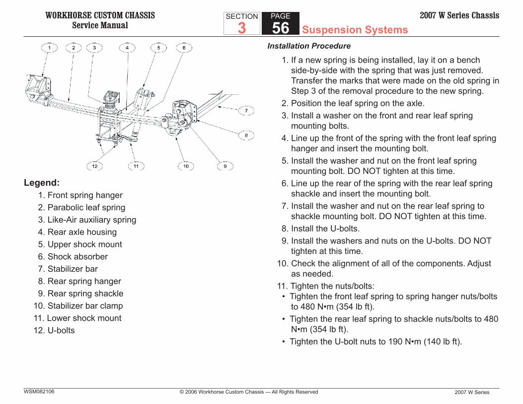
WORKHORSE CUSTOM CHASSISService Manual
2007 W Series
SECTION
3PAGE
56 Suspension Systems2007 W Series Chassis
© 2006 Workhorse Custom Chassis — All Rights ReservedWSM082106
Legend: 1. Front spring hanger 2. Parabolic leaf spring 3. Like-Air auxiliary spring 4. Rear axle housing 5. Upper shock mount 6. Shock absorber 7. Stabilizer bar 8. Rear spring hanger 9. Rear spring shackle10. Stabilizer bar clamp11. Lower shock mount12. U-bolts
Installation Procedure
1. If a new spring is being installed, lay it on a bench side-by-side with the spring that was just removed. Transfer the marks that were made on the old spring in Step 3 of the removal procedure to the new spring.
2. Position the leaf spring on the axle. 3. Install a washer on the front and rear leaf spring
mounting bolts. 4. Line up the front of the spring with the front leaf spring
hanger and insert the mounting bolt. 5. Install the washer and nut on the front leaf spring
mounting bolt. DO NOT tighten at this time. 6. Line up the rear of the spring with the rear leaf spring
shackle and insert the mounting bolt. 7. Install the washer and nut on the rear leaf spring to
shackle mounting bolt. DO NOT tighten at this time. 8. Install the U-bolts. 9. Install the washers and nuts on the U-bolts. DO NOT
tighten at this time.10. Check the alignment of all of the components. Adjust
as needed.11. Tighten the nuts/bolts:
• Tighten the front leaf spring to spring hanger nuts/bolts to 480 N•m (354 lb ft).
• Tighten the rear leaf spring to shackle nuts/bolts to 480 N•m (354 lb ft).
• Tighten the U-bolt nuts to 190 N•m (140 lb ft).

WORKHORSE CUSTOM CHASSISService Manual Suspension Systems
2007 W Series © 2006 Workhorse Custom Chassis — All Rights Reserved
SECTION
3PAGE
572007 W Series Chassis
WSM082106
Front Axle Replacement
Removal Procedure
1. Lift and support the front of the vehicle by the frame rails.
2. Place a support under each end of the front axle, just inside of the U-bolts. This is done to eliminate any load on the springs.
3. Remove the front tire/wheel assemblies. 4. Remove the shock absorbers. 5. Mark or scribe the current position of the spring on the
axle. 6. Remove the nuts and washers from the U-bolts. 7. Remove the U-bolts. 8. Remove the front axle from the vehicle.
Installation Procedure
1. If a new front axle is being installed, place the old axle next to the new axle and transfer the spring position to the new axle.
2. Position the new axle under the leaf springs and place supports under the axle.
3. Install the U-bolts. 4. Install the washers and nuts on the U-bolts. DO NOT
tighten at this time. 5. Check the alignment of the axle with the springs.
Adjust as necessary to make sure they are square. 6. Tighten the nuts on the U-bolts to 190 N•m (140 lb ft).. 7. Install the shock absorbers. 8. Install the tire/wheel assemblies. 9. Remove the supports from under the front axle.10. Lower the vehicle.11. Check the wheel alignment.
WORKHORSE CUSTOM CHASSISService Manual
2007 W Series
SECTION
3PAGE
58 Suspension Systems2007 W Series Chassis
© 2006 Workhorse Custom Chassis — All Rights ReservedWSM082106
TIRE AND WHEEL REPAIRS
Tire and Wheel Removal and Installation
CAUTION:If penetrating oil gets on the vertical surfaces between the wheel and the rotor or drum it could cause the wheel to work loose as the vehicle is driven, resulting in loss of control and an injury accident.
NOTICE: Never use heat to loosen a tight wheel. It can shorten Never use heat to loosen a tight wheel. It can shorten the life of the wheel, studs, or hub and bearing assem-the life of the wheel, studs, or hub and bearing assem-blies. Wheel nuts must be tightened in sequence and to blies. Wheel nuts must be tightened in sequence and to the specified torque to avoid bending the wheel or rotor.the specified torque to avoid bending the wheel or rotor.Penetrating oil is not effective in removing tight wheels. Penetrating oil is not effective in removing tight wheels. However, if used, apply the penetrating oil sparingly to However, if used, apply the penetrating oil sparingly to the hub surface only.the hub surface only.Excessive force, such as hammering the wheel or the Excessive force, such as hammering the wheel or the tire, may cause damage. Lightly tap the tire’s sidewall tire, may cause damage. Lightly tap the tire’s sidewall with a rubber mallet.with a rubber mallet.
NOTICESometimes wheels can be difficult to remove from the Sometimes wheels can be difficult to remove from the vehicle due to foreign material or a tight fit between the vehicle due to foreign material or a tight fit between the wheel center hole and the hub or rotor. Use the follow-wheel center hole and the hub or rotor. Use the follow-ing procedure to safely remove the wheel:ing procedure to safely remove the wheel:
1. Tighten all of the wheel nuts on the affected wheel. 2. Loosen each wheel nut two turns. 3. Lower the vehicle onto the fl oor. 4. Rock the vehicle from side to side as hard as possible
using one or more person’s body weight to loosen the wheel.
5. Rock the vehicle from Drive gear to Reverse gear allowing the vehicle to move several feet in each direction. Apply quick, hard jabs on the brake pedal in order to loosen the wheel.
Removal Procedure
CAUTION: To avoid eye injury, use approved safety lenses, goggles, or face shield to prevent eye injury when deflating tires.
IMPORTANT: When removing and demounting any tire and wheel When removing and demounting any tire and wheel assembly, deflate the tire by removing the valve core. assembly, deflate the tire by removing the valve core. Perform this procedure before removing the tire assem-Perform this procedure before removing the tire assem-bly from the vehicle.bly from the vehicle.
1. Break the wheel nuts loose. 2. Raise the vehicle until the tire clears the fl oor. Support
the vehicle. Refer to Lifting and Jacking the Vehicle in General Information.
3. Remove the wheel nuts. 4. Remove the wheel from the hub. 5. Clean the following components:
• Clean the wheel nuts.• Clean the studs.• Clean the wheel.• Clean the rotor mounting surfaces.
WORKHORSE CUSTOM CHASSISService Manual Suspension Systems
2007 W Series © 2006 Workhorse Custom Chassis — All Rights Reserved
SECTION
3PAGE
592007 W Series Chassis
WSM082106
Installation Procedure
CAUTION: Before installing the wheels, remove any buildup of corrosion on the wheel mounting surface and brake drum or disc mounting sur-face by scraping and wire brushing. Installing wheels with poor metal-to-metal contact at the mounting surfaces can cause wheel nuts to loosen. This can cause a wheel to come off when the vehicle is moving, causing loss of control and possibly personal injury.
NOTICE: Wheel hub flanges, wheel studs, and stud nuts should Wheel hub flanges, wheel studs, and stud nuts should be free of rust, lubricants, dirt, and finish color paint on be free of rust, lubricants, dirt, and finish color paint on all contact surfaces to ensure proper torque retention.all contact surfaces to ensure proper torque retention.
1. Apply a thin coat of grease to the hub pads in order to prevent corrosion.
2. Turn the hub so that a hub pad is at a 12 o’clock position.
3. Install the wheel on the hub.IMPORTANT:
Perform steps 4 and 5 for dual wheel applications only. Perform steps 4 and 5 for dual wheel applications only. For single wheel applications proceed to step 6.For single wheel applications proceed to step 6.
4. Install the inner wheel on the hub. 5. Install the outer wheel on the hub with the valve stems
of both wheels positioned as close to 180 degrees as possible.
IMPORTANT: Tighten the wheel nuts progressively using the first Tighten the wheel nuts progressively using the first specification; then retighten the nuts using the second specification; then retighten the nuts using the second specification.specification.
NOTICE: A torque wrench or J 39544 must be used to ensure A torque wrench or J 39544 must be used to ensure that wheel nuts are tightened to specification.that wheel nuts are tightened to specification.Never use lubricants or penetrating fluids on wheel Never use lubricants or penetrating fluids on wheel stud, nuts, or mounting surfaces, as this can raise the stud, nuts, or mounting surfaces, as this can raise the actual torque on the nut without a corresponding torque actual torque on the nut without a corresponding torque reading on the torque wrench. Wheel nuts, studs, and reading on the torque wrench. Wheel nuts, studs, and mounting surfaces must be clean and dry.mounting surfaces must be clean and dry.Failure to follow these instructions could result in wheel, Failure to follow these instructions could result in wheel, nut, and/or stud damage.nut, and/or stud damage.
NOTICE: Refer to fastener Notice in Cautions and Notices.Refer to fastener Notice in Cautions and Notices.
6. Install the wheel nuts. 7. Tighten the wheel nuts to specifi cations. Refer to
Fastener Tightening Specifi cations. Tighten the wheel nuts evenly and alternately in order to avoid excessive runout.
Tire Mounting and Dismounting
NOTICE:Use a tire changing machine in order to dismount tires. Use a tire changing machine in order to dismount tires. Do not use hand tools or tire irons alone in order to Do not use hand tools or tire irons alone in order to remove the tire from the wheel. Damage to the tire remove the tire from the wheel. Damage to the tire beads or the wheel rim could result.beads or the wheel rim could result.
NOTICE: It is important to note that damage to either the tire It is important to note that damage to either the tire mounting surface or the wheel mounting holes can mounting surface or the wheel mounting holes can result from the use of improper wheel attachment or tire result from the use of improper wheel attachment or tire mounting techniques. It takes 70 seconds for all the air mounting techniques. It takes 70 seconds for all the air to completely exhaust from a large tire. Failure to fol-to completely exhaust from a large tire. Failure to fol-low proper procedures could cause the tire changer to low proper procedures could cause the tire changer to put enough force on the tire to bend the wheel at the put enough force on the tire to bend the wheel at the mounting surface. Such damage may result in vibration mounting surface. Such damage may result in vibration and/or shimmy and under severe usage lead to crack-and/or shimmy and under severe usage lead to crack-ing.ing.
WORKHORSE CUSTOM CHASSISService Manual
2007 W Series
SECTION
3PAGE
60 Suspension Systems2007 W Series Chassis
© 2006 Workhorse Custom Chassis — All Rights ReservedWSM082106
Follow the tire changing machine manufacturer’s Follow the tire changing machine manufacturer’s instructions in order to properly separate the tire from instructions in order to properly separate the tire from the wheel.the wheel.
Bias Ply Tire Mounting Procedure
1. Clean the tire bead area. 2. Clean the rim bead seats with a wire brush or coarse
steel wool in order to remove lubricants, old rubber, and light rust.
3. Apply an approved tire lubricant to the tire bead area. 4. Attach the tire to the wheel.
• Use a tire changing machine.• Follow the equipment manufacturer’s instructions.
CAUTION: To avoid serious personal injury, do not stand over tire when inflating. The bead may break when the bead snaps over the safety hump. Do not exceed 275 kPa (40 psi) pres-sure when inflating any tire if beads are not seated. If 275 kPa (40 psi) pressure will not seat the beads, deflate, relubricate the beads and reinflate. Overinflation may cause the bead to break and cause serious personal injury.
5. Install a valve core. Infl ate the tire to the specifi ed pressure on the certifi cation label.
• The locating rings on each side of the tire must show above the rim fl anges.
• Position the rings in direct relation to the wheel, not off-center as compared to the rim.
6. Check the bead seating. Mount and infl ate the tires in accordance with the safety precautions included with the tire mounting equipment.
Radial Ply Tire Mounting Procedure
NOTICE: Failure to follow radial tire inflation procedures can Failure to follow radial tire inflation procedures can cause bead deformation in both tube and tubeless tires cause bead deformation in both tube and tubeless tires due to incorrect bead seating.due to incorrect bead seating.
Tubeless Tire Mounting Procedure
NOTICE: The use of tubes in tubeless tires is not a recommend-The use of tubes in tubeless tires is not a recommend-ed repair due to the fact that speed ratings are greatly ed repair due to the fact that speed ratings are greatly reduced.reduced.
IMPORTANT: Only use rims approved for radial tire usage by the rim Only use rims approved for radial tire usage by the rim manufacturer.manufacturer.
1. Clean the rim. Remove all rust and foreign material.NOTICE:
Do not use silicone base lubricants-this could cause the Do not use silicone base lubricants-this could cause the tire to slip on the wheel.tire to slip on the wheel.
2. Lubricate the tire beads and the rim bead seats with an approved rubber lubricant.

WORKHORSE CUSTOM CHASSISService Manual Suspension Systems
2007 W Series © 2006 Workhorse Custom Chassis — All Rights Reserved
SECTION
3PAGE
612007 W Series Chassis
WSM082106
3. Infl ate the tire to the recommended pressure. • Because of the construction of radial truck tires,
particularly in the lower sidewall and bead area, diffi culty may occur in getting the tire to take air.
• An infl ation aid may be necessary in order to help seat the bead of radial tubeless tires. The following are two types of infl ation aids commercially available:
• Metal rings that use compressed air to seat the beads.
• Rubber rings that seal between the tire bead and the rim bead seat, allowing the bead to move out and seat.
• Lubrication is necessary with both aids.IMPORTANT:
In order to prevent bead deformation, follow this proce-In order to prevent bead deformation, follow this proce-dure to insure proper bead seating.dure to insure proper bead seating.Mount and inflate radial and bias tires in accordance Mount and inflate radial and bias tires in accordance with safety precautions noted in RMA Radial and Bias with safety precautions noted in RMA Radial and Bias Truck Tire Service Manuals.Truck Tire Service Manuals.
4. Check the spacing between the rim fl ange and one of the three rings of the lower sidewall rim line, while the tire is laying fl at, in order to verify bead seating.
• Measure each 90 degrees around the circumference of the rim fl ange.
• If the spacing is uneven around the bead from side to side, repeat Steps 1 through 3, then recheck.
Tire Rotation
In order to equalize wear, rotate the tires at the specifi ed intervals. Refer to Maintenance Schedule in Maintenance and Lubrication. In addition to scheduled rotation, rotate the tire and wheel assembly whenever uneven tire wear is found.Radial tires tend to wear faster in the shoulder area, particularly in front positions, due to design. Radial tires in non-drive locations may develop an irregular wear pattern that can generate tire noise. This especially makes regular tire rotation necessary.
For vehicles with single rear wheels (four tires), rotate the tires as shown.

WORKHORSE CUSTOM CHASSISService Manual
2007 W Series
SECTION
3PAGE
62 Suspension Systems2007 W Series Chassis
© 2006 Workhorse Custom Chassis — All Rights ReservedWSM082106
For vehicles with single rear wheels (fi ve tires), rotate the tires as shown.
For vehicles with dual rear wheels (same tire sizes and load ranges), rotate the tires as shown.
For vehicles with dual rear wheels (different tire sizes and load ranges), rotate the tires as shown.
WHEEL ALIGNMENT ADJUSTMENTS
The only adjustment available on the front end alignment is the Toe setting.
Front Toe Adjustment
1. Determine the toe settings using the alignment equipment.
2. Change the length of both of the tie rod sleeves in order to effect a toe change.
3. Increase or decrease by changing the length of the tie rod ends. A threaded sleeve is provided for this purpose.