2007 volvo s40 - just give me the damn manual
TRANSCRIPT

2 0 0 7 VOLVO
S40
VOLVO OWNER'S MANUAL S40
1
Welcome to the worldwide family of Volvo owners. We hope that you will enjoy manyyears of safe driving in your Volvo, an automobile designed with your safety andcomfort in mind. To help ensure your satisfaction with this vehicle, we encourage youto familiarize yourself with the equipment descriptions, operating instructions andmaintenance requirements/recommendations in this manual. We also urge you andyour passengers to wear seat belts at all times in this (or any other) automobile. And,of course, please do not operate a vehicle if you may be affected by alcohol,medication or any impairment that could hinder your ability to drive.
Your Volvo is designed to meet all applicable safety and emission standards, asindicated by the certification labels attached to the driver's door opening, and on theunderside of the hood.
For further information please contact your retailer, or:
In the USA: Volvo Cars of North America, LLCCustomer Care CenterP.O. Box 914 Rockleigh, New Jersey 07647-09141-800-458-1552www.volvocars.us

In Canada: Volvo Cars of Canada Corp.National Customer Service175 Gordon Baker RoadNorth York, Ontario M2H 2N71-800-663-8255www.volvocanada.com
2006 © Volvo Car Corporation. All rights reserved.
2 Contents
00 IntroductionGeneral information 6Volvo and the environment 7Important warnings 9
01 SafetyOccupant safety 12Seat belts 14Supplemental Restraint System 17Front airbags 18Occupant Weight Sensor (OWS) 21Side impact protection airbags 24Volvo Inflatable Curtain (VIC) 25Whiplash Protection System 27Crash mode 29Child safety 30Child restraint systems 33Infant seats 35Convertible seats 37Booster cushions 40ISOFIX lower anchors 41Top tether anchors 42
02 Instrument and controlsInstrument overview 46Instrument panel 49Indicator and warning symbols 51Symbols - instrument panel 52Information display 55Center console controls 57Lighting panel 58Left-side steering wheel lever 60Trip computer 61Cruise control 63Right-side steering wheel lever 64Rain sensor 65Steering wheel adjustment, Hazardwarning flashers 66
Parking brake 67Power windows 68Mirrors 70Power moonroof (option) 72

Personal settings 74Home Link® UniversalTransceiver (option) 76
3 Contents
03 ClimateGeneral information 82Air vents 84Manual climate control 85Electronic Climate Control (ECC) -option 87
Air distribution 90
04 InteriorFront seats 94Interior lighting 97Storage compartments 99Rear seat 101Trunk 103
05 Locks and alarmRemote control and key blade 106Valet locking 110Keyless drive (option asavailable) 112
Locking and unlocking 115Locking the glove compartment,Child safety locks 116
Alarm 117
4 Contents
06 Starting and drivingGeneral information 122Fuel requirements 125Starting the vehicle 129Starting the car with keyless drive(option as available) 131
Manual transmission, 5-speed 133Manual transmission, 6-speed 134Automatic transmission 135Shiftlock override 138All Wheel Drive (option) 139Brake system 140Stability system 142Towing 144Jump starting 146Towing a trailer 147Detachable trailer hitch 149Transporting loads 150
07 Wheel and tiresGeneral information 154Tire inflation 156Tire designations 160Glossary of tire terminology 162Vehicle loading 163Uniform tire quality gradings 165Snow chains, snow tires, studdedtires 166
Temporary spare 167Wheel nuts 168Tire rotation 169Changing a wheel 170
08 Car careWashing and cleaning the car 176Paint touch up 180
5 Contents

09 Maintenance and servicingVolvo maintenance 184Maintaining your car 185Hood and engine compartment 187Engine oil 189Fluids 190Wiper blades 192Battery 193Bulbs 195Replacing front bulbs 196Replacing taillight bulbs 200Replacing interior bulbs 201Fuses 202
10 AudioAudio functions 210Radio functions 213Sirius satellite radio (option orretailer-installed accessory) 215
CD player/CD changer (option) 219Audio menu 223
11 SpecificationsLabel information 226Dimensions and weights 228Engine oil 231Engine specifications 233Electrical system 234Volvo programs 236
6 01 Safety
General information
Shiftlock (automatic transmission)When your car is parked, the gear selector is locked in the Park (P) position. To release the selector from this position,turn the ignition key to position II (or start the engine), depress the brake pedal, press the button on the front side of thegear selector and move the selector from Park (P).
Keylock (automatic transmission)When the ignition is switched off, the gear selector must be in the Park (P) position before the key can be removedfrom the ignition switch.
Anti-lock Brake System (ABS)The ABS system in your car performs a selfdiagnostic test when the vehicle first reaches the speed of approximately12 mph (20 km/h). The brake pedal will pulsate several times and a sound may be audible from the ABS controlmodule. This is normal.
Fuel filler doorPress the button on the light switch panel when the car is at a standstill to open the fuel filler door.
Fuel filler capAfter refueling, close the fuel filler cap by turning it clockwise until it clicks into place. If this cap is not closed tightlyor if the engine is running when the car is refueled, the Malfunction Indicator Lamp ("Check Engine" light) mayindicate a fault.
Points to keep in mind
Before you operate your vehicle for the first time, please familiarize yourself with the new-engine oil consumptioninformation on page 189. You should also be familiar with the information found in the chapters "Instruments andcontrols," and "Starting and driving."
Information contained in the balance of the manual is extremely useful and should be read after operating thevehicle for the first time.
The manual is structured so that it can be used for reference. For this reason, it should be kept in the vehicle for

ready access. Do not export your Volvo to another country before investigating that country's applicable safety and emission
control requirements. In some cases it may be difficult or impossible to comply with these requirements. Modificationsto the emission control system(s) may render your Volvo not certifiable for legal operation in the U.S., Canada andother countries.
All information, illustrations and specifications contained in this manual are based on the latest product informationavailable at the time of publication. Please note that some vehicles may be equipped differently, depending on speciallegal requirements. Optional equipment described in this manual may not be available in all markets.
Volvo reserves the right to make model changes at any time, or to change specifications or design without noticeand without incurring obligation.
WARNING
If your vehicle is involved in an accident, unseen damage may affect its driveability and safety.
WARNING
CALIFORNIA proposition 65 Engine exhaust, some of its constituents, and certain vehicle components contain or emit chemicals known to thestate of California to cause cancer, and birth defects or other reproductive harm. In addition, certain fluids containedin vehicles and certain products of component wear contain or emit chemicals known to the State of California tocause cancer, and birth defects or other reproductive harm.
7 01 Safety
Volvo and the environment
Volvo is committed to the well being of its customers. As a natural part of this commitment, we care about theenvironment in which we all live. Caring for the environment means an everyday involvement in reducing ourenvironmental impact. Volvo's environmental activities are based on a holistic view, which means we consider theoverall environmental impact of a product throughout its complete life cycle. In this context, design, production,product use, and recycling are all important considerations. In production, Volvo has partly or completely phased outseveral chemicals including CFCs, lead chromates, asbestos, and cadmium; and reduced the number of chemicals usedin our plants 50% since 1991.
Volvo was the first in the world to introduce into production a three-way catalytic converter with a Lambda sond, nowcalled the heated oxygen sensor, in 1976. The current version of this highly efficient system reduces emissions ofharmful substances (CO, HC, NOx) from the exhaust pipe by approximately 95-99% and the search to eliminate theremaining emissions continues. Volvo is the only automobile manufacturer to offer CFCfree retrofit kits for the airconditioning system of all models as far back as the 1975 model 240. Advanced electronic engine controls and cleanerfuels are bringing us closer to our goal. After Volvo vehicles and parts have fulfilled their use, recycling is the nextcritical step in completing the life cycle. The metal content is about 75% of the total weight of a vehicle, which makesthe vehicle among the most recycled industrial products. In order to have efficient and well controlled recycling, allVolvo variants have printed dismantling manuals, indicating the weight and material of individual components. ForVolvo, all homogeneous plastic parts weighing more than 3.4 oz. (100 grams) are marked with international symbolsthat indicate how the component is to be sorted for recycling. In addition to continuous environmental refinement ofconventional gasoline-powered internal combustion engines, Volvo is actively looking at advanced technologyalternative-fuel vehicles.
When you drive a Volvo, you become our partner in the work to lessen the car's impact on the environment. To reduceyour vehicle's environmental impact, you can:

Maintain proper air pressure in your tires. Tests have shown decreased fuel economy with improperly inflated tires. Follow the recommended maintenance schedule in your Warranty and Service Records Information booklet. Drive at a constant speed whenever possible. See a trained and qualified Volvo service technician as soon as possible for inspection if the check engine
(malfunction indicator) light illuminates, or stays on after the vehicle has started. Properly dispose of any vehicle-related waste such as used motor oil, used batteries, brake pads, etc. When cleaning your vehicle, please use genuine Volvo car care products. All Volvo car care products are
formulated to be environmentally friendly.
WARNING
Certain components of this vehicle such as air bag modules, seat belt pretensioners, adaptive steering columns, andbutton cell batteries may contain Perchlorate material. Special handling may apply for service or vehicle end of lifedisposal. See www.dtsc.ca.gov/hazardouswaste/perchlorate.
For additional information regarding the environmental activities in which Volvo Cars of North America, LLC andVolvo Car Corporation are involved, visit our Internet home page at: http://www.volvocars.us.
8 01 Safety
Volvo and the environment
PremAir® (certain models only)The surface of the radiator in the engine compartment1 is treated with a special coating called PremAir2. This coatingworks as a catalytic converter, converting most of the ground level ozone passing through the radiator into oxygen,thereby reducing harmful ground-level ozone.
NOTE
If a PremAir-coated radiator needs to be replaced, it should be replaced with another radiator with this coating. Ifthis is not done, the Malfunction Indicator Light (see page 52) will illuminate.
1Only U.S. vehicles with engine B5244 S7 (engine code 39 in the VIN)
2PremAir is a registered trademark of Engelhard Corporation.
9 01 Safety
Important warnings
Accessory Installation
We strongly recommend that Volvo owners install only genuine, Volvo-approved accessories, and that accessoryinstallations be performed only by the factorytrained technicians at your authorized Volvo retailer.
Genuine Volvo accessories are tested to ensure compatibility with the performance, safety, and emission systems inyour car. Additionally, your authorized Volvo retailer knows where accessories may and may not be safely installed inyour Volvo. In all cases, please consult your authorized Volvo retailer before installing any accessory in or on your car.
Accessories that have not been approved by Volvo may or may not be specifically tested for compatibility with yourcar. Additionally, an inexperienced installer may not be familiar with some of your car's systems.
Any of your car's performance and safety systems could be adversely affected if you install accessories that Volvo

has not tested, or if you allow accessories to be installed by someone unfamiliar with your car. Damage caused by unapproved or improperly installed accessories may not be covered by your new car warranty.
See your Warranty and Service Records Information booklet for more warranty information. Volvo assumes noresponsibility for death, injury, or expenses that may result from the installation of non-genuine accessories.
Driver distractionDriver distraction results from driver activities that are not directly related to controlling the car in the drivingenvironment. Your new Volvo is, or can be, equipped with many feature- rich entertainment and communicationsystems. These include hands-free cellular telephones, navigation systems, and multipurpose audio systems. You mayalso own other portable electronic devices for your own convenience. When used properly and safely, they enrich thedriving experience. Improperly used, any of these could cause a distraction.
For all of these systems, we want to provide the following warning that reflects the strong Volvo concern for yoursafety:
Never use these devices or any feature of your vehicle in a way that distracts you from the task of driving safely.Distraction can lead to a serious accident.
In addition to this general warning, we offer the following guidance regarding specific newer features that may befound in your vehicle:
Never use a hand-held cellular telephone while driving. Some jurisdictions prohibit cellular telephone use by adriver while the vehicle is moving.
If your car is equipped with a navigation system, set and make changes to your travel itinerary only with the vehicleparked.
Never program your audio system while the vehicle is moving. Program radio presets with the vehicle parked, anduse your programmed presets to make radio use quicker and simpler.
Never use portable computers or personal digital assistants while the vehicle is moving.
A driver has a responsibility to do everything possible to ensure his or her own safety and the safety of passengers inthe vehicle and others sharing the roadway. Avoiding distractions is part of that responsibility.
Contents | Top of Page

2 0 0 7VOLVO
S40
10 01 Safety
Occupant safety 12Seat belts 14Supplemental Restraint System 17Front airbags 18Occupant Weight Sensor (OWS) 21Side impact protection airbags 24Volvo Inflatable Curtain (VIC) 25Whiplash Protection System 27Crash mode 29Child safety 30Child restraint systems 33Infant seats 35Convertible seats 37Booster cushions 40ISOFIX lower anchors 41Top tether anchors 42
11 01 Safety
12 01 Safety
Occupant safety
Volvo's concern for safety
Safety is Volvo's cornerstone. Our concern dates back to 1927 when the first Volvo rolled off the production line.Three-point seat belts (a Volvo invention), safety cages, and energy-absorbing impact zones were designed into Volvocars long before it was fashionable or required by government regulation.

We will not compromise our commitment to safety. We continue to seek out new safety features and to refine thosealready in our cars. You can help. We would appreciate hearing your suggestions about improving automobile safety.We also want to know if you ever have a safety concern with your car.Call us in the U.S. at: 1-800-458-1552 or in Canada at: 1-800-663-8255.
Occupant safety reminders
How safely you drive doesn't depend on how old you are but rather on:
How well you see. Your ability to concentrate. How quickly you make decisions under stress to avoid an accident.
The following suggestions are intended to help you cope with the ever changing traffic environment.
Never drink and drive. If you are taking any medication, consult your physician about its potential effects on your driving abilities. Take a driver-retraining course. Have your eyes checked regularly. Keep your windshield and headlights clean. Replace wiper blades when they start to leave streaks. Take into account the traffic, road, and weather conditions, particularly with regard to stopping distance.
Reporting safety defects in the U.S.
If you believe that your vehicle has a defect which could cause a crash or could cause injury or death, you shouldimmediately inform the National Highway Traffic Safety Administration (NHTSA) in addition to notifying Volvo Carsof North America, LLC. If NHTSA receives similar complaints, it may open an investigation, and if it finds that asafety defect exists in a group of vehicles, it may order a recall and remedy campaign. However, NHTSA cannotbecome involved in individual problems between you, your retailer, or Volvo Cars of North America, LLC.
To contact NHTSA, you may either call the Auto Safety Hotline toll-free at1-888-327-4236(TTY: 1-800-424-9153) or write to:NHTSA, U.S. Department of Transportation, Washington D.C. 20590.
You can also obtain other information about motor vehicle safety from:
http://www.safecar.gov
Volvo strongly recommends that if your vehicle is covered under a service campaign, safety or emission recall orsimilar action, it should be completed as soon as possible. Please check with your local retailer or Volvo Cars of NorthAmerica, LLC if your vehicle is covered under these conditions.
13 01 Safety
Occupant safety
NHTSA can be reached at:Internet:http://www.nhtsa.gov
Telephone:

1-888-DASH-2-DOT (1-888-327-4236).
Reporting safety defects in Canada
If you believe your vehicle has a defect that could cause a crash or could cause injury or death, you shouldimmediately inform Transport Canada in addition to notifying Volvo Cars of Canada Corp.
To contact Transport Canada, call (800) 333-0510, or (613) 993-9851 if you are calling from the Ottawa region.
14 01 Safety
Seat belts
Using seat belts
Volvo, the inventor of the three-point seat belt, urges you and all occupants of your vehicle to wear seat belts andensure that children are properly restrained, using an infant, car, or booster seat determined by age, weight and height.
Volvo also believes no child should sit in the front seat of a vehicle.
Most states and provinces make it mandatory for occupants of a vehicle to use seat belts.
Seat belt tensionersThe front and rear outboard seat belts are equipped with tensioners that reduce slack in the belts. These tensioners aretriggered in situations where the airbags deploy. The front seat belts also include a tension reducing device which, inthe event of a collision, limits the peak forces exerted by the seat belt on the occupant.
Buckling a seat beltPull the belt out far enough to insert the latch plate into the receptacle until a distinct click is heard. The seat beltretractor is normally "unlocked" and you can move freely, provided that the shoulder belt is not pulled out too far.
The retractor will lock up as follows:
if the belt is pulled out rapidly during braking and acceleration if the vehicle is leaning excessively when driving in turns
When wearing the seat belt remember:

The belt should not be twisted or turned. The lap section of the belt must be positioned low on the hips (not pressing against the abdomen). Make sure that the shoulder belt is rolled up into its retractor and that the shoulder and lap belts are taut.
Unbuckling the seat belt
To remove the seat belt, press the red section on the seat belt receptacle. Before exiting the vehicle, check that theseat belt retracts fully after being unbuckled. If necessary, guide the belt back into the retractor slot.
WARNING
Never use a seat belt for more than one occupant. Never wear the shoulder portion of the belt under the arm, behindthe back or otherwise out of position. Such use could cause injury in the event of an accident. As seat belts losemuch of their strength when exposed to violent stretching, they should be replaced after any collision, even if theyappear to be undamaged.
15 01 Safety
Seat belts
WARNING
Never repair the belt yourself; have this work done by a trained and qualified Volvo service technician only. Any device used to induce slack into the shoulder belt portion of the three-point belt system will have a
detrimental effect on the amount of protection available to you in the event of a collision. The seat back should not be tilted too far back. The shoulder belt must be taut in order to function properly. Do not use child safety seats or child booster cushions/backrests in the front passenger's seat. We also recommend
that children who have outgrown these devices sit in the rear seat with the seat belt properly fastened.
Seat belt use during pregnancy
The seat belt should always be worn during pregnancy. But it is crucial that it be worn in the correct way. The diagonalsection should wrap over the shoulder then be routed between the breasts and to the side of the belly. The lap sectionshould lay flat over the thighs and as low as possible under the belly. It must never be allowed to ride upward. Removeall slack from the belt and insure that it fits close to the body without any twists.
As a pregnancy progresses, pregnant drivers should adjust their seats and steering wheel such that they can easilymaintain control of the vehicle as they drive (which means they must be able to easily operate the foot pedals andsteering wheel). Within this context, they should strive to position the seat with as large a distance as possible between

their belly and the steering wheel.
Child seats
Please refer to page 35 for information on securing child seats with the seat belts.
16 01 Safety
Seat belts
Seat belt reminder
The seat belt reminder consists of an audible signal, an indicator light above the rearview mirror, and a symbol in theinstrument panel (see page 53) that alert the driver and front seat passenger if their seat belts are not fastened.
NOTE
The function is active for a total of 6 minutes from the time the ignition is switched on.
During the first minute:The seat belt reminder function only reacts if the driver has not fastened his/her seat belt.
The indicator light above the mirror and the symbol in the instrument panel will light up and stay lit until the seatbelt has been fastened.
A chime will sound for 6 seconds. The frequency of the chiming increases with the speed of the car.
After one minute has elapsed:The seat belt reminder reacts if the driver and/or the front seat passenger have not fastened their seat belts.
The indicator light above the mirror and the symbol in the instrument panel will light up and stay lit until the seatbelt(s) have been fastened, or until the remaining 5 minutes of the 6-minute cycle have elapsed.
The chime will sound for 6 seconds, at 30- second intervals. The frequency of the chiming increases with the speedof the car.
After 6 minutes, the chime will no longer sound and the indicator lights will go out.
Seat belt maintenance
Check periodically that the seat belts are in good condition. Use water and a mild detergent for cleaning. Check seat

belt mechanism function as follows: attach the seat belt and pull rapidly on the strap.
17 01 Safety
Supplemental Restraint System
Supplemental Restraint System (SRS)
As an enhancement to the three-point seat belts, your Volvo is equipped with a Supplemental Restraint System (SRS).Volvo's SRS consists of seat belt tensioners, front airbags, side impact airbags, the occupant weight sensor, andinflatable curtains. All of these systems are monitored by the SRS control module. An SRS warning light in theinstrument panel (see the illustration above) illuminates when the ignition key is turned to position I, II, or III, and willnormally go out after approximately 7 seconds if no faults are detected in the system.
Where applicable, a text message will also be displayed when the SRS warning light illuminates. If this warningsymbol is not functioning properly, the general warning symbol illuminates and either SRS AIRBAG SERVICE
URGENT or SRS AIRBAG SERVICE REQUIRED will be displayed.
WARNING
If the SRS warning light stays on after the engine has started or if it illuminates while you are driving, have thevehicle inspected by a trained and qualified Volvo service technician as soon as possible.
Never try to repair any component or part of the SRS yourself. Any interference in the system could causemalfunction and serious injury. All work on these systems should be performed by a trained and qualified Volvoservice technician.
WARNING
If your vehicle has been subjected to flood conditions (e.g. soaked carpeting/standing water on the floor of thevehicle) or if your vehicle has become flood-damaged in any way, do not attempt to start the vehicle or put the keyin the ignition before disconnecting the battery (see below). This may cause airbag deployment which could result inpersonal injury. Have the vehicle towed to a trained and qualified Volvo service technician for repairs.
Automatic transmissionBefore attempting to tow the vehicle, use the following procedure to override the shiftlock system to move the gearselector to the neutral position:
Switch off the ignition for at least 10 minutes and disconnect the battery
Wait at least one minute. Insert the key in the ignition and turn it to position II. Press firmly on the brake pedal. Move the gear selector from Park (P) to the Neutral (N) position. See page 138 for information on manually
overriding the shiftlock system.
18 01 Safety
Front airbags
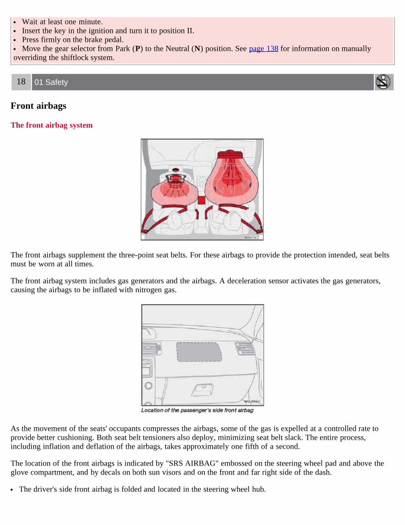
The front airbag system
The front airbags supplement the three-point seat belts. For these airbags to provide the protection intended, seat beltsmust be worn at all times.
The front airbag system includes gas generators and the airbags. A deceleration sensor activates the gas generators,causing the airbags to be inflated with nitrogen gas.
As the movement of the seats' occupants compresses the airbags, some of the gas is expelled at a controlled rate toprovide better cushioning. Both seat belt tensioners also deploy, minimizing seat belt slack. The entire process,including inflation and deflation of the airbags, takes approximately one fifth of a second.
The location of the front airbags is indicated by "SRS AIRBAG" embossed on the steering wheel pad and above theglove compartment, and by decals on both sun visors and on the front and far right side of the dash.
The driver's side front airbag is folded and located in the steering wheel hub.

The passenger's side front airbag is folded behind a panel located above the glove compartment.
WARNING
The airbags in the vehicle are designed to be a SUPPLEMENT to-not a replacement for-the three-point seat belts.For maximum protection, wear seat belts at all times. Be aware that no system can prevent all possible injuries thatmay occur in an accident.
Never drive a vehicle with a steering wheel-mounted airbag with your hands on the steering wheel pad/airbaghousing.
The front airbags are designed to help prevent serious injury. Deployment occurs very quickly and withconsiderable force. During normal deployment and depending on variables such as seating position, one mayexperience abrasions, bruises, swellings, or other injuries as a result from deployment of one or both of the airbags.
When installing any accessory equipment, make sure that the front airbag system is not damaged. Any interferencein the system could cause malfunction.
19 01 Safety
Front airbags
Front airbag deployment
The front airbags are designed to deploy during certain frontal or front-angular collisions, impacts, or decelerations,depending on the crash severity, angle, speed and object impacted. The airbags may also deploy in certain non-frontalcollisions where rapid deceleration occurs.
The SRS sensors, which trigger the front airbags, are designed to react to both the impact of the collision and theinertial forces generated by it, and to determine if the intensity of the collision is sufficient for the seat belt tensionersand/or airbags to be deployed.
However, not all frontal collisions activate the front airbags.
If the collision involves a nonrigid object (e.g., a snow drift or bush), or a rigid, fixed object at a low speed, thefront airbags will not necessarily deploy.
Front airbags do not normally deploy in a side impact collision, in a collision from the rear or in a rollover situation. The amount of damage to the bodywork does not reliably indicate if the airbags should have deployed or not.
NOTE
Deployment of front airbags occurs only one time during an accident. In a collision where deployment occurs, theairbags and seat belt tensioners activate. Some noise occurs and a small amount of powder is released. The release ofthe powder may appear as smoke-like matter. This is a normal characteristic and does not indicate fire.
Volvo's dual-threshold, dual-stage front airbags use special sensors that are integrated with the front seat buckles.The point at which the airbag deploys is determined by whether or not the seat belt is being used, as well as theseverity of the collision.
Collisions can occur where only one of the airbags deploys. If the impact is less severe, but severe enough topresent a clear injury risk, the dual-stage airbags are triggered at 70% of their total capacity. If the impact is moresevere, the dual-stage airbags are triggered at full capacity.
Should you have questions about any component in the SRS system, please contact a trained and qualified Volvoservice technician or Volvo Customer Support:
In the USA

Volvo Cars of North America, LLCCustomer Care CenterP.O. Box 914 Rockleigh, New Jersey 07647-09141-800-458-1552www.volvocars.us
In Canada
Volvo Cars of Canada Corp.National Customer Service175 Gordon Baker RoadNorth York, Ontario M2H 2N71-800-663-8255www.volvocanada.com
WARNING
Do not use child safety seats or child booster cushions/backrests in the front passenger's seat. We also recommendthat occupants under 4 feet 7 inches (140 cm) in height who have outgrown these devices sit in the rear seat with theseat belt fastened1.
Never drive with the airbags deployed. The fact that they hang out can impair the steering of your vehicle. Othersafety systems can also be damaged.
The smoke and dust formed when the airbags are deployed can cause skin and eye irritation in the event ofprolonged exposure.
1See also the Occupant Weight Sensor information on page 21.
20 01 Safety
Front airbags

WARNING
Children must never be allowed in the front passenger's seat. Volvo recommends that ALL occupants (adults andchildren) shorter than 4 feet 7 inches (140 cm) be seated in the back seat of any vehicle with a passenger-side frontairbag. See page 32 for guidelines.
Occupants in the front passenger's seat must never sit on the edge of the seat, sit leaning toward the instrumentpanel or otherwise sit out of position.
-The occupant's back must be as upright as comfort allows and be against the seat back with the seat belt properlyfastened.
Feet must be on the floor, e.g., not on the dash, seat or out of the window.
WARNING
No objects or accessory equipment, e.g. dashboard covers, may be placed on, attached to, or installed near the airbag hatch (the area above the glove compartment) or the area affected by airbag deployment (see the illustration onpage 18).
There should be no loose articles, e.g. coffee cups, on the floor, seat, or dashboard area. Never try to open the airbag cover on the steering wheel or the passenger's side dashboard. This should only be
done by a trained and qualified Volvo service technician. Failure to follow these instructions can result in injury to the vehicle occupants.
21 01 Safety
Occupant Weight Sensor (OWS)
Disabling the passenger's side front airbag

Volvo recommends that ALL occupants (adults and children) shorter than 4 feet 7 inches (140 cm) be seated in the rearseat of any vehicle with a passenger's side front airbag, and be properly restrained. Children should always be seatedin child restraints appropriate for their size and weight. See also the child safety recommendations beginning on page30.
The Occupant Weight Sensor (OWS) is designed to meet the regulatory requirements of Federal Motor Vehicle SafetyStandard (FMVSS) 208 and is designed to disable (will not inflate) the passenger's side front airbag under certainconditions.
The OWS works with sensors that are part of the front passenger's seat and seat belt. The sensors are designed todetect the presence of a properly seated occupant and determine if the passenger's side front airbag should be enabled(may inflate) or disabled (will not inflate).
The OWS will disable (will not inflate) the passenger's side front airbag when:
the front passenger's seat is unoccupied, or has small/medium objects in the front seat, the system determines that an infant is present in a rear-facing infant seat that is installed according to the
manufacturer's instructions, the system determines that a small child is present in a forward-facing child restraint that is installed according to
the manufacturer's instructions, the system determines that a small child is present in a booster seat, a front passenger takes his/her weight off of the seat for a period of time, a child or a small person occupies the front passenger's seat.
The OWS uses a PASSENGER AIRBAG OFF indicator lamp which will illuminate and stay on to remind you that thepassenger's side front airbag is disabled. The PASSENGER AIRBAG OFF indicator lamp is located in the overheadconsole, near the base of the rearview mirror.
NOTE
The PASSENGER AIRBAG OFF indicator lamp will illuminate for a short period of time when the ignition is turnedon to confirm it is functional. When the front passenger's seat is not occupied (empty seat) or in the event that thepassenger's side front airbag is enabled (may inflate), the PASSENGER AIRBAG OFF indicator lamp will be off.
However, if a fault is detected in the system:
The OWS indicator light will stay on The SRS warning light (see page 17) will come on and stay on The message PASS. AIRBAG OFF SERVICE URGENT will be displayed in the information display.

22 01 Safety
Occupant Weight Sensor (OWS)
WARNING
Never try to open, remove, or repair any components in the OWS system. This could result in system malfunction.Maintenance or repairs should only be carried out by an a trained and qualified Volvo service technician.
If a fault in the system is detected and indicated as explained on the preceding page, be aware that the passenger'sside front airbag will not deploy in the event of a collision. In this case, the SRS system and Occupant WeightSensor should be inspected by a trained and qualified Volvo service technician as soon as possible.
The front passenger's seat should not be modified in any way. This could reduce pressure on the seat cushion,which might interfere with the OWS system's function.
The OWS is designed to disable (will not inflate) the passenger's side front airbag when a rear facing infant seat, aforward-facing child restraint, or a booster seat is detected. The PASSENGER AIRBAG OFF indicator lamp willilluminate and stay on to remind you that the passenger's side front airbag is disabled (see the following table).
1Volvo recommends that children always be properly restrained in appropriate child restraints in the rear seats.In rare situations when the seat belt is not properly fastened, some child restraints may not be detected by the OWS because there is very littleweight on the vehicle seat cushion. In these cases the passenger's side front airbag may be disabled, but the PASSENGER AIRBAG OFF indicatorlamp will not be lit. Do not assume that the passenger's side front airbag is disabled unless the PASSENGER AIRBAG OFF indicator lamp is lit.Make sure the child restraint is properly installed (turn the vehicle off, remove the child restraint from the vehicle and reinstall the restraintfollowing the child restraint manufacturer's instructions) and that the PASSENGER AIRBAG OFF indicator lamp is on, or move the child restraintto the rear seat.
The OWS is designed to enable (may inflate) the passenger's side front airbag anytime the system senses that a personof adult size is sitting properly in the front passenger's seat. The PASSENGER AIRBAG OFF indicator lamp will beoff and remain off.
If a person of adult size is sitting in the front passenger's seat, but the PASSENGER AIRBAG OFF indicator lamp ison, it is possible that the person isn't sitting properly in the seat. If this happens:
Turn the vehicle off and ask the person to place the seatback in an upright position. Have the person sit upright in the seat, centered on the seat cushion, with the person's legs comfortably extended.

Restart the vehicle and have the person remain in this position for about two minutes. This will allow the system todetect that person and enable the passenger's frontal airbag.
If the PASSENGER AIRBAG OFF indicator lamp remains on even after this, the person should be advised to ridein the rear seat.
This condition reflects limitations of the OWS classification capability. It does not indicate OWS malfunction.
23 01 Safety
Occupant Weight Sensor (OWS)
ModificationsIf you are considering modifying your vehicle in any way to accommodate a disability, for example by altering oradapting the driver's or front passenger's seat(s) and/or airbag systems, please contact Volvo at:
In the USA
Volvo Cars of North America, LLCCustomer Care CenterP.O. Box 914 Rockleigh, New Jersey 07647-09141-800-458-1552
In Canada
Volvo Cars of Canada Corp.National Customer Service175 Gordon Baker Road North York, Ontario M2H 2N71-800-663-8255
WARNING
No objects that add to the total weight on the seat should be placed on the front passenger's seat. If a child isseated in the front passenger's seat with any additional weight, this extra weight could cause the OWS system toenable the airbag, which might cause it to deploy in the event of a collision, thereby injuring the child.
The seat belt should never be wrapped around an object on the front passenger's seat. This could interfere with theOWS system's function.
The front passenger's seat belt should never be used in a way that exerts more pressure on the passenger thannormal. This could increase the pressure exerted on the weight sensor by a child, and could result in the airbag beingenabled, which might cause it to deploy in the event of a collision, thereby injuring the child.
WARNING
Keep the following points in mind with respect to the OWS system. Failure to follow these instructions couldadversely affect the system's function and result in serious injury to the occupant of the front passenger's seat:
The full weight of the front seat passenger should always be on the seat cushion. The passenger should never lifthim/herself off the seat cushion using the armrest in the door or the center console, by pressing the feet on the floor,by sitting on the edge of the seat cushion, or by pressing against the backrest in a way that reduces pressure on theseat cushion. This could cause OWS to disable the passenger's side front airbag.
Do not place any type of object on the front passenger's seat in such a way that jamming, pressing, or squeezingoccurs between the object and the front seat, other than as a direct result of the correct use of the ALR/ELR seat belt(see page 32).
No objects should be placed under the front passenger's seat. This could interfere with the OWS system's function.

24 01 Safety
Side impact protection airbags
Side impact airbags - front seats only
As an enhancement to the structural side impact protection built into your car, the car is also equipped with SideImpact Protection System (SIPS) airbags.
The SIPS airbag system is designed to help increase occupant protection in the event of certain side impact collisions.The SIPS airbags are designed to deploy only during certain side-impact collisions, depending on the crash severity,angle, speed and point of impact.
NOTE
SIPS airbag deployment (one airbag) occurs only on the side of the vehicle affected by the impact. The airbags arenot designed to deploy in all side impact situations.
Components in the SIPS airbag systemThis SIPS airbag system consists of gas generators and side airbag modules built into the outboard sides of both frontseat backrests.
WARNING

The SIPS airbag system is a supplement to the structural Side Impact Protection System and the three-point seatbelt system. It is not designed to deploy during collisions from the front or rear of the car or in rollover situations.
The use of seat covers on the front seats may impede SIPS airbag deployment. No objects, accessory equipment or stickers may be placed on, attached to or installed near the SIPS airbag system
or in the area affected by SIPS airbag deployment. Never try to open or repair any components of the SIPS airbag system. This should be done only by a trained and
qualified Volvo service technician. In order for the SIPS airbag to provide its best protection, both front seat occupants should sit in an upright
position with the seat belt properly fastened. Failure to follow these instructions can result in injury to the occupants of the vehicle in the event of an accident.
25 01 Safety
Volvo Inflatable Curtain (VIC)
The Volvo Inflatable Curtain system
This system consists of inflatable curtains located along the sides of the roof liners, stretching from the center of bothfront side windows to the rear edge of the rear side door windows. It is designed to help protect the heads of theoccupants of the front seats and the occupant of the outboard rear seating positions in certain side impact collisions.
In certain side impacts, both the Inflatable Curtain (VIC) and the Side Impact Airbag System (SIPS-bag) will deploy,whereas, in some cases, only the Inflatable Curtain (VIC) will deploy. In cases where both the VIC and the SIPS-bagdeploy, this will occur simultaneously.
NOTE
If the inflatable curtain deploys, it remains inflated for approximately 3 seconds.
WARNING
The VIC system is a supplement to the Side Impact Protection System. It is not designed to deploy duringcollisions from the front or rear of the car or in rollover situations.
Never try to open or repair any components of the VIC system. This should be done only by a trained andqualified Volvo service technician.
Never hang heavy items from the ceiling handles. This could impede deployment of the Inflatable curtain.
26 01 Safety

Volvo Inflatable Curtain (VIC)
WARNING
In order for the VIC to provide its best protection, both front seat occupants and both outboard rear seat occupantsshould sit in an upright position with the seat belt properly fastened; adults using the seat belt and children using theproper child restraint system. Only adults should sit in the front seats. Children must never be allowed in the frontpassenger's seat. See page 32 for guidelines. Failure to follow these instructions can result in injury to the vehicleoccupants in an accident.
27 01 Safety
Whiplash Protection System
Whiplash Protection System (WHIPS) - front seats only
The WHIPS system consists of specially designed hinges and brackets on the front seat backrests designed to helpabsorb some of the energy generated in a collision from the rear (when the vehicle is "rear-ended").
In the event of a collision of this type, the hinges and brackets of the front seat backrests are designed to changeposition slightly to allow the backrest/head restraint to help support the occupant's head before moving slightlyrearward. This movement helps absorb some of the forces that could result in whiplash.
WARNING

The WHIPS system is designed to supplement the other safety systems in your car. For this system to functionproperly, the three-point seat belt must be worn. Please be aware that no system can prevent all possible injuries thatmay occur in an accident.
The WHIPS system is designed to function in certain collisions from the rear, depending on the crash severity,angle and speed.
28 01 Safety
Whiplash Protection System
WARNING
Occupants in the front seats must never sit out of position. The occupant's back must be as upright as comfort allowsand be against the seat back with the seat belt properly fastened.
WARNING
If your car has been involved in a rearend collision, the front seat backrests must be inspected by a trained andqualified Volvo service technician, even if the seats appear to be undamaged. Certain components in the WHIPSsystem may need to be replaced.
Do not attempt to service any component in the WHIPS system yourself.
WARNING
Any contact between the front seat backrests and the folded rear seat could impede the function of the WHIPSsystem. If the rear seat is folded down, the occupied front seats must be adjusted forward so that they do not touchthe folded rear seat.

WARNING
Boxes, suitcases, etc. wedged behind the front seats could impede the function of the WHIPS system. If the rear seat backrests are folded down, cargo must be secured to prevent it from sliding forward against the
front seat backrests in the event of a collision from the rear. This could interfere with the action of the WHIPSsystem.
29 01 Safety
Crash mode
Driving after a collision
If the vehicle has been involved in a collision, the text CRASH MODE SEE MANUAL may appear in the informationdisplay. This indicates that the vehicle's functionality has been reduced.
NOTE
This text can only be shown if the display is undamaged and the vehicle's electrical system is intact.
CRASH MODE is a feature that is triggered if one or more of the safety systems (for example, front or side airbags,an inflatable curtain, or one or more of the seat belt tensioners) has deployed. The collision may have damaged animportant function in the vehicle, such as the fuel lines, sensors for one of the safety systems, the brake system, etc.
WARNING

Never attempt to repair the vehicle yourself or to reset the electrical system after the vehicle has displayedCRASH MODE SEE MANUAL. This could result in injury or improper system function.
Restoring the vehicle to normal operating mode should only be done by a trained and qualified Volvo servicetechnician.
After CRASH MODE SEE MANUAL has been displayed, if you detect the odor of fuel vapor, or see any signs offuel leakage, do not attempt to start the vehicle. Leave the vehicle immediately.
Attempting to start the vehicleIf damage to the vehicle is minor and there is no fuel leakage, you may attempt to start the vehicle. To do so:
1. Remove the ignition key or optional keyless drive start control (see page 131).
2. Reinsert the key or start control in the ignition switch. The vehicle will then attempt to reset CRASH MODE tonormal mode.
3. Try to start the vehicle.
Moving the vehicleIf the electrical system is able to reset system status to normal (CRASH MODE SEE MANUAL will no longer bedisplayed), the vehicle may be moved carefully from its present position, if for example, it is blocking traffic. Itshould, however, not be moved farther than is absolutely necessary.
WARNING
Even if the vehicle appears to be drivable after CRASH MODE has been set, it should not be driven or towed(pulled by another vehicle). There may be concealed damage that could make it difficult or impossible to control.The vehicle should be transported on a flatbed tow truck to a trained and qualified Volvo service technician forinspection/ repairs.
30 01 Safety
Child safety
Children should be seated safely
Volvo recommends the proper use of restraint systems for all occupants including children. Remember that, regardlessof age and size, a child should always be properly restrained in a car.
Your car is also equipped with ISOFIX/LATCH attachments, which make it more convenient to install child seats.
Some restraint systems for children are designed to be secured in the vehicle by lap belts or the lap portion of a lap-shoulder belt. Such child restraint systems can help protect children in cars in the event of an accident only if they areused properly. However, children could be endangered in a crash if the child restraints are not properly secured in thevehicle. Failure to follow the installation instructions for your child restraint can result in your child striking thevehicle's interior in a sudden stop.
Holding a child in your arms is NOT a suitable substitute for a child restraint system. In an accident, a child held in aperson's arms can be crushed between the vehicle's interior and an unrestrained person. The child could also be injuredby striking the interior, or by being ejected from the vehicle during a sudden maneuver or impact. The same can alsohappen if the infant or child rides unrestrained on the seat. Other occupants should also be properly restrained to helpreduce the chance of injuring or increasing the injury of a child.
All states and provinces have legislation governing how and where children should be carried in a car. Find out the

regulations existing in your state or province. Recent accident statistics have shown that children are safer in rearseating positions than front seating positions when properly restrained. A child restraint system can help protect a childin a vehicle. Here's what to look for when selecting a child restraint system:
It should have a label certifying that it meets applicable Federal Motor Vehicle Safety Standards (FMVSS 213) - orin Canada, CMVSS 213.
Make sure the child restraint system is approved for the child's height, weight and development - the label requiredby the standard or regulation, or instructions for infant restraints, typically provide this information.
In using any child restraint system, we urge you to carefully look over the instructions that are provided with therestraint. Be sure you understand them and can use the device properly and safely in this vehicle. A misused childrestraint system can result in increased injuries for both the infant or child and other occupants in the vehicle.
When a child has outgrown the child safety seat, you should use the rear seat with the standard seat belt fastened. Thebest way to help protect the child here is to place the child on a cushion so that the seat belt is properly located on thehips (see the illustration on page 40). Legislation in your state or province may mandate the use of a child seat orcushion in combination with the seat belt, depending on the child's age and/or size. Please check local regulations.
A specially designed and tested booster cushion (not available in Canada) can be obtained from your Volvo retailer forchildren weighing 33 - 80 lb. (15 - 36 kg) and 38-54 inches (97 - 137 cm) in height.
31 01 Safety
Child safety
WARNING
Do not use child safety seats or child booster cushions/backrests in the front passenger's seat. We also recommendthat children under 4 feet 7 inches (140 cm) in height who have outgrown these devices sit in the rear seat with theseat belt fastened.
Keep vehicle doors and trunk locked and keep keys out of a child's reach. Unsupervised children could lockthemselves in an open trunk and risk injury. Children should be taught not to play in vehicles.
On hot days, the temperature in the trunk or vehicle interior can rise very quickly. Exposure to these hightemperatures for even a short period of time can cause heat-related injury or death. Small children are particularly atrisk.
32 01 Safety
Child safety
Automatic Locking Retractor/Emergency Locking Retractor
To make child seat installation easier, each seat belt (except for the driver's belt) is equipped with a locking mechanismto help keep the seat belt taut.
When attaching the seat belt to a child seat:
Attach the seat belt to the child seat according to the child seat manufacturer's instructions. Pull the seat belt out as far as possible. Insert the seat belt latch plate into the buckle (lock) in the usual way. Release the seat belt and pull it taut around the child seat.

A sound from the seat belt retractor will be audible at this time and is normal. The belt will now be locked in place.This function is automatically disabled when the seat belt is unlocked and the belt is fully retracted.
WARNING
Do not use child safety seats or child booster cushions/backrests in the front passenger's seat. We also recommendthat children who have outgrown these devices sit in the rear seat with the seat belt properly fastened.
Volvo's recommendationsWhy does Volvo believe that no child should sit in the front seat of a car? It's quite simple really. A front airbag is avery powerful device designed, by law, to help protect an adult.
Because of the size of the airbag and its speed of inflation, a child should never be placed in the front seat, even if heor she is properly belted or strapped into a child safety seat. Volvo has been an innovator in safety for over seventy-five years, and we'll continue to do our part. But we need your help. Please remember to put your children in the backseat, and buckle them up.
Volvo has some very specific recommendations:
Always wear your seat belt. Airbags are a SUPPLEMENTAL safety device which, when used with a three-point seat belt can help reduce
serious injuries during certain types of accidents. Volvo recommends that you do not disconnect the airbag system inyour vehicle.
Volvo strongly recommends that everyone in the vehicle be properly restrained. Volvo recommends that ALL occupants (adults and children) shorter than 4 feet 7 inches (140 cm) be seated in the
back seat of any vehicle with a front passenger side airbag. Drive safely!
33 01 Safety
Child restraint systems
Child restraints
There are three main types of child restraint systems: infant seats, convertible seats, and booster cushions. They areclassified according to the child's age and size.
The following section provides general information on securing a child restraint using a three-point seat belt. Refer topages 41-42 for information on securing a child restraint using ISOFIX lower anchors and/or top tether anchorages.

WARNING
A child seat should never be used in the front passenger seat of any vehicle with a front passenger airbag - not evenif the "Passenger airbag off" symbol near the rear-view mirror is illuminated (on vehicles equipped with OccupantWeight Sensor). If the severity of an accident were to cause the airbag to inflate, this could lead to serious injury ordeath to a child seated in this position.
WARNING
Always refer to the child restraint manufacturer's instructions for detailed information on securing the restraint.
34 01 Safety
Child restraint systems
WARNING
When not in use, keep the child restraint system secured or remove it from the passenger compartment to helpprevent it from injuring passengers in the event of a sudden stop or collision.
A small child's head represents a considerable part of its total weight and its neck is still very weak. Volvorecommends that children up to age 4 travel, properly restrained, facing rearward. In addition, Volvo recommendsthat children should ride rearward facing, properly restrained, as long as possible.

35 01 Safety
Infant seats
Securing an infant seat with a seat belt
NOTE
Refer to pages 41-42 for information on securing a child restraint using ISOFIX lower anchors and/or top tetheranchorages.
1. Place the infant seat in the rear seat of the vehicle.
WARNING
An infant seat must be in the rear-facing position only. The infant seat should not be positioned behind the driver's seat unless there is adequate space for safe installation.
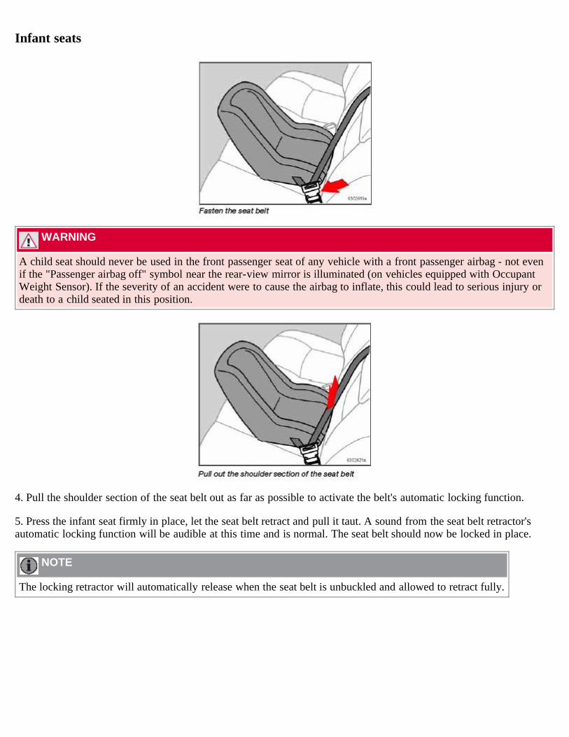
2. Attach the seat belt to the infant seat according to the manufacturer's instructions.
3. Fasten the seat belt by inserting the latch plate into the buckle (lock) until a distinct click is audible.
36 01 Safety
Infant seats
WARNING
A child seat should never be used in the front passenger seat of any vehicle with a front passenger airbag - not evenif the "Passenger airbag off" symbol near the rear-view mirror is illuminated (on vehicles equipped with OccupantWeight Sensor). If the severity of an accident were to cause the airbag to inflate, this could lead to serious injury ordeath to a child seated in this position.
4. Pull the shoulder section of the seat belt out as far as possible to activate the belt's automatic locking function.
5. Press the infant seat firmly in place, let the seat belt retract and pull it taut. A sound from the seat belt retractor'sautomatic locking function will be audible at this time and is normal. The seat belt should now be locked in place.
NOTE
The locking retractor will automatically release when the seat belt is unbuckled and allowed to retract fully.
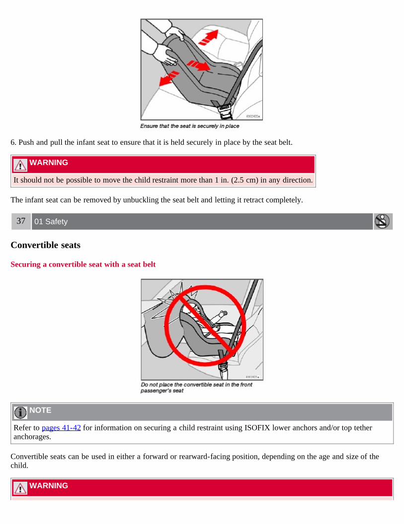
6. Push and pull the infant seat to ensure that it is held securely in place by the seat belt.
WARNING
It should not be possible to move the child restraint more than 1 in. (2.5 cm) in any direction.
The infant seat can be removed by unbuckling the seat belt and letting it retract completely.
37 01 Safety
Convertible seats
Securing a convertible seat with a seat belt
NOTE
Refer to pages 41-42 for information on securing a child restraint using ISOFIX lower anchors and/or top tetheranchorages.
Convertible seats can be used in either a forward or rearward-facing position, depending on the age and size of thechild.
WARNING
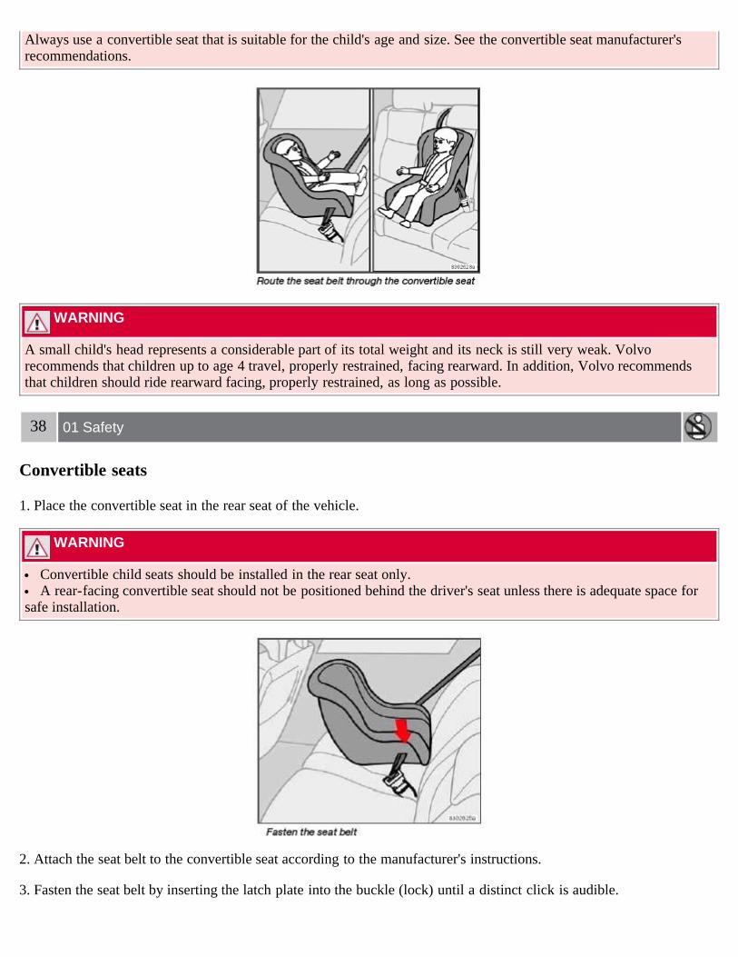
Always use a convertible seat that is suitable for the child's age and size. See the convertible seat manufacturer'srecommendations.
WARNING
A small child's head represents a considerable part of its total weight and its neck is still very weak. Volvorecommends that children up to age 4 travel, properly restrained, facing rearward. In addition, Volvo recommendsthat children should ride rearward facing, properly restrained, as long as possible.
38 01 Safety
Convertible seats
1. Place the convertible seat in the rear seat of the vehicle.
WARNING
Convertible child seats should be installed in the rear seat only. A rear-facing convertible seat should not be positioned behind the driver's seat unless there is adequate space for
safe installation.
2. Attach the seat belt to the convertible seat according to the manufacturer's instructions.
3. Fasten the seat belt by inserting the latch plate into the buckle (lock) until a distinct click is audible.

4. Pull the shoulder section of the seat belt out as far as possible to activate the belt's automatic locking function.
5. Press the convertible seat firmly in place, let the seat belt retract and pull it taut. A sound from the seat beltretractor's automatic locking function will be audible at this time and is normal. The seat belt should now be locked inplace.
39 01 Safety
Convertible seats
NOTE
The locking retractor will automatically release when the seat belt is unbuckled and allowed to retract fully.
6. Push and pull the convertible seat to ensure that it is held securely in place by the seat belt.
WARNING
It should not be possible to move the child restraint more than 1 in. (2.5 cm) in any direction.
The convertible seat can be removed by unbuckling the seat belt and letting it retract completely.
40 01 Safety

Booster cushions
Securing a booster cushion
WARNING
A child seat should never be used in the front passenger seat of any vehicle with a front passenger airbag - not evenif the "Passenger airbag off" symbol near the rear-view mirror is illuminated (on vehicles equipped with OccupantWeight Sensor). If the severity of an accident were to cause the airbag to inflate, this could lead to serious injury ordeath to a child seated in this position.
Booster cushions are recommended for children who have outgrown convertible seats.
1. Place the booster cushion in the rear seat of the vehicle.
2. With the child properly seated on the booster cushion, attach the seat belt to or around the cushion according to themanufacturer's instructions.
3. Fasten the seat belt by inserting the latch plate into the buckle (lock) until a distinct click is audible.
4. Ensure that the seat belt is pulled taut and fits snugly around the child.
WARNING
The hip section of the three-point seat belt must fit snugly across the child's hips, not across the stomach.

The shoulder section of the three-point seat belt should be positioned across the chest and shoulder. The shoulder belt must never be placed behind the child's back or under the arm.
41 01 Safety
ISOFIX lower anchors
Using the ISOFIX lower child seat anchors
Lower anchors for ISOFIX-equipped child seats are located in the rear, outboard seats, hidden below the backrestcushions. Symbols on the seat back upholstery mark the anchor positions (see the illustration above).
To access the anchors:1. Put the child restraint in position.
2. Kneel on the child restraint to press down the seat cushion and locate the anchors by feel.
3. Fasten the attachment on the child restraint's lower straps to the ISOFIX lower anchors.
4. Firmly tension the lower child seat straps according to the manufacturer's instructions.
NOTE
The rear seat's center position is not equipped with ISOFIX lower anchors. When installing a child restraint in thisposition, attach the restraint's top tether strap (if it is so equipped) to the top tether anchorage point (see theinformation on page 42) and secure the restraint with the vehicle's center seat belt (see the information beginning onpage 33).
Always follow your child seat manufacturer's installation instructions, and use both ISOFIX lower anchors and toptethers whenever possible.
WARNING
The ISOFIX lower child restraint anchors are only intended for use with child seats positioned in the outboardseating positions. These anchors are not certified for use with any child restraint that is positioned in the centerseating position. When securing a child restraint in the center seating position, use only the vehicle's center seat belt.
WARNING
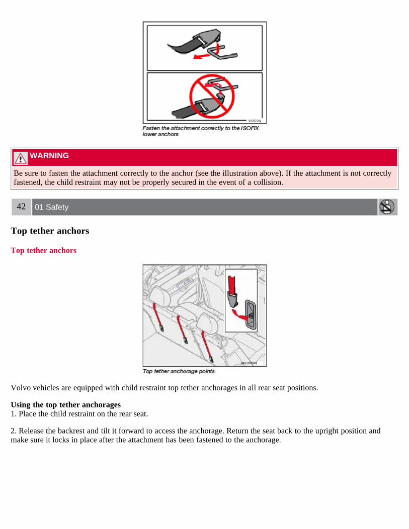
Be sure to fasten the attachment correctly to the anchor (see the illustration above). If the attachment is not correctlyfastened, the child restraint may not be properly secured in the event of a collision.
42 01 Safety
Top tether anchors
Top tether anchors
Volvo vehicles are equipped with child restraint top tether anchorages in all rear seat positions.
Using the top tether anchorages1. Place the child restraint on the rear seat.
2. Release the backrest and tilt it forward to access the anchorage. Return the seat back to the upright position andmake sure it locks in place after the attachment has been fastened to the anchorage.

3. Route the top tether strap under the head restraint and fasten its attachment to the anchorage.
WARNING
Be sure to fasten the child tether attachment correctly to the anchor. If it is not correctly fastened, the child seat maynot be properly restrained in the event of a collision.
4. Firmly tension the top tether strap according to the child restraint manufacturer's instructions. Tension the top tetherstrap only after the lower anchor straps or the seat belt have been firmly tensioned.
See page 41 for on securing the child restraint to ISOFIX lower anchors.
WARNING
Never route a top tether strap over the top or around the head restraint. It should always be routed under the headrestraint.
Child restraint anchorages are designed to withstand only those loads imposed by correctly fitted child restraints.Under no circumstances are they to be used for adult seat belts or harnesses. The anchorages are not able towithstand excessive forces on them in the event of collision if full harness seat belts or adult seat belts are installedto them. An adult who uses a belt anchored in a child restraint anchorage runs a great risk of suffering severe injuriesshould a collision occur.
Do not install rear speakers that require the removal of the top tether anchors or interfere with the proper use ofthe top tether strap.
43 01 Safety
Top tether anchors
NOTE
Child restraints could be recalled for safety reasons. You must register your child restraint to be reached in arecall. To stay informed about child safety seat recalls, be sure to fill out and return the registration card that comeswith new child restraints.
Child restraint recall information is readily available in both the U.S. and Canada. For recall information in theU.S., call the U.S. Government's Auto Safety Hotline at 1-800- 424-9393. In Canada, visit Transport Canada's ChildSafety website at http://www.tc.gc.ca/roadsafety/childsafety/menu.htm.

Contents | Top of Page

2 0 0 7VOLVO
S40
44 02 Instruments and controls
Instrument overview 46Instrument panel 49Indicator and warning symbols 51Symbols - instrument panel 52Information display 55Center console controls 57Lighting panel 58Left-side steering wheel lever 60Trip computer 61Cruise control 63Right-side steering wheel lever 64Rain sensor 65Steering wheel adjustment, Hazard warning flashers 66Parking brake 67Power windows 68Mirrors 70Power moonroof (option) 72Personal settings 74Home Link® Universal Transceiver (option) 76
45 02 Instruments and controls
46 02 Instruments and controls
Instrument overview

47 02 Instruments and controls
Instrument overview
1. Steering wheel adjustment 662. Hood opener 1873. Controls in front doors (see inset illustration at next page)4. Left steering wheel lever 605. Lighting panel 586. Door open handle and locking button 1157. Climate system air vent 848. Side window air vent 849. Cruise control 6310. Horn, airbag 1811. Main instrument panel 4912. Audio controls (option) 21113. Right steering wheel lever 6414. Ignition switch 12815. Moonroof control (option) 7216. Not in use17. Movement detector (option), alarm sensor 11818. Courtesy lighting switch 9719. Driver's side reading light 9720. Passenger's side reading light 9721. Seat belt reminder 53
22. Rear-view mirror 7023. Display for climate control, personal settings, and audio system 74/21024. Audio system 21025. Controls for personal settings and audio system 74/21026. Controls for climate system 85/8727. Gear selector, manual 133-134 Gear selector, automatic 13528. Hazard warning flashers 6629. Door open handle, and locking button 11530. Glove compartment 100/11631. Parking brake 6732. 12-volt socket 5733. Not in use34. Not in use
48 02 Instruments and controls
Instrument overview
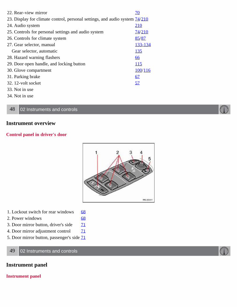
Control panel in driver's door
1. Lockout switch for rear windows 682. Power windows 683. Door mirror button, driver's side 714. Door mirror adjustment control 715. Door mirror button, passenger's side 71
49 02 Instruments and controls
Instrument panel
Instrument panel

1. Speedometer
2. Turn signal, left
3. Warning symbol - See the following pages for additional information.
4. Information display - The display presents information and warning messages, the ambient temperature, and theclock, etc. When the ambient temperature is between 23° and 36°F (-5° and +2°C), a snowflake symbol is shown inthe display. This symbol serves as a warning for possible slippery road surfaces. Please note that this symbol does notindicate a fault with your car. At low speeds, or when the car is not moving, the temperature readings may be slightlyhigher than the actual ambient temperature.
5. Information symbol - See the next pages for additional information.
6. Turn signal, right
7. Tachometer - Shows engine speed in thousands of revolutions per minute (rpm). Do not drive continuously with theneedle in the red area of the dial, which indicates maximum allowable engine rpm range. Instead, shift to a higher gearor slow the vehicle down. The engine management system will automatically prevent excessively high engines speeds.This will be noticeable as a pronounced unevenness in engine speed.
8. Indicator and warning symbols
9. The fuel tank holds approximately 15.9 US gallons (60 liters). When a warning light in the gauge comes on, thereare approximately 2.1 US gallons (8 liters) of fuel remaining in the tank1.
10. Trip odometer reset button - The trip odometers are used to measure short distances. Press the button briefly to
1Models with All Wheel Drive have a tank volume of 15 US gallons (57 liters). Models with engine code 39 have a fuel tank capacity of 14 USgallons (53 liters). This code is the 6th and 7th digits from the left in your vehicle's VIN number. See page 226 for the location of the VIN plate.
50 02 Instruments and controls
Instrument panel
switch between the odometer for the car's total mileage and the two trip odometers, T1 and T2. A long press (morethan 2 seconds) resets the currently selected trip odometer.
11. Function display - This window displays information on functions such as the odometer, trip odometers, optionalrain sensor, and cruise control.

12. High beam indicator
13. Clock setting button - Turn the button to set the time.
14. Temperature gauge - The gauge indicates the temperature of the engine cooling system. If the temperature isabnormally high and the needle enters the red zone, a message is shown in the display. Bear in mind that auxiliarylamps in front of the air intake reduce the cooling capacity at high outside temperatures and high engine loads.
15. Indicator and warning symbols
51 02 Instruments and controls
Indicator and warning symbols
Function check
The indicator and warning symbols1 light up when you turn the ignition key or the optional keyless drive start controlto the driving position (position II) before starting. This shows that the symbols are functioning.
When the engine starts, all symbols go out. If the engine is not started within 5 seconds, all of the symbols exceptCHECK ENGINE and will go out. Certain symbols may not have their functions illustrated, depending on the car'sequipment.
The PARK BRAKE symbol will not go out until the parking brake has been released.
1On certain engines, the symbol for low oil pressure is not used. Instead, a text warning is provided in the information display, see also page 190.
Symbols in the center of the instrument panel
Warning symbol
The red warning symbol lights up to indicate a fault that could affect the car's drivability. A text explaining the natureof the fault will also be shown in the information display. The symbol and accompanying text will remain on until thefault has been corrected. This symbol may also light up in combination with other indicator or warning symbols.
If the red warning symbol lights up:
1. Stop the car as soon as possible in a suitable location.
2. Read the message in the information display.
3. Follow the instructions provided, or contact a trained and qualified Volvo service technician.
Information symbol
The yellow information symbol lights up to alert the driver to a message in the information display.
The message can be erased by pressing the READ button (see page 55), or will disappear automatically after twominutes.
When the message "TIME FOR REGULAR SERVICE" is displayed, the text can be erased and the informationsymbol light can be turned off by pressing the READ button. The text will disappear and the symbol light will go outautomatically after two minutes.
This symbol may also light up in combination with other indicator or warning symbols.
52 02 Instruments and controls
Symbols - instrument panel
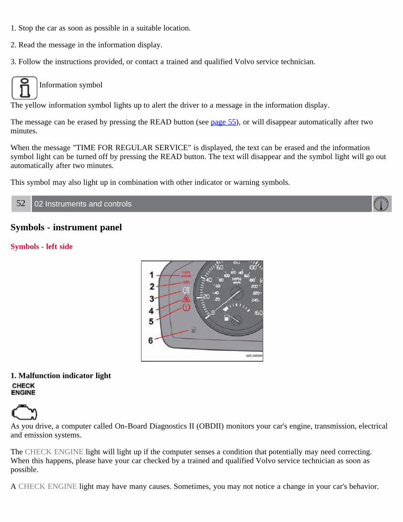
Symbols - left side
1. Malfunction indicator light
As you drive, a computer called On-Board Diagnostics II (OBDII) monitors your car's engine, transmission, electricaland emission systems.
The CHECK ENGINE light will light up if the computer senses a condition that potentially may need correcting.When this happens, please have your car checked by a trained and qualified Volvo service technician as soon aspossible.
A CHECK ENGINE light may have many causes. Sometimes, you may not notice a change in your car's behavior.

Even so, an uncorrected condition could hurt fuel economy, emission controls, and drivability. Extended drivingwithout correcting the cause could even damage other components in your car.
NOTE
Canadian models are equipped with the second symbol.
2. Anti-lock Brake system (ABS)
If the warning light comes on, there is a malfunction of the ABS system (the standard braking system will stillfunction).
The vehicle should be driven to a trained and qualified Volvo service technician for inspection. See page 140 foradditional information.
NOTE
Canadian models are equipped with the second symbol.
3. Rear fog light
This symbol indicates that the rear fog light (located in the driver's side taillight cluster) is on.
4. Stability system STC or DSTC
This indicator symbol flashes when the STC (Stability and Traction control system) or the DSTC (Dynamic Stabilityand Traction control system) is actively working to stabilize the car. See page 142 for more detailed information.
5. Not in use
6. Fuel level warning light
When this light comes on, there are approximately 2.1 US gallons (8 liters) of fuel remaining in the tank.
53 02 Instruments and controls
Symbols - instrument panel
Symbols - right side

1. Turn signal indicator for trailer (certain models)
If you are towing a trailer, this light will flash simultaneously with the turn signals on the trailer. If the light does notflash when signaling, one of the turn signals on the trailer or on the car are not functioning properly.
2. Parking brake applied
This light is on when the parking brake (hand brake) is applied. The parking brake lever is situated between the frontseats. See page 67 for more information.
NOTE
Canadian models are equipped with the second symbol.
3. SRS system warning light
If this light comes on while the car is being driven, or remains on for longer than approximately 10 seconds after thecar has been started, the SRS system's diagnostic functions have detected a fault in a seat belt lock or tensioner, a frontairbag, side impact airbag, and/or an inflatable curtain. Have the system(s) inspected by a trained and qualified Volvoservice technician as soon as possible.
4. Oil pressure warning light1
If the light comes on while driving the car, stop the engine immediately, and check the engine oil level. If the oil levelis normal and the light stays on after restart, have the car towed to the nearest authorized Volvo retailer. After harddriving, the light may come on occasionally when the engine is idling. This is normal, provided it goes off when theengine speed is increased.
5. Seat belt reminder
This symbol (and the seat belt reminder light above the rear view mirror) will light up if either front seat occupant hasnot buckled his/her seat belt. If the car is not moving, the symbols will go out after approximately 6 seconds.

6. Generator warning light
If the light comes on while the engine is running, have the charging system checked by an authorized Volvo workshop.
1 On certain engines, this symbol is not used to indicate low oil pressure. Instead, a text warning is provided in the information display, see alsopage 190.
54 02 Instruments and controls
Symbols - instrument panel
7. Brake failure warning light
If this light comes on while driving or braking, stop the car as quickly as possible in a safe place, open the hood, andcheck the brake fluid level in the reservoir. See page 188 for the location of the reservoir.
NOTE
Canadian models are equipped with the second symbol.
WARNING
If the fluid level is below the MIN mark in the reservoir or if a "Brake failure - Service urgent" message is displayedin the information display: DO NOT DRIVE. Have the car towed to a trained and qualified Volvo service technicianand have the brake system inspected.
If the BRAKE and ABS warning lights come on at the same time, this could indicate a fault in the brake system.In this case:1. Stop the car in a suitable place and switch off the engine.2. Restart the engine.3. If both warning lights go off, no further action is required and the car can be driven.4. If both lights remain on after the engine has been restarted, switch off the engine again and check the brake fluidlevel. See page 188 for the location of the reservoir.
Door open warning
The driver will be alerted if one of the doors, the hood, or the trunk lid are open or ajar.
At low speeds
If the car is moving at a speed of less than approximately 4 m.p.h. (7 km/h), the Information symbol in the instrument

panel will light up and a message will be shown in the information display indicating which door(s), etc is notcompletely closed.
At higher speeds
If the car is moving at a speed above approximately 4 m.p.h. (7 km/h), the Warning symbol in the instrument panelwill light up and a message will be shown in the information display indicating which door(s), etc is not completelyclosed.
Hood and trunk
If the hood and/or trunk lid is not completely closed, the Information symbol in the instrument panel will light up and amessage will be displayed, regardless of the vehicle's speed.
55 02 Instruments and controls
Information display
Messages
When an indicator or warning light in the instrument panel comes on, a message is also shown in the informationdisplay. To read a message:
1. Press the READ button (1).
2. Pressing READ repeatedly enables you to scroll to any other messages that may be stored.
NOTE
If a message is displayed when e.g. you are using the trip computer, this message must be read before you can accessthe trip computer.
56 02 Instruments and controls
Information display

57 02 Instruments and controls
Center console controls
12-volt socket
The 12-volt socket can be used to plug in certain accessories such as cellular telephones, etc. The key must be inposition I (or higher) for the auxiliary socket to function.
Ashtrays/cigarette lighterThe auxiliary socket can also be used for a cigarette lighter and ashtrays, which are available as accessories. Pleasecontact your Volvo retailer1.
NOTE
The cover should be kept on when the auxiliary socket is not in use.
Auxiliary equipment
The buttons to the right of the 12-volt socket can be used for Volvo-installed optional or auxiliary equipment.
1 Ashtrays are also available as an accessory.
58 02 Instruments and controls
Lighting panel

Parking lights
The front and rear parking lights can be turned on even when the ignition is switched off.
Turn switch (1) to position .
The license plate lights also illuminate when the parking lights are switched on.
Headlights
1. Turn the ignition key to position II.
2. The low beam headlights (daytime running lights) illuminate automatically, except when the light switch (1) is inposition 1.
NOTE
See page 60 for information on switching between high and low beams.
Fog lights
Front fog lights (option)The front fog lights can be used in combination with either the headlights or the parking lights.
1. Turn the ignition key to position II.
2. Press button 3 to turn on the front fog lights.
An indicator light in the button illuminates when the front fog lights are on.
1On Canadian models, the daytime running lights will remain on with the light switch in this position.
Rear fog light
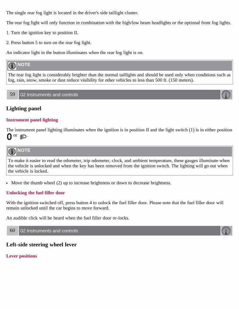
The single rear fog light is located in the driver's side taillight cluster.
The rear fog light will only function in combination with the high/low beam headlights or the optional front fog lights.
1. Turn the ignition key to position II.
2. Press button 5 to turn on the rear fog light.
An indicator light in the button illuminates when the rear fog light is on.
NOTE
The rear fog light is considerably brighter than the normal taillights and should be used only when conditions such asfog, rain, snow, smoke or dust reduce visibility for other vehicles to less than 500 ft. (150 meters).
59 02 Instruments and controls
Lighting panel
Instrument panel lighting
The instrument panel lighting illuminates when the ignition is in position II and the light switch (1) is in either position or .
NOTE
To make it easier to read the odometer, trip odometer, clock, and ambient temperature, these gauges illuminate whenthe vehicle is unlocked and when the key has been removed from the ignition switch. The lighting will go out whenthe vehicle is locked.
Move the thumb wheel (2) up to increase brightness or down to decrease brightness.
Unlocking the fuel filler door
With the ignition switched off, press button 4 to unlock the fuel filler door. Please note that the fuel filler door willremain unlocked until the car begins to move forward.
An audible click will be heard when the fuel filler door re-locks.
60 02 Instruments and controls
Left-side steering wheel lever
Lever positions

1. Turn signals, lane change position
2. Turn signals, position for normal turns
3. High beam flash
4. Toggle between high and low beams, Home Safe lighting
Turn signals
When turningMove the lever as far up or down as possible (to position 2) to start the turn signals. The turn signals will be cancelledautomatically by the movement of the steering wheel, or the lever can be returned to its initial position by hand.
When changing lanesThe driver can automatically flash the turn signals 3 times by:
Moving the turn signal lever up or down to position 1 and releasing it. Moving the lever up or down to position 2 and immediately back to its original position.
NOTE
This automatic flashing sequence can be interrupted by immediately moving the lever in the opposite direction. If the turn signal indicator flashes faster than normal, check for a burned-out turn signal bulb.
High/low beam headlights
Continuous high beams1. Turn the ignition key to position II.
2. With the light switch (1) in position , (see page 58) pull the turn signal lever toward the steering wheel (position
4) to toggle between high and low beams.
High beam flash1. Turn the ignition key to position II.
2. Pull the turn signal lever to position
3. The high beams will remain on until the lever is released.
Home safe lighting

When you leave your car at night, you can make use of the home safe lighting function to illuminate the area in frontof the car.
1. Remove the key from the ignition switch.
2. Pull the direction indicator lever as far as possible towards the steering wheel (to position 4) and release it.
3. Exit the car and lock the doors.
The headlights and parking lights will illuminate and remain on for 301, 60 or 90 seconds. The time interval can bechanged according to your preferences by using the Personal Settings function, see page 74 for more information.
1 Factory setting
61 02 Instruments and controls
Trip computer
Trip computer (option)
The trip computer stores information gathered from several systems in your car and has five menus (six on Canadianmodels) that can be shown in the information display.
MILES TO EMPTY TANKAVERAGE (average fuel consumption)INSTANTANEOUS (current fuel consumption)AVERAGE SPEEDACTUAL SPEED (current speed in m.p.h., Canadian models only)STC/DSTC (see page 142)
NOTE
Warning messages from the car's monitoring systems will override the trip computer function.
If a warning message is shown in the information display while you are using the trip computer:
1. Acknowledge the message by pressing the READ button (A).
2. Press button A again to return to the trip computer function.

Controls
The trip computer functions can be accessed by twisting INFO (B) one step at a time in either direction. Twisting afinal time returns you to the original function.
The trip computer can be reset (average fuel consumption and average speed will be erased from system memory) bypressing RESET (C) for at least five seconds.
MILES TO EMPTY TANKThis function shows the approximate distance that can be driven on the fuel remaining in the tank. This calculation isbased on average fuel consumption during the last 20 miles (30 km) of driving and the amount of fuel remaining in thetank when the reading was taken. When the driving distance on current fuel reserve is less than 12 miles (20 km), "----" will be displayed in the information display.
AVERAGEThis value indicates fuel consumption since the last time the trip computer was reset (by pressing RESET, button C).When the engine is switched off, information on fuel consumption is stored and remains in system memory until theRESET (button C) is pressed again.
INSTANTANEOUSThis value indicates the current fuel consumption, based on readings taken once per second. When the car is notmoving, "----" will be displayed.
AVERAGE SPEEDThis value indicates average speed since the last time the trip computer was reset (by pressing RESET, button C).When the engine is switched off, information on average speed is stored and remains in system memory until theRESET (button C) is pressed again.
62 02 Instruments and controls
Trip computer
ACTUAL SPEED (Canadian models only)This function provides the driver with an instantaneous conversion of the car's current speed from km/h to m.p.h.
NOTE
Trip computer readings may vary slightly depending on the circumference of the tires on the car, tire inflation, ordriving style.
63 02 Instruments and controls
Cruise control
Engaging the cruise control function

The cruise control buttons are located on the left side of the steering wheel hub.
1. Press the CRUISE button. CRUISE will appear in the function display in the center of the instrument panel.
NOTE
This does not set the vehicle's speed.
2. Press + or - to set the current speed. CRUISE ON will be displayed.
Increasing or decreasing speed
Use + or - in the following ways to increase or decrease the vehicle's speed:
1. Press and hold down + or - until the vehicle reaches the desired speed. This will become the set speed when thebutton is released.
2. Press + or - for approximately a half second and release the button to increase or decrease vehicle speed byapproximately 1 mph (1.6 km/h).
NOTE
Cruise control will not function at speeds below 20 mph. (30 km/h). Momentary acceleration, for less than 1 minute (e.g. when passing another car), does not affect cruise control
operation. The car will automatically return to the previously set speed when the accelerator pedal is released.
Temporarily disengaging the cruise control
Press 0 to temporarily disengage cruise control.
CRUISE will appear in the function display. The currently set speed is stored in the system's memory.
Cruise control is also automatically disengaged:
If the speed drops below approximately 20 mph (30 km/h) when driving uphill. When the brake or clutch pedal is depressed. If the gear selector is moved to the Neutral (N) position. During wheel spin or wheel lock-up. If the vehicle's speed is increased by using the accelerator pedal for more than 1 minute.
Returning to the set speed

Press the button to resume the previously set speed.
Disengaging cruise control
Cruise control can also be disengaged by:
Pressing the CRUISE button (CRUISE ON will no longer be shown in the function display). Putting the gear selector in Neutral (N).
WARNING
Cruise control should not be used in heavy traffic or when driving on wet or slippery roads. Cruise control may notmaintain set speed on steep downgrades.
64 02 Instruments and controls
Right-side steering wheel lever
Windshield wipers
A. Windshield/headlight washers
B. Rain sensor (option) - on/off, see page 65
C. Thumb wheel
D. Used on wagon models only
Windshield wipers off
The windshield wipers are off when the lever is in position 0.
Manual wiper function
From position 0, move the lever upward. The windshield wipers will sweep one stroke at a time for as long as the leveris held up.
Intermittent wiper function
With the lever in this position, you can set the wiper interval by moving the thumb wheel (C) upward to increase wiperspeed or downward to decrease the speed.
Continuous wiper functionThe wipers operate at "normal" speed.
High speed wiper function.
Windshield washers (A)
Pull the lever toward the steering wheel and release it. The wipers will make 2-3 sweeps across the windshield after thelever has been released.
CAUTION
Use ample washer fluid when washing the windshield. The windshield should be thoroughly wet when the wipersare in operation.
Headlight washers (certain models)
When the lever has been pulled, high pressure jets mounted in the bumper will spray the headlights.
The following applies to conserve washer fluid (see page 58 for information on the light switch positions):
Low/high beam headlights on
The headlights will be washed the first time the windshield is washed. Thereafter, the headlights will only be washedonce for every five times the windshield is washed within a 10-minute period.
Parking lights on
Optional Bi-Xenon headlights will be washed once for every five times the windshield is washed.
Normal halogen headlights will not be washed.
65 02 Instruments and controls
Rain sensor
B - Rain sensor (option)

The rain sensor regulates windshield wiper speed according to the amount of water on the windshield. The sensitivityof the rain sensor is adjusted by moving the thumb wheel (C in the illustration on the previous page) up (the wiperswill sweep the windshield more frequently) or down (the wipers will sweep the windshield less frequently).
On/Off
To activate the rain sensor:1. Switch on the ignition.
2. Put the windshield wiper lever in position 0.
3. Press button B (see the illustration on the previous page). The rain sensor symbol will appear in the lower display.
The rain sensor can be deactivated by:
Pressing button (B).
or
Moving the windshield wiper lever down.
NOTE
The rain sensor function will remain activated if the lever is briefly moved up to activate the "manual sweep"function.
CAUTION
The rain sensor should be deactivated when washing the car in an automatic car wash, etc. If the rain sensor functionis left on, the wipers will start inadvertently in the car wash and could be damaged.
The rain sensor is automatically deactivated:
When the key is removed from the ignition. Five minutes after the ignition is switched off if the key is left in the ignition.
C - Thumb wheel
The thumb wheel is used to set the wiper interval when intermittent wiping is selected, or the sensitivity to the amountof rain on the windshield when the rain sensor is selected. Move the wheel upward or downward to increase/decreasewiper speed when the intermittent function is selected, or to increase/decrease the optional rain sensor's sensitivity

when the this function is activated.
66 02 Instruments and controls
Steering wheel adjustment, Hazard warning flashers
Steering wheel adjustment
Both the height and the reach of the steering wheel can be adjusted to a comfortable position for the driver.
1. Pull down the lever on the steering column to release the steering wheel.
2. Adjust the steering wheel to a suitable position
3. Press the lever back into place to lock the steering wheel in the new position. If necessary, press the steering wheelslightly while pressing the lever into the locked position.
Check that the steering wheel is locked in the new position.
WARNING
Never adjust the steering wheel while driving.
Hazard warning flashers
The four-way flasher should be used to indicate that the vehicle has become a traffic hazard. To activate the flashers,press the triangular button in the center dash. Press the button again to turn off the flashers.

NOTE
Regulations regarding the use of the hazard warning flasher may vary, depending on where you live.
67 02 Instruments and controls
Parking brake
Parking brake (hand brake)
The parking brake lever is located between the front seats.
NOTE
The indicator light will light up even if the parking brake has only been partially-applied.
When applying the parking brake1. Press firmly on the brake pedal.
2. Pull the parking brake lever up firmly to its full extent.
3. Release the brake pedal and ensure that the vehicle is at a standstill.
4. If the vehicle rolls, the parking brake lever must be pulled more firmly.
5. When parking a vehicle always put the gear selector in first gear (for manual transmission) or P (for automatictransmission).
Parking on a hill
If the vehicle is pointing uphill, turn the front wheels so that they point away from the curb. If the vehicle is pointing downhill, turn the front wheels so that they point toward the curb.
Releasing the parking brake1. Press firmly on the brake pedal.
2. Pull the lever up slightly, press the button at the end of the lever and lower the lever completely.
WARNING
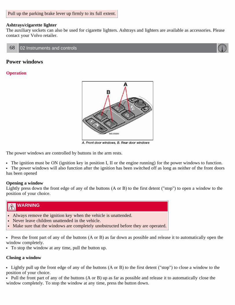
Pull up the parking brake lever up firmly to its full extent.
Ashtrays/cigarette lighterThe auxiliary sockets can also be used for cigarette lighters. Ashtrays and lighters are available as accessories. Pleasecontact your Volvo retailer.
68 02 Instruments and controls
Power windows
Operation
The power windows are controlled by buttons in the arm rests.
The ignition must be ON (ignition key in position I, II or the engine running) for the power windows to function. The power windows will also function after the ignition has been switched off as long as neither of the front doors
has been opened
Opening a windowLightly press down the front edge of any of the buttons (A or B) to the first detent ("stop") to open a window to theposition of your choice.
WARNING
Always remove the ignition key when the vehicle is unattended. Never leave children unattended in the vehicle. Make sure that the windows are completely unobstructed before they are operated.
Press the front part of any of the buttons (A or B) as far down as possible and release it to automatically open thewindow completely.
To stop the window at any time, pull the button up.
Closing a window
Lightly pull up the front edge of any of the buttons (A or B) to the first detent ("stop") to close a window to theposition of your choice.
Pull the front part of any of the buttons (A or B) up as far as possible and release it to automatically close thewindow completely. To stop the window at any time, press the button down.

Lockout switch for rear windows
The electrically operated rear door windows can be disabled by a switch located on the driver's door (see illustration).
If the light in the switch is OFF: The rear door windows can be raised or lowered with the buttons on the rear doorarmrests or with the buttons on the driver's door armrest.
If the light in the switch is ON: The rear door windows can only be raised or lowered with the buttons on the driver'sdoor.
69 02 Instruments and controls
Power windows
Power window control - front passenger's side
The control for the power window in the front passenger's door operates that window only.
Power windows in the rear doors

The rear door windows can be operated with the control on each door and with the switch on the driver's door.
70 02 Instruments and controls
Mirrors
Rearview mirror
Night positionTo reduce glare from the headlights of following vehicles, use control (1) to switch between the normal and night-driving positions.
2. Normal position
3. Night position, reduces glare from following traffic
Auto-dim function (option)An optional integrated sensor reacts to headlights from following traffic and automatically reduces glare.
Rearview mirror with compass (option)

The upper right-hand corner of the rearview mirror has an integrated display that shows the compass direction towardwhich the car is pointing. Eight different directions can be displayed: N, NE, E, SE, S, SW, W and NW. The displayshows your car's orientation with respect to true north.
Calibrating the compass
The earth is divided into 15 magnetic zones. The compass is initially set for the zone to which the car was delivered,and should always be adjusted if the car is driven to a new magnetic zone. A "C" will be displayed if calibrationbecomes necessary.
To calibrate the compass:1. Stop the car in a large, open area, away from traffic.
2. Using a pen or similar object, hold the button (1) depressed for at least 6 seconds. "C" will be displayed.
71 02 Instruments and controls
Mirrors

3. Press button (1) for at least 3 seconds to display the number of the current magnetic zone.
4. Press button (1) repeatedly until the number for the required geographical area (1-15) is displayed. "C" will bedisplayed again.
5. Drive slowly in a circle at a maximum speed of 6 m.p.h. (10 km/h) until a compass direction is displayed.
Calibration is complete.
Power door mirrors
To adjust the mirrors:
Driver's door mirror:Press the L button (a light in the switch will go on) to activate the adjustment control. Use this control to adjust thedriver's door mirror.
Passenger's door mirror:Press the R switch (a light in the switch will go on) to activate the adjustment control. Use this control to adjust thepassenger's door mirror.
After you have adjusted the mirror(s), press the L or R switch again (the LED will go out) to deactivate the adjustmentcontrol.
Storing the mirrors' positionThe position of the door mirrors is stored when the vehicle is locked. The next time the driver's door is unlocked withthe same remote control and that door is opened within 2 minutes, the optional power driver's seat and side door

mirrors will automatically move to the position that they were in when the doors were most recently locked with thesame remote control.
WARNING
The mirrors should always be adjusted prior to driving. Objects seen in the passenger's side wide-angle door mirrorare closer than they appear to be.
72 02 Instruments and controls
Power moonroof (option)
Operating the moonroof
To operate the moonroof, the ignition key must first be turned to the intermediate or drive position (position I, II or theengine running). The moonroof can be opened in two ways:
A. Tilt position
B. Sliding moonroof
1. Auto open
2. Manual open
3. Manual close

4. Auto close
5. Tilt open
6. Tilt close
Tilt positionOpen: Press the rear edge of the control upward to position 5.
Close: Pull the rear edge of the control down to position 6.
Sliding moonroof
Auto open/closeOpen: Pull the switch as far back as possible (to position 1) and release it to automatically slide open the moonroof.
Close: Push the switch as far forward as possible (to position 4) and release it to automatically close the moonroof.
Manual open/closeOpen: Pull the switch back to the first stop (position 2) and hold it until the moonroof has opened to the position ofyour choice.
Close: Push the switch forward to the first stop (position 3) and hold it until the moonroof has closed to the position ofyour choice, or has closed completely.
WARNING
If the moonroof is obstructed during auto-close operation, it will automatically reverse direction and return to itsstarting position.
During manual closing, if the moonroof is obstructed, immediately open it again.
73 02 Instruments and controls
Power moonroof (option)
NOTE
If the moonroof is repeatedly obstructed during auto-close operation, an overload circuit breaker will temporarily haltmoonroof function. The moonroof will return to normal function after a brief cool-down period.
WARNING
Never open or close the moonroof if it is obstructed in any way. Never allow a child to operate the moonroof. Never extend any object or body part though the open moonroof, even if the vehicle's ignition is completely
switched off. Never leave a child alone in a vehicle.
CAUTION
Remove ice and snow before opening the moonroof.
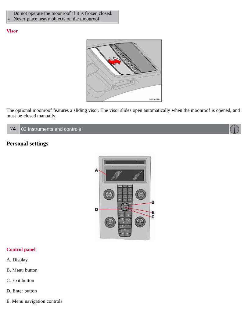
Do not operate the moonroof if it is frozen closed. Never place heavy objects on the moonroof.
Visor
The optional moonroof features a sliding visor. The visor slides open automatically when the moonroof is opened, andmust be closed manually.
74 02 Instruments and controls
Personal settings
Control panel
A. Display
B. Menu button
C. Exit button
D. Enter button
E. Menu navigation controls

Personal settings can be made for some of the car's functions, such as the central locking system, climate control, andthe audio system. Please refer to the audio information beginning on page 210 for more information on the audiofunctions that can be adjusted. The settings are presented in the display (A).
To access the menu and adjust settings:1. Press MENU (B).
2. Scroll to "Car Settings" using the menu navigation control (E).
3. Press ENTER (D).
4. Select an alternative using the menu navigation control (E).
5. Confirm your selection by pressing ENTER.
To exit the menu:Press EXIT (C).
Available settings
Lock confirmation lightWhen the car is locked/unlocked with the remote control, the direction indicators can be selected to flash to confirmthe action. The alternatives On/Off are available for both locking and unlocking.
AutolockWhen the car starts to move, the doors and trunk can be locked automatically. The alternatives On/Off are available.
NOTE
Pulling the handle twice on a door unlocks and opens that door.
UnlockThere are two alternatives for unlocking:
1. Global (All doors) - unlocks all doors and the trunk with one press on the remote control.
2. Two Step (Two-stage unlocking) - This alternative unlocks the driver's door with one press on the remote control. Asecond press unlocks the passenger's door and the trunk.
75 02 Instruments and controls
Personal settings
Approach lightingThis alternative determines the length of time for which the car's lights will remain on when the Approach light buttonon the central locking system's remote control is pressed. Intervals of 30/60/90 seconds may be selected. See page 107for more information.
Home safe lightingThis alternative determines the length of time for which the car's lights will remain on when the high beam lever on thesteering column is pulled toward the wheel with the ignition switched off. Intervals of 30/60/90 seconds may beselected. See page 60 for information on using this function.

Information
VIN number - The VIN (Vehicle Identification Number) is the car's unique identity number. Number of Keys - the number of keys registered for the car is displayed here.
Climate functions
Blower speed in AUTO mode - the blower speed can be set to AUTO mode in models equipped with ECC. Choosebetween "Low", "Normal" and "High".
Timer for recirculation - when the timer is active, the air recirculates in the car for 3- 12 minutes depending on theambient temperature. Select On/Off depending on whether the recirculation timer is to be active or not.
Keyless locking and unlocking (option as available)The following alternatives can be selected for locking and unlocking the doors and trunk:
All doors - all doors are locked or unlocked at the same time. Doors on the same side - front and rear doors on the same side are unlocked together. Both front doors - both front doors are unlocked together. One front door - either of the front doors can be unlocked separately1.
Reset to factory settingsUse this alternative to return to the default climate system settings.
1Factory default
76 02 Instruments and controls
Home Link® Universal Transceiver (option)
Introduction
HomeLink1 is a system that can be programmed to learn the codes of three different remote controlled-devices (forexample, a garage door opener, remote lighting, entry gate). HomeLink's sun visor-mounted transceiver, powered byyour car's electrical system, may then be used in place of your handheld remote controls. The HomeLink transceiverconsists of three programmable buttons and an indicator light.
1 HomeLink is a registered trademark of Johnson Controls, Intl.
© JCI, All rights reserved

NOTE
For your security, the HomeLink Universal Transceiver is designed to not function if you lock your car from theoutside.
Retain the original transmitter(s) for future programming procedures (for example, if you purchase a new vehicle). For your own security, erase all programmed buttons on the HomeLink Universal Transceiver when you sell your
vehicle. Metallic sun protection films should not be used on any windows in a vehicle equipped with HomeLink Universal
Transceiver. This could interfere with the transceivers function.
Operating the HomeLink Universal TransceiverOnce programmed, the HomeLink Universal Transceiver can be used in place of your handheld transmitters.
NOTE
The HomeLink universal transceiver will function for 30 minutes after the driver's door has been opened withoutswitching on the vehicle's ignition.
Press the programmed HomeLink button to activate the garage door, driveway gate, security lightning, home securitysystem etc.
Your original hand-held transmitters may, of course, be used at any time.
WARNING
If you use HomeLink to open a garage door or gate, be sure no one is near the gate or door while it is in motion. Do not use the HomeLink Universal Transceiver with any garage door opener that lacks safety "stop" and
"reverse" features as required by federal safety standards. (This includes any garage door opener model manufacturedbefore April 1, 1982). A garage door opener that cannot "detect" an object, signalling the door to "stop" and"reverse" does not meet current federal safety standards. Using a garage door opener without these features increasesthe risk of serious injury or death. For more information on this matter, call toll-free 1-800-355-3515. (Internet:www.HomeLink.com).
Programming the transceiver for the first time (U.S. residents)1. For first time training, press and hold the two outer HomeLink buttons, releasing only when the HomeLink indicatorlight begins to flash after 20 seconds. (Do not perform this step when training the additional HomeLink buttons.)
2. Position the hand-held transmitter 1-3 inches away from the HomeLink surface
77 02 Instruments and controls
Home Link® Universal Transceiver (option)
(located on your sun visor), keeping the HomeLink indicator light in view.
3. Using both hands, simultaneously press and hold both the desired HomeLink button and hand held transmitterbutton. DO NOT release until the HomeLink indicator light flashes slowly and then rapidly. When the indicator lightflashes rapidly, both buttons may be released. (The rapid flashing indicates successful training.)
NOTE
Some garage door openers may require you to replace step 3 with the "cycling" procedure noted in the"Programming the transceiver for the first time (Canadian residents)" section.
4. Press and hold the trained HomeLink button and observe the indicator light.
If the indicator light is solid/continuous, training is complete and your device should activate when the HomeLinkbutton is pressed and released.
If the indicator light blinks rapidly for 2 seconds and then turns a solid/continuous light, proceed with the followingtraining instructions for a rolling code device. A second person may make the following steps quicker and easier.Please use a ladder or other device. Do not stand on your vehicle to perform the next steps.
5. At the garage door opener receiver (motorhead unit) in the garage, locate the "learn" or "smart" button (usually nearwhere the hanging antenna wire is attached to the unit). If there is difficulty locating the training button, reference thegarage door opener's manual or contact us toll-free 1-800-355-3515 (Internet: www.HomeLink.com).
6. Press and release the "learn" or "smart" button (the name and color of the button may vary by manufacturer).
NOTE
Once the button is pressed, there are 30 seconds in which to initiate the next step.
7. Return to the vehicle and firmly press and hold the trained HomeLink button for two seconds and release. Repeatthe "press/hold/release" sequence up to 3 times to complete the training process.
To train additional HomeLink buttons, begin with step two.
Programming the transceiver for the first time (Canadian residents)1. For first time training, press and hold the two outer HomeLink buttons releasing only when the HomeLink indicatorlight begins to flash after 20 seconds. (Do not perform this step when training the additional HomeLink buttons.)
2. Position the hand-held transmitter 1-3 inches (2.5-7.5 cm) away from the HomeLink surface (located on your)keeping the HomeLink indicator light in view.
3. Using both hands, simultaneously press and hold both the desired HomeLink button and hand held transmitterbutton. During programming, your handheld transmitter may automatically stop transmitting. Continue to press andhold the desired HomeLink button while you press and re-press ("cycle") your handheld transmitter every two secondsuntil the frequency signal has been learned. The indicator light will flash slowly and then rapidly after several secondsupon successful training. DO NOT release until the HomeLink indicator light flashes slowly and then rapidly. Whenthe indicator light flashes rapidly, both buttons may be released. (The rapid flashing indicates successful training.)
78 02 Instruments and controls
Home Link® Universal Transceiver (option)
4. Press and hold the trained HomeLink button and observe the indicator light.
If the indicator light is solid/continuous, training is complete and your device should activate when the HomeLinkbutton is pressed and released.
If the indicator light blinks rapidly for 2 seconds and then turns a solid/continuous light, proceed with the followingtraining instructions for a rolling code device. A second person may make the following steps quicker and easier.Please use a ladder or other device. Do not stand on your vehicle to perform the next steps.
5. At the garage door opener receiver (motorhead unit) in the garage, locate the "learn" or "smart" button (usually near

where the hanging antenna wire is attached to the unit). If there is difficulty locating the training button reference thegarage door opener's manual or contact us.
6. Press and release the "learn" or "smart" button (the name and color of the button may vary by manufacturer).
NOTE
Once the button is pressed, there are 30 seconds in which to initiate the next step.
7. Return to the vehicle and firmly press and hold the trained HomeLink button for two seconds and release. Repeatthe "press/hold/release" sequence up to 3 times to complete the training process.
NOTE
During programming, your hand-held transmitter may automatically stop transmitting. Continue to press and holdthe desired HomeLink button while you press and repress ("cycle") your hand-held transmitter every two secondsuntil the frequency signal has been learned. The indicator light will flash slowly and then rapidly after severalseconds upon successful training. If necessary, follow steps 5-7 to complete the training for a rolling code device.
To train additional HomeLink buttons, begin with step two.
Rolling Code ProgrammingRolling code garage door openers that are "code-protected" and manufactured after 1996 may be determined by the-following:
Reference the garage door opener owner's manual for verification. The handheld transmitter appears to program the HomeLink Universal Transceiver but does not activate the garage
door. Press and hold the trained HomeLink button. The garage door opener has the rolling code feature if the indicator
light flashes rapidly and then turns solid after 2 seconds.
To train a garage door with the rolling code feature, follow these instructions (the aid of a second person may make thetraining quicker and easier):
1. Locate the training button on the garage door opener motor head unit. Exact location and color of the button mayvary by garage door opener brand. If there is difficulty locating the training button, reference the garage door openerowner's manual or please visit our Web site at www.HomeLink.com.
2. Press the training button on the garage door opener motor head unit (which activates the "training light").
NOTE
Following step 2, there are 30 seconds in which to initiate step 3.
3. Firmly press and release the programmed HomeLink® button. Press and release the HomeLink button a second timeto complete the training process. (Some garage door openers may require
79 02 Instruments and controls
Home Link® Universal Transceiver (option)
you to do this procedure a third time to complete the training.)

The garage door opener should now recognize the HomeLink Wireless Control System. The remaining two buttonsmay now be trained if this has not previously been done. Refer to the Programming portion of this text. TheHomeLink Wireless Control System (once programmed) or the original handheld transmitter may be used to activatethe garage door. In the event that there are still difficulties in programming the HomeLink Wireless Control System,please visit our Web site, www.HomeLink.com.
Reprogramming a Single HomeLink ButtonTo program a device to HomeLink using a HomeLink button previously trained, follow these steps:
1. Press and hold the desired HomeLink button. Do NOT release until step 4 has been completed.
2. When the indicator light begins to flash slowly (after 20 seconds), position the handheld transmitter 1 to 3 inchesaway from the HomeLink surface.
3. Press and hold the handheld transmitter button. The HomeLink indicator light will flash, first slowly and thenrapidly.
4. When the indicator light begins to flash rapidly, release both buttons.
The previous device has now been erased and the new device can be activated by pushing the HomeLink button thathas just been programmed. This procedure will not affect any other programmed HomeLink.
Erasing ChannelsIndividual buttons cannot be erased. However, to erase all three programmed buttons:
1. Press and hold the two outside buttons until the indicator light begins to flash (after 20 seconds).
2. Release both buttons.
The HomeLink® Wireless Control System is now in the training (learning) mode and can be programmed at any timefollowing steps 2 through 4 in the Programming section.
Contents | Top of Page
2 0 0 7VOLVO
S40
80 03 Climate
General information 82Air vents 84Manual climate control 85Electronic Climate Control (ECC) - option 87Air distribution 90
81 03 Climate
82 03 Climate
General information
Air conditioning - A/C
Your car is equipped with a climate control system that includes either manually adjustable air conditioning or optionalElectronic Climate Control (ECC).
The air conditioning system can be switched off, but for optimal air quality in the passenger compartment and toprevent the windows from fogging, the air conditioning should be left on - even in cool weather.
NOTE
In warm weather, a small amount of water may accumulate under the car when it has been parked. This water iscondensation from the A/C system and is normal.
Ice and snow
Always keep the air intake grille at the base of the windshield free of snow.
Climate control maintenance

Special tools and equipment are required to maintain and carry out repairs on the climate system. Work of this typeshould only be done by a trained and qualified Volvo service technician.
Refrigerant
Volvo cares about the environment. The air conditioning system in your car contains a CFC-free refrigerant - R134a.This substance will not deplete the ozone layer. The system contains 1.2 lbs (530 g) R134a (HFC 134a), and uses PAGoil.
Passenger compartment filter
Replace the cabin air filter with a new one at the recommended intervals. Please refer to your Warranty and ServiceRecords Information booklet, or consult your Volvo retailer for these intervals. The filter should be replaced moreoften when driving under dirty and dusty conditions. The filter cannot be cleaned and therefore should always bereplaced with a new one.
NOTE
There are different types of cabin air filters. Ensure that the correct type is installed.
Display
The display above the climate control panel shows the climate settings that have been made.
Personal settings
There are two functions in the climate system that can be set to your preferences:
Blower speed to Auto mode (models with ECC only). Timer controlled recirculation of the air in the passenger compartment. For information about how to make these
settings, see the Personal settings section on page 74.
83 03 Climate
General information
Models equipped with ECC (option)
SensorsThe sunlight sensor on the upper side of the dashboard and the passenger compartment temperature sensor, locatedbehind the climate system control panel, should not be obstructed.
Side windows and optional moonroofThe electronic climate control system will function best if the windows and moonroof are closed. If you drive with thewindows or moonroof open, it may be preferable to manually adjust the temperature and blower control (the LED inthe AUTO switch should be off).
AccelerationThe air conditioning system is temporarily switched off during full throttle acceleration.
84 03 Climate

Air vents
Air vents in the dashboard
A. Open
B. Closed
C. Horizontal air flow
D. Vertical air flow
Direct the outer air vents toward the side windows to defrost.
85 03 Climate
Manual climate control
1. Blower speed
2. Recirculation
3. Defroster
4. Airflow controls
5. A/C - ON/OFF
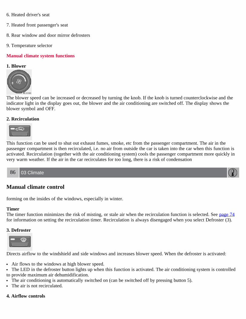
6. Heated driver's seat
7. Heated front passenger's seat
8. Rear window and door mirror defrosters
9. Temperature selector
Manual climate system functions
1. Blower
The blower speed can be increased or decreased by turning the knob. If the knob is turned counterclockwise and theindicator light in the display goes out, the blower and the air conditioning are switched off. The display shows theblower symbol and OFF.
2. Recirculation
This function can be used to shut out exhaust fumes, smoke, etc from the passenger compartment. The air in thepassenger compartment is then recirculated, i.e. no air from outside the car is taken into the car when this function isactivated. Recirculation (together with the air conditioning system) cools the passenger compartment more quickly invery warm weather. If the air in the car recirculates for too long, there is a risk of condensation
86 03 Climate
Manual climate control
forming on the insides of the windows, especially in winter.
TimerThe timer function minimizes the risk of misting, or stale air when the recirculation function is selected. See page 74for information on setting the recirculation timer. Recirculation is always disengaged when you select Defroster (3).
3. Defroster
Directs airflow to the windshield and side windows and increases blower speed. When the defroster is activated:
Air flows to the windows at high blower speed. The LED in the defroster button lights up when this function is activated. The air conditioning system is controlled
to provide maximum air dehumidification. The air conditioning is automatically switched on (can be switched off by pressing button 5). The air is not recirculated.
4. Airflow controls

Press one of the three buttons in the illustration to activate the selected airflow. A symbol in the display above theclimate control panel and a lit LED in the selected button indicate that the manual function has been selected. Withmanually selected airflow both warm and cool air can be selected. The desired temperature is selected using control 9.
5. A/C - On or Off
ON: The air conditioning system is engaged when the ON light is lit.
OFF: The system is disengaged when the OFF lights up.
If Defroster (3) is activated the air conditioning is always engaged.
6/7. Heated front seats (option)
Maximum heating: Press the button once - both LEDs light up.
Reduced heating: Press the button a second time - one LED lights up.
Seat heating off: Press the button a third time - no LEDs are lit.
8. Heated rear window and door mirrors
Use this function to defrost the rear window and door mirrors.
9. Temperature selector
The knob with the thermometer symbol is used to select cooling or heating for both the driver's and passenger's sidesof the car.
87 03 Climate
Electronic Climate Control (ECC) - option

1. Auto - On/Off
2. Blower speed
3. Recirculation
4. Defroster
5. Airflow controls
6. A/C - ON/OFF
7. Heated driver's seat
8. Heated front passenger's seat
9. Rear window and door mirror defrosters
10.Temperature selector
ECC functions
1. Auto - On/Off
The AUTO function automatically regulates climate control to maintain the desired temperature. The automaticfunction controls heating, air conditioning, blower speed, recirculation, and air distribution.
If you select one or more manual functions, the remaining functions continue to be controlled automatically. Allmanual settings are switched off when AUTO is switched on. AUTO CLIMATE is shown in the display.
2. Blower speed
The blower speed can be increased or decreased by turning the knob. The blower speed is regulated
88 03 Climate
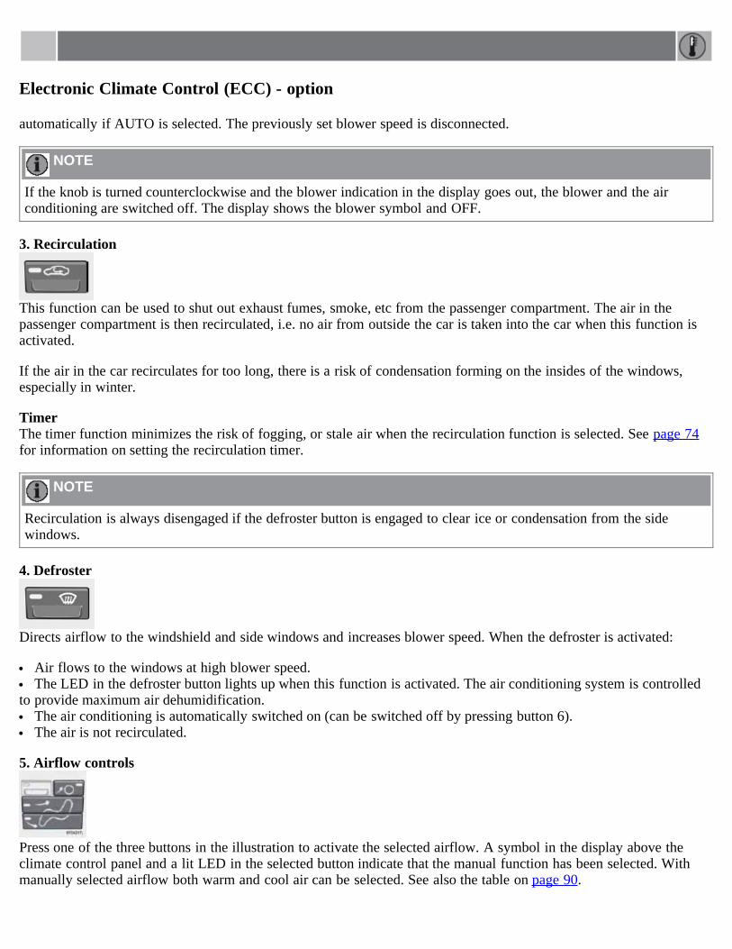
Electronic Climate Control (ECC) - option
automatically if AUTO is selected. The previously set blower speed is disconnected.
NOTE
If the knob is turned counterclockwise and the blower indication in the display goes out, the blower and the airconditioning are switched off. The display shows the blower symbol and OFF.
3. Recirculation
This function can be used to shut out exhaust fumes, smoke, etc from the passenger compartment. The air in thepassenger compartment is then recirculated, i.e. no air from outside the car is taken into the car when this function isactivated.
If the air in the car recirculates for too long, there is a risk of condensation forming on the insides of the windows,especially in winter.
TimerThe timer function minimizes the risk of fogging, or stale air when the recirculation function is selected. See page 74for information on setting the recirculation timer.
NOTE
Recirculation is always disengaged if the defroster button is engaged to clear ice or condensation from the sidewindows.
4. Defroster
Directs airflow to the windshield and side windows and increases blower speed. When the defroster is activated:
Air flows to the windows at high blower speed. The LED in the defroster button lights up when this function is activated. The air conditioning system is controlled
to provide maximum air dehumidification. The air conditioning is automatically switched on (can be switched off by pressing button 6). The air is not recirculated.
5. Airflow controls
Press one of the three buttons in the illustration to activate the selected airflow. A symbol in the display above theclimate control panel and a lit LED in the selected button indicate that the manual function has been selected. Withmanually selected airflow both warm and cool air can be selected. See also the table on page 90.

6. Air conditioning On/Off
ON: The air conditioning system is engaged when the ON light is lit and is controlled automatically by the system tomaintain the selected temperature.
OFF: The system is disengaged when the OFF lights up.
When OFF is selected and the OFF LED is lit, the air conditioning system is deactivated. Other functions are stillcontrolled automatically.
When Defroster (4) is selected, the air conditioning system is activated for maximum dehumidifying.
89 03 Climate
Electronic Climate Control (ECC) - option
7 and 8. Heated front seats (option)
Maximum heating: Press the button once - both LEDs light up.
Reduced heating: Press the button a second time - one LED lights up.
Seat heating off: Press the button a third time - no LEDs are lit.
9. Rear window and door mirror defrosters
Press to defrost the rear window and door mirrors.
The rear window and door mirrors are defrosted simultaneously if the switch is pressed once. The function is active ifone LED is lit in the switch. The door mirrors are deactivated automatically after approximately 6 minutes. The rearwindscreen is deactivated after approximately 12 minutes.
10. Temperature selector
The temperatures on the driver's and passenger's sides can be set separately using the knob (with the thermometer init). The temperature can be set for both sides of the car when the ignition is switched on (both LEDs will be on), whichmeans that a temperature setting will apply to both sides of the car.
To set the temperature on one side of the car:
1. Press the knob once. The LED for one side of the car will light up. Turn the knob to adjust the temperature.
2. Press the knob a second time to set the temperature on the opposite side of the car.
3. Press the knob a third time to set the temperature on both sides of the car at the same time.

NOTE
Selecting a temperature that is higher or lower than necessary will not heat or cool the passenger compartment faster.
90 03 Climate
Air distribution
91 03 Climate
This page left intentionally blank.
Contents | Top of Page

2 0 0 7VOLVO
S40
92 04 Interior
Front seats 94Interior lighting 97Storage compartments 99Rear seat 101Trunk 103
93 04 Interior
94 04 Interior
Front seats
Manual seat adjustment
The driver's and passenger's seats can be adjusted in a number of ways to provide a comfortable driving and sittingposition.
1. Forward-rearward: Pull the lever up and slide the seat to the position of your choice.
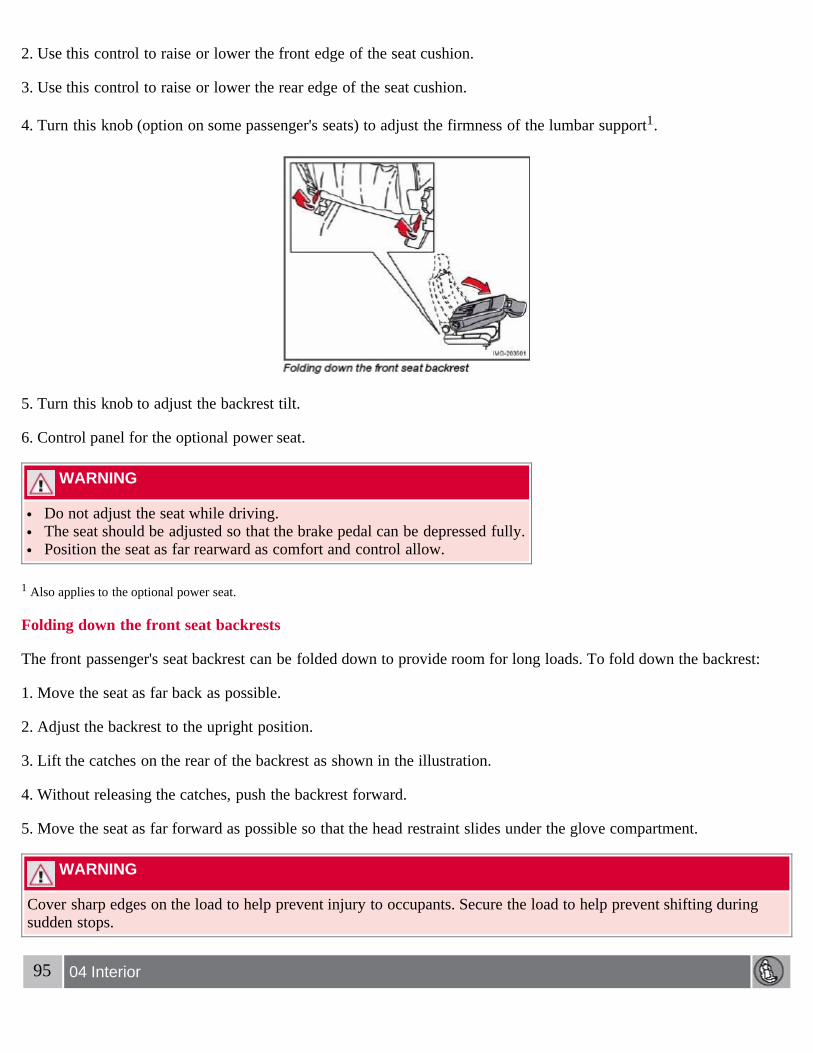
2. Use this control to raise or lower the front edge of the seat cushion.
3. Use this control to raise or lower the rear edge of the seat cushion.
4. Turn this knob (option on some passenger's seats) to adjust the firmness of the lumbar support1.
5. Turn this knob to adjust the backrest tilt.
6. Control panel for the optional power seat.
WARNING
Do not adjust the seat while driving. The seat should be adjusted so that the brake pedal can be depressed fully. Position the seat as far rearward as comfort and control allow.
1 Also applies to the optional power seat.
Folding down the front seat backrests
The front passenger's seat backrest can be folded down to provide room for long loads. To fold down the backrest:
1. Move the seat as far back as possible.
2. Adjust the backrest to the upright position.
3. Lift the catches on the rear of the backrest as shown in the illustration.
4. Without releasing the catches, push the backrest forward.
5. Move the seat as far forward as possible so that the head restraint slides under the glove compartment.
WARNING
Cover sharp edges on the load to help prevent injury to occupants. Secure the load to help prevent shifting duringsudden stops.
95 04 Interior

Front seats
Power seats (option)
The power driver's seat can be adjusted:
If the ignition key is in position I or II. During a 10 minute period after the doors have been unlocked if the door remains open. If the door is closed and the ignition key is not yet in the ignition, or if the key is in position 0, the seat can be
adjusted or during a period of 40 seconds. The power passenger's seat can only be adjusted if the ignition key is inposition I or II, or if the engine is running.
Adjusting the seatSeat adjustment controls 1, 2, 3, and 4 on the side of the seat can be used to move the seat to the position of yourchoice.
1. Move this section of the control up or down to raise/lower the front section of the seat cushion.
2. Move the control forward/rearward to move the seat forward or rearward.
3. Move this section of the control up or down to raise/lower the rear section of the seat cushion.
4. Backrest tilt.
NOTE
The power seats have an overload protector that activates if a seat is blocked by any object. If this occurs, switch offthe ignition (key in position 0) and wait for approximately 20 seconds before operating the seat again.
Emergency stopIf the seat inadvertently begins to move, press any of the buttons to stop the seat.
Programming the seat memory, driver's seat only (option)

Three different seating positions can be stored in the seat's memory. The memory buttons are located on the outboardside of the driver's seat (see the illustration above). The following example explains how memory button 1 can beprogrammed. Buttons 2 and 3 can be programmed in the same way.
To program (store) a seat position in memory button 1:
1. Adjust the seat to the desired position (see the instructions above).
96 04 Interior
Front seats
2. Press and hold down the "M" (Memory) button.
3. With the "M" button depressed, press memory button 1 to store the seat's current position.
To move the seat to the position that it was in when memory button 1 was programmed, press and hold down button 1until the seat stops moving.
As a safety precaution, the seat will stop automatically if the button is released before the seat has reached the presetposition.
Central locking system remote control and driver's seat memoryThe remote control transmitter can also be equipped with an optional function that controls the electrically operateddriver's seat in the following way:
1. Adjust the seat to the desired position.
2. When you leave the car, lock it using the remote control.
3. The next time the driver's door is unlocked with the same remote control and that door is opened within 2 minutes,the driver's seat and side door mirrors will automatically move to the position that they were in when the doors weremost recently locked with the same remote control.
NOTE
The memory function in the remote control operates independently of the memory function in the seat.
WARNING

Because the driver's seat can be adjusted with the ignition off, children should never be left unattended in the car. Movement of the seat can be STOPPED at any time by pressing any button on the power seat control panel. Do not adjust the seat while driving. The seat should be adjusted so that the brake pedal can be depressed fully. In
addition, position the seat as far rearward as comfort and control allow. The seat rails on the floor must not be obstructed in any way when the seat is in motion.
97 04 Interior
Interior lighting
Interior lighting
1. Front driver's side reading light, on/off
2. Courtesy lighting
3. Front passenger's side reading light, on/off
The front and rear reading lights can be activated when the ignition key is position I or II, or when the engine isrunning. The front reading lights are switched on and off by pressing buttons 1 or 3.
The courtesy lighting (2) can be set to three positions:
Press the left side of the button: the interior courtesy lighting turns on. Neutral position: the interior courtesy lighting comes on when a door is opened, and is switched off 10 seconds after
the door is closed. Press the right side of the button: the interior courtesy lighting stays off.
Courtesy lighting - automatic function
The interior lighting has a built-in automatic function that switches on the courtesy lighting for 30 seconds when:
the car is unlocked from the outside using the key or remote control the engine is switched off and the ignition key is turned to the 0 position.
The courtesy lighting lights up or remains on for 5 minutes when:
one of the doors is opened and left open. the courtesy lighting has not been switched off (the right side of button 2 depressed).

The automatic lighting goes out when:
the engine is started the car is locked from the outside using the key or remote control.
If the courtesy lighting is not switched off manually, it will be turned off automatically 5 minutes after the engine hasbeen switched off.
Rear reading lights
4. Rear driver's side reading light, on/off
5. Rear passenger's side reading light, on/off
The rear reading lights can be switched on or off by pressing the respective buttons, and function if the ignition key isin positions I, II, or if the engine is running.
The courtesy lighting can be switched on or off within 30 minutes after the engine has been switched off, or after adoor has been opened or closed.
These lights switch off automatically 5 minutes after the engine has been switched off.
98 04 Interior
Interior lighting
Vanity mirror

Raise the cover to switch on the light.
99 04 Interior
Storage compartments
100 04 Interior
Storage compartments
1. Storage pocket (also on front side of seat cushion)
2. Compartment in door panel
3. Ticket clip
4. Jacket holder (intended for light garments only)
5. Glove compartment
6. Waste bin (accessory), located behind the center instrument panel
7. Storage compartment for e.g., CDs and cup holders
8. Rear seat storage compartment and cup holders.
WARNING
Anchor any heavy objects to prevent them from moving during sudden stops.

Packages on the rear parcel shelf can obscure vision and may become dangerous projectiles in the event of asudden stop or an accident.
Glove compartment
The owners manual and maps can be stored here. There are also holders for coins, pens and fuel cards. The glovecompartment can only be locked and unlocked using the detachable key blade from the central locking system's remotecontrol. See the chapter "Locks and alarm" for further information about the key blade.
101 04 Interior
Rear seat
Rear seat head restraints
Each of the rear seat head restraints can be adjusted vertically to suit the height of the passenger. The upper edge ofthe head restraint should be on a level with the midpoint of the rear side of the passenger's head (see illustration).
To raise: slide the head restraint up to the desired height. To lower: Press the catch at the base of the right support and press the head restraint down.
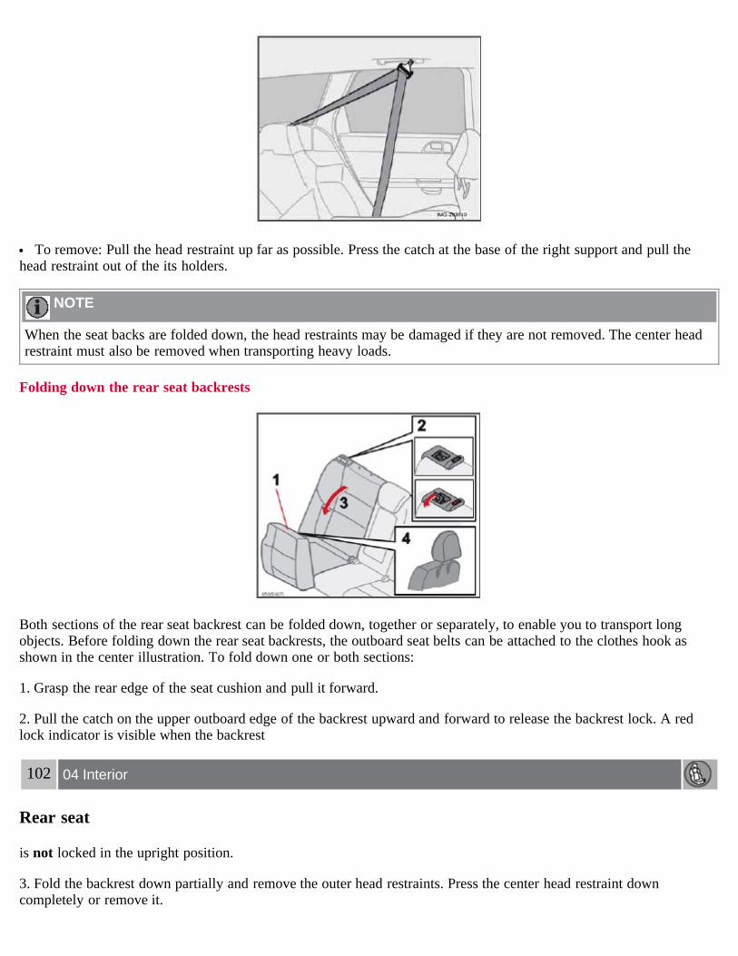
To remove: Pull the head restraint up far as possible. Press the catch at the base of the right support and pull thehead restraint out of the its holders.
NOTE
When the seat backs are folded down, the head restraints may be damaged if they are not removed. The center headrestraint must also be removed when transporting heavy loads.
Folding down the rear seat backrests
Both sections of the rear seat backrest can be folded down, together or separately, to enable you to transport longobjects. Before folding down the rear seat backrests, the outboard seat belts can be attached to the clothes hook asshown in the center illustration. To fold down one or both sections:
1. Grasp the rear edge of the seat cushion and pull it forward.
2. Pull the catch on the upper outboard edge of the backrest upward and forward to release the backrest lock. A redlock indicator is visible when the backrest
102 04 Interior
Rear seat
is not locked in the upright position.
3. Fold the backrest down partially and remove the outer head restraints. Press the center head restraint downcompletely or remove it.

4. Place the head restraints in the plastic tubes, which are now accessible on the under side of the seat cushions.
WARNING
The red lock indicator is VISIBLE when the backrest is NOT locked in position and hidden when the backrest iscorrectly locked in place. When the backrest is in the upright position, it must always be correctly locked in place.
When the rear seat is folded down, do not place heavy objects against the backs of the front seats. This places asevere strain on the folded down backrest of the rear seat. Be sure to secure cargo.
Cargo must not be stacked higher than the top of seat backs. This will reduce the possibility of luggage, etc.becoming projectiles during sudden maneuvers, rapid braking or an accident.
103 04 Interior
Trunk
Load anchoring eyelets
The eyelets in the trunk can be used to fasten accessory load and lashing straps, load nets, and other load anchors.
Contents | Top of Page
2 0 0 7VOLVO
S40
104 05 Locks and alarm
Remote control and key blade 106Valet locking 110Keyless drive (option as available) 112Locking and unlocking 115Locking the glove compartment, Child safety locks 116Alarm 117
105 05 Locks and alarm
106 05 Locks and alarm
Remote control and key blade
Remote controls
Two remote controls that also function as ignition keys are provided with your car. The remote controls containdetachable metal key blades for manually locking or unlocking the driver's door and the glove compartment.
USA - FCC ID: LTQVO315TXThis device complies with part 15 of the FCC rules. Operation is subject to the following conditions: (1) This devicemay not cause harmful interference, and (2) this device must accept any interference received, including interferencethat may cause undesired operation.
Canada - IC: 3659AVO315TXOperation is subject to the following conditions: (1) this device may not cause interference, and (2) this device mustaccept any interference, including interference that may cause undesired operation of the device.
Loss of a remote control

If either of the remote controls is lost, the other must be taken with the car to a Volvo retailer. As an anti-theftmeasure, the code of the lost remote control must be erased from the system.
Each key blade has a unique code, which is used if new key blades are required. A maximum of six remotecontrols/key blades can be programmed and used for one car.
Immobilizer (start inhibitor)
Each of the keys supplied with your car contains a coded transponder. The code in the key is transmitted to an antennain the ignition switch where it is compared to the code stored in the start inhibitor module. The car will start only witha properly coded key. If you misplace a key, take the other keys to an authorized Volvo retailer for reprogramming asan antitheft measure.
USA - FCC ID: LTQWFS 125VOThis device complies with part 15 of the FCC rules. Operation is subject to the following condition: (1) This devicemay not cause harmful interference, and (2) this device must accept any interference received, including interferencethat may cause undesired operation.
Canada - IC: 3659A-WFS125VOOperation is subject to the following conditions: (1) this device may not cause interference, and (2) this device mustaccept any interference, including interference that may cause undesired operation of the device.
CAUTION
Never use force on the narrow section of the remote control - this is where the transponder is located. The car cannotbe started if the transponder is damaged.
107 05 Locks and alarm
Remote control and key blade
Remote control functions
1. Lock - Press the Lock button on the remote once to lock all doors and the trunk. The turn signals will flash once toconfirm locking.
NOTE
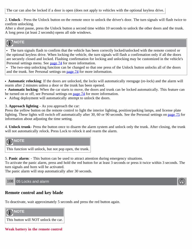
The car can also be locked if a door is open (does not apply to vehicles with the optional keyless drive.
2. Unlock - Press the Unlock button on the remote once to unlock the driver's door. The turn signals will flash twice toconfirm unlocking.After a short pause, press the Unlock button a second time within 10 seconds to unlock the other doors and the trunk.A long press (at least 2 seconds) opens all side windows.
NOTE
The turn signals flash to confirm that the vehicle has been correctly locked/unlocked with the remote control orthe optional keyless drive. When locking the vehicle, the turn signals will flash a confirmation only if all the doorsare securely closed and locked. Flashing confirmation for locking and unlocking may be customized in the vehicle'sPersonal settings menu. See page 74 for more information.
The two-step unlocking function can be changed so that one press of the Unlock button unlocks all of the doorsand the trunk. See Personal settings on page 74 for more information.
Automatic relocking: If the doors are unlocked, the locks will automatically reengage (re-lock) and the alarm willrearm after 2 minutes unless a door or the trunk has been opened.
Automatic locking: When the car starts to move, the doors and trunk can be locked automatically. This feature canbe turned on or off, see Personal settings on page 74 for more information.
Airbag deployment will automatically attempt to unlock the doors.
3. Approach lighting - As you approach the car:Press the yellow button on the remote control to light the interior lighting, position/parking lamps, and license platelighting. These lights will switch off automatically after 30, 60 or 90 seconds. See the Personal settings on page 75 forinformation about adjusting the time setting.
4. Unlock trunk- Press the button once to disarm the alarm system and unlock only the trunk. After closing, the trunkwill not automatically relock. Press Lock to relock it and rearm the alarm.
NOTE
This function will unlock, but not pop open, the trunk.
5. Panic alarm: - This button can be used to attract attention during emergency situations.To activate the panic alarm, press and hold the red button for at least 3 seconds or press it twice within 3 seconds. Theturn signals and horn will be activated.The panic alarm will stop automatically after 30 seconds.
108 05 Locks and alarm
Remote control and key blade
To deactivate, wait approximately 5 seconds and press the red button again.
NOTE
This button will NOT unlock the car.
Weak battery in the remote control

When the battery begins to lose its charge, the Information symbol in the instrument panel (see page 51) lights up andREMOTE BATTERY LOW VOLTAGE is shown in the information display.
Replacing the battery in the remote control
If the range of the transmitter is noticeably reduced, this indicates that the battery (type CR 2032, 3V) is weak andshould be replaced. To replace the battery:
1. Remove the key blade.
2. Place the remote control with the keypad downward. Remove the screw (1) using a small slotted screwdriver.
3. Remove the cover.
4. Note how the + and - sides of the battery are positioned on the inside of the cover. The plus side of the new battery(marked on the battery) must face downward.
CAUTION
When replacing the battery, avoid touching the electrical circuitry in the other half of the remote control.
5. Pry out (2) and replace the battery. Avoid touching the battery and its contact surfaces with your fingers.
6. Press the cover back into place and tighten the screw.
7. Reinsert the key blade in the remote control.
The old battery should be disposed of properly at a recycling center or at your Volvo retailer.
109 05 Locks and alarm
Remote control and key blade
Key blade

The key blade can be removed from the remote control. When removed, the key blade can be used as follows:
To lock/unlock the driver's door To lock/unlock the glove compartment (see page 116) For valet locking (see the explanation below)
Removing the key bladeSlide the spring loaded catch (1) to the side and pull the key blade (2) out of the remote control.
Reinserting the key blade in the remote control1. Hold the remote control with the pointed end down.
2. Carefully slide the key blade into its groove.
3. Gently press the key blade in the groove until it clicks into place.
Unlocking the doors with the detached key bladeInsert the key blade as far as possible in the driver's door lock. Turn the key blade clockwise approximately one-quarter turn to unlock the driver's door only.
NOTE
After unlocking the driver's door with the key blade, opening the door will trigger the alarm.
To disable the alarm:
Models with the standard remote control: Press the Unlock button on the remote control, or insert the key in theignition switch.
Models with the optional keyless drive: Press the Unlock button on the keyless drive remote control. If thebatteries in the remote are weak, remove the keyless drive start control from the ignition switch by pressing the catch(see the illustration on page 131) and pulling the control out of the ignition switch. Insert the ignition key section of akeyless drive remote control in the ignition switch.
Locking the doors with the detached key blade1. Lock the rear doors and the front passenger's door by pressing the lock button on each door.
2. Turn the key blade one-quarter turn counterclockwise to lock the driver's door.
NOTE
This does not arm the alarm or lock the trunk.
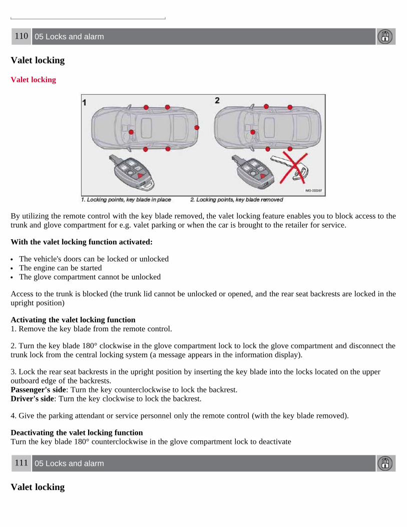
110 05 Locks and alarm
Valet locking
Valet locking
By utilizing the remote control with the key blade removed, the valet locking feature enables you to block access to thetrunk and glove compartment for e.g. valet parking or when the car is brought to the retailer for service.
With the valet locking function activated:
The vehicle's doors can be locked or unlocked The engine can be started The glove compartment cannot be unlocked
Access to the trunk is blocked (the trunk lid cannot be unlocked or opened, and the rear seat backrests are locked in theupright position)
Activating the valet locking function1. Remove the key blade from the remote control.
2. Turn the key blade 180° clockwise in the glove compartment lock to lock the glove compartment and disconnect thetrunk lock from the central locking system (a message appears in the information display).
3. Lock the rear seat backrests in the upright position by inserting the key blade into the locks located on the upperoutboard edge of the backrests. Passenger's side: Turn the key counterclockwise to lock the backrest. Driver's side: Turn the key clockwise to lock the backrest.
4. Give the parking attendant or service personnel only the remote control (with the key blade removed).
Deactivating the valet locking functionTurn the key blade 180° counterclockwise in the glove compartment lock to deactivate
111 05 Locks and alarm
Valet locking

valet locking, and use the key blade to unlock the rear seat backrests.
See page 116 for information on locking the glove compartment normally.
112 05 Locks and alarm
Keyless drive (option as available)
Keyless locking and unlocking
This system makes it possible to unlock and lock the vehicle without having to use the remote control. It is onlynecessary to have a keyless drive remote control in your possession to operate the central locking system.
NOTE
The buttons on the keyless drive remote control can also be used to lock and unlock the vehicle. See page 107 formore information.
Both of the remote controls provided with the vehicle have the keyless function, and additional remotes can beordered. The system can accommodate up to six keyless drive remote controls.
NOTE
The number of doors that are unlocked at the same time can be set in the Personal settings menu. See page 74 for

additional information.
Unlocking the vehicle1. A keyless drive remote control must be on the same side of the vehicle as the door to be opened, and be within 5feet (1.5 meters) of the lock or the trunk opening control (see the shaded areas in the illustration).
2. Pull a door handle to unlock and open the door or press the trunk opening control on the trunk lid.
Locking the vehicleThe doors and the trunk can be locked by pressing the lock button in any of the outside door handles.
NOTE
If one or more doors and/or the trunk is not fully closed when the lock button is pressed, the door(s) or trunk will notbe locked.
Locking or unlocking the vehicle with the key bladeThe driver's door on vehicles equipped with keyless drive can be locked or unlocked with the remote control'sdetachable key blade if necessary. See page 109 for information on removing the key blade from the remote control.To access the keyhole in the driver's door:
113 05 Locks and alarm
Keyless drive (option as available)
1. Pry off the keyhole cover by inserting the key blade or a small screwdriver in the hole on the underside of the cover(indicated by the arrow in the inset illustration in page above).
2. Insert the key blade as far as possible in the driver's door lock. Turn the key blade clockwise approximately onequarter turn to unlock the driver's door only. This will trigger the alarm.
Disabling the alarm: Press the Unlock button on the keyless drive remote control. If the batteries in the remote areweak, remove the keyless drive start control from the ignition switch by pressing the catch (see the illustration on page131) and pulling the control out of the ignition switch. Insert the ignition key section of a keyless drive remote controlin the ignition switch.
Keyless drive remote control and driver's seat memoryThis function is only available on vehicles equipped with the optional power driver's seat.
When you leave the car with a keyless drive remote control in your possession and lock any door, the position ofthe driver's seat will be stored in the seat's memory.
The next time a door is opened by a person with the same remote control in his/her possession, the driver's seat willautomatically move to the position that it was in when the door was most recently locked.
NOTE
If several people carrying keyless drive remote controls approach the vehicle at the same time, the driver's seat willassume the position it was in for the person who opens a door first.
Keyless drive information messagesIf anyone leaves the vehicle with the only keyless drive remote control in his or her possession while the ignition isswitched on, a message will be shown in the information display and an audible signal will sound.

NOTE
This message will only be displayed if the start control is in position I or II.
The message will be erased from the display and the audible signal will stop when the remote control has beenreturned to the vehicle and one of the following has occurred:
A door has been opened and closed The start control has been turned to position 0 The READ button (see page 55 for the location of this button) has been pressed.
CAUTION
Keyless drive remote controls should never be left in the vehicle. In the event of a break-in, a remote found in thevehicle could make it possible to start the engine.
Electromagnetic fields or metal obstructions can interfere with the keyless drive system. Avoid placing the remotecontrol near cellular phones, metallic objects or e.g., in a metal briefcase.
Canada - IC:267T- 5WK48952, 267T- 5WK48964, 267T-5WK48891NOTEThis device complies with RSS -210 of Industry Canada. Operation is subject to the following two conditions: (1)This device may not cause harmful interference, and (2) this device must accept interference received, includinginterference that may cause undesired operation.CAUTIONChanges or modifications not expressly approved by the manufacturer could void the user's authority to operate theequipment.
114 05 Locks and alarm
Keyless drive (option as available)
USA - FCC ID:KR55WK48952, KR55WK48964NOTEThis device complies with part 15 of the FCC Rules. Operation is subject to the following two conditions: (1) Thisdevice may not cause harmful interference, and (2) this device must accept interference received, includinginterference that may cause undesired operation.CAUTIONChanges or modifications not expressly approved by the manufacturer could void the user's authority to operate theequipment. Siemens VDO5WK48891Tested To Comply With FCC Standards For Automobile Use
115 05 Locks and alarm
Locking and unlocking
Locking/unlocking the car from the inside

The switches near the door opening handles on the driver's and front passenger's doors can be used to lock or unlockall doors and the trunk, and to set the alarm.
Unlocking:Press in the upper section in the lock button. A long press (at least two seconds) also opens all the side windows.
Locking:Press in the lower section of the lock button.
NOTE
The doors cannot be opened by pulling up the lock button. Each door can also be locked manually using the lock button on that particular door. This applies only if the car
has not been locked from the outside. The doors can also be unlocked (and the door opened) by pulling the handle in the door twice.
Opening the trunk from the inside1
The vehicle is equipped with a florescent handle on the inside of the trunk lid, which can be used in an emergencysituation to open the trunk from the inside.
Pull the handle down to release the trunk lid. After use, the handle must be pushed back into its original positionbefore the trunk can be closed.
1 U.S. models only
116 05 Locks and alarm

Locking the glove compartment, Child safety locks
Locking the glove compartment
The glove compartment can only be locked and unlocked using the detachable key blade on the remote control. Seepage 109 for information on removing the key blade from the remote control.
1. Unlock the glove compartment by turning the key a quarter of a turn (90°) counterclockwise. The key slot is verticalwhen the glove compartment is unlocked.
2. Lock the glove compartment by turning the key a quarter of a turn (90°) clockwise. The key slot is horizontal whenthe glove compartment is locked.
Manual child safety locks, rear doors
The controls are located on the rear inside edges of the doors, and are only accessible when the doors are open.Use the ignition key blade or a screwdriver to turn the control.
A. The door cannot be opened from the inside when the slot in the control is in the horizontal position. The door canbe opened from the outside.
B. The door can be opened from the inside when the slot in the control is in the vertical position.

117 05 Locks and alarm
Alarm
The alarm system
The alarm is automatically armed whenever the car is locked with the remote control, or if a front lock button isdepressed.
When armed, the alarm continuously monitors a number of points on the car. The following conditions will trigger thealarm:
The hood is forced open. The trunk is forced open. A door is forced open. The ignition switch is tampered with An attempt is made to start the car with a non-approved key (a key not coded to the car's ignition). If there is movement in the passenger compartment (if the car is equipped with the optional movement sensor). The car is lifted or towed (if the car is equipped with the optional inclination sensor) The battery is disconnected (while the alarm is armed). The siren is disconnected when the alarm is disarmed.
The alarm indicator light
The status of the alarm system is indicated by the indicator light on at the top of the dashboard (see illustration):
Indicator light off - the alarm is not armed

The indicator light flashes every two seconds - the alarm is armed The indicator light flashes rapidly before the ignition is switched on - the alarm has been triggered. The message
"ALARM TRIGGERED, CHECK CAR" will also be displayed.Fault in the alarm system: If a fault has been detected in the alarm system, a message will be shown in the
information display. Contact your Volvo retailer to have the alarm system inspected and repaired if necessary.
Arming the alarm
Press the LOCK button on the remote control, or press the central lock button on one of the front doors with the dooropen. One long flash of the turn signals will confirm that the alarm is armed.
Disarming the alarm
Press the UNLOCK button on the remote control or insert the key in the ignition1 to disarm the alarm. Two shortflashes from the car's direction indicators confirm that the alarm has been deactivated and that all doors are unlocked.
Turning off (stopping) the alarm
If the alarm is sounding, it can be stopped by pressing the UNLOCK button on the remote control or by inserting thekey in the ignition
1 On vehicles with the optional keyless drive, press in the start control in the ignition switch.
118 05 Locks and alarm
Alarm
switch. The driver's door must first be unlocked with the key blade.
NOTE
On vehicles equipped with the optional keyless drive, the start control must be removed from the ignition switchbefore the key can be inserted. See page 131 for instructions.
Audible/visual alarm signal
An audible alarm signal is given by a battery powered siren. The alarm cycle lasts for 30 seconds.
NOTE
The visual alarm signal is given by flashing all turn signals and turning on the interior lighting for approximately 5minutes.
Temporarily turning off the accessory alarm sensor(s)

In certain situations it may be desirable to turn off the accessory inclination and movement alarm sensors if, forexample, you drive your vehicle onto a ferry where the rocking of the boat could trigger the alarm or if a pet is left inthe vehicle with the doors locked.
1. From position II or higher, turn the ignition key to 0 and remove it from the ignition switch1
2. Press the button (1). The LED in the button will remain on for one minute after the key has been removed from theignition switch or until the car is locked.
1 The optional keyless drive start control does not need to be removed.
CAUTION
The accessory sensors are automatically reconnected to the alarm system the next time the vehicle is unlocked andthen locked again.
This function will not turn off the vehicle's standard alarm
U.S.A. FCC ID: MAYDA 5823(3)This device complies with part 15 of the FCC rules. Operation is subject to the following conditions: (1) This devicemay not cause harmful interference, and (2) this device must accept any interference received, including interferencethat may cause undesired operation.
Canada IC: 4405A-DA 5823(3)Movement sensor DA5823 by Dynex Operation is subject to the following conditions: (1) this device may not causeinterference, and (2) this device must accept any interference, including interference that may cause undesiredoperation of the device.
119 05 Locks and alarm
This page left intentionally blank.
Contents | Top of Page

2 0 0 7VOLVO
S40
120 06 Starting and driving
General information 122Fuel requirements 125Starting the vehicle 129Starting the car with keyless drive (option as available) 131Manual transmission, 5-speed 133Manual transmission, 6-speed 134Automatic transmission 135Shiftlock override 138All Wheel Drive (option) 139Brake system 140Stability system 142Towing 144Jump starting 146Towing a trailer 147Detachable trailer hitch 149Transporting loads 150
121 06 Starting and driving
122 06 Starting and driving
General information
Economical driving conserves natural resources
Better driving economy may be obtained by thinking ahead, avoiding rapid starts and stops and adjusting the speed ofyour vehicle to immediate traffic conditions.

Observe the following rules:
Bring the engine to normal operating temperature as soon as possible by driving with a light foot on the acceleratorpedal for the first few minutes of operation. A cold engine uses more fuel and is subject to increased wear.
Whenever possible, avoid using the vehicle for driving short distances. This does not allow the engine to reachnormal operating temperature.
Drive carefully and avoid rapid acceleration and hard braking. Use the transmission's Drive (D) position as often as possible and avoid using kickdown. Do not exceed posted speed limits. Avoid carrying unnecessary items (extra load) in the vehicle. Maintain correct tire pressure. Check tire pressure regularly (when tires are cold). Remove snow tires when threat of snow or ice has ended. Note that roof racks, ski racks, etc, increase air resistance and also fuel consumption. At highway driving speeds, fuel consumption will be lower with the air conditioning on and the windows closed
than with the air conditioning off and the windows open. Using the onboard trip computer's fuel consumption modes can help you learn how to drive more economically.
Other factors that decrease gas mileage are:
Dirty air cleaner Dirty engine oil and clogged oil filter Dragging brakes Incorrect front end alignment
Some of the above mentioned items and others are checked at the standard maintenance intervals.
Weight distribution affects handling
WARNING
Driving with the trunk open: Driving with the trunk open could lead to poisonous exhaust gases entering thepassenger compartment. If the trunk must be kept open for any reason, proceed as follows:
Close the windows Set the ventilation system control to air flow to floor, windshield and side windows and the blower control to its
highest setting.
At the specified curb weight your vehicle has a tendency to understeer, which means that the steering wheel has to beturned more than might seem appropriate for the curvature of a bend. This ensures good stability and reduces the riskof rear wheel skid. Remember that these properties can alter with the vehicle load. The heavier the load in the cargoarea, the less the tendency to understeer.
Handling, roadholding
Vehicle load, tire design and inflation pressure all affect vehicle handling. Therefore, check that the tires are inflated tothe recommended pressure according to the vehicle load. See the "Tire pressure" section. Loads should be distributedso that capacity weight
123 06 Starting and driving
General information
or maximum permissible axle loads are not exceeded.
Driving through water
The vehicle can be driven through water up to a depth of approximately 9 in. (25 cm), at a maximum speed of 6 mph(10 km/h).
Take particular care when driving through flowing water. Clean the electrical connections for trailer wiring after driving in mud or water When driving through water, maintain low speed and do not stop in the water.
WARNING
After driving through water, press lightly on the brake pedal to ensure that the brakes are functioning normally.Water or mud can make the brake linings slippery, resulting in delayed braking effect.
CAUTION
Engine damage will occur if water is drawn into the air cleaner. If the vehicle is driven through water deeper than 9 in (25 cm), water may enter the differential and the
transmission. This reduces the oil's lubricating capacity and may shorten the service life of these components. Do not allow the vehicle to stand in water up to the door sills longer than absolutely necessary. This could result
in electrical malfunctions. If the engine has been stopped while the car is in water, do not attempt to restart the engine. Have the car towed
out of the water.
Cold weather precautions
If you wish to check your vehicle before the approach of cold weather, the following advice is worth noting:
Make sure that the engine coolant contains 50 percent antifreeze. Any other mixture will reduce freeze protection.This gives protection against freezing down to - 31°F (-35°C). See section "Coolant". The use of "recycled" antifreezeis not approved by Volvo. Different types of antifreeze must not be mixed.
Volvo recommends using only genuine Volvo antifreeze in your vehicle's radiator. Your Volvo retailer stocks plentyof Volvo engine coolant to help protect your vehicle during cold weather.
Try to keep the fuel tank well filled - this prevents the formation of condensation in the tank. In addition, inextremely cold weather conditions it is worthwhile to add fuel line de-icer before refueling.
The viscosity of the engine oil is important. Oil with low viscosity (thinner oil) improves cold-weather starting aswell as decreasing fuel consumption while the engine is warming up. For winter use, 5W-30 oil, particularly thesynthetic type1, is recommended. Be sure to use good quality oil but do not use cold-weather oil for hard driving or inwarm weather. See page 231 for more information.
The load placed on the battery is greater during the winter since the windshield wipers, lighting, etc. are used moreoften. Moreover, the capacity of the battery decreases as the temperature drops. In very cold weather, a poorly chargedbattery can freeze and be damaged. It is therefore advisable to check the state of
1 Synthetic oil is not used when the oil is changed at the normal maintenance intervals except at owner request and at additional charge. Pleaseconsult your Volvo retailer.
124 06 Starting and driving
General information
charge more frequently and spray an antirust oil on the battery posts.

Volvo recommends the use of snow tires on all four wheels for winter driving - see the chapter "Wheels and tires." To prevent the washer fluid reservoir from freezing, add washer solvents containing antifreeze (see age 188 for the
location of the washer fluid reservoir). This is important since dirt is often splashed on the windshield during winterdriving, requiring the frequent use of the washers and wipers. Volvo Washer Solvent should be diluted as follows:Down to 14° F (-10° C): 1 part washer solvent and 4 parts water Down to 5° F (-15° C): 1 part washer solvent and 3parts water Down to 0° F (- 18° C): 1 part washer solvent and 2 parts water Down to -18° F (-28° C): 1 part washersolvent and 1 part water.
Use Volvo Teflon Lock Spray in the locks.
NOTE
Avoid using de-icing sprays as they can cause damage to the locks.
Conserving electrical current
Keep the following in mind to help minimize battery drain:
When the engine is not running, avoid turning the ignition key to position II. Many electrical systems (the audiosystem, the optional navigation system, power windows, etc) will function with the ignition key in position I. Thisposition reduces drain on the battery.
Please keep in mind that using systems, accessories, etc that consume a great deal of current when the engine is notrunning could result in the battery being completely drained.
The optional 12-volt socket in the cargo area provides electrical current even with the ignition switched off, whichdrains the battery.
NOTE
If the ignition is switched on, a warning message will be displayed in the text window in the instrument panelwhen the battery charge is low.
An energy conserving function designed into the vehicle's electrical system will switch off certain functions orreduce the load on the battery by, e.g., reducing the audio system's volume.
Before a long distance trip
It is always worthwhile to have your vehicle checked at a Volvo retailer before driving long distances. Your retailerwill also be able to supply you with bulbs, fuses, spark plugs and wiper blades for your use in the event that problemsoccur.
As a minimum, the following items should be checked before any long trip:
Check that engine runs smoothly and that fuel consumption is normal. Check for fuel, oil, and fluid leakage Have the transmission oil level checked1. Check condition of drive belts. Check state of the battery's charge. Examine tires carefully (the spare tire as well), and replace those that are worn. Check tire pressures. The brakes, front wheel alignment, and steering gear should be checked by your Volvo retailer only. Check all lights, including high beams. Reflective warning triangles are legally required in some states/provinces. Have a word with your Volvo retailer if you intend to drive in countries where it may be difficult to obtain the
correct fuel. Consider your destination. If you will be driving through an area where snow or ice are likely to occur, consider
snow tires.

1 To prevent injury from contact with hot surfaces, do not inspect your vehicle's transmission fluid yourself. Have your vehicle's transmission fluidlevel inspected by a qualified Volvo service technician.
125 06 Starting and driving
Fuel requirements
Octane rating
Volvo engines are designed to achieve rated horsepower, torque, and fuel economy performance using premium 91octane fuel.
Volvo recommends premium for best performance, but using 87 octane or above will not affect engine reliability.
In demanding driving conditions, such as operating the vehicle in hot weather, towing a trailer, or driving for extendedperiods at higher altitudes than normal, it may be advisable to switch to higher octane fuel (91 or higher) or to changegasoline brands to fully utilize your engine's capacity, and for the smoothest possible operation.
NOTE
When switching to higher octane fuel or changing gasoline brands, it may be necessary to fill the tank more thanonce before a difference in engine operation is noticeable.
Deposit control gasoline (detergent additives)

Volvo recommends the use of detergent gasoline to control engine deposits. Detergent gasoline is effective in keepinginjectors and intake valves clean. Consistent use of deposit control gasolines will help ensure good driveability andfuel economy. If you are not sure whether the gasoline contains deposit control additives, check with the servicestation operator.
NOTE
Volvo does not recommend the use of store-bought fuel injector cleaning additives.
Unleaded fuel
Each Volvo has a three-way catalytic converter and must use only unleaded gasoline. U.S. and Canadian regulationsrequire that pumps delivering unleaded gasoline be labelled "UNLEADED". Only these pumps have nozzles which fityour vehicle's filler inlet. It is unlawful to dispense leaded fuel into a vehicle labelled "unleaded gasoline only".Leaded gasoline damages the three-way catalytic converter and the heated oxygen sensor system. Repeated use ofleaded gasoline will lessen the effectiveness of the
126 06 Starting and driving
Fuel requirements
emission control system and could result in loss of emission warranty coverage. State and local vehicle inspectionprograms will make detection of misfueling easier, possibly resulting in emission test failure for misfueled vehicles.
NOTE
Some U.S. and Canadian gasolines contain an octane enhancing additive called methyl-cyclopentadienyl manganesetricarbonyl (MMT). If such fuels are used, your Emission Control System performance may be affected, and theCheck Engine Light (malfunction indicator lamp) located on your instrument panel may light. If this occurs, pleasereturn your vehicle to an authorized Volvo retailer for maintenance.
Gasoline containing alcohol and ethers
Some fuel suppliers sell gasoline containing "oxygenates" which are usually alcohols or ethers. In some areas, state orlocal laws require that the service pump be marked indicating use of alcohols or ethers. However, there are areas inwhich the pumps are unmarked. If you are not sure whether there is alcohol or ethers in the gasoline you buy, checkwith the service station operator. To meet seasonal air quality standards, some areas require the use of "oxygenated"fuel. Volvo allows the use of the following "oxygenated" fuels; however, the octane ratings listed on this page muststill be met.
Alcohol - EthanolFuels containing up to 10% ethanol by volume may be used. Ethanol may also be referred to as Ethyl alcohol, or"Gasohol".Ethers - MTBE: Fuels containing up to 15% MTBE may be used.
Fuel Formulations
Do not use gasoline that contains lead as a knock inhibitor, and do not use lead additives. Besides damaging theexhaust emission control systems on your vehicle, lead has been strongly linked to certain forms of cancer. Many fuelscontain benzene as a solvent. Unburned benzene has been strongly linked to certain forms of cancer. If you live in anarea where you must fill your own gas tank, take precautions.

These may include:
standing upwind away from the filler nozzle while refueling refueling only at gas stations with vapor recovery systems that fully seal the mouth of the filler neck during
refueling wearing neoprene gloves while handling a fuel filler nozzle.
WARNING
Carbon monoxide is a poisonous, colorless, and odorless gas. It is present in all exhaust gases. If you ever smellexhaust fumes inside the vehicle, make sure the passenger compartment is ventilated, and immediately return thevehicle to your retailer for correction.
Use of Additives
With the exception of fuel line antifreeze during winter months, do not add solvents, thickeners, or other store-boughtadditives to your vehicle's fuel, cooling, or lubricating systems. Overuse may damage your engine, and some of theseadditives contain organically volatile chemicals. Do not needlessly expose yourself to these chemicals.
Fuel filler door
Press the button on the light switch panel (see the illustration on page 58) with the ignition switched off to unlock thefuel filler door. Please note that the fuel filler door will remain unlocked until the vehicle begins to move forward. Anaudible click will be heard when the fuel filler door relocks.
127 06 Starting and driving
Fuel requirements
If you intend to leave your vehicle while it is being refueled, this feature enables you to lock the doors/trunk whileleaving the fuel filler door unlocked.
You can also keep the vehicle locked if you remain inside it during refueling. The central locking button does not lockthe fuel filler door.
Be sure the fuel filler door is not obstructed and is completely closed after refueling.Open the fuel filler cap slowly during hot weather.
Refueling
The fuel tank is designed to hold approximately 15.9 US gallons (60 liters)1 with sufficient volume left over toaccommodate possible expansion of the fuel in hot weather. Be aware that the "usable" tank capacity will be somewhatless than the specified maximum. When the fuel level is low, such factors as ambient temperature, the fuel's "Reidvapor pressure" characteristics, and terrain can affect the fuel pump's ability to supply the engine with an adequatesupply of fuel.
Therefore, it is advisable to refuel as soon as possible when the needle nears the red zone, or when the fuel warninglight comes on.
1Models with All Wheel Drive have a tank volume of 15 US gallons (57 liters).Models with engine code 39 have a fuel tank capacity of 14 US gallons (53 liters). This code is the 6th and 7th digits from the left in your vehicle'sVIN number. See page 227 for the location of the VIN plate.
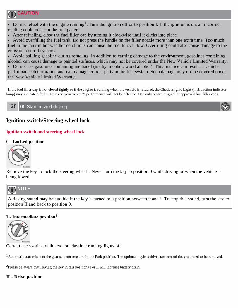
CAUTION
Do not refuel with the engine running1. Turn the ignition off or to position I. If the ignition is on, an incorrectreading could occur in the fuel gauge
After refueling, close the fuel filler cap by turning it clockwise until it clicks into place. Avoid overfilling the fuel tank. Do not press the handle on the filler nozzle more than one extra time. Too much
fuel in the tank in hot weather conditions can cause the fuel to overflow. Overfilling could also cause damage to theemission control systems.
Avoid spilling gasoline during refueling. In addition to causing damage to the environment, gasolines containingalcohol can cause damage to painted surfaces, which may not be covered under the New Vehicle Limited Warranty.
Do not use gasolines containing methanol (methyl alcohol, wood alcohol). This practice can result in vehicleperformance deterioration and can damage critical parts in the fuel system. Such damage may not be covered underthe New Vehicle Limited Warranty.
1If the fuel filler cap is not closed tightly or if the engine is running when the vehicle is refueled, the Check Engine Light (malfunction indicatorlamp) may indicate a fault. However, your vehicle's performance will not be affected. Use only Volvo original or approved fuel filler caps.
128 06 Starting and driving
Ignition switch/Steering wheel lock
Ignition switch and steering wheel lock
0 - Locked position
Remove the key to lock the steering wheel1. Never turn the key to position 0 while driving or when the vehicle isbeing towed.
NOTE
A ticking sound may be audible if the key is turned to a position between 0 and I. To stop this sound, turn the key toposition II and back to position 0.
I - Intermediate position2
Certain accessories, radio, etc. on, daytime running lights off.
1Automatic transmission: the gear selector must be in the Park position. The optional keyless drive start control does not need to be removed.
2Please be aware that leaving the key in this positions I or II will increase battery drain.
II - Drive position

The key's position when driving. The vehicle's entire electrical system is activated.
III - Start position
Turn the key to this position and release it immediately. The key returns automatically to the Drive position.A chime will sound if the key is left in the ignition and the driver's door is opened (does not apply to vehicles with theoptional keyless drive).
Steering wheel lock
When the key is removed from the ignition, the steering wheel locks so that it cannot be turned.
NOTE
The steering wheel lock is activated when the driver's door is opened on vehicles with the optional keyless drive.
Releasing the steering wheel lockIf the front wheels are hard up against a curb, the steering wheel lock may be under too much tension to unlock.
If so, the key will turn in the ignition switch but the car will not start.
At the same time, a message "Steering locked turn wheel" will appear in the information display.
If this happens:
1. Remove the key3 from the ignition.
2. Turn the steering wheel slightly and hold it to release pressure on the lock mechanism.
3. Reinsert the key and start the vehicle. The steering should immediately unlock. If not, try again.
NOTE
In order to help reduce vehicle theft, make sure the steering wheel lock is engaged before leaving the vehicle.
3 Vehicles with optional keyless drive: Turn the start control to position 0, turn the wheel slightly to release the pressure, and turn the start controlto position III to start the vehicle.
129 06 Starting and driving
Starting the vehicle
WARNING

Never switch off the ignition (turn the ignition key or start control to position 0) or remove the key or start controlfrom the ignition switch while the vehicle is in motion. This could cause the steering wheel to lock, which wouldmake the vehicle impossible to steer.
To start the engine
1. Fasten the seat belt.
WARNING
Before starting, check that the seat, steering wheel and mirrors are adjusted properly. Make sure the brake pedal canbe depressed completely. Adjust the seat if necessary.
2. Apply the parking brake if not already set. The gear selector should be locked in the Park (P) position (Shiftlock).See also page 138.Manual transmission: the clutch must be fully depressed.
3. The vehicle is equipped with an autostart feature. Without touching the throttle pedal, turn the key to position IIIand release it. The starter motor will then operate automatically (for up to ten seconds) until the engine starts. If theengine fails to start, repeat this step.
NOTE
After a cold start, idle speed may be noticeably higher than normal for a short period. This is done to help bringcomponents in the emission control system to their normal operating temperature as quickly as possible, whichenables them to control emissions and help reduce the vehicle's impact on the environment.
4. To release the gear selector from the Park (P) position, the engine must be running (or the ignition key must be inposition II) and the brake pedal must be depressed.
5. Select the desired gear. On models with an automatic transmission, the gear engages after a very slight delay whichis especially noticeable when selecting R.
130 06 Starting and driving
Starting the vehicle
NOTE
Immobilizer: If two of the keys to your vehicle are close together, e.g., on the same key ring when you try to startthe vehicle, this could cause interference in the immobilizer system and result in the vehicle not starting. If thisshould occur, remove one of the keys from the key ring before trying to start the vehicle again.
Keylock: Models equipped an automatic transmission have a keylock system. When the engine is switched off, thegear selector must be in the Park (P) position before the key can be removed from the ignition switch1.
When starting in cold weather, the transmission may shift up at slightly higher engine speeds than normal until theautomatic transmission fluid reaches normal operating temperature.
Do not race a cold engine immediately after starting. Oil flow may not reach some lubrication points fast enoughto prevent engine damage.
1 The optional keyless drive start control does not need to be removed from the ignition switch.

WARNING
Volvo's floor mats are specially manufactured for your car. They must be firmly secured in the clips on the floor sothat they cannot slide and become trapped under the pedals on the driver's side.
CAUTION
Automatic transmission: The engine should be idling when you move the gear selector. Never accelerate until afteryou feel the transmission engage! Accelerating immediately after selecting a gear will cause harsh engagement andpremature transmission wear. Selecting P or N when idling at a standstill for prolonged periods of time will helpprevent overheating of the automatic transmission fluid.
WARNING
Always place the gear selector in Park (manual transmission: first or reverse gear) and apply the parking brakebefore leaving the vehicle.and apply the parking brake before leaving the vehicle. Never leave the vehicle unattendedwith the engine running.
Always open garage doors fully before starting the engine inside a garage to ensure adequate ventilation. Theexhaust gases contain carbon monoxide, which is invisible and odorless but very poisonous.
131 06 Starting and driving
Starting the car with keyless drive (option as available)
Starting a vehicle with keyless drive
Starting a vehicle with keyless drive
Keyless drive makes it possible to unlock, start and lock the vehicle without using a remote control.
A start control is fitted in the ignition switch on vehicles equipped with the optional keyless drive. This control is usedin the same way as the ignition key to start the engine.
See also page 129 for general information on starting the engine.
NOTE
A keyless drive remote control must be in the passenger's compartment or in the trunk/cargo area in order to start theengine.

1. Press the brake pedal (the clutch pedal must also be fully depressed on models with a manual transmission).
2. Press in the keyless drive start control and turn it to position III.
NOTE
The vehicle is equipped with an autostart function that makes it possible to start the engine without holding the startcontrol in position III. Turn the start control to position III and release it. The starter motor will then operateautomatically (for up to ten seconds) until the engine starts.
132 06 Starting and driving
Starting the car with keyless drive (option as available)
Starting the vehicle with the ignition key (remote control)
A vehicle with keyless drive can also be started with the ignition key (if, for example, the battery in the keyless driveremote control is weak). To do so:
1. Remove the keyless drive start control from the ignition switch by pressing the catch (see the illustration above) andpulling the control out of the ignition switch.
2. Insert the remote control into the ignition switch and turn it to position III to start the engine. See also page 129 forcomplete starting information.
133 06 Starting and driving
Manual transmission, 5-speed
5-speed manual transmission (option on certain models)

Depress the clutch pedal completely when changing gears1.
Remove your foot from the clutch pedal while driving. The shift pattern should be followed.
Overdrive (5th gear) should be used as often as possible to help improve fuel economy.
1 Clutch interlockThe clutch must be fully depressed before you can start your car. If the clutch is not depressed, it will not be possible to start the engine.
Engaging reverse gear, 5-speed transmission
Reverse gear should only be engaged from a complete stop.
CAUTION
Never shift into reverse while moving forward.
WARNING
An extra mat on the driver's floor can cause the accelerator, brake, and/or clutch pedal to catch. Check that themovement of these pedals is not impeded. Not more than one protective floor covering may be used at one time.
134 06 Starting and driving
Manual transmission, 6-speed

6-speed manual transmission (option on certain models)
Depress the clutch pedal completely when changing gears1.
Remove your foot from the clutch pedal while driving. The shift pattern should be followed.
Overdrive (5th and 6th gears) should be used as often as possible to help improve fuel economy.
1 Clutch interlockThe clutch must be fully depressed before you can start your car. If the clutch is not depressed, it will not be possible to start the engine.
Engaging reverse gear, 6-speed transmission
Reverse gear should only be engaged from a complete stop.
NOTE
Reverse gear is electronically blocked and cannot be selected if the vehicle is moving at a speed of approximately 13mph (20km/h).
CAUTION
Never shift into reverse while moving forward.
WARNING
An extra mat on the driver's floor can cause the accelerator, brake, and/or clutch pedal to catch. Check that the

movement of these pedals is not impeded. Not more than one protective floor covering may be used at one time.
135 06 Starting and driving
Automatic transmission
Shiftgate positions
Depress the button on the front of the gear selector knob to move the selector between the R, N, D, and P positions.
The gear selector can be moved freely between the Geartronic (manual shifting) and Drive (D) positions while driving.
Gear selector positions
P - ParkSelect the P position when starting or parking.
In P, the transmission is mechanically blocked (Shiftlock). Always apply the parking brake when parking.
CAUTION
The car must be stationary when selecting position P.
R - ReverseThe car must be stationary when shifting to position R.
N - Neutral

N is the neutral position. The engine can be started, but no gear is selected. Apply the
136 06 Starting and driving
Automatic transmission
parking brake when the car is stationary with the gear selector in N.
NOTE
If the gear selector is in the Neutral position and the car has been at a standstill for at least 3 seconds (regardless ofwhether the engine is running or not), the gear selector will be locked in Neutral.
In order to move the gear selector to another position:
1. Turn the ignition key to position II (if the engine is not already running).
2. Depress the brake pedal.
3. Move the gear selector to the desired position.
D - DriveD is the normal driving position. The Drive position offers 5 forward gears1.The car automatically shifts between thevarious forward gears, based on the level of acceleration and speed. The car must be at a standstill when shifting toposition D from position R.
1 T5 models have 6 forward gears.
Manual shifting - Geartronic
The manual shifting mode (Geartronic) can be selected at any time to manually select forward gears, including whilethe car is moving.
NOTE
Reverse, Neutral, and Park cannot be selected in Geartronic mode.
To access the (M)anual shifting position from Drive (D), move the gear selector to the right to M. To return to the (D)rive position from M, move the gear selector to the left.
While driving
If you select the M position while driving, the gear that was being used in the Drive position will also initially beselected in the M position.
Move the gear selector forward (toward "+") to shift to a higher gear or rearward (toward "-") to shift to a lowergear.
If you hold the gear selector toward "-", the transmission will downshift one gear at a time and will utilize thebraking power of the engine. If the current speed is too high for using a lower gear, the downshift will not occur untilthe speed has decreased enough to allow the lower gear to be used.
If you slow to a very low speed, the transmission will automatically shift down.
W - Winter/Wet driving mode - enhanced vehicle traction

Mode W reduces torque at the wheels, which helps improve traction when starting off on a slippery surface.
Press the button near the base of the gear selector to engage/disengage this driving mode.
A "W" will be displayed in the instrument panel when Winter/Wet driving mode is engaged. Mode W will only function if the gear selector is in the Drive (D) position.
Once underway, turn off mode W to improve vehicle performance and fuel economy.
Cold starts (turbo engines)
When driving before the engine has reached its normal operating temperature, the transmission will shift up at slightlyhigher engine speeds to heat the three-way catalytic converter as quickly as possible.
137 06 Starting and driving
Automatic transmission
Kickdown
Automatic shift to a lower gear (kickdown) is achieved by depressing the accelerator pedal fully and briskly. Anupshift will occur when approaching the top speed for a particular gear or by releasing the accelerator pedal slightly.Kickdown can be used for maximum acceleration or when passing at highway speeds.
NOTE
The gear selector must be in the D (Drive) position for kickdown to function.
138 06 Starting and driving
Shiftlock override
Overriding the shiftlock system
Shiftlock prevents the gear selector from being moved out of Park unless the ignition key is in position II and thebrake pedal is depressed.
In certain cases it may be necessary to move the gear selector from the Park position manually.

To manually override the Shiftlock system:1. Apply the parking brake.
2. Depress the brake pedal.
3. There is a small cover below P-R-N-D on the gear selector panel. Open the rear edge of the panel.
4. Insert the key blade (see page 109) into the opening and press it down until it bottoms.
5. With the key blade pressed down, move the gear selector out of the P position.
139 06 Starting and driving
All Wheel Drive (option)
All Wheel Drive (AWD) - general information
Your Volvo can be equipped with permanent All Wheel Drive (option), which means that power is distributedautomatically between the front and rear wheels. Under normal driving conditions, most of the engine's power isdirected to the front wheels. However, if there is any tendency for the front wheels to spin, an electronically controlledcoupling distributes power to the wheels that have the best traction.
Tire dimensions
Volvo recommends that you always drive on tires of the same brand, size, construction (radial), tread pattern, load-,speed-, traction- , temperature-, and treadwear rating. Never drive on mixed tires, except for brief periods when thetemporary spare tire is in use.
Always use properly inflated tires of correct dimensions. Tire size and inflation pressures are shown on a placardlocated on the driver's side B-pillar (the structural member at the side of the vehicle, at the rear of the driver's dooropening). See also the tire inflation pressure tables beginning on page 158.
Temporary Spare
The temporary spare tire is for temporary, low-speed, short-distance use only. Replace it with a full-sized tire as soonas possible. Do not drive on the temporary spare at speeds above 50 m.p.h. (80 km/h) or for distances greater than 50miles (80 km).
Never install snow chains on a temporary spare.
140 06 Starting and driving
Brake system
Brake circuit malfunction
The brake system is a hydraulic system consisting of two separate brake circuits. If a problem should occur in one ofthese circuits, it is still possible to stop the vehicle with the other brake circuit.
If the brake pedal must be depressed farther than normal and requires greater foot pressure, the stopping distance willbe longer.
A warning light in the instrument panel will light up to warn the driver that a fault has occurred.

If this light comes on while driving or braking, stop immediately and check the brake fluid level in the reservoir.
NOTE
Press the brake pedal hard and maintain pressure on the pedal - do not pump the brakes.
WARNING
If the fluid level is below the MIN mark in the reservoir or if a brake system message is shown in the informationdisplay: DO NOT DRIVE. Have the vehicle towed to a Volvo retailer and have the brake system inspected.
Power brakes function only when the engine is running
The power brakes utilize vacuum pressure which is only created when the engine is running. Never let the vehicle rollto a stop with the engine switched off.
If the power brakes are not working, the brake pedal must be pressed approximately five times harder than usual tomake up for the lack of power assistance. This can happen for example when towing your vehicle or if the engine isswitched off when the vehicle is rolling. The brake pedal feels harder than usual.
Water on brake discs and brake pads affects braking
Driving in rain and slush or passing through an automatic car wash can cause water to collect on the brake discs andpads. This will cause a delay in braking effect when the pedal is depressed. To avoid such a delay when the brakes areneeded, depress the pedal occasionally when driving through rain, slush, etc. This will remove the water from thebrakes. Check that brake application feels normal. This should also be done after washing or starting in very damp orcold weather.
Severe strain on the brake system
The brakes will be subject to severe strain when driving in mountains or hilly areas, or when towing a trailer. Vehiclespeed is usually slower, which means that the cooling of the brakes is less efficient than when driving on level roads.To reduce the strain on the brakes, shift into a lower gear and let the engine help with the braking. Do not forget that ifyou are towing a trailer, the brakes will be subjected to a greater than normal load.
Anti-lock brakes (ABS)
The Anti-lock Braking System (ABS) helps to improve vehicle control (stopping and steering) during severe brakingconditions by limiting brake lockup. When the system "senses" impending lockup, braking pressure is automaticallymodulated in order to help prevent lockup that could lead to a skid.
The system performs a self-diagnostic test when the engine is started and when the vehicle first reaches a speedof approximately 12 m.p.h. (20 km/h). The brake pedal will pulsate several times and a sound may be audible fromthe ABS control module. This is normal.
141 06 Starting and driving
Brake system
For optimal ABS braking effect:1. Press down on the brake pedal with full force. The pedal will pulsate.

2. Steer the vehicle in the direction of travel and keep the brake pedal depressed.
Electronic Brake Force Distribution (EBD)EBD is an integrated part of the ABS system. EBD regulates the hydraulic pressure to the rear brakes to help provideoptimal braking capacity.
The switching of the ABS modulator will be audible and the brake pedal will pulsate during braking. Please be awarethat ABS does not increase the absolute braking potential of the vehicle. While control will be enhanced, ABS will notshorten stopping distances on slippery surfaces.
If the warning lamp lights up there is a malfunction of the ABS system (the standard braking system will still function)and the vehicle should be driven cautiously to a Volvo retailer for inspection.
WARNING
If the BRAKE and ABS warning symbols light at the same time, there may be a problem in the brake system. If thebrake fluid level is normal in these circumstances, drive carefully to the nearest Volvo workshop to have the brakesystem checked.
Emergency Brake Assistance - EBAEBA is designed to provide full brake effect immediately in the event of sudden, hard braking. The system is activatedby the speed with which the brake pedal is depressed.
When the EBA system is activated, the brake pedal will go down and pressure in the brake system immediatelyincreases to the maximum level. Maintain full pressure on the brake pedal in order to utilize the system completely.EBA is automatically deactivated when the brake pedal is released.
NOTE
When the EBA system is activated, the brake pedal will go down and pressure in the brake system immediatelyincreases to the maximum level. You must maintain full pressure on the brake pedal in order to utilize the systemcompletely. There will be no braking effect if the pedal is released. EBA is automatically deactivated when the brakepedal is released.
When the vehicle has been parked for some time, the brake pedal may sink more than usual when the engine isstarted. This is normal and the pedal will return to its usual position when it is released.
142 06 Starting and driving
Stability system
Stability Traction Control (STC)/Dynamic Stability Traction Control (DSTC)
The stability system consists of a number of functions designed help reduce wheel spin, counteract skidding, and togenerally help improve directional stability.
A pulsating sound will be audible when the system is actively operating and is normal.

Traction control - TCThis function is designed to help reduce wheel spin by transferring power from a drive wheel that begins to losetraction to the wheel on the opposite side of the vehicle (on the same axle).
TC is most active at low speeds.
This is one of the stability system's permanent functions and cannot be switched off.
Spin control (SC)The spin control function is designed to help prevent the drive wheels from spinning while the vehicle is accelerating.
Under certain circumstances, such as when driving with snow chains, or driving in deep snow or loose sand, it may beadvisable to temporarily switch off this function for maximum tractive force1.
1 Models equipped with All Wheel Drive (AWD) have an integrated traction control function that cannot be disabled. DSTC is optional on AWDmodels.
Temporarily switching off Spin control1. Turn the thumbwheel (A) on the left-side steering wheel lever until the STC/DSTC menu is displayed.
2. Hold down the RESET button (B) to toggle between STC/DSTC SPIN CONTROL ON or OFF.
NOTE
The message STC/DSTC SPIN CONTROL OFF indicates that the stability system's spin control function hastemporarily been switched off.
The stability control indicator light will illuminate and remain on until spin control has been reactivated.
The spin control function is automatically enabled each time the engine is started.STC/DSTC ON indicates that all system functions are active.
Active yaw control - AYC (DSTC only)This function helps maintain directional stability, for example when cornering, by braking one or more of the wheels if

the vehicle shows a tendency to skid or slide laterally.
143 06 Starting and driving
Stability system
This is one of the stability system's permanent functions and cannot be switched off.
WARNING
The car's handling and stability characteristics will be altered if the STC/DSTC system functions have been disabled.
STC/DSTC-related messages in the text window
"TRACTION CONTROL TEMPORARILY OFF" - The system has been temporarily switched off due to highbrake temperature and will automatically switch on again when the brakes have cooled.
"ANTI SKID SERVICE REQUIRED" - the system has been automatically disengaged due to a fault. An authorizedVolvo retailer should check the system.
Symbols in the instrument panel
The Stability Control indicator light
This light indicates different conditions, depending on how it illuminates.
The Stability Control indicator light illuminates for approximately 2 secondsThis indicates that the system is performing a self-diagnostic test when the ignition is switched on.
The Stability Control indicator light flashesThis indicates that the stability system is actively functioning to help counteract wheel spin and/or a skid.
The Stability Control indicator light glows steadily"ANTI SKID SERVICE REQUIRED" will be displayed in the text window at the same time.
A fault is indicated in the stability system.
1. Stop the vehicle in a safe place and switch off the engine.
2. Restart the engine.
3. If the indicator light goes out, the fault was temporary and no further action is required.
4. If the indicator light remains on, drive to an authorized Volvo workshop as soon as possible to have the systemchecked.
The Stability Control indicator light glows steadilyIf "STC/DSTC SPIN CONTROL OFF" is displayed in the text window at the same time, this is a reminder that spincontrol has been disabled by the driver.
The warning symbol
The warning symbol glows steadily yellow

The system has been temporarily switched off due to high brake temperature. "TRACTION CONTROLTEMPORARILY OFF" will be displayed. The system will automatically switch on again when the brakes have cooled.
WARNING
The stability system is intended to help improve driving safety. It supplements, but can never replace, the driver'sjudgement and responsibility when operating the vehicle. Speed and driving style should always be adapted to trafficand road conditions.
144 06 Starting and driving
Towing
Emergency towing
The towing eyelet is located under the floor of the cargo area. This eyelet must be screwed into the positions providedon the right sides of either the front or rear bumper (see illustrations).
To attach the towing eyelet:1. Use a coin or screwdriver to pry open the lower edge of the cover.
2. Screw the towing eyelet in place first by hand and then using the tire iron until it is securely in place.
After the vehicle has been towed, the eyelet should be removed and returned to the tool bag. Press the cover back intoposition.
Towing a vehicle with all four wheels on the ground
WARNING
Volvo does not recommend towing a disabled vehicle behind another vehicle. Significant difficulty in steering andbraking, combined with unfavorable weather, traffic, and road conditions may make it impossible to maintain vehiclecontrol.
1. Apply the parking brake.
2. Insert the key into the ignition to unlock the steering wheel. The steering wheel must be unlocked. With the engineoff and the vehicle at a standstill, great effort will be required to turn the steering wheel.

WARNING
Towing a vehicle with a locked steering wheel will make the vehicle impossible to steer.
3. Turn the ignition key to position II.
4. Place the gear selector in neutral. For vehicles with automatic transmissions, follow instruction on page 138,"Shiftlock override" to allow the gear selector to be moved from the Park position.
5. Keep firm pressure on the brake pedal while releasing the parking brake.
6. When towing has been completed, return the gear selector to Park (automatic) or Reverse (manual) and apply theparking brake.
The following points should also be observed:
Never exceed 50 mph (80 km/h). Never exceed local towing speed limits and heed all local towing restrictions.Never tow farther than 50 miles (80 km). Keep the tow rope taut at all times while the vehicle is in motion. The disabled vehicle should be towed in the forward direction only.
145 06 Starting and driving
Towing
WARNING
Never allow a vehicle to be towed without a driver behind the wheel of the disabled vehicle. Never remove the key from the ignition while the vehicle is moving. The steering wheel could lock, making it
impossible to steer the vehicle. When the engine is not running, steering resistance and the effort needed to apply the brakes will be great. Never attempt to tow a vehicle with a dead battery at night.
CAUTION
Check with state and local authorities before attempting this type of towing, as vehicles being towed are subject toregulations regarding maximum towing speed, length and type of towing device, lighting, marker flags, etc.
Never attempt to push- or tow-start a vehicle with a dead battery. This would inject unburned fuel into the three-way catalytic converter(s), causing overheating, backfiring, and damage. See page 146 for instructions on jumpstarting the vehicle.
Towing vehicles with front wheel drive

Volvo recommends the use of flat bed equipment for towing vehicles with front wheel drive. If wheel lift equipmentmust be used, please use extreme caution to help avoid damage to the vehicle.
In this case, the vehicle should be towed with the rear wheels on the ground if at all possible.
If it is absolutely necessary to tow the vehicle with the front wheels on the ground, please refer to the towinginformation on the previous page.
Sling-type equipment applied at the front will damage radiator and air conditioning lines. It is equally important not to use sling-type equipment at the rear or apply lifting equipment inside the rear wheels;
serious damage to the rear axle may result. If the vehicle is being towed on a flat bed truck, the towing eyelets must not be used to secure the vehicle on the flat
bed. Consult the tow truck operator.
WARNING
Remember that the power brakes and power steering will not function when engine is not running. The brakingand steering systems will function but the brake pedal pressure required is 3 - 5 times above normal and greatersteering effort must be exerted.
The towing eyelets must not be used for pulling the vehicle out of a ditch or for any similar purpose involvingsevere strain. Do not use the towing eyelets to pull the vehicle up onto a flat bed tow truck.
146 06 Starting and driving
Jump starting
Follow these instructions to jump start your vehicle's dead battery or to jump start another vehicle's dead battery using

your vehicle. If the 12-volt auxiliary battery to be used is in another vehicle, check that the vehicles are not touching toprevent premature completion of a circuit. Be sure to follow jump starting instructions provided for the other vehicle.
To jump start your vehicle:
1. Switch off the ignition.
2. First connect the auxiliary battery positive (+) terminal (1) to the positive (+) terminal in your vehicle's battery (2),marked with a "+" sign.
3. Connect the auxiliary battery's negative (-) terminal (3) to the ground point in your vehicle's engine compartmentnear the driver's side spring strut (4).
4. Start the engine in the assisting vehicle, then start the engine in the vehicle with dead battery.
5. After the engine has started, first remove the negative (-) terminal jumper cable. Then remove the positive (+)terminal jumper cable.
WARNING
PROPOSITION 65 WARNING!Battery posts, terminals, and related accessories contain lead and lead compounds, chemicals known to the state ofCalifornia to cause cancer and reproductive harm. Wash hands after handling.
WARNING
Do not connect the jumper cable to any part of the fuel system or to any moving parts. Avoid touching hotmanifolds.
Batteries generate hydrogen gas, which is flammable and explosive. Battery fluid contains sulfuric acid. Do not allow battery fluid to contact eyes, skin, fabrics or painted surfaces. If
contact occurs, flush the affected area immediately with water. Obtain medical help immediately if eyes are affected. Never expose the battery to open flame or electric spark. Do not smoke near the battery. Failure to follow the instructions for jump starting can lead to personal injury. Do not touch the jumper cables during the attempt to start the vehicle. This could cause sparks.
147 06 Starting and driving
Towing a trailer
General information
Volvo recommends the use of Volvo trailer hitches that are specially designed for the vehicle.
CAUTION
Models equipped with the B5244S7 engine (engine code 39, which is the 6th and 7th digits from the left in yourvehicle's VIN number, see page 227 for the location of the VIN plate), may not be used to tow trailers or vehicles ofany kind. This could cause damage to the vehicle's emission control systems.
Maximum trailer weights recommended by Volvo are:

Trailers without brakes: 1,540 lbs (700 kg).Trailers with brakes: 2,000 lbs (900 kg) Observe the legal requirements of the state/province in which the vehicles
are registered.The maximum recommended hitch tongue load is 165 lbs (75 kg). All Volvo models are equipped with energy-absorbing shock-mounted bumpers. Trailer hitch installation should not
interfere with the proper operation of this bumper system.
Trailer towing does not normally present any particular problems, but take into consideration:
Increase tire pressure to recommended full. See the chapter "Wheels and tires." When your vehicle is new, avoid towing heavy trailers during the first 620 miles (1,000 km). Maximum speed when towing a trailer: 50 m.p.h. (80 km/h). Engine and transmission are subject to increased loads. Therefore, engine coolant temperature should be closely
watched when driving in hot climates or hilly terrain. Use a lower gear and turn off the air conditioner if thetemperature gauge needle enters the red range.
If the automatic transmission begins to overheat, a message will be displayed in the information display. Avoid overload and other abusive operation. Hauling a trailer affects handling, durability, and economy. It is necessary to balance trailer brakes with the towing vehicle brakes to provide a safe stop (check and observe
state/local regulations). Do not connect the trailer's brake system directly to the vehicle's brake system. More frequent vehicle maintenance is required. Remove the ball and drawbar assembly when the hitch is not being used. Volvo recommends the use of synthetic engine oil when towing a trailer over long distances or in mountainous
areas.
WARNING
Bumper-attached trailer hitches must not be used on Volvos, nor should safety chains be attached to the bumper. Trailer hitches attaching to the vehicle's rear axle must not be used. Never connect a trailer's hydraulic brake system directly to the vehicle brake system, nor a trailer's lighting system
directly to the vehicle lighting system. Consult your nearest authorized Volvo retailer for correct installation. When towing a trailer, the trailer's safety wire must be correctly fastened to the hole or hook provided in the
trailer hitch on the vehicle. The safety wire should never be fastened to or wound around the drawbar ball.
148 06 Starting and driving
Towing a trailer
NOTE
When parking the vehicle with a trailer on a hill, apply the parking brake before putting the gear selector in Park(P) or in reverse on models with a manual transmission. Always follow the trailer manufacturer's recommendationsfor wheel chocking.
If you use the manual (Geartronic) shift positions while towing a trailer, or if the vehicle is equipped with amanual transmission, make sure the gear you select does not put too much strain on the engine (using too high agear).
The drawbar assembly/trailer hitch may be rated for trailers heavier than the vehicle is designed to tow. Pleaseadhere to Volvo's recommended trailer weights.
Avoid driving with a trailer on inclines exceeding 15%.

149 06 Starting and driving
Detachable trailer hitch
Installing the ball holder
1. If necessary, remove the cotter pin from the locking bolt and slide the locking bolt out of the hitch assembly.
2. Slide the ball holder into the hitch assembly.
3. Align the hole in the ball holder with the one in the hitch assembly.
4. Slide the locking bolt through the hitch assembly/ball holder.
5. Insert the cotter pin in the hole at the end of the locking bolt.
Removing the ball holder
1. Remove the cotter pin from the locking bolt and slide the locking bolt out of the ball holder/hitch assembly.
2. Pull the ball holder out of the hitch assembly.
NOTE
A cover for the hitch assembly is also included in the kit.
150 06 Starting and driving
Transporting loads
Loading the car
Your vehicle's load-carrying capacity is affected by factors such as:
the number of passengers tire inflation the amount of optional or accessory equipment installed

the amount of cargo
See the chapter "Wheels and tires" for more detailed information.
Before loading the car, turn off the engine, and apply the parking brake when loading or unloading long objects. Thegear selector can be inadvertently knocked out of position by long cargo, causing the car to move.
Keep the following in mind when loading the vehicle:
Load the cargo in the cargo area against the rear seat backrest. Load heavy cargo as low as possible. Center wide loads. Secure all cargo with restraining straps anchored to the load securing eyelets. Cover sharp edges on the load. Seats can be folded down and head restraints removed to extend the cargo compartment. See page 101.
WARNING
Remember that an object weighing 44 lbs (20 kg) produces a force of 2,200 lbs (1,000 kg) in a head-on collisionat 30 m.p.h. (50 km/h)!
When the rear backrest(s) are folded down, the vehicle should not be loaded to a level higher than 2 in. (5 cm)below the upper edge of the rear side windows. Objects placed higher than this level could impede the function ofthe Volvo Inflatable Curtain.
Load carriers (accessory)
Load carriers are available as Volvo accessories. Follow the installation instructions supplied with the load carriers.
Observe the following points when using load carriers:
To avoid damaging your car and to achieve maximum safety when driving, we recommend using the load carriersthat Volvo has developed especially for your car.
Volvo-approved removable roof racks are designed to carry the maximum allowable roof load for this vehicle: 165lbs (75 kg).
For Non-Volvo roof racks, check the manufacturer's weight limits for the rack.
Never exceed the rack manufacturer's weigh limits and never exceed the maximum rated roof load of 165 lbs (75kg).
Avoid single-point loads. Distribute loads evenly. Place heavier cargo at the bottom of the load. Secure the cargo correctly with appropriate tie-down equipment. Check periodically that the load carriers and load are properly secured. Remember that the car's center of gravity and handling change when you carry a load on the roof. The car's wind resistance and fuel consumption will increase with the size of the load. Drive smoothly. Avoid rapid starts, fast cornering and hard braking.
151 06 Starting and driving
This page left intentionally blank.

Contents | Top of Page
2 0 0 7VOLVO
S40
152 07 Wheels and tires
General information 154Tire inflation 156Tire designations 160Glossary of tire terminology 162Vehicle loading 163Uniform tire quality gradings 165Snow chains, snow tires, studded tires 166Temporary spare 167Wheel nuts 168Tire rotation 169Changing a wheel 170
153 07 Wheels and tires
154 07 Wheels and tires
General information
Your vehicle is equipped with tires according to the vehicle's tire information placard on the B-pillar (the structuralmember at the side of the vehicle, at the rear of the driver's door opening), or on the inside of the fuel filler door onCanadian models.
The tires have good road holding characteristics and offer good handling on dry and wet surfaces. It should be notedhowever that the tires have been developed to give these features on snow/ice-free surfaces.
Certain models are equipped with "all-season" tires, which provide a somewhat higher degree of road holding onslippery surfaces than tires without the "all-season" rating. However, for optimum road holding on icy or snow-covered roads, we recommend suitable winter tires on all four wheels.

When replacing tires, be sure that the new tires are the same size designation, type (radial) and preferably from thesame manufacturer, on all four wheels. Otherwise there is a risk of altering the car's roadholding and handlingcharacteristics.
Storing wheels and tiresWhen storing complete wheels (tires mounted on rims), they should be suspended off the floor or placed on their sideson the floor.
Tires not mounted on rims should be stored on their sides or standing upright, but should not be suspended.
WARNING
Tires should preferably be stored in a cool, dry, dark place, and should never be stored in close proximity tosolvents, gasoline, oils, etc.
WARNING
The wheel and tire sizes for your Volvo are specified to meet stringent stability and handling requirements.Unapproved wheel/ tire size combinations can negatively affect your vehicle's stability and handling. Approved tiresizes are shown in the Tire inflation pressure tables on pages 158 and 159.
Any damage caused by installation of unapproved wheel/tire size combinations will not be covered by your newvehicle warranty. Volvo assumes no responsibility for death, injury, or expenses that may result from suchinstallations.
Tread wear indicator
The tires have wear indicator strips running across or parallel to the tread. The letters TWI are printed on the side ofthe tire. When approximately 1/16" (1.6 mm) is left on the tread, these strips become visible and indicate that the tireshould be replaced. Tires with less than 1/16" (1.6 mm) tread offer very poor traction.
When replacing worn tires, it is recommended that the tire be identical in type (radial) and size as the one beingreplaced. Using a tire of the same make (manufacturer) will prevent alteration of the driving characteristics of thevehicle.
155 07 Wheels and tires
General information
New Tires

Remember that tires are perishable goods. As of 2000, the manufacturing week and year (Department ofTransportation (DOT) stamp) will be indicated with 4 digits (e.g. 1502 means that the tire illustrated was manufacturedduring week 15 of 2002).
Tire ageTires degrade over time, even when they are not being used. It is recommended that tires generally be replaced after 6years of normal service. Heat caused by hot climates, frequent high loading conditions or Ultra Violet (U.V) exposurecan accelerate the aging process.
You should replace the spare tire when you replace the other road tires due to the aging of the spare.
A tire's age can be determined by the DOT stamp on the sidewall (see the illustration above).
A tire with e.g., visible cracks or discoloration should be replaced immediately.
Improving tire economy:
Maintain correct tire pressure. See the tire pressure tables beginning on page 158. Drive smoothly: avoid fast starts, hard braking and tire screeching. Tire wear increases with speed. Correct front wheel alignment is very important. Unbalanced wheels impair tire economy and driving comfort. Tires must maintain the same direction of rotation throughout their lifetime. When replacing tires, the tires with the most tread should be mounted on the rear wheels to reduce the chance of
oversteer during hard braking. Hitting curbs or potholes can damage the tires and/or wheels permanently.
156 07 Wheels and tires
Tire inflation
Inflation placards
Check tire inflation pressure regularly.
Tables listing the recommended inflation pressure for your vehicle can be found on pages 158 and 159. A tire inflationpressure placard is also located on the driver's side B-pillar (the structural member at the side of the vehicle, at the rearof the driver's door opening). This placard indicates the designation of the factory-mounted tires on your vehicle, aswell as load limits and inflation pressure.

NOTE
The placards shown indicate inflation pressure for the tires installed on the car at the factory only.
Use a tire gauge to check the tire inflation pressure, including the spare, at least once a month and before long trips.You are strongly urged to buy a reliable tire pressure gauge, as automatic service station gauges may be inaccurate.
Use the recommended cold inflation pressure for optimum tire performance and wear.
Under-inflation or over-inflation may cause uneven treadwear patterns.
WARNING
Under-inflation is the most common cause of tire failure and may result in severe tire cracking, tread separation,or "blowout," with unexpected loss of vehicle control and increased risk of injury.
Under-inflated tires reduce the load carrying capacity of your vehicle.
When weather temperature changes occur, tire inflation pressures also change. A 10-degree temperature drop causes acorresponding drop of 1 psi (7 kPa) in inflation pressure. Check your tire pressures frequently and adjust them to theproper pressure, which can be found on the vehicle's tire information placard or certification label.
Checking tire pressure
Cold tiresInflation pressure should be checked when the tires are cold.
The tires are considered to be cold when they have the same temperature as the surrounding (ambient) air.
157 07 Wheels and tires
Tire inflation
This temperature is normally reached after the car has been parked for at least 3 hours.
After driving a distance of approximately 1 mile (1.6 km), the tires are considered to be hot. If you have to drivefarther than this distance to pump your tire(s), check and record the tire pressure first and add the appropriate airpressure when you get to the pump.
If checking tire pressure when the tire is hot, never "bleed" or reduce air pressure. The tires are hot from driving and it

is normal for pressures to increase above recommended cold pressures. A hot tire at or below recommended coldinflation pressure could be significantly under-inflated.
To check inflation pressure:1. Remove the cap from the valve on one tire, then firmly press the tire gauge onto the valve.
2. Add air to reach the recommended air pressure
3. Replace the valve cap.
4. Repeat this procedure for each tire, including the spare.
5. Visually inspect the tires to make sure there are no nails or other objects embedded that could puncture the tire andcause an air leak.
6. Check the sidewalls to make sure there are no gouges, cuts, bulges or other irregularities.
NOTE
If you overfill the tire, release air by pushing on the metal stem in the center of the valve. Then recheck thepressure with your tire gauge.
Some spare tires require higher inflation pressure than the other tires. Consult the tire inflation table on page158/159 or see the inflation pressure placard.
Tire pressures recommended by Volvo for your vehicle. Refer to the tire inflation placard for information specificto the tires installed on your vehicle at the factory.
158 07 Wheels and tires
Tire inflation
Tire inflation pressure tables - U.S. models
The following tire pressures are recommended by Volvo for your vehicle. Refer to the tire inflation placard forinformation specific to the tires installed on your vehicle at the factory.
Load ratings

The load ratings in the tables above translate as follows:91 = 1365 lbs (615 kg), 93 = 1433 lbs (650 kg), 99 = 1709 lbs (755 kg)
Speed ratingsThe speed ratings in the tables translate as follows:M = 81 mph (130 km/h), V = 149 mph (240 km/h), W = 168 mph (270 km/h)
See also page 160 for an explanation of the designations on the sidewall of the tire.
159 07 Wheels and tires
Tire inflation
Tire inflation pressure tables - Canadian models
The following tire pressures are recommended by Volvo for your vehicle. Refer to the tire inflation placard forinformation specific to the tires installed on your vehicle at the factory.
1Optional pressure may not be used for homologation of fuel consumption or emissions.
160 07 Wheels and tires
Tire designations
Tire designations

Federal law mandates that tire manufacturers place standardized information on the sidewall of all tires (see theillustration).
The following information is listed on the tire sidewall:
The tire designation (the following figures are examples of a tire designation):
1. 215: the width of the tire (in millimeters) from sidewall edge to sidewall edge. The larger the number, the wider thetire.
2. 65: The ratio of the tire's height to its width.
3. R: Radial tire.
4. 15: The diameter of the wheel rim (in inches).
5. 95: The tire's load index. In this example, a load index of 95 equals a maximum load of 1521 lbs (690 kg).
6. H: The tire's speed rating, or the maximum speed at which the tire is designed to be driven for extended periods oftime, carrying a permissible load for the vehicle, and with correct inflation pressure. For example, H indicates a speedrating of 130 mph (210 km/h).
NOTE
This information may not appear on the tire because it is not required by law.
7. M+S or M/S = Mud and Snow, AT = All Terrain, AS = All Season
8. U.S. DOT Tire Identification Number (TIN): This begins with the letters "DOT" and indicates that the tire meetsall federal standards. The next two numbers or letters are the plant code where it was manufactured, the next two arethe tire size code and the last four numbers represent the week and year the tire was built. For example, the numbers317 mean the 31st week of 1997. After 2000 the numbers go to four digits. For example, 2501 means the 25th week of2001. The numbers in between are marketing codes used at the manufacturer's discretion. This information helps a tiremanufacturer identify a tire for safety recall purposes.
9. Tire Ply Composition and Material Used: Indicates the number of plies indicates or the number of layers ofrubber-coated fabric in the tire tread and sidewall. Tire manufacturers also must indicate the ply materials in the tireand the sidewall, which include steel, nylon, polyester, and others.
10. Maximum Load: Indicates the maximum load in pounds and kilograms that can be carried by the tire. Refer to thevehicle's tire information placard or the safety certification label, located on the B-Pillar or the driver's door or on theinside of the fuel filler door on Canadian models, for the correct tire pressure for your vehicle.
11. Treadwear, Traction, and Temperature grades: See page 165 for more information.
12. Maximum permissible inflation pressure: the greatest amount of air pressure that should ever be put in the tire.This limit is set by the tire manufacturer.
161 07 Wheels and tires
Tire designations
The tire suppliers may have additional markings, notes or warnings such as standard load, radial tubeless, etc.

162 07 Wheels and tires
Glossary of tire terminology
Glossary of tire terminology
Tire information placard: A placard showing the OE (Original Equipment) tire sizes, recommended inflationpressure, and the maximum weight the vehicle can carry.
Tire Identification Number (TIN): A number on the sidewall of each tire providing information about the tirebrand and manufacturing plant, tire size and date of manufacturer.
Inflation pressure: A measure of the amount of air in a tire.Standard load: A class of P-metric or Metric tires designed to carry a maximum load at 35 psi [37 psi (2.5 bar) for
Metric tires]. Increasing the inflation pressure beyond this pressure will not increase the tires load carrying capability.Extra load: A class of P-metric or Metric tires designed to carry a heavier maximum load at 41 psi [43 psi (2.9 bar)
for Metric tires]. Increasing the inflation pressure beyond this pressure will not increase the tires load carryingcapability.
kPa: Kilopascal, a metric unit of air pressure.PSI: Pounds per square inch, a standard unit of air pressure.B-pillar: The structural member at the side of the vehicle behind the front door.Bead area of the tire: Area of the tire next to the rim.Sidewall of the tire: Area between the bead area and the tread.Tread area of the tire: Area of the perimeter of the tire that contacts the road when mounted on the vehicle.Rim: The metal support (wheel) for a tire or a tire and tube assembly upon which the tire beads are seated.Maximum load rating: a figure indicating the maximum load in pounds and kilograms that can be carried by the
tire. This rating is established by the tire manufacturer.Maximum permissible inflation pressure: the greatest amount of air pressure that should ever be put in the tire.
This limit is set by the tire manufacturer.Recommended tire inflation pressure: inflation pressure, established by Volvo, which is based on the type of tires
that are mounted on a vehicle at the factory. This inflation pressure is affected by the number of occupants in the car,the amount of cargo, and the speed at which the vehicle will be driven for a prolonged period. This information can befound on the tire inflation placard(s) located on the driver's side B-pillar or on the inside of the fuel filler door onCanadian models, and in the tire inflation table in this chapter.
Cold tires: The tires are considered to be cold when they have the same temperature as the surrounding (ambient)air. This temperature is normally reached after the car has been parked for at least 3 hours.
163 07 Wheels and tires
Vehicle loading
Loading the vehicle
Properly loading your vehicle will provide maximum return of vehicle design performance.
Before loading your vehicle, familiarize yourself with the following terms for determining your vehicle's weightratings, with or without a trailer, from the vehicle's Federal/Canadian Motor Vehicle Safety Standards(FMVSS/CMVSS) label, and the vehicle's tire information placard:
Curb weightThe weight of the vehicle including a full tank of fuel and all standard equipment. It does not include passengers,cargo, or optional equipment.
Capacity weight

All weight added to the curb weight, including cargo and optional equipment. When towing, trailer hitch tongue loadis also part of cargo weight.
NOTE
For trailer towing information, please refer to the section "Towing a trailer" on page 147.
Permissible axle weightThe maximum allowable weight that can be carried by a single axle (front or rear). These numbers are shown on theFederal/Canadian Motor Vehicle Safety Standards (FMVSS/CMVSS) label. The total load on each axle must neverexceed its maximum permissible weight.
Gross vehicle weight (GVW)The vehicle's curb weight + cargo + passengers.
NOTE
The location of the various labels in your vehicle can be found on page 227. A table listing important weight limits for your vehicle can be found on page 229.
Steps for Determining Correct Load Limit
(1) Locate the statement ''the combined weight of occupants and cargo should never exceed XXX pounds'' on yourvehicle's placard.
(2) Determine the combined weight of the driver and passengers that will be riding in your vehicle.
(3) Subtract the combined weight of the driver and passengers from XXX kilograms or XXX pounds.
(4) The resulting figure equals the available amount of cargo and luggage load capacity. For example, if the ''XXX''amount equals 1400 lbs. and there will be five 150 lb. passengers in your vehicle, the amount of available cargo andluggage load capacity is 650 lbs. (1400-750 (5 x 150) = 650 lbs.)
(5) Determine the combined weight of luggage and cargo being loaded on the vehicle. That weight may not safelyexceed the available cargo and luggage load capacity calculated in Step 4.
(6) If your vehicle will be towing a trailer, load from your trailer will be transferred to your vehicle. Consult thismanual1 to determine
1 See "Towing a trailer" on page 147.
164 07 Wheels and tires
Vehicle loading
how this reduces the available cargo and luggage load capacity of your vehicle.
WARNING
Exceeding the permissible axle weight, gross vehicle weight, or any other weight rating limits can cause tireoverheating resulting in permanent deformation or catastrophic failure.
Do not use replacement tires with lower load carrying capacities than the tires that were original equipment on the

vehicle because this will lower the vehicle's GVW rating. Replacement tires with a higher limit than the originals donot increase the vehicle's GVW rating limitations.
165 07 Wheels and tires
Uniform tire quality gradings
Uniform tire quality gradings
ALL PASSENGER VEHICLE TIRES MUST CONFORM TO FEDERAL SAFETY REQUIREMENTS INADDITION TO THESE GRADES
Quality grades can be found, where applicable, on the tire sidewall between the tread shoulder and maximumsection width. For example:
Treadwear 200 Traction AA Temperature A
TREADWEARThe treadwear grade is a comparative rating based on the wear rate of the tire when tested under controlled conditionson a specified government test course. For example, a tire graded 150 would wear one and one half (1 1/2) times aswell on the government course as a tire graded 100. The relative performance of tires depends upon the actualconditions of their use, however, and many depart significantly from the norm due to variation in driving habits,maintenance practices and differences in road characteristics and climate.
TRACTIONThe traction grades, from highest to lowest, are AA, A, B, and C, as measured under controlled conditions on specifiedgovernment test surfaces of asphalt and concrete. A tire marked C may have poor traction performance. The tractiongrade assigned to this tire is based on braking (straight-ahead) traction tests and is not a measure of cornering (turning)traction.
WARNING
The traction grade assigned to this tire is based on braking (straight-ahead) traction tests and is not a measure ofcornering (turning) traction.
TEMPERATUREThe temperature grades are AA (the highest), A, B, and C, representing the tire's resistance to the generation of heatand its ability to dissipate heat when tested under controlled conditions on a specified indoor laboratory test wheel.Sustained high temperature can cause the material of the tire to degenerate and reduce tire life, and excessivetemperature can lead to sudden tire failure. The grade C corresponds to a minimum level of performance that allpassenger vehicle tires must meet under the Federal Motor Safety Standard No. 109. Grades B and A represent higherlevels of performance on the laboratory test wheel than the minimum required by law.
WARNING
The temperature grade for this tire is established for a tire that is properly inflated and not overloaded. Excessivespeed, under-inflation, or excessive loading, either separately or in combination, can cause heat buildup and tirefailure.
166 07 Wheels and tires

Snow chains, snow tires, studded tires
Snow chains
Snow chains can be used on your Volvo with the following restrictions:
Snow chains should be installed on front wheels only. Use only Volvo approved snow chains. If accessory, aftermarket or "custom" tires and wheels are installed and are of a size different than the original tires
and wheels, chains in some cases CANNOT be used. Sufficient clearances between chains and brakes, suspension andbody components must be maintained.
Some strap-on type chains will interfere with brake components and therefore CANNOT be used.All Wheel Drive models: Snow chains should only be installed on the front wheels. Only chains adapted for AWD
models should be used.
Consult your Volvo retailer for additional snow chain information.
CAUTION
Check local regulations regarding the use of snow chains before installing. Always follow the chain manufacturer's installation instructions carefully. Install chains as tightly as possible and
retighten periodically. Never exceed the chain manufacturer's specified maximum speed limit. (Under no circumstances should you
exceed 31 mph (50 km/h). Avoid bumps, holes or sharp turns when driving with snow chains. The handling of the vehicle can be adversely affected when driving with chains. Avoid fast or sharp turns as well
as locked wheel braking.
Snow tires, studded tires
Tires for winter use:
Owners who live in or regularly commute through areas with sustained periods of snow or icy driving conditions arestrongly advised to fit suitable winter tires to help retain the highest degree of traction.
It is important to install winter tires on all four wheels to help retain traction during cornering, braking, andaccelerating. Failure to do so could reduce traction to an unsafe level or adversely affect handling.
Do not mix tires of different design as this could also negatively affect overall tire road grip. Winter tires wear more quickly on dry roads in warm weather. They should be removed when the winter driving
season has ended. Studded tires should be run-in 300-600 miles (500-1000 km) during which the car should be driven as smoothly as
possible to give the studs the opportunity to seat properly in the tires. The tires should have the same rotationaldirection throughout their entire lifetime.
NOTE
Please consult state or provincial regulations restricting the use of studded winter tires before installing such tires.
167 07 Wheels and tires
Temporary spare
Temporary spare

The spare tire in your car is called a "Temporary Spare".
Recommended tire pressure (see the placard on the B-pillar or on the fuel filler door) should be maintained irrespectiveof which position on the car the temporary spare tire is used on.
In the event of damage to this tire, a new one can be purchased from your Volvo retailer.
WARNING
Current legislation prohibits the use of the "Temporary Spare" tire other than as a temporary replacement for apunctured tire. It must be replaced as soon as possible by a standard tire. Road holding and handling may be affectedwith the "Temporary Spare" in use. Do not exceed 50 mph (80 km/h). Do not drive farther than 50 miles (80 km) ona temporary spare tire.
CAUTION
The car must not be driven with wheels of different dimensions or with a spare tire other than the one that came withthe car. The use of different size wheels can seriously damage your car's transmission.
168 07 Wheels and tires
Wheel nuts
Types of wheel nuts
There are two different types of wheel nut, depending on whether the wheels are steel or aluminum.
Steel rims - low nutSteel rims are normally secured using the low type of nut, although steel rims may also use the high type.
WARNING
Never use the short type of nut for aluminum wheels. This could cause the wheel to come loose.
Aluminum wheels - high nutOnly the high type of nut can be used for aluminum wheels. This is considerably different from other types of nutbecause it has a rotating conical thrust washer.

NOTE
This nut can also be used on steel wheels.
Lockable wheel nutIf steel wheels with lockable wheel nuts are used in combination with wheel covers, the lockable wheel nut must befitted to the stud nearest the air valve. The wheel cover cannot otherwise be installed on the wheel.
169 07 Wheels and tires
Tire rotation
Summer and winter tires
When switching between summer and winter tires, mark the tires to indicate where they were mounted on the car,e.g. LF = left front, RR = right rear
Tires with tread designed to roll in only one direction are marked with an arrow on the sidewall. Incorrectly mounted tires impair the car's braking properties and ability to force aside rain, snow and slush. The tires with the most tread should always be at the rear (to reduce the risk of skidding). Contact a Volvo workshop if you are unsure about the tread depth.
Tire rotationYour vehicle has no recommended tire rotation. The following information is intended to help you understand why.
Tread setAs a tire ages and the rubber cures, front and rear tires set at different angles. Therefore, if tires are rotated, the treadwill eventually set at an angle that is a compromise. Even if ride, handling, and road noise may still seem acceptable,they may not be optimal. Further, tires that are rotated, but not on a regular basis, may actually cause more tire noise,faster tire wear, and unpleasant changes in steering feel and vehicle handling.
A tire that can fully adapt to its position will provide better steering feel, lower tire noise, and better fuel economy.
Braking stability performanceYour vehicle is driven mainly by the front tires, which will wear faster. This can be beneficial. Having more tread onthe rear tires will help reduce oversteer. Oversteer is when a vehicle wants to keep turning because of momentum anddynamic forces on its suspension.
Suspension wear diagnosticsEvery suspension needs periodic inspection and maintenance. A tire's wear pattern can be an aid in detecting a

suspension problem. Each tire, if left in place, tells a story about the suspension. Tire rotation, on the other hand, couldmake suspension wear harder to detect. Early detection is very important, because suspension problems can make tirewear worse.
If you do rotate your tires...Please follow the tire manufacturer's recommendations, as outlined in the tire manufacturers tire warranty pamphlet.
170 07 Wheels and tires
Changing a wheel
Changing a wheel
The spare tire, jack, and crank are located under the carpet on the floor of the cargo area.
To change a tire:
1. Engage the parking brake.
2. Put the gear selector in Park (P).
3. Block the wheels that are on the ground with wooden blocks or large stones.
4. Remove the wheel cap (where applicable) using the lug wrench in the tool bag.
5. With the car still on the ground, use the lug wrench to loosen the wheel nuts 1/2 - 1 turn by exerting downwardpressure. Turn the nuts counterclockwise to loosen.

6. There are two jack attachment points on each side of the car. Position the jack correctly in the attachment (seeillustration above) and crank while simultaneously guiding the base of the jack to the ground. The base of the jackmust be flat on a level, firm, non-slippery surface. Before raising the car, check that the jack is still correctlypositioned in the attachment.
7. Raise the vehicle until the wheel to be changed is lifted off the ground.
8. Unscrew the wheel bolts completely and carefully remove the wheel so as not to damage the threads on the studs.
171 07 Wheels and tires
Changing a wheel
WARNING
The jack must correctly engage the jack attachment. Be sure the jack is on a firm, level, non-slippery surface. Never allow any part of your body to be extended under a car supported by a jack. Use the jack intended for the car when changing a tire. For any other job, use stands to support the car. Apply the parking brake and put the gear selector in the Park (P) position. Block the wheels standing on the ground, use rigid wooden blocks or large stones. The jack should be kept well-greased.
Installing the wheel
1. Clean the contact surfaces on the wheel and hub.
2. Lift the wheel and place it on the hub.
3. Install the wheel nuts and tighten hand-tight. Using the lug wrench, tighten crosswise until all nuts are snug.
4. Lower the vehicle to the ground and alternately tighten the bolts crosswise to 62 ft. lbs. (85 Nm).
5. Install the wheel cap (where applicable).
172 07 Wheels and tires
Changing a wheel

Returning the jack and spare wheel to the storage space
1. Crank the jack (1) down approximately halfway until the mark on the washer (2) aligns with the mark on the jack'sarm (3).
2. Place the jack in the storage space. Fold in the jack's crank (4) and place the lug wrench (5) on the jack.
3. Screw the jack's retaining pin into hole 6 so that it holds the jack securely in place.
4. Place the spare wheel (7) over the jack.
5. Insert the spare wheel's retaining pin through the center hole in the spare wheel so that it aligns with hole 8.
Screw the retaining pin into hole 8 so that it holds the spare wheel securely in place.
173 07 Wheels and tires
This page left intentionally blank.
Contents | Top of Page

2 0 0 7VOLVO
S40
174 08 Car care
Washing and cleaning the car 176Paint touch up 180
175 08 Car care
176 08 Car care
Washing and cleaning the car
Washing the car
The following points should be kept in mind when washing and cleaning the car:
The car should be washed at regular intervals since dirt, dust, insects and tar spots adhere to the paint and may causedamage. To help prevent corrosion, it is particularly important to wash the car frequently in the wintertime when salthas been used on the roads.
Avoid washing your car in direct sunlight. Doing so may cause detergents and wax to dry out and become abrasive.To avoid scratching, use lukewarm water to soften the dirt before you wash with a soft sponge, and plenty of sudsywater.
Bird droppings: Remove from paintwork as soon as possible. Otherwise the finish may be permanently damaged. A detergent can be used to facilitate the softening of dirt and oil. A water-soluble grease solvent may be used in cases of sticky dirt. However, use a wash place equipped with a
drainage separator. Dry the car with a clean chamois and remember to clean the drain holes in the doors and rocker panels. Tar spots can be removed with kerosene or tar remover after the car has been washed. A stiff-bristle brush and lukewarm soapy water can be used to clean the wiper blades. Frequent cleaning improves
visibility considerably. Wash off the dirt from the underside (wheel housings, fenders, etc). In areas of high industrial fallout, more frequent washing is recommended. After cleaning the engine, the spark plug wells should be inspected for water and blown dry if necessary.

Exterior plastic componentsCleaning exterior plastic components should be done with a cleaning agent specially designed for this purpose.Solvents or stain removers should not be used. Consult your Volvo retailer.
NOTE
When washing the car, remember to remove dirt from the drain holes in the doors and sills.
NOTE
During high pressure washing, the spray mouthpiece must never be closer to the vehicle than 13" (30 cm). Do notspray into the locks.
When washing or steam cleaning the engine, avoid spraying water or steam directly on the electrical componentsor toward the rear side of the engine. Special moonroof cautions:
Always close the moonroof and sun shade before washing your vehicle. Never use abrasive cleaning agents on the moonroof. Never use wax on the rubber seals around the moonroof
Automatic washing - simple and quickWe do NOT recommend washing your car in an automatic wash during the first six months (because the paint will nothave hardened sufficiently).
An automatic wash is a simple and quick way to clean your car, but it is worth remembering that it may not be asthorough as when you yourself go over the car with sponge and water. Keeping the underbody clean is most important,especially in the winter. Some
177 08 Car care
Washing and cleaning the car
automatic washers do not have facilities for washing the underbody.
CAUTION
Before driving into an automatic car wash, turn off the optional rain sensor to avoid damaging the windshieldwipers.
Make sure that side view mirrors, auxiliary lamps, etc, are secure, and that any antenna(s) are retracted orremoved. Otherwise there is risk of the machine dislodging them.
Chromed wheels: Clean chrome-plated wheels using the same detergents used for the body of the vehicle.Aggressive wheel-cleaning agents can permanently stain chrome-plated wheels
WARNING
When the car is driven immediately after being washed, apply the brakes several times in order to remove anymoisture from the brake linings.
Engine cleaning agents should not be used when the engine is warm. This constitutes a fire risk.
Exterior lightingCondensation may form temporarily on the inside of the lenses of exterior lights such as headlights, fog lights, ortaillights. This is normal and the lights are designed to withstand moisture. Normally, condensation will dissipate afterthe lights have been on for a short time.

Polishing and Waxing
Normally, polishing is not required during the first year after delivery, however, waxing may be beneficial. Before applying polish or wax the vehicle must be washed and dried. Tar spots can be removed with kerosene or tar
remover. Difficult spots may require a fine rubbing compound. After polishing use liquid or paste wax. Several commercially available products contain both polish and wax. Waxing alone does not substitute for polishing a dull surface. A wide range of polymer-based waxes can be purchased today. These waxes are easy to use and produce a long-
lasting, high-gloss finish that protects the bodywork against oxidation, road dirt and fading. Do not polish or wax your vehicle in direct sunlight (the surface of the vehicle should not be warmer than 113° F
(45° C).
CAUTION
Volvo does not recommend the use of long-life or durable paint protection coatings, some of which may claim toprevent pitting, fading, oxidation, etc. These coatings have not been tested by Volvo for compatibility with yourvehicle's clear coat. Some of them may cause the clear coat to soften, crack, or cloud. Damage caused by applicationof paint protection coatings may not be covered under your vehicle's paint warranty.
178 08 Car care
Washing and cleaning the car
Upholstery care
FabricClean with soapy water or a detergent. For more difficult spots caused by oil, ice cream, shoe polish, grease, etc., use aclothing/fabric stain remover. Consult your Volvo retailer.
Interior plastic componentsCleaning interior plastic components should be done with a cleaning agent specially designed for this purpose. Consultyour Volvo retailer.
Alcantera™ suede-like materialSuede-like upholstery can be cleaned with a soft cloth and mild soap solution.
Leather careVolvo's leather upholstery is manufactured with a protectant to repel soiling. Over time, sunlight, grease and dirt canbreak down the protection. Staining, cracking, scuffing, and fading can result.
Volvo offers an easy-to-use, non-greasy leather care kit formulated to clean and beautify your vehicle's leather, and torenew the protective qualities of its finish. The cleaner removes dirt and oil buildup. The light cream protectantrestores a barrier against soil and sunlight.
Volvo also offers a special leather softener that should be applied after the cleaner and protectant. It leaves leather softand smooth, and reduces friction between leather and other finishes in the vehicle.
Volvo recommends cleaning, protecting and conditioning your vehicle's leather two to four times a year. Ask yourVolvo retailer about Leather Care Kit 951 0251 and Leather Softener 943 7429.
CAUTION

Under no circumstances should gasoline, naphtha or similar cleaning agents be used on the plastic or the leathersince these can cause damage.
Take extra care when removing stains such as ink or lipstick since the coloring can spread. Use solvents sparingly. Too much solvent can damage the seat padding. Start from the outside of the stain and work toward the center. Sharp objects (e.g. pencils or pens in a pocket) or Velcro fasteners on clothing may damage the textile upholstery. Clothing that is not colorfast, such as new jeans or suede garments, may stain the upholstery.
179 08 Car care
Washing and cleaning the car
Cleaning the seat belts
Clean only with lukewarm water and a mild soap solution.
Cleaning floor mats
The floor mats should be vacuumed or brushed clean regularly, especially during winter when they should be taken outfor drying. Spots on textile mats can be removed with a mild detergent. For best protection in winter, Volvorecommends the use of Volvo rubber floor mats. Consult your Volvo retailer.
180 08 Car care
Paint touch up
Touching up minor paint damage
Paint damage requires immediate attention to avoid rusting. Make it a habit to check the finish regularly - whenwashing the vehicle for instance. Touch-up if necessary. Paint repairs require special equipment and skill. Contact yourVolvo retailer for any extensive damage. Minor scratches can be repaired by using Volvo touch-up paint.
Color code
When ordering touch-up paint from your Volvo retailer, make sure you have the right color. Use the paint code

indicated on the model plate (1 in the illustration above).
If the stone chip has not penetrated down to the metal and an undamaged layer of paint remains, the touch-up paint canbe applied as soon as the spot has been cleaned.
Minor stone chips and scratches
Material:
Primer - can Paint - touch-up pen Brush Masking tape
NOTE
When touching up the vehicle, it should be clean and dry. The surface temperature should be above 60° F (15° C). If the stone chip has not penetrated down to the metal and an undamaged layer of pain remains, the touch-up paint
can be applied as soon as the spot has been cleaned.
181 08 Car care
Paint touch up
Deep scratches
1. Place a strip of masking tape over the damaged surface. Pull the tape off so that any loose flakes of paint adhere toit.
2. Thoroughly mix the primer and apply it with a small brush. When the primer surface is dry, the paint can be appliedusing a brush. Mix the paint thoroughly; apply several thin paint coats and let dry after each application.
3. If there is a longer scratch, you may want to protect surrounding paint by masking it off.
Contents | Top of Page
2 0 0 7VOLVO
S40
182 09 Maintenance and servicing
Volvo maintenance 184Maintaining your car 185Hood and engine compartment 187Engine oil 189Fluids 190Wiper blades 192Battery 193Bulbs 195Replacing front bulbs 196Replacing taillight bulbs 200Replacing interior bulbs 201Fuses 202
183 09 Maintenance and servicing
184 09 Maintenance and servicing
Volvo maintenance
General
Volvo advises you to follow the maintenance program outlined in the Warranty and Service Records Information booklet.This maintenance program contains inspections and services necessary for the proper function of your vehicle. Themaintenance services contain several checks that require special tools and training, and therefore must be performed by aqualified technician. To keep your Volvo in top condition, specify time-tested and proven Genuine Volvo Parts andAccessories.
The Federal Clean Air Act - U.S
The Federal Clean Air Act requires vehicle manufacturers to furnish written instructions to the ultimate purchaser to assurethe proper servicing and function of the components that control emissions. These services, which are listed in the

"Warranty and Service Records Information" booklet, are not covered by the warranty. You will be required to pay forlabor and material used.
Maintenance
Your Volvo passed several major inspections before it was delivered to you, in accordance with Volvo specifications. Themaintenance procedures outlined in the Warranty and Service Records Information booklet, many of which will positivelyaffect your vehicle's emissions, should be performed as indicated. It is recommended that receipts for vehicle emissionmaintenance be retained in case questions arise concerning maintenance. Inspection and maintenance should also beperformed anytime a malfunction is observed or suspected.
Applicable warranties - U.S/Canada
In accordance with applicable U.S. and Canadian regulations, the following list of warranties is provided.
New Vehicle Limited Warranty Parts and Accessories Limited Warranty Corrosion Protection Limited Warranty Seat Belt and Supplemental Restraint Systems Limited Warranty Emission Design and Defect Warranty Emission Performance Warranty
These are the federal warranties; other warranties are provided as required by state/provincial law. Refer to your separateWarranty and Service Records Information booklet for detailed information concerning each of the warranties.
Periodic maintenance helps minimize emissions
Periodic maintenance will help keep your vehicle running well. Your Warranty and Service Records Information bookletprovides a comprehensive periodic maintenance schedule up to 150,000 miles (240,000 km) of vehicle maintenance. Theschedule includes components that affect vehicle emissions. This page describes some of the emission-related components.
Vehicle Event Data (Black Box)
Your vehicle's driving and safety systems employ computers that monitor, and share with each other, information aboutyour vehicle's operation. One or more of these computers may store what they monitor, either during normal vehicleoperation or in a crash or near-crash event. Stored information may be read and used by:
Volvo Car Corporation service and repair facilities law enforcement or government agencies others who may assert a legal right to know, or who obtain your consent to know such information.
185 09 Maintenance and servicing
Maintaining your car
Owner maintenance
Periodic maintenance requirements and intervals are described in your vehicle's Warranty and Service Records Informationbooklet.
The following points can be carried out between the normally scheduled maintenance services.
Each time the car is refueled:
Check the engine oil level

Clean the windshield, windshield wipers, headlights, and taillights
Monthly:
Check cold tire pressure in all tires. Inspect the tires for wear. Check that engine coolant and other fluid levels are between the indicated "min" and "max" markings. Clean interior glass surfaces with a glass cleaner and soft paper towels. Wipe driver information displays with a soft cloth. Visually inspect battery terminals for corrosion. Corrosion may indicate a loose terminal connector, or a battery near the
end of its useful service life. Consult your Volvo retailer for additional information.
As needed:
Wash the car, including the undercarriage, to reduce wear that can be caused by a buildup of dirt, and corrosion that canbe caused by salt residues.
Clean leaves and twigs from air intake vents at the base of the windshield, and from other places where they maycollect.
NOTE
Complete service information for qualified technicians is available online for purchase or subscription atwww.volvotechinfo.com.
186 09 Maintenance and servicing
Maintaining your car
Emission inspection readiness
What is an Onboard Diagnostic System (OBD II)?OBD II is part of your vehicle's computerized engine management system. It stores diagnostic information about yourvehicle's emission controls. It can light the Check Engine light (MIL) if it detects an emission control "fault." A "fault" is acomponent or system that is not performing within an expected range. A fault may be permanent or temporary. OBD IIwill store a message about any fault.
How Do States Use OBD II for Emission Inspections?Many states connect a computer directly to a vehicle's OBD II system. The inspector can then read "faults." In some states,this type of inspection has replaced the tailpipe emission test.
How Can My Vehicle Fail OBD II Emission Inspection?Your vehicle can fail OBD II emission inspection for any of the following reasons.
If your Check Engine (MIL) light is lit, your vehicle may fail inspection. If your vehicle's Check Engine light was lit, but went out without any action on your part, OBD II will still have a
recorded fault. Your vehicle may pass or fail, depending on the inspection practices in your area. If you had recent service that required disconnecting the battery, OBD II diagnostic information may be incomplete and
"not ready" for inspection. A vehicle that is not ready may fail inspection.
How Can I Prepare for My Next OBD II Emission Inspection?
If your Check Engine (MIL) light is lit - or was lit but went out without service, have your vehicle diagnosed and, ifnecessary, serviced by a qualified Volvo technician.
If you recently had service for a lit Check Engine light, or if you had service that required disconnecting the battery, aperiod of driving is necessary to bring the OBD II system to "ready" for inspection. A half-hour trip of mixed stop-and-go/highway driving is typically needed to allow OBD II to reach readiness. Your Volvo retailer can provide you with more

information on planning a trip. Maintain your vehicle in accordance with your vehicle's maintenance schedule.
187 09 Maintenance and servicing
Hood and engine compartment
Opening the hood
To open the hood:
1. Pull the lever located under the left side of the dash to release the hood lock.
2. Lift the hood slightly.
3. Press up the release control located under the front edge of the hood (at the center) up to the right, and lift the hood.
WARNING
Check that the hood locks engage properly when closed.
188 09 Maintenance and servicing
Hood and engine compartment
Engine compartment
1. Cooling system expansion tank

2. Power steering fluid reservoir (concealed behind the headlight)
3. Dipstick - engine oil
4. Radiator
5. Cooling fan
6. Washer fluid reservoir
7. Engine oil filler cap
8. Brake/clutch fluid reservoir
9. Battery
10. Relay/fuse box
11. Air cleaner
WARNING
The cooling fan may start or continue to operate (for up to 6 minutes) after the engine has been switched off.
189 09 Maintenance and servicing
Engine oil
Changing engine oil and oil filter
See page 231 for oil specifications. Refer to the Warranty and Service Records Information booklet for information on theoil change intervals.
Volvo recommends .
NOTE
Volvo does not recommend the use of oil additives. Synthetic oil is not used when the oil is changed at the normal maintenance intervals except at owner request and at
additional charge. Please consult your Volvo retailer.
Checking and adding oilThe oil level should be checked every time the vehicle is refueled. This is especially important during the period up to thefirst scheduled maintenance service
The car should be parked on a level surface when the oil is checked.If the engine is warm, wait for at least 10- 15 minutes after the engine has been switched off before checking the oil.

Checking the oil1. Pull out the dipstick and wipe it with a lint-free rag.
2. Reinsert the dipstick, pull it out, and check the oil level.
3. Add oil if necessary. If the level is close to the MIN mark, add approximately 1 US quart (1 liter) of oil.
4. Run the engine until it reaches normal operating temperature.
5. Switch off the engine and wait for at least 10-15 minutes and recheck the oil level. If necessary, add oil until the level isnear the MAX mark.
NOTE
Not checking the oil level regularly can result in serious engine damage if the oil level becomes too low. Oil that is lower than the specified quality can damage the engine. Always add oil of the same type and viscosity as already used. Never fill oil above the MAX mark. This could cause an increase in oil consumption.
190 09 Maintenance and servicing
Fluids
WARNING
Do not allow oil to spill onto or come into contact with hot exhaust pipe surfaces

NOTE
Volvo uses different systems to indicate a low oil level or pressure. Some models have an oil pressure sensor, in whichcase a warning symbol (see page 53) is used to indicate low oil pressure. Other models have an oil level sensor, in whichcase the driver is alerted by the warning symbol in the center of the instrument panel and a text in the informationdisplay. Some models use both systems. Contact an authorized Volvo retailer for more information.
Washer fluid
The washer fluid reservoir is located in the engine compartment and holds approximately 6.8 US qts (6.5 liters). Duringcold weather, the reservoir should be filled with windshield washer solvent containing antifreeze.
Coolant
Normally, the coolant does not need to be changed. If the system must be drained, consult your Volvo retailer.
NOTE
Do not top off with water only. This reduces the rust-protective and antifreeze qualities of the coolant and has a lowerboiling point. It can also cause damage to the cooling system if it should freeze. Top off with Volvo GenuineCoolant/Antifreeze only (a 50/50 mix of water and antifreeze).
191 09 Maintenance and servicing
Fluids
CAUTION

The cooling system must always be kept filled to the correct level, and the level must be between the MIN and MAXmarks. If it is not kept filled, there can be high local temperatures in the engine which could result in damage. Differenttypes of antifreeze/coolant may not be mixed. Check coolant regularly!
WARNING
Never remove the radiator cap while the engine is warm. Wait until the vehicle cools. If it is necessary to top off thecoolant when the engine is warm, unscrew the expansion tank cap slowly so that the overpressure dissipates.
Brake fluid
The brake fluid should always be between the MIN and MAX marks on the side of the reservoir. Check, without removingthe cap, that there is sufficient fluid in the reservoir.
Fluid type: DOT 4+ boiling point >536°F (280°C), P/N 9437433
Replace: The fluid should be replaced according to the intervals specified in the Warranty and Service RecordsInformation booklet. When driving under extremely hard conditions (mountain driving, etc), it may be necessary to replacethe fluid more often. Consult your Volvo retailer. Always entrust brake fluid changing to an authorized Volvo retailer.
Power steering fluidThe fluid level is checked at each service interval.
Fluid type: Volvo power steering fluid or equivalent.
Replace: No fluid change required.
WARNING
If a problem should occur in the power steering system or if the vehicle has no electrical current and must be towed, it isstill possible to steer the vehicle. However, keep in mind that greater effort will be required to turn the steering wheel.
192 09 Maintenance and servicing
Wiper blades
Replacing windshield wiper blades
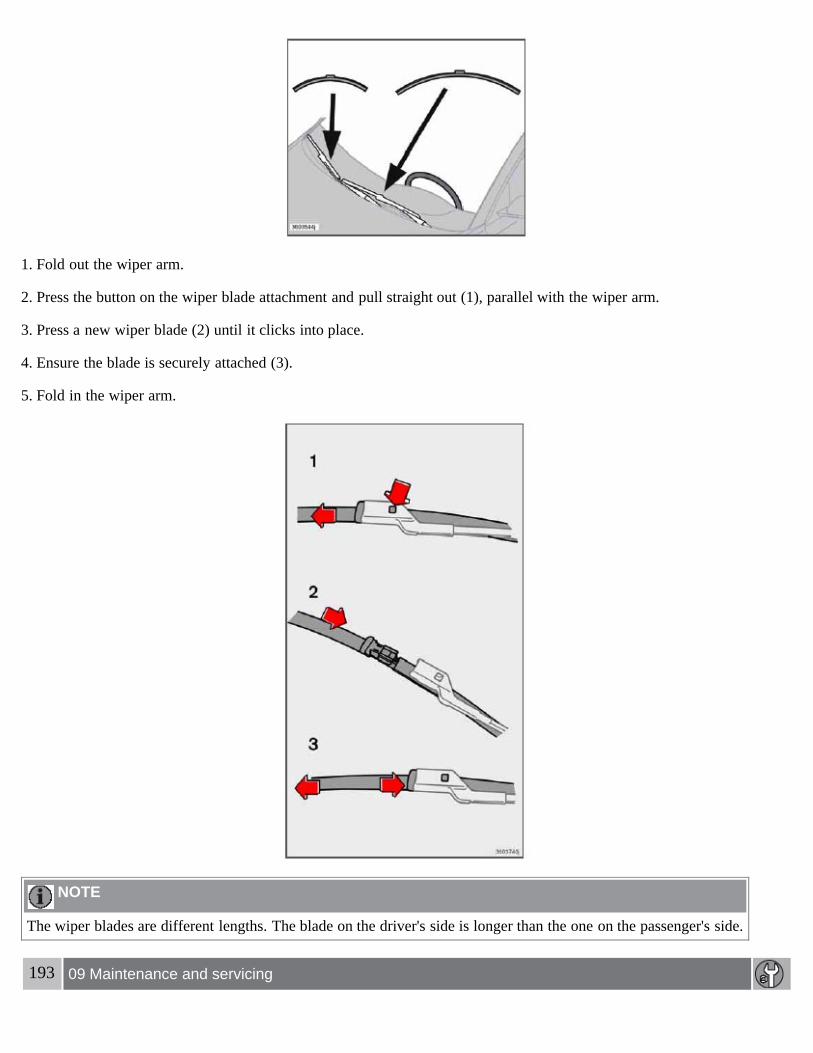
1. Fold out the wiper arm.
2. Press the button on the wiper blade attachment and pull straight out (1), parallel with the wiper arm.
3. Press a new wiper blade (2) until it clicks into place.
4. Ensure the blade is securely attached (3).
5. Fold in the wiper arm.
NOTE
The wiper blades are different lengths. The blade on the driver's side is longer than the one on the passenger's side.
193 09 Maintenance and servicing
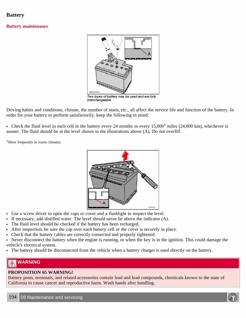
Battery
Battery maintenance
Driving habits and conditions, climate, the number of starts, etc., all affect the service life and function of the battery. Inorder for your battery to perform satisfactorily, keep the following in mind:
Check the fluid level in each cell in the battery every 24 months or every 15,0001 miles (24,000 km), whichever issooner. The fluid should be at the level shown in the illustrations above (A). Do not overfill.
1More frequently in warm climates.
Use a screw driver to open the caps or cover and a flashlight to inspect the level. If necessary, add distilled water. The level should never be above the indicator (A). The fluid level should be checked if the battery has been recharged. After inspection, be sure the cap over each battery cell or the cover is securely in place. Check that the battery cables are correctly connected and properly tightened. Never disconnect the battery when the engine is running, or when the key is in the ignition. This could damage the
vehicle's electrical system. The battery should be disconnected from the vehicle when a battery charger is used directly on the battery.
WARNING
PROPOSITION 65 WARNING!Battery posts, terminals, and related accessories contain lead and lead compounds, chemicals known to the state ofCalifornia to cause cancer and reproductive harm. Wash hands after handling.
194 09 Maintenance and servicing

Battery
Battery symbols
Battery replacement
Removing the battery1. Switch off the ignition and remove the key.
2. Wait at least 5 minutes after switching off the ignition before disconnecting the battery so that all information in thevehicle's electrical system can be stored in the control modules.
3. Remove the cover over the battery.
4. Disconnect the battery negative (ground) cable.
5. Disconnect the positive cable.
6. Remove the front side of the battery box with a screwdriver.
7. Release the clamp holding the battery.
8. Lift out the battery.
Installing a new battery1. Put the battery in place in the engine compartment.
2. Install the battery's retaining clamp.
3. Reinstall the front side of the battery box.
4. Connect the positive cable.

5. Connect the ground cable.
6. Reinstall the cover over the battery.
NOTE
Used batteries should be properly disposed of at a recycling station or similar facility, or taken to your Volvo retailer.
WARNING
Never expose the battery to open flame or electric spark. Do not smoke near the battery. Battery fluid contains sulfuric acid. Do not allow battery fluid to contact eyes, skin, fabrics or painted surfaces. If
contact occurs, flush the affected area immediately with water. Obtain medical help immediately if eyes are affected.
195 09 Maintenance and servicing
Bulbs
Bulbs used in the car
NOTE
Never touch the glass of bulbs with your fingers. Grease and oils from your fingers vaporize in the heat and will leavea deposit on the reflector, which will damage it.
The optional Bi-Xenon headlight bulbs contain trace amounts of mercury. These bulbs should always be disposed ofby an authorized Volvo retailer.
Certain bulbs should only be replaced by a trained and qualified Volvo service technician:- Courtesy (dome) lighting- Reading lights- Glove compartment lights- Turn signals and courtesy lights in the side door mirrors

- High-mounted brake lights- Bi-Xenon headlights
196 09 Maintenance and servicing
Replacing front bulbs
Removing the headlight housing
The entire headlight housing must be lifted out when replacing the high/low beam, parking light, turn signal, and sidemarker bulbs. To lift out the housing:
1. Remove the key from the ignition and turn the headlight switch to position 0.
2. Open the hood.
3. Pull up the headlight housing's retaining pin (1)
4. Pull the headlight housing to one side and then forward (2).
5. Disconnect the wiring connector.
6. Lift out the headlight housing and place it on a soft surface to avoid scratching the lens.
After the defective bulb has been replaced, reinsert the housing in the reverse order. Check that the retaining pin iscorrectly inserted.
WARNING
Bi-Xenon headlights (option) - due to the high voltage used by these headlights, these bulbs should only be replaced byan authorized Volvo service technician.
Low beam bulb

1. Open the hood.
2. Remove the headlight housing.
3. Press the retaining clamps to the sides.
4. Release the bulb's retaining spring by pressing it to the right, and then moving it outward and downward.
5. Pull out the bulb.
6. Disconnect the wiring connector from the bulb.
197 09 Maintenance and servicing
Replacing front bulbs
Installing a new bulb1. Insert the new bulb. It can only be installed in one position.
2. Press the retaining spring upward and slightly to the left until it snaps into place.
3. Press the wiring connector onto the bulb.
4. Put the plastic cover in place.
5. Press the retaining clamps back into place.
6. Reinstall the headlight housing.
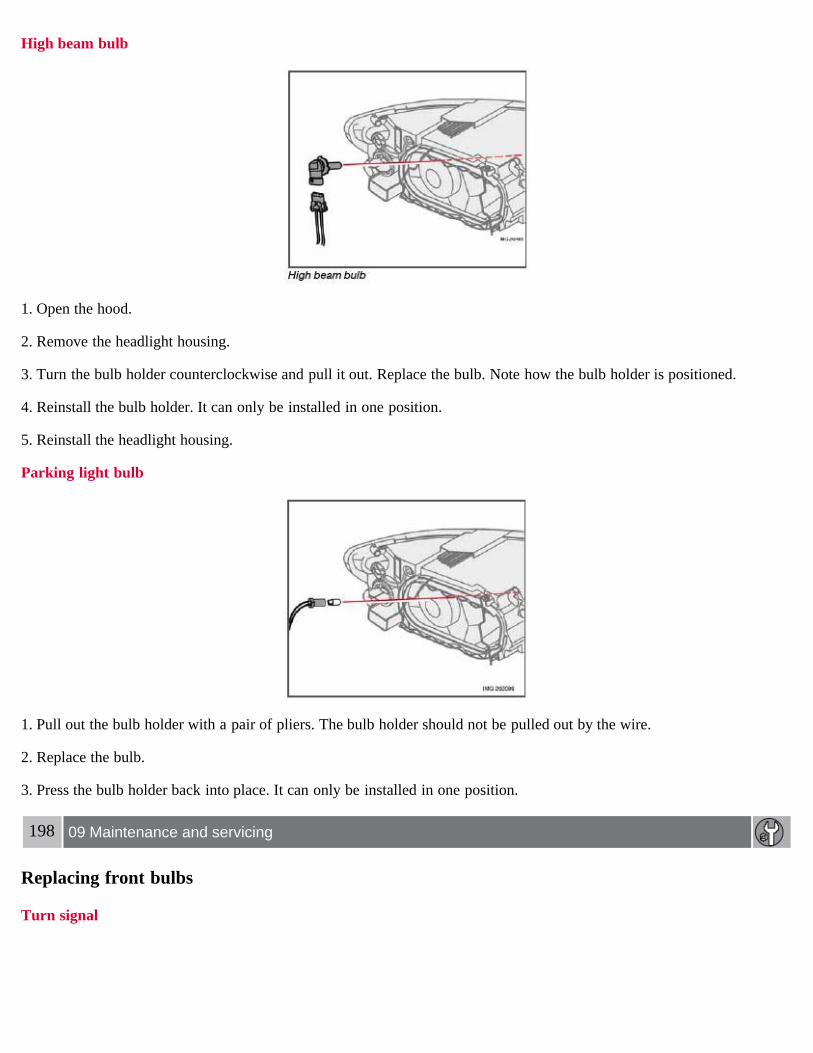
High beam bulb
1. Open the hood.
2. Remove the headlight housing.
3. Turn the bulb holder counterclockwise and pull it out. Replace the bulb. Note how the bulb holder is positioned.
4. Reinstall the bulb holder. It can only be installed in one position.
5. Reinstall the headlight housing.
Parking light bulb
1. Pull out the bulb holder with a pair of pliers. The bulb holder should not be pulled out by the wire.
2. Replace the bulb.
3. Press the bulb holder back into place. It can only be installed in one position.
198 09 Maintenance and servicing
Replacing front bulbs
Turn signal

1. Turn the bulb holder counterclockwise and remove it.
2. Remove the bulb from the holder by pressing it in and twisting it counterclockwise.
3. Insert a new bulb and reinstall the bulb holder in the headlight housing.
Side marker light
1. Turn the bulb holder counterclockwise, pull it out, and replace the bulb.
2. Reinstall the bulb holder. It can only be installed in one position.
Front fog light (option)
1. Switch off all lights and turn the key to position 0.
2. Remove the panel around the fog light housing.
3. Unscrew both torx screws in the fog light housing and remove it.

4. Disconnect the connector from the bulb.
5. Turn the bulb counterclockwise and pull it out.
6. Install the new bulb in its seat and turn it clockwise.
7. Reconnect the connector to the bulb.
199 09 Maintenance and servicing
Replacing front bulbs
8. Secure the fog light housing with the screws and press the panel back into place.
200 09 Maintenance and servicing
Replacing taillight bulbs
Removing the taillight bulb holder
All bulbs in the taillight cluster can be replaced from the cargo area. To access the bulb holders:
1. Switch off all lights and turn the key to position 0.
2. Remove the covers in the left/right panels to access the bulb holders.
3. Disconnect the wiring connector from the affected bulb holder.
4. Press the catches together and pull out the bulb holder.
5. Replace the defective bulb.

6. Press the wiring connector back into position.
7. Press the bulb holder into place and reinstall the cover.
Location of taillight bulbs
NOTE
If the message indicating a burned out bulb remains in the information display after the bulb has been replaced, consultan authorized Volvo retailer or workshop.
High-level brake lightThese bulbs should only be replaced by an authorized Volvo service technician.
201 09 Maintenance and servicing
Replacing interior bulbs
License plate lighting
1. Switch off all lights and turn the key to position 0.

2. Remove the screw with a screw driver.
3. Detach the entire bulb housing and carefully pull it out. Turn the connector counterclockwise and pull out the bulb.
4. Replace the bulb.
5. Reinstall the connector and turn it clockwise.
6. Reinstall the entire bulb housing and screw it into place.
Footwell lighting
The footwell lighting is located under the dashboard on the driver's and passenger's sides. To replace a bulb:
1. Insert a screwdriver under the edge of the lens. Turn the screwdriver gently to detach the lens.
2. Remove the defective bulb.
3. Install a new bulb.
4. Press the lens back into place.
Cargo area lighting
1. Insert a screwdriver and turn it gently to detach the bulb housing.
2. Remove the defective bulb.
3. Install a new bulb.
4. Press the bulb housing back into place.
Vanity mirror lighting
1. Insert a screwdriver under the center of the lower edge of the mirror, turn it, and carefully pry up the lugs at the edge.
2. Move the screwdriver under the edge on the left and right-hand sides (near the black rubber sections) and pry carefullyto release the lower edge of the mirror.
3. Pry carefully and lift out the entire mirror and the cover.
4. Remove the defective bulb and replace it with a new one.
5. To reinstall the mirror, begin by pressing the three lugs at the upper edge of the mirror back into place.

6. Press the three lower lugs back into place.
202 09 Maintenance and servicing
Fuses
Fuse box in the engine compartment
The fuse box in the engine compartment has positions for 36 fuses.
Fuses 1-18 are relays/circuit breakers and should only be removed or replaced by an authorized Volvo servicetechnician.
Fuses 19-36 may be changed at any time when necessary.
Several extra fuses and a fuse removal tool to assist in removing/replacing fuses can be found on the underside of the fusebox cover in the engine compartment.
Replacing fuses
There are relay/fuse boxes located in the engine compartment and the passenger compartment.
If an electrical component fails to function, this may be due to a blown fuse. The easiest way to see if a fuse is blown is toremove it.
To do so:
1. Pull the fuse straight out. If a fuse is difficult to remove, special fuse removal tools are located on the inside of the fusebox covers.
2. From the side, examine the curved metal wire in the fuse to see if it is intact.
3. If the wire is broken, insert a new fuse of the same color and amperage (written on the fuse).
If fuses burn out repeatedly, have the electrical system inspected by an authorized Volvo retailer.
WARNING
Never use fuses with higher amperage than those stated in the following tables. Doing so could overload the vehicle'selectrical system.
203 09 Maintenance and servicing

Fuses
Fuse box in the passenger compartment
The fuse box in the passenger compartment is located under the glove compartment.
To access the fuses:
1. Remove the upholstery covering the fuse box by first pressing in the center pins in the mounting clips approximately 0.5in (1 cm) with a small screwdriver and then pulling the pins out.
2. Turn both retaining screws (2) counterclockwise until they release.
3. Fold down the fuse box (3) half way. Pull it toward the seat until it stops. Fold it down completely. The fuse box can beunhooked completely.
4. Replace the blown fuse.
5. Close the fuse box in reverse order.
6. Pull the center pins fully out of the mounting clips, secure the upholstery with the mounting clips and press the pins intothe mounting clips again. The mounting clips then expand, holding the upholstery in position.
204 09 Maintenance and servicing
Fuses
Fuses in the engine compartment
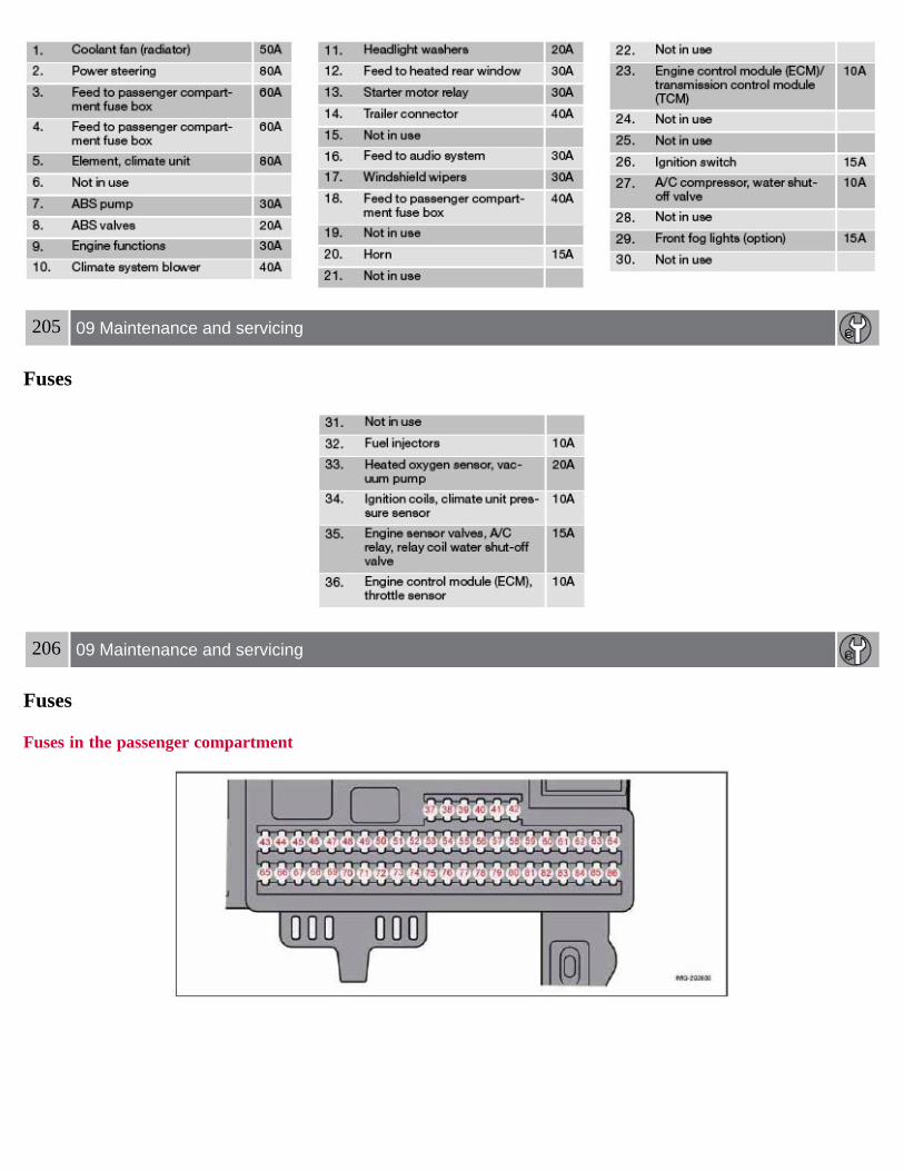
205 09 Maintenance and servicing
Fuses
206 09 Maintenance and servicing
Fuses
Fuses in the passenger compartment

207 09 Maintenance and servicing
Fuses
Contents | Top of Page

2 0 0 7VOLVO
S40
208 10 Audio
Audio functions 210Radio functions 213Sirius satellite radio (option or retailer-installed accessory) 215CD player/CD changer (option) 219Audio menu 223
209 10 Audio
210 10 Audio
Audio functions
Audio system controls
1. VOLUME dial
2. AM/FM - select a radio band
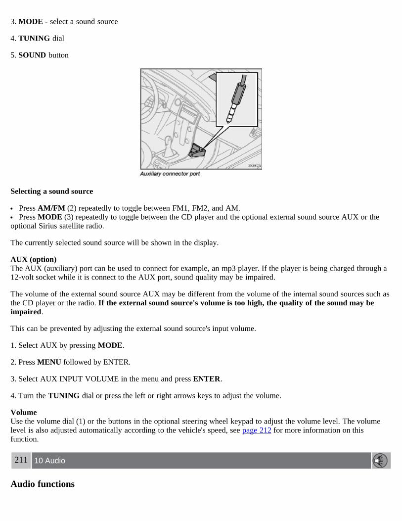
3. MODE - select a sound source
4. TUNING dial
5. SOUND button
Selecting a sound source
Press AM/FM (2) repeatedly to toggle between FM1, FM2, and AM. Press MODE (3) repeatedly to toggle between the CD player and the optional external sound source AUX or the
optional Sirius satellite radio.
The currently selected sound source will be shown in the display.
AUX (option)The AUX (auxiliary) port can be used to connect for example, an mp3 player. If the player is being charged through a12-volt socket while it is connect to the AUX port, sound quality may be impaired.
The volume of the external sound source AUX may be different from the volume of the internal sound sources such asthe CD player or the radio. If the external sound source's volume is too high, the quality of the sound may beimpaired.
This can be prevented by adjusting the external sound source's input volume.
1. Select AUX by pressing MODE.
2. Press MENU followed by ENTER.
3. Select AUX INPUT VOLUME in the menu and press ENTER.
4. Turn the TUNING dial or press the left or right arrows keys to adjust the volume.
VolumeUse the volume dial (1) or the buttons in the optional steering wheel keypad to adjust the volume level. The volumelevel is also adjusted automatically according to the vehicle's speed, see page 212 for more information on thisfunction.
211 10 Audio
Audio functions

Steering wheel keypad (option )
The four buttons on the steering wheel keypad can be used to control the audio system. The steering wheel keypad canbe used to adjust volume, shift between preset stations and change CD tracks. Press one of the two left-hand buttonsbriefly to change to the next/previous preset radio station, or to go to the next/previous track on a CD. Press and holddown these buttons to search within a track on a CD.
Daytime/twilight displayIn daylight the information is displayed against a light background. In darkness it is displayed against a darkbackground.
Sound settings1. Press SOUND (5). Press this button repeatedly until you come to the setting that you wish to change.
2. Turn the TUNING dial (4) to make the desired setting.
The following settings can be made:
BASS-set the bass level
TREBLE-set the treble level
BALANCE-set the left/right sound balance
FADER-set the front/rear sound balance
SUBWOOFER (accessory)-set the level for the subwoofer (bass speaker)
CENTER1-make settings for the center speaker
SURROUND1-make settings for surround sound
1Premium Sound System only
Subwoofer (accessory)To switch the subwoofer on or off:
1. Press MENU followed by ENTER.
2. Select AUDIO SETTINGS and press ENTER.

3. Select SUBWOOFER and press ENTER.
Surround sound
Surround sound settings are used to balance sound levels throughout the vehicle. Surround settings for the varioussound sources are made separately.
NOTE
Dolby Surround Pro Logic II is only available on the Premium Sound system. When listening to FM radio stations, Dolby Surround Pro Logic II functions best in areas with strong reception. If
reception is weak, selecting 2 or 3-channel stereo may provide better sound quality.
The Dolby symbol will be appear in the display when Dolby Pro Logic II is activated.
There are three alternative settings:
Pro Logic II 3-channel
212 10 Audio
Audio functions
Off (normal 2-channel stereo)
Activating/deactivating Surround sound1. Press MENU followed by ENTER.
2. Select AUDIO SETTINGS in the menu and press ENTER.
3. Select Surround FM/AM/CD/AUX and press ENTER.
4. Select PRO LOGIC II, 3-channel stereo or OFF and press ENTER.
Equalizer Front/RearThis function is used to fine-tune the sound level for different frequencies separately.
NOTE
This function is only available on certain sound systems.
To adjust the equalizer settings:
1. Press MENU followed by ENTER.
2. Select AUDIO SETTINGS in the menu and press ENTER.
3. Select EQUALIZER FRONT/REAR and press ENTER.
The column in the display indicates the sound level for the current frequency.

Adjust the level with the TUNING dial (4), or use the Up/Down arrows. Additional frequencies can be selectedwith the Right/Left arrows.
Save the settings by pressing ENTER or exit without saving by pressing EXIT.
Automatic sound controlThe audio system's volume is adjusted automatically according to the speed of the vehicle. There are three settingsavailable, which determine the level of volume compensation:
LOWMEDIUM*HIGH
* Default setting.
To set the automatic sound level:
1. Press MENU followed by ENTER.
2. Select AUDIO SETTINGS in the menu and press ENTER.
3. Select AUTO. VOLUME CONTROL in the menu and press ENTER.
4. Select LOW, MEDIUM, or HIGH and press ENTER.
213 10 Audio
Radio functions
Radio function controls
1. AM/FM1/FM2 selection
2. Station preset buttons
3. TUNING dial for selecting radio stations
4. SCAN
5. MENU NAVIGATION CONTROL-press the up or down arrow keys to scroll in a menu, or the keys on theleft/right sides of the control to search for or change radio stations/CD tracks

6. EXIT-press to cancel a menu selection or a selected function
7. AUTO-search for and store the strongest radio stations in the area in which you are driving
Searching for stationsThere are two ways to manually tune a radio station:
1. Turn the TUNING dial (3) to the desired frequency.
2. Press the left or right arrow key on the MENU NAVIGATION CONTROL and hold it down. The radio scansslowly in the selected direction and will increase the scanning speed after a few seconds. Release the button when thedesired frequency appears in the display.
The frequency can be fine-tuned by short presses on the left/right arrow keys.
Storing preset stations
Manually storing a station1. Tune to the desired station.
2. Press and hold the preset button under which the station is to be stored. The audio system sound will be interruptedfor a few seconds and STATION STORED will appear in the display.
NOTE
A total of 30 stations can be stored; 10 stations each in AM, FM1 and FM2.
Automatically storing a stationPressing AUTO (7) automatically searches for and stores up to ten strong AM or FM stations in a separate memory. Ifmore than ten stations are found, the ten strongest ones are stored. This function is especially useful in areas in whichyou are not familiar with radio stations or their frequencies.
To use the AUTO function:
1. Select a waveband using the AM/FM button (1).
2. Start the search by pressing AUTO until AUTO STORING appears in the display.
When the search is completed, AUTO STORING will no longer be displayed. If there are no stations with sufficientsignal strength, NO AST FOUND is displayed.
The auto-stored stations can be selected using the preset buttons (2).
Press EXIT (6) to terminate the automatic storing function.
When the radio is in auto-store mode, AUTO is shown in the display. AUTO disappears when you return to normalradio mode, which can be done by briefly pressing AM/FM (1), EXIT (6), or AUTO (7).
214 10 Audio
Radio functions
To return to the Auto-store mode, press the AUTO button briefly and select a stored station by pressing one of thepreset buttons (2).

Saving auto-stored stations in the preset memoryAn auto-stored station can be saved in the memory for manually preset stations.
1. Press AUTO (7) briefly.
2. Auto is displayed.
3. Press one of the preset buttons (2) under which the station is to be stored. Hold down the button until STATIONSTORED is displayed.
The radio will then exit auto-store mode and the stored station can be selected by pressing the preset button.
Scanning
SCAN (4) automatically searches through the selected waveband for strong AM or FM stations. When the radio finds astation, that station will be played for approximately 8 seconds, after which scanning resumes.
Activating/deactivating SCAN
1. Select radio mode using the AM/FM button (2).
2. Press SCAN to activate the function. SCAN is shown in the display.
3. Press the SCAN or EXIT button to deactivate the scan function and listen to the selected station.
Storing a station found with SCANA station can be stored as a preset while the SCAN function is activated.
Press one of the preset buttons (2) under which the station is to be stored. Hold down the button until STATIONSTORED is displayed.
The SCAN function will be deactivated and the station can be selected by pressing the preset button.
Radio text
Certain stations broadcast program information, which can be shown in the display.
To start this function:
1. Select FM1 or FM2 and press the MENU button.
2. Press ENTER.
3. Select RADIOTEXT in the menu and press ENTER.
To deactivate this function, select RADIOTEXT again and press ENTER.
215 10 Audio
Sirius satellite radio (option or retailer-installed accessory)
Listening to satellite radio
The Sirius satellite system consists of a number of high elevation satellites in geosynchronous orbit.

NOTE
The digital signals from the Sirius satellites are line-of-sight, which means that physical obstructions such as bridges,tunnels, etc, may temporarily interfere with signal reception.
Selecting Sirius radio mode1. Press Power to switch on the audio system (see page 213 for information on the standard radio functions).
2. Press the MODE button repeatedly until Sirius 1 or 2 is displayed.
Activating Sirius radio1. Tune to a satellite channel that has no audio, which means that the channel is unsubscribed and the text "CALL 888-539-SIRIUS TO SUBSCRIBE" is displayed (see also "Selecting a channel" below).
2. Call Sirius at 1-888-539-SIRIUS (7474).
3. When asked for the Sirius ID number press AUTO to display this number. It is also possible to retrieve the Sirius IDfrom the MENU.
4. "UPDATING SUBSCRIPTION" will be displayed while the subscription is being updated, after which the displaywill return to the normal view.
SIRIUS IDThe SIRIUS ID is required when contacting the Sirius Call Center. It is used to activate your account and when makingany account transactions. The SIRIUS ID is sometimes referred to as the Electronic Serial Number (ESN).
Selecting a channel category1. Select Sirius radio mode as described above.
2. Press ENTER.
3. Use the up/down arrow keys to scroll through the list of categories.
4. Press ENTER or the right arrow key to select a category.
5. Use the left or right arrow keys to select a channel in the currently chosen category.
6. Press ENTER to listen to a channel.
NOTE
The category "All" is default, which enables you to scroll through the entire list of available satellite channels. The channel categories are automatically updated several times a year. This takes approximately two minutes and
will interrupt normal broadcasting. A message will be displayed while updating is in progress. Information onchannel or feature updates is available at www.sirius.com.
Selecting a channelThere are three ways of tuning in a channel:
Using the left and right arrow keys By turning the tuning control Through direct channel entry
Direct channel entry

The Sirius satellite channels are numbered consecutively throughout all of the categories. To access a channel directly:
1. Press MENU and scroll to "Direct channel entry."
2. Use the numerical keypad to enter the channel's number.
3. Press ENTER. The radio will tune to this channel, even if it belongs to a category other than the currently selectedone.
216 10 Audio
Sirius satellite radio (option or retailer-installed accessory)
NOTE
The numbers of skipped or locked channels will not be displayed. If a channel is locked, the access code must be entered before the channel can be selected. See "Unlocking a
channel" on page 217.
Scanning
NOTE
SCAN automatically searches through the list of satellite channels. See page 214 for more detailed information.
Storing a channel
A long press on one of the number keys stores the currently tuned channel on that key. A short press on a number key while the radio is in Sirius 1or 2 mode will tune to the preset satellite channel stored
on that button, regardless of the currently selected channel category.
Song Seek and Song Memory
The Song Seek and Song Memory functions provide both audio and visual notification when Sirius is broadcastingyour favorite songs. Song Seek enables you to store the name of the song for future advance notification when thatsong is being played. The Song Memory feature makes it possible to view all of the current songs that are stored inmemory.
Song memoryUp to ten songs can be saved in the system's memory.
1. Press MENU.
2. Scroll to "ADD SONG TO SONG MEM." and follow the instructions shown in the display.
If a new song is selected when the memory is full, you will be prompted to press ENTER to delete the last song onthe list.
NOTE
The remaining songs in the list will move down one position, and the newly added song will be placed at the top ofthe list.
Song seekWhen a satellite radio channel plays one of the songs stored in the song memory, the listener will be alerted by a textmessage and an audible signal.
Press ENTER to listen to the song or EXIT to cancel.
To activate/deactivate the song seek function:
1. Press MENU
2. Scroll to "SONG SEEK"
3. Press ENTER to activate or deactivate the function.
NOTE
When the song has ended, the radio will remain tuned to the channel on which the song was played.
Radio textThe text that is displayed about the song that is currently playing can be changed. Use the AUTO button or the menuto display the ARTIST, TITLE, COMPOSER, or switch RADIO TEXT OFF.
217 10 Audio
Sirius satellite radio (option or retailer-installed accessory)
Advanced settings
This menu function enables you to make settings on certain Sirius satellite radio functions.
To access this menu:
1. Press MENU.
2. Scroll to Sirius menu.
3. Select ADVANCED SIRIUS SETTINGS .
WARNING
Settings should be made when the vehicle is at a standstill.
The following settings can be made in the Sirius menu.
Songs can be added to the song list Channel skip settings can be made Channel lock settings can be made The channel access code can be displayed or changed Your Sirius ID can be displayed
Skip optionsThis function is used to remove a channel from the list of available channels.

Skip current1. Select CHANNEL SKIP LIST and press ENTER.
2. Select a category in the list and press ENTER.
3. Skip channels in the list presented by pressing ENTER or right arrow key.
Unskip all channelsThis permanently removes all channels from the skip list and makes them available for selection.
Temp. unskip all ch.This function will temporarily unskip all channels and make them available for selection. The channels remain on theskip list and will again be skipped the next time the ignition is switched on.
Channel lockAccess to specific channels can be restricted (locked). A locked channel will not provide audio, song titles, or artistinformation.
NOTE
All channels are initially unlocked.
Locking a channel:1. Select "SIRIUS ID" in the menu and select LOCK OPTIONS and press ENTER.
2. Select CHANNEL LOCK LIST and press ENTER
3. Enter the channel access code and press ENTER.
4. Select a category in the list and press ENTER.
5. Lock channels in the list presented by pressing ENTER or right arrow.
The channel is now locked and a checked box will be displayed to indicate this. It will be necessary to enter thechannel access code1 in order to listen to a locked channel.
Unlocking a channel:A channel's access code1 is required to unlock a channel.
Unlock all channelsThis permanently removes all channels from the locked list and makes them available for selection.
Temp. unlock all ch.This function will temporarily unlock all channels and make them available for selection. The channels remain on thelocked list and will again be locked the next time the ignition is switched on.
218 10 Audio
Sirius satellite radio (option or retailer-installed accessory)
CHANGE CODEThis function makes it possible to change the channel access code. The default code is 0000.

To change the code:
1. Select CHANGE CODE and press ENTER.
2. Enter the current code and press ENTER.
3. Enter the code and press ENTER.
4. Confirm the new code and press ENTER.
If an incorrect code is entered, the text WRONG CODE! is displayed.
If you have forgotten the access code:
1. Select "SIRIUS ID" in the Sirius settings menu and press ENTER.
2. Press and hold the ENTER button for 2 seconds.
3. The current code will be displayed.
Your Volvo retailer can also provide you with assistance.
SIRIUS IDThis function displays the 12-digit Sirius activation ID.
219 10 Audio
CD player/CD changer (option)
CD function controls
1. MENU NAVIGATION CONTROL-press the up or down arrow keys to scroll in a menu, or the keys on theleft/right sides of the control to change CD tracks/fast forward/back
2. Buttons for selecting a disc in the optional CD changer
3. CD eject button
4. CD slot
5. MODE button

6. TUNING dial for selecting tracks
Playing a CD
Single CD playerStart the CD player by pressing the MODE button (5) and inserting a disc in the slot (4). If there is already a discinserted, it will begin to play.
NOTE
If a CD is in the slot when the audio system is in CD mode, the CD will be played automatically.
CD changerThe CD changer can hold up to six discs.
1. Start the CD changer by pressing the MODE button (5).
2. Select an empty position using the 1-6 buttons or the up/down keys on the MENU NAVIGATION CONTROL. Thedisplay shows which positions are empty.
3. Insert a disc into the slot (4).
NOTE
Ensure that INSERT DISC is displayed before inserting a disc. If a CD position in the changer containing a disc is selected, and the audio system is in CD mode when it is
switched on, the CD will play automatically.
CD ejectEject from Single CD playerPress the eject button (3) to eject the disc.
Eject from CD changerThis function makes it possible to eject a single disc, or to eject all of the discs in the changer.
Press the eject button (3) briefly to eject the disc that is currently playing. A longer press (more than two seconds) starts the process of ejecting all of the discs in the changer.
220 10 Audio
CD player/CD changer (option)
NOTE
The EJECT ALL function can only be used while the vehicle is at a standstill and will be cancelled if the vehiclebegins to move.
For reasons of traffic safety, the ejected CD must be removed within 12 seconds or it will be automatically drawnback into the slot and the CD player will enter pause mode. Press the CD button to restart the disc.
CD PauseWhen the audio system volume is turned off completely, the CD player will pause and will resume playing when thevolume is turned up again.

Audio filesIn addition to playing normal music CDs, the CD player/changer can also play discs containing files in mp3 or wmaformat.
NOTE
Certain discs that are copy protected cannot be read by the player.
When a disc with audio files is inserted in the player, the player scans the disc's folders before it begins playing thefiles. The length of time that this takes depends on the quality of the disc.
Navigating the disc and playing tracksIf a disc with audio files is in the CD player, press ENTER to display a list of folders on the disc.
Use the up and down arrows in the navigation control (see the illustration on page 219) to move among the folders onthe disc. Audio files have the symbol and folders containing these files have the symbol. Press ENTER to play aselected folder or a file.
When the music file has been played, the player will continue to play the rest of the files in the current folder. Whenall of the files in the folder have been played, the player will automatically go to the next folder and play the files in it.
Press the left or right arrow key on the navigation control if the entire name of the current track does not fit in thedisplay.
Changing tracksBriefly press the left or right arrow keys on the MENU NAVIGATION CONTROL to skip to the previous or nexttrack/file.
NOTE
The TUNING dial (6) (turn clockwise to go to the next track/file, or counterclockwise to go to the previoustrack/file) or the optional steering wheel keypad can also be used for this purpose.
Fast forward/backPress and hold down the left or right arrows keys in the MENU NAVIGATION CONTROL (or the correspondingkeys on the optional steering wheel keypad) to search within a track/file or the whole disc. The search continues for aslong as the buttons are held down.
Random playThis function plays the tracks/files on a CD (or on all of the CDs if the vehicle is equipped with the optional CDchanger) in random order (shuffle).
221 10 Audio
CD player/CD changer (option)
Activating/deactivating the random function-CD player
If a normal CD is being played:
1. Press MENU followed by ENTER.

2. Select Random and press ENTER.
If a CD with audio files is being played:
1. Press MENU followed by ENTER.
2. Select RANDOM and press ENTER.
3. Select DISC or FOLDER and press ENTER.
Activating/deactivating the random function-CD changer
If a normal CD is being played:
1. Press MENU followed by ENTER.
2. Select RANDOM and press ENTER.
3. Select SINGLE DISC or ALL DISCS and press ENTER.
If a CD with audio files is being played:
1. Press MENU followed by ENTER.
2. Select RANDOM and press ENTER.
3. Select SINGLE DISC or FOLDER and press ENTER.
NOTE
CD changer only-you can only select the next random track/file on the current disc.
Press the EXIT button to stop random play. The random function is automatically deactivated when another disc isselected.
Disc text (CD changer only)Certain CDs contain information about the disc, such as the titles of the tracks, etc. This information can be shown inthe display by activating the DISC TEXT function.
1. Press MENU. Select the menu for relevant sound source and press ENTER.
2. Select DISC TEXT in the menu and press ENTER.
3. If information is stored on the disc, it will now appear in the display.
To deactivate this function, select DISC TEXT in the menu and press ENTER.
ScanThis function plays the first 10 seconds of each track/file on the CD.
1. Press SCAN.
2. Press EXIT or SCAN to stop the scan function and listen to an entire track/ file.
CD ejectSingle CD player

Press the eject button (3) to eject the disc.
CD changerThis function makes it possible to eject a single disc, or to eject all of the discs in the changer.
Press the eject button (3) briefly to eject the disc that is currently playing. A longer press (more than two seconds) starts the process of ejecting all of the discs in the changer.
NOTE
The Eject all function can only be used while the vehicle is at a standstill and will be cancelled if the vehiclebegins to move.
For reasons of traffic safety, the ejected CD must be removed within 12 seconds or it will be automatically drawnback into the slot and the CD player will enter pause mode. Press the CD button to restart the disc.
Compact disc care
Keep the following in mind when playing/ handling compact discs
Do not put tape or labels on the disc itself. They could become stuck in the player. CDR discs can cause listening problems due to the quality of the disc or recording equipment used.
222 10 Audio
CD player/CD changer (option)
DualDisc: The audio side of a DualDisc (combined CD/DVD) does not meet CD specifications and may not play inyour audio system.
Keep the discs clean. Wipe them with a soft, clean, lint-free cloth, working from the center outward. If necessary,dampen the cloth with a neutral soap solution. Dry thoroughly before using.
Never use cleaning spray or antistatic liquid. Use only cleaners specifically made for CDs. Use discs of the correct size only (3.5" discs should never be used). Volvo does not recommend the use of plastic outer rings on the disc. Condensation may occur on discs/optical components of the changer in cold winter weather. The disc can be dried
with a clean, lint-free cloth. Optical components in the CD changer may, however, take up to one hour to dry off. Never attempt to play a damaged CD. When not in use, the discs should be stored in their covers. Avoid storing discs in excessive heat, direct sunlight or
in dusty locations.
223 10 Audio
Audio menu
FM1/FM2 menu
1. RADIOTEXT ON/OFF
2. ADVANCED RADIO SETTINGS
3. AUDIO SETTINGS
AM menu
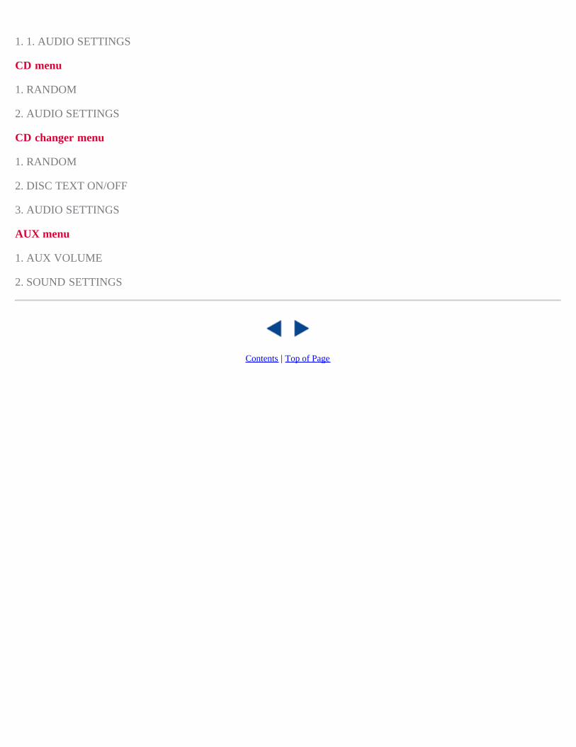
1. 1. AUDIO SETTINGS
CD menu
1. RANDOM
2. AUDIO SETTINGS
CD changer menu
1. RANDOM
2. DISC TEXT ON/OFF
3. AUDIO SETTINGS
AUX menu
1. AUX VOLUME
2. SOUND SETTINGS
Contents | Top of Page

2 0 0 7VOLVO
S40
224 11 Specifications
Label information 226Dimensions and weights 228Engine oil 231Engine specifications 233Electrical system 234Volvo programs 236
225 11 Specifications
226 11 Specifications
Label information
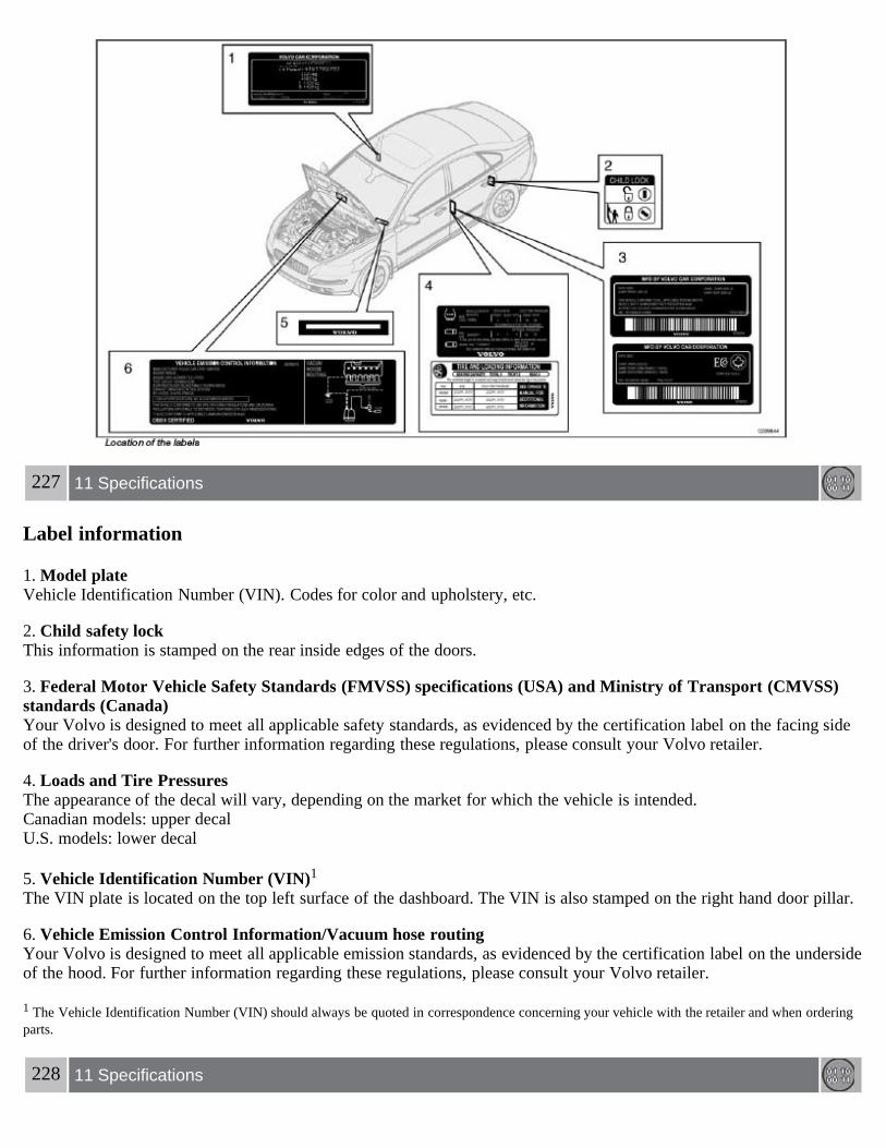
227 11 Specifications
Label information
1. Model plateVehicle Identification Number (VIN). Codes for color and upholstery, etc.
2. Child safety lockThis information is stamped on the rear inside edges of the doors.
3. Federal Motor Vehicle Safety Standards (FMVSS) specifications (USA) and Ministry of Transport (CMVSS)standards (Canada)Your Volvo is designed to meet all applicable safety standards, as evidenced by the certification label on the facing sideof the driver's door. For further information regarding these regulations, please consult your Volvo retailer.
4. Loads and Tire PressuresThe appearance of the decal will vary, depending on the market for which the vehicle is intended.Canadian models: upper decalU.S. models: lower decal
5. Vehicle Identification Number (VIN)1
The VIN plate is located on the top left surface of the dashboard. The VIN is also stamped on the right hand door pillar.
6. Vehicle Emission Control Information/Vacuum hose routingYour Volvo is designed to meet all applicable emission standards, as evidenced by the certification label on the undersideof the hood. For further information regarding these regulations, please consult your Volvo retailer.
1 The Vehicle Identification Number (VIN) should always be quoted in correspondence concerning your vehicle with the retailer and when orderingparts.
228 11 Specifications

Dimensions and weights
Dimensions
1 38.4 cu. ft. (1088 liters) with the front passenger's seat backrest folded down (certain models only).
CAUTION
The maximum permissible axle loads and/ or the gross vehicle weight must not be exceeded.
WARNING
When adding accessories, equipment, luggage and other cargo to your vehicle, the total capacity weight must not beexceeded.
229 11 Specifications
Dimensions and weights
Weights
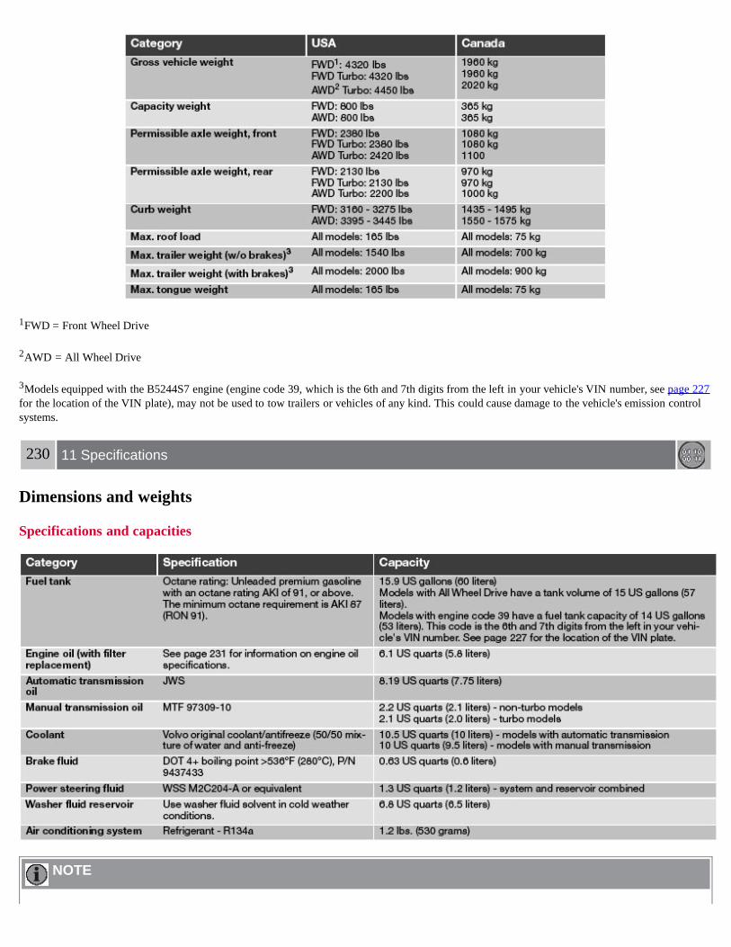
1FWD = Front Wheel Drive
2AWD = All Wheel Drive
3Models equipped with the B5244S7 engine (engine code 39, which is the 6th and 7th digits from the left in your vehicle's VIN number, see page 227for the location of the VIN plate), may not be used to tow trailers or vehicles of any kind. This could cause damage to the vehicle's emission controlsystems.
230 11 Specifications
Dimensions and weights
Specifications and capacities
NOTE

The transmission oil does not normally need to be changed during the service life of the vehicle. However, it may benecessary to replace the oil if the vehicle is often driven in areas of sustained temperature extremes (hot or cold), whentowing a trailer over long distances, for prolonged driving in mountainous areas, or if the vehicle is often driven shortdistances in temperatures under 40°F (5°C).
231 11 Specifications
Engine oil
Oil specifications
Engine oil must meet the minimum ILSAC specification GF-3, API SL, and ACEA A1/B1. Lower quality oils may notoffer the same fuel economy, engine performance, or engine protection.
Volume: 6.1 US qts (5.8 liters).
Volume between the MIN and Max marks on the dipstick: approximately 1.4 US qts (1.3 liters).
Volvo recommends .
Depending on your driving habits, premium or synthetic oils may provide superior fuel economy and engine protection.Consult your Volvo retailer for recommendations on premium or synthetic oils.
Oil additives must not be used.
NOTE
Synthetic oil is not used when the oil is changed at the normal service intervals. This oil is only used at customerrequest, at additional charge. Please consult your Volvo retailer.
Oil viscosity (stable ambient temperatures)
Operation in hot climatesWhen temperatures exceed 86° F (30° C) in your area, Volvo recommends, for the protection of your engine, that youuse a heavier weight oil, such as such as SAE 5W-40 or 0W-40. See the viscosity chart.
Operation in temperate climatesIncorrect viscosity oil can shorten engine life. Under normal use when temperatures do not exceed 86° F (30° C), SAE5W-30 will provide good fuel economy and engine protection. See the viscosity chart.

Extreme engine operationSynthetic oils meeting SAE 0W-30 or 0W-40 and complying with oil quality requirements are recommended for drivingin areas of sustained temperature extremes (hot or cold), when towing a trailer over long distances, and for prolongeddriving in mountainous areas.
1 See the information on page 232.
232 11 Specifications
Engine oil
American Petroleum Institute (API) symbolThe API Service Symbol "donut" is divided into three parts:
The upper section describes the oil's performance level. The center identifies the oil's viscosity. The lower section indicates whether the oil has demonstrated energy-conserving properties in a standard test in
comparison to a reference oil.
233 11 Specifications
Engine specifications

1 The engine specifications for horsepower and torque listed in this table are based on the use of premium fuel.
Charge air cooler (Intercooler)Turbocharged engines employ a turbo-compressor to force air into the engine inlet manifold and a charge air cooler tocool the compressed inlet air. The resulting increase in air flow raises pressure in the intake manifold and increasesengine power over that developed by the normally-aspirated engine. The charge air cooler (which resembles a radiator) islocated between the turbo-compressor and inlet manifold.
Fuel systemThe engine is equipped with a multiport fuel injection system.
234 11 Specifications
Electrical system
General information
12-volt system with voltage controlled generator. Single wire system in which the chassis and engine block are used asconductors, grounded on the chassis.
BulbsPlease refer to page 195 for a list of the bulbs used in your car.
Battery
1

Models equipped with the High Performance audio system
2Models equipped with the Premium Sound audio system, the Volvo Navigation System and/or keyless drive
If the battery must be replaced, replace it with one with the same cold start capacity and reserve capacity as the original(see the decal on the battery).
WARNING
PROPOSITION 65 WARNING!Battery posts, terminals, and related accessories contain lead and lead compounds, chemicals known to the state ofCalifornia to cause cancer and reproductive harm. Wash hands after handling.
235 11 Specifications
Electrical system
Three-way catalytic converter - general information
Keep your engine properly tuned. Certain engine malfunctions, particularly involving the electrical, fuel or distributorignition systems, may cause unusually high three-way catalytic converter temperatures. Do not continue to operate yourvehicle if you detect engine misfire, noticeable loss of power or other unusual operating conditions, such as engineoverheating or backfiring. A properly tuned engine will help avoid malfunctions that could damage the three-waycatalytic converter.
Do not park your vehicle over combustible materials, such as grass or leaves, which can come into contact with thehot exhaust system and cause such materials to ignite under certain wind and weather conditions.
Excessive starter cranking (in excess of one minute), or an intermittently firing or flooded engine can cause three-waycatalytic converter or exhaust system overheating.
Remember that tampering or unauthorized modifications to the engine, the Electronic Control Module, or the vehiclemay be illegal and can cause three-way catalytic converter or exhaust system overheating.This includes:- Altering fuel injection settings or components.- Altering emission system components or location or removing components.- Repeated use of leaded fuel.
NOTE
Unleaded fuel is required for vehicles with three-way catalytic converters.
236 11 Specifications
Volvo programs
Volvo On Call Roadside Assistance
Your new Volvo comes with a four year ON CALL roadside assistance. Additional information, features, and benefitsare described in a separate information package in your glove compartment. If you have misplaced your package, dial:In the U.S.A. 1-800-638-6586 (1-800-63- VOLVO)In Canada: 1-800-263-0475
Technician certification

In addition to Volvo factory training, Volvo supports certification by the National Institute for Automotive ServiceExcellence (A.S.E.). Certified technicians have demonstrated a high degree of competence in specific areas. Besidespassing exams, each technician must also have worked in the field for two or more years before a certificate is issued.These professional technicians are best able to analyze vehicle problems and perform the necessary maintenanceprocedures to keep your Volvo at peak operating condition.
237 11 Specifications
This page left intentionally blank.
Contents | Top of Page