200702 technical guide book - tistorycfs3.tistory.com/upload_control/download.blog?fhandle... ·...
TRANSCRIPT

PLM Technical Guide Book
IBM Product Lifecycle Management
published by
PLM Solutions, IBM Korea
February 2007 [No.32]

———————————————————————————————————————————————————————————————————————————————————————————————————————————————————————————————————————————————————————————————————————————————————————————————————————————————————————————————————— PLM Solutions, IBM KoreaPLM Solutions, IBM KoreaPLM Solutions, IBM KoreaPLM Solutions, IBM Korea 2
목 차
I. CATIA V5 Administration Fundamental – Customizing
Standards Part II .............................................................3 II. FreeStyle - Control Points ............................................8 III. Performance Benefit을 위한 설계 방법론..................... 20 IV. Notices.................................................................... 22 1. Service Pack List ................................................................................................ 22 2. Question & Answer ............................................................................................. 22

———————————————————————————————————————————————————————————————————————————————————————————————————————————————————————————————————————————————————————————————————————————————————————————————————————————————————————————————————— PLM Solutions, IBM KoreaPLM Solutions, IBM KoreaPLM Solutions, IBM KoreaPLM Solutions, IBM Korea 3
I. CATIA V5 Administration Fundamental – Customizing
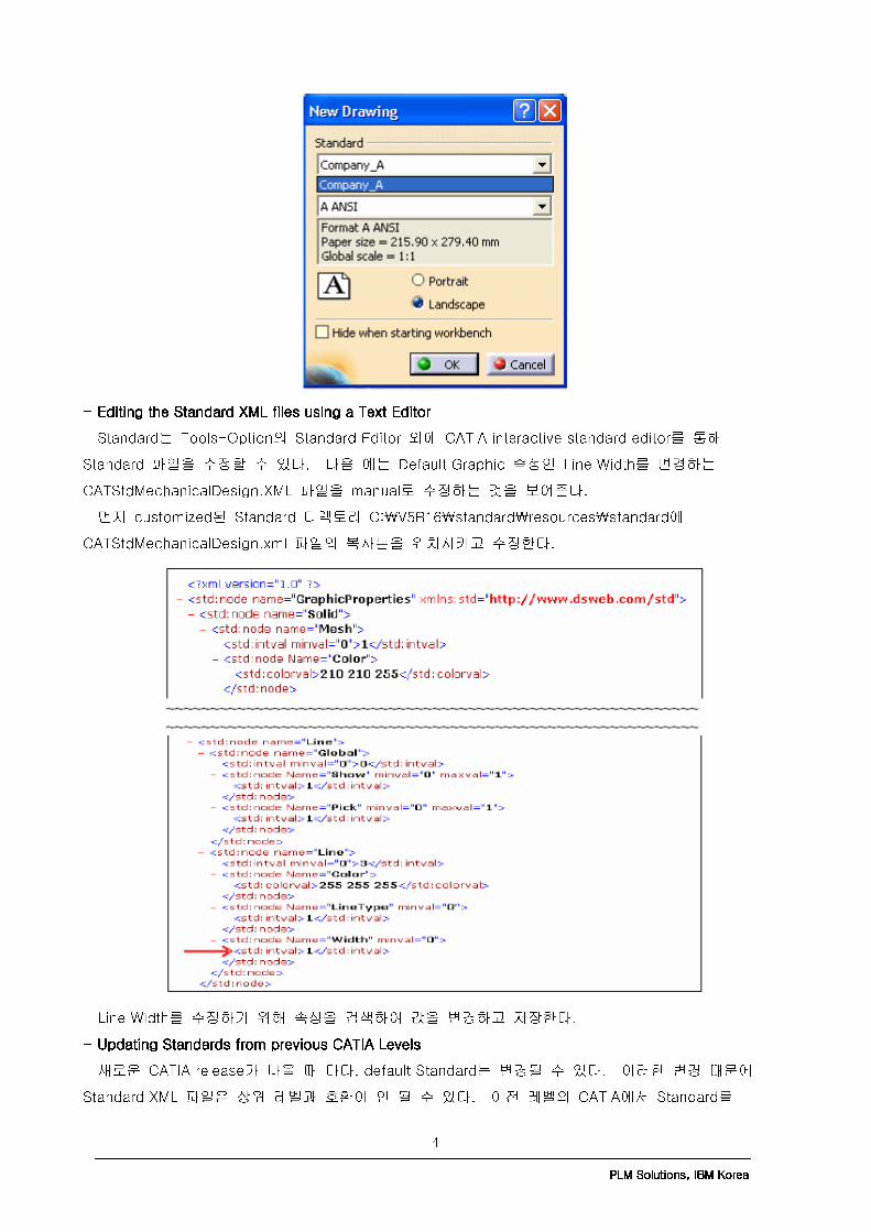
Standards Part II Based on IBM PLM Technical Support Series III. Managing the CATIA V5 StandardsIII. Managing the CATIA V5 StandardsIII. Managing the CATIA V5 StandardsIII. Managing the CATIA V5 Standards - Tips for Defining Drafting Standards DirectoriesTips for Defining Drafting Standards DirectoriesTips for Defining Drafting Standards DirectoriesTips for Defining Drafting Standards Directories 많은 유저들은 Drafting Standard만을 대체로 수정하지만 CATCollectionStandardCATCollectionStandardCATCollectionStandardCATCollectionStandard 환경변수 정의에서 실수가 발생하곤 한다. 이 문제는 변수가 Standard 디렉토리 대신 drafting 서브 디렉토리로 지정했기 때문이다. 예로 C:\CATIA\V5R16\standard 대신 C:\CATIA\V5R16\standard\drafting으로 정의한 것과 같다. ---- Tips for controlling multiple custom Tips for controlling multiple custom Tips for controlling multiple custom Tips for controlling multiple customized drafting standardsized drafting standardsized drafting standardsized drafting standards 복수의 CATIA 환경에서, Drafting Standard는 각각 다를 수 있다. 각각의 환경에서 특정한 Drafting Standard를 강제하려면, 다음의 과정을 취한다. 1. 각각의 환경에서 CATReferenceSettingPathCATReferenceSettingPathCATReferenceSettingPathCATReferenceSettingPath과 CATCollectionStandard CATCollectionStandard CATCollectionStandard CATCollectionStandard 변수에 고유의 값을 부여하고 디렉토리 구조를 만든다. 2. 각각의 환경에서 새로운 Drafting Standard를 만들고 drafting 서브 디렉토리에 XML 파일을 CATCollectionStandardCATCollectionStandardCATCollectionStandardCATCollectionStandard에 저장한다. 다른 방법은 사용하고자 하는 Drafting Standard XML 파일을 copy해서 CATCollectionStandardCATCollectionStandardCATCollectionStandardCATCollectionStandard drafting 서브 디렉토리에 paste하는 것이다. 3. Default drafting 서브 디렉토리에서 default drafting standard XML 파일이 이용 불가함을 확인한다. 예로 Windows에서: 다음의 디렉토리에 있는 XML 파일을 이동한다. C:C:C:C:\\\\Program FilesProgram FilesProgram FilesProgram Files\\\\Dassault SystemesDassault SystemesDassault SystemesDassault Systemes\\\\B16B16B16B16\\\\intel_aintel_aintel_aintel_a\\\\resourcesresourcesresourcesresources\\\\standardstandardstandardstandard\\\\draftingdraftingdraftingdrafting To C:C:C:C:\\\\Program FilesProgram FilesProgram FilesProgram Files\\\\Dassault SystemesDassault SystemesDassault SystemesDassault Systemes\\\\B16B16B16B16\\\\intel_aintel_aintel_aintel_a\\\\resourcesresourcesresourcesresources\\\\standardstandardstandardstandard\\\\draftingdraftingdraftingdrafting\\\\originaloriginaloriginaloriginal 이렇게 하는 이유는 original standard 파일을 향후에 사용할 수 있게 보존하는 것이다. 이들 과정이 취해지면, 사용자는 새로운 CATIA Drawing을 만들 때 CATCollectionStandardCATCollectionStandardCATCollectionStandardCATCollectionStandard에서 이용 가능한 Customized된 Standard를 볼 수 있다. 아래 그림처럼 선택 가능한 새로운 Standard인 Company_A.xml이다.
———————————————————————————————————————————————————————————————————————————————————————————————————————————————————————————————————————————————————————————————————————————————————————————————————————————————————————————————————— PLM Solutions, IBM KoreaPLM Solutions, IBM KoreaPLM Solutions, IBM KoreaPLM Solutions, IBM Korea 4
---- Editing the Standard XML files using a Text Editor Editing the Standard XML files using a Text Editor Editing the Standard XML files using a Text Editor Editing the Standard XML files using a Text Editor Standard는 Tools-Option의 Standard Editor 외에 CATIA interactive standard editor를 통해 Standard 파일을 수정할 수 있다. 다음 예는 Default Graphic 속성인 Line Width를 변경하는 CATStdMechanicalDesign.XML 파일을 manual로 수정하는 것을 보여준다. 먼저 customized된 Standard 디렉토리 C:\V5R16\standard\resources\standard에 CATStdMechanicalDesign.xml 파일의 복사본을 위치시키고 수정한다.
Line Width를 수정하기 위해 속성을 검색하여 값을 변경하고 저장한다. ---- Updating Standards from previous CATIA Levels Updating Standards from previous CATIA Levels Updating Standards from previous CATIA Levels Updating Standards from previous CATIA Levels 새로운 CATIA release가 나올 때 마다, default Standard는 변경될 수 있다. 이러한 변경 때문에 Standard XML 파일은 상위 레벨과 호환이 안 될 수 있다. 이전 레벨의 CATIA에서 Standard를

———————————————————————————————————————————————————————————————————————————————————————————————————————————————————————————————————————————————————————————————————————————————————————————————————————————————————————————————————— PLM Solutions, IBM KoreaPLM Solutions, IBM KoreaPLM Solutions, IBM KoreaPLM Solutions, IBM Korea 5
customize했고, 현재 상위 레벨에서 사용하고자 한다면, XML 파일이 upgrade되어야 한다. 이전 레벨에서 Non-drafting standard 파일을 customize했다면, 새로운 레벨의 Standard 파일을 통해 수정을 하는 re-customize 과정을 거쳐야 한다. Drafting Standard의 경우, 일부의 parameter만을 customize했다면 수정 작업은 쉽겠지만, 그 수가 많다면 이전의 XML 파일을 현재의 XML로 생성하는 batch utility를 활용하는 것이 좋다. Batch Utility인 CATAnnStandardTools는 Drafting Standard에 대해서만 conversion이 가능하다. Drafting Standard XML 파일을 현재 레벨로 upgrade한다면, 다음 명령어 중 하나를 실행한다. CATAnnStandardTools UPGRADE_ALL “directory for upgraded XML files”CATAnnStandardTools UPGRADE_ALL “directory for upgraded XML files”CATAnnStandardTools UPGRADE_ALL “directory for upgraded XML files”CATAnnStandardTools UPGRADE_ALL “directory for upgraded XML files” CATAnnStandardTools UPGRADE XXX “directory for upCATAnnStandardTools UPGRADE XXX “directory for upCATAnnStandardTools UPGRADE XXX “directory for upCATAnnStandardTools UPGRADE XXX “directory for upgraded XML files”graded XML files”graded XML files”graded XML files” where XXX XXX XXX XXX is the Drafting Standard name (such as Company_A.xmlCompany_A.xmlCompany_A.xmlCompany_A.xml) UPGRADE_ALL 변수를 통해 batch tool을 실행하면 CATDefaultCollectionStandardCATDefaultCollectionStandardCATDefaultCollectionStandardCATDefaultCollectionStandard와 CATCollectionStandardCATCollectionStandardCATCollectionStandardCATCollectionStandard 환경변수에서 지정된 drafting 디렉토리의 모든 Drafting Standard XML 파일을 검색하고 upgrade된 XML 파일로 변경시킨다. UPGRADE XXX 변수가 사용되면, batch tool은 특정 모든 Drafting Standard XML 파일을 검색하고 변경한다. For Windows, this command is executed in a DOS window from the directory C:C:C:C:\\\\Program FilesProgram FilesProgram FilesProgram Files\\\\Dassault SystemesDassault SystemesDassault SystemesDassault Systemes\\\\B16B16B16B16\\\\intel_aintel_aintel_aintel_a\\\\codecodecodecode\\\\binbinbinbin For UNIX, in a UNIX window cd to the directory /us/us/us/usr/DassaultSystemes/B16r/DassaultSystemes/B16r/DassaultSystemes/B16r/DassaultSystemes/B16\\\\OSOSOSOS\\\\codecodecodecode\\\\command command command command and execute one of the following commands: ./catstart ./catstart ./catstart ./catstart ----run CATAnnStandardTools UPGRADE_ALL “directory for upgraded XML files”run CATAnnStandardTools UPGRADE_ALL “directory for upgraded XML files”run CATAnnStandardTools UPGRADE_ALL “directory for upgraded XML files”run CATAnnStandardTools UPGRADE_ALL “directory for upgraded XML files” ./catstart ./catstart ./catstart ./catstart ----run CATAnnStandardTools UPGRADE XXX “directory for upgraded XML files”run CATAnnStandardTools UPGRADE XXX “directory for upgraded XML files”run CATAnnStandardTools UPGRADE XXX “directory for upgraded XML files”run CATAnnStandardTools UPGRADE XXX “directory for upgraded XML files” where XXXXXXXXX X X X is the Drafting Standard name (such as Company_A.xmlCompany_A.xmlCompany_A.xmlCompany_A.xml) ---- ““““Tools Tools Tools Tools –––– Options Options Options Options”””” for controlling Standards for controlling Standards for controlling Standards for controlling Standards 사용자가 Drafting과 DXF Standard를 변경하는 것을 막기 위해 Tools-Options의 일부 option은 lock 할 수 있다. 이를 위해서 CATIA admin mode로 접속하여 Tools-Option lock 항목을 지정할 수 있다. 다음은 두 가지의 Standard에 대한 option 항목 설정을 보여준다. 1. Drafting Standards Settings 이들 option은 Tools-Options-Mechanical Design-Drafting-Administration에 위치한다.

———————————————————————————————————————————————————————————————————————————————————————————————————————————————————————————————————————————————————————————————————————————————————————————————————————————————————————————————————— PLM Solutions, IBM KoreaPLM Solutions, IBM KoreaPLM Solutions, IBM KoreaPLM Solutions, IBM Korea 6
2. DXF/DWG Standard Settings 이들 option은 Tools-Options-General-Compatibility-DXF에 위치한다.
IV. Sharing of Customized CATIA V5 StandardsIV. Sharing of Customized CATIA V5 StandardsIV. Sharing of Customized CATIA V5 StandardsIV. Sharing of Customized CATIA V5 Standards 특정 Standard를 사용하는 CATIA 문서를 만들 필요가 있다면, 새로운 Standard 파일을 customize하거나, 기존의 customize된 standard 파일을 CATCollectionStandard 환경변수에서 정의된 디렉토리에 위치시키는 방법을 사용할 수 있다. 네트워크 접근이 가능한 하나의 워크스테이션에서 Standard 디렉토리 구조가 만들어지면, 이 구조는 공유 디렉토리를 통해 export될 수 있다. 아래 그림처럼 각각의 환경은 V5R16 폴더 아래 서브 디렉토리를 가지고 있다. 각각의 Company는 lock된 CATSetting 환경을 가지고 있는 catlock 서브 디렉토리와 필요한 Standard 환경을 가지고 있는 standard 서브 디렉토리를 가지고 있다. Company_A & Company_B는 customize된 Drafting Standards만을 가지고 있는 반면, My_Company는 customize된 Drafting, DXF/DWG, Generative Parameters를 가지고 있다.

———————————————————————————————————————————————————————————————————————————————————————————————————————————————————————————————————————————————————————————————————————————————————————————————————————————————————————————————————— PLM Solutions, IBM KoreaPLM Solutions, IBM KoreaPLM Solutions, IBM KoreaPLM Solutions, IBM Korea 7
Client 워크스테이션에서, 이 디렉토리 구조는 Windows 혹은 NFS mount된 UNIX를 통해 mapping될 수 있다. 각각의 client는 개별 company로 정의된 다른 CATIA 환경을 가져야 한다. 각 환경에서, CATReferenceSettingPath와 CATCollectionStandard 환경변수는 맞는 디렉토리에 mapping되어야 한다.

———————————————————————————————————————————————————————————————————————————————————————————————————————————————————————————————————————————————————————————————————————————————————————————————————————————————————————————————————— PLM Solutions, IBM KoreaPLM Solutions, IBM KoreaPLM Solutions, IBM KoreaPLM Solutions, IBM Korea 8
II. FreeStyle - Control Points Based on CATIA V5R16 English Documentation Tested in CATIA V5R16 SP05 이번 장은 curve와 surface를 modify하기 위한 Control Points 에 대해 알아 보도록 하겠습니다. 자세한 내용은 CATIA V5R16 English Documentation->FreeStyle Shaper, Optimizer & Profiler ->What’s New?->Enhanced Functionalities->Using Control Points를 참고하시길 바랍니다. (1) Selecting Control Points Control Points click합니다.
Support에서 Normal to compass , Options에서 Points only 를 선택합니다.<-Points only : control point들만 선택 가능합니다.

———————————————————————————————————————————————————————————————————————————————————————————————————————————————————————————————————————————————————————————————————————————————————————————————————————————————————————————————————— PLM Solutions, IBM KoreaPLM Solutions, IBM KoreaPLM Solutions, IBM KoreaPLM Solutions, IBM Korea 9
Options에서 Mesh only 를 선택합니다.<-Mesh only : mesh line들만 선택 가능합니다. * Points and mesh : point와 mesh line을 선택할 수 있도록 합니다.(Points only , Mesh only 의 혼합) Tools Dashboard Surface.1, Surface.2를 선택합니다. 2개의 surface에 Control point와 mesh가 display됩니다.

———————————————————————————————————————————————————————————————————————————————————————————————————————————————————————————————————————————————————————————————————————————————————————————————————————————————————————————————————— PLM Solutions, IBM KoreaPLM Solutions, IBM KoreaPLM Solutions, IBM KoreaPLM Solutions, IBM Korea 10
의 Manipulators Snap 을 click합니다. 첫 번째 control point를 click합니다.
두 번째 control point를 선택합니다.

———————————————————————————————————————————————————————————————————————————————————————————————————————————————————————————————————————————————————————————————————————————————————————————————————————————————————————————————————— PLM Solutions, IBM KoreaPLM Solutions, IBM KoreaPLM Solutions, IBM KoreaPLM Solutions, IBM Korea 11
(2) Editing Control Points Control Points click합니다. Surface.1을 click합니다. Support에서 Normal to compass , Options에서 Points only 를 click합니다. 다음 그림의 지정된 지점의 contextual menu에서 Edit position을 선택합니다. Z coordinate에 -50mm를 입력합니다.
, <-Point에 cursor가 가까이 가면, cross cursor가 나타납니다. Point에서 멀어지면, arrow cursor가 나타납니다. Contextual menu에서 Freeze를 click합니다.
———————————————————————————————————————————————————————————————————————————————————————————————————————————————————————————————————————————————————————————————————————————————————————————————————————————————————————————————————— PLM Solutions, IBM KoreaPLM Solutions, IBM KoreaPLM Solutions, IBM KoreaPLM Solutions, IBM Korea 12
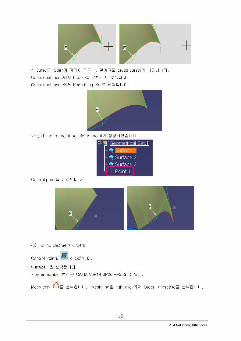
, <-cursor가 point가 가까이 가거나, 멀어져도 cross cursor가 나타납니다. Contextual menu에서 Freeze를 선택하지 않습니다. Contextual menu에서 Keep this point를 선택합니다. <-현재 control point position에 point가 생성되었습니다.
Control point를 움직입니다. , (3) Editing Geometry Orders Control Points click합니다. Surface.1을 선택합니다. * order number 변경은 CATIA V5R14 SP06 HF35와 동일함. Mesh only 를 선택합니다. Mesh line을 right click하여 Order->Increase를 선택합니다.

———————————————————————————————————————————————————————————————————————————————————————————————————————————————————————————————————————————————————————————————————————————————————————————————————————————————————————————————————— PLM Solutions, IBM KoreaPLM Solutions, IBM KoreaPLM Solutions, IBM KoreaPLM Solutions, IBM Korea 13
Mesh와 U order label이 수정되었습니다.
(4) Using Control Points Support Control Points click합니다. Surface.1 선택합니다.
Normal to compass (Points only )
———————————————————————————————————————————————————————————————————————————————————————————————————————————————————————————————————————————————————————————————————————————————————————————————————————————————————————————————————— PLM Solutions, IBM KoreaPLM Solutions, IBM KoreaPLM Solutions, IBM KoreaPLM Solutions, IBM Korea 14
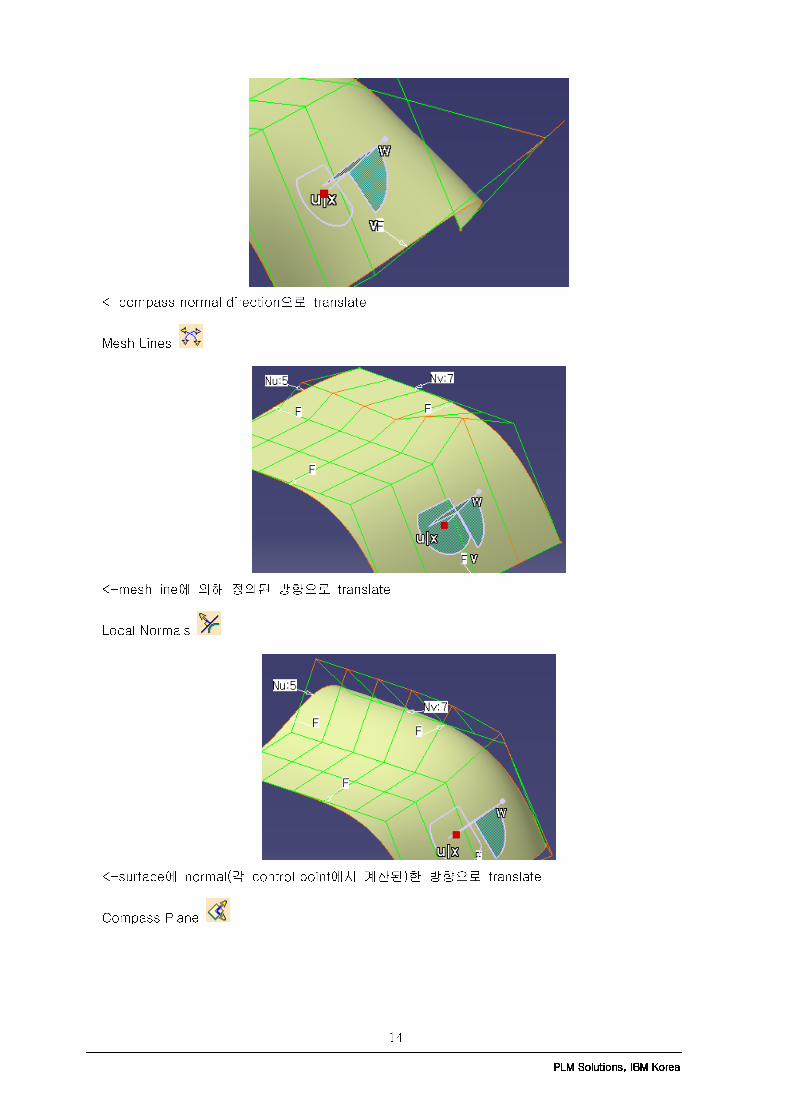
<-compass normal direction으로 translate Mesh Lines
<-mesh line에 의해 정의된 방향으로 translate Local Normals
<-surface에 normal(각 control point에서 계산된)한 방향으로 translate Compass Plane
———————————————————————————————————————————————————————————————————————————————————————————————————————————————————————————————————————————————————————————————————————————————————————————————————————————————————————————————————— PLM Solutions, IBM KoreaPLM Solutions, IBM KoreaPLM Solutions, IBM KoreaPLM Solutions, IBM Korea 15
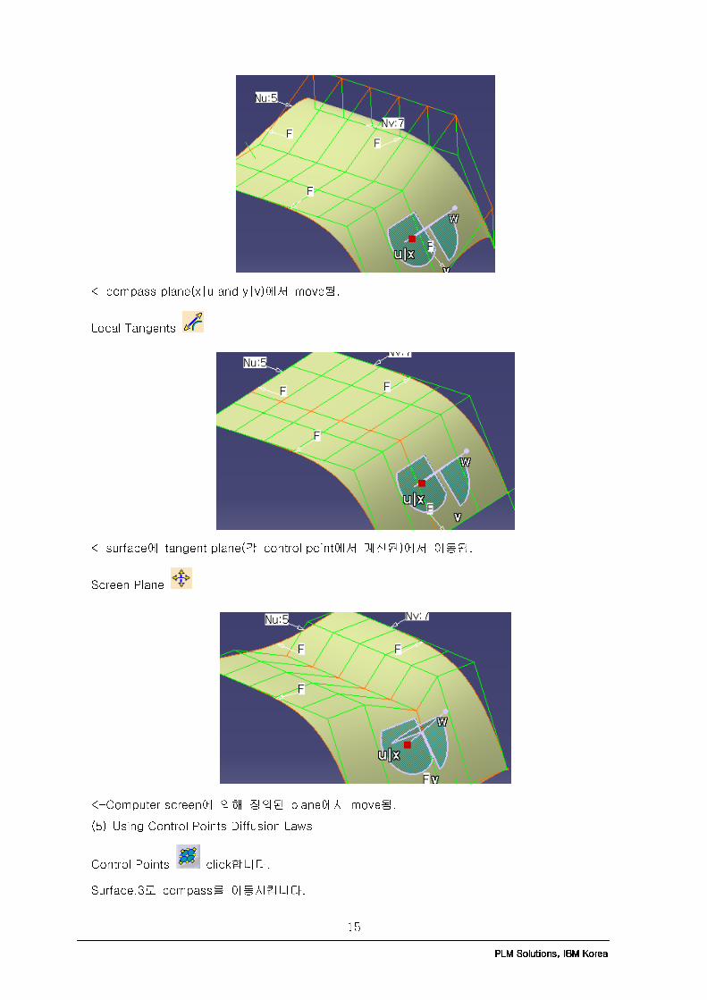
<-compass plane(x|u and y|v)에서 move됨. Local Tangents
<-surface에 tangent plane(각 control point에서 계산된)에서 이동됨. Screen Plane
<-Computer screen에 의해 정의된 plane에서 move됨. (5) Using Control Points Diffusion Laws Control Points click합니다. Surface.3로 compass를 이동시킵니다.
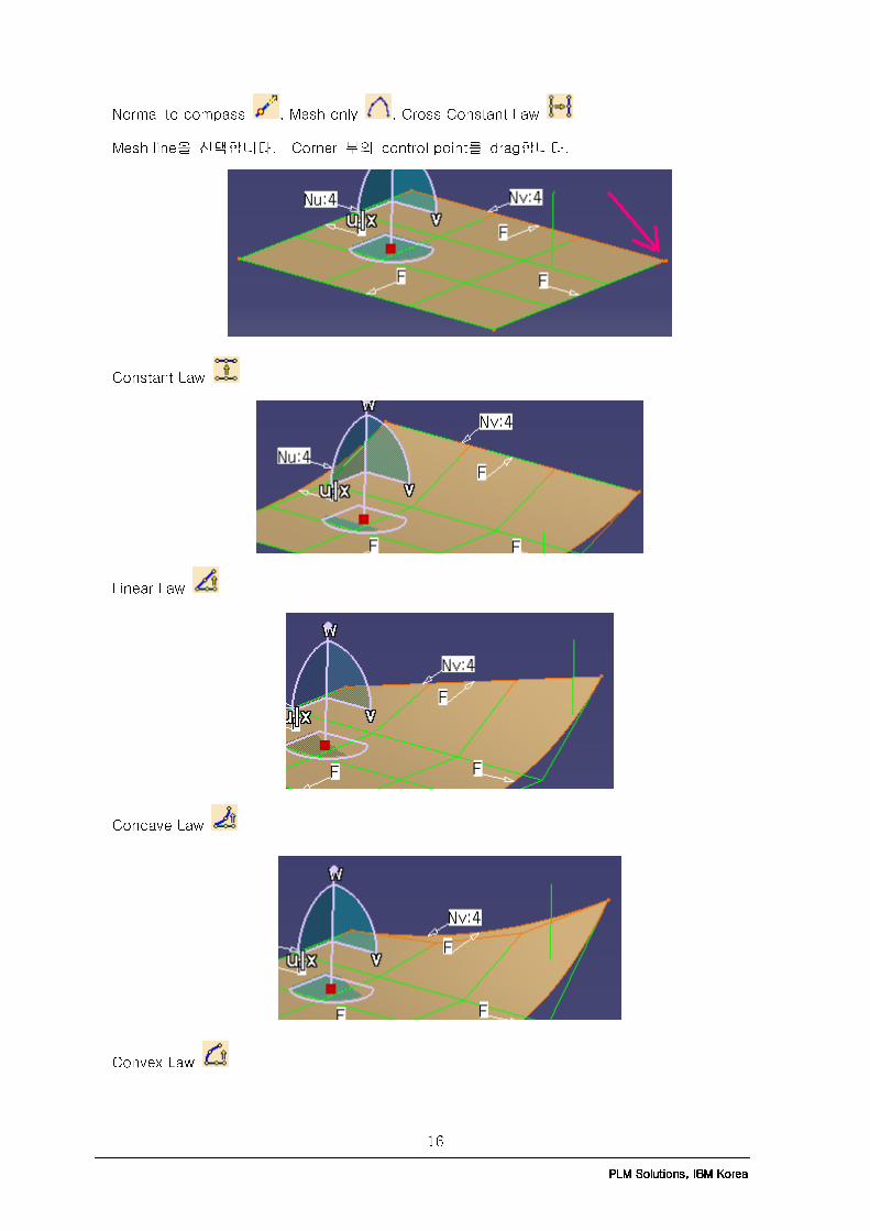
———————————————————————————————————————————————————————————————————————————————————————————————————————————————————————————————————————————————————————————————————————————————————————————————————————————————————————————————————— PLM Solutions, IBM KoreaPLM Solutions, IBM KoreaPLM Solutions, IBM KoreaPLM Solutions, IBM Korea 16
Normal to compass , Mesh only , Cross Constant Law Mesh line을 선택합니다. Corner 부의 control point를 drag합니다. Constant Law
Linear Law Concave Law Convex Law

———————————————————————————————————————————————————————————————————————————————————————————————————————————————————————————————————————————————————————————————————————————————————————————————————————————————————————————————————— PLM Solutions, IBM KoreaPLM Solutions, IBM KoreaPLM Solutions, IBM KoreaPLM Solutions, IBM Korea 17
Bell Law (6) Using Control Points Cross Diffusion Laws Control Points click합니다. Surface.3로 compass를 이동시킵니다.
Normal to compass , Constant Law , Select All Points , Mesh only 를 선택합니다. Mesh line을 선택합니다. Corner 부의 control point를 drag합니다. Cross Constant Law

———————————————————————————————————————————————————————————————————————————————————————————————————————————————————————————————————————————————————————————————————————————————————————————————————————————————————————————————————— PLM Solutions, IBM KoreaPLM Solutions, IBM KoreaPLM Solutions, IBM KoreaPLM Solutions, IBM Korea 18
Cross Linear law Concave Law
Cross Convex Law Cross Bell Law

———————————————————————————————————————————————————————————————————————————————————————————————————————————————————————————————————————————————————————————————————————————————————————————————————————————————————————————————————— PLM Solutions, IBM KoreaPLM Solutions, IBM KoreaPLM Solutions, IBM KoreaPLM Solutions, IBM Korea 19

———————————————————————————————————————————————————————————————————————————————————————————————————————————————————————————————————————————————————————————————————————————————————————————————————————————————————————————————————— PLM Solutions, IBM KoreaPLM Solutions, IBM KoreaPLM Solutions, IBM KoreaPLM Solutions, IBM Korea 20
III. Performance Benefit을 위한 설계 방법론 Based on Admin Performance Info and Tuning of PLM Technical Support Series Large AssemblyLarge AssemblyLarge AssemblyLarge Assembly에에에에 대한대한대한대한 성능성능성능성능 향상향상향상향상 법법법법 CATIA 최종 사용자가 large assembly로 작업할 때 성능을 향상하기 위하여 변경할 수 있는 몇 가지 항목이 있습니다. 이러한 변경 중에는 회전, 이동, 확대/축소와 같은 local transformation의 성능 향상을 다루고 있고, 어떤 것은 assembly를 open하는 시간을 줄이는 방법, 그리고 나머지는 large assembly로 작업할 때 전체적으로 더 나은 성능을 얻을 수 있도록 addressable memory의 사용량을 줄이는 방법에 대해 다루고 있습니다. 이러한 방법들의 각각은 서로 trade off 관계에 있습니다. 즉, 더 나은 성능을 위해서 사용자는 화면에 보이는 것을 줄이고, 저장하는 방식을 변경하고, 전체적으로 large assembly를 작업하는 방식을 변경할 필요가 있을 것입니다. 이러한 변경 중에 몇몇은 사용자 CATIA menu의 Tools–>Options 수정으로 가능하며, 반면에 나머지는 어떤 contextual menu 변경과 다른 선택들로 interactive하게 수행됩니다. 다음의 보기들은 최종 사용자가 large assembly상에서 작업할 때 성능을 향상시킬 수 있는 몇 가지 변경들을 보여줍니다. 이러한 항목들의 각각에 대한 보다 자세한 정보를 위하여 사용자는 CATIA English Documentation의 내용을 참조해야 합니다. Interactive Interactive Interactive Interactive 변경변경변경변경 예예예예 � Loading 시간을 향상시키고 addressable memory의 사용량을 줄이기 위해 visualization mode를 사용 하십시오. visualization mode에서 part가 display 될 때는, data의 subset만 memory에 적재되고, 나머지 data는 필요 시 적재됩니다. part를 편집하거나 constraint를 부여할 필요가 있을 때에만 design mode로 switch 하십시오. � Assembly를 열기 전에, “Do not activate default shape on open” option을 설정하십시오. 이것은 no-show 공간 안에 있는 불필요한 정보를 줄이고 성능을 향상시킵니다. 이 option이 더 많은 성능을 기하기 위해서는 visualization mode와 함께 사용하셔야 합니다. � Shading할 때 모서리를 제거하는 것은 display 성능을 향상시킵니다. � Activate시킬 component들을 복수 선택하는 것과 같이, 작업구성을 제어하기 위하여 Selection Set를 만드십시오. ToolsToolsToolsTools---->Options >Options >Options >Options 변경변경변경변경 예예예예 � screen에 표시되는 detail 수준을 낮추면 local transformation이 향상될 것입니다. 이것은 “While Moving”에 대한 “Level of Detail” 과 “Pixel culling” 설정 치를 증가함으로 인해 가능하며, 움직일 때 보다 적은 data가 display 됩니다. � Undo stack을 감소시키십시오. Default로, 마지막 10번의 interaction이 언제든지 undo될 수 있지만, 이 option은 많은 양의 addressable memory를 사용합니다. Undo Stack Size를 2까지 감소시킴으로써, addressable memory가 보다 큰 assembly를 적재할 수 있도록 하게 됩니다. � Cache 사용을 Activate하는 것은 addressable memory 사용량과 assembly를 여는 시간을 절감해서 visualization mode의 사용을 최적화합니다.

———————————————————————————————————————————————————————————————————————————————————————————————————————————————————————————————————————————————————————————————————————————————————————————————————————————————————————————————————— PLM Solutions, IBM KoreaPLM Solutions, IBM KoreaPLM Solutions, IBM KoreaPLM Solutions, IBM Korea 21
� Automatic Save를 해제하십시오. Automatic Save는 crash가 발생하는 경우, 사용자 작업의 복구를 가능하도록 하지만, 대부분의 경우, assembly는 crash 후에 복구될 수 없습니다. 매우 큰 assembly의 경우, automatic save하는데 거의 수 분 정도 걸리기 때문에, 이 option을 해제하는 것은 30분(?)마다 CATIA가 hang 걸리는 현상을 제거할 것입니다. � 모든 component를 deactivate시킨 채로 assembly를 연 다음, 설계를 위해 필요한 파트의 representation만을 activate 시키십시오. 이것은 local transformation 성능을 향상시키고 addressable memory 사용량을 절감시킬 것입니다. Drafting Large AssemblyDrafting Large AssemblyDrafting Large AssemblyDrafting Large Assembly에에에에 대한대한대한대한 방법론방법론방법론방법론 Large assembly의 drafting을 작업할 때의 성능 향상을 위한 여러 가지 다른 기법이 있습니다. 간단히 해당 view에 필요한 것만 drafting안에 generate하기 위해 smart drafting 기법을 넣고, 사용하십시오. 이것은 data 용량을 감소시켜 최상의 성능을 산출할 것입니다. 만일 smart drafting 기법이 충분치 않다면, assembly는 Convert Product to CATPart 기능을 사용하여 단순화 되어야 합니다. 다음 두 개의 section은 약간의 smart drafting 기법과 단순화된 assembly에 대하여 다룹니다. Large AssemblyLarge AssemblyLarge AssemblyLarge Assembly에에에에 대한대한대한대한 Smart Drafting Smart Drafting Smart Drafting Smart Drafting 기법기법기법기법 예예예예 � Scene 개수를 assembly를 표현하는데 필요한 만큼만 최소한으로 제한하십시오. 충분히 만들어진 각각의 scene은 CATProduct의 크기를 증가시킵니다. � Raster로부터 만들어진 view는 image로 만드십시오. 이것은 사용자로 하여금 visualization mode로 열 수 있는 large assembly에 대해 전체 view를 빠르게 만들 수 있게 합니다. Raster view를 만드는 데 제한이 있더라도, 그들이 사용될 때에는 data 용량을 감소시키고 addressable memory 사용량을 향상시킵니다. � view를 generation하기 전에, assembly 내에 보여지는 element를 수동으로 제어하십시오. View 내에서 보여져서는 안될 것들은 assembly 내에서도 보여져서는 안됩니다. � Tree안에서 assembly 전체가 아닌 drawing 내에만 보여지길 원하는 element들의 node들만 multi-selecting을 통해 view를 만드십시오. Simplified AssembliesSimplified AssembliesSimplified AssembliesSimplified Assemblies 하나의 simplified assembly는 assembly의 content들이 하나 또는 그 이상의 CATPart로 merge될 때 만들어져서 새로운 CATProduct으로 reassemble됩니다. 본래의 CATProduct의 선택된 component들은 CATPart내에 개별적인 body로 변환됩니다. 200MB이상의 assembly들은 simplified assembly로 만들 수 있는지 검토되어야 합니다. Assembly들은 만일 smart drafting 기법이 충분치 않다면 Convert Product to CATPart 기능을 사용하여 단순화 되어야 합니다. Assembly를 단순화하는 것은 설계가 거의 완성되어 상세 설계할 준비가 된 후에 이루어집니다. 이 기법은 잦은 변경이 발생하는 설계 단계에서는 사용하지 마십시오. 왜냐하면 변경이 발생하면 본래의 데이터에 대해 수동으로 동기 작업을 해야 하기 때문입니다.

———————————————————————————————————————————————————————————————————————————————————————————————————————————————————————————————————————————————————————————————————————————————————————————————————————————————————————————————————— PLM Solutions, IBM KoreaPLM Solutions, IBM KoreaPLM Solutions, IBM KoreaPLM Solutions, IBM Korea 22
IV. Notices 1. Service Pack List V5R14 Service Pack 1 : included in GA code V5R14 Service Packs Service Pack 2~10 : available V5R15 V5R15 Service Packs Service Pack 1~7 : available V5R16 V5R16 Service Packs Service Pack 1~8 : available V5R17 V5R17 Service Packs Service Pack 1~4 : available 2. Question & Answer Question 1 : Body를 replacing하는 방법을 알고 싶습니다. Answer 1 : CATIA V5R16 English Documentation->Part Design->Replacing a Body->ReplaceBody.CATPart를 open합니다.
Replace할 body로 Body.3를 선택합니다. Right-click한 후, Replace...를 선택합니다.

———————————————————————————————————————————————————————————————————————————————————————————————————————————————————————————————————————————————————————————————————————————————————————————————————————————————————————————————————— PLM Solutions, IBM KoreaPLM Solutions, IBM KoreaPLM Solutions, IBM KoreaPLM Solutions, IBM Korea 23
Replacing body로 Body.4를 선택합니다.
사용자의 Replacing face 선택을 돕기 위해, Replace Viewer window가 display됩니다. Replacing face를 선택합니다.
직접 선택도 가능합니다.

———————————————————————————————————————————————————————————————————————————————————————————————————————————————————————————————————————————————————————————————————————————————————————————————————————————————————————————————————— PLM Solutions, IBM KoreaPLM Solutions, IBM KoreaPLM Solutions, IBM KoreaPLM Solutions, IBM Korea 24
OK
Update All 을 click합니다.(menu, Tools->Options->Infrastructure->Part Infrastructure->General tab->Update Manual일 경우)
Question 2 : Boolean operation(Add, Assemble, Remove, Union Trim)을 다른 Answer 2 :

———————————————————————————————————————————————————————————————————————————————————————————————————————————————————————————————————————————————————————————————————————————————————————————————————————————————————————————————————— PLM Solutions, IBM KoreaPLM Solutions, IBM KoreaPLM Solutions, IBM KoreaPLM Solutions, IBM Korea 25
CATIA V5R16 English Documentation->Part Design->Changing a Boolean Operation into Another One->Intersect.CATPart를 open합니다. Body.1을 PartBody에 Assemble합니다.
Body.2를 Remove합니다.
Remove된 Body.2->Pad.3의 top edge에 Edge Fillet 합니다.

———————————————————————————————————————————————————————————————————————————————————————————————————————————————————————————————————————————————————————————————————————————————————————————————————————————————————————————————————— PLM Solutions, IBM KoreaPLM Solutions, IBM KoreaPLM Solutions, IBM KoreaPLM Solutions, IBM Korea 26
Spec. tree에서 Remove.1을 right-click한 후, Remove.1 object->Change to Assemble을 선택합니다.
Spec. tree에서 Assemble.2를 right-click한 후, Assemble.2 object->Change to Union Trim을 선택합니다. Faces to keep을 위해, cylinder의 top face를 선택합니다.
Question 3 :

———————————————————————————————————————————————————————————————————————————————————————————————————————————————————————————————————————————————————————————————————————————————————————————————————————————————————————————————————— PLM Solutions, IBM KoreaPLM Solutions, IBM KoreaPLM Solutions, IBM KoreaPLM Solutions, IBM Korea 27
FreeStyle->Control Points의 Display delta option이 나타나지 않습니다. Answer 3 : Tested in CATIA V5R16 SP05 (1) CATStCptDisplayDeviation=1를 env에 추가합니다. (2) ->Control Points 를 click합니다. (3) Surface를 선택합니다.
(4) Options에서 Display deviation를 click합니다.
(5) control point를 drag합니다.