2009 ambulance specifications - rapid city, south …archive.rcgov.org/lf20081230/lf123008-10/2009...
TRANSCRIPT
1
SPECIFICATIONS BIDDER COMPLIES
SPECIFICATIONS FOR
FOUR (4) NEW TYPE III CLASS I STAR-OF-LIFE CERTIFI ED AMBULANCES 165”X95”
The Emergency Medical Vehicles described in this specification are designed to meet or exceed the requirements of Federal Ambulance Specification KKK-A-1822 Revision E, and AMD Standards 001-009. The specifications listed herein will apply to all new vehicles furnished. NOTE: Throughout the written Federal Ambulance Specification KKK-A-1822, there are frequent references to items to be included WHEN SPECIFIED. The manufacturer will build into a given ambulance any WHEN SPECIFIED item, but such items may not be included in the attached specifications. This specification covers new, commercially built surface emergency medical care vehicles herein after referred to as ambulance or vehicle. A vehicle in compliance with this specification shall be defined as a standard ambulance. This vehicle shall be in accord with the Ambulance Design Criteria of the National Highway Traffic Administration, U.S. Department of Transportation, Washington, D.C. This bid specification is based on the Federal Ambulance Specification KKK-A-1822E. The purpose of this document is to provide minimum specifications and test parameters for the manufacture of emergency medical care vehicles that meets the needs and desires of this agency. It establishes essential criteria for the design, performance, equipment, and appearance of the vehicle. All dimensions listed are given as the approximate sizes required to meet the needs of this department. The object is to provide a vehicle that is in accordance with nationally recognized guidelines. All vendors and manufacturers must meet all state and local regulations regarding the manufacturing, licensing, and sale of emergency rescue vehicles and ambulances within the state of South Dakota. This specification calls for the following type of vehicle. It is in accordance with paragraph 1.2.1 of KKK-A-1822E. Type III: Specialty van (cutaway chassis) with inte gral or containerized modular body. Class I: Two-rear wheel driven (4x2). Configuration B: Elevating cot and squad bench for ALS (see 3.1.5.1/3.15.3 of KKK-A-1822E). This is an engineer design, construct, and deliver type specification and it is not the intention of this agency to write out vendors or manufacturers of similar or equal equipment of the types specified. It should be noted, however, that this specification is written around the specific needs of this department. With the intent to standardize certain components, specific brands have been specified in certain places. This has been done to establish a certain standard of quality and consistency in the departments vehicle fleet.
YES NO

2
The emergency medical care vehicles, chassis, ambulance bodies, equipment, devices, medical accessories, and electronic equipment to be delivered under this contract shall be standard commercial products that meet or exceed the requirements of this specification. The ambulances shall comply with all Federal Motor Vehicle Safety Standards (FMVSS) and Federal regulations applicable or specified for the year of manufacture. The chassis, components, and optional items shall be represented in the manufacturer's current technical data. Materials used in the construction shall be new and not less than the quality conforming to current engineering and manufacturing practices. Materials shall be free of defects and shall be suitable for the intended use. EXAMINATION OF SPECIFICATIONS It is incumbent on each manufacturer to be thoroughly familiar with the specification contained herein. Any exceptions to these specifications must be clearly pointed out. Otherwise, it will be considered that the items offered are in strict compliance with the written specifications and that the successful bidder will be responsible for delivering vehicles meeting these specifications. The specification will require a “YES” or “NO” or when requested a definitive answer to each section or subsection. Sections or subsections not marked with a “YES” or “NO” or answered shall be deemed incomplete and considered non-responsive. A “YES” answer constitutes a complete compliance to the section or subsection as written. A “NO” shall indicate noncompliance and does not eliminate a manufacturer from competition. A manufacturer may object or counter to a specific section or subsection. A manufacturer must indicate in writing on a separate page marked “EXCEPTIONS” the section or subsection in dispute. The manufacturer must include the verbiage as written, new verbiage presented, explanation of verbiage with consequences and supporting tests and documentation. Failure to comply will be deemed as non-responsive. This agency reserves the right to determine compliance. Bid proposals taking total exception to these specifications will not be accepted.
Bid proposals that do not comply with the prescribed method to take exceptions listed will be rejected without further consideration. _______________________________________________________________________ BID EVALUATION Bids received shall be evaluated by this agency. This evaluation will be based on all of the following: Completeness of the proposal
Manufacturing and Delivery schedule
Manufacturer's demonstrated capabilities and qualifications
Manufacturer's past performance on similar Bid Proposals
Manufacturer's maintainability and recommendations
Manufacturer's logistical and service support _______________________________________________________________________ INFORMATION AND DESCRIPTIVE MATERIAL The bidder must furnish all information requested in the spaces provided on the bid forms.
3
The manufacturer must submit evidence of compliance with KKK-A1822-E testing parameters. The testing is to be performed by an independent testing facility and verified by person(s) with the standing of Professional Engineer. If further testing is required by any lawful agency of the Federal or State Government then it shall be incumbent upon the manufacturer to provide this agency with certification required. This agency also recognizes Ford Motor Company's Qualified Vehicle Modifiers (QVM) accreditation. Therefore, regardless of chassis specifications the manufacturer must include with this proposal their current QVM certification. The manufacturer must supply a web site address for the Ford QVM program certification list as proof that they are a current member of the Qualified Vehicle Modifier Program. The manufacturer must also supply certification to the current revision of KKK-A-1822 specification for this particular type of vehicle, and at least one (1) complete set of sketches, descriptive literature, and complete specifications covering the products offered. Bids not meeting this requirement will be considered non-responsive and shall be rejected. The manufacturer must provide proof of ISO 9001:2000 Certification.
Failure to provide this agency with the documentation required will be deemed non-responsive.
NO EXCEPTIONS. _______________________________________________________________________
GENERAL LIABILITY Bidders are required to submit with their bids a Certificate of Liability Insurance in the amount of ten million ($10,000,000) US dollars that is based on a PER INCIDENT basis as issued by the bidders insurance company. This insurance shall be issued by a company rated “A” or better as reported in the current edition of Bests Key Rating Guide, published by Alfred M. Best Company, Inc. Aggregate liability coverage will not be considered regardless of amount. Failure to comply will be deemed non-responsive. _______________________________________________________________________ PERFORMANCE BOND This agency reserves the right to seek a one hundred percent (100%) performance and payment bond as a condition of award. A letter must be included from a certified bonding agency stating that a performance bond can be issued on behalf of the manufacturer. Failure to comply may be deemed as non-responsive. _______________________________________________________________________ FAMILIARITY WITH LAWS The manufacturer shall be familiar with all Federal, State and Local laws, ordinance, code rules and regulations that may in any way effect the work. Ignorance of the law on the part of the manufacturer is not acceptable. _______________________________________________________________________ PRE-CONSTRUCTION CONFERENCE The successful manufacturer shall be required to hold a pre-construction conference with representatives of this agency to finalize outstanding construction details. This conference will be held at this agency and shall be held before construction is started.

4
PRE-DELIVERY INSPECTION The successful manufacturer shall be required to facilitate a pre-delivery inspection of all vehicles bid with representatives of this agency. This inspection shall take place at the manufacturer’s location in a temperature controlled inspection area separate from the production facility. The manufacturer shall provide adequate transportation, lodging, and meals for two (2) designated personnel from this agency to conduct this inspection. Further, if the location is in an excess of three hundred (300) miles from this agencies location, the transportation shall be by a commercial air carrier. _______________________________________________________________________
DRAWINGS The manufacturer shall provide an accurate set of line drawings that accurately depict the vehicle(s) as specified. The drawings will show all exterior and interior planes with dimensions. Failure to comply will be deemed non-responsive. _______________________________________________________________________
EMPLOYEE STATEMENT It is mandated by the United States Government that all employees currently and to be employed during the duration of this contract are not discriminated against because of their race, creed, color, sex, nationality origin and disability. Further, this agency must be satisfied that the manufacturer's labor pool is treated in a fair and equitable manner. Therefore, it will be the responsibility of the manufacturer to include a human resource statement outlining employment status, working conditions, and benefits. _______________________________________________________________________
ANTI-COLLUSION STATEMENT By signing this bid, the manufacturer agrees that this bid is made without any understanding, agreement or connection with any other person, firm or corporation making a bid for the same purpose and this bid is in all respects fair and without collusion or fraud. _______________________________________________________________________ CONTRACT AWARD This agency reserves the right to increase the number of vehicles or equipment specified under this contract. If awarded, the manufacturer agrees that additional agencies may purchase under the same terms and prices afforded by any contract arising from the bid award, unless prohibited by law. _______________________________________________________________________ DELIVERY/PAYMENT The successful bidder shall deliver all vehicles sp ecified with a 200 day time frame from the time the bid is awarded. The delivery tim e shall include the transit time of the finished vehicle(s). Failure to deliver in the time frame specified will incur a per day penalty in the amount of $ 150.00 per day. Unless otherwise requested, the manufacturer shall arrange over the road delivery of the completed vehicle(s) to this agency's designated local address under the vehicles own power. Costs of transportation and preparation are to be included with the price as bid. Payment in full shall be processed after delivery and once a final acceptance inspection of the vehicle(s) by this agencies authorized representative(s) confirms compliance with the specification.
5
WARRANTY The successful manufacturer shall provide a twelve (12) month/12,000 mile warranty on the vehicles which covers defective parts and/or components, the improper choice of materials, parts, and/or components, improper design or engineering, and poor or improper workmanship or quality control techniques. The warranty shall cover the complete vehicle and shall include all costs for labor and parts or materials that are required to correct all deficiencies. In addition, the manufacturer shall submit their various warranties and warranty options, if applicable, with the proposal for evaluation. Also, the manufacturer shall supply the name and phone number of a contact person in the event this agency requires clarification of the submitted warranty documents. The manufacturer will provide the location of the closest approved warranty center. Indicate to this agency, in writing, to be included with this proposal; the process to initiate and file a warranty claim. There shall be provided a lifetime electrical warranty that covers all conversion circuit boards and harnesses. There shall be provided a fifteen (15) year transferable modular body structural warranty. The term transferable is to cover the transfer of the warranty to a second purchaser should the department sell this unit later. The 15 year structural warranty period shall also remain in effect should the modular body be remounted onto a new chassis. This remount must be performed at a service center authorized by the original manufacturer. There shall be a ten (10) year/50,000 mile paint warranty. _______________________________________________________________________
WARRANTY SURETY To ensure quality, service, and full compliance to the above warranties, the ambulance manufacturer must construct the complete vehicle, with the exception of the chassis. Additional elements constructed and installed "in house" are required to ensure service and parts availability. Subcontractors or lease/rental agreements to outside agencies will fail to meet this requirement. NO EXCEPTIONS WILL BE ALLOWED. • Does the ambulance manufacturer as the prime contractor construct the modular body? • Does the ambulance manufacturer as the prime contractor apply paint? • Are interior cabinets constructed and installed by the ambulance manufacturer as the prime contractor? • Are the wiring harnesses, circuit boards, and oxygen systems assembled, installed and tested by the ambulance manufacturer as the prime contractor? • Is the upholstery for seat cushions, head pads, and backrests assembled and installed by the ambulance manufacturer as the prime contractor? SERVICE FACILITY The successful bidder must have access to a service facility. Bidders must list below the nearest service facility and parts department to the purchaser. Facility Name: _____________________________________________________ Address: _____________________________________________________

6
Phone Number: _____________________________________________________ Contact Name: _____________________________________________________ Appx. miles from agency: ___________________________________________ Due to the high demands on a pre-hospital care vehicle, this agency requires that the primary manufacturer have available, a twenty four hour a day technical assist service. This 24/7 service must be staffed by the manufacturers service personnel. Include phone number: ______________________________ _______________________________________________________________________ REFERENCES All bidders must submit a list containing a minimum of fifteen [15] customers who are operating a similar model ambulance as described in this specification. The customer reference list shall contain the Department name, address, phone number and contact person. References shall be of units sold since 2006 by the dealer who is bidding. _______________________________________________________________________ QUALITY ASSURANCE To ensure the purchaser that proper engineering and production control guidelines have been implemented, the ambulance manufacturer shall employ an integrated quality and process control program including specific process controls for facets of the manufacturing process deemed to be “critical.” These critical elements of the process shall be documented and that documentation shall be available not only to manufacturing personnel but also customers who visit the manufacturing facilities. The critical elements shall be denoted on the vehicle control document, which accompanies the vehicle through the manufacturing process. A sample of this document shall be available to the purchaser upon request. A continuous series of inspections shall be performed and signed off on the vehicle control document and shall include but not be limited to the following: Visual inspection of the body, welds, and exterior attachments. Visual and mechanical inspection of the heater/air conditioning lines, cables, grommets, valve connections, clamps, mounting brackets, belts, etc. Visual inspection of cabinets, sliding/hinged cabinet doors, moldings, flooring, walls, headliner, and cushions. Visual inspection of exterior paint, decals, and lettering. Operational inspection of all electrical systems. This must consist of tests of battery voltage, electrical load tests, alternator output, beacons, flashers, siren, interior lighting, compartment lighting, power exhaust vent, scene lights, load lights, chassis lights, silent signal lights/buzzer, heat/cool unit, and any optional electrical devices as furnished by the manufacturer. The current requirements of each device tested must be noted on an inspection sheet together with the total current requirements. The oxygen and vacuum systems shall be tested both prior to and after installation to meet the requirements as listed in those individual sections of this specification. Test data indicating temperature, pressure, timing, flow, etc., shall be recorded. All chassis fluid levels shall be checked and filled to capacity. All doors, locks, windows, tires, etc. shall be inspected for proper operation and/or condition.

7
The completed vehicle(s) must be test driven a minimum of five (5) miles on paved highways and on rough terrain to check handling, brakes, acceleration, and noises. A water spray test and visual inspection shall be performed after the road test. The primary manufacturer shall employ a full time Quality Control Manager whose primary function is to monitor quality. NO EXCEPTIONS STATEMENT OF FACT The following shall be provided by the manufacturer and dealer to ensure that the manufacturer is capable of building the units per the specifications: 1) Statement of fact, signed by an officer of the manufacturing company, disclosing that
the manufacturer has delivered two hundred (200) ambulances within the last twelve (12) months of the date of this bid.
2) The size and location of manufacturing facilities and the number of production staff. 3) Interior pictures to verify plant facilities. 4) A list of on-site engineering staff with educational accreditation. 5) Statement of loaner vehicle policy by the dealer. 6) Statement of on-site service, 24/7 service, out of service policy by the dealer . Failure to provide this information with the documentation required will be deemed non-responsive. NO EXCEPTIONS. _______________________________________________________________________ GENERAL VEHICLE DESIGN, TYPE, AND FLOOR PLAN The ambulances and the allied equipment furnished under this specification shall be the manufacturers current commercial vehicle of the type and class specified. The ambulances shall be complete with the operating accessories as specified herein and furnished with such modifications and attachments as may be necessary or specified to enable the vehicle to function reliably and efficiently in sustained operation. The design of the vehicle and the specified equipment shall permit accessibility for servicing, replacement, and adjustment of component parts and accessories with minimum disturbance to other components and systems. The term "HEAVY DUTY" as used to describe an item shall mean in excess of the usual quantity, quality, or capacity that is normally supplied with the standard production vehicle or component. COMPLETED VEHICLE DIMENSIONAL PARAMETERS The vehicle(s) furnished shall comply approximately with the following dimensions at curb weight: Length, Overall (including rear step) 259.5" Width, Exterior (excluding mirrors) 95" Wheelbase 158" Height, Rear Loading 31" Height, Ground to Step 17" Ground Clearance 7" Length, Patient Compartment Interior 154" Aisle Space with Cot Installed 12"
8
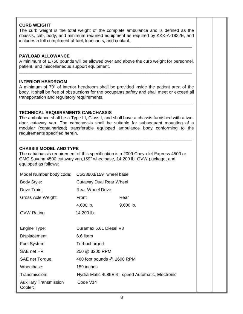
CURB WEIGHT The curb weight is the total weight of the complete ambulance and is defined as the chassis, cab, body, and minimum required equipment as required by KKK-A-1822E, and includes a full compliment of fuel, lubricants, and coolant. _______________________________________________________________________ PAYLOAD ALLOWANCE A minimum of 1,750 pounds will be allowed over and above the curb weight for personnel, patient, and miscellaneous support equipment. _______________________________________________________________________ INTERIOR HEADROOM A minimum of 70" of interior headroom shall be provided inside the patient area of the body. It shall be free of obstructions for the occupants safety and shall meet or exceed all transportation and regulatory requirements. _______________________________________________________________________ TECHNICAL REQUIREMENTS CAB/CHASSIS The ambulance shall be a Type III, Class I, and shall have a chassis furnished with a two-door cutaway van. The cab/chassis shall be suitable for subsequent mounting of a modular (containerized) transferable equipped ambulance body conforming to the requirements specified herein. _______________________________________________________________________ CHASSIS MODEL AND TYPE The cab/chassis requirement of this specification is a 2009 Chevrolet Express 4500 or GMC Savana 4500 cutaway van,159" wheelbase, 14,200 lb. GVW package, and equipped as follows: Model Number body code: CG33803/159” wheel base
Body Style: Cutaway Dual Rear Wheel
Drive Train: Rear Wheel Drive
Gross Axle Weight: Front Rear
4,600 lb. 9,600 lb.
GVW Rating 14,200 lb.
Engine Type: Duramax 6.6L Diesel V8
Displacement 6.6 liters
Fuel System Turbocharged
SAE net HP 250 @ 3200 RPM
SAE net Torque 460 foot pounds @ 1600 RPM
Wheelbase: 159 inches
Transmission: Hydra-Matic 4L85E 4 - speed Automatic, Electronic
Auxiliary Transmission Code V14 Cooler:

9
Rear Axle Ratio: 4:10 Locking Rear Differential
Tire Size: LT225/75R16D, 2 front, 4 rear
Spare Tire Size: LT225/75R16D
Wheels All including spare, steel 16.0 x 6.0
Brakes: ABS System, Power Disc Brakes front and rear
Engine Oil Cooling System: Code KC4
Engine Block Heater: Code K05
Alternators: Dual OEM 145 Ampere Alternators
Batteries: Dual, 63-AH, 770 CCA
Ambulance Prep. Package: Code YF2
High Idle Switch: Code UF3
Throttle Control, Electronic: Code KUP
Air Conditioning: Code C60
Auxiliary Heat Generator: Code K08
Fuel Tank: Code NE7 Single 57 Gallon
Deluxe Front Appearance Code V22 Package:
Chrome Appearance Pkg: Code ZR7
Chrome Front Bumper: Code V46
Front License Plate Mount: Code VK3
Dual Cloth High Back Code ZX2 Bucket Seats:
Tilt Wheel and Speed Control Code ZQ3
Steering: Power
Radio: Code U1C AM/FM/CD Radio
Power Locks/Windows Code ZQ2
Head-lamps, Auto Control, Code T74 Delay
Cold Climate Package Code V10
Cloth Cab Headliner
Cloth sun visors
Cloth Cab Door Trim Panels
Medium Pewter Interior Color/
Solid Exterior Color (Summit White)

10
BRAKES The chassis brake system shall be GM OEM standard Hydro-boost 4-wheel disc, 4-wheel ABS with Dynamic Rear Proportioning. _______________________________________________________________________ TIRES The vehicle shall be equipped with seven (7) wheels and tires. The tires shall be Michelin LTX 225/75R16E steel belted radials with all-season tread design. _______________________________________________________________________ SPARE TIRE A spare tire shall be provided and mounted on the rear wall of the exterior D2 compartment. It shall match the tires specified for the vehicle. Shelves or equipment trays provided in this compartment will be constructed to allow for easy access to the spare tire. _______________________________________________________________________ SWAY BAR An OEM supplied front sway bar and an IPD 1.50'' diameter rear sway bar (if available for the specified chassis) shall be provided and installed to assist vehicle stability. _______________________________________________________________________ SHOCK ABSORBERS Front and rear shock absorbers shall be heavy duty OEM supplied and installed. _______________________________________________________________________ ELECTRIC THROTTLE The OEM High Idle Speed Control shall be installed as part of the Code YF2 Ambulance Prep Package. The throttle shall be preset to initiate engine high idle at 1300 RPM’s when activated. When the transmission is placed in Park and the Park Brake is engaged, the throttle will be activated. Releasing the Park Brake, depressing the brake pedal or shifting the transmission into gear shall deactivate it. _______________________________________________________________________ APPOINTMENTS The manufacturer's heaviest duty heating and air conditioning package must be used. The rearview mirror shall be day/night visibility type. The vehicle shall be equipped with dual electric multi-speed, delay windshield wipers and washer mechanism. The seatbelt/shoulder harness mechanisms shall be encased with a high impact plastic trim housing color keyed to match the driver's compartment. The balance of the driver's compartment trim shall be finished with laminate, carpet, and cloth backed vinyl trim panels with .375" thick high-density foam padding color keyed to match the rest of the driver's compartment. _______________________________________________________________________ CAB SEATING The driver's compartment shall be provided with OEM dual cloth high-back captains chairs with armrests and chassis manufacturer standard features for the trim level selected. _______________________________________________________________________ HEADLINER The cab headliner shall be OEM standard automotive cloth.

11
CAB SIGNS One (1) "NO SMOKING OXYGEN EQUIPPED" and "FASTEN SEATBELT" sign shall be installed in the driver's compartment on the passenger side of the dash. These signs shall be engraved or molded plastic for durability. _______________________________________________________________________ CAB FLOORING The cab flooring shall standard OEM supplied flooring with removable OEM floormats. _______________________________________________________________________ CAB WINDOW TINT The side windows on the vehicle cab shall be tinted with high-performance lifetime warranty window tinting film to a light transmissibility of 35%. _______________________________________________________________________ MAP BOX A high-quality map and glove box shall be provided and installed on the bulkhead wall where the walk-thru is deleted, below the sliding window and between the driver and passenger seating positions. It shall have a minimum of three (3) dividers, two (2) glove receptacles and shall be easily accessible by either the driver or passenger. The dividers and the glove box covers shall be constructed from plexiglass and angled downward so as to retain map books etc. when the vehicle is in motion. _______________________________________________________________________ BATTERY SWITCH A heavy-duty battery switch of the type normally used by the vehicle manufacturer is to be installed. This system will have an integral timer pre-set to open the power circuit from the batteries to the main circuit board and interrupt power to all conversion functions after 5 minutes with chassis ignition OFF. ENGINE BLOCK HEATER The OEM chassis engine block heater shall be supplied and wired to the external 115 volt power source. _______________________________________________________________________ WHEEL COVERS Phoenix brand polished stainless steel covers shall be provided on all in- service wheels of the vehicle. Braided stainless steel valve extenders shall be installed on the rear inboard tires to allow easy access for filling. WHEEL CENTER AND LUG COVERS Phoenix brand polished stainless steel wheel center covers and lug covers shall be provided on all in-service wheels of the vehicle. _______________________________________________________________________ MIRRORS The mirrors shall be firmly secured, vibration-less rear view mirrors totaling at least one hundred and twenty five square inches. Brand shall be Velvac #714563, Remote, Black. The mirrors will be power /no heat.
12
VEHICLE WIRING All insulated cable shall conform to SAE J1292 requirements and shall have type GXL high temperature thermoplastic insulation conforming to SAE J1127 and J1128. All wire shall be of a gauge size to carry 125% of the current required without overheating. All wires are to be color coded and stamped with the function of the circuit for the continuous length of the line. Where practical, all wires shall be routed in high temperature looms with a rating of 300 degrees Fahrenheit. All conductors shall be annealed copper with machine crimps. Wiring harnesses shall be assembled and warranted by the vehicle manufacturer. NO EXCEPTIONS WILL BE ALLOWED . Additionally, these vehicles must meet or exceed AMD Standard 005, Ambulance 12-Volt DC Electrical System. _______________________________________________________________________ ALTERNATORS Two (2) internally regulated and internally rectified GM OEM 145 amp alternators, as included with the YF2 Ambulance Prep Package, shall be supplied. The alternators must be covered by the chassis manufacturer's warranty. _______________________________________________________________________ PORTABLE EQUIPMENT CHARGING CIRCUIT Two (2) additional 12 VDC circuits for charging portable battery powered devices, i.e. suction units, hand lights, defibrillators, portable radios, etc. shall be provided. These circuits shall prevent discharge of chassis batteries by only permitting the charging of portable devices when the vehicle is either running or the battery conditioner/charger is connected to shore power (operational). This implies that a battery conditioner/charger is required as part of this specification. A minimum of 10-amp circuit breaker protection shall be provided for each circuit. These leads shall be clearly tagged, identified and shall be located, one (1) in the patient compartment and one (1) in the vehicle cab. These leads shall not be connected to power nor shall they have any connectors attached at either end. These circuits are intended for unspecified future use. _______________________________________________________________________ CIRCUIT PROTECTION Circuit breakers and relays are to be mounted securely to the inside of the electrical control center located in the patient compartment forward of the technician seat backrest. This cabinet shall have a door large enough for complete and unobstructed inspection and maintenance, and shall hinge out of the way for free movement. The control center shall be large enough to house all circuit breakers, relays, flashers, and the medical isolator. Space for one (1) additional 15-amp single pole breaker shall be provided on the main electrical board. All auxiliary circuitry shall incorporate overload protection devices of automatic or manual reset thermal breaker types with spade style plug-in connectors and shall continuously carry 100% of the rated capacity for a minimum of one (1) hour. Bosch, Potter & Brumfield, Hella, and Omron brand relays may be used. All circuit breakers and relays are to be spade mounted snap-in type for easy removal. The circuit board shall be screen printed with all circuits legibly numbered and labeled. The electrical distribution panel must be a double-sided copper trace printed circuit board with a double-sided laminated isolator. Terminal strips must be mounted on the board for connection of wiring harnesses. The printed circuit board must meet or exceed a polyclad layered glass epoxy NEMA GRADE FR-4 material, and meet or exceed UL-94-V-O

13
flammability rating and MIL-P-13949F- 4B Specifications. The printed circuit board surface protection must be Dupont Vacrel "8000" Polymer and withstand the MIL-STD-810C Corrosion Test and the MIL-STD- 055110D Thermal Shock Test. Design must be interchangeable with model styles from vehicle to vehicle without modification to wiring or compartment construction. In addition to the main circuit board, there shall be additional boards of the same design to provide control, lighting, and indication for the compartment and entry doors. All wires and connectors shall be of like resistance materials. One (1) complete set of each size relay and circuit breaker shall be included and mounted next to the main circuit board. _______________________________________________________________________ CIRCUIT GROUNDING Grounding must be accomplished by use of a full ground wire harness. All ground wires shall be white in color and stamped along their length with the word "GROUND" or lettering "GRND". Ground return connections shall be made to the chassis structure, protected from corrosion, and available for service. In no case shall the aluminum body be used as a ground return. Additionally, there shall be a minimum of five (5) ground points between the chassis and body components of the ambulance and the chassis frame. These critical ground points shall be established with crimped copper ring connectors and dual star washers at each end of the ground strap. Due to the application of undercoating these grounds require no specific labeling. NO EXCEPTIONS WILL BE ALLOWED. _______________________________________________________________________ INSTALLATION AND PROTECTION Wires must be grouped or harnessed where practical. Metal edges through which cables pass shall be protected with nonmetallic bushings or grommets. All auxiliary circuits shall be wired separate and distinct from the vehicle chassis circuits, color coded, and clearly numbered. All wire passing from the console head shall be encased in a heavy-duty loom. All wiring shall be clipped or otherwise attached at suitable intervals to prevent rubbing or chafing due to wire movement, vibration, etc. All wiring must be stamped, color coded, labeled to indicate wire function, and conform to SAE 1292. NO EXCEPTIONS WILL BE ALLOWED. _______________________________________________________________________ SEQUENCER / LOAD MANAGER To prevent excessive loading or load spikes on the electrical generating system at system start up, a sequencer/load manager shall be integrated into the main circuit board for stepped control of the main master emergency functions. The sequencer shall sequence ON or OFF all master emergency functions at 0.5 second intervals. The sequencer/load manager shall sequence specified loads ON, in the following manner: 1. Body Warning Lights 2. Patient Compartment Dome Lights 3. Patient Compartment HVAC 4. Front Light Bar 5. Intersection and Grille Lights 6. Rear Light Bar - if installed 7. Wig-Wag Headlights - if installed

14
When a “low voltage” situation is detected, an audible alarm shall sound and an indicator light shall illuminate signaling the situation. When the vehicle transmission is in PARK, the load manager shall shed emergency functions until the system output voltage and the amperage draw of the systems still in operation equalize. When in PARK and the vehicle PARK BRAKE is applied the High Idle Control System will activate to provide additional voltage for the system. If the “low voltage”, (12.0 volts or lower) persists, the sequencer/load manager shall initiate the load shedding sequence at each 0.2 volt increment in the reverse order of these emergency functions. NOTE: Vital medical equipment such as suction aspirator system and/or electric oxygen valve shall not be included in the load shedding sequence. These systems shall remain powered until total failure of the electrical generating system occurs. _______________________________________________________________________ LOW VOLTAGE MONITORING SYSTEM There shall be installed, as an integral function of the ambulance conversion main power board, circuitry that continually monitors electrical system voltage. This system shall activate an audible alarm and a steady burn red LED warning light to indicate that system voltage has reached or fallen below 11.8 volts. There shall be included a switch to deactivate the audible alarm. The audible alarm, LED indicator light and the switch shall be located on an auxiliary control panel located in the drivers control console below the main switch panel. _________________________________________________________________________ DRIVER SWITCHING CONSOLE A console of the highest quality and newest technology built by the manufacturer shall be built onto the engine cover. The console will house the patient code lights and door open indicator lights. The ammeter, voltmeter, and battery indicator lights shall be located on a separate panel if possible. The ammeter, depending on equipment/chassis manufacturer specified, shall indicate the current flow to the batteries or from the alternator. The 12 volt voltmeter shall indicate the voltage of the batteries. An audible low voltage-warning device shall be installed with a reset cancel switch. This device shall sound whenever the voltage of the vehicle drops below 11.8 volts. This device shall automatically reset once the batteries are above 11.8 volts. A Datacon engine hour meter will be located near the bottom of the console on the driver's side and will be wired to ensure an accurate reading of running hours. Both the volt and ammeters shall be digital with LED display. A Federal Signal brand LF Series “LIttlelite” LED gooseneck map light shall be provided and installed on the passenger side of the console. This light shall have a manual “on/off” switch on the light itself. The complete console, manufactured of automotive plastics, shall be free of sharp edges and molded to match the contours of the engine cover. It shall contain all emergency switches, module switching, and legends according to their function and have back lighting controlled by the headlight rheostat. The switches shall be Eurostyle, moisture resistant, rocker type, and shall be UL listed and CSA approved. Switch terminals shall be 1/4" spade types. The switch legends shall be engraved plastic inserts. The back lighting shall light the words themselves rather than the background. Back lighting shall be accomplished with electro-luminescent light strips for their benefits of consistent light output, low amp draw, and extended service life.
15
The console shall be attached solidly to the engine cover but constructed in such a manner to make it easily serviceable and the wiring harnesses and switches easy to disconnect and reattach. The console shall be constructed and have sufficient space to facilitate professional quality installation of Department radio equipment and computer data terminal mounting equipment. The final configuration of the console and the placement of Department radios and other equipment in and on the console will be determined at the pre-construction meeting. The console shall contain at a minimum, the following features: Master Patient Status Indicator Lights Primary/Secondary Patient Door Open Red Light (and audible signal) Front Lightbar/Lights Rear Domes Rear Lightbar/Lights Compartment Door Open Amber Light (and audible signal) Backup Alarm Disable Hourmeter Horn/Siren [2] Ammeters Leftside Scene Lights Voltmeter Rear Load Lights Battery Indicator Lights Rightside Scene Lights Module Disconnect Spare Switch Two (2) 12 volt power point style outlets shall be installed in the console for supplying power to cell phone chargers and other equipment. Exact location will be determined at the pre-construction meeting. Two (2) cup-holders shall be installed on/in the console, exact location will be determined at the pre-construction meeting. Additional switches and switch heads shall be added to the console when specified in this document. _________________________________________________________________________ BATTERIES There shall be two (2) INTERSTATE brand 31 ECL 12 volt batteries supplied. They shall total not less than 1,400 CCA. The batteries shall be relocated from the OEM locations to a compartment/slide out tray on the curbside front of the body. Battery cables shall be upgraded to a minimum of 3/0 AWG. This is required to maintain compliance with SAE J541 specification for starter motor circuit voltage drop for heavy duty applications. All primary manufacturers must meet this specification. There should be NO battery disconnect switches or devices installed that in any way cut-off power to the chassis. Any battery disconnect devices should interrupt power to the ambulance module only. There shall be a battery switch with a five-minute timer that secures power to the conversion module once the ignition has been turned off. The battery system shall be wired in accordance with KKK - A1822 - E and current Ford Motor QVM specifications. The system must meet SAE J541 for starter circuit voltage drop.

16
INTERNAL 12 VOLT DC POWER For certain standard internal 12-volt DC power circuits, there shall be circuit protection provided by the use of manual reset breakers mounted in the outboard panel of the driver's seat base or other easily accessible location. Potter & Brumfield 12 VDC breakers shall separately protect the radio power circuit with a 40-amp breaker; the constant power circuit with a 20-amp breaker; the auto-throttle system with a 10-amp breaker; and the Isolator circuit for the two (2) additional 12 VDC charging circuits required a 20-amp breaker. Due to the potential danger associated with a separate "battery hot" circuit, no exceptions to the above will be allowed. This Isolator circuit includes a "low voltage" Schottky Diode to isolate medical equipment batteries from any electrical loads. The diode shall be located and electrically connected between the circuit breaker and the receptacles. Additional breakers may be added for optional equipment such as power door locks, multiple radio installations or compressor pumps. _________________________________________________________________________ PATIENT COMPARTMENT INTERIOR POWER OUTLET One (1) 12 volt power point style outlet shall be installed in the patient compartment. It shall be installed in the rear of the front half of the action area overhead cabinet (power for Smithworks IV warmer). Exact location will be determined at the pre-construction meeting _______________________________________________________________________ 115 VOLT AC POWER There shall be 115 volt AC wiring furnished. A three-wire system is used for powering medical equipment, battery charger, etc. This electrical system, including wiring and associated equipment, shall comply with AMD STD 009, 120V AC Electrical Systems. The system shall incorporate a hospital grade GFI (Ground Fault Interrupt) device with a 20 amp circuit breaker that can also be used as a disconnect switch for the interior 115 volt outlets. The GFI device shall be located on the street side in the action area. An automatic transfer switch for the inverter shall be furnished which will automatically turn off the inverter 115 volt supply when the 115 volt utility shoreline power is applied. _______________________________________________________________________ INVERTER A Vanner, model #20-1050CULW inverter/battery conditioner/charger shall be provided and installed either on a high shelf in compartment D2 or in cabinetry underneath the primary action area or the electrical panel. Exact location will be determined at a pre-construction meeting. An ON/OFF switch for the inverter shall be provided in the patient compartment primary action area. _______________________________________________________________________ EXTERIOR SHORE POWER / VOLTAGE INDICATOR There shall be a Kussmaul 115 volt "Auto-Eject" plug rated at 20 amps or more with a spring-loaded cover assembly, UL listed for exterior use, located on the left side of the ambulance body close to the driver's door. The plug shall be equipped with a Dynamic Disconnect Switch. This shall energize the vehicle's 115 volt AC circuit from an exterior power source. This connector must be labeled: "115 volt AC, 60 Hz,20 amp power supply".

17
There shall be a weatherproof Kussmaul bar graph voltage display installed on the exterior body by the shoreline connection. This display shall indicate battery line voltage. There shall be an easily visible blue LED “Shoreline Active” light on the switching console. _______________________________________________________________________ PARK BRAKE ENGAGED LIGHT There shall be a red LED “Park Brake Engaged” light mounted on the left A pillar that illuminates when the park brake is engaged. This light shall intrude minimally into the cab interior. _______________________________________________________________________ INTERIOR 115 VOLT AC OUTLETS There shall be five (5) three-wire duplex 115-volt AC hospital grade receptacles. Two [2] shall be located in the primary action area, two [2] in the rearward second action area, and one [1] over the squad bench toward the rear. There shall be red indicator lights located within each 115-volt outlet to indicate a live "hot" circuit. Add-on style indicators are not acceptable. The receptacles shall be clearly labeled: "115 VAC". _______________________________________________________________________ ELECTRICAL EQUIPMENT All electrical equipment shall be electromagnetic radiation suppressed, filtered, or shielded to prevent interference with radio and telemetry equipment. The RFI shall not exceed SAE J551 limits. _______________________________________________________________________ SPOTLIGHT There shall be one (1) hand-held spotlight rated at 400,000-candle power or higher hardwired and located behind the driver seat. The spotlight must be weatherproof, corrosion and chip resistant, have a non-glare bulb, and have a momentary "ON" switch. The curly cord shall be capable of extension to a length of approximately 5-feet to allow for use by either the driver or passenger. A hanger for the spotlight shall be shipped loose for installation by this agency. _______________________________________________________________________ SPOTLIGHT BRACKET There shall be a bracket to hold the spotlight. The bracket shall be constructed from .090 smooth aluminum with plastic trim on the edges. The plastic trim shall protect the spotlight housing from damage. The bracket provides not only a stable mounting device for the spotlight but also a heat sink type form to assist in the dissipation of heat following use of the light. _______________________________________________________________________ SIREN / PUBLIC ADDRESS SYSTEM A combination siren and public address system shall be provided and mounted in the auxiliary panel of the driver's control console to the right of the driver. This unit shall be a Whelen Model WS-295-HFRS, with remote amplifier and noise canceling microphone. The remote amplifier shall be located behind the face of the drivers console. Sound patterns generated by this siren shall at a minimum consist of wail and yelp modes and shall be emitted through its own matched pair of 100 watt rated speakers.
18
This system shall function through both the horn ring and manually at the siren control head. Plug-in connectors shall be used between the front control console and the main harness for ease of electrical maintenance and quick access to the engine cover by removal of the console. The public address function shall be powered with the same switch as the siren functions but have a separately controlled volume function. The noise canceling microphone shall be hard wired to the control head and have a mounting bracket shipped loose with the completed vehicle. ELECTRICAL SIREN A Federal Signal, model #E-Q2B electronic siren shall be recess mounted into the front bumper. It shall sound exactly like the mechanical siren and shall be activated by the appropriate Federal Signal switch panel, mounted within easy reach of the driver and passenger on the control console. This siren shall have it’s own 200 watt rated single speaker or a matched pair of 100 watt rated speakers. _______________________________________________________________________ SIREN SPEAKERS Cast Products, Inc. dual speaker systems shall be provided and used where possible. Each speaker driver shall be rated at 100 watts output. All siren speakers will be mounted either under or recessed into the chassis front bumper. No speakers shall be mounted on top of the bumper. _______________________________________________________________________ AIR HORNS A Buell 5440 air horn system with two chrome horns shall be installed under the front bumper. The air horns shall be powered by a 12-volt compressor & dual air reservoir kit installed by the manufacturer. A check valve shall be installed between the air horns and the air reservoir to prevent depletion of the air reservoir. Air horn compressors and solenoids shall not be placed under the vehicle, they will be installed either in an exterior compartment or inside the vehicle to protect them from the elements of weather. Note: In the event chassis manufacturer restrictions prohibit mounting both sets of siren speakers and the air horn trumpets in and under the chassis front bumper in the 2009 chassis, an acceptable alternate mounting location for the air horn trumpets will be on top of the chassis cab or on the front of the module body in an exact location determined at a pre-construction meeting. A horn ring three-position switch shall be provided to activate the air horn(s). It shall also activate the vehicle horn and siren. _______________________________________________________________________ BACKUP ALARM A Preco, Model #230 backup alarm shall be installed on a floor structural member at the rear of the ambulance. This alarm shall activate whenever the ambulance is put into reverse gear. There shall be a momentary switch in the driver's switch console that will cancel the alarm. The system shall have an automatic reset to activate the alarm the next time the vehicle is placed into reverse. When activated, this alarm shall generate an intermittent warning tone at a minimum of 97 dB as prescribed by KKKA-1822E.
19
EXTERIOR LIGHTING Exterior lighting shall conform to FMVSS 108 and consist of halogen headlights, ICC LED clearance lights, parking lights, hazard warning lights, license plate lights, tail, stop, and backup lights. Tail and stoplights shall have red, clear, and amber lenses. Electrical wires for the taillights shall be sealed and or encapsulated to protect them from the elements of weather. There shall be, included with the bid, evidence from the lighting manufacturer that all specified warning lights meet the photometric and chromaticity requirements of the current version of KKK-A-1822 as certified by a third party testing entity. Fourteen (14) LED ICC/DOT lights shall be provided and installed on the upper ambulance module body. Each light shall be LED type with a protective chrome bezel if not built into the body. Two (2) each shall be installed on the side upper body corner extrusion areas. Five (5) shall be installed on the rear and front upper body corner extrusion area. Tail and stoplights shall be red Whelen 600 Series LED with integral chrome Whelen flanges. The backup lights shall be clear Whelen 600 Series halogen with integral Whelen flanges. All LEDs and the electrical wires for the taillights and turn indicators shall be sealed and or encapsulated to protect them from the elements of weather. Turn lights shall be amber Whelen 600 Series LED arrow turns with integral Whelen flanges. The tail and stoplights shall be mounted either on the rear kick plate or on the rear module body. An integral Whelen taillight/stop/turn package may be used in lieu of the separate lights. Amber Whelen 600 Series LED arrow turns with integral Whelen flanges shall also be installed on the front of the module body below the warning lights to indicate turns from the front. _______________________________________________________________________ FRONT WARNING LIGHTS Two (2) Whelen 700 Series strobe lights, each with a bezel or an integral chrome flange shall be provided in the front grille area, right side will be clear (white), left side will be red. Note: In the event the GM chassis does not allow sufficient cleanly installed mounting space for the strobe light head, it shall be acceptable to use Whelen 500 series TIR6 Super LED lights with chrome flange, colors as noted above. These lights will flash alternately (double flash if LEDs). Type of light used shall be determined at the pre-construction meeting. Two (2) Whelen 700 Series strobe intersection lights, each with an integral chrome 700 series flange shall be provided on the cab front fenders just to the rear of the parking lights. These lights will have a split red/clear lens (red lens to front) and will flash alternately with the intersection lights mounted over the rear wheel wells. _______________________________________________________________________ FRONT WARNING LIGHTS There shall be a series of seven (7) Whelen 900 Series Super LED lights provided and mounted across the upper front of the module body, these lights will replace the front lightbar. These lights shall be alternating Super LED and Strobe lightheads The color/light type sequence from left to right will be as follows: Red LED – White Strobe – Red LED – White Strobe – Red LED – White Strobe – Red LED

20
Lens colors shall be clear on all lightheads. These lights shall have chrome flanges if space allows. Similar lightheads in the light row will flash alternately. LEDS will double flash. _______________________________________________________________________ SIDE BODY WARNING LIGHTS Four (4) Whelen 900 Series Super LED side body lights with chrome flanges shall be provided and mounted one (1) in each upper corner on both sides of the body. The lens colors shall be clear on both the streetside and curbside light sets. These lights will double flash alternately when viewed from one side of the body. Two (2) Whelen 700 Series strobe intersection lights, each with an integral chrome 700 series flange shall be provided and mounted one (1) directly above each rear wheel well. These lights will have a split red/clear lens (red lens to front) and will flash alternately with the intersection lights mounted on the front fenders. SCENE LIGHTS There shall be four (4) Whelen 900 Series Opti-Scene 8-32 degree dual halogen internal optic light head assemblies with double parabolic shaped rectangular reflectors and chrome flanges provided. Two shall be mounted on each side of the body. Each scene light shall have an integral prismatic inner lens giving a downward cast to the lightbeam. Each side shall be independently lighted and switched separately in the driver's switch console. These lights shall not be less than 75 inches above the ground and shall not be obstructed by any open doors. The two (2) curbside scene lights shall activate when the side entry door is opened and the (2) rearmost scene lights shall activate when the vehicle is placed in reverse. _______________________________________________________________________ FIRE RESEARCH SCENE LIGHTS There shall also be two (2) Fire Research Focus model FCA200-D30 recessed scene lights installed. One shall be mounted on each side of the module body equidistant between and at the same level as the Whelen scene lights. The housing shall incorporate internal heat-dissipating fins and incorporate a polished aluminum or chrome flange. The lamphead shall protrude no more that 1 1/2" from the housing flange. Each side shall be independently lighted and switched separately in the driver's switch console. There will be no activation from door opening or gear changes. _________________________________________________________________________ REAR WARNING LIGHTS / LOAD LIGHTS There shall be a series of seven (7) Whelen 700 Series lights provided and mounted across the upper rear of the module body, these lights will replace the rear lightbar. Five (5) of these lights will be Whelen 700 Series strobe lights and two (2) will be clear Whelen, 70K000ZB, halogen loading lights. The load lights shall illuminate the area surrounding the back loading and unloading doors. The lamps shall project downwards at a twenty-six degree angle from the horizontal plane. Rear loading lights shall activate automatically when the rear doors are open regardless of the switch position in the cab console. The rear load lights shall be incorporated with the FMVSS backup lighting system.
21
All of these lights shall have chrome flanges if space allows. Lens color shall be the same as the light color. Similar color strobe lights will flash alternately. The color sequence will be as follows from left to right: Clear – Red - Clear load – Amber - Clear load – Red - Clear Two (2) Whelen 900 Series Super LED rear body lights with chrome flanges shall be provided and mounted in the mid-height position, one (1) on each side of the rear body so as to be visible through the rear door windows when the doors are open. The lens colors shall be clear. These lights will double flash alternately when viewed from the rear of the vehicle. _______________________________________________________________________ WHELEN LED ARROWSTICK A Whelen 500 series Linear-LED Front load # TANF85 Eight Linear-LED 46 7/8” Arrowstick (Traffic Advisor) with TACTRLD1 LED control head. shall be provided and flush mounted on the rear of the module body below the Whelen 700 Series lights. The control head shall be provided and mounted in the front console. It shall be wired to come on with the master emergency and set to "CENTER OUT" flash pattern. _______________________________________________________________________ WARNING LIGHT FLASH REQUIREMENTS Within the flash pattern established for each light or light group by KKK-A-1822E, each emergency light shall flash on/off a minimum of 75 to 125 times per minute. Each light shall have a minimum of 20 square inches of illuminated viewing area. The flash pattern for the warning lights on these vehicles shall be as described in KKK-A-1822E, Section 3.8.2.1, Table 1. Compliance with this specification shall not be compromised in order to maintain a high level of conspicuity for 360-degrees around the vehicle. _______________________________________________________________________ STROBE SUPPLY Sufficient Whelen strobe power supplies with “Scan-Lock” technology shall be provided and mounted in an easy to service location to power all strobe lights. _______________________________________________________________________ BODY CONSTRUCTION CHARACTERISTICS The module body shall be a minimum of 165" long and 95" wide. All body panels, structures, and extrusions shall be fabricated of aluminum using alloys consistent with the load requirements of the vehicle. Unitized body construction will be accomplished by MIG welding all sheets, radius extrusions, corners, structural members, etc. together. All body surface aluminum side panels and roof panels shall be intermittently heliarc welded to body frame support members in such a manner as to provide maximum strength and durability without causing heat warp. All exterior metal-to-metal body seams or the area of attachment of one aluminum panel to another shall be heliarc welded. All such welds shall be ground smooth for proper paint adhesion and appearance. The body structure shall be built and warranted by the vehicle manufacturer. NO EXCEPTIONS WILL BE ALLOWED. This agency is extremely concerned that the modular body be designed and built with the highest level of integrity and quality. Documentation and certification that the modular body being proposed meets Static Load Test Code for Ambulance Body Structure AMD

22
Standard 001 must be included with this proposal. The manufacturer must have programs in place for continual modular body safety improvements. To this end, this agency requires proof that ongoing safety testing and evaluation of modular body safety programs are in place. _______________________________________________________________________ CERTIFIED WELDING PERSONNEL To assure that the specified vehicle meets the letter, as well as the intent of the Specification, the welding of body structure, chassis attachment points, doors, any aluminum or stainless steel components or attachments shall be performed by or directly supervised by personnel Certified by the American Standard Welding Association (ASWA). Those individuals shall have proof of current certification and shall make such proof available to the department upon reasonable demand. _______________________________________________________________________ CORNER EXTRUSIONS To ensure weight support and structure durability in the event of an accident or impact, high strength corner posts must be used. A radius arched type aluminum extrusion is preferred. Corner posts that are a part of the exterior body skin will not be accepted as they may pull away at the point of impact. The extrusions must have a minimum strength of 29,000 psi. _________________________________________________________________________ ROOF The roof shall be constructed of one-piece minimum .090" aluminum. This aluminum shall be a highly corrosion resistant alloy with a tensile strength range of a minimum of 28,000 to 33,000 psi. The roof substructure shall be constructed of a minimum of four (4) full-length sections welded to the roof for support. Those sections shall be a series of six (6) separate pieces running full length, front to back, bridging to the roof bow frame work. They shall be of equally spaced distance, inboard to outboard, of stair stepped sizes to form a crowned roof facilitating water runoff and ice build up. The roof shall then be reinforced the entire length of the unit. For this reason, flat roofs shall be considered unacceptable. There shall be in addition to the above supports, a minimum of twelve (12) cross members welded to the sections a maximum of 12" on center and be made of a highly corrosion resistant alloy with a tensile strength range of 31,000 to 35,000 psi. Aluminum plates shall be welded between the roof support channels to mount lighting fixtures, assist rails, hanging stretcher mounts, and IV holders. Corner gussets shall be heliarc welded to the roof extrusions to enhance roof load bearing characteristics. Horizontal corner extrusions shall be a minimum of .125" thickness and 2-1/2" radius. There shall be an integral drip rail formed into the extrusion. The horizontal extrusions shall use an interlocking method to secure the roof sheet into the envelope of the extrusion. Corner caps shall be a minimum of .125" cast aluminum and welded in place. Only roof construction that meets or exceeds these specifications for strength and durability will be considered. _______________________________________________________________________ SIDES The sides shall be constructed of a minimum of .125" aluminum sheets with a highly corrosion resistant alloy with a minimum tensile strength range of 28,000 to 33,000 psi.

23
The body shall have straight sides free of waves and welding warpage. Doorjambs shall be formed integral into the sidewall aluminum sheets. Each sidewall shall have a minimum of twelve (12) vertical wall studs a maximum of 12" on center and joined to the roof supports. The wall studs shall be a highly corrosion resistant .125 aluminum alloy with a tensile strength range of 31,000 to 35,000 psi. The complete roof and sidewall structure shall be treated with a sound-deadening barrier of BUNA Rubber. Only side wall construction that meeds or exceeds these specifications for strength and durability will be considered. _______________________________________________________________________ FLOOR The body floor shall have a tubular frame structure with main members constructed of a minimum of .125" aluminum tubes, all being fully welded and gusseted. This framework shall be mounted using rubber gaskets to prevent contact of dissimilar metals. The tubular framing shall be an average of 12" on center. A minimum of a 3/4" thick aluminum plate shall be welded on top of the cushion rubber mounts installed full length of the body. This is necessary to add additional strength, ease in mounting, and ease in remounting the body later if necessary. There shall be plates welded into the floor structure to provide additional mounting support for the cot mounts and technician seat. The floor frame shall be plated the entire length with an aluminum moisture barrier mounted under the sub floor to act as a heat shield and vapor barrier. The sub floor shall be a minimum of ¾” plywood, sealed and fastened to the floor structure. Only floor construction that meets or exceeds these specifications for strength and durability will be considered _______________________________________________________________________ DRIVE SHAFT GUARD A square tube steel drive shaft loop or guard shall be installed just behind the front U-joint. This is designed to prevent the drive shaft from creating a dangerous situation such as hitting the ground or whipping in the event of a universal joint failure. _______________________________________________________________________ EXTERIOR COMPARTMENT DEPTH All exterior compartments shall have a clear depth of approximately 18.5", except the backboard compartment which shall have an approximate depth of 20.5". _______________________________________________________________________ INSULATION - WALLS / CEILING / FLOOR / SIDES / STE PWELL Prior to installation of the insulation, the entire interior body surface will be sprayed with a heavy protective coating of sprayable latex rubber to provide sound deadening and corrosion protection. The module shall have an expandable polyurethane spray foam type in the walls, ceiling, floor, sides and bottom of the stepwell of the patient compartment to provide maximum protection from changes in outside temperature. The insulation shall be fire retardant, non-settling, non-hydroscopic, and mildew and vermin proof. Only insulation that meets or exceeds these specifications for sound deadening, insulation and corrosion protection will be considered.

24
There shall be a generous amount of undercoating applied throughout the undercarriage of the body and chassis. Undercoating must be applied according to chassis manufacturer guidelines. _______________________________________________________________________ FENDER INSULATOR An additional insulator shall be provided and installed on top of the wheel well liner. This shall be a layered rubber and aluminum foil material to diminish the effects of noise created by road debris and provide additional thermal insulation for the patient compartment . _______________________________________________________________________ FLOOR INSULATOR An additional insulator shall be provided and installed between the 3/4" plywood sub floor and the aluminum vapor barrier. It shall be a flash patch liner and shall provide extra sound deadening from road noise. _______________________________________________________________________ CAB CONNECTION Bolting shall be accomplished by a minimum of twenty-five (25) 1/4" Grade 8 bolts with lock washers. Special care shall be taken in the installation of the neoprene gasket between the cab flange and the body to prevent the contact of dissimilar metals or deforming or tearing of the gasket. _______________________________________________________________________ MOUNTING The iso-mount technique shall be used to mount the ambulance body to the chassis frame. Mounting hardware shall consist of .750” x 6” 6061T6 aluminum bar stock body sill plates, ten (10) 7/16”-14 UNC threaded Grade 8 bolts, paired rubber isolators with steel cap and collared mounting nut for each mounting point. The bolts and rubber isolators are identical to the type used to mount the vehicle cab and are provided by the chassis manufacturer. Mounting holes in the top flange of chassis frame shall be those provided by the chassis manufacturer. The .750 ” x 6” aluminum bar stock mounting plates shall be bolted through the upper mounting isolator above the upper frame flange with the OEM Grade 8 bolt. The bolt passes through and secures the second isolator below the flange with the collared nut. The body shall be lowered onto the sill plates and the body sub floor cross members shall be welded to the aluminum bar stock mounting plates. This combination of components provides the body a cushioned ride on top of the frame and allows the body and frame to flex independently diminishing frame stress. This body-mounting configuration shall not prevent the vehicle from complying with the floor loading height requirement of KKKA-1822E for the specified type of emergency medical vehicle. Only mounting techniques that meet or exceed these specifications for strength and durability will be considered. _______________________________________________________________________ COMPARTMENT & ENTRY DOOR CONSTRUCTION All exterior compartment and entry doors shall be constructed of a single piece of minimum .125” sheet aluminum. The use of extrusions for doors, doorjambs or door frames is not acceptable. The door profile shall be a double pan form of minimum 2.75” total thickness. In addition, for maximum rigidity, “C" channel bracing shall be added internally for additional door structural integrity. Each door shall have the seal installed on

25
the outer door pan flange to assure maximum sealing surface and to protect the rotary latching mechanism from environmental damage . Access for maintenance to the latching mechanism shall be provided through minimum 2.0” holes located in the upper and lower outboard edges of the inner door pan panel. The inner door pan flange shall be formed to provide a recess in which the inner door liner panel is seated. Inner door liner panels shall be affixed to the flange with stainless steel, serrated spring washers and TX -25 Type F Torx-head machine screws. Each door shall be insulated with not less than 2.0” of spray foam. The insulation must be configured to prevent contact with or the fouling of the coated steel latch connecting rods. The interior door pan of each exterior door shall be stamped with a unique alphanumeric code denoting the specific size of that door. This code shall assure the quick and exact replacement of a damaged door. Only door construction that meets or exceeds these specifications for strength, durability and ease of maintenance will be considered. _______________________________________________________________________ LEFT SIDE COMPARTMENTATION FORWARD OF REAR WHEEL WELL - D1 AND D2 A full height compartment (D1) shall be provided in the forward position ahead of the wheel well. It shall have approximate exterior dimensions of: 21" wide x 73.5" high The D1 compartment shall have a solid, flush mounted, vertically hinged door constructed of aluminum. It shall have a single, chrome, locking Tri-Mark paddle latch. An intermediate compartment (D2) shall be provided in the rearward position ahead of the wheel well. It shall have approximate exterior dimensions of: 42" wide x 36" high. The D2 compartment shall have double solid, flush mounted, vertically hinged doors. Each door shall be constructed of aluminum. It shall have a two (2) chrome, Tri-Mark paddle latches, one locking, one non-locking. _______________________________________________________________________ REAR OF WHEEL WELL - D4 An intermediate compartment (D4) shall be provided in the area rearward of the rear wheel well. It shall have the approximate exterior dimensions as follows: 29" wide x 60" high The D4 compartment shall have a single solid, flush mounted, vertically hinged doors. The door shall be constructed of aluminum. The D4 compartment shall have inside / outside access and two (2) adjustable shelves. A durable rubber floor mat shall be installed on the shelves. It shall have a single, chrome, locking Tri-Mark paddle latch. _______________________________________________________________________ RIGHT SIDE COMPARTMENTATION FORWARD OF REAR WHEEL WELL - P1 AND P2 An intermediate compartment shall be provided in the upper, forward position ahead of the entry/egress door that allows easy access to the interior ALS cabinet. It shall have approximate exterior dimensions of: 23" wide x 44" high The P1 compartment shall have a solid, flush mounted, vertically hinged door, constructed of aluminum. It shall have a single, chrome, locking Tri-Mark paddle latch.

26
A low compartment (P2) shall be provided in the lower, forward position ahead of the entry/egress door. It shall have approximate exterior dimensions of: 23" wide x 14" high It shall have a slide-out tray with battery mounts. The door shall be permanently affixed to create a "drawer" for easy access of the batteries. It shall have a single, chrome, locking Tri-Mark paddle latch. _______________________________________________________________________ SIDE ENTRY DOOR The entry/egress door shall be constructed of a minimum of .125" aluminum with a minimum .090" alloy aluminum diamond plate inner liner. Extruded doors and/or door frames are not acceptable. In addition, for maximum rigidity, "C" channel bracing shall be added internally for additional door structural integrity. NO EXCEPTIONS WILL BE ALLOWED. The door shall have a FMVSS approved chrome Tri-Mark rotary latch with a Tri-Mark locking handle and shall have a two-point rotary latch with adjustable Nader pins located on the side of the door. It shall also be equipped with a spring assisted two-directional cam-over door check. The door shall provide a clear opening of at least 32" wide and 66" high. When opened, the door shall activate the interior dome lights. Each access door is to be stamped with an alphanumeric code, this will enable the exact replacement of a damaged door. The door shall have two (2) Whelen #52 or 500 series Super-LED amber warning lights with chrome flanges installed, one at the top and one at the bottom of the door. These lights shall be flush/surface mount, wired ignition hot and activate and flash when the door is opened. When open, a “patient door open” light shall illuminate on the drivers switching console and an audible signal shall sound. The highest quality available switches shall be used to activate lights. STEPWELL The patient compartment access door shall have a full aluminum diamond plate stepwell. The stepwell must have a full 18" deep step which allows for easy entry and egress, a 9" high riser and be 32" wide to match the width of the side entry patient compartment door. There shall be two (2) recessed, white LED lights installed that illuminate the stepwell when the side door and the rear entry doors are opened. _______________________________________________________________________ SIDE DOOR TRIM The entry/egress door shall have a minimum .090" aluminum panel covered full height and full width with .028" formica, with color to match interior. It shall be impervious to moisture, easily cleaned, durable, and attractive. The door panels shall be designed to allow removal without disturbing the door latching hardware. Door panels must be flush fitting not overlay. The lower 12" shall be faced with a bright finish aluminum diamond plate kick guard. The center shall have a reflective chevron covered aluminum section that is a minimum of 10” wide. The chevron colors shall be reflective red and orange. The side entry/egress entrance door shall have a 1" diameter polished stainless steel ergonomic style assist handle.

27
SLIDING WINDOW The entry/egress door shall be provided with an approximate 18" high x 19" wide horizontally sliding window. It shall have tempered, automotive, privacy safety glass and shall have a locking mechanism to keep the window panels in the desired position. A screen shall be provided, to prevent airborne particles from entering the vehicle when the window panels are in the open position. _______________________________________________________________________ REAR OF WHEEL WELL - P3 AND P4 A low compartment (P3) shall be provided in the forward area behind the rear wheel well. It shall have the approximate dimensions as follows: 18" wide x 15" high. The P3 compartment shall have a solid, flush mounted, vertically hinged door constructed of aluminum. It shall have a single, chrome, locking Tri-Mark paddle latch. A full height compartment (P4) shall be provided in the rearward area behind the rear wheel well. It shall have the approximate dimensions as follows: 14" wide x 73.5" high The P4 compartment shall have a solid, flush mounted, vertically hinged door constructed of aluminum. It shall have a single, chrome, locking Tri-Mark paddle latch. The P4 compartment will include dividers and a quality strap fastening system for backboards, scoop stretchers, etc. _______________________________________________________________________ REAR PATIENT ENTRANCE DOORS Each rear patient entrance door shall be constructed of a minimum of .125" aluminum sheet with a minimum of a .090" alloy aluminum diamond plate inner liner. Extruded doors and/or door frames are not acceptable. In addition, for maximum rigidity, "C" channel bracing shall be added internally for additional door structural integrity. NO EXCEPTIONS WILL BE ALLOWED. Each rear patient entrance door shall have a FMVSS approved chrome Tri-Mark locking handle keyed alike to the side entrance door. The rear streetside and curbside doors shall have two-point double rotary latches with adjustable Nader pins at the top and bottom with handles on the interior faces of the doors. When opened, the rear doors shall provide a clear opening of at least 59" high and 50" wide. Each rear door shall be equipped with a Cast Products "grabber" style door check, which shall be located at the bottom of the door NO EXCEPTIONS. When opened, the rear doors shall activate the interior dome lights and the rear exterior load lights. Each access door is to be stamped with an alphanumeric code, this will enable the exact replacement of a damaged door. Each door shall have two (2) Whelen #52 or 500 series Super-LED amber warning lights with chrome flanges installed, one at the top and one at the bottom of the door. These lights shall be flush/surface mount and wired ignition hot and activate and flash when the door is opened. When open, a “patient door open” light shall illuminate on the drivers switching console and an audible signal shall sound. The highest quality available switches shall be used to activate lights.

28
REAR DOOR TRIM Each patient entrance door shall have a minimum .090" aluminum panel covered full height and full width with .028" formica, with color to match interior. It shall be impervious to moisture, easily cleaned, durable, and attractive. The door panels shall be designed to allow removal without disturbing the door latching hardware. Door panels must be flush fitting not overlay. The lower 12" of each door shall be faced with a bright finish aluminum diamond plate kick guard. The center shall have a reflective chevron covered aluminum section that is a minimum of 10” wide. The chevron colors shall be reflective red and orange. Each rear patient entrance door shall have a 1" diameter polished stainless steel 45 degree ergonomic style assist handle. _______________________________________________________________________ FIXED WINDOWS The rear patient entry doors shall each be provided with an approximately 18" high x 19" wide fixed window panel. Each window shall have tempered, automotive privacy tinted safety glass. _______________________________________________________________________ SIDE BODY WINDOW A fixed, privacy tinted automotive safety glass window shall be provided in the right body side above the rear wheel well in the upper body side. It shall be approximately 36" wide x 18" high. This window shall have a sliding interior cover that is able to be closed to prevent the window from being seen through from the exterior. The cover shall have the ability to slide far enough open so the window is completely visible. _______________________________________________________________________ EXTERIOR COMPARTMENT FABRICATION All exterior compartment walls and ceilings shall be constructed of a minimum of .090" smooth aluminum with .090" smooth aluminum floors, formed and heliarc welded. Exterior compartments are to be welded to both the inside wall vertical structure and floor structure components for strength and durability. All exterior compartment floors, walls and ceilings shall be coated with LINE-X (or equivalent) commercial textured finish coating. Color will be determined at the pre-construction meeting. Each floor shall have weep-hole baffles to prevent road water entry. The P4 backboard compartment and dividers and D4 compartment interiors shall additionally be covered with a black cushioning material that will provide sound-deadening and prevent damage to backboards and equipment . All exterior compartment doors shall be equipped with a high-quality gas charged hold open door check. The floor and shelf of each exterior compartment shall be covered with Dri-Deck material that shall be black in color. All exterior compartments will be provided with white recessed LED compartment lights that activate when the compartment door is opened.

29
EXTERIOR COMPARTMENT DOORS Each exterior compartment door shall be constructed of a minimum of .125" aluminum sheet, with a minimum .063" alloy aluminum diamond plate interior liner. Extruded doors and/or door frames are not acceptable. In addition, for maximum rigidity, "C" channel bracing shall be added internally for additional door structural integrity. The exterior face of the door and the door edges shall be formed from one [1] sheet of aluminum. All doors shall be flush with the body side and shall be fully insulated. When opened, the doors will activate their respective compartment lights. When any compartment door is opened, a “compartment door open” light shall illuminate on the drivers switching console and an audible signal shall sound. The highest quality available switches shall be used to activate lights. All compartment doors shall be keyed alike. Each access door is to be stamped with an alphanumeric code; this will enable the quick and exact replacement of a damaged door. The inner door panels shall be affixed to the flange with stainless steel serrated spring washers and TX-25 Type F Torx-head machine screws (not Phillips head screws). _______________________________________________________________________ EXTERIOR COMPARTMENT DOOR HANDLES AND LATCHING Door hinges shall be full length stainless steel #304-2B buffed and polished with a minimum of a 1/4" stainless pin and shall be fastened to the door and door frame with self-locking stainless steel screws. Hinges are to be of a slotted style with a round hole on each leaf of the hinge for permanent lifetime adjustment of the doors. Hinges shall be staked, not welded, every 4” to prevent pin from moving. NO EXCEPTIONS ALLOWED. The locking mechanism shall be a chrome Tri-Mark #13136 outside handle, a #13028 inside handle with a #12765-01 gasket for the external handle with #14229- 01 and #14230-01 rotary latch and #10355U adjustable Nader pin. Latches shall be near flush with the door skin. Each latch must be capable of being locked independently with an integral exterior key lock and a key matching the locks on the curbside and rear entry doors. The latch system is to be activated by the use of a plated steel rod with a single point threaded adjustment mechanism. Systems operated by cables are unacceptable due to the tendency of cable to stretch or fatigue prematurely. NO EXCEPTIONS WILL BE ALLOWED. The latch and the Nader pin shall be mounted so as not to interrupt the continuous door seal. A hole shall be drilled into the edge of each door adjacent to the paddle handle. This lubrication access shall be sealed with a removable plastic cap for protection of the internal mechanism.

30
EXTERIOR OXYGEN COMPARTMENT VENT One (1) #1031 Cast Products, polished aluminum exterior oxygen compartment vent shall be provided and installed on the door of the exterior compartment that houses the oxygen tank retention system. The vent hole shall be 3” in diameter and provide adequate ventilation for gaseous oxygen should a leak occur. A black plastic vent shall be provided and installed on the interior door liner covering the vent hole to protect it from intrusion by the elements when the door is open. _______________________________________________________________________ DOOR GRABBERS A set of door Cast Products "Grabbers" shall be provided at the bottom of the rear patient entry doors. They shall be fastened to the door and module body with self-locking stainless steel screws. There will be sufficient “backing plate” material provided behind the doors and module body where the “Grabbers” are bolted to prevent any possibility of deformation of the sheet metal surface. NO EXCEPTIONS WILL BE ALLOWED. _______________________________________________________________________ POWER DOOR LOCK SYSTEM - PATIENT AND SIDE ENTRY/EGR ESS DOORS The rear patient entry doors, side entry/egress door and ALS exterior door shall be equipped with a power lock that can be activated from within the cab. The switch shall be placed within easy reach of the driver. _______________________________________________________________________ HIDDEN POWER DOOR LOCK SWITCH An additional heavy-duty, weatherproof power door lock switch shall be provided and installed in an exterior location, hidden from obvious view. It shall be in addition to the switch installed in the cab to control the power door locks installed on designated compartment doors. _______________________________________________________________________ PATIENT COMPARTMENT POWER DOOR LOCK SWITCH An additional power door lock switch shall be provided and installed in the patient compartment, within easy reach of the occupants. It shall be in addition to the switch installed in the cab to control the power door locks installed on designated compartment doors. _______________________________________________________________________ POWER DOOR LOCK ACTIVATION The patient compartment door locks (rear patient entry and side entry/egress) shall be wired to the chassis power door locks. _______________________________________________________________________ STAINLESS STEEL DOOR SILL PROTECTION There shall be stainless steel compartment door sill protection on all exterior compartment openings. _______________________________________________________________________ EXTERIOR COMPARTMENT ILLUMINATION Each exterior compartment shall be illuminated with a white LED light module. These lights shall have clear lenses and be recessed into the compartment sides and/or ceiling
31
above and below any specified shelf. Each door shall have an individual automatic switch to signal a “door or compartment open” condition and to turn on interior lighting when the door is opened. The switches shall be heavy duty, magnetic reed switches mounted in the door frame header interior to the protective door seal. _______________________________________________________________________ OXYGEN TANK MOUNT One (1) set of fully adjustable stainless steel rings shall be provided to secure an "M" type oxygen tank in exterior compartment D1. The retention system required shall consist of four (4) distinct sections including: (1) headpiece consisting of an angled, “U”-shaped plate with a retainer collar wing-nutted in place across the open “U” and one overlapping, hinged ring with wing-nut closure; (2) additional sets of hinged, overlapping rings; (1) fixed base plate with cylinder centering ring. The headpiece and ring sets shall be adjustable for height to accommodate cylinders of various dimensions. Vertical adjustment shall be accomplished by mounting these components with spring-nuts into an aluminum C-channel securely bolted to the wall of the compartment with Grade 8 bolts drilled and tapped into a minimum of a .250” aluminum plate welded to the inboard side of the compartment wall. This oxygen tank retention system must meet or exceed AMD Standard 003, Oxygen Retention System. NO EXCEPTIONS ALLOWED. _______________________________________________________________________ ADJUSTABLE SHELF/FASTENING SYSTEM Two (2) infinitely adjustable shelves shall be provided in the D4 compartment. They shall be easily adjusted to accommodate equipment/supply requirements. The D4 compartment shall also include a quality double strap fastening system to secure equipment stored in the lower half of the compartment _______________________________________________________________________ SAFETY REFLECTORS A minimum of a 4.5" wide x 1" high red reflector shall be provided and installed on the inside, lower outboard area of each exterior door. These reflectors shall warn oncoming traffic of an open door while on scene. _______________________________________________________________________ GRAB RAIL An exterior style 16" polished stainless steel grab rail shall be installed on the curbside of the vehicle to the left of the side entry/egress door. The grab rail must be bolted to the aluminum side frame structure. A grab rail mounted to the body skin is unacceptable. _______________________________________________________________________ SIDE BODY SEAMS All side center body seams are to be MIG welded, fully filled and body finished to create a smooth, blemish free surface for final finishing and painting. _______________________________________________________________________ REAR BUMPER The rear step bumper shall be approximately 94" wide with a depth of approximately 10 1/2". The bumper shall be supported with a minimum of 3" steel angle subframe and have a minimum of 1/4" steel angle outer frame construction. The bumper shall be bolted to the chassis frame rails to reduce body damage and direct impact under the body, away from

32
the patient area should a crash occur. There shall be a one half inch clearance between the bumper assembly and the rear of the modular body to allow water drainage and inhibit water collection. There shall be supports built into the bumper framing to reinforce the bumper end pods, which shall be removable, NO EXCEPTIONS. The height of the outer end pods shall be a minimum of 4" and have 3" radius corners. The top surface of the end pods shall be finished with a minimum of a 375" slip resistant raised pattern. The center section of the bumper shall be approximately 8" x 46" x 2" of an open grate diamond back material and shall flip-up for ease in loading a cot. The aluminum step shall be bolted to the subframe with a minimum of 1/4" stainless steel bolts for ease of replacement. A minimum of a .125" alloy polished aluminum diamond plate kick plate shall be secured to the full width of the body between the step and the threshold. Two (2) heavy-duty cushioning bumpers shall be affixed to the kick plate to prevent damage from the flip-up section of the bumper. The kick panel shall be securely fastened with ceramic coated stainless steel screws to inhibit rust that could result from electro-lysis and run the full rear width of the module. Pop rivets are not acceptable. Two red LED marker lights shall be installed in the rear bumper. One shall be installed on the driver's side and one installed on the passenger side of the rear bumper pontoons. These lights shall flash with the turn signals and illuminate with the vehicle headlight control. One high-quality rubber dock bumper shall be installed on the rear face of each rear bumper pontoon. _______________________________________________________________________ TOW HOOKS A pair of tow hooks shall be provided at the rear of the vehicle. They shall be frame mounted and shall meet or exceed all standards related to towing capacities and performance. ______________________________________________________________________ BODY HARDWARE All lights and fixtures, all body hardware, all compartment and entry doors shall be mounted on the module body with stainless steel fasteners. All stainless mounting fasteners shall be dipped in or sprayed with electrolysis preventive solution before installation on the body. This is required to minimize the process of electrolysis. NO EXCEPTIONS ALLOWED. _______________________________________________________________________ BODY PROTECTION A full-length body rubrail shall be attached to both sides and extend at least 1-1/2" from the body below the compartment doors. This rubrail shall be a minimum of .100" alloy polished aluminum diamond plate. The rubrails shall be attached to the bottom of the body sill plate via a shearbolt system that will allow the rubrails to slide under the body and not damage the body sill plate should the vehicle be struck.
33
Two [2] heavy duty mudflaps shall be installed behind the rear dual wheels. _______________________________________________________________________ FUEL ENTRY There shall be an approximate 7.75” x 7.75” cast aluminum fuel fill protector recessed into the body above and behind the streetside wheel well. Steel fuel fill protectors are not acceptable. This protective bezel shall be sealed to the body to prevent spilled fuel from seeping behind the bezel and shall have a rubber grommet hole to protect the fuel cap retention strap. A “Diesel Fuel Only” decal shall be applied above the fuel filler. _______________________________________________________________________ RUNNING BOARDS AND GUARDS To provide for increased road splash protection and ease of driver/technician entry and exit, polished aluminum diamond plate running boards shall be installed on the vehicle. The running boards shall incorporate front splash and stone guards and be tapered out to the edge of the chassis fenders and fastened. The material used must be a minimum of .090" alloy polished aluminum diamond plate. ______________________________________________________________________ STONE GUARDS The lower forward corners of the body shall have approximately 14" high minimum .063" alloy polished aluminum diamond plate rolled around the corner radius and terminated at the junction of the cab and the body. The lower rear corners of the body shall have approximately 12.5" high minimum .063" alloy polished aluminum diamond plate rolled around the corner radius and terminated at the rear kick plate area. _______________________________________________________________________ FENDERETTES Formed, minimum 16 gauge polished stainless steel fenderettes shall be provided around each rear wheel well opening. They shall help diminish damage to the wheel well area of the body caused by stones and road debris _______________________________________________________________________ LICENSE PLATE A rear license plate holder, Cast Products model #LP0002-1 shall be provided and recessed into the rear kick panel below the rear doors. It shall be constructed of polished cast aluminum and have two [2] top lights (LED if available) to illuminate the license plate. _______________________________________________________________________ UNDERCOATING Ziebart brand undercoating shall be liberally applied to the entire undercarriage of the chassis and vehicle body. Undercoating shall be applied according to QVM guidelines to a thickness between .062” to .125” as prescribed in KKK-A-1822E. _______________________________________________________________________ INTERIOR PATIENT COMPARTMENT COMPONENTS Patient Compartment Sound Levels: This vehicle shall provide an interior working environment in which the ambient noise level is less than 80 dB as measured according to AMD Standard 006, Sound Level Test Code for Ambulance Compartment Interiors.

34
Patient Compartment Carbon Monoxide Levels: This vehicle shall provide an interior working environment in which the carbon monoxide level is less than 10 ppm as measured in accordance with AMD Standard 007, Carbon Monoxide Levels for Ambulance Compartment Interiors. _______________________________________________________________________ CABINET GLASS All cabinet doors incorporating acrylic glass, as sliding or hinged doors/windows shall have a minimum of .250” thick smoked acrylic Plexiglas® as the standard material _______________________________________________________________________ CABINETRY The cabinetry in the patient compartment shall have picture framed window face fronts fabricated from a minimum of 3/4" lightweight plywood material and laminated with a minimum .028" Formica. The shelves and the supporting structure shall be a minimum of 3/4" lightweight plywood material and laminated with a minimum of .028" Formica on both sides. Non-supportive partitions shall be a minimum of 1/2" lightweight plywood material and laminated with a minimum of .028" Formica on both sides. Only cabinetry that meets or exceeds this specification for utility, durability, ease of clean-up and aesthetics will be considered. All vertical outside corners and protruding edges of overhead storage shall be capped with a minimum of a 3" radius satin finish anodized aluminum moldings or color-keyed padded vinyl NO EXCEPTIONS. All interior Formica shall have a matte finish. The interior corners of all cabinets will be sealed for ease of clean-up. All cabinetry shall be sealed and molded to the floor with bright-anodized aluminum molding. All interior materials, cabinetry, vinyl, foam, and installation used shall meet or exceed FMVSS 302 requirements on flammability of interior materials (where applicable). _______________________________________________________________________ BULKHEAD CABINETRY MOVE The bulkhead cabinetry shall be moved toward the rear of the patient compartment to allow for 13 inches of cab seat travel. _______________________________________________________________________ LIGHTED CABINETS All cabinets within the patient compartment shall be lighted. Cabinet lights shall be white LED’s and activated by a manual "on/off" switch in the rear switch panel. _______________________________________________________________________ COUNTERTOPS The countertop in the primary action area of the patient compartment shall be Corian brand material. It shall have a radius edge and shall be scratch and dent resistant. The countertop color in the primary action area shall be determined at a pre-construction meeting.

35
The countertop in the second action area of the patient compartment shall be Corian brand material. It shall have a radius edge and shall be scratch and dent resistant. The countertop color in the second action area shall be determined at a pre-construction meeting. _______________________________________________________________________ PATIENT COMPARTMENT LIGHTS Patient compartment lighting shall consist of seven (7) dual intensity Whelen Super LED dome lights switched in the action area control panel. These lights shall have clear lenses, and shall be activated in separate banks. There shall be one bank of three (3) over the squad bench and one bank of four (4) over the primary cot. Two (2) switches shall be provided in the action area console, (one [1] switch for each bank of lights) with high/off/low positions (no rheostats) . There shall also be a switch in the drivers console that will activate the dome lights. All seven (7) dome lights shall also be activated on "LOW" when either the side patient entry/egress door or rear patient entry doors are opened. There shall be a three-minute time delay to off system activated by the opening of the patient entry doors. This system shall be battery hot. No ceiling light or attachment shall protrude into the patient compartment by more than 1-1/4". Two flush mount (2) Thinlite brand 39" fluorescent lights shall also be provided and installed on the ceiling of the patient compartment. One (1) on/off position switch shall be provided in the action area console. The fluorescent lights will have the capability to be switched on when the ignition of the vehicle is off and the shoreline is plugged in. The exact location of these fluorescent lights will be determined at the pre-construction meeting. An automatic timer system shall also be provided for the fluorescent lights. The system shall be preset to automatically turn the lights off after activating the on/off switch. The on/off switch shall be located on the patient compartment wall just inside and to the rear of the side entry/egress door. The timer shall be factory preset for deactivation after five or ten minutes. Deactivation time shall be determined at a pre-construction meeting after award of the bid. _______________________________________________________________________ CEILING HEADLINER The patient compartment headliner shall be constructed of a durable, high-gloss white, plasticized Marlite, backed with a nonrigid plywood substrate material. The headliner shall be securely affixed to the roof bows and to the .aluminum accessory plate welded to the roof structure. There shall be a full-length inspection access/wire race in the center of the ceiling, which provides access to the wiring harness and antennae bases/leads. The access shall have color-keyed easily removable padded vinyl covers. Padded, color-keyed vinyl headliners may be accepted if the manufacturer proves that the headliner is durable, easily cleaned and free from stitching, seams, etc, that could trap blood-borne pathogens.
36
CONDUIT A 1.5" flex conduit with pull wire and grommeted stainless steel cover plate shall be supplied and mounted to the underside of the vehicle. It shall be run from the cab backward to the left side interior. Exact location of the conduit end plate shall be determined at the pre-construction meeting, depending upon final cabinet configurations. _______________________________________________________________________ FLOORING The sub floor of the patient compartment shall be constructed of three (3) layers of different material each suited to a specific function in the floor structure. Over the aluminum structural floor tubes there shall be laid a single sheet of minimum .090 ” smooth aluminum to function as a heat and vapor barrier. This sheet shall be sealed around its perimeter to prevent the incursion of environmental elements such as water and exhaust fumes. Over the vapor barrier there shall be laid a minimum of .750” 7-ply marine grade plywood. The marine grade plywood may be in two sections to accommodate the extended floor length of this vehicle. The small, added section shall be laid at the front of the floor and shall be in a low traffic area. The plywood flooring and the underlying aluminum vapor barrier shall be attached to the structural floor tubes utilizing a minimum of 1.5”x 8 square drive floor screws. This attachment shall be made at a minimum of six (6) points across each floor tube and the width of the patient compartment floor. All screw insertion sites and the front panel juncture shall be filled and sanded to provide a smooth, solid surface for the vinyl top covering. Only floor construction that meets or exceeds these specifications for durability, sound deadening and exclusion to heat and vapor will be considered. The final layer of the floor shall be commercial grade, heavy-duty, non-porous, non-skid flooring applied to the entire floor and roll-up in a one-piece seamless application utilizing a commercial grade contact adhesive recommended by the flooring manufacturer. This commercial flooring shall have minimums of nominal overall thickness of 2.03 mm. The flooring shall comply with ASTM F 970 (modified); in regard to static load bearing and D-2047 James Test for slip resistance. NO EXCEPTIONS. There shall be a minimum 5” roll-up splash guard installed on the streetside cabinet wall and the squad bench face. The 5” roll-up shall be supported by the installation of high-quality aluminum continuous extrusions along the floor at the base of the streetside cabinet wall and the squad bench base. The extrusion shall be radiused to form the curvature for the flooring and the flooring shall be terminated at the top of the extrusion. All flooring and cabinet junctures shall be constructed so as not to easily allow any daily usage foot damage to the cabinet formica. NO EXCEPTIONS. A waterproof sealant shall be applied between the cabinetry and the floor at the cabinet and floor covering juncture.
37
REAR THRESHOLD There shall be a minimum 6" wide, minimum 16 gauge formed, polished stainless steel threshold protector installed on the rear interior of the body. The protector shall run the entire width of the floor at the door opening and be sealed with a waterproof sealer to keep dirt and debris from accumulating under it. A 2" wide, adhesive-backed non-skid material shall be installed on the threshold piece to assist with safe entry and exit from the vehicle. _______________________________________________________________________ LOWER COLOR STRIPE A lower accent stripe color on interior Formica shall be provided. _______________________________________________________________________ FLOORING TYPE AND COLOR The flooring shall be LonCoin with a non-skid clear coat, color shall be determined at the pre-construction meeting. NO EXCEPTIONS. _______________________________________________________________________ SEATING SURFACE COLOR Color of all seating surfaces within the patient compartment shall be determined at a pre-construction meeting. _______________________________________________________________________ LEFT SIDE CABINETRY ACTION AREA An efficient and accessible action area shall be located to the right of the attendant seat. Oxygen and suction/aspiration equipment outlets shall be readily accessible. It shall provide a counter for the technicians use. The countertop shall have a minimum of a 3/4" lip to prevent items from falling or sliding off. The countertop in the action area Corian brand material. It shall have a radius edge (no foam padding) and shall be scratch and dent resistant. The countertop color in the action area shall be determined at a pre-construction meeting. For the technicians safety, the foremost vertical leading edge and top horizontal edge of the action area overhead cabinet shall be trimmed with fabric backed padded vinyl. The foam padding shall be a minimum of 3/8" high-density foam and shall have a R-factor of 0.25. All seams are to be machine stitched for proper fit and durability. _______________________________________________________________________ ACTION AREA LIGHTING A Thinlite brand 18" fluorescent light shall be provided and installed in the primary action area. This light shall have a manual "on/off" switch on the light itself. A Federal Signal brand LF Series “LIttlelite” LED gooseneck map light shall be provided and installed in the primary action area. This light shall have a manual “on/off” switch on the light itself. _______________________________________________________________________ ACTION AREA CONTROL PANEL All patient compartment lighting , environmental equipment and other indicators and controls critical to the care of the patient shall be controlled from a switching console
38
located to the right side of the rear facing technicians seat. The switch console shall be located in a cabinet face cut at an approximate 30-degree angle above the action area and below the overhead cabinet. The switch panel shall be designed to provide easy operation and high visibility from either the rear facing technicians seat or side mounted CPR seat. To facilitate easy troubleshooting and maintenance or repair, the controls for all ambulance conversion functions shall be basic, automotive style, nonprogrammable type controls. This type of control mechanism can be easily repaired by department maintenance personnel and does not require electronic interaction with a third party for programming or problem solving. The switches shall be, moisture resistant, Euro-style, rocker-type, and shall be UL listed and CSA approved. Each switch shall have one or more LED indicator lights integral to the switch rocker indicating the function status. Switches may be simple ON/OFF type or multi-position rockers or rotary, stepped-position switches, depending upon their specific function. The switch function legends shall be engraved plastic inserts. The backlighting shall light the words themselves rather than the background. Backlighting and switch perimeter lighting shall be accomplished with electro-luminescent light strips attached to the backside of the switch panel. This type of light source shall be used for consistent light output, low amp draw, and extended service life. The switch panel shall contain at a minimum, the following switches and controls: Heat/Cool Fan Speed Control: Rotary, stepped-position control selecting Hi, Med, Low, Off Heat/Cool Mode Selector: Two-position rocker control selecting Heating or Cooling function Left Dome Lights: Three-position rocker control selecting Low, Off, Hi for curbside dome lights Right Dome Lights: Three-position rocker control selecting Low, Off, Hi for streetside dome lights Fluorescent Lights O2 Compartment Light Suction Pump: ON/OFF control selecting Thomas suction pump Spare Switch: (1) Spare switch and (3) Blank positions for future use Patient Status Indicator Lights, (3) Locking push button controls, Red, Yellow, Green, selecting indication of patient status, signal to front switch panel Exhaust Fan Control: Rotary, stepped-position control selecting Hi, Med, Low, Off for patient compartment exhaust fan Additional switches and switch heads shall be added to the switch panel when specified in this document. _______________________________________________________________________ REAR RADIO HEAD There shall be professional, quality installation of a Motorola rear radio head installed with microphone and connected to power and antennae. Details on this radio are noted in the “RADIOS” section below.

39
The exact location of this radio head shall be determined at the pre-construction meeting. _______________________________________________________________________ INVERTER SWITCH An "on/off" switch shall be mounted in the action area that shall control the inverter. _______________________________________________________________________ OXYGEN COMPARTMENT LIGHT CONTROL An "on/off" switch shall be mounted in the action area control panel that shall control the light in the exterior oxygen compartment. _______________________________________________________________________ EXHAUST FAN There shall be a Detroit Marine power vent supplied and installed in the patient module. The power vent shall have a 3-speed fan switch installed in the action area switch panel. There shall be a chrome cover supplied where the vent exits the module body. _______________________________________________________________________ Note: All listed cabinet dimensions are approximate and may vary slightly due to vehicle construction features. Exact cabinet placement and dimensions shall be determined at the pre-construction meeting NO EXCEPTIONS. ACTION AREA OVERHEAD CABINET A cabinet approximately 15" high x 45" wide shall be installed above the action area and shall be provided with one [1] infinitely adjustable shelf and a fixed divider. It shall have sliding Plexiglass doors. It shall have a full length aluminum handle on each door. A Department supplied Smithworks floor mount IV warmer shall be installed in the right lower side of this cabinet and plugged into the 12V power point specified for this cabinet elsewhere in this document. _______________________________________________________________________ WRITING TRAY BELOW ACTION AREA A pull-out writing tray shall be provided below the action area, in the rearward position. It shall have approximate dimensions of 1" high x 14" wide x 15" deep. In the closed position, it shall be flush with the front edge of the cabinetry. _______________________________________________________________________ CPR DOUBLE CABINET There shall be a double cabinet above the CPR seat. It shall be approximately 24" wide x 12" high. It shall have double flip-up plexiglass doors with mini-strut hold open devices. It shall have chrome “C” handles with roller ball catches on each door. _______________________________________________________________________ CPR SEAT To the rear of the first action area, there shall be a bench type CPR seat with an approximate 24" width. This area is intended for use as an technician seat for administering aid to a patient when the center mount cot position is used. The seat shall have a fold-down backrest for use as additional counter space when seating is not required. The seat cushion must be a minimum of 3" thick x 18" deep x 22" wide.

40
STORAGE UNDER CPR SEAT There will be a storage area under the CPR seat. Access to this area will be by tilting up the CPR seat cushion, which shall be hinged to tilt toward the center of the vehicle. _______________________________________________________________________ SECOND ACTION AREA The 2nd Action Area, the technicians secondary work center, shall be an open countertop designed for efficiency and accessibility. The action area shall be located to the rear of the CPR seat in the streetside cabinet wall and shall be accessible from the Squad Bench also. The counter top shall have dimensions of approximately 23.5” wide x 18” deep with a minimum of a 3/4” lip to prevent items from sliding off the work surface. The countertop in the second action area shall be Corian brand material. It shall have a radius edge (no foam padding) and shall be scratch and dent resistant. The countertop color in the second action area shall be determined at a pre-construction meeting. The lower horizontal edge of the 2nd action area supply cabinet shall be trimmed with fabric backed padded vinyl for technicians safety. The color-keyed foam padding shall be a minimum of 3/8" high-density foam and shall have a R-factor of 0.25. All seams are to be machine stitched for proper fit and durability. The overhead open area for the second action area shall be a minimum of 18” (from countertop to bottom of 2nd action area upper supply cabinet). The countertop area of this area may be lower than the primary action area countertop if necessary to accomplish the necessary open space. A NCE brand part # H8000A Philips MRX cardiac monitor mount shall be provided and mounted to the countertop in the 2nd action area. The proper clearances shall be made to the lip on the countertop to allow the mount to slide in and out. _______________________________________________________________________ 2ND ACTION AREA LOWER SUPPLY CABINET A roll-out supply cabinet with the dimensions of approximately 23” wide x 7” high x 10” deep shall be provided just below the second action area. It shall have hinges that do not allow it to pull out more that the depth of the cabinet unless required for cleaning. It shall have a positive latching system and a handle that does not protrude into the patient compartment. _______________________________________________________________________ 2ND ACTION AREA UPPER SUPPLY CABINET An upper double supply cabinet shall be provided just above the second action area below the overhead cabinet. It shall have dimensions of approximately 24” wide x minimum 6” high and be the depth of the second action area. It shall have double flip-down Plexiglass doors with hold-open devices and a chrome pull handle with a roller ball catch provided on each door. _______________________________________________________________________ OVERHEAD CABINET An overhead cabinet approximately 15" high x 52" wide shall be installed on the streetside interior above the 2nd action area supply cabinet and the rearward supply cabinet. It shall have one (1) infinitely adjustable shelf and a fixed divider. It shall have sliding double Plexiglass doors and a full length, extruded aluminum handle on each door.

41
SUPPLY CABINET A supply cabinet shall be provided in the rearward section of the streetside interior, below the overhead cabinet. It shall be approximately 29” wide x 35" high and shall be accessible from both the interior and the exterior (D4) compartment. It shall have center opening double Plexiglas doors and a chrome pull handle with a roller ball catch provided on each door. It shall have two (2) infinitely adjustable shelves. _______________________________________________________________________ RIGHT SIDE CABINETRY SQUAD BENCH The squad bench shall be approximately 22" deep x 73" wide and have split lids with storage underneath both sections. The front face of the squad bench shall be fabricated from a minimum of 3/4" plywood. The forward lid shall have a gas prop style hold-open device and a latch that automatically holds the lid closed (preventing opening in case of accident). The lid shall automatically open when the latch is released. Three [3] sets of retractable seat belts are required for seated passengers and for securing a stretcher. The retractors and seatbelts shall be color-keyed high-quality automotive style with plastic housings. The lid will be fitted with a removable cushion covered with a heavy grade fabric backed vinyl that meets FMVSS 302. A matching full-length backrest will be mounted on the wall behind the squad bench. The squad bench backrests shall be comprised of two (2) full width x approximately 3” thick x 8" high protective pads. One (1) shall be mounted approximately 10" above the bench seat and be attached to the curbside wall by a minimum of five (5) sets of zinc-plated steel M/W clips. These clips shall be configured to allow for countersinking the heads of the mounting screws to maintain a near flush position on the wall. The second pad shall be affixed with high strength Velcro tabs to the upper curbside wall just below the overhead cabinetry. Both backrest pads shall be easily removed for cleaning and reinstalled without special tools. SQUAD BENCH OVERHEAD CABINET An overhead cabinet, approximately 8" high x 60" wide x 6’ deep, shall be located over the squad bench at the ceiling level, rearward of the entry/egress door opening. The width of this cabinet shall be approximately the length of the crew bench, allowing for installation of an oxygen outlet in the forward area to the rear of the entry/egress door. This cabinet shall be divided into three (3) separate sections. Any horizontal or vertical portions of this cabinet that protrude into the patient compartment shall be trimmed with fabric backed padded color-keyed vinyl that matches the standard of the rest of the patient compartment padding in this specification. The forward section of this cabinet shall house a three (3) compartment glove box holder with plexiglass doors.
42
The rear 2 sections of the cabinet shall have two (2) flip-up Plexiglass doors. Each door shall have spring-strut hold-open devices and chrome pull handles with roller ball catches. _________________________________________________________________________ ARMREST A stainless steel "A" bar armrest and sharps/waste container shall be located at the head of the squad bench near the entry/egress door. The sharps/waste container shall be easily accessible from the front of the squad bench.
FRONT CABINETRY All front cabinetry that protrudes into the patient compartment shall have a minimum of 3” radius corners. MEDI-KOOL DRAWER REFRIGERATION UNIT A Medi-Kool brand 1.5 Drawer stainless steel locking refrigeration unit will be provided and installed in the upper right side of the forward wall. It shall be designed as a cooling unit and shall have inlet and outlet vents installed to vent the refrigeration cabinetry. There shall be a minimum of one (1) additional 4” auxiliary fan installed to exhaust warm air from the refrigeration cabinetry. The fan will vent air from the unit to the exterior of the vehicle and one (1) chrome exterior compartment vent shall be provided and installed where the vent exits the vehicle body. The fan shall be wired in series to activate with the integral refrigerator fans. The exact location of this fan will be determined at a pre-construction meeting. The refrigeration unit shall be configured to run on 12V or 110V power and will additionally be configured to auto change over from 12V to 110V when the unit senses 110V power. This refrigeration unit shall be wired to run only when ignition hot or plugged into shore power. The digital control panel that controls the refrigeration unit will be installed in a location that is visible through the rear and side windows of the vehicle body. There shall be a small, green LED light installed in close proximity to the control panel that indicates and is labeled “power to refrigeration unit”. The installation of the refrigeration units shall be such that it appears built in, all walls will be finished to the side walls of the body. _______________________________________________________________________ ALS SUPPLY CABINET A supply cabinet shall be provided and installed in the right side of the forward wall directly underneath the refrigeration unit. This cabinet shall be finished with the same material as the other cabinets. It shall have approximate dimensions of 14” high x 26” wide and be the full depth to the cab bulkhead wall. It shall have a durable rubber floor mat provided on the bottom of the cabinet This cabinet shall be accessible from the exterior corresponding compartment (P1). This cabinet shall have a flip-down Plexiglass door. The door shall have a spring-strut hold-open device and chrome pull handles with roller ball catches.

43
ALS CABINET A cabinet shall be provided and installed in the right side of the forward wall directly underneath the ALS supply cabinet. This cabinet shall be finished with the same material as the other cabinets. It shall have approximate dimensions of 40” high x 26” wide and be the full depth to the cab bulkhead wall. (the height of this cabinet is approximate, this cabinet, the ALS supply cabinet above it and the refrigeration unit shall take up the full height of the bulkhead wall with minimal spacing between). This cabinet shall be accessible from the exterior corresponding compartment (P1). This cabinet shall have three [3] infinitely adjustable shelves running the full width and depth of the cabinet A durable rubber floor mat shall be installed on the bottom floor and all shelves of this cabinet. This cabinet shall have a roll-up tambour style metal door. In the event a roll-up door is not available from a particular manufacturer, dual wood doors with plexiglass inserts and full length stainless steel piano style hinges with either Southco style non-locking latches or non-locking paddle style latches will be acceptable. _______________________________________________________________________ PORTABLE OXYGEN BOTTLE STORAGE A double oxygen bottle storage system shall be provided and installed on the cabinet wall at floor level on the left side of the ALS cabinet. It shall provide vertical storage of two (2) "D" size oxygen bottles and each shall be mounted with a Cast Products base and ring. _______________________________________________________________________ NOTEBOOK STORAGE There shall be an area constructed for notebook storage on the left side of the ALS cabinet over the portable O2 bottle storage area. This area shall be approximately at the same level as the sliding window on the bulkhead. This area shall have a minimum of three (3) dividers and be wide and deep enough for a 2” 3-ring binder. It shall be built in, constructed from cabinet material and plexiglass and angled downward so as to retain notebooks and similar materials when the vehicle is in motion. _______________________________________________________________________ WALK-THROUGH DELETE The walk-through between the cab and module body shall be deleted and replaced with a sliding plexiglass window with approximate dimensions of 23” high x 23” wide. The space between the top of the sliding plexiglass window and the bottom of the module heating and cooling cabinet shall be covered with a padded color keyed vinyl pad. _______________________________________________________________________ HEATING AND COOLING The ambulance cab shall be equipped with the heaviest duty OEM supplied in-dash air conditioner and hot water heater. The patient compartment shall be equipped with a combination hot water heater/air conditioner and a power exhaust vent.

44
Front and rear heaters and air conditioners shall operate as separate and independent environmental systems. The controls for the rear environmental systems shall be located in the action area switch panel. The patient compartment heat and air conditioning shall be controlled and maintained through a standard, automatically controlled digital thermostat. The addition of the rear HVAC system shall have no deleterious effect upon the chassis system and especially the windshield defroster system as described in FMVSS 103, Windshield Defrosting and Defogging System. A combination heater/air conditioner having a minimum air output of 650 CFM at 0 static pressure, a minimum cooling capacity of 32,000 BTU and a minimum heating capacity of 35,000 BTU shall be installed over the sliding plexiglass window that replaces the walk-through. Alternatively installed systems that use ducting shall be acceptable. The manufacturer’s highest quality module heating/air conditioning system shall be installed. The fan shall be a dual squirrel cage permanent magnet type with a minimum three (3) year warranty. Two (2) automatically controlled liquid shut off valves shall be installed permitting use of the system. The fan speed shall be controlled manually by a three speed fan switch located in the action area. All heater hoses shall be EPDM Nomex material. ELECTRICAL CABINET A boxed style cabinet behind the rear facing technician seat shall house the electrical components. Solenoids, relays, circuit breakers, etc. shall be on a module disconnect panel behind a door measuring approximately 26" high x 15" wide. Ample venting shall be supplied. A small LED light with a switch shall be installed in the circuit board area of the electrical cabinet for troubleshooting. The light shall be wired battery hot. The cabinet shall have a vertically hinged door and shall be provided with a locking Southco type latch. This door shall hinge on the left side for ease of maintenance and repair. _______________________________________________________________________ CABINETS UNDER ELECTRICAL CABINET Two cabinets with removable doors shall be provided below the electrical cabinet. Each cabinet shall be approximately 15” high x 15” wide with removable doors and non-locking Southco latches. Note: The noted approximate height of these cabinets may be varied, all available space underneath the electrical cabinet shall be used. _______________________________________________________________________ OXYGEN COMPARTMENT The oxygen cylinder storage compartment shall be located in the streetside front compartment D1.

45
Access to the regulator, contents gauge, and cylinder shut-off valve from the interior of the vehicle shall be by means of a hinged minimum .250 ” thick Plexiglass door in the forward wall of the action area. This opening shall be trimmed with a black, ABS formed bezel to protect the technicians hands and provide a finished opening. The oxygen compartment shall have two (2) recessed, white LED lights installed that are controlled by a switch in the action area panel as well as being activated when the compartment door is opened. The compartment shall be vented through the exterior door with a minimum 28 square inch opening. The vent opening shall be covered with a polished aluminum or chrome vent cover attached with stainless screws. The oxygen cylinder retention bracket shall be mounted to the wall of the compartment by Grade 8 bolts tapped into a minimum .250” aluminum plate welded onto the inboard side of the compartment wall. This retention bracket must meet or exceed AMD Standard 003, Oxygen Retention System. The finished oxygen system including regulator, contents gauge, hoses, outlets and flowmeter must meet or exceed the requirements of AMD Standard 015, Ambulance Main Oxygen System Test. _______________________________________________________________________ OXYGEN SYSTEM The medical oxygen system shall be capable of storing and supplying a minimum of 3000 liters of oxygen. A suitable high-pressure hose shall be provided. The concealed oxygen supply hose shall be minimum .250” ID, .50” OD nylon base with polyester fiber reinforcing. This electrically conductive hose shall be certified to 1,875 psi and have a 7,500 pound burst rating. The fittings shall be DISS and flare, and be securely crimped to the barbed fittings by means of compressed copper sleeves. Oxygen supply hose shall be routed through the ceiling of the ambulance body and be secured with non-abrasive plastic "C" clamps. The entire oxygen system shall be subjected to a 155-psi leak test for 24-hours before installation of panels or covers that may obscure or hide the system components. After the vehicle is completed, a test as prescribed by AMD Standard 015 shall be conducted for a period of four (4) hours to insure system integrity. This test shall be performed using nitrogen gas to purge the lines of all moisture and foreign debris. Upon completion of the test, the lines shall be bled free of nitrogen and capped. This medical oxygen system shall meet or exceed AMD Standard 015, Ambulance Main Oxygen System Test. _______________________________________________________________________ OXYGEN SUPPLY The oxygen system shall have four (4) outlets, two (2) on the action area wall, one (1) on the ceiling over the patient cot area and one (1) over the squad bench. The outlets over the patient cot area and the squad bench shall be closer to the “head end” of the cot and squad bench area. The department shall specify the brand of quick-connectors to be used.

46
Oxygen outlets shall be Amvex brand with Ohio style fittings. These outlets shall be certified by the equipment manufacturer to meet the appropriate FDA standards for medical oxygen outlets. One (1) gravity type Thorpe tube oxygen flowmeter shall be provided. This flowmeter shall be certified by the equipment manufacturer to meet the appropriate FDA standards for medical oxygen flow meters. One (1) additional gravity type oxygen flowmeter shall be provided and installed within the primary action area. _______________________________________________________________________ OXYGEN REGULATOR A 50 psi, preset medical oxygen regulator shall be provided and installed on the supply end of the oxygen system hose. This regulator shall be certified by the equipment manufacturer to meet the appropriate FDA standards for medical oxygen regulators. _______________________________________________________________________ SUCTION AND ASPIRATION SYSTEMS An SSCOR Model 20001/02 suction aspirator system with 1200 ml disposable canister, stainless steel bracket and wall-mounted vacuum control shall be supplied and installed in the primary action area. A Thomas brand electric suction pump, Model 107CDC20 E, shall be supplied and installed either on a high shelf in streetside compartment D2 or in cabinetry underneath the primary action area or the electrical panel. If the D2 compartment is utilized, the pump shall be covered with a protective metal grating. The self-sealing vacuum outlet shall be mounted on the action area wall next to the oxygen outlets. To prevent premature fatigue of the suction plumbing, the line from the vacuum pump to the wall outlet shall be a minimum of .375” I.D. double braided neoprene hose. This suction aspirator system shall have the capability of attaining a vacuum of 300 millimeters of mercury within four (4) seconds. The vacuum control regulator panel shall be installed on the action area wall adjacent to the vacuum outlet and the oxygen outlets. This control panel shall contain a vacuum gauge calibrated on a dual scale, to read vacuum pressure in increments from 0 millimeters of Mercury or 0 inches of Mercury to 750 mmHg or 30 inHg. A quarter-turn adjustment vacuum control and shut-off valve to adjust the vacuum levels or to discontinue suction immediately shall be integral to the control panel housing the vacuum gauge. The system as provided, shall include one (1) 10-foot length of transparent non-kinking clear plastic tubing and an operator's manual. This suction aspirator system shall be certified by the equipment manufacturer to meet the appropriate FDA standards for medical suction aspirator systems. _______________________________________________________________________ ATTENDANT SEAT Seating for the attendant shall consist of a contoured high back padded EVS bucket seat. The seat covering shall be an easy to clean vinyl material and be impervious to blood

47
borne pathogens and other contaminants. Therefore, cloth seats or seats with welting seams or visible stitching will not be accepted. Seating must meet OSHA regulation 1910.1030. The seat belt must be certified to KKK - A1822 - E specification and to FMVSS and shall be an integrated three-point harness. An integrated child safety seat shall be incorporated in the seat. Installation shall comply with FMVSS. The seat shall be mounted on a metal box base and be capable of swiveling and locking securely in place.. _______________________________________________________________________ MACHINE STITCHED UPHOLSTERY All seating, backrests, armrests and trim panels in the patient compartment shall be constructed of minimum 32 ounce machine stitched fabric backed expanded vinyl. Squad bench seating covers shall be zippered at the rear so that the vinyl cover may be removed for the ease of cleaning. _______________________________________________________________________ IV HOLDERS Four (4) ceiling mounted, recessed Cast Products 2008-1 IV holders shall be supplied. They shall be located at the patient head and foot areas, two (2) over the squad bench and two (2) over the primary cot. The fold-down structure shall be a flexible rubber material to prevent injury to technicians moving in the patient compartment. When not in use, the rubber fold-down shall flip up for flush storage in the recessed ceiling housing. Each holder must have the capacity to hold two (2) bags of solution and have Velcro securing straps to prevent excessive movement of the bags during transport. _______________________________________________________________________ ASSIST RAILS One [1] 1" diameter, polished stainless steel overhead assist rail shall be provided and securely fastened to the ceiling over the primary cot. It shall be a minimum of 90” long. One [1] 1" diameter, polished stainless steel overhead assist rail shall be provided and securely fastened over the squad bench. It shall be a minimum of 60” long. Both assist rails shall be long enough to provide grab rail assistance from both ends of the interior of the module body. Assist rails fastened with self-tapping machine screws will not be acceptable. These assist rails must meet or exceed AMD Standard 008, Load Test for Ambulance Patient Compartment Grab Rail. _______________________________________________________________________ AMBULANCE COT A new, Stryker Power-Pro XT ambulance cot shall be provided with each vehicle. The Stryker cot shall be provided with the following options: Dual wheel locks Base storage net 2-stage IV pole (left side mount) Foot mount O2 bottle holder Battery(s) and charger
48
COT MOUNT A new Stryker #6370 single position, floor cot mount shall be provided and installed. This cot mount system must meet or exceed AMD Standard 004, Litter Retention System. Location of the cot mount will be center mount and its exact location shall be determined at a pre-construction meeting. _______________________________________________________________________ SIGNS Self adhesive "NO SMOKING OXYGEN EQUIPPED" and "FASTEN SEATBELT" signs shall be installed in the primary action area. _______________________________________________________________________ RADIO(S) A Motorola XTL 5000 digital radio with a dual control head shall be installed in each vehicle. The primary control head shall be installed in the cab console. The secondary control head shall be installed in the Action Area in the module body as noted above. The radio system for each vehicle shall be ordered with the following options: Motorola XTL 5000 VHF Mobile 10-50 Watt 136 M20KSS9PW1 N Software Astro Digital CAI G806 3600 Smartzone Operation G51 Enhanced Digital ID Display G114 ¼ Wave Broadband Antennae 146-174 G629 XTL 5000 05 Control Head G442 Control Head Software G444 Dual-Control Hardware GA00092 Remote Mount Cable 17ft. G628 Remote Mount G67 Auxiliary Speaker Spectra Motor B18 Standard Palm Microphone (1 front, 1 back) HMN1090 All power, ground and antennae connections shall be made to the radio system and the system shall be tested for continuity and function by a qualified radio installation facility prior to vehicles being delivered. Both the primary and secondary radio head shall be wired to include an auxiliary speaker. All radio installations shall be professionally done and appear as “built in” as possible while still allowing ease of radio maintenance. The location of all radios and their speakers shall be determined at the pre-construction meeting. _______________________________________________________________________ RADIO EQUIPMENT POWER Three (3) 10 gauge power (battery hot) wires, three (3) switched ignition wires, three (3) ground wires, three (3) RG58U coax cables, and three (3) PL 259 connectors shall be provided and installed. All provided ground wires shall be grounded on the non-equipment end in a manner consistent with specifications for ground wires noted elsewhere in this specification. All power, ground and coax cables shall be run in appropriate protective loom, raceway, grommets, etc. to prevent them from being damaged NO EXCEPTIONS.
49
All antenna coax shall be run through the wiring raceway in the ceiling of the module body to the area of the roof where antenna bases are to be installed. Two (2) Motorola antenna bases shall be installed in the roof of the module body and all coax connections made at the antenna base and at the radios. One (1) set of power, ground, switched ignition and coax cables shall be connected to the secondary radio head in the Action Area in the module body (coax connections shall be made at the radio heads as necessary per manufacturer specifications). Two (2) sets of power, ground, switched ignition and coax cables shall be run to the cab chassis. One set shall be connected to the radio in the cab console, one shall terminate behind the passenger seat with a 36" service loop at the termination. The set that terminates behind the passenger seat shall not be hooked to live power (antenna coax will be connected to antenna bases), but tagged, clearly identified and secured on the opposite end. Location of these tagged and secured ends shall be noted in the wiring schematic and operators manual for the vehicle. Ground connections shall be made on the opposite end. All power and antenna connections will be tested for continuity and function prior to vehicles being delivered. _______________________________________________________________________ PHONE EQUIPMENT One (1) department supplied Motorola cellular phone car kit, one (1) 10 gauge power, one (1) ground wire, one (1) switched ignition wire, one (1) RG58U coax cable and one (1) PL 259 connector shall be installed. Antenna coax will be run through the wiring raceway in the ceiling of the module body to the area of the roof where cellular phone antenna base is to be installed. A commercial, high-quality cellular phone antenna and base shall be installed in the roof of the module body and all coax connections made at the antenna base. Cellular phone car kit (speaker, mic, hang-up cup, power box and cables) shall be installed in an area to be determined at a pre-construction meeting. All power, ground and coax connections shall be made and the system shall be tested for continuity and function prior to vehicles being delivered. _______________________________________________________________________ LOW VOLTAGE DISCONNECT A Newmar model LVD 12-30 low voltage disconnect module shall be supplied and installed. The module will be wired to disconnect the refrigeration unit when battery voltage falls to a point specified by the department. The module shall be installed in a location that makes it easy to service and adjust. ________________________________________________________________________ COMPUTER MOUNT A department supplied Mobile Data Terminal mount will be installed in the vehicle cab between the driver and passenger seat. The exact location of this mount will be determined at a pre- construction meeting.

50
FIRE EXTINGUISHERS Two (2) 5 pound rated ABC fire extinguishers with mounting brackets shall be furnished with the ambulances. These shall be shipped loose to allow the department to install in the desired locations. _______________________________________________________________________ SHARPS/BIO-HAZARD A sharps container with a crash stable mounting bracket shall be supplied and shipped loose. A biohazard container with lid and twelve [12] red biohazard bags shall be shipped loose for installation by the department. _______________________________________________________________________ CHASSIS PAINT The chassis shall be repainted a single color, Pierce #90 (Sikkens FLNA3042 or equivalent), utilizing a high quality base coat/clear coat paint system (Sikkens or equivalent) using the paint process standards noted below. _______________________________________________________________________ MODULE SURFACE PREPARATION A corrosion inhibitor shall be used on specified exterior surfaces and on specified fasteners, hinges and accessories that are subject to the effects of corrosion due to the electrolytic process that occurs between dissimilar metals. The product, designated as ECK, is a petroleum-based substance with a very slow rate of desiccation. The substance functions as a barrier to water thus minimizes the electrolytic process. It shall be applied in the following conditions and to the following accessories and fasteners: 1. Behind stone guards or any other surface area where there is direct contact between dissimilar metals. 2. On light assemblies utilizing self-tapping mounting screws that penetrate the body. 3. On screws and screw holes for any accessory whose holes are drilled and tapped. 4. On the body surface when any accessory without a rubber or composite gasket is to be mounted; i.e. entry or compartment door hinges or light assemblies without gaskets. NO EXCEPTIONS ECK shall not be applied in the following conditions: 1. When mounting any accessory that has a rubber or composite gasket. 2. On light assemblies, which have, plastic inserts for mount screws. _______________________________________________________________________ PAINT To produce a high quality paint finish and to comply with the requirements for support of a ten (10) year/50,000 mile warranty the preparation and painting process described below, shall be used. Prior to initiating the surface preparation process, all hardware, handles, light fixtures, door hinges, corner trim, etc. shall be removed from the body. Additionally, any portion of the chassis, which does not require refinishing, shall be protected from the ensuing process.
51
To rid the aluminum body of any extraneous materials or material impurities the entire surface shall be washed and wiped dry with a certified wax and grease remover. Excess weld material shall be removed by grinding all welds, seams, and any other body imperfections. The entire surface shall then be sanded with 80 - 150 grit dry sandpaper to provide good adhesion for any fillers and primers. The required areas will be filled with approved premium lightweight filler and sanded smooth. A premium polysurfacer will be applied directly over these areas to ensure adequate base for application of primers. The entire surface shall be cleaned again with certified wax and grease remover before application of any primers. A self etching primer shall be applied to provide a base for adequate adherence of materials to be applied in subsequent steps of this process. A high quality urethane primer surfacer shall then be applied. The entire surface to receive topcoat will be sanded smooth to ensure a level and defect free surface. Door edges and doorjambs shall be prepared similarly to other body surfaces and finish painted with a certified topcoat paint. The entire surface of vehicle body shall be DA finish sanded with no coarser than 320 grit dry sandpaper. The surface shall be washed and wiped once again with certified wax and grease remover and tacked for application of urethane sealer. A full wet coat of urethane primer sealer shall be applied and allowed to flash per specifications. Base coat color will be applied to ensure color correctness then clear coated with a minimum of 2 full wet coats of qualified urethane clear coat and baked at 140 degrees for 30 minutes. Body shall then be color sanded, compounded, buffed and polished to a smooth defect free finish. Upon final assembly, door hinges, hinge side of doorjambs and all stainless steel mounting hardware shall be coated with ECK, a corrosion inhibitor and permanently mounted to vehicle. _______________________________________________________________________ BODY PAINT COLOR The body shall be painted a single color of Pierce #90 (Sikkens FLNA3042 or equivalent), utilizing a high quality base coat/clear coat paint system (Sikkens or equivalent) using the same paint process standards as noted above. _______________________________________________________________________ MODULE BODY ROOF COLOR The module body roof from the drip rail up shall be painted white (GM Summit White base coat/clear coat or equivalent) utilizing a high quality base coat/clear coat paint system (Sikkens or equivalent) using the same paint process standards as noted above. _______________________________________________________________________ LETTERING AND GRAPHICS Lettering and graphics shall be applied per the RCFD Ambulance Lettering and Graphics specification. Exact RCFD Ambulance Lettering and Graphics specifications shall be supplied when the successful bidder supplies line drawings. 3M Scotchlite brand vinyl shall be used for all lettering, stripes and graphics. Lettering requiring shading shall be shaded down and to the right.
52
MAIN SCOTCHLITE STRIPE The main Scotchlite stripe shall be a reflective, white in color, "straight" design on the chassis and body sides. It shall start at the side of the cab and run along each side of the cab and body, just under the cab window. The stripe will angle upwards approximately 5 inches when it meets the module body and continue straight across the body terminating at the rear of the sides of the body. The main stripe shall not exceed 9 inches in width, it shall have a white ½” accent stripe above and below it . Scotchlite color, stripe dimension and layout shall be as noted per the RCFD Ambulance Lettering and Graphics specification. Exact location will be determined at a pre-construction meeting. _______________________________________________________________________ NFPA 1901 REAR REFLECTIVE STRIPING The rear of the module body shall be striped with reflective red and orange stripes in a chevron pattern sloping downward from the center of the vehicle at a 45-degree angle. The stripes shall be a minimum of 6 in wide. The striping pattern shall interface with the other graphics and be as noted and in the RCFD Ambulance Lettering and Graphics specification. _______________________________________________________________________ OPERATOR'S MANUAL A vehicle owner's manual (reference handbook) for each ambulance provided shall be provided in an 8 1/2" x 11" three-ring, hard cover, loose-leaf binder. It shall contain copies of the chassis manufacturer's warranties and chassis owner's manual, copies of the ambulance manufacturer's warranties and New Vehicle Owners Manual, component manufacturer's equipment information, installation, operating, service instructions, warranties, etc., and a complete set of wiring diagrams or schematics with circuits and components clearly and accurately labeled. Verification of the chassis predelivery inspection, and a copy of the ambulance manufacturer's quality assurance form with results of the final vehicle release inspection shall be supplied upon the request of the department. _______________________________________________________________________ OPERATING INSTRUCTIONS To provide a safe working environment for emergency medical technicians to provide care of patients, this emergency vehicle must be operated in the safest manner possible. To provide proper training for all operators of this emergency vehicle, a professionally produced operations videotape or DVD shall be included with the vehicle at the time of delivery. The videotape shall present all aspects of the operation of the vehicle including front and rear switch panel operation; daily check-out and maintenance procedures; location of and precautions about the main electrical panel and components. The authorized representative of the manufacturer shall present the videotape and review its contents with the potential operators of the vehicle and shall answer any questions regarding its optional features and safe and correct operation. _______________________________________________________________________ ELECTRICAL SCHEMATICS CD To provide for continued quality operations of the new ambulance and timely information regarding the vehicles electrical system, the manufacturer shall provide a compact disc with the basic electrical schematics for this emergency vehicle. This CD shall be delivered to this department as an item included in the New Vehicle Owners Manual.
53
PAINT WARRANTY The manufacturer shall warranty the paint on each new ambulance for a period of ten (10) years or fifty thousand miles, whichever occurs first, from the date of manufacturers certification. The finished areas shall be covered for the following failures: A. Durability and Appearance of the Topcoat Gloss, color retention and cracking will be covered one hundred percent Loss of gloss Clear coat, for the entire one hundred and twenty months the gloss will not fall below sixty gloss units. Gloss measurements will be taken at a twenty-degree geometry. Poor color retention Clear coat for the entire one hundred and twenty months the color shift will be no greater than a Delta E of 3.0. Cracking , cracking of the paint system (as set out in ASTM D661-86). B. Integrity of the Entire Coating System Items related to the integrity of the entire coating system (adhesion) will be covered one hundred percent (100%) for the first thirty-six (36) months; from the thirty-seventh (37) month to the eight-fourth (84) month coverage will be fifty percent (50%); from the eighty-fifth (85) month to the one hundred and twentieth (120) month coverage will be twenty-five percent (25%). Loss of Adhesion, bad adhesion of any element of the Paint System resulting in appearance below the standards set out in ASTM 1654-79a, Table 2, rating 6 or lower. Exclusions: The vehicle undercarriage, or the cab or body interior, or compartment interiors. Hazing, chalking, or loss of gloss caused by improper care, abrasive polishes, cleaning agents, heavy-duty pressure washing, or aggressive mechanical wash systems. Paint deterioration caused by abuse, accidents, acid rain, chemical fallout or acts of nature. Accidents, scratches, chips, bruises, and gloss reduction due to normal vehicle use and maintenance. Custom finishes, exotic finishes or any other finish than standard refinish procedure. Failures resulting from product misuse or abuse. Repairs done to previously refinished areas unless stripped to bare metal or appropriate substrate. Claims presented without proper documentation. Application and removal of stickers from a painted surface. Should repairs become necessary under the terms of this warranty, the extent of that repair shall be determined solely by the manufacturer and shall be performed solely by the manufacturer or a Commercial Repair Facility designated by the manufacturer. The expense of any transportation to or from such repair facility shall be that of the purchaser and shall not an item covered by this warranty. C. Corrosion The manufacturer warrants each new ambulance against corrosion damage and damage caused by electrolysis for a period of five (5) years, from the date of manufacturers certification. Coverage for damage due to corrosion and electrolysis damage shall be administered according to the following prorated schedule: Year 1- 100% of repair cost Year 2- 80% of repair cost Year 3- 60% of repair cost

54
Year 4- 40% of repair cost Year 5- 20% of repair cost _______________________________________________________________________ VEHICLE TRADE-IN The successful bidder shall include as part of their bid, accepting two (2) of the departments present Medtec Type III ambulances and one (1) Medtec Type III “mini-mod” ambulance as trade-ins. The value of the trade-ins shall be noted as a separate figure in the bid document but shall be included in the over-all bid price.

55
SPECIFICATIONS FOR THE REMOUNT OF ONE OF THE DEPARTMENTS PRESENT
TYPE III AMBULANCE BODIES ON A NEW GM CHASSIS
The Emergency Medical Vehicle described in this specification is designed to meet or exceed the requirements of Federal Ambulance Specification KKK-A-1822 Revision E, and AMD Standards 001-009. The purpose of this part of this document is to provide minimum specifications and parameters for the remanufacture/remount of an emergency medical care vehicle that meets the needs and desires of this agency. It establishes essential criteria for the design, performance, equipment, and appearance of the vehicle. All dimensions listed are given as the approximate sizes required to meet the needs of this department. The object is to provide a vehicle that is in accordance with nationally recognized guidelines. All vendors and manufacturers must meet all state and local regulations regarding the manufacturing, licensing, and sale of emergency rescue vehicles and ambulances within the state of South Dakota. This is an engineer design, construct, and deliver type specification and it is not the intention of this agency to write out vendors or manufacturers of similar or equal equipment of the types specified. It should be noted, however, that this specification is written around the specific needs of this department. With the intent to standardize certain components, specific brands have been specified in certain places. This has been done to establish a certain standard of quality. Previously stated stipulations in this document for the four (4) new ambulances reference: Examination of Specifications Information and Descriptive Material Familiarity With laws Employee Statements Delivery and Payment General Liability Pre-Delivery Inspection Will also apply to this remounted vehicle. _______________________________________________________________________ REMOUNT SERVICES The successful bidder/manufacturer for the four (4) new ambulances will provide and warranty in-house remount services for the specified remount vehicle. Remount services shall not be subcontracted to third party vendors or outside agencies. Any bids referring the remount services to another vendor will be considered non-responsive and will fail to meet this requirement. NO EXCEPTIONS _______________________________________________________________________ REFERENCES The successful bidders must submit a list containing a minimum of ten [10] customers who are operating a similar model (Type III) remounted ambulance as described in this specification (chassis may be different). The customer reference list shall contain the

56
Department name, address, phone number and contact person. References shall be of units remounted and sold since 2005, by the dealer who is bidding. WARRANTY There shall be provided a twelve (12) month/12,000 mile warranty on the vehicle which covers defective parts and/or components, the improper choice of materials, parts, and/or components, improper design or engineering, and poor or improper workmanship or quality control techniques. The warranty shall cover the remounted part of the vehicle and shall include all costs for labor and parts or materials that are required to correct all deficiencies. In addition, the service facility shall submit their various warranties and warranty options, if applicable, with the proposal for evaluation. Also, the facility shall supply the name and phone number of a contact person in the event this agency requires clarification of the submitted warranty documents. The chassis manufacturers warranty shall be in effect on the chassis and the chassis manufacturer shall be responsible for the standard warranty on the supplied chassis. _______________________________________________________________________ QUALITY ASSURANCE To ensure the purchaser that proper engineering and production control guidelines have been implemented during the remount, the remount service shall employ an integrated quality and process control program including specific process controls for facets of the manufacturing process deemed to be “critical.” These critical elements of the process shall be documented and that documentation shall be available not only to manufacturing personnel but also customers who visit the manufacturing facilities. The critical elements shall be denoted on a vehicle control document, which accompanies the vehicle through the remount process. A sample of this document shall be available to the purchaser upon request. A continuous series of inspections shall be performed and signed off on the vehicle control document and shall include but not be limited to the following: Visual inspection of the body, welds, and exterior attachments. Visual and mechanical inspection of the heater/air conditioning lines, cables, grommets, valve connections, clamps, mounting brackets, belts, etc. Visual inspection of cabinets, sliding/hinged cabinet doors, moldings, flooring, walls, headliner, and cushions. Visual inspection of exterior paint, decals, and lettering. Operational inspection of all electrical systems. This must consist of tests of battery voltage, electrical load tests, alternator output, beacons, flashers, siren, interior lighting, compartment lighting, power exhaust vent, scene lights, load lights, chassis lights, silent signal lights/buzzer, heat/cool unit, and any optional electrical devices as furnished by the manufacturer. The current requirements of each device tested must be noted on an inspection sheet together with the total current requirements. The oxygen and vacuum systems shall be tested both prior to and after installation to meet the requirements as listed in those individual sections of this specification. Test data indicating temperature, pressure, timing, flow, etc., shall be recorded. All chassis fluid levels shall be checked and filled to capacity. All doors, locks, windows, tires, etc. shall be inspected for proper operation and/or condition.
57
The completed vehicle must be test driven a minimum of five (5) miles on paved highways and on rough terrain to check handling, brakes, acceleration, and noises. A water spray test and visual inspection shall be performed after the road test. _______________________________________________________________________ PRE-CONSTRUCTION CONFERENCE The successful bidder/manufacturer shall be required to hold a pre-construction conference with representatives of this agency to finalize outstanding construction details and go over the specifications and vehicle to insure the ambulance refurbishment/remount is accomplished to meet or exceed all specifications. This conference will be held at this agency and shall be held before construction is started. This pre-construction conference shall be held at the same time as the pre-construction conference for the new ambulances. _______________________________________________________________________ PRE-DELIVERY INSPECTION The successful bidder/manufacturer shall be required to facilitate a pre-delivery inspection of the remounted ambulance with representatives of this agency. This inspection shall take place at the service facility location where the remount was performed so any problems with construction can be corrected in a timely manner. This inspection shall take place in a temperature controlled inspection area separate from the production facility. The manufacturer shall provide adequate transportation, lodging, and meals for two (2) designated personnel from this agency to conduct this inspection. Further, if the location is in an excess of three hundred (300) miles from this agencies location, the transportation shall be by a commercial air carrier. _______________________________________________________________________ STATEMENT OF FACT The following shall be provided to ensure that the facility is capable of building the unit per the specifications: 1) Statement of fact, signed by an officer of the facility, disclosing that the facility has
delivered ten (10) remounted ambulances within the last forty eight (48) months of the date of this bid.
2) The size and location of manufacturing facilities and the number of production staff. 3) Interior pictures to verify plant facilities. 4) A list of on-site engineering staff with educational accreditation. 5) Statement of loaner vehicle policy by the dealer. 6) Statement of on-site service, 24/7 service, out of service policy by the dealer . Failure to provide this information with the documentation required will be deemed non-responsive. NO EXCEPTIONS. _______________________________________________________________________ TECHNICAL REQUIREMENTS CAB/CHASSIS The remount ambulance shall be a Type III, Class I, and shall have a chassis furnished with a two-door cutaway van. The cab/chassis shall be suitable for subsequent mounting of a modular (containerized) transferable equipped ambulance body conforming to the requirements specified herein.
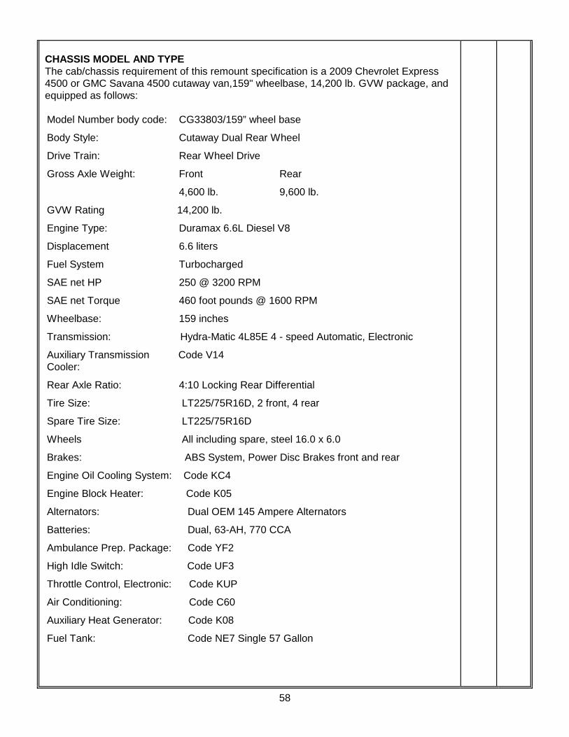
58
CHASSIS MODEL AND TYPE The cab/chassis requirement of this remount specification is a 2009 Chevrolet Express 4500 or GMC Savana 4500 cutaway van,159" wheelbase, 14,200 lb. GVW package, and equipped as follows: Model Number body code: CG33803/159” wheel base
Body Style: Cutaway Dual Rear Wheel
Drive Train: Rear Wheel Drive
Gross Axle Weight: Front Rear
4,600 lb. 9,600 lb.
GVW Rating 14,200 lb.
Engine Type: Duramax 6.6L Diesel V8
Displacement 6.6 liters
Fuel System Turbocharged
SAE net HP 250 @ 3200 RPM
SAE net Torque 460 foot pounds @ 1600 RPM
Wheelbase: 159 inches
Transmission: Hydra-Matic 4L85E 4 - speed Automatic, Electronic
Auxiliary Transmission Code V14 Cooler:
Rear Axle Ratio: 4:10 Locking Rear Differential
Tire Size: LT225/75R16D, 2 front, 4 rear
Spare Tire Size: LT225/75R16D
Wheels All including spare, steel 16.0 x 6.0
Brakes: ABS System, Power Disc Brakes front and rear
Engine Oil Cooling System: Code KC4
Engine Block Heater: Code K05
Alternators: Dual OEM 145 Ampere Alternators
Batteries: Dual, 63-AH, 770 CCA
Ambulance Prep. Package: Code YF2
High Idle Switch: Code UF3
Throttle Control, Electronic: Code KUP
Air Conditioning: Code C60
Auxiliary Heat Generator: Code K08
Fuel Tank: Code NE7 Single 57 Gallon

59
Deluxe Front Appearance Code V22 Package:
Chrome Appearance Pkg: Code ZR7
Chrome Front Bumper: Code V46
Front License Plate Mount: Code VK3
Dual Cloth High Back Code ZX2 Bucket Seats:
Tilt Wheel and Speed Control Code ZQ3
Steering: Power
Radio: Code U1C AM/FM/CD Radio
Power Locks/Windows Code ZQ2
Head-lamps, Auto Control, Code T74 Delay
Cold Climate Package Code V10
Cloth Cab Headliner
Cloth sun visors
Cloth Cab Door Trim Panels
Medium Pewter Interior Color/
Solid Exterior Color (Summit White)
_______________________________________________________________________ ELECTRIC THROTTLE The OEM High Idle Speed Control shall be installed as part of the Code YF2 Ambulance Prep Package. The throttle shall be preset to initiate engine high idle at 1300 RPMs when activated. When the transmission is placed in Park and the Park Brake is engaged, the throttle will be activated. Releasing the Park Brake, depressing the brake pedal or shifting the transmission into gear shall deactivate it. _______________________________________________________________________ CAB SIGNS One (1) "NO SMOKING OXYGEN EQUIPPED" and "FASTEN SEATBELT" sign shall be installed in the driver's compartment on the passenger side of the dash. These signs shall be engraved or molded plastic for durability. _______________________________________________________________________ CAB FLOORING The cab flooring shall standard OEM supplied flooring with removable OEM floormats. _______________________________________________________________________ CAB WINDOW TINT The side windows on the vehicle cab shall be tinted with a premium, high-performance lifetime warranty window tinting film to a light transmissibility of 35%.

60
MAP BOX A high-quality map and glove box similar to the ones provided on the new ambulances shall be provided and installed on the bulkhead wall where the walk-thru is deleted, below the sliding window and between the driver and passenger seating positions. It shall have a minimum of three (3) dividers, two (2) glove receptacles and shall be easily accessible by either the driver or passenger. The dividers and the glove box covers shall be constructed from plexiglass and angled downward so as to retain map books etc. when the vehicle is in motion. _______________________________________________________________________ BATTERY SWITCH A heavy-duty battery switch of the type normally used by the vehicle manufacturer is to be installed. This system will have an integral timer pre-set to open the power circuit from the batteries to the main circuit board and interrupt power to all conversion functions after 5 minutes with chassis ignition OFF. BRAKES The chassis brake system shall be GM OEM standard Hydroboost 4-wheel disc, 4-wheel ABS with Dynamic Rear Proportioning. _______________________________________________________________________ TIRES The vehicle shall be equipped with seven (7) wheels and tires. The tires shall be Michelin LTX 225/75R16E steel belted radials with all-season tread design. _______________________________________________________________________ SPARE TIRE A spare tire of the type specified for the vehicle shall be provided and mounted on the rear wall of the exterior D2 compartment. _______________________________________________________________________ REMOVAL OF MODULAR BODY FROM OLD CHASSIS MODULE DISMOUNT AND INSPECTION The modular body and all sub systems including wiring harnesses and air conditioner/ heater hoses shall be disconnected. The modular body shall then be lifted and removed from the original cab chassis. A full inspection of the under structure shall be performed. The inspection shall consist of checking all exposed structures and framing for cracks, corrosion or excessive wear. All questionable areas shall be treated with a dye specially manufacturer to penetrate the area and expose any cracks. All defects shall be repaired to like new condition. There shall be provided a written check list documenting the inspection and repair process. One copy of the documentation shall be provided to this agency and one copy shall be kept by the service facility.
61
MODULAR EXTERIOR PAINT PREPARATION After the module has been dismounted and passed the inspection and repair procedures, it shall be mounted on a roll around platform to enter the paint prep stage. Prior to repainting the module, all hardware, lights, door handles, stone guards, skirt rails, kick panels, diamond plate, etc. shall be removed. All module doors shall also be removed to be painted separate from the module body. After all hardware is removed, the module shall be fully inspected as to any minor body damage or electrolysis / corrosion damage. All body damages are to be professionally repaired and brought back to like new condition. Any electrolysis / corrosion damage shall be treated to prevent further deterioration. The module surfaces shall then be chemically treated and the surfaces sanded and prepared for repainting per the new ambulance specifications noted earlier in this document. The complete module body and module doors shall then be repainted Pierce #90 (Sikkens FLNA3042 or equivalent), utilizing a high quality base coat/clear coat paint system (Sikkens or equivalent) to match the new ambulance specifications noted earlier in this document. The module body roof from the drip rail up shall be painted white (GM Summit White base coat/clear coat or equivalent) utilizing a high quality base coat/clear coat paint system (Sikkens or equivalent) using the same paint process standards as noted above. Additionally, all exterior storage compartments shall be striped of rubber seals, then sanded, prepped, and re-coated per the new ambulance specifications noted earlier in this document. All painting is to be done in house as per paint manufacturers instructions, specifications and guidelines and shall be painted by a certified paint technician. _______________________________________________________________________ LETTERING STRIPES AND GRAPHICS Lettering, stripes and graphics shall be applied per the RCFD Ambulance Lettering and Graphics specification noted earlier in this document and shall match the graphics package applied to the new ambulances (including NFPA 1901 rear striping). 3M Scotchlite brand vinyl shall be used for all lettering, stripes and graphics. Lettering requiring shading shall be shaded down and to the right. All lettering, stripes and graphics shall be applied by the same facility that applies the lettering, stripes and graphics for the new ambulances. _______________________________________________________________________ RUNNING BOARDS AND GUARDS To provide for increased road splash protection and ease of driver/technician entry and exit, new high quality, heavy duty polished aluminum diamond plate running boards shall be installed on the vehicle. The running boards shall incorporate front splash and stone guards and be tapered out to the edge of the chassis fenders and fastened. The material used must be a minimum of .090" alloy polished aluminum diamond plate.

62
ENGINE BLOCK HEATER The OEM chassis engine block heater shall be supplied and wired to the external 115 volt power source. _______________________________________________________________________ WHEEL COVERS New Phoenix brand polished stainless steel covers shall be provided on all in- service wheels of the vehicle. Braided stainless steel valve extenders shall be installed on the rear inboard tires to allow easy access for filling. WHEEL CENTER AND LUG COVERS New Phoenix brand polished stainless steel wheel center covers and lug covers shall be provided on all in-service wheels of the vehicle. _______________________________________________________________________ MIRRORS New mirrors shall be supplied and firmly secured, vibration-less rear view mirrors totaling at least one hundred and twenty five square inches. Brand shall be Velvac #714563, Remote, Black. The mirrors will be power /no heat. _______________________________________________________________________ FUEL FILLER NECK MODIFICATIONS The chassis fuel tank filler neck shall be modified to fit the modular body. There shall be supplied new fuel filler hoses and plumbing. As necessary, there shall be provided aluminum body patches and repairs should there be required new fuel filler locations or should the remounted body have additional fuel filler cut outs not required. All fuel filler neck modifications shall be performed per Ford Q.V.M. requirements. _______________________________________________________________________ EXHAUST MODIFICATIONS The chassis O.E.M. tail pipe shall be extended to behind the dual rear wheels. The exhaust modifications shall be on the curbside. _______________________________________________________________________ CHASSIS PAINT The chassis shall be repainted a single color, Pierce #90 (Sikkens FLNA3042 or equivalent), utilizing a high quality base coat/clear coat paint system (Sikkens or equivalent) using the paint process standards as noted for the module body. _______________________________________________________________________ TRANSFER OF BODY TO NEW CHASSIS After full inspection from paint process, the module body will be transported to the chassis remounting area. The module will then be mounted on the new chassis. This procedure shall utilizing mounting procedures and specifications as noted for the new ambulances. Mounting hardware shall be repaired or replaced as necessary. There shall be installed a non-electrolytic rubber seal between the cab and module to serve as an interface to eliminate air and water leaks. The seal and process shall be the

63
same as the mounting procedures and specifications as noted for the new ambulances. The module body shall be squarely mounted on the new chassis and shall conform to all Ford Motor Co. QVM mounting requirements. _______________________________________________________________________ NEW EXTERIOR BODY TRIM BODY HARDWARE All lights and fixtures, all body hardware, all compartment and entry doors shall be mounted on the module body with stainless steel fasteners. All stainless mounting fasteners shall be dipped in or sprayed with electrolysis preventive solution (ECK) before installation on the body. This is required to minimize the process of electrolysis. NO EXCEPTIONS ALLOWED. _______________________________________________________________________ STONE GUARDS There shall be provided four each new stone guards mounted on each exterior corner. The stone guards shall be fabricated using new aluminum diamond plate, shall be the same dimensions as the old stone guards and shall conform to the module corner post. The stone guards shall be attached to the module using stainless steel fasteners. _______________________________________________________________________ SKIRT / RUB RAIL The skirt/rubrail presently on the module body shall be replaced with new aluminum diamond plate pieces that match the pieces presently on the module body. Fastening process for the new pieces shall be the same as the old pieces. _______________________________________________________________________ REAR KICK PANEL There shall be provided a new rear kick panel. The kick panel shall be the same dimensions as the old kick panel. The rear kick panel shall be fabricated using new aluminum diamond plate and attached to the module using stainless steel fasteners (no pop rivets shall be acceptable). It shall be fabricated to accept the license plate mounting bracket. _______________________________________________________________________ REAR STEP BUMPER The rear step bumper frame shall be inspected as to any damage or defects and refurbished as necessary to like new condition. All aluminum diamond plate bumper tips and grip strut insert shall be replaced. The rear step bumper shall be bolted to the chassis frame rails using the same mounting process the bumper originally used. Mounting structures shall be inspected and repaired/replaced as necessary. _______________________________________________________________________ FENDERETTES New, formed, minimum 16 gauge polished stainless steel fenderettes shall be provided around each rear wheel well opening. They shall help diminish damage to the wheel well area of the body caused by stones and road debris

64
ELECTRICAL SYSTEM CAB CONSOLE There shall be provided a new console in the cab area. The console shall house a new front switch panel and use the existing siren heads (if serviceable, repair or replace as necessary) and any light control heads (if serviceable, repair or replace as necessary) for lights presently on the module body. The switch panel shall incorporate new rocker style switches, door and compartment indicator lights, voltmeter and amp gauges. The cab console shall be per the specification for and largely match the cab console for the new ambulances as noted earlier in this document. The style, color, construction, layout, switches, siren and light control head placement shall be as similar as possible to the new ambulances. The manufacturer of the new ambulances shall supply the cab console for the remount. _______________________________________________________________________ 12 VOLT POWER PANEL There shall be performed a complete operations check of the current 12 volt electrical system. The system shall be upgraded to meet all current needs and requirements. All circuit breakers, relays, solenoids, etc. on the power distribution panel that are not operating properly shall be replaced with new components. Upon completion, the 12 volt power panel and system shall be 100 per cent operable. _______________________________________________________________________ NEW CAB CHASSIS WIRING There shall be provided a new under hood harness and new battery cables. The harnesses shall be built with new power wiring conforming to SAE, KKK-A-1822E requirements and Ford QVM guidelines. All wiring shall be color coded and function labeled for ease of trouble shooting. All wiring shall be routed in high temperature loom with a minimum rating of 300 degrees Fahrenheit. All wiring shall additionally be accessible and shall be secured to the body or frame using insulated metal clamps. _______________________________________________________________________ RADIOS A Motorola radio system identical to the ones provided in the new ambulances shall be provided and installed. All the radio specifications as well as the installation specifications and requirements as apply to the new ambulances shall also apply to this remounted ambulance. _______________________________________________________________________ OTHER ELECTRICAL COMPONENTS / WIRING All electrical components and wiring presently in service on the vehicle that will be retained shall be checked for integrity and function and repaired or replaced as necessary. This shall include wiring and wiring looms

65
INVERTER The inverter/charger presently in service on the vehicle will be replaced with a new unit of the same make and model in the same location. All inverter/charger wiring shall be inspected and repaired or replaced as necessary. _______________________________________________________________________ EXTERIOR SHORE POWER / VOLTAGE INDICATOR There shall be a new Kussmaul 115 volt "Auto-Eject" plug rated at 20 amps or more with a spring-loaded cover assembly, UL listed for exterior use, located on the left side of the ambulance body in the same position as the old unit. The plug shall be equipped with a Dynamic Disconnect Switch. This shall energize the vehicle's 115 volt AC circuit from an exterior power source. This connector must be labeled: "115 volt AC, 60 Hz,20 amp power supply". There shall also be a weatherproof Kussmaul bar graph voltage display installed on the exterior body by the shoreline connection. This display shall indicate battery line voltage. There shall be an easily visible blue LED “Shoreline Active” light on the switching console. _______________________________________________________________________ PARK BRAKE ENGAGED LIGHT There shall be a red LED “Park Brake Engaged” light mounted on the left A pillar that illuminates when the park brake is engaged. This light shall intrude minimally into the cab interior. _______________________________________________________________________ BATTERIES There shall be two (2) new INTERSTATE brand 31 ECL 12 volt batteries supplied. They shall total not less than 1,400 CCA. _______________________________________________________________________ NEW SIREN SPEAKERS All siren speakers shall be replaced. The speakers shall be mounted in the front chassis bumper area to match the mounting for the new ambulances as noted earlier in this document. _______________________________________________________________________ BUELL AIR HORN The present Buell air horn system shall be inspected, refurbished and parts replaced as necessary. The horns shall be mounted to match the mounting on the new ambulances. _______________________________________________________________________ FRONT INTERSECTION LIGHT The current front intersection lights shall be re-installed on the new cab chassis. The lights shall be installed one each side in the front fender area of the cab chassis to match the mounting on the new ambulances. The lights shall be inspected, cleaned and repaired as necessary. The chrome bezels shall be replaced if damaged, new lenses shall be installed. The lights shall match the previous flashing sequence and lens color.

66
FRONT GRILL LIGHTS The current grill lights shall be re-installed on the new cab chassis if the chassis change allows those lights to be used. If the current lights can be used, they shall be installed to match as closely as possible the mounting on the new ambulances. The lights shall be inspected, cleaned and repaired as necessary. The chrome bezels shall be replaced if damaged, new lenses shall be installed. The lights shall match the previous flashing sequence and lens color. If the current lights cannot be used, they will be replaced with the same style and type of lights used on the new ambulances and will be mounted in the same manner. The lights shall match the previous flashing sequence and lens color. _______________________________________________________________________ CURRENT MODULE WARNING AND OTHER LIGHT SYSTEMS The current module warning light system including the: Front lightbar Rear lights that replace the rear lightbar Module body lights Rear intersection lights Marker lights Taillights Load lights Scene lights All shall be completely checked and serviced. Any lights or bulbs found defective are to be replaced with new components. All exterior lenses on module warning light system shall be replaced with new lenses, to include all warning lights, all scene lights, all light bars, all tail lights and all ICC marker lights. Lens color on all 900 series module body lights shall be clear. All other lights will remain the color they presently are. _______________________________________________________________________ BACKUP ALARM A new Preco, Model #230 backup alarm shall be installed on a floor structural member at the rear of the ambulance. This alarm shall activate whenever the ambulance is put into reverse gear. There shall be a momentary switch in the driver's switch console that will cancel the alarm. The system shall have an automatic reset to activate the alarm the next time the vehicle is placed into reverse. When activated, this alarm shall generate an intermittent warning tone at a minimum of 97 dB as prescribed by KKKA-1822E. _______________________________________________________________________ EXTERIOR COMPARTMENTS / DOORS NEW WEATHER STRIPPING / DOOR SEALS All compartment door and entry door weather stripping and door seals shall be replaced with new rubber or equivalent seal. All old material shall be completely removed to allow proper installation and seal.

67
EXTERIOR COMPARTMENT / ENTRY DOORS All exterior doors shall be removed prior to repainting the module. Each door shall be inspected for damage and needed repairs and repaired or replaced as necessary. Upon reinstallation, the doors shall be checked as per alignment and ease of closure. All door latches, hinges, closers and hardware are to be lubricated to insure proper operation. Any latch, lock, hinge or closer not working properly shall be repaired or replaced. Entry door windows and or sliding side windows and screens shall be repaired or replaced as necessary if damaged. Each entry door (2 rear and 1 side) shall have two (2) Whelen #52 or 500 series Super-LED amber warning lights with chrome flanges installed, one at the top and one at the bottom of the door. These lights shall be flush/surface mount and wired ignition hot and activate and flash when the door is opened. The highest quality available switches shall be used to activate lights. _______________________________________________________________________ ENTRY DOOR TRIM Each entry door (rear and side) shall have the interior trim repaired or replaced as necessary where damaged or worn. The center shall have a reflective chevron covered aluminum section that is a minimum of 10” wide. The chevron colors shall be reflective red and orange. _______________________________________________________________________ INTERIOR PATIENT COMPARTMENT NEW FLOOR COVERING There shall be provided a new heavy duty commercial grade vinyl floor covering in the interior patient compartment. The floor covering shall be installed and rolled up the side walls the same distance as the old floor.. Before the new floor covering is installed, the old floor covering shall be removed and the sub floor shall be inspected for any damage. Sub floor shall be repaired or replaced as necessary. The new floor covering shall be LonCoin, with a clear, non-skid coating. Color shall be compatible with the interior presently in the body and determined at the pre-construction conference. Because of the resilient and design of this style floor cover, no exceptions are allowed. _______________________________________________________________________ NEW THRESHOLDS There shall be provided two each new thresholds to replace the side and rear door thresholds. The new threshold shall be sealed for sanitation purposes and shall have non skid tape attached for safety.

68
NEW UPHOLSTERY All upholstery in the interior patient compartment shall be replaced with new heavy duty material. Exact color of new upholstery shall be determined at the pre-construction conference. _______________________________________________________________________ CABINET/COMPARTMENT MATS Any exterior compartment or interior cabinet that presently has a rubber mat or Dri-Dek mat installed shall have a new replacement mat of the same type provided. _______________________________________________________________________ PATIENT COMPARTMENT CABINETS/WALLS All interior patient compartment cabinets, walls, shelves and formica shall be checked for problems, physical damage, operation and defects. Included in checklist are insuring mounting bolt are properly tightened and all shelves are secure. Any visible damage shall be repaired or parts replaced as necessary. Any trim or screws damaged or missing are to be replaced. All present interior compartment cabinet halogen/incandescent lights shall be replaced with a comparable size and shape white LED light. _______________________________________________________________________ MEDI-KOOL DRAWER REFRIGERATION UNIT A Medi-Cool brand 1.5 Drawer stainless steel locking refrigeration unit will be provided and installed in the upper right side of the forward wall. It shall be designed as a cooling unit and shall have inlet and outlet vents installed to vent the refrigeration cabinetry. There shall be a minimum of one (1) additional 4” auxiliary fan installed to exhaust warm air from the refrigeration cabinetry. The fan will vent air from the unit to the exterior of the vehicle and one (1) chrome exterior compartment vent shall be provided and installed where the vent exits the vehicle body. The fan shall be wired in series to activate with the integral refrigerator fans. The exact location of this fan will be determined at a pre-construction meeting. The refrigeration unit shall be configured to run on 12V or 110V power and will additionally be configured to auto change over from 12V to 110V when the unit senses 110V power. The refrigeration unit shall be configured to run only when vehicle ignition is hot or the shoreline is plugged in. The digital control panel that controls the refrigeration unit will be installed in a location that is visible through the rear and side windows of the vehicle body. There shall be a small, green LED light installed in close proximity to the control panel that indicates and is labeled “power to refrigeration unit”. The installation of the refrigeration units shall be such that it appears built in, all walls will be finished to the side walls of the body. _______________________________________________________________________ RIGHT SIDE FRONT ALS CABINETRY The present front right side ALS cabinetry shall be reconfigured to accommodate the installation of the new refrigerator. The cabinetry shall be reconfigured to match as much

69
as possible the same location cabinetry in the new ambulances. Dimensions are approximate and allowances can be made for size differences in the different module bodies. The reconfigured cabinetry shall be approximately as below. ALS SUPPLY CABINET A reconfigured/replacement supply cabinet shall be provided and installed in the right side of the forward wall directly underneath the refrigeration unit. This cabinet shall be finished with the same or similar material as the other cabinets. It shall have approximate dimensions of 14” high x 26” wide and be the full depth to the cab bulkhead wall. It shall have a durable rubber floor mat provided on the bottom of the cabinet This cabinet shall be accessible from the exterior corresponding compartment (P1). This cabinet shall have a flip-down Plexiglass door. The door shall have a spring-strut hold-open device and chrome pull handles with roller ball catches. _______________________________________________________________________ ALS CABINET A reconfigured/replacement cabinet shall be provided and installed in the right side of the forward wall directly underneath the ALS supply cabinet. This cabinet shall be finished with the same or similar material as the other cabinets. It shall have approximate dimensions of 40” high x 26” wide and be the full depth to the cab bulkhead wall. (the height of this cabinet is approximate, this cabinet, the ALS supply cabinet above it and the refrigeration unit shall take up the full height of the bulkhead wall with minimal spacing between). This cabinet shall be accessible from the exterior corresponding compartment (P1). This cabinet shall have three [3] infinitely adjustable shelves running the full width and depth of the cabinet A durable rubber floor mat shall be installed on the bottom floor and all shelves of this cabinet. This cabinet shall have a roll-up tambour style metal door. In the event a roll-up door is not available from a particular manufacturer, dual wood doors with plexiglass inserts and full length stainless steel piano style hinges with either Southco style non-locking latches or non-locking paddle style latches. _______________________________________________________________________ SEAT BELTS All patient compartment seat belts and mounts are to be inspected for proper operation, mounting and wear. Any defective or significantly worn seat belts shall be replaced with new. _______________________________________________________________________ PLEXIGLAS All Plexiglas and sliding track for interior compartments shall be inspected for proper operation and damage. Track shall be repaired or replaced as necessary to assure smooth operation. Any Plexiglas windows that are visibly worn or damaged shall be replaced with new Plexiglas.

70
NEW DOOR SWITCHES All exterior door switches shall be replaced with new switches of comparable or higher quality. _______________________________________________________________________ NEW INTERIOR DOME LIGHTS All existing halogen interior dome lights shall be replaced with a Whelen Super LED dual intensity light of the same size and shape. _______________________________________________________________________ NEW SWITCHES ON REAR ACTION AREA PANEL There shall be provided new rocker style switches on the rear control panel. The new switches shall be of a comparable or higher quality as the old switches. Additionally all switch function labels shall be replaced with new where possible. _______________________________________________________________________ HEATING / A.C. SYSTEM The module body heat/cool system presently in the vehicle shall be completely inspected and tested for operation, function and reliability. The system shall be repaired and or parts replaced to bring the system up to like new performance and reliability. This shall include the digital thermostat. The system shall be configured to interface with the new cab chassis system and be re-installed with all new hoses and fittings. The system shall be thoroughly tested for peak performance. Note: In the event the present heat/cool system will not interface with the new cab chassis system, or is not economically repairable, the entire heat/cool system shall be replaced with a new system. Any new system shall have the same performance and reliability as noted above. There shall be supplied in the vehicle documentation, a copy of the testing and certification on the performance of the system. _______________________________________________________________________ POWER VENTILATOR The power ventilator shall be inspected and treated to insure proper operations. The unit shall be repaired or replaced as necessary. _______________________________________________________________________ OXYGEN / VACUUM SYSTEMS OXYGEN SYSTEM The current piped oxygen system shall be tested to insure proper operations. Testing shall include a minimum four hour nitrogen leak test. The entire system including outlets and lines shall be repaired or replaced as necessary. Documentation concerning the oxygen system testing shall be provided in the vehicle owners manual.

71
VACUUM SYSTEM The current piped vacuum system shall be tested to insure proper operations. The entire system including outlets and piping shall be repaired or replaced as necessary. Documentation concerning the vacuum / suction system testing shall be provided in the vehicles owners manual. _______________________________________________________________________ COT MOUNT The Stryker #6370 single position, floor cot mount presently in the vehicle shall be inspected for damage and function and repaired or replaced as necessary to restore like new function. _______________________________________________________________________ SIGNS New self adhesive "NO SMOKING OXYGEN EQUIPPED" and "FASTEN SEATBELT" signs shall be installed in the primary action area. _______________________________________________________________________