2009 gmc sierra owner manual m - general motors · pdf file2009 gmc sierra owner manual m....
TRANSCRIPT

Seats and Restraint System ............................. 1-1Head Restraints ......................................... 1-3Front Seats ............................................... 1-4Rear Seats .............................................. 1-14Safety Belts ............................................. 1-16Child Restraints ....................................... 1-38Airbag System ......................................... 1-73Restraint System Check ............................ 1-90
Features and Controls ..................................... 2-1Keys ........................................................ 2-3Doors and Locks ...................................... 2-10Windows ................................................. 2-15Theft-Deterrent Systems ............................ 2-18Starting and Operating Your Vehicle ........... 2-22Mirrors .................................................... 2-57Object Detection Systems .......................... 2-62OnStar® System ...................................... 2-71Universal Home Remote System ................ 2-74Storage Areas ......................................... 2-81Sunroof .................................................. 2-85
Instrument Panel ............................................. 3-1Instrument Panel Overview .......................... 3-4Climate Controls ...................................... 3-24Warning Lights, Gages, and Indicators ........ 3-33Driver Information Center (DIC) .................. 3-53Audio System(s) ....................................... 3-85
Driving Your Vehicle ....................................... 4-1Your Driving, the Road, and the Vehicle ....... 4-2Towing ................................................... 4-45
Service and Appearance Care .......................... 5-1Service ..................................................... 5-4Fuel ......................................................... 5-6Checking Things Under the Hood ............... 5-12Rear Axle ............................................... 5-49Four-Wheel Drive ..................................... 5-51Front Axle ............................................... 5-53Noise Control System ............................... 5-54Headlamp Aiming ..................................... 5-55Bulb Replacement .................................... 5-58
2009 GMC Sierra Owner Manual M

Windshield Wiper Blade Replacement ......... 5-64Tires ...................................................... 5-65Appearance Care ................................... 5-113Vehicle Identification ............................... 5-121Electrical System .................................... 5-122Capacities and Specifications ................... 5-129
Maintenance Schedule ..................................... 6-1Maintenance Schedule ................................ 6-2
Customer Assistance Information .................... 7-1Customer Assistance and Information ........... 7-2Reporting Safety Defects ........................... 7-14Vehicle Data Recording and Privacy ........... 7-16
Index ................................................................ 1

GENERAL MOTORS, GM, the GM Emblem, GMC,the GMC Truck Emblem, and the name SIERRA areregistered trademarks of General Motors Corporation.
This manual includes the latest information at the time itwas printed. GM reserves the right to make changes afterthat time without further notice. For vehicles first sold inCanada, substitute the name “General Motors of CanadaLimited” for GMC wherever it appears in this manual.
This manual describes features that may or may not beon your specific vehicle.
Read this manual from beginning to end to learn aboutthe vehicle’s features and controls. Pictures, symbols,and words work together to explain vehicle operation.
If the vehicle has the DURAMAX® Diesel engine, referto the DURAMAX® Diesel supplement for additionaland specific information on this engine.
Keep this manual in the vehicle for quick reference.
Canadian OwnersA French language copy of this manual can be obtainedfrom your dealer/retailer or from:
Helm, IncorporatedP.O. Box 07130Detroit, MI 48207
1-800-551-4123helminc.com
Propriétaires CanadiensOn peut obtenir un exemplaire de ce guide en françaisauprès de concessionnaire ou à l’adresse suivante:
Helm IncorporatedP.O. Box 07130Detroit, MI 48207
1-800-551-4123helminc.com
Litho in U.S.A.Part No. 15911381 A First Printing ©2008 General Motors Corporation. All Rights Reserved.
iii

IndexTo quickly locate information about the vehicle use theIndex in the back of the manual. It is an alphabeticallist of what is in the manual and the page number whereit can be found.
Safety Warnings and Symbols
A circle with a slashthrough it is a safetysymbol which means“Do Not,” “Do not do this” or“Do not let this happen.”
A box with the word CAUTION is used to tell aboutthings that could hurt you or others if you were to ignorethe warning.
{CAUTION:
These mean there is something that could hurtyou or other people.
Cautions tell what the hazard is and what to do to avoidor reduce the hazard. Read these cautions.
A notice tells about something that can damage thevehicle.
Notice: These mean there is something that coulddamage your vehicle.
Many times, this damage would not be covered by thevehicle’s warranty, and it could be costly. The noticetells what to do to help avoid the damage.
There are also warning labels on the vehicle which usethe same words, CAUTION or Notice.
Vehicle SymbolsThe vehicle has components and labels that usesymbols instead of text. Symbols are shown alongwith the text describing the operation or informationrelating to a specific component, control, message,gage, or indicator.
M : This symbol is shown when you need to see yourowner manual for additional instructions or information.
* : This symbol is shown when you need to see aservice manual for additional instructions or information.
iv

Vehicle Symbol ChartHere are some additional symbols that may be found onthe vehicle and what they mean. For more informationon the symbol, refer to the index.
0 : Adjustable Pedals
9 : Airbag Readiness Light
# : Air Conditioning
! : Antilock Brake System (ABS)
g : Audio Steering Wheel Controls or OnStar®
$ : Brake System Warning Light
" : Charging System
I : Cruise Control
B : Engine Coolant Temperature
O : Exterior Lamps
# : Fog Lamps
. : Fuel Gage
+ : Fuses
i : Headlamp High/Low-Beam Changer
j : LATCH System Child Restraints
* : Malfunction Indicator Lamp
: : Oil Pressure
g : Outside Power Foldaway Mirrors
} : Power
/ : Remote Vehicle Start
> : Safety Belt Reminders
7 : Tire Pressure Monitor
_ : Tow/Haul Mode
F : Traction Control
M : Windshield Washer Fluid
v

✍ NOTES
vi

Head Restraints ...............................................1-3Front Seats ......................................................1-4
Manual Seats ................................................1-4Power Seats ..................................................1-5Manual Lumbar ..............................................1-6Power Lumbar ...............................................1-7Heated Seats .................................................1-8Memory Seat, Mirrors, and Pedals ....................1-8Reclining Seatbacks ......................................1-10Seatback Latches .........................................1-13Center Seat .................................................1-14
Rear Seats .....................................................1-14Rear Seat Operation (Extended Cab) ...............1-14Rear Seat Operation (All Except
Extended Cab) ..........................................1-15Safety Belts ...................................................1-16
Safety Belts: They Are for Everyone ................1-16How to Wear Safety Belts Properly .................1-21Lap-Shoulder Belt .........................................1-30Safety Belt Use During Pregnancy ..................1-36Lap Belt (Crew and Extended Cab) .................1-36Safety Belt Extender .....................................1-37
Child Restraints .............................................1-38Older Children ..............................................1-38Infants and Young Children ............................1-41Child Restraint Systems .................................1-45Where to Put the Restraint .............................1-48Lower Anchors and Tethers for
Children (LATCH) ......................................1-49Securing a Child Restraint in a
Rear Seat Position ....................................1-58Securing a Child Restraint in the
Center Front Seat Position ..........................1-61Securing a Child Restraint in the Right
Front Seat Position (With AirbagOff Switch) ...............................................1-62
Securing a Child Restraint inthe Right Front Seat Position(With Passenger Sensing System) ...............1-66
Securing a Child Restraint in theRight Front Seat Position (Heavy DutyCrew Cab Only) ........................................1-70
Section 1 Seats and Restraint System
1-1

Airbag System ...............................................1-73Where Are the Airbags? ................................1-75When Should an Airbag Inflate? .....................1-77What Makes an Airbag Inflate? .......................1-79How Does an Airbag Restrain? .......................1-79What Will You See After an
Airbag Inflates? .........................................1-79Airbag Off Switch ..........................................1-81Passenger Sensing System ............................1-84Servicing Your Airbag-Equipped Vehicle ...........1-88Adding Equipment to Your Airbag-Equipped
Vehicle ....................................................1-89
Restraint System Check ..................................1-90Checking the Restraint Systems ......................1-90Replacing Restraint System Parts
After a Crash ............................................1-91
Section 1 Seats and Restraint System
1-2

Head RestraintsThe front seats have adjustable head restraints in theoutboard seating positions.
{CAUTION:
With head restraints that are not installed andadjusted properly, there is a greater chance thatoccupants will suffer a neck/spinal injury in acrash. Do not drive until the head restraints for alloccupants are installed and adjusted properly.
Adjust the head restraint so that the top of the restraint isat the same height as the top of the occupant’s head.This position reduces the chance of a neck injury in acrash.
1-3

Pull the head restraint up to raise it. To lower the headrestraint, press the button, located on the top of theseatback, and push the restraint down.
Push down on the head restraint after the button isreleased to make sure that it is locked in place.
The head restraints are not designed to be removed.
The rear seat has head rests that can be adjustedup and down.
Front Seats
Manual Seats
{CAUTION:
You can lose control of the vehicle if you try toadjust a manual driver’s seat while the vehicle ismoving. The sudden movement could startle andconfuse you, or make you push a pedal when youdo not want to. Adjust the driver’s seat only whenthe vehicle is not moving.
1-4

If the vehicle has a manual seat, it can be movedforward or rearward.
1. Lift the bar to unlockthe seat.
2. Slide the seat to thedesired position andrelease the bar.
Try to move the seat with your body to be sure the seatis locked in place.
Power Seats
On a vehicle with power seats, the controls used tooperate them are located on the outboard side ofthe seats.
Move the seat forward or rearward by sliding the controlforward or rearward.
Driver’s Seat with Power Seat Control, PowerRecline, and Power Lumbar shown
1-5

Your vehicle may have additional features to adjust yourvehicle’s power seat:
• Raise or lower the front part of the seat cushion bymoving the front of the control up or down.
• Raise or lower the rear part of the seat cushion bymoving the rear of the control up or down.
• Raise or lower the entire seat by moving the entirecontrol up or down.
On seats with power reclining seatbacks, the control islocated behind the power seat control on the outboardside of the seats. See “Power Reclining Seatbacks”under Reclining Seatbacks on page 1-10.
A vehicle with a memory function allows seat settings tobe saved and recalled. See Memory Seat, Mirrors,and Pedals on page 1-8 for more information.
Manual Lumbar
On vehicles with this feature the control is located onthe outboard side of the seat.
Increase or decrease lumbar support by turning theknob forward or rearward.
1-6

Power Lumbar
On seats with power lumbar, the controls used tooperate this feature are located on the outboard side ofthe seats.
• To increase lumbar support, press and hold thefront of the control.
• To decrease lumbar support, press and hold therear of the control.
The vehicle may have additional features to adjust yourvehicle’s power seat:
• To raise the height of the lumbar support, pressand hold the top of the control.
• To lower the height of the lumbar support, pressand hold the bottom of the control.
Release the control when the lower seatback reachesthe desired level of lumbar support.
Your vehicle may have a memory function which allowsseat settings to be saved and recalled. See MemorySeat, Mirrors, and Pedals on page 1-8 for moreinformation.
Keep in mind that as your seating position changes,as it may during long trips, so should the position ofyour lumbar support. Adjust the seat as needed.
1-7

Heated SeatsOn vehicles with heated front seats, the controls arelocated on the driver and passenger doors.
I (Heated Seatback): Press to turn on the heatedseatback.
J (Heated Seat and Seatback): Press to turn on theheated seat and seatback.
The light on the button will come on to indicate that thefeature is working. Press the button to cycle throughthe temperature settings of high, medium, and low andto turn the heat to the seat off. Indicator lights willshow the level of heat selected: three for high, two formedium, and one for low.
The heated seats will be canceled 10 seconds after theignition is turned off. To use the heated seat featureafter restarting the vehicle, press the heated seator seatback button again.
Memory Seat, Mirrors, and PedalsYour vehicle may have the memory package.
The controls for this featureare located on the driver’sdoor panel, and are used toprogram and recall memorysettings for the driver’sseat, outside mirrors, andthe adjustable throttle andbrake pedal.
1-8

To save seating positions in memory:
1. Adjust the driver’s seat, including the seatbackrecliner and lumbar, both outside mirrors, andthe throttle and brake pedals to a comfortableposition.See Outside Power Mirrors on page 2-59 andAdjustable Throttle and Brake Pedal on page 2-26for more information.Not all mirrors, adjustable throttles and brakepedals, or power lumbar will have the ability tosave and recall their positions.
2. Press and hold button 1 until two beeps sound toindicate that the position has been stored.
A second seating, lumbar, mirror, and throttle and brakepedal position can be programmed by repeating theabove steps and pressing button 2.
To recall the memory positions, the vehicle must be inPARK (P). Press and release either button 1 or button 2corresponding to the desired driving position. The seat,outside mirrors, and adjustable throttle and brake pedalswill move to the position previously stored. You will hear asingle beep.
If you use the remote keyless entry transmitter to enteryour vehicle and the remote recall memory feature is on,automatic seat, adjustable mirror, and adjustable pedalmovements will occur. See “MEMORY SEAT RECALL”under DIC Vehicle Customization (With DIC Buttons) onpage 3-76 for more information.
To stop recall movement of the memory function at anytime, press one of the power seat controls, memorybuttons, power mirror buttons, or adjustable pedalswitch.
If something has blocked the driver’s seat and/or theadjustable pedals while recalling a memory position, thedriver’s seat and/or the adjustable pedals recall maystop working. If this happens, remove the obstructionand press the appropriate control for the area that is notresponding for two seconds. Try recalling the memoryposition again by pressing the appropriate memorybutton. If the memory position is still not recalling, seeyour dealer for service.
1-9
Easy Exit SeatThe control for this feature is located on the driver’sdoor panel between buttons 1 and 2.
With the vehicle in PARK (P), the driver’s seat exitposition can be recalled by pressing the exit button.You will hear a single beep, and the driver’s seatwill move back.
If the easy exit seat feature is programmed in the DriverInformation Center (DIC), automatic seat movement willoccur when the key is removed from the ignition. See“EASY EXIT SEAT” under DIC Vehicle Customization(With DIC Buttons) on page 3-76 for more information.
The memory seat and easy exit features can also beprogrammed using the DIC.
For programming information, see DIC VehicleCustomization (With DIC Buttons) on page 3-76.
Reclining Seatbacks
{CAUTION:
You can lose control of the vehicle if you try toadjust a manual driver’s seat while the vehicle ismoving. The sudden movement could startle andconfuse you, or make you push a pedal when youdo not want to. Adjust the driver’s seat only whenthe vehicle is not moving.
{CAUTION:
If either seatback is not locked, it could moveforward in a sudden stop or crash. That couldcause injury to the person sitting there. Alwayspush and pull on the seatbacks to be sure theyare locked.
1-10

{CAUTION:
Sitting in a reclined position when your vehicle isin motion can be dangerous. Even if you buckleup, your safety belts cannot do their job when youare reclined like this.
The shoulder belt cannot do its job. In a crash,you could go into it, receiving neck or otherinjuries.
The lap belt cannot do its job either. In a crash thebelt could go up over your abdomen. The beltforces would be there, not at your pelvic bones.This could cause serious internal injuries.
For proper protection when the vehicle is inmotion, have the seatback upright. Then sit wellback in the seat and wear your safety beltproperly.
1-11

Manual Reclining SeatbacksOn seats with manual reclining seatbacks, the leverused to operate them is located on the outboard side ofthe seat(s).
To recline the seatback:
1. Lift the recline lever.
2. Move the seatback to the desired position, thenrelease the lever to lock the seatback in place.
3. Push and pull on the seatback to make sure it islocked.
To return the seatback to an upright position, do thefollowing:
1. Lift the lever fully without applying pressure to theseatback and the seatback will return to the uprightposition.
2. Push and pull on the seatback to make sure it islocked.
1-12

Power Reclining Seatbacks
If the seats have power reclining seatbacks, the controlused to recline them is located on the outboard sideof the seat behind the power seat control.
• To recline the seatback, tilt the top of the controlrearward.
• To bring the seatback forward, tilt the top of thecontrol forward.
Do not have a seatback reclined if your vehicle ismoving.
Seatback LatchesThe front seatbacks tilt forward to allow access to therear of the cab.
To tilt the seatback forward, lift the lever located on theoutboard side of the seat cushion.
{CAUTION:
If either seatback is not locked, it could moveforward in a sudden stop or crash. That couldcause injury to the person sitting there. Alwayspush and pull on the seatbacks to be sure theyare locked.
To return the seatback to the upright position, push theseatback rearward until it latches. After returning theseatback to its upright position, push and pull onthe seatback to make sure it is locked.
1-13

Center SeatYour vehicle may have a front center seat. The seatbackdoubles as an armrest and cupholder/storage area for thedriver and passenger when the center seat is not used.Do not use it as a seating position when the seatback isfolded down.
Rear Seats
Rear Seat Operation (Extended Cab)
Folding the Rear SeatTo fold the seat up, do the following:
Notice: Folding a rear seat with the safety belts stillfastened may cause damage to the seat or the safetybelts. Always unbuckle the safety belts and returnthem to their normal stowed position before foldinga rear seat.
1. Pull up on the front ofthe seat cushion whilepulling down on therelease strap, locatedunder the seat cushion.
2. Pull the seat cushion up until it latches with theseatback.
3. After latching the seat cushion up, pull forward on itto make sure it is locked.
To fold the seat down, do the following:
1. Push the seat cushion rearward while pulling therelease strap, located under the seat cushion.Pull the seat cushion down until it latches.
2. After latching the seat cushion, pull up on it tomake sure it is locked.
1-14

Rear Seat Operation (All ExceptExtended Cab)
Folding Rear SeatOn a vehicle with a second row 60/40 split seat eitherside of the rear seat may be folded for added cargospace.
Notice: Folding a rear seat with the safety beltsstill fastened may cause damage to the seat or thesafety belts. Always unbuckle the safety beltsand return them to their normal stowed positionbefore folding a rear seat.
Make sure that nothing is on the seat.
To fold the seat, slowly pull the seat cushion up.
To return the seat to the normal seating position, slowlypull the seat cushion down.
{CAUTION:
A safety belt that is improperly routed, not properlyattached, or twisted will not provide the protectionneeded in a crash. The person wearing the beltcould be seriously injured. After raising the rearseatback, always check to be sure that the safetybelts are properly routed and attached, and arenot twisted.
1-15

Safety Belts
Safety Belts: They Are for EveryoneThis part of the manual tells you how to use safetybelts properly. It also tells you some things you shouldnot do with safety belts.
{CAUTION:
Do not let anyone ride where a safety belt cannotbe worn properly. In a crash, if you or yourpassenger(s) are not wearing safety belts, theinjuries can be much worse. You can hit thingsinside the vehicle harder or be ejected from thevehicle. You and your passenger(s) can beseriously injured or killed. In the same crash, youmight not be, if you are buckled up. Always fastenyour safety belt, and check that your passenger(s)are restrained properly too.
{CAUTION:
People riding on the tailgate (if equipped) caneasily lose their balance and fall even when thevehicle is operated at low speeds. Falling from amoving vehicle may result in serious injuries ordeath.
{CAUTION:
It is extremely dangerous to ride in a cargo area,inside or outside of a vehicle. In a collision, peopleriding in these areas are more likely to beseriously injured or killed. Do not allow people toride in any area of your vehicle that is notequipped with seats and safety belts. Be sureeveryone in your vehicle is in a seat and using asafety belt properly.
Your vehicle has indicators as a reminder to buckle yoursafety belts. See Safety Belt Reminders on page 3-36.
1-16

In most states and in all Canadian provinces, the lawrequires wearing safety belts. Here is why:
You never know if you will be in a crash. If you do havea crash, you do not know if it will be a serious one.
A few crashes are mild, and some crashes can beso serious that even buckled up, a person would notsurvive. But most crashes are in between. In manyof them, people who buckle up can survive andsometimes walk away. Without belts they could havebeen badly hurt or killed.
After more than 40 years of safety belts in vehicles, thefacts are clear. In most crashes buckling up doesmatter... a lot!
Why Safety Belts WorkWhen you ride in or on anything, you go as fast asit goes.
Take the simplest vehicle. Suppose it is just a seat onwheels.
1-17

Put someone on it. Get it up to speed. Then stop the vehicle. The riderdoes not stop.
1-18
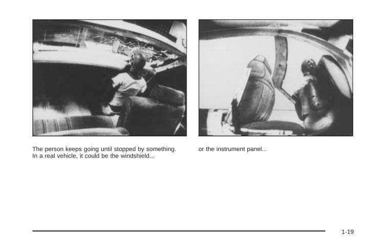
The person keeps going until stopped by something.In a real vehicle, it could be the windshield...
or the instrument panel...
1-19
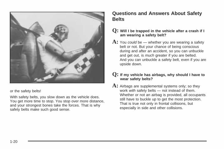
or the safety belts!
With safety belts, you slow down as the vehicle does.You get more time to stop. You stop over more distance,and your strongest bones take the forces. That is whysafety belts make such good sense.
Questions and Answers About SafetyBelts
Q: Will I be trapped in the vehicle after a crash if Iam wearing a safety belt?
A: You could be — whether you are wearing a safetybelt or not. But your chance of being consciousduring and after an accident, so you can unbuckleand get out, is much greater if you are belted.And you can unbuckle a safety belt, even if you areupside down.
Q: If my vehicle has airbags, why should I have towear safety belts?
A: Airbags are supplemental systems only; so theywork with safety belts — not instead of them.Whether or not an airbag is provided, all occupantsstill have to buckle up to get the most protection.That is true not only in frontal collisions, butespecially in side and other collisions.
1-20

Q: If I am a good driver, and I never drive far fromhome, why should I wear safety belts?
A: You may be an excellent driver, but if you are in acrash — even one that is not your fault — you andyour passenger(s) can be hurt. Being a gooddriver does not protect you from things beyond yourcontrol, such as bad drivers.
Most accidents occur within 25 miles (40 km) ofhome. And the greatest number of serious injuriesand deaths occur at speeds of less than 40 mph(65 km/h).
Safety belts are for everyone.
How to Wear Safety Belts ProperlyThis section is only for people of adult size.
Be aware that there are special things to know aboutsafety belts and children. And there are differentrules for smaller children and infants. If a child will beriding in the vehicle, see Older Children on page 1-38or Infants and Young Children on page 1-41. Followthose rules for everyone’s protection.
It is very important for all occupants to buckle up.Statistics show that unbelted people are hurt more oftenin crashes than those who are wearing safety belts.
Occupants who are not buckled up can be thrown out ofthe vehicle in a crash. And they can strike others inthe vehicle who are wearing safety belts.
First, before you or your passenger(s) wear a safetybelt, there is important information you should know.
1-21

Sit up straight and always keep your feet on the floor infront of you. The lap part of the belt should be wornlow and snug on the hips, just touching the thighs.
In a crash, this applies force to the strong pelvic bonesand you would be less likely to slide under the lapbelt. If you slid under it, the belt would apply force onyour abdomen. This could cause serious or evenfatal injuries. The shoulder belt should go over theshoulder and across the chest. These parts of the bodyare best able to take belt restraining forces.
The shoulder belt locks if there is a sudden stop orcrash.
1-22

Q: What is wrong with this?
A: The shoulder belt is too loose. It will not give asmuch protection this way.
{CAUTION:
You can be seriously hurt if your shoulder belt istoo loose. In a crash, you would move forward toomuch, which could increase injury. The shoulderbelt should fit snugly against your body.
1-23

Q: What is wrong with this?
A: The lap belt is too loose. It will not give nearly asmuch protection this way.
{CAUTION:
You can be seriously hurt if your lap belt is tooloose. In a crash, you could slide under the lapbelt and apply force on your abdomen. This couldcause serious or even fatal injuries. The lap beltshould be worn low and snug on the hips, justtouching the thighs.
1-24

Q: What is wrong with this?
A: The belt is buckled in the wrong buckle.
{CAUTION:
You can be seriously injured if your belt is buckledin the wrong place like this. In a crash, the beltwould go up over your abdomen. The belt forceswould be there, not on the pelvic bones. Thiscould cause serious internal injuries. Alwaysbuckle your belt into the buckle nearest you.
1-25

Q: What is wrong with this?
A: The belt is over an armrest.
{CAUTION:
You can be seriously injured if your belt goes overan armrest like this. The belt would be much toohigh. In a crash, you can slide under the belt. Thebelt force would then be applied on the abdomen,not on the pelvic bones, and that could causeserious or fatal injuries. Be sure the belt goesunder the armrests.
1-26

Q: What is wrong with this?
A: The shoulder belt is worn under the arm. It shouldbe worn over the shoulder at all times.
{CAUTION:
You can be seriously injured if you wear theshoulder belt under your arm. In a crash, yourbody would move too far forward, which wouldincrease the chance of head and neck injury. Also,the belt would apply too much force to the ribs,which are not as strong as shoulder bones. Youcould also severely injure internal organs like yourliver or spleen. The shoulder belt should go overthe shoulder and across the chest.
1-27

Q: What is wrong with this?
A: The belt is behind the body.
{CAUTION:
You can be seriously injured by not wearing thelap-shoulder belt properly. In a crash, you wouldnot be restrained by the shoulder belt. Your bodycould move too far forward increasing the chanceof head and neck injury. You might also slideunder the lap belt. The belt force would then beapplied right on the abdomen. That could causeserious or fatal injuries. The shoulder belt shouldgo over the shoulder and across the chest.
1-28

Q: What is wrong with this?
A: The belt is twisted across the body.
{CAUTION:
You can be seriously injured by a twisted belt. In acrash, you would not have the full width of the beltto spread impact forces. If a belt is twisted, makeit straight so it can work properly, or ask yourdealer/retailer to fix it.
1-29

Lap-Shoulder BeltIf your vehicle is a regular cab, then all seating positionsin the vehicle have a lap-shoulder belt. If your vehicle is acrew or extended cab, then all seating positions in thevehicle have a lap-shoulder belt except for the centerfront passenger position (if equipped), which has a lapbelt. See Lap Belt (Crew and Extended Cab) onpage 1-36 for more information.
The following instructions explain how to wear alap-shoulder belt properly.
1. Adjust the seat, if the seat is adjustable, so youcan sit up straight. To see how, see “Seats” inthe Index.
2. Pick up the latch plate and pull the belt across you.Do not let it get twisted.The lap-shoulder belt may lock if you pull the beltacross you very quickly. If this happens, let the beltgo back slightly to unlock it. Then pull the beltacross you more slowly.If the shoulder portion of a passenger belt is pulledout all the way, the child restraint locking featuremay be engaged. If this happens, let the beltgo back all the way and start again.Engaging the child restraint locking feature mayaffect the passenger sensing system. See PassengerSensing System on page 1-84 for more information.
If the belt stops before it reaches the buckle, whenusing the lap-shoulder belt in a rear center seatingposition of a crew-cab, tilt the latch plate and keeppulling the safety belt until it can be buckled.
1-30

3. Push the latch plate into the buckle until it clicks.Pull up on the latch plate to make sure it is secure.If the belt is not long enough, see Safety BeltExtender on page 1-37.If the latch plate will not go fully into the buckle,check if the correct buckle is being used.Position the release button on the buckle so thatthe safety belt could be quickly unbuckled ifnecessary.
4. If equipped with a shoulder belt height adjuster,move it to the height that is right for you. See“Shoulder Belt Height Adjustment” later in thissection.
5. To make the lap part tight, pull up on theshoulder belt.It may be necessary to pull stitching on the safetybelt through the latch plate to fully tighten thelap belt on smaller occupants.
1-31

To unlatch the belt, push the button on the buckle.The belt should return to its stowed position.
Before a door is closed, be sure the safety belt is outof the way. If a door is slammed against a safetybelt, damage can occur to both the safety belt and thevehicle.
Shoulder Belt Height AdjusterThe vehicle has a shoulder belt height adjuster for thedriver and right front passenger.
Adjust the height so that the shoulder portion of the beltis centered on the shoulder. The belt should be awayfrom the face and neck, but not falling off the shoulder.Improper shoulder belt height adjustment couldreduce the effectiveness of the safety belt in a crash.
To move the adjusterdown for the regular andcrew cabs, squeeze thebuttons (A) on the sidesof the height adjuster andmove the height adjusterto the desired position.
Regular and Crew Cab
1-32

On the extended cab,push down on the releasebutton (A) and movethe height adjuster tothe desired position.
You can move the adjuster up just by pushing up on theshoulder belt guide.
After you move the adjuster to where you want it, tryto move it down, without squeezing the buttons for theregular and crew cabs, or without pushing the releasebutton for extended cabs, to make sure it has locked intoposition.
Safety Belt PretensionersThis vehicle has safety belt pretensioners forfront outboard occupants. Although the safety beltpretensioners cannot be seen, they are part of the safetybelt assembly. They can help tighten the safety beltsduring the early stages of a moderate to severe frontal,near frontal, or rear crash if the threshold conditions forpretensioner activation are met. And, if your vehicle hasside impact airbags, safety belt pretensioners can helptighten the safety belts in a side crash or a rollover event.
Pretensioners work only once. If the pretensionersactivate in a crash, they will need to be replaced, andprobably other new parts for the vehicle’s safetybelt system. See Replacing Restraint System PartsAfter a Crash on page 1-91.
Extended Cab
1-33

Rear Safety Belt Comfort GuidesRear shoulder belt comfort guides may provide addedsafety belt comfort for older children who have outgrownbooster seats and for some adults. When installed ona shoulder belt, the comfort guide positions the beltaway from the neck and head.There is one guide for each outboard passenger positionin the rear seat. Here is how to install a comfort guide tothe shoulder belt:1. Remove the guide from its storage clip on the
interior body.
2. Place the guide over the belt and insert the twoedges of the belt into the slots of the guide.
3. Be sure that the belt is not twisted and it lies flat.The elastic cord must be under the belt and theguide on top.
1-34

{CAUTION:
A safety belt that is not properly worn may notprovide the protection needed in a crash. Theperson wearing the belt could be seriously injured.The shoulder belt should go over the shoulder andacross the chest. These parts of the body are bestable to take belt restraining forces.
4. Buckle, position, and release the safety belt asdescribed previously in this section. Make surethat the shoulder belt crosses the shoulder.
To remove and store the comfort guide, squeeze thebelt edges together so that the safety belt can beremoved from the guide. Slide the guide onto thestorage clip.
1-35

Safety Belt Use During PregnancySafety belts work for everyone, including pregnantwomen. Like all occupants, they are more likely to beseriously injured if they do not wear safety belts.
A pregnant woman should wear a lap-shoulder belt, andthe lap portion should be worn as low as possible,below the rounding, throughout the pregnancy.
The best way to protect the fetus is to protect themother. When a safety belt is worn properly, it is morelikely that the fetus will not be hurt in a crash. Forpregnant women, as for anyone, the key to makingsafety belts effective is wearing them properly.
Lap Belt (Crew and Extended Cab)This section is only for the lap belt. To learn how to weara lap-shoulder belt, see Lap-Shoulder Belt on page 1-30.
Your vehicle may have a center seating position. Whenyou sit in the center front seating position, you havea lap safety belt, which has no retractor.
To make the belt longer, tilt the latch plate and pull italong the belt.
Buckle, position, and release it the same way as the lappart of a lap-shoulder belt.
1-36

To make the belt shorter, pull its free end as shownuntil the belt is snug.
If the belt is not long enough, see Safety Belt Extenderon page 1-37.
Make sure the release button on the buckle is positionedso you would be able to unbuckle the safety beltquickly if necessary.
Safety Belt ExtenderIf the safety belt will fasten around you, you shoulduse it.
But if a safety belt is not long enough, your dealer/retailerwill order you an extender. When you go in to order it,take the heaviest coat you will wear, so the extender willbe long enough for you. To help avoid personal injury, donot let someone else use it, and use it only for the seat itis made to fit. The extender has been designed for adults.Never use it for securing child seats. To wear it, attach itto the regular safety belt. For more information, see theinstruction sheet that comes with the extender.
1-37
Child Restraints
Older Children
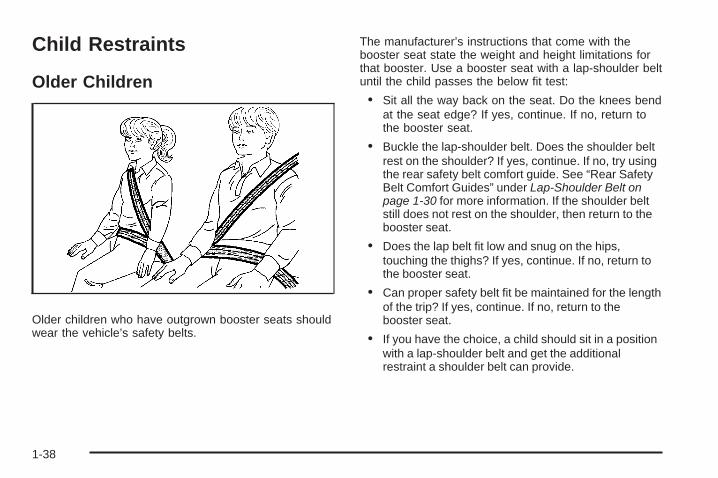
Older children who have outgrown booster seats shouldwear the vehicle’s safety belts.
The manufacturer’s instructions that come with thebooster seat state the weight and height limitations forthat booster. Use a booster seat with a lap-shoulder beltuntil the child passes the below fit test:
• Sit all the way back on the seat. Do the knees bendat the seat edge? If yes, continue. If no, return tothe booster seat.
• Buckle the lap-shoulder belt. Does the shoulder beltrest on the shoulder? If yes, continue. If no, try usingthe rear safety belt comfort guide. See “Rear SafetyBelt Comfort Guides” under Lap-Shoulder Belt onpage 1-30 for more information. If the shoulder beltstill does not rest on the shoulder, then return to thebooster seat.
• Does the lap belt fit low and snug on the hips,touching the thighs? If yes, continue. If no, return tothe booster seat.
• Can proper safety belt fit be maintained for the lengthof the trip? If yes, continue. If no, return to thebooster seat.
• If you have the choice, a child should sit in a positionwith a lap-shoulder belt and get the additionalrestraint a shoulder belt can provide.
1-38

Q: What is the proper way to wear safety belts?
A: An older child should wear a lap-shoulder belt andget the additional restraint a shoulder belt canprovide. The shoulder belt should not cross the faceor neck. The lap belt should fit snugly below the hips,just touching the top of the thighs. This applies beltforce to the child’s pelvic bones in a crash. It shouldnever be worn over the abdomen, which could causesevere or even fatal internal injuries in a crash.
Also see “Rear Safety Belt Comfort Guides” underLap-Shoulder Belt on page 1-30.
According to accident statistics, children and infantsare safer when properly restrained in a child restraintsystem or infant restraint system secured in a rearseating position.
In a crash, children who are not buckled up can strikeother people who are buckled up, or can be thrownout of the vehicle. Older children need to use safetybelts properly.
{CAUTION:
Never do this.
Never allow two children to wear the same safetybelt. The safety belt can not properly spread theimpact forces. In a crash, the two children can becrushed together and seriously injured. A safetybelt must be used by only one person at a time.
1-39

{CAUTION:
Never do this.
Never allow a child to wear the safety belt with theshoulder belt behind their back. A child can beseriously injured by not wearing the lap-shoulderbelt properly. In a crash, the child would not berestrained by the shoulder belt. The child couldmove too far forward increasing the chance ofhead and neck injury. The child might also slideunder the lap belt. The belt force would then beapplied right on the abdomen. That could causeserious or fatal injuries. The shoulder belt shouldgo over the shoulder and across the chest.
1-40

Infants and Young ChildrenEveryone in a vehicle needs protection! This includesinfants and all other children. Neither the distancetraveled nor the age and size of the traveler changesthe need, for everyone, to use safety restraints. In fact,the law in every state in the United States and in everyCanadian province says children up to some age mustbe restrained while in a vehicle.
{CAUTION:
Children can be seriously injured or strangled if ashoulder belt is wrapped around their neck andthe safety belt continues to tighten. Never leavechildren unattended in a vehicle and never allowchildren to play with the safety belts.
Airbags plus lap-shoulder belts offer protection for adultsand older children, but not for young children and infants.Neither the vehicle’s safety belt system nor its airbagsystem is designed for them. Every time infants andyoung children ride in vehicles, they should have theprotection provided by appropriate child restraints.
Children who are not restrained properly can strike otherpeople, or can be thrown out of the vehicle.
1-41

{CAUTION:
Never do this.
Never hold an infant or a child while riding in avehicle. Due to crash forces, an infant or a childwill become so heavy it is not possible to hold itduring a crash. For example, in a crash at only25 mph (40 km/h), a 12 lb (5.5 kg) infant willsuddenly become a 240 lb (110 kg) force on aperson’s arms. An infant should be secured in anappropriate restraint.
1-42

{CAUTION:
Never do this.
Children who are up against, or very close to, anyairbag when it inflates can be seriously injuredor killed. Never put a rear-facing child restraint inthe right front seat. Secure a rear-facing childrestraint in a rear seat. It is also better to secure aforward-facing child restraint in a rear seat. If youmust secure a forward-facing child restraint in theright front seat, always move the front passengerseat as far back as it will go.
1-43

Q: What are the different types of add-on childrestraints?
A: Add-on child restraints, which are purchased by thevehicle’s owner, are available in four basic types.Selection of a particular restraint should take intoconsideration not only the child’s weight, height,and age but also whether or not the restraint willbe compatible with the motor vehicle in which it willbe used.
For most basic types of child restraints, there aremany different models available. When purchasinga child restraint, be sure it is designed to beused in a motor vehicle. If it is, the restraint willhave a label saying that it meets federal motorvehicle safety standards.
The restraint manufacturer’s instructions thatcome with the restraint state the weight andheight limitations for a particular child restraint.In addition, there are many kinds of restraintsavailable for children with special needs.
{CAUTION:
To reduce the risk of neck and head injury duringa crash, infants need complete support. This isbecause an infant’s neck is not fully developedand its head weighs so much compared withthe rest of its body. In a crash, an infant in arear-facing child restraint settles into the restraint,so the crash forces can be distributed across thestrongest part of an infant’s body, the back andshoulders. Infants should always be secured inrear-facing child restraints.
1-44

{CAUTION:
A young child’s hip bones are still so small thatthe vehicle’s regular safety belt may not remainlow on the hip bones, as it should. Instead, it maysettle up around the child’s abdomen. In a crash,the belt would apply force on a body area that isunprotected by any bony structure. This alonecould cause serious or fatal injuries. To reduce therisk of serious or fatal injuries during a crash,young children should always be secured inappropriate child restraints.
Child Restraint Systems
A rear-facing infantseat (A) provides restraintwith the seating surfaceagainst the back ofthe infant.
The harness system holds the infant in place and, in acrash, acts to keep the infant positioned in the restraint.
A forward-facing childseat (B) provides restraintfor the child’s bodywith the harness.
1-45

A booster seat (C-D) is a child restraint designed toimprove the fit of the vehicle’s safety belt system.A booster seat can also help a child to see out thewindow.
Securing an Add-On Child Restraint inthe Vehicle
{CAUTION:
A child can be seriously injured or killed in a crashif the child restraint is not properly secured in thevehicle. Secure the child restraint properly in thevehicle using the vehicle’s safety belt or LATCHsystem, following the instructions that came withthat child restraint and the instructions in thismanual.
1-46

To help reduce the chance of injury, the child restraintmust be secured in the vehicle. Child restraint systemsmust be secured in vehicle seats by lap belts or thelap belt portion of a lap-shoulder belt, or by the LATCHsystem. See Lower Anchors and Tethers for Children(LATCH) on page 1-49 for more information. A child canbe endangered in a crash if the child restraint is notproperly secured in the vehicle.
When securing an add-on child restraint, refer to theinstructions that come with the restraint which may be onthe restraint itself or in a booklet, or both, and to thismanual. The child restraint instructions are important, soif they are not available, obtain a replacement copyfrom the manufacturer.
Keep in mind that an unsecured child restraint canmove around in a collision or sudden stop and injurepeople in the vehicle. Be sure to properly secureany child restraint in the vehicle — even whenno child is in it.
Securing the Child Within the ChildRestraint
{CAUTION:
A child can be seriously injured or killed in a crashif the child is not properly secured in the childrestraint. Secure the child properly following theinstructions that came with that child restraint.
1-47

Where to Put the RestraintAccording to accident statistics, children and infants aresafer when properly restrained in a child restraintsystem or infant restraint system secured in a rearseating position.
We recommend that children and child restraints besecured in a rear seat, including: an infant or achild riding in a rear-facing child restraint; a child ridingin a forward-facing child seat; an older child riding ina booster seat; and children, who are large enough,using safety belts.
A label on the sun visor says, “Never put a rear-facingchild seat in the front.” This is because the risk tothe rear-facing child is so great, if the airbag deploys.
{CAUTION:
A child in a rear-facing child restraint can beseriously injured or killed if the right frontpassenger airbag inflates. This is because theback of the rear-facing child restraint would bevery close to the inflating airbag. A child in aforward-facing child restraint can be seriouslyinjured or killed if the right front passenger airbaginflates and the passenger seat is in a forwardposition.
Even if the passenger sensing system or airbagswitch has turned off the right front passengerfrontal airbag, no system is fail-safe. No one canguarantee that an airbag will not deploy undersome unusual circumstance, even though it isturned off.
Secure rear-facing child restraints in a rearseat, even if the airbag is off. If you secure aforward-facing child restraint in the right front seat,always move the front passenger seat as far backas it will go. It is better to secure the child restraintin a rear seat.
1-48

{CAUTION:
A child in a child restraint in the center front seatcan be badly injured or killed by the frontal airbagsif they inflate. Never secure a child restraint in thecenter front seat. It is always better to secure achild restraint in a rear seat.
Do not use child restraints in the center front seatposition.
When securing a child restraint in a rear seatingposition, study the instructions that came with your childrestraint to make sure it is compatible with this vehicle.
If the vehicle does not have a rear seat that willaccommodate a rear-facing child restraint, a rear-facingchild restraint should not be installed in the vehicle,even if the airbag is off.
Wherever a child restraint is installed, be sure to securethe child restraint properly.
Keep in mind that an unsecured child restraint canmove around in a collision or sudden stop and injurepeople in the vehicle. Be sure to properly secureany child restraint in your vehicle — even whenno child is in it.
Lower Anchors and Tethers forChildren (LATCH)The LATCH system holds a child restraint during drivingor in a crash. This system is designed to make installationof a child restraint easier. The LATCH system usesanchors in the vehicle and attachments on the childrestraint that are made for use with the LATCH system.
Make sure that a LATCH-compatible child restraint isproperly installed using the anchors, or use the vehicle’ssafety belts to secure the restraint, following theinstructions that came with that restraint, and also theinstructions in this manual. When installing a childrestraint with a top tether, you must also use either thelower anchors or the safety belts to properly secure thechild restraint. A child restraint must never be installedusing only the top tether and anchor.
In order to use the LATCH system in your vehicle, youneed a child restraint that has LATCH attachments.The child restraint manufacturer will provide you withinstructions on how to use the child restraint and itsattachments. The following explains how to attach achild restraint with these attachments in your vehicle.
Not all vehicle seating positions or child restraints havelower anchors and attachments or top tether anchorsand attachments.
1-49

Lower Anchors
Lower anchors (A) are metal bars built into the vehicle.There are two lower anchors for each LATCH seatingposition that will accommodate a child restraint withlower attachments (B).
Top Tether Anchor
A top tether (A, C) anchors the top of the child restraintto the vehicle. A top tether anchor is built into the vehicle.The top tether attachment (B) on the child restraintconnects to the top tether anchor in the vehicle in orderto reduce the forward movement and rotation of the childrestraint during driving or in a crash.
Your child restraint may have a single tether (A) or adual tether (C). Either will have a single attachment (B)to secure the top tether to the anchor.
1-50

Some child restraints that have a top tether are designedfor use with or without the top tether being attached.Others require the top tether always to be attached.In Canada, the law requires that forward-facingchild restraints have a top tether, and that the tether beattached. Be sure to read and follow the instructionsfor your child restraint.
If the child restraint does not have a top tether, one canbe obtained, in kit form, for many child restraints. Askthe child restraint manufacturer whether or not a kitis available.
Lower Anchor and Top Tether AnchorLocations
i (Top Tether Anchor):Seating positions with toptether anchors.
Do not install a child restraint in the center front seatposition. See Securing a Child Restraint in the CenterFront Seat Position on page 1-61 for more information.
Regular Cab —Two-Passenger
Front Seat
Regular Cab —Three-Passenger
Front Seat
1-51

i (Top Tether Anchor):Seating positions with toptether anchors.
j (Lower Anchor): Seatingpositions with two loweranchors.
For crew and extended cab models, the rear outboardseating positions have exposed metal lower anchorslocated in the crease between the seatback and the seatcushion.
For regular cab models,there is an anchor symbolon the covers to assistyou in locating thetop tether anchors.
Crew and Extended CabRear Seat
1-52

Do not install a child restraint in the center seat position.See Securing a Child Restraint in the Center FrontSeat Position on page 1-61 for more information.
For regular cab models, the top tether anchors arelocated under covers on the back panel behind thepassenger seat. Remove the trim plug to access theanchor. Be sure to use an anchor located on the sameside of the vehicle as the seating position where the childrestraint will be placed.
For crew and extended cab models, the top tetheranchors are the loops located near the top of theseatback for each rear seating position. These loops willbe used to route the top tether through, as well as, tosecure the top tether in the vehicle. Be sure to use ananchor (loop) located on the same side of the vehicle asthe seating position where the child restraint will beplaced.
Be sure to read the instructions following to properlyinstall a child restraint using these loops.
Regular Cab
Crew Cab Shown, Extended Cab Similar
1-53

Do not secure a child restraint in a position without atop tether anchor if a national or local law requires thatthe top tether be attached, or if the instructions thatcome with the child restraint say that the top tethermust be attached.
According to accident statistics, children and infants aresafer when properly restrained in a child restraintsystem or infant restraint system secured in a rearseating position. See Where to Put the Restrainton page 1-48 for additional information.
Securing a Child Restraint Designed forthe LATCH System
{CAUTION:
If a LATCH-type child restraint is not attached toanchors, the child restraint will not be able toprotect the child correctly. In a crash, the childcould be seriously injured or killed. Install aLATCH-type child restraint properly using theanchors, or use the vehicle’s safety belts to securethe restraint, following the instructions that camewith the child restraint and the instructions in thismanual.
{CAUTION:
Do not attach more than one child restraint to asingle anchor, except for the center top tetheranchors in the crew and extended cabs. Attachingmore than one child restraint to a single anchorcould cause the anchor or attachment to comeloose or even break during a crash. A child orothers could be injured. To reduce the risk ofserious or fatal injuries during a crash, attach onlyone child restraint per anchor.
{CAUTION:
Children can be seriously injured or strangled if ashoulder belt is wrapped around their neck andthe safety belt continues to tighten. Buckle anyunused safety belts behind the child restraint sochildren cannot reach them. Pull the shoulder beltall the way out of the retractor to set the lock, ifyour vehicle has one, after the child restraint hasbeen installed.
1-54

Notice: Do not let the LATCH attachments rubagainst the vehicle’s safety belts. This may damagethese parts. If necessary, move buckled safetybelts to avoid rubbing the LATCH attachments.
Do not fold the empty rear seat with a safety beltbuckled. This could damage the safety belt orthe seat. Unbuckle and return the safety belt to itsstowed position, before folding the seat.
Regular Cab Models
1. If the child restraint manufacturer recommends thatthe top tether be attached, attach and tighten thetop tether to the top tether anchor, if yourvehicle has one. Refer to the child restraintinstructions and the following steps:
1.1. Pull the passenger seatback forward bypulling the recliner handle upward to accessthe top tether anchor. See RecliningSeatbacks on page 1-10 for additionalinformation.
1.2. Find the top tether anchor.1.3. Remove the cover to expose the anchor.
1.4. Route, attach, and tighten the top tetheraccording to your child restraint instructionsand the following instructions:
If the position you are usinghas an adjustable headrestor head restraint and youare using a dual tether,route the tether around theheadrest or head restraint.
If the position you are usinghas an adjustable headrestor head restraint and youare using a single tether,raise the headrest or headrestraint and route thetether under the headrestor head restraint and inbetween the headrest orhead restraint posts.
1-55

2. See Securing a Child Restraint in the Right FrontSeat Position (With Airbag Off Switch) on page 1-62or Securing a Child Restraint in the Right Front SeatPosition (With Passenger Sensing System) onpage 1-66 or Securing a Child Restraint in the RightFront Seat Position (Heavy Duty Crew Cab Only) onpage 1-70 for instructions on installing the childrestraint using the safety belts.
3. Push and pull the child restraint in differentdirections to be sure it is secure.
Crew and Extended Cab Models1. Attach and tighten the lower attachments to the
lower anchors. If the child restraint does not havelower attachments or the desired seating positiondoes not have lower anchors, secure the childrestraint with the top tether and the safety belts.Refer to your child restraint manufacturerinstructions and the instructions in this manual.
1.1. Find the lower anchors for the desiredseating position.
1.2. Put the child restraint on the seat.1.3. Attach and tighten the lower attachments on
the child restraint to the lower anchors.
2. If the child restraint manufacturer recommends thatthe top tether be attached, attach and tighten the toptether to the top tether anchor (loop), if your vehiclehas one. Refer to the child restraint instructions andthe following steps:
Example — Rear Driver’s Side Position
1-56

2.1. When using a child restraint with a top tetherin the rear driver side position:
A. Raise the headrest or head restraint.B. Route the top tether (B) between
the headrest or head restraint posts,through the loop (A), behind the inboardheadrest or head restraint post, andunder the center shoulder belt (C).
C. Attach the top tether (B) to the toptether anchor (loop) (D) at the centerrear seating position.
2.2. When using a child restraint with a top tetherin the rear center position:
D. Route the top tether (B) through thecenter loop (D), and behind theinboard passenger side headrest orhead restraint post.
E. Attach the top tether (B) to the toptether anchor (loop) at the rearpassenger side seating position.
2.3. When using a child restraint with a top tetherin the rear passenger position:
F. Raise the headrest or head restraint.G. Route the top tether (B) between
the headrest or head restraintposts, through the loop on thepassenger side and behind the inboardheadrest or head restraint post.
H. Attach the top tether (B) to the toptether anchor (loop) (D) at the centerrear seating position.
2.4. Tighten the top tether when and as the childrestraint manufacturer’s instructions say.When the top tether is tightened, the anchor(loop) may bend. This is normal and will notdamage the vehicle.
3. Push and pull the child restraint in differentdirections to be sure it is secure.
Example — Rear Driver’s Side Position
1-57

Securing a Child Restraint in a RearSeat PositionWhen securing a child restraint in a rear seating position,study the instructions that came with the child restraint tomake sure it is compatible with this vehicle.
If the child restraint has the LATCH system, see LowerAnchors and Tethers for Children (LATCH) on page 1-49for how and where to install the child restraint usingLATCH. If a child restraint is secured in the vehicle usinga safety belt and it uses a top tether, see Lower Anchorsand Tethers for Children (LATCH) on page 1-49 for toptether anchor locations.
Do not secure a child seat in a position without a toptether anchor if a national or local law requires thatthe top tether be anchored, or if the instructionsthat come with the child restraint say that the top strapmust be anchored.
In Canada, the law requires that forward-facing childrestraints have a top tether, and that the tether beattached.
If the child restraint does not have the LATCH system,you will be using the safety belt to secure the childrestraint in this position. Be sure to follow the instructionsthat came with the child restraint. Secure the child in thechild restraint when and as the instructions say.
If more than one child restraint needs to be installedin the rear seat, be sure to read Where to Put theRestraint on page 1-48.
1. Put the child restraint on the seat.
2. Pick up the latch plate, and run the lap and shoulderportions of the vehicle’s safety belt through oraround the restraint. The child restraint instructionswill show you how.
1-58

For crew cab second row seatings positions, tilt thelatch plate to adjust the belt if needed.
3. Push the latch plate into the buckle until it clicks.Position the release button on the buckle so thatthe safety belt could be quickly unbuckled ifnecessary.
1-59

4. Pull the rest of the shoulder belt all the way out ofthe retractor to set the lock.
5. To tighten the belt, push down on the child restraint,pull the shoulder portion of the belt to tighten the lapportion of the belt and feed the shoulder belt backinto the retractor. When installing a forward-facingchild restraint, it may be helpful to use your kneeto push down on the child restraint as you tightenthe belt.
1-60

6. If the child restraint has a top tether, follow the childrestraint manufacturer’s instructions regarding theuse of the top tether. See Lower Anchors andTethers for Children (LATCH) on page 1-49 formore information.
7. Push and pull the child restraint in differentdirections to be sure it is secure.
To remove the child restraint, unbuckle the vehiclesafety belt and let it return to the stowed position.If the top tether is attached to a top tether anchor,disconnect it.
Securing a Child Restraint in theCenter Front Seat Position
{CAUTION:
A child in a child restraint in the center front seatcan be badly injured or killed by the frontal airbagsif they inflate. Never secure a child restraint in thecenter front seat. It is always better to secure achild restraint in a rear seat.
Do not use child restraints in the center front seatposition.
1-61
Securing a Child Restraint inthe Right Front Seat Position(With Airbag Off Switch)This vehicle has airbags. A rear seat is a safer place tosecure a forward-facing child restraint. See Where toPut the Restraint on page 1-48.
There may be a switch in the glove box that you canuse to turn off the right front passenger frontal airbag.See Airbag Off Switch on page 1-81 for more onthis, including important safety information.
A label on the sun visor says, “Never put a rear-facingchild seat in the front.” This is because the risk tothe rear-facing child is so great, if the airbag deploys.
{CAUTION:
A child in a rear-facing child restraint can beseriously injured or killed if the right frontpassenger airbag inflates. This is because theback of the rear-facing child restraint would bevery close to the inflating airbag. A child in aforward-facing child restraint can be seriouslyinjured or killed if the right front passenger airbaginflates and the passenger seat is in a forwardposition.
Even if the airbag switch has turned off the rightfront passenger frontal airbag, no system isfail-safe. No one can guarantee that an airbag willnot deploy under some unusual circumstance,even though it is turned off.
Secure rear-facing child restraints in a rearseat, even if the airbag is off. If you secure aforward-facing child restraint in the right front seat,always move the front passenger seat as far backas it will go. It is better to secure the child restraintin a rear seat.
1-62

{CAUTION:
If the airbag readiness light ever comes on whenyou have turned off the airbag, it means thatsomething may be wrong with the airbag system.The right front passenger’s airbag could inflateeven though the switch is off. If this ever happens,do not let anyone whom the national governmenthas identified as a member of a passenger airbagrisk group sit in the right front passenger’s position(for example, do not secure a rear-facing childrestraint in the right front passenger’s seat) untilyou have your vehicle serviced. See Airbag OffSwitch on page 1-81 and Airbag Readiness Lighton page 3-37 for more on this, including importantsafety information.
If the vehicle does not have a rear seat that willaccommodate a rear-facing child restraint, a rear-facingchild restraint should not be installed in the vehicle,even if the airbag is off.
If your child restraint has the LATCH system, see LowerAnchors and Tethers for Children (LATCH) on page 1-49for how and where to install your child restraint using
LATCH. If you secure a child restraint using a safety beltand it uses a top tether, see Lower Anchors and Tethersfor Children (LATCH) on page 1-49 for top tether anchorlocations.
Do not secure a child restraint in a position without atop tether anchor if a national or local law requires thatthe top tether be anchored, or if the instructions thatcome with the child restraint say that the top strap mustbe anchored.
In Canada, the law requires that forward-facing childrestraints have a top tether, and that the tether beattached.
You will be using the lap-shoulder belt to secure thechild restraint in this position. Follow the instructions thatcame with the child restraint.
1. Move the seat as far back as it will go beforesecuring the forward-facing child restraint.If you have no other choice but to install a rear-facingchild restraint in this seat, make sure the airbag is offonce the child restraint has been installed.When the airbag off switch has turned off the rightfront passenger frontal airbag, the off indicator in theairbag off light should light and stay lit when you startthe vehicle. See Airbag Off Light on page 3-38.
2. Put the child restraint on the seat.
1-63

3. Pick up the latch plate, and run the lap and shoulderportions of the vehicle’s safety belt through oraround the restraint. The child restraint instructionswill show you how.
4. Push the latch plate into the buckle until it clicks.Position the release button so that the safety beltcould be quickly unbuckled if necessary.
5. Pull the rest of the shoulder belt all the way out ofthe retractor to set the lock.
1-64

6. To tighten the belt, push down on the child restraint,pull the shoulder portion of the belt to tighten the lapportion of the belt and feed the shoulder belt backinto the retractor. When installing a forward-facingchild restraint, it may be helpful to use your kneeto push down on the child restraint as you tightenthe belt.
7. If your vehicle does not have a rear seat and yourchild restraint has a top tether, follow the childrestraint manufacturer’s instructions regarding theuse of the top tether. See Lower Anchors andTethers for Children (LATCH) on page 1-49.
8. Push and pull the child restraint in differentdirections to be sure it is secure.
To remove the child restraint, unbuckle the vehiclesafety belt and let it return to the stowed position.If the top tether is attached to a top tether anchor,disconnect it.
If you turned the airbag off with the switch, turn onthe right front passenger airbag when you removethe child restraint from the vehicle unless the personwho will be sitting there is a member of a passengerairbag risk group. See Airbag Off Switch on page 1-81.
1-65

Securing a Child Restraint inthe Right Front Seat Position(With Passenger Sensing System)This vehicle has airbags. A rear seat is a safer place tosecure a forward-facing child restraint. See Where toPut the Restraint on page 1-48.
In addition, the vehicle may have a passenger sensingsystem which is designed to turn off the right frontpassenger frontal airbag under certain conditions.See Passenger Sensing System on page 1-84 andPassenger Airbag Status Indicator on page 3-40for more information on this, including important safetyinformation.
A label on the sun visor says, “Never put a rear-facingchild seat in the front.” This is because the risk tothe rear-facing child is so great, if the airbag deploys.
{CAUTION:
A child in a rear-facing child restraint can beseriously injured or killed if the right frontpassenger airbag inflates. This is because theback of the rear-facing child restraint would bevery close to the inflating airbag. A child in aforward-facing child restraint can be seriouslyinjured or killed if the right front passenger airbaginflates and the passenger seat is in a forwardposition.
CAUTION: (Continued)
1-66
CAUTION: (Continued)
Even if the passenger sensing system has turnedoff the right front passenger frontal airbag, nosystem is fail-safe. No one can guarantee that anairbag will not deploy under some unusualcircumstance, even though it is turned off.
Secure rear-facing child restraints in a rearseat, even if the airbag is off. If you secure aforward-facing child restraint in the right front seat,always move the front passenger seat as far backas it will go. It is better to secure the child restraintin a rear seat.
See Passenger Sensing System on page 1-84 foradditional information.
If the vehicle does not have a rear seat that willaccommodate a rear-facing child restraint, a rear-facingchild restraint should not be installed in the vehicle,even if the airbag is off.
If your child restraint has the LATCH system, see LowerAnchors and Tethers for Children (LATCH) on page 1-49for how and where to install your child restraint usingLATCH. If you secure a child restraint using a safety belt
and it uses a top tether, see Lower Anchors and Tethersfor Children (LATCH) on page 1-49 for top tether anchorlocations.
Do not secure a child seat in a position without a toptether anchor if a national or local law requires that thetop tether be anchored, or if the instructions that comewith the child restraint say that the top strap must beanchored.
In Canada, the law requires that forward-facing childrestraints have a top tether, and that the tether beattached.
You will be using the lap-shoulder belt to secure thechild restraint in this position. Follow the instructions thatcame with the child restraint.
1. Move the seat as far back as it will go beforesecuring the forward-facing child restraint.When the passenger sensing system has turned offthe right front passenger frontal airbag, the offindicator in the passenger airbag status indicatorshould light and stay lit when you start the vehicle.See Passenger Airbag Status Indicator onpage 3-40.
2. Put the child restraint on the seat.
3. Pick up the latch plate, and run the lap and shoulderportions of the vehicle’s safety belt through oraround the restraint. The child restraint instructionswill show you how.
1-67

4. Push the latch plate into the buckle until it clicks.Position the release button so that the safety beltcould be quickly unbuckled if necessary.
5. Pull the rest of the shoulder belt all the way out ofthe retractor to set the lock.
1-68

6. To tighten the belt, push down on the child restraint,pull the shoulder portion of the belt to tighten the lapportion of the belt and feed the shoulder belt backinto the retractor. When installing a forward-facingchild restraint, it may be helpful to use your kneeto push down on the child restraint as you tightenthe belt.
7. If the vehicle does not have a rear seat and the childrestraint has a top tether, follow the child restraintmanufacturer’s instructions regarding the use of thetop tether. See Lower Anchors and Tethers forChildren (LATCH) on page 1-49 for moreinformation.
8. Push and pull the child restraint in differentdirections to be sure it is secure.
If the airbag is off, the off indicator in the passengerairbag status indicator will come on and stay on whenthe vehicle is started.
If a child restraint has been installed and the onindicator is lit, see “If the On Indicator is Lit for a ChildRestraint ” under Passenger Sensing System onpage 1-84 for more information.
To remove the child restraint, unbuckle the vehiclesafety belt and let it return to the stowed position.If the top tether is attached to a top tether anchor,disconnect it.
1-69
Securing a Child Restraint inthe Right Front Seat Position(Heavy Duty Crew Cab Only)Your vehicle has airbags. A rear seat is a safer place tosecure a forward-facing child restraint. See Where toPut the Restraint on page 1-48.
A label on the sun visor says, “Never put a rear-facingchild seat in the front.” This is because the risk tothe rear-facing child is so great, if the airbag deploys.
Never put a rear-facing child restraint in the rightfront passenger seat. Here is why:
{CAUTION:
A child in a rear-facing child restraint can beseriously injured or killed if the right frontpassenger’s airbag inflates. This is because theback of the rear-facing child restraint would bevery close to the inflating airbag. Always secure arear-facing child restraint in a rear seat.
If the vehicle does not have a rear seat that willaccommodate a rear-facing child restraint, a rear-facingchild restraint should not be installed in the vehicle,even if the airbag is off.
If your child restraint has the LATCH system, see LowerAnchors and Tethers for Children (LATCH) on page 1-49for how and where to install your child restraint usingLATCH. If you secure a child restraint using a safety beltand it uses a top tether, see Lower Anchors and Tethersfor Children (LATCH) on page 1-49 for top tether anchorlocations.
Do not secure a child seat in a position without a toptether anchor if a national or local law requires thatthe top tether be anchored, or if the instructionsthat come with the child restraint say that the topstrap must be anchored.
In Canada, the law requires that forward-facing childrestraints have a top tether, and that the tether beattached.
1-70

You will be using the lap-shoulder belt to secure thechild restraint in this position. Follow the instructions thatcame with the child restraint.
1. Move the seat as far back as it will go beforesecuring the forward-facing child restraint.
2. Put the child restraint on the seat.
3. Pick up the latch plate, and run the lap and shoulderportions of the vehicle’s safety belt through oraround the restraint. The child restraint instructionswill show you how.
4. Push the latch plate into the buckle until it clicks.
Make sure the release button is positioned so youwould be able to unbuckle the safety belt quicklyif necessary.
5. Pull the rest of the shoulder belt all the way out ofthe retractor to set the lock.
1-71

6. To tighten the belt, push down on the child restraint,pull the shoulder portion of the belt to tighten the lapportion of the belt and feed the shoulder belt backinto the retractor. If you are using a forward-facingchild restraint, you may find it helpful to use yourknee to push down on the child restraint as youtighten the belt.
7. If your child restraint has a top tether, follow thechild restraint manufacturer’s instructions regardingthe use of the top tether. See Lower Anchorsand Tethers for Children (LATCH) on page 1-49for more information.
8. Push and pull the child restraint in differentdirections to be sure it is secure.
To remove the child restraint, unbuckle the vehiclesafety belt and let it return to the stowed position.If the top tether is attached to a top tether anchor,disconnect it.
1-72

Airbag SystemThe vehicle has the following airbags:
• A frontal airbag for the driver.
• A frontal airbag for the right front passenger.
The vehicle may have the following airbags:
• A roof-rail airbag for the driver and the passengerseated directly behind the driver.
• A roof-rail airbag for the right front passenger andthe person seated directly behind the right frontpassenger.
All of the airbags in the vehicle will have the wordAIRBAG embossed in the trim or on an attached labelnear the deployment opening.
For frontal airbags, the word AIRBAG will appear on themiddle part of the steering wheel for the driver andon the instrument panel for the right front passenger.
With roof-rail airbags, the word AIRBAG will appearalong the headliner or trim.
Airbags are designed to supplement the protectionprovided by safety belts. Even though today’s airbagsare also designed to help reduce the risk of injuryfrom the force of an inflating bag, all airbags must inflatevery quickly to do their job.
Here are the most important things to know about theairbag system:
{CAUTION:
You can be severely injured or killed in a crash ifyou are not wearing your safety belt — even if youhave airbags. Airbags are designed to work withsafety belts, but do not replace them. Also, airbagsare not designed to deploy in every crash. In somecrashes safety belts are your only restraint. SeeWhen Should an Airbag Inflate? on page 1-77.
Wearing your safety belt during a crash helpsreduce your chance of hitting things inside thevehicle or being ejected from it. Airbags are“supplemental restraints” to the safety belts.Everyone in your vehicle should wear a safety beltproperly — whether or not there is an airbag forthat person.
1-73

{CAUTION:
Airbags inflate with great force, faster than the blinkof an eye. Anyone who is up against, or very closeto, any airbag when it inflates can be seriouslyinjured or killed. Do not sit unnecessarily close tothe airbag, as you would be if you were sitting onthe edge of your seat or leaning forward. Safetybelts help keep you in position before and during acrash. Always wear your safety belt, even withairbags. The driver should sit as far back aspossible while still maintaining control of thevehicle.
Occupants should not lean on or sleep against thedoor or side windows in seating positions withroof-rail airbags.
{CAUTION:
Children who are up against, or very close to, anyairbag when it inflates can be seriously injured orkilled. Airbags plus lap-shoulder belts offerprotection for adults and older children, but not foryoung children and infants. Neither the vehicle’ssafety belt system nor its airbag system is designedfor them. Young children and infants need theprotection that a child restraint system can provide.Always secure children properly in your vehicle.To read how, see Older Children on page 1-38 orInfants and Young Children on page 1-41.
There is an airbagreadiness light on theinstrument panel cluster,which shows the airbagsymbol.
The system checks the airbag electrical system formalfunctions. The light tells you if there is an electricalproblem. See Airbag Readiness Light on page 3-37for more information.
1-74

Where Are the Airbags?
The driver’s airbag is in the middle of the steeringwheel.
The right front passenger’s airbag is in the instrumentpanel on the passenger’s side.
1-75

If your vehicle has roof-rail airbags for the driver, rightfront passenger, and second row outboard passengers,they are in the ceiling above the side windows.
{CAUTION:
If something is between an occupant and anairbag, the airbag might not inflate properly or itmight force the object into that person causingsevere injury or even death. The path of aninflating airbag must be kept clear. Do not putanything between an occupant and an airbag,and do not attach or put anything on the steeringwheel hub or on or near any other airbagcovering.
Never secure anything to the roof of a vehicle withroof-rail airbags by routing a rope or tie downthrough any door or window opening. If you do,the path of an inflating roof-rail airbag will beblocked.
Driver Side shown, Passenger Side similar
1-76

When Should an Airbag Inflate?Frontal airbags are designed to inflate in moderate tosevere frontal or near-frontal crashes to help reduce thepotential for severe injuries mainly to the driver’s orright front passenger’s head and chest. However, theyare only designed to inflate if the impact exceeds apredetermined deployment threshold. Deploymentthresholds are used to predict how severe a crash islikely to be in time for the airbags to inflate andhelp restrain the occupants.
Whether the frontal airbags will or should deploy is notbased on how fast your vehicle is traveling. It dependslargely on what you hit, the direction of the impact,and how quickly your vehicle slows down.
Frontal airbags may inflate at different crash speeds.For example:
• If the vehicle hits a stationary object, the airbagscould inflate at a different crash speed than if thevehicle hits a moving object.
• If the vehicle hits an object that deforms, theairbags could inflate at a different crash speed thanif the vehicle hits an object that does not deform.
• If the vehicle hits a narrow object (like a pole), theairbags could inflate at a different crash speedthan if the vehicle hits a wide object (like a wall).
• If the vehicle goes into an object at an angle, theairbags could inflate at a different crash speedthan if the vehicle goes straight into the object.
Thresholds can also vary with specific vehicle design.
Frontal airbags are not intended to inflate during vehiclerollovers, rear impacts, or in many side impacts.
1-77

If the GVWR (Gross Vehicle Weight Rating) of yourvehicle is 8,500 lb (3 855 kg) or above, your vehicle hassingle stage airbags. If the GVWR is below 8,500 lb(3 855 kg) then your vehicle has dual stage airbags.You can find the GVWR on the certification label onthe rear edge of the driver’s door. See Loadingthe Vehicle on page 4-32 for more information.
In addition, the vehicle may have dual-stage frontalairbags. Dual-stage airbags adjust the restraint accordingto crash severity. The vehicle has electronic frontalsensors, which help the sensing system distinguishbetween a moderate frontal impact and a more severefrontal impact. For moderate frontal impacts, dual-stageairbags inflate at a level less than full deployment. Formore severe frontal impacts, full deployment occurs.
Vehicles with dual stage airbags also have seat positionsensors which enable the sensing system to monitor theposition of the driver seat (all models) and the right frontpassenger seat (light-duty regular cab and light-dutyextended cab models only). The seat position sensorprovides information that is used to determine if theairbags should deploy at a reduced level or at fulldeployment.
The vehicle may or may not have roof-rail airbags.See Airbag System on page 1-73. Roof-rail airbags areintended to inflate in moderate to severe side crashes.In addition, these roof-rail airbags are intended to inflateduring a rollover or in a severe frontal impact. Roof-railairbags will inflate if the crash severity is above thesystem’s designed threshold level. The threshold levelcan vary with specific vehicle design.
Roof-rail airbags are not intended to inflate in rearimpacts. Both roof-rail airbags will deploy when eitherside of the vehicle is struck, or if the sensing systempredicts that the vehicle is about to roll over, or ina severe frontal impact.
In any particular crash, no one can say whether anairbag should have inflated simply because of thedamage to a vehicle or because of what the repair costswere. For frontal airbags, inflation is determined bywhat the vehicle hits, the angle of the impact, and howquickly the vehicle slows down. For roof-rail airbags,deployment is determined by the location and severity ofthe side impact. In a rollover event, roof-rail airbagdeployment is determined by the direction of the roll.
1-78

What Makes an Airbag Inflate?In a deployment event, the sensing system sends anelectrical signal triggering a release of gas from theinflator. Gas from the inflator fills the airbag causing thebag to break out of the cover and deploy. The inflator, theairbag, and related hardware are all part of the airbagmodule.
Frontal airbag modules are located inside the steeringwheel and instrument panel. For vehicles with roof-railairbags, there are airbag modules in the ceiling of thevehicle, near the side windows that have occupantseating positions.
How Does an Airbag Restrain?In moderate to severe frontal or near frontal collisions,even belted occupants can contact the steering wheelor the instrument panel. In moderate to severe sidecollisions, even belted occupants can contact the insideof the vehicle.
Airbags supplement the protection provided by safetybelts. Frontal airbags distribute the force of the impactmore evenly over the occupant’s upper body, stoppingthe occupant more gradually. Roof-rail airbags distributethe force of the impact more evenly over the occupant’supper body.
Rollover capable roof-rail airbags are designed to helpcontain the head and chest of occupants in the outboardseating positions in the first and second rows. Therollover capable roof-rail airbags are designed to helpreduce the risk of full or partial ejection in rollover events,although no system can prevent all such ejections.
But airbags would not help in many types of collisions,primarily because the occupant’s motion is nottoward those airbags. See When Should an AirbagInflate? on page 1-77 for more information.
Airbags should never be regarded as anything morethan a supplement to safety belts.
What Will You See After an AirbagInflates?After the frontal airbags inflate, they quickly deflate, soquickly that some people may not even realize an airbaginflated. Roof-rail airbags may still be at least partiallyinflated for some time after they deploy. Somecomponents of the airbag module may be hot for severalminutes. For location of the airbag modules, see WhatMakes an Airbag Inflate? on page 1-79.
1-79

The parts of the airbag that come into contact with youmay be warm, but not too hot to touch. There may besome smoke and dust coming from the vents in thedeflated airbags. Airbag inflation does not prevent thedriver from seeing out of the windshield or being able tosteer the vehicle, nor does it prevent people from leavingthe vehicle.
{CAUTION:
When an airbag inflates, there may be dust in theair. This dust could cause breathing problems forpeople with a history of asthma or other breathingtrouble. To avoid this, everyone in the vehicleshould get out as soon as it is safe to do so.If you have breathing problems but cannot get outof the vehicle after an airbag inflates, then getfresh air by opening a window or a door. If youexperience breathing problems following an airbagdeployment, you should seek medical attention.
The vehicle has a feature that may automatically unlockthe doors, turn the interior lamps on, and turn thehazard warning flashers on when the airbags inflate.You can lock the doors, turn the interior lamps off, andturn the hazard warning flashers off by using thecontrols for those features.
In many crashes severe enough to inflate the airbag,windshields are broken by vehicle deformation. Additionalwindshield breakage may also occur from the right frontpassenger airbag.
• Airbags are designed to inflate only once. After anairbag inflates, you will need some new parts for theairbag system. If you do not get them, the airbagsystem will not be there to help protect you in anothercrash. A new system will include airbag modules andpossibly other parts. The service manual for thevehicle covers the need to replace other parts.
• The vehicle has a crash sensing and diagnosticmodule which records information after a crash. SeeVehicle Data Recording and Privacy on page 7-16and Event Data Recorders on page 7-17.
• Let only qualified technicians work on the airbagsystems. Improper service can mean that an airbagsystem will not work properly. See your dealer/retailer for service.
1-80

Airbag Off SwitchIf one of the switches pictured in the followingillustrations is located in the glove box, the vehicle hasan airbag on-off switch that you can use to manuallyturn on or off the right front passenger airbag.
If the vehicle does not have an airbag off switch, it mayhave a passenger sensing system. See PassengerSensing System on page 1-84.
This switch should only be turned to the off position ifthe person in the right front passenger position is amember of a passenger risk group identified bythe national government as follows:
Infant. An infant (less than 1 year old) mustride in the front seat because:• My vehicle has no rear seat;
• My vehicle has a rear seat too small toaccommodate a rear-facing infant seat; or
• The infant has a medical condition which, accordingto the infant’s physician, makes it necessary for theinfant to ride in the front seat so that the drivercan constantly monitor the child’s condition.
Child age 1 to 12. A child age 1 to 12 mustride in the front seat because:• My vehicle has no rear seat;
• Although children ages 1 to 12 ride in the rearseat(s) whenever possible, children ages 1 to 12sometimes must ride in the front because no spaceis available in the rear seat(s) of my vehicle; or
• The child has a medical condition which, accordingto the child’s physician, makes it necessary for thechild to ride in the front seat so that the drivercan constantly monitor the child’s condition.
United States Canada
1-81

Medical Condition. A passenger has amedical condition which, according to his orher physician:• Causes the passenger airbag to pose a special risk
for the passenger; and
• Makes the potential harm from the passengerairbag in a crash greater than the potentialharm from turning off the airbag and allowing thepassenger, even if belted, to hit the dashboardor windshield in a crash.
{CAUTION:
If the right front passenger’s airbag is turned offfor a person who is not in a risk group identifiedby the national government, that person will nothave the extra protection of an airbag. In a crash,the airbag will not be able to inflate and helpprotect the person sitting there. Do not turn off thepassenger’s airbag unless the person sitting thereis in a risk group.
To turn off the right front passenger airbag, insert theignition key into the switch, push in, and move the switchto the off position.
The word OFF or the off symbol will come on in thepassenger airbag status indicator located in theoverhead console to let you know that the right frontpassenger airbag is off, after the system check iscompleted. The airbag off light will come on and stay onto let you know that the right front passenger’s airbagis off. See Airbag Off Light on page 3-38.
United States Canada
1-82

{CAUTION:
If the airbag readiness light ever comes on andstays on, it means that something may be wrongwith the airbag system. For example, the rightfront passenger airbag could inflate even thoughthe airbag on-off switch is turned off.
To help avoid injury to yourself or others, have thevehicle serviced right away. See Airbag ReadinessLight on page 3-37 for more information, includingimportant safety information.
To turn the right front passenger airbag on again, insertthe ignition key into the switch, push in, and movethe switch to the on position.
The right front passenger frontal airbag is now enabled(may inflate). See Airbag Off Light on page 3-38 formore information.
United States Canada
1-83

Passenger Sensing SystemIf the vehicle has one of the indicators pictured in thefollowing illustrations, then the vehicle has a passengersensing system for the right front passenger position,unless there is an airbag off switch located in the glovebox. If there is an airbag off switch, the vehicle doesnot have a passenger sensing system. See Airbag OffSwitch on page 1-81 for more information.
The passenger airbag status indicator will be visible onthe overhead console when the vehicle is started.
The words ON and OFF, or the symbol for on and off,will be visible during the system check. If you areusing remote start to start the vehicle from a distance,if equipped, you may not see the system check.When the system check is complete, either the wordON or OFF, or the symbol for on or off, will be visible.See Passenger Airbag Status Indicator on page 3-40.
The passenger sensing system will turn off the rightfront passenger frontal airbag under certain conditions.The driver airbag and the roof-rail airbags (if equipped)are not affected by the passenger sensing system.
The passenger sensing system works with sensors thatare part of the right front passenger seat and safetybelt. The sensors are designed to detect the presenceof a properly-seated occupant and determine if theright front passenger frontal airbag should be enabled(may inflate) or not.
According to accident statistics, children are safer whenproperly secured in a rear seat in the correct childrestraint for their weight and size.
We recommend that children be secured in a rear seat,including: an infant or a child riding in a rear-facingchild restraint; a child riding in a forward-facing childseat; an older child riding in a booster seat; and children,who are large enough, using safety belts.
A label on the sun visor says, “Never put a rear-facingchild seat in the front.” This is because the risk tothe rear-facing child is so great, if the airbag deploys.
United States Canada
1-84

{CAUTION:
A child in a rear-facing child restraint can beseriously injured or killed if the right frontpassenger airbag inflates. This is because theback of the rear-facing child restraint would bevery close to the inflating airbag. A child in aforward-facing child restraint can be seriouslyinjured or killed if the right front passenger airbaginflates and the passenger seat is in a forwardposition.
Even if the passenger sensing system has turnedoff the right front passenger frontal airbag, nosystem is fail-safe. No one can guarantee thatan airbag will not deploy under some unusualcircumstance, even though the airbag is turned off.
Secure rear-facing child restraints in a rearseat, even if the airbag is off. If you secure aforward-facing child restraint in the right front seat,always move the front passenger seat as far backas it will go. It is better to secure the child restraintin a rear seat.
If the vehicle does not have a rear seat that willaccommodate a rear-facing child restraint, a rear-facingchild restraint should not be installed in the vehicle,even if the airbag is off.
The passenger sensing system is designed to turn offthe right front passenger frontal airbag if:
• The right front passenger seat is unoccupied.
• The system determines an infant is present in achild restraint.
• A right front passenger takes his/her weight off ofthe seat for a period of time.
• Or, if there is a critical problem with the airbagsystem or the passenger sensing system.
When the passenger sensing system has turned off theright front passenger frontal airbag, the off indicatorwill light and stay lit to remind you that the airbag is off.See Passenger Airbag Status Indicator on page 3-40.
The passenger sensing system is designed to turnon (may inflate) the right front passenger frontal airbaganytime the system senses that a person of adultsize is sitting properly in the right front passenger seat.
When the passenger sensing system has allowedthe airbag to be enabled, the on indicator will lightand stay lit to remind you that the airbag is active.
1-85

For some children, including children in child restraints,and for very small adults, the passenger sensing systemmay or may not turn off the right front passenger frontalairbag, depending upon the person’s seating postureand body build. Everyone in your vehicle who hasoutgrown child restraints should wear a safety beltproperly — whether or not there is an airbag for thatperson.
{CAUTION:
If the airbag readiness light ever comes on andstays on, it means that something may be wrongwith the airbag system. To help avoid injury toyourself or others, have the vehicle serviced rightaway. See Airbag Readiness Light on page 3-37for more information, including important safetyinformation.
If the On Indicator is Lit for a ChildRestraintIf a child restraint has been installed and the onindicator is lit:
1. Turn the vehicle off.
2. Remove the child restraint from the vehicle.
3. Remove any additional items from the seat such asblankets, cushions, seat covers, seat heaters, orseat massagers.
4. Reinstall the child restraint following the directionsprovided by the child restraint manufacturer andrefer to Securing a Child Restraint in the Right FrontSeat Position With Passenger Sensing System inthe Index.
5. If, after reinstalling the child restraint and restartingthe vehicle, the on indicator is still lit, turn thevehicle off. Then slightly recline the vehicle seatbackand adjust the seat cushion, if adjustable, tomake sure that the vehicle seatback is not pushingthe child restraint into the seat cushion.Also make sure the child restraint is not trappedunder the vehicle head restraint. If this happens,adjust the head restraint. See Head Restraintson page 1-3.
6. Restart the vehicle.The passenger sensing system may or may not turnoff the airbag for a child in a child restraint dependingupon the child’s seating posture and body build. It isbetter to secure the child restraint in a rear seat.
1-86
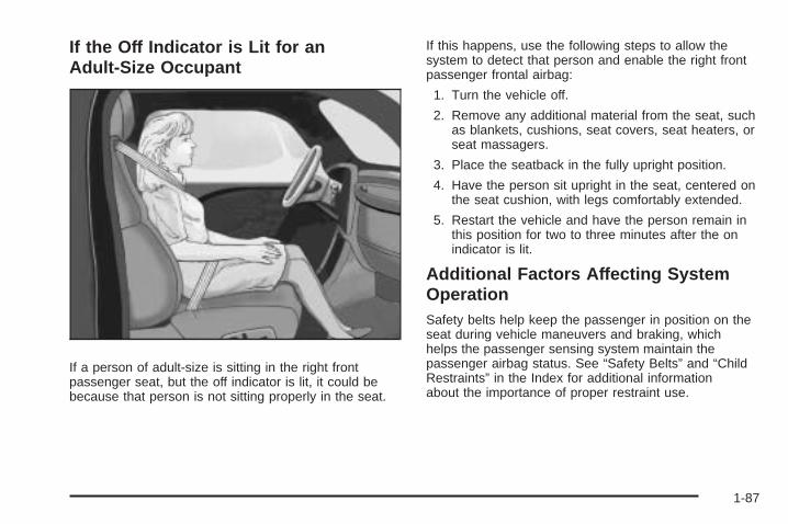
If the Off Indicator is Lit for anAdult-Size Occupant
If a person of adult-size is sitting in the right frontpassenger seat, but the off indicator is lit, it could bebecause that person is not sitting properly in the seat.
If this happens, use the following steps to allow thesystem to detect that person and enable the right frontpassenger frontal airbag:
1. Turn the vehicle off.
2. Remove any additional material from the seat, suchas blankets, cushions, seat covers, seat heaters, orseat massagers.
3. Place the seatback in the fully upright position.
4. Have the person sit upright in the seat, centered onthe seat cushion, with legs comfortably extended.
5. Restart the vehicle and have the person remain inthis position for two to three minutes after the onindicator is lit.
Additional Factors Affecting SystemOperationSafety belts help keep the passenger in position on theseat during vehicle maneuvers and braking, whichhelps the passenger sensing system maintain thepassenger airbag status. See “Safety Belts” and “ChildRestraints” in the Index for additional informationabout the importance of proper restraint use.
1-87

If the shoulder portion of the belt is pulled out all theway, the child restraint locking feature will be engaged.This may unintentionally cause the passenger sensingsystem to turn the airbag off for some adult sizeoccupants. If this happens, let the belt go back all theway and start again.
A thick layer of additional material, such as a blanket orcushion, or aftermarket equipment such as seat covers,seat heaters, and seat massagers can affect how well thepassenger sensing system operates. We recommendthat you not use seat covers or other aftermarketequipment except when approved by GM for your specificvehicle. See Adding Equipment to Your Airbag-EquippedVehicle on page 1-89 for more information aboutmodifications that can affect how the system operates.
The on indicator may be lit if an object, such as abriefcase, handbag, grocery bag, laptop or otherelectronic device, is put on an unoccupied seat.If this is not desired, remove the object from the seat.
{CAUTION:
Stowing of articles under the passenger seat orbetween the passenger seat cushion and seatbackmay interfere with the proper operation of thepassenger sensing system.
Servicing Your Airbag-EquippedVehicleAirbags affect how the vehicle should be serviced. Thereare parts of the airbag system in several places aroundthe vehicle. Your dealer/retailer and the service manualhave information about servicing the vehicle and theairbag system. To purchase a service manual, seeService Publications Ordering Information on page 7-15.
{CAUTION:
For up to 10 seconds after the ignition is turned offand the battery is disconnected, an airbag can stillinflate during improper service. You can be injuredif you are close to an airbag when it inflates.Avoid yellow connectors. They are probably partof the airbag system. Be sure to follow properservice procedures, and make sure the personperforming work for you is qualified to do so.
1-88

Adding Equipment to YourAirbag-Equipped Vehicle
Q: Is there anything I might add to or changeabout the vehicle that could keep the airbagsfrom working properly?
A: Yes. If you add things that change your vehicle’sframe, bumper system, height, front end or sidesheet metal, they may keep the airbag system fromworking properly. Changing or moving any parts ofthe front seats, safety belts, the airbag sensing anddiagnostic module, steering wheel, instrument panel,roof-rail airbag modules, ceiling headliner or pillargarnish trim, overhead console, front sensors,rollover sensor module, or airbag wiring can affectthe operation of the airbag system.In addition, your vehicle may have a passengersensing system for the right front passenger’sposition, which includes sensors that are part of thepassenger’s seat. The passenger sensing system
may not operate properly if the original seat trim isreplaced with non-GM covers, upholstery or trim, orwith GM covers, upholstery or trim designed for adifferent vehicle. Any object, such as an aftermarketseat heater or a comfort enhancing pad or device,installed under or on top of the seat fabric, could alsointerfere with the operation of the passenger sensingsystem. This could either prevent proper deploymentof the passenger airbag(s) or prevent the passengersensing system from properly turning off thepassenger airbag(s). See Passenger SensingSystem on page 1-84.
If you have any questions about this, you shouldcontact Customer Assistance before you modifyyour vehicle. The phone numbers and addressesfor Customer Assistance are in Step Two ofthe Customer Satisfaction Procedure in this manual.See Customer Satisfaction Procedure on page 7-2.If your vehicle has rollover roof-rail airbags, seeDifferent Size Tires and Wheels on page 5-86for additional important information.
1-89

Q: What if I added a snow plow? Will it keep theairbags from working properly?
A: We have designed our airbag systems to workproperly under a wide range of conditions, includingsnow plowing with vehicles that have the optionalSnow Plow Prep Package (RPO VYU). But donot change or defeat the snow plow’s “trippingmechanism.” If you do, it can damage your snowplow and your vehicle, and it may cause an airbaginflation.
Q: Because I have a disability, I have to get myvehicle modified. How can I find out whetherthis will affect my airbag system?
A: If you have questions, call Customer Assistance.The phone numbers and addresses for CustomerAssistance are in Step Two of the CustomerSatisfaction Procedure in this manual. SeeCustomer Satisfaction Procedure on page 7-2.
In addition, your dealer/retailer and the service manualhave information about the location of the airbag sensors,sensing and diagnostic module and airbag wiring.
Restraint System Check
Checking the Restraint Systems
Safety BeltsNow and then, check the safety belt reminder light,safety belts, buckles, latch plates, retractors, andanchorages are all working properly.
Look for any other loose or damaged safety belt systemparts that might keep a safety belt system from doingits job. See your dealer/retailer to have it repaired. Tornor frayed safety belts may not protect you in a crash.They can rip apart under impact forces. If a belt is tornor frayed, get a new one right away.
Make sure the safety belt reminder light is working.See Safety Belt Reminders on page 3-36 for moreinformation.
Keep safety belts clean and dry. See Care of SafetyBelts on page 5-116.
1-90
AirbagsThe airbag system does not need regularly scheduledmaintenance or replacement. Make sure the airbagreadiness light is working. See Airbag Readiness Lighton page 3-37 for more information.
Notice: If an airbag covering is damaged, opened, orbroken, the airbag may not work properly. Do notopen or break the airbag coverings. If there are anyopened or broken airbag covers, have the airbagcovering and/or airbag module replaced. For thelocation of the airbag modules, see What Makes anAirbag Inflate? on page 1-79. See your dealer/retailerfor service.
Replacing Restraint System PartsAfter a Crash
{CAUTION:
A crash can damage the restraint systems in yourvehicle. A damaged restraint system may notproperly protect the person using it, resulting inserious injury or even death in a crash. To helpmake sure your restraint systems are workingproperly after a crash, have them inspected and anynecessary replacements made as soon as possible.
If the vehicle has been in a crash, do you need newsafety belts or LATCH system (if equipped) parts?
After a very minor crash, nothing may be necessary.But the safety belt assemblies that were used during anycrash may have been stressed or damaged. See yourdealer/retailer to have the safety belt assembliesinspected or replaced.
If the vehicle has the LATCH system and it was beingused during a crash, you may need new LATCHsystem parts.
New parts and repairs may be necessary even if thesafety belt or LATCH system (if equipped), wasnot being used at the time of the crash.
If an airbag inflates, you will need to replace airbagsystem parts. See the part on the airbag system earlierin this section.
Have the safety belt pretensioners checked if thevehicle has been in a crash, if the airbag readiness lightstays on after the vehicle is started, or while you aredriving. See Airbag Readiness Light on page 3-37.
1-91

✍ NOTES
1-92
Keys ...............................................................2-3Remote Keyless Entry (RKE) System ................2-4Remote Keyless Entry (RKE) System
Operation ...................................................2-5Remote Vehicle Start ......................................2-7
Doors and Locks ............................................2-10Door Locks ..................................................2-10Power Door Locks ........................................2-10Delayed Locking ...........................................2-11Programmable Automatic Door Locks ..............2-11Rear Door Security Locks ..............................2-11Lockout Protection ........................................2-12Rear Doors ..................................................2-12Tailgate .......................................................2-13
Windows ........................................................2-15Manual Windows ..........................................2-16Power Windows ............................................2-16Power Sliding Rear Window ...........................2-17Sun Visors ...................................................2-18
Theft-Deterrent Systems ..................................2-18Content Theft-Deterrent .................................2-18PASS-Key® III+ Electronic Immobilizer .............2-20PASS-Key® III+ Electronic Immobilizer
Operation .................................................2-20
Starting and Operating Your Vehicle ................2-22New Vehicle Break-In ....................................2-22Ignition Positions ..........................................2-22Retained Accessory Power (RAP) ...................2-23Starting the Engine .......................................2-24Fast Idle System ..........................................2-25Adjustable Throttle and Brake Pedal ................2-26Engine Coolant Heater ..................................2-27Active Fuel Management™ .............................2-28Automatic Transmission Operation ...................2-28Tow/Haul Mode ............................................2-34Four-Wheel Drive ..........................................2-37Parking Brake ..............................................2-50Shifting Into Park ..........................................2-52Shifting Out of Park ......................................2-54Parking Over Things That Burn .......................2-54Engine Exhaust ............................................2-55Running the Vehicle While Parked ..................2-56
Mirrors ...........................................................2-57Manual Rearview Mirror .................................2-57Automatic Dimming Rearview Mirror ................2-57Outside Manual Mirrors ..................................2-58Outside Towing Mirrors ..................................2-58Outside Power Mirrors ...................................2-59Outside Power Foldaway Mirrors .....................2-59
Section 2 Features and Controls
2-1

Park Tilt Mirrors ............................................2-60Outside Convex Mirror ...................................2-61Outside Heated Mirrors ..................................2-61
Object Detection Systems ...............................2-62Ultrasonic Rear Parking
Assist (URPA) ...........................................2-62Rear Vision Camera (RVC) ............................2-65
OnStar® System .............................................2-71Universal Home Remote System ......................2-74
Universal Home Remote System Operation(With Three Round LED) .............................2-75
Storage Areas ................................................2-81Glove Box ...................................................2-81Cupholders ..................................................2-81Instrument Panel Storage ...............................2-81Center Console Storage .................................2-82Luggage Carrier ...........................................2-82Rear Seat Armrest ........................................2-83Cargo Management System ...........................2-84
Sunroof .........................................................2-85
Section 2 Features and Controls
2-2

Keys
{CAUTION:
Leaving children in a vehicle with the ignition keyis dangerous for many reasons, children or otherscould be badly injured or even killed. They couldoperate the power windows or other controls oreven make the vehicle move. The windows willfunction with the keys in the ignition and childrencould be seriously injured or killed if caught in thepath of a closing window. Do not leave the keys ina vehicle with children.
The key is used for the ignition and all door locks.
The key has a bar-coded key tag that the dealer/retaileror qualified locksmith can use to make new keys.Store this information in a safe place, not in the vehicle.
2-3

See your dealer/retailer if a replacement key oradditional key is needed.
Notice: If you ever lock your keys in the vehicle,you may have to damage the vehicle to get in.Be sure you have spare keys.
If you are locked out of the vehicle, call the RoadsideAssistance Center. See Roadside Assistance Programon page 7-7.
Remote Keyless Entry (RKE)SystemIf this vehicle has the Remote Keyless Entry (RKE)system, it operates on a radio frequency subjectto Federal Communications Commission (FCC)Rules and with Industry Canada.
This device complies with Part 15 of the FCC Rules.Operation is subject to the following two conditions:
1. This device may not cause interference.
2. This device must accept any interference received,including interference that may cause undesiredoperation of the device.
This device complies with RSS-210 of Industry Canada.Operation is subject to the following two conditions:
1. This device may not cause interference.
2. This device must accept any interference received,including interference that may cause undesiredoperation of the device.
Changes or modifications to this system by other thanan authorized service facility could void authorizationto use this equipment.
If there is a decrease in the RKE operating range,try this:
• Check the distance. The transmitter may be too farfrom the vehicle. Stand closer during rainy or snowyweather.
• Check the location. Other vehicles or objects may beblocking the signal. Take a few steps to the left orright, hold the transmitter higher, and try again.
• Check the transmitter’s battery. See “BatteryReplacement” later in this section.
• If the transmitter is still not working correctly,see your dealer/retailer or a qualified technicianfor service.
2-4

Remote Keyless Entry (RKE)System OperationThe Remote Keyless Entry (RKE) transmitter functionswork up to 195 feet (60 m) away from the vehicle.
There are other conditions which can affect theperformance of the transmitter. See Remote KeylessEntry (RKE) System on page 2-4.
/ (Remote Vehicle Start): For vehicles with thisfeature, press / to start the engine from outside thevehicle using the RKE transmitter. See Remote VehicleStart on page 2-7 for additional information.
Q (Lock): Press to lock all the doors.
If enabled through the Driver Information Center (DIC),the turn signal lamps flash once to indicate lockinghas occurred. If enabled through the DIC, the hornchirps when Q is pressed again within three seconds.See DIC Vehicle Customization (With DIC Buttons)on page 3-76 for additional information.
Pressing Q arms the content theft-deterrent system.See Content Theft-Deterrent on page 2-18.
K (Unlock): Press once to unlock only the driver door.If K is pressed again within three seconds, all remainingdoors unlock. The interior lamps may come on and stayon for 20 seconds or until the ignition is turned on.
With Remote Start(Without Remote Start
Similar)
2-5

If enabled through the DIC, the turn signal lamps flashtwice to indicate unlocking has occurred. See DICVehicle Customization (With DIC Buttons) on page 3-76.If enabled through the DIC, the exterior lights may turnon. See “APPROACH LIGHTING” under DIC VehicleCustomization (With DIC Buttons) on page 3-76.
Pressing K on the RKE transmitter disarms the contenttheft-deterrent system. See Content Theft-Deterrent onpage 2-18.
L (Vehicle Locator/Panic Alarm): Press and releaseto locate the vehicle. The turn signal lamps flash andthe horn sounds three times.
Press and hold L for more than two seconds toactivate the panic alarm. The turn signal lamps flashand the horn sounds repeatedly for 30 seconds.The alarm turns off when the ignition is moved toON/RUN or L is pressed again. The ignition mustbe in LOCK/OFF for the panic alarm to work.
Programming Transmitters to theVehicleOnly RKE transmitters programmed to this vehiclewill work. If a transmitter is lost or stolen, a replacementcan be purchased and programmed through yourdealer/retailer. When the replacement transmitter isprogrammed to this vehicle, all remaining transmittersmust also be reprogrammed. Any lost or stolentransmitters will no longer work once the new transmitteris programmed. Each vehicle can have up to eighttransmitters programmed to it. See “Relearn RemoteKey” under DIC Operation and Displays (With DICButtons) on page 3-53 or DIC Operation and Displays(Without DIC Buttons) on page 3-59 for instructions onhow to match RKE transmitters to your vehicle.
Battery ReplacementReplace the battery if the REPLACE BATTERY INREMOTE KEY message displays in the DIC. See“REPLACE BATTERY IN REMOTE KEY” under DICWarnings and Messages on page 3-66 for additionalinformation.
Notice: When replacing the battery, do not touchany of the circuitry on the transmitter. Staticfrom your body could damage the transmitter.
2-6

To replace the battery:
1. Separate the transmitter with a flat, thin objectinserted into the notch on the side.
2. Remove the old battery. Do not use a metal object.
3. Insert the new battery, positive side facing down.Replace with a CR2032 or equivalent battery.
4. Snap the transmitter back together.
Remote Vehicle StartYour vehicle may have a remote starting feature. Thisfeature allows you to start the engine from outside of thevehicle. It may also start up the vehicle’s heating or airconditioning systems and rear window defogger. Normaloperation of the system will return after the key is turnedto the ON/RUN position.
If your vehicle has an automatic climate control system,the climate control system will default to a heating orcooling mode depending on the outside temperatures.If your vehicle does not have an automatic climate controlsystem, the system will turn on at the setting the vehiclewas set to when the vehicle was last turned off.
During a remote start, if your vehicle has an automaticclimate control system and heated seats, the heatedseats will turn on during colder outside temperaturesand will shut off when the key is turned to ON/RUN.If your vehicle does not have an automatic climate controlsystem, during remote start, you will need to manuallyturn the heated seats on and off. See Heated Seats onpage 1-8 for additional information.
Laws in some communities may restrict the use ofremote starters. For example, some laws may requirea person using the remote start to have the vehiclein view when doing so. Check local regulations forany requirements on remote starting of vehicles.
2-7

Do not use the remote start feature if your vehicle is lowon fuel. Your vehicle may run out of fuel.
If your vehicle has the remote start feature, the RKEtransmitter functions will have an increased range ofoperation. However, the range may be less while thevehicle is running.
There are other conditions which can affect theperformance of the transmitter, see Remote KeylessEntry (RKE) System on page 2-4 for additionalinformation.
/ (Remote Start): This button will be on the RKEtransmitter if you have remote start.
To start the vehicle using the remote start feature:
1. Aim the transmitter at the vehicle.
2. Press and release the transmitter’s lock button.The vehicle’s doors will lock. Immediately pressand hold the transmitter’s remote start button untilthe turn signal lights flash. If you cannot seethe vehicle’s lights, press and hold the remotestart button for two to four seconds. Pressing theremote start button again after the vehicle hasstarted will turn the engine off.When the vehicle starts, the parking lamps will turnon and remain on while the vehicle is running.
If the vehicle is left running it will automatically shutoff after 10 minutes unless a time extension hasbeen done.
3. If it is the first remote start since the vehicle hasbeen driven, repeat these steps, while the engine isstill running, to extend the engine running time by10 minutes. Remote start can be extended one time.
After entering the vehicle during a remote start, insertand turn the key to RUN to drive the vehicle.
To manually shut off a remote start, do any of thefollowing:
• Aim the RKE transmitter at the vehicle and pressthe remote start button until the parking lampsturn off.
• Turn on the hazard warning flashers.
• Turn the ignition switch on and then off.
The vehicle can be remote started two separate timesbetween driving sequences. The engine will run for10 minutes after each remote start.
Or, you can extend the engine run time by another10 minutes within the first 10 minute remote start timeframe, and before the engine stops.
2-8

For example, if the lock button and then the remotestart buttons are pressed again after the vehiclehas been running for five minutes, 10 minutes areadded, allowing the engine to run for 15 minutes.
The additional ten minutes are considered a secondremote vehicle start.
Once two remote starts, or a single remote start withone time extension has been done, the vehicle mustbe started with the key. After the key is removed fromthe ignition, the vehicle can be remote started again.
The vehicle cannot be remote started if the key is in theignition, the hood is not closed, or if there is an emissioncontrol system malfunction and the check engine lightcomes on.
Also, the engine will turn off during a remote vehiclestart if the coolant temperature gets too high or if theoil pressure gets low.
Vehicles that have the remote vehicle start feature areshipped from the factory with the remote vehicle startsystem enabled. The system may be enabled or disabledthrough the DIC. See “REMOTE START” under DICVehicle Customization (With DIC Buttons) on page 3-76for additional information. If your vehicle does not haveDIC buttons, see your dealer/retailer to enable or disablethe remote vehicle start system.
Remote Start ReadyIf your vehicle does not have the remote vehicle startfeature, it may have the remote start ready feature.This feature allows your dealer/retailer to add themanufacturer’s remote vehicle start feature.
See your dealer/retailer if you would like to add themanufacturer’s remote vehicle start feature to yourvehicle.
2-9

Doors and Locks
Door Locks
{CAUTION:
Unlocked doors can be dangerous.• Passengers, especially children, can easily
open the doors and fall out of a movingvehicle. When a door is locked, the handlewill not open it. You increase the chance ofbeing thrown out of the vehicle in a crash ifthe doors are not locked. So, wear safetybelts properly and lock the doors wheneveryou drive.
• Young children who get into unlocked vehiclesmay be unable to get out. A child can beovercome by extreme heat and can sufferpermanent injuries or even death from heatstroke. Always lock your vehicle wheneveryou leave it.
• Outsiders can easily enter through anunlocked door when you slow down or stopyour vehicle. Locking your doors can helpprevent this from happening.
There are several ways to lock and unlock your vehicle.
From the outside, use the Remote Keyless Entry (RKE)transmitter or the key in the driver’s door.
From the inside, use the power door locks or manualdoor locks. To lock or unlock the door with the manuallocks, push down or pull up on the manual lock knob.
Power Door LocksOn vehicles with power door locks the switches arelocated on the front doors.
" (Unlock): Press to unlock the doors.
Q (Lock): Remove the key from the ignition and pressto lock the doors.
2-10

Delayed LockingThe vehicle may have the delayed locking feature.When locking the doors with the power lock switch orthe Remote Keyless Entry (RKE) transmitter and a dooris open, the doors will lock five seconds after the lastdoor is closed. You will hear three chimes to signal thatthe delayed locking feature is in use.
Pressing the power lock switch twice or the lock buttonon the RKE transmitter twice will override the delayedlocking feature and immediately lock all the doors.
This feature will not operate if the key is in the ignition.
You can program this feature using the DriverInformation Center (DIC). See DELAY DOOR LOCKunder DIC Vehicle Customization (With DIC Buttons)on page 3-76.
Programmable Automatic DoorLocksVehicles with an automatic lock/unlock feature enableyou to program the vehicle’s power door locks. You canprogram this feature through the Driver InformationCenter (DIC). See DIC Vehicle Customization (WithDIC Buttons) on page 3-76 for more information onDIC programming.
Rear Door Security LocksYour vehicle has rear door security locks. Theseprevent passengers from opening the rear doorsfrom the inside.
The rear door securitylocks are located onthe inside edge of eachrear door.
The rear doors must be open to access them.The label showing lock and unlock positions is locatednear the lock.
To set the locks, do the following:
1. Insert the key into the security lock slot and turn itso the slot is in the horizontal position.
2. Close the door.
2-11

When you want to open a rear door when the securitylock is on, do the following:
1. Unlock the door by lifting the rear door manual lock,using the power door lock switch, or the RemoteKeyless Entry (RKE) transmitter, if the vehiclehas one.
2. Open the door from the outside.
To cancel the rear door security lock, do the following:
1. Unlock the door and open it from the outside.
2. Insert the key into the security lock slot and turn itso the slot is in the vertical position.
Lockout ProtectionThis feature protects you from locking the key in thevehicle when the key is in the ignition and a front dooris open.
If the driver’s side power door lock switch is pressedwhen the driver’s door is open and the key is in theignition, all of the doors will lock and then the driver’sdoor will unlock.
If the passenger’s side power door lock switch ispressed when the front passenger’s door is open andthe key is in the ignition, all of the doors will lock andthen the front passenger’s door will unlock.
Rear Doors
Extended CabYour vehicle may have a rear access door(s) that allowseasier access to the rear area of the extended cab.
To open a rear accessdoor from the outside, firstopen the front door. Then,use the handle located onthe front edge of the rearaccess door to open it.
You must fully close a rear access door before you canclose the front door.
2-12

To open a rear accessdoor from the inside, thefront door must be openedfirst. Then, use the handlelocated on the inside of therear access door to open.
Crew CabsIf your vehicle is a crew cab, you can open your doorsfrom the inside or outside. Your vehicle may also have afeature which prevents children from opening the reardoors. See Rear Door Security Locks on page 2-11 formore information.
Tailgate
{CAUTION:
It is extremely dangerous to ride on the tailgate,even when the vehicle is operated at low speeds.People riding on the tailgate can easily lose theirbalance and fall in response to vehicle maneuvers.Falling from a moving vehicle may result in seriousinjuries or death. Do not allow people to ride onthe tailgate. Be sure everyone in your vehicle isin a seat and using a safety belt properly.
On vehicles with a lock on the tailgate, use the key tolock or unlock the tailgate.
Open the tailgate by lifting up on its handle while pullingthe tailgate toward you.
To shut the tailgate, firmly push it upward until itlatches.
After you put the tailgate back up, pull it back towardsyou to be sure it latches securely.
2-13

Tailgate RemovalThe tailgate can be removed to allow for differentloading situations. Although the tailgate can be removedwithout assistance, you may want someone to assistyou with the removal to avoid possible damage tothe vehicle.
On vehicles with a rear vision camera, it must bedisconnected before removing the tailgate. See RearVision Camera (RVC) on page 2-65 for more information.
To remove the tailgate, do the following:
1. Raise the tailgateslightly and releaseboth retaining cableclips. To release theretaining cable clips, liftthe cable so it pointsstraight out. Lift the clipover the bolt, and pushthe cable forward thenrotate down.
2. With the tailgate about halfway open, lift the rightedge of the tailgate from the lower pivot.On vehicles with the tailgate assist feature, raisethe tailgate nearly all the way to the closed positionprior to removing the left edge.
3. Move the tailgate to the right to release theleft edge.
Reverse this procedure to reinstall the tailgate.Make sure the tailgate is secure.
2-14

Windows
{CAUTION:
Leaving children, helpless adults, or pets in avehicle with the windows closed is dangerous.They can be overcome by the extreme heat andsuffer permanent injuries or even death from heatstroke. Never leave a child, a helpless adult, or apet alone in a vehicle, especially with the windowsclosed in warm or hot weather.
2-15

Manual WindowsTurn the hand crank on each door to manually raise orlower the manual windows.
Power Windows
{CAUTION:
Leaving children in a vehicle with the keys isdangerous for many reasons, children or otherscould be badly injured or even killed. They couldoperate the power windows or other controls oreven make the vehicle move. The windows willfunction and they could be seriously injured orkilled if caught in the path of a closing window.Do not leave keys in a vehicle with children.
When there are children in the rear seat use thewindow lockout button to prevent unintentionaloperation of the windows.
If your vehicle has powerwindows, the controls arelocated on each of theside doors in the front andrear for crew cab andextended cab models.
The driver’s door has a switch for the passenger’s andrear windows as well. Your power windows will workwhen the ignition has been turned to ACCESSORY orRUN or when Retained Accessory Power (RAP) is active.See Retained Accessory Power (RAP) on page 2-23.
Press the switch down to lower the window, and pull upthe front of the switch to raise the window.
Crew Cab shown
2-16

Express Down WindowsVehicles with the express down feature allow the driverand front passenger windows to be lowered withoutholding the switch. Press down fully on the windowswitch, then release, to activate the express down mode.The express down mode can be canceled at any time bypulling up on the switch. To open the window partway,press the switch to the first depression position, untilthe window is at the desired position.
Window Lockout
o (Window Lockout): If your crew cab or extendedcab vehicle has power windows, the driver’s door powerwindow switch has a lockout feature. The lockout switchis located in front of the window switches. This featureprevents the rear windows from operating, except fromthe driver’s position. Press the switch to engage ordisengage the lockout feature. An indicator light on theswitch will come on when the lockout feature is engaged,and will go off when disengaged.
Power Sliding Rear WindowOn vehicles with a powersliding rear window,the switch is located inthe overhead console.
The power sliding rear window works when the ignitionhas been turned to ACC/ACCESSORY, ON/RUN,or when Retained Accessory Power (RAP) is active.See Retained Accessory Power (RAP) on page 2-23for more information.
The power sliding rear window cannot be operatedmanually.
T : Push to open the window.
S : Pull to close the window.
2-17

Sun VisorsPull the sun visor down to block glare. Swing the sunvisor to the side to cover the side window.
The passenger’s side sun visor may have a vanitymirror.
Theft-Deterrent SystemsVehicle theft is big business, especially in some cities.This vehicle has theft-deterrent features, however,they do not make it impossible to steal.
Content Theft-DeterrentYour vehicle may have a content theft-deterrent alarmsystem.
This is the security light.
To arm the theft-deterrent system:
1. Open the door.
2. Lock the door with the Remote Keyless Entry (RKE)transmitter. The security light should come on andflash.If the delayed locking feature is active, the alarmwill not be activated until all doors are closedand the security light goes off.
3. Close all doors. The security light will stopflashing and go off after approximately 30 seconds.The content theft deterrent alarm is not armed untilthe security light goes off.
If a locked door is opened without using the RKEtransmitter, a ten second pre-alarm will occur. The hornwill chirp and the lights will flash. If the key is not placedin the ignition and turned to START or the door is notunlocked by pressing the unlock button on the RKEtransmitter during the ten second pre-alarm, the alarmwill go off. Your vehicle’s headlamps will flash and thehorn will sound for about two minutes, then will turn offto save the battery power.
2-18
The theft-deterrent system will not activate if the doorsare locked with the vehicle’s key or the manual door lock.It activates only if you use the power door lock switch withthe door open or the RKE transmitter. You should alsoremember that you can start your vehicle with the correctignition key if the alarm has been set off.
To avoid setting off the alarm by accident:
• If you do not want to activate the theft-deterrentsystem, the vehicle should be locked with thedoor key after the doors are closed.
• Always unlock a door with the RKE transmitter.Unlocking a door any other way will set off the alarmif the system has been armed.
If you set off the alarm by accident, press unlock on theRKE transmitter or place the key in the ignition andturn it to START to turn it off.
Testing the AlarmTo test the alarm:
1. From inside the vehicle, lower the driver’s windowand open the driver’s door.
2. Activate the system by locking the doors with theRKE transmitter.
3. Get out of the vehicle, close the door and wait forthe security light to go out.
4. Then reach in through the window, unlock the doorwith the manual door lock and open the door.This should set off the alarm.
If the alarm does not sound when it should but theheadlamps flash, check to see if the horn works.The horn fuse may be blown. To replace the fuse,see Fuses and Circuit Breakers on page 5-122.
If the alarm does not sound or the headlamps do notflash, see your dealer/retailer for service.
2-19

PASS-Key® III+ ElectronicImmobilizerThe PASS-Key III+ system operates on a radiofrequency subject to Federal CommunicationsCommission (FCC) Rules and with Industry Canada.
This device complies with Part 15 of the FCC Rules.Operation is subject to the following two conditions:
1. This device may not cause harmful interference.
2. This device must accept any interference received,including interference that may cause undesiredoperation.
This device complies with RSS-210 of Industry Canada.Operation is subject to the following two conditions:
1. This device may not cause interference.
2. This device must accept any interference received,including interference that may cause undesiredoperation of the device.
Changes or modifications to this system by other thanan authorized service facility could void authorization touse this equipment.
PASS-Key III+ uses a radio frequency transponder inthe key that matches a decoder in the vehicle.
PASS-Key® III+ ElectronicImmobilizer OperationYour vehicle has PASS-Key® III+ (PersonalizedAutomotive Security System) theft-deterrent system.PASS-Key® III+ is a passive theft-deterrent system.
The system is automatically armed when the keyis removed from the ignition.
The system is automatically disarmed when the keyis turned to ON/RUN, ACC/ACCESSORY or STARTfrom the LOCK/OFF position.
You do not have to manually arm or disarm the system.
The security light will come on if there is a problemwith arming or disarming the theft-deterrent system.
When the PASS-Key® III+ system senses that someoneis using the wrong key, it prevents the vehicle fromstarting. Anyone using a trial-and-error method to startthe vehicle will be discouraged because of the highnumber of electrical key codes.
If the engine does not start and the security light onthe instrument panel cluster comes on when trying tostart the vehicle, there may be a problem with yourtheft-deterrent system. Turn the ignition off and try again.
2-20

If the engine still does not start, and the key appears tobe undamaged, try another ignition key. At this time, youmay also want to check the fuse, see Fuses and CircuitBreakers on page 5-122. If the engine still does not startwith the other key, your vehicle needs service. If yourvehicle does start, the first key may be faulty. See yourdealer/retailer who can service the PASS-Key® III+ tohave a new key made. In an emergency, contactRoadside Assistance.
It is possible for the PASS-Key® III+ decoder to learnthe transponder value of a new or replacement key.Up to 10 keys may be programmed for the vehicle.The following procedure is for programming additionalkeys only. If all the currently programmed keys are lostor do not operate, you must see your dealer/retailer ora locksmith who can service PASS-Key® III+ to havekeys made and programmed to the system.
See your dealer/retailer or a locksmith who can servicePASS-Key® III+ to get a new key blank that is cutexactly as the ignition key that operates the system.
To program the new additional key:
1. Verify that the new key has a 1 stamped on it.
2. Insert the original, already programmed, key in theignition and start the engine. If the engine will notstart, see your dealer/retailer for service.
3. After the engine has started, turn the key toLOCK/OFF, and remove the key.
4. Insert the new key to be programmed and turn it tothe ON/RUN position within five seconds of turningthe ignition to the LOCK/OFF position in Step 3.The security light will turn off once the key has beenprogrammed.
5. Repeat Steps 1 through 4 if additional keys are tobe programmed.
If you lose or damage your PASS-Key® III+ key, seeyour dealer/retailer or a locksmith who can servicePASS-Key® III+ to have a new key made.
Do not leave the key or device that disarms ordeactivates the theft deterrent system in the vehicle.
2-21

Starting and Operating YourVehicle
New Vehicle Break-InNotice: The vehicle does not need an elaboratebreak-in. But it will perform better in the long runif you follow these guidelines:
• Keep your speed at 55 mph (88 km/h) or less forthe first 500 miles (805 km).
• Do not drive at any one constant speed, fastor slow, for the first 500 miles (805 km). Do notmake full-throttle starts. Avoid downshifting tobrake or slow the vehicle.
• Avoid making hard stops for the first 200 miles(322 km) or so. During this time the new brakelinings are not yet broken in. Hard stops withnew linings can mean premature wear and earlierreplacement. Follow this breaking-in guidelineevery time you get new brake linings.
• Do not tow a trailer during break-in. See Towinga Trailer on page 4-51 for the trailer towingcapabilities of the vehicle and more information.
Following break-in, engine speed and load can begradually increased.
Ignition PositionsThe ignition switch hasfour different positions.
To shift out of P (Park), the ignition must be in ON/RUNor ACC/ACCESSORY and the regular brake pedal mustbe applied.
A (LOCK/OFF): This position locks the ignition. It alsolocks the transmission on automatic transmissionvehicles. The key can be removed in LOCK/OFF.
On vehicles with an automatic transmission, the shiftlever must be in P (Park) to turn the ignition switchto LOCK/OFF.
2-22

The steering can bind with the wheels turned off center.If this happens, move the steering wheel from rightto left while turning the key to ACC/ACCESSORY.If this doesn’t work, then the vehicle needs service.
Notice: Using a tool to force the key to turn inthe ignition could cause damage to the switch orbreak the key. Use the correct key, make sure itis all the way in, and turn it only with your hand.If the key cannot be turned by hand, see yourdealer/retailer.
B (ACC/ACCESSORY): This position lets things like theradio and the windshield wipers operate while the engineis off. Use this position if the vehicle must be pushed ortowed.
C (ON/RUN): This position can be used to operate theelectrical accessories and to display some instrumentpanel cluster warning and indicator lights. The switchstays in this position when the engine is running.The transmission is also unlocked in this position onautomatic transmission vehicles.
If you leave the key in the ACC/ACCESSORY or ON/RUN position with the engine off, the battery could bedrained. You may not be able to start the vehicle if thebattery is allowed to drain for an extended period of time.
D (START): This is the position that starts the engine.When the engine starts, release the key. The ignitionswitch returns to ON/RUN for driving.
A warning tone will sound when the driver door isopened, the ignition is in ACC/ACCESSORY orLOCK/OFF and the key is in the ignition.
Retained Accessory Power (RAP)The following vehicle accessories can be used for up to10 minutes after the engine is turned off:
• Audio System
• Power Windows
• OnStar® System (if equipped)
• Sunroof (if equipped)
These features work when the key is in ON/RUN orACC/ACCESSORY. Once the key is turned fromON/RUN to LOCK/OFF, the windows and sunroofcontinue to work up to 10 minutes until any dooris opened. The radio continues to work for up to10 minutes or until the driver door is opened.
2-23

Starting the EngineIf the vehicle has the DURAMAX® Diesel engine, seethe DURAMAX® Diesel manual for more information.
If the vehicle is a Two-mode Hybrid, see the Two-modeHybrid manual for more information.
Notice: Do not try to shift to P (Park) if thevehicle is moving. If you do, you could damage thetransmission. Shift to P (Park) only when the vehicleis stopped.
Move the shift lever to P (Park) or N (Neutral).The engine will not start in any other position.To restart the engine when the vehicle is alreadymoving, use N (Neutral) only.
Starting Procedure1. With your foot off the accelerator pedal, turn the
ignition key to START. When the engine starts,let go of the key. The idle speed will go down asyour engine gets warm. Do not race the engineimmediately after starting it. Operate the engineand transmission gently to allow the oil to warmup and lubricate all moving parts.
The vehicle has a Computer-Controlled CrankingSystem. This feature assists in starting the engineand protects components. If the ignition key is turnedto the START position, and then released when theengine begins cranking, the engine will continuecranking for a few seconds or until the vehicle starts.If the engine does not start and the key is held inSTART for many seconds, cranking will be stoppedafter 15 seconds to prevent cranking motor damage.To prevent gear damage, this system also preventscranking if the engine is already running. Enginecranking can be stopped by turning the ignitionswitch to the ACC/ACCESSORY or LOCK/OFFposition.
Notice: Cranking the engine for long periods oftime, by returning the key to the START positionimmediately after cranking has ended, can overheatand damage the cranking motor, and drain thebattery. Wait at least 15 seconds between each try,to let the cranking motor cool down.
2-24

2. If the engine does not start after 5-10 seconds,especially in very cold weather (below 0°F or −18°C),it could be flooded with too much gasoline. Trypushing the accelerator pedal all the way to the floorand holding it there as you hold the key in START forup to 15 seconds. Wait at least 15 seconds betweeneach try, to allow the cranking motor to cool down.When the engine starts, let go of the key andaccelerator. If the vehicle starts briefly but thenstops again, do the same thing. This clears theextra gasoline from the engine. Do not race theengine immediately after starting it. Operate theengine and transmission gently until the oil warmsup and lubricates all moving parts.
Notice: The engine is designed to work with theelectronics in the vehicle. If you add electrical partsor accessories, you could change the way the engineoperates. Before adding electrical equipment, checkwith your dealer/retailer. If you do not, the enginemight not perform properly. Any resulting damagewould not be covered by the vehicle warranty.
Fast Idle System
Fast Idle System with Switch
If the vehicle has thisfeature it is available onlywith cruise control. Themanual fast idle switch isoperated using the cruisecontrol buttons located onthe left hand side of thesteering wheel.
This system can be used to increase engine idle speedwhenever the following conditions are met:
• The park brake is set.
• The brake pedal is not pressed.
• The vehicle must not be moving and the acceleratormust not be pressed.
2-25
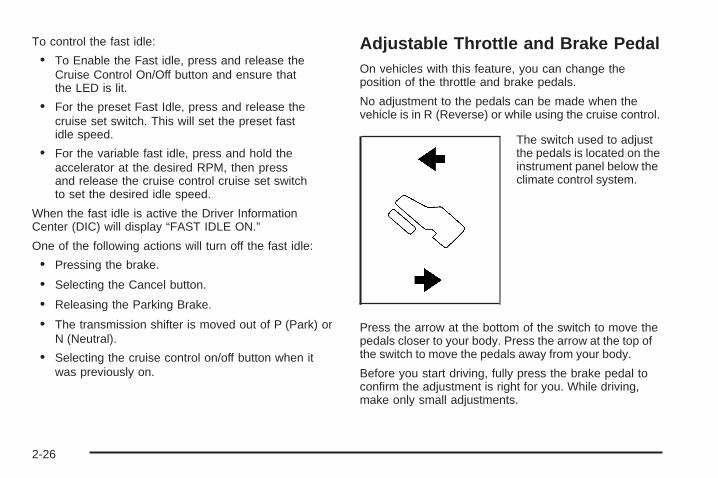
To control the fast idle:
• To Enable the Fast idle, press and release theCruise Control On/Off button and ensure thatthe LED is lit.
• For the preset Fast Idle, press and release thecruise set switch. This will set the preset fastidle speed.
• For the variable fast idle, press and hold theaccelerator at the desired RPM, then pressand release the cruise control cruise set switchto set the desired idle speed.
When the fast idle is active the Driver InformationCenter (DIC) will display “FAST IDLE ON.”
One of the following actions will turn off the fast idle:
• Pressing the brake.
• Selecting the Cancel button.
• Releasing the Parking Brake.
• The transmission shifter is moved out of P (Park) orN (Neutral).
• Selecting the cruise control on/off button when itwas previously on.
Adjustable Throttle and Brake PedalOn vehicles with this feature, you can change theposition of the throttle and brake pedals.
No adjustment to the pedals can be made when thevehicle is in R (Reverse) or while using the cruise control.
The switch used to adjustthe pedals is located on theinstrument panel below theclimate control system.
Press the arrow at the bottom of the switch to move thepedals closer to your body. Press the arrow at the top ofthe switch to move the pedals away from your body.
Before you start driving, fully press the brake pedal toconfirm the adjustment is right for you. While driving,make only small adjustments.
2-26

The vehicle may have a memory function which letspedal settings be saved and recalled. See Memory Seat,Mirrors, and Pedals on page 1-8 for more information.
Engine Coolant HeaterThe engine heater can provide easier starting and betterfuel economy during engine warm-up in cold weatherconditions at or below 0°F (−18°C). Vehicles with anengine heater should be plugged in at least four hoursbefore starting. An internal thermostat in the plug-end ofthe cord may exist which will prevent engine coolantheater operation at temperatures above 0°F (−18°C).
If the vehicle has the DURAMAX® Diesel engine, seethe DURAMAX® Diesel manual for more information.
To Use the Engine Coolant Heater1. Turn off the engine.
2. Open the hood and unwrap the electrical cord.The cord is located on the driver’s side of theengine compartment, near the power steeringfluid reservoir.
3. Plug the cord into a normal, grounded 110-voltAC outlet.
{CAUTION:
Plugging the cord into an ungrounded outlet couldcause an electrical shock. Also, the wrong kind ofextension cord could overheat and cause a fire.You could be seriously injured. Plug the cord into aproperly grounded three-prong 110-volt AC outlet.If the cord will not reach, use a heavy-dutythree-prong extension cord rated for at least15 amps.
4. Before starting the engine, be sure to unplug andstore the cord as it was before to keep it awayfrom moving engine parts. If you do not, it couldbe damaged.
The length of time the heater should remain pluggedin depends on several factors. Ask a dealer/retailerin the area where you will be parking the vehicle forthe best advice on this.
2-27

Active Fuel Management™Vehicles with V8 engines may have Active FuelManagement™. This system allows the engine tooperate on either all or half of its cylinders, dependingon the driving conditions.
When less power is required, such as cruising at aconstant vehicle speed, the system will operate in the halfcylinder mode, allowing the vehicle to achieve better fueleconomy. When greater power demands are required,such as accelerating from a stop, passing, or mergingonto a freeway, the system will maintain full-cylinderoperation.
If your vehicle has an Active Fuel Management™indicator, see DIC Operation and Displays (With DICButtons) on page 3-53 or DIC Operation and Displays(Without DIC Buttons) on page 3-59 for more informationon using this display.
Automatic Transmission OperationVehicles with an automatic transmission have anelectronic shift position indicator within the instrumentpanel cluster. This display comes on when the ignitionkey is turned to the ON/RUN position.
There are several different positions for the shift lever.
Hydra-Matic® 4-SpeedAutomatic Transmission
2-28

See “Range Selection Mode” later in this section.
P (Park): This position locks the rear wheels. It is thebest position to use when starting the engine becausethe vehicle cannot move easily. When parked on a hill,especially when the vehicle has a heavy load, you mightnotice an increase in the effort to shift out of P (Park).See Torque Lock (Automatic Transmission) underShifting Into Park on page 2-52 for more information.
{CAUTION:
It is dangerous to get out of the vehicle if the shiftlever is not fully in P (Park) with the parking brakefirmly set. The vehicle can roll.
Do not leave the vehicle when the engine isrunning unless you have to. If you have left theengine running, the vehicle can move suddenly.You or others could be injured. To be sure thevehicle will not move, even when you are on fairlylevel ground, always set the parking brake andmove the shift lever to P (Park). See Shifting IntoPark on page 2-52. If you are pulling a trailer,see Towing a Trailer on page 4-51.
Heavy Duty 6-Speed Automatic TransmissionShown (Light Duty 6 Speed Similar)
2-29

{CAUTION:
If you have Four-Wheel Drive, the vehiclewill be free to roll — even if the shift lever isin P (Park) — if the transfer case is in Neutral.So, be sure the transfer case is in a drive gear,Two-Wheel Drive High or Four-Wheel Drive Highor Four-Wheel Drive Low — not in Neutral.See Shifting Into Park on page 2-52.
R (Reverse): Use this gear to back up.
Notice: Shifting to R (Reverse) while the vehicle ismoving forward could damage the transmission.The repairs would not be covered by the vehiclewarranty. Shift to R (Reverse) only after the vehicleis stopped.
To rock the vehicle back and forth to get out of snow,ice, or sand without damaging the transmission, see IfYour Vehicle is Stuck in Sand, Mud, Ice, or Snow onpage 4-30.
N (Neutral): In this position, the engine does notconnect with the wheels. To restart when you arealready moving, use N (Neutral) only. Also, useN (Neutral) when the vehicle is being towed.
{CAUTION:
Shifting into a drive gear while the engine isrunning at high speed is dangerous. Unless yourfoot is firmly on the brake pedal, the vehicle couldmove very rapidly. You could lose control and hitpeople or objects. Do not shift into a drive gearwhile the engine is running at high speed.
Notice: Shifting out of P (Park) or N (Neutral) withthe engine running at high speed may damage thetransmission. The repairs would not be covered bythe vehicle warranty. Be sure the engine is notrunning at high speed when shifting the vehicle.
D (Drive): This position is for normal driving. It providesthe best fuel economy. If you need more power forpassing, and you are:
• Going less than about 35 mph (55 km/h), push theaccelerator pedal about halfway down.
• Going about 35 mph (55 km/h) or more, push theaccelerator all the way down.
By doing this, the vehicle shifts down to the nextgear and has more power.
2-30

D (Drive) can be used when towing a trailer, carrying aheavy load, driving on steep hills, or for off-road driving.You might want to shift the transmission to a lower gearselection if the transmission shifts too often.
Downshifting the transmission in slippery road conditionscould result in skidding. See Skidding under Loss ofControl on page 4-11
The vehicle has a shift stabilization feature that adjuststhe transmission shifting to the current driving conditionsin order to reduce rapid upshifts and downshifts. This shiftstabilization feature is designed to determine, beforemaking an upshift, if the engine is able to maintain vehiclespeed by analyzing things such as vehicle speed, throttleposition, and vehicle load. If the shift stabilization featuredetermines that a current vehicle speed cannot bemaintained, the transmission does not upshift and insteadholds the current gear. In some cases, this could appearto be a delayed shift, however the transmission isoperating normally.
The transmission uses adaptive shift controls.Adaptive shift controls continually compares key shiftparameters to pre-programmed ideal shifts stored in thetransmissions computer. The transmission constantlymakes adjustments to improve vehicle performanceaccording to how the vehicle is being used, such as witha heavy load or when temperature changes. During thisadaptive shift control process, shifting might feel differentas the transmission determines the best settings.
When temperatures are very cold, the AllisonTransmission® and Hydra-Matic® 6-Speed transmission’sgear shifting could be delayed providing more stableshifts until the engine warms up. Shifts could be morenoticeable with a cold transmission. This difference inshifting is normal.
M (Manual Mode): This position is available onvehicles with the Allison Transmission® or Hydra-Matic®
6-Speed transmission. It lets drivers select the rangeof gears appropriate for current driving conditions.If the vehicle has this feature, see Range Select Mode(Allison Transmission® or Hydra-Matic® 6-Speedtransmission) later in this section.
3 (Third): This position is also used for normal driving.It reduces vehicle speed more than D (Drive) withoutusing the brakes. You might choose 3 (Third) insteadof D (Drive) when driving on hilly, winding roads,when towing a trailer, so there is less shifting betweengears and when going down a steep hill.
2 (Second): This position reduces vehicle speed evenmore than 3 (Third) without using the brakes. You canuse 2 (Second) on hills. It can help control vehicle speedas you go down steep mountain roads, but then youwould also want to use the brakes off and on.
2-31

If you manually select 2 (Second) in an automatictransmission, the transmission will start in second gear.You can use this feature for reducing the speed of therear wheels when you are trying to start the vehicle froma stop on slippery road surfaces.
1 (First): For the Hydra-Matic® 4-Speed transmissionthis position reduces vehicle speed even more than2 (Second) without using the brakes. You can use it onvery steep hills, or in deep snow or mud. If the shift leveris put in 1 (First) while the vehicle is moving forward, thetransmission does not shift into first gear until the vehicleis going slowly enough.
For an Allison Transmission® or Hydra-Matic® 6-Speedtransmission, this position reduces vehicle speed withoutusing the brakes. You can use it for major/severedowngrades and off-road driving where the vehiclewould otherwise accelerate due to steepness of grade.When you shift to 1 (First) it provides the lowest gearappropriate to current road speed and continues todownshift as the vehicle slows, eventually downshiftingto 1 (First) gear.
Notice: Spinning the tires or holding the vehicle inone place on a hill using only the accelerator pedalmay damage the transmission. The repair will not becovered by the vehicle warranty. If you are stuck, donot spin the tires. When stopping on a hill, use thebrakes to hold the vehicle in place.
Range Selection Mode (Allison® orHydra-Matic® 6-Speed Transmission)
The vehicle may have a Range Selection Mode.The Range Selection Mode helps control the vehicle’stransmission and vehicle speed while driving down hillor towing a trailer by letting you select a desired rangeof gears.
2-32

To use this feature, do the following:
1. Move the shift lever to M (Manual Mode).
2. Press the plus/minus buttons, located on thesteering column shift lever, to select the desiredrange of gears for current driving conditions.
When M (Manual Mode) is selected a number displaysnext to the M, indicating the current gear.
This number is the highest gear that can be used.However, the vehicle can automatically shift to lowergears as it adjusts to driving conditions. This meansthat all gears below that number are available. When5 (Fifth) is selected, 1 (First) through 5 (Fifth) gears areautomatically shifted by the vehicle, but 6 (Sixth) cannotbe used until the plus/minus button located on thesteering column lever is used to change to the gear.
Grade Braking is not available when Range SelectionMode is active. See Tow/Haul Mode on page 2-34.
While using Range Selection Mode, cruise control andthe Tow/Haul mode can be used.
Notice: Spinning the tires or holding the vehicle inone place on a hill using only the accelerator pedalmay damage the transmission. The repair will not becovered by the vehicle warranty. If you are stuck, donot spin the tires. When stopping on a hill, use thebrakes to hold the vehicle in place.
Low Traction ModeIf your vehicle has the Allison Transmission®, or theHydra-Matic® 6-Speed Automatic Transmission, it has aLow Traction Mode that can assist in vehicle accelerationwhen road conditions are slippery, such as with ice orsnow. While the vehicle is at a stop, select the secondgear range using Range Selection Mode. This will limittorque to the wheels after it detects wheel slip, preventingthe tires from spinning.
2-33

Tow/Haul Mode Vehicles with an automatic transmission have a tow/haul mode. The tow/haul mode adjusts the transmissionshift pattern to reduce shift cycling, providing increasedperformance, vehicle control, and transmission coolingwhen towing or hauling heavy loads.
The selector button is located on the end of the shiftlever. Turn the tow/haul on and off by pressing thebutton. When the tow/haul is on, a light on theinstrument panel cluster will come on.
See Tow/Haul Mode Light on page 3-51 for moreinformation.
Also see Tow Haul Mode under Towing a Trailer onpage 4-51 for more information.
2-34
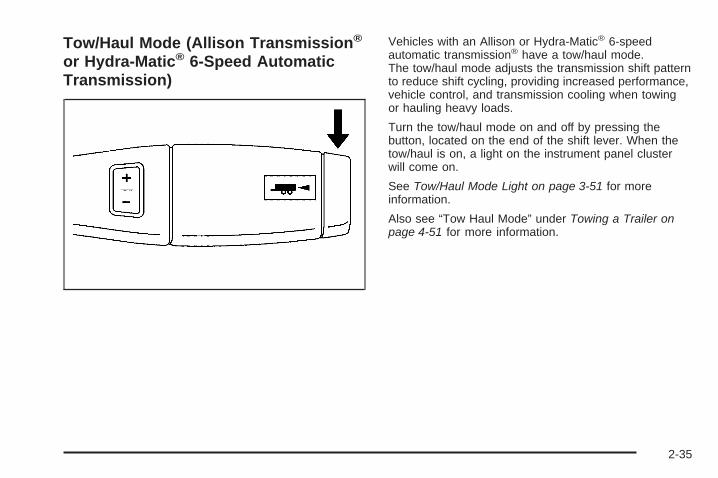
Tow/Haul Mode (Allison Transmission®
or Hydra-Matic® 6-Speed AutomaticTransmission)
Vehicles with an Allison or Hydra-Matic® 6-speedautomatic transmission® have a tow/haul mode.The tow/haul mode adjusts the transmission shift patternto reduce shift cycling, providing increased performance,vehicle control, and transmission cooling when towingor hauling heavy loads.
Turn the tow/haul mode on and off by pressing thebutton, located on the end of the shift lever. When thetow/haul is on, a light on the instrument panel clusterwill come on.
See Tow/Haul Mode Light on page 3-51 for moreinformation.
Also see “Tow Haul Mode” under Towing a Trailer onpage 4-51 for more information.
2-35

Grade Braking (Allison Transmission®
or Hydra-Matic® 6-Speed AutomaticTransmission)The Grade Braking shift modes can be activated bypressing the button on the end of the shift control lever.While in Range Selection Mode, Grade Braking isdeactivated allowing the driver to select a desiredrange of gears.
Grade Braking is only active while the Tow/Haul Mode isselected and you are not in the Range Selection Mode.See “Tow/Haul Mode listed previously and AutomaticTransmission Operation on page 2-28 for moreinformation on the Range Selection Mode. Grade Brakingassists in maintaining desired vehicle speeds whendriving on downhill grades by automatically implementinga shift schedule that utilizes the engine and transmissionto slow the vehicle. This reduces wear on the brakingsystem and increases control of the vehicle. GradeBraking monitors vehicle speed, acceleration, enginetorque and brake pedal usage. Using this information,it detects when the truck is on a downhill grade and thedriver desires to slow the vehicle by pressing the brake.
Also see Towing a Trailer on page 4-51 for moreinformation.
Cruise Grade Braking (AllisonTransmission® or Hydra-Matic®
6-Speed Automatic Transmission)Cruise Grade Braking assists when driving on adownhill grade. It maintains vehicle speed byautomatically implementing a shift schedule thatuses the engine and the transmission to slow thevehicle. Cruise Grade Braking operates while CruiseControl is engaged in Tow/Haul mode to assist inmaintaining vehicle speed under loaded vehicleconditions. It utilizes vehicle acceleration and deviationfrom desired speed to determine the correct gear for theoperating condition. If vehicle speed is above the desiredspeed the transmission will downshift to slow the vehicle.If vehicle speed is near or below desired speed the transwill upshift, allowing vehicle speed to increase.
While in the Range Select Mode (RSM) mode, cruisegrade braking is not available.
See Automatic Transmission Operation on page 2-28.
2-36

Four-Wheel DriveIf the vehicle has Four-Wheel Drive, you can send theengine’s driving power to all four wheels for extra traction.To get the most satisfaction out of Four-Wheel Drive, youmust be familiar with its operation. Read the followingbefore using Four-Wheel Drive. See the appropriatetext for the transfer case in the vehicle.
Notice: Driving on clean, dry pavement inFour-Wheel-Drive High or Four-Wheel-Drive Low foran extended period of time may cause prematurewear on your vehicle’s powertrain. Do not drive onclean, dry pavement in Four-Wheel-Drive High orFour-Wheel-Drive Low for extended periods of time.
While driving on clean dry pavement and during tightturns, you may experience vibration in the steeringsystem.
If the vehicle has StabiliTrak®, shifting intoFour-Wheel-Drive Low will turn Traction Control andStabiliTrak® off. See StabiliTrak® System on page 4-6.
Front AxleThe front axle engages and disengages automaticallywhen you shift the transfer case. Some delay forthe axle to engage or disengage is normal.
Manual Transfer Case
The transfer case shift lever is on the floor to the rightof the driver. Use this lever to shift into and out ofFour-Wheel Drive.
A Four-Wheel Driveindicator light comeson when you shift intofour-wheel drive andthe front axle engages.See Four-Wheel-DriveLight on page 3-51.
2-37

Some delay between shifting and when the indicatorlight comes on is normal.
Recommended Transfer Case Settings
Driving ConditionsTransfer Case Settings
2 m 4 m 4 n N
Normal YES
Severe YES
Extreme YES
Vehicle in Tow* YES
*See Recreational Vehicle Towing on page 4-45Towing Your Vehicle on page 4-45
Notice: Driving on clean, dry pavement infour-wheel drive for an extended period of time cancause premature wear on the vehicle’s powertrain.Do not drive on clean, dry pavement in Four-WheelDrive for extended periods of time.
4 n (Four-Wheel-Drive Low): This setting also engagesthe front axle and delivers extra torque. You may neverneed Four-Wheel-Drive Low. It sends maximum power toall four wheels. You might choose Four-Wheel-Drive Lowif you are driving off-road in deep sand, deep mud, deepsnow, and while climbing or descending steep hills.
If the vehicle has StabiliTrak®, shifting intoFour-Wheel-Drive Low will turn Traction Control andStabiliTrak® off. See StabiliTrak® System on page 4-6.
A parking brake symbolis located next to theN (Neutral) symbol as areminder to set the parkingbrake before shifting thetransfer case intoN (Neutral).
{CAUTION:
Shifting the transfer case to Neutral can causethe vehicle to roll even if the transmission is inP (Park). You or someone else could be seriouslyinjured. Be sure to set the parking brake beforeplacing the transfer case in Neutral. See ParkingBrake on page 2-50.
2-38

N (Neutral): Shift to this setting only when the vehicleneeds to be towed. See Recreational Vehicle Towingon page 4-45 or Towing Your Vehicle on page 4-45.
2 m (Two-Wheel-Drive High): This setting is used fordriving in most street and highway situations. The frontaxle is not engaged in two-wheel drive. This setting alsoprovides the best fuel economy.
4 m (Four-Wheel-Drive High): Use this setting whenyou need extra traction, such as on snowy or icy roadsor in most off-road situations. This setting also engagesthe front axle to help drive your vehicle. This is the bestsetting to use when plowing snow.
You can shift from Two-Wheel-Drive High toFour-Wheel-Drive High or Four-Wheel-Drive High toTwo-Wheel-Drive High while the vehicle is moving.In extremely cold weather, it may be necessary to stopor slow the vehicle to shift into Four-Wheel-Drive High.
When Using the Manual Transfer Case• Shifting should be made using quick motions.
Shifting slowly may make it more difficult to shift.
• You may notice that it is harder to shift when thevehicle is cold. After the vehicle warms up theshifting will return to normal.
• While in Four-Wheel High or Four-Wheel-Drive Lowyou may experience reduced fuel economy.
• Avoid driving in Four-Wheel Drive on clean, drypavement. It may cause your tires to wear faster,make the transfer case harder to shift, and runnoisier.
• If the transfer case shifter is in the N (Neutral)position and you have difficulty reaching the selectedtransfer case mode, with the engine running, shift thetransmission momentarily to drive and then back toN (Neutral). This will realign the gear teeth in thetransfer case and allow you to complete the shift.
2-39

Shifting from Two-Wheel-Drive High toFour-Wheel-Drive High• Shifts between Two-Wheel-Drive High and
Four-Wheel-Drive High can be made at anyvehicle speed.
• Shift the transfer case lever in one continuousmotion into either the Four-Wheel-Drive Highor Two-Wheel-Drive High position.
• In extremely cold weather, it may benecessary to slow or stop the vehicle to shiftinto Four-Wheel-Drive High until the vehiclehas warmed up.
• While in Four-Wheel-Drive High, the vehicle can bedriven at any posted legal speed limit.
Shifting In or Out of Four-Wheel-Drive Low
Notice: Shifting the transfer case intoFour-Wheel-Drive Low while moving at speedsfaster than 3 mph (5 km/h) may cause prematurewear to the transfer case, and may cause the gearsto grind. To avoid causing premature wear, andgrinding the gears, do not shift the transfer caseinto Four-Wheel-Drive Low while the vehicle ismoving faster than 3 mph (5 km/h).
Shifting into Four-Wheel-Drive Low should be done, ifpossible, with the vehicle at a slight roll, 3 mph (5 km/h)or less.• Shift the transmission into N (Neutral).
{CAUTION:
Shifting the transfer case to Neutral can causethe vehicle to roll even if the transmission is inP (Park). You or someone else could be seriouslyinjured. Be sure to set the parking brake beforeplacing the transfer case in Neutral. See ParkingBrake on page 2-50.
• Shifting into Four-Wheel-Drive Low with the vehicleat a stop may be more difficult. You may be unableto complete the shift to Four-Wheel-Drive Low, andthe transfer case will end up in N (Neutral). This isnormal, and is a function of the gear teeth aligning inthe transfer case. When this happens, make sure theengine is on, shift the transmission momentarily toD (Drive) and back to N (Neutral), and then completethe transfer case shift.
• Shift the transfer case shift lever in one continuousmotion into the Four-Wheel-Drive Low position.
• When Four-Wheel-Drive Low do not drive faster than45 mph. This will reduce wear and extend the life ofyour transfer case.
2-40

Shifting In or Out of Neutral
1. With the vehicle running and the engine at an idleset the parking brake.
2. Place the transmission into N (Neutral).
Shift the transfer case in one continuous motion into orout of the N (Neutral) position.
Electronic Transfer Case
The transfer case knob islocated next to thesteering column.
Use the dial to shift into and out of four-wheel drive.
Recommended Transfer Case Settings
Driving ConditionsTransfer Case Settings
2 m 4 m 4 n N
Normal YES
Severe YES
Extreme YES
Vehicle in Tow* YES
*See Recreational Vehicle Towing on page 4-45Towing Your Vehicle on page 4-45
You can choose among four driving settings:
Indicator lights in the dial show which setting you are in.The indicator lights will come on briefly when you turn onthe ignition and one will stay on. If the lights do not comeon, you should take the vehicle to your dealer/retailerfor service. An indicator light flashes while shifting thetransfer case and remains illuminated when the shift iscomplete. If for some reason the transfer case cannotmake a requested shift, it will return to the last chosensetting.
2-41

2 m (Two-Wheel-Drive High): This setting is used fordriving in most street and highway situations. The frontaxle is not engaged in Two-Wheel Drive. This setting alsoprovides the best fuel economy.
4 m (Four-Wheel-Drive High): Use theFour-Wheel-Drive High position when extratraction is needed, such as on snowy or icy roadsor in most off-road situations. This setting also engagesthe front axle to help drive the vehicle. This is the bestsetting to use when plowing snow.
4 n (Four-Wheel-Drive Low): This setting also engagesthe front axle and delivers extra torque. You may neverneed this setting. It sends maximum power to all fourwheels. You might choose Four-Wheel-Drive Low whiledriving off-road in deep sand, deep mud, deep snow, andwhile climbing or descending steep hills.
If the vehicle has StabiliTrak®, shifting intoFour-Wheel-Drive Low will turn Traction Control andStabiliTrak® off. See StabiliTrak® System on page 4-6.
{CAUTION:
Shifting the transfer case to N (Neutral) cancause the vehicle to roll even if the transmissionis in P (Park). You or someone else could beseriously injured. Be sure to set the parking brakebefore placing the transfer case in N (Neutral).See Parking Brake on page 2-50.
N (Neutral): Shift the vehicle’s transfer caseto N (Neutral) only when towing the vehicle.See Recreational Vehicle Towing on page 4-45 orTowing Your Vehicle on page 4-45 for more information.
If the SERVICE 4–Wheel Drive message stays on,you should take the vehicle to your dealer/retailerfor service. See “Service 4–Wheel Drive message”under DIC Warnings and Messages on page 3-66.
2-42

Shifting Into Two-Wheel-Drive HighTurn the knob to the Two-Wheel-Drive High position.This can be done at any speed, except when shiftingfrom Four-Wheel-Drive Low. See Shifting Out ofFour-Wheel-Drive Low for more information.
Shifting Into Four-Wheel Drive LowWhen Four-Wheel-Drive Low is engaged, vehicle speedshould be kept below 45 mph. Extended high-speedoperation in Four-Wheel-Drive Low may damageor shorten the life of the drivetrain.
To shift to the Four-Wheel-Drive Low position, theignition must be in ON/RUN and the vehicle must bestopped or moving less than 3 mph (5 km/h) with thetransmission in N (Neutral). The preferred method forshifting into Four-Wheel-Drive Low is to have the vehiclemoving 1 to 2 mph (1.6 to 3.2 km/h). Turn the knob to theFour-Wheel-Drive Low position. You must wait for theFour-Wheel-Drive Low indicator light to stop flashingand remain on before shifting the transmission in gear.
Notice: Shifting the transmission into gear beforethe requested mode indicator light has stoppedflashing could damage the transfer case. To helpavoid damaging the vehicle, always wait for themode indicator lights to stop flashing beforeshifting the transmission into gear.
It is typical for the vehicle to exhibit significantengagement noise and bump when shifting betweenFour-Wheel-Drive Low and Four-Wheel-Drive Highranges or from transfer case N (Neutral) with theengine running.
If the knob is turned to the Four-Wheel-Drive Lowposition when the vehicle is in gear and/or moving,the Four-Wheel-Drive Low indicator light will flash for30 seconds and not complete the shift unless the vehicleis moving less than 3 mph (5 km/h) and the transmissionis in N (Neutral). After 30 seconds the transfer casewill shift to Four-Wheel-Drive High mode.
2-43

Shifting Out of Four-Wheel-Drive LowTo shift from Four-Wheel-Drive Low toFour-Wheel-Drive High, or Two-Wheel-Drive High,the vehicle must be stopped or moving less than3 mph (5 km/h) with the transmission in N (Neutral)and the ignition in ON/RUN. The preferred method forshifting out of Four-Wheel-Drive Low is to have thevehicle moving 1 to 2 mph (1.6 to 3.2 km/h). Turn theknob to the Four-Wheel-Drive High, or Two-Wheel-DriveHigh position. You must wait for the Four-Wheel-DriveHigh, or Two-Wheel-Drive High indicator light to stopflashing and remain on before shifting the transmissioninto gear.
Notice: Shifting the transmission into gear beforethe requested mode indicator light has stoppedflashing could damage the transfer case. To helpavoid damaging the vehicle, always wait for themode indicator lights to stop flashing before shiftingthe transmission into gear.
It is typical for the vehicle to exhibit significantengagement noise and bump when shifting betweenFour-Wheel-Drive Low and Four-Wheel-Drive Highranges or from transfer case N (Neutral) with theengine running.
If the knob is turned to the Four-Wheel-Drive High,or Two-Wheel-Drive High switch position when thevehicle is in gear and/or moving, the Four-Wheel-DriveHigh, or Two-Wheel-Drive High indicator light will flashfor 30 seconds but will not complete the shift unless yourvehicle is moving less than 3 mph (5 km/h) and thetransmission is in N (Neutral).
2-44

Shifting into NeutralTo shift the transfer case to N (Neutral) do the following:
1. Make sure the vehicle is parked so that it will not roll.
2. Set the parking brake and press and hold theregular brake pedal. See Parking Brake onpage 2-50 for more information.
3. Start the vehicle or turn the ignition to ON/RUN.
4. Shift the transmission to N (Neutral).
5. Shift the transfer case to Two-Wheel-Drive High.
6. Turn the transfer case dial clockwise to N (Neutral)until it stops and hold it there until the Neutral lightstarts blinking. This will take at least 10 seconds.Then slowly release the dial to the four low position.The N (Neutral) light will come on when the transfercase shift to N (Neutral) is complete.
7. If the engine is running, verify that the transfercase is in N (Neutral) by shifting the transmissionto R (Reverse) for one second, then shift thetransmission to D (Drive) for one second.
8. Turn the ignition to ACC/ACCESSORY, which willturn the engine off.
9. Place the transmission shift lever in P (Park).
10. Release the parking brake prior to moving thevehicle.
11. Turn the ignition to LOCK/OFF.
Shifting Out of NeutralTo shift the transfer case out of N (Neutral) do thefollowing:
1. Set the parking brake and apply the regularbrake pedal.
2. Turn the ignition to ON/RUN with the engine off,and shift the transmission to N (Neutral).
3. Turn the transfer case dial to Two-Wheel-Drive High.After the transfer case has shifted out of N (Neutral),the N (Neutral) light will go out.
4. Release the parking brake prior to moving thevehicle.
Notice: Shifting the transmission into gear beforethe requested mode indicator light has stoppedflashing could damage the transfer case. To helpavoid damaging the vehicle, always wait for the modeindicator lights to stop flashing before shifting thetransmission into gear.
5. Start the engine and shift the transmission to thedesired position.
Excessively shifting the transfer case into or out of thedifferent modes may cause the transfer case to enter theshift protection mode. This will protect the transfer casefrom possible damage and will only allow the transfercase to respond to one shift per 10 seconds. The transfercase may stay in this mode for up to three minutes.
2-45

Automatic Transfer Case
The transfer case knobis located next to thesteering column.
Use the dial to shift into and out of Four-Wheel Drive.
You can choose among five driving settings:
Indicator lights in the dial show which setting you are in.The indicator lights will come on briefly when you turn onthe ignition and one will stay on. If the lights do not comeon, you should take the vehicle to your dealer/retailer forservice. An indicator light will flash while shifting thetransfer case. It will remain illuminated when the shift iscomplete. If for some reason the transfer case cannotmake a requested shift, it will return to the last chosensetting.
2 m (Two-Wheel-Drive High): This setting is used fordriving in most street and highway situations. The frontaxle is not engaged in Two-Wheel Drive. This setting alsoprovides the best fuel economy.
AUTO (Automatic Four-Wheel Drive): This setting isideal for use when road surface traction conditions arevariable. When driving the vehicle in AUTO, the front axleis engaged, but the vehicle’s power is sent only to thefront and rear wheels automatically based on drivingconditions. Driving in this mode results in slightly lowerfuel economy than Two-Wheel-Drive High.
4 m (Four-Wheel-Drive High): Use theFour-Wheel-Drive High position when extra tractionis needed, such as on snowy or icy roads or in mostoff-road situations. This setting also engages the frontaxle to help drive the vehicle. This is the best setting touse when plowing snow.
4 n (Four-Wheel-Drive Low): This setting also engagesthe front axle and delivers extra torque. You may neverneed this setting. It sends maximum power to all fourwheels. You might choose Four-Wheel-Drive Low if youare driving off-road in deep sand, deep mud, deep snow,and while climbing or descending steep hills.
2-46

If the vehicle has StabiliTrak®, shifting intoFour-Wheel-Drive Low will turn Traction Control andStabiliTrak® off. See StabiliTrak® System on page 4-6.
{CAUTION:
Shifting the transfer case to N (Neutral) cancause the vehicle to roll even if the transmissionis in P (Park). You or someone else could beseriously injured. Be sure to set the parking brakebefore placing the transfer case in N (Neutral).See Parking Brake on page 2-50.
N (Neutral): Shift the vehicle’s transfer caseto N (Neutral) only when towing the vehicle. SeeRecreational Vehicle Towing on page 4-45 or TowingYour Vehicle on page 4-45 for more information.
If the SERVICE 4-Wheel Drive message stays on,you should take the vehicle to your dealer/retailerfor service. See “Service 4-Wheel Drive message”under DIC Warnings and Messages on page 3-66.
Shifting Into Four-Wheel-Drive Highor AUTO (Automatic Four-Wheel Drive)Turn the knob to the Four-Wheel-Drive High or AUTOposition. This can be done at any speed, except whenshifting from Four-Wheel-Drive Low. The indicator lightwill flash while shifting. It will remain on when the shift iscompleted.
Shifting Into Two-Wheel-Drive HighTurn the knob to the Two-Wheel-Drive High position.This can be done at any speed, except when shiftingfrom Four-Wheel-Drive Low. The indicator light willflash while shifting. It will remain on when the shiftis completed.
2-47

Shifting Into Four-Wheel-Drive LowWhen Four-Wheel-Drive Low is engaged, vehicle speedshould be kept below 45 mph. Extended high-speedoperation in Four-Wheel-Drive Low may damageor shorten the life of the drivetrain.
To shift to the Four-Wheel-Drive Low position, theignition must be in ON/RUN and the vehicle must bestopped or moving less than 3 mph (5 km/h) with thetransmission in N (Neutral). The preferred method forshifting into Four-Wheel-Drive Low is to have the vehiclemoving 1 to 2 mph (1.6 to 3.2 km/h). Turn the knob to theFour-Wheel-Drive Low position. You must wait for theFour-Wheel-Drive Low indicator light to stop flashing andremain on before shifting the transmission into gear.
Notice: Shifting the transmission into gear beforethe requested mode indicator light has stoppedflashing could damage the transfer case. To helpavoid damaging the vehicle, always wait for themode indicator lights to stop flashing beforeshifting the transmission into gear.
It is typical for the vehicle to exhibit significantengagement noise and bump when shifting betweenFour-Wheel-Drive Low and Four-Wheel-Drive Highranges or from N (Neutral) with the engine running.
If the knob is turned to the Four-Wheel-Drive Lowposition when the vehicle is in gear and/or moving,the Four-Wheel-Drive Low indicator light will flash for30 seconds and not complete the shift unless the vehicleis moving less than 3 mph (5 km/h) and the transmissionis in N (Neutral). After 30 seconds the transfer casewill shift to Four-Wheel-Drive High mode.
Shifting Out of Four-Wheel-Drive LowTo shift from Four-Wheel-Drive Low toFour-Wheel-Drive High, AUTO or Two-Wheel-DriveHigh, the vehicle must be stopped or moving less than3 mph (5 km/h) with the transmission in N (Neutral) andthe ignition in ON/RUN. The preferred method for shiftingout of Four-Wheel-Drive Low is to have the vehiclemoving 1 to 2 mph (1.6 to 3.2 km/h). Turn the knob to theFour-Wheel-Drive High, AUTO or Two-Wheel-Drive Highposition. You must wait for the Four-Wheel-Drive High,AUTO or Two-Wheel-Drive High indicator light to stopflashing and remain on before shifting the transmissioninto gear.
2-48

Notice: Shifting the transmission into gear beforethe requested mode indicator light has stoppedflashing could damage the transfer case. To helpavoid damaging the vehicle, always wait for themode indicator lights to stop flashing before shiftingthe transmission into gear.
It is typical for the vehicle to exhibit significantengagement noise and bump when shifting betweenFour-Wheel-Drive Low and Four-Wheel-Drive Highranges or from N (Neutral) with the engine running.
If the knob is turned to the Four-Wheel-DriveHigh, AUTO, or Two-Wheel-Drive High switchposition when the vehicle is in gear and/or moving,the Four-Wheel-Drive High, AUTO or Two-Wheel-DriveHigh indicator light will flash for 30 seconds but will notcomplete the shift unless the vehicle is moving less than3 mph (5 km/h) and the transmission is in N (Neutral).
Shifting into NeutralTo shift the transfer case to N (Neutral) do the following:
1. Make sure the vehicle is parked so that it will not roll.
2. Set the parking brake and apply the regular brakepedal. See Parking Brake on page 2-50 for moreinformation.
3. Start the vehicle or turn the ignition to ON/RUN.
4. Put the transmission in N (Neutral).
5. Shift the transfer case to Two-Wheel Drive High.
6. Turn the transfer case dial clockwise to N (Neutral)until it stops and hold it there until the N (Neutral)light starts blinking. This will take at least10 seconds. Then slowly release the dial to thefour low position. The N (Neutral) light will comeon when the transfer case shift to N (Neutral) iscomplete.
7. If the engine is running, make sure that the transfercase is in N (Neutral) by shifting the transmissionto R (Reverse) for one second, then shift thetransmission to D (Drive) for one second.
8. Turn the ignition to ACC/ACCESSORY, which willturn the engine off.
9. Place the transmission shift lever in P (Park).
10. Release the parking brake prior to moving thevehicle.
11. Turn the ignition to LOCK/OFF.
2-49

Shifting Out of NeutralTo shift out of N (Neutral) do the following:
1. Set the parking brake and apply the regularbrake pedal.
2. Turn the ignition to ON/RUN with the engine off,and shift the transmission to N (Neutral).
3. Turn the transfer case dial to Two-Wheel-DriveHigh, Four-Wheel-Drive High, AUTO.After the transfer case has shifted out of N (Neutral),the N (Neutral) light will go out.
4. Release the parking brake prior to moving thevehicle.
Notice: Shifting the transmission into gear beforethe requested mode indicator light has stoppedflashing could damage the transfer case. To helpavoid damaging the vehicle, always wait for themode indicator lights to stop flashing beforeshifting the transmission into gear.
5. Start the engine and shift the transmission to thedesired position.
Parking Brake
For vehicles with a release handle, set the parkingbrake by holding the regular brake pedal down, thenpushing down the parking brake pedal.If the ignition is on, the brake system warning light willcome on. See Brake System Warning Light on page 3-42.A chime sounds and the warning light flashes whenthe parking brake is applied and the vehicle is movingat least 5 mph (8 km/h).To release the parking brake, hold the regular brakepedal down. Then pull the bottom edge of the lever withthe parking brake symbol, located above the parkingbrake pedal.
2-50

If the ignition is on when the parking brake is released,the brake system warning light goes off.
Notice: Driving with the parking brake on canoverheat the brake system and cause prematurewear or damage to brake system parts. Make surethat the parking brake is fully released and the brakewarning light is off before driving.
If you are towing a trailer and are parking on any hill,see Towing a Trailer on page 4-51.
For vehicles without a release handle, set the parkingbrake by holding the regular brake pedal down, thenpushing down the parking brake pedal.
If the ignition is on, the brake system warning light willcome on. See Brake System Warning Light on page 3-42.
Notice: Driving with the parking brake on canoverheat the brake system and cause prematurewear or damage to brake system parts. Make surethat the parking brake is fully released and the brakewarning light is off before driving.
To release the parking brake, hold the regular brakepedal down, then push down momentarily on the parkingbrake pedal until you feel the pedal release. Slowly pullyour foot up off the park brake pedal. If the parking brakeis not released when you begin to drive, the brake systemwarning light will flash and a chime will sound warningyou that the parking brake is still on.
If you are towing a trailer and are parking on a hill,see Towing a Trailer on page 4-51.
2-51

Shifting Into Park
{CAUTION:
It can be dangerous to get out of the vehicle if theshift lever is not fully in P (Park) with the parkingbrake firmly set. The vehicle can roll. If you have leftthe engine running, the vehicle can move suddenly.You or others could be injured. To be sure thevehicle will not move, even when you are on fairlylevel ground, use the steps that follow. Withfour-wheel drive, if the transfer case is in Neutral,the vehicle will be free to roll, even if the shift leveris in P (Park). So, be sure the transfer case is in adrive gear — not in Neutral. If you are pulling atrailer, see Towing a Trailer on page 4-51.
1. Hold the brake pedal down, then set theparking brake.See Parking Brake on page 2-50 for moreinformation.
2. Move the shift lever into the P (Park) position bypulling the shift lever toward you and moving it upas far as it will go.
3. Be sure the transfer case is in a drive gear — notin N (Neutral).
4. Turn the ignition key to LOCK/OFF.
5. Remove the key and take it with you. If you canleave the vehicle with the ignition key in yourhand, the vehicle is in P (Park).
2-52

Leaving the Vehicle With the EngineRunning
{CAUTION:
It can be dangerous to leave the vehicle with theengine running. The vehicle could move suddenlyif the shift lever is not fully in P (Park) with theparking brake firmly set.
If you have four-wheel drive and the transfer caseis in Neutral, the vehicle will be free to roll, evenif the shift lever is in P (Park). So be sure thetransfer case is in a drive gear — not in Neutral.
And, if you leave the vehicle with the enginerunning, it could overheat and even catch fire.You or others could be injured. Do not leavethe vehicle with the engine running unless youhave to.
If you have to leave the vehicle with the engine running,be sure your vehicle is in P (Park) and the parking brakeis firmly set before you leave it. After you move the shiftlever into P (Park), hold the regular brake pedal down.Then, see if you can move the shift lever away fromP (Park) without first pulling it toward you. If you can,it means that the shift lever was not fully locked intoP (Park).
Torque LockIf you are parking on a hill and you do not shift yourtransmission into P (Park) properly, the weight of thevehicle may put too much force on the parking pawl inthe transmission. You may find it difficult to pull the shiftlever out of P (Park). This is called torque lock. Toprevent torque lock, set the parking brake and then shiftinto P (Park) properly before you leave the driver seat.To find out how, see Shifting Into Park on page 2-52.
When you are ready to drive, move the shift lever out ofP (Park) before you release the parking brake.
If torque lock does occur, you may need to haveanother vehicle push yours a little uphill to take some ofthe pressure from the parking pawl in the transmission,then you will be able to pull the shift lever out of P (Park).
2-53

Shifting Out of ParkThis vehicle is equipped with an electronic shift lockrelease system. The shift lock release is designed to:
• Prevent ignition key removal unless the shiftlever is in P (Park) with the shift lever button fullyreleased, and
• Prevent movement of the shift lever out ofP (Park), unless the ignition is in ON/RUN orACC/ACCESSORY and the regular brake pedalis applied.
The shift lock release is always functional except in thecase of an uncharged or low voltage (less than 9 volt)battery.
If the vehicle has an uncharged battery or a battery withlow voltage, try charging or jump starting the battery.See Jump Starting on page 5-44 for more information.
To shift out of P (Park) use the following:
1. Apply the brake pedal.
2. Move the shift lever to the desired position.
If you still are unable to shift out of P (Park):
1. Ease the pressure on the shift lever.
2. While holding down the brake pedal, press the shiftlever all the way into P (Park).
3. Move the shift lever to the desired position.
If you are still having a problem shifting, then have thevehicle serviced soon.
Parking Over Things That Burn
{CAUTION:
Things that can burn could touch hot exhaustparts under the vehicle and ignite. Do not parkover papers, leaves, dry grass, or other things thatcan burn.
2-54

Engine Exhaust
{CAUTION:
Engine exhaust contains Carbon Monoxide (CO)which cannot be seen or smelled. Exposure to COcan cause unconsciousness and even death.
Exhaust may enter the vehicle if:• The vehicle idles in areas with poor ventilation
(parking garages, tunnels, deep snow thatmay block underbody airflow or tail pipes).
• The exhaust smells or sounds strange ordifferent.
• The exhaust system leaks due to corrosion ordamage.
CAUTION: (Continued)
CAUTION: (Continued)
• The vehicle’s exhaust system has beenmodified, damaged or improperly repaired.
• There are holes or openings in thevehicle body from damage or after-marketmodifications that are not completely sealed.
If unusual fumes are detected or if it is suspectedthat exhaust is coming into the vehicle:
• Drive it only with the windows completely down.• Have the vehicle repaired immediately.
Never park the vehicle with the engine running in anenclosed area such as a garage or a building thathas no fresh air ventilation.
2-55

Running the Vehicle While ParkedIt is better not to park with the engine running. But if youever have to, here are some things to know.
{CAUTION:
Idling a vehicle in an enclosed area with poorventilation is dangerous. Engine exhaust mayenter the vehicle. Engine exhaust contains CarbonMonoxide (CO) which cannot be seen or smelled.It can cause unconsciousness and even death.Never run the engine in an enclosed area thathas no fresh air ventilation. For more information,see Engine Exhaust on page 2-55.
{CAUTION:
It can be dangerous to get out of the vehicle ifthe automatic transmission shift lever is not fullyin P (Park) with the parking brake firmly set.
CAUTION: (Continued)
CAUTION: (Continued)
The vehicle can roll. Do not leave the vehiclewhen the engine is running unless you have to.If you have left the engine running, the vehicle canmove suddenly. You or others could be injured.To be sure the vehicle will not move, even whenyou are on fairly level ground, always set theparking brake and move the shift lever to P (Park).
{CAUTION:
Four-wheel drive vehicles with the transfer case inN (Neutral) will allow the vehicle to roll, even if theautomatic transmission shift lever is in P (Park). So,be sure the transfer case is in a drive gear — not inN (Neutral). Always set the parking brake.
Follow the proper steps to be sure the vehicle will notmove. See Shifting Into Park on page 2-52.
If pulling a trailer, see Towing a Trailer on page 4-51.
2-56

Mirrors
Manual Rearview MirrorHold the inside rearview mirror in the center to move itfor a clearer view behind your vehicle. Adjust the mirror toavoid glare from the headlamps behind you. Push the tabforward for daytime use and pull it for nighttime use.
Automatic Dimming Rearview MirrorThe vehicle may have an automatic dimming insiderearview mirror.
Vehicles with OnStar® have three additional controlbuttons for the OnStar® system. See your dealer/retailerfor more information about OnStar® and how to subscribeto it. See OnStar® System on page 2-71 for moreinformation about the services OnStar® provides.
O (On/Off): Press to turn the dimming featureon or off.
The vehicle may also have a Rear VisionCamera (RVC). See Rear Vision Camera (RVC)on page 2-65 for more information.
If the vehicle has RVC, the O (On/Off) button forturning the automatic dimming feature on or off willnot be available.
Automatic Dimming Mirror OperationAutomatic dimming reduces the glare from theheadlamps of the vehicle behind you. The dimmingfeature comes on and the indicator light illuminateseach time the ignition is turned to start.
Cleaning the MirrorDo not spray glass cleaner directly on the mirror.Use a soft towel dampened with water.
2-57

Outside Manual MirrorsAdjust the outside mirrors to see the side of the vehicleand have a clear view of objects behind you.
Manually fold the mirrors inward to prevent damagewhen going through an automatic car wash. To fold, pushthe mirror toward the vehicle. Push the mirror outward, toreturn to its original position.
Using hood-mounted air deflectors and add-on convexmirror attachments could decrease mirror performance.
Outside Towing Mirrors
If the vehicle has towing mirrors, they can be adjustedfor a clearer view of the objects behind you. Manuallypull out the mirror head to extend it for better visibilitywhen towing a trailer.
Manually fold the mirrors forward or rearward. The lowerportion of the mirror is convex. A convex mirror’s surfaceis curved to see more from the driver seat. The convexmirror can be adjusted manually to the driver preferredposition for better vision.
The mirror may have a turn signal arrow that flashes inthe direction of the turn or lane change.
2-58

Outside Power MirrorsVehicles with outsidepower mirrors havecontrols located on thedriver door armrest.
To adjust each mirror:
1. Press (A) or (B) to select the driver or passengerside mirror.
2. Press one of the four arrows located on the controlpad to adjust the mirror.
3. Adjust each outside mirror to see a little of thevehicle, and the area behind your vehicle.
4. Press either (A) or (B) again to deselect the mirror.
Manually fold the mirrors inward to prevent damagewhen going through an automatic car wash. To fold, pushthe mirror toward the vehicle. Push the mirror outward, toreturn to its original position.
Outside Power Foldaway MirrorsVehicles with outsidepower foldaway mirrorshave controls locatedon the driver door armrest.
Mirror Adjustment1. Press (C) to fold the mirrors out to the driving
position.
2. Press (D) to fold the mirrors in to the foldedposition.
2-59
Resetting the Power Foldaway MirrorsReset the power foldaway mirrors if:
• The mirrors are accidentally obstructed whilefolding.
• They are accidentally manually folded/unfolded.
• The mirrors will not stay in the unfolded position.
• The mirrors vibrate at normal driving speeds.
To reset the power foldaway mirrors, fold and unfoldthem one time using the mirror controls. This will resetthem to their normal position.
Automatic DimmingThe driver outside mirror adjusts for the glare of theheadlamps behind you. See Automatic DimmingRearview Mirror on page 2-57 for more information.
Turn Signal IndicatorThe vehicle may also have a turn signal indicator on themirror. An arrow on the mirror flashes in the directionof the turn or lane change.
Park Tilt MirrorsIf the vehicle has the memory package, the passengerand/or driver mirror tilts to a preselected position whenthe vehicle is in R (Reverse). This feature lets the driverview the curb when parallel parking. The mirror(s) returnto the original position when the vehicle is shifted out ofR (Reverse), or the ignition is turned off or to OFF/LOCK.
Turn this feature on or off through the Driver InformationCenter (DIC). See DIC Vehicle Customization (WithDIC Buttons) on page 3-76 for more information.
2-60

Outside Convex Mirror
{CAUTION:
A convex mirror can make things (like othervehicles) look farther away than they really are.If you cut too sharply into the right lane, youcould hit a vehicle on the right. Check the insidemirror or glance over your shoulder beforechanging lanes.
The passenger side mirror is convex shaped. A convexmirror’s surface is curved so more can be seen fromthe driver seat.
Outside Heated MirrorsFor vehicles with heated mirrors:
< (Rear Window Defogger): Press to heat themirrors. Only the upper glass of the mirror is heated.The lower convex part of the mirror is not heated.Depending on the vehicle’s features, see “Rear WindowDefogger” under, Climate Control System (With HeaterOnly) on page 3-24 or Climate Control System (With AirConditioning) on page 3-25 or Dual Automatic ClimateControl System on page 3-27 for more information.
2-61

Object Detection Systems
Ultrasonic Rear ParkingAssist (URPA)For vehicles with the Ultrasonic Rear Parking Assist(URPA) system, it operates at speeds less than 5 mph(8 km/h), and assists the driver with parking and avoidingobjects while in R (Reverse). The sensors on the rearbumper are used to detect the distance to an object up to8 feet (2.5 m) behind the vehicle, and at least 10 inches(25.4 cm) off the ground.
{CAUTION:
The Ultrasonic Rear Parking Assist (URPA)system does not replace driver vision. It cannotdetect:
• objects that are below the bumper, underneaththe vehicle, or if they are too close or far fromthe vehicle
• children, pedestrians, bicyclists, or pets.
CAUTION: (Continued)
CAUTION: (Continued)
If you do not use proper care before and whilebacking; vehicle damage, injury, or death couldoccur. Even with URPA, always check behind thevehicle before backing up. While backing, be sureto look for objects and check the vehicle’s mirrors.
The display is located nearthe passenger side rearwindow and can be seenby looking over your rightshoulder.
URPA uses three color-coded lights to provide distanceand system information.
2-62

How the System WorksURPA comes on automatically when the shift leveris moved into R (Reverse). The rear display brieflyilluminates to indicate the system is working.
URPA operates only at speeds less than 5 mph(8 km/h). If the vehicle is above this speed, the red lighton the rear display will flash.
To be detected, objects must be at least 10 inches(25.4 cm) off the ground and below tailgate level.Objects must also be within 8 feet (2.5 m) from therear bumper. This distance may be less during warmeror humid weather.
A single beep will sound the first time an object isdetected between 40 inches (1 m) and 8 feet (2.5 m)away. Beeping will occur continuously when the vehicleis at 23 inches (0.6 m) or closer to an object.
The following describes what will occur with the URPAdisplay as the vehicle gets closer to a detected object:
Description English Metricamber light 8 ft 2.5 m
amber/amber lights 40 in 1.0 mamber/amber/red lightsand continuous beeping
for five seconds23 in 0.6 m
amber/amber/red lightsflashing and continuousbeeping for five seconds
1 ft 0.3 m
The system can bedisabled by pressing therear park aid disable buttonlocated next to the radio.
2-63
The indicator light will come on and PARK ASSISTOFF displays on the Driver Information Center (DIC)to indicate that URPA is off, see DIC Warnings andMessages on page 3-66 for information about clearingthe message.
Notice: If you use URPA while the tailgate islowered, it may not detect an object behind yourvehicle, and you might back into the object anddamage your vehicle. Always verify the tailgate isclosed when using URPA or turn off URPA whendriving with the tailgate lowered.
When the System Does Not Seem toWork ProperlyIf the URPA system will not activate due to a temporarycondition, the message PARK ASSIST OFF will bedisplayed on the DIC and a red light will be shown onthe rear URPA display when the shift lever is moved intoR (Reverse). This occurs under the following conditions:
• The driver disables the system.
• The ultrasonic sensors are not clean. Keep thevehicle’s rear bumper free of mud, dirt, snow,ice and slush. For cleaning instructions, seeWashing Your Vehicle on page 5-117.
• A trailer was attached to the vehicle, or a bicycle oran object was hanging out of the tailgate during thelast drive cycle, the red light may illuminate in therear display. Once the attached object is removed,URPA will return to normal operation.
• A tow bar is attached to the vehicle.
• The vehicle’s bumper is damaged. Take the vehicleto your dealer/retailer to repair the system.
• Other conditions may affect system performance,such as vibrations from a jackhammer or thecompression of air brakes on a very large truck.
If the system is still disabled, after driving forwardat least 15 mph (25 km/h), take the vehicle to yourdealer/retailer.
2-64

Rear Vision Camera (RVC)This vehicle may have a Rear Vision Camera system.Read this entire section before using it.
{CAUTION:
The Rear Vision Camera (RVC) system does notreplace driver vision. RVC does not:
• Detect objects that are outside the camera’sfield of view, below the bumper, or underneaththe vehicle.
• Detect children, pedestrians, bicyclists, or pets.
Do not back the vehicle by only looking at the rearvision camera screen, or use the screen duringlonger, higher speed backing maneuvers or wherethere could be cross-traffic. Your judged distancesusing the screen will differ from actual distances.
So if you do not use proper care before backing up,you could hit a vehicle, child, pedestrian, bicyclist,or pet, resulting in vehicle damage, injury, or death.Even though the vehicle has the RVC system,always check carefully before backing up bychecking behind and around the vehicle.
Vehicles Without Navigation SystemThe rear vision camera system is designed to help thedriver when backing up by displaying a view of the areabehind the vehicle. When the key is in the ON/RUNposition and the driver shifts the vehicle into R (Reverse),the video image automatically appears on the inside rearview mirror. Once the driver shifts out of R (Reverse), thevideo image automatically disappears from the insiderear view mirror.
Turning the Rear Vision Camera SystemOff or OnTo turn off the rear vision camera system, press andhold z, located on the inside rearview mirror, until theleft indicator light turns off. The rear camera visiondisplay is now disabled.
To turn the rear vision camera system on again, pressand hold z until the left indicator light illuminates.The rear vision camera system display is now enabledand the display will appear in the mirror normally.
2-65

Vehicles With Navigation SystemThe rear vision camera system is designed to help thedriver when backing up by displaying a view of the areabehind the vehicle. When the driver shifts the vehicleinto R (Reverse), the video image automatically appearson the navigation screen. Once the driver shifts out ofR (Reverse), the navigation screen will go back to thelast screen that had been displayed, after a delay.
Turning the Rear Vision Camera SystemOn or OffTo turn the rear vision camera system on or off:
1. Shift into P (Park).
2. Press the MENU button to enter the configuremenu options, then press the MENU hard keyto select Display or touch the Display screen button.
3. Select the Rear Camera Options screen button.The Rear Camera Options screen will display.
4. Select the Video screen button. When the Videoscreen button is highlighted the RVC system is on.
The delay that is received after shifting out ofR (Reverse) is approximately 10 seconds. The delaycan be cancelled by performing one of the following:
• Pressing a hard key on the navigation system.
• Shifting in to P (Park).
• Reach a vehicle speed of 5 mph (8 km/h).
There is a message on the rear vision camera screenthat states “Check Surroundings for Safety”.
2-66

Adjusting the Brightness and Contrast ofthe ScreenTo adjust the brightness and contrast of the screen,press the MENU button while the rear vision cameraimage is on the display. Any adjustments made will onlyaffect the rear vision camera screen.
] (Brightness): Touch the + (plus) or – (minus)screen buttons to increase or decrease the brightnessof the screen.
_ (Contrast): Touch the + (plus) or – (minus) screenbuttons to increase or decrease the contrast of thescreen.
SymbolsThe navigation system may have a feature that lets thedriver view symbols on the navigation screen while usingthe rear vision camera. The Ultrasonic Rear Park Assist(URPA) system must not be disabled to use the cautionsymbols. If URPA has been disabled and the symbolshave been turned on, the Rear Parking Assist SymbolsUnavailable error message may display. See UltrasonicRear Parking Assist (URPA) on page 2-62.
The symbols appear when an object has been detectedby the URPA system. The symbol may cover theobject when viewing the navigation screen.
To turn the symbols on or off:
1. Make sure that URPA has not been disabled.
2. Shift into P (Park).
3. Press the MENU hard key to enter the configuremenu options, then press the MENU hard keyrepeatedly until Display is selected or touchthe Display screen button.
4. Select the Rear Camera Options screen button.The Rear Camera Options screen will display.
5. Touch the Symbols screen button. The screenbutton will be highlighted when on.
Rear Vision Camera Error Messages
Service Rear Vision Camera System: This messagecan display when the system is not receiving informationit requires from other vehicle systems.
If any other problem occurs or if a problem persists, seeyour dealer/retailer.
2-67

Rear Vision Camera Location
The image is provided by the camera located in thebezel for the tailgate handle.The camera uses a special lens. The distance of theimage that appears on the screen differs from the actualdistance. The area displayed by the camera is limited.The camera does not display objects which are closeto either corner of the bumper or under the bumper.The area displayed on the screen can vary accordingto vehicle orientation or road conditions.The following illustration shows the field of view that thecamera provides.
2-68
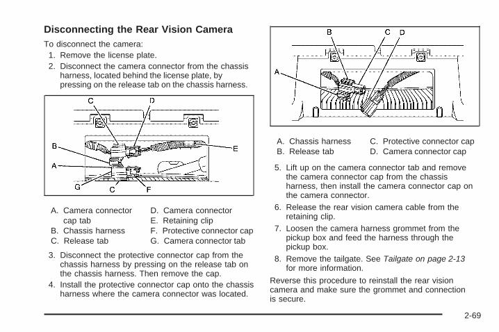
Disconnecting the Rear Vision CameraTo disconnect the camera:1. Remove the license plate.2. Disconnect the camera connector from the chassis
harness, located behind the license plate, bypressing on the release tab on the chassis harness.
A. Camera connectorcap tab
B. Chassis harnessC. Release tab
D. Camera connectorE. Retaining clipF. Protective connector capG. Camera connector tab
3. Disconnect the protective connector cap from thechassis harness by pressing on the release tab onthe chassis harness. Then remove the cap.
4. Install the protective connector cap onto the chassisharness where the camera connector was located.
A. Chassis harnessB. Release tab
C. Protective connector capD. Camera connector cap
5. Lift up on the camera connector tab and removethe camera connector cap from the chassisharness, then install the camera connector cap onthe camera connector.
6. Release the rear vision camera cable from theretaining clip.
7. Loosen the camera harness grommet from thepickup box and feed the harness through thepickup box.
8. Remove the tailgate. See Tailgate on page 2-13for more information.
Reverse this procedure to reinstall the rear visioncamera and make sure the grommet and connectionis secure.
2-69

When the System Does Not Seem ToWork ProperlyThe rear vision camera system might not work properlyor display a clear image if:
• The RVC is turned off. See “Turning the RearCamera System On or Off” earlier in this section.
• It is dark.
• The sun or the beam of headlights is shiningdirectly into the camera lens.
• Ice, snow, mud, or anything else builds up on thecamera lens. Clean the lens, rinse it with water,and wipe it with a soft cloth.
• The back of the vehicle is in an accident, theposition and mounting angle of the cameracan change or the camera can be affected.Be sure to have the camera and its position andmounting angle checked at your dealer/retailer.
• There are extreme temperature changes.
The rear vision camera system display in the rearviewmirror may turn off or not appear as expected due toone of the following conditions. If this occurs theleft indicator light on the mirror will flash.
• A slow flash may indicate a loss of video signal, orno video signal present during the reverse cycle.
• A fast flash may indicate that the display has beenon for the maximum allowable time during a reversecycle, or the display has reached an OverTemperature limit.
The fast flash conditions are used to protect thevideo device from high temperature conditions.Once conditions return to normal the device willreset and the green indicator will stop flashing.
During any of these fault conditions, the display will beblank and the indicator will continue to flash as longas the vehicle is in R (Reverse) or until the conditionsreturn to normal.
Pressing and holding z when the left indicator light isflashing will turn off the video display along with theleft indicator light.
2-70

OnStar® System
OnStar uses several innovative technologies and liveadvisors to provide a wide range of safety, security,information, and convenience services. If the airbagsdeploy, the system is designed to make an automaticcall to OnStar Emergency advisors who can requestemergency services be sent to your location. If the keysare locked in the vehicle, call OnStar at 1-888-4-ONSTARto have a signal sent to unlock the doors. OnStarHands-Free Calling, including 30 trial minutes goodfor 60 days, is available on most vehicles. OnStarTurn-by-Turn Navigation service, with one trial route,is available on most vehicles. Press the OnStar buttonto have an OnStar advisor contact Roadside Service.
OnStar service is provided subject to the OnStar Termsand Conditions included in the OnStar Subscriberglove box literature.
Some services such as Remote Door Unlock or StolenVehicle Location Assistance may not be available untilthe owner of the vehicle registers with OnStar. After thefirst prepaid year, contact OnStar to select a monthly orannual subscription payment plan. If a payment planis not selected, the OnStar system and all services,including airbag notification and emergency services,may be deactivated and no longer available. For moreinformation visit onstar.com (U.S.) or onstar.ca (Canada),or press the OnStar button to speak with an advisor.
Not all OnStar services are available on all vehicles.To check if this vehicle is able to provide the servicesdescribed below, or for a full description of OnStarservices and system limitations, see the OnStar Owner’sGuide in the glove box or visit onstar.com (U.S.) oronstar.ca (Canada), contact OnStar at 1-888-4-ONSTAR(1-888-466-7827) or TTY 1-877-248-2080, or press theOnStar button to speak with an OnStar advisor 24 hoursa day, 7 days a week.
2-71
OnStar Services Available with theSafe & Sound Plan• Automatic Notification of Airbag Deployment
• Advanced Automatic Crash Notification (AACN)(If equipped)
• Link to Emergency Services
• Roadside Assistance
• Stolen Vehicle Location Assistance
• Remote Door Unlock/Vehicle Alert
• OnStar Vehicle Diagnostic Email
• GM Goodwrench On Demand Diagnostics
• OnStar Hands-Free Calling with 30 trial minutes
• OnStar Virtual Advisor (U.S. Only)
OnStar Services Included withDirections & Connections Plan• All Safe and Sound Plan Services
• OnStar Turn-by-Turn Navigation (If equipped) orDriving Directions - Advisor delivered
• RideAssist
• Information and Convenience Services
OnStar Hands-Free CallingOnStar Hands-Free Calling allows eligible OnStarsubscribers to make and receive calls using voicecommands. Hands-Free Calling is fully integrated intothe vehicle, and can be used with OnStar Pre-PaidMinute Packages. Most vehicles include 30 trial minutesgood for 60 days. Hands-Free Calling can also belinked to a Verizon Wireless service plan in the U.S. ora Bell Mobility service plan in Canada, dependingon eligibility. To find out more, refer to the OnStarOwner’s Guide in the vehicle’s glove box, visitonstar.com or onstar.ca, or speak with an OnStaradvisor by pressing the OnStar button or calling1-888-4-ONSTAR (1-888-466-7827).
OnStar Turn-by-Turn NavigationVehicles with the OnStar Turn-by-Turn Navigationsystem can provide voice-guided driving directions.Press the OnStar button to have an OnStar advisorlocate a business or address and download drivingdirections to the vehicle. Voice-guided directions to thedesired destination will play through the audio systemspeakers. See the OnStar Owner’s Guide for moreinformation.
2-72

OnStar Virtual AdvisorOnStar Virtual Advisor is a feature of OnStarHands-Free Calling that uses minutes to accesslocation-based weather, local traffic reports, and stockquotes. Press the phone button and give a few simplevoice commands to browse through the various topics.See the OnStar Owner’s Guide for more information.This feature is only available in the continental U.S.
OnStar Steering Wheel ControlsThis vehicle may have a Talk/Mute button that canbe used to interact with OnStar Hands-Free Calling.See Audio Steering Wheel Controls on page 3-141 formore information.
On some vehicles, the mute button can be used todial numbers into voice mail systems, or to dial phoneextensions. See the OnStar Owner’s Guide for moreinformation.
How OnStar Service WorksThe OnStar system can record and transmit vehicleinformation. This information is automatically sent to anOnStar Call Center when the OnStar button is pressed,the emergency button is pressed, or if the airbags orAACN system deploy. This information usually includesthe vehicle’s GPS location and, in the event of a crash,additional information regarding the crash that the vehiclewas involved in (e.g. the direction from which the vehiclewas hit). When the Virtual Advisor feature of OnStarHands-Free Calling is used, the vehicle also sendsOnStar the vehicle’s GPS location so they can provideservices where it is located.
OnStar service cannot work unless the vehicle is in aplace where OnStar has an agreement with a wirelessservice provider for service in that area. OnStar servicealso cannot work unless the vehicle is in a place wherethe wireless service provider OnStar has hired for thatarea has coverage, network capacity and reception whenthe service is needed, and technology that is compatiblewith the OnStar service. Not all services are availableeverywhere, particularly in remote or enclosed areas,or at all times.
2-73

Location information about the vehicle is only availableif the GPS satellite signals are unobstructed andavailable.
The vehicle must have a working electrical system,including adequate battery power, for the OnStarequipment to operate. There are other problems OnStarcannot control that may prevent OnStar from providingOnStar service at any particular time or place. Someexamples are damage to important parts of the vehiclein a crash, hills, tall buildings, tunnels, weather orwireless phone network congestion.
Your ResponsibilityIncrease the volume of the radio if the OnStar advisorcannot be heard. If the light next to the OnStar buttonsis red, the system may not be functioning properly.Press the OnStar button and request a vehiclediagnostic. If the light appears clear (no light isappearing), your OnStar subscription has expired andall services have been deactivated. Press the OnStarbutton to confirm that the OnStar equipment is active.
Universal Home RemoteSystemThe Universal Home Remote System provides a way toreplace up to three hand-held Radio-Frequency (RF)transmitters used to activate devices such as garagedoor openers, security systems, and home lighting.
This device complies with Part 15 of the FCC Rules.Operation is subject to the following two conditions:
1. This device may not cause harmful interference.
2. This device must accept any interference received,including interference that may cause undesiredoperation.
This device complies with RSS-210 of Industry Canada.Operation is subject to the following two conditions:
1. This device may not cause interference.
2. This device must accept any interference received,including interference that may cause undesiredoperation of the device.
Changes or modifications to this system by other thanan authorized service facility could void authorization touse this equipment.
2-74
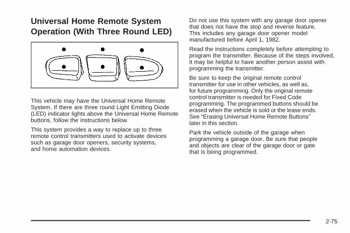
Universal Home Remote SystemOperation (With Three Round LED)
This vehicle may have the Universal Home RemoteSystem. If there are three round Light Emitting Diode(LED) indicator lights above the Universal Home Remotebuttons, follow the instructions below.
This system provides a way to replace up to threeremote control transmitters used to activate devicessuch as garage door openers, security systems,and home automation devices.
Do not use this system with any garage door openerthat does not have the stop and reverse feature.This includes any garage door opener modelmanufactured before April 1, 1982.
Read the instructions completely before attempting toprogram the transmitter. Because of the steps involved,it may be helpful to have another person assist withprogramming the transmitter.
Be sure to keep the original remote controltransmitter for use in other vehicles, as well as,for future programming. Only the original remotecontrol transmitter is needed for Fixed Codeprogramming. The programmed buttons should beerased when the vehicle is sold or the lease ends.See “Erasing Universal Home Remote Buttons”later in this section.
Park the vehicle outside of the garage whenprogramming a garage door. Be sure that peopleand objects are clear of the garage door or gatethat is being programmed.
2-75

Programming Universal HomeRemote — Rolling CodeFor questions or help programming the UniversalHome Remote System, call 1-866-572-2728 or goto learcar2u.com.
Most garage door openers sold after 1996 are RollingCode units.
Programming a garage door opener involvestime-sensitive actions, so read the entire procedurebefore starting. Otherwise, the device will time outand the procedure will have to be repeated.
To program up to three devices:
1. From inside the vehicle, press the two outsidebuttons at the same time for one to two seconds,and immediately release them.
2. Locate in the garage, the garage door openerreceiver (motor-head unit). Locate the “Learn” or“Smart” button. It can usually be found where thehanging antenna wire is attached to the motor-headunit and may be a colored button. Press this button.After pressing this button, complete the followingsteps in less than 30 seconds.
3. Immediately return to the vehicle. Press and holdthe Universal Home Remote button that will beused to control the garage door until the garagedoor moves. The indicator light, above the selectedbutton, should slowly blink. This button mayneed to be held for up to 20 seconds.
2-76

4. Immediately, within one second, release the buttonwhen the garage door moves. The indicator lightwill blink rapidly until programming is complete.
5. Press and release the same button again.The garage door should move, confirmingthat programming is successful and complete.
To program another Rolling Code device such as anadditional garage door opener, a security device, or homeautomation device, repeat Steps 1 through 5, choosing adifferent function button in Step 3 than what was used forthe garage door opener.
If these instructions do not work, the garage dooropener is probably a Fixed Code unit. Follow theProgramming instructions that follow for a Fixed Codegarage door opener.
Programming Universal HomeRemote — Fixed CodeFor questions or help programming the UniversalHome Remote System, call 1-866-572-2728 or goto learcar2u.com.
Most garage door openers sold before 1996 are FixedCode units.
Programming a garage door opener involvestime-sensitive actions, so read the entire procedurebefore starting. Otherwise, the device will time outand the procedure will have to be repeated.
To program up to three devices:
1. To verify that the garage door opener is a FixedCode unit, remove the battery cover on the handheld transmitter supplied by the manufacturer of thegarage door opener motor. If there are a row of dipswitches similar to the graphic above, the garagedoor opener is a Fixed Code unit. If you do notsee a row of dip switches, return to the previoussection for Programming Universal HomeRemote – Rolling Code.Your hand held transmitter can have betweeneight to 12 dip switches depending on the brandof transmitter.
2-77

The garage door opener receiver (motor head unit)could also have a row of dip switches that canbe used when programming the Universal HomeRemote. If the total number of switches on the motorhead and hand held transmitter are different, or ifthe dip switch settings are different, use the dipswitch settings on the motor head unit to programthe Universal Home Remote. The motor head dipswitch settings can also be used when the originalhand held transmitter is not available.
The panel of switches might not appear exactly asthey do in the examples above, but they shouldbe similar.The switch positions on the hand-held transmittercould be labeled, as follows:
• A switch in the up position could be labeledas “Up,” “+,” or “On.”
• A switch in the down position could be labeledas “Down,” “−,” or “Off.”
• A switch in the middle position could be labeledas “Middle,” “0,” or “Neutral.”
Example of Eight Dip Switches with Two Positions
Example of Eight Dip Switches with Three Positions
2-78

2. Write down the eight to 12 switch settings from leftto right as follows:
• When a switch is in the up position, write “Left.”
• When a switch is in the down position,write “Right.”
• If a switch is set between the up and downposition, write “Middle.”The switch settings written down in Step 2 nowbecome the button strokes to be entered into theUniversal Home Remote in Step 4. Be sure toenter the switch settings written down in Step 2,in order from left to right, into the Universal HomeRemote, when completing Step 4.
3. From inside your vehicle, first firmly press all threebuttons at the same time for about three seconds.Release the buttons to put the Universal HomeRemote into programming mode.
4. The indicator lights will blink slowly. Enter eachswitch setting from Step 2 into your vehicle’sUniversal Home Remote. You will have two andone-half minutes to complete Step 4. Now pressone button on the Universal Home Remote foreach switch setting as follows:
• If you wrote “Left,” press the left button in thevehicle.
• If you wrote “Right,” press the right button in thevehicle.
• If you wrote “Middle,” press the middle button inthe vehicle.
2-79

5. After entering all of the switch positions, again,firmly press and release all three buttons at thesame time. The indicator lights will turn on.
6. Press and hold the button that will be used tocontrol the garage door until the garage doormoves. The indicator light above the selectedbutton should slowly blink. This button mayneed to be held for up to 55 seconds.
7. Immediately release the button when the garagedoor moves. The indicator light will blink rapidlyuntil programming is complete.
8. Press and release the same button again.The garage door should move, confirmingthat programming is successful and complete.
To program another Fixed Code device such as anadditional garage door opener, a security device,or home automation device, repeat Steps 1-8, choosinga different button in Step 6 than what was used forthe garage door opener.
Using Universal Home RemotePress and hold the appropriate button for at leasthalf of a second. The indicator light will come onwhile the signal is being transmitted.
Reprogramming Universal HomeRemote ButtonsAny of the three buttons can be reprogrammed byrepeating the instructions.
Erasing Universal Home RemoteButtonsThe programmed buttons should be erased when thevehicle is sold or the lease ends.
To erase either Rolling Code or Fixed Code on theUniversal Home Remote device:
1. Press and hold the two outside buttons at the sametime for approximately 20 seconds, until the indicatorlights, located directly above the buttons, begin toblink rapidly.
2. Once the indicator lights begin to blink, release bothbuttons. The codes from all buttons will be erased.
For help or information on the Universal Home RemoteSystem, call the customer assistance phone numberunder Customer Assistance Offices on page 7-6.
2-80

Storage Areas
Glove BoxLift up on the glove box lever to open it.
CupholdersVehicles with cupholders, have them located on andbehind the center console and in the rear seat armrest.Pull the loop down on the rear seat armrest to accessthe cupholders.
Pull downward on the lid to access the cupholdersbehind the center console.
Instrument Panel StorageVehicles that have an instrument panel storage area,have it located above the glove box.
Press and hold the driver’s side of the handle in andpull out on the exposed portion of the handle to accessthe storage area.
2-81

Center Console StorageVehicles with an upper and lower center consolestorage area, cupholders are included.
Pull the lever (A) up to access the upper storage area.Raise the upper storage bin, then pull the lever (B)up to access the lower storage area. Use the key tolock and unlock the lower storage area.
Luggage CarrierNotice: Loading cargo on the luggage carrier thatweighs more than 200 lbs (91 kg) or hangs over therear or sides of the vehicle can damage the vehicle.Load cargo so that it rests on the slats as far forwardas possible and against the side rails, making sure tofasten it securely.
For vehicles with a luggage carrier, items can be loadedon top of the vehicle.
The luggage carrier has siderails attached to the roof.It can also have crossrails which can be moved back andforth to help secure cargo. Tie the load to the siderails orsiderail supports.
Do not exceed the maximum vehicle capacity whenloading the vehicle. For more information on vehiclecapacity and loading, see Loading the Vehicle onpage 4-32.
Make sure the cargo is properly loaded.
2-82

To prevent damage or loss of cargo while driving,periodically stop and check to make sure cargo is stillsecurely fastened.
• If small heavy objects are placed on the roof, cut apiece of 3/8 inch plywood to fit inside the crossrailsand siderails to spread the load. Tie the plywoodto the siderail supports.
• Tie the load and secure it to the crossrails or thesiderail supports. Use the crossrails only to keep theload from sliding. To move a crossrail, lift the releaselever up, on both sides of the rail. Then slide thecrossrail to the desired position balancing the forceside to side. Press the release lever down on bothsides of the rail, down to tighten it. Try to slide thecrossrail back and forth slightly to make sure itis tight.
• To carry long items, move the crossrails as far apartas possible. Tie the load to the crossrails and thesiderails or siderail supports. Also tie the load to thebumpers, but do not tie the load so tightly that thecrossrails or siderails are damaged.
• After moving a crossrail, be sure it is securely lockedinto the siderail.
A Center High-Mounted Stoplamp (CHMSL) is locatedabove the rear window glass.
Make sure items loaded on the roof of the vehicle donot block or damage the CHMSL.
Rear Seat ArmrestVehicles with a rear seat armrest, have two cupholders.Pull the armrest down from the rear seatback to accessthe cupholders.
2-83

Cargo Management SystemFor vehicles with a cargo management system, it islocated in the bed of the truck. The system containsthree rails located on the front and sides of the bed.
The system has four adjustable cargo tie-downs,that can be placed on the upper and lower slidesof the rail.
To adjust a tie-down, pull the locator pin out and movethe tie-down to another location making sure the locatorpin lines up with a locator hole on the rail. The tie-downpin may not be installed correctly if the pin does not line
up, turn it over and reinstall. The tie-down will not movewhen the pin is completely installed. The maximum loadfor each rail is 500 lbs (227 kg).
The rails are notched at each end which allows thetie-downs to be removed and placed on another rail.To remove, pull the locator pin out and slide the tie-downto the end of the rail and pull back.
To remove or install cargo tie-downs at the front of thebed, slide the corner cap towards the center of thebed to expose the rail notches. To remove the cornercap, pull either edge away from the rail.
To remove the system, loosen the toggle bolts oneach rail until they can be removed from the bed of thetruck. To replace the system, place the toggle boltsand rails into their original locations and tighten themto a torque setting of 12.5 ft lbs (17 Y).
If the system is removed to install a bed liner, makesure there is no bed liner material in the installationpoints.
Notice: If cargo is tied down using the horizontalslots on the top of the pickup box, the box could bedamaged. Using the horizontal slots on the top of thepickup box for tie-down locations may cause damageto the pickup box and would not be covered by thevehicle warranty. Only use the tie-down loops if thevehicle does not have the cargo managementsystem.
2-84

SunroofOn vehicle with a power sliding sunroof, the ignitionneeds to be turned to RUN, or the Retained AccessoryPower (RAP) must be activated to open or close thesunroof. When RAP is active, the sunroof will workfor 10 minutes after the ignition is turned off, or untilthe driver’s door is opened. See Retained AccessoryPower (RAP) on page 2-23 for more information.
Extended Cab
If your vehicle is anextended cab, the sunroofswitch is located on theheadliner above therearview mirror.
Vent: From the closed position, press and hold the rearof the switch to vent the sunroof. To close the sunroof,press and hold the front of the switch.
Open: From the vent position, the sunroof can be fullyopened either manually or by using the express-openfeature. To open manually, press the rear of the switchto the first depression and hold until the sunroofhas reached the desired position. To open usingexpress-open, press the rear of the switch fully andrelease. The sunroof will move to the full open position.To stop the sunroof partway, press the switch asecond time.
Close: From the vent, or open position, press and holdthe front of the switch to close the sunroof.
The sunroof also has a roller sunshade that can beused to block the rays of the sun. The roller sunshadecan be manually operated with the sunroof in an openor closed position. To open the sunshade, pressand unlatch it, and roll it back. To close, pull itforward and latch it into the closed position.
When the sunroof is opened, an air deflector willautomatically raise. The air deflector will retract whenthe sunroof is closed.
2-85

Crew Cab
If your vehicle is a crewcab, there are two sunroofswitches located in theoverhead console abovethe rearview mirror.
Vent: From the closed position, press the rear of thepassenger’s side switch to vent the sunroof. To close thesunroof, press and hold the front of the passenger’sside switch.
Manual-Open/Manual-Close: To open the sunroofpress and hold the rear of the driver’s side switch untilthe sunroof reaches the desired position. To close thesunroof, press and hold the front of the driver’s sideswitch until the sunroof reaches the desired position.
When the sunroof is opened, an air deflector willautomatically raise. The air deflector will retract whenthe sunroof is closed.
Express-Open/Express-Close: To express-open thesunroof, fully press and release the rear of the driver’sside switch. The sunroof will open automatically. To stopthe sunroof partway, press the switch a second time.To express-close the sunroof, fully press and release thefront of the driver’s side switch. The sunroof will closeautomatically. To stop the sunroof partway, press theswitch a second time.
The sunroof also has a sunshade which you can pullforward to block sun rays. The sunshade must be openedand closed manually.
Anti-Pinch Feature (Crew Cab Only): If an object isin the path of the sunroof while it is closing, the anti-pinchfeature will detect the object and stop the sunroof fromclosing at the point of the obstruction. The sunroof willthen open halfway, and the air deflector will raise.To close the sunroof once it has re-opened, refer to theExpress-Close or Manual-Close functions describedpreviously. If the sunroof is in the vent position, and thereis an object in the path of the sunroof when it closing,the anti-pinch feature will detect the object and stop thesunroof. To close the sunroof once it has stopped, referto the Vent functions described previously.
Do not leave the sunroof open for long periods of timewhile the vehicle is not in use. Debris can collect inthe tracks and damage the sunroof operation and plugthe water draining system.
2-86

Instrument Panel Overview ...............................3-4Instrument Panel Overview (Base/Uplevel
version) .....................................................3-4Instrument Panel Overview
(Premium version) .......................................3-6Hazard Warning Flashers ................................3-8Horn .............................................................3-8Tilt Wheel .....................................................3-8Turn Signal/Multifunction Lever .........................3-9Turn and Lane-Change Signals ........................3-9Headlamp High/Low-Beam Changer .................3-10Flash-to-Pass ...............................................3-10Windshield Wipers ........................................3-10Rainsense™ II Wipers ...................................3-11Windshield Washer .......................................3-12Cruise Control ..............................................3-13Exterior Lamps .............................................3-16Headlamps on Reminder ................................3-17Daytime Running Lamps (DRL) .......................3-17Automatic Headlamp System ..........................3-18Puddle Lamps ..............................................3-19Fog Lamps ..................................................3-19Auxiliary Roof Mounted Lamp .........................3-19Instrument Panel Brightness ...........................3-20Dome Lamps ...............................................3-20Dome Lamp Override ....................................3-20Entry Lighting ...............................................3-20
Exit Lighting .................................................3-20Reading Lamps ............................................3-21Cargo Lamp .................................................3-21Electric Power Management ...........................3-21Battery Run-Down Protection ..........................3-22Accessory Power Outlet(s) .............................3-22Ashtray(s) and Cigarette Lighter ......................3-23
Climate Controls ............................................3-24Climate Control System
(With Heater Only) .....................................3-24Climate Control System
(With Air Conditioning) ...............................3-25Dual Automatic Climate Control System ...........3-27Outlet Adjustment .........................................3-33
Warning Lights, Gages, and Indicators ............3-33Instrument Panel Cluster ................................3-34Speedometer and Odometer ...........................3-35Trip Odometer ..............................................3-35Tachometer .................................................3-35Safety Belt Reminders ...................................3-36Airbag Readiness Light ..................................3-37Airbag Off Light ............................................3-38Passenger Airbag Status Indicator ...................3-40Charging System Light ..................................3-41Voltmeter Gage ............................................3-41Brake System Warning Light ..........................3-42
Section 3 Instrument Panel
3-1

Antilock Brake System (ABS)Warning Light ...........................................3-43
StabiliTrak® Indicator Light .............................3-44Engine Coolant Temperature Gage ..................3-44Tire Pressure Light .......................................3-45Malfunction Indicator Lamp .............................3-45Oil Pressure Gage ........................................3-48Oil Pressure Light .........................................3-49Security Light ...............................................3-50Fog Lamp Light ............................................3-50Cruise Control Light ......................................3-50Highbeam On Light .......................................3-50Four-Wheel-Drive Light ..................................3-51Tow/Haul Mode Light ....................................3-51Fuel Gage ...................................................3-51Low Fuel Warning Light .................................3-52
Driver Information Center (DIC) .......................3-53DIC Operation and Displays (With DIC
Buttons) ...................................................3-53DIC Operation and Displays (Without DIC
Buttons) ...................................................3-59DIC Compass ..............................................3-63DIC Warnings and Messages .........................3-66DIC Vehicle Customization
(With DIC Buttons) ....................................3-76
Audio System(s) .............................................3-85Setting the Clock ..........................................3-86Radio(s) ......................................................3-88Using an MP3 (Radio with CD or
Six-Disc CD Player) .................................3-108Using an MP3 (Radio with CD and
DVD Player) ...........................................3-113XM Radio Messages ...................................3-118Navigation/Radio System ..............................3-119Bluetooth® .................................................3-119Rear Seat Entertainment (RSE) System .........3-129Rear Seat Audio (RSA) ................................3-139Theft-Deterrent Feature ................................3-140Audio Steering Wheel Controls ......................3-141Radio Reception .........................................3-141Fixed Mast Antenna ....................................3-142XM™ Satellite Radio Antenna System ..............3-142
Section 3 Instrument Panel
3-2

✍ NOTES
3-3

Instrument Panel OverviewInstrument Panel Overview (Base/Uplevel version)
3-4

The main components of the instrument panel are the following:
A. Outlet Adjustment on page 3-33.B. Turn Signal/Multifunction Lever on page 3-9.C. Driver Information Center (DIC) on page 3-53.D. Hazard Warning Flashers on page 3-8.E. Instrument Panel Cluster on page 3-34.F. Shift Lever. See Automatic Transmission
Operation on page 2-28. Tow/Haul Selector Button(If Equipped). See Tow/Haul Mode on page 2-34.Range Selection Mode (Allison Transmissionand Hydra-Matic® 6-Speed Button (If Equipped).See Automatic Transmission Operation onpage 2-28.
G. Audio System(s) on page 3-85.H. Instrument Panel Storage on page 2-81.I. Integrated Trailer Brake Controller (If Equipped).
See Towing a Trailer on page 4-51.J. Exterior Lamps on page 3-16.K. Hood Release on page 5-13.L. Parking Brake on page 2-50.M. Dome Lamp Override on page 3-20. Dome Lamps
on page 3-20. Fog Lamps on page 3-19(If Equipped).
N. Cruise Control on page 3-13.O. Tilt Wheel on page 3-8.
P. Horn on page 3-8.Q. Audio Steering Wheel Controls on page 3-141
(If Equipped).R. Automatic Transfer Case Control (If Equipped).
See Four-Wheel Drive on page 2-37.S. Ashtray (If Equipped). See Ashtray(s) and Cigarette
Lighter on page 3-23.T. StabiliTrak® System on page 4-6 (If Equipped).
Ultrasonic Rear Parking Assist (URPA) on page 2-62(If Equipped). Pedal Adjust Button (If Equipped).See Adjustable Throttle and Brake Pedal onpage 2-26. Heated Windshield Washer Fluid Button(If Equipped). Windshield Washer on page 3-12.
U. Accessory Power Outlet(s) on page 3-22.V. Climate Control System (With Heater Only) on
page 3-24 or Climate Control System (With AirConditioning) on page 3-25 and Dual AutomaticClimate Control System on page 3-27.
W. Power Take Off (PTO) Control (If Equipped).See Power Take Off (PTO) in the Duramax DieselSupplement Index.
X. Passenger Airbag Off Control (If Equipped).See Airbag Off Switch on page 1-81.
Y. Glove Box on page 2-81.
3-5

Instrument Panel Overview (Premium version)
3-6

The main components of the instrument panel are the following:
A. Outlet Adjustment on page 3-33.B. Turn Signal/Multifunction Lever on page 3-9.C. Instrument Panel Cluster on page 3-34.D. Hazard Warning Flashers on page 3-8.E. Shift Lever. See Automatic Transmission Operation
on page 2-28.F. Tow/Haul Mode on page 2-34 (If Equipped).G. Driver Information Center (DIC) on page 3-53.H. Audio System(s) on page 3-85.I. Exterior Lamps on page 3-16.J. Integrated Trailer Brake Controller (If Equipped).
See Towing a Trailer on page 4-51.K. Dome Lamp Override on page 3-20. Dome Lamps
on page 3-20.L. Automatic Transfer Case Control. (If Equipped).
See Four-Wheel Drive on page 2-37.M. Hood Release on page 5-13.N. Parking Brake on page 2-50.O. Cruise Control on page 3-13.
P. Tilt Wheel on page 3-8.Q. Horn on page 3-8.R. Audio Steering Wheel Controls on page 3-141.S. Climate Control System (With Heater Only)
on page 3-24 or Climate Control System (With AirConditioning) on page 3-25 or Dual AutomaticClimate Control System on page 3-27 (If Equipped).
T. Accessory Power Outlet(s) on page 3-22.Cigarette Lighter (If Equipped). See Ashtray(s)and Cigarette Lighter on page 3-23.
U. StabiliTrak® System on page 4-6 (If Equipped).Pedal Adjust Button (If Equipped). See AdjustableThrottle and Brake Pedal on page 2-26. UltrasonicRear Parking Assist (URPA) on page 2-62(If Equipped). Heated Windshield Washer FluidButton (If Equipped). See Windshield Washeron page 3-12.
V. Passenger Airbag Off Control (If Equipped).See Airbag Off Switch on page 1-81.
W. Glove Box on page 2-81.
3-7

Hazard Warning Flashers
| (Hazard Warning Flasher): Press this buttonlocated on top of the steering column, to make the frontand rear turn signal lamps flash on and off. This warnsothers that you are having trouble. Press again to turn theflashers off.
When the hazard warning flashers are on, the vehicle’sturn signals will not work.
HornTo sound the horn, press the horn symbols located onthe steering wheel.
Tilt WheelThe tilt wheel lets the steering wheel be adjusted.
The tilt lever is located on the lower left side of thesteering column.
To tilt the wheel, hold the steering wheel and pull thelever. Then move the steering wheel to a comfortableposition and release the lever to lock the wheel in place.
Do not adjust the steering wheel while driving.
3-8

Turn Signal/Multifunction Lever
The lever on the left side of the steering columnincludes the following:
G : Turn and Lane Change Signals
5 3 : Headlamp High/Low-Beam Changer
N : Windshield Wipers
L : Windshield Washer
Flash-to-Pass.
Exterior Lamps.
Information for these features is on the pages following.
Turn and Lane-Change SignalsAn arrow on the instrumentpanel cluster flashes in thedirection of the turn orlane change.
Move the lever all the way up or down to signal a turn.
Raise or lower the lever for less than one seconduntil the arrow starts to flash to signal a lane change.This causes the turn signals to automatically flash threetimes. It will flash six times if tow-haul mode is active.Holding the turn signal lever for more than one secondwill cause the turn signals to flash until you releasethe lever.
The lever returns to its starting position whenever it isreleased.
If after signaling a turn or a lane change the arrowsflash rapidly or do not come on, a signal bulb could beburned out.
Have the bulbs replaced. If the bulb is not burned out,check the fuse. See Fuses and Circuit Breakers onpage 5-122.
3-9
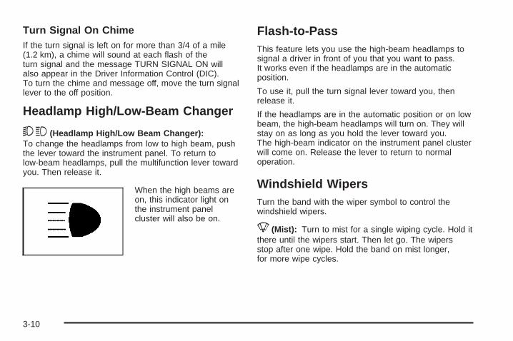
Turn Signal On ChimeIf the turn signal is left on for more than 3/4 of a mile(1.2 km), a chime will sound at each flash of theturn signal and the message TURN SIGNAL ON willalso appear in the Driver Information Control (DIC).To turn the chime and message off, move the turn signallever to the off position.
Headlamp High/Low-Beam Changer
53 (Headlamp High/Low Beam Changer):To change the headlamps from low to high beam, pushthe lever toward the instrument panel. To return tolow-beam headlamps, pull the multifunction lever towardyou. Then release it.
When the high beams areon, this indicator light onthe instrument panelcluster will also be on.
Flash-to-PassThis feature lets you use the high-beam headlamps tosignal a driver in front of you that you want to pass.It works even if the headlamps are in the automaticposition.
To use it, pull the turn signal lever toward you, thenrelease it.
If the headlamps are in the automatic position or on lowbeam, the high-beam headlamps will turn on. They willstay on as long as you hold the lever toward you.The high-beam indicator on the instrument panel clusterwill come on. Release the lever to return to normaloperation.
Windshield WipersTurn the band with the wiper symbol to control thewindshield wipers.
8 (Mist): Turn to mist for a single wiping cycle. Hold itthere until the wipers start. Then let go. The wipersstop after one wipe. Hold the band on mist longer,for more wipe cycles.
3-10

9 (Off): Turns the wipers off.
6 (Delay): Turn the band to adjust the delay time.The delay between wiping cycles becomes shorter asthe band is moved to the top of the lever. This canbe very useful in light rain or snow.
6 (Low Speed): For steady wiping at low speed.
? (High Speed): For high-speed wiping.
Clear ice and snow from the wiper blades before usingthem. If they are frozen to the windshield, gentlyloosen or thaw them. Damaged wiper blades may notclear the windshield well, making it harder to seeand drive safely. If the blades do become damaged,install new blades or blade inserts. For more information,see Windshield Wiper Blade Replacement on page 5-64.
Heavy snow or ice can overload the wiper motor.A circuit breaker will stop the motor until it cools down.Clear away snow or ice to prevent an overload.
Rainsense™ II WipersFor vehicles with Rainsense™ II windshield wipers, themoisture sensor is located next to the inside rearviewmirror and is mounted on the windshield. When active,these sensors are able to detect moisture on thewindshield and automatically turn on the wipers.
To turn on the Rainsense feature, the wipers must beset to one of the five delay settings on the multifunctionlever. Each of the five settings adjusts the sensitivityof the sensor.
Since different drivers have different setting preferences,it is recommended that the mid-range setting (position 3)be used initially. For more wipes, select the highersettings; for fewer wipes, select the lower settings locatedcloser to the off position on the multifunction lever.
The sensor will automatically control the frequency of thewipes from the off setting to the high speed settingaccording to the weather conditions. The wipers can beleft in a rainsense mode even when it is not raining.
When Rainsense is active, the headlamps will turn onautomatically if the exterior lamp control is in theAUTO position and the wipers are active.
Notice: Going through an automatic car wash withthe wipers on can damage them. Turn the wipersoff when going through an automatic car wash.
3-11

Windshield Washer
{CAUTION:
In freezing weather, do not use your washer untilthe windshield is warmed. Otherwise the washerfluid can form ice on the windshield, blocking yourvision.
L (Washer Fluid): Push the paddle marked withthe windshield washer symbol at the top of themultifunction lever, to spray washer fluid on thewindshield. The wipers clear the window and theneither stop or return to the preset speed.
Heated Windshield WasherFor vehicles with the heated windshield washer fluidsystem it can be used to help clear ice, snow, tree sap,or bugs from the windshield.
_ (Heated Washer Fluid): Press the heated washerfluid button to activate the heated windshield washerfluid system. This activation initiates four heatedwash/wipe cycles. The first heated wash/wipe cycle maytake up to 40 seconds to occur, depending on outsidetemperature. After the first wash/wipe cycle, it may takeup to 20 seconds for each of the remaining cycles tobegin. Press the button again to turn off the heatedwindshield washer fluid system or it will automaticallyturn off after four wipe cycles have been completed.
When the heated windshield washer fluid systemis activated under certain outside temperatureconditions, steam may flow out of the washer nozzlesfor a short period of time before washer fluid is sprayed.This is a normal condition.
HEATING WASH FLUID WASH WIPES PENDING isdisplayed on the DIC when the washer system is heatingthe fluid. WASHER FLUID LOW ADD FLUID isdisplayed when the washer fluid is low. See DICWarnings and Messages on page 3-66.
3-12

Cruise Control
{CAUTION:
Cruise control can be dangerous where you cannotdrive safely at a steady speed. So, do not use thecruise control on winding roads or in heavy traffic.
Cruise control can be dangerous on slippery roads.On such roads, fast changes in tire traction cancause excessive wheel slip, and you could losecontrol. Do not use cruise control on slippery roads.
With cruise control, a speed of about 25 mph (40 km/h)or more can be maintained without keeping your footon the accelerator. This can really help on longtrips. Cruise control does not work at speeds belowabout 25 mph (40 km/h).
When the brakes are applied, cruise control is turned off.
For vehicles with an Allison® or Hydra-Matic 6-speedautomatic transmission, see “Grade Braking and CruiseGrade Braking (Allison Transmission) under Tow/HaulMode on page 2-34 for an explanation of how cruisecontrol interacts with the Range Selection Mode,tow/haul and grade braking systems.
For vehicles with the StabiliTrak® system that beginsto limit wheel spin while you are using cruise control,the cruise control will automatically disengage.See StabiliTrak® System on page 4-6. When roadconditions allow the cruise control to be safely usedagain, it can be turned back on.
3-13

The cruise control buttonsare located on left side ofthe steering wheel.
T (On/Off): This button can both activate and turn offthe system. The indicator light is on when cruisecontrol is on and turns off when cruise control is off.
+ RES (Resume/Accelerate): Press to make thevehicle accelerate or resume to a previously set speed.
SET − (Set/Coast): Press to set the speed or makethe vehicle decelerate.
[ (Cancel): Press to cancel cruise control withouterasing the set speed from memory.
Setting Cruise ControlCruise control will not work if the parking brake is set, orif the master cylinder brake fluid level is low.
The cruise control light on the instrument panel clusterwill come on after the cruise control has been set tothe desired speed.
{CAUTION:
If you leave your cruise control on when you are notusing cruise, you might hit a button and go intocruise when you do not want to. You could bestartled and even lose control. Keep the cruisecontrol switch off until you want to use cruise control.
1. Press the cruise control On/Off button.2. Get up to the desired speed.3. Press the SET− button located on the steering
wheel and release it.4. Take your foot off the accelerator.
Resuming a Set SpeedIf the brakes are applied while the cruise control is set,the cruise control is disengaged. But it does not needto be reset.
3-14

Once the vehicle speed reaches about 25 mph (40 km/h)or more, press the +RES button on the steering wheel.The vehicle will go back to the previous set speed andstay there.
Increasing Speed While Using CruiseControlTo increase the cruise speed while using cruise control:
• Press and hold the +RES button on the steeringwheel until the desired speed is reached, thenrelease it.
• To increase vehicle speed in small increments,press the +RES button. Each time this is done,the vehicle goes about 1 mph (1.6 km/h) faster.
Reducing Speed While Using CruiseControlTo reduce the vehicle speed while using cruise control:
• Press and hold the SET– button on the steeringwheel until the desired lower speed is reached,then release it.
• To slow down in very small amounts, press theSET– button on the steering wheel briefly.Each time this is done, the vehicle goes about1 mph (1.6 km/h) slower.
Passing Another Vehicle While UsingCruise ControlUse the accelerator pedal to increase the vehicle speed.When you take your foot off the pedal, the vehicle willslow down to the previous set cruise speed.
Using Cruise Control on HillsHow well the cruise control will work on hills dependsupon the vehicle speed, load, and the steepness of thehills. While going up steep hills, you might have tostep on the accelerator pedal to maintain the vehicle’sspeed. While going downhill, you might have to brakeor shift to a lower gear to keep the vehicle’s speeddown. When the brakes are applied the cruise controlturns off.
Ending Cruise ControlThere are three ways to end cruise control:
• Step lightly on the brake pedal.
• Press the cancel button on the steering wheel.
• Press the On/Off button on the steering wheel.
Erasing Speed MemoryThe cruise control set speed memory is erased, whenthe cruise control or the ignition is turned off.
3-15

Exterior LampsThe exterior lamps controlis located on the instrumentpanel to the left of thesteering wheel.
It controls the following systems:
• Headlamps
• Taillamps
• Parking Lamps
• License Plate Lamps
• Instrument Panel Lights
The exterior lamps control has four positions:
O (Off): Turns off the automatic headlamps anddaytime running lamps (DRL). Turn the headlampcontrol to the off position again to turn the automaticheadlamps or DRL back on.
For vehicles first sold in Canada, the off position willonly work when the vehicle is shifted into P (Park).
AUTO (Automatic): Automatically turns on theheadlamps at normal brightness, together with thefollowing:
• Parking Lamps
• Instrument Panel Lights
• Taillamps
• License Plate Lamps
When the vehicle is turned off and the headlamps are inAUTO, the headlamps may automatically remain onfor a set time. The time of the delay can be changedusing the DIC. See Driver Information Center (DIC)on page 3-53.
; (Parking Lamps): Turns on the parking lampstogether with the following:
• Instrument Panel Lights
• Taillamps
• License Plate Lamps
3-16

2 (Headlamps): Turns on the headlamps togetherwith the following:
• Parking Lamps
• Instrument Panel Lights
• Taillamps
• License Plate Lamps
When the headlamps are turned on while the vehicle ison, the headlamps turn off automatically 10 minutesafter the ignition is turned off. When the headlamps areturned on while the vehicle is off, the headlamps willstay on for 10 minutes before automatically turning offto prevent the battery from being drained. Turn theheadlamp control to off and then back to the headlampon position to make the headlamps stay on for anadditional 10 minutes.
Push the turn signal/multifunction lever toward theinstrument panel to change the headlamps from lowbeam to high beam.
Headlamps on ReminderA reminder chime will sound when the headlamps orparking lamps are manually turned on and the ignition isoff and a door is open. To disable the chime, turn thelight off.
Daytime Running Lamps (DRL)Daytime Running Lamps (DRL) can make it easierfor others to see the front of your vehicle during the day.Fully functional daytime running lamps are requiredon all vehicles first sold in Canada.
The DRL system will come on when the followingconditions are met:
• The ignition is on.
• The exterior lamps control is in AUTO.
• The transmission is not in P (Park).
• The light sensor determines it is daytime.
When the DRL are on, only the DRL lamps will be on.The taillamps, sidemarker, instrument panel lights,and other lamps will not be on.
When it begins to get dark, the automatic headlampsystem will switch from DRL to the headlamps.
To turn off the DRL lamps, turn the exterior lampscontrol to the OFF position and then release.For vehicles first sold in Canada, the transmissionmust be in the P (Park) position, before the DRL lampscan be turned off.
3-17

Automatic Headlamp SystemWhen it is dark enough outside, the automatic headlampsystem turns on the headlamps at the normal brightness,along with the taillamps, sidemarker, parking lamps,and the instrument panel lights. The radio lights will alsobe dim.
To turn off the automatic headlamp system, turn theexterior lamps switch to the off position and then releaseit. For vehicles first sold in Canada, the transmissionmust be in the P (Park) position, before the automaticheadlamp system can be turned off.
The vehicle has a light sensor located on the top of theinstrument panel in the defroster grille that regulateswhen the automatic headlamps turn on. Do not coverthe sensor or the headlamps will come on whenever theignition is on.
The system may also turn on the headlamps whendriving through a parking garage, heavy overcastweather, or a tunnel. This is normal.
There is a delay in the transition between the daytimeand nighttime operation of the Daytime RunningLamps (DRL) and the automatic headlamp systems sothat driving under bridges or bright overhead street
lights does not affect the system. The DRL andautomatic headlamp system is only affected when thelight sensor detects a change in lighting lastinglonger than the delay.
If the vehicle is started in a dark garage, the automaticheadlamp system will come on immediately. Oncethe vehicle leaves the garage, it takes approximatelyone minute for the automatic headlamp system tochange to DRL if it is bright enough outside. During thatdelay, the instrument panel cluster may not be asbright as usual. Make sure the instrument panelbrightness control is in the full bright position.See Instrument Panel Brightness on page 3-20.
To idle the vehicle with the automatic headlamp systemoff, turn the control to the off position.
The headlamps will also stay on after you exit thevehicle. This feature can be programmed using theDriver Information Center (DIC). See DIC VehicleCustomization (With DIC Buttons) on page 3-76.
The regular headlamp system can be turned on whenneeded.
3-18

Puddle LampsIf the vehicle has puddle lamps, they come on when theunlock button on the Remote Keyless Entry (RKE)Transmitter is pressed. The lamps time out or turn offonce the engine is started.
Fog LampsFor vehicles with fog lamps, the control is located nextto the exterior lamps control on the instrument panel,to the left of the steering column.
The ignition must be in the ON/RUN position for thefog lamps to come on.
# (Fog Lamps): Press to turn the fog lamps on or off.A light will come on in the instrument panel cluster.
When the fog lamps are turned on, the parking lampsautomatically turn on.
When the headlamps are changed to high-beam, thefog lamps also go off. When the high-beam headlampsare turned off, the fog lamps will come on again.
Some localities have laws that require the headlamps tobe on along with the fog lamps.
Auxiliary Roof Mounted LampIf the vehicle has this feature, this button includes wiringprovisions for a dealer or a qualified service center toinstall an auxiliary roof lamp.
This button is located onthe overhead console.
When the wiring is connected to an auxiliary roofmounted lamp, pressing the bottom of the button willactivate the lamp and illuminate an indicator light at thebottom of this button. Pressing the top of the buttonwill turn off the roof mounted lamp and indicator.
The emergency roof lamp circuit is fused at 30 amps, sothe total current draw of the attached lamps should beless than this value. The attachment points for the rooflamp circuits are two blunt cut wires located above theoverhead console, a dark green switched power wire anda black ground wire.
3-19

For further information on roof mount emergency lampinstallation, please visit the GM Upfitter website atwww.gmupfitters.com or contact your dealer.
If the vehicle has this button, the vehicle may have thesnow plow prep package. For further information seeAdding a Snow Plow or Similar Equipment on page 4-38.
Instrument Panel BrightnessD (Instrument Panel Brightness): This featurecontrols the brightness of the instrument panel lightsand is located next to the exterior lamp control.
Push the knob to extend out and then it can be turned.
Turn the knob clockwise or counterclockwise to brightenor dim the instrument panel lights. Turning the knob to thefarthest clockwise position turns on the dome lamps.
Dome LampsThe dome lamps come on when any door is opened.They turn off after all the doors are closed.
The dome lamps can also be turned on by turning theinstrument panel brightness knob, located on theinstrument panel to the left of the steering column,clockwise to the farthest position. In this position, thedome lamps remain on whether a door is openedor closed.
Dome Lamp OverrideThe dome lamp override button is located next to theexterior lamps control.
k (Dome Off): Press the button in and the domelamps remain off when a door is opened. Pressthe button again to return it to the extended position sothat the dome lamps come on when a door is opened.
Entry LightingThe vehicle has an illuminated entry feature.
When the doors are opened, the dome lamps will comeon if the dome override button is in the extendedposition. If the dome override button is pressed in,the lamps will not come on.
Exit LightingThe interior lamps come on when the key is removedfrom the ignition. They turn off automatically in20 seconds. The lights do not come on if the domeoverride button is pressed in.
3-20
Reading LampsFor vehicles with reading lamps, they are located onthe overhead console.
To turn on the reading lamps, press the buttonlocated next to each lamp. To turn them off, press thebutton again.
The vehicle may also have reading lamps in otherlocations. To turn the lamps on or off, press the buttonlocated next to the lamp.
If the vehicle has a DVD Rear Seat Entertainment (RSE)system, press the lamp lenses to turn the lampson or off.
The lamps are fixed and cannot be adjusted.
Cargo LampThe cargo lamps come on by turning the instrumentpanel brightness control knob to the farthest clockwiseposition. This knob is located on the instrumentpanel and also turns on the dome lamps.
The cargo lamp can be used if more light is neededin the cargo area of the vehicle or in the top-boxstorage units.
Electric Power ManagementThe vehicle has Electric Power Management (EPM)that estimates the battery’s temperature and stateof charge. It then adjusts the voltage for bestperformance and extended life of the battery.
When the battery’s state of charge is low, the voltageis raised slightly to quickly bring the charge backup. When the state of charge is high, the voltage islowered slightly to prevent overcharging. If the vehiclehas a voltmeter gage or a voltage display on theDriver Information Center (DIC), you may see thevoltage move up or down. This is normal. If there is aproblem, an alert will be displayed.
The battery can be discharged at idle if the electricalloads are very high. This is true for all vehicles.This is because the generator (alternator) may not bespinning fast enough at idle to produce all the powerthat is needed for very high electrical loads.
A high electrical load occurs when several of thefollowing are on, such as: headlamps, high beams,fog lamps, rear window defogger, climate control fan athigh speed, heated seats, engine cooling fans, trailerloads, and loads plugged into accessory power outlets.
3-21

EPM works to prevent excessive discharge of thebattery. It does this by balancing the generator’s outputand the vehicle’s electrical needs. It can increaseengine idle speed to generate more power, wheneverneeded. It can temporarily reduce the power demandsof some accessories.
Normally, these actions occur in steps or levels, withoutbeing noticeable. In rare cases at the highest levelsof corrective action, this action may be noticeable tothe driver. If so, a Driver Information Center (DIC)message might be displayed, such as BATTERYSAVER ACTIVE, BATTERY VOLTAGE LOW, orLOW BATTERY. If this message is displayed, it isrecommended that the driver reduce the electrical loadsas much as possible. See DIC Warnings and Messageson page 3-66.
Battery Run-Down ProtectionThis feature shuts off the dome and reading lamps,if they are left on for more than 10 minutes afterthe ignition is turned off. The cargo lamp shuts offafter 20 minutes. This prevents the battery fromrunning down.
Accessory Power Outlet(s)Accessory power outlets can be used to connectauxiliary electrical equipment, such as a cellulartelephone.
The vehicle may have two accessory power outletslocated below the climate control system, or may haveone accessory power outlet and one cigarette lighter.The cigarette lighter is designed to fit only in thereceptacle closest to the driver.
There may be another accessory power outlet in therear cargo area. If the vehicle has a floor console, thereis an accessory power outlet inside the storage binand one on the rear of the floor console.
To use an accessory power outlet, remove the protectivecap. When not in use, always cover the accessorypower outlet with the protective cap.
Notice: Leaving electrical equipment plugged in foran extended period of time while the vehicle is offwill drain the battery. Power is always suppliedto the outlets. Always unplug electrical equipmentwhen not in use and do not plug in equipmentthat exceeds the maximum 20 ampere rating.
3-22

Certain power accessory plugs may not be compatibleto the accessory power outlet and could result inblown vehicle or adapter fuses. If you experience aproblem, see your dealer/retailer for additionalinformation on the accessory power plugs.
The accessory power outlets are powered, even whenthe ignition is in LOCK/OFF. Continuing to usepower outlets while the ignition is in LOCK/OFF maycause the vehicle’s battery to run down.
Notice: Adding any electrical equipment to thevehicle can damage it or keep other componentsfrom working as they should. The repairs would notbe covered by the vehicle warranty. Do not useequipment exceeding maximum amperage rating of20 amperes. Check with your dealer/retailer beforeadding electrical equipment.
When adding electrical equipment, be sure to follow theproper installation instructions included with theequipment.
Notice: Improper use of the power outlet can causedamage not covered by the warranty. Do not hangany type of accessory or accessory bracket from theplug because the power outlets are designed foraccessory power plugs only.
Ashtray(s) and Cigarette LighterThe vehicle may have a front ashtray located near thecenter of the instrument panel. Pull on the door toopen it. The ashtray may have a cigarette lighter.
Notice: If papers, pins, or other flammable itemsare put in the ashtray, hot cigarettes or othersmoking materials could ignite them and possiblydamage the vehicle. Never put flammable itemsin the ashtray.
To remove the ashtray, open the door and pull theashtray bin toward you. To replace the ashtray, insertthe ashtray bin inside the ashtray door and press downuntil it engages. To use the cigarette lighter, push itin all the way, and let go. When it is ready for use, thelighter pops back out.
Notice: Holding a cigarette lighter in while it isheating does not let the lighter back away from theheating element when it is hot. Damage fromoverheating can occur to the lighter or heatingelement, or a fuse could be blown. Do not hold acigarette lighter in while it is heating.
3-23

Climate Controls
Climate Control System(With Heater Only)With this system the heating and ventilation can becontrolled.
A. Fan ControlB. Temperature ControlC. Air Delivery Mode Control
Temperature Control: Turn clockwise orcounterclockwise to increase or decrease thetemperature inside the vehicle.
9 (Fan Control): Turn clockwise or counterclockwiseto increase or decrease the fan speed. Turn the knoball the way counterclockwise to turn the front system off.
Air Delivery Mode Control: Turn clockwise orcounterclockwise to increase or decrease thetemperature inside the vehicle. The knob can bepositioned between two modes to select a combinationof those modes.
Select from the following:
H (Vent): Air is directed to the instrument panel outlets.
) (Bi-Level): Air is divided between the instrumentpanel and floor outlets.
6 (Floor): Air is directed to the floor outlets, withsome air directed to the windshield, side window, andsecond row floor outlets. In this mode, the systemautomatically selects outside air.
- (Defog): This mode clears the windows of fog ormoisture. Air is directed to the windshield, floor outlets,and side window vents.
0 (Defrost): This mode removes fog or frost from thewindshield more quickly. Air is directed to the windshieldand the side window vents, with some air directed to thefloor vents. The system automatically forces outside airinto the vehicle.
Do not drive the vehicle until all the windows are clear.
3-24

Climate Control System(With Air Conditioning)With this system the heating, cooling, and ventilationcan be controlled.
A. Fan ControlB. Temperature
ControlC. Air Delivery
Mode Control
D. Air ConditioningE. Outside AirF. RecirculationG. Rear Window
Defogger
Temperature Control: Turn clockwise orcounterclockwise to increase or decrease thetemperature inside the vehicle.
9 (Fan Control): Turn clockwise or counterclockwiseto increase or decrease the fan speed. Turn theknob all the way counterclockwise to turn the frontsystem off.
Air Delivery Mode Control: Turn clockwise orcounterclockwise to change the direction of the airflowinside the vehicle. The knob can be positioned betweentwo modes to select a combination of those modes.
Select from the following:
H (Vent): Air is directed to the instrument panel outlets.
) (Bi-Level): Air is divided between the instrumentpanel and floor outlets.
6 (Floor): Air is directed to the floor outlets, with someair directed to the windshield and side window outlets.In this mode, the system automatically selects outside air.Recirculation cannot be selected in floor mode.
- (Defog): This mode clears the windows of fog ormoisture. Air is directed to the windshield, floor outlets,and side window vents.
0 (Defrost): This mode removes fog or frost fromthe windshield more quickly. Air is directed to thewindshield and the side window vents, with some airdirected to the floor vents. The system automaticallyforces outside air into the vehicle.
3-25

The recirculation mode cannot be selected in the defogor defrost mode. When either mode is selected, thesystem runs the air conditioning compressor, unless theoutside temperature is close to freezing.
Do not drive the vehicle until all the windows are clear.
: (Outside Air): Press to turn the outside airmode on. An indicator light comes on to show thatoutside air is on. In this mode outside air circulatesthroughout the vehicle. The outside air mode canbe used with all modes, but it cannot be used with therecirculation mode.
? (Recirculation): Press to turn the recirculationmode on. An indicator light comes on to show thatrecirculation is on.
This mode recirculates and helps to quickly cool the airinside the vehicle. It can be used to help preventoutside air and odors from entering the vehicle.
The recirculation mode cannot be used with floor, defogor defrost modes. If recirculation is selected with one ofthese modes, the indicator light flashes three times andthen turns off. While in recirculation mode the windowsmay fog when the weather is cold and damp. To clear thefog, select either the defog or defrost mode and increasethe fan speed.
The recirculation mode can be turned off by pressing theoutside air button, or by turning off the ignition.
# (Air Conditioning): Press to turn the air conditioningsystem on or off. An indicator light comes on to show thatthe air conditioning is on. The air conditioning can beselected in any mode as long as the fan switch is on.
The air conditioning system removes moisture from theair, so a small amount of water might drip under thevehicle while idling or after turning off the engine.This is normal.
Rear Window DefoggerFor vehicles with a rear window defogger, a warminggrid is used to remove fog from the rear window.
< (Rear): Press to turn the rear window defogger onor off. An indicator light on the button comes on toshow that the rear window defogger is on.
The rear window defogger only works when the ignitionis in ON/RUN. The rear window defogger stays onfor approximately 10 minutes after the button is pressed,unless the ignition is turned to ACC/ACCESSORY orLOCK/OFF. The defogger can also be turned offby turning off the engine.
Notice: Do not use anything sharp on the insideof the rear window. If you do, you could cut ordamage the warming grid, and the repairs would notbe covered by the vehicle warranty. Do not attacha temporary vehicle license, tape, a decal oranything similar to the defogger grid.
3-26

Dual Automatic Climate ControlSystemThe heating, cooling, and ventilation in the vehicle can becontrolled with this system. The vehicle also has aflow-through ventilation system described later inthis section.
A. Driver and PassengerTemperature Controls
B. Fan ControlC. AUTOD. DefrostE. RecirculationF. Outside Air
G. Air Delivery ModeControl
H. DisplayI. Power ButtonJ. Rear Window
DefoggerK. Air ConditioningL. PASS (Passenger)
O (On/Off): Press to turn the climate control systemon or off. Outside air still enters the vehicle, and isdirected to the floor. This direction can be changedby pressing the mode button. Recirculation canbe selected once you have selected vent or bi-levelmode. The temperature can also be adjusted usingeither temperature button. If the air delivery mode ortemperature settings are adjusted with the systemoff, the display illuminates briefly to show the settingsand then returns to off. The system can be turned backon by pressing either O, D , C , #, the defrost orthe AUTO button.
3-27

Driver and Passenger Side TemperatureControlsThe driver and passenger side temperature buttonsare used to adjust the temperature of the air comingthrough the system on the driver or passenger’s side ofthe vehicle. The temperature can be adjusted even ifthe system is turned off. This is possible since outsideair always flows through the system as the vehicleis moving forward unless it is set to recirculation mode.See “Recirculation” later in this section.
Press the + or − buttons to increase or decrease thecabin temperature. The driver side or passenger sidetemperature display shows the temperature settingdecreasing or increasing.
The passenger’s temperature setting can be set tomatch the driver’s temperature setting by pressing thePASS button and turning off the PASS indicator.When the passenger’s temperature setting is setdifferent than the driver’s setting, the indicator on thePASS button illuminates and both the driver sideand passenger side temperature displays are shown.
Automatic OperationAUTO (Automatic): When automatic operation isactive the system controls the inside temperature,the air delivery, and the fan speed.
Use the steps below to place the entire system inautomatic mode:
1. Press the AUTO button.When AUTO is selected, the display changes toshow the current temperature(s) and AUTO is lit onthe display. The current air delivery mode andfan speed are also displayed for about 5 seconds.When AUTO is selected, the air conditioningoperation and air inlet are automatically controlled.The air conditioning compressor may run whenthe outside temperature is above freezing. The airinlet will normally be set to outside air. If it ishot outside, the air inlet may automatically switch tothe recirculate mode to help quickly cool downthe air inside the vehicle. The light on the buttoncomes on in recirculation.
3-28

2. Set the driver’s and passenger’s temperature.To find your comfort setting, start with a 74°F (23°C)temperature setting and allow about 20 minutesfor the system to regulate. Use the driver orpassenger temperature buttons to adjust thetemperature setting as necessary. If a temperaturesetting of 60°F (15°C) is chosen, the systemremains at the maximum cooling setting. If atemperature setting of 90°F (32°C) is chosen, thesystem remains at the maximum heat setting.Choosing either maximum setting will not cause thevehicle to heat or cool any faster.
Do not cover the solar sensor located on the top of theinstrument panel near the windshield. This sensorregulates air temperature based on sun load. For moreinformation on the solar sensor, see “Sensors” laterin this section.
To avoid blowing cold air in cold weather, the systemdelays turning the fan on until warm air is available.The length of delay depends on the engine coolanttemperature. Pressing the fan switch overrides this delayand changes the fan to a selected speed.
Manual Operation
D C (Fan Control): Press these buttons to increase ordecrease the fan speed.
Pressing either fan button while in automatic controlplaces the fan under manual control. The fan settingremains displayed and the AUTO light turns off. The airdelivery mode remains under automatic control.
H G (Air Delivery Mode Control): Press these buttonsto change the direction of the airflow in the vehicle.Repeatedly press either button until the desired modeappears on the display. Pressing either mode buttonwhile the system is off changes the air delivery modewithout turning the system on. Pressing either modebutton while in automatic control places the mode undermanual control.
The air delivery mode setting is displayed and theAUTO light turns off. The fan remains under automaticcontrol.
H (Vent): Air is directed to the instrument panel outlets.
) (Bi-Level): Air is divided between the instrumentpanel and floor outlets. Some air is directed towards thewindshield and side window outlets.
3-29

6 (Floor): Air is directed to the floor outlets, withsome to the windshield, side window outlets, andsecond row floor outlets. In this mode, the systemautomatically selects outside air.
- (Defog): This mode clears the windows of fog ormoisture. Air is directed to the windshield, floor outlets,and side window vents. In this mode, the systemturns off recirculation and runs the air conditioningcompressor unless the outside temperature is close tofreezing. The recirculation mode cannot be selectedwhile in the defrost mode.
0 (Defrost): This mode removes fog or frost fromthe windshield more quickly. Air is directed to thewindshield and side window vents, with some directedto the floor vents. In this mode, the system automaticallyforces outside air into the vehicle and runs the airconditioning compressor unless the outside temperatureis close to freezing. The recirculation mode cannot beselected while in the defrost mode.
Do not drive the vehicle until all the windows are clear.
# (Air Conditioning): Press to turn the air conditioning(A/C) compressor on and off. An indicator light comeson to show that the air conditioning is on.
If this button is pressed when the air conditioningcompressor is unavailable due to outside conditions,the indicator flashes three times and then turns off.If the air conditioning is on and the outside temperaturedrops below a temperature which is too cool for airconditioning to be effective, the air conditioning lightturns off to show that the air conditioning mode hasbeen canceled.
On hot days, open the windows long enough to let hotinside air escape. This helps to reduce the time ittakes for the vehicle to cool down. It also helps thesystem to operate more efficiently.
The air conditioning system removes moisture from theair, so a small amount of water might drip under thevehicle while idling or after turning off the engine.This is normal.
@ (Recirculation): Press to turn the recirculationmode on. An indicator light comes on to show that therecirculation is on.
3-30

This mode recirculates and helps to quickly cool theair inside the vehicle. It can be used to help preventoutside air and odors from entering the vehicle.
The recirculation mode cannot be used with floor,defog, or defrost modes. If recirculation is selectedwith one of those modes, the indicator light flashesthree times and then turns off. The air conditioningcompressor also comes on when this mode is activated.While in recirculation mode the windows may fog whenthe weather is cold and damp. To clear the fog,select either the defog or defrost mode and increasethe fan speed.
The recirculation mode can be turned off by pressingthe outside air button, or by turning off the ignition.
; (Outside Air): Press to turn the outside air modeon. An indicator light on the button comes on to showthat outside is on. When selected, air from outsidethe vehicle circulates throughout the vehicle. The outsideair mode can be used with all modes, but it cannot beused with the recirculation mode.
Rear Window DefoggerThe rear window defogger uses a warming grid toremove fog from the rear window.
< (Rear Window Defogger): For vehicles withthis feature, press to turn the defogger on or off.It automatically turns off several minutes after it hasbeen activated. The defogger can also be turned off byturning the engine off. Do not drive the vehicle untilall the windows are clear.
Notice: Do not use a razor blade or sharp objectto clear the inside rear window. Do not adhereanything to the defogger grid lines in the rear glass.These actions may damage the rear defogger.Repairs would not be covered by your warranty.
Heated Mirrors: For vehicles with heated outsiderearview mirrors, the mirrors heat to help clear fog orfrost from the surface of the mirror when the rear windowdefog button is pressed. See Outside Power Mirrorson page 2-59.
3-31

SensorsThe solar sensor, locatedin the defrost grille, in themiddle of the instrumentpanel, monitors the solarheat. Do not cover the solarsensor or the system willnot work properly.
The interior temperaturesensor, located in theheadliner, measures thetemperature of the airinside the vehicle.
There is also an exterior temperature sensor locatedbehind the front grille. This sensor reads the outsideair temperature and helps maintain the temperatureinside the vehicle. Any cover on the front of thevehicle could cause a false reading in the displayedtemperature.
The climate control system uses the information fromthese sensors to maintain your comfort setting byadjusting the outlet temperature, fan speed, and theair delivery mode. The system may also supplycooler air to the side of the vehicle facing the sun.The recirculation mode will also be used as neededto maintain cool outlet temperatures.
3-32

Outlet AdjustmentUse the air outlets located in the center and on the sideof the instrument panel to direct the airflow. Use thethumbwheels near the air outlets to open or close offthe airflow.
Operation Tips• Clear away any ice, snow, or leaves from air inlets
at the base of the windshield that could block theflow of air into the vehicle.
• Keep the path under the front seats clear of objectsto help circulate the air inside of the vehicle moreeffectively.
• Use of non-GM approved hood deflectors canadversely affect the performance of the system.Check with your dealer/retailer before addingequipment to the outside of the vehicle.
Warning Lights, Gages, andIndicatorsWarning lights and gages can signal that something iswrong before it becomes serious enough to causean expensive repair or replacement. Paying attention tothe warning lights and gages could prevent injury.
Warning lights come on when there may be or is aproblem with one of the vehicle’s functions. Somewarning lights come on briefly when the engine is startedto indicate they are working.
Gages can indicate when there may be or is a problemwith one of the vehicle’s functions. Often gages andwarning lights work together to indicate a problem withthe vehicle.
When one of the warning lights comes on and stays onwhile driving, or when one of the gages shows theremay be a problem, check the section that explainswhat to do. Follow this manual’s advice. Waiting to dorepairs can be costly and even dangerous.
3-33

Instrument Panel Cluster
The instrument cluster is designed to show how the vehicle is running. It shows how fast the vehicle is going, abouthow much fuel the vehicle has and many other things needed to drive safely and economically. For vehicles witha DURAMAX® Diesel engine, see the DURAMAX® Diesel manual for more information.
United States Light Duty Premium version shown. Canada, Uplevel, Base, Heavy Duty Clusters similar.
3-34

Speedometer and OdometerThe speedometer shows the vehicle speed in bothmiles per hour (mph) and kilometers per hour (km/h).The odometer shows how far the vehicle has beendriven, in either miles (used in the United States)or kilometers (used in Canada).
Engine Hour Meter DisplayThe Driver Information Center (DIC) can also displaythe number of hours the engine has run. To display theengine hours, turn the ignition off, press and hold thereset button for at least four seconds. The hour meterdisplays for up to 30 seconds, or until the ignition isturned on. See DIC Operation and Displays (With DICButtons) on page 3-53 or DIC Operation and Displays(Without DIC Buttons) on page 3-59 for moreinformation.
Trip OdometerThe trip odometer shows how far the vehicle has beendriven since the trip odometer was last set to zero.
Press the reset button, located on the instrument panelcluster next to the voltmeter, to toggle between thetrip odometer and the regular odometer. Holding thereset button for approximately one second while the tripodometer is displayed will reset it.
To display the odometer reading with the ignition off,press the reset button.
See DIC Operation and Displays (With DIC Buttons)on page 3-53 or DIC Operation and Displays (WithoutDIC Buttons) on page 3-59 for more information.
TachometerThe tachometer displays the engine speed in revolutionsper minute (rpm). For a description of how Grade Brakingaffects vehicle speed while the Tow/Haul Mode isactivated, see “Grade Braking (Allison Transmission®)”under Tow/Haul Mode on page 2-34 for more information.
3-35

Safety Belt Reminders
Safety Belt Reminder LightWhen the engine is started, a chime sounds forseveral seconds to remind a driver to fasten the safetybelt, unless the driver safety belt is already buckled.
The safety belt light comeson and stays on forseveral seconds, thenflashes for several more.
This chime and light are repeated if the driver remainsunbuckled and the vehicle is in motion. If the driver’ssafety belt is already buckled, neither the chime nor thelight comes on.
Passenger Safety Belt Reminder LightSeveral seconds after the engine is started, a chimesounds for several seconds to remind the frontpassenger to buckle their safety belt. This only occursif the passenger airbag is enabled. See PassengerSensing System on page 1-84 for more information.The passenger safety belt light, located on theinstrument panel, comes on and stays on forseveral seconds and then flashes for several more.
This chime and light arerepeated if the passengerremains unbuckled andthe vehicle is in motion.
If the passenger safety belt is buckled, neither thechime nor the light comes on.
The front passenger safety belt warning light and chimemay turn on if an object is put on the seat such as abriefcase, handbag, grocery bag, laptop or otherelectronic device. To turn off the warning light and orchime, remove the object from the seat or bucklethe safety belt.
3-36

Airbag Readiness LightThe system checks the airbag’s electrical system forpossible malfunctions. If the light stays on it indicatesthere is an electrical problem. The system checkincludes the airbag sensor, the pretensioners, the airbagmodules, the wiring and the crash sensing anddiagnostic module. For more information on the airbagsystem, see Airbag System on page 1-73.
The airbag readiness lightflashes for a few secondswhen the engine is started.If the light does not comeon then, have it fixedimmediately.
{CAUTION:
If the airbag readiness light stays on after thevehicle is started or comes on while driving, itmeans the airbag system might not be workingproperly. The airbags in the vehicle might notinflate in a crash, or they could even inflatewithout a crash. To help avoid injury, have thevehicle serviced right away.
If there is a problem with the airbag system, an airbagDriver Information Center (DIC) message can also comeon. See DIC Warnings and Messages on page 3-66for more information.
3-37

Airbag Off LightIf the vehicle has an airbag on-off switch, it also hasa passenger airbag status indicator located in theoverhead console.
When the vehicle is started, the passenger airbag statusindicator will light ON and OFF, or the symbol for onand off, will light for several seconds as a system check.Then, after several more seconds, the status indicatorON or OFF, or either the on or off symbol, will light tolet you know the status of the right front passengerfrontal airbag.
When the right front passenger airbag is manuallyturned off using the airbag on-off switch in the glove box,the indicator light OFF or the off symbol will come onand stay on as a reminder that the airbag has beenturned off. This light will go off when the airbag has beenturned on. See Airbag Off Switch on page 1-81 formore information, including important safety information.
United States Canada
United States Canada
3-38

{CAUTION:
If the right front passenger’s airbag is turned offfor a person who is not in a risk group identifiedby the national government, that person will nothave the extra protection of an airbag. In a crash,the airbag will not be able to inflate and helpprotect the person sitting there.
Do not turn off the passenger’s airbag unless theperson sitting there is in a risk group identified bythe national government. See Airbag Off Switchon page 1-81 for more on this, including importantsafety information.
{CAUTION:
If the airbag readiness light ever comes on andstays on, it means that something may be wrongwith the airbag system. For example, the rightfront passenger airbag could inflate even thoughthe airbag on-off switch is turned off.
To help avoid injury to yourself or others, have thevehicle serviced right away. See Airbag ReadinessLight on page 3-37 for more information, includingimportant safety information.
If the word ON or the on symbol is lit, it means that theright front passenger frontal airbag is enabled (mayinflate). See Airbag Off Switch on page 1-81 for moreinformation, including important safety information.
If, after several seconds, both status indicator lightsremain on, or if there are no lights at all, there may bea problem with the lights or the airbag on-off switch.See your dealer/retailer for service.
3-39

Passenger Airbag Status IndicatorIf the vehicle has the passenger sensing system,the overhead console will have a passenger airbagstatus indicator. See Passenger Sensing Systemon page 1-84 for important safety information.
When the vehicle is started, the passenger airbag statusindicator will light ON and OFF, or the symbol for onand off, for several seconds as a system check. Then,after several more seconds, the status indicator willlight either ON or OFF, or either the on or off symbol tolet you know the status of the right front passengerfrontal airbag.
If the word ON or the on symbol is lit on the passengerairbag status indicator, it means that the right frontpassenger frontal airbag is enabled (may inflate).
If the word OFF or the off symbol is lit on the airbagstatus indicator, it means that the passenger sensingsystem has turned off the right front passengerfrontal airbag.
If, after several seconds, both status indicator lightsremain on, or if there are no lights at all, there may bea problem with the lights or the passenger sensingsystem. See your dealer/retailer for service.
{CAUTION:
If the airbag readiness light ever comes on andstays on, it means that something may be wrongwith the airbag system. To help avoid injury toyourself or others, have the vehicle serviced rightaway. See Airbag Readiness Light on page 3-37for more information, including important safetyinformation.
United States Canada
3-40

Charging System LightThis light comes on brieflywhen the ignition key isturned to START, butthe engine is not running,as a check to show itis working.
If it does not, have the vehicle serviced by yourdealer/retailer.
The light should go out once the engine starts. If itstays on, or comes on while driving, there could be aproblem with the charging system. A charging systemmessage in the Driver Information Center (DIC) can alsoappear. See DIC Warnings and Messages on page 3-66for more information. This light could indicate thatthere are problems with a generator drive belt, or thatthere is an electrical problem. Have it checked rightaway. If the vehicle must be driven a short distance withthe light on, turn off accessories, such as the radioand air conditioner.
Voltmeter GageFor vehicles with avoltmeter gage, this gageindicates the batteryvoltage when the ignitionis turned on.
When the ignition is on, this gage indicates thebattery voltage.
When the engine is running, this gage shows thecondition of the charging system. The gage cantransition from a higher to lower or a lower to higherreading. This is normal. If the vehicle is operatingoutside the normal operating range, the charging systemlight comes on. See Charging System Light onpage 3-41 for more information. The voltmeter gagemay also read lower when in fuel economy mode.This is normal.
3-41

Readings outside the normal operating range can alsooccur when a large number of electrical accessoriesare operating in the vehicle and the engine is left idlingfor an extended period. This condition is normal sincethe charging system is not able to provide full power atengine idle. As engine speeds are increased, thiscondition should correct itself as higher engine speedsallow the charging system to create maximum power.
The vehicle can only be driven for a short time with thereadings outside the normal operating range. If thevehicle must be driven, turn off all accessories, such asthe radio and air conditioner.
Readings outside the normal operating range indicate apossible problem in the electrical system. Have thevehicle serviced as soon as possible.
Brake System Warning LightWith the ignition on, the brake system warning lightcomes on when the parking brake is set. If the vehicle isdriven with the parking brake engaged, a chime soundswhen the vehicle speed is greater than 5 mph (8 km/h).
The vehicle’s hydraulic brake system is divided intotwo parts. If one part is not working, the other part canstill work and stop the vehicle. For good braking,both parts need to be working well.
If the warning light comes on and a chime sounds therecould be a brake problem. Have the brake systeminspected right away.
This light can also come on due to low brake fluid.See Brakes on page 5-40 for more information.
United States Canada
3-42

This light comes on briefly when the ignition key isturned to ON/RUN. If it does not come on then, have itfixed so it is ready to warn if there is a problem.
{CAUTION:
The brake system might not be working properly ifthe brake system warning light is on. Driving withthe brake system warning light on can lead to acrash. If the light is still on after the vehicle hasbeen pulled off the road and carefully stopped,have the vehicle towed for service.
If the light comes on while driving, pull off the road andstop carefully. The pedal might be harder to push ormight go closer to the floor. It can take longer to stop.If the light is still on, have the vehicle towed for service.See Towing Your Vehicle on page 4-45.
Antilock Brake System (ABS)Warning Light
For vehicles with theAntilock Brake System(ABS), this light comes onbriefly when the engineis started.
If it does not, have the vehicle serviced by yourdealer/retailer. If the system is working normally theindicator light then goes off.
If the ABS light stays on, turn the ignition off. If the lightcomes on while driving, stop as soon as it is safelypossible and turn the ignition off. Then start the engineagain to reset the system. If the ABS light stays on,or comes on again while driving, the vehicle needsservice. If the regular brake system warning light isnot on, the vehicle still has brakes, but not antilockbrakes. If the regular brake system warning light is alsoon, the vehicle does not have antilock brakes andthere is a problem with the regular brakes. See BrakeSystem Warning Light on page 3-42.
For vehicles with a Driver Information Center (DIC),see DIC Warnings and Messages on page 3-66 for allbrake related DIC messages.
3-43

StabiliTrak® Indicator LightFor vehicles with theStabiliTrak® system, thislight comes on briefly whilestarting the engine.
If it does not, have the vehicle serviced by yourdealer/retailer. If the system is working normally theindicator light then goes off.
If the light comes on and stays on while driving, therecould be a problem with the StabiliTrak® system and thevehicle might need service. When this warning light ison, the StabiliTrak® system is off and does not limitwheel spin.
The light flashes if the system is active and is workingto assist the driver with directional control of thevehicle in difficult driving conditions.
See StabiliTrak® System on page 4-6 for moreinformation.
Engine Coolant Temperature Gage
This gage shows the engine coolant temperature.
It also provides an indicator of how hard the vehicle isworking. During a majority of the operation, the gage willread 210°F (100°C) or less. If the vehicle is pulling aload or going up hills, it is normal for the temperatureto fluctuate and go over the 235°F (113°C) mark.However, if the gage reaches the 260°F (125°C) mark,it indicates that the cooling system is working beyondits capacity.
See Engine Overheating on page 5-34.
United States Canada
3-44

Tire Pressure LightFor vehicles with a tirepressure light, this lightcomes on briefly when theengine is started andprovides information abouttire pressures and theTire Pressure MonitoringSystem.
When the Light is On SteadyThis indicates that one or more of the tires is significantlyunderinflated.
A tire pressure message in the Driver InformationCenter (DIC), can accompany the light. See DICWarnings and Messages on page 3-66 for moreinformation. Stop and check the tires as soon as it issafe to do so. If a tire is underinflated, inflate to theproper pressure. See Tires on page 5-65 for moreinformation.
When the Light Flashes First and Then isOn SteadyThis indicates that there could be a problem with theTire Pressure Monitor System. The light flashes forabout a minute and stays on steady for the remainderof the ignition cycle. This sequence repeats withevery ignition cycle. See Tire Pressure Monitor Systemon page 5-76 for more information.
Malfunction Indicator Lamp
Check Engine LightA computer system called OBD II (On-BoardDiagnostics-Second Generation) monitors operationof the fuel, ignition, and emission control systems.It ensures that emissions are at acceptable levels forthe life of the vehicle, helping to produce a cleanerenvironment.
This light should come onwhen the ignition is on, butthe engine is not running,as a check to show itis working. If it does not,have the vehicle servicedby your dealer/retailer.
3-45

If the check engine light comes on and stays on, whilethe engine is running, this indicates that there is anOBD II problem and service is required.
Malfunctions often are indicated by the system beforeany problem is apparent. Being aware of the lightcan prevent more serious damage to the vehicle.This system assists the service technician in correctlydiagnosing any malfunction.
Notice: If the vehicle is continually driven withthis light on, after a while, the emission controlsmight not work as well, the vehicle’s fuel economymight not be as good, and the engine might notrun as smoothly. This could lead to costly repairsthat might not be covered by the vehicle warranty.
Notice: Modifications made to the engine,transmission, exhaust, intake, or fuel system of thevehicle or the replacement of the original tires withother than those of the same Tire PerformanceCriteria (TPC) can affect the vehicle’s emissioncontrols and can cause this light to come on.Modifications to these systems could lead tocostly repairs not covered by the vehicle warranty.This could also result in a failure to pass arequired Emission Inspection/Maintenance test.See Accessories and Modifications on page 5-4.
This light comes on during a malfunction in one oftwo ways:
Light Flashing: A misfire condition has been detected.A misfire increases vehicle emissions and coulddamage the emission control system on the vehicle.Diagnosis and service might be required.
To prevent more serious damage to the vehicle:
• Reduce vehicle speed.
• Avoid hard accelerations.
• Avoid steep uphill grades.
• If towing a trailer, reduce the amount of cargo beinghauled as soon as it is possible.
If the light continues to flash, when it is safe to do so,stop the vehicle. Find a safe place to park the vehicle.Turn the key off, wait at least 10 seconds, and restartthe engine. If the light is still flashing, follow the previoussteps and see your dealer/retailer for service as soonas possible.
3-46
Light On Steady: An emission control systemmalfunction has been detected on the vehicle.Diagnosis and service might be required.
An emission system malfunction might be corrected bydoing the following:
• Make sure the fuel cap is fully installed. See Fillingthe Tank on page 5-10. The diagnostic system candetermine if the fuel cap has been left off orimproperly installed. A loose or missing fuel capallows fuel to evaporate into the atmosphere. A fewdriving trips with the cap properly installed shouldturn the light off.
• If the vehicle has been driven through a deeppuddle of water, the vehicle’s electrical systemmight be wet. The condition is usually correctedwhen the electrical system dries out. A few drivingtrips should turn the light off.
• Make sure to fuel the vehicle with quality fuel.Poor fuel quality causes the engine not to runas efficiently as designed and can cause: stallingafter start-up, stalling when the vehicle is changedinto gear, misfiring, hesitation on acceleration,or stumbling on acceleration. These conditionsmight go away once the engine is warmed up.
If one or more of these conditions occurs, changethe fuel brand used. It will require at least onefull tank of the proper fuel to turn the light off.See Gasoline Octane on page 5-6.
If none of the above have made the light turn off, yourdealer/retailer can check the vehicle. The dealer/retailerhas the proper test equipment and diagnostic tools tofix any mechanical or electrical problems that might havedeveloped.
3-47

Emissions Inspection andMaintenance ProgramsSome state/provincial and local governments have ormight begin programs to inspect the emission controlequipment on the vehicle. Failure to pass this inspectioncould prevent getting a vehicle registration.
Here are some things to know to help the vehicle passan inspection:
• The vehicle will not pass this inspection if the checkengine light is on with the engine running, or if thekey is in ON/RUN and the light is not on.
• The vehicle will not pass this inspection if theOBD II (on-board diagnostic) system determinesthat critical emission control systems have not beencompletely diagnosed by the system. The vehiclewould be considered not ready for inspection.This can happen if the battery has recently beenreplaced or if the battery has run down. Thediagnostic system is designed to evaluate criticalemission control systems during normal driving.This can take several days of routine driving.If this has been done and the vehicle still does notpass the inspection for lack of OBD II systemreadiness, your dealer/retailer can prepare thevehicle for inspection.
Oil Pressure Gage
For vehicles with an engine oil pressure gage, it showsthe engine oil pressure in psi (pounds per square inch)when the engine is running. Canadian vehicles indicatepressure in kPa (kilopascals).
Oil pressure can vary with engine speed, outsidetemperature and oil viscosity, but if readings are outsidethe normal operating range, the oil pressure lightcomes on. See Oil Pressure Light on page 3-49 formore information.
United States Canada
3-48

A reading outside the normal operating range can becaused by a dangerously low oil level or some otherproblem causing low oil pressure. Check the vehicle’s oilas soon as possible. See “OIL PRESSURE LOW” underDIC Warnings and Messages on page 3-66 and EngineOil on page 5-15.
{CAUTION:
Do not keep driving if the oil pressure is low.The engine can become so hot that it catches fire.Someone could be burned. Check the oil as soonas possible and have the vehicle serviced.
Notice: Lack of proper engine oil maintenancecan damage the engine. The repairs would not becovered by the vehicle warranty. Always followthe maintenance schedule in this manual forchanging engine oil.
Oil Pressure Light
{CAUTION:
Do not keep driving if the oil pressure is low.The engine can become so hot that it catches fire.Someone could be burned. Check the oil as soonas possible and have the vehicle serviced.
Notice: Lack of proper engine oil maintenancecan damage the engine. The repairs would not becovered by the vehicle warranty. Always followthe maintenance schedule in this manual forchanging engine oil.
This light comes on briefly while starting the engine.If it does not, have the vehicle serviced by yourdealer/retailer. If the system is working normally theindicator light then goes off.
3-49

If the light comes on and stays on, it means that oil isnot flowing through the engine properly. The vehiclecould be low on oil and it might have some other systemproblem.
Security LightFor information regardingthis light and the vehicle’ssecurity system, seeContent Theft-Deterrenton page 2-18.
Fog Lamp LightThe fog lamp light comeson when the fog lamps arein use.
The light goes out when the fog lamps are turned off.See Fog Lamps on page 3-19 for more information.
Cruise Control LightThe cruise control lightcomes on whenever thecruise control is set.
The light goes out when the cruise control is turned off.See Cruise Control on page 3-13 for more information.
Highbeam On LightThis light comes on whenthe high-beam headlampsare in use.
See Headlamp High/Low-Beam Changer on page 3-10for more information.
3-50

Four-Wheel-Drive LightThe four-wheel-drive lightcomes on when a vehiclewith a manual transfercase is shifted intofour-wheel drive and thefront axle engages.
Some delay between the shifting and the light comingon is normal.
See Four-Wheel Drive on page 2-37 for more information.
Tow/Haul Mode LightThis light comes on whenthe Tow/Haul mode hasbeen activated.
For more information, see Tow/Haul Mode on page 2-34.
Fuel Gage
When the ignition is on, the fuel gage shows abouthow much fuel is left in the fuel tank.
An arrow on the fuel gage indicates the side of thevehicle the fuel door is on.
The gage will first indicate empty before the vehicleis out of fuel, but the vehicle’s fuel tank should befilled soon.
When the fuel tank is low the FUEL LEVEL LOWmessage appears. See DIC Warnings and Messageson page 3-66 for more information.
United States Canada
3-51

Here are some situations owners can experience withthe fuel gage. None of these indicate a problem with thefuel gage.
• At the gas station, the fuel pump shuts off beforethe gage reads full.
• It takes a little more or less fuel to fill up than thefuel gage indicated. For example, the gage mayhave indicated the tank was half full, but it actuallytook a little more or less than half the fuel tank’scapacity to fill it.
• The gage goes back to empty when the ignition isturned off.
For a diesel engine, see “Fuel Gage” in the DieselEngine Supplement.
Low Fuel Warning LightThis light, under the fuelgage, comes on brieflywhile the engine is beingstarted.
This light and a chime comes on when the fuel tank islow on fuel. The Driver Information Center also displaysa “FUEL LEVEL LOW” message. See DIC Warningsand Messages on page 3-66 for more information.When fuel is added this light and message should gooff. If it does not, have the vehicle serviced by yourdealer/retailer.
3-52

Driver Information Center (DIC)Your vehicle has a Driver Information Center (DIC).
The DIC displays information about your vehicle. It alsodisplays warning messages if a system problem isdetected.
All messages will appear in the DIC display locatedbelow the tachometer in the instrument panel cluster.
The DIC comes on when the ignition is on. After a shortdelay, the DIC will display the information that waslast displayed before the engine was turned off.
If your vehicle has DIC buttons, see “DIC Operation andDisplays (With DIC Buttons)” later in this section andDIC Vehicle Customization (With DIC Buttons) onpage 3-76 for the displays available.
If your vehicle does not have DIC buttons, see “DICOperation and Displays (Without DIC Buttons)” later inthis section for the displays available.
DIC Operation and Displays(With DIC Buttons)If your vehicle has DIC buttons, the information belowexplains the operation of this system.
The DIC has different displays which can be accessedby pressing the DIC buttons located on the instrumentpanel, next to the steering wheel.
The DIC displays trip, fuel, and vehicle systeminformation, and warning messages if a system problemis detected.
The DIC also allows some features to be customized.See DIC Vehicle Customization (With DIC Buttons)on page 3-76 for more information.
If your vehicle has DIC buttons, you can also usethe trip odometer reset stem to view some of theDIC displays. See “DIC Operation and Displays(Without DIC Buttons)” later in this section.
3-53

DIC Buttons
The buttons are thetrip/fuel, vehicleinformation, customization,and set/reset buttons.The button functionsare detailed in thefollowing pages.
3 (Trip/Fuel): Press this button to display theodometer, trip odometer, fuel range, average economy,fuel used, timer, and transmission temperature.The compass and outside temperature will also beshown in the display. The temperature will be shownin °F or °C depending on the units selected.
T (Vehicle Information): Press this button to displaythe oil life, units, tire pressure readings for vehicleswith the Tire Pressure Monitor System (TPMS), trailerbrake gain and output information for vehicles withthe Integrated Trailer Brake Control (ITBC) system,engine hours, Remote Keyless Entry (RKE) transmitterprogramming, compass zone setting, and compassrecalibration.
U (Customization): Press this button to customize thefeature settings on your vehicle. See DIC VehicleCustomization (With DIC Buttons) on page 3-76 for moreinformation.
V (Set/Reset): Press this button to set or reset certainfunctions and to turn off or acknowledge messageson the DIC.
3-54

Trip/Fuel Menu Items
3 (Trip/Fuel): Press this button to scroll through thefollowing menu items:
OdometerPress the trip/fuel button until ODOMETER displays.This display shows the distance the vehicle hasbeen driven in either miles (mi) or kilometers (km).Pressing the trip odometer reset stem will also displaythe odometer.
To switch between English and metric measurements,see “Units” later in this section.
Trip OdometerPress the trip/fuel button until TRIP displays. Thisdisplay shows the current distance traveled in eithermiles (mi) or kilometers (km) since the last reset for thetrip odometer. Pressing the trip odometer reset stemwill also display the trip odometer.
The trip odometer can be reset to zero by pressing theset/reset button while the trip odometer is displayed.You can also reset the trip odometer while it is displayedby pressing and holding the trip odometer reset stem.
The trip odometer has a feature called the retro-activereset. This can be used to set the trip odometer tothe number of miles (kilometers) driven since theignition was last turned on. This can be used if the tripodometer is not reset at the beginning of the trip.
To use the retro-active reset feature, press and holdthe set/reset button for at least four seconds. The tripodometer will display the number of miles (mi) orkilometers (km) driven since the ignition was last turnedon and the vehicle was moving. Once the vehiclebegins moving, the trip odometer will accumulatemileage. For example, if the vehicle was driven5 miles (8 km) before it is started again, and then theretro-active reset feature is activated, the displaywill show 5 miles (8 km). As the vehicle begins moving,the display will then increase to 5.1 miles (8.2 km),5.2 miles (8.4 km), etc.
3-55

Fuel RangePress the trip/fuel button until FUEL RANGE displays.This display shows the approximate number ofremaining miles (mi) or kilometers (km) the vehicle canbe driven without refueling. The display will showLOW if the fuel level is low.
The fuel range estimate is based on an average of thevehicle’s fuel economy over recent driving historyand the amount of fuel remaining in the fuel tank.This estimate will change if driving conditions change.For example, if driving in traffic and making frequentstops, this display may read one number, but ifthe vehicle is driven on a freeway, the number maychange even though the same amount of fuel is in thefuel tank. This is because different driving conditionsproduce different fuel economies. Generally, freewaydriving produces better fuel economy than city driving.Fuel range cannot be reset.
Average EconomyPress the trip/fuel button until AVG ECONOMY displays.This display shows the approximate average milesper gallon (mpg) or liters per 100 kilometers (L/100 km).This number is calculated based on the number ofmpg (L/100 km) recorded since the last time this menuitem was reset. To reset AVG ECONOMY, press andhold the set/reset button.
Fuel UsedPress the trip/fuel button until FUEL USED displays.This display shows the number of gallons (gal) orliters (L) of fuel used since the last reset of this menuitem. To reset the fuel used information, press and holdthe set/reset button while FUEL USED is displayed.
TimerPress the trip/fuel button until TIMER displays.This display can be used as a timer.
To start the timer, press the set/reset button whileTIMER is displayed. The display will show the amountof time that has passed since the timer was lastreset, not including time the ignition is off. Time willcontinue to be counted as long as the ignition is on,even if another display is being shown on the DIC.The timer will record up to 99 hours, 59 minutes and59 seconds (99:59:59) after which the display willreturn to zero.
To stop the timer, press the set/reset button briefly whileTIMER is displayed.
To reset the timer to zero, press and hold the set/resetbutton while TIMER is displayed.
3-56

Transmission TemperaturePress the trip/fuel button until TRANS TEMP displays.This display shows the temperature of the automatictransmission fluid in either degrees Fahrenheit (°F) ordegrees Celsius (°C).
Blank DisplayThis display shows no information.
Vehicle Information Menu Items
T (Vehicle Information): Press this button to scrollthrough the following menu items:
Oil LifePress the vehicle information button until OIL LIFEREMAINING displays. This display shows an estimateof the oil’s remaining useful life. If you see 99% OIL LIFEREMAINING on the display, that means 99% of thecurrent oil life remains. The engine oil life systemwill alert you to change the oil on a schedule consistentwith your driving conditions.
When the remaining oil life is low, the CHANGEENGINE OIL SOON message will appear on the display.See “CHANGE ENGINE OIL SOON” under DICWarnings and Messages on page 3-66. You should
change the oil as soon as you can. See Engine Oilon page 5-15. In addition to the engine oil life systemmonitoring the oil life, additional maintenance isrecommended in the Maintenance Schedule in thismanual. See Scheduled Maintenance (Gasoline Engine)on page 6-4 for more information.
Remember, you must reset the OIL LIFE displayyourself after each oil change. It will not reset itself.Also, be careful not to reset the OIL LIFE displayaccidentally at any time other than when the oil has justbeen changed. It cannot be reset accurately until thenext oil change. To reset the engine oil life system,see Engine Oil Life System on page 5-18.
UnitsPress the vehicle information button until UNITSdisplays. This display allows you to select betweenEnglish or Metric units of measurement. Once in thisdisplay, press the set/reset button to select betweenENGLISH or METRIC units. All of the vehicle informationwill then be displayed in the unit of measurementselected.
3-57

Tire PressureIf your vehicle has the Tire Pressure Monitor System(TPMS), the pressure for each tire can be viewed in theDIC. The tire pressure will be shown in either poundsper square inch (psi) or kilopascals (kPa). Press thevehicle information button until the DIC displays FRONTTIRES PSI (kPa) LEFT ## RIGHT ##. Press thevehicle information button again until the DIC displaysREAR TIRES PSI (kPa) LEFT ## RIGHT ##.
If a low or high tire pressure condition is detected bythe system while driving, a message advising you tocheck the pressure in a specific tire will appear in thedisplay. See Inflation - Tire Pressure on page 5-73and DIC Warnings and Messages on page 3-66 for moreinformation.
If the tire pressure display shows dashes instead of avalue, there may be a problem with your vehicle. If thisconsistently occurs, see your dealer/retailer for service.
Trailer Gain and OutputOn vehicles with the Integrated Trailer Brake Control(ITBC) system, the trailer brake display appears inthe DIC. Press the vehicle information button untilTRAILER GAIN and OUTPUT display.
TRAILER GAIN shows the trailer gain setting. Thissetting can be adjusted from 0.0 to 10.0 with either atrailer connected or disconnected. To adjust this setting,see “Integrated Trailer Brake Control System” underTowing a Trailer on page 4-51 for more information.
OUTPUT shows the power output to the trailer anytimea trailer with electric brakes is connected. Output isdisplayed in 0 to 10 bars. Dashes may appear inthe OUTPUT display. See “Integrated Trailer BrakeControl System” under Towing a Trailer on page 4-51for more information.
Engine HoursPress the vehicle information button until ENGINEHOURS displays. This display shows the total numberof hours the engine has run.
Relearn Remote KeyThis display allows you to match Remote KeylessEntry (RKE) transmitters to your vehicle. To match anRKE transmitter to your vehicle:1. Press the vehicle information button until PRESS V
TO RELEARN REMOTE KEY displays.
2. Press the set/reset button until REMOTE KEYLEARNING ACTIVE is displayed.
3-58

3. Press and hold the lock and unlock buttons on thefirst transmitter at the same time for about15 seconds.On vehicles with memory recall seats, the firsttransmitter learned will match driver 1 andthe second will match driver 2.A chime will sound indicating that the transmitteris matched.
4. To match additional transmitters at this time,repeat Step 3.Each vehicle can have a maximum ofeight transmitters matched to it.
5. To exit the programming mode, you must cyclethe key to LOCK/OFF.
Compass Zone SettingThis display allows for setting the compass zone.See DIC Compass on page 3-63 for more information.
Compass RecalibrationThis display allows for calibrating the compass.See DIC Compass on page 3-63 for more information.
Blank DisplayThis display shows no information.
DIC Operation and Displays(Without DIC Buttons)If your vehicle does not have DIC buttons, theinformation below explains the operation of this system.
The DIC has different displays which can be accessedby pressing the trip odometer reset stem located on theinstrument panel cluster. Pressing the trip odometerreset stem will also turn off, or acknowledge, DICmessages.
The DIC displays trip and vehicle system information,and warning messages if a system problem is detected.
If your vehicle does not have DIC buttons, you canuse the trip odometer reset stem to view the followingdisplays: odometer, engine hours, trip odometer,transmission temperature, trailer brake gain and outputinformation for vehicles with the Integrated TrailerBrake Control (ITBC) system, compass zone setting,compass recalibration, oil life, Tire Pressure MonitorSystem (TPMS) programming for vehicles with theTPMS, Remote Keyless Entry (RKE) transmitterprogramming, and display language.
If your vehicle has DIC buttons, you can use the tripodometer reset stem to view the following displays:odometer, engine hours, trip odometer, and displaylanguage.
3-59

Trip Odometer Reset Stem Menu Items
OdometerPress the trip odometer reset stem until ODOMETERdisplays. This display shows the distance the vehiclehas been driven in either miles (mi) or kilometers (km).
Engine HoursTo display the ENGINE HOURS, place the ignition inLOCK/OFF or ACC/ACCESSORY, then press and holdthe trip odometer reset stem for four seconds whileviewing the ODOMETER. This display shows the totalnumber of hours the engine has run.
Trip OdometerPress the trip odometer reset stem until TRIP displays.This display shows the current distance traveled ineither miles (mi) or kilometers (km) since the last resetfor the trip odometer.
The trip odometer can be reset to zero by pressing andholding the trip odometer reset stem while the tripodometer is displayed.
The trip odometer has a feature called the retro-activereset. This can be used to set the trip odometer tothe number of miles (kilometers) driven since theignition was last turned on. This can be used if thetrip odometer is not reset at the beginning of the trip.
To use the retro-active reset feature, press and hold thetrip odometer reset stem for at least four seconds.The trip odometer will display the number of miles (mi)or kilometers (km) driven since the ignition was lastturned on and the vehicle was moving. Once the vehiclebegins moving, the trip odometer will accumulatemileage. For example, if the vehicle was driven5 miles (8 km) before it is started again, and then theretro-active reset feature is activated, the displaywill show 5 miles (8 km). As the vehicle begins moving,the display will then increase to 5.1 miles (8.2 km),5.2 miles (8.4 km), etc.
Transmission TemperaturePress the trip odometer reset stem until TRANS TEMPdisplays. This display shows the temperature of theautomatic transmission fluid in either degreesFahrenheit (°F) or degrees Celsius (°C).
3-60

Trailer Gain and OutputOn vehicles with the Integrated Trailer Brake Control(ITBC) system, the trailer brake display appears in theDIC. Press the trip odometer reset stem until TRAILERGAIN and OUTPUT display.
TRAILER GAIN shows the trailer gain setting. Thissetting can be adjusted from 0.0 to 10.0 with either atrailer connected or disconnected. To adjust this setting,see “Integrated Trailer Brake Control System” underTowing a Trailer on page 4-51 for more information.
OUTPUT shows the power output to the trailer anytimea trailer with electric brakes is connected. Output isdisplayed in 0 to 10 bars. Dashes may appear inthe OUTPUT display. See “Integrated Trailer BrakeControl System” under Towing a Trailer on page 4-51for more information.
Compass Zone SettingThis display allows for setting the compass zone.See DIC Compass on page 3-63 for more information.
Compass RecalibrationThis display allows for calibrating the compass.See DIC Compass on page 3-63 for more information.
Oil LifeTo access this display, the vehicle must be in P (Park).Press the trip odometer reset stem until OIL LIFEREMAINING displays. This display shows an estimateof the oil’s remaining useful life. If you see 99% OIL LIFEREMAINING on the display, that means 99% of thecurrent oil life remains. The engine oil life systemwill alert you to change the oil on a schedule consistentwith your driving conditions.
When the remaining oil life is low, the CHANGEENGINE OIL SOON message will appear on the display.See “CHANGE ENGINE OIL SOON” under DICWarnings and Messages on page 3-66. You shouldchange the oil as soon as you can. See Engine Oil onpage 5-15. In addition to the engine oil life systemmonitoring the oil life, additional maintenance isrecommended in the Maintenance Schedule in thismanual. See Scheduled Maintenance (Gasoline Engine)on page 6-4 for more information.
Remember, you must reset the OIL LIFE displayyourself after each oil change. It will not reset itself.Also, be careful not to reset the OIL LIFE displayaccidentally at any time other than when the oil has justbeen changed. It cannot be reset accurately until thenext oil change. To reset the engine oil life system,see Engine Oil Life System on page 5-18.
3-61

Relearn Tire PositionsYour vehicle may have this display. To access thisdisplay, the vehicle must be in P (Park). If your vehiclehas the Tire Pressure Monitor System (TPMS), afterrotating the tires or after replacing a tire or sensor, thesystem must re-learn the tire positions. To re-learnthe tire positions, see Tire Pressure Monitor Systemon page 5-76. See Tire Inspection and Rotationon page 5-81 and DIC Warnings and Messages onpage 3-66 for more information.
Relearn Remote KeyTo access this display, the vehicle must be in P (Park).This display allows you to match Remote KeylessEntry (RKE) transmitters to your vehicle. To match anRKE transmitter to your vehicle:
1. Press the trip odometer reset stem until RELEARNREMOTE KEY displays.
2. Press and hold the trip odometer reset stem forthree seconds.The message REMOTE KEY LEARNING ACTIVEwill display.
3. Press and hold the lock and unlock buttons onthe first transmitter at the same time for about15 seconds.On vehicles with memory recall seats, the firsttransmitter learned will match driver 1 andthe second will match driver 2.A chime will sound indicating that the transmitteris matched.
4. To match additional transmitters at this time,repeat Step 3.Each vehicle can have a maximum ofeight transmitters matched to it.
5. To exit the programming mode, you must cyclethe key to LOCK/OFF.
3-62
LanguageThis display allows you to select the language in whichthe DIC messages will appear. To select a language:
1. Press the trip odometer reset stem untilODOMETER displays.
2. While in the ODOMETER display, press and holdthe trip odometer reset stem for three seconds untilthe currently set language displays.
3. Continue to press and hold the trip odometer resetstem to scroll through all of the available languages.The available languages are ENGLISH (default),FRANCAIS (French), ESPANOL (Spanish), andNO CHANGE.
4. Once the desired language is displayed, releasethe trip odometer reset stem to set your choice.
DIC CompassYour vehicle may have a compass in the DriverInformation Center (DIC).
Compass ZoneThe zone is set to zone eight upon leaving the factory.Your dealer/retailer will set the correct zone for yourlocation.
Under certain circumstances, such as during a longdistance cross-country trip or moving to a new state orprovince, it will be necessary to compensate forcompass variance by resetting the zone through theDIC if the zone is not set correctly.
Compass variance is the difference between the earth’smagnetic north and true geographic north. If thecompass is not set to the zone where you live, thecompass may give false readings. The compass mustbe set to the variance zone in which the vehicle istraveling.
3-63

To adjust for compass variance, use the followingprocedure:
Compass Variance (Zone) Procedure1. Do not set the compass zone when the vehicle is
moving. Only set it when the vehicle is in P (Park).
Press the vehicle information button until PRESS V
TO CHANGE COMPASS ZONE displays. Or, if thevehicle does not have DIC buttons, press the tripodometer reset stem until CHANGE COMPASSZONE displays.
2. Find the vehicle’s current location and variancezone number on the map.Zones 1 through 15 are available.
3. Press the set/reset button to scroll through andselect the appropriate variance zone.
3-64
4. Press the trip/fuel button until the vehicle heading,for example, N for North, is displayed in the DIC.Or, if the vehicle does not have DIC buttons,press and hold the trip odometer reset stem fortwo seconds to select the next available variancezone. Repeat this step until the appropriate variancezone is displayed.
5. If calibration is necessary, calibrate the compass.See “Compass Calibration Procedure” following.
Compass CalibrationThe compass can be manually calibrated. Only calibratethe compass in a magnetically clean and safe location,such as an open parking lot, where driving the vehicle incircles is not a danger. It is suggested to calibrate awayfrom tall buildings, utility wires, manhole covers, orother industrial structures, if possible.
If CAL should ever appear in the DIC display, thecompass should be calibrated.
If the DIC display does not show a heading, for example,N for North, or the heading does not change aftermaking turns, there may be a strong magnetic fieldinterfering with the compass. Such interference may becaused by a magnetic CB or cell phone antenna mount,a magnetic emergency light, magnetic note padholder, or any other magnetic item. Turn off the vehicle,move the magnetic item, then turn on the vehicleand calibrate the compass.
To calibrate the compass, use the following procedure:
Compass Calibration Procedure1. Before calibrating the compass, make sure the
compass zone is set to the variance zone inwhich the vehicle is located. See “CompassVariance (Zone) Procedure” earlier in this section.Do not operate any switches such as window,sunroof, climate controls, seats, etc. duringthe calibration procedure.
2. Press the vehicle information button until PRESS V
TO CALIBRATE COMPAS (Compass) displays.Or, if the vehicle does not have DIC buttons, pressthe trip odometer reset stem until CALIBRATECOMPASS displays.
3. Press the set/reset button to start the compasscalibration. Or, if the vehicle does not have DICbuttons, press and hold the trip odometer reset stemfor two seconds to start the compass calibration.
4. The DIC will display CALIBRATING: DRIVE INCIRCLES. Drive the vehicle in tight circles atless than 5 mph (8 km/h) to complete the calibration.The DIC will display CALIBRATION COMPLETEfor a few seconds when the calibration iscomplete. The DIC display will then return tothe previous menu.
3-65
DIC Warnings and MessagesMessages are displayed on the DIC to notify the driverthat the status of the vehicle has changed and thatsome action may be needed by the driver to correct thecondition. Multiple messages may appear one afteranother.
Some messages may not require immediate action, butyou can press any of the DIC buttons on the instrumentpanel or the trip odometer reset stem on the instrumentpanel cluster to acknowledge that you received themessages and to clear them from the display.
Some messages cannot be cleared from the DICdisplay because they are more urgent. These messagesrequire action before they can be cleared. You shouldtake any messages that appear on the display seriouslyand remember that clearing the messages will onlymake the messages disappear, not correct the problem.
The following are the possible messages that can bedisplayed and some information about them.
If your vehicle has the DURAMAX® Diesel engine, seethe DURAMAX Diesel manual for more information.
CHANGE ENGINE OIL SOONThis message displays when the engine oil needs to bechanged. When you change the engine oil, be sureto reset the CHANGE ENGINE OIL SOON message.See Engine Oil Life System on page 5-18 for informationon how to reset the message. See Engine Oil onpage 5-15 and Scheduled Maintenance (GasolineEngine) on page 6-4 for more information.
CHECK TIRE PRESSUREIf your vehicle has the Tire Pressure Monitor System(TPMS), this message displays when the pressurein one or more of the vehicle’s tires needs to bechecked. This message also displays LEFT FRONT,RIGHT FRONT, LEFT REAR, or RIGHT REAR toindicate which tire needs to be checked. You canreceive more than one tire pressure message at a time.To read the other messages that may have beensent at the same time, press the set/reset button or thetrip odometer reset stem. If a tire pressure messageappears on the DIC, stop as soon as you can. Have thetire pressures checked and set to those shown on theTire Loading Information label. See Tires on page 5-65,
3-66

Loading the Vehicle on page 4-32, and Inflation - TirePressure on page 5-73. The DIC also shows thetire pressure values. See “DIC Operation and Displays(With DIC Buttons)” earlier in this section. If the tirepressure is low, the low tire pressure warning lightcomes on. See Tire Pressure Light on page 3-45.
CHECK TRAILER WIRINGOn vehicles with the Integrated Trailer Brake Control(ITBC) system, this message may display and a chimemay sound when one of the following conditions exists:
• A trailer with electric brakes becomes disconnectedfrom the vehicle.
− If the disconnect occurs while the vehicle isstopped, this message clears itself after ashort time.
− If the disconnect occurs while the vehicle ismoving, this message stays on until theignition is turned off.
• There is a short in the wiring to the electric trailerbrakes.
When this message displays, power is no longeravailable to the trailer brakes.
As soon as it is safe to do so, carefully pull your vehicleover to the side of the road and turn the ignition off.Check the wiring connection to the trailer and turn theignition back on. This message clears if the traileris reconnected. This message also clears if youacknowledge it. If this message still displays, eitheryour vehicle or the trailer needs service. See yourdealer/retailer.
See “Integrated Trailer Brake Control System” underTowing a Trailer on page 4-51 for more information.
DRIVER DOOR OPENThis message displays and a chime sounds if the driverdoor is not fully closed and the vehicle is shifted outof P (Park). Stop and turn off the vehicle, check the doorfor obstructions, and close the door again. Check tosee if the message still appears on the DIC.
3-67

ENGINE HOT A/C (Air Conditioning)TURNED OFFThis message displays when the engine coolantbecomes hotter than the normal operating temperature.See Engine Coolant Temperature Gage on page 3-44.To avoid added strain on a hot engine, the airconditioning compressor automatically turns off.When the coolant temperature returns to normal,the air conditioning compressor turns back on.You can continue to drive your vehicle.
If this message continues to appear, have the systemrepaired by your dealer/retailer as soon as possibleto avoid damage to the engine.
ENGINE OIL HOT IDLE ENGINEThis message displays when the engine oil becomeshotter than the normal operating temperature. Stop andallow the vehicle to idle until it cools down. See EngineCoolant Temperature Gage on page 3-44.
ENGINE OVERHEATED IDLE ENGINENotice: If you drive your vehicle while the engineis overheating, severe engine damage may occur.If an overheat warning appears on the instrumentpanel cluster and/or DIC, stop the vehicle as soonas possible. See Engine Overheating on page 5-34for more information.
This message displays when the engine coolanttemperature is too hot. Stop and allow the vehicle toidle until it cools down. See Engine CoolantTemperature Gage on page 3-44.
See Overheated Engine Protection Operating Mode onpage 5-37 for information on driving to a safe placein an emergency.
ENGINE OVERHEATED STOP ENGINENotice: If you drive your vehicle while the engineis overheating, severe engine damage may occur.If an overheat warning appears on the instrumentpanel cluster and/or DIC, stop the vehicle as soonas possible. See Engine Overheating on page 5-34for more information.
This message displays and a chime sounds if theengine cooling system reaches unsafe temperatures foroperation. Stop and turn off the vehicle as soon as itis safe to do so to avoid severe damage. This messageclears when the engine has cooled to a safe operatingtemperature.
ENGINE POWER IS REDUCEDThis message displays and a chime sounds when thecooling system temperature gets too hot and the enginefurther enters the engine coolant protection mode.See Engine Overheating on page 5-34 for furtherinformation.
3-68
This message also displays when the vehicle’s enginepower is reduced. Reduced engine power can affect thevehicle’s ability to accelerate. If this message is on,but there is no reduction in performance, proceedto your destination. The performance may be reducedthe next time the vehicle is driven. The vehicle maybe driven at a reduced speed while this message is on,but acceleration and speed may be reduced. Anytimethis message stays on, the vehicle should be takento your dealer/retailer for service as soon as possible.
FAST IDLE ONIf your vehicle has this feature, this message displayswhen the fast idle feature is on. See Fast Idle System onpage 2-25 for more information.
FUEL LEVEL LOWThis message displays and a chime sounds if the fuellevel is low. Refuel as soon as possible. See Fuel Gageon page 3-51 and Fuel on page 5-6 for moreinformation.
HEATED WASHER FLUID SYSTEM OFFThis message displays when the heated windshieldwasher has been turned off. See Windshield Washer onpage 3-12 for more information.
HEATING WASH FLUID WASH WIPESPENDINGThis message displays when the heated windshieldwasher system is heating the fluid. See WindshieldWasher on page 3-12 for more information.
HOOD OPENThis message displays and a chime sounds if the hood isnot fully closed. Stop and turn off the vehicle, check thehood for obstructions, and close the hood again. Check tosee if the message still appears on the DIC.
ICE POSSIBLE DRIVE WITH CAREThis message displays when ice conditions are possible.
LEFT REAR DOOR OPEN (Crew Cab)This message displays and a chime sounds if the driverside rear door is not fully closed and the vehicle isshifted out of P (Park). Stop and turn off the vehicle,check the door for obstructions, and close the dooragain. Check to see if the message still appearson the DIC.
3-69

OIL PRESSURE LOW STOP ENGINE
Notice: If you drive your vehicle while the engineoil pressure is low, severe engine damage mayoccur. If a low oil pressure warning appears on theDriver Information Center (DIC), stop the vehicleas soon as possible. Do not drive the vehicle untilthe cause of the low oil pressure is corrected.See Engine Oil on page 5-15 for more information.
This message displays if low oil pressure levelsoccur. Stop the vehicle as soon as safely possible anddo not operate it until the cause of the low oil pressurehas been corrected. Check the oil as soon as possibleand have your vehicle serviced by your dealer/retailer.See Engine Oil on page 5-15.
PARK ASSIST OFFIf your vehicle has the Ultrasonic Rear Parking Assist(URPA) system, after the vehicle has been started, thismessage displays to remind the driver that the URPAsystem has been turned off. Press the set/reset buttonor the trip odometer reset stem to acknowledge thismessage and clear it from the DIC display. To turn theURPA system back on, see Ultrasonic Rear ParkingAssist (URPA) on page 2-62.
PASSENGER DOOR OPENThis message displays and a chime sounds if the frontpassenger door is not fully closed and the vehicle isshifted out of P (Park). Stop and turn off the vehicle,check the door for obstructions, and close the dooragain. Check to see if the message still appears onthe DIC.
REMOTE KEY LEARNING ACTIVEThis message displays while you are matching aRemote Keyless Entry (RKE) transmitter to your vehicle.See “Matching Transmitter(s) to Your Vehicle” underRemote Keyless Entry (RKE) System Operationon page 2-5 and DIC Operation and Displays (With DICButtons) on page 3-53 or DIC Operation and Displays(Without DIC Buttons) on page 3-59 for moreinformation.
REPLACE BATTERY IN REMOTE KEYThis message displays if a Remote Keyless Entry (RKE)transmitter battery is low. The battery needs to bereplaced in the transmitter. See “Battery Replacement”under Remote Keyless Entry (RKE) System Operationon page 2-5.
3-70
RIGHT REAR DOOR OPEN (Crew Cab)This message displays and a chime sounds if thepassenger side rear door is not fully closed and thevehicle is shifted out of P (Park). Stop and turn off thevehicle, check the door for obstructions, and closethe door again. Check to see if the message stillappears on the DIC.
SERVICE 4 WHEEL DRIVEThis message displays if a problem occurs with thefour-wheel-drive system. If this message appears, stopas soon as possible and turn off the vehicle. Makesure the key is in the LOCK/OFF position for at leastone minute and then restart the vehicle and checkfor the message on the DIC display. If the messageis still displayed or appears again when you begindriving, the four-wheel-drive system needs service.See your dealer/retailer.
SERVICE AIR BAGThis message displays if there is a problem with theairbag system. Have your dealer/retailer inspectthe system for problems. See Airbag Readiness Lighton page 3-37 and Airbag System on page 1-73 for moreinformation.
SERVICE BATTERY CHARGINGSYSTEMOn some vehicles, this message displays if there is aproblem with the battery charging system. Under certainconditions, the charging system light may also turn onin the instrument panel cluster. See Charging SystemLight on page 3-41. Driving with this problem could drainthe battery. Turn off all unnecessary accessories.Have the electrical system checked as soon as possible.See your dealer/retailer.
SERVICE BRAKE SYSTEMThis message displays along with the brake systemwarning light if there is a problem with the brake system.See Brake System Warning Light on page 3-42. If thismessage appears, stop as soon as possible and turn offthe vehicle. Restart the vehicle and check for themessage on the DIC display. If the message is stilldisplayed or appears again when you begin driving,the brake system needs service as soon as possible.See your dealer/retailer.
3-71

SERVICE BRAKES SOONThis message displays if there is a problem with thebrake system. If this message appears, stop as soon aspossible and turn off the vehicle. Restart the vehicle andcheck for the message on the DIC display. If the messageis still displayed or appears again when you begin driving,the brake system needs service. See your dealer/retailer.
SERVICE PARK ASSISTIf your vehicle has the Ultrasonic Rear Parking Assist(URPA) system, this message displays if there is aproblem with the URPA system. Do not use this systemto help you park. See Ultrasonic Rear Parking Assist(URPA) on page 2-62 for more information. See yourdealer/retailer for service.
SERVICE STABILITRAKIf your vehicle has StabiliTrak® and this messagedisplays, it means there may be a problem with theStabiliTrak system. If you see this message, try toreset the system. Stop; turn off the engine for at least15 seconds; then start the engine again. If thismessage still comes on, it means there is a problem.You should see your dealer/retailer for service.The vehicle is safe to drive, however, you do not havethe benefit of StabiliTrak, so reduce your speed anddrive accordingly.
SERVICE THEFT DETERRENT SYSTEMThis message displays when there is a problem withthe theft-deterrent system. The vehicle may or may notrestart so you may want to take the vehicle to yourdealer/retailer before turning off the engine. SeePASS-Key® III+ Electronic Immobilizer Operation onpage 2-20 for more information.
SERVICE TIRE MONITOR SYSTEMIf your vehicle has the Tire Pressure Monitor System(TPMS), this message displays if a part on the system isnot working properly. The tire pressure light alsoflashes and then remains on during the same ignitioncycle. See Tire Pressure Light on page 3-45. Severalconditions may cause this message to appear. See TirePressure Monitor Operation on page 5-77 for moreinformation. If the warning comes on and stays on,there may be a problem with the TPMS. See yourdealer/retailer.
SERVICE TRACTION CONTROLIf your vehicle has StabiliTrak, this message displayswhen there is a problem with the Traction ControlSystem (TCS). When this message displays, the systemwill not limit wheel spin. Adjust your driving accordingly.See your dealer/retailer for service. See StabiliTrak®
System on page 4-6 for more information.
3-72

SERVICE TRAILER BRAKE SYSTEMOn vehicles with the Integrated Trailer Brake Control(ITBC) system, this message displays and a chimesounds when there is a problem with the ITBC system.
When this message displays, power is no longeravailable to the trailer brakes.
As soon as it is safe to do so, carefully pull your vehicleover to the side of the road and turn the ignition off.Check the wiring connection to the trailer and turn theignition back on. If this message still displays, either yourvehicle or the trailer needs service. See yourdealer/retailer.
See “Integrated Trailer Brake Control System” underTowing a Trailer on page 4-51 for more information.
STABILITRAK OFFIf your vehicle has StabiliTrak, this message displayswhen you turn off StabiliTrak, or when the stabilitycontrol has been automatically disabled. To limit wheelspin and realize the full benefits of the stabilityenhancement system, you should normally leaveStabiliTrak on. However, you should turn StabiliTrak offif your vehicle gets stuck in sand, mud, ice, or snowand you want to rock your vehicle to attempt to free it,or if you are driving in extreme off-road conditions
and require more wheel spin. See If Your Vehicle isStuck in Sand, Mud, Ice, or Snow on page 4-30.To turn the StabiliTrak system on or off, see StabiliTrak®
System on page 4-6.
There are several conditions that can cause thismessage to appear.
• One condition is overheating, which could occur ifStabiliTrak® activates continuously for an extendedperiod of time.
• The message also displays if the brake systemwarning light is on. See Brake System WarningLight on page 3-42.
• The message could display if the stability systemtakes longer than usual to complete its diagnosticchecks due to driving conditions.
• The message displays if an engine or vehiclerelated problem has been detected and the vehicleneeds service. See your dealer/retailer.
• The message also displays if the vehicle is shiftedinto 4LO.
The message turns off as soon as the conditions thatcaused the message to be displayed are no longerpresent.
3-73

TIGHTEN GAS CAPThis message may display along with the check enginelight on the instrument panel cluster if the vehicle’sfuel cap is not tightened properly. See MalfunctionIndicator Lamp on page 3-45. Reinstall the fuel cap fully.See Filling the Tank on page 5-10. The diagnosticsystem can determine if the fuel cap has been left offor improperly installed. A loose or missing fuel capallows fuel to evaporate into the atmosphere. A fewdriving trips with the cap properly installed should turnthis light and message off.
TIRE LEARNING ACTIVEIf your vehicle has the Tire Pressure Monitor System(TPMS), this message displays when the system isre-learning the tire positions on your vehicle.See “DIC Operation and Displays (Without DIC Buttons)”earlier in this section for more information. The tirepositions must be re-learned after rotating the tires orafter replacing a tire or sensor. See Tire Inspection andRotation on page 5-81, Tire Pressure Monitor Systemon page 5-76, and Inflation - Tire Pressure on page 5-73for more information.
TRACTION CONTROL OFFIf your vehicle has StabiliTrak, this message displayswhen the Traction Control System (TCS) is turnedoff. Adjust your driving accordingly. See StabiliTrak®
System on page 4-6 for more information.
TRAILER CONNECTEDOn vehicles with the Integrated Trailer Brake Control(ITBC) system, this message displays briefly whena trailer with electric brakes is first connected tothe vehicle.
This message clears itself after several seconds.This message also clears if you acknowledge it.After this message clears, the TRAILER GAIN/OUTPUTdisplay appears in the DIC.
See “TRAILER GAIN/OUTPUT” under DIC Operationand Displays (With DIC Buttons) on page 3-53 orDIC Operation and Displays (Without DIC Buttons)on page 3-59 and “Integrated Trailer Brake ControlSystem” under Towing a Trailer on page 4-51 for moreinformation.
3-74

TRANSMISSION HOT IDLE ENGINE
Notice: If you drive your vehicle while thetransmission fluid is overheating and thetransmission temperature warning is displayed onthe instrument panel cluster and/or DIC, youcan damage the transmission. This could lead tocostly repairs that would not be covered byyour warranty. Do not drive your vehicle withoverheated transmission fluid or while thetransmission temperature warning is displayed.
This message displays along with a sound if thetransmission fluid in the vehicle gets hot. Driving withthe transmission fluid temperature high can causedamage to the vehicle. Stop the vehicle and let it idle toallow the transmission to cool. This message clearsand the chime stops when the fluid temperature reachesa safe level.
TURN SIGNAL ONThis message displays and a chime sounds if a turnsignal is left on for 3/4 of a mile (1.2 km). Move the turnsignal/multifunction lever to the off position.
WASHER FLUID LOW ADD FLUIDThis message displays when the windshield washerfluid is low. Fill the windshield washer fluid reservoir assoon as possible. See Engine Compartment Overviewon page 5-14 for the location of the windshield washerfluid reservoir. Also, see Windshield Washer Fluidon page 5-39 for more information.
3-75

DIC Vehicle Customization(With DIC Buttons)Your vehicle may have customization capabilities thatallow you to program certain features to one preferredsetting. Customization features can only be programmedto one setting on the vehicle and cannot be programmedto a preferred setting for two different drivers.
All of the customization options may not be availableon your vehicle. Only the options available will bedisplayed on the DIC.
The default settings for the customization features wereset when your vehicle left the factory, but may havebeen changed from their default state since then.
The customization preferences are automaticallyrecalled.
To change customization preferences, use thefollowing procedure.
Entering the Feature Settings Menu1. Turn the ignition on and place the vehicle in
P (Park).To avoid excessive drain on the battery, it isrecommended that the headlamps are turned off.
2. Press the customization button to scroll throughthe available customizable options.
Feature Settings Menu ItemsThe following are customization features that allow youto program settings to the vehicle:
DISPLAY IN ENGLISHThis feature will only display if a language other thanEnglish has been set. This feature allows you to changethe language in which the DIC messages appear toEnglish.
Press the customization button until the PRESS V TODISPLAY IN ENGLISH screen appears on the DICdisplay. Press the set/reset button once to display allDIC messages in English.
3-76

DISPLAY LANGUAGEThis feature allows you to select the language in whichthe DIC messages will appear.
Press the customization button until the DISPLAYLANGUAGE screen appears on the DIC display.Press the set/reset button once to access the settingsfor this feature. Then press the customization buttonto scroll through the following settings:
ENGLISH (default): All messages will appear inEnglish.
FRANCAIS: All messages will appear in French.
ESPANOL: All messages will appear in Spanish.
NO CHANGE: No change will be made to this feature.The current setting will remain.
To select a setting, press the set/reset button while thedesired setting is displayed on the DIC.
You can also change the language by pressing thetrip odometer reset stem. See “Language” under DICOperation and Displays (Without DIC Buttons) earlier inthis section for more information.
AUTO DOOR LOCKThis feature allows you to select when the vehicle’sdoors will automatically lock. See ProgrammableAutomatic Door Locks on page 2-11 for moreinformation.
Press the customization button until AUTO DOORLOCK appears on the DIC display. Press the set/resetbutton once to access the settings for this feature.Then press the customization button to scroll throughthe following settings:
SHIFT OUT OF PARK (default): The doors willautomatically lock when the vehicle is shifted out ofP (Park).
AT VEHICLE SPEED: The doors will automatically lockwhen the vehicle speed is above 8 mph (13 km/h) forthree seconds.
NO CHANGE: No change will be made to this feature.The current setting will remain.
To select a setting, press the set/reset button while thedesired setting is displayed on the DIC.
3-77

AUTO DOOR UNLOCKThis feature allows you to select whether or not to turnoff the automatic door unlocking feature. It alsoallows you to select which doors and when the doorswill automatically unlock. See Programmable AutomaticDoor Locks on page 2-11 for more information.
Press the customization button until AUTO DOORUNLOCK appears on the DIC display. Press theset/reset button once to access the settings for thisfeature. Then press the customization button to scrollthrough the following settings:
OFF: None of the doors will automatically unlock.
DRIVER AT KEY OUT: Only the driver’s door willunlock when the key is taken out of the ignition.
DRIVER IN PARK: Only the driver’s door will unlockwhen the vehicle is shifted into P (Park).
ALL AT KEY OUT: All of the doors will unlock whenthe key is taken out of the ignition.
ALL IN PARK (default): All of the doors will unlockwhen the vehicle is shifted into P (Park).
NO CHANGE: No change will be made to this feature.The current setting will remain.
To select a setting, press the set/reset button while thedesired setting is displayed on the DIC.
REMOTE DOOR LOCKThis feature allows you to select the type of feedbackyou will receive when locking the vehicle with theRemote Keyless Entry (RKE) transmitter. You will notreceive feedback when locking the vehicle with the RKEtransmitter if the doors are open. See Remote KeylessEntry (RKE) System Operation on page 2-5 for moreinformation.Press the customization button until REMOTE DOORLOCK appears on the DIC display. Press the set/resetbutton once to access the settings for this feature.Then press the customization button to scroll throughthe following settings:
OFF: There will be no feedback when you press thelock button on the RKE transmitter.
LIGHTS ONLY: The exterior lamps will flash when youpress the lock button on the RKE transmitter.
HORN ONLY: The horn will sound on the second pressof the lock button on the RKE transmitter.
HORN & LIGHTS (default): The exterior lamps will flashwhen you press the lock button on the RKE transmitter,and the horn will sound when the lock button is pressedagain within five seconds of the previous command.
NO CHANGE: No change will be made to this feature.The current setting will remain.To select a setting, press the set/reset button while thedesired setting is displayed on the DIC.
3-78

REMOTE DOOR UNLOCKThis feature allows you to select the type of feedbackyou will receive when unlocking the vehicle withthe Remote Keyless Entry (RKE) transmitter. You willnot receive feedback when unlocking the vehiclewith the RKE transmitter if the doors are open.See Remote Keyless Entry (RKE) System Operation onpage 2-5 for more information.
Press the customization button until REMOTE DOORUNLOCK appears on the DIC display. Press theset/reset button once to access the settings for thisfeature. Then press the customization button to scrollthrough the following settings:
LIGHTS OFF: The exterior lamps will not flash whenyou press the unlock button on the RKE transmitter.
LIGHTS ON (default): The exterior lamps willflash when you press the unlock button on the RKEtransmitter.
NO CHANGE: No change will be made to this feature.The current setting will remain.
To select a setting, press the set/reset button while thedesired setting is displayed on the DIC.
DELAY DOOR LOCKOn vehicles with a crew cab, this feature allows youto select whether or not the locking of the vehicle’sdoors will be delayed. When locking the doors with thepower door lock switch and a door is open, thisfeature will delay locking the doors until five secondsafter the last door is closed. You will hear three chimesto signal that the delayed locking feature is in use.The key must be out of the ignition for this feature towork. You can temporarily override delayed lockingby pressing the power door lock switch twice or the lockbutton on the RKE transmitter twice. See DelayedLocking on page 2-11 for more information.
Press the customization button until DELAY DOORLOCK appears on the DIC display. Press the set/resetbutton once to access the settings for this feature.Then press the customization button to scroll throughthe following settings:
OFF: There will be no delayed locking of the vehicle’sdoors.
ON (default): The doors will not lock until five secondsafter the last door is closed.
NO CHANGE: No change will be made to this feature.The current setting will remain.
To select a setting, press the set/reset button while thedesired setting is displayed on the DIC.
3-79
EXIT LIGHTINGThis feature allows you to select the amount of time youwant the exterior lamps to remain on when it is darkenough outside. This happens after the key is turnedfrom ON/RUN to LOCK/OFF.
Press the customization button until EXIT LIGHTINGappears on the DIC display. Press the set/reset buttononce to access the settings for this feature. Thenpress the customization button to scroll through thefollowing settings:
OFF: The exterior lamps will not turn on.
30 SECONDS (default): The exterior lamps willstay on for 30 seconds.
1 MINUTE: The exterior lamps will stay on forone minute.
2 MINUTES: The exterior lamps will stay on fortwo minutes.
NO CHANGE: No change will be made to this feature.The current setting will remain.
To select a setting, press the set/reset button while thedesired setting is displayed on the DIC.
APPROACH LIGHTINGThis feature allows you to select whether or not to havethe exterior lights turn on briefly during low lightperiods after unlocking the vehicle using the RemoteKeyless Entry (RKE) transmitter.
Press the customization button until APPROACHLIGHTING appears on the DIC display. Press theset/reset button once to access the settings forthis feature. Then press the customization button toscroll through the following settings:
OFF: The exterior lights will not turn on when youunlock the vehicle with the RKE transmitter.
ON (default): If it is dark enough outside, the exteriorlights will turn on briefly when you unlock the vehiclewith the RKE transmitter.
The lights will remain on for 20 seconds or until the lockbutton on the RKE transmitter is pressed, or the vehicleis no longer off. See Remote Keyless Entry (RKE)System Operation on page 2-5 for more information.
NO CHANGE: No change will be made to this feature.The current setting will remain.
To select a setting, press the set/reset button while thedesired setting is displayed on the DIC.
3-80

CHIME VOLUMEThis feature allows you to select the volume level ofthe chime.
Press the customization button until CHIME VOLUMEappears on the DIC display. Press the set/resetbutton once to access the settings for this feature.Then press the customization button to scroll throughthe following settings:
NORMAL: The chime volume will be set to anormal level.
LOUD: The chime volume will be set to a loud level.
NO CHANGE: No change will be made to this feature.The current setting will remain.
There is no default for chime volume. The volume willstay at the last known setting.
To select a setting, press the set/reset button while thedesired setting is displayed on the DIC.
PARK TILT MIRRORSIf your vehicle has this feature, it allows you to selectwhether or not the outside mirror(s) will automatically tiltdown when the vehicle is shifted into R (Reverse).See Outside Power Foldaway Mirrors on page 2-59 formore information.
Press the customization button until PARK TILTMIRRORS appears on the DIC display. Press theset/reset button once to access the settings forthis feature. Then press the customization button toscroll through the following settings:
OFF (default): Neither outside mirror will be tilted downwhen the vehicle is shifted into R (Reverse).
DRIVER MIRROR: The driver’s outside mirror will betilted down when the vehicle is shifted into R (Reverse).
PASSENGER MIRROR: The passenger’s outsidemirror will be tilted down when the vehicle is shiftedinto R (Reverse).
BOTH MIRRORS: The driver’s and passenger’s outsidemirrors will be tilted down when the vehicle is shiftedinto R (Reverse).
NO CHANGE: No change will be made to this feature.The current setting will remain.To select a setting, press the set/reset button while thedesired setting is displayed on the DIC.
3-81

EASY EXIT RECALLIf your vehicle has this feature, it allows you to selectyour preference for the automatic easy exit seat feature.See Memory Seat, Mirrors, and Pedals on page 1-8for more information.
Press the customization button until EASY EXIT RECALLappears on the DIC display. Press the set/reset buttononce to access the settings for this feature. Then pressthe customization button to scroll through the followingsettings:
DOOR BUTTON ONLY: No automatic seat exit recallwill occur. The recall will only occur after pressingthe easy exit seat button.
BUTTON & KEY OUT (default): If the features areenabled through the EASY EXIT SETUP menu, thedriver’s seat will move back when the key is removed fromthe ignition or after pressing the easy exit seat button.The automatic easy exit seat movement will only occurone time after the key is removed from the ignition. If theautomatic movement has already occurred, and you putthe key back in the ignition and remove it again, the seatwill stay in the original exit position, unless a memoryrecall took place prior to removing the key again.
NO CHANGE: No change will be made to this feature.The current setting will remain.To select a setting, press the set/reset button while thedesired setting is displayed on the DIC.
EASY EXIT SETUPIf your vehicle has this feature, it allows you to selectwhich areas will recall with the automatic easy exit seatfeature. It also allows you to turn off the automaticeasy exit feature. See Memory Seat, Mirrors, and Pedalson page 1-8 and “EASY EXIT RECALL” earlier formore information.
Press the customization button until EASY EXIT SETUPappears on the DIC display. Press the set/reset buttononce to access the settings for this feature. Then pressthe menu up/down button to scroll through thefollowing settings:
OFF: No automatic seat exit will recall.
SEAT ONLY (Default): The driver’s seat will recall.
NO CHANGE: No change will be made to this feature.The current setting will remain.
To select a setting, press the set/reset button while thedesired setting is displayed on the DIC.
3-82

MEMORY SEAT RECALLIf your vehicle has this feature, it allows you to selectyour preference for the remote memory seat recallfeature. See Memory Seat, Mirrors, and Pedalson page 1-8 for more information.
Press the customization button until MEMORY SEATRECALL appears on the DIC display. Press the set/resetbutton once to access the settings for this feature.Then press the customization button to scroll throughthe following settings:
OFF (default): No remote memory seat recall will occur.
ON: The driver’s seat and, on some vehicles, theoutside mirrors will automatically move to the storeddriving position when the unlock button on the RemoteKeyless Entry (RKE) transmitter is pressed. On somevehicles with the adjustable throttle and brake pedalfeature, the pedals will also automatically move.See “Relearn Remote Key” under DIC Operation andDisplays (With DIC Buttons) on page 3-53 or DICOperation and Displays (Without DIC Buttons) onpage 3-59 for more information on matching transmittersto driver ID numbers.
NO CHANGE: No change will be made to this feature.The current setting will remain.
To select a setting, press the set/reset button while thedesired setting is displayed on the DIC.
REMOTE STARTIf your vehicle has this feature, it allows you to turn theremote start off or on. The remote start feature allowsyou to start the engine from outside of the vehicle usingthe Remote Keyless Entry (RKE) transmitter. SeeRemote Vehicle Start on page 2-7 for more information.
Press the customization button until REMOTE STARTappears on the DIC display. Press the set/resetbutton once to access the settings for this feature.Then press the customization button to scroll throughthe following settings:
OFF: The remote start feature will be disabled.
ON (default): The remote start feature will be enabled.
NO CHANGE: No change will be made to thisfeature. The current setting will remain.
To select a setting, press the set/reset button while thedesired setting is displayed on the DIC.
3-83

FACTORY SETTINGSThis feature allows you to set all of the customizationfeatures back to their factory default settings.
Press the customization button until FACTORYSETTINGS appears on the DIC display. Press theset/reset button once to access the settings forthis feature. Then press the customization button toscroll through the following settings:
RESTORE ALL (default): The customization featureswill be set to their factory default settings.
DO NOT RESTORE: The customization features willnot be set to their factory default settings.
To select a setting, press the set/reset button while thedesired setting is displayed on the DIC.
EXIT FEATURE SETTINGSThis feature allows you to exit the feature settings menu.
Press the customization button until PRESS V TO EXITFEATURE SETTINGS appears in the DIC display.Press the set/reset button once to exit the menu.
If you do not exit, pressing the customization buttonagain will return you to the beginning of the featuresettings menu.
Exiting the Feature Settings MenuThe feature settings menu will be exited when any ofthe following occurs:
• The vehicle is no longer in ON/RUN.
• The trip/fuel or vehicle information DIC buttons arepressed.
• The end of the feature settings menu is reachedand exited.
• A 40 second time period has elapsed with noselection made.
3-84

Audio System(s)Determine which radio the vehicle has and read thefollowing pages to become familiar with its features.
{CAUTION:
Taking your eyes off the road for extended periodscould cause a crash resulting in injury or death toyou or others. Do not give extended attention toentertainment tasks while driving.
This system provides access to many audio and nonaudio listings.
To minimize taking your eyes off the road while driving,do the following while the vehicle is parked:
• Become familiar with the operation and controls ofthe audio system.
• Set up the tone, speaker adjustments, and presetradio stations.
For more information, see Defensive Driving onpage 4-2.
Notice: Contact your dealer/retailer before addingany equipment.
Adding audio or communication equipment couldinterfere with the operation of the vehicle’s engine,radio, or other systems, and could damage them.Follow federal rules covering mobile radio andtelephone equipment.
The vehicle has Retained Accessory Power (RAP).With RAP, the audio system can be played even afterthe ignition is turned off. See Retained Accessory Power(RAP) on page 2-23 for more information.
3-85

Setting the Clock
AM-FM Radio with Optional CD PlayerIf the vehicle has an AM/FM radio with an optionalCD player, it has a H (clock) button for setting the time.With these types of radios, the clock can be set witheither the radio turned on or off.
To set the clock:
1. Press the H button until the hour numbers beginflashing on the display. Press the H button asecond time and the minute numbers begin flashingon the display. Press the H button a third timeand the 12HR or 24HR time format begins flashing.
2. While either the hour or the minute numbersare flashing, turn the f knob, located on the upperright side of the radio faceplate, clockwise orcounterclockwise to increase or decrease the time.While the 12HR or 24HR time format is flashing,turn the f knob clockwise or counterclockwiseto select the default time settings.
3. Press the H button again until the clock displaystops flashing to set the currently displayed time;otherwise, the flashing stops after five seconds andthe current time displayed will be automatically set.
MP3 Radios with a Single CD or aSingle CD and DVD PlayerIf the vehicle has a radio with a single CD or a CDand DVD player, it has a H button for setting the timeand date.
To set the time and date:
1. Press the H button and the HR, MIN, MM, DD,YYYY (hour, minute, month, day, and year)displays.
2. Press the pushbutton located under any one ofthe labels to change. Every time the pushbuttonis pressed again, the time or the date if selected,increases by one.
• Another way to increase the time or date, is topress the right ¨SEEK arrow or the \ FWD(forward) button.
• To decrease, press the left ©SEEK arrow orthe s REV (reverse) button, or turn the f knob,located on the upper right side of the radio, toadjust the selected setting.
3-86

Changing the Time and Date DefaultSettingsTo change the time default setting from 12 hoursto 24 hours or change the date default setting frommonth/day/year to day/month/year.
To change the time or date default settings:
1. Press the H button and then the pushbuttonlocated under the forward arrow that is currentlydisplayed on the radio screen until the time12H (hour) and 24H (hour), and the date MM/DD(month and day) and DD/MM (day and month)are displayed.
2. Press the pushbutton located under the desiredoption.
3. Press the H button again to apply the selecteddefault, or let the screen time out.
MP3 Radio with a Six-Disc CD PlayerIf the vehicle has a radio with a six-disc CD player, theradio has a MENU button instead of the H button toset the time and date.
To set the time and date:
1. Press the MENU button.
2. Once the H option displays, press the pushbuttonlocated under that label. The HR, MIN, MM, DD,YYYY (hour, minute, month, day, and year)displays.
3. Press the pushbutton located under any one of thelabels to change. Every time the pushbutton ispressed again, the time or the date if selected,increases by one.• Another way to increase the time or date, is to
press the right ¨SEEK arrow or the \ FWD(forward) button.
4. To decrease, press the left ©SEEK arrow orthe s REV (reverse) button, or turn the f knob,located on the upper right side of the radio, to adjustthe selected setting.
3-87

Changing the Time and Date DefaultSettingsTo change the time default setting from 12 hours to24 hours or change the date default setting frommonth/day/year to day/month/year.
To change the time or date default settings:
1. Press the MENU button. Once the H optiondisplays, press the pushbutton located underthe forward arrow that is currently displayed on theradio screen until the 12H (hour) and 24H (hour),and the date MM/DD (month and day) and DD/MM(day and month) displays.
2. Press the pushbutton located under the desiredoption.
3. Press the MENU button again to apply the selecteddefault, or let the screen time out.
Radio(s)
AM-FM Radio
3-88

The vehicle has one of these radios as its audiosystem.
Radio with CD (MP3) shown,Radio with Six-Disc CD (MP3) similar
Radio with CD and DVD (MP3)
3-89

Radios with CD and DVDRadios with CD and DVD have a Bose® Surround SoundSystem. Some of its features are explained later in thissection under, “Adjusting the Speakers (Balance/Fade)”.
If the vehicle has a Rear Seat Entertainment (RSE)system, it has a CD/DVD radio. See Rear SeatEntertainment (RSE) System on page 3-129 for moreinformation on the vehicle’s RSE system.
The DVD player is the top slot on the radio faceplate.The player is capable of reading the DTS programmedDVD Audio or DVD Video media, (DTS and DTSDigital Surround are registered trademarks of DigitalTheater Systems, Inc.).
Manufactured under license from Dolby Laboratories.Dolby and the double-D symbol are trademarks ofDolby Laboratories.
Radio Data System (RDS)The audio system has a Radio Data System (RDS).The RDS feature is available for use only on FM stationsthat broadcast RDS information. This system reliesupon receiving specific information from these stationsand only works when the information is available.While the radio is tuned to an FM-RDS station, thestation name or call letters displays. In rare cases,a radio station could broadcast incorrect information thatcauses the radio features to work improperly. If thishappens, contact the radio station.
Playing the Radio
O (Power/Volume): Press to turn the systemon and off.
Turn clockwise or counterclockwise to increase ordecrease the volume.
4 (Information) (AM-FM Radio): Press to switch thedisplay between the radio station frequency andthe time. While the ignition is off, press this button todisplay the time.
3-90

H (Clock) (AM-FM Radio): The radio may have aclock button for setting the time. With this type of radio,the clock can be set with either the radio turned onor off. See Setting the Clock on page 3-86 for moreinformation.
Speed Compensated Volume (SCV): Radios withSpeed Compensated Volume (SCV) automaticallyadjusts the radio volume to compensate for road andwind noise as the vehicle’s speed changes while driving,so that the volume level stays consistent.
To activate SCV:
1. Set the radio volume to the desired level.
2. Press the MENU button to display the radiosetup menu.
3. Press the pushbutton under the AUTO VOLUM(automatic volume) label on the radio display.
4. Press the pushbutton under the desired SpeedCompensated Volume setting (OFF, Low, Med,or High) to select the level of radio volumecompensation. The display times out afterapproximately 10 seconds. Each higher settingallows for more radio volume compensation atfaster vehicle speeds.
Finding a StationBAND: Press to switch between AM, FM, or XM™(if equipped). The selection displays.
f (Tune): Turn to select radio stations.
©SEEK ¨: Press either arrow to go to the previousor to the next station and stay there.
To scan stations, press and hold either arrow for afew seconds until a beep sounds. The radio goes to astation, plays for a few seconds, then goes to thenext station.
For AM-FM Radio, the station frequency flashes whilethe radio is in the scan mode.
Press either arrow again to stop scanning.
The radio only seeks and scans stations with a strongsignal that are in the selected band.
For the AM-FM Radio, scan presets within the currentselected band by pressing and holding either seek arrowfor four seconds until a double beep sounds. The radiogoes to a stored preset, plays for a few seconds ifa strong signal is present, then goes to the next storedpreset. The station frequency flashes while the radiois in the scan mode.
3-91

4 (Information) (XM Satellite Radio Service, MP3, andRDS Features): Press to switch the display betweenthe radio station frequency and the time.When the ignition is in the OFF position, press 4 todisplay the time. For vehicles with XM, MP3, WMA orRDS features, press 4 to display additional textinformation related to the current FM-RDS or XM station;or CD, MP3 or WMA song. If information is availableduring XM, CD, MP3 or WMA playback, the songtitle information displays on the top line of the displayand artist information displays on the bottom line.When information is not available, “NO INFO” displays.
Setting Preset Stations (AM-FM Radio)If the radio does not have XM, up to 18 stations(six FM1, six FM2, and six AM), can be programmed onthe six numbered pushbuttons. To program presets:
1. Turn the radio on.
2. Press BAND to select FM1, FM2, or AM.
3. Tune in the desired station.
4. Press and hold one of the six numberedpushbuttons for three seconds until a beep sounds.Whenever that pushbutton is pressed andreleased, the station that was set, returns.
5. Repeat the Steps 2 through 4 for each pushbutton.
Storing a Radio Station as a FavoriteDrivers are encouraged to set up their radio stationfavorites while the vehicle is parked. Tune to favoritestations using the presets, favorites button, andsteering wheel controls, if the vehicle has this feature.See Defensive Driving on page 4-2.
FAV (Favorites): If the vehicle has XM and has a FAVbutton, a maximum of 36 stations can be programmedas favorites using the six pushbuttons positionedbelow the radio station frequency labels and by usingthe radio favorites page button (FAV button). Press theFAV button to go through up to six pages of favorites,each having six favorite stations available per page.Each page of favorites can contain any combination ofAM, FM, or XM (if equipped) stations.
The balance/fade and tone settings that were previouslyadjusted, are stored with the favorite stations.
To store a station as a favorite:
1. Tune to the desired radio station.
2. Press the FAV button to display the page where thestation will be stored.
3. Press and hold one of the six pushbuttons until abeep sounds. When that pushbutton is pressedand released, the station that was set, returns.
4. Repeat the steps for each pushbutton radio stationto store as a favorite.
3-92
The number of favorites pages can be setup using theMENU button. To setup the number of favorites pages:
1. Press the MENU button to display the radiosetup menu.
2. Press the pushbutton located below theFAV 1-6 label.
3. Select the desired number of favorites pages bypressing the pushbutton located below thedisplayed page numbers.
4. Press the FAV button, or let the menu time out, toreturn to the original main radio screen showing theradio station frequency labels and to begin theprocess of programming favorites for the chosenamount of numbered pages.
Setting the Tone (Bass/Treble)(AM-FM Radio)
Bass/Treble: To adjust the bass or treble, press thetune knob or the EQ button until the desired tonecontrol label displays. Turn the tune knob clockwise orcounterclockwise to increase or decrease the setting.The display shows the current bass or treble level.If a station’s frequency is weak, or if there is static,decrease the treble.
Setting the Tone(Bass/Midrange/Treble)
BASS/MID/TREB (Bass, Midrange, or Treble):To adjust bass, midrange, or treble, press the f knobuntil the tone control labels display. Continue pressing tohighlight the desired label, or press the pushbuttonpositioned under the desired label. Turn the f knobclockwise or counterclockwise to adjust the highlightedsetting, or adjust the highlighted setting by pressingeither SEEK arrow, \ FWD (forward), or s REV(reverse) button until the desired levels are obtained.If a station’s frequency is weak or if there is static,decrease the treble.
To quickly adjust bass, midrange, or treble to the middleposition, press the pushbutton positioned under theBASS, MID, or TREB label for more than two seconds.A beep sounds and the level adjusts to the middleposition.
To quickly adjust all tone and speaker controls to themiddle position, press the f knob for more thantwo seconds until a beep sounds.
3-93

EQ (Equalization): Press this button to choose bassand treble equalization settings designed for differenttypes of music. The choices are pop, rock, country, talk,jazz, and classical. Selecting MANUAL or changingbass or treble, returns the EQ to the manual bass andtreble settings.
Unique EQ settings can be saved for each source.
If the radio has a Bose® audio system, the EQ settingsare either MANUAL or TALK.
Adjusting the Speakers (Balance/Fade)(AM-FM Radio)
` (Balance/Fade): To adjust the balance or fade,press this button or the tune knob until the desiredspeaker control label displays. Turn the tune knobclockwise or counterclockwise to adjust the setting.
The setting can also be adjusted by pressing theseek arrows.
Adjusting the Speakers (Balance/Fade)
BAL/FADE (Balance/Fade): To adjust balance orfade, press the f knob until the speaker control labelsdisplay. Continue pressing to highlight the desiredlabel, or press the pushbutton positioned under thedesired label. Turn the f knob clockwise orcounterclockwise to adjust the highlighted setting,or adjust the highlighted setting by pressing eitherSEEK arrow, \ FWD, or s REV button until thedesired levels are obtained.
To quickly adjust balance or fade to the middle position,press the pushbutton positioned under the BAL orFADE label for more than two seconds. A beep soundsand the level adjusts to the middle position.
To quickly adjust all speaker and tone controls to themiddle position, press the f knob for more thantwo seconds.
If the Rear Seat Audio (RSA) is turned on, the radiodisables FADE and mutes the rear speakers.
3-94

Finding a Category (CAT) Station
CAT (Category): The CAT button is used to findXM stations when the radio is in the XM mode.To find XM channels within a desired category:
1. Press the BAND button until the XM frequencydisplays. Press the CAT button to display thecategory labels. Continue pressing the CAT buttonuntil the desired category name displays.
• Radios with CD and DVD can also navigate thecategory list by pressing the \ FWD or thes REV button.
2. Press either of the two buttons below the desiredcategory label to immediately tune to the firstXM station associated with that category.
3. Turn the f knob, press the buttons below the rightor left arrows displayed, or press either SEEK arrowto go to the previous or to the next XM stationwithin the selected category.
4. To exit the category search mode, press theFAV button or BAND button to display thefavorites again.
Undesired XM categories can be removed through thesetup menu. To remove an undesired category:
1. Press the MENU button to display the radiosetup menu.
2. Press the pushbutton located below theXM CAT label.
3. Turn the f knob to display the category to beremoved.
4. Press the pushbutton located under the Removelabel until the category name along with the wordRemoved displays.
5. Repeat the steps to remove more categories.
Removed categories can be restored by pressing thepushbutton under the Add label when a removedcategory is displayed or by pressing the pushbuttonunder the Restore All label.
Categories cannot be removed or added while thevehicle is moving faster than 5 mph (8 km/h).
3-95

Radio MessagesCalibration Error: The audio system has beencalibrated for the vehicle from the factory. If CalibrationError displays, it means that the radio has not beenconfigured properly for the vehicle and it must bereturned to your dealer/retailer for service.
Locked or Loc: One of these messages will displaywhen the THEFTLOCK® system has locked up theradio. Take the vehicle to your dealer/retailer for service.
If any error occurs repeatedly or if an error cannot becorrected, contact your dealer/retailer.
XM™ Satellite Radio ServiceXM is a satellite radio service that is based in the48 contiguous United States and 10 Canadianprovinces. XM Satellite Radio has a wide varietyof programming and commercial-free music,coast-to-coast, and in digital-quality sound. During yourtrial or when you subscribe, you will get unlimitedaccess to XM Radio Online for when you are not inthe vehicle. A service fee is required to receive theXM service. For more information, contact XM atxmradio.com or call 1-800-929-2100 in the U.S. andxmradio.ca or call 1-877-438-9677 in Canada.
Radio Messages for XM OnlySee XM Radio Messages on page 3-118 later in thissection for further detail.
Playing a CD (Single CD Player)Insert a CD partway into the slot, label side up.The player pulls it in and the CD should begin playing.
Playing a CD(s) (Six-Disc CD Player)
LOAD ^ : Press to load CDs into the CD player.This CD player holds up to six CDs.
To insert one CD:1. Press and release the ^ button.
2. Wait for the message to insert the disc.
3. Load a CD. Insert the CD partway into the slot,label side up. The player pulls the CD in.
To insert multiple CDs:1. Press and hold the ^ button for two seconds.
A beep sounds and Load All Discs displays.
2. Follow the displayed instruction on when to insertthe discs. The CD player takes up to six CDs.
3. Press the ^ button again to cancel loadingmore CDs.
Insert a CD partway into the slot, label side up.The player pulls it in and the CD should begin playing.To insert a CD with the ignition off, first press theZ button or the DISP knob.
3-96

If the ignition or radio is turned off with a CD in theplayer it stays in the player. When the ignition or radiois turned on, the CD starts to play where it stopped, if itwas the last selected audio source.
When the CD is inserted, the CD symbol displays.As each new track starts to play, the track numberdisplays.
The CD player can play the smaller 3 inch (8 cm)single CDs with an adapter ring. Full-size CDs and thesmaller CDs are loaded in the same manner.
Playing a CD (In Either the DVD orCD Slot)Insert a CD partway into the slot, label side up.The player pulls it in and the CD should begin playing(loading a disc into the system, depending on mediatype and format ranges from 5 to 20 seconds for a CD,and up to 30 seconds for a DVD to begin playing).
If the ignition or radio is turned off, with a CD in theplayer, it stays in the player. When the ignition or radiois turned on, the CD starts playing where it stopped,if it was the last selected audio source. The CD iscontrolled by the buttons on the radio faceplate orby the RSA unit. See Rear Seat Audio (RSA) onpage 3-139 for more information. The DVD/CD decks,(upper slot is the DVD deck and the lower slot is theCD deck) of the radio are compatible with mostaudio CDs, CD-R, CD-RW, and MP3s.
When a CD is inserted, the text label DVD or CDsymbol displays on the left side of the radio display.As each new track starts to play, the track numberdisplays.
The CD player can play the smaller 3 inch (8 cm)single CDs with an adapter ring. Full-size CDs and thesmaller CDs are loaded in the same manner.
Care of CDsIf playing a CD-R, the sound quality can be reduceddue to CD-R or CD-RW quality, the method of recording,the quality of the music that has been recorded, andthe way the CD-R or CD-RW has been handled. Handlethem carefully. Store CD-R(s) or CD-RW(s) in theiroriginal cases or other protective cases and away fromdirect sunlight and dust. The CD or DVD player scansthe bottom surface of the disc. If the surface of a CD isdamaged, such as cracked, broken, or scratched,the CD does not play properly or not at all. Do not touchthe bottom side of a CD while handling it; this coulddamage the surface. Pick up CDs by grasping the outeredges or the edge of the hole and the outer edge.
If the surface of a CD is soiled, take a soft, lint free clothor dampen a clean, soft cloth in a mild, neutral detergentsolution mixed with water, and clean it. Make sure thewiping process starts from the center to the edge.
3-97

Care of the CD and DVD PlayerDo not add any label to a CD, it could get caught in theCD or DVD player. If a CD is recorded on a personalcomputer and a description label is needed, try labelingthe top of the recorded CD with a marking pen instead.
The use of CD lens cleaners for CDs is not advised,due to the risk of contaminating the lens of the CD opticswith lubricants internal to the CD and DVD playermechanism.
Notice: If a label is added to a CD, or more thanone CD is inserted into the slot at a time, or anattempt is made to play scratched or damaged CDs,the CD player could be damaged. While using theCD player, use only CDs in good condition withoutany label, load one CD at a time, and keep theCD player and the loading slot free of foreignmaterials, liquids, and debris.
If an error displays, see “CD Messages” later in thissection.
Z EJECT or CD (Eject): Press and release to ejectthe disc that is currently playing. A CD ejecting froma radio with CD and DVD, ejects from the bottom slot.A beep sounds and Ejecting Disc displays. Once the
disc is ejected, Remove Disc displays. The disccan be removed. If the disc is not removed, afterseveral seconds, the disc automatically pulls backinto the player.
For the Six-Disc CD player, press and hold fortwo seconds to eject all discs.
Z DVD (Eject): Press and release to eject the discthat is currently playing in the top slot. A beep soundsand Ejecting Disc displays.
If loading and reading of a disc cannot be completed,such as unknown format, etc., and the disc fails to eject,press and hold for more than five seconds to forcethe disc to eject.
f (Tune): Turn to select tracks on the CD that iscurrently playing.
©SEEK ¨: Press the left arrow to go to the start ofthe current track, if more than ten seconds on theCD have played. Press the right arrow to go to thenext track.
For Radios with CD and DVD, Press the left arrow to goto the start of the current track, if more than five secondson the CD have played. If less than five seconds onthe CD have played, the previous track plays. Press theright arrow to go to the next track.
3-98

If either arrow is held, or pressed multiple times, theplayer continues moving backward or forward throughthe tracks on the CD.
s REV (Fast Reverse): Press and hold to reverseplayback quickly within a track. Sound will be heard at areduced volume. Release to resume playing thetrack. The elapsed time of the track displays.
\ FWD (Fast Forward): Press and hold to advanceplayback quickly within a track. Sound will be heard at areduced volume. Release to resume playing thetrack. The elapsed time of the track displays.
RDM (Random): With the random setting, the trackscan be listened to in random, rather than sequentialorder. To use random, do one of the following:
• Press the CD/AUX button, or for a single CD player,insert a disc partway into the slot of the CD player.A RDM label displays.To play the tracks from the single CD in randomorder, press the pushbutton positioned under theRDM label until Random Current Disc displays.Press the pushbutton again to turn off random play.
• Press the CD/AUX button, or for a six-disc CDplayer, press and hold the ^ button. A beep soundsand Load All Discs displays. Insert one or more discspartway into the slot of the CD player.To play tracks from all CDs loaded in a six-disc CDplayer in random order, press the pushbuttonpositioned under the RDM label until Randomize AllDiscs displays. Press the same pushbutton again toturn off random play.To play the tracks from a CD loaded in the radio withCD and DVD, press the DVD/CD AUX button whennot sourced to the CD, or insert a disc partway intothe slot. A RDM label displays.To play tracks from a single CD in random order,press the pushbutton positioned under the RDMlabel until Random Current Disc displays. Press thepushbutton again to turn off random play.
BAND: Press to listen to the radio when a CD isplaying. The CD remains inside the radio for futurelistening.
For the radio with CD and DVD, press to listen to theradio when a CD or DVD is playing. The CD or DVDremains inside the radio for future listening or for viewingentertainment.
3-99

CD/AUX (CD/Auxiliary): Press to play a CD whenlistening to the radio. The CD icon and a messageshowing the disc and/or track number displays when aCD is in the player. Press again and the systemautomatically searches for an auxiliary input device,such as a portable audio player. If a portable audioplayer is not connected, “No Input Device Found”displays.
DVD/CD AUX (Auxiliary): Press this button to cyclethrough DVD, CD, or Auxiliary when listening tothe radio. The DVD/CD text label and a messageshowing the track or chapter number displays when adisc is in either slot. Press this button again andthe system automatically searches for an auxiliary inputdevice, such as a portable audio player. If a portableaudio player is not connected, “No Aux Input Device”displays. If a disc is in both the DVD slot and the CD slotthe DVD/CD AUX button cycles between the twosources and not indicate “No Aux Input Device”. If afront auxiliary device is connected, the DVD/CD AUXbutton cycles through all available options, suchas: DVD slot, CD slot, Front Auxiliary, and Rear Auxiliary(if available). See “Using the Auxiliary Input Jack(s)”later in this section, or “Audio/Video (A/V) Jacks” under,Rear Seat Entertainment (RSE) System on page 3-129for more information.
If a disc is inserted into top DVD slot, the rear seatoperator can turn on the video screen and usethe remote control to navigate the CD (tracks only)through the remote control.
Radios with CD and DVD Audio OutputOnly one audio source can be heard through thespeakers at one time. An audio source is defined asDVD slot, CD slot, XM, FM/AM, Front Auxiliary Jack, orRear Auxiliary Jack.
Press the O button to turn the radio on. The radio canbe heard through all of the vehicle speakers.
Front seat passengers can listen to the radio(AM, FM, or XM) by pressing the BAND button or theDVD/CD AUX button to select CD slot, DVD slot,front or rear auxiliary input (if available).
If a playback device is plugged into the radio’s frontauxiliary input jack or the rear auxiliary jack, the frontseat passengers are able to listen to playback fromthis source through the vehicle speakers. See “Usingthe Auxiliary Input Jack(s)” later in this section, or“Audio/Video (A/V) Jacks” under, Rear SeatEntertainment (RSE) System on page 3-129 for moreinformation.
3-100
In some vehicles, depending on audio options, the rearspeakers can be muted when the RSA power isturned on. See Rear Seat Audio (RSA) on page 3-139for more information.
Playing an MP3 CD-R or CD-RW DiscRadios with a Single CD player or a Six-Disc CD playerhas the capability of playing an MP3 CD-R or CD-RWdisc. For more information on how to play an MP3 CD-Ror CD-RW disc, see “Using an MP3” in the index.
Playing an MP3/WMA CD-R orCD-RW DiscRadios with CD and DVD has the capability of playingan MP3/WMA CD-R or CD-RW disc. For moreinformation on how to play an MP3/WMA CD-R orCD-RW disc, see “Using an MP3” in the index.
CD MessagesCHECK DISC: Radios with a Single CD player orradios with a Six-Disc player displays CHECK DISCand/or ejects the CD if an error occurs.
Radios with a CD and DVD player may display othermessages when an error occurs:
Optical Error: The disc was inserted upside down.
Disk Read Error: A disc was inserted with an invalid orunknown format.
Player Error: There are disc LOAD or disc EJECTproblems.• It is very hot. When the temperature returns to
normal, the CD should play.• The road is very rough. When the road becomes
smoother, the CD should play.• The CD is dirty, scratched, wet, or upside down.• The air is very humid. If so, wait about an hour
and try again.• There could have been a problem while burning
the CD.• The label could be caught in the CD player.
If the CD is not playing correctly, for any other reason,try a known good CD.
Radios with a CD and DVD player displays
If any error occurs repeatedly or if an error cannot becorrected, contact your dealer/retailer. If the radiodisplays an error message, write it down and provide itto your dealer/retailer when reporting the problem.
3-101
Using the DVD PlayerThe DVD player is controlled by the buttons on theremote control, or by the RSA system, or by the buttonson the radio faceplate. See “Remote Control”, underRear Seat Entertainment (RSE) System on page 3-129and Rear Seat Audio (RSA) on page 3-139 for moreinformation.
The DVD player is only compatible with DVDs of theappropriate region code that is printed on the jacket ofmost DVDs.
The DVD slot of the radio is compatible with mostaudio CDs, CD-R, CD-RW, DVD-Video, DVD-Audio,DVD-R/RW, DVD+R/RW media along with MP3and WMA formats.
If an error message displays on the video screen orthe radio, see “DVD Display Error Messages” under,Rear Seat Entertainment (RSE) System on page 3-129and “DVD Radio Error Messages” in this section formore information.
Playing a DVD
DVD/CD AUX (Auxiliary): Press this button to cyclethrough DVD, CD, or Auxiliary when listening tothe radio. The DVD/CD text label and a messageshowing track or chapter number displays when a discis in either slot. Press this button again and thesystem automatically searches for an auxiliary inputdevice, such as a portable audio player. If a portableaudio player is not connected, “No Aux Input Device”displays. If a disc is in both the DVD slot and theCD slot the DVD/CD AUX button cycles between thetwo sources and not indicate “No Aux Input Device”. If afront auxiliary device is connected, the DVD/CD AUXbutton cycles through all available options, such as:DVD slot, CD slot, Front Auxiliary, and Rear Auxiliary(if available). See “Using the Auxiliary Input Jack(s)”later in this section, or “Audio/Video (A/V) Jacks” under,Rear Seat Entertainment (RSE) System on page 3-129for more information.
O (Power): Press to turn the radio on or off. Turn thisknob clockwise or counterclockwise to increase ordecrease the volume. Press and hold for more thantwo seconds to turn off the entire radio and Rear SeatEntertainment (RSE) system and to start the parentalcontrol feature. Parental control prevents the rearseat occupant from operating the Rear Seat Audio(RSA) system or remote control.
3-102

A lock symbol displays next to the clock display.The parental control feature remains on until the knobis pressed and held for more than two seconds again, oruntil the driver turns the ignition off and exits thevehicle.
f (Tune): Turn to change tracks on a CD or DVD, tomanually tune a radio station, or to change clock or datesettings, while in the clock or date setting mode. Seethe information given earlier in this section specific to theradio, CD, and the DVD. Also, see “Setting the Time”in the index, for setting the clock and date.
©SEEK (Previous Track/Chapter): Press the leftarrow to return to the start of the current track orchapter. Press the left arrow again to go to the previoustrack or chapter. This button might not work when theDVD is playing the copyright information or the previews.
SEEK ¨(Next Track/Chapter): Press the rightarrow to go to the next track or chapter. This buttonmight not work when the DVD is playing the copyrightinformation or the previews.
s REV (Fast Reverse): Press to quickly reverse theCD or DVD at five times the normal speed. The radiodisplays the elapsed time while in fast reverse. To stopfast reversing, press again. This button might not workwhen the DVD is playing the copyright information orthe previews.
\ FWD (Fast Forward): Press to fast forward the CDor DVD. The radio displays the elapsed time and fastforwards five times the normal speed. To stop fastforwarding, press again. This button might not workwhen the DVD is playing the copyright information orthe previews.
Z (Eject): Press to eject a CD or DVD. If a CD orDVD is ejected, but not removed, the playerautomatically pulls it back in after 15 seconds.
If loading and reading of a CD cannot be completed,because of an unknown format, etc., and the disc failsto eject, press and hold for more than five secondsto force the disc to eject.
3-103
DVD-V (Video) Display ButtonsOnce a DVD-V is inserted, the radio display menushows several tag options for DVD playing. Press thepushbuttons located under any desired tag option duringDVD playback. See the tag options listed after, formore information.
The rear seat passenger can navigate the DVD-Vmenus and controls through the remote control.See “Remote Control”, under Rear Seat Entertainment(RSE) System on page 3-129 for more information.The Video Screen automatically turns on whenthe DVD-V is inserted into the DVD slot.
r / j (Play/Pause): Press either the play or pauseicon displayed on the radio system, to toggle betweenpausing or restarting playback of a DVD. If the forwardarrow is showing on display, the system is in pausemode. If the pause icon is showing on display, thesystem is in playback mode. If the DVD screen is off,press the play button to turn the screen on.
Some DVDs begin playing after the previews havefinished, although there could be a delay of up to30 seconds. If the DVD does not begin playing the
movie automatically, press the pushbutton locatedunder the play/pause symbol tag displayed on the radio.If the DVD still does not play, refer to the on-screeninstructions, if available.
c (Stop): Press to stop playing, rewinding, or fastforwarding a DVD.
r (Enter): Press to select the choices that arehighlighted in any menu.
y (Menu): Press to access the DVD menu. The DVDmenu is different on every DVD. Use the pushbuttonslocated under the navigation arrows to navigatethe cursor through the DVD menu. After making aselection press this button. This button only operateswhen using a DVD.
Nav (Navigate): Press to display directional arrows fornavigating through the menus.
q (Return): Press to exit the current active menuand return to the previous menu. This button operatesonly when a DVD is playing and a menu is active.
3-104

DVD-A (Audio) Display ButtonsOnce a DVD-A is inserted, radio display menu showsseveral tag options for DVD playing. Press thepushbuttons located under any desired tag optionduring DVD playback. See the tag options listed after,for more information.
The rear seat operator can navigate the DVD-A menusand controls through the remote control. See “RemoteControl”, under Rear Seat Entertainment (RSE) Systemon page 3-129 for more information. The Video Screendoes not automatically power on when the DVD-Ais inserted into the DVD slot. It must be manually turnedon by the rear seat occupant through the remotecontrol power button.
r / j (Play/Pause): Press either the play or pauseicon displayed on the radio system, to toggle betweenpausing or restarting playback of a DVD. If theforward arrow is showing on the display, the system isin pause mode. If the pause icon is showing on thedisplay, the system is in playback mode.
q Group r: Press to cycle through musical groupingson the DVD-A disc.
Nav (Navigate): Press to display directional arrows fornavigating through the menus.
e (Audio Stream): Press to cycle through audiostream formats located on the DVD-A disc. The videoscreen shows the audio stream changing.
Inserting a DiscTo play a disc, gently insert the disc, with the label sideup, into the loading slot. The DVD player might notaccept some paper labeled media. The player startsloading the disc into the system and show “LoadingDisc” on the radio display. At the same time, the radiodisplays a softkey menu of option(s). Some discsautomatically play the movie while others default to thesoftkey menu display, which requires the Play, Enter,or Navigation softkeys to be pressed; either by softkeyor by the rear seat passenger using the remotecontrol.
Loading a disc into the system, depending on mediatype and format, ranges from 5 to 20 seconds for a CD,and up to 30 seconds for a DVD.
3-105

Stopping and Resuming PlaybackTo stop playing a DVD without turning off the system,press the c button on the remote control, or press thepushbutton located under the stop or the play/pausesymbol tags displayed on the radio. If the radio head issourced to something other than DVD-V, press theDVD/CD AUX button to make DVD-V the active source.
To resume DVD playback, press the r / j buttonon the remote control, or press the pushbutton locatedunder the play/pause symbol tag displayed on theradio. The DVD should resume play from where it laststopped if the disc has not been ejected and thestop button has not been pressed twice on the remotecontrol. If the disc has been ejected or the stopbutton has been pressed twice on the remote control,the disc resumes playing at the beginning of the disc.
Ejecting a DiscPress the Z button on the radio to eject the disc. If adisc is ejected from the radio, but not removed, theradio reloads the disc after a short period of time.
The disc is stored in the radio. The radio does notresume play of the disc automatically. If the RSA systemis sourced to the DVD, the movie when reloaded intothe DVD player begins to play again. In case loadingand reading of a DVD or CD cannot be completed(unknown format, etc.), and the disc fails to eject, pressand hold the DVD Z button more than five secondsto force the disc to eject.
DVD Radio Error Messages
Player Error: This message displays when there aredisc load or eject problems.
Disc Format Error: This message displays, if the discis inserted with the disc label wrong side up, or ifthe disc is damaged.
Disc Region Error: This message displays, if the discis not from a correct region.
No Disc Inserted: This message displays, if no discis present when the Z or DVD/CD AUX button ispressed on the radio.
3-106

Using the Auxiliary Input JackThe radio system has an auxiliary input jack located onthe lower right side of the faceplate. This is not anaudio output; do not plug the headphone set into thefront auxiliary input jack. An external audio device suchas an iPod, laptop computer, MP3 player, CD player,etc. can be connected to the auxiliary input jack for useas another source for audio listening.
Drivers are encouraged to set up any auxiliary devicewhile the vehicle is in P (Park). See Defensive Driving onpage 4-2 for more information on driver distraction.
To use a portable audio player, connect a 3.5 mm(1/8 inch) cable to the radio’s front auxiliary input jack.When a device is connected, press the radio CD/AUXbutton to begin playing audio from the device overthe vehicle speakers.
For optimal sound quality, increase the portable audiodevice’s volume to the loudest level.
It is always best to power the portable audio devicethrough its own battery while playing.
O (Power/Volume): Turn clockwise or counterclockwiseto increase or decrease the volume of the portable player.Additional volume adjustments might have to be madefrom the portable device if the volume is not loud orsoft enough.
BAND: Press to listen to the radio when a portableaudio device is playing. The portable audio devicecontinues playing.
CD/AUX (CD/Auxiliary): Press to play a CD when aportable audio device is playing. Press again andthe system begins playing audio from the connectedportable audio player. If a portable audio player isnot connected, “No Input Device Found” displays.
DVD/CD AUX (CD/Auxiliary): Press to cycle throughDVD, CD, or Auxiliary when listening to the radio.The DVD/CD text label and a message showing track orchapter number displays when a disc is in either slot.Press again and the system automatically searchesfor an auxiliary input device, such as a portable audioplayer. If a portable audio player is not connected,“No Aux Input Device” displays. If a disc is in both theDVD slot and the CD slot the DVD/CD AUX buttoncycles between the two sources and not indicate“No Aux Input Device”. If a front auxiliary device isconnected, the DVD/CD AUX button cycles throughall available options, such as: DVD slot, CD slot,Front Auxiliary, and Rear Auxiliary (if available). See“Using the Auxiliary Input Jack(s)” later in this section,or “Audio/Video (A/V) Jacks” under, Rear SeatEntertainment (RSE) System on page 3-129 for moreinformation.
3-107

Using an MP3 (Radio with CD orSix-Disc CD Player)
MP3 CD-R or CD-RW DiscThe radio plays MP3 files that were recorded on aCD-R or CD-RW disc. The files can be recorded withthe following fixed bit rates: 32 kbps, 40 kbps, 56 kbps,64 kbps, 80 kbps, 96 kbps, 112 kbps, 128 kbps,160 kbps, 192 kbps, 224 kbps, 256 kbps, and 320 kbpsor a variable bit rate. Song title, artist name, and albumare available for display by the radio when recordedusing ID3 tags version 1 and 2.
Compressed AudioThe radio also plays discs that contain bothuncompressed CD audio (.CDA files) and MP3 files.By default the radio shows the MP3 label on the left sideof the screen but plays both file formats in the orderin which they were recorded to the disc.
MP3 FormatBurning an MP3 disc on a personal computer:
• Make sure the MP3 files are recorded on a CD-Ror CD-RW disc.
• Do not mix standard audio and MP3 files on one disc.
• Make sure the CD does not have more than amaximum of 50 folders, 15 playlists, and 512 foldersand files to read and play.
• Create a folder structure that makes it easy to findsongs while driving. Organize songs by albums usingone folder for each album. Each folder or albumshould contain 18 songs or less.
• Avoid subfolders. The system can support up toeight subfolders deep, however, keep the totalnumber of folders to a minimum in order to reducethe complexity and confusion in trying to locate aparticular folder during playback.
• Make sure playlists have a .m3u extension as otherfile extensions might not work.
• Minimize the length of the file, folder, or playlistnames. Long file, folder, or playlist names, or acombination of a large number of files and folders, orplaylists could cause the player to be unable to playup to the maximum number of files, folders, playlists,or sessions. To play a large number of files, folders,playlists or sessions, minimize the length of the file,folder, or playlist name. Long names also take upmore space on the display, potentially getting cut off.
• Finalize the audio disc before burning it. Trying toadd music to an existing disc could cause the discnot to function in the player.
3-108

Playlists can be changed by using the Sc (previous)and c T (next) folder buttons, the f knob, or the©SEEK ¨arrows. MP3 CD-R or CD-RW that havebeen recorded without using file folders can be played.If a CD-R or CD-RW contains more than the maximumof 50 folders, 15 playlists, and 512 folders and files,the player allows access and navigates up to themaximum, but all items over the maximum are notaccessible.
Root DirectoryThe root directory of the CD-R or CD-RW is treated asa folder. If the root directory has compressed audiofiles, the directory displays as the CD label. Allfiles contained directly under the root directory areaccessed prior to any root directory folders. However,playlists (Px) are always accessed before root foldersor files.
If a disc contains both uncompressed CD audio (.CDA)and MP3 files, a folder under the root directory calledCD accesses all of the CD audio tracks on the disc.
Empty Directory or FolderIf a root directory or a folder exists somewhere in thefile structure that contains only folders/subfolders andno compressed files directly beneath them, the
player advances to the next folder in the file structurethat contains compressed audio files. The emptyfolder does not display.
No FolderWhen the CD contains only compressed files, the filesare located under the root folder. The next and previousfolder function does not display on a CD that wasrecorded without folders or playlists.
When the CD contains only playlists and compressedaudio files, but no folders, all files are located under theroot folder. The folder down and up buttons searchplaylists (Px) first and then goes to the root folder.
Order of PlayTracks recorded to the CD-R or CD-RW are played inthe following order:• Play begins from the first track in the first playlist
and continues sequentially through all tracks ineach playlist. When the last track of the last playlisthas played, play continues from the first track ofthe first playlist.
• Play begins from the first track in the first folder andcontinues sequentially through all tracks in eachfolder. When the last track of the last folder hasplayed, play continues from the first track of thefirst folder.
3-109
When play enters a new folder, the display does notautomatically show the new folder name unless thefolder mode has been chosen as the default display.The new track name displays.
File System and NamingThe song name that displays is the song name that iscontained in the ID3 tag. If the song name is not presentin the ID3 tag, then the radio displays the file namewithout the extension (such as .mp3) as the track name.
Track names longer than 32 characters or four pagesare shortened. Parts of words on the last page oftext and the extension of the filename does not display.
Preprogrammed PlaylistsPreprogrammed playlists that were created usingWinAmp™, MusicMatch™, or Real Jukebox™ softwarecan be accessed, however, they cannot be editedusing the radio. These playlists are treated as specialfolders containing compressed audio song files.
Playing an MP3Insert a CD-R or CD-RW partway into the slot (SingleCD Player), or press the load button and wait forthe message to insert disc (Six-Disc CD Player), labelside up. The player pulls it in, and the CD-R or CD-RWshould begin playing.
If the ignition or radio is turned off with a CD-R orCD-RW in the player it stays in the player. When theignition or radio is turned on, the CD-R or CD-RW startsto play where it stopped, if it was the last selectedaudio source.
As each new track starts to play, the track number andsong title displays.
Z EJECT: Press this button to eject CD-R(s) orCD-RW(s). To eject the CD-R or CD-RW that is currentlyplaying, press and release this button. A beep soundsand Ejecting Disc displays. Once the disc is ejected,Remove Disc displays. The CD-R or CD-RW canbe removed. If the CD-R or CD-RW is not removed,after several seconds, the CD-R or CD-RWautomatically pulls back into the player and beginsplaying. For the Six-Disc CD player, press and hold thisbutton for two seconds to eject all discs.
3-110

f (Tune): Turn this knob to select MP3 files on theCD-R currently playing.
©SEEK ¨: Press the left SEEK arrow to go to thestart of the current MP3 file, if more than ten secondshave played. Press the right SEEK arrow to go tothe next MP3 file. If either SEEK arrow is held orpressed multiple times, the player continues movingbackward or forward through MP3 files on the CD.
Sc (Previous Folder): Press the pushbuttonpositioned under the Folder label to go to the first trackin the previous folder.
c T (Next Folder): Press the pushbutton positionedunder the Folder label to go to the first track in thenext folder.
s REV (Reverse): Press and hold this button toreverse playback quickly within an MP3 file. Sound willbe heard at a reduced volume. Release this buttonto resume playing the file. The elapsed time of the filedisplays.
\ FWD (Fast Forward): Press and hold this button toadvance playback quickly within an MP3 file. Soundwill be heard at a reduced volume. Release this buttonto resume playing the file. The elapsed time of thefile displays.
RDM (Random): With the random setting, MP3 files onthe CD-R or CD-RW can be listened to in random,rather than sequential order, on one CD-R or CD-RW orall discs in a six-disc CD player. To use random,do one of the following:
1. To play MP3 files from the CD-R or CD-RW inrandom order, press the pushbutton positionedunder the RDM label until Random CurrentDisc displays. Press the same pushbutton againto turn off random play.
2. To play songs from all CDs loaded in a six-disc CDplayer in random order, press the pushbuttonpositioned under the RDM label until Randomize AllDiscs displays. Press the same pushbutton againto turn off random play.
3-111

h (Music Navigator): Use the music navigatorfeature to play MP3 files on the CD-R or CD-RW inorder by artist or album. Press the pushbutton locatedbelow the music navigator label. The player scansthe disc to sort the files by artist and album ID3 taginformation. It could take several minutes to scanthe disc depending on the number of MP3 files recordedto the CD-R or CD-RW. The radio can begin playingwhile it is scanning the disc in the background.When the scan is finished, the CD-R or CD-RWbegins playing again.
Once the disc has scanned, the player defaults toplaying MP3 files in order by artist. The current artistplaying is shown on the second line of the displaybetween the arrows. Once all songs by that artistare played, the player moves to the next artist inalphabetical order on the CD-R or CD-RW and beginsplaying MP3 files by that artist. To listen to MP3 filesby another artist, press the pushbutton located beloweither arrow button. The next or previous artist inalphabetical order plays. Continue pressing either buttonuntil the desired artist is displayed.
To change from playback by artist to playback byalbum, press the pushbutton located below the Sort Bylabel. From the sort screen, push one of the buttonsbelow the album button. Press the pushbutton below theback label to return to the main music navigator screen.Now the album name is displayed on the second linebetween the arrows and songs from the currentalbum begins to play. Once all songs from that albumare played, the player moves to the next album inalphabetical order on the CD-R or CD-RW and beginsplaying MP3 files from that album.
To exit music navigator mode, press the pushbuttonbelow the Back label to return to normal MP3 playback.
BAND: Press this button to listen to the radio whena CD is playing. The CD remains safely inside the radiofor future listening.
CD/AUX (CD/Auxiliary): Press this button to play a CDwhen listening to the radio. The CD icon and amessage showing disc and/or track number displayswhen a CD is in the player. Press this button again andthe system automatically searches for an auxiliaryinput device such as a portable audio player. If aportable audio player is not connected, “No Input DeviceFound” displays.
3-112

Using an MP3 (Radio with CD andDVD Player)
MP3/WMA CD-R or CD-RW Disc
Compressed Audio or Mixed Mode DiscsThe radio also plays discs that contain bothuncompressed CD audio (.CDA files) and MP3/WMAfiles depending on which slot the disc is loaded into.By default the radio reads only the uncompressed audio(.CDA) and ignores the MP3/WMA files on the DVDdeck. On the CD deck, press the CAT (category) buttonto toggle between compressed and uncompressedaudio format, the default being the uncompressedformat (.CDA).
MP3/WMA FormatBurning an MP3/WMA disc on a personal computer:
• Make sure the MP3/WMA files are recordedon a CD-R or CD-RW disc.
• Do not mix standard audio and MP3/WMA fileson one disc.
• The CD player (lower slot) is able to read and playa maximum combination of 512 files and folders.The DVD player (upper slot) is able to read255 folders, 15 playlists and 40 sessions.
• Create a folder structure that makes it easy to findsongs while driving. Organize songs by albumsusing one folder for each album. Each folderor album should contain 18 songs or less.
• Avoid subfolders. The system can support up toeight subfolders deep, however, keep the totalnumber of folders to a minimum in order to reducethe complexity and confusion in trying to locatea particular folder during playback.
• Make sure playlists have a .m3u extension as otherfile extensions might not work.
• Minimize the length of the file, folder, or playlistnames. Long file, folder, or playlist names, or acombination of a large number of files and folders,or playlists could cause the player to be unableto play up to the maximum number of files, folders,playlists, or sessions. To play a large number offiles, folders, playlists, or sessions, minimizethe length of the file, folder, or playlist name. Longnames also take up more space on the display,potentially getting cut off.
• Finalize the audio disc before burning it. Trying toadd music to an existing disc could cause thedisc not to function in the player.
3-113
Root DirectoryThe root directory of the CD-R or CD-RW is treated asa folder. If the root directory has compressed audiofiles, the directory is displayed as F1 ROOT. All filescontained directly under the root directory are accessedprior to any root directory folders. However, playlists (Px)are always accessed before root folders or files.
Empty Directory or FolderIf a root directory or a folder exists somewhere in thefile structure that contains only folders/subfoldersand no compressed files directly beneath them, theplayer advances to the next folder in the file structurethat contains compressed audio files. The emptyfolder does not display.
No FolderWhen the CD contains only compressed files, the filesare located under the root folder. The next and previousfolder function does not function on a CD that wasrecorded without folders or playlists. When displayingthe name of the folder the radio displays ROOT.
When the CD contains only playlists and compressedaudio files, but no folders, all files are located under theroot folder. The folder down and the folder up buttonssearch playlists (Px) first and then goes to the rootfolder. When the radio displays the name of the folderthe radio displays ROOT.
Order of PlayTracks recorded to the CD-R or CD-RW are played inthe following order:
• Play begins from the first track in the first playlistand continues sequentially through all tracks ineach playlist. When the last track of the last playlisthas played, play continues from the first track ofthe first playlist.
• Play begins from the first track in the first folder andcontinues sequentially through all tracks in eachfolder. When the last track of the last folder hasplayed, play continues from the first track of thefirst folder.
When play enters a new folder, the display does notautomatically show the new folder name unlessfolder mode has been chosen as the default display.The new track name displays.
File System and NamingThe song name that is displayed is the song name that iscontained in the ID3 tag. If the song name is not presentin the ID3 tag, then the radio displays the file namewithout the extension (such as .mp3) as the track name.
Track names longer than 32 characters or four pagesare shortened. Parts of words on the last page oftext and the extension of the filename displays.
3-114

Preprogrammed PlaylistsPreprogrammed playlists that were created usingWinAmp™, MusicMatch™, or Real Jukebox™ softwarecan be accessed, however, they cannot be editedusing the radio. These playlists are treated as specialfolders containing compressed audio song files.
Playing an MP3/WMA(In Either the DVD or CD Slot)Insert a CD-R or CD-RW partway into either the top orbottom slot, label side up. The player pulls it in, andthe CD-R or CD-RW should begin playing.
Depending on the format of the disc, a softkey menuappears and allows navigation of the disc. The menureads left to right as RDM (Randomize song play order), aFolder icon with left and right arrows (to move up or downthrough available folders), a PL tag if the disc has aPlaylist available, and a Music Navigator tag. If a Playlisttag is shown, toggling this key brings up a Folder softkeyonly or the menu as previously described.
If the ignition or radio is turned off with a CD-R or CD-RWin the player it stays in the player. When the ignition orradio is turned back on, the CD-R starts to play where itstopped, if it was the last selected audio source.
As each new track starts to play, the track number andsong title displays.
Z CD (Eject): Press and release this button to ejectthe CD-R or CD-RW that is currently playing in thebottom slot. A beep sounds and Ejecting Disc displays.Once the disc is ejected, Remove Disc displays.The CD-R or CD-RW can be removed. If the CD-R orCD-RW is not removed, after several seconds, the CD-Ror CD-RW automatically pulls back into the player.
If loading and reading of a CD cannot be completed,such as unknown format, etc., and the disc fails to eject,press and hold this button for more than five secondsto force the disc to eject.
Z DVD (Eject): Press and release this button to ejectthe CD-R or CD-RW that is currently playing in thetop slot. A beep sounds and Ejecting Disc displays.Once the disc is ejected, Remove Disc displays.The CD-R or CD-RW can be removed. If the CD-R orCD-RW is not removed, after several seconds, the CD-Rautomatically pulls back into the player. If loading andreading of a CD cannot be completed, such as unknownformat, etc., and the disc fails to eject, press and holdthis button for more than five seconds to force the discto eject.
f (Tune): Turn this knob to select MP3/WMA files onthe CD-R or CD-RW that is currently playing.
3-115

©SEEK ¨: Press the left SEEK arrow to go to thestart of the current MP3/WMA file, if more thanfive seconds have played. If less than five seconds haveplayed, the previous MP3/WMA file plays. Press theright SEEK arrow to go to the next MP3/WMA file.If either SEEK arrow is held, or pressed multiple times,the player continues moving backward or forwardthrough the MP3/WMA files on the CD.
Sc (Previous Folder): Press the pushbuttonpositioned under the Folder label to go to the first trackin the previous folder.
cT (Next Folder): Press the pushbutton positionedunder the Folder label to go to the first track in thenext folder.
s REV (Reverse): Press and hold this button toreverse playback quickly within an MP3/WMA file.Sound is heard at a reduced volume. Release thisbutton to resume playing the file. The elapsed time ofthe file displays.
\ FWD (Fast Forward): Press and hold this button toadvance playback quickly within an MP3/WMA file.Sound is heard at a reduced volume. Release thisbutton to resume playing the file. The elapsed time ofthe file displays.
RDM (Random): With the random setting, MP3/WMAfiles on the CD-R or CD-RW can be listened to inrandom, rather than sequential order. To play MP3/WMAfiles from the CD-R or CD-RW in random order, pressthe pushbutton positioned under the RDM label untilRandom Current Disc displays. Press the samepushbutton again to turn off random play.
h (Music Navigator): Use the music navigatorfeature to play MP3/WMA files on the CD-R or CD-RWin order by artist or album. Press the pushbuttonlocated below the music navigator label. The playerscans the disc to sort the files by artist and album ID3tag information. It could take several minutes to scan thedisc depending on the number of MP3/WMA filesrecorded to the CD-R or CD-RW.
To cancel music navigator while the player is scanning,press the pushbutton located below the musicnavigator label or eject the disc.
The radio can begin playing while it is scanning thedisc in the background. When the scan is finished,the CD-R or CD-RW begins playing again.
3-116

Once the disc has been scanned, the player defaults toplaying MP3/WMA files in order by artist. The currentartist playing is shown on the second line of the displaybetween the arrows. To listen to MP3/WMA files byanother artist, press the pushbutton located below eitherarrow button. The disc goes to the next or previousartist in alphabetical order. Continue pressing eitherbutton until the desired artist is displayed.
To change from playback by artist to playback byalbum, press the pushbutton located below the Sort Bylabel. From the sort screen, push one of the buttonsbelow the album button. Press the pushbutton belowthe back label to return to the main music navigatorscreen. Now the album name displays on the secondline between the arrows and songs from the currentalbum begin to play. Once all songs from that albumare played, the player moves to the next album inalphabetical order on the CD-R or CD-RW and beginsplaying MP3/WMA files from that album.
To exit music navigator mode, press the pushbuttonbelow the Back label to return to normal MP3/WMAplayback.
BAND: Press this button to listen to the radio when aCD or a DVD is playing. The CD or DVD remains insidethe radio for future listening or viewing entertainment.
DVD/CD AUX (Auxiliary): Press this button tocycle through DVD, CD, or Auxiliary when listening tothe radio. The DVD/CD text label and a messageshowing track or chapter number displays when a discis in either slot. Press this button again and thesystem automatically searches for an auxiliary inputdevice, such as a portable audio player. If a portableaudio player is not connected, “No Aux Input Device”displays. If a disc is in both the DVD slot and theCD slot the DVD/CD AUX button cycles between thetwo sources and not indicate “No Aux Input Device”. If afront auxiliary device is connected, the DVD/CD AUXbutton cycles through all available options, suchas: DVD slot, CD slot, Front Auxiliary, and Rear Auxiliary(if available). See “Using the Auxiliary Input Jack(s)”earlier in this section, or “Audio/Video (A/V) Jacks”under, Rear Seat Entertainment (RSE) Systemon page 3-129 for more information.
If a MP3/WMA is inserted into top DVD slot, the rearseat operator can turn on the video screen and use theremote control to navigate the CD (tracks only)through the remote control.
3-117

XM Radio Messages
XL (Explicit Language Channels): These channels, orany others, can be blocked at a customer’s request,by calling 1-800-852-XMXM (9696).
XM Updating: The encryption code in the receiver isbeing updated, and no action is required. This processshould take no longer than 30 seconds.
No XM Signal: The system is functioning correctly,but the vehicle is in a location that is blocking the XM™signal. When the vehicle is moved into an open area,the signal should return.
Loading XM: The audio system is acquiring andprocessing audio and text data. No action is needed.This message should disappear shortly.
Channel Off Air: This channel is not currently inservice. Tune in to another channel.
Channel Unauth: This channel is blocked or cannot bereceived with your XM Subscription package.
Channel Unavail: This previously assigned channel isno longer assigned. Tune to another station. If thisstation was one of the presets, choose another stationfor that preset button.
No Artist Info: No artist information is available at thistime on this channel. The system is working properly.
No Title Info: No song title information is availableat this time on this channel. The system is workingproperly.
No CAT Info: No category information is available atthis time on this channel. The system is workingproperly.
No Information: No text or informational messages areavailable at this time on this channel. The system isworking properly.
CAT Not Found: There are no channels available forthe selected category. The system is working properly.
XM Theftlocked: The XM™ receiver in your vehiclecould have previously been in another vehicle. Forsecurity purposes, XM™ receivers cannot be swappedbetween vehicles. If this message is received afterhaving your vehicle serviced, check with yourdealer/retailer.
XM Radio ID: If tuned to channel 0, this messagealternates with the XM™ Radio 8 digit radio ID label.This label is needed to activate the service.
3-118

Unknown: If this message is received when tuned tochannel 0, there could be a receiver fault. Consult withyour dealer/retailer.
Check XM Receivr: If this message does not clearwithin a short period of time, the receiver could have afault. Consult with your dealer/retailer.
XM Not Available: If this message does not clearwithin a short period of time, the receiver could have afault. Consult with your dealer/retailer.
Navigation/Radio SystemFor vehicles with a navigation radio system, see theseparate Navigation System manual.
Bluetooth®
Vehicles with a Bluetooth system can use a Bluetoothcapable cell phone with a Hands Free Profile to makeand receive phone calls. The system can be used whilethe key is in ON/RUN or ACC/ACCESSORY position.The range of the Bluetooth system can be up to30 ft. (9.1 m). Not all phones support all functions,and not all phones are guaranteed to work withthe in-vehicle Bluetooth system. See gm.com/bluetoothfor more information on compatible phones.
Voice RecognitionThe Bluetooth system uses voice recognition to interpretvoice commands to dial phone numbers and name tags.
Noise: Keep interior noise levels to a minimum. Thesystem may not recognize voice commands if thereis too much background noise.
When to Speak: A short tone sounds after the systemresponds indicating when it is waiting for a voicecommand. Wait until the tone and then speak.
How to Speak: Speak clearly in a calm and naturalvoice.
Audio SystemWhen using the in-vehicle Bluetooth system, soundcomes through the vehicle’s front audio system speakersand overrides the audio system. Use the audio systemvolume knob, during a call, to change the volume level.The adjusted volume level remains in memory forlater calls. To prevent missed calls, a minimum volumelevel is used if the volume is turned down too low.
3-119

Bluetooth ControlsUse the buttons located on the steering wheel tooperate the in-vehicle Bluetooth system. See AudioSteering Wheel Controls on page 3-141 for moreinformation.
bg (Push To Talk): Press to answer incoming calls,to confirm system information, and to start speechrecognition.
cx (Phone On Hook): Press to end a call, rejecta call, or to cancel an operation.
PairingA Bluetooth enabled cell phone must be paired to thein-vehicle Bluetooth system first and then connected tothe vehicle before it can be used. See the cell phonemanufacturers user guide for Bluetooth functions beforepairing the cell phone. If a Bluetooth phone is notconnected, calls will be made using OnStar®
Hands-Free Calling, if available. Refer to the OnStarowner’s guide for more information.
Pairing Information:
• Up to five cell phones can be paired to the in-vehicleBluetooth system.
• The pairing process is disabled when the vehicleis moving.
• The in-vehicle Bluetooth system automatically linkswith the first available paired cell phone in theorder the phone was paired.
• Only one paired cell phone can be connected tothe in-vehicle Bluetooth system at a time.
• Pairing should only need to be completed once,unless changes to the pairing information havebeen made or the phone is deleted.
To link to a different paired phone, see Linking to aDifferent Phone later in this section.
Pairing a Phone1. Press and hold b g for two seconds. The system
responds with “Ready” followed by a tone.
2. Say “Bluetooth”. The system responds with“Bluetooth ready” followed by a tone.
3. Say “Pair”. The system responds with instructionsand a four digit PIN number. The PIN number willbe used in Step 4.
3-120
4. Start the Pairing process on the cell phone that willbe paired to the vehicle. Reference the cell phonemanufacturers user guide for information onthis process.Locate the device named “General Motors” in thelist on the cellular phone and follow the instructionson the cell phone to enter the four digit PIN numberthat was provided in Step 3.
5. The system prompts for a name for the phone. Usea name that best describes the phone. This namewill be used to indicate which phone is connected.The system then confirms the name provided.
6. The system responds with “<Phone name> hasbeen successfully paired” after the pairing processis complete.
7. Repeat Steps 1 through 7 for additional phones tobe paired.
Listing All Paired and Connected Phones1. Press and hold bg for two seconds. The system
responds with “Ready” followed by a tone.
2. Say “Bluetooth”. The system responds with“Bluetooth ready” followed by a tone.
3. Say “List”. The system lists all the paired Bluetoothdevices. If a phone is connected to the vehicle, thesystem will say “Is connected” after the connectedphone.
Deleting a Paired Phone1. Press and hold b g for two seconds. The system
responds with “Ready” followed by a tone.
2. Say “Bluetooth”. The system responds with“Bluetooth ready” followed by a tone.
3. Say “Delete”. The system asks which phone todelete followed by a tone.
4. Say the name of the phone to be deleted. If thephone name is unknown, use the “List” commandfor a list of all paired phones. The system respondswith “Would you like to delete <phone name>?Yes or No” followed by a tone.
5. Say “Yes” to delete the phone. The systemresponds with “OK, deleting <phone name>”.
Linking to a Different Phone1. Press and hold b g for two seconds. The system
responds with “Ready” followed by a tone.
2. Say “Bluetooth”. The system responds with“Bluetooth ready” followed by a tone.
3. Say “Change phone”. The system responds with“Please wait while I search for other phones”.• If another phone is found, the response will be
“<Phone name> is now connected”.• If another phone is not found, the original phone
remains connected.
3-121

Storing Name TagsThe system can store up to thirty phone numbers asname tags that are shared between the Bluetooth andOnStar systems.
The system uses the following commands to store andretrieve phone numbers:
• Store
• Digit Store
• Directory
Using the Store CommandThe store command allows a phone number to bestored without entering the digits individually.
1. Press and hold b g for two seconds. The systemresponds with “Ready” followed by a tone.
2. Say “Store”. The system responds with “Store,number please” followed by a tone.
3. Say the complete phone number to be stored atonce with no pauses.
• If the system recognizes the number it respondswith “OK, Storing” and repeats the phonenumber.
• If the system is unsure it recognizes the phonenumber, it responds with “Store” and repeats thenumber followed by “Please say yes or no”. If thenumber is correct, say “Yes”. If the number is notcorrect, say “No”. The system will ask for thenumber to be re-entered.
4. After the system stores the phone number,it responds with “Please say the name tag”followed by a tone.
5. Say a name tag for the phone number. The nametag is recorded and the system responds with“About to store <name tag>. Does that sound OK?”.
• If the name tag does not sound correct, say“No” and repeat Step 5.
• If the name tag sounds correct, say “Yes” andthe name tag is stored. After the number isstored the system returns to the main menu.
Using the Digit Store CommandThe digit store command allows a phone number to bestored by entering the digits individually.
1. Press and hold b g for two seconds. The systemresponds with “Ready” followed by a tone.
2. Say “Digit Store”. The system responds with “Pleasesay the first digit to store” followed by a tone.
3-122
3. Say the first digit to be stored. The system willrepeat back the digit it heard followed by a tone.Continue entering digits until the number to bestored is complete.
• If an unwanted number is recognized by thesystem, say “Clear” at any time to clear thelast number.
• To hear all of the numbers recognized by thesystem, say “Verify” at any time and thesystem will repeat them.
4. After the complete number has been entered, say“Store”. The system responds with “Please say thename tag” followed by a tone.
5. Say a name tag for the phone number. The nametag is recorded and the system responds with“About to store <name tag>. Does that sound OK?”.
• If the name tag does not sound correct, say“No” and repeat Step 5.
• If the name tag sounds correct, say “Yes” andthe name tag is stored. After the number isstored the system returns to the main menu.
Using the Directory CommandThe directory command lists all of the name tags storedby the system. To use the directory command:
1. Press and hold b g for two seconds. The systemresponds with “Ready” followed by a tone.
2. Say “Directory”. The system responds with“Directory” and then plays back all of the storedname tags. When the list is complete, the systemreturns to the main menu.
Deleting Name TagsThe system uses the following commands to deletename tags:
• Delete• Delete all name tags
Using the Delete CommandThe delete command allows specific name tags to bedeleted.
To use the delete command:
1. Press and hold b g for two seconds. The systemresponds with “Ready” followed by a tone.
2. Say “Delete”. The system responds with “Delete,please say the name tag” followed by a tone.
3-123

3. Say the name tag to be deleted. The systemresponds with “Would you like to delete, <nametag>? Please say yes or no”.
• If the name tag is correct, say “Yes” to deletethe name tag. The system responds with “OK,deleting <name tag>, returning to the main menu.”
• If the name tag is incorrect, say “No”. The systemresponds with “No. OK, let’s try again, please saythe name tag.”
Using the Delete All Name Tags CommandThe delete all name tags command deletes all storedphone book name tags and route name tags for OnStar(if present).
To use the delete all name tags command:
1. Press and hold b g for two seconds. The systemresponds with “Ready” followed by a tone.
2. Say “Delete all name tags”. The system respondswith “You are about to delete all name tags storedin your phone directory and your route destinationdirectory. Are you sure you want to do this? Pleasesay yes or no.”
• Say “Yes” to delete all name tags.
• Say “No” to cancel the function and return to themain menu.
Making a CallCalls can be made using the following commands:
• Dial
• Digit Dial
• Call
• Re-dial
Using the Dial Command1. Press and hold b g for two seconds. The system
responds with “Ready” followed by a tone.
2. Say “Dial”. The system responds with “Dial using<phone name>, number please” followed by a tone.
3. Say the entire number without pausing.
• If the system recognizes the number, it respondswith “OK, Dialing” and dials the number.
• If the system does not recognize the number,it confirms the numbers followed by a tone.If the number is correct, say “Yes”. The systemresponds with “OK, Dialing” and dials thenumber. If the number is not correct, say “No”.The system will ask for the number to bere-entered.
3-124
Using the Digit Dial Command1. Press and hold b g for two seconds. The system
responds with “Ready” followed by a tone.
2. Say “Digit Dial”. The system responds with “Digitdial using <phone name>, please say the first digitto dial” followed by a tone.
3. Say the digit to be dialed one at a time. Followingeach digit, the system will repeat back the digit itheard followed by a tone.
4. Continue entering digits until the number to bedialed is complete. After the whole number hasbeen entered, say “Dial”. The system responds with“OK, Dialing” and dials the number.
• If an unwanted number is recognized by thesystem, say “Clear” at any time to clear thelast number.
• To hear all of the numbers recognized by thesystem, say “Verify” at any time and thesystem will repeat them.
Using the Call Command1. Press and hold b g for two seconds. The system
responds with “Ready” followed by a tone.
2. Say “Call”. The system responds with “Call using<phone name>. Please say the name tag” followedby a tone.
3. Say the name tag of the person to call.
• If the system clearly recognizes the name tag itresponds with “OK, calling, <name tag>” anddials the number.
• If the system is unsure it recognizes the rightname tag, it confirms the name tag followedby a tone. If the name tag is correct, say“Yes”. The system responds with “OK, calling,<name tag>” and dials the number. If thename tag is not correct, say “No”. The systemwill ask for the name tag to be re-entered.
Once connected, the person called will be heardthrough the audio speakers.
Using the Re-dial Command1. Press and hold b g for two seconds. The system
responds with “Ready” followed by a tone.
2. After the tone, say “Re-dial”. The system respondswith “Re-dial using <phone name>” and dials thelast number called from the connected Bluetoothphone.
Once connected, the person called will be heardthrough the audio speakers.
3-125

Receiving a CallWhen an incoming call is received, the audio systemmutes and a ring tone is heard in the vehicle.
• Press b g and begin speaking to answer the call.
• Press c x to ignore a call.
Call WaitingCall waiting must be supported on the Bluetooth phoneand enabled by the wireless service carrier to work.
• Press b g to answer an incoming call whenanother call is active. The original call is placedon hold.
• Press b g again to return to the original call.
• To ignore the incoming call, continue with theoriginal call with no action.
• Press c x to disconnect the current call andswitch to the call on hold.
Three-Way CallingThree-Way Calling must be supported on the Bluetoothphone and enabled by the wireless service carrierto work.
1. While on a call press b g . The system respondswith “Ready” followed by a tone.
2. Say “Three-way call”. The system responds with“Three-way call, please say dial or call”.
3. Use the dial or call command to dial the number ofthe third party to be called.
4. Once the call is connected, press b g to link allthe callers together.
Ending a Call
Press c x to end a call.
Muting a CallDuring a call, all sounds from inside the vehicle can bemuted so that the person on the other end of thecall cannot hear them.
3-126

To Mute a call1. Press b g . The system responds with “Ready”
followed by a tone.
2. Say “Mute Call”. The system responds with“Call muted”.
To Cancel Mute1. Press b g . The system responds with “Ready”
followed by a tone.
2. After the tone, say “Mute Call”. The systemresponds with “Resuming call”.
Transferring a CallAudio can be transferred between the in-vehicleBluetooth system and the cell phone.
To Transfer Audio to the Cell PhoneDuring a call with the audio in the vehicle:
1. Press b g . The system responds with “Ready”followed by a tone.
2. Say “Transfer Call.” The system responds with“Transferring call” and the audio will switch fromthe vehicle to the cell phone.
To Transfer Audio to the In-VehicleBluetooth SystemThe cellular phone must be paired and connected withthe Bluetooth system before a call can be transferred.The connection process can take up to two minutes afterthe key is turned to the ON/RUN or ACC/ACCESSORYposition.
During a call with the audio on the cell phone, press bgfor more than two seconds. The audio switches from thecell phone to the vehicle.
Voice Pass-ThruVoice Pass-Thru allows access to the voice recognitioncommands on the cell phone. See the cell phonemanufacturers user guide to see if the cell phonesupports this feature. This feature can be used toverbally access contacts stored in the cell phone.
1. Press and hold b g for two seconds. The systemresponds with “Ready” followed by a tone.
2. Say “Bluetooth”. The system responds with“Bluetooth ready” followed by a tone.
3. Say “Voice”. The system responds with “OK,accessing <phone name>”.• The cell phone’s normal prompt messages will
go through its cycle according to the phone’soperating instructions.
3-127

Dual Tone Multi-Frequency (DTMF)TonesThe in-vehicle Bluetooth system can send numbers andnumbers stored as name tags during a call. This isused when calling a menu driven phone system.Account numbers can be programmed into thephonebook for retrieval during menu driven calls.
Sending a Number During a Call1. Press b g . The system responds with “Ready”
followed by a tone.
2. Say “Dial”. The system responds with “Say anumber to send tones” followed by a tone.
3. Say the number to send.
• If the system clearly recognizes the number itresponds with “OK, Sending Number” and thedial tones are sent and the call continues.
• If the system is not sure it recognized thenumber properly, it responds “Dial Number,Please say yes or no?” followed by a tone.If the number is correct, say “Yes”. The systemresponds with “OK, Sending Number” andthe dial tones are sent and the call continues.
Sending a Stored Name Tag During a Call1. Press bg . The system responds with “Ready”
followed by a tone.
2. Say “Send name tag.” The system responds with“Say a name tag to send tones” followed by a tone.
3. Say the name tag to send.
• If the system clearly recognizes the name tag itresponds with “OK, Sending <name tag>” andthe dial tones are sent and the call continues.
• If the system is not sure it recognized the nametag properly, it responds “Dial <name tag>,Please say yes or no?” followed by a tone. If thename tag is correct, say “Yes”. The systemresponds with “OK, Sending <name tag>” andthe dial tones are sent and the call continues.
Clearing the SystemUnless information is deleted out of the in-vehicleBluetooth system, it will be retained indefinitely.This includes all saved name tags in the phonebookand phone pairing information. For information on howto delete this information, see the above sectionson Deleting a Paired Phone and Deleting Name Tags.
3-128

Other InformationThe Bluetooth® word mark and logos are owned by theBluetooth® SIG, Inc. and any use of such marks byGeneral Motors is under license. Other trademarks andtrade names are those of their respective owners.
This device complies with Part 15 of the FCC Rules.Operation is subject to the following two conditions:
1. This device may not cause harmful interference.
2. This device must accept any interference received,including interference that may cause undesiredoperation.
This device complies with RSS-210 of Industry Canada.Operation is subject to the following two conditions:
1. This device may not cause interference.
2. This device must accept any interference received,including interference that may cause undesiredoperation of the device.
Changes or modifications to this system by other thanan authorized service facility could void authorization touse this equipment.
Rear Seat Entertainment (RSE)SystemThe vehicle may have a DVD Rear Seat Entertainment(RSE) system. The RSE system works with thevehicle’s audio system. The DVD player is part of thefront radio. The RSE system includes a radio with aDVD player, a video display screen, audio/video jacks,two wireless headphones, and a remote control.See Radio(s) on page 3-88 for more information on thevehicle’s audio/DVD system.
Before DrivingThe RSE is designed for rear seat passengers only.The driver cannot safely view the video screenwhile driving and should not try to do so.
In severe or extreme weather conditions the RSEsystem might not work until the temperature is withinthe operating range. The operating range for theRSE system is above −4°F (−20°C) or below140°F (60°C). If the temperature of the vehicle isoutside of this range, heat or cool the vehicle until thetemperature is within the operating range of theRSE system.
3-129
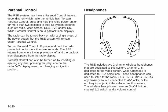
Parental ControlThe RSE system may have a Parental Control feature,depending on which radio the vehicle has. To startParental Control, press and hold the radio power buttonfor more than two seconds to stop all system featuressuch as: radio, video screen, RSA, DVD and/or CD.While Parental Control is on, a padlock icon displays.
The radio can be turned back on with a single press ofthe power button, but the RSE system will remainunder Parental Control.
To turn Parental Control off, press and hold the radiopower button for more than two seconds. The RSEreturns from where it was previously left and the padlockicon disappears from the radio display.
Parental Control can also be turned off by inserting orejecting any disc, pressing the play icon on theradio DVD display menu, or changing an ignitionposition.
Headphones
The RSE includes two 2-channel wireless headphonesthat are dedicated to this system. Channel 1 isdedicated to the video screen, while Channel 2 isdedicated to RSA selections. These headphones canused to listen to the radio, CDs, DVDs, MP3s, DVDAs,any auxiliary source connected to A/V jacks, or theauxiliary input jack, if the vehicle has this feature.The wireless headphones have an On/Off button,channel 1/2 switch, and a volume control.
3-130

Push the power button to turn on the headphones.An indicator light located on the headphones comes on.If the light comes on but, there is intermittent soundand/or static on the headphones, or if the indicator lightdoes not come on, the batteries might need to bereplaced. See “Battery Replacement” later in this sectionfor more information. Switch the headphones to Offwhen not in use.
Infrared transmitters are located at the rear of theoverhead console. The headphones shut offautomatically to save the battery power if the RSEsystem and RSA are shut off or if the headphonesare out of range of the transmitters for more thanthree minutes. If you move too far forward or step out ofthe vehicle, the headphones lose the audio signal.
The headphones automatically turns off after four hoursof continuous use.
To adjust the volume on the headphones, use thevolume control located on the right side.
For optimal audio performance, the headphones mustbe worn correctly. The symbol L (Left) appears onthe upper left side, above the ear pad and should bepositioned on the left ear. The symbol R (Right) appearson the upper right side, above the ear pad and shouldbe positioned on the right ear.
Notice: Do not store the headphones in heat ordirect sunlight. This could damage the headphonesand repairs will not be covered by the warranty.Storage in extreme cold can weaken the batteries.Keep the headphones stored in a cool, dry place.
If the foam ear pads attached to the headphonesbecome worn or damaged, the pads can be replacedseparately from the headphone set. Refer to yourdealer/retailer for more information.
Battery ReplacementTo change the batteries on the headphones, do thefollowing:
1. Turn the screw to loosen the battery door locatedon the left side of the headphones. Slide thebattery door open.
2. Replace the two batteries in the compartment.Make sure that they are installed correctly, usingthe diagram on the inside of the batterycompartment.
3. Replace the battery door and tighten the doorscrew.
If the headphones are to be stored for a long period oftime, remove the batteries and keep them in a cool,dry place.
3-131
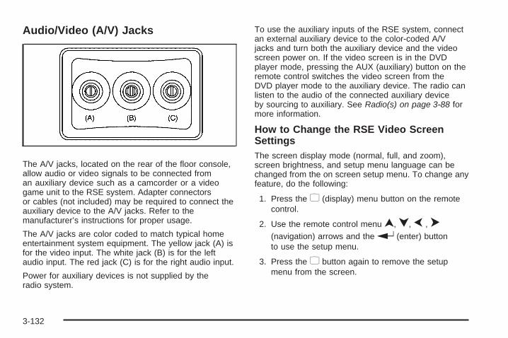
Audio/Video (A/V) Jacks
The A/V jacks, located on the rear of the floor console,allow audio or video signals to be connected froman auxiliary device such as a camcorder or a videogame unit to the RSE system. Adapter connectorsor cables (not included) may be required to connect theauxiliary device to the A/V jacks. Refer to themanufacturer’s instructions for proper usage.
The A/V jacks are color coded to match typical homeentertainment system equipment. The yellow jack (A) isfor the video input. The white jack (B) is for the leftaudio input. The red jack (C) is for the right audio input.
Power for auxiliary devices is not supplied by theradio system.
To use the auxiliary inputs of the RSE system, connectan external auxiliary device to the color-coded A/Vjacks and turn both the auxiliary device and the videoscreen power on. If the video screen is in the DVDplayer mode, pressing the AUX (auxiliary) button on theremote control switches the video screen from theDVD player mode to the auxiliary device. The radio canlisten to the audio of the connected auxiliary deviceby sourcing to auxiliary. See Radio(s) on page 3-88 formore information.
How to Change the RSE Video ScreenSettingsThe screen display mode (normal, full, and zoom),screen brightness, and setup menu language can bechanged from the on screen setup menu. To change anyfeature, do the following:
1. Press the z (display) menu button on the remotecontrol.
2. Use the remote control menu n, q, p , o(navigation) arrows and the r (enter) buttonto use the setup menu.
3. Press the z button again to remove the setupmenu from the screen.
3-132

Audio OutputAudio from the DVD player or auxiliary inputs can beheard through the following possible sources:
• Wireless Headphones
• Vehicle Speakers
• Vehicle wired headphone jacks on the rear seataudio system, if the vehicle has this feature.
The RSE system always transmits the audio signal tothe wireless headphones, if there is audio available.See “Headphones” earlier in this section for moreinformation.
The DVD player is capable of outputting audio to thewired headphone jacks on the RSA system, if thevehicle has this feature. The DVD player can beselected as an audio source on the RSA system.See Rear Seat Audio (RSA) on page 3-139 for moreinformation.
When a device is connected to the A/V jacks, or theradio’s auxiliary input jack, if the vehicle has this feature,the rear seat passengers are able to hear audio fromthe auxiliary device through the wireless or wiredheadphones. The front seat passengers are able tolisten to playback from this device through the vehiclespeakers by selecting AUX as the source on the radio.
Video ScreenThe video screen is located in the overhead console.
To use the video screen, do the following:
1. Push the release button located on the overheadconsole.
2. Move the screen to the desired position.
When the video screen is not in use, push it up into itslocked position.
If a DVD is playing and the screen is raised to its lockedposition, the screen remains on. This is normal, andthe DVD continues to play through the previous audiosource. Use the remote control power button or eject thedisc to turn off the screen.
The overhead console contains the infrared transmittersfor the wireless headphones and the infrared receiversfor the remote control. They are located at the rearof the console.
Notice: Avoid directly touching the video screen,as damage may occur. See “Cleaning the VideoScreen” later in this section for more information.
3-133

Remote ControlTo use the remote control, aim it at the transmitterwindow at the rear of the RSE overhead console andpress the desired button. Direct sunlight or very brightlight could affect the ability of the RSE transmitterto receive signals from the remote control. If the remotecontrol does not seem to be working, the batteriesmight need to be replaced. See “Battery Replacement”later in this section. Objects blocking the line of sightcould also affect the function of the remote control.
If a CD or DVD is in the Radio DVD slot, the remotecontrol O (power) button can be used to turn onthe video screen display and start the disc. The radiocan also turn on the video screen display. See Radio(s)on page 3-88 for more information.
Notice: Storing the remote control in a hot area orin direct sunlight can damage it, and the repairswill not be covered by the warranty. Storage inextreme cold can weaken the batteries. Keep theremote control stored in a cool, dry place.
If the remote control becomes lost or damaged, a newuniversal remote control can be purchased. If thishappens, make sure the universal remote control usesa code set of Toshiba®.
Remote Control Buttons
O (Power): Press this button to turn the video screenon and off.
P (Illumination): Press this button to turn the remotecontrol backlight on. The backlight automaticallytimes out after seven to ten seconds if no other buttonis pressed while the backlight is on.
v (Title): Press this button to return the DVD to themain menu of the DVD. This function could vary foreach disc.
3-134

y (Main Menu): Press this button to access the DVDmenu. The DVD menu is different on every DVD.Use the navigation arrows to move the cursor aroundthe DVD menu. After making a selection press the enterbutton. This button only operates when using a DVD.
n, q, p, o (Menu Navigation Arrows): Usethe arrow buttons to navigate through a menu.
r (Enter): Press this button to select the choice thatis highlighted in any menu.
z (Display Menu): Press this button to adjust thebrightness, screen display mode (normal, full, or zoom),and display the language menu.
q (Return): Press this button to exit the currentactive menu and return to the previous menu. Thisbutton operates only when the display menu or a DVDmenu is active.
c (Stop): Press this button to stop playing, fastreversing, or fast forwarding a DVD. Press this buttontwice to return to the beginning of the DVD.
s (Play/Pause): Press this button to start playing aDVD. Press this button while a DVD is playing topause it. Press it again to continue playing the DVD.
While the DVD is playing, the DVD can be played slowlyby pressing the play/pause button then pressing thefast forward button. The DVD continues playing in a slow
play mode. Also, reverse can be played slowly bypressing the play/pause button and then pressing thefast reverse button. To cancel slow play mode, press theplay/pause button.
t (Previous Track/Chapter): Press this button toreturn to the start of the current track or chapter.Press this button again to go to the previous track orchapter. This button might not work when the DVDis playing the copyright information or the previews.
u (Next Track/Chapter): Press this button to go to thebeginning of the next chapter or track. This buttonmight not work while the DVD is playing the copyrightinformation or the previews.
r (Fast Reverse): Press this button to quickly reversethe DVD or CD. To stop fast reversing a DVD video,press the play/pause button. To stop fast reversinga DVD audio or CD, release the fast reverse button.This button might not work when the DVD is playing thecopyright information or the previews.
[ (Fast Forward): Press this button to fast forwardthe DVD or CD. To stop fast forwarding a DVDvideo, press the play/pause button. To stop fastforwarding a DVD audio or CD, release the fast forwardbutton. This button might not work while the DVD isplaying the copyright information or the previews.
3-135

e (Audio): Press this button to change audio tracks onDVDs that have this feature when the DVD is playing.The format and content of this function vary for each disc.
{ (Subtitles): Press this button to turn ON/OFFsubtitles and to move through subtitle options when aDVD is playing. The format and content of this functionvary for each disc.
AUX (Auxiliary): Press this button to switch the systembetween the DVD player and an auxiliary source.
d (Camera): Press this button to change cameraangles on DVDs that have this feature while a DVD isplaying. The format and content of this function vary foreach disc.
1 through 0 (Numeric Keypad): The numeric keypadprovides the capability of direct chapter or tracknumber selection.
\ (Clear): Press this button within three seconds afterentering a numeric selection, to clear all numerical inputs.
} 10 (Double Digit Entries): Press this button toselect chapter or track numbers greater than nine.Press this button before entering the number.
Battery ReplacementTo change the remote control batteries, do the following:
1. Slide the rear cover back on the remote control.
2. Replace the two batteries in the compartment.Make sure they are installed correctly using thediagram on the inside of the remote control.
3. Replace the battery cover.
If the remote control is to be stored for a long period oftime, remove the batteries and keep them in a cool,dry place.
Problem Recommended ActionNo power. The ignition might not be
turned ON/RUN or inACC/ACCESSORY.
The picture does not fillthe screen. There areblack borders on thetop and bottom or onboth sides or it looksstretched out.
Check the display modesettings in the setup menuby pressing the displaymenu button on theremote control.
In auxiliary mode, thepicture moves or scrolls.
Check the auxiliary inputconnections at bothdevices.
3-136

Problem Recommended ActionThe remote control doesnot work.
Check to make sure thereis no obstruction betweenthe remote control andthe transmitter window.Check the batteries tomake sure they are notdead or installedincorrectly.
After stopping the player,I push Play but sometimesthe DVD starts where I leftoff and sometimes at thebeginning.
If the stop button waspressed one time, theDVD player resumesplaying where the DVDwas stopped. If the stopbutton was pressed twotimes the DVD playerbegins to play from thebeginning of the DVD.
The auxiliary source isrunning but there is nopicture or sound.
Check that the RSE videoscreen is in the auxiliarysource mode.Check the auxiliary inputconnections at bothdevices.
Problem Recommended ActionSometimes the wirelessheadphone audio cuts outor buzzes.
Check for obstructions,low batteries, receptionrange, and interferencefrom cellular telephonetowers or by using acellular telephone inthe vehicle.Check that theheadphones are oncorrectly using the L (left)and R (right) on theheadphones.
I lost the remote and/orthe headphones.
See your dealer/retailerfor assistance.
The DVD is playing, butthere is no picture orsound.
Check that the RSE videoscreen is sourced to theDVD player.
3-137

DVD Display Error MessagesThe DVD display error message depends on the radiothat is in the vehicle. The video screen can displayone of the following:
Disc Load/Eject Error: This message displays whenthere are disc load or eject problems.
Disc Format Error: This message displays, if the discis inserted with the disc label wrong side up, or ifthe disc is damaged.
Disc Region Error: This message displays, if the discis not from a correct region.
No Disc Inserted: This message displays, if no discis present when EJECT or DVD AUX is pressed onthe radio.
DVD DistortionVideo distortion can occur when operating cellularphones, scanners, CB radios, Global Position Systems(GPS)*, two-way radios, mobile fax, or walkie talkies.
It might be necessary to turn off the DVD player whenoperating one of these devices in or near the vehicle.
*Excludes the OnStar® System.
Cleaning the RSE Overhead ConsoleWhen cleaning the RSE overhead console surface, useonly a clean cloth dampened with clean water.
Cleaning the Video ScreenWhen cleaning the video screen, use only a clean clothdampened with clean water. Use care when directlytouching or cleaning the screen, as damage could result.
3-138
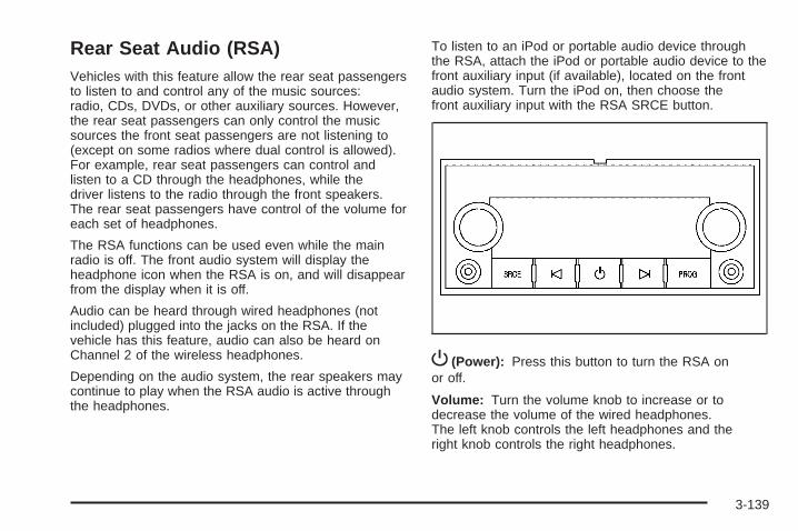
Rear Seat Audio (RSA)Vehicles with this feature allow the rear seat passengersto listen to and control any of the music sources:radio, CDs, DVDs, or other auxiliary sources. However,the rear seat passengers can only control the musicsources the front seat passengers are not listening to(except on some radios where dual control is allowed).For example, rear seat passengers can control andlisten to a CD through the headphones, while thedriver listens to the radio through the front speakers.The rear seat passengers have control of the volume foreach set of headphones.
The RSA functions can be used even while the mainradio is off. The front audio system will display theheadphone icon when the RSA is on, and will disappearfrom the display when it is off.
Audio can be heard through wired headphones (notincluded) plugged into the jacks on the RSA. If thevehicle has this feature, audio can also be heard onChannel 2 of the wireless headphones.
Depending on the audio system, the rear speakers maycontinue to play when the RSA audio is active throughthe headphones.
To listen to an iPod or portable audio device throughthe RSA, attach the iPod or portable audio device to thefront auxiliary input (if available), located on the frontaudio system. Turn the iPod on, then choose thefront auxiliary input with the RSA SRCE button.
P (Power): Press this button to turn the RSA onor off.
Volume: Turn the volume knob to increase or todecrease the volume of the wired headphones.The left knob controls the left headphones and theright knob controls the right headphones.
3-139

SRCE (Source): Press this button to switch betweenthe radio (AM/FM), XM™ (if equipped), CD, and ifthe vehicle has these features, DVD, front auxiliary,and rear auxiliary.
©¨(Seek): When listening to FM, AM, or XM™(if equipped), press the seek arrows to go to theprevious or to the next station or channels and staythere. This function is inactive, with some radios, if thefront seat passengers are listening to the radio.
Press and hold either seek arrow until the displayflashes, to tune to an individual station. The displaystops flashing after the buttons have not been pushedfor more than two seconds. This function is inactive, withsome radios, if the front seat passengers are listeningto the radio.
While listening to a disc, press the left seek arrow togo back to the start of the current track or chapter(if more than ten seconds have played). Press theright seek arrow to go the next track or chapter on thedisc. This function is inactive, with some radios, ifthe front seat passengers are listening to the disc.
While a DVD video menu is being displayed, presseither seek arrow to perform a cursor up or down on themenu. Hold either seek arrow to perform a cursor leftor right on the menu.
PROG (Program): Press this button to go to thenext preset radio station or channel set on the mainradio. This function is inactive, with some radios, if thefront seat passengers are listening to the radio.
While a CD or DVD audio disc is playing, press thisbutton to go to the beginning of the CD or DVD audio.This function is inactive, with some radios, if thefront seat passengers are listening to the CD orDVD audio.
While a disc is playing in the CD or DVD changer, pressthis button to select the next disc, if multiple discs areloaded. This function is inactive, with some radios, if thefront seat passengers are listening to the disc.
While a DVD video menu is being displayed, press thePROG button to perform the menu function, Enter.
Theft-Deterrent FeatureTHEFTLOCK® is designed to discourage theft of thevehicle’s radio by learning a portion of the VehicleIdentification Number (VIN). The radio does not operateif it is stolen or moved to a different vehicle.
3-140

Audio Steering Wheel ControlsVehicles with audiosteering wheel controlscould differ depending onthe vehicle’s options.Some audio controlscan be adjusted at thesteering wheel.
w (Next): Press to go to the next radio station storedas a favorite, or the next track if a CD/DVD is playing.
xc (Previous/End): Press to go to the previousradio station stored as a favorite, the next trackif a CD/DVD is playing, to reject an incoming call, orend a current call.
bg (Mute/Push to Talk): Press to silence the vehiclespeakers only. Press again to turn the sound on.For vehicles with OnStar® or Bluetooth systems pressand hold bg for longer than two seconds to interactwith those systems. See OnStar® System on page 2-71and Bluetooth® on page 3-119 in this manual for moreinformation.
SRCE (Source/Voice Recognition): Press to switchbetween the radio (AM, FM, XM), CD, and for vehicleswith, DVD, front auxiliary, and rear auxiliary.
For vehicles with the navigation system, press and holdthis button for longer than one second to initiatevoice recognition. See “Voice Recognition” in theNavigation System manual for more information.
+ e − e (Volume): Press to increase or to decreasethe radio volume.
¨(Seek): Press to go to the next radio station while inAM, FM, or XM™. Press ¨ to go to the next track orchapter while sourced to the CD or DVD slot. Pressthe ¨if multiple discs are loaded to go to the next discwhile sourced to a CD player.
Radio ReceptionFrequency interference and static can occur duringnormal radio reception if items such as cell phonechargers, vehicle convenience accessories, and externalelectronic devices are plugged into the accessory poweroutlet. If there is interference or static, unplug the itemfrom the accessory power outlet.
3-141

AMThe range for most AM stations is greater than for FM,especially at night. The longer range can cause stationfrequencies to interfere with each other. For better radioreception, most AM radio stations boost the powerlevels during the day, and then reduce these levelsduring the night. Static can also occur when things likestorms and power lines interfere with radio reception.When this happens, try reducing the treble on the radio.
FM StereoFM signals only reach about 10 to 40 miles (16 to 65 km).Although the radio has a built-in electronic circuit thatautomatically works to reduce interference, some staticcan occur, especially around tall buildings or hills,causing the sound to fade in and out.
XM™ Satellite Radio ServiceXM Satellite Radio Service gives digital radio receptionfrom coast-to-coast in the 48 contiguous United States,and in Canada. Just as with FM, tall buildings or hills caninterfere with satellite radio signals, causing the sound tofade in and out. In addition, traveling or standing underheavy foliage, bridges, garages, or tunnels may causeloss of the XM signal for a period of time.
Cellular Phone UsageCellular phone usage may cause interference with thevehicle’s radio. This interference may occur whenmaking or receiving phone calls, charging the phone’sbattery, or simply having the phone on. This interferencecauses an increased level of static while listening tothe radio. If static is received while listening to the radio,unplug the cellular phone and turn it off.
Fixed Mast AntennaThe fixed mast antenna can withstand most car washeswithout being damaged as long as it is securely attachedto the base. If the mast becomes slightly bent, straightenit out by hand. If the mast is badly bent, replace it.
Occasionally check to make sure the antenna istightened to its base. If tightening is required, tighten byhand until fully seated plus one quarter turn.
XM™ Satellite Radio Antenna SystemThe XM Satellite Radio antenna is located on the roof ofthe vehicle. Keep the antenna clear of obstructionsfor clear radio reception.
If the vehicle has a sunroof, the performance of theXM system may be affected if the sunroof is open.
3-142

Your Driving, the Road, and the Vehicle ............4-2Driving for Better Fuel Economy .......................4-2Defensive Driving ...........................................4-2Drunk Driving .................................................4-3Control of a Vehicle ........................................4-3Braking .........................................................4-4Antilock Brake System (ABS) ...........................4-5Braking in Emergencies ...................................4-6StabiliTrak® System ........................................4-6Locking Rear Axle ..........................................4-9Steering ........................................................4-9Off-Road Recovery .......................................4-10Passing .......................................................4-11Loss of Control .............................................4-11Off-Road Driving ...........................................4-12Driving at Night ............................................4-25Driving in Rain and on Wet Roads ..................4-25
Before Leaving on a Long Trip .......................4-26Highway Hypnosis ........................................4-26Hill and Mountain Roads ................................4-27Winter Driving ..............................................4-28If Your Vehicle is Stuck in Sand, Mud,
Ice, or Snow .............................................4-30Rocking Your Vehicle to Get It Out .................4-30Recovery Hooks ...........................................4-31Loading the Vehicle ......................................4-32Adding a Snow Plow or Similar Equipment .......4-38Truck-Camper Loading Information ..................4-42Pickup Conversion to Chassis Cab ..................4-45
Towing ..........................................................4-45Towing Your Vehicle .....................................4-45Recreational Vehicle Towing ...........................4-45Towing a Trailer ...........................................4-51Trailer Recommendations ...............................4-84
Section 4 Driving Your Vehicle
4-1

Your Driving, the Road, andthe Vehicle
Driving for Better Fuel EconomyDriving habits can affect fuel mileage. Here are somedriving tips to get the best fuel economy possible.
• Avoid fast starts and accelerate smoothly.
• Brake gradually and avoid abrupt stops.
• Avoid idling the engine for long periods of time.
• When road and weather conditions are appropriate,use cruise control, if equipped.
• Always follow posted speed limits or drive moreslowly when conditions require.
• Keep vehicle tires properly inflated.
• Combine several trips into a single trip.
• Replace the vehicle’s tires with the same TPC Specnumber molded into the tire’s sidewall near the size.
• Follow recommended scheduled maintenance.
Defensive DrivingDefensive driving means “always expect theunexpected.” The first step in driving defensivelyis to wear your safety belt — See Safety Belts: TheyAre for Everyone on page 1-16.
{CAUTION:
Assume that other road users (pedestrians,bicyclists, and other drivers) are going to becareless and make mistakes. Anticipate whatthey might do and be ready. In addition:
• Allow enough following distance between youand the driver in front of you.
• Focus on the task of driving.
Driver distraction can cause collisions resulting ininjury or possible death. These simple defensivedriving techniques could save your life.
4-2

Drunk Driving
{CAUTION:
Drinking and then driving is very dangerous. Yourreflexes, perceptions, attentiveness, and judgmentcan be affected by even a small amount of alcohol.You can have a serious — or even fatal — collisionif you drive after drinking. Do not drink and drive orride with a driver who has been drinking. Ride homein a cab; or if you are with a group, designate adriver who will not drink.
Death and injury associated with drinking and driving isa global tragedy.
Alcohol affects four things that anyone needs to drive avehicle: judgment, muscular coordination, vision, andattentiveness.
Police records show that almost 40 percent of all motorvehicle-related deaths involve alcohol. In most cases,these deaths are the result of someone who was drinkingand driving. In recent years, more than 17,000 annualmotor vehicle-related deaths have been associated withthe use of alcohol, with about 250,000 people injured.
For persons under 21, it is against the law in everyU.S. state to drink alcohol. There are good medical,psychological, and developmental reasons forthese laws.
The obvious way to eliminate the leading highwaysafety problem is for people never to drink alcoholand then drive.
Medical research shows that alcohol in a person’ssystem can make crash injuries worse, especiallyinjuries to the brain, spinal cord, or heart. This meansthat when anyone who has been drinking — driveror passenger — is in a crash, that person’s chanceof being killed or permanently disabled is higher thanif the person had not been drinking.
Control of a VehicleThe following three systems help to control the vehiclewhile driving — brakes, steering, and accelerator.At times, as when driving on snow or ice, it is easy toask more of those control systems than the tires androad can provide. Meaning, you can lose control ofthe vehicle. See StabiliTrak® System on page 4-6.
Adding non-dealer/non-retailer accessories can affectvehicle performance. See Accessories and Modificationson page 5-4.
4-3

BrakingSee Brake System Warning Light on page 3-42.
Braking action involves perception time and reactiontime. Deciding to push the brake pedal is perceptiontime. Actually doing it is reaction time.
Average reaction time is about three-fourths of asecond. But that is only an average. It might be lesswith one driver and as long as two or three seconds ormore with another. Age, physical condition, alertness,coordination, and eyesight all play a part. So do alcohol,drugs, and frustration. But even in three-fourths of asecond, a vehicle moving at 60 mph (100 km/h) travels66 feet (20 m). That could be a lot of distance in anemergency, so keeping enough space between thevehicle and others is important.
And, of course, actual stopping distances vary greatlywith the surface of the road, whether it is pavement orgravel; the condition of the road, whether it is wet, dry,or icy; tire tread; the condition of the brakes; the weightof the vehicle; and the amount of brake force applied.
Avoid needless heavy braking. Some people drivein spurts — heavy acceleration followed by heavybraking — rather than keeping pace with traffic. Thisis a mistake. The brakes might not have time to coolbetween hard stops. The brakes will wear out much fasterwith a lot of heavy braking. Keeping pace with the trafficand allowing realistic following distances eliminates a lotof unnecessary braking. That means better braking andlonger brake life.
If the engine ever stops while the vehicle is beingdriven, brake normally but do not pump the brakes. If thebrakes are pumped, the pedal could get harder to pushdown. If the engine stops, there will still be some powerbrake assist but it will be used when the brake is applied.Once the power assist is used up, it can take longer tostop and the brake pedal will be harder to push.
Adding non-dealer/non-retailer accessories can affectvehicle performance. See Accessories and Modificationson page 5-4.
4-4

Antilock Brake System (ABS)This vehicle has the Antilock Brake System (ABS),an advanced electronic braking system that willhelp prevent a braking skid.
When the engine is started and the vehicle begins todrive away, ABS checks itself. A momentary motor orclicking noise might be heard while this test is going on.This is normal.
If there is a problem withABS, this warning lightstays on. See AntilockBrake System (ABS)Warning Light onpage 3-43.
Along with ABS, the vehicle has a Dynamic RearProportioning (DRP) system. If there is a DRP problem,both the brake and ABS warning lights come onaccompanied by a 10-second chime. The lights andchime will come on each time the ignition is turned onuntil the problem is repaired. See your dealer/retailerfor service.
Let us say the road is wet and you are driving safely.Suddenly, an animal jumps out in front of you. You slamon the brakes and continue braking. Here is whathappens with ABS:
A computer senses that the wheels are slowing down.If one of the wheels is about to stop rolling, the computerwill separately work the brakes at each front wheeland at both rear wheels.
ABS can change the brake pressure to each wheel,as required, faster than any driver could. This can helpthe driver steer around the obstacle while braking hard.
As the brakes are applied, the computer keeps receivingupdates on wheel speed and controls braking pressureaccordingly.
Remember: ABS does not change the time neededto get a foot up to the brake pedal or always decreasestopping distance. If you get too close to the vehicle infront of you, there will not be enough time to apply thebrakes if that vehicle suddenly slows or stops. Alwaysleave enough room up ahead to stop, even with ABS.
Using ABSDo not pump the brakes. Just hold the brake pedaldown firmly and let antilock work. The brakes mightvibrate or some noise might be heard, but this is normal.
4-5

Braking in EmergenciesABS allows the driver to steer and brake at the sametime. In many emergencies, steering can help more thaneven the very best braking.
Brake Assist (Except With 4.3L V6 Engine)If this vehicle has StabiliTrak®, it also has a BrakeAssist feature designed to assist the driver in stoppingor decreasing vehicle speed in emergency drivingconditions. This feature uses the stability systemhydraulic brake control module to supplement thepower brake system under conditions where the driverhas quickly and forcefully applied the brake pedal inan attempt to quickly stop or slow down the vehicle.The stability system hydraulic brake control moduleincreases brake pressure at each corner of the vehicleuntil the ABS activates. Minor brake pedal pulsationsor pedal movement during this time is normal andthe driver should continue to apply the brake pedal asthe driving situation dictates The Brake Assist featurewill automatically disengage when the brake pedalis released or brake pedal pressure is quicklydecreased.
StabiliTrak® SystemThe vehicle may have a vehicle stability enhancementsystem called StabiliTrak. It is an advanced computercontrolled system that assists the driver with directionalcontrol of the vehicle in difficult driving conditions.
StabiliTrak activates when the computer senses adiscrepancy between the intended path and the directionthe vehicle is actually traveling. StabiliTrak selectivelyapplies braking pressure at any one of the vehicle’sbrakes to assist the driver with keeping the vehicleon the intended path.
When the vehicle is started and begins to move, thesystem performs several diagnostic checks to insurethere are no problems. The system may be heard or feltwhile it is working. This is normal and does not meanthere is a problem with the vehicle. The system shouldinitialize before the vehicle reaches 20 mph (32 km/h).In some cases, it may take approximately two miles ofdriving before the system initializes.
If cruise control is being used when StabiliTrakactivates, the cruise control automatically disengages.The cruise control can be re-engaged when roadconditions allow. See Cruise Control on page 3-13for more information.
4-6
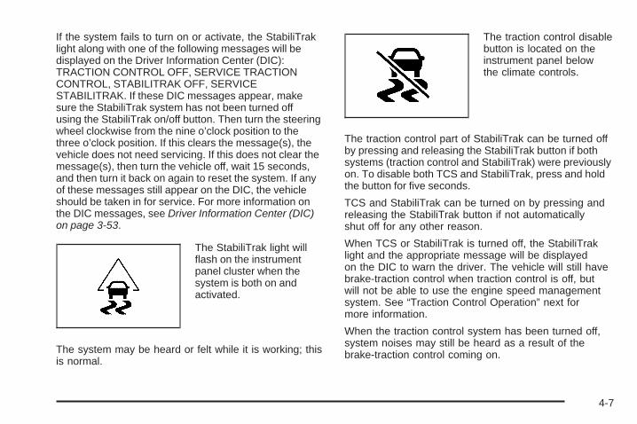
If the system fails to turn on or activate, the StabiliTraklight along with one of the following messages will bedisplayed on the Driver Information Center (DIC):TRACTION CONTROL OFF, SERVICE TRACTIONCONTROL, STABILITRAK OFF, SERVICESTABILITRAK. If these DIC messages appear, makesure the StabiliTrak system has not been turned offusing the StabiliTrak on/off button. Then turn the steeringwheel clockwise from the nine o’clock position to thethree o’clock position. If this clears the message(s), thevehicle does not need servicing. If this does not clear themessage(s), then turn the vehicle off, wait 15 seconds,and then turn it back on again to reset the system. If anyof these messages still appear on the DIC, the vehicleshould be taken in for service. For more information onthe DIC messages, see Driver Information Center (DIC)on page 3-53.
The StabiliTrak light willflash on the instrumentpanel cluster when thesystem is both on andactivated.
The system may be heard or felt while it is working; thisis normal.
The traction control disablebutton is located on theinstrument panel belowthe climate controls.
The traction control part of StabiliTrak can be turned offby pressing and releasing the StabiliTrak button if bothsystems (traction control and StabiliTrak) were previouslyon. To disable both TCS and StabiliTrak, press and holdthe button for five seconds.
TCS and StabiliTrak can be turned on by pressing andreleasing the StabiliTrak button if not automaticallyshut off for any other reason.
When TCS or StabiliTrak is turned off, the StabiliTraklight and the appropriate message will be displayedon the DIC to warn the driver. The vehicle will still havebrake-traction control when traction control is off, butwill not be able to use the engine speed managementsystem. See “Traction Control Operation” next formore information.
When the traction control system has been turned off,system noises may still be heard as a result of thebrake-traction control coming on.
4-7

It is recommended to leave the system on for normaldriving conditions, but it may be necessary to turn thesystem off if the vehicle is stuck in sand, mud, ice orsnow, and you want to “rock” the vehicle to attempt tofree it. It may also be necessary to turn off the systemwhen driving in extreme off-road conditions where highwheel spin is required. See If Your Vehicle is Stuck inSand, Mud, Ice, or Snow on page 4-30
When the transfer case is in 4LO, the stability system isautomatically disabled, the StabiliTrak light comes on andthe STABILITRAK OFF message will appear on the DIC.Both traction control and StabiliTrak are automaticallydisabled in this condition.
Traction Control OperationThe traction control system is part of the StabiliTraksystem. Traction control limits wheel spin by reducingengine power to the wheels (engine speed management)and by applying brakes to each individual wheel(brake-traction control) as necessary.
The traction control system is enabled automaticallywhen the vehicle is started. It will activate and theStabiliTrak light will flash if it senses that any of thewheels are spinning or beginning to lose tractionwhile driving. If traction control is turned off, only thebrake-traction control portion of traction control willwork. The engine speed management will be disabled.
In this mode, engine power is not reduced automaticallyand the driven wheels can spin more freely. This cancause the brake-traction control to activate constantly.
Notice: If the wheel(s) of one axle is allowed tospin excessively while the StabiliTrak, ABS and brakewarning lights and any relevant DIC messages aredisplayed, the transfer case could be damaged. Therepairs would not be covered by the vehicle warranty.Reduce engine power and do not spin the wheel(s)excessively while these lights and messages aredisplayed.
The traction control system may activate on dryor rough roads or under conditions such as heavyacceleration while turning or abrupt upshifts/downshiftsof the transmission. When this happens, a reductionin acceleration may be noticed, or a noise or vibrationmay be heard. This is normal.
If cruise control is being used when the systemactivates, the StabiliTrak light will flash and cruisecontrol will automatically disengage. Cruise controlmay be reengaged when road conditions allow.See Cruise Control on page 3-13.
StabiliTrak may also turn off automatically if itdetermines that a problem exists with the system.If the problem does not clear itself after restartingthe vehicle, see your dealer/retailer for service.
4-8

Locking Rear AxleVehicles with a locking rear axle can give moretraction on snow, mud, ice, sand or gravel. It workslike a standard axle most of the time, but when tractionis low, this feature will allow the rear wheel with the mosttraction to move the vehicle.
Steering
Power SteeringIf the vehicle is a Two-mode Hybrid, see the Two-modeHybrid manual for more information.
If power steering assist is lost because the engine stopsor the system is not functioning, the vehicle can besteered but it will take more effort.
Steering TipsIt is important to take curves at a reasonable speed.
Traction in a curve depends on the condition of the tiresand the road surface, the angle at which the curve isbanked, and vehicle speed. While in a curve, speedis the one factor that can be controlled.
If there is a need to reduce speed, do it before enteringthe curve, while the front wheels are straight.
Try to adjust the speed so you can drive through thecurve. Maintain a reasonable, steady speed. Wait toaccelerate until out of the curve, and then accelerategently into the straightaway.
Steering in EmergenciesThere are times when steering can be more effectivethan braking. For example, you come over a hill and finda truck stopped in your lane, or a car suddenly pulls outfrom nowhere, or a child darts out from between parkedcars and stops right in front of you. These problems canbe avoided by braking — if you can stop in time. Butsometimes you cannot stop in time because there is noroom. That is the time for evasive action — steeringaround the problem.
The vehicle can perform very well in emergencies likethese. First, apply the brakes. See Braking on page 4-4.It is better to remove as much speed as possible from acollision. Then steer around the problem, to the left orright depending on the space available.
4-9

An emergency like this requires close attention anda quick decision. If holding the steering wheel at therecommended 9 and 3 o’clock positions, it can be turneda full 180 degrees very quickly without removing eitherhand. But you have to act fast, steer quickly, and just asquickly straighten the wheel once you have avoided theobject.
The fact that such emergency situations are alwayspossible is a good reason to practice defensive drivingat all times and wear safety belts properly.
Off-Road RecoveryThe vehicle’s right wheels can drop off the edge of aroad onto the shoulder while driving.
If the level of the shoulder is only slightly below thepavement, recovery should be fairly easy. Ease off theaccelerator and then, if there is nothing in the way, steerso that the vehicle straddles the edge of the pavement.Turn the steering wheel 3 to 5 inches, 8 to 13 cm, (aboutone-eighth turn) until the right front tire contacts thepavement edge. Then turn the steering wheel to gostraight down the roadway.
4-10

PassingPassing another vehicle on a two-lane road can bedangerous. To reduce the risk of danger while passing:
• Look down the road, to the sides, and to crossroadsfor situations that might affect a successful pass.If in doubt, wait.
• Watch for traffic signs, pavement markings, andlines that could indicate a turn or an intersection.Never cross a solid or double-solid line on yourside of the lane.
• Do not get too close to the vehicle you want topass. Doing so can reduce your visibility.
• Wait your turn to pass a slow vehicle.
• When you are being passed, ease to the right.
Loss of ControlLet us review what driving experts say about whathappens when the three control systems — brakes,steering, and acceleration — do not have enoughfriction where the tires meet the road to do what thedriver has asked.
In any emergency, do not give up. Keep trying to steerand constantly seek an escape route or area of lessdanger.
SkiddingIn a skid, a driver can lose control of the vehicle.Defensive drivers avoid most skids by taking reasonablecare suited to existing conditions, and by not overdrivingthose conditions. But skids are always possible.
The three types of skids correspond to the vehicle’sthree control systems. In the braking skid, the wheels arenot rolling. In the steering or cornering skid, too muchspeed or steering in a curve causes tires to slip and losecornering force. And in the acceleration skid, too muchthrottle causes the driving wheels to spin.
Remember: StabiliTrak® helps avoid only theacceleration skid. See StabiliTrak® System on page 4-6.If the StabiliTrak® System is off, then an accelerationskid is best handled by easing your foot off theaccelerator pedal.
If the vehicle starts to slide, ease your foot off theaccelerator pedal and quickly steer the way you wantthe vehicle to go. If you start steering quickly enough,the vehicle may straighten out. Always be ready fora second skid if it occurs.
4-11

Of course, traction is reduced when water, snow, ice,gravel, or other material is on the road. For safety, slowdown and adjust your driving to these conditions. It isimportant to slow down on slippery surfaces becausestopping distance will be longer and vehicle controlmore limited.
While driving on a surface with reduced traction, try yourbest to avoid sudden steering, acceleration, or braking,including reducing vehicle speed by shifting to a lowergear. Any sudden changes could cause the tires toslide. You may not realize the surface is slippery untilthe vehicle is skidding. Learn to recognize warningclues — such as enough water, ice, or packed snowon the road to make a mirrored surface — and slowdown when you have any doubt.
Remember: Any Antilock Brake System (ABS) helpsavoid only the braking skid.
Off-Road DrivingVehicles with four-wheel drive can be used for off-roaddriving. Vehicles without four-wheel drive and vehicleswith 20-inch tire/wheel assemblies should not be drivenoff-road except on a level, solid surface.
The airbag system is designed to work properly undera wide range of conditions, including off-road usage.Always wear your safety belt and observe safe drivingspeeds, especially on rough terrain.
Drinking and driving can be very dangerous on any roadand this is certainly true for off-road driving. At the verytime you need special alertness and driving skills, yourreflexes, perceptions, and judgment can be affectedby even a small amount of alcohol. You could have aserious — or even fatal — accident if you drink anddrive or ride with a driver who has been drinking.
Off-roading can be great fun but has some definitehazards. The greatest of these is the terrain itself. Whenoff-road driving, traffic lanes are not marked, curves arenot banked, and there are no road signs. Surfaces canbe slippery, rough, uphill, or downhill.
Avoid sharp turns and abrupt maneuvers. Failure tooperate the vehicle correctly off-road could result inloss of vehicle control or vehicle rollover.
Off-roading involves some new skills. That is why it isvery important that you read these driving tips andsuggestions to help make off-road driving saferand more enjoyable.
4-12

Before You Go Off-Roading• Have all necessary maintenance and service
work done.
• Make sure there is enough fuel, that fluid levels arewhere they should be, and that the spare tire is fullyinflated.
• Be sure to read all the information aboutfour-wheel-drive vehicles in this manual.
• Make sure all underbody shields, if the vehicle hasthem, are properly attached.
• Know the local laws that apply to off-roading whereyou will be driving or check with law enforcementpeople in the area.
• Be sure to get the necessary permission if you willbe on private land.
If you think you will need some more ground clearanceat the front of your vehicle, you can remove the frontfascia lower air dam. The air dam is held in place bytwo bolts and 10 snaps accessible from underneath thefront fascia.
To remove the air dam:
1. Remove the two outboard air dam bolts.
2. With a flat-blade tool, disengage the snaps.
3. After the bolts are removed and the snaps aredisengaged, push forward on the air dam until itis free.
Notice: Operating your vehicle for extendedperiods without the front fascia lower air daminstalled can cause improper air flow to the engine.Always be sure to replace the front fascia airdam when you are finished off-road driving.
After off-roading, be sure to reinstall the air dam:
1. Line up the snaps and push the air dam rearwardto engage the snaps.
2. Install the two outboard bolts.
4-13

Loading Your Vehicle for Off-RoadDriving
{CAUTION:
• Cargo on the load floor piled higher than theseatbacks can be thrown forward during asudden stop. You or your passengers couldbe injured. Keep cargo below the top of theseatbacks.
• Unsecured cargo on the load floor can betossed about when driving over rough terrain.You or your passengers can be struck byflying objects. Secure the cargo properly.
CAUTION: (Continued)
CAUTION: (Continued)
• Heavy loads on the roof raise the vehicle’scenter of gravity, making it more likely to rollover. You can be seriously or fatally injured ifthe vehicle rolls over. Put heavy loads insidethe cargo area, not on the roof. Keep cargo inthe cargo area as far forward and low aspossible.
There are some important things to remember abouthow to load your vehicle.
• The heaviest things should be on the floor, forwardof the rear axle. Put heavier items as far forwardas you can.
• Be sure the load is properly secured, so things arenot tossed around.
You will find other important information under Loadingthe Vehicle on page 4-32 and Tires on page 5-65.
4-14

Environmental ConcernsOff-road driving can provide wholesome and satisfyingrecreation. However, it also raises environmentalconcerns. We recognize these concerns and urge everyoff-roader to follow these basic rules for protecting theenvironment:
• Always use established trails, roads, and areas thathave been specially set aside for public off-roadrecreational driving and obey all posted regulations.
• Avoid any driving practice that could damageshrubs, flowers, trees, or grasses or disturb wildlife.This includes wheel-spinning, breaking down trees,or unnecessary driving through streams or over softground.
• Always carry a litter bag and make sure all refuse isremoved from any campsite before leaving.
• Take extreme care with open fires (where permitted),camp stoves, and lanterns.
• Never park your vehicle over dry grass or othercombustible materials that could catch fire from theheat of the vehicle’s exhaust system.
Traveling to Remote AreasIt makes sense to plan your trip, especially when goingto a remote area. Know the terrain and plan your route.Get accurate maps of trails and terrain. Check to see ifthere are any blocked or closed roads.
It is also a good idea to travel with at least one othervehicle in case something happens to one of them.
For vehicles with a winch, be sure to read the winchinstructions. In a remote area, a winch can be handyif you get stuck but you will want to know how to use itproperly.
4-15

Getting Familiar with Off-Road DrivingIt is a good idea to practice in an area that is safeand close to home before you go into the wilderness.Off-roading requires some new and different skills.
Tune your senses to different kinds of signals. Youreyes need to constantly sweep the terrain for unexpectedobstacles. Your ears need to listen for unusual tire orengine sounds. Use your arms, hands, feet, and bodyto respond to vibrations and vehicle bounce.
Controlling the vehicle is the key to successful off-roaddriving. One of the best ways to control the vehicleis to control the speed. At higher speeds:
• You approach things faster and have less timeto react.
• There is less time to scan the terrain for obstacles.
• The vehicle has more bounce when driving overobstacles.
• More braking distance is needed, especially on anunpaved surface.
{CAUTION:
When you are driving off-road, bouncing and quickchanges in direction can easily throw you out ofposition. This could cause you to lose control andcrash. So, whether you are driving on or off theroad, you and your passengers should wearsafety belts.
Scanning the TerrainOff-road driving can take you over many different kindsof terrain. Be familiar with the terrain and its manydifferent features.
Surface Conditions: Off-roading surfaces can behard-packed dirt, gravel, rocks, grass, sand, mud, snow,or ice. Each of these surfaces affects the vehicle’ssteering, acceleration, and braking in different ways.Depending on the surface, slipping, sliding, wheelspinning, delayed acceleration, poor traction, andlonger braking distances can occur.
Surface Obstacles: Unseen or hidden obstaclescan be hazardous. A rock, log, hole, rut, or bump canstartle you if you are not prepared for them. Often theseobstacles are hidden by grass, bushes, snow, or eventhe rise and fall of the terrain itself.
4-16

Some things to consider:
• Is the path ahead clear?
• Will the surface texture change abruptly up ahead?
• Does the travel take you uphill or downhill?
• Will you have to stop suddenly or change directionquickly?
When driving over obstacles or rough terrain, keep afirm grip on the steering wheel. Ruts, troughs, or othersurface features can jerk the wheel out of your hands.
When driving over bumps, rocks, or other obstacles,the wheels can leave the ground. If this happens,even with one or two wheels, you cannot controlthe vehicle as well or at all.
Because you will be on an unpaved surface, it isespecially important to avoid sudden acceleration,sudden turns, or sudden braking.
Off-roading requires a different kind of alertness fromdriving on paved roads and highways. There are no roadsigns, posted speed limits, or signal lights. Use goodjudgment about what is safe and what is not.
Driving on HillsOff-road driving often takes you up, down, or acrossa hill. Driving safely on hills requires good judgment andan understanding of what the vehicle can and cannotdo. There are some hills that simply cannot be driven,no matter how well built the vehicle.
{CAUTION:
Many hills are simply too steep for any vehicle.If you drive up them, you will stall. If you drive downthem, you cannot control your speed. If you driveacross them, you will roll over. You could beseriously injured or killed. If you have any doubtabout the steepness, do not drive the hill.
4-17

Approaching a HillWhen you approach a hill, decide if it is too steep toclimb, descend, or cross. Steepness can be hard tojudge. On a very small hill, for example, there may bea smooth, constant incline with only a small change inelevation where you can easily see all the way to the top.On a large hill, the incline may get steeper as you nearthe top, but you might not see this because the crest ofthe hill is hidden by bushes, grass, or shrubs.
Consider this as you approach a hill:
• Is there a constant incline, or does the hill getsharply steeper in places?
• Is there good traction on the hillside, or will thesurface cause tire slipping?
• Is there a straight path up or down the hill so youwill not have to make turning maneuvers?
• Are there obstructions on the hill that can block yourpath, such as boulders, trees, logs, or ruts?
• What is beyond the hill? Is there a cliff, anembankment, a drop-off, a fence? Get out andwalk the hill if you do not know. It is the smartway to find out.
• Is the hill simply too rough? Steep hills often haveruts, gullies, troughs, and exposed rocks becausethey are more susceptible to the effects of erosion.
Driving UphillOnce you decide it is safe to drive up the hill:
• Use a low gear and get a firm grip on the steeringwheel.
• Get a smooth start up the hill and try to maintainspeed. Not using more power than needed canavoid spinning the wheels or sliding.
{CAUTION:
Turning or driving across steep hills can bedangerous. You could lose traction, slidesideways, and possibly roll over. You could beseriously injured or killed. When driving up hills,always try to go straight up.
• Try to drive straight up the hill if at all possible.If the path twists and turns, you might want tofind another route.
• Ease up on the speed as you approach the top ofthe hill.
• Attach a flag to the vehicle to be more visible toapproaching traffic on trails or hills.
4-18

• Sound the horn as you approach the top of the hillto let opposing traffic know you are there.
• Use headlamps even during the day to make thevehicle more visible to oncoming traffic.
{CAUTION:
Driving to the top (crest) of a hill at full speedcan cause an accident. There could be a drop-off,embankment, cliff, or even another vehicle. Youcould be seriously injured or killed. As you near thetop of a hill, slow down and stay alert.
If the vehicle stalls, or is about to stall, and you cannotmake it up the hill:
• Push the brake pedal to stop the vehicle and keepit from rolling backwards and apply the parkingbrake.
• If the engine is still running, shift the transmission toR (Reverse), release the parking brake, and slowlyback down the hill in R (Reverse).
• If the engine has stopped running, you need torestart it. With the brake pedal pressed and theparking brake still applied, shift the transmissionto P (Park) and restart the engine. Then, shift toR (Reverse), release the parking brake, and slowlyback down the hill as straight as possible inR (Reverse).
• While backing down the hill, put your left hand on thesteering wheel at the 12 o’clock position so you cantell if the wheels are straight and can maneuver asyou back down. It is best to back down the hill withthe wheels straight rather than in the left or rightdirection. Turning the wheel too far to the left orright will increase the possibility of a rollover.
Things not to do if the vehicle stalls, or is about to stall,when going up a hill:
• Never attempt to prevent a stall by shifting intoN (Neutral) to rev-up the engine and regain forwardmomentum. This will not work. The vehicle can rollbackward very quickly and could go out of control.
• Never try to turn around if about to stall when goingup a hill. If the hill is steep enough to stall the vehicle,it is steep enough to cause it to roll over. If youcannot make it up the hill, back straight down the hill.
4-19

If, after stalling, you try to back down the hill and decideyou just cannot do it, set the parking brake, put yourtransmission in P (Park), and turn off the engine. Leavethe vehicle and go get some help. Exit on the uphill sideand stay clear of the path the vehicle would take if it rolleddownhill. Do not shift the transfer case to Neutral whenyou leave the vehicle. Leave it in some gear.
{CAUTION:
Shifting the transfer case to Neutral can causeyour vehicle to roll even if the transmission is inP (Park). This is because the Neutral position onthe transfer case overrides the transmission. Youor someone else could be injured. If you are goingto leave your vehicle, set the parking brake andshift the transmission to P (Park). But do not shiftthe transfer case to Neutral.
Driving DownhillWhen off-roading takes you downhill, consider:
• How steep is the downhill? Will I be able to maintainvehicle control?
• What is the surface like? Smooth? Rough?Slippery? Hard-packed dirt? Gravel?
• Are there hidden surface obstacles? Ruts? Logs?Boulders?
• What is at the bottom of the hill? Is there a hiddencreek bank or even a river bottom with large rocks?
If you decide you can go down a hill safely, try to keepthe vehicle headed straight down. Use a low gear soengine drag can help the brakes so they do not have todo all the work. Descend slowly, keeping the vehicleunder control at all times.
4-20

{CAUTION:
Heavy braking when going down a hill can causeyour brakes to overheat and fade. This couldcause loss of control and a serious accident.Apply the brakes lightly when descending a hilland use a low gear to keep vehicle speed undercontrol.
Things not to do when driving down a hill:
• When driving downhill, avoid turns that take youacross the incline of the hill. A hill that is not toosteep to drive down might be too steep to driveacross. The vehicle could roll over.
• Never go downhill with the transmission inN (Neutral), called free-wheeling. The brakes willhave to do all the work and could overheat and fade.
Vehicles are much more likely to stall when going uphill,but if it happens when going downhill:
1. Stop the vehicle by applying the regular brakes andapply the parking brake.
2. Shift to P (Park) and, while still braking, restart theengine.
3. Shift back to a low gear, release the parking brake,and drive straight down.
4. If the engine will not start, get out and get help.
4-21

Driving Across an InclineAn off-road trail will probably go across the inclineof a hill. To decide whether to try to drive across theincline, consider the following:
{CAUTION:
Driving across an incline that is too steep willmake your vehicle roll over. You could beseriously injured or killed. If you have any doubtabout the steepness of the incline, do not driveacross it. Find another route instead.
• A hill that can be driven straight up or downmight be too steep to drive across. When goingstraight up or down a hill, the length of the wheelbase — the distance from the front wheels to the rearwheels — reduces the likelihood the vehicle willtumble end over end. But when driving across anincline, the narrower track width — the distancebetween the left and right wheels — might notprevent the vehicle from tilting and rolling over.Driving across an incline puts more weight on thedownhill wheels which could cause a downhill slideor a rollover.
• Surface conditions can be a problem. Loose gravel,muddy spots, or even wet grass can cause thetires to slip sideways, downhill. If the vehicle slipssideways, it can hit something that will trip it — arock, a rut, etc. — and roll over.
• Hidden obstacles can make the steepness of theincline even worse. If you drive across a rock with theuphill wheels, or if the downhill wheels drop into a rutor depression, the vehicle can tilt even more.
For these reasons, carefully consider whether to try todrive across an incline. Just because the trail goesacross the incline does not mean you have to drive it.The last vehicle to try it might have rolled over.
If you feel the vehicle starting to slide sideways, turndownhill. This should help straighten out the vehicle andprevent the side slipping. The best way to prevent this isto “walk the course” first, so you know what the surface islike before driving it.
4-22

Stalling on an Incline
{CAUTION:
Getting out on the downhill (low) side of a vehiclestopped across an incline is dangerous. If thevehicle rolls over, you could be crushed or killed.Always get out on the uphill (high) side of thevehicle and stay well clear of the rollover path.
If the vehicle stalls when crossing an incline, be sureyou, and any passengers, get out on the uphill side, evenif the door there is harder to open. If you get out on thedownhill side and the vehicle starts to roll over, you willbe right in its path.
If you have to walk down the slope, stay out of the paththe vehicle will take if it does roll over.
Driving in Mud, Sand, Snow, or IceWhen you drive in mud, snow, or sand, the wheelsdo not get good traction. Acceleration is not as quick,turning is more difficult, and braking distances arelonger.
It is best to use a low gear when in mud — the deeperthe mud, the lower the gear. In really deep mud, keep thevehicle moving so it does not get stuck.
When driving on sand, wheel traction changes.On loosely packed sand, such as on beaches or sanddunes, the tires will tend to sink into the sand. This affectssteering, accelerating, and braking. Drive at a reducedspeed and avoid sharp turns or abrupt maneuvers.
Hard packed snow and ice offer the worst tire traction.On these surfaces, it is very easy to lose control. On wetice, for example, the traction is so poor that you willhave difficulty accelerating. And, if the vehicle does getmoving, poor steering and difficult braking can cause itto slide out of control.
{CAUTION:
Driving on frozen lakes, ponds, or rivers can bedangerous. Underwater springs, currents under theice, or sudden thaws can weaken the ice. Yourvehicle could fall through the ice and you and yourpassengers could drown. Drive your vehicle on safesurfaces only.
4-23

Driving in Water
{CAUTION:
Driving through rushing water can be dangerous.Deep water can sweep your vehicle downstreamand you and your passengers could drown. If itis only shallow water, it can still wash away theground from under your tires, and you could losetraction and roll the vehicle over. Do not drivethrough rushing water.
Heavy rain can mean flash flooding, and flood watersdemand extreme caution.
Find out how deep the water is before driving through it.Do not try it if it is deep enough to cover the wheel hubs,axles, or exhaust pipe — you probably will not getthrough. Deep water can damage the axle and othervehicle parts.
If the water is not too deep, drive slowly through it.At faster speeds, water splashes on the ignition systemand the vehicle can stall. Stalling can also occur if you getthe tailpipe under water. If the tailpipe is under water, youwill never be able to start the engine. When going throughwater, remember that when the brakes get wet, it mighttake longer to stop. See Driving in Rain and on WetRoads on page 4-25.
After Off-Road DrivingRemove any brush or debris that has collectedon the underbody, chassis, or under the hood.These accumulations can be a fire hazard.
After operation in mud or sand, have the brake liningscleaned and checked. These substances can causeglazing and uneven braking. Check the body structure,steering, suspension, wheels, tires, and exhaust systemfor damage and check the fuel lines and cooling systemfor any leakage.
The vehicle requires more frequent service due tooff-road use. Refer to the Maintenance Schedule foradditional information.
4-24

Driving at NightNight driving is more dangerous than day drivingbecause some drivers are likely to be impaired — byalcohol or drugs, with night vision problems, or by fatigue.
Night driving tips include:
• Drive defensively.
• Do not drink and drive.
• Reduce headlamp glare by adjusting the insiderearview mirror.
• Slow down and keep more space between you andother vehicles because headlamps can only light upso much road ahead.
• Watch for animals.
• When tired, pull off the road.
• Do not wear sunglasses.
• Avoid staring directly into approaching headlamps.
• Keep the windshield and all glass on your vehicleclean — inside and out.
• Keep your eyes moving, especially during turns orcurves.
No one can see as well at night as in the daytime.But, as we get older, these differences increase.A 50-year-old driver might need at least twice as muchlight to see the same thing at night as a 20-year-old.
Driving in Rain and on Wet RoadsRain and wet roads can reduce vehicle traction andaffect your ability to stop and accelerate. Always driveslower in these types of driving conditions and avoiddriving through large puddles and deep-standing orflowing water.
{CAUTION:
Wet brakes can cause crashes. They might notwork as well in a quick stop and could causepulling to one side. You could lose control ofthe vehicle.
After driving through a large puddle of water or acar/vehicle wash, lightly apply the brake pedal untilthe brakes work normally.
Flowing or rushing water creates strong forces.Driving through flowing water could cause yourvehicle to be carried away. If this happens, youand other vehicle occupants could drown. Do notignore police warnings and be very cautious abouttrying to drive through flowing water.
4-25

HydroplaningHydroplaning is dangerous. Water can build up underyour vehicle’s tires so they actually ride on the water. Thiscan happen if the road is wet enough and you are goingfast enough. When your vehicle is hydroplaning, it haslittle or no contact with the road.
There is no hard and fast rule about hydroplaning.The best advice is to slow down when the road is wet.
Other Rainy Weather TipsBesides slowing down, other wet weather driving tipsinclude:
• Allow extra following distance.
• Pass with caution.
• Keep windshield wiping equipment in good shape.
• Keep the windshield washer fluid reservoir filled.
• Have good tires with proper tread depth. See Tireson page 5-65.
• Turn off cruise control.
Before Leaving on a Long TripTo prepare your vehicle for a long trip, consider havingit serviced by your dealer/retailer before departing.Things to check on your own include:• Windshield Washer Fluid: Reservoir full? Windows
clean — inside and outside?• Wiper Blades: In good shape?
• Fuel, Engine Oil, Other Fluids: All levels checked?
• Lamps: Do they all work and are lenses clean?
• Tires: Are treads good? Are tires inflated torecommended pressure?
• Weather and Maps: Safe to travel?Have up-to-date maps?
Highway HypnosisAlways be alert and pay attention to your surroundingswhile driving. If you become tired or sleepy, find asafe place to park your vehicle and rest.Other driving tips include:• Keep the vehicle well ventilated.
• Keep interior temperature cool.
• Keep your eyes moving — scan the road aheadand to the sides.
• Check the rearview mirror and vehicle instrumentsoften.
4-26

Hill and Mountain RoadsDriving on steep hills or through mountains is differentthan driving on flat or rolling terrain. Tips for drivingin these conditions include:
• Keep the vehicle serviced and in good shape.
• Check all fluid levels and brakes, tires, coolingsystem, and transmission.
• Going down steep or long hills, shift to a lower gear.
{CAUTION:
If you do not shift down, the brakes could get sohot that they would not work well. You would thenhave poor braking or even none going down a hill.You could crash. Shift down to let the engineassist the brakes on a steep downhill slope.
{CAUTION:
Coasting downhill in N (Neutral) or with the ignitionoff is dangerous. The brakes will have to do all thework of slowing down and they could get so hotthat they would not work well. You would thenhave poor braking or even none going down a hill.You could crash. Always have the engine runningand the vehicle in gear when going downhill.
• Stay in your own lane. Do not swing wide or cutacross the center of the road. Drive at speedsthat let you stay in your own lane.
• Top of hills: Be alert — something could be in yourlane (stalled car, accident).
• Pay attention to special road signs (falling rocksarea, winding roads, long grades, passing orno-passing zones) and take appropriate action.
See Off-Road Driving on page 4-12 for informationabout driving off-road.
4-27

Winter Driving
Driving on Snow or IceDrive carefully when there is snow or ice between thetires and the road, creating less traction or grip. Wet icecan occur at about 32°F (0°C) when freezing rain beginsto fall, resulting in even less traction. Avoid driving on wetice or in freezing rain until roads can be treated with saltor sand.
Drive with caution, whatever the condition. Accelerategently so traction is not lost. Accelerating too quicklycauses the wheels to spin and makes the surfaceunder the tires slick, so there is even less traction.
Try not to break the fragile traction. If you accelerate toofast, the drive wheels will spin and polish the surfaceunder the tires even more.
The StabiliTrak® System on page 4-6 improves theability to accelerate on slippery roads, but slow downand adjust your driving to the road conditions. Whendriving through deep snow, turn off the traction controlpart of the StabiliTrak® System to help maintainvehicle motion at lower speeds.
The Antilock Brake System (ABS) on page 4-5 improvesvehicle stability during hard stops on a slippery roads, butapply the brakes sooner than when on dry pavement.
Allow greater following distance on any slippery roadand watch for slippery spots. Icy patches can occur onotherwise clear roads in shaded areas. The surfaceof a curve or an overpass can remain icy when thesurrounding roads are clear. Avoid sudden steeringmaneuvers and braking while on ice.
Turn off cruise control, if equipped, on slippery surfaces.
Blizzard ConditionsBeing stuck in snow can be in a serious situation. Staywith the vehicle unless there is help nearby. If possible,use the Roadside Assistance Program on page 7-7.To get help and keep everyone in the vehicle safe:
• Turn on the Hazard Warning Flashers on page 3-8.
• Tie a red cloth to an outside mirror.
4-28

{CAUTION:
Snow can trap engine exhaust under the vehicle.This may cause exhaust gases to get inside.Engine exhaust contains carbon monoxide (CO)which cannot be seen or smelled. It can causeunconsciousness and even death.
If the vehicle is stuck in the snow:• Clear away snow from around the base of
your vehicle, especially any that is blockingthe exhaust pipe.
• Check again from time to time to be suresnow does not collect there.
• Open a window about two inches (5 cm) onthe side of the vehicle that is away from thewind to bring in fresh air.
• Fully open the air outlets on or under theinstrument panel.
• Adjust the Climate Control system to a settingthat circulates the air inside the vehicle andset the fan speed to the highest setting.See Climate Control System in the Index.
CAUTION: (Continued)
CAUTION: (Continued)
For more information about carbon monoxide, seeEngine Exhaust on page 2-55.
Snow can trap exhaust gases under your vehicle.This can cause deadly CO (carbon monoxide) gasto get inside. CO could overcome you and kill you.You cannot see it or smell it, so you might notknow it is in your vehicle. Clear away snow fromaround the base of your vehicle, especially anythat is blocking the exhaust.
Run the engine for short periods only as needed tokeep warm, but be careful.To save fuel, run the engine for only short periods asneeded to warm the vehicle and then shut the engineoff and close the window most of the way to save heat.Repeat this until help arrives but only when you feel reallyuncomfortable from the cold. Moving about to keep warmalso helps.If it takes some time for help to arrive, now and thenwhen you run the engine, push the accelerator pedalslightly so the engine runs faster than the idle speed.This keeps the battery charged to restart the vehicle andto signal for help with the headlamps. Do this as little aspossible to save fuel.
4-29

If Your Vehicle is Stuck in Sand,Mud, Ice, or SnowSlowly and cautiously spin the wheels to free thevehicle when stuck in sand, mud, ice, or snow.See Rocking Your Vehicle to Get It Out on page 4-30.
If the vehicle has a traction system, it can often helpto free a stuck vehicle. Refer to the vehicle’s tractionsystem in the Index. If stuck too severely for the tractionsystem to free the vehicle, turn the traction system offand use the rocking method.
{CAUTION:
If you let your vehicle’s tires spin at high speed,they can explode, and you or others could beinjured. The vehicle can overheat, causing anengine compartment fire or other damage.Spin the wheels as little as possible and avoidgoing above 35 mph (55 km/h) as shown on thespeedometer.
For information about using tire chains on the vehicle,see Tire Chains on page 5-90.
Rocking Your Vehicle to Get It OutTurn the steering wheel left and right to clear the areaaround the front wheels. For four-wheel-drive vehicles,shift into Four-Wheel High. For vehicles with StabiliTrak®,turn the traction control part of the system off. Shift backand forth between R (Reverse) and a forward gear,spinning the wheels as little as possible. To preventtransmission wear, wait until the wheels stop spinningbefore shifting gears. Release the accelerator pedal whileshifting, and press lightly on the accelerator pedal whenthe transmission is in gear. Slowly spinning the wheelsin the forward and reverse directions causes a rockingmotion that could free the vehicle. If that does not get thevehicle out after a few tries, it might need to be towed out.Recovery hooks can be used, if the vehicle has them.If the vehicle does need to be towed out, see TowingYour Vehicle on page 4-45.
4-30

Recovery Hooks
{CAUTION:
These hooks, when used, are under a lot of force.Always pull the vehicle straight out. Never pull onthe hooks at a sideways angle. The hooks couldbreak off and you or others could be injured fromthe chain or cable snapping back.
Notice: Never use recovery hooks to tow thevehicle. Your vehicle could be damaged and itwould not be covered by warranty.
For vehicles with recovery hooks at the front of thevehicle, you can use them if you are stuck off-roadand need to be pulled to some place where you cancontinue driving.
4-31

Loading the VehicleIt is very important to know how much weight yourvehicle can carry. This weight is called the vehiclecapacity weight and includes the weight of alloccupants, cargo, and all nonfactory-installedoptions. Two labels on your vehicle show howmuch weight it was designed to carry, the Tireand Loading Information label and the Certification/Tire label.
{CAUTION:
Do not load the vehicle any heavier thanthe Gross Vehicle Weight Rating (GVWR), oreither the maximum front or rear Gross AxleWeight Rating (GAWR). If you do, parts on thevehicle can break, and it can change the wayyour vehicle handles. These could cause youto lose control and crash. Also, overloadingcan shorten the life of the vehicle.
Tire and Loading Information Label
A vehicle specific Tire and Loading Informationlabel is attached to the center pillar (B-pillar).With the driver’s door open, you will find the labelattached below the door lock post (striker). The tireand loading information label shows the number ofoccupant seating positions (A), and the maximumvehicle capacity weight (B) in kilograms andpounds.
Label Example
4-32

The Tire and Loading Information label also showsthe size of the original equipment tires (C) and therecommended cold tire inflation pressures (D).For more information on tires and inflation seeTires on page 5-65 and Inflation - Tire Pressureon page 5-73.
There is also important loading information on thevehicle Certification/Tire label. It tells you the GrossVehicle Weight Rating (GVWR) and the Gross AxleWeight Rating (GAWR) for the front and rear axles.See “Certification/Tire Label” later in this section.
Steps for Determining Correct Load Limit1. Locate the statement “The combined weight
of occupants and cargo should never exceedXXX kg or XXX lbs” on your vehicle’s placard.
2. Determine the combined weight of the driverand passengers that will be riding in yourvehicle.
3. Subtract the combined weight of the driverand passengers from XXX kg or XXX lbs.
4. The resulting figure equals the availableamount of cargo and luggage load capacity.For example, if the “XXX” amount equals1400 lbs and there will be five 150 lbpassengers in your vehicle, the amount ofavailable cargo and luggage load capacityis 650 lbs (1400 − 750 (5 x 150) = 650 lbs).
5. Determine the combined weight of luggageand cargo being loaded on the vehicle. Thatweight may not safely exceed the availablecargo and luggage load capacity calculatedin Step 4.
6. If your vehicle will be towing a trailer, the loadfrom your trailer will be transferred to yourvehicle. Consult this manual to determine howthis reduces the available cargo and luggageload capacity of your vehicle. See Towing aTrailer on page 4-51 for important informationon towing a trailer, towing safety rules andtrailering tips.
4-33

Item Description Total
AVehicle CapacityWeight forExample 1 =
1,000 lbs(453 kg)
BSubtract OccupantWeight 150 lbs(68 kg) × 2 =
300 lbs (136 kg)
C Available Occupantand Cargo Weight = 700 lbs (317 kg)
Item Description Total
AVehicle CapacityWeight forExample 2 =
1,000 lbs(453 kg)
BSubtract OccupantWeight 150 lbs(68 kg) × 5 =
750 lbs (340 kg)
C Available CargoWeight = 250 lbs (113 kg)
Example 1 Example 2
4-34

Item Description Total
AVehicle CapacityWeight forExample 3 =
1,000 lbs(453 kg)
BSubtract OccupantWeight 200 lbs(91 kg) × 5 =
1000 lbs(453 kg)
C Available CargoWeight = 0 lbs (0 kg)
Refer to your vehicle’s tire and loading informationlabel for specific information about your vehicle’scapacity weight and seating positions.
The combined weight of the driver, passengers,and cargo should never exceed your vehicle’scapacity weight.
Certification/Tire Label
A vehicle specific Certification/Tire label is foundon the rear edge of the driver’s door. The labelshows the size of your vehicle’s original tires andthe inflation pressures needed to obtain the grossweight capacity of your vehicle. This is called GrossVehicle Weight Rating (GVWR). The GVWRincludes the weight of the vehicle, all occupants,fuel, and cargo.
Example 3
4-35

The Certification/Tire label also tells you themaximum weights for the front and rear axles,called Gross Axle Weight Rating (GAWR). To findout the actual loads on your front and rear axles,you need to go to a weigh station and weigh yourvehicle. Your dealer can help you with this. Be sureto spread out your load equally on both sides of thecenterline.
Never exceed the GVWR for your vehicle, or theGAWR for either the front or rear axle.
The Certification/Tire label also contains importantinformation about your Front Axle ReserveCapacity. See “What is front axle reserve capacity,and how do I calculate it?” under Adding a SnowPlow or Similar Equipment on page 4-38.
{CAUTION:
In the case of a sudden stop or collision,things carried in the bed of your truck couldshift forward and come into the passengerarea, injuring you and others. If you putthings in the bed of your truck, you shouldmake sure they are properly secured.
{CAUTION:
Do not load the vehicle any heavier thanthe Gross Vehicle Weight Rating (GVWR), oreither the maximum front or rear Gross AxleWeight Rating (GAWR). If you do, parts on thevehicle can break, and it can change the wayyour vehicle handles. These could cause youto lose control and crash. Also, overloadingcan shorten the life of the vehicle.
Notice: Overloading your vehicle may causedamage. Repairs would not be covered by yourwarranty. Do not overload your vehicle.Using heavier suspension components to getadded durability might not change your weightratings. Ask your dealer to help you load yourvehicle the right way.
If you put things inside your vehicle — likesuitcases, tools, packages, or anything else — theygo as fast as the vehicle goes. If you have to stopor turn quickly, or if there is a crash, they will keepgoing.
4-36

{CAUTION:
Things you put inside your vehicle can strikeand injure people in a sudden stop or turn,or in a crash.
• Put things in the cargo area of yourvehicle. Try to spread the weight evenly.
• Never stack heavier things, likesuitcases, inside the vehicle so that someof them are above the tops of the seats.
• Do not leave an unsecured child restraintin your vehicle.
• When you carry something inside thevehicle, secure it whenever you can.
• Do not leave a seat folded down unlessyou need to.
There is also important loading information foroff-road driving in this manual. See “Loading YourVehicle for Off-Road Driving“ under Off-RoadDriving on page 4-12.
Two-Tiered LoadingDepending on the model of your pick-up, youcan create an upper load platform by positioningtwo or four 2 inches (5 cm) by 6 inches (15 cm)wooden planks across the width of the pickup box.The planks must be inserted in the pickup boxdepressions. The length of the planks must allowfor at least a 3/4 inch (2 cm) bearing surface oneach end of the plank.
When using this upper load platform, be sure theload is securely tied down to prevent it from shifting.The load’s center of gravity should be positioned ina zone over the rear axle. The zone is located in thearea between the front of each wheel well and therear of each wheel well. The center of gravity heightmust not extend above the top of the pickup boxflareboard.
Any load that extends beyond the vehicle’staillamp area must be properly marked accordingto local laws and regulations.
Remember not to exceed the Gross Axle WeightRating (GAWR) of the front or rear axle.
4-37

Add-On EquipmentWhen you carry removable items, you may needto put a limit on how many people you carryinside your vehicle. Be sure to weigh your vehiclebefore you buy and install the new equipment.
Notice: Overloading your vehicle may causedamage. Repairs would not be covered by yourwarranty. Do not overload your vehicle.Remember not to exceed the Gross Axle WeightRating (GAWR) of the front or rear axle.
* Equipment Maximum WeightLadder Rack andCargo 750 lbs (340 kg)
Cross Toolbox andCargo 400 lbs (181 kg)
Side Boxes and Cargo 250 lbs per side(113 kg per side)
* The combined weight for all rail-mountedequipment should not exceed 1,000 lbs (454 kg).
Adding a Snow Plow or SimilarEquipmentBefore installing a snow plow on your vehicle, here aresome things you will need to know:
Notice: If your vehicle does not have the snowplow prep package, adding a plow can damage yourvehicle, and the repairs would not be covered bywarranty. Unless your vehicle was built to carry asnow plow, do not add one to your vehicle. If yourvehicle has the snow plow prep package, calledRPO VYU, then the payload your vehicle can carrywill be reduced when a snow plow is installed. Yourvehicle can be damaged if either the front or rear axleratings or the Gross Vehicle Weight (GVW) areexceeded.
Some vehicles are built with a special snow plow preppackage, called RPO VYU. If your vehicle has this option,you can add a plow to it, provided certain weights, suchas the weights on the vehicle’s axles and the GrossVehicle Weight (GVW), are not exceeded.
4-38
The plow your vehicle can carry depends on manythings, such as:
• The options your vehicle came with, and the weightof those options.
• The weight and number of passengers you intendto carry.
• The weight of items you have added to yourvehicle, like a tool box or truck cap.
• The total weight of any additional cargo you intendto carry.
Say, for example, you have a 700 lb (318 kg) snowplow. The total weight of all occupants and cargo insidethe cab should not exceed 300 lb (135 kg). This meansthat you may only be able to carry one passenger.But, even this may be too much if you have got otherequipment already adding to the weight of your vehicle.
Here are some guidelines for safely carrying a snowplow on your vehicle:
• Make sure the weight on the front and rear axlesdoes not exceed the axle rating for each.
• For the front axle, if more cargo or passengersmust be carried, appropriate counter ballast must beinstalled rear of the rear axle. Counter ballast mustbe properly secured so it will not move during driving.
• Follow the snow plow manufacturer’srecommendations regarding rear ballast.Rear ballast may be required to ensure a properfront and rear weight distribution ratio, even thoughthe actual weight at the front axle may be less thanthe front axle rating.
• The snow plow manufacturer or installer can assistyou in determining the amount of rear ballastrequired, to help make sure your snowplow/vehiclecombination does not exceed the GVW rating, thefront and rear axle ratings, and the front and rearweight distribution ratio.
• The total vehicle must not exceed the GVW rating.
4-39

Front axle reserve capacity is the difference betweenyour front Gross Axle Weight Rating (GAWR) andthe front axle weight of your vehicle with full fuel andpassengers. Basically, it is the amount of weight you canadd to your front axle before reaching your front GAWR.
The front axle reserve capacity for your vehicle can befound in the lower right corner of the Certification/Tirelabel, as shown.
In order to calculate the amount of weight any frontaccessory, such as a snow plow, is adding to the frontaxle, use the following formula:
(W x (A + W.B.)) /W.B.= Weight the accessory is addingto the front axle.
Where:W = Weight of added accessoryA = Distance that the accessory is in front of thefront axleW.B. = Vehicle Wheelbase
United States Canada
4-40

For example, adding a 700 lb (318 kg) snow plowactually adds more than 700 lbs (318 kg) to the frontaxle. Using the formula, if the snow plow is 4 ft (122 cm)in front of the front axle and the wheel base is 10 ft(305 cm), then:W = 700 lb (318 kg)A = 4 ft (122 cm)W.B. = 10 ft (305 cm)
(W x (A + W.B.))/W.B. = (700 x (4 + 10))/10 = 980 lbs(445 kg)
So, if your truck’s front axle reserve capacity is morethan 980 lbs (445 kg), you could add the snow plowwithout exceeding the front GAWR.
You can add heavier equipment on the front of thevehicle if you compensate for it by carrying fewerpassengers, less cargo, or by positioning cargo towardsthe rear. This has the effect of reducing the load on thefront. However, the front GAWR, rear GAWR, and theGross Vehicle Weight Rating (GVWR) must never beexceeded.
{CAUTION:
On some vehicles that have certain front mountedequipment, such as a snow plow, it may be possibleto load the front axle to the front gross axle weightrating (GAWR) but not have enough weight on therear axle to have proper braking performance.If your brakes can not work properly, you couldhave a crash. To help your brakes work properlywhen a snow plow is installed, always followthe snow plow manufacturer or installer’srecommendation for rear ballast to ensure a properfront and rear weight distribution ratio, even thoughthe actual front weight may be less than the frontGAWR, and the total vehicle weight is less than thegross vehicle weight rating (GVWR). Maintaining aproper front and rear weight distribution ratio isnecessary to provide proper braking performance.
Total vehicle reserve capacity is the difference betweenyour GVWR and the weight of your truck with full fueland passengers. It is the amount of weight you canadd to your vehicle before reaching your GVWR.
4-41

Keep in mind that reserve capacity numbers are intendedas a guide when selecting the amount of equipment orcargo your truck can carry. If you are unsure of yourvehicle’s front, rear, or total weight, go to a weigh stationand weigh your vehicle. Your dealer/retailer can also helpyou with this.
The total vehicle reserve capacity for your vehicle canbe found in the lower right corner of the Certification/Tirelabel as shown previously.
See your dealer/retailer for additional advice andinformation about using a snow plow on your vehicle.Also, see Loading the Vehicle on page 4-32.
Emergency Roof Lamp ProvisionsVehicles with the RPO VYU snow plow prep packagealso have an emergency roof lamp provision package,RPO TRW. Wiring for the emergency roof lamp isprovided above the overhead console. See AuxiliaryRoof Mounted Lamp on page 3-19 for switch location.
Truck-Camper Loading InformationA vehicle specific Truck-Camper Loadinginformation label is attached to the inside of yourvehicle’s glove box. This label will tell you if yourvehicle can carry a slide-in camper, how much ofa load your vehicle can carry, and how to correctlyspread out the load. Also, it will help you match theright slide-in camper to your vehicle.
When you carry a slide-in camper, the total cargoload of your vehicle is the weight of the camper,plus the following:• Everything else added to the camper after it
left the factory• Everything in the camper• All the people inside
The Cargo Weight Rating (CWR) is the maximumweight of the load your vehicle can carry. It does notinclude the weight of the people inside. But, youcan figure about 150 lbs (68 kg) for each seat.
4-42

The total cargo load must not be more than yourvehicle’s CWR.
Refer to the Truck-Camper Loading Informationlabel in the glove box for dimensions A andB as shown in the following illustration.
Use the rear edge of the load floor formeasurement purposes. The recommendedlocation for the cargo center of gravity is atpoint C for the CWR. It is the point where themass of a body is concentrated and, if suspendedat that point, would balance the front and rear.
Here is an example of proper truck and campermatch:
A. Camper Center of GravityB. Recommended Center of Gravity Location Zone
When the truck is used to carry a slide-in camper,the total cargo load of the truck consists of themanufacturer’s camper weight figure, the weight ofinstalled additional camper equipment not includedin the manufacturer’s camper weight figure,the weight of camper cargo, and the weight ofpassengers in the camper. The total cargo loadshould not exceed the truck’s cargo weight ratingand the camper’s center of gravity (A) should fallwithin the truck’s recommended center of gravityzone (B) when installed.
4-43

You must weigh any accessories or otherequipment that you add to your vehicle. Then,subtract this extra weight from the CWR. This extraweight may shorten the center of gravity zone ofyour vehicle. Your dealer can help you with this.
If your slide-in camper and its load weighsless than the CWR, the center of gravity zonefor your vehicle may be larger.
Your dealer can help you make a goodvehicle-camper match and help you determinethe CWR.
After you have loaded your vehicle and camper,drive to a weigh station and weigh the front and rearwheels separately. This will tell you the loads on theaxles. The loads on the front and rear axles shouldnot be more than either of the Gross Axle WeightRatings (GAWR). The total of the axle loads shouldnot be more than the Gross Vehicle WeightRating (GVWR).
Open the driver’s door and look at theCertification/Tire label to find out yourvehicle’s GAWRs and GVWR.
If your vehicle has gone over the weight ratings,move or take out some things until all theweight falls below the ratings.
Secure loose items to prevent weight shifts thatcould affect the balance of your vehicle. When thetruck-camper is loaded, drive to a scale and weighon the front and on the rear wheels separately todetermine axle loads. Individual axle loads shouldnot exceed either of the gross axle weight ratings(GAWR). The total axle loads should not exceedyour vehicle’s gross vehicle weight rating (GVWR).These ratings are given on the vehicle certificationlabel attached to the rear edge of the driver’s door.See “Certification/Tire Label” under Loading theVehicle on page 4-32. If weight ratings areexceeded, move or remove items to bring allweights below the ratings.
When you install and load your slide-in camper,check the manufacturer’s instructions.
If you want more information on curb weights,cargo weights, Cargo Weight Rating and thecorrect center of gravity zone for your vehicle,your dealer can help you. Just ask for a copy of“Consumer Information, Truck-Camper Loading.”
4-44

Pickup Conversion to Chassis CabWe are aware that some vehicle owners might considerhaving the pickup box removed and a commercial orrecreational body installed. Owners should be awarethat, as manufactured, there are differences between achassis cab and a pickup with the box removed whichcould affect vehicle safety. The components necessaryto adapt a pickup to permit its safe use with a specializedbody should be installed by the body builder.
Towing
Towing Your VehicleTo avoid damage, the disabled vehicle should be towedwith all four wheels off the ground. Consult your dealer/retailer or a professional towing service if the disabledvehicle must be towed. See Roadside AssistanceProgram on page 7-7.
To tow the vehicle behind another vehicle forrecreational purposes (such as behind a motorhome),see “Recreational Vehicle Towing” following.
Recreational Vehicle TowingRecreational vehicle towing means towing the vehiclebehind another vehicle – such as behind a motorhome.The two most common types of recreational vehicletowing are known as dinghy towing and dolly towing.Dinghy towing is towing the vehicle with all four wheelson the ground. Dolly towing is towing the vehiclewith two wheels on the ground and two wheels upon a device known as a dolly.
Here are some important things to consider beforerecreational vehicle towing:
• What is the towing capacity of the towing vehicle?Be sure to read the tow vehicle manufacturer’srecommendations.
• What is the distance that will be travelled? Somevehicles have restrictions on how far and howlong they can tow.
• Is the proper towing equipment going to be used?See your dealer/retailer or trailering professional foradditional advice and equipment recommendations.
• Is the vehicle ready to be towed? Just as preparingthe vehicle for a long trip, make sure the vehicle isprepared to be towed. See Before Leaving on aLong Trip on page 4-26.
4-45

Dinghy TowingTwo-Wheel-Drive Vehicles
Notice: If the vehicle is towed with all four wheelson the ground, the drivetrain components couldbe damaged. The repairs would not be covered bythe vehicle warranty. Do not tow the vehicle withall four wheels on the ground.
Two-wheel-drive vehicles should not be towedwith all four wheels on the ground. Two-wheel-drivetransmissions have no provisions for internal lubricationwhile being towed.
Four-Wheel-Drive Vehicles
Use the following procedure to dinghy tow afour-wheel-drive vehicle:
1. Position the vehicle being towed behind the towvehicle and shift the transmission to P (Park).
2. Turn the engine off and firmly set the parking brake.
3. Securely attach the vehicle being towed to thetow vehicle.
4-46

{CAUTION:
Shifting a four-wheel-drive vehicle’s transfer caseinto N (Neutral) can cause the vehicle to roll evenif the transmission is in P (Park). The driver orothers could be injured. Make sure the parkingbrake is firmly set before the transfer case isshifted to N (Neutral).
4. Shift the transfer case to N (Neutral). See “Shiftinginto Neutral” under Four-Wheel Drive on page 2-37for the proper procedure to select the Neutralposition for the vehicle.
5. Release the parking brake only after the vehiclebeing towed is firmly attached to the towing vehicle.
6. Turn the ignition to LOCK/OFF and remove thekey — the steering wheel will still turn.
After towing, see “Shifting Out of Neutral” underFour-Wheel Drive on page 2-37 for the proper procedureto take the vehicle out of the Neutral position.
Dolly TowingFront Towing (Front Wheels Offthe Ground)Two-Wheel-Drive Vehicles
Notice: If a two-wheel-drive vehicle is towed withthe rear wheels on the ground, the transmissioncould be damaged. The repairs would not becovered by the vehicle warranty. Never tow thevehicle with the rear wheels on the ground.Two-wheel-drive vehicles should not be towedwith the rear wheels on the ground. Two-wheel-drivetransmissions have no provisions for internal lubricationwhile being towed.
4-47

To dolly tow a two-wheel-drive vehicle, the vehiclemust be towed with the rear wheels on the dolly.See “Rear Towing (Rear Wheels Off the Ground)”later in this section for more information.
Four-Wheel-Drive Vehicles
Use the following procedure to dolly tow afour-wheel-drive vehicle from the front:1. Attach the dolly to the tow vehicle following the
dolly manufacturer’s instructions.2. Drive the front wheels onto the dolly.3. Shift the transmission to P (Park).4. Firmly set the parking brake.
{CAUTION:
Shifting a four-wheel-drive vehicle’s transfer caseinto N (Neutral) can cause the vehicle to roll evenif the transmission is in P (Park). The driver orothers could be injured. Make sure the parkingbrake is firmly set before the transfer case isshifted to N (Neutral).
5. Use an adequate clamping device designed fortowing to ensure that the front wheels are lockedinto the straight position.
6. Secure the vehicle to the dolly following themanufacturer’s instructions.
7. Shift the transfer case to N (Neutral). See “Shiftinginto Neutral” under Four-Wheel Drive on page 2-37for the proper procedure to select the neutral positionfor the vehicle.
8. Release the parking brake only after the vehiclebeing towed is firmly attached to the towing vehicle.
9. Turn the ignition to LOCK/OFF.After towing, see “Shifting Out of Neutral” underFour-Wheel Drive on page 2-37.
4-48
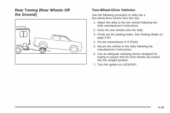
Rear Towing (Rear Wheels Offthe Ground)
Two-Wheel-Drive VehiclesUse the following procedure to dolly tow atwo-wheel-drive vehicle from the rear:
1. Attach the dolly to the tow vehicle following thedolly manufacturer’s instructions.
2. Drive the rear wheels onto the dolly.
3. Firmly set the parking brake. See Parking Brake onpage 2-50.
4. Put the transmission in P (Park).
5. Secure the vehicle to the dolly following themanufacturer’s instructions.
6. Use an adequate clamping device designed fortowing to ensure that the front wheels are lockedinto the straight position.
7. Turn the ignition to LOCK/OFF.
4-49

Four-Wheel-Drive VehiclesUse the following procedure to dolly tow afour-wheel-drive vehicle from the rear:
1. Attach the dolly to the tow vehicle following thedolly manufacturer’s instructions.
2. Drive the rear wheels onto the dolly.
3. Firmly set the parking brake. See Parking Brake onpage 2-50.
4. Put the transmission in P (Park).
5. Secure the vehicle to the dolly following themanufacturer’s instructions.
6. Use an adequate clamping device designed fortowing to ensure that the front wheels are lockedinto the straight position.
{CAUTION:
Shifting a four-wheel-drive vehicle’s transfer caseinto N (Neutral) can cause the vehicle to roll evenif the transmission is in P (Park). The driver orothers could be injured. Make sure the parkingbrake is firmly set before the transfer case isshifted to N (Neutral).
7. Shift the transfer case to N (Neutral). See “Shiftinginto Neutral” under Four-Wheel Drive on page 2-37for the proper procedure to select the neutralposition for the vehicle.
8. Turn the ignition to LOCK/OFF.
After towing, see “Shifting Out of Neutral” underFour-Wheel Drive on page 2-37.
4-50

Towing a TrailerIf the vehicle has a diesel engine, see the DURAMAX®
Diesel manual for more information.
Do not tow a trailer during break-in. See New VehicleBreak-In on page 2-22 for more information.
{CAUTION:
The driver can lose control when pulling a trailer ifthe correct equipment is not used or the vehicle isnot driven properly. For example, if the trailer is tooheavy, the brakes may not work well or even at all.The driver and passengers could be seriouslyinjured. The vehicle may also be damaged; theresulting repairs would not be covered by thevehicle warranty. Pull a trailer only if all the steps inthis section have been followed. Ask your dealer/retailer for advice and information about towing atrailer with the vehicle.
Notice: Pulling a trailer improperly can damagethe vehicle and result in costly repairs not coveredby the vehicle warranty. To pull a trailer correctly,follow the advice in this section and see yourdealer/retailer for important information abouttowing a trailer with the vehicle.
To identify the trailering capacity of the vehicle, readthe information in “Weight of the Trailer” that appearslater in this section.
Trailering is different than just driving the vehicle byitself. Trailering means changes in handling, acceleration,braking, durability and fuel economy. Successful, safetrailering takes correct equipment, and it has to be usedproperly.
The following information has many time-tested,important trailering tips and safety rules. Many ofthese are important for your safety and that of yourpassengers. So please read this section carefullybefore pulling a trailer.
4-51

Pulling A TrailerHere are some important points:
• There are many different laws, including speed limitrestrictions, having to do with trailering. Make surethe rig will be legal, not only where you live butalso where you will be driving. A good source forthis information can be state or provincial police.
• Consider using a sway control. See “Hitches” laterin this section.
• Do not tow a trailer at all during the first 500 miles(800 km) the new vehicle is driven. The engine,axle or other parts could be damaged.
• Then, during the first 500 miles (800 km) that atrailer is towed, do not drive over 50 mph (80 km/h)and do not make starts at full throttle. This helpsthe engine and other parts of the vehicle wear inat the heavier loads.
• Vehicles can tow in D (Drive). Shift the transmissionto a lower gear if the transmission shifts too oftenunder heavy loads and/or hilly conditions.
Three important considerations have to do with weight:
• The weight of the trailer
• The weight of the trailer tongue
• And the weight on the vehicle’s tires
Weight of the TrailerHow heavy can a trailer safely be?
It depends on how the rig is used. For example, speed,altitude, road grades, outside temperature and how muchthe vehicle is used to pull a trailer are all important. It candepend on any special equipment on the vehicle, andthe amount of tongue weight the vehicle can carry.See “Weight of the Trailer Tongue” later in this sectionfor more information.
Maximum trailer weight is calculated assuming only thedriver is in the tow vehicle and it has all the requiredtrailering equipment. The weight of additional optionalequipment, passengers and cargo in the tow vehiclemust be subtracted from the maximum trailer weight.
Use the following chart to determine how much thevehicle can weigh, based upon the vehicle modeland options.
Weights listed apply for conventional trailers andfifth-wheel trailers unless otherwise noted.
4-52

Vehicle Axle Ratio Maximum Trailer Weight GCWR (a)
1500 Series 2WD Regular Cab Standard Box (b)
4.3L V6 (c) 3.23 4,800 lbs (2 177 kg) 9,500 lbs (4 309 kg)
4.3L V6 (c) 3.73 5,300 lbs (2 404 kg) 10,000 lbs (4 536 kg)
4.8L V8 (c) 3.23 5,200 lbs (2 359 kg) 10,000 lbs (4 536 kg)
4.8L V8 3.73 7,200 lbs (3 266 kg) 12,000 lbs (5 443 kg)
5.3L V8 4 Speed Automatic 3.42 7,200 lbs (3 266 kg) 12,000 lbs (5 443 kg)
5.3L V8 4 Speed Automatic 3.73 8,200 lbs (3 720 kg) 13,000 lbs (5 897 kg)
5.3L LMG V8 6 Speed Automatic 3.42 6,600 lbs (2 994 kg) 11,500 lbs (5 216 kg)
5.3L LY5 V8 6 Speed Automatic 3.42 6,700 lbs (3 039 kg) 11,500 lbs (5 216 kg)
5.3L LMG V8 6 Speed Automatic,K5L HD Cooling Pkg 3.42 9,100 lbs (4 128 kg) 14,000 lbs (6 350 kg)
5.3L LY5 V8 6 Speed Automatic,K5L HD Cooling Pkg 3.42 9,200 lbs (4 173 kg) 14,000 lbs (6 350 kg)
1500 Series 2WD Extended Cab Standard Box (b)
4.3L V6 (c) 3.23 4,400 lbs (1 996 kg) 9,500 lbs (4 309 kg)
4.3L V6 (c) 3.73 4,900 lbs (2 223 kg) 10,000 lbs (4 536 kg)
4.8L V8 (c) 3.23 4,700 lbs (2 132 kg) 10,000 lbs (4 536 kg)
4.8L V8 3.73 6,700 lbs (3 039 kg) 12,000 lbs (5 443 kg)
4-53

Vehicle Axle Ratio Maximum Trailer Weight GCWR (a)
5.3L V8 4 Speed Automatic 3.42 6,700 lbs (3 039 kg) 12,000 lbs (5 443 kg)
5.3L V8 4 Speed Automatic 3.73 7,700 lbs (3 493 kg) 13,000 lbs (5 897 kg)
5.3L V8 6 Speed Automatic 3.42 6,200 lbs (2 812 kg) 11,500 lbs (5 216 kg)
5.3L V8 6 Speed Automatic, K5L HDCooling Pkg — Fifth-Wheel Trailer 3.42 9,100 lbs (4 128 kg) 15,000 lbs (6 804 kg)
5.3L V8 6 Speed Automatic, K5L HDCooling Pkg — Conventional Trailer 3.42 9,700 lbs (4 400 kg) 15,000 lbs (6 804 kg)
6.0L V8 3.42 6,700 lbs (3 039 kg) 12,000 lbs (5 443 kg)
6.0L V8 K5L HD CoolingPkg — Fifth-Wheel Trailer 3.42 8,700 lbs (3 946 kg) 15,000 lbs (6 804 kg)
6.0L V8 K5L HD CoolingPkg — Conventional Trailer 3.42 9,700 lbs (4 400 kg) 15,000 lbs (6 804 kg)
6.0L V8 NHT Max TraileringPkg — Fifth-Wheel Trailer 3.73 10,000 lbs (4 536 kg) 16,000 lbs (7 257 kg)
6.0L V8 NHT Max TraileringPkg — Conventional Trailer 3.73 10,700 lbs (4 853 kg) 16,000 lbs (7 257 kg)
1500 Series 2WD Extended Cab Short Box (c)
4.3L V6 3.23 4,400 lbs (1 996 kg) 9,500 lbs (4 309 kg)
4.3L V6 3.73 4,900 lbs (2 223 kg) 10,000 lbs (4 536 kg)
4.8L V8 3.42 5,800 lbs (2 631 kg) 12,000 lbs (5 443 kg)
4-54

Vehicle Axle Ratio Maximum Trailer Weight GCWR (a)
4.8L V8 3.73 6,800 lbs (3 084 kg) 12,000 lbs (5 443 kg)
5.3L V8 3.42 6,800 lbs (3 084 kg) 12,000 lbs (5 443 kg)
5.3L V8 3.73 7,800 lbs (3 538 kg) 13,000 lbs (5 897 kg)
6.0L V8 3.42 6,700 lbs (3 039 kg) 12,000 lbs (5 443 kg)
6.0L V8 K5L HD Cooling Pkg 3.42 9,700 lbs (4 400 kg) 15,000 lbs (6 804 kg)
1500 Series 2WD Crew Cab Short Box (c)
4.8L V8 3.23 4,700 lbs (2 132 kg) 10,000 lbs (4 536 kg)
4.8L V8 3.73 6,700 lbs (3 039 kg) 12,000 lbs (5 443 kg)
5.3L V8 3.42 6,100 lbs (2 767 kg) 11,500 lbs (5 216 kg)
5.3L V8 K5L HD Cooling Pkg 3.42 9,600 lbs (4 355 kg) 15,000 lbs (6 804 kg)
6.0L, 6.2L V8 3.42 6,600 lbs (2 994 kg) 12,000 lbs (5 443 kg)
6.0L, 6.2L V8 K5L HD Cooling Pkg 3.42 9,600 lbs (4 355 kg) 15,000 lbs (6 804 kg)
6.0L, 6.2L V8 NHT MaxTrailering Pkg 3.73 10,600 lbs (4 808 kg) 16,000 lbs (7 257 kg)
1500 Series 2WD Regular Cab Long Box (b)
4.3L V6 (c) 3.23 4,700 lbs (2 132 kg) 9,500 lbs (4 309 kg)
4.3L V6 (c) 3.73 5,200 lbs (2 359 kg) 10,000 lbs (4 536 kg)
4.8L V8 (c) 3.23 5,100 lbs (2 313 kg) 10,000 lbs (4 536 kg)
4-55

Vehicle Axle Ratio Maximum Trailer Weight GCWR (a)
4.8L V8 3.73 7,100 lbs (3 221 kg) 12,000 lbs (5 443 kg)
5.3L V8 4 Speed Automatic 3.42 7,000 lbs (3 175 kg) 12,000 lbs (5 443 kg)
5.3L V8 4 Speed Automatic 3.73 8,000 lbs (3 629 kg) 13,000 lbs (5 897 kg)
5.3L V8 6 Speed Automatic 3.42 6,500 lbs (2 948 kg) 11,500 lbs (5 216 kg)
5.3L V8 6 Speed Automatic, K5L HDCooling Pkg — Fifth-Wheel Trailer 3.42 8,700 lbs (3 946 kg) 15,000 lbs (6 804kg)
5.3L V8 6 Speed Automatic, K5L HDCooling Pkg — Conventional Trailer 3.42 10,000 lbs (4 536 kg) 15,000 lbs (6 804kg)
1500 Series 2WD Extended Cab Long Box (b)
5.3L V8 4 SpeedAutomatic — Fifth-Wheel Trailer 3.73 7,500 lbs (3 402 kg) 13,000 lbs (5 897 kg)
5.3L V8 4 SpeedAutomatic — Conventional Trailer 3.73 7,600 lbs (3 447 kg) 13,000 lbs (5 897 kg)
5.3L V8 6 Speed Automatic 3.42 6,000 lbs (2 722 kg) 11,500 lbs (5 216 kg)
5.3L V8 6 Speed Automatic, K5L HDCooling Pkg — Fifth-Wheel Trailer 3.42 8,700 lbs (3 946 kg) 15,000 lbs (6 804kg)
5.3L V8 6 Speed Automatic, K5L HDCooling Pkg — Conventional Trailer 3.42 9,500 lbs (4 309 kg) 15,000 lbs (6 804kg)
4-56

Vehicle Axle Ratio Maximum Trailer Weight GCWR (a)
1500 Series 4WD Regular Cab Standard Box (b)
4.3L V6 (c) 3.73 5,100 lbs (2 313 kg) 10,000 lbs (4 536 kg)
4.8L V8 (c) 3.42 6,000 lbs (2 722 kg) 11,000 lbs (4 990 kg)
5.3L V8 3.42 6,400 lbs (2 903 kg) 11,500 lbs (5 216 kg)
5.3L V8 K5L HD CoolingPkg — Fifth-Wheel Trailer 3.42 8,100 lbs (3 674 kg) 14,000 lbs (6 350 kg)
5.3L V8 K5L HD CoolingPkg — Conventional Trailer 3.42 8,900 lbs (4 037 kg) 14,000 lbs (6 350 kg)
5.3L V8 3.73 7,900 lbs (3 583 kg) 13,000 lbs (5 897 kg)
5.3L V8 — Fifth-Wheel Trailer 4.10 8,300 lbs (3 765 kg) 14,000 lbs (6 350 kg)
5.3L V8 — Conventional Trailer 4.10 8,900 lbs (4 037 kg) 14,000 lbs (6 350 kg)
1500 Series 4WD Extended Cab Standard Box (b)
4.8L V8 (c) 3.42 5,500 lbs (2 495 kg) 11,000 lbs (4 990 kg)
5.3L V8 (c) 3.42 5,900 lbs (2 676 kg) 11,500 lbs (5 216 kg)
5.3L V8 K5L HD CoolingPkg — Fifth-Wheel Trailer 3.42 8,900 lbs (4 037 kg) 15,000 lbs (6 804kg)
5.3L V8 K5L HD CoolingPkg — Conventional Trailer 3.42 9,400 lbs (4 264 kg) 15,000 lbs (6 804kg)
5.3L V8 3.73 7,500 lbs (3 402 kg) 13,000 lbs (5 897 kg)
4-57

Vehicle Axle Ratio Maximum Trailer Weight GCWR (a)
5.3L V8 4.10 8,500 lbs (3 856 kg) 14,000 lbs (6 350 kg)
6.0L V8 (c) 3.42 6,400 lbs (2 903 kg) 12,000 lbs (5 443 kg)
6.0L V8 K5L HD CoolingPkg — Fifth-Wheel Trailer 3.42 8,400 lbs (3 810 kg) 15,000 lbs (6 804kg)
6.0L V8 K5L HD CoolingPkg — Conventional Trailer 3.42 9,400 lbs (4 264 kg) 15,000 lbs (6 804kg)
6.0L V8 NHT Max TraileringPkg — Fifth-Wheel Trailer 3.73 9,700 lbs (4 400 kg) 16,000 lbs (7 257 kg)
6.0L V8 NHT Max TraileringPkg — Conventional Trailer 3.73 10,400 lbs (4 717 kg) 16,000 lbs (7 257 kg)
1500 Series 4WD Extended Cab Short Box (c)
4.8L V8 3.42 5,500 lbs (2 495 kg) 11,000 lbs (4 990 kg)
4.8L V8 4.10 8,500 lbs (3 856 kg) 14,000 lbs (6 350 kg)
5.3L V8 3.73 7,500 lbs (3 402 kg) 13,000 lbs (5 897 kg)
5.3L V8 4.10 8,500 lbs (3 856 kg) 14,000 lbs (6 350 kg)
6.0L V8 3.42 6,400 lbs (2 903 kg) 12,000 lbs (5 443 kg)
6.0L V8 K5L HD Cooling Pkg 3.42 9,400 lbs (4 264 kg) 15,000 lbs (6 804kg)
4-58

Vehicle Axle Ratio Maximum Trailer Weight GCWR (a)
1500 Series 4WD Crew Cab Short Box (c)
4.8L V8 3.42 5,400 lbs (2 449 kg) 11,000 lbs (4 990 kg)
5.3L V8 3.42 6,000 lbs (2 722 kg) 11,500 lbs (5 216 kg)
5.3L V8 K5L HD Cooling Pkg 3.42 9,500 lbs (4 309 kg) 15,000 lbs (6 804kg)
6.0L, 6.2L V8 3.42 6,300 lbs (2 858 kg) 12,000 lbs (5 443 kg)
6.0L, 6.2L V8 K5L HD Cooling Pkg 3.42 9,300 lbs (4 218 kg) 15,000 lbs (6 804kg)
6.0L V8 NHT Max TraileringPkg — Fifth-Wheel Trailer 3.73 9,900 lbs (4 491 kg) 16,000 lbs (7 257 kg)
6.0L, 6.2L V8 NHT Max TraileringPkg — Conventional Trailer 3.73 10,400 lbs (4 717 kg) 16,000 lbs (7 257 kg)
1500 Series 4WD Regular Cab Long Box (b)
4.3L V6 (c) 3.73 4,900 lbs (2 223 kg) 10,000 lbs (4 536 kg)
4.8L V8 (c) 3.42 5,800 lbs (2 631 kg) 11,000 lbs (4 990 kg)
5.3L V8 3.42 6,300 lbs (2 858 kg) 11,500 lbs (5 216 kg)
5.3L V8 K5L HD CoolingPkg — Fifth-Wheel Trailer 3.42 9,500 lbs (4 309 kg) 15,000 lbs (6 804kg)
5.3L V8 K5L HD CoolingPkg — Conventional Trailer 3.42 9,800 lbs (4 445 kg) 15,000 lbs (6 804kg)
5.3L V8 — Fifth-Wheel Trailer 3.73 7,800 lbs (3 538 kg) 13,000 lbs (5 897 kg)
4-59

Vehicle Axle Ratio Maximum Trailer Weight GCWR (a)
5.3L V8 — Conventional Trailer 3.73 7,900 lbs (3 583 kg) 13,000 lbs (5 897 kg)
5.3L V8 — Fifth-Wheel Trailer 4.10 8,800 lbs (3 992 kg) 14,000 lbs (6 350 kg)
5.3L V8 — Conventional Trailer 4.10 8,900 lbs (4 037 kg) 14,000 lbs (6 350 kg)
1500 Series 4WD Extended Cab Long Box (b)
5.3L V8 (c) 3.42 5,700 lbs (2 586 kg) 11,500 lbs (5 216 kg)
5.3L V8 K5L HD CoolingPkg — Fifth-Wheel Trailer 3.42 7,700 lbs (3 493 kg) 15,000 lbs (6 804 kg)
5.3L V8 K5L HD CoolingPkg — Conventional Trailer 3.42 9,200 lbs (4 173 kg) 15,000 lbs (6 804 kg)
5.3L LMG V8 3.73 7,600 lbs (3 447 kg) 13,000 lbs (5 897 kg)
5.3L LY5 V8 3.73 7,300 lbs (3 311 kg) 13,000 lbs (5 897 kg)
2500 Series 2WD Extended Cab Standard Box HD (d)
6.0L V8 3.734.10
10,200 lbs (4 627 kg)12,700 lbs (5 761 kg)
16,000 lbs (7 257 kg)18,500 lbs (8 391 kg)
2500 Series 2WD Crew Cab Standard Box HD (d)
6.0L V8 3.734.10
10,000 lbs (4 536 kg)12,500 lbs (5 670 kg)
16,000 lbs (7 257 kg)18,500 lbs (8 391 kg)
2500 Series 2WD Regular Cab Long Box HD (d)
6.0L V8 3.734.10
10,500 lbs (4 763 kg)13,000 lbs (5 897 kg)
16,000 lbs (7 257 kg)18,500 lbs (8 391 kg)
4-60

Vehicle Axle Ratio Maximum Trailer Weight GCWR (a)
2500 Series 2WD Extended Cab Long Box HD (d)
6.0L V8 3.734.10
10,000 lbs (4 536 kg)12,500 lbs (5 670 kg)
16,000 lbs (7 257 kg)18,500 lbs (8 391 kg)
2500 Series 2WD Crew Cab Long Box HD (d)
6.0L V8 3.734.10
9,900 lbs (4 491 kg)12,400 lbs (5 625 kg)
16,000 lbs (7 257 kg)18,500 lbs (8 391 kg)
2500 Series 4WD Extended Cab Standard Box HD (d)
6.0L V8 3.734.10
9,900 lbs (4 491 kg)12,400 lbs (5 625 kg)
16,000 lbs (7 257 kg)18,500 lbs (8 391 kg)
2500 Series 4WD Crew Cab Standard Box HD (d)
6.0L V8 3.734.10
9,800 lbs (4 445 kg)12,300 lbs (5 579 kg)
16,000 lbs (7 257 kg)18,500 lbs (8 391 kg)
2500 Series 4WD Regular Cab Long Box HD (d)
6.0L V8 3.734.10
10,200 lbs (4 627 kg)12,700 lbs (5 761 kg)
16,000 lbs (7 257 kg)18,500 lbs (8 391 kg)
2500 Series 4WD Extended Cab Long Box HD (d)
6.0L V8 3.734.10
9,800 lbs (4 445 kg)12,300 lbs (5 579 kg)
16,000 lbs (7 257 kg)18,500 lbs (8 391 kg)
4-61

Vehicle Axle Ratio Maximum Trailer Weight GCWR (a)
2500 Series 4WD Crew Cab Long Box HD (d)
6.0L V8 3.734.10
9,600 lbs (4 355 kg)12,100 lbs (5 489 kg)
16,000 lbs (7 257 kg)18,500 lbs (8 391 kg)
3500 Series 2WD Extended Cab (e)
6.0L V8 (Single Rear Wheels) 3.734.10
9,900 lbs (4 491 kg)12,400 lbs (5 625 kg)
16,000 lbs (7 257 kg)18,500 lbs (8 391 kg)
6.0L V8 (Dual Rear Wheels) 3.734.10
9,500 lbs (4 309 kg)12,000 lbs (5 443 kg)
16,000 lbs (7 257 kg)18,500 lbs (8 391 kg)
3500 Series 2WD Crew Cab (e)
6.0L V8 (Single Rear Wheels) 3.734.10
9,700 lbs (4 400 kg)12,200 lbs (5 534 kg)
16,000 lbs (7 257 kg)18,500 lbs (8 391 kg)
6.0L V8 (Dual Rear Wheels) 3.734.10
9,300 lbs (4 218 kg)11,800 lbs (5 352 kg)
16,000 lbs (7 257 kg)18,500 lbs (8 391 kg)
3500 Series 4WD Regular Cab (e)
6.0L V8 (Single Rear Wheels) 3.734.10
10,000 lbs (4 536 kg)12,500 lbs (5 670 kg)
16,000 lbs (7 257 kg)18,500 lbs (8 391 kg)
6.0L V8 (Dual Rear Wheels) 3.734.10
9,700 lbs (4 400 kg)12,200 lbs (5 534 kg)
16,000 lbs (7 257 kg)18,500 lbs (8 391 kg)
4-62

Vehicle Axle Ratio Maximum Trailer Weight GCWR (a)
3500 Series 4WD Extended Cab (e)
6.0L V8 (Single Rear Wheels) 3.734.10
9,600 lbs (4 355 kg)12,100 lbs (5 489 kg)
16,000 lbs (7 257 kg)18,500 lbs (8 391 kg)
6.0L V8 (Dual Rear Wheels) 3.734.10
9,200 lbs (4 173 kg)11,700 lbs (5 307 kg)
16,000 lbs (7 257 kg)18,500 lbs (8 391 kg)
3500 Series 4WD Crew Cab (e)
6.0L V8 (Single Rear Wheels) 3.734.10
9,400 lbs (4 264 kg)11,900 lbs (5 398 kg)
16,000 lbs (7 257 kg)18,500 lbs (8 391 kg)
6.0L V8 (Dual Rear Wheels) 3.734.10
9,100 lbs (4 128 kg)11,600 lbs (5 262 kg)
16,000 lbs (7 257 kg)18,500 lbs (8 391 kg)
(a) The Gross Combination Weight Rating (GCWR) is the total allowable weight of the completely loaded vehicleand trailer including any passengers, cargo, equipment and conversions. The GCWR for the vehicle should not beexceeded.(b) Fifth-wheel or gooseneck kingpin weight 15 percent to 25 percent of trailer weight up to 1,500 lbs (680 kg)maximum.(c) This model is neither designed nor intended to tow fifth-wheel or gooseneck trailers.(d) Fifth-wheel or gooseneck kingpin weight should be 15 percent to 25 percent of trailer weight up to3,000 lbs (1 361 kg) maximum.(e) Fifth-wheel or gooseneck kingpin weight should be 15 percent to 25 percent of trailer weight up to3,500 lbs (1 587 kg) maximum.
Ask your dealer/retailer for our trailering information or advice, or write us at our Customer Assistance Offices.See Customer Assistance Offices on page 7-6 for more information.
4-63

Weight of the Trailer TongueThe tongue load (A) of any trailer is an important weightto measure because it affects the total gross weight of thevehicle. The Gross Vehicle Weight (GVW) includes thecurb weight of the vehicle, any cargo carried in it, and thepeople who will be riding in the vehicle. If there are a lot ofoptions, equipment, passengers or cargo in the vehicle, itwill reduce the tongue weight the vehicle can carry, whichwill also reduce the trailer weight the vehicle can tow.If towing a trailer, the tongue load must be added to theGVW because the vehicle will be carrying that weight,too. See for more information about the vehicle’smaximum load capacity. The trailer tongue weight (A) should be 10 percent
to 15 percent of the total loaded trailer weight, up to amaximum of 600 lbs (272 kg) for the 1500 or 2500 series,and up to a maximum of 750 lbs (340 kg) for the 2500 HDor 3500 series with a weight carrying hitch. The trailertongue weight (A) should be 10 percent to 15 percentof the total loaded trailer weight, up to a maximum of1,000 lbs (453 kg) for the 1500 series and up to amaximum of 1,500 lbs (680 kg) for the 2500, 2500 HDor 3500 series with a weight distributing hitch.
4-64
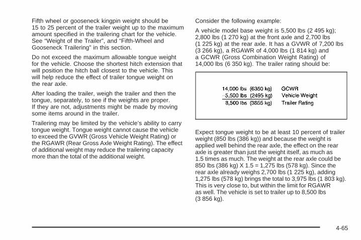
Fifth wheel or gooseneck kingpin weight should be15 to 25 percent of the trailer weight up to the maximumamount specified in the trailering chart for the vehicle.See “Weight of the Trailer”, and “Fifth-Wheel andGooseneck Trailering” in this section.
Do not exceed the maximum allowable tongue weightfor the vehicle. Choose the shortest hitch extension thatwill position the hitch ball closest to the vehicle. Thiswill help reduce the effect of trailer tongue weight onthe rear axle.
After loading the trailer, weigh the trailer and then thetongue, separately, to see if the weights are proper.If they are not, adjustments might be made by movingsome items around in the trailer.
Trailering may be limited by the vehicle’s ability to carrytongue weight. Tongue weight cannot cause the vehicleto exceed the GVWR (Gross Vehicle Weight Rating) orthe RGAWR (Rear Gross Axle Weight Rating). The effectof additional weight may reduce the trailering capacitymore than the total of the additional weight.
Consider the following example:
A vehicle model base weight is 5,500 lbs (2 495 kg);2,800 lbs (1 270 kg) at the front axle and 2,700 lbs(1 225 kg) at the rear axle. It has a GVWR of 7,200 lbs(3 266 kg), a RGAWR of 4,000 lbs (1 814 kg) anda GCWR (Gross Combination Weight Rating) of14,000 lbs (6 350 kg). The trailer rating should be:
Expect tongue weight to be at least 10 percent of trailerweight (850 lbs (386 kg)) and because the weight isapplied well behind the rear axle, the effect on the rearaxle is greater than just the weight itself, as much as1.5 times as much. The weight at the rear axle could be850 lbs (386 kg) X 1.5 = 1,275 lbs (578 kg). Since therear axle already weighs 2,700 lbs (1 225 kg), adding1,275 lbs (578 kg) brings the total to 3,975 lbs (1 803 kg).This is very close to, but within the limit for RGAWRas well. The vehicle is set to trailer up to 8,500 lbs(3 856 kg).
4-65

If the vehicle has many options and there is a frontseat passenger and two rear seat passengers with someluggage and gear in the vehicle as well. 300 lbs (136 kg)could be added to the front axle weight and 400 lbs(181 kg) to the rear axle weight. The vehicle now weighs:
Weight is still below 7,200 lbs (3 266 kg) and youmight think 700 additional pounds (318 kg) should besubtracted from the trailering capacity to stay withinGCWR limits. The maximum trailer would only be7,800 lbs (3 538 kg). You may go further and think thetongue weight should be limited to less than 1,000 lbs(454 kg) to avoid exceeding GVWR. But the effect on therear axle must still be considered. Because the rear axlenow weighs 3,100 lbs (1 406 kg), 900 lbs (408 kg) canbe put on the rear axle without exceeding RGAWR.
The effect of tongue weight is about 1.5 times the actualweight. Dividing the 900 lbs (408 kg) by 1.5 leaves only600 lbs (272 kg) of tongue weight that can be handled.Since tongue weight is usually at least 10 percent of totalloaded trailer weight, expect that the largest trailer thevehicle can properly handle is 6,000 lbs (2 721 kg).
It is important that the vehicle does not exceed any ofits ratings — GCWR, GVWR, RGAWR, Maximum TrailerRating or Tongue Weight. The only way to be sure itis not exceeding any of these ratings is to weighthe vehicle and trailer.
Total Weight on the Vehicle’s TiresBe sure the vehicle’s tires are inflated to the upperlimit for cold tires. These numbers can be found on theCertification label at the rear edge of the drivers dooror see Loading the Vehicle on page 4-32 for moreinformation. Make sure not to go over the GVW limit forthe vehicle, or the GAWR, including the weight of thetrailer tongue. If using a weight distributing hitch, makesure not to go over the rear axle limit before applying theweight distribution spring bars.
4-66

HitchesIt is important to have the correct hitch equipment.Crosswinds, large trucks going by and rough roadsare a few reasons why the right hitch is needed.
Weight-Distributing Hitches and WeightCarrying Hitches
A: Body to Ground Distance
B: Front of Vehicle
When using a weight-distributing hitch, the hitch mustbe adjusted so the distance (A) remains the same bothbefore and after coupling the trailer to the tow vehicle.
If a step-bumper hitch will be used, the bumper couldbe damaged in sharp turns. Make sure there is ampleroom when turning to avoid contact between the trailerand the bumper.
If the loaded trailer being pulled will weigh more than5,000 lbs (2 270 kg), be sure to use a properly mountedweight-distributing hitch and sway control of the propersize. This equipment is very important for proper vehicleloading and good handling when driving. Always use asway control if the trailer will weigh more than theselimits. Ask a hitch dealer about sway controls.
4-67

Fifth Wheel and Gooseneck TraileringFifth wheel and gooseneck trailers can be used withmany pickup models. These trailers place a largerpercentage of the weight (kingpin weight) on the towvehicle than conventional trailers. Make sure this weightdoes not cause the vehicle to exceed GAWR or GVWR.
Fifth wheel or gooseneck kingpin weight should be15 to 25 percent of the trailer weight up to the maximumamount specified in the trailering chart for the vehicle.See “Weight of the Trailer” in this section for moreinformation.
The hitch should be located in the pickup bed so that itscenterline is over or slightly in front of the rear axle. Takecare that it is not so far forward that it will contact the backof the cab in sharp turns. This is especially important forshort box pickups. Trailer pin box extensions and slidingfifth wheel hitch assemblies can help this condition. Thereshould be at least six inches of clearance between the topof the pickup box and the bottom of the trailer shelf thatextends over the box.
Make sure the hitch is attached to the tow vehicle framerails. Do not use the pickup box for support.
Safety ChainsAlways attach chains between the vehicle and thetrailer. Cross the safety chains under the tongue of thetrailer to help prevent the tongue from contacting the roadif it becomes separated from the hitch. Instructions aboutsafety chains may be provided by the hitch manufactureror by the trailer manufacturer. If the trailer being towedweighs up to 5,000 lbs (2 271 kg) with a factory-installedstep bumper, safety chains may be attached to theattaching points on the bumper. If the trailer being towedweighs up to the vehicle’s trailer rating limit, safety chainsmay be attached to the attaching point on the hitchplatform. Always leave just enough slack so the rig canturn. Never allow safety chains to drag on the ground.
4-68

Tow/Haul Mode
Pressing this button atthe end of the shift leverturns on and off thetow/haul mode.
This indicator light on theinstrument panel clustercomes on when thetow/haul mode is on.
Tow/Haul is a feature that assists when pulling a heavytrailer or a large or heavy load. See Tow/Haul Modeon page 2-34 for more information.
Tow/Haul is designed to be most effective when thevehicle and trailer combined weight is at least 75 percentof the vehicle’s Gross Combined Weight Rating (GCWR).See “Weight of the Trailer” later in the section. Tow/Haulis most useful under the following driving conditions:
• When pulling a heavy trailer or a large or heavy loadthrough rolling terrain.
• When pulling a heavy trailer or a large or heavy loadin stop and go traffic.
• When pulling a heavy trailer or a large or heavy loadin busy parking lots where improved low speedcontrol of the vehicle is desired.
Operating the vehicle in Tow/Haul when lightly loadedor with no trailer at all will not cause damage. However,there is no benefit to the selection of Tow/Haul whenthe vehicle is unloaded. Such a selection when unloadedmay result in unpleasant engine and transmissiondriving characteristics and reduced fuel economy.Tow/Haul is recommended only when pulling aheavy trailer or a large or heavy load.
4-69

Trailer BrakesA loaded trailer that weighs more than 2,000 lbs(900 kg) needs to have its own brake system that isadequate for the weight of the trailer. Be sure to readand follow the instructions for the trailer brakes sothey are installed, adjusted and maintained properly.
If the vehicle is equipped with StabiliTrak®, thetrailer cannot tap into the vehicle’s hydraulic brakesystem.
The trailer brake system can tap into the vehicle’shydraulic brake system only if:
• The trailer parts can withstand3,000 psi (20 650 kPa) of pressure.
• The trailer’s brake system will use less than0.02 cubic inch (0.3 cc) of fluid from the vehicle’smaster cylinder. Otherwise, both braking systemswill not work well or at all.
If everything checks out this far, make the brake tapat the port on the master cylinder that sends the fluid tothe rear brakes. Use only steel brake tubing to makethe tap.
Integrated Trailer Brake ControlSystem
The vehicle may have anIntegrated Trailer BrakeControl (ITBC) system forelectric trailer brakes.
This symbol is located on the Trailer Brake ControlPanel on vehicles with an Integrated Trailer BrakeControl System. The power output to the trailer brakesis based on the amount of brake pressure beingapplied by the vehicle’s brake system. This availablepower output to the trailer brakes can be adjusted toa wide range of trailering situations.
The ITBC system is integrated with the vehicle’s brake,anti-lock brake and StabiliTrak (if equipped) systems.In trailering conditions that cause the vehicle’s anti-lockbrake or StabiliTrak systems to activate, power sentto the trailer’s brakes will be automatically adjusted tominimize trailer wheel lock-up. This does not implythat the trailer has the StabiliTrak system.
4-70

If the vehicle’s brake, anti-lock brake or StabiliTraksystems are not functioning properly, the ITBC systemmay not be fully functional or may not function at all.Make sure all of these systems are fully operationalto ensure full functionality of the ITBC system.
The ITBC system is powered through the vehicle’selectrical system. Turning the ignition off will also turnoff the ITBC system. The ITBC system is fully functionalonly when the ignition is in ON or in RUN.
The ITBC system can only be used with trailers withelectric brakes.
{CAUTION:
Connecting a trailer that is not compatible with theITBC system may result in reduced or completeloss of trailer braking. There may be an increase instopping distance or trailer instability which couldresult in personal injury or damage to the vehicle,trailer, or other property. An aftermarket controllermay be available for use with trailers with surge,air or electric-over-hydraulic trailer brake systems.To determine the type of brakes on the trailer andthe availability of controllers, check with your trailermanufacturer or dealer/retailer.
When trailering, make sure of the following:
• The ITBC system is used only with trailers that areequipped with electric brakes.
• All applicable local and federal laws and regulationsare followed.
• All electrical and mechanical connections to thetrailer are made correctly.
• The trailer’s brakes are in proper working condition.
• The trailer and vehicle are properly loaded forthe towing condition.
The ITBC system is a factory installed item.Out-of-factory installation of this system should notbe attempted. GM is not responsible for warrantyor performance of the system resulting fromout-of-factory installation.
4-71

Trailer Brake Control Panel
A. Manual Trailer Brake Apply LeverB. Trailer Gain Adjustment Buttons
The ITBC system has a control panel located onthe instrument panel to the left of the steering column.See Instrument Panel Overview (Base/Uplevel version)
on page 3-4 or Instrument Panel Overview (Premiumversion) on page 3-6 for more information on location.The control panel allows adjustment to the amount ofoutput, referred to as trailer gain, available to the electrictrailer brakes and allows manual application of the trailerbrakes. The Trailer Brake Control Panel is used alongwith the Trailer Brake Display Page on the DIC to adjustand display power output to the trailer brakes.
Trailer Brake DIC Display PageThe ITBC system displays messages into the vehicle’sDriver Information Center (DIC). See DIC Warningsand Messages on page 3-66 for more information.
The display page indicates Trailer Gain setting, poweroutput to the electric trailer brakes, trailer connectionand system operational status.
4-72

A. Trailer Gain SettingB. Power Output to Trailer BrakesC. No trailer with electric brakes connected or fault
presentThe Trailer Brake Display Page can be displayed byperforming any of the following actions:• Scrolling through the DIC menu pages using the
odometer trip stem or the DIC Vehicle Informationbutton (if equipped).
• Pressing a Trailer Gain button – If the Trailer BrakeDisplay Page is not currently displayed, pressing aTrailer Gain button will first recall the current TrailerGain setting. After the Trailer Brake Display Pageis displayed, each press and release of the gainbuttons will then cause the Trailer Gain setting tochange.
• Activating the Manual Trailer Brake Apply lever.• Connecting a trailer equipped with electric trailer
brakes.
All DIC warning and service messages must first beacknowledged by the driver by pressing the odometer tripstem or the DIC Vehicle Information button (if equipped)before the Trailer Brake Display Page can be displayedand Trailer Gain can be adjusted.
TRAILER GAIN – This setting is displayed anytime theTrailer Brake Display Page is active. This setting can beadjusted from 0.0 to 10.0 with either a trailer connected ordisconnected. To adjust the Trailer Gain, press one of theTrailer Gain adjustment buttons located on the TrailerBrake Control Panel. Press and hold a gain button tocause the Trailer Gain to continuously adjust. To turn theoutput to the trailer off, adjust the Trailer Gain setting to0.0 (zero).
0.0 (zero) gain is the factory default setting. To properlyadjust trailer gain, see the Trailer Gain AdjustmentProcedure later in this section.
TRAILER OUTPUT – This is displayed any time a trailerwith electric brakes is connected. Output to the electricbrakes is based on the amount of vehicle braking presentand relative to the Trailer Gain setting. Output isdisplayed from 0 to 10 bars for each gain setting.
4-73

The Trailer Output will indicate “- - - - - -“ on the TrailerBrake Display Page whenever the following occur:
• No trailer is connected.
• A trailer without electric brakes is connected(no DIC message is displayed).
• A trailer with electric brakes has becomedisconnected (a CHECK TRAILER WIRINGmessage will also be displayed on the DIC).
• There is a fault present in the wiring to the electrictrailer brakes (a CHECK TRAILER WIRINGmessage will also be displayed on the DIC).
• There is a fault in the ITBC system (a SERVICETRAILER BRAKE SYSTEM message will alsobe displayed in the DIC).
Manual Trailer Brake ApplyThe Manual Trailer Brake Apply Lever is located onthe Trailer Brake Control Panel and is used to apply thetrailer’s electric brakes independent of the vehicle’sbrakes. This lever is used in the Trailer Gain AdjustmentProcedure to properly adjust the power output to thetrailer brakes. Sliding the lever to the left will apply onlythe trailer brakes. The power output to the trailer isindicated in the Trailer Brake Display Page in the DIC.
If the vehicle’s service brakes are applied while usingthe Manual Trailer Brake Apply Lever, the trailer outputpower will be the greater of the two.
The trailer and the vehicle’s brake lamps will come onwhen either vehicle braking or manual trailer brakes areapplied.
Trailer Gain Adjustment ProcedureTrailer Gain should be set for a specific traileringcondition and must be adjusted any time vehicle loading,trailer loading or road surface conditions change.
Setting the Trailer Gain properly is needed for the besttrailer stopping performance. A trailer that is over-gainedmay result in locked trailer brakes. A trailer that isunder-gained may result in not enough trailer braking.Both of these conditions may result in poorer stoppingand stability of the vehicle and trailer.
Use the following procedure to correctly adjust TrailerGain for each towing condition:
1. Make sure the trailer brakes are in proper workingcondition.
2. Connect a properly loaded trailer to the vehicleand make all necessary mechanical and electricalconnections. See Loading the Vehicle on page 4-32for more information.
4-74

3. After the electrical connection is made to a trailerequipped with electric brakes:
• A TRAILER CONNECTED message will bebriefly displayed on the DIC display.
• The Trailer Brake Display Page will appear onthe DIC showing TRAILER GAIN and TRAILEROUTPUT.
• In the Trailer Output display on the DIC, “- - - - - -“will disappear if there is no error present.Connecting a trailer without electric brakeswill not clear the six dashed lines.
4. Adjust the Trailer Gain by using the gain adjustment(+ / -) buttons on the Trailer Brake Control Panel.
5. Drive the vehicle with the trailer attached on alevel road surface representative of the towingcondition and free of traffic at about 20 to 25 mph(32 to 40 km/h) and fully apply the Manual TrailerBrake Apply lever.Adjusting trailer gain at speeds lower than20 to 25 mph (32 to 40 km/h) may result inan incorrect gain setting.
6. Adjust the Trailer Gain to just below the point oftrailer wheel lock-up, indicated by trailer wheelsqueal or tire smoke when a trailer wheel locks.Trailer wheel lock-up may not occur if towinga heavily loaded trailer. In this case, adjust theTrailer Gain to the highest allowable setting forthe towing condition.
7. Re-adjust Trailer Gain any time vehicle loading,trailer loading or road surface conditions changeor if trailer wheel lock-up is noticed at any timewhile towing.
Other ITBC Related DIC MessagesIn addition to displaying TRAILER GAIN and TRAILEROUTPUT through the DIC, trailer connection and ITBCsystem status is displayed in the DIC.
TRAILER CONNECTED – This message will bebriefly displayed when a trailer with electric brakesis first connected to the vehicle. This message willautomatically turn off in about ten seconds. The drivercan also acknowledge this message before itautomatically turns off.
4-75

CHECK TRAILER WIRING – This message will bedisplayed if:
1. The ITBC system first determines connection toa trailer with electric brakes and then the trailerharness becomes disconnected from the vehicle.If the disconnect occurs while the vehicle isstationary, this message will automatically turnoff in about thirty seconds. This message will alsoturn off if the driver acknowledges this messageoff or if the trailer harness is re-connected.If the disconnect occurs while the vehicle is moving,this message will continue until the ignition is turnedoff. This message will also turn off if the driveracknowledges this message off or if the trailerharness is re-connected.
2. There is an electrical fault in the wiring to theelectric trailer brakes. This message will continueas long as there is an electrical fault in the trailerwiring. This message will also turn off if the driveracknowledges this message off.
To determine if the electrical fault is on the vehicle sideor trailer side of the trailer wiring harness connection,do the following:
1. Disconnect the trailer wiring harness from thevehicle.
2. Turn the ignition OFF.
3. Wait ten seconds, then turn the ignition backto RUN.
4. If the CHECK TRAILER WIRING messagere-appears, the electrical fault is on the vehicle side.If the CHECK TRAILER WIRING message onlyre-appears when connecting the trailer wiringharness to the vehicle, the electrical fault is onthe trailer side.
SERVICE TRAILER BRAKE SYSTEM – This messagewill be displayed when there is a problem with theITBC system. If this message persists over multipleignition cycles there is a problem with the ITBC system.Take the vehicle to an authorized GM dealer to havethe ITBC system diagnosed and repaired.
If either the CHECK TRAILER WIRING or SERVICETRAILER BRAKE SYSTEM message is displayed whiledriving the vehicle, power is no longer available to thetrailer brakes. When traffic conditions allow, carefullypull the vehicle over to the side of the road and turn theignition off. Check the wiring connection to the trailer andturn the ignition back on. If either of these messagescontinues, either the vehicle or trailer needs service.
An authorized GM dealer may be able to diagnose andrepair problems with the trailer. However, any diagnosisand repair of the trailer is not covered under the vehiclewarranty. Please contact your trailer dealer for assistancewith trailer repairs and trailer warranty information.
4-76

Driving with a Trailer
{CAUTION:
When towing a trailer, exhaust gases may collectat the rear of the vehicle and enter if the liftgate,trunk/hatch, or rear-most window is open.
Engine exhaust contains carbon monoxide (CO)which cannot be seen or smelled. It can causeunconsciousness and even death.
To maximize safety when towing a trailer:• Have the exhaust system inspected for
leaks and make necessary repairs beforestarting a trip.
• Never drive with the liftgate, trunk/hatch,or rear-most window open.
• Fully open the air outlets on or under theinstrument panel.
• Adjust the Climate Control system to a settingthat brings in only outside air and set the fanspeed to the highest setting. See ClimateControl System in the Index.
For more information about carbon monoxide, seeEngine Exhaust on page 2-55.
Towing a trailer requires a certain amount ofexperience. Get to know the rig before setting out for theopen road. Get acquainted with the feel of handling andbraking with the added weight of the trailer. And alwayskeep in mind that the vehicle you are driving is nowlonger and not as responsive as the vehicle is by itself.
Before starting, check all trailer hitch parts andattachments, safety chains, electrical connectors, lamps,tires and mirror adjustments. If the trailer has electricbrakes, start the vehicle and trailer moving and thenapply the trailer brake controller by hand to be sure thebrakes are working. This checks the electrical connectionat the same time.
During the trip, check occasionally to be sure that theload is secure, and that the lamps and any trailer brakesare still working.
While towing a trailer or when exposed to long periodsof sunshine, the floor of the truck bed may becomevery warm. Avoid putting items in the truck bedthat might be affected by high ambient temperatures.
4-77

Following DistanceStay at least twice as far behind the vehicle ahead asyou would when driving the vehicle without a trailer. Thiscan help to avoid situations that require heavy brakingand sudden turns.
PassingMore passing distance is needed when towing a trailer.Because the rig is longer, it is necessary to go muchfarther beyond the passed vehicle before returning tothe lane.
Backing UpHold the bottom of the steering wheel with one hand.Then, to move the trailer to the left, move that handto the left. To move the trailer to the right, move yourhand to the right. Always back up slowly and, if possible,have someone guide you.
Making Turns
Notice: Making very sharp turns while traileringcould cause the trailer to come in contact withthe vehicle. The vehicle could be damaged. Avoidmaking very sharp turns while trailering.
When turning with a trailer, make wider turns thannormal. Do this so the trailer will not strike softshoulders, curbs, road signs, trees or other objects.Avoid jerky or sudden maneuvers. Signal well inadvance.
Turn Signals When Towing a TrailerThe arrows on the instrument panel flash wheneversignaling a turn or lane change. Properly hooked up,the trailer lamps also flash, telling other drivers thevehicle is turning, changing lanes or stopping.
When towing a trailer, the arrows on the instrumentpanel flash for turns even if the bulbs on the trailerare burned out. For this reason you may think otherdrivers are seeing the signal when they are not.It is important to check occasionally to be surethe trailer bulbs are still working.
4-78
Driving On GradesReduce speed and shift to a lower gear before startingdown a long or steep downgrade. If the transmission isnot shifted down, the brakes might have to be used somuch that they would get hot and no longer work well.
Vehicles can tow in D (Drive). Shift the transmission toa lower gear if the transmission shifts too often underheavy loads and/or hilly conditions.
The tow/haul mode may be used if the transmissionshifts too often. See Tow/Haul Mode Light on page 3-51.
When towing at high altitude on steep uphill grades,consider the following: Engine coolant will boil at a lowertemperature than at normal altitudes. If the engine isturned off immediately after towing at high altitude onsteep uphill grades, the vehicle may show signs similar toengine overheating. To avoid this, let the engine run whileparked, preferably on level ground, with the automatictransmission in P (Park) for a few minutes before turningthe engine off. If the overheat warning comes on, seeEngine Overheating on page 5-34.
Parking on Hills
{CAUTION:
Parking the vehicle on a hill with the trailerattached can be dangerous. If something goeswrong, the rig could start to move. People canbe injured, and both the vehicle and the trailercan be damaged. When possible, always parkthe rig on a flat surface.
If parking the rig on a hill:
1. Press the brake pedal, but do not shift into P (Park)yet. Turn the wheels into the curb if facing downhillor into traffic if facing uphill.
2. Have someone place chocks under the trailerwheels.
3. When the wheel chocks are in place, release theregular brakes until the chocks absorb the load.
4-79

4. Reapply the brake pedal. Then apply the parkingbrake and shift into P (Park).
5. If the vehicle is four-wheel-drive, be sure thetransfer case is in a drive gear and not in N (Neutral).
6. Release the brake pedal.
{CAUTION:
It can be dangerous to get out of the vehicle if theshift lever is not fully in P (Park) with the parkingbrake firmly set. The vehicle can roll.
If the engine has been left running, the vehicle canmove suddenly. You or others could be injured.To be sure the vehicle will not move, even whenon fairly level ground, use the steps that follow.
Always put the shift lever fully in P (Park) with theparking brake firmly set.
CAUTION: (Continued)
CAUTION: (Continued)
If the transfer case on four-wheel drive vehicles isin N (Neutral), the vehicle will be free to roll, evenif the shift lever is in P (Park). Be sure the transfercase is in a drive gear — not in N (Neutral).
See Four-Wheel Drive on page 2-37.
Leaving After Parking on a Hill1. Apply and hold the brake pedal while you:
• Start the engine
• Shift into a gear
• Release the parking brake
2. Let up on the brake pedal.
3. Drive slowly until the trailer is clear of the chocks.
4. Stop and have someone pick up and store thechocks.
4-80

Maintenance When Trailer TowingThe vehicle needs service more often when pulling atrailer. See this manual’s Maintenance Schedule or Indexfor more information. Things that are especially importantin trailer operation are automatic transmission fluid,engine oil, axle lubricant, belts, cooling system and brakesystem. It is a good idea to inspect these before andduring the trip.
Check periodically to see that all hitch nuts and boltsare tight.
Trailer Wiring HarnessThe vehicle is equipped with one of the followingwiring harnesses for towing a trailer or hauling aslide-in camper.
Basic Trailer WiringAll regular, extended cab and crew cab pickups have aseven-wire trailer towing harness.
For vehicles not equipped with heavy duty trailering,the harness is secured to the vehicle’s frame behind thespare tire mount. The harness requires the installationof a trailer connector, which is available throughyour dealer/retailer.
If towing a light-duty trailer with a standard four-wayround pin connector, an adapter is available from yourdealer/retailer.
4-81

Heavy-Duty Trailer Wiring HarnessPackage
For vehicles equipped with heavy duty trailering, theharness is connected to a bracket on the hitch platform.The seven-wire harness contains the following trailercircuits:
• Yellow: Left Stop/Turn Signal
• Dark Green: Right Stop/Turn Signal
• Brown: Taillamps
• White: Ground
• Light Green: Back-up Lamps
• Red: Battery Feed*
• Dark Blue: Trailer Brake*
*The fuses for these two circuits are installed inthe underhood electrical center, but the wires arenot connected. They should be connected by yourdealer/retailer or a qualified service center. The fuseand wire for the ITBC is factory installed and connectedif the vehicle is equipped with an ITBC. The fuse forthe battery feed is not required if the vehicle hasan auxiliary battery. If the vehicle does not have anauxiliary battery, have your dealer/retailer or authorizedservice center install the required fuse.
If charging a remote (non-vehicle) battery, press thetow/haul mode button located at the end of the shift lever.This will boost the vehicle system voltage and properlycharge the battery. If the trailer is too light for tow/haulmode, turn on the headlamps as a second way to boostthe vehicle system and charge the battery.
4-82

Camper/Fifth-Wheel Trailer Wiring PackageThe seven-wire camper harness is located under thefront edge of the pickup box on the drivers side ofthe vehicle, attached to the frame bracket. A connectormust be added to the wiring harness which connectsto the camper.
The harness contains the following camper/trailercircuits:
• Yellow: Left Stop/Turn Signal
• Dark Green: Right Stop/Turn Signal
• Brown: Taillamps
• White: Ground
• Light Green: Back-up Lamps
• Red: Battery Feed
• Dark Blue: Trailer Brake
If the vehicle is equipped with the “Heavy-DutyTrailering” option, please refer to “Heavy-Duty TrailerWiring Package” earlier in this section.
When the camper-wiring harness is ordered without theheavy-duty trailering package, an eight-wire harnesswith a seven-pin connector is located at the rear ofthe vehicle and is tied to the vehicle’s frame.
4-83
Electric Brake Control WiringProvisionsThese wiring provisions are included with the vehicle aspart of the trailer wiring package. These provisions arefor an electric brake controller. The instrument panelcontains blunt cut wires behind the steering column forthe trailer brake controller. The harness contains thefollowing wires:• Dark Blue: Brake Signal to Trailer Connector• Red/Black: Battery• Light Blue/White: Brake Switch• White: Ground
It should be installed by your dealer/retailer or aqualified service center.If the vehicle is equipped with an ITBC, the blunt cutsexist, but are not connected further in the harness.If an aftermarket trailer brake controller is installed,the ITBC must be disconnected. Do not powerboth ITBC and aftermarket controllers to controlthe trailer brakes at the same time.
Auxiliary BatteryThe auxiliary battery provision can be used to supplyelectrical power to additional equipment that may beadded, such as a slide-in camper. If the vehicle has thisprovision, this relay will be located on the drivers side ofthe vehicle, next to the underhood electrical center.
Be sure to follow the proper installation instructionsthat are included with any electrical equipment thatis installed.
Notice: Leaving electrical equipment on forextended periods will drain the battery. Always turnoff electrical equipment when not in use and donot use equipment that exceeds the maximumamperage rating for the auxiliary battery provision.
Trailer RecommendationsSubtract the hitch loads from the Cargo Weight Rating(CWR). CWR is the maximum weight of the load thevehicle can carry. It does not include the weight of thepeople inside, but you can figure about 150 lbs. (68 kg)for each passenger. The total cargo load must not bemore than the vehicles CWR.Weigh the vehicle with the trailer attached, sothe GVWR or GAWR are not exceeded. If using aweight-distributing hitch, weigh the vehicle withoutthe spring bars in place.The best performance is obtained by correctly spreadingout the weight of the load and choosing the correcthitch and trailer brakes.For more information see Towing a Trailer on page 4-51.
4-84

Service ............................................................5-4Accessories and Modifications ..........................5-4California Proposition 65 Warning .....................5-5California Perchlorate Materials
Requirements .............................................5-5Doing Your Own Service Work .........................5-5Adding Equipment to the Outside of
the Vehicle .................................................5-6Fuel ................................................................5-6
Gasoline Octane ............................................5-6Gasoline Specifications ....................................5-7California Fuel ...............................................5-7Additives .......................................................5-7Fuel E85 (85% Ethanol) ..................................5-8Fuels in Foreign Countries ...............................5-9Filling the Tank ............................................5-10Filling a Portable Fuel Container .....................5-12
Checking Things Under the Hood ....................5-12Hood Release ..............................................5-13Engine Compartment Overview .......................5-14Engine Oil ...................................................5-15Engine Oil Life System ..................................5-18Engine Air Cleaner/Filter ................................5-19
Automatic Transmission Fluid (4-SpeedTransmission) ...........................................5-21
Automatic Transmission Fluid (6-SpeedTransmission) ...........................................5-24
Cooling System ............................................5-28Engine Coolant .............................................5-29Engine Overheating .......................................5-34Overheated Engine Protection
Operating Mode ........................................5-37Engine Fan Noise .........................................5-37Power Steering Fluid .....................................5-38Windshield Washer Fluid ................................5-39Brakes ........................................................5-40Battery ........................................................5-43Jump Starting ...............................................5-44
Rear Axle .......................................................5-49Four-Wheel Drive ............................................5-51Front Axle ......................................................5-53Noise Control System .....................................5-54
Tampering with Noise Control SystemProhibited .................................................5-54
Headlamp Aiming ...........................................5-55
Section 5 Service and Appearance Care
5-1

Bulb Replacement ..........................................5-58Halogen Bulbs ..............................................5-58Headlamps ..................................................5-58Center High-Mounted Stoplamp (CHMSL)
and Cargo Lamp .......................................5-59Pickup Box Identification and Fender
Marker Lamps ...........................................5-60Taillamps, Turn Signal, Stoplamps and
Back-up Lamps .........................................5-61License Plate Lamp ......................................5-63Replacement Bulbs .......................................5-63
Windshield Wiper Blade Replacement ..............5-64Tires ..............................................................5-65
Tire Sidewall Labeling ...................................5-66Tire Terminology and Definitions .....................5-70Inflation - Tire Pressure .................................5-73High-Speed Operation ...................................5-74Dual Tire Operation .......................................5-75Tire Pressure Monitor System .........................5-76Tire Pressure Monitor Operation .....................5-77Tire Inspection and Rotation ...........................5-81When It Is Time for New Tires .......................5-83Buying New Tires .........................................5-84Different Size Tires and Wheels ......................5-86
Uniform Tire Quality Grading ..........................5-86Wheel Alignment and Tire Balance ..................5-88Wheel Replacement ......................................5-89Tire Chains ..................................................5-90If a Tire Goes Flat ........................................5-91Changing a Flat Tire .....................................5-92Removing the Spare Tire and Tools ................5-93Removing the Flat Tire and Installing
the Spare Tire ..........................................5-98Secondary Latch System ..............................5-106Storing a Flat or Spare Tire and Tools ...........5-109Spare Tire .................................................5-113
Appearance Care ..........................................5-113Interior Cleaning .........................................5-113Fabric/Carpet ..............................................5-115Leather ......................................................5-115Instrument Panel, Vinyl, and Other
Plastic Surfaces .......................................5-116Care of Safety Belts ....................................5-116Weatherstrips .............................................5-116Washing Your Vehicle ..................................5-117Cleaning Exterior Lamps/Lenses ....................5-117Finish Care ................................................5-118Windshield and Wiper Blades .......................5-118
Section 5 Service and Appearance Care
5-2

Aluminum or Chrome-Plated Wheelsand Trim ................................................5-119
Tires .........................................................5-120Sheet Metal Damage ...................................5-120Finish Damage ...........................................5-120Underbody Maintenance ...............................5-120Chemical Paint Spotting ...............................5-120
Vehicle Identification .....................................5-121Vehicle Identification Number (VIN) ................5-121Service Parts Identification Label ...................5-121
Electrical System ..........................................5-122Add-On Electrical Equipment .........................5-122Windshield Wiper Fuses ...............................5-122Power Windows and Other
Power Options ........................................5-122Fuses and Circuit Breakers ..........................5-122Instrument Panel Fuse Block ........................5-123Center Instrument Panel Fuse Block ..............5-125Underhood Fuse Block ................................5-126
Capacities and Specifications ........................5-129
Section 5 Service and Appearance Care
5-3

ServiceFor service and parts needs, visit your dealer/retailer.You will receive genuine GM parts and GM-trained andsupported service people.
Genuine GM parts have one of these marks:
Accessories and ModificationsWhen non-dealer/non-retailer accessories are added tothe vehicle, they can affect vehicle performance andsafety, including such things as airbags, braking, stability,ride and handling, emissions systems, aerodynamics,durability, and electronic systems like antilock brakes,traction control, and stability control. Some of theseaccessories could even cause malfunction or damagenot covered by the vehicle warranty.
Damage to vehicle components resulting from theinstallation or use of non-GM certified parts, includingcontrol module modifications, are not covered under theterms of the vehicle warranty and may affect remainingwarranty coverage for affected parts.
GM Accessories are designed to complement andfunction with other systems on the vehicle. Your GMdealer/retailer can accessorize the vehicle using genuineGM Accessories. When you go to your GMdealer/retailer and ask for GM Accessories, you willknow that GM-trained and supported service technicianswill perform the work using genuine GM Accessories.
Also, see Adding Equipment to Your Airbag-EquippedVehicle on page 1-89.
5-4

California Proposition 65 WarningMost motor vehicles, including this one, contain and/oremit chemicals known to the State of California tocause cancer and birth defects or other reproductiveharm. Engine exhaust, many parts and systems(including some inside the vehicle), many fluids, andsome component wear by-products contain and/or emitthese chemicals.
California Perchlorate MaterialsRequirementsCertain types of automotive applications, such as airbaginitiators, seat belt pretensioners, and lithium batteriescontained in remote keyless transmitters, may containperchlorate materials. Special handling may benecessary. For additional information, seewww.dtsc.ca.gov/hazardouswaste/perchlorate.
Doing Your Own Service WorkIf this vehicle is a Two-mode Hybrid, see the Two-modeHybrid manual for more information.
{CAUTION:
You can be injured and the vehicle could bedamaged if you try to do service work on a vehiclewithout knowing enough about it.
• Be sure you have sufficient knowledge,experience, the proper replacement parts, andtools before attempting any vehiclemaintenance task.
• Be sure to use the proper nuts, bolts, andother fasteners. English and metric fastenerscan be easily confused. If the wrong fastenersare used, parts can later break or fall off. Youcould be hurt.
If doing some of your own service work, use the properservice manual. It tells you much more about how toservice the vehicle than this manual can. To orderthe proper service manual, see Service PublicationsOrdering Information on page 7-15.
5-5

This vehicle has an airbag system. Before attempting todo your own service work, see Servicing YourAirbag-Equipped Vehicle on page 1-88.
Keep a record with all parts receipts and list the mileageand the date of any service work performed. SeeMaintenance Record on page 6-19.
Adding Equipment to the Outside ofthe VehicleThings added to the outside of the vehicle can affectthe airflow around it. This can cause wind noise and canaffect fuel economy and windshield washer performance.Check with your dealer/retailer before adding equipmentto the outside of the vehicle.
FuelFor diesel engine vehicles, see “Diesel FuelRequirements and Fuel System” in the DURAMAX®
Diesel manual.
For vehicles with gasoline engines, please read this.
GasolineUse of the recommended fuel is an important part of theproper maintenance of this vehicle. To help keep theengine clean and maintain optimum vehicle performance,we recommend the use of gasoline advertised as TOPTIER Detergent Gasoline.
The 8th digit of the Vehicle Identification Number (VIN)shows the code letter or number that identifies thevehicle’s engine. The VIN is at the top left of theinstrument panel. See Vehicle Identification Number(VIN) on page 5-121.
If the vehicle has the 5.3L V8 engine (VIN Code 0), the5.3L V8 engine (VIN Code 3), or the 6.2L V8 engine(VIN Code 2), you can use either unleaded gasolineor ethanol fuel containing up to 85% ethanol (E85).See Fuel E85 (85% Ethanol) on page 5-8. In all othergasoline engines, use only unleaded gasoline.See Gasoline Octane on page 5-6.
Gasoline OctaneFor all vehicles except those with the 6.2L V8 engine(VIN Code 2), use regular unleaded gasoline witha posted octane rating of 87 or higher. If the octanerating is less than 87, you might notice an audibleknocking noise when you drive, commonly referred toas spark knock. If this occurs, use a gasoline rated at87 octane or higher as soon as possible. If you are usinggasoline rated at 87 octane or higher and you hearheavy knocking, the engine needs service.
If the vehicle has the 6.2L V8 engine (VIN Code 2), usepremium unleaded gasoline with a posted octane ratingof 91 or higher. You can also use regular unleadedgasoline rated at 87 octane or higher, but the vehicle’sacceleration could be slightly reduced, and you might
5-6

notice a slight audible knocking noise, commonly referredto as spark knock. If the octane is less than 87, you mightnotice a heavy knocking noise when you drive. If thisoccurs, use a gasoline rated at 87 octane or higher assoon as possible. Otherwise, you could damage theengine. If you are using gasoline rated at 87 octane orhigher and you hear heavy knocking, the engine needsservice.
Gasoline SpecificationsAt a minimum, gasoline should meet ASTM specificationD 4814 in the United States or CAN/CGSB-3.5 or 3.511 inCanada. Some gasolines contain an octane-enhancingadditive called methylcyclopentadienyl manganesetricarbonyl (MMT). We recommend against the use ofgasolines containing MMT. See Additives on page 5-7for additional information.
California FuelIf the vehicle is certified to meet California EmissionsStandards, it is designed to operate on fuels that meetCalifornia specifications. See the underhood emissioncontrol label. If this fuel is not available in states adoptingCalifornia emissions standards, the vehicle will operatesatisfactorily on fuels meeting federal specifications, butemission control system performance might be affected.The malfunction indicator lamp could turn on and the
vehicle might fail a smog-check test. See MalfunctionIndicator Lamp on page 3-45. If this occurs, return to yourauthorized dealer/retailer for diagnosis. If it is determinedthat the condition is caused by the type of fuel used,repairs might not be covered by the vehicle warranty.
AdditivesTo provide cleaner air, all gasolines in the United Statesare now required to contain additives that help preventengine and fuel system deposits from forming, allowingthe emission control system to work properly. In mostcases, you should not have to add anything to the fuel.However, some gasolines contain only the minimumamount of additive required to meet U.S. EnvironmentalProtection Agency regulations. To help keep fuelinjectors and intake valves clean, or if the vehicleexperiences problems due to dirty injectors or valves,look for gasoline that is advertised as TOP TIERDetergent Gasoline.
For customers who do not use TOP TIER DetergentGasoline regularly, one bottle of GM Fuel SystemTreatment PLUS, added to the fuel tank at every engineoil change, can help clean deposits from fuel injectorsand intake valves. GM Fuel System Treatment PLUS isthe only gasoline additive recommended by GeneralMotors.
Also, your dealer/retailer has additives that will helpcorrect and prevent most deposit-related problems.
5-7

Gasolines containing oxygenates, such as ethers andethanol, and reformulated gasolines might be available inyour area. We recommend that you use these gasolines,if they comply with the specifications described earlier.However, E85 (85% ethanol) and other fuels containingmore than 10% ethanol must not be used in vehicles thatwere not designed for those fuels.
Notice: This vehicle was not designed for fuelthat contains methanol. Do not use fuel containingmethanol. It can corrode metal parts in the fuelsystem and also damage plastic and rubber parts.That damage would not be covered under thevehicle warranty.
Some gasolines that are not reformulated for lowemissions can contain an octane-enhancing additivecalled methylcyclopentadienyl manganese tricarbonyl(MMT); ask the attendant where you buy gasolinewhether the fuel contains MMT. We recommend againstthe use of such gasolines. Fuels containing MMT canreduce the life of spark plugs and the performance ofthe emission control system could be affected. Themalfunction indicator lamp might turn on. If thisoccurs, return to your dealer/retailer for service.
Fuel E85 (85% Ethanol)The 8th digit of the Vehicle Identification Number (VIN)shows the code letter or number that identifies thevehicle’s engine. The VIN is at the top left of theinstrument panel. See Vehicle Identification Number(VIN) on page 5-121.
If the vehicle has the 5.3L V8 engine (Code 0), the5.3L V8 engine (Code 3), or the 6.2L V8 engine (Code 2),you can use either unleaded gasoline or ethanol fuelcontaining up to 85% ethanol (E85). See Fuel onpage 5-6. In all other engines, use only the unleadedgasoline described under Gasoline Octane on page 5-6.
Only vehicles that have the 5.3L V8 engine (Code 0), the5.3L V8 engine (Code 3), or the 6.2L V8 engine (Code 2)can use 85% ethanol fuel (E85). We encourage the useof E85 in vehicles that are designed to use it. The ethanolin E85 is a “renewable” fuel, meaning it is made fromrenewable sources such as corn and other crops.
Many service stations will not have an 85% ethanolfuel (E85) pump available. The U. S. Departmentof Energy has an alternative fuels website(www.eere.energy.gov/afdc/infrastructure/locator.html)that can help you find E85 fuel. Those stations thatdo have E85 should have a label indicating ethanolcontent. Do not use the fuel if the ethanol contentis greater than 85%.
5-8
At a minimum, E85 should meet ASTM SpecificationD 5798. By definition, this means that fuel labeled E85will have an ethanol content between 70% and 85%.Filling the fuel tank with fuel mixtures that do not meetASTM specifications can affect driveability and couldcause the malfunction indicator lamp to come on.
To ensure quick starts in the wintertime, the E85 fuelmust be formulated properly for your climate according toASTM specification D 5798. If you have trouble startingon E85, it could be because the E85 fuel is not properlyformulated for your climate. If this happens, switching togasoline or adding gasoline to the fuel tank can improvestarting. For good starting and heater efficiency below32°F (0°C), the fuel mix in the fuel tank should containno more than 70% ethanol. It is best not to alternaterepeatedly between gasoline and E85. If you do switchfuels, it is recommended that you add as much fuel aspossible — do not add less than three gallons (11 L)when refueling. You should drive the vehicle immediatelyafter refueling for at least seven miles (11 km) to allow thevehicle to adapt to the change in ethanol concentration.
E85 has less energy per gallon than gasoline, so you willneed to refill the fuel tank more often when using E85than when you are using gasoline. See Filling the Tankon page 5-10.
Notice: Some additives are not compatible withE85 fuel and can harm the vehicle’s fuel system.Do not add anything to E85. Damage causedby additives would not be covered by the vehiclewarranty.
Notice: This vehicle was not designed for fuel thatcontains methanol. Do not use fuel containingmethanol. It can corrode metal parts in the fuelsystem and also damage plastic and rubber parts.That damage would not be covered under thevehicle warranty.
Fuels in Foreign CountriesIf you plan on driving in another country outside theUnited States or Canada, the proper fuel might be hardto find. Never use leaded gasoline or any other fuelnot recommended in the previous text on fuel. Costlyrepairs caused by use of improper fuel would notbe covered by the vehicle warranty.
To check the fuel availability, ask an auto club, orcontact a major oil company that does business in thecountry where you will be driving.
5-9

Filling the TankIf the vehicle has the DURAMAX Diesel engine, see theDURAMAX Diesel manual for more information.
{CAUTION:
Fuel vapor burns violently and a fuel fire cancause bad injuries. To help avoid injuries to youand others, read and follow all the instructions onthe pump island. Turn off the engine when you arerefueling. Do not smoke if you are near fuel orrefueling the vehicle. Do not use cellular phones.Keep sparks, flames, and smoking materials awayfrom fuel. Do not leave the fuel pump unattendedwhen refueling the vehicle. This is against the lawin some places. Do not re-enter the vehicle whilepumping fuel. Keep children away from the fuelpump; never let children pump fuel.
The tethered fuel cap is located behind a hinged fueldoor on the driver side of the vehicle. If the vehicle hasE85 fuel capability, the fuel cap will be yellow andstate that E85 or gasoline can be used. See Fuel E85(85% Ethanol) on page 5-8.
To remove the fuel cap, turn it slowly counterclockwise.
5-10

{CAUTION:
Fuel can spray out on you if you open the fuel captoo quickly. If you spill fuel and then somethingignites it, you could be badly burned. This spraycan happen if the tank is nearly full, and is morelikely in hot weather. Open the fuel cap slowly andwait for any hiss noise to stop. Then unscrew thecap all the way.
If the vehicle is a dual fuel tank chassis cab model, andit runs out of fuel, refuel the front fuel tank first toensure a quick restart.
Be careful not to spill fuel. Do not top off or overfill thetank and wait a few seconds after you have finishedpumping before removing the nozzle. Clean fuelfrom painted surfaces as soon as possible.See Washing Your Vehicle on page 5-117.
When replacing the fuel cap, turn it clockwise until itclicks. It will require more effort to turn the fuel cap onthe last turn as you tighten it. Make sure the cap isfully installed. The diagnostic system can determine if
the fuel cap has been left off or improperly installed.This would allow fuel to evaporate into the atmosphere.See Malfunction Indicator Lamp on page 3-45.
The TIGHTEN GAS CAP message displays on the DriverInformation Center (DIC) if the fuel cap is not properlyinstalled. See DIC Warnings and Messages on page 3-66for more information.
{CAUTION:
If a fire starts while you are refueling, do notremove the nozzle. Shut off the flow of fuel byshutting off the pump or by notifying the stationattendant. Leave the area immediately.
Notice: If you need a new fuel cap, be sure to getthe right type. Your dealer/retailer can get onefor you. If you get the wrong type, it may not fitproperly. This may cause the malfunction indicatorlamp to light and may damage the fuel tank andemissions system. See Malfunction Indicator Lampon page 3-45.
5-11

Filling a Portable Fuel Container
{CAUTION:
Never fill a portable fuel container while it is in thevehicle. Static electricity discharge from thecontainer can ignite the fuel vapor. You can bebadly burned and the vehicle damaged if thisoccurs. To help avoid injury to you and others:
• Dispense fuel only into approved containers.• Do not fill a container while it is inside a
vehicle, in a vehicle’s trunk, pickup bed, or onany surface other than the ground.
• Bring the fill nozzle in contact with the insideof the fill opening before operating the nozzle.Contact should be maintained until the fillingis complete.
• Do not smoke while pumping fuel.• Do not use a cellular phone while
pumping fuel.
Checking Things Underthe Hood
{CAUTION:
An electric fan under the hood can start up andinjure you even when the engine is not running.Keep hands, clothing, and tools away from anyunderhood electric fan.
{CAUTION:
Things that burn can get on hot engine parts andstart a fire. These include liquids like fuel, oil,coolant, brake fluid, windshield washer and otherfluids, and plastic or rubber. You or others couldbe burned. Be careful not to drop or spill thingsthat will burn onto a hot engine.
5-12

Hood ReleaseTo open the hood:
1. Pull the handle withthis symbol on it.It is located insidethe vehicle to the leftof the brake pedal.
2. Then go to the front of the vehicle and locate thesecondary hood release. This is located under thehood, near the center of the grille.
3. Push the secondary hood release to the right.
4. Lift the hood.Before closing the hood, be sure all the filler caps areon properly. Then bring the hood from full open towithin 6 inches (152 mm) from the closed position,pause, then push the front center of the hood with aswift, firm motion to fully close the hood.
5-13

Engine Compartment OverviewIf the vehicle has the DURAMAX® Diesel engine, see the DURAMAX® Diesel manual for more information.
When you open the hood on the 5.3L engine (4.3L, 4.8L, 6.0L and 6.2L similar), this is what you will see:
5-14

A. Engine Air Cleaner/Filter on page 5-19.B. Coolant Surge Tank and Pressure Cap. See Cooling
System on page 5-28.C. Positive (+) Terminal. See Jump Starting on
page 5-44.D. Battery on page 5-43.E. Engine Oil Fill Cap. See “When to Add Engine Oil”
under Engine Oil on page 5-15.F. Automatic Transmission Dipstick. See “Checking the
Fluid Level” under Automatic Transmission Fluid(4-Speed Transmission) on page 5-21 or AutomaticTransmission Fluid (6-Speed Transmission) onpage 5-24.
G. Remote Negative (−) Terminal (Out of View).See Jump Starting on page 5-44.
H. Engine Oil Dipstick (Out of View). See “CheckingEngine Oil” under Engine Oil on page 5-15.
I. Engine Cooling Fan. See Cooling System onpage 5-28.
J. Power Steering Fluid Reservoir. See Power SteeringFluid on page 5-38.
K. Brake Master Cylinder Reservoir. See “Brake Fluid”under Brakes on page 5-40.
L. Underhood Fuse Block on page 5-126.M. Windshield Washer Fluid Reservoir. See “Adding
Washer Fluid” under Windshield Washer Fluidon page 5-39.
Engine OilFor diesel engine vehicles, see “Engine Oil” in theDURAMAX® Diesel manual.
Checking Engine OilIt is a good idea to check the engine oil every time youget fuel. In order to get an accurate reading, the oilmust be warm and the vehicle must be on level ground.
The engine oil dipstick handle is a yellow loop.See Engine Compartment Overview on page 5-14 forthe location of the engine oil dipstick.
1. Turn off the engine and give the oil several minutesto drain back into the oil pan. If you do not do this,the oil dipstick might not show the actual level.
2. Pull out the dipstick and clean it with a paper towelor cloth, then push it back in all the way. Remove itagain, keeping the tip down, and check the level.
5-15

When to Add Engine Oil
If the oil is below the cross-hatched area at the tip of thedipstick, add at least one quart/liter of the recommendedoil. This section explains what kind of oil to use. Forengine oil crankcase capacity, see Capacities andSpecifications on page 5-129.
Notice: Do not add too much oil. If the enginehas so much oil that the oil level gets above thecross-hatched area that shows the proper operatingrange, the engine could be damaged.
See Engine CompartmentOverview on page 5-14for the location of theengine oil fill cap.
Add enough oil to put the level somewhere in the properoperating range. Push the dipstick all the way back inwhen you are through.
5-16

What Kind of Engine Oil to UseLook for three things:
• GM6094M
Use only an oil that meets GM Standard GM6094M.
• SAE 5W-30
SAE 5W-30 is best for the vehicle. These numberson an oil container show its viscosity, or thickness.Do not use other viscosity oils such as SAE 20W-50.
• American Petroleum Institute (API) starburst symbol
Oils meeting theserequirements should havethe starburst symbol onthe container. This symbolindicates that the oilhas been certified by theAmerican PetroleumInstitute (API).
Notice: Use only engine oil identified as meetingGM Standard GM6094M and showing the AmericanPetroleum Institute Certified For Gasoline Enginesstarburst symbol. Failure to use the recommendedoil can result in engine damage not covered bythe vehicle warranty.
Cold Temperature OperationIf in an area of extreme cold, where the temperaturefalls below −20°F (−29°C), use either an SAE 5W-30synthetic oil or an SAE 0W-30 engine oil. Both provideeasier cold starting for the engine at extremely lowtemperatures. Always use an oil that meets the requiredspecification, GM6094M. See “What Kind of EngineOil to Use” for more information.
5-17

Engine Oil Additives / Engine OilFlushesDo not add anything to the oil. The recommendedoils with the starburst symbol that meet GM StandardGM6094M are all that is needed for good performanceand engine protection.
Engine oil system flushes are not recommended andcould cause engine damage not covered by the vehiclewarranty.
Engine Oil Life System
When to Change Engine OilThis vehicle has a computer system that indicates whento change the engine oil and filter. This is based onengine revolutions and engine temperature, and not onmileage. Based on driving conditions, the mileage atwhich an oil change is indicated can vary considerably.For the oil life system to work properly, the systemmust be reset every time the oil is changed.
When the system has calculated that oil life has beendiminished, it indicates that an oil change is necessary.A CHANGE ENGINE OIL SOON message comes on.See DIC Warnings and Messages on page 3-66. Changethe oil as soon as possible within the next 600 miles(1 000 km). It is possible that, if driving under the bestconditions, the oil life system might not indicate that an oilchange is necessary for over a year. However, the engineoil and filter must be changed at least once a year and atthis time the system must be reset. Your dealer/retailerhas trained service people who will perform this workusing genuine parts and reset the system. It is alsoimportant to check the oil regularly and keep it at theproper level.
If the system is ever reset accidentally, the oil must bechanged at 3,000 miles (5 000 km) since the last oilchange. Remember to reset the oil life system wheneverthe oil is changed.
5-18

How to Reset the Engine Oil LifeSystemThe Engine Oil Life System calculates when to changethe engine oil and filter based on vehicle use. Wheneverthe oil is changed, reset the system so it can calculatewhen the next oil change is required. If a situation occurswhere the oil is changed prior to a CHANGE ENGINE OILSOON message coming on, reset the system.
Always reset the engine oil life to 100% after every oilchange. It will not reset itself. To reset the EngineOil Life System:
1. Display the OIL LIFE REMAINING on the DIC.If the vehicle does not have DIC buttons, thevehicle must be in P (Park) to access this display.See DIC Operation and Displays (With DICButtons) on page 3-53 or DIC Operation andDisplays (Without DIC Buttons) on page 3-59.
2. Press and hold the SET/RESET button on the DIC,or the trip odometer reset stem if the vehicle doesnot have DIC buttons, for more than five seconds.The oil life will change to 100%.
If the CHANGE ENGINE OIL SOON message comesback on when the vehicle is started, the Engine Oil LifeSystem has not reset. Repeat the procedure.
What to Do with Used OilUsed engine oil contains certain elements that can beunhealthy for your skin and could even cause cancer.Do not let used oil stay on your skin for very long. Cleanyour skin and nails with soap and water, or a goodhand cleaner. Wash or properly dispose of clothing orrags containing used engine oil. See the manufacturer’swarnings about the use and disposal of oil products.
Used oil can be a threat to the environment. If youchange your own oil, be sure to drain all the oil from thefilter before disposal. Never dispose of oil by putting it inthe trash, pouring it on the ground, into sewers, or intostreams or bodies of water. Recycle it by taking it to aplace that collects used oil.
Engine Air Cleaner/FilterIf the vehicle has a diesel engine, see “Pickup Models”under “Engine Air Cleaner/Filter” in the DURAMAX®
Diesel Supplement for the correct inspection andreplacement procedures.
See Engine Compartment Overview on page 5-14 forthe location of the engine air cleaner/filter.
5-19
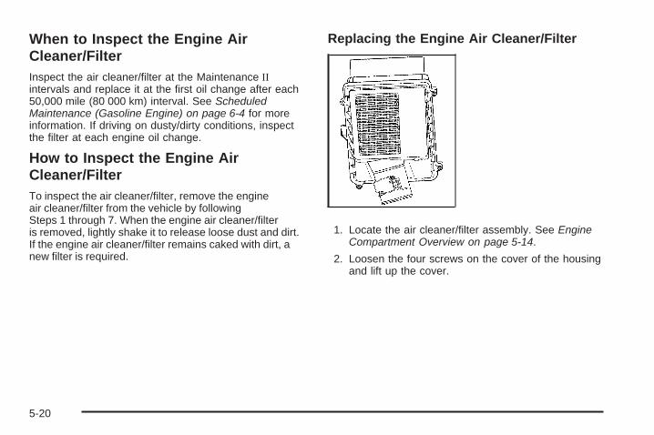
When to Inspect the Engine AirCleaner/FilterInspect the air cleaner/filter at the Maintenance IIintervals and replace it at the first oil change after each50,000 mile (80 000 km) interval. See ScheduledMaintenance (Gasoline Engine) on page 6-4 for moreinformation. If driving on dusty/dirty conditions, inspectthe filter at each engine oil change.
How to Inspect the Engine AirCleaner/FilterTo inspect the air cleaner/filter, remove the engineair cleaner/filter from the vehicle by followingSteps 1 through 7. When the engine air cleaner/filteris removed, lightly shake it to release loose dust and dirt.If the engine air cleaner/filter remains caked with dirt, anew filter is required.
Replacing the Engine Air Cleaner/Filter
1. Locate the air cleaner/filter assembly. See EngineCompartment Overview on page 5-14.
2. Loosen the four screws on the cover of the housingand lift up the cover.
5-20

3. Remove the engine air cleaner/filter from thehousing. Care should be taken to dislodge aslittle dirt as possible.
4. Clean the engine air cleaner/filter sealing surfacesand the housing.
5. Inspect or replace the engine air cleaner/filter.
6. Reinstall the cover and tighten the screws.
{CAUTION:
Operating the engine with the air cleaner/filter offcan cause you or others to be burned. The aircleaner not only cleans the air; it helps to stopflames if the engine backfires. If it is not there andthe engine backfires, you could be burned. Do notdrive with it off, and be careful working on theengine with the air cleaner/filter off.
Automatic Transmission Fluid(4-Speed Transmission)
When to Check and Change AutomaticTransmission FluidA good time to check the automatic transmission fluidlevel is when the engine oil is changed.
Change the fluid and filter at the intervals listed inAdditional Required Services on page 6-7 and be sureto use the transmission fluid listed in RecommendedFluids and Lubricants on page 6-15.
5-21

How to Check Automatic TransmissionFluidBecause this operation can be a little difficult, you maychoose to have this done at the dealer/retailer servicedepartment.
If you do it yourself, be sure to follow all the instructionshere or you could get a false reading on the dipstick.
Notice: Too much or too little fluid can damage yourtransmission. Too much can mean that some of thefluid could come out and fall on hot engine parts orexhaust system parts, starting a fire. Too little fluidcould cause the transmission to overheat. Be sureto get an accurate reading if you check yourtransmission fluid.
Wait at least 30 minutes before checking thetransmission fluid level if you have been driving:
• When outside temperatures are above 90°F (32°C).
• At high speed for quite a while.
• In heavy traffic — especially in hot weather.
• While pulling a trailer.
To get the right reading, the fluid should be at normaloperating temperature, which is 180°F to 200°F(82°C to 93°C).
Get the vehicle warmed up by driving about 15 miles(24 km) when outside temperatures are above 50°F(10°C). If it is colder than 50°F (10°C), drive the vehiclein 3 (Third) until the engine temperature gage movesand then remains steady for 10 minutes.
A cold fluid check can be made after the vehicle hasbeen sitting for eight hours or more with the engine off,but this is used only as a reference. Let the enginerun at idle for five minutes if outside temperatures are50°F (10°C) or more. If it is colder than 50°F (10°C), youmay have to idle the engine longer. Should the fluidlevel be low during this cold check, you must check thefluid hot before adding fluid. Checking the fluid hotwill give you a more accurate reading of the fluid level.
Checking the Fluid LevelPrepare the vehicle as follows:
1. Park the vehicle on a level place. Keep the enginerunning.
2. With the parking brake applied, place the shift leverin P (Park).
3. With your foot on the brake pedal, move the shiftlever through each gear range, pausing for aboutthree seconds in each range. Then, positionthe shift lever in P (Park).
4. Let the engine run at idle for three minutes or more.
5-22

Then, without shutting off the engine, follow these steps:
1. Locate the transmissiondipstick handle with thisgraphic which is locatedat the rear of the enginecompartment, on thepassenger side of thevehicle.
See Engine Compartment Overview on page 5-14for more information on location.
2. Flip the handle up and then pull out the dipstickand wipe it with a clean rag or paper towel.
3. Push it back in all the way, wait three seconds andthen pull it back out again.
4. Check both sides of the dipstick, and read the lowerlevel. The fluid level must be in the COLD area,below the cross-hatched area, for a cold check orin the HOT or cross-hatched area for a hot check.Be sure to keep the dipstick pointed down to get anaccurate reading.
5. If the fluid level is in the acceptable range, push thedipstick back in all the way; then flip the handledown to lock the dipstick in place.
Consistency of ReadingsAlways check the fluid level at least twice using theprocedure described previously. Consistency (repeatablereadings) is important to maintaining proper fluid level. Ifreadings are still inconsistent, contact your dealer/retailer.
5-23

How to Add Automatic TransmissionFluidRefer to the Maintenance Schedule to determine whatkind of transmission fluid to use. See RecommendedFluids and Lubricants on page 6-15.
Using a funnel, add fluid down the transmission dipsticktube only after checking the transmission fluid while it ishot. A cold check is used only as a reference. If the fluidlevel is low, add only enough of the proper fluid to bringthe level up to the HOT area for a hot check. It doesnot take much fluid, generally less than one pint (0.5 L).Do not overfill.
Notice: Use of the incorrect automatic transmissionfluid may damage the vehicle, and the damagesmay not be covered by the vehicle’s warranty.Always use the automatic transmission fluid listedin Recommended Fluids and Lubricants onpage 6-15.
• After adding fluid, recheck the fluid level asdescribed under “How to Check AutomaticTransmission Fluid,” earlier in this section.
• When the correct fluid level is obtained, push thedipstick back in all the way; then flip the handledown to lock the dipstick in place.
Automatic Transmission Fluid(6-Speed Transmission)
When to Check and Change AutomaticTransmission FluidIt is usually not necessary to check the transmission fluidlevel. The only reason for fluid loss is a transmission leakor overheating the transmission. If you suspect a smallleak, then use the following checking procedures to checkthe fluid level. However, if there is a large leak, then itmay be necessary to have the vehicle towed to a dealer/retailer service department and have it repaired beforedriving the vehicle further.
Notice: Use of the incorrect automatic transmissionfluid may damage the vehicle, and the damages maynot be covered by the vehicle’s warranty. Alwaysuse the automatic transmission fluid listed inRecommended Fluids and Lubricants on page 6-15.
Change the fluid and filter at the intervals listed in theMaintenance Schedule. See Scheduled Maintenance(Gasoline Engine) on page 6-4. Be sure to use thetransmission fluid listed in Recommended Fluids andLubricants on page 6-15.
5-24
How to Check Automatic TransmissionFluid
Notice: Too much or too little fluid can damageyour transmission. Too much can mean that someof the fluid could come out and fall on hot engineparts or exhaust system parts, starting a fire.Too little fluid could cause the transmission tooverheat. Be sure to get an accurate reading if youcheck your transmission fluid.
Before checking the fluid level, prepare the vehicle asfollows:
1. Start the engine and park the vehicle on a levelsurface. Keep the engine running.
2. Apply the parking brake and place the shift lever inP (Park).
3. With your foot on the brake pedal, move the shiftlever through each gear range, pausing for aboutthree seconds in each range. Then, move theshift lever back to P (Park).
4. Allow the engine to idle (500 – 800 rpm) for at leastone minute. Slowly release the brake pedal.
5. Keep the engine running and press the Trip/Fuelbutton or trip odometer reset stem until TRANSTEMP (Transmission Temperature) displays on theDriver Information Center (DIC).
6. Using the TRANS TEMP reading, determine andperform the appropriate check procedure. If theTRANS TEMP reading is not within the requiredtemperature ranges, allow the vehicle to cool,or operate the vehicle until the appropriatetransmission fluid temperature is reached.
5-25

Cold Check ProcedureUse this procedure only as a reference to determine ifthe transmission has enough fluid to be operated safelyuntil a hot check procedure can be made. The hot checkprocedure is the most accurate method to check thefluid level. Perform the hot check procedure at the firstopportunity. Use this cold check procedure to check fluidlevel when the transmission temperature is between80°F and 90°F (27°C and 32°C).
1. Locate the transmissiondipstick at the rearof the enginecompartment,on the passengerside of the vehicle.
See Engine Compartment Overview on page 5-14for more information.
2. Flip the handle up, and then pull out the dipstickand wipe it with a clean rag or paper towel.
3. Install the dipstick by pushing it back in all the way,wait three seconds, and then pull it back out again.
4. Check both sides of the dipstick and read the lowerlevel. Repeat the check procedure to verify thereading.
5. If the fluid level is below the COLD check band, addonly enough fluid as necessary to bring the levelinto the COLD band. It does not take much fluid,generally less than one pint (0.5L). Do not overfill.
6. Perform a hot check at the first opportunity afterthe transmission reaches a normal operatingtemperature between 160°F to 200°F (71°C to 93°C).
7. If the fluid level is in the acceptable range, push thedipstick back in all the way, then flip the handledown to lock the dipstick in place.
5-26

Hot Check ProcedureUse this procedure to check the transmission fluid levelwhen the transmission fluid temperature is between160°F and 200°F (71°C and 93°C).
The hot check is the most accurate method to check thefluid level. The hot check should be performed at the firstopportunity in order to verify the cold check. The fluidlevel rises as fluid temperature increases, so it isimportant to ensure the transmission temperature iswithin range.
1. Locate the transmissiondipstick at the rearof the enginecompartment,on the passengerside of the vehicle.
See Engine Compartment Overview on page 5-14for more information.
2. Flip the handle up, and then pull out the dipstickand wipe it with a clean rag or paper towel.
3. Install the dipstick by pushing it back in all the way,wait three seconds, and then pull it back out again.
4. Check both sides of the dipstick and read the lowerlevel. Repeat the check procedure to verify thereading.
5. Safe operating level is within the HOT cross hatchband on the dipstick. If the fluid level is not withinthe HOT band, and the transmission temperature isbetween 160°F and 200°F (71°C and 93°C), add ordrain fluid as necessary to bring the level into theHOT band. If the fluid level is low, add only enoughfluid to bring the level into the HOT band. It does nottake much fluid, generally less than one pint (0.5L).Do not overfill.
6. If the fluid level is in the acceptable range, push thedipstick back in all the way, then flip the handledown to lock the dipstick in place.
5-27

Consistency of ReadingsAlways check the fluid level at least twice using theprocedure described previously. Consistency (repeatablereadings) is important to maintaining proper fluid level. Ifreadings are still inconsistent, contact your dealer/retailer.
Cooling SystemIf your vehicle has the DURAMAX® Diesel engine, seethe DURAMAX® Diesel manual for more information.
The Cooling System allows the engine to maintain thecorrect working temperature.
A. Coolant Surge TankB. Coolant Surge Tank Pressure CapC. Engine Cooling Fan
5.3L Engine (4.3L, 4.8L, 6.0L and 6.2L Similar)
5-28

{CAUTION:
An electric engine cooling fan can start even whenthe engine is not running. To avoid injury, alwayskeep hands, clothing, and tools away from anyengine cooling fan.
{CAUTION:
Heater and radiator hoses, and other engine parts,can be very hot. Do not touch them. If you do, youcan be burned.
Do not run the engine if there is a leak. If you runthe engine, it could lose all coolant. That couldcause an engine fire, and you could be burned.Get any leak fixed before you drive the vehicle.
Notice: Using coolant other than DEX-COOL® cancause premature engine, heater core, or radiatorcorrosion. In addition, the engine coolant couldrequire changing sooner, at 30,000 miles (50 000 km)or 24 months, whichever occurs first. Any repairswould not be covered by the vehicle warranty.Always use DEX-COOL® (silicate-free) coolant inthe vehicle.
Engine CoolantThe cooling system in the vehicle is filled withDEX-COOL® engine coolant. This coolant is designedto remain in the vehicle for five years or 150,000 miles(240 000 km), whichever occurs first.
The following explains the cooling system and how tocheck and add coolant when it is low. If there is aproblem with engine overheating, see EngineOverheating on page 5-34.
5-29
What to Use
{CAUTION:
Adding only plain water to the cooling system canbe dangerous. Plain water, or some other liquidsuch as alcohol, can boil before the proper coolantmixture will. The vehicle’s coolant warning systemis set for the proper coolant mixture. With plainwater or the wrong mixture, the engine could gettoo hot but you would not get the overheatwarning. The engine could catch fire and you orothers could be burned. Use a 50/50 mixture ofclean, drinkable water and DEX-COOL® coolant.
Use a 50/50 mixture of clean, drinkable water andDEX-COOL® coolant. If using this mixture, nothing elseneeds to be added. This mixture:
• Gives freezing protection down to −34°F (−37°C),outside temperature.
• Gives boiling protection up to 265°F (129°C),engine temperature.
• Protects against rust and corrosion.
• Will not damage aluminum parts.
• Helps keep the proper engine temperature.
5-30

Notice: If an improper coolant mixture is used,the engine could overheat and be badly damaged.The repair cost would not be covered by the vehiclewarranty. Too much water in the mixture can freezeand crack the engine, radiator, heater core, andother parts.
Notice: If extra inhibitors and/or additives are usedin the vehicle’s cooling system, the vehicle couldbe damaged. Use only the proper mixture ofthe engine coolant listed in this manual for thecooling system. See Recommended Fluids andLubricants on page 6-15 for more information.
Checking CoolantThe coolant surge tank is located in the enginecompartment on the passenger side of the vehicle.See Engine Compartment Overview on page 5-14 formore information on location.
The vehicle must be on a level surface when checkingthe coolant level.
Check to see if coolant is visible in the coolant surge tank.If the coolant inside the coolant surge tank is boiling,do not do anything else until it cools down. If coolant isvisible but the coolant level is not at or above the FULLCOLD mark, add a 50/50 mixture of clean, drinkablewater and DEX-COOL® coolant at the coolant surge tank,but be sure the cooling system is cool before this is done.
5-31

The coolant level should be at or above the FULLCOLD mark. If it is not, you may have a leak in thecooling system.
If the vehicle has a low coolant sensor and the LOWCOOLANT LEVEL message comes on and stays on,it means you are low on engine coolant. See “LOWCOOLANT LEVEL” under DIC Warnings and Messageson page 3-66.
How to Add Coolant to the CoolantSurge Tank for Gasoline EnginesIf the vehicle has a diesel engine, see “Cooling System”in the DURAMAX® Diesel Supplement for the propercoolant fill procedure.
{CAUTION:
You can be burned if you spill coolant on hotengine parts. Coolant contains ethylene glycol andit will burn if the engine parts are hot enough.Do not spill coolant on a hot engine.
Notice: This vehicle has a specific coolant fillprocedure. Failure to follow this procedure couldcause the engine to overheat and be severelydamaged.
5-32

{CAUTION:
An electric engine cooling fan under the hood canstart up even when the engine is not running andcan cause injury. Keep hands, clothing, and toolsaway from any underhood electric fan.
{CAUTION:
Steam and scalding liquids from a hot coolingsystem can blow out and burn you badly. They areunder pressure, and if you turn the coolant surgetank pressure cap — even a little — they cancome out at high speed. Never turn the cap whenthe cooling system, including the coolant surgetank pressure cap, is hot. Wait for the coolingsystem and coolant surge tank pressure cap tocool if you ever have to turn the pressure cap.
If no coolant is visible in the surge tank, add coolant asfollows:
1. Remove the coolantsurge tank pressurecap when the coolingsystem, including thecoolant surge tankpressure cap andupper radiator hose,is no longer hot.
Turn the pressure cap slowly counterclockwiseabout one full turn. If you hear a hiss, wait for that tostop. A hiss means there is still some pressure left.
2. Keep turning the pressure cap slowly, and remove it.
5-33

3. Fill the coolant surge tank with the proper mixtureto the FULL COLD mark.
4. With the coolant surge tank pressure cap off,start the engine and let it run until the enginecoolant temperature gage indicates approximately195°F (90°C).By this time, the coolant level inside the coolantsurge tank may be lower. If the level is lower, addmore of the proper mixture to the coolant surge tankuntil the level reaches the FULL COLD mark.
5. Replace the pressure cap. Be sure the pressurecap is hand-tight and fully seated.
6. Verify coolant level after engine is shut off and thecoolant is cold. If necessary, repeat coolant fillprocedure Steps 1 through 6.
Notice: If the pressure cap is not tightly installed,coolant loss and possible engine damage may occur.Be sure the cap is properly and tightly secured.
Engine OverheatingIf the vehicle has the DURAMAX® Diesel engine, seethe DURAMAX® Diesel manual for more information.
The vehicle has several indicators to warn of engineoverheating.
You will find a coolant temperature gage on the vehicle’sinstrument panel. See Engine Coolant TemperatureGage on page 3-44.
In addition, you will find ENGINE OVERHEATED STOPENGINE, ENGINE OVERHEATED IDLE ENGINE, andENGINE POWER IS REDUCED messages in the DriverInformation Center (DIC) on the instrument panel. SeeDIC Warnings and Messages on page 3-66.
5-34
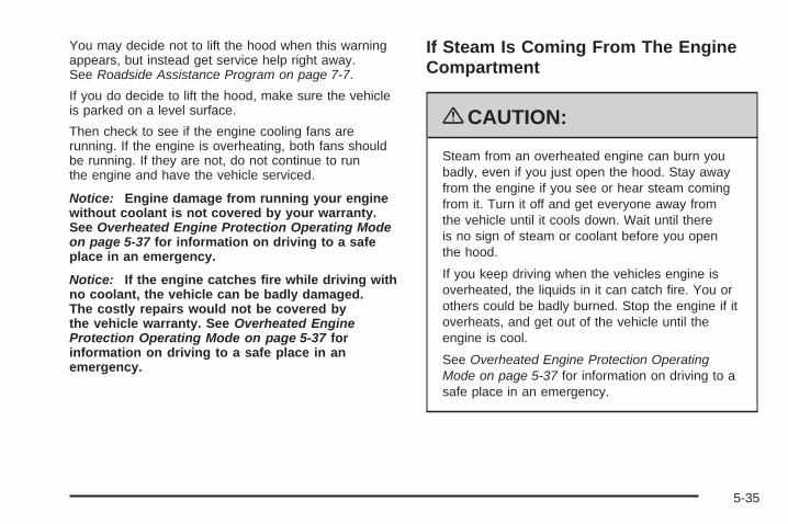
You may decide not to lift the hood when this warningappears, but instead get service help right away.See Roadside Assistance Program on page 7-7.
If you do decide to lift the hood, make sure the vehicleis parked on a level surface.
Then check to see if the engine cooling fans arerunning. If the engine is overheating, both fans shouldbe running. If they are not, do not continue to runthe engine and have the vehicle serviced.
Notice: Engine damage from running your enginewithout coolant is not covered by your warranty.See Overheated Engine Protection Operating Modeon page 5-37 for information on driving to a safeplace in an emergency.
Notice: If the engine catches fire while driving withno coolant, the vehicle can be badly damaged.The costly repairs would not be covered bythe vehicle warranty. See Overheated EngineProtection Operating Mode on page 5-37 forinformation on driving to a safe place in anemergency.
If Steam Is Coming From The EngineCompartment
{CAUTION:
Steam from an overheated engine can burn youbadly, even if you just open the hood. Stay awayfrom the engine if you see or hear steam comingfrom it. Turn it off and get everyone away fromthe vehicle until it cools down. Wait until thereis no sign of steam or coolant before you openthe hood.
If you keep driving when the vehicles engine isoverheated, the liquids in it can catch fire. You orothers could be badly burned. Stop the engine if itoverheats, and get out of the vehicle until theengine is cool.
See Overheated Engine Protection OperatingMode on page 5-37 for information on driving to asafe place in an emergency.
5-35

If No Steam Is Coming From TheEngine CompartmentThe ENGINE OVERHEATED STOP ENGINE or theENGINE OVERHEATED IDLE ENGINE message, alongwith a low coolant condition, can indicate a seriousproblem.
If you get an engine overheat warning, but see or hearno steam, the problem may not be too serious.Sometimes the engine can get a little too hot when you:
• Climb a long hill on a hot day.
• Stop after high-speed driving.
• Idle for long periods in traffic.
• Tow a trailer. See Towing a Trailer on page 4-51.
If you get the ENGINE OVERHEATED STOP ENGINE orthe ENGINE OVERHEATED IDLE ENGINE messagewith no sign of steam, try this for a minute or so:
1. Turn the air conditioning off.
2. Turn the heater on to the highest temperature andto the highest fan speed. Open the windows asnecessary.
3. If you are stopped in a traffic jam, apply the brake,shift to N (Neutral); otherwise, shift to the highestgear while driving — D (Drive) or 3 (Third).
If the temperature overheat gage is no longer in theoverheat zone or an overheat warning no longer displays,the vehicle can be driven. Continue to drive the vehicleslow for about 10 minutes. Keep a safe vehicle distancefrom the car in front of you. If the warning does not comeback on, continue to drive normally.
If the warning continues, pull over, stop, and park thevehicle right away.
If there is no sign of steam, idle the engine forfive minutes while parked. If the warning is stilldisplayed, turn off the engine until it cools down.Also, see “Overheated Engine Protection OperatingMode” later in this section.
5-36

Overheated Engine ProtectionOperating ModeIf an overheated engine condition exists and theREDUCED ENGINE POWER message is displayed, anoverheat protection mode which alternates firing groupsof cylinders helps prevent engine damage. In this mode,you will notice a loss in power and engine performance.This operating mode allows the vehicle to be driven to asafe place in an emergency. Driving extended miles (km)and/or towing a trailer in the overheat protection modeshould be avoided.
Notice: After driving in the overheated engineprotection operating mode, to avoid engine damage,allow the engine to cool before attempting any repair.The engine oil will be severely degraded. Repair thecause of coolant loss, change the oil and reset the oillife system. See Engine Oil on page 5-15.
Engine Fan NoiseIf the vehicle has a clutched engine cooling fan, when theclutch is engaged, the fan spins faster to provide more airto cool the engine. In most everyday driving conditions,the fan is spinning slower and the clutch is not fullyengaged. This improves fuel economy and reduces fannoise. Under heavy vehicle loading, trailer towing, and/orhigh outside temperatures, the fan speed increases asthe clutch more fully engages, so you may hear anincrease in fan noise. This is normal and should not bemistaken as the transmission slipping or making extrashifts. It is merely the cooling system functioning properly.The fan will slow down when additional cooling is notrequired and the clutch disengages.
You may also hear this fan noise when you start theengine. It will go away as the fan clutch partiallydisengages.
If the vehicle has electric cooling fans, you may hearthe fans spinning at low speed during most everydaydriving. The fans may turn off if no cooling is required.Under heavy vehicle loading, trailer towing, and/orhigh outside temperatures, or if you are operating theair conditioning system, the fans may change tohigh speed and you may hear an increase in fan noise.This is normal and indicates that the cooling systemis functioning properly. The fans will change to lowspeed when additional cooling is no longer required.
5-37

Power Steering Fluid
See Engine CompartmentOverview on page 5-14 forreservoir location.
When to Check Power Steering FluidIt is not necessary to regularly check power steering fluidunless you suspect there is a leak in the system or youhear an unusual noise. A fluid loss in this system couldindicate a problem. Have the system inspected andrepaired.
How to Check Power Steering FluidTo check the power steering fluid:
1. Turn the key off and let the engine compartmentcool down.
2. Wipe the cap and the top of the reservoir clean.
3. Unscrew the cap and wipe the dipstick with aclean rag.
4. Replace the cap and completely tighten it.
5. Remove the cap again and look at the fluidlevel on the dipstick.
The level should be at the FULL COLD mark.If necessary, add only enough fluid to bring thelevel up to the mark.
What to UseTo determine what kind of fluid to use, seeRecommended Fluids and Lubricants on page 6-15.Always use the proper fluid.
Notice: Use of the incorrect fluid may damage thevehicle and the damages may not be covered bythe vehicle’s warranty. Always use the correct fluidlisted in Recommended Fluids and Lubricants onpage 6-15.
5-38

Windshield Washer Fluid
What to UseWhen windshield washer fluid needs to be added, besure to read the manufacturer’s instructions before use.Use a fluid that has sufficient protection againstfreezing in an area where the temperature may fallbelow freezing.
Adding Washer FluidThe vehicle has a low washer fluid message in the DICthat comes on when the washer fluid is low. The messageis displayed for 15 seconds at the start of each ignitioncycle. When the WASHER FLUID LOW ADD FLUIDmessage displays, you will need to add washer fluid tothe windshield washer fluid reservoir.
Open the cap with thewasher symbol on it.Add washer fluid until thetank is full. See EngineCompartment Overview onpage 5-14 for reservoirlocation.
Notice:
• When using concentrated washer fluid, followthe manufacturer’s instructions for addingwater.
• Do not mix water with ready-to-use washer fluid.Water can cause the solution to freeze anddamage your washer fluid tank and other partsof the washer system. Also, water does notclean as well as washer fluid.
• Fill the washer fluid tank only three-quarters fullwhen it is very cold. This allows for fluidexpansion if freezing occurs, which coulddamage the tank if it is completely full.
• Do not use engine coolant (antifreeze) in yourwindshield washer. It can damage the vehicle’swindshield washer system and paint.
5-39

Brakes
Brake Fluid
The brake master cylinderreservoir is filled withDOT-3 brake fluid. SeeEngine CompartmentOverview on page 5-14 forthe location of the reservoir.
There are only two reasons why the brake fluid level inthe reservoir might go down:
• The brake fluid level goes down because of normalbrake lining wear. When new linings are installed,the fluid level goes back up.
• A fluid leak in the brake hydraulic system can alsocause a low fluid level. Have the brake hydraulicsystem fixed, since a leak means that sooneror later the brakes will not work well.
Do not top off the brake fluid. Adding fluid does notcorrect a leak. If fluid is added when the liningsare worn, there will be too much fluid when new brakelinings are installed. Add or remove brake fluid, asnecessary, only when work is done on the brakehydraulic system.
{CAUTION:
If too much brake fluid is added, it can spill onthe engine and burn, if the engine is hot enough.You or others could be burned, and the vehiclecould be damaged. Add brake fluid only whenwork is done on the brake hydraulic system.See “Checking Brake Fluid” in this section.
Refer to the Maintenance Schedule to determine whento check the brake fluid. See Scheduled Maintenance(Gasoline Engine) on page 6-4.
5-40

Checking Brake FluidCheck brake fluid by looking at the brake fluid reservoir.See Engine Compartment Overview on page 5-14.
The fluid level should beabove MIN. If it is not,have the brake hydraulicsystem checked tosee if there is a leak.
After work is done on the brake hydraulic system,make sure the level is above the MIN but not over theMAX mark.
What to AddUse only new DOT-3 brake fluid from a sealed container.See Recommended Fluids and Lubricants on page 6-15.
Always clean the brake fluid reservoir cap and the areaaround the cap before removing it. This helps keepdirt from entering the reservoir.
{CAUTION:
With the wrong kind of fluid in the brake hydraulicsystem, the brakes might not work well. This couldcause a crash. Always use the proper brake fluid.
Notice:
• Using the wrong fluid can badly damage brakehydraulic system parts. For example, just afew drops of mineral-based oil, such as engineoil, in the brake hydraulic system can damagebrake hydraulic system parts so badly that theywill have to be replaced. Do not let someoneput in the wrong kind of fluid.
• If brake fluid is spilled on the vehicle’s paintedsurfaces, the paint finish can be damaged.Be careful not to spill brake fluid on the vehicle.If you do, wash it off immediately. See WashingYour Vehicle on page 5-117.
5-41

Brake WearThis vehicle has front disc brakes and could have reardrum brakes or rear disc brakes.
Disc brake pads have built-in wear indicators that make ahigh-pitched warning sound when the brake pads areworn and new pads are needed. The sound can comeand go or be heard all the time the vehicle is moving,except when applying the brake pedal firmly.
{CAUTION:
The brake wear warning sound means that soonthe brakes will not work well. That could lead to anaccident. When the brake wear warning sound isheard, have the vehicle serviced.
Notice: Continuing to drive with worn-out brakepads could result in costly brake repair.
Some driving conditions or climates can cause a brakesqueal when the brakes are first applied or lightly applied.This does not mean something is wrong with the brakes.
Properly torqued wheel nuts are necessary to helpprevent brake pulsation. When tires are rotated, inspectbrake pads for wear and evenly tighten wheel nuts inthe proper sequence to torque specifications inCapacities and Specifications on page 5-129.
If the vehicle has rear drum brakes, they do not havewear indicators, but if a rear brake rubbing noise is heard,have the rear brake linings inspected immediately.Rear brake drums should be removed and inspectedeach time the tires are removed for rotation or changing.Drum brakes have an inspection hole to inspect liningwear during scheduled maintenance. When the frontbrake pads are replaced, have the rear brakesinspected, too.
Brake linings should always be replaced as completeaxle sets.
Brake Pedal TravelSee your dealer/retailer if the brake pedal does notreturn to normal height, or if there is a rapid increase inpedal travel. This could be a sign that brake servicemight be required.
Brake AdjustmentEvery brake stop, the brakes adjust for wear.
5-42

Replacing Brake System PartsThe braking system on a vehicle is complex. Its manyparts have to be of top quality and work well together ifthe vehicle is to have really good braking. The vehiclewas designed and tested with top-quality brake parts.When parts of the braking system are replaced — forexample, when the brake linings wear down and newones are installed — be sure to get new approvedreplacement parts. If this is not done, the brakes mightnot work properly. For example, if someone puts in brakelinings that are wrong for the vehicle, the balancebetween the front and rear brakes can change — for theworse. The braking performance expected can change inmany other ways if the wrong replacement brake partsare installed.
BatteryIf the vehicle is a Two-mode Hybrid, see the Two-modeHybrid manual for more information.
This vehicle has a maintenance free battery (or batteries).When it is time for a new battery, see your dealer/retailerfor one that has the replacement number shown on theoriginal battery’s label. See Engine CompartmentOverview on page 5-14 for battery location.
Warning: Battery posts, terminals, and relatedaccessories contain lead and lead compounds,chemicals known to the State of California to causecancer and reproductive harm. Wash hands afterhandling.
5-43

Vehicle Storage
{CAUTION:
Batteries have acid that can burn you and gas thatcan explode. You can be badly hurt if you are notcareful. See Jump Starting on page 5-44 for tipson working around a battery without getting hurt.
Infrequent Usage: If the vehicle is driven infrequently,remove the black, negative (−) cable from the battery.This helps keep the battery from running down.
Extended Storage: For extended storage of the vehicle,remove the black, negative (−) cable from the battery oruse a battery trickle charger. This helps maintain thecharge of the battery over an extended period of time.
Jump StartingIf the vehicle is a Two-mode Hybrid, see the Two-modeHybrid manual for more information.If the vehicle’s battery (or batteries) has run down, youmay want to use another vehicle and some jumper cablesto start your vehicle. Be sure to use the following steps todo it safely.
{CAUTION:
Batteries can hurt you. They can be dangerousbecause:
• They contain acid that can burn you.• They contain gas that can explode or ignite.• They contain enough electricity to burn you.
If you do not follow these steps exactly, some orall of these things can hurt you.
Notice: Ignoring these steps could result in costlydamage to the vehicle that would not be coveredby the warranty.Trying to start the vehicle by pushing or pulling itwill not work, and it could damage the vehicle.1. Check the other vehicle. It must have a 12-volt
battery with a negative ground system.
5-44

Notice: If the other vehicle’s system is not a 12-voltsystem with a negative ground, both vehicles canbe damaged. Only use vehicles with 12-volt systemswith negative grounds to jump start your vehicle.
2. If you have a vehicle with a diesel engine with twobatteries, you should know before you begin that,especially in cold weather, you may not be ableto get enough power from a single battery in anothervehicle to start your diesel engine. If your vehiclehas more than one battery, use the battery thatis closer to the starter -- this will reduce electricalresistance. This is located on the passenger side, inthe rear of the engine compartment.
3. Get the vehicles close enough so the jumper cablescan reach, but be sure the vehicles are not touchingeach other. If they are, it could cause an unwantedground connection. You would not be able to startyour vehicle, and the bad grounding could damagethe electrical systems.To avoid the possibility of the vehicles rolling, set theparking brake firmly on both vehicles involved in thejump start procedure. Put the automatic transmissionin P (Park) or a manual transmission in Neutralbefore setting the parking brake. If you have afour-wheel-drive vehicle, be sure the transfercase is in a drive gear, not in Neutral.
Notice: If you leave the radio or other accessorieson during the jump starting procedure, they could bedamaged. The repairs would not be covered by thewarranty. Always turn off the radio and otheraccessories when jump starting the vehicle.
4. Turn off the ignition on both vehicles. Unplugunnecessary accessories plugged into the cigarettelighter or the accessory power outlets. Turn offthe radio and all the lamps that are not needed.This will avoid sparks and help save both batteries.And it could save the radio!
5. Open the hood on the other vehicle and locate thepositive (+) and negative (−) terminal locations onthat vehicle.The positive (+) terminal, is located under a redplastic cover at the positive battery post. To uncoverthe positive (+) terminal, open the red plastic cover.
5-45
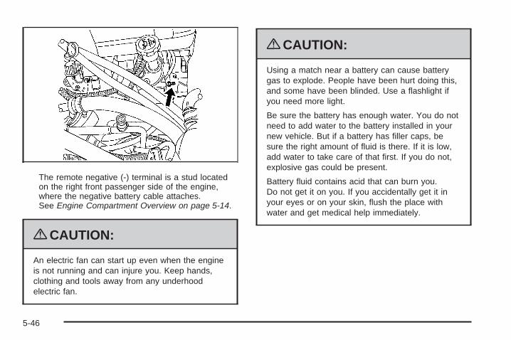
The remote negative (-) terminal is a stud locatedon the right front passenger side of the engine,where the negative battery cable attaches.See Engine Compartment Overview on page 5-14.
{CAUTION:
An electric fan can start up even when the engineis not running and can injure you. Keep hands,clothing and tools away from any underhoodelectric fan.
{CAUTION:
Using a match near a battery can cause batterygas to explode. People have been hurt doing this,and some have been blinded. Use a flashlight ifyou need more light.
Be sure the battery has enough water. You do notneed to add water to the battery installed in yournew vehicle. But if a battery has filler caps, besure the right amount of fluid is there. If it is low,add water to take care of that first. If you do not,explosive gas could be present.
Battery fluid contains acid that can burn you.Do not get it on you. If you accidentally get it inyour eyes or on your skin, flush the place withwater and get medical help immediately.
5-46

{CAUTION:
Fans or other moving engine parts can injure youbadly. Keep your hands away from moving partsonce the engine is running.
6. Check that the jumper cables do not have loose ormissing insulation. If they do, you could get ashock. The vehicles could be damaged too.Before you connect the cables, here are somebasic things you should know. Positive (+) will go topositive (+) or to a remote positive (+) terminal if thevehicle has one. Negative (−) will go to a heavy,unpainted metal engine part or to a remotenegative (−) terminal if the vehicle has one.Do not connect positive (+) to negative (−) or youwill get a short that would damage the batteryand maybe other parts too. And do not connect thenegative (−) cable to the negative (−) terminal onthe dead battery because this can cause sparks.
7. Connect the redpositive (+) cable to thepositive (+) terminalof the vehicle with thedead battery.
8. Do not let the other end touch metal. Connect it tothe positive (+) terminal of the good battery. Use aremote positive (+) terminal if the vehicle has one.
9. Now connect the black negative (−) cable to thenegative (−) terminal of the good battery. Use aremote negative (−) terminal if the vehicle has one.Do not let the other end touch anything until thenext step.
5.3L engine (4.3L, 4.8L,6.0L and 6.2L similar)
5-47

10. Connect the other end of the negative (−) cable to aheavy, unpainted metal engine part or to the remotenegative (−) terminal, on the vehicle with thedead battery.
11. Start the vehicle with the good battery and run theengine for a while.
12. Try to start the vehicle that had the dead battery.If it will not start after a few tries, it probably needsservice.
Notice: If the jumper cables are connected orremoved in the wrong order, electrical shorting mayoccur and damage the vehicle. The repairs wouldnot be covered by your warranty. Always connectand remove the jumper cables in the correct order,making sure that the cables do not touch each otheror other metal.
A. Heavy, Unpainted Metal Engine Part or RemoteNegative (−) Terminal
B. Good Battery or Remote Positive (+) and RemoteNegative (−) Terminals
C. Dead Battery or Remote Positive (+) Terminal
Jumper Cable Removal
5-48

To disconnect the jumper cables from both vehicles dothe following:
1. Disconnect the black negative (−) cable from thevehicle that had the bad battery.
2. Disconnect the black negative (−) cable from thevehicle with the good battery.
3. Disconnect the red positive (+) cable from thevehicle with the good battery.
4. Disconnect the red positive (+) cable from the othervehicle.
5. Return the positive (+) terminal cover, to its originalposition.
Rear AxleWhen to Check LubricantIt is not necessary to regularly check rear axle fluidunless you suspect there is a leak or you hear anunusual noise. A fluid loss could indicate a problem.Have it inspected and repaired.
All axle assemblies are filled by volume of fluid duringproduction. They are not filled to reach a certain level.When checking the fluid level on any axle, variations inthe readings can be caused by factory fill differencesbetween the minimum and the maximum fluid volume.Also, if a vehicle has just been driven before checking thefluid level, it may appear lower than normal because fluidhas traveled out along the axle tubes and has not drainedback to the sump area. Therefore, a reading taken fiveminutes after the vehicle has been driven will appear tohave a lower fluid level than a vehicle that has beenstationary for an hour or two. Remember that the rearaxle assembly must be supported to get a true reading.
5-49

How to Check Lubricant
To get an accurate reading, the vehicle should be on alevel surface.
• For all 4.3L, 4.8L and 5.3L 1500 Series applications,the proper level is 0.04 inches to 0.75 inches(1.0 mm to 19.0 mm) below the bottom of the fillerhole, located on the rear axle. Add only enoughfluid to reach the proper level.
• For all 6.0L and 6.2L 1500 Series applications,the proper level is from 0.6 inches to 1.6 inches(15 mm to 40 mm) below the bottom of the filler plughole, located on the rear axle. Add only enoughfluid to reach the proper level.
2500HD with 6.0L and 6.2L
All Other Series and Engines
5-50

• For all 6.0L and 6.2L 2500HD Series applications,the proper level is from 0 to 0.5 inches(0 mm to 13 mm) below the bottom of the fillerplug hole, located on the rear axle. Add onlyenough fluid to reach the proper level.
• For all 6.6L DURAMAX DIESEL 2500HD Seriesapplications and all 3500 Series applications,the proper level is from 0.6 inches to 0.8 inches(17 mm to 21 mm) below the bottom of the filler plughole, located on the rear axle. Add only enoughfluid to reach the proper level.
What to UseRefer to the Maintenance Schedule to determine whatkind of lubricant to use. See Recommended Fluidsand Lubricants on page 6-15.
Four-Wheel DriveLubricant checks in this section also apply to thesevehicles.
Transfer CaseWhen to Check LubricantIt is not necessary to regularly check transfer case fluidunless you suspect there is a leak, or you hear anunusual noise. A fluid loss could indicate a problem.Have it inspected and repaired.
How to Check Lubricant
A. Fill PlugB. Drain Plug
Electric Shift Transfer Case
5-51

A. Fill PlugB. Drain Plug
A. Fill PlugB. Drain Plug
To get an accurate reading, the vehicle should be on alevel surface.
If the level is below the bottom of the filler plug hole,located on the transfer case, you will need to add somelubricant. Add enough lubricant to raise the level to thebottom of the filler plug hole. Use care not to overtightenthe plug.
Manual Shift Transfer Case Active Transfer Case
5-52

When to Change LubricantRefer to the Maintenance Schedule to determine howoften to change the lubricant. See ScheduledMaintenance (Gasoline Engine) on page 6-4.
What to UseRefer to the Maintenance Schedule to determine whatkind of lubricant to use. See Recommended Fluidsand Lubricants on page 6-15.
Front AxleWhen to Check and Change LubricantIt is not necessary to regularly check front axle fluidunless you suspect there is a leak or you hear anunusual noise. A fluid loss could indicate a problem.Have it inspected and repaired.
How to Check LubricantTo get an accurate reading, the vehicle should be on alevel surface.
1500 Series
A: Fill PlugB: Drain Plug
5-53

A: Fill PlugB: Drain Plug
• When the differential is cold, add enough lubricant toraise the level from 0 (0 mm) to 1/8 inch (3.2 mm)below the filler plug hole.
• When the differential is at operating temperature(warm), add enough lubricant to raise the level tothe bottom of the filler plug hole.
What to UseRefer to the Maintenance Schedule to determine whatkind of lubricant to use. See Recommended Fluidsand Lubricants on page 6-15.
Noise Control System
Tampering with Noise ControlSystem ProhibitedThe following information relates to compliance withfederal noise emission standards for vehicles with aGross Vehicle Weight Rating (GVWR) of more than10,000 lbs (4 536 kg). The Maintenance Scheduleprovides information on maintaining the noise controlsystem to minimize degradation of the noise emissioncontrol system during the life of your vehicle. The noisecontrol system warranty is given in your warranty booklet.These standards apply only to vehicles sold in theUnited States.Federal law prohibits the following acts or the causingthereof:1. The removal or rendering inoperative by any person,
other than for purposes of maintenance, repair orreplacement, of any device or element of designincorporated into any new vehicle for the purposeof noise control, prior to its sale or delivery to theultimate purchaser or while it is in use; or
2. The use of the vehicle after such device or elementof design has been removed or rendered inoperativeby any person.
Among those acts presumed to constitute tampering arethe acts listed below.
5-54

Insulation:• Removal of the noise shields or any underhood
insulation.
Engine:• Removal or rendering engine speed governor, if the
vehicle has one, inoperative so as to allow enginespeed to exceed manufacturer specifications.
Fan and Drive:• Removal of fan clutch, if the vehicle has one, or
rendering clutch inoperative.
• Removal of the fan shroud, if the vehicle has one.
Air Intake:• Removal of the air cleaner silencer.
• Modification of the air cleaner.
Exhaust:• Removal of the muffler and/or resonator.
• Removal of the exhaust pipes and exhaust pipeclamps.
Headlamp AimingThe vehicle has a visual optical headlamp aimingsystem. The aim of the headlamps have been preset atthe factory and should need no further adjustment.
However, if the vehicle is damaged in a crash, the aimof the headlamps may be affected and adjustmentmay be necessary.
If oncoming vehicles flash their high beams at you, thismay mean the vertical aim of your headlamps needsto be adjusted.
It is recommended that the vehicle is taken to yourdealer/retailer for service if the headlamps need to beadjusted. It is possible however, to re-aim theheadlamps as described.
5-55

The vehicle should:
• Be placed so the headlamps are 25 ft. (7.6 m) froma light colored wall.
• Have all four tires on a level surface which is levelall the way to the wall.
• Be placed so it is perpendicular to the wall.
• Not have any snow, ice, or mud on it.
• Be fully assembled and all other work stopped whileheadlamp aiming is being performed.
• Normally loaded with a full tank of fuel andone person or 160 lbs (75 kg) sitting on thedriver seat.
• Have the tires properly inflated.
• Have the spare tire is in its proper location in thevehicle.
Headlamp aiming is done with the vehicle’s low-beamheadlamps. The high-beam headlamps will be correctlyaimed if the low-beam headlamps are aimed properly.
To adjust the vertical aim:
1. Open the hood. See Hood Release on page 5-13for more information.
2. Locate the aim dot on the lens of the low-beamheadlamp.
3. Record the distance from the ground to the aim doton the low-beam headlamp.
5-56

4. At a wall, measure from the ground upward (A) tothe recorded distance from Step 3 and mark it.
5. Draw or tape a horizontal line (B) on the wall thewidth of the vehicle at the height of the mark inStep 4.
Notice: Do not cover a headlamp to improve beamcut-off when aiming. Covering a headlamp may causeexcessive heat build-up which may cause damage tothe headlamp.
6. Turn on the low-beam headlamps and place apiece of cardboard or equivalent in front of theheadlamp not being adjusted. This allows only thebeam of light from the headlamp being adjustedto be seen on the flat surface.
7. Locate the vertical headlamp aiming screws, whichare under the hood near each headlamp assembly.The adjustment screw can be turned with aE8 Torx® socket.
8. Turn the vertical aiming screw until the headlampbeam is aimed to the horizontal tape line. Turn itclockwise or counterclockwise to raise or lower theangle of the beam.
5-57

9. Make sure that the light from the headlamp ispositioned at the bottom edge of the horizontal tapeline. The lamp on the left (A) shows the correctheadlamp aim. The lamp on the right (B) shows theincorrect headlamp aim.
10. Repeat Steps 7 through 9 for the oppositeheadlamp.
Bulb ReplacementFor the proper type of replacement bulbs, seeReplacement Bulbs on page 5-63.
For any bulb changing procedure not listed in thissection, contact your dealer/retailer.
Halogen Bulbs
{CAUTION:
Halogen bulbs have pressurized gas inside andcan burst if you drop or scratch the bulb. You orothers could be injured. Be sure to read and followthe instructions on the bulb package.
HeadlampsTo replace one of these bulbs:
1. Open the hood. See Hood Release on page 5-13for more information.
2. If you are replacing the bulb on the passenger sideremove the Engine Air Cleaner cover. See EngineAir Cleaner/Filter on page 5-19 for moreinformation.
3. Reach in and access the bulb sockets from insidethe engine compartment.
5-58

4. Turn the bulb socket counterclockwise to remove itfrom the headlamp assembly and pull it straight out.
5. Unplug the electrical connector from the old bulb byreleasing the clips on the bulb socket.
6. Replace it with a new bulb socket.
7. Plug in the electrical connector to the new bulbsocket.
8. Reinstall the new bulb socket into the headlampassembly and turn it clockwise to secure.
9. Close the hood.
Center High-Mounted Stoplamp(CHMSL) and Cargo LampTo replace one of these bulbs:
1. Remove the screws and lift off the lamp assembly.
5-59

A. Cargo LampB. Center High-Mounted Stoplamp Bulb (CHMSL)
2. Remove the bulbs by turning socketcounterclockwise and pulling the bulb straight out.
3. Install the bulbs by pushing the bulb straight in andturning clockwise.
4. Reinstall the lamp assembly and tighten the screws.
Pickup Box Identification andFender Marker LampsTo replace a pickup box identification or fender markerlamp bulb:
1. Press the tab from the back to remove the lamp.
2. Unplug the lamp assembly harness.
3. Gently pry the individual lamp from the lampassembly.
4. Unplug the lamp.
5. Plug in a new lamp and snap it into the assembly.
6. Reinstall the lamp assembly.
5-60

Taillamps, Turn Signal, Stoplampsand Back-up LampsTo replace one of these bulbs:
1. Open the tailgate. Tailgate on page 2-13 for moreinformation.
2. Remove the two rearlamp assembly screwsnear the tailgate latchstrikerpost and pull outthe lamp assembly.
3. Determine which of the following taillampassemblies applies to your vehicle.
A. Stoplamp/Taillamp/Turn Signal LampB. Back-up LampC. Stoplamp/Taillamp/Turn Signal Lamp
4. Press the tab, if the vehicle has one, and turn thebulb socket counterclockwise to remove it from thetaillamp assembly.
Dually Models
5-61

A. Stoplamp/Taillamp/Turn Signal Lamp
B. Stoplamp/Taillamp/Turn Signal Lamp
C. Back-up LampD. Sidemarker Lamp
5. Pull the old bulb straight out from the socket.
6. Press a new bulb into the socket and turn the socketclockwise into the taillamp assembly.
7. Reinstall the taillamp assembly.
Taillamps (Chassis Cab Models)
A. Backup LampB. Stoplamp/Taillamp/Turn Signal Lamp
To replace one of these bulbs:1. Remove the four screws.2. Lift the lens off the lamp assembly.3. Turn the old bulb counterclockwise and pull the it
straight out from the socket.4. Install a new bulb into the socket, turn it clockwise,
and press it in until it is tight.5. Reinstall the lens and the four screws.
All Other Models
5-62

License Plate LampTo replace one of these bulbs:
1. Reach under the rear bumper for the bulb socket.
2. Turn the bulb socket counterclockwise and pull thebulb socket out of the connector.
3. Pull the old bulb from the bulb socket, keeping thebulb straight as you pull it out.
4. Install the new bulb.
5. Reverse Steps 1 through 3 to reinstall the bulbsocket.
Replacement Bulbs
Exterior Lamp Bulb NumberBack-up Lamp 3047Back-up Lamp* 1156Cargo Lamp and CenterHigh-Mounted Stoplamp (CHMSL) 912
Fender Marker W5WLLHigh-Beam Headlamp 9005Low-Beam Headlamp H11License Plate Lamp 168Stoplamp/Taillamp/TurnSignal Lamp 3047
Sidemarker Lamp 194Stoplamp/Turn SignalLamp/Taillamp* 1157
* Chassis Cab Models
For replacement bulbs not listed here, contact yourdealer/retailer.
5-63

Windshield Wiper BladeReplacementWindshield wiper blades should be inspected for wearor cracking. See Scheduled Maintenance (GasolineEngine) on page 6-4 for more information on wiper bladeinspection.
Replacement blades come in different types and areremoved in different ways. Here is how to removethe wiper blade:
1. Pull the windshield wiper arm connector away fromthe windshield.
2. Squeeze the grooved areas on each side of theblade and turn the blade assembly away from thearm connector.
3. Install the new blade onto the arm connector andmake sure the grooved areas are fully set in thelocked position.
For the proper type and size, see MaintenanceReplacement Parts on page 6-17.
5-64

TiresYour new vehicle comes with high-quality tiresmade by a leading tire manufacturer. If you everhave questions about your tire warranty and whereto obtain service, see your vehicle Warranty bookletfor details. For additional information refer to the tiremanufacturer.
{CAUTION:
Poorly maintained and improperly used tiresare dangerous.
• Overloading your vehicle’s tires cancause overheating as a result of toomuch flexing. You could have an air-outand a serious accident. See Loading theVehicle on page 4-32.
CAUTION: (Continued)
CAUTION: (Continued)
• Underinflated tires pose the same dangeras overloaded tires. The resultingaccident could cause serious injury.Check all tires frequently to maintain therecommended pressure. Tire pressureshould be checked when your vehicle’stires are cold. See Inflation - TirePressure on page 5-73.
• Overinflated tires are more likely to becut, punctured, or broken by a suddenimpact — such as when you hit a pothole.Keep tires at the recommended pressure.
• Worn, old tires can cause accidents. If thetire’s tread is badly worn, or if yourvehicle’s tires have been damaged,replace them.
5-65

20-Inch TiresIf your vehicle has the optional 20-inchP275/55R20 size tires, they are classified astouring tires and are designed for on road use. Thelow-profile, wide tread design is not recommendedfor “off-road” driving or commercial uses suchas snow plowing. See Off-Road Driving onpage 4-12 and Adding a Snow Plow or SimilarEquipment on page 4-38 for additional information.
Notice: If the vehicle has low-profile tires,they are more susceptible to damage from roadhazards or curb impact than standard profiletires. Tire and/or wheel assembly damage canoccur when coming into contact with roadhazards like, potholes, or sharp edged objects,or when sliding into a curb. The vehiclewarranty does not cover this type of damage.Keep tires set to the correct inflation pressureand, when possible avoid contact with curbs,potholes, and other road hazards.
Tire Sidewall LabelingUseful information about a tire is molded into thesidewall. The following illustrations are examplesof a typical P-Metric and a LT-Metric tire sidewall.
(A) Tire Size: The tire size code is a combinationof letters and numbers used to define a particulartire’s width, height, aspect ratio, constructiontype, and service description. See the “Tire Size”illustration later in this section for more detail.
Passenger (P-Metric) Tire
5-66

(B) TPC Spec (Tire Performance CriteriaSpecification): Original equipment tires designedto GM’s specific tire performance criteria havea TPC specification code molded onto the sidewall.GM’s TPC specifications meet or exceed allfederal safety guidelines.
(C) DOT (Department of Transportation):The Department of Transportation (DOT) codeindicates that the tire is in compliance with theU.S. Department of Transportation Motor VehicleSafety Standards.
(D) Tire Identification Number (TIN): The lettersand numbers following DOT code are the TireIdentification Number (TIN). The TIN shows themanufacturer and plant code, tire size, and date thetire was manufactured. The TIN is molded onto bothsides of the tire, although only one side may havethe date of manufacture.
(E) Tire Ply Material: The type of cord andnumber of plies in the sidewall and under thetread.
(F) Uniform Tire Quality Grading (UTQG): Tiremanufacturers are required to grade tires based onthree performance factors: treadwear, traction, andtemperature resistance. For more information, seeUniform Tire Quality Grading on page 5-86.
(G) Maximum Cold Inflation Load Limit:Maximum load that can be carried and themaximum pressure needed to support that load.For information on recommended tire pressuresee Inflation - Tire Pressure on page 5-73and Loading the Vehicle on page 4-32.
5-67

(A) Tire Size: The tire size code is a combinationof letters and numbers used to define a particulartire’s width, height, aspect ratio, constructiontype, and service description. See the “Tire Size”illustration later in this section for more detail.
(B) TPC Spec (Tire Performance CriteriaSpecification): Original equipment tires designedto GM’s specific tire performance criteria havea TPC specification code molded onto the sidewall.GM’s TPC specifications meet or exceed allfederal safety guidelines.
(C) Dual Tire Maximum Load: Maximum loadthat can be carried and the maximum pressureneeded to support that load when used in a dualconfiguration. For information on recommendedtire pressure see Inflation - Tire Pressure onpage 5-73 and Loading the Vehicle on page 4-32.
(D) DOT (Department of Transportation):The Department of Transportation (DOT) codeindicates that the tire is in compliance with theU.S. Department of Transportation Motor VehicleSafety Standards.
(E) Tire Identification Number (TIN): The lettersand numbers following DOT code are the TireIdentification Number (TIN). The TIN showsthe manufacturer and plant code, tire size, anddate the tire was manufactured. The TIN is moldedonto both sides of the tire, although only oneside may have the date of manufacture.
Light Truck (LT-Metric) Tire
5-68

(F) Tire Ply Material: The type of cord andnumber of plies in the sidewall and under thetread.
(G) Single Tire Maximum Load: Maximum loadthat can be carried and the maximum pressureneeded to support that load when used as asingle. For information on recommendedtire pressure see Inflation - Tire Pressure onpage 5-73 and Loading the Vehicle on page 4-32.
Tire SizeThe following examples show the different parts ofa tire size.
(A) Passenger (P-Metric) Tire: The United Statesversion of a metric tire sizing system. The letter Pas the first character in the tire size means apassenger vehicle tire engineered to standardsset by the U.S. Tire and Rim Association.
(A) Light Truck (LT-Metric) Tire: TheUnited States version of a metric tire sizingsystem. The letters LT as the first two charactersin the tire size means a light truck tire engineeredto standards set by the U.S. Tire and RimAssociation.
(B) Tire Width: The three-digit number indicatesthe tire section width in millimeters from sidewallto sidewall.
Passenger (P-Metric) Tire
Light Truck (LT-Metric) Tire
5-69

(C) Aspect Ratio: A two-digit number thatindicates the tire height-to-width measurements.For example, if the tire size aspect ratio is 75, asshown in item C of the light truck (LT-Metric) tireillustration, it would mean that the tire’s sidewall is75 percent as high as it is wide.
(D) Construction Code: A letter code is used toindicate the type of ply construction in the tire. Theletter R means radial ply construction; the letter Dmeans diagonal or bias ply construction; and theletter B means belted-bias ply construction.
(E) Rim Diameter: Diameter of the wheel ininches.
(F) Service Description: The service descriptionindicates the load range and speed rating of atire. The load index represents the load carrycapacity a tire is certified to carry. The load indexcan range from 1 to 279. The speed rating isthe maximum speed a tire is certified to carry aload. Speed ratings range from A to Z.
Tire Terminology and Definitions
Air Pressure: The amount of air inside thetire pressing outward on each square inch of thetire. Air pressure is expressed in pounds persquare inch (psi) or kilopascal (kPa).
Accessory Weight: This means the combinedweight of optional accessories. Some examples ofoptional accessories are, automatic transmission,power steering, power brakes, power windows,power seats, and air conditioning.
Aspect Ratio: The relationship of a tire’s heightto its width.
Belt: A rubber coated layer of cords that islocated between the plies and the tread. Cordsmay be made from steel or other reinforcingmaterials.
Bead: The tire bead contains steel wires wrappedby steel cords that hold the tire onto the rim.
Bias Ply Tire: A pneumatic tire in which the pliesare laid at alternate angles less than 90 degreesto the centerline of the tread.
5-70

Cold Tire Pressure: The amount of air pressure ina tire, measured in pounds per square inch (psi) orkilopascals (kPa) before a tire has built up heatfrom driving. See Inflation - Tire Pressure onpage 5-73.
Curb Weight: The weight of a motor vehicle withstandard and optional equipment including themaximum capacity of fuel, oil, and coolant,but without passengers and cargo.
DOT Markings: A code molded into the sidewallof a tire signifying that the tire is in compliancewith the U.S. Department of Transportation (DOT)motor vehicle safety standards. The DOT codeincludes the Tire Identification Number (TIN),an alphanumeric designator which can also identifythe tire manufacturer, production plant, brand,and date of production.
GVWR: Gross Vehicle Weight Rating.See Loading the Vehicle on page 4-32.
GAWR FRT: Gross Axle Weight Rating for thefront axle. See Loading the Vehicle on page 4-32.
GAWR RR: Gross Axle Weight Rating for therear axle. See Loading the Vehicle on page 4-32.
Intended Outboard Sidewall: The side of anasymmetrical tire, that must always face outwardwhen mounted on a vehicle.
Kilopascal (kPa): The metric unit for air pressure.
Light Truck (LT-Metric) Tire: A tire used onlight duty trucks and some multipurpose passengervehicles.
Load Index: An assigned number ranging from1 to 279 that corresponds to the load carryingcapacity of a tire.
Maximum Inflation Pressure: The maximum airpressure to which a cold tire can be inflated.The maximum air pressure is molded onto thesidewall.
Maximum Load Rating: The load rating for a tireat the maximum permissible inflation pressurefor that tire.
Maximum Loaded Vehicle Weight: The sum ofcurb weight, accessory weight, vehicle capacityweight, and production options weight.
Normal Occupant Weight: The number ofoccupants a vehicle is designed to seat multipliedby 150 lbs (68 kg). See Loading the Vehicle onpage 4-32.
Occupant Distribution: Designated seatingpositions.
5-71

Outward Facing Sidewall: The side of anasymmetrical tire that has a particular side thatfaces outward when mounted on a vehicle.The side of the tire that contains a whitewall, bearswhite lettering, or bears manufacturer, brand,and/or model name molding that is higheror deeper than the same moldings on the othersidewall of the tire.
Passenger (P-Metric) Tire: A tire used onpassenger cars and some light duty trucks andmultipurpose vehicles.
Recommended Inflation Pressure: Vehiclemanufacturer’s recommended tire inflationpressure as shown on the tire placard. SeeInflation - Tire Pressure on page 5-73 and Loadingthe Vehicle on page 4-32.
Radial Ply Tire: A pneumatic tire in which theply cords that extend to the beads are laid at90 degrees to the centerline of the tread.
Rim: A metal support for a tire and upon whichthe tire beads are seated.
Sidewall: The portion of a tire between the treadand the bead.
Speed Rating: An alphanumeric code assigned toa tire indicating the maximum speed at which atire can operate.
Traction: The friction between the tire and theroad surface. The amount of grip provided.
Tread: The portion of a tire that comes intocontact with the road.
Treadwear Indicators: Narrow bands, sometimescalled wear bars, that show across the tread ofa tire when only 1/16 inch (1.6 mm) of treadremains. See When It Is Time for New Tires onpage 5-83.
UTQGS (Uniform Tire Quality GradingStandards): A tire information system thatprovides consumers with ratings for a tire’straction, temperature, and treadwear. Ratings aredetermined by tire manufacturers usinggovernment testing procedures. The ratings aremolded into the sidewall of the tire. See UniformTire Quality Grading on page 5-86.
Vehicle Capacity Weight: The number ofdesignated seating positions multiplied by 150 lbs(68 kg) plus the rated cargo load. See Loadingthe Vehicle on page 4-32.
5-72

Vehicle Maximum Load on the Tire: Load onan individual tire due to curb weight, accessoryweight, occupant weight, and cargo weight.
Vehicle Placard: A label permanently attachedto a vehicle showing the vehicle’s capacityweight and the original equipment tire size andrecommended inflation pressure. See “Tire andLoading Information Label” under Loading theVehicle on page 4-32.
Inflation - Tire PressureTires need the correct amount of air pressure tooperate effectively.
Notice: Do not let anyone tell you thatunder-inflation or over-inflation is all right.It is not. If your tires do not have enough air(under-inflation), you can get the following:• Too much flexing• Too much heat• Tire overloading• Premature or irregular wear• Poor handling• Reduced fuel economy
If your tires have too much air (over-inflation),you can get the following:• Unusual wear• Poor handling• Rough ride• Needless damage from road hazards
A vehicle specific Tire and Loading Informationlabel is attached to your vehicle. This label showsyour vehicle’s original equipment tires and thecorrect inflation pressures for your tires when theyare cold. The recommended cold tire inflationpressure, shown on the label, is the minimumamount of air pressure needed to supportyour vehicle’s maximum load carrying capacity.
For additional information regarding how muchweight your vehicle can carry, and an example ofthe Tire and Loading Information label, see Loadingthe Vehicle on page 4-32. How you load yourvehicle affects vehicle handling and ride comfort.Never load your vehicle with more weight than itwas designed to carry.
When to CheckCheck your tires once a month or more.
Do not forget to check the pressure of the sparetire, if your vehicle has one. See Spare Tireon page 5-113 for additional information.
5-73

How to CheckUse a good quality pocket-type gage to checktire pressure. You cannot tell if your tires areproperly inflated simply by looking at them. Radialtires may look properly inflated even when they’reunderinflated. Check the tire’s inflation pressurewhen the tires are cold. Cold means your vehiclehas been sitting for at least three hours or drivenno more than 1 mile (1.6 km).
Remove the valve cap from the tire valve stem.Press the tire gage firmly onto the valve to get apressure measurement. If the cold tire inflationpressure matches the recommended pressure onthe tire and loading information label, no furtheradjustment is necessary. If the pressure is low, addair until you reach the recommended amount.
If you overfill the tire, release air by pushing onthe metal stem in the center of the tire valve.Recheck the tire pressure with the tire gage.
Be sure to put the valve caps back on the valvestems. They help prevent leaks by keeping out dirtand moisture.
High-Speed Operation
{CAUTION:
Driving at high speeds, 100 mph (160 km/h) orhigher, puts an additional strain on tires. Sustainedhigh-speed driving causes excessive heat build upand can cause sudden tire failure. You could havea crash and you or others could be killed. Somehigh-speed rated tires require inflation pressureadjustment for high speed operation. When speedlimits and road conditions are such that a vehiclecan be driven at high speeds, make sure the tiresare rated for high speed operation, in excellentcondition, and set to the correct cold tire inflationpressure for the vehicle load.
5-74

Vehicles with P265/70R17 or P275/55R20 size tiresrequire inflation pressure adjustment when driving thevehicle at speeds of 100 mph (160 km/h) or higher.Set the cold tire inflation pressure to 3 psi (20 kPa)above the recommended cold tire pressure shown onthe Tire and Loading Information label.
When you end this high-speed driving, return the tiresto the cold inflation pressure shown on the Tire andLoading Information label. See Loading the Vehicle onpage 4-32 and Inflation - Tire Pressure on page 5-73.
Dual Tire OperationWhen the vehicle is new, or whenever a wheel, wheel boltor wheel nut is replaced, check the wheel nut torque after100, 1,000 and 6,000 miles (160, 1 600 and 10 000 km)of driving. For proper torque and wheel nut tighteninginformation, see Removing the Spare Tire and Tools onpage 5-93.
The outer tire on a dual wheel setup generally wearsfaster than the inner tire. Your tires will wear moreevenly and last longer if you rotate the tires periodically,see Tire Inspection and Rotation on page 5-81. Alsosee Scheduled Maintenance (Gasoline Engine) onpage 6-4.
{CAUTION:
If you operate your vehicle with a tire that is badlyunderinflated, the tire can overheat. An overheatedtire can lose air suddenly or catch fire. You orothers could be injured. Be sure all tires (includingthe spare) are properly inflated.
See Inflation - Tire Pressure on page 5-73, forinformation on proper tire inflation.
5-75

Tire Pressure Monitor SystemThe Tire Pressure Monitor System (TPMS) uses radioand sensor technology to check tire pressure levels.The TPMS sensors monitor the air pressure in yourvehicle’s tires and transmit tire pressure readings toa receiver located in the vehicle.
Each tire, including the spare (if provided), should bechecked monthly when cold and inflated to the inflationpressure recommended by the vehicle manufactureron the vehicle placard or tire inflation pressure label.(If your vehicle has tires of a different size than the sizeindicated on the vehicle placard or tire inflationpressure label, you should determine the proper tireinflation pressure for those tires.)
As an added safety feature, your vehicle has beenequipped with a tire pressure monitoring system (TPMS)that illuminates a low tire pressure telltale when oneor more of your tires is significantly under-inflated.
Accordingly, when the low tire pressure telltaleilluminates, you should stop and check your tires assoon as possible, and inflate them to the properpressure. Driving on a significantly under-inflated tirecauses the tire to overheat and can lead to tire failure.Under-inflation also reduces fuel efficiency and tiretread life, and may affect the vehicle’s handlingand stopping ability.
Please note that the TPMS is not a substitute for propertire maintenance, and it is the driver’s responsibility tomaintain correct tire pressure, even if under-inflation hasnot reached the level to trigger illumination of theTPMS low tire pressure telltale.
Your vehicle has also been equipped with a TPMSmalfunction indicator to indicate when the system isnot operating properly. The TPMS malfunction indicatoris combined with the low tire pressure telltale. Whenthe system detects a malfunction, the telltale willflash for approximately one minute and then remaincontinuously illuminated. This sequence will continueupon subsequent vehicle start-ups as long as themalfunction exists.
When the malfunction indicator is illuminated, the systemmay not be able to detect or signal low tire pressure asintended. TPMS malfunctions may occur for a varietyof reasons, including the installation of replacement oralternate tires or wheels on the vehicle that prevent theTPMS from functioning properly. Always check the TPMSmalfunction telltale after replacing one or more tires orwheels on your vehicle to ensure that the replacement oralternate tires and wheels allow the TPMS to continue tofunction properly.
See Tire Pressure Monitor Operation on page 5-77 foradditional information.
5-76

Federal Communications Commission(FCC) and Industry and Science CanadaThe Tire Pressure Monitor System (TPMS) operateson a radio frequency and complies with Part 15 ofthe FCC Rules. Operation is subject to the followingtwo conditions:
1. This device may not cause harmful interference.
2. This device must accept any interference received,including interference that may cause undesiredoperation.
The TPMS operates on a radio frequency and complieswith RSS-210 of Industry and Science Canada.Operation is subject to the following two conditions:
1. This device may not cause interference.
2. This device must accept any interference received,including interference that may cause undesiredoperation of the device.
Changes or modifications to this system by other thanan authorized service facility could void authorization touse this equipment.
Tire Pressure Monitor OperationThis vehicle may have a Tire Pressure Monitor System(TPMS). The TPMS is designed to warn the driver whena low tire pressure condition exists. TPMS sensors aremounted onto each tire and wheel assembly, excludingthe spare tire and wheel assembly. The TPMS sensorsmonitor the air pressure in the vehicle’s tires andtransmits the tire pressure readings to a receiverlocated in the vehicle.
When a low tire pressurecondition is detected, theTPMS will illuminate thelow tire pressure warningsymbol located on theinstrument panel cluster.
At the same time a message to check the pressure in aspecific tire appears on the Driver Information Center(DIC) display. The low tire pressure warning light and theDIC warning message come on at each ignition cycleuntil the tires are inflated to the correct inflation pressure.
5-77

If your vehicle has DIC buttons, tire pressure levels canbe viewed by the driver. For additional information anddetails about the DIC operation and displays see DICOperation and Displays (With DIC Buttons) on page 3-53or DIC Operation and Displays (Without DIC Buttons) onpage 3-59 and DIC Warnings and Messages onpage 3-66.
The low tire pressure warning light may come on in coolweather when the vehicle is first started, and thenturn off as you start to drive. This could be an earlyindicator that the air pressure in the tire(s) are gettinglow and need to be inflated to the proper pressure.
A Tire and Loading Information label, attached to yourvehicle, shows the size of your vehicle’s originalequipment tires and the correct inflation pressure foryour vehicle’s tires when they are cold. See Loading theVehicle on page 4-32, for an example of the Tire andLoading Information label and its location on yourvehicle. Also see Inflation - Tire Pressure on page 5-73.
Your vehicle’s TPMS can warn you about a low tirepressure condition but it does not replace normaltire maintenance. See Tire Inspection and Rotation onpage 5-81 and Tires on page 5-65.
Notice: Liquid tire sealants could damage the TirePressure Monitor System (TPMS) sensors. Sensordamage caused by using a tire sealant is notcovered by your warranty. Do not use liquid tiresealants.
TPMS Malfunction Light and MessageThe TPMS will not function properly if one or more of theTPMS sensors are missing or inoperable. When thesystem detects a malfunction, the low tire warning lightflashes for about one minute and then stays on forthe remainder of the ignition cycle. A DIC warningmessage is also displayed. The low tire warning lightand DIC warning message come on at each ignitioncycle until the problem is corrected. Some of theconditions that can cause the malfunction light and DICmessage to come on are:
• One of the road tires has been replaced with thespare tire. The spare tire does not have a TPMSsensor. The TPMS malfunction light and DICmessage should go off once you re-install the roadtire containing the TPMS sensor.
• The TPMS sensor matching process was startedbut not completed or not completed successfullyafter rotating the vehicle’s tires. The DIC messageand TPMS malfunction light should go off oncethe TPMS sensor matching process is performedsuccessfully. See “TPMS Sensor Matching Process”later in this section.
5-78

• One or more TPMS sensors are missing ordamaged. The DIC message and the TPMSmalfunction light should go off when the TPMSsensors are installed and the sensor matchingprocess is performed successfully. See yourdealer/retailer for service.
• Replacement tires or wheels do not match yourvehicle’s original equipment tires or wheels.Tires and wheels other than those recommendedfor your vehicle could prevent the TPMS fromfunctioning properly. See Buying New Tires onpage 5-84.
• Operating electronic devices or being near facilitiesusing radio wave frequencies similar to the TPMScould cause the TPMS sensors to malfunction.
If the TPMS is not functioning it cannot detect or signal alow tire condition. See your dealer/retailer for service ifthe TPMS malfunction light and DIC message comes onand stays on.
TPMS Sensor Matching ProcessEach TPMS sensor has a unique identification code.Any time you rotate your vehicle’s tires or replace one ormore of the TPMS sensors, the identification codes willneed to be matched to the new tire/wheel position.The sensors are matched to the tire/wheel positions inthe following order: driver side front tire, passenger sidefront tire, passenger side rear tire, and driver side rear tireusing a TPMS diagnostic tool. See your dealer/retailer forservice.
The TPMS sensors can also be matched to eachtire/wheel position by increasing or decreasing the tire’sair pressure. If increasing the tire’s air pressure, do notexceed the maximum inflation pressure indicated on thetire’s sidewall.
To decrease air-pressure out of a tire you can use thepointed end of the valve cap, a pencil-style air pressuregage, or a key.
You have two minutes to match the first tire/wheelposition, and five minutes overall to match all fourtire/wheel positions. If it takes longer than two minutes, tomatch the first tire and wheel, or more than five minutesto match all four tire and wheel positions the matchingprocess stops and you need to start over.
5-79

The TPMS sensor matching process is outlined below:
1. Set the parking brake.
2. Turn the ignition switch to ON/RUN with theengine off.
3. Press the Remote Keyless Entry (RKE) transmitter’sLOCK and UNLOCK buttons at the same time forapproximately five seconds. The horn sounds twiceto signal the receiver is in relearn mode and TIRELEARNING ACTIVE message displays on the DICscreen.If your vehicle does not have RKE, press the DriverInformation Center (DIC) vehicle information buttonuntil the PRESS V TO RELEARN TIRE POSITIONSmessage displays. The horn sounds twice to signalthe receiver is in relearn mode and TIRE LEARNINGACTIVE message displays on the DIC screen.If your vehicle does not have RKE or DIC buttons,press the trip odometer reset stem located on theinstrument panel cluster until the PRESS V TORELEARN TIRE POSITIONS message displays.The horn sounds twice to signal the receiver is inrelearn mode and TIRE LEARNING ACTIVEmessage displays on the DIC screen.
4. Start with the driver side front tire.
5. Remove the valve cap from the valve cap stem.Activate the TPMS sensor by increasing ordecreasing the tire’s air pressure for five seconds,or until a horn chirp sounds. The horn chirp,which may take up to 30 seconds to sound,confirms that the sensor identification code hasbeen matched to this tire and wheel position.
6. Proceed to the passenger side front tire, and repeatthe procedure in Step 5.
7. Proceed to the passenger side rear tire, and repeatthe procedure in Step 5.
8. Proceed to the driver side rear tire, and repeat theprocedure in Step 5. The horn sounds two times toindicate the sensor identification code has beenmatched to the driver side rear tire, and that theTPMS sensor matching process is no longer active.The TIRE LEARNING ACTIVE message on the DICdisplay screen goes off.
9. Turn the ignition switch to LOCK/OFF.
10. Set all four tires to the recommended air pressurelevel as indicated on the Tire and LoadingInformation label.
11. Put the valve caps back on the valve stems.
5-80

Tire Inspection and RotationWe recommend that you regularly inspect yourvehicle’s tires, including the spare tire, for signs ofwear or damage. See When It Is Time for NewTires on page 5-83 for more information.
Tires should be rotated every 5,000 to 8,000 miles(8 000 to 13 000 km). See Scheduled Maintenance(Gasoline Engine) on page 6-4.
The purpose of a regular tire rotation is to achievea uniform wear for all tires on the vehicle. Thiswill ensure that your vehicle continues to performmost like it did when the tires were new.
Any time you notice unusual wear, rotate your tiresas soon as possible and check wheel alignment.Also check for damaged tires or wheels. See WhenIt Is Time for New Tires on page 5-83 and WheelReplacement on page 5-89.
If your vehicle has dual rear wheels, also see DualTire Operation on page 5-75.
If your vehicle has single rear wheels and thetread design for the front tires is the same as therear tires, use the rotation pattern shown herewhen rotating the tires.
5-81

If your vehicle has dual rear wheels and the treaddesign for the front tires is the same as therear tires, always use one of the correct rotationpatterns shown here when rotating the tires.
If your vehicle has dualrear wheels and thetread design for the fronttires is different from thedual rear tires, alwaysuse the correct rotationpattern shown herewhen rotating the tires.
The dual tires are rotated as a pair, and the insiderear tires become the outside rear tires.
When you install dual wheels, be sure the ventholes in the inner and outer wheels on each sideare lined up.
After the tires have been rotated, adjust the frontand rear inflation pressures as shown on the Tireand Loading Information label. See Inflation - TirePressure on page 5-73 and Loading the Vehicle onpage 4-32.
5-82

Make certain that all wheel nuts are properlytightened. See “Wheel Nut Torque” underCapacities and Specifications on page 5-129.
{CAUTION:
Rust or dirt on a wheel, or on the parts towhich it is fastened, can make wheel nutsbecome loose after time. The wheel couldcome off and cause an accident. When youchange a wheel, remove any rust or dirt fromplaces where the wheel attaches to thevehicle. In an emergency, you can use acloth or a paper towel to do this; but be sureto use a scraper or wire brush later, ifneeded, to get all the rust or dirt off. SeeChanging a Flat Tire on page 5-92.
If your vehicle has a Tire Pressure MonitorSystem (TPMS), reset the TPMS sensors afterrotating the tires. See Tire Pressure MonitorOperation on page 5-77.
Make sure the spare tire, if your vehicle has one,is stored securely. Push, pull, and then try torotate or turn the tire. If it moves, tighten the cable.See Storing a Flat or Spare Tire and Tools onpage 5-109.
When It Is Time for New TiresVarious factors, such as maintenance, temperatures,driving speeds, vehicle loading, and road conditions,influence when you need new tires.
One way to tell when it istime for new tires is tocheck the treadwearindicators, which appearwhen your tires haveonly 1/16 inch (1.6 mm) orless of tread remaining.Some commercialtruck tires may not havetreadwear indicators.
5-83

You need new tires if any of the following statementsare true:
• You can see the indicators at three or more placesaround the tire.
• You can see cord or fabric showing through thetire’s rubber.
• The tread or sidewall is cracked, cut, or snaggeddeep enough to show cord or fabric.
• The tire has a bump, bulge, or split.
• The tire has a puncture, cut, or other damage thatcannot be repaired well because of the size orlocation of the damage.
The rubber in tires degrades over time, even if they arenot being used. This is also true for the spare tire, ifyour vehicle has one. Multiple conditions affect how fastthis aging takes place, including temperatures, loadingconditions, and inflation pressure maintenance. Withproper care and maintenance tires will typically wear outbefore they degrade due to age. If you are unsureabout the need to replace your tires as they get older,consult the tire manufacturer for more information.
Buying New TiresGM has developed and matched specific tires for yourvehicle. The original equipment tires installed on yourvehicle, when it was new, were designed to meetGeneral Motors Tire Performance Criteria Specification(TPC spec) system rating. If you need replacement tires,GM strongly recommends that you get tires with the sameTPC Spec rating. This way, your vehicle will continue tohave tires that are designed to give the sameperformance and vehicle safety, during normal use, asthe original tires.GM’s exclusive TPC Spec system considers over adozen critical specifications that impact the overallperformance of your vehicle, including brake systemperformance, ride and handling, traction control, and tirepressure monitoring performance. GM’s TPC Specnumber is molded onto the tire’s sidewall near the tiresize. If the tires have an all-season tread design,the TPC spec number will be followed by a MS, for mudand snow. See Tire Sidewall Labeling on page 5-66for additional information.GM recommends replacing tires in sets of four (or six ifyour vehicle has dual rear wheels). This is becauseuniform tread depth on all tires will help keep your vehicleperforming most like it did when the tires were new.Replacing less than a full set of tires can affect thebraking and handling performance of your vehicle. SeeTire Inspection and Rotation on page 5-81 for informationon proper tire rotation.
5-84

{CAUTION:
Mixing tires could cause you to lose controlwhile driving. If you mix tires of differentsizes, brands, or types (radial and bias-beltedtires) the vehicle may not handle properly,and you could have a crash. Using tires ofdifferent sizes, brands, or types may alsocause damage to your vehicle. Be sure touse the correct size, brand, and type of tireson your vehicle’s wheels.
{CAUTION:
If you use bias-ply tires on the vehicle, thewheel rim flanges could develop cracks aftermany miles of driving. A tire and/or wheelcould fail suddenly, causing a crash. Useonly radial-ply tires with the wheels on thevehicle.
If you must replace your vehicle’s tires with those thatdo not have a TPC Spec number, make sure theyare the same size, load range, speed rating, andconstruction type (radial and bias-belted tires) as yourvehicle’s original tires.
Vehicles that have a tire pressure monitoring systemcould give an inaccurate low-pressure warning ifnon-TPC Spec rated tires are installed on your vehicle.Non-TPC Spec rated tires may give a low-pressurewarning that is higher or lower than the proper warninglevel you would get with TPC Spec rated tires. SeeTire Pressure Monitor System on page 5-76.
Your vehicle’s original equipment tires are listed on theTire and Loading Information label. See Loading theVehicle on page 4-32, for more information aboutthe Tire and Loading Information label and its locationon your vehicle.
5-85

Different Size Tires and WheelsIf you add wheels or tires that are a different size thanyour original equipment wheels and tires, this couldaffect the way your vehicle performs, including itsbraking, ride and handling characteristics, stability, andresistance to rollover. Additionally, if your vehiclehas electronic systems such as anti-lock brakes, rolloverairbags, traction control, and electronic stability control,the performance of these systems can be affected.
{CAUTION:
If you add different sized wheels, your vehicle maynot provide an acceptable level of performanceand safety if tires not recommended for thosewheels are selected. You may increase thechance that you will crash and suffer seriousinjury. Only use GM specific wheel and tiresystems developed for your vehicle, and havethem properly installed by a GM certifiedtechnician.
See Buying New Tires on page 5-84 and Accessoriesand Modifications on page 5-4 for additional information.
Uniform Tire Quality GradingQuality grades can be found where applicable onthe tire sidewall between tread shoulder andmaximum section width. For example:
Treadwear 200 Traction AATemperature AThe following information relates to the systemdeveloped by the United States NationalHighway Traffic Safety Administration (NHTSA),which grades tires by treadwear, traction, andtemperature performance. This applies only tovehicles sold in the United States. The grades aremolded on the sidewalls of most passenger cartires. The Uniform Tire Quality Grading (UTQG)system does not apply to deep tread, winter-typesnow tires, space-saver, or temporary use sparetires, tires with nominal rim diameters of10 to 12 inches (25 to 30 cm), or to somelimited-production tires.
While the tires available on General Motorspassenger cars and light trucks may vary withrespect to these grades, they must also conformto federal safety requirements and additionalGeneral Motors Tire Performance Criteria (TPC)standards.
5-86

TreadwearThe treadwear grade is a comparative rating basedon the wear rate of the tire when tested undercontrolled conditions on a specified governmenttest course. For example, a tire graded 150 wouldwear one and a half (1.5) times as well on thegovernment course as a tire graded 100. Therelative performance of tires depends upon theactual conditions of their use, however, and maydepart significantly from the norm due to variationsin driving habits, service practices, and differencesin road characteristics and climate.
Traction – AA, A, B, CThe traction grades, from highest to lowest, areAA, A, B, and C. Those grades represent the tire’sability to stop on wet pavement as measured undercontrolled conditions on specified government testsurfaces of asphalt and concrete. A tire marked Cmay have poor traction performance.
{WARNING:
The traction grade assigned to this tire isbased on straight-ahead braking tractiontests, and does not include acceleration,cornering, hydroplaning, or peak tractioncharacteristics.
5-87

Temperature – A, B, CThe temperature grades are A (the highest), B,and C, representing the tire’s resistance tothe generation of heat and its ability to dissipateheat when tested under controlled conditions on aspecified indoor laboratory test wheel. Sustainedhigh temperature can cause the material of the tireto degenerate and reduce tire life, and excessivetemperature can lead to sudden tire failure.The grade C corresponds to a level of performancewhich all passenger car tires must meet underthe Federal Motor Vehicle Safety StandardNo. 109. Grades B and A represent higher levelsof performance on the laboratory test wheelthan the minimum required by law.
{WARNING:
The temperature grade for this tire isestablished for a tire that is properly inflatedand not overloaded. Excessive speed,underinflation, or excessive loading, eitherseparately or in combination, can cause heatbuildup and possible tire failure.
Wheel Alignment and Tire BalanceThe tires and wheels on your vehicle were aligned andbalanced carefully at the factory to give you the longesttire life and best overall performance. Adjustments towheel alignment and tire balancing will not be necessaryon a regular basis. However, if you notice unusual tirewear or your vehicle pulling to one side or the other, thealignment might need to be checked. If you notice yourvehicle vibrating when driving on a smooth road, the tiresand wheels might need to be rebalanced. See yourdealer/retailer for proper diagnosis.
5-88

Wheel ReplacementReplace any wheel that is bent, cracked, or badly rustedor corroded. If wheel nuts keep coming loose, the wheel,wheel bolts and wheel nuts should be replaced. If thewheel leaks air, replace it (except some aluminumwheels, which can sometimes be repaired). See yourdealer/retailer if any of these conditions exist.
Your dealer/retailer will know the kind of wheel you need.
Each new wheel should have the same load-carryingcapacity, diameter, width, offset and be mountedthe same way as the one it replaces.
If you need to replace any of the wheels, wheel bolts,wheel nuts or Tire Pressure Monitor System (TPMS)sensors, replace them only with new GM originalequipment parts. This way, you will be sure to have theright wheel, wheel bolts, wheel nuts, and TPMS sensorsfor the vehicle.
{CAUTION:
Using the wrong replacement wheels, wheel bolts,or wheel nuts on your vehicle can be dangerous.It could affect the braking and handling of yourvehicle, make your tires lose air and make youlose control. You could have a collision in whichyou or others could be injured. Always use thecorrect wheel, wheel bolts, and wheel nuts forreplacement.
Notice: The wrong wheel can also cause problemswith bearing life, brake cooling, speedometer orodometer calibration, headlamp aim, bumper height,vehicle ground clearance, and tire or tire chainclearance to the body and chassis.
Whenever a wheel, wheel bolt or wheel nut is replacedon a dual wheel setup, check the wheel nut torque after100, 1,000 and 6,000 miles (160, 1 600 and 10 000 km)of driving. For proper torque, see “Wheel Nut Torque”under Capacities and Specifications on page 5-129.
See Changing a Flat Tire on page 5-92 for moreinformation.
5-89

Used Replacement Wheels
{CAUTION:
Putting a used wheel on the vehicle is dangerous.You cannot know how it has been used or how farit has been driven. It could fail suddenly andcause a crash. If you have to replace a wheel, usea new GM original equipment wheel.
Tire Chains
{CAUTION:
If your vehicle has dual wheels or P265/65R18,P275/55R20 or LT265/70R17 size tires, do notuse tire chains. They can damage your vehiclebecause there is not enough clearance. Tirechains used on a vehicle without the properamount of clearance can cause damage to the
CAUTION: (Continued)
CAUTION: (Continued)
brakes, suspension, or other vehicle parts. Thearea damaged by the tire chains could cause youto lose control of your vehicle and you or othersmay be injured in a crash.
Use another type of traction device only if itsmanufacturer recommends it for use on yourvehicle and tire size combination and roadconditions. Follow that manufacturer’s instructions.To help avoid damage to your vehicle, driveslowly, readjust, or remove the device if it iscontacting your vehicle, and do not spin yourvehicle’s wheels.
If you do find traction devices that will fit, installthem on the rear tires.
Notice: If your vehicle does not have dual wheelsand has a tire size other than P265/65R18,P275/55R20 or LT265/70R17, use tire chains onlywhere legal and only when you must. Use chainsthat are the proper size for your tires. Install themon the tires of the rear axle. Do not use chainson the tires of the front axle. Tighten them as tightlyas possible with the ends securely fastened.
5-90

Drive slowly and follow the chain manufacturer’sinstructions. If you can hear the chains contactingyour vehicle, stop and retighten them. If the contactcontinues, slow down until it stops. Driving toofast or spinning the wheels with chains on willdamage your vehicle.
If a Tire Goes FlatIt is unusual for a tire to blowout while you are driving,especially if you maintain your vehicle’s tires properly.If air goes out of a tire, it is much more likely to leak outslowly. But if you should ever have a blowout, hereare a few tips about what to expect and what to do:
If a front tire fails, the flat tire creates a drag that pullsthe vehicle toward that side. Take your foot off theaccelerator pedal and grip the steering wheel firmly.Steer to maintain lane position, and then gently brake toa stop well out of the traffic lane.
A rear blowout, particularly on a curve, acts much like askid and may require the same correction you woulduse in a skid. In any rear blowout remove your foot from
the accelerator pedal. Get the vehicle under control bysteering the way you want the vehicle to go. It maybe very bumpy and noisy, but you can still steer. Gentlybrake to a stop, well off the road if possible.
{CAUTION:
Lifting a vehicle and getting under it to domaintenance or repairs is dangerous without theappropriate safety equipment and training. If a jackis provided with the vehicle, it is designed only forchanging a flat tire. If it is used for anything else,you or others could be badly injured or killed if thevehicle slips off the jack. If a jack is provided withthe vehicle, only use it for changing a flat tire.
If a tire goes flat, the next part shows how to use thejacking equipment to change a flat tire safely.
5-91

Changing a Flat TireIf a tire goes flat, avoid further tire and wheel damageby driving slowly to a level place. Turn on the hazardwarning flashers. See Hazard Warning Flasherson page 3-8.
{CAUTION:
Changing a tire can be dangerous. The vehiclecan slip off the jack and roll over or fall on you orother people. You and they could be badly injuredor even killed. Find a level place to change yourtire. To help prevent the vehicle from moving:
1. Set the parking brake firmly.
2. Put the shift lever in P (Park).
3. If you have a four-wheel-drive vehicle,be sure the transfer case is in a drivegear – not in N (Neutral).
CAUTION: (Continued)
CAUTION: (Continued)
4. Turn off the engine and do not restart whilethe vehicle is raised.
5. Do not allow passengers to remain in thevehicle.
To be even more certain the vehicle will not move,put blocks at the front and rear of the tire farthestaway from the one being changed. That would bethe tire on the other side, at the opposite end ofthe vehicle.
When the vehicle has a flat tire (B), use the followingexample as a guide to assist you in the placementof wheel blocks (A).
5-92

A. Wheel BlockB. Flat Tire
The following information explains how to use the jackand change a tire.
Removing the Spare Tire and Tools
A. Wing Nut RetainingTool Kit
B. Tool KitC. Wheel Blocks
D. JackE. Jack KnobF. Wing Nut Retaining
Wheel Blocks
Crew Cab
5-93

A. Wing Nut RetainingTool Kit
B. Tool KitC. Wheel Blocks
D. JackE. Jack KnobF. Wing Nut Retaining
Wheel Blocks
A. Wing Nut RetainingTool Kit
B. Tool Kit
C. Wheel BlocksD. JackE. Jack Knob
Regular Cab Extended Cab
5-94

For regular cab models, the equipment you will need isbehind the passenger’s seat. For extended and crewcab models, the equipment is on the shelf behindthe passenger’s side second row seat.
1. Turn the knob on the jack counterclockwise to lowerthe jack head to release the jack from its holder.
2. Remove the wheel blocks and the wheel blockretainer by turning the wing nut counterclockwise.
3. Remove the wing nut used to retain the storagebag and tools by turning it counterclockwise.
You will use the jack handle extensions and the wheelwrench to remove the underbody-mounted spare tire.
A. Spare Tire (ValveStem Pointed Down)
B. Hoist AssemblyC. Hoist CableD. Tire/Wheel RetainerE. Hoist ShaftF. Hoist End of
Extension Tool
G. Hoist Shaft AccessHole
H. Wheel WrenchI. Jack Handle
ExtensionsJ. Spare Tire Lock
(If equipped)
5-95

1. Open the spare tire lock cover on the bumper anduse the ignition key to remove the spare tire lock (J).To remove the spare tire lock, insert the ignition keyturn and pull straight out.
2. Assemble the wheel wrench (H) and the two jackhandle extensions (I) as shown.
3. Insert the hoist end(open end) (F) of theextension through thehole (G) in the rearbumper.
Do not use the chiseledend of the wheel wrench.
Be sure the hoist end of the extension (F) connectsto the hoist shaft (E). The ribbed square end ofthe extension is used to lower the spare tire.
4. Turn the wheel wrench (H) counterclockwise tolower the spare tire to the ground. Continue toturn the wheel wrench until the spare tire can bepulled out from under the vehicle.If the spare tire does not lower to the ground, thesecondary latch is engaged causing the tire not tolower. See Secondary Latch System on page 5-106.
5-96

5. Use the wheel wrenchhook which allows youto pull the hoist cabletowards you to assist inreaching the spare tire.
6. Tilt the tire toward the vehicle with some slack in thecable to access the tire/wheel retainer. Separate theretainer from the guide pin by sliding the retainer upthe pin while pressing down on the latch.
5-97

Once the retainer is separated from the guide pin,tilt the retainer and pull it through the center ofthe wheel along with the cable and guide latch.
7. Put the spare tire near the flat tire.
Removing the Flat Tire andInstalling the Spare TireUse the following pictures and instructions to removethe flat tire and raise the vehicle.
The tools you will be using include the jack (A), thewheel blocks (B), the jack handle (C), the jack handleextensions (D), and the wheel wrench (E).
1. Do a safety check before proceeding. See Changinga Flat Tire on page 5-92 for more information.
5-98

2. If your vehicle haswheel nut caps, loosenthem by turning thewheel wrenchcounterclockwise.
If the vehicle has a center cap with wheel nut caps,the wheel nut caps are designed to stay with thecenter cap after they are loosened. Removethe entire center cap.
If the wheel has a smooth center cap, place thechisel end of the wheel wrench in the slot onthe wheel, and gently pry it out.
5-99

3. Use the wheel wrench and turn it counterclockwiseto loosen the wheel nuts. Do not remove the wheelnuts yet.
4. Position the jack under the vehicle as shown.If the flat tire is on the front of the vehicle(1500 Model vehicles), position the jack underthe bracket attached to the vehicle’s frame, behindthe flat tire. If the flat tire is on the front of thevehicle (all other models), position the jack onthe frame behind the flat tire.
Front Position - 1500 Models
5-100

If the flat tire is on the rear, for 1500 models,position the jack under the rear axle about 2 inches(5 cm) inboard of the shock absorber bracket;for all other models, position the jack under the rearaxle between the spring anchor and the shockabsorber bracket.
Front Position - All Other Models
Rear Position - 1500Models
Rear Position - AllOther Models
5-101

If you have added a snow plow to the front of yourvehicle, lower the snow plow fully before raisingthe vehicle.Make sure that the jack head is positioned so thatthe rear axle is resting securely between thegrooves that are on the jack head.
{CAUTION:
Getting under a vehicle when it is jacked up isdangerous. If the vehicle slips off the jack, youcould be badly injured or killed. Never get under avehicle when it is supported only by a jack.
{CAUTION:
Raising your vehicle with the jack improperlypositioned can damage the vehicle and evenmake the vehicle fall. To help avoid personal injuryand vehicle damage, be sure to fit the jack lifthead into the proper location before raising thevehicle.
5. Turn the wheel wrench clockwise to raise the vehicle.Raise the vehicle far enough off the ground so thereis enough room for the spare tire to fit under thewheel well.
6. Remove all the wheelnuts and take off theflat tire.
5-102

{CAUTION:
Rust or dirt on a wheel, or on the parts to which itis fastened, can make wheel nuts become looseafter time. The wheel could come off and causean accident. When changing a wheel, remove anyrust or dirt from places where the wheel attachesto the vehicle. In an emergency, use a cloth or apaper towel to do this; but be sure to use ascraper or wire brush later, if needed, to get all therust or dirt off. See Changing a Flat Tire onpage 5-92.
7. Remove any rust or dirtfrom the wheel bolts,mounting surfaces, andspare wheel.
8. Install the spare tire.
5-103

{CAUTION:
Never use oil or grease on bolts or nuts becausethe nuts might come loose. The vehicle’s wheelcould fall off, causing a crash.
9. Put the wheel nuts back on with the rounded end ofthe nuts toward the wheel.
10. Tighten each wheel nut by hand. Then use thewheel wrench to tighten the nuts until the wheelis held against the hub.
11. Turn the wheel wrench counterclockwise to lowerthe vehicle. Lower the jack completely.
{CAUTION:
If wheel studs are damaged, they can break. If allthe studs on a wheel broke, the wheel could comeoff and cause a crash. If any stud is damagedbecause of a loose-running wheel, it could be thatall of the studs are damaged. To be sure, replaceall studs on the wheel. If the stud holes in a wheelhave become larger, the wheel could collapse inoperation. Replace any wheel if its stud holeshave become larger or distorted in any way.Inspect hubs and hub-piloted wheels for damage.Because of loose running wheels, piloting paddamage may occur and require replacement of theentire hub, for proper centering of the wheels.When replacing studs, hubs, wheel nuts orwheels, be sure to use GM original equipmentparts.
5-104

{CAUTION:
Incorrect or improperly tightened wheel nuts cancause the wheel to come loose and even comeoff. This could lead to a crash. If you have toreplace them, be sure to get new originalequipment wheel nuts. Stop somewhere as soonas you can and have the nuts tightened with atorque wrench to the proper torque specification.See Capacities and Specifications on page 5-129for wheel nut torque specification.
Notice: Improperly tightened wheel nuts can leadto brake pulsation and rotor damage. To avoidexpensive brake repairs, evenly tighten the wheelnuts in the proper sequence and to the propertorque specification. See Capacities andSpecifications on page 5-129 for the wheel nuttorque specification.
12. Tighten the nuts firmly in a crisscross sequence asshown by turning the wheel wrench clockwise.
When you reinstall the regular wheel and tire, you mustalso reinstall either the center cap, or bolt-on hub cap,depending on what your vehicle is equipped with. Forcenter caps, place the cap on the wheel and tap it intoplace until it seats flush with the wheel. The cap onlygoes on one way. Be sure to line up the tab on the centercap with the indentation on the wheel. For bolt-on hubcaps, align the plastic nut caps with the wheel nuts andthen tighten by hand. Then use the wheel wrench totighten.
5-105

Secondary Latch SystemYour vehicle has an underbody-mounted tire hoistassembly equipped with a secondary latch system.It is designed to stop the spare tire from suddenly fallingoff your vehicle. For the secondary latch to work, thespare must be installed with the valve stem pointingdown. See Storing a Flat or Spare Tire and Tools onpage 5-109.
{CAUTION:
Before beginning this procedure read all theinstructions. Failure to read and follow theinstructions could damage the hoist assembly andyou and others could get hurt. Read and follow theinstructions listed next.
To release the spare tire from the secondary latch:
1. Check under thevehicle to see if thecable end is visible.If the cable is notvisible proceedto Step 6.
2. If it is visible, first try to tighten the cable by turningthe wheel wrench clockwise until you hear two clicksor feel it skip twice. You cannot overtighten the cable.
3. Loosen the cable by turning the wrenchcounterclockwise three or four turns.
4. Repeat this procedure at least two times. If the sparetire lowers to the ground, continue with Step 5 ofRemoving the Spare Tire and Tools on page 5-93.
5. If the spare does not lower, turn the wrenchcounterclockwise until approximately 6 inches(15 cm) of cable is exposed.
6. Stand the wheel blocks on their shortest ends, withthe backs facing each other.
5-106

7. Place the bottom edgeof the jack (A) on thewheel blocks (B),separating them so thatthe jack is balancedsecurely.
8. Attach the jack handle, extension, and wheel wrenchto the jack and place it (with the wheel blocks) underthe vehicle toward the front of the rear bumper.
5-107

9. Position the center lift point of the jack under thecenter of the spare tire.
10. Turn the wrench clockwise to raise the jack until itlifts the end fitting.
11. Continue raising the jack until the spare tire stopsmoving upward and is held firmly in place. Thesecondary latch has released and the spare tire isbalancing on the jack.
12. Lower the jack by turning the wheel wrenchcounterclockwise. Keep lowering the jack until thespare tire slides off the jack or is hanging bythe cable.
{CAUTION:
Someone standing too close during the procedurecould be injured by the jack. If the spare tire doesnot slide off the jack completely, make sure noone is behind you or on either side of you as youpull the jack out from under the spare.
13. Disconnect the jack handle from the jack andcarefully remove the jack. Use one hand to pushagainst the spare while firmly pulling the jack outfrom under the spare tire with the other hand.If the spare tire is hanging from the cable, insertthe hoist end of extension, and wheel wrench intothe hoist shaft hole in the bumper and turn thewheel wrench counterclockwise to lower the sparethe rest of the way.
14. Turn the wheel wrench in the hoist shaft hole in thebumper clockwise to raise the cable back up if thecable is hanging under the vehicle.
Have the hoist assembly inspected as soon as you can.You will not be able to store a spare or flat tire usingthe hoist assembly until it has been inspected and/orreplaced.To continue changing the flat tire, see Removing theFlat Tire and Installing the Spare Tire on page 5-98.
5-108

Storing a Flat or Spare Tire andTools
{CAUTION:
Storing a jack, a tire, or other equipment in thepassenger compartment of the vehicle couldcause injury. In a sudden stop or collision, looseequipment could strike someone. Store all these inthe proper place.
Notice: Storing an aluminum wheel with a flat tireunder your vehicle for an extended period of timeor with the valve stem pointing up can damagethe wheel. Always stow the wheel with the valvestem pointing down and have the wheel/tire repairedas soon as possible.
Store the tire under the rear of the vehicle in the sparetire carrier.
A. Flat or Spare Tire(Valve StemPointed Down)
B. Hoist AssemblyC. Hoist CableD. Tire/Wheel RetainerE. Hoist ShaftF. Hoist End of
Extension Tool
G. Hoist ShaftAccess Hole
H. Wheel WrenchI. Jack Handle
ExtensionsJ. Spare Tire Lock
(If Equipped)
5-109
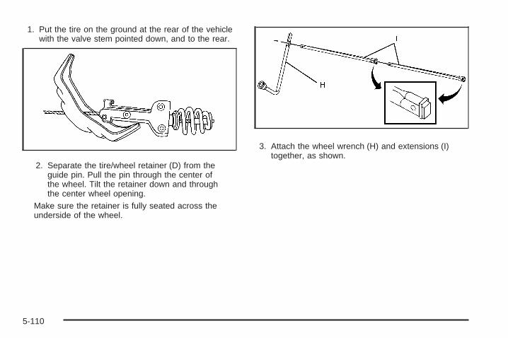
1. Put the tire on the ground at the rear of the vehiclewith the valve stem pointed down, and to the rear.
2. Separate the tire/wheel retainer (D) from theguide pin. Pull the pin through the center ofthe wheel. Tilt the retainer down and throughthe center wheel opening.
Make sure the retainer is fully seated across theunderside of the wheel.
3. Attach the wheel wrench (H) and extensions (I)together, as shown.
5-110

4. Insert the hoist end (F)through the hole (G) inthe rear bumper andonto the hoist shaft.
Do not use the chiseledend of the wheelwrench.
5. Raise the tire part way upward. Make sure theretainer is seated in the wheel opening.
6. Raise the tire fully against the underside of thevehicle by turning the wheel wrench clockwiseuntil you hear two clicks or feel it skip twice.You cannot overtighten the cable.
7. Make sure the tire is stored securely. Push, pull (A),and then try to turn (B) the tire. If the tire moves,use the wheel wrench to tighten the cable.
8. Reinstall the spare tire lock, if the vehicle has one.
To store the jack and jack tools:
5-111

A. Wing Nut RetainingWheel Blocks
B. Wheel BlocksC. Wing Nut Retaining
Tool KitD. Wheel Wrench and
Extensions
E. Tool BagF. Jack Mounting
BracketG. JackH. Bolt Retaining Wheel
Blocks
1. Put the tools (D) in the tool bag (E) and place themin the retaining bracket (C).
2. Tighten down the wing nut (C).
3. Assemble the wheel blocks (B) and jack (G)together with the wing nut (A) and retaining bolt (H).
4. Position the jack (G) in the mounting bracket (F).Position the holes in the base of the jack (G) ontothe pin in the mounting bracket (F).
5. Return them to their original location in the vehicle.For more information, refer to Removing the SpareTire and Tools on page 5-93 for more information.
5-112

Spare TireYour vehicle, when new, had a fully-inflated spare tire.A spare tire may lose air over time, so check its inflationpressure regularly. See Inflation - Tire Pressure onpage 5-73 and Loading the Vehicle on page 4-32 forinformation regarding proper tire inflation and loadingyour vehicle. For instruction on how to remove, install orstore a spare tire, see Removing the Flat Tire andInstalling the Spare Tire on page 5-98 and Storing a Flator Spare Tire and Tools on page 5-109.
Notice: If the vehicle has four-wheel drive and thedifferent size spare tire is installed on the vehicle,do not drive in four-wheel drive until you can haveyour flat tire repaired and/or replaced. You coulddamage the vehicle, and the repair costs would notbe covered by your warranty. Never use four-wheeldrive when the different size spare tire is installed onthe vehicle.
Your vehicle may have a different size spare tire than theroad tires originally installed on your vehicle. This sparetire was developed for use on your vehicle, so it is all rightto drive on it. If your vehicle has four-wheel drive and thedifferent size spare tire is installed, keep the vehicle intwo-wheel drive.
After installing the spare tire on your vehicle, you shouldstop as soon as possible and make sure the sparetire is correctly inflated. Have the damaged or flat road
tire repaired or replaced as soon as you can andinstalled back onto your vehicle. This way, the spare tirewill be available in case you need it again.
Do not mix tires and wheels of different sizes, becausethey will not fit. Keep your spare tire and its wheeltogether. If your vehicle has a spare tire that does notmatch your vehicle’s original road tires and wheelsin size and type, do not include the spare in thetire rotation.
Appearance Care
Interior CleaningThe vehicle’s interior will continue to look its best if it iscleaned often. Although not always visible, dust anddirt can accumulate on the upholstery. Dirt can damagecarpet, fabric, leather, and plastic surfaces. Regularvacuuming is recommended to remove particles from theupholstery. It is important to keep the upholstery frombecoming and remaining heavily soiled. Soils should beremoved as quickly as possible. The vehicle’s interiormay experience extremes of heat that could causestains to set rapidly.
Lighter colored interiors may require more frequentcleaning. Use care because newspapers and garmentsthat transfer color to home furnishings may alsotransfer color to the vehicle’s interior.
5-113

When cleaning the vehicle’s interior, only use cleanersspecifically designed for the surfaces being cleaned.Permanent damage may result from using cleaners onsurfaces for which they were not intended. Use glasscleaner only on glass. Remove any accidental over-sprayfrom other surfaces immediately. To prevent over-spray,apply cleaner directly to the cleaning cloth.
Notice: Using abrasive cleaners when cleaningglass surfaces on the vehicle, could scratchthe glass and/or cause damage to the rear windowdefogger. When cleaning the glass on the vehicle,use only a soft cloth and glass cleaner.
Many cleaners contain solvents that may becomeconcentrated in the vehicle’s breathing space. Beforeusing cleaners, read and adhere to all safety instructionson the label. While cleaning the vehicle’s interior,maintain adequate ventilation by opening the vehicle’sdoors and windows.
Dust may be removed from small buttons and knobsusing a small brush with soft bristles.
Products that remove odors from the vehicle’supholstery and clean the vehicle’s glass can be obtainedfrom your dealer/retailer.
Do not clean the vehicle using:
• A knife or any other sharp object to remove a soilfrom any interior surface.
• A stiff brush. It can cause damage to the vehicle’sinterior surfaces.
• Heavy pressure or aggressive rubbing with acleaning cloth. Use of heavy pressure can damagethe interior and does not improve the effectivenessof soil removal.
• Laundry detergents or dishwashing soaps withdegreasers can leave residue that streaks andattracts dirt. For liquid cleaners, about 20 dropsper gallon (3.78 L) of water is a good guide.Use only mild, neutral-pH soaps.
• Too much cleaner that saturates the upholstery.
• Organic solvents such as naptha, alcohol, etc. thatcan damage the vehicle’s interior.
5-114

Fabric/CarpetUse a vacuum cleaner with a soft brush attachmentfrequently to remove dust and loose dirt. A canistervacuum with a beater bar in the nozzle may only be usedon floor carpet and carpeted floor mats. For any soil,always try to remove it first with plain water or club soda.Before cleaning, gently remove as much of the soil aspossible using one of the following techniques:
• For liquids: gently blot the remaining soil with a papertowel. Allow the soil to absorb into the paper toweluntil no more can be removed.
• For solid dry soils: remove as much as possible andthen vacuum.
To clean:
1. Saturate a lint-free, clean white cloth with water orclub soda.
2. Wring the cloth to remove excess moisture.
3. Start on the outside edge of the soil and gently rubtoward the center. Continue cleaning, using a cleanarea of the cloth each time it becomes soiled.
4. Continue to gently rub the soiled area until thecleaning cloth remains clean.
5. If the soil is not completely removed, use a mildsoap solution and repeat the cleaning processthat was used with plain water.
If any of the soil remains, a commercial fabric cleaneror spot lifter may be necessary. When a commercialupholstery cleaner or spot lifter is to be used, testa small hidden area for colorfastness first. If the locallycleaned area gives any impression that a ringformation may result, clean the entire surface.
After the cleaning process has been completed, a papertowel can be used to blot excess moisture from thefabric or carpet.
LeatherA soft cloth dampened with water can be used to removedust. If a more thorough cleaning is necessary, a softcloth dampened with a mild soap solution can be used.Allow the leather to dry naturally. Do not use heat to dry.Never use steam to clean leather. Never use spot liftersor spot removers on leather. Many commercial leathercleaners and coatings that are sold to preserve andprotect leather may permanently change the appearanceand feel of the leather and are not recommended. Do notuse silicone or wax-based products, or those containingorganic solvents to clean the vehicle’s interior becausethey can alter the appearance by increasing the gloss in anon-uniform manner. Never use shoe polish on leather.
5-115

Instrument Panel, Vinyl, and OtherPlastic SurfacesA soft cloth dampened with water may be used toremove dust. If a more thorough cleaning is necessary,a clean soft cloth dampened with a mild soap solutioncan be used to gently remove dust and dirt. Neveruse spot lifters or removers on plastic surfaces.Many commercial cleaners and coatings that aresold to preserve and protect soft plastic surfaces maypermanently change the appearance and feel ofthe interior and are not recommended. Do not usesilicone or wax-based products, or those containingorganic solvents to clean the vehicle’s interior becausethey can alter the appearance by increasing thegloss in a non-uniform manner.
Some commercial products may increase gloss on theinstrument panel. The increase in gloss may causeannoying reflections in the windshield and even make itdifficult to see through the windshield under certainconditions.
Care of Safety BeltsKeep belts clean and dry.
{CAUTION:
Do not bleach or dye safety belts. It may severelyweaken them. In a crash, they might not be ableto provide adequate protection. Clean safety beltsonly with mild soap and lukewarm water.
WeatherstripsSilicone grease on weatherstrips will make them lastlonger, seal better, and not stick or squeak. Applysilicone grease with a clean cloth. During very cold,damp weather frequent application may be required. SeeRecommended Fluids and Lubricants on page 6-15.
5-116

Washing Your VehicleThe best way to preserve the vehicle’s finish is to keepit clean by washing it often.
Notice: Certain cleaners contain chemicals that candamage the emblems or nameplates on the vehicle.Check the cleaning product label. If it states thatit should not be used on plastic parts, do not use iton the vehicle or damage may occur and it wouldnot be covered by the warranty.
Do not wash the vehicle in direct sunlight. Use a carwashing soap. Do not use cleaning agents that arepetroleum based or that contain acid or abrasives, asthey can damage the paint, metal or plastic on thevehicle. Approved cleaning products can be obtainedfrom your dealer/retailer. Follow all manufacturers’directions regarding correct product usage, necessarysafety precautions and appropriate disposal of anyvehicle care product.
Rinse the vehicle well, before washing and after toremove all cleaning agents completely. If they areallowed to dry on the surface, they could stain.
Dry the finish with a soft, clean chamois or an all-cottontowel to avoid surface scratches and water spotting.
High pressure car washes may cause water to enter thevehicle. Avoid using high pressure washes closerthan 12 inches (30 cm) to the surface of the vehicle.Use of power washers exceeding 1,200 psi (8 274 kPa)can result in damage or removal of paint and decals.
Cleaning Exterior Lamps/LensesUse only lukewarm or cold water, a soft cloth and a carwashing soap to clean exterior lamps and lenses.Follow instructions under Washing Your Vehicle onpage 5-117.
5-117

Finish CareOccasional waxing or mild polishing of the vehicleby hand may be necessary to remove residue from thepaint finish. Approved cleaning products can beobtained from your dealer/retailer.
If the vehicle has a basecoat/clearcoat paint finish, theclearcoat gives more depth and gloss to the coloredbasecoat. Always use waxes and polishes that arenon-abrasive and made for a basecoat/clearcoatpaint finish.
Notice: Machine compounding or aggressivepolishing on a basecoat/clearcoat paint finish maydamage it. Use only non-abrasive waxes andpolishes that are made for a basecoat/clearcoatpaint finish on the vehicle.
Foreign materials such as calcium chloride and othersalts, ice melting agents, road oil and tar, tree sap, birddroppings, chemicals from industrial chimneys, etc.,can damage the vehicle’s finish if they remain on paintedsurfaces. Wash the vehicle as soon as possible. Ifnecessary, use non-abrasive cleaners that are markedsafe for painted surfaces to remove foreign matter.
Exterior painted surfaces are subject to aging, weatherand chemical fallout that can take their toll over a periodof years. To help keep the paint finish looking new, keepthe vehicle garaged or covered whenever possible.
Protecting Exterior Bright Metal PartsBright metal parts should be cleaned regularly to keeptheir luster. Washing with water is all that is usuallyneeded. However, chrome polish may be used onchrome or stainless steel trim, if necessary.
Use special care with aluminum trim. To avoid damagingprotective trim, never use auto or chrome polish, steam orcaustic soap to clean aluminum. A coating of wax, rubbedto high polish, is recommended for all bright metal parts.
Windshield and Wiper BladesClean the outside of the windshield with glass cleaner.
Clean the rubber blades using a lint free cloth orpaper towel soaked with windshield washer fluid ora mild detergent. Wash the windshield thoroughly whencleaning the blades. Bugs, road grime, sap, and abuildup of vehicle wash/wax treatments may cause wiperstreaking. Replace the wiper blades if they are wornor damaged.
Wipers can be damaged by:
• Extreme dusty conditions
• Sand and salt
• Heat and sun
• Snow and ice, without proper removal
5-118
Aluminum or Chrome-Plated Wheelsand TrimThe vehicle may have either aluminum or chrome-platedwheels.
Keep the wheels clean using a soft clean cloth with mildsoap and water. Rinse with clean water. After rinsingthoroughly, dry with a soft clean towel. A wax may thenbe applied.
Notice: Chrome wheels and other chrome trim maybe damaged if the vehicle is not washed after drivingon roads that have been sprayed with magnesium,calcium or sodium chloride. These chlorides areused on roads for conditions such as ice and dust.Always wash the vehicle’s chrome with soap andwater after exposure.
Notice: Using strong soaps, chemicals, abrasivepolishes, cleaners, brushes, or cleaners that containacid on aluminum or chrome-plated wheels, coulddamage the surface of the wheel(s). The repairswould not be covered by the warranty. Use onlyapproved cleaners on aluminum or chrome-platedwheels.
The surface of these wheels is similar to the paintedsurface of the vehicle. Do not use strong soaps,chemicals, abrasive polishes, abrasive cleaners,cleaners with acid, or abrasive cleaning brushes onthem because they could damage the surface. Do notuse chrome polish on aluminum wheels.
Notice: Using chrome polish on aluminum wheelscould damage the wheels. The repairs would notbe covered by the warranty. Use chrome polish onchrome wheels only.
Use chrome polish only on chrome-plated wheels, butavoid any painted surface of the wheel, and buff offimmediately after application.
Notice: Driving the vehicle through an automatic carwash that has silicone carbide tire cleaning brushes,could damage the aluminum or chrome-platedwheels. The repairs would not be covered by thewarranty. Never drive a vehicle equipped withaluminum or chrome-plated wheels through anautomatic car wash that uses silicone carbide tirecleaning brushes.
5-119

TiresTo clean the tires, use a stiff brush with tire cleaner.
Notice: Using petroleum-based tire dressingproducts on the vehicle may damage the paint finishand/or tires. When applying a tire dressing, alwayswipe off any overspray from all painted surfaceson the vehicle.
Sheet Metal DamageIf the vehicle is damaged and requires sheet metalrepair or replacement, make sure the body repair shopapplies anti-corrosion material to parts repaired orreplaced to restore corrosion protection.
Original manufacturer replacement parts will provide thecorrosion protection while maintaining the vehiclewarranty.
Finish DamageAny stone chips, fractures or deep scratches in the finishshould be repaired right away. Bare metal will corrodequickly and may develop into major repair expense.
Minor chips and scratches can be repaired with touch-upmaterials available from your dealer/retailer. Largerareas of finish damage can be corrected in yourdealer’s/retailer’s body and paint shop.
Underbody MaintenanceChemicals used for ice and snow removal and dustcontrol can collect on the underbody. If these are notremoved, corrosion and rust can develop on theunderbody parts such as fuel lines, frame, floor pan,and exhaust system even though they have corrosionprotection.
At least every spring, flush these materials from theunderbody with plain water. Clean any areas where mudand debris can collect. Dirt packed in close areas ofthe frame should be loosened before being flushed.Your dealer/retailer or an underbody car washing systemcan do this.
Chemical Paint SpottingSome weather and atmospheric conditions can create achemical fallout. Airborne pollutants can fall upon andattack painted surfaces on the vehicle. This damage cantake two forms: blotchy, ring-shaped discolorations,and small, irregular dark spots etched into thepaint surface.
Although no defect in the paint job causes this, we willrepair, at no charge to the owner, the surfaces ofnew vehicles damaged by this fallout condition within12 months or 12,000 miles (20 000 km) of purchase,whichever occurs first.
5-120

Vehicle Identification
Vehicle Identification Number (VIN)
This is the legal identifier for your vehicle. It appears ona plate in the front corner of the instrument panel, onthe driver side. It can be seen through the windshieldfrom outside the vehicle. The VIN also appears onthe Certification/Tire and Service Parts labels and thecertificates of title and registration.
Engine IdentificationThe eighth character in the VIN is the engine code. Thiscode helps identify the vehicle’s engine, specifications,and replacement parts. See “Engine Specifications”under Capacities and Specifications on page 5-129 foryour vehicle’s engine code.
Service Parts Identification LabelThis label is on the inside of the glove box. It isvery helpful if you ever need to order parts. The labelhas the following information:
• Vehicle Identification Number (VIN)
• Model designation
• Paint information
• Production options and special equipment
Do not remove this label from the vehicle.
5-121

Electrical System
Add-On Electrical EquipmentNotice: Do not add anything electrical to thevehicle unless you check with your dealer/retailerfirst. Some electrical equipment can damagethe vehicle and the damage would not be coveredby the vehicle’s warranty. Some add-on electricalequipment can keep other components fromworking as they should.
Add-on equipment can drain the vehicle battery, even ifthe vehicle is not operating.
The vehicle has an airbag system. Before attempting toadd anything electrical to the vehicle, see ServicingYour Airbag-Equipped Vehicle on page 1-88.
Windshield Wiper FusesThe windshield wiper motor is protected by an internalcircuit breaker and a fuse. If the motor overheats due toheavy snow, etc., the wiper will stop until the motorcools. If the overload is caused by some electricalproblem and not snow, etc., be sure to get it fixed.
Power Windows and Other PowerOptionsCircuit breakers protect the power windows and otherpower accessories. If the current load is too heavy,the circuit breaker opens and then closes after a cooldown period, protecting the circuit until the problemis fixed or goes away.
Fuses and Circuit BreakersIf the vehicle is a Two-mode Hybrid, see the Two-modeHybrid manual for more information.
The wiring circuits in the vehicle are protected fromshort circuits by a combination of fuses, circuit breakersand fusible thermal links. This greatly reduces thechance of fires caused by electrical problems.
Look at the silver-colored band inside the fuse. If theband is broken or melted, replace the fuse. Be sure youreplace a bad fuse with a new one of the identicalsize and rating.
If you ever have a problem on the road and don’t havea spare fuse, you can borrow one that has the sameamperage. Just pick some feature of your vehiclethat you can get along without – like the radio orcigarette lighter – and use its fuse, if it is the correctamperage. Replace it as soon as you can.
5-122

Instrument Panel Fuse Block
The instrument panel fuseblock access door islocated on the driver sideedge of the instrumentpanel.
Pull off the cover to access the fuse block.The vehicle may not use all of the fuses shown.
Fuses Usage1 Rear Seats2 Rear Accessory Power Outlet3 Steering Wheel Controls Backlight4 Driver Door Module
5-123

Fuses Usage
5 Dome Lamps, Driver Side TurnSignal
6 Driver Side Turn Signal, Stoplamp7 Instrument Panel Back Lighting
8 Passenger Side Turn Signal,Stoplamp
9 Passenger Door Module, DriverUnlock
10 Power Door Lock 2 (Unlock Feature)11 Power Door Lock 2 (Lock Feature)
12 Stoplamps, Center-High MountedStoplamp
13 Rear Climate Controls14 Power Mirror15 Body Control Module (BCM)16 Accessory Power Outlets17 Interior Lamps18 Power Door Lock 1 (Unlock Feature)19 Rear Seat Entertainment
20 Ultrasonic Rear Parking Assist,Power Liftgate
Fuses Usage21 Power Door Lock 1 (Lock Feature)22 Driver Information Center (DIC)23 Rear Wiper24 Cooled Seats
25 Driver Seat Module, RemoteKeyless Entry System
26 Driver Power Door Lock(Unlock Feature)
Circuit Breaker Usage
LT DR Driver Side Power Window CircuitBreaker
HarnessConnector Usage
LT DR Driver Door Harness ConnectionBODY Harness ConnectorBODY Harness Connector
5-124

Center Instrument Panel Fuse BlockThe center instrument panel fuse block is locatedunderneath the instrument panel, to the left of thesteering column.
Top View
HarnessConnector Usage
BODY 2 Body Harness Connector 2BODY 1 Body Harness Connector 1BODY 3 Body Harness Connector 3
HarnessConnector Usage
HEADLINER 3 Headliner Harness Connector 3HEADLINER 2 Headliner Harness Connector 2HEADLINER 1 Headliner Harness Connector 1
SEO/UPFITTER Special Equipment Option UpfitterHarness Connector
Circuit Breaker Usage
CB1 Passenger Side Power WindowCircuit Breaker
CB2 Passenger Seat Circuit BreakerCB3 Driver Seat Circuit BreakerCB4 Rear Sliding Window
5-125

Underhood Fuse BlockIf your vehicle has the DURAMAX® Diesel engine, seethe DURAMAX® Diesel manual for more information.
If the vehicle is a Two-mode Hybrid, see the Two-modeHybrid manual for more information.
The underhood fuse block is located in the enginecompartment, on the driver side of the vehicle.
Lift the cover to access the fuse block.
Notice: Spilling liquid on any electrical componentson the vehicle may damage it. Always keep thecovers on any electrical component.
To remove fuses, hold the end of the fuse between yourthumb and index finger and pull straight out.
Fuses Usage1 Right Trailer Stop/Turn Lamp
2 Electronic Suspension Control,Automatic Level Control Exhaust
3 Left Trailer Stop/Turn Lamp4 Engine Controls
5 Engine Control Module, ThrottleControl
6 Trailer Brake Controller
5-126

Fuses Usage7 Front Washer8 Oxygen Sensor9 Antilock Brakes System 2
10 Trailer Back-up Lamps11 Driver Side Low-Beam Headlamp12 Engine Control Module (Battery)
13 Fuel Injectors, Ignition Coils(Right Side)
14 Transmission Control Module(Battery)
15 Vehicle Back-up Lamps
16 Passenger Side Low-BeamHeadlamp
17 Air Conditioning Compressor18 Oxygen Sensors19 Transmission Controls (Ignition)20 Fuel Pump21 Fuel System Control Module22 Not Used23 Not Used
24 Fuel Injectors, Ignition Coils(Left Side)
25 Trailer Park Lamps26 Driver Side Park Lamps
Fuses Usage27 Passenger Side Park Lamps28 Fog Lamps29 Horn
30 Passenger Side High-BeamHeadlamp
31 Daytime Running Lamps32 Driver Side High-Beam Headlamp33 Daytime Running Lights 234 Sunroof
35 Key Ignition System, Theft DeterrentSystem
36 Windshield Wiper37 SEO B2 Upfitter Usage (Battery)38 Electric Adjustable Pedals39 Climate Controls (Battery)40 Airbag System (Ignition)41 Amplifier42 Audio System
43 Miscellaneous (Ignition), CruiseControl
44 Not Used45 Airbag System (Battery)46 Instrument Panel Cluster47 Power Take-Off
5-127

Fuses Usage48 Auxiliary Climate Control (Ignition)
49 Center High-Mounted Stoplamp(CHMSL)
50 Rear Defogger51 Heated Mirrors52 SEO B1 Upfitter Usage (Battery)
53 Cigarette Lighter, Auxiliary PowerOutlet
54 SEO Upfitter Usage55 Climate Controls (Ignition)
56 Engine Control Module, SecondaryFuel Pump (Ignition)
J-Case Fuses Usage57 Cooling Fan 158 Not Used59 Heavy Duty Antilock Brake System60 Cooling Fan 261 Antilock Brake System 162 Starter63 Stud 2 (Trailer Brakes)64 Left Bussed Electrical Center 165 Not Used66 Heated Windshield Washer System
J-Case Fuses Usage67 Four-Wheel Drive System
68Stud 1 (Trailer Connector BatteryPower) (Optional - 40A FuseRequired)
69 Mid-Bussed Electrical Center 170 Climate Control Blower71 Not Used72 Left Bussed Electrical Center 2
Relays UsageFAN HI Cooling Fan High SpeedFAN LO Cooling Fan Low SpeedFAN CNTRL Cooling Fan ControlHDLP LO/HID Low-Beam HeadlampFOG LAMP Front Fog LampsA/C CMPRSR Air Conditioning CompressorSTRTR StarterPWR/TRN PowertrainFUEL PMP Fuel PumpPRK LAMP Parking LampsREAR DEFOG Rear DefoggerRUN/CRANK Switched Power
5-128

Capacities and SpecificationsThe following approximate capacities are given in English and metric conversions. See Recommended Fluids andLubricants on page 6-15 for more information.
If your vehicle has the DURAMAX® Diesel engine, see the DURAMAX® Diesel manual for more information.
ApplicationCapacities
English Metric
Air Conditioning Refrigerant R134a
For the air conditioning system refrigerant chargeamount, see the refrigerant caution label located
under the hood. See your dealer for moreinformation.
Cooling System4.3L V6 1500 Series 16.5 qt 15.6 L4.8L V8 1500 Series 16.9 qt 16.0 L5.3L V8 1500 Series 16.9 qt 16.0 L6.0L V8 1500 Series 16.8 qt 15.9 L6.0L V8 2500 Series and 3500 Series 16.4 qt 15.5 L6.2L V8 1500 Series 17.6 qt 16.7 L
Engine Oil with Filter4.3L V6 4.5 qt 4.3 L4.8L V8; 5.3L V8; 6.0L V8; 6.2L V8 6.0 qt 5.7 L
5-129

ApplicationCapacities
English MetricFuel Tank
1500 Series Standard and Short Box 26.0 gal 98.0 L1500 Series Long Box 34.0 gal 128.7 L2500 Series Standard Box 26.0 gal 98.0 L2500 Series and 3500 Series Long Box 34.0 gal 128.7 L3500 Series Chassis Cab 50.0 gal 189.0 L3500 Chassis Cab – Front Tank 27.0 gal 102.0 L3500 Chassis Cab – Rear Tank (if equipped) 23.0 gal 87.0 L
Transmission Fluid (Pan Removal and Filter Replacement)Auto 4-Speed Transmission 4L60-E ElectronicTransmission 5.0 qt 4.7 L
Auto 6-Speed Transmission 6L80-E 6.0 qt 5.7 LAuto 6-Speed Transmission 6L90-E 6.3 qt 6.0 LAuto 6-Speed Transmission Allison 7.4 qt 7.0 L
Transfer Case Fluid 1.6 qt 1.5 LWheel Nut Torque 140 ft lb 190 Y
All capacities are approximate. When adding, be sure to fill to the approximate level, as recommended in thismanual. Recheck fluid level after filling.
5-130

Engine SpecificationsEngine VIN Code Transmission Spark Plug Gap
4.3L V6 X Automatic 0.060 in (1.52 mm)
4.8L V8 C Automatic 0.040 in (1.01 mm)
5.3L V8 Flexible Fuel withActive Fuel Management™(Iron Block)
0 Automatic 0.040 in (1.01 mm)
5.3L V8 Flexible Fuel withActive Fuel Management™(Aluminum Block)
3 Automatic 0.040 in (1.01 mm)
5.3L V8 with Active FuelManagement™ (Iron Block) J Automatic 0.040 in (1.01 mm)
5.3L V8 with Active FuelManagement™(Aluminum Block)
M Automatic 0.040 in (1.01 mm)
6.0L V8 (Iron Block) K Automatic 0.040 in (1.01 mm)
6.0L V8 with Active FuelManagement™(Aluminum Block)
Y Automatic 0.040 in (1.01 mm)
6.2L V8 Flexible Fuel(Aluminum Block) 2 Automatic 0.040 in (1.01 mm)
5-131

✍ NOTES
5-132

Maintenance Schedule ......................................6-2Introduction ...................................................6-2Maintenance Requirements ..............................6-2Your Vehicle and the Environment ....................6-2Using the Maintenance Schedule ......................6-3Scheduled Maintenance
(Gasoline Engine) .......................................6-4Additional Required Services ............................6-7Maintenance Footnotes ...................................6-9Owner Checks and Services ..........................6-11
At the First 100, 1,000 and6,000 Miles (160, 1 600 and10 000 km) ..............................................6-11
At Each Fuel Fill ..........................................6-11At Least Once a Month .................................6-12At Least Once a Year ...................................6-12Recommended Fluids and Lubricants ...............6-15Maintenance Replacement Parts .....................6-17Engine Drive Belt Routing ..............................6-18Maintenance Record .....................................6-19
Section 6 Maintenance Schedule
6-1

Maintenance Schedule
IntroductionThis maintenance section applies to vehicles with agasoline engine. For diesel engine vehicles, seethe maintenance schedule section in the DURAMAXDiesel manual.
Important: Keep engine oil at the proper level andchange as recommended.
Have you purchased the GM Protection Plan? The Plansupplements the vehicle warranties. See the Warrantyand Owner Assistance booklet or your dealer/retailer fordetails.
Maintenance RequirementsNotice: Maintenance intervals, checks, inspections,replacement parts, and recommended fluids andlubricants as prescribed in this manual are necessaryto keep this vehicle in good working condition.Any damage caused by failure to follow scheduledmaintenance might not be covered by the vehiclewarranty.
Your Vehicle and the EnvironmentProper vehicle maintenance not only helps to keepthe vehicle in good working condition, but also helpsthe environment. All recommended maintenance isimportant. Improper vehicle maintenance can even affectthe quality of the air we breathe. Improper fluid levels orthe wrong tire inflation can increase the level of emissionsfrom the vehicle. To help protect the environment, and tokeep the vehicle in good condition, be sure to maintainthe vehicle properly.
6-2

Using the Maintenance ScheduleWe want to help keep this vehicle in good workingcondition. But we do not know exactly how you will driveit. You might drive very short distances only a few times aweek. Or you might drive long distances all the time invery hot, dusty weather. You might use the vehicle inmaking deliveries. Or you might drive it to work, to doerrands, or in many other ways.
Because of all the different ways people use theirvehicles, maintenance needs vary. You might needmore frequent checks and replacements. So pleaseread the following and note how you drive. If you haveany questions on how to keep the vehicle in goodcondition, see your dealer/retailer.
This schedule is for vehicles that:
• carry passengers and cargo within recommendedlimits on the Tire and Loading Information label.See Loading the Vehicle on page 4-32.
• are driven on reasonable road surfaces within legaldriving limits.
• are driven off-road in the recommended manner.See Off-Road Driving on page 4-12.
• use the recommended fuel. See Gasoline Octaneon page 5-6.
The services in Scheduled Maintenance (GasolineEngine) on page 6-4 should be performed whenindicated. See Additional Required Services on page 6-7and Maintenance Footnotes on page 6-9 for furtherinformation.
{CAUTION:
Performing maintenance work on a vehicle can bedangerous. In trying to do some jobs, you can beseriously injured. Do your own maintenance workonly if you have the required know-how and theproper tools and equipment for the job. If you haveany doubt, see your dealer/retailer to have aqualified technician do the work. See Doing YourOwn Service Work on page 5-5.
Some maintenance services can be complex. So, unlessyou are technically qualified and have the necessaryequipment, have your dealer/retailer do these jobs.
When you go to your dealer/retailer for service, trainedand supported service technicians will perform the workusing genuine parts.
To purchase service information, see ServicePublications Ordering Information on page 7-15.
6-3

Owner Checks and Services on page 6-11 tells whatshould be checked, when to check it, and what can easilybe done to help keep the vehicle in good condition.
The proper replacement parts, fluids, and lubricants touse are listed in Recommended Fluids and Lubricantson page 6-15 and Maintenance Replacement Partson page 6-17. When the vehicle is serviced, make surethese are used. All parts should be replaced and allnecessary repairs done before you or anyone elsedrives the vehicle. We recommend the use of genuineparts from your dealer/retailer.
Scheduled Maintenance(Gasoline Engine)This maintenance section applies to vehicles with agasoline engine. For diesel engine vehicles, see themaintenance schedule section in the DURAMAX® Dieselmanual.
When the CHANGE ENGINE OIL SOON messagedisplays, service is required for the vehicle. Have thevehicle serviced as soon as possible within the next600 miles (1 000 km). It is possible that, if driving underthe best conditions, the engine oil life system may notindicate that vehicle service is necessary for over a year.However, the engine oil and filter must be changed atleast once a year and at this time the system must be
reset. Your dealer/retailer has trained service technicianswho will perform this work using genuine parts and resetthe system.
If the engine oil life system is ever reset accidentally,service the vehicle within 3,000 miles (5 000 km)since the last service. Remember to reset the oil lifesystem whenever the oil is changed. See Engine Oil LifeSystem on page 5-18 for information on the EngineOil Life System and resetting the system.
When the CHANGE ENGINE OIL SOON messageappears, certain services, checks, and inspections arerequired. Required services are described in thefollowing for “Maintenance I” and “Maintenance II.”Generally, it is recommended that the first service beMaintenance I, the second service be Maintenance II,and then alternate Maintenance I and Maintenance IIthereafter. However, in some cases, Maintenance IImay be required more often.
Maintenance I — Use Maintenance I if the CHANGEENGINE OIL SOON message displays within 10 monthssince the vehicle was purchased or Maintenance IIwas performed.
Maintenance II — Use Maintenance II if the previousservice performed was Maintenance I. Always useMaintenance II whenever the message displays10 months or more since the last service or if themessage has not come on at all for one year.
6-4

Scheduled MaintenanceService Maintenance I Maintenance II
Change engine oil and filter. See Engine Oil on page 5-15. Reset oil life system.See Engine Oil Life System on page 5-18. An Emission Control Service. • •
Allison Transmission® only: Replace external transmission filter at the firstmaintenance service performed on the vehicle.
Lubricate chassis components. See footnote #. • •
Visually check for any leaks or damage. See footnote (j). • •
Inspect engine air cleaner filter or change indicator (if equipped). If necessary,replace filter. See Engine Air Cleaner/Filter on page 5-19. See footnote (p). •
Rotate tires and check inflation pressures and wear. See Tire Inspection andRotation on page 5-81 and “Tire Wear Inspection” in At Least Once a Month onpage 6-12.
• •
Inspect brake system. See footnote (a). • •
Check engine coolant and windshield washer fluid levels and add fluid asneeded. • •
6-5

Scheduled Maintenance (cont’d)Service Maintenance I Maintenance II
Perform any needed additional services. See “Additional Required Services” inthis section. • •
Inspect suspension and steering components. See footnote (b). •
Inspect engine cooling system. See footnote (c). •
Inspect wiper blades. See footnote (d). •
Inspect restraint system components. See footnote (e). •
Lubricate body components. See footnote (f). •
Check transmission fluid level and add fluid as needed. •
Inspect shields, vehicles with diesel engine or with GVWR above 10,000 lbs(4 536 kg) only. See footnote (n). •
6-6
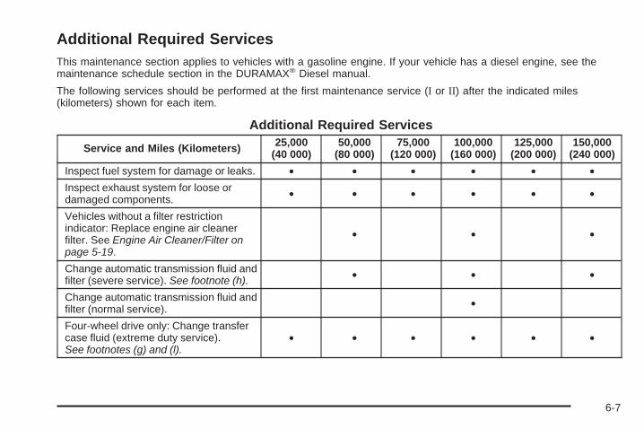
Additional Required ServicesThis maintenance section applies to vehicles with a gasoline engine. If your vehicle has a diesel engine, see themaintenance schedule section in the DURAMAX® Diesel manual.
The following services should be performed at the first maintenance service (I or II) after the indicated miles(kilometers) shown for each item.
Additional Required Services
Service and Miles (Kilometers) 25,000(40 000)
50,000(80 000)
75,000(120 000)
100,000(160 000)
125,000(200 000)
150,000(240 000)
Inspect fuel system for damage or leaks. • • • • • •Inspect exhaust system for loose ordamaged components. • • • • • •
Vehicles without a filter restrictionindicator: Replace engine air cleanerfilter. See Engine Air Cleaner/Filter onpage 5-19.
• • •
Change automatic transmission fluid andfilter (severe service). See footnote (h). • • •
Change automatic transmission fluid andfilter (normal service). •
Four-wheel drive only: Change transfercase fluid (extreme duty service).See footnotes (g) and (l).
• • • • • •
6-7
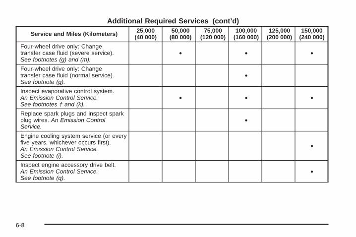
Additional Required Services (cont’d)
Service and Miles (Kilometers) 25,000(40 000)
50,000(80 000)
75,000(120 000)
100,000(160 000)
125,000(200 000)
150,000(240 000)
Four-wheel drive only: Changetransfer case fluid (severe service).See footnotes (g) and (m).
• • •
Four-wheel drive only: Changetransfer case fluid (normal service).See footnote (g).
•
Inspect evaporative control system.An Emission Control Service.See footnotes † and (k).
• • •
Replace spark plugs and inspect sparkplug wires. An Emission ControlService.
•
Engine cooling system service (or everyfive years, whichever occurs first).An Emission Control Service.See footnote (i).
•
Inspect engine accessory drive belt.An Emission Control Service.See footnote (q).
•
6-8

Maintenance FootnotesThis maintenance section applies to vehicles with agasoline engine. For diesel engine vehicles, seethe maintenance schedule section in the DURAMAX®
Diesel manual.
† The U.S. Environmental Protection Agency or theCalifornia Air Resources Board has determined that thefailure to perform this maintenance item will not nullifythe emission warranty or limit recall liability prior tothe completion of the vehicle’s useful life. We, however,urge that all recommended maintenance services beperformed at the indicated intervals and themaintenance be recorded.
# Lubricate the front suspension, steering linkage,and parking brake cable guides. Control arm ball jointson 2500/3500 series vehicles require lubrication butshould not be lubricated unless their temperature is10°F (−12°C) or higher, or they could be damaged.Control arm ball joints on 1500 series vehicles aremaintenance-free. Vehicles used under severecommercial operating conditions require lubricationon a regular basis every 3,000 miles (5 000 km).
(a) Visually inspect brake lines and hoses for properhook-up, binding, leaks, cracks, chafing, etc. Inspect discbrake pads for wear and rotors for surface condition.Inspect drum brake linings/shoes for wear or cracks.Inspect other brake parts, including drums, wheelcylinders, calipers, parking brake, etc.
(b) Visually inspect front and rear suspension andsteering system for damaged, loose or missing parts,signs of wear or lack of lubrication. Inspect powersteering lines and hoses for proper hook-up, binding,leaks, cracks, chafing, etc. Visually check constantvelocity joints, rubber boots, and axle seals for leaks.
(c) Visually inspect hoses and have them replaced ifthey are cracked, swollen, or deteriorated. Inspect allpipes, fittings and clamps; replace with genuine parts asneeded. To help ensure proper operation, a pressure testof the cooling system and pressure cap and cleaning theoutside of the radiator and air conditioning condenser isrecommended at least once a year.
(d) Inspect wiper blades for wear, cracking, orcontamination. Clean the windshield and wiper blades,if contaminated. Replace wiper blades that are worn ordamaged. See Windshield Wiper Blade Replacementon page 5-64 and Windshield and Wiper Blades onpage 5-118 for more information.
(e) Make sure the safety belt reminder light and safetybelt assemblies are working properly. Look for any otherloose or damaged safety belt system parts. If you seeanything that might keep a safety belt system from doingits job, have it repaired. Have any torn or frayed safetybelts replaced. Also see Checking the Restraint Systemson page 1-90.
6-9

(f) Lubricate all key lock cylinders, body door hinges,hood latch assembly, secondary latch, pivots, springanchor, release pawl, tailgate hinges, tailgate linkage,tailgate handle pivot points, latch bolt, fuel door hinge,locks, and folding seat hardware. More frequentlubrication may be required when exposed to a corrosiveenvironment. Applying silicone grease on weatherstripswith a clean cloth will make them last longer, seal better,and not stick or squeak.
(g) Check vent hose at transfer case for kinks and properinstallation. Check to be sure vent hose is unobstructed,clear, and free of debris. During any maintenance, if apower washer is used to clean mud and dirt from theunderbody, care should be taken to not directly spray thetransfer case output seals. High pressure water canovercome the seals and contaminate the transfer casefluid. Contaminated fluid will decrease the life of thetransfer case and should be replaced.
(h) Change automatic transmission fluid and filter ifthe vehicle Gross Vehicle Weight Rating (GVWR) is over8600 lbs or if the vehicle is mainly driven under oneor more of these conditions:
− In heavy city traffic where the outside temperatureregularly reaches 90°F (32°C) or higher.
− In hilly or mountainous terrain.− When doing frequent trailer towing.− Uses such as found in taxi, police or delivery
service.
(i) Drain, flush, and refill cooling system. This servicecan be complex; you should have your dealer/retailerperform this service. See Engine Coolant on page 5-29for what to use. Inspect hoses. Clean radiator,condenser, pressure cap, and filler neck. Pressure testthe cooling system and pressure cap.
(j) A fluid loss in any vehicle system could indicate aproblem. Have the system inspected and repaired andthe fluid level checked. Add fluid if needed.
(k) Inspect system. Check all fuel and vapor lines andhoses for proper hook-up, routing, and condition. Checkthat the purge valve, if the vehicle has one, worksproperly. Replace as needed.
(l) Extreme Duty Service: Change transfer case fluid ifthe vehicle is mainly driven off-road in four-wheeldrive. Vehicles used for farming, mining, forestry,Department of Natural Resources (DNR), and snowplowing occupations meet this definition.
(m) Severe Duty Service: Change transfer case fluid ifthe vehicle is mainly driven under one or more ofthese conditions:
− Frequent trailer towing.− Taxi, police, or delivery service.
6-10

(n) Vehicles with diesel engine or with GVWR above10,000 lbs (4 536 kg) only: Inspect shields for damage orlooseness. Adjust or replace as required. This is a NoiseEmission Control Service. Applicable to vehicles sold inthe United States and recommended for vehicles sold inCanada.
(p) If driving regularly under dusty conditions, inspectthe filter or change indicator (if equipped) at each engineoil change.
(q) Visually inspect belt for fraying, excessive cracks, orobvious damage. Replace belt if necessary.
Owner Checks and ServicesThese owner checks and services should be performedat the intervals specified to help ensure vehicle safety,dependability, and emission control performance. Yourdealer/retailer can assist with these checks and services.
Be sure any necessary repairs are completed at once.Whenever any fluids or lubricants are added to thevehicle, make sure they are the proper ones, as shownin Recommended Fluids and Lubricants on page 6-15.
At the First 100, 1,000 and6,000 Miles (160, 1 600 and10 000 km)For vehicles with dual wheels, check dual wheel nuttorque. For proper torque, see Capacities andSpecifications on page 5-129.
At Each Fuel FillIt is important to perform these underhood checks ateach fuel fill.
Engine Oil Level Check
Notice: It is important to check the engine oilregularly and keep it at the proper level. Failure tokeep the engine oil at the proper level can causedamage to the engine not covered by the vehiclewarranty.
Check the engine oil level and add the proper oil ifnecessary. See Engine Oil on page 5-15.
6-11

Engine Coolant Level CheckCheck the engine coolant level and add DEX-COOL®
coolant mixture if necessary. See Engine Coolanton page 5-29.
Windshield Washer Fluid Level CheckCheck the windshield washer fluid level in the windshieldwasher fluid reservoir and add the proper fluid ifnecessary.
At Least Once a Month
Tire Inflation CheckInspect the vehicle’s tires and make sure they areinflated to the correct pressures. Do not forget to checkthe spare tire. See Inflation - Tire Pressure on page 5-73.Check to make sure the spare tire is stored securely.See Changing a Flat Tire on page 5-92.
Tire Wear InspectionTire rotation may be required for high mileage highwaydrivers prior to the Engine Oil Life System servicenotification. Check the tires for wear and, if necessary,rotate the tires. See Tire Inspection and Rotation onpage 5-81.
At Least Once a Year
Starter Switch Check
{CAUTION:
When you are doing this inspection, the vehiclecould move suddenly. If the vehicle moves, you orothers could be injured.
1. Before starting this check, be sure there is enoughroom around the vehicle.
2. Firmly apply both the parking brake and the regularbrake. See Parking Brake on page 2-50.Do not use the accelerator pedal, and be ready toturn off the engine immediately if it starts.
3. Try to start the engine in each gear. The vehicleshould start only in P (Park) or N (Neutral). If thevehicle starts in any other position, contactyour dealer/retailer for service.
6-12

Automatic Transmission Shift LockControl System Check
{CAUTION:
When you are doing this inspection, the vehiclecould move suddenly. If the vehicle moves, you orothers could be injured.
1. Before starting this check, be sure there is enoughroom around the vehicle. It should be parked on alevel surface.
2. Firmly apply the parking brake. See Parking Brakeon page 2-50.Be ready to apply the regular brake immediately ifthe vehicle begins to move.
3. With the engine off, turn the ignition to ON/RUN,but do not start the engine. Without applying theregular brake, try to move the shift lever outof P (Park) with normal effort. If the shift levermoves out of P (Park), contact your dealer/retailerfor service.
Ignition Transmission Lock CheckWhile parked, and with the parking brake set, try to turnthe ignition to LOCK/OFF in each shift lever position.
• The ignition should turn to LOCK/OFF onlywhen the shift lever is in P (Park).
• The ignition key should come out only inLOCK/OFF.
Contact your dealer/retailer if service is required.
6-13

Parking Brake and AutomaticTransmission P (Park) MechanismCheck
{CAUTION:
When you are doing this check, the vehicle couldbegin to move. You or others could be injured andproperty could be damaged. Make sure there isroom in front of the vehicle in case it begins to roll.Be ready to apply the regular brake at onceshould the vehicle begin to move.
Park on a fairly steep hill, with the vehicle facingdownhill. Keeping your foot on the regular brake,set the parking brake.
• To check the parking brake’s holding ability:With the engine running and the transmissionin N (Neutral), slowly remove foot pressure fromthe regular brake pedal. Do this until the vehicleis held by the parking brake only.
• To check the P (Park) mechanism’s holding ability:With the engine running, shift to P (Park). Thenrelease the parking brake followed by the regularbrake.
Contact your dealer/retailer if service is required.
Underbody Flushing ServiceAt least every spring, use plain water to flush anycorrosive materials from the underbody. Take care toclean thoroughly any areas where mud and other debriscan collect.
6-14

Recommended Fluids andLubricantsThis maintenance section applies to vehicles with agasoline engine. If your vehicle has a diesel engine, seethe maintenance schedule section in the DURAMAX®
Diesel manual.
Fluids and lubricants identified below by name, partnumber, or specification can be obtained from yourdealer/retailer.
Usage Fluid/Lubricant
Engine Oil
Engine oil which meets GM StandardGM6094M and displays theAmerican Petroleum InstituteCertified for Gasoline Enginesstarburst symbol. To determine theproper viscosity for your vehicle’sengine, see Engine Oil on page 5-15.
Engine Coolant
50/50 mixture of clean, drinkablewater and use only DEX-COOL®
coolant. See Engine Coolant onpage 5-29.
Hydraulic BrakeSystem
Delco® Supreme 11 Brake Fluid orequivalent DOT-3 brake fluid.
WindshieldWasher Optikleen® Washer Solvent.
Usage Fluid/Lubricant
Power SteeringSystem
GM Power Steering Fluid(GM Part No. U.S. 89021184,in Canada 89021186).
AutomaticTransmission
DEXRON®-VI AutomaticTransmission Fluid.
Key LockCylinders
Multi-Purpose Lubricant, Superlube(GM Part No. U.S. 12346241,in Canada 10953474).
Floor ShiftLinkage
Lubriplate Lubricant Aerosol(GM Part No. U.S. 12346293,in Canada 992723) or lubricantmeeting requirements of NLGI #2Category LB or GC-LB.
ChassisLubrication
Chassis Lubricant(GM Part No. U.S. 12377985,in Canada 88901242) or lubricantmeeting requirements of NLGI #2,Category LB or GC-LB.
Front Axle(1500 Series) -
Four-WheelDrive
SAE 80W-90 Axle Lubricant(GM Part No. U.S. 89021671,in Canada 89021672).
Front Axle(1500 HD,
1500 AWD,2500,
2500 HD, and3500 Series)
SAE 75W-90Synthetic Axle Lubricant(GM Part No. U.S. 89021677,in Canada 89021678) meetingGM Specification 9986115.
6-15

Usage Fluid/Lubricant
Rear Axle
SAE 75W-90Synthetic Axle Lubricant(GM Part No. U.S. 89021677,in Canada 89021678) meetingGM Specification 9986115.
Transfer Case(Four-Wheel
Drive)
DEXRON®-VI AutomaticTransmission Fluid.
Front AxlePropshaftSpline or
One-PiecePropshaft
Spline(Two-WheelDrive with
4-Speed Auto.Trans.)
Spline Lubricant, Special Lubricant(GM Part No. U.S. 12345879,in Canada 10953511) or lubricantmeeting requirements ofGM 9985830.
Rear DrivelineCenter Spline
Chassis Lubricant(GM Part No. U.S. 12377985,in Canada 88901242) or lubricantmeeting requirements of NLGI #2,Category LB or GC-LB.
Hood HingesMulti-Purpose Lubricant, Superlube(GM Part No. U.S. 12346241,in Canada 10953474).
Usage Fluid/LubricantBody DoorHinge Pins,
Tailgate Hingeand Linkage,
Folding Seats,and Fuel Door
Hinge
Multi-Purpose Lubricant, Superlube(GM Part No. U.S. 12346241,in Canada 10953474).
Tailgate HandlePivot Points,
Hinges, LatchBolt, andLinkage
Multi-Purpose Lubricant, Superlube(GM Part No. U.S. 12346241,in Canada 10953474).
WeatherstripConditioning
Weatherstrip Lubricant(GM Part No. U.S. 3634770,in Canada 10953518) orDielectric Silicone Grease(GM Part No. U.S. 12345579,in Canada 992887).
WeatherstripSqueaks
Synthetic Greasewith Teflon, Superlube(GM Part No. U.S. 12371287,in Canada 10953437).
6-16

Maintenance Replacement PartsReplacement parts identified below by name, part number, or specification can be obtained from your dealer/retailer.
If your vehicle has the DURAMAX® diesel engine, see the DURAMAX® Diesel manual for more information.
Part GM Part Number ACDelco Part NumberEngine Air Cleaner/Filter
Standard Filter 15908916* A3086C*High Capacity Filter 15908915 A3085C
Oil Filter4.3L V6 25010792 PF474.8L V8; 5.3L V8; 6.0L V8; 6.2L V8 89017524 PF48
Spark Plugs4.3L V6 12607234 41-9934.8L V8; 5.3L V8; 6.0L V8; 6.2L V8 12609877 41-985
Wiper Blades – 21.6 in (55.0 cm) 25877402 —*15908915 (A3085C) high-capacity air cleaner filter may be substituted.
6-17

Engine Drive Belt Routing
If your vehicle has the DURAMAX ® Diesel engine, seethe DURAMAX ® Diesel manual for more information.
V6 Engines
V8 Engines
6-18
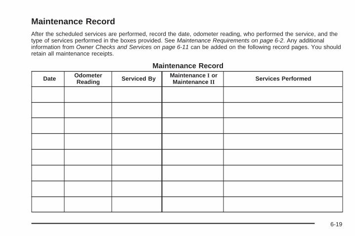
Maintenance RecordAfter the scheduled services are performed, record the date, odometer reading, who performed the service, and thetype of services performed in the boxes provided. See Maintenance Requirements on page 6-2. Any additionalinformation from Owner Checks and Services on page 6-11 can be added on the following record pages. You shouldretain all maintenance receipts.
Maintenance Record
Date OdometerReading Serviced By Maintenance I or
Maintenance II Services Performed
6-19

Maintenance Record (cont’d)
Date OdometerReading Serviced By Maintenance I or
Maintenance II Services Performed
6-20

Maintenance Record (cont’d)
Date OdometerReading Serviced By Maintenance I or
Maintenance II Services Performed
6-21

Maintenance Record (cont’d)
Date OdometerReading Serviced By Maintenance I or
Maintenance II Services Performed
6-22

Customer Assistance and Information ...............7-2Customer Satisfaction Procedure ......................7-2Online Owner Center ......................................7-5Customer Assistance for Text Telephone
(TTY) Users ...............................................7-6Customer Assistance Offices ............................7-6GM Mobility Reimbursement Program ................7-7Roadside Assistance Program ..........................7-7Scheduling Service Appointments ....................7-10Courtesy Transportation .................................7-10Collision Damage Repair ................................7-11
Reporting Safety Defects ................................7-14Reporting Safety Defects to the
United States Government ..........................7-14Reporting Safety Defects to the
Canadian Government ................................7-15Reporting Safety Defects to
General Motors .........................................7-15Service Publications Ordering Information .........7-15
Vehicle Data Recording and Privacy ................7-16Event Data Recorders ...................................7-17OnStar® ......................................................7-18Navigation System ........................................7-18Radio Frequency
Identification (RFID) ...................................7-18
Section 7 Customer Assistance Information
7-1

Customer Assistance andInformation
Customer Satisfaction ProcedureYour satisfaction and goodwill are important to yourdealer and to GMC. Normally, any concerns with thesales transaction or the operation of the vehicle will beresolved by the dealer’s sales or service departments.Sometimes, however, despite the best intentions of allconcerned, misunderstandings can occur. If your concernhas not been resolved to your satisfaction, the followingsteps should be taken:
STEP ONE: Discuss your concern with a member ofdealership management. Normally, concerns canbe quickly resolved at that level. If the matter hasalready been reviewed with the sales, service or partsmanager, contact the owner of the dealership orthe general manager.
STEP TWO: If after contacting a member of dealershipmanagement, it appears your concern cannot beresolved by the dealership without further help, in theU.S., call the GMC Consumer Relations Manager at1-800-GMC-8782 (1-800-462-8782, CustomerAssistance prompt). In Canada, call General Motors ofCanada Customer Communication at 1-800-263-3777(English) or 1-800-263-7854 (French).
We encourage you to call the toll-free number in order togive your inquiry prompt attention. Have the followinginformation available to give the Customer AssistanceRepresentative:
• Vehicle Identification Number (VIN). This is availablefrom the vehicle registration or title, or the plate at thetop left of the instrument panel and visible throughthe windshield.
• Dealership name and location.
• Vehicle delivery date and present mileage.
When contacting GMC, remember that your concern willlikely be resolved at a dealer’s facility. That is why wesuggest following Step One first.
7-2

STEP THREE — U.S. Owners: Both General Motorsand your dealer are committed to making sure you arecompletely satisfied with your new vehicle. However, ifyou continue to remain unsatisfied after following theprocedure outlined in Steps One and Two, you can filewith the Better Business Bureau (BBB) Auto LineProgram to enforce your rights.
The BBB Auto Line Program is an out of court programadministered by the Council of Better Business Bureausto settle automotive disputes regarding vehicle repairs orthe interpretation of the New Vehicle Limited Warranty.Although you may be required to resort to this informaldispute resolution program prior to filling out a courtaction, use of the program is free of charge and your casewill generally be heard within 40 days. If you do not agreewith the decision given in your case, you may reject it andproceed with any other venue for relief available to you.
You may contact the BBB Auto Line Program using thetoll-free telephone number or write them at the followingaddress:
BBB Auto Line ProgramCouncil of Better Business Bureaus, Inc.4200 Wilson BoulevardSuite 800Arlington, VA 22203-1838
Telephone: 1-800-955-5100dr.bbb.org/goauto
This program is available in all 50 states and the Districtof Columbia. Eligibility is limited by vehicle age, mileage,and other factors. General Motors reserves the right tochange eligibility limitations and/or discontinue itsparticipation in this program.
7-3

STEP THREE — Canadian Owners: In the event thatyou do not feel your concerns have been addressed afterfollowing the procedure outlined in Steps One and Two,General Motors of Canada Limited wants you to be awareof its participation in a no-charge Mediation/ArbitrationProgram. General Motors of Canada Limited hascommitted to binding arbitration of owner disputesinvolving factory-related vehicle service claims. Theprogram provides for the review of the facts involved byan impartial third party arbiter, and may include aninformal hearing before the arbiter. The program isdesigned so that the entire dispute settlement process,from the time you file your complaint to the final decision,should be completed in approximately 70 days. Webelieve our impartial program offers advantages overcourts in most jurisdictions because it is informal, quick,and free of charge.
For further information concerning eligibility in theCanadian Motor Vehicle Arbitration Plan (CAMVAP), calltoll-free 1-800-207-0685, or call the General MotorsCustomer Communication Centre, 1-800-263-3777(English), 1-800-263-7854 (French), or write to:
Mediation/Arbitration Programc/o Customer Communication CentreGeneral Motors of Canada LimitedMail Code: CA1-163-0051908 Colonel Sam DriveOshawa, Ontario L1H 8P7
Telephone: 1-800-955-5100
Your inquiry should be accompanied by the VehicleIdentification Number (VIN).
7-4

Online Owner Center
Online Owner Center (U.S.) —www.gmownercenter.com/gmcInformation and services customized for your specificvehicle — all in one convenient place.
• Digital owner manual, warranty information,and more
• Online service and maintenance records
• Find GMC dealers for service nationwide
• Exclusive privileges and offers
• Recall notices for your specific vehicle
• OnStar® and GM Cardmember Services Earningssummaries
Other Helpful Links:GMC − www.gmc.com
GMC Merchandise — www.gmccollection.com
Help Center — www.gmc.com/helpcenter
• FAQ
• Contact Us
My GM Canada (Canada) — www.gm.caMy GM Canada is a password-protected section ofwww.gm.ca where you can save information onGM vehicles, get personalized offers, and use handytools and forms with greater ease.
Here are a few of the valuable tools and services youwill have access to:
• My Showroom: Find and save information onvehicles and current offers in your area.
• My Dealers/Retailers: Save details such as addressand phone number for each of your preferred GMdealers/retailers.
• My Driveway: Access quick links to parts andservice estimates, check trade-in values, orschedule a service appointment by adding thevehicles you own to your driveway profile.
• My Preferences: Manage your profile and use toolsand forms with greater ease.
To sign up, visit the My GM Canada section withinwww.gm.ca.
7-5

Customer Assistance for TextTelephone (TTY) UsersTo assist customers who are deaf, hard of hearing, orspeech-impaired and who use the Text Telephones(TTYs), GMC has TTY equipment available at itsCustomer Assistance Center. Any TTY user cancommunicate with GMC by dialing: 1-800-GMC-8583(462-8583). (TTY users in Canada can dial1-800-263-3830.)
Customer Assistance OfficesGMC encourages customers to call the toll-free numberfor assistance. However, if a customer wishes towrite or e-mail GMC, the letter should be addressed to:
United StatesGMC Customer Assistance CenterP.O. Box 33172Detroit, MI 48232-5172
www.GMC.com1-800-GMC-8782 (462-8782)1-800-GMC-8583 (462-8583) (For Text Telephonedevices (TTYs))Roadside Assistance: 1-800-GMC-8782 (462-8782)
From Puerto Rico1-800-496-9992 (English)1-800-496-9993 (Spanish)
U.S. Virgin Islands:1-800-496-9994
CanadaGeneral Motors of Canada LimitedCustomer Communication Centre, CA1-163-0051908 Colonel Sam DriveOshawa, Ontario L1H 8P7www.gmcanada.com1-800-263-3777 (English)1-800-263-7854 (French)1-800-263-3830 (For Text Telephone devices (TTYs))Roadside Assistance: 1-800-268-6800
All Overseas LocationsPlease contact the local General Motors Business Unit.
Mexico, Central America andCaribbean Islands/Countries (ExceptPuerto Rico and U.S. Virgin Islands)
General Motors de Mexico, S. de R.L. de C.V.Customer Assistance CenterPaseo de la Reforma # 2740Col. Lomas de BezaresC.P. 11910, Mexico, D.F.01-800-508-0000Long Distance: 011-52-53 29 0 800
7-6
GM Mobility ReimbursementProgram
This program, available to qualified applicants, canreimburse you up to $1,000 of the cost of eligibleaftermarket adaptive equipment required for your vehicle,such as hand controls or a wheelchair/scooter lift.
The offer is available for a very limited period of timefrom the date of vehicle purchase/lease. For moredetails, or to determine your vehicle’s eligibility, visitgmmobility.com or call the GM Mobility AssistanceCenter at 1-800-323-9935. Text telephone (TTY) users,call 1-800-833-9935.
General Motors of Canada also has a Mobility Program.Call 1-800-GM-DRIVE (463-7483) for details.TTY users call 1-800-263-3830.
Roadside Assistance ProgramFor U.S. purchased vehicles, call 1-800-GMC-8782(1-800-462-8782); (Text telephone (TTY):1-888-889-2438).
For Canadian purchased vehicles, call 1-800-268-6800.
Service is available 24 hours a day, 365 days a year.
Calling for AssistanceWhen calling Roadside Assistance, have the followinginformation ready:
• Your name, home address, and home telephonenumber
• Telephone number of your location
• Location of the vehicle
• Model, year, color, and license plate number of thevehicle
• Odometer reading, Vehicle IdentificationNumber (VIN), and delivery date of the vehicle
• Description of the problem
7-7

CoverageServices are provided up to 5 years/100,000 miles(160 000 km), whichever comes first.
In the U.S., anyone driving the vehicle is covered.In Canada, a person driving the vehicle withoutpermission from the owner is not covered.
Roadside Assistance is not a part of the New VehicleLimited Warranty. GMC and General Motors of CanadaLimited reserve the right to make any changes ordiscontinue the Roadside Assistance program at anytime without notification.
GMC and General Motors of Canada Limited reservethe right to limit services or payment to an owneror driver if they decide the claims are made too often, orthe same type of claim is made many times.
Services Provided• Emergency Fuel Delivery: Delivery of enough fuel
for the vehicle to get to the nearest service station.
• Lock-Out Service: Service is provided to unlock thevehicle if you are locked out. A remote unlock maybe available if you have OnStar®. For securityreasons, the driver must present identificationbefore this service is given.
• Emergency Tow From a Public Road or Highway:Tow to the nearest GMC dealer for warranty service,or if the vehicle was in a crash and cannot be driven.Assistance is also given when the vehicle is stuck inthe sand, mud, or snow.
• Flat Tire Change: Service is provided to change aflat tire with the spare tire. The spare tire, if equipped,must be in good condition and properly inflated.It is the owner’s responsibility for the repair orreplacement of the tire if it is not covered by thewarranty.
• Battery Jump Start: Service is provided to jumpstart a dead battery.
• Trip Routing Service: Detailed maps of NorthAmerica are provided when requested either withthe most direct route or the most scenic route.Additional travel information is also available.Allow three weeks for delivery.
• Trip Interruption Benefits and Assistance: If yourtrip is interrupted due to a warranty failure, incidentalexpenses may be reimbursed during the 5 years/100,000 miles (160 000 km) Powertrain warrantyperiod. Items considered are hotel, meals, andrental car.
7-8

Services Not Included in RoadsideAssistance• Impound towing caused by violation of any laws.
• Legal fines.
• Mounting, dismounting or changing of snow tires,chains, or other traction devices.
• Towing or services for vehicles driven on anon-public road or highway.
Services Specific to CanadianPurchased Vehicles• Fuel delivery: Reimbursement is approximately
$5 Canadian. Diesel fuel delivery may be restricted.Propane and other fuels are not provided throughthis service.
• Lock-Out Service: Vehicle registration is required.
• Trip Routing Service: Limit of six requestsper year.
• Trip Interruption Benefits and Assistance: Mustbe over 250 kilometres from where your trip wasstarted to qualify. General Motors of Canada Limitedrequires pre-authorization, original detailed receipts,and a copy of the repair orders. Once authorizationhas been received, the Roadside Assistance advisorwill help you make arrangements and explain how toreceive payment.
• Alternative Service: If assistance cannot beprovided right away, the Roadside Assistanceadvisor may give you permission to get localemergency road service. You will receive payment,up to $100, after sending the original receipt toRoadside Assistance. Mechanical failures may becovered, however any cost for parts and labor forrepairs not covered by the warranty are the ownerresponsibility.
7-9

Scheduling Service AppointmentsWhen your vehicle requires warranty service, contactyour dealer/retailer and request an appointment.By scheduling a service appointment and advising yourservice consultant of your transportation needs, yourdealer/retailer can help minimize your inconvenience.
If your vehicle cannot be scheduled into the servicedepartment immediately, keep driving it until it can bescheduled for service, unless, of course, the problem issafety-related. If it is, please call your dealership/retailer,let them know this, and ask for instructions.
If the dealer/retailer requests you to bring the vehicle forservice, you are urged to do so as early in the workday as possible to allow for the same day repair.
Courtesy TransportationTo enhance your ownership experience, we and ourparticipating dealers are proud to offer CourtesyTransportation, a customer support program for vehicleswith the Bumper to Bumper (Base Warranty Coverageperiod in Canada) and extended powertrain, andhybrid specific warranty in both the U.S. and Canada.
Several courtesy transportation options are available toassist in reducing your inconvenience when warrantyrepairs are required.
Courtesy Transportation is not a part of the New VehicleLimited Warranty. A separate booklet entitled “Warrantyand Owner Assistance Information” furnished witheach new vehicle provides detailed warranty coverageinformation.
Transportation OptionsWarranty service can generally be completed while youwait. However, if you are unable to wait, GM helpsto minimize your inconvenience by providing severaltransportation options. Depending on the circumstances,your dealer can offer you one of the following:
Shuttle ServiceShuttle service is the preferred means of offeringCourtesy Transportation. Dealers may provide you withshuttle service to get you to your destination with minimalinterruption of your daily schedule. This includes one-wayor round trip shuttle service within reasonable time anddistance parameters of the dealer’s area.
Public Transportation or FuelReimbursementIf your vehicle requires overnight warranty repairs,and public transportation is used instead of the dealer’sshuttle service, the expense must be supported byoriginal receipts and can only be up to the maximumamount allowed by GM for shuttle service.
7-10

In addition, for U.S. customers, should you arrangetransportation through a friend or relative, limitedreimbursement for reasonable fuel expenses may beavailable. Claim amounts should reflect actual costs andbe supported by original receipts. See your dealer forinformation regarding the allowance amounts forreimbursement of fuel or other transportation costs.
Courtesy Rental VehicleYour dealer may arrange to provide you with a courtesyrental vehicle or reimburse you for a rental vehicle thatyou obtain if your vehicle is kept for an overnight warrantyrepair. Rental reimbursement will be limited and mustbe supported by original receipts. This requires that yousign and complete a rental agreement and meet state/provincial, local, and rental vehicle provider requirements.Requirements vary and may include minimum agerequirements, insurance coverage, credit card, etc.You are responsible for fuel usage charges and mayalso be responsible for taxes, levies, usage fees,excessive mileage, or rental usage beyond thecompletion of the repair.
It may not be possible to provide a like-vehicle as acourtesy rental.
Additional Program InformationAll program options, such as shuttle service, may not beavailable at every dealer. Please contact your dealerfor specific information about availability. All CourtesyTransportation arrangements will be administeredby appropriate dealer personnel.
General Motors reserves the right to unilaterally modify,change or discontinue Courtesy Transportation at anytime and to resolve all questions of claim eligibilitypursuant to the terms and conditions described hereinat its sole discretion.
Collision Damage RepairIf your vehicle is involved in a collision and it isdamaged, have the damage repaired by a qualifiedtechnician using the proper equipment and qualityreplacement parts. Poorly performed collision repairsdiminish your vehicle’s resale value, and safetyperformance can be compromised in subsequentcollisions.
7-11

Collision PartsGenuine GM Collision parts are new parts made with thesame materials and construction methods as the partswith which your vehicle was originally built. Genuine GMCollision parts are your best choice to ensure that yourvehicle’s designed appearance, durability, and safety arepreserved. The use of Genuine GM parts can helpmaintain your GM New Vehicle Warranty.
Recycled original equipment parts may also be used forrepair. These parts are typically removed from vehiclesthat were total losses in prior crashes. In most cases,the parts being recycled are from undamaged sectionsof the vehicle. A recycled original equipment GMpart, may be an acceptable choice to maintain yourvehicle’s originally designed appearance and safetyperformance, however, the history of these parts is notknown. Such parts are not covered by your GM NewVehicle Limited Warranty, and any related failuresare not covered by that warranty.
Aftermarket collision parts are also available. These aremade by companies other than GM and may not havebeen tested for your vehicle. As a result, these parts mayfit poorly, exhibit premature durability/corrosion problems,and may not perform properly in subsequent collisions.Aftermarket parts are not covered by your GM NewVehicle Limited Warranty, and any vehicle failure relatedto such parts are not covered by that warranty.
Repair FacilityWe recommend that you choose a collision repairfacility that meets your needs before you ever needcollision repairs. Your dealer/retailer may have acollision repair center with GM-trained technicians andstate of the art equipment, or be able to recommenda collision repair center that has GM-trained techniciansand comparable equipment.
Insuring Your VehicleProtect your investment in your GM vehicle withcomprehensive and collision insurance coverage. Thereare significant differences in the quality of coverageafforded by various insurance policy terms. Manyinsurance policies provide reduced protection to your GMvehicle by limiting compensation for damage repairs byusing aftermarket collision parts. Some insurancecompanies will not specify aftermarket collision parts.When purchasing insurance, we recommend that youassure your vehicle will be repaired with GM originalequipment collision parts. If such insurance coverage isnot available from your current insurance carrier,consider switching to another insurance carrier.If your vehicle is leased, the leasing company mayrequire you to have insurance that assures repairs withGenuine GM Original Equipment Manufacturer (OEM)parts or Genuine Manufacturer replacement parts.Read your lease carefully, as you may be chargedat the end of your lease for poor quality repairs.
7-12
If a Crash OccursHere is what to do if you are involved in a crash.
• Check to make sure that you are all right. If youare uninjured, make sure that no one else in yourvehicle, or the other vehicle, is injured.
• If there has been an injury, call emergency servicesfor help. Do not leave the scene of a crash until allmatters have been taken care of. Move your vehicleonly if its position puts you in danger or you areinstructed to move it by a police officer.
• Give only the necessary and requested informationto police and other parties involved in the crash.Do not discuss your personal condition, mentalframe of mind, or anything unrelated to the crash.This will help guard against post-crash legal action.
• If you need roadside assistance, call GM RoadsideAssistance. See Roadside Assistance Program onpage 7-7 for more information.
• If your vehicle cannot be driven, know where thetowing service will be taking it. Get a card from thetow truck operator or write down the driver’s name,the service’s name, and the phone number.
• Remove any valuables from your vehicle before it istowed away. Make sure this includes your insuranceinformation and registration if you keep these itemsin your vehicle.
• Gather the important information you will need fromthe other driver. Things like name, address, phonenumber, driver’s license number, vehicle licenseplate, vehicle make, model and model year, VehicleIdentification Number (VIN), insurance company andpolicy number, and a general description of thedamage to the other vehicle.
• If possible, call your insurance company fromthe scene of the crash. They will walk you throughthe information they will need. If they ask for apolice report, phone or go to the police departmentheadquarters the next day and you can get a copy ofthe report for a nominal fee. In some states/provinceswith “no fault” insurance laws, a report may not benecessary. This is especially true if there are noinjuries and both vehicles are driveable.
• Choose a reputable collision repair facility for yourvehicle. Whether you select a dealer/retailer or aprivate collision repair facility to fix the damage,make sure you are comfortable with them.Remember, you will have to feel comfortable withtheir work for a long time.
• Once you have an estimate, read it carefully andmake sure you understand what work will beperformed on your vehicle. If you have a question,ask for an explanation. Reputable shops welcomethis opportunity.
7-13

Managing the Vehicle Damage RepairProcessIn the event that your vehicle requires damage repairs,GM recommends that you take an active role in its repair.If you have a pre-determined repair facility of choice, takeyour vehicle there, or have it towed there. Specify to thefacility that any required replacement collision parts beoriginal equipment parts, either new Genuine GM parts orrecycled original GM parts. Remember, recycled partswill not be covered by your GM vehicle warranty.
Insurance pays the bill for the repair, but you mustlive with the repair. Depending on your policy limits,your insurance company may initially value the repairusing aftermarket parts. Discuss this with your repairprofessional, and insist on Genuine GM parts. Rememberif your vehicle is leased you may be obligated to have thevehicle repaired with Genuine GM parts, even if yourinsurance coverage does not pay the full cost.
If another party’s insurance company is paying forthe repairs, you are not obligated to accept a repairvaluation based on that insurance company’s collisionpolicy repair limits, as you have no contractual limits withthat company. In such cases, you can have control ofthe repair and parts choices as long as cost stays withinreasonable limits.
Reporting Safety Defects
Reporting Safety Defects to theUnited States GovernmentIf you believe that your vehicle has a defect whichcould cause a crash or could cause injury ordeath, you should immediately inform the NationalHighway Traffic Safety Administration (NHTSA)in addition to notifying General Motors.
If NHTSA receives similar complaints, it may openan investigation, and if it finds that a safety defectexists in a group of vehicles, it may order a recalland remedy campaign. However, NHTSA cannotbecome involved in individual problems betweenyou, your dealer/retailer, or General Motors.
To contact NHTSA, you may call the VehicleSafety Hotline toll-free at 1-888-327-4236(TTY: 1-800-424-9153); go to safercar.gov;or write to:
Administrator, NHTSA1200 New Jersey Avenue, S.E.Washington D.C., 20590
You can also obtain other information about motorvehicle safety from safercar.gov.
7-14

Reporting Safety Defects to theCanadian GovernmentIf you live in Canada, and you believe that yourvehicle has a safety defect, notify Transport Canadaimmediately, in addition to notifying General Motors ofCanada Limited. Call them at 1-800-333-0510 or write to:
Transport CanadaRoad Safety Branch2780 Sheffield RoadOttawa, Ontario K1B 3V9
Reporting Safety Defects toGeneral MotorsIn addition to notifying NHTSA (or Transport Canada) ina situation like this, please notify General Motors.
Call 1-800-GMC-8782 (1-800-462-8782), or write:
GMC Customer Assistance CenterP.O. Box 33172Detroit, MI 48232-5172
In Canada, call 1-800-263-3777 (English) or1-800-263-7854 (French), or write:
General Motors of Canada LimitedCustomer Communication Centre, CA1-163-0051908 Colonel Sam DriveOshawa, Ontario L1H 8P7
Service Publications OrderingInformation
Service ManualsService Manuals have the diagnosis and repairinformation on engines, transmission, axle suspension,brakes, electrical, steering, body, etc.
Service BulletinsService Bulletins give additional technical serviceinformation needed to knowledgeably service GeneralMotors cars and trucks. Each bulletin containsinstructions to assist in the diagnosis and service ofyour vehicle.
Owner InformationOwner publications are written specifically for ownersand intended to provide basic operational informationabout the vehicle. The owner manual includes theMaintenance Schedule for all models.
In-Portfolio: Includes a Portfolio, Owner Manual, andWarranty Booklet.
RETAIL SELL PRICE: $35.00 (U.S.) plus processing fee
Without Portfolio: Owner Manual only.
RETAIL SELL PRICE: $25.00 (U.S.) plus processing fee
7-15

Current and Past Model Order FormsTechnical Service Bulletins and Manuals are availablefor current and past model GM vehicles. To requestan order form, specify year and model name ofthe vehicle.
ORDER TOLL FREE: 1-800-551-4123Monday-Friday 8:00 AM - 6:00 PMEastern TimeFor Credit Card Orders Only(VISA-MasterCard-Discover), visit Helm, Inc.on the World Wide Web at: helminc.com
Or you can write to:
Helm, IncorporatedP.O. Box 07130Detroit, MI 48207
Prices are subject to change without notice and withoutincurring obligation. Allow ample time for delivery.
Note to Canadian Customers: All listed prices arequoted in U.S. funds. Canadian residents are to makechecks payable in U.S. funds.
Vehicle Data Recording andPrivacyYour GM vehicle has a number of sophisticatedcomputers that record information about the vehicle’sperformance and how it is driven. For example, yourvehicle uses computer modules to monitor and controlengine and transmission performance, to monitor theconditions for airbag deployment and deploy airbags in acrash and, if so equipped, to provide antilock braking tohelp the driver control the vehicle. These modules maystore data to help your dealer/retailer technician serviceyour vehicle. Some modules may also store data abouthow you operate the vehicle, such as rate of fuelconsumption or average speed. These modules mayalso retain the owner’s personal preferences, such asradio pre-sets, seat positions, and temperature settings.
7-16
Event Data RecordersThis vehicle has an Event Data Recorder (EDR).The main purpose of an EDR is to record, in certaincrash or near crash-like situations, such as an airbagdeployment or hitting a road obstacle, data that will assistin understanding how a vehicle’s systems performed.The EDR is designed to record data related to vehicledynamics and safety systems for a short period of time,typically 30 seconds or less. The EDR in this vehicle isdesigned to record such data as:
• How various systems in your vehicle were operating
• Whether or not the driver and passenger safety beltswere buckled/fastened
• How far, if at all, the driver was pressing theaccelerator and/or brake pedal
• How fast the vehicle was traveling
This data can help provide a better understanding of thecircumstances in which crashes and injuries occur.
Important: EDR data is recorded by your vehicle onlyif a non-trivial crash situation occurs; no data is recordedby the EDR under normal driving conditions and nopersonal data (e.g., name, gender, age, and crashlocation) is recorded. However, other parties, such as lawenforcement, could combine the EDR data with the typeof personally identifying data routinely acquired during acrash investigation.
To read data recorded by an EDR, special equipmentis required, and access to the vehicle or the EDR isneeded. In addition to the vehicle manufacturer, otherparties, such as law enforcement, that have the specialequipment, can read the information if they have accessto the vehicle or the EDR.
GM will not access this data or share it with othersexcept: with the consent of the vehicle owner or, if thevehicle is leased, with the consent of the lessee; inresponse to an official request of police or similargovernment office; as part of GM’s defense of litigationthrough the discovery process; or, as required by law.Data that GM collects or receives may also be used forGM research needs or may be made available to othersfor research purposes, where a need is shown and thedata is not tied to a specific vehicle or vehicle owner.
7-17

OnStar®
If your vehicle has OnStar and you subscribe to theOnStar services, please refer to the OnStar Termsand Conditions for information on data collection anduse. See also OnStar® System on page 2-71 inthis manual for more information.
Navigation SystemIf your vehicle has a navigation system, use of thesystem may result in the storage of destinations,addresses, telephone numbers, and other tripinformation. Refer to the navigation system operatingmanual for information on stored data and for deletioninstructions.
Radio FrequencyIdentification (RFID)RFID technology is used in some vehicles for functionssuch as tire pressure monitoring and ignition systemsecurity, as well as in connection with conveniencessuch as key fobs for remote door locking/unlocking andstarting, and in-vehicle transmitters for garage dooropeners. RFID technology in GM vehicles does not useor record personal information or link with any otherGM system containing personal information.
7-18

AAccessories and Modifications ............................ 5-4Accessory Power Outlets ................................. 3-22Adding a Snow Plow or Similar Equipment ......... 4-38Adding Equipment to Your Airbag-Equipped
Vehicle ....................................................... 1-89Additives, Fuel ................................................. 5-7Add-On Electrical Equipment ........................... 5-122Adjustable Throttle and Brake Pedal .................. 2-26Air Cleaner/Filter, Engine ................................. 5-19Air Conditioning .............................. 3-24, 3-25, 3-27Airbag
Off Light ..................................................... 3-38Passenger Status Indicator ........................... 3-40Readiness Light .......................................... 3-37
Airbag System ................................................ 1-73Adding Equipment to Your Airbag-Equipped
Vehicle ................................................... 1-89Airbag Off Switch ........................................ 1-81How Does an Airbag Restrain? ...................... 1-79Passenger Sensing System ........................... 1-84Servicing Your Airbag-Equipped Vehicle .......... 1-88What Makes an Airbag Inflate? ...................... 1-79What Will You See After an Airbag Inflates? .... 1-79When Should an Airbag Inflate? .................... 1-77Where Are the Airbags? ............................... 1-75
Antenna, Fixed Mast ...................................... 3-142Antenna, XM™ Satellite Radio
Antenna System ........................................ 3-142
Antilock Brake System (ABS) ............................. 4-5Antilock Brake, System Warning Light ................ 3-43Appearance Care
Aluminum or Chrome-Plated Wheels ............. 5-119Care of Safety Belts ................................... 5-116Chemical Paint Spotting .............................. 5-120Cleaning Exterior Lamps/Lenses .................. 5-117Fabric/Carpet ............................................ 5-115Finish Care ............................................... 5-118Finish Damage .......................................... 5-120Instrument Panel, Vinyl, and Other
Plastic Surfaces ..................................... 5-116Interior Cleaning ........................................ 5-113Leather .................................................... 5-115Sheet Metal Damage .................................. 5-120Tires ........................................................ 5-120Underbody Maintenance ............................. 5-120Washing Your Vehicle ................................. 5-117Weatherstrips ............................................ 5-116Windshield and Wiper Blades ...................... 5-118
Appointments, Scheduling Service ..................... 7-10Ashtray ......................................................... 3-23Audio System ................................................. 3-85
Audio Steering Wheel Controls .................... 3-141Fixed Mast Antenna ................................... 3-142Navigation/Radio System, see
Navigation Manual .................................. 3-119Radio Reception ........................................ 3-141Rear Seat Audio (RSA) ............................... 3-139
1

Audio System (cont.)Setting the Clock ......................................... 3-86Theft-Deterrent Feature ............................... 3-140XM™ Satellite Radio Antenna System ........... 3-142
Audio System(s) ............................................. 3-88Automatic Headlamp System ............................ 3-18Automatic Transmission
Fluid .................................................. 5-21, 5-24Operation ................................................... 2-28
Auxiliary Roof Mounted Lamp Switch ................. 3-19
BBattery .......................................................... 5-43
Electric Power Management .......................... 3-21Run-Down Protection ................................... 3-22
Bluetooth® .................................................... 3-119Brake
Emergencies ................................................ 4-6Brake Fluid .................................................... 5-40Brakes .......................................................... 5-40
System Warning Light .................................. 3-42Braking ........................................................... 4-4Braking in Emergencies ..................................... 4-6Break-In, New Vehicle ..................................... 2-22Bulb Replacement ........................................... 5-58
Center High-Mounted Stoplamp (CHMSL)and Cargo Lamp ...................................... 5-59
Halogen Bulbs ............................................ 5-58
Bulb Replacement (cont.)Headlamp Aiming ........................................ 5-55Headlamps ................................................. 5-58License Plate Lamps .................................... 5-63Pickup Box Identification and Fender
Marker Lamps ......................................... 5-60Replacement Bulbs ...................................... 5-63Taillamps, Turn Signal, Stoplamps and
Back-up Lamps ........................................ 5-61Buying New Tires ........................................... 5-84
CCalibration ..................................................... 3-63California Fuel .................................................. 5-7California Perchlorate Materials
Requirements ............................................... 5-5California Proposition 65 Warning ....................... 5-5Canadian Owners ................................................ iiCapacities and Specifications .......................... 5-129Carbon Monoxide ........................... 2-13, 2-55, 4-28Care of
Safety Belts .............................................. 5-116Cargo Lamp ................................................... 3-21Cargo Management System ............................. 2-84CD, MP3 ............................................ 3-108, 3-113Center Console Storage Area ........................... 2-82Center High-Mounted Stoplamp (CHMSL)
and Cargo Lamp ......................................... 5-59
2

Center Seat ................................................... 1-14Chains, Tire ................................................... 5-90Charging System Light .................................... 3-41Check
Engine Lamp .............................................. 3-45Checking Things Under the Hood ...................... 5-12Chemical Paint Spotting ................................. 5-120Child Restraints
Child Restraint Systems ............................... 1-45Infants and Young Children ........................... 1-41Lower Anchors and Tethers for Children .......... 1-49Older Children ............................................. 1-38Securing a Child Restraint in a Rear
Seat Position ........................................... 1-58Securing a Child Restraint in the
Center Front Seat Position ........................ 1-61Securing a Child Restraint in the
Right Front Seat Position .......... 1-62, 1-66, 1-70Where to Put the Restraint ........................... 1-48
Cigarette Lighter ............................................. 3-23Cleaning
Aluminum or Chrome-Plated Wheels ............. 5-119Exterior Lamps/Lenses ................................ 5-117Fabric/Carpet ............................................ 5-115Finish Care ............................................... 5-118Instrument Panel, Vinyl, and Other
Plastic Surfaces ..................................... 5-116Interior ..................................................... 5-113Leather .................................................... 5-115Tires ........................................................ 5-120
Cleaning (cont.)Underbody Maintenance ............................. 5-120Washing Your Vehicle ................................. 5-117Weatherstrips ............................................ 5-116Windshield and Wiper Blades ...................... 5-118
Climate Control System ........................... 3-24, 3-25Dual Automatic ............................................ 3-27Outlet Adjustment ........................................ 3-33
Clock, Setting ................................................. 3-86Collision Damage Repair .................................. 7-11Compass ....................................................... 3-63Content Theft-Deterrent .................................... 2-18Control of a Vehicle .......................................... 4-3Coolant
Engine ....................................................... 5-29Engine Temperature Gage ............................ 3-44
Cooling System .............................................. 5-28Cruise Control ................................................ 3-13Cruise Control Light ........................................ 3-50Cupholders .................................................... 2-81Customer Assistance Information
Courtesy Transportation ................................ 7-10Customer Assistance for Text Telephone
(TTY) Users .............................................. 7-6Customer Assistance Offices ........................... 7-6Customer Satisfaction Procedure ..................... 7-2GM Mobility Reimbursement Program ............... 7-7Reporting Safety Defects to General Motors ....... 7-15Reporting Safety Defects to the Canadian
Government ............................................ 7-15
3

Customer Assistance Information (cont.)Reporting Safety Defects to the
United States Government ......................... 7-14Roadside Assistance Program ......................... 7-7Service Publications Ordering Information ........ 7-15
DDaytime Running Lamp ................................... 3-17Defensive Driving ............................................. 4-2Delayed Locking ............................................. 2-11DIC Compass ................................................. 3-63Disc, MP3 .......................................... 3-108, 3-113Doing Your Own Service Work ........................... 5-5Dome Lamp Override ...................................... 3-20Dome Lamps ................................................. 3-20Door
Delayed Locking .......................................... 2-11Locks ........................................................ 2-10Power Door Locks ....................................... 2-10Programmable Automatic Door Locks ............. 2-11Rear Door Security Locks ............................. 2-11Rear Doors ................................................. 2-12
Driver Information Center (DIC) ......................... 3-53DIC Operation and Displays .................. 3-53, 3-59DIC Vehicle Customization ............................ 3-76DIC Warnings and Messages ........................ 3-66
DrivingAt Night ..................................................... 4-25Before a Long Trip ...................................... 4-26Defensive ..................................................... 4-2Drunken ....................................................... 4-3Highway Hypnosis ....................................... 4-26Hill and Mountain Roads .............................. 4-27In Rain and on Wet Roads ........................... 4-25Off-Road .................................................... 4-12Recovery Hooks .......................................... 4-31Rocking Your Vehicle to Get it Out ................. 4-30Winter ........................................................ 4-28
Driving for Better Fuel Economy ......................... 4-2Dual Automatic Climate Control System ............. 3-27Dual Tire Operation ......................................... 5-75DVD
Rear Seat Entertainment System .................. 3-129
EEDR ............................................................. 7-16Electrical System
Add-On Equipment ..................................... 5-122Center Instrument Panel Fuse Block ............. 5-125Fuses and Circuit Breakers ......................... 5-122Instrument Panel Fuse Block ....................... 5-123Power Windows and Other
Power Options ....................................... 5-122
4

Electrical System (cont.)Underhood Fuse Block ............................... 5-126Windshield Wiper Fuses ............................. 5-122
Electronic ImmobilizerPASS-Key® III+ ........................................... 2-20
Electronic Immobilizer OperationPASS-Key® III+ ........................................... 2-20
EngineAir Cleaner/Filter ......................................... 5-19Check and Service Engine Soon Lamp ........... 3-45Coolant ...................................................... 5-29Coolant Heater ............................................ 2-27Coolant Temperature Gage ........................... 3-44Drive Belt Routing ....................................... 6-18Engine Compartment Overview ...................... 5-14Exhaust ..................................................... 2-55Fan Noise .................................................. 5-37Fast Idle System ......................................... 2-25Oil ............................................................. 5-15Oil Life System ........................................... 5-18Overheated Protection Operating Mode ........... 5-37Overheating ................................................ 5-34Starting ...................................................... 2-24
Entry Lighting ................................................. 3-20Event Data Recorders ..................................... 7-17Exit Lighting ................................................... 3-20Extender, Safety Belt ....................................... 1-37Exterior Lamps ............................................... 3-16
FFast Idle System ............................................ 2-25Filter
Engine Air Cleaner ...................................... 5-19Finish Damage ............................................. 5-120Fixed Mast Antenna ....................................... 3-142Flashers, Hazard Warning .................................. 3-8Flash-to-Pass ................................................. 3-10Flat Tire ........................................................ 5-91Flat Tire, Changing ......................................... 5-92Flat Tire, Storing ........................................... 5-109Fluid
Automatic Transmission ........................ 5-21, 5-24Power Steering ........................................... 5-38Windshield Washer ...................................... 5-39
Fog LampFog ........................................................... 3-19
Fog Lamp Light .............................................. 3-50Four-Wheel Drive .................................... 2-37, 5-51Four-Wheel-Drive Light .................................... 3-51Front Axle ...................................................... 5-53Fuel ............................................................... 5-6
Additives ...................................................... 5-7California Fuel .............................................. 5-7Driving for Better Economy ............................. 4-2E85 (85% Ethanol) ........................................ 5-8Filling a Portable Fuel Container .................... 5-12Filling the Tank ........................................... 5-10
5

Fuel (cont.)Fuels in Foreign Countries .............................. 5-9Gage ......................................................... 3-51Gasoline Octane ........................................... 5-6Gasoline Specifications .................................. 5-7Low Warning Light ....................................... 3-52
FusesCenter Instrument Panel Fuse Block ............. 5-125Fuses and Circuit Breakers ......................... 5-122Instrument Panel Fuse Block ....................... 5-123Underhood Fuse Block ............................... 5-126Windshield Wiper ....................................... 5-122
GGage
Engine Coolant Temperature ......................... 3-44Fuel .......................................................... 3-51Oil Pressure ............................................... 3-48Speedometer .............................................. 3-35Tachometer ................................................. 3-35Voltmeter Gage ........................................... 3-41
Garage Door Opener ....................................... 2-74Gasoline
Octane ........................................................ 5-6Specifications ............................................... 5-7
Glove Box ..................................................... 2-81GM Mobility Reimbursement Program .................. 7-7
HHazard Warning Flashers ................................... 3-8Head Restraints ............................................... 1-3Headlamp
Aiming ....................................................... 5-55Headlamps .................................................... 5-58
Bulb Replacement ....................................... 5-58Daytime Running Lamp ................................ 3-17Exterior Lamps ............................................ 3-16Flash-to-Pass .............................................. 3-10Halogen Bulbs ............................................ 5-58High/Low Beam Changer .............................. 3-10On Reminder .............................................. 3-17Pickup Box Identification and Fender
Marker Lamps ......................................... 5-60Heated Seats ................................................... 1-8Heater ................................................... 3-24, 3-25
Engine Coolant ........................................... 2-27Heater ........................................................... 3-27Highbeam On Light ......................................... 3-50High-Speed Operation, Tires ............................. 5-74Highway Hypnosis ........................................... 4-26Hill and Mountain Roads .................................. 4-27Hood
Checking Things Under ................................ 5-12Release ..................................................... 5-13
Horn ............................................................... 3-8How to Wear Safety Belts Properly ................... 1-21
6

IIgnition Positions ............................................. 2-22Infants and Young Children, Restraints ............... 1-41Inflation - Tire Pressure ................................... 5-73Instrument Panel
Brightness .................................................. 3-20Cluster ....................................................... 3-34Overview ............................................... 3-4, 3-6Storage Area .............................................. 2-81
JJump Starting ................................................. 5-44
KKeyless Entry System ....................................... 2-4Keys ............................................................... 2-3
LLabeling, Tire Sidewall ..................................... 5-66Lamp
Malfunction Indicator .................................... 3-45Lamps
Auxiliary Roof Mounted Lamp ........................ 3-19Cargo ........................................................ 3-21Dome ........................................................ 3-20
Lamps (cont.)Dome Lamp Override ................................... 3-20Puddle ....................................................... 3-19Reading ..................................................... 3-21
Lap Belt ........................................................ 1-36Lap-Shoulder Belt ........................................... 1-30LATCH System for Child Restraints ................... 1-49Latches, Seatback .......................................... 1-13License Plate Lamps ....................................... 5-63Light
Airbag Off .................................................. 3-38Airbag Readiness ........................................ 3-37Antilock Brake System (ABS) Warning ............ 3-43Brake System Warning ................................. 3-42Charging System ......................................... 3-41Cruise Control ............................................. 3-50Fog Lamp .................................................. 3-50Four-Wheel-Drive ......................................... 3-51Highbeam On ............................................. 3-50Low Fuel Warning ....................................... 3-52Oil Pressure ............................................... 3-49Passenger Airbag Status Indicator .................. 3-40Safety Belt Reminders .................................. 3-36Security ..................................................... 3-50StabiliTrak® Indicator .................................... 3-44Tire Pressure .............................................. 3-45Tow/Haul Mode ........................................... 3-51
LightingEntry ......................................................... 3-20Exit ........................................................... 3-20
7

LightsExterior Lamps ............................................ 3-16Flash-to-Pass .............................................. 3-10High/Low Beam Changer .............................. 3-10On Reminder .............................................. 3-17
Loading Your Vehicle ....................................... 4-32Locking Rear Axle ............................................ 4-9Lockout Protection .......................................... 2-12Locks
Delayed Locking .......................................... 2-11Door .......................................................... 2-10Lockout Protection ....................................... 2-12Power Door ................................................ 2-10Programmable Automatic Door Locks ............. 2-11Rear Door Security Locks ............................. 2-11
Loss of Control ............................................... 4-11Low Fuel Warning Light ................................... 3-52Lower Anchors and Tethers for Children ............. 1-49Luggage Carrier .............................................. 2-82Lumbar
Manual Controls ............................................ 1-6Power Controls ............................................. 1-7
MMaintenance Schedule
Additional Required Services ........................... 6-7At Each Fuel Fill ......................................... 6-11At Least Once a Month ................................ 6-12
Maintenance Schedule (cont.)At Least Once a Year .................................. 6-12At the First 100, 1,000 and 6,000 Miles
(160, 1 600 and 10 000km) ....................... 6-11Introduction .................................................. 6-2Maintenance Footnotes .................................. 6-9Maintenance Record .................................... 6-19Maintenance Replacement Parts .................... 6-17Maintenance Requirements ............................. 6-2Owner Checks and Services ......................... 6-11Recommended Fluids and Lubricants ............. 6-15Scheduled Maintenance ................................. 6-4Using .......................................................... 6-3Your Vehicle and the Environment ................... 6-2
Malfunction Indicator Lamp ............................... 3-45Manual Lumbar Controls .................................... 1-6Manual Seats ................................................... 1-4Manual Windows ............................................ 2-16Memory Seat, Mirrors, and Pedals ...................... 1-8Message
DIC Warnings and Messages ........................ 3-66Mirrors
Automatic Dimming Rearview ........................ 2-57Manual Rearview Mirror ................................ 2-57Outside Convex Mirror ................................. 2-61Outside Heated Mirrors ................................ 2-61Outside Manual Mirrors ................................ 2-58Outside Power Foldaway Mirrors .................... 2-59
8
Mirrors (cont.)Outside Power Mirrors .................................. 2-59Outside Towing Mirrors ................................. 2-58Park Tilt ..................................................... 2-60
MP3 .................................................. 3-108, 3-113MyGMLink.com ................................................ 7-5
NNavigation System, Privacy .............................. 7-18Navigation/Radio System, see
Navigation Manual ..................................... 3-119New Vehicle Break-In ...................................... 2-22Noise Control System, Tampering ...................... 5-54
OOdometer ...................................................... 3-35Odometer, Trip ............................................... 3-35Off-Road Driving ............................................. 4-12Off-Road Recovery .......................................... 4-10Oil
Engine ....................................................... 5-15Pressure Gage ............................................ 3-48Pressure Light ............................................. 3-49
Oil, Engine Oil Life System .............................. 5-18Older Children, Restraints ................................ 1-38Online Owner Center ........................................ 7-5OnStar, Privacy .............................................. 7-18
OnStar® System, see OnStar® Manual ............... 2-71Operation, Universal Home Remote System ........ 2-75Outlet Adjustment ............................................ 3-33Outlets
Accessory Power ......................................... 3-22Outside
Convex Mirror ............................................. 2-61Heated Mirrors ............................................ 2-61Manual Mirrors ............................................ 2-58Power Foldaway Mirrors ............................... 2-59Power Mirrors ............................................. 2-59Towing Mirrors ............................................ 2-58
Overheated Engine ProtectionOperating Mode .......................................... 5-37
Owner Checks and Services ............................. 6-11Owners, Canadian ............................................... ii
PPaint, Damage .............................................. 5-120Park
Shifting Into ................................................ 2-52Shifting Out of ............................................ 2-54
Park Aid ................................................ 2-62, 2-65Park Brake .................................................... 2-50Park Tilt Mirrors .............................................. 2-60Parking
Assist ........................................................ 2-62Over Things That Burn ................................. 2-54
9

Parking (cont.)Passenger Airbag Status Indicator ..................... 3-40Passenger Sensing System .............................. 1-84Passing ......................................................... 4-11PASS-Key® III+ Electronic Immobilizer ............... 2-20PASS-Key® III+ Electronic Immobilizer
Operation ................................................... 2-20Perchlorate Materials Requirements,
California ..................................................... 5-5Phone
Bluetooth® ................................................ 3-119Pickup Conversion to Chassis Cab .................... 4-45Power
Door Locks ................................................. 2-10Electrical System ....................................... 5-122Lumbar Controls ........................................... 1-7Retained Accessory ..................................... 2-23Seat ............................................................ 1-5Sliding Rear Window .................................... 2-17Steering Fluid ............................................. 5-38Windows .................................................... 2-16
Privacy .......................................................... 7-16Event Data Recorders .................................. 7-17Navigation System ....................................... 7-18OnStar ....................................................... 7-18Radio Frequency Identification ....................... 7-18
Programmable Automatic Door Locks ................. 2-11Puddle Lamps ................................................ 3-19
RRadio Frequency Identification (RFID),
Privacy ...................................................... 7-18Radio(s) ........................................................ 3-88Radios
Navigation/Radio System, see NavigationManual ................................................. 3-119
Rear Seat Audio ........................................ 3-139Reception ................................................. 3-141Setting the Clock ......................................... 3-86Theft-Deterrent .......................................... 3-140
Rainsense™ II Wipers ..................................... 3-11Reading Lamps .............................................. 3-21Rear Axle ...................................................... 5-49
Locking ........................................................ 4-9Rear Door Security Locks ................................ 2-11Rear Doors .................................................... 2-12Rear Seat Armrest .......................................... 2-83Rear Seat Audio (RSA) .................................. 3-139Rear Seat Entertainment System ..................... 3-129Rear Seat Operation ............................... 1-14, 1-15Rear Vision Camera ........................................ 2-65Rearview Mirror, Automatic Dimming .................. 2-57Rearview Mirrors ............................................. 2-57Reclining Seatbacks ........................................ 1-10Recommended Fluids and Lubricants ................. 6-15Recovery Hooks ............................................. 4-31
10

Recreational Vehicle Towing ............................. 4-45Remote Keyless Entry (RKE) System .................. 2-4Remote Keyless Entry (RKE) System,
Operation ..................................................... 2-5Remote Vehicle Start ........................................ 2-7Removing the Flat Tire and Installing the
Spare Tire .................................................. 5-98Removing the Spare Tire and Tools ................... 5-93Replacement Bulbs ......................................... 5-63Replacement Parts, Maintenance ...................... 6-17Reporting Safety Defects
Canadian Government .................................. 7-15General Motors ........................................... 7-15United States Government ............................ 7-14
Restraint System CheckChecking the Restraint Systems .................... 1-90Replacing Restraint System Parts
After a Crash .......................................... 1-91Retained Accessory Power ............................... 2-23Roadside
Assistance Program ....................................... 7-7Rocking Your Vehicle to Get it Out .................... 4-30Routing, Engine Drive Belt ............................... 6-18Running the Vehicle While Parked ..................... 2-56
SSafety Belt Reminders ..................................... 3-36Safety Belts
Care of .................................................... 5-116How to Wear Safety Belts Properly ................ 1-21Lap Belt ..................................................... 1-36Lap-Shoulder Belt ........................................ 1-30Safety Belt Extender .................................... 1-37Safety Belt Use During Pregnancy ................. 1-36Safety Belts Are for Everyone ....................... 1-16
Safety Warnings and Symbols .............................. iiiScheduled Maintenance ..................................... 6-4Seatback Latches ........................................... 1-13Seats
Center Seat ................................................ 1-14Heated Seats ............................................... 1-8Manual Lumbar ............................................. 1-6Memory, Mirrors and Pedals ........................... 1-8Power Lumbar .............................................. 1-7Power Seats ................................................. 1-5Rear Seat Operation ............................ 1-14, 1-15Reclining Seatbacks ..................................... 1-10Seatback Latches ........................................ 1-13
Secondary Latch System ................................ 5-106Securing a Child Restraint
Center Front Seat Position ............................ 1-61Rear Seat Position ...................................... 1-58Right Front Seat Position .............. 1-62, 1-66, 1-70
11

Security Light ................................................. 3-50Service ........................................................... 5-4
Accessories and Modifications ......................... 5-4Adding Equipment to the Outside of
the Vehicle ................................................ 5-6California Perchlorate Materials
Requirements ............................................ 5-5California Proposition 65 Warning .................... 5-5Doing Your Own Work ................................... 5-5Engine Soon Lamp ...................................... 3-45Publications Ordering Information ................... 7-15
Service, Scheduling Appointments ..................... 7-10Servicing Your Airbag-Equipped Vehicle .............. 1-88Setting the Clock ............................................ 3-86Sheet Metal Damage ..................................... 5-120Shifting Into Park ............................................ 2-52Shifting Out of Park ........................................ 2-54Signals, Turn and Lane-Change .......................... 3-9Sliding Rear Window, Power ............................. 2-17Snow Plow .................................................... 4-38Spare Tire .................................................... 5-113
Installing .................................................... 5-98Removing ................................................... 5-93Storing ..................................................... 5-109
Specifications, Capacities ............................... 5-129Speedometer .................................................. 3-35StabiliTrak® Indicator Light ............................... 3-44StabiliTrak® System .......................................... 4-6Start Vehicle, Remote ....................................... 2-7Starting the Engine ......................................... 2-24
Steering .......................................................... 4-9Steering Wheel Controls, Audio ....................... 3-141Steering Wheel, Tilt Wheel ................................. 3-8Storage Areas
Cargo Management System .......................... 2-84Center Console Storage Area ........................ 2-82Cupholders ................................................. 2-81Glove Box .................................................. 2-81Instrument Panel Storage Area ...................... 2-81Luggage Carrier .......................................... 2-82Rear Seat Armrest ....................................... 2-83
Stuck in Sand, Mud, Ice, or Snow ..................... 4-30Sun Visors ..................................................... 2-18Sunroof ......................................................... 2-85
TTachometer .................................................... 3-35Tailgate ......................................................... 2-13Taillamps
Turn Signal, Stoplamps andBack-up Lamps ........................................ 5-61
Theft-Deterrent, Radio .................................... 3-140Theft-Deterrent Systems ................................... 2-18
Content Theft-Deterrent ................................ 2-18PASS-Key® III+ Electronic Immobilizer ............ 2-20PASS-Key® III+ Electronic Immobilizer
Operation ................................................ 2-20Tilt Wheel ........................................................ 3-8
12

Time, Setting .................................................. 3-86Tire
Pressure Light ............................................. 3-45Tires ............................................................. 5-65
Aluminum or Chrome-Plated Wheels,Cleaning ............................................... 5-119
Buying New Tires ........................................ 5-84Chains ....................................................... 5-90Changing a Flat Tire .................................... 5-92Cleaning ................................................... 5-120Different Size .............................................. 5-86Dual Tire Operation ..................................... 5-75High-Speed Operation .................................. 5-74If a Tire Goes Flat ....................................... 5-91Inflation - Tire Pressure ................................ 5-73Inspection and Rotation ................................ 5-81Installing the Spare Tire ................................ 5-98Pressure Monitor Operation ........................... 5-77Pressure Monitor System .............................. 5-76Removing the Flat Tire ................................. 5-98Removing the Spare Tire and Tools ............... 5-93Secondary Latch System ............................ 5-106Spare Tire ................................................ 5-113Storing a Flat or Spare Tire and Tools .......... 5-109Tire Sidewall Labeling .................................. 5-66Tire Terminology and Definitions .................... 5-70Uniform Tire Quality Grading ......................... 5-86Wheel Alignment and Tire Balance ................. 5-88
Tires (cont.)Wheel Replacement ..................................... 5-89When It Is Time for New Tires ...................... 5-83
Tow/Haul Mode ............................................... 2-34Tow/Haul Mode Light ....................................... 3-51Towing
Recreational Vehicle ..................................... 4-45Towing a Trailer .......................................... 4-51Your Vehicle ............................................... 4-45
TractionStabiliTrak® System ....................................... 4-6
TrailerRecommendations ....................................... 4-84
TransmissionFluid, Automatic .................................. 5-21, 5-24
Transmission Operation, Automatic .................... 2-28Trip Odometer ................................................ 3-35Truck-Camper Loading Information .................... 4-42Turn and Lane-Change Signals .......................... 3-9Turn Signal/Multifunction Lever ........................... 3-9
UUltrasonic Rear Parking Assist (URPA) ............... 2-62Uniform Tire Quality Grading ............................ 5-86Universal Home Remote System ....................... 2-74
Operation ................................................... 2-75
13

VVehicle
Control ........................................................ 4-3Loading ...................................................... 4-32Running While Parked .................................. 2-56Symbols ......................................................... iii
Vehicle Customization, DIC .............................. 3-76Vehicle Data Recording and Privacy .................. 7-16Vehicle Identification
Number (VIN) ............................................ 5-121Service Parts Identification Label .................. 5-121
Vehicle, Remote Start ....................................... 2-7Ventilation Adjustment ...................................... 3-33Visors ........................................................... 2-18Voltmeter Gage .............................................. 3-41
WWarning Lights, Gages, and Indicators ............... 3-33Warnings
DIC Warnings and Messages ........................ 3-66Hazard Warning Flashers ............................... 3-8Safety and Symbols ......................................... iii
WheelsAlignment and Tire Balance .......................... 5-88Different Size .............................................. 5-86Replacement ............................................... 5-89
Where to Put the Restraint ............................... 1-48Windows ....................................................... 2-15
Manual ...................................................... 2-16Power ........................................................ 2-16Sliding Rear ................................................ 2-17
WindshieldRainsense™ II Wipers .................................. 3-11Washer ...................................................... 3-12Washer Fluid .............................................. 5-39Wiper Blade Replacement ............................. 5-64Wiper Blades, Cleaning .............................. 5-118Wiper Fuses ............................................. 5-122Wipers ....................................................... 3-10
Winter Driving ................................................ 4-28
XXM Radio Messages ..................................... 3-118XM™ Satellite Radio Antenna System .............. 3-142
YYour Vehicle and the Environment ....................... 6-2
14