2009_gl320_gl450_gl550
TRANSCRIPT
GLOperator’s Manual
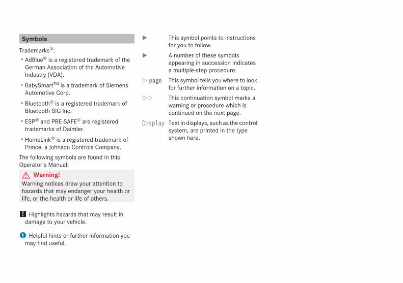
SymbolsTrademarks®:RAdBlue® is a registered trademark of the
German Association of the AutomotiveIndustry (VDA).RBabySmartTM is a trademark of Siemens
Automotive Corp.RBluetooth® is a registered trademark of
Bluetooth SIG Inc.RESP® and PRE-SAFE® are registered
trademarks of Daimler.RHomeLink® is a registered trademark of
Prince, a Johnson Controls Company.The following symbols are found in thisOperator’s Manual:G Warning!Warning notices draw your attention tohazards that may endanger your health orlife, or the health or life of others.
! Highlights hazards that may result indamage to your vehicle.
i Helpful hints or further information youmay find useful.
X This symbol points to instructionsfor you to follow.
X A number of these symbolsappearing in succession indicatesa multiple-step procedure.
Y page This symbol tells you where to lookfor further information on a topic.
YY This continuation symbol marks awarning or procedure which iscontinued on the next page.
Display Text in displays, such as the controlsystem, are printed in the typeshown here.
Our company and staff congratulate you onthe purchase of your new Mercedes-Benz.Your selection of our product is ademonstration of your trust in our companyname. Furthermore, it exemplifies your desireto own an automobile that will be as easy aspossible to operate and provide years ofservice.Your Mercedes-Benz represents the efforts ofmany skilled engineers and craftsmen. Tohelp assure your driving pleasure, and alsothe safety of you and your passengers, we askyou to make a small investment of time:RPlease read this manual carefully, then
return it to your vehicle where it will behandy for your reference.RPlease follow the recommendations
contained in this manual. They aredesigned to acquaint you with theoperation of your Mercedes-Benz.RPlease pay attention to the warnings and
cautions contained in this manual. They aredesigned to help improve the safety of thevehicle operator and occupants.
We extend our best wishes for many miles ofsafe, pleasurable driving.Mercedes-Benz USA, LLCA Daimler Company
2
Index . . . . . . . . . . . . . . . . . . . . . . . . . . . . 3
Introduction . . . . . . . . . . . . . . . . . . . . . 20
At a glance . . . . . . . . . . . . . . . . . . . . . . 27
Safety and security . . . . . . . . . . . . . . . 45
Controls in detail . . . . . . . . . . . . . . . . . 83
Operation . . . . . . . . . . . . . . . . . . . . . . 263
Practical hints . . . . . . . . . . . . . . . . . . 325
Technical data . . . . . . . . . . . . . . . . . . 419
Contents
3
1, 2, 3 ...115V AC Socket . . . . . . . . . . . . . . . . . 2493-zone automatic climate control
see Climate control system 4-ETS (Electronic Traction System) . . 784MATIC
see All-wheel drive (4MATIC)
AABS (Antilock Brake System) . . . . . . . 76
Indicator lamp . . . . . . . . . . . . . . . . 371Messages in the multifunctiondisplay . . . . . . . . . . . . . . . . . . 332, 347
Accessory weight . . . . . . . . . . . . . . . 293Accidents . . . . . . . . . . . . . . . . . . . . . . 132
Active head restraints . . . . . . . . . . . 66Air bag deployment . . . . . . . . . . . . . 47Distance warning function . . . . . . . 181Emergency calls (Tele Aid) . . . . . . . 252
Active Bi-Xenon headlampsMessages in the multifunctiondisplay . . . . . . . . . . . . . . . . . . . . . . 363see Headlamps
Active head restraints . . . . . . . . . . . . . 66Resetting . . . . . . . . . . . . . . . . . . . . 385
Adaptive Damping Systemsee ADS
AdBlue® . . . . . . . . . . . . . . . . . . . 405, 437Capacity, AdBlue® tank . . . . . . . . . 433Refilling . . . . . . . . . . . . . . . . . . . . . 405
AdditivesEngine oil . . . . . . . . . . . . . . . . . . . . 435Gasoline . . . . . . . . . . . . . . . . . . . . . 437
Address change . . . . . . . . . . . . . . . . . . 22ADS (Adaptive Damping System) . . . 185Air bags . . . . . . . . . . . . . . . . . . . . . . . . . 47
Children . . . . . . . . . . . . . . . . . . . . . . 47Emergency call upon deployment . 252Front, driver . . . . . . . . . . . . . . . . . . . 50Front, passenger . . . . . . . . . . . . . . . 50Front passenger front air bag offindicator lamp . . . . . . . . . . . . . . 40, 41, 56, 381, 382Knee bag . . . . . . . . . . . . . . . . . . . . . 51Messages in the multifunctiondisplay . . . . . . . . . . . . . . . . . . . . . . 335Safety guidelines . . . . . . . . . . . . . . . 49Side impact . . . . . . . . . . . . . . . . . . . 51Window curtain . . . . . . . . . . . . . . . . 52
Air conditioning refrigerant andlubricant . . . . . . . . . . . . . . . . . . . . . . . 435Air distribution . . . . . . . . . . . . . 207, 220Air filter . . . . . . . . . . . . . . . . . . . . . . . 362Air pressure
see Tire inflation pressure Air pressure (tires) . . . . . . . . . . . . . . 293Air recirculation mode . . . . . . . 208, 222
Air suspension program . . . . . . . . . . 185Comfortable driving style . . . . . . . . 185Messages in the multifunctiondisplay . . . . . . . . . . . . . . . . . . . . . . 349Sporty driving style . . . . . . . . . . . . 185Suspension tuning . . . . . . . . . . . . . 185Vehicle level control . . . . . . . . . . . . 186
Air volume . . . . . . . . . . . . . . . . . 207, 221Alarm system
see Anti-theft systems Alignment bolt (vehicle tool kit) . . . . . . . . . . . . . . . . . . . . . . . . . . 326, 401All-wheel drive (4MATIC) . . . . . . . . . 193Alternator . . . . . . . . . . . . . . . . . . . . . . 429
Messages in the multifunctiondisplay . . . . . . . . . . . . . . . . . . . . . . 360
Anticorrosion/antifreeze . . . . . . . . . 439Antiglare, Interior rear view mirror . 111Antilock Brake System
see ABS Anti-theft systems . . . . . . . . . . . . . . . . 80
Anti-theft alarm system . . . . . . . . . . 81Immobilizer . . . . . . . . . . . . . . . . . . . 80
Aquaplaningsee Hydroplaning
Ashtrays . . . . . . . . . . . . . . . . . . . . . . . 247Aspect ratio (tires) . . . . . . . . . . . . . . 294Audio/DVD menu . . . . . . . . . . . . . . . 153Auto-dimming rear view mirrors . . . 112Automatic central locking . . . . . 89, 163
Index
4
Automatic headlamp mode . . . . . . . 115Automatic interior lighting control . 120Automatic locking when driving . . . 163Automatic transmission . . . . . . . . . . 135
Emergency operation (limp-homemode) . . . . . . . . . . . . . . . . . . . . . . . 141Gear range indicator . . . . . . . . . . . 139Gear ranges . . . . . . . . . . . . . . . . . . 139Gear selector lever . . . . . . . . . . . . . 135Gearshifting malfunctions . . . . . . . 141Hill start assist system . . . . . . . . . . 181Kickdown . . . . . . . . . . . . . . . . . . . . 139One-touch gearshifting . . . . . . . . . 140Shifting procedure . . . . . . . . . . . . . 137Steering wheel gearshift control . . 140Towing a trailer . . . . . . . . . . . . . . . 139Transmission position indicator . . . 137Transmission positions . . . . . . . . . 137
AUX socket . . . . . . . . . . . . . . . . . . . . . 242Axle oils . . . . . . . . . . . . . . . . . . . . . . . 432
BBabySmartTM
Air bag deactivation system . . . . . . . 57Self-test . . . . . . . . . . . . . . . . . . . . . . 59
Backrestsee Seats
Backup lampsMessages in the multifunctiondisplay . . . . . . . . . . . . . . . . . . . . . . 363Replacing bulbs . . . . . . . . . . . . . . . 388
Bar (air pressure unit) . . . . . . . . . . . . 294BAS (Brake Assist System) . . . . . . . . . 77Batteries, SmartKey
Checking condition . . . . . . . . . . . . . 88Replacing . . . . . . . . . . . . . . . . . . . . 386
Battery, VehicleCharging . . . . . . . . . . . . . . . . . . . . . 409Jump starting . . . . . . . . . . . . . . . . . 410Messages in the multifunctiondisplay . . . . . . . . . . . . . . . . . . . . . . 360
Bead (tire) . . . . . . . . . . . . . . . . . . . . . . 294Beverage holders
see Cup holders Bleeding the fuel system (dieselengine) . . . . . . . . . . . . . . . . . . . . . . . . 404BlueTEC
AdBlue® tank . . . . . . . . . . . . . 405, 433Brake fluid
Messages in the multifunctiondisplay . . . . . . . . . . . . . . . . . . . . . . 347
Brake lampsCleaning lenses . . . . . . . . . . . . . . . 321High-mounted brake lamp . . . . . . . 388Replacing bulbs . . . . . . . . . . . . . . . 388
Brake padsMessages in the multifunctiondisplay . . . . . . . . . . . . . . . . . . . . . . 346
Brakes . . . . . . . . . . . . . . . . . . . . . . . . . 300Parking brake . . . . . . . . . . . . . 133, 302Warning lamp . . . . . . . . . . . . . . . . . 372
Break-in period . . . . . . . . . . . . . . . . . 264Bulbs
see Replacing bulbs
CCAC (Customer Assistance Center) . . 24California retail buyers andlessees, important notice for . . . . . . . 21Calls (phone) . . . . . . . . . . . . . . . . . . . 167Can holders
see Cup holders Capacities and recommendedfuel/lubricants . . . . . . . . . . . . . . . . . 432Cargo compartment
Cargo net . . . . . . . . . . . . . . . . . . . . 240Cargo volume, expanding . . . . . . . . 235Fuse box . . . . . . . . . . . . . . . . . . . . 417Tie-down rings . . . . . . . . . . . . . . . . 234
Cargo compartment cover blind . . . 239Carpets, cleaning . . . . . . . . . . . . . . . . 323Carriers . . . . . . . . . . . . . . . . . . . . . . . . 228
Index
5
Center consoleLower part . . . . . . . . . . . . . . . . . . . . 42Upper part . . . . . . . . . . . . . . . . . . . . 40
Central lockingAutomatic . . . . . . . . . . . . . . . . 89, 163Locking/unlocking from inside . . . . 89
Central locking/unlocking switch . . . 89Certification label . . . . . . . . . . . . . . . 421Children in the vehicle . . . . . . . . . . . . 68
Air bags . . . . . . . . . . . . . . . . . . . . . . 47BabySmartTM air bag deactivationsystem . . . . . . . . . . . . . . . . . . . . . . . 57Blocking of rear window operation . . 74Child safety locks (rear doors) . . . . . 73Indicator lamp, front passengerfront air bag . . . . . . . . . . . . . . . . . . . 56Infant and child restraint systems . . 68LATCH-type child seat anchors . . . . 72Occupant Classification System(OCS) . . . . . . . . . . . . . . . . . . . . . . . . 53Safety notes . . . . . . . . . . . . . . . . . . . 68Tether anchorage points . . . . . . . . . 71
Child safetysee Children in the vehicle
Chrome-plated exhaust tip,cleaning . . . . . . . . . . . . . . . . . . . . . . . 324Cigarette lighter . . . . . . . . . . . . . . . . 248Climate control system
3-zone automatic climate control . 210Air conditioning, cooling . . . . 206, 217
Air conditioning refrigerant . . . . . . 435Air distribution . . . . . . . . . . . . 207, 220Air recirculation mode . . . . . . 208, 222Air volume . . . . . . . . . . . . . . . 207, 221Automatic mode . . . . . . . . . . 206, 218Climate control . . . . . . . . . . . . . . . 202Deactivating system . . . . . . . 205, 217Front defroster . . . . . . . . . . . . 207, 221Residual engine heat (REST) . 209, 223Temperature . . . . . . . . . . . . . 207, 219
Clock . . . . . . . . . . . . . . . . . . . . . . . 33, 160Cockpit . . . . . . . . . . . . . . . . . . . . . . . . . 30Cold tire inflation pressure . . . . . . . 294Collapsible wheel chock . . . . . . . . . . 326COMAND system
see separate COMAND systemoperating instructions
Combination switch . . . . . . . . . . . . . 117Comfort submenu
Easy-entry/exit feature . . . . . . . . . 163Fold-in function for exterior rearview mirrors . . . . . . . . . . . . . . . . . . 164
CompassCalling up . . . . . . . . . . . . . . . . . . . . 260
Control system . . . . . . . . . . . . . . . . . 148Multifunction display . . . . . . . . . . . 150Multifunction steering wheel . . . . . 148Resetting to factory settings . . . . . 157
Control system menus . . . . . . . . . . . 151Audio/DVD . . . . . . . . . . . . . . . . . . 153
Distronic . . . . . . . . . . . . . . . . . . . . 156Navigation . . . . . . . . . . . . . . . . . . . 155Off-road . . . . . . . . . . . . . . . . . . . . . 155Settings . . . . . . . . . . . . . . . . . . . . . 157Standard display . . . . . . . . . . . . . . 152Telephone . . . . . . . . . . . . . . . . . . . 167Trip computer . . . . . . . . . . . . . . . . 165Vehicle configuration . . . . . . . . . . . 164Vehicle status message memory . . 156
Control system submenus . . . . . . . . 151Comfort . . . . . . . . . . . . . . . . . . . . . 163Instrument cluster . . . . . . . . . . . . . 158Lighting . . . . . . . . . . . . . . . . . . . . . 160Time/Date . . . . . . . . . . . . . . . . . . . 160Vehicle . . . . . . . . . . . . . . . . . . . . . . 163
CoolantAnticorrosion/antifreeze . . . . . . . . 439Capacities . . . . . . . . . . . . . . . . . . . 433Checking level . . . . . . . . . . . . . . . . 271Messages in the multifunctiondisplay . . . . . . . . . . . . . . 356, 357, 359
Corner-illuminating front fog lamps 119Cruise control . . . . . . . . . . . . . . . . . . 169
Last stored speed . . . . . . . . . . . . . 171Resume function . . . . . . . . . . . . . . 171
Cup holders . . . . . . . . . . . . . . . . . . . . 245Curb weight . . . . . . . . . . . . . . . . . . . . 294Customer Assistance Center
see CAC
Index
6
DDashboard
see Instrument cluster Data recording . . . . . . . . . . . . . . . . . . . 25Date, Setting . . . . . . . . . . . . . . . . . . . 160Daytime running lamp mode . . 116, 161Deep water
see Standing water Defroster
Rear window . . . . . . . . . . . . . . . . . 223Windshield . . . . . . . . . . . . . . . 207, 221
Delayed shut-offExterior lamps . . . . . . . . . . . . . . . . 162Interior lighting . . . . . . . . . . . . . . . . 162
Department of Transportationsee DOT
Diesel enginepreglow indicator lamp . . . . . . . . . . 35
Diesel fuelsee Fuel
Differential locks . . . . . . . . . . . . . . . . 144A few words about . . . . . . . . . . . . . 144Messages in the multifunctiondisplay . . . . . . . . . . . . . . . . . . 146, 351Switching . . . . . . . . . . . . . . . . . . . . 145
DifficultiesWhile driving . . . . . . . . . . . . . . . . . 132With starting . . . . . . . . . . . . . . . . . 130
Digital clocksee Clock
Digital speedometer . . . . . . . . . . . . . 153Dimensions (vehicle) . . . . . . . . . . . . . 430Direction of rotation (tires) . . . . . . . 275Displays
Digital speedometer . . . . . . . . . . . . 153Distronic . . . . . . . . . . . . . . . . . . . . 174Maintenance service indicator . . . . 316Messages in the multifunctiondisplay . . . . . . . . . . . . . . . . . . . . . . 330Multifunction display . . . . . . . . . . . 150Outside temperature . . . . . . . 150, 159Symbol messages . . . . . . . . . . . . . 346Text messages . . . . . . . . . . . . . . . . 332Trip computer . . . . . . . . . . . . 150, 165Vehicle status message memory . . 156Vehicle system settings . . . . . . . . . 157
Distronic . . . . . . . . . . . . . . . . . . . . . . . 172Cleaning system sensor . . . . . . . . . 321Control system . . . . . . . . . . . . . . . . 156Distance warning function . . . . . . . 181Driving hints . . . . . . . . . . . . . . . . . . 179Last stored speed . . . . . . . . . . . . . 178Menu . . . . . . . . . . . . . . . . . . . . . . . 175Messages in the multifunctiondisplay . . . . . . . . . . . . . . . . . . . . . . 340Resume function . . . . . . . . . . . . . . 178Sensor cover . . . . . . . . . . . . . . . . . 321Warning and indicator lamps . 174, 377
Door control panel . . . . . . . . . . . . . . . . 44Door handles . . . . . . . . . . . . . . . . . . . . 44Doors
Child safety locks . . . . . . . . . . . . . . . 73Locking/unlocking (KEYLESS-GO) . . 85Locking/unlocking (SmartKey) . . . . 84Locking/unlocking from outside . . . 84Messages in the multifunctiondisplay . . . . . . . . . . . . . . . . . . . . . . 353Opening from inside . . . . . . . . . . . . . 88Remote door unlock (Tele Aid) . . . . 255Unlocking (Mechanical key) . . . . . . 384
DOT (Department ofTransportation) . . . . . . . . . . . . . . . . . 294Downhill Speed Regulation
see DSR Drinking and driving . . . . . . . . . . . . . 299Driving
Abroad . . . . . . . . . . . . . . . . . . . . . . 314Hydroplaning . . . . . . . . . . . . . . . . . 302Instructions . . . . . . . . . . . . . . 128, 299In winter . . . . . . . . . . . . . . . . . . . . . 298Off-road . . . . . . . . . . . . . . . . . . . . . 303Problems . . . . . . . . . . . . . . . . . . . . 132Safety systems . . . . . . . . . . . . . . . . . 75Systems . . . . . . . . . . . . . . . . . . . . . 169Through standing water . . . . . . . . . 302With Distronic . . . . . . . . . . . . . . . . 179
Driving and parkingSafety notes . . . . . . . . . . . . . . . . . . 128
Index
7
Driving off . . . . . . . . . . . . . . . . . 131, 302Driving safety systems . . . . . . . . . . . . 75
4-ETS . . . . . . . . . . . . . . . . . . . . . . . . 78ABS . . . . . . . . . . . . . . . . . . . . . . . . . 76BAS . . . . . . . . . . . . . . . . . . . . . . . . . 77EBP . . . . . . . . . . . . . . . . . . . . . . . . . . 77ESP® . . . . . . . . . . . . . . . . . . . . . . . . 77
Driving systemsAir suspension program . . . . . . . . . 185Cruise control . . . . . . . . . . . . . . . . 169Distronic . . . . . . . . . . . . . . . . . . . . 172Downhill Speed Regulation (DSR) . 182Off-road driving program . . . . . . . . 185Parktronic system . . . . . . . . . . . . . 193Rear view camera . . . . . . . . . . . . . 197
Driving tips, automatictransmission . . . . . . . . . . . . . . . . . . . 139DSR (Downhill Speed Regulation) . . 182
Messages in the multifunctiondisplay . . . . . . . . . . . . . . . . . . . . . . 353
EEasy-entry/exit feature . . . . . . 109, 163EBP (Electronic BrakeProportioning) . . . . . . . . . . . . . . . . . . . 77Electrical system
Improper work on or modifications . 23Power outlets . . . . . . . . . . . . . . . . . 249Technical data . . . . . . . . . . . . . . . . 429
Electronic Stability Programsee ESP®
Electronic Traction Systemsee 4-ETS
Emergency, in case ofBattery, jump starting . . . . . . . . . . 410First aid kit . . . . . . . . . . . . . . . . . . . 326Flat tire . . . . . . . . . . . . . . . . . . . . . . 397Hazard warning flasher . . . . . . . . . 118Roadside Assistance . . . . . . . . . . . . 22Towing the vehicle . . . . . . . . . . . . . 412
Emergency callsTele Aid . . . . . . . . . . . . . . . . . . . . . 252
Emergency engine shutdown . . . . . . 417Emergency operations
Limp-home mode . . . . . . . . . . . . . . 141Locking/unlocking the vehicle . . . 384Remote door unlock . . . . . . . . . . . . 255
Emergency Tensioning Devicesee ETD
Emission control . . . . . . . . . . . . . . . . 315Information label . . . . . . . . . . . . . . 422System warranties . . . . . . . . . . . . . . 21
EngineBrake-in recommendations . . . . . . 264Cleaning . . . . . . . . . . . . . . . . . . . . . 319Compartment . . . . . . . . . . . . . . . . . 267Malfunction indicator lamp . . . . . . . . . . . . . . . . . . . . . . . . . 35, 379Maximum engine speed . . . . . . . . . 423
Messages in the multifunctiondisplay . . . . . . . . . . . . . . . . . . . . . . 356Number . . . . . . . . . . . . . . . . . . . . . 422Starting . . . . . . . . . . . . . . . . . . . . . 128Technical data . . . . . . . . . . . . . . . . 423Turning off . . . . . . . . . . . . . . . . . . . 133
Engine coolantsee Coolant
Engine oilAdding . . . . . . . . . . . . . . . . . . . . . . 270Additives . . . . . . . . . . . . . . . . . . . . 435Checking level . . . . . . . . . . . . . . . . 269Consumption . . . . . . . . . . . . . . . . . 269Messages in the multifunctiondisplay . . . . . . . . . . . . . . . . . . . . . . 361Oil dipstick . . . . . . . . . . . . . . . . . . . 269Recommended engine oils and oilfilter . . . . . . . . . . . . . . . . . . . . . . . . 434
ESP® (Electronic Stability Program) . 774-ETS . . . . . . . . . . . . . . . . . . . . . . . . 78Messages in the multifunctiondisplay . . . . . . . . . . . . . . . . . . 333, 347Off-road ESP® . . . . . . . . . . . . . . . . . 80Trailer stabilization . . . . . . . . . . . . . . 80Warning lamp . . . . . . . . . . . . . . . . . 376
ETD (Emergency TensioningDevice) . . . . . . . . . . . . . . . . . . . . . . . . . 64
Safety guidelines . . . . . . . . . . . . . . . 49
Index
8
Express operationPower windows . . . . . . . . . . . . . . . 124Tilt/sliding sunroof . . . . . . . . . . . . 224
Exterior lamp switch . . . . . . . . . . . . . 115Exterior rear view mirrors . . . . . . . . 111
Fold-in function . . . . . . . . . . . . . . . 164Power folding . . . . . . . . . . . . . . . . . 112
Exterior view of vehicle . . . . . . . . . . . 28
FFastening the seat belts . . . . . . . . . . . 61First aid kit . . . . . . . . . . . . . . . . . . . . . 326Flat tire . . . . . . . . . . . . . . . . . . . . . . . . 397
Lowering the vehicle . . . . . . . . . . . 402Mounting the spare wheel . . . . . . . 398Preparing the vehicle . . . . . . . . . . . 398Spare wheel . . . . . . . . . . . . . . 398, 428
Floormats . . . . . . . . . . . . . . . . . . . . . . 260Fluids
AdBlue® . . . . . . . . . . . . . . . . . . . . . 433Automatic transmission fluid . . . . . 432Brake fluid . . . . . . . . . . . . . . . . . . . 433Capacities . . . . . . . . . . . . . . . . . . . 432Engine coolant . . . . . . . . . . . . . . . . 433Engine oil . . . . . . . . . . . . . . . . . . . . 432Power steering fluid . . . . . . . . . . . . 433Washer and headlamp cleaningsystem . . . . . . . . . . . . . . . . . . . . . . 434
Fog lamps . . . . . . . . . . . . . . . . . . . . . . 117Messages in the multifunctiondisplay . . . . . . . . . . . . . . . . . . 364, 365Replacing bulbs . . . . . . . . . . . . . . . 388
Fold-in function for exterior rearview mirrors . . . . . . . . . . . . . . . . . . . . 164Four-wheel drive
see All-wheel drive (4MATIC) Front air bags
see Air bags Front axle oil . . . . . . . . . . . . . . . . . . . 432Front lamps
see Headlamps Front passenger front air bag . . . . . . 50
Messages in the multifunctiondisplay . . . . . . . . . . . . . . . . . . . . . . 335
Front passenger front air bag offindicator lamp . . . . . . . . . . . . . . . . . 40, 41, 51, 381, 382Front seat head restraints
see Head restraints Fuel . . . . . . . . . . . . . . . . . . . . . . . 266, 299
Additives . . . . . . . . . . . . . . . . . . . . 437Capacity, fuel tank . . . . . . . . . . . . . 433Diesel fuel . . . . . . . . . . . . . . . 266, 433Fuel consumption statistics . . . . . . 165Fuel filler flap and cap . . . . . . . . . . 265Fuel tank reserve warning lamp . . . . . . . . . . . . . . . . . . . . . . . . . 35, 378
Premium unleaded gasoline . . . . . . . . . . . . . . . . . . . 266, 433, 435Refueling . . . . . . . . . . . . . . . . . . . . 265Requirements . . . . . . . . . . . . . . . . . 436
Fuel filler flap . . . . . . . . . . . . . . . . . . . 266Locking/unlocking . . . . . . . . . . . . . 266Opening . . . . . . . . . . . . . . . . . . . . . 266Opening manually . . . . . . . . . . . . . 385
Fuels, coolants, lubricants etc.Capacities . . . . . . . . . . . . . . . . . . . 432
Fuel system, bleeding (dieselengine) . . . . . . . . . . . . . . . . . . . . . . . . 404Fuel tank
Capacity . . . . . . . . . . . . . . . . . . . . . 433Fuel filler flap and cap . . . . . . . . . . 265Refueling . . . . . . . . . . . . . . . . . . . . 265
Fuses . . . . . . . . . . . . . . . . . . . . . . . . . . 415Fuse box in cargo compartment . . 417
GGarage door opener . . . . . . . . . . 43, 256Gasoline
see Fuel GAWR (Gross Axle Weight Rating) . . 294Gear range
Automatic transmission . . . . . . . . . 139Indicator . . . . . . . . . . . . . . . . . . . . . 139Limiting . . . . . . . . . . . . . . . . . . . . . 140
Index
9
Shifting into optimal . . . . . . . . . . . . 141Transfer case . . . . . . . . . . . . . . . . . 142
Gear selector lever . . . . . . . . . . . . . . 135Cleaning . . . . . . . . . . . . . . . . . . . . . 323Gearshift pattern . . . . . . . . . . . . . . 135Messages in the multifunctiondisplay . . . . . . . . . . . . . . . . . . 343, 344Shifting procedure . . . . . . . . . . . . . 137Transmission position indicator . . . 137Transmission positions . . . . . . . . . 137
Generatorsee Alternator
Global locking/unlockingsee Key, SmartKey
Glove box . . . . . . . . . . . . . . . . . . . . . . 242Gross Axle Weight Rating
see GAWR Gross Trailer Weight
see GTW Gross Vehicle Weight
see GVW Gross Vehicle Weight Rating
see GVWR GTW . . . . . . . . . . . . . . . . . . . . . . . . . . . 294GVW (Gross Vehicle Weight) . . . . . . 294GVWR (Gross Vehicle WeightRating) . . . . . . . . . . . . . . . . . . . . . . . . 294
HHalogen headlamps
see Headlamps Hard plastic trim items, cleaning . . 323Hazard warning flasher . . . . . . . . . . . 118Headlamp cleaning system . . . . . . . 119Headlamps
Active Bi-Xenon headlamps . . . . . . 114Adjusting aim . . . . . . . . . . . . . . . . . 394Automatic headlamp mode . . . . . . 115Bi-Xenon . . . . . . . . . . . . . . . . 114, 388Cleaning lenses . . . . . . . . . . . . . . . 321Cleaning system . . . . . . . . . . . . . . . 119Delayed shut-off . . . . . . . . . . . . . . . 162Halogen . . . . . . . . . . . . . . . . . . . . . 389High-beam flasher . . . . . . . . . . . . . 118High-beam headlamps . . . . . . . . . . 118Low-beam headlamps . . . . . . . . . . 115Replacing bulbs . . . . . . . . . . . . . . . 388Switch . . . . . . . . . . . . . . . . . . . . . . 115
Headliner, cleaning and care of . . . . 323Head restraints . . . . . . . . . . . . . . . . . . 97
Active head restraints . . . . . . . 66, 385Adjusting . . . . . . . . . . . . . . . . . . . . . 99
Heated seats . . . . . . . . . . . . . . . . . . . 107Heated steering wheel . . . . . . . . . . . 110Height adjustment
Seats . . . . . . . . . . . . . . . . . . . . . . . . 98Vehicle level control . . . . . . . . . . . . 186
High-beam flasher . . . . . . . . . . . . . . . 118High-beam headlamps . . . . . . . 118, 388
Indicator lamp . . . . . . . . . . . . . . . . . 35Replacing bulbs . . . . . . . . . . . . . . . 388
High-mounted brake lamp . . . . . . . . 388Replacing bulbs . . . . . . . . . . . . . . . 388
Hill start assist system . . . . . . . . . . . 181Hinged quarter windows . . . . . . . . . 126Hood . . . . . . . . . . . . . . . . . . . . . . . . . . 267
Messages in the multifunctiondisplay . . . . . . . . . . . . . . . . . . . . . . 353
Hooks . . . . . . . . . . . . . . . . . . . . . . . . . 234Horn . . . . . . . . . . . . . . . . . . . . . . . . . . . 31HVAC
see Climate control system Hydroplaning . . . . . . . . . . . . . . . . . . . 302
IIdentification labels . . . . . . . . . . . . . 421Identification number, vehicle(VIN) . . . . . . . . . . . . . . . . . . . . . . . . . . 421Ignition . . . . . . . . . . . . . . . . . . 95, 97, 129Immobilizer . . . . . . . . . . . . . . . . . . . . . 80Indicator lamps
see Lamps, indicator and warning Infant and child restraint systems
see Children in the vehicle Inflation pressure
see Tires, Inflation pressure
Index
10
Inside door handle . . . . . . . . . . . . . . . . 88Instrument cluster . . . . . . . . . . . 32, 147
Illumination . . . . . . . . . . . . . . . . . . 147Lamps . . . . . . . . . . . . . . . . . . . . . . 370Multifunction display . . . . . . . . . . . 150
Instrument lightingsee Instrument cluster, Illumination
Instrument panelsee Instrument cluster
Instruments and controlssee Cockpit
Interior lightingDelayed shut-off . . . . . . . . . . . . . . . 162Emergency lighting . . . . . . . . . . . . 121Front . . . . . . . . . . . . . . . . . . . . . . . 120Front reading lamps . . . . . . . . . . . . 120Rear . . . . . . . . . . . . . . . . . . . . . . . . 121Rear reading lamps . . . . . . . . . . . . 121
Interior rear view mirror . . . . . . . . . . 111Auto-dimming rear view mirrors . . . 112
Interior storage spacessee Storage compartments
Intermittent wipingWindshield wipers . . . . . . . . . . . . . 122
JJack . . . . . . . . . . . . . . . . . . . . . . . . . . . 329Jump starting . . . . . . . . . . . . . . . . . . . 410
KKey, Mechanical . . . . . . . . . . . . . . . . . 384
Loss of . . . . . . . . . . . . . . . . . . . . . . . 88Key, SmartKey
Battery check lamp . . . . . . . . . . . . . 85Checking batteries . . . . . . . . . . . . . . 88Factory setting . . . . . . . . . . . . . . 85, 87Global locking (KEYLESS-GO) . . . . . . . . . . . . . . . . . . . . . . . . . . . . . 87Global locking (SmartKey) . . . . . . . . 85Global unlocking (KEYLESS-GO) . . . . . . . . . . . . . . . . . . . . . . . . . . . . . 87Global unlocking (SmartKey) . . . . . . 85Important notes on KEYLESS-GO . . . 86Locking/unlocking . . . . . . . . . . . . . . 84Loss of . . . . . . . . . . . . . . . . . . . . . . . 88Messages in the multifunctiondisplay . . . . . . . . . . . . . . . . . . 353, 354Opening and closing the powertilt/sliding sunroof . . . . . . . . . . . . . 127Opening and closing the windows . 127Remote control . . . . . . . . . . . . . . . . 84Replacing batteries . . . . . . . . . . . . 386Restoring to factory setting . . . . 85, 87Selective setting . . . . . . . . . . . . 85, 87Starter switch positions . . . . . . . . . . 95
KEYLESS-GOStarter switch positions . . . . . . . . . . 96
Kickdown . . . . . . . . . . . . . . . . . . . . . . 139
Kilopascal (air pressure unit) . . . . . . 294Knee bag . . . . . . . . . . . . . . . . . . . . . . . . 51
LLabels
Certification . . . . . . . . . . . . . . . . . . 421Emission control information . . . . . 422
Lamps, exteriorExterior lamp switch . . . . . . . . . . . 115Front . . . . . . . . . . . . . . . . . . . . . . . 388Messages in the multifunctiondisplay . . . . . . . . . . . . . . . . . . . . . . 363Rear . . . . . . . . . . . . . . . . . . . . . . . . 388Switching on/off . . . . . . . . . . . . . . 115
Lamps, indicator and warningABS . . . . . . . . . . . . . . . . . . . . . 33, 371Battery (SmartKey) . . . . . . . . . . . . . . 85Brakes . . . . . . . . . . . . . . . . . . . . . . 372Center console . . . . . . . . . . . . . . . . . 40Differential locks . . . . . . . . . . . . . . 145Distance warning lamp . 174, 181, 377Engine malfunction . . . . . . . . . 35, 379ESP® . . . . . . . . . . . . . . . . . . . . 33, 376Fog lamps . . . . . . . . . . . . . . . . . . . 117Front passenger front air bag off . . . . . . . . . . . . . . 40, 41, 51, 381, 382Fuel tank reserve . . . . . . . . . . . 35, 378High-beam headlamps . . . . . . . . . . . 35Instrument cluster . . . . . . . . . . . . . 370
Index
11
Seat belt telltale . . . . . . . . . . . . 35, 374SRS . . . . . . . . . . . . . . . . . . . . . 47, 375Turn signals . . . . . . . . . . . . . . . . . . . 33
Language, selecting . . . . . . . . . . . . . 159LATCH-type child seat anchors
see Children in the vehicle License plate lamps . . . . . . . . . . . . . 388
Messages in the multifunctiondisplay . . . . . . . . . . . . . . . . . . . . . . 365Replacing bulbs . . . . . . . . . . . . . . . 388
Light alloy wheels, cleaning . . . . . . . 322Lighter
see Cigarette lighter Lighting . . . . . . . . . . . . . . . . . . . . . . . . 114
Daytime running lamp mode . . . . . 116Exterior . . . . . . . . . . . . . . . . . . . . . 115Interior . . . . . . . . . . . . . . . . . . . . . . 120
Limp-home mode . . . . . . . . . . . . . . . . 141Loading
see Vehicle loading Locator lighting . . . . . . . . . . . . . . . . . 161Lock button
Door handle (KEYLESS-GO) . . . . . . . 87Locking the vehicle . . . . . . . . . . . . 84, 85
Manually . . . . . . . . . . . . . . . . . . . . 384Loss of
Key . . . . . . . . . . . . . . . . . . . . . . . . . . 88Service and Warranty Informationbooklet . . . . . . . . . . . . . . . . . . . . . . 421
Low-beam headlamps . . . . . . . . . . . . 115Exterior lamp switch . . . . . . . . . . . 115Replacing bulbs . . . . . . . . . . . . . . . 388Switching on . . . . . . . . . . . . . . . . . 115
LOW RANGE mode . . . . . . . . . . . . . . . 142Messages in the multifunctiondisplay . . . . . . . . . . . . . . . . . . . . . . 352Switching . . . . . . . . . . . . . . . . . . . . 143
Lubricants . . . . . . . . . . . . . . . . . . . . . 432Lumbar support . . . . . . . . . . . . . . . . . 103
MMaintenance . . . . . . . . . . . . . . . . . . . . . 22Maintenance System . . . . . . . . . . . . . 315
Calling up service indicator . . . . . . 317Clearing service indicatormessage . . . . . . . . . . . . . . . . . . . . . 316Resetting service indicator . . . . . . 317Service indicator . . . . . . . . . . . . . . 316Service indicator message . . . . . . . 316Service term exceeded . . . . . . . . . 316
Manual headlamp mode (Low-beam headlamps) . . . . . . . . . . . . . . . 115Maximum loaded vehicle weight . . . 294Maximum load rating (tires) . . . . . . . 294Maximum permissible tireinflation pressure . . . . . . . . . . . . . . . 295Mechanical key . . . . . . . . . . . . . . . . . 384Media interface . . . . . . . . . . . . . . . . . 242
Memory function . . . . . . . . . . . . . . . . 113Menus
see Control system menus Minispare wheel
see Spare wheel Mirrors
Auto-dimming rear view mirrors . . . 112Exterior rear view mirrors . . . . . . . 111Interior rear view mirror . . . . . . . . . 111Memory function . . . . . . . . . . . . . . 113
MOExtended system . . . . . . . . . . . . . 403MOExtended tires . . . . . . . . . . . 403, 425MON (Motor Octane Number) . 266, 436Motor Octane Number
see MON Multicontour seats . . . . . . . . . . . . . . 106Multifunction display . . . . . . . . . . . . 150
Symbol messages . . . . . . . . . . . . . 346Text messages . . . . . . . . . . . . . . . . 332Vehicle status messages . . . . . . . . 330
Multifunction display messagesABS . . . . . . . . . . . . . . . . . . . . 332, 347Active headlamps . . . . . . . . . . . . . . 363Air bags . . . . . . . . . . . . . . . . . . . . . 335Air filter . . . . . . . . . . . . . . . . . . . . . 362Air suspension program . . . . . . . . . 349Alternator . . . . . . . . . . . . . . . . . . . . 360Automatic transmission . . . . . . . . . . . . . . . . . . . . . . . 343, 344Battery . . . . . . . . . . . . . . . . . . . . . . 360
Index
12
Brake fluid . . . . . . . . . . . . . . . . . . . 347Brake pads . . . . . . . . . . . . . . . . . . . 346Coolant . . . . . . . . . . . . . 356, 357, 359Corner-illuminating front foglamps . . . . . . . . . . . . . . . . . . . . . . . 366Cruise control . . . . . . . . . . . . . . . . 340Differential locks . . . . . . . . . . 146, 351Display malfunction . . . . . . . . . . . . 330Distronic . . . . . . . . . . . . . . . . . . . . 340Doors . . . . . . . . . . . . . . . . . . . . . . . 353Downhill Speed Regulation (DSR) . 353EBP . . . . . . . . . . . . . . . . . . . . . . . . . 347Engine oil . . . . . . . . . . . . . . . . . . . . 361ESP® . . . . . . . . . . . . . . . . . . . 333, 347Fog lamps . . . . . . . . . . . . . . . 364, 365Front passenger front air bag . . . . 335Gas cap . . . . . . . . . . . . . . . . . . . . . 362Gear selector lever . . . . . . . . . . . . . . . . . . . . . . . 343, 344High-beam lamps . . . . . . . . . . . . . . 364Hood . . . . . . . . . . . . . . . . . . . . . . . 353License plate lamps . . . . . . . . . . . . 365Light sensor . . . . . . . . . . . . . . . . . . 365Low-beam lamps . . . . . . . . . . . . . . 365LOW RANGE mode . . . . . . . . . . . . . 352Parking brake . . . . . . . . . . . . . . . . . 347Parking lamps . . . . . . . . . . . . . . . . 364PRE-SAFE® . . . . . . . . . . . . . . . . . . . 334Reserve fuel . . . . . . . . . . . . . . . . . . 362Reverse lamp . . . . . . . . . . . . . . . . . 363
Side marker lamps . . . . . . . . . . . . . 364SmartKey . . . . . . . . . . . . . . . . . . . . 354SmartKey with KEYLESS-GO . . . . . 353SRS . . . . . . . . . . . . . . . . . . . . . . . . 348Tailgate . . . . . . . . . . . . . . . . . . . . . 353Tail lamps . . . . . . . . . . . . . . . . . . . . 366Tele Aid . . . . . . . . . . . . . . . . . . . . . 348Tire pressure . . . . . . . . . . . . . 344, 368Tire pressure monitor . . . . . . . . . . . 345Tires . . . . . . . . . . . . . . . . . . . . 344, 368TPMS . . . . . . . . . . . . . . . . . . . 345, 368Trailer brake lamps . . . . . . . . . . . . 366Trailer tail lamps . . . . . . . . . . . . . . 366Trailer turn signal lamps . . . . . . . . . 367Turn signals . . . . . . . . . . . . . . . . . . 367Washer fluid . . . . . . . . . . . . . . . . . . 355
Multifunction steering wheelAdjusting . . . . . . . . . . . . . . . . . . . . 108Buttons . . . . . . . . . . . . . . . . . . . . . 148Cleaning . . . . . . . . . . . . . . . . . . . . . 323Easy-entry/exit feature . . . . . 109, 163Gearshift control . . . . . . . . . . . . . . 140Heating . . . . . . . . . . . . . . . . . . . . . 110Memory function . . . . . . . . . . . . . . 113Overview . . . . . . . . . . . . . . . . . . . . . 38
NNavigation menu . . . . . . . . . . . . . . . . 155Nets, parcel . . . . . . . . . . . . . . . . . . . . 233Night security illumination . . . 117, 162
Normal occupant weight . . . . . . . . . 295Number, vehicle identification(VIN) . . . . . . . . . . . . . . . . . . . . . . . . . . 421
OOccupant Classification System
see OCS Occupant distribution . . . . . . . . . . . . 295Occupant safety . . . . . . . . . . . . . . . . . . 46
Air bags . . . . . . . . . . . . . . . . . . . . . . 47BabySmartTM . . . . . . . . . . . . . . . . . . 57Children and air bags . . . . . . . . . . . . 47Children in the vehicle . . . . . . . . . . . 68Fastening the seat belts . . . . . . . . . . 61Front passenger front air bag offindicator lamp . . . . . . . . . 53, 381, 382Infant and child restraint systems . . 68LATCH-type child seat anchors . . . . 72OCS . . . . . . . . . . . . . . . . . . . . . . . . . 53PRE-SAFE® . . . . . . . . . . . . . . . . . . . . 65Seat belts . . . . . . . . . . . . . . . . . . 49, 59
OCS (Occupant ClassificationSystem) . . . . . . . . . . . . . . . . . . . . . . . . . 53
Self-test . . . . . . . . . . . . . . . . . . . . . . 56Odometer . . . . . . . . . . . . . . . . . . . . . . 150Off-road driving . . . . . . . . . . . . . . . . . 303
Checklist . . . . . . . . . . . . . . . . 304, 309Crossing obstacles . . . . . . . . . . . . . 307Driving instructions . . . . . . . . . . . . 303
Index
13
Driving on sand . . . . . . . . . . . . . . . 308Driving through water . . . . . . . . . . 306Returning . . . . . . . . . . . . . . . . . . . . 309Ruts . . . . . . . . . . . . . . . . . . . . . . . . 308Steep terrain . . . . . . . . . . . . . . . . . 305
Off-road driving program . . . . . . . . . 185Off-road menu . . . . . . . . . . . . . . . . . . 155Oil
see Engine oil Oil level
see Engine oil, Checking level On-board computer
see Control system One-touch gearshifting . . . . . . . . . . . 140Operating safety . . . . . . . . . . . . . . . . . 23Ornamental moldings, cleaning . . . . 320Outside temperature
see Displays Overhead control panel . . . . . . . . . . . 43
PPaintwork, cleaning . . . . . . . . . . . . . . 319Paintwork code . . . . . . . . . . . . . . . . . 421Panic alarm . . . . . . . . . . . . . . . . . . . . . 75Panorama roof
Sunshade . . . . . . . . . . . . . . . . . . . . 247Parcel nets . . . . . . . . . . . . . . . . . . . . . 233Parking . . . . . . . . . . . . . . . . . . . . . . . . 132
Parktronic . . . . . . . . . . . . . . . . . . . 193
Parking brake . . . . . . . . . . . . . . 133, 302Messages in the multifunctiondisplay . . . . . . . . . . . . . . . . . . . . . . 347
Parking positionTransmission position . . . . . . . . . . 137
Parktronic . . . . . . . . . . . . . . . . . . . . 40, 41Cleaning system sensors . . . . . . . . 321Malfunctions . . . . . . . . . . . . . . . . . 197Minimum distance . . . . . . . . . . . . . 195Range . . . . . . . . . . . . . . . . . . . . . . . 194System sensors . . . . . . . . . . . 194, 321Warning indicators . . . . . . . . . . 31, 195
Parts service . . . . . . . . . . . . . . . . . . . 420PASS AIR BAG OFF indicator lamp
see Front passenger front air bagoff indicator lamp
Passenger safetysee Occupant safety
Pedals . . . . . . . . . . . . . . . . . . . . . . . . . 299Phone
see Telephone Plastic parts, cleaning . . . . . . . . . . . . 323Power assistance . . . . . . . . . . . . . . . 300Power outlets . . . . . . . . . . . . . . . . . . . 249Power seats
see Seats
Power tailgateClosing . . . . . . . . . . . . . . . . . . . . . . . 91Messages in the multifunctiondisplay . . . . . . . . . . . . . . . . . . . . . . 353Opening . . . . . . . . . . . . . . . . . . . . . . 91
Power tilt/sliding sunroofOperation . . . . . . . . . . . . . . . . . . . . 224Synchronizing . . . . . . . . . . . . . . . . . 226
Power washer . . . . . . . . . . . . . . . . . . 319Power windows . . . . . . . . . . . . . . . . . 124
Cleaning . . . . . . . . . . . . . . . . . . . . . 322Door windows . . . . . . . . . . . . . . . . 125Hinged quarter windows . . . . . . . . 126Operation . . . . . . . . . . . . . . . . . . . . 124Rear door window, Blockingoperation . . . . . . . . . . . . . . . . . . . . . 74Synchronizing . . . . . . . . . . . . . . . . . 126
Practical hints . . . . . . . . . . . . . . . . . . 326Preglow indicator lamp . . . . . . . . 35, 129PRE-SAFE® . . . . . . . . . . . . . . . . . . . . . . 65
Messages in the multifunctiondisplay . . . . . . . . . . . . . . . . . . . . . . 334
ProblemsWhile driving . . . . . . . . . . . . . . . . . 132With vehicle . . . . . . . . . . . . . . . . . . . 24
Product information . . . . . . . . . . . . . . 20Production options weight . . . . . . . . 295Proximity key
see Key, SmartKey PSI (air pressure unit) . . . . . . . . . . . . 295
Index
14
Push-startsee Tow-start
RRadio
Selecting stations . . . . . . . . . . . . . 154Radio transmitters . . . . . . . . . . . . . . 314Rear axle oil . . . . . . . . . . . . . . . . . . . . 432Rear doors
Child safety locks . . . . . . . . . . . . . . . 73Rear door window
Blocking operation . . . . . . . . . . . . . . 74Rear fog lamp
see Fog lamps Rear lamps
see Tail lamps Rear seats
see Seats Rear view camera . . . . . . . . . . . . . . . 197
cleaning the lens . . . . . . . . . . . . . . 321Rear window defroster . . . . . . . . . . . 223Rear window wiper/washer . . . . . . . 123Recommended tire inflationpressure . . . . . . . . . . . . . . . . . . . 279, 295Recovery services, Stolen vehicle(Tele Aid) . . . . . . . . . . . . . . . . . . . . . . . 256Refilling
AdBlue® . . . . . . . . . . . . . . . . . . . . . 405Refrigerant, air conditioning . . . . . . 435
Refueling . . . . . . . . . . . . . . . . . . . . . . 265Regular checks . . . . . . . . . . . . . . . . . 267Reminder, Seat belt
see Seat belts, Telltale Remote control
see Key, SmartKey Remote door unlock (Tele Aid) . . . . . 255Replacing bulbs . . . . . . . . . . . . . . . . . 388
Brake lamps . . . . . . . . . . . . . . . . . . 388Headlamps . . . . . . . . . . . . . . . . . . . 388High-beam headlamps . . . . . . . . . . 388High-mounted brake lamp . . . . . . . 388License plate lamps . . . . . . . . . . . . 388Low-beam headlamps . . . . . . . . . . 388Parking lamps . . . . . . . . . . . . . . . . 388Side marker lamps . . . . . . . . . . . . . 388Standing lamps . . . . . . . . . . . . . . . 388Tail lamps . . . . . . . . . . . . . . . . . . . . 388Turn signal lamps . . . . . . . . . . . . . . 388
Reporting safety defects . . . . . . . . . . 25Research Octane Number
see RON Reserve fuel
Messages in the multifunctiondisplay . . . . . . . . . . . . . . . . . . . . . . 362Warning lamp . . . . . . . . . . . . . . . . . . 35
Reset button . . . . . . . . . . . . 33, 147, 157Restraint systems
see Occupant safety Rims . . . . . . . . . . . . . . . . . . . . . . 295, 425
Roadside Assistance . . . . . . . . . . 22, 253RON (Research Octane Number) . . . . . . . . . . . . . . . . . . . . . . . . . . 266, 436Roof rack . . . . . . . . . . . . . . . . . . . . . . 228Route guidance
see Navigation system Rubber parts, cleaning . . . . . . . . . . . 323Run Flat Indicator . . . . . . . . . . . . . . . 282Run-flat tires
see MOExtended tires
SSafety
Driving safety systems . . . . . . . . . . . 75Occupant safety . . . . . . . . . . . . . . . . 46Reporting defects . . . . . . . . . . . . . . . 25
Safety beltssee Seat belts
Seat belt force limiter . . . . . . . . . . . . . 64Seat belts . . . . . . . . . . . . . . . . . . . . . . . 59
Children in the vehicle . . . . . . . . . . . 68Cleaning . . . . . . . . . . . . . . . . . . . . . 323Fastening . . . . . . . . . . . . . . . . . . . . . 61Height adjustment . . . . . . . . . . . . . . 63Proper use of . . . . . . . . . . . . . . . . . . 60Safety guidelines . . . . . . . . . . . . . . . 49Safety notes . . . . . . . . . . . . . . . . . . . 59Telltale . . . . . . . . . . . . . . . . . . . 35, 374Warning lamp . . . . . . . . . . . . . . . . . 374
Index
15
Seating capacity . . . . . . . . . . . . . . . . 276Seats . . . . . . . . . . . . . . . . . . . . . . . . . . . 97
Adjusting . . . . . . . . . . . . . . . . . . . . . 98Easy-entry/exit feature . . . . . . . . . 109Folding (expanding cargo volume) . 235Heating . . . . . . . . . . . . . . . . . . . . . 107Memory function . . . . . . . . . . . . . . 113Multicontour seat . . . . . . . . . . . . . . 106Rear seats . . . . . . . . . . . . . . . . . . . 103Ventilation . . . . . . . . . . . . . . . . . . . 107
Securing cargoCargo tie-down rings . . . . . . . . . . . 234
Selective settingsee Key, SmartKey
Selector leversee Gear selector lever
Self-testBabySmartTM . . . . . . . . . . . . . . . . . . 59OCS . . . . . . . . . . . . . . . . . . . . . . . . . 56Tele Aid . . . . . . . . . . . . . . . . . . . . . 252
Servicesee Maintenance
Service, parts . . . . . . . . . . . . . . . . . . . 420Service and warranty information . . . 21Service intervals
see Maintenance System, Serviceindicator
Service life (tires) . . . . . . . . . . . . . . . 274
SettingsControl system menus andsubmenus . . . . . . . . . . . . . . . . . . . 151Date . . . . . . . . . . . . . . . . . . . . . . . . 160Factory setting (SmartKey) . . . . 85, 87Individual (vehicle) . . . . . . . . . . . . . 157Memory function . . . . . . . . . . . . . . 113Menu . . . . . . . . . . . . . . . . . . . . . . . 157Selective setting (SmartKey) . . . 85, 87Time . . . . . . . . . . . . . . . . . . . . . . . . 160
Side impact air bags . . . . . . . . . . . . . . 51Side marker lamps
Cleaning lenses . . . . . . . . . . . . . . . 321Messages in the multifunctiondisplay . . . . . . . . . . . . . . . . . . . . . . 364Replacing bulbs . . . . . . . . . . . . . . . 388
Sidewall (tires) . . . . . . . . . . . . . . . . . . 295Side windows
see Power windows SmartKey
see Key, SmartKey SmartKey with KEYLESS-GO
see Key, SmartKey Snow chains . . . . . . . . . . . . . . . . . . . . 297Snow tires
see Winter tires Spare wheel . . . . . . . . . . . . . . . . 329, 425
Mounting . . . . . . . . . . . . . . . . . . . . 398Speedometer . . . . . . . . . . . . . . . . 33, 174
Speed settingsDistronic . . . . . . . . . . . . . . . . . . . . 176Resume function . . . . . . . . . . . . . . 178
Sport Utility Vehiclesee SUV
SRS . . . . . . . . . . . . . . . . . . . . . . . . . . . . 47Indicator lamp . . . . . . . . . . . . . 35, 375Messages in the multifunctiondisplay . . . . . . . . . . . . . . . . . . . . . . 348
Standing water, driving through . . . 302Starter switch positions . . . . . . . . 95, 96Starting difficulties (engine) . . . . . . 130Starting the engine . . . . . . . . . . . . . . 128Steering column
see Multifunction steering wheel,Adjusting
Steering wheelsee Multifunction steering wheel
Steering wheel gearshift control . . . 140Stolen Vehicle Recovery services . . 256Storage compartments . . . . . . . . 36, 242Storing tires . . . . . . . . . . . . . . . . . . . . 274Stranded vehicle . . . . . . . . . . . . . . . . 414Submenus
see Control system submenus Sunroof
see Power tilt/sliding sunroof Sunshade
Rear panorama roof . . . . . . . . . . . . 247Sun visors . . . . . . . . . . . . . . . . . . . . . . 246
Index
16
Suspension tuningsee Air suspension program
SUV (Sport Utility Vehicle) . . . . . . . . . 23
TTachometer . . . . . . . . . . . . . . . . . 35, 148
Overspeed range . . . . . . . . . . . . . . 148Tailgate
Closing . . . . . . . . . . . . . . . . . . . . . . . 90Messages in the multifunctiondisplay . . . . . . . . . . . . . . . . . . . . . . 353Opening . . . . . . . . . . . . . . . . . . . . . . 90Power tailgate . . . . . . . . . . . . . . . . . 91
Tail lamps . . . . . . . . . . . . . . . . . . . . . . 388Cleaning lenses . . . . . . . . . . . . . . . 321Messages in the multifunctiondisplay . . . . . . . . . . . . . . . . . . . . . . 366Replacing bulbs . . . . . . . . . . . . . . . 388
Tar stains . . . . . . . . . . . . . . . . . . . . . . 319Technical data
Air conditioning refrigerant . . . . . . 435Brake fluid . . . . . . . . . . . . . . . . . . . 435Capacities fuels, coolants,lubricants etc. . . . . . . . . . . . . . . . . 432Coolant . . . . . . . . . . . . . . . . . . . . . 438Dimensions . . . . . . . . . . . . . . . . . . 430Electrical system . . . . . . . . . . . . . . 429Engine . . . . . . . . . . . . . . . . . . . . . . 423Engine oil additives . . . . . . . . . . . . 435Engine oils . . . . . . . . . . . . . . . . . . . 434
Fuel requirements . . . . . . . . . . . . . 436Gasoline additives . . . . . . . . . . . . . 437Identification labels . . . . . . . . . . . . 421Premium unleaded gasoline . . . . . . 435Rims and tires . . . . . . . . . . . . . . . . 425Spare wheel . . . . . . . . . . . . . . . . . . 428Washer and headlamp cleaningsystem . . . . . . . . . . . . . . . . . . . . . . 434Weights . . . . . . . . . . . . . . . . . . . . . 431
Tele Aid . . . . . . . . . . . . . . . . . . . . . . . . 251Emergency calls . . . . . . . . . . . . . . . 252Information button . . . . . . . . . . . . . 254Initiating an emergency callmanually . . . . . . . . . . . . . . . . . . . . . 253Messages in the multifunctiondisplay . . . . . . . . . . . . . . . . . . . . . . 348Remote door unlock . . . . . . . . . . . . 255Roadside Assistance button . . . . . 253SOS button . . . . . . . . . . . . . . . . . . 253Stolen Vehicle Recovery services . 256System self-test . . . . . . . . . . . . . . . 252
Telephone . . . . . . . . . . . . . . . . . . . . . . . 38Answering/ending a call . . . . . . . . 167Hands-free microphone . . . . . . . . . . 43Menu . . . . . . . . . . . . . . . . . . . . . . . 167Operation . . . . . . . . . . . . . . . . . . . . 167Phone book . . . . . . . . . . . . . . . . . . 167Redialing . . . . . . . . . . . . . . . . . . . . 168
TemperatureInterior temperature . . . . . . . 207, 219Outside . . . . . . . . . . . . . . . . . 153, 159
Tether anchorage pointssee Children in the vehicle
Tie-down rings . . . . . . . . . . . . . . . . . . 234Tightening torque
Spark plugs . . . . . . . . . . . . . . . . . . 429Wheels . . . . . . . . . . . . . . . . . . . . . . 403
Time setting . . . . . . . . . . . . . . . . . . . . 160TIN (Tire Identification Number) . . . 295Tire and Loading InformationPlacard . . . . . . . . . . . . . . . . . . . . . . . . 275Tire and loading terminology . . . . . . 293Tire Identification Number
see TIN Tire inflation pressure
Checking . . . . . . . . . . . . . . . . . . . . 281Important notes on . . . . . . . . . . . . 280Placard on driver’s door B-pillar . . . 275
Tire labeling . . . . . . . . . . . . . . . . . . . . 286Tire load rating . . . . . . . . . . . . . . . . . . 295Tire ply composition and materialused . . . . . . . . . . . . . . . . . . . . . . . . . . 295Tire Pressure Monitoring System(TPMS) . . . . . . . . . . . . . . . . . . . . . . . . . 283
Messages in the multifunctiondisplay . . . . . . . . . . . . . . . . . . 345, 368
Tires . . . . . . . . . . . . . . . . . . . . . . 272, 425Air pressure . . . . . . . . . . . . . . . . . . 279
Index
17
Care and maintenance . . . . . . . . . . 273Cleaning . . . . . . . . . . . . . . . . . . . . . 274Direction of rotation, spinning . . . . 275Important notes on tire inflationpressure . . . . . . . . . . . . . . . . . . . . . 280Inflation pressure . . . . . . . . . . 280, 281Information placard . . . . . . . . . . . . 275Inspection . . . . . . . . . . . . . . . . . . . 273Labeling . . . . . . . . . . . . . . . . . . . . . 286Load rating . . . . . . . . . . . . . . . . . . . 295Messages in the multifunctiondisplay . . . . . . . . . . . . . . . . . . 344, 368MOExtended . . . . . . . . . . . . . . . . . 425Ply composition and material used 295Problems under-/overinflation . . . . 280Retreads . . . . . . . . . . . . . . . . . . . . . 272Rims and tires (technical data) . . . 425Rotation . . . . . . . . . . . . . . . . . . . . . 296Run Flat Indicator . . . . . . . . . . . . . . 282Service life . . . . . . . . . . . . . . . . . . . 274Sizes . . . . . . . . . . . . . . . . . . . . . . . 425Snow chains . . . . . . . . . . . . . . . . . . 297Speed rating . . . . . . . . . . . . . 288, 295Storing . . . . . . . . . . . . . . . . . . . . . . 274Temperature . . . . . . . . . . . . . 280, 293Terminology . . . . . . . . . . . . . . . . . . 293Tire Identification Number . . . . . . . 295Tire Pressure Monitoring System(TPMS) . . . . . . . . . . . . . . . . . . . . . . 283
TPMS low tire pressure/malfunction telltale . . . . . . . . . . . . 380Traction . . . . . . . . . . . . . . . . . 292, 296Tread . . . . . . . . . . . . . . . . . . . . . . . 296Tread depth . . . . . . . . . . . . . . 274, 297Treadwear indicators . . . . . . . 274, 296Vehicle maximum load on . . . . . . . 296Wear pattern . . . . . . . . . . . . . . . . . 296Winter tires . . . . . . . . . . . . . . 297, 425
Tire speed rating . . . . . . . . . . . . 288, 295Tongue Weight Rating
see TWR Top tether
Children in the vehicle . . . . . . . . . . . 68Total load limit . . . . . . . . . . . . . . . . . . 295Towing
Trailer . . . . . . . . . . . . . . . . . . . . . . . 139Vehicle . . . . . . . . . . . . . . . . . . . . . . 412
Towing eye bolt . . . . . . . . . . . . . . . . . 413Tow-start . . . . . . . . . . . . . . . . . . 410, 412Traction . . . . . . . . . . . . . . . . . . . . . . . 296Trailer towing . . . . . . . . . . . . . . . 139, 310
Coupling a trailer . . . . . . . . . . . . . . 311Decoupling . . . . . . . . . . . . . . . . . . . 313Electrical connections . . . . . . . . . . 310Towing . . . . . . . . . . . . . . . . . . . . . . 312Trailer hitch . . . . . . . . . . . . . . . . . . 310Weights and ratings . . . . . . . . . . . . 310
Transfer case . . . . . . . . . . . . . . . . . . . 141Gear ranges . . . . . . . . . . . . . . . . . . 142
LOW RANGE mode . . . . . . . . . . . . . 142Switching LOW RANGE mode . . . . 143
Transmissionsee Automatic transmission
Transmission fluid level . . . . . . . . . . 270Transmission gear selector lever
see Gear selector lever Transmission positions . . . . . . . . . . . 137Traveling abroad . . . . . . . . . . . . . . . . 314Tread (tires) . . . . . . . . . . . . . . . . . . . . 296Tread depth (tires) . . . . . . . . . . 274, 297Treadwear indicators (tires) . . . 274, 296Trip computer menu . . . . . . . . . . . . . 165Trip odometer, resetting . . . . . . . . . . 148Turning off the engine . . . . . . . . . . . . 133Turn signals . . . . . . . . . . . . . . . . . . . . 118
Additional in mirrors . . . . . . . . . . . 388Bulbs . . . . . . . . . . . . . . . . . . . . . . . 388Cleaning lenses . . . . . . . . . . . . . . . 321Indicator lamps . . . . . . . . . . . . . . . . 33Messages in the multifunctiondisplay . . . . . . . . . . . . . . . . . . . . . . 367Replacing bulbs . . . . . . . . . . . . . . . 388
TWR (Tongue Weight Rating) . . . . . . 296
Index
18
UUniform Tire Quality GradingStandards . . . . . . . . . . . . . . . . . . 292, 296Units, Settings
Speedometer . . . . . . . . . . . . . . . . . 159Unleaded gasoline, premium . . . . . . 435Unlocking the vehicle . . . . . . . . . . 84, 85
Manually . . . . . . . . . . . . . . . . . . . . 384Upholstery, cleaning . . . . . . . . . . . . . 323Useful features . . . . . . . . . . . . . . . . . 245
VVehicle
Battery . . . . . . . . . . . . . . . . . . . . . . 408Care . . . . . . . . . . . . . . . . . . . . . . . . 318Control system . . . . . . . . . . . . . . . . 148Dimensions . . . . . . . . . . . . . . . . . . 430Individual settings . . . . . . . . . . . . . 157Locking/unlocking . . . . . . . . . . . 84, 85Locking/unlocking manually . . . . . 384Lowering (wheel change) . . . . . . . . 402Modifications and alterations,Operating safety . . . . . . . . . . . . . . . . 23Towing . . . . . . . . . . . . . . . . . . . . . . 412
Vehicle configuration menu . . . . . . . 164Vehicle jack
see Jack Vehicle level control
see Air suspension program
Vehicle lighting . . . . . . . . . . . . . . . . . 114Vehicle loading
Cargo tie-down rings . . . . . . . . . . . 234Carrier . . . . . . . . . . . . . . . . . . . . . . 228Instructions . . . . . . . . . . . . . . . . . . 227Load limit . . . . . . . . . . . . . . . . . . . . 277Terminology . . . . . . . . . . . . . . . . . . 293
Vehicle maximum load on the tire . . 296Vehicle Recovery services, Stolen(Tele Aid) . . . . . . . . . . . . . . . . . . . . . . . 256Vehicle status message memory . . . 156Vehicle tool kit . . . . . . . . . . . . . . . . . . 326Vehicle washing
see Vehicle care
WWarning lamps
see Lamps, Indicator and warning Warning sounds
Distance warning function . . . . . . . 181Distronic . . . . . . . . . . . . . . . . . . . . 174Driver’s or passenger’s seat belt . . . 64Parking brake . . . . . . . . . . . . . . . . . 347Parktronic system . . . . . . . . . . . . . 197Seat belt telltale . . . . . . . . . . . . . . . 374
Warranty coverage . . . . . . . . . . . . . . 420
Washer fluidMessages in the multifunctiondisplay . . . . . . . . . . . . . . . . . . . . . . 355Mixing ratio . . . . . . . . . . . . . . . . . . 440Refilling . . . . . . . . . . . . . . . . . . . . . 271Wiping . . . . . . . . . . . . . . . . . . . . . . 123
Washer system . . . . . . . . . . . . . . . . . 440Washing the vehicle . . . . . . . . . . . . . 318Wear pattern (tires) . . . . . . . . . . . . . . 296Wheel
Changing . . . . . . . . . . . . . . . . . . . . 398Removing . . . . . . . . . . . . . . . . . . . . 401Spare . . . . . . . . . . . . . . . . . . . . . . . 398Tightening torque . . . . . . . . . . . . . . 403
Wheels, sizes . . . . . . . . . . . . . . . . . . . 425Wheels, Tires and . . . . . . . . . . . . . . . 272Window curtain air bags . . . . . . . . . . . 52Windows
see Power windows Windows, cleaning . . . . . . . . . . . . . . 322Windshield
Cleaning wiper blades . . . . . . . . . . 322Washer fluid . . . . . . . . . . . . . . 123, 440Wipers . . . . . . . . . . . . . . . . . . . . . . 122
Windshield wipersReplacing wiper blades . . . . . . . . . 395
Winter drivingSnow chains . . . . . . . . . . . . . . . . . . 297Tires . . . . . . . . . . . . . . . . . . . . . . . . 297
Winter driving instructions . . . . . . . 298
Index
19
Winter tires . . . . . . . . . . . . . . . . 297, 425Wood trims, cleaning . . . . . . . . . . . . 324
Index
Operator’s Manual
20
Product Information
Please observe the following in your own bestinterest:We recommend using Genuine Mercedes-Benz Parts as well as conversion parts andaccessories explicitly approved by us for yourvehicle model.We have tested these parts to determine theirreliability, safety and special suitability forMercedes-Benz vehicles.We are unable to make an assessment forother products and therefore cannot be heldresponsible for them, even if in individualcases an official approval or authorization bygovernmental or other agencies should exist.Use of such parts and accessories couldadversely affect the safety, performance orreliability of your vehicle. Please do not usethem.Genuine Mercedes-Benz Parts and pre-approved conversion parts and accessoriesare available at any authorized Mercedes-Benz Center. In addition, you will receivecomprehensive information on permissibletechnical modifications and expertinstallations.
Operator’s Manual
NotesThis Operator’s Manual contains a great dealof useful information. We urge you to read itcarefully and familiarize yourself with thevehicle before driving.For your own safety and longer service life ofthe vehicle, we urge you to follow theinstructions and warnings contained in thisOperator’s Manual. Ignoring them couldresult in damage to the vehicle or personalinjury to you or others. Vehicle damagecaused by failure to follow instructions is notcovered by the Mercedes-Benz LimitedWarranty.We continuously strive to improve ourproduct, and ask for your understanding thatwe reserve the right to make changes indesign and equipment. Therefore,information, illustrations and descriptions inthis Operator’s Manual might differ from yourvehicle.
Vehicle equipmentYour vehicle may have some or all of theequipment described in this manual.Therefore, you may find explanations foroptional equipment not installed in yourvehicle. If you have any questions aboutoperating any equipment, any authorizedMercedes-Benz Center will be glad todemonstrate the proper procedures.Optional equipment is also described in thismanual, including operating instructionswherever necessary. Since they are special-order items, the descriptions and illustrationsherein may vary slightly from the actualequipment of your vehicle.If there are any equipment details that are notshown or described in this Operator’sManual, any authorized Mercedes-BenzCenter will be glad to inform you of correctcare and operating procedures. TheOperator’s Manual and Maintenance Bookletare important documents and should be keptwith the vehicle.
Introduction
Operator’s Manual
21
Service and warranty informationThe Service and Warranty Informationbooklet contains detailed information aboutthe warranties covering your Mercedes-Benz,including:RNew Truck Limited WarrantyREmission System WarrantyREmission Performance WarrantyRCalifornia, Connecticut, Maine,
Massachusetts, New York, Pennsylvania,Rhode Island, and Vermont EmissionControl System Warranty1
RState Warranty Enforcement Laws (LemonLaws)
Important notice for California retailbuyers and lessees of Mercedes-Benzautomobiles
Under California law you may be entitled to areplacement of your vehicle or a refund of thepurchase price or lease price, if after areasonable number of repair attemptsMercedes-Benz USA, LLC and/or itsauthorized repair or service facilities fail to fixone or more substantial defects ormalfunctions in the vehicle that are coveredby its express warranty. During the period of18 months from original delivery of thevehicle or the accumulation of 18 000 miles(approximately 29 000 km) on the odometerof the vehicle, whichever occurs first, areasonable number of repair attempts ispresumed for a retail buyer or lessee if one ormore of the following occurs:(1) the same substantial defect or
malfunction results in a condition that islikely to cause death or serious bodilyinjury if the vehicle is driven, that defector malfunction has been subject to repairtwo or more times, and you have directly
notified Mercedes-Benz USA, LLC inwriting of the need for its repair,
(2) the same substantial defect ormalfunction of a less serious nature thancategory (1) has been subject to repairfour or more times and you have directlynotified us in writing of the need for itsrepair, or
(3) the vehicle is out of service by reason ofrepair of the same or different substantialdefects or malfunctions for a cumulativetotal of more than 30 calendar days.
Written notification should not be sent to adealer, it should be addressed toMercedes-Benz USA, LLCCustomer Assistance CenterOne Mercedes DriveMontvale, NJ 07645-0350
1 Applicable to vehicles with gasoline engine only.
Introduction
Z
Operator’s Manual
22
MaintenanceThe Maintenance Booklet describes all thenecessary maintenance work which shouldbe performed at regular intervals.Always have the Maintenance Booklet withyou when you take the vehicle to anauthorized Mercedes-Benz Center forservice. The service advisor will record eachservice in the booklet for you.
Roadside AssistanceThe Mercedes-Benz Roadside AssistanceProgram provides factory-trained technicalhelp in the event of a breakdown. Calls to thetoll-free Roadside Assistance number1-800-FOR-MERCedes (in the USA)1-800-387-0100 (in Canada)will be answered by Mercedes-BenzCustomer Assistance Representatives24 hours a day, 365 days a year.Roadside Assistance will be provided inaccordance with standard programguidelines which include providing service tothe vehicle up to a reasonable distance froma paved roadway. We will make every effortto assist in a breakdown situation, however,the accessibility of your vehicle will be
determined by our authorized Mercedes-BenzCenter technician or the tow service provideron a case-by-case basis and may be a factorin our ability to respond.Additional charges may be applicable for abreakdown location determined not to be areasonably accessible roadside location asdetermined by our authorized technician andtow service provider.For additional information refer to theMercedes-Benz Roadside AssistanceProgram brochure (in the USA) or theRoadside Assistance section of the Serviceand Warranty Information Booklet (inCanada) in your vehicle literature portfolio.
Change of address or ownershipIf you change your address, be sure to sendin the “Change of Address Notice” found inthe Service and Warranty InformationBooklet, or simply call the Mercedes-BenzCustomer Assistance Center (in the USA) at1-800-FOR-MERCedes, or Customer Service(in Canada) at 1-800-387-0100. This willassist us in contacting you in a timely mannershould the need arise.
If you sell your Mercedes, please leave allliterature with the vehicle to make it availableto the next operator.If you bought this vehicle used, be sure tosend in the “Notice of Purchase of UsedTruck” found in the Service and WarrantyInformation Booklet, or call the Mercedes-Benz Customer Assistance Center (in theUSA) at 1-800-FOR-MERCedes, or CustomerService (in Canada) at 1-800-387-0100.
Operating your vehicle outside theUSA or Canada
If you plan to operate your vehicle in foreigncountries, please be aware that:Rservice facilities or replacement parts may
not be readily available,Runleaded gasoline for vehicles with
catalytic converters may not be available;the use of leaded fuels will damage thecatalysts,Rgasoline may have a considerably lower
octane rating, and improper fuel can causeengine damage.
Introduction
Operating safety
23
Sport Utility Vehicle
G Warning!This Sport Utility Vehicle is designed forboth on-road and off-road use. It can goplaces and perform tasks for whichconventional 2-wheel drive passenger carsare not intended. This vehicle will handleand maneuver differently fromconventional passenger cars in drivingconditions which may occur on streets,highways and off-road use.This vehicle has a higher ground clearanceand a higher center of gravity than manypassenger cars. As with other vehicles ofthis type, if you make sharp turns atexcessive speeds or abrupt maneuvers, thevehicle may roll over or may go out ofcontrol and crash. Utility vehicles have asignificantly higher rollover rate than othertypes of vehicles. Failure to operate thisvehicle safely may result in an accident,rollover of the vehicle, and severe or fatalinjury.Before you start to drive this vehicle, readthe Operator’s Manual. Take time tobecome familiar with the drivingcharacteristics of this vehicle. Be sure youare familiar with all vehicle controls. Learn
how your vehicle handles on different roadsurfaces. Do not attempt sharp turns atexcessive speeds or abrupt maneuvers orother unsafe driving actions that can causeloss of vehicle control. When driving off-road or working the vehicle hard, do notoverload it. And, always wear your seatbelts at all times. In a rollover crash, anunbelted person is significantly more likelyto die than a person wearing a seat belt.
Operating safety
G Warning!Work improperly carried out on electroniccomponents and associated softwarecould cause them to cease functioning.Because the vehicle’s electroniccomponents are interconnected, anymodifications made may produce anundesired effect on other systems.Electronic malfunctions could seriouslyimpair the operating safety of your vehicle.Contact an authorized Mercedes-BenzCenter for repairs or modifications toelectronic components.Other improper work or modifications onthe vehicle could also have a negativeimpact on the operating safety of thevehicle.Some safety systems only function whilethe engine is running. You should thereforenever turn off the engine while driving.
G Warning!Heavy blows against the vehicle underbodyor tires/wheels, for example when runningover an obstacle, road debris or a pothole,may cause serious damage and impair the
Introduction
Z
Problems with your vehicle
24
operating safety of your vehicle. If you feela sudden significant vibration or ridedisturbance, or you suspect that damage toyour vehicle has occurred, you should turnon your hazard warning flashers, carefullyslow down, and drive with caution to anarea which is a safe distance from the road.Inspect the vehicle underbody and tires/wheels for possible damage. If the vehicleappears unsafe, have it towed to thenearest authorized Mercedes-Benz Centeror other qualified maintenance or repairfacility for further inspection or repairs.
Proper use of the vehicleProper use of the vehicle requires that you arefamiliar with the following information andrules:Rthe safety precautions in this manualRthe “Technical data” section in this manualRtraffic rules and regulationsRmotor vehicle laws and safety standards
G Warning!Various warning labels are attached to yourvehicle. These warning labels are intended
to make you and others aware of variousrisks. You should not remove any of thesewarning labels unless explicitly instructedto do so by information on the label itself.Removal of any of these labels may causeyou and others to be unaware of certainrisks which may result in an accident and/or personal injury.
Problems with your vehicle
If you should experience a problem with yourvehicle, particularly one that you believe mayaffect its safe operation, we urge you tocontact an authorized Mercedes-Benz Centerimmediately to have the problem diagnosedand corrected if required. If the matter is nothandled to your satisfaction, please discussthe problem with the Mercedes-Benz Centermanagement or, if necessary, contact us atone of the following addresses:In the USA:Customer Assistance CenterMercedes-Benz USA, LLCOne Mercedes DriveMontvale, NJ 07645-0350In Canada:Customer Relations DepartmentMercedes-Benz Canada, Inc.98 Vanderhoof AvenueToronto, Ontario M4G 4C9
Introduction
Vehicle data recording
25
Reporting safety defects
For the USA only:The following text is published as required ofmanufacturers under Title 49, Code of U.S.Federal Regulations, Part 575 pursuant to the“National Traffic and Motor Vehicle Safety Actof 1966”.
Reporting safety defectsIf you believe that your vehicle has a defectwhich could cause a crash or could causeinjury or death, you should immediatelyinform the National Highway Traffic SafetyAdministration (NHTSA) in addition tonotifying Mercedes-Benz USA, LLC.If NHTSA receives similar complaints, it mayopen an investigation, and if it finds that asafety defect exists in a group of vehicles, itmay order a recall and remedy campaign.However, NHTSA cannot become involved inindividual problems between you, yourdealer, or Mercedes-Benz USA, LLC.To contact NHTSA, you may call the VehicleSafety Hotline toll-free at 1-888-327-4236(TTY: 1-800-424-9153); go towww.safercar.gov; or write to: Administrator,NHTSA Headquarters,
1200 New Jersey Avenue, SE, West Building,Washington, DC 20590.You can also obtain other information aboutmotor vehicle safety from www.safercar.gov.
Vehicle data recording
Information regarding electronicrecording devices
(Including notice pursuant to California Code§ 9951)Please note that your vehicle is equipped withdevices that can record vehicle systems dataand, if equipped with the Tele Aid system, maytransmit some data in certain accidents.This information helps, for example, todiagnose vehicle systems after a collision andto continuously improve vehicle safety.Daimler may access the information andshare it with othersRfor safety research or vehicle diagnosis
purposesRwith the consent of the vehicle owner or
lesseeRin response to an official request by law
enforcement or other government agencyRfor use in dispute resolution involving
Daimler, its affiliates or sales/serviceorganization and/orRas otherwise required or permitted by law.Please check the Tele Aid subscriptionservice agreement for details regarding the
Introduction
Z

Vehicle data recording
26
information that may be recorded ortransmitted via that system.
Introduction
27
Exterior view ....................................... 28Cockpit ................................................. 30Instrument cluster .............................. 32Storage compartments ....................... 36Multifunction steering wheel ............. 38Center console .................................... 40Overhead control panel ...................... 43Door control panel .............................. 44
At a glance
Exterior view
28
Exterior view
At a glance
Exterior view
29
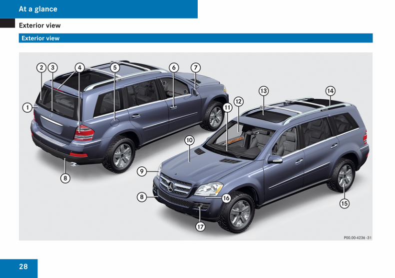
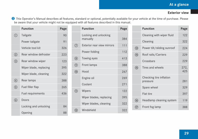
i This Operator’s Manual describes all features, standard or optional, potentially available for your vehicle at the time of purchase. Pleasebe aware that your vehicle might not be equipped with all features described in this manual.
Function Page
1 Tailgate 90
Power tailgate 91
Vehicle tool kit 326
2 Rear window defroster 223
3 Rear window wiper 123
Wiper blade, replacing 395
Wiper blade, cleaning 322
4 Rear lamps 388
5 Fuel filler flap 265
Fuel requirements 436
6 Doors
Locking and unlocking 84
Opening 88
Function Page
Locking and unlockingmanually 384
7 Exterior rear view mirrors 111
Power folding 112
8 Towing eyes 413
9 Front lamps 388
a Hood 267
Engine oil 269
Coolant 271
b Wipers 122
Wiper blades, replacing 395
Wiper blades, cleaning 322
c Windshield 322
Function Page
Cleaning with wiper fluid 122
Cleaning 322
d Power tilt/sliding sunroof 224
e Roof rails/Carriers 229
Crossbars 229
f Tires and wheels 272,425
Checking tire inflationpressure 281
Spare wheel 329
Flat tire 397
g Headlamp cleaning system 119
h Front fog lamp 388
At a glance
Z
Cockpit
30
Cockpit
At a glance
Cockpit
31
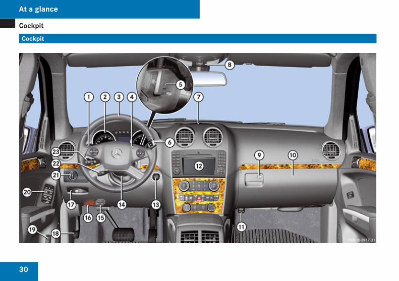
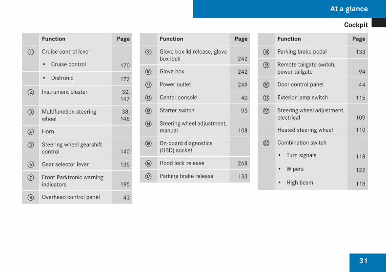
Function Page
1 Cruise control lever
• Cruise control 170
• Distronic 172
2 Instrument cluster 32,147
3 Multifunction steeringwheel
38,148
4 Horn
5 Steering wheel gearshiftcontrol 140
6 Gear selector lever 135
7 Front Parktronic warningindicators 195
8 Overhead control panel 43
Function Page
9 Glove box lid release, glovebox lock 242
a Glove box 242
b Power outlet 249
c Center console 40
d Starter switch 95
e Steering wheel adjustment,manual 108
f On-board diagnostics(OBD) socket
g Hood lock release 268
h Parking brake release 133
Function Page
j Parking brake pedal 133
k Remote tailgate switch,power tailgate 94
l Door control panel 44
m Exterior lamp switch 115
n Steering wheel adjustment,electrical 109
Heated steering wheel 110
o Combination switch
• Turn signals 118
• Wipers 122
• High beam 118
At a glance
Z
Instrument cluster
32
Instrument cluster
At a glance
Instrument cluster
33
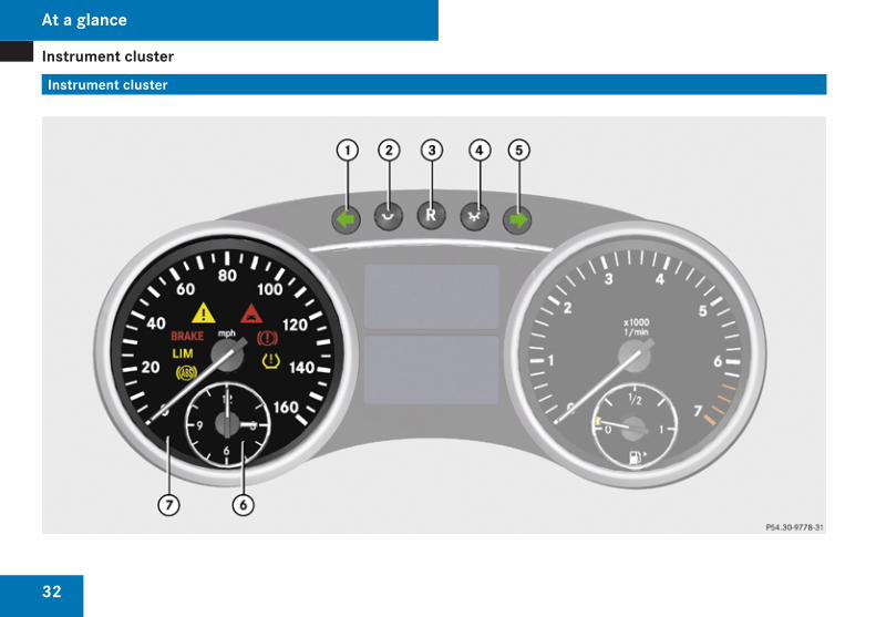
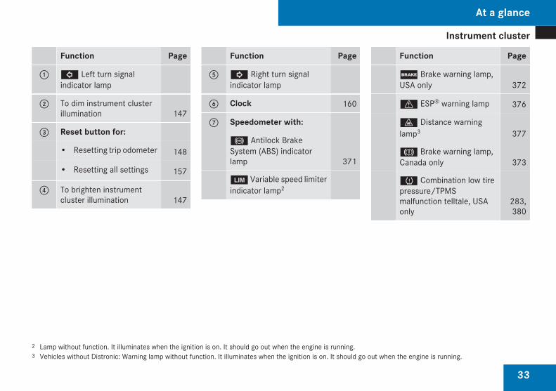
Function Page
1 L Left turn signalindicator lamp
2 To dim instrument clusterillumination 147
3 Reset button for:
• Resetting trip odometer 148
• Resetting all settings 157
4 To brighten instrumentcluster illumination 147
Function Page
5 K Right turn signalindicator lamp
6 Clock 160
7 Speedometer with:
- Antilock BrakeSystem (ABS) indicatorlamp 371
m Variable speed limiterindicator lamp2
Function Page
; Brake warning lamp,USA only 372
v ESP® warning lamp 376
l Distance warninglamp3 377
3 Brake warning lamp,Canada only 373
H Combination low tirepressure/TPMSmalfunction telltale, USAonly
283,380
2 Lamp without function. It illuminates when the ignition is on. It should go out when the engine is running.3 Vehicles without Distronic: Warning lamp without function. It illuminates when the ignition is on. It should go out when the engine is running.
At a glance
Z
Instrument cluster
34
At a glance
Instrument cluster
35
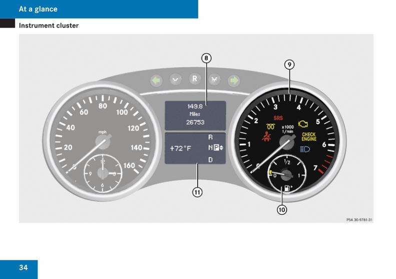
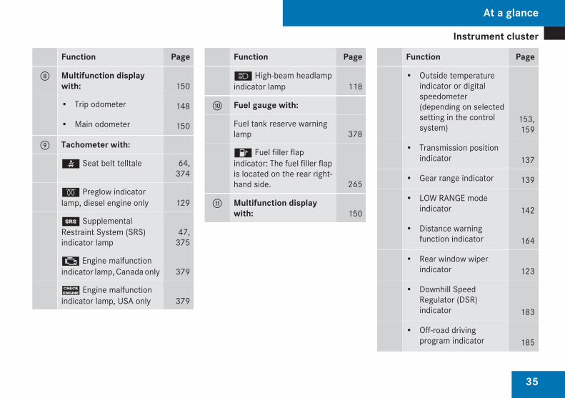
Function Page
8 Multifunction displaywith: 150
• Trip odometer 148
• Main odometer 150
9 Tachometer with:
< Seat belt telltale 64,374
q Preglow indicatorlamp, diesel engine only 129
1 SupplementalRestraint System (SRS)indicator lamp
47,375
± Engine malfunctionindicator lamp, Canada only 379
? Engine malfunctionindicator lamp, USA only 379
Function Page
A High-beam headlampindicator lamp 118
a Fuel gauge with:
Fuel tank reserve warninglamp 378
4 Fuel filler flapindicator: The fuel filler flapis located on the rear right-hand side. 265
b Multifunction displaywith: 150
Function Page
• Outside temperatureindicator or digitalspeedometer(depending on selectedsetting in the controlsystem)
153,159
• Transmission positionindicator 137
• Gear range indicator 139
• LOW RANGE modeindicator 142
• Distance warningfunction indicator 164
• Rear window wiperindicator 123
• Downhill SpeedRegulator (DSR)indicator 183
• Off-road drivingprogram indicator 185
At a glance
Z
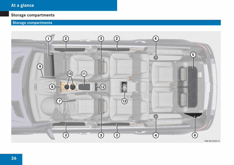
Storage compartments
36
Storage compartments
At a glance
Storage compartments
37
Function Page
1 Glove box 242
2 Door pockets
3 Parcel nets on front seatbackrests 233
4 Cup holders 245
5 Vehicle tool kit, sparewheel 326
Function Page
6 First aid kit 326
7 Holder, e.g. for gas cards 246
8 Storage compartment 242
Ashtray 247
9 Parcel net in frontpassenger footwell 233
Function Page
a Cup holder 245
b Storage compartment withcoin holder 244
c Rear storagecompartments 244
d Cup holder 245
At a glance
Z
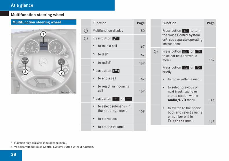
Multifunction steering wheel
38
Multifunction steering wheel Function Page
1 Multifunction display 150
2 Press button s
• to take a call 167
• to dial4 167
• to redial4 167
Press button t
• to end a call 167
• to reject an incomingcall 167
Press button æ or ç
• to select submenus inthe Settings menu 158
• to set values
• to set the volume
Function Page
Press button ! to turnthe Voice Control Systemon5, see separate operatinginstructions
3 Press button è or ·to select next/previousmenu 157
Press button j or kbriefly
• to move within a menu
• to select previous ornext track, scene orstored station withinAudio/DVD menu 153
• to switch to the phonebook and select a nameor number withinTelephone menu 167
4 Function only available in telephone menu.5 Vehicles without Voice Control System: Button without function.
At a glance
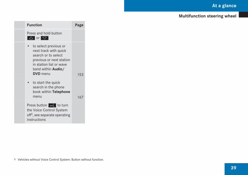
Multifunction steering wheel
39
Function Page
Press and hold buttonj or k
• to select previous ornext track with quicksearch or to selectprevious or next stationin station list or waveband within Audio/DVD menu 153
• to start the quicksearch in the phonebook within Telephonemenu 167
Press button 0 to turnthe Voice Control Systemoff5, see separate operatinginstructions
5 Vehicles without Voice Control System: Button without function.
At a glance
Z
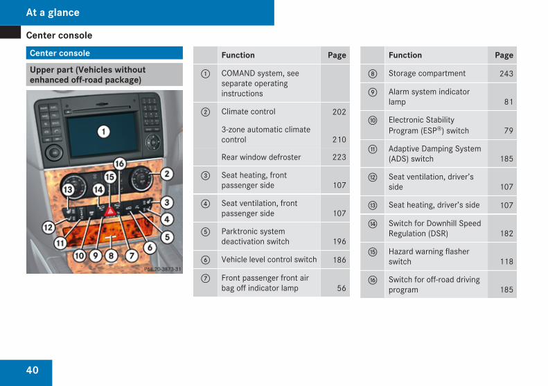
Center console
40
Center console
Upper part (Vehicles withoutenhanced off-road package)
Function Page
1 COMAND system, seeseparate operatinginstructions
2 Climate control 202
3-zone automatic climatecontrol 210
Rear window defroster 223
3 Seat heating, frontpassenger side 107
4 Seat ventilation, frontpassenger side 107
5 Parktronic systemdeactivation switch 196
6 Vehicle level control switch 186
7 Front passenger front airbag off indicator lamp 56
Function Page
8 Storage compartment 243
9 Alarm system indicatorlamp 81
a Electronic StabilityProgram (ESP®) switch 79
b Adaptive Damping System(ADS) switch 185
c Seat ventilation, driver’sside 107
d Seat heating, driver’s side 107
e Switch for Downhill SpeedRegulation (DSR) 182
f Hazard warning flasherswitch 118
g Switch for off-road drivingprogram 185
At a glance
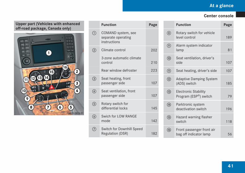
Center console
41
Upper part (Vehicles with enhancedoff-road package, Canada only)
Function Page
1 COMAND system, seeseparate operatinginstructions
2 Climate control 202
3-zone automatic climatecontrol 210
Rear window defroster 223
3 Seat heating, frontpassenger side 107
4 Seat ventilation, frontpassenger side 107
5 Rotary switch fordifferential locks 145
6 Swich for LOW RANGEmode 142
7 Switch for Downhill SpeedRegulation (DSR) 182
Function Page
8 Rotary switch for vehiclelevel control 189
9 Alarm system indicatorlamp 81
a Seat ventilation, driver’sside 107
b Seat heating, driver’s side 107
c Adaptive Damping System(ADS) switch 185
d Electronic StabilityProgram (ESP®) switch 79
e Parktronic systemdeactivation switch 196
f Hazard warning flasherswitch 118
g Front passenger front airbag off indicator lamp 56
At a glance
Z
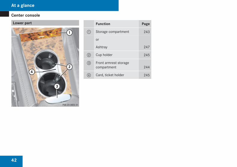
Center console
42
Lower part Function Page
1 Storage compartment 243
or
Ashtray 247
2 Cup holder 245
3 Front armrest storagecompartment 244
4 Card, ticket holder 245
At a glance
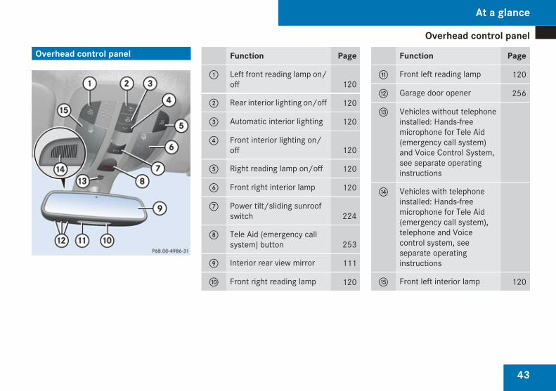
Overhead control panel
43
Overhead control panel Function Page
1 Left front reading lamp on/off 120
2 Rear interior lighting on/off 120
3 Automatic interior lighting 120
4 Front interior lighting on/off 120
5 Right reading lamp on/off 120
6 Front right interior lamp 120
7 Power tilt/sliding sunroofswitch 224
8 Tele Aid (emergency callsystem) button 253
9 Interior rear view mirror 111
a Front right reading lamp 120
Function Page
b Front left reading lamp 120
c Garage door opener 256
d Vehicles without telephoneinstalled: Hands-freemicrophone for Tele Aid(emergency call system)and Voice Control System,see separate operatinginstructions
e Vehicles with telephoneinstalled: Hands-freemicrophone for Tele Aid(emergency call system),telephone and Voicecontrol system, seeseparate operatinginstructions
f Front left interior lamp 120
At a glance
Z
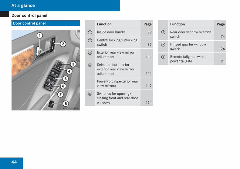
Door control panel
44
Door control panel Function Page
1 Inside door handle 88
2 Central locking/unlockingswitch 89
3 Exterior rear view mirroradjustment 111
4 Selection buttons forexterior rear view mirroradjustment 111
Power-folding exterior rearview mirrors 112
5 Switches for opening/closing front and rear doorwindows 124
Function Page
6 Rear door window overrideswitch 74
7 Hinged quarter windowswitch 126
8 Remote tailgate switch,power tailgate 91
At a glance
45
Vehicle equipment .............................. 46Occupant safety .................................. 46Panic alarm .......................................... 75Driving safety systems ....................... 75Anti-theft systems .............................. 80
Safety and security
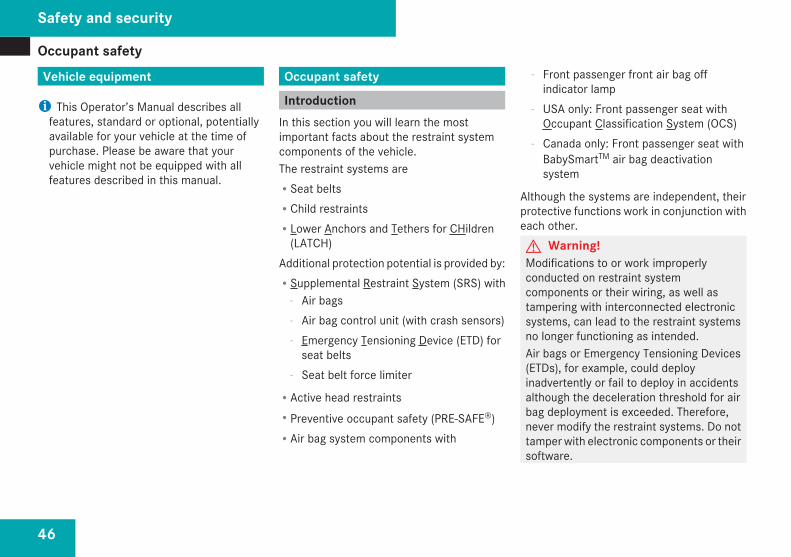
Occupant safety
46
Vehicle equipment
i This Operator’s Manual describes allfeatures, standard or optional, potentiallyavailable for your vehicle at the time ofpurchase. Please be aware that yourvehicle might not be equipped with allfeatures described in this manual.
Occupant safety
IntroductionIn this section you will learn the mostimportant facts about the restraint systemcomponents of the vehicle.The restraint systems areRSeat beltsRChild restraintsRLower Anchors and Tethers for CHildren
(LATCH)Additional protection potential is provided by:RSupplemental Restraint System (SRS) with
- Air bags- Air bag control unit (with crash sensors)- Emergency Tensioning Device (ETD) for
seat belts- Seat belt force limiter
RActive head restraintsRPreventive occupant safety (PRE-SAFE®)RAir bag system components with
- Front passenger front air bag offindicator lamp
- USA only: Front passenger seat withOccupant Classification System (OCS)
- Canada only: Front passenger seat withBabySmartTM air bag deactivationsystem
Although the systems are independent, theirprotective functions work in conjunction witheach other.G Warning!Modifications to or work improperlyconducted on restraint systemcomponents or their wiring, as well astampering with interconnected electronicsystems, can lead to the restraint systemsno longer functioning as intended.Air bags or Emergency Tensioning Devices(ETDs), for example, could deployinadvertently or fail to deploy in accidentsalthough the deceleration threshold for airbag deployment is exceeded. Therefore,never modify the restraint systems. Do nottamper with electronic components or theirsoftware.
Safety and security
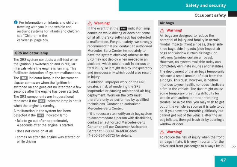
Occupant safety
47
i For information on infants and childrentraveling with you in the vehicle andrestraint systems for infants and children,see “Children in thevehicle” (Y page 68).
SRS indicator lampThe SRS system conducts a self-test whenthe ignition is switched on and in regularintervals while the engine is running. Thisfacilitates detection of system malfunctions.The 1 indicator lamp in the instrumentcluster comes on when the ignition isswitched on and goes out no later than a fewseconds after the engine has been started.The SRS components are in operationalreadiness if the 1 indicator lamp is not litwhen the engine is running.A malfunction in the system has beendetected if the 1 indicator lampRfails to go out after approximately
4 seconds after the engine is startedRdoes not come on at allRcomes on after the engine was started or
while driving
G Warning!In the event that the 1 indicator lampcomes on while driving or does not comeon at all, the SRS self-check has detecteda malfunction. For your safety, we stronglyrecommend that you contact an authorizedMercedes-Benz Center immediately tohave the system checked; otherwise theSRS may not deploy when needed in anaccident, which could result in serious orfatal injury, or it might deploy unexpectedlyand unnecessarily which could also resultin injury.In addition, improper work on the SRScreates a risk of rendering the SRSinoperative or causing unintended air bagdeployment. Work on the SRS musttherefore only be performed by qualifiedtechnicians. Contact an authorizedMercedes-Benz Center.If it is necessary to modify an air bag systemto accommodate a person with disabilities,contact an authorized Mercedes-BenzCenter or call our Customer AssistanceCenter at 1-800-FOR-MERCedes(1-800-367-6372) for details.
Air bags
G Warning!Air bags are designed to reduce thepotential of injury and fatality in certainfrontal impacts (front air bags, driver sideknee bag), side impacts (side impact airbags and window curtain air bags), orrollovers (window curtain air bags).However, no system available today cancompletely eliminate injuries and fatalities.The deployment of the air bags temporarilyreleases a small amount of dust from theair bags. This dust, however, is neitherinjurious to your health, nor does it indicatea fire in the vehicle. The dust might causesome temporary breathing difficulty forpeople with asthma or other breathingtrouble. To avoid this, you may wish to getout of the vehicle as soon as it is safe to doso. If you have any breathing difficulty butcannot get out of the vehicle after the airbag inflates, then get fresh air by opening awindow or door.
G Warning!To reduce the risk of injury when the frontair bags inflate, it is very important for thedriver and front passenger to always be in
Safety and security
Z
Occupant safety
48
a properly seated position and to wear theirrespective seat belt.For maximum protection in the event of acollision always be in normal seatedposition with your back against the seatbackrest. Fasten your seat belt and makesure it is properly positioned on your body.Since the air bag inflates with considerablespeed and force, a proper seating positionand correct positioning of the hands on thesteering wheel will help to keep you at asafe distance from the air bag. Occupantswho are not wearing their seat belt, are notseated properly or are too close to the airbag can be seriously injured or killed by anair bag as it inflates with great forceinstantaneously:RSit with the seat belt properly fastened in
a position that is as upright as possiblewith your back against the seat backrest.RMove the driver seat as far back as
possible, still permitting properoperation of vehicle controls. Thedistance from the center of the driver’schest to the center of the air bag coveron the steering wheel must be at least10 inches (25 cm) or more. You shouldbe able to accomplish this by adjusting
the seat and steering wheel. If you haveany difficulties, please contact anauthorized Mercedes-Benz Center.RDo not lean your head or chest close to
the steering wheel or dashboard.RKeep hands on the outside of the steering
wheel rim. Placing hands and arms insidethe rim can increase the risk andpotential severity of hand/arm injurywhen the driver’s front air bag inflates.RAdjust the front passenger seat as far as
possible rearward from the dashboardwhen the seat is occupied.ROccupants, especially children, should
never place their bodies or lean theirheads in the area of the door where theside impact air bag inflates. This couldresult in serious injuries or death shouldthe side impact air bag be deployed.Always sit as upright as possible, wearthe seat belt properly and use anappropriately sized infant restraint,toddler restraint, or booster seatrecommended for the size and weight ofthe child.RCanada only: Children 12 years old and
under must never ride in the front seat,
except in a Mercedes-Benz authorizedBabySmartTM compatible child seat,which operates with the BabySmartTM airbag deactivation system installed in thevehicle to deactivate the front passengerfront air bag when it is installed properly.Otherwise they will be struck by the airbag when it inflates in a crash. If thishappens, serious or fatal injury willresult.
Failure to follow these instructions canresult in severe injuries to you or otheroccupants.If you sell your vehicle, it is important thatyou make the buyer aware of this safetyinformation. Be sure to give the buyer thisOperator’s Manual.
G Warning!Accident research shows that the safestplace for children in an automobile is in therear seat.There is a possibility for a side impact airbag related injury if occupants, especiallychildren, are not properly seated orrestrained when next to a side impact airbag which needs to deploy rapidly in a sideimpact in order to do its job.
Safety and security
Occupant safety
49
To help avoid the possibility of injury,please follow these guidelines:
(1) Always sit as upright as possible,properly use the seat belts, andfor children 12 years old andunder, use an appropriatelysized infant restraint, toddlerrestraint, or booster seatrecommended for the size andweight of the child.
(2) Always wear seat belts properly.
Air bags are designed to deploy only in certainfrontal impacts (front air bags, driver sideknee bag), side impacts (side impact andwindow curtain air bags) which exceed presetdeployment thresholds, and in certainrollovers (window curtain air bags). Only inthe event of such a situation will they providetheir supplemental protection.The driver and passengers should alwayswear their seat belts. Otherwise it is notpossible for the air bags to provide theirsupplemental protection.In case of other types of impacts and impactsbelow air bag deployment thresholds, airbags will not deploy. The driver andpassengers will then be protected to theextent possible by a properly fastened seat
belt. A properly fastened seat belt is alsoneeded to provide the best possibleprotection in a rollover.Air bags are not a substitute for seat belts.Always wear your seat belt, regardless ofwhether or not your vehicle is equipped withair bags.It is important to your safety and that of yourpassengers that you replace deployed airbags and repair any malfunctioning air bagsto make sure the vehicle will continue toprovide supplemental crash protection foroccupants.
Safety guidelines for the seat belt,Emergency Tensioning Device (ETD)and air bag
G Warning!RDamaged seat belts or seat belts that
have been subjected to stress in anaccident must be replaced and theiranchoring points must also be checked.Only use seat belts installed or suppliedby an authorized Mercedes-Benz Center.RAir bags and pyrotechnic emergency
tensioning devices (ETDs) containperchlorate material, which may require
special handling and regard for theenvironment. Check with your localgovernment’s disposal guidelines.California residents, seewww.dtsc.ca.gov/HazardousWaste/Perchlorate/index.cfm.RAir bags and ETDs are designed to
function on a one-time-only basis. An airbag or ETD that is deployed must bereplaced. PRE-SAFE® has electricallyoperated reversible pre-tensioners inaddition to the pyrotechnic ETDs.RDo not pass seat belts over sharp edges.
They could tear.RDo not make any modification that could
change the effectiveness of the seatbelts.RDo not bleach or dye seat belts as this
may severely weaken them. In a crashthey may not be able to provide adequateprotection.RNo modifications of any kind may be
made to any components or wiring of theSRS. This includes changing or removingany component or part of the SRS, theinstallation of additional trim material,seat covers, badges, etc. over the
Safety and security
Z
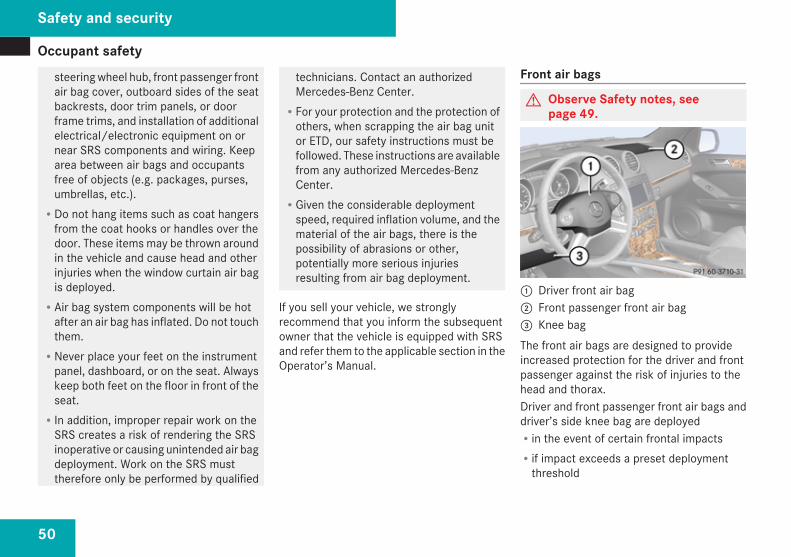
Occupant safety
50
steering wheel hub, front passenger frontair bag cover, outboard sides of the seatbackrests, door trim panels, or doorframe trims, and installation of additionalelectrical/electronic equipment on ornear SRS components and wiring. Keeparea between air bags and occupantsfree of objects (e.g. packages, purses,umbrellas, etc.).RDo not hang items such as coat hangers
from the coat hooks or handles over thedoor. These items may be thrown aroundin the vehicle and cause head and otherinjuries when the window curtain air bagis deployed.RAir bag system components will be hot
after an air bag has inflated. Do not touchthem.RNever place your feet on the instrument
panel, dashboard, or on the seat. Alwayskeep both feet on the floor in front of theseat.RIn addition, improper repair work on the
SRS creates a risk of rendering the SRSinoperative or causing unintended air bagdeployment. Work on the SRS musttherefore only be performed by qualified
technicians. Contact an authorizedMercedes-Benz Center.RFor your protection and the protection of
others, when scrapping the air bag unitor ETD, our safety instructions must befollowed. These instructions are availablefrom any authorized Mercedes-BenzCenter.RGiven the considerable deployment
speed, required inflation volume, and thematerial of the air bags, there is thepossibility of abrasions or other,potentially more serious injuriesresulting from air bag deployment.
If you sell your vehicle, we stronglyrecommend that you inform the subsequentowner that the vehicle is equipped with SRSand refer them to the applicable section in theOperator’s Manual.
Front air bags
G Observe Safety notes, seepage 49.
1 Driver front air bag2 Front passenger front air bag3 Knee bagThe front air bags are designed to provideincreased protection for the driver and frontpassenger against the risk of injuries to thehead and thorax.Driver and front passenger front air bags anddriver’s side knee bag are deployedRin the event of certain frontal impactsRif impact exceeds a preset deployment
threshold
Safety and security
Occupant safety
51
Rif the system determines that air bagdeployment can offer additional protectionto that provided by the seat beltRdepending on whether the seat belt is in
useRindependently of the side impact air bags
and/or the window curtain air bagsThe front air bags in this vehicle have beendesigned to inflate in two stages. This allowsthe air bags to have different rates of inflationthat are based on the vehicle decelerationrate as assessed by the air bag control unit.Vehicles with OCS, USA only: On the frontpassenger side, front air bag 2 deploymentis additionally influenced by the passenger’sweight category as identified by the OccupantClassification System (OCS) (Y page 53).Vehicles with OCS, USA only: The lighter thefront passenger side occupant, the higher thevehicle deceleration rate required for secondstage inflation of front air bag 2.The air bags will not deploy in impacts whichdo not exceed the system’s presetdeployment thresholds. You will then beprotected by the fastened seat belts.The front air bags will not deployed in theevent of a rollover unless the vehicle’s rate oflongitudinal deceleration or acceleration
exceeds the preset deployment threshold forthe front air bags.The front passenger front air bag 2 will onlybe deployed ifRvehicles with OCS, USA only: the system,
based on OCS weight sensor readings,detects that the front passenger seat isoccupiedRthe 59 indicator lamp in the
center console is not lit(USA only: (Y page 56),Canada only: (Y page 58))Rthe impact exceeds a preset deployment
threshold
! Vehicles with BabySmartTM air bagdeactivation system, Canada only: Do notplace objects heavier than 20 lb (9 kg) onthe front passenger seat. This could causethe front or side impact air bag on the frontpassenger side to deploy in a crash whichexceeds the system’s deploymentthreshold.
Knee bagThe knee bag 3 is located on the driver sidelower instrument panel. It is designed tooperate together with the driver front air bag
in certain frontal impacts exceeding a presetdeployment threshold. The knee bag 3operates best in conjunction with a properlypositioned and fastened seat belt.
Side impact air bags
G Observe Safety notes, seepage 49.
G Warning!The pressure sensors for side impact airbag control are located in the doors. Do notmodify any components of the doors ordoor trim panels including, for example, theaddition of door speakers.Improper repair work on the doors or themodification or addition of components tothe doors create a risk of rendering the sideimpact air bags inoperative or causingunintended air bag deployment. Work onthe doors must therefore only beperformed by qualified technicians.Contact an authorized Mercedes-BenzCenter
Safety and security
Z
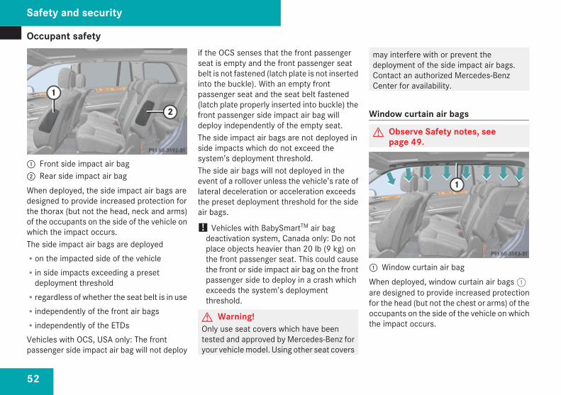
Occupant safety
52
1 Front side impact air bag2 Rear side impact air bagWhen deployed, the side impact air bags aredesigned to provide increased protection forthe thorax (but not the head, neck and arms)of the occupants on the side of the vehicle onwhich the impact occurs.The side impact air bags are deployedRon the impacted side of the vehicleRin side impacts exceeding a preset
deployment thresholdRregardless of whether the seat belt is in useRindependently of the front air bagsRindependently of the ETDsVehicles with OCS, USA only: The frontpassenger side impact air bag will not deploy
if the OCS senses that the front passengerseat is empty and the front passenger seatbelt is not fastened (latch plate is not insertedinto the buckle). With an empty frontpassenger seat and the seat belt fastened(latch plate properly inserted into buckle) thefront passenger side impact air bag willdeploy independently of the empty seat.The side impact air bags are not deployed inside impacts which do not exceed thesystem’s deployment threshold.The side air bags will not deployed in theevent of a rollover unless the vehicle’s rate oflateral deceleration or acceleration exceedsthe preset deployment threshold for the sideair bags.
! Vehicles with BabySmartTM air bagdeactivation system, Canada only: Do notplace objects heavier than 20 lb (9 kg) onthe front passenger seat. This could causethe front or side impact air bag on the frontpassenger side to deploy in a crash whichexceeds the system’s deploymentthreshold.
G Warning!Only use seat covers which have beentested and approved by Mercedes-Benz foryour vehicle model. Using other seat covers
may interfere with or prevent thedeployment of the side impact air bags.Contact an authorized Mercedes-BenzCenter for availability.
Window curtain air bags
G Observe Safety notes, seepage 49.
1 Window curtain air bagWhen deployed, window curtain air bags 1are designed to provide increased protectionfor the head (but not the chest or arms) of theoccupants on the side of the vehicle on whichthe impact occurs.
Safety and security
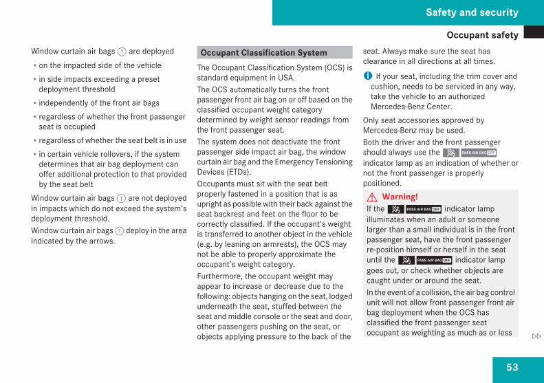
Occupant safety
53
Window curtain air bags 1 are deployedRon the impacted side of the vehicleRin side impacts exceeding a preset
deployment thresholdRindependently of the front air bagsRregardless of whether the front passenger
seat is occupiedRregardless of whether the seat belt is in useRin certain vehicle rollovers, if the system
determines that air bag deployment canoffer additional protection to that providedby the seat belt
Window curtain air bags 1 are not deployedin impacts which do not exceed the system’sdeployment threshold.Window curtain air bags 1 deploy in the areaindicated by the arrows.
Occupant Classification SystemThe Occupant Classification System (OCS) isstandard equipment in USA.The OCS automatically turns the frontpassenger front air bag on or off based on theclassified occupant weight categorydetermined by weight sensor readings fromthe front passenger seat.The system does not deactivate the frontpassenger side impact air bag, the windowcurtain air bag and the Emergency TensioningDevices (ETDs).Occupants must sit with the seat beltproperly fastened in a position that is asupright as possible with their back against theseat backrest and feet on the floor to becorrectly classified. If the occupant’s weightis transferred to another object in the vehicle(e.g. by leaning on armrests), the OCS maynot be able to properly approximate theoccupant’s weight category.Furthermore, the occupant weight mayappear to increase or decrease due to thefollowing: objects hanging on the seat, lodgedunderneath the seat, stuffed between theseat and middle console or the seat and door,other passengers pushing on the seat, orobjects applying pressure to the back of the
seat. Always make sure the seat hasclearance in all directions at all times.
i If your seat, including the trim cover andcushion, needs to be serviced in any way,take the vehicle to an authorizedMercedes-Benz Center.
Only seat accessories approved byMercedes-Benz may be used.Both the driver and the front passengershould always use the 59indicator lamp as an indication of whether ornot the front passenger is properlypositioned.G Warning!If the 59 indicator lampilluminates when an adult or someonelarger than a small individual is in the frontpassenger seat, have the front passengerre-position himself or herself in the seatuntil the 59 indicator lampgoes out, or check whether objects arecaught under or around the seat.In the event of a collision, the air bag controlunit will not allow front passenger front airbag deployment when the OCS hasclassified the front passenger seatoccupant as weighting as much as or less
Safety and security
Z
Occupant safety
54
than a typical 12-month-old child in astandard child restraint or if the frontpassenger seat is classified as being empty.When the OCS senses that the frontpassenger seat occupant is classified asbeing up to or less than the weight of atypical 12-month-old child in a standardchild restraint, the 59indicator lamp will illuminate when theengine is started and remain illuminated,indicating that the front passenger front airbag is deactivated.When the OCS senses that the frontpassenger seat is classified as being empty,the 59 indicator lamp willilluminate when the engine is started andremain illuminated, indicating that the frontpassenger front air bag is deactivated.When the OCS senses that the frontpassenger seat occupant is classified asbeing heavier than the weight of a typical12-month-old child seated in a standardchild restraint or as being a small individual(such as a young teenager or a small adult),the 59 indicator lamp willilluminate for approximately 6 secondswhen the engine is started and then,depending on occupant weight sensor
readings from the seat, remain illuminatedor go out. With the 59indicator lamp illuminated, the frontpassenger front air bag is deactivated. Withthe 59 indicator lamp out, thefront passenger front air bag is activated.When the OCS senses that the frontpassenger seat occupant is classified as anadult or someone larger than a smallindividual, the 59 indicatorlamp will illuminate for approximately 6seconds when the engine is started andthen go out, indicating that the frontpassenger front air bag is activated.If the 59 indicator lamp isilluminated, the front passenger front airbag is deactivated and will not be deployed.If the 59 indicator lamp is notilluminated, the front passenger front airbag is activated and will be deployedRin the event of certain frontal impactsRif impact exceeds a preset deployment
thresholdRindependently of the side impact air bags
If the front passenger front air bag isdeployed, the rate of inflation will beinfluenced byRthe rate of relevant vehicle deceleration
as assessed by the air bag control unitRthe front passenger’s weight category as
identified by the OCS
For information about air bag displaymessages (Y page 335).G Warning!According to accident statistics, childrenare safer when properly restrained in therear seating positions than in the frontseating position. Thus, we stronglyrecommend that children be placed in therear seats whenever possible. Regardlessof seating position, children 12 years oldand under must be seated and properlysecured in an appropriate infant restraint,toddler restraint, or booster seatrecommended for the size and weight of thechild.The infant or child restraint must beproperly secured with the vehicle’s seatbelt, the seat belt and top tether strap, orlower anchors and top tether strap, fully in
Safety and security
Occupant safety
55
accordance with the child seatmanufacturer’s instructions.Occupants, especially children, shouldalways sit as upright as possible, wear theseat belt properly and use an appropriatelysized infant restraint, toddler restraint, orbooster seat recommended for the size andweight of the child.Children can be killed or seriously injuredby an inflating air bag. Note the followingimportant information when circumstancesrequire you to place a child in the frontpassenger seat:RYour vehicle is equipped with air bag
technology designed to deactivate thefront passenger front air bag in yourvehicle when the system senses theweight of a typical 12-month-old child orless along with the weight of a standardappropriate child restraint on the frontpassenger seat.RA child in a rear-facing child restraint on
the front passenger seat will be seriouslyinjured or even killed if the frontpassenger front air bag inflates in acollision which could occur under somecircumstances, even with the air bagtechnology installed in your vehicle. The
only means to completely eliminate thisrisk is to never place a child in a rear-facing child restraint in the front seat. Wetherefore strongly recommend that youalways place a child in a rear-facing childrestraint in a backseat.RIf you must install a rear-facing child
restraint on the front passenger seatbecause circumstances require you to doso, make sure the 59indicator lamp is illuminated, indicatingthat the front passenger front air bag isdeactivated. Should the 59indicator lamp not illuminate or go outwhile the restraint is installed, pleasecheck installation. Periodically check the59 indicator lamp whiledriving to make sure the59 indicator lamp isilluminated. If the 59indicator lamp goes out or remains out,do not transport a child on the frontpassenger seat until the system has beenrepaired.A child in a rear-facing child restraint onthe front passenger seat will be seriously
injured or even killed if the frontpassenger front air bag inflates.RIf you have to place a child in a forward-
facing child restraint on the frontpassenger seat, move the seat as farback as possible, use the proper childrestraint recommended for the age, sizeand weight of the child, and secure childrestraint with the vehicle’s seat beltaccording to the child seatmanufacturer’s instructions. For childrenlarger than the typical 12-month-oldchild, the front passenger front air bagmay or may not be activated.
Deployment of the driver front air bag doesnot mean that the front passenger front airbag also should have deployed.The OCS may have determined:Rthat the seat was empty or occupied by the
weight up to or less than that of a typical12-month-old child seated in a standardchild restraint – both instances where thesystem suppresses deployment of the frontpassenger front air bag even though theimpact met the criteria and was of
Safety and security
Z
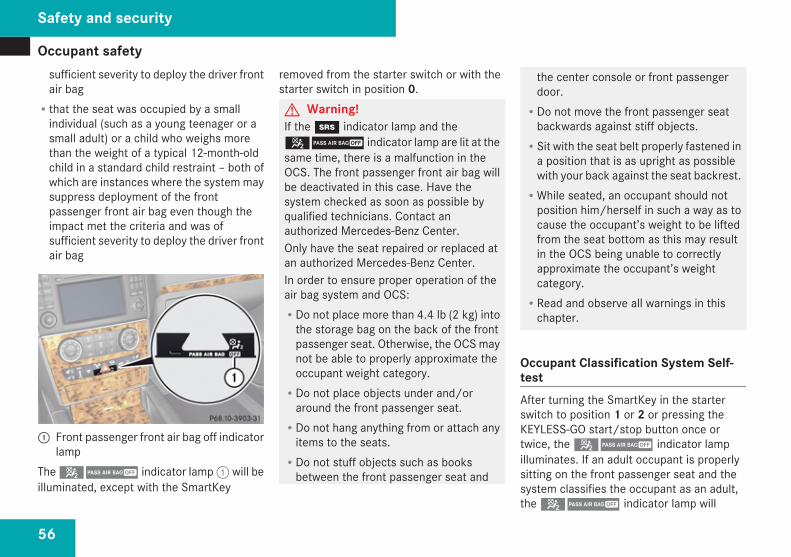
Occupant safety
56
sufficient severity to deploy the driver frontair bagRthat the seat was occupied by a small
individual (such as a young teenager or asmall adult) or a child who weighs morethan the weight of a typical 12-month-oldchild in a standard child restraint – both ofwhich are instances where the system maysuppress deployment of the frontpassenger front air bag even though theimpact met the criteria and was ofsufficient severity to deploy the driver frontair bag
1 Front passenger front air bag off indicatorlamp
The 59 indicator lamp 1 will beilluminated, except with the SmartKey
removed from the starter switch or with thestarter switch in position 0.G Warning!If the 1 indicator lamp and the59 indicator lamp are lit at thesame time, there is a malfunction in theOCS. The front passenger front air bag willbe deactivated in this case. Have thesystem checked as soon as possible byqualified technicians. Contact anauthorized Mercedes-Benz Center.Only have the seat repaired or replaced atan authorized Mercedes-Benz Center.In order to ensure proper operation of theair bag system and OCS:RDo not place more than 4.4 lb (2 kg) into
the storage bag on the back of the frontpassenger seat. Otherwise, the OCS maynot be able to properly approximate theoccupant weight category.RDo not place objects under and/or
around the front passenger seat.RDo not hang anything from or attach any
items to the seats.RDo not stuff objects such as books
between the front passenger seat and
the center console or front passengerdoor.RDo not move the front passenger seat
backwards against stiff objects.RSit with the seat belt properly fastened in
a position that is as upright as possiblewith your back against the seat backrest.RWhile seated, an occupant should not
position him/herself in such a way as tocause the occupant’s weight to be liftedfrom the seat bottom as this may resultin the OCS being unable to correctlyapproximate the occupant’s weightcategory.RRead and observe all warnings in this
chapter.
Occupant Classification System Self-testAfter turning the SmartKey in the starterswitch to position 1 or 2 or pressing theKEYLESS-GO start/stop button once ortwice, the 59 indicator lampilluminates. If an adult occupant is properlysitting on the front passenger seat and thesystem classifies the occupant as an adult,the 59 indicator lamp will
Safety and security
Occupant safety
57
illuminate and go out after approximately 6seconds.If the seat is not occupied and the systemclassifies the front passenger seat as beingempty, the 59 indicator lampwill illuminate and not go out.G Warning!If the 59 indicator lamp doesnot illuminate, the system is notfunctioning. You must contact anauthorized Mercedes-Benz Center beforeseating any child on the front passengerseat.
For more information, see the “Practicalhints” section (Y page 381).G Warning!Never place anything between seat cushionand child seat (e.g. pillow), since it reducesthe effectiveness of the OCS. The bottomof the child seat must make full contactwith the passenger seat cushion. Anincorrectly mounted child seat could causeinjuries to the child in case of an accident,instead of increasing protection for thechild.Follow the manufacturer’s instructions forinstallation of child seats.
BabySmart™ air bag deactivationsystem
The BabySmartTM air bag deactivation systemis standard equipment in Canada.G Warning!According to accident statistics, childrenare safer when properly restrained in therear seating positions than in the frontseating position. Thus, we stronglyrecommend that children be placed in therear seats whenever possible. Regardlessof seating position, children 12 years oldand under must be seated and properlysecured in an appropriate infant restraint,toddler restraint, or booster seatrecommended for the size and weight of thechild.The infant or child restraint must beproperly secured with the vehicle’s seatbelt, the seat belt and top tether strap, orlower anchors and top tether strap, fully inaccordance with the child seatmanufacturer’s instructions.Occupants, especially children, shouldalways sit as upright as possible, wear theseat belt properly and use an appropriatelysized infant restraint, toddler restraint, or
booster seat recommended for the size andweight of the child.Children can be killed or seriously injuredby an inflating air bag. Note the followingimportant information when circumstancesrequire you to place a child in the frontpassenger seat:RChildren 12 years old and under must
never ride in the front seat, except in aMercedes-Benz authorizedBabySmartTM compatible child seat,which operates with the BabySmartTM
system installed in the vehicle todeactivate the front passenger front airbag when it is installed properly.Otherwise they will be struck by the airbag when it inflates in a crash. If thishappens, serious or fatal injury willresult.RA child in a rear-facing child restraint on
the front passenger seat will be seriouslyinjured or even killed if the frontpassenger front air bag inflates in acollision which could occur under somecircumstances, even with the air bagtechnology installed in your vehicle. Theonly means to completely eliminate thisrisk is to never place a child in a rear-
Safety and security
Z
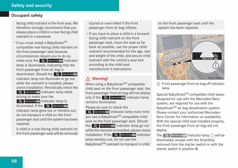
Occupant safety
58
facing child restraint in the front seat. Wetherefore strongly recommend that youalways place a child in a rear-facing childrestraint in a backseat.RIf you must install a BabySmartTM
compatible rear-facing child restraint onthe front passenger seat becausecircumstances require you to do so,make sure the 59 indicatorlamp is illuminated, indicating that thefront passenger front air bag isdeactivated. Should the 59indicator lamp not illuminate or go outwhile the restraint is installed, pleasecheck installation. Periodically check the59 indicator lamp whiledriving to make sure the59 indicator lamp isilluminated. If the 59indicator lamp goes out or remains out,do not transport a child on the frontpassenger seat until the system has beenrepaired.A child in a rear-facing child restraint onthe front passenger seat will be seriously
injured or even killed if the frontpassenger front air bag inflates.RIf you have to place a child in a forward-
facing child restraint on the frontpassenger seat, move the seat as farback as possible, use the proper childrestraint recommended for the age, sizeand weight of the child, and secure childrestraint with the vehicle’s seat beltaccording to the child seatmanufacturer’s instructions.
G Warning!When using a BabySmartTM compatiblechild seat on the front passenger seat, thefront passenger front air bag will not deployonly if the 59 indicator lampremains illuminated.Please be sure to check the59 indicator lamp every timeyou use a BabySmartTM compatible childseat on the front passenger seat. Shouldthe 59 indicator lamp go outwhile the restraint is installed, please checkinstallation. If the 59 indicatorlamp remains out, do not use theBabySmartTM restraint to transport a child
on the front passenger seat until thesystem has been repaired.
1 Front passenger front air bag off indicatorlamp
Special BabySmartTM compatible child seats,designed for use with the Mercedes-Benzsystem, are required for use with theBabySmartTM air bag deactivation system.Please contact your authorized Mercedes-Benz Center for information on availability.With the special child seat installed properly,the front passenger front air bag will notdeploy.The 59 indicator lamp 1 will beilluminated, except with the SmartKeyremoved from the starter switch or with thestarter switch in position 0.
Safety and security
Occupant safety
59
The system does not deactivate the sideimpact air bag, the window curtain air bag andthe Emergency Tensioning Device (ETD).
Self-test BabySmartTM without specialchild seat installedAfter turning the SmartKey in the starterswitch to position 1 or 2 or pressing theKEYLESS-GO start/stop button once ortwice, the 59 indicator lampcomes on for approximately 6 seconds andthen goes out.If the 59 indicator lamp shouldnot come on or is continuously lit, the systemis not functioning. You must see anauthorized Mercedes-Benz Center beforeseating any child on the passenger seat. Moreinformation can be found in the “Practicalhints” section (Y page 332).G Warning!Do not place powered-on laptops, mobilephones, electronic tags such as those usedin ski passes and like electronic devices onthe front passenger seat. Signals from suchdevices may interfere with theBabySmartTM air bag deactivation system.Such signal interference may cause the
59 indicator lamp not to comeon during self-test or be continuously lit,indicating that the system is notfunctioning.
G Warning!The BabySmartTM air bag deactivationsystem will ONLY work with a special childseat designed to operate with it. It will notwork with child seats which are notBabySmartTM compatible.Never place anything between seat cushionand child seat (e.g. pillow), since it reducesthe effectiveness off the BabySmartTM airbag deactivation system. The bottom of thechild seat must make full contact with thepassenger seat cushion. An incorrectlymounted child seat could cause injuries tothe child in case of an accident, instead ofprotecting the child.Follow the manufacturer’s instructions forinstallation of special child seats.
Seat belts
Safety notesThe use of seat belts and infant and childrestraint systems is required by law in all 50states, the District of Columbia, the U.S.territories and all Canadian provinces.Even where this is not the case, all vehicleoccupants should have their seat beltsfastened whenever the vehicle is in motion.For information on infants and childrentraveling with you in the vehicle and restraintsystems for infants and children, see“Children in the vehicle” (Y page 68).G Warning!Always fasten your seat belt before drivingoff. Always make sure all of yourpassengers are properly restrained. Youand your passengers should always wearseat belts.Failure to wear and properly fasten andposition your seat belt greatly increasesyour risk of injuries and their likely severityin an accident.If you are ever in an accident, your injuriescan be considerably more severe withoutyour seat belt properly buckled. Without
Safety and security
Z
Occupant safety
60
your seat belt buckled, you are much morelikely to hit the interior of the vehicle or beejected from it. You can be seriously injuredor killed.In the same crash, the possibility of injuryor death is lessened if you are properlywearing your seat belt. The air bags canonly protect as intended if the occupantsare properly wearing their seat belts.
G Warning!Never ride in a moving vehicle with the seatbackrest in an excessively reclined positionas this can be dangerous. You could slideunder the seat belt in a collision. If you slideunder it, the seat belt would apply force atthe abdomen or neck. That could causeserious or even fatal injuries. The seatbackrest and seat belt provide the bestrestraint when the wearer is in a positionthat is as upright as possible and the seatbelt is properly positioned on the body.
G Warning!Never let more people ride in the vehiclethan there are seat belts available. Makesure everyone riding in the vehicle iscorrectly restrained with a separate seat
belt. Never use a seat belt for more thanone person at a time.
G Warning!Damaged seat belts or seat belts that havebeen subjected to stress in an accidentmust be replaced and their anchoringpoints must also be checked.Only use seat belts which have beenapproved by Mercedes-Benz.Do not make any modifications to the seatbelts. This can lead to unintendedactivation of the ETDs or to their failure toactivate when necessary.Do not bleach or dye seat belts as this mayseverely weaken them. In a crash they maynot be able to provide adequate protection.Have all work carried out only by qualifiedtechnicians. Contact an authorizedMercedes-Benz Center.
Proper use of seat belts
G Warning!USE SEAT BELTS PROPERLYRSeat belts can only work when used
properly. Never wear seat belts in any
other way than as described in thissection, as that could result in seriousinjuries in case of an accident.REach occupant should wear their seat
belt at all times, because seat belts helpreduce the likelihood of and potentialseverity of injuries in accidents, includingrollovers. The integrated restraint systemincludes SRS (driver front air bag, driverside knee bag, front passenger front airbag, side impact air bags, window curtainair bags for side windows), EmergencyTensioning Devices (ETDs), seat beltforce limiters, and front seat kneebolsters.The system is designed to enhance theprotection offered to properly beltedoccupants in certain frontal (front airbags, driver side knee bag and ETDs) andside (side impact air bags, windowcurtain air bags, and ETDs) impactswhich exceed preset deploymentthresholds and in certain rollovers(window curtain air bags and ETDs).RNever wear the shoulder belt under your
arm, against your neck or off yourshoulder. In a frontal crash, your bodywould move too far forward. That would
Safety and security
Occupant safety
61
increase the chance of head and neckinjuries. The seat belt would also applytoo much force to the ribs or abdomen,which could severely injure internalorgans such as your liver or spleen.Adjust the seat belt so that the shouldersection is located as close as possible tothe middle of the shoulder (it should nottouch the neck). Never pass the shoulderportion of the seat belt under your arm.For this purpose, you can adjust theheight of the seat belt outlet.RPosition the lap belt as low as possible
on your hips and not across theabdomen. If the lap belt is positionedacross your abdomen, it could causeserious injuries in a crash.RNever wear seat belts over rigid or
breakable objects in or on your clothing,such as eyeglasses, pens, keys etc., asthese might cause injuries.RMake sure the seat belt is always fitted
snugly. Take special care of this whenwearing loose clothing.RNever use a seat belt for more than one
person at a time. Do not fasten a seat belt
around a person and another person orother objects at the same time.RSeat belts should not be worn twisted. In
a crash, you would not have the full widthof the seat belt to distribute impactforces. The twisted seat belt against yourbody could cause injuries.RPregnant women should also always use
a lap/shoulder belt. The lap belt portionshould be positioned as low as possibleon the hips to avoid any possiblepressure on the abdomen.RPlace the seat backrest in a position that
is as upright as possible.RCheck your seat belt during travel to
make sure it is properly positioned.RNever place your feet on the instrument
panel, dashboard, or on the seat. Alwayskeep both feet on the floor in front of theseat.RWhen using a seat belt to secure infant
restraints, toddler restraints, or childrenin booster seats, always follow the childseat manufacturer’s instructions.
G Warning!Do not pass seat belts over sharp edges.They could tear.Do not allow the seat belt to get caught inthe door or in the seat adjustmentmechanism. This could damage the seatbelt.Never attempt to make modifications toseat belts. This could impair theeffectiveness of the seat belts.Do not bleach or dye seat belts as this mayseverely weaken them. In a crash, they maynot be able to provide adequate protection.Damaged seat belts or seat belts that havebeen subjected to stress in an accidentmust be replaced and their anchoringpoints must also be checked. Contact anauthorized Mercedes-Benz Center.
Fastening the seat belts
G Warning!Always fasten your seat belt before drivingoff. Always make sure all of yourpassengers are properly restrained. Youand your passengers should always wearseat belts.
Safety and security
Z
Occupant safety
62
Failure to wear and properly fasten andposition your seat belt greatly increasesyour risk of injuries and their likely severityin an accident.If you are ever in an accident, your injuriescan be considerably more severe withoutyour seat belt properly buckled. Withoutyour seat belt buckled, you are much morelikely to hit the interior of the vehicle or beejected from it. You can be seriously injuredor killed.In the same crash, the possibility of injuryor death is lessened if you are properlywearing your seat belt. The air bags canonly protect as intended if the occupantsare properly wearing their seat belts.
G Warning!According to accident statistics, childrenare safer when properly restrained in therear seating positions than in the frontseating position. Thus, we stronglyrecommend that children be placed in therear seats whenever possible. Regardlessof seating position, children 12 years oldand under must be seated and properlysecured in an appropriately sized infantrestraint, toddler restraint, or booster seatrecommended for the size and weight of the
child. For additional information, see“Children in the vehicle”.A child’s risk of serious or fatal injuries issignificantly increased if the child restraintsare not properly secured in the vehicleand/or the child is not properly secured inthe child restraint.
G Warning!Vehicles with BabySmartTM air bagdeactivation system, Canada only: Children12 years old and under must never ride inthe front seat, except in a Mercedes-Benzauthorized BabySmartTM compatible childseat, which operates with theBabySmartTM system installed in thevehicle to deactivate the front passengerfront air bag when it is installed properly.Otherwise they will be struck by the air bagwhen it inflates in a crash. If this happens,serious or fatal injury will result.
G Warning!Never let more people ride in the vehiclethan there are seat belts available. Makesure everyone riding in the vehicle iscorrectly restrained with a separate seatbelt. Never use a seat belt for more thanone person at a time.
G Warning!Never ride in a moving vehicle with the seatbackrest in an excessively reclined positionas this can be dangerous. You could slideunder the seat belt in a collision. If you slideunder it, the seat belt would apply force atthe abdomen or neck. That could causeserious or even fatal injuries. The seatbackrest and seat belt provide the bestrestraint when the wearer is in a positionthat is as upright as possible and the seatbelt is properly positioned on the body.
Safety and security
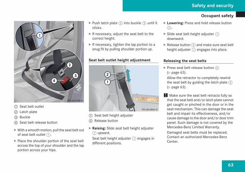
Occupant safety
63
1 Seat belt outlet2 Latch plate3 Buckle4 Seat belt release button
X With a smooth motion, pull the seat belt outof seat belt outlet 1.
X Place the shoulder portion of the seat beltacross the top of your shoulder and the lapportion across your hips.
X Push latch plate 2 into buckle 3 until itclicks.
X If necessary, adjust the seat belt to thecorrect height.
X If necessary, tighten the lap portion to asnug fit by pulling shoulder portion up.
Seat belt outlet height adjustment
1 Seat belt height adjuster2 Release button
X Raising: Slide seat belt height adjuster1 upward.Seat belt height adjuster 1 engages indifferent positions.
X Lowering: Press and hold release button2.
X Slide seat belt height adjuster 1downward.
X Release button 2 and make sure seat beltheight adjuster 1 engages into place.
Releasing the seat beltsX Press seat belt release button 4
(Y page 63).Allow the retractor to completely rewindthe seat belt by guiding the latch plate 2(Y page 63).
! Make sure the seat belt retracts fully sothat the seat belt and/or latch plate cannotget caught or pinched in the door or in theseat mechanism. This can damage the seatbelt and impair its effectiveness, and/orcause damage to the door and/or door trimpanel. Such damage is not covered by theMercedes-Benz Limited Warranty.Damaged seat belts must be replaced.Contact an authorized Mercedes-BenzCenter.
Safety and security
Z
Occupant safety
64
Enhanced seat belt reminder systemWhen the engine is started, the seat belttelltale < will always illuminate for6 seconds to remind you and your passengersto fasten your seat belts.If the driver’s seat belt is not fastened whenthe engine is started, an additional warningchime will also sound for a maximum of6 seconds or until the driver’s seat belt isfastened.If after these 6 seconds the driver’s or thefront passenger’s seat belt (with the frontpassenger seat occupied) is not fastened withfront doors closed,Rthe seat belt telltale < remains
illuminated for as long as either the driver’sor front passenger’s seat belt is notfastened.Rand if the vehicle speed once exceeds
15 mph (25 km/h), the seat belt telltale< starts flashing and a warning chimesounds with increasing intensity for amaximum of 60 seconds or until thedriver’s and front passenger’s seat belt arefastened.If you and/or your passenger release theseat belt during driving, the seat belt
telltale < starts flashing and thewarning chime sounds as described before.If the driver’s or the front passenger’s seatbelt remains unfastened after 60 seconds,the warning chime stops sounding, the seatbelt telltale < stops flashing butcontinues to be illuminated.After a vehicle standstill, the warning chimeis reactivated and the seat belt telltale< is flashing again if the vehicle speedonce exceeds 15 mph (25 km/h).
The seat belt telltale < will only go out ifboth the driver’s and the front passenger’sseat belt (with the front passenger seatoccupied) are fastened, or the vehicle isstanding still and a front door is opened.For more information, see “Practicalhints” (Y page 374).
Emergency Tensioning Device (ETD),seat belt force limiterThe seat belts for the front seats and secondrow outer seats are equipped with ETDs andseat belt force limiters. The seat belts for thethird-row seats are equipped with ETDs.
The ETDs are designed to activate in thefollowing cases:Rin frontal or rear-end impacts exceeding
the system’s preset deployment thresholdRin side impacts exceeding the system’s
preset deployment threshold on the farside of the impactRin certain vehicle rolloversRif the restraint systems are operational and
functioning correctly, see 1 indicatorlamp (Y page 47)
The ETDs for the front seats will only activateif the front seat belts are fastened (latch plateproperly inserted into buckle).The ETDs for the rear outer seats (second-rowseats) or rear seats (third-row seats) willactivate with or without the respective seatbelts fastened.In an impact, the ETDs remove slack from theseat belts in such a way that the seat belts fitmore snugly against the body. Seat belt forcelimiters, when activated, are employed tohelp reduce the peak force exerted by theseat belts on occupants during a crash.
i The ETDs do not correct an incorrect seatposition or incorrectly worn seat belts.
Safety and security
Occupant safety
65
The ETDs do not pull occupants backtoward the seat backrest.
G Warning!Pyrotechnic ETDs that were activated mustbe replaced.For your safety, when disposing of thepyrotechnic ETDs always follow our safetyinstructions. These are available at anyauthorized Mercedes-Benz Center.PRE-SAFE® has electrically operatedreversible pre-tensioners that do notrequire replacement after activation.
Preventive occupant safety (PRE-SAFE®)
G Warning!PRE-SAFE® is intended to reduce theeffects of an accident on vehicle occupantswho are wearing their seat belt properly.Despite having the PRE-SAFE® system inyour vehicle, the possibility of injuriesoccurring as a result of an accident cannotbe eliminated. Therefore, you shouldalways drive carefully and adjust yourdriving to the prevailing road, weather, andtraffic conditions.
Your vehicle takes preventive measures tobetter protect the occupants in the followinghazardous situations automatically.PRE-SAFE® takes action inRemergency braking maneuvers with the
Brake Assist System (BAS) (Y page 77)activatedRcritical dynamic driving situations, e.g.
when the vehicle is understeering oroversteering because it has exceeded itsphysical limitations
When you are driving faster than 22 mph(35 km/h), PRE-SAFE® takes the followingmeasures in such situations:RThe front seat belts are pre-tensioned
automatically.RVehicles with front passenger seat memory
function: If the passenger seat is in anunfavorable position, it will be adjusted toa better position.RIf the vehicle is in a severe skid or is
spinning, the door windows close until onlya small gap remains.RVehicles with power tilt/sliding sunroof: If
the vehicle is in a severe skid or is spinning,the tilt/sliding sunroof also close until onlya small gap remains.
If the closing procedure of the door windowsor tilt/sliding sunroof is blocked, the doorwindows or tilt/sliding sunroof will stop andopen slightly.Once the hazardous situation is over withoutan accident occurring, the seat belt pre-tensioning is deactivated. You can readjust allof the settings made by PRE-SAFE®.If the seat belts do not release:X Adjust the seat backrest or seat slightly to
the rear until the seat belt tension isdiminished.The locking mechanism releases.
! When moving the seats, make sure thereare no items in the footwell or behind theseats. Otherwise, you could damage theseats.
Safety and security
Z
Occupant safety
66
Active head restraintsThe active head restraints are intended tooffer the driver and front passenger increasedprotection from whiplash-type injuries. In theevent of a rear-end collision, the active headrestraints on the driver’s and frontpassenger’s seat are designed to moveforward in the direction of travel, providingthe head with increased support earlier on inthe collision sequence. The active headrestraints move forward whether the seat isoccupied or not.G Warning!Do not attach any objects (e.g. hangers) tothe head restraint posts. Otherwise, theactive head restraints may not be able tofunction properly or offer the intendeddegree of protection they were designed forin the event of a rear-end collision.
If the active head restraints have beentriggered in an accident, the active headrestraints must be reset. Otherwise, theactive head restraints cannot offer anyadditional protection in the event of anotherrear-end collision.For information on resetting the activatedactive head restraints, see “Resettingactivated head restraints” (Y page 385).
You cannot remove the active head restrainton the driver’s and front passenger’s seats.G Warning!Only use seat or head restraint coverswhich have been tested and approved byMercedes-Benz for your vehicle model.Using other seat or head restraint coversmay interfere with or prevent the activationof the active head restraints and/or thedeployment of the front side impact airbags.Contact an authorized Mercedes-BenzCenter for availability.
G Warning!For your protection, drive only with properlypositioned head restraints.Adjust the head restraint so that it is asclose to the head as possible and the centerof the head restraint supports the back ofthe head at eye level. This will reduce thepotential for injury to the head and neck inthe event of an accident or similar situation.
For information on head restraint adjustment,see “Head restraints” (Y page 100).
Correct driver seat adjustment
G Warning!In order to avoid possible loss of vehiclecontrol all seat, head restraint, steeringwheel, and rear view mirror adjustments, aswell as fastening of seat belts, must bedone before the vehicle is put into motion.
Safety and security
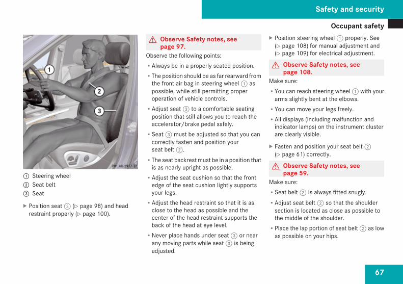
Occupant safety
67
1 Steering wheel2 Seat belt3 Seat
X Position seat 3 (Y page 98) and headrestraint properly (Y page 100).
G Observe Safety notes, seepage 97.
Observe the following points:RAlways be in a properly seated position.RThe position should be as far rearward from
the front air bag in steering wheel 1 aspossible, while still permitting properoperation of vehicle controls.RAdjust seat 3 to a comfortable seating
position that still allows you to reach theaccelerator/brake pedal safely.RSeat 3 must be adjusted so that you can
correctly fasten and position yourseat belt 2.RThe seat backrest must be in a position that
is as nearly upright as possible.RAdjust the seat cushion so that the front
edge of the seat cushion lightly supportsyour legs.RAdjust the head restraint so that it is as
close to the head as possible and thecenter of the head restraint supports theback of the head at eye level.RNever place hands under seat 3 or near
any moving parts while seat 3 is beingadjusted.
X Position steering wheel 1 properly. See(Y page 108) for manual adjustment and(Y page 109) for electrical adjustment.
G Observe Safety notes, seepage 108.
Make sure:RYou can reach steering wheel 1 with your
arms slightly bent at the elbows.RYou can move your legs freely.RAll displays (including malfunction and
indicator lamps) on the instrument clusterare clearly visible.
X Fasten and position your seat belt 2(Y page 61) correctly.
G Observe Safety notes, seepage 59.
Make sure:RSeat belt 2 is always fitted snugly.RAdjust seat belt 2 so that the shoulder
section is located as close as possible tothe middle of the shoulder.RPlace the lap portion of seat belt 2 as low
as possible on your hips.
Safety and security
Z
Occupant safety
68
Children in the vehicle
Safety notesIf an infant or child is traveling with you in thevehicle:X Secure the child using an infant or child
restraint appropriate to the age and size ofthe child.
X Make sure the infant or child is properlysecured at all times while the vehicle is inmotion.
G Warning!When leaving the vehicle, always removethe SmartKey from the starter switch.Always take the SmartKey with you andlock the vehicle. Do not leave childrenunattended in the vehicle, even if they aresecured in a child restraint system, or withaccess to an unlocked vehicle. A child’sunsupervised access to a vehicle couldresult in an accident and/or seriouspersonal injury. The children couldRinjure themselves on parts of the vehicleRbe seriously or fatally injured through
excessive exposure to extreme heat orcoldRinjure themselves or cause an accident
with vehicle equipment that can beoperated even if the SmartKey isremoved from the starter switch orremoved from the vehicle, such as seatadjustment, steering wheel adjustment,or the memory function.
If children open a door, they could injureother persons or get out of the vehicle andinjure themselves or be injured by followingtraffic.
Do not expose the child restraint system todirect sunlight. The child restraint system’smetal parts, for example, could becomevery hot, and the child could be burned onthese parts.
G Warning!Do not carry heavy or hard objects in thepassenger or cargo compartment unlessthey are firmly secured in place.Unsecured or improperly positioned cargoincreases a child’s risk of injury in the eventofRstrong braking maneuversRsudden changes of directionRan accident
For more information on loading, please referto the “Loading and storing” (Y page 227)chapter.
Infant and child restraint systems
G Observe Safety notes, seepage 68.
We recommend all infants and children beproperly restrained at all times while thevehicle is in motion.
Safety and security
Occupant safety
69
Canada only:Only use a BabySmartTM compatible childrestraint for the front passenger seat in thisvehicle.All lap/shoulder belts except the driver’s seatbelt have special seat belt retractors forsecure fastening of child restraints.To fasten a child restraint, follow childrestraint instructions for mounting. Then pullthe shoulder belt out completely and let itretract. During seat belt retraction, aratcheting sound can be heard to indicatethat the special seat belt retractor isactivated. The seat belt is now locked. Pushdown on child restraint to take up any slack.To deactivate, release the seat belt buckleand let the seat belt retract completely. Todeactivate the special seat belt retractor forthe front passenger seat, the front passengerseat must be in the most backward position.The seat belt can again be used in the usualmanner.G Warning!Never release the seat belt buckle while thevehicle is in motion, since the special seatbelt retractor will be deactivated.
i Information on child seats with mountingfittings for tether anchorages(Y page 71).For information on LATCH-type child seatanchors (Y page 72).
The use of infant or child restraints is requiredby law in all 50 states, the District ofColumbia, the U.S. territories and allCanadian provinces.Infants and small children should be seatedin an appropriate infant or child restraintsystem, properly secured in accordance withthe manufacturer’s instructions for the childrestraint, that complies with U.S. FederalMotor Vehicle Safety Standards 213 and 225and Canadian Motor Vehicle SafetyStandards 213 and 210.2.A statement by the child restraintmanufacturer of compliance with thesestandards can be found on the instructionlabel on the restraint and in the instructionmanual provided with the restraint.When using any infant restraint, toddlerrestraint, or booster seat, make sure tocarefully read and follow all manufacturer’sinstructions for installation and use.Please read and observe warning labelsaffixed to the inside of the vehicle and toinfant or child restraints.
G Warning!According to accident statistics, childrenare safer when properly restrained in therear seating positions than in the frontseating position. Thus, we stronglyrecommend that children be placed in therear seats whenever possible. Regardlessof seating position, children 12 years oldand under must be seated and properlysecured in an appropriate infant restraint,toddler restraint, or booster seatrecommended for the size and weight of thechild.The infant or child restraint must beproperly secured with the vehicle’s seatbelt, the seat belt and top tether strap, orlower anchors and top tether strap, fully inaccordance with the child seatmanufacturer’s instructions.Occupants, especially children, shouldalways sit as upright as possible, wear theseat belt properly and use an appropriatelysized infant restraint, toddler restraint, orbooster seat recommended for the size andweight of the child.
Safety and security
Z
Occupant safety
70
Children can be killed or seriously injuredby an inflating air bag. Note the followingimportant information when circumstancesrequire you to place a child in the frontpassenger seat:RUSA only: Your vehicle is equipped with
air bag technology designed todeactivate the front passenger front airbag in your vehicle when the systemsenses the weight of a typical 12-month-old child or less along with the weight ofa standard appropriate child restraint onthe front passenger seat.RUSA only: For children larger than the
typical 12-month-old child, the frontpassenger front air bag may or may notbe activated. Always make sure the59 indicator lamp isilluminated, indicating that the frontpassenger front air bag is deactivated.RCanada only: Children 12 years old and
under must never ride in the front seat,except in a Mercedes-Benz authorizedBabySmartTM compatible child seat,which operates with the BabySmartTM
system installed in the vehicle todeactivate the front passenger front airbag when it is installed properly.
Otherwise they will be struck by the airbag when it inflates in a crash. If thishappens, serious or fatal injury willresult.RA child in a rear-facing child restraint on
the front passenger seat will be seriouslyinjured or even killed if the frontpassenger front air bag inflates in acollision which could occur under somecircumstances, even with the air bagtechnology installed in your vehicle. Theonly means to completely eliminate thisrisk is to never place a child in a rear-facing child restraint in the front seat. Wetherefore strongly recommend that youalways place a child in a rear-facing childrestraint in a backseat.RIf you must install a rear-facing child
restraint on the front passenger seatbecause circumstances require you to doso, make sure the 59indicator lamp is illuminated, indicatingthat the front passenger front air bag isdeactivated. Should the 59indicator lamp not illuminate or go outwhile the restraint is installed, pleasecheck installation. Periodically check the59 indicator lamp while
driving to make sure the59 indicator lamp isilluminated. If the 59indicator lamp goes out or remains out,do not transport a child on the frontpassenger seat until the system has beenrepaired.A child in a rear-facing child restraint onthe front passenger seat will be seriouslyinjured or even killed if the frontpassenger front air bag inflates.RIf you have to place a child in a forward-
facing child restraint on the frontpassenger seat, move the seat as farback as possible, use the proper childrestraint recommended for the age, sizeand weight of the child, and secure childrestraint with the vehicle’s seat beltaccording to the child seatmanufacturer’s instructions.
G Warning!Infants and small children should nevershare a seat belt with another occupant.During an accident, they could be crushedbetween the occupant and seat belt.A child’s risk of serious or fatal injuries issignificantly increased if the child restraints
Safety and security
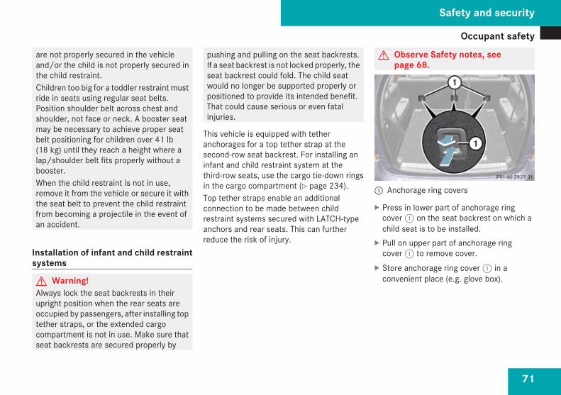
Occupant safety
71
are not properly secured in the vehicleand/or the child is not properly secured inthe child restraint.Children too big for a toddler restraint mustride in seats using regular seat belts.Position shoulder belt across chest andshoulder, not face or neck. A booster seatmay be necessary to achieve proper seatbelt positioning for children over 41 lb(18 kg) until they reach a height where alap/shoulder belt fits properly without abooster.When the child restraint is not in use,remove it from the vehicle or secure it withthe seat belt to prevent the child restraintfrom becoming a projectile in the event ofan accident.
Installation of infant and child restraintsystems
G Warning!Always lock the seat backrests in theirupright position when the rear seats areoccupied by passengers, after installing toptether straps, or the extended cargocompartment is not in use. Make sure thatseat backrests are secured properly by
pushing and pulling on the seat backrests.If a seat backrest is not locked properly, theseat backrest could fold. The child seatwould no longer be supported properly orpositioned to provide its intended benefit.That could cause serious or even fatalinjuries.
This vehicle is equipped with tetheranchorages for a top tether strap at thesecond-row seat backrest. For installing aninfant and child restraint system at thethird-row seats, use the cargo tie-down ringsin the cargo compartment (Y page 234).Top tether straps enable an additionalconnection to be made between childrestraint systems secured with LATCH-typeanchors and rear seats. This can furtherreduce the risk of injury.
G Observe Safety notes, seepage 68.
1 Anchorage ring covers
X Press in lower part of anchorage ringcover 1 on the seat backrest on which achild seat is to be installed.
X Pull on upper part of anchorage ringcover 1 to remove cover.
X Store anchorage ring cover 1 in aconvenient place (e.g. glove box).
Safety and security
Z
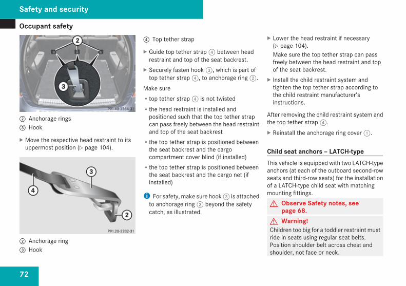
Occupant safety
72
2 Anchorage rings3 Hook
X Move the respective head restraint to itsuppermost position (Y page 104).
2 Anchorage ring3 Hook
4 Top tether strap
X Guide top tether strap 4 between headrestraint and top of the seat backrest.
X Securely fasten hook 3, which is part oftop tether strap 4, to anchorage ring 2.
Make sureRtop tether strap 4 is not twistedRthe head restraint is installed and
positioned such that the top tether strapcan pass freely between the head restraintand top of the seat backrestRthe top tether strap is positioned between
the seat backrest and the cargocompartment cover blind (if installed)Rthe top tether strap is positioned between
the seat backrest and the cargo net (ifinstalled)
i For safety, make sure hook 3 is attachedto anchorage ring 2 beyond the safetycatch, as illustrated.
X Lower the head restraint if necessary(Y page 104).Make sure the top tether strap can passfreely between the head restraint and topof the seat backrest.
X Install the child restraint system andtighten the top tether strap according tothe child restraint manufacturer’sinstructions.
After removing the child restraint system andthe top tether strap 4.X Reinstall the anchorage ring cover 1.
Child seat anchors – LATCH-typeThis vehicle is equipped with two LATCH-typeanchors (at each of the outboard second-rowseats and third-row seats) for the installationof a LATCH-type child seat with matchingmounting fittings.G Observe Safety notes, see
page 68.G Warning!Children too big for a toddler restraint mustride in seats using regular seat belts.Position shoulder belt across chest andshoulder, not face or neck.
Safety and security
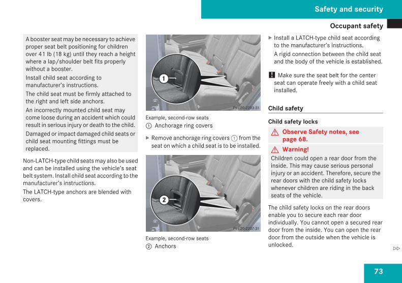
Occupant safety
73
A booster seat may be necessary to achieveproper seat belt positioning for childrenover 41 lb (18 kg) until they reach a heightwhere a lap/shoulder belt fits properlywithout a booster.Install child seat according tomanufacturer’s instructions.The child seat must be firmly attached tothe right and left side anchors.An incorrectly mounted child seat maycome loose during an accident which couldresult in serious injury or death to the child.Damaged or impact damaged child seats orchild seat mounting fittings must bereplaced.
Non-LATCH-type child seats may also be usedand can be installed using the vehicle’s seatbelt system. Install child seat according to themanufacturer’s instructions.The LATCH-type anchors are blended withcovers.
Example, second-row seats1 Anchorage ring covers
X Remove anchorage ring covers 1 from theseat on which a child seat is to be installed.
Example, second-row seats2 Anchors
X Install a LATCH-type child seat accordingto the manufacturer’s instructions.A rigid connection between the child seatand the body of the vehicle is established.
! Make sure the seat belt for the centerseat can operate freely with a child seatinstalled.
Child safety
Child safety locksG Observe Safety notes, see
page 68.G Warning!Children could open a rear door from theinside. This may cause serious personalinjury or an accident. Therefore, secure therear doors with the child safety lockswhenever children are riding in the backseats of the vehicle.
The child safety locks on the rear doorsenable you to secure each rear doorindividually. You cannot open a secured reardoor from the inside. You can open the reardoor from the outside when the vehicle isunlocked.
Safety and security
Z
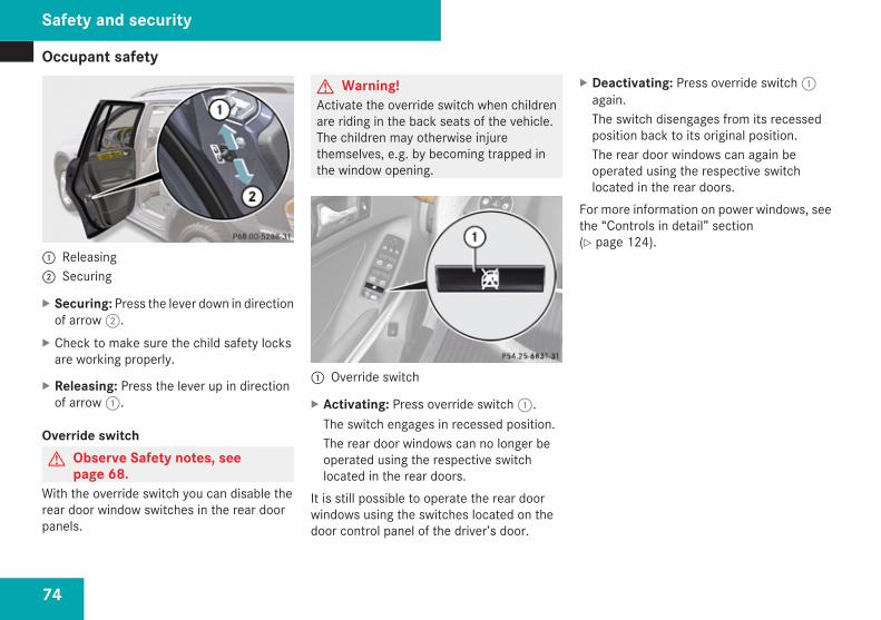
Occupant safety
74
1 Releasing2 Securing
X Securing: Press the lever down in directionof arrow 2.
X Check to make sure the child safety locksare working properly.
X Releasing: Press the lever up in directionof arrow 1.
Override switchG Observe Safety notes, see
page 68.With the override switch you can disable therear door window switches in the rear doorpanels.
G Warning!Activate the override switch when childrenare riding in the back seats of the vehicle.The children may otherwise injurethemselves, e.g. by becoming trapped inthe window opening.
1 Override switch
X Activating: Press override switch 1.The switch engages in recessed position.The rear door windows can no longer beoperated using the respective switchlocated in the rear doors.
It is still possible to operate the rear doorwindows using the switches located on thedoor control panel of the driver’s door.
X Deactivating: Press override switch 1again.The switch disengages from its recessedposition back to its original position.The rear door windows can again beoperated using the respective switchlocated in the rear doors.
For more information on power windows, seethe “Controls in detail” section(Y page 124).
Safety and security
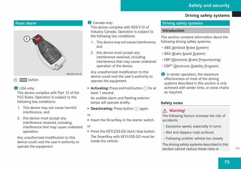
Driving safety systems
75
Panic alarm
1Â button
i USA only:This device complies with Part 15 of theFCC Rules. Operation is subject to thefollowing two conditions:1. This device may not cause harmful
interference, and2. this device must accept any
interference received, includinginterference that may cause undesiredoperation.
Any unauthorized modification to thisdevice could void the user’s authority tooperate the equipment.
i Canada only:This device complies with RSS-210 ofIndustry Canada. Operation is subject tothe following two conditions:1. This device may not cause interference,
and2. this device must accept any
interference received, includinginterference that may cause undesiredoperation of the device.
Any unauthorized modification to thisdevice could void the user’s authority tooperate the equipment.
X Activating: Press and hold button 1 for atleast 1 second.An audible alarm and flashing exteriorlamps will operate briefly.
X Deactivating: Press button 1 again.orX Insert the SmartKey in the starter switch.orX Press the KEYLESS-GO start/stop button.
The SmartKey with KEYLESS-GO must beinside the vehicle.
Driving safety systems
IntroductionThis section contains information about thefollowing driving safety systems:RABS (Antilock Brake System)RBAS (Brake Assist System)REBP (Electronic Brake Proportioning)RESP® (Electronic Stability Program)
i In winter operation, the maximumeffectiveness of most of the drivingsystems described in this section is onlyachieved with winter tires, or snow chainsas required.
Safety notes
G Warning!The following factors increase the risk ofaccidents:RExcessive speed, especially in turnsRWet and slippery road surfacesRFollowing another vehicle too closelyThe driving safety systems described in thissection cannot reduce these risks or
Safety and security
Z
Driving safety systems
76
prevent the natural laws of physics fromacting on the vehicle. They cannot increasebraking or steering efficiency beyond thatafforded by the condition of the vehiclebrakes and tires or the traction afforded.Only a safe, attentive, and skillful driver canprevent accidents.The capabilities of a vehicle equipped withthe driving safety systems described in thissection must never be exploited in areckless or dangerous manner which couldjeopardize the user’s safety or the safety ofothers.Always adjust your driving style to theprevailing road and weather conditions andkeep a safe distance to other road usersand objects on the street.If a driving system malfunctions, otherdriving safety systems may also switch off.Observe indicator and warning lamps thatmay come on as well as messages in themultifunction display that may appear.
ABS
G Observe Safety notes, seepage 75.
G Warning!Do not pump the brake pedal. Use firm,steady brake pedal pressure instead.Pumping the brake pedal defeats thepurpose of the ABS and significantlyreduces braking effectiveness.
The Antilock Brake System (ABS) regulatesthe brake pressure so that the wheels do notlock during braking. This allows you tomaintain the ability to steer your vehicle.The ABS is functional above a speed ofapproximately 5 mph (8 km/h) independentof road surface conditions.On slippery road surfaces, the ABS willrespond even to light brake pressure.The - indicator lamp in the instrumentcluster comes on when you switch on theignition. It goes out when the engine isrunning.
BrakingAt the instant one of the wheels is about tolock up, a slight pulsation can be felt in the
brake pedal, indicating that the ABS is in theregulating mode.X Keep firm and steady pressure on the brake
pedal while you feel the pulsation.Continuous, steady brake pedal pressureyields the advantages provided by the ABS,namely braking power and the ability to steerthe vehicle.The pulsating brake pedal can be anindication of hazardous road conditions andfunctions as a reminder to take extra carewhile driving.
Emergency brake maneuverX Keep continuous full pressure on the brake
pedal.
G Warning!If the ABS malfunctions, other drivingsafety systems such as the BAS or theESP® are also switched off. Observeindicator and warning lamps that may comeon as well as messages in the multifunctiondisplay that may appear.If the ABS malfunctions, the wheels maylock during hard braking, reducing steeringcapability and extending the brakingdistance.
Safety and security
Driving safety systems
77
For more information, see “What to doif …?” (Y page 371).
Off-road ABSWith the off-road driving program switchedon, or with the transmission in LOW RANGE,mode the ABS is designed for off-road isautomatically activated.When applying the brakes at speeds below18 mph (30 km/h), the front wheels arelocked cyclically to shorten the brakingdistance (dig-in effect). This effects steeringthe vehicle.
BAS
G Observe Safety notes, seepage 75.
The Brake Assist System (BAS) operates inemergency situations. If you apply the brakesvery quickly, the BAS automatically providesfull brake boost, thereby potentially reducingthe braking distance.X Apply continuous full braking pressure until
the emergency braking situation is over.The ABS will prevent the wheels fromlocking.
When you release the brake pedal, the brakesfunction again as normal. The BAS is thendeactivated.G Warning!If the BAS malfunctions, the brake systemstill functions, but without the additionalbrake boost available that the BAS wouldnormally provide in an emergency brakingmaneuver. Therefore, the braking distancemay increase.
EBP
G Observe Safety notes, seepage 75.
The Electronic Brake Proportioning (EBP)enhances braking effectiveness by allowingthe rear brakes to supply a greater proportionof the braking effort in straight line brakingwithout a loss of vehicle stability.G Warning!If the EBP malfunctions, the brake systemwill still function with full brake boost.However, the rear wheels could lock upduring emergency braking situations, forexample. You could lose control of thevehicle and cause an accident.
Adapt your driving style to the changeddriving characteristics.
ESP®
G Observe Safety notes, seepage 75.
The Electronic Stability Program (ESP®) isoperational as soon as the engine is runningand monitors the vehicle’s traction (force ofadhesive friction between the tires and theroad surface) and handling.The ESP® recognizes when a wheel isspinning or if the vehicle starts to skid. Byapplying brakes to individual wheels and bylimiting the engine output, the ESP® works tostabilize the vehicle. The ESP® is especiallyuseful while driving off and on wet or slipperyroad surfaces. The ESP® also stabilizes thevehicle during braking and steeringmaneuvers.The ESP® warning lamp v in theinstrument cluster comes on when you switchon the ignition. It goes out when the engineis running.
Safety and security
Z
Driving safety systems
78
The ESP® warning lamp v in theinstrument cluster flashes when the ESP® isengaged.G Warning!Never switch off the ESP® when you see theESP® warning lamp v flashing in theinstrument cluster. In this case proceed asfollows:RWhen driving off, apply as little throttle
as possible.RWhile driving, ease up on the accelerator
pedal.RAdapt your speed and driving style to the
prevailing road conditions.Failure to observe these guidelines couldcause the vehicle to skid. The ESP® cannotprevent accidents resulting from excessivespeed.
! Only conduct operational or performancetests on a two-axle dynamometer. If suchtests are necessary, contact an authorizedMercedes-Benz Center. You couldotherwise seriously damage the brakesystem or the transfer case which is notcovered by the Mercedes-Benz LimitedWarranty.
! Because the ESP® operatesautomatically, the engine and ignition mustbe shut off (SmartKey in starter switchposition 0 or 1 or KEYLESS-GO start/stopbutton in position 0 or 1) when the parkingbrake is being tested on a brake testdynamometer. Such testing should be nolonger than 10 seconds.Active braking action through the ESP®
may otherwise seriously damage the brakesystem which is not covered by theMercedes-Benz Limited Warranty.
! The ESP® will only function properly if youuse wheels of the recommended tire sizeas specified in the “Technical data” sectionof this Operator’s Manual.
i The Distronic system and cruise controlswitch off automatically when the ESP®
engages.For more information, see the “Practicalhints” section (Y page 332) and(Y page 376).
Electronic Traction System (4-ETS)
G Observe Safety notes, seepage 75.
The 4-ETS (four-wheel Electronic TractionSystem) are components of the ESP®. The4-ETS improves the vehicle’s ability to utilizeavailable traction, especially under slipperyroad conditions by applying the brakes to aspinning wheel. In addition, more power istransferred to the wheel(s) with traction.When you switch off the ESP®, the 4-ETS isstill enabled.X If conditions require, switch on the off-road
driving program (Y page 185) or the LOWRANGE mode (Y page 141).
Off-road 4-ETSWith the off-road driving program switched on(Y page 185), or the transmission in LOWRANGE mode (Y page 142), the 4-ETSdesigned for off-road use is activatedautomatically.
Safety and security
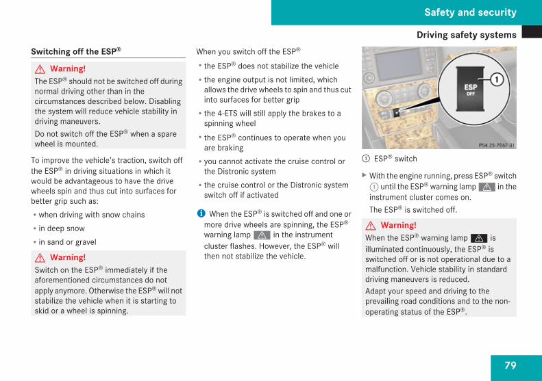
Driving safety systems
79
Switching off the ESP®
G Warning!The ESP® should not be switched off duringnormal driving other than in thecircumstances described below. Disablingthe system will reduce vehicle stability indriving maneuvers.Do not switch off the ESP® when a sparewheel is mounted.
To improve the vehicle’s traction, switch offthe ESP® in driving situations in which itwould be advantageous to have the drivewheels spin and thus cut into surfaces forbetter grip such as:Rwhen driving with snow chainsRin deep snowRin sand or gravel
G Warning!Switch on the ESP® immediately if theaforementioned circumstances do notapply anymore. Otherwise the ESP® will notstabilize the vehicle when it is starting toskid or a wheel is spinning.
When you switch off the ESP®
Rthe ESP® does not stabilize the vehicleRthe engine output is not limited, which
allows the drive wheels to spin and thus cutinto surfaces for better gripRthe 4-ETS will still apply the brakes to a
spinning wheelRthe ESP® continues to operate when you
are brakingRyou cannot activate the cruise control or
the Distronic systemRthe cruise control or the Distronic system
switch off if activated
i When the ESP® is switched off and one ormore drive wheels are spinning, the ESP®
warning lamp v in the instrumentcluster flashes. However, the ESP® willthen not stabilize the vehicle.
1 ESP® switch
X With the engine running, press ESP® switch1 until the ESP® warning lamp v in theinstrument cluster comes on.The ESP® is switched off.
G Warning!When the ESP® warning lamp v isilluminated continuously, the ESP® isswitched off or is not operational due to amalfunction. Vehicle stability in standarddriving maneuvers is reduced.Adapt your speed and driving to theprevailing road conditions and to the non-operating status of the ESP®.
Safety and security
Z
Anti-theft systems
80
! Avoid spinning of a drive wheel for anextended period with the ESP® switchedoff. This may cause serious damage to thedrivetrain which is not covered by theMercedes-Benz Limited Warranty.
Switching on the ESP®
X Press ESP® switch 1 until the ESP®
warning lamp v in the instrumentcluster goes out.You are now again in normal driving modewith the ESP® switched on.
Off-road ESP®
With the off-road driving program switched on(Y page 185), or with the transmission inLOW RANGE mode (Y page 142), the ESP®
designed for off-road use is automaticallyactivated. At speeds below 27 mph(45 km/h), the ESP® assists in over-/understeering, thus improving vehicletraction.
ESP® trailer stabilizationIf the trailer you are towing should begin tosway, the rig can only be stabilized by
immediately applying the brakes hard.Steering during this maneuver will not help tostabilize the rig.The ESP® will assist you in such situations.The ESP® recognizes when the trailer startsswaying and will apply the brakes to reducethe vehicle speed to a non-critical speed thatallows the vehicle-trailer combination tostabilize.The ESP® trailer stabilization is functional atvehicle speeds above approximately 40 mph(65 km/h) when the ESP® is switched on.G Warning!The system will not be able to assist whenthe trailer jackknifesRif the ESP® has switched off due to a
malfunctionRon wet or icy roadsRon roads with slippery surfaceRin sand or gravelTrailers with a high center of gravity may tipover before the system recognizes swayingof the trailer.
Anti-theft systems
ImmobilizerThe immobilizer prevents unauthorizedpersons from starting your vehicle.When leaving the vehicle, always take theSmartKey with you and lock the vehicle. Theengine can be started by anyone with a validSmartKey that is left inside the vehicle.
ActivatingX With SmartKey: Remove the SmartKey
from the starter switch.X With KEYLESS-GO: Turn off the engine and
open the driver’s door.
DeactivatingX Switch on the ignition.
i Starting the engine will also deactivatethe immobilizer.In the event that the engine cannot bestarted (yet the vehicle’s battery ischarged), the system is not operational.Contact an authorized Mercedes-BenzCenter or call 1-800-FOR-MERCedes (in theUSA), or 1-800-387-0100 (in Canada).
Safety and security
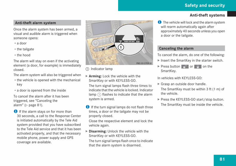
Anti-theft systems
81
Anti-theft alarm systemOnce the alarm system has been armed, avisual and audible alarm is triggered whensomeone opens:Ra doorRthe tailgateRthe hoodThe alarm will stay on even if the activatingelement (a door, for example) is immediatelyclosed.The alarm system will also be triggered whenRthe vehicle is opened with the mechanical
keyRa door is opened from the insideTo cancel the alarm after it has beentriggered, see “Canceling thealarm” (Y page 81).
i If the alarm stays on for more than30 seconds, a call to the Response Centeris initiated automatically by the Tele Aidsystem provided that you have subscribedto the Tele Aid service and that it has beenactivated properly, and that the necessarymobile phone, power supply and GPScoverage are available.
1 Indicator lamp
X Arming: Lock the vehicle with theSmartKey or with KEYLESS-GO.The turn signal lamps flash three times toindicate that the vehicle is locked. Indicatorlamp 1 flashes to indicate that the alarmsystem is armed.
i If the turn signal lamps do not flash threetimes, a door or the tailgate may not beproperly closed.Close the respective element and lock thevehicle again.
X Disarming: Unlock the vehicle with theSmartKey or with KEYLESS-GO.The turn signal lamps flash once to indicatethat the alarm system is disarmed.
i The vehicle will lock and the alarm systemwill rearm automatically again afterapproximately 40 seconds unless you opena door or the tailgate.
Canceling the alarmTo cancel the alarm, do one of the following:X Insert the SmartKey in the starter switch.X Press button k or j on the
SmartKey.
In vehicles with KEYLESS-GO:X Grasp an outside door handle.
The SmartKey must be within 3 ft (1 m) ofthe vehicle.
X Press the KEYLESS-GO start/stop button.The SmartKey must be inside the vehicle.
Safety and security
Z

82
83
Vehicle equipment .............................. 84Locking and unlocking ....................... 84Starter switch positions ..................... 95Seats .................................................... 97Multifunction steering wheel .......... 108Mirrors ............................................... 111Memory function .............................. 113Lighting .............................................. 114Wipers ................................................ 122Power windows ................................. 124Driving and parking .......................... 128Automatic transmission ................... 135
Transfer case .................................... 141Differential locks (Canada only) ...... 144Instrument cluster ............................ 147Control system .................................. 148Driving systems ................................ 169Overview of climate control sys-tem functions and air vents ............. 199Climate control ................................. 2023-zone automatic climate control . . . 210Rear window defroster ..................... 223Power tilt/sliding sunroof ............... 224Loading and storing .......................... 227Useful features ................................. 245
Controls in detail
Locking and unlocking
84
Vehicle equipment
i This Operator’s Manual describes allfeatures, standard or optional, potentiallyavailable for your vehicle at the time ofpurchase. Please be aware that yourvehicle might not be equipped with allfeatures described in this manual.
Locking and unlocking
Notes
G Observe Safety notes, seepage 68.
When unlocking the vehicle, all turn signallamps flash once, the locking knobs in thedoors move up, and the anti-theft alarmsystem is disarmed.When locking the vehicle, all turn signal lampsflash three times, the locking knobs in thedoors move down, and the anti-theft alarmsystem is armed.All doors and the tailgate must be closed.
! If you cannot lock or unlock the vehiclewith the SmartKey, the batteries in theSmartKey are discharged, the SmartKey ismalfunctioning, or the vehicle battery isdrained.RCheck the batteries in the SmartKey and
replace them if necessary.RUse the mechanical key to unlock the
driver’s door.
RUse the mechanical key to lock thevehicle.RHave the vehicle battery and the vehicle
battery connections checked at anauthorized Mercedes-Benz Center.
If the SmartKey is malfunctioning, contactRoadside Assistance or an authorizedMercedes-Benz Center.
SmartKeyYour vehicle comes supplied with twoSmartKeys, each with remote control and aremovable mechanical key.The SmartKey centrally locks and unlocks:Rthe doorsRthe tailgateRthe fuel filler flap
Controls in detail
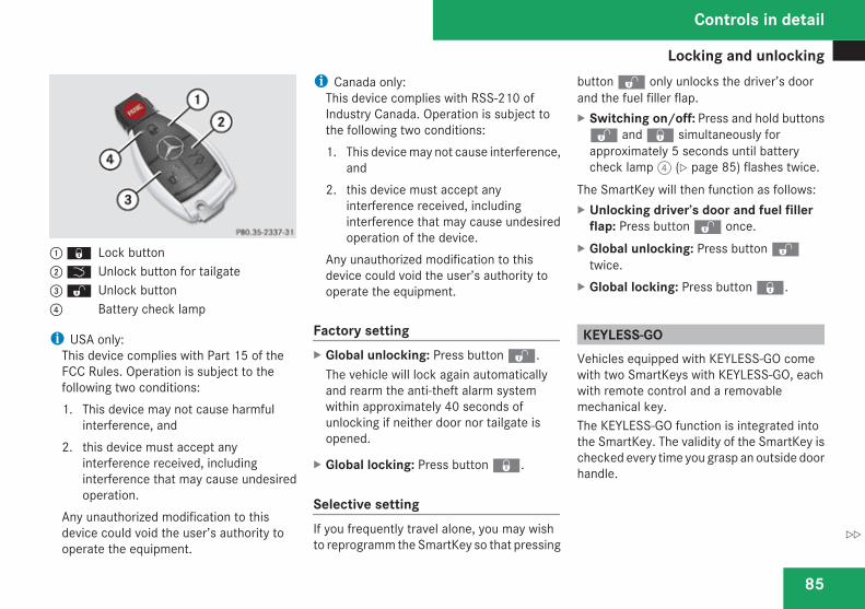
Locking and unlocking
85
1 j Lock button2 i Unlock button for tailgate3 k Unlock button4 Battery check lamp
i USA only:This device complies with Part 15 of theFCC Rules. Operation is subject to thefollowing two conditions:1. This device may not cause harmful
interference, and2. this device must accept any
interference received, includinginterference that may cause undesiredoperation.
Any unauthorized modification to thisdevice could void the user’s authority tooperate the equipment.
i Canada only:This device complies with RSS-210 ofIndustry Canada. Operation is subject tothe following two conditions:1. This device may not cause interference,
and2. this device must accept any
interference received, includinginterference that may cause undesiredoperation of the device.
Any unauthorized modification to thisdevice could void the user’s authority tooperate the equipment.
Factory settingX Global unlocking: Press button k.
The vehicle will lock again automaticallyand rearm the anti-theft alarm systemwithin approximately 40 seconds ofunlocking if neither door nor tailgate isopened.
X Global locking: Press button j.
Selective settingIf you frequently travel alone, you may wishto reprogramm the SmartKey so that pressing
button k only unlocks the driver’s doorand the fuel filler flap.X Switching on/off: Press and hold buttonsk and j simultaneously forapproximately 5 seconds until batterycheck lamp 4 (Y page 85) flashes twice.
The SmartKey will then function as follows:X Unlocking driver’s door and fuel filler
flap: Press button k once.X Global unlocking: Press button k
twice.X Global locking: Press button j.
KEYLESS-GOVehicles equipped with KEYLESS-GO comewith two SmartKeys with KEYLESS-GO, eachwith remote control and a removablemechanical key.The KEYLESS-GO function is integrated intothe SmartKey. The validity of the SmartKey ischecked every time you grasp an outside doorhandle.
Controls in detail
Z
Locking and unlocking
86
When the SmartKey is valid, your vehicleunlocksRthe doorsRthe fuel filler flapRthe tailgate
i USA only:This device complies with Part 15 of theFCC Rules. Operation is subject to thefollowing two conditions:1. This device may not cause harmful
interference, and2. this device must accept any
interference received, includinginterference that may cause undesiredoperation.
Any unauthorized modification to thisdevice could void the user’s authority tooperate the equipment.
i Canada only:This device complies with RSS-210 ofIndustry Canada. Operation is subject tothe following two conditions:1. This device may not cause interference,
and2. this device must accept any
interference received, includinginterference that may cause undesiredoperation of the device.
Any unauthorized modification to thisdevice could void the user’s authority tooperate the equipment.
Important notes on using KEYLESS-GORYou can also use the SmartKey with
KEYLESS-GO like a normal SmartKey(Y page 84).RYou can combine KEYLESS-GO functions
with normal SmartKey functions (e.g.unlocking with KEYLESS-GO and lockingwith button j).RAlways carry the SmartKey with you.RNever store the SmartKey together with:
- Electronic items such as a mobile phoneor another SmartKey
- Metallic objects such as coins or metalfoil
Doing so could impair the function of theKEYLESS-GO system.RTo lock or unlock the vehicle, the SmartKey
must be located outside the vehicle withinapproximately 3 ft (1 m) of a door or thetailgate.RIf the vehicle has been parked for more
than 72 hours, you must pull an outsidedoor handle in order to activate theKEYLESS-GO function.RIf the SmartKey is positioned farther away
from the vehicle, the system may no longerrecognize the SmartKey. The vehiclecannot be locked or the engine started viathe KEYLESS-GO system.RIf the SmartKey is removed from the vehicle
(e.g. if a passenger exits the vehicle withthe SmartKey)- when pressing the KEYLESS-GO start/
stop button or trying to lock the vehiclewith the lock button on an outside doorhandle the message Key Not
Controls in detail
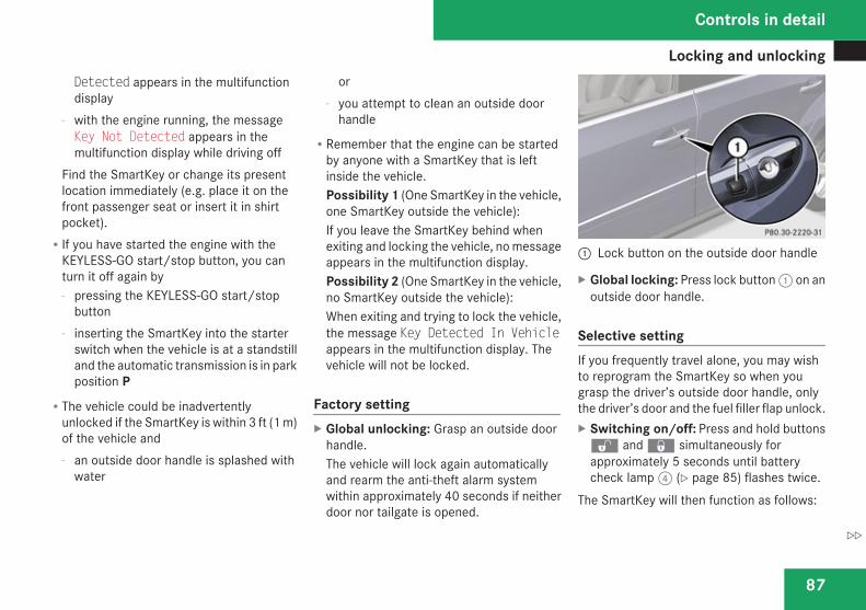
Locking and unlocking
87
Detected appears in the multifunctiondisplay
- with the engine running, the messageKey Not Detected appears in themultifunction display while driving off
Find the SmartKey or change its presentlocation immediately (e.g. place it on thefront passenger seat or insert it in shirtpocket).RIf you have started the engine with the
KEYLESS-GO start/stop button, you canturn it off again by- pressing the KEYLESS-GO start/stop
button- inserting the SmartKey into the starter
switch when the vehicle is at a standstilland the automatic transmission is in parkposition P
RThe vehicle could be inadvertentlyunlocked if the SmartKey is within 3 ft (1 m)of the vehicle and- an outside door handle is splashed with
water
or- you attempt to clean an outside door
handle
RRemember that the engine can be startedby anyone with a SmartKey that is leftinside the vehicle.Possibility 1 (One SmartKey in the vehicle,one SmartKey outside the vehicle):If you leave the SmartKey behind whenexiting and locking the vehicle, no messageappears in the multifunction display.Possibility 2 (One SmartKey in the vehicle,no SmartKey outside the vehicle):When exiting and trying to lock the vehicle,the message Key Detected In Vehicleappears in the multifunction display. Thevehicle will not be locked.
Factory settingX Global unlocking: Grasp an outside door
handle.The vehicle will lock again automaticallyand rearm the anti-theft alarm systemwithin approximately 40 seconds if neitherdoor nor tailgate is opened.
1 Lock button on the outside door handle
X Global locking: Press lock button 1 on anoutside door handle.
Selective settingIf you frequently travel alone, you may wishto reprogram the SmartKey so when yougrasp the driver’s outside door handle, onlythe driver’s door and the fuel filler flap unlock.X Switching on/off: Press and hold buttonsk and j simultaneously forapproximately 5 seconds until batterycheck lamp 4 (Y page 85) flashes twice.
The SmartKey will then function as follows:
Controls in detail
Z
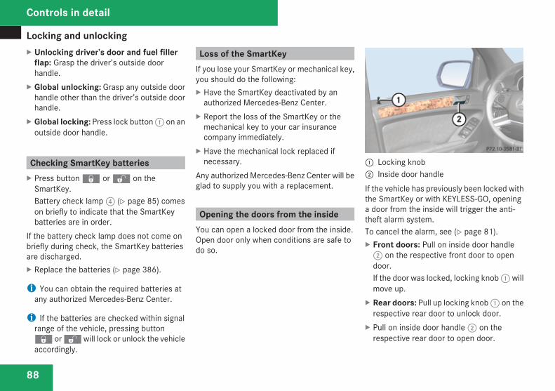
Locking and unlocking
88
X Unlocking driver’s door and fuel fillerflap: Grasp the driver’s outside doorhandle.
X Global unlocking: Grasp any outside doorhandle other than the driver’s outside doorhandle.
X Global locking: Press lock button 1 on anoutside door handle.
Checking SmartKey batteriesX Press button j or k on the
SmartKey.Battery check lamp 4 (Y page 85) comeson briefly to indicate that the SmartKeybatteries are in order.
If the battery check lamp does not come onbriefly during check, the SmartKey batteriesare discharged.X Replace the batteries (Y page 386).
i You can obtain the required batteries atany authorized Mercedes-Benz Center.
i If the batteries are checked within signalrange of the vehicle, pressing buttonj or k will lock or unlock the vehicleaccordingly.
Loss of the SmartKeyIf you lose your SmartKey or mechanical key,you should do the following:X Have the SmartKey deactivated by an
authorized Mercedes-Benz Center.X Report the loss of the SmartKey or the
mechanical key to your car insurancecompany immediately.
X Have the mechanical lock replaced ifnecessary.
Any authorized Mercedes-Benz Center will beglad to supply you with a replacement.
Opening the doors from the insideYou can open a locked door from the inside.Open door only when conditions are safe todo so.
1 Locking knob2 Inside door handleIf the vehicle has previously been locked withthe SmartKey or with KEYLESS-GO, openinga door from the inside will trigger the anti-theft alarm system.To cancel the alarm, see (Y page 81).X Front doors: Pull on inside door handle
2 on the respective front door to opendoor.If the door was locked, locking knob 1 willmove up.
X Rear doors: Pull up locking knob 1 on therespective rear door to unlock door.
X Pull on inside door handle 2 on therespective rear door to open door.
Controls in detail
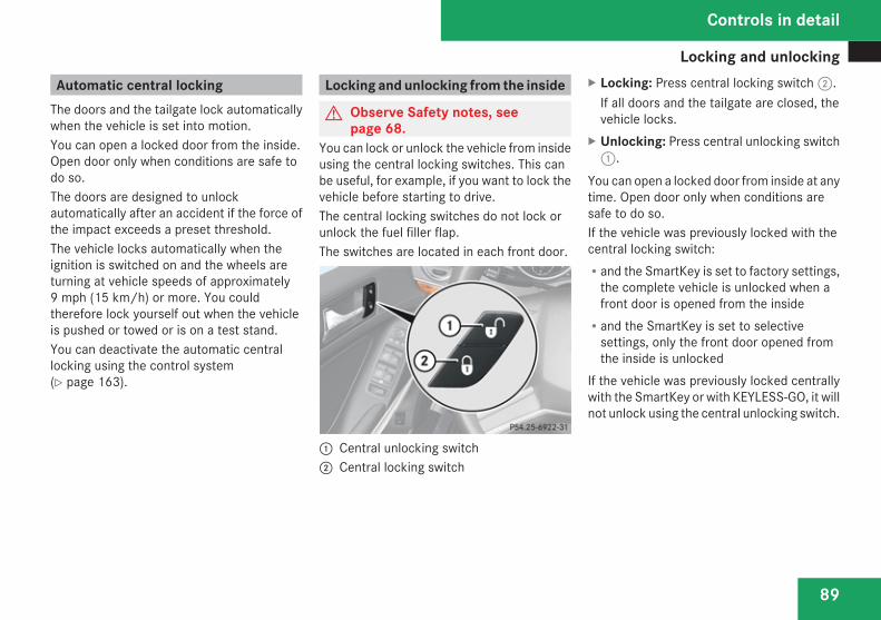
Locking and unlocking
89
Automatic central lockingThe doors and the tailgate lock automaticallywhen the vehicle is set into motion.You can open a locked door from the inside.Open door only when conditions are safe todo so.The doors are designed to unlockautomatically after an accident if the force ofthe impact exceeds a preset threshold.The vehicle locks automatically when theignition is switched on and the wheels areturning at vehicle speeds of approximately9 mph (15 km/h) or more. You couldtherefore lock yourself out when the vehicleis pushed or towed or is on a test stand.You can deactivate the automatic centrallocking using the control system(Y page 163).
Locking and unlocking from the inside
G Observe Safety notes, seepage 68.
You can lock or unlock the vehicle from insideusing the central locking switches. This canbe useful, for example, if you want to lock thevehicle before starting to drive.The central locking switches do not lock orunlock the fuel filler flap.The switches are located in each front door.
1 Central unlocking switch2 Central locking switch
X Locking: Press central locking switch 2.If all doors and the tailgate are closed, thevehicle locks.
X Unlocking: Press central unlocking switch1.
You can open a locked door from inside at anytime. Open door only when conditions aresafe to do so.If the vehicle was previously locked with thecentral locking switch:Rand the SmartKey is set to factory settings,
the complete vehicle is unlocked when afront door is opened from the insideRand the SmartKey is set to selective
settings, only the front door opened fromthe inside is unlocked
If the vehicle was previously locked centrallywith the SmartKey or with KEYLESS-GO, it willnot unlock using the central unlocking switch.
Controls in detail
Z
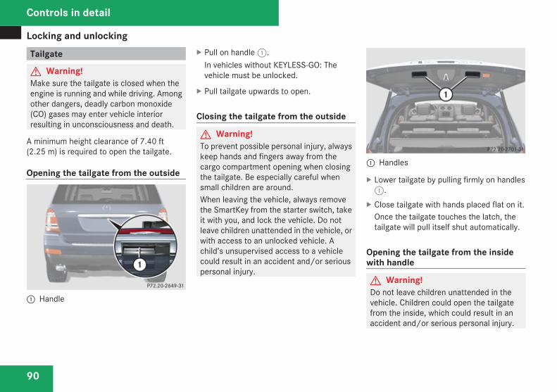
Locking and unlocking
90
Tailgate
G Warning!Make sure the tailgate is closed when theengine is running and while driving. Amongother dangers, deadly carbon monoxide(CO) gases may enter vehicle interiorresulting in unconsciousness and death.
A minimum height clearance of 7.40 ft(2.25 m) is required to open the tailgate.
Opening the tailgate from the outside
1 Handle
X Pull on handle 1.In vehicles without KEYLESS-GO: Thevehicle must be unlocked.
X Pull tailgate upwards to open.
Closing the tailgate from the outside
G Warning!To prevent possible personal injury, alwayskeep hands and fingers away from thecargo compartment opening when closingthe tailgate. Be especially careful whensmall children are around.When leaving the vehicle, always removethe SmartKey from the starter switch, takeit with you, and lock the vehicle. Do notleave children unattended in the vehicle, orwith access to an unlocked vehicle. Achild’s unsupervised access to a vehiclecould result in an accident and/or seriouspersonal injury.
1 Handles
X Lower tailgate by pulling firmly on handles1.
X Close tailgate with hands placed flat on it.Once the tailgate touches the latch, thetailgate will pull itself shut automatically.
Opening the tailgate from the insidewith handle
G Warning!Do not leave children unattended in thevehicle. Children could open the tailgatefrom the inside, which could result in anaccident and/or serious personal injury.
Controls in detail
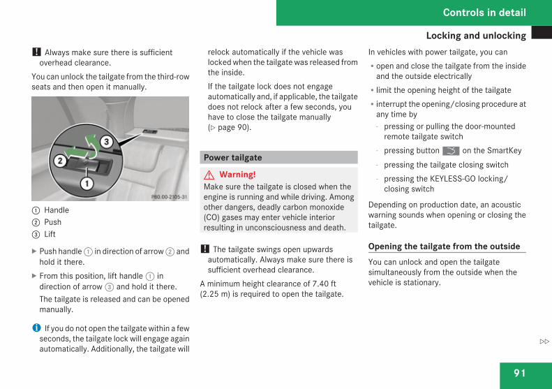
Locking and unlocking
91
! Always make sure there is sufficientoverhead clearance.
You can unlock the tailgate from the third-rowseats and then open it manually.
1 Handle2 Push3 Lift
X Push handle 1 in direction of arrow 2 andhold it there.
X From this position, lift handle 1 indirection of arrow 3 and hold it there.The tailgate is released and can be openedmanually.
i If you do not open the tailgate within a fewseconds, the tailgate lock will engage againautomatically. Additionally, the tailgate will
relock automatically if the vehicle waslocked when the tailgate was released fromthe inside.If the tailgate lock does not engageautomatically and, if applicable, the tailgatedoes not relock after a few seconds, youhave to close the tailgate manually(Y page 90).
Power tailgate
G Warning!Make sure the tailgate is closed when theengine is running and while driving. Amongother dangers, deadly carbon monoxide(CO) gases may enter vehicle interiorresulting in unconsciousness and death.
! The tailgate swings open upwardsautomatically. Always make sure there issufficient overhead clearance.
A minimum height clearance of 7.40 ft(2.25 m) is required to open the tailgate.
In vehicles with power tailgate, you canRopen and close the tailgate from the inside
and the outside electricallyRlimit the opening height of the tailgateRinterrupt the opening/closing procedure at
any time by- pressing or pulling the door-mounted
remote tailgate switch- pressing button i on the SmartKey- pressing the tailgate closing switch- pressing the KEYLESS-GO locking/
closing switch
Depending on production date, an acousticwarning sounds when opening or closing thetailgate.
Opening the tailgate from the outsideYou can unlock and open the tailgatesimultaneously from the outside when thevehicle is stationary.
Controls in detail
Z
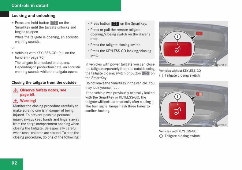
Locking and unlocking
92
X Press and hold button i on theSmartKey until the tailgate unlocks andbegins to open.While the tailgate is opening, an acousticwarning sounds.
orX Vehicles with KEYLESS-GO: Pull on the
handle (Y page 90).The tailgate is unlocked and opens.Depending on production date, an acousticwarning sounds while the tailgate opens.
Closing the tailgate from the outside
G Observe Safety notes, seepage 68.
G Warning!Monitor the closing procedure carefully tomake sure no one is in danger of beinginjured. To prevent possible personalinjury, always keep hands and fingers awayfrom the cargo compartment opening whenclosing the tailgate. Be especially carefulwhen small children are around. To stop theclosing procedure, do one of the following:
RPress button i on the SmartKey.RPress or pull the remote tailgate
opening/closing switch on the driver’sdoor.RPress the tailgate closing switch.RPress the KEYLESS-GO locking/closing
switch.
In vehicles with power tailgate you can closethe tailgate separately from the outside usingthe tailgate closing switch or button i onthe SmartKey.Do not leave the SmartKey in the vehicle. Youmay lock yourself out.If the vehicle was previously centrally lockedwith the SmartKey or KEYLESS-GO, thetailgate will lock automatically after closing it.The turn signal lamps flash three times toconfirm locking.
Vehicles without KEYLESS-GO1 Tailgate closing switch
Vehicles with KEYLESS-GO1 Tailgate closing switch
Controls in detail
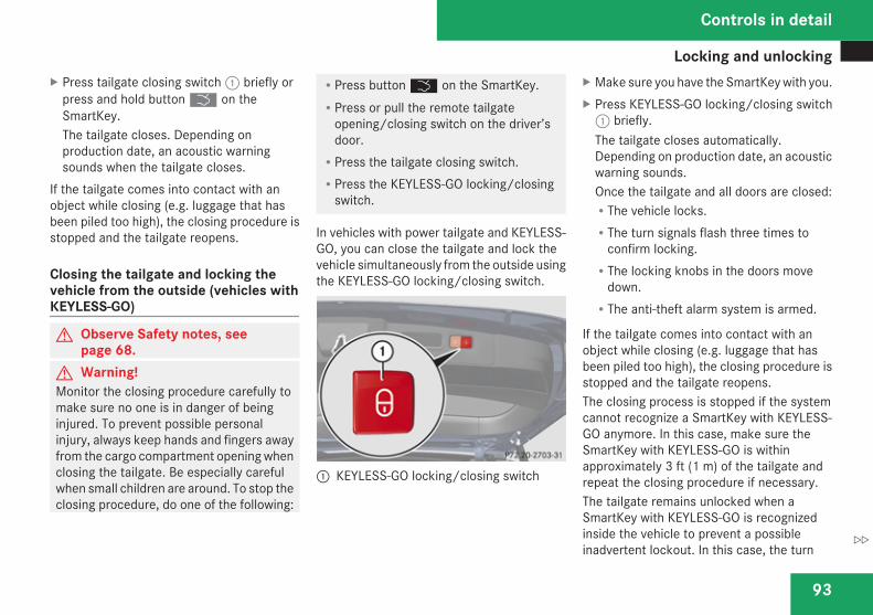
Locking and unlocking
93
X Press tailgate closing switch 1 briefly orpress and hold button i on theSmartKey.The tailgate closes. Depending onproduction date, an acoustic warningsounds when the tailgate closes.
If the tailgate comes into contact with anobject while closing (e.g. luggage that hasbeen piled too high), the closing procedure isstopped and the tailgate reopens.
Closing the tailgate and locking thevehicle from the outside (vehicles withKEYLESS-GO)
G Observe Safety notes, seepage 68.
G Warning!Monitor the closing procedure carefully tomake sure no one is in danger of beinginjured. To prevent possible personalinjury, always keep hands and fingers awayfrom the cargo compartment opening whenclosing the tailgate. Be especially carefulwhen small children are around. To stop theclosing procedure, do one of the following:
RPress button i on the SmartKey.RPress or pull the remote tailgate
opening/closing switch on the driver’sdoor.RPress the tailgate closing switch.RPress the KEYLESS-GO locking/closing
switch.
In vehicles with power tailgate and KEYLESS-GO, you can close the tailgate and lock thevehicle simultaneously from the outside usingthe KEYLESS-GO locking/closing switch.
1 KEYLESS-GO locking/closing switch
X Make sure you have the SmartKey with you.X Press KEYLESS-GO locking/closing switch
1 briefly.The tailgate closes automatically.Depending on production date, an acousticwarning sounds.Once the tailgate and all doors are closed:RThe vehicle locks.RThe turn signals flash three times to
confirm locking.RThe locking knobs in the doors move
down.RThe anti-theft alarm system is armed.
If the tailgate comes into contact with anobject while closing (e.g. luggage that hasbeen piled too high), the closing procedure isstopped and the tailgate reopens.The closing process is stopped if the systemcannot recognize a SmartKey with KEYLESS-GO anymore. In this case, make sure theSmartKey with KEYLESS-GO is withinapproximately 3 ft (1 m) of the tailgate andrepeat the closing procedure if necessary.The tailgate remains unlocked when aSmartKey with KEYLESS-GO is recognizedinside the vehicle to prevent a possibleinadvertent lockout. In this case, the turn
Controls in detail
Z
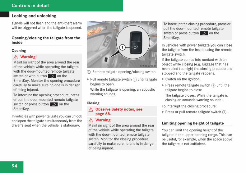
Locking and unlocking
94
signals will not flash and the anti-theft alarmwill be triggered when the tailgate is opened.
Opening/closing the tailgate from theinside
OpeningG Warning!Maintain sight of the area around the rearof the vehicle while operating the tailgatewith the door-mounted remote tailgateswitch or with button i on theSmartKey. Monitor the opening procedurecarefully to make sure no one is in dangerof being injured.To interrupt the opening procedure, pressor pull the door-mounted remote tailgateswitch or press button i on theSmartKey.
In vehicles with power tailgate you can unlockand open the tailgate simultaneously from thedriver’s seat when the vehicle is stationary.
1 Remote tailgate opening/closing switch
X Pull remote tailgate switch 1 until tailgatebegins to open.While the tailgate is opening, an acousticwarning sounds.
ClosingG Observe Safety notes, see
page 68.G Warning!Maintain sight of the area around the rearof the vehicle while operating the tailgatewith the door-mounted remote tailgateswitch. Monitor the closing procedurecarefully to make sure no one is in dangerof being injured.
To interrupt the closing procedure, press orpull the door-mounted remote tailgateswitch or press button i on theSmartKey.
In vehicles with power tailgate you can closethe tailgate from the inside using the remotetailgate switch.If the tailgate comes into contact with anobject while closing (e.g. luggage that hasbeen piled too high) the closing procedure isstopped and the tailgate reopens.X Switch on the ignition.X Press remote tailgate switch 1 until the
tailgate begins to close.The tailgate closes. While the tailgate isclosing an acoustic warning sounds.
To interrupt the closing procedure:X Press or pull remote tailgate switch 1.
Limiting opening height of tailgateYou can limit the opening height of thetailgate in the upper opening range. This canbe useful, for example, when the space abovethe tailgate is not sufficient.
Controls in detail
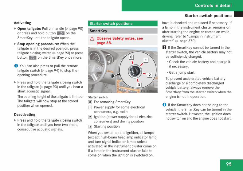
Starter switch positions
95
ActivatingX Open tailgate: Pull on handle (Y page 90)
or press and hold button i on theSmartKey until the tailgate opens.
X Stop opening procedure: When thetailgate is in the desired position, presstailgate closing switch (Y page 93) or pressbutton i on the SmartKey once more.
i You can also press or pull the remotetailgate switch (Y page 94) to stop theopening procedure.
X Press and hold the tailgate closing switchin the tailgate (Y page 93) until you hear ashort acoustic signal.The opening height of the tailgate is limited.The tailgate will now stop at the storedposition when opened.
DeactivatingX Press and hold the tailgate closing switch
in the tailgate until you hear two short,consecutive acoustic signals.
Starter switch positions
SmartKey
G Observe Safety notes, seepage 68.
Starter switch} For removing SmartKey$ Power supply for some electrical
consumers, e.g. radio% Ignition (power supply for all electrical
consumers) and driving position & Starting positionWhen you switch on the ignition, all lamps(except high-beam headlamp indicator lamp,and turn signal indicator lamps unlessactivated) in the instrument cluster come on.If a lamp in the instrument cluster fails tocome on when the ignition is switched on,
have it checked and replaced if necessary. Ifa lamp in the instrument cluster remains onafter starting the engine or comes on whiledriving, refer to “Lamps in instrumentcluster” (Y page 370).
! If the SmartKey cannot be turned in thestarter switch, the vehicle battery may notbe sufficiently charged.RCheck the vehicle battery and charge it
if necessary.RGet a jump start.To prevent accelerated vehicle batterydischarge or a completely dischargedvehicle battery, always remove theSmartKey from the starter switch when theengine is not in operation.
i If the SmartKey does not belong to thevehicle, the SmartKey can be turned in thestarter switch. However, the ignition doesnot switch on and the engine does not start.
Controls in detail
Z
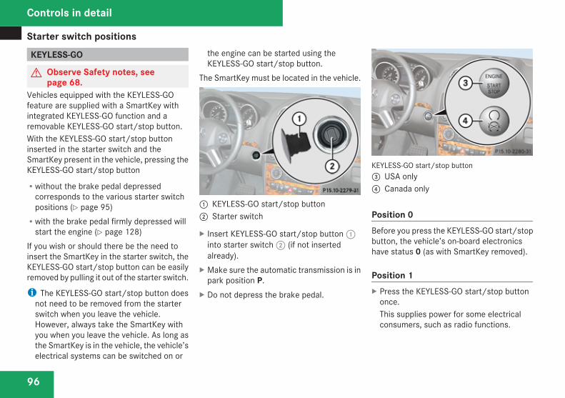
Starter switch positions
96
KEYLESS-GO
G Observe Safety notes, seepage 68.
Vehicles equipped with the KEYLESS-GOfeature are supplied with a SmartKey withintegrated KEYLESS-GO function and aremovable KEYLESS-GO start/stop button.With the KEYLESS-GO start/stop buttoninserted in the starter switch and theSmartKey present in the vehicle, pressing theKEYLESS-GO start/stop button
Rwithout the brake pedal depressedcorresponds to the various starter switchpositions (Y page 95)Rwith the brake pedal firmly depressed will
start the engine (Y page 128)If you wish or should there be the need toinsert the SmartKey in the starter switch, theKEYLESS-GO start/stop button can be easilyremoved by pulling it out of the starter switch.
i The KEYLESS-GO start/stop button doesnot need to be removed from the starterswitch when you leave the vehicle.However, always take the SmartKey withyou when you leave the vehicle. As long asthe SmartKey is in the vehicle, the vehicle’selectrical systems can be switched on or
the engine can be started using theKEYLESS-GO start/stop button.
The SmartKey must be located in the vehicle.
1 KEYLESS-GO start/stop button2 Starter switch
X Insert KEYLESS-GO start/stop button 1into starter switch 2 (if not insertedalready).
X Make sure the automatic transmission is inpark position P.
X Do not depress the brake pedal.
KEYLESS-GO start/stop button3 USA only4 Canada only
Position 0Before you press the KEYLESS-GO start/stopbutton, the vehicle’s on-board electronicshave status 0 (as with SmartKey removed).
Position 1X Press the KEYLESS-GO start/stop button
once.This supplies power for some electricalconsumers, such as radio functions.
Controls in detail
Seats
97
i If you now press the KEYLESS-GO start/stop buttonRonce more, the ignition (position 2) is
switched onRtwice more the power supply is again
switched off
Ignition (or position 2)X Press the KEYLESS-GO start/stop button
twice.This supplies power for all electricalconsumers.All lamps (except high-beam headlampindicator lamp and turn signal indicatorlamps unless activated) in the instrumentcluster come on. If a lamp in the instrumentcluster fails to come on when the ignitionis switched on, have it checked andreplaced if necessary. If a lamp in theinstrument cluster remains on afterstarting the engine or comes on whiledriving, refer to “Lamps in instrumentcluster” (Y page 370).
i If you now press the KEYLESS-GO start/stop button once, the power supply is againswitched off.
Seats
Safety notes
G Warning!In order to avoid possible loss of vehiclecontrol all seat, head restraint, steeringwheel, and rear view mirror adjustments, aswell as fastening of seat belts, must bedone before the vehicle is put into motion.
G Warning!Do not adjust the driver’s seat while driving.Adjusting the seat while driving could causethe driver to lose control of the vehicle.Never ride in a moving vehicle with the seatbackrest in an excessively reclined positionas this can be dangerous. You could slideunder the seat belt in a collision. If you slideunder it, the seat belt would apply force atthe abdomen or neck. That could causeserious or fatal injuries. The seat backrestand seat belts provide the best restraintwhen the wearer is in a position that is asupright as possible and seat belts areproperly positioned on the body.
G Warning!Your seat must be adjusted so that you cancorrectly fasten your seat belt.Observe the following points:RAdjust the seat backrest until your arms
are slightly angled when holding thesteering wheel.RAdjust the seat to a comfortable seating
position that still allows you to reach theaccelerator/brake pedal safely. Theposition should be as far back as possiblewith the driver still able to operate thecontrols properly.RAdjust the head restraint so that it is as
close to the head as possible and thecenter of the head restraint supports theback of the head at eye level.RNever place hands under the seat or near
any moving parts while a seat is beingadjusted.
Failure to do so could result in an accidentand/or serious personal injury.
G Warning!The power seats can be operated at anytime. Therefore, do not leave childrenunattended in the vehicle, or with access to
Controls in detail
Z
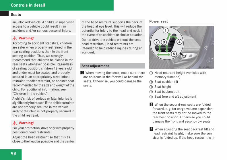
Seats
98
an unlocked vehicle. A child’s unsupervisedaccess to a vehicle could result in anaccident and/or serious personal injury.
G Warning!According to accident statistics, childrenare safer when properly restrained in therear seating positions than in the frontseating position. Thus, we stronglyrecommend that children be placed in therear seats whenever possible. Regardlessof seating position, children 12 years oldand under must be seated and properlysecured in an appropriately sized infantrestraint, toddler restraint, or booster seatrecommended for the size and weight of thechild. For additional information, see“Children in the vehicle”.A child’s risk of serious or fatal injuries issignificantly increased if the child restraintsare not properly secured in the vehicleand/or the child is not properly secured inthe child restraint.
G Warning!For your protection, drive only with properlypositioned head restraints.Adjust the head restraint so that it is asclose to the head as possible and the center
of the head restraint supports the back ofthe head at eye level. This will reduce thepotential for injury to the head and neck inthe event of an accident or similar situation.Do not drive the vehicle without the seathead restraints. Head restraints areintended to help reduce injuries during anaccident.
Seat adjustment! When moving the seats, make sure there
are no items in the footwell or behind theseats. Otherwise, you could damage theseats.
Power seat
1 Head restraint height (vehicles withmemory function)
2 Seat cushion tilt3 Seat height4 Seat backrest tilt5 Seat fore and aft adjustment
! When the second-row seats are foldedforward, e. g. for cargo volume expansion,the front seats may not be moved to therearmost position. Otherwise you coulddamage the front and second-row seats.
! When adjusting the seat backrest tilt andhead restraint height, make sure the sunvisor is folded up. If the head restraint is in
Controls in detail
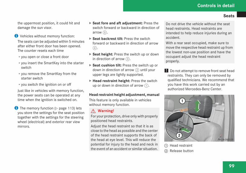
Seats
99
the uppermost position, it could hit anddamage the sun visor.
i Vehicles without memory function:The seats can be adjusted within 5 minutesafter either front door has been opened.The counter resets each timeRyou open or close a front doorRyou insert the SmartKey into the starter
switchRyou remove the SmartKey from the
starter switchRyou switch the ignition on or offJust like in vehicles with memory function,the power seats can be operated at anytime when the ignition is switched on.
i The memory function (Y page 113) letsyou store the settings for the seat positiontogether with the settings for the steeringwheel (electrical) and exterior rear viewmirrors.
X Seat fore and aft adjustment: Press theswitch forward or backward in direction ofarrow 5.
X Seat backrest tilt: Press the switchforward or backward in direction of arrow4.
X Seat height: Press the switch up or downin direction of arrow 3.
X Seat cushion tilt: Press the switch up ordown in direction of arrow 2 until yourupper legs are lightly supported.
X Head restraint height: Press the switchup or down in direction of arrow 1.
Head restraint height adjustment, manualThis feature is only available in vehicleswithout memory function.G Warning!For your protection, drive only with properlypositioned head restraints.Adjust the head restraint so that it is asclose to the head as possible and the centerof the head restraint supports the back ofthe head at eye level. This will reduce thepotential for injury to the head and neck inthe event of an accident or similar situation.
Do not drive the vehicle without the seathead restraints. Head restraints areintended to help reduce injuries during anaccident.With a rear seat occupied, make sure tomove the respective head restraint up fromthe lowest non-use position and have theoccupant adjust the head restraintproperly.
! Do not attempt to remove front seat headrestraints. They can only be removed byqualified technicians. We recommend thatyou have this work carried out by anauthorized Mercedes-Benz Center.
1 Head restraint2 Release button
Controls in detail
Z
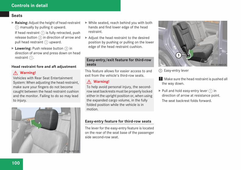
Seats
100
X Raising: Adjust the height of head restraint1 manually by pulling it upward.If head restraint 1 is fully retracted, pushrelease button 2 in direction of arrow andpull head restraint 1 upward.
X Lowering: Push release button 2 indirection of arrow and press down on headrestraint 1.
Head restraint fore and aft adjustmentG Warning!Vehicles with Rear Seat EntertainmentSystem: When adjusting the head restraint,make sure your fingers do not becomecaught between the head restraint cushionand the monitor. Failing to do so may leadto injury.
X While seated, reach behind you with bothhands and find lower edge of the headrestraint.
X Adjust the head restraint to the desiredposition by pushing or pulling on the loweredge of the head restraint cushion.
Easy-entry/exit feature for third-rowseats
This feature allows for easier access to andexit from the vehicle’s third-row seats.G Warning!To help avoid personal injury, the second-row seat backrests must be properly lockedeither in the upright position or, when usingthe expanded cargo volume, in the fullyfolded position while the vehicle is inmotion.
Easy-entry feature for third-row seatsThe lever for the easy-entry feature is locatedon the rear of the seat base of the passengerside second-row seat.
1 Easy-entry lever
! Make sure the head restraint is pushed allthe way down.
X Pull and hold easy-entry lever 1 indirection of arrow at resistance point.The seat backrest folds forward.
Controls in detail
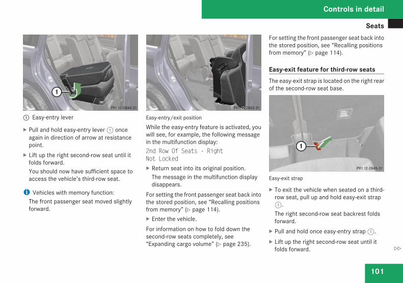
Seats
101
1 Easy-entry lever
X Pull and hold easy-entry lever 1 onceagain in direction of arrow at resistancepoint.
X Lift up the right second-row seat until itfolds forward.You should now have sufficient space toaccess the vehicle’s third-row seat.
i Vehicles with memory function:The front passenger seat moved slightlyforward.
Easy-entry/exit position
While the easy-entry feature is activated, youwill see, for example, the following messagein the multifunction display:2nd Row Of Seats - RightNot LockedX Return seat into its original position.
The message in the multifunction displaydisappears.
For setting the front passenger seat back intothe stored position, see “Recalling positionsfrom memory” (Y page 114).X Enter the vehicle.For information on how to fold down thesecond-row seats completely, see“Expanding cargo volume” (Y page 235).
For setting the front passenger seat back intothe stored position, see “Recalling positionsfrom memory” (Y page 114).
Easy-exit feature for third-row seatsThe easy-exit strap is located on the right rearof the second-row seat base.
Easy-exit strap
X To exit the vehicle when seated on a third-row seat, pull up and hold easy-exit strap1.The right second-row seat backrest foldsforward.
X Pull and hold once easy-entry strap 1.X Lift up the right second-row seat until it
folds forward.
Controls in detail
Z
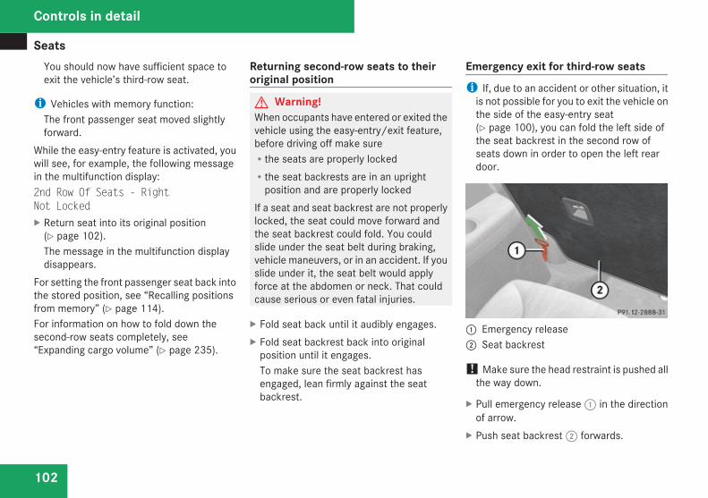
Seats
102
You should now have sufficient space toexit the vehicle’s third-row seat.
i Vehicles with memory function:The front passenger seat moved slightlyforward.
While the easy-entry feature is activated, youwill see, for example, the following messagein the multifunction display:2nd Row Of Seats - RightNot LockedX Return seat into its original position
(Y page 102).The message in the multifunction displaydisappears.
For setting the front passenger seat back intothe stored position, see “Recalling positionsfrom memory” (Y page 114).For information on how to fold down thesecond-row seats completely, see“Expanding cargo volume” (Y page 235).
Returning second-row seats to theiroriginal position
G Warning!When occupants have entered or exited thevehicle using the easy-entry/exit feature,before driving off make sureRthe seats are properly lockedRthe seat backrests are in an upright
position and are properly lockedIf a seat and seat backrest are not properlylocked, the seat could move forward andthe seat backrest could fold. You couldslide under the seat belt during braking,vehicle maneuvers, or in an accident. If youslide under it, the seat belt would applyforce at the abdomen or neck. That couldcause serious or even fatal injuries.
X Fold seat back until it audibly engages.X Fold seat backrest back into original
position until it engages.To make sure the seat backrest hasengaged, lean firmly against the seatbackrest.
Emergency exit for third-row seatsi If, due to an accident or other situation, it
is not possible for you to exit the vehicle onthe side of the easy-entry seat(Y page 100), you can fold the left side ofthe seat backrest in the second row ofseats down in order to open the left reardoor.
1 Emergency release2 Seat backrest
! Make sure the head restraint is pushed allthe way down.
X Pull emergency release 1 in the directionof arrow.
X Push seat backrest 2 forwards.
Controls in detail
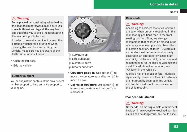
Seats
103
G Warning!To help avoid personal injury when foldingthe seat backrest forward, make sure youmove both feet and legs all the way backand out of the way to avoid them contactingthe seat as it pivots forward.In order to prevent an accident or any otherpotentially dangerous situations whenopening the rear door and exiting thevehicle, make sure you are aware of thetraffic situation at all times.
X Open the left door.X Exit the vehicle.
Lumbar supportYou can adjust the contour of the driver’s seatlumbar support to help enhance support toyour spine.
1 Curvature up2 Less curvature3 Curvature down4 Greater curvature
X Curvature position: Use button 1 tomove the curvature up and button 3 tomove it down.
X Degree of curvature: Use button 2 tolessen the curvature and button 4 toincrease it.
Rear seats
G Warning!According to accident statistics, childrenare safer when properly restrained in therear seating positions than in the frontseating position. Thus, we stronglyrecommend that children be placed in therear seats whenever possible. Regardlessof seating position, children 12 years oldand under must be seated and properlysecured in an appropriately sized infantrestraint, toddler restraint, or booster seatrecommended for the size and weight of thechild. For additional information, see“Children in the vehicle”.A child’s risk of serious or fatal injuries issignificantly increased if the child restraintsare not properly secured in the vehicleand/or the child is not properly secured inthe child restraint.
Rear seat adjustment
G Warning!Never ride in a moving vehicle with the seatbackrest in an excessively reclined positionas this can be dangerous. You could slide
Controls in detail
Z
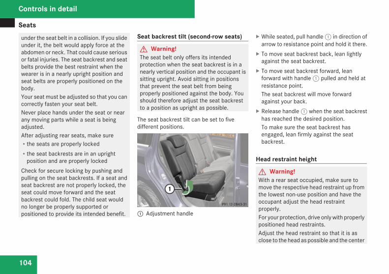
Seats
104
under the seat belt in a collision. If you slideunder it, the belt would apply force at theabdomen or neck. That could cause seriousor fatal injuries. The seat backrest and seatbelts provide the best restraint when thewearer is in a nearly upright position andseat belts are properly positioned on thebody.Your seat must be adjusted so that you cancorrectly fasten your seat belt.Never place hands under the seat or nearany moving parts while a seat is beingadjusted.After adjusting rear seats, make sureRthe seats are properly lockedRthe seat backrests are in an upright
position and are properly lockedCheck for secure locking by pushing andpulling on the seat backrests. If a seat andseat backrest are not properly locked, theseat could move forward and the seatbackrest could fold. The child seat wouldno longer be properly supported orpositioned to provide its intended benefit.
Seat backrest tilt (second-row seats)
G Warning!The seat belt only offers its intendedprotection when the seat backrest is in anearly vertical position and the occupant issitting upright. Avoid sitting in positionsthat prevent the seat belt from beingproperly positioned against the body. Youshould therefore adjust the seat backrestto a position as upright as possible.
The seat backrest tilt can be set to fivedifferent positions.
1 Adjustment handle
X While seated, pull handle 1 in direction ofarrow to resistance point and hold it there.
X To move seat backrest back, lean lightlyagainst the seat backrest.
X To move seat backrest forward, leanforward with handle 1 pulled and held atresistance point.The seat backrest will move forwardagainst your back.
X Release handle 1 when the seat backresthas reached the desired position.To make sure the seat backrest hasengaged, lean firmly against the seatbackrest.
Head restraint height
G Warning!With a rear seat occupied, make sure tomove the respective head restraint up fromthe lowest non-use position and have theoccupant adjust the head restraintproperly.For your protection, drive only with properlypositioned head restraints.Adjust the head restraint so that it is asclose to the head as possible and the center
Controls in detail
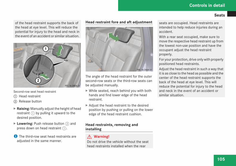
Seats
105
of the head restraint supports the back ofthe head at eye level. This will reduce thepotential for injury to the head and neck inthe event of an accident or similar situation.
Second-row seat head restraint1 Head restraint2 Release button
X Raising: Manually adjust the height of headrestraint 1 by pulling it upward to thedesired position.
X Lowering: Push release button 2 andpress down on head restraint 1.
i The third-row seat head restraints areadjusted in the same manner.
Head restraint fore and aft adjustment
The angle of the head restraint for the outersecond-row seats or the third-row seats canbe adjusted manually.X While seated, reach behind you with both
hands and find lower edge of the headrestraint.
X Adjust the head restraint to the desiredposition by pushing or pulling on the loweredge of the head restraint cushion.
Head restraints, removing andinstalling
G Warning!Do not drive the vehicle without the seathead restraints installed when the rear
seats are occupied. Head restraints areintended to help reduce injuries during anaccident.With a rear seat occupied, make sure tomove the respective head restraint up fromthe lowest non-use position and have theoccupant adjust the head restraintproperly.For your protection, drive only with properlypositioned head restraints.Adjust the head restraint in such a way thatit is as close to the head as possible and thecenter of the head restraint supports theback of the head at eye level. This willreduce the potential for injury to the headand neck in the event of an accident orsimilar situation.
Controls in detail
Z
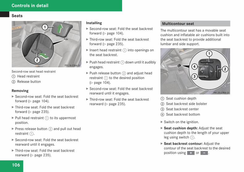
Seats
106
Second-row seat head restraint1 Head restraint2 Release button
RemovingX Second-row seat: Fold the seat backrest
forward (Y page 104).X Third-row seat: Fold the seat backrest
forward (Y page 235).X Pull head restraint 1 to its uppermost
position.X Press release button 2 and pull out head
restraint 1.X Second-row seat: Fold the seat backrest
rearward until it engages.X Third-row seat: Fold the seat backrest
rearward (Y page 235).
InstallingX Second-row seat: Fold the seat backrest
forward (Y page 104).X Third-row seat: Fold the seat backrest
forward (Y page 235).X Insert head restraint 1 into openings on
the seat backrest.
X Push head restraint 1 down until it audiblyengages.
X Push release button 2 and adjust headrestraint 1 to the desired position(Y page 104).
X Second-row seat: Fold the seat backrestrearward until it engages.
X Third-row seat: Fold the seat backrestrearward (Y page 235).
Multicontour seatThe multicontour seat has a movable seatcushion and inflatable air cushions built intothe seat backrest to provide additionallumbar and side support.
1 Seat cushion depth2 Seat backrest side bolster3 Seat backrest center4 Seat backrest bottom
X Switch on the ignition.X Seat cushion depth: Adjust the seat
cushion depth to the length of your upperleg using switch 1.
X Seat backrest contour: Adjust thecontour of the seat backrest to the desiredposition using + or -.
Controls in detail
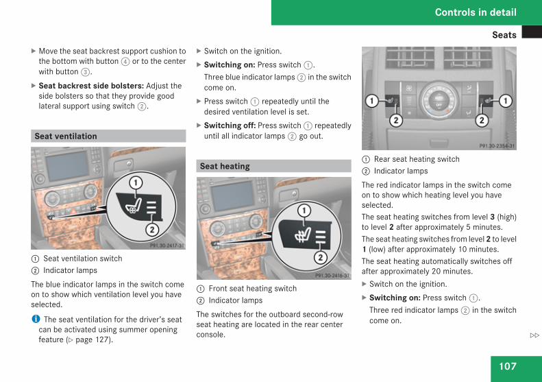
Seats
107
X Move the seat backrest support cushion tothe bottom with button 4 or to the centerwith button 3.
X Seat backrest side bolsters: Adjust theside bolsters so that they provide goodlateral support using switch 2.
Seat ventilation
1 Seat ventilation switch2 Indicator lampsThe blue indicator lamps in the switch comeon to show which ventilation level you haveselected.
i The seat ventilation for the driver’s seatcan be activated using summer openingfeature (Y page 127).
X Switch on the ignition.X Switching on: Press switch 1.
Three blue indicator lamps 2 in the switchcome on.
X Press switch 1 repeatedly until thedesired ventilation level is set.
X Switching off: Press switch 1 repeatedlyuntil all indicator lamps 2 go out.
Seat heating
1 Front seat heating switch2 Indicator lampsThe switches for the outboard second-rowseat heating are located in the rear centerconsole.
1 Rear seat heating switch2 Indicator lampsThe red indicator lamps in the switch comeon to show which heating level you haveselected.The seat heating switches from level 3 (high)to level 2 after approximately 5 minutes.The seat heating switches from level 2 to level1 (low) after approximately 10 minutes.The seat heating automatically switches offafter approximately 20 minutes.X Switch on the ignition.X Switching on: Press switch 1.
Three red indicator lamps 2 in the switchcome on.
Controls in detail
Z
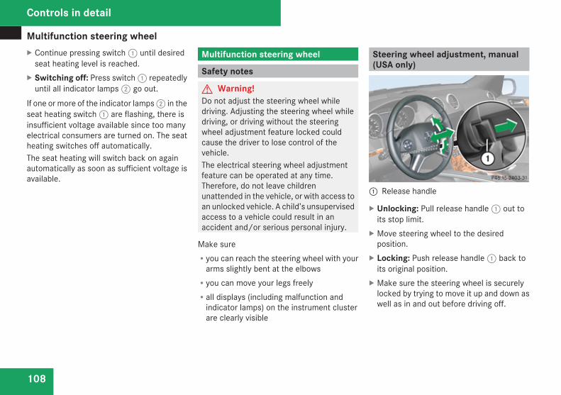
Multifunction steering wheel
108
X Continue pressing switch 1 until desiredseat heating level is reached.
X Switching off: Press switch 1 repeatedlyuntil all indicator lamps 2 go out.
If one or more of the indicator lamps 2 in theseat heating switch 1 are flashing, there isinsufficient voltage available since too manyelectrical consumers are turned on. The seatheating switches off automatically.The seat heating will switch back on againautomatically as soon as sufficient voltage isavailable.
Multifunction steering wheel
Safety notes
G Warning!Do not adjust the steering wheel whiledriving. Adjusting the steering wheel whiledriving, or driving without the steeringwheel adjustment feature locked couldcause the driver to lose control of thevehicle.The electrical steering wheel adjustmentfeature can be operated at any time.Therefore, do not leave childrenunattended in the vehicle, or with access toan unlocked vehicle. A child’s unsupervisedaccess to a vehicle could result in anaccident and/or serious personal injury.
Make sureRyou can reach the steering wheel with your
arms slightly bent at the elbowsRyou can move your legs freelyRall displays (including malfunction and
indicator lamps) on the instrument clusterare clearly visible
Steering wheel adjustment, manual(USA only)
1 Release handle
X Unlocking: Pull release handle 1 out toits stop limit.
X Move steering wheel to the desiredposition.
X Locking: Push release handle 1 back toits original position.
X Make sure the steering wheel is securelylocked by trying to move it up and down aswell as in and out before driving off.
Controls in detail
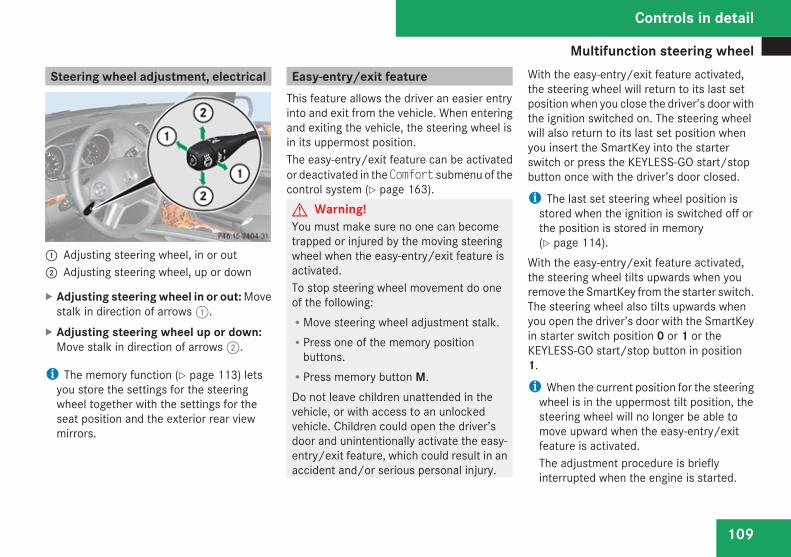
Multifunction steering wheel
109
Steering wheel adjustment, electrical
1 Adjusting steering wheel, in or out2 Adjusting steering wheel, up or down
X Adjusting steering wheel in or out: Movestalk in direction of arrows 1.
X Adjusting steering wheel up or down:Move stalk in direction of arrows 2.
i The memory function (Y page 113) letsyou store the settings for the steeringwheel together with the settings for theseat position and the exterior rear viewmirrors.
Easy-entry/exit featureThis feature allows the driver an easier entryinto and exit from the vehicle. When enteringand exiting the vehicle, the steering wheel isin its uppermost position.The easy-entry/exit feature can be activatedor deactivated in the Comfort submenu of thecontrol system (Y page 163).G Warning!You must make sure no one can becometrapped or injured by the moving steeringwheel when the easy-entry/exit feature isactivated.To stop steering wheel movement do oneof the following:RMove steering wheel adjustment stalk.RPress one of the memory position
buttons.RPress memory button M.Do not leave children unattended in thevehicle, or with access to an unlockedvehicle. Children could open the driver’sdoor and unintentionally activate the easy-entry/exit feature, which could result in anaccident and/or serious personal injury.
With the easy-entry/exit feature activated,the steering wheel will return to its last setposition when you close the driver’s door withthe ignition switched on. The steering wheelwill also return to its last set position whenyou insert the SmartKey into the starterswitch or press the KEYLESS-GO start/stopbutton once with the driver’s door closed.
i The last set steering wheel position isstored when the ignition is switched off orthe position is stored in memory(Y page 114).
With the easy-entry/exit feature activated,the steering wheel tilts upwards when youremove the SmartKey from the starter switch.The steering wheel also tilts upwards whenyou open the driver’s door with the SmartKeyin starter switch position 0 or 1 or theKEYLESS-GO start/stop button in position1.
i When the current position for the steeringwheel is in the uppermost tilt position, thesteering wheel will no longer be able tomove upward when the easy-entry/exitfeature is activated.The adjustment procedure is brieflyinterrupted when the engine is started.
Controls in detail
Z
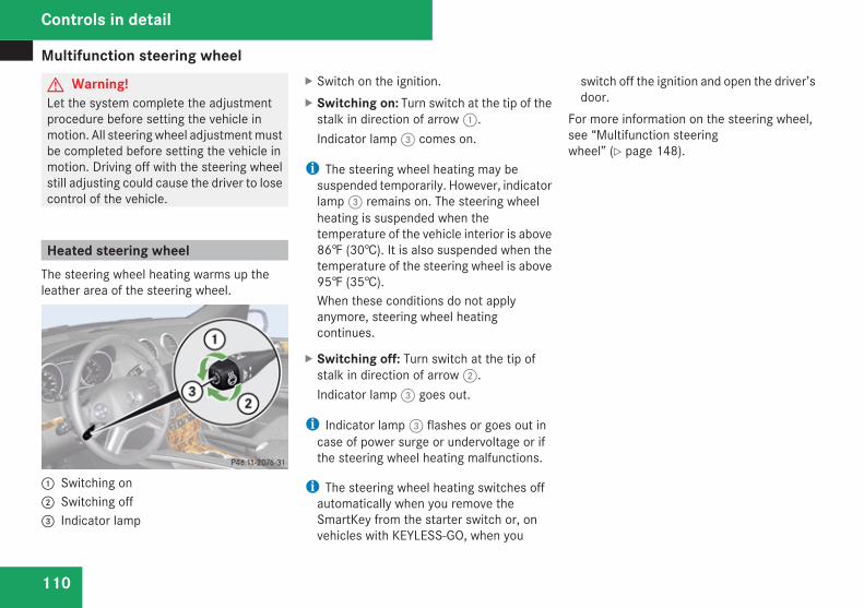
Multifunction steering wheel
110
G Warning!Let the system complete the adjustmentprocedure before setting the vehicle inmotion. All steering wheel adjustment mustbe completed before setting the vehicle inmotion. Driving off with the steering wheelstill adjusting could cause the driver to losecontrol of the vehicle.
Heated steering wheelThe steering wheel heating warms up theleather area of the steering wheel.
1 Switching on2 Switching off3 Indicator lamp
X Switch on the ignition.X Switching on: Turn switch at the tip of the
stalk in direction of arrow 1.Indicator lamp 3 comes on.
i The steering wheel heating may besuspended temporarily. However, indicatorlamp 3 remains on. The steering wheelheating is suspended when thetemperature of the vehicle interior is above86‡ (30†). It is also suspended when thetemperature of the steering wheel is above95‡ (35†).When these conditions do not applyanymore, steering wheel heatingcontinues.
X Switching off: Turn switch at the tip ofstalk in direction of arrow 2.Indicator lamp 3 goes out.
i Indicator lamp 3 flashes or goes out incase of power surge or undervoltage or ifthe steering wheel heating malfunctions.
i The steering wheel heating switches offautomatically when you remove theSmartKey from the starter switch or, onvehicles with KEYLESS-GO, when you
switch off the ignition and open the driver’sdoor.
For more information on the steering wheel,see “Multifunction steeringwheel” (Y page 148).
Controls in detail
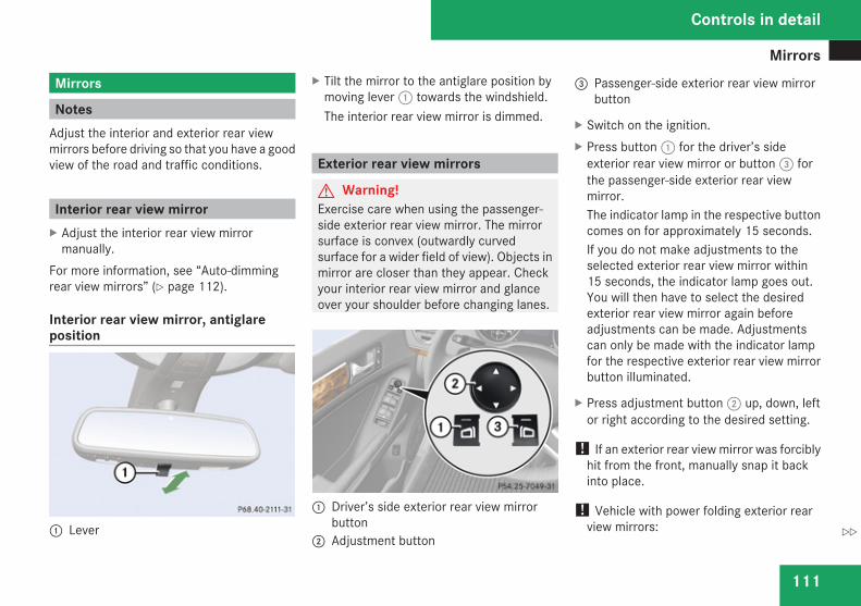
Mirrors
111
Mirrors
NotesAdjust the interior and exterior rear viewmirrors before driving so that you have a goodview of the road and traffic conditions.
Interior rear view mirrorX Adjust the interior rear view mirror
manually.For more information, see “Auto-dimmingrear view mirrors” (Y page 112).
Interior rear view mirror, antiglareposition
1 Lever
X Tilt the mirror to the antiglare position bymoving lever 1 towards the windshield.The interior rear view mirror is dimmed.
Exterior rear view mirrors
G Warning!Exercise care when using the passenger-side exterior rear view mirror. The mirrorsurface is convex (outwardly curvedsurface for a wider field of view). Objects inmirror are closer than they appear. Checkyour interior rear view mirror and glanceover your shoulder before changing lanes.
1 Driver’s side exterior rear view mirrorbutton
2 Adjustment button
3 Passenger-side exterior rear view mirrorbutton
X Switch on the ignition.X Press button 1 for the driver’s side
exterior rear view mirror or button 3 forthe passenger-side exterior rear viewmirror.The indicator lamp in the respective buttoncomes on for approximately 15 seconds.If you do not make adjustments to theselected exterior rear view mirror within15 seconds, the indicator lamp goes out.You will then have to select the desiredexterior rear view mirror again beforeadjustments can be made. Adjustmentscan only be made with the indicator lampfor the respective exterior rear view mirrorbutton illuminated.
X Press adjustment button 2 up, down, leftor right according to the desired setting.
! If an exterior rear view mirror was forciblyhit from the front, manually snap it backinto place.
! Vehicle with power folding exterior rearview mirrors:
Controls in detail
Z
Mirrors
112
If an exterior rear view mirror housing isforcibly pushed forward (hit from the rear)or forcibly pushed rearward (hit from front),press fold button to fold mirrors in, thenpress fold button again to fold mirrors out.Do not force mirrors by hand as this maydamage the adjustment mechanism.The mirror housing is then properlypositioned and you can adjust the mirror inthe usual manner.
i At low ambient temperatures, the exteriorrear view mirrors will be heatedautomatically.
Auto-dimming rear view mirrorsThe exterior rear view mirror on the driver’sside and the interior rear view mirror willrespond automatically to glare when theignition is switched on and incoming lightfrom headlamps falls on the sensor in theinterior rear view mirror.The rear view mirrors will not react if theautomatic transmission is set to reverse gearR or the interior lighting is switched on.
G Warning!The auto-dimming function does not reactif incoming light is not aimed directly atsensors in the interior rear view mirror.The interior rear view mirror and theexterior rear view mirror on the driver’s sidedo not react, for example, whentransporting cargo which covers the rearwindow.Light hitting the mirror(s) at certain angles(incident light) could blind you. As a result,you may not be able to observe trafficconditions and could cause an accident.
Power folding exterior rear viewmirrors
! Before you drive the vehicle through anautomatic car wash, fold in the exterior rearview mirrors. Otherwise they may getdamaged.
Folding in and out automaticallyWhen the corresponding function in thecontrol system is activated (Y page 164):
RThe exterior rear view mirrors fold inautomatically as soon as the vehicle islocked from the outside.RThe exterior rear view mirrors fold out
automatically as soon as the vehicle isunlocked and the driver’s or frontpassenger door are subsequently opened.
SynchronizingThe power folding rear view mirrors may haveto be synchronized after the vehicle batteryhas been disconnected or discharged. If theexterior rear view mirrors do not fold properlyupon locking or unlocking the vehiclealthough the corresponding function in thecontrol system is activated (Y page 164), dothe following:X Fold each exterior rear view mirror in
completely (Y page 113).X Fold each exterior rear view mirror out
completely (Y page 113).When the exterior rear view mirrors foldproperly upon locking the vehicle, the exteriormirrors are synchronized. Otherwise repeatthe above steps.
Controls in detail
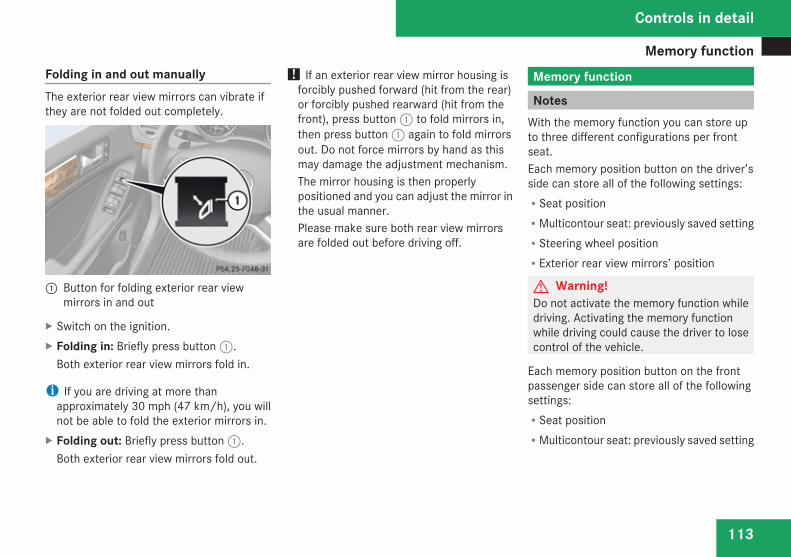
Memory function
113
Folding in and out manuallyThe exterior rear view mirrors can vibrate ifthey are not folded out completely.
1 Button for folding exterior rear viewmirrors in and out
X Switch on the ignition.X Folding in: Briefly press button 1.
Both exterior rear view mirrors fold in.
i If you are driving at more thanapproximately 30 mph (47 km/h), you willnot be able to fold the exterior mirrors in.
X Folding out: Briefly press button 1.Both exterior rear view mirrors fold out.
! If an exterior rear view mirror housing isforcibly pushed forward (hit from the rear)or forcibly pushed rearward (hit from thefront), press button 1 to fold mirrors in,then press button 1 again to fold mirrorsout. Do not force mirrors by hand as thismay damage the adjustment mechanism.The mirror housing is then properlypositioned and you can adjust the mirror inthe usual manner.Please make sure both rear view mirrorsare folded out before driving off.
Memory function
NotesWith the memory function you can store upto three different configurations per frontseat.Each memory position button on the driver’sside can store all of the following settings:RSeat positionRMulticontour seat: previously saved settingRSteering wheel positionRExterior rear view mirrors’ position
G Warning!Do not activate the memory function whiledriving. Activating the memory functionwhile driving could cause the driver to losecontrol of the vehicle.
Each memory position button on the frontpassenger side can store all of the followingsettings:RSeat positionRMulticontour seat: previously saved setting
Controls in detail
Z
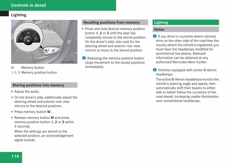
Lighting
114
M Memory button1, 2, 3 Memory position button
Storing positions into memoryX Adjust the seats.X On the driver’s side, additionally adjust the
steering wheel and exterior rear viewmirrors to the desired positions.
X Press memory button M.X Release memory button M and press
memory position button 1, 2 or 3 within3 seconds.When the settings are stored to theselected position, an acknowledgementsignal sounds.
Recalling positions from memoryX Press and hold desired memory position
button 1, 2 or 3 until the seat hascompletely moved to the stored position.On the driver’s side, also wait for thesteering wheel and exterior rear viewmirrors to move to the stored position.
i Releasing the memory position buttonstops movement to the stored positionsimmediately.
Lighting
Notesi If you drive in countries where vehicles
drive on the other side of the road than thecountry where the vehicle is registered, youmust have the headlamps modified forsymmetrical low beams. Relevantinformation can be obtained at anyauthorized Mercedes-Benz Center.
i Vehicles equipped with active Bi-Xenonheadlamps:The active Bi-Xenon headlamps monitor thevehicle’s steering angle and speed, thenautomatically shift their beams to eitherside to better follow the curvature of theroad ahead, increasing usable illuminationover conventional headlamps.
Controls in detail
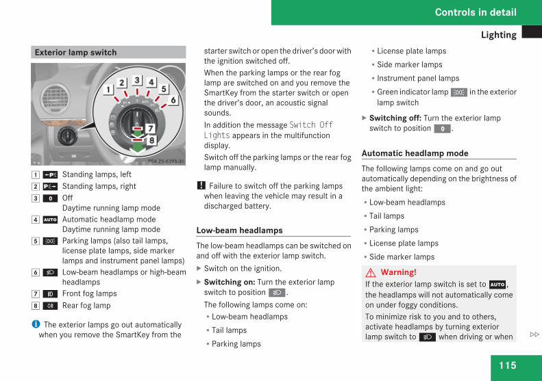
Lighting
115
Exterior lamp switch
$ a Standing lamps, left% g Standing lamps, right& M Off
Daytime running lamp mode( U Automatic headlamp mode
Daytime running lamp mode) C Parking lamps (also tail lamps,
license plate lamps, side markerlamps and instrument panel lamps)
* B Low-beam headlamps or high-beamheadlamps
, ¥ Front fog lamps. † Rear fog lamp
i The exterior lamps go out automaticallywhen you remove the SmartKey from the
starter switch or open the driver’s door withthe ignition switched off.When the parking lamps or the rear foglamp are switched on and you remove theSmartKey from the starter switch or openthe driver’s door, an acoustic signalsounds.In addition the message Switch OffLights appears in the multifunctiondisplay.Switch off the parking lamps or the rear foglamp manually.
! Failure to switch off the parking lampswhen leaving the vehicle may result in adischarged battery.
Low-beam headlampsThe low-beam headlamps can be switched onand off with the exterior lamp switch.X Switch on the ignition.X Switching on: Turn the exterior lamp
switch to position B.The following lamps come on:RLow-beam headlampsRTail lampsRParking lamps
RLicense plate lampsRSide marker lampsRInstrument panel lampsRGreen indicator lamp C in the exterior
lamp switch
X Switching off: Turn the exterior lampswitch to position M.
Automatic headlamp modeThe following lamps come on and go outautomatically depending on the brightness ofthe ambient light:RLow-beam headlampsRTail lampsRParking lampsRLicense plate lampsRSide marker lamps
G Warning!If the exterior lamp switch is set to U,the headlamps will not automatically comeon under foggy conditions.To minimize risk to you and to others,activate headlamps by turning exteriorlamp switch to B when driving or when
Controls in detail
Z
Lighting
116
traffic and/or ambient lighting conditionsrequire you to do so.In low ambient lighting conditions, onlyswitch from position U to B with thevehicle at a standstill in a safe location.Switching from U to B will brieflyswitch off the headlamps. Doing so whiledriving in low ambient lighting conditionsmay result in an accident.The automatic headlamp feature is only anaid to the driver. The driver is responsiblefor the operation of the vehicle’s lights atall times.
X Switching on: Turn the exterior lampswitch to position U.With the SmartKey in starter switchposition 1 or the KEYLESS-GO start/stopbutton pressed once, the tail and parkinglamps, the license plate lamps and the sidemarker lamps will come on and go outdepending on the brightness of the ambientlight.When the engine is running the low-beamheadlamps, the tail and parking lamps, thelicense plate lamps and the side markerlamps will come on and go out dependingon the brightness of the ambient light.
Canada only: High-beam headlamps are onlyavailable with the exterior lamp switch inposition B.
Daytime running lamp modeIn Canada, the daytime running lamp mode ismandatory and therefore in a constant mode.In the USA, the daytime running lamp modeis deactivated by default. Activate thedaytime running lamp mode using the controlsystem, see “Setting daytime running lampmode (USA only)” (Y page 161).X Turn the exterior lamp switch to positionM or U.When the engine is running, the low-beamheadlamps come on.In low ambient lighting conditions, thefollowing lamps will come on additionally:RTail lampsRParking lampsRLicense plate lampsRSide marker lamps
With the daytime running lamp modeactivated and the engine running, you cannotswitch off the low-beam headlamps manually.
Canada onlyWith the exterior lamp switch in positionM or U, you cannot switch on the high-beam headlamps.The high-beam flasher is available at all times.For nighttime driving turn the exterior lampswitch to position B to permit activationof the high-beam headlamps.When the engine is running, and youRshift from a driving position to neutral
position N or park position P with thevehicle at a standstill, the low-beamheadlamps will go out with a delay of 3minutesRturn the exterior lamp switch to positionC, the low-beam headlamps, the tailand parking lamps, the license plate lampsand the side marker lamps come onRturn the exterior lamp switch to positionB, the manual headlamp mode haspriority over the daytime running lampmodeThe corresponding exterior lamps come on(Y page 115).
Controls in detail
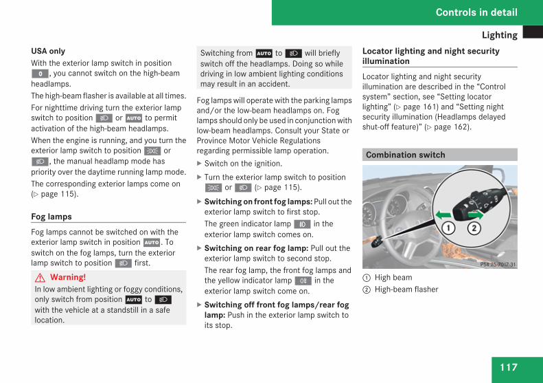
Lighting
117
USA onlyWith the exterior lamp switch in positionM, you cannot switch on the high-beamheadlamps.The high-beam flasher is available at all times.For nighttime driving turn the exterior lampswitch to position B or U to permitactivation of the high-beam headlamps.When the engine is running, and you turn theexterior lamp switch to position C orB, the manual headlamp mode haspriority over the daytime running lamp mode.The corresponding exterior lamps come on(Y page 115).
Fog lampsFog lamps cannot be switched on with theexterior lamp switch in position U. Toswitch on the fog lamps, turn the exteriorlamp switch to position B first.
G Warning!In low ambient lighting or foggy conditions,only switch from position U to Bwith the vehicle at a standstill in a safelocation.
Switching from U to B will brieflyswitch off the headlamps. Doing so whiledriving in low ambient lighting conditionsmay result in an accident.
Fog lamps will operate with the parking lampsand/or the low-beam headlamps on. Foglamps should only be used in conjunction withlow-beam headlamps. Consult your State orProvince Motor Vehicle Regulationsregarding permissible lamp operation.X Switch on the ignition.X Turn the exterior lamp switch to positionC or B (Y page 115).
X Switching on front fog lamps: Pull out theexterior lamp switch to first stop.The green indicator lamp ¥ in theexterior lamp switch comes on.
X Switching on rear fog lamp: Pull out theexterior lamp switch to second stop.The rear fog lamp, the front fog lamps andthe yellow indicator lamp † in theexterior lamp switch come on.
X Switching off front fog lamps/rear foglamp: Push in the exterior lamp switch toits stop.
Locator lighting and night securityilluminationLocator lighting and night securityillumination are described in the “Controlsystem” section, see “Setting locatorlighting” (Y page 161) and “Setting nightsecurity illumination (Headlamps delayedshut-off feature)” (Y page 162).
Combination switch
1 High beam2 High-beam flasher
Controls in detail
Z
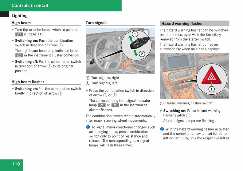
Lighting
118
High beamX Turn the exterior lamp switch to positionB (Y page 115).
X Switching on: Push the combinationswitch in direction of arrow 1.The high-beam headlamp indicator lampA in the instrument cluster comes on.
X Switching off: Pull the combination switchin direction of arrow 2 to its originalposition.
High-beam flasherX Switching on: Pull the combination switch
briefly in direction of arrow 2.
Turn signals
1 Turn signals, right2 Turn signals, left
X Press the combination switch in directionof arrow 1 or 2.The corresponding turn signal indicatorlamp L or K in the instrumentcluster flashes.
The combination switch resets automaticallyafter major steering wheel movements.
i To signal minor directional changes suchas changing lanes, press combinationswitch only to point of resistance andrelease. The corresponding turn signallamps will flash three times.
Hazard warning flasherThe hazard warning flasher can be switchedon at all times, even with the SmartKeyremoved from the starter switch.The hazard warning flasher comes onautomatically when an air bag deploys.
1 Hazard warning flasher switch
X Switching on: Press hazard warningflasher switch 1.All turn signal lamps are flashing.
i With the hazard warning flasher activatedand the combination switch set for eitherleft or right turn, only the respective left or
Controls in detail
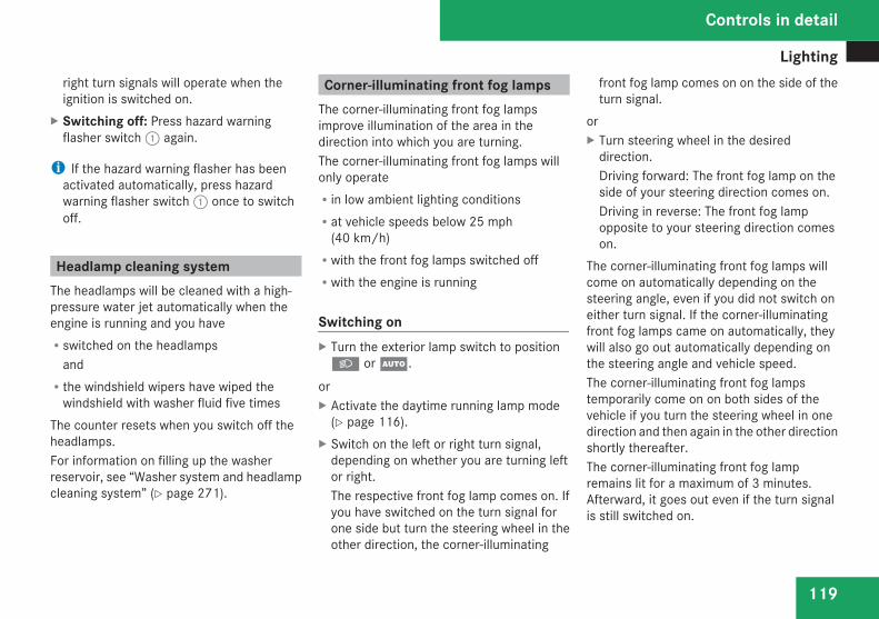
Lighting
119
right turn signals will operate when theignition is switched on.
X Switching off: Press hazard warningflasher switch 1 again.
i If the hazard warning flasher has beenactivated automatically, press hazardwarning flasher switch 1 once to switchoff.
Headlamp cleaning systemThe headlamps will be cleaned with a high-pressure water jet automatically when theengine is running and you haveRswitched on the headlamps
andRthe windshield wipers have wiped the
windshield with washer fluid five timesThe counter resets when you switch off theheadlamps.For information on filling up the washerreservoir, see “Washer system and headlampcleaning system” (Y page 271).
Corner-illuminating front fog lampsThe corner-illuminating front fog lampsimprove illumination of the area in thedirection into which you are turning.The corner-illuminating front fog lamps willonly operateRin low ambient lighting conditionsRat vehicle speeds below 25 mph
(40 km/h)Rwith the front fog lamps switched offRwith the engine is running
Switching onX Turn the exterior lamp switch to positionB or U.
orX Activate the daytime running lamp mode
(Y page 116).X Switch on the left or right turn signal,
depending on whether you are turning leftor right.The respective front fog lamp comes on. Ifyou have switched on the turn signal forone side but turn the steering wheel in theother direction, the corner-illuminating
front fog lamp comes on on the side of theturn signal.
orX Turn steering wheel in the desired
direction.Driving forward: The front fog lamp on theside of your steering direction comes on.Driving in reverse: The front fog lampopposite to your steering direction comeson.
The corner-illuminating front fog lamps willcome on automatically depending on thesteering angle, even if you did not switch oneither turn signal. If the corner-illuminatingfront fog lamps came on automatically, theywill also go out automatically depending onthe steering angle and vehicle speed.The corner-illuminating front fog lampstemporarily come on on both sides of thevehicle if you turn the steering wheel in onedirection and then again in the other directionshortly thereafter.The corner-illuminating front fog lampremains lit for a maximum of 3 minutes.Afterward, it goes out even if the turn signalis still switched on.
Controls in detail
Z
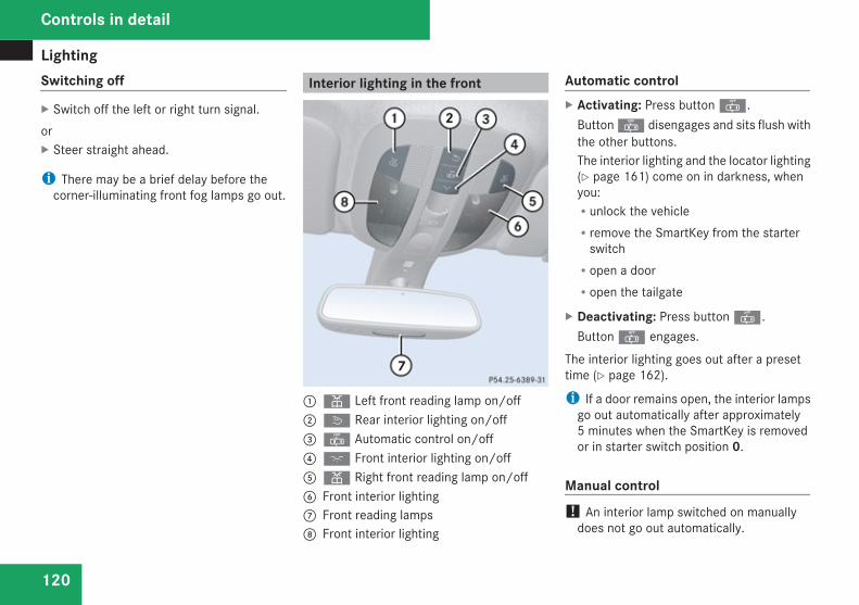
Lighting
120
Switching off
X Switch off the left or right turn signal.orX Steer straight ahead.
i There may be a brief delay before thecorner-illuminating front fog lamps go out.
Interior lighting in the front
1X Left front reading lamp on/off2ò Rear interior lighting on/off3] Automatic control on/off4ð Front interior lighting on/off 5X Right front reading lamp on/off6 Front interior lighting7 Front reading lamps 8 Front interior lighting
Automatic controlX Activating: Press button ].
Button ] disengages and sits flush withthe other buttons.The interior lighting and the locator lighting(Y page 161) come on in darkness, whenyou:Runlock the vehicleRremove the SmartKey from the starter
switchRopen a doorRopen the tailgate
X Deactivating: Press button ].Button ] engages.
The interior lighting goes out after a presettime (Y page 162).
i If a door remains open, the interior lampsgo out automatically after approximately5 minutes when the SmartKey is removedor in starter switch position 0.
Manual control! An interior lamp switched on manually
does not go out automatically.
Controls in detail
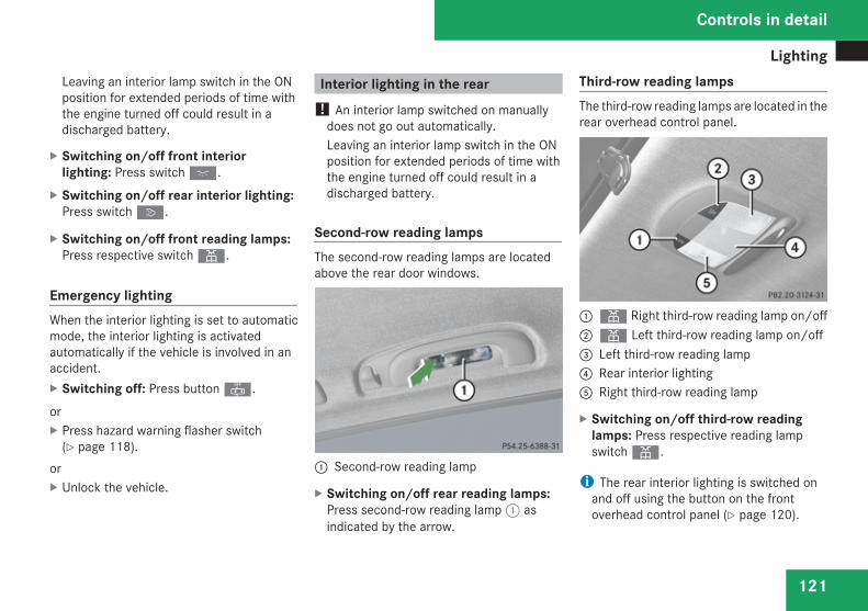
Lighting
121
Leaving an interior lamp switch in the ONposition for extended periods of time withthe engine turned off could result in adischarged battery.
X Switching on/off front interiorlighting: Press switch ð.
X Switching on/off rear interior lighting:Press switch ò.
X Switching on/off front reading lamps:Press respective switch X.
Emergency lightingWhen the interior lighting is set to automaticmode, the interior lighting is activatedautomatically if the vehicle is involved in anaccident.X Switching off: Press button ].
orX Press hazard warning flasher switch
(Y page 118).orX Unlock the vehicle.
Interior lighting in the rear! An interior lamp switched on manually
does not go out automatically.Leaving an interior lamp switch in the ONposition for extended periods of time withthe engine turned off could result in adischarged battery.
Second-row reading lampsThe second-row reading lamps are locatedabove the rear door windows.
1 Second-row reading lamp
X Switching on/off rear reading lamps:Press second-row reading lamp 1 asindicated by the arrow.
Third-row reading lampsThe third-row reading lamps are located in therear overhead control panel.
1X Right third-row reading lamp on/off2X Left third-row reading lamp on/off3 Left third-row reading lamp4 Rear interior lighting5 Right third-row reading lamp
X Switching on/off third-row readinglamps: Press respective reading lampswitch X.
i The rear interior lighting is switched onand off using the button on the frontoverhead control panel (Y page 120).
Controls in detail
Z
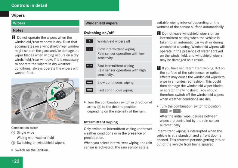
Wipers
122
Wipers
Notes! Do not operate the wipers when the
windshield/rear window is dry. Dust thataccumulates on a windshield/rear windowmight scratch the glass and/or damage thewiper blades when wiping occurs on a drywindshield/rear window. If it is necessaryto operate the wipers in dry weatherconditions, always operate the wipers withwasher fluid.
Combination switch1 Single wipe
Wiping with washer fluid2 Switching on windshield wipers
X Switch on the ignition.
Windshield wipers
Switching on/off
M Windshield wipers off
U Slow intermittent wipingRain sensor operation with lowsensitivity.
V Fast intermittent wipingRain sensor operation with highsensitivity.
u Slow continuous wiping
t Fast continuous wiping
X Turn the combination switch in direction ofarrow 2 to the desired position,depending on the intensity of the rain.
Intermittent wipingOnly switch on intermittent wiping under wetweather conditions or in the presence ofprecipitation.When you select intermittent wiping, the rainsensor is activated. The rain sensor sets a
suitable wiping interval depending on thewetness of the sensor surface automatically.
! Do not leave windshield wipers on anintermittent setting when the vehicle istaken to an automatic car wash or duringwindshield cleaning. Windshield wipers willoperate in the presence of water sprayedon the windshield, and windshield wipersmay be damaged as a result.
! If you have set intermittent wiping, dirt onthe surface of the rain sensor or opticaleffects may cause the windshield wipers towipe in an undesired fashion. This couldthen damage the windshield wiper bladesor scratch the windshield. You shouldtherefore switch off the windshield wiperswhen weather conditions are dry.
X Turn the combination switch to positionU or V.After the initial wipe, pauses betweenwipes are controlled by the rain sensorautomatically.
Intermittent wiping is interrupted when thevehicle is at a standstill and a front door isopened. This protects persons getting into orout of the vehicle from being sprayed.
Controls in detail
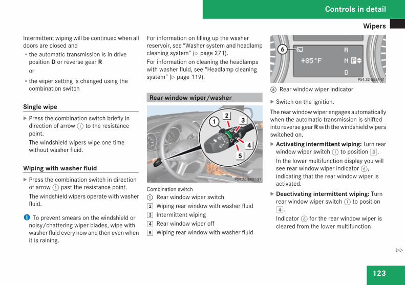
Wipers
123
Intermittent wiping will be continued when alldoors are closed andRthe automatic transmission is in drive
position D or reverse gear RorRthe wiper setting is changed using the
combination switch
Single wipeX Press the combination switch briefly in
direction of arrow 1 to the resistancepoint.The windshield wipers wipe one timewithout washer fluid.
Wiping with washer fluidX Press the combination switch in direction
of arrow 1 past the resistance point.The windshield wipers operate with washerfluid.
i To prevent smears on the windshield ornoisy/chattering wiper blades, wipe withwasher fluid every now and then even whenit is raining.
For information on filling up the washerreservoir, see “Washer system and headlampcleaning system” (Y page 271).For information on cleaning the headlampswith washer fluid, see “Headlamp cleaningsystem” (Y page 119).
Rear window wiper/washer
Combination switch1 Rear window wiper switch% Wiping rear window with washer fluid& Intermittent wiping( Rear window wiper off) Wiping rear window with washer fluid
6 Rear window wiper indicator
X Switch on the ignition.The rear window wiper engages automaticallywhen the automatic transmission is shiftedinto reverse gear R with the windshield wipersswitched on.X Activating intermittent wiping: Turn rear
window wiper switch 1 to position &.In the lower multifunction display you willsee rear window wiper indicator 6,indicating that the rear window wiper isactivated.
X Deactivating intermittent wiping: Turnrear window wiper switch 1 to position(.Indicator 6 for the rear window wiper iscleared from the lower multifunction
Controls in detail
Z
Power windows
124
display, indicating that the rear windowwiper is deactivated.
X Wiping with washer fluid: Turn and holdrear window wiper switch 1 in position% or ) until the rear window is clean.
For information on filling up the washerreservoir, see “Washer system and headlampcleaning system” (Y page 271).
Problems with wipers! If anything blocks the windshield wipers
(leaves, snow, etc.), switch them offimmediately.For safety reasons, stop the vehicle in asafe location, andR- remove the SmartKey from the starter
switchor
- turn off the engine by pressing theKEYLESS-GO start/stop button andopen the driver’s door (with thedriver’s door open, starter switch is inposition 0, same as with SmartKeyremoved from starter switch)
- engage the parking brake
before attempting to remove anyblockage.RRemove blockage.RTurn the windshield wipers on again.If the windshield wipers fail to function atall with the combination switch in positionU or V,Rset the combination switch to the next
higher wiper speedRhave the windshield wipers checked at
the nearest authorized Mercedes-BenzCenter
Power windows
Opening and closingThe door windows and the hinged quarterwindows are opened and closed electrically.The switches for all door windows and thehinged quarter windows are located on thedriver’s door control panel. The switches forthe respective door windows are located onthe front passenger door and the rear doors.The hinged quarter windows can be operatedfrom the driver’s seat only.
i Operating the rear door windows fromthe rear is not possible when you activatethe override switch (Y page 74).
Vehicles equipped with the PRE-SAFE®
system: If the vehicle is in a severe skid or isspinning, the door windows close until only asmall gap remains.G Warning!When opening or closing the windows,make sure there is no danger of anyonebeing harmed by the opening/closingprocedure.The door windows are equipped with theexpress operation and automatic reversalfunction. If in express operation mode a
Controls in detail
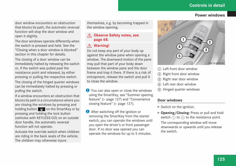
Power windows
125
door window encounters an obstructionthat blocks its path, the automatic reversalfunction will stop the door window andopen it slightly.The door windows operate differently whenthe switch is pressed and held. See the“Closing when a door window is blocked”section in this chapter for details.The closing of a door window can beimmediately halted by releasing the switchor, if the switch was pulled past theresistance point and released, by eitherpressing or pulling the respective switch.The closing of the hinged quarter windowscan be immediately halted by pressing orpulling the switch.If a window encounters an obstruction thatblocks its path in a circumstance where youare closing the windows by pressing andholding button j on the SmartKey or bypressing and holding the lock button(vehicles with KEYLESS-GO) on an outsidedoor handle, the automatic reversalfunction will not operate.Activate the override switch when childrenare riding in the back seats of the vehicle.The children may otherwise injure
themselves, e.g. by becoming trapped inthe window opening.
G Observe Safety notes, seepage 68.
G Warning!Do not keep any part of your body upagainst the window pane when opening awindow. The downward motion of the panemay pull that part of your body downbetween the window pane and the doorframe and trap it there. If there is a risk ofentrapment, release the switch and pull itto close the window.
i You can also open or close the windowsusing the SmartKey, see “Summer openingfeature” (Y page 127) and “Convenienceclosing feature” (Y page 127).
i After switching off the ignition orremoving the SmartKey from the starterswitch, you can operate the windows untilyou open the driver’s or front passengerdoor. If no door was opened you canoperate the windows for up to 5 minutes.
1 Left front door window2 Right front door window3 Right rear door window4 Left rear door window5 Hinged quarter windows
Door windowsX Switch on the ignition.X Opening/Closing: Press or pull and hold
switch 1 to 4 to the resistance point.The corresponding window will movedownwards or upwards until you releasethe switch.
Controls in detail
Z
Power windows
126
X Express operation: Press or pull switch1 to 4 past the resistance point andrelease.The corresponding window opens or closescompletely.
X Stopping during express operation:Press or pull the respective switch again.
Closing when a door window is blockedG Warning!Make sure that nobody can becometrapped and be seriously or even fatallyinjured when closing a door window withgreater force or without automatic reversalfunction.
If the upward movement of a door window isblocked during the closing procedure, thedoor window will stop and open slightly.However, the door window will exert greaterforce before reversing than when the doorwindow is closed in express operation. Pleaseexercise caution!X Immediately after the door window has
stopped because it was blocked, pull therespective switch upwards until the doorwindow is fully closed.
If the door window is blocked again and opensslightly:X Immediately after the door window was
blocked, pull the respective switchupwards until the door window is fullyclosed.
G Warning!Pressing and holding the switch to close thedoor window immediately after it had beenblocked two times will cause the doorwindow to close without any reversalfunction for as long as you hold the switch.
Hinged quarter windowsX Switch on the ignition.X Opening: Press switch 5 and release.
Both hinged quarter windows opencompletely.
X Closing: Pull switch 5 and release.Both hinged quarter windows closecompletely.
i When the obstruction sensor detects thata hinged quarter windows is blocked during
the closing process, they will stop and openslightly.
X Halting closing process: Press or pullswitch 5 once more during the closingprocess.The hinged quarter windows will stop andopen completely.
i For your safety, the hinged quarterwindows cannot be opened again until4 seconds have passed.
Synchronizing door windowsThe door windows must be synchronized afterthe battery has been disconnected or if thedoor windows cannot be fully closed (expressoperation).Each door window must be synchronizedseparately.X Close all doors.X Switch on the ignition.X Pull and hold switch 1, 2, 3 or 4
(Y page 125) until the respective doorwindow is closed.The door window opens again slightly.
Controls in detail
Power windows
127
X Pull and hold the respective switch oncemore immediately until the door window iscompletely closed.
X Hold the respective switch forapproximately 1 second.The door window is synchronized.
Summer opening featureIf the weather is warm, you can ventilate thevehicle before driving off by simultaneously:Ropening the door windowsRopening the hinged quarter windowsRopening the tilt/sliding sunroofRswitching on the seat ventilation for the
driver’s seatThe “Summer opening” feature can only beactivated via the remote control of theSmartKey. The SmartKey must be in closeproximity to the driver’s outside door handle.X Aim transmitter eye of the SmartKey at the
driver’s outside door handle.X Press and hold button k on the
SmartKey until the windows and the tilt/
sliding sunroof have reached the desiredposition.The vehicle unlocks.
X Release button k on the SmartKey tointerrupt the opening procedure.
Convenience closing featureWhen locking the vehicle, you cansimultaneously closeRthe door windowsRthe hinged quarter windowsRthe tilt/sliding sunroof
G Warning!When closing the windows and the tilt/sliding sunroof, make sure there is nodanger of anyone being harmed by theclosing procedure.If potential danger exists, proceed asfollows:RRelease button j to stop the closing
procedure. To open, press and holdbutton k. To continue the closingprocedure after making sure that there isno danger of anyone being harmed by the
closing procedure, press and hold buttonj.
Vehicles with KEYLESS-GO:RRelease the lock button on the outside
door handle to stop the closingprocedure.RImmediately pull on the same outside
door handle and hold firmly. The windowsand the tilt/sliding sunroof will open foras long as the door handle is held but thedoor not opened.
With SmartKeyThe SmartKey must be in close proximity tothe driver’s outside door handle.X Aim transmitter eye of the SmartKey at the
driver’s outside door handle.X Press and hold button j on the
SmartKey until the windows and the tilt/sliding sunroof are completely closed.The vehicle locks.
X Release button j on the SmartKey tointerrupt the closing procedure.
Controls in detail
Z
Driving and parking
128
With KEYLESS-GOThe SmartKey with KEYLESS-GO must belocated outside the vehicle withinapproximately 3 ft (1 m) of a door.X Close all doors.
X Press and hold the lock button on anoutside door handle (Y page 87) until thedoor windows and the tilt/sliding sunroofare completely closed.
X Release the lock button on the outside doorhandle to interrupt the closing procedure.
Driving and parking
Safety notes
G Warning!Make sure absolutely no objects areobstructing the pedals’ range of movement.Keep the driver’s footwell clear of allobstacles. If there are any floormats orcarpets in the footwell, make sure thepedals still have sufficient clearance.During sudden driving or brakingmaneuvers the objects could get caughtbetween the pedals. You could then nolonger brake or accelerate. This could leadto accidents and injury.
G Warning!With the engine not running, there is nopower assistance for the brake andsteering systems. In this case, it isimportant to keep in mind that aconsiderably higher degree of effort isnecessary to brake and steer the vehicle.Adapt your driving accordingly.
Starting the engine
G Warning!Inhalation of exhaust gas is hazardous toyour health. All exhaust gas containscarbon monoxide (CO), and inhaling it cancause unconsciousness and possibledeath.Do not run the engine in confined areas(such as a garage) which are not properlyventilated. If you think that exhaust gasfumes are entering the vehicle whiledriving, have the cause determined andcorrected immediately. If you must driveunder these conditions, drive only with atleast one window fully open at all times.
Controls in detail
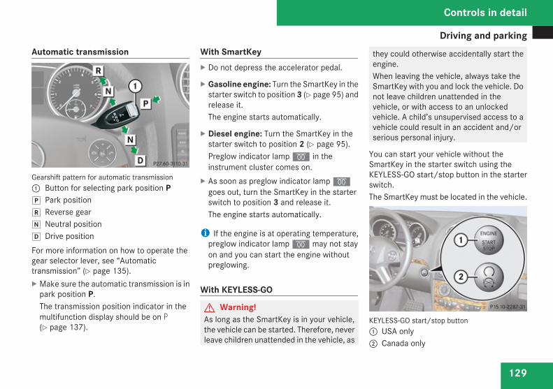
Driving and parking
129
Automatic transmission
Gearshift pattern for automatic transmission1 Button for selecting park position PÁ Park position Reverse gearÀ Neutral position¿ Drive positionFor more information on how to operate thegear selector lever, see “Automatictransmission” (Y page 135).X Make sure the automatic transmission is in
park position P.The transmission position indicator in themultifunction display should be on P(Y page 137).
With SmartKeyX Do not depress the accelerator pedal.
X Gasoline engine: Turn the SmartKey in thestarter switch to position 3 (Y page 95) andrelease it.The engine starts automatically.
X Diesel engine: Turn the SmartKey in thestarter switch to position 2 (Y page 95).Preglow indicator lamp q in theinstrument cluster comes on.
X As soon as preglow indicator lamp qgoes out, turn the SmartKey in the starterswitch to position 3 and release it.The engine starts automatically.
i If the engine is at operating temperature,preglow indicator lamp q may not stayon and you can start the engine withoutpreglowing.
With KEYLESS-GO
G Warning!As long as the SmartKey is in your vehicle,the vehicle can be started. Therefore, neverleave children unattended in the vehicle, as
they could otherwise accidentally start theengine.When leaving the vehicle, always take theSmartKey with you and lock the vehicle. Donot leave children unattended in thevehicle, or with access to an unlockedvehicle. A child’s unsupervised access to avehicle could result in an accident and/orserious personal injury.
You can start your vehicle without theSmartKey in the starter switch using theKEYLESS-GO start/stop button in the starterswitch.The SmartKey must be located in the vehicle.
KEYLESS-GO start/stop button1 USA only2 Canada only
Controls in detail
Z

Driving and parking
130
X Make sure the KEYLESS-GO start/stopbutton is inserted in the starter switch.
i If you wish to start the engine with theSmartKey instead of the KEYLESS-GOfunction, remove the KEYLESS-GO start/stop button from the starter switch andproceed as described in “WithSmartKey” (Y page 129).
X Depress the brake pedal during the startingprocedure.
X Do not depress the accelerator pedal.
X Gasoline engine: Press the KEYLESS-GOstart/stop button once.The engine starts automatically.
X Diesel engine: Press the KEYLESS-GOstart/stop button once.The engine preglows and startsautomatically.
i If the engine is at operating temperature,the time the engine needs to preglow isreduced.
Starting difficulties! Remember that extended starting
attempts can drain the battery.
The engine does not start. You can hearthe starter.There could be a malfunction in the engineelectronics or in the fuel supply system.Carry out the following steps:X If you are starting the engine with the
SmartKey: Turn the SmartKey in the starterswitch to position 0 and repeat the startingprocedure.
X If you are starting the engine with KEYLESS-GO: Close any doors that may be open toallow for better detection of the SmartKey.
orX Remove the KEYLESS-GO start/stop
button from the starter switch.X Start the engine with the SmartKey as radio
signals from another source may beinterfering with the KEYLESS-GO function.
X Repeat the starting procedure.
If the engine does not start after severalstarting attempts:X Contact an authorized Mercedes-Benz
Center or call Roadside Assistance.
The engine does not start. You cannothear the starter.The battery may not be sufficiently charged.X Get a jump start (Y page 410).
If the engine will not start despite a jumpstart:X Contact an authorized Mercedes-Benz
Center or call Roadside Assistance.The starter has been exposed to excessivetemperatures.X Let the starter cool for about two minutes.X Repeat the starting procedure.
If the engine does not start after severalstarting attempts:X Contact an authorized Mercedes-Benz
Center or call Roadside Assistance.
Controls in detail
Driving and parking
131
Driving off
G Warning!On slippery road surfaces, never downshiftin order to obtain braking action. This couldresult in drive wheel slip and reducedvehicle control. Your vehicle’s ABS will notprevent this type of loss of control.
! Do not run cold engine at high enginespeeds. Running a cold engine at highengine speeds may shorten the service lifeof the engine. This is not covered by theMercedes-Benz Limited Warranty.
! If you hear a warning signal and themessage Release Parking Brakeappears in the multifunction display whendriving off, you have forgotten to releasethe parking brake.Release the parking brake.
! Avoid spinning of a drive wheel. This maycause serious damage to the drivetrainwhich is not covered by the Mercedes-BenzLimited Warranty.
! Simultaneously depressing theaccelerator pedal and applying the brakesreduces engine performance and causes
premature brake and drivetrain wear whichis not covered by the Mercedes-BenzLimited Warranty.
i Once the vehicle is in motion, theautomatic central locking system engagesand the locking knobs in the doors movedown.The automatic door lock feature can bedeactivated (Y page 163).
Automatic transmission
G Warning!It is dangerous to shift the automatictransmission out of park position P orneutral position N if the engine speed ishigher than idle speed. If your foot is notfirmly on the brake pedal, the vehicle couldaccelerate quickly forward or in reverse.You could lose control of the vehicle and hitsomeone or something. Only shift into gearwhen the engine is idling normally andwhen your right foot is firmly on the brakepedal.
! Only shift the automatic transmission intoreverse gear R or park position P when the
vehicle is stopped. Otherwise theautomatic transmission could be damaged.
X Depress the brake pedal.The gear selector lever can now be used.
X Shift the automatic transmission into driveposition D or reverse gear R.
i Shifting the automatic transmission out ofpark position P is only possible with thebrake pedal depressed.Without the brake pedal depressed, thegear selector lever can be moved up ordown, but the parking pawl remainsengaged, not allowing shifting to occur.
X Wait for the gear selection process tocomplete before setting the vehicle inmotion.
X Release the brake pedal.X If engaged, release the parking brake.X Carefully depress the accelerator pedal.After a cold start, the automatic transmissionshifts at a higher engine revolution. Thisallows the catalytic converter (gasolineengine) or the oxidation catalyst (dieselengine) to reach its operating temperatureearlier.
Controls in detail
Z
Driving and parking
132
For more information on driving, see “Drivinginstructions” (Y page 299).For information on off-road driving, see “Off-road driving” (Y page 303).
Problems while driving
The engine runs erratically and misfiresRGasoline engine: An ignition cable may
be damaged.RThe engine electronics may not be
operating properly.RGasoline engine: Unburned gasoline may
have entered the catalytic converter anddamaged it.
X Give very little gas.X Have the problem checked at an authorized
Mercedes-Benz Center as soon as possible.
The coolant temperature is above248‡ (120†)The coolant is too hot and is no longer coolingthe engine.
X Stop the vehicle in a safe location as soonas possible.
X Turn off the engine immediately.X Allow the engine and coolant to cool off.X Check the coolant level and add coolant if
necessary (Y page 271).
In case of accidentIf the vehicle is leaking fuel:X Do not start the engine under any
circumstances.X Exit the vehicle at a safe distance from the
roadway.X Notify local fire and/or police authorities.
If the extent of the damage cannot bedetermined:X Contact an authorized Mercedes-Benz
Center or call Roadside Assistance.
If no damage on major assemblies, fuelsystem, and engine mount can bedetermined:X Start the engine in the usual manner.
Parking
G Warning!Do not park this vehicle in areas wherecombustible materials such as grass, hayor leaves can come into contact with thehot exhaust system, as these materialscould be ignited and cause a vehicle fire.To reduce the risk of serious personalinjury, or damage to the vehicle or thevehicle drivetrain, as a result of vehiclemovement, always do the following beforeturning off the engine and leaving thevehicle:RKeep right foot on the brake pedal.REngage the parking brake.RShift the automatic transmission into
park position P.RSlowly release the brake pedal.RWhen parked on an incline, always turn
the front wheels towards the road curb.RTurn the SmartKey in the starter switch
to position 0 and remove the SmartKey
Controls in detail
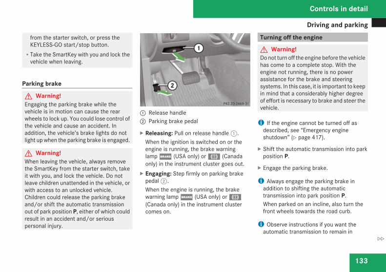
Driving and parking
133
from the starter switch, or press theKEYLESS-GO start/stop button.RTake the SmartKey with you and lock the
vehicle when leaving.
Parking brake
G Warning!Engaging the parking brake while thevehicle is in motion can cause the rearwheels to lock up. You could lose control ofthe vehicle and cause an accident. Inaddition, the vehicle’s brake lights do notlight up when the parking brake is engaged.
G Warning!When leaving the vehicle, always removethe SmartKey from the starter switch, takeit with you, and lock the vehicle. Do notleave children unattended in the vehicle, orwith access to an unlocked vehicle.Children could release the parking brakeand/or shift the automatic transmissionout of park position P, either of which couldresult in an accident and/or seriouspersonal injury.
1 Release handle2 Parking brake pedal
X Releasing: Pull on release handle 1.When the ignition is switched on or theengine is running, the brake warninglamp ; (USA only) or 3 (Canadaonly) in the instrument cluster goes out.
X Engaging: Step firmly on parking brakepedal 2.When the engine is running, the brakewarning lamp ; (USA only) or 3(Canada only) in the instrument clustercomes on.
Turning off the engine
G Warning!Do not turn off the engine before the vehiclehas come to a complete stop. With theengine not running, there is no powerassistance for the brake and steeringsystems. In this case, it is important to keepin mind that a considerably higher degreeof effort is necessary to brake and steer thevehicle.
i If the engine cannot be turned off asdescribed, see “Emergency engineshutdown” (Y page 417).
X Shift the automatic transmission into parkposition P.
X Engage the parking brake.
i Always engage the parking brake inaddition to shifting the automatictransmission into park position P.When parked on an incline, also turn thefront wheels towards the road curb.
i Observe instructions if you want theautomatic transmission to remain in
Controls in detail
Z
Driving and parking
134
neutral position N, see “Remaining inneutral position N” (Y page 136).
With SmartKeyX Turn the SmartKey in the starter switch to
position 0.
X Remove the SmartKey from the starterswitch.The immobilizer is activated.
If you turn off the engine using the SmartKey,and remove the SmartKey from the starterswitch or open a front door, the automatictransmission will shift into park position Pautomatically.G Warning!Keep in mind that turning off the enginealone only will shift the automatictransmission into neutral position Nautomatically.Always shift the automatic transmissioninto park position P before turning off theengine.Otherwise the vehicle could roll away whichcould result in an accident and/or seriouspersonal injury.
With KEYLESS-GOX Press the KEYLESS-GO start/stop button.
With the driver’s door closed, the starterswitch is now in position 1. With the driver’sdoor opened, the starter switch is set toposition 0, same as the SmartKey removedfrom the starter switch (Y page 95).
If you turn off the engine using the KEYLESS-GO start/stop button and open a front door,the automatic transmission will shift into parkposition P automatically.G Warning!Keep in mind that turning off the enginealone only will shift the automatictransmission into neutral position Nautomatically.Always shift the automatic transmissioninto park position P before turning off theengine.Otherwise the vehicle could roll away whichcould result in an accident and/or seriouspersonal injury.
i In an emergency you can turn off theengine while driving by pressing andholding the KEYLESS-GO start/stop buttonfor approximately 3 seconds.
If you have started the engine with theKEYLESS-GO start/stop button and cannotturn it off as described above:X Remove the KEYLESS-GO start/stop
button from the starter switch.X Insert the SmartKey into the starter switch.
The engine turns off. The starter switch isin position 0 (Y page 95).
Controls in detail
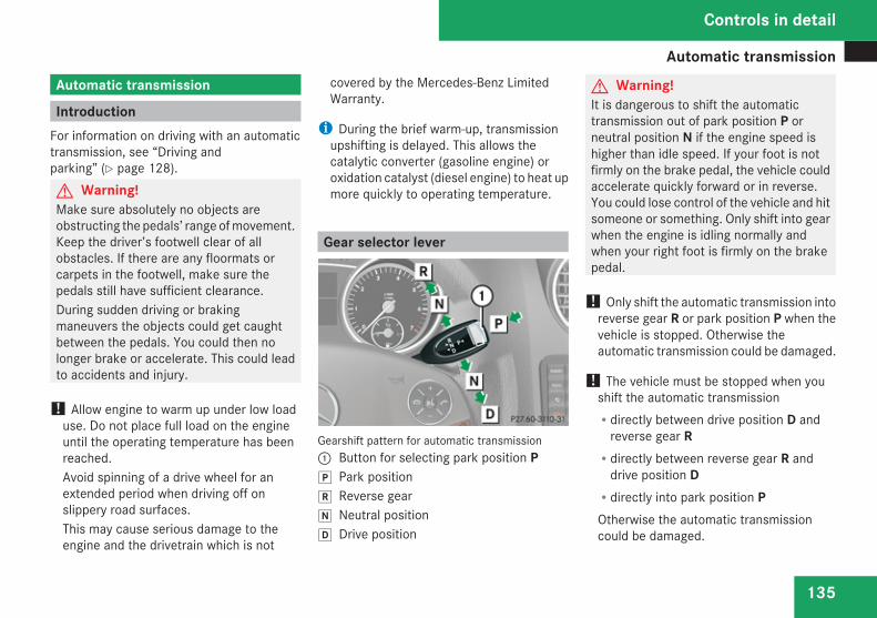
Automatic transmission
135
Automatic transmission
IntroductionFor information on driving with an automatictransmission, see “Driving andparking” (Y page 128).G Warning!Make sure absolutely no objects areobstructing the pedals’ range of movement.Keep the driver’s footwell clear of allobstacles. If there are any floormats orcarpets in the footwell, make sure thepedals still have sufficient clearance.During sudden driving or brakingmaneuvers the objects could get caughtbetween the pedals. You could then nolonger brake or accelerate. This could leadto accidents and injury.
! Allow engine to warm up under low loaduse. Do not place full load on the engineuntil the operating temperature has beenreached.Avoid spinning of a drive wheel for anextended period when driving off onslippery road surfaces.This may cause serious damage to theengine and the drivetrain which is not
covered by the Mercedes-Benz LimitedWarranty.
i During the brief warm-up, transmissionupshifting is delayed. This allows thecatalytic converter (gasoline engine) oroxidation catalyst (diesel engine) to heat upmore quickly to operating temperature.
Gear selector lever
Gearshift pattern for automatic transmission1 Button for selecting park position PÁ Park position Reverse gearÀ Neutral position¿ Drive position
G Warning!It is dangerous to shift the automatictransmission out of park position P orneutral position N if the engine speed ishigher than idle speed. If your foot is notfirmly on the brake pedal, the vehicle couldaccelerate quickly forward or in reverse.You could lose control of the vehicle and hitsomeone or something. Only shift into gearwhen the engine is idling normally andwhen your right foot is firmly on the brakepedal.
! Only shift the automatic transmission intoreverse gear R or park position P when thevehicle is stopped. Otherwise theautomatic transmission could be damaged.
! The vehicle must be stopped when youshift the automatic transmissionRdirectly between drive position D and
reverse gear RRdirectly between reverse gear R and
drive position DRdirectly into park position POtherwise the automatic transmissioncould be damaged.
Controls in detail
Z
Automatic transmission
136
When trying to free a vehicle stuck in mud orsnow, see “Rocking thevehicle” (Y page 139).
i Shifting the automatic transmission out ofpark position P is only possible with thebrake pedal depressed.Without the brake pedal depressed, thegear selector lever can be moved up ordown, but the parking pawl remainsengaged, not allowing shifting to occur.
i The gear selector lever always returns toits original position.The current transmission position P, R, N,or D appears in the multifunction display(Y page 137).
Shifting into park position PX With the vehicle at a standstill, press button
1 on the gear selector lever to select parkposition P.
SmartKey: When you turn off the engine usingthe SmartKey, and remove the SmartKeyfrom the starter switch or open a front door,the automatic transmission will shift into parkposition P automatically.KEYLESS-GO: When you turn off the engineusing the KEYLESS-GO start/stop button and
open a front door, the automatic transmissionwill shift into park position P automatically.G Warning!Keep in mind that turning off the enginealone only will shift the automatictransmission into neutral position Nautomatically.Always shift the automatic transmissioninto park position P before turning off theengine.Otherwise the vehicle could roll away whichcould result in an accident and/or seriouspersonal injury.
i Moving the gear selector lever up or downshifts the automatic transmission out ofpark position P.
Shifting into neutral position NX With the vehicle at a standstill, depress the
brake pedal and move the gear selectorlever up or down to the resistance point toselect neutral position N.
When you turn off the engine, the automatictransmission will shift into neutral positionN automatically.
SmartKey: Removing the SmartKey from thestarter switch or opening a front door afterturning off the engine will shift the automatictransmission into park position Pautomatically.KEYLESS-GO: Opening a front door afterturning off the engine will shift the automatictransmission into park position Pautomatically.
Remaining in neutral position NIf you want the automatic transmission toremain in neutral position N, e.g. when takingthe vehicle through an automatic conveyor-type car wash, observe the followinginstructions:G Warning!When leaving the SmartKey in the starterswitch, do not leave children unattended inthe vehicle. It is possible for children toswitch on the ignition which could result inunsupervised use of vehicle equipment.Unsupervised use of vehicle equipmentcould result in an accident and/or seriouspersonal injury.
Controls in detail
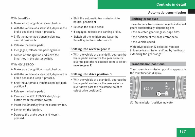
Automatic transmission
137
With SmartKey:X Make sure the ignition is switched on.X With the vehicle at a standstill, depress the
brake pedal and keep it pressed.X Shift the automatic transmission into
neutral position N.X Release the brake pedal.X If engaged, release the parking brake.X Switch off the ignition and leave the
SmartKey in the starter switch.
With KEYLESS-GO:X Make sure the ignition is switched on.X With the vehicle at a standstill, depress the
brake pedal and keep it pressed.X Shift the automatic transmission into park
position P.X Release the brake pedal.X Remove the KEYLESS-GO start/stop
button from the starter switch.X Insert the SmartKey into the starter switch.X Switch on the ignition.X Depress the brake pedal and keep it
pressed.
X Shift the automatic transmission intoneutral position N.
X Release the brake pedal.X If engaged, release the parking brake.X Switch off the ignition and leave the
SmartKey in the starter switch.
Shifting into reverse gear RX With the vehicle at a standstill, depress the
brake pedal and move the gear selectorlever up past the resistance point to selectreverse gear R.
Shifting into drive position DX With the vehicle at a standstill, depress the
brake pedal and move the gear selectorlever down past the resistance point toselect drive position D.
Shifting procedureThe automatic transmission selects individualgears automatically, depending on:Rthe selected gear range (Y page 139)Rthe position of the accelerator pedalRthe vehicle speedWith drive position D selected, you caninfluence transmission shifting by limiting orextending the gear range.
Transmission positionsThe current transmission position appears inthe multifunction display.
1 Transmission position indicator
Controls in detail
Z
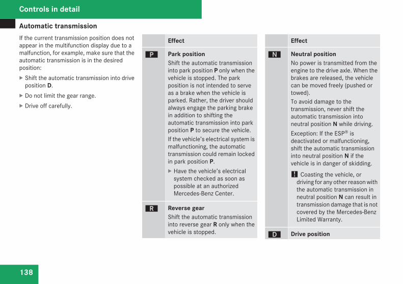
Automatic transmission
138
If the current transmission position does notappear in the multifunction display due to amalfunction, for example, make sure that theautomatic transmission is in the desiredposition:X Shift the automatic transmission into drive
position D.X Do not limit the gear range.X Drive off carefully.
Effect
ì Park positionShift the automatic transmissioninto park position P only when thevehicle is stopped. The parkposition is not intended to serveas a brake when the vehicle isparked. Rather, the driver shouldalways engage the parking brakein addition to shifting theautomatic transmission into parkposition P to secure the vehicle.If the vehicle’s electrical system ismalfunctioning, the automatictransmission could remain lockedin park position P.X Have the vehicle’s electrical
system checked as soon aspossible at an authorizedMercedes-Benz Center.
í Reverse gearShift the automatic transmissioninto reverse gear R only when thevehicle is stopped.
Effect
ë Neutral positionNo power is transmitted from theengine to the drive axle. When thebrakes are released, the vehiclecan be moved freely (pushed ortowed).To avoid damage to thetransmission, never shift theautomatic transmission intoneutral position N while driving.Exception: If the ESP® isdeactivated or malfunctioning,shift the automatic transmissioninto neutral position N if thevehicle is in danger of skidding.
! Coasting the vehicle, ordriving for any other reason withthe automatic transmission inneutral position N can result intransmission damage that is notcovered by the Mercedes-BenzLimited Warranty.
ê Drive position
Controls in detail
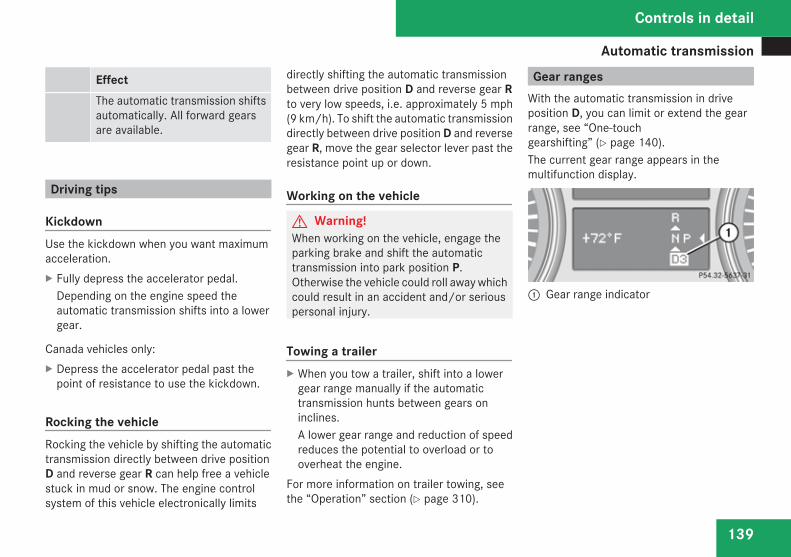
Automatic transmission
139
EffectThe automatic transmission shiftsautomatically. All forward gearsare available.
Driving tips
KickdownUse the kickdown when you want maximumacceleration.X Fully depress the accelerator pedal.
Depending on the engine speed theautomatic transmission shifts into a lowergear.
Canada vehicles only:X Depress the accelerator pedal past the
point of resistance to use the kickdown.
Rocking the vehicleRocking the vehicle by shifting the automatictransmission directly between drive positionD and reverse gear R can help free a vehiclestuck in mud or snow. The engine controlsystem of this vehicle electronically limits
directly shifting the automatic transmissionbetween drive position D and reverse gear Rto very low speeds, i.e. approximately 5 mph(9 km/h). To shift the automatic transmissiondirectly between drive position D and reversegear R, move the gear selector lever past theresistance point up or down.
Working on the vehicle
G Warning!When working on the vehicle, engage theparking brake and shift the automatictransmission into park position P.Otherwise the vehicle could roll away whichcould result in an accident and/or seriouspersonal injury.
Towing a trailerX When you tow a trailer, shift into a lower
gear range manually if the automatictransmission hunts between gears oninclines.A lower gear range and reduction of speedreduces the potential to overload or tooverheat the engine.
For more information on trailer towing, seethe “Operation” section (Y page 310).
Gear rangesWith the automatic transmission in driveposition D, you can limit or extend the gearrange, see “One-touchgearshifting” (Y page 140).The current gear range appears in themultifunction display.
1 Gear range indicator
Controls in detail
Z
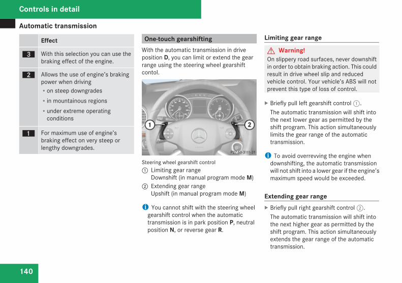
Automatic transmission
140
Effect
è With this selection you can use thebraking effect of the engine.
ç Allows the use of engine’s brakingpower when drivingRon steep downgradesRin mountainous regionsRunder extreme operating
conditions
æ For maximum use of engine’sbraking effect on very steep orlengthy downgrades.
One-touch gearshiftingWith the automatic transmission in driveposition D, you can limit or extend the gearrange using the steering wheel gearshiftcontol.
Steering wheel gearshift control1 Limiting gear range
Downshift (in manual program mode M)2 Extending gear range
Upshift (in manual program mode M)
i You cannot shift with the steering wheelgearshift control when the automatictransmission is in park position P, neutralposition N, or reverse gear R.
Limiting gear range
G Warning!On slippery road surfaces, never downshiftin order to obtain braking action. This couldresult in drive wheel slip and reducedvehicle control. Your vehicle’s ABS will notprevent this type of loss of control.
X Briefly pull left gearshift control 1.The automatic transmission will shift intothe next lower gear as permitted by theshift program. This action simultaneouslylimits the gear range of the automatictransmission.
i To avoid overrevving the engine whendownshifting, the automatic transmissionwill not shift into a lower gear if the engine’smaximum speed would be exceeded.
Extending gear rangeX Briefly pull right gearshift control 2.
The automatic transmission will shift intothe next higher gear as permitted by theshift program. This action simultaneouslyextends the gear range of the automatictransmission.
Controls in detail
Transfer case
141
i If you press on the accelerator pedalwhen the engine has reached therevolution limit of the current gear range,the automatic transmission will upshiftbeyond any gear range limit selected.
Canceling gear range limitX Pull and hold right gearshift control 2 until
the gear range indicator disappears fromthe multifunction display.The automatic transmission will shift fromthe current gear range directly into gearrange D.
Shifting into optimal gear rangeX Pull and hold left gearshift control 1.
The automatic transmission will select thegear range suited for optimal accelerationand deceleration automatically. This willinvolve shifting down one or more gears.
Emergency operation (limp-homemode)
If vehicle acceleration becomes lessresponsive or sluggish or the automatictransmission no longer shifts, the automatictransmission is most likely operating in limp-home (emergency operation) mode. In thismode only second gear and reverse gear Rcan be selected.X Stop the vehicle in a safe location.X Shift the automatic transmission into park
position P.X Turn off the engine.X Wait at least 10 seconds before restarting.X Restart the engine.X Shift the automatic transmission into drive
position D (for second gear) or reverse gearR.
X Have the automatic transmission checkedat an authorized Mercedes-Benz Center assoon as possible.
Transfer case
The vehicle is equipped with all-wheel drive(4MATIC). Both the front and rear axles arepowered at all times when the vehicle is beingoperated.
! Only conduct operational or performancetests on a two-axle dynamometer. If suchtests are necessary, contact an authorizedMercedes-Benz Center. You couldotherwise seriously damage the brakesystem or the transfer case which is notcovered by the Mercedes-Benz LimitedWarranty.
! Because the ESP® operatesautomatically, the engine and ignition mustbe shut off (SmartKey in starter switchposition 0 or 1 or KEYLESS-GO start/stopbutton in position 0 or 1) when the parkingbrake is being tested on a brake testdynamometer. Such testing should be nolonger than 10 seconds.Active braking action through the ESP®
may otherwise seriously damage the brakesystem which is not covered by theMercedes-Benz Limited Warranty.
Controls in detail
Z
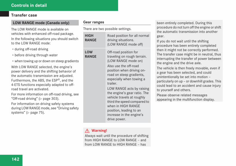
Transfer case
142
LOW RANGE mode (Canada only) The LOW RANGE mode is available onvehicles with enhanced off-road package.In the following situations you should switchto the LOW RANGE mode:Rduring off-road drivingRbefore driving through waterRwhen towing up or down on steep gradientsWith LOW RANGE selected, the engine’spower delivery and the shifting behavior ofthe automatic transmission are adjusted.Furthermore, the ABS, the ESP®, and the4-ETS functions especially adapted to off-road travel are activated.For more information on off-road driving, see“Off-road driving” (Y page 303).For information on driving safety systemsduring LOW RANGE mode, see “Driving safetysystems” (Y page 75).
Gear rangesThere are two possible settings.
HIGHRANGE
Road position for all normaldriving situations.(LOW RANGE mode off)
LOWRANGE
Off-road position fortraveling on rough terrain.(LOW RANGE mode on)Also use the off-roadposition when driving on-road on steep gradients,especially when towing atrailer.LOW RANGE acts by raisingthe engine’s gear ratio. Thevehicle travels at roughlythird the speed compared towhen in HIGH RANGEposition, leading to anincrease in the engine’sdrive power.
G Warning!Always wait until the procedure of shiftingfrom HIGH RANGE to LOW RANGE – andfrom LOW RANGE to HIGH RANGE – has
been entirely completed. During thisprocedure do not turn off the engine or shiftthe automatic transmission into anothergear.If you do not wait until the shiftingprocedure has been entirely completedthen it might not be correctly performed.The transfer case might be in neutral, thusinterrupting the transfer of power betweenthe engine and the drive axle.The vehicle is then freely movable, even ifa gear has been selected, and couldunintentionally be set into motion –particularly on up – or downhill grades. Thiscould lead to an accident and cause injuryto yourself and others.Please observe related messagesappearing in the multifunction display.
Controls in detail
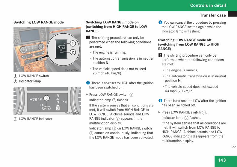
Transfer case
143
Switching LOW RANGE mode
1 LOW RANGE switch2 Indicator lamp
3 LOW RANGE indicator
Switching LOW RANGE mode on(switching from HIGH RANGE to LOWRANGE)! The shifting procedure can only be
performed when the following conditionsare met:RThe engine is running.RThe automatic transmission is in neutral
position N.RThe vehicle speed does not exceed
25 mph (40 km/h).
i There is no reset to HIGH after the ignitionhas been switched off.
X Press LOW RANGE switch 1.Indicator lamp 2 flashes.If the system senses that all conditions aremet, it will switch from HIGH RANGE toLOW RANGE. A chime sounds and LOWRANGE indicator 3 appears in themultifunction display.Indicator lamp 2 on LOW RANGE switch1 comes on continuously, indicating thatthe LOW RANGE mode has been activated.
i You can cancel the procedure by pressingthe LOW RANGE switch again while theindicator lamp is flashing.
Switching LOW RANGE mode off(switching from LOW RANGE to HIGHRANGE)! The shifting procedure can only be
performed when the following conditionsare met:RThe engine is running.RThe automatic transmission is in neutral
position N.RThe vehicle speed does not exceed
43 mph (70 km/h).
i There is no reset to LOW after the ignitionhas been switched off.
X Press LOW RANGE switch 1.Indicator lamp 2 flashes.If the system senses that all conditions aremet, it will switch from LOW RANGE toHIGH RANGE. A chime sounds and LOWRANGE indicator 3 disappears from themultifunction display.
Controls in detail
Z
Differential locks (Canada only)
144
Indicator lamp 2 on LOW RANGE switch1 goes out, indicating that the LOWRANGE mode has been deactivated.
i You can cancel the procedure by pressingthe LOW RANGE switch again while theindicator lamp is flashing.
For messages in the multifunction display,see the “Practical hints” section(Y page 352).
Differential locks (Canada only)
Vehicles with enhanced off-road package areequipped with automatic locks for the centerand rear axle differential to improve vehicletraction.The center differential compensates fordifferences in wheel rotation between thefront and rear axle.The rear axle differential compensatesdifferences between the rear wheels.
i At the front axles, the 4-ETS systemcompensates for any traction problems.
For more information on off-road driving, see“Off-road driving” (Y page 303).
A few words about differentials anddifferential locks
When a vehicle negotiates a turn, wheels onthe outside of the curve must travel fartherand rotate faster than the inside wheels. Thedifferential, the operation of a set of gearsthat allows the powered wheels in a vehicleto turn at different speeds, makes thisessential function possible.The drawback is that the differential alsosends most of the engine’s power to the
wheel with the least load or strain on it. Forexample, if one of a vehicle’s powered wheelssits on a patch of snow and spins becausethere is no traction, all of the engine’s powerwill go to that wheel because the power willtake the path of least resistance. Meanwhile,the opposite wheel, sitting on dry pavementwhere it could get enough grip to start thevehicle moving, sits idle because it receivesno power.The 4-ETS addresses this problem andprovides for good control and steering abilityby automatically slowing the slipping wheeland thus increasing the power to the othernon-slipping drive wheels to get the vehiclemoving. The ESP® and the 4-ETS in thisvehicle feature such intelligent limited-slipdifferential technology, ideally suited for on-road and light off-road driving. Transfer caseposition LOW (Y page 142) also enhances off-road driving capabilities.More extreme off-road conditions may call foranother solution, engaging a differential lockor preventing the differential from operatingaltogether. This vehicle comes with twodifferential locks: transfer case (center) andrear. Each can be engaged simply byoperating the rotary switch located on thecenter console (Y page 145). When thetransfer case (center) differential is locked,
Controls in detail
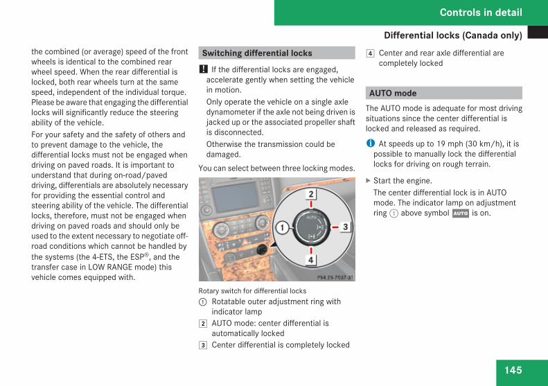
Differential locks (Canada only)
145
the combined (or average) speed of the frontwheels is identical to the combined rearwheel speed. When the rear differential islocked, both rear wheels turn at the samespeed, independent of the individual torque.Please be aware that engaging the differentiallocks will significantly reduce the steeringability of the vehicle.For your safety and the safety of others andto prevent damage to the vehicle, thedifferential locks must not be engaged whendriving on paved roads. It is important tounderstand that during on-road/paveddriving, differentials are absolutely necessaryfor providing the essential control andsteering ability of the vehicle. The differentiallocks, therefore, must not be engaged whendriving on paved roads and should only beused to the extent necessary to negotiate off-road conditions which cannot be handled bythe systems (the 4-ETS, the ESP®, and thetransfer case in LOW RANGE mode) thisvehicle comes equipped with.
Switching differential locks ! If the differential locks are engaged,
accelerate gently when setting the vehiclein motion.Only operate the vehicle on a single axledynamometer if the axle not being driven isjacked up or the associated propeller shaftis disconnected.Otherwise the transmission could bedamaged.
You can select between three locking modes.
Rotary switch for differential locks1 Rotatable outer adjustment ring with
indicator lamp % AUTO mode: center differential is
automatically locked& Center differential is completely locked
( Center and rear axle differential arecompletely locked
AUTO modeThe AUTO mode is adequate for most drivingsituations since the center differential islocked and released as required.
i At speeds up to 19 mph (30 km/h), it ispossible to manually lock the differentiallocks for driving on rough terrain.
X Start the engine.The center differential lock is in AUTOmode. The indicator lamp on adjustmentring 1 above symbol U is on.
Controls in detail
Z
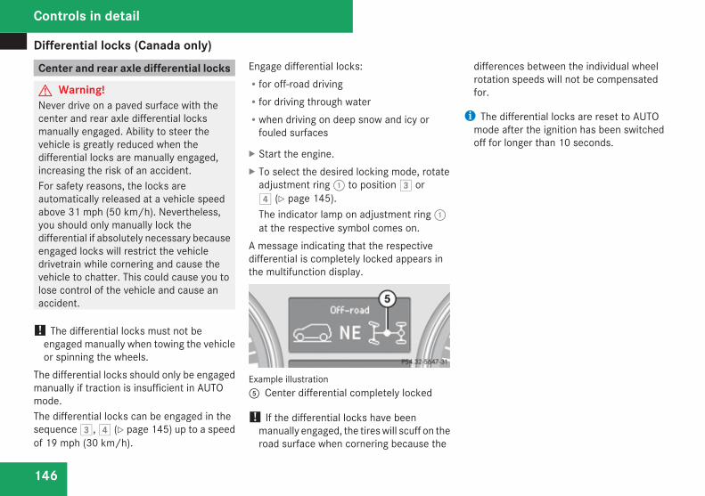
Differential locks (Canada only)
146
Center and rear axle differential locks
G Warning!Never drive on a paved surface with thecenter and rear axle differential locksmanually engaged. Ability to steer thevehicle is greatly reduced when thedifferential locks are manually engaged,increasing the risk of an accident.For safety reasons, the locks areautomatically released at a vehicle speedabove 31 mph (50 km/h). Nevertheless,you should only manually lock thedifferential if absolutely necessary becauseengaged locks will restrict the vehicledrivetrain while cornering and cause thevehicle to chatter. This could cause you tolose control of the vehicle and cause anaccident.
! The differential locks must not beengaged manually when towing the vehicleor spinning the wheels.
The differential locks should only be engagedmanually if traction is insufficient in AUTOmode.The differential locks can be engaged in thesequence &, ( (Y page 145) up to a speedof 19 mph (30 km/h).
Engage differential locks:Rfor off-road drivingRfor driving through waterRwhen driving on deep snow and icy or
fouled surfaces
X Start the engine.X To select the desired locking mode, rotate
adjustment ring 1 to position & or( (Y page 145).The indicator lamp on adjustment ring 1at the respective symbol comes on.
A message indicating that the respectivedifferential is completely locked appears inthe multifunction display.
Example illustration5 Center differential completely locked
! If the differential locks have beenmanually engaged, the tires will scuff on theroad surface when cornering because the
differences between the individual wheelrotation speeds will not be compensatedfor.
i The differential locks are reset to AUTOmode after the ignition has been switchedoff for longer than 10 seconds.
Controls in detail
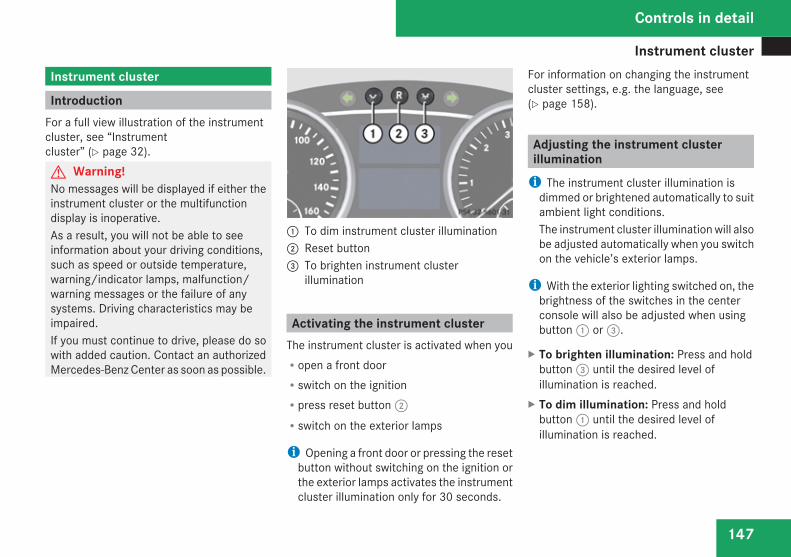
Instrument cluster
147
Instrument cluster
IntroductionFor a full view illustration of the instrumentcluster, see “Instrumentcluster” (Y page 32).G Warning!No messages will be displayed if either theinstrument cluster or the multifunctiondisplay is inoperative.As a result, you will not be able to seeinformation about your driving conditions,such as speed or outside temperature,warning/indicator lamps, malfunction/warning messages or the failure of anysystems. Driving characteristics may beimpaired.If you must continue to drive, please do sowith added caution. Contact an authorizedMercedes-Benz Center as soon as possible.
1 To dim instrument cluster illumination2 Reset button 3 To brighten instrument cluster
illumination
Activating the instrument clusterThe instrument cluster is activated when youRopen a front doorRswitch on the ignitionRpress reset button 2Rswitch on the exterior lamps
i Opening a front door or pressing the resetbutton without switching on the ignition orthe exterior lamps activates the instrumentcluster illumination only for 30 seconds.
For information on changing the instrumentcluster settings, e.g. the language, see(Y page 158).
Adjusting the instrument clusterillumination
i The instrument cluster illumination isdimmed or brightened automatically to suitambient light conditions.The instrument cluster illumination will alsobe adjusted automatically when you switchon the vehicle’s exterior lamps.
i With the exterior lighting switched on, thebrightness of the switches in the centerconsole will also be adjusted when usingbutton 1 or 3.
X To brighten illumination: Press and holdbutton 3 until the desired level ofillumination is reached.
X To dim illumination: Press and holdbutton 1 until the desired level ofillumination is reached.
Controls in detail
Z
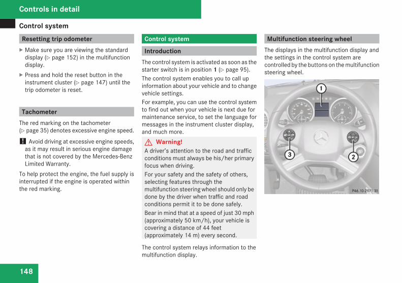
Control system
148
Resetting trip odometerX Make sure you are viewing the standard
display (Y page 152) in the multifunctiondisplay.
X Press and hold the reset button in theinstrument cluster (Y page 147) until thetrip odometer is reset.
TachometerThe red marking on the tachometer(Y page 35) denotes excessive engine speed.
! Avoid driving at excessive engine speeds,as it may result in serious engine damagethat is not covered by the Mercedes-BenzLimited Warranty.
To help protect the engine, the fuel supply isinterrupted if the engine is operated withinthe red marking.
Control system
IntroductionThe control system is activated as soon as thestarter switch is in position 1 (Y page 95).The control system enables you to call upinformation about your vehicle and to changevehicle settings.For example, you can use the control systemto find out when your vehicle is next due formaintenance service, to set the language formessages in the instrument cluster display,and much more.G Warning!A driver’s attention to the road and trafficconditions must always be his/her primaryfocus when driving.For your safety and the safety of others,selecting features through themultifunction steering wheel should only bedone by the driver when traffic and roadconditions permit it to be done safely.Bear in mind that at a speed of just 30 mph(approximately 50 km/h), your vehicle iscovering a distance of 44 feet(approximately 14 m) every second.
The control system relays information to themultifunction display.
Multifunction steering wheelThe displays in the multifunction display andthe settings in the control system arecontrolled by the buttons on the multifunctionsteering wheel.
Controls in detail
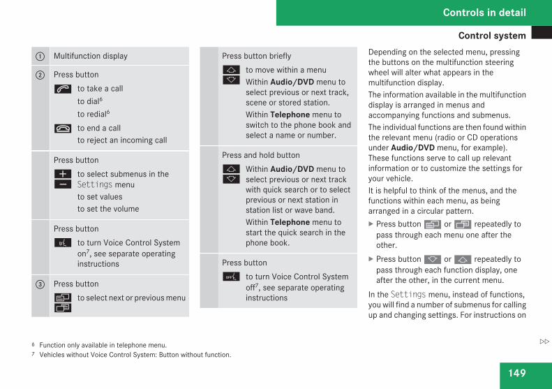
Control system
149
1 Multifunction display
2 Press buttons to take a call
to dial6
to redial6
t to end a callto reject an incoming call
Press buttonæç
to select submenus in theSettings menuto set valuesto set the volume
Press button! to turn Voice Control System
on7, see separate operatinginstructions
3 Press buttonèÿ
to select next or previous menu
Press button brieflyjk
to move within a menuWithin Audio/DVD menu toselect previous or next track,scene or stored station.Within Telephone menu toswitch to the phone book andselect a name or number.
Press and hold buttonjk
Within Audio/DVD menu toselect previous or next trackwith quick search or to selectprevious or next station instation list or wave band.Within Telephone menu tostart the quick search in thephone book.
Press button0 to turn Voice Control System
off7, see separate operatinginstructions
Depending on the selected menu, pressingthe buttons on the multifunction steeringwheel will alter what appears in themultifunction display.The information available in the multifunctiondisplay is arranged in menus andaccompanying functions and submenus.The individual functions are then found withinthe relevant menu (radio or CD operationsunder Audio/DVD menu, for example).These functions serve to call up relevantinformation or to customize the settings foryour vehicle.It is helpful to think of the menus, and thefunctions within each menu, as beingarranged in a circular pattern.X Press button è or ÿ repeatedly to
pass through each menu one after theother.
X Press button k or j repeatedly topass through each function display, oneafter the other, in the current menu.
In the Settings menu, instead of functions,you will find a number of submenus for callingup and changing settings. For instructions on
6 Function only available in telephone menu.7 Vehicles without Voice Control System: Button without function.
Controls in detail
Z
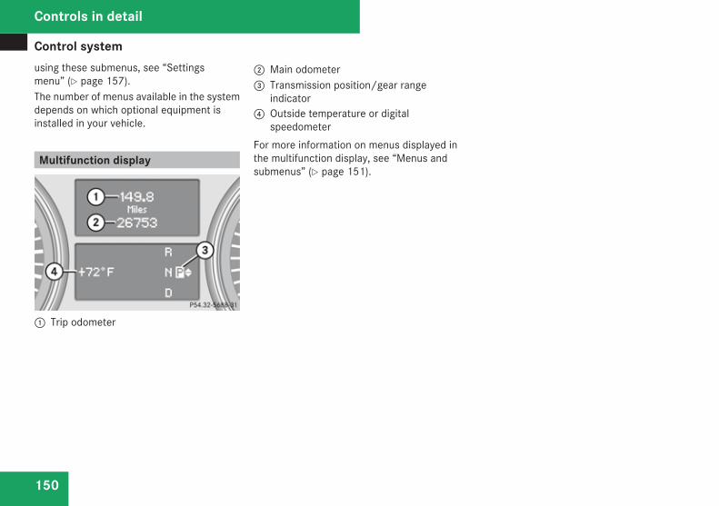
Control system
150
using these submenus, see “Settingsmenu” (Y page 157).The number of menus available in the systemdepends on which optional equipment isinstalled in your vehicle.
Multifunction display
1 Trip odometer
2 Main odometer3 Transmission position/gear range
indicator4 Outside temperature or digital
speedometerFor more information on menus displayed inthe multifunction display, see “Menus andsubmenus” (Y page 151).
Controls in detail
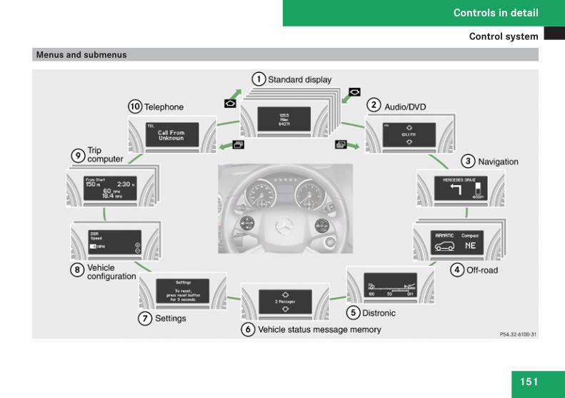
Control system
151
Menus and submenus
Controls in detail
Z
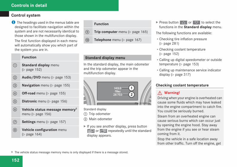
Control system
152
i The headings used in the menus table aredesigned to facilitate navigation within thesystem and are not necessarily identical tothose shown in the multifunction display.The first function displayed in each menuwill automatically show you which part ofthe system you are in.
Function
1 Standard display menu(Y page 152)
2 Audio/DVD menu (Y page 153)
3 Navigation menu (Y page 155)
4 Off-road menu (Y page 155)
5 Distronic menu (Y page 156)
6 Vehicle status message memory8
menu (Y page 156)
7 Settings menu (Y page 157)
8 Vehicle configuration menu(Y page 164)
Function
9 Trip computer menu (Y page 165)
a Telephone menu (Y page 167)
Standard display menuIn the standard display, the main odometerand the trip odometer appear in themultifunction display.
Standard display1 Trip odometer2 Main odometer
X If you see another display, press buttonè or ÿ repeatedly until the standarddisplay appears.
X Press button j or k to select thefunctions in the Standard display menu.
The following functions are available:RChecking tire inflation pressure
(Y page 281)RChecking coolant temperature
(Y page 152)RCalling up digital speedometer or outside
temperature (Y page 153)RCalling up maintenance service indicator
display (Y page 317)
Checking coolant temperature
G Warning!Driving when your engine is overheated cancause some fluids which may have leakedinto the engine compartment to catch fire.You could be seriously burned.Steam from an overheated engine cancause serious burns which can occur justby opening the engine hood. Stay awayfrom the engine if you see or hear steamcoming from it.Stop the vehicle in a safe location awayfrom other traffic. Turn off the engine, get
8 The vehicle status message memory menu is only displayed if there is a message stored.
Controls in detail
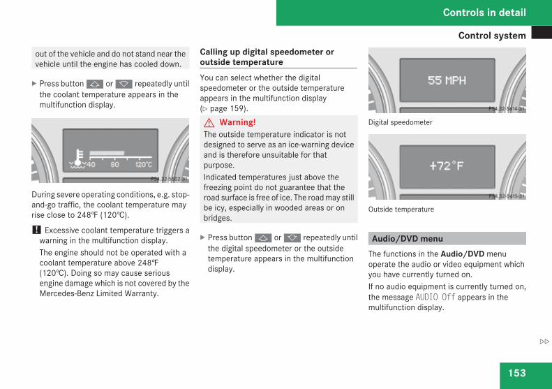
Control system
153
out of the vehicle and do not stand near thevehicle until the engine has cooled down.
X Press button j or k repeatedly untilthe coolant temperature appears in themultifunction display.
During severe operating conditions, e.g. stop-and-go traffic, the coolant temperature mayrise close to 248‡ (120†).
! Excessive coolant temperature triggers awarning in the multifunction display.The engine should not be operated with acoolant temperature above 248‡(120†). Doing so may cause seriousengine damage which is not covered by theMercedes-Benz Limited Warranty.
Calling up digital speedometer oroutside temperatureYou can select whether the digitalspeedometer or the outside temperatureappears in the multifunction display(Y page 159).G Warning!The outside temperature indicator is notdesigned to serve as an ice-warning deviceand is therefore unsuitable for thatpurpose.Indicated temperatures just above thefreezing point do not guarantee that theroad surface is free of ice. The road may stillbe icy, especially in wooded areas or onbridges.
X Press button j or k repeatedly untilthe digital speedometer or the outsidetemperature appears in the multifunctiondisplay.
Digital speedometer
Outside temperature
Audio/DVD menuThe functions in the Audio/DVD menuoperate the audio or video equipment whichyou have currently turned on.If no audio equipment is currently turned on,the message AUDIO Off appears in themultifunction display.
Controls in detail
Z
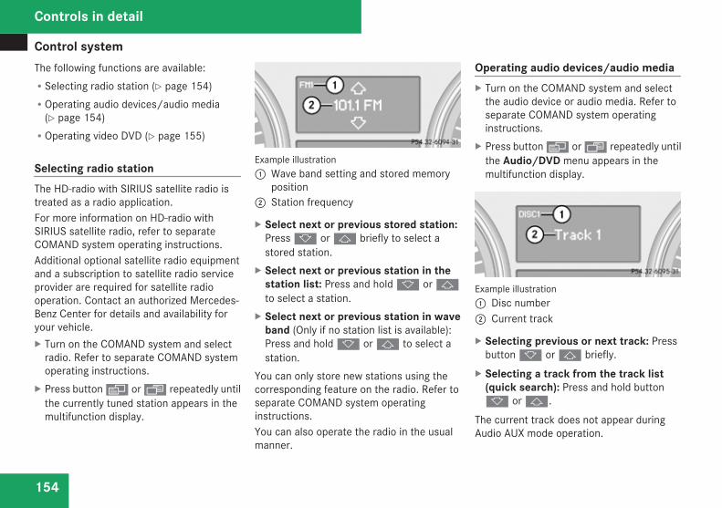
Control system
154
The following functions are available:RSelecting radio station (Y page 154)ROperating audio devices/audio media
(Y page 154)ROperating video DVD (Y page 155)
Selecting radio stationThe HD-radio with SIRIUS satellite radio istreated as a radio application.For more information on HD-radio withSIRIUS satellite radio, refer to separateCOMAND system operating instructions.Additional optional satellite radio equipmentand a subscription to satellite radio serviceprovider are required for satellite radiooperation. Contact an authorized Mercedes-Benz Center for details and availability foryour vehicle.X Turn on the COMAND system and select
radio. Refer to separate COMAND systemoperating instructions.
X Press button è or ÿ repeatedly untilthe currently tuned station appears in themultifunction display.
Example illustration1 Wave band setting and stored memory
position2 Station frequency
X Select next or previous stored station:Press k or j briefly to select astored station.
X Select next or previous station in thestation list: Press and hold k or jto select a station.
X Select next or previous station in waveband (Only if no station list is available):Press and hold k or j to select astation.
You can only store new stations using thecorresponding feature on the radio. Refer toseparate COMAND system operatinginstructions.You can also operate the radio in the usualmanner.
Operating audio devices/audio mediaX Turn on the COMAND system and select
the audio device or audio media. Refer toseparate COMAND system operatinginstructions.
X Press button è or ÿ repeatedly untilthe Audio/DVD menu appears in themultifunction display.
Example illustration1 Disc number2 Current track
X Selecting previous or next track: Pressbutton k or j briefly.
X Selecting a track from the track list(quick search): Press and hold buttonk or j.
The current track does not appear duringAudio AUX mode operation.
Controls in detail
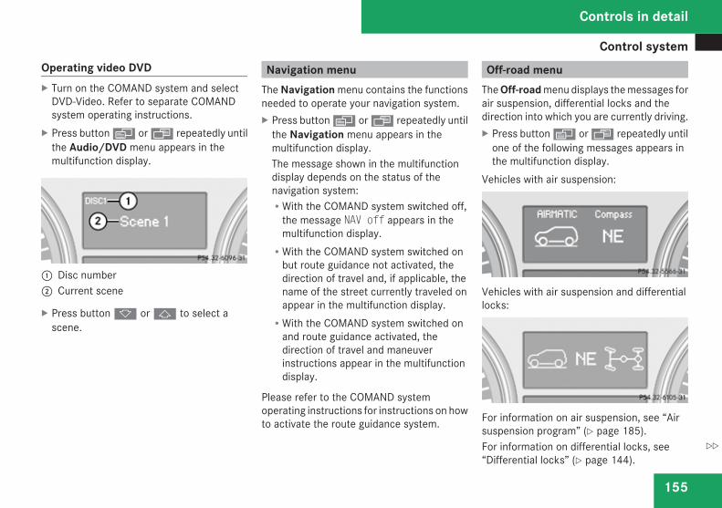
Control system
155
Operating video DVDX Turn on the COMAND system and select
DVD-Video. Refer to separate COMANDsystem operating instructions.
X Press button è or ÿ repeatedly untilthe Audio/DVD menu appears in themultifunction display.
1 Disc number2 Current scene
X Press button k or j to select ascene.
Navigation menuThe Navigation menu contains the functionsneeded to operate your navigation system.X Press button è or ÿ repeatedly until
the Navigation menu appears in themultifunction display.The message shown in the multifunctiondisplay depends on the status of thenavigation system:RWith the COMAND system switched off,
the message NAV off appears in themultifunction display.RWith the COMAND system switched on
but route guidance not activated, thedirection of travel and, if applicable, thename of the street currently traveled onappear in the multifunction display.RWith the COMAND system switched on
and route guidance activated, thedirection of travel and maneuverinstructions appear in the multifunctiondisplay.
Please refer to the COMAND systemoperating instructions for instructions on howto activate the route guidance system.
Off-road menuThe Off-road menu displays the messages forair suspension, differential locks and thedirection into which you are currently driving.X Press button è or · repeatedly until
one of the following messages appears inthe multifunction display.
Vehicles with air suspension:
Vehicles with air suspension and differentiallocks:
For information on air suspension, see “Airsuspension program” (Y page 185).For information on differential locks, see“Differential locks” (Y page 144).
Controls in detail
Z
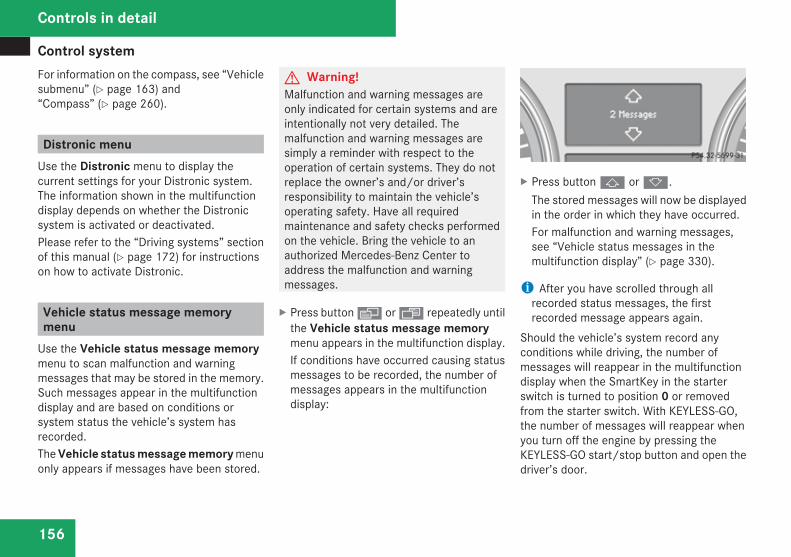
Control system
156
For information on the compass, see “Vehiclesubmenu” (Y page 163) and“Compass” (Y page 260).
Distronic menuUse the Distronic menu to display thecurrent settings for your Distronic system.The information shown in the multifunctiondisplay depends on whether the Distronicsystem is activated or deactivated.Please refer to the “Driving systems” sectionof this manual (Y page 172) for instructionson how to activate Distronic.
Vehicle status message memorymenu
Use the Vehicle status message memorymenu to scan malfunction and warningmessages that may be stored in the memory.Such messages appear in the multifunctiondisplay and are based on conditions orsystem status the vehicle’s system hasrecorded.The Vehicle status message memory menuonly appears if messages have been stored.
G Warning!Malfunction and warning messages areonly indicated for certain systems and areintentionally not very detailed. Themalfunction and warning messages aresimply a reminder with respect to theoperation of certain systems. They do notreplace the owner’s and/or driver’sresponsibility to maintain the vehicle’soperating safety. Have all requiredmaintenance and safety checks performedon the vehicle. Bring the vehicle to anauthorized Mercedes-Benz Center toaddress the malfunction and warningmessages.
X Press button è or ÿ repeatedly untilthe Vehicle status message memorymenu appears in the multifunction display.If conditions have occurred causing statusmessages to be recorded, the number ofmessages appears in the multifunctiondisplay:
X Press button j or k.The stored messages will now be displayedin the order in which they have occurred.For malfunction and warning messages,see “Vehicle status messages in themultifunction display” (Y page 330).
i After you have scrolled through allrecorded status messages, the firstrecorded message appears again.
Should the vehicle’s system record anyconditions while driving, the number ofmessages will reappear in the multifunctiondisplay when the SmartKey in the starterswitch is turned to position 0 or removedfrom the starter switch. With KEYLESS-GO,the number of messages will reappear whenyou turn off the engine by pressing theKEYLESS-GO start/stop button and open thedriver’s door.
Controls in detail
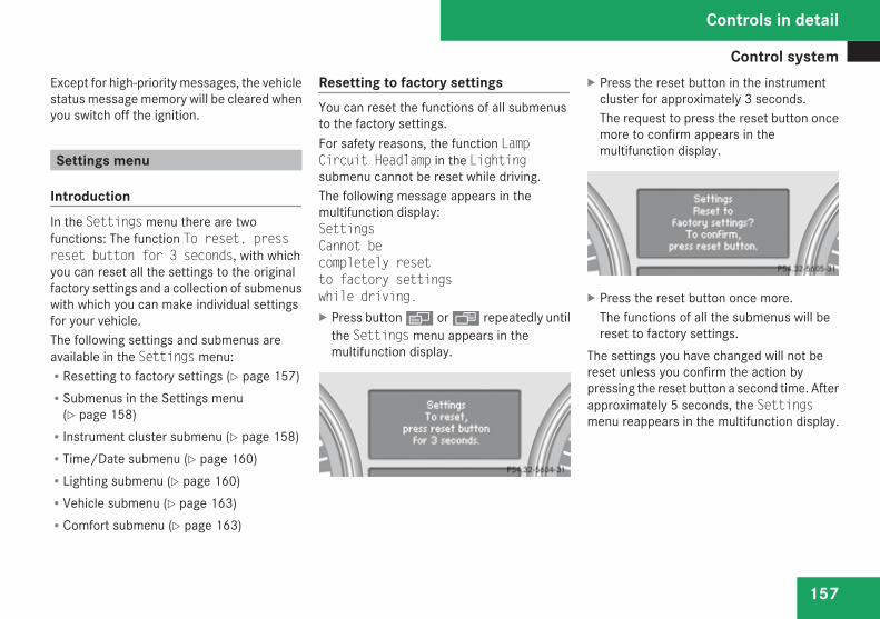
Control system
157
Except for high-priority messages, the vehiclestatus message memory will be cleared whenyou switch off the ignition.
Settings menu
IntroductionIn the Settings menu there are twofunctions: The function To reset, pressreset button for 3 seconds, with whichyou can reset all the settings to the originalfactory settings and a collection of submenuswith which you can make individual settingsfor your vehicle.The following settings and submenus areavailable in the Settings menu:RResetting to factory settings (Y page 157)RSubmenus in the Settings menu
(Y page 158)RInstrument cluster submenu (Y page 158)RTime/Date submenu (Y page 160)RLighting submenu (Y page 160)RVehicle submenu (Y page 163)RComfort submenu (Y page 163)
Resetting to factory settingsYou can reset the functions of all submenusto the factory settings.For safety reasons, the function LampCircuit Headlamp in the Lightingsubmenu cannot be reset while driving.The following message appears in themultifunction display:SettingsCannot becompletely resetto factory settingswhile driving.X Press button è or ÿ repeatedly until
the Settings menu appears in themultifunction display.
X Press the reset button in the instrumentcluster for approximately 3 seconds.The request to press the reset button oncemore to confirm appears in themultifunction display.
X Press the reset button once more.The functions of all the submenus will bereset to factory settings.
The settings you have changed will not bereset unless you confirm the action bypressing the reset button a second time. Afterapproximately 5 seconds, the Settingsmenu reappears in the multifunction display.
Controls in detail
Z
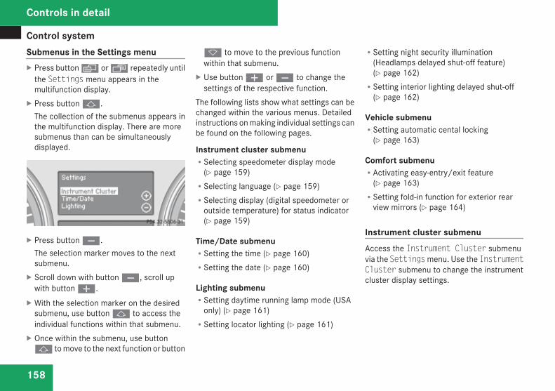
Control system
158
Submenus in the Settings menuX Press button è or ÿ repeatedly until
the Settings menu appears in themultifunction display.
X Press button j.The collection of the submenus appears inthe multifunction display. There are moresubmenus than can be simultaneouslydisplayed.
X Press button ç.The selection marker moves to the nextsubmenu.
X Scroll down with button ç, scroll upwith button æ.
X With the selection marker on the desiredsubmenu, use button j to access theindividual functions within that submenu.
X Once within the submenu, use buttonj to move to the next function or button
k to move to the previous functionwithin that submenu.
X Use button æ or ç to change thesettings of the respective function.
The following lists show what settings can bechanged within the various menus. Detailedinstructions on making individual settings canbe found on the following pages.
Instrument cluster submenuRSelecting speedometer display mode
(Y page 159)RSelecting language (Y page 159)RSelecting display (digital speedometer or
outside temperature) for status indicator(Y page 159)
Time/Date submenuRSetting the time (Y page 160)RSetting the date (Y page 160)
Lighting submenuRSetting daytime running lamp mode (USA
only) (Y page 161)RSetting locator lighting (Y page 161)
RSetting night security illumination(Headlamps delayed shut-off feature)(Y page 162)RSetting interior lighting delayed shut-off
(Y page 162)
Vehicle submenuRSetting automatic cental locking
(Y page 163)
Comfort submenuRActivating easy-entry/exit feature
(Y page 163)RSetting fold-in function for exterior rear
view mirrors (Y page 164)
Instrument cluster submenuAccess the Instrument Cluster submenuvia the Settings menu. Use the InstrumentCluster submenu to change the instrumentcluster display settings.
Controls in detail
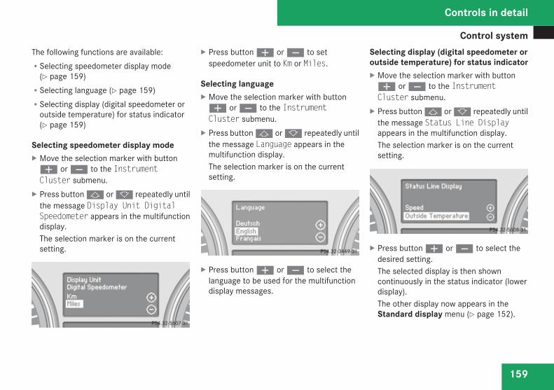
Control system
159
The following functions are available:RSelecting speedometer display mode
(Y page 159)RSelecting language (Y page 159)RSelecting display (digital speedometer or
outside temperature) for status indicator(Y page 159)
Selecting speedometer display modeX Move the selection marker with buttonæ or ç to the InstrumentCluster submenu.
X Press button j or k repeatedly untilthe message Display Unit DigitalSpeedometer appears in the multifunctiondisplay.The selection marker is on the currentsetting.
X Press button æ or ç to setspeedometer unit to Km or Miles.
Selecting languageX Move the selection marker with buttonæ or ç to the InstrumentCluster submenu.
X Press button j or k repeatedly untilthe message Language appears in themultifunction display.The selection marker is on the currentsetting.
X Press button æ or ç to select thelanguage to be used for the multifunctiondisplay messages.
Selecting display (digital speedometer oroutside temperature) for status indicatorX Move the selection marker with buttonæ or ç to the InstrumentCluster submenu.
X Press button j or k repeatedly untilthe message Status Line Displayappears in the multifunction display.The selection marker is on the currentsetting.
X Press button æ or ç to select thedesired setting.The selected display is then showncontinuously in the status indicator (lowerdisplay).The other display now appears in theStandard display menu (Y page 152).
Controls in detail
Z
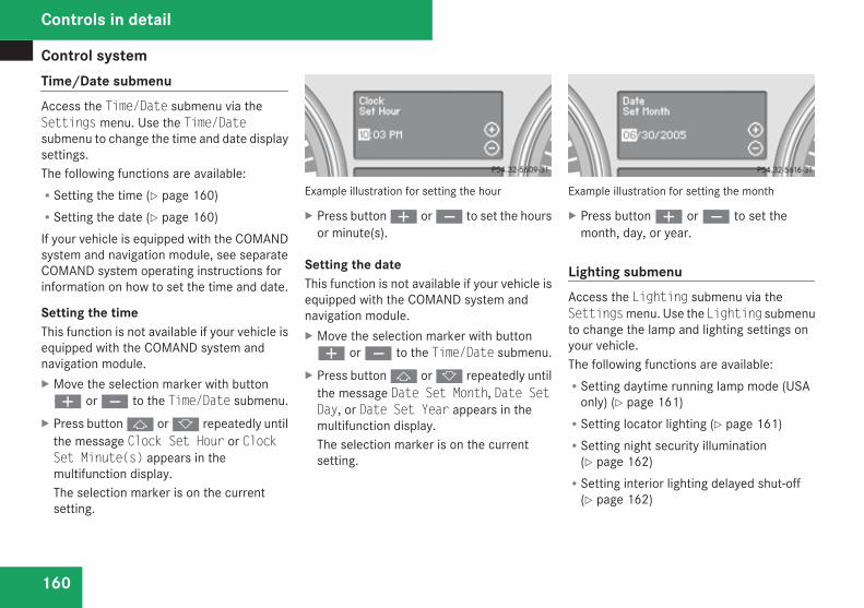
Control system
160
Time/Date submenuAccess the Time/Date submenu via theSettings menu. Use the Time/Datesubmenu to change the time and date displaysettings.The following functions are available:RSetting the time (Y page 160)RSetting the date (Y page 160)If your vehicle is equipped with the COMANDsystem and navigation module, see separateCOMAND system operating instructions forinformation on how to set the time and date.
Setting the timeThis function is not available if your vehicle isequipped with the COMAND system andnavigation module.X Move the selection marker with buttonæ or ç to the Time/Date submenu.
X Press button j or k repeatedly untilthe message Clock Set Hour or ClockSet Minute(s) appears in themultifunction display.The selection marker is on the currentsetting.
Example illustration for setting the hour
X Press button æ or ç to set the hoursor minute(s).
Setting the dateThis function is not available if your vehicle isequipped with the COMAND system andnavigation module.X Move the selection marker with buttonæ or ç to the Time/Date submenu.
X Press button j or k repeatedly untilthe message Date Set Month, Date SetDay, or Date Set Year appears in themultifunction display.The selection marker is on the currentsetting.
Example illustration for setting the month
X Press button æ or ç to set themonth, day, or year.
Lighting submenuAccess the Lighting submenu via theSettings menu. Use the Lighting submenuto change the lamp and lighting settings onyour vehicle.The following functions are available:RSetting daytime running lamp mode (USA
only) (Y page 161)RSetting locator lighting (Y page 161)RSetting night security illumination
(Y page 162)RSetting interior lighting delayed shut-off
(Y page 162)
Controls in detail
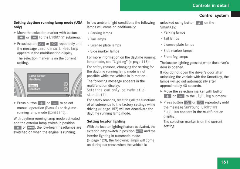
Control system
161
Setting daytime running lamp mode (USAonly)X Move the selection marker with buttonæ or ç to the Lighting submenu.
X Press button j or k repeatedly untilthe message Lamp Circuit Headlampappears in the multifunction display.The selection marker is on the currentsetting.
X Press button æ or ç to selectmanual operation (Manual) or daytimerunning lamp mode (Constant).
With daytime running lamp mode activatedand the exterior lamp switch in positionM or U, the low-beam headlamps areswitched on when the engine is running.
In low ambient light conditions the followinglamps will come on additionally:RParking lampsRTail lampsRLicense plate lampsRSide marker lampsFor more information on the daytime runninglamp mode, see “Lighting” (Y page 116).For safety reasons, changing the setting forthe daytime running lamp mode is notpossible while the vehicle is in motion.The following message appears in themultifunction display:Settings can only be made at astandstill.For safety reasons, resetting all the functionsof all submenus to the factory settings whiledriving (Y page 157) will not deactivate thedaytime running lamp mode.
Setting locator lightingWith the locator lighting feature activated, theexterior lamp switch in position U and theinterior lighting in automatic mode(Y page 120), the following lamps will comeon during darkness when the vehicle is
unlocked using button k on theSmartKey:RParking lampsRTail lampsRLicense plate lampsRSide marker lampsRFront fog lampsThe locator lighting goes out when the driver’sdoor is opened.If you do not open the driver’s door afterunlocking the vehicle with the SmartKey, thelamps will go out automatically afterapproximately 40 seconds.X Move the selection marker with buttonæ or ç to the Lighting submenu.
X Press button j or k repeatedly untilthe message Surround LightingFunction appears in the multifunctiondisplay.The selection marker is on the currentsetting.
Controls in detail
Z
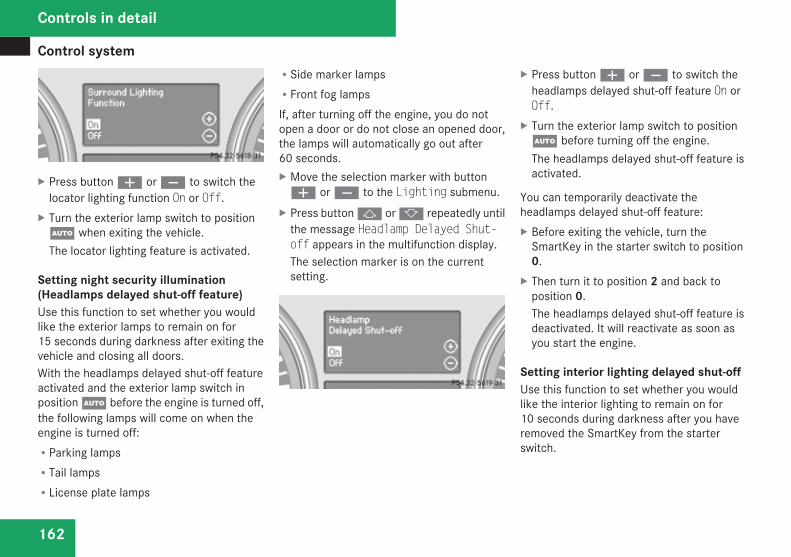
Control system
162
X Press button æ or ç to switch thelocator lighting function On or Off.
X Turn the exterior lamp switch to positionU when exiting the vehicle.The locator lighting feature is activated.
Setting night security illumination(Headlamps delayed shut-off feature)Use this function to set whether you wouldlike the exterior lamps to remain on for15 seconds during darkness after exiting thevehicle and closing all doors.With the headlamps delayed shut-off featureactivated and the exterior lamp switch inposition U before the engine is turned off,the following lamps will come on when theengine is turned off:RParking lampsRTail lampsRLicense plate lamps
RSide marker lampsRFront fog lampsIf, after turning off the engine, you do notopen a door or do not close an opened door,the lamps will automatically go out after60 seconds.X Move the selection marker with buttonæ or ç to the Lighting submenu.
X Press button j or k repeatedly untilthe message Headlamp Delayed Shut-off appears in the multifunction display.The selection marker is on the currentsetting.
X Press button æ or ç to switch theheadlamps delayed shut-off feature On orOff.
X Turn the exterior lamp switch to positionU before turning off the engine.The headlamps delayed shut-off feature isactivated.
You can temporarily deactivate theheadlamps delayed shut-off feature:X Before exiting the vehicle, turn the
SmartKey in the starter switch to position0.
X Then turn it to position 2 and back toposition 0.The headlamps delayed shut-off feature isdeactivated. It will reactivate as soon asyou start the engine.
Setting interior lighting delayed shut-offUse this function to set whether you wouldlike the interior lighting to remain on for10 seconds during darkness after you haveremoved the SmartKey from the starterswitch.
Controls in detail
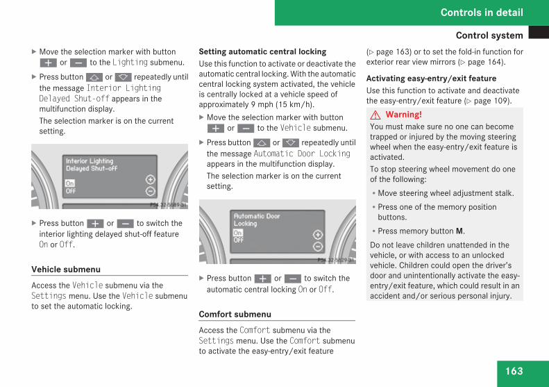
Control system
163
X Move the selection marker with buttonæ or ç to the Lighting submenu.
X Press button j or k repeatedly untilthe message Interior LightingDelayed Shut-off appears in themultifunction display.The selection marker is on the currentsetting.
X Press button æ or ç to switch theinterior lighting delayed shut-off featureOn or Off.
Vehicle submenuAccess the Vehicle submenu via theSettings menu. Use the Vehicle submenuto set the automatic locking.
Setting automatic central lockingUse this function to activate or deactivate theautomatic central locking. With the automaticcentral locking system activated, the vehicleis centrally locked at a vehicle speed ofapproximately 9 mph (15 km/h).X Move the selection marker with buttonæ or ç to the Vehicle submenu.
X Press button j or k repeatedly untilthe message Automatic Door Lockingappears in the multifunction display.The selection marker is on the currentsetting.
X Press button æ or ç to switch theautomatic central locking On or Off.
Comfort submenuAccess the Comfort submenu via theSettings menu. Use the Comfort submenuto activate the easy-entry/exit feature
(Y page 163) or to set the fold-in function forexterior rear view mirrors (Y page 164).
Activating easy-entry/exit featureUse this function to activate and deactivatethe easy-entry/exit feature (Y page 109).G Warning!You must make sure no one can becometrapped or injured by the moving steeringwheel when the easy-entry/exit feature isactivated.To stop steering wheel movement do oneof the following:RMove steering wheel adjustment stalk.RPress one of the memory position
buttons.RPress memory button M.Do not leave children unattended in thevehicle, or with access to an unlockedvehicle. Children could open the driver’sdoor and unintentionally activate the easy-entry/exit feature, which could result in anaccident and/or serious personal injury.
Controls in detail
Z
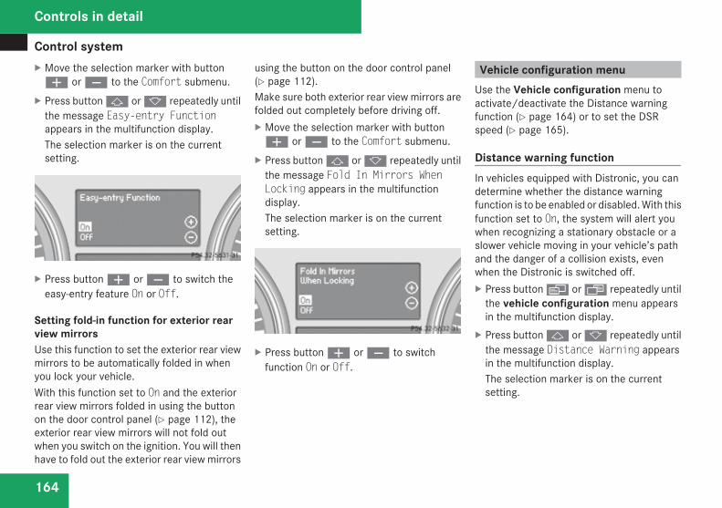
Control system
164
X Move the selection marker with buttonæ or ç to the Comfort submenu.
X Press button j or k repeatedly untilthe message Easy-entry Functionappears in the multifunction display.The selection marker is on the currentsetting.
X Press button æ or ç to switch theeasy-entry feature On or Off.
Setting fold-in function for exterior rearview mirrorsUse this function to set the exterior rear viewmirrors to be automatically folded in whenyou lock your vehicle.With this function set to On and the exteriorrear view mirrors folded in using the buttonon the door control panel (Y page 112), theexterior rear view mirrors will not fold outwhen you switch on the ignition. You will thenhave to fold out the exterior rear view mirrors
using the button on the door control panel(Y page 112).Make sure both exterior rear view mirrors arefolded out completely before driving off.X Move the selection marker with buttonæ or ç to the Comfort submenu.
X Press button j or k repeatedly untilthe message Fold In Mirrors WhenLocking appears in the multifunctiondisplay.The selection marker is on the currentsetting.
X Press button æ or ç to switchfunction On or Off.
Vehicle configuration menuUse the Vehicle configuration menu toactivate/deactivate the Distance warningfunction (Y page 164) or to set the DSRspeed (Y page 165).
Distance warning functionIn vehicles equipped with Distronic, you candetermine whether the distance warningfunction is to be enabled or disabled. With thisfunction set to On, the system will alert youwhen recognizing a stationary obstacle or aslower vehicle moving in your vehicle’s pathand the danger of a collision exists, evenwhen the Distronic is switched off.X Press button è or · repeatedly until
the vehicle configuration menu appearsin the multifunction display.
X Press button j or k repeatedly untilthe message Distance Warning appearsin the multifunction display.The selection marker is on the currentsetting.
Controls in detail
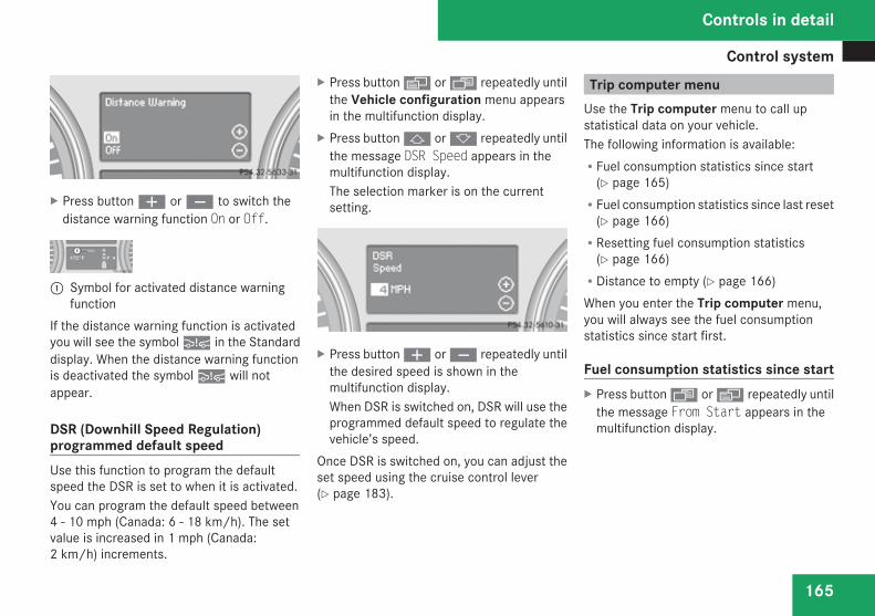
Control system
165
X Press button æ or ç to switch thedistance warning function On or Off.
1 Symbol for activated distance warningfunction
If the distance warning function is activatedyou will see the symbol : in the Standarddisplay. When the distance warning functionis deactivated the symbol : will notappear.
DSR (Downhill Speed Regulation)programmed default speedUse this function to program the defaultspeed the DSR is set to when it is activated.You can program the default speed between4 - 10 mph (Canada: 6 - 18 km/h). The setvalue is increased in 1 mph (Canada:2 km/h) increments.
X Press button è or · repeatedly untilthe Vehicle configuration menu appearsin the multifunction display.
X Press button j or k repeatedly untilthe message DSR Speed appears in themultifunction display.The selection marker is on the currentsetting.
X Press button æ or ç repeatedly untilthe desired speed is shown in themultifunction display.When DSR is switched on, DSR will use theprogrammed default speed to regulate thevehicle’s speed.
Once DSR is switched on, you can adjust theset speed using the cruise control lever(Y page 183).
Trip computer menuUse the Trip computer menu to call upstatistical data on your vehicle.The following information is available:RFuel consumption statistics since start
(Y page 165)RFuel consumption statistics since last reset
(Y page 166)RResetting fuel consumption statistics
(Y page 166)RDistance to empty (Y page 166)When you enter the Trip computer menu,you will always see the fuel consumptionstatistics since start first.
Fuel consumption statistics since startX Press button ÿ or è repeatedly until
the message From Start appears in themultifunction display.
Controls in detail
Z
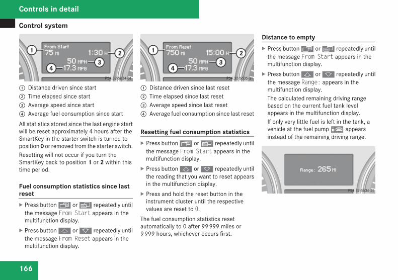
Control system
166
1 Distance driven since start2 Time elapsed since start3 Average speed since start4 Average fuel consumption since startAll statistics stored since the last engine startwill be reset approximately 4 hours after theSmartKey in the starter switch is turned toposition 0 or removed from the starter switch.Resetting will not occur if you turn theSmartKey back to position 1 or 2 within thistime period.
Fuel consumption statistics since lastresetX Press button ÿ or è repeatedly until
the message From Start appears in themultifunction display.
X Press button j or k repeatedly untilthe message From Reset appears in themultifunction display.
1 Distance driven since last reset2 Time elapsed since last reset3 Average speed since last reset4 Average fuel consumption since last reset
Resetting fuel consumption statisticsX Press button ÿ or è repeatedly until
the message From Start appears in themultifunction display.
X Press button j or k repeatedly untilthe reading that you want to reset appearsin the multifunction display.
X Press and hold the reset button in theinstrument cluster until the respectivevalues are reset to 0.
The fuel consumption statistics resetautomatically to 0 after 99 999 miles or9 999 hours, whichever occurs first.
Distance to emptyX Press button ÿ or è repeatedly until
the message From Start appears in themultifunction display.
X Press button j or k repeatedly untilthe message Range: appears in themultifunction display.The calculated remaining driving rangebased on the current fuel tank levelappears in the multifunction display.If only very little fuel is left in the tank, avehicle at the fuel pump ¿ appearsinstead of the remaining driving range.
Controls in detail
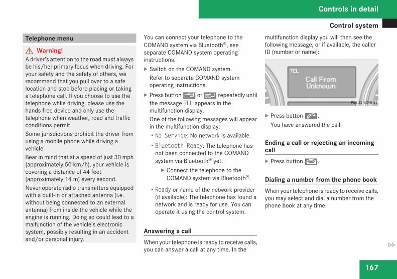
Control system
167
Telephone menu
G Warning!A driver’s attention to the road must alwaysbe his/her primary focus when driving. Foryour safety and the safety of others, werecommend that you pull over to a safelocation and stop before placing or takinga telephone call. If you choose to use thetelephone while driving, please use thehands-free device and only use thetelephone when weather, road and trafficconditions permit.Some jurisdictions prohibit the driver fromusing a mobile phone while driving avehicle.Bear in mind that at a speed of just 30 mph(approximately 50 km/h), your vehicle iscovering a distance of 44 feet(approximately 14 m) every second.Never operate radio transmitters equippedwith a built-in or attached antenna (i.e.without being connected to an externalantenna) from inside the vehicle while theengine is running. Doing so could lead to amalfunction of the vehicle’s electronicsystem, possibly resulting in an accidentand/or personal injury.
You can connect your telephone to theCOMAND system via Bluetooth®, seeseparate COMAND system operatinginstructions.X Switch on the COMAND system.
Refer to separate COMAND systemoperating instructions.
X Press button ÿ or è repeatedly untilthe message TEL appears in themultifunction display.One of the following messages will appearin the multifunction display:RNo Service: No network is available.RBluetooth Ready: The telephone has
not been connected to the COMANDsystem via Bluetooth® yet.X Connect the telephone to the
COMAND system via Bluetooth®.
RReady or name of the network provider(if available): The telephone has found anetwork and is ready for use. You canoperate it using the control system.
Answering a callWhen your telephone is ready to receive calls,you can answer a call at any time. In the
multifunction display you will then see thefollowing message, or if available, the callerID (number or name):
X Press button s.You have answered the call.
Ending a call or rejecting an incomingcallX Press button t.
Dialing a number from the phone bookWhen your telephone is ready to receive calls,you may select and dial a number from thephone book at any time.
Controls in detail
Z
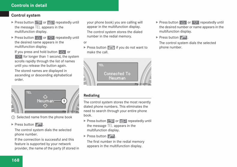
Control system
168
X Press button ÿ or è repeatedly untilthe message TEL appears in themultifunction display.
X Press button j or k repeatedly untilthe desired name appears in themultifunction display.If you press and hold button j ork for longer than 1 second, the systemscrolls rapidly through the list of namesuntil you release the button again.The stored names are displayed inascending or descending alphabeticalorder.
1 Selected name from the phone book
X Press button s.The control system dials the selectedphone number.If the connection is successful and thisfeature is supported by your networkprovider, the name of the party (if stored in
your phone book) you are calling willappear in the multifunction display.The control system stores the dialednumber in the redial memory.
orX Press button t if you do not want to
make the call.
RedialingThe control system stores the most recentlydialed phone numbers. This eliminates theneed to search through your entire phonebook.X Press button ÿ or è repeatedly until
the message TEL appears in themultifunction display.
X Press button s.The first number in the redial memoryappears in the multifunction display.
X Press button j or k repeatedly untilthe desired number or name appears in themultifunction display.
X Press button s.The control system dials the selectedphone number.
Controls in detail
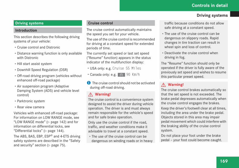
Driving systems
169
Driving systems
IntroductionThis section describes the following drivingsystems of your vehicle:RCruise control and DistronicRDistance warning function is only available
with DistronicRHill start assist systemRDownhill Speed Regulation (DSR)ROff-road driving program (vehicles without
enhanced off-road package)RAir suspension program (Adaptive
Damping System (ADS) and vehicle levelcontrol)RParktronic systemRRear view cameraVehicles with enhanced off-road package:For information on LOW RANGE mode, see“LOW RANGE mode” (Y page 142) and forinformation on differential locks, see“Differential locks” (Y page 144).The ABS, BAS, EBP, ESP® and 4-ETS drivingsafety systems are described in the “Safetyand security” section (Y page 75).
Cruise controlThe cruise control automatically maintainsthe speed you set for your vehicle.The use of the cruise control is recommendedfor driving at a constant speed for extendedperiods of time.The currently set speed or last set speed(“Resume” function) appears in the statusindicator of the multifunction display:RUSA only: e.g. Cruise 55 MilesRCanada only: e.g. Ñ 90 Km/h
i The cruise control should not be activatedduring off-road driving.
G Warning!The cruise control is a convenience systemdesigned to assist the driver during vehicleoperation. The driver is and must alwaysremain responsible for the vehicle’s speedand for safe brake operation.Only use the cruise control if the road,traffic, and weather conditions make itadvisable to travel at a constant speed.RThe use of the cruise control can be
dangerous on winding roads or in heavy
traffic because conditions do not allowsafe driving at a constant speed.RThe use of the cruise control can be
dangerous on slippery roads. Rapidchanges in tire traction can result inwheel spin and loss of control.RDeactivate the cruise control when
driving in fog.The “Resume” function should only beoperated if the driver is fully aware of thepreviously set speed and wishes to resumethis particular preset speed.
G Warning!The cruise control brakes automatically sothat the set speed is not exceeded. Thebrake pedal depresses automatically whenthe cruise control engages the brakes.Keep the driver’s footwell clear at all times,including the area under the brake pedal.Objects stored in this area may impairpedal movement which could interfere withthe braking ability of the cruise controlsystem.Do not place your foot under the brakepedal – your foot could become caught.
Controls in detail
Z
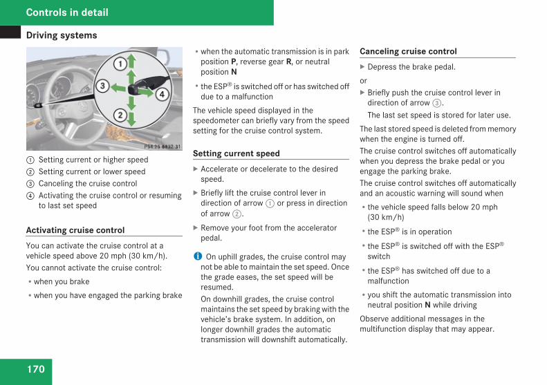
Driving systems
170
1 Setting current or higher speed2 Setting current or lower speed3 Canceling the cruise control4 Activating the cruise control or resuming
to last set speed
Activating cruise controlYou can activate the cruise control at avehicle speed above 20 mph (30 km/h).You cannot activate the cruise control:Rwhen you brakeRwhen you have engaged the parking brake
Rwhen the automatic transmission is in parkposition P, reverse gear R, or neutralposition NRthe ESP® is switched off or has switched off
due to a malfunctionThe vehicle speed displayed in thespeedometer can briefly vary from the speedsetting for the cruise control system.
Setting current speedX Accelerate or decelerate to the desired
speed.X Briefly lift the cruise control lever in
direction of arrow 1 or press in directionof arrow 2.
X Remove your foot from the acceleratorpedal.
i On uphill grades, the cruise control maynot be able to maintain the set speed. Oncethe grade eases, the set speed will beresumed.On downhill grades, the cruise controlmaintains the set speed by braking with thevehicle’s brake system. In addition, onlonger downhill grades the automatictransmission will downshift automatically.
Canceling cruise controlX Depress the brake pedal.orX Briefly push the cruise control lever in
direction of arrow 3.The last set speed is stored for later use.
The last stored speed is deleted from memorywhen the engine is turned off.The cruise control switches off automaticallywhen you depress the brake pedal or youengage the parking brake.The cruise control switches off automaticallyand an acoustic warning will sound whenRthe vehicle speed falls below 20 mph
(30 km/h)Rthe ESP® is in operationRthe ESP® is switched off with the ESP®
switchRthe ESP® has switched off due to a
malfunctionRyou shift the automatic transmission into
neutral position N while drivingObserve additional messages in themultifunction display that may appear.
Controls in detail
Driving systems
171
Depressing the accelerator pedal does notdeactivate the cruise control. After a briefacceleration (e.g. for passing), the cruisecontrol will resume the last set speed.
Changing the set speed
G Warning!Keep in mind that it may take a briefmoment until the vehicle has made thenecessary adjustments.Increase or decrease the set vehicle speedto a value that the prevailing roadconditions and legal speed limits permit.Otherwise, sudden and unexpectedacceleration or deceleration of the vehiclecould cause an accident and/or seriousinjury to you and others.
You can increase or decrease the set speedin 1 mph (Canada: 1 km/h) increments or in5 mph (Canada: 10 km/h) increments.When you use the cruise control lever todecelerate, the brake system will brake thevehicle automatically if the engine’s brakingpower does not brake the vehicle sufficiently.
Adjustment in 1 mph (Canada: 1 km/h)incrementsi The set speed value is increased or
decreased in 1 mph (Canada: 1 km/h)increments each time you lift or press thecruise control lever up or down to theresistance point.
X Briefly lift the cruise control lever up to theresistance point in direction of arrow 1 toincrease or press the cruise control leverdown to the resistance point in direction ofarrow 2 to decrease.
X Release the cruise control lever.The new speed is set and the vehicle willaccelerate or decelerate.
Adjustment in 5 mph (Canada: 10 km/h)incrementsi The set speed value is increased or
decreased in 5 mph (Canada: 10 km/h)increments each time you lift or press thecruise control lever up or down past theresistance point.
X Briefly lift the cruise control lever up pastthe resistance point in direction of arrow1 to increase or press the cruise control
lever down past the resistance point indirection of arrow 2 to decrease.
X Release the cruise control lever.The new speed is set and the vehicle willaccelerate or decelerate. Keep in mind thatit may take a brief moment until the vehiclehas reached the set speed.
Resume last stored speed
G Warning!The set speed stored in memory shouldonly be set again if prevailing roadconditions and legal speed limits permit.Possible acceleration or decelerationdifferences arising from returning to thepreset speed could cause an accident and/or serious injury to you and others.
X Briefly pull the cruise control lever indirection of arrow 4.If no speed is stored, the current speed isset and stored.
X Remove your foot from the acceleratorpedal.
The last stored speed is deleted from memorywhen the engine is turned off.
Controls in detail
Z
Driving systems
172
Distronic
Safety notesWhen activated, the Distronic adaptive cruisecontrol increases the driving convenienceafforded by the cruise control while travelingon expressways and other major roadways.RIf the Distronic distance sensor detects a
slower moving vehicle directly ahead, yourvehicle speed will be reduced so that youfollow that vehicle at your preset followingdistance.RIf there is no vehicle directly ahead of you,
the Distronic will function in the same wayas standard cruise control (Y page 169).
G Warning!The Distronic is a convenience system. Itsspeed adjustment reduction capability isintended to make cruise control moreeffective and usable when traffic speedsvary. It is not however, intended to, nordoes it, replace the need for extreme care.The responsibility for the vehicle’s speed,distance to the preceding vehicle and, mostimportantly, brake operation to ensure asafe stopping distance, always remainswith the driver.
Complex driving situations are not alwaysfully recognized by the Distronic. This couldresult in wrong or missing distancewarnings.
G Warning!The Distronic adaptive cruise control is nota substitute for active driving involvement.It does not react to pedestrians or onstationary objects, nor does it recognize orpredict the lane curvature or the movementof preceding vehicles.The Distronic can only apply 20% of themaximum braking power of the vehicle.It is the driver’s responsibility at all times tobe attentive to the road, weather and trafficconditions. Additionally, the driver mustprovide the steering, braking and otherdriving inputs necessary to remain incontrol of the vehicle.High-frequency sources such as tollstations, speed measuring systems etc.can cause the Distronic system tomalfunction.
G Warning!The Distronic requires familiarity with itsoperational characteristics. We strongly
recommend that you review the followinginformation carefully before operating thesystem.
G Warning!The Distronic cannot take road and trafficconditions into account. Only use theDistronic if the road, weather and trafficconditions make it advisable to travel at aconstant speed.
G Warning!Use of the Distronic can be dangerous onslippery roads. Rapid changes in tiretraction can result in wheel spin and loss ofcontrol.The Distronic does not function in adversesight and distance conditions. Do not usethe Distronic during conditions of fog,heavy rain, snow or sleet.
G Warning!The Distronic cannot take weatherconditions into account. Switch off theDistronic or do not switch it on if:Rroads are slippery or covered with snow
or ice. The wheels could lose traction
Controls in detail
Driving systems
173
while braking or accelerating, and thevehicle could skid.Rthe Distronic system sensor cover is dirty
or visibility is diminished due to snow,rain or fog, for example. The distancecontrol system functionality could beimpaired.
Always pay attention to surrounding trafficconditions even while the Distronic isswitched on. Otherwise, you may not beable to recognize dangerous situations untilit is too late. This could cause an accidentin which you and/or others could beinjured.
G Warning!The “Resume” function should only beoperated if the driver is fully aware of thepreviously set speed and wishes to resumethis particular preset speed.
G Warning!Close attention to road and trafficconditions is imperative at all times,regardless of whether or not the Distronicis activated.Use of the Distronic can be dangerous onwinding roads or in heavy traffic because
conditions do not allow safe driving at aconstant speed.The Distronic will not react to stationaryobjects in the roadway (e.g. a stoppedvehicle in a traffic jam or a disabledvehicle). The Distronic will also not respondto oncoming vehicles.Switch off the Distronic:Rwhen changing from the left to the right
lane if vehicles are moving more slowlyin the left laneRwhen entering a turn lane or highway off
rampRin complex driving situations, such as in
highway construction zonesIn these situations, the Distronic willcontinue to maintain the set speed unlessdeactivated.The Distronic is designed and intended onlyto maintain a set speed and keep a setdistance from moving objects in front of it.
i USA only:This device has been approved by the FCCas a “Vehicular Radar System”. The radarsensor is intended for use in an automotiveradar system only. Removal, tampering, or
altering of the device will void anywarranties, and is not permitted by theFCC. Do not tamper with, alter, or use inany non-approved way.Any unauthorized modification to thisdevice could void the user’s authority tooperate the equipment.
i Canada only:This device complies with RSS-210 ofIndustry Canada. Operation is subject tothe following two conditions:1. This device may not cause interference,
and2. this device must accept any
interference received, includinginterference that may cause undesiredoperation of the device.
Removal, tampering, or altering of thedevice will void any warranties, and is notpermitted. Do not tamper with, alter, or usein any non-approved way.Any unauthorized modification to thisdevice could void the user’s authority tooperate the equipment.
Controls in detail
Z

Driving systems
174
Distronic displays in the speedometer
1 Set speedIf the Distronic is activated, one or two cruisecontrol speed segments come on around theset speed.The vehicle speed displayed on thespeedometer can briefly vary from the speedsetting on the Distronic system.
1 Set speed2 Cruise control speed segments3 Speed of the vehicle aheadIf the Distronic detects a vehicle directlyahead, the cruise control speed segments2 appear in the speedometer. Thesesegments represent the difference betweenthe set speed of your vehicle 1 and thespeed of the preceding vehicle 3.If the Distronic calculates that there is adanger of collision, the distance warning lampl in the instrument cluster comes on andan intermittent warning sounds.X Immediately apply the brakes to avoid a
collision.Under no circumstances should the driverawait the intermittent warning soundbefore braking.
The intermittent warning sound ceases andthe distance warning lamp l goes outwhen the necessary distance to the vehicleahead is established again.
G Warning!An intermittent warning sounds and thedistance warning lamp l in theinstrument cluster is illuminated if theDistronic system calculates that thedistance to the vehicle ahead and yourvehicle’s current speed indicate that theDistronic will not be capable of slowing thevehicle sufficiently to maintain the presetfollowing distance, which creates a dangerof a collision.Immediately brake the vehicle to increaseyour distance to the preceding vehicle. Thewarning sound is intended as a final cautionin which you should intercede with yourown braking inputs to avoid a potentiallydangerous situation. Do not wait for theoperation of the warning signal to intercedewith your own braking. This will result inpotentially dangerous emergency brakingwhich will not always result in an impactbeing avoided.Tailgating increases the risk of an accident.
Controls in detail
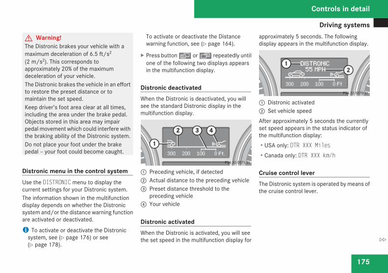
Driving systems
175
G Warning!The Distronic brakes your vehicle with amaximum deceleration of 6.5 ft/s2
(2 m/s2). This corresponds toapproximately 20% of the maximumdeceleration of your vehicle.The Distronic brakes the vehicle in an effortto restore the preset distance or tomaintain the set speed.Keep driver’s foot area clear at all times,including the area under the brake pedal.Objects stored in this area may impairpedal movement which could interfere withthe braking ability of the Distronic system.Do not place your foot under the brakepedal – your foot could become caught.
Distronic menu in the control systemUse the DISTRONIC menu to display thecurrent settings for your Distronic system.The information shown in the multifunctiondisplay depends on whether the Distronicsystem and/or the distance warning functionare activated or deactivated.
i To activate or deactivate the Distronicsystem, see (Y page 176) or see(Y page 178).
To activate or deactivate the Distancewarning function, see (Y page 164).
X Press button è or ÿ repeatedly untilone of the following two displays appearsin the multifunction display.
Distronic deactivatedWhen the Distronic is deactivated, you willsee the standard Distronic display in themultifunction display.
1 Preceding vehicle, if detected2 Actual distance to the preceding vehicle3 Preset distance threshold to the
preceding vehicle4 Your vehicle
Distronic activatedWhen the Distronic is activated, you will seethe set speed in the multifunction display for
approximately 5 seconds. The followingdisplay appears in the multifunction display.
1 Distronic activated2 Set vehicle speedAfter approximately 5 seconds the currentlyset speed appears in the status indicator ofthe multifunction display:RUSA only: DTR XXX MilesRCanada only: DTR XXX km/h
Cruise control leverThe Distronic system is operated by means ofthe cruise control lever.
Controls in detail
Z
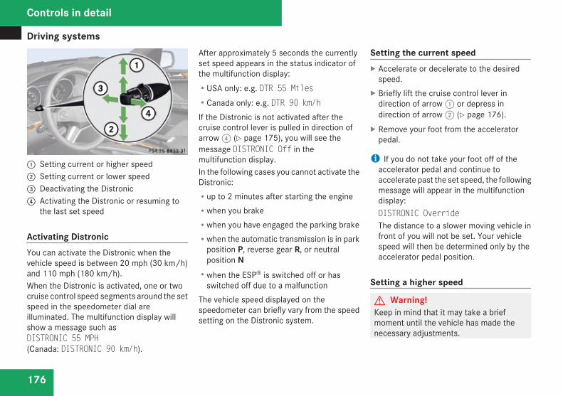
Driving systems
176
1 Setting current or higher speed2 Setting current or lower speed3 Deactivating the Distronic4 Activating the Distronic or resuming to
the last set speed
Activating DistronicYou can activate the Distronic when thevehicle speed is between 20 mph (30 km/h)and 110 mph (180 km/h).When the Distronic is activated, one or twocruise control speed segments around the setspeed in the speedometer dial areilluminated. The multifunction display willshow a message such asDISTRONIC 55 MPH(Canada: DISTRONIC 90 km/h).
After approximately 5 seconds the currentlyset speed appears in the status indicator ofthe multifunction display:RUSA only: e.g. DTR 55 MilesRCanada only: e.g. DTR 90 km/hIf the Distronic is not activated after thecruise control lever is pulled in direction ofarrow 4 (Y page 175), you will see themessage DISTRONIC Off in themultifunction display.In the following cases you cannot activate theDistronic:Rup to 2 minutes after starting the engineRwhen you brakeRwhen you have engaged the parking brakeRwhen the automatic transmission is in park
position P, reverse gear R, or neutralposition NRwhen the ESP® is switched off or has
switched off due to a malfunctionThe vehicle speed displayed on thespeedometer can briefly vary from the speedsetting on the Distronic system.
Setting the current speedX Accelerate or decelerate to the desired
speed.X Briefly lift the cruise control lever in
direction of arrow 1 or depress indirection of arrow 2 (Y page 176).
X Remove your foot from the acceleratorpedal.
i If you do not take your foot off of theaccelerator pedal and continue toaccelerate past the set speed, the followingmessage will appear in the multifunctiondisplay:DISTRONIC OverrideThe distance to a slower moving vehicle infront of you will not be set. Your vehiclespeed will then be determined only by theaccelerator pedal position.
Setting a higher speed
G Warning!Keep in mind that it may take a briefmoment until the vehicle has made thenecessary adjustments.
Controls in detail
Driving systems
177
Increase the set vehicle speed to a valuethat the prevailing road conditions and legalspeed limits permit. Otherwise, sudden andunexpected acceleration of the vehiclecould cause an accident and/or seriousinjury to you and others.
You can increase the set speed in 1 mph(Canada: 1 km/h) increments or in 5 mph(Canada: 10 km/h) increments.
Adjustment in 1 mph (Canada: 1 km/h)incrementsi The set speed value is increased in 1 mph
(Canada: 1 km/h) increments each timeyou lift the cruise control lever up to theresistance point.
X Briefly lift the cruise control lever up to theresistance point in direction of arrow 1(Y page 175).
X Release the cruise control lever.The new speed is set and the vehicle willaccelerate.
Adjustment in 5 mph (Canada: 10 km/h)incrementsi The set speed value is increased in 5 mph
(Canada: 10 km/h) increments each time
you lift the cruise control lever up past theresistance point.
X Briefly lift the cruise control lever up pastthe resistance point in direction ofarrow 1 (Y page 175).
X Release the cruise control lever.The new speed is set and the vehicle willaccelerate. Keep in mind that it may take abrief moment until the vehicle has reachedthe set speed.
Setting a lower speed
G Warning!Keep in mind that it may take a briefmoment until the vehicle has made thenecessary adjustments.Decrease the set vehicle speed to a valuethat the prevailing road conditions and legalspeed limits permit. Otherwise, sudden andunexpected deceleration of the vehiclecould cause an accident and/or seriousinjury to you and others.
i When you use the cruise control lever todecelerate, the brake system willautomatically brake the vehicle if the
engine’s braking power does not brake thevehicle sufficiently.
You can reduce the set speed in 1 mph(Canada: 1 km/h) increments or in 5 mph(Canada: 10 km/h) increments.
Adjustment in 1 mph (Canada: 1 km/h)incrementsi The set speed value is decreased in 1 mph
(Canada: 1 km/h) increments each timeyou press the cruise control lever down tothe resistance point.
X Briefly press the cruise control lever downto the resistance point in direction ofarrow 2.
X Release the cruise control lever.The new speed is set and the vehicle willdecelerate.
Adjustment in 5 mph (Canada: 10 km/h)incrementsi The set speed value is decreased in 5 mph
(Canada: 10 km/h) increments each timeyou press the cruise control lever downpast the resistance point.
Controls in detail
Z
Driving systems
178
X Briefly press the cruise control lever downpast the resistance point in direction ofarrow 2.
X Release the cruise control lever.The new speed is set and the vehicle willdecelerate. Keep in mind that it may take abrief moment until the vehicle has reachedthe set speed.
Setting stored speed (Resume function)
G Warning!The set speed stored in memory shouldonly be set again if prevailing roadconditions and legal speed limits permit.Possible acceleration or decelerationdifferences arising from returning to thepreset speed could cause an accident and/or serious injury to you and others.
X Briefly pull the cruise control lever indirection of arrow 4 (Y page 176).If no speed is stored, the current speed isset and stored.
X Remove your foot from the acceleratorpedal.
Deactivating DistronicX Depress the brake pedal.orX Briefly push the cruise control lever in
direction of arrow 3 (Y page 176).The cruise control speed segments in thespeedometer dial will go out and thefollowing message appears briefly in themultifunction display: DISTRONIC OffThe last set speed is stored for later use.
The last stored speed is deleted from memorywhen the engine is turned off.The Distronic switches off automaticallywhen you depress the brake pedal or youengage the parking brake. In this case, thecruise control speed segments in thespeedometer dial will go out.The Distronic also switches off automaticallywhenRthe vehicle speed falls below 20 mph
(30 km/h)Rthe ESP® is in operationRthe ESP® is switched off with the ESP®
switch
Rthe ESP® has switched off due to amalfunctionRyou shift the automatic transmission into
neutral position N while drivingThe cruise control speed segments in thespeedometer dial goes out and an acousticwarning will sound. Observe additionalmessages in the multifunction display thatmay appear.G Warning!Distronic switches off and releases thebrakes when the vehicle decelerates belowthe minimum speed of 20 mph (30 km/h)by operation of the system. At that time thedriver must apply the brakes in order toreduce vehicle speed further or bring it toa stop.
Depressing the accelerator pedal does notdeactivate the Distronic. After a briefacceleration (e.g. for passing), the Distronicwill resume the last set speed.
Setting the following distance inDistronicYou can set the specified following distancefor Distronic by varying the time settingbetween 1.0 and 2.0 seconds. Using this time
Controls in detail
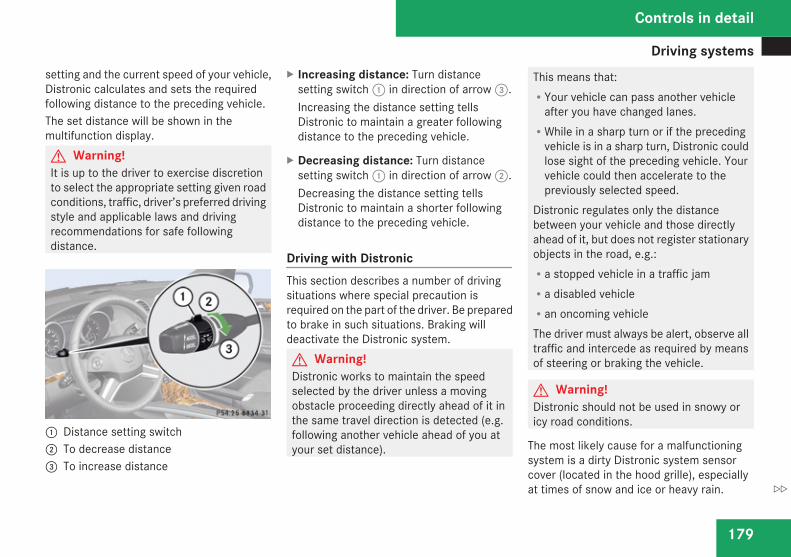
Driving systems
179
setting and the current speed of your vehicle,Distronic calculates and sets the requiredfollowing distance to the preceding vehicle.The set distance will be shown in themultifunction display.G Warning!It is up to the driver to exercise discretionto select the appropriate setting given roadconditions, traffic, driver’s preferred drivingstyle and applicable laws and drivingrecommendations for safe followingdistance.
1 Distance setting switch2 To decrease distance3 To increase distance
X Increasing distance: Turn distancesetting switch 1 in direction of arrow 3.Increasing the distance setting tellsDistronic to maintain a greater followingdistance to the preceding vehicle.
X Decreasing distance: Turn distancesetting switch 1 in direction of arrow 2.Decreasing the distance setting tellsDistronic to maintain a shorter followingdistance to the preceding vehicle.
Driving with DistronicThis section describes a number of drivingsituations where special precaution isrequired on the part of the driver. Be preparedto brake in such situations. Braking willdeactivate the Distronic system.G Warning!Distronic works to maintain the speedselected by the driver unless a movingobstacle proceeding directly ahead of it inthe same travel direction is detected (e.g.following another vehicle ahead of you atyour set distance).
This means that:RYour vehicle can pass another vehicle
after you have changed lanes.RWhile in a sharp turn or if the preceding
vehicle is in a sharp turn, Distronic couldlose sight of the preceding vehicle. Yourvehicle could then accelerate to thepreviously selected speed.
Distronic regulates only the distancebetween your vehicle and those directlyahead of it, but does not register stationaryobjects in the road, e.g.:Ra stopped vehicle in a traffic jamRa disabled vehicleRan oncoming vehicleThe driver must always be alert, observe alltraffic and intercede as required by meansof steering or braking the vehicle.
G Warning!Distronic should not be used in snowy oricy road conditions.
The most likely cause for a malfunctioningsystem is a dirty Distronic system sensorcover (located in the hood grille), especiallyat times of snow and ice or heavy rain.
Controls in detail
Z
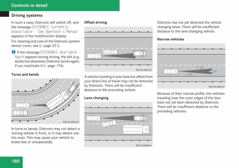
Driving systems
180
In such a case, Distronic will switch off, andthe message DISTRONIC CurrentlyUnavailable – See Operator’s Manualappears in the multifunction display.For cleaning and care of the Distronic systemsensor cover, see (Y page 321).
i If the message DISTRONIC AvailableAgain appears during driving, the dirt (e.g.slush) has dissolved; Distronic works again,if you reactivate it (Y page 176).
Turns and bends
In turns or bends, Distronic may not detect amoving vehicle in front, or it may detect onetoo soon. This may cause your vehicle tobrake late or unexpectedly.
Offset driving
A vehicle traveling in your lane but offset fromyour direct line of travel may not be detectedby Distronic. There will be insufficientdistance to the preceding vehicle.
Lane changing
Distronic has not yet detected the vehiclechanging lanes. There will be insufficientdistance to the lane-changing vehicle.
Narrow vehicles
Because of their narrow profile, the vehiclestraveling near the outer edges of the lanehave not yet been detected by Distronic.There will be insufficient distance to thepreceding vehicles.
Controls in detail
Driving systems
181
Distance warning functionWhen the Distronic is deactivated, thisfunction will continue to warn you whenrecognizing a stationary obstacle or a slowervehicle moving in your vehicle’s path and thedanger of a collision exists:RThe distance warning lamp l in the
instrument cluster comes on.RAn intermittent warning will sound if
necessary.If these warnings are issued, you must brakemanually to maintain a safe distance andavoid a collision with the preceding vehicle.When depressing the brake pedal, thewarning sound ceases. The warning soundwill also cease when the distance to thepreceding vehicle is sufficient again withoutapplying the brakes. In this case, the distancewarning lamp l will also go out.
G Warning!If the distance warning lamp l in theinstrument cluster comes on while drivingand/or an intermittent warning sounds,immediate attention on the part of thedriver is required. As required by the trafficsituation, apply the brakes and navigatearound a possible obstacle. However, do
not drive by relying on the distance warningfunction, as this will result in an emergencybraking application. This will not alwaysenable you to avoid a collision, especiallywhen traveling on varying road surfaceconditions and with varying driver reaction.Complex driving situations are not alwaysfully recognized by the distance warningfunction. This could result in wrong ormissing distance warnings.
X Switch on the distance warning function inthe control system (Y page 164).
Hill start assist system
G Warning!The hill start assist system is not designedto function as a parking brake and does notprevent the vehicle from moving whenparked on an incline.Always engage the parking brake inaddition to shifting the automatictransmission into park position P.
On uphill grades with a gradient angle of morethan 5°, the hill start assist system maintainsthe pressure in the brake system forapproximately 1 second after you have
released the brake pedal. Therefore, you canstart off smoothly without the vehicle movingimmediately after releasing the brake pedal.X Depress the brake pedal.X Shift the automatic transmission into drive
position D or reverse gear R.X Release the brake pedal.X Carefully depress the accelerator pedal.The hill start assist system is inactiveRwhen starting off on a level road or downhill
gradesRwith the automatic transmission in neutral
position NRwith the parking brake engagedRif the ESP® has switched off due to a
malfunction
Controls in detail
Z
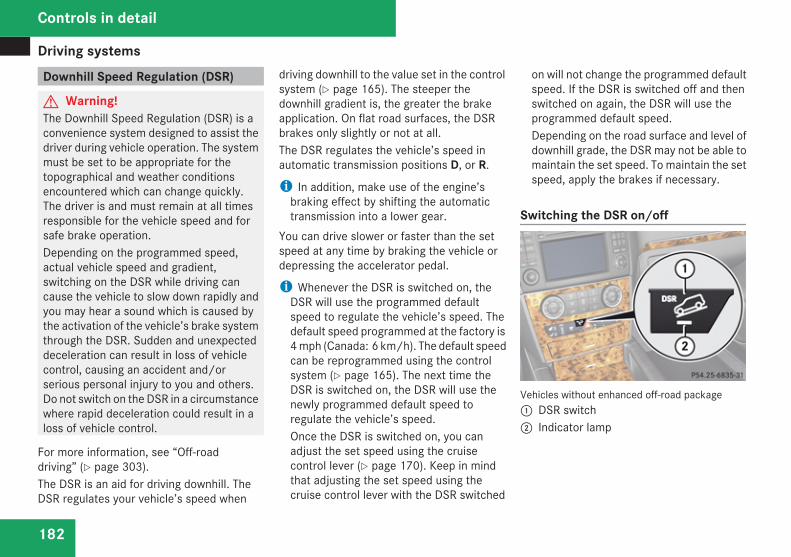
Driving systems
182
Downhill Speed Regulation (DSR)
G Warning!The Downhill Speed Regulation (DSR) is aconvenience system designed to assist thedriver during vehicle operation. The systemmust be set to be appropriate for thetopographical and weather conditionsencountered which can change quickly.The driver is and must remain at all timesresponsible for the vehicle speed and forsafe brake operation.Depending on the programmed speed,actual vehicle speed and gradient,switching on the DSR while driving cancause the vehicle to slow down rapidly andyou may hear a sound which is caused bythe activation of the vehicle’s brake systemthrough the DSR. Sudden and unexpecteddeceleration can result in loss of vehiclecontrol, causing an accident and/orserious personal injury to you and others.Do not switch on the DSR in a circumstancewhere rapid deceleration could result in aloss of vehicle control.
For more information, see “Off-roaddriving” (Y page 303).The DSR is an aid for driving downhill. TheDSR regulates your vehicle’s speed when
driving downhill to the value set in the controlsystem (Y page 165). The steeper thedownhill gradient is, the greater the brakeapplication. On flat road surfaces, the DSRbrakes only slightly or not at all.The DSR regulates the vehicle’s speed inautomatic transmission positions D, or R.
i In addition, make use of the engine’sbraking effect by shifting the automatictransmission into a lower gear.
You can drive slower or faster than the setspeed at any time by braking the vehicle ordepressing the accelerator pedal.
i Whenever the DSR is switched on, theDSR will use the programmed defaultspeed to regulate the vehicle’s speed. Thedefault speed programmed at the factory is4 mph (Canada: 6 km/h). The default speedcan be reprogrammed using the controlsystem (Y page 165). The next time theDSR is switched on, the DSR will use thenewly programmed default speed toregulate the vehicle’s speed.Once the DSR is switched on, you canadjust the set speed using the cruisecontrol lever (Y page 170). Keep in mindthat adjusting the set speed using thecruise control lever with the DSR switched
on will not change the programmed defaultspeed. If the DSR is switched off and thenswitched on again, the DSR will use theprogrammed default speed.Depending on the road surface and level ofdownhill grade, the DSR may not be able tomaintain the set speed. To maintain the setspeed, apply the brakes if necessary.
Switching the DSR on/off
Vehicles without enhanced off-road package1 DSR switch2 Indicator lamp
Controls in detail
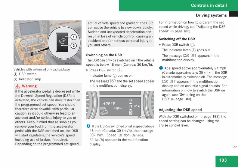
Driving systems
183
Vehicles with enhanced off-road package1 DSR switch2 Indicator lamp
G Warning!If the accelerator pedal is depressed whilethe Downhill Speed Regulation (DSR) isactivated, the vehicle can drive faster thanthe programmed set speed. You shouldtherefore drive downhill with particularcaution as it could otherwise lead to anaccident and/or serious injury to you orothers. Keep in mind that as soon as youremove your foot from the acceleratorpedal with the DSR switched on, the DSRwill start regulating the vehicle’s speedincluding use of brakes if required.Depending on the programmed set speed,
actual vehicle speed and gradient, the DSRcan cause the vehicle to slow down rapidly.Sudden and unexpected deceleration canresult in loss of vehicle control, causing anaccident and/or serious personal injury toyou and others.
Switching on the DSRThe DSR can only be switched on if the vehiclespeed is below 18 mph (Canada: 30 km/h).X Press DSR switch 1.
Indicator lamp 2 comes on.The message DSR and the set speed appearin the multifunction display.
i If the DSR is switched on at a speed above18 mph (Canada: 30 km/h), the messageDSR Max. Speed 18 mph (Canada:30 km/h) appears in the multifunctiondisplay.
For information on how to program the setspeed while driving, see “Adjusting the DSRspeed” (Y page 183).
Switching off the DSRX Press DSR switch 1.
The indicator lamp 2 goes out.The message DSR Off appears in themultifunction display.
i At a speed above approximately 21 mph(Canada approximately: 35 km/h), the DSRis automatically switched off. The messageDSR Off appears in the multifunctiondisplay and an acoustic signal sounds. Forinformation on how to switch the DSR onagain, see “Switching on theDSR” (Y page 183).
Adjusting the DSR speedWith the DSR switched on (Y page 183), thespeed setting can be changed using thecruise control lever.
Controls in detail
Z
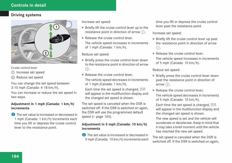
Driving systems
184
Cruise control lever1 Increase set speed2 Reduce set speedYou can change the set speed between3-10 mph (Canada: 4-18 km/h).You can increase or reduce the set speed intwo ways.
Adjustment in 1 mph (Canada: 1 km/h)incrementsi The set value is increased or decreased in
1 mph (Canada: 1 km/h) increments eachtime you lift or depress the cruise controllever to the resistance point.
Increase set speed:X Briefly lift the cruise control lever up to the
resistance point in direction of arrow 1.X Release the cruise control lever.
The vehicle speed increases in incrementsof 1 mph (Canada: 1 km/h).
Reduce set speed:X Briefly press the cruise control lever down
to the resistance point in direction of arrow2.
X Release the cruise control lever.The vehicle speed decreases in incrementsof 1 mph (Canada: 1 km/h).Each time the set speed is changed, DSRwill appear in the multifunction display andthe changed set speed is shown.
The set speed is canceled when the DSR isswitched off. If the DSR is switched on again,the DSR will use the programmed defaultspeed (Y page 165).
Adjustment in 5 mph (Canada: 10 km/h)incrementsi The set value is increased or decreased in
5 mph (Canada: 10 km/h) increments each
time you lift or depress the cruise controllever past the resistance point.
Increase set speed:X Briefly lift the cruise control lever up past
the resistance point in direction of arrow1.
X Release the cruise control lever.The vehicle speed increases in incrementsof 5 mph (Canada: 10 km/h).
Reduce set speed:X Briefly press the cruise control lever down
past the resistance point in direction ofarrow 2.
X Release the cruise control lever.The vehicle speed decreases in incrementsof 5 mph (Canada: 10 km/h).Each time the set speed is changed, DSRwill appear in the multifunction display andthe changed set speed is shown.The new speed is set and the vehicle willaccelerate or decelerate. Keep in mind thatit may take a brief moment until the vehiclehas reached the new set speed.
The set speed is canceled when the DSR isswitched off. If the DSR is switched on again,
Controls in detail
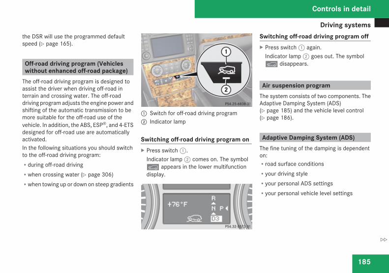
Driving systems
185
the DSR will use the programmed defaultspeed (Y page 165).
Off-road driving program (Vehicleswithout enhanced off-road package)
The off-road driving program is designed toassist the driver when driving off-road interrain and crossing water. The off-roaddriving program adjusts the engine power andshifting of the automatic transmission to bemore suitable for the off-road use of thevehicle. In addition, the ABS, ESP®, and 4-ETSdesigned for off-road use are automaticallyactivated.In the following situations you should switchto the off-road driving program:Rduring off-road drivingRwhen crossing water (Y page 306)Rwhen towing up or down on steep gradients
1 Switch for off-road driving program2 Indicator lamp
Switching off-road driving program onX Press switch 1.
Indicator lamp 2 comes on. The symboly appears in the lower multifunctiondisplay.
Switching off-road driving program offX Press switch 1 again.
Indicator lamp 2 goes out. The symboly disappears.
Air suspension programThe system consists of two components. TheAdaptive Damping System (ADS)(Y page 185) and the vehicle level control(Y page 186).
Adaptive Damping System (ADS)The fine tuning of the damping is dependenton:Rroad surface conditionsRyour driving styleRyour personal ADS settingsRyour personal vehicle level settings
Controls in detail
Z
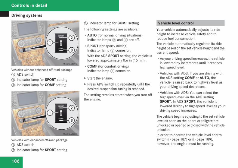
Driving systems
186
Vehicles without enhanced off-road package1 ADS switch2 Indicator lamp for SPORT setting3 Indicator lamp for COMF setting
Vehicles with enhanced off-road package1 ADS switch2 Indicator lamp for SPORT setting
3 Indicator lamp for COMF settingThe following settings are available:RAUTO (for normal driving situations)
Indicator lamps 2 and 3 are off.RSPORT (for sporty driving)
Indicator lamp 2 comes on.With the ADS SPORT setting, the vehicle islowered approximately 0.6 in (15 mm).RCOMF (for comfort driving)
Indicator lamp 3 comes on.
X Start the engine.X Press ADS switch 1 repeatedly until the
desired suspension tuning is reached.The setting remains stored when you turn offthe engine.
Vehicle level controlYour vehicle automatically adjusts its rideheight to increase vehicle safety and toreduce fuel consumption.The vehicle automatically regulates its rideheight based on the set vehicle height and thecurrent speed:RAs your driving speed increases, the vehicle
is lowered by increments until it reacheshighspeed level.RVehicles with ADS: If you are driving with
the ADS setting COMF or AUTO, thevehicle is raised back to highway level asyour driving speed decreases.RVehicles with ADS: You can select the
highspeed level via the ADS settingSPORT. In ADS SPORT, the vehicle islowered directly to highspeed level as yourdriving speed increases.
The vehicle begins adjusting to the set vehiclelevel as soon as the doors or tailgate areunlocked or opened or closed with the vehicleunlocked.In order to operate the vehicle level controlswitch (Y page 187) or (Y page 189),however, the engine must be running.
Controls in detail
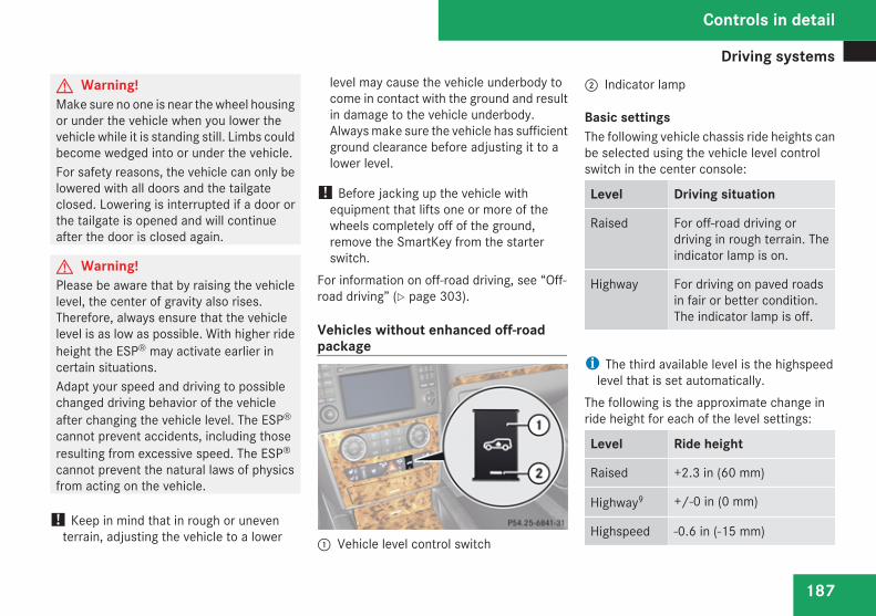
Driving systems
187
G Warning!Make sure no one is near the wheel housingor under the vehicle when you lower thevehicle while it is standing still. Limbs couldbecome wedged into or under the vehicle.For safety reasons, the vehicle can only belowered with all doors and the tailgateclosed. Lowering is interrupted if a door orthe tailgate is opened and will continueafter the door is closed again.
G Warning!Please be aware that by raising the vehiclelevel, the center of gravity also rises.Therefore, always ensure that the vehiclelevel is as low as possible. With higher rideheight the ESP® may activate earlier incertain situations.Adapt your speed and driving to possiblechanged driving behavior of the vehicleafter changing the vehicle level. The ESP®
cannot prevent accidents, including thoseresulting from excessive speed. The ESP®
cannot prevent the natural laws of physicsfrom acting on the vehicle.
! Keep in mind that in rough or uneventerrain, adjusting the vehicle to a lower
level may cause the vehicle underbody tocome in contact with the ground and resultin damage to the vehicle underbody.Always make sure the vehicle has sufficientground clearance before adjusting it to alower level.
! Before jacking up the vehicle withequipment that lifts one or more of thewheels completely off of the ground,remove the SmartKey from the starterswitch.
For information on off-road driving, see “Off-road driving” (Y page 303).
Vehicles without enhanced off-roadpackage
1 Vehicle level control switch
2 Indicator lamp
Basic settingsThe following vehicle chassis ride heights canbe selected using the vehicle level controlswitch in the center console:
Level Driving situation
Raised For off-road driving ordriving in rough terrain. Theindicator lamp is on.
Highway For driving on paved roadsin fair or better condition.The indicator lamp is off.
i The third available level is the highspeedlevel that is set automatically.
The following is the approximate change inride height for each of the level settings:
Level Ride height
Raised +2.3 in (60 mm)
Highway9 +/-0 in (0 mm)
Highspeed -0.6 in (-15 mm)
Controls in detail
Z
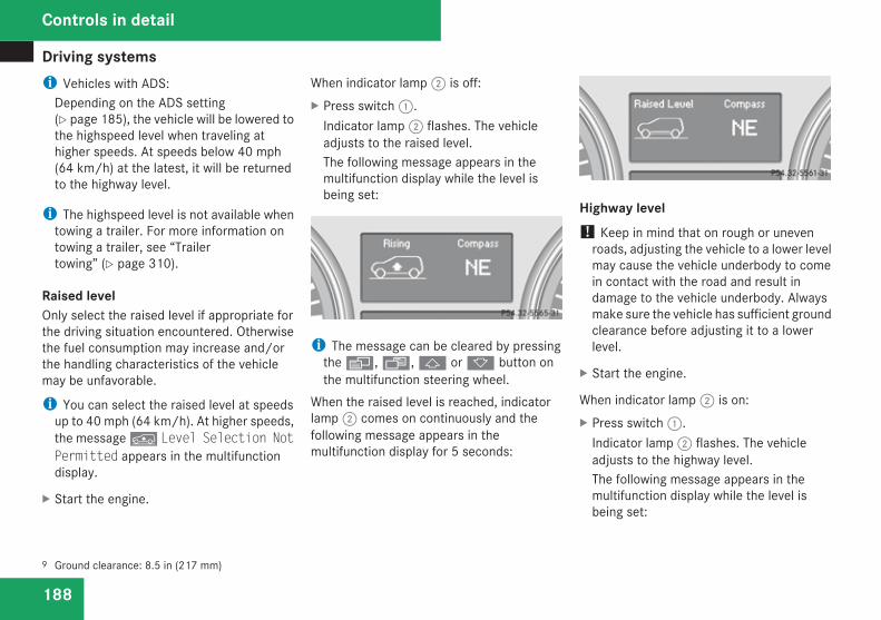
Driving systems
188
i Vehicles with ADS:Depending on the ADS setting(Y page 185), the vehicle will be lowered tothe highspeed level when traveling athigher speeds. At speeds below 40 mph(64 km/h) at the latest, it will be returnedto the highway level.
i The highspeed level is not available whentowing a trailer. For more information ontowing a trailer, see “Trailertowing” (Y page 310).
Raised levelOnly select the raised level if appropriate forthe driving situation encountered. Otherwisethe fuel consumption may increase and/orthe handling characteristics of the vehiclemay be unfavorable.
i You can select the raised level at speedsup to 40 mph (64 km/h). At higher speeds,the message n Level Selection NotPermitted appears in the multifunctiondisplay.
X Start the engine.
When indicator lamp 2 is off:X Press switch 1.
Indicator lamp 2 flashes. The vehicleadjusts to the raised level.The following message appears in themultifunction display while the level isbeing set:
i The message can be cleared by pressingthe è, ·, j or k button onthe multifunction steering wheel.
When the raised level is reached, indicatorlamp 2 comes on continuously and thefollowing message appears in themultifunction display for 5 seconds:
Highway level! Keep in mind that on rough or uneven
roads, adjusting the vehicle to a lower levelmay cause the vehicle underbody to comein contact with the road and result indamage to the vehicle underbody. Alwaysmake sure the vehicle has sufficient groundclearance before adjusting it to a lowerlevel.
X Start the engine.
When indicator lamp 2 is on:X Press switch 1.
Indicator lamp 2 flashes. The vehicleadjusts to the highway level.The following message appears in themultifunction display while the level isbeing set:
9 Ground clearance: 8.5 in (217 mm)
Controls in detail
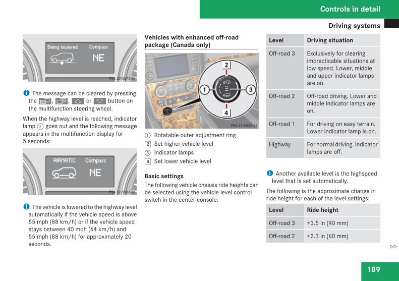
Driving systems
189
i The message can be cleared by pressingthe è, ·, j or k button onthe multifunction steering wheel.
When the highway level is reached, indicatorlamp 2 goes out and the following messageappears in the multifunction display for5 seconds:
i The vehicle is lowered to the highway levelautomatically if the vehicle speed is above55 mph (88 km/h) or if the vehicle speedstays between 40 mph (64 km/h) and55 mph (88 km/h) for approximately 20seconds.
Vehicles with enhanced off-roadpackage (Canada only)
1 Rotatable outer adjustment ring% Set higher vehicle level3 Indicator lamps( Set lower vehicle level
Basic settingsThe following vehicle chassis ride heights canbe selected using the vehicle level controlswitch in the center console:
Level Driving situation
Off-road 3 Exclusively for clearingimpracticable situations atlow speed. Lower, middleand upper indicator lampsare on.
Off-road 2 Off-road driving. Lower andmiddle indicator lamps areon.
Off-road 1 For driving on easy terrain.Lower indicator lamp is on.
Highway For normal driving. Indicatorlamps are off.
i Another available level is the highspeedlevel that is set automatically.
The following is the approximate change inride height for each of the level settings:
Level Ride height
Off-road 3 +3.5 in (90 mm)
Off-road 2 +2.3 in (60 mm)
Controls in detail
Z
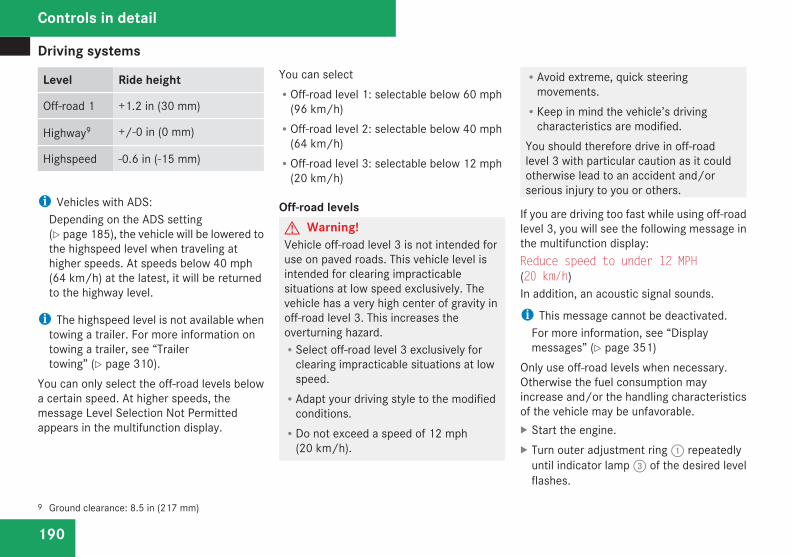
Driving systems
190
Level Ride height
Off-road 1 +1.2 in (30 mm)
Highway9 +/-0 in (0 mm)
Highspeed -0.6 in (-15 mm)
i Vehicles with ADS:Depending on the ADS setting(Y page 185), the vehicle will be lowered tothe highspeed level when traveling athigher speeds. At speeds below 40 mph(64 km/h) at the latest, it will be returnedto the highway level.
i The highspeed level is not available whentowing a trailer. For more information ontowing a trailer, see “Trailertowing” (Y page 310).
You can only select the off-road levels belowa certain speed. At higher speeds, themessage Level Selection Not Permittedappears in the multifunction display.
You can selectROff-road level 1: selectable below 60 mph
(96 km/h)ROff-road level 2: selectable below 40 mph
(64 km/h)ROff-road level 3: selectable below 12 mph
(20 km/h)
Off-road levelsG Warning!Vehicle off-road level 3 is not intended foruse on paved roads. This vehicle level isintended for clearing impracticablesituations at low speed exclusively. Thevehicle has a very high center of gravity inoff-road level 3. This increases theoverturning hazard.RSelect off-road level 3 exclusively for
clearing impracticable situations at lowspeed.RAdapt your driving style to the modified
conditions.RDo not exceed a speed of 12 mph
(20 km/h).
RAvoid extreme, quick steeringmovements.RKeep in mind the vehicle’s driving
characteristics are modified.You should therefore drive in off-roadlevel 3 with particular caution as it couldotherwise lead to an accident and/orserious injury to you or others.
If you are driving too fast while using off-roadlevel 3, you will see the following message inthe multifunction display:Reduce speed to under 12 MPH(20 km/h)In addition, an acoustic signal sounds.
i This message cannot be deactivated.For more information, see “Displaymessages” (Y page 351)
Only use off-road levels when necessary.Otherwise the fuel consumption mayincrease and/or the handling characteristicsof the vehicle may be unfavorable.X Start the engine.X Turn outer adjustment ring 1 repeatedly
until indicator lamp 3 of the desired levelflashes.
9 Ground clearance: 8.5 in (217 mm)
Controls in detail
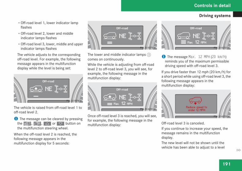
Driving systems
191
ROff-road level 1, lower indicator lampflashesROff-road level 2, lower and middle
indicator lamps flashesROff-road level 3, lower, middle and upper
indicator lamps flashesThe vehicle adjusts to the correspondingoff-road level. For example, the followingmessage appears in the multifunctiondisplay while the level is being set:
The vehicle is raised from off-road level 1 tooff-road level 2.
i The message can be cleared by pressingthe è, ·, j or k button onthe multifunction steering wheel.
When the off-road level 2 is reached, thefollowing message appears in themultifunction display for 5 seconds:
The lower and middle indicator lamps 3comes on continuously.While the vehicle is adjusting from off-roadlevel 2 to off-road level 3, you will see, forexample, the following message in themultifunction display:
Once off-road level 3 is reached, you will see,for example, the following message in themultifunction display:
i The message Max. 12 MPH (20 km/h)reminds you of the maximum permissibledriving speed with off-road level 3.
If you drive faster than 12 mph (20 km/h) fora short period while using off-road level 3, thefollowing message appears in themultifunction display:
Off-road level 3 is canceled.If you continue to increase your speed, themessage remains in the multifunctiondisplay.The new level will not be shown until thevehicle has been able to adjust to a level
Controls in detail
Z
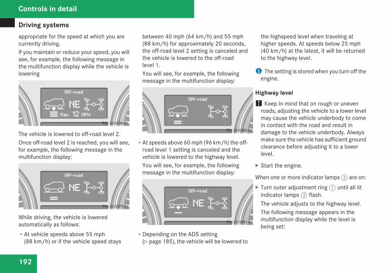
Driving systems
192
appropriate for the speed at which you arecurrently driving.If you maintain or reduce your speed, you willsee, for example, the following message inthe multifunction display while the vehicle islowering
The vehicle is lowered to off-road level 2.Once off-road level 2 is reached, you will see,for example, the following message in themultifunction display:
While driving, the vehicle is loweredautomatically as follows:RAt vehicle speeds above 55 mph
(88 km/h) or if the vehicle speed stays
between 40 mph (64 km/h) and 55 mph(88 km/h) for approximately 20 seconds,the off-road level 2 setting is canceled andthe vehicle is lowered to the off-roadlevel 1.You will see, for example, the followingmessage in the multifunction display:
RAt speeds above 60 mph (96 km/h) the off-road level 1 setting is canceled and thevehicle is lowered to the highway level.You will see, for example, the followingmessage in the multifunction display:
RDepending on the ADS setting(Y page 185), the vehicle will be lowered to
the highspeed level when traveling athigher speeds. At speeds below 25 mph(40 km/h) at the latest, it will be returnedto the highway level.
i The setting is stored when you turn off theengine.
Highway level! Keep in mind that on rough or uneven
roads, adjusting the vehicle to a lower levelmay cause the vehicle underbody to comein contact with the road and result indamage to the vehicle underbody. Alwaysmake sure the vehicle has sufficient groundclearance before adjusting it to a lowerlevel.
X Start the engine.
When one or more indicator lamps 3 are on:X Turn outer adjustment ring 1 until all lit
indicator lamps 3 flash.The vehicle adjusts to the highway level.The following message appears in themultifunction display while the level isbeing set:
Controls in detail
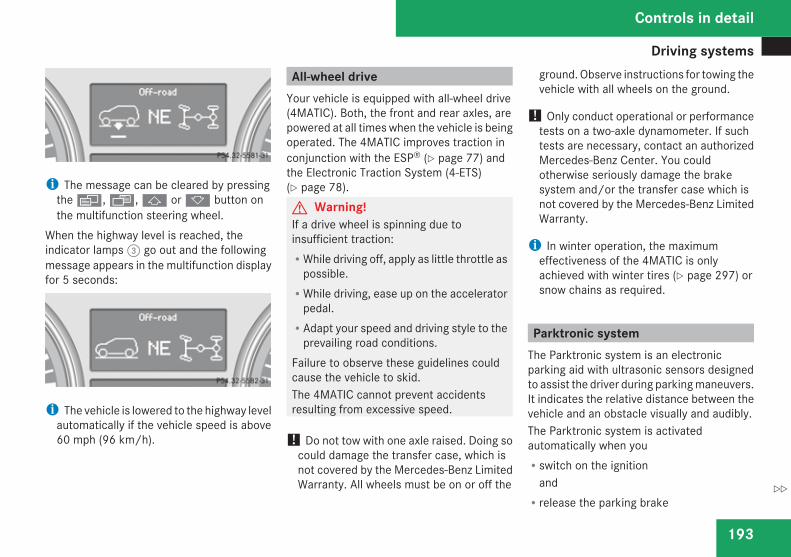
Driving systems
193
i The message can be cleared by pressingthe è, ·, j or k button onthe multifunction steering wheel.
When the highway level is reached, theindicator lamps 3 go out and the followingmessage appears in the multifunction displayfor 5 seconds:
i The vehicle is lowered to the highway levelautomatically if the vehicle speed is above60 mph (96 km/h).
All-wheel driveYour vehicle is equipped with all-wheel drive(4MATIC). Both, the front and rear axles, arepowered at all times when the vehicle is beingoperated. The 4MATIC improves traction inconjunction with the ESP® (Y page 77) andthe Electronic Traction System (4-ETS)(Y page 78).G Warning!If a drive wheel is spinning due toinsufficient traction:RWhile driving off, apply as little throttle as
possible.RWhile driving, ease up on the accelerator
pedal.RAdapt your speed and driving style to the
prevailing road conditions.Failure to observe these guidelines couldcause the vehicle to skid.The 4MATIC cannot prevent accidentsresulting from excessive speed.
! Do not tow with one axle raised. Doing socould damage the transfer case, which isnot covered by the Mercedes-Benz LimitedWarranty. All wheels must be on or off the
ground. Observe instructions for towing thevehicle with all wheels on the ground.
! Only conduct operational or performancetests on a two-axle dynamometer. If suchtests are necessary, contact an authorizedMercedes-Benz Center. You couldotherwise seriously damage the brakesystem and/or the transfer case which isnot covered by the Mercedes-Benz LimitedWarranty.
i In winter operation, the maximumeffectiveness of the 4MATIC is onlyachieved with winter tires (Y page 297) orsnow chains as required.
Parktronic systemThe Parktronic system is an electronicparking aid with ultrasonic sensors designedto assist the driver during parking maneuvers.It indicates the relative distance between thevehicle and an obstacle visually and audibly.The Parktronic system is activatedautomatically when youRswitch on the ignition
andRrelease the parking brake
Controls in detail
Z
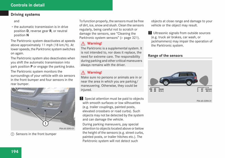
Driving systems
194
andRthe automatic transmission is in drive
position D, reverse gear R, or neutralposition N
The Parktronic system deactivates at speedsabove approximately 11 mph (18 km/h). Atlower speeds, the Parktronic system switcheson again.The Parktronic system also deactivates whenyou shift the automatic transmission intopark position P or engage the parking brake.The Parktronic system monitors thesurroundings of your vehicle with six sensorsin the front bumper and four sensors in therear bumper.
1 Sensors in the front bumper
To function properly, the sensors must be freeof dirt, ice, snow and slush. Clean the sensorsregularly, being careful not to scratch ordamage the sensors, see “Cleaning theParktronic system sensors” (Y page 321).G Warning!The Parktronic is a supplemental system. Itis not intended to, nor does it replace, theneed for extreme care. The responsibilityduring parking and other critical maneuversalways remains with the driver.
G Warning!Make sure no persons or animals are in ornear the area in which you are parking/maneuvering. Otherwise, they could beinjured.
! Special attention must be paid to objectswith smooth surfaces or low silhouettes(e.g. trailer couplings, painted posts,elevated crossbars or road curbs). Suchobjects may not be detected by the systemand can damage the vehicle.During parking maneuvers, pay specialattention to objects located above or belowthe height of the sensors (e.g. street curbs,painted posts, or trailer hitches etc.). TheParktronic system will not detect such
objects at close range and damage to yourvehicle or the object may result.
! Ultrasonic signals from outside sources(e.g. truck air brakes, car wash, orjackhammers) may impair the operation ofthe Parktronic system.
Range of the sensors
Controls in detail
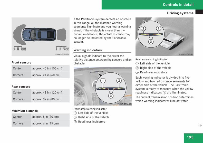
Driving systems
195
Front sensors
Center approx. 40 in (100 cm)
Corners approx. 24 in (60 cm)
Rear sensors
Center approx. 48 in (120 cm)
Corners approx. 32 in (80 cm)
Minimum distance
Center approx. 8 in (20 cm)
Corners approx. 6 in (15 cm)
If the Parktronic system detects an obstaclein this range, all the distance warningsegments illuminate and you hear a warningsignal. If the obstacle is closer than theminimum distance, the actual distance mayno longer be indicated by the Parktronicsystem.
Warning indicatorsVisual signals indicate to the driver therelative distance between the sensors and anobstacle.
Front area warning indicator1 Left side of the vehicle2 Right side of the vehicle3 Readiness indicators
Rear area warning indicator1 Left side of the vehicle2 Right side of the vehicle3 Readiness indicatorsEach warning indicator is divided into fiveyellow and two red distance segments foreither side of the vehicle. The Parktronicsystem is ready to measure when the yellowreadiness indicators 3 are illuminated.The current transmission position determineswhich warning indicator will be activated.
Controls in detail
Z
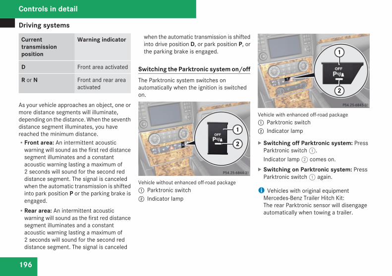
Driving systems
196
Currenttransmissionposition
Warning indicator
D Front area activated
R or N Front and rear areaactivated
As your vehicle approaches an object, one ormore distance segments will illuminate,depending on the distance. When the seventhdistance segment illuminates, you havereached the minimum distance.RFront area: An intermittent acoustic
warning will sound as the first red distancesegment illuminates and a constantacoustic warning lasting a maximum of2 seconds will sound for the second reddistance segment. The signal is canceledwhen the automatic transmission is shiftedinto park position P or the parking brake isengaged.RRear area: An intermittent acoustic
warning will sound as the first red distancesegment illuminates and a constantacoustic warning lasting a maximum of2 seconds will sound for the second reddistance segment. The signal is canceled
when the automatic transmission is shiftedinto drive position D, or park position P, orthe parking brake is engaged.
Switching the Parktronic system on/offThe Parktronic system switches onautomatically when the ignition is switchedon.
Vehicle without enhanced off-road package1 Parktronic switch2 Indicator lamp
Vehicle with enhanced off-road package1 Parktronic switch2 Indicator lamp
X Switching off Parktronic system: PressParktronic switch 1.Indicator lamp 2 comes on.
X Switching on Parktronic system: PressParktronic switch 1 again.
i Vehicles with original equipmentMercedes-Benz Trailer Hitch Kit:The rear Parktronic sensor will disengageautomatically when towing a trailer.
Controls in detail
Driving systems
197
Parktronic system malfunctionThere is a malfunction in the Parktronicsystem, if only the red distance segmentsilluminate and an acoustic warning sounds.The Parktronic system will switch offautomatically after 20 seconds and indicatorlamp 2 in Parktronic switch 1 comes on.X Have the Parktronic system checked at an
authorized Mercedes-Benz Center as soonas possible.
If only the red distance segments illuminateand no acoustic warning sounds, theParktronic system sensors are dirty (e.g. dirt,ice, snow and slush) or there is aninterference from other radio or ultrasonicsignals (e.g. truck air brakes, car wash, orjackhammers). The Parktronic system willswitch off automatically after 20 seconds andindicator lamp 2 in Parktronic switch 1comes on.X Switch off the ignition.X Clean the Parktronic system sensors
(Y page 321).X Switch on the ignition.
orX Check the Parktronic system operation at
another location to rule out interferencefrom outside radio or ultrasonic signals.
Rear view camera
G Warning!The rear view camera is only an aid and maydisplay obstacles from a distortedperspective or inaccurately, or may notdisplay obstacles at all. The rear viewcamera does not relieve you of theresponsibility to be cautious, take care andpay careful attention. The rear view cameramay not show objects which areRvery close to the rear bumperRunder the rear bumperRabove the tailgate handleYou are responsible for safety at all timesand must continue to pay attention to theimmediate surroundings when parking andmaneuvering. This includes the areabehind, in front of and beside the vehicle.Otherwise you could endanger yourselfand/or others.
G Warning!Make sure no persons or animals are in ornear the area in which you are parking/maneuvering. Otherwise, they could beinjured.
G Warning!The rear view camera either will notfunction or will not function to its fullcapability ifRthe tailgate is openRit is raining very hard, snowing or foggyRit is night or you are parking/
maneuvering your vehicle in an areawhere it is very darkRthe camera is exposed to a very bright
white lightRthe immediate surroundings are
illuminated with fluorescent light (thedisplay may flicker)Rthere is a sudden change in temperature,
e.g. if you drive into a heated garage fromthe cold (lens condensation)Rthe camera lens is dirty or coveredRthe rear of your vehicle is damaged
Controls in detail
Z
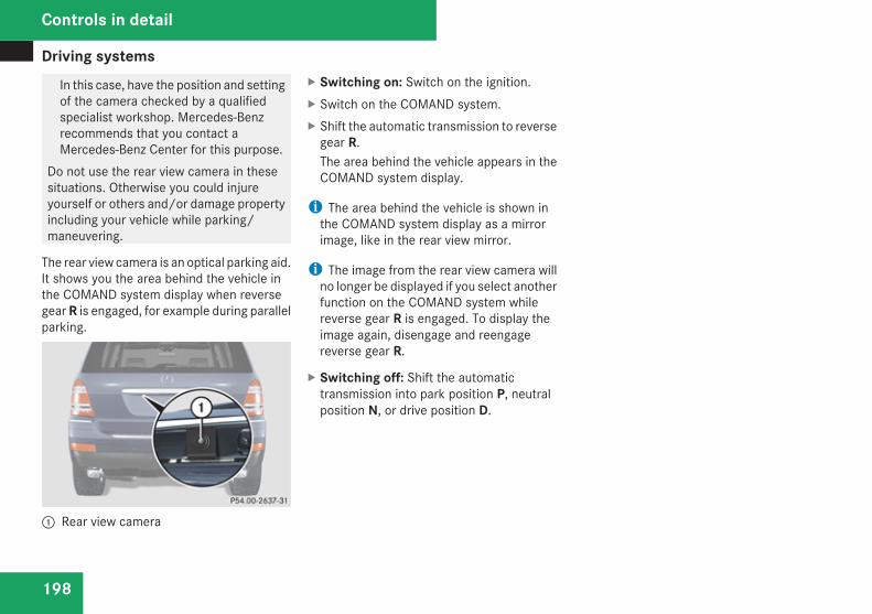
Driving systems
198
In this case, have the position and settingof the camera checked by a qualifiedspecialist workshop. Mercedes-Benzrecommends that you contact aMercedes-Benz Center for this purpose.
Do not use the rear view camera in thesesituations. Otherwise you could injureyourself or others and/or damage propertyincluding your vehicle while parking/maneuvering.
The rear view camera is an optical parking aid.It shows you the area behind the vehicle inthe COMAND system display when reversegear R is engaged, for example during parallelparking.
1 Rear view camera
X Switching on: Switch on the ignition.X Switch on the COMAND system.X Shift the automatic transmission to reverse
gear R.The area behind the vehicle appears in theCOMAND system display.
i The area behind the vehicle is shown inthe COMAND system display as a mirrorimage, like in the rear view mirror.
i The image from the rear view camera willno longer be displayed if you select anotherfunction on the COMAND system whilereverse gear R is engaged. To display theimage again, disengage and reengagereverse gear R.
X Switching off: Shift the automatictransmission into park position P, neutralposition N, or drive position D.
Controls in detail
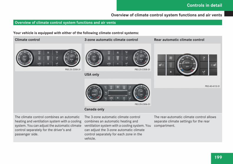
Overview of climate control system functions and air vents
199
Overview of climate control system functions and air vents
Your vehicle is equipped with either of the following climate control systems:
Climate control 3-zone automatic climate control
USA only
Canada only
Rear automatic climate control
The climate control combines an automaticheating and ventilation system with a coolingsystem. You can adjust the automatic climatecontrol separately for the driver’s andpassenger side.
The 3-zone automatic climate controlcombines an automatic heating andventilation system with a cooling system. Youcan adjust the 3-zone automatic climatecontrol separately for each zone in thevehicle.
The rear-automatic climate control allowsseparate climate settings for the rearcompartment.
Controls in detail
Z
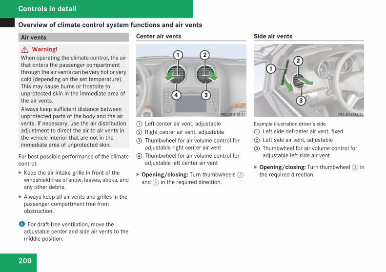
Overview of climate control system functions and air vents
200
Air vents
G Warning!When operating the climate control, the airthat enters the passenger compartmentthrough the air vents can be very hot or verycold (depending on the set temperature).This may cause burns or frostbite tounprotected skin in the immediate area ofthe air vents.Always keep sufficient distance betweenunprotected parts of the body and the airvents. If necessary, use the air distributionadjustment to direct the air to air vents inthe vehicle interior that are not in theimmediate area of unprotected skin.
For best possible performance of the climatecontrol:X Keep the air intake grille in front of the
windshield free of snow, leaves, sticks, andany other debris.
X Always keep all air vents and grilles in thepassenger compartment free fromobstruction.
i For draft-free ventilation, move theadjustable center and side air vents to themiddle position.
Center air vents
1 Left center air vent, adjustable2 Right center air vent, adjustable3 Thumbwheel for air volume control for
adjustable right center air vent4 Thumbwheel for air volume control for
adjustable left center air vent
X Opening/closing: Turn thumbwheels 3and 4 in the required direction.
Side air vents
Example illustration driver’s side1 Left side defroster air vent, fixed2 Left side air vent, adjustable3 Thumbwheel for air volume control for
adjustable left side air vent
X Opening/closing: Turn thumbwheel 3 inthe required direction.
Controls in detail
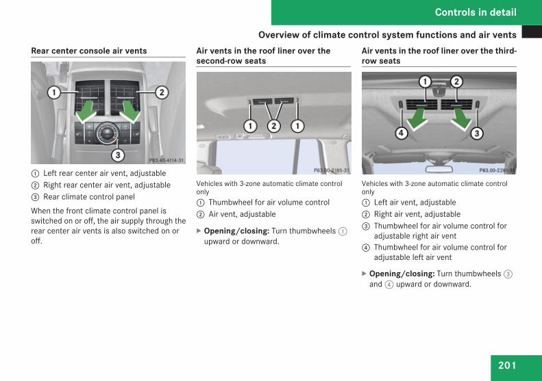
Overview of climate control system functions and air vents
201
Rear center console air vents
1 Left rear center air vent, adjustable2 Right rear center air vent, adjustable3 Rear climate control panelWhen the front climate control panel isswitched on or off, the air supply through therear center air vents is also switched on oroff.
Air vents in the roof liner over thesecond-row seats
Vehicles with 3-zone automatic climate controlonly1 Thumbwheel for air volume control2 Air vent, adjustable
X Opening/closing: Turn thumbwheels 1upward or downward.
Air vents in the roof liner over the third-row seats
Vehicles with 3-zone automatic climate controlonly1 Left air vent, adjustable2 Right air vent, adjustable3 Thumbwheel for air volume control for
adjustable right air vent4 Thumbwheel for air volume control for
adjustable left air vent
X Opening/closing: Turn thumbwheels 3and 4 upward or downward.
Controls in detail
Z
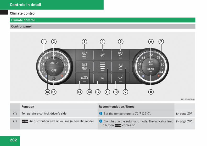
Climate control
202
Climate control
Control panel
Function Recommendation/Notes
1 Temperature control, driver’s side i Set the temperature to 72‡ (22†). (Y page 207)
2 U Air distribution and air volume (automatic mode) i Switches on the automatic mode. The indicator lampin button U comes on.
(Y page 206)
Controls in detail
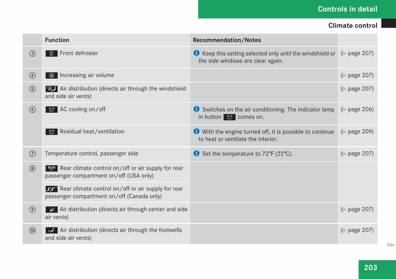
Climate control
203
Function Recommendation/Notes
3 | Front defroster i Keep this setting selected only until the windshield orthe side windows are clear again.
(Y page 207)
4 Q Increasing air volume (Y page 207)
5 { Air distribution (directs air through the windshieldand side air vents)
(Y page 207)
6 9 AC cooling on/off i Switches on the air conditioning. The indicator lampin button 9 comes on.
(Y page 206)
9 Residual heat/ventilation i With the engine turned off, it is possible to continueto heat or ventilate the interior.
(Y page 209)
7 Temperature control, passenger side i Set the temperature to 72‡ (22†). (Y page 207)
8 : Rear climate control on/off or air supply for rearpassenger compartment on/off (USA only)
< Rear climate control on/off or air supply for rearpassenger compartment on/off (Canada only)
9 a Air distribution (directs air through center and sideair vents)
(Y page 207)
a Y Air distribution (directs air through the footwellsand side air vents)
(Y page 207)
Controls in detail
Z
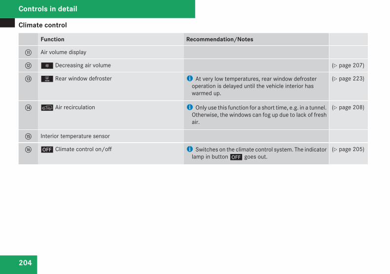
Climate control
204
Function Recommendation/Notes
b Air volume display
c · Decreasing air volume (Y page 207)
d 1 Rear window defroster i At very low temperatures, rear window defrosteroperation is delayed until the vehicle interior haswarmed up.
(Y page 223)
e : Air recirculation i Only use this function for a short time, e.g. in a tunnel.Otherwise, the windows can fog up due to lack of freshair.
(Y page 208)
f Interior temperature sensor
g ´ Climate control on/off i Switches on the climate control system. The indicatorlamp in button ´ goes out.
(Y page 205)
Controls in detail
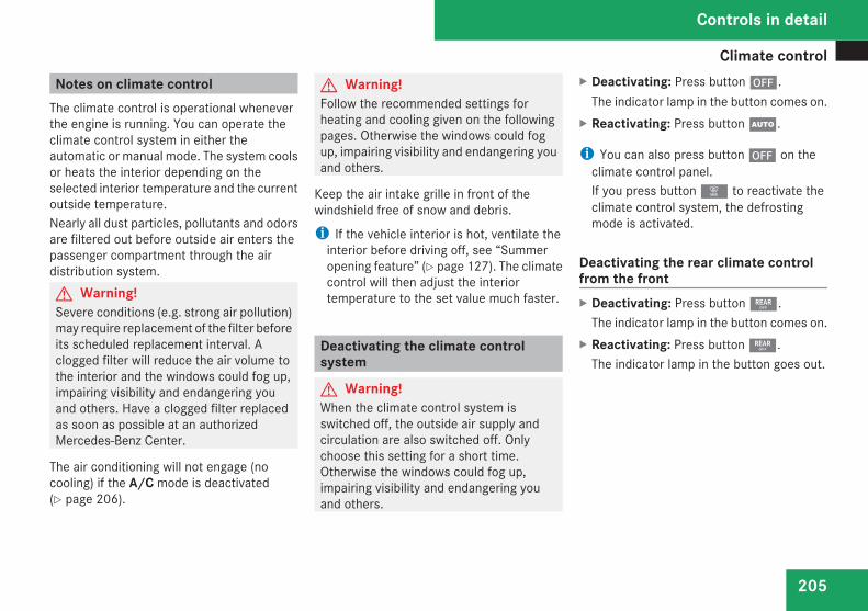
Climate control
205
Notes on climate controlThe climate control is operational wheneverthe engine is running. You can operate theclimate control system in either theautomatic or manual mode. The system coolsor heats the interior depending on theselected interior temperature and the currentoutside temperature.Nearly all dust particles, pollutants and odorsare filtered out before outside air enters thepassenger compartment through the airdistribution system.G Warning!Severe conditions (e.g. strong air pollution)may require replacement of the filter beforeits scheduled replacement interval. Aclogged filter will reduce the air volume tothe interior and the windows could fog up,impairing visibility and endangering youand others. Have a clogged filter replacedas soon as possible at an authorizedMercedes-Benz Center.
The air conditioning will not engage (nocooling) if the A/C mode is deactivated(Y page 206).
G Warning!Follow the recommended settings forheating and cooling given on the followingpages. Otherwise the windows could fogup, impairing visibility and endangering youand others.
Keep the air intake grille in front of thewindshield free of snow and debris.
i If the vehicle interior is hot, ventilate theinterior before driving off, see “Summeropening feature” (Y page 127). The climatecontrol will then adjust the interiortemperature to the set value much faster.
Deactivating the climate controlsystem
G Warning!When the climate control system isswitched off, the outside air supply andcirculation are also switched off. Onlychoose this setting for a short time.Otherwise the windows could fog up,impairing visibility and endangering youand others.
X Deactivating: Press button ´.The indicator lamp in the button comes on.
X Reactivating: Press button U.
i You can also press button ´ on theclimate control panel.If you press button | to reactivate theclimate control system, the defrostingmode is activated.
Deactivating the rear climate controlfrom the frontX Deactivating: Press button :.
The indicator lamp in the button comes on.X Reactivating: Press button :.
The indicator lamp in the button goes out.
Controls in detail
Z
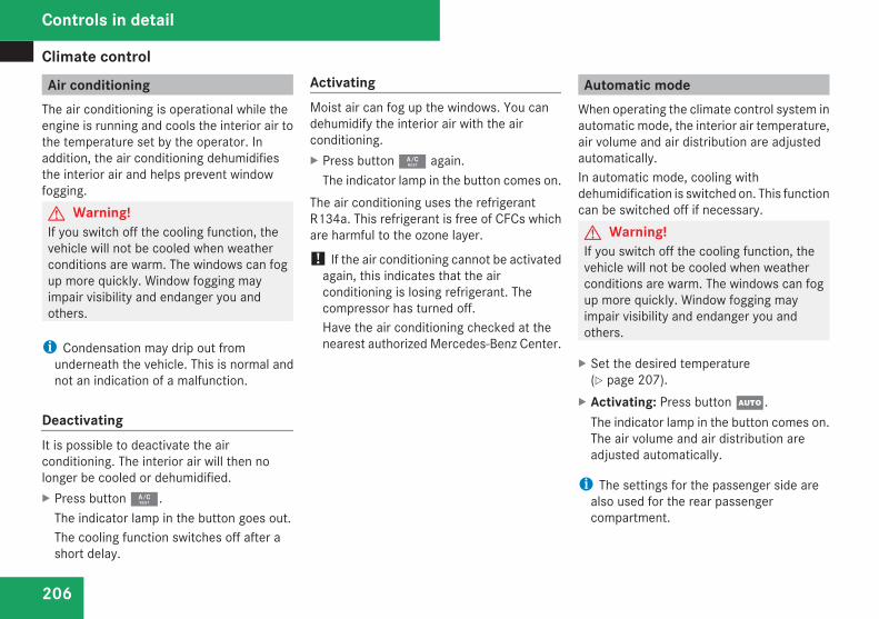
Climate control
206
Air conditioningThe air conditioning is operational while theengine is running and cools the interior air tothe temperature set by the operator. Inaddition, the air conditioning dehumidifiesthe interior air and helps prevent windowfogging.G Warning!If you switch off the cooling function, thevehicle will not be cooled when weatherconditions are warm. The windows can fogup more quickly. Window fogging mayimpair visibility and endanger you andothers.
i Condensation may drip out fromunderneath the vehicle. This is normal andnot an indication of a malfunction.
DeactivatingIt is possible to deactivate the airconditioning. The interior air will then nolonger be cooled or dehumidified.X Press button 9.
The indicator lamp in the button goes out.The cooling function switches off after ashort delay.
ActivatingMoist air can fog up the windows. You candehumidify the interior air with the airconditioning.X Press button 9 again.
The indicator lamp in the button comes on.The air conditioning uses the refrigerantR134a. This refrigerant is free of CFCs whichare harmful to the ozone layer.
! If the air conditioning cannot be activatedagain, this indicates that the airconditioning is losing refrigerant. Thecompressor has turned off.Have the air conditioning checked at thenearest authorized Mercedes-Benz Center.
Automatic modeWhen operating the climate control system inautomatic mode, the interior air temperature,air volume and air distribution are adjustedautomatically.In automatic mode, cooling withdehumidification is switched on. This functioncan be switched off if necessary.G Warning!If you switch off the cooling function, thevehicle will not be cooled when weatherconditions are warm. The windows can fogup more quickly. Window fogging mayimpair visibility and endanger you andothers.
X Set the desired temperature(Y page 207).
X Activating: Press button U.The indicator lamp in the button comes on.The air volume and air distribution areadjusted automatically.
i The settings for the passenger side arealso used for the rear passengercompartment.
Controls in detail
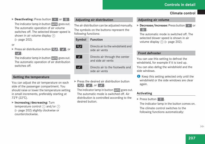
Climate control
207
X Deactivating: Press button · or Q.The indicator lamp in button U goes out.The automatic operation of air volumeswitches off. The selected blower speed isshown in air volume display b(Y page 202).
orX Press air distribution button {, a, orY.The indicator lamp in button U goes out.The automatic operation of air distributionswitches off.
Setting the temperatureYou can adjust the air temperature on eachside of the passenger compartment. Youshould raise or lower the temperature settingin small increments, preferably starting at72‡ (22†).X Increasing/decreasing: Turn
temperature control 1 and/or 7(Y page 202) slightly clockwise orcounterclockwise.
Adjusting air distributionThe air distribution can be adjusted manually.The symbols on the buttons represent thefollowing functions:
Symbol Function
{ Directs air to the windshield andside air vents
a Directs air through the centerand side air vents
Y Directs air to the footwells andside air vents
X Press the desired air distribution button{, a, or Y.The indicator lamp in button U goes out.The automatic mode is switched off. Airdistribution is controlled according to thedesired button.
Adjusting air volumeX Decrease/increase: Press button · orQ.The automatic mode is switched off. Theselected blower speed is shown in airvolume display b (Y page 202).
Front defrosterYou can use this setting to defrost thewindshield, for example if it is iced up.You can also defog the windshield and theside windows.
i Keep this setting selected only until thewindshield or the side windows are clearagain.
ActivatingX Press button |.
The indicator lamp in the button comes on.The climate control switches to thefollowing functions automatically:
Controls in detail
Z
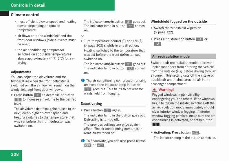
Climate control
208
Rmost efficient blower speed and heatingpower, depending on outsidetemperatureRair flows onto the windshield and the
front door windows (side air vents mustbe open)Rthe air conditioning compressor
switches on at outside temperaturesabove approximately 41‡ (5†) for air-drying
AdjustmentsYou can adjust the air volume and thetemperature when the front defroster isswitched on. The air flow will remain on thewindshield and front door windows.X Press button Ï to decrease or buttonQ to increase air volume to the desiredlevel.The air volume decreases/increases to thenext lower/higher blower speed andheating switches to the temperature thatwas set before the front defroster wasswitched on.
The indicator lamp in button | goes out.The indicator lamp in button 9 comeson.
orX Turn temperature control 1 and/or 7
(Y page 202) slightly in any direction.Heating switches to the temperature thatwas set before the front defroster wasswitched on.The indicator lamp in button | goes out.The indicator lamp in button 9 comeson.
i The air conditioning compressor remainson even if the indicator lamp in button| goes out. This helps to prevent thewindshield from fogging.
DeactivatingX Press button | again.
The indicator lamp in the button goes out.Defrosting is turned off.The previous settings are once again ineffect. The air conditioning compressorremains switched on.
i To deactivate, you can also press button´ or U.
Windshield fogged on the outsideX Switch the windshield wipers on
(Y page 122).
X Press air distribution button a orY.
Air recirculation modeSwitch to air recirculation mode to preventunpleasant odors from entering the vehiclefrom the outside (e. g. before driving througha tunnel). This setting cuts off the intake ofoutside air and recirculates the air in thepassenger compartment.G Warning!Fogged windows impair visibility,endangering you and others. If the windowsbegin to fog on the inside, switching off theair recirculation mode immediately shouldclear interior window fogging. If interiorwindow fogging persists, make sure the airconditioning is activated, or press button|.
X Activating: Press button :.The indicator lamp in the button comes on.
Controls in detail
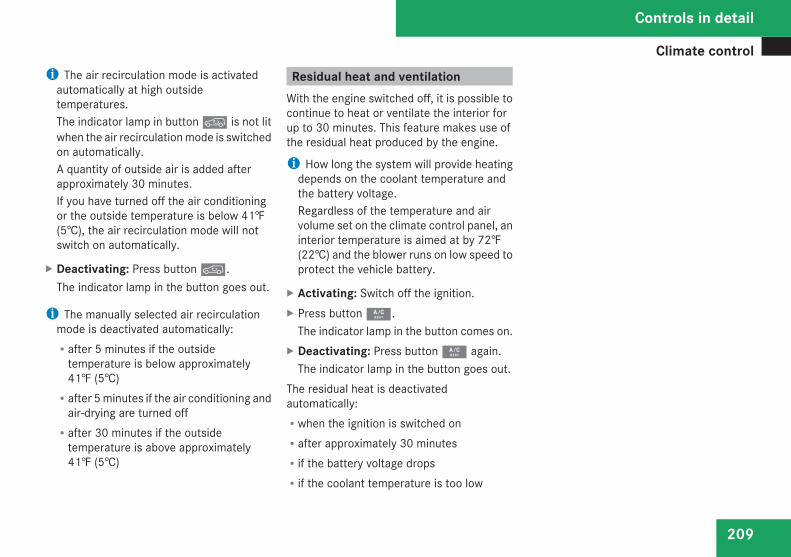
Climate control
209
i The air recirculation mode is activatedautomatically at high outsidetemperatures.The indicator lamp in button : is not litwhen the air recirculation mode is switchedon automatically.A quantity of outside air is added afterapproximately 30 minutes.If you have turned off the air conditioningor the outside temperature is below 41‡(5†), the air recirculation mode will notswitch on automatically.
X Deactivating: Press button :.The indicator lamp in the button goes out.
i The manually selected air recirculationmode is deactivated automatically:Rafter 5 minutes if the outside
temperature is below approximately41‡ (5†)Rafter 5 minutes if the air conditioning and
air-drying are turned offRafter 30 minutes if the outside
temperature is above approximately41‡ (5†)
Residual heat and ventilationWith the engine switched off, it is possible tocontinue to heat or ventilate the interior forup to 30 minutes. This feature makes use ofthe residual heat produced by the engine.
i How long the system will provide heatingdepends on the coolant temperature andthe battery voltage.Regardless of the temperature and airvolume set on the climate control panel, aninterior temperature is aimed at by 72‡(22†) and the blower runs on low speed toprotect the vehicle battery.
X Activating: Switch off the ignition.X Press button 9.
The indicator lamp in the button comes on.X Deactivating: Press button 9 again.
The indicator lamp in the button goes out.The residual heat is deactivatedautomatically:Rwhen the ignition is switched onRafter approximately 30 minutesRif the battery voltage dropsRif the coolant temperature is too low
Controls in detail
Z
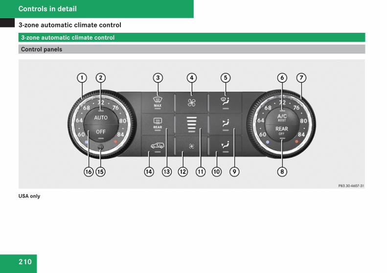
3-zone automatic climate control
210
3-zone automatic climate control
Control panels
USA only
Controls in detail
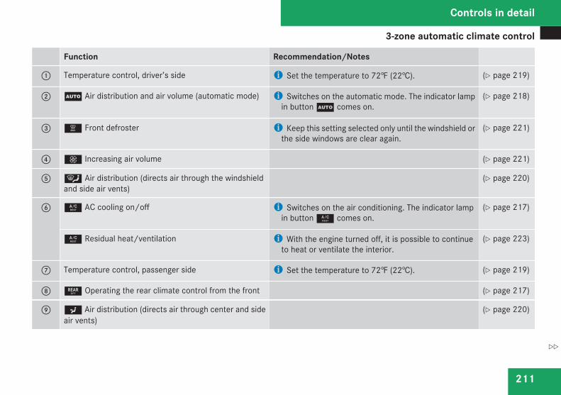
3-zone automatic climate control
211
Function Recommendation/Notes
1 Temperature control, driver’s side i Set the temperature to 72‡ (22†). (Y page 219)
2 U Air distribution and air volume (automatic mode) i Switches on the automatic mode. The indicator lampin button U comes on.
(Y page 218)
3 | Front defroster i Keep this setting selected only until the windshield orthe side windows are clear again.
(Y page 221)
4 Q Increasing air volume (Y page 221)
5 { Air distribution (directs air through the windshieldand side air vents)
(Y page 220)
6 9 AC cooling on/off i Switches on the air conditioning. The indicator lampin button 9 comes on.
(Y page 217)
9 Residual heat/ventilation i With the engine turned off, it is possible to continueto heat or ventilate the interior.
(Y page 223)
7 Temperature control, passenger side i Set the temperature to 72‡ (22†). (Y page 219)
8 : Operating the rear climate control from the front (Y page 217)
9 a Air distribution (directs air through center and sideair vents)
(Y page 220)
Controls in detail
Z
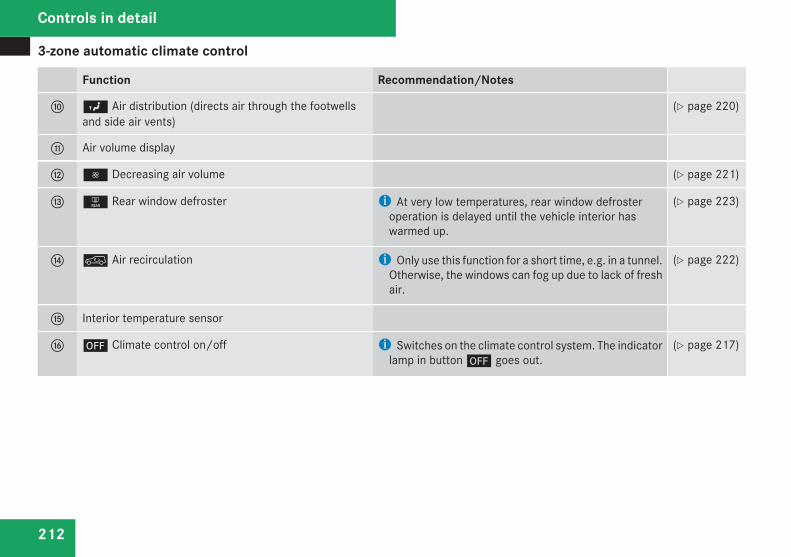
3-zone automatic climate control
212
Function Recommendation/Notes
a Y Air distribution (directs air through the footwellsand side air vents)
(Y page 220)
b Air volume display
c · Decreasing air volume (Y page 221)
d 1 Rear window defroster i At very low temperatures, rear window defrosteroperation is delayed until the vehicle interior haswarmed up.
(Y page 223)
e : Air recirculation i Only use this function for a short time, e.g. in a tunnel.Otherwise, the windows can fog up due to lack of freshair.
(Y page 222)
f Interior temperature sensor
g ´ Climate control on/off i Switches on the climate control system. The indicatorlamp in button ´ goes out.
(Y page 217)
Controls in detail
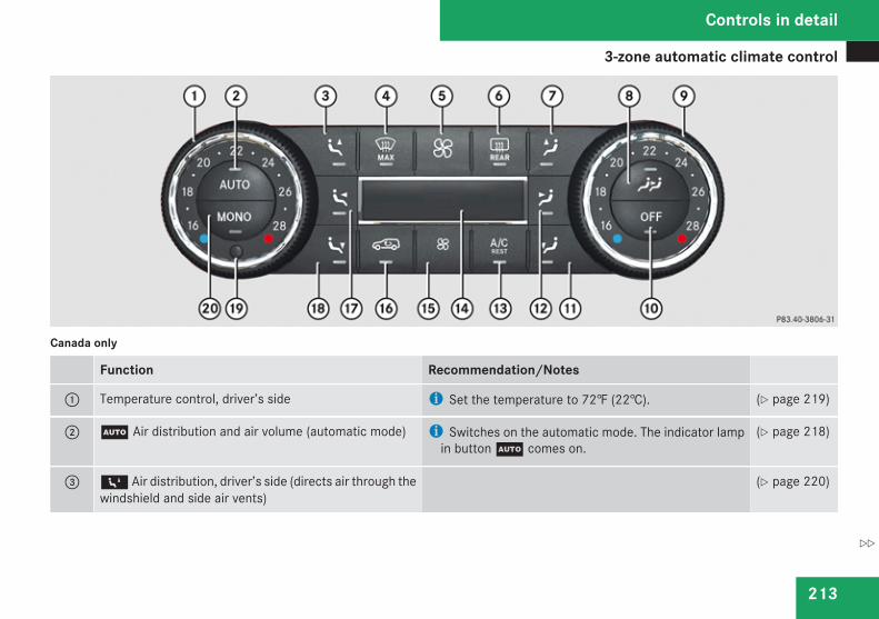
3-zone automatic climate control
213
Canada only
Function Recommendation/Notes
1 Temperature control, driver’s side i Set the temperature to 72‡ (22†). (Y page 219)
2 U Air distribution and air volume (automatic mode) i Switches on the automatic mode. The indicator lampin button U comes on.
(Y page 218)
3 6 Air distribution, driver’s side (directs air through thewindshield and side air vents)
(Y page 220)
Controls in detail
Z
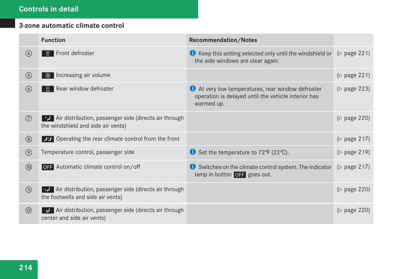
3-zone automatic climate control
214
Function Recommendation/Notes
4 | Front defroster i Keep this setting selected only until the windshield orthe side windows are clear again.
(Y page 221)
5 Q Increasing air volume (Y page 221)
6 1 Rear window defroster i At very low temperatures, rear window defrosteroperation is delayed until the vehicle interior haswarmed up.
(Y page 223)
7 Z Air distribution, passenger side (directs air throughthe windshield and side air vents)
(Y page 220)
8 Ñ Operating the rear climate control from the front (Y page 217)
9 Temperature control, passenger side i Set the temperature to 72‡ (22†). (Y page 219)
a ´ Automatic climate control on/off i Switches on the climate control system. The indicatorlamp in button ´ goes out.
(Y page 217)
b Y Air distribution, passenger side (directs air throughthe footwells and side air vents)
(Y page 220)
c a Air distribution, passenger side (directs air throughcenter and side air vents)
(Y page 220)
Controls in detail
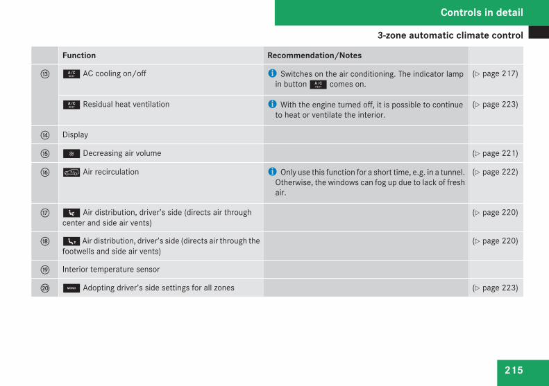
3-zone automatic climate control
215
Function Recommendation/Notes
d 9 AC cooling on/off i Switches on the air conditioning. The indicator lampin button 9 comes on.
(Y page 217)
9 Residual heat ventilation i With the engine turned off, it is possible to continueto heat or ventilate the interior.
(Y page 223)
e Display
f ß Decreasing air volume (Y page 221)
g : Air recirculation i Only use this function for a short time, e.g. in a tunnel.Otherwise, the windows can fog up due to lack of freshair.
(Y page 222)
h 7 Air distribution, driver’s side (directs air throughcenter and side air vents)
(Y page 220)
j 8 Air distribution, driver’s side (directs air through thefootwells and side air vents)
(Y page 220)
k Interior temperature sensor
l ; Adopting driver’s side settings for all zones (Y page 223)
Controls in detail
Z
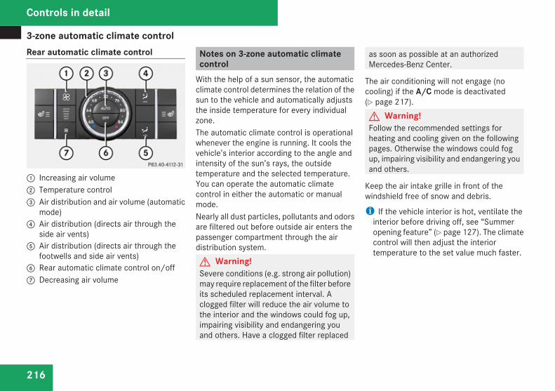
3-zone automatic climate control
216
Rear automatic climate control
1 Increasing air volume2 Temperature control3 Air distribution and air volume (automatic
mode)4 Air distribution (directs air through the
side air vents)5 Air distribution (directs air through the
footwells and side air vents)6 Rear automatic climate control on/off7 Decreasing air volume
Notes on 3-zone automatic climatecontrol
With the help of a sun sensor, the automaticclimate control determines the relation of thesun to the vehicle and automatically adjuststhe inside temperature for every individualzone.The automatic climate control is operationalwhenever the engine is running. It cools thevehicle’s interior according to the angle andintensity of the sun’s rays, the outsidetemperature and the selected temperature.You can operate the automatic climatecontrol in either the automatic or manualmode.Nearly all dust particles, pollutants and odorsare filtered out before outside air enters thepassenger compartment through the airdistribution system.G Warning!Severe conditions (e.g. strong air pollution)may require replacement of the filter beforeits scheduled replacement interval. Aclogged filter will reduce the air volume tothe interior and the windows could fog up,impairing visibility and endangering youand others. Have a clogged filter replaced
as soon as possible at an authorizedMercedes-Benz Center.
The air conditioning will not engage (nocooling) if the A/C mode is deactivated(Y page 217).G Warning!Follow the recommended settings forheating and cooling given on the followingpages. Otherwise the windows could fogup, impairing visibility and endangering youand others.
Keep the air intake grille in front of thewindshield free of snow and debris.
i If the vehicle interior is hot, ventilate theinterior before driving off, see “Summeropening feature” (Y page 127). The climatecontrol will then adjust the interiortemperature to the set value much faster.
Controls in detail
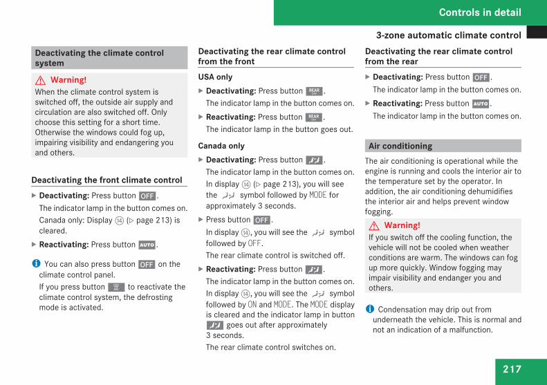
3-zone automatic climate control
217
Deactivating the climate controlsystem
G Warning!When the climate control system isswitched off, the outside air supply andcirculation are also switched off. Onlychoose this setting for a short time.Otherwise the windows could fog up,impairing visibility and endangering youand others.
Deactivating the front climate controlX Deactivating: Press button ´.
The indicator lamp in the button comes on.Canada only: Display e (Y page 213) iscleared.
X Reactivating: Press button U.
i You can also press button ´ on theclimate control panel.If you press button | to reactivate theclimate control system, the defrostingmode is activated.
Deactivating the rear climate controlfrom the frontUSA onlyX Deactivating: Press button :.
The indicator lamp in the button comes on.X Reactivating: Press button :.
The indicator lamp in the button goes out.
Canada onlyX Deactivating: Press button Ñ.
The indicator lamp in the button comes on.In display e (Y page 213), you will seethe ) symbol followed by MODE forapproximately 3 seconds.
X Press button ´.In display e, you will see the ) symbolfollowed by OFF.The rear climate control is switched off.
X Reactivating: Press button Ñ.The indicator lamp in the button comes on.In display e, you will see the ) symbolfollowed by ON and MODE. The MODE displayis cleared and the indicator lamp in buttonÑ goes out after approximately3 seconds.The rear climate control switches on.
Deactivating the rear climate controlfrom the rearX Deactivating: Press button ´.
The indicator lamp in the button comes on.X Reactivating: Press button U.
The indicator lamp in the button comes on.
Air conditioningThe air conditioning is operational while theengine is running and cools the interior air tothe temperature set by the operator. Inaddition, the air conditioning dehumidifiesthe interior air and helps prevent windowfogging.G Warning!If you switch off the cooling function, thevehicle will not be cooled when weatherconditions are warm. The windows can fogup more quickly. Window fogging mayimpair visibility and endanger you andothers.
i Condensation may drip out fromunderneath the vehicle. This is normal andnot an indication of a malfunction.
Controls in detail
Z
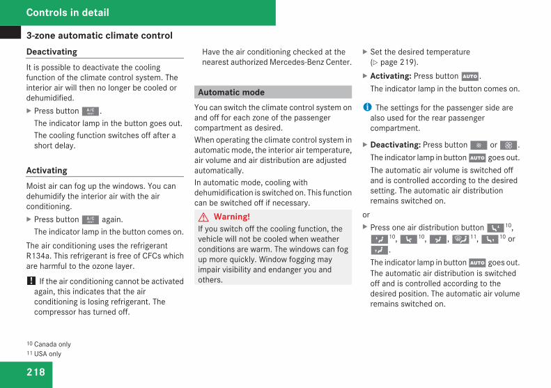
3-zone automatic climate control
218
DeactivatingIt is possible to deactivate the coolingfunction of the climate control system. Theinterior air will then no longer be cooled ordehumidified.X Press button 9.
The indicator lamp in the button goes out.The cooling function switches off after ashort delay.
ActivatingMoist air can fog up the windows. You candehumidify the interior air with the airconditioning.X Press button 9 again.
The indicator lamp in the button comes on.The air conditioning uses the refrigerantR134a. This refrigerant is free of CFCs whichare harmful to the ozone layer.
! If the air conditioning cannot be activatedagain, this indicates that the airconditioning is losing refrigerant. Thecompressor has turned off.
Have the air conditioning checked at thenearest authorized Mercedes-Benz Center.
Automatic modeYou can switch the climate control system onand off for each zone of the passengercompartment as desired.When operating the climate control system inautomatic mode, the interior air temperature,air volume and air distribution are adjustedautomatically.In automatic mode, cooling withdehumidification is switched on. This functioncan be switched off if necessary.G Warning!If you switch off the cooling function, thevehicle will not be cooled when weatherconditions are warm. The windows can fogup more quickly. Window fogging mayimpair visibility and endanger you andothers.
X Set the desired temperature(Y page 219).
X Activating: Press button U.The indicator lamp in the button comes on.
i The settings for the passenger side arealso used for the rear passengercompartment.
X Deactivating: Press button · or Q.The indicator lamp in button U goes out.The automatic air volume is switched offand is controlled according to the desiredsetting. The automatic air distributionremains switched on.
orX Press one air distribution button 610,Z10, 710, a, {11, 810 orY.The indicator lamp in button U goes out.The automatic air distribution is switchedoff and is controlled according to thedesired position. The automatic air volumeremains switched on.
10 Canada only11 USA only
Controls in detail
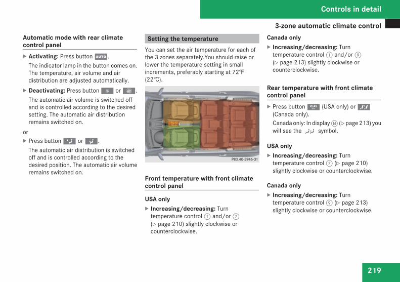
3-zone automatic climate control
219
Automatic mode with rear climatecontrol panelX Activating: Press button U.
The indicator lamp in the button comes on.The temperature, air volume and airdistribution are adjusted automatically.
X Deactivating: Press button · or Q.The automatic air volume is switched offand is controlled according to the desiredsetting. The automatic air distributionremains switched on.
orX Press button Z or a.
The automatic air distribution is switchedoff and is controlled according to thedesired position. The automatic air volumeremains switched on.
Setting the temperatureYou can set the air temperature for each ofthe 3 zones separately.You should raise orlower the temperature setting in smallincrements, preferably starting at 72‡(22†).
Front temperature with front climatecontrol panel
USA onlyX Increasing/decreasing: Turn
temperature control 1 and/or 7(Y page 210) slightly clockwise orcounterclockwise.
Canada onlyX Increasing/decreasing: Turn
temperature control 1 and/or 9(Y page 213) slightly clockwise orcounterclockwise.
Rear temperature with front climatecontrol panelX Press button : (USA only) or Ñ
(Canada only).Canada only: In display e (Y page 213) youwill see the ) symbol.
USA onlyX Increasing/decreasing: Turn
temperature control 7 (Y page 210)slightly clockwise or counterclockwise.
Canada onlyX Increasing/decreasing: Turn
temperature control 9 (Y page 213)slightly clockwise or counterclockwise.
Controls in detail
Z
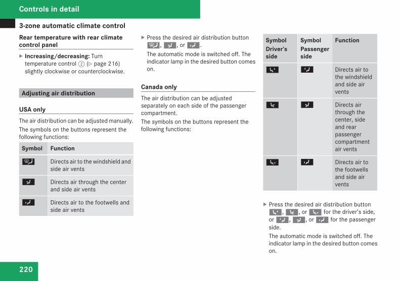
3-zone automatic climate control
220
Rear temperature with rear climatecontrol panelX Increasing/decreasing: Turn
temperature control 2 (Y page 216)slightly clockwise or counterclockwise.
Adjusting air distribution
USA onlyThe air distribution can be adjusted manually.The symbols on the buttons represent thefollowing functions:
Symbol Function
{ Directs air to the windshield andside air vents
a Directs air through the centerand side air vents
Y Directs air to the footwells andside air vents
X Press the desired air distribution button{, a, or Y.The automatic mode is switched off. Theindicator lamp in the desired button comeson.
Canada onlyThe air distribution can be adjustedseparately on each side of the passengercompartment.The symbols on the buttons represent thefollowing functions:
SymbolDriver’sside
SymbolPassengerside
Function
6 Z Directs air tothe windshieldand side airvents
7 a Directs airthrough thecenter, sideand rearpassengercompartmentair vents
8 Y Directs air tothe footwellsand side airvents
X Press the desired air distribution button6, 7, or 8 for the driver’s side,or Z, a, or Y for the passengerside.The automatic mode is switched off. Theindicator lamp in the desired button comeson.
Controls in detail
3-zone automatic climate control
221
Adjusting air volumeUSA onlyX Decrease/increase: Press button · orQ.The automatic mode is switched off. Theselected blower speed is shown in airvolume display b (Y page 210).
Canada onlyX Decrease/increase: Press button · orQ.The automatic mode is switched off. Theselected blower speed appears in displaye (Y page 213).
Front defrosterYou can use this setting to defrost thewindshield, for example if it is iced up.You can also defog the windshield and theside windows.
i Keep this setting selected only until thewindshield or the side windows are clearagain.
ActivatingX Press button |.
The indicator lamp in the button comes on.The climate control switches to thefollowing functions automatically:Rmost efficient blower speed and heating
power, depending on outsidetemperatureRair flows onto the windshield and the
front door windows (side air vents mustbe open)Rthe air conditioning compressor
switches on at outside temperaturesabove approximately 41‡ (5†) for air-drying
AdjustmentsYou can adjust the air volume and thetemperature when the front defroster isswitched on. The air flow will remain on thewindshield and front door windows.X Press button Ï to decrease or buttonQ to increase air volume to the desiredlevel.The air volume decreases/increases to thenext lower/higher blower speed andheating switches to the temperature that
was set before the front defroster wasswitched on.The indicator lamp in button | goes out.The indicator lamp in button 9 comeson.
orX Turn temperature control 1 and/or 7
(USA only) (Y page 210) or 1 and/or 9(Canada only) (Y page 213) slightly in anydirection.Heating switches to the temperature thatwas set before the front defroster wasswitched on.The indicator lamp in button | goes out.The indicator lamp in button 9 comeson.
i The air conditioning compressor remainson even if the indicator lamp in button| goes out. This helps to prevent thewindshield from fogging.
DeactivatingX Press button | once more.
The indicator lamp in the button goes out.Defrosting is turned off.
Controls in detail
Z
3-zone automatic climate control
222
The previous settings are once again ineffect. The air conditioning compressorremains switched on.
i To deactivate, you can also press button´ or U.
Windshield fogged on the outsideX Switch the windshield wipers on
(Y page 122).X Press button U.
The indicator lamp in the button goes out.Air volume and air distribution arecontrolled separately for each zone.
If the automatic air volume and airdistribution are switched off:X Press buttons Y/812 and a/712.
Air recirculation modeSwitch to air recirculation mode to preventunpleasant odors from entering the vehiclefrom the outside (e. g. before driving througha tunnel). This setting cuts off the intake ofoutside air and recirculates the air in thepassenger compartment.G Warning!Fogged windows impair visibility,endangering you and others. If the windowsbegin to fog on the inside, switching off theair recirculation mode immediately shouldclear interior window fogging. If interiorwindow fogging persists, make sure the airconditioning is activated, or press button|.
X Activating: Press button :.The indicator lamp in the button comes on.
i The air recirculation mode is activatedautomatically at high outsidetemperatures.The indicator lamp in button : is not litwhen the air recirculation mode is switchedon automatically.
A quantity of outside air is added afterapproximately 30 minutes.If you have turned off the air conditioningor the outside temperature is below 41‡(5†), the air recirculation mode will notswitch on automatically.
X Deactivating: Press button :.The indicator lamp in the button goes out.
i The manually selected air recirculationmode is deactivated automatically:Rafter 5 minutes if the outside
temperature is below approximately41‡ (5†)Rafter 5 minutes if the air conditioning and
air-drying are turned offRafter 30 minutes if the outside
temperature is above approximately41‡ (5†)
At outside temperatures above 79‡ (26†)the system will not automatically switch backto outside air. A quantity of outside air isadded after approximately 30 minutes.
12 Canada only
Controls in detail
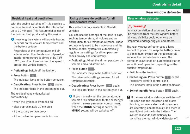
Rear window defroster
223
Residual heat and ventilationWith the engine switched off, it is possible tocontinue to heat or ventilate the interior forup to 30 minutes. This feature makes use ofthe residual heat produced by the engine.
i How long the system will provide heatingdepends on the coolant temperature andthe battery voltage.Regardless of the temperature and airvolume set on the climate control panel, aninterior temperature is aimed at by 72‡(22†) and the blower runs on low speed toprotect the vehicle battery.
X Activating: Switch off the ignition.X Press button 9.
The indicator lamp in the button comes on.X Deactivating: Press button 9 again.
The indicator lamp in the button goes out.The residual heat is deactivatedautomatically:Rwhen the ignition is switched onRafter approximately 30 minutesRif the battery voltage dropsRif the coolant temperature is too low
Using driver-side settings for alltemperature zones
This feature is only available in Canadavehicles.You can use the settings of the driver’s side,such as temperature, air volume and airdistribution, for all temperature zones. Thesesettings only need to be made once and theclimate control system will automaticallyregulate the settings for all temperaturezones quickly and comfortably.X Activating: Adjust the air temperature, air
volume and air distribution.X Press button ;.
The indicator lamp in the button comes on.The driver-side settings are used for alltemperature zones.
X Deactivating: Press button ; again.The indicator lamp in the button goes out.
i If you manually set the temperature, airvolume or air distribution for the passengerside or the rear passenger compartmentwhen the MONO setting is active, theMONO setting will be switched off.
Rear window defroster
G Warning!Any accumulation of snow and ice shouldbe removed from the rear window beforedriving. Visibility could otherwise beimpaired, endangering you and others.
The rear window defroster uses a largeamount of power. To keep the battery drainto a minimum, switch off the defroster assoon as the rear window is clear. Thedefroster is switched off automatically aftersome time of operation depending on theoutside temperature.X Switch on the ignition.X Switching on: Press button 1 on the
respective climate control panel.The indicator lamp in the button comes on.
X Switching off: Press button 1 again.
! If the rear window defroster switches offtoo soon and the indicator lamp startsflashing, too many electrical consumersare operating simultaneously and there isinsufficient voltage in the battery. Thesystem responds automatically byswitching the rear window defroster off.
Controls in detail
Z
Power tilt/sliding sunroof
224
As soon as the battery has sufficientvoltage, the rear window defrosterswitches back on automatically.
Power tilt/sliding sunroof
Opening and closing
G Warning!When opening or closing the tilt/slidingsunroof, make sure there is no danger ofanyone being harmed by the opening/closing procedure.The tilt/sliding sunroof is equipped with theexpress operation and automatic reversalfunction. If in express operation mode thetilt/sliding sunroof encounters anobstruction that blocks its path, theautomatic reversal function will stop thetilt/sliding sunroof and open it slightly.The tilt/sliding sunroof operates differentlywhen the sunroof switch is pressed andheld. See the “Closing when the tilt/slidingsunroof is blocked” section for details.The opening/closing procedure of the tilt/sliding sunroof can be immediately haltedby releasing the sunroof switch or, if thesunroof switch was moved past theresistance point and released, by movingthe sunroof switch in any direction.
G Observe Safety notes, seepage 68.
G Warning!The tilt/sliding sunroof is made out ofglass. In the event of an accident, the glassmay shatter. This may result in an openingin the roof.In a vehicle rollover, occupants not wearingtheir seat belts or not wearing themproperly may be thrown out of the opening.Such an opening also presents a potentialfor injury for occupants wearing their seatbelts properly as entire body parts orportions of them may protrude from thepassenger compartment.
! To avoid damaging the seals, do nottransport any objects with sharp edgeswhich can stick out of the tilt/slidingsunroof.Do not open the tilt/sliding sunroof if thereis snow or ice on the roof, as this couldresult in malfunctions.If you cannot open or close the tilt/slidingsunroof due to a malfunction contactRoadside Assistance or an authorizedMercedes-Benz Center.
Controls in detail
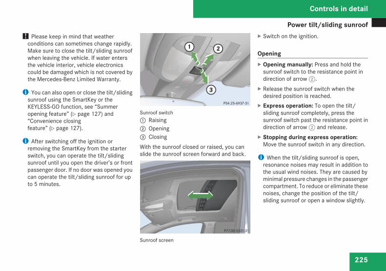
Power tilt/sliding sunroof
225
! Please keep in mind that weatherconditions can sometimes change rapidly.Make sure to close the tilt/sliding sunroofwhen leaving the vehicle. If water entersthe vehicle interior, vehicle electronicscould be damaged which is not covered bythe Mercedes-Benz Limited Warranty.
i You can also open or close the tilt/slidingsunroof using the SmartKey or theKEYLESS-GO function, see “Summeropening feature” (Y page 127) and“Convenience closingfeature” (Y page 127).
i After switching off the ignition orremoving the SmartKey from the starterswitch, you can operate the tilt/slidingsunroof until you open the driver’s or frontpassenger door. If no door was opened youcan operate the tilt/sliding sunroof for upto 5 minutes.
Sunroof switch1 Raising2 Opening3 ClosingWith the sunroof closed or raised, you canslide the sunroof screen forward and back.
Sunroof screen
X Switch on the ignition.
OpeningX Opening manually: Press and hold the
sunroof switch to the resistance point indirection of arrow 2.
X Release the sunroof switch when thedesired position is reached.
X Express operation: To open the tilt/sliding sunroof completely, press thesunroof switch past the resistance point indirection of arrow 2 and release.
X Stopping during express operation:Move the sunroof switch in any direction.
i When the tilt/sliding sunroof is open,resonance noises may result in addition tothe usual wind noises. They are caused byminimal pressure changes in the passengercompartment. To reduce or eliminate thesenoises, change the position of the tilt/sliding sunroof or open a window slightly.
Controls in detail
Z

Power tilt/sliding sunroof
226
RaisingX Rasing manually: Press and hold the
sunroof switch to the resistance point indirection of arrow 1.
X Release the sunroof switch when thedesired position is reached.
X Express operation: To raise the tilt/sliding sunroof completely, press thesunroof switch past the resistance point indirection of arrow 1 and release.
X Stopping during express operation:Move the sunroof switch in any direction.
ClosingX Closing manually: Pull and hold the
sunroof switch to the resistance point indirection of arrow 3.
X Release the sunroof switch when thedesired position is reached.
X Express operation: To close the tilt/sliding sunroof completely, pull the sunroofswitch past the resistance point indirection of arrow 3 and release.
X Stopping during express operation:Move the sunroof switch in any direction.
Closing when the tilt/sliding sunroof isblockedG Warning!Make sure that nobody can becometrapped and be seriously or even fatallyinjured when closing the tilt/slidingsunroof with greater force or withoutautomatic reversal function.
If the movement of the tilt/sliding sunroof isblocked during the closing procedure, thetilt/sliding sunroof will stop and open slightly.However, the tilt/sliding sunroof will exertgreater force before reversing than when thetilt/sliding sunroof is closed in expressoperation. Please exercise caution!X Immediately after the tilt/sliding sunroof
has stopped because it was blocked, pullthe sunroof switch in direction of arrow3 (Y page 225) until the tilt/slidingsunroof is fully closed.
If the tilt/sliding sunroof is blocked again andopens slightly:X Immediately after the tilt/sliding sunroof
was blocked, pull the sunroof switch indirection of arrow 3 until the tilt/slidingsunroof is fully closed.
G Warning!Pulling and holding the sunroof switch toclose the tilt/sliding sunroof immediatelyafter it had been blocked two times willcause the tilt/sliding sunroof to closewithout any reversal function for as long asyou hold the sunroof switch.
SynchronizingThe tilt/sliding sunroof must be synchronizedRafter the battery has been disconnected or
dischargedRafter a malfunctionRif the tilt/sliding sunroof does not open
smoothly
! If the tilt/sliding sunroof cannot be closedor synchronized, contact an authorizedMercedes-Benz Center or call RoadsideAssistance.
X Vehicles with SmartKey: Switch off theignition and remove the SmartKey from thestarter switch.
X Vehicles with KEYLESS-GO: Switch off theignition and open the driver’s door (thisputs the starter switch in position 0, same
Controls in detail
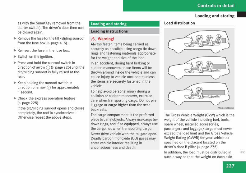
Loading and storing
227
as with the SmartKey removed from thestarter switch). The driver’s door then canbe closed again.
X Remove the fuse for the tilt/sliding sunrooffrom the fuse box (Y page 415).
X Reinsert the fuse in the fuse box.X Switch on the ignition.X Press and hold the sunroof switch in
direction of arrow 1 (Y page 225) until thetilt/sliding sunroof is fully raised at therear.
X Keep holding the sunroof switch indirection of arrow 1 for approximately1 second.
X Check the express operation feature(Y page 225).If the tilt/sliding sunroof opens and closescompletely, the roof is synchronized.Otherwise repeat the above steps.
Loading and storing
Loading instructions
G Warning!Always fasten items being carried assecurely as possible using cargo tie-downrings and fastening materials appropriatefor the weight and size of the load.In an accident, during hard braking orsudden maneuvers, loose items will bethrown around inside the vehicle and cancause injury to vehicle occupants unlessthe items are securely fastened in thevehicle.To help avoid personal injury during acollision or sudden maneuver, exercisecare when transporting cargo. Do not pileluggage or cargo higher than the seatbackrests.The cargo compartment is the preferredplace to carry objects. Always use cargo tie-down rings, and if so equipped, always usethe cargo net when transporting cargo.Never drive vehicle with the tailgate open.Deadly carbon monoxide (CO) gases mayenter vehicle interior resulting inunconsciousness and death.
Load distribution
The Gross Vehicle Weight (GVW) which is theweight of the vehicle including fuel, tools,spare wheel, installed accessories,passengers and luggage/cargo must neverexceed the load limit and the Gross VehicleWeight Rating (GVWR) for your vehicle asspecified on the placard located on thedriver’s door B-pillar (Y page 275).In addition, the load must be distributed insuch a way so that the weight on each axle
Controls in detail
Z
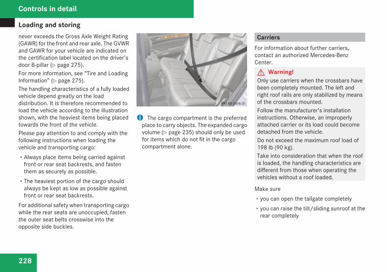
Loading and storing
228
never exceeds the Gross Axle Weight Rating(GAWR) for the front and rear axle. The GVWRand GAWR for your vehicle are indicated onthe certification label located on the driver’sdoor B-pillar (Y page 275).For more information, see “Tire and LoadingInformation” (Y page 275).The handling characteristics of a fully loadedvehicle depend greatly on the loaddistribution. It is therefore recommended toload the vehicle according to the illustrationshown, with the heaviest items being placedtowards the front of the vehicle.Please pay attention to and comply with thefollowing instructions when loading thevehicle and transporting cargo:RAlways place items being carried against
front or rear seat backrests, and fastenthem as securely as possible.RThe heaviest portion of the cargo should
always be kept as low as possible againstfront or rear seat backrests.
For additional safety when transporting cargowhile the rear seats are unoccupied, fastenthe outer seat belts crosswise into theopposite side buckles.
i The cargo compartment is the preferredplace to carry objects. The expanded cargovolume (Y page 235) should only be usedfor items which do not fit in the cargocompartment alone.
CarriersFor information about further carriers,contact an authorized Mercedes-BenzCenter.G Warning!Only use carriers when the crossbars havebeen completely mounted. The left andright roof rails are only stabilized by meansof the crossbars mounted.Follow the manufacturer’s installationinstructions. Otherwise, an improperlyattached carrier or its load could becomedetached from the vehicle.Do not exceed the maximum roof load of198 lb (90 kg).Take into consideration that when the roofis loaded, the handling characteristics aredifferent from those when operating thevehicles without a roof loaded.
Make sureRyou can open the tailgate completelyRyou can raise the tilt/sliding sunroof at the
rear completely
Controls in detail
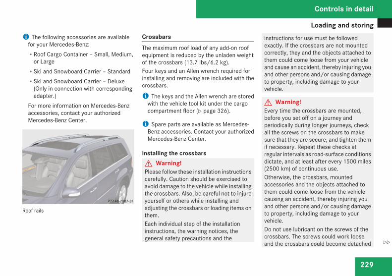
Loading and storing
229
i The following accessories are availablefor your Mercedes-Benz:RRoof Cargo Container – Small, Medium,
or LargeRSki and Snowboard Carrier – StandardRSki and Snowboard Carrier – Deluxe
(Only in connection with correspondingadapter.)
For more information on Mercedes-Benzaccessories, contact your authorizedMercedes-Benz Center.
Roof rails
CrossbarsThe maximum roof load of any add-on roofequipment is reduced by the unladen weightof the crossbars (13.7 Ibs/6.2 kg).Four keys and an Allen wrench required forinstalling and removing are included with thecrossbars.
i The keys and the Allen wrench are storedwith the vehicle tool kit under the cargocompartment floor (Y page 326).
i Spare parts are available as Mercedes-Benz accessories. Contact your authorizedMercedes-Benz Center.
Installing the crossbarsG Warning!Please follow these installation instructionscarefully. Caution should be exercised toavoid damage to the vehicle while installingthe crossbars. Also, be careful not to injureyourself or others while installing andadjusting the crossbars or loading items onthem.Each individual step of the installationinstructions, the warning notices, thegeneral safety precautions and the
instructions for use must be followedexactly. If the crossbars are not mountedcorrectly, they and the objects attached tothem could come loose from your vehicleand cause an accident, thereby injuring youand other persons and/or causing damageto property, including damage to yourvehicle.
G Warning!Every time the crossbars are mounted,before you set off on a journey andperiodically during longer journeys, checkall the screws on the crossbars to makesure that they are secure, and tighten themif necessary. Repeat these checks atregular intervals as road-surface conditionsdictate, and at least after every 1500 miles(2500 km) of continuous use.Otherwise, the crossbars, mountedaccessories and the objects attached tothem could come loose from the vehiclecausing an accident, thereby injuring youand other persons and/or causing damageto property, including damage to yourvehicle.Do not use lubricant on the screws of thecrossbars. The screws could work looseand the crossbars could become detached
Controls in detail
Z
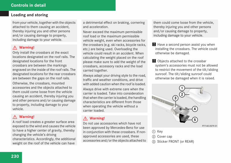
Loading and storing
230
from your vehicle, together with the objectsattached to them causing an accident,thereby injuring you and other personsand/or causing damage to property,including damage to your vehicle.
G Warning!Only install the crossbars at the exactlocations designated on the roof rails. Thedesignated locations for the frontcrossbars are between the markingsengraved on the inside of the roof rails. Thedesignated locations for the rear crossbarsare between the gaps on the roof rails.Otherwise, the crossbars, mountedaccessories and the objects attached tothem could come loose from the vehiclecausing an accident, thereby injuring youand other persons and/or causing damageto property, including damage to yourvehicle.
G Warning!A roof load creates a greater surface areaexposed to the wind and causes the vehicleto have a higher center of gravity, therebychanging the vehicle’s drivingcharacteristics. Accordingly, the additionalweight on the roof of the vehicle can have
a detrimental effect on braking, corneringand acceleration.Never exceed the maximum permissibleroof load or the maximum permissiblevehicle weight, even when accessories forthe crossbars (e.g. ski racks, bicycle racks,etc.) are being used. Overloading thevehicle could result in an accident. Whencalculating the weight placed on the roofplease make sure to add the weight of thecrossbars, accessory racks and the loadcarried together.Always adapt your driving style to the road,traffic and weather conditions, and drivewith added caution when the roof is loaded.Always drive with extreme care when thecarrier is loaded. Take into considerationthat when the carrier is loaded, the handlingcharacteristics are different from thosewhen operating the vehicle without acarrier loaded.
G Warning!Do not use accessories which have notbeen approved by Mercedes-Benz for usein conjunction with these crossbars. If non-approved accessories are used, theseaccessories and/or the objects attached to
them could come loose from the vehicle,thereby injuring you and other personsand/or causing damage to property,including damage to your vehicle.
! Have a second person assist you wheninstalling the crossbars. The vehicle couldotherwise be damaged.
! Objects attached to the crossbarsystem’s accessories must not be allowedto restrict the movement of the tilt/slidingsunroof. The tilt/sliding sunroof couldotherwise be damaged when it is raised.
1 Key2 Cover cap3 Sticker FRONT (or REAR)
Controls in detail
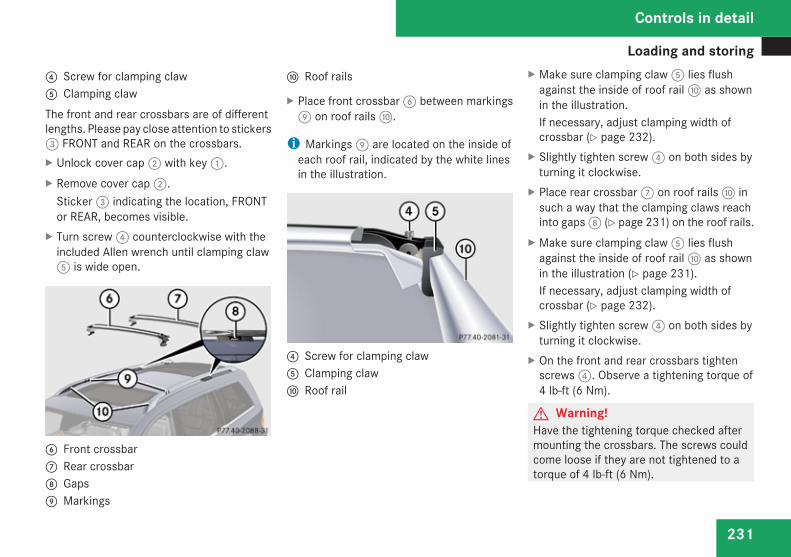
Loading and storing
231
4 Screw for clamping claw5 Clamping clawThe front and rear crossbars are of differentlengths. Please pay close attention to stickers3 FRONT and REAR on the crossbars.X Unlock cover cap 2 with key 1.X Remove cover cap 2.
Sticker 3 indicating the location, FRONTor REAR, becomes visible.
X Turn screw 4 counterclockwise with theincluded Allen wrench until clamping claw5 is wide open.
6 Front crossbar7 Rear crossbar8 Gaps9 Markings
a Roof rails
X Place front crossbar 6 between markings9 on roof rails a.
i Markings 9 are located on the inside ofeach roof rail, indicated by the white linesin the illustration.
4 Screw for clamping claw5 Clamping clawa Roof rail
X Make sure clamping claw 5 lies flushagainst the inside of roof rail a as shownin the illustration.If necessary, adjust clamping width ofcrossbar (Y page 232).
X Slightly tighten screw 4 on both sides byturning it clockwise.
X Place rear crossbar 7 on roof rails a insuch a way that the clamping claws reachinto gaps 8 (Y page 231) on the roof rails.
X Make sure clamping claw 5 lies flushagainst the inside of roof rail a as shownin the illustration (Y page 231).If necessary, adjust clamping width ofcrossbar (Y page 232).
X Slightly tighten screw 4 on both sides byturning it clockwise.
X On the front and rear crossbars tightenscrews 4. Observe a tightening torque of4 lb-ft (6 Nm).
G Warning!Have the tightening torque checked aftermounting the crossbars. The screws couldcome loose if they are not tightened to atorque of 4 lb-ft (6 Nm).
Controls in detail
Z
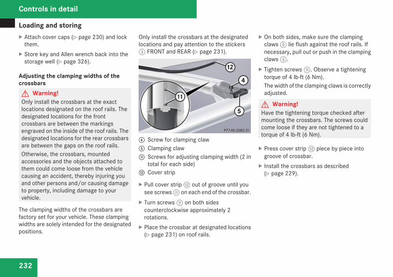
Loading and storing
232
X Attach cover caps (Y page 230) and lockthem.
X Store key and Allen wrench back into thestorage well (Y page 326).
Adjusting the clamping widths of thecrossbarsG Warning!Only install the crossbars at the exactlocations designated on the roof rails. Thedesignated locations for the frontcrossbars are between the markingsengraved on the inside of the roof rails. Thedesignated locations for the rear crossbarsare between the gaps on the roof rails.Otherwise, the crossbars, mountedaccessories and the objects attached tothem could come loose from the vehiclecausing an accident, thereby injuring youand other persons and/or causing damageto property, including damage to yourvehicle.
The clamping widths of the crossbars arefactory set for your vehicle. These clampingwidths are solely intended for the designatedpositions.
Only install the crossbars at the designatedlocations and pay attention to the stickers3 FRONT and REAR (Y page 231).
4 Screw for clamping claw5 Clamping clawb Screws for adjusting clamping width (2 in
total for each side)c Cover strip
X Pull cover strip c out of groove until yousee screws b on each end of the crossbar.
X Turn screws b on both sidescounterclockwise approximately 2rotations.
X Place the crossbar at designated locations(Y page 231) on roof rails.
X On both sides, make sure the clampingclaws 5 lie flush against the roof rails. Ifnecessary, pull out or push in the clampingclaws 5.
X Tighten screws b. Observe a tighteningtorque of 4 lb-ft (6 Nm).The width of the clamping claws is correctlyadjusted.
G Warning!Have the tightening torque checked aftermounting the crossbars. The screws couldcome loose if they are not tightened to atorque of 4 lb-ft (6 Nm).
X Press cover strip c piece by piece intogroove of crossbar.
X Install the crossbars as described(Y page 229).
Controls in detail
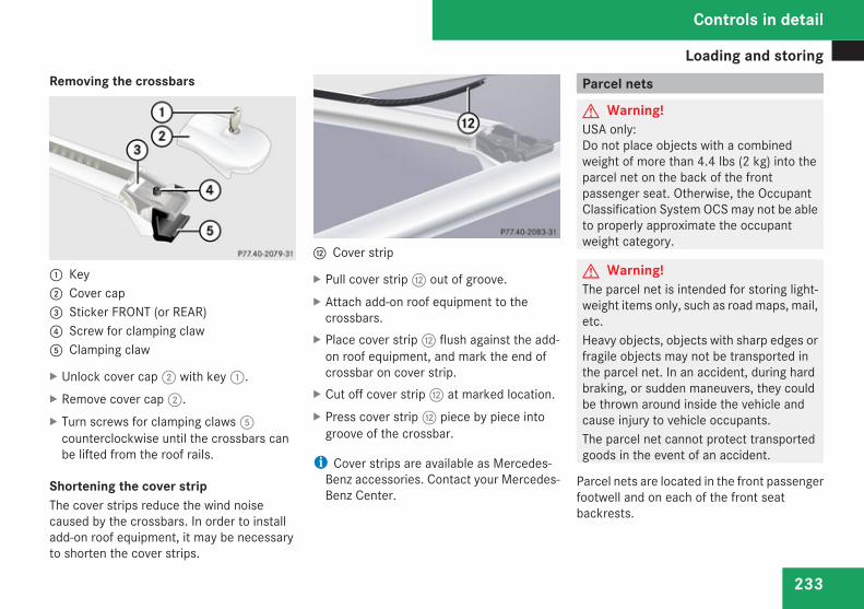
Loading and storing
233
Removing the crossbars
1 Key2 Cover cap3 Sticker FRONT (or REAR)4 Screw for clamping claw5 Clamping claw
X Unlock cover cap 2 with key 1.X Remove cover cap 2.X Turn screws for clamping claws 5
counterclockwise until the crossbars canbe lifted from the roof rails.
Shortening the cover stripThe cover strips reduce the wind noisecaused by the crossbars. In order to installadd-on roof equipment, it may be necessaryto shorten the cover strips.
c Cover strip
X Pull cover strip c out of groove.X Attach add-on roof equipment to the
crossbars.X Place cover strip c flush against the add-
on roof equipment, and mark the end ofcrossbar on cover strip.
X Cut off cover strip c at marked location.X Press cover strip c piece by piece into
groove of the crossbar.
i Cover strips are available as Mercedes-Benz accessories. Contact your Mercedes-Benz Center.
Parcel nets
G Warning!USA only:Do not place objects with a combinedweight of more than 4.4 lbs (2 kg) into theparcel net on the back of the frontpassenger seat. Otherwise, the OccupantClassification System OCS may not be ableto properly approximate the occupantweight category.
G Warning!The parcel net is intended for storing light-weight items only, such as road maps, mail,etc.Heavy objects, objects with sharp edges orfragile objects may not be transported inthe parcel net. In an accident, during hardbraking, or sudden maneuvers, they couldbe thrown around inside the vehicle andcause injury to vehicle occupants.The parcel net cannot protect transportedgoods in the event of an accident.
Parcel nets are located in the front passengerfootwell and on each of the front seatbackrests.
Controls in detail
Z
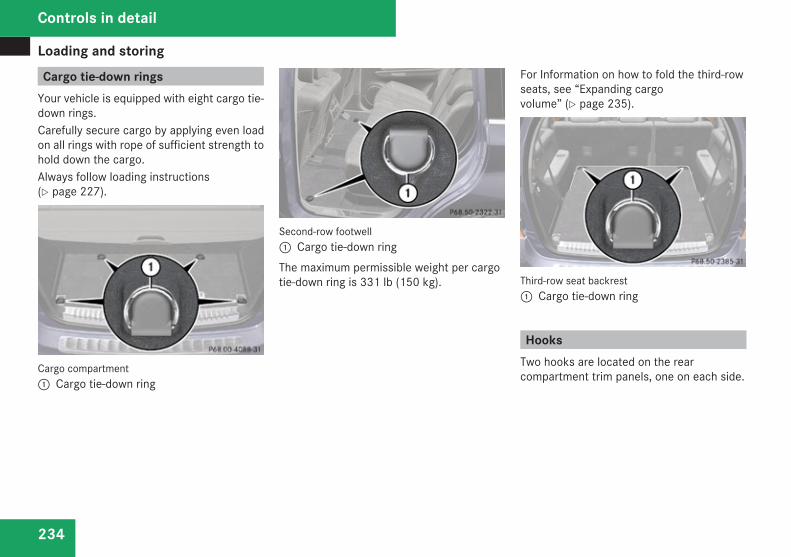
Loading and storing
234
Cargo tie-down ringsYour vehicle is equipped with eight cargo tie-down rings.Carefully secure cargo by applying even loadon all rings with rope of sufficient strength tohold down the cargo.Always follow loading instructions(Y page 227).
Cargo compartment1 Cargo tie-down ring
Second-row footwell1 Cargo tie-down ringThe maximum permissible weight per cargotie-down ring is 331 lb (150 kg).
For Information on how to fold the third-rowseats, see “Expanding cargovolume” (Y page 235).
Third-row seat backrest1 Cargo tie-down ring
HooksTwo hooks are located on the rearcompartment trim panels, one on each side.
Controls in detail
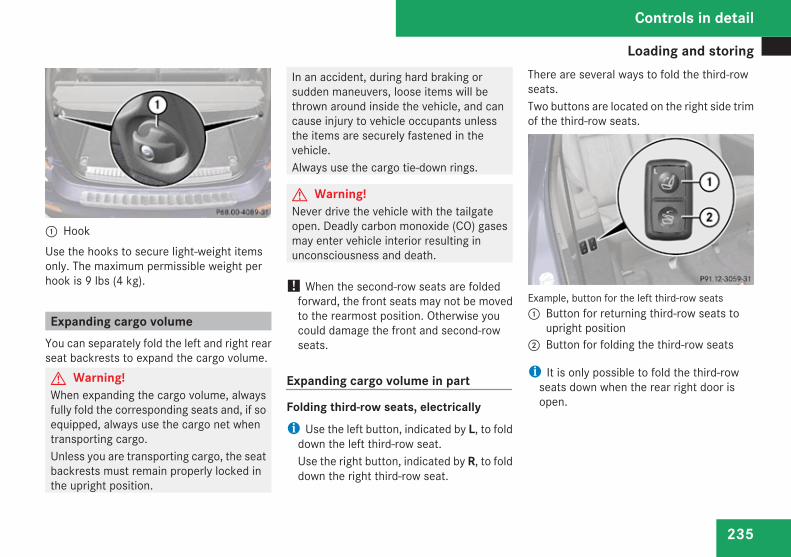
Loading and storing
235
1 HookUse the hooks to secure light-weight itemsonly. The maximum permissible weight perhook is 9 lbs (4 kg).
Expanding cargo volumeYou can separately fold the left and right rearseat backrests to expand the cargo volume.G Warning!When expanding the cargo volume, alwaysfully fold the corresponding seats and, if soequipped, always use the cargo net whentransporting cargo.Unless you are transporting cargo, the seatbackrests must remain properly locked inthe upright position.
In an accident, during hard braking orsudden maneuvers, loose items will bethrown around inside the vehicle, and cancause injury to vehicle occupants unlessthe items are securely fastened in thevehicle.Always use the cargo tie-down rings.
G Warning!Never drive the vehicle with the tailgateopen. Deadly carbon monoxide (CO) gasesmay enter vehicle interior resulting inunconsciousness and death.
! When the second-row seats are foldedforward, the front seats may not be movedto the rearmost position. Otherwise youcould damage the front and second-rowseats.
Expanding cargo volume in part
Folding third-row seats, electricallyi Use the left button, indicated by L, to fold
down the left third-row seat.Use the right button, indicated by R, to folddown the right third-row seat.
There are several ways to fold the third-rowseats.Two buttons are located on the right side trimof the third-row seats.
Example, button for the left third-row seats1 Button for returning third-row seats to
upright position2 Button for folding the third-row seats
i It is only possible to fold the third-rowseats down when the rear right door isopen.
Controls in detail
Z
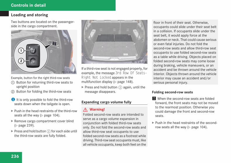
Loading and storing
236
Two buttons are located on the passenger-side in the cargo compartment.
Example, button for the right third-row seats1 Button for returning third-row seats to
upright position2 Button for folding the third-row seats
i It is only possible to fold the third-rowseats down when the tailgate is open.
X Push in the head restraints of the third-rowseats all the way (Y page 104).
X Remove cargo compartment cover blind(Y page 239).
X Press and hold button 2 for each side untilthe third-row seats are fully folded.
If a third-row seat is not engaged properly, forexample, the message 3rd Row Of Seats-Right Not Locked appears in themultifunction display (Y page 148).X Press and hold button 2 again, until the
message disappears.
Expanding cargo volume fully
G Warning!Folded second-row seats are intended toserve as a cargo volume expansion inconjunction with folded third-row seatsonly. Do not fold the second-row seats andallow third-row seat occupants to usefolded second-row seats as a footrest whiledriving. Third-row seat occupants must, likeall vehicle occupants, keep both feet on the
floor in front of their seat. Otherwise,occupants could slide under their seat beltin a collision. If occupants slide under theseat belt, it would apply force at theabdomen or neck. That could cause seriousor even fatal injuries. Do not fold thesecond-row seats and allow third-row seatoccupants to use folded second-row seatsas a table while driving. Objects placed onfolded second-row seats may come looseduring braking, vehicle maneuvers, or anaccident and be thrown around the vehicleinterior. Objects thrown around the vehicleinterior may cause an accident and/orserious personal injury.
Folding second-row seats! When the second-row seats are folded
forward, the front seats may not be movedto the rearmost position. Otherwise youcould damage the front and second-rowseats.
X Push in the head restraints of the second-row seats all the way (Y page 104).
Controls in detail
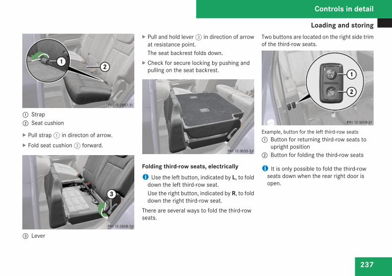
Loading and storing
237
1 Strap2 Seat cushion
X Pull strap 1 in directon of arrow.X Fold seat cushion 2 forward.
3 Lever
X Pull and hold lever 3 in direction of arrowat resistance point.The seat backrest folds down.
X Check for secure locking by pushing andpulling on the seat backrest.
Folding third-row seats, electricallyi Use the left button, indicated by L, to fold
down the left third-row seat.Use the right button, indicated by R, to folddown the right third-row seat.
There are several ways to fold the third-rowseats.
Two buttons are located on the right side trimof the third-row seats.
Example, button for the left third-row seats1 Button for returning third-row seats to
upright position2 Button for folding the third-row seats
i It is only possible to fold the third-rowseats down when the rear right door isopen.
Controls in detail
Z
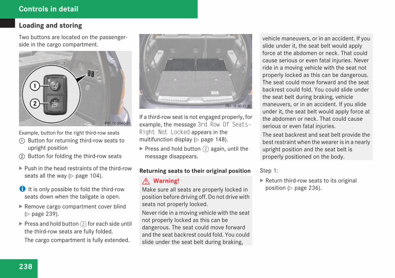
Loading and storing
238
Two buttons are located on the passenger-side in the cargo compartment.
Example, button for the right third-row seats1 Button for returning third-row seats to
upright position2 Button for folding the third-row seats
X Push in the head restraints of the third-rowseats all the way (Y page 104).
i It is only possible to fold the third-rowseats down when the tailgate is open.
X Remove cargo compartment cover blind(Y page 239).
X Press and hold button 2 for each side untilthe third-row seats are fully folded.The cargo compartment is fully extended.
If a third-row seat is not engaged properly, forexample, the message 3rd Row Of Seats-Right Not Locked appears in themultifunction display (Y page 148).X Press and hold button 2 again, until the
message disappears.
Returning seats to their original positionG Warning!Make sure all seats are properly locked inposition before driving off. Do not drive withseats not properly locked.Never ride in a moving vehicle with the seatnot properly locked as this can bedangerous. The seat could move forwardand the seat backrest could fold. You couldslide under the seat belt during braking,
vehicle maneuvers, or in an accident. If youslide under it, the seat belt would applyforce at the abdomen or neck. That couldcause serious or even fatal injuries. Neverride in a moving vehicle with the seat notproperly locked as this can be dangerous.The seat could move forward and the seatbackrest could fold. You could slide underthe seat belt during braking, vehiclemaneuvers, or in an accident. If you slideunder it, the seat belt would apply force atthe abdomen or neck. That could causeserious or even fatal injuries.The seat backrest and seat belt provide thebest restraint when the wearer is in a nearlyupright position and the seat belt isproperly positioned on the body.
Step 1:X Return third-row seats to its original
position (Y page 236).
Controls in detail
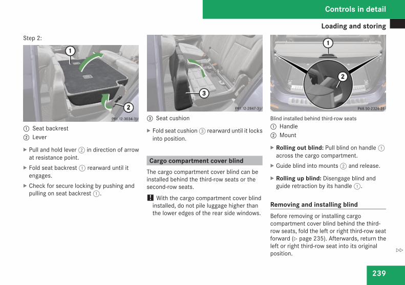
Loading and storing
239
Step 2:
1 Seat backrest2 Lever
X Pull and hold lever 2 in direction of arrowat resistance point.
X Fold seat backrest 1 rearward until itengages.
X Check for secure locking by pushing andpulling on seat backrest 1.
3 Seat cushion
X Fold seat cushion 3 rearward until it locksinto position.
Cargo compartment cover blindThe cargo compartment cover blind can beinstalled behind the third-row seats or thesecond-row seats.
! With the cargo compartment cover blindinstalled, do not pile luggage higher thanthe lower edges of the rear side windows.
Blind installed behind third-row seats1 Handle2 Mount
X Rolling out blind: Pull blind on handle 1across the cargo compartment.
X Guide blind into mounts 2 and release.
X Rolling up blind: Disengage blind andguide retraction by its handle 1.
Removing and installing blindBefore removing or installing cargocompartment cover blind behind the third-row seats, fold the left or right third-row seatforward (Y page 235). Afterwards, return theleft or right third-row seat into its originalposition.
Controls in detail
Z

Loading and storing
240
Before installing cargo compartment coverblind behind the second-row seats, fold thethird-row seats forward (Y page 235).
Blind installed behind second-row seats1 Release button2 Blind
X Removing: Pull blind 2 to the left until itengages.
X Installing: Remove the mount covers in theside trims of the third seat row wheninstalling roller blind 2 behind the second-row seats.
Mount cover behind second-row seats3 Cover
X Press on cover 3 at its upper edge asindicated by arrow.The cover’s lower edge flips up.
X Remove cover 3 by pulling its lower edgeout of the side trim.
i To avoid loss of the covers, insert thecovers into the mounts currently not in use.
X Make sure release button 1 faces up andthe roller blind handle (Y page 239) is tothe rear before inserting the roller blind.
X Place left side of blind 2 in left mount.X Position right side of blind 2 over right
mount.
X Press release button 1 and guide blind2 into mount.
X Make sure the cargo compartment coverblind is securely fastened.
Cargo net
G Warning!Make sure the cargo net is properlyengaged at top and bottom position and thetightening belts are securely fastened.Never use a damaged cargo net.To help avoid personal injury from smallerobjects being thrown around in theoccupant compartment during a collision orsudden maneuver, always use cargo netwhen transporting cargo.The cargo net cannot prevent themovement of large, heavier objects into thepassenger compartment in an accident.Such items must be properly secured usingthe cargo tie-down rings in the cargocompartment floor.Passenger use of seats behind installedcargo net is restricted because of thefootwell being taken up by the net.
Controls in detail
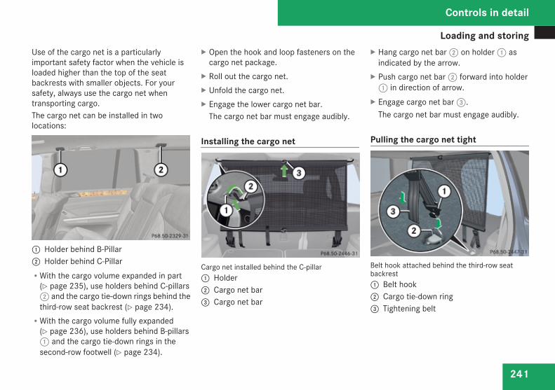
Loading and storing
241
Use of the cargo net is a particularlyimportant safety factor when the vehicle isloaded higher than the top of the seatbackrests with smaller objects. For yoursafety, always use the cargo net whentransporting cargo.The cargo net can be installed in twolocations:
1 Holder behind B-Pillar2 Holder behind C-PillarRWith the cargo volume expanded in part
(Y page 235), use holders behind C-pillars2 and the cargo tie-down rings behind thethird-row seat backrest (Y page 234).RWith the cargo volume fully expanded
(Y page 236), use holders behind B-pillars1 and the cargo tie-down rings in thesecond-row footwell (Y page 234).
X Open the hook and loop fasteners on thecargo net package.
X Roll out the cargo net.X Unfold the cargo net.X Engage the lower cargo net bar.
The cargo net bar must engage audibly.
Installing the cargo net
Cargo net installed behind the C-pillar1 Holder2 Cargo net bar3 Cargo net bar
X Hang cargo net bar 2 on holder 1 asindicated by the arrow.
X Push cargo net bar 2 forward into holder1 in direction of arrow.
X Engage cargo net bar 3.The cargo net bar must engage audibly.
Pulling the cargo net tight
Belt hook attached behind the third-row seatbackrest1 Belt hook2 Cargo tie-down ring3 Tightening belt
Controls in detail
Z
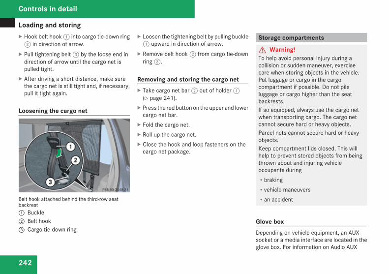
Loading and storing
242
X Hook belt hook 1 into cargo tie-down ring2 in direction of arrow.
X Pull tightening belt 3 by the loose end indirection of arrow until the cargo net ispulled tight.
X After driving a short distance, make surethe cargo net is still tight and, if necessary,pull it tight again.
Loosening the cargo net
Belt hook attached behind the third-row seatbackrest1 Buckle2 Belt hook3 Cargo tie-down ring
X Loosen the tightening belt by pulling buckle1 upward in direction of arrow.
X Remove belt hook 2 from cargo tie-downring 3.
Removing and storing the cargo netX Take cargo net bar 2 out of holder 1
(Y page 241).X Press the red button on the upper and lower
cargo net bar.X Fold the cargo net.X Roll up the cargo net.X Close the hook and loop fasteners on the
cargo net package.
Storage compartments
G Warning!To help avoid personal injury during acollision or sudden maneuver, exercisecare when storing objects in the vehicle.Put luggage or cargo in the cargocompartment if possible. Do not pileluggage or cargo higher than the seatbackrests.If so equipped, always use the cargo netwhen transporting cargo. The cargo netcannot secure hard or heavy objects.Parcel nets cannot secure hard or heavyobjects.Keep compartment lids closed. This willhelp to prevent stored objects from beingthrown about and injuring vehicleoccupants duringRbrakingRvehicle maneuversRan accident
Glove boxDepending on vehicle equipment, an AUXsocket or a media interface are located in theglove box. For information on Audio AUX
Controls in detail
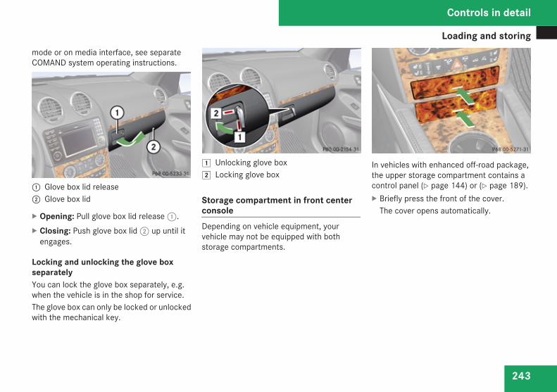
Loading and storing
243
mode or on media interface, see separateCOMAND system operating instructions.
1 Glove box lid release2 Glove box lid
X Opening: Pull glove box lid release 1.X Closing: Push glove box lid 2 up until it
engages.
Locking and unlocking the glove boxseparatelyYou can lock the glove box separately, e.g.when the vehicle is in the shop for service.The glove box can only be locked or unlockedwith the mechanical key.
$ Unlocking glove box% Locking glove box
Storage compartment in front centerconsoleDepending on vehicle equipment, yourvehicle may not be equipped with bothstorage compartments.
In vehicles with enhanced off-road package,the upper storage compartment contains acontrol panel (Y page 144) or (Y page 189).X Briefly press the front of the cover.
The cover opens automatically.
Controls in detail
Z
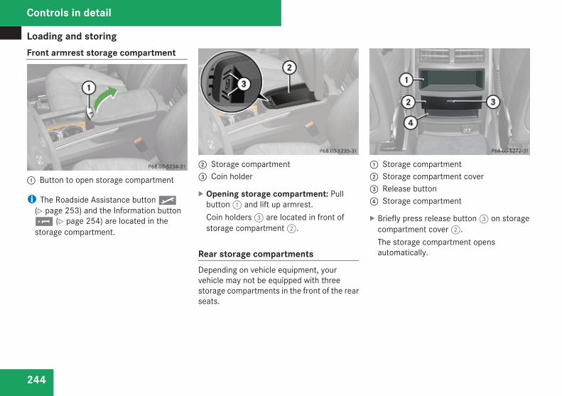
Loading and storing
244
Front armrest storage compartment
1 Button to open storage compartment
i The Roadside Assistance button p(Y page 253) and the Information button¡ (Y page 254) are located in thestorage compartment.
2 Storage compartment3 Coin holder
X Opening storage compartment: Pullbutton 1 and lift up armrest.Coin holders 3 are located in front ofstorage compartment 2.
Rear storage compartmentsDepending on vehicle equipment, yourvehicle may not be equipped with threestorage compartments in the front of the rearseats.
1 Storage compartment2 Storage compartment cover3 Release button4 Storage compartment
X Briefly press release button 3 on storagecompartment cover 2.The storage compartment opensautomatically.
Controls in detail
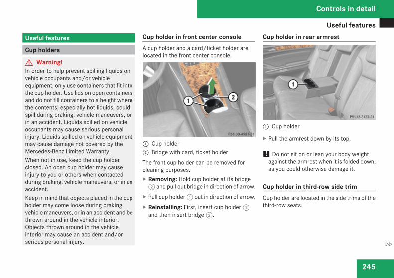
Useful features
245
Useful features
Cup holders
G Warning!In order to help prevent spilling liquids onvehicle occupants and/or vehicleequipment, only use containers that fit intothe cup holder. Use lids on open containersand do not fill containers to a height wherethe contents, especially hot liquids, couldspill during braking, vehicle maneuvers, orin an accident. Liquids spilled on vehicleoccupants may cause serious personalinjury. Liquids spilled on vehicle equipmentmay cause damage not covered by theMercedes-Benz Limited Warranty.When not in use, keep the cup holderclosed. An open cup holder may causeinjury to you or others when contactedduring braking, vehicle maneuvers, or in anaccident.Keep in mind that objects placed in the cupholder may come loose during braking,vehicle maneuvers, or in an accident and bethrown around in the vehicle interior.Objects thrown around in the vehicleinterior may cause an accident and/orserious personal injury.
Cup holder in front center consoleA cup holder and a card/ticket holder arelocated in the front center console.
1 Cup holder2 Bridge with card, ticket holderThe front cup holder can be removed forcleaning purposes.X Removing: Hold cup holder at its bridge
2 and pull out bridge in direction of arrow.X Pull cup holder 1 out in direction of arrow.X Reinstalling: First, insert cup holder 1
and then insert bridge 2.
Cup holder in rear armrest
1 Cup holder
X Pull the armrest down by its top.
! Do not sit on or lean your body weightagainst the armrest when it is folded down,as you could otherwise damage it.
Cup holder in third-row side trimCup holder are located in the side trims of thethird-row seats.
Controls in detail
Z
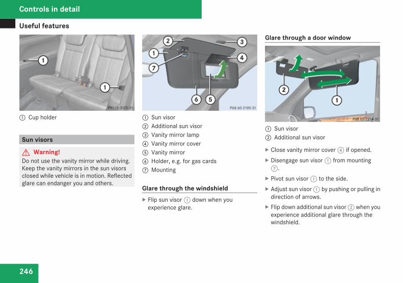
Useful features
246
1 Cup holder
Sun visors
G Warning!Do not use the vanity mirror while driving.Keep the vanity mirrors in the sun visorsclosed while vehicle is in motion. Reflectedglare can endanger you and others.
1 Sun visor2 Additional sun visor3 Vanity mirror lamp4 Vanity mirror cover5 Vanity mirror6 Holder, e.g. for gas cards7 Mounting
Glare through the windshieldX Flip sun visor 1 down when you
experience glare.
Glare through a door window
1 Sun visor2 Additional sun visor
X Close vanity mirror cover 4 if opened.X Disengage sun visor 1 from mounting
7.X Pivot sun visor 1 to the side.X Adjust sun visor 1 by pushing or pulling in
direction of arrows.X Flip down additional sun visor 2 when you
experience additional glare through thewindshield.
Controls in detail
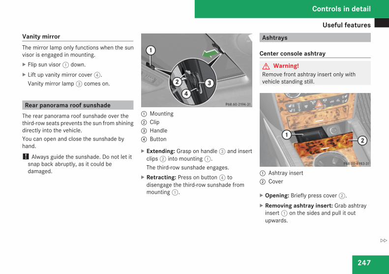
Useful features
247
Vanity mirrorThe mirror lamp only functions when the sunvisor is engaged in mounting.X Flip sun visor 1 down.X Lift up vanity mirror cover 4.
Vanity mirror lamp 3 comes on.
Rear panorama roof sunshadeThe rear panorama roof sunshade over thethird-row seats prevents the sun from shiningdirectly into the vehicle.You can open and close the sunshade byhand.
! Always guide the sunshade. Do not let itsnap back abruptly, as it could bedamaged.
1 Mounting2 Clip3 Handle4 Button
X Extending: Grasp on handle 3 and insertclips 2 into mounting 1.The third-row sunshade engages.
X Retracting: Press on button 4 todisengage the third-row sunshade frommounting 1.
Ashtrays
Center console ashtray
G Warning!Remove front ashtray insert only withvehicle standing still.
1 Ashtray insert2 Cover
X Opening: Briefly press cover 2.X Removing ashtray insert: Grab ashtray
insert 1 on the sides and pull it outupwards.
Controls in detail
Z
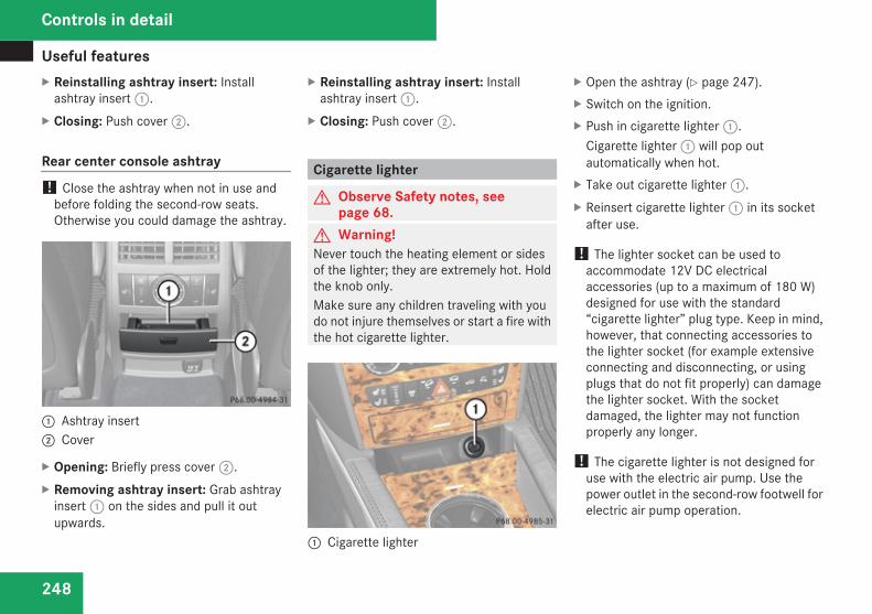
Useful features
248
X Reinstalling ashtray insert: Installashtray insert 1.
X Closing: Push cover 2.
Rear center console ashtray! Close the ashtray when not in use and
before folding the second-row seats.Otherwise you could damage the ashtray.
1 Ashtray insert2 Cover
X Opening: Briefly press cover 2.X Removing ashtray insert: Grab ashtray
insert 1 on the sides and pull it outupwards.
X Reinstalling ashtray insert: Installashtray insert 1.
X Closing: Push cover 2.
Cigarette lighter
G Observe Safety notes, seepage 68.
G Warning!Never touch the heating element or sidesof the lighter; they are extremely hot. Holdthe knob only.Make sure any children traveling with youdo not injure themselves or start a fire withthe hot cigarette lighter.
1 Cigarette lighter
X Open the ashtray (Y page 247).X Switch on the ignition.X Push in cigarette lighter 1.
Cigarette lighter 1 will pop outautomatically when hot.
X Take out cigarette lighter 1.X Reinsert cigarette lighter 1 in its socket
after use.
! The lighter socket can be used toaccommodate 12V DC electricalaccessories (up to a maximum of 180 W)designed for use with the standard“cigarette lighter” plug type. Keep in mind,however, that connecting accessories tothe lighter socket (for example extensiveconnecting and disconnecting, or usingplugs that do not fit properly) can damagethe lighter socket. With the socketdamaged, the lighter may not functionproperly any longer.
! The cigarette lighter is not designed foruse with the electric air pump. Use thepower outlet in the second-row footwell forelectric air pump operation.
Controls in detail
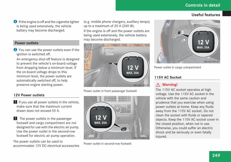
Useful features
249
i If the engine is off and the cigarette lighteris being used extensively, the vehiclebattery may become discharged.
Power outletsi You can use the power outlets even if the
ignition is switched off.An emergency shut-off feature is designedto prevent the vehicle’s on-board voltagefrom dropping below a minimum level. Ifthe on-board voltage drops to thisminimum level, the power outlets areautomatically switched off, to helppreserve engine starting power.
12V Power outlets! If you use all power outlets in the vehicle,
make sure that the maximum currentdrawn does not exceed 55 A.
! The power outlets in the passengerfootwell and cargo compartment are notdesigned for use with the electric air pump.Use the power outlet in the second-rowfootwell for electric air pump operation.
The power outlets can be used toaccommodate 12V DC electrical accessories
(e.g. mobile phone chargers, auxiliary lamps)up to a maximum of 20 A (240 W).If the engine is off and the power outlets arebeing used extensively, the vehicle batterymay become discharged.
Power outlet in front passenger footwell
Power outlet in second-row footwell
Power outlet in cargo compartment
115V AC Socket
G Warning!The 115V AC socket operates at highvoltage. Use the 115V AC socket in thevehicle with the same caution andprudence that you exercise when usingpower outlets at home. Keep any fluidsaway from the 115V AC socket. Do notclean the socket with fluids or taperedobjects. Keep the 115V AC socket cover inthe closed position, when not in use.Otherwise, you could suffer an electricshock and be seriously or even fatallyinjured.
Controls in detail
Z
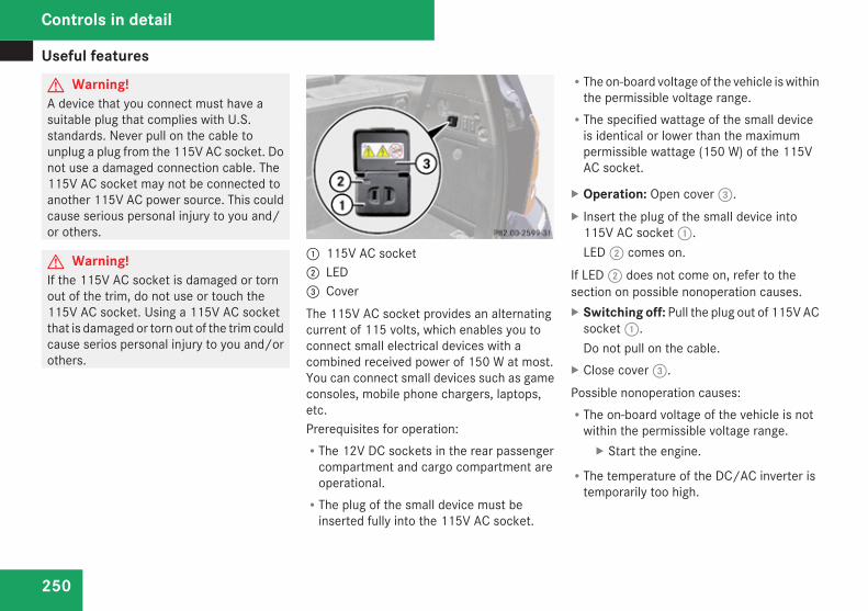
Useful features
250
G Warning!A device that you connect must have asuitable plug that complies with U.S.standards. Never pull on the cable tounplug a plug from the 115V AC socket. Donot use a damaged connection cable. The115V AC socket may not be connected toanother 115V AC power source. This couldcause serious personal injury to you and/or others.
G Warning!If the 115V AC socket is damaged or tornout of the trim, do not use or touch the115V AC socket. Using a 115V AC socketthat is damaged or torn out of the trim couldcause serios personal injury to you and/orothers.
1 115V AC socket2 LED3 CoverThe 115V AC socket provides an alternatingcurrent of 115 volts, which enables you toconnect small electrical devices with acombined received power of 150 W at most.You can connect small devices such as gameconsoles, mobile phone chargers, laptops,etc.Prerequisites for operation:RThe 12V DC sockets in the rear passenger
compartment and cargo compartment areoperational.RThe plug of the small device must be
inserted fully into the 115V AC socket.
RThe on-board voltage of the vehicle is withinthe permissible voltage range.RThe specified wattage of the small device
is identical or lower than the maximumpermissible wattage (150 W) of the 115VAC socket.
X Operation: Open cover 3.X Insert the plug of the small device into
115V AC socket 1.LED 2 comes on.
If LED 2 does not come on, refer to thesection on possible nonoperation causes.X Switching off: Pull the plug out of 115V AC
socket 1.Do not pull on the cable.
X Close cover 3.Possible nonoperation causes:RThe on-board voltage of the vehicle is not
within the permissible voltage range.X Start the engine.
RThe temperature of the DC/AC inverter istemporarily too high.
Controls in detail
Useful features
251
X Pull the plug of the small device out ofthe 115V AC socket and plug it in againafter waiting a few minutes.
RSome small devices have a continuouspower rating of less than 150 W but a veryhigh switch-on current. Such devices willnot operate. When connecting such adevice, the socket will not provide power.
If LED 2 still does not come on, contact anauthorized Mercedes-Benz Center.
Tele Aid! In order to activate the Tele Aid system, a
subscriber agreement must be completed.To ensure your system is activated andoperational, please press the ¡ buttonto perform the acquaintance call. Failure tocomplete either of these steps may resultin a system that is not activated.If you have any questions regardingactivation, please call the Response Centerat 1-800-756-9018 (in the USA) or1-888-923-8367 (in Canada).
Shortly after the completion of your Tele Aidacquaintance call, you will receive a user IDand password in the mail. You may use thispassword to access the Tele Aid section in
“Owner’s Online” at mbusa.com (USA only).The “My Tele Aid” section will give you accessto account information, remote door unlockand more.The Tele Aid system is available ifRit has been activated and is operational.
Activation requires a subscription formonitoring services, connection andcellular air time.Rvehicle battery power is availableRthe relevant cellular phone network and
GPS signals are available and pass theinformation on to the Response Center.
i Location of the vehicle on a map is onlypossible if the vehicle is able to receivesignals from the GPS satellite network andpass the information on to the ResponseCenter.
The Tele Aid system(Telematic Alarm Identification on Demand)
The Tele Aid system consists of three typesof response:RAutomatic and manual emergencyRRoadside AssistanceRInformationThe Tele Aid system is operational providingthat the vehicle’s battery is charged, properlyconnected, not damaged, and cellular andGPS coverage is available. The Tele Aidsystem utilizes the cellular network forcommunication and the GPS (GlobalPositioning System) satellites for vehiclelocation. If either of these signals areunavailable, the Tele Aid system may notfunction and if this occurs, assistance mustbe summoned by other means.To adjust the speaker volume during a TeleAid call do the following:X Press button æ or ç on the
multifunction steering wheel.orX Use the adjustment button on your
COMAND system.
Controls in detail
Z
Useful features
252
System self-testThe system performs a self-test after youhave switched on the ignition.G Warning!If the indicator lamps in the SOS button, inthe Roadside Assistance button p and/or in the Information button ¡ do notcome on during the system self-test, or ifany of these indicators remain illuminatedconstantly in red and/or the message TeleAid Inoperative is displayed in themultifunction display after the system self-test, a malfunction in the system has beendetected.If a malfunction is indicated as outlinedabove, the system may not operate asexpected. In case of an emergency, helpwill have to be summoned by other means.Have the system checked at the nearestMercedes-Benz Center or contact theResponse Center at 1-800-756-9018 (inthe USA) or 1-888-923-8367 (in Canada) assoon as possible.
Emergency calls! In order to activate the Tele Aid system, a
subscriber agreement must be completed.
To ensure your system is activated andoperational, please press the ¡ buttonto perform the acquaintance call. Failure tocomplete either of these steps may resultin a system that is not activated.If you have any questions regardingactivation, please call the Response Centerat 1-800-756-9018 (in the USA) or1-888-923-8367 (in Canada).
An emergency call is initiated automaticallyfollowing an accident in which the EmergencyTensioning Devices (ETDs) or air bags deploy.An emergency call can also be initiatedmanually.Once the emergency call is in progress, theindicator lamp in the SOS button will begin toflash. The message Connecting Callappears in the multifunction display and theCOMAND system is muted. When theconnection is established, the message CallConnected appears in the multifunctiondisplay.All information relevant to the emergency,such as the location of the vehicle(determined by the GPS satellite locationsystem), vehicle model, identification numberand color are generated.A voice connection between the ResponseCenter and the occupants of the vehicle will
be established automatically soon after theemergency call has been initiated. TheResponse Center will attempt to determinemore precisely the nature of the emergencyprovided they can speak to an occupant ofthe vehicle.
i If no vehicle occupant responds, anambulance will be sent to the vehicleimmediately.
G Warning!If the indicator lamp in the SOS button isflashing continuously and there was novoice connection to the Response Centerestablished, then the Tele Aid system couldnot initiate an emergency call (e.g. therelevant cellular phone network is notavailable).The message Call Failed appears in themultifunction display for approximately10 seconds.Should this occur, assistance must besummoned by other means.
i The “911” emergency call system is apublic service. Using it without due causeis a criminal offense.
Controls in detail
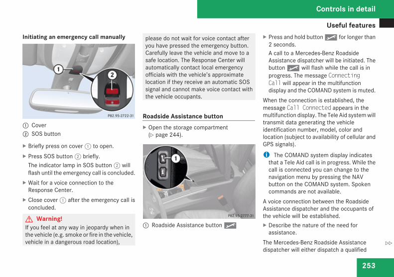
Useful features
253
Initiating an emergency call manually
1 Cover2 SOS button
X Briefly press on cover 1 to open.X Press SOS button 2 briefly.
The indicator lamp in SOS button 2 willflash until the emergency call is concluded.
X Wait for a voice connection to theResponse Center.
X Close cover 1 after the emergency call isconcluded.
G Warning!If you feel at any way in jeopardy when inthe vehicle (e.g. smoke or fire in the vehicle,vehicle in a dangerous road location),
please do not wait for voice contact afteryou have pressed the emergency button.Carefully leave the vehicle and move to asafe location. The Response Center willautomatically contact local emergencyofficials with the vehicle’s approximatelocation if they receive an automatic SOSsignal and cannot make voice contact withthe vehicle occupants.
Roadside Assistance buttonX Open the storage compartment
(Y page 244).
1 Roadside Assistance button p
X Press and hold button p for longer than2 seconds.A call to a Mercedes-Benz RoadsideAssistance dispatcher will be initiated. Thebutton p will flash while the call is inprogress. The message ConnectingCall will appear in the multifunctiondisplay and the COMAND system is muted.
When the connection is established, themessage Call Connected appears in themultifunction display. The Tele Aid system willtransmit data generating the vehicleidentification number, model, color andlocation (subject to availability of cellular andGPS signals).
i The COMAND system display indicatesthat a Tele Aid call is in progress. While thecall is connected you can change to thenavigation menu by pressing the NAVbutton on the COMAND system. Spokencommands are not available.
A voice connection between the RoadsideAssistance dispatcher and the occupants ofthe vehicle will be established.X Describe the nature of the need for
assistance.The Mercedes-Benz Roadside Assistancedispatcher will either dispatch a qualified
Controls in detail
Z
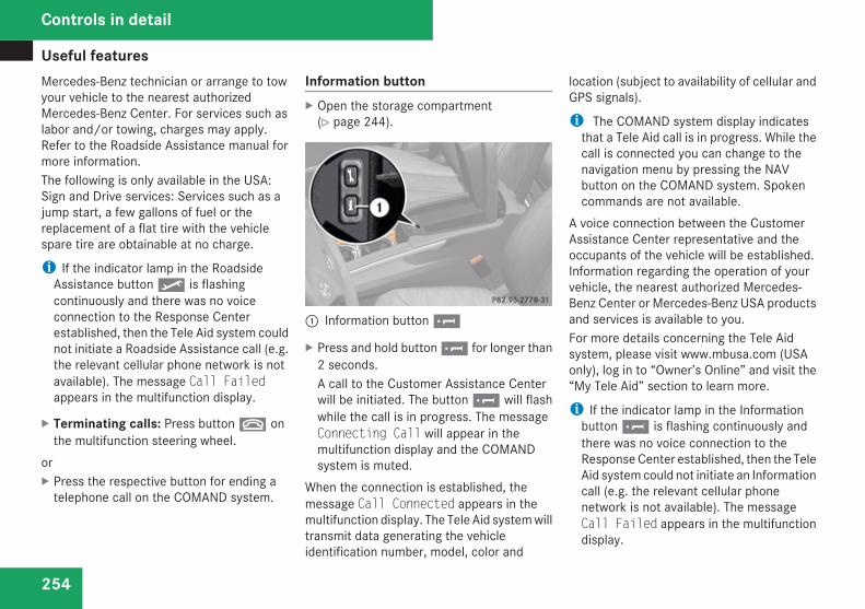
Useful features
254
Mercedes-Benz technician or arrange to towyour vehicle to the nearest authorizedMercedes-Benz Center. For services such aslabor and/or towing, charges may apply.Refer to the Roadside Assistance manual formore information.The following is only available in the USA:Sign and Drive services: Services such as ajump start, a few gallons of fuel or thereplacement of a flat tire with the vehiclespare tire are obtainable at no charge.
i If the indicator lamp in the RoadsideAssistance button p is flashingcontinuously and there was no voiceconnection to the Response Centerestablished, then the Tele Aid system couldnot initiate a Roadside Assistance call (e.g.the relevant cellular phone network is notavailable). The message Call Failedappears in the multifunction display.
X Terminating calls: Press button t onthe multifunction steering wheel.
orX Press the respective button for ending a
telephone call on the COMAND system.
Information buttonX Open the storage compartment
(Y page 244).
1 Information button ¡
X Press and hold button ¡ for longer than2 seconds.A call to the Customer Assistance Centerwill be initiated. The button ¡ will flashwhile the call is in progress. The messageConnecting Call will appear in themultifunction display and the COMANDsystem is muted.
When the connection is established, themessage Call Connected appears in themultifunction display. The Tele Aid system willtransmit data generating the vehicleidentification number, model, color and
location (subject to availability of cellular andGPS signals).
i The COMAND system display indicatesthat a Tele Aid call is in progress. While thecall is connected you can change to thenavigation menu by pressing the NAVbutton on the COMAND system. Spokencommands are not available.
A voice connection between the CustomerAssistance Center representative and theoccupants of the vehicle will be established.Information regarding the operation of yourvehicle, the nearest authorized Mercedes-Benz Center or Mercedes-Benz USA productsand services is available to you.For more details concerning the Tele Aidsystem, please visit www.mbusa.com (USAonly), log in to “Owner’s Online” and visit the“My Tele Aid” section to learn more.
i If the indicator lamp in the Informationbutton ¡ is flashing continuously andthere was no voice connection to theResponse Center established, then the TeleAid system could not initiate an Informationcall (e.g. the relevant cellular phonenetwork is not available). The messageCall Failed appears in the multifunctiondisplay.
Controls in detail
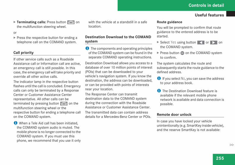
Useful features
255
X Terminating calls: Press button t onthe multifunction steering wheel.
orX Press the respective button for ending a
telephone call on the COMAND system.
Call priorityIf other service calls such as a RoadsideAssistance call or Information call are active,an emergency call is still possible. In thiscase, the emergency call will take priority andoverride all other active calls.The indicator lamp in the respective buttonflashes until the call is concluded. Emergencycalls can only be terminated by a ResponseCenter or Customer Assistance Centerrepresentative. All other calls can beterminated by pressing button t on themultifunction steering wheel or therespective button for ending a telephone callon the COMAND system.
i When a Tele Aid call has been initiated,the COMAND system audio is muted. Themobile phone is no longer connected to theCOMAND system. If you must use thisphone, we recommend that you use it only
with the vehicle at a standstill in a safelocation.
Destination Download to the COMANDsystemi The components and operating principles
of the COMAND system can be found in theseparate COMAND operating instructions.
Destination Download allows you access to adatabase of over 10 million points of interest(POIs) that can be downloaded to yourvehicle’s navigation system. If you know thedestination, the address can be downloaded,or can be provided with points of interestsnear your location.The Response Center can transmitdestination data to the COMAND systemduring the connection with the RoadsideAssistance or Customer Assistance Center.The transmitted data can contain addressdetails for a Mercedes-Benz Center or POIs.
Route guidanceYou will be prompted to confirm that routeguidance to the entered address is to bestarted.X Select Yes using button ( or & on
the COMAND system.X Press button C on the COMAND system
to confirm.The system calculates the route andsubsequently starts the route guidance to thedefined address.
i If you select No, you can save the addressto your address book.
i The Destination Download feature isavailable if the relevant mobile phonenetwork is available and data connection ispossible.
Remote door unlockIn case you have locked your vehicleunintentionally (e.g. SmartKey inside vehicle),and the reserve SmartKey is not available:
Controls in detail
Z
Useful features
256
X Contact the Response Center at1-800-756-9018 (in the USA) or1-888-923-8367 (in Canada).You will be asked to provide your password.
X Then return to your vehicle at the timearranged with the Response Center andpull the tailgate recessed handle(Y page 90) for a minimum of 20 secondsuntil the SOS button is flashing.The message Connecting Call appears inthe multifunction display.
As an alternative, you may unlock the vehiclevia Internet in the “My Tele Aid” section of“Owner’s Online”, using your ID and password(USA only).The Response Center will then unlock yourvehicle with the remote door unlockingfeature.
i The remote door unlock feature isavailable if the relevant cellular phonenetwork is available.The SOS button will flash and the messageCall Connected will appear in themultifunction display to indicate receipt ofthe door unlock command.
Once the vehicle is unlocked, a ResponseCenter specialist will attempt to establishvoice contact with the vehicle occupants.If the tailgate recessed handle was pulledfor more than 20 seconds before doorunlock authorization was received by theResponse Center, you must wait15 minutes before pulling the tailgaterecessed handle again.
Stolen Vehicle Recovery servicesIn the event your vehicle was stolen:X Report the incident to the police.
The police will issue a numbered incidentreport.
X Pass this number on to the ResponseCenter along with your password.The Response Center will then attempt tocovertly contact the vehicle’s Tele Aidsystem. Once the vehicle is located, theResponse Center will contact the local lawenforcement and you. The vehicle’slocation will only be provided to lawenforcement.
i If the anti-theft alarm stays on for morethan 30 seconds, a call to the ResponseCenter is initiated automatically by the Tele
Aid system provided Tele Aid service wassubscribed to and properly activated, andthat necessary cellular service and GPScoverage are available. See “Anti-theftalarm system” (Y page 81).
Garage door openerThe integrated remote control can operate upto three separately controlled devicescompatible with HomeLink® or some othersystems.G Warning!Before programming the integrated remotecontrol to a garage door opener or gateoperator, make sure people and objects areout of the way of the device to preventpotential harm or damage. Whenprogramming a garage door opener, thedoor moves up or down. Whenprogramming a gate operator, the gateopens or closes.Do not use the integrated remote controlwith any garage door opener that lackssafety stop and reverse features asrequired by U.S. federal safety standards(this includes any garage door openermodel manufactured before April 1, 1982).
Controls in detail
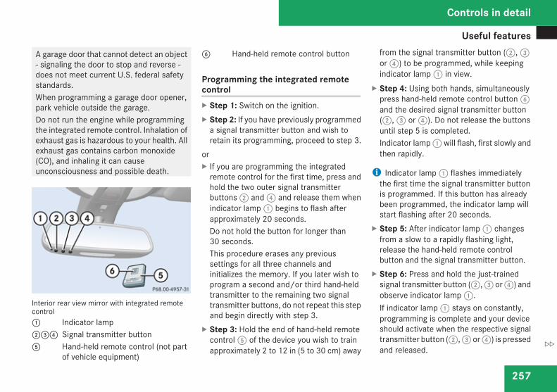
Useful features
257
A garage door that cannot detect an object- signaling the door to stop and reverse -does not meet current U.S. federal safetystandards.When programming a garage door opener,park vehicle outside the garage.Do not run the engine while programmingthe integrated remote control. Inhalation ofexhaust gas is hazardous to your health. Allexhaust gas contains carbon monoxide(CO), and inhaling it can causeunconsciousness and possible death.
Interior rear view mirror with integrated remotecontrol1 Indicator lamp234 Signal transmitter button5 Hand-held remote control (not part
of vehicle equipment)
6 Hand-held remote control button
Programming the integrated remotecontrolX Step 1: Switch on the ignition.X Step 2: If you have previously programmed
a signal transmitter button and wish toretain its programming, proceed to step 3.
orX If you are programming the integrated
remote control for the first time, press andhold the two outer signal transmitterbuttons 2 and 4 and release them whenindicator lamp 1 begins to flash afterapproximately 20 seconds.Do not hold the button for longer than30 seconds.This procedure erases any previoussettings for all three channels andinitializes the memory. If you later wish toprogram a second and/or third hand-heldtransmitter to the remaining two signaltransmitter buttons, do not repeat this stepand begin directly with step 3.
X Step 3: Hold the end of hand-held remotecontrol 5 of the device you wish to trainapproximately 2 to 12 in (5 to 30 cm) away
from the signal transmitter button (2, 3or 4) to be programmed, while keepingindicator lamp 1 in view.
X Step 4: Using both hands, simultaneouslypress hand-held remote control button 6and the desired signal transmitter button(2, 3 or 4). Do not release the buttonsuntil step 5 is completed.Indicator lamp 1 will flash, first slowly andthen rapidly.
i Indicator lamp 1 flashes immediatelythe first time the signal transmitter buttonis programmed. If this button has alreadybeen programmed, the indicator lamp willstart flashing after 20 seconds.
X Step 5: After indicator lamp 1 changesfrom a slow to a rapidly flashing light,release the hand-held remote controlbutton and the signal transmitter button.
X Step 6: Press and hold the just-trainedsignal transmitter button (2, 3 or 4) andobserve indicator lamp 1.If indicator lamp 1 stays on constantly,programming is complete and your deviceshould activate when the respective signaltransmitter button (2, 3 or 4) is pressedand released.
Controls in detail
Z
Useful features
258
i If indicator lamp 1 flashes rapidly forapproximately 2 seconds and then turns toa constant light, continue withprogramming steps 8 through 12 as yourgarage door opener may be equipped withthe “rolling code” feature.
X Step 7: To program the remaining twosignal transmitter buttons, repeat the stepsabove starting with step 3.
Rolling code programmingTo train a garage door opener (or other rollingcode devices) with the rolling code feature,follow these instructions after completing the“Programming” portion (steps 1 through 6) ofthis text. (A second person may make thefollowing training procedures quicker andeasier.)X Step 8: Locate the “training” button on the
garage door opener motor head unit.
i Exact location and color of the button mayvary by garage door opener brand.Depending on manufacturer, the “training”button may also be referred to as “learn”or“smart” button. If there is difficulty locatingthe transmitting button, refer to the garagedoor opener Operator’s Manual.
X Step 9: Press the “training” button on thegarage door opener motor head unit.The “training light” is activated.You have 30 seconds to initiate thefollowing two steps.
X Step 10: Return to the vehicle and firmlypress, hold for 2 seconds and release theprogrammed signal transmitter button(2, 3 or 4).
X Step 11: Press, hold for 2 seconds andrelease same signal transmitter button asecond time to complete the trainingprocess.
i Some garage door openers (or otherrolling code equipped devices) may requireyou to press, hold for 2 seconds andrelease the same signal transmitter buttona third time to complete the trainingprocess.
X Step 12: Confirm the garage dooroperation by pressing the programmedsignal transmitter button (2, 3 or 4).
X Step 13: To program the remaining twosignal transmitter buttons, repeat the stepsabove starting with step 3.
Gate operator/Canadian programmingCanadian radio-frequency laws requiretransmitter signals to “time-out” (or quit)after several seconds of transmission whichmay not be long enough for the integratedsignal transmitter to pick up the signal duringprogramming. Similar to this Canadian law,some U.S. gate operators are designed to“time-out” in the same manner.If you live in Canada or if you are havingdifficulties programming a gate operator(regardless of where you live) by using theprogramming procedures, replace step 4 withthe following:X Step 4: Press and hold the signal
transmitter button (2, 3 or 4). Do notrelease this button until it has beensuccessfully trained.
X While still holding down the signaltransmitter button (2, 3 or 4), “cycle”your hand-held remote control button 6as follows: Press and hold button 6 for2 seconds, then release it for 2 seconds,and again press and hold it for 2 seconds.Repeat this sequence on the hand-held
Controls in detail
Useful features
259
remote control until the frequency signalhas been learned.Upon successful training, indicator lamp1 will flash slowly and then rapidly afterseveral seconds.
X Proceed with programming step 5 andstep 6 to complete.
i Upon completion of programming theintegrated remote control, make sure youretain the hand-held remote control thatcame with the garage door opener, gateoperator or other device. You may need itfor use in other vehicles, for futureprogramming of an integrated remotecontrol, or simply for continued use as ahand-held remote control to operate therespective device in other situations.
Reprogramming a single signaltransmitter buttonTo program a device using a signaltransmitter button previously trained, followthese steps:
X Switch on the ignition.X Press and hold the desired signal
transmitter button (2, 3 or 4). Do notrelease the button.Indicator lamp 1 will begin to flash after20 seconds.
X Without releasing the signal transmitterbutton, proceed with programming startingwith step 3.
Operation of integrated remote controlX Switch on the ignition.X Select and press the appropriate
integrated signal transmitter button (2,3 or 4) to activate the remote controlleddevice.The integrated remote control transmittercontinues to send the signal as long as thebutton is pressed – up to 20 seconds.
Erasing the integrated remote controlmemoryi If you sell your vehicle, erase the codes of
all three channels.
X Switch on the ignition.X Simultaneously press and hold outer signal
transmitter buttons 2 and 4, forapproximately 20 seconds, until indicatorlamp 1 flashes rapidly. Do not hold forlonger than 30 seconds.The codes of all three channels are erased.
Programming tipsIf you are having difficulty programming theintegrated remote control, here are somehelpful tips:RCheck the frequency of hand-held remote
control 5 (typically located on the reverseside of the remote). The integrated remotecontrol is compatible with radio-frequencydevices operating between 280-390 MHz.RPut a new battery in hand-held remote
control 5. This will increase the likelihoodof the hand-held remote control sending afaster and more accurate signal to theintegrated remote control.RWhile performing step 3, hold hand-held
remote control 5 at different lengths andangles from the signal transmitter button(2, 3 or 4) you are programming.Attempt varying angles at the distance of 2
Controls in detail
Z
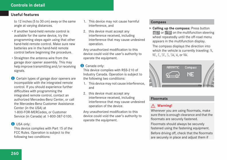
Useful features
260
to 12 inches (5 to 30 cm) away or the sameangle at varying distances.RIf another hand-held remote control is
available for the same device, try theprogramming steps again using that otherhand-held remote control. Make sure newbatteries are in the hand-held remotecontrol before beginning the procedure.RStraighten the antenna wire from the
garage door opener assembly. This mayhelp improve transmitting and/or receivingsignals.
i Certain types of garage door openers areincompatible with the integrated remotecontrol. If you should experience furtherdifficulties with programming theintegrated remote control, contact anauthorized Mercedes-Benz Center, or callthe Mercedes-Benz Customer AssistanceCenter (in the USA) at1-800-FOR-MERCedes, or CustomerService (in Canada) at 1-800-387-0100.
i USA only:This device complies with Part 15 of theFCC Rules. Operation is subject to thefollowing two conditions:
1. This device may not cause harmfulinterference, and
2. this device must accept anyinterference received, includinginterference that may cause undesiredoperation.
Any unauthorized modification to thisdevice could void the user’s authority tooperate the equipment.
i Canada only:This device complies with RSS-210 ofIndustry Canada. Operation is subject tothe following two conditions:1. This device may not cause interference,
and2. this device must accept any
interference received, includinginterference that may cause undesiredoperation of the device.
Any unauthorized modification to thisdevice could void the user’s authority tooperate the equipment.
CompassX Calling up the compass: Press buttonè or ÿ on the multifunction steeringwheel repeatedly until the off-road menuappears in the multifunction display.The compass displays the direction intowhich the vehicle is currently traveling: N,NE, E, SE, S, SW, W, or NW.
Floormats
G Warning!Whenever you are using floormats, makesure there is enough clearance and that thefloormats are securely fastened.Floormats should always be securelyfastened using the fastening equipment.Before driving off, check that the floormatsare securely in place and adjust them if
Controls in detail
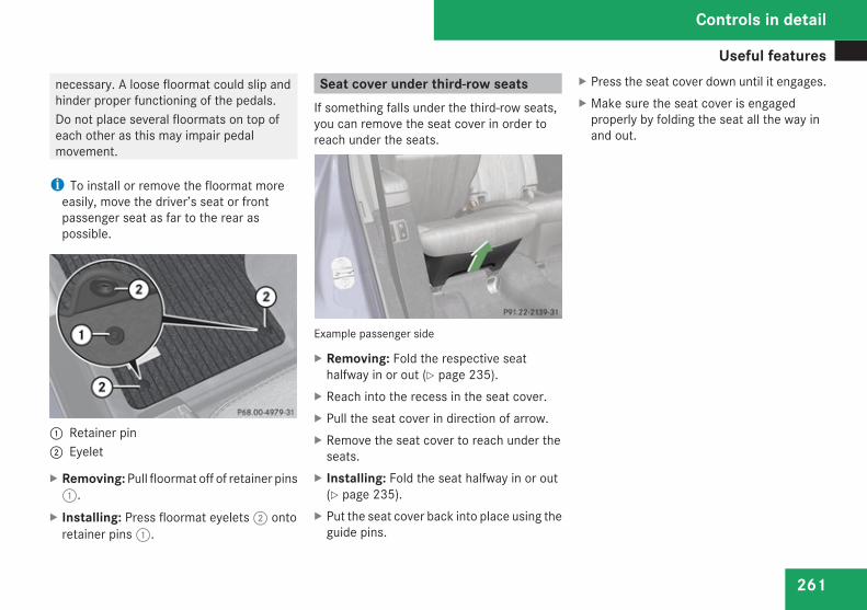
Useful features
261
necessary. A loose floormat could slip andhinder proper functioning of the pedals.Do not place several floormats on top ofeach other as this may impair pedalmovement.
i To install or remove the floormat moreeasily, move the driver’s seat or frontpassenger seat as far to the rear aspossible.
1 Retainer pin2 Eyelet
X Removing: Pull floormat off of retainer pins1.
X Installing: Press floormat eyelets 2 ontoretainer pins 1.
Seat cover under third-row seatsIf something falls under the third-row seats,you can remove the seat cover in order toreach under the seats.
Example passenger side
X Removing: Fold the respective seathalfway in or out (Y page 235).
X Reach into the recess in the seat cover.X Pull the seat cover in direction of arrow.X Remove the seat cover to reach under the
seats.X Installing: Fold the seat halfway in or out
(Y page 235).X Put the seat cover back into place using the
guide pins.
X Press the seat cover down until it engages.X Make sure the seat cover is engaged
properly by folding the seat all the way inand out.
Controls in detail
Z

262
263
Vehicle equipment ............................ 264The first 1000 miles (1500 km) ....... 264At the gas station ............................. 265Engine compartment ........................ 267Tires and wheels ............................... 272Winter driving ................................... 297Driving instructions .......................... 299Maintenance ...................................... 315Vehicle care ....................................... 318
Operation
The first 1000 miles (1500 km)
264
Vehicle equipment
i This Operator’s Manual describes allfeatures, standard or optional, potentiallyavailable for your vehicle at the time ofpurchase. Please be aware that yourvehicle might not be equipped with allfeatures described in this manual.
The first 1000 miles (1500 km)
The more cautiously you treat your vehicleduring the break-in period, the more satisfiedyou will be with its performance later on.RDrive your vehicle during the first
1 000 miles (1 500 km) at varying butmoderate vehicle and engine speeds.RDuring this period, avoid heavy loads (full
throttle driving) and excessive enginespeeds (no more than 2/3 of maximum rpmin each gear).RAvoid accelerating by kickdown.RDo not attempt to slow the vehicle down by
shifting to a lower gear using the gearselector lever.RSelect gear ranges 3, 2 or 1 (Y page 139)
only when driving at moderate speeds (forhill driving).
After 1 000 miles (1 500 km) you maygradually increase vehicle and engine speedsto the permissible maximum.All of the above instructions, as may apply toyour vehicle type, also apply when driving thefirst 1 000 miles (1 500 km) after the engine,the transfer case, the center differential orthe rear differential has been replaced.
i Always obey applicable speed limits.
Operation
At the gas station
265
At the gas station
Refueling
G Warning!Gasoline and diesel fuels are highlyflammable and poisonous. They burnviolently and can cause serious injury.Never allow sparks, flames or smokingmaterials near gasoline or diesel fuel!Turn off the engine before refueling.Whenever you are around gasoline or dieselfuel, avoid inhaling fumes and any skin orclothing contact. Extinguish all smokingmaterials.Direct skin contact with fuels and theinhalation of fuel vapors are damaging yourhealth.
G Warning!Overfilling of the fuel tank may createpressure in the system which could causea gas discharge. This could cause the gasto spray back out when removing the fuelpump nozzle, which could cause personalinjury.
G Warning!Do not fill diesel tanks with gasoline. Do notmix diesel fuel with gasoline. Otherwise thefuel system and engine could be damaged.In addition, the vehicle could catch fire.
! Never use diesel fuel in vehicles withgasoline engine. Never refuel vehicles withgasoline engine with diesel fuel. Even smallamounts of incorrect fuel will damage thefuel system and engine. Damage resultingfrom the use of non-approved fuels or fueladditives or resulting from mixing gasolinewith diesel fuel or vice versa is not coveredby the Mercedes-Benz Limited Warranty.
! If you have accidentally filled the tankwith incorrect or non-approved fuel, do notswitch on the ignition. Otherwise theincorrect or non-approved fuel will get intothe fuel lines. The fuel system must bedrained completely. Contact an authorizedMercedes-Benz Center to have the fuelsystem drained completely.
! Gasoline engine:To prevent damage to the catalyticconverters, only use premium unleadedgasoline in this vehicle.
Any noticeable irregularities in engineoperation should be repaired promptly.Otherwise, excessive unburned fuel mayreach the catalytic converter, causing it tooverheat and potentially start a fire.
! Diesel engine:When filling the diesel fuel tank using fuelcontainers, place a filling filter, a suedecloth or a clean flannel cloth as a filter.Otherwise, particles from the fuel containercould clog the fuel lines and/or the dieselinjection system.
! Diesel engine:The engine is more susceptible to wear anddamage if you useRmarine diesel fuelRheating oilRadditivesThe exhaust aftertreatment device will beseriously damaged if you use any otherdiesel fuel than ULTRA-LOW SULFURHIGHWAY DIESEL FUEL (15 ppm SULFURMAXIMUM).The use of such non-approved fuels and/orspecial additives is not covered by theMercedes-Benz Limited Warranty.
Operation
Z
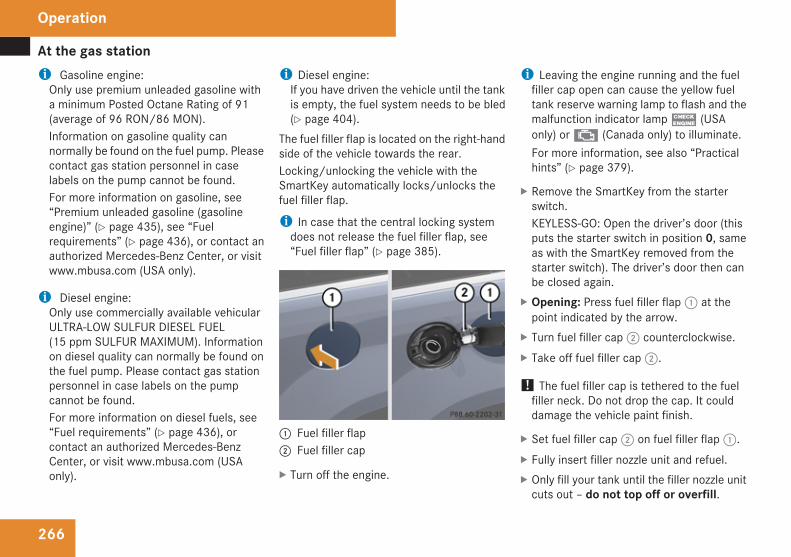
At the gas station
266
i Gasoline engine:Only use premium unleaded gasoline witha minimum Posted Octane Rating of 91(average of 96 RON/86 MON).Information on gasoline quality cannormally be found on the fuel pump. Pleasecontact gas station personnel in caselabels on the pump cannot be found.For more information on gasoline, see“Premium unleaded gasoline (gasolineengine)” (Y page 435), see “Fuelrequirements” (Y page 436), or contact anauthorized Mercedes-Benz Center, or visitwww.mbusa.com (USA only).
i Diesel engine:Only use commercially available vehicularULTRA-LOW SULFUR DIESEL FUEL(15 ppm SULFUR MAXIMUM). Informationon diesel quality can normally be found onthe fuel pump. Please contact gas stationpersonnel in case labels on the pumpcannot be found.For more information on diesel fuels, see“Fuel requirements” (Y page 436), orcontact an authorized Mercedes-BenzCenter, or visit www.mbusa.com (USAonly).
i Diesel engine:If you have driven the vehicle until the tankis empty, the fuel system needs to be bled(Y page 404).
The fuel filler flap is located on the right-handside of the vehicle towards the rear.Locking/unlocking the vehicle with theSmartKey automatically locks/unlocks thefuel filler flap.
i In case that the central locking systemdoes not release the fuel filler flap, see“Fuel filler flap” (Y page 385).
1 Fuel filler flap2 Fuel filler cap
X Turn off the engine.
i Leaving the engine running and the fuelfiller cap open can cause the yellow fueltank reserve warning lamp to flash and themalfunction indicator lamp ? (USAonly) or ± (Canada only) to illuminate.For more information, see also “Practicalhints” (Y page 379).
X Remove the SmartKey from the starterswitch.KEYLESS-GO: Open the driver’s door (thisputs the starter switch in position 0, sameas with the SmartKey removed from thestarter switch). The driver’s door then canbe closed again.
X Opening: Press fuel filler flap 1 at thepoint indicated by the arrow.
X Turn fuel filler cap 2 counterclockwise.X Take off fuel filler cap 2.
! The fuel filler cap is tethered to the fuelfiller neck. Do not drop the cap. It coulddamage the vehicle paint finish.
X Set fuel filler cap 2 on fuel filler flap 1.X Fully insert filler nozzle unit and refuel.X Only fill your tank until the filler nozzle unit
cuts out – do not top off or overfill.
Operation
Engine compartment
267
X Closing: Turn fuel filler cap 2 clockwiseuntil it audibly engages.
i Make sure to close the fuel filler flapbefore locking your vehicle as the flaplocking pin prevents closing after you havelocked the vehicle.
X Close fuel filler flap 1.
Low outside temperatures (dieselengine)! Do not fill the tank with gasoline. Do not
blend diesel fuel with gasoline or kerosene.The fuel system and engine will otherwisebe damaged, which is not covered by theMercedes-Benz Limited Warranty.
To prevent malfunctions, diesel fuel withimproved cold flow characteristics is offeredin the winter months. Check with your fuelretailer.
Check regularly and before a long tripFor information on quantities andrequirements of operating agents, see “Fuels,coolants, lubricants, etc.” (Y page 432).Check the following:REngine oil level (Y page 269)RTire inflation pressure (Y page 281)RCoolant level (Y page 271)RVehicle lighting (Y page 388)RWasher system and headlamp cleaning
system (Y page 271)RBrake fluid
Engine compartment
Hood
G Warning!Do not pull the release lever while thevehicle is in motion. Otherwise the hoodcould be forced open by passing air flow.This could cause the hood to come looseand injure you and/or others.
Opening
G Warning!If you see flames or smoke coming from theengine compartment, or if the coolanttemperature display indicates that theengine is overheated, do not open the hood.Move away from vehicle and do not openthe hood until the engine has cooled. Ifnecessary, call the fire department.
G Warning!You could be injured when the hood is open– even when the engine is turned off.Parts of the engine can become very hot.To prevent burns, let the engine cool offcompletely before touching any
Operation
Z
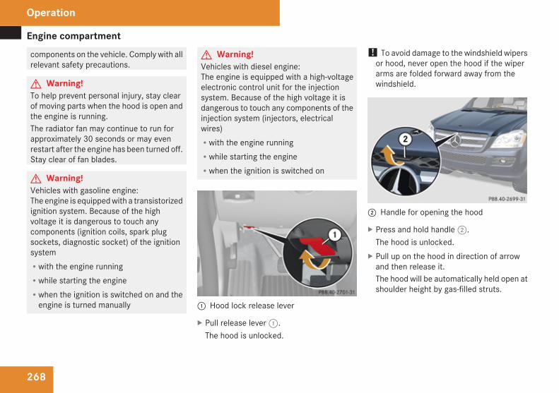
Engine compartment
268
components on the vehicle. Comply with allrelevant safety precautions.
G Warning!To help prevent personal injury, stay clearof moving parts when the hood is open andthe engine is running.The radiator fan may continue to run forapproximately 30 seconds or may evenrestart after the engine has been turned off.Stay clear of fan blades.
G Warning!Vehicles with gasoline engine:The engine is equipped with a transistorizedignition system. Because of the highvoltage it is dangerous to touch anycomponents (ignition coils, spark plugsockets, diagnostic socket) of the ignitionsystemRwith the engine runningRwhile starting the engineRwhen the ignition is switched on and the
engine is turned manually
G Warning!Vehicles with diesel engine:The engine is equipped with a high-voltageelectronic control unit for the injectionsystem. Because of the high voltage it isdangerous to touch any components of theinjection system (injectors, electricalwires)Rwith the engine runningRwhile starting the engineRwhen the ignition is switched on
1 Hood lock release lever
X Pull release lever 1.The hood is unlocked.
! To avoid damage to the windshield wipersor hood, never open the hood if the wiperarms are folded forward away from thewindshield.
2 Handle for opening the hood
X Press and hold handle 2.The hood is unlocked.
X Pull up on the hood in direction of arrowand then release it.The hood will be automatically held open atshoulder height by gas-filled struts.
Operation
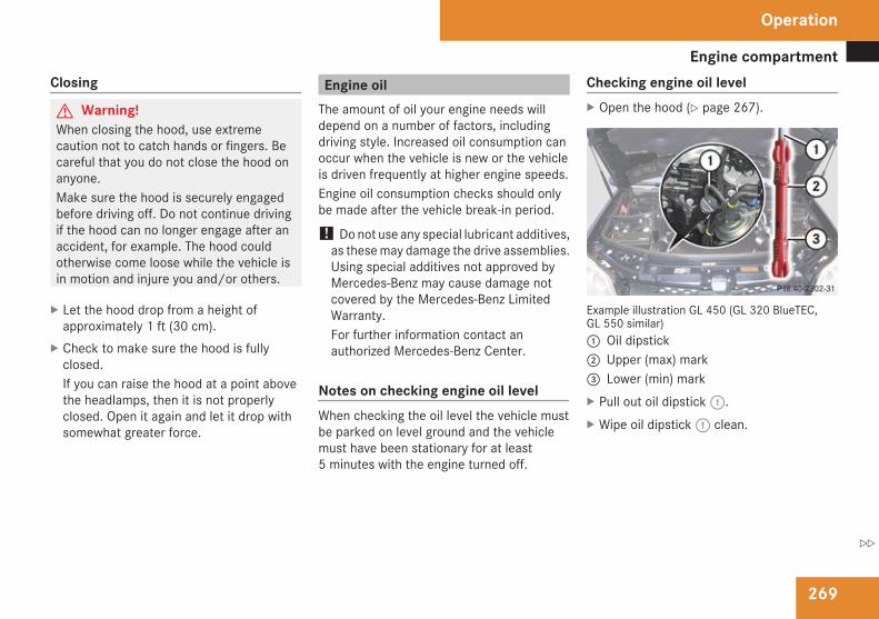
Engine compartment
269
Closing
G Warning!When closing the hood, use extremecaution not to catch hands or fingers. Becareful that you do not close the hood onanyone.Make sure the hood is securely engagedbefore driving off. Do not continue drivingif the hood can no longer engage after anaccident, for example. The hood couldotherwise come loose while the vehicle isin motion and injure you and/or others.
X Let the hood drop from a height ofapproximately 1 ft (30 cm).
X Check to make sure the hood is fullyclosed.If you can raise the hood at a point abovethe headlamps, then it is not properlyclosed. Open it again and let it drop withsomewhat greater force.
Engine oilThe amount of oil your engine needs willdepend on a number of factors, includingdriving style. Increased oil consumption canoccur when the vehicle is new or the vehicleis driven frequently at higher engine speeds.Engine oil consumption checks should onlybe made after the vehicle break-in period.
! Do not use any special lubricant additives,as these may damage the drive assemblies.Using special additives not approved byMercedes-Benz may cause damage notcovered by the Mercedes-Benz LimitedWarranty.For further information contact anauthorized Mercedes-Benz Center.
Notes on checking engine oil levelWhen checking the oil level the vehicle mustbe parked on level ground and the vehiclemust have been stationary for at least5 minutes with the engine turned off.
Checking engine oil levelX Open the hood (Y page 267).
Example illustration GL 450 (GL 320 BlueTEC,GL 550 similar)1 Oil dipstick 2 Upper (max) mark3 Lower (min) markX Pull out oil dipstick 1.X Wipe oil dipstick 1 clean.
Operation
Z
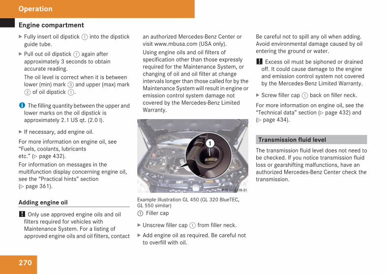
Engine compartment
270
X Fully insert oil dipstick 1 into the dipstickguide tube.
X Pull out oil dipstick 1 again afterapproximately 3 seconds to obtainaccurate reading.The oil level is correct when it is betweenlower (min) mark 3 and upper (max) mark2 of oil dipstick 1.
i The filling quantity between the upper andlower marks on the oil dipstick isapproximately 2.1 US qt. (2.0 l).
X If necessary, add engine oil.For more information on engine oil, see“Fuels, coolants, lubricantsetc.” (Y page 432).For information on messages in themultifunction display concerning engine oil,see the “Practical hints” section(Y page 361).
Adding engine oil! Only use approved engine oils and oil
filters required for vehicles withMaintenance System. For a listing ofapproved engine oils and oil filters, contact
an authorized Mercedes-Benz Center orvisit www.mbusa.com (USA only).Using engine oils and oil filters ofspecification other than those expresslyrequired for the Maintenance System, orchanging of oil and oil filter at changeintervals longer than those called for by theMaintenance System will result in engine oremission control system damage notcovered by the Mercedes-Benz LimitedWarranty.
Example illustration GL 450 (GL 320 BlueTEC,GL 550 similar)1 Filler cap
X Unscrew filler cap 1 from filler neck.X Add engine oil as required. Be careful not
to overfill with oil.
Be careful not to spill any oil when adding.Avoid environmental damage caused by oilentering the ground or water.
! Excess oil must be siphoned or drainedoff. It could cause damage to the engineand emission control system not coveredby the Mercedes-Benz Limited Warranty.
X Screw filler cap 1 back on filler neck.For more information on engine oil, see the“Technical data” section (Y page 432) and(Y page 434).
Transmission fluid levelThe transmission fluid level does not need tobe checked. If you notice transmission fluidloss or gearshifting malfunctions, have anauthorized Mercedes-Benz Center check thetransmission.
Operation
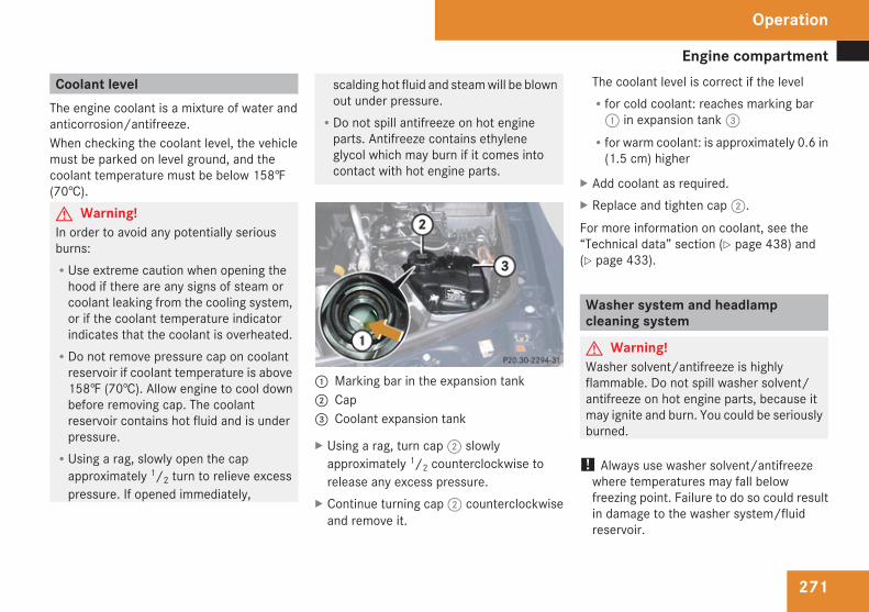
Engine compartment
271
Coolant levelThe engine coolant is a mixture of water andanticorrosion/antifreeze.When checking the coolant level, the vehiclemust be parked on level ground, and thecoolant temperature must be below 158‡(70†).G Warning!In order to avoid any potentially seriousburns:RUse extreme caution when opening the
hood if there are any signs of steam orcoolant leaking from the cooling system,or if the coolant temperature indicatorindicates that the coolant is overheated.RDo not remove pressure cap on coolant
reservoir if coolant temperature is above158‡ (70†). Allow engine to cool downbefore removing cap. The coolantreservoir contains hot fluid and is underpressure.RUsing a rag, slowly open the cap
approximately 1/2 turn to relieve excesspressure. If opened immediately,
scalding hot fluid and steam will be blownout under pressure.RDo not spill antifreeze on hot engine
parts. Antifreeze contains ethyleneglycol which may burn if it comes intocontact with hot engine parts.
1 Marking bar in the expansion tank2 Cap3 Coolant expansion tank
X Using a rag, turn cap 2 slowlyapproximately 1/2 counterclockwise torelease any excess pressure.
X Continue turning cap 2 counterclockwiseand remove it.
The coolant level is correct if the levelRfor cold coolant: reaches marking bar
1 in expansion tank 3Rfor warm coolant: is approximately 0.6 in
(1.5 cm) higher
X Add coolant as required.X Replace and tighten cap 2.For more information on coolant, see the“Technical data” section (Y page 438) and(Y page 433).
Washer system and headlampcleaning system
G Warning!Washer solvent/antifreeze is highlyflammable. Do not spill washer solvent/antifreeze on hot engine parts, because itmay ignite and burn. You could be seriouslyburned.
! Always use washer solvent/antifreezewhere temperatures may fall belowfreezing point. Failure to do so could resultin damage to the washer system/fluidreservoir.
Operation
Z
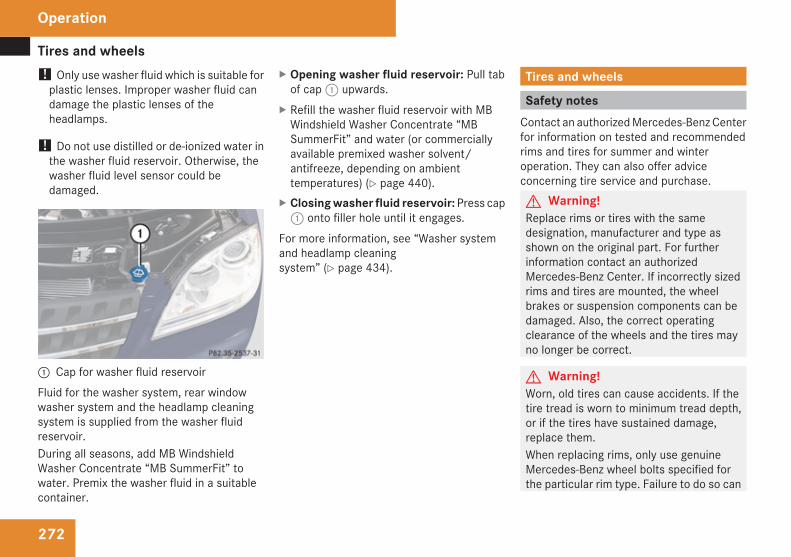
Tires and wheels
272
! Only use washer fluid which is suitable forplastic lenses. Improper washer fluid candamage the plastic lenses of theheadlamps.
! Do not use distilled or de-ionized water inthe washer fluid reservoir. Otherwise, thewasher fluid level sensor could bedamaged.
1 Cap for washer fluid reservoirFluid for the washer system, rear windowwasher system and the headlamp cleaningsystem is supplied from the washer fluidreservoir.During all seasons, add MB WindshieldWasher Concentrate “MB SummerFit” towater. Premix the washer fluid in a suitablecontainer.
X Opening washer fluid reservoir: Pull tabof cap 1 upwards.
X Refill the washer fluid reservoir with MBWindshield Washer Concentrate “MBSummerFit” and water (or commerciallyavailable premixed washer solvent/antifreeze, depending on ambienttemperatures) (Y page 440).
X Closing washer fluid reservoir: Press cap1 onto filler hole until it engages.
For more information, see “Washer systemand headlamp cleaningsystem” (Y page 434).
Tires and wheels
Safety notesContact an authorized Mercedes-Benz Centerfor information on tested and recommendedrims and tires for summer and winteroperation. They can also offer adviceconcerning tire service and purchase.G Warning!Replace rims or tires with the samedesignation, manufacturer and type asshown on the original part. For furtherinformation contact an authorizedMercedes-Benz Center. If incorrectly sizedrims and tires are mounted, the wheelbrakes or suspension components can bedamaged. Also, the correct operatingclearance of the wheels and the tires mayno longer be correct.
G Warning!Worn, old tires can cause accidents. If thetire tread is worn to minimum tread depth,or if the tires have sustained damage,replace them.When replacing rims, only use genuineMercedes-Benz wheel bolts specified forthe particular rim type. Failure to do so can
Operation
Tires and wheels
273
result in the bolts loosening and possibly anaccident.Retreaded tires are not tested orrecommended by Mercedes-Benz, sinceprevious damage cannot always berecognized on retreads. The operatingsafety of the vehicle cannot be assuredwhen such tires are used.
G Warning!If you feel a sudden significant vibration orride disturbance, or you suspect thatpossible damage to your vehicle hasoccurred, you should turn on the hazardwarning flashers, carefully slow down, anddrive with caution to an area which is a safedistance from the road.Inspect the tires and the vehicle underbodyfor possible damage. If the vehicle or tiresappear unsafe, have the vehicle towed tothe nearest authorized Mercedes-BenzCenter or tire dealer for repairs.
G Warning!Do not drive with a flat tire. A flat tire affectsthe ability to steer or brake the vehicle. Youcould lose control of the vehicle. Continueddriving with a flat tire or driving at high
speed with a flat tire will cause excessiveheat build-up and possibly a fire.
Important guidelinesROnly use sets of tires and rims of the same
type and make.RTires must be of the correct size for the rim.RBreak in new tires for approximately
60 miles (100 km) at moderate speeds.RRegularly check the tires and rims for
damage. Dented or bent rims can cause tireinflation pressure loss and damage to thetire beads.RIf vehicle is heavily loaded, check tire
inflation pressure and correct as required.RDo not allow your tires to wear down too
far. Adhesion properties on wet roads aresharply reduced at tread depths of lessthan 1/8 in (3 mm).RWhen replacing individual tires, you should
mount new tires on the front wheels first(on vehicles with same-sized wheels allaround).
Tire care and maintenance
G Warning!Regularly check the tires for damage.Damaged tires can cause tire inflationpressure loss. As a result, you could losecontrol of your vehicle.Worn, old tires can cause accidents. If thetire tread is worn to minimum tread depth,or if the tires have sustained damage,replace them.
Check the tire inflation pressure at least everyother week. For more information onchecking tire inflation pressure, see“Recommended tire inflationpressure” (Y page 279).
Tire inspectionEvery time you check the tire inflationpressure, you should also inspect your tiresfor the following:Rexcessive treadwear (Y page 274)Rcord or fabric showing through the tire’s
rubberRbumps, bulges, cuts, cracks or splits in the
tread or side of the tire
Operation
Z
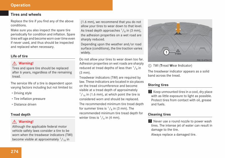
Tires and wheels
274
Replace the tire if you find any of the aboveconditions.Make sure you also inspect the spare tireperiodically for condition and inflation. Sparetires will age and become worn over time evenif never used, and thus should be inspectedand replaced when necessary.
Life of tire
G Warning!Tires and spare tire should be replacedafter 6 years, regardless of the remainingtread.
The service life of a tire is dependent uponvarying factors including but not limited to:RDriving styleRTire inflation pressureRDistance driven
Tread depth
G Warning!Although the applicable federal motorvehicle safety laws consider a tire to beworn when the treadwear indicators (TWI)become visible at approximately 1/16 in
(1.6 mm), we recommend that you do notallow your tires to wear down to that level.As tread depth approaches 1/8 in (3 mm),the adhesion properties on a wet road aresharply reduced.Depending upon the weather and/or roadsurface (conditions), the tire traction varieswidely.
Do not allow your tires to wear down too far.Adhesion properties on wet roads are sharplyreduced at tread depths of less than 1/8 in(3 mm).Treadwear indicators (TWI) are required bylaw. These indicators are located in six placeson the tread circumference and becomevisible at a tread depth of approximately1/16 in (1.6 mm), at which point the tire isconsidered worn and should be replaced.The recommended minimum tire tread depthfor summer tires is 1/8 in (3 mm). Therecommended minimum tire tread depth forwinter tires is 1/6 in (4 mm).
1 TWI (Tread Wear Indicator)The treadwear indicator appears as a solidband across the tread.
Storing tires! Keep unmounted tires in a cool, dry place
with as little exposure to light as possible.Protect tires from contact with oil, greaseand fuels.
Cleaning tires! Never use a round nozzle to power wash
tires. The intense jet of water can result indamage to the tire.Always replace a damaged tire.
Operation
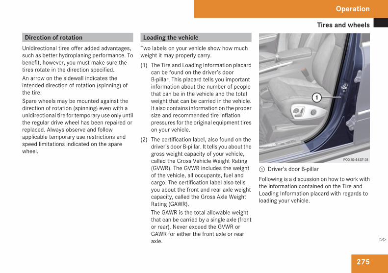
Tires and wheels
275
Direction of rotationUnidirectional tires offer added advantages,such as better hydroplaning performance. Tobenefit, however, you must make sure thetires rotate in the direction specified.An arrow on the sidewall indicates theintended direction of rotation (spinning) ofthe tire.Spare wheels may be mounted against thedirection of rotation (spinning) even with aunidirectional tire for temporary use only untilthe regular drive wheel has been repaired orreplaced. Always observe and followapplicable temporary use restrictions andspeed limitations indicated on the sparewheel.
Loading the vehicleTwo labels on your vehicle show how muchweight it may properly carry.(1) The Tire and Loading Information placard
can be found on the driver’s doorB-pillar. This placard tells you importantinformation about the number of peoplethat can be in the vehicle and the totalweight that can be carried in the vehicle.It also contains information on the propersize and recommended tire inflationpressures for the original equipment tireson your vehicle.
(2) The certification label, also found on thedriver’s door B-pillar. It tells you about thegross weight capacity of your vehicle,called the Gross Vehicle Weight Rating(GVWR). The GVWR includes the weightof the vehicle, all occupants, fuel andcargo. The certification label also tellsyou about the front and rear axle weightcapacity, called the Gross Axle WeightRating (GAWR).The GAWR is the total allowable weightthat can be carried by a single axle (frontor rear). Never exceed the GVWR orGAWR for either the front axle or rearaxle.
1 Driver’s door B-pillarFollowing is a discussion on how to work withthe information contained on the Tire andLoading Information placard with regards toloading your vehicle.
Operation
Z
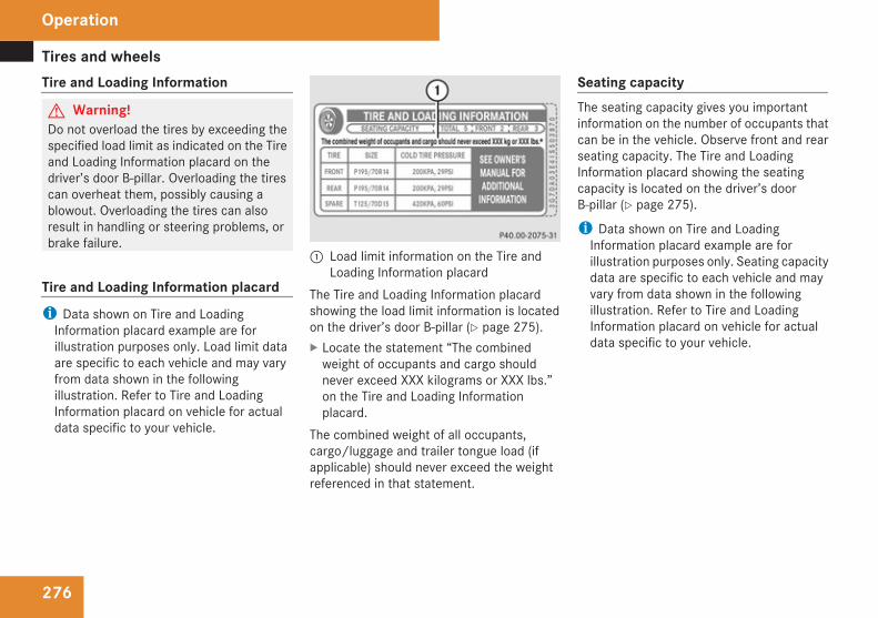
Tires and wheels
276
Tire and Loading Information
G Warning!Do not overload the tires by exceeding thespecified load limit as indicated on the Tireand Loading Information placard on thedriver’s door B-pillar. Overloading the tirescan overheat them, possibly causing ablowout. Overloading the tires can alsoresult in handling or steering problems, orbrake failure.
Tire and Loading Information placardi Data shown on Tire and Loading
Information placard example are forillustration purposes only. Load limit dataare specific to each vehicle and may varyfrom data shown in the followingillustration. Refer to Tire and LoadingInformation placard on vehicle for actualdata specific to your vehicle.
1 Load limit information on the Tire andLoading Information placard
The Tire and Loading Information placardshowing the load limit information is locatedon the driver’s door B-pillar (Y page 275).X Locate the statement “The combined
weight of occupants and cargo shouldnever exceed XXX kilograms or XXX lbs.”on the Tire and Loading Informationplacard.
The combined weight of all occupants,cargo/luggage and trailer tongue load (ifapplicable) should never exceed the weightreferenced in that statement.
Seating capacityThe seating capacity gives you importantinformation on the number of occupants thatcan be in the vehicle. Observe front and rearseating capacity. The Tire and LoadingInformation placard showing the seatingcapacity is located on the driver’s doorB-pillar (Y page 275).
i Data shown on Tire and LoadingInformation placard example are forillustration purposes only. Seating capacitydata are specific to each vehicle and mayvary from data shown in the followingillustration. Refer to Tire and LoadingInformation placard on vehicle for actualdata specific to your vehicle.
Operation
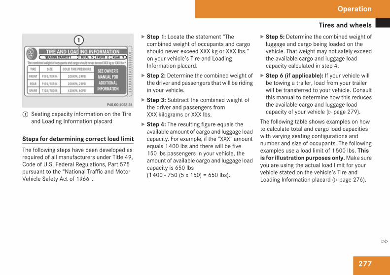
Tires and wheels
277
1 Seating capacity information on the Tireand Loading Information placard
Steps for determining correct load limitThe following steps have been developed asrequired of all manufacturers under Title 49,Code of U.S. Federal Regulations, Part 575pursuant to the “National Traffic and MotorVehicle Safety Act of 1966”.
X Step 1: Locate the statement “Thecombined weight of occupants and cargoshould never exceed XXX kg or XXX lbs.”on your vehicle’s Tire and LoadingInformation placard.
X Step 2: Determine the combined weight ofthe driver and passengers that will be ridingin your vehicle.
X Step 3: Subtract the combined weight ofthe driver and passengers fromXXX kilograms or XXX lbs.
X Step 4: The resulting figure equals theavailable amount of cargo and luggage loadcapacity. For example, if the “XXX” amountequals 1 400 lbs and there will be five150 lbs passengers in your vehicle, theamount of available cargo and luggage loadcapacity is 650 lbs(1 400 - 750 (5 x 150) = 650 lbs).
X Step 5: Determine the combined weight ofluggage and cargo being loaded on thevehicle. That weight may not safely exceedthe available cargo and luggage loadcapacity calculated in step 4.
X Step 6 (if applicable): If your vehicle willbe towing a trailer, load from your trailerwill be transferred to your vehicle. Consultthis manual to determine how this reducesthe available cargo and luggage loadcapacity of your vehicle (Y page 279).
The following table shows examples on howto calculate total and cargo load capacitieswith varying seating configurations andnumber and size of occupants. The followingexamples use a load limit of 1 500 lbs. Thisis for illustration purposes only. Make sureyou are using the actual load limit for yourvehicle stated on the vehicle’s Tire andLoading Information placard (Y page 276).
Operation
Z
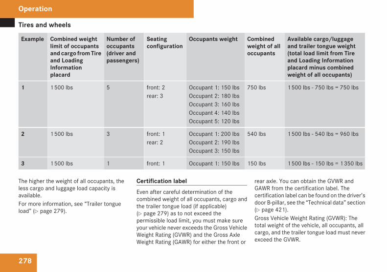
Tires and wheels
278
Example Combined weightlimit of occupantsand cargo from Tireand LoadingInformationplacard
Number ofoccupants(driver andpassengers)
Seatingconfiguration
Occupants weight Combinedweight of alloccupants
Available cargo/luggageand trailer tongue weight(total load limit from Tireand Loading Informationplacard minus combinedweight of all occupants)
1 1 500 lbs 5 front: 2rear: 3
Occupant 1: 150 lbsOccupant 2: 180 lbsOccupant 3: 160 lbsOccupant 4: 140 lbsOccupant 5: 120 lbs
750 lbs 1 500 lbs - 750 lbs = 750 lbs
2 1 500 lbs 3 front: 1rear: 2
Occupant 1: 200 lbsOccupant 2: 190 lbsOccupant 3: 150 lbs
540 lbs 1 500 lbs - 540 lbs = 960 lbs
3 1 500 lbs 1 front: 1 Occupant 1: 150 lbs 150 lbs 1 500 lbs - 150 lbs = 1 350 lbs
The higher the weight of all occupants, theless cargo and luggage load capacity isavailable.For more information, see “Trailer tongueload” (Y page 279).
Certification labelEven after careful determination of thecombined weight of all occupants, cargo andthe trailer tongue load (if applicable)(Y page 279) as to not exceed thepermissible load limit, you must make sureyour vehicle never exceeds the Gross VehicleWeight Rating (GVWR) and the Gross AxleWeight Rating (GAWR) for either the front or
rear axle. You can obtain the GVWR andGAWR from the certification label. Thecertification label can be found on the driver’sdoor B-pillar, see the “Technical data” section(Y page 421).Gross Vehicle Weight Rating (GVWR): Thetotal weight of the vehicle, all occupants, allcargo, and the trailer tongue load must neverexceed the GVWR.
Operation
Tires and wheels
279
Gross Axle Weight Rating (GAWR): The totalallowable weight that can be carried by asingle axle (front or rear).To assure that your vehicle does not exceedthe maximum permissible weight limits(GVWR and GAWR for front and rear axle),have the loaded vehicle (including driver,passengers and all cargo and, if applicable,trailer fully loaded) weighed on a suitablecommercial scale.
Trailer tongue loadThe tongue load of any trailer is an importantweight to measure because it affects the loadyou can carry in your vehicle. If a trailer istowed, the tongue load must be added to theweight of all occupants riding and any cargoyou are carrying in the vehicle. The tongueload typically is between 8% and 15% of thetrailer weight and everything loaded in it.
Recommended tire inflation pressure
G Warning!Follow recommended tire inflationpressures.Do not underinflate tires. Underinflatedtires wear excessively and/or unevenly,adversely affect handling and fueleconomy, and are more likely to fail frombeing overheated.Do not overinflate tires. Overinflated tirescan adversely affect handling and ridecomfort, wear unevenly, increase stoppingdistance, and result in sudden deflation(blowout) because they are more likely tobecome punctured or damaged by roaddebris, potholes etc.Do not overload the tires by exceeding thespecified load limit as indicated on the Tireand Loading Information placard on thedriver’s door B-pillar. Overloading the tirescan overheat them, possibly causing ablowout. Overloading the tires can alsoresult in handling or steering problems, orbrake failure.
Your vehicle is equipped with the Tire andLoading Information placard located on thedriver’s door B-pillar (Y page 275).
The tire inflation pressure should be checkedregularly and should only be adjusted on coldtires. The tires can be considered cold if thevehicle has been parked for at least 3 hoursor driven less than 1 mile (1.6 km).Follow recommended cold tire inflationpressures listed on Tire and LoadingInformation placard on the driver’s doorB-pillar.Keeping the tires properly inflated providesthe best handling, tread life and ridingcomfort.In addition to the Tire and LoadingInformation placard on the driver’s doorB-pillar, also consult the tire inflationpressure label (if available) on the inside ofthe filler flap for any additional informationpertaining to special driving situations. Formore information, see “Important notes ontire inflation pressure” (Y page 280).
i Data shown on Tire and LoadingInformation placard example are forillustration purposes only. Tire data arespecific to each vehicle and may vary fromdata shown in the following illustration.Refer to Tire and Loading Informationplacard on vehicle for actual data specificto your vehicle.
Operation
Z
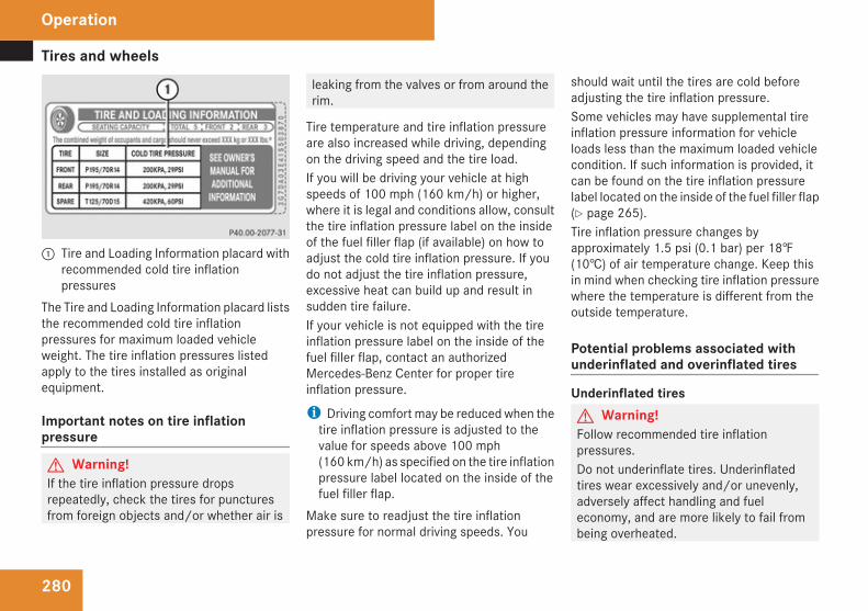
Tires and wheels
280
1 Tire and Loading Information placard withrecommended cold tire inflationpressures
The Tire and Loading Information placard liststhe recommended cold tire inflationpressures for maximum loaded vehicleweight. The tire inflation pressures listedapply to the tires installed as originalequipment.
Important notes on tire inflationpressure
G Warning!If the tire inflation pressure dropsrepeatedly, check the tires for puncturesfrom foreign objects and/or whether air is
leaking from the valves or from around therim.
Tire temperature and tire inflation pressureare also increased while driving, dependingon the driving speed and the tire load.If you will be driving your vehicle at highspeeds of 100 mph (160 km/h) or higher,where it is legal and conditions allow, consultthe tire inflation pressure label on the insideof the fuel filler flap (if available) on how toadjust the cold tire inflation pressure. If youdo not adjust the tire inflation pressure,excessive heat can build up and result insudden tire failure.If your vehicle is not equipped with the tireinflation pressure label on the inside of thefuel filler flap, contact an authorizedMercedes-Benz Center for proper tireinflation pressure.
i Driving comfort may be reduced when thetire inflation pressure is adjusted to thevalue for speeds above 100 mph(160 km/h) as specified on the tire inflationpressure label located on the inside of thefuel filler flap.
Make sure to readjust the tire inflationpressure for normal driving speeds. You
should wait until the tires are cold beforeadjusting the tire inflation pressure.Some vehicles may have supplemental tireinflation pressure information for vehicleloads less than the maximum loaded vehiclecondition. If such information is provided, itcan be found on the tire inflation pressurelabel located on the inside of the fuel filler flap(Y page 265).Tire inflation pressure changes byapproximately 1.5 psi (0.1 bar) per 18‡(10†) of air temperature change. Keep thisin mind when checking tire inflation pressurewhere the temperature is different from theoutside temperature.
Potential problems associated withunderinflated and overinflated tires
Underinflated tiresG Warning!Follow recommended tire inflationpressures.Do not underinflate tires. Underinflatedtires wear excessively and/or unevenly,adversely affect handling and fueleconomy, and are more likely to fail frombeing overheated.
Operation
Tires and wheels
281
Underinflated tires canRcause excessive and uneven tire wearRadversely affect fuel economyRlead to tire failure from being overheatedRadversely affect handling characteristics
Overinflated tiresG Warning!Follow recommended tire inflationpressures.Do not overinflate tires. Overinflated tirescan adversely affect handling and ridecomfort, wear unevenly, increase stoppingdistance, and result in sudden deflation(blowout) because they are more likely tobecome punctured or damaged by roaddebris, potholes etc.
Overinflated tires canRadversely affect handling characteristicsRcause uneven tire wearRbe more prone to damage from road
hazardsRadversely affect ride comfortRincrease stopping distance
Checking tire inflation pressure
Safety notes
G Warning!Follow recommended tire inflationpressures.Do not underinflate tires. Underinflatedtires wear excessively and/or unevenly,adversely affect handling and fueleconomy, and are more likely to fail frombeing overheated.Do not overinflate tires. Overinflated tirescan adversely affect handling and ridecomfort, wear unevenly, increase stoppingdistance, and result in sudden deflation(blowout) because they are more likely tobecome punctured or damaged by roaddebris, potholes etc.Do not overload the tires by exceeding thespecified load limit as indicated on the Tireand Loading Information placard on thedriver’s door B-pillar. Overloading the tirescan overheat them, possibly causing ablowout. Overloading the tires can alsoresult in handling or steering problems, orbrake failure.
Check the tire inflation pressure at least everyother week.
Check and adjust the tire inflation pressurewhen the tires are cold. The tires can beconsidered cold if the vehicle has beenparked for at least 3 hours or driven less than1 mile (1.6 km).If you check the tire inflation pressure whenthe tires are warm (the vehicle has beendriven for several miles or sitting less than3 hours), the reading will be approximately4 psi (0.3 bar) higher than the cold reading.This is normal. Do not let air out to match thespecified cold tire inflation pressure.Otherwise, the tire will be underinflated.
Checking tire inflation pressuremanuallyFollow the steps below to achieve correct tireinflation pressure:X Remove the cap from the valve on one tire.X Firmly press a tire gauge onto the valve.X Read the tire inflation pressure on the tire
gauge and check against therecommended tire inflation pressure on theTire and Loading Information placard on thedriver’s door B-pillar (Y page 275). Ifnecessary, add air to achieve therecommended tire inflation pressure.
Operation
Z
Tires and wheels
282
X If you have overfilled the tire, release tireinflation pressure by pushing the metalstem of the valve with e.g. a tip of a pen.Then recheck the tire inflation pressurewith the tire gauge.
X Install the valve cap.X Repeat this procedure for each tire.
Run Flat Indicator (Canada only)While the vehicle is being driven, the Run FlatIndicator monitors the set tire inflationpressures by evaluating each wheel’srotational speed. This allows the system todetect a significant loss of pressure in a tire.If a wheel’s rotational speed changes due tofalling tire inflation pressure, you will see acorresponding warning message in themultifunction display.The Run Flat Indicator may function in arestricted manner or with a delayRwhen snow chains are mounted to the
vehicleRin the presence of ice and snow
Rwhen you are driving on a loose surface(e.g. sand or gravel)Rwhen you are driving in a very sporty
manner (involving rapid acceleration orhigh speeds in curves)
G Warning!When the multifunction display shows themessage Tire Pressure Check Tires,one or more of your tires is significantlyunderinflated. You should stop and checkyour tires as soon as possible, and inflatethem to the proper tire inflation pressure asindicated on the vehicle’s Tire and LoadingInformation placard or, if available, on thetire inflation pressure label.Driving on a significantly underinflated tirecauses the tire to overheat and can lead totire failure. Underinflation also reduces fuelefficiency and tire tread life, and may affectthe vehicle’s handling and stopping ability.Each tire, including the spare, should bechecked every other week when cold andset to the recommended tire inflationpressure as specified on the Tire andLoading Information placard on the driver’sdoor B-pillar or, if available, on the tireinflation pressure label located on theinside of the fuel filler flap.
i The recommended tire inflation pressuresfor your vehicle can be found on the Tireand Loading Information placard locatedon the driver’s door B-pillar (Y page 275)or, if available, on the tire inflation pressurelabel on the on the inside of the fuel fillerflap (Y page 266). The tire inflationpressures are not listed in the Operator'sManual.
G Warning!The Run Flat Indicator does not provide awarning for wrongly selected tire inflationpressures. Always adjust tire inflationpressure according to the Tire and LoadingInformation placard on the driver’s doorB-pillar or, if available, on the tire inflationpressure label located on the inside of thefuel filler flap.The Run Flat Indicator does not replaceregular checks of the tire inflationpressures since a gradual pressure loss inmore than one tire cannot be detected bythe Run Flat Indicator.The Run Flat Indicator is not able to issue awarning due to a sudden dramatic loss oftire inflation pressure (e.g. tire blowoutcaused by a foreign object). In this casebring the vehicle to a halt by carefully
Operation
Tires and wheels
283
applying the brakes and avoiding abruptsteering maneuvers.
Restarting the Run Flat IndicatorThe Run Flat Indicator must be restarted inthe following situations:Rafter you have changed the tire inflation
pressureRafter you have replaced the wheels or tiresRafter you have installed new wheels or tires
X Using the Tire and Loading Informationplacard on the driver’s door B-pillar or, ifavailable, the tire inflation pressure label onthe inside of the fuel filler flap, make surethe tire inflation pressure of all four tires iscorrect.
G Warning!The Run Flat Indicator can only warn you ina reliable manner if you have set the correcttire inflation pressures for each tire.If an incorrect tire inflation pressure wasset, the system will monitor the pressureaccording to the incorrect value.
X Switch on the ignition.X Make sure the standard display appears in
the multifunction display (Y page 152).X Press button k or j on the
multifunction steering wheel repeatedlyuntil the following message appears in themultifunction display:Run Flat IndicatorActiveMenu: R-Button
X Press the reset button (Y page 147).The following message will appear in themultifunction display:RestartRun Flat Indicator?
X If you wish to confirm: Press buttonæ.The following message will appear in themultifunction display:Run Flat IndicatorRestartedAfter a certain “learning phase”, the RunFlat Indicator checks the set pressurevalues for all four tires.
X If you wish to cancel: Press buttonç.
orX Wait until the message RestartRun Flat Indicator?disappears.
Tire Pressure Monitoring System(TPMS), (USA only)Your vehicle is equipped with a Tire PressureMonitoring System (TPMS). It measures thetire inflation pressure in the vehicle’s tiresand issues warnings in case of pressure loss.The Tire Pressure Monitoring System (TPMS)is equipped with a combination low tirepressure/TPMS malfunction telltale in theinstrument cluster. Depending on how thetelltale illuminates, it indicates a low tirepressure condition or a malfunction in theTPMS system itself:RIf the telltale illuminates continuously, one
or more of your tires are significantly
Operation
Z
Tires and wheels
284
underinflated. There is no malfunction inthe TPMS.RIf the telltale flashes for 60 seconds and
then stays illuminated, the TPMS systemitself is not operating properly.
The TPMS only functions on wheels that areequipped with the proper electronic sensors.It monitors the tire inflation pressure, asselected by the driver, in all four tires. Awarning is issued to alert you to a decreasein pressure in one or more of the tires.G Warning!The TPMS does not indicate a warning forwrongly selected inflation pressures.Always adjust tire inflation pressureaccording to the Tire and LoadingInformation placard or, if available, on thesupplemental tire inflation pressureinformation on the inside of the fuel fillerflap.The TPMS is not able to issue a warning dueto a sudden dramatic loss of pressure (e.g.tire blowout caused by a foreign object). Inthis case bring the vehicle to a halt bycarefully applying the brakes and avoidingabrupt steering maneuvers.
G Warning!Each tire, including the spare (if provided),should be checked every other week whencold and inflated to the inflation pressurerecommended by the vehicle manufactureron the Tire and Loading Information placardon the driver’s door B-pillar or, if available,the tire inflation pressure label on the insideof the fuel filler flap. If your vehicle has tiresof a different size than the size indicated onthe Tire and Loading Information placard or,if available, the tire inflation pressure label,you should determine the proper tireinflation pressure for those tires.As an added safety feature, your vehicle hasbeen equipped with a tire pressuremonitoring system (TPMS) that illuminatesa low tire pressure telltale when one ormore of your tires are significantlyunderinflated. Accordingly, when the lowtire pressure telltale illuminates, you shouldstop and check your tires as soon aspossible, and inflate them to the properpressure. Driving on a significantlyunderinflated tire causes the tire tooverheat and can lead to tire failure.Underinflation also reduces fuel efficiencyand tire tread life, and may affect the
vehicle’s handling and stopping ability.Please note that the TPMS is not asubstitute for proper tire maintenance, andit is the driver’s responsibility to maintaincorrect tire pressure, even if underinflationhas not reached the level to triggerillumination of the TPMS low tire pressuretelltale.Your vehicle has also been equipped with aTPMS malfunction indicator to indicatewhen the system is not operating properly.The TPMS malfunction indicator iscombined with the low tire pressuretelltale. When the system detects amalfunction, the telltale will flash forapproximately 1 minute and then remaincontinuously illuminated. This sequencewill continue upon subsequent vehiclestart-ups as long as the malfunction exists.When the malfunction indicator isilluminated, the system may not be able todetect or signal low tire pressure asintended.TPMS malfunctions may occur for a varietyof reasons, including the installation ofincompatible replacement or alternate tiresor wheels on the vehicle that prevent theTPMS from functioning properly. Alwayscheck the TPMS malfunction telltale after
Operation
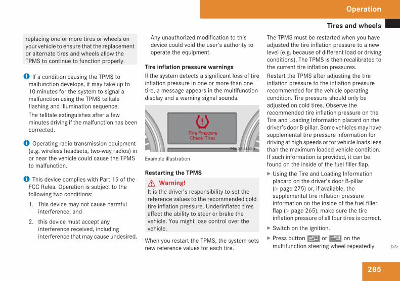
Tires and wheels
285
replacing one or more tires or wheels onyour vehicle to ensure that the replacementor alternate tires and wheels allow theTPMS to continue to function properly.
i If a condition causing the TPMS tomalfunction develops, it may take up to10 minutes for the system to signal amalfunction using the TPMS telltaleflashing and illumination sequence.The telltale extinguishes after a fewminutes driving if the malfunction has beencorrected.
i Operating radio transmission equipment(e.g. wireless headsets, two-way radios) inor near the vehicle could cause the TPMSto malfunction.
i This device complies with Part 15 of theFCC Rules. Operation is subject to thefollowing two conditions:1. This device may not cause harmful
interference, and2. this device must accept any
interference received, includinginterference that may cause undesired.
Any unauthorized modification to thisdevice could void the user’s authority tooperate the equipment.
Tire inflation pressure warningsIf the system detects a significant loss of tireinflation pressure in one or more than onetire, a message appears in the multifunctiondisplay and a warning signal sounds.
Example illustration
Restarting the TPMSG Warning!It is the driver’s responsibility to set thereference values to the recommended coldtire inflation pressure. Underinflated tiresaffect the ability to steer or brake thevehicle. You might lose control over thevehicle.
When you restart the TPMS, the system setsnew reference values for each tire.
The TPMS must be restarted when you haveadjusted the tire inflation pressure to a newlevel (e.g. because of different load or drivingconditions). The TPMS is then recalibrated tothe current tire inflation pressures.Restart the TPMS after adjusting the tireinflation pressure to the inflation pressurerecommended for the vehicle operatingcondition. Tire pressure should only beadjusted on cold tires. Observe therecommended tire inflation pressure on theTire and Loading Information placard on thedriver’s door B-pillar. Some vehicles may havesupplemental tire pressure information fordriving at high speeds or for vehicle loads lessthan the maximum loaded vehicle condition.If such information is provided, it can befound on the inside of the fuel filler flap.X Using the Tire and Loading Information
placard on the driver’s door B-pillar(Y page 275) or, if available, thesupplemental tire inflation pressureinformation on the inside of the fuel fillerflap (Y page 265), make sure the tireinflation pressure of all four tires is correct.
X Switch on the ignition.X Press button è or ÿ on the
multifunction steering wheel repeatedly
Operation
Z
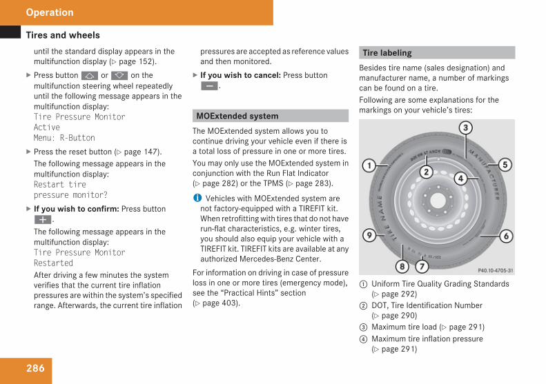
Tires and wheels
286
until the standard display appears in themultifunction display (Y page 152).
X Press button j or k on themultifunction steering wheel repeatedlyuntil the following message appears in themultifunction display:Tire Pressure MonitorActiveMenu: R-Button
X Press the reset button (Y page 147).The following message appears in themultifunction display:Restart tirepressure monitor?
X If you wish to confirm: Press buttonæ.The following message appears in themultifunction display:Tire Pressure MonitorRestartedAfter driving a few minutes the systemverifies that the current tire inflationpressures are within the system’s specifiedrange. Afterwards, the current tire inflation
pressures are accepted as reference valuesand then monitored.
X If you wish to cancel: Press buttonç.
MOExtended systemThe MOExtended system allows you tocontinue driving your vehicle even if there isa total loss of pressure in one or more tires.You may only use the MOExtended system inconjunction with the Run Flat Indicator(Y page 282) or the TPMS (Y page 283).
i Vehicles with MOExtended system arenot factory-equipped with a TIREFIT kit.When retrofitting with tires that do not haverun-flat characteristics, e.g. winter tires,you should also equip your vehicle with aTIREFIT kit. TIREFIT kits are available at anyauthorized Mercedes-Benz Center.
For information on driving in case of pressureloss in one or more tires (emergency mode),see the “Practical Hints” section(Y page 403).
Tire labelingBesides tire name (sales designation) andmanufacturer name, a number of markingscan be found on a tire.Following are some explanations for themarkings on your vehicle’s tires:
1 Uniform Tire Quality Grading Standards(Y page 292)
2 DOT, Tire Identification Number(Y page 290)
3 Maximum tire load (Y page 291)4 Maximum tire inflation pressure
(Y page 291)
Operation
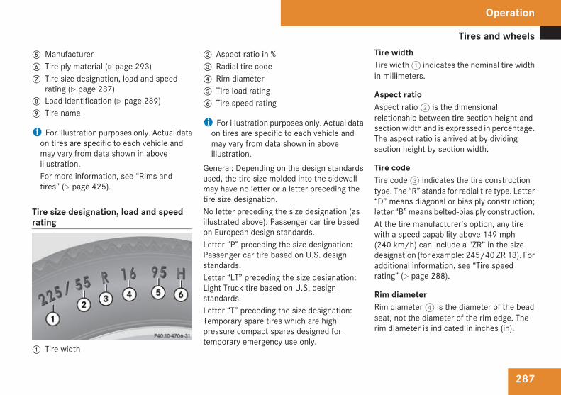
Tires and wheels
287
5 Manufacturer6 Tire ply material (Y page 293)7 Tire size designation, load and speed
rating (Y page 287)8 Load identification (Y page 289)9 Tire name
i For illustration purposes only. Actual dataon tires are specific to each vehicle andmay vary from data shown in aboveillustration.For more information, see “Rims andtires” (Y page 425).
Tire size designation, load and speedrating
1 Tire width
2 Aspect ratio in %3 Radial tire code4 Rim diameter5 Tire load rating6 Tire speed rating
i For illustration purposes only. Actual dataon tires are specific to each vehicle andmay vary from data shown in aboveillustration.
General: Depending on the design standardsused, the tire size molded into the sidewallmay have no letter or a letter preceding thetire size designation.No letter preceding the size designation (asillustrated above): Passenger car tire basedon European design standards.Letter “P” preceding the size designation:Passenger car tire based on U.S. designstandards.Letter “LT” preceding the size designation:Light Truck tire based on U.S. designstandards.Letter “T” preceding the size designation:Temporary spare tires which are highpressure compact spares designed fortemporary emergency use only.
Tire widthTire width 1 indicates the nominal tire widthin millimeters.
Aspect ratioAspect ratio 2 is the dimensionalrelationship between tire section height andsection width and is expressed in percentage.The aspect ratio is arrived at by dividingsection height by section width.
Tire codeTire code 3 indicates the tire constructiontype. The “R” stands for radial tire type. Letter“D” means diagonal or bias ply construction;letter “B” means belted-bias ply construction.At the tire manufacturer’s option, any tirewith a speed capability above 149 mph(240 km/h) can include a “ZR” in the sizedesignation (for example: 245/40 ZR 18). Foradditional information, see “Tire speedrating” (Y page 288).
Rim diameterRim diameter 4 is the diameter of the beadseat, not the diameter of the rim edge. Therim diameter is indicated in inches (in).
Operation
Z
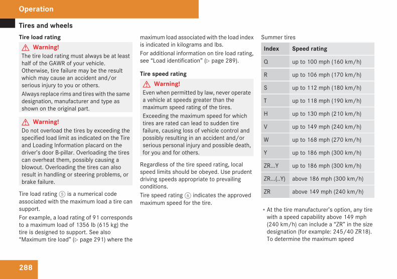
Tires and wheels
288
Tire load ratingG Warning!The tire load rating must always be at leasthalf of the GAWR of your vehicle.Otherwise, tire failure may be the resultwhich may cause an accident and/orserious injury to you or others.Always replace rims and tires with the samedesignation, manufacturer and type asshown on the original part.
G Warning!Do not overload the tires by exceeding thespecified load limit as indicated on the Tireand Loading Information placard on thedriver’s door B-pillar. Overloading the tirescan overheat them, possibly causing ablowout. Overloading the tires can alsoresult in handling or steering problems, orbrake failure.
Tire load rating 5 is a numerical codeassociated with the maximum load a tire cansupport.For example, a load rating of 91 correspondsto a maximum load of 1356 lb (615 kg) thetire is designed to support. See also“Maximum tire load” (Y page 291) where the
maximum load associated with the load indexis indicated in kilograms and lbs.For additional information on tire load rating,see “Load identification” (Y page 289).
Tire speed ratingG Warning!Even when permitted by law, never operatea vehicle at speeds greater than themaximum speed rating of the tires.Exceeding the maximum speed for whichtires are rated can lead to sudden tirefailure, causing loss of vehicle control andpossibly resulting in an accident and/orserious personal injury and possible death,for you and for others.
Regardless of the tire speed rating, localspeed limits should be obeyed. Use prudentdriving speeds appropriate to prevailingconditions.Tire speed rating 6 indicates the approvedmaximum speed for the tire.
Summer tires
Index Speed rating
Q up to 100 mph (160 km/h)
R up to 106 mph (170 km/h)
S up to 112 mph (180 km/h)
T up to 118 mph (190 km/h)
H up to 130 mph (210 km/h)
V up to 149 mph (240 km/h)
W up to 168 mph (270 km/h)
Y up to 186 mph (300 km/h)
ZR...Y up to 186 mph (300 km/h)
ZR...(..Y) above 186 mph (300 km/h)
ZR above 149 mph (240 km/h)
RAt the tire manufacturer’s option, any tirewith a speed capability above 149 mph(240 km/h) can include a “ZR” in the sizedesignation (for example: 245/40 ZR18).To determine the maximum speed
Operation
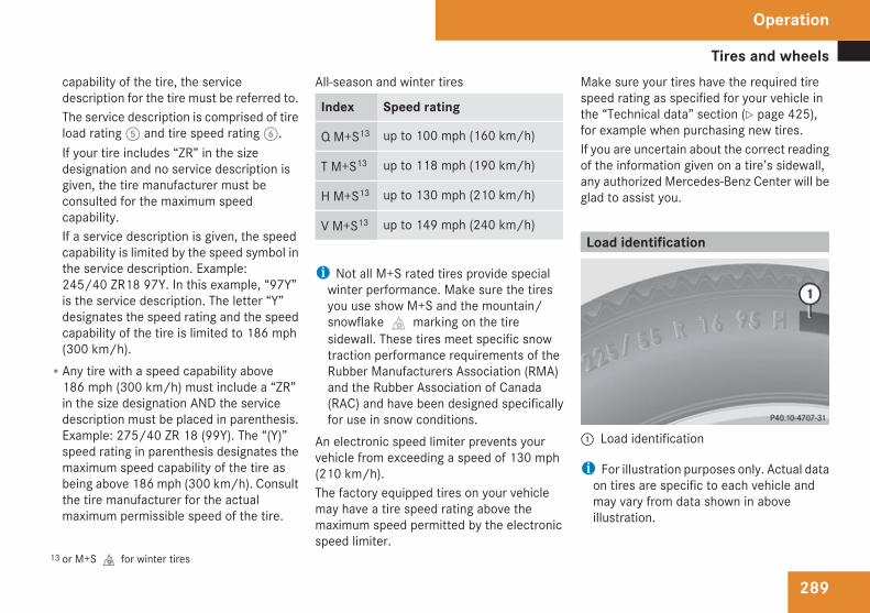
Tires and wheels
289
capability of the tire, the servicedescription for the tire must be referred to.The service description is comprised of tireload rating 5 and tire speed rating 6.If your tire includes “ZR” in the sizedesignation and no service description isgiven, the tire manufacturer must beconsulted for the maximum speedcapability.If a service description is given, the speedcapability is limited by the speed symbol inthe service description. Example:245/40 ZR18 97Y. In this example, “97Y”is the service description. The letter “Y”designates the speed rating and the speedcapability of the tire is limited to 186 mph(300 km/h).RAny tire with a speed capability above
186 mph (300 km/h) must include a “ZR”in the size designation AND the servicedescription must be placed in parenthesis.Example: 275/40 ZR 18 (99Y). The “(Y)”speed rating in parenthesis designates themaximum speed capability of the tire asbeing above 186 mph (300 km/h). Consultthe tire manufacturer for the actualmaximum permissible speed of the tire.
All-season and winter tires
Index Speed rating
Q M+S13 up to 100 mph (160 km/h)
T M+S13 up to 118 mph (190 km/h)
H M+S13 up to 130 mph (210 km/h)
V M+S13 up to 149 mph (240 km/h)
i Not all M+S rated tires provide specialwinter performance. Make sure the tiresyou use show M+S and the mountain/snowflake.marking on the tiresidewall. These tires meet specific snowtraction performance requirements of theRubber Manufacturers Association (RMA)and the Rubber Association of Canada(RAC) and have been designed specificallyfor use in snow conditions.
An electronic speed limiter prevents yourvehicle from exceeding a speed of 130 mph(210 km/h).The factory equipped tires on your vehiclemay have a tire speed rating above themaximum speed permitted by the electronicspeed limiter.
Make sure your tires have the required tirespeed rating as specified for your vehicle inthe “Technical data” section (Y page 425),for example when purchasing new tires.If you are uncertain about the correct readingof the information given on a tire’s sidewall,any authorized Mercedes-Benz Center will beglad to assist you.
Load identification
1 Load identification
i For illustration purposes only. Actual dataon tires are specific to each vehicle andmay vary from data shown in aboveillustration.
13 or M+S.for winter tires
Operation
Z
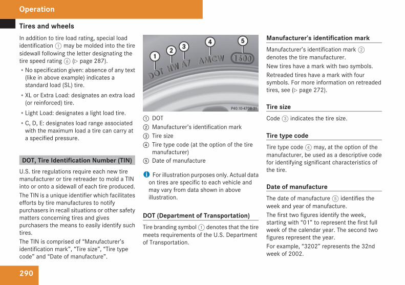
Tires and wheels
290
In addition to tire load rating, special loadidentification 1 may be molded into the tiresidewall following the letter designating thetire speed rating 6 (Y page 287).RNo specification given: absence of any text
(like in above example) indicates astandard load (SL) tire.RXL or Extra Load: designates an extra load
(or reinforced) tire.RLight Load: designates a light load tire.RC, D, E: designates load range associated
with the maximum load a tire can carry ata specified pressure.
DOT, Tire Identification Number (TIN)U.S. tire regulations require each new tiremanufacturer or tire retreader to mold a TINinto or onto a sidewall of each tire produced.The TIN is a unique identifier which facilitatesefforts by tire manufactures to notifypurchasers in recall situations or other safetymatters concerning tires and givespurchasers the means to easily identify suchtires.The TIN is comprised of “Manufacturer’sidentification mark”, “Tire size”, “Tire typecode” and “Date of manufacture”.
1 DOT2 Manufacturer’s identification mark3 Tire size4 Tire type code (at the option of the tire
manufacturer)5 Date of manufacture
i For illustration purposes only. Actual dataon tires are specific to each vehicle andmay vary from data shown in aboveillustration.
DOT (Department of Transportation)Tire branding symbol 1 denotes that the tiremeets requirements of the U.S. Departmentof Transportation.
Manufacturer’s identification markManufacturer’s identification mark 2denotes the tire manufacturer.New tires have a mark with two symbols.Retreaded tires have a mark with foursymbols. For more information on retreadedtires, see (Y page 272).
Tire sizeCode 3 indicates the tire size.
Tire type codeTire type code 4 may, at the option of themanufacturer, be used as a descriptive codefor identifying significant characteristics ofthe tire.
Date of manufactureThe date of manufacture 5 identifies theweek and year of manufacture.The first two figures identify the week,starting with “01” to represent the first fullweek of the calendar year. The second twofigures represent the year.For example, “3202” represents the 32ndweek of 2002.
Operation
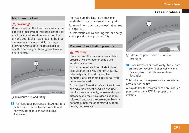
Tires and wheels
291
Maximum tire load
G Warning!Do not overload the tires by exceeding thespecified load limit as indicated on the Tireand Loading Information placard on thedriver’s door B-pillar. Overloading the tirescan overheat them, possibly causing ablowout. Overloading the tires can alsoresult in handling or steering problems, orbrake failure.
1 Maximum tire load rating
i For illustration purposes only. Actual dataon tires are specific to each vehicle andmay vary from data shown in aboveillustration.
The maximum tire load is the maximumweight the tires are designed to support.For more information on tire load rating, see(Y page 288).For information on calculating total and cargoload capacities, see (Y page 277).
Maximum tire inflation pressure
G Warning!Never exceed the maximum tire inflationpressure. Follow recommended tireinflation pressures.Do not underinflate tires. Underinflatedtires wear excessively and/or unevenly,adversely affect handling and fueleconomy, and are more likely to fail frombeing overheated.Do not overinflate tires. Overinflated tirescan adversely affect handling and ridecomfort, wear unevenly, increase stoppingdistance, and result in sudden deflation(blowout) because they are more likely tobecome punctured or damaged by roaddebris, potholes etc.
1 Maximum permissible tire inflationpressure
i For illustration purposes only. Actual dataon tires are specific to each vehicle andmay vary from data shown in aboveillustration.
This is the maximum permissible tire inflationpressure for the tire.Always follow the recommended tire inflationpressure (Y page 279) for proper tireinflation.
Operation
Z
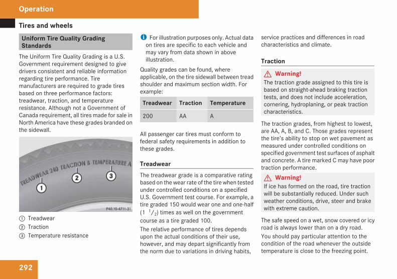
Tires and wheels
292
Uniform Tire Quality GradingStandards
The Uniform Tire Quality Grading is a U.S.Government requirement designed to givedrivers consistent and reliable informationregarding tire performance. Tiremanufacturers are required to grade tiresbased on three performance factors:treadwear, traction, and temperatureresistance. Although not a Government ofCanada requirement, all tires made for sale inNorth America have these grades branded onthe sidewall.
1 Treadwear2 Traction3 Temperature resistance
i For illustration purposes only. Actual dataon tires are specific to each vehicle andmay vary from data shown in aboveillustration.
Quality grades can be found, whereapplicable, on the tire sidewall between treadshoulder and maximum section width. Forexample:
Treadwear Traction Temperature
200 AA A
All passenger car tires must conform tofederal safety requirements in addition tothese grades.
TreadwearThe treadwear grade is a comparative ratingbased on the wear rate of the tire when testedunder controlled conditions on a specifiedU.S. Government test course. For example, atire graded 150 would wear one and one-half(1 1/2) times as well on the governmentcourse as a tire graded 100.The relative performance of tires dependsupon the actual conditions of their use,however, and may depart significantly fromthe norm due to variations in driving habits,
service practices and differences in roadcharacteristics and climate.
Traction
G Warning!The traction grade assigned to this tire isbased on straight-ahead braking tractiontests, and does not include acceleration,cornering, hydroplaning, or peak tractioncharacteristics.
The traction grades, from highest to lowest,are AA, A, B, and C. Those grades representthe tire’s ability to stop on wet pavement asmeasured under controlled conditions onspecified government test surfaces of asphaltand concrete. A tire marked C may have poortraction performance.G Warning!If ice has formed on the road, tire tractionwill be substantially reduced. Under suchweather conditions, drive, steer and brakewith extreme caution.
The safe speed on a wet, snow covered or icyroad is always lower than on a dry road.You should pay particular attention to thecondition of the road whenever the outsidetemperature is close to the freezing point.
Operation
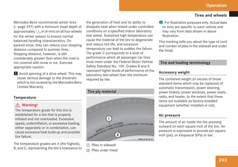
Tires and wheels
293
Mercedes-Benz recommends winter tires(Y page 297) with a minimum tread depth ofapproximately 1/6 in (4 mm) on all four wheelsfor the winter season to ensure normalbalanced handling characteristics. Onpacked snow, they can reduce your stoppingdistance compared to summer tires.Stopping distance, however, is stillconsiderably greater than when the road isnot covered with snow or ice. Exerciseappropriate caution.
! Avoid spinning of a drive wheel. This maycause serious damage to the drivetrainwhich is not covered by the Mercedes-BenzLimited Warranty.
Temperature
G Warning!The temperature grade for this tire isestablished for a tire that is properlyinflated and not overloaded. Excessivespeed, underinflation, or excessive loading,either separately or in combination, cancause excessive heat build-up and possibletire failure.
The temperature grades are A (the highest),B, and C, representing the tire’s resistance to
the generation of heat and its ability todissipate heat when tested under controlledconditions on a specified indoor laboratorytest wheel. Sustained high temperature cancause the material of the tire to degenerateand reduce tire life, and excessivetemperature can lead to sudden tire failure.The grade C corresponds to a level ofperformance which all passenger car tiresmust meet under the Federal Motor VehicleSafety Standard No. 109. Grades B and Arepresent higher levels of performance on thelaboratory test wheel than the minimumrequired by law.
Tire ply material
1 Plies in sidewall2 Plies under tread
i For illustration purposes only. Actual dataon tires are specific to each vehicle andmay vary from data shown in aboveillustration.
This marking tells you about the type of cordand number of plies in the sidewall and underthe tread.
Tire and loading terminology
Accessory weightThe combined weight (in excess of thosestandard items which may be replaced) ofautomatic transmission, power steering,power brakes, power windows, power seats,radio, and heater, to the extent that theseitems are available as factory-installedequipment (whether installed or not).
Air pressureThe amount of air inside the tire pressingoutward on each square inch of the tire. Airpressure is expressed in pounds per squareinch (psi), or kilopascal (kPa) or bar.
Operation
Z
Tires and wheels
294
Aspect ratioDimensional relationship between tiresection height and section width expressedin percentage.
BarAnother metric unit for air pressure. There are14.5038 pounds per square inch (psi) to1 bar; there are 100 kilopascals (kPa) to 1 bar.
BeadThe tire bead contains steel wires wrapped bysteel cords that hold the tire onto the rim.
Cold tire inflation pressureTire inflation pressure when your vehicle hasbeen sitting for at least 3 hours or driven nomore than 1 mile (1.6 km).
Curb weightThe weight of a motor vehicle with standardequipment including the maximum capacityof fuel, oil, and coolant, and, if so equipped,air conditioning and additional optionalequipment, but without passengers andcargo.
DOT (Department of Transportation)A tire branding symbol which denotes the tiremeets requirements of the U.S. Departmentof Transportation.
GAWR (Gross Axle Weight Rating)The GAWR is the maximum permissible axleweight. The gross vehicle weight on each axlemust never exceed the GAWR for the frontand rear axle indicated on the certificationlabel located on the driver’s door B-pillar.
GTW (Gross Trailer Weight)The GTW is the weight of the trailer plus theweight of all cargo, equipment, luggage etc.loaded on the trailer.
GVW (Gross Vehicle Weight)The GVW comprises the weight of the vehicleincluding fuel, tools, spare wheel, installedaccessories, passengers and cargo and, ifapplicable, trailer tongue load. The GVW mustnever exceed the GVWR indicated on thecertification label located on the driver’s doorB-pillar.
GVWR (Gross Vehicle Weight Rating)This is the maximum permissible vehicleweight of the fully loaded vehicle (weight ofthe vehicle including all options, passengers,fuel, and cargo and, if applicable, trailertongue load). It is indicated on certificationlabel located on the driver’s door B-pillar.
Kilopascal (kPa)The metric unit for air pressure. There are6.9 kPa to 1 psi; another metric unit for airpressure is bar. There are 100 kilopascals(kPa) to 1 bar.
Maximum load ratingThe maximum load in kilograms and poundsthat can be carried by the tire.
Maximum loaded vehicle weightThe sum of curb weight, accessory weight,total load limit, and production optionsweight.
Operation
Tires and wheels
295
Maximum permissible tire inflationpressureThis number is the greatest amount of airpressure that should ever be put in the tire.
Normal occupant weightThe number of occupants the vehicle isdesigned to seat, multiplied by 68 kilograms(150 lb).
Occupant distributionThe distribution of occupants in a vehicle attheir designated seating positions.
Production options weightThe combined weight of those installedregular production options weighing over5 lbs (2.3 kilograms) in excess of thosestandard items which they replace, notpreviously considered in curb weight oraccessory weight, including heavy dutybrakes, ride levelers, roof rack, heavy dutybattery, and special trim.
PSI (Pounds per square inch)A standard unit of measure for air pressure.
Recommended tire inflation pressureThe recommended tire inflation pressure fornormal driving conditions is listed on the Tireand Loading Information placard located onthe driver’s door B-pillar and provides besthandling, tread life and riding comfort. If soequipped, supplemental informationpertaining to special driving situations can befound on the tire inflation pressure label onthe inside of the fuel filler flap.
RimA metal support for a tire or a tire and tubeassembly upon which the tire beads areseated.
SidewallThe portion of a tire between the tread andthe bead.
TIN (Tire Identification Number)Unique identifier which facilitates efforts bytire manufacturers to notify purchasers in
recall situations or other safety mattersconcerning tires and gives purchasers themeans to easily identify such tires. The TIN iscomprised of “Manufacturer’s identificationmark”, “Tire size”, “Tire type code” and “Dateof manufacture”.
Tire load ratingNumerical code associated with themaximum load a tire can support.
Tire ply composition and material usedThis indicates the number of plies or thenumber of layers of rubber-coated fabric inthe tire tread and sidewall. Tiremanufacturers also must indicate the plymaterials in the tire and sidewall, whichinclude steel, nylon, polyester, and others.
Tire speed ratingPart of tire designation; indicates the speedrange for which a tire is approved.
Total load limitRated cargo and luggage load plus68 kilograms (150 lb) times the vehicle’sdesignated seating capacity.
Operation
Z
Tires and wheels
296
TractionForce exerted by the vehicle on the road viathe tires. The amount of grip provided.
TreadThe portion of a tire that comes into contactwith the road.
Treadwear indicatorsNarrow bands, sometimes called “wear bars”that show across the tread of a tire when only1/16 in (1.6 mm) of tread remains.
TWR (Tongue Weight Rating)Maximum permissible weight on trailertongue.
Uniform Tire Quality Grading StandardsA tire information system that providesconsumers with ratings for a tire’s traction,temperature and treadwear. Ratings aredetermined by tire manufacturers using U.S.government testing procedures. The ratingsare molded into the sidewall of the tire.
Vehicle maximum load on the tireLoad on an individual tire that is determinedby distributing to each axle its share of themaximum loaded vehicle weight and dividingit by two.
Rotating tires
G Warning!Rotate front and rear wheels only if the tiresare of the same dimension.If your vehicle is equipped with mixed-sizetires (different tire dimensions front vs.rear), tire rotation is not possible.
G Warning!Have the tightening torque checked afterchanging a wheel. The wheels could comeloose if they are not tightened to a torqueof 110 lb-ft (150 Nm).Only use genuine Mercedes-Benz wheelbolts specified for your vehicle’s rims.
Tire rotation can be performed on vehicleswith tires of the same dimension all around.If your vehicle is equipped with tires of thesame dimension all around, tires can berotated, observing a front-to-rear rotationpattern that will maintain the intended
rotation (spinning) direction of the tire(Y page 275).In some cases, such as when your vehicle isequipped with mixed-size tires (different tiredimension front vs. rear), tire rotation is notpossible.If applicable to your vehicle’s tireconfiguration, tires can be rotated accordingto the tire manufacturer’s recommendedintervals in the tire manufacturer’s warrantypamphlet located in your vehicle literatureportfolio. If none is available, tires should berotated every 3 000 to 6 000 miles (5 000 to10 000 km), or sooner if necessary, accordingto the degree of tire wear. The same rotation(spinning) direction must be maintained.Rotate tires before the characteristic tirewear pattern becomes visible (shoulder wearon front tires and tread center wear on reartires).Thoroughly clean the mounting face of wheelsand brake disks, i.e. the inner side of thewheels/tires, during each rotation. Check forand ensure proper tire inflation pressure.For information on wheel change, see “Flattire” (Y page 397).
Operation
Winter driving
297
Winter driving
General informationHave your vehicle winterized at an authorizedMercedes-Benz Center.
Winter tires
G Warning!Winter tires with a tread depth of less than1/6 in (4 mm) must be replaced. They areno longer suitable for winter operation.
G Warning!If you use your spare wheel when wintertires are fitted on the other wheels, beaware that the difference in tirecharacteristics may very well impair turningstability and that overall driving stabilitymay be reduced. Adapt your driving styleaccordingly.Have the spare wheel replaced by regularroad wheel with a winter tire at the nearestauthorized Mercedes-Benz Center.
Always use winter tires at temperaturesbelow 45‡ (7†) and whenever wintry roadconditions prevail. Not all M+S rated tiresprovide special winter performance. Make
sure the tires you use show the mountain/snowflake.marking on the tire sidewall.These tires meet specific snow tractionperformance requirements of the RubberManufacturers Association (RMA) and theRubber Association of Canada (RAC) andhave been designed specifically for use insnow conditions. Use of winter tires is theonly way to achieve the maximumeffectiveness of your vehicle’s driving safetysystems such as the ABS and the ESP® inwinter operation.For safe handling, make sure all mountedwinter tires are of the same make and havethe same tread design.For information on winter tires for yourvehicle model, see the “Technical data”section (Y page 425).Always observe the speed rating of the wintertires installed on your vehicle. If the maximumspeed for which your tires are rated is belowthe speed rating of your vehicle, you mustplace a notice to this effect where it will beseen by the driver. Such notices are availableat your tire dealer or any authorizedMercedes-Benz Center.
Snow chains! Vehicles with Adaptive Damping System
(ADS):When driving with snow chains, do notselect SPORT mode as this may result indamage to your vehicle.
! Some tire sizes do not leave adequateclearance for snow chains. To help avoidserious damage to your vehicle or tires,make sure the use of snow chains ispermissible as specified in the “Technicaldata” section of this Operator’s Manual.
Snow chains should only be driven on snow-covered roads at speeds not to exceed30 mph (50 km/h). Remove chains as soonas possible when driving on roads withoutsnow.Observe the following guidelines when usingsnow chains:RUse of snow chains is not permissible with
all wheel/tire combinations (Y page 425).RUse snow chains in pairs and on rear
wheels only. Follow the manufacturer’smounting instructions.
! If snow chains are mounted to the frontwheels, they may scrape against the body
Operation
Z
Winter driving
298
or axle components. The tires or the vehiclecould be damaged as a result.ROnly use snow chains that are approved by
Mercedes-Benz. Any authorized Mercedes-Benz Center will be glad to advise you onthis subject.RUse of snow chains may be prohibited
depending on location. Always check localand state laws before installing snowchains.RDo not use snow chains on the spare wheel.
i When driving with snow chains, you maywish to switch off the ESP® (Y page 77)before setting the vehicle in motion. Thiswill improve the vehicle’s traction.
Winter driving instructions
G Warning!If the vehicle becomes stuck in snow, makesure snow is kept clear of the exhaust pipeand from around the vehicle with the enginerunning. Otherwise, deadly carbonmonoxide (CO) gases may enter vehicleinterior resulting in unconsciousness anddeath.To assure sufficient fresh air ventilation,open a window slightly on the side of thevehicle not facing the wind.
G Warning!The outside temperature indicator is notdesigned to serve as an ice-warning deviceand is therefore unsuitable for thatpurpose.Indicated temperatures just above thefreezing point do not guarantee that theroad surface is free of ice. The road may stillbe icy, especially in wooded areas or onbridges.
G Warning!On slippery road surfaces, never downshiftin order to obtain braking action. This couldresult in drive wheel slip and reduced
vehicle control. Your vehicle’s ABS will notprevent this type of control loss.Do not engage the transfer case in positionLOW when driving on ice or packed snow.At speeds below 18 mph (30 km/h) vehiclesteering is adversely affected by the Off-road ABS.
The most important rule for slippery or icyroads is to drive sensibly and to avoid abruptacceleration, braking and steeringmaneuvers. Do not use the cruise controlsystem under such conditions.When the vehicle is in danger of skidding, shiftthe automatic transmission to neutralposition N. Try to keep the vehicle undercontrol by corrective steering action.
i For information on driving with snowchains, see “Snow chains” (Y page 297).
Road salts and chemicals can adverselyaffect braking efficiency. Increased pedalforce may become necessary to produce thenormal brake effect.Depressing the brake pedal periodically whentraveling at length on salt-strewn roads canbring road-salt-impaired braking efficiencyback to normal.If the vehicle is parked after being driven onsalt-treated roads, the braking efficiency
Operation
Driving instructions
299
should be tested as soon as possible afterdriving is resumed.G Warning!Make sure not to endanger any other roadusers when carrying out these brakingmaneuvers.
Driving instructions
Drive sensibly – save fuelTo save fuel you should:RKeep tires at the recommended inflation
pressures.RRemove unnecessary loads.RRemove carriers when not in use.RRemove the crossbars when not in use.RAllow engine to warm up under low load
use.RAvoid frequent acceleration and
deceleration.RHave all maintenance work performed at
the intervals specified in the MaintenanceBooklet and as required by theMaintenance system. Contact anauthorized Mercedes-Benz Center.
Fuel consumption is also increased by drivingin cold weather, in stop-and-go traffic, onshort trips and in mountainous areas.
Drinking and driving
G Warning!Drinking and driving and/or taking drugsand driving are very dangerouscombinations. Even a small amount ofalcohol or drugs can affect your reflexes,perceptions and judgment.The possibility of a serious or even fatalaccident are greatly increased when youdrink or take drugs and drive.Do not drink or take drugs and drive or allowanyone to drive who has been drinking ortaking drugs.
Pedals
G Warning!Make sure absolutely no objects areobstructing the pedals’ range of movement.Keep the driver’s footwell clear of allobstacles. If there are any floormats orcarpets in the footwell, make sure that thepedals still have sufficient clearance.During sudden driving or brakingmaneuvers, the objects could get caughtbetween the pedals. You could then no
Operation
Z
Driving instructions
300
longer brake or accelerate. This could leadto accidents and injury.
Power assistance
G Warning!There is no power assistance for thesteering and the service brake when theengine is not running.Steering and braking requires significantlymore effort and you could lose control ofthe vehicle and cause an accident as aresult.Do not turn off the engine while the vehicleis in motion.
Brakes
Downhill grades! When driving down long and steep
grades, relieve the load on the brakes byshifting into a lower gear to use theengine’s braking power. This helps preventoverheating of the brakes and reduceswear.When using the engine’s braking power, adrive wheel may not spin for an extendedperiod of time, e.g. on slippery roadsurfaces. This may cause serious damageto the drivetrain which is not covered by theMercedes-Benz Limited Warranty.
Continuous or hard braking
G Warning!Resting your foot on the brake pedal willcause excessive and premature wear of thebrake pads.It can also result in the brakes overheating,thereby significantly reducing theireffectiveness. It may not be possible tostop the vehicle in sufficient time to avoidan accident.
After hard braking, it is advisable to drive onfor some time, rather than immediately park,so that the air stream will cool down thebrakes faster.
Wet roads
G Warning!After driving in heavy rain for some timewithout applying the brakes or throughwater deep enough to wet brakecomponents, the first braking action maybe somewhat reduced and increased pedalpressure may be necessary to obtainexpected brake effect. Maintain a safedistance from vehicles in front.
To help prevent brake disk corrosion afterdriving on wet or salt-covered roads, it isadvisable to brake the vehicle withconsiderable force prior to parking. The heatgenerated serves to dry the brakes.
Salt-covered roads
G Warning!A layer of salt on the brake discs and thebrake linings may cause a delay in thebraking effect, resulting in a significantly
Operation
Driving instructions
301
increased braking distance, which couldlead to an accident.To avoid this danger, you should:Roccasionally brake carefully when you
are driving on salt-covered roads, so thatany layer of salt that may have built upon the brake discs and the brake liningsis removed without putting other roadusers at riskRmaintain a greater distance to the vehicle
ahead and drive with particular careRcarefully apply the brakes at the end of a
trip and immediately after commencing anew trip, so that salt residues areremoved from the brake disc
Brake service! The brake fluid level in the reservoir may
be too low if the brake warning lamp in theinstrument cluster comes on and anacoustic warning sounds although theparking brake is released. Observeadditional messages in the multifunctiondisplay that may appear.
Brake pad wear or a leak in the system maybe the reason for low brake fluid in thereservoir.Have the brake system inspectedimmediately. Contact an authorizedMercedes-Benz Center.
All checks and service work on the brakesystem should be carried out by qualifiedtechnicians only. Contact an authorizedMercedes-Benz Center.Only install brake pads and use brake fluidrecommended by Mercedes-Benz.G Warning!If other than recommended brake pads areinstalled, or other than recommendedbrake fluid is used, the braking propertiesof the vehicle can be degraded to an extentthat safe braking is substantially impaired.This could result in an accident.
! Only conduct operational or performancetests on a two-axle dynamometer. If suchtests are necessary, contact an authorizedMercedes-Benz Center. You couldotherwise seriously damage the brakesystem or the transfer case which is notcovered by the Mercedes-Benz LimitedWarranty.
! Because the ESP® operatesautomatically, the engine and ignition mustbe shut off (SmartKey in starter switchposition 0 or 1 or KEYLESS-GO start/stopbutton in position 0 or 1) when the parkingbrake is being tested on a brake testdynamometer. Such testing should be nolonger than 10 seconds.Active braking action through the ESP®
may otherwise seriously damage the brakesystem which is not covered by theMercedes-Benz Limited Warranty.
If your brake system is normally onlysubjected to moderate loads, you shouldoccasionally test the effectiveness of thebrakes by applying above-normal brakingpressure at higher speeds. This will alsoenhance the grip of the brake pads.G Warning!Make sure not to endanger any other roadusers when carrying out these brakingmaneuvers.
Refer to the description of the Brake AssistSystem (BAS) (Y page 77).
Operation
Z
Driving instructions
302
Parking brakeWhen driving on wet roads or dirt coveredsurfaces, road salt and/or dirt can get intothe parking brake.To prevent corrosion and a reduction in thebraking power of the parking brake, observethe following:X From time to time, lightly engage the
parking brake before driving off.X Drive a distance of approximately 110 yds
(100 m) at a maximum speed of 12 mph(20 km/h).
G Warning!While performing this procedure pleaseassure that the vehicle is stopped beforeapplying the parking brake. Otherwise therear wheels could lock up. You could losecontrol of the vehicle and cause anaccident. In addition, the vehicle’s brakelights do not light up when the parkingbrake is engaged. Make sure not toendanger any other road users when youengage the parking brake.
Driving offWarm up the engine smoothly. Do not placefull load on the engine until the operatingtemperature has been reached.
! When driving off on a slippery surface, donot allow a drive wheel to spin for anextended period with the ESP® switchedoff. Doing so may cause serious damage tothe drivetrain which is not covered by theMercedes-Benz Limited Warranty.
! Simultaneously depressing theaccelerator pedal and applying the brakesreduces engine performance and causespremature brake and drivetrain wear whichis not covered by the Mercedes-BenzLimited Warranty.
HydroplaningDepending on the depth of the water layer onthe road, hydroplaning may occur, even at lowspeeds and with new tires.X Reduce vehicle speed.X Avoid track grooves in the road.X Brakes cautiously in the rain.
Standing water! Do not drive through flooded areas.
Before driving through water, determine itsdepth.If you must drive through standing water,drive slowly to prevent water from enteringthe passenger compartment or the enginecompartment. Water in these areas couldcause damage to electrical components orwiring of the engine or transmission, orcould result in water being ingested by theengine through the air intake causingsevere internal engine damage. Any suchdamage is not covered by the Mercedes-Benz Limited Warranty.
i Select the raised level (Y page 186)before driving through standing water.
Operation
Driving instructions
303
For more information, see “Driving throughwater” (Y page 306).
Off-road driving
G Warning!Do not load items on the crossbars. It maycause instability during some maneuverswhich could result in an accident.Drive slowly in unknown terrain. This willmake it easier to recognize unexpectedobstacles and avoid damage to the vehicle.To help avoid the vehicle rolling over, neverturn it around on steep inclines. If thevehicle cannot complete the attemptedclimb, back it down in reverse gear.Do not drive along the side of a slope. Thevehicle might otherwise rollover. If in doingso the vehicle begins to show a tendencyto roll, immediately steer into a line ofgravity (straight up or downhill).Never let the vehicle roll backwards in idle.You may lose control of the vehicle if youuse only the service brake. For informationon driving downhill, see “Driving downhill”.
G Warning!Sand, dirt, mud and other material havingfriction property can cause exceptionalwear and tear as well as brake failure.Have the brakes checked for dirt build-upand cleaned. There is otherwise a risk thatfull braking power may not be available inan emergency.
G Warning!Please be aware that by raising the vehiclelevel, the center of gravity also rises.Therefore, always ensure that the vehiclelevel is as low as possible. With higher rideheight the ESP® may activate earlier incertain situations.
Read this chapter carefully before you beginoff-road travel.Familiarize yourself with the vehiclecharacteristics and gear changing before youattempt any difficult terrain off-road driving.We recommend that you start out with easyoff-road travel.
Special driving features for off-roaddrivingThe following driving features are available forspecific kind of operation:ROff-road ABS (Y page 77)ROff-road ESP® (Y page 80)ROff-road 4-ETS (Y page 78)RHill start assist system (Y page 139)RLOW RANGE mode (Y page 142)RDifferential locks (Y page 144)RDownhill Speed Regulation (DSR)
(Y page 182)ROff-road driving program (Vehicles without
enhanced off-road package) (Y page 185)RAir suspension program (Y page 185)
Off-road driving rulesREngage the off-road driving program
(Y page 185) or LOW RANGE mode(Y page 142) before driving under off-roadconditions.RIf necessary, activate differential locks
(Y page 144).
Operation
Z
Driving instructions
304
RMake sure you select a vehicle level(Y page 186) appropriate to thetopographical conditions. Always makesure the vehicle has enough groundclearance.RFasten items being carried as securely as
possible (Y page 227).RAlways navigate gradients with the engine
on and with the transmission engaged in agear. Switch on the DSR (Y page 182) tohelp maintain a preset speed.
! Observe the following during off-roaddriving:RKeep doors, tailgate, windows, and tilt/
sliding sunroof closed whenever drivingoff-road.RAdjust vehicle speed to condition of
terrain. The more uneven, rutty andsteeper the terrain, the lower the speedshould be. Drive through water slowly atan even speed, avoiding a bow wave.RBe especially careful when driving in
unknown territory. It may be necessaryto get out of the vehicle and scout thepath you intend to take.
RWatch out for obstacles, such as rocks,holes, tree stumps and ruts.RBefore driving through water, determine
its depth.RDo not stop vehicle while immersed in
water, and do not shut off the engine.RIn sandy soil, drive at a steady speed as
allowed by conditions. This helpsovercome the vehicle rolling resistanceand reduces the likelihood of the vehiclesinking into the ground.RDo not initiate jumps with the vehicle. It
interrupts the forward momentum of thevehicle.RAlways drive onto slopes with the engine
running and the vehicle in gear.RDo not shift automatic transmission into
neutral position N.
G Warning!Do not reduce the tire inflation pressurebefore driving through sand. However, ifyou do so, remember to correct the tireinflation pressure before continuing yourtrip. Driving with reduced tire inflationpressure increases the risk of losing controlof the vehicle and rolling over.
Checklist before off-road driving
Engine oil levelRCheck the engine oil level (Y page 269).
Only with a proper oil level can the vehicleobtain a trouble-free oil supply, even onsteep gradients.
! If the engine oil level warning lamp comeson while driving, stop the vehicle in a safelocation or as soon at is safe to do so.Check the engine oil level.The engine oil level warnings should not beignored. Extended driving with the symboldisplayed could result in serious enginedamage that is not covered by theMercedes-Benz Limited Warranty.
TiresRCheck the tread depth and maintain
specified tire inflation pressure (a placardwith the recommended tire inflationpressures is located on the driver’s door B-pillar (Y page 276)).RCheck tires for possible damage and
remove foreign objects.RReplace missing valve caps.
Operation
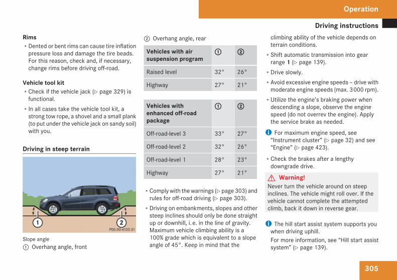
Driving instructions
305
RimsRDented or bent rims can cause tire inflation
pressure loss and damage the tire beads.For this reason, check and, if necessary,change rims before driving off-road.
Vehicle tool kitRCheck if the vehicle jack (Y page 329) is
functional.RIn all cases take the vehicle tool kit, a
strong tow rope, a shovel and a small plank(to put under the vehicle jack on sandy soil)with you.
Driving in steep terrain
Slope angle1 Overhang angle, front
2 Overhang angle, rear
Vehicles with airsuspension program
1 2
Raised level 32° 26°
Highway 27° 21°
Vehicles withenhanced off-roadpackage
1 2
Off-road-level 3 33° 27°
Off-road-level 2 32° 26°
Off-road-level 1 28° 23°
Highway 27° 21°
RComply with the warnings (Y page 303) andrules for off-road driving (Y page 303).RDriving on embankments, slopes and other
steep inclines should only be done straightup or downhill, i. e. in the line of gravity.Maximum vehicle climbing ability is a100% grade which is equivalent to a slopeangle of 45°. Keep in mind that the
climbing ability of the vehicle depends onterrain conditions.RShift automatic transmission into gear
range 1 (Y page 139).RDrive slowly.RAvoid excessive engine speeds – drive with
moderate engine speeds (max. 3 000 rpm).RUtilize the engine’s braking power when
descending a slope, observe the enginespeed (do not overrev the engine). Applythe service brake as needed.
i For maximum engine speed, see“Instrument cluster” (Y page 32) and see“Engine” (Y page 423).
RCheck the brakes after a lengthydowngrade drive.
G Warning!Never turn the vehicle around on steepinclines. The vehicle might roll over. If thevehicle cannot complete the attemptedclimb, back it down in reverse gear.
i The hill start assist system supports youwhen driving uphill.For more information, see “Hill start assistsystem” (Y page 139).
Operation
Z
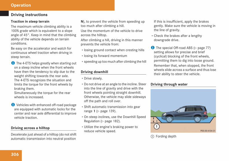
Driving instructions
306
Traction in steep terrainThe maximum vehicle climbing ability is a100% grade which is equivalent to a slopeangle of 45°. Keep in mind that the climbingability of the vehicle depends on terrainconditions.Be easy on the accelerator and watch forcontinuous wheel traction when driving insteep terrain.
i The 4-ETS helps greatly when starting outon a steep incline when the front wheelshave then the tendency to slip due to theweight shifting towards the rear axle.The 4-ETS recognizes the situation andlimits the torque for the front wheels bybraking them.Simultaneously the torque for the rearwheels is increased.
i Vehicles with enhanced off-road packageare equipped with automatic locks for thecenter and rear axle differential to improvevehicle traction.
Driving across a hilltopDecelerate just ahead of a hilltop (do not shiftautomatic transmission into neutral position
N), to prevent the vehicle from speeding uptoo much after climbing a hill.Use the momentum of the vehicle to driveacross the hilltop.After climbing a hill, driving in this mannerprevents the vehicle from:Rlosing ground contact when cresting hillsRlosing its forward momentumRspeeding up too much after climbing the hill
Driving downhillRDrive slowly.RDo not drive at an angle to the incline. Steer
into the line of gravity and drive with thefront wheels pointing straight downhill.Otherwise, the vehicle may slide sidewaysoff the path and roll over.RShift automatic transmission into gear
range 1 (Y page 139).ROn steep inclines, use the Downhill Speed
Regulation (Y page 182).RUtilize the engine’s braking power to
reduce vehicle speed.
If this is insufficient, apply the brakesgently. Make sure the vehicle is moving inthe line of gravity.RCheck the brakes after a lengthy
downgrade drive.
i The special Off-road ABS (Y page 77)setting allows for precise and brief(cyclical) blocking of the front wheels,permitting them to dig into loose ground.Remember that, when stopped, the frontwheels slide across a surface and thus losetheir ability to steer the vehicle.
Driving through water
1 Fording depth
Operation
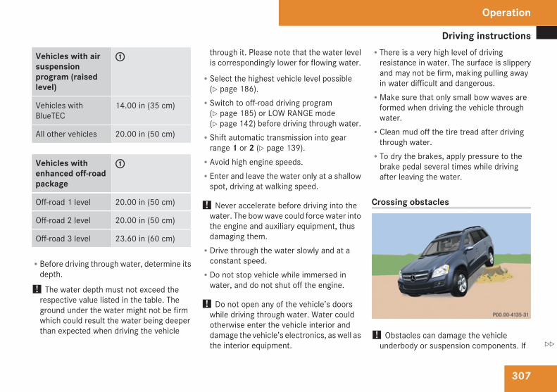
Driving instructions
307
Vehicles with airsuspensionprogram (raisedlevel)
1
Vehicles withBlueTEC
14.00 in (35 cm)
All other vehicles 20.00 in (50 cm)
Vehicles withenhanced off-roadpackage
1
Off-road 1 level 20.00 in (50 cm)
Off-road 2 level 20.00 in (50 cm)
Off-road 3 level 23.60 in (60 cm)
RBefore driving through water, determine itsdepth.
! The water depth must not exceed therespective value listed in the table. Theground under the water might not be firmwhich could result the water being deeperthan expected when driving the vehicle
through it. Please note that the water levelis correspondingly lower for flowing water.
RSelect the highest vehicle level possible(Y page 186).RSwitch to off-road driving program
(Y page 185) or LOW RANGE mode(Y page 142) before driving through water.RShift automatic transmission into gear
range 1 or 2 (Y page 139).RAvoid high engine speeds.REnter and leave the water only at a shallow
spot, driving at walking speed.
! Never accelerate before driving into thewater. The bow wave could force water intothe engine and auxiliary equipment, thusdamaging them.RDrive through the water slowly and at a
constant speed.RDo not stop vehicle while immersed in
water, and do not shut off the engine.
! Do not open any of the vehicle’s doorswhile driving through water. Water couldotherwise enter the vehicle interior anddamage the vehicle’s electronics, as well asthe interior equipment.
RThere is a very high level of drivingresistance in water. The surface is slipperyand may not be firm, making pulling awayin water difficult and dangerous.RMake sure that only small bow waves are
formed when driving the vehicle throughwater.RClean mud off the tire tread after driving
through water.RTo dry the brakes, apply pressure to the
brake pedal several times while drivingafter leaving the water.
Crossing obstacles
! Obstacles can damage the vehicleunderbody or suspension components. If
Operation
Z
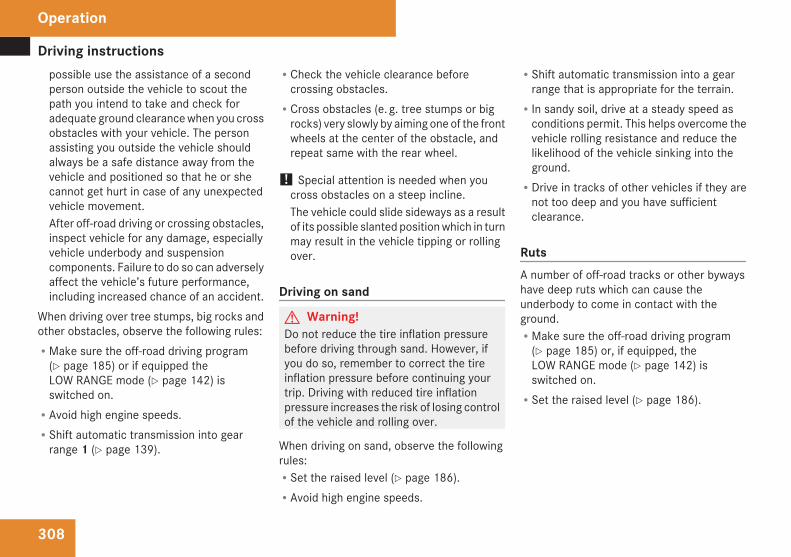
Driving instructions
308
possible use the assistance of a secondperson outside the vehicle to scout thepath you intend to take and check foradequate ground clearance when you crossobstacles with your vehicle. The personassisting you outside the vehicle shouldalways be a safe distance away from thevehicle and positioned so that he or shecannot get hurt in case of any unexpectedvehicle movement.After off-road driving or crossing obstacles,inspect vehicle for any damage, especiallyvehicle underbody and suspensioncomponents. Failure to do so can adverselyaffect the vehicle’s future performance,including increased chance of an accident.
When driving over tree stumps, big rocks andother obstacles, observe the following rules:RMake sure the off-road driving program
(Y page 185) or if equipped theLOW RANGE mode (Y page 142) isswitched on.RAvoid high engine speeds.RShift automatic transmission into gear
range 1 (Y page 139).
RCheck the vehicle clearance beforecrossing obstacles.RCross obstacles (e. g. tree stumps or big
rocks) very slowly by aiming one of the frontwheels at the center of the obstacle, andrepeat same with the rear wheel.
! Special attention is needed when youcross obstacles on a steep incline.The vehicle could slide sideways as a resultof its possible slanted position which in turnmay result in the vehicle tipping or rollingover.
Driving on sand
G Warning!Do not reduce the tire inflation pressurebefore driving through sand. However, ifyou do so, remember to correct the tireinflation pressure before continuing yourtrip. Driving with reduced tire inflationpressure increases the risk of losing controlof the vehicle and rolling over.
When driving on sand, observe the followingrules:RSet the raised level (Y page 186).RAvoid high engine speeds.
RShift automatic transmission into a gearrange that is appropriate for the terrain.RIn sandy soil, drive at a steady speed as
conditions permit. This helps overcome thevehicle rolling resistance and reduce thelikelihood of the vehicle sinking into theground.RDrive in tracks of other vehicles if they are
not too deep and you have sufficientclearance.
RutsA number of off-road tracks or other bywayshave deep ruts which can cause theunderbody to come in contact with theground.RMake sure the off-road driving program
(Y page 185) or, if equipped, theLOW RANGE mode (Y page 142) isswitched on.RSet the raised level (Y page 186).
Operation
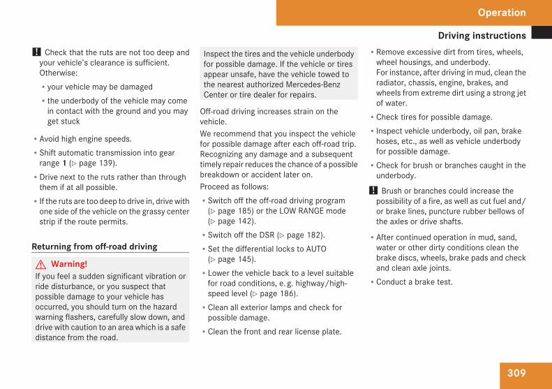
Driving instructions
309
! Check that the ruts are not too deep andyour vehicle’s clearance is sufficient.Otherwise:Ryour vehicle may be damagedRthe underbody of the vehicle may come
in contact with the ground and you mayget stuck
RAvoid high engine speeds.RShift automatic transmission into gear
range 1 (Y page 139).RDrive next to the ruts rather than through
them if at all possible.RIf the ruts are too deep to drive in, drive with
one side of the vehicle on the grassy centerstrip if the route permits.
Returning from off-road driving
G Warning!If you feel a sudden significant vibration orride disturbance, or you suspect thatpossible damage to your vehicle hasoccurred, you should turn on the hazardwarning flashers, carefully slow down, anddrive with caution to an area which is a safedistance from the road.
Inspect the tires and the vehicle underbodyfor possible damage. If the vehicle or tiresappear unsafe, have the vehicle towed tothe nearest authorized Mercedes-BenzCenter or tire dealer for repairs.
Off-road driving increases strain on thevehicle.We recommend that you inspect the vehiclefor possible damage after each off-road trip.Recognizing any damage and a subsequenttimely repair reduces the chance of a possiblebreakdown or accident later on.Proceed as follows:RSwitch off the off-road driving program
(Y page 185) or the LOW RANGE mode(Y page 142).RSwitch off the DSR (Y page 182).RSet the differential locks to AUTO
(Y page 145).RLower the vehicle back to a level suitable
for road conditions, e. g. highway/high-speed level (Y page 186).RClean all exterior lamps and check for
possible damage.RClean the front and rear license plate.
RRemove excessive dirt from tires, wheels,wheel housings, and underbody.For instance, after driving in mud, clean theradiator, chassis, engine, brakes, andwheels from extreme dirt using a strong jetof water.RCheck tires for possible damage.RInspect vehicle underbody, oil pan, brake
hoses, etc., as well as vehicle underbodyfor possible damage.RCheck for brush or branches caught in the
underbody.
! Brush or branches could increase thepossibility of a fire, as well as cut fuel and/or brake lines, puncture rubber bellows ofthe axles or drive shafts.
RAfter continued operation in mud, sand,water or other dirty conditions clean thebrake discs, wheels, brake pads and checkand clean axle joints.RConduct a brake test.
Operation
Z
Driving instructions
310
Trailer towing
G Warning!Failure to use proper equipment and drivingtechnique can result in a loss of vehiclecontrol when towing a trailer.Improper towing or failure to follow theinstructions in this manual can result invehicle damage and/or serious personalinjury. Follow the guidelines below carefullyto assure safe trailer operation.Contact an authorized Mercedes-BenzCenter should you require an explanationof information contained in this manual.
Trailer hitchROnly install a trailer hitch receiver approved
for your vehicle.For information on availability andinstallation, contact an authorizedMercedes-Benz Center.RThe bumpers on your vehicle are not
designed for use with clamp-type hitches.
Do not attach rental hitches or otherbumper-type hitches to them.RTo reduce the possibility of damage,
remove the hitch ball adapter from thereceiver when not in use.
Electrical connectionsThe vehicle is prewired to accept the seven-wire harness included in the Mercedes-Benzapproved trailer hitch receiver kit.
i A four-pole conversion plug is availablefrom your authorized Mercedes-BenzCenter as a spare part.
For further information, contact anauthorized Mercedes-Benz Center.
Vehicle and trailer weights and ratingsThe Gross Trailer Weight (GTW) is the weightof the trailer plus the weight of all cargo,equipment, luggage, etc. loaded on thetrailer. The maximum permissible grosstrailer weight to be towed: 7 500 lb (3 402 kg).Trailer Tongue Weight Rating (TWR) is themaximum permissible weight on the trailertongue: 600 lb (272 kg) limit for Mercedes-Benz approved hitch receiver.
Loading a trailerRWhen loading a trailer, you should observe
that neither the permissible GTW, nor theGross Vehicle Weight Rating (GVWR) areexceeded. The GVWR is indicated on thecertification label located on the driver’sdoor B-pillar (Y page 275).Maximum permissible values are listed onthe safety compliance certification labelsfor the vehicle and for the trailer to betowed.The lowest value listed must be selectedwhen determining how the vehicle andtrailer are loaded.RThe Tongue Weight (TW) at the hitch ball
must be added to the Gross Vehicle Weight(GVW) to prevent exceeding yourMercedes-Benz tow vehicle’s rear GrossAxle Weight Rating (GAWR). The GVW andGAWR are indicated on the certificationlabel located on the driver’s door B-pillar(Y page 275).
i Mercedes-Benz recommend loading thetrailer in such a manner that it has a TWbetween 8 % and 15 % of the GTW.
i Maximum trailer weight ratings arecalculated assuming the vehicle, plus
Operation
Driving instructions
311
driver. The weight of other accessories,passengers and cargo will reduce themaximum trailer weight and TW yourvehicle can tow.
Checking weights of vehicle and trailerRTo assure that the towing vehicle and trailer
are in compliance with the maximumpermissible weight limits, have the loadedrig (towing vehicle including driver,passengers and cargo, trailer fully loaded)weighed on a commercial scale.RCheck the vehicle’s front and rear Gross
Axle Weight (GAW), the Gross TrailerWeight (GTW) and Tongue Weight (TW).The values as measured must not exceedthe weight limits listed under “Vehicle andtrailer weights and ratings” (Y page 310).
Coupling a trailer
G Warning!While you are coupling or decoupling atrailer, make sure nobody locks or unlocksthe vehicle and/or opens or closes doorsor the tailgate.
The vehicle’s level could change and youcould endanger yourself and/or others asa result.Make sure that you do not operate the ADSbutton or the vehicle level control systemwhen coupling/decoupling the trailer.
Observe maximum permitted trailerdimensions (width and length).Most states and all Canadian provincesrequireRsafety chains between the towing vehicle
and the trailerThe chains should be criss-crossed underthe trailer tongue. They must be attachedto the hitch receiver, and not to thevehicle’s bumper or axle.Make sure to leave enough slack in thechains to permit turning corners.Ra separate brake system at various trailer
weightsRa break-away switch on trailers with a
separate brake system.Check with your local state laws for specificrequirements.The switch activates the trailer brakes inthe possible event that the trailer mightseparate from the tow vehicle.
! Do not connect a trailer brake system (iftrailer is so equipped) directly to thevehicle’s hydraulic brake system, as yourvehicle is equipped with antilock brakes. Ifyou do, neither the vehicle’s brakes nor thetrailer’s brakes will function properly.
i The provided vehicle electrical wiringharness for trailer towing has a brake signalwire for hook-up to a brake controller.
X Make sure the automatic transmission is inpark position P (Y page 136).
X Engage the parking brake for the vehicle(Y page 133).
X Start the engine (Y page 128).X Set the vehicle level to highway
(Y page 186).
X Vehicles with ADS:Set the ADS to AUTO or COMF(Y page 185).
X Turn off the engine (Y page 133).X Close all doors and the tailgate.X Attach the trailer.X Plug in all electrical connectors.
Operation
Z
Driving instructions
312
i When you are towing a trailer, the vehiclelevel always remains in the highway setting.The following applies additionally whentowing a trailer:RThe vehicle is lowered to the highway
level when it reaches a speed of 5 mph(8 km/h) if not set to highway level.RThe highspeed level is not available.The restrictions that apply to towing alsoapply when using accessories that areconnected to the trailer power socket, suchas a bicycle rack.
Towing a trailerThere are many different laws, includingspeed limit restrictions, having to do withtrailer towing. Make sure your rig will be legal,not only for where you reside, but also forwhere you will be driving. A good source forthis information can be the police or localauthorities.Note the following, when driving with a trailer:RIn order to gain skill and an understanding
of the vehicle’s behavior, you should
practice turning, stopping and backing upin an area which is free from traffic.RBefore you start driving check the
- trailer hitch- break-away switch- safety chains- electrical connections- lighting- tires
RAdjust the mirrors (Y page 111) to permitunobstructed view beyond rear of trailer.RIf the trailer has electric brakes, start your
vehicle and trailer moving slowly, and thenapply only the trailer brake controller byhand to make sure the brakes are workingproperly.RAlways secure items in the trailer to
prevent load shifts while driving.RWhen towing a trailer, check occasionally
to make sure the load is secure, and thatlighting and trailer brakes (if so equipped)are functioning properly.RTake into consideration that when towing a
trailer, the handling characteristics are
different and less stable from those whenoperating the vehicle without a trailer.It is important to avoid sudden maneuvers.RThe vehicle and trailer combination is
heavier, and therefore is limited inacceleration and climbing ability, andrequires longer stopping distances.It is more prone to reacting to cross windgusts, and requires more sensitive steeringinput.RIf possible, do not brake abruptly, but
rather engage the brake slightly at first topermit the trailer to activate its brake. Thenincrease the braking force.
! If the trailer should begin to sway, reducethe vehicle’s speed immediately.Do not attempt to straighten out the towvehicle and trailer by increasing the speed.
RIf the transmission shifts between gears oninclines repeatedly, shift to a lower gearrange manually (Y page 139). Select 4, 3,2 or 1.A lower gear and reduction of speedreduces the chance of engine overloadingand/or overheating.ROn very steep inclines, not manageable
with automatic transmission in gear range
Operation
Driving instructions
313
1, switch on off-road driving program(Y page 185) or LOW RANGE mode(Y page 142).RWhen going down an incline, shift into a
lower gear and use the engine’s brakingeffect.Avoid riding the brakes, thus overheatingthe vehicle and trailer brakes (if soequipped).RIf the engine coolant rises to an extremely
high temperature when the air conditioningis on, turn off the air conditioning system.Engine coolant heat can be additionallyvented by opening the windows, switchingthe climate control fan speed to high andsetting the temperature control to themaximum.RExtreme care must be exercised since your
vehicle with a trailer will require additionalpassing distance ahead than when drivingwithout a trailer.Because your vehicle and trailer is longerthan your vehicle alone, you will also needto go much farther ahead of the passedvehicle before you can return to your lane.
Decoupling the trailer
G Warning!While you are coupling or decoupling atrailer, make sure nobody locks or unlocksthe vehicle and/or opens or closes doorsor the tailgate.The vehicle’s level could change and youcould endanger yourself and/or others asa result.Make sure that you do not operate the ADSbutton or the vehicle level control systemwhen coupling/decoupling the trailer.
X Make sure the automatic transmission is inpark position P (Y page 136).
X Engage the parking brake for the vehicle(Y page 133).
X Start the engine (Y page 128).X Close all doors and the tailgate.X Engage the parking brake for the trailer.
G Warning!As soon as you disconnect the electricalconnection between the trailer and thevehicle, the vehicle will lower. To help avoidpersonal injury, make sure no one is nearthe wheel housing or underneath the
vehicle before the electrical connection isdisconnected.When you decouple the trailer, the vehicleis temporarily raised because the springsare relieved of load. Be especially carefulduring this process, as you could otherwiseinjure yourself and/or others. Make surethat any persons remaining in the vehicledo not press the switches for vehicle levelcontrol or the ADS.
X Disconnect all electrical plug connectors.X Decouple the trailer.X Make sure that the trailer coupling is free
of load.X Turn off the engine (Y page 133).
Operation
Z
Driving instructions
314
Driving abroadIf you plan to drive the vehicle outside the U.S.or Canada, you should request dealernetwork information for your destination fromany authorized Mercedes-Benz Center.
Control and operation of radiotransmitter
Safety notes
G Warning!Please do not forget that your primaryresponsibility is to drive the vehicle safely.Only operate the COMAND (CockpitManagement and Data system), radio ortelephone14 if road, weather and trafficconditions permit. Otherwise, you may notbe able to observe traffic conditions andcould endanger yourself and others.Bear in mind that at a speed of just 30 mph(approximately 50 km/h), your vehicle iscovering a distance of 44 feet(approximately 14 m) every second.
Telephones and two-way radios
G Warning!Never operate radio transmitters equippedwith a built-in or attached antenna, such asa portable telephone or a citizens band unit,from inside the vehicle while the engine isrunning. Doing so could lead to amalfunction of the vehicle’s electronicsystem, possibly resulting in an accidentand/or serious personal injury. Radiotransmitters should only be used inside thevehicle if they are connected to an antennathat is installed on the outside of thevehicle.
G Warning!Please do not forget that your primaryresponsibility is to drive the vehicle. Adriver’s attention to the road must alwaysbe his/her primary focus when driving. Foryour safety and the safety of others, werecommend that you pull over to a safelocation and stop before placing or takinga telephone call.If you choose to use the telephone15 whiledriving, please use the hands-free device
and only use the telephone when road,weather and traffic conditions permit.Some jurisdictions prohibit the driver fromusing a mobile telephone while driving avehicle.Only operate the COMAND15 (CockpitManagement and Data System) if road,weather and traffic conditions permit.Bear in mind that at a speed of just 30 mph(approximately 50 km/h), your vehicle iscovering a distance of 44 feet(approximately 14 m) every second.
Refer to the radio transmitter operationinstructions regarding use of an externalantenna.
14 Observe all legal requirements.15 Observe all legal requirements
Operation
Maintenance
315
Emission controlCertain systems of the engine serve to keepthe toxic components of the exhaust gaseswithin permissible limits required by law.These systems will function properly onlywhen maintained strictly according to factoryspecifications. Any adjustments on theengine should, therefore, be carried out onlyby qualified Mercedes-Benz Centerauthorized technicians.Engine adjustments should not be altered inany way. Moreover, the specified serviceprocedures must be carried out regularlyaccording to Mercedes-Benz servicingrequirements. For details refer to theMaintenance Booklet.G Warning!Inhalation of exhaust gas is hazardous toyour health. All exhaust gas containscarbon monoxide (CO), and inhaling it cancause unconsciousness and possibledeath.Do not run the engine in confined areas(such as a garage) which are not properlyventilated. If you think that exhaust gasfumes are entering the vehicle whiledriving, have the cause determined and
corrected immediately. If you must driveunder these conditions, drive only with atleast one window fully open at all times.
Maintenance
NotesThe Maintenance System in your vehicletracks distance driven and the time elapsedsince the last maintenance service,calculates other maintenance service workrequired, and calls for the next maintenanceservice accordingly.We strongly recommend that you have yourvehicle serviced at an authorized Mercedes-Benz Center, in accordance with theMaintenance Booklet at the times called forby the maintenance service indicator.
i Failure to have the vehicle maintained inaccordance with the Maintenance Bookletand maintenance service indicator at thedesignated times/mileage will result invehicle damage not covered by theMercedes-Benz Limited Warranty.
Operation
Z
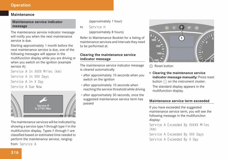
Maintenance
316
Maintenance service indicatormessage
The maintenance service indicator messagewill notify you when the next maintenanceservice is due.Starting approximately 1 month before thenext maintenance service is due, one of thefollowing messages will appear in themultifunction display while you are driving orwhen you switch on the ignition (exampleservice A):Service A In XXXX Miles (km)Service A In XXX DaysService A In X DayService A Due Now
The maintenance services will be indicated byshowing a service type A through type H in themultifunction display. Types A through H areclassified based on estimated time needed toperform the maintenance service, ranging:from Service A
(approximately 1 hour)to Service H
(approximately 8 hours)Refer to Maintenance Booklet for a listing ofmaintenance services and intervals they needto be performed at.
Clearing the maintenance serviceindicator messageThe maintenance service indicator messageis cleared automaticallyRafter approximately 10 seconds when you
switch on the ignitionRafter approximately 10 seconds when
reaching the service threshold while drivingRafter approximately 30 seconds, once the
suggested maintenance service term haspassed
1 Reset button
X Clearing the maintenance serviceindicator message manually: Press resetbutton 1 on the instrument cluster.The standard display appears in themultifunction display.
Maintenance service term exceededIf you have exceeded the suggestedmaintenance service term, you will see thefollowing message in the multifunctiondisplay:Service A Exceeded By XXXXX Miles(Km)Service A Exceeded By XXX DaysService A Exceeded By X Day
Operation
Maintenance
317
In addition, a signal sounds when themessage appears.Any authorized Mercedes-Benz Center willreset the maintenance service indicatorfollowing a completed maintenance service.
Calling up the maintenance serviceindicator display
i The menu overview can be found on(Y page 151).
You can call up the maintenance serviceindicator display at any time to check whenthe next maintenance service is due.X Switch on the ignition.X Press button è or ÿ on the
multifunction steering wheel repeatedlyuntil the standard display (Y page 152)appears in the multifunction display.
X Press button k or j on themultifunction steering wheel until themaintenance service indicator display withthe service symbol 9 and themaintenance service deadline appears inthe multifunction display.
i If the battery is disconnected, the days ofdisconnection will not be included in the
count shown by the maintenance serviceindicator. To arrive at the true maintenanceservice deadline, you will need to subtractthese days from the days shown in themaintenance service indicator message ormaintenance service indicator display.Do not confuse the maintenance serviceindicator with the engine oil level indicatorN.
Resetting the maintenance serviceindicator
In the event that the maintenance service onyour vehicle is not carried out at an authorizedMercedes-Benz Center, you can have themaintenance service indicator reset.The automotive maintenance facility carryingout the maintenance service will find theinformation for resetting the maintenanceservice indicator in the maintenance-relevantliterature for your vehicle.Such literature is available from anyauthorized Mercedes-Benz Center or directlyfrom Mercedes-Benz.
i If the maintenance service indicator wasinadvertently reset, have an authorizedMercedes-Benz Center correct it.
Only reset if the proper maintenanceservice has been performed. Resetting thesystem without performing the propermaintenance service as called for by themaintenance service indicator will result inengine damage and/or other vehicledamage not covered by the Mercedes-BenzLimited Warranty.
Operation
Z
Vehicle care
318
Vehicle care
Cleaning and care of the vehicle
NotesRegular and proper care will help to maintainthe value of your vehicle.G Warning!Many cleaning products can be hazardous.Some are poisonous, others are flammable.Always follow the instructions on theparticular container. Always open yourvehicle’s doors or windows when cleaningthe inside.Never use fluids or solvents that are notdesigned for cleaning your vehicle.Always lock away cleaning products andkeep them out of reach of children.
! When cleaning the vehicle, do not usescouring agents. Never apply strong forceand only use a soft, wet cloth or sponge.Otherwise you may scratch or damage thesurface to be cleaned.
While in operation, even while parked, yourvehicle is subjected to varying externalinfluences which, if gone unchecked, can
attack the paintwork as well as the vehicleunderbody and cause lasting damage.Such damage is caused not only by extremeand varying climatic conditions, but also by:RAir pollutionRRoad saltRTarRGravel and stone chippingTo avoid paint damage, you shouldimmediately remove:RGrease and oilRFuelRCoolantRBrake fluidRBird droppingsRInsectsRTree resins etc.Frequent washing reduces and/or eliminatesthe aggressiveness and potency of the aboveadverse influences.
More frequent washings are necessary todeal with unfavorable conditions:Rnear the oceanRin industrial areas (smoke, exhaust
emissions)Rduring winter operationYou should check your vehicle from time totime for stone chipping or other damage. Anydamage should be repaired as soon aspossible to prevent corrosion.In doing so, do not neglect the underbody ofthe vehicle. A prerequisite for a thoroughcheck is a washing of the underbody followedby a thorough inspection. Damaged areasneed to be re-undercoated.Your vehicle has been treated at the factorywith a wax-base rustproofing in the bodycavities which will last for the lifetime of thevehicle. Post-production treatment is neithernecessary nor recommended by Mercedes-Benz because of the possibility ofincompatibility between materials used in theproduction process and others applied later.We have selected vehicle-care products andcompiled recommendations which arespecially matched to our vehicles and whichalways reflect the latest technology. You canobtain Mercedes-Benz approved vehicle-care
Operation
Vehicle care
319
products at an authorized Mercedes-BenzCenter.Scratches, corrosive deposits, corrosion ordamage due to negligent or incorrect carecannot always be removed or repaired withthe vehicle-care products recommendedhere. In such cases it is best to seek aid at anauthorized Mercedes-Benz Center.The following topics deal with the cleaningand care of your vehicle and give important“how-to” information as well as references toMercedes-Benz approved vehicle-careproducts.
Power washer! Follow the instructions provided by the
power washer manufacturer onmaintaining a distance between the vehicleand the nozzle of the power washer.Never use a round nozzle to power-washtires. The intense jet of water can result indamage to the tire.Always replace a damaged tire.Always keep the jet of water moving acrossthe surface. Do not aim directly at electricalparts, electrical connectors, seals, or otherrubber parts.
i Vehicles with KEYLESS-GO:If a door handle is hit by a strong jet ofwater, and a SmartKey is withinapproximately 3 ft (1 m) of the vehicle, itcould be inadvertently locked or unlocked.
Tar stainsQuickly remove tar stains before they dry andbecome more difficult to remove. A tarremover is recommended.
Paintwork, painted body components! Affixing stickers, magnets, adhesive tape
or similar materials to painted bodycomponents may damage the paintwork.
Mercedes-Benz approved Paint Care shouldbe applied when water drops on the paintsurface do not “bead up”. This shouldnormally be done every 3 to 5 months,depending on the climate and washingdetergent used.Mercedes-Benz approved Paint Cleanershould be applied if the paint surface showssigns of embedded dirt (i.e. loss of gloss).Do not apply any of these products or wax ifyour vehicle is parked in the sun or if the hoodis still hot.
X Use the appropriate MB-Touch-Up Stick forquick and provisional repairs of minor paintdamage (i.e. chips from stones, vehicledoors, etc.).
Engine cleaningPrior to cleaning the engine compartment,make sure to protect electrical componentsand connectors from contact with water andcleaning agents.Corrosion protection, such as MBAnticorrosion Wax should be applied to theengine compartment after every enginecleaning. Before applying, all control linkagebushings and joints should be lubricated. Thepoly-V-belt and all pulleys should beprotected from any wax.
Vehicle washingIn the winter, thoroughly remove all traces ofroad salt as soon as possible.When washing the vehicle underbody, do notforget to clean the inner sides of the wheels.
i Vehicles with KEYLESS-GO:If a door handle is hit by a strong jet ofwater, and a SmartKey is within
Operation
Z
Vehicle care
320
approximately 3 ft (1 m) of the vehicle, itcould be inadvertently locked or unlocked.
Hand-washX Do not use hot water or wash your vehicle
in direct sunlight.X Only use a soft, wet cloth or sponge to
clean the vehicle.X Only use a mild vehicle wash detergent,
such as Mercedes-Benz approved CarShampoo.
X Thoroughly spray the vehicle with adiffused jet of water.
X Do not spray directly towards theventilation intake.
X Use plenty of water and rinse the spongeand chamois frequently.
X Rinse with clean water and thoroughly drywith a chamois.Do not allow cleaning agents to dry on thefinish.
Automatic car washYou can have your vehicle washed in anautomatic car wash from the start. Brushlesscar washes are preferable.
X To protect the filter system, activate the airrecirculation mode using button : onthe climate control panel.
! Do not clean your vehicle in an automatictouchless car wash which uses causticspray. Caustic spray will damage the paintor ornamental moldings.
If the vehicle is very dirty, prewash it beforerunning it through the automatic car wash.
! Make sure the combination switch is setto wiper setting M. Otherwise, the rainsensor could activate and cause the wipersto move unintentionally. This may lead tovehicle damage.Due to the width of the vehicle, fold inexterior rear view mirrors prior to runningthe vehicle through an automatic car washto prevent damage to the mirrors.
X When taking the vehicle through anautomatic conveyor-type car wash:Make sure the automatic transmissionremains in neutral position N. Observeinstructions, see “Remaining in neutralposition N” (Y page 136).
When leaving the automatic car wash, makesure the mirrors are folded out.
After running the vehicle through anautomatic car wash, wipe any wax off of thewindshield and the wiper blade inserts. Thiswill prevent smears and reduce wiping noisewhich can be caused by residual wax on thewindshield.
Ornamental moldingsX For regular cleaning and care of ornamental
moldings, use a damp cloth.
! Do not use chrome cleaner on ornamentalmoldings. Although ornamental moldingsmay have chrome appearance, they couldbe made of anodized aluminum that will bedamaged when cleaned with chromecleaner. Instead, use a damp cloth to cleanthose ornamental moldings.For very dirty ornamental moldings ofwhich you are sure are chrome-plated, usea chrome cleaner. If in doubt whether anornamental molding is chrome-plated,contact an authorized Mercedes-BenzCenter.
Operation
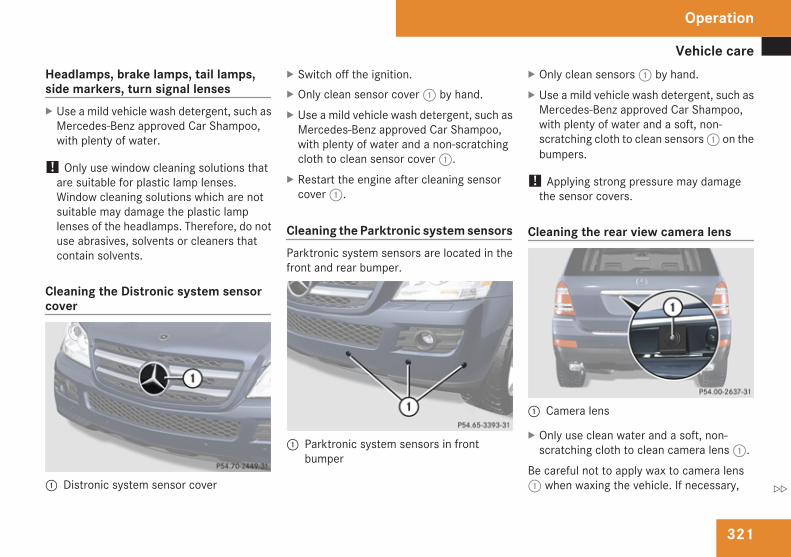
Vehicle care
321
Headlamps, brake lamps, tail lamps,side markers, turn signal lensesX Use a mild vehicle wash detergent, such as
Mercedes-Benz approved Car Shampoo,with plenty of water.
! Only use window cleaning solutions thatare suitable for plastic lamp lenses.Window cleaning solutions which are notsuitable may damage the plastic lamplenses of the headlamps. Therefore, do notuse abrasives, solvents or cleaners thatcontain solvents.
Cleaning the Distronic system sensorcover
1 Distronic system sensor cover
X Switch off the ignition.X Only clean sensor cover 1 by hand.X Use a mild vehicle wash detergent, such as
Mercedes-Benz approved Car Shampoo,with plenty of water and a non-scratchingcloth to clean sensor cover 1.
X Restart the engine after cleaning sensorcover 1.
Cleaning the Parktronic system sensorsParktronic system sensors are located in thefront and rear bumper.
1 Parktronic system sensors in frontbumper
X Only clean sensors 1 by hand.X Use a mild vehicle wash detergent, such as
Mercedes-Benz approved Car Shampoo,with plenty of water and a soft, non-scratching cloth to clean sensors 1 on thebumpers.
! Applying strong pressure may damagethe sensor covers.
Cleaning the rear view camera lens
1 Camera lens
X Only use clean water and a soft, non-scratching cloth to clean camera lens 1.
Be careful not to apply wax to camera lens1 when waxing the vehicle. If necessary,
Operation
Z
Vehicle care
322
remove the wax using the Mercedes-Benzapproved Car Shampoo with plenty of water.
! Do not clean the camera and the areaaround the cameraRwith a high-pressure cleanerRwith a dry cloth and strong pressureRwith aggressive cleaning agentsYou could otherwise damage the camera.
Cleaning the windows and the wiperblades! Never open the hood when the wiper arms
are folded forward.
G Warning!For safety reasons, switch off wipers andremove SmartKey from starter switch(vehicles with KEYLESS-GO: Make sure thevehicle’s on-board electronics have status0) before cleaning the windshield and/orthe wiper blades. Otherwise, the wipermotor could suddenly turn on and causeinjury.
! Do not pull on the wiper blade inserts.They could tear.
X Fold the wiper arms forward until they snapinto place.
X Clean the windshield and the wiper bladeinserts with a clean cloth and milddetergent solution.
X Use a soft, clean cloth and a mild windowcleaning solution on all outside and insideglass surfaces.An automotive glass cleaner isrecommended.
! Fold the windshield wiper arms back ontothe windshield before turning the SmartKeyin the starter switch or pressing theKEYLESS-GO start/stop button (vehicleswith KEYLESS-GO).Hold on to the wiper when folding the wiperarm back. If released, the force of theimpact from the tensioning spring couldcrack the windshield.
! To clean the window interior, do not usea dry cloth, abrasives, solvents or cleanerscontaining solvents. Do not touch theinside of the front, rear or side windows andthe power tilt/sliding sunroof or rearpanorama roof with hard objects such asan ice scraper or ring. Doing so may
damage the windows or the sunroof/panorama roof.
Light alloy wheelsIf possible, clean wheels once a week.X Use Mercedes-Benz approved Wheel Care,
a soft bristle brush and a strong spray ofwater for cleaning the light alloy wheels.
! Only use acid-free cleaning materials.Acid may cause corrosion or damage theclear coat.
! The vehicle should not be parked for anextended period of time immediately afterit has been cleaned, especially not after thewheel rims have been cleaned with wheelrim cleaner. Wheel rim cleaners can lead toincreased corrosion of the brake disks andbrake pads. Non-approved wheel cleanersmay also damage the wheel paint if thevehicle is not driven after cleaning.Therefore, the vehicle’s brake systemshould always be warmed-up before it isparked after cleaning. Drive your vehicle forseveral minutes to allow the brakes to dry.When applying Mercedes-Benz approvedTire Care and Mercedes-Benz approved
Operation
Vehicle care
323
Wheel Care products, take care not tospray them on the brake disks.
Plastic and rubber partsX Use a gentle dishwashing detergent or mild
detergent for delicate fabrics as a washingsolution.
X Wipe with a cloth moistened in a lukewarmsolution.The surface may temporarily change color.If this is the case, wait for it to dry.
G Warning!Do not use cleaners or cockpit care sprayscontaining solvents to clean the cockpit orthe steering wheel. Cleaners containingsolvents will make the surface porous andvehicle occupants could suffer seriousinjuries from plastic parts coming loose inthe event of air bag deployment.
! Do not use oil, wax or scouring agents.Otherwise you may scratch or damage thesurface.
Hard plastic trim itemsX Use Mercedes-Benz approved Interior Care
on a soft, lint-free cloth and apply with lightpressure.
COMAND display! You must switch off the COMAND display
and allow it to cool prior to cleaning.
! Do not use any liquids or cleaning agents.These can damage or even destroy theaudio display screen.
X Use a standard microfiber cloth and applywith light pressure.
Steering wheelX Wipe with a damp cloth and dry thoroughly
or clean with Mercedes-Benz approvedLeather Care.
CarpetsX Use Mercedes-Benz approved Carpet and
Fabric Care for cleaning the carpets.
HeadlinerX Use a soft bristle brush or a dry-shampoo
cleaner in case of excessive dirt.
Seat beltsX Only use clear, lukewarm water and soap.
! The seat belts must not be treated withchemical cleaning agents. Do not dry theseat belts at temperatures above 176‡(80†) or in direct sunlight.
G Warning!Do not bleach or dye seat belts as this mayseverely weaken them. In a crash they maynot be able to provide adequate protection.
UpholsteryUsing aftermarket seat covers or wearingclothing that have the tendency to give offcoloring (e.g. when wet, etc.) may cause theupholstery to become permanentlydiscolored. By lining the seats with a properintermediate cover, contact-discoloration willbe prevented.
Operation
Z
Vehicle care
324
G Warning!Only use seat or head restraint coverswhich have been tested and approved byMercedes-Benz for your vehicle model.Using other seat or head restraint coversmay interfere with or preventRdeployment of the front side impact air
bagsRdeployment of the rear side impact air
bagsRactivation of the active head restraintsContact an authorized Mercedes-BenzCenter for availability.
Leather upholsteryPlease note that leather upholstery is anatural product and is therefore subject to anatural aging process. Leather upholsterymay also react to certain ambient influencessuch as high humidity or high temperature byshowing wrinkles for example.X Wipe leather upholstery with a damp cloth
and dry thoroughly or clean with Mercedes-Benz approved Leather Care.
! To avoid damage to leather upholstery:RWipe with light pressure only.RDo not clean with abrasive cleaning
agents such as scouring milk or powder.RDo not soak the leather upholstery.
As leather is a natural product, it couldotherwise harden or become porous.RExercise particular care when cleaning
perforated leather as its undersideshould not become wet.
MB Tex upholsteryX Use Mercedes-Benz approved Interior Care
onto a soft, lint-free cloth and apply withlight pressure for cleaning the upholstery.
Wood trimsX Only use water and a damp cloth to clean
wood trims in your vehicle.
! Do not use solvents like tar remover orwheel cleaner nor polishes or waxes asthese may be abrasive.
Chrome-plated exhaust tipRegular cleaning and care of chrome-platedexhaust tips will help to maintain their shineand the classy appearance.X Use Mercedes-Benz approved Chrome
Polishing Paste each time the vehicle hasbeen washed, especially during the winter.
! Do not use alkaline cleaners such aswheel cleaners as they could causecorrosion.
Operation
325
Vehicle equipment ............................ 326Where will I find ...? .......................... 326Vehicle status messages in themultifunction display ....................... 330What to do if … .................................. 370Unlocking/locking manually ........... 384Resetting activated head restraints 385Replacing SmartKey batteries ......... 386Replacing bulbs ................................. 388
Replacing wiper blades .................... 395Flat tire .............................................. 397Bleeding the fuel system (dieselengine only) ....................................... 404AdBlue® (diesel engine only) ........... 405Battery ............................................... 408Jump starting .................................... 410Towing the vehicle ............................ 412Fuses .................................................. 415
Practical hints
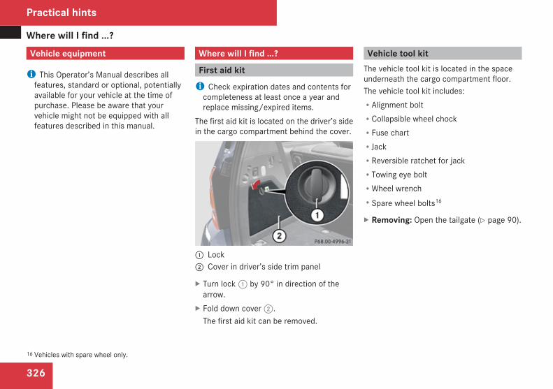
Where will I find ...?
326
Vehicle equipment
i This Operator’s Manual describes allfeatures, standard or optional, potentiallyavailable for your vehicle at the time ofpurchase. Please be aware that yourvehicle might not be equipped with allfeatures described in this manual.
Where will I find ...?
First aid kiti Check expiration dates and contents for
completeness at least once a year andreplace missing/expired items.
The first aid kit is located on the driver’s sidein the cargo compartment behind the cover.
1 Lock2 Cover in driver’s side trim panel
X Turn lock 1 by 90° in direction of thearrow.
X Fold down cover 2.The first aid kit can be removed.
Vehicle tool kitThe vehicle tool kit is located in the spaceunderneath the cargo compartment floor.The vehicle tool kit includes:RAlignment boltRCollapsible wheel chockRFuse chartRJackRReversible ratchet for jackRTowing eye boltRWheel wrenchRSpare wheel bolts16
X Removing: Open the tailgate (Y page 90).
16 Vehicles with spare wheel only.
Practical hints
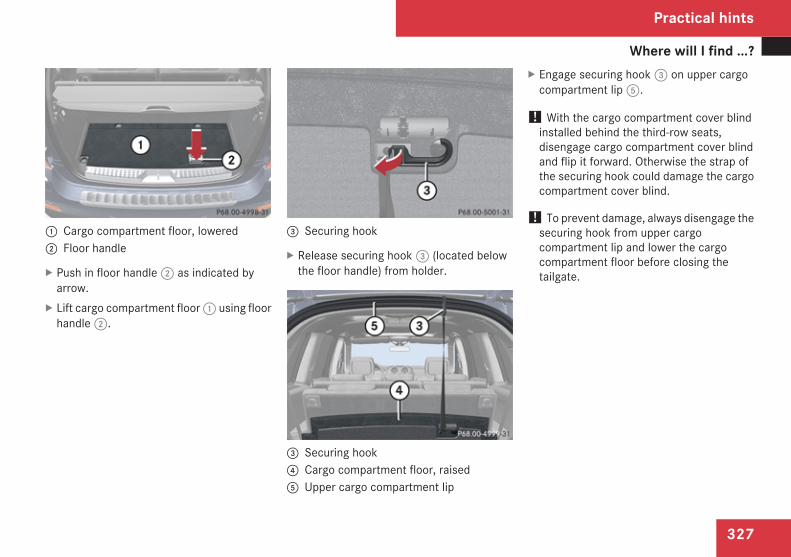
Where will I find ...?
327
1 Cargo compartment floor, lowered2 Floor handle
X Push in floor handle 2 as indicated byarrow.
X Lift cargo compartment floor 1 using floorhandle 2.
3 Securing hook
X Release securing hook 3 (located belowthe floor handle) from holder.
3 Securing hook4 Cargo compartment floor, raised5 Upper cargo compartment lip
X Engage securing hook 3 on upper cargocompartment lip 5.
! With the cargo compartment cover blindinstalled behind the third-row seats,disengage cargo compartment cover blindand flip it forward. Otherwise the strap ofthe securing hook could damage the cargocompartment cover blind.
! To prevent damage, always disengage thesecuring hook from upper cargocompartment lip and lower the cargocompartment floor before closing thetailgate.
Practical hints
Z
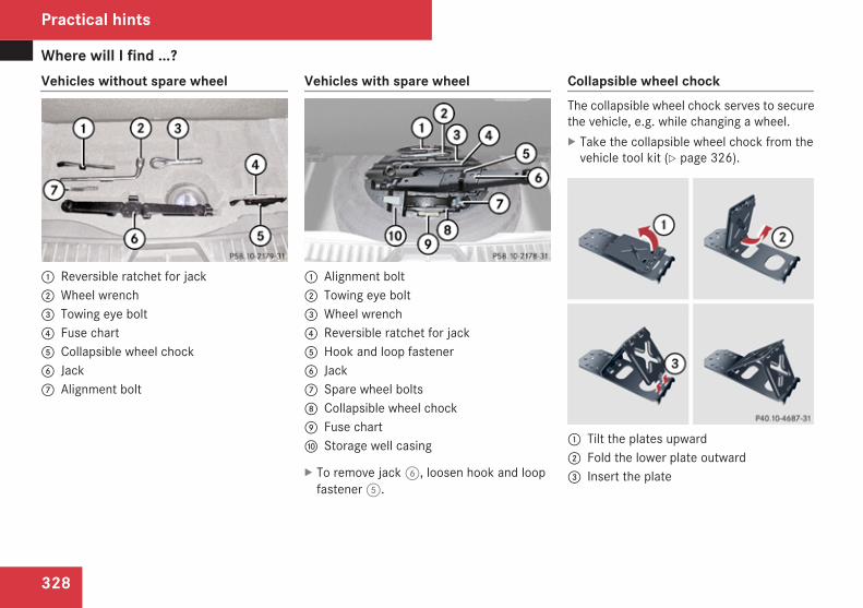
Where will I find ...?
328
Vehicles without spare wheel
1 Reversible ratchet for jack2 Wheel wrench3 Towing eye bolt4 Fuse chart5 Collapsible wheel chock6 Jack7 Alignment bolt
Vehicles with spare wheel
1 Alignment bolt2 Towing eye bolt3 Wheel wrench4 Reversible ratchet for jack5 Hook and loop fastener6 Jack7 Spare wheel bolts8 Collapsible wheel chock9 Fuse charta Storage well casing
X To remove jack 6, loosen hook and loopfastener 5.
Collapsible wheel chockThe collapsible wheel chock serves to securethe vehicle, e.g. while changing a wheel.X Take the collapsible wheel chock from the
vehicle tool kit (Y page 326).
1 Tilt the plates upward2 Fold the lower plate outward3 Insert the plate
Practical hints
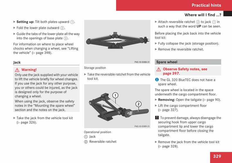
Where will I find ...?
329
X Setting up: Tilt both plates upward 1.X Fold the lower plate outward 2.X Guide the tabs of the lower plate all the way
into the openings of base plate 3.For information on where to place wheelchocks when changing a wheel, see “Liftingthe vehicle” (Y page 398).
Jack
G Warning!Only use the jack supplied with your vehicleto lift the vehicle briefly for wheel changes.If you use the jack for any other purpose,you or others could be injured, as the jackis designed only for the purpose ofchanging a wheel.When using the jack, observe the safetynotes in the “Mounting the spare wheel”section and the notes on the jack.
X Take the jack from the vehicle tool kit(Y page 326).
Storage position
X Take the reversible ratchet from the vehicletool kit.
Operational position1 Jack2 Reversible ratchet
X Attach reversible ratchet 2 to jack 1 insuch a way that the word UP can be seen.
Before placing the jack back into the vehicletool kit:X Fully collapse the jack (storage position).X Remove the reversible ratchet.
Spare wheel
G Observe Safety notes, seepage 397.
i The GL 320 BlueTEC does not have aspare wheel.
The spare wheel is located in the spaceunderneath the cargo compartment floor.X Removing: Open the tailgate (Y page 90).X Lift the cargo compartment floor
(Y page 327).
! To prevent damage, always disengage thesecuring hook from upper cargocompartment lip and lower the cargocompartment floor before closing thetailgate.
X Remove the jack from the vehicle tool kit(Y page 328).
Practical hints
Z
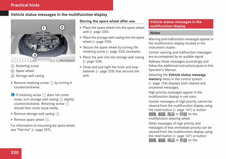
Vehicle status messages in the multifunction display
330
1 Retaining screw2 Spare wheel3 Storage well casing
X Remove retaining screw 1 by turning itcounterclockwise.
i If retaining screw 1 does not comeloose, turn storage well casing 3 slightlycounterclockwise. Retaining screw 1should then come loose easily.
X Remove storage well casing 3.X Remove spare wheel 2.For information on mounting the spare wheel,see “Flat tire” (Y page 397).
Storing the spare wheel after useX Place the spare wheel into the spare wheel
well (Y page 330).X Place the storage well casing into the spare
wheel (Y page 330).X Secure the spare wheel by turning the
retaining screw (Y page 330) clockwise.X Place the jack into the storage well casing
(Y page 328).X Close and pull tight the hook and loop
fastener (Y page 328) that secures thejack.
Vehicle status messages in themultifunction display
NotesWarning and malfunction messages appear inthe multifunction display located in theinstrument cluster.Certain warning and malfunction messagesare accompanied by an audible signal.Address these messages accordingly andfollow the additional instructions given in thisOperator’s Manual.Selecting the Vehicle status messagememory menu in the control system(Y page 156) displays both cleared anduncleared messages.High-priority messages appear in themultifunction display in red color.Certain messages of high priority cannot becleared from the multifunction display usingthe reset button (Y page 147) or buttonj, k, · or è on themultifunction steering wheel.Other messages of high priority andmessages of less immediate priority can becleared from the multifunction display usingthe reset button (Y page 147) or buttonj, k, · or è on the
Practical hints
Vehicle status messages in the multifunction display
331
multifunction steering wheel. They are thenstored in the Vehicle status messagememory menu (Y page 156). Remember thatclearing a message will only make themessage disappear. Clearing a message willnot correct the condition that caused themessage to appear.G Warning!All categories of messages containimportant information which should betaken note of and, where a malfunction isindicated, addressed as soon as possible atan authorized Mercedes-Benz Center.
Failure to repair the condition noted maycause damage not covered by theMercedes-Benz Limited Warranty, or resultin property damage or personal injury.
G Warning!No messages will be displayed if either theinstrument cluster or the multifunctiondisplay is inoperative.As a result, you will not be able to seeinformation about your driving conditions,such as speed or outside temperature,
warning/indicator lamps, malfunction/warning messages or the failure of anysystems. Driving characteristics may beimpaired.If you must continue to drive, please do sowith added caution. Contact an authorizedMercedes-Benz Center as soon as possible.
On the pages that follow, you will find acompilation of the most important warningand malfunction messages that may appearin the multifunction display.For your convenience the messages aredivided into text messages (Y page 332) andsymbol messages (Y page 346).
Practical hints
Z
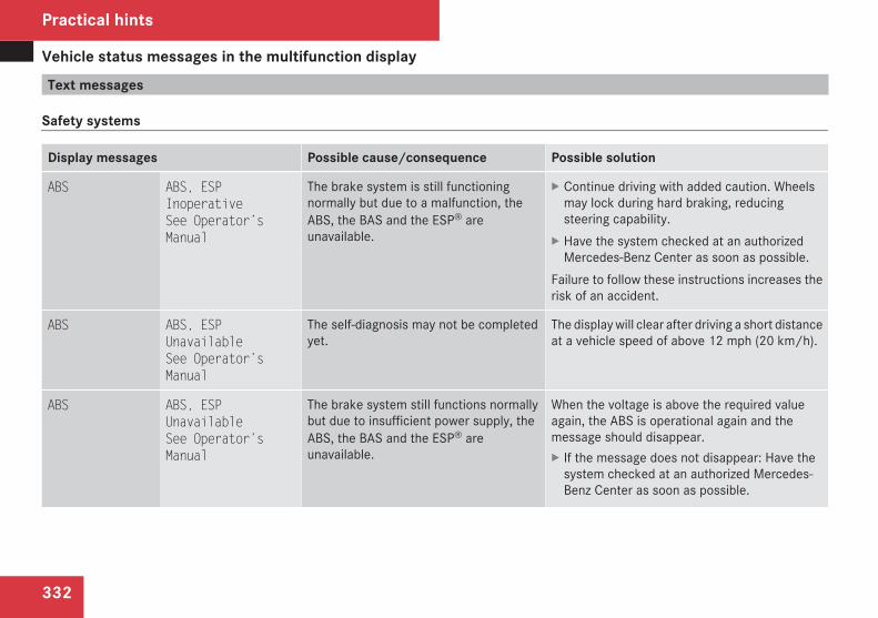
Vehicle status messages in the multifunction display
332
Text messages
Safety systems
Display messages Possible cause/consequence Possible solution
ABS ABS, ESPInoperativeSee Operator’sManual
The brake system is still functioningnormally but due to a malfunction, theABS, the BAS and the ESP® areunavailable.
X Continue driving with added caution. Wheelsmay lock during hard braking, reducingsteering capability.
X Have the system checked at an authorizedMercedes-Benz Center as soon as possible.
Failure to follow these instructions increases therisk of an accident.
ABS ABS, ESPUnavailableSee Operator’sManual
The self-diagnosis may not be completedyet.
The display will clear after driving a short distanceat a vehicle speed of above 12 mph (20 km/h).
ABS ABS, ESPUnavailableSee Operator’sManual
The brake system still functions normallybut due to insufficient power supply, theABS, the BAS and the ESP® areunavailable.
When the voltage is above the required valueagain, the ABS is operational again and themessage should disappear.X If the message does not disappear: Have the
system checked at an authorized Mercedes-Benz Center as soon as possible.
Practical hints
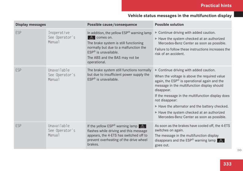
Vehicle status messages in the multifunction display
333
Display messages Possible cause/consequence Possible solution
ESP InoperativeSee Operator’sManual
In addition, the yellow ESP® warning lampv comes on.The brake system is still functioningnormally but due to a malfunction theESP® is unavailable.The ABS and the BAS may not beoperational.
X Continue driving with added caution.X Have the system checked at an authorized
Mercedes-Benz Center as soon as possible.Failure to follow these instructions increases therisk of an accident.
ESP UnavailableSee Operator’sManual
The brake system still functions normallybut due to insufficient power supply theESP® is unavailable.
X Continue driving with added caution.When the voltage is above the required valueagain, the ESP® is operational again and themessage in the multifunction display shoulddisappear.If the message in the multifunction display doesnot disappear:X Have the alternator and the battery checked.X Have the system checked at an authorized
Mercedes-Benz Center as soon as possible.
ESP UnavailableSee Operator’sManual
If the yellow ESP® warning lamp vflashes while driving and this messageappears, the 4-ETS has switched off toprevent overheating of the drive wheelbrakes.
As soon as the brakes have cooled off, the 4-ETSswitches on again.The message in the multifunction displaydisappears and the ESP® warning lamp vgoes out.
Practical hints
Z
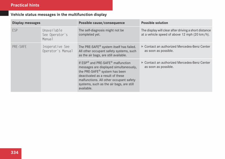
Vehicle status messages in the multifunction display
334
Display messages Possible cause/consequence Possible solution
ESP UnavailableSee Operator’sManual
The self-diagnosis might not becompleted yet.
The display will clear after driving a short distanceat a vehicle speed of above 12 mph (20 km/h).
PRE-SAFE Inoperative SeeOperator’s Manual
The PRE-SAFE® system itself has failed.All other occupant safety systems, suchas the air bags, are still available.
X Contact an authorized Mercedes-Benz Centeras soon as possible.
If ESP® and PRE-SAFE® malfunctionmessages are displayed simultaneously,the PRE-SAFE® system has beendeactivated as a result of thesemalfunctions. All other occupant safetysystems, such as the air bags, are stillavailable.
X Contact an authorized Mercedes-Benz Centeras soon as possible.
Practical hints
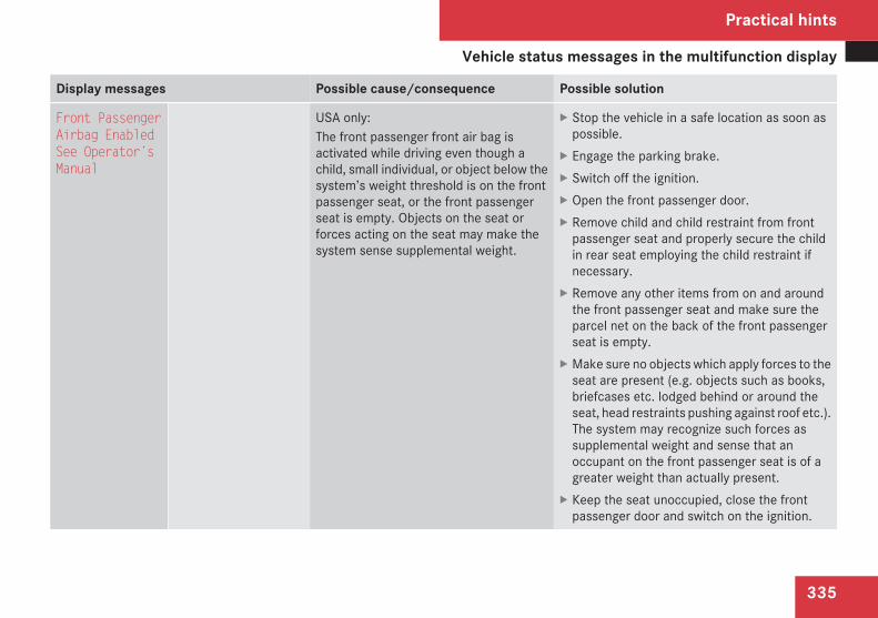
Vehicle status messages in the multifunction display
335
Display messages Possible cause/consequence Possible solution
Front PassengerAirbag EnabledSee Operator’sManual
USA only:The front passenger front air bag isactivated while driving even though achild, small individual, or object below thesystem’s weight threshold is on the frontpassenger seat, or the front passengerseat is empty. Objects on the seat orforces acting on the seat may make thesystem sense supplemental weight.
X Stop the vehicle in a safe location as soon aspossible.
X Engage the parking brake.X Switch off the ignition.X Open the front passenger door.X Remove child and child restraint from front
passenger seat and properly secure the childin rear seat employing the child restraint ifnecessary.
X Remove any other items from on and aroundthe front passenger seat and make sure theparcel net on the back of the front passengerseat is empty.
X Make sure no objects which apply forces to theseat are present (e.g. objects such as books,briefcases etc. lodged behind or around theseat, head restraints pushing against roof etc.).The system may recognize such forces assupplemental weight and sense that anoccupant on the front passenger seat is of agreater weight than actually present.
X Keep the seat unoccupied, close the frontpassenger door and switch on the ignition.
Practical hints
Z
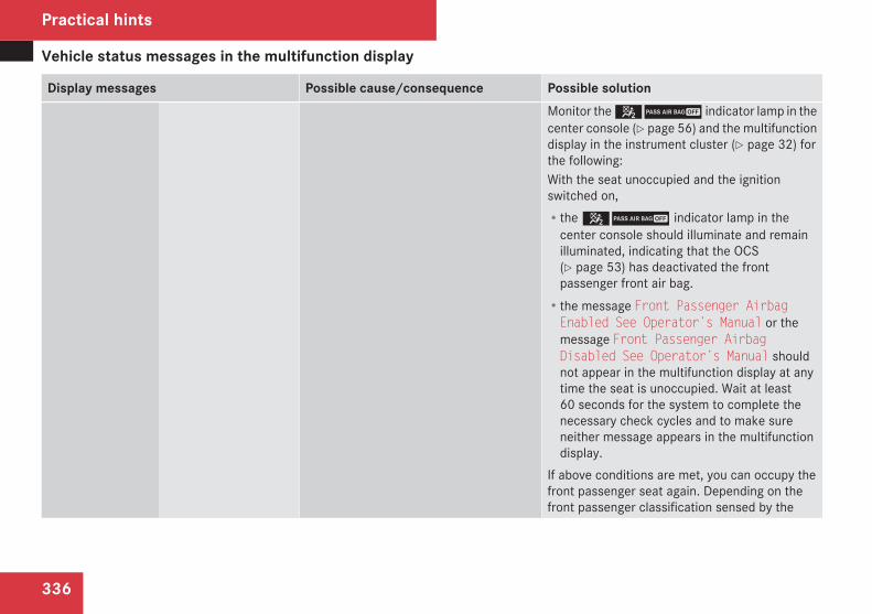
Vehicle status messages in the multifunction display
336
Display messages Possible cause/consequence Possible solutionMonitor the 59 indicator lamp in thecenter console (Y page 56) and the multifunctiondisplay in the instrument cluster (Y page 32) forthe following:With the seat unoccupied and the ignitionswitched on,Rthe 59 indicator lamp in the
center console should illuminate and remainilluminated, indicating that the OCS(Y page 53) has deactivated the frontpassenger front air bag.Rthe message Front Passenger AirbagEnabled See Operator’s Manual or themessage Front Passenger AirbagDisabled See Operator’s Manual shouldnot appear in the multifunction display at anytime the seat is unoccupied. Wait at least60 seconds for the system to complete thenecessary check cycles and to make sureneither message appears in the multifunctiondisplay.
If above conditions are met, you can occupy thefront passenger seat again. Depending on thefront passenger classification sensed by the
Practical hints
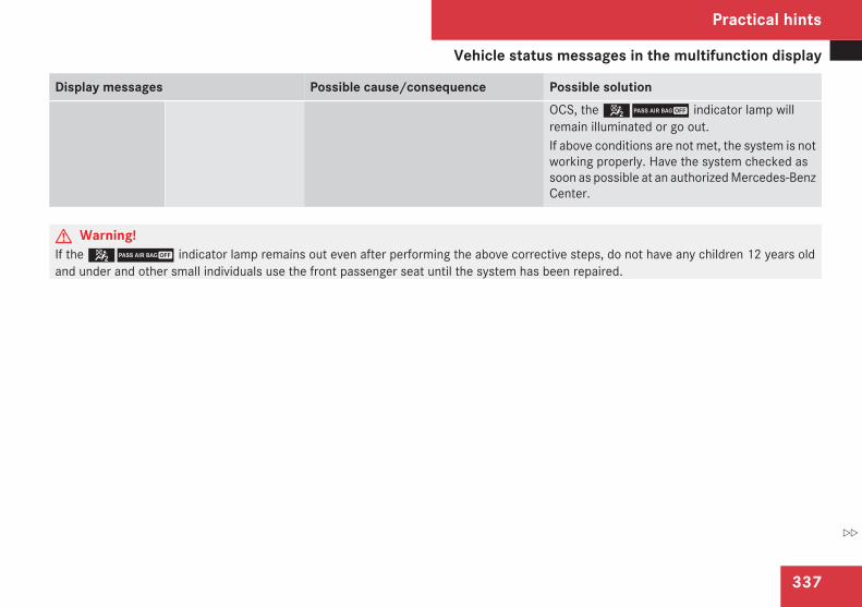
Vehicle status messages in the multifunction display
337
Display messages Possible cause/consequence Possible solutionOCS, the 59 indicator lamp willremain illuminated or go out.If above conditions are not met, the system is notworking properly. Have the system checked assoon as possible at an authorized Mercedes-BenzCenter.
G Warning!If the 59 indicator lamp remains out even after performing the above corrective steps, do not have any children 12 years oldand under and other small individuals use the front passenger seat until the system has been repaired.
Practical hints
Z
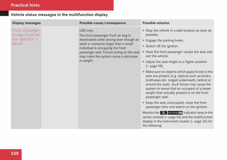
Vehicle status messages in the multifunction display
338
Display messages Possible cause/consequence Possible solution
Front PassengerAirbag DisabledSee Operator’sManual
USA only:The front passenger front air bag isdeactivated while driving even though anadult or someone larger than a smallindividual is occupying the frontpassenger seat. Forces acting on the seatmay make the system sense a decreasein weight.
X Stop the vehicle in a safe location as soon aspossible.
X Engage the parking brake.X Switch off the ignition.X Have the front passenger vacate the seat and
exit the vehicle.X Adjust the seat height to a higher position
(Y page 98).X Make sure no objects which apply forces to the
seat are present (e.g. objects such as books,briefcases etc. lodged underneath, behind oraround the seat). Such forces may cause thesystem to sense that an occupant of a lesserweight than actually present is on the frontpassenger seat.
X Keep the seat unoccupied, close the frontpassenger door and switch on the ignition.
Monitor the 59 indicator lamp in thecenter console (Y page 56) and the multifunctiondisplay in the instrument cluster (Y page 32) forthe following:
Practical hints
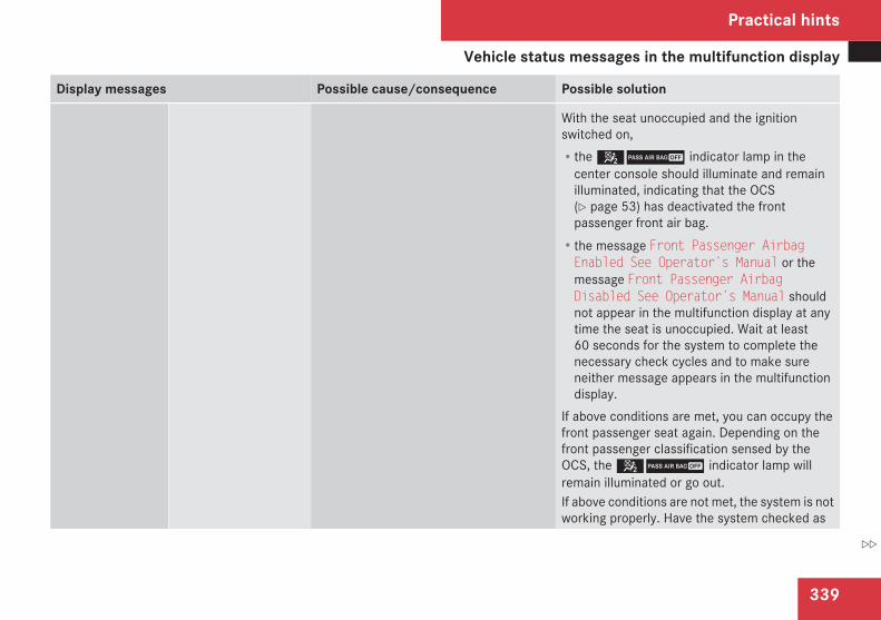
Vehicle status messages in the multifunction display
339
Display messages Possible cause/consequence Possible solution
With the seat unoccupied and the ignitionswitched on,Rthe 59 indicator lamp in the
center console should illuminate and remainilluminated, indicating that the OCS(Y page 53) has deactivated the frontpassenger front air bag.Rthe message Front Passenger AirbagEnabled See Operator’s Manual or themessage Front Passenger AirbagDisabled See Operator’s Manual shouldnot appear in the multifunction display at anytime the seat is unoccupied. Wait at least60 seconds for the system to complete thenecessary check cycles and to make sureneither message appears in the multifunctiondisplay.
If above conditions are met, you can occupy thefront passenger seat again. Depending on thefront passenger classification sensed by theOCS, the 59 indicator lamp willremain illuminated or go out.If above conditions are not met, the system is notworking properly. Have the system checked as
Practical hints
Z
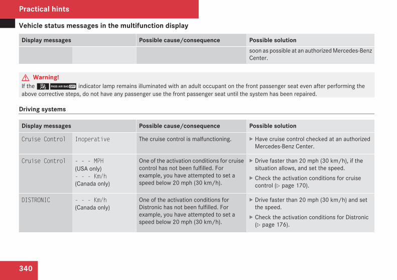
Vehicle status messages in the multifunction display
340
Display messages Possible cause/consequence Possible solutionsoon as possible at an authorized Mercedes-BenzCenter.
G Warning!If the 59 indicator lamp remains illuminated with an adult occupant on the front passenger seat even after performing theabove corrective steps, do not have any passenger use the front passenger seat until the system has been repaired.
Driving systems
Display messages Possible cause/consequence Possible solution
Cruise Control Inoperative The cruise control is malfunctioning. X Have cruise control checked at an authorizedMercedes-Benz Center.
Cruise Control - - - MPH(USA only)- - - Km/h(Canada only)
One of the activation conditions for cruisecontrol has not been fulfilled. Forexample, you have attempted to set aspeed below 20 mph (30 km/h).
X Drive faster than 20 mph (30 km/h), if thesituation allows, and set the speed.
X Check the activation conditions for cruisecontrol (Y page 170).
DISTRONIC - - - Km/h(Canada only)
One of the activation conditions forDistronic has not been fulfilled. Forexample, you have attempted to set aspeed below 20 mph (30 km/h).
X Drive faster than 20 mph (30 km/h) and setthe speed.
X Check the activation conditions for Distronic(Y page 176).
Practical hints
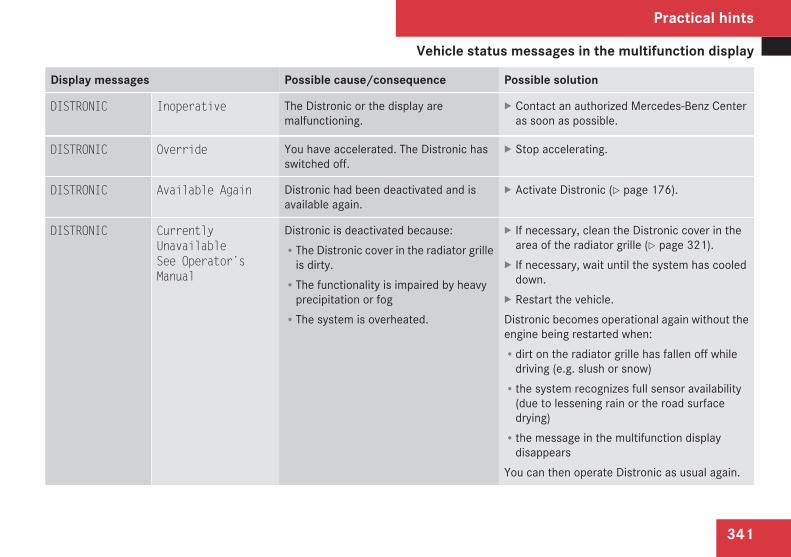
Vehicle status messages in the multifunction display
341
Display messages Possible cause/consequence Possible solution
DISTRONIC Inoperative The Distronic or the display aremalfunctioning.
X Contact an authorized Mercedes-Benz Centeras soon as possible.
DISTRONIC Override You have accelerated. The Distronic hasswitched off.
X Stop accelerating.
DISTRONIC Available Again Distronic had been deactivated and isavailable again.
X Activate Distronic (Y page 176).
DISTRONIC CurrentlyUnavailableSee Operator’sManual
Distronic is deactivated because:RThe Distronic cover in the radiator grille
is dirty.RThe functionality is impaired by heavy
precipitation or fogRThe system is overheated.
X If necessary, clean the Distronic cover in thearea of the radiator grille (Y page 321).
X If necessary, wait until the system has cooleddown.
X Restart the vehicle.Distronic becomes operational again without theengine being restarted when:Rdirt on the radiator grille has fallen off while
driving (e.g. slush or snow)Rthe system recognizes full sensor availability
(due to lessening rain or the road surfacedrying)Rthe message in the multifunction display
disappearsYou can then operate Distronic as usual again.
Practical hints
Z
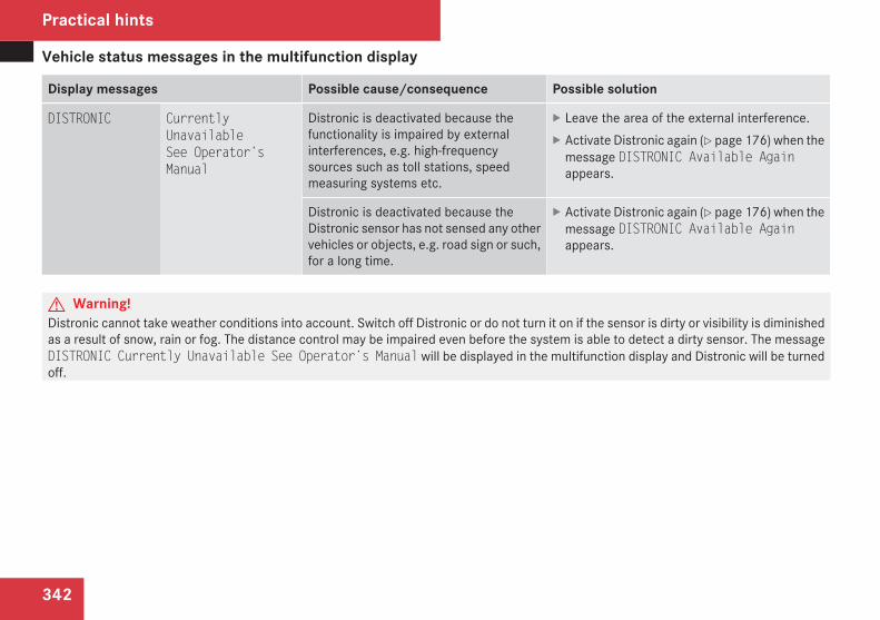
Vehicle status messages in the multifunction display
342
Display messages Possible cause/consequence Possible solution
DISTRONIC CurrentlyUnavailableSee Operator’sManual
Distronic is deactivated because thefunctionality is impaired by externalinterferences, e.g. high-frequencysources such as toll stations, speedmeasuring systems etc.
X Leave the area of the external interference.X Activate Distronic again (Y page 176) when the
message DISTRONIC Available Againappears.
Distronic is deactivated because theDistronic sensor has not sensed any othervehicles or objects, e.g. road sign or such,for a long time.
X Activate Distronic again (Y page 176) when themessage DISTRONIC Available Againappears.
G Warning!Distronic cannot take weather conditions into account. Switch off Distronic or do not turn it on if the sensor is dirty or visibility is diminishedas a result of snow, rain or fog. The distance control may be impaired even before the system is able to detect a dirty sensor. The messageDISTRONIC Currently Unavailable See Operator’s Manual will be displayed in the multifunction display and Distronic will be turnedoff.
Practical hints
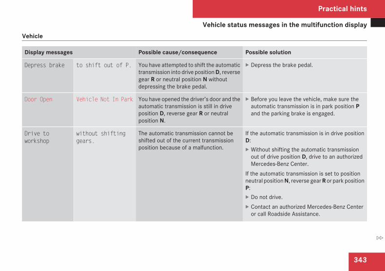
Vehicle status messages in the multifunction display
343
Vehicle
Display messages Possible cause/consequence Possible solution
Depress brake to shift out of P. You have attempted to shift the automatictransmission into drive position D, reversegear R or neutral position N withoutdepressing the brake pedal.
X Depress the brake pedal.
Door Open Vehicle Not In Park You have opened the driver’s door and theautomatic transmission is still in driveposition D, reverse gear R or neutralposition N.
X Before you leave the vehicle, make sure theautomatic transmission is in park position Pand the parking brake is engaged.
Drive toworkshop
without shiftinggears.
The automatic transmission cannot beshifted out of the current transmissionposition because of a malfunction.
If the automatic transmission is in drive positionD:X Without shifting the automatic transmission
out of drive position D, drive to an authorizedMercedes-Benz Center.
If the automatic transmission is set to positionneutral position N, reverse gear R or park positionP:X Do not drive.X Contact an authorized Mercedes-Benz Center
or call Roadside Assistance.
Practical hints
Z
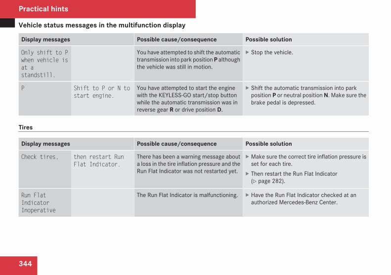
Vehicle status messages in the multifunction display
344
Display messages Possible cause/consequence Possible solution
Only shift to Pwhen vehicle isat astandstill.
You have attempted to shift the automatictransmission into park position P althoughthe vehicle was still in motion.
X Stop the vehicle.
P Shift to P or N tostart engine.
You have attempted to start the enginewith the KEYLESS-GO start/stop buttonwhile the automatic transmission was inreverse gear R or drive position D.
X Shift the automatic transmission into parkposition P or neutral position N. Make sure thebrake pedal is depressed.
Tires
Display messages Possible cause/consequence Possible solution
Check tires, then restart RunFlat Indicator.
There has been a warning message abouta loss in the tire inflation pressure and theRun Flat Indicator was not restarted yet.
X Make sure the correct tire inflation pressure isset for each tire.
X Then restart the Run Flat Indicator(Y page 282).
Run FlatIndicatorInoperative
The Run Flat Indicator is malfunctioning. X Have the Run Flat Indicator checked at anauthorized Mercedes-Benz Center.
Practical hints
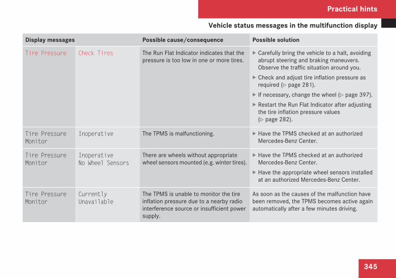
Vehicle status messages in the multifunction display
345
Display messages Possible cause/consequence Possible solution
Tire Pressure Check Tires The Run Flat Indicator indicates that thepressure is too low in one or more tires.
X Carefully bring the vehicle to a halt, avoidingabrupt steering and braking maneuvers.Observe the traffic situation around you.
X Check and adjust tire inflation pressure asrequired (Y page 281).
X If necessary, change the wheel (Y page 397).X Restart the Run Flat Indicator after adjusting
the tire inflation pressure values(Y page 282).
Tire PressureMonitor
Inoperative The TPMS is malfunctioning. X Have the TPMS checked at an authorizedMercedes-Benz Center.
Tire PressureMonitor
InoperativeNo Wheel Sensors
There are wheels without appropriatewheel sensors mounted (e.g. winter tires).
X Have the TPMS checked at an authorizedMercedes-Benz Center.
X Have the appropriate wheel sensors installedat an authorized Mercedes-Benz Center.
Tire PressureMonitor
CurrentlyUnavailable
The TPMS is unable to monitor the tireinflation pressure due to a nearby radiointerference source or insufficient powersupply.
As soon as the causes of the malfunction havebeen removed, the TPMS becomes active againautomatically after a few minutes driving.
Practical hints
Z
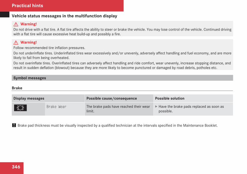
Vehicle status messages in the multifunction display
346
G Warning!Do not drive with a flat tire. A flat tire affects the ability to steer or brake the vehicle. You may lose control of the vehicle. Continued drivingwith a flat tire will cause excessive heat build-up and possibly a fire.
G Warning!Follow recommended tire inflation pressures.Do not underinflate tires. Underinflated tires wear excessively and/or unevenly, adversely affect handling and fuel economy, and are morelikely to fail from being overheated.Do not overinflate tires. Overinflated tires can adversely affect handling and ride comfort, wear unevenly, increase stopping distance, andresult in sudden deflation (blowout) because they are more likely to become punctured or damaged by road debris, potholes etc.
Symbol messages
Brake
Display messages Possible cause/consequence Possible solution
2 Brake Wear The brake pads have reached their wearlimit.
X Have the brake pads replaced as soon aspossible.
! Brake pad thickness must be visually inspected by a qualified technician at the intervals specified in the Maintenance Booklet.
Practical hints
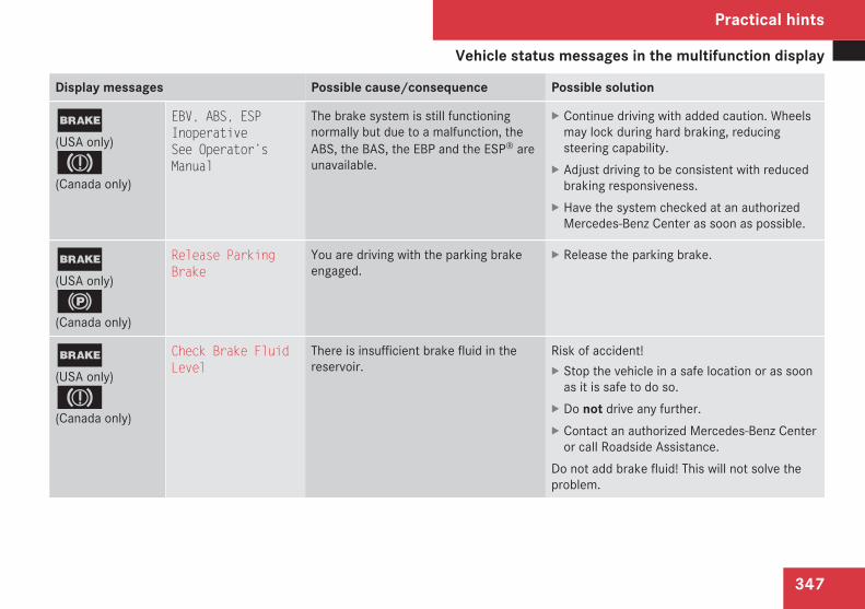
Vehicle status messages in the multifunction display
347
Display messages Possible cause/consequence Possible solution
;(USA only)3(Canada only)
EBV, ABS, ESPInoperativeSee Operator’sManual
The brake system is still functioningnormally but due to a malfunction, theABS, the BAS, the EBP and the ESP® areunavailable.
X Continue driving with added caution. Wheelsmay lock during hard braking, reducingsteering capability.
X Adjust driving to be consistent with reducedbraking responsiveness.
X Have the system checked at an authorizedMercedes-Benz Center as soon as possible.
;(USA only)!(Canada only)
Release ParkingBrake
You are driving with the parking brakeengaged.
X Release the parking brake.
;(USA only)3(Canada only)
Check Brake FluidLevel
There is insufficient brake fluid in thereservoir.
Risk of accident!X Stop the vehicle in a safe location or as soon
as it is safe to do so.X Do not drive any further.X Contact an authorized Mercedes-Benz Center
or call Roadside Assistance.Do not add brake fluid! This will not solve theproblem.
Practical hints
Z
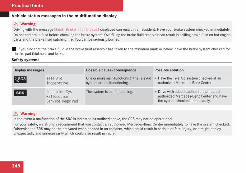
Vehicle status messages in the multifunction display
348
G Warning!Driving with the message Check Brake Fluid Level displayed can result in an accident. Have your brake system checked immediately.Do not add brake fluid before checking the brake system. Overfilling the brake fluid reservoir can result in spilling brake fluid on hot engineparts and the brake fluid catching fire. You can be seriously burned.
! If you find that the brake fluid in the brake fluid reservoir has fallen to the minimum mark or below, have the brake system checked forbrake pad thickness and leaks.
Safety systems
Display messages Possible cause/consequence Possible solution
L Tele AidInoperative
One or more main functions of the Tele Aidsystem are malfunctioning.
X Have the Tele Aid system checked at anauthorized Mercedes-Benz Center.
1 Restraint Sys.MalfunctionService Required
The system is malfunctioning. X Drive with added caution to the nearestauthorized Mercedes-Benz Center and havethe system checked immediately.
G Warning!In the event a malfunction of the SRS is indicated as outlined above, the SRS may not be operational.For your safety, we strongly recommend that you contact an authorized Mercedes-Benz Center immediately to have the system checked.Otherwise the SRS may not be activated when needed in an accident, which could result in serious or fatal injury, or it might deployunexpectedly and unnecessarily which could also result in injury.
Practical hints
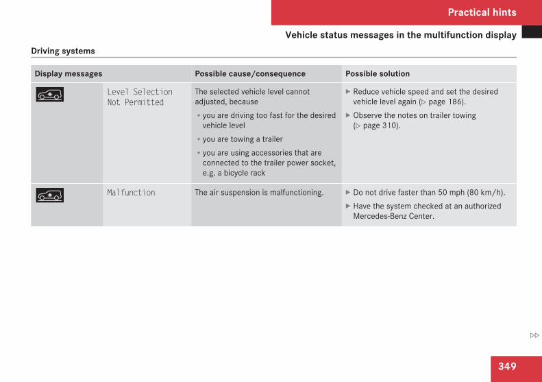
Vehicle status messages in the multifunction display
349
Driving systems
Display messages Possible cause/consequence Possible solution
n Level SelectionNot Permitted
The selected vehicle level cannotadjusted, becauseRyou are driving too fast for the desired
vehicle levelRyou are towing a trailerRyou are using accessories that are
connected to the trailer power socket,e.g. a bicycle rack
X Reduce vehicle speed and set the desiredvehicle level again (Y page 186).
X Observe the notes on trailer towing(Y page 310).
n Malfunction The air suspension is malfunctioning. X Do not drive faster than 50 mph (80 km/h).X Have the system checked at an authorized
Mercedes-Benz Center.
Practical hints
Z
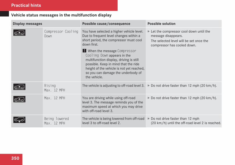
Vehicle status messages in the multifunction display
350
Display messages Possible cause/consequence Possible solution
n Compressor CoolingDown
You have selected a higher vehicle level.Due to frequent level changes within ashort period, the compressor must cooldown first.
! When the message CompressorCooling Down appears in themultifunction display, driving is stillpossible. Keep in mind that the rideheight of the vehicle is not yet reached,so you can damage the underbody ofthe vehicle.
X Let the compressor cool down until themessage disappears.The selected level will be set once thecompressor has cooled down.
n RisingMax. 12 MPH
The vehicle is adjusting to off-road level 3. X Do not drive faster than 12 mph (20 km/h).
n Max. 12 MPH You are driving while using off-roadlevel 3. The message reminds you of themaximum speed at which you may drivewith off-road level 3.
X Do not drive faster than 12 mph (20 km/h).
p Being loweredMax. 12 MPH
The vehicle is being lowered from off-roadlevel 3 to off-road level 2.
X Do not drive faster than 12 mph(20 km/h) until the off-road level 2 is reached.
Practical hints
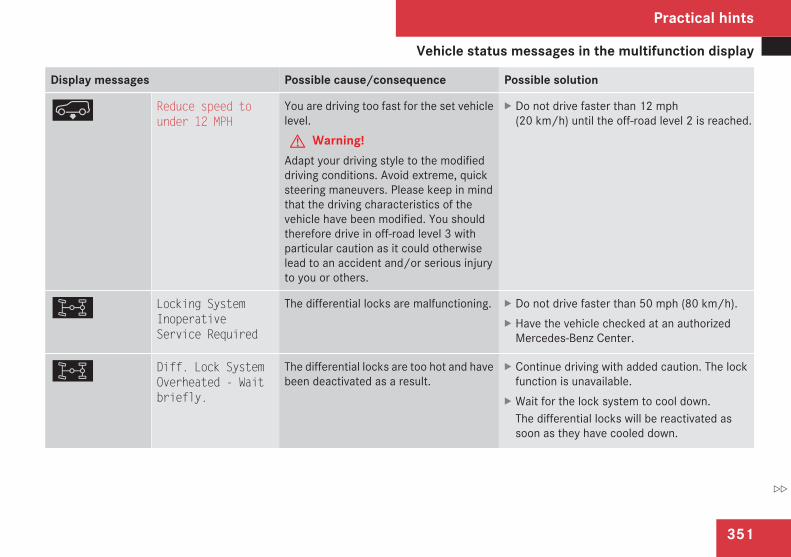
Vehicle status messages in the multifunction display
351
Display messages Possible cause/consequence Possible solution
p Reduce speed tounder 12 MPH
You are driving too fast for the set vehiclelevel.G Warning!
Adapt your driving style to the modifieddriving conditions. Avoid extreme, quicksteering maneuvers. Please keep in mindthat the driving characteristics of thevehicle have been modified. You shouldtherefore drive in off-road level 3 withparticular caution as it could otherwiselead to an accident and/or serious injuryto you or others.
X Do not drive faster than 12 mph(20 km/h) until the off-road level 2 is reached.
< Locking SystemInoperativeService Required
The differential locks are malfunctioning. X Do not drive faster than 50 mph (80 km/h).X Have the vehicle checked at an authorized
Mercedes-Benz Center.
< Diff. Lock SystemOverheated - Waitbriefly.
The differential locks are too hot and havebeen deactivated as a result.
X Continue driving with added caution. The lockfunction is unavailable.
X Wait for the lock system to cool down.The differential locks will be reactivated assoon as they have cooled down.
Practical hints
Z
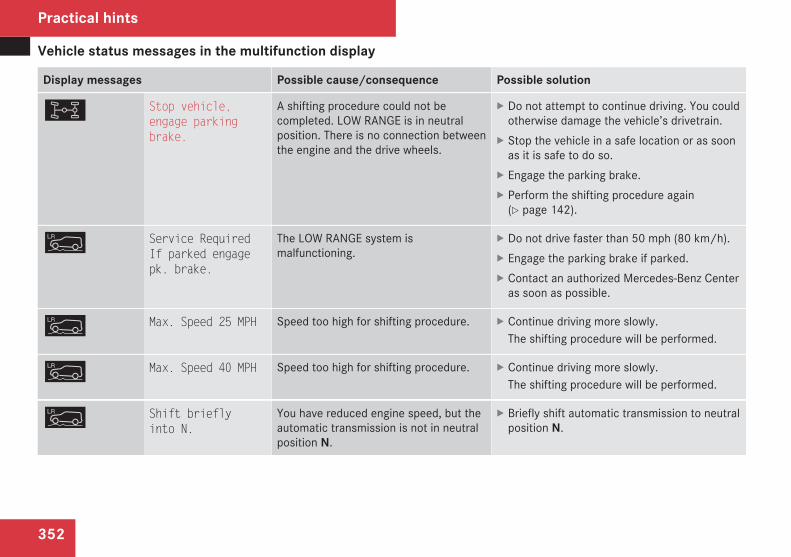
Vehicle status messages in the multifunction display
352
Display messages Possible cause/consequence Possible solution
< Stop vehicle,engage parkingbrake.
A shifting procedure could not becompleted. LOW RANGE is in neutralposition. There is no connection betweenthe engine and the drive wheels.
X Do not attempt to continue driving. You couldotherwise damage the vehicle’s drivetrain.
X Stop the vehicle in a safe location or as soonas it is safe to do so.
X Engage the parking brake.X Perform the shifting procedure again
(Y page 142).
m Service RequiredIf parked engagepk. brake.
The LOW RANGE system ismalfunctioning.
X Do not drive faster than 50 mph (80 km/h).X Engage the parking brake if parked.X Contact an authorized Mercedes-Benz Center
as soon as possible.
m Max. Speed 25 MPH Speed too high for shifting procedure. X Continue driving more slowly.The shifting procedure will be performed.
m Max. Speed 40 MPH Speed too high for shifting procedure. X Continue driving more slowly.The shifting procedure will be performed.
m Shift brieflyinto N.
You have reduced engine speed, but theautomatic transmission is not in neutralposition N.
X Briefly shift automatic transmission to neutralposition N.
Practical hints
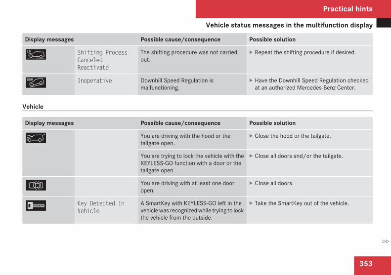
Vehicle status messages in the multifunction display
353
Display messages Possible cause/consequence Possible solution
m Shifting ProcessCanceledReactivate
The shifting procedure was not carriedout.
X Repeat the shifting procedure if desired.
{ Inoperative Downhill Speed Regulation ismalfunctioning.
X Have the Downhill Speed Regulation checkedat an authorized Mercedes-Benz Center.
Vehicle
Display messages Possible cause/consequence Possible solution
a You are driving with the hood or thetailgate open.
X Close the hood or the tailgate.
You are trying to lock the vehicle with theKEYLESS-GO function with a door or thetailgate open.
X Close all doors and/or the tailgate.
V You are driving with at least one dooropen.
X Close all doors.
I Key Detected InVehicle
A SmartKey with KEYLESS-GO left in thevehicle was recognized while trying to lockthe vehicle from the outside.
X Take the SmartKey out of the vehicle.
Practical hints
Z
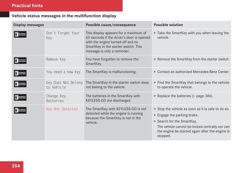
Vehicle status messages in the multifunction display
354
Display messages Possible cause/consequence Possible solution
I Don’t Forget YourKey
This display appears for a maximum of60 seconds if the driver’s door is openedwith the engine turned off and noSmartKey in the starter switch. Thismessage is only a reminder.
X Take the SmartKey with you when leaving thevehicle.
I Remove Key You have forgotten to remove theSmartKey.
X Remove the SmartKey from the starter switch.
I You need a new key. The SmartKey is malfunctioning. X Contact an authorized Mercedes-Benz Center.
I Key Does Not Belongto Vehicle
The SmartKey in the starter switch doesnot belong to the vehicle.
X Find the SmartKey that belongs to the vehicleto operate the vehicle.
I Change KeyBatteries
The batteries in the SmartKey withKEYLESS-GO are discharged.
X Replace the batteries (Y page 386).
I Key Not Detected The SmartKey with KEYLESS-GO is notdetected while the engine is runningbecause the SmartKey is not in thevehicle.
X Stop the vehicle as soon as it is safe to do so.X Engage the parking brake.X Search for the SmartKey.
The vehicle cannot be locked centrally nor canthe engine be started again after the engine isstopped.
Practical hints
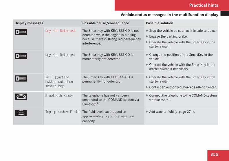
Vehicle status messages in the multifunction display
355
Display messages Possible cause/consequence Possible solution
I Key Not Detected The SmartKey with KEYLESS-GO is notdetected while the engine is runningbecause there is strong radio-frequencyinterference.
X Stop the vehicle as soon as it is safe to do so.X Engage the parking brake.X Operate the vehicle with the SmartKey in the
starter switch.
I Key Not Detected The SmartKey with KEYLESS-GO ismomentarily not detected.
X Change the position of the SmartKey in thevehicle.
X Operate the vehicle with the SmartKey in thestarter switch if necessary.
I Pull startingbutton out theninsert key.
The SmartKey with KEYLESS-GO ispermanently not detected.
X Operate the vehicle with the SmartKey in thestarter switch.
X Contact an authorized Mercedes-Benz Center.
t Bluetooth Ready The telephone has not yet beenconnected to the COMAND system viaBluetooth®.
X Connect the telephone to the COMAND systemvia Bluetooth®.
W Top Up Washer Fluid The fluid level has dropped toapproximately 1/3 of total reservoircapacity.
X Add washer fluid (Y page 271).
Practical hints
Z
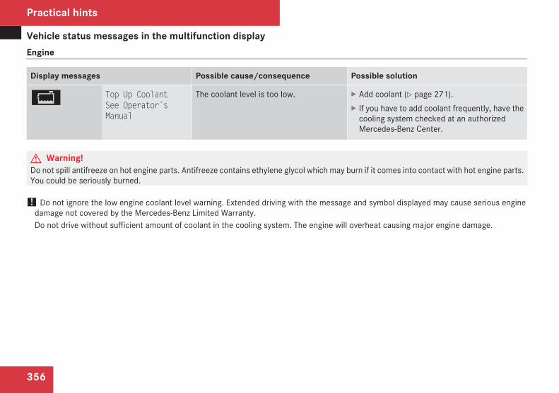
Vehicle status messages in the multifunction display
356
Engine
Display messages Possible cause/consequence Possible solution
B Top Up CoolantSee Operator’sManual
The coolant level is too low. X Add coolant (Y page 271).X If you have to add coolant frequently, have the
cooling system checked at an authorizedMercedes-Benz Center.
G Warning!Do not spill antifreeze on hot engine parts. Antifreeze contains ethylene glycol which may burn if it comes into contact with hot engine parts.You could be seriously burned.
! Do not ignore the low engine coolant level warning. Extended driving with the message and symbol displayed may cause serious enginedamage not covered by the Mercedes-Benz Limited Warranty.Do not drive without sufficient amount of coolant in the cooling system. The engine will overheat causing major engine damage.
Practical hints
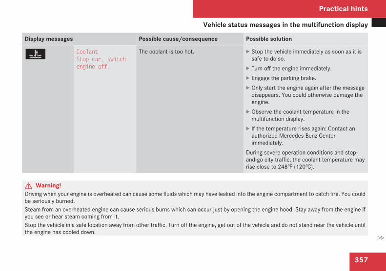
Vehicle status messages in the multifunction display
357
Display messages Possible cause/consequence Possible solution
Ì CoolantStop car, switchengine off.
The coolant is too hot. X Stop the vehicle immediately as soon as it issafe to do so.
X Turn off the engine immediately.X Engage the parking brake.X Only start the engine again after the message
disappears. You could otherwise damage theengine.
X Observe the coolant temperature in themultifunction display.
X If the temperature rises again: Contact anauthorized Mercedes-Benz Centerimmediately.
During severe operation conditions and stop-and-go city traffic, the coolant temperature mayrise close to 248‡ (120†).
G Warning!Driving when your engine is overheated can cause some fluids which may have leaked into the engine compartment to catch fire. You couldbe seriously burned.Steam from an overheated engine can cause serious burns which can occur just by opening the engine hood. Stay away from the engine ifyou see or hear steam coming from it.Stop the vehicle in a safe location away from other traffic. Turn off the engine, get out of the vehicle and do not stand near the vehicle untilthe engine has cooled down.
Practical hints
Z
Vehicle status messages in the multifunction display
358
! The engine should not be operated with the coolant temperature above 248‡ (120†). Doing so may cause serious damage which is notcovered by the Mercedes-Benz Limited Warranty.
Practical hints
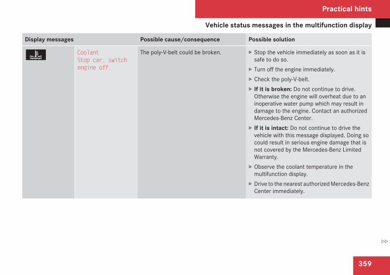
Vehicle status messages in the multifunction display
359
Display messages Possible cause/consequence Possible solution
Ì CoolantStop car, switchengine off.
The poly-V-belt could be broken. X Stop the vehicle immediately as soon as it issafe to do so.
X Turn off the engine immediately.X Check the poly-V-belt.X If it is broken: Do not continue to drive.
Otherwise the engine will overheat due to aninoperative water pump which may result indamage to the engine. Contact an authorizedMercedes-Benz Center.
X If it is intact: Do not continue to drive thevehicle with this message displayed. Doing socould result in serious engine damage that isnot covered by the Mercedes-Benz LimitedWarranty.
X Observe the coolant temperature in themultifunction display.
X Drive to the nearest authorized Mercedes-BenzCenter immediately.
Practical hints
Z
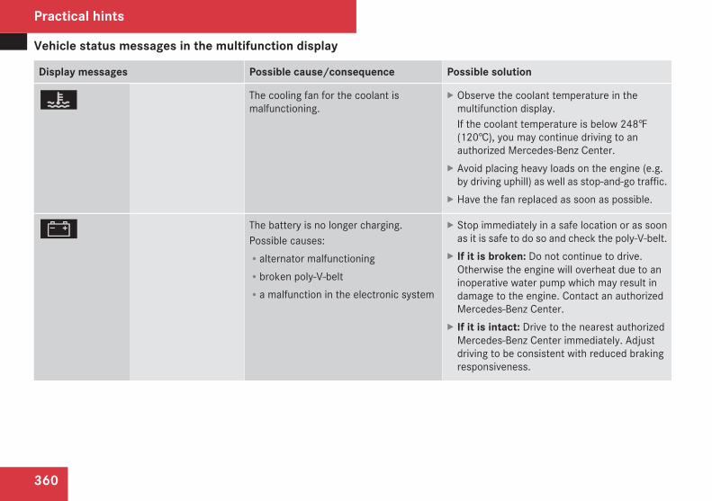
Vehicle status messages in the multifunction display
360
Display messages Possible cause/consequence Possible solution
Ì The cooling fan for the coolant ismalfunctioning.
X Observe the coolant temperature in themultifunction display.If the coolant temperature is below 248‡(120†), you may continue driving to anauthorized Mercedes-Benz Center.
X Avoid placing heavy loads on the engine (e.g.by driving uphill) as well as stop-and-go traffic.
X Have the fan replaced as soon as possible.
# The battery is no longer charging.Possible causes:Ralternator malfunctioningRbroken poly-V-beltRa malfunction in the electronic system
X Stop immediately in a safe location or as soonas it is safe to do so and check the poly-V-belt.
X If it is broken: Do not continue to drive.Otherwise the engine will overheat due to aninoperative water pump which may result indamage to the engine. Contact an authorizedMercedes-Benz Center.
X If it is intact: Drive to the nearest authorizedMercedes-Benz Center immediately. Adjustdriving to be consistent with reduced brakingresponsiveness.
Practical hints
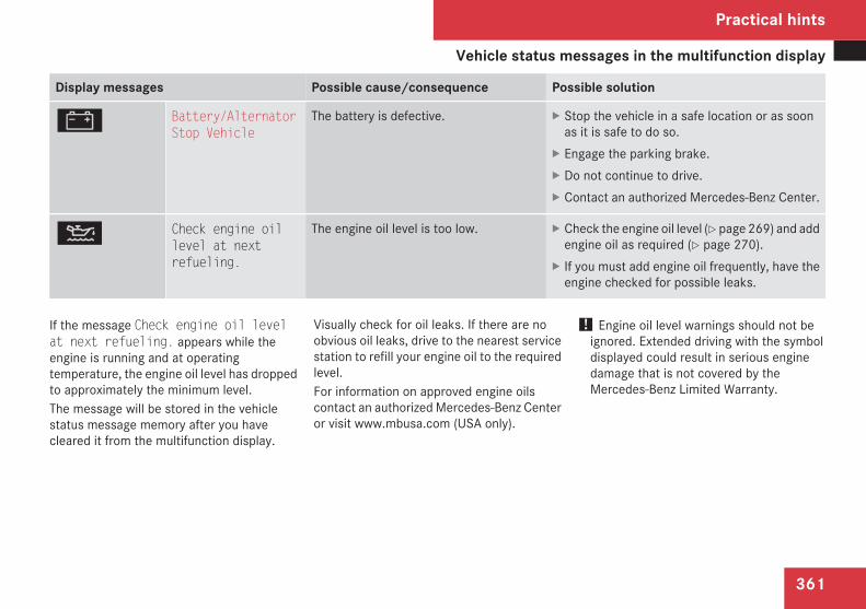
Vehicle status messages in the multifunction display
361
Display messages Possible cause/consequence Possible solution
# Battery/AlternatorStop Vehicle
The battery is defective. X Stop the vehicle in a safe location or as soonas it is safe to do so.
X Engage the parking brake.X Do not continue to drive.X Contact an authorized Mercedes-Benz Center.
N Check engine oillevel at nextrefueling.
The engine oil level is too low. X Check the engine oil level (Y page 269) and addengine oil as required (Y page 270).
X If you must add engine oil frequently, have theengine checked for possible leaks.
If the message Check engine oil levelat next refueling. appears while theengine is running and at operatingtemperature, the engine oil level has droppedto approximately the minimum level.The message will be stored in the vehiclestatus message memory after you havecleared it from the multifunction display.
Visually check for oil leaks. If there are noobvious oil leaks, drive to the nearest servicestation to refill your engine oil to the requiredlevel.For information on approved engine oilscontact an authorized Mercedes-Benz Centeror visit www.mbusa.com (USA only).
! Engine oil level warnings should not beignored. Extended driving with the symboldisplayed could result in serious enginedamage that is not covered by theMercedes-Benz Limited Warranty.
Practical hints
Z

Vehicle status messages in the multifunction display
362
Display messages Possible cause/consequence Possible solution
¿ The fuel level is low. X Refuel at the next gas station.
4 Reserve Fuel The fuel level has dropped below thereserve mark.
X Refuel at the next gas station.
4 Ultra Low-sulfurDiesel Fuel Only
Vehicles with diesel engine only:The fuel level has dropped below thereserve mark.
X Refuel at the next gas station.X Only use commercially available vehicular
ULTRA-LOW SULFUR DIESEL FUEL (15 ppmSULFUR MAXIMUM).
4 Gas Cap Open A loss of pressure has been detected inthe fuel system. The fuel cap may not beclosed properly or the fuel system may beleaky.
X Check the fuel cap (Y page 265).X If it is not closed properly: Close the fuel cap.X If it is closed properly: Have the fuel system
checked at an authorized Mercedes-BenzCenter.
ò Replace air filter The air filter is clogged. X Have the air filter checked at an authorizedMercedes-Benz Center.
] Clean Fuel Filter There is water in the fuel filter. X Have the water drained at an authorizedMercedes-Benz Center as soon as possible.
û Check AdditiveSee Operator'sManual
The AdBlue® supply is almost depleted. X Have the AdBlue® tank refilled as soon aspossible (Y page 405).Contact an authorized Mercedes-Benz Center.
Practical hints
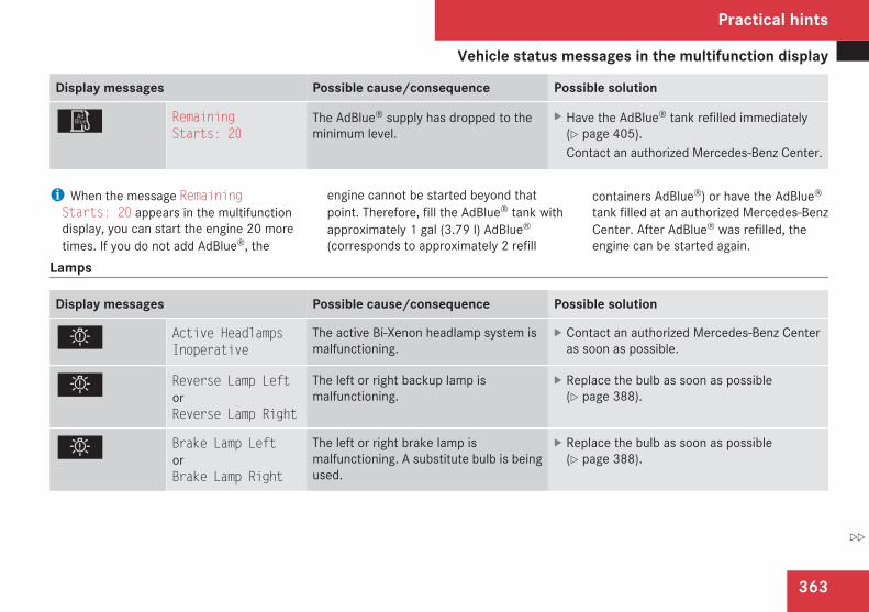
Vehicle status messages in the multifunction display
363
Display messages Possible cause/consequence Possible solution
û RemainingStarts: 20
The AdBlue® supply has dropped to theminimum level.
X Have the AdBlue® tank refilled immediately(Y page 405).Contact an authorized Mercedes-Benz Center.
i When the message RemainingStarts: 20 appears in the multifunctiondisplay, you can start the engine 20 moretimes. If you do not add AdBlue®, the
engine cannot be started beyond thatpoint. Therefore, fill the AdBlue® tank withapproximately 1 gal (3.79 l) AdBlue®
(corresponds to approximately 2 refill
containers AdBlue®) or have the AdBlue®
tank filled at an authorized Mercedes-BenzCenter. After AdBlue® was refilled, theengine can be started again.
Lamps
Display messages Possible cause/consequence Possible solution
. Active HeadlampsInoperative
The active Bi-Xenon headlamp system ismalfunctioning.
X Contact an authorized Mercedes-Benz Centeras soon as possible.
. Reverse Lamp LeftorReverse Lamp Right
The left or right backup lamp ismalfunctioning.
X Replace the bulb as soon as possible(Y page 388).
. Brake Lamp LeftorBrake Lamp Right
The left or right brake lamp ismalfunctioning. A substitute bulb is beingused.
X Replace the bulb as soon as possible(Y page 388).
Practical hints
Z
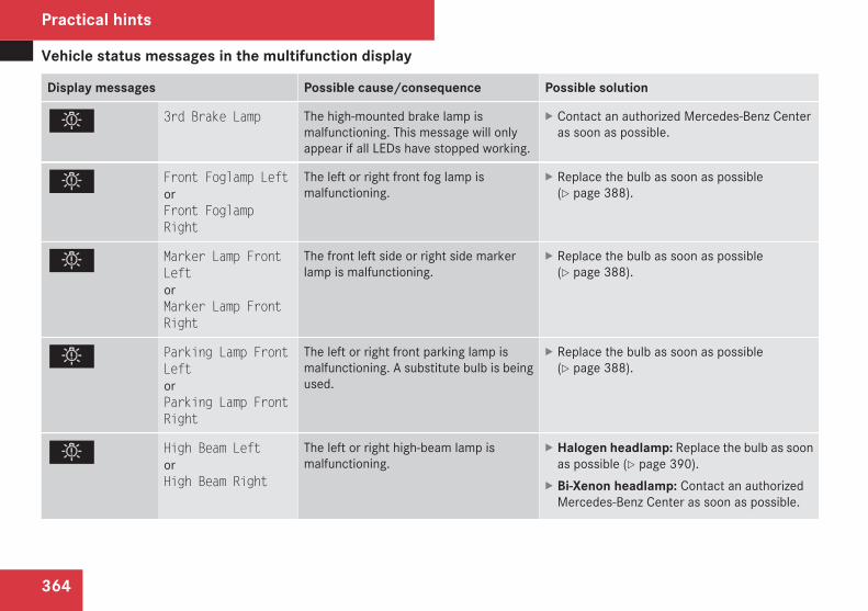
Vehicle status messages in the multifunction display
364
Display messages Possible cause/consequence Possible solution
. 3rd Brake Lamp The high-mounted brake lamp ismalfunctioning. This message will onlyappear if all LEDs have stopped working.
X Contact an authorized Mercedes-Benz Centeras soon as possible.
. Front Foglamp LeftorFront FoglampRight
The left or right front fog lamp ismalfunctioning.
X Replace the bulb as soon as possible(Y page 388).
. Marker Lamp FrontLeftorMarker Lamp FrontRight
The front left side or right side markerlamp is malfunctioning.
X Replace the bulb as soon as possible(Y page 388).
. Parking Lamp FrontLeftorParking Lamp FrontRight
The left or right front parking lamp ismalfunctioning. A substitute bulb is beingused.
X Replace the bulb as soon as possible(Y page 388).
. High Beam LeftorHigh Beam Right
The left or right high-beam lamp ismalfunctioning.
X Halogen headlamp: Replace the bulb as soonas possible (Y page 390).
X Bi-Xenon headlamp: Contact an authorizedMercedes-Benz Center as soon as possible.
Practical hints
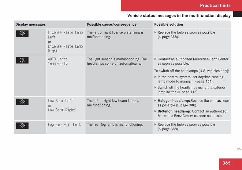
Vehicle status messages in the multifunction display
365
Display messages Possible cause/consequence Possible solution
. License Plate LampLeftorLicense Plate LampRight
The left or right license plate lamp ismalfunctioning.
X Replace the bulb as soon as possible(Y page 388).
. AUTO LightInoperative
The light sensor is malfunctioning. Theheadlamps come on automatically.
X Contact an authorized Mercedes-Benz Centeras soon as possible.
To switch off the headlamps (U.S. vehicles only):X In the control system, set daytime running
lamp mode to manual (Y page 161).X Switch off the headlamps using the exterior
lamp switch (Y page 115).
. Low Beam LeftorLow Beam Right
The left or right low-beam lamp ismalfunctioning.
X Halogen headlamp: Replace the bulb as soonas possible (Y page 388).
X Bi-Xenon headlamp: Contact an authorizedMercedes-Benz Center as soon as possible.
. Foglamp Rear Left The rear fog lamp is malfunctioning. X Replace the bulb as soon as possible(Y page 388).
Practical hints
Z

Vehicle status messages in the multifunction display
366
Display messages Possible cause/consequence Possible solution
. Switch Off Lights You have removed the SmartKey from thestarter switch, opened the driver’s doorand left the headlamps on or removed theSmartKey with KEYLESS-GO from thevehicle and left the headlamps on.
X Turn the exterior lamp switch to M orU (Y page 115).
orX With the rear fog lamp switched on: Push in
the exterior lamp switch to its stop.
. Tail Lamp LeftorTail Lamp Right
The left or right tail lamp ismalfunctioning. A substitute bulb is beingused.
X Replace the bulb as soon as possible(Y page 388).
. Cornering LampLeftorCornering LampRight
The left or right corner-illuminating frontfog lamp is malfunctioning.
X Replace the bulb as soon as possible(Y page 388).
. Trailer Brake Lamp The left or right trailer brake lamp ismalfunctioning.
X Replace the bulb as soon as possible.
. Trailer Tail LampLeftorTrailer Tail LampRight
The left or right trailer tail lamp ismalfunctioning.
X Replace the bulb as soon as possible.
Practical hints
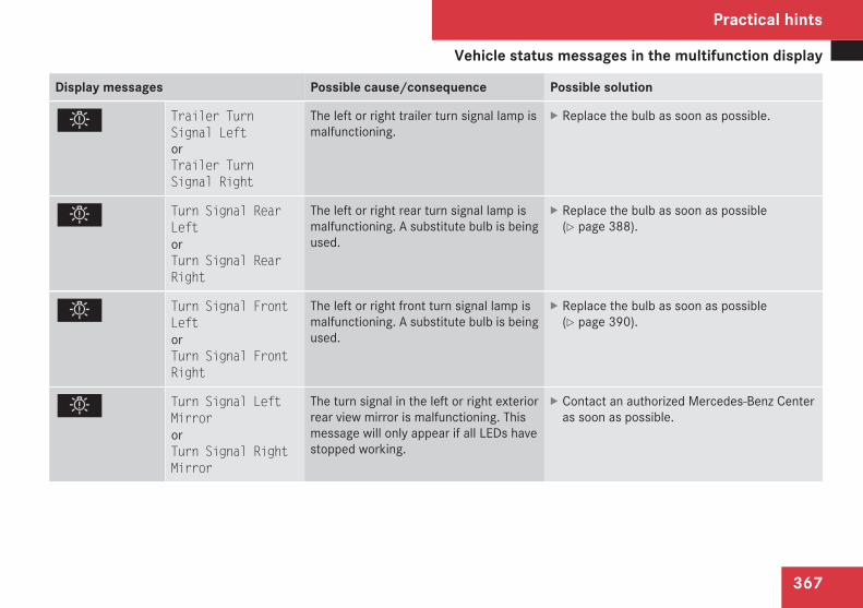
Vehicle status messages in the multifunction display
367
Display messages Possible cause/consequence Possible solution
. Trailer TurnSignal LeftorTrailer TurnSignal Right
The left or right trailer turn signal lamp ismalfunctioning.
X Replace the bulb as soon as possible.
. Turn Signal RearLeftorTurn Signal RearRight
The left or right rear turn signal lamp ismalfunctioning. A substitute bulb is beingused.
X Replace the bulb as soon as possible(Y page 388).
. Turn Signal FrontLeftorTurn Signal FrontRight
The left or right front turn signal lamp ismalfunctioning. A substitute bulb is beingused.
X Replace the bulb as soon as possible(Y page 390).
. Turn Signal LeftMirrororTurn Signal RightMirror
The turn signal in the left or right exteriorrear view mirror is malfunctioning. Thismessage will only appear if all LEDs havestopped working.
X Contact an authorized Mercedes-Benz Centeras soon as possible.
Practical hints
Z
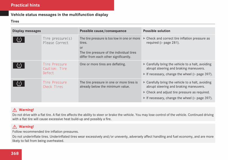
Vehicle status messages in the multifunction display
368
Tires
Display messages Possible cause/consequence Possible solution
H Tire pressure(s)Please Correct
The tire pressure is too low in one or moretires.orThe tire pressure of the individual tiresdiffer from each other significantly.
X Check and correct tire inflation pressure asrequired (Y page 281).
H Tire PressureCaution: TireDefect
One or more tires are deflating. X Carefully bring the vehicle to a halt, avoidingabrupt steering and braking maneuvers.
X If necessary, change the wheel (Y page 397).
H Tire PressureCheck Tires
The tire pressure in one or more tires isalready below the minimum value.
X Carefully bring the vehicle to a halt, avoidingabrupt steering and braking maneuvers.
X Check and adjust tire pressure as required.X If necessary, change the wheel (Y page 397).
G Warning!Do not drive with a flat tire. A flat tire affects the ability to steer or brake the vehicle. You may lose control of the vehicle. Continued drivingwith a flat tire will cause excessive heat build-up and possibly a fire.
G Warning!Follow recommended tire inflation pressures.Do not underinflate tires. Underinflated tires wear excessively and/or unevenly, adversely affect handling and fuel economy, and are morelikely to fail from being overheated.
Practical hints
Vehicle status messages in the multifunction display
369
Do not overinflate tires. Overinflated tires can adversely affect handling and ride comfort, wear unevenly, increase stopping distance, andresult in sudden deflation (blowout) because they are more likely to become punctured or damaged by road debris, potholes etc.
Practical hints
Z
What to do if …
370
What to do if …
Lamps in instrument cluster
NotesIf any of the following lamps in the instrumentcluster fails to come on during the bulb self-
check when switching on the ignition, havethe respective bulb checked and replaced ifnecessary.When you switch on the ignition, all lamps(except high-beam headlamp indicator lamp,and turn signal indicator lamps unlessactivated) in the instrument cluster come on.If a lamp in the instrument cluster fails tocome on when the ignition is switched on,have it checked and replaced if necessary.
Practical hints
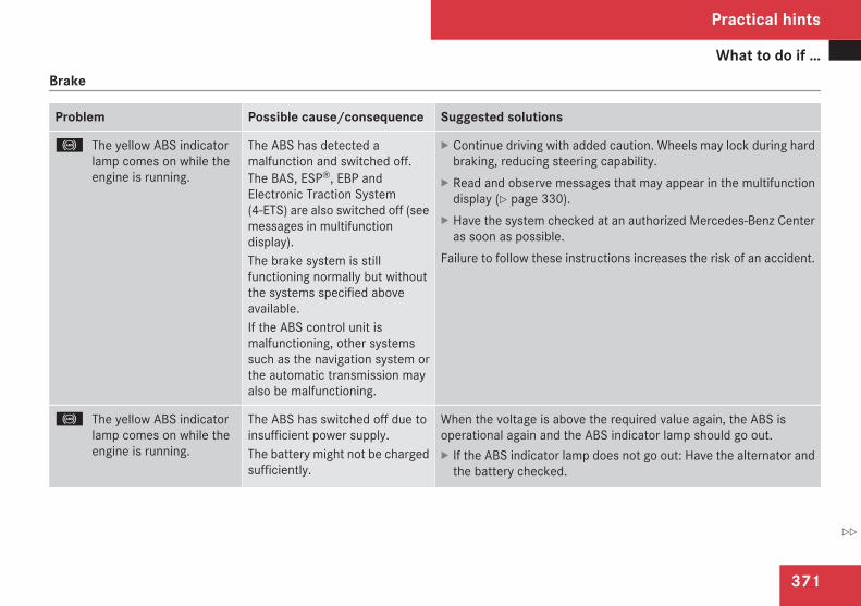
What to do if …
371
Brake
Problem Possible cause/consequence Suggested solutions
- The yellow ABS indicatorlamp comes on while theengine is running.
The ABS has detected amalfunction and switched off.The BAS, ESP®, EBP andElectronic Traction System(4-ETS) are also switched off (seemessages in multifunctiondisplay).The brake system is stillfunctioning normally but withoutthe systems specified aboveavailable.If the ABS control unit ismalfunctioning, other systemssuch as the navigation system orthe automatic transmission mayalso be malfunctioning.
X Continue driving with added caution. Wheels may lock during hardbraking, reducing steering capability.
X Read and observe messages that may appear in the multifunctiondisplay (Y page 330).
X Have the system checked at an authorized Mercedes-Benz Centeras soon as possible.
Failure to follow these instructions increases the risk of an accident.
- The yellow ABS indicatorlamp comes on while theengine is running.
The ABS has switched off due toinsufficient power supply.The battery might not be chargedsufficiently.
When the voltage is above the required value again, the ABS isoperational again and the ABS indicator lamp should go out.X If the ABS indicator lamp does not go out: Have the alternator and
the battery checked.
Practical hints
Z
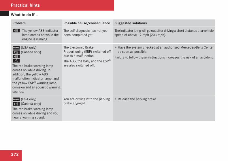
What to do if …
372
Problem Possible cause/consequence Suggested solutions
- The yellow ABS indicatorlamp comes on while theengine is running.
The self-diagnosis has not yetbeen completed yet.
The indicator lamp will go out after driving a short distance at a vehiclespeed of above 12 mph (20 km/h).
; (USA only)3 (Canada only)-v
The red brake warning lampcomes on while driving. Inaddition, the yellow ABSmalfunction indicator lamp, andthe yellow ESP® warning lampcome on and an acoustic warningsounds.
The Electronic BrakeProportioning (EBP) switched offdue to a malfunction.The ABS, the BAS, and the ESP®
are also switched off.
X Have the system checked at an authorized Mercedes-Benz Centeras soon as possible.
Failure to follow these instructions increases the risk of an accident.
; (USA only)3 (Canada only)The red brake warning lampcomes on while driving and youhear a warning sound.
You are driving with the parkingbrake engaged.
X Release the parking brake.
Practical hints
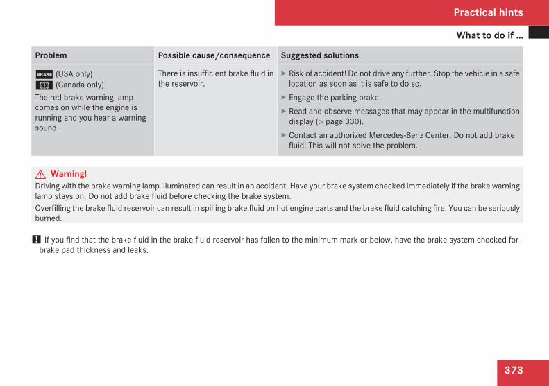
What to do if …
373
Problem Possible cause/consequence Suggested solutions
; (USA only)3 (Canada only)The red brake warning lampcomes on while the engine isrunning and you hear a warningsound.
There is insufficient brake fluid inthe reservoir.
X Risk of accident! Do not drive any further. Stop the vehicle in a safelocation as soon as it is safe to do so.
X Engage the parking brake.X Read and observe messages that may appear in the multifunction
display (Y page 330).X Contact an authorized Mercedes-Benz Center. Do not add brake
fluid! This will not solve the problem.
G Warning!Driving with the brake warning lamp illuminated can result in an accident. Have your brake system checked immediately if the brake warninglamp stays on. Do not add brake fluid before checking the brake system.Overfilling the brake fluid reservoir can result in spilling brake fluid on hot engine parts and the brake fluid catching fire. You can be seriouslyburned.
! If you find that the brake fluid in the brake fluid reservoir has fallen to the minimum mark or below, have the brake system checked forbrake pad thickness and leaks.
Practical hints
Z
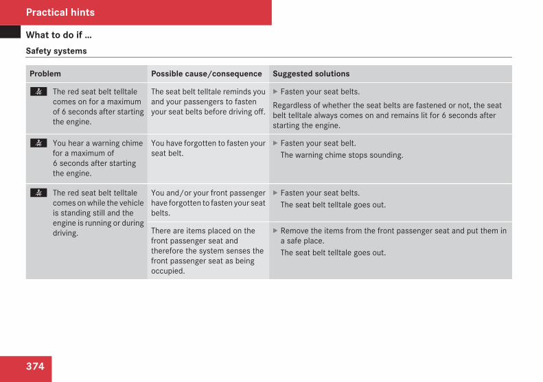
What to do if …
374
Safety systems
Problem Possible cause/consequence Suggested solutions
< The red seat belt telltalecomes on for a maximumof 6 seconds after startingthe engine.
The seat belt telltale reminds youand your passengers to fastenyour seat belts before driving off.
X Fasten your seat belts.Regardless of whether the seat belts are fastened or not, the seatbelt telltale always comes on and remains lit for 6 seconds afterstarting the engine.
< You hear a warning chimefor a maximum of6 seconds after startingthe engine.
You have forgotten to fasten yourseat belt.
X Fasten your seat belt.The warning chime stops sounding.
< The red seat belt telltalecomes on while the vehicleis standing still and theengine is running or duringdriving.
You and/or your front passengerhave forgotten to fasten your seatbelts.
X Fasten your seat belts.The seat belt telltale goes out.
There are items placed on thefront passenger seat andtherefore the system senses thefront passenger seat as beingoccupied.
X Remove the items from the front passenger seat and put them ina safe place.The seat belt telltale goes out.
Practical hints
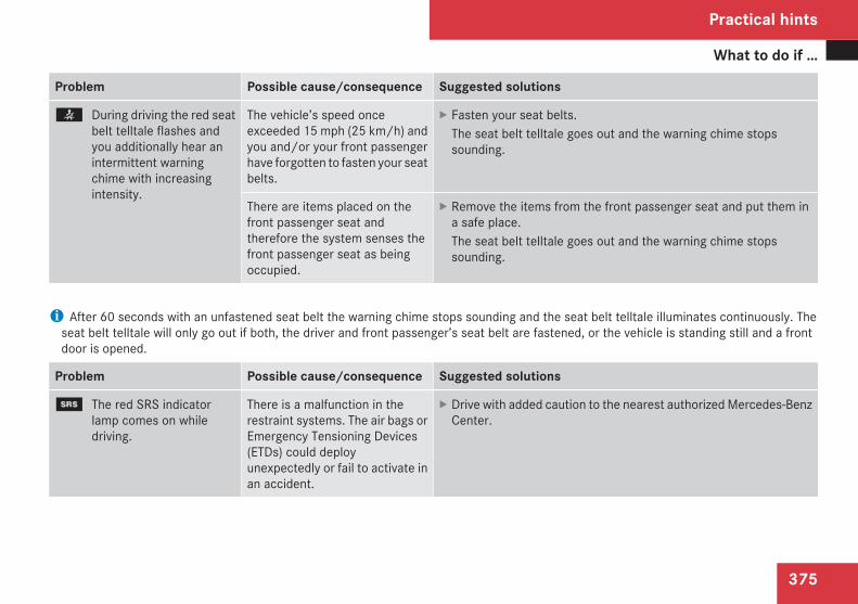
What to do if …
375
Problem Possible cause/consequence Suggested solutions
< During driving the red seatbelt telltale flashes andyou additionally hear anintermittent warningchime with increasingintensity.
The vehicle’s speed onceexceeded 15 mph (25 km/h) andyou and/or your front passengerhave forgotten to fasten your seatbelts.
X Fasten your seat belts.The seat belt telltale goes out and the warning chime stopssounding.
There are items placed on thefront passenger seat andtherefore the system senses thefront passenger seat as beingoccupied.
X Remove the items from the front passenger seat and put them ina safe place.The seat belt telltale goes out and the warning chime stopssounding.
i After 60 seconds with an unfastened seat belt the warning chime stops sounding and the seat belt telltale illuminates continuously. Theseat belt telltale will only go out if both, the driver and front passenger’s seat belt are fastened, or the vehicle is standing still and a frontdoor is opened.
Problem Possible cause/consequence Suggested solutions
1 The red SRS indicatorlamp comes on whiledriving.
There is a malfunction in therestraint systems. The air bags orEmergency Tensioning Devices(ETDs) could deployunexpectedly or fail to activate inan accident.
X Drive with added caution to the nearest authorized Mercedes-BenzCenter.
Practical hints
Z
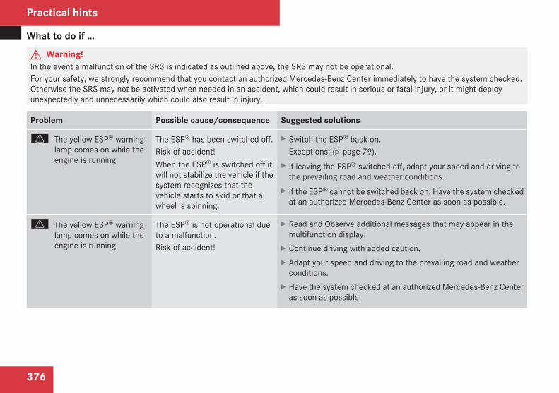
What to do if …
376
G Warning!In the event a malfunction of the SRS is indicated as outlined above, the SRS may not be operational.For your safety, we strongly recommend that you contact an authorized Mercedes-Benz Center immediately to have the system checked.Otherwise the SRS may not be activated when needed in an accident, which could result in serious or fatal injury, or it might deployunexpectedly and unnecessarily which could also result in injury.
Problem Possible cause/consequence Suggested solutions
v The yellow ESP® warninglamp comes on while theengine is running.
The ESP® has been switched off.Risk of accident!When the ESP® is switched off itwill not stabilize the vehicle if thesystem recognizes that thevehicle starts to skid or that awheel is spinning.
X Switch the ESP® back on.Exceptions: (Y page 79).
X If leaving the ESP® switched off, adapt your speed and driving tothe prevailing road and weather conditions.
X If the ESP® cannot be switched back on: Have the system checkedat an authorized Mercedes-Benz Center as soon as possible.
v The yellow ESP® warninglamp comes on while theengine is running.
The ESP® is not operational dueto a malfunction.Risk of accident!
X Read and Observe additional messages that may appear in themultifunction display.
X Continue driving with added caution.X Adapt your speed and driving to the prevailing road and weather
conditions.X Have the system checked at an authorized Mercedes-Benz Center
as soon as possible.
Practical hints
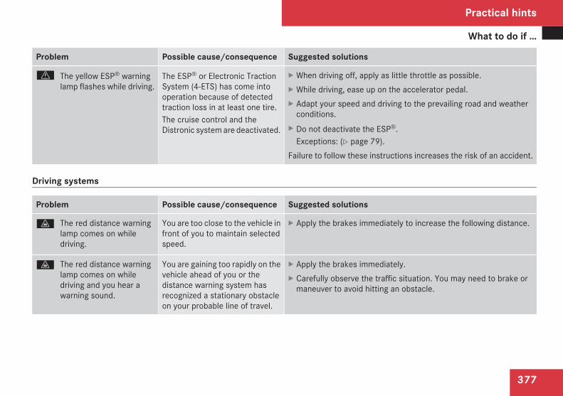
What to do if …
377
Problem Possible cause/consequence Suggested solutions
v The yellow ESP® warninglamp flashes while driving.
The ESP® or Electronic TractionSystem (4-ETS) has come intooperation because of detectedtraction loss in at least one tire.The cruise control and theDistronic system are deactivated.
X When driving off, apply as little throttle as possible.X While driving, ease up on the accelerator pedal.X Adapt your speed and driving to the prevailing road and weather
conditions.X Do not deactivate the ESP®.
Exceptions: (Y page 79).Failure to follow these instructions increases the risk of an accident.
Driving systems
Problem Possible cause/consequence Suggested solutions
l The red distance warninglamp comes on whiledriving.
You are too close to the vehicle infront of you to maintain selectedspeed.
X Apply the brakes immediately to increase the following distance.
l The red distance warninglamp comes on whiledriving and you hear awarning sound.
You are gaining too rapidly on thevehicle ahead of you or thedistance warning system hasrecognized a stationary obstacleon your probable line of travel.
X Apply the brakes immediately.X Carefully observe the traffic situation. You may need to brake or
maneuver to avoid hitting an obstacle.
Practical hints
Z
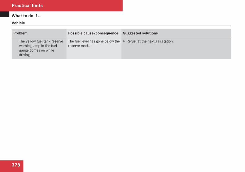
What to do if …
378
Vehicle
Problem Possible cause/consequence Suggested solutions
The yellow fuel tank reservewarning lamp in the fuelgauge comes on whiledriving.
The fuel level has gone below thereserve mark.
X Refuel at the next gas station.
Practical hints
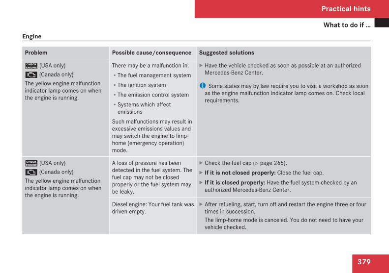
What to do if …
379
Engine
Problem Possible cause/consequence Suggested solutions
? (USA only)± (Canada only)The yellow engine malfunctionindicator lamp comes on whenthe engine is running.
There may be a malfunction in:RThe fuel management systemRThe ignition systemRThe emission control systemRSystems which affect
emissionsSuch malfunctions may result inexcessive emissions values andmay switch the engine to limp-home (emergency operation)mode.
X Have the vehicle checked as soon as possible at an authorizedMercedes-Benz Center.
i Some states may by law require you to visit a workshop as soonas the engine malfunction indicator lamp comes on. Check localrequirements.
? (USA only)± (Canada only)The yellow engine malfunctionindicator lamp comes on whenthe engine is running.
A loss of pressure has beendetected in the fuel system. Thefuel cap may not be closedproperly or the fuel system maybe leaky.
X Check the fuel cap (Y page 265).X If it is not closed properly: Close the fuel cap.X If it is closed properly: Have the fuel system checked by an
authorized Mercedes-Benz Center.
Diesel engine: Your fuel tank wasdriven empty.
X After refueling, start, turn off and restart the engine three or fourtimes in succession.The limp-home mode is canceled. You do not need to have yourvehicle checked.
Practical hints
Z
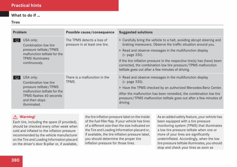
What to do if …
380
Tires
Problem Possible cause/consequence Suggested solutions
H USA only:Combination low tirepressure telltale/TPMSmalfunction telltale for theTPMS illuminatescontinuously.
The TPMS detects a loss ofpressure in at least one tire.
X Carefully bring the vehicle to a halt, avoiding abrupt steering andbraking maneuvers. Observe the traffic situation around you.
X Read and observe messages in the multifunction display(Y page 330).
If the tire inflation pressure in the respective tire(s) has (have) beencorrected, the combination low tire pressure/TPMS malfunctiontelltale goes out after a few minutes of driving.
H USA only:Combination low tirepressure telltale/TPMSmalfunction telltale for theTPMS flashes 60 secondsand then staysilluminated.
There is a malfunction in theTPMS.
X Read and observe messages in the multifunction display(Y page 330).
X Have the TPMS checked by an authorized Mercedes-Benz Center.After the malfunction has been remedied, the combination low tirepressure/TPMS malfunction telltale goes out after a few minutes ofdriving.
G Warning!Each tire, including the spare (if provided),should be checked every other week whencold and inflated to the inflation pressurerecommended by the vehicle manufactureron the Tire and Loading Information placardon the driver’s door B-pillar or, if available,
the tire inflation pressure label on the insideof the fuel filler flap. If your vehicle has tiresof a different size than the size indicated onthe Tire and Loading Information placard or,if available, the tire inflation pressure label,you should determine the proper tireinflation pressure for those tires.
As an added safety feature, your vehicle hasbeen equipped with a tire pressuremonitoring system (TPMS) that illuminatesa low tire pressure telltale when one ormore of your tires are significantlyunderinflated. Accordingly, when the lowtire pressure telltale illuminates, you shouldstop and check your tires as soon as
Practical hints
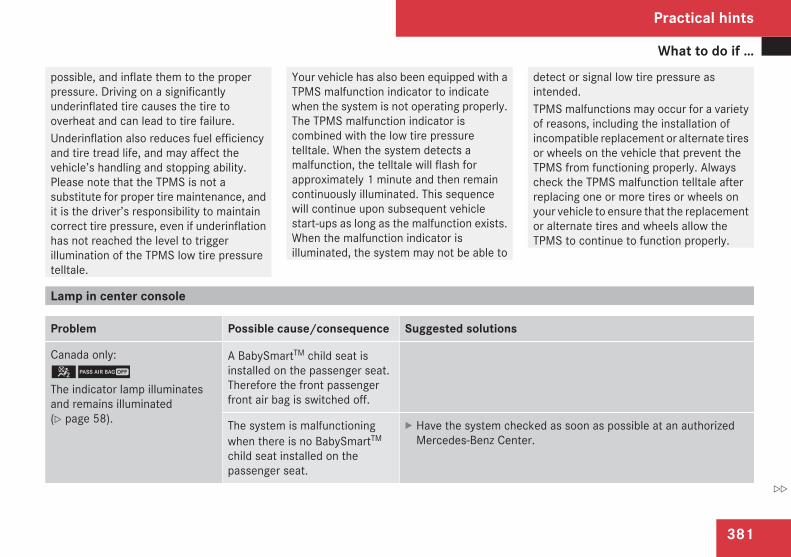
What to do if …
381
possible, and inflate them to the properpressure. Driving on a significantlyunderinflated tire causes the tire tooverheat and can lead to tire failure.Underinflation also reduces fuel efficiencyand tire tread life, and may affect thevehicle’s handling and stopping ability.Please note that the TPMS is not asubstitute for proper tire maintenance, andit is the driver’s responsibility to maintaincorrect tire pressure, even if underinflationhas not reached the level to triggerillumination of the TPMS low tire pressuretelltale.
Your vehicle has also been equipped with aTPMS malfunction indicator to indicatewhen the system is not operating properly.The TPMS malfunction indicator iscombined with the low tire pressuretelltale. When the system detects amalfunction, the telltale will flash forapproximately 1 minute and then remaincontinuously illuminated. This sequencewill continue upon subsequent vehiclestart-ups as long as the malfunction exists.When the malfunction indicator isilluminated, the system may not be able to
detect or signal low tire pressure asintended.TPMS malfunctions may occur for a varietyof reasons, including the installation ofincompatible replacement or alternate tiresor wheels on the vehicle that prevent theTPMS from functioning properly. Alwayscheck the TPMS malfunction telltale afterreplacing one or more tires or wheels onyour vehicle to ensure that the replacementor alternate tires and wheels allow theTPMS to continue to function properly.
Lamp in center console
Problem Possible cause/consequence Suggested solutions
Canada only:59
The indicator lamp illuminatesand remains illuminated(Y page 58).
A BabySmartTM child seat isinstalled on the passenger seat.Therefore the front passengerfront air bag is switched off.
The system is malfunctioningwhen there is no BabySmartTM
child seat installed on thepassenger seat.
X Have the system checked as soon as possible at an authorizedMercedes-Benz Center.
Practical hints
Z
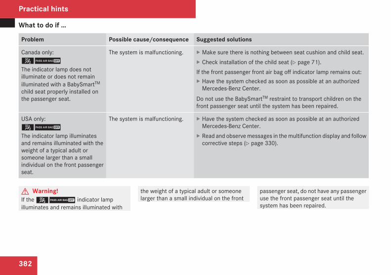
What to do if …
382
Problem Possible cause/consequence Suggested solutions
Canada only:59
The indicator lamp does notilluminate or does not remainilluminated with a BabySmartTM
child seat properly installed onthe passenger seat.
The system is malfunctioning. X Make sure there is nothing between seat cushion and child seat.X Check installation of the child seat (Y page 71).If the front passenger front air bag off indicator lamp remains out:X Have the system checked as soon as possible at an authorized
Mercedes-Benz Center.
Do not use the BabySmartTM restraint to transport children on thefront passenger seat until the system has been repaired.
USA only:59
The indicator lamp illuminatesand remains illuminated with theweight of a typical adult orsomeone larger than a smallindividual on the front passengerseat.
The system is malfunctioning. X Have the system checked as soon as possible at an authorizedMercedes-Benz Center.
X Read and observe messages in the multifunction display and followcorrective steps (Y page 330).
G Warning!If the 59 indicator lampilluminates and remains illuminated with
the weight of a typical adult or someonelarger than a small individual on the front
passenger seat, do not have any passengeruse the front passenger seat until thesystem has been repaired.
Practical hints
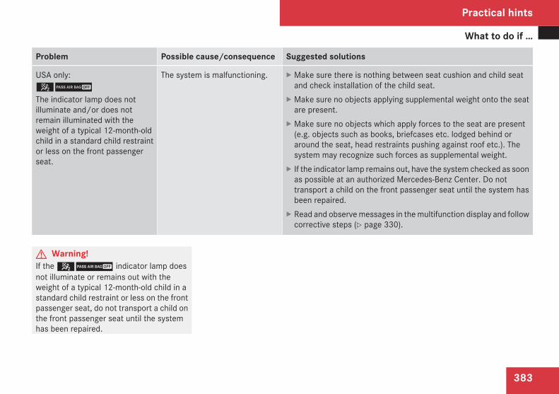
What to do if …
383
Problem Possible cause/consequence Suggested solutions
USA only:59
The indicator lamp does notilluminate and/or does notremain illuminated with theweight of a typical 12-month-oldchild in a standard child restraintor less on the front passengerseat.
The system is malfunctioning. X Make sure there is nothing between seat cushion and child seatand check installation of the child seat.
X Make sure no objects applying supplemental weight onto the seatare present.
X Make sure no objects which apply forces to the seat are present(e.g. objects such as books, briefcases etc. lodged behind oraround the seat, head restraints pushing against roof etc.). Thesystem may recognize such forces as supplemental weight.
X If the indicator lamp remains out, have the system checked as soonas possible at an authorized Mercedes-Benz Center. Do nottransport a child on the front passenger seat until the system hasbeen repaired.
X Read and observe messages in the multifunction display and followcorrective steps (Y page 330).
G Warning!If the 59 indicator lamp doesnot illuminate or remains out with theweight of a typical 12-month-old child in astandard child restraint or less on the frontpassenger seat, do not transport a child onthe front passenger seat until the systemhas been repaired.
Practical hints
Z
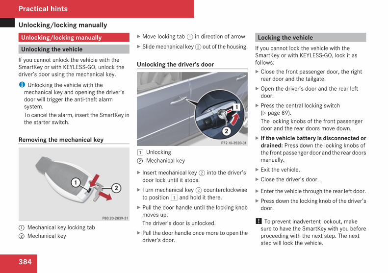
Unlocking/locking manually
384
Unlocking/locking manually
Unlocking the vehicleIf you cannot unlock the vehicle with theSmartKey or with KEYLESS-GO, unlock thedriver’s door using the mechanical key.
i Unlocking the vehicle with themechanical key and opening the driver’sdoor will trigger the anti-theft alarmsystem.To cancel the alarm, insert the SmartKey inthe starter switch.
Removing the mechanical key
1 Mechanical key locking tab2 Mechanical key
X Move locking tab 1 in direction of arrow.X Slide mechanical key 2 out of the housing.
Unlocking the driver’s door
$ Unlocking2 Mechanical key
X Insert mechanical key 2 into the driver’sdoor lock until it stops.
X Turn mechanical key 2 counterclockwiseto position $ and hold it there.
X Pull the door handle until the locking knobmoves up.The driver’s door is unlocked.
X Pull the door handle once more to open thedriver’s door.
Locking the vehicleIf you cannot lock the vehicle with theSmartKey or with KEYLESS-GO, lock it asfollows:X Close the front passenger door, the right
rear door and the tailgate.X Open the driver’s door and the rear left
door.X Press the central locking switch
(Y page 89).The locking knobs of the front passengerdoor and the rear doors move down.
X If the vehicle battery is disconnected ordrained: Press down the locking knobs ofthe front passenger door and the rear doorsmanually.
X Exit the vehicle.X Close the driver’s door.
X Enter the vehicle through the rear left door.X Press down the locking knob of the driver’s
door.
! To prevent inadvertent lockout, makesure to have the SmartKey with you beforeproceeding with the next step. The nextstep will lock the vehicle.
Practical hints
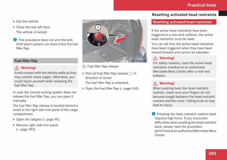
Resetting activated head restraints
385
X Exit the vehicle.X Close the rear left door.
The vehicle is locked.
i This procedure does not arm the anti-theft alarm system, nor does it lock the fuelfiller flap.
Fuel filler flap
G Warning!Avoid contact with the vehicle walls as theymay contain sharp edges. Otherwise, youcould injure yourself while releasing thefuel filler flap.
In case the central locking system does notrelease the fuel filler flap, you can open itmanually.The fuel filler flap release is located behind acover in the right side trim panel of the cargocompartment.X Open the tailgate (Y page 90).X Remove right side trim panel
(Y page 393).
1 Fuel filler flap release
X Pull red fuel filler flap release 1 indirection of arrow.The fuel filler flap is unlocked.
X Open the fuel filler flap (Y page 265).
Resetting activated head restraints
If the active head restraints have beentriggered in a rear-end collision, the activehead restraints must be reset.You can tell that the active head restraintshave been triggered when they have beenmoved forward and cannot be adjusted.G Warning!For safety reasons, have the active headrestraints checked at an authorizedMercedes-Benz Center after a rear-endcollision.
G Warning!When pushing back the head restraintcushion, make sure your fingers do notbecome caught between the head restraintcushion and the cover. Failing to do so maylead to injury.
i Pressing the head restraint cushion backrequires high force. If you encounterdifficulties when pushing the head restraintback, please have the procedureperformed at an authorized Mercedes-BenzCenter.
Practical hints
Z
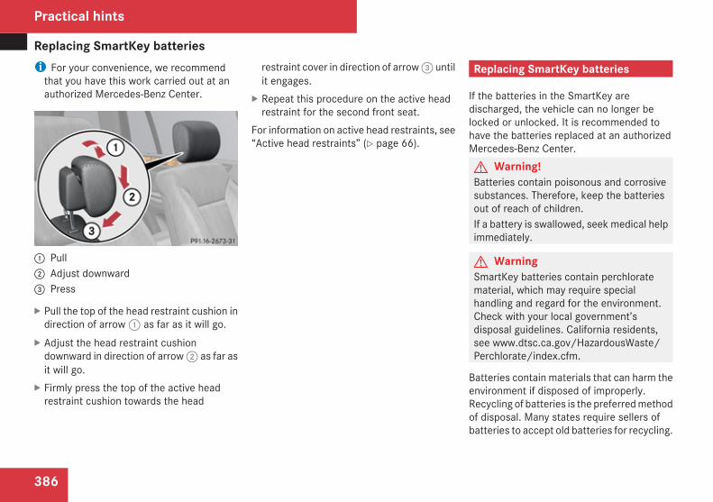
Replacing SmartKey batteries
386
i For your convenience, we recommendthat you have this work carried out at anauthorized Mercedes-Benz Center.
1 Pull2 Adjust downward3 Press
X Pull the top of the head restraint cushion indirection of arrow 1 as far as it will go.
X Adjust the head restraint cushiondownward in direction of arrow 2 as far asit will go.
X Firmly press the top of the active headrestraint cushion towards the head
restraint cover in direction of arrow 3 untilit engages.
X Repeat this procedure on the active headrestraint for the second front seat.
For information on active head restraints, see“Active head restraints” (Y page 66).
Replacing SmartKey batteries
If the batteries in the SmartKey aredischarged, the vehicle can no longer belocked or unlocked. It is recommended tohave the batteries replaced at an authorizedMercedes-Benz Center.G Warning!Batteries contain poisonous and corrosivesubstances. Therefore, keep the batteriesout of reach of children.If a battery is swallowed, seek medical helpimmediately.
G WarningSmartKey batteries contain perchloratematerial, which may require specialhandling and regard for the environment.Check with your local government’sdisposal guidelines. California residents,see www.dtsc.ca.gov/HazardousWaste/Perchlorate/index.cfm.
Batteries contain materials that can harm theenvironment if disposed of improperly.Recycling of batteries is the preferred methodof disposal. Many states require sellers ofbatteries to accept old batteries for recycling.
Practical hints
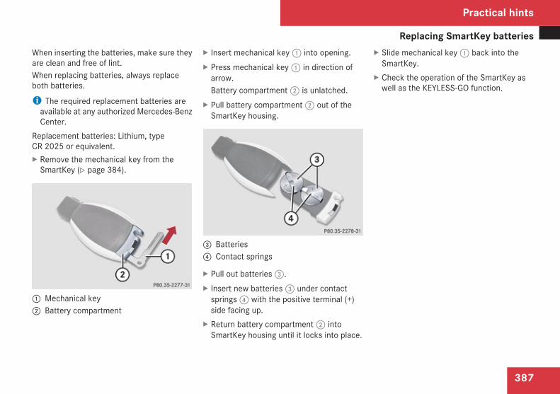
Replacing SmartKey batteries
387
When inserting the batteries, make sure theyare clean and free of lint.When replacing batteries, always replaceboth batteries.
i The required replacement batteries areavailable at any authorized Mercedes-BenzCenter.
Replacement batteries: Lithium, typeCR 2025 or equivalent.X Remove the mechanical key from the
SmartKey (Y page 384).
1 Mechanical key2 Battery compartment
X Insert mechanical key 1 into opening.X Press mechanical key 1 in direction of
arrow.Battery compartment 2 is unlatched.
X Pull battery compartment 2 out of theSmartKey housing.
3 Batteries4 Contact springs
X Pull out batteries 3.X Insert new batteries 3 under contact
springs 4 with the positive terminal (+)side facing up.
X Return battery compartment 2 intoSmartKey housing until it locks into place.
X Slide mechanical key 1 back into theSmartKey.
X Check the operation of the SmartKey aswell as the KEYLESS-GO function.
Practical hints
Z
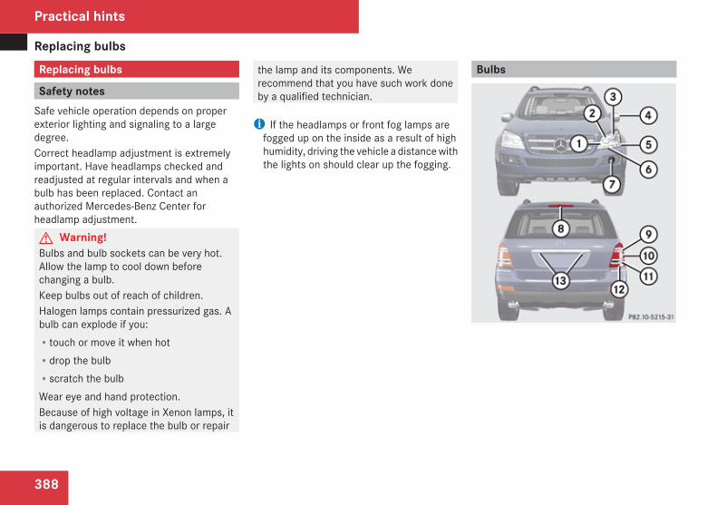
Replacing bulbs
388
Replacing bulbs
Safety notesSafe vehicle operation depends on properexterior lighting and signaling to a largedegree.Correct headlamp adjustment is extremelyimportant. Have headlamps checked andreadjusted at regular intervals and when abulb has been replaced. Contact anauthorized Mercedes-Benz Center forheadlamp adjustment.G Warning!Bulbs and bulb sockets can be very hot.Allow the lamp to cool down beforechanging a bulb.Keep bulbs out of reach of children.Halogen lamps contain pressurized gas. Abulb can explode if you:Rtouch or move it when hotRdrop the bulbRscratch the bulbWear eye and hand protection.Because of high voltage in Xenon lamps, itis dangerous to replace the bulb or repair
the lamp and its components. Werecommend that you have such work doneby a qualified technician.
i If the headlamps or front fog lamps arefogged up on the inside as a result of highhumidity, driving the vehicle a distance withthe lights on should clear up the fogging.
Bulbs
Practical hints
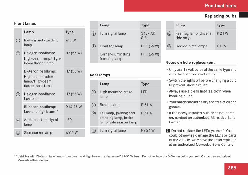
Replacing bulbs
389
Front lamps
Lamp Type
1 Parking and standinglamp
W 5 W
2 Halogen headlamp:High-beam lamp/High-beam flasher lamp
H7 (55 W)
Bi-Xenon headlamp:High-beam flasherlamp/High-beamflasher spot lamp
H7 (55 W)
3 Halogen headlamp:Low beam
H7 (55 W)
Bi-Xenon headlamp:Low and high beam17
D1S-35 W
4 Additional turn signallamp
LED
5 Side marker lamp WY 5 W
Lamp Type
6 Turn signal lamp 3457 AKS-8
7 Front fog lamp H11 (55 W)
Corner-illuminatingfront fog lamp
H11 (55 W)
Rear lamps
Lamp Type
8 High-mounted brakelamp
LED
9 Backup lamp P 21 W
a Tail lamp, parking andstanding lamp, brakelamp, side marker lamp
P 21 W
b Turn signal lamp PY 21 W
Lamp Type
c Rear fog lamp (driver’sside only)
P 21 W
d License plate lamps C 5 W
Notes on bulb replacementROnly use 12 volt bulbs of the same type and
with the specified watt rating.RSwitch the lights off before changing a bulb
to prevent short circuits.RAlways use a clean lint-free cloth when
handling bulbs.RYour hands should be dry and free of oil and
grease.RIf the newly installed bulb does not come
on, contact an authorized Mercedes-BenzCenter.
! Do not replace the LEDs yourself. Youcould otherwise damage the LEDs or partsof the vehicle. Only have the LEDs replacedat an authorized Mercedes-Benz Center.
17 Vehicles with Bi-Xenon headlamps: Low beam and high beam use the same D1S-35 W lamp. Do not replace the Bi-Xenon bulbs yourself. Contact an authorizedMercedes-Benz Center.
Practical hints
Z
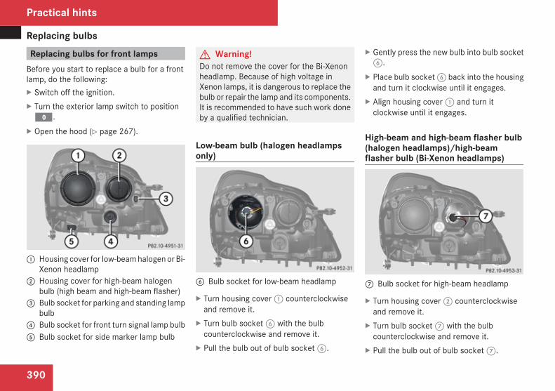
Replacing bulbs
390
Replacing bulbs for front lampsBefore you start to replace a bulb for a frontlamp, do the following:X Switch off the ignition.X Turn the exterior lamp switch to positionM.
X Open the hood (Y page 267).
1 Housing cover for low-beam halogen or Bi-Xenon headlamp
2 Housing cover for high-beam halogenbulb (high beam and high-beam flasher)
3 Bulb socket for parking and standing lampbulb
4 Bulb socket for front turn signal lamp bulb5 Bulb socket for side marker lamp bulb
G Warning!Do not remove the cover for the Bi-Xenonheadlamp. Because of high voltage inXenon lamps, it is dangerous to replace thebulb or repair the lamp and its components.It is recommended to have such work doneby a qualified technician.
Low-beam bulb (halogen headlampsonly)
6 Bulb socket for low-beam headlamp
X Turn housing cover 1 counterclockwiseand remove it.
X Turn bulb socket 6 with the bulbcounterclockwise and remove it.
X Pull the bulb out of bulb socket 6.
X Gently press the new bulb into bulb socket6.
X Place bulb socket 6 back into the housingand turn it clockwise until it engages.
X Align housing cover 1 and turn itclockwise until it engages.
High-beam and high-beam flasher bulb(halogen headlamps)/high-beamflasher bulb (Bi-Xenon headlamps)
7 Bulb socket for high-beam headlamp
X Turn housing cover 2 counterclockwiseand remove it.
X Turn bulb socket 7 with the bulbcounterclockwise and remove it.
X Pull the bulb out of bulb socket 7.
Practical hints
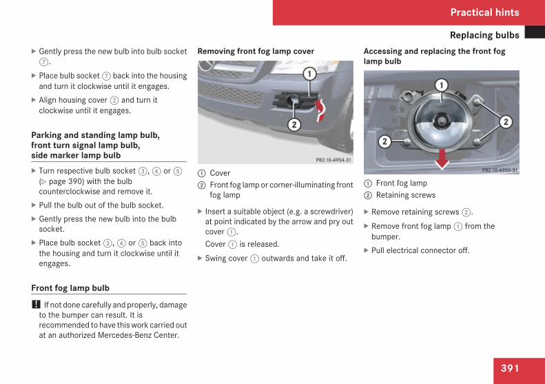
Replacing bulbs
391
X Gently press the new bulb into bulb socket7.
X Place bulb socket 7 back into the housingand turn it clockwise until it engages.
X Align housing cover 2 and turn itclockwise until it engages.
Parking and standing lamp bulb,front turn signal lamp bulb,side marker lamp bulbX Turn respective bulb socket 3, 4 or 5
(Y page 390) with the bulbcounterclockwise and remove it.
X Pull the bulb out of the bulb socket.X Gently press the new bulb into the bulb
socket.X Place bulb socket 3, 4 or 5 back into
the housing and turn it clockwise until itengages.
Front fog lamp bulb! If not done carefully and properly, damage
to the bumper can result. It isrecommended to have this work carried outat an authorized Mercedes-Benz Center.
Removing front fog lamp cover
1 Cover2 Front fog lamp or corner-illuminating front
fog lamp
X Insert a suitable object (e.g. a screwdriver)at point indicated by the arrow and pry outcover 1.Cover 1 is released.
X Swing cover 1 outwards and take it off.
Accessing and replacing the front foglamp bulb
1 Front fog lamp2 Retaining screws
X Remove retaining screws 2.X Remove front fog lamp 1 from the
bumper.X Pull electrical connector off.
Practical hints
Z
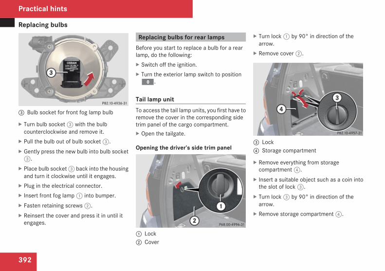
Replacing bulbs
392
3 Bulb socket for front fog lamp bulb
X Turn bulb socket 3 with the bulbcounterclockwise and remove it.
X Pull the bulb out of bulb socket 3.X Gently press the new bulb into bulb socket
3.X Place bulb socket 3 back into the housing
and turn it clockwise until it engages.X Plug in the electrical connector.X Insert front fog lamp 1 into bumper.X Fasten retaining screws 2.X Reinsert the cover and press it in until it
engages.
Replacing bulbs for rear lampsBefore you start to replace a bulb for a rearlamp, do the following:X Switch off the ignition.X Turn the exterior lamp switch to positionM.
Tail lamp unitTo access the tail lamp units, you first have toremove the cover in the corresponding sidetrim panel of the cargo compartment.X Open the tailgate.
Opening the driver’s side trim panel
1 Lock2 Cover
X Turn lock 1 by 90° in direction of thearrow.
X Remove cover 2.
3 Lock4 Storage compartment
X Remove everything from storagecompartment 4.
X Insert a suitable object such as a coin intothe slot of lock 3.
X Turn lock 3 by 90° in direction of thearrow.
X Remove storage compartment 4.
Practical hints
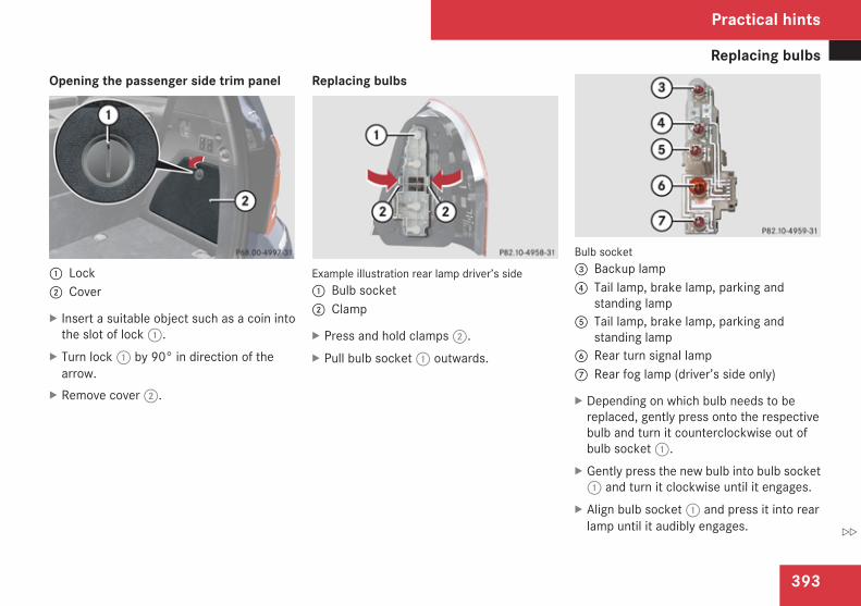
Replacing bulbs
393
Opening the passenger side trim panel
1 Lock2 Cover
X Insert a suitable object such as a coin intothe slot of lock 1.
X Turn lock 1 by 90° in direction of thearrow.
X Remove cover 2.
Replacing bulbs
Example illustration rear lamp driver’s side1 Bulb socket2 Clamp
X Press and hold clamps 2.X Pull bulb socket 1 outwards.
Bulb socket3 Backup lamp4 Tail lamp, brake lamp, parking and
standing lamp5 Tail lamp, brake lamp, parking and
standing lamp6 Rear turn signal lamp7 Rear fog lamp (driver’s side only)
X Depending on which bulb needs to bereplaced, gently press onto the respectivebulb and turn it counterclockwise out ofbulb socket 1.
X Gently press the new bulb into bulb socket1 and turn it clockwise until it engages.
X Align bulb socket 1 and press it into rearlamp until it audibly engages.
Practical hints
Z
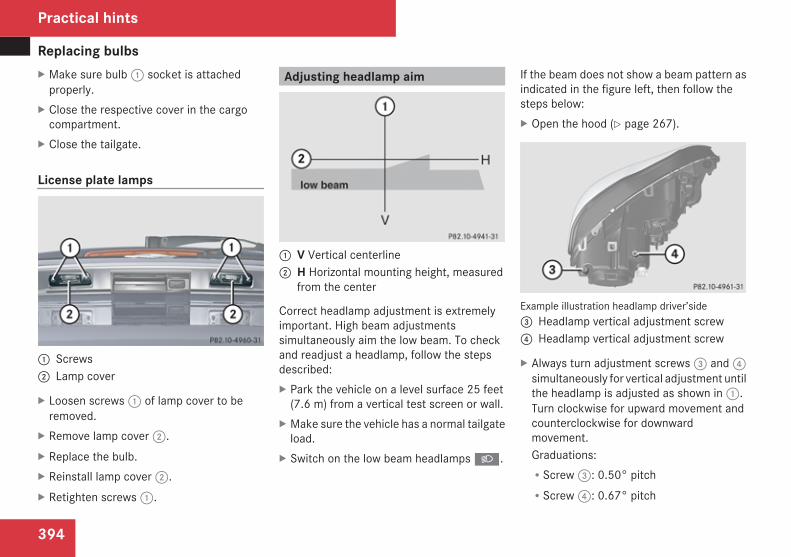
Replacing bulbs
394
X Make sure bulb 1 socket is attachedproperly.
X Close the respective cover in the cargocompartment.
X Close the tailgate.
License plate lamps
1 Screws2 Lamp cover
X Loosen screws 1 of lamp cover to beremoved.
X Remove lamp cover 2.X Replace the bulb.X Reinstall lamp cover 2.X Retighten screws 1.
Adjusting headlamp aim
1 V Vertical centerline2 H Horizontal mounting height, measured
from the center
Correct headlamp adjustment is extremelyimportant. High beam adjustmentssimultaneously aim the low beam. To checkand readjust a headlamp, follow the stepsdescribed:X Park the vehicle on a level surface 25 feet
(7.6 m) from a vertical test screen or wall.X Make sure the vehicle has a normal tailgate
load.X Switch on the low beam headlamps B.
If the beam does not show a beam pattern asindicated in the figure left, then follow thesteps below:X Open the hood (Y page 267).
Example illustration headlamp driver’side3 Headlamp vertical adjustment screw4 Headlamp vertical adjustment screw
X Always turn adjustment screws 3 and 4simultaneously for vertical adjustment untilthe headlamp is adjusted as shown in 1.Turn clockwise for upward movement andcounterclockwise for downwardmovement.Graduations:RScrew 3: 0.50° pitchRScrew 4: 0.67° pitch
Practical hints
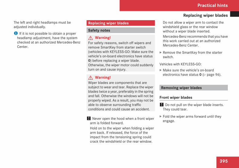
Replacing wiper blades
395
The left and right headlamps must beadjusted individually.
i If it is not possible to obtain a properheadlamp adjustment, have the systemchecked at an authorized Mercedes-BenzCenter.
Replacing wiper blades
Safety notes
G Warning!For safety reasons, switch off wipers andremove SmartKey from starter switch(vehicles with KEYLESS-GO: Make sure thevehicle’s on-board electronics have status0) before replacing a wiper blade.Otherwise, the wiper motor could suddenlyturn on and cause injury.
G Warning!Wiper blades are components that aresubject to wear and tear. Replace the wiperblades twice a year, preferably in the springand fall. Otherwise the windows will not beproperly wiped. As a result, you may not beable to observe surrounding trafficconditions and could cause an accident.
! Never open the hood when a front wiperarm is folded forward.Hold on to the wiper when folding a wiperarm back. If released, the force of theimpact from the tensioning spring couldcrack the windshield or the rear window.
Do not allow a wiper arm to contact thewindshield glass or the rear windowwithout a wiper blade inserted.Mercedes-Benz recommends that you havethis work carried out at an authorizedMercedes-Benz Center.
X Remove the SmartKey from the starterswitch.
Vehicles with KEYLESS-GO:X Make sure the vehicle’s on-board
electronics have status 0 (Y page 96).
Removing wiper blades
Front wiper blades! Do not pull on the wiper blade inserts.
They could tear.
X Fold the wiper arms forward until theyengage.
Practical hints
Z
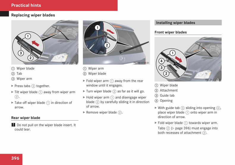
Replacing wiper blades
396
1 Wiper blade2 Tab3 Wiper arm
X Press tabs 2 together.X Tilt wiper blade 1 away from wiper arm
3.X Take off wiper blade 1 in direction of
arrow.
Rear wiper blade! Do not pull on the wiper blade insert. It
could tear.
1 Wiper arm2 Wiper blade
X Fold wiper arm 1 away from the rearwindow until it engages.
X Turn wiper blade 2 as far as it will go.X Hold wiper arm 1 and disengage wiper
blade 2 by carefully sliding it in directionof arrow.
X Remove wiper blade 2.
Installing wiper blades
Front wiper blades
1 Wiper blade2 Attachment3 Guide tab4 Opening
X With guide tab 3 sliding into opening 4,place wiper blade 1 onto wiper arm indirection of arrow.
X Fold wiper blade 1 towards wiper arm.Tabs 2 (Y page 396) must engage intoboth recesses of attachment 2.
Practical hints
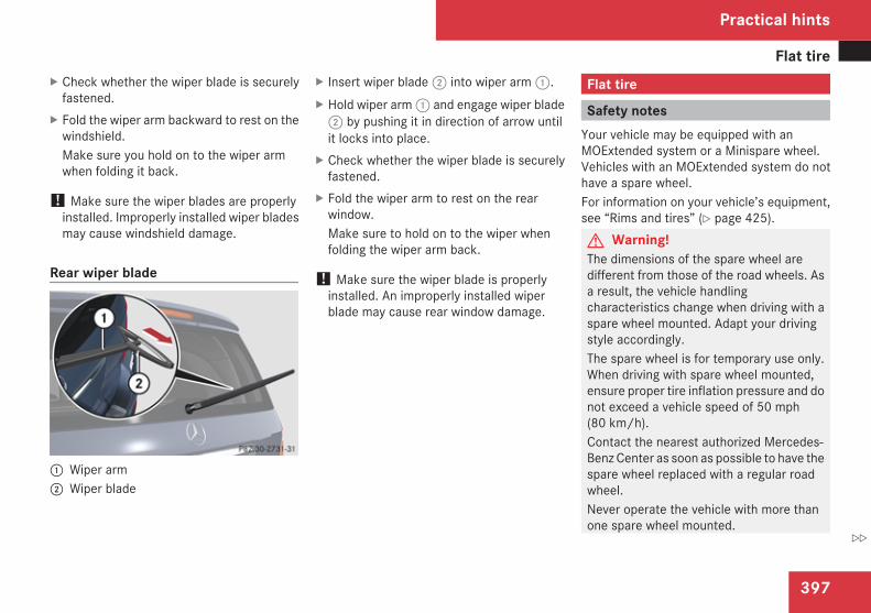
Flat tire
397
X Check whether the wiper blade is securelyfastened.
X Fold the wiper arm backward to rest on thewindshield.Make sure you hold on to the wiper armwhen folding it back.
! Make sure the wiper blades are properlyinstalled. Improperly installed wiper bladesmay cause windshield damage.
Rear wiper blade
1 Wiper arm2 Wiper blade
X Insert wiper blade 2 into wiper arm 1.X Hold wiper arm 1 and engage wiper blade
2 by pushing it in direction of arrow untilit locks into place.
X Check whether the wiper blade is securelyfastened.
X Fold the wiper arm to rest on the rearwindow.Make sure to hold on to the wiper whenfolding the wiper arm back.
! Make sure the wiper blade is properlyinstalled. An improperly installed wiperblade may cause rear window damage.
Flat tire
Safety notesYour vehicle may be equipped with anMOExtended system or a Minispare wheel.Vehicles with an MOExtended system do nothave a spare wheel.For information on your vehicle’s equipment,see “Rims and tires” (Y page 425).G Warning!The dimensions of the spare wheel aredifferent from those of the road wheels. Asa result, the vehicle handlingcharacteristics change when driving with aspare wheel mounted. Adapt your drivingstyle accordingly.The spare wheel is for temporary use only.When driving with spare wheel mounted,ensure proper tire inflation pressure and donot exceed a vehicle speed of 50 mph(80 km/h).Contact the nearest authorized Mercedes-Benz Center as soon as possible to have thespare wheel replaced with a regular roadwheel.Never operate the vehicle with more thanone spare wheel mounted.
Practical hints
Z
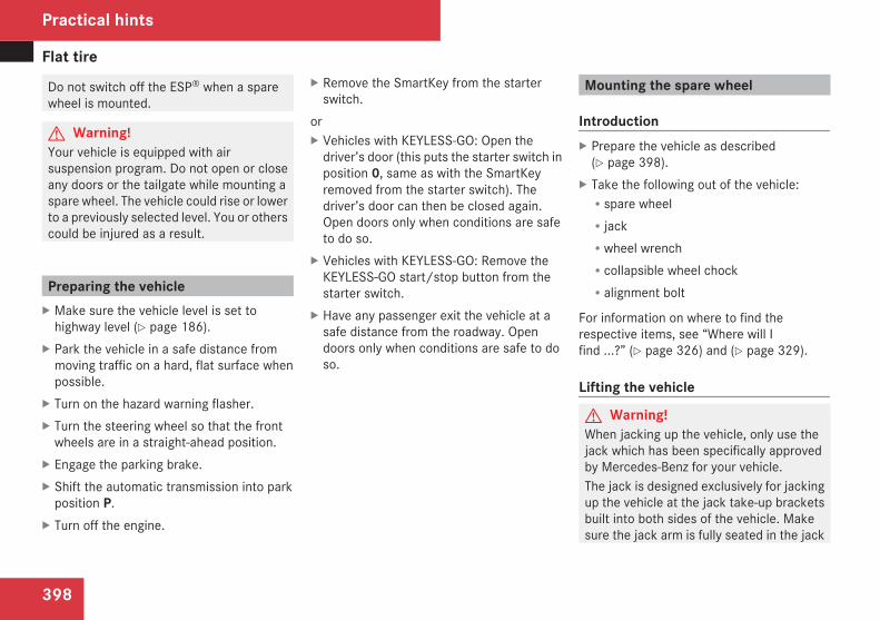
Flat tire
398
Do not switch off the ESP® when a sparewheel is mounted.
G Warning!Your vehicle is equipped with airsuspension program. Do not open or closeany doors or the tailgate while mounting aspare wheel. The vehicle could rise or lowerto a previously selected level. You or otherscould be injured as a result.
Preparing the vehicleX Make sure the vehicle level is set to
highway level (Y page 186).X Park the vehicle in a safe distance from
moving traffic on a hard, flat surface whenpossible.
X Turn on the hazard warning flasher.X Turn the steering wheel so that the front
wheels are in a straight-ahead position.X Engage the parking brake.X Shift the automatic transmission into park
position P.X Turn off the engine.
X Remove the SmartKey from the starterswitch.
orX Vehicles with KEYLESS-GO: Open the
driver’s door (this puts the starter switch inposition 0, same as with the SmartKeyremoved from the starter switch). Thedriver’s door can then be closed again.Open doors only when conditions are safeto do so.
X Vehicles with KEYLESS-GO: Remove theKEYLESS-GO start/stop button from thestarter switch.
X Have any passenger exit the vehicle at asafe distance from the roadway. Opendoors only when conditions are safe to doso.
Mounting the spare wheel
IntroductionX Prepare the vehicle as described
(Y page 398).X Take the following out of the vehicle:Rspare wheelRjackRwheel wrenchRcollapsible wheel chockRalignment bolt
For information on where to find therespective items, see “Where will Ifind ...?” (Y page 326) and (Y page 329).
Lifting the vehicle
G Warning!When jacking up the vehicle, only use thejack which has been specifically approvedby Mercedes-Benz for your vehicle.The jack is designed exclusively for jackingup the vehicle at the jack take-up bracketsbuilt into both sides of the vehicle. Makesure the jack arm is fully seated in the jack
Practical hints
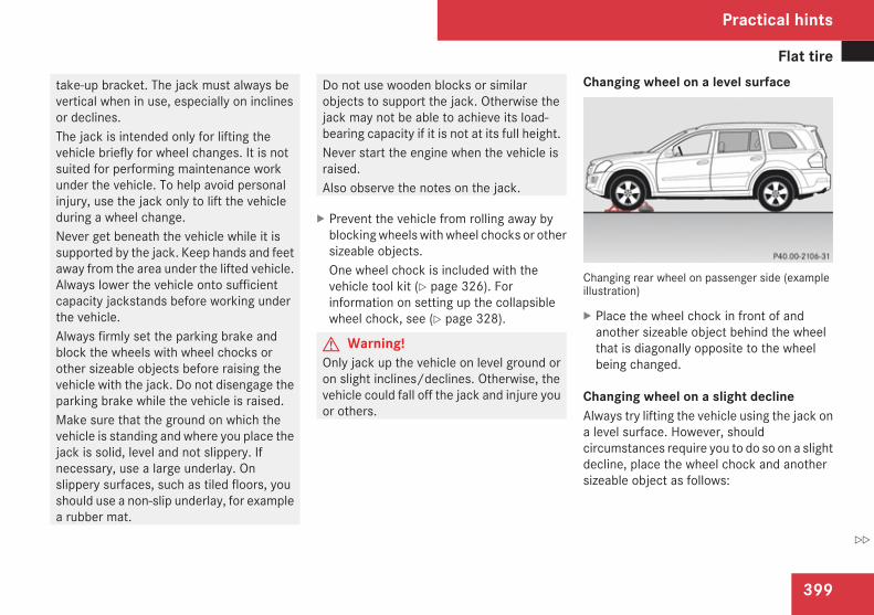
Flat tire
399
take-up bracket. The jack must always bevertical when in use, especially on inclinesor declines.The jack is intended only for lifting thevehicle briefly for wheel changes. It is notsuited for performing maintenance workunder the vehicle. To help avoid personalinjury, use the jack only to lift the vehicleduring a wheel change.Never get beneath the vehicle while it issupported by the jack. Keep hands and feetaway from the area under the lifted vehicle.Always lower the vehicle onto sufficientcapacity jackstands before working underthe vehicle.Always firmly set the parking brake andblock the wheels with wheel chocks orother sizeable objects before raising thevehicle with the jack. Do not disengage theparking brake while the vehicle is raised.Make sure that the ground on which thevehicle is standing and where you place thejack is solid, level and not slippery. Ifnecessary, use a large underlay. Onslippery surfaces, such as tiled floors, youshould use a non-slip underlay, for examplea rubber mat.
Do not use wooden blocks or similarobjects to support the jack. Otherwise thejack may not be able to achieve its load-bearing capacity if it is not at its full height.Never start the engine when the vehicle israised.Also observe the notes on the jack.
X Prevent the vehicle from rolling away byblocking wheels with wheel chocks or othersizeable objects.One wheel chock is included with thevehicle tool kit (Y page 326). Forinformation on setting up the collapsiblewheel chock, see (Y page 328).
G Warning!Only jack up the vehicle on level ground oron slight inclines/declines. Otherwise, thevehicle could fall off the jack and injure youor others.
Changing wheel on a level surface
Changing rear wheel on passenger side (exampleillustration)
X Place the wheel chock in front of andanother sizeable object behind the wheelthat is diagonally opposite to the wheelbeing changed.
Changing wheel on a slight declineAlways try lifting the vehicle using the jack ona level surface. However, shouldcircumstances require you to do so on a slightdecline, place the wheel chock and anothersizeable object as follows:
Practical hints
Z
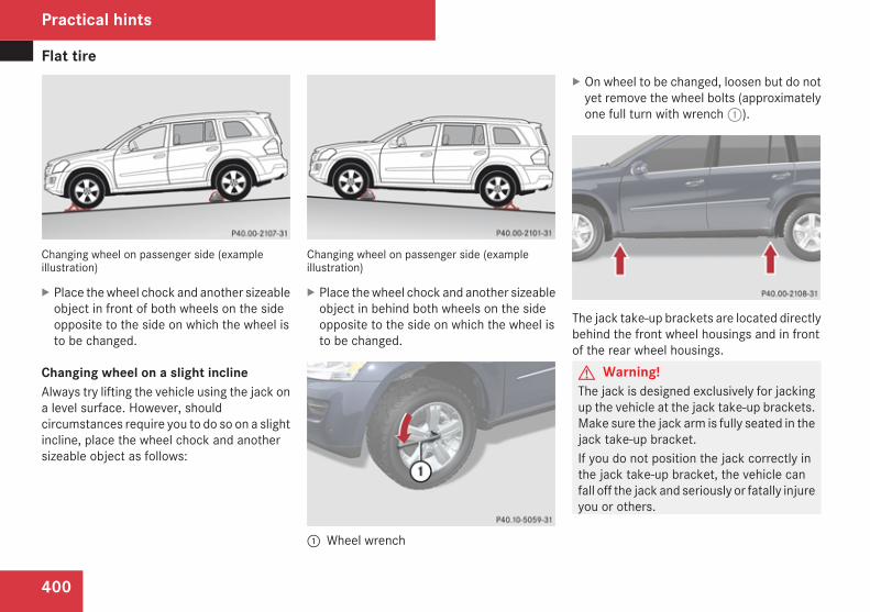
Flat tire
400
Changing wheel on passenger side (exampleillustration)
X Place the wheel chock and another sizeableobject in front of both wheels on the sideopposite to the side on which the wheel isto be changed.
Changing wheel on a slight inclineAlways try lifting the vehicle using the jack ona level surface. However, shouldcircumstances require you to do so on a slightincline, place the wheel chock and anothersizeable object as follows:
Changing wheel on passenger side (exampleillustration)
X Place the wheel chock and another sizeableobject in behind both wheels on the sideopposite to the side on which the wheel isto be changed.
1 Wheel wrench
X On wheel to be changed, loosen but do notyet remove the wheel bolts (approximatelyone full turn with wrench 1).
The jack take-up brackets are located directlybehind the front wheel housings and in frontof the rear wheel housings.G Warning!The jack is designed exclusively for jackingup the vehicle at the jack take-up brackets.Make sure the jack arm is fully seated in thejack take-up bracket.If you do not position the jack correctly inthe jack take-up bracket, the vehicle canfall off the jack and seriously or fatally injureyou or others.
Practical hints
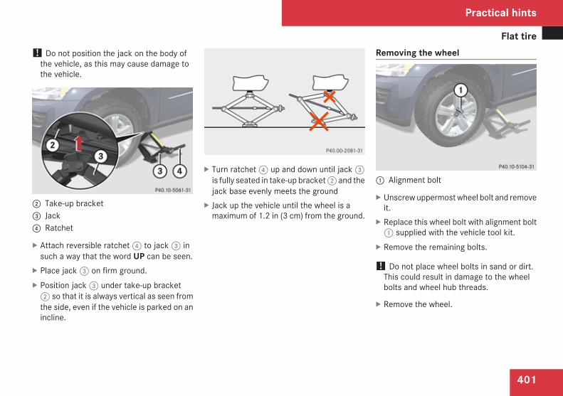
Flat tire
401
! Do not position the jack on the body ofthe vehicle, as this may cause damage tothe vehicle.
2 Take-up bracket3 Jack4 Ratchet
X Attach reversible ratchet 4 to jack 3 insuch a way that the word UP can be seen.
X Place jack 3 on firm ground.X Position jack 3 under take-up bracket
2 so that it is always vertical as seen fromthe side, even if the vehicle is parked on anincline.
X Turn ratchet 4 up and down until jack 3is fully seated in take-up bracket 2 and thejack base evenly meets the ground
X Jack up the vehicle until the wheel is amaximum of 1.2 in (3 cm) from the ground.
Removing the wheel
1 Alignment bolt
X Unscrew uppermost wheel bolt and removeit.
X Replace this wheel bolt with alignment bolt1 supplied with the vehicle tool kit.
X Remove the remaining bolts.
! Do not place wheel bolts in sand or dirt.This could result in damage to the wheelbolts and wheel hub threads.
X Remove the wheel.
Practical hints
Z
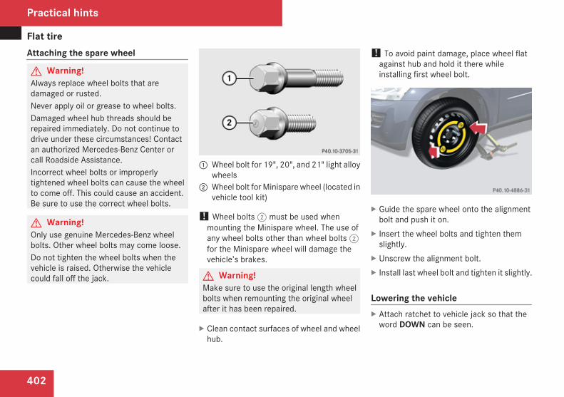
Flat tire
402
Attaching the spare wheel
G Warning!Always replace wheel bolts that aredamaged or rusted.Never apply oil or grease to wheel bolts.Damaged wheel hub threads should berepaired immediately. Do not continue todrive under these circumstances! Contactan authorized Mercedes-Benz Center orcall Roadside Assistance.Incorrect wheel bolts or improperlytightened wheel bolts can cause the wheelto come off. This could cause an accident.Be sure to use the correct wheel bolts.
G Warning!Only use genuine Mercedes-Benz wheelbolts. Other wheel bolts may come loose.Do not tighten the wheel bolts when thevehicle is raised. Otherwise the vehiclecould fall off the jack.
1 Wheel bolt for 19", 20", and 21" light alloywheels
2 Wheel bolt for Minispare wheel (located invehicle tool kit)
! Wheel bolts 2 must be used whenmounting the Minispare wheel. The use ofany wheel bolts other than wheel bolts 2for the Minispare wheel will damage thevehicle’s brakes.
G Warning!Make sure to use the original length wheelbolts when remounting the original wheelafter it has been repaired.
X Clean contact surfaces of wheel and wheelhub.
! To avoid paint damage, place wheel flatagainst hub and hold it there whileinstalling first wheel bolt.
X Guide the spare wheel onto the alignmentbolt and push it on.
X Insert the wheel bolts and tighten themslightly.
X Unscrew the alignment bolt.X Install last wheel bolt and tighten it slightly.
Lowering the vehicleX Attach ratchet to vehicle jack so that the
word DOWN can be seen.
Practical hints
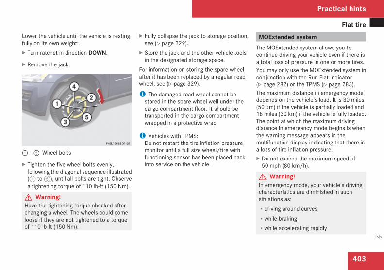
Flat tire
403
Lower the vehicle until the vehicle is restingfully on its own weight:X Turn ratchet in direction DOWN.
X Remove the jack.
1 – 5 Wheel bolts
X Tighten the five wheel bolts evenly,following the diagonal sequence illustrated(1 to 5), until all bolts are tight. Observea tightening torque of 110 lb-ft (150 Nm).
G Warning!Have the tightening torque checked afterchanging a wheel. The wheels could comeloose if they are not tightened to a torqueof 110 lb-ft (150 Nm).
X Fully collapse the jack to storage position,see (Y page 329).
X Store the jack and the other vehicle toolsin the designated storage space.
For information on storing the spare wheelafter it has been replaced by a regular roadwheel, see (Y page 329).
i The damaged road wheel cannot bestored in the spare wheel well under thecargo compartment floor. It should betransported in the cargo compartmentwrapped in a protective wrap.
i Vehicles with TPMS:Do not restart the tire inflation pressuremonitor until a full size wheel/tire withfunctioning sensor has been placed backinto service on the vehicle.
MOExtended systemThe MOExtended system allows you tocontinue driving your vehicle even if there isa total loss of pressure in one or more tires.You may only use the MOExtended system inconjunction with the Run Flat Indicator(Y page 282) or the TPMS (Y page 283).The maximum distance in emergency modedepends on the vehicle’s load. It is 30 miles(50 km) if the vehicle is partially loaded and18 miles (30 km) if the vehicle is fully loaded.The point at which the maximum drivingdistance in emergency mode begins is whenthe warning message appears in themultifunction display indicating that there isa loss of tire inflation pressure.X Do not exceed the maximum speed of
50 mph (80 km/h).
G Warning!In emergency mode, your vehicle’s drivingcharacteristics are diminished in suchsituations as:Rdriving around curvesRwhile brakingRwhile accelerating rapidly
Practical hints
Z
Bleeding the fuel system (diesel engine only)
404
Therefore, your driving style must beadapted accordingly. Avoid abrupt steeringand driving maneuvers, as well as drivingover obstacles (road curbs, potholes, or off-road areas). This is especially important ifthe vehicle is heavily loaded.The emergency driving distance that can beachieved greatly depends on the demandsplaced on the vehicle. Depending on speed,load, driving maneuvers, road conditions,outside temperature, etc., the distance canbe significantly shorter or, if the vehicle isdriven cautiously, somewhat longer.Do not continue driving in emergency modeifRyou notice knocking soundsRthe vehicle starts to shakeRsmoke develops and you smell rubberRESP® is intervening continuouslyRyou notice tears on the tire sidewallsAfter driving in emergency mode, you musthave the rims inspected by an authorizedMercedes-Benz Center to check if they aresuitable for further use. The failed tire mustbe replaced in any case.
When replacing individual or all tires on thevehicle, make sure only tires marked with
“MOExtended” are mounted in the sizespecified for your vehicle (Y page 425).
Bleeding the fuel system (dieselengine only)
Driving the vehicle until the fuel tank is emptyis not recommended. Otherwise, air may besucked into the fuel system. If this happens,the malfunction indicator lamp ú (USAonly) or ± (Canada only) comes on and theengine may not start immediately afterrefueling the vehicle.After refueling:X Make sure the automatic transmission is in
park position P.The gear position indicator in themultifunction display should be on P.
X Do not depress the accelerator.X If necessary, remove the KEYLESS-GO
start/stop button from the starter switch.X Turn the SmartKey in the starter switch to
position 2 for at least 10 seconds.X Return the SmartKey in the starter switch
to position 0.X Turn the SmartKey in the starter switch to
position 3 and hold it there for a maximumof 40 seconds or until the engine runssurge-free.
If the engine does not start:
Practical hints
AdBlue® (diesel engine only)
405
X Wait for approximately 2 minutes.X Turn the SmartKey in the starter switch to
position 3 and hold it there for a maximumof 40 seconds or until the engine runssurge-free.
If the engine still does not start, do not makeany further attempts to start the engine.Contact an authorized Mercedes-Benz Centeror call Roadside Assistance (Y page 253).
i When the malfunction indicator lampú (USA only) or ± (Canada only) inthe instrument cluster has been illuminatedfor the above condition, it will remainilluminated until the engine was cycled onand off four times in a row.
AdBlue® (diesel engine only)
The BlueTEC exhaust gas aftertreatmentsystem requires a reducing agent (AdBlue®)in order to function properly. Refilling withAdBlue® is part of the regular maintenanceservice work. A tankful of AdBlue® shouldsuffice until the next maintenance serviceunder normal driving conditions.When the AdBlue® tank is low, the messageCheck Additive see Operator’sManual appears in the multifunction display.When the AdBlue® level drops to theminimum level, the message RemainingStarts: 20 appears in the multifunctiondisplay.
i When the message Remaining Starts:20 appears in the multifunction display, youcan start the engine 20 more times. If youdo not add AdBlue®, the engine cannot bestarted beyond that point. Fill theAdBlue® tank with approximately 1 gal(3.79 l) AdBlue® (corresponds toapproximately 2 AdBlue® refill containers)or have the AdBlue® tank filled by anauthorized Mercedes-Benz Center.
i For refilling outside the maintenanceservice intervals, refill the AdBlue® tankwith approximately 1 gal (3.79 l) AdBlue®
(corresponds to approximately 2 AdBlue®
refill containers).
Always use the particular AdBlue® refillcontainers for refilling outside themaintenance service interval. Contact anauthorized Mercedes-Benz Center or callRoadside Assistance if necessary(Y page 253).Additional information on BlueTEC exhaustgas aftertreatment and AdBlue® is availableat any authorized Mercedes-Benz Center.
Refilling with AdBlue®
G Warning!Make sureRAdBlue® does not come into contact with
skin, eyes, or clothingRto keep AdBlue® out of the reach of
children
Practical hints
Z
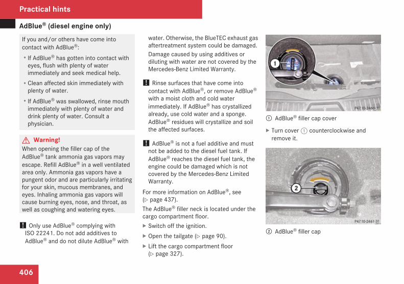
AdBlue® (diesel engine only)
406
If you and/or others have come intocontact with AdBlue®:RIf AdBlue® has gotten into contact with
eyes, flush with plenty of waterimmediately and seek medical help.RClean affected skin immediately with
plenty of water.RIf AdBlue® was swallowed, rinse mouth
immediately with plenty of water anddrink plenty of water. Consult aphysician.
G Warning!When opening the filler cap of theAdBlue® tank ammonia gas vapors mayescape. Refill AdBlue® in a well ventilatedarea only. Ammonia gas vapors have apungent odor and are particularly irritatingfor your skin, mucous membranes, andeyes. Inhaling ammonia gas vapors willcause burning eyes, nose, and throat, aswell as coughing and watering eyes.
! Only use AdBlue® complying withISO 22241. Do not add additives toAdBlue® and do not dilute AdBlue® with
water. Otherwise, the BlueTEC exhaust gasaftertreatment system could be damaged.Damage caused by using additives ordiluting with water are not covered by theMercedes-Benz Limited Warranty.
! Rinse surfaces that have come intocontact with AdBlue®, or remove AdBlue®
with a moist cloth and cold waterimmediately. If AdBlue® has crystallizedalready, use cold water and a sponge.AdBlue® residues will crystallize and soilthe affected surfaces.
! AdBlue® is not a fuel additive and mustnot be added to the diesel fuel tank. IfAdBlue® reaches the diesel fuel tank, theengine could be damaged which is notcovered by the Mercedes-Benz LimitedWarranty.
For more information on AdBlue®, see(Y page 437).The AdBlue® filler neck is located under thecargo compartment floor.X Switch off the ignition.X Open the tailgate (Y page 90).X Lift the cargo compartment floor
(Y page 327).
1 AdBlue® filler cap cover
X Turn cover 1 counterclockwise andremove it.
2 AdBlue® filler cap
Practical hints
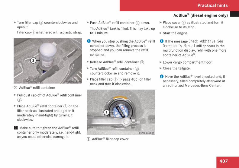
AdBlue® (diesel engine only)
407
X Turn filler cap 2 counterclockwise andopen it.Filler cap 2 is tethered with a plastic strap.
3 AdBlue® refill container
X Pull dust cap off of AdBlue® refill container3.
X Place AdBlue® refill container 3 on thefiller neck as illustrated and tighten itmoderately (hand-tight) by turning itclockwise.
! Make sure to tighten the AdBlue® refillcontainer only moderately, i.e. hand-tight,as you could otherwise damage it.
X Push AdBlue® refill container 3 down.The AdBlue® tank is filled. This may take upto 1 minute.
i When you stop pushing the AdBlue® refillcontainer down, the filling process isstopped and you can remove the refillcontainer.
X Release AdBlue® refill container 3.X Turn AdBlue® refill container 3
counterclockwise and remove it.X Place filler cap 2 (Y page 406) on filler
neck and turn it clockwise.
1 AdBlue® filler cap cover
X Place cover 1 as illustrated and turn itclockwise to its stop.
X Start the engine.
i If the message Check Additive SeeOperator’s Manual still appears in themultifunction display, refill with one morecontainer of AdBlue®.
X Lower cargo compartment floor.X Close the tailgate.
i Have the AdBlue® level checked and, ifnecessary, filled completely afterward atan authorized Mercedes-Benz Center.
Practical hints
Z
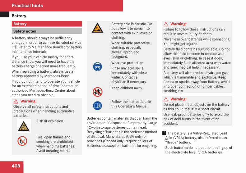
Battery
408
Battery
Safety notesA battery should always be sufficientlycharged in order to achieve its rated servicelife. Refer to Maintenance Booklet for batterymaintenance intervals.If you use your vehicle mostly for short-distance trips, you will need to have thebattery charge checked more frequently.When replacing a battery, always use abattery approved by Mercedes-Benz.If you do not intend to operate your vehiclefor an extended period of time, contact anauthorized Mercedes-Benz Center aboutsteps you need to observe.G Warning!Observe all safety instructions andprecautions when handling automotivebatteries.
Risk of explosion.
Fire, open flames andsmoking are prohibitedwhen handling batteries.Avoid creating sparks.
Battery acid is caustic. Donot allow it to come intocontact with skin, eyes orclothing.Wear suitable protectiveclothing, especiallygloves, apron andfaceguard.Wear eye protection.Rinse any acid spillsimmediately with clearwater. Contact aphysician if necessary.Keep children away.
Follow the instructions inthis Operator’s Manual.
Batteries contain materials that can harm theenvironment if disposed of improperly. Large12-volt storage batteries contain lead.Recycling of batteries is the preferred methodof disposal. Many states (USA only) orprovinces (Canada only) require sellers ofbatteries to accept old batteries for recycling.
G Warning!Failure to follow these instructions canresult in severe injury or death.Never lean over batteries while connecting.You might get injured.Battery fluid contains sulfuric acid. Do notallow this fluid to come in contact witheyes, skin or clothing. In case it does,immediately flush affected area with waterand seek medical help if necessary.A battery will also produce hydrogen gas,which is flammable and explosive. Keepflames or sparks away from battery, avoidimproper connection of jumper cables,smoking etc.
G Warning!Do not place metal objects on the batteryas this could result in a short circuit.Use leak-proof batteries only to avoid therisk of acid burns in the event of anaccident.
! The battery is a Valve-Regulated LeadAcid (VRLA) battery, also referred to as“fleece” battery.Such batteries do not require topping-up ofthe electrolyte level. VRLA batteries
Practical hints
Battery
409
therefore do not have cell caps and thebattery cover is non-removable. Do notattempt to open the battery as otherwisethe battery will be damaged.Even though VRLA batteries do not requiretopping-up of the electrolyte level andcannot be opened to check the electrolytelevel, the battery condition must bechecked periodically by performing abattery conductance test. Refer toMaintenance Booklet for battery conditiontesting intervals.The factory-equipped VRLA battery is leak-proofed. Only use a battery as replacementthat has the same security features and isof identical size, voltage, and capacity asthe factory-equipped battery.
! As with any other battery, have thebattery disconnect at a qualified workshopor an authorized Mercedes-Benz Center ifyou do not intend to operate your vehiclefor an extended period of time to preventbattery discharge. You may also connect anaccessory battery charge unit expresslyapproved by Mercedes-Benz for yourvehicle model to maintain the batterycharge. Contact an authorized Mercedes-Benz Center for further information.
The battery, the battery ventilation hoseand the lateral plug must always besecurely installed when the vehicle is inoperation.
! Never loosen or detach battery terminalclamps while the engine is running or theSmartKey is in the starter switch orKEYLESS-GO button is in position 1.Otherwise the alternator and otherelectronic components could be severelydamaged.Have the battery checked regularly at anauthorized Mercedes-Benz Center.Refer to Maintenance Booklet formaintenance intervals or contact anauthorized Mercedes-Benz Center forfurther information.
i After battery power was interrupted, dothe following:RSet the clock (Y page 160).
Vehicles with COMAND system withnavigation module: Time and date are setautomatically.RSynchronize the door windows
(Y page 126).
RSynchronize the power tilt/slidingsunroof (Y page 226).RSynchronize the exterior rear view
mirrors (Y page 112).
Charging the battery
G Warning!Never charge a battery while still installedin the vehicle unless the accessory batterycharge unit approved by Mercedes-Benz isbeing used. Gases may escape duringcharging and cause explosions that mayresult in paint damage, corrosion orpersonal injury.An accessory battery charge unit speciallyadapted for Mercedes-Benz vehicles andtested and approved by Mercedes-Benz isavailable, permitting the charging of thebattery in its installed position. Contact anauthorized Mercedes-Benz Center forinformation and availability.Charge battery in accordance with theseparate instructions for the accessorybattery charger.
Have batteries charged at an authorizedMercedes-Benz Center. If you charge the
Practical hints
Z
Jump starting
410
batteries yourself, follow the operatinginstructions for your charging device.Only use a battery charge unit with amaximum charging voltage of 14.8 V.X Charge battery in accordance with the
instructions of the battery chargermanufacturer.
Jump starting
G Warning!Failure to follow these directions will causedamage to the electronic components, andcan lead to a battery explosion and severeinjury or death.Never lean over batteries while connectingor jump starting. You might get injured.Battery fluid contains sulfuric acid. Do notallow this fluid to come in contact witheyes, skin or clothing. In case it does,immediately flush affected area with water,and seek medical help if necessary.A battery will also produce hydrogen gas,which is flammable and explosive. Keepflames or sparks away from battery, avoidimproper connection of jumper cables,smoking, etc.Attempting to jump start a frozen batterycan result in it exploding, causing personalinjury.Read all instructions before proceeding.
! Do not tow-start the vehicle. You couldotherwise seriously damage the automatic
transmission which is not covered by theMercedes-Benz Limited Warranty.
! Jump starting should only be performedusing the jump-start terminals located inthe engine compartment.Avoid repeated and lengthy startingattempts.Do not attempt to start the engine using abattery quick-charge unit.If the engine does not run after severalunsuccessful starting attempts, have itchecked at the nearest authorizedMercedes-Benz Center.Excessive unburned fuel generated byrepeated failed starting attempts maydamage the catalytic converter18 and maypresent a fire risk.Make sure the jumper cables do not haveloose or missing insulation.Make sure the cable clamps do not touchany other metal part while the other end isstill attached to a battery.
18 Vehicles with gasoline engine only.
Practical hints
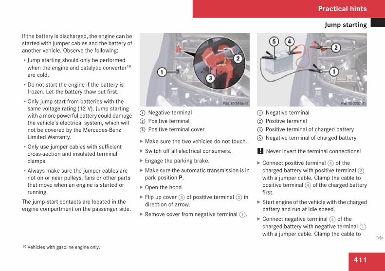
Jump starting
411
If the battery is discharged, the engine can bestarted with jumper cables and the battery ofanother vehicle. Observe the following:RJump starting should only be performed
when the engine and catalytic converter19
are cold.RDo not start the engine if the battery is
frozen. Let the battery thaw out first.ROnly jump start from batteries with the
same voltage rating (12 V). Jump startingwith a more powerful battery could damagethe vehicle’s electrical system, which willnot be covered by the Mercedes-BenzLimited Warranty.ROnly use jumper cables with sufficient
cross-section and insulated terminalclamps.RAlways make sure the jumper cables are
not on or near pulleys, fans or other partsthat move when an engine is started orrunning.
The jump-start contacts are located in theengine compartment on the passenger side.
1 Negative terminal2 Positive terminal3 Positive terminal cover
X Make sure the two vehicles do not touch.X Switch off all electrical consumers.X Engage the parking brake.X Make sure the automatic transmission is in
park position P.X Open the hood.X Flip up cover 3 of positive terminal 2 in
direction of arrow.X Remove cover from negative terminal 1.
1 Negative terminal2 Positive terminal4 Positive terminal of charged battery5 Negative terminal of charged battery
! Never invert the terminal connections!
X Connect positive terminal 4 of thecharged battery with positive terminal 2with a jumper cable. Clamp the cable topositive terminal 4 of the charged batteryfirst.
X Start engine of the vehicle with the chargedbattery and run at idle speed.
X Connect negative terminal 5 of thecharged battery with negative terminal 1with a jumper cable. Clamp the cable to
19 Vehicles with gasoline engine only.
Practical hints
Z
Towing the vehicle
412
negative terminal 5 of the charged batteryfirst.
X Start engine of the vehicle with thedischarged battery and run at idle speed.You can now turn on the electricalconsumers. Do not switch on theheadlamps under any circumstances.
X Remove the jumper cables first fromnegative terminals 1 and 5 and thenfrom positive terminals 2 and 4.You can now switch on the headlamps.
X Have the battery checked at the nearestauthorized Mercedes-Benz Center.
Towing the vehicle
Safety notesMercedes-Benz recommends that the vehiclebe transported with all wheels off the groundusing flatbed or appropriate wheel lift/dollyequipment. This method is preferable to othertypes of towing.
! To prevent damage during transport, donot tie down vehicle by its chassis orsuspension parts.
If circumstances do not permit therecommended towing methods, the vehiclemay be towed with all wheels on the groundonly so far as necessary to have the vehiclemoved to a safe location where therecommended towing methods can beemployed.
! Before towing the vehicle observe thefollowing instructions:RDo not tow-start the vehicle. You could
otherwise seriously damage theautomatic transmission which is notcovered by the Mercedes-Benz LimitedWarranty.RDo not tow with sling-type equipment.
Towing with sling-type equipment over
bumpy roads will damage radiator andsupports.RTowing of the vehicle should only be
done using the properly installed towingeye bolt. Never attach a tow cable, towrope or tow rod to the vehicle chassis,frame or suspension parts.
! Do not tow with one axle raised. Doing socould damage the transfer case, which isnot covered by the Mercedes-Benz LimitedWarranty. All wheels must be on or off theground. Observe instructions for towing thevehicle with all wheels on the ground.
i If the battery is disconnected ordischargedRthe SmartKey will not turn in the starter
switchRthe automatic transmission will remain in
park position PRFor more information see
“Battery” (Y page 408) or “Jumpstarting” (Y page 410).
Practical hints
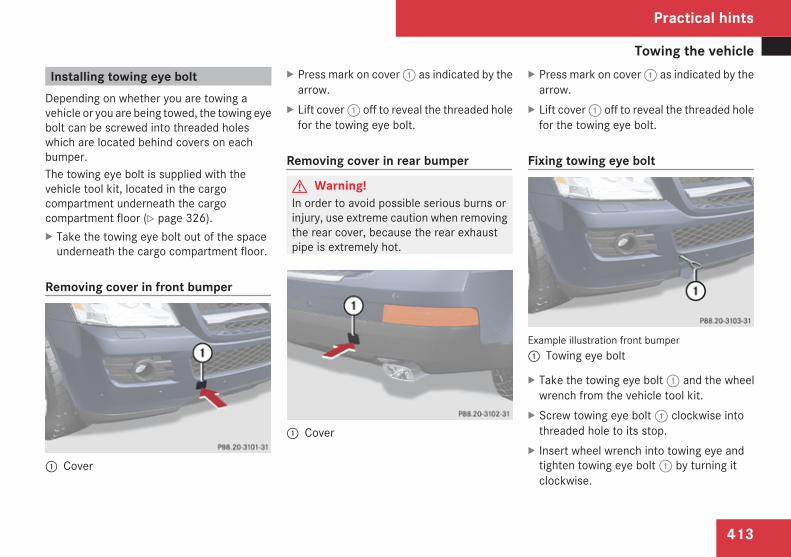
Towing the vehicle
413
Installing towing eye boltDepending on whether you are towing avehicle or you are being towed, the towing eyebolt can be screwed into threaded holeswhich are located behind covers on eachbumper.The towing eye bolt is supplied with thevehicle tool kit, located in the cargocompartment underneath the cargocompartment floor (Y page 326).X Take the towing eye bolt out of the space
underneath the cargo compartment floor.
Removing cover in front bumper
1 Cover
X Press mark on cover 1 as indicated by thearrow.
X Lift cover 1 off to reveal the threaded holefor the towing eye bolt.
Removing cover in rear bumper
G Warning!In order to avoid possible serious burns orinjury, use extreme caution when removingthe rear cover, because the rear exhaustpipe is extremely hot.
1 Cover
X Press mark on cover 1 as indicated by thearrow.
X Lift cover 1 off to reveal the threaded holefor the towing eye bolt.
Fixing towing eye bolt
Example illustration front bumper1 Towing eye bolt
X Take the towing eye bolt 1 and the wheelwrench from the vehicle tool kit.
X Screw towing eye bolt 1 clockwise intothreaded hole to its stop.
X Insert wheel wrench into towing eye andtighten towing eye bolt 1 by turning itclockwise.
Practical hints
Z
Towing the vehicle
414
Removing towing eye boltX Loosen towing eye bolt 1
counterclockwise with wheel wrench.X Unscrew towing eye bolt 1.X Reinstalling cover: Engage cover 1
(Y page 413) at top and press at bottom.
X Store the towing eye bolt and wheel wrenchback into the vehicle tool kit.
Towing with all wheels on the ground
G Warning!If circumstances require towing the vehiclewith all wheels on the ground, always towwith a tow bar if:Rthe engine will not runRthere is a malfunction in the brake
systemRthere is a malfunction in the power
supply or in the vehicle’s electricalsystem
This is necessary to adequately control thetowed vehicle.
Prior to towing the vehicle with all wheelson the ground, make sure the SmartKey isin starter switch position 2.
G Warning!With the engine not running, there is nopower assistance for the brake andsteering systems. In this case, it isimportant to keep in mind that aconsiderably higher degree of effort isnecessary to brake and steer the vehicle.Adapt your driving accordingly.
X Make sure the ignition is switched on.X With the vehicle at a standstill, depress the
brake pedal and keep it pressed.X Shift the automatic transmission into
neutral position N.X Release the brake pedal.X If engaged, release the parking brake.X Switch on the hazard warning flasher
(Y page 118).
! Keep in mind that it is important to havethe ignition switched on. Removing theSmartKey from the starter switch oropening a front door with the ignitionswitched off will automatically shift the
automatic transmission into park positionP.
! The vehicle may be towed only fordistances up to 30 miles (50 km) and at aspeed not to exceed 30 mph (50 km/h).
i To signal turns while being towed with thehazard warning flasher in use you canactivate the combination switch for the leftor right turn signal in the usual manner –only the selected turn signal will operate.Upon canceling the turn signal, the hazardwarning flasher will operate again.
Stranded vehicleFreeing a stranded vehicle, on which thewheels are dug into sand or mud, should bedone with the greatest of care, especially ifthe vehicle is heavily loaded.
Practical hints
Fuses
415
Note the following when freeing a strandedvehicle:RAvoid pulling the vehicle abruptly or
diagonally, since it could result in damageto the chassis alignment.RNever try to free a vehicle that is still
coupled to a trailer.RIf possible, a vehicle equipped with a trailer
hitch receiver should be pulled backward inits own previously made tracks.
Fuses
IntroductionThe electrical fuses in your vehicle serve toswitch off malfunctioning power circuits.If a fuse is blown, the components andsystems secured by that fuse will stopoperating.G Warning!Only use fuses approved by Mercedes-Benzwith the specified amperage for the systemin question and do not attempt to repair orbridge a blown fuse. Using other thanapproved fuses or using repaired or bridgedfuses may cause an overload leading to afire, and/or cause damage to electricalcomponents and/or systems. Have thecause determined and remedied by anauthorized Mercedes-Benz Center.
A blown fuse must be replaced by anappropriate spare fuse (recognizable by itscolor or the fuse rating given on the fuse) ofthe amperage recommended in the fusechart. Any Mercedes-Benz Center will be gladto advise you on this subject.
i In case of a blown fuse contact RoadsideAssistance or an authorized Mercedes-Benz Center.
If a newly inserted fuse blows again, have thecause determined and rectified by anauthorized Mercedes-Benz Center.A fuse chart is located in the cargocompartment with the vehicle tool kit(Y page 326). The fuse chart explains the fuseallocation and fuse amperages.
Before replacing fusesX Engage the parking brake.X Make sure the automatic transmission is in
park position P.The transmission position indicator in themultifunction display should be on P.
X Switch off all electrical consumers.X Turn off the engine.X Remove the SmartKey from the starter
switch.X Vehicles with KEYLESS-GO: Open the
driver’s door (this puts the starter switch inposition 0, same as with the SmartKeyremoved from the starter switch). Thedriver’s door then can be closed again.
Practical hints
Z
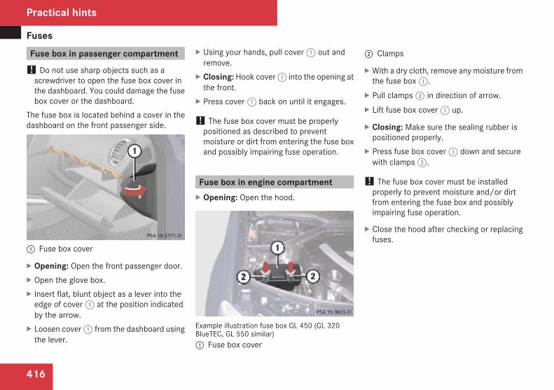
Fuses
416
Fuse box in passenger compartment! Do not use sharp objects such as a
screwdriver to open the fuse box cover inthe dashboard. You could damage the fusebox cover or the dashboard.
The fuse box is located behind a cover in thedashboard on the front passenger side.
1 Fuse box cover
X Opening: Open the front passenger door.X Open the glove box.X Insert flat, blunt object as a lever into the
edge of cover 1 at the position indicatedby the arrow.
X Loosen cover 1 from the dashboard usingthe lever.
X Using your hands, pull cover 1 out andremove.
X Closing: Hook cover 1 into the opening atthe front.
X Press cover 1 back on until it engages.
! The fuse box cover must be properlypositioned as described to preventmoisture or dirt from entering the fuse boxand possibly impairing fuse operation.
Fuse box in engine compartmentX Opening: Open the hood.
Example illustration fuse box GL 450 (GL 320BlueTEC, GL 550 similar)1 Fuse box cover
2 Clamps
X With a dry cloth, remove any moisture fromthe fuse box 1.
X Pull clamps 2 in direction of arrow.X Lift fuse box cover 1 up.
X Closing: Make sure the sealing rubber ispositioned properly.
X Press fuse box cover 1 down and securewith clamps 2.
! The fuse box cover must be installedproperly to prevent moisture and/or dirtfrom entering the fuse box and possiblyimpairing fuse operation.
X Close the hood after checking or replacingfuses.
Practical hints
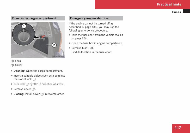
Fuses
417
Fuse box in cargo compartment
1 Lock2 Cover
X Opening: Open the cargo compartment.X Insert a suitable object such as a coin into
the slot of lock 1.X Turn lock 1 by 90° in direction of arrow.X Remove cover 2.X Closing: Install cover 2 in reverse order.
Emergency engine shutdownIf the engine cannot be turned off asdescribed (Y page 133), you may use thefollowing emergency procedure.X Take the fuse chart from the vehicle tool kit
(Y page 326).X Open the fuse box in engine compartment.X Remove fuse 120.
Find its location in the fuse chart.
Practical hints
Z

418
419
Vehicle equipment ............................ 420Parts service ..................................... 420Warranty coverage ........................... 420Identification labels .......................... 421Engine ................................................ 423Rims and tires ................................... 425Electrical system .............................. 429Main dimensions ............................... 430Weights .............................................. 431Fuels, coolants, lubricants etc. ....... 432
Technical data
Warranty coverage
420
Vehicle equipment
i This Operator’s Manual describes allfeatures, standard or optional, potentiallyavailable for your vehicle at the time ofpurchase. Please be aware that yourvehicle might not be equipped with allfeatures described in this manual.
Parts service
All authorized Mercedes-Benz Centersmaintain a stock of Genuine Mercedes-BenzParts required for maintenance and repairwork. In addition, strategically located partsdistribution centers provide quick andreliable parts service.More than 300 000 different parts forMercedes-Benz models are available.Genuine Mercedes-Benz Parts are subjectedto stringent quality inspections. Each part hasbeen specifically developed, manufactured orselected for and adapted to Mercedes-Benzvehicles.Therefore, Genuine Mercedes-Benz Partsshould be installed.
! Do not use non-genuine Mercedes-Benzparts and accessories not authorized byMercedes-Benz. Doing so could damagethe vehicle, which is not covered by theMercedes-Benz Limited Warranty. Also, itcould compromise the vehicle’s durabilityor safety.
Warranty coverage
Your vehicle is covered under the terms of thewarranties printed in the Service andWarranty Information booklet.Your authorized Mercedes-Benz Center willexchange or repair any defective partsoriginally installed in the vehicle inaccordance with the terms of the followingwarranties:RNew Truck Limited WarrantyREmission System WarrantyREmission Performance WarrantyRCalifornia, Connecticut, Maine,
Massachusetts, New York, Pennsylvania,Rhode Island, and Vermont EmissionControl Systems Warranty20
RState Warranty Enforcement Laws (LemonLaws)
Replacement parts and accessories arecovered by the Mercedes-Benz Parts andAccessories warranties, copies of which areavailable at any authorized Mercedes-BenzCenter.
20 Applicable to vehicles with gasoline engine only.
Technical data
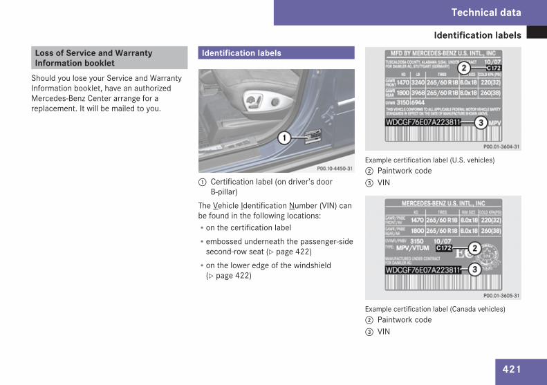
Identification labels
421
Loss of Service and WarrantyInformation booklet
Should you lose your Service and WarrantyInformation booklet, have an authorizedMercedes-Benz Center arrange for areplacement. It will be mailed to you.
Identification labels
1 Certification label (on driver’s doorB-pillar)
The Vehicle Identification Number (VIN) canbe found in the following locations:Ron the certification labelRembossed underneath the passenger-side
second-row seat (Y page 422)Ron the lower edge of the windshield
(Y page 422)
Example certification label (U.S. vehicles)2 Paintwork code 3 VIN
Example certification label (Canada vehicles)2 Paintwork code3 VIN
Technical data
Z
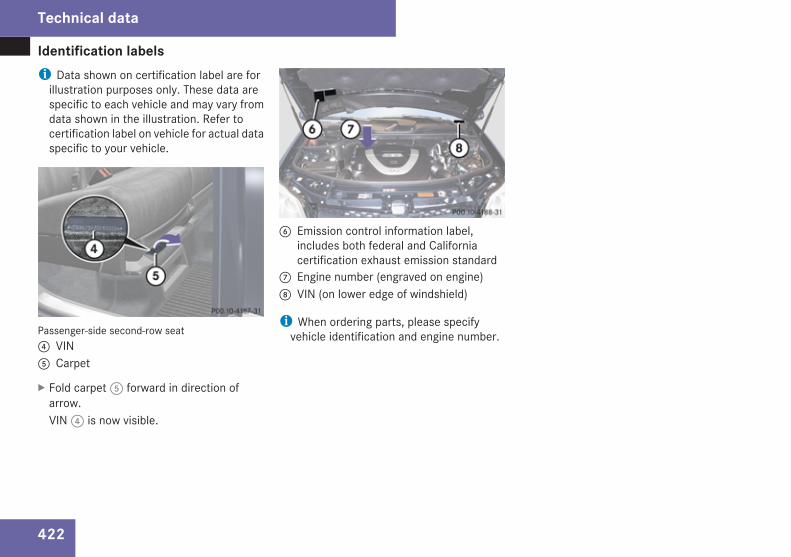
Identification labels
422
i Data shown on certification label are forillustration purposes only. These data arespecific to each vehicle and may vary fromdata shown in the illustration. Refer tocertification label on vehicle for actual dataspecific to your vehicle.
Passenger-side second-row seat4 VIN5 Carpet
X Fold carpet 5 forward in direction ofarrow.VIN 4 is now visible.
6 Emission control information label,includes both federal and Californiacertification exhaust emission standard
7 Engine number (engraved on engine) 8 VIN (on lower edge of windshield)
i When ordering parts, please specifyvehicle identification and engine number.
Technical data
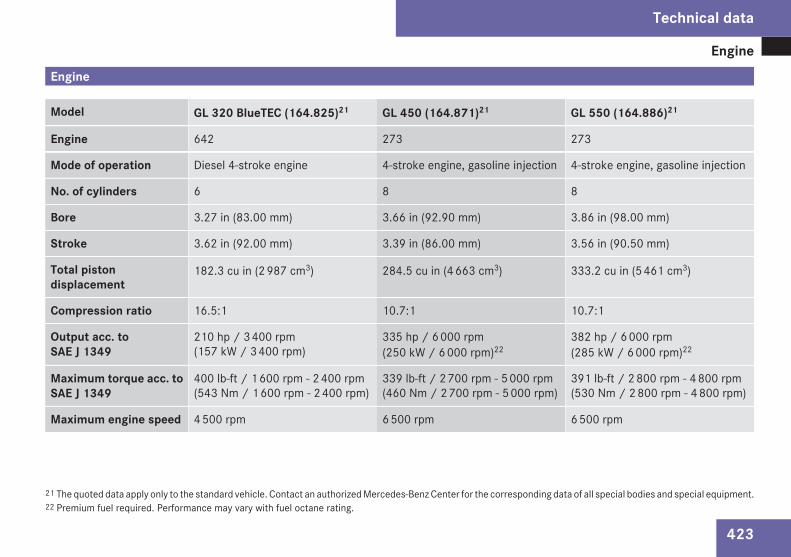
Engine
423
Engine
Model GL 320 BlueTEC (164.825)21 GL 450 (164.871)21 GL 550 (164.886)21
Engine 642 273 273
Mode of operation Diesel 4-stroke engine 4-stroke engine, gasoline injection 4-stroke engine, gasoline injection
No. of cylinders 6 8 8
Bore 3.27 in (83.00 mm) 3.66 in (92.90 mm) 3.86 in (98.00 mm)
Stroke 3.62 in (92.00 mm) 3.39 in (86.00 mm) 3.56 in (90.50 mm)
Total pistondisplacement
182.3 cu in (2 987 cm3) 284.5 cu in (4 663 cm3) 333.2 cu in (5 461 cm3)
Compression ratio 16.5:1 10.7:1 10.7:1
Output acc. toSAE J 1349
210 hp / 3 400 rpm(157 kW / 3 400 rpm)
335 hp / 6 000 rpm(250 kW / 6 000 rpm)22
382 hp / 6 000 rpm(285 kW / 6 000 rpm)22
Maximum torque acc. toSAE J 1349
400 lb-ft / 1 600 rpm - 2 400 rpm(543 Nm / 1 600 rpm - 2 400 rpm)
339 lb-ft / 2 700 rpm - 5 000 rpm(460 Nm / 2 700 rpm - 5 000 rpm)
391 lb-ft / 2 800 rpm - 4 800 rpm(530 Nm / 2 800 rpm - 4 800 rpm)
Maximum engine speed 4 500 rpm 6 500 rpm 6 500 rpm
21 The quoted data apply only to the standard vehicle. Contact an authorized Mercedes-Benz Center for the corresponding data of all special bodies and special equipment.22 Premium fuel required. Performance may vary with fuel octane rating.
Technical data
Z
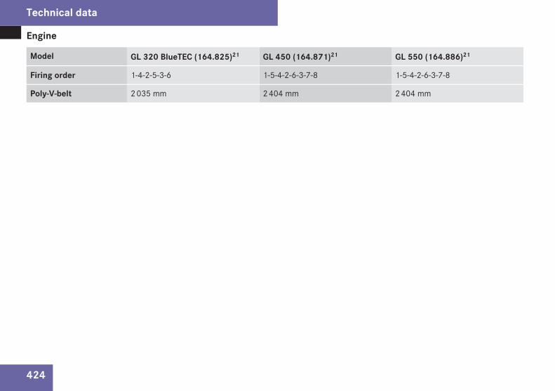
Engine
424
Model GL 320 BlueTEC (164.825)21 GL 450 (164.871)21 GL 550 (164.886)21
Firing order 1-4-2-5-3-6 1-5-4-2-6-3-7-8 1-5-4-2-6-3-7-8
Poly-V-belt 2 035 mm 2 404 mm 2 404 mm
Technical data
Rims and tires
425
Rims and tires
Notes! Only use tires which have been tested and
approved by Mercedes-Benz. Tiresapproved by Mercedes-Benz are developedto provide best possible performance inconjunction with the driving safety systemson your vehicle such as the ABS or theESP®. Tires specially developed for yourvehicle and tested and approved byMercedes-Benz can be identified by findingthe following on the tire’s sidewall:RMO = Mercedes-Benz Original
equipment tiresRMOE = Mercedes-Benz Original Extended
(tires with limited run-flatcharacteristics) original equipment tires
Using tires other than those approved byMercedes-Benz may result in damage thatis not covered by the Mercedes-BenzLimited Warranty.
For information on driving with MOExtendedtires, see the “Practical hints” section(Y page 403).
i Vehicles with MOExtended system arenot factory-equipped with a TIREFIT kit.
When retrofitting with tires that do not haverun-flat characteristics, e.g. winter tires,you should also equip your vehicle with aTIREFIT kit. TIREFIT kits are available at anyauthorized Mercedes-Benz Center.
! Using tires other than those approved byMercedes-Benz can have detrimentaleffects, such asRpoor handling characteristicsRincreased noiseRincreased fuel consumptionMoreover, tires and rims not approved byMercedes-Benz may, under load, exhibitdimensional variations and different tiredeformation characteristics that couldcause them to come into contact with thevehicle body or axle parts. Damage to thetires or the vehicle may be the result.
i Further information on tires and rims isavailable at any authorized Mercedes-BenzCenter. A placard with the recommendedtire inflation pressures is located on thedriver’s door B-pillar. Some vehicles mayhave supplemental tire inflation pressureinformation for driving at high speeds or forvehicle loads less than the maximum
loaded vehicle condition. If suchinformation is provided, it can be found onthe placard located on the inside of the fuelfiller flap. The tire inflation pressure shouldbe checked regularly and should only beadjusted on cold tires. Follow tiremanufacturer’s maintenancerecommendation included with the vehicle.
For information on recommended tireinflation pressure and supplemental tireinflation pressure information for specialdriving situations, see (Y page 279).
i The following pages also list the approvedwheel rim and tire sizes for equipping yourvehicles with winter tires. Winter tires arenot available as standard or optionalfactory equipment, but can be purchasedfrom an authorized Mercedes-Benz Center.Equipping your vehicle with winter tiresapproved for your vehicle model mayrequire the purchase of two or four wheelrims of the recommended size for use withthese winter tires. This depends on vehiclemodel and the standard or optional factory-equipped wheel rim/tire configuration onyour vehicle. For more information contactan authorized Mercedes-Benz Center.
Technical data
Z
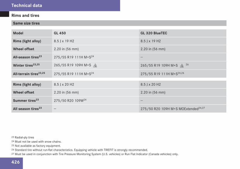
Rims and tires
426
Same size tires
Model GL 450 GL 320 BlueTEC
Rims (light alloy) 8.5 J x 19 H2 8.5 J x 19 H2
Wheel offset 2.20 in (56 mm) 2.20 in (56 mm)
All-season tires23 275/55 R19 111H M+S24 —
Winter tires23,25 265/55 R19 109H M+S. 265/55 R19 109H M+S.26
All-terrain tires23,25 275/55 R19 111H M+S24 275/55 R19 111H M+S24,26
Rims (light alloy) 8.5 J x 20 H2 8.5 J x 20 H2
Wheel offset 2.20 in (56 mm) 2.20 in (56 mm)
Summer tires23 275/50 R20 109W24 —
All season tires23 — 275/50 R20 109H M+S MOExtended24,27
23 Radial-ply tires24 Must not be used with snow chains.25 Not available as factory equipment.26 Standard tire without run-flat characteristics. Equipping vehicle with TIREFIT is strongly recommended.27 Must be used in conjunction with Tire Pressure Monitoring System (U.S. vehicles) or Run Flat Indicator (Canada vehicles) only.
Technical data
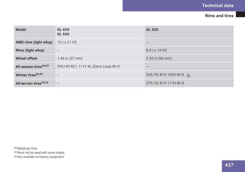
Rims and tires
427
Model GL 450GL 550
GL 550
AMG rims (light alloy) 10 J x 21 H2 —
Rims (light alloy) — 8.5 J x 19 H2
Wheel offset 1.46 in (37 mm) 2.20 in (56 mm)
All season tires28,29 295/40 R21 111V XL (Extra Load) M+S —
Winter tires28,30 — 265/55 R19 109H M+S.
All-terrain tires28,30 — 275/55 R19 111H M+S
28 Radial-ply tires29 Must not be used with snow chains.30 Not available as factory equipment.
Technical data
Z
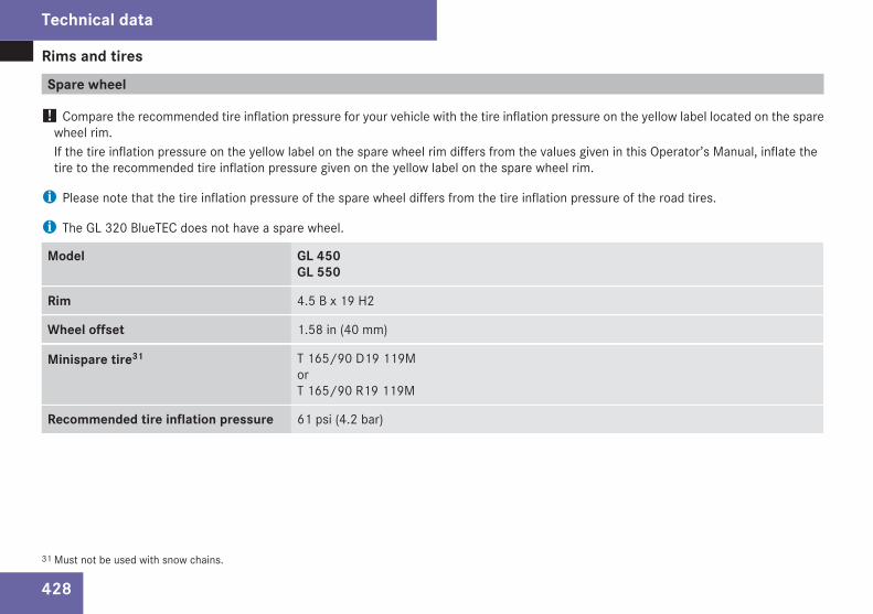
Rims and tires
428
Spare wheel
! Compare the recommended tire inflation pressure for your vehicle with the tire inflation pressure on the yellow label located on the sparewheel rim.If the tire inflation pressure on the yellow label on the spare wheel rim differs from the values given in this Operator’s Manual, inflate thetire to the recommended tire inflation pressure given on the yellow label on the spare wheel rim.
i Please note that the tire inflation pressure of the spare wheel differs from the tire inflation pressure of the road tires.
i The GL 320 BlueTEC does not have a spare wheel.
Model GL 450GL 550
Rim 4.5 B x 19 H2
Wheel offset 1.58 in (40 mm)
Minispare tire31 T 165/90 D19 119MorT 165/90 R19 119M
Recommended tire inflation pressure 61 psi (4.2 bar)
31 Must not be used with snow chains.
Technical data
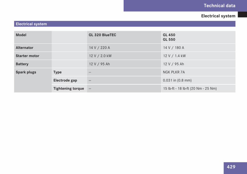
Electrical system
429
Electrical system
Model GL 320 BlueTEC GL 450GL 550
Alternator 14 V / 220 A 14 V / 180 A
Starter motor 12 V / 2.0 kW 12 V / 1.4 kW
Battery 12 V / 95 Ah 12 V / 95 Ah
Spark plugs Type — NGK PLKR 7A
Electrode gap — 0.031 in (0.8 mm)
Tightening torque — 15 lb-ft - 18 lb-ft (20 Nm - 25 Nm)
Technical data
Z
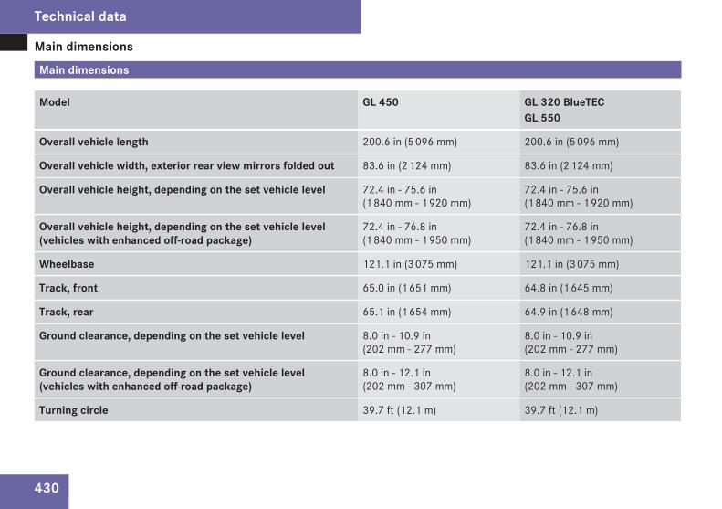
Main dimensions
430
Main dimensions
Model GL 450 GL 320 BlueTECGL 550
Overall vehicle length 200.6 in (5 096 mm) 200.6 in (5 096 mm)
Overall vehicle width, exterior rear view mirrors folded out 83.6 in (2 124 mm) 83.6 in (2 124 mm)
Overall vehicle height, depending on the set vehicle level 72.4 in - 75.6 in(1 840 mm - 1 920 mm)
72.4 in - 75.6 in(1 840 mm - 1 920 mm)
Overall vehicle height, depending on the set vehicle level(vehicles with enhanced off-road package)
72.4 in - 76.8 in(1 840 mm - 1 950 mm)
72.4 in - 76.8 in(1 840 mm - 1 950 mm)
Wheelbase 121.1 in (3 075 mm) 121.1 in (3 075 mm)
Track, front 65.0 in (1 651 mm) 64.8 in (1 645 mm)
Track, rear 65.1 in (1 654 mm) 64.9 in (1 648 mm)
Ground clearance, depending on the set vehicle level 8.0 in - 10.9 in(202 mm - 277 mm)
8.0 in - 10.9 in(202 mm - 277 mm)
Ground clearance, depending on the set vehicle level(vehicles with enhanced off-road package)
8.0 in - 12.1 in(202 mm - 307 mm)
8.0 in - 12.1 in(202 mm - 307 mm)
Turning circle 39.7 ft (12.1 m) 39.7 ft (12.1 m)
Technical data
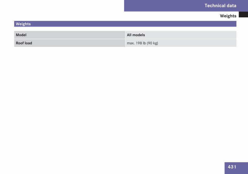
Weights
431
Weights
Model All models
Roof load max. 198 lb (90 kg)
Technical data
Z
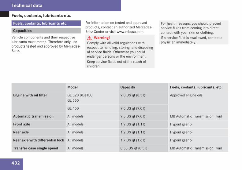
Fuels, coolants, lubricants etc.
432
Fuels, coolants, lubricants etc.
CapacitiesVehicle components and their respectivelubricants must match. Therefore only useproducts tested and approved by Mercedes-Benz.
For information on tested and approvedproducts, contact an authorized Mercedes-Benz Center or visit www.mbusa.com.G Warning!Comply with all valid regulations withrespect to handling, storing, and disposingof service fluids. Otherwise you couldendanger persons or the environment.Keep service fluids out of the reach ofchildren.
For health reasons, you should preventservice fluids from coming into directcontact with your skin or clothing.If a service fluid is swallowed, contact aphysician immediately.
Model Capacity Fuels, coolants, lubricants, etc.
Engine with oil filter GL 320 BlueTECGL 550
9.0 US qt (8.5 l) Approved engine oils
GL 450 9.5 US qt (9.0 l)
Automatic transmission All models 9.5 US qt (9.0 l) MB Automatic Transmission Fluid
Front axle All models 1.2 US qt (1.1 l) Hypoid gear oil
Rear axle All models 1.2 US qt (1.1 l) Hypoid gear oil
Rear axle with differential lock All models 1.7 US qt (1.6 l) Hypoid gear oil
Transfer case single speed All models 0.53 US qt (0.5 l) MB Automatic Transmission Fluid
Technical data
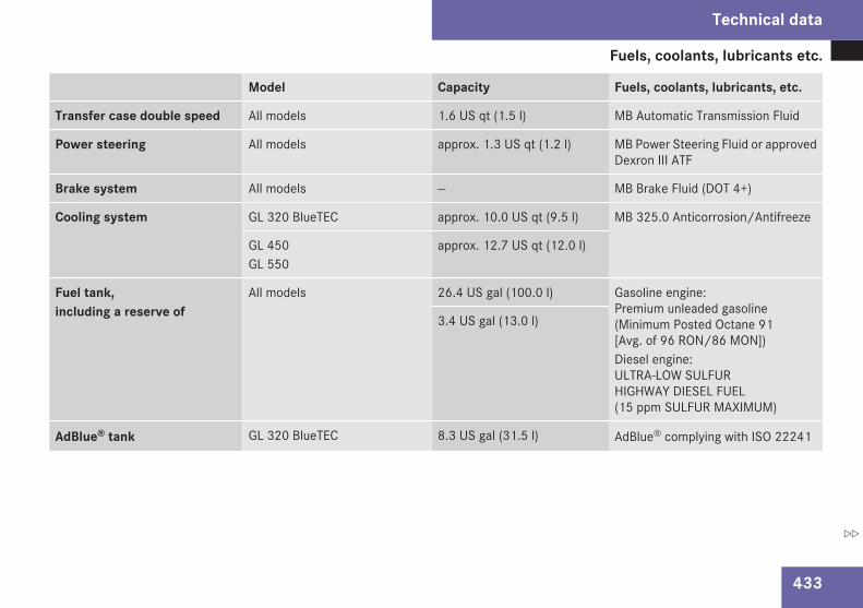
Fuels, coolants, lubricants etc.
433
Model Capacity Fuels, coolants, lubricants, etc.
Transfer case double speed All models 1.6 US qt (1.5 l) MB Automatic Transmission Fluid
Power steering All models approx. 1.3 US qt (1.2 l) MB Power Steering Fluid or approvedDexron III ATF
Brake system All models — MB Brake Fluid (DOT 4+)
Cooling system GL 320 BlueTEC approx. 10.0 US qt (9.5 l) MB 325.0 Anticorrosion/Antifreeze
GL 450GL 550
approx. 12.7 US qt (12.0 l)
Fuel tank,including a reserve of
All models 26.4 US gal (100.0 l) Gasoline engine:Premium unleaded gasoline(Minimum Posted Octane 91[Avg. of 96 RON/86 MON])Diesel engine:ULTRA-LOW SULFURHIGHWAY DIESEL FUEL(15 ppm SULFUR MAXIMUM)
3.4 US gal (13.0 l)
AdBlue® tank GL 320 BlueTEC 8.3 US gal (31.5 l) AdBlue® complying with ISO 22241
Technical data
Z
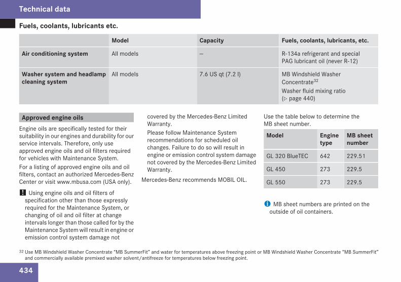
Fuels, coolants, lubricants etc.
434
Model Capacity Fuels, coolants, lubricants, etc.
Air conditioning system All models — R-134a refrigerant and specialPAG lubricant oil (never R-12)
Washer system and headlampcleaning system
All models 7.6 US qt (7.2 l) MB Windshield WasherConcentrate32
Washer fluid mixing ratio(Y page 440)
Approved engine oilsEngine oils are specifically tested for theirsuitability in our engines and durability for ourservice intervals. Therefore, only useapproved engine oils and oil filters requiredfor vehicles with Maintenance System.For a listing of approved engine oils and oilfilters, contact an authorized Mercedes-BenzCenter or visit www.mbusa.com (USA only).
! Using engine oils and oil filters ofspecification other than those expresslyrequired for the Maintenance System, orchanging of oil and oil filter at changeintervals longer than those called for by theMaintenance System will result in engine oremission control system damage not
covered by the Mercedes-Benz LimitedWarranty.Please follow Maintenance Systemrecommendations for scheduled oilchanges. Failure to do so will result inengine or emission control system damagenot covered by the Mercedes-Benz LimitedWarranty.
Mercedes-Benz recommends MOBIL OIL.
Use the table below to determine theMB sheet number.
Model Enginetype
MB sheetnumber
GL 320 BlueTEC 642 229.51
GL 450 273 229.5
GL 550 273 229.5
i MB sheet numbers are printed on theoutside of oil containers.
32 Use MB Windshield Washer Concentrate “MB SummerFit” and water for temperatures above freezing point or MB Windshield Washer Concentrate “MB SummerFit”and commercially available premixed washer solvent/antifreeze for temperatures below freezing point.
Technical data
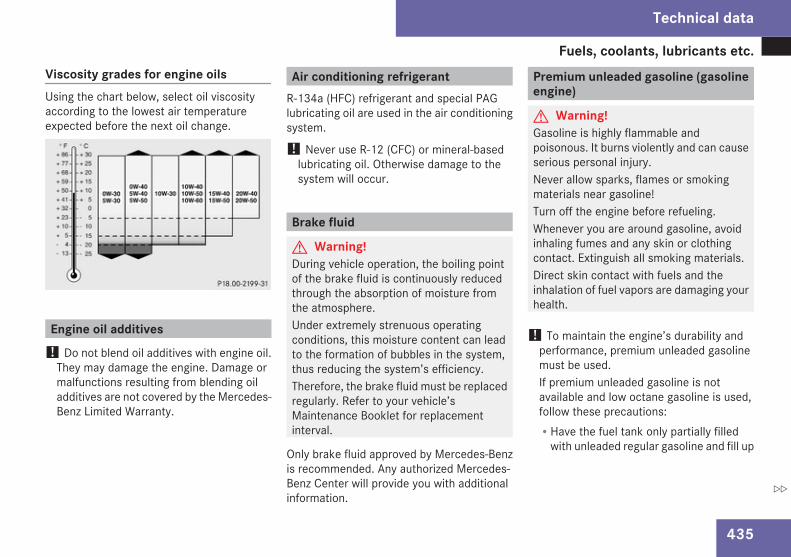
Fuels, coolants, lubricants etc.
435
Viscosity grades for engine oilsUsing the chart below, select oil viscosityaccording to the lowest air temperatureexpected before the next oil change.
Engine oil additives! Do not blend oil additives with engine oil.
They may damage the engine. Damage ormalfunctions resulting from blending oiladditives are not covered by the Mercedes-Benz Limited Warranty.
Air conditioning refrigerantR-134a (HFC) refrigerant and special PAGlubricating oil are used in the air conditioningsystem.
! Never use R-12 (CFC) or mineral-basedlubricating oil. Otherwise damage to thesystem will occur.
Brake fluid
G Warning!During vehicle operation, the boiling pointof the brake fluid is continuously reducedthrough the absorption of moisture fromthe atmosphere.Under extremely strenuous operatingconditions, this moisture content can leadto the formation of bubbles in the system,thus reducing the system’s efficiency.Therefore, the brake fluid must be replacedregularly. Refer to your vehicle’sMaintenance Booklet for replacementinterval.
Only brake fluid approved by Mercedes-Benzis recommended. Any authorized Mercedes-Benz Center will provide you with additionalinformation.
Premium unleaded gasoline (gasolineengine)
G Warning!Gasoline is highly flammable andpoisonous. It burns violently and can causeserious personal injury.Never allow sparks, flames or smokingmaterials near gasoline!Turn off the engine before refueling.Whenever you are around gasoline, avoidinhaling fumes and any skin or clothingcontact. Extinguish all smoking materials.Direct skin contact with fuels and theinhalation of fuel vapors are damaging yourhealth.
! To maintain the engine’s durability andperformance, premium unleaded gasolinemust be used.If premium unleaded gasoline is notavailable and low octane gasoline is used,follow these precautions:RHave the fuel tank only partially filled
with unleaded regular gasoline and fill up
Technical data
Z
Fuels, coolants, lubricants etc.
436
with premium unleaded gasoline as soonas possible.RAvoid full throttle driving and abrupt
acceleration.RDo not exceed an engine speed of
3 000 rpm if the vehicle is loaded with alight load such as two persons and noluggage.RDo not exceed 2/3 of maximum
accelerator pedal position if the vehicleis fully loaded or operating inmountainous terrain.
Fuel requirements
Gasoline engineOnly use premium unleaded gasoline. Theoctane number (posted at the pump) must be91 min. It is an average of both the ResearchOctane Number (RON) and the Motor OctaneNumber (MON): (RON+MON)/2. This is alsoknown as the ANTI-KNOCK INDEX.Reformulated gasolines (RFG) and/orunleaded gasoline containing oxygenatessuch as ethanol, TAME, ETBE, IPA, IBA, andTBA can be used provided the ratio of any one
of these oxygenates to gasoline does notexceed 10%; MTBE must not exceed 15%.The ratio of methanol to gasoline must notexceed 3% plus additional cosolvents.Using mixtures of ethanol and methanol is notallowed. Gasohol, which contains 10%ethanol and 90% unleaded gasoline, can beused.These blends must also meet all other fuelrequirements, such as resistance to sparkknock, boiling range, vapor pressure, etc.
Diesel engineOnly use commercially available vehicularULTRA-LOW SULFUR HIGHWAY DIESEL FUEL(15 ppm SULFUR MAXIMUM). Failure to useULTRA-LOW SULFUR HIGHWAY DIESEL FUELcan severely damage the vehicle’s exhaustafter-treatment device.To prevent malfunctions, diesel fuel withimproved cold flow characteristics is offeredin the winter months. Check with your fuelretailer.
! Do not fill the tank with gasoline. Do notblend diesel fuel with gasoline or kerosene.The fuel system and engine will otherwisebe damaged, which is not covered by theMercedes-Benz Limited Warranty.
B5 BiodieselMercedes-Benz approves the use of B5biodiesel (standard diesel with a maximum ofup to 5% biodiesel content) in all Common RailInjection (CDI) and BlueTEC diesel engines.Diesel fuels containing a higher percentage ofbiodiesel content will cause damage to yourengine and are not approved.As biodiesel can be refined from a variety ofraw materials resulting in widely varyingproperties, the only approved biodieselcontent is one that meets ASTM D6751specification. It must also have the necessaryoxidation stability (min. 6h, proved withEN14112 method) to prevent damage to thesystem from deposits and/or corrosion.Please ask your service station for furtherinformation. If the B5 biodiesel blend is notsufficiently labeled to clearly indicate that itmeets the above standards, please do not useit. The Mercedes-Benz Limited Warranty doesnot cover damage caused by the use of fuelsnot meeting Mercedes-Benz approved fuelstandards.
Technical data
Fuels, coolants, lubricants etc.
437
Gasoline additives (gasoline engine)A major concern among enginemanufacturers is carbon build-up caused bygasoline. Mercedes-Benz recommends onlythe use of quality gasoline containingadditives that prevent the build-up of carbondeposits.After an extended period of using fuelswithout such additives carbon deposits canbuild up, especially on the intake valves andin the combustion area, leading to engineperformance problems such as:RWarm-up hesitationRUnstable idleRKnocking/pingingRMisfireRPower lossIn areas where carbon deposits may beencountered due to lack of availability ofgasoline which contains these additives,Mercedes-Benz recommends the use ofadditives approved by us for use onMercedes-Benz vehicles.Contact an authorized Mercedes-Benz Centeror visit www.mbusa.com (USA only) for alisting of approved product(s). Followdirections on product label.
Do not blend other fuel additives with fuel.This only results in unnecessary cost and maybe harmful to the engine operation.
! Damage or malfunction resulting frompoor fuel quality or from blending additionalfuel additives other than those tested andapproved by us for use on Mercedes-Benzvehicles are not covered by the Mercedes-Benz Limited Warranty or by any pre-ownedor Extended Limited warranties.
AdBlue®
AdBlue® is a non-flammable, non-toxic,colorless and odorless, water-soluble liquid.
! Only use AdBlue® complying withISO 22241. Do not blend with additives.
! Rinse surfaces that have come intocontact with AdBlue®, or remove AdBlue®
with a moist cloth and cold waterimmediately. If AdBlue® has crystallizedalready, use cold water and a sponge.AdBlue® residues will crystallize and soilthe affected surfaces.
High ambient temperaturesIf AdBlue® in the reservoir heats up to above122‡ (50†) for a long period of time, forexample due to direct sunlight, ammonia gasvapors may escape when opening theAdBlue® tank.G Warning!When opening the filler cap of theAdBlue® tank ammonia gas vapors mayescape. Refill AdBlue® in a well ventilatedarea only. Ammonia gas vapors have apungent odor and are particularly irritatingfor your skin, mucous membranes, andeyes. Inhaling ammonia gas vapors willcause burning eyes, nose, and throat, aswell as coughing and watering eyes.
Low ambient temperaturesAdBlue® freezes at a temperature ofapproximately 12‡ (-11†). Your vehicle isfactory equipped with an AdBlue® preheatingsystem. The vehicle can thus be operated attemperatures below 12‡ (-11†).
Technical data
Z
Fuels, coolants, lubricants etc.
438
Special additives
! Only use AdBlue® complying withISO 22241. Do not add additives toAdBlue® and do not dilute AdBlue® withwater. Otherwise, the BlueTEC exhaust gasaftertreatment system could be damaged.Damage caused by using additives ordiluting with water are not covered by theMercedes-Benz Limited Warranty.
PurityThe purity of AdBlue® is of particularimportance for avoiding malfunctions in theexhaust gas aftertreatment.If AdBlue® is pumped out of the tank, e.g.during repair work, the same liquid must notbe used to refill the tank as its purity is nolonger guaranteed.
! Impurities caused for example by otherservice products, cleaning agents, and dustresult in increased emissions,malfunctions, catalyst damage, or enginedamage.
CoolantsThe engine coolant is a mixture of water andanticorrosion/antifreeze, which provides:RCorrosion protectionRFreeze protectionRBoiling protection (by increasing the boiling
point)The cooling system was filled at the factorywith a coolant providing freeze protection toapproximately -35‡ (-37†) and corrosionprotection.
! Add premixed coolant solution only.Adding water and MB 325.0 Anticorrosion/Antifreeze separately from each other,could cause engine damage not covered bythe Mercedes-Benz Limited Warranty.
If the antifreeze mixture is effective to -35‡(-37†), the boiling point of the coolant in thepressurized cooling system is reached atapproximately 266‡ (130†).The coolant solution must be used year roundto provide the necessary corrosion protectionand increase boil-over protection. Refer tothe Maintenance Booklet for replacementinterval.Coolant system design and coolant useddetermine the replacement interval. The
replacement interval published in theMaintenance Booklet is only applicable ifMB 325.0 Anticorrosion/Antifreeze solutionor other Mercedes-Benz approved productsof equal specification are used to renew thecoolant concentration or bring it back up tothe proper level.For information on other Mercedes-Benzapproved products of equal specification,contact an authorized Mercedes-Benz Centeror visit www.mbusa.com (USA only).To provide important corrosion protection,the solution must be at least 50%anticorrosion/antifreeze (equivalent tofreeze protection to approximately -35‡[-37†]).If you use a solution that is more than 55%anticorrosion/antifreeze (freeze protectionto approximately -49‡ [-45†]), the enginetemperature will increase due to the lowerheat transfer capability of the solution.Therefore, do not use more than this amountof anticorrosion/antifreeze.If the coolant level is low, water and MB 325.0Anticorrosion/Antifreeze should be used tobring it up to the proper level (have coolingsystem checked for signs of leakage). Pleasemake sure the mixture is in accordance withlabel instructions.
Technical data
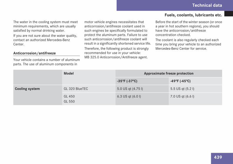
Fuels, coolants, lubricants etc.
439
The water in the cooling system must meetminimum requirements, which are usuallysatisfied by normal drinking water.If you are not sure about the water quality,contact an authorized Mercedes-BenzCenter.
Anticorrosion/antifreezeYour vehicle contains a number of aluminumparts. The use of aluminum components in
motor vehicle engines necessitates thatanticorrosion/antifreeze coolant used insuch engines be specifically formulated toprotect the aluminum parts. Failure to usesuch anticorrosion/antifreeze coolant willresult in a significantly shortened service life.Therefore, the following product is stronglyrecommended for use in your vehicle:MB 325.0 Anticorrosion/Antifreeze agent.
Before the start of the winter season (or oncea year in hot southern regions), you shouldhave the anticorrosion/antifreezeconcentration checked.The coolant is also regularly checked eachtime you bring your vehicle to an authorizedMercedes-Benz Center for service.
Model Approximate freeze protection
-35‡ (-37†) -49‡ (-45†)
Cooling system GL 320 BlueTEC 5.0 US qt (4.75 l) 5.5 US qt (5.2 l)
GL 450GL 550
6.3 US qt (6.0 l) 7.0 US qt (6.6 l)
Technical data
Z
Fuels, coolants, lubricants etc.
440
Washer system and headlampcleaning system
G Warning!Washer solvent/antifreeze is highlyflammable. Do not spill washer solvent/antifreeze on hot engine parts, because itmay ignite and burn. You could be seriouslyburned.
Washer fluid mixing ratioFor temperatures above freezing point, useMB Windshield Washer Concentrate “MBSummerFit” and water:R1 part “MB SummerFit” to 100 parts water
(1.34 fl oz [40 ml] “MB SummerFit” to 1 gal[4.0 l] water)
For temperatures below freezing point, useMB Windshield Washer Concentrate “MBSummerFit” and commercially availablepremixed washer solvent/antifreeze:R1 part “MB SummerFit” to 100 parts
solvent(1.34 fl oz [40 ml] “MB SummerFit” to 1 gal[4.0 l] solvent)
Technical data
Service and LiteratureYour authorized Mercedes-Benz Center hastrained technicians and Genuine Mercedes-Benz Parts to service your vehicle properly.For expert advice and quality service, contactan authorized Mercedes-Benz Center.If you are interested in obtaining serviceliterature for your vehicle, please contact anauthorized Mercedes-Benz Center.We consider this the best way for you toobtain accurate information for your vehicle.For further information you can find us on theMercedes-Benz web-site www.mbusa.com(USA only) or www.mercedes-benz.ca(Canada only).G Warning!To help avoid personal injury, be extremelycareful when performing any service workor repairs. Improper or incomplete serviceor the use of incorrect or inappropriateparts or materials may damage the vehicleor its equipment, which may in turn resultin personal injury.If you have any questions about carryingout any type of service, turn to the adviceof an authorized Mercedes-Benz Center.
We reserve the right to make changes indesign and equipment.
Therefore, information, illustrations anddescriptions in this Operator’s Manual mightdiffer from your vehicle.Reprinting, translation and copying, even ofexcerpts, is not permitted without our priorauthorization in writing.Press time April 01, 2008GSP / OISPrinted in U. S. A.

Order no. 6515 4291 13 Part no. 164 584 71 82 Edition A 2009
É1645847182&ËÍ1645847182