201 digital laser sensor ls-500 series
TRANSCRIPT

201
FIBERSENSORS
LASERSENSORS
PHOTOELECTRICSENSORS
MICROPHOTOELECTRIC
SENSORS
AREASENSORS
SAFETY LIGHT CURTAINS /
SAFETY COMPONENTSPRESSURE /
FLOWSENSORS
INDUCTIVEPROXIMITY
SENSORS
PARTICULARUSE SENSORS
SENSOROPTIONS
SIMPLEWIRE-SAVING
UNITS
WIRE-SAVING SYSTEMS
MEASUREMENTSENSORS
STATIC CONTROL DEVICES
LASERMARKERS
PLC
HUMAN MACHINE INTERFACES
ENERGY MANAGEMENT
SOLUTIONS
FA COMPONENTS
MACHINE VISION SYSTEMS
UV CURING SYSTEMS
Selection Guide
Amplifier Built-in
Amplifier-separated
LS-500
LS-400
Related Information
Digital Laser Sensor Amplifier-separated
LS-500 SERIES
Industry’s smallest*Industry’s smallest* + Stainless steel (SUS) enclosure
Self-diagnosis
diagnosis
Interferenceprevention
Automaticsensitivity setting
Light intensitymonitor
This product is classified as a Class 1 Laser Product in IEC / JIS standards and in FDA* regulations. Do not look at the laser beam through optical system such as a lens.
■SC-GU3 ........................................ P.971~
■About laser beam........................ P.1593~
■General terms and conditions ............. F-3
■Glossary of terms / General precautions ....... P.1549~ / P.1552~
■Selection guide ............................. P.169~
panasonic.net/id/pidsx/globalTimerPNP output
type available
* Amplifier-separated type laser sensor head as of September 2014, in-company survey
* Amplifier-separated type laser sensor head as of September 2014, in-company survey
Featuring stainless steel (SUS) enclosure that won’t break when bumped during installation or maintenance.
(In STD amplifier response time mode)
LS-H101
1,000 39.370
Unit: mm in
5ø3.5
ø0.138ø5
ø0.197
500 19.685100 3.937
Beam-emitting partø2.3ø0.091
ø2ø0.079
Test input
Stainless steel (SUS) body 1 m 3.281 ft sensing range
One-point M6 installation
Featuring waterproof IP67 to allow use in the presence of large amounts of water or dust.
Two-point installationThe thru-beam type LS-H102 features the same form as the EX-L200 amplifier built-in ultra-compact laser sensor. And it can be used as an EX-L200 with a digital indicator.
The LS-H101 features an easy-to-install design.
30 mm 1.181 in
M6
Body: Stainless steel (SUS)
Operation indicator (receiver only)
Actual size
1 m 3.281 ft sensing range (In STD amplifier response time mode)
The LS-H102 delivers sufficient sensing range for use with 450 mm 17.717 in wafers.
Check the optimal receiving location at a glance while watching the red spot on the beam axis adjustment screen.
Simple positioning
Installation pitch13 mm 0.512 in
EX-L211 / EX-L212LS-H102
Same installation pitch as the EX-L200 series
Industry’s smallest* + IP67 * Amplifier-separated type laser sensor head as of September 2014, in-company survey LS-H102
Waterproof IP67
* This product complies with 21 CFR 1040.10 and 1040.11 Laser Notice No. 50, dated June 24, 2007, issued by CDRH (Center for Devices and Radiological Health) under the FDA (Food and Drug Administration).
Conforming toFDA regulations

Digital Laser Sensor LS-500 SERIES 202
FIBERSENSORS
LASERSENSORS
PHOTOELECTRICSENSORS
MICROPHOTOELECTRICSENSORS
AREASENSORS
SAFETY LIGHT CURTAINS /SAFETY COMPONENTSPRESSURE / FLOWSENSORSINDUCTIVEPROXIMITYSENSORS
PARTICULARUSE SENSORS
SENSOROPTIONS
SIMPLEWIRE-SAVINGUNITS
WIRE-SAVING SYSTEMS
MEASUREMENTSENSORS
STATIC CONTROL DEVICES
LASERMARKERS
PLC
HUMAN MACHINE INTERFACES
ENERGY MANAGEMENT SOLUTIONS
FA COMPONENTS
MACHINE VISION SYSTEMS
UV CURING SYSTEMS
Selection GuideAmplifier Built-inAmplifier-separated
LS-500
LS-400
Industry’s smallest* + Thinnest profile * Amplifier-separated type laser sensor head as of September 2014, in-company survey LS-H201
Coaxial design
Featuring a 60% smaller design (by volume) than previous coaxial reflective models
Small, long-range spot Easy-to-see operation indicator
By using a laser with high linearity in a coaxial design, the LS-H201 is able to deliver stable sensing in confined spaces as well as simple installation.
The LS-H201 produces a spot with a diameter of 2 mm 0.079 in at a sensing range of up to 300 mm 11.811 in (in STD amplifier response time mode).
The LS-H201’s operation indicator is visible from all directions.
Our smallest unit is smaller in every dimension at just W8 × H23 × D18 mm W0.315 × H0.906 × D0.709 in (excluding indicators).
Lead frame position detection Wafer inclination detection IC float detection
Detection of the top of DVDs,substrate, etc.
Detection of workpiecesthrough a workbench
8mm0.315 in
23mm0.906 in
18mm0.709 in
ø2 mmø0.079 in
300 mm11.811 in
Detection of gaskets in caps
Gasket
Sensingobject
Reflected light
Laser lightReflective surface
Emittingelement
Reflective photoelectric sensor
Coaxial design
Receiving lens
Receiving element
Emittingpart
Receivingpart
ReceivingpartCoaxial principle
APPLICATIONS
203 Digital Laser Sensor LS-500 SERIES
FIBERSENSORS
LASERSENSORS
PHOTOELECTRICSENSORS
MICROPHOTOELECTRIC
SENSORS
AREASENSORS
SAFETY LIGHT CURTAINS /
SAFETY COMPONENTSPRESSURE /
FLOWSENSORS
INDUCTIVEPROXIMITY
SENSORS
PARTICULARUSE SENSORS
SENSOROPTIONS
SIMPLEWIRE-SAVING
UNITS
WIRE-SAVING SYSTEMS
MEASUREMENTSENSORS
STATIC CONTROL DEVICES
LASERMARKERS
PLC
HUMAN MACHINE INTERFACES
ENERGY MANAGEMENT
SOLUTIONS
FA COMPONENTS
MACHINE VISION SYSTEMS
UV CURING SYSTEMS
Selection Guide
Amplifier Built-in
Amplifier-separated
LS-500
LS-400
8 mm0.315 in
4 mm 0.157 in
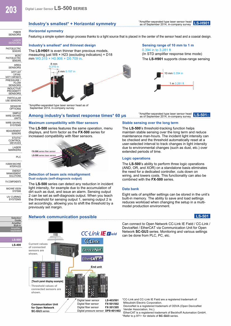
Industry’s smallest* + Horizontal symmetry
Among industry’s fastest response times* 60 μs
* Amplifier-separated type laser sensor head as of September 2014, in-company survey
* Amplifier-separated type laser sensor head as of September 2014, in-company survey
* Amplifier-separated type laser sensor head as of September 2014, in-company survey
LS-H901
LS-501□
Industry’s smallest* and thinnest design
Horizontal symmetry
Sensing range of 10 mm to 1 m
Featuring a simple system design process thanks to a light source that is placed in the center of the sensor head and a coaxial design.
The LS-H901 is even thinner than previous models, measuring just W8 × H23 (excluding indicators) × D18 mm W0.315 × H0.906 × D0.709 in. The LS-H901 supports close-range sensing
0.394 in to 3.281 ft (In STD amplifier response time mode)
10 mm 0.394 in
1 m 3.281 ft
Maximum compatibility with fiber sensorsThe LS-500 series features the same operation, menu displays, and form factor as the FX-500 series for increased compatibility with fiber sensors.
Detection of beam axis misalignmentDual outputs (self-diagnosis output)
The LS-500 series can detect any reduction in incident light intensity, for example due to the accumulation of dirt such as dust, and issue an alarm. Sensing output 2 can be set as self-diagnosis output. When you teach the threshold for sensing output 1, sensing output 2 is set accordingly, allowing you to shift the threshold by a previously set margin.
Stable sensing over the long termThe LS-500’s threshold-tracking function helps maintain stable sensing over the long term and reduce maintenance man-hours. The incident light intensity can be checked and the threshold automatically reset at a user-selected interval to track changes in light intensity due to environmental changes (such as dust, etc.) over extended periods of time.
Logic operationsThe LS-500’s ability to perform three logic operations (AND, OR, and XOR) on a standalone basis eliminates the need for a dedicated controller, cuts down on wiring, and lowers costs. This functionality can also be combined with the FX-500 series.
Data bankEight sets of amplifier settings can be stored in the unit’s built-in memory. The ability to save and load settings reduces workload when changing the setup in a multi-model production environment.
Network communication possible LS-501
FX-500 series fiber sensor
LS-500 series laser sensor
Can connect to Open Network CC-Link IE Field / CC-Link / DeviceNet / EtherCAT via Communication Unit for Open Network SC-GU3 series. Monitoring and various settings can be done from PLC, PC, etc.
しきい値1ch
現在値90 65
2ch 50 03ch 40 704ch 0 05ch 0 06ch 0 07ch 0 08ch 0 0
しきい値9ch
現在値0 0
10ch 0 011ch 0 012ch 0 013ch 0 014ch 0 015ch 0 016ch 0 0
LS-403/501FX-501/502FX-301/305DPS-401/402
Current values of connected sensors are shown.
[Touch panel display example]Threshold values of connected sensors are shown.
End unit
Digital laser sensorDigital fiber sensorDigital fiber sensorDigital pressure sensor
Communication Unit for Open NetworkSC-GU3 series
*�CC-Link and CC-Link IE Field are a registered trademark of Mitsubishi Electric Corporation.DeviceNet is a registered trademark of ODVA (Open DeviceNet Vender Association, Inc.).EtherCAT is a registered trademark of Beckhoff Automation GmbH. * Refer to p.971~ for details of SC-GU3 series.
204Digital Laser Sensor LS-500 SERIES
FIBERSENSORS
LASERSENSORS
PHOTO-ELECTRICSENSORSMICROPHOTO-ELECTRICSENSORS
AREASENSORS
SAFETY LIGHT CURTAINS /SAFETY COMPONENTSPRESSURE / FLOWSENSORS
INDUCTIVEPROXIMITYSENSORS
PARTICULARUSE SENSORS
SENSOROPTIONS
SIMPLEWIRE-SAVINGUNITS
WIRE-SAVING SYSTEMS
MEASURE-MENTSENSORS
STATIC CONTROL DEVICES
LASERMARKERS
PLC
HUMAN MACHINE INTERFACES
ENERGY MANAGEMENT SOLUTIONS
FA COMPONENTS
MACHINE VISION SYSTEMS
UV CURING SYSTEMS
Selection GuideAmplifier Built-inAmplifier-separated
LS-500
LS-400
750 mm 29.528 in600 mm 23.622 in
450 mm 17.717 in300 mm 11.811 in
200 mm 7.874 in150 mm 5.906 in
1 m 3.281 ft1 m 3.281 ft1 m 3.281 ft1 m 3.281 ft1 m 3.281 ft1 m 3.281 ft1 m 3.281 ft1 m 3.281 ft1 m 3.281 ft1 m 3.281 ft1 m 3.281 ft1 m 3.281 ft
0.01 to 1.5m 0.033 to 4.921 ft0.01 to 2 m 0.033 to 6.562 ft
0.01 to 2.5 m 0.033 to 8.202 ft
0.01 to 1m 0.033 to 3.281 ft0.01 to 1m 0.033 to 3.281 ft0.01 to 1m 0.033 to 3.281 ft
AppearanceType
Thru
-bea
m ty
pe
Model No.
LS-H101
LS-H102
LS-H201
LS-H901
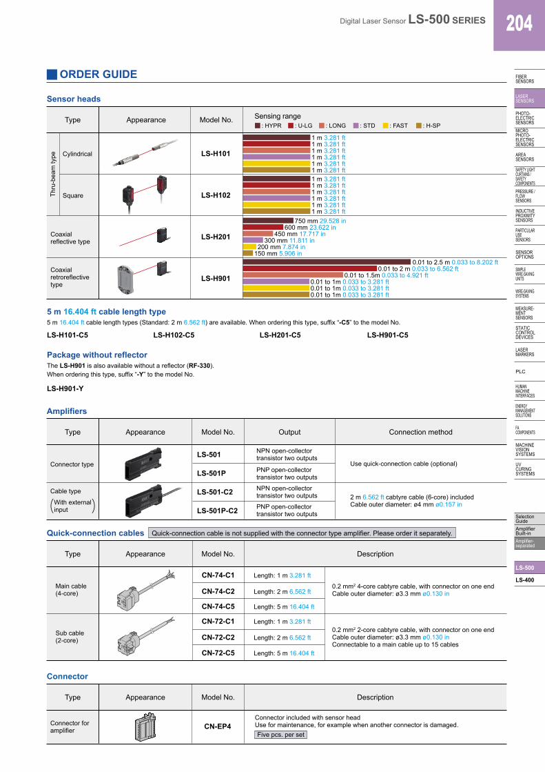
Sensor heads
Cylindrical
Square
Coaxial reflective type
Coaxial retroreflective type
Package without reflectorThe LS-H901 is also available without a reflector (RF-330).When ordering this type, suffix “-Y” to the model No.
5 m 16.404 ft cable length type5 m 16.404 ft cable length types (Standard: 2 m 6.562 ft) are available. When ordering this type, suffix “-C5” to the model No.
LS-H901-Y
LS-H101-C5 LS-H102-C5 LS-H201-C5 LS-H901-C5
AppearanceType
With externalinput
Cable type
Connector type
Connection method
Use quick-connection cable (optional)
2 m 6.562 ft cabtyre cable (6-core) includedCable outer diameter: ø4 mm ø0.157 in
NPN open-collector transistor two outputs
PNP open-collectortransistor two outputs
NPN open-collectortransistor two outputs
PNP open-collectortransistor two outputs
OutputModel No.
LS-501
LS-501P
LS-501-C2
LS-501P-C2
Amplifiers
Quick-connection cables
AppearanceType
Connector foramplifier
Connector included with sensor headUse for maintenance, for example when another connector is damaged.
Model No.
CN-EP4
Connector
Type Model No. Description
Description
CN-74-C1 Length: 1 m 3.281 ft
0.2 mm2 4-core cabtyre cable, with connector on one endCable outer diameter: ø3.3 mm ø0.130 in
0.2 mm2 2-core cabtyre cable, with connector on one endCable outer diameter: ø3.3 mm ø0.130 inConnectable to a main cable up to 15 cables
Length: 2 m 6.562 ft
Length: 1 m 3.281 ft
Length: 2 m 6.562 ft
CN-74-C2
Length: 5 m 16.404 ftCN-74-C5
CN-72-C1
CN-72-C2
Length: 5 m 16.404 ftCN-72-C5
Main cable(4-core)
Sub cable(2-core)
Quick-connection cable is not supplied with the connector type amplifier. Please order it separately.
Appearance
Sensing range : HYPR : U-LG : LONG : STD : FAST : H-SP
Five pcs. per set
ORDER GUIDE

205 Digital Laser Sensor LS-500 SERIES
FIBERSENSORS
LASERSENSORS
PHOTO-ELECTRICSENSORS
MICROPHOTO-
ELECTRICSENSORS
AREASENSORS
SAFETY LIGHT CURTAINS /
SAFETY COMPONENTSPRESSURE /
FLOWSENSORS
INDUCTIVEPROXIMITY
SENSORS
PARTICULARUSE
SENSORS
SENSOROPTIONS
SIMPLEWIRE-SAVING
UNITS
WIRE-SAVING SYSTEMS
MEASURE-MENT
SENSORS
STATIC CONTROL DEVICES
LASERMARKERS
PLC
HUMAN MACHINE
INTERFACES
ENERGY MANAGEMENT
SOLUTIONS
FA COMPONENTS
MACHINE VISION
SYSTEMS
UV CURING
SYSTEMS
Selection Guide
Amplifier Built-in
Amplifier-separated
LS-500
LS-400
ORDER GUIDE
Sensor head mounting bracket
Designation Description
Sensor head mounting bracket
For LS-H102□ (square side sensing type)Foot angled mounting bracketFor LS-H102□ (square side sensing type)Universal sensor mounting bracketFor LS-H102□ (square side sensing type)Back angled mounting bracket
Mounting bracket for amplifier
Amplifier protective seal
10 sets of 2 communication window seals and 1 connector sealCommunication window seal: It prevents malfunction due to transmission signal from another amplifier, as well as, prevents
effect on another amplifier.Connector seal: It prevents contact of any metal, etc., with the pins of the quick-connection cable.
Model No.
• MS-EXL2-1
Material: Stainless steel (SUS304)Two M3 (length 14 mm 0.551 in) screws with washers [stainless steel (SUS)] are attached.
• MS-EXL2-4 • MS-EXL2-5
Adjustment±3°
360°rotation
Move vertically 15 mm 0.591 in
Amplifier mounting bracket• MS-DIN-2
Amplifier protective seal• FX-MB1
Communication window seal
Connector seal
MS-EXL2-1
MS-EXL2-4
MS-EXL2-5
MS-DIN-2
FX-MB1
RF-310
RF-31
RF-33
For coaxial retroreflective typeCompact reflector
For coaxial retroreflective typeSize: 25.2 × 27.8 × t 0.4 mm 0.992 × 1.094 × t 0.016 in
For coaxial retroreflective typeSize: 9.2 × 9.2 × t 0.4 mm 0.362 × 0.362 × t 0.016 in
Reflector
Reflective tape
Reflector• RF-310
24 mm0.945 in
12 mm0.472 in
4 mm0.157 in
• RF-33
• RF-31
Reflective tape
9.2 mm0.362 in
0.4 mm0.016 in 9.2 mm
0.362 in
Amplifier mounting bracket
End plates are not supplied with the amplifier. Please order them separately when the amplifiers are mounted in cascade.
MS-DIN-E
When cascading multiple amplifiers, or when it moves depending on the way it is installed on a DIN rail, these end plates clamp amplifiers into place on both sides. Make sure to use end plates when cascading multiple amplifiers together.
End plates
Appearance Model No. Description
AccessoriesMS-LS-1 (Sensor head mounting bracket)For LS-H201□ / LS-H901□
Foot angled mounting
Back angled mounting
RF-330 (Reflector) MS-EXL2-2 (Mounting plate for thru-beam type)
13 mm0.512 in
t 0.8 mmt 0.031 in
8.2 mm0.323 in
Mounting plate MS-EXL2-2 (Accessory)
Two pcs. per set
M3 screw (Purchase separately.)
Material: Stainless steel (SUS304)Two M2 (length 12 mm 0.472 in) screws with washers [stainless steel (SUS)] are attached.
Material: Stainless steel (SUS304)
Sensing range: Same as the RF-330.
Sensing range: 0.01 to 1 m 0.033 to 3.281 ft
Material: Die-cast zinc alloyTwo M3 (length 14 mm 0.551 in) screws with washers [stainless steel (SUS)], one M3 (length 10 mm 0.394 in) hexagon-socket-head bolt [stainless steel (SUS)], and one M3 hexagon nut [stainless steel (SUS)] are attached.
Material: Stainless steel (SUS304)Two M3 (length 14 mm 0.551 in) screws with washers [stainless steel (SUS)] are attached.
27.8 mm1.094 in0.4 mm
0.016 in 25.2 mm0.992 in
OPTIONS

206Digital Laser Sensor LS-500 SERIES
FIBERSENSORS
LASERSENSORS
PHOTO-ELECTRICSENSORSMICROPHOTO-ELECTRICSENSORS
AREASENSORS
SAFETY LIGHT CURTAINS /SAFETY COMPONENTSPRESSURE / FLOWSENSORS
INDUCTIVEPROXIMITYSENSORS
PARTICULARUSE SENSORS
SENSOROPTIONS
SIMPLEWIRE-SAVINGUNITS
WIRE-SAVING SYSTEMS
MEASURE-MENTSENSORS
STATIC CONTROL DEVICES
LASERMARKERS
PLC
HUMAN MACHINE INTERFACES
ENERGY MANAGEMENT SOLUTIONS
FA COMPONENTS
MACHINE VISION SYSTEMS
UV CURING SYSTEMS
Selection GuideAmplifier Built-inAmplifier-separated
LS-500
LS-400
Sensor headsThru-beam type Coaxial reflective
typeCoaxial retroreflective
type
Item
ø5 mm ø0.197 in approx. or less at a distance from theemitter of 1 m 3.281 ft
at a distance from the sensorhead of 300 mm 11.811 in
ø2 mm ø0.079 in approx. or lessat a distance from thesensor head of 1 m 3.281 ft
ø6 mm ø0.236 in approx. or less ø5 mm ø0.197 in approx. or less at a distance from theemitter of 1 m 3.281 ft
1 m 3.281 ft
1 m 3.281 ft
1 m 3.281 ft
1 m 3.281 ft
1 m 3.281 ft
1 m 3.281 ft
150 mm 5.906 in
200 mm 7.874 in
300 mm 11.811 in
450 mm 17.717 in
600 mm 23.622 in
750 mm 29.528 in
0.01 to 1 m 0.033 to 3.281 ft
0.01 to 1 m 0.033 to 3.281 ft
0.01 to 1 m 0.033 to 3.281 ft
0.01 to 1.5 m 0.033 to 4.921 ft
0.01 to 2 m 0.033 to 6.562 ft
0.01 to 2.5 m 0.033 to 8.202 ft
1 m 3.281 ft
1 m 3.281 ft
1 m 3.281 ft
1 m 3.281 ft
1 m 3.281 ft
1 m 3.281 ft
MS-EXL2-2 (Mounting plate): 2 pcs.
Net weight: 50 g approx.Gross weight: 70 g approx.
M6 screw: 4 pcs.Toothed lock washer: 2 pcs.
Enclosure: Stainless steel (SUS303)Cover: Polycarbonate
Enclosure: PBTCover: Acrylic
Enclosure: PBT, Indicator cover: Polycarbonate Beam-emitting/receiving surfaces: Glass
LS-501(P), LS-501(P)-C2 (Note 2)
EMC Directive, RoHS Directive
Opaque, translucent, or transparent object (Note 5)
Orange LED (lights up when the amplifier output is ON)
–10 to +55 °C +14 to +131 °F (No dew condensation or icing allowed), Storage: –20 to +70 °C –4 to +158 °F
35 to 85 % RH, Storage: 35 to 85 % RH
Incandescent light: 3,000 ℓx or less at the light-receiving face
1,000 V AC for one min. between all supply terminals connected together and enclosure
20 MΩ, or more, with 250 V DC megger between all supply terminals connected together and enclosure
10 to 500 Hz frequency, 1.5 mm 0.059 in double amplitude in X, Y and Z directions for two hours each
100 m/s2 acceleration (10 G approx.) in X, Y and Z directions three times each
Red semiconductor laser diode
660 nm 0.026 mil
Class 1 [IEC / JIS / FDA (Note 6)]
0.15 mm2, 2-core two parallel shielded cables, 2 m 6.562 ft long (Note 7)0.09 mm2 2-core shielded cable, 2 m 6.562 ft long (Note 7)
Sen
sing
rang
e (N
ote
3,4)
LS-H101Cylindrical
LS-H102Square
LS-H201 LS-H901
IP40 (IEC) IP67 (IEC) IP40 (IEC) IP40 (IEC)
Net weight: 50 g approx.Gross weight: 80 g approx.
Net weight: 50 g approx.Gross weight: 85 g approx.
MS-LS-1(Mounting bracket): 1pc.
MS-LS-1 (Mounting bracket): 1pc.RF-330 (Refrector): 1pc.
2 mW
Net weight: 50 g approx.Gross weight: 75 g approx.
2 mW 2 mW 1 mW
Env
ironm
enta
l res
ista
nce
Em
ittin
g el
emen
t
Notes: 1) Where measurement conditions have not been specified precisely, the conditions used were an ambient temperature of +23 °C +73.4 °F. 2) When using the thru-beam type LS-H101□ or LS-H102□, do not set the receiving light sensitivity (gctL) of the applicable LS-500 series amplifier to level
2 or less. This is because there is a possibility of sensing becoming unstable. 3) The sensing range of the coaxial reflective type sensor is specified for white non-glossy paper (100 × 100 mm 3.937 × 3.937 in) as the object. 4) The sensing ranges for coaxial retroreflective type sensors are values for the RF-330 reflector. In addition, the sensing range is the possible setting
range for the reflector. The sensor can detect an object less than 0.01 m 0.033 ft away. Note that if there are white papers or specular objects near the sensor head, reflected light from these objects may be received. In such cases, use the amplifier unit’s receiving sensitivity function to lower the sensitivity, change the response time, or move the sensor head away from the target object. The incident light intensity may vary with the condition of the reflector surface. When using one of the applicable LS-500 series amplifiers, leave an adequate safety margin when setting the threshold.
5) Make sure to confirm detection with an actual sensor before use. 6) This product complies with 21 CFR 1040.10 and 1040.11 Laser Notice No. 50, dated June 24, 2007, issued by CDRH (Center for Devices and
Radiological Health) under the FDA (Food and Drug Administration). 7) Cable cannot be extended.
Model No.
Type
H−SP
Sensing object
Material
Cable
Weight
Accessories
Operation indicator
Applicable amplifiers
CE marking directive compliance
Spot size
FAST
STD
LONG
U−LG
HYPR
Protection
Ambient temperature
Ambient humidity
Ambient illuminance
Voltage withstandability
Insulation resistance
Vibration resistance
Shock resistance
Type
Peak emission wavelength
Laser class
Max. output
SPECIFICATIONS

207 Digital Laser Sensor LS-500 SERIES
FIBERSENSORS
LASERSENSORS
PHOTO-ELECTRICSENSORS
MICROPHOTO-
ELECTRICSENSORS
AREASENSORS
SAFETY LIGHT CURTAINS /
SAFETY COMPONENTSPRESSURE /
FLOWSENSORS
INDUCTIVEPROXIMITY
SENSORS
PARTICULARUSE
SENSORS
SENSOROPTIONS
SIMPLEWIRE-SAVING
UNITS
WIRE-SAVING SYSTEMS
MEASURE-MENT
SENSORS
STATIC CONTROL DEVICES
LASERMARKERS
PLC
HUMAN MACHINE
INTERFACES
ENERGY MANAGEMENT
SOLUTIONS
FA COMPONENTS
MACHINE VISION
SYSTEMS
UV CURING
SYSTEMS
Selection Guide
Amplifier Built-in
Amplifier-separated
LS-500
LS-400
Timer functions
AmplifiersConnector type
LS-501
LS-501P
Cable type
LS-501-C2
LS-501P-C2
Type
NPN output
PNP outputItem
Power consumption Normal operation: 1,200 mW or less (Current consumption 50 mA or less at 24 V supply voltage,Cable type: excluding monitor current output)ECO mode: 980 mW or less (Current consumption 40 mA or less at 24 V supply voltage,Cable type: excluding monitor current output)
Supply voltage
Sensing outputs(Sensing output 1, 2)(Note 4)
Selectable either Light-ON or Dark-ONIncorporated
Normal mode, differential mode, hysteresis mode, window comparator mode, selectable
H-SP: 60 μs or less, FAST: 150 μs or less, STD: 250 μs or less, LONG: 500 μs or less, U-LG: 5 ms or less, HYPR: 24 ms or less , selectable
Timer period
<NPN output type>NPN open-collector transistor
• Maximum sink current: 50 mA (Note 2)• Applied voltage: 30 V DC or less (between output and 0 V)• Residual voltage: 2 V or less (at max. sink current)
<PNP output type>PNP open-collector transistor
• Maximum source current: 50 mA (Note 2)• Applied voltage: 30 V DC or less (between output and +V)• Residual voltage: 2 V or less (at max. source current)
Output current: Approx. 4 to 20 mA (H-SP, FAST, STD: at 0 to 4,000 indication)Response time: 2 ms or lessZero point: 4 mA ± 1 % F.S.Span: 16 mA ± 5 % F.S.Linearity: ± 3 % F.S.Load resistance: 0 to 250 Ω
Response time
Laser emission halt / teaching (full-auto teaching, limit teaching, 2 point teaching) / logic operation setting / copy lock / display adjustment / data bank load / data bank save, selectableExternal input function
Sensing output setting
Orange LED (lights up when sensing output 1 or sensing output 2 is ON)Green LED (lights up during laser emission)
Yellow LED (lights up when output is selected)8-digit 7-segment digital display (4-digit green LED + 4-digit red LED), MODE indicator (Yellow LED): L/D, CUST, PRO
H-SP / FAST / STD: 0 to 4,000, LONG / U-LG / HYPR: 0 to 9,9992-level teaching / limit teaching / full auto teaching / manual adjustment
Incorporated (Note 3)
– 10 to +55°C +14 to +131 °F (If 4 to 7 units are mounted close together, – 10 to +50°C +14 to +122 °F; if 8 to 16 units (cable type: 8 to 12 units) are mounted close together, – 10 to +45 °C +14 to +113°F) (No dew condensation or icing allowed), Storage: – 20 to +70 °C – 4 to +158 °F
Interference prevention function
Ambient temperature
<NPN output type>NPN non-contact input
• Signal condition High: +8 V to +V DC or open, Low: 0 to +2 V DC (source current 0.5 mA or less)• Input impedance: 10 kΩ approx.
Normal mode, differential mode, hysteresis mode, self-diagnosis output mode, selectable
Normal mode, differential mode, hysteresis mode, self-diagnosis output mode, answer-back output mode, selectable
35 to 85 % RH, Storage: 35 to 85 % RH1,000 V AC for one min. between all supply terminals connected together and enclosure
20 MΩ, or more, with 250 V DC megger between all supply terminals connected together and enclosure10 to 150 Hz frequency, 0.75 mm 0.030 in (max. 10 G) double amplitude in X, Y and Z directions for two hours each
98 m/s2 acceleration (10 G approx.) in X, Y and Z directions five times eachEnclosure: Polycarbonate, Cover: Polycarbonate, Switch: Polyacetal
IP40 (IEC)
Extension up to total 100 m 328.084 ft is possible with 0.3 mm2, or more, cable.
FX-MB1 (Amplifier protective seal): 1 set
Between sensing output 1 and calculation target: Disabled / AND / OR / XOR, selectableCalculation target: Sensing output 2 / adjacent upstream amplifier (sensing output 1) / external input, selectable
Net weight: 15 g approx., Gross weight: 55 g approx.
0.2 mm2 6-core cabtyre cable, 2 m 6.562 ft long
Net weight: 75 g approx., Gross weight: 110 g approx.
Timer range “ms”: 0.5 ms approx., 1 to 9,999 ms approx., in approx. 1 ms intervalsTimer range “sec”: 0.5 sec. approx., 1 to 32 sec. approx., in approx. 1 sec. intervalsTimer range “1/10 ms”: 0.05 ms approx., 0.1 to 999.9 ms approx., in approx. 0.1 ms intervals, Set separately for each output.
<PNP output type>PNP non-contact input
• Signal condition High: +4 V to +V DC (sink current 3.0 mA or less), Low: 0 to +0.6 V DC or open• Input impedance: 10 kΩ approx.
External input (Note 4)
Env
ironm
enta
lre
sist
ance
Mode
l No.
Notes: 1) Where measurement conditions have not been specified precisely, the conditions used were an ambient temperature of +23 °C +73.4 °F. 2) 25 mA if 5 or more amplifier are connected in cascade (excluding cable extension). 3) Number of units that can be mounted close together: 0 for H-SP; 2 for FAST; 4 for STD, LONG, U-LG, or HYPR 4) Select either sensing output 2 or external input as the connector type.
12 to 24 V DC % Ripple P-P 10 % or less+10–15
CE marking directive compliance EMC Directive, RoHS Directive
Output operation
Short-circuit protectionSensing output 1
Sensing output 2 (Note 4)
Sensing output operation indicatorLaser emission indicatorOutput select indicatorDigital displayIncident light indication rangeSensitivity setting
Logical operation
Ambient humidityVoltage withstandabilityInsulation resistanceVibration resistanceShock resistance
Material
Protection
CableCable extensionWeightAccessory
Monitor current output
<Sensing output 1>OFF-delay timer, ON-delay timer, One-shot timer, ON/OFF-delay timer, ON-delay / One-shot timer, switchable either effective or ineffective, with variable timer period
<Sensing output 2>OFF-delay timer, ON-delay timer, One-shot timer, switchable either effective or ineffective, with variable timer period
SPECIFICATIONS

208Digital Laser Sensor LS-500 SERIES
FIBERSENSORS
LASERSENSORS
PHOTO-ELECTRICSENSORSMICROPHOTO-ELECTRICSENSORS
AREASENSORS
SAFETY LIGHT CURTAINS /SAFETY COMPONENTSPRESSURE / FLOWSENSORS
INDUCTIVEPROXIMITYSENSORS
PARTICULARUSE SENSORS
SENSOROPTIONS
SIMPLEWIRE-SAVINGUNITS
WIRE-SAVING SYSTEMS
MEASURE-MENTSENSORS
STATIC CONTROL DEVICES
LASERMARKERS
PLC
HUMAN MACHINE INTERFACES
ENERGY MANAGEMENT SOLUTIONS
FA COMPONENTS
MACHINE VISION SYSTEMS
UV CURING SYSTEMS
Selection GuideAmplifier Built-inAmplifier-separated
LS-500
LS-400
I/O CIRCUIT AND WIRING DIAGRAMS
Symbols ... D1, D2, D3, D4: Reverse supply polarity protection diodeZD1, ZD2: Surge absorption zener diodeTr1, Tr2 : NPN output transistor
Users’ circuitInternal circuit
Sen
sor c
ircui
t
Color code of quick-connection cable
(Brown) +V (Note 1)
(Blue) 0 V (Note 1)
(White) Sensing output 2/ external input
(Black) Sensing output 1
1
Terminal No. of connector type
+
−
ZD2ZD1
D1
D4
D2
D3 4
2
10 kΩ
*1
D1
Users’ circuitInternal circuit
(Brown) +V
Tr1Tr2
50 mA max.
(Black) Sensing output 1
(Gray) Monitor output
(White) Sensing output 2
0V
12 to 24 V DC+
−4
1
50 mA max.
Load
Load
Load
3
%+10−15
D4
D3
D2Sen
sor c
ircui
t
2
ZD1
ZD2
10 kΩ(Pink) External input
(Blue) 0 V
Notes: 1) The quick-connection sub cable does not have +V (brown) and 0 V (blue).The power is supplied from the connector of the main cable.
2) Wiring when sensing output 2 is selected is shown with solid lines. Wiring when external input is selected is shown with broken lines.
12 to 24 V DC
*1
NPN output typeConnector type Cable type
I/O circuit diagrams
NPN output type PNP output type
Notes: 1) The quick-connection sub cable does not have brown lead wire and blue lead wire. The power is supplied from the connector of the main cable.
2) The quick-connection cable does not have gray or pink lead wires.
Wiring diagrams
Terminal layout of connector type
12 to 24 V DC+−
Color code of cable type/quick-connection cable Color code of cable type/quick-connection cable
Brown (Note 1)
White
Pink
Blue (Note 1)
Gray
12 to 24 V DC+−
1+V Terminal No.
30V
2Output 1
4Output 2
Notes: 1) The quick-connection sub cable does not have brown lead wire and blue lead wire. The power is supplied from the connector of the main cable.
2) The quick-connection cable does not have gray or pink lead wires.
LoadBlack
LoadLoad
3
4
5
6
1
2
Terminal No. Connection cablePurpleWhiteShieldShieldBlackPink
* Connector for amplifier (CN-EP4) pin position
%+10−15
%+10−15
Users’ circuitInternal circuit
Sen
sor c
ircui
t
Color code of quick-connection cable
(Brown) +V (Note 1)
(Blue) 0 V (Note 1)
(White) Sensing output 2/ external input
(Black) Sensing output 1Tr1
Tr2
LoadLoad
+3.3 V
1
Terminal No. of connector type
+
−ZD2
ZD1
D1
D2
D3
D4
Notes: 1) The quick-connection sub cable does not have +V (brown) and 0 V (blue).The power is supplied from the connector of the main cable.
2) Wiring when sensing output 2 is selected is shown with solid lines. Wiring when external input is selected is shown with broken lines.
4
3
Users’ circuitInternal circuit
Sen
sor c
ircui
t
Color code
(Brown) +V
(White) Sensing output 2
(Pink) External input
(Blue) 0 V
(Gray) Monitor output
(Black) Sensing output 1Tr1
Tr2
LoadLoad
+3.3 V10 kΩ
1
4
2
12 to 24 V DC+
−
ZD2ZD1
D1
D2
D3
D4
50 mA max.
3 %+10−15
%+10−15
%+10−15
Load
50 mA max.
PNP output typeConnector type Cable type
Brown (Note 1)
BlackWhite
Pink
Blue (Note 1)
Gray
Load
Load Load
6
5
Color code
5
6
2
10 kΩ
50 mA max.
50 mA max.
0V
LoadLoad
Tr4
Tr3
3
50 mA max.
50 mA max. 12 to 24 V DC
Symbols ... D1, D2, D3, D4: Reverse supply polarity protection diodeZD1, ZD2: Surge absorption zener diodeTr1, Tr2 : PNP output transistor
Non-voltage contact or NPN open-collector transistor
or• External input High: +8 V to +V, or open Low: 0 to +2 V (source current: 0.5 mA or less)• Light emission halts and teaching occurs when at Low.
Non-voltage contact or PNP open-collector transistor
or• External input High: +4 V to +V (sink current: 3 mA or less) Low : 0 to +0.6 V, or open• Light emission halts and teaching occurs when at High.
123456
*1
*1
209 Digital Laser Sensor LS-500 SERIES
FIBERSENSORS
LASERSENSORS
PHOTO-ELECTRICSENSORS
MICROPHOTO-
ELECTRICSENSORS
AREASENSORS
SAFETY LIGHT CURTAINS /
SAFETY COMPONENTSPRESSURE /
FLOWSENSORS
INDUCTIVEPROXIMITY
SENSORS
PARTICULARUSE
SENSORS
SENSOROPTIONS
SIMPLEWIRE-SAVING
UNITS
WIRE-SAVING SYSTEMS
MEASURE-MENT
SENSORS
STATIC CONTROL DEVICES
LASERMARKERS
PLC
HUMAN MACHINE
INTERFACES
ENERGY MANAGEMENT
SOLUTIONS
FA COMPONENTS
MACHINE VISION
SYSTEMS
UV CURING
SYSTEMS
Selection Guide
Amplifier Built-in
Amplifier-separated
LS-500
LS-400
PRECAUTIONS FOR PROPER USE Refer to p.1552~ for general precautions and p.1593~ for information about laser beam.
Metal plate Accessory for MS-EXL2-1
Sensor head mounting bracket MS-EXL2-1 (Optional)
M3 (length: 14 mm 0.551 in) screw with washer Accessory for MS-EXL2-1
Metal plate MS-EXL2-2 (Accessory)
• This catalog is a guide to select a suitable product. Be sure to read the instruction manual attached to the product prior to its use.
• Never use this product as a sensing device for personnel protection.
• In case of using sensing devices for personnel protection, use products which meet regulations and standards, such as OSHA, ANSI or IEC etc., for personnel protection applicable in each region or country.
• These products are Class 1 laser in compliance with IEC, JIS standards and FDA* regulations. To reduce the risk of danger, do not look directly at the laser beam or view it through an optical system.
• A label with instructions as found at the below is affixed to the product. Handle this sensor as per the instruction on the labels.
Cautions for laser beams
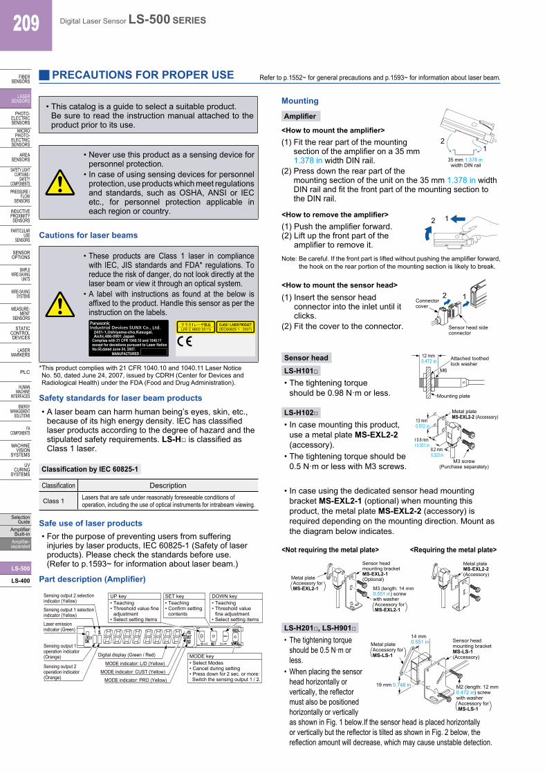
Part description (Amplifier)
Mounting
Amplifier
LS-H201□, LS-H901□
<How to mount the amplifier>(1) Fit the rear part of the mounting
section of the amplifier on a 35 mm 1.378 in width DIN rail.
(2) Press down the rear part of the mounting section of the unit on the 35 mm 1.378 in width DIN rail and fit the front part of the mounting section to the DIN rail.
<How to mount the sensor head>(1) Insert the sensor head
connector into the inlet until it clicks.
(2) Fit the cover to the connector.
<How to remove the amplifier>(1) Push the amplifier forward.(2) Lift up the front part of the
amplifier to remove it.Note: Be careful. If the front part is lifted without pushing the amplifier forward,
the hook on the rear portion of the mounting section is likely to break.
Sensor head
LS-H101□• The tightening torque
should be 0.98 N·m or less.
LS-H102□• In case mounting this product,
use a metal plate MS-EXL2-2 (accessory).
• The tightening torque should be 0.5 N·m or less with M3 screws.
<Not requiring the metal plate> <Requiring the metal plate>
• In case using the dedicated sensor head mounting bracket MS-EXL2-1 (optional) when mounting this product, the metal plate MS-EXL2-2 (accessory) is required depending on the mounting direction. Mount as the diagram below indicates.
• The tightening torque should be 0.5 N·m or less.
• When placing the sensor head horizontally or vertically, the reflector must also be positioned horizontally or vertically as shown in Fig. 1 below. If the sensor head is placed horizontally or vertically but the reflector is tilted as shown in Fig. 2 below, the reflection amount will decrease, which may cause unstable detection.
Digital display (Green / Red)
Laser emissionindicator (Green)
MODE indicator: PRO (Yellow)
MODE indicator: L/D (Yellow)Sensing output 2 operation indicator (Orange)
Sensing output 1 operation indicator (Orange)
Sensing output 1 selectionindicator (Yellow)
Sensing output 2 selectionindicator (Yellow)
MODE indicator: CUST (Yellow)
UP key• Teaching• Threshold value fine
adjustment• Select setting items
MODE key• Select Modes• Cancel during setting• Press down for 2 sec. or more: Switch the sensing output 1 / 2.
DOWN key• Teaching• Threshold value
fine adjustment• Select setting items
SET key• Teaching• Confirm setting
contents
Safety standards for laser beam products• A laser beam can harm human being’s eyes, skin, etc.,
because of its high energy density. IEC has classified laser products according to the degree of hazard and the stipulated safety requirements. LS-H□ is classified as Class 1 laser.
Classification by IEC 60825-1
Classification Description
Class 1 Lasers that are safe under reasonably foreseeable conditions of operation, including the use of optical instruments for intrabeam viewing.
21
35 mm 1.378 in width DIN rail
2 1
2 1Connectorcover
Sensor head side connector
Attached toothed lock washer
Mounting plate
12 mm 0.472 in
M6
Metal plateMS-EXL2-2 (Accessory)
M3 screw(Purchase separately)
13 mm 0.512 in
t 0.8 mm t 0.031 in
8.2 mm 0.323 in
Metal plate Accessory for MS-LS-1
Sensor head mounting bracket MS-LS-1 (Accessory)
M2 (length: 12 mm 0.472 in) screw with washer Accessory for MS-LS-1
14 mm 0.551 in
19 mm 0.748 in
Safe use of laser products• For the purpose of preventing users from suffering
injuries by laser products, IEC 60825-1 (Safety of laser products). Please check the standards before use. (Refer to p.1593~ for information about laser beam.)
* This product complies with 21 CFR 1040.10 and 1040.11 Laser Notice No. 50, dated June 24, 2007, issued by CDRH (Center for Devices and Radiological Health) under the FDA (Food and Drug Administration).

210Digital Laser Sensor LS-500 SERIES
FIBERSENSORS
LASERSENSORS
PHOTO-ELECTRICSENSORSMICROPHOTO-ELECTRICSENSORS
AREASENSORS
SAFETY LIGHT CURTAINS /SAFETY COMPONENTSPRESSURE / FLOWSENSORS
INDUCTIVEPROXIMITYSENSORS
PARTICULARUSE SENSORS
SENSOROPTIONS
SIMPLEWIRE-SAVINGUNITS
WIRE-SAVING SYSTEMS
MEASURE-MENTSENSORS
STATIC CONTROL DEVICES
LASERMARKERS
PLC
HUMAN MACHINE INTERFACES
ENERGY MANAGEMENT SOLUTIONS
FA COMPONENTS
MACHINE VISION SYSTEMS
UV CURING SYSTEMS
Selection GuideAmplifier Built-inAmplifier-separated
LS-500
LS-400
PRECAUTIONS FOR PROPER USE Refer to p.1552~ for general precautions and p.1593~ for information about laser beam.
Fig. 1 Proper positioning
When placing the sensor head horizontally or vertically, the reflector shall also be positioned horizontally or vertically.
Fig. 2 Improper positioning
When placing the reflector tilted even when the sensor head is positioned horizontally or vertically.
Wiring• Make sure that the power supply is off while wiring.• Verify that the supply voltage variation is within the rating.• Take care that if a voltage exceeding the rated range is
applied, or if an AC power supply is directly connected, the sensor may get burnt or damaged.
• If power is supplied from a commercial switching regulator, ensure that the frame ground (F.G.) terminal of the power supply is connected to an actual ground.
• Make sure to use the optional quick-connection cable for the connection of the amplifier [connector type LS-501(P)]. Extension up to total 100 m 328.084 ft is possible with 0.3 mm2, or more, cable. However, in order to reduce noise, make the wiring as short as possible. Set the supply voltage after considering the voltage drop caused by the cable’s resistance.
Others• Do not use during the initial transient time (0.5 sec. approx.)
after the power supply is switched on.• Because the sensitivity is higher in U-LG and HYPER modes
than in other modes, it can be more easily affected by extraneous noise. Check the operating environment before use.
DIMENSIONS (Unit mm in) The CAD data can be downloaded from our website.
AmplifierLS-501 LS-501P
R23.2
R0.913
10.50.413
3.950.156
3 0.118
100.394
4.75 0.187
70.276
2.7 0.1066.5 0.256
Communication window
Digital display (Red, Green)
Suitable for 35 mm1.378 in width DIN rail
Sensing output 1 selection indicator (Yellow)
Sensing output 2 selection indicator (Yellow)
Sensing output 1operation indicator (Orange)
Laser emission indicator (Green)
Sensing output 2operation indicator (Orange)
9.950.3922 0.0798.2
0.323
MODE key
Setting key
22.7 0.894
62.5 2.461
19.20.756
47.81.882
321.260
281.102
20.80.819
47.2 1.858
36.5 1.437240.945
75 2.953(98.3 3.870)
AmplifierLS-501-C2 LS-501P-C2
100.394
2.7 0.1066.5 0.256
Suitable for 35 mm1.378 in width DIN rail
ø4 ø0.157 in 6-core cable, 2 m 6.562 ft long
2.80.110
9.20.362
4.75 0.187
Digital display (Red, Green)
Sensing output 1 selection indicator (Yellow)
Sensing output 2 selection indicator (Yellow)
Sensing output 1operation indicator (Orange)
Laser emission indicator (Green)
Sensing output 2operation indicator (Orange)
9.950.3922 0.0798.2
0.323
MODE key
Setting key
Communication window
3 0.118
70.276
22.7 0.894
R23.2
R0.913
47.81.882
62.5 2.461
19.20.756
47.2 1.858
240.945 36.5 1.437
75 2.953(98.3 3.870)
321.260
281.102
20.80.819
• Length (L)
CN-74-C1
CN-74-C2
Model No. Length (mm in)
1,000 39.370
2,000 78.740
CN-74-C5 5,000 196.850
ø3.3 ø0.130 cable
2.650.104
2.54 0.100
2.540.100
7.20.283
30.118
0.20.008
13.60.535
100.394
70.276
L 501.969
120.472 10.5
0.413
140.551 2.9
0.114
60.236
100.394
CN-74-C1 CN-74-C2 CN-74-C5 Main cable (Optional)
• Length (L)
CN-72-C1
CN-72-C5
Model No. Length (mm in)
1,000 39.370
5,000 196.850
CN-72-C2 2,000 78.740
7.20.283
30.118
0.20.008
13.60.535
100.394
70.276
2.650.104
ø3.3 ø0.130 cable3 0.118
501.969
L
2.540.100
2.54 0.100
120.472
60.2362.9
0.114
140.551
10.50.413
100.394
Sub cable (Optional)CN-72-C1 CN-72-C2 CN-72-C5
When adding units, wiring length must not exceed 50 m 164.042 ft (for 5 to 8 amplifiers) or 20 m 65.617 ft (for 9 to 16 amplifiers).
<Correct>
<Incorrect>
211 Digital Laser Sensor LS-500 SERIES
FIBERSENSORS
LASERSENSORS
PHOTO-ELECTRICSENSORS
MICROPHOTO-
ELECTRICSENSORS
AREASENSORS
SAFETY LIGHT CURTAINS /
SAFETY COMPONENTSPRESSURE /
FLOWSENSORS
INDUCTIVEPROXIMITY
SENSORS
PARTICULARUSE
SENSORS
SENSOROPTIONS
SIMPLEWIRE-SAVING
UNITS
WIRE-SAVING SYSTEMS
MEASURE-MENT
SENSORS
STATIC CONTROL DEVICES
LASERMARKERS
PLC
HUMAN MACHINE
INTERFACES
ENERGY MANAGEMENT
SOLUTIONS
FA COMPONENTS
MACHINE VISION
SYSTEMS
UV CURING
SYSTEMS
Selection Guide
Amplifier Built-in
Amplifier-separated
LS-500
LS-400
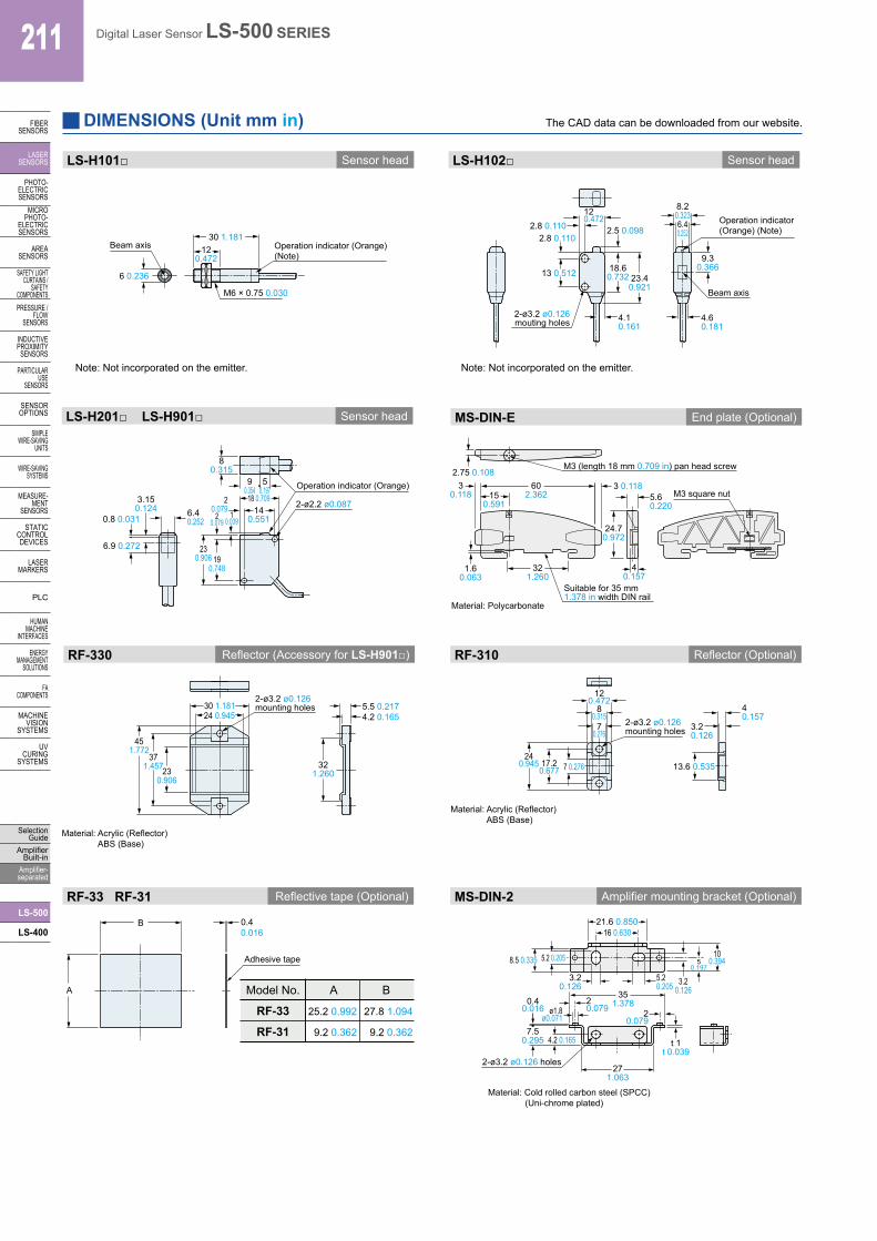
DIMENSIONS (Unit mm in) The CAD data can be downloaded from our website.
LS-H101□ Sensor head
M6 × 0.75 0.030
120.472
Operation indicator (Orange) (Note)
Beam axis
6 0.236
Note: Not incorporated on the emitter.
30 1.181
Sensor headLS-H102□
2-ø3.2 ø0.126 mouting holes
Operation indicator (Orange) (Note)
13 0.512
2.8 0.1102.8 0.110
120.472
2.5 0.098
4.1 0.161
6.40.252
8.20.323
9.30.366
4.6 0.181
Beam axis
Note: Not incorporated on the emitter.
18.60.732 23.4
0.921
LS-H201□ LS-H901□ Sensor head
10.039
3.150.124
20.079
2-ø2.2 ø0.0876.40.252
Operation indicator (Orange)
6.9 0.272
80.315
0.8 0.031
50.197
90.354
20.079 14
0.551
18 0.709
230.906 19
0.748 1.60.063
321.260
40.157
5.60.220
2.75 0.108M3 (length 18 mm 0.709 in) pan head screw
M3 square nut150.591
3 0.11830.118
602.362
Material: Polycarbonate
Suitable for 35 mm1.378 in width DIN rail
24.70.972
MS-DIN-E End plate (Optional)
451.772
371.45723
0.906
2-ø3.2 ø0.126mounting holes
Material: Acrylic (Reflector) ABS (Base)
4.2 0.1655.5 0.217
321.260
30 1.18124 0.945
Reflector (Accessory for LS-H901□)RF-330
Material: Acrylic (Reflector) ABS (Base)
2-ø3.2 ø0.126mounting holes
7 0.27617.20.677
240.945
120.472
70.276
3.20.126
40.157
13.6 0.535
80.315
RF-310 Reflector (Optional)
Adhesive tape
A
B 0.40.016
Model No.
RF-33
RF-31
A
25.2 0.992
9.2 0.362
B
27.8 1.094
9.2 0.362
Reflective tape (Optional)RF-33 RF-31
351.378
271.063
20.079
t 1t 0.039
0.40.016
7.50.295 4.2 0.165
20.079ø1.8
ø0.071
2-ø3.2 ø0.126 holes
3.20.126
5.20.205
8.5 0.335
3.20.126
50.197
100.394
Material: Cold rolled carbon steel (SPCC) (Uni-chrome plated)
21.6 0.85016 0.630
5.2 0.205
MS-DIN-2 Amplifier mounting bracket (Optional)

212Digital Laser Sensor LS-500 SERIES
FIBERSENSORS
LASERSENSORS
PHOTO-ELECTRICSENSORSMICROPHOTO-ELECTRICSENSORS
AREASENSORS
SAFETY LIGHT CURTAINS /SAFETY COMPONENTSPRESSURE / FLOWSENSORS
INDUCTIVEPROXIMITYSENSORS
PARTICULARUSE SENSORS
SENSOROPTIONS
SIMPLEWIRE-SAVINGUNITS
WIRE-SAVING SYSTEMS
MEASURE-MENTSENSORS
STATIC CONTROL DEVICES
LASERMARKERS
PLC
HUMAN MACHINE INTERFACES
ENERGY MANAGEMENT SOLUTIONS
FA COMPONENTS
MACHINE VISION SYSTEMS
UV CURING SYSTEMS
Selection GuideAmplifier Built-inAmplifier-separated
LS-500
LS-400
DIMENSIONS (Unit mm in) The CAD data can be downloaded from our website.
10°
3.4°
R23.6R0.929
110.433
2.40.094
Back angled mounting bracket
Foot angled mounting bracket
Universal sensor mounting bracket
Assembly dimensions
Material: Stainless steel (SUS304)Two M3 (length 14 mm 0.551 in) screws with washers [stainless steel (SUS)] are attached.
Material: Stainless steel (SUS304)Two M2 (length 12 mm 0.472 in) screws with washers [stainless steel (SUS)] are attached.
Material: Stainless steel (SUS304) Note: Without using the mounting plate, beam misalignment may occur.
Mounting drawing with the emitter of LS-H102□
Assembly dimensionsMounting drawing with the receiver of LS-H102□
Assembly dimensions
Note: Screws are not attached. Purchase separately.
t 0.8t 0.031
1.50.059 2.6 0.102
10.039 2-ø3.05 ø0.120
10.60.417
2.8 0.110
3.05 0.120
2.8 0.110
18.80.740
3.5 0.138 1 0.039
2.6 0.102
Beam-emitting part
90.354
4.90.193
2
60.23614
0.551
1.50.059
120.472
9.50.374
ø8.5ø0.335
40.157
5.5 0.217
15.50.610
19.50.768
2-hexagon nut seats
ø3.3 ø0.130 thru-hole
2-ø3.2 ø0.126mounting holes
3.8 0.150
140.551
5.5 0.217
150.591
33-M3 × 0.5 0.020
10°t 1.5t 0.059
2.50.098
2.50.098
160.630
13 0.512
2.50.098
1
11.20.441
3.450.136
8.4 0.331
3.050.120
3°
30.118
130.512
1.5 0.059
4.10.161
1.50.059
ø8.5ø0.335
3.05 0.120
4 0.157
25.51.00431.5
1.240
301.181
25.51.00428.5
1.122
140.551
60.236
9.50.374
130.512
3 0.1185.1 0.201
ø8.5 ø0.335
3.8 0.150
Beam-receiving part
2-ø3.2 ø0.126mounting holes
31.51.240
301.181
(Note)
Note: This is the adjustable range of the movable part.
19.50.768
2.30.091
6.5 0.256
Mounting drawing with the receiver of LS-H102□
80.315
3 0.118
30.118
4.50.177
16.50.650
8.80.346
3.4 0.13414° R13
R0.512
30.118
14.20.559
t 1.2t 0.047
18.50.728
3.20.126
3.050.120
3.050.120
t 1.5t 0.059
3-M3 × 0.50.020
13 0.512
2.50.098
2.50.0982.5 0.098
6 0.236
3.5 0.138
110.433
3.50.138
40.157
8.70.343
50.197
2.40.094
2-ø2.2 ø0.087
t 1.2t 0.047
3.50.138
140.551
t 1.2t 0.047
40.157 R1.5
R0.0592-M2 × 0.4 0.01614.50.571
2.50.098
R23.6R0.929
3.4°
3°
20.2°
26 1.024
29.51.161
190.748
190.748
23.60.929
130.512 16.4
0.646 130.51224
0.945
160.630
21
2121
6.70.264
150.591
120.47215
0.591
3.050.120
3.20.126
2 0.0798 0.315
3.50.138
3.2 0.126
12.5 0.4927.50.295
30.118
t 1.2t 0.047
14°R13 R0.512
431.693
3.05 0.120
3.10.122
13 0.512
26.5 1.043
t 1.5 t 0.059
3-M3 × 0.50.020
2.50.098
10°
2.50.098
2.50.098
16 0.63013 0.512
Beam-receiving part
80.315
2 0.0793.20.1263.5
0.138
120.472
1.2 0.047
13 0.512
t 1.2t 0.047
R13 R0.512
12.5 0.492
3.20.126
7.50.295
11.6 0.457
14°
MS-LS-1 Sensor head mounting bracket (Accessory for LS-H201□, LS-H901□) Sensor head mounting bracket for LS-H102□ (Optional)MS-EXL2-1
MS-EXL2-2 Mounting plate (Accessory for LS-H102□) Sensor head mounting bracket for LS-H102□ (Optional)
MS-EXL2-4 Sensor head mounting bracket for LS-H102□ (Optional)
MS-EXL2-5
24.10.949
160.630
331.299
431.693
26.51.043
160.630
8.80.346
30.118
Material: Stainless steel (SUS304)Two M3 (length 14 mm 0.551 in) screws with washers [stainless steel (SUS)] are attached.
Material: Die-cast zinc alloy
Two M3 (length 14 mm 0.551 in) screws with washers [stainless steel (SUS)], one M3 (length 10 mm 0.394 in) hexagon socket-head bolt [stainless steel (SUS)], and one M3 hexagon nut [stainless steel (SUS)] are attached.