2011-2013 jeep grand cherokee - interior trim removal ... · pdf file2011-2013 jeep grand...
TRANSCRIPT
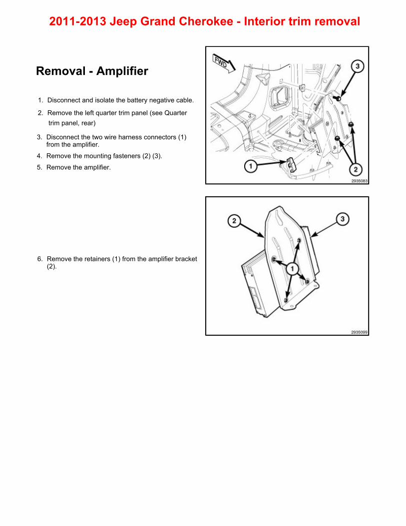
2011-2013 Jeep Grand Cherokee - Interior trim removal Removal - Amplifier
1. Disconnect and isolate the battery negative cable.
2. Remove the left quarter trim panel (see Quarter trim panel, rear)
3. Disconnect the two wire harness connectors (1) from the amplifier.
4. Remove the mounting fasteners (2) (3).
5. Remove the amplifier.
6. Remove the retainers (1) from the amplifier bracket (2).

Removal - A-pillar trim
1. Using a trim stick C-4755 or equivalent, release the clips (2) and separate the A-pillar trim from the A-pillar (1).
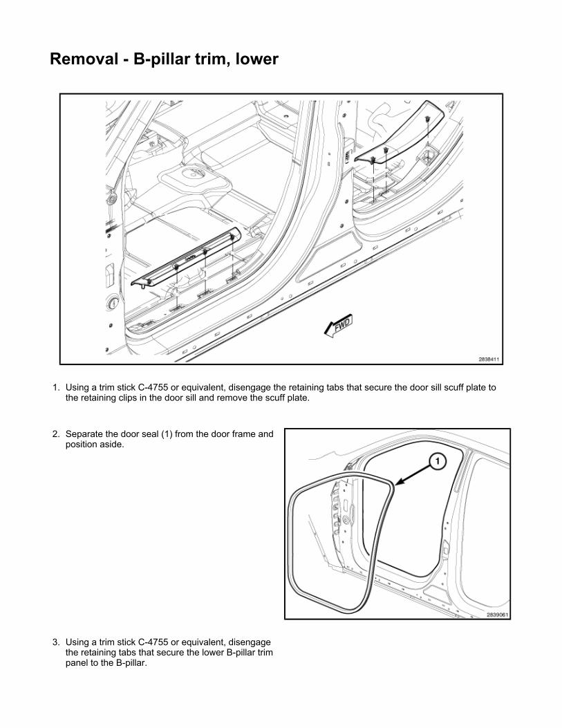
Removal - B-pillar trim, lower
1. Using a trim stick C-4755 or equivalent, disengage the retaining tabs that secure the door sill scuff plate to the retaining clips in the door sill and remove the scuff plate.
2. Separate the door seal (1) from the door frame and position aside.
3. Using a trim stick C-4755 or equivalent, disengage the retaining tabs that secure the lower B-pillar trim panel to the B-pillar.

Removal - B-pillar trim, upper
1. Adjust the front seat to its most forward position for easiest access to the front seat belt lower anchor cover (2) and the B-pillar trim.
2. Grasp the upper edge of the lower anchor cover and pull it carefully upward and outward to unsnap it from the front seat cushion outboard side shield (4).
3. Remove the screw (1) that secures the seat belt lower anchor (3) to the outboard side of the front seat cushion frame.
4. Remove the lower B-pillar trim. (Refer to 23 - Body/Interior/PANEL, B-Pillar Trim - Removal)
5. Using a trim stick C-4755 or equivalent, disengage the retaining clips (2) that secure the upper trim (3) to the pillar and remove the trim panel.
6. Remove the seat belt from the trim.
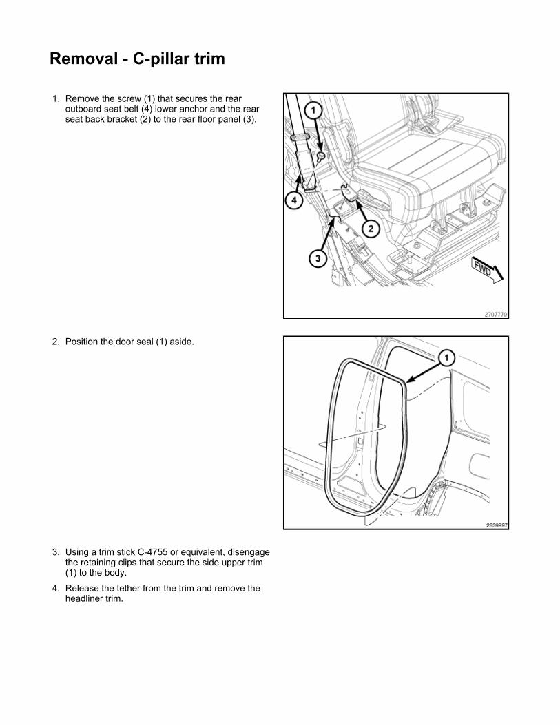
Removal - C-pillar trim
1. Remove the screw (1) that secures the rear outboard seat belt (4) lower anchor and the rear seat back bracket (2) to the rear floor panel (3).
2. Position the door seal (1) aside.
3. Using a trim stick C-4755 or equivalent, disengage the retaining clips that secure the side upper trim (1) to the body.
4. Release the tether from the trim and remove the headliner trim.

5. Using a trim stick C-4755 or equivalent, disengage the retaining clips (2) that secure the upper trim (3) to the pillar and remove the trim panel.
6. Remove the seat belt from the trim.

Removal - D-pillar trim
1. Remove the rear header trim panel (3).
2. Using a trim stick C-4755 or equivalent, disengage the retaining clips that secure the side upper trim (1) to the body.
3. Release the tether from the trim and remove the headliner trim.

4. Using a trim stick C-4755 or equivalent, release the retaining clips (2) and separate the trim from the pillar.
5. If equipped, disconnect the speaker electrical connector (2).
6. Release the two tethers from the trim and remove the trim.

Removal - AGM battery
1. Turn the ignition switch to the Off position. Be certain that all electrical accessories are turned off.
2. If equipped with power seats, move the passenger
seat to the most forward and upright position. If equipped with manual seats, move the seat to the most
forward position.
3. Remove the battery cover (1).
NOTE: Negative battery terminal shown, positive terminal similar.
3. Remove the negative battery cable (1) from the battery.
4. Disconnect the positive battery cable and position aside.
5. Remove the battery thermal blanket.
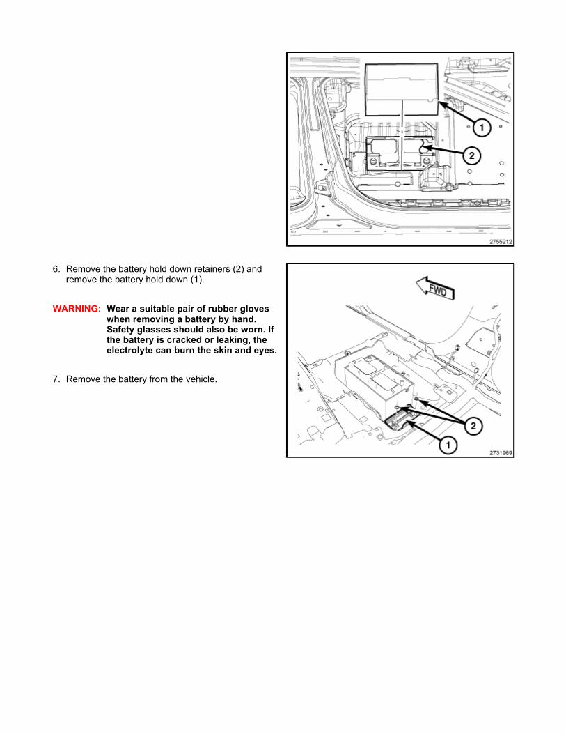
6. Remove the battery hold down retainers (2) and remove the battery hold down (1).
WARNING: Wear a suitable pair of rubber gloves when removing a battery by hand. Safety glasses should also be worn. If the battery is cracked or leaking, the electrolyte can burn the skin and eyes.
7. Remove the battery from the vehicle.
REMOVAL - Storage bin, center console
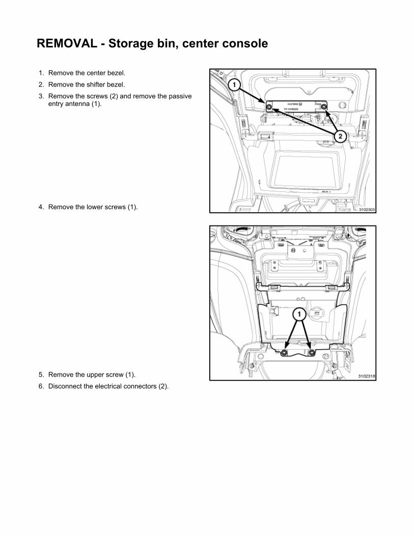
1. Remove the center bezel.
2. Remove the shifter bezel.
3. Remove the screws (2) and remove the passive entry antenna (1).
4. Remove the lower screws (1).
5. Remove the upper screw (1).
6. Disconnect the electrical connectors (2).

7. Remove the storage bin (2) and separate the connectors (1), if equipped.

INSTALLATION - Storage bin, center console
1. Connect the electrical connector (1), if equipped.
2. Install the storage bin (2) back into the center stack.
3. Connect the electrical connectors (2).
4. Install the upper screw (1).
5. Install the lower screws (1).
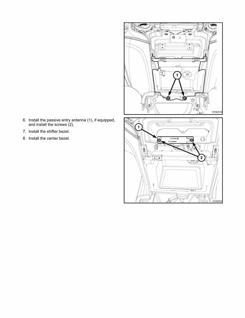
6. Install the passive entry antenna (1), if equipped, and install the screws (2).
7. Install the shifter bezel.
8. Install the center bezel.
Removal - Cargo load floor
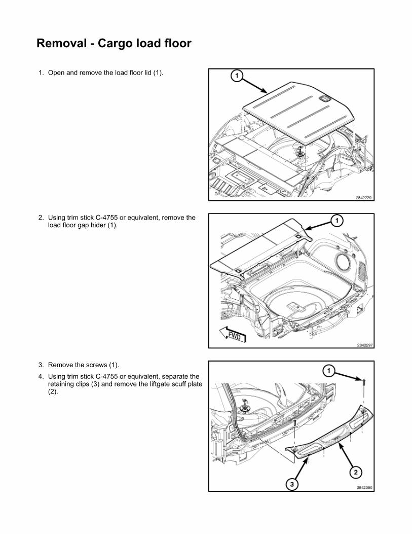
1. Open and remove the load floor lid (1).
2. Using trim stick C-4755 or equivalent, remove the load floor gap hider (1).
3. Remove the screws (1).
4. Using trim stick C-4755 or equivalent, separate the retaining clips (3) and remove the liftgate scuff plate (2).

5. Remove the two front cargo loop screws (1).
6. Remove the rear nuts (3) and remove the load floor bin (2).
REMOVAL - Carpet
1. Remove the front seats 2. Remove the rear seat
3. Remove the floor console 4. Remove the front door sill scuff plates
5. Remove the cowl trim panels 6. Remove the rear passenger door sill scuff plates
7. Remove the lower B-pillar trim panels 8. Remove the rear load flooring
9. Remove the quarter trim 10. Remove the carpet from the vehicle
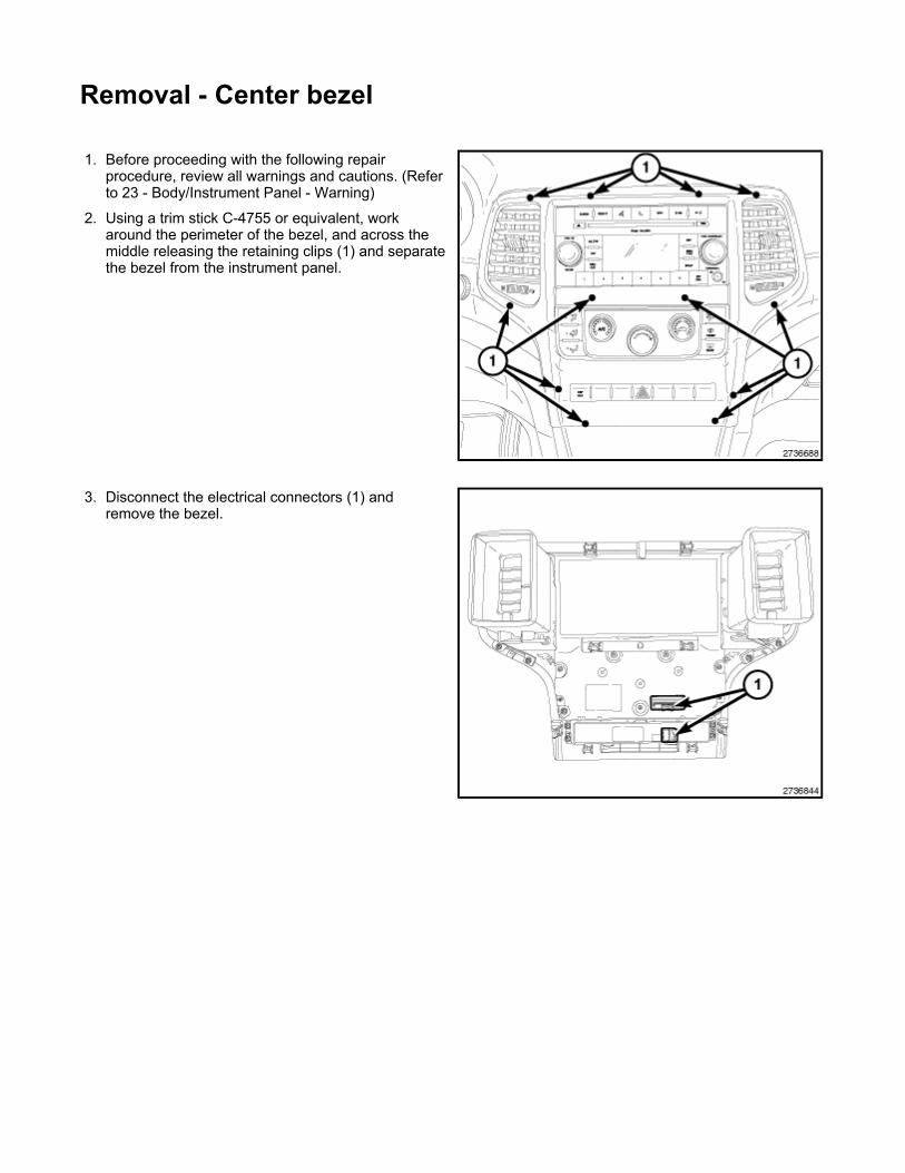
Removal - Center bezel
1. Before proceeding with the following repair procedure, review all warnings and cautions. (Refer to 23 - Body/Instrument Panel - Warning)
2. Using a trim stick C-4755 or equivalent, work around the perimeter of the bezel, and across the middle releasing the retaining clips (1) and separate the bezel from the instrument panel.
3. Disconnect the electrical connectors (1) and remove the bezel.
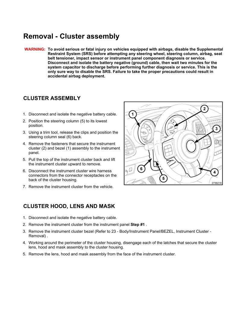
Removal - Cluster assembly
CLUSTER ASSEMBLY
CLUSTER HOOD, LENS AND MASK
WARNING: To avoid serious or fatal injury on vehicles equipped with airbags, disable the Supplemental Restraint System (SRS) before attempting any steering wheel, steering column, airbag, seat belt tensioner, impact sensor or instrument panel component diagnosis or service. Disconnect and isolate the battery negative (ground) cable, then wait two minutes for the system capacitor to discharge before performing further diagnosis or service. This is the only sure way to disable the SRS. Failure to take the proper precautions could result in accidental airbag deployment.
1. Disconnect and isolate the negative battery cable.
2. Position the steering column (5) to its lowest position.
3. Using a trim tool, release the clips and position the steering column seal (6) back.
4. Remove the fasteners that secure the instrument cluster (2) and bezel (1) assembly to the instrument panel.
5. Pull the top of the instrument cluster back and lift the instrument cluster upward to remove.
6. Disconnect the instrument cluster wire harness connectors from the connector receptacles on the back of the cluster housing.
7. Remove the instrument cluster from the vehicle.
1. Disconnect and isolate the negative battery cable.
2. Remove the instrument cluster from the instrument panel Step #1 .3. Remove the instrument cluster bezel (Refer to 23 - Body/Instrument Panel/BEZEL, Instrument Cluster -
Removal) .
4. Working around the perimeter of the cluster housing, disengage each of the latches that secure the cluster lens, hood and mask assembly to the cluster housing.
5. Remove the lens, hood and mask assembly from the face of the instrument cluster.
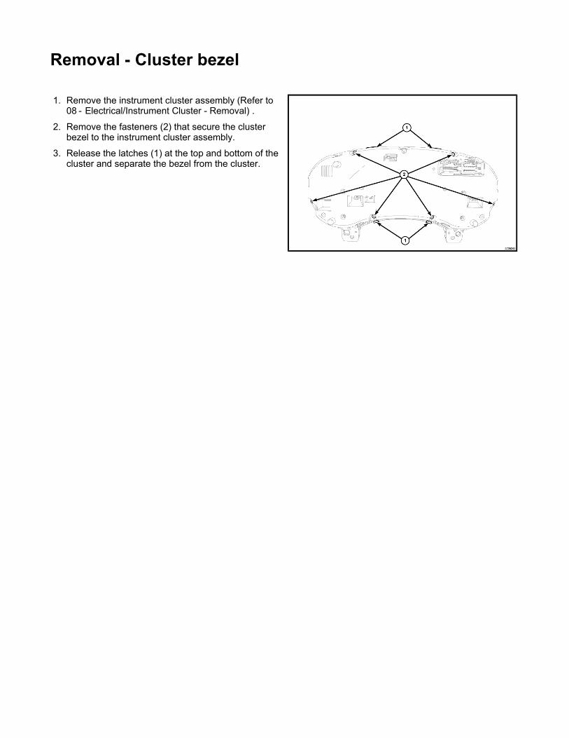
Removal - Cluster bezel
1. Remove the instrument cluster assembly (Refer to 08 - Electrical/Instrument Cluster - Removal) .
2. Remove the fasteners (2) that secure the cluster bezel to the instrument cluster assembly.
3. Release the latches (1) at the top and bottom of the cluster and separate the bezel from the cluster.

Removal - floor console
1. Remove the shift bezel.
2. Place the seats into the full forward positions.
3. Remove the screw covers (2) and remove the screws (1).
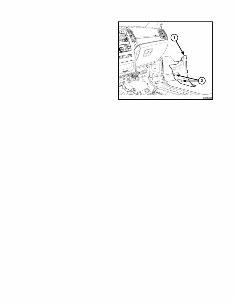
4. Using trim stick C-4755 or equivalent, release the clip fasteners and separate the side covers (1).
5. Disconnect the shifter electrical connectors (3).
6. Remove the bolts (2) and remove the shifter assembly (1).
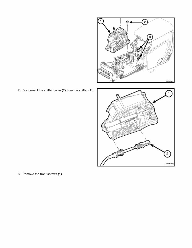
7. Disconnect the shifter cable (2) from the shifter (1).
8. Remove the front screws (1).
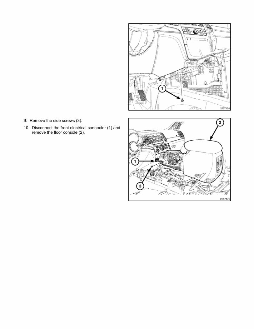
9. Remove the side screws (3).
10. Disconnect the front electrical connector (1) and remove the floor console (2).

Removal - overhead console
1. Disconnect and isolate the negative battery cable.
2. Pull downward on the sides of the overhead console housing firmly and evenly to disengage the snap clips from the overhead console bracket.
3. Lower the overhead console far enough to access the wire harness connectors (1).
4. Disconnect the roof wire harness connectors from the connector receptacles.
5. Remove the overhead console.

Removal - Cowl trim panel
1. Using a trim stick C-4755 or equivalent, disengage the retaining tabs that secure the door sill scuff plate to the retaining clips in the door sill and remove the scuff plate.
2. Separate the door seal (1) from the door frame and position aside.
3. Using a trim stick C-4755 or equivalent, disengage the retaining clips (2) that secure the cowl trim (1) and remove the cowl trim panel.
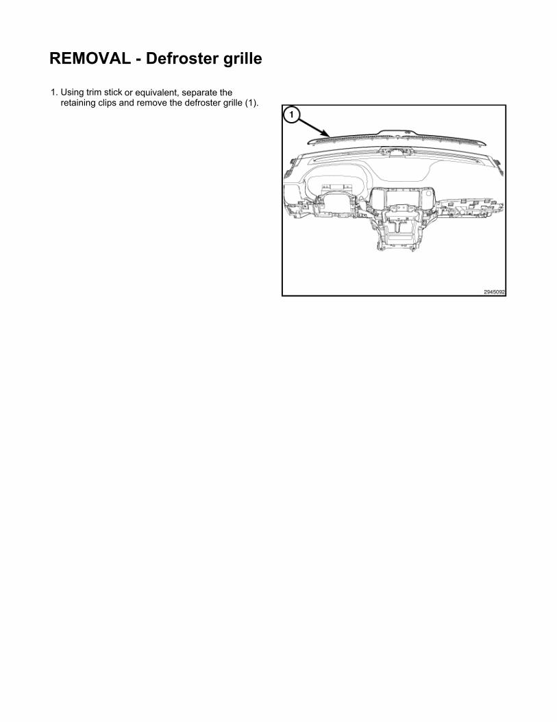
REMOVAL - Defroster grille
1. Using trim stick or equivalent, separate the retaining clips and remove the defroster grille (1).
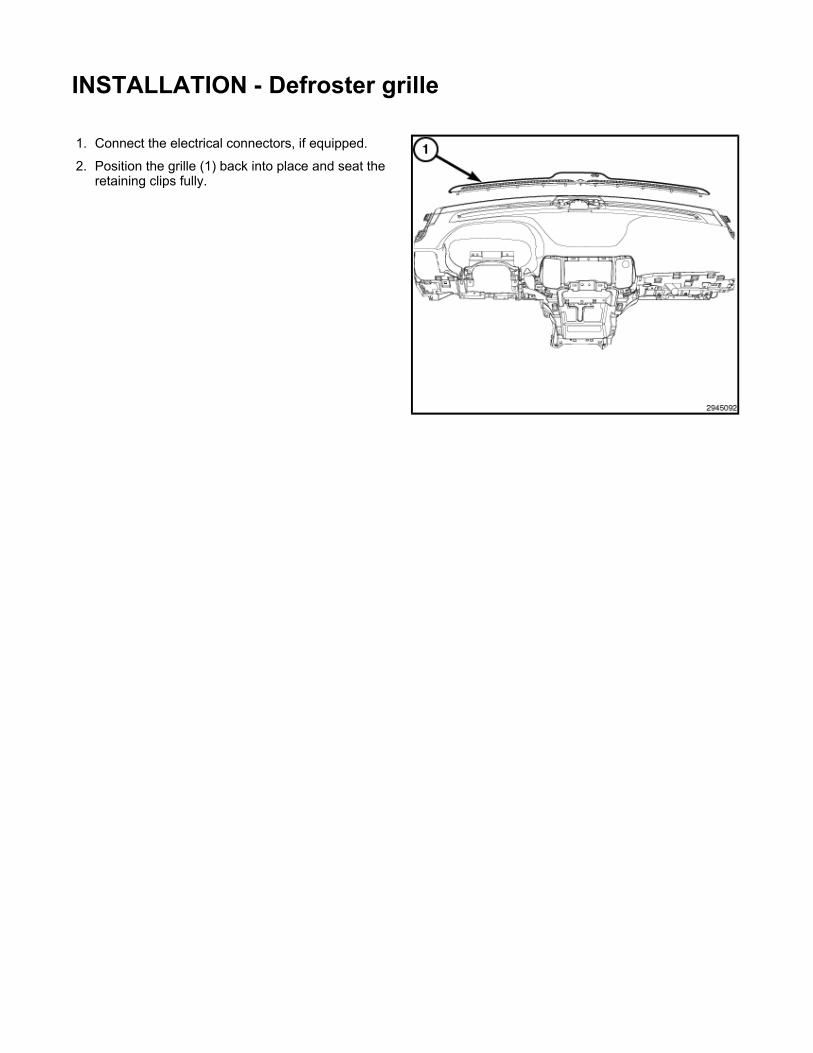
INSTALLATION - Defroster grille
1. Connect the electrical connectors, if equipped.
2. Position the grille (1) back into place and seat the retaining clips fully.
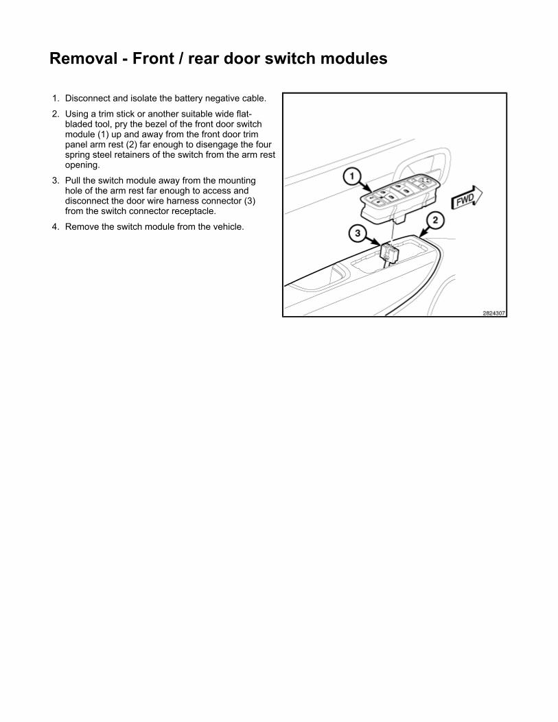
Removal - Front / rear door switch modules
1. Disconnect and isolate the battery negative cable.
2. Using a trim stick or another suitable wide flat-bladed tool, pry the bezel of the front door switch module (1) up and away from the front door trim panel arm rest (2) far enough to disengage the four spring steel retainers of the switch from the arm rest opening.
3. Pull the switch module away from the mounting hole of the arm rest far enough to access and disconnect the door wire harness connector (3) from the switch connector receptacle.
4. Remove the switch module from the vehicle.
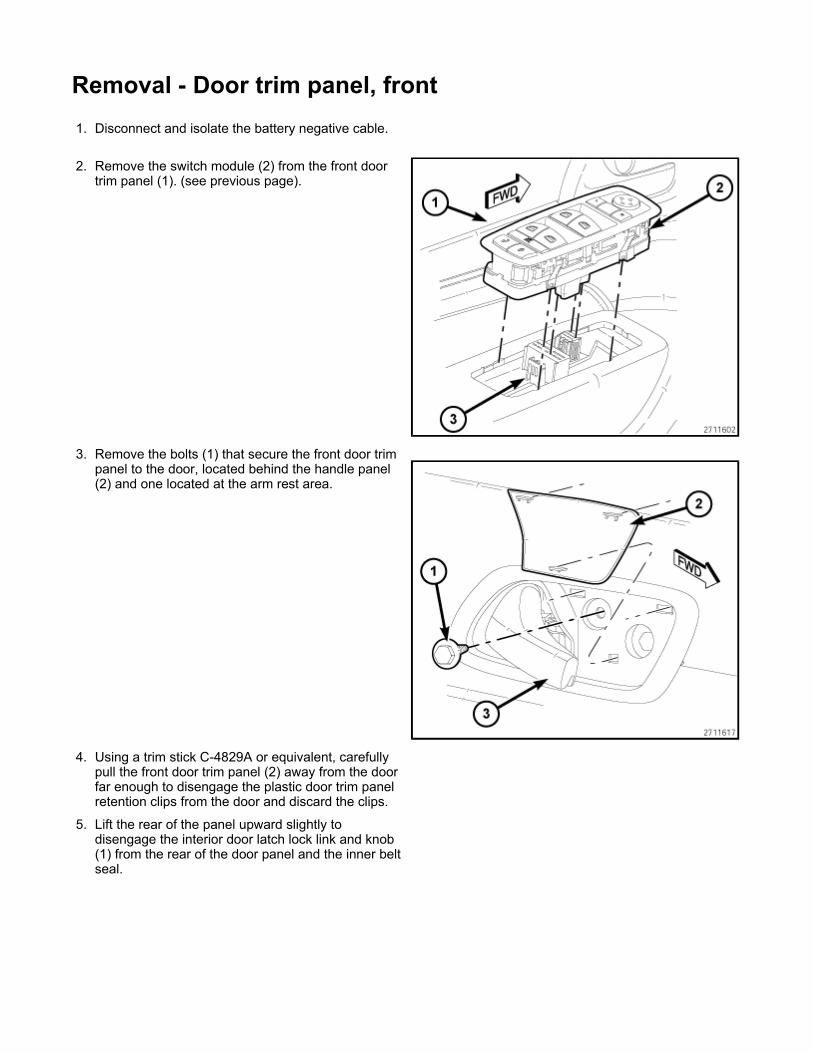
Removal - Door trim panel, front
1. Disconnect and isolate the battery negative cable.
2. Remove the switch module (2) from the front door trim panel (1). (see previous page).
3. Remove the bolts (1) that secure the front door trim panel to the door, located behind the handle panel (2) and one located at the arm rest area.
4. Using a trim stick C-4829A or equivalent, carefully pull the front door trim panel (2) away from the door far enough to disengage the plastic door trim panel retention clips from the door and discard the clips.
5. Lift the rear of the panel upward slightly to disengage the interior door latch lock link and knob (1) from the rear of the door panel and the inner belt seal.
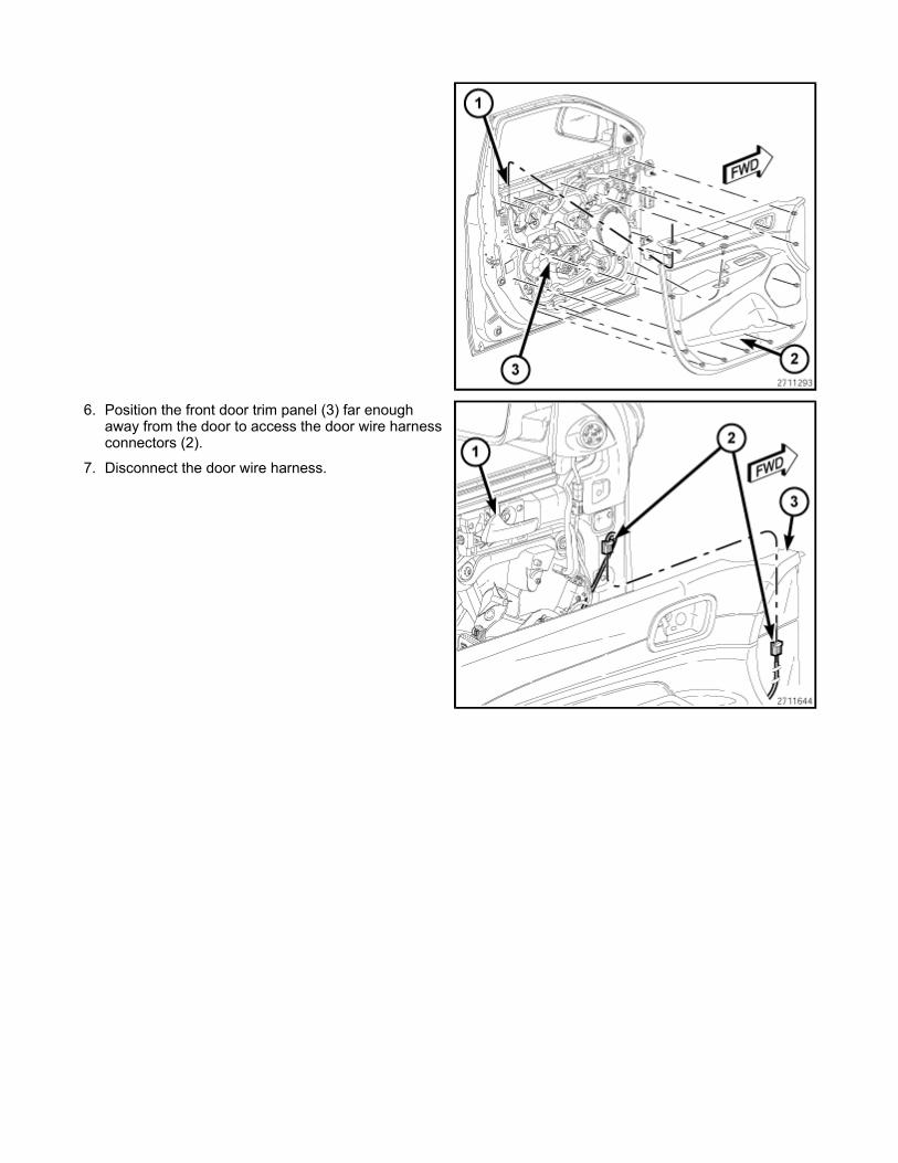
6. Position the front door trim panel (3) far enough away from the door to access the door wire harness connectors (2).
7. Disconnect the door wire harness.
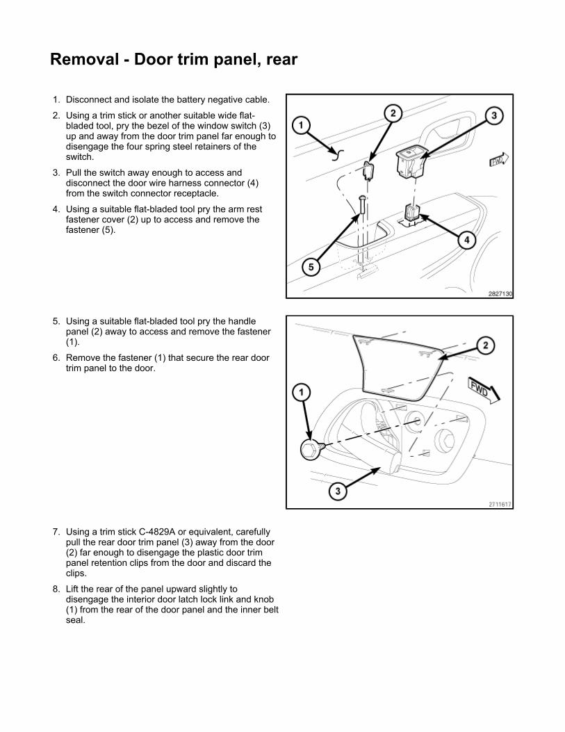
Removal - Door trim panel, rear
1. Disconnect and isolate the battery negative cable.
2. Using a trim stick or another suitable wide flat-bladed tool, pry the bezel of the window switch (3) up and away from the door trim panel far enough to disengage the four spring steel retainers of the switch.
3. Pull the switch away enough to access and disconnect the door wire harness connector (4) from the switch connector receptacle.
4. Using a suitable flat-bladed tool pry the arm rest fastener cover (2) up to access and remove the fastener (5).
5. Using a suitable flat-bladed tool pry the handle panel (2) away to access and remove the fastener (1).
6. Remove the fastener (1) that secure the rear door trim panel to the door.
7. Using a trim stick C-4829A or equivalent, carefully pull the rear door trim panel (3) away from the door (2) far enough to disengage the plastic door trim panel retention clips from the door and discard the clips.
8. Lift the rear of the panel upward slightly to disengage the interior door latch lock link and knob (1) from the rear of the door panel and the inner belt seal.


Removal - Glove box
1. Separate the glove box damper (2) from the clove box by sliding the clip towards the rear of the vehicle to release it from the bin.
2. Open the glove box and carefully use fingers to press in the glove box open stop tabs (3) at the top of the bin, downward to allow the glove box to rotate toward the carpet.
3. Rotate the box down and release the door hinges (1) at the bottom and remove the glove box.
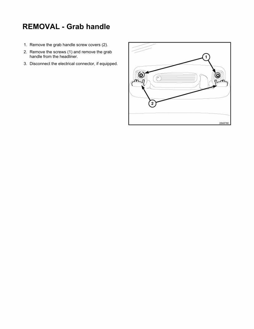
REMOVAL - Grab handle
1. Remove the grab handle screw covers (2).
2. Remove the screws (1) and remove the grab handle from the headliner.
3. Disconnect the electrical connector, if equipped.
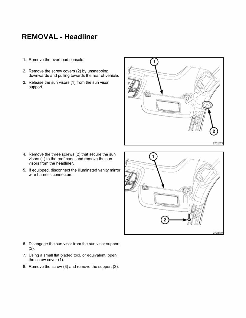
REMOVAL - Headliner
1. Remove the overhead console.
2. Remove the screw covers (2) by unsnapping downwards and pulling towards the rear of vehicle.
3. Release the sun visors (1) from the sun visor support.
4. Remove the three screws (2) that secure the sun visors (1) to the roof panel and remove the sun visors from the headliner.
5. If equipped, disconnect the illuminated vanity mirror wire harness connectors.
6. Disengage the sun visor from the sun visor support (2).
7. Using a small flat bladed tool, or equivalent, open the screw cover (1).
8. Remove the screw (3) and remove the support (2).
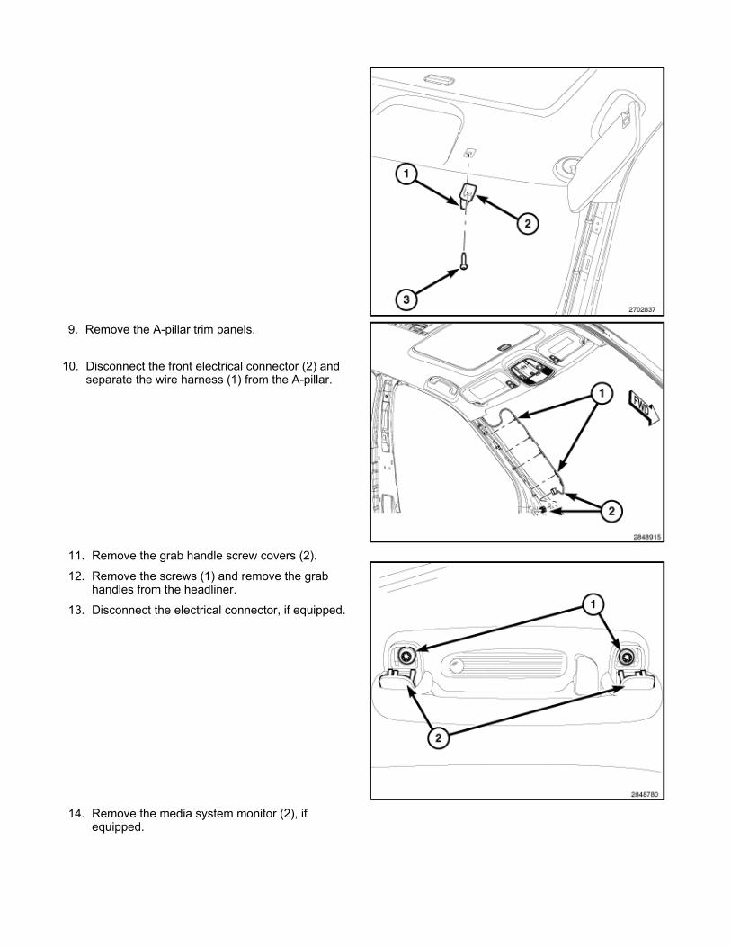
9. Remove the A-pillar trim panels.
10. Disconnect the front electrical connector (2) and separate the wire harness (1) from the A-pillar.
11. Remove the grab handle screw covers (2).
12. Remove the screws (1) and remove the grab handles from the headliner.
13. Disconnect the electrical connector, if equipped.
14. Remove the media system monitor (2), if equipped.
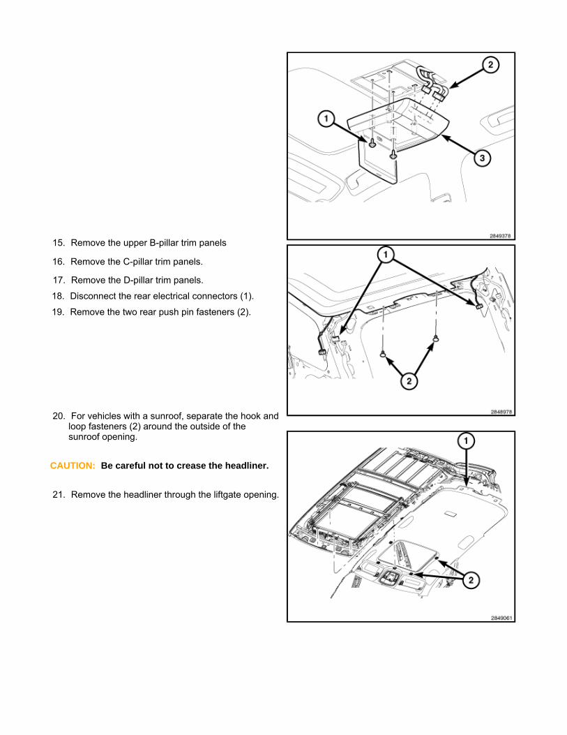
15. Remove the upper B-pillar trim panels
16. Remove the C-pillar trim panels.
17. Remove the D-pillar trim panels.
18. Disconnect the rear electrical connectors (1).
19. Remove the two rear push pin fasteners (2).
20. For vehicles with a sunroof, separate the hook and loop fasteners (2) around the outside of the sunroof opening.
CAUTION: Be careful not to crease the headliner.
21. Remove the headliner through the liftgate opening.

REMOVAL - Headrest, front Labor Operations: Click to display a list of Labor Operations associated with this procedure
WARNING: Disable the airbag system before attempting any component diagnosis or service of the front seats, when equipped with front seat air bags. Disconnect and isolate the negative battery (ground) cable, then wait two minutes for the airbag system capacitor to discharge before performing further diagnosis or service. This is the only sure way to disable the airbag system. Failure to take the proper precautions may result in accidental airbag deployment and possible serious or fatal injury.
WARNING: Improper installation of the headrests may result in reduced protection of the occupants. If, after installation, the headrest can be removed, without simultaneously pressing the buttons on the master and slave guide sleeves, then the head restraint is installed incorrectly. Failure to follow these instructions may result in possible serious or fatal injury.
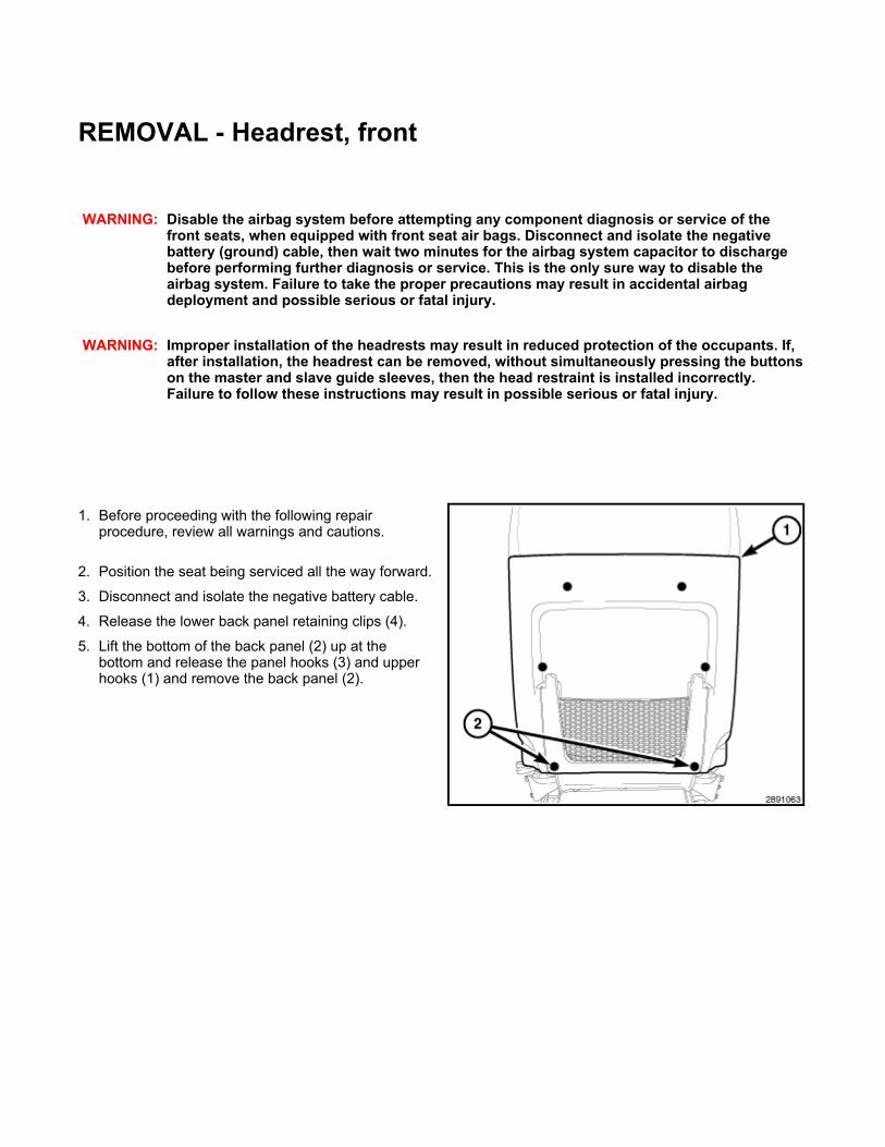
1. Before proceeding with the following repair procedure, review all warnings and cautions.
2. Position the seat being serviced all the way forward.
3. Disconnect and isolate the negative battery cable.
4. Release the lower back panel retaining clips (4).
5. Lift the bottom of the back panel (2) up at the bottom and release the panel hooks (3) and upper hooks (1) and remove the back panel (2).

6. Disconnect the electrical connector (1).
7. Recline the seat to gain enough room to remove the AHR (3).
8. Press the release button (1) on the left side headrest master sleeve.
9. Using a thin wire type tool (2), press the hidden release button on the right side headrest slave sleeve.
CAUTION: Special care should be taken not to damage to the AHR connector.
10. Slowly lift the AHR (3) up while pressing the buttons simultaneously.
11. Watch the connector as it reaches the bottom of the tube and guide the connector through.
12. Remove the AHR (3) fully.
REMOVAL - Headrest, front
WARNING: Disable the airbag system before attempting any component diagnosis or service of the front seats, when equipped with front seat air bags. Disconnect and isolate the negative battery (ground) cable, then wait two minutes for the airbag system capacitor to discharge before performing further diagnosis or service. This is the only sure way to disable the airbag system. Failure to take the proper precautions may result in accidental airbag deployment and possible serious or fatal injury.
WARNING: Improper installation of the headrests may result in reduced protection of the occupants. If, after installation, the headrest can be removed, without simultaneously pressing the buttons on the master and slave guide sleeves, then the head restraint is installed incorrectly. Failure to follow these instructions may result in possible serious or fatal injury.
1. Before proceeding with the following repair procedure, review all warnings and cautions.
2. Position the seat being serviced all the way forward.
3. Disconnect and isolate the negative battery cable.
4. Release the lower back panel retaining clips (4).
5. Lift the bottom of the back panel (2) up at the bottom and release the panel hooks (3) and upper hooks (1) and remove the back panel (2).

6. Disconnect the electrical connector (1).
7. Recline the seat to gain enough room to remove the AHR (3).
8. Press the release button (1) on the left side headrest master sleeve.
9. Using a thin wire type tool (2), press the hidden release button on the right side headrest slave sleeve.
CAUTION: Special care should be taken not to damage to the AHR connector.
10. Slowly lift the AHR (3) up while pressing the buttons simultaneously.
11. Watch the connector as it reaches the bottom of the tube and guide the connector through.
12. Remove the AHR (3) fully.
REMOVAL - Headrest, rear
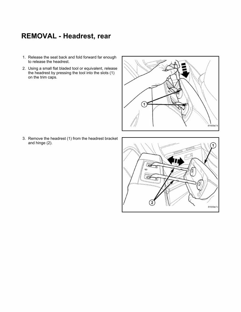
1. Release the seat back and fold forward far enough to release the headrest.
2. Using a small flat bladed tool or equivalent, release the headrest by pressing the tool into the slots (1) on the trim caps.
3. Remove the headrest (1) from the headrest bracket and hinge (2).

1. Remove the steering column.
2. Remove the ignition switch.
3. Remove the instrument cluster. 4. Remove the bolts (1) from behind the cluster.
5. Remove the fenceline bolt (1).
REMOVAL - Instrument panel

6. Remove the left end cap (1).
7. Remove the left cowl trim panel.
8. Remove the left A-pillar trim.
9. Disconnect the left wire harness (1).
10. Remove the left side retaining bolts (1).
11. Remove the front floor console.
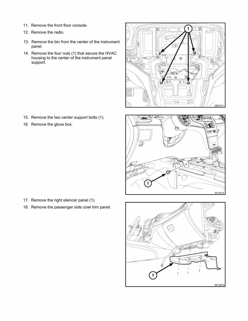
12. Remove the radio.
13. Remove the bin from the center of the instrument panel.
14. Remove the four nuts (1) that secure the HVAC housing to the center of the instrument panel support.
15. Remove the two center support bolts (1).
16. Remove the glove box.
17. Remove the right silencer panel (1).
18. Remove the passenger side cowl trim panel.
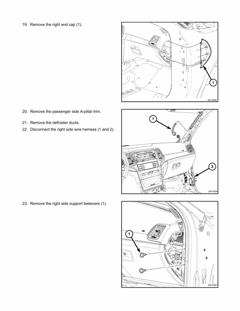
19. Remove the right end cap (1).
20. Remove the passenger side A-pillar trim.
21. Remove the defroster ducts.
22. Disconnect the right side wire harness (1 and 2).
23. Remove the right side support fasteners (1).
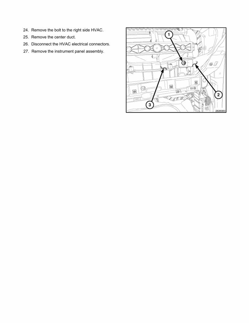
24. Remove the bolt to the right side HVAC.
25. Remove the center duct.
26. Disconnect the HVAC electrical connectors.
27. Remove the instrument panel assembly.
INSTALLATION - Instrument panel
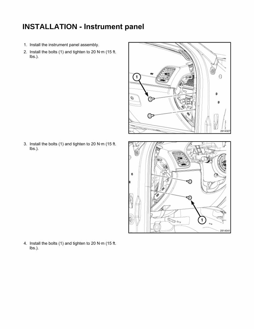
1. Install the instrument panel assembly.
2. Install the bolts (1) and tighten to 20 N·m (15 ft. lbs.).
3. Install the bolts (1) and tighten to 20 N·m (15 ft. lbs.).
4. Install the bolts (1) and tighten to 20 N·m (15 ft. lbs.).

5. Install the bolts (1) and tighten to 20 N·m (15 ft. lbs.).
6. Install the bolts (1) and tighten to 9 N·m (6.5 ft. lbs.).
7. Install the nut (1) that secures the passenger side end of the HVAC housing (3) to the instrument
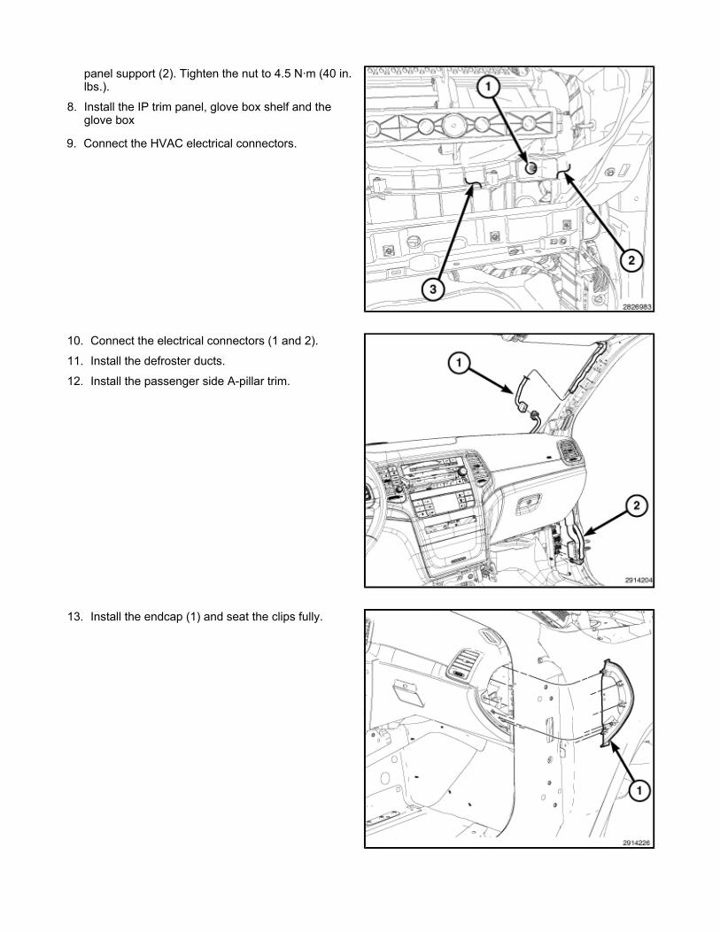
panel support (2). Tighten the nut to 4.5 N·m (40 in. lbs.).
8. Install the IP trim panel, glove box shelf and the glove box
9. Connect the HVAC electrical connectors.
10. Connect the electrical connectors (1 and 2).
11. Install the defroster ducts.
12. Install the passenger side A-pillar trim.
13. Install the endcap (1) and seat the clips fully.

14. Install the passenger side instrument panel silencer (1).
15. Install the passenger side cowl trim panel.
16. Install the four nuts (1) that secure the HVAC housing to the center of the instrument panel support. Tighten the nuts to 4.5 N·m (40 in. lbs.).
17. Install the bin into the center of the instrument panel.
18. Install the center duct.
19. Install the radio
20. Install the floor console
21. Connect the electrical connectors (1).
22. Install the driver side A-pillar trim.

23. Install the end cap (1).
24. Install the driver side cowl trim panel.
25. Install the instrument cluster.
26. Install the ignition switch.
27. Install the steering column.
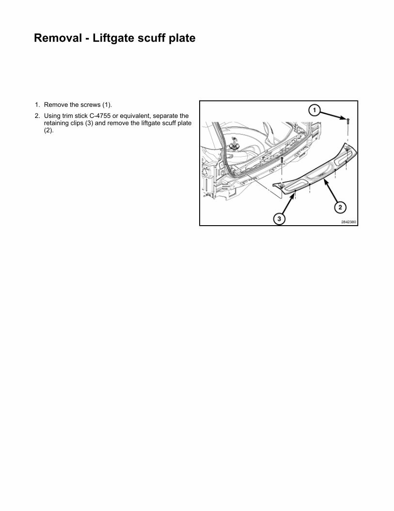
Removal - Liftgate scuff plate
1. Remove the screws (1).
2. Using trim stick C-4755 or equivalent, separate the retaining clips (3) and remove the liftgate scuff plate (2).
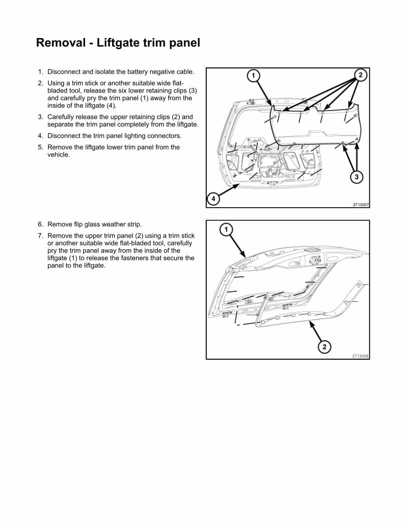
Removal - Liftgate trim panel
1. Disconnect and isolate the battery negative cable.
2. Using a trim stick or another suitable wide flat-bladed tool, release the six lower retaining clips (3) and carefully pry the trim panel (1) away from the inside of the liftgate (4).
3. Carefully release the upper retaining clips (2) and separate the trim panel completely from the liftgate.
4. Disconnect the trim panel lighting connectors.
5. Remove the liftgate lower trim panel from the vehicle.
6. Remove flip glass weather strip.
7. Remove the upper trim panel (2) using a trim stick or another suitable wide flat-bladed tool, carefully pry the trim panel away from the inside of the liftgate (1) to release the fasteners that secure the panel to the liftgate.

REMOVAL - Rearview mirror
Without Smartbeam
With Smartbeam
1. If equipped, open the access panel (5) and disconnect the mirror harness connector (2).
2. Separate the harness cover (1) from the mirror base and position the harness aside.
3. Loosen the setscrew (4) that secures the mirror base to the bracket (3) on the windshield.
4. Slide the mirror base upward and off of the bracket (3).
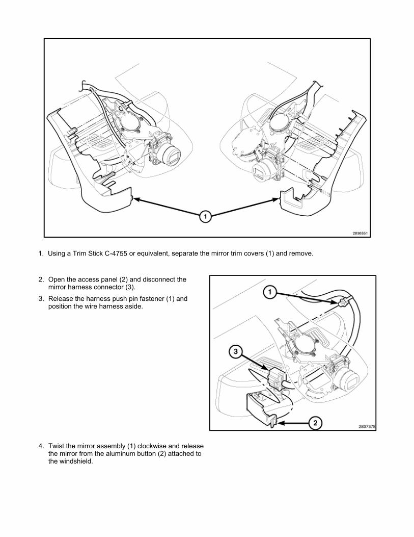
1. Using a Trim Stick C-4755 or equivalent, separate the mirror trim covers (1) and remove.
2. Open the access panel (2) and disconnect the mirror harness connector (3).
3. Release the harness push pin fastener (1) and position the wire harness aside.
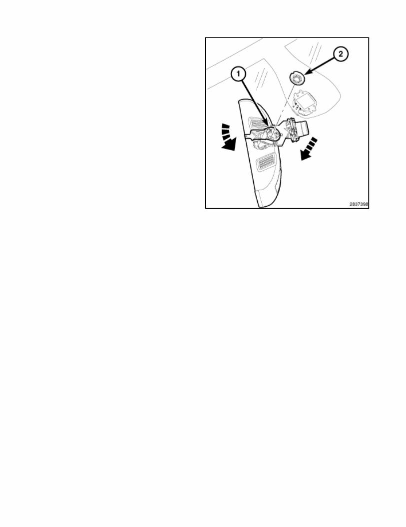
4. Twist the mirror assembly (1) clockwise and release the mirror from the aluminum button (2) attached to the windshield.

Removal - media system monitor 1. Disconnect and isolate the battery negative cable.
2. Remove the two mounting fasteners.
3. Using a trim stick, press the retaining clip at the rear of the monitor. Move the monitor from side to side to release from headliner.
4. Disconnect electrical harness connector and remove monitor.

Removal - Heating and Air Conditioning/Distribution/OUTLET, Air/Removal
OUTBOARD OUTLETS
1. Disconnect and isolate the negative battery cable.
2. When servicing the passenger side air outlet:
remove the passenger side instrument panel silencer
remove the glove box, glove box shelf and the trim panel, located behind the glove box.
3. When servicing the driver side air outlet:
remove the driver side instrument panel silencer remove the knee blocker
4. Using Trim Stick C-4755 or equivalent, disengage the retaining tabs (2) that secure the outboard air outlet trim panel to the face of the instrument panel cover (4).
WARNING: Disable the airbag system before attempting any steering wheel, steering column, or instrument panel component diagnosis or service. Disconnect and isolate the negative battery (ground) cable. Wait two minutes for the airbag system capacitor to discharge before performing further diagnosis or service. This is the only sure way to disable the airbag system. Failure to take the proper precautions may result in accidental airbag deployment and possible serious or fatal injury.
NOTE: LHD model shown in illustrations. RHD model similar.
NOTE: The outboard air outlets can be serviced without removing the instrument panel cover.
NOTE: Underside of instrument panel cover shown. Instrument panel duct removed from view for clarity.
NOTE: The air outlet trim panels are serviced with the air outlets as an assembly.
5. Reach up behind the instrument panel and disengage the four retaining tabs (1 and 3) that secure each
outboard air outlet (5) to the back of the instrument panel cover.
6. Remove the outboard air outlet(s) from the instrument panel cover.
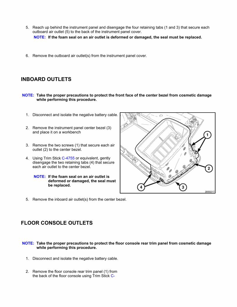
INBOARD OUTLETS
1. Disconnect and isolate the negative battery cable.
2. Remove the instrument panel center bezel (3) and place it on a workbench
3. Remove the two screws (1) that secure each air outlet (2) to the center bezel.
4. Using Trim Stick C-4755 or equivalent, gently disengage the two retaining tabs (4) that secure each air outlet to the center bezel.
5. Remove the inboard air outlet(s) from the center bezel.
FLOOR CONSOLE OUTLETS
1. Disconnect and isolate the negative battery cable.
2. Remove the floor console rear trim panel (1) from the back of the floor console using Trim Stick C-
NOTE: If the foam seal on an air outlet is deformed or damaged, the seal must be replaced.
NOTE: Take the proper precautions to protect the front face of the center bezel from cosmetic damage while performing this procedure.
NOTE: If the foam seal on an air outlet is deformed or damaged, the seal must be replaced.
NOTE: Take the proper precautions to protect the floor console rear trim panel from cosmetic damage while performing this procedure.

4755 or equivalent. Disconnect any necessary electrical connectors and place the trim panel on a workbench.
3. Remove the six screws (1 and 3) that secure floor console rear duct (2) to the floor console rear trim panel (4).
4. Remove the floor console rear duct from the floor console rear trim panel.
5. Using Trim Stick C-4755 (1) or equivalent, gently pry on the air outlet barrel(s) (3) until the barrel retainers release from the pivot shafts on the console rear duct (2). Rotate the air outlet barrel(s) as necessary.
NOTE: If the foam seal on the console rear duct is deformed or damaged, the seal must be replaced.

Removal - Liftgate upper header panel
1. Using a trim stick C-4755 or equivalent, disengage the retaining clips that secure the upper liftgate trim panel to the liftgate opening and remove the trim panel.
2. If equipped, disconnect the cargo lamp electrical connector.
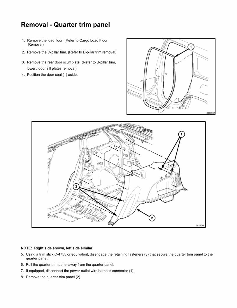
Removal - Quarter trim panel
1. Remove the load floor. (Refer to Cargo Load Floor Removal)
2. Remove the D-pillar trim. (Refer to D-pillar trim removal)
3. Remove the rear door scuff plate. (Refer to B-pillar trim,
lower / door sill plates removal)
4. Position the door seal (1) aside.
NOTE: Right side shown, left side similar. 5. Using a trim stick C-4755 or equivalent, disengage the retaining fasteners (3) that secure the quarter trim panel to the
quarter panel.
6. Pull the quarter trim panel away from the quarter panel.
7. If equipped, disconnect the power outlet wire harness connector (1).
8. Remove the quarter trim panel (2).
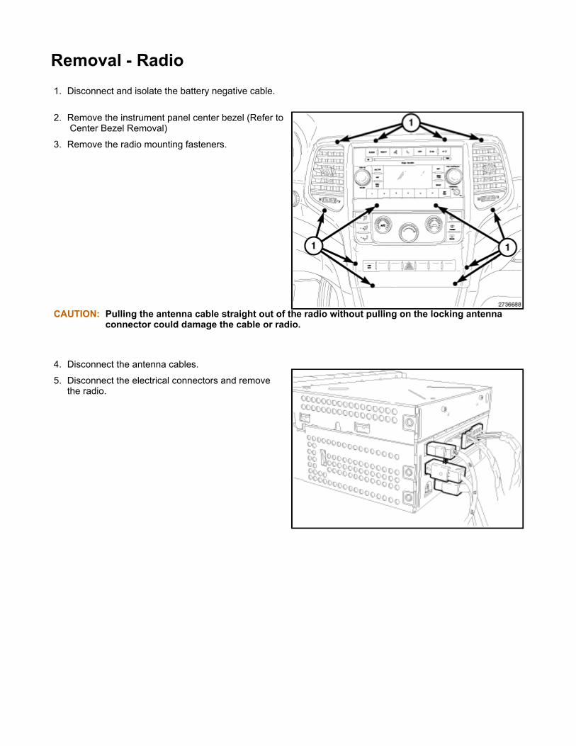
Removal - Radio
1. Disconnect and isolate the battery negative cable.
2. Remove the instrument panel center bezel (Refer to Center Bezel Removal)
3. Remove the radio mounting fasteners.
CAUTION: Pulling the antenna cable straight out of the radio without pulling on the locking antenna connector could damage the cable or radio.
4. Disconnect the antenna cables.
5. Disconnect the electrical connectors and remove the radio.
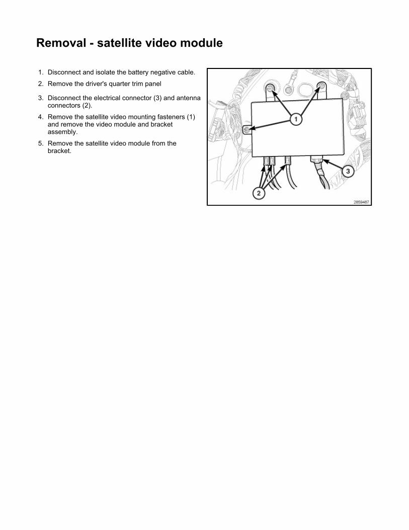
Removal - satellite video module 1. Disconnect and isolate the battery negative cable.
2. Remove the driver's quarter trim panel
3. Disconnect the electrical connector (3) and antenna connectors (2).
4. Remove the satellite video mounting fasteners (1) and remove the video module and bracket assembly.
5. Remove the satellite video module from the bracket.

WARNING - Front seats and airbags WARNING: During and following any seat belt or child restraint anchor service, carefully inspect
all seat belts, buckles, mounting hardware, retractors, tether straps, and anchors for proper installation, operation, or damage. Replace any belt that is cut, frayed, or torn. Straighten any belt that is twisted. Tighten any loose fasteners. Replace any belt that has a damaged or inoperative buckle or retractor. Replace any belt that has a bent or damaged latch plate or anchor plate. Replace any child restraint anchor or the unit to which the anchor is integral that has been bent or damaged. Never attempt to repair a seat belt or child restraint component. Always replace damaged or faulty seat belt and child restraint components with the correct, new and unused replacement parts listed in the Chrysler Mopar® parts catalog. Failure to follow these instructions may result in personal injury or death.
On vehicles equipped with airbags, disable the supplemental restraint system before attempting any steering wheel, steering column, airbag, occupant classification system, seat belt tensioner, impact sensor, or instrument panel component diagnosis or service. Disconnect and isolate the battery negative (ground) cable, then wait two minutes for the system capacitor to discharge before performing further diagnosis or service. This is the only sure way to disable the supplemental restraint system. Failure to take the proper precautions could result in accidental airbag deployment. Failure to follow these instructions may result in personal injury or death.
On vehicles equipped with airbags, before performing any welding operations disconnect and isolate the battery negative (ground) cable and disconnect all wire harness connectors from the Occupant Restraint Controller (ORC). Failure to take the proper precautions could result in accidental airbag deployment and other possible damage to the supplemental restraint system circuits and components. Failure to follow these instructions may result in personal injury or death.
Replace all restraint system components only with parts specified in the Chrysler Mopar® parts catalog. Substitute parts may appear interchangeable, but internal differences may result in inferior occupant protection. Failure to follow these instructions may result in personal injury or death.
The fasteners, screws, and bolts originally used for the restraint system components must never be replaced with any substitutes. These fasteners have special coatings and are specifically designed for the restraint system. Any time a new fastener is needed, replace it with the correct fasteners provided in the service package or specified in the Chrysler Mopar® parts catalog. Failure to follow these instructions may result in personal injury or death.
On vehicles equipped with the Occupant Classification System (OCS), do not hang any after market devices from the front passengers seat back. Do not install a front drivers seat back cover with map pocket onto the passenger seat. Failure to follow these instructions may result in personal injury or death.
The Seat Weight Sensor is a sensitive, calibrated unit and must be handled carefully. Do not drop or handle roughly. If dropped or damaged, replace with another sensor. Failure to follow these instructions may result in personal injury or death.
The front passenger seat must be handled carefully as well. When removing the seat, be careful when setting on floor not to drop. If dropped, the sensor may be inoperative. Failure to follow these instructions may result in personal injury or death.
When the seat is on the floor, no one should sit in the front passenger seat. This uneven force may damage the sensing ability of the seat weight sensors. If sat on and damaged, the sensor may be inoperative. Failure to follow these instructions may result in personal injury or death.

Removal - front seats
1. Before proceeding with the following repair procedure, review all warnings and cautions.
2. Adjust the front seat to its most forward position for easiest access to the front seat belt lower anchor cover (2) and the B-pillar trim.
3. Grasp the upper edge of the lower anchor cover and pull it carefully upward and outward to unsnap it from the front seat cushion outboard side shield (4).
4. Remove the screw (1) that secures the seat belt lower anchor (3) to the outboard side of the front seat cushion frame.
5. Move the seat back to gain access to the bolts (2).
6. Remove trim covers (1) and remove the two front bolts (2).
7. Open the trim covers (2) and remove the two rear bolts (1).
8. Disconnect and isolate battery negative cable.
9. Disconnect the electrical connectors, if equipped, and remove the seat from the vehicle.


Removal - front seat cushion side shield
NOTE: Left hand drive model shown. Right hand drive model similar.
1. Position the seat being serviced all the way forward.
2. Disconnect and isolate the negative battery cable.
3. Remove the seat belt anchor trim panel (1) from the outboard seat cushion side trim panel (2) using Trim Stick C-4755 or equivalent (3).
NOTE: It is not necessary to remove the seat belt anchor from the seat when servicing the power lumbar support switch.
4. Remove the screw (1) that secures the seat cushion side trim panel (2) to the seat frame (3).
5. Using Trim Stick C-4755 or equivalent (1), carefully disengage the tabs (2) that secure the seat cushion side trim panel (3) to the rear of the seat.

6. Slide the seat cushion side trim panel (1) forward to disengage the trim panel from the side of the seat.
7. Position the seat cushion side trim panel to gain access to the back of the switches.
8. Disconnect the electric connectors (2) from the switches, if equipped.
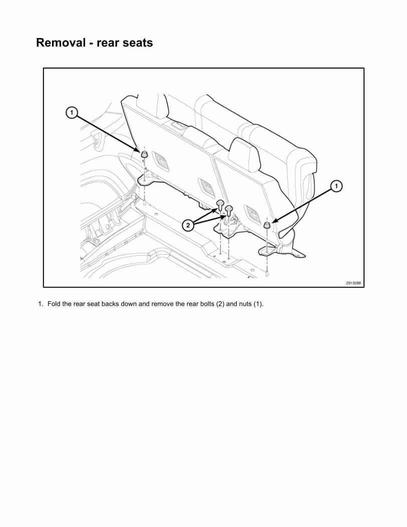
Removal - rear seats
1. Fold the rear seat backs down and remove the rear bolts (2) and nuts (1).

2. Fold the seat backs up.
3. Open the fasteners covers (1).
4. Remove the outer nuts (2) and inner bolts (3).
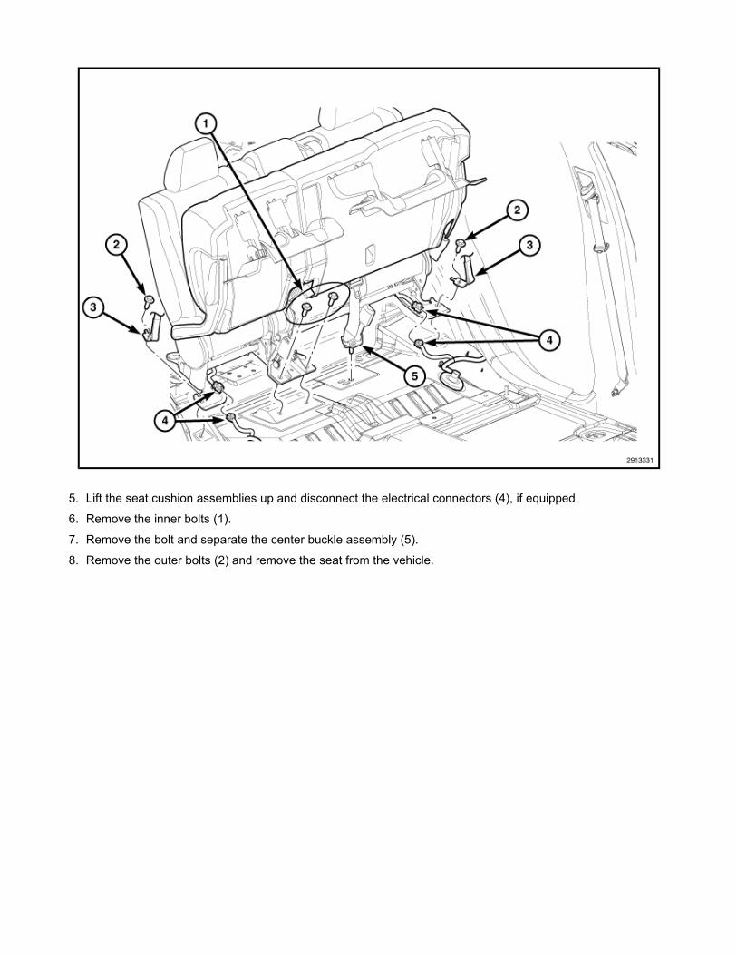
5. Lift the seat cushion assemblies up and disconnect the electrical connectors (4), if equipped.
6. Remove the inner bolts (1).
7. Remove the bolt and separate the center buckle assembly (5).
8. Remove the outer bolts (2) and remove the seat from the vehicle.
Removal - shift knob and bezel
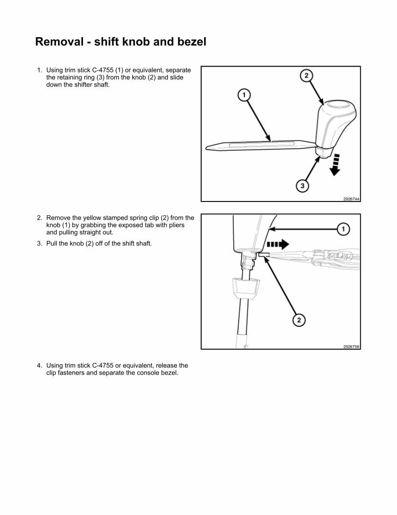
1. Using trim stick C-4755 (1) or equivalent, separate the retaining ring (3) from the knob (2) and slide down the shifter shaft.
2. Remove the yellow stamped spring clip (2) from the knob (1) by grabbing the exposed tab with pliers and pulling straight out.
3. Pull the knob (2) off of the shift shaft.
4. Using trim stick C-4755 or equivalent, release the clip fasteners and separate the console bezel.

5. Disconnect the electrical connectors (1) and remove the shifter bezel.

Removal - Silencer panel
1. Disconnect and isolate battery negative cable.
2. Remove the bolts (3) and remove the drivers side silencer panel (1).
3. Using a trim stick C-4755 or equivalent, separate the steering column trim ring (1).
4. Using a trim stick C-4755 or equivalent, separate the retaining clips and remove the cover (1).

Removal - D- pillar speakers
1. Remove the rear header panel.
2. Remove the D-Pillar trim panel (1)
3. Remove the retainers (1) and remove the speaker (2).

Removal - front door speakers
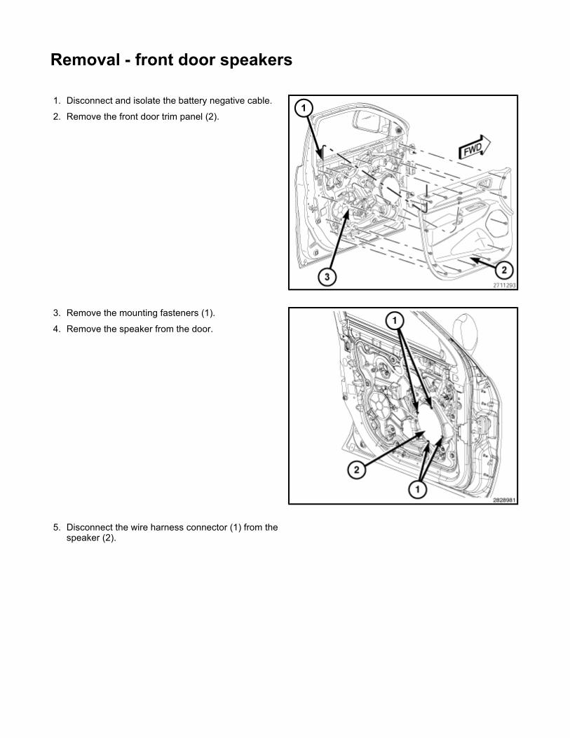
1. Disconnect and isolate the battery negative cable.
2. Remove the front door trim panel (2).
3. Remove the mounting fasteners (1).
4. Remove the speaker from the door.
5. Disconnect the wire harness connector (1) from the speaker (2).


Removal - rear door speakers
1. Disconnect and isolate the battery negative cable.
2. Remove the rear door trim panel (3).
3. Remove the mounting fasteners (1).
4. Remove the speaker from door (2).
5. Disconnect wire harness connector from the speaker.
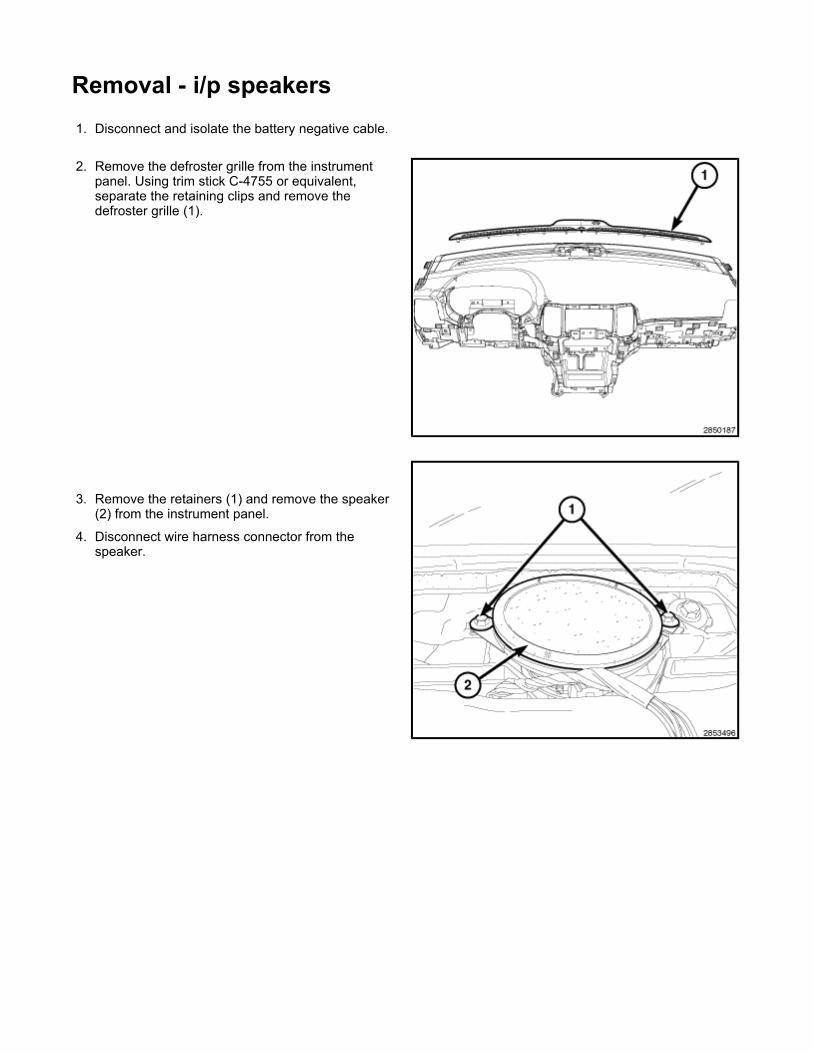
Removal - i/p speakers
1. Disconnect and isolate the battery negative cable.
2. Remove the defroster grille from the instrument panel. Using trim stick C-4755 or equivalent, separate the retaining clips and remove the defroster grille (1).
3. Remove the retainers (1) and remove the speaker (2) from the instrument panel.
4. Disconnect wire harness connector from the speaker.

Removal - subwoofer
1. Disconnect the negative battery cable.
NOTE: Without subwoofer shown, with subwoofer similar.
2. Remove the passenger side quarter trim panel.
3. Disconnect the subwoofer electrical connector.
4. Remove the three subwoofer mounting retainers (2).
5. Remove the subwoofer (1).
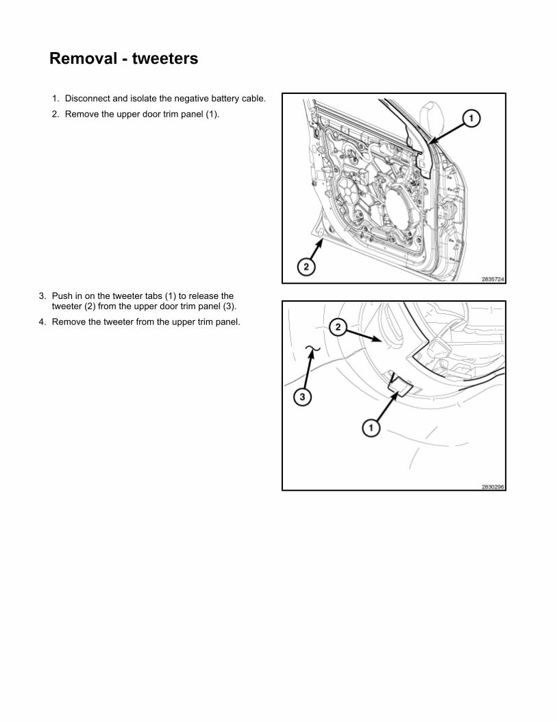
Removal - tweeters
1. Disconnect and isolate the negative battery cable.
2. Remove the upper door trim panel (1).
3. Push in on the tweeter tabs (1) to release the tweeter (2) from the upper door trim panel (3).
4. Remove the tweeter from the upper trim panel.

Removal - Sun visor
1. Put sun visor in downwards position.
2. Remove screw cover (2) by unsnapping downwards and pulling towards the rear of vehicle.
3. Disengage the sun visor (1) from the sun visor support.
4. Remove the two screws (2) that secure the sun visor (1) to the roof panel and remove the sun visor from the headliner.
5. If equipped, disconnect the illuminated vanity mirror wire harness connector.