2011 iso monitor - amity technology technology reserves the right to alter illustrations and...
TRANSCRIPT

2011 ISO Monitor
Operators Manual
Amity Technology, LLC 2800 7th Avenue North Fargo, ND 58102 (701) 232-4199 www.amitytech.com

Page 2 2011 ISO Monitor Manual
This Page Left Intentionally Blank
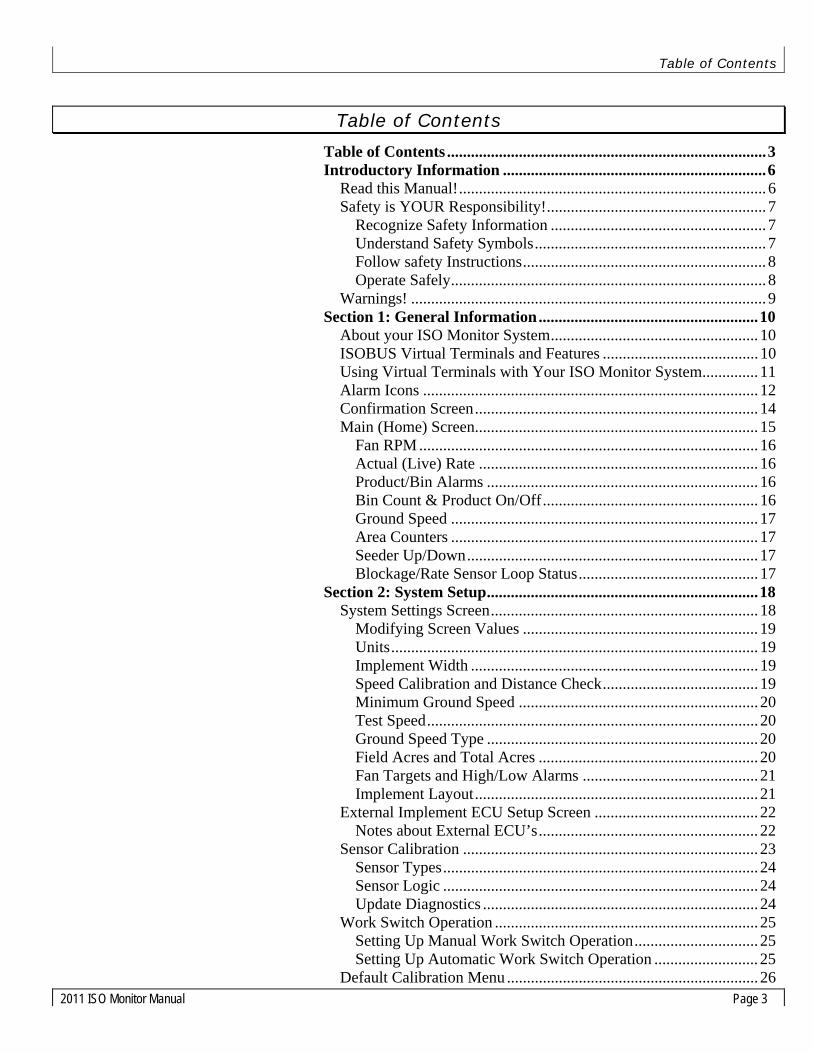
Table of Contents
2011 ISO Monitor Manual Page 3
Table of Contents
Table of Contents ................................................................................3 Introductory Information ..................................................................6
Read this Manual!............................................................................. 6 Safety is YOUR Responsibility!....................................................... 7
Recognize Safety Information ...................................................... 7 Understand Safety Symbols.......................................................... 7 Follow safety Instructions............................................................. 8 Operate Safely............................................................................... 8
Warnings! ......................................................................................... 9 Section 1: General Information.......................................................10
About your ISO Monitor System.................................................... 10 ISOBUS Virtual Terminals and Features ....................................... 10 Using Virtual Terminals with Your ISO Monitor System.............. 11 Alarm Icons .................................................................................... 12 Confirmation Screen....................................................................... 14 Main (Home) Screen....................................................................... 15
Fan RPM ..................................................................................... 16 Actual (Live) Rate ...................................................................... 16 Product/Bin Alarms .................................................................... 16 Bin Count & Product On/Off...................................................... 16 Ground Speed ............................................................................. 17 Area Counters ............................................................................. 17 Seeder Up/Down......................................................................... 17 Blockage/Rate Sensor Loop Status............................................. 17
Section 2: System Setup....................................................................18 System Settings Screen................................................................... 18
Modifying Screen Values ........................................................... 19 Units............................................................................................ 19 Implement Width ........................................................................ 19 Speed Calibration and Distance Check....................................... 19 Minimum Ground Speed ............................................................ 20 Test Speed................................................................................... 20 Ground Speed Type .................................................................... 20 Field Acres and Total Acres ....................................................... 20 Fan Targets and High/Low Alarms ............................................ 21 Implement Layout....................................................................... 21
External Implement ECU Setup Screen ......................................... 22 Notes about External ECU’s....................................................... 22
Sensor Calibration .......................................................................... 23 Sensor Types............................................................................... 24 Sensor Logic ............................................................................... 24 Update Diagnostics ..................................................................... 24
Work Switch Operation .................................................................. 25 Setting Up Manual Work Switch Operation............................... 25 Setting Up Automatic Work Switch Operation .......................... 25
Default Calibration Menu ............................................................... 26
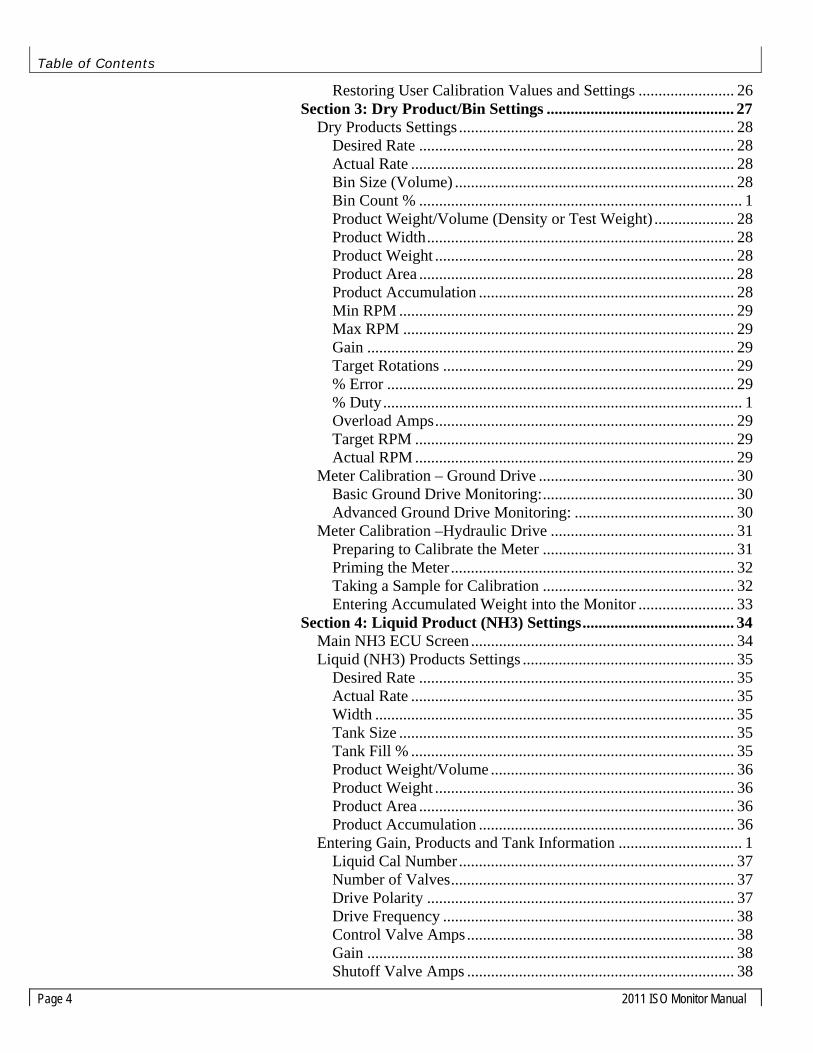
Table of Contents
Page 4 2011 ISO Monitor Manual
Restoring User Calibration Values and Settings ........................ 26 Section 3: Dry Product/Bin Settings ............................................... 27
Dry Products Settings ..................................................................... 28 Desired Rate ............................................................................... 28 Actual Rate ................................................................................. 28 Bin Size (Volume) ...................................................................... 28 Bin Count % ................................................................................. 1 Product Weight/Volume (Density or Test Weight) .................... 28 Product Width............................................................................. 28 Product Weight ........................................................................... 28 Product Area ............................................................................... 28 Product Accumulation ................................................................ 28 Min RPM .................................................................................... 29 Max RPM ................................................................................... 29 Gain ............................................................................................ 29 Target Rotations ......................................................................... 29 % Error ....................................................................................... 29 % Duty.......................................................................................... 1 Overload Amps........................................................................... 29 Target RPM ................................................................................ 29 Actual RPM ................................................................................ 29
Meter Calibration – Ground Drive ................................................. 30 Basic Ground Drive Monitoring:................................................ 30 Advanced Ground Drive Monitoring: ........................................ 30
Meter Calibration –Hydraulic Drive .............................................. 31 Preparing to Calibrate the Meter ................................................ 31 Priming the Meter....................................................................... 32 Taking a Sample for Calibration ................................................ 32 Entering Accumulated Weight into the Monitor ........................ 33
Section 4: Liquid Product (NH3) Settings...................................... 34 Main NH3 ECU Screen .................................................................. 34 Liquid (NH3) Products Settings ..................................................... 35
Desired Rate ............................................................................... 35 Actual Rate ................................................................................. 35 Width .......................................................................................... 35 Tank Size .................................................................................... 35 Tank Fill % ................................................................................. 35 Product Weight/Volume ............................................................. 36 Product Weight ........................................................................... 36 Product Area ............................................................................... 36 Product Accumulation ................................................................ 36
Entering Gain, Products and Tank Information ............................... 1 Liquid Cal Number ..................................................................... 37 Number of Valves....................................................................... 37 Drive Polarity ............................................................................. 37 Drive Frequency ......................................................................... 38 Control Valve Amps................................................................... 38 Gain ............................................................................................ 38 Shutoff Valve Amps ................................................................... 38

Table of Contents
2011 ISO Monitor Manual Page 5
% Error........................................................................................ 38 Target RPM................................................................................. 38 Actual RPM ................................................................................ 38
Calculating Liquid Calibration Number ......................................... 39 Checking and Fine-Tuning NH3 Calibration ................................. 40 Purging the NH3 System ................................................................ 40
Section 5: ART Seed Monitoring (Blockage) .................................41 Main Toolbar ECU Screen ............................................................. 41
Sensitivity ................................................................................... 42 Row count ................................................................................... 43 High and Low Rate Alarms ........................................................ 43 Target Rate.................................................................................. 43 Alarm Delay................................................................................ 43 Seed Rate Wizard........................................................................ 44
Seed Monitoring Operation ............................................................ 45 Work switch................................................................................ 45 Installed Sensors ......................................................................... 45 Area Rate .................................................................................... 46 Communication Error ................................................................. 46 System Information Bars ............................................................ 46 Loop Status ................................................................................. 47 Sensor Diagnostics...................................................................... 48
Seed Sensor Sensitivity Values ...................................................... 49 Blockage System Troubleshooting ................................................. 50
Section 6: System Troubleshooting .................................................52 Section 7: Appendix ..........................................................................55
Appendix A: Connector Pinouts.................................................... 55 ECU Signal Connectors .............................................................. 55 ISO-BUS Extension Connector .................................................. 56 CAN Terminator Connector ....................................................... 56 ECU Power Contacts .................................................................. 56 Motor Control Connectors .......................................................... 57 Low-Bin Level Sensor Connectors............................................. 57 Motor Speed (Tach) Connectors................................................. 57 Meter Box Sensor Connectors .................................................... 57 Ground Speed Sensor Connector ................................................ 58 Fan Sensor Connectors ............................................................... 58 Anhydrous Ammonia/Liquid Control Connector ....................... 59
Appendix B: Metric Conversion Factors....................................... 60 Appendix C: Common Values and Equations ............................... 61 Appendix D: ICON Glossary......................................................... 63

Introductory Information
Page 6 2011 ISO Monitor Manual
Introductory Information
Read this Manual!
READ AND UNDERSTAND THIS MANUAL BEFORE YOU OPERATE THIS MACHINE.
Learn how to operate and service your machine correctly. Failure to do so could result in personal injury or equipment damage. Amity Technology will not accept any responsibility for any damage or malfunctions resulting from failure to comply with the operator’s manual.
If you do not understand the information in this manual, or if you have any questions, contact Amity Technology Customer Service.
This manual should be considered a permanent part of your machine and should remain with the machine when you sell it.
Amity Technology reserves the right to alter illustrations and technical data contained in this manual.
The contents of this manual are the intellectual property Amity Technology All use and/or reproduction not specifically authorized by Amity Technology is prohibited.
All information, illustrations and specifications in this manual are based on the latest information available at the time of publication. Amity Technology reserves the right to make changes at any time without notice.

Introductory Information
2011 ISO Monitor Manual Page 7
Safety is YOUR Responsibility!
Recognize Safety Information
This is a safety-alert symbol. When you see this symbol on your machine or in this manual, be alert to the potential for personal injury.
Follow recommended precautions and safe operating practices.
Understand Safety Symbols
A reminder of safety practices or attention to unsafe practices which could result in injury or death if proper precautions are not taken.
A hazard exists which could result in injury or death if proper precautions are not taken.
An extreme inherent hazard exists which could result in injury or death if proper precautions are not taken.

Introductory Information
Page 8 2011 ISO Monitor Manual
Follow safety Instructions
Carefully read all safety messages in this manual and on your machine safety decals. Keep safety decals in good condition. Replace missing or damaged safety decals. Be sure new equipment components and repair parts include the current safety decals.
Learn how to operate the machine and how to use controls properly. Do not let anyone operate without instruction.
Keep your machine in proper working condition.
Unauthorized modifications to the machine may impair the function and/or safety and affect machine life and thus void the warranty.
Operate Safely
Do not make adjustments while the machine is in motion.
Do not enter the tank unless another person is present and hydraulic hoses are disconnected from the tractor.
Operate the machine from the tractor seat only.
Keep hands and fingers away from hinge area when positioning auger. Lock auger in storage position before operating in the field.
Clear the area around the machine before raising or lowering the machine or wings.
Stop the tractor on level ground when raising or lowering wings. Do not operate with wings raised. To improve stability, travel through the field with the wings unfolded. Fold wings to transport position just before leaving the field and entering a roadway.
Do not operate close to the edge of a ditch, creek, gully or steep embankment.
Avoid holes, ditches and obstructions which may cause tractor, cart or seeding tool to roll over, especially on hillsides.
Avoid sharp turns on hillsides.
Slow down when turning or traveling over rough ground, and when turning on inclines.
Shut off the tractor and shift to Park or set brakes when leaving the tractor. Remove the key when leaving the tractor unattended.

Introductory Information
2011 ISO Monitor Manual Page 9
Warnings!
ATTENTION! Read this manual carefully and fully before operations.
WARNING! Take care if welding on the frame of cart of planting system. Ensure that no power is applied to the ECU. Unplug the main harness from the tractor and properly ground the welder. Connect the welder ground cable as close as possible to the weld area.
ATTENTION! Low battery or alternator voltage can cause system errors.
WARNING! Be careful when testing NH3 systems. Be sure to clear the area of people and pets. While testing, wear proper protective clothing and eyewear. Always position yourself up-wind while testing.
NOTICE! Depending on the processing speed of your virtual terminal, there may be a delay in function changes when a soft key is pressed. If you quickly press a soft key several times, you may initiate multiple functions on several pages. Allow time between pressing soft keys to ensure the virtual terminal has time to respond.
NOTICE! When operating product meters in test mode (Test Speed), be sure to open the access door under the meter, or run the fan, to prevent material from building up and stopping the meter.
ATTENTION! Ensure that your virtual terminal is updated with the latest version of its software from its manufacturer.

Section 1: General Information
Page 10 2011 ISO Monitor Manual
Section 1: General Information
About your ISO Monitor System
Your Amity ISO Monitor system is based on the ISO 11783 standard, sometimes also referred to as ISOBUS. Essentially, ISOBUS is a communications standard that enables a variety of agricultural electronics systems to talk to each other. Its purpose is to integrate all current and future farm functions by standardizing communication between tractor and implement. Tractor and implement are operated as a single unit, which reduces operator stress and increases efficiency. ISOBUS permits the use of the same tractor terminal on a number of different machines and hence control of a wide range of implements without the need to reprogram a system.
All of this means that your Amity ISO Monitor can be controlled from any tractor that is equipped with an ISOBUS-compatible terminal, regardless of the manufacturer.
ISOBUS Virtual Terminals and Features
Several companies manufacture ISOBUS-compatible virtual terminals. Although the locations and types of controls may vary from manufacturer to manufacturer, all terminals use the same icons to represent the main functions. When an ISOBUS-compatible terminal is connected to an ISOBUS-compatible implement system, the “personality” (program, control screens, unique icons, etc) for that system are loaded into the terminal. The control screens, or pages, for that implement (which are displayed in the central area of the screen) are identical for any ISOBUS-compatible terminal.
Currently the following virtual terminals can be used with your ISO Monitor system:
• GTA Console 1 (AGCO) • GTA Console 2 (AGCO) • C-1000 (AGCO) • AFS Pro 600 (Case IH) • GreenStar2 (John Deere) • IntelliView II (New Holland) • IntelliView Plus II (New Holland) • IntelliAg (DICKEY-john) • LH6000 (TeeJet)

Section 1: General Information
2011 ISO Monitor Manual Page 11
Using Virtual Terminals with Your ISO Monitor System
Any ISOBUS-compatible virtual terminal (VT) should be able to communicate with and control your ISO Monitor. When the VT in your tractor is connected to the ECU it downloads the information from the ECU and displays it on the VT’s screen. The central part of the screen displays information pages identically, regardless of the VT you are using. Typically, icons representing other pages are located around, or to the side of the central part of the screen. Selecting these soft keys enables you to navigate to the pages they represent. The location of page icons may vary depending on the manufacturer of the VT. Also, some VTs have touch screens, whereas others use pushbuttons located around the outside of the screen, adjacent to on-screen icons.
ISOBUS compatible VTs can be used to set up, operate and monitor your ISO Monitor but the exact details of how to access and change values and settings may vary from manufacturer to manufacturer. For example, when entering numerical values during system setup, some VTs may open a keypad-style page. Others may assign numbers to switches around the outside of the screen. For this reason, procedures in this manual simply state “Enter the numerical value for…”. You will have to consult the manufacturer’s operating manual for your specific VT to determine the details.
Tip! For detailed information on how to operate your virtual terminal, refer to its operation manual.
An example of an ISO Monitor page

Section 1: General Information
Page 12 2011 ISO Monitor Manual
Alarm Icons The following is a list of alarms that could occur during system operation. Alarms show up as separate screens and are aknowledged based on your Virtual Terminal type.
Icon Alarm
Meter Box Empty
Bin Low
Clutch Current Overload
Fan RPM High
Fan RPM Low
Fan RPM Off
Liquid Rate High
Liquid Rate Low
Liquid Valve Current Overload
Liquid Rate Off
High Rate – Dry Product
Low Rate – Dry Product
VR Current Overload
Seed Flow Blockage
Section 1: General Information
2011 ISO Monitor Manual Page 13
Icon Alarm
Seed Flow Communication Error
Seed Flow High Rate
Seed Flow Low Rate
Seed Flow Current Overload
Ground Speed High
Ground Speed Low
Internal Communication Error
Low Battery Voltage
Note: - This alarm screen shows Fan 1 in alarm with a RPM of 0. - Acknowledging the alarm is done by either touching the OK” softkey or the “ESC” button. This will vary based on which virtual terminal you are using.
Fan 1 RPM 0
Section 1: General Information
Page 14 2011 ISO Monitor Manual
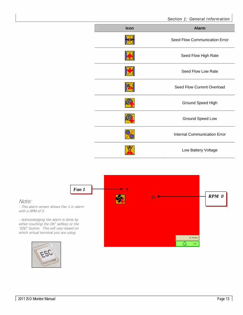
Confirmation Screen
Changing of certain settings or values on your Amity ISO Monitor system may require confirmation, clearing an acre counter or setting the default system settings for example. When confirmation is needed, a blue confirmation screen will appear.
To Confirm your selection and return to the previous screen,
select the softkey.
To Cancel your selection and return to the previous screen, select
the softkey.
Accept
Cancel

Section 1: General Information
2011 ISO Monitor Manual Page 15
Main (Home) Screen
On the Main page of the ISO Monitor system you can view many critical machine functions. The following screen shot shows the key information provided on this page. Each function will be explained in greater detail following this diagram.
Home Screen Softkeys
Icon Page Icon Page
Main (Home)
On/Off
(Manual Work Switch)
System Settings
Product Bins Settings (1-5)
NH3 Settings ART (Blockage) Settings
Note: If the softkey is blacked out, it means either the feature is turned off or the feature is setup to be used with an External ECU (Blockage or NH3 for example).
FAN 1 RPM
FAN 2 RPM
Actual Rate
Alarms
Ground Speed
Bin Fill %
Seeder up/down
Area 1
Loop 1 Status Loop 2 Status
Prod on/off
Area 2
Target Rate

Section 1: General Information
Page 16 2011 ISO Monitor Manual
Fan RPM
Displays Fan speed in RPM. Min and Max alarms can be set in the System Settings screen. See System Setup for more information.
Actual (Live) Rate
Graphically displays the Actual Rate for Motors 1-5 and N (liquid NH3) as a percentage (0-200% of desired rate). When the indicator bar is in the center of the graph, the Actual Rate matches the Desired Rate. The Desired rate for each product is also numerically shown in red.
Only the products enabled during system setup will appear on the main page.
Product/Bin Alarms
The following symbols can be displayed in the alarm box for each product/bin.
Symbol Alarm
Rate High Alarm
Rate Low Alarm
Motor Overload Alarm
Clutch Engaged Indicator (Ground Drive Only)
Bin Low Alarm
Meter Box Empty Alarm
Bin Count & Product On/Off Displays the status of the bin levels as a percentage. The Bin Count feature can be calibrated in the Product Calibration screen. These indicators are an approximation based on the calculated meter accumulation and must be properly calibrated in order to properly function. Pressing the Product On/Off buttons will turn any particular product on or off. A Green indicator represents Product On and a Red indicator represents Product Off. The single clutch on Ground Drive units is tied to Product 1, individual bin control is not available.

Section 1: General Information
2011 ISO Monitor Manual Page 17
Ground Speed
Displays ground speed of the cart in mph (kph). The speed source can be changed in the System Settings screen.
Area Counters Displays total area in Acres or Hectares. Pressing the Area button will clear the area accumulation.
Seeder Up/Down Pressing the Seeder Up/Down button will turn on the work switch.
Symbol Alarm
WS “Ready”
WS “Hold”
Seeder UP
Seeder DOWN
The work switch softkey will only turn green when there is a speed present (either test speed or other input), the seeder is down, and the Seeder Up/Down button is in the WS “Ready” state.
Blockage/Rate Sensor Loop Status
Displays a quick snapshot of the status of each loop.
Important! When work switch softkey turns green Master Work Switch is ON.
Loop 1 Loop 2 Blocked Sensor % Loop 1
Sensitivity Value
Installed Sensors
Sensitivity
Seed Rate Wizard
Blocked Sensor % Loop 2

Section 2: System Setup
Page 18 2011 ISO Monitor Manual
Section 2: System Setup
Before operation of your new Amity ISO Monitor system, there are several setup and calibration procedures that must be performed to ensure proper planting performance. If these operations are not completed, planting performance and accuracy will be affected.
System Settings Screen Use the following procedures to set up system parameters before using your system:
System Setup Screen Softkeys
Icon Page Icon Page
Main (Home)
On/Off
(Manual Work Switch)
External ECU Setup
Sensor Calibration
Default Settings
Important! This system setup procedure MUST be completed or your system will not operate correctly. Complete all steps.
Distance Check Implement Width
Min Speed
Speed Cal
Clear Field Acres
Test Speed
Implement Layout
Fan Settings
System Current
SPI Communication
ECU Voltage
Clear Total Acres
Software Version
Ground Speed Type
Units Indicator U - U.S. M - Metric I - Imperial ? - Mixed

Section 2: System Setup
2011 ISO Monitor Manual Page 19
Modifying Screen Values
The method of modifying the values on the screen varies depending on the model of Virtual Terminal you are using. Common methods are a touch-screen, scroll buttons, or a scroll wheel. Refer to your Virtual Terminal Operators Manual for more information on modifying values.
• Numbers in RED are input numbers that can be modified.
• Numbers in BLUE are output numbers that cannot be modified.
Units
The Amity ISO Monitor system utilizes either SAE (US) or Metric units. Units are configured in the Virtual Terminal System Settings. Verify which system of units your VT is using before entering these values and operating your system. Refer to your VT Operators Manual for more information on checking the units. The Units Indicator on the System Setup Screen displays the units setting of the Virtual Terminal for your reference.
Implement Width
Step 1. On the Calibration page, select Width by pressing the number
next to the width icon.
Step 2. Enter the width value in inches or millimeters.
Step 3. Repeat this procedure to set the Width value for each individual product being used.
Speed Calibration and Distance Check
Use the following calibration procedure to set up the ground speed sensor on the commodity cart. This procedure only applies when the Speed Type is set to Cart Speed.
Step 1. Measure a specific distance in front of the implement.
Step 2. Clear the accumulated distance value by pressing the Clear Distance button.
Step 3. Drive the implement the measured distance and then stop.
Step 4. Enter the Distance value by pressing the number next to the Distance icon.
Step 5. The Speed Cal number will automatically be calculated and appear.
Tip! If your machine is 60 feet wide, multiply 60 X 12 inches per foot = 720 inches. Enter “720”.
Common Speed Cal Values
Tire Size Drive Speed Cal 18.4R26 Hyd 9.5” (241) 23.1R26 Hyd 10.5” (267) 18.4R26 Ground 13.6” (345) 23.1R26 Ground 15.0” (381) 5250-GPS Hyd 0.38” (9.6)
Note! Select the number NOT the icon to enter the VT into edit mode.

Section 2: System Setup
Page 20 2011 ISO Monitor Manual
Minimum Ground Speed
Step 1. Select the number next to the Min Speed icon
Step 2. Enter the minimum seeding speed in mph or kph.
Test Speed
Step 1. Select the number next to the Test Speed icon
Step 2. Enter the desired test speed in mph or kph.
A test speed will affect both dry products and NH3 operation.
Ground Speed Type
Pressing the Speed Button will toggle between the different ground speed input types. The ISO speeds are only available if the tractor is broadcasting these over the ISO-BUS.
Symbol Speed Type
Cart Speed (Default for Normal Operation)
Test Speed (set in the Calibration Menu)
ISO Ground Speed (Tractor GPS)
ISO Wheel Speed (Tractor Wheel or Radar)
External ECU Speed (from another Amity ECU)
Field Acres and Total Acres
There are two tools to use when calculating planted acres: Field Acres and Total Acres. Use the following procedure to reset them in preparation for totalizing planted acres:
Step 1. Press the button to reset the Field Acres total to zero.
Step 2. Press the button once to reset the Total Acres total to zero.
Tip! Set this value to match your lowest product minimum speed for optimal performance.

Section 2: System Setup
2011 ISO Monitor Manual Page 21
Fan Targets and High/Low Alarms
Fan target settings as well as fan high and low alarm / settings are shown here. The default value for fan targets is 2-targets per revolution.
Implement Layout
Step 1. You can turn product 1-5 and liquid (NH3) on/off by selecting the corresponding blue box.
Step 2. You must select the task controller (TC) type you will be using for operation. The type of task controller selected may affect the available operational features
Symbol Function
Turns products 1-4 on or off.
Checked is ON. Unchecked is OFF.
Turns liquid (NH3) on or off
Checked is ON. Unchecked is OFF.
Checked enables a ground drive clutch on that product.
Unchecked is hydraulic (variable) drive.
Selects Task Controller type Checked is single product TC. Unchecked is multiple TC
Note: JD GS2 can only use single product TC
Selects the Bin # that single product TC uses.
Fan 1 Settings
Fan 2 Settings
X-Offset Dimension for Task Controller use. Represents distance from the tractor GPS reference point (typically the rear axle) to the seeding openers. Displayed in inches or millimeters.

Section 2: System Setup
Page 22 2011 ISO Monitor Manual
External Implement ECU Setup Screen
Your Amity ISO monitor system utilizes the ISO-Bus to communicate with various Amity Technology ECU’s mounted on the implement in order to share common information. Use of separate implement ECU’s means simpler wiring between the implement and cart, as well as the ability to use these ECU’s independently when the cart is not connected. The current system can communicate with the Toolbar ECU and the NH3 ECU. The following types of information are shared.
• Ground Speed
• Work Switch Position & State
• Toolbar ECU (Blockage) Status for Display on the Home Screen
• NH3 ECU Status for Display on the Home screen
Symbol Function
Enables sharing of Toolbar ECU (blockage) information
Checked is ON. Unchecked is OFF.
Enables sharing of NH3 ECU information
Checked is ON. Unchecked is OFF.
Notes about External ECU’s
• Each ECU connected to the ISO-Bus will have its own set of menu’s that can be accessed by your VT. These menus will provide more advanced operational and setup tools compared to what can be viewed on the home screen of the Cart ECU. Refer to the manual for your VT for methods on toggling between the menus of different ECU’s that are connected to the ISO-Bus.
• The Cart ECU is typically the input for ground speed. All other ECU’s should have their speed type set to external. .
• The Toolbar ECU is typically the input for work switch position. All other ECU’s should have their work switch channel set to external
• Pressing the Manaul Workswitch Softkey when viewing the screens for any of the ECU’s will toggle the work switch state on all ECU’s.
• When clearing alarms, VT will bring you back to the screen of the ECU that generated the alarm in case further action is needed.
• In order to know which ECU’s screens you are viewing on your VT, look at the Softkey in the top-right corner of the screen. For example, all of the menus for the Cart ECU have the “house” icon in the upper right hand corner of the display screen.
ECU Screen Identification
Softkey in Upper RH Corner of Display
ECU ID
Cart ECU
Toolbar ECU (Blockage)
NH3 ECU
Tip! These boxes must be checked in order for the Toolbar ECU and NH3 ECU information to show up on the Home Screen of the Cart ECU.
Section 2: System Setup
2011 ISO Monitor Manual Page 23
Sensor Calibration
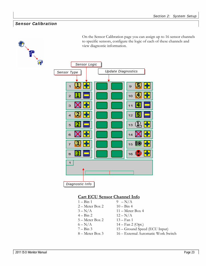
On the Sensor Calibration page you can assign up to 16 sensor channels to specific sensors, configure the logic of each of these channels and view diagnostic information.
Cart ECU Sensor Channel Info 1 – Bin 1 9 – N/A 2 – Meter Box 2 10 – Bin 4 3 – N/A 11 – Meter Box 4 4 – Bin 2 12 – N/A 5 – Meter Box 2 13 – Fan 1 6 – N/A 14 – Fan 2 (Opt.) 7 – Bin 3 15 – Ground Speed (ECU Input) 8 – Meter Box 3 16 – External Automatic Work Switch
Sensor Logic
Update Diagnostics Sensor Type
Diagnostic Info

Section 2: System Setup
Page 24 2011 ISO Monitor Manual
Sensor Types
The following symbols represent the sensor types that are available:
Symbol Sensor Type
Bin 1-4
Meter Box 1-4
Fan 1-2
Ground Speed
Automatic Work Switch
External Automatic Work Switch (Toolbar ECU)
None
Sensor Logic
You can configure the logic of each sensor channel. Logic is the expected output when the sensor is activated. For example, logic determines whether an action is initiated when a switch closes or when it opens. This page enables you to invert the logic (action) of any sensor. Sensor logic is preset from the factory, but if you add a sensor for some purpose, you may have to configure its logic.
Step 1. Selecting the or will toggle between inverted or non-inverted signal.
Update Diagnostics
Step 1. Selecting the blue box will update diagnostics for that sensor at the bottom of the screen. In this example sensor #3 is a shaft sensor.
Section 2: System Setup
2011 ISO Monitor Manual Page 25
Work Switch Operation
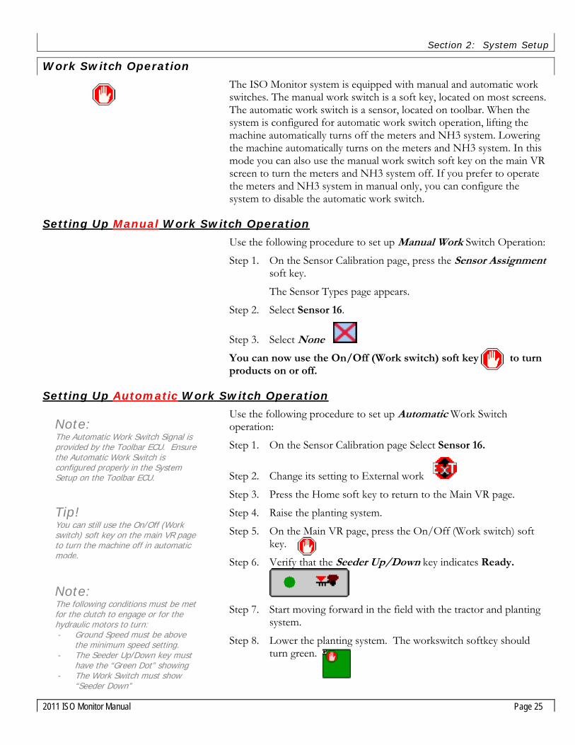
The ISO Monitor system is equipped with manual and automatic work switches. The manual work switch is a soft key, located on most screens. The automatic work switch is a sensor, located on toolbar. When the system is configured for automatic work switch operation, lifting the machine automatically turns off the meters and NH3 system. Lowering the machine automatically turns on the meters and NH3 system. In this mode you can also use the manual work switch soft key on the main VR screen to turn the meters and NH3 system off. If you prefer to operate the meters and NH3 system in manual only, you can configure the system to disable the automatic work switch.
Setting Up Manual Work Switch Operation
Use the following procedure to set up Manual Work Switch Operation:
Step 1. On the Sensor Calibration page, press the Sensor Assignment soft key.
The Sensor Types page appears.
Step 2. Select Sensor 16.
Step 3. Select None
You can now use the On/Off (Work switch) soft key to turn products on or off.
Setting Up Automatic Work Switch Operation
Use the following procedure to set up Automatic Work Switch operation:
Step 1. On the Sensor Calibration page Select Sensor 16.
Step 2. Change its setting to External work
Step 3. Press the Home soft key to return to the Main VR page.
Step 4. Raise the planting system.
Step 5. On the Main VR page, press the On/Off (Work switch) soft key.
Step 6. Verify that the Seeder Up/Down key indicates Ready.
Step 7. Start moving forward in the field with the tractor and planting
system.
Step 8. Lower the planting system. The workswitch softkey should turn green.
Tip! You can still use the On/Off (Work switch) soft key on the main VR page to turn the machine off in automatic mode.
Note: The following conditions must be met for the clutch to engage or for the hydraulic motors to turn: - Ground Speed must be above
the minimum speed setting. - The Seeder Up/Down key must
have the “Green Dot” showing - The Work Switch must show
“Seeder Down”
Note: The Automatic Work Switch Signal is provided by the Toolbar ECU. Ensure the Automatic Work Switch is configured properly in the System Setup on the Toolbar ECU.

Section 2: System Setup
Page 26 2011 ISO Monitor Manual
Default Calibration Menu
The Default Calibration feature can be used to reset all settings to their default values in case of system error.
Restoring User Calibration Values and Settings
If for some reason you lose rates, cal numbers, etc due to system error:
Step 1. In the System Settings menu, press the Default Calibration soft key.
Step 2. Press the softkey corresponding to the type of commodity cart being used.
Symbol Cart Type
2-Tank Ground Drive (2800/3350)
2-Tank Hydraulic Drive (2800/3350)
3-Bin Hydraulic Drive (5250)
Step 3. Confirm selection and return to Home Screen.
Step 4. Perform initial system setup to verify all settings are configured properly.
Important Note! If you use the Default Cal soft key to restore the factory default settings you will have to redo the entire System Setup procedure.
Section 3: Dry Product/Bin Settings
2011 ISO Monitor Manual Page 27
Section 3: Dry Product/Bin Settings
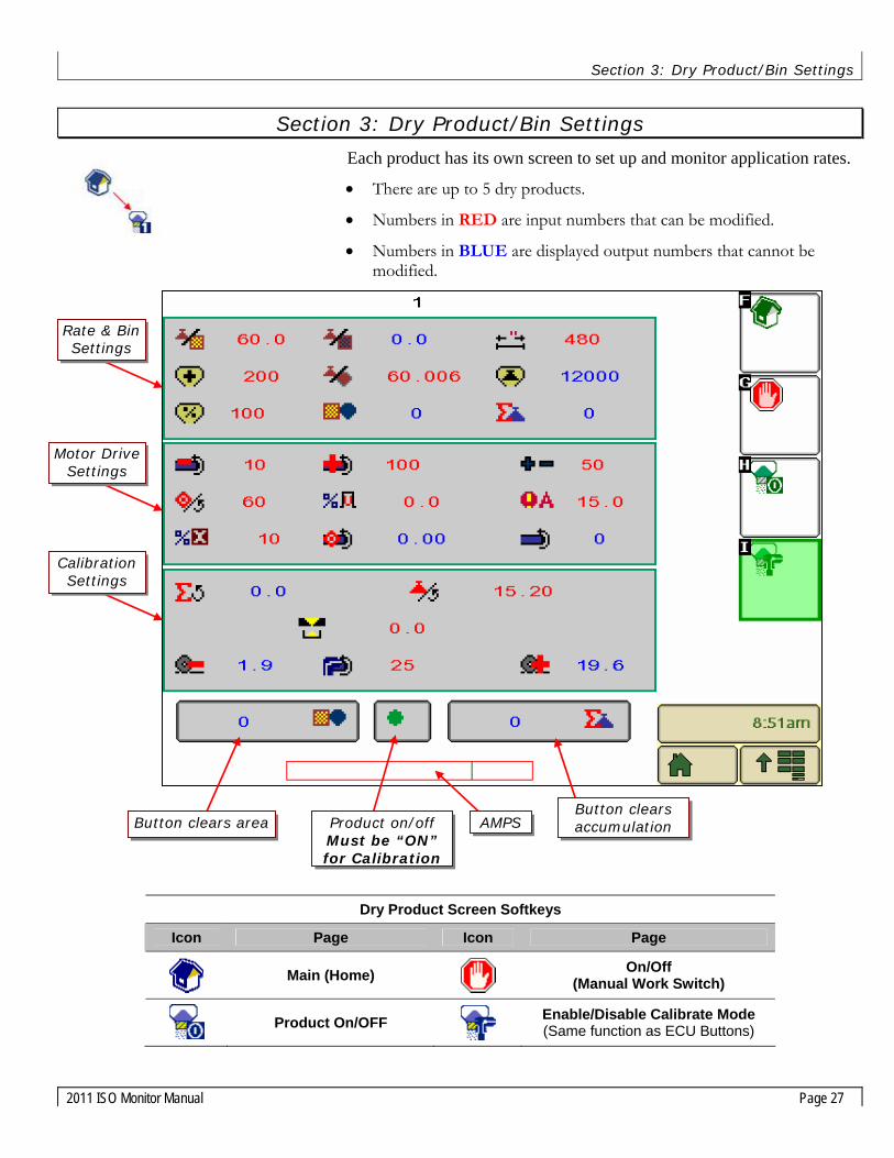
Each product has its own screen to set up and monitor application rates.
• There are up to 5 dry products.
• Numbers in RED are input numbers that can be modified.
• Numbers in BLUE are displayed output numbers that cannot be modified.
Dry Product Screen Softkeys
Icon Page Icon Page
Main (Home)
On/Off
(Manual Work Switch)
Product On/OFF
Enable/Disable Calibrate Mode (Same function as ECU Buttons)
Button clears area Product on/off Must be “ON” for Calibration
AMPS Button clears accumulation
Rate & Bin Settings
Motor Drive Settings
Calibration Settings

Section 3: Dry Product/Bin Settings
Page 28 2011 ISO Monitor Manual
Dry Products Settings
Desired Rate
Enter your desired application rate in Pounds/Acre (Kg/Ha) .
Actual Rate
Displays the actual rate in Pounds/Acre (Kg/Ha).
Bin Size (Volume)
Enter the size of your tank in bushels (liters). This value is pre-set at the factory. This value is used for the “Bin Count” feature.
Bin Count %
Enter the percentage of estimated product in the bin each time the tank is filled. When calibrated properly, the Bin Count feature provides an estimated approximation of the product left in that bin. This percentage is displayed on the status bar on the Home Screen.
Product Weight/Volume (Density or Test Weight)
Enter the test weight of your product in Pounds/bushel (Kg/liter). This value is needed for proper operation of the “Bin Count” feature.
Product Width
Enter the width of your toolbar in inches (millimeters). Ensure the Width setting is the same for all products being used.
Product Weight
Displays estimated remaining product weight in the bin in Pounds (Kg).
Product Area
Displays area covered while metering in Acres (Ha).
Product Accumulation
Displays weight dispensed while metering in Pounds (Kg).
Desired Rate Actual Rate Width
Bin %
Product Accumulation
Bin Size
Product Weight
Weight/ Volume
Product Area
Note: Do not use the Bin Count feature if you are using Basic Monitoring with a Ground Drive type unit

Section 3: Dry Product/Bin Settings
2011 ISO Monitor Manual Page 29
Note! Changing % Duty will override normal operation of the unit.
Note: The Motor Drive Settings are pre-set at the factory and should not be adjusted!
Min RPM
Lowest allowable meter RPM.
Max RPM
Highest allowable meter RPM.
Gain
Used to control reaction speed of the meters.
Target Rotations
Enter the number of targets per revolution of the meter. This value should be 60 for hydraulic drive and 1 for ground drive.
% Error
Enter the allowable % of error without alarming.
% Duty
Diagnostic feature that overrides the control function and sets output drive at a fixed %.
Overload Amps
Enter the allowable current draw without alarming.
Target RPM
This value is the calculated desired RPM of meter based on current speed, calibration values, width and target rate.
Actual RPM
This value is the actual RPM of the meter.
Target RPM
Overload Amps
Actual RPM
% Error
Target Rotations
Gain
% Duty
Max Meter RPM Min Meter RPM

Section 3: Dry Product/Bin Settings
Page 30 2011 ISO Monitor Manual
Meter Calibration – Ground Drive
Meter Calibration and application rate settings for Ground Drive units are performed and set mechanically on the tank. For instructions on calibration with a Ground Drive type unit, please reference your “Air System Operating and Parts Manual”. The only control aspect that the Amity ISO monitor system has on Ground Drive units is the operation of the meter drive clutch.
The Amity ISO monitor system also provides monitoring of critical cart functions on Ground Drive units. There are two levels of monitoring that are available to the operator. Both types of monitoring include fan speed, shaft speed, ground speed, empty meter box, and low bin level.
Basic Ground Drive Monitoring:
Basic monitoring requires very little interaction with the monitor, but the operator will not be able to use the “Bin Count” feature or the product accumulation counter. Fixed values are used for the “Target Rate” and “Meter Cal” in order to properly synchronize the meter shaft sensors with the implement width and drive train configuration. Use a Target Rate of 100 lbs/acre. Reference the following chart for the proper Meter Cal value to be used. These values only need to be set once for each product.
Implement Width
Tire Size Gearbox Sprocket
30 ft (9m)
40 ft (12m)
50’ ft (15m)
60’ ft (18m)
18.4R26 17T
23.1R26 15T
12.5 oz/rev(354 g/rev)
16.7 oz/rev (473 g/rev)
20.8 oz/rev(590 g/rev)
25 oz/rev (709 g/rev)
18.4R26 12T
23.1R26 10T
18.8 oz/rev(533 g/rev)
25.0 oz/rev (709 g/rev)
31.3 oz/rev(887 g/rev)
37.5 oz/rev(1063 g/rev)
Advanced Ground Drive Monitoring:
Advanced monitoring requires more interaction with the monitor, but allows the operator to utilize the “Bin Count’ feature and the product accumulation counter. To set the system for Advanced Monitoring, calculate the “Motor Cal’ value for each bin when you calibrate by dividing your sample weight (oz) by the number of times the crank was turned. Set this value for each bin. You also need to set the “Target Rate” based on the target rate value used for calibration.
For example, if you want to apply 60 lbs/acre from Bin 1 and you were able to adjust your meter to get 96 oz from 9.5 turns, set the Meter Cal Value for Bin 1 to 10.1 oz/rev and set the Target Rate to 60 lbs/acre.
)()()/(revCrankTurnsOfThe
ozgWeightInBarevozlueMeterCalVa =

Section 3: Dry Product/Bin Settings
2011 ISO Monitor Manual Page 31
Meter Calibration –Hydraulic Drive
Calibration is performed in four parts. First, you must prepare the system for calibration. Second, you prime the meter. Third, you take a sample and weight it. Finally, you enter the sample, or Accumulated Weight into the Monitor. This process must be completed for each meter that needs to be calibrated.
Preparing to Calibrate the Meter
Hydraulic Power is needed for calibration. The following procedure sets up the air system for the calibration procedure.
Step 1. Ensure that the air system’s hydraulic lines are connected to a tractor..
Step 2. Verify that the tractor hydraulic remote for the blower is in neutral until hydraulic power is needed.
Step 3. Ensure that the monitor wire harness is properly connected to the tractor.
Step 4. Power up the monitor in the tractor.
Step 5. Verify that the VT in the cab is communicating with the Air System ECU.
Step 6. Ensure that the meter door is properly attached to the meter.
Step 7. Ensure that the bin is at least 25% full of the product that will be applied.
Step 8. Set the meter gate to the appropriate position for the rate being applied.
Step 9. Ensure the auger selector valve is directing oil to the fan/meter circuit.
Step 10. Close the blower ball valve.
Step 11. Actuate the tractor remote controlling the blower circuit.
Step 12. Make sure the blower is not spinning for the following steps. If the blower is spinning, check the ball valve to make sure that it is fully closed and blocking flow to the blower.
Step 13. Open the cleanout door below the meter you wish to calibrate
Step 14. Open the meter gate. Use the following chart as a guide when using the high capacity meter roll in normal conditions.
Meter Gate Setting Guide – Hydraulic Drive Rate lbs/ac(Kg/Ha)
30 ft (9m)
40 ft (12m)
50 ft (15m)
60 ft (18m)
50 (56) 3” (76 mm) 4” (102 mm) 5” (127 mm) 6” (152 mm)
100 (112) 4” (102 mm) 6” (152 mm) 8” (203 mm) 10” (254 mm)
150 (168) 6” (152 mm) 8” (203 mm) 10” (254 mm) Max 200 (224) 8” (203 mm) 10” (254 mm) Max Max
Note! The meter must be calibrated if: - The gate setting has changed - A different product is being used - A different meter roll is being used Each meter must be calibrated individually, even if all the gates are set the same
Auger Selector Valve
Adjusting the Meter Gate

Section 3: Dry Product/Bin Settings
Page 32 2011 ISO Monitor Manual
Priming the Meter
To ensure accurate calibration, the meter must be primed with product.
Step 1. On the ECU keypad, locate the button with the number corresponding to the meter you are calibrating. This is called the ECU Calibration button.
Step 2. Press the ECU Calibration button once.
The meter roll begins spinning
Step 3. Allow the meter to spin 2 to 3 revolutions to ensure that the meter is full of product.
Step 4. Press the same button again to stop the meter.
The meter is now primed
Taking a Sample for Calibration
Step 1. Using the weigh scale included with your system, hang the calibration bag (also included) on the scale and zero the reading on the scale.
Step 2. Place the calibration bag below the cleanout opening. Be careful to ensure all product will flow into the bag.
Step 3. Press the ECU Calibrate button to activate the meter.
Step 4. Allow the meter to spin until the bag is at least half full.
Step 5. Press the ECU calibrate button again to stop the meter.
Step 6. Weight the bag with the supplied scale.
Step 7. Convert the weight to ounces and record the value.
This value is the Accumulated Weight you will enter into the Virtual Terminal.
Note: Do not press the ECU Calibrate button again until the Accumulated weight is entered into the VT. Pressing the ECU Calibrate button before the weight is entered will clear the rotation counter and void the sample.
Step 8. Repeat the previous steps to obtain sample weights for the rest of the meters.
Step 9. When all the weights have been found, go back to the tractor and enter the calibration weights into the Product page on the Virtual Terminal
Note! Each time the ECU calibrate button is pressed to activate the meter the ECU counts the revolutions of the meter roll. This count is reset each time the ECU button is pressed. Once you stop the meter roll, the bag must be weighed. If you did not collect enough product in the bag to obtain a measureable weight, you must dump the bag and start over with an empty bag.
Note! To calibrate a product meter that product must be enabled (active).

Section 3: Dry Product/Bin Settings
2011 ISO Monitor Manual Page 33
Entering Accumulated Weight into the Monitor
Step 1. With accumulated weight in hand, return to the virtual terminal monitor.
Step 2. On the Main VR page , press the soft key for the desired product.
The Product page for the selected product appears.
Step 3. On the Product page, select the number next to Meter Cal Accumulation.
Step 4. Enter the accumulated weight value obtained in previous meter calibration procedure in ounces (grams).
Step 5. Press Home soft key to return to the Main VR page.
Repeat Steps 2 to 4 for each additional bin (if used)
About Meter Cal Once you enter the Accum (oz) value (in Step 3) the ECU automatically calculates the Meter Cal value. The Meter Cal value is the number of ounces (oz) of product applied per revolution of the meter roller. E.g. If the Meter Cal value is 16.80, the meter will deliver 16.80 oz of material during each revolution of the meter roll.
Tip! (Variable Rate Application) To verify your meter roller will apply prescription map high and low rates accurately: If you are doing variable rate application, you may have rate changes of 25 lbs/acre to 100 lbs/acre for a single product on a single field. To ensure you have the proper meter roller installed, perform the following test after calibrating the system and entering the Accum (oz) value:
1. Change the application rate to a low value. (e.g. 25) 2. Note the Min and Max Speed values 3. Change the application rate to a high value. (e.g. 100) 4. Note the Min Speed and Max Speed values. 5. If your desired speed does not fall within the range of speed values, you must change meter rollers.
This is the Meter Cal Value in ounces/rev or grams/rev
Max Speed Meter Cal Accumulation
Meter Cal Value Cal Rotations
Min Speed
Calibration Speed (RPM)

Section 4: Liquid Product (NH3) Settings
Page 34 2011 ISO Monitor Manual
Section 4: Liquid Product (NH3) Settings
Main NH3 ECU Screen
Before operating your NH3 ECU, there are several setup and calibration procedures that must be performed to ensure proper fertilizer application. If these operations are not completed, performance and accuracy will be affected.
Main NH3 ECU Screen Softkeys
Icon Page Icon Page
Main NH3 ECU Screen
On/Off
(Manual Work Switch)
System Settings
Product On/OFF
NH3 Purge
Rate & Tank Settings
NH3 Valve Settings
Button clears area Product on/off Must be “ON” for Calibration
AMPS Button clears accumulation AMPS

Section 3: Dry Product/Bin Settings
2011 ISO Monitor Manual Page 35
Liquid (NH3) Rate and Tank Fill Settings
Desired Rate
Step 1. On the Liquid/NH3 page, select Desired Rate by pressing the number next to the rate icon.
Step 2. Enter the rate value in Kg/Ha or Lb/Ac.
Actual Rate
Displays the actual rate in Kg/Ha or Lb/Ac.
Width
Step 1. On the Liquid/NH3 page, select Width by pressing the number next to the width icon.
Step 2. Enter the width value in inches or millimeters.
Tank Size
Step 1. On the Liquid/NH3 page, select Tank Size by pressing the number next to the bin icon.
Step 2. Enter the size of your tank in gallons (liters).
Tank Fill %
Step 1. On the Liquid/NH3 page, select Tank Fill % by pressing the number next to the bin % icon.
Step 2. Enter the percentage of product remaining in tank.
Tip! If your machine is 60 feet wide, multiply 60 X 12 inches per foot = 720 inches. Enter “720”.
Product Area Counter
Product Weight
Product Accumulation
Tank Fill %
Tank Size
Weight
Product Density
Actual Rate Desired Rate

Section 4: Liquid Product (NH3) Settings
Page 36 2011 ISO Monitor Manual
Product Weight/Volume
Step 1. On the Liquid/NH3 page, select Product Weight/Volume by pressing the number next to the product weight/volume icon.
Step 2. Enter the weight/volume of the product in tank.
Product Weight
Displays remaining weight in Kg or Lbs.
Product Area
Displays area covered while metering in Ha or Ac.
Product Accumulation
Displays weight dispensed while metering in Kg or Lbs.

Section 3: Dry Product/Bin Settings
2011 ISO Monitor Manual Page 37
Liquid (NH3) Valve Settings
Liquid Cal Number
Step 1. On the Liquid/NH3 page, select Liquid Cal Number by pressing the number next to the liquid cal icon. See the next section on the procedure to obtain the liquid cal number.
Step 2. Enter flow meter pulses in Kg or Lb.
System Type (Number of Valves)
Step 1. On the Liquid/NH3 page, select System Type by pressing the number next to the number of valves icon.
Step 2. Enter number of valves used in the NH3 system.
The default setting for number of valves is 2.
Note: When the System Type is set to 1, the control valve is commanded to close when the Master Work Switch is off. When the System Type is set to 2, the control valve does not change position when the Master Work Switch is off, but command the Shutoff Valve to close.
Drive Polarity
Step 1. On the Liquid/NH3 page, select Drive Polarity by pressing the number next to the drive polarity icon.
Step 2. Enter the drive direction of your valve, either positive or negative.
Note: The default polarity is which will send a positive signal down the red wire to open the valve, and a positive signal down the green wire to close the valve..
Target Flow
Product Weight
Actual Flow
% Error
Control Valve Amps
Drive Frequency
Gain
System Type Liquid Cal Number
Drive Polarity

Section 4: Liquid Product (NH3) Settings
Page 38 2011 ISO Monitor Manual
Drive Frequency
Step 1. On the Liquid/NH3 page, select Drive Frequency by pressing the number next to the drive frequency icon.
Step 2. Enter the drive frequency of your valve.
Control Valve Amps
Step 1. On the Liquid/NH3 page, select Control Valve Amps by pressing the number next to the control valve amps icon.
Step 2. Enter allowable current draw for control valve.
Control Valve Gain
Step 1. On the Liquid/NH3 page, select Gain by pressing the number next to the gain icon.
Step 2. Enter valve reaction speed.
• Usually, you should start the gain value at approximately 50. Adjust this value higher for faster response, or lower for slower response.
• There is a maximum gain value at which the motors and actuators on your system valves cannot open or close any faster.
Shutoff Valve Amps
Step 1. On the Liquid/NH3 page, select Shutoff Valve Amps by pressing the number next to the shutoff valve amps icon.
Step 2. Enter allowable current draw for shutoff valve.
% Error
Step 1. On the Liquid/NH3 page, select % Error by pressing the number next to the % error icon.
Step 2. Enter allowable error without alarming.
Target Flow
This value is the target flow of the liquid flowmeter based on current speed, calibration values, width and target rate.
Actual Flow
This value is the actual flow of the liquid flowmeter.

Section 3: Dry Product/Bin Settings
2011 ISO Monitor Manual Page 39
Calculating Liquid Calibration Number
To calculate Liquid Calibration Number:
Your liquid calibration number is very important for accurate application of anhydrous ammonia (NH3). When entering your NH3 rate, remember that you are applying NH3 in actual pounds of N (nitrogen) per acre. Your Liquid Cal number has to be calculated as pulses per pound of actual N.
Step 1. Locate the Calibration Number Tag on your flow meter.
Step 2. Note the units of your flow meter’s Cal Number. Depending on the brand of flow meter, the units may be given in:
a. Pulses per pound of product.
b. Pulses per 10 gallons of liquid.
c. Pulses per gallon of liquid.
d. Other.
Step 3. Using the units used on your flow meter, create a formula to convert the value of Cal Number Tag to pulses per pound of actual N. (See Example)
The result is the Liquid Calibration Number.
Example For this example a typical Raven flow meter will be used: The Raven flow meter tag indicates it generates 710 pulses per 10 gallons of liquid. If there are 4.22 lbs of actual N per gallon:
Remember Anhydrous ammonia (NH3) contains 4.22 lbs. of actual N per gallon. Your flow meter should have a tag that indicates the number of pulses per unit volume or weight of the liquid flowing through it.

Section 4: Liquid Product (NH3) Settings
Page 40 2011 ISO Monitor Manual
Checking and Fine-Tuning NH3 Calibration
To check the calibration of the NH3 controller:
Step 1. Once the liquid cal value has been entered, and other functions on the NH3 screen are set, apply one tank of NH3 in the field.
Step 2. Calculate the actual application rate per acres using the tare weight of the tank (NH3 used) and the total acres covered.
Step 3. Compare the actual application rate with your desired application rate.
Step 4. On the Main VR page, press the NH3 soft key. The NH3 page appears.
Step 5. Select Liquid Cal Number.
Adjust your Liquid Cal number as follows:
Step 1. If your actual application rate is less than your desired application rate, increase the Liquid Cal number.
Step 2. If your actual application rate is greater than your desired application rate, decrease the Liquid Cal number.
If further refinement of the calibration is needed, repeat the procedure.
Purging the NH3 System
The NH3 system can be purged using the Purge soft key.
Step 1. On the Main VR page, press the NH3 soft key.
The NH3 page appears.
Step 2. On the NH3 page, press the Purge soft key three (3) times.
The NH3 valves open for six (6) seconds, allowing NH3 to flow.
Step 3. After six (6) seconds verify that the Purge indication on the NH3 page shows OFF and that flow has stopped.
Caution! Ensure no one is around the implement and that the tractor is upwind before using this function.
Tip! When fine tuning the actual applied rate you will have to use trial and error, making slight changes to the Liquid Cal number after applying each of several tanks of NH3. Typically adjust the Liquid Cal number by only 0.1 or 0.2 each time. If you are under applying, increase the LIQUID CAL value by 0.1 or 0.2 until actual applied rate is acceptable. If you are over applying, decrease the LIQUID CAL value by 0.1 or 0.2 until actual applied rate is acceptable.
Tip! When calculating the amount of product used per acre, be sure to remember that one pound of NH3 is 82% nitrogen. So, if you weigh your tank after use and a total of 1000 lbs has been applied, you applied 820lbs of actual N. If your rate per acre was 100 lbs of actual N, and you do 10 acres, and you know that 1220 lbs of NH3 were applied from tank, don’t panic. 1220 lbs of NH3 is a total of 1000 lbs of actual N. At a desired rate of 100 lbs of N per acre, and a total of 10 acres, you are right on target.

Section 5: ART Seed Monitoring (Blockage)
2011 ISO Monitor Manual Page 41
Section 5: ART Seed Monitoring (Blockage)
Main Toolbar ECU Screen
Before operating your Toolbar ECU, there are several setup and calibration procedures that must be performed to ensure proper seed rate/blockage monitoring. If these operations are not completed, performance and accuracy will be affected.
Main Toolbar ECU Screen Softkeys
Icon Page Icon Page
Main Toolbar ECU Screen
On/Off
(Manual Work Switch)
Loop 1 Status
Loop 2 Status
System Settings
Loop 1
Loop 2
Low Rate Alarm
Seed Rate Wizard Button
High Rate Alarm Target Rate
Alarm Delay
Total # of Seed Rows
Sensitivity

Section 5: ART Seed Monitoring (Blockage)
Page 42 2011 ISO Monitor Manual
Sensitivity
The goal is to have the SENSITIVITY value as high as possible without giving constant alarms. If a seed sensor measures fewer seeds per second than the Blockage Sensitivity value indicates, a blockage alarm occurs.
1. From the main ART screen, select the Sensitivity number. Select a sensitivity between 0 and 125. See Appendix A for approximate values.
2. To select a sensitivity value, ensure that there are no blockages and begin seeding.
3. Increase the sensitivity until the monitor alarms. Then, decrease the sensitivity by 3 to 5 units at a time until the monitor no longer indicates blocked alarms.
Tip! A Blockage Sensitivity value of 0 will disable the power and alarms to the seed sensor loop. The default value is 15. Sensitivity values less than 15 require the scanning loop to run slower giving the sensors longer than 1 sec periods to count seed. This allows for sensitivity ranges down to 1 sec/30sec.
Rows
Sensitivity Value
Installed Sensors
Sensitivity %

Section 5: ART Seed Monitoring (Blockage)
2011 ISO Monitor Manual Page 43
Row count
Users should enter the total number of openers on the seeder.
1. From the main ART screen, press the Rows icon.
2. Enter a value between 1 and 120. The row value is the total number of openers on the seeder for each loop. This allows for accurate seed rate calculations.
High and Low Rate Alarms
The low and high alarm settings depend on your desired operational range.
1. From the main ART screen, press the High Rate Alarm.
2. Set RATE HIGH value (0 disables the alarm.)
3. From the main ART screen, press the Low Rate Alarm.
4. Set RATE LOW value (0 disables the alarm.)
Target Rate
Use the following procedure to set up the desired application rate in either mass per unit area (lbs/acre) or population per unit area (seeds/acre). Do not use more than 3 digits. If you are applying 100,000 seeds/acre, use a value of 100. The Target Rate value is used in the Seed Rate Wizard Calculation.
1. From the main ART screen, press the Target Rate icon.
2. Enter a desired application rate.
Alarm Delay
The Alarm Delay allows the user to give a delay in seconds from when the work switch is enabled in order to allow seed to fully fill the air system:
1. From the main ART screen, press the Seed Delay icon.
2. Enter a desired seed delay time in seconds.

Section 5: ART Seed Monitoring (Blockage)
Page 44 2011 ISO Monitor Manual
Seed Rate Wizard
The Seed Rate Wizard is used to create a “smart” link between the desired application rate (Target Rate) and the blockage sensor readings. When the seed rate wizard is properly configured, it will display a real-time Seed Rate value which is in the same units as the Target Rate. For example, if the Seed Rate Wizard was configured with a target rate of 120 lbs/acre, the Seed Rate value will display the Real-Time output of the blockage sensors in units of lbs/acre.
The Seed Rate Wizard will also set the set High and Low alarms based on the Target Rate or Seed Rate. Use the following procedure for configuring the Seed Rate Wizard
1. Enter the desired value into the Target Rate. (Optional)
2. Begin seeding.
3. From the main ART screen, press the Seed Rate Wizard.
If Target Rate is greater than zero:
Low alarm will set to 50% of Target Rate
High Alarm will set to 150% of Target rate
If Seed Rate is greater than zero:
Will set Seed Rate = Target Rate
If Target Rate is equal to zero and Seed Rate greater than 0:
Seed Rate will show actual readings form the blockage sensors in units of particles per square meter.
Low alarm will set to 50% of Seed Rate
High Alarm will set to 150% of Seed Rate
Tip! In order for the Seed Rate Wizard to work no sensors can be blocked!
Low Rate Alarm Seed Rate
High Rate Alarm Seed Rate Wizard Button

Section 5: ART Seed Monitoring (Blockage)
2011 ISO Monitor Manual Page 45
Seed Monitoring Operation
Work switch
Pressing the Work Switch will start seed monitoring operation.
1. Grey background indicates work switch OFF.
2. Green background indicates work switch ON.
3. When the work switch is off, all alarms will silence, and area totals will not accumulate.
Installed Sensors
The system will display the number of Installed Sensors on the Main Art screen.
1. Ensure the module is detecting all installed sensors.
2. If the number is incorrect, see System Troubleshooting.
Communication Error Area Rate
# of Installed Sensors
Section 5: ART Seed Monitoring (Blockage)
Page 46 2011 ISO Monitor Manual
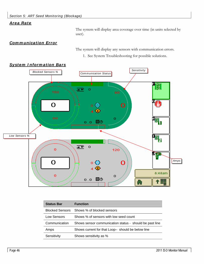
Area Rate
The system will display area coverage over time (in units selected by user).
Communication Error
The system will display any sensors with communication errors.
1. See System Troubleshooting for possible solutions.
System Information Bars
Status Bar Function
Blocked Sensors Shows % of blocked sensors
Low Sensors Shows % of sensors with low seed count
Communication Shows sensor communication status - should be past line
Amps Shows current for that Loop– should be below line
Sensitivity Shows sensitivity as %
Blocked Sensors % Communication StatusSensitivity
Low Sensors %
Amps

Section 5: ART Seed Monitoring (Blockage)
2011 ISO Monitor Manual Page 47
Loop Status
You can monitor the status of each sensor in each Loop.
1. Press the (for Loop1) or key (for Loop 2) from the Main Screen
2. The status of each sensor will be shown as follows:
Symbol Sensor Status
= Not installed
O Running
X Blocked
+ High rate
- Low rate
! Clean
Tip! Pressing the button of any sensor will display more information for that specific sensor.

Section 5: ART Seed Monitoring (Blockage)
Page 48 2011 ISO Monitor Manual
Sensor Diagnostics
You can find out information about each individual sensor by pressing the button of the sensor you wish to see on the Loop 1 or Loop 2 screen. The following information will be displayed:
Emitter Strength Shows emitter strength for all emitters
Detector Strength Shows detector strength for all detectors
SW Version Displays the software version of sensor
HW Version Displays the hardware version of sensor
Sensor # Sensor number of information
Test Button Enters test mode to simulate test seeds/second

Section 5: ART Seed Monitoring (Blockage)
2011 ISO Monitor Manual Page 49
Seed Sensor Sensitivity Values
Sensitivity Seeds/second
0 Loop is off
1 1 seed 30 seconds
5 1 seed 20 seconds
10 1 seed 10 seconds
15 1
20 7
30 17
40 27
50 44
60 80
70 148
80 281
90 539
100 1043
110 2019
120 4400
121 4800
122 5300
123 5800
124 6400
125 7000

Section 5: ART Seed Monitoring (Blockage)
Page 50 2011 ISO Monitor Manual
Blockage System Troubleshooting No loop information
The loop indicated is turned off.
To turn loop on, increase sensitivity >1
Communication error
The monitor is not detecting any sensors.
Check all the cables and connections. Bypass Sensor 1 by connecting Sensor 2 to the sensor loop cable from the main wiring harness.
If the message is no longer displayed…
…replace Sensor 1.
If the problem persists… …connect a Seed Sensor directly to the main wiring harness’ male Sensor Loop Cable.
If you get a SNR 2 ERR… …replace the Sensor Loop extension cable between the Main wiring harness and Seed Sensor 1.
Monitor is showing less sensors than installed
The monitor is reading an incorrect number of sensors.
Check all the cables and connections. Bypass the last sensor by connecting the second last sensor to the sensor loop cable to the main wiring harness.
If the message is no longer displayed…
…replace the last sensor in the loop.
If the problem persists… …connect a Seed Sensor directly to the main wiring harness.
If you get an SNR 2 ERR… …replace the main wiring harness.
If you get an SNR 1 ERR… …replace the Sensor Loop extension cable between the main wiring harness and the last Seed Sensor.
Blocked Sensor The sensor indicated is blocked.
Clean blockage from indicated run.
If the indicated run is not blocked…
…verify the Sensitivity is not set too high. Check inside the distribution towers for any foreign material. This may cause blockages to move from sensor to sensor.
If it is always the same sensor giving the blocked message…
…trade that sensor with one in another position.
If the blocked message moves with the sensor…
…replace that sensor.

Section 5: ART Seed Monitoring (Blockage)
2011 ISO Monitor Manual Page 51
The sensor indicated is blocked.
Clean blockage from indicated run.
If the indicated run is not blocked…
…verify the Sensitivity is not set too high. Check inside the distribution towers for any foreign material. This may cause blockages to move from sensor to sensor.
If it is always the same sensor giving the blocked message…
…trade that sensor with one in another position.
Blocked runs are indicated but when checked and found to be clear.
The monitor is receiving incorrect blockage information.
Verify that the Sensitivity is not set too high. Check inside the distribution towers for any foreign material. This may cause blockages to move from sensor to sensor.
If it is always the same sensor giving the blocked message…
…trade that sensor with one in another position.
If the blocked message moves with the sensor…
…replace that sensor.
Amp Overload This message indicates that there is too large a power draw on the indicated sensor loop. There is most likely a short in the Sensor Loop.
Check all the cables and connections.
Monitor displays ERROR alarms when one loop is disabled, but no alarms when both loops enabled.
Typically this means that loops are all connected but cables are crossed either going to sensor 1 or coming back from the last sensor.
Trace sensor cables from the main wiring harness to the first and last sensor of one loop. Re-connect the cables correctly.

Error! Reference source not found.
Page 52 2011 ISO Monitor Manual
Section 6: System Troubleshooting Symptom What it Means Recommended Action Amity ECU doesn’t show up on Virtual Terminal in Cab
Hitch connector not connected Check the 9-pin connector at the front of the cart and the front of the drill.
VT Pool memory has been corrupted
Delete the Pool Memory from the VT and restart the system.
Incorrect Power from Tractor Ensure there is proper power being supplied by the 9-pin connector on the Tractor.
Terminating Resistor not Installed Ensure there is a terminating resistor installed at the both ends of the ISO-Bus.
Clutch Won’t Engage Work Switch Not Engaged Ensure you are: - Moving faster than the minimum ground speed - Work switch is in the “Seeder Ready” state - Automatic Work Switch is in the “Down” position
Product 1 not enabled Product 1 needs to be enabled for the clutch to engage. Product Type not configured as
“Clutch” Ensure the product is configured as a “Clutch” on the System Settings menu.
Clutch Out of Adjustment Ensure the clutch is assembled properly to the Driveshaft. Hydraulic Motors won’t Turn Work Switch Not Engaged Ensure you are:
- Moving faster than the minimum ground speed - Work switch is in the “Seeder Ready” state - Automatic Work Switch is in the “Down” position
Product not Enabled Ensure the product you are trying to apply is enabled. Blower Hydraulics not On The blower hydraulics need to be On for the hydraulic drive
system to function. Foreign Object in the Meter Check the meter compartment and remove any foreign
objects that may be jamming the meter roll. Calibrate Buttons on the ECU don’t work (Hyd Drive)
ECU not receiving Power Ensure there is power to the ECU. The lights on the ECU should be blinking when the ECU has power.
Product not Enabled Ensure the product you are trying to apply is enabled. Blower Hydraulics not On The blower hydraulics need to be On for the hydraulic drive
system to function. Foreign Object in the Meter Check the meter compartment and remove any foreign
objects that may be jamming the meter roll. VT Pool memory has been
corrupted Delete the Pool Memory from the VT and restart the system.
Erratic Hydraulic Motor Operation
Product Configured as Clutch Ensure the “clutch” box in the System Settings menu is unchecked.
Improper Tachometer Value Ensure the “Targets per Rev” value in the Product Screen for each Bin is set to 60.
Improper Meter Door Setting for Desired Application Rate
Check the Min and Max speed range for each product. Your desired seeding speed should be in the middle of that range.
I finished my field and my meters put too much or too little product out.
Improper Width Setting Ensure the Width Setting is correct in the System Setup menu as well as in each Product Screen for each bin that’s being used.
Erroneous Calibration Value Re-calibrate your meter to ensure the calibration value being used is correct.
Ground Speed Source not Accurate Perform the Distance Check procedure to ensure the Ground Speed source is accurate.
Meter Door Setting changed without re-calibrating meter.
Calibration must be performed whenever the meter door setting is changed.
Changed to a different product type without re-calibrating meter
Calibration must be performed when you switch to a different product type.
Bin Pressurization Problem Ensure the Bin Door is fully closed and properly sealed and that the bin pressurization hose is properly installed.

Error! Reference source not found.
2011 ISO Monitor Manual Page 53
Symptom What it Means Recommended Action Ground/meter speed sensor not picking up speed or the speed reading is erratic
Improper Sensor Range Adjustment
The recommended gap setting is 1/16” (.063”) from the face of the sensor to the tip of the sprocket teeth. If the gap is out of range, adjust to bring back within specifications.
Missing or Damaged Target Replace the target sprocket if it is missing or if the teeth have been damaged. Ensure the sprocket is in proper alignment with the sensor.
Sensor Physically Damaged by Target
If the sensor was adjusted too close to the target, it will be hit and damaged. Replace the damaged sensor and check for proper range adjustment.
Damaged Sensor Mount The sensor mounting bracket holds the sensor in place so that the sensor is at the proper location and spacing from the sprocket teeth. Replace or Repair the sensor mount if it is damaged and/or if the sensor barrel does not line up with the targets.
Defective Sensor When the sensor is powered, the red light on the sensor will be on. The light will remain solid-on during operation. If the light is not on or if the light is on and the ground speed reading remains at “0” when the cart is moving, check the wiring. If the wiring is good, replace the sensor.
Defective Wiring Use a jumper wire to intermittently jump across the Signal and Ground wires (Pins 2 & 3, Orange & Blue) in the main harness to simulate the sensor in operation. If “0” speed is still shown on the display while simulating, the sensor’s signal is not getting back to the ECU and there is a bad/loose connection or a problem with the wiring. Perform steps to diagnose the harness.
Fan speed sensor not picking up speed or the speed reading is erratic
Improper Sensor Range Adjustment
The face of the sensor should be between 2mm and 4mm away from the target. If out of range, adjust to bring back within specifications.
Sensor Physically Damaged by Target
If the sensor was adjusted too close to the target, it will get hit and damaged. Replace the damaged sensor.
Defective Sensor When the sensor is powered, the red light on the sensor will be on. When the sensor senses the target, the red light will go off until the target leaves the range of the sensor. Replace sensor if defective.
Defective Wiring Use a jumper wire to intermittently jump across the Signal and Ground wires (Pins 2 & 3, Pink & Blue) in the main harness to simulate the sensor working. If “0” speed is still shown on the display while simulating, the display head is not reading the sensor and there is a problem with the wiring. Perform steps to diagnose the wire harness.
Missing or Defective Target Two 3/8” x 1/2” UNC bolts are fastened to the fan rotor and are used as targets for the speed pickup. Lock washers are used under the bolt head. Replace any missing or damaged bolts/washers.
Damaged Sensor Mount The sensor mounting bracket holds the sensor in place so that the sensor is at the proper location and spacing from the two bolts (targets) on the fan rotor. Replace or Repair the sensor mount if it is damaged and/or if the sensor barrel does not line up with the targets.

Error! Reference source not found.
Page 54 2011 ISO Monitor Manual
Symptom What it Means Recommended Action Meter-Box Proximity Sensor Not Operating Correctly
Meter Empty If the meter-empty alarm is active, check the meter to ensure the meter is empty before performing further troubleshooting.
Sensor Face Dirty If the face of the sensor has foreign material or product stuck to it, the sensor will give a false reading. Remove foreign material from the face of the sensor.
Sensor Sensitivity out of Adjustment
The light on the end of this sensor should be OFF when the meter box is empty and ON when the meter box is full of product. To properly adjust the sensitivity, empty the meter box (need to close the gate & pull the doors off), and ensure the face of the sensor is clean. Put the door back on and open the seed gate to allow product back into the meter box. With the meter box full of product, perform the following sensor adjustment: o Find the calibration screw on the rear of the sensor (next to the yellow light). Turn the screw counter-clockwise until the light turns off. If the light is already off, go to the next step. o Turn the screw clockwise until the light just turns back on. Then turn the screw 2 more full turns in the clockwise direction.
Defective Sensor Test the sensor by placing an object in-front of the sensor face. The LED light on the sensor should light up when the object is present. The LED light should be off when there is nothing in front of the sensor. The sensor needs to be connected to the harness and the monitor needs to be turned on to perform this test. Replace sensor if defective.
Defective Wiring Use a jumper wire to jump across the Signal and Ground wires (Pins 2 & 3, Violet & Blue) in the main harness to simulate a full meter. The Low-Meter alarm should activate when the sensor is unhooked and the alarm should be off when the jump-wire is used. If these alarm conditions are not observed, begin troubleshooting the wire harness.
Low-Bin Level Sensor Not Operating Correctly
Bin Empty If the low-bin alarm is active, check the bin to ensure the seed level is below the sensor before performing further troubleshooting.
Defective Sensor Test the sensor by blocking the path between the two sensor eyes. When the path is open, the low-bin alarm should be active. When the path is blocked, the low-bin alarm should be off. Replace sensor if defective.
Improper Sensor Mounting Ensure the sensor is mounted in a position where product cannot collect on the sensor.
Defective Wiring Use a jumper wire to jump across the Signal and Ground wires (Pins 2 & 3, Tan & Blue) in the main harness to simulate a low-bin level condition. If the bin alarm does not activate, begin troubleshooting the wire harness.

Section 7: Appendix
2011 ISO Monitor Manual Page 55
Section 7: Appendix
Appendix A: Connector Pinouts
ECU Signal Connectors Left Connector (Black Body) Center Connector (Grey Body) Right Connector (Blue Body) Pin # Function Pin # Pin # Function 1 Motor 1 Power 1 1 Bin 3 Signal 2 Motor 4 Power 2 2 Meter 3 Signal3 CAN Comm. High 3 3 4 Bin 1 Signal 4 4 5 Meter Box 1 Signal 5 5 6 6 6 7 Meter Box 2 Signal 7 7 8 Motor 1 Ground 8 8 9 Bin 2 Signal 9 9 10 Motor 3 Ground 10 Sensor Power (12V) 10 11 Speed Signal 11 11 12 Motor 3 Power 12 12 13 Fan 1 Signal 13 13 14 Fan 2 Signal 14 14 15 CAN Comm. Low 15 15 16 16 16 17 Tach 1 Ground 17 17 18 Tach 2 Ground 18 18 19 Tach 3 Ground 19 19 20 Tach 2 Signal 20 20 21 Tach 4 Ground 21 Sensor Ground 21 22 ECU Ground 22 22 23 ECU Power 23 23 24 Tach 1 Signal 24 24 25 Motor 2 Ground 25 25 26 Motor 2 Power 26 26 27 Tach 4 Signal 27 27 28 Tach 1 Power 28 28 29 Tach 2 Power 29 29 30 Tach 3 Power 30 30 Bin 4 Signal 31 Tach 4 Power 31 31 32 Work Signal 32 32 Meter 4 Signal33 Motor 4 Ground 33 33 34 Tach 3 Signal 34 34 35 35 35 Notes: • All connections terminated in Ampseal 35 pin plug, AMP 776164 • Each Ampseal connector has a different polarization (colour) to prevent incorrect connection

Section 7: Appendix
Page 56 2011 ISO Monitor Manual
ISO-BUS Extension Connector
Pin # Function 1 Battery Negative 2 ECU Ground 3 Battery Positive 4 ECU Power 5 TBC_DIS 6 TBC_PWR 7 TBC_RTN 8 CAN H 9 CAN L Notes: • Battery Positive and Negative on double 8AWG wiring to reduce voltage drop between battery and ECU power terminals in high
current systems. • Dust cap provided to protect connector when not in use
CAN Terminator Connector
Pin # Function A B TBC PWR C D TBC RTN E CAN H F CAN L Notes: • Connector mates with Powell TBC. TBC (CANBUS
terminating bias circuit) should only be installed at the physical end of the CANBUS system.
• Terminated in Metripack 12052848 connector (150 Series)
ECU Power Contacts
Pin # Function N/A Battery Positive (red) N/A Battery Negative (black) Notes: • #10 (M5) ring terminal connects to ECU power terminals. • Battery Positive and Negative on double 8AWG wiring to
reduce voltage drop between battery and ECU power terminals in high current systems.
• Caution! – reverse polarity power connection will damage ECU

Section 7: Appendix
2011 ISO Monitor Manual Page 57
Motor Control Connectors
Pin # Function 1 Motor Power 2 Motor Ground Notes: • Electric motor or electric over hydraulic control is possible • Terminated in Deutsch DT06-2S connector, contacts rated
to 13 amps, 16AWG wiring • Mating connector is Deutsch DT04-2P
Low-Bin Level Sensor Connectors
Pin # Function 1 Bin Power 2 Bin Signal 3 Bin Ground Notes: • Independent feedback for up to 4 bin level sensors
(infrared, capacitive proximity) • Mates directly to Agtron bin level sensors, 3rd party
sensors may require additional wiring • Terminated in Deutsch DTM06-3S connector, contacts
rated to 7 amps, 20AWG wiring • Mating connector is Deutsch DTM04-3P
Motor Speed (Tach) Connectors
Pin # Function 1 Tach Power 2 Tach Signal 3 Tach Ground Notes: • Independent feedback for up to 4 variable rate
meters/motors • Terminated in Deutsch DTM06-3S connector, contacts
rated to 7 amps, 20AWG wiring • Mating connector is Deutsch DTM04-3P
Meter Box Sensor Connectors
Pin # Function 1 Meter Power 2 Meter Signal 3 Meter Ground Notes: • Independent feedback for up to 4 additional bin level
sensors (infrared, capacitive proximity) • Mates directly to Agtron bin level sensors, 3rd party
sensors may require additional wiring • Terminated in Deutsch DTM06-3S connector, contacts
rated to 7 amps, 20AWG wiring • Mating connector is Deutsch DTM04-3P

Section 7: Appendix
Page 58 2011 ISO Monitor Manual
Ground Speed Sensor Connector
Pin # Function 1 Speed Power 2 Speed Signal 3 Speed Ground Notes: • Ground speed sensor feedback (hall effect, reed switch, inductive) • Mates directly to Agtron inductive and reed switch sensors, 3rd party sensors may require additional wiring • Wiring is common between the radar and speed sensor connections; only one speed source can be used. • Terminated in Deutsch DTM06-3S connector, contacts rated to 7 amps, 20AWG wiring • Mating connector is Deutsch DTM04-3P
Fan Sensor Connectors
Pin # Function 1 Fan Power 2 Fan Signal 3 Fan Ground Notes: • Independent feedback for up to 2 fan RPM sensors (hall effect, reed switch, inductive) • Mates directly to Agtron inductive and reed switch sensors, 3rd party sensors may require additional wiring • Terminated in Deutsch DTM06-3S connector, contacts rated to 7 amps, 20AWG wiring • Mating connector is Deutsch DTM04-3P

Section 7: Appendix
2011 ISO Monitor Manual Page 59
Anhydrous Ammonia/Liquid Control Connector
Pin # Function A Flowmeter Signal B Safety Battery Positive C Flowmeter Ground D N/A E Flowmeter Power F Shutoff Valve Ground G Rate Control Valve Negative H Rate Control Valve Positive J Shutoff Valve Power K Safety Battery Negative Notes: • Terminated in Metripack 150 series 10 pin receptacle • Mates directly to Micro-Trak harness part number 13273. • Adaptors for the Raven Accu-Flow system available.

Section 7: Appendix
Page 60 2011 ISO Monitor Manual
Appendix B: Metric Conversion Factors
To convert from English to Metric measurements, multiply by the following factors.
To Convert To Multiply By
Inches Millimeters 25.4
Feet Meters 0.3048
Yards Meters 0.9144
Miles Kilometers 1.609
Square Foot Square Meters 0.0929
Acres Hectares 0.4047
Pounds Kilograms 0.4536
Cubic foot Cubic Meter 0.02832
Bushels Cubic Meters 0.03524
Pounds/Square Inch Kilopascals 6.8948
Pounds/Square Inch Bar 0.06895
Pounds-Force-Foot Newton-Meters 1.3568
Miles-Per-Hour Kilometers-Per-Hour 1.609
Pounds-Per-Acre Kilograms-Per-Hectare 1.1209
Acre-Per-Hour Hectare-Per-Hour 0.405
Feet-Per-Minute Meters-Per-Second 0.005
Feet-Per-Second Meters-Per-Second 0.305
Horsepower Kilowatt 0.746
27 in. of Water =1 psi
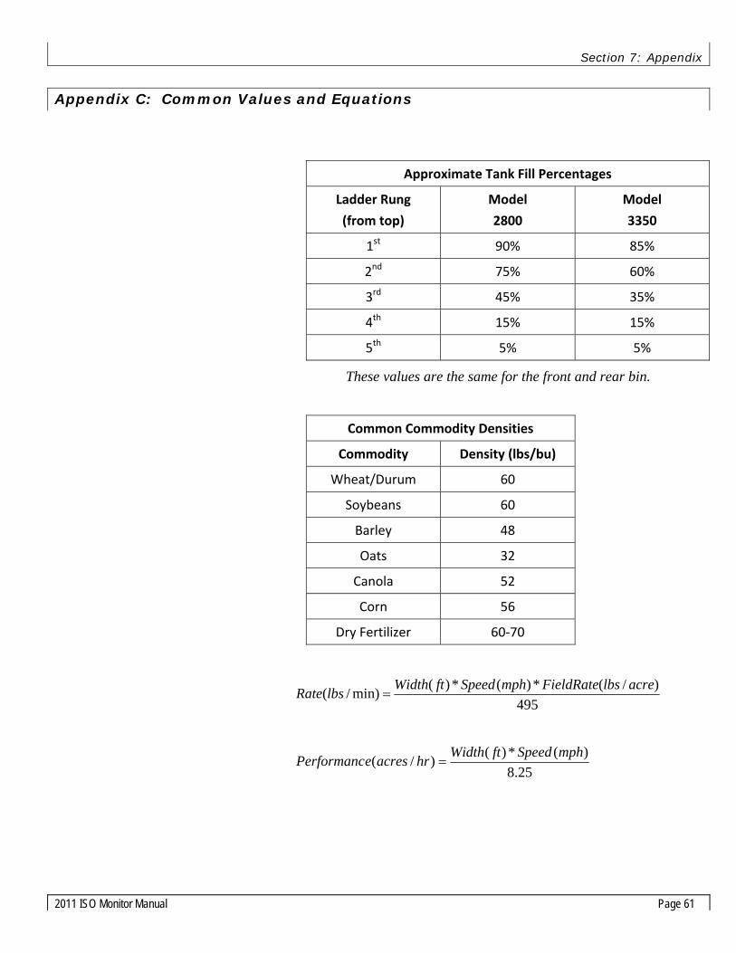
Section 7: Appendix
2011 ISO Monitor Manual Page 61
Appendix C: Common Values and Equations
Approximate Tank Fill Percentages
Ladder Rung
(from top)
Model
2800
Model
3350
1st 90% 85%
2nd 75% 60%
3rd 45% 35%
4th 15% 15%
5th 5% 5%
These values are the same for the front and rear bin.
Common Commodity Densities
Commodity Density (lbs/bu)
Wheat/Durum 60
Soybeans 60
Barley 48
Oats 32
Canola 52
Corn 56
Dry Fertilizer 60‐70
495)/(*)(*)(min)/( acrelbsFieldRatemphSpeedftWidthlbsRate =
25.8)(*)()/( mphSpeedftWidthhracresePerformanc =

Section 7: Appendix
Page 62 2011 ISO Monitor Manual
This Page Left Intentionally Blank

Section 7: Appendix
2011 ISO Monitor Manual Page 63
Appendix D: ICON Glossary
Alarms
Aux low
Bin low
Clutch overload
Fan high
Fan low
Fan off
Ground Speed high
Ground Speed low
Low Battery Voltage
RPM high
RPM low
RPM off
RPM overload
Seed flow block
Seed flow clean
Seed flow com
Seed flow high
Seed flow low
Seed flow overload
Internal communication error
Liquid/nh3 high
Liquid/nh3 low
Liquid/nh3 off
Liquid/nh3 overload

Section 7: Appendix
Page 64 2011 ISO Monitor Manual
Soft Keys
Home
Work switch
Products 1‐5
Default calibration
Sensor calibration
Seed flow
Calibration
Liquid/nh3 override
Product calibration
Liquid/nh3
Product on/off
Product override
Seed flow loop 1
Seed flow loop 2
Liquid/nh3 purge
2 product ground drive Default Cal
2 product hydraulic drive Default Cal
3 product hydraulic drive Default Cal

Section 7: Appendix
2011 ISO Monitor Manual Page 65
Home Screen ( ) Fan 1
Fan 2
Work switch off
Work switch on
Seeder down
Seeder up
Low bin
Low aux
Variable rate low
Variable rate high
GPS speed
Ground speed
Radar speed
Test speed
Area 1
Area 2

Section 7: Appendix
Page 66 2011 ISO Monitor Manual
Product Screen ( ) Desired product rate
Actual product rate
Product Width
Total bin volume
Product weight/volume (Test Weight)
Product weight remaining in bin
Bin fill percentage
Accumulated weight
Accumulated product weight
Minimum meter RPM
Maximum meter RPM
Meter calibration RPM
Targets per revolution
Duty cycle
Overload
Percent error
Target meter RPM
Actual meter RPM
Accumulated revolutions
Product weight per revolution
Accumulated product weight
Minimum speed
Maximum speed
Accumulated weight
Accumulated product weight
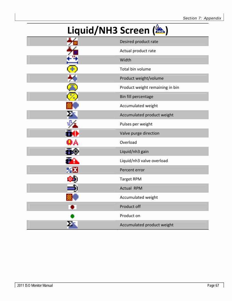
Section 7: Appendix
2011 ISO Monitor Manual Page 67
Liquid/NH3 Screen ( ) Desired product rate
Actual product rate
Width
Total bin volume
Product weight/volume
Product weight remaining in bin
Bin fill percentage
Accumulated weight
Accumulated product weight
Pulses per weight
Valve purge direction
Overload
Liquid/nh3 gain
Liquid/nh3 valve overload
Percent error
Target RPM
Actual RPM
Accumulated weight
Product off
Product on
Accumulated product weight

Section 7: Appendix
Page 68 2011 ISO Monitor Manual
System Setup Screen ( ) Width
Speed cal
Minimum speed
Test speed
Distance check
Distance zero
Area total
Area life
Fan targets
Fan high RPM
Fan low RPM
Product Enable
Clutch drive enable
Task controller type
Task controller tank select
Liquid/nh3 enable
X offset
Sensor Calibration Screen ( )
Low‐Bin Sensor
Empty Meter Box Sensor
Fan Sensor
Ground Speed Sensor
No Sensor Installed
Regular Sensor Logic
Inverted Sensor Logic

Section 7: Appendix
2011 ISO Monitor Manual Page 69
Notes:

Section 7: Appendix
Page 70 2011 ISO Monitor Manual
Notes: