© 2011 pella corporation installation instruction … · installation instruction entry door with...
TRANSCRIPT

Installation Instructions for Typical Wood Frame Construction.
These instructions were developed and tested for use with typical wood frame wall construction in a wall system designed to manage water. These instructions are not to be used with any other construction method. Installation instructions for use with other construction methods, multiple units or bow and bay windows, may be obtained from Pella Corporation or a local Pella retailer, or by visiting http://www.pella.com. Building designs, construction methods, building materials, and site conditions unique to your project may require an installation method different from these instructions and additional care. Determining the appropriate installation method is the responsibility of you, your architect, or construction professional.
Always read the Vinyl Window and Door Limited Warranty before purchasing or installing Vinyl Windows and Doors manufactured by Pella Corporation. By installing this product, you are acknowledging that this Limited Warranty is part of the terms of the sale. Failure to comply with all Pella installation and maintenance instructions may void your Pella product warranty. See Limited Warranty for complete details at http://warranty.pella.com.
Part Number: 819Y0101
INSTALLATION INSTRUCTION ENTRY DOOR WITH EXTERIOR CLAD TRIM IN REPLACEMENT APPLICATIONS
© 2011 Pella Corporation
REMEMBER TO USE APPROPRIATE PERSONAL PROTECTIVE EQUIPMENT.
Sill Flashing Tape #2Sill Flashing Tape #1
Sill Support
Clad Brickmould
Sill

YOU WILL NEED TO SUPPLY: TOOLS REQUIRED:
Composite or Impervious shims/spacers (12 to 20)Pella® SmartFlash™ foil backed butyl window and door flashing tape or equivalentHead flashing (if none exists)Exterior sealant: High quality exterior grade polyurethane sealant (2-3 tubes per door)Recommended: #6 x 1-1/2" (minimum) Corrosion Resistant Wood ScrewsAlternate: 1-1/2" Galvanized roofing nails (Note: If using roofing nails, each nailing location must be pilot drilled to prevent cracking of installation fin)Backer rodGreat Stuff ™ Window and Door Insulating Foam Sealant by the Dow Chemical Company or equivalent low pressure polyurethane window and door foam DO NOT use high pressure or latex foams. Pella aluminum sill support or wood blocking
Tape measureLevelHammerScissors or Utility knifeSealant gun
Screwdrivers (#2 Phillips & Flat blade)Drill and drill bits
T20 Torx wrench (used w/ adjustable hinges)Reciprocating sawNipper PliersPry BarPutty knifeWood chisel
1 REMOVE THE EXISTING DOOR
Installation will require two or more persons for safety reasons.
Caution: Many doors in older homes are painted with lead-based paint. Removal of old doors may disturb this paint. Proper precautions must be taken to minimize exposure to dust and debris. Consult state or local authorities for more information.
Note: Remove the new door from its packaging. Inspect and measure the new door to confirm it will fit into the opening prior to removing existing door. Rough opening should be at least 3/4" wider and 3/8" taller than the door frame. The exterior siding/wall cladding should be approximately 1/2" wider and 1/4" taller than the door installation fin (door width measurement use outer most edges of jamb installation fin, door height measurement use upper most edge of head fin to door frame sill).
A. Score paint or varnish between the interior trim and the wall with a sharp utility knife.
Note: This will minimize the damage to the interior wall and trim.
B. Remove the interior trim. Using a pry bar and block of wood, remove the interior trim from all three sides of the door and at the sill if present. If the interior trim is being reused, pull the nails out through the back side of the board with nipper pliers.
C. Cut the exterior sealant line between the exterior brickmould or trim and the exterior siding or wall cladding.
1B
1A
Interior

2 OPENING PREPARATIONA. Clean the opening and repair/replace any rotted or
damaged wood. Trim any house wrap extending into the rough opening flush with the rough opening.
B. Applications with weather resistive barrier and head flashing, do not tape weather resistive barrier to rough opening (see Step 3B for proper head flashing installation). All other applications, cut a piece of flashing tape to the width of the rough opening. Apply tape to the head rough opening running the entire width of the opening (does not need to extend onto the jambs). Overlap head tape onto the exterior wall extending to the exterior siding or approximately 1". If weather resistive barrier exists, overlap tape onto the weather barrier sealing to the rough opening.
C. Apply sill flashing tape #1. Cut a piece of flashing tape 12" longer than the opening width. Apply at the bottom of the opening as shown so it overhangs 1" to the exterior.
Note: The tape is cut 12" longer than the width so that it will extend 6" up each side of the opening.
D. Tab the sill flashing tape and fold. Cut 1" wide tabs at each corner (1/2" from each side of corner) (2C). Fold tape to the exterior and press firmly to adhere it to the water resistive barrier.
E. Apply sill flashing tape #2. Cut a piece of flashing tape 12" longer than the opening width. Apply at the bottom, overlapping tape #1 by at least 1". DO NOT allow the tape to extend past the interior face of the framing. If the wall depth is greater than 5", add a third piece of flashing tape. The flashing tape should come to within 1" of the interior face of the framing.
Note: The flashing tape does not need to extend all the way to the interior of the framing.
F. When required for adequate sill support, attach the optional aluminum sill support or wood blocking to the exterior of the box plate to support the edge of the door sill. Place the sill support flush with the subfloor.
1" 2E
1"
1/2"
1/2"
6" 2C
2E
D. Remove the exterior brickmould or flat trim using a pry bar and block of wood.
Caution: Some doors may come out of the opening as the exterior trim is removed.
E. Remove the door frame using a pry bar if necessary.
1 REMOVE THE EXISTING DOOR (CONTINUED)
2F
1D
Exterior
1"
2B

2 OPENING PREPARATION (CONTINUED)Optional Sill Pan Instructions:
G. Cut the sill pan to the width of the rough opening plus 2".
Note: The 2" added onto the rough opening width is for a 1" bend on each end.
H. Make a 1" cut in each fold at both end of the sill pan.
Note: These cuts will allow the edges of the sill pan to be bent.
Note: 4-5/8" wide for Out-Swing and In-Swing for 4-9/16" wall condition. For other wall conditions, measure wall depth and add 1/16".
I. Cut 1" off each end of the interior sill pan lip.
J. Bend each end of the sill pan upwards.
K. Install the sill pan by sliding into place until the exterior sill pan lip is flush with the exterior of the rough opening.
L. Apply sill flashing tape. Cut a piece of flashing tape 2" longer than the opening width. Apply at the bottom of the opening, covering the exterior sill pan lip as shown.
Note: If applicable, apply spray adhesive to building felt prior to applying the flashing tape.
M. Cut two 9" pieces of flashing tape with a 1-1/2" x 3" tab at the bottom, on opposite corners as shown.
N. Apply the tabbed 9" pieces of flashing tape. The tape is applied so 1-1/2" will cover the inside of the rough opening and lap over the side flange of the sill pan. The 1-1/2" x 3" tab laps over the bottom flashing tape as shown.
O. Cut two 6" pieces of flashing tape and apply to each side of the rough opening, overlapping the first piece by 1" and lapping the bottom over the side flange of the sill pan as shown.
ExteriorEXTERIOR SILL PAN LIP
Install flush against exterior rough opening.
EXTERIOR SILL PAN LIP
EXTERIOR SILL PAN LIPFlashing TapeWeather Barrier
Weather Barrier
2K
2L
INTERIOR SILL PAN LIP
EXTERIOR SILL PAN LIP
1L
INTERIOR SILL PAN LIP
EXTERIOR SILL PAN LIP
1" 1K2I
2J
INTERIOR SILL PAN LIP
EXTERIOR SILL PAN LIP 1"
1"
Variable
1J
1"
2H
EXTERIOR SILL PAN LIP Flashing Tape 1-1/2"
1-1/2" Side Flange 9"
EXTERIOR SILL PAN LIPFlashing Tape
1"
1-1/2"
1-1/2"
9"
2N 2O
9"
3"
Tabs
3"
1-1/2"
9"
1O
1-1/2"Tabs
1-1/2"
1-1/2"
9"
3"
2M
2 OPENING PREPARATION (CONTINUED)
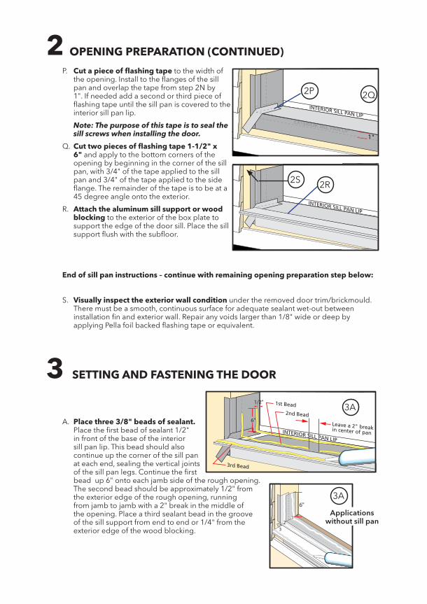
P. Cut a piece of flashing tape to the width of the opening. Install to the flanges of the sill pan and overlap the tape from step 2N by 1". If needed add a second or third piece of flashing tape until the sill pan is covered to the interior sill pan lip.
Note: The purpose of this tape is to seal the sill screws when installing the door.
Q. Cut two pieces of flashing tape 1-1/2" x 6" and apply to the bottom corners of the opening by beginning in the corner of the sill pan, with 3/4" of the tape applied to the sill pan and 3/4" of the tape applied to the side flange. The remainder of the tape is to be at a 45 degree angle onto the exterior.
R. Attach the aluminum sill support or wood blocking to the exterior of the box plate to support the edge of the door sill. Place the sill support flush with the subfloor.
3 SETTING AND FASTENING THE DOOR
12
3
6"3A
EXTERIOR SILL PAN LIP
INTERIOR SILL PAN LIP
2nd Bead
Leave a 2" break in center of pan
1st Bead
3rd Bead
3A 6"
1/2"3A
Applications without sill pan
End of sill pan instructions – continue with remaining opening preparation step below:
S. Visually inspect the exterior wall condition under the removed door trim/brickmould. There must be a smooth, continuous surface for adequate sealant wet-out between installation fin and exterior wall. Repair any voids larger than 1/8" wide or deep by applying Pella foil backed flashing tape or equivalent.
EXTERIOR SILL PAN LIP
INTERIOR SILL PAN LIP
1"
EXTERIOR SILL PAN LIP
INTERIOR SILL PAN LIP
2P 2Q
2R2S
A. Place three 3/8" beads of sealant. Place the first bead of sealant 1/2" in front of the base of the interior sill pan lip. This bead should also continue up the corner of the sill pan at each end, sealing the vertical joints of the sill pan legs. Continue the first bead up 6" onto each jamb side of the rough opening. The second bead should be approximately 1/2" from the exterior edge of the rough opening, running from jamb to jamb with a 2" break in the middle of the opening. Place a third sealant bead in the groove of the sill support from end to end or 1/4" from the exterior edge of the wood blocking.

C. Place a continuous 3/8" bead of sealant on the weather barrier (or sheathing if weather barrier is not present) along the jambs and head, approximately 1/2" from the rough opening edge.
1/2"
TWO OR MORE PEOPLE ARE REQUIRED FOR THE FOLLOWING STEPS
D. Insert the door from the exterior of the building. DO NOT slide the bottom of the door into the opening. (Sliding will damage the sealant lines.) Place the bottom of the door at the bottom of the opening, then tilt the top into position. Center the door between the sides of the opening to allow clearance for shimming, and insert one screw on each end of the top installation fin, approximately 2" from each fin end. These are used to hold the door in place while shimming it plumb and square.
3D
3C
B. Install head flashing where possible, apply sealant to the back of the flashing and slide the flashing under any existing weather resistive barrier.
3 SETTING AND FASTENING THE DOOR (CONTINUED)
HEAD

E. Plumb and square door. Place shims at each hinge and lock strike location between the door and the sides of the opening. Trim the shims so they are recessed back 1/4" - 1/2" from the interior face of the door frame. Insert shims in other locations as needed starting up 6" from the bottom of the door to square it in the opening. Make sure the frame to panel reveal is equal from top of jamb to bottom, one end of the head to the other and one end of the sill to the other. (Reveal on the hinge side may be tighter than the head, lock jamb and sill.)
Note: On center latch double doors the lock strike will not be shimmed since it is located in the center of the unit. DO NOT over shim.
F. Check the interior reveal. Make sure the measurement from the interior face of the door to the interior face of the wall is equal at several points around the door.
3 SETTING AND FASTENING THE DOOR (CONTINUED)
Interior1
2 0 3 0 4 0 5 0 6 0 7 0
23
INCHESmm
3E
3F
G. Fasten the door to opening by driving screws in the installation fin, approximately 2" from each end of fins and drive the remaining screws on each X mark. (Locating on these marks will ensure proper wet-out of the sealant).
NOTE: If alternate attaching method of roofing nails is used, pilot drill fin at each attachment point to prevent cracking of the installation fin.
H. Carefully open the door panels and remove all shipping spacers.
Note: Be sure to remove the spacers from the bottom edge of the door panel.
I. With multi-point lock: Use the construction handle to operate the active door handle. Operate the flushbolts per the instructions on the label on the strike located on the astragal.
J. For combinations (multi-wide), pre-drill through the frame head and sill as shown and insert #8 x 3" corrosion resistant screws 3" and 6" from each jamb at the mullion. For masonry applications, use a 3/16" masonry screw.
OUTSWING INSWING
Vent PlacementFixed PlacementVent Placement
Fixed Placement
Fixed and Vent Placement Vent Placement
Fixed Placement
3J
K. For Low Profile Sills: Through each installation screw hole drill a 1/8" pilot; and install a #8 x 3" corrosion resistant screw (provided) into the pilot hole into the floor. For doors including a standard lock install tubs per instruction included with the sill strike package.
Note: For concrete floors use masonry screws that are a minimum size of 3/16" diameter x 2" and pilot per manufacturer’s recommendations for the screw.
L. For double doors only: Remove sill strike shipping spacer. Remove sill strike screws from the sill strike located on the door sill. Place a dab of sealant into the two sill strike holes and install the two #12 x 2-1/2" flat head corrosion resistant screws (provided) into the holes.
M. For double doors only: Shim between the frame and the rough opening at the head strike location and at every frame anchor hole location. Trim all shims back 1/4" - 1/2" from the interior face of the door frame. Remove and replace head strike screws with two #12 x 2-1/2" corrosion resistant screws (provided) through the head strike, door frame, shims and into the rough opening.
Note: For doors with no head strike check head for pre-drilled installation holes. If installation holes are present drill 1/8" pilot in each installation hole and install a #8 x 3" corrosion resistant screw (provided) in each hole.
N. On each hinge, drill an 1/8" pilot hole through each open screw hole going through the shims and into the structural framing. Starting at the top, insert a corrosion resistant screw (#8 x 3" screw, provided) into the open screw hole.
Note: Does not apply if a sidelight is mulled to the hinge side of the vent door.
3 SETTING AND FASTENING THE DOOR (CONTINUED)
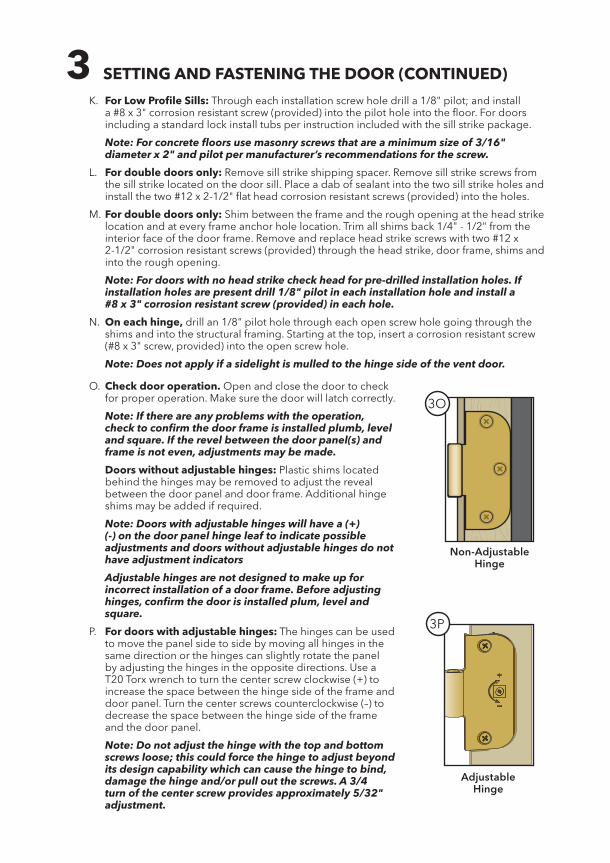
O. Check door operation. Open and close the door to check for proper operation. Make sure the door will latch correctly.
Note: If there are any problems with the operation, check to confirm the door frame is installed plumb, level and square. If the revel between the door panel(s) and frame is not even, adjustments may be made.
Doors without adjustable hinges: Plastic shims located behind the hinges may be removed to adjust the reveal between the door panel and door frame. Additional hinge shims may be added if required.
Note: Doors with adjustable hinges will have a (+)(-) on the door panel hinge leaf to indicate possible adjustments and doors without adjustable hinges do not have adjustment indicators
Adjustable hinges are not designed to make up for incorrect installation of a door frame. Before adjusting hinges, confirm the door is installed plum, level and square.
P. For doors with adjustable hinges: The hinges can be used to move the panel side to side by moving all hinges in the same direction or the hinges can slightly rotate the panel by adjusting the hinges in the opposite directions. Use a T20 Torx wrench to turn the center screw clockwise (+) to increase the space between the hinge side of the frame and door panel. Turn the center screws counterclockwise (–) to decrease the space between the hinge side of the frame and the door panel.
Note: Do not adjust the hinge with the top and bottom screws loose; this could force the hinge to adjust beyond its design capability which can cause the hinge to bind, damage the hinge and/or pull out the screws. A 3/4 turn of the center screw provides approximately 5/32" adjustment.
Non-Adjustable Hinge
3O
Adjustable Hinge
3P
3 SETTING AND FASTENING THE DOOR (CONTINUED)
2"
1"
2"
1/2"
3R 3S
3T 3U
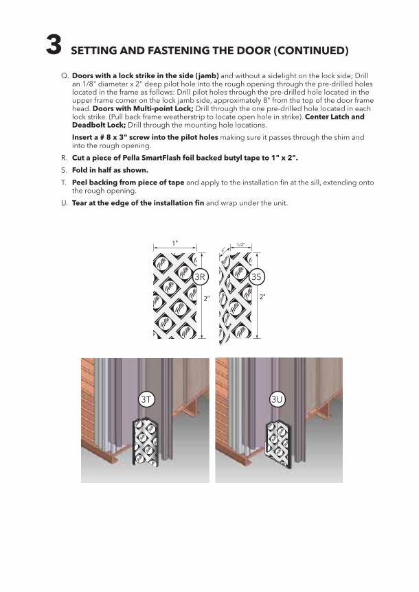
Q. Doors with a lock strike in the side (jamb) and without a sidelight on the lock side; Drill an 1/8" diameter x 2" deep pilot hole into the rough opening through the pre-drilled holes located in the frame as follows: Drill pilot holes through the pre-drilled hole located in the upper frame corner on the lock jamb side, approximately 8" from the top of the door frame head. Doors with Multi-point Lock; Drill through the one pre-drilled hole located in each lock strike. (Pull back frame weatherstrip to locate open hole in strike). Center Latch and Deadbolt Lock; Drill through the mounting hole locations.
Insert a # 8 x 3" screw into the pilot holes making sure it passes through the shim and into the rough opening.
R. Cut a piece of Pella SmartFlash foil backed butyl tape to 1" x 2".
S. Fold in half as shown.
T. Peel backing from piece of tape and apply to the installation fin at the sill, extending onto the rough opening.
U. Tear at the edge of the installation fin and wrap under the unit.

4 BRICKMOULD ATTACHMENT
A. Remove brickmould from packaging and place on a large, flat area positioning parts in the correct orientation.
B. Attach the head part to the jambs using the provided screws (#6 x 11/16").
5 SEALING THE DOOR TO THE EXTERIOR WALL CLADDING
Note: The sealant details shown are standard recommendations from the sealant industry. Contact your sealant supplier for recommendations and instructions for these and any other applications.
A. Insert backer rod in the space around the door deep enough to provide at least a 1/2" clearance between the backer rod and the brickmould.
Note: Backer rod adds shape and depth for the sealant line.
B. Apply a bead of high quality exterior grade sealant to the entire perimeter of the door.
C. Apply a bead of sealant between the exterior edge of the sill and the sill support.
D. Shape, tool and clean excess sealant.
Note: This method creates a more flexible sealant line capable of expanding and contracting.
5A
5B
4A
4B
C. Apply the clad brickmould assembly to the unit by pressing it onto the barbs located on the fin.
Note: Use a hammer and a block of wood to assist in seating the brickmould onto the barbs. When fully seated the brickmould should be touching the door frame.
D. Adjust the mitered corners as necessary.
4C

Caution: Ensure use of low pressure polyurethane window and door installation foams and strictly follow the foam manufacturer’s recommendations for application. Use of high pressure foams or improper application of the foam may cause the door to bow and hinder operation.
A. Add a sealant bead across the inner sill and 6" up each jamb between the frame and rough opening.
B. Apply insulating foam. From the interior, insert the nozzle of the applicator approximately 1" deep into the space between the door and the rough opening and apply a 1" deep bead of foam. This will allow room for expansion of the foam and will minimize squeeze out. Apply sealant across the interior surface of shims to create a continuous seal. For doors with jamb extensions installed, ensure the foam is placed between the door frame and the rough opening, not between the jamb extension and the rough opening. Follow foam manufacturer's instructions.
Note: It may be necessary to squeeze the end of the tube with pliers to insert it into the space between the door frame and the rough opening. DO NOT completely fill the space from the back of the brickmould to the interior face of the opening.
C. Check the door operation by opening and closing the door.
Note: If the door does not operate correctly, check to make sure it is still plumb, level, square and that the sides are not bowed. If adjustments are required, remove the foam with a serrated knife. Adjust the shims and reapply the insulating foam sealant.
6 INTERIOR SEAL
Interior
6"
6B
6A
FINISHING INSTRUCTIONS
Paint or finish immediately after installation.Note: DO NOT paint, stain or finish weather strip or vinyl parts! If paint, stain or finish gets on the weather stripping, wipe it off immediately with a damp cloth. To maintain proper product performance, do not remove weather strip, foam corner seal wedges or gaskets. Air and water leakage may result if these factory-installed items are removed. After finishing, allow doors to dry completely before closing them. Pella will not be responsible for finishing imperfections. The use of unapproved finishes, solvents or cleaning chemicals may cause adverse reactions with door materials. Pella will not be responsible for problems caused by the use of unapproved materials. If in doubt, contact your local retailer or representative.
Use of inappropriate finishes, solvents, brickwash or cleaning chemicals will cause adverse actions with window and door materials and voids the Limited Warranty.
Care and maintenance information is available in the Pella Owner's Manual. You can obtain an owner's manual by contacting your local Pella retailer. This information is also available on www.pella.com.
Factory Prefinished Panels: A door panel that has been prefinished with stain or paint from the factory requires no additional finishing. Clean the surface with mild soap and water. DO NOT use a brasives. DO NOT scrape or use tools that might damage the surface.

Clad Exterior Frame:The exterior frame is protected by aluminum cladding with our tough EnduraClad baked-an-factory finish that needs no painting. Clean this surface with mild soap and water. DO NOT use abrasives. DO NOT scrape or use tools that might damage the surface.
Panel Cleaning and Prep Instructions for Unfinished or Primed Panels:Dry wipe dust from doors gently. Examine door for possible smudges or fingerprints made from normal handling or construction. To remove smudges, lightly wipe surface with warm water. DO NOT sand surface of fiberglass panel. Scuff sand with light grade sand paper or abrasive pad (220 grit or higher). Rinse surface with mineral spirits for fiberglass panels and warm water for steel panels. Let door and side light surfaces dry completely before applying finish. Finish the door panels as soon as possible after installation.
Staining fiberglass panels or unfinished interior frame members:Fiberglass door and sidelight panels may be stained with a gel stain if a wood look is desired. Pella offers stain kits in a variety of colors. Apply and finish per the stain kit manufacturer's instruction. Ensure that all exposed pane l edges are finished to minimize the chance of damage. Unprimed interior frame parts may be stained with wood stains and should be finished with a minimum of two coats of a clear polyurethane finish. DO NOT bridge the top coat between the outer edge of the glazing frame and t he door panel.
Note: The fiberglass base color tone will vary, This variance is normal and will not impact the stain color of the door.
Painting Instructions:Wood door frame exteriors premium steel door panels, sidelights are factory primed. If a paint finish is desired, finish the parts with two coats of a 100% latex paint that has a good blocking resistance. On units with glass, DO NOT bridge paint between the outer edges of the glazing frame and the door panel. On fiberglass products, brush the paint in the same direct ion as the simulated wood grain. Ensure that all exposed panel edges a refinished to minimize the chance of panel damage.
Failure to use the correct type of finish may result in a door that sticks shut. Ask a qualified paint professional to specify a product with good blocking resistance.
FINISHING INSTRUCTIONS (CONTINUED)