2011 sulfur symposium environmental and safety forum ...€¦ · 2011 sulfur recovery symposium...
TRANSCRIPT
2011 Sulfur Recovery Symposium Environmental and Safety Forum
September 14, 2011
2011 Sulfur Recovery Symposium
Sonnenalp Resort, Vail, Colorado

9/4/2011
1
The information, practices and techniques di d i thi t ti ifi t
Disclaimer:
discussed in this presentation are specific to the Houston Refining, LP’s Houston, Texas Refinery or other unspecified facilities. Houston Refining, LP does not claim that this information, practices and techniques will be successful in their use at other sulfur recovery facilities. LyondellBasell is not responsible for the successful or unsuccessful application of the information in this presentation. The use of the information is done so at the user’s own risk
2011 Sulfur Recovery Symposium, Vail Colorado September 12-16, 2011
risk.
1
2011 Sulfur Recovery Symposium Regulatory UpdateRegulatory Update
September 14, 20112011 Sulfur Recovery SymposiumSonnenalp Resort, Vail, Colorado
By: Philip J. Oberbroeckling, P.E.
2011 Sulfur Recovery Symposium, Vail Colorado September 12-16, 2011 2
Consulting EngineerTechnical Assurance - Process DesignHouston Refining LPA LyondellBasell Company
Environmental and Safety Forum
2011 Sulfur Recovery Symposium
9/4/2011
2
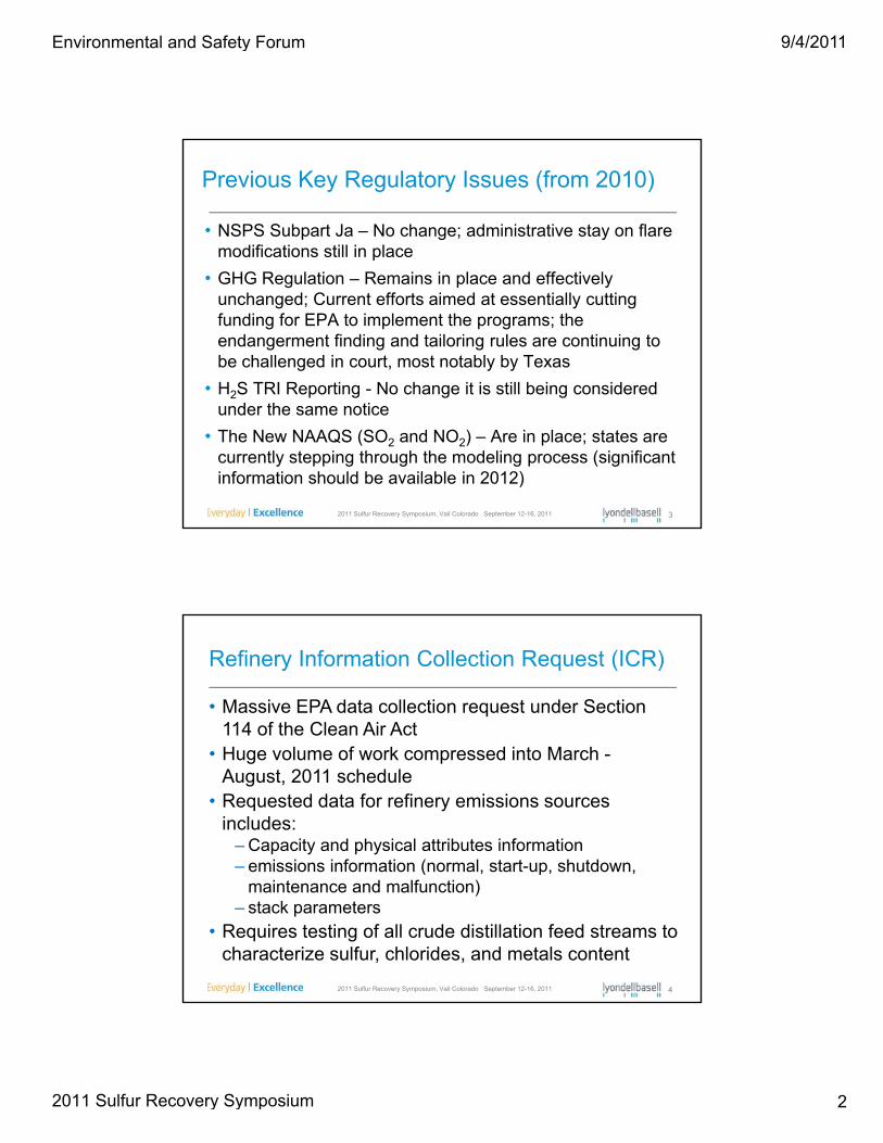
Previous Key Regulatory Issues (from 2010)
• NSPS Subpart Ja – No change; administrative stay on flare modifications still in place
• GHG Regulation – Remains in place and effectively unchanged; Current efforts aimed at essentially cutting funding for EPA to implement the programs; the endangerment finding and tailoring rules are continuing to be challenged in court, most notably by Texas
• H2S TRI Reporting - No change it is still being considered
2011 Sulfur Recovery Symposium, Vail Colorado September 12-16, 2011 3
under the same notice
• The New NAAQS (SO2 and NO2) – Are in place; states are currently stepping through the modeling process (significant information should be available in 2012)
Refinery Information Collection Request (ICR)
• Massive EPA data collection request under Section 114 of the Clean Air Act
• Huge volume of work compressed into March -August, 2011 schedule
• Requested data for refinery emissions sources includes:
– Capacity and physical attributes information– emissions information (normal, start-up, shutdown,
2011 Sulfur Recovery Symposium, Vail Colorado September 12-16, 2011 4
( , p, ,maintenance and malfunction)
– stack parameters
• Requires testing of all crude distillation feed streams to characterize sulfur, chlorides, and metals content
Environmental and Safety Forum
2011 Sulfur Recovery Symposium
9/4/2011
3
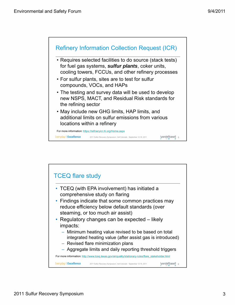
Refinery Information Collection Request (ICR)
• Requires selected facilities to do source (stack tests) for fuel gas systems, sulfur plants, coker units, cooling towers FCCUs and other refinery processescooling towers, FCCUs, and other refinery processes
• For sulfur plants, sites are to test for sulfur compounds, VOCs, and HAPs
• The testing and survey data will be used to develop new NSPS, MACT, and Residual Risk standards for the refining sector
2011 Sulfur Recovery Symposium, Vail Colorado September 12-16, 2011 5
g
• May include new GHG limits, HAP limits, and additional limits on sulfur emissions from various locations within a refinery
For more information: https://refineryicr.rti.org/Home.aspx
TCEQ flare study
• TCEQ (with EPA involvement) has initiated a comprehensive study on flaring
• Findings indicate that some common practices may reduce efficiency below default standards (over steaming, or too much air assist)
• Regulatory changes can be expected – likely impacts:– Minimum heating value revised to be based on total
2011 Sulfur Recovery Symposium, Vail Colorado September 12-16, 2011 6
Minimum heating value revised to be based on total integrated heating value (after assist gas is introduced)
– Revised flare minimization plans– Aggregate limits and daily reporting threshold triggers
For more information: http://www.tceq.texas.gov/airquality/stationary-rules/flare_stakeholder.html
Environmental and Safety Forum
2011 Sulfur Recovery Symposium

9/4/2011
4
Cross-State Air Pollution Rule (CSAPR)
• Rule was finalized on July 6, 2011 and published in the Federal Register on August 8, 2011(76 FR g g (48208)
• This is a replacement for the Clean Air Interstate Rule which regulates electric utilities
• This rule requires 28 states to significantly i i lit b d i l t
2011 Sulfur Recovery Symposium, Vail Colorado September 12-16, 2011 7
improve air quality by reducing power plant emissions that contribute to ozone and/or fine particle pollution in other states
Cross-State Air Pollution Rule
2011 Sulfur Recovery Symposium, Vail Colorado September 12-16, 2011 8
States controlled for both fine particulates (annual SO2 and NOX) and ozone (ozone season NOX) (21 states)
States controlled for fine particulates only (annual SO2 and NOX) (2 states)
States controlled for ozone only (ozone season NOX) (5 states)
States not covered by the Cross-State Air Pollution Rule
Environmental and Safety Forum
2011 Sulfur Recovery Symposium

9/4/2011
5
Cross-State Air Pollution Rule (CSAPR)
• The rule implements massive reductions in SO2
emissions in a very short time frame (starting January 1 2012) h t th t t it t ibl1, 2012) – so short that most sites cannot possibly install controls in time to meet limits
• As a result, many utilities will have to look to fuel switching in 2012 and 2013 to try to minimize penalties
• Oil, pet coke-fired and coal utility boilers and power plants will be looking for lower sulfur versions or
2011 Sulfur Recovery Symposium, Vail Colorado September 12-16, 2011 9
plants will be looking for lower sulfur versions or alternatives to their regular fuel
• Many utilities are looking at switching to NG-fired unitsFor more information: http://www.epa.gov/airtransport/
H.R. 1204 – The BREATHE Act
BREATHE = Bringing Reductions to Energy’s Airborne Toxic Health Effects
I t d d t C M h 17 2011• Introduced to Congress on March 17, 2011• Amend the Clean AIR Act to:
– Eliminate the exemption for aggregation of emissions from oil and gas development sources
– List H2S as a hazardous air pollutant (HAP) in Section 112
• Forces improved emissions controls on small oil and gas production facilities
2011 Sulfur Recovery Symposium, Vail Colorado September 12-16, 2011 10
production facilities• Will force MACT type controls for sources of H2S emissions• Supported by: Alaska Wilderness League, Center for Biological Diversity,
Earthjustice, Earthworks, Natural Resources Defense Council, Sierra Club, The Wilderness Society
For more information: http://polis.house.gov/Legislation/hr1204.htm
Environmental and Safety Forum
2011 Sulfur Recovery Symposium
9/4/2011
6
Proposed NSPS Subpart OOOO
• EPA Administrator signed the proposed New Source Performance Standards (NSPS) regulations on July 28, 2011
• Impacts onshore oil and gas processing and transmission and• Impacts onshore oil and gas processing and transmission and storage facilities
• Natural gas plant regulations NSPS Subparts KKK and LLL are revised and consolidated in the new regulations
• New regulations impacts:– Increase the SO2 emissions control efficiency to 99.9% for NG
sulfur recovery units > 5 tpd feed rate with H2S content 50%
2011 Sulfur Recovery Symposium, Vail Colorado September 12-16, 2011 11
– Add leak detection and repair (LDAR) programs for fugitive emissions
– Storage tanks with 1 BPD condensate throughput or 20 BPD crude throughput must have 95% Vapor recovery efficiency or flare controlled
Claus Unit Over Pressure Protection(Proper Design Basis and NFPA Considerations)( p g )
September 14, 20112011 Sulfur Recovery SymposiumSonnenalp Resort, Vail, Colorado
By: Philip J. Oberbroeckling, P.E.Consulting EngineerTechnical Assurance - Process DesignHouston Refining LP
2011 Sulfur Recovery Symposium, Vail Colorado September 12-16, 2011 1212
gA LyondellBasell Company
Alan D. Mosher, P.E.Director of EngineeringKPS Technology & Engineering, LLCA Member of the KNM Group
Environmental and Safety Forum
2011 Sulfur Recovery Symposium
9/4/2011
7
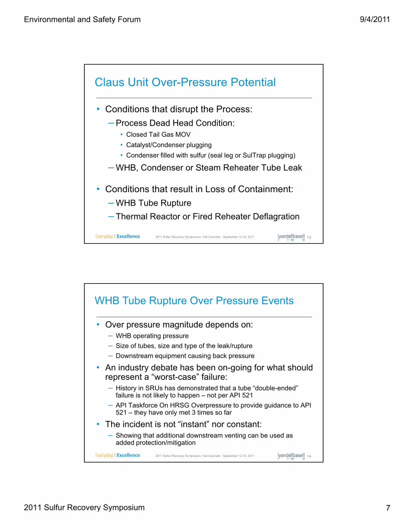
• Conditions that disrupt the Process:
– Process Dead Head Condition:
Claus Unit Over-Pressure Potential
Process Dead Head Condition:• Closed Tail Gas MOV
• Catalyst/Condenser plugging
• Condenser filled with sulfur (seal leg or SulTrap plugging)
– WHB, Condenser or Steam Reheater Tube Leak
2011 Sulfur Recovery Symposium, Vail Colorado September 12-16, 2011 13
• Conditions that result in Loss of Containment:
– WHB Tube Rupture
– Thermal Reactor or Fired Reheater Deflagration
• Over pressure magnitude depends on:– WHB operating pressure
WHB Tube Rupture Over Pressure Events
– Size of tubes, size and type of the leak/rupture
– Downstream equipment causing back pressure
• An industry debate has been on-going for what should represent a “worst-case” failure:– History in SRUs has demonstrated that a tube “double-ended”
failure is not likely to happen – not per API 521
API T kf O HRSG O id id API
2011 Sulfur Recovery Symposium, Vail Colorado September 12-16, 2011 14
– API Taskforce On HRSG Overpressure to provide guidance to API 521 – they have only met 3 times so far
• The incident is not “instant” nor constant:– Showing that additional downstream venting can be used as
added protection/mitigation
Environmental and Safety Forum
2011 Sulfur Recovery Symposium

9/4/2011
8
• The point being: WHB tube failures may or may not be the driver for equipment design criteria
WHB Tube Rupture Over Pressure Events
• Therefore: each plant needs to apply the specifics of their process, equipment and acceptable failure conditions to understand this scenario’s impact to the design
• Numerous past paper/presentations available on this subject
2011 Sulfur Recovery Symposium, Vail Colorado September 12-16, 2011 15
this subject
• National Fire Protection Association (NFPA) 68-2007 –Standard on Explosion Protection by Deflagration Venting Annex B addresses the fundamentals of Deflagration
Deflagrations
Annex B addresses the fundamentals of Deflagration
• Deflagration = Propagation of a combustion zone at a velocity less than the speed of sound in the un-reacted medium
– Note: Greater than the speed of sound = Detonation
• Deflagration requirements:
2011 Sulfur Recovery Symposium, Vail Colorado September 12-16, 2011 16
– A fuel concentration within flammable limits
– Oxidant concentration sufficient to support combustion
– Presence of an ignition source
Environmental and Safety Forum
2011 Sulfur Recovery Symposium
9/4/2011
9
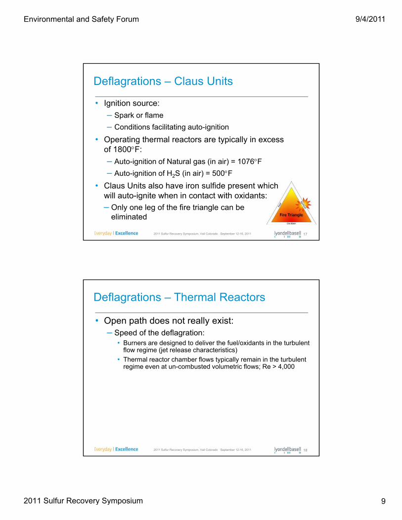
Deflagrations – Claus Units
• Ignition source:
– Spark or flame
– Conditions facilitating auto-ignition
• Operating thermal reactors are typically in excess of 1800F:
– Auto-ignition of Natural gas (in air) = 1076F
– Auto-ignition of H2S (in air) = 500F
2011 Sulfur Recovery Symposium, Vail Colorado September 12-16, 2011 17
• Claus Units also have iron sulfide present which will auto-ignite when in contact with oxidants:
– Only one leg of the fire triangle can be eliminated
• Open path does not really exist:– Speed of the deflagration:
Deflagrations – Thermal Reactors
• Burners are designed to deliver the fuel/oxidants in the turbulent flow regime (jet release characteristics)
• Thermal reactor chamber flows typically remain in the turbulent regime even at un-combusted volumetric flows; Re > 4,000
2011 Sulfur Recovery Symposium, Vail Colorado September 12-16, 2011 18
Environmental and Safety Forum
2011 Sulfur Recovery Symposium
9/4/2011
10
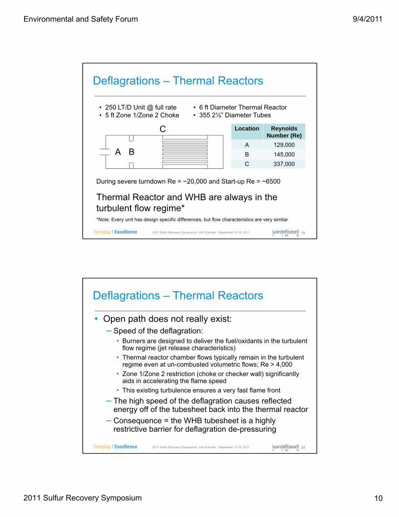
Deflagrations – Thermal Reactors
• 250 LT/D Unit @ full rate• 5 ft Zone 1/Zone 2 Choke
• 6 ft Diameter Thermal Reactor• 355 2½” Diameter Tubes
Location Reynolds Number (Re)
A 129,000
B 145,000
C 337,000
A B
C
During severe turndown Re = 20 000 and Start up Re = 6500
2011 Sulfur Recovery Symposium, Vail Colorado September 12-16, 2011 19
Thermal Reactor and WHB are always in the turbulent flow regime*
During severe turndown Re = ~20,000 and Start-up Re = ~6500
*Note: Every unit has design specific differences, but flow characteristics are very similar
• Open path does not really exist:– Speed of the deflagration:
Deflagrations – Thermal Reactors
• Burners are designed to deliver the fuel/oxidants in the turbulent flow regime (jet release characteristics)
• Thermal reactor chamber flows typically remain in the turbulent regime even at un-combusted volumetric flows; Re > 4,000
• Zone 1/Zone 2 restriction (choke or checker wall) significantly aids in accelerating the flame speed
• This existing turbulence ensures a very fast flame front
2011 Sulfur Recovery Symposium, Vail Colorado September 12-16, 2011 20
– The high speed of the deflagration causes reflected energy off of the tubesheet back into the thermal reactor
– Consequence = the WHB tubesheet is a highly restrictive barrier for deflagration de-pressuring
Environmental and Safety Forum
2011 Sulfur Recovery Symposium
9/4/2011
11
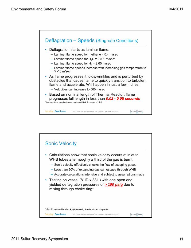
Deflagration – Speeds (Stagnate Conditions)
• Deflagration starts as laminar flame:– Laminar flame speed for methane = 0.4 m/sec
Laminar flame speed for H S 0 5 1 m/sec*– Laminar flame speed for H2S = 0.5-1 m/sec*
– Laminar flame speed for H2 = 2.65 m/sec
– Laminar flame speeds increase with increasing gas temperature to 5 -10 m/sec
• As flame progresses it folds/wrinkles and is perturbed by obstacles that cause flame to quickly transition to turbulent flame and accelerate. Will happen in just a few inches:
2011 Sulfur Recovery Symposium, Vail Colorado September 12-16, 2011
pp j– Velocities can increase to 500 m/sec
• Based on nominal length of Thermal Reactor, flame progresses full length in less than 0.02 - 0.05 seconds
* Laminar flame speed estimates courtesy of Nick Roussakis of HEC
Sonic Velocity
• Calculations show that sonic velocity occurs at inlet to WHB tubes after roughly a third of the gas is burnt:g y g– Sonic velocity effectively chocks the flow of escaping gases
– Less than 20% of expanding gas can escape through WHB
– Accurate calculations intensive and subject to assumptions made
• Testing on vessel (8’ ID x 33’L) with one open end yielded deflagration pressures of > 100 psig due to mixing through choke ring*
2011 Sulfur Recovery Symposium, Vail Colorado September 12-16, 2011
mixing through choke ring
* Gas Explosion Handbook; Bjerketvedt, Bakke, & van Wingerden
Environmental and Safety Forum
2011 Sulfur Recovery Symposium

9/4/2011
12
Testing Vessel (8’ ID x 33’L)
2011 Sulfur Recovery Symposium, Vail Colorado September 12-16, 2011
Video Source: Gas Explosion Handbook; Bjerketvedt, Bakke, & van Wingerden
• During Start-up:
– Unlit burners can place sufficient amounts of fuel and air
Deflagration Potential
into the thermal reactor to reach LFL conditions
– Conditions facilitating auto-ignition will be present during hot restarts
– Many ignition system components can malfunction
• Undetected flame-outs:
2011 Sulfur Recovery Symposium, Vail Colorado September 12-16, 2011 24
– H2S and Oxidant levels already at LFL conditions
– Unlit burner entry temperature is 300+F below auto-ignition temperature – Zone 1 accumulation can occur
– Flame Scanner imperfections can lead to this condition
Environmental and Safety Forum
2011 Sulfur Recovery Symposium
9/4/2011
13
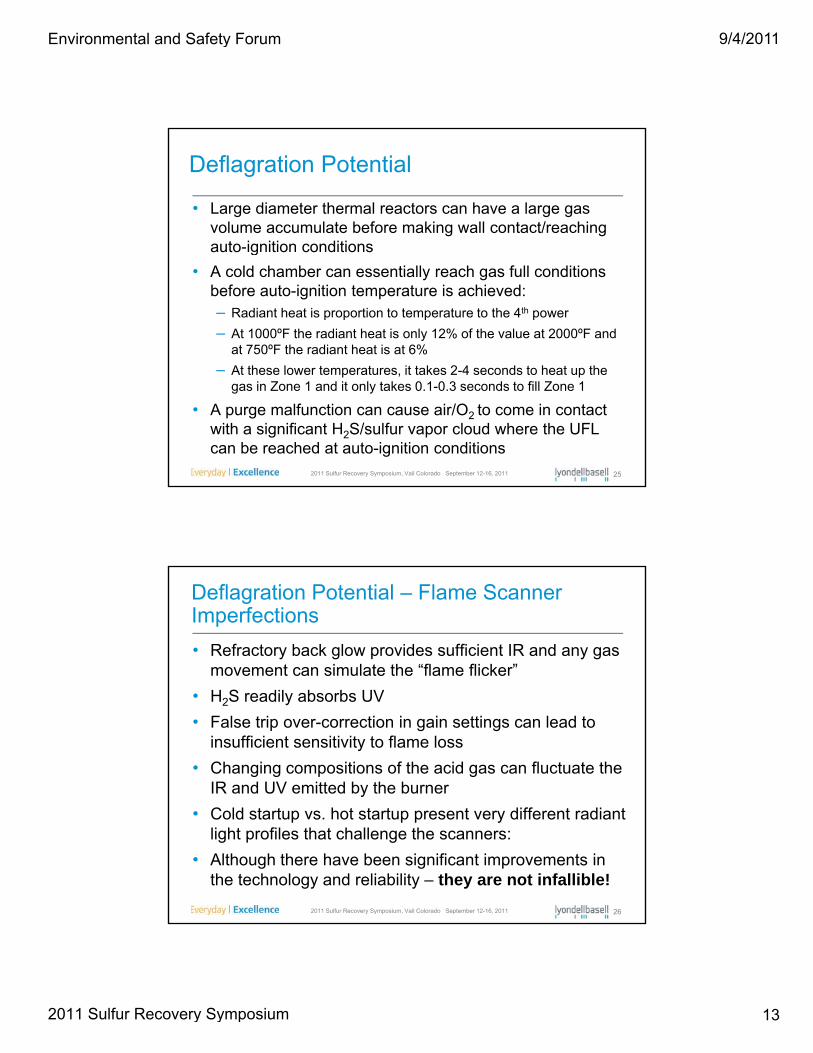
• Large diameter thermal reactors can have a large gas volume accumulate before making wall contact/reaching auto-ignition conditions
Deflagration Potential
auto-ignition conditions
• A cold chamber can essentially reach gas full conditions before auto-ignition temperature is achieved:– Radiant heat is proportion to temperature to the 4th power
– At 1000ºF the radiant heat is only 12% of the value at 2000ºF and at 750ºF the radiant heat is at 6%
At th l t t it t k 2 4 d t h t th
2011 Sulfur Recovery Symposium, Vail Colorado September 12-16, 2011 25
– At these lower temperatures, it takes 2-4 seconds to heat up the gas in Zone 1 and it only takes 0.1-0.3 seconds to fill Zone 1
• A purge malfunction can cause air/O2 to come in contact with a significant H2S/sulfur vapor cloud where the UFL can be reached at auto-ignition conditions
• Refractory back glow provides sufficient IR and any gas movement can simulate the “flame flicker”
Deflagration Potential – Flame Scanner Imperfections
• H2S readily absorbs UV
• False trip over-correction in gain settings can lead to insufficient sensitivity to flame loss
• Changing compositions of the acid gas can fluctuate the IR and UV emitted by the burner
2011 Sulfur Recovery Symposium, Vail Colorado September 12-16, 2011 26
• Cold startup vs. hot startup present very different radiant light profiles that challenge the scanners:
• Although there have been significant improvements in the technology and reliability – they are not infallible!
Environmental and Safety Forum
2011 Sulfur Recovery Symposium
9/4/2011
14
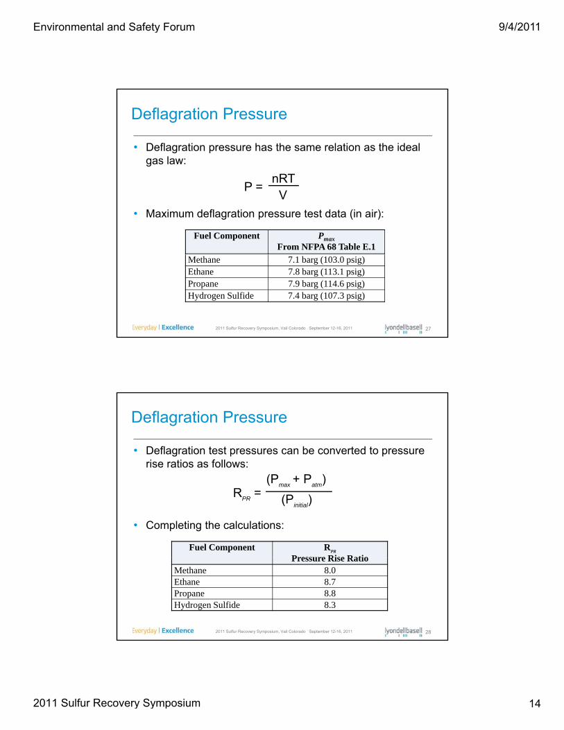
• Deflagration pressure has the same relation as the ideal gas law:
Deflagration Pressure
nRTV
P =
Fuel Component Pmax
From NFPA 68 Table E.1
• Maximum deflagration pressure test data (in air):
2011 Sulfur Recovery Symposium, Vail Colorado September 12-16, 2011 27
Methane 7.1 barg (103.0 psig)Ethane 7.8 barg (113.1 psig)Propane 7.9 barg (114.6 psig)Hydrogen Sulfide 7.4 barg (107.3 psig)
• Deflagration test pressures can be converted to pressure rise ratios as follows:
Deflagration Pressure
(P P )(Pmax
+ Patm
)R
PR= (P
initial)
• Completing the calculations:
Fuel Component RPR
Pressure Rise Ratio
2011 Sulfur Recovery Symposium, Vail Colorado September 12-16, 2011 28
Pressure Rise RatioMethane 8.0Ethane 8.7Propane 8.8Hydrogen Sulfide 8.3
Environmental and Safety Forum
2011 Sulfur Recovery Symposium

9/4/2011
15
• Typical final deflagration pressures (air only):Methane P
initial= 1.1 psig (start-up)
Deflagration Pressure
H2S Pinitial
= 9.3 psig (full rate)
Pdef
= RPR
(Pinitial
+ Patm
) - Patm
Fuel ComponentP
def
Claus Unit Deflagration Pressure (psig)Methane* 111.7Hydrogen Sulfide 186.2
2011 Sulfur Recovery Symposium, Vail Colorado September 12-16, 2011 29
• However, we know that acid gas is not pure H2S
• And many of today’s operations are O2 enriched
*Natural gas may yield slightly lower deflagration pressures due to possible inert components
• An example amine acid gas composition
BR&E’ P ® ft
Deflagration Pressure
Species Mol% Wt%
N2 0.43% 0.38%CH4 0.02% 0.01%
• BR&E’s Promax® software was used to create process simulations of the combustion of this amine acid gas with air and O2 enriched air environments
• The simulated combustion t t d l f
CH4 0.02% 0.01%CO2 10.50% 9.27%C2H4 0.01% 0.01%C2H6 0.01% 0.01%H2S 78.29% 84.14%COS 0.00% 0.00%C3H8 0.09% 0.13%H2O 10.65% 6.05%
2011 Sulfur Recovery Symposium, Vail Colorado September 12-16, 2011 30
temperature and moles of combustion product were then used to calculate the deflagration pressure using the ideal gas law
TOTAL 100.00% 100.00%
Temp (F) 139P (psig) 11.5Mol Weight 33.39Density (lb/ft3) 0.1366
Environmental and Safety Forum
2011 Sulfur Recovery Symposium
9/4/2011
16
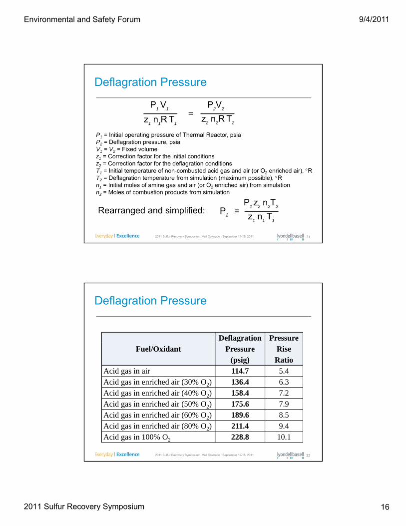
Deflagration Pressure
=P
1V
1
z1n
1R T
1
P2V
2
z2n
2R T
21 1 1 2 2 2
P1 = Initial operating pressure of Thermal Reactor, psiaP2 = Deflagration pressure, psiaV1 = V2 = Fixed volumez1 = Correction factor for the initial conditionsz2 = Correction factor for the deflagration conditionsT1 = Initial temperature of non-combusted acid gas and air (or O2 enriched air), RT2 = Deflagration temperature from simulation (maximum possible), R
I iti l l f i d i ( O i h d i ) f i l ti
2011 Sulfur Recovery Symposium, Vail Colorado September 12-16, 2011 31
n1 = Initial moles of amine gas and air (or O2 enriched air) from simulation n2 = Moles of combustion products from simulation
=P2
P1 z
2n
2T
2
z1n
1T
1
Rearranged and simplified:
Deflagration Pressure
Deflagration Pressure Fuel/Oxidant Pressure
(psig)Rise Ratio
Acid gas in air 114.7 5.4Acid gas in enriched air (30% O2) 136.4 6.3Acid gas in enriched air (40% O2) 158.4 7.2A id i i h d i (50% O ) 175 6 7 9
2011 Sulfur Recovery Symposium, Vail Colorado September 12-16, 2011 32
Acid gas in enriched air (50% O2) 175.6 7.9Acid gas in enriched air (60% O2) 189.6 8.5Acid gas in enriched air (80% O2) 211.4 9.4Acid gas in 100% O2 228.8 10.1
Environmental and Safety Forum
2011 Sulfur Recovery Symposium

9/4/2011
17
• Deflagration Venting:– Devise to relieve the
Deflagration Protection Methods
Devise to relieve the pressure by venting the vessel contents directly to the atmosphere
– Addressed in NFPA 68Thermal Oxidizer Deflagration Vent
2011 Sulfur Recovery Symposium, Vail Colorado September 12-16, 2011 33
• NFPA 68 requires it to be done in a safe manner:– Thermal Reactor release temperature would exceed 2000F– This would result in a significant toxic gas release
– Obviously not recommended nor NFPA complaint for this service
• NFPA 69 – Explosion Prevention Systems:
Deflagration Protection Methods
M th d Ch tMethod ChapterDeflagration Prevention by Oxidant Concentration Reduction 7Deflagration Prevention by Combustible Concentration Reduction 8
Pre-deflagration Detection and Control of Ignition Sources 9Deflagration Control by Suppression 10Deflagration Control by Active Isolation 11
2011 Sulfur Recovery Symposium, Vail Colorado September 12-16, 2011 34
Deflagration Control by Passive Isolation 12Deflagration Control by Pressure Containment 13Passive Explosion Suppression Using Expanded Metal Mesh or Polymer Foams 14
Environmental and Safety Forum
2011 Sulfur Recovery Symposium
9/4/2011
18
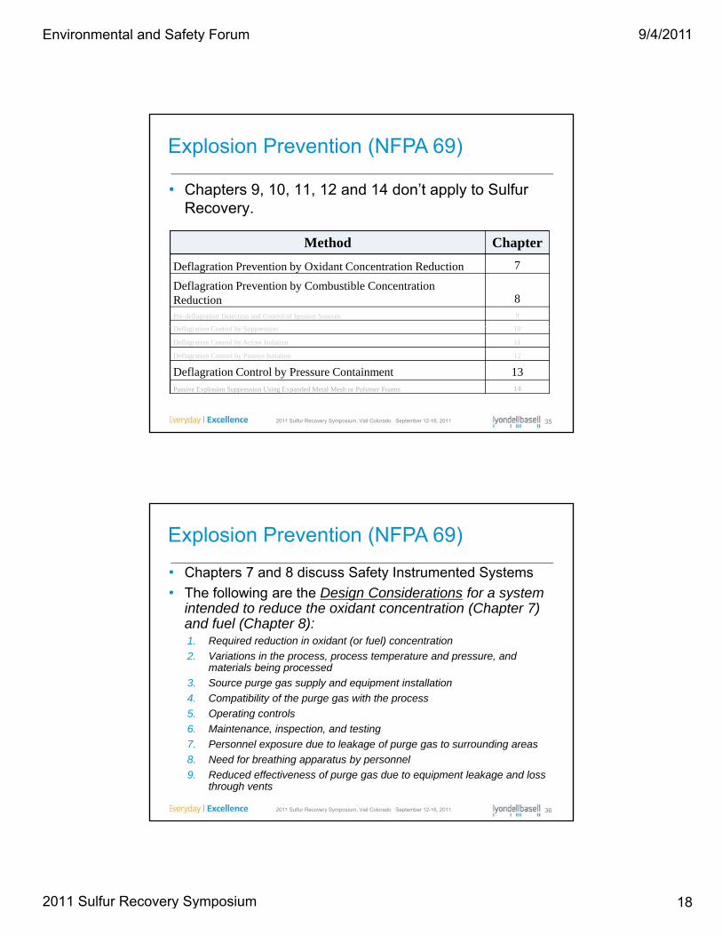
• Chapters 9, 10, 11, 12 and 14 don’t apply to Sulfur Recovery.
Explosion Prevention (NFPA 69)
Method Chapter
Deflagration Prevention by Oxidant Concentration Reduction 7
Deflagration Prevention by Combustible Concentration Reduction 8Pre-deflagration Detection and Control of Ignition Sources 9
D fl i C l b S i 10
2011 Sulfur Recovery Symposium, Vail Colorado September 12-16, 2011 35
Deflagration Control by Suppression 10
Deflagration Control by Active Isolation 11
Deflagration Control by Passive Isolation 12
Deflagration Control by Pressure Containment 13Passive Explosion Suppression Using Expanded Metal Mesh or Polymer Foams 14
• Chapters 7 and 8 discuss Safety Instrumented Systems
• The following are the Design Considerations for a system intended to reduce the oxidant concentration (Chapter 7)
Explosion Prevention (NFPA 69)
intended to reduce the oxidant concentration (Chapter 7) and fuel (Chapter 8):1. Required reduction in oxidant (or fuel) concentration
2. Variations in the process, process temperature and pressure, and materials being processed
3. Source purge gas supply and equipment installation
4. Compatibility of the purge gas with the process
5 Operating controls
2011 Sulfur Recovery Symposium, Vail Colorado September 12-16, 2011 36
5. Operating controls
6. Maintenance, inspection, and testing
7. Personnel exposure due to leakage of purge gas to surrounding areas
8. Need for breathing apparatus by personnel
9. Reduced effectiveness of purge gas due to equipment leakage and loss through vents
Environmental and Safety Forum
2011 Sulfur Recovery Symposium

9/4/2011
19
Explosion Prevention (NFPA 69)Chapters 7 and 8 - Other Requirements• The following Information is required for monitoring and control shall be compiled and documented. This
shall include, but not be limited to, the following information:1. Monitoring and control objectives2. Monitored and controlled areas of the process3 Dimensioned drawings of the process with the following information:3. Dimensioned drawings of the process with the following information:
a. Equipment make and model if available, including volumes and diameters and design strengthb. Plan and elevation views with flows indicated
4. Startup, normal, shutdown, temporary operations, and emergency shutdown process conditions andranges for the following factors:
a. Flowb. Temperaturec. Pressured. Oxidant concentration
5. Process flow diagram and description6. Ambient temperature in process area7. Process interlocks
2011 Sulfur Recovery Symposium, Vail Colorado September 12-16, 2011 37
• The owner or operator shall be responsible for the maintenance of the system after installation andacceptance based on procedures provided by the vendor.
• Maintenance records shall be retained for inspection by the authority having jurisdiction• The owner or operator shall be responsible for periodic inspection of the system by personnel trained by the
system manufacturer.• Required levels of oxidant or fuel concentration - owner or operator documents that their system achieves
the levels and that maintenance and inspection are completed on a regular basis to confirm the system isoperating correctly.
Explosion Prevention (NFPA 69)Chapters 7 and 8
• Requires a sophisticated SIS addressing start-up, normal, shutdown, temporary operations, and emergency shutdown process conditions/ranges for the these factors:
a. Flowb. Temperaturec. Pressure
d. Oxidant concentratione. Fuel Concentrationf. Inert Purging
• Oxidants act as a fuel in the Claus Unit equipment due
2011 Sulfur Recovery Symposium, Vail Colorado September 12-16, 2011 38
• Oxidants act as a fuel in the Claus Unit equipment due to impregnated sulfur and iron sulfide build-up
• Continuous flame stability is essential which is ensured only through flame scan which is not full-proof
Environmental and Safety Forum
2011 Sulfur Recovery Symposium
9/4/2011
20
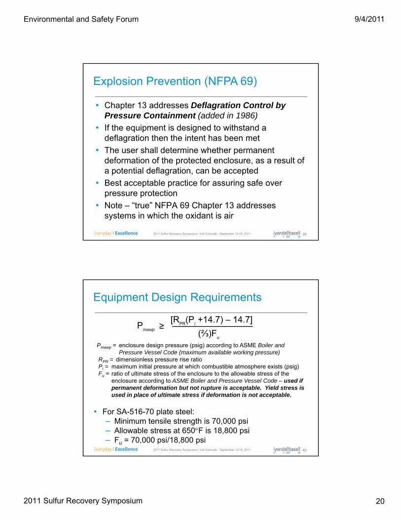
• Chapter 13 addresses Deflagration Control by Pressure Containment (added in 1986)
Explosion Prevention (NFPA 69)
• If the equipment is designed to withstand a deflagration then the intent has been met
• The user shall determine whether permanent deformation of the protected enclosure, as a result of a potential deflagration, can be accepted
Best acceptable practice for assuring safe over
2011 Sulfur Recovery Symposium, Vail Colorado September 12-16, 2011 39
• Best acceptable practice for assuring safe over pressure protection
• Note – “true” NFPA 69 Chapter 13 addresses systems in which the oxidant is air
Equipment Design Requirements
≥Pmawp
[RPR
(Pi+14.7) – 14.7]
(⅔)Fuu
Pmawp = enclosure design pressure (psig) according to ASME Boiler and Pressure Vessel Code (maximum available working pressure)
RPR = dimensionless pressure rise ratioPi = maximum initial pressure at which combustible atmosphere exists (psig)Fu = ratio of ultimate stress of the enclosure to the allowable stress of the
enclosure according to ASME Boiler and Pressure Vessel Code – used if permanent deformation but not rupture is acceptable. Yield stress is used in place of ultimate stress if deformation is not acceptable.
2011 Sulfur Recovery Symposium, Vail Colorado September 12-16, 2011 40
p p
• For SA-516-70 plate steel:– Minimum tensile strength is 70,000 psi– Allowable stress at 650F is 18,800 psi– Fu = 70,000 psi/18,800 psi
Environmental and Safety Forum
2011 Sulfur Recovery Symposium

9/4/2011
21
Equipment Design Requirements(SA -516-70 Plate Steel Vessels)
F l/O id t RPmawp
Pi= 9.3 psig (full rate)
Fuel/Oxidant RRPmawp
(psig)Acid gas in air 5.4 46.2Acid gas in enriched air (30% O2) 6.3 54.9Acid gas in enriched air (40% O2) 7.2 63.8Acid gas in enriched air (50% O2) 7.9 70.8A id i i h d i (60% O ) 8 5 76 4
2011 Sulfur Recovery Symposium, Vail Colorado September 12-16, 2011 41
Acid gas in enriched air (60% O2) 8.5 76.4Acid gas in enriched air (80% O2) 9.4 85.2Acid gas in 100% O2 10.1 92.2Natural gas in air (P
i= 1.0 psig) 7.2 39.6
• One last plausible case to consider:– Amine acid gas at the upper flammability limit in oxygen
Equipment Design Requirements(SA -516-70 Plate Steel Vessels)
– The upper flammability limit of H2S, at ambient conditions, is 49.8 mole%*
– Pi = 9.3 psig
– SA-516-70 Plate Steel Vessel
Pdef RRP
Pmawp
2011 Sulfur Recovery Symposium, Vail Colorado September 12-16, 2011 42
*Source = “Explosion Limits of H2S/CO2/Air and H2S/N2/Air” by Robert Pahl and Kai Holtappels, 2005, WILEY-VCH, Verlag GmbH & Co. KGaA, Weinheim
(psig)RRP (psig)
198.5 8.3 74.0
Environmental and Safety Forum
2011 Sulfur Recovery Symposium
9/4/2011
22
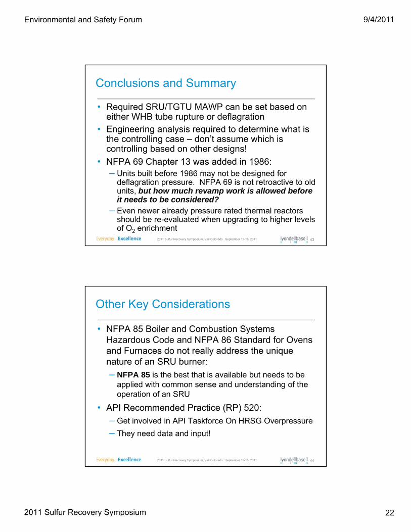
• Required SRU/TGTU MAWP can be set based on either WHB tube rupture or deflagration
Conclusions and Summary
• Engineering analysis required to determine what is the controlling case – don’t assume which is controlling based on other designs!
• NFPA 69 Chapter 13 was added in 1986:– Units built before 1986 may not be designed for
deflagration pressure. NFPA 69 is not retroactive to old
2011 Sulfur Recovery Symposium, Vail Colorado September 12-16, 2011 43
g punits, but how much revamp work is allowed before it needs to be considered?
– Even newer already pressure rated thermal reactors should be re-evaluated when upgrading to higher levels of O2 enrichment
• NFPA 85 Boiler and Combustion Systems Hazardous Code and NFPA 86 Standard for Ovens
Other Key Considerations
and Furnaces do not really address the unique nature of an SRU burner:
– NFPA 85 is the best that is available but needs to be applied with common sense and understanding of the operation of an SRU
• API Recommended Practice (RP) 520:
2011 Sulfur Recovery Symposium, Vail Colorado September 12-16, 2011 44
• API Recommended Practice (RP) 520:
– Get involved in API Taskforce On HRSG Overpressure
– They need data and input!
Environmental and Safety Forum
2011 Sulfur Recovery Symposium

9/4/2011
23
Thank you for your attention
2011 Sulfur Recovery Symposium, Vail Colorado September 12-16, 2011 45
Appendix A: Simulation Results
Fuel/Oxidant CaseP1
(psia)z1 z2
T1
(R)T2
(R)n1
(moles)n2
(moles)
Acid gas in air 24.007 0.9995 1.0002 648.74 3706.6 669.00 630.84
Acid gas in enriched air (30% O2) 24.007 0.9994 1.0000 663.29 4491.1 485.29 450.81
Acid gas in enriched air (40% O2) 24.007 0.9989 1.0000 644.2 5034.6 384.25 354.07
Acid gas in enriched air (50% O2) 24.007 0.9984 1.0000 627.9 5412.8 325.28 298.61
Acid gas in enriched air (60% O2) 24.007 0.9980 1.0000 613.9 5691.3 288.39 264.15
Acid gas in enriched air (80% O2) 24.007 0.9971 1.0000 590.7 6076.7 246.74 225.24
Acid gas in 100% O2 24.007 0.9962 1.0000 571.4 6335.8 222.00 202.29
Acid gas at UFL in O2 24.007 0.9998 1.0000 578.5 4736.9 157.22 157.94
2011 Sulfur Recovery Symposium, Vail Colorado September 12-16, 2011 46
Environmental and Safety Forum
2011 Sulfur Recovery Symposium
About the Authors:
Special Thanks:
To Jason Graves, P.E. of Waid Environmental for assistance with the topical research for the Regulatory Update.
Providing Solutions for Tomorrow’s Environment
Alan D Mosher, P.E. is the Director of Engineering for KPS Technology & Engineering LLC. Alan has 25 years of experience in consulting engineering on a variety of licensed technologies. For the last 15 years Alan’s work has primarily been in Sulfur Recovery, Tail Gas Treating ,and Sour Water Stripping. He is involved in process design, operator training, startup, and troubleshooting. Alan has a Bachelor of Science Degree in Chemical Engineering from the University of Kansas and is a Registered Professional Engineering in the State of Kansas.
Philip Oberbroeckling, P.E. is a Consulting Engineer in LyondellBasell’s Refining Process Engineering Group providing Sulfur Recovery technical support to the Houston and Berre, France Refineries. Philip is the Lead Process Engineer for all sulfur recovery capital projects at Houston including the currently ongoing Oxygen Enrichment Expansion. Over Philip’s 21 years of service in the Refining Industry, he has had held numerous engineering and management positions in Process, HSSE and Operations including a 5-year tenure as the Operations Superintendent of the Houston Refinery’s 1000 LT/D Sulfur Recovery Facility. Philip holds a Bachelor of Science degree in Chemical Engineering from Iowa State University and is a registered Professional Engineer in the states of Montana and Texas. Philip has authored over 30 technical papers and presentations on topics related to the Sulfur Recovery and the Refining Industries. Philip is a member of the Sulfur Recovery Symposium Technical Advisory Committee and the Founder and Chairman of the Environmental and Safety Committee.
Environmental and Safety Forum
2011 Sulfur Recovery Symposium