2011 tisd hhs
TRANSCRIPT

22-12-2011 TISD HHS
Thesis: Design and Engineering of Main Gas
Compression Piping.
Student
Rembrandt Brandjes
08032556
Company supervisor René Bosselaar
Discipline Manager Piping
SBM Schiedam
2011

Design and Engineering of Main Gas Compression Piping
Rembrandt N.C. Brandjes08032556
SBM Schiedam
December 21, 2011

Acknowledgements
To conclude my studies in Mechanical Engineering at “De Haagse Hogeschool” I have beengranted the opportunity to write my thesis at SBM Schiedam, subsidiary of SBM Offshore.SBM Schiedam is an execution and research centre dedicated to Floating Production Storageand Offloading vessels (FPSO). SBM Schiedam oversees the entire design and complete engi-neering process of these units, new constructions as well as conversions.
Hereby I would like to take the opportunity to thank everyone involved with my gradua-tion project. First of all I would like to thank Rene Bosselaar, Discipline Manager Pipingfor granting me the opportunity to graduate at SBM Schiedam and coaching me throughoutthe entire project. Secondly I am indebted to Rene Visser, expert engineer piping, for hisexcellent help and sound advice during the project. I would also like to thank Frank vanSteenbruggen, junior draughtsman piping, for teaching me essential 2D-AutoCAD, which Iwas lacking at the beginning of my internship. I also thank my internship coach from school,Fatih Erdurcan for his involvement in the project. Lastly, a big thank you to all people inthe topsides department.
I am proud to present to you the final project of my HBO studies in Mechanical Engi-neering. I am happy that my project has captured a few essentials subjects from mechanicalengineering: designing, material science and statics; combined with knowledge from the fieldof piping design and engineering, learnt on the job.
Rembrandt Brandjes.Schiedam December 2011.

Contents
1 Abbreviations 2
2 Summary 3
3 Project backgrounds 43.1 Brazilian oil developments . . . . . . . . . . . . . . . . . . . . . . . . . . . . . 43.2 FPSO overview . . . . . . . . . . . . . . . . . . . . . . . . . . . . . . . . . . . 53.3 Main gas compression process description . . . . . . . . . . . . . . . . . . . . 8
4 Project definition 94.1 Main Objective . . . . . . . . . . . . . . . . . . . . . . . . . . . . . . . . . . . 94.2 Goals . . . . . . . . . . . . . . . . . . . . . . . . . . . . . . . . . . . . . . . . 9
5 Basis of design 105.1 Main Gas Compression Process . . . . . . . . . . . . . . . . . . . . . . . . . . 105.2 Material Selection . . . . . . . . . . . . . . . . . . . . . . . . . . . . . . . . . 145.3 Material Classes . . . . . . . . . . . . . . . . . . . . . . . . . . . . . . . . . . 145.4 Flushing and testing . . . . . . . . . . . . . . . . . . . . . . . . . . . . . . . . 145.5 Piping Plant Layout . . . . . . . . . . . . . . . . . . . . . . . . . . . . . . . . 175.6 Pipe Stress . . . . . . . . . . . . . . . . . . . . . . . . . . . . . . . . . . . . . 19
6 Design 236.1 Routing of the compressor piping . . . . . . . . . . . . . . . . . . . . . . . . . 236.2 Plot Plan . . . . . . . . . . . . . . . . . . . . . . . . . . . . . . . . . . . . . . 256.3 Supports . . . . . . . . . . . . . . . . . . . . . . . . . . . . . . . . . . . . . . . 266.4 Isometrics . . . . . . . . . . . . . . . . . . . . . . . . . . . . . . . . . . . . . . 26
7 Pipe Stress & Nozzle Loads 277.1 Pipe stress . . . . . . . . . . . . . . . . . . . . . . . . . . . . . . . . . . . . . . 277.2 CAESAR II analysis . . . . . . . . . . . . . . . . . . . . . . . . . . . . . . . . 287.3 Results Analysis . . . . . . . . . . . . . . . . . . . . . . . . . . . . . . . . . . 32
8 Conclusion 39
9 Bibliography 40
10 Appendix 41
1

1
Abbreviations
The following list serves to clarify the abbreviations used in this document.
BOE Barrels of Oil EquivalentBOE/D Barrels of Oil Equivalent per DayFPSO Floating Production Storage and Offloading VesselLOI Letter of intentVLCC Very Large Crude CarrierCO2 Carbon Dioxide GasHP High PressureLP Low PressureBOD Basis of DesignCES Corporate Engineering StandardsPMC Pipe Material ClassesP&ID Process and Instrumentation DiagramPFD Process Flow DiagramFore Front side of a shipAft Back side of a shipASME American Society of Mechanical EngineersAPI American Petroleum InstituteDNV Det Norske VeritasFEA Finite Element AnalysisCAESAR2 FEM based Pipe Stress Analysis Software
2

2
Summary
SBM Schiedam is active in the design, engineering and construction of Floating ProductionStorage and Offloading (FPSO) ships. Currently SBM has a few projects for Petrobras. Pur-pose of an FPSO is to produce oil from a subsea oilfield. The FPSO production process issplit over different modules which can be built simultaneously. A few of these modules are gasprocessing modules, where gas is treated and compressed. This compression process requiresa centrifugal compressor which is connected to scrubbers and heat exchangers by piping.Because centrifugal compressors are sensitive rotating machines, they can take little nozzleloading. Industry supports this view and API subscribes a recommendation for allowablenozzle loads. These nozzle loads need to be adhered to as a minimum to guarantee properfunctioning of equipment.
In order to stay below allowable nozzle loads. The piping system must be self support-ing, that is to say it does not rest on the compressor system. This is just the start of a gooddesign, in fact the compressor piping near the machine must be designed so that it is isolatedfrom the effects of the rest of the piping system. This forms the investigation of this report.To find the solution a basis of design is made, a design is proposed and this design is testedby means of a finite element model.
The proposed solution is to design ‘isolation loops’ around the compressor, which allow con-trolled thermal growth in the horizontal direction. The isolation loops are separate from thesystem by placing an axial stop in line with the fixed point of the centrifugal compressor.Furthermore a spring hanger is fitted for vertical support but allowing vertical growth. Isola-tion loops create an additional problem for some conditions to minimize this effect a snubberdevice is added to the loops.
The proposed solution works in theory and needs to be implemented in a working modeland if proven effective, tried on a real module.
3

3
Project backgrounds
In this chapter a brief background is given to understand the context of the assignment.
3.1 Brazilian oil developments
Only a decade ago, the notion that Brazil would become self-sufficient in energy, let alonea major exporter, seemed far-fetched. This changed with the discovery of ultra-deepwaterpre-salt reservoirs like Tupi, estimated to be the western hemisphere’s largest oil discovery ofthe last 30 years. [Subsea7] The pre-salt oil reserves are estimated to contain a measure of56 billion barrels of oil equivalent (BOE).
Although the upstream oil sector was fully liberalized in 2000 Petrobras, Brazil’s nationaloil and gas company, still retains a dominant position in the industry. Petrobras has set anambitious growth target to be the largest oil producer by 2020 outperforming other internati-nal oil companies. By 2014 Petrobras wants to produce 3,9 million (BOE/D) and by 2020 5,4million (BOE/D) to reach this target 1 million (BOE/D) will eventually be expected fromthe pre-salt fields. [Petrobras]
Figure 3.1: Santos Pre-Salt Basin
4

The Santos Basin pre-salt fields are located 300km offshore South-East of Sao Paulo,Brazil and consist of an area of 352,260 square kilometers. (See figure 3.1) The fields arecalled pre salt because the oil is buried below as much as 2000m of salt. The wells in theSantos Basin start at a water depth of 2km. The total measured drilling depth is almost6km.[Halliburton] The waterdepth and drilling depth are historical challenges that need tobe addressed. Due to the ultra-deepwater conditions conventional fixed production platformsare not feasible. Therefore Petrobras has chosen to use floating production facilities, some ofwhich are FPSOs. In December 2009 Petrobras employed a total of 41 production platformsand FPSOs by 2020 Petrobras expects a total of 84.
In August 2011 SBM Offshore received a letter of intent (LOI) from a consortium headedby Petrobras, for the 20 year charter and operation of an FPSO for the Guara Norte blockdevelopment. The Guara Norte field is located in block BM-S-9 in the Santos Basin.
The FPSO will include topside facilities to process 150.000 BPD of production fluids,associated gas treatment for 6,000,000 m3/d with compression and carbon dioxide removal,hydrogen sulphide removal, and a water injection facility for 180.000 BPD. The project sched-ule foresees delivery of the FPSO in 35 months from LOI. In the near future this FPSO willbe referred to as FPSO ’Cidade de Ilhabela.’ This will be the ninth FPSO for the Brazilianmarket and the largest FPSO (capacity) to date.
3.2 FPSO overview
This section gives a brief overview of floating production storage and offloading vessels (FP-SOs). Reference will be made to the Ilha Bela, SBMs latest FPSO EPCM project. For thisproject SBM Offshore is refurbishing and converting a very large crude carrier (VLCC) into aFPSO. The ship is refurbished and prepared for integration of the modules in China, process-ing modules are constructed in Brazil and placed on the vessel at a later stage. To understandthe FPSO concept one needs to be familiar with the development of a typical offshore oil andgas field.
1. Exploration
2. Exploratory drilling
3. Development drilling
4. Production
5. Storage and offloading
6. Transportation
7. Decommisioning
The FPSO is involved in the exploitation of field from the production stage onwards. TheFPSO is connected to the oil field and stores produced oil in storage tanks. Flowlines con-nected to flexible risers link the subsea development wells to the FPSO after the developmentwells have been drilled by other types of offshore units. Produced oil is periodically offloadedto shuttle tankers using a flexible hose reel.
5

Figure 3.2: Spread Moored FPSO
FPSOs can be moored using different methods depending on prevailing ocean and weatherconditions. The Ilha Bela will make use of a spread mooring arrangemenent. This is amooring system that consists of multiple lines terminating at different locations on the floatingstructure, extending outwards and anchored to the seabed. This provides an almost constantvessel heading and secures the FPSO in one location. These lines are made of heavy chainswhich are tensioned onboard the vessel by special winches. This mooring arrangement is analternative for SBMs patented turret mooring system, for rough environmental conditions.
The incoming risers carrying the produced hydrocarbons enter the vessel on the side ofthe ship by means of a dedicated riser balcony. There are also outgoing risers hung from thisbalcony for enhancing well production by reinjecting water, gas and CO2. On the balcony isa riser pulling system that provides the right amount of tension on the risers.
Figure 3.3: Riser Balcony
6

A current trend in the FPSO industry is that vessel’s production capacity is increasingboth in size and in terms of scope. FPSOs are becoming full offshore production systemswhere a saleable crude oil is made onboard the facility. The hydrocarbon well stream comingfrom subsea production is separated into water, oil and gas. These products are furthertreated for carbon dioxided and other contaminants. Produced water and carbon dioxide isre-injected in the reservoir to maintain pressure. This trend calls for larger vessels with ahigh equipment density on the deck. The mentioned processing systems are seperately builton modules and integrated on board of the vessel. Modules are arranged so that low pressure,non hydrocarbon processes occur at aft of the ship and high pressure processes are locatedat the bow. Living quarters, accommodation and utilities are located near aft and the flaresystem is located at the bow, this with respect to safety. (See Drawing DTT001 and DTT006located in the appendix)
Utilities Function
Power generation Generate electricity for vessel and processes.Seawater treatment Produce desalinated water for processes.
Production process
Chemical injection Enhance recovery of the oil field.Water injection Pressurize oil field and dispose produced water.Production manifold Couples incoming/outgoing risers to the FPSO.Oil processing Separation of well streams into water, oil and gas.Main gas compressors Provide pressure differential in the gas stream.CO2 compressors Compress CO2 gas.Gas treatment Removal of CO2, removal of sulphur, dehydration.Injection gas compressors Compress gas for injection into well.Flare system Burn off toxic, hazardous, flammable gasses in emergencies.Vent system Depressurize the system.Offloading system Offload produced crude into shuttle tanker
The FPSO is a complex processing facility, the focus of this document is on the piping ofthe Main Gas Compression Module B.
7

3.3 Main gas compression process description
To understand the context of the compressor piping system a brief description of the process.These processes are typically divided over different modules.
After the crude enters the vessels it is treated and split into three main streams: water,oil and gas. This separation happens in vessels called separators. Gas from the High Pressure(HP) separator and the vapor recovery unit is routed to Main Gas compressor A. Here the gasis pressurized to a level sufficient to feed the gas treatment system. Main Gas Compressor Ashall also be able to handle regeneration fas flow from the downstream Gas Treatment system.The gas used for regeneration of the molecular sieves is recycled to Main Gas CompressorA. Since this gas is available at a higher pressure, the gas stream shall be introduced to thecompressor as a side stream at a level higher than the suction pressure. Main Gas CompressorA shall have a 2 times 100% configuration and is single stage. For spare capacity and backup purposes.Main Gas Compressor B is fed with treated gas by the CO2 removal membranes systemor with non treated gas by the bypass connection around the membranes system, followingproduction modes. The gas is further pressurized to a sufficient level for export and for furtherre-injection into the reservoir, to pressurize the field. Main Gas Compressor B shall also havea 2 times 100% configuration and is two stage.
Figure 3.4: Module Main Gas Compressor B
8

4
Project definition
4.1 Main Objective
Design and engineering of compressor piping systems are a recurring challenge on SBM Off-shore’s projects. Compressors modules are inherently one of the toughest modules to designdue to many basis of design criteria. Because this system transports high pressure, high tem-perature, flammable gasses the compressor piping systems requires sound engineering. Failureof the compressor piping system can lead to large scale disasters. Besides physical danger,poor engineering of compressor modules can threaten financial success of the project in termsof construction difficulty and maintenance costs. By setting a good standard for the criticallines of the compressor, engineering lead time can be reduced and troubleshooting for poorengineering in a later phase can be avoided.
The main objective of the project is to set a standard philosophy for thecompressor interface pipe routing and supporting to be used as a reference onfuture projects.
4.2 Goals
The main objective is decomposed into the following goals:
• Generate a basis of design (BOD) for gas compressor piping systems.
• Design a piping system that meets BOD requirements.
• Verify design by means of a pipe stress analysis.
• Set a standard for gas compressor modules.
Because there are multiple gas compression modules on the FPSO, Main Gas CompressorB is chosen. This is the most challenging compressor because it is a two stage compressorwith the four nozzles and because gas is at relatively high pressure and temperature. Inoperation this compressor raises the gas pressure from 130 to 324 bar g. with an associatedend temperature of 101 ◦C. These pressures and temperatures are not much of a problem forthe piping system, however due to the large wall thickness of pipe to contain this pressure,the nozzles are subject to large loads and moments. Goal of the assignment is to reduce theseloads by flexible routing and choosing adequate, practical supports.
9

5
Basis of design
The basis of design (BOD) has been compiled based on SBM’s Corporate Engineering Stan-dards (CES) (see appendix) and is further based on interviews with experienced piping pro-fessionals. The BOD serves to be an exhaustive list of criteria that the compressor pipingsystem should meet.
5.1 Main Gas Compression Process
The main gas compressor piping is routed between three pieces of equipment: suction scrub-ber, centrifugal compressor and heat exchanger. Compressor B is usually located on a dedi-cated module in a 2x100% configuration for back up and sparing operation modes. We willfocus on one compressor configuration that can be duplicated on the module. Where infor-mation such as wall thickness, material, process data etc... is needed, data from a existingFPSO is used.
10

5.1.1 Suction scrubber
Suction scrubbers are placed upstream of the compressor’s inlet nozzle. The suction scrubberremoves liquids from the gas stream that could be damaging to the compressor impeller. Theinternals of the scrubber are configured so that gas streams through a dense mesh to removeliquid contaminants. These liquid contaminants in the gas stream, exit the scrubber at thebottom, gas flows to the compressor from the top nozzle of the scrubber. See figure 5.1 foran impression.
Figure 5.1: Suction Scrubber
11
5.1.2 Centrifugal compressor
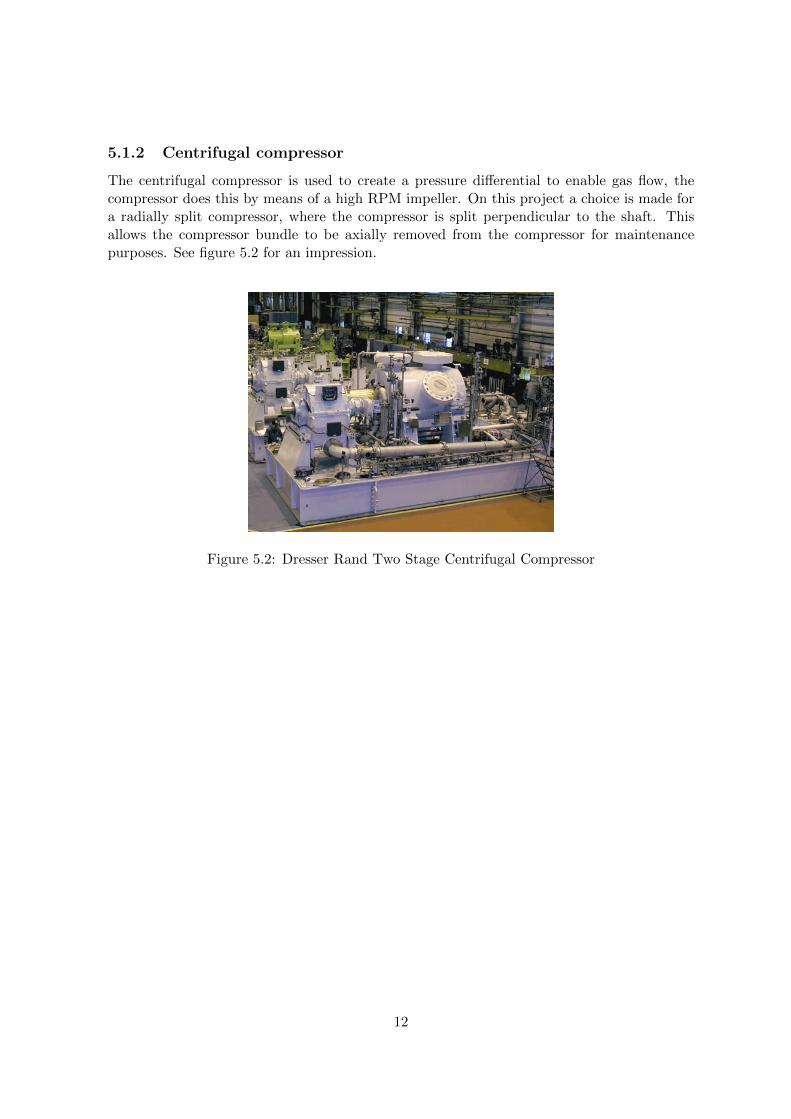
The centrifugal compressor is used to create a pressure differential to enable gas flow, thecompressor does this by means of a high RPM impeller. On this project a choice is made fora radially split compressor, where the compressor is split perpendicular to the shaft. Thisallows the compressor bundle to be axially removed from the compressor for maintenancepurposes. See figure 5.2 for an impression.
Figure 5.2: Dresser Rand Two Stage Centrifugal Compressor
12

5.1.3 Heat exchanger
The compressor conducts work on the gas raising temperature and pressure. The heat ex-changer is a piece of equipment built for efficient heat transfer from one medium to another.The heat exchanger is installed downstream from the compressor to cool the gas. The heatexchanger is a printed circuit type and cools using inhibited water. These heat exchangersare also referred to as discharge coolers. See figure 5.3 for an impression.
Figure 5.3: Compact Plate Heat Exchanger
5.1.4 Equipment Summary
The following table displays the equipment at the interface of the piping system, reference ismade to the appendix for vendor drawings of the equipment.
Equipment Tag-numbers
Compressor B 1K-T7141Stage 1 suction scrubber 1V-T7141Stage 2 suction scrubber 1V-T7142Stage 1 discharge cooler 1E-T7141Stage 2 discharge cooler 1E-T7142
13

5.2 Material Selection
The material selection standard provides general principles, engineering guidance and require-ments for material selection and corrosion protection for all parts of the offshore installations;
• Corrosion and material selection evaluations.
• Specific material selection where appropriate
• Corrosion protection
• Design limitations for candidate materials
• Qualification requirements for new materials or new applications
Based on these factors and process conditions a material selection is made for the compressorpiping. In the case of the compressor piping two pipe materials A333 Gr.6 and API 5L X52,which have the same mechanical properties.
5.3 Material Classes
The material classes specfication covers Piping Material Classes (PMC) with material require-ments for all FPSO Topsides piping systems. The PMCs have been setup with respect to theABSM B31.3 process piping code. Data from the assigned pipe class is used to construct andmodel the compressor piping system.
The PMC consists of piping components selected according to the requirements in theapplicable rules and regulations. Within the design limits of the PMC the individual com-ponents of the piping system are fit for purpose. Each line on the P&ID is assigned a PMCwhich is specified further in the PMC. Below is a summary of the lines subject of study. Formore information reference is made to the appendix.
Line Nominal size [inches] Pipeclass
Scrubber 1 to Compressor 12 15C04Compressor to Discharge Cooler 1 12 15C04Scrubber 2 to Compressor 12 15C04Compressor to Discharge Cooler 2 10 25C06
5.4 Flushing and testing
The flushing and testing specification covers flushing, testing and non destructive examination(NDE) of piping systems. The safety of personnel shall be of prime importance during theseprocedures. For the compressor lines this implies that all lines will be tested and need tobe designed to allow for this. Especially the hydrotest creates an additional design challengebecause the system needs to be examined closest to its intended state. Thus the final spool,connected to the compressor is fitted with a flanged connection to allow rotation and fittingof a blind flange.
14

5.4.1 Non Destructive Examination
A complex visual inspection and dimensional check shall be carried out for all fabricatedpiping systems in accordance with ASME B31.3, Chapter VI. Each piping system shall bechecked against the isometric drawings for material identification, dimensions and fittings. Arecord shall be retained of all such checks and inspections.Inspection and testing shall be carried out after fabrication, welding and heat treatment hasbeen finalized but prior to painting, coating and lining. If any welding is performed afterinspection and testing, a retest will be required.Various examination techniques are used depending on the pressure class, wall thickness andpipe material. The following examination techniques are used:
• Visual inspection
• Radiographic testing
• Ultrasonic testing
• Magnetic particle examination
• Liquid penatrant examination
5.4.2 Preparation for flusing and pressure testing
All items that could be damaged resulting from flushing/testing shall be blanked off, orremoved from the system.All piping shall be adequately supported; spring supports shall have the pin insterted/blockedto prevent movement. Temporary supports shall be provided if additional stability is deemednecessary. Special consideration shall be given to vapor lines.Hydrotest and flushing medium (usually water) shall not exceed 200ppm chloride ions andshall contain a corrosion inhibitor to protect the piping system. Lines need to be thoroughlydried after testing. For stainless steel, hydrotest and flushing medium shall not exceed 50ppm.All lines shall be checked to ensure they are clear of debris that may have accumulated duringfacbrication, installation and erection. Wherever practical, all the lines shall be blown downwith compressed air prior to flushing. All necessary precautions shall be taken to ensuredebris is not flushed into associated equipment or “dead ends.”All in-line pressure sensitive equipment shall be substituted with hydrotest spools. All spoolsshall be pressure rated to the applicable PMC, consistent with equipment pressure rating.
5.4.3 Flushing
Flushing is required to clean the system from debris.When lines are broken for flushing, oncompletion of the flushing, broken connections shall be reinstated using new gaskets.All linesthat require pressure testing shall be flushed prior to system testing. The medium used forflusing shall be same as that required for the pressure test. For corriosion resistant alloys,seawater may be used as the flusing medium as long as the line is properly cleaned afterflushing.For piping systems where the flusing medium is water, flow velocities of 1.5 to 2 times thenormal operating velocity or 5 m/s, whichever is greater must be achieved wherever possible.
15
Piping systems which are blown-out using compressed air, shall be oil free and dry, the flowvelocity should not be less than 35 m/s.The main headers shall be flushed out first and then all the branches, which are connected toany equipment. All necessary precautions shall be taken to ensure that debris is not flusedinto associated equipment or dead ends. The main headers shall be flushed for 30minutes atleast, branches 15 minutes respectively. The system shall be flushed or blown down from thehighest point in the system.
5.4.4 Pressure testing
Pressure testing is necessary to verify that the system is suitable to hold 1,5x design pressurewithout leaking. In-line equipment such as control valves, shall be isolated during the hydro-static test. If this is impractical then a vendor agreement shall be obtained to satisfy pointslisted. Pressure vessels are usually tested separately.
• The equipment test pressure is equal to or greater than the piping system.
• The supporting steelwork should not be over stressed if the pipework and equipmentwere tested together due to combined weights.
• Equipment shall not suffer damage due to testing meidum.
The thickness of blinds used for pressure testing shall be in accordance with ASME B16.5Pipe Flanges and Flanged Fittings. Blinds cut from plate shall have the thickness calculatedin accordance with ASME B31.3.
16
5.5 Piping Plant Layout
5.5.1 General Layout Considerations
This specification in addition to other specifications and codes, defines the general pipingrequirements for the plot plan and plant layout design to provide the required operational,maintenance and safety measures. Layout shall be consistent with prevailing atmospheric andsite conditions and accepted engineering practices. It is important to assess the escape routerequirements at a very early stage to ensure escape areas are not compromised during layoutdevelopment. The arrangement of modules shall provide the maximum separation betweenhazardous and safe areas in descending order, from fore to aft.Lower deck module steel (pancakes) are aligned with columns, which are attached to the deckat ship webframes. Major equipment (pumps, drums, exchangers, compressors etc.) shouldbe arranged so that their supoorts are on primary steel work where possible, to avoid need forheavy secondary steel. Rotating machinery such as compressors preferably shall be positionedwith the centerline being parallel to that of the vessel, the steadiest axis of the ship.The primary consideration in the piping layout of areas shall be to provide an economicalfacility that is safe, fit for purpose, logical, easy to operate and maintain. Piping arrang-ments shall favor compactness but shall allow sufficient room for escape routes. Piping shallbe routed to ensure the shortest practical length without affecting flexibility. A minimumnumber of flanges, fittings and other components are to be used.Valves, instruments and equipment requiring inspection, maintenance or servicing shall beaccessible from major platforms or walkways where possible. When access from major plat-forms on walkways is not possible, then additional platforming, walkways or ladders shallonly be provided when economically feasible.Piping around equipment shall be designed to allow maintenance, servicing, testing and re-moval of equipment with minimum dismantling and disruption of piping systems. This canbe accomplished by providing valves, spades and spectacle blins and sufficient flanged connec-tions. Provision shall be made for using mechanical means of lifiting, where weight exceeds25kg.
17

5.5.2 Compressor Module Layout
The following design criteria are more specific to the compressor system and need to be metas a minimum.
• Piping local to the compressor will be supported using spring supports to allow thermalexpansion of the nozzle but take the weight of the compressor nozzle.
• Temporary or permanent strainers shall be provided in compressor suction lines for startup and continuous operation. The strainer shall be located as close as possible to thecompressor inlet nozzle. Piping arrangement shall allow removal of temporary strainerwithout the need to dismantle piping, supports or affect alignment.
• All gas compressor suction piping between the scrubber and compressor shall be kept toa minimum length and routed to avoid trapping or collecting liquid and permit drainingof condensate back to the knock-out vessel. Therefore the suction lines will slope backtoward the scrubbers. Heat exchangers should be elevated above the scrubbers.
• Reducers located upstream of compressor should be located 5D minimum from nozzleto induce an even inflow, important for equal loading of the impeller blades. For flowmeasurement purposes there must be a straight length of 4D upstream and downstream20D, where an orrifice flange will be fitted.
• A check valve (non-slam) shall be located on each compressor discharge line, as close tothe discharge nozzle as is practically possible. The check valve prevents medium flowingback to the compressor in case of a shut down.
• From a maintenance perspective the layout of the compressor must allow for mechanicalhandling. For the gas compressor body and bundle a lifting arrangement is provided inthe surrounding steel structure for maintenance.
• Removable spools shall be provided for all equipment that needs maintenance and shallbe as short and light as possible for handling purposes. The compressor is fitted witha removable spool to allow easy assembly. Furthermore the spool needs to be rotatable(clash free) to allow for pressure testing.
• The compressor bundle (approximately 3000 kg) is extractable and in case of mainte-nance, put to rest on a vendor supplied maintenance sledge. This sledge is mountedonto the compressor casing. The compressor bundle is pulled from the compressor ontothe sledge. If local maintenance is not feasible, the sledge is mounted on a trolley witha dedicated beam and moved to a location that is within crane reach.
• For supporting reason multiple layers of pipe above each other are to be avoided, thebottom of pipe (BOP) elevation is to be kept the same.
• All equipment especially the compressor is to be “isolated” from rest of the system tominimize nozzle loading under all circumstances by using bends and adequate supports.
18
5.6 Pipe Stress
Within the piping discipline, structural analysis of piping systems is commonly referredto as pipe stress analysis or just stress analysis. To validate the structural integrity of thecompressor piping system different analysis are performed. All piping shall be designedin such a way to optimize loading on equipment nozzles to satisfy vendor allowablecriteria and to prevent disturbance of alignment and internal clearance. Changes indirection and built-in loops shall be used to increase flexibility of the system. Allpiping shall be designed taking taking into account vessel motion and environmentalconditions. Normally the piping system is also evaluated for blast but this is disregardedin the scope of this project. Fatigue is also excluded in the analysis as the system isassumed to have less than 7000 start up/shutdown cycles during its lifetime. The systemwill be evaluated using the following standards.
– API Standard 617 Axial and centrifugal compressors and expander-compressorsfor petroleum, chemical and gas industry services.
– AMSE B31.3 Process Piping
– ASME B16.5 Pipe Flanges and Flanged Fittings
– DNV Recommended Practice DNV-RP-D101L Structural Analysis of Piping Sys-tems
– SBM Allowable Nozzle Loads
The ASME B31.3 code is the basic design code for all process piping on the FPSO mod-ules. To ensure the structural integrity of the piping systems, the code has assembleda set of procedures and specifications covering the minimum requirements for material,design, fabricaton, erection, inspection and testing. The piping system is ensured ofproper safety factor on structural integrity when all code requirements are followed andsatisfied. For the purpose of this project the code will be used to evaluate the sustainedloads and displacement strains on the system. To conduct this analysis use is made ofCOADE CAESAR2, a dedicated pipe stress software based on beam element theory,which contains a piping code-check module. [DNV] A hand calculation will be used toverify accuracy of the software this will be demonstrated during the defense of this thesis.
5.6.1 API617 nozzle loads
The layout of the piping system is governed by the allowed interface reaction loads. API617 specifies that “the design of each compressor body must allow for limited pipingloads on the various casing nozzles. For maximum reliability, nozzle loads imposed bypiping should be as low as possible regardless of the compressor’s machines’ load carryingcapability.” The API load is increased with a factor of 3,5 after mutual agreementbetween SBM Offshore and vendor, allowing higher loads. The compressor cannotendure slight deformations due to the risk of shaft misalignment. To maintain smoothoperation of the rotating equipment, the shaft needs to be kept in perfect alignment.[PENG]
19

The total resultant force and total resultant moment imposed on the compressor at anysingle connection (individual nozzle) should not exceed the values shown in equation(5.1)
Fr + 1.09Mr ≤ 189De (5.1)
where
Fr = resultant force in Newtons
Fr =√F 2x + F 2
y + F 2z (5.2)
Mr = resultant moment in Newton-meters
Mr =√M2
x +M2y +M2
z (5.3)
For sizes up to 200 mm (8 in.), use a value of:
Dc =400 +Dnom
3(mm) (5.4)
where
Dc =equivalent pipe diameter of the connection, in mm.
Dnom = nominal pipe diameter, in mm.
The combined resultants of the forces and moments of the two inlets and two dis-charge connections resolved at the centerline of the largest connection shall not exceedthe following:1. The resultants shall not exceed:
Fx + 1.64Mc ≤ 141.4Dc (5.5)
where
Fc = combined resultant of inlet and discharge forces, in Newtons.
Mc = combined resultant of inlet and discharge moments, and moments resulting fromforces, in Newton-meters.
Dc = diameter (in mm) of one circular opening equal to the total areas of the inletand discharge openings. Because the equivalent nozzle diameter is greater than 230 mm(9 in.) a value of Dc equal to:
Dc =460 + Equivalent Diameter
3(mm) (5.6)
20

The individual components of these resultants should not exceed:
Fx = 56Dc Mx = 86Dc
Fy = 142Dc Mx = 43Dc
Fz = 114Dc Mx = 43Dc
whereFx = horizontal component of Fc parallel to the compressor shaft, in Newtons,Fy = vertical component of Fc, in Newtons,Fz = horizontal component of Fc at right angles to the compressor shaft, in Newtons,Mx = component of Mc around the horizontal axis, in Newton-meters,My = component of Mc around the vertical axis, in Newton-meters,Mz = component of Mc around the horizontal axis at right angles to the compressorshaft, in Newton-meters.
Figure 5.4 shows the orientation of the nozzle loads for the API617 calculation. Theloads necessary for this calculation are obtained from the CAESAR 2 calculation.
Figure 5.4: API 617 Nozzle Loads Orientation
21

5.6.2 Equipment Nozzle Loads Calculation
Nozzle loads on the scubbers and heat exchangers are subject to allowable nozzle loadsas indicated by SBM specification ES45000 SKF92064C1. These loads can be found intable beneath. Figure 5.5 shows the description of the nozzle load components.
Equipment Size in. Orientation Class Fx (N) Fy Fz (N) Fr (N) Mx (Nm) My Mz (Nm) Mr(Nm)
1V-T7141 16” -Y 900 38345 46965 76690 67450 47660 953251V-T7142 14” +Y 1500 41830 51235 83665 64465 45585 917101E-T7141 10” +Z 2500 22920 28075 45845 31555 22315 446281E-T7142 8” +Z 2500 17865 21880 35730 19950 14110 28217
Figure 5.5: Equipment Nozzle Loads
22

6
Design
In this chapter a design is proposed for the main gas compression B piping. Please referto drawings DTT002 ‘Overall Plan’ and ‘DTT005 Concept Side View’in the appendixwhen reading this section. As stated in the basis of design the API 617 states certainallowable loads on the compressor, this has large implications for the routing and sup-porting of piping local to the compressor. The most important goal of the assignment isto generate a philosophy for the routing and supporting of compressor piping. The restof the design is also of importance but is to a lesser extent the focus of the assignment.
6.1 Routing of the compressor piping
The routing and supporting of compressor piping is designed to minimize loading ofthe compressor nozzles. The main philosophy behind the compressor piping system isto ’isolate’ the piping that is connected to the compressor. This can be achieved bydesigning a loop around the compressor as shown in (figure 6.1). As the temperatureof the piping system increases, there is thermal growth of the pipe. If this thermalgrowth differs across the legs of the loop, a moment is built up on the compressornozzle. By installing an axial stop in line with the fixed point of the compressor twoequal legs are created, because these legs are unrestrained they can grow equally inthe same direction, preventing development of a moment. Furthermore this axial stopprevents displacements occuring elsewhere in the system from being transmitted on thecompressor nozzle. The legs are also fitted with a guide so that sideward movement isrestricted, expansion only happens in the fore direction of the vessel.
23

Figure 6.1: Isolation loop
The loop is fitted with a variable spring hanger (see figure 6.2). The variable springhanger takes the load of the compressor nozzle by providing an upward force. This forceis also present during thermal growth of the piping system, thus the piping remains sup-ported. The underlying objective for using a spring hanger is to minimize the changeof load applied by the piping on the connected equipment. Internally a spring hangerconsists of a spring coil which resists the force which compresses it. To calculate therequired spring the sustained vertical load (dead load) is considered.
Figure 6.2: Variable spring hanger
24

During the stress analysis phase it was observed that the loops work for most condi-tons. However there are some cases, such as a storm (heavy winds and high vesselaccelerations) where the loops create excessive loading of the compressor nozzle. Anideal solution for this problem is installing a device called a snubber. A snubber is usedwhen unrestrained movement must be allowed, but acts as a restraint during impulsiveor cyclic disturbances. The unit is nof effective against low amplitude, high frequencymovement. As can be seen in (figure 6.3) most hydraulic snubbers have a piston whichis relatively unconstrained at low displacement rates. At high displacement rates thepiston ’locks-up’, that is, the force required to move the piston increases substantially,usually as a result of closing of a valve. The snubber is mounted at a 45◦angle with thepipe to restrict motion in both vertical and fore/aft direction.
Figure 6.3: Hydraulic snubber
The loops have been designed so that they do not reach over the driver, leaving room formaintenance. Each of the connections has been designed using the following philosophy.The final spool is disconnectable (for maintenance), rotatable (to hydrotest the systemin one go) and it can be field welded (alignment with the compressor). The idea isthat the system can be installed up to the first flange after the spring hanger, thespring hanger will keep the system in place. The final spool is made on site to achievealignment requirements with the compressor. After achieving correct alignment, thespool is rotated at the flange and fitted with a blind flange.
6.2 Plot Plan
After establishing that the compressor piping system is to be designed with loops, wayswere examined to fulfill the other basis of design requirements. A plot plan establishesthe location of the equipment and orientation of the nozzles. In designing the plot planaccount was taken of typical module sizing. Modules typically consist of main beamsspaced at 5(m) intervals. The compressor is placed on a skid that is about 10m in length(shortest). There is a requirement to have a 20D and 4D straight length requirementfor placing a measurement device in the suction lines. This gives a module length of
25

about 20m. The scrubber nozzles are given a sideways orientation to create so thatthey can also be designed with an ’isolation loop.’ By positioning the scrubbers at theback of the module, incoming piping can enter and leave the module in the center. Theheat exchangers are positioned at a higher level in the module, they are spaced as as farapart as possible to allow handling of the bundles. Furthermore piping can be routedunder deck, improving access on the deck. The heat exchangers are also designed tohave an ’isolation loop.’
6.3 Supports
In designing the piping, pipe supports were taken into consideration at an early stage.All of the loops have the same bottom of pipe elevation and there is no routing of pipeabove them. The idea behind this is that pipes are easily reached and supports can besuspended from the deck above. Furthermore it was the aim to keep supports in linewith each other in the sideward direction and close to primary steel, to avoid additionalpipe support steel in the modules.
6.4 Isometrics
Based on the proposed overall plan isometrics of the piping system have been generatedwhich serve as an input for the pipe stress analysis, subject of the next chapter.
26

7
Pipe Stress & Nozzle Loads
In this chapter the design proposed in the previous chapter is analysed. In order todo this a brief explanation of the pipe stress subject is given for the unfamiliar reader.The CAESAR2 model is discussed and the various load cases for which the system isanalysed. After that a summary is given of the most important CAESAR2 output.Detailed output can be found in the appendix.
7.1 Pipe stress
As stated earlier, pipe stress analysis checks the structural integrity of piping systems.Pipe stress analysis has some commonalities with structural analysis sustained loadson the system, but differs due to temperatures and pressure to which the system isexposed. When the pipe is exposed to temperature, it will expand, when this expansionis restrained it causes stresses.Within pipe stress analysis a distinction is made between primary stresses and secondarystresses. The ASME B31.3 code for Process Piping also makes this distinction for judg-ment of the piping system. The code specifies an allowable stress for sustained loads(primary stresses) and for displacement stresses (secondary stresses). “Primary stressesare those developed by the imposed loading and are necessary to satisfy the equilib-rium between external and internal forces and moments of the piping system. Typicalloads are dead weight and internal pressure.” [DNV] Primary stresses are sustainedstresses and are not self limiting. “Secondary stresses are those developed by constrain-ing the free displacement of piping subjected to thermal loads or imposed displacementsfrom movements of anchor points. Secondary stresses are self limiting.” Each of thesestresses is associated with a different kind of failure mode. Primary stresses can causegross plastic deformation and rupture. Failure of the piping system may occur due tosingle application of the load. Allowable loads for secondary stresses are based uponcyclic and fatigue failure modes. A single application of the load never produces failure.Failure only occurs after a high number of applications of the load.
27

7.2 CAESAR II analysis
7.2.1 Methodology
In modern engineering practice most pipe stress analysis is carried out using Finite Ele-ment Analysis (FEA) software that is based on the beam element theory in combinationwith stress intensity and stress concentration factors. For the analysis of the systemthe piping system is divided into many small bodies that consist of nodes and elements.In piping analysis, these bodies are actually fairly large compared to the general senseof a finite element analysis. In piping FEA analysis the system is broken down intotwo types of beam elements: straight pipe and curved pipe. By decomposing the modelinto these elements, the direct stiffness method algorithm can be employed to solve forunknown displacements and forces, which can then be used to further calculate stresses.This paper will not go into further detail on this subject but will assume that accurateresults are given by this type of analysis. Please refer to stress isometrics in appendixfor further information. A CAESAR input echo for the piping system is also given in theappendix. For modeling purposes the system has been broken down into four distinctlines.
Line Drawing(s)
Suction 1 DTT007-DTT008Discharge 1 DTT009-DTT010Discharge 2 DTT011Suction 2 DTT012
7.2.2 Temperatures and Pressures
The system will be tested at three different temperatures and four different pressures.These temperatures and pressures are found on the isometrics and are based on processconditions.
– Design Maximum Temperature (T1) with corresponding pressure (P1)
– Design Minimum Temperature (T2) with corresponding pressure (P2)
– Operational Temperature (T3) with corresponding pressure (P3)
– Hydrotest Pressure (HP)
28

7.2.3 Displacements
Just as the pipe system undergoes thermal growth when subjected to different temper-atures, equipment such as scrubbers and heat exchangers also undergo thermal growth.The result is that the nozzles of the equipment, interface with the piping system under-goes displacement. To take this effect into account, nozzle displacements are modeledaccording to following tables. Displacements are calculated based on tabulated data onthe expansion of carbon steel.
Scrubber 1
Case Temperature (◦C) Z-displacement (mm) X-displacement (mm)
Operational 20 0 0Design 1 80 2.01 0.74Design 2 -29 -1.70 -0.62
Scrubber 2
Case Temperature (◦C) Z-displacement (mm) X-displacement (mm)
Operational 40 0.5 0.18Design 1 80 1.8 0.66Design 2 -29 -1.51 -0.55
Heat Exchanger 1
Case Temperature (◦C) Z-displacement (mm) X-displacement (mm)
Operational 92 0.73 1Design 1 140 1.33 1.84Design 2 -29 -0.20 -0.28
Heat Exchanger 2
Case Temperature (◦C) Z-displacement (mm) X-displacement (mm)
Operational 101 1.01 1.06Design 1 141 1.40 1.47Design 2 -29 -0.57 -0.59
7.2.4 Loads
An important step in the pipe stress analysis is to define the load cases to which thepiping system will be subjected. Just like the stress categories, loads can be divided intoprimary loads and expansion loads. Primary loads can be divided into two categoriesbased on the duration of the loading: sustained loads and occasional loads. Sustainedloads are expected to be present throughout the operation: pressure and weight. Oc-casional loads are present at infrequent intervals vessel motion (inertia load) and (windload) from different directions. These load cases are taken from SBM’s Piping StressSpecification from the Cidade de Paraty project.
29
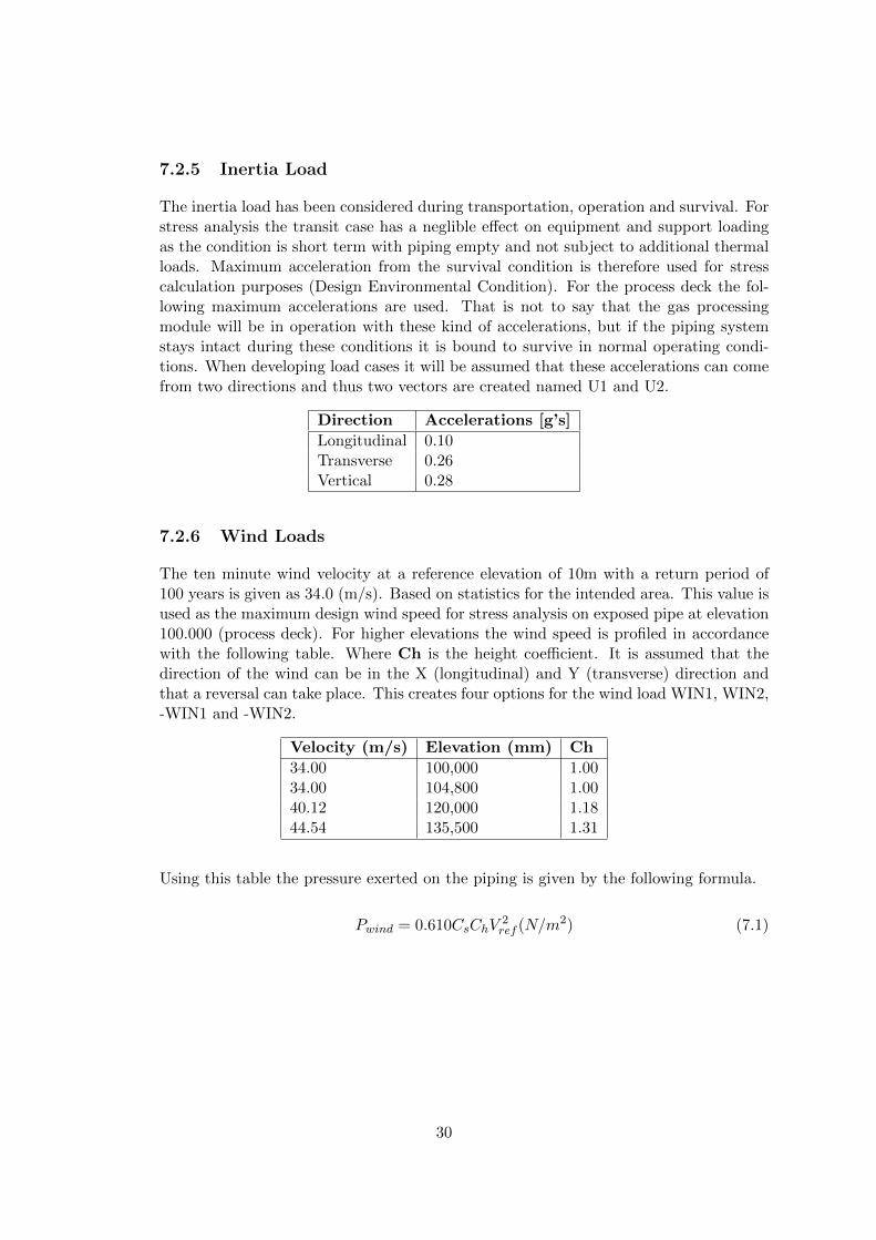
7.2.5 Inertia Load
The inertia load has been considered during transportation, operation and survival. Forstress analysis the transit case has a neglible effect on equipment and support loadingas the condition is short term with piping empty and not subject to additional thermalloads. Maximum acceleration from the survival condition is therefore used for stresscalculation purposes (Design Environmental Condition). For the process deck the fol-lowing maximum accelerations are used. That is not to say that the gas processingmodule will be in operation with these kind of accelerations, but if the piping systemstays intact during these conditions it is bound to survive in normal operating condi-tions. When developing load cases it will be assumed that these accelerations can comefrom two directions and thus two vectors are created named U1 and U2.
Direction Accelerations [g’s]
Longitudinal 0.10Transverse 0.26Vertical 0.28
7.2.6 Wind Loads
The ten minute wind velocity at a reference elevation of 10m with a return period of100 years is given as 34.0 (m/s). Based on statistics for the intended area. This value isused as the maximum design wind speed for stress analysis on exposed pipe at elevation100.000 (process deck). For higher elevations the wind speed is profiled in accordancewith the following table. Where Ch is the height coefficient. It is assumed that thedirection of the wind can be in the X (longitudinal) and Y (transverse) direction andthat a reversal can take place. This creates four options for the wind load WIN1, WIN2,-WIN1 and -WIN2.
Velocity (m/s) Elevation (mm) Ch
34.00 100,000 1.0034.00 104,800 1.0040.12 120,000 1.1844.54 135,500 1.31
Using this table the pressure exerted on the piping is given by the following formula.
Pwind = 0.610CsChV2ref (N/m2) (7.1)
30

7.2.7 Load Case Table
The following table displays the load cases to which the piping system is subjected.Load cases are built up using the prementioned loading conditions, using different com-binations the system is exposed to all loads that can be experienced during lifetime ofthe system.
Loadcase Combination Snubbers Description
1 (HGR) W -2 (HGR) W+D1+T1+P1 -3 (OPE) W+D1+T1+P1+H -4 (OPE) W+D2+T2+P1+H -5 (OPE) W+D3+T3+P1+H -6 (OPE) W+D1+T1+P1+H+U1+WIN1 active7 (OPE) W+D1+T1+P1+H+U1+WIN2 active8 (OPE) W+D1+T1+P1+H+U2-WIN1 active9 (OPE) W+D1+T1+P1+H+U2-WIN2 active10 (OPE) W+D2+T2+P1+H+U1+WIN1 active11 (OPE) W+D2+T2+P1+H+U1+WIN1 active12 (OPE) W+D2+T2+P1+H+U2-WIN1 active13 (OPE) W+D2+T2+P1+H+U2-WIN2 active14 (OPE) W+D3+T3+P3+H+U1+WIN1 active15 (OPE) W+D3+T3+P3+H+U1+WIN2 active16 (OPE) W+D3+T3+P3+H+U2-WIN1 active17 (OPE) W+D3+T3+P3+H+U2-WIN2 active18 (SUS) W+P1+H - sustained loadcase19 (HYD) WW+HP - hydrotest loadcase20 (OCC) L20=L6-L3 - occasional effect21 (OCC) L21=L7-L3 - occasional effect22 (OCC) L22=L8-L3 - occasional effect23 (OCC) L23=L9-L3 - occasional effect24 (OCC) L24=L18+L20 - occasional code stress25 (OCC) L25=L18+L21 - occasional code stress26 (OCC) L26=L18+L22 - occasional code stress27 (OCC) L27=L18+L23 - occasional code stress28 (EXP) L28=L3-L18 - expansion design hot29 (EXP) L29=L4-L18 - expansion design cold30 (EXP) L30=L5-L18 - expansion operating31 (EXP) L31=L3-L4 - expansion range
31

7.3 Results Analysis
This section presents the results of the analysis based on the CAESAR2 model. Due tothe large quantity of data that is computed by the model, the most important resultswill be summarised. For a detailed presentation of the model results please refer to theappendix of the report, an overview of the model is given below.
Figure 7.1: CAESAR2 Model
32

As stated earlier lines were modeled individually to reduce complexity of the model.Figure 7.2 is an image the second discharge line. Nozzle loads are combined later in theAPI617 calculation.
Figure 7.2: Discharge 2 Line
33

7.3.1 ASME B31.3 Code Compliance
To comply with ASME B31.3 code requirements the beneath stated conditions need tobe met. CAESAR2 will test the resulting stresses generated by each load case against thefollowing criteria, depending on the load case category. For every load case the stresseswere below the allowable stress, thus the system complies to the code for stress. Thisis not surprising, since the system isolation loops creates freedom for thermal growth,stress relief, and is properly supported. Therefore secondary, expansion stresses are notvery high also the system is relatively ‘cold’ from a pipe stress point of view.
Sustained StressSsustained < Sh (Allowable stress at design temperature)Displacement StressSexpansion < Sa (Allowable stress range)Occasional StressSoccasional < 1.33Sh
The table below gives the code stress for the highest temperature and pressure lineto give the reader an idea of the stresses present. As stated earlier the three types ofstresses are assessed independently. The first stresses in the table are the sustainedstresses, HYD is for the hydrotest of the system water weight and hydrotest pres-sure. Then there are the occasional stress components due to environmental conditions.Lastly we see the expansion stresses. The expansion stresses are quite low in comparisonwith the occasional and sustained stresses.
Case Node Code Stress N/mm2 Allowable Stress N/mm2 Code Stress Ratio
18 &(SUS) W+P1+H 4715 64.9 137.9 47.119 &(HYD) WW+HP 4715 81.6 241.3 33.824 &(OCC) L24=L18+L20 4560 67.1 183.4 36.625 &(OCC) L25=L18+L21 4560 67.5 183.4 36.826 &(OCC) L26=L18+L22 4560 68.9 183.4 37.627 &(OCC) L27=L18+L23 4560 69 183.4 37.628 &(EXP) L28=L3-L18 4720 19.9 282.1 7.129 &(EXP) L29=L4-L18 4399 9.9 290.8 3.431 &(EXP) L31=L3-L4 4399 27.8 282.1 9.9
34

7.3.2 API617 Nozzle Loads
A bigger challenge for the piping system is the interface with the centrifugal compressor,to meet the API nozzle load requirements. For all relevant load cases the individualand combined load cases are in the allowable range. Table beneath shows the load casesand the results percentage wise of the combined nozzle loads. Under normal operat-ing conditions combined nozzle loads are in the ’safe’ zone. Loadcases 14 to 17 areall occasional load cases based on the design environmental conditions. Though thecompressor will not be operating under these conditions, nozzle load compliance underthese conditions proves that the system is properly designed.
Loadcase Combination Combined Nozzle Loads %
5 (OPP) W+D3+T3+P1+H 34,55%14 (OPE) W+D3+T3+P3+H+U1+WIN1 91.29%15 (OPE) W+D3+T3+P3+H+U1+WIN2 93,35%16 (OPE) W+D3+T3+P3+H+U2-WIN1 79.70%17 (OPE) W+D3+T3+P3+H+U2-WIN2 90.43%
35
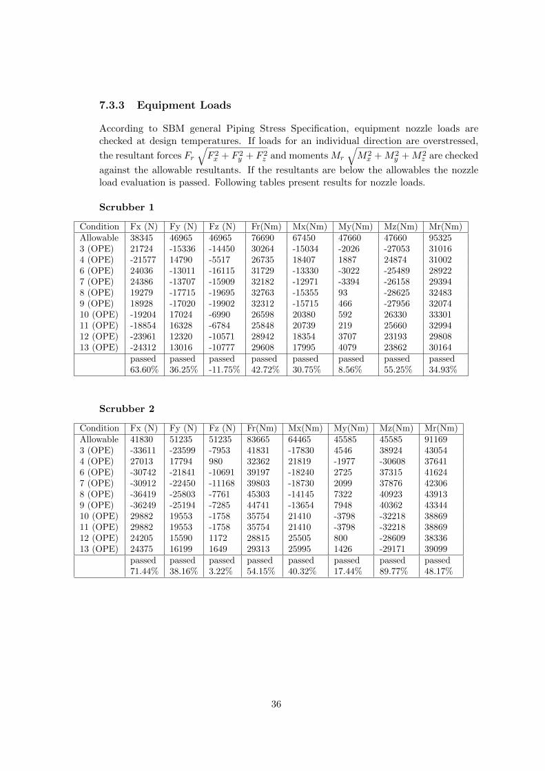
7.3.3 Equipment Loads
According to SBM general Piping Stress Specification, equipment nozzle loads arechecked at design temperatures. If loads for an individual direction are overstressed,
the resultant forces Fr
√F 2x + F 2
y + F 2z and moments Mr
√M2
x +M2y +M2
z are checked
against the allowable resultants. If the resultants are below the allowables the nozzleload evaluation is passed. Following tables present results for nozzle loads.
Scrubber 1
Condition Fx (N) Fy (N) Fz (N) Fr(Nm) Mx(Nm) My(Nm) Mz(Nm) Mr(Nm)Allowable 38345 46965 46965 76690 67450 47660 47660 953253 (OPE) 21724 -15336 -14450 30264 -15034 -2026 -27053 310164 (OPE) -21577 14790 -5517 26735 18407 1887 24874 310026 (OPE) 24036 -13011 -16115 31729 -13330 -3022 -25489 289227 (OPE) 24386 -13707 -15909 32182 -12971 -3394 -26158 293948 (OPE) 19279 -17715 -19695 32763 -15355 93 -28625 324839 (OPE) 18928 -17020 -19902 32312 -15715 466 -27956 3207410 (OPE) -19204 17024 -6990 26598 20380 592 26330 3330111 (OPE) -18854 16328 -6784 25848 20739 219 25660 3299412 (OPE) -23961 12320 -10571 28942 18354 3707 23193 2980813 (OPE) -24312 13016 -10777 29608 17995 4079 23862 30164
passed passed passed passed passed passed passed passed63.60% 36.25% -11.75% 42.72% 30.75% 8.56% 55.25% 34.93%
Scrubber 2
Condition Fx (N) Fy (N) Fz (N) Fr(Nm) Mx(Nm) My(Nm) Mz(Nm) Mr(Nm)Allowable 41830 51235 51235 83665 64465 45585 45585 911693 (OPE) -33611 -23599 -7953 41831 -17830 4546 38924 430544 (OPE) 27013 17794 980 32362 21819 -1977 -30608 376416 (OPE) -30742 -21841 -10691 39197 -18240 2725 37315 416247 (OPE) -30912 -22450 -11168 39803 -18730 2099 37876 423068 (OPE) -36419 -25803 -7761 45303 -14145 7322 40923 439139 (OPE) -36249 -25194 -7285 44741 -13654 7948 40362 4334410 (OPE) 29882 19553 -1758 35754 21410 -3798 -32218 3886911 (OPE) 29882 19553 -1758 35754 21410 -3798 -32218 3886912 (OPE) 24205 15590 1172 28815 25505 800 -28609 3833613 (OPE) 24375 16199 1649 29313 25995 1426 -29171 39099
passed passed passed passed passed passed passed passed71.44% 38.16% 3.22% 54.15% 40.32% 17.44% 89.77% 48.17%
36

HEX 1
Condition Fx (N) Fy (N) Fz (N) Fr(Nm) Mx(Nm) My(Nm) Mz(Nm) Mr(Nm)Allowable 22920 28075 28075 45845 31555 22315 22315 446283 (OPE) -8850 2633 -16336 18765 22519 -1976 5107 231754 (OPE) -15522 142 2999 15810 -5942 -21689 -3228 227196 (OPE) -15079 11182 -14268 23579 7841 -8267 -1291 114677 (OPE) -15457 12426 -15632 25252 7841 -9910 -2314 128478 (OPE) -10280 -5458 -19652 22840 38175 -4737 10933 399919 (OPE) -9901 -6702 -18289 21850 38174 -3094 11955 4012210 (OPE) -21916 8814 5035 24153 -20796 -28281 -9741 3643011 (OPE) -22295 10058 3671 24733 -20796 -29924 -10763 3799712 (OPE) -17117 -7826 -349 18824 9538 -24751 2483 2664113 (OPE) -16739 -9070 1015 19065 9537 -23108 3506 25243
passed passed passed passed overstressed overstressed passed passed-38.61% 44.26% 17.93% 55.08% 120.98% -8.86% 53.57% 89.90%
HEX 2
Condition Fx (N) Fy (N) Fz (N) Fr(Nm) Mx(Nm) My(Nm) Mz(Nm) Mr(Nm)Allowable 17865 21880 21880 35730 19950 14110 14110 282173 (OPE) -9350 -7490 4700 12869 -15609 8105 -2226 177284 (OPE) -15211 1618 1244 15347 699 19075 1039 191166 (OPE) -12742 -4944 7595 15636 -12865 11190 -2985 173107 (OPE) -12668 -4246 7061 15112 -12375 10995 -3512 169228 (OPE) -12481 -10603 2771 16610 -20021 11622 -791 231639 (OPE) -12555 -11302 3305 17213 -20511 11816 -263 2367310 (OPE) -19110 4196 4253 20022 3230 23276 3 2349911 (OPE) -19110 4196 4253 20022 3230 23276 3 2349912 (OPE) -18728 -1471 -598 18795 -3876 23441 2263 2386713 (OPE) -18800 -2170 -64 18925 -4365 23631 2792 24192
fail passed passed passed fail overstressed passed passed-52.34% 19.18% 34.71% 56.04% 16.19% 167.48% 19.79% 85.74%
37
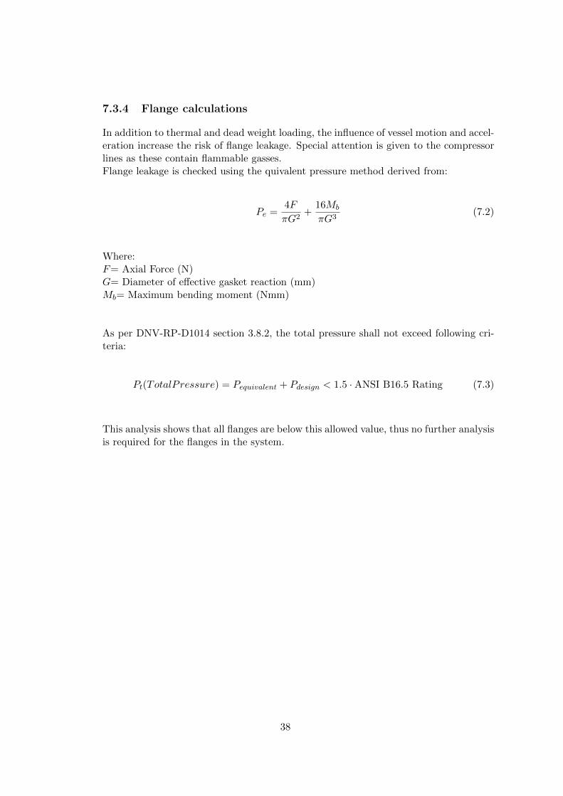
7.3.4 Flange calculations
In addition to thermal and dead weight loading, the influence of vessel motion and accel-eration increase the risk of flange leakage. Special attention is given to the compressorlines as these contain flammable gasses.Flange leakage is checked using the quivalent pressure method derived from:
Pe =4F
πG2+
16Mb
πG3(7.2)
Where:F= Axial Force (N)G= Diameter of effective gasket reaction (mm)Mb= Maximum bending moment (Nmm)
As per DNV-RP-D1014 section 3.8.2, the total pressure shall not exceed following cri-teria:
Pt(TotalPressure) = Pequivalent + Pdesign < 1.5 · ANSI B16.5 Rating (7.3)
This analysis shows that all flanges are below this allowed value, thus no further analysisis required for the flanges in the system.
38

8
Conclusion
Here we shall review if the main objective and goals of the assignment have been ac-complished. As a reminder the objective of the project is to set a standard philosophyfor the compressor pipe routing to be used as a reference for future projects. Duringthe assignment an appropriate method has been found to route and support the pipingwhich is directly at the interface of the compressor. The key to achieving this is byisolating the compressor from the rest of the piping system. This has been achievedby designing an ‘isolation loop’ round the compressor that is separated from the restof the system by an axial stop. This axial stop has been positioned in line with thefixed point on the compressor to create equal growth on both sides of the loop. Thisisolation loops functions well for the normal load cases and absorb thermal growth ofthe system. However it can reate an additional problem for the compressor nozzlesunder harsh environmental conditions. To solve this problem, inertia load on the loopshas been reduced by installing snubbers. Variable spring hangers are always requiredto allow vertical growth but allow continuous vertical support. Outcome of this routingis that the API617 Centrifugal Compressor Nozzle Loads are satisfied, even for designenvironmental conditions.
Design-wise and in CAESAR2 this approach works, but it is recommended that thisapproach is to be tried in a PDMS model and on a physical module, to find out if itworks in practice. The removable spool necessary for maintenance, hydrotesting andcompressor nozzle alignment is still not ideal. Recommendation is made for furtherstudy and investigation, to see if a more practical solution can be reached. This spoolcould be pressure tested separately and installed afterwards. Further study could alsobe done into optimising the rest of the compressor module layout. Biggest lesson fromthis investigation is that engineering of FPSO modules requires a multidisciplinary ap-proach. Ideally one would not make compromises on his design but sometimes thisnecessary to fulfil requirements of another discipline. Nevertheless safety requirementsshould never be compromised due to higher engineering and construction costs.
39

9
Bibliography
API. “API 617 Axial and Centrifugal Compressors and Expander-compressors for Petroleum,Chemical and Gas Industry Services,” (2009). Web. 21 Dec. 2011. www.api.org.
ASME. “ASME 16.5 Flanges.” (2009). Web. 21 Dec. 2011. www.asme.org
ASME. “B31.3 Process Piping Design.” (2009). Print. www.asme.org
DNV. “DNV-RP-D101: Structural Analysis of Piping Systems.” (2008). Web. 21Dec. 2011. www.dnv.com.
Kellogg, M. W. Design of Piping Systems. Wiley, 1965. Print.
Peng, Liang-Chuan, and Tsen-Loong Peng. Pipe Stress Engineering. New York: ASME,2009. Print.
Petrobras. “Petrobras Business Plan.” Petrobras - Energia, Tecnologia E Desenvolvi-mento Sustentvel. Web. 21 Dec. 2011. www.petrobras.com.br/ri.
Subsea 7.“Subsea7 - Brazil.” Subsea7 - Home. Web. 21 Dec. 2011. www.subsea7.com/brazil.html.
ABS. “Guide for building and classing floating production installations” ABS, 2009.
SBM Coporate Engineering Standards
Piping Material Classes Standard Specification ES45000-T92022
Piping Plant Layout Design Standard ES45000-SPT92019
Piping Flushing Testing Standard Specification ES45000-SPT95001
Piping Stress Standard Specification ES45000-SPT92021
40

Mechanical Equipment Nozzle Loading ES45000-SKF92060
Mechanical Handling Design Philosophy ES45000-SKF92015
41

10
Appendix
The following list shows the content of the appendix. The reader is strongly advisedto refer to the appendix whilst reading the report. For practical reasons large A3 sizedrawings are found in this appendix. Preview of the contents of the calculations aregiven behind cover sheets. Considering the environment and cost of paper, the reader iskindly asked to refer to the included CD-ROM for full calculation reports (hundreds ofpages). Most important results from calculations have been included within the reportin a summarised format.
1. Vendor Drawings
2. Design Drawings
3. Stress Isometrics
4. Code Compliance and Restraints
5. API617 Reports
6. CAESARII Input Echo
7. CAESARII Files
42