2012 buoyancy lab d03-teamd3avionicssystemproject
TRANSCRIPT

Avionics System Project
Team D3
Dylan Carter, Jesse Cummings,
Kenneth Murphy, Rajesh Yalamanchili

Link Budgets for Communication
• Communication needs during the mission are divided
into distinct phases, each with its own set of
assumptions:
o Earth-Lunar Transit
o Lunar Operations
o Lunar EVA

Earth-Lunar Transit
• The assumptions made for the first phase of the mission
were:
• Communication with TDRSS, not DSN
o Diameter of receiving antenna of 4.9m
o Receiver system noise temperature of 100K
• Slant range was selected as the apogee radius of the
moon as a worst case scenario

Ku and S Band to Earth Link
Budgets
• The chosen diameter of the receiving antenna is 25.4
centimeters (1 foot) and is used for all subsequent
transmissions from the crew vehicle to TDRSS
• Link Margin for Ku Band is 3.22 dB, which is a safety
factor of 2.1, with a transmitter power of 0.75 Watts
• Link Margin for S Band is 3.15 dB, which is also a safety
factor of 2.1, with a transmitter power of 17 Watts

Lunar Operations
• The assumptions made for the second phase of the
mission were:
o The distance from the moon to the L2 point is 60,000
km
o The diameter of the receiving antenna of the L2 relay
satellite is 4.9 meters (based off of TDRSS receiver
diameter)
o The diameter of the L2 relay satellite transmitter was
assumed to be 2 meters (based off of TDRSS
transmitter diameter)

Ka Band to L2 Relay Satellite
• Because of the proximity of the satellite, the transmitter
diameter for communication to the L2 Relay Satellite was
assumed to be 10 centimeters
• The link margin for this signal was determined to be 57.5
dB, which results in an extremely large safety factor of
566,218 with a transmitter power of 1 Milliwatt
• Because of the huge link margin, communication is
practically guaranteed with the L2 Relay Satellite barring
malfunction of hardware

Ku Band of L2 Relay Satellite to
TDRSS
• The transmitter diameter was 2 meters, as per the
specifications of the TDRSS satellites
• The link margin for this signal was determined to be 3.19
dB, which is a safety factor of 2.1 with a transmitter
power of 0.01 Watts

Lunar EVA
• The assumptions made for this phase of the mission
were:
o A maximum slant range of 15 kilometers, based on an
expansion of the 12.1 kilometer distance achieved
during the Apollo 17 mission
o A receiver system noise temperature of 100K
o An omni-directional transmitter/receiver

EVA UHF Band
• The link margin for this signal was determined to be
10.87 dB (safety factor of 12.2), with a transmitter power
of 0.01 Watts
• The low power consumption of this system is
advantageous to this phase of the mission, where low
power requirements are necessary for periods of time
when the vehicle will not be exposed to the sun to
generate power. The same holds true for the Ka to L2
Relay Satellite Band.

Sensors
• Many sensors required to measure and regulate state of
the craft
o Regulate crew cabin conditions
o Identify relative attitude and position in free space
o Track usage of propellants and consumables
o Measure power requirements and consumption
Crew Systems Sensors
• Life support of crew is of the highest importance
o Unwanted deviation from design conditions can
cause reduced human performance or death
o Excessively high or low temperature may damage
components
o Improper depressurization prior to EVA wastes
valuable oxygen stores
o If emergency redundancy systems are in place, must
be aware of system failures

Crew Systems Sensors
• Measured Quantities:
o Cabin Pressure
Used at all times by O2 and N2 resupply systems
Also monitored during airlock operation
o Atmosphere Composition
Regulate relative composition of O2 and N2
Measure CO2 and H2O for proper scrubbing
o Tank Pressures
Pressure transducer data used by helium
pressurization system for O2 and N2 tanks
o Consumables Remaining
Flow rate monitored during operation to track usage
Crew Systems Sensors
• Measured Quantities (continued):
o Waste Tank Level
Monitored for proper waste ejection
o Temperature
Internal and external thermocouples for best
thermal control
Used at all times by thermal regulation system
o Radiation
Geiger counter to identify unexpected radiation
Alerts crew to hazardous conditions

Attitude and Position Sensors
• Accurately determining relative position and orientation
in space is critical to mission success
o Attitude must be correctly estimated to perform
successful orbital maneuvers
o Entry, descent, and landing rely on accurate
proximity and relative position measurements
o Can be very difficult to determine exact relative
position and velocity in free space

Attitude and Position Sensors
• Measured Quantities:
o Attitude
Sun sensor measures attitude relative to the Sun
Star tracker compares star profile against database
to obtain attitude relative to stars (free space)
Magnetometer gets attitude relative to geomagnetic
field (only effective near Earth)
IMU and gyros track angular changes over time
o Rotation
Gyros and MEMS measure angular rotation
IMU tracks angular acceleration over time to obtain
velocity

Attitude and Position Sensors
• Measured Quantities (continued):
o Position
Laser rangefinder determines distance from lunar
surface during landing
IMU tracks position changes over time
o Velocity
IMU and MEMS can determine velocity from
acceleration changes
o Acceleration
IMU and MEMS measure instantaneous
acceleration

Propellant Sensors
• Proper staging and engine performance rely on accurate
measurements of propellant usage
o Helium pressurization requires constant pressure
measurement
o Spent stages detach when tanks are empty
o Measured Quantities:
o Propellant Tank Pressure
Same type of system as on crew consumables tanks
Used by helium pressurization system
o Propellant Usage
Same type of system as on crew consumables tanks
Flow rate monitored during operation to track usage

Power Consumption Sensors
• Important to track power consumption and production,
and demand on power supply
• Measured Quantities:
o H2 Levels in Fuel Cells
Determines remaining fuel in power supply
o Power Consumption
Multimeter measures power draw from all
systems

Sensor List
Sensor Sensor Type Sampling Rate Location Number Criticality*
Atmospheric O2 Apogee Instrument
Oxygen Sensors
0.084 Hz Radially-mounted on inside
cabin wall
4 1
Atmospheric N2 OxyCheq R-33N Nitrogen
Sensors
0.1 Hz Unique locations inside the
cabin
2 2
Atmospheric
CO2
CO2Meter Carbon Dioxide
Sensors
2 Hz Radially-mounted on inside
cabin wall
4 1
Cabin Pressure Setra Model 270 100 Hz Mounted inside cabin 2 1
Oxygen Tank GEMS SENSORS Flow
rate sensor
30 Hz Mounted in-line with feed
lines
2 2
Swagelok Explosion-Proof
Pressure Transducer
1 kHz Mounted inside tank 2 3
Nitrogen Tank GEMS SENSORS Flow
rate sensor
30 Hz Mounted in-line with feed
lines
2 2
Swagelok Explosion-Proof
Pressure Transducer
1 kHz Mounted inside tank 2 3
Cabin Humidity Omega Relative Humidity
Sensor
Mounted inside cabin 2 3
Water Tank GEMS SENSORS Flow
rate sensor
30 Hz Mounted in-line with feed
lines
2 2
Swagelok Explosion-Proof
Pressure Transducer
1 kHz Mounted inside tank 2 3
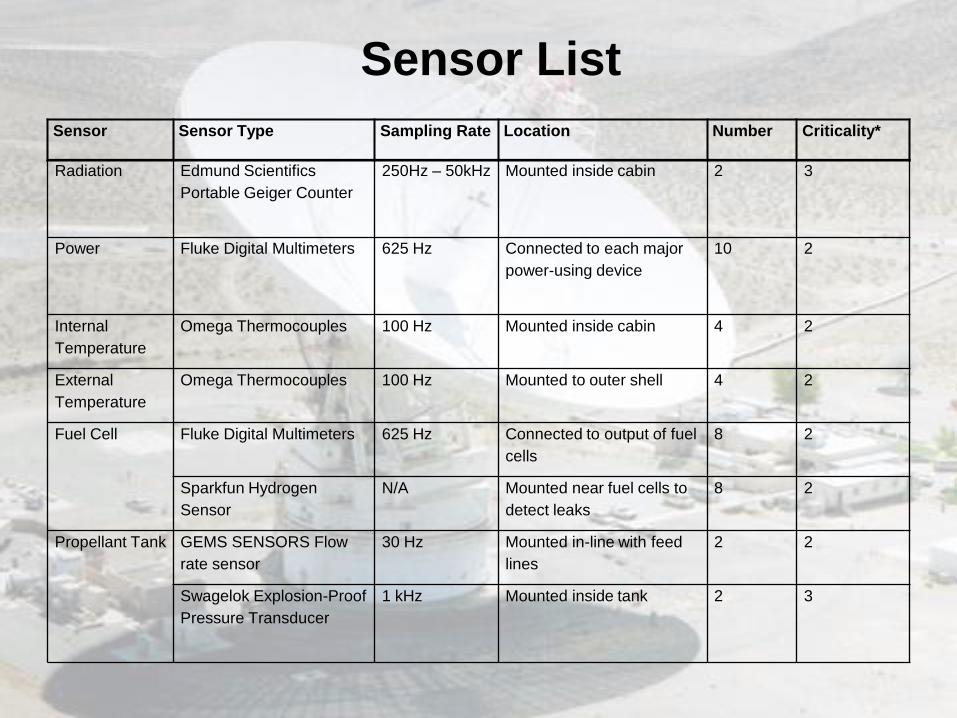
Sensor Sensor Type Sampling Rate Location Number Criticality*
Radiation Edmund Scientifics
Portable Geiger Counter
250Hz – 50kHz Mounted inside cabin 2 3
Power Fluke Digital Multimeters 625 Hz Connected to each major
power-using device
10 2
Internal
Temperature
Omega Thermocouples 100 Hz Mounted inside cabin 4 2
External
Temperature
Omega Thermocouples 100 Hz Mounted to outer shell 4 2
Fuel Cell Fluke Digital Multimeters 625 Hz Connected to output of fuel
cells
8 2
Sparkfun Hydrogen
Sensor
N/A Mounted near fuel cells to
detect leaks
8 2
Propellant Tank GEMS SENSORS Flow
rate sensor
30 Hz Mounted in-line with feed
lines
2 2
Swagelok Explosion-Proof
Pressure Transducer
1 kHz Mounted inside tank 2 3
Sensor List
Sensor List
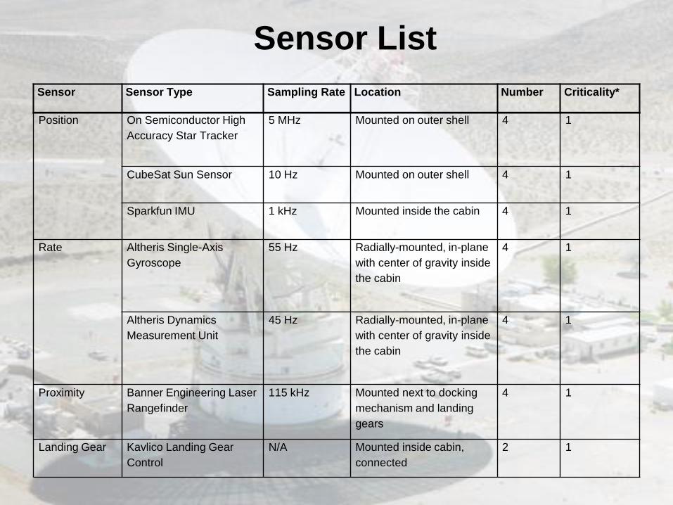
Sensor Sensor Type Sampling Rate Location Number Criticality*
Position On Semiconductor High
Accuracy Star Tracker
5 MHz Mounted on outer shell 4 1
CubeSat Sun Sensor 10 Hz Mounted on outer shell 4 1
Sparkfun IMU 1 kHz Mounted inside the cabin 4 1
Rate Altheris Single-Axis
Gyroscope
55 Hz Radially-mounted, in-plane
with center of gravity inside
the cabin
4 1
Altheris Dynamics
Measurement Unit
45 Hz Radially-mounted, in-plane
with center of gravity inside
the cabin
4 1
Proximity Banner Engineering Laser
Rangefinder
115 kHz Mounted next to docking
mechanism and landing
gears
4 1
Landing Gear Kavlico Landing Gear
Control
N/A Mounted inside cabin,
connected
2 1

Basic Avionics Sensor Architecture
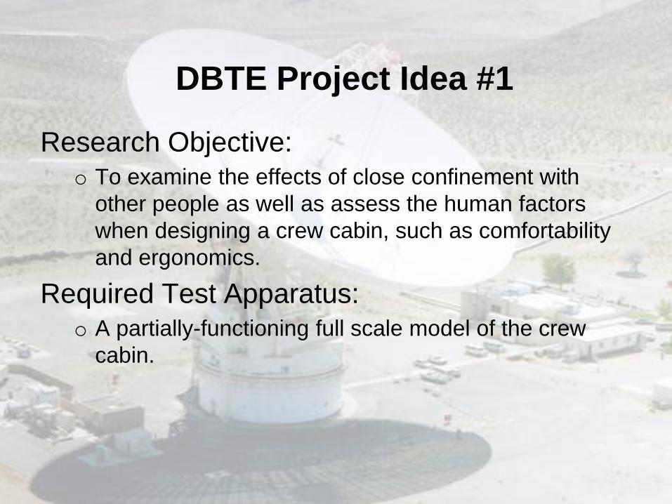
DBTE Project Idea #1
Research Objective:
o To examine the effects of close confinement with
other people as well as assess the human factors
when designing a crew cabin, such as comfortability
and ergonomics.
Required Test Apparatus: o A partially-functioning full scale model of the crew
cabin.

DBTE Project Idea #1
Test Operations:
o A group of three volunteer students in the class
would go through a partial mission simulation of the
most stressful mission phase, Earth-Lunar transit. The
"realness" of the simulation could be varied as
deemed appropriate. Students partaking in the
simulation would keep a log of what could be
changed about the layout of the crew cabin and the
functionality of certain components.

DBTE Project Idea #2
Research Objective:
o To design and build a functional docking mechanism
for the capsule. A compact docking mechanism inside
the nose cone of the capsule is critical for a staged
mission to the moon.
Required Test Apparatus: o A full-scale model of the nose cone geometry for use
in the neutral buoyancy tank in the Space Systems
Laboratory.

DBTE Project Idea #2
Test Operations:
o A group of students (ideally belonging to the
structures group) designs and builds a functioning
model of the docking mechanism and what it couples
to. Using the neutral buoyancy tank, scuba-certified
students will simulate docking using real approach
rates according to NASA standards. Assuming
successful docking, functionality and improvements to
the design will be assessed based on the results of
the simulation.
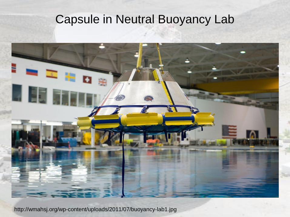
Capsule in Neutral Buoyancy Lab
http://wmahsj.org/wp-content/uploads/2011/07/buoyancy-lab1.jpg
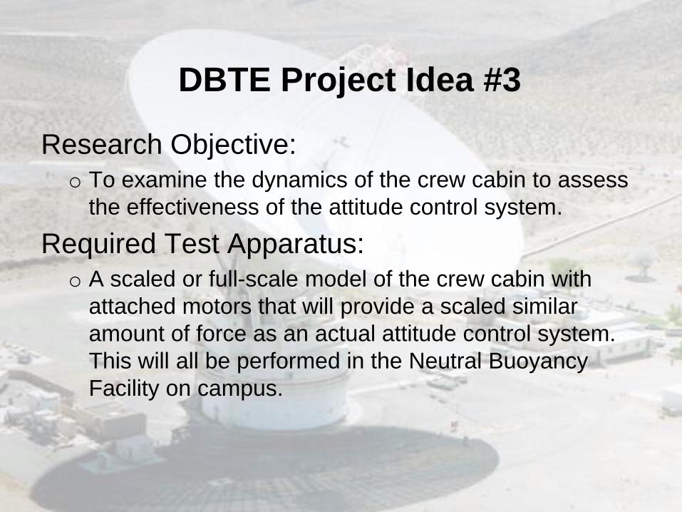
DBTE Project Idea #3
Research Objective:
o To examine the dynamics of the crew cabin to assess
the effectiveness of the attitude control system.
Required Test Apparatus:
o A scaled or full-scale model of the crew cabin with
attached motors that will provide a scaled similar
amount of force as an actual attitude control system.
This will all be performed in the Neutral Buoyancy
Facility on campus.

DBTE Project Idea #3
Test Operations:
o A team would first determine how to attach foam
blocks onto the cabin to make it neutrally buoyant
while minimizing the effects this has on the dynamics
of the object. After that is completed, underwater
thrusters would be attached to the cabin to simulate
real attitude control thrusters, and the effectiveness of
the system can be roughly approximated.
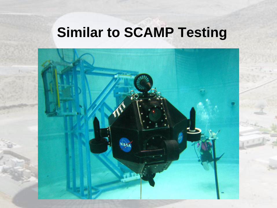
Similar to SCAMP Testing

CO2 Meter. CO2Meter. 14 Dec. 2012 <http://www.co2meter.com/collections/co2-sensors>.
Digital Multimeters. Fluke Instruments. 14 Dec. 2012
<http://www.fluke.com/Fluke/usen/Products/categorydmm.htm?id=DMMfunnel-en>.
Flow Rate Sensor. GEMS SENSORS. 14 Dec. 2012 <http://www.grainger.com/Grainger/GEMS-
SENSORS-Flow-Rate-Sensor-4ARL1>.
High Accuracy Star Tracker. ON Semiconductor. 14 Dec. 2012
<http://www.onsemi.com/PowerSolutions/product.do?id=HAS2>.
Hydrogen Gas Sensor. Sparkfun. 14 Dec. 2012 <https://www.sparkfun.com/products/10916>.
IMU Digital Combo Board. Sparkfun. 14 Dec. 2012
<https://www.sparkfun.com/products/10121>.
"Landing Gear Control (LGC)." Landing Gear Control (LGC). Kavlico Sensing Solutions. 14
Dec. 2012 <http://www.kavlico.com/catalog/landing_gear_control.php?section=products>.
Sensor Links

Sensor Links
Laser Sensors. Banner Engineering. 14 Dec. 2012 <http://www.bannerengineering.com/en-
US/products/8/Sensors/38/Laser-Sensors>.
Model 270. Setra. 14 Dec. 2012 <http://www.setra.com/ProductDetails/270_Baro.htm>.
OxyCheq. OxyCheq. 13 Dec. 2012
<www.oxycheq.com/index.php?main_page=product_info&cPath=1_6&products_id=28>.
Oxygen Sensors. Apogee Instruments. 14 Dec. 2012
<http://www.apogeeinstruments.com/oxygensensor/>.
Portable Geiger Counter. Edmund Scientifics. 14 Dec. 2012
<http://www.scientificsonline.com/portable-geiger-counter.html>.
Pressure Transducers. Swagelok. 14 Dec. 2012
<http://www.swagelok.com/products/measurement-devices/pressure-transducers.aspx>.

Sensor Links
Relative Humidity Sensor. Omega. 14 Dec. 2012
<http://www.omega.com/ppt/pptsc.asp?ref=HX15&Nav=temhu06>.
Silicon MEMS Single-Axis Gyros. Altheris. 14 Dec. 2012
<http://www.altheris.com/products/angular-rate-silicon-MEMS-single-axis-gyros.htm>.
Sun Sensor. Cubesat. 14 Dec. 2012
<http://www.cubesatshop.com/index.php?page=shop.product_details&product_id=104&flyp
age=flypage.tpl&pop=0&option=com_virtuemart&Itemid=65&vmcchk=1&Itemid=65>.
Thermocouples. Omega. 14 Dec. 2012 <http://www.omega.com/prodinfo/thermocouples.html>.
SCAMP Testing. 8 Aug. 2007
<http://spacecraft.ssl.umd.edu/SSL.photos/NBtest.photos/NBtest.2007/070808.NB07-
078/070808.NB07-078.19.jpg>.