2013 – 2014 jx/qx60; judder during light acceleration
TRANSCRIPT

1/20
Classification: Reference: Date:
AT13-018 ITB13-037 September 20
10, 13
2013 – 2014 JX/QX60; JUDDER DURING LIGHT ACCELERATION APPLIED VEHICLE: 2013 JX (L50)
2014 QX60 (L50) Built after 5N1AL0M(**)DC 343902 and MAR 26, 2013
APPLIED TRANSMISSION: CVT IF YOU CONFIRM
When driving an Applied Vehicle a judder (shudder, single or multiple bumps or vibrations) happens during light acceleration,
and all of the following when the issue occurs:
• Vehicle speed is between 5 and 35 mph.
• Throttle position is about 10%.
• When issue occurs, if more throttle is applied issue stops.
• No DTCs are stored. ACTION
1. To determine the root cause perform the Service Procedure starting on page 3. 2. Should reprogramming the TCM NOT resolve the concern, first verifying the vehicle’s service history and then
recording and analyzing the data with Consult III plus (C-III plus) as the symptom occurs is required to accurately determine the root cause of the incident, if it should occur.
NOTE: This bulletin does not apply to a condition called “fuel economy drone”. If the customer describes their issue as a lugging or as a groan/drone at low speed this is a normal condition to maximize fuel economy. Some customers will describe the condition as similar to a manual transmission vehicle in high gear at low speed.
IMPORTANT: The purpose of "ACTION" (above) is to give you a quick idea of the work you will be performing. You MUST closely follow the entire Service Procedure as it contains information that is essential to successfully completing this repair. Infiniti Bulletins are intended for use by qualified technicians, not 'do-it-yourselfers'. Qualified technicians are properly trained individuals who have the equipment, tools, safety instruction, and know-how to do a job properly and safely. NOTE: If you believe that a described condition may apply to a particular vehicle, DO NOT assume that it does. See your Infiniti dealer to determine if this applies to your vehicle.
SB-10053323-9461

FLOW CHART A
A Judder, Bump or Shock sensation is confirmed
(low speed)
Reprogram the TCM and attempt duplication
Was the Issue duplicated?
No
Record the data using CIII plus
Lock up shock caused by the
Torque Converter
Analyze CIII plus data
Pressure Vibration
Replace the Torque Converter
Procedure complete
Replace the CVT
Yes
2/20 ITB13-037

SERVICE PROCEDURE TCM Reprogramming NOTE:
• Most instructions for reprogramming with CONSULT-III plus (C-III plus) are displayed on the CONSULT PC screen.
• If you are not familiar with the reprogramming procedure, click here. This will link you to the "CONSULT- III plus (C-III plus) Reprogramming" general procedure.
CAUTION:
• Connect a battery charger to the vehicle battery. If the vehicle battery voltage drops below 12.0V or rises above 15.5V during reprogramming, the TCM may be damaged.
• Be sure to turn OFF all vehicle electrical loads.
If a vehicle electrical load remains ON, the TCM may be damaged.
• Be sure to connect the AC Adapter. If the CONSULT PC battery voltage drops during reprogramming, the process will be interrupted and the TCM may be damaged.
• Turn off all external Bluetooth® devices (e.g., cell phones, printers, etc.) within range of the
CONSULT PC and the VI. If Bluetooth® signal waves are within range of the CONSULT PC during reprogramming, reprogramming may be interrupted and the TCM may be damaged.
3/20 ITB13-037

1. Connect the CONSULT PC to the vehicle to begin the reprogramming procedure. 2. Start CONUSLT-III (C-III) plus. 3. Wait for the plus VI to be recognized.
• The serial number will display when the plus VI is recognized. 4. Select Re/programming, Configuration.
VI is recognized
Step 4
Figure 1 5. Follow the on-screen instructions and navigate the C-III plus to the screen shown in Figure 2 on the next page.
4/20 ITB13-037

6. When you get to the screen shown in Figure 2, confirm this bulletin applies as follows.
A. Find the TCM Part Number and write it on the repair order.
NOTE: This is the current TCM Part Number (P/N).
TRANSMISSION 6A: Current TCM P/N
Fig
B. Compare the P/N you wrote down to the numbersbelow.
• If there is a match, this reprogramming appl
• If there is not a match, this reprogramming i
Table A
Model Model Year
Curren
JX/QX60 (L50) 13-14MY
5
31036 - _ _ _ _ _
ure 2
in the Current TCM Part Number column in Table A
ies. Continue with the reprogramming procedure.
s not needed.
t TCM Part Number Before Reprogramming: 31036 -
9NA6A, 3JU0A
/20 ITB13-037

7. Follow the on-screen instructions to navigate C-III plus and reprogram the TCM.
NOTE:
• In some cases, more than one new P/N for reprogramming is available.
In this case, the screen in Figure 3 displays.
Select and use the reprogramming option that does not have the message “Caution! Use ONLY with NTBXX-XXX”.
• If you get this screen and it is blank (no reprogramming listed), it means there is no reprogramming available
for this vehicle. Close C-III plus and refer back to ASIST for further diagnosis.
IMPORTANT: If C-III plus locks up or freezes at this point or displays “cannot complete reprogramming, the CONSULT PC is set up with User Rights. Reprogramming can be completed with Administrator log in”, the TOUGHBOOK settings need to be changed so that Users have full access rights. See your Dealership’s IT System Administrator for details.
TRANSMISSION
Figure 3
6/20 ITB13-037
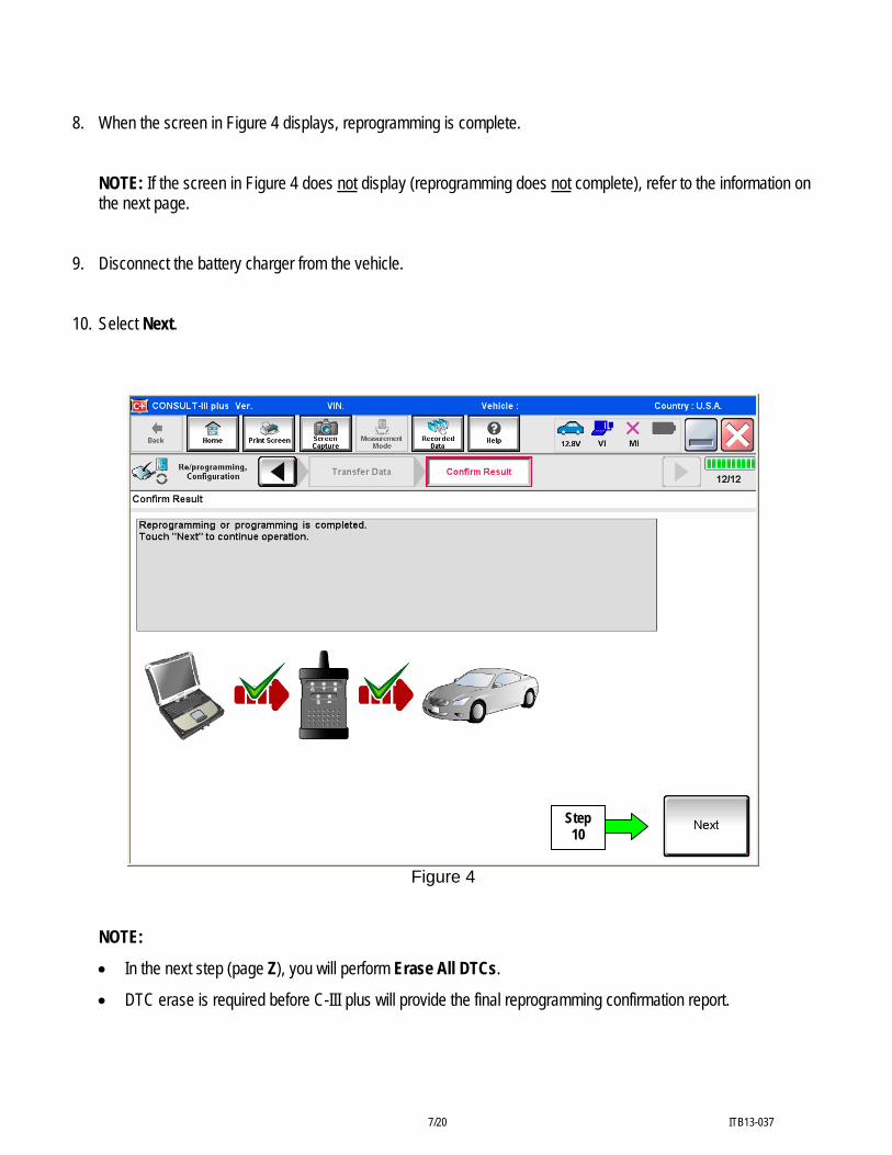
8. When the screen in Figure 4 displays, reprogramming is complete.
NOTE: If the screen in Figure 4 does not display (reprogramming does not complete), refer to the information on the next page.
9. Disconnect the battery charger from the vehicle. 10. Select Next.
Step 10
Figure 4
NOTE:
• In the next step (page Z), you will perform Erase All DTCs.
• DTC erase is required before C-III plus will provide the final reprogramming confirmation report.
7/20 ITB13-037

TCM recovery:
Do not disconnect plus VI or shut down C-III plus if reprogramming does not complete. If reprogramming does not complete and the “!?” icon displays as shown in Figure 5:
Figure 5
If reprogramming does not complete and the “X” icon displays as shown in Figure 6:
Figure 6
• Check battery voltage (12.0–15.5 V).
• Ignition is ON, engine OFF.
• External Bluetooth® devices are
OFF.
• All electrical loads are OFF.
• Select retry and follow the on screen instructions.
• “Retry” may not go through on first
attempt and can be selected more than once.
• Check battery voltage (12.0 – 15.5 V).
• CONSULT A/C adapter is plugged
in.
• Ignition is ON, engine OFF.
• Transmission is in Park.
• All C-III plus / VI cables are securely connected.
• All C-III plus updates are installed.
• Select Home, and restart the
reprogram procedure from the beginning.
8/20 ITB13-037

11. Follow the on-screen instructions to Erase All DTCs. 12. When the entire reprogramming process is complete, the screen in Figure 7 will display. 13. Verify the before and after part numbers are different. 14. Print a copy of this screen (Figure 7) and attach it to the repair order for warranty documentation. 15. Select Confirm.
Step 13
31036 - _ _ _ _ _
31036 - _ _ _ _ _
Step 14
TRANSMISSION
Step 15
Figure 7 16. Close C-III plus. 17. Turn the ignition OFF. 18. Disconnect the plus VI from the vehicle. 19. Make sure the vehicle operates correctly and the MIL is OFF.
9/20 ITB13-037
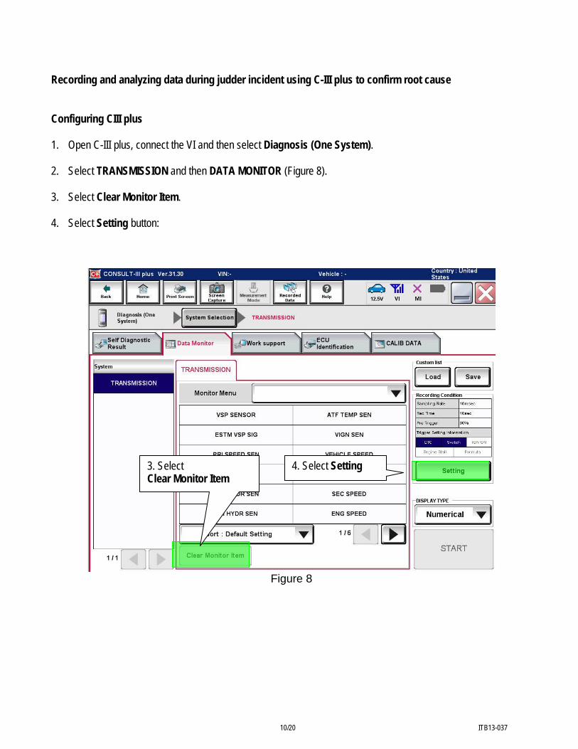
Recording and analyzing data during judder incident using C-III plus to confirm root cause Configuring CIII plus 1. Open C-III plus, connect the VI and then select Diagnosis (One System). 2. Select TRANSMISSION and then DATA MONITOR (Figure 8). 3. Select Clear Monitor Item. 4. Select Setting button:
3. Select Clear Monitor Item
4. Select Setting
Figure 8
10/20 ITB13-037

5. Under setting, select settings shown in Figure 9. • Manual trigger.
And then:
• Recording Time: 10sec.
• Sampling Rate: 10msec.
• Trigger Point (Pre/post):
Pre-Trigger 80% Post-Trigger 20%
Step 5
6. Select Confirm
Figure 9 6. Select Confirm to save the new Recording Conditions as the default.
11/20 ITB13-037

7. Select these 5 monitored signals ONLY from Monitor Menu and then select START when ready.
• INPUT REV • SEC SPEED • ENG SPEED • SEC PRESSURE • PRI PRESSURE
IMPORTANT: For this Service Procedure, select only the signals in step 6.
Use arrow to roll to the next page for more monitored signals
Figure 10
12/20 ITB13-037

8. Perform the customer’s described driving conditions to see if the judder incident can be duplicated.
• Once duplicated, immediately record the data with the C-III plus that was set up in steps 1-7 as the issue occurs.
Save and Review Recorded Data 9. After the C-III plus data has been recorded with DATA MONITOR, save the data file as
“FlyingGraph(last 8 of VIN).txt file” (example: FlyingGraphEM123456.txt file) onto the Consult PC desktop as shown in Figure 11.
NOTE: The Flying Graph software is available on the desktop of your Consult PC. It can be used for the data review. • Data files must be saved as “.txt file” type before it can be used with the Flying Graph application. Refer to
Figure 11 below for example. • For an illustration of the C-III plus desktop shortcut to the Flying Graph application see Figure 12 on the next
page.
Select Save first and then name the file
Save the recorded data as a “.txt file” onto the Consult PC desktop so that it can be viewed with the Flying Graph application.
Figure 11
13/20 ITB13-037

10. Open the .txt file saved to the Consult PC desktop in step 9 by dragging the text file on the desktop over the icon
for the Flying Graph application (see Figure 12 below).
Drag this icon over the Flying Graph application icon to open the file
Figure 12
14/20 ITB13-037

11 The Flying Graph will initially display only four (4) data channels. To display the 5th recorded channel, right click
to the left of the data channel not visible (see Figure 13) and click on “Add graph” to display the graph. 12. Review the INPUT REV, SEC SPEED, ENG SPEED, PRI PRESSURE and SEC PRESSURE signals for signs of
a “Pressure Vibration”.
• Figures 13 and 14 show reference examples of with and without a Pressure Vibration.
Figure 13
Repetitive Pressure Vibration in PRI and/or SEC Pressure signals.
These variations in PRI and SEC PRESSURE are a normal response to vehicle input.
Vibrations also present in one or more speed signals
Step 11. With mouse, right click here and select “Add graph”
15/20 ITB13-037

These variations in PRI and SEC PRESSURE are a normal response to vehicle input.
Figure 14
NOTE: Figure 14 shows INPUT REV, SEC SPEED, ENG SPEED, PRI PRESSURE and SEC PRESSURE from a vehicle that does not have a judder present.
13. During data review, if your data shows a Repetitive Pressure Vibration in either
PRI PRESSURE or SEC PRESSURE, and also shows an irregular (non-smooth) line in one or more speed signals (ENG SPEED, INPUT REV, SEC SPEED) as indicated in Figure 13, replace the CVT to resolve (Figure 13 shows Repetitive Pressure Vibrations circled in red).
• Do not replace the torque converter assembly if the data review shows Repetitive Pressure Vibration as described above.
• If a judder is present and the recorded data review shows that the data lines are smooth with no oscillations as shown in Figure 14 above refer to Torque Converter Replacement on page 17.
NOTE: Refer to the appropriate section of the Electronic Service Manual (ESM) for the procedure to replace the CVT, as needed.
• If a judder is present, recorded data review does not indicate pressure vibration and the torque converter in
the CVT is already “D” level or greater (see FLOW CHART B on page 17), refer to ASIST or the appropriate section of the ESM for further diagnostic assistance.
16/20 ITB13-037

FLOW CHART B
Check the stamping on the outside of the torque converter
25B 25C 25D 25E
DO NOT Replace the Torque Converter
Replace the Torque Converter
Serial Number
Serial Number
Greater than:
Greater than: Less than
or equal to: Less than or equal to:
35210393 37190633
35210393
DO NOT Replace the
Torque Converter
DO NOT Replace the
Torque Converter
35210393
Replace the Torque
Converter Replace the
Torque Converter
17/20 ITB13-037
Torque Converter Replacement 1. Replace the torque converter with the new one listed in the Parts Information:
• Refer to the TM section of the appropriate Service Manual for replacement information.
NOTE:
• Make sure the converter housing oil seal (front seal) is not damaged. If damaged, replace it.
• If the front seal is replaced, use special tool J-50817 (oil pump seal installer) to install and properly seat the seal.
• Make sure CVT fluid, as a lubricant, is applied to the front seal, torque converter snout, and input shaft o-ring seal before installation of the new torque converter.
18/20 ITB13-037

PARTS INFORMATION
DESCRIPTION PART Number QUANTITY Torque Converter (2) 31100 – 3WX0D 1
CVT ASSEMBLY (1) 1 NS-3 CVT Fluid 999MP-NS300P (3)
(1) Refer to the electronic parts catalog (FAST) for the correct CVT Assembly part number for the vehicle. (2) Due to limited supply, Part Number 31100-3WX0D will be on restriction for several weeks after the publication date of this
bulletin. If 31100 – 3WX0D is needed during the restriction period, use the Parts Order Form attached to the last page of this bulletin.
(3) As needed.
NS-3 CVT Fluid can be ordered from the Maintenance Advantage website that can be accessed through www.nnanet.com (NNANET.COM, Parts & Service, Maintenance Advantage-Tire/Wiper/Battery/Chemical). CLAIMS INFORMATION Submit a Primary Part (PP) type line claim using the following claims coding:
DESCRIPTION PFP OP CODE SYM DIA FRT Reprogram Transmission Control Module JE99AA (2)
Diagnose Judder ** (1) JX25AA ZE 32
1.0
OR
Submit a Primary Part (PP) type line claim using the following claims coding:
DESCRIPTION PFP OP CODE SYM DIA FRT Reprogram Transmission Control Module JE99AA
R&I Automatic CVT Transaxle Assy JD01AA
RPL Torque Converter Assy ** JD043A RPL Automatic CVT Transaxle JD023A
(2)
Diagnose Judder **
(1)
JX25AA
BE 32
1.0
(1) Refer to Parts Information above and use the Torque Converter Part Number (31100-XXXXX) as the PFP. (2) Reference the current Nissan Warranty Flat Rate Manual and use the indicated Flat Rate Time. ** Use these operation codes only if need for the diagnosis and actual repair performed.
19/20 ITB13-037

PARTS ORDER FORM for
2013 JX35 SHUDDER FROM TORQUE CONVERTER LOCK UP CLUTCH
INCOMPLETE ORDER FORMS WILL NOT BE PROCESSED
Dealer Code: Order Date:
Dealership Email Address: VIN Number: PDC: Sacramento PDC Orlando PDC
Los Angeles PDC Chicago PDC Dallas PDC Greenville PDC
Baltimore PDC Memphis – Olive Branch PDC New York PDC
Part Number Description Quantity
31100-3WX0D Torque Converter Send the completed form to:
Email to [email protected]
NOTE: This bulletin and Service Procedure is not a campaign. For convenience, the above email address is being used to fulfill and expedite this part request.
20/20 ITB13-037