2013 annual meeting of the aashto - etouches · referred to the guide specifications for seismic...
TRANSCRIPT

2013 Annual Meeting of the
AASHTOSubcommittee onBridges and Structures
June 16 – 20, 2013 • Portland Marriott Downtown Waterfront
Photo ©2010 Eric Vogt

2013 AASHTO BRIDGE SUBCOMMITTEE MEETING
TABLE OF CONTENTS
(As of May 15, 2013)
(Note: Agenda items for presentations are marked with alphabetical entries; those which are candidates as ballot items are sequentially numbered)
Item No. Item Page
Technical Committee Meetings
Main Meeting Schedule
A Welcome by Chairman and Host State of Oregon
B Service Resolutions and Remarks by Chairman, and Roll Call by Secretary
C Remarks by Secretary and FHWA Update – Myint Lwin
D Bridge Engineers’ Questionnaire – Sue Hida
E AASHTOWare Update – Tim Armbrecht
F Purdue S BRITE Engineering Center – Anne Rearick and Robert Conner
1 T-3 Committee (Seismic) – LRFD Bridge Design Specifications: Section 3, Articles 3.10.1 & 3.16
1
2 T-3 Committee (Seismic w/ T-14 Steel) – LRFD Bridge Design Specifications: Section 6, Various Articles
3
3 T-3 Committee (Seismic w/ T-14 Steel) – AASHTO Guide Specifications for LRFD Seismic Bridge Design, Sections 1, 2, 3, 4 & 7, Various Articles
6
G Column Design for Blast Loading – Eric Williamson
4 T-5 Committee (Loads) – LRFD Bridge Design Specifications: Section 3, Article C3.6.1.3.1 (WAI 37)
12
5 T-5 Committee (Loads) – LRFD Bridge Design Specifications: Section 4, Various Articles (WAI 48)
14
6 T-10 Committee (Concrete) – LRFD Bridge Design Specifications: Section 5, Articles 5.3, 5.8.3.6.3 & 5.8.6.4 (WAI 130-11)
17
7 T-10 Committee (Concrete) – LRFD Bridge Design Specifications: Section 5, Articles 5.8.2.5, C5.8.2.5 & C5.8.2.7 (WAI 130-05)
19
8 T-10 Committee (Concrete) – LRFD Design Specifications: Section 5, Articles 5.8.3.6.2 & C5.8.3.6.2 (WAI 130-10)
24
9 T-10 Committee (Concrete) – LRFD Bridge Design Specifications: Section 5, Articles C5.8.4.1, 5.8.4.2 & C5.8.4.2 (WAI 172)
27
10 T-10 Committee (Concrete) – LRFD Bridge Design Specifications: Section 5, Article 5.8.6.5 (WAI 130-07)
30
11 T-10 Committee (Concrete) – LRFD Bridge Design Specifications: Section 5, Articles 5.10.9.3.4b & C5.10.9.3.4b (WAI 152)
31
12 T-10 Committee (Concrete) – LRFD Bridge Design Specifications: Section 5, Various Articles (WAI 145)
35

Item No. Item Page
H University at Buffalo – Bridge Engineering Program – George Lee
13 T-11 Committee (Research) – Committee Report and Recommendations for Approval
50
I FHWA Research Update – Lou Triandafilou
14 T-13 Committee (Culverts) – LRFD Bridge Design Specifications: Section 12, Articles 12.8.9.3.1 & 12.8.9.6, Tables A12-14 & A12-15
51
J LTBP Update – Hamid Ghasemi
K John James Audubon Cable Stayed Bridge – Greg Shafer, Parsons
L Bridge Fabricator Certification Program – Jacques Cattan, AISC
15 T-14 Committee (Steel w/ T-5 Loads) – LRFD Bridge Design Specifications: Section 3, Articles 3.4.2.1 & 3.4.2.2 (T-5 WAI 47); Section 6, Article 6.5.4.1
54
16 T-14 Committee (Steel w/ T-5 Loads) – LRFD Bridge Design Specifications: Section 4, Various Articles
57
17 T-14 Committee (Steel w/ T-5 Loads) – LRFD Bridge Design Specifications: Section 4, Various Articles; Section 6, Article 6.10.1.5
61
18 T-14 Committee (Steel) – LRFD Bridge Design Specifications: Section 6, Article 6.5.4.2
65
19 T-14 Committee (Steel w/ T-12 Structural Supports for Highway Signs, Luminaires and Traffic Signals) – LRFD Bridge Design Specifications: Section 6, Table 6.6.1.2.3-1
67
20 T-14 Committee (Steel) – LRFD Bridge Design Specifications: Section 6, Article 6.7.4.1
70
21 T-14 Committee (Steel) – LRFD Bridge Design Specifications: Section 6, Article C6.7.4.2
71
22 T-14 Committee (Steel) – LRFD Bridge Design Specifications: Section 6, Articles 6.9.2.2, 6.9.5 & 6.17
73
23 T-14 Committee (Steel) – LRFD Bridge Design Specifications: Section 6, Articles C6.10.1 & 6.17
89
24 T-14 Committee (Steel) – LRFD Bridge Design Specifications: Section 6, Article C6.10.1.6 & 6.17
91
25 T-14 Committee (Steel) – LRFD Bridge Design Specifications: Section 6, Various Articles
93
26 T-14 Committee (Steel w/ T-4 Construction) – LRFD Bridge Construction Specifications: Section 11, Article 11.4.12.2.2 and LRFD Bridge Design Specifications: Section 6, Articles 6.7.7.1 and 6.7.7.2
107
M Bridge Railings Research - NCHRP 22-12(03) – Christine Carrigan
27 T-15 Committee (Substructures and Retaining Walls) – LRFD Bridge Design Specifications: Section 10, Various Articles
120
28 T-15 Committee (Substructures and Retaining Walls) – LRFD Bridge Design Specifications: Section 11, Article C11.6.2.3
173

Item No. Item Page
29 T-15 Committee (Substructures and Retaining Walls) – LRFD Bridge Design Specifications: Section 11, Articles 11.10.2.3.1 & 11.10.6.2.1
174
30 T-15 Committee (Substructures and Retaining Walls) – LRFD Bridge Design Specifications: Section 11, Articles 11.10.5.3 & C11.10.5.3
176
31 T-15 Committee (Substructures and Retaining Walls) – LRFD Bridge Design Specifications: Section 11, Articles 11.10.6.2.1 & 11.10.6.3.2
178
32 T-15 Committee (Substructures and Retaining Walls) – LRFD Bridge Design Specifications: Section 11, Article 11.10.6.4.2a
181
33 T-15 Committee (Substructures and Retaining Walls) – LRFD Bridge Design Specifications: Section 11, Article 11.10.6.4.2a
182
34 T-15 Committee (Substructures and Retaining Walls) – LRFD Bridge Design Specifications: Section 11, Article C11.10.6.4.2a
183
35 T-15 Committee (Substructures and Retaining Walls) – LRFD Bridge Design Specifications: Section 11, Article C11.10.11
185
36 T-15 Committee (Substructures and Retaining Walls) – LRFD Bridge Design Specifications: Section 11, Article C11.10.11 & Figure 11.10.10.1-2
187
37 T-15 Committee (Substructures and Retaining Walls) – LRFD Bridge Design Specifications: Section 11 D1.5 Bridge Welding Code: Section 2, Figure 2.4, Article 11.11.1
189
N SSL Mechanically Stabilized Wall Failure, Lessons Learned – Barton Newton
O TRB Research Update – Wassem Delkalbab
P Korean Highways Bridge Technology – Mr. Lee
Q SHRP 2 Bridge Research and Implementation – Gregg Fredrick
R Status of the High Chloride Content Study – Joey Hartman
38 T-17 Committee (Welding) – D1.5 Bridge Welding Code: Section 2, Figure 2.4 191
39 T-17 Committee (Welding) – D1.5 Bridge Welding Code: Section 3, Articles C3.13.1 & C3.13.2.1
193
S Software Inventory and Future Direction of T-19 – Scot Becker
T Element Migrator and Changes to the Element Level Inspection Manual – Allan Marshall
40 T-18 Committee (Bridge Management, Evaluation and Rehabilitation) – The Manual for Bridge Evaluation: Section 1, Various Articles (T18-1)
195
41 T-18 Committee (Bridge Management, Evaluation and Rehabilitation w/ T-14 Steel) – The Manual for Bridge Evaluation: Section 1, Article 1.6; Section 6, Articles C6A.4 & C6A.6; Part B, Articles C6B.5.2.1& C6B.5.3.1; and Appendix L6B (T18-3)
200
42 T-18 Committee (Bridge Management, Evaluation and Rehabilitation) – The Manual for Bridge Evaluation: Section 2, Various Articles (T18-2)
234
43 T-18 Committee (Bridge Management, Evaluation and Rehabilitation) – The Manual for Bridge Evaluation: Section 6, Article 6A.4.1 (T18-6)
241

Item No. Item Page
44 T-18 Committee (Bridge Management, Evaluation and Rehabilitation) – The Manual for Bridge Evaluation: Section 6, Various Articles (T18-8)
243
45 T-18 Committee (Bridge Management, Evaluation and Rehabilitation w/ T-14 Steel) – The Manual for Bridge Evaluation: Section 6, Articles 6A.6.3 and C6A.6.3 (T18-9)
246
46 T-18 Committee (Bridge Management, Evaluation and Rehabilitation) – The Manual for Bridge Evaluation: APPENDIX A: Illustrative Examples, Table of Contents & Example A11 (T18-4)
248
47 T-18 Committee (Bridge Management, Evaluation and Rehabilitation) – The Manual for Bridge Evaluation: APPENDIX A: Illustrative Examples, Table of Contents (T18-5)
280
48 T-18 Committee (Bridge Management, Evaluation and Rehabilitation) – AASHTO Guide Manual for Bridge Element Inspection: Section 3 (T18-7) (Provided on CD)
282
U Editorial Changes – John Kulicki 284
V Announcement of 2014 SCOBS in Columbus, OH – Tim Keller
Bridge Membership 295
Technical Committees Membership 314
FHWA Ex-Officio 324

2013 AASHTO BRIDGE COMMITTEE AGENDA ITEM: 1 SUBJECT: LRFD Bridge Design Specifications: Section 3, Articles 3.10.1 & 3.16 TECHNICAL COMMITTEE: T-3 Seismic
REVISION ADDITION NEW DOCUMENT
DESIGN SPEC CONSTRUCTION SPEC MOVABLE SPEC MANUAL FOR BRIDGE SEISMIC GUIDE SPEC COASTAL GUIDE SPEC
EVALUATION OTHER DATE PREPARED: 2/1/13 DATE REVISED: AGENDA ITEM:Item#1 Add the following paragraph to the end of Article 3.10.1:
When seismic isolation is used, the design shall be in accordance with the Guide Specifications for Seismic Isolation Design, unless otherwise specified by the Owner. Item #2 In Article 3.16, add the following reference: AASHTO. 2010. Guide Specifications for Seismic Isolation Design, Third Edition, American Association of State Highway and Transportation Officials, Washington, DC.
OTHER AFFECTED ARTICLES:None
BACKGROUND:The intent of this item is to provide clear direction for the seismic design of seismically isolated bridges. Item 1 requires the Engineer to design seismically isolated structures using the Guide Specifications for Seismic Isolation Design. The clause “unless otherwise specified by the Owner” permits project-specific criteria to be developed should an isolation system not covered by the Guide Specifications arise. Item 2 adds the Guide Specifications for Seismic Isolation Design to the Section 3 Reference List.
ANTICIPATED EFFECT ON BRIDGES:Improved seismic response

REFERENCES: None
OTHER: None

2013 AASHTO BRIDGE COMMITTEE AGENDA ITEM: 2 SUBJECT: LRFD Bridge Design Specifications: Section 6, Various Articles TECHNICAL COMMITTEE: T-3 Seismic/T-14 Steel
REVISION ADDITION NEW DOCUMENT
DESIGN SPEC CONSTRUCTION SPEC MOVABLE SPEC MANUAL FOR BRIDGE SEISMIC GUIDE SPEC COASTAL GUIDE SPEC
EVALUATION OTHER DATE PREPARED: 2/1/13 DATE REVISED: AGENDA ITEM:Item#1 Revise the 1st paragraph of Article 6.5.5 as follows:
All applicable extreme event load combinations in Table 3.4.1-1 shall be investigated. For Extreme Event I, γp for DC and DW loads shall be taken equal to 1.0. Item #2 In Article 6.16.4.1, revise the bullets and the 2nd paragraph as follows: • Type 1A—Design an elastic superstructure with a ductile substructure according to the provisions of Article
6.16.4.4 these Specifications. • Type 2B—With the approval of the Owner including the design methodology, dDesign an elastic
superstructure and substructure with a fusing mechanism at the interface between the superstructure and substructure according the provisions of Article 6.16.4.4. The deck and shear connectors on bridges located in Seismic Zones 3 or 4 shall also satisfy the provisions of
Articles 6.16.4.2 and 6.16.4.3, respectively. If Strategy Types 1A or 2B are invoked for bridges in Seismic Zone 2, the provisions of Articles 6.16.4.2 and 6.16.4.3 should be considered. Item #3 Revise the 1st sentence of the 1st paragraph of Article C6.16.4.1 as follows:
An alternative The conventional seismic performance criterion design strategy for slab-on-steel-girder bridges, denoted herein as Type A, is to provide an elastic superstructure in combination with a ductile substructure. Item #4 Revise the 2nd paragraph of Article C6.16.4.1 as follows:
Providing an essentially elastic superstructure and substructure by utilizing response modification devices such as base seismic isolation as a fusing mechanism is a viable alternative strategy to Type A for designing steel-girder bridges in Seismic Zones 3 and 4 to resist earthquake loading. When seismic isolation is used, the Engineer is

referred to the Guide Specifications for Seismic Isolation Design (AASHTO, 2010). Item #5 Revise the 3rd paragraph of Article C6.16.4.1 as follows:
The provision of an alternative fusing mechanism between the interface of the superstructure and substructure by shearing off the anchor bolts is may also comprise an adequate seismic strategy. However, care must be taken to provide adequate seat width support length and to stiffen the girder webs against out-of-plane forces at support locations. It is also anticipated that large deformations will occur in the superstructure at support locations during a seismic event where this strategy is employed. Item #6 Revise the bullets in Article 6.16.4.2 as follows: • For structures in Seismic Zone 2 designed using Strategy Type 1A, the elastic transverse base shears at the
support under consideration divided by the a response modification factor, R, specified in Table 3.10.7.1-1 equal to 1.0.
• For structures in Seismic Zones 3 or 4 designed using Strategy Type 1A, the lesser of:
o The elastic transverse base shears at the support under consideration divided by the a response
modification factor, R, specified in Table 3.10.7.1-1 equal to 1.0, and
o The inelastic hinging force determined as specified in Article 3.10.9.4.3 multiplied by 1.2 or 1.4 for ASTM A706 or ASTM A615 Grade 60 reinforcement, respectively.
• For structures in Seismic Zones 2, 3 or 4 designed using Strategy Type 2B, the expected lateral resistance of the fusing mechanism multiplied by the applicable an appropriate overstrength factor.
Item #7 In Article C6.16.4.2, revise the 2nd sentence of the 5th paragraph as follows: At skewed supports in structures designed using Strategy Type 1A, F should be taken as the sum of the absolute values of the components of the transverse and longitudinal base shears parallel to the skew combined as specified in Article 3.10.8, as shown in Figure C6.16.4.2-1. Item #8 Revise the last paragraph of Article 6.16.4.4 as follows:
The lateral force, F, for the design of the support cross-frame members or support diaphragms shall be
determined as specified in Article 6.16.4.2 for structures designed using Strategy Types 1A or 2B, as applicable. Item #9 In Article 6.17, add the following reference: AASHTO. 2010. Guide Specifications for Seismic Isolation Design, Third Edition, American Association of State Highway and Transportation Officials, Washington, DC.

OTHER AFFECTED ARTICLES:None
BACKGROUND:The changes proposed herein address several shortcomings included in the language that was passed in 2012. Item 1 addressed the fact that the permanent load factors, γp, for DC and DW for Extreme Event I should be the same for all materials and as established in Article 3.4.1. Item 2 addresses the fact that Article 6.16.4.4 does not cross reference all the provisions required to complete a Type A or Type B design. For Type A the Engineer must follow all the applicable provisions in the LRFD Bridge Design Specifications. For Type B the designer will need Owner’s approval for use of the strategy and will need to agree with the Owner on a design criteria and methodology. The item also changes the Strategy Type designations from 1 and 2 to A and B to distinguish these from and avoid confusion with those used in the Guide Specifications for LRFD Seismic Bridge Design. Item 3 recognizes that the conventional design methodology is for Type A designs. Item 4 recognizes seismic isolation as a distinct strategy and refers the Engineer to the Guide Specification for Seismic Isolation Design. The item also corrects the term “base” isolation to “seismic” isolation. Item 5 addresses the need for caution when applying alternative fusing mechanisms to seismic isolation. The item also corrects the older term “seat width” to the current term “support length”. Item 6 addresses the design shear forces used to design an elastic superstructure. The design shear forces may either be taken as the full unreduced R=1.0 forces or the inelastic hinging forces, whichever are less. The use of a normal substructure R value (R>1.0), as the current article permits, could lead to unintentionally weak systems where failure could occur in the superstructure, rather than yielding occurring in the substructure, as intended. Additionally, the item removes the 1.2 and 1.4 overstrength factors, which are redundant because Article 3.10.9.4.3 already includes a 1.3 factor, which serves as the overstrength factor in LRFD for reinforced concrete columns. Finally, the item changes the Strategy Type designations from 1 and 2 to A and B to distinguish these from and avoid confusion with those used in the Guide Specifications for LRFD Seismic Bridge Design. Item 7 revises the Strategy Type designations from 1 to A for Article C6.16.4.2. Item 8 revises the Strategy Type designations from 1 and 2 to A and B for Article 6.16.4.4. Item 9 adds the Guide Specifications for Seismic Isolation Design to the Section 6 Reference List.
ANTICIPATED EFFECT ON BRIDGES:Improved seismic response
REFERENCES: None
OTHER: None

2013 AASHTO BRIDGE COMMITTEE AGENDA ITEM: 3 SUBJECT: AASHTO Guide Specifications for LRFD Seismic Bridge Design, Sections 1, 2, 3, 4 & 7, Various Articles TECHNICAL COMMITTEE: T-3 Seismic / T-14 Steel
REVISION ADDITION NEW DOCUMENT
DESIGN SPEC CONSTRUCTION SPEC MOVABLE SPEC MANUAL FOR BRIDGE SEISMIC GUIDE SPEC COASTAL GUIDE SPEC
EVALUATION OTHER DATE PREPARED: 2/1/13 DATE REVISED: 4/17/13 AGENDA ITEM:Item #1 Revise the 4th paragraph of Article 1.3 as follows: The flowcharts in Figure 1.3 address the design of bridges using the Type 1 design strategy. The flowchart in Figure 1.3-1 guides the designer on the applicability of the Guide Specifications and the seismic design procedure for bridges in SDC A and single-span bridges. Figures 1.3-2 through 1.3-4 show seismic design procedure flowcharts for bridges in SDC B through D, respectively. Figure 1.3-5 shows foundation design and detailing flowcharts. Item #2 In Article 2.2, delete and revise the following notation: KDED = stiffness of the ductile end diaphragm (kip/in.) (7.4.6) KSUB = stiffness of the substructure (kip/in.) (7.4.6) R = maximum expected displacement ductility of the structure; response modification factor (4.3.3) (7.2)
(7.2.2) (7.4.6) Item #3 Revise the 2nd bullet in Article 3.3 as follows: • Type 2—Essentially Elastic Substructure with a Ductile Superstructure: This category applies only to steel
superstructures, and ductility is achieved by ductile elements in the pier cross-frames. This category applies only to straight, nonskewed, steel I-Section composite girder superstructures with ductile cross frames at the supports. The use of this strategy shall be approved by the Owner and based on a case-specific design criteria and methodology.
Item #4 In Article C3.3, add the following as the 2nd paragraph in “Type 2—Essentially Elastic Substructure with a Ductile Superstructure”:

The use of this strategy requires the Owner’s approval and a case-specific design criteria and methodology because the design guidelines are under development and there is a lack of practical experience with ductile cross frames. Item #5 Replace identification label of element Number 3 in Figure 3.3-2 with the following:
Ductile end diaphragms in superstructure (Article 7.4.6) Ductile cross frame at the supports in the superstructure (Article 7.4.6)
Item #6 Add the following to the end of Article 4.3.3: For steel substructures using a Type 1 design strategy, the response modification factor, R, may be used in lieu of the maximum local member displacement ductility demand, μD, in Eq. 4.3.3-1. Item #7 Revise the last paragraph of Article 4.11.1 as follows: For SDC C or D, exception to capacity design requirements using provisions for conventional plastic hinge formation in the substructure elements is permitted for the following: • The seismic resisting system includes the fusing effects of an isolation device (Type 3 global design strategy), • A ductile end diaphragm is incorporated into the transverse response of a steel superstructure (Type 2 global
design strategy; see Article 7.2.2), and
• A foundation situated in soft or potentially liquefiable soils where plastic hinging is permitted below ground. Item #8 In Article C4.11.1, revise the 1st paragraph and add an new 2nd paragraph as follows: The objective of these provisions for conventional design is that inelastic deformation (plastic hinging) occurs at the location in the columns (top or bottom or both) where they can be readily inspected and repaired. To achieve this objective, all members connected to the columns, the shear capacity of the column, and all members in the load path from the superstructure to the foundation, should be capable of transmitting the maximum (overstrength) force effects developed by plastic hinges in the columns. The exceptions to the need for capacity design of connecting elements are:
• Where seismic isolation design is used, and
• In the transverse direction of columns when a ductile diaphragm is used and piers when ductile cross frames (Type 2 strategy) are used.
When seismic isolation (Type 3 strategy) is used, capacity design using provisions for conventional plastic hinge

formation (Type 1 strategy) for connecting elements is not necessarily required. In this case, the substructure should be designed to resist the maximum lateral force generated by the isolation bearings (using the maximum System Property Modification Factors as defined in the AASHTO Guide Specifications for Seismic Isolation Design) and the inertial forces of the substructure elements in an elastic manner. However, the Designer is referred to the paragraphs below for design force increase consideration which are intended to provide additional conservatism for cases where Type 1 capacity design methods are not used. Item #9 In Section 7, revise the Table of Contents as follows: 7.4.6 – Ductile End Diaphragm in Slab-on-Girder Bridges…………………………………..7-10 7.4.6—Ductile Cross Frames………………………………………………………………….7-10 Item #10 Replace the term “end diaphragms” with “support diaphragms” in the 3rd paragraph and the 3rd bullet of Article 7.1. Item #11 Replace the last paragraph of Article C7.1 with the following: Bridge bearings may not resist lateral loads in a uniform manner especially in bridges with relatively flexible support diaphragms or cross frames. Bearings that are subjected to greater demands may be damaged prior to those subjected to lesser demands. Damaged bearings may transfer a different amount of load to the girders than undamaged bearings. Nonuniform bearing demands should be taken into account in the design of the support diaphragms or cross frames. Also, a significant change in the load distribution between abutments and piers may occur and should be considered in the design. Item #12 Replace the 4th paragraph of Article 7.2 with the following: Seismic design forces for individual members designed as earthquake resisting elements (ERE) to respond in a ductile manner shall be determined by dividing the unreduced elastic seismic forces by the appropriate response modification factor (R) specified in the AASHTO LRFD Bridge Design Specifications. A combination of orthogonal seismic forces equivalent to the orthogonal seismic displacement combination specified in Article 4.4 shall be used to obtain the seismic force demands. Item #13 Add the following to the end of Article C7.2: The Type 2 design strategy using ductile cross frames is intended to limit the transverse demands acting on the substructure but do not significantly alter the longitudinal demands. A Type 2 strategy alone may not be a feasible method of addressing both longitudinal and transverse seismic demands. In the longitudinal direction, a Type 1 or Type 3 strategy may be required to accommodate seismic demands. Item #14 Replace Article 7.2.2 with the following: 7.2.2—Type 2 For Type 2 structures, the Designer may, with the Owner’s approval, design a ductile superstructure and an

essentially elastic substructure using a case-specific criteria and methodology. When the Type 2 system consists of ductile cross frames at supports, the substructure shall be designed to resist a force in the transverse direction of the bridge that includes at least the sum of the following:
• The overstrength lateral resistance of the ductile cross frame using the expected material properties,
• The lateral resistance of the frame action generated between the girders and deck, and
• The inertial forces of the girders and substructure. Where a Type 2 strategy is used, the substructure shall be detailed such that it has the capacity to respond in a ductile manner in both the longitudinal and transverse directions. Item #15 Insert the following new commentary to Article 7.2.2: C7.2.2 The use of ductile cross frames at the supports of steel superstructures may be an effective means of accommodating transverse seismic demands. Longitudinal demands must be accommodated using other means such as a Type 1 strategy (ductile substructure) or by utilizing the longitudinal restraint offered by the abutments (see Article 5.2.3). However, due to the lack of specific analytical or experimental data substantiating this strategy, the Designer is required to develop appropriate criteria and methodologies, which are to be approved by the Owner, before employing this strategy. Seismic demands on the substructure must consider all of the applicable force components. These forces include those associated with inelastic resistance of ductile cross frames as well as inertial effects of the structure below the deck. Demands in the longitudinal direction, including potential inelastic demands, must also be considered. Because the design guidelines for a Type 2 strategy are still under development, ductile detailing of the substructure elements in both the transverse and longitudinal direction is required. The extent of the inelastic action in the substructure and subsequent ductile detailing requirements are developed in a case-specific manner. Item #16 Replace Article 7.4.6 with the following: 7.4.6—Ductile Cross Frames When permitted by the Owner, ductile cross frames may be used to accommodate transverse seismic demands. Ductile cross frames shall be designed using a case-specific criteria and methodology. Ductile cross frames shall only be used for bridges satisfying the following requirements: • I-Section girders (rolled or built up) with composite cast-in-place concrete decks, • Bridges with shear stud connectors provided throughout the length of the girders including the negative
moment regions of continuous structures, • Bridges without skew,
• Bridges without horizontal curvature, and • Bridges with uniform width and girder spacing

Item #17 Insert the following new commentary to Article 7.4.6: C7.4.6 At this time, the use of ductile cross frames at the bridge supports to address transverse seismic demands is considered to be experimental and developments are ongoing. Refer to Articles 4.11.1 and C7.2.2 for additional information and design requirements.
OTHER AFFECTED ARTICLES:None
BACKGROUND:The Guide Specifications for LRFD Seismic Bridge Design (SGS) includes provisions for the use of ductile cross frames (Type 2 design strategy) in steel I-Section girder bridges. The use of ductile cross frames is intended to protect substructures from transverse seismic demands by permitting inelastic response in the superstructure. Experts in the development and use of ductile cross frames have identified problems with the current SGS provisions. These problems include:
• Special detailing requirements necessary to justify a force reduction factor, R, of 4 that are not presented in the provisions
• Lack of testing and verification of a force reduction factor of 3 for “regular” ductile cross frames that do not incorporate special detailing currently permitted in the SGS
• Longitudinal bridge performance would likely require a Type 1 (plastic hinging in the substructure) response that is not addressed
• Special member slenderness requirements are more restrictive than those presented in Section 7 necessary to accommodate large ductility in the cross frames
• Special detailing provisions of shear stud connectors on girders and top horizontal members of ductile cross frames
• Research limitations that would not permit the use of ductile cross frames on bridges with irregular geometry, skew, or horizontal curvature
• Lack of reliable overstrength factors for ductile cross frames necessary to design capacity protected substructure elements in the transverse direction
Owner approval has been and remains a requirement for the use of ductile cross frames. The proposed changes do not preclude the use of ductile cross frames but do require that case-specific design criteria and design methodology be developed when using ductile cross frames. Future development of ductile cross frames may be incorporated into future editions of the SGS as the design guidelines become available. The changes proposed herein address the shortcomings in the SGS that may result in unacceptable performance when using ductile cross frames.
ANTICIPATED EFFECT ON BRIDGES:Improved seismic response and clarification to the use and implementation of the Type 2 seismic strategy for steel I-Section slab-on-steel-girder bridges.

REFERENCES: Carden, L.P., Buckle, I., and Itani, A., 2007, “Transverse Displacement Capacity and Stiffness of Steel Plate Girder Bridge Superstructures for Seismic Loads,” Journal of Constructional Steel Research, Vol. 63, 1546-1559. Carden, L.P., A.M. Itani, and I. Buckle. 2006. "Seismic Performance of Steel Girder Bridges with Ductile End Cross Frames Using Single Angle X Braces," Journal of Structural Engineering, American Society of Civil Engineers, Reston, VA. Carden, L.P., F. Garcia-Alverez, A.M. Itani, and I. Buckle. 2006. "Cyclic Behavior of Single Angles for Ductile End Cross Frames," Engineering Journal, American Institute of Steel Construction, Chicago, IL.
OTHER: None

2013 AASHTO BRIDGE COMMITTEE AGENDA ITEM: 4 SUBJECT: LRFD Bridge Design Specifications: Section 3, Article C3.6.1.3.1 (WAI 37) TECHNICAL COMMITTEE: T-5 Loads
REVISION ADDITION NEW DOCUMENT
DESIGN SPEC CONSTRUCTION SPEC MOVABLE SPEC MANUAL FOR BRIDGE SEISMIC GUIDE SPEC BRIDGE ELEMENT INSP GUIDE
EVALUATION OTHER DATE PREPARED: 12/5/12 DATE REVISED: 4/12/13 AGENDA ITEM:Item #1 In Article C3.6.1.3.1, add the following between the existing 4th and 5th paragraphs: The HL93 live load model was found to be appropriate for global analysis of long-span bridges (Nowak 2010). In general, the design lane load portion of the HL-93 design load, which is the major contributor to live load force effects for long loaded lengths, is conservative. The conservatism is generally acceptable since members with long loaded lengths typically have much larger dead load than the live load. The conservatism could be somewhat less where the dead load has been mitigated, such as with cambered stiffening trusses on suspension bridges. Item #2 Add the following reference to Article 3.16: Nowak, A.S., M. Lutomirska and F.I. Sheikh Ibrahim. 2010. “The Development of Live Load for Long Span Bridges,” Bridge Structures. IOS Press, Amsterdam, Vol. 6, 2010, pp. 1-7.
OTHER AFFECTED ARTICLES:None
BACKGROUND:None
ANTICIPATED EFFECT ON BRIDGES:None

REFERENCES: Nowak, A.S., M. Lutomirska and F.I. Sheikh Ibrahim. 2010. “The Development of Live Load for Long Span Bridges,” Bridge Structures. IOS Press, Amsterdam, Vol. 6, 2010, pp. 1-7. (also http://iospress.metapress.com/content/65278l2663530375/fulltext.pdf).
OTHER: None

2013 AASHTO BRIDGE COMMITTEE AGENDA ITEM: 5 SUBJECT: LRFD Bridge Design Specifications: Section 4, Various Articles (WAI 48) TECHNICAL COMMITTEE: T-5 Loads
REVISION ADDITION NEW DOCUMENT
DESIGN SPEC CONSTRUCTION SPEC MOVABLE SPEC MANUAL FOR BRIDGE SEISMIC GUIDE SPEC BRIDGE ELEMENT INSP GUIDE
EVALUATION OTHER DATE PREPARED: 11/2012 DATE REVISED: 5/7/13 AGENDA ITEM:Item #1 In Article 4.6.2.2.1 after the 13th paragraph, insert the following: The term L (length) shall be determined for use in the live load distribution factor equations given in Articles 4.6.2.2.2 and 4.6.2.2.3 as shown in Table 4.6.2.2.1-2. Move Table C4.6.2.2.1-1 from Commentary to Specifications after Table 4.6.2.2.1-1 and change the title as follows: Table C4.6.2.2.1-2—L for Use in Live Load Distribution Factor Equations Revise the 16th paragraph of Article C4.6.2.2.1as follows: Table C4.6.2.2.1-1 describes how the term L (length) may be determined for use in the live load distribution factor equations given in Articles 4.6.2.2.2 and 4.6.2.2.3. The value of L to be used for positive and negative moment distribution factors will differ within spans of continuous girder bridges as will the distribution factors for positive and negative flexure. Item #2 Renumber existing Table 4.6.2.2.1-2 as Table 4.6.2.2.1-3. Also renumber the references to this table. Item #3 Revise Article 4.6.2.2.2d as follows:
The live load flexural moment for exterior beams may be determined by applying the live load distribution factor, g, specified in Table 4.6.2.2.2d-1. However if the girders are not equally spaced and g for the exterior girder is a function of ginterior, ginterior should be based on the spacing between the exterior and first-interior girder.
The distance, de, shall be taken as positive if the exterior web is inboard of the interior face of the traffic railing and negative if it is outboard of the curb or traffic barrier. However, if a negative value for de falls outside the range of applicability as shown in Table 4.6.2.2.2.d-1 de should be limited to -1.0.
In steel beam-slab bridge cross-sections with diaphragms or cross-frames, the distribution factor for the exterior beam shall not be taken to be less than that which would be obtained by assuming that the cross-section deflects and rotates as a rigid cross-section. The provisions of Article 3.6.1.1.2 shall apply. Revise the 1st and 2nd paragraphs of Article C4.6.2.2.2d as follows:

This additional investigation is required because the distribution factor for girders in a multigirder cross-section, Types “a,” “e,” and “k” in Table 4.6.2.2.1-1, was determined without consideration of diaphragm or cross-frames, or parapets. The recommended procedure is an interim provision until research provides a better solution. Some research shows a minimal contribution to load transfer from diaphragms or cross-bracing and resultant increase in force effects in external girders. However, reactions may be calculated using a The procedure outlined in this section is similar to the same as the conventional approximation for loads on piles as shown below.
2
L
b
N
extL
Nb
X eN
RN
x= +
∑
∑ (C4.6.2.2.2d-1)
where: R = reaction on exterior beam in terms of lanes NL = number of loaded lanes under consideration e = eccentricity of a design truck or a design lane load from the center of gravity of the pattern of girders (ft) x = horizontal distance from the center of gravity of the pattern of girders to each girder (ft) Xext = horizontal distance from the center of gravity of the pattern of girders to the exterior girder (ft) Nb = number of beams or girders Item #4 Revise Article 4.6.2.2.3c as follows:
Shear in the exterior beam at the obtuse corner of the bridge girders shall be adjusted when the line of support is skewed. The value of the correction factor shall be obtained from Table 4.6.2.2.3c-1. It is and applied to the live load distribution factors, g, specified in Table 4.6.2.2.3a-1 for interior beams and in Table 4.6.2.2.3b-1 for exterior beams at the obtuse corner of the span, and from Table 4.6.2.2.3a-1 for interior beams. If the beams are well connected and behave as a unit, only the exterior and first interior beam need to be adjusted. The shear correction factors should be applied between the point of support at the obtuse corner and mid-span, and may be decreased linearly to a value of 1.0 at mid-span, regardless of end condition. This factor should not be applied in addition to modeling skewed supports. In determining the end shear in multibeam bridges, the skew correction at the obtuse corner shall be applied to all the beams. In Table 4.6.2.2.3c-1, revise the 2nd row as follows:
Cast-in-Place Concrete Multicell Box
d For exterior girder:
12.01.0 0.25 tan70
Ld
⎛ ⎞+ + θ⎜ ⎟⎝ ⎠
For first interior girder:
12.01.0 0.042 tan420
Ld
⎛ ⎞+ + θ⎜ ⎟⎝ ⎠
0 606.0 13.020 24035 110
3c
SLd
N
° < θ ≤ °< ≤≤ ≤≤ ≤≥
Revise Article C4.6.2.2.3c as follows:
Verifiable correction factors are not available for cases not covered in Table 4.6.2.2.3c-1, including large skews and skews in combination with curved bridge alignments. When torsional force effects due to skew become significant; load distribution factors are inappropriate. The equal treatment of all beams in a multibeam bridge (box beams and deck girders) is conservative regarding

positive reaction and shear. The contribution from transverse post-tensioning is conservatively ignored. However, it is not necessarily conservative regarding uplift in the case of large skew and short exterior spans of continuous beams. A supplementary investigation of uplift should be considered using the correction factor from Table 4.6.2.2.3c-1, i.e., the terms other than 1.0, taken as negative for the exterior beam at on the acute corner.
Item #5 Revise Article 4.9 References as follows: Zokaie, T. 1998, 1999, 2000, 2012-13. Private Correspondence.
OTHER AFFECTED ARTICLES:None
BACKGROUND:The AASHTO Manual for Bridge Evaluation refers to load distribution in Section 4 of the AASHTO LRFD Bridge Design Specifications. This ballot item contains clarifications for application of the Design Specifications to existing as well as new bridges.
Items 1 and 2: In Article 4.6.2.2.1-1, the last two paragraphs of Commentary on the definition of span length ‘L’ and Table C4.6.2.2.1-1 first appeared in the ’96-’97 Interims. Since then, the definitions have become more widely accepted and thus more appropriate to be specified rather than suggested in the Commentary. These items are to ensure that appropriate values for span length are used to determine approximate load distribution factors.
Item 3: The purpose of this item is to remove the rigid cross-section check from structures that don’t behave as rigid structures.
Item 4: This item clarifies the intent of NCHRP Report 12-26 Distribution of Wheel Loads on Highway Bridges. Skew factors are needed to increase the shear force effects not just at abutment supports when using approximate load distribution analysis, but also at intermediate bents. Skew factors are necessary for all girders when the cross-section does not deflect in a rigid manner, but unnecessary for interior girders if well-connected. The effectiveness of connectivity is dependent on the geometry and details used, and left to the judgment of the engineer.
ANTICIPATED EFFECT ON BRIDGES:None
REFERENCES: Davis, R. and Wallace, M. “Skew Parameter Studies, Volumes 1 & 2, California Department of Transportation, October 1976.
Zokaie, T., T. A. Osterkamp, and R. A. Imbsen. 1991. Distribution of Wheel Loads on Highway Bridges, NCHRP Report 12-2611. Transportation Research Board, National Research Council, Washington, DC.
OTHER: Thanks to MNDOT, NCDOT, and TXDOT for submitting comments.
The previous draft of this ballot item proposed clarification of eg as being the distance between the centers of gravity of the basic beam and deck for composite girders, and zero for noncomposite girders. This proposal was pulled after comments were received that some engineers feel some composite strength is obtainable even without studs or vertical bars extending into the deck.

2013 AASHTO BRIDGE COMMITTEE AGENDA ITEM: 6 SUBJECT: LRFD Bridge Design Specifications: Section 5, Articles 5.3, 5.8.3.6.3 & 5.8.6.4 (WAI 130-11) TECHNICAL COMMITTEE: T-10 Concrete
REVISION ADDITION NEW DOCUMENT
DESIGN SPEC CONSTRUCTION SPEC MOVABLE SPEC MANUAL FOR BRIDGE SEISMIC GUIDE SPEC BRIDGE ELEMENT INSP GUIDE
EVALUATION OTHER DATE PREPARED: 10/9/11 DATE REVISED: 4/3/13 AGENDA ITEM:Item #1 Revise the definition of A in Article 5.3 as follows:
A = area of longitudinal torsion reinforcement in the exterior web of the a box girder (in.2); area of longitudinal column reinforcement (in.2) (5.8.3.6.3) (5.11.5.2.1)
Item #2 Add the following as the last paragraph of Article 5.8.3.6.3: A shall be distributed around the outer-most webs and top and bottom slabs of the box girder. Item #3 Add the following at the end of Article C5.8.3.6.3: Torsion addressed in this Article, St. Venant’s Torsion, causes an axial tensile force. In a nonprestressed beam this force is resisted by longitudinal reinforcement having an axial tensile strength of Alfy. This steel is in addition to the flexural reinforcement and is to be distributed uniformly around the perimeter so that the resultant acts along the axis of the member. In a prestressed beam, the same approach (providing additional reinforcing bars with strength Alfy) can be followed, or the longitudinal torsion reinforcement can be comprised of normal reinforcing bars and that portion of the longitudinal prestressing steel not required to provide cross-sectional flexural capacity at strength limit states. For box girder construction, interior webs should not be considered in the calculation of the longitudinal torsion reinforcing required by this Article. The values of ph and A should be for the box shape defined by the outer-most webs and the top and bottom slabs of the box girder. In wide, multi-cell box girders, longitudinal stresses resulting from cross-section distortion may require more reinforcement that St. Venant’s torsion. Special analyses could be performed to determine these longitudinal distortional stresses. Often, the longitudinal reinforcement to resist longitudinal stresses resulting from cross-section distortion is placed in the outer-most webs only. The longitudinal tension due to torsion may be considered to be offset in part by compression at a cross- section resulting from longitudinal flexure, allowing a reduction in the longitudinal torsion steel in longitudinally compressed portions of the cross-section at strength limit states.

Item #4 Revise the definition of A in Article 5.8.6.4 as follows:
A = total area of longitudinal torsion reinforcement in the exterior web of the a box girder (in.2)
Revise the 5th paragraph of Article 5.8.6.4 as follows:
A shall be distributed around the perimeter of the closed stirrups outer-most webs and top and bottom slabs of the box girder in accordance with Article 5.8.6.6.
OTHER AFFECTED ARTICLES:None
BACKGROUND:
In Article 5.8.3.6.3, it isn’t clear if the longitudinal torsion reinforcement A should be distributed around the
perimeter of the box, or just in the webs. Article 5.8.6.4 defines A as being in the exterior web but it isn’t clear if the value is to be split between two webs, or provided in both webs. This ballot item resolves the conflicting requirements and terminology--based on the rationale in the proposed new Commentary. ASBI assisted in developing this ballot item, although the provisions in Article 5.8.3 apply to all cellular cross-sections, and not just for segmental construction.
ANTICIPATED EFFECT ON BRIDGES:Improved distribution of longitudinal reinforcement when torsion is to be considered.
REFERENCES: AASHTO (2012) “AASHTO LRFD Bridge Design Specifications,” American Association of State Highway and Transportation Officials, 6th Edition, Washington, DC, 2012.
OTHER: None

2013 AASHTO BRIDGE COMMITTEE AGENDA ITEM: 7 SUBJECT: LRFD Bridge Design Specifications: Section 5, Articles 5.8.2.5, C5.8.2.5 & C5.8.2.7 (WAI 130-05) TECHNICAL COMMITTEE: T-10 Concrete
REVISION ADDITION NEW DOCUMENT
DESIGN SPEC CONSTRUCTION SPEC MOVABLE SPEC MANUAL FOR BRIDGE SEISMIC GUIDE SPEC BRIDGE ELEMENT INSP GUIDE
EVALUATION OTHER DATE PREPARED: 10/9/11 DATE REVISED: 4/12/13 AGENDA ITEM:Item #1 Revise Article 5.8.2.5 as follows: Except for segmental post-tensioned concrete box girder bridges, wWhere transverse reinforcement is required, as specified in Article 5.8.2.4, the area of steel shall satisfy:
y
vcv f
sbfA '0316.0≥ (5.8.2.5.1)
where: Av = area if a of transverse reinforcement with within distance s (in.2) bv = width of web adjusted for the presence of ducts as specified in Article 5.8.2.9 (in) s = spacing of transverse reinforcement (in.) fy = yield strength of transverse reinforcement (ksi) ≤ 100 ksi For segmental post-tensioned concrete box girder bridges, where transverse reinforcement is required, as specified in Article 5.8.6.5, the area of transverse reinforcement shall satisfy:
y
wv f
sbA 05.0≥ (5.8.2.5-2)
where: Av = area of a transverse shear reinforcement per web within distance s (in.2) bw = width of web (in.) s = spacing of transverse reinforcement (in.) fy = yield strength of transverse reinforcement (ksi) For segmental post-tensioned concrete box girder bridges, where transverse reinforcement is not required, as specified in Articles 5.8.6.5, the minimum area of transverse shear reinforcement per web shall not be less than the equivalent of two No. 4 Grade 60 reinforcement bars per foot of length.

Item #2 Add the following paragraph to the end of Article C5.8.2.5: Previous editions of these Specifications had a minimum transverse reinforcement requirement for segmentally-constructed, post-tensioned concrete box girders that was not a function of concrete strength. Observations in shear testing of prestressed concrete girders indicate that higher strength concrete with lightly reinforced girders can fail soon after cracking. Since the limit for segmental structures was both less conservative and not tied to concrete strength, it was eliminated. Item #3 Revise the 1st paragraph of Article C5.8.2.7 as follows: Sections that are highly stressed in shear require more closely spaced reinforcement to provide crack control. Some research (NCHRP Report 579) indicates that in prestressed girders the angle of diagonal cracking can be sufficiently steep that a transverse bar reinforcement spacing of 0.8dv could result in no stirrups intersecting and impeding the opening of a diagonal crack. A limit of 0.6dv may be appropriate in some situations. Reducing the transverse bar reinforcement diameter is another approach taken by some.
OTHER AFFECTED ARTICLES:None
BACKGROUND:Item # 1 and #2 A role of providing minimum shear reinforcement is to ensure that the nominal shear capacity after cracking, Vn, is greater than that of shear cracking, Vcr. This cracking stress is predicted by codes in North America as being proportional to the square root of the cylinder compressive strength, and therefore so should be the minimum reinforcement requirements.
y
vcv f
sbfA '0316.0≥ (where f′c is in ksi units);
y
vcv f
sbfA '≥ (where f′c is in psi units)
Any coefficient in front of cf ' controls the level of conservatism of the minimum shear reinforcement requirements. Dr. Dan Kuchma who drafted this change proposal led a similar effort for ACI318 Building Code Requirements that results in the minimum requirements of:
y
vcv f
sbfA '75.0≥ (where f′c is in psi units)
In this study, it was observed, as shown in Figure 1, that members with reinforcement amount of
psif yv 6040 ≤≤ ρ (the minimum for segmental is 50 psi) were the most likely to be under their calculated strength. In this case, the ratio of Vtest/Vcode is by the AASHTO Simplified Method. The data used to make this assessment were taken from the identified references at the end of this document.

Figure 1 Variation of Vtest/Vn with f’c for all test results
Subsequent testing on prestressed concrete girders (NCHRP Report 579, 2007) illustrated the problem of shear reinforcement in lightly reinforced members yielding immediately after cracking. This provides additional justification for being conservative in setting minimum shear reinforcement levels and having them increase as a function of the tensile strength of the concrete. Thereby, leaving the minimum requirements for bridges proportional to cf '1 is justified rather than making them proportional to ACI’s cf '75.0 (psi units). Item #3 Dr. Kuchma made T-10 aware that the Canadian Code limit smax to 0.7dv in Eq. 5.8.2.7-1, rather than AASHTO’s 0.8dv. Others cap vu to 0.10 f’c rather than AASHTO’s 0.125f’c. As test data is limited, T-10 instead added Commentary so the designer is made alert and can opt to use more conservative limits. The justification for being more conservative in selection of the maximum spacing of shear reinforcement for regions of members with lighter amounts of shear reinforcement stem from an examination of patterns of cracking in prestressed concrete girders (NCHRP Report 579) that indicates that the angle of diagonal cracking can be sufficiently steep that a spacing of 0.8dv of transverse reinforcement could result in essentially no stirrups intersecting and thereby controlling the opening of a diagonal cracking. See Figure 2.

Figure 2: Spacing of transverse reinforcement and shear cracks
ANTICIPATED EFFECT ON BRIDGES:Increase in minimum provided reinforcement in segmental provisions and decrease in spacing of lightly reinforced members designed in accordance to the general requirements. These two effects will increase the margin of safety against brittle shear failures.
REFERENCES: AASHTO (2010) “AASHTO LRFD Bridge Design Specifications”, American Association of State Highway and Transportation Officials, 5th Edition, with 2010 Interim Revisions, Washington, DC, 2010, 1822 pp. ACI318-08 (2008) “Building Code Requirements for Structural Concrete (ACI 318-08) and Commentary (ACI 318R-08)”, American Concrete Institute, Farmington Hills, Michigan, 2008, 521 pp. ACI318-95 (1995) “Building Code Requirements for Reinforced Concrete (ACI318-95), and Commentary (ACI318R-95)”, American Concrete Institute, Farmington Hills, Michigan NCHRP Report 579 (2007) National Cooperative Highway Research Program Report 579 “Application of the LRFD Bridge Design Specifications to High-Strength Structural Concrete: Shear Provisions”, http://onlinepubs.trb.org/onlinepubs/nchrp/nchrp_rpt_579.pdf , 206 pp., 2007.

List of Papers Reporting Tests on Lightly Reinforced Members Young-Soo Yoon, William D. Cook, and Denis Mitchell, “Minimum Shear Reinforcement in Normal, Medium, and High-Strength Concrete Beams”, ACI Structural Journal, v.93, No.5, 1996, pp.576-584. Michael Collins, Daniel Kuchma, “How Safe Are Our Large, Lightly Reinforced Concrete Beams, Slabs, and Footings?, ACI Structural Journal, July-August 1999, pp. 282-290. John J. Roller, and Henry G. Russell, “Shear Strength of High-Strength Concrete Beams with Web Reinforcement”, ACI Structural Journal, v.87, No.2, 1990, pp.191-198. Kaiss F. Sarsam and Janan M.S. Al-Musawi, Shear Design of High and Normal Strength Concrete Beams with Web Reinforcement, ACI Structural Journal, Nov-Dec. 1992, pp. 658-664. Paul Y. L. Kong, and B. Vijaya Rangan, “Shear Strength of High” -688. Mark K. Johnson, and Julio A. Ramirez, “Minimum Shear Reinforcement in Beams with Higher Strength Concrete”, ACI Structural Journal, v.86, No.4, 1989, pp.376-382. Guney Ozcebe, Ugur Ersoy, and Tugrul Tankut, “Evaluation of Minimum Shear Reinforcement Requirements for Higher Strength Concrete”, ACI Structural Journal, v.96, No.3, 1999, pp.361-368. Dino Angelakos, M.A.Sc. Thesis, Department of Civil Engineering, University of Performance Concrete Beams”, ACI Structural Journal, v.95, No.6, 1998, pp.677Toronto, 1999.
OTHER: None

2013 AASHTO BRIDGE COMMITTEE AGENDA ITEM: 8 SUBJECT: LRFD Design Specifications: Section 5, Articles 5.8.3.6.2 & C5.8.3.6.2 (WAI 130-10) TECHNICAL COMMITTEE: T-10 Concrete
REVISION ADDITION NEW DOCUMENT
DESIGN SPEC CONSTRUCTION SPEC MOVABLE SPEC MANUAL FOR BRIDGE SEISMIC GUIDE SPEC BRIDGE ELEMENT INSP GUIDE
EVALUATION OTHER DATE PREPARED: 10/26/11 DATE REVISED: AGENDA ITEM:Item #1 Revise the definition in Article 5.8.3.6.2 as follows: θ = angle of crack or diagonal compression as determined in accordance with the provisions of Article 5.8.3.4
with the modifications to the expressions for v and Vu herein (degrees) Item #2 Add the following at the end of Article 5.8.3.6.2
While the general shear design procedure in Article 5.8.3.4.2 provides a best possible estimate of strain, it is acceptable to assume a strain of 0.0024 for prestressed concrete members and 0.0045 for reinforced concrete members. Item #3
Add new Commentary Article C5.8.3.6.2
C5.8.3.6.2
The assumed strains suggested as an approximation for the procedure of Article 5.8.3.4.2 imply the angles of diagonal compression theta, of 37.5 and 45 degrees, respectively.
OTHER AFFECTED ARTICLES:None
BACKGROUND:In the AASHTO Standard Specifications (AASHTO, 2004), the angle of diagonal compression is taken to be 45 degrees. The general design provisions of the first edition of the AASHTO LRFD Bridge Design Specifications introduced the use of a variable angle truss model for calculating the required levels of shear and longitudinal

reinforcements. The equilibrium relationships presented in Equations 5.8.3.6.2-1 and 5.8.3.6.3-1 indicate that the flatter the angle of diagonal compression (θ), the lower the demand for shear reinforcement and the greater the demanded for longitudinal reinforcement. While the general shear design procedure in Article 5.8.3.4.2 of the current AASHTO LRFD Specifications (AASHTO, 2010) provide a best possible estimated of the angle of diagonal compression θ that considers compatibility, inelastic constitutive relationships, and equilibrium, assuming other reasonable values for θ is also acceptable. The traditional angle of 45 degrees is acceptable to use for reinforced concrete members and 37.50 degrees is acceptable for the use for prestressed concrete members. Such an approach for assuming angles is permitted in Eurocode2 (EC2-02, 2002).
The influence of the angle of diagonal compression/cracking on the longitudinal and shear reinforcement demands is presented in the figure above. The lower curved line presents the cotangent of θ as a function of the strain in the longitudinal tension reinforcement. Comparing this versus to the cotangents associated with θ = 37.5 (εs = 2.4 x 10-
3) and 45 degrees (εs =4.6 x 10⁻³) provides for an assessment of how assuming this value impacts the required amount of shear reinforcement. For most reinforced concrete members, εs is going to be well less than 4.6 millistrain and therefore the assumption of 45 degrees will lead to a larger required amount of shear reinforcement than by using 5.8.3.4.2 to determine θ. For most prestressed concrete member, the longitudinal strain is likely to be less than 2.4 millistrains and thereby the assumption of 37.50 degrees will lead to a larger required amount of shear reinforcement than by using 5.8.3.4.2 to determine θ. The opposite is true for determining the required amount of longitudinal reinforcements.
ANTICIPATED EFFECT ON BRIDGES:Modest change in relative amounts of required shear and longitudinal reinforcements.
REFERENCES: AASHTO (2010) “AASHTO LRFD Bridge Design Specifications”, American Association of State Highway and Transportation Officials, 5th Edition with 2010 Interim Revisions, Washington, DC, 2010, 1822 pp. AASHTO (2004) “AASHTO Standard Specifications for Highway Bridges, 17th Edition”, American Association of State Highway and Transportation Officials, Washington, DC, 2004, 1028 pp. EC2-02 (2002) Commite European de Normalisation (CEN), “Eurocode 2: Design of Concrete Structures. Part 1-General Rules and Rules for Buildings,” EN 1992-1, 2002, 211 pp.

OTHER: None

2013 AASHTO BRIDGE COMMITTEE AGENDA ITEM: 9 SUBJECT: LRFD Bridge Design Specifications: Section 5, Articles C5.8.4.1, 5.8.4.2 & C5.8.4.2 (WAI 172) TECHNICAL COMMITTEE: T-10 Concrete
REVISION ADDITION NEW DOCUMENT
DESIGN SPEC CONSTRUCTION SPEC MOVABLE SPEC MANUAL FOR BRIDGE SEISMIC GUIDE SPEC BRIDGE ELEMENT INSP GUIDE
EVALUATION OTHER DATE PREPARED: 1/20/13 DATE REVISED: 4/1/13 AGENDA ITEM:Item #1 Delete the 11th paragraph of Article C5.8.4.1 as follows: Composite section design utilizing full-depth precast deck panels is not addressed by these provisions. Design specifications for such systems should be established by, or coordinated with the Owner. Item #2 Revise the last paragraph of Article 5.8.4.2 as follows: For beams and girders, the longitudinal center-to-center pitch spacing of nonwelded interface shear connectors the rows of interface shear transfer reinforcing bars shall not exceed 24.0 48.0 in. Item #3
Add the following at the end of Article C5.8.4.2: Recent research (Markowski et al. 2005, Tadros & Girgis, 2006, Badie & Tadros 2008, Sullivan et al. 2011) has demonstrated that increasing interface shear connector spacing from 24.0 to 48.0 in. has resulted in no deficiency in composite action for the same resistance of shear connectors per foot, and girder and deck configurations. These research projects have independently demonstrated no vertical separation between the girder top and the deck under cyclic or ultimate loads. As the spacing of connector groups increases, the capacities of the concrete and grout in their vicinity become more critical and need to be carefully verified. This applies to all connected elements at the interface. Eqs. 5.8.4.1-2 and 5.8.4.1-3 are intended to ensure that the capacity of the concrete component of the interface is adequate. Methods to enhance that capacity, if needed, include use of high strength materials and of localized confinement reinforcement. Item #4
Add the following references to the list of REFERENCES in Section 5:

Badie, S.S., and Tadros, M.K., “Guidelines for Design, Fabrication and Construction of Full-Depth, Precast Concrete Bridge Deck Panel Systems,” National Cooperative Highway Research Program (NCHRP) Report 584, Transportation Research Board (TRB), Washington, D.C., 2008. Tadros, M.K., and Girgis, A.F., “Concrete Filled Steel Tube Arch”, Nebraska Department of Roads, SPR-P1 (04) P571, 2006. Markowski, S.M.; Ehmke, F.G., Oliva; M.G.; Carter III, J.W.; Bank, L.C.; Russell, J.S.; Woods, S.; and Becker; R.; “Full-Depth, Precast, Prestressed Bridge Deck Panel System for Bridge Construction in Wisconsin,” Proceeding of The PCI/National Bridge Conference, Palm Springs, CA, October 16-19, 2005. Sullivan, S.R.; Wollman, C.L.R.; and Swenty, M.K., “Composite Behavior of Precast Concrete Bridge Deck-panel Systems,” PCI Journal, Summer 2011, V. 56, No. 3, pp. 43-59.
OTHER AFFECTED ARTICLES:None
BACKGROUND:The proposed revisions were developed in the NCHRP 12-65 research project “FULL-DEPTH, PRECAST-CONCRETE BRIDGE DECK PANEL SYSTEM,” (NCHRP Report 584). Also, independent studies were conducted at the University of Nebraska and the University of Wisconsin to study connections of bridge decks with floor beams and stringer systems. These studies showed no detrimental effect when the connectors spacing increased from 24.0 to 48.0 in. However, when the spacing increased to 96.0 in., a slight separation between the deck and the girder top flange was observed near the failure load. The current 24.0 in maximum spacing appears to be based on an empirical spacing of four times a slab thickness of 6.0 in. originally adopted in the AC1318-08 building code. The current limits specified by Equations 5.8.4.1-2 and 5.8.1-3 are adequate to ensure satisfactory resistance to localized concrete crushing near the connector reinforcement. If necessary, confinement of the concrete at each cluster of connectors could be provided to enhance the capacity of the concrete portion of the interface connection. NCHRP Report 584 has demonstrated that precast concrete deck panels reinforced with 4#4 closed loops immediately around the grout pockets were adequate to overcome possible concrete compressive strength deficiency indicated by Equations 5.8.4.1-2 and 5.8.1-3. Other options to satisfy these two equations would be to increase the concrete strength in the pockets and to increase the pocket size. The following references are cited in Chapter 17 of the AC1318-08, which give the background of the 24.0 in. spacing: 17.2 Kaar, P.H., Kriz, L.B.; and Hognestad, E., “Precast-Prestressed Concreted Bridges: (1) Pilot Tests of
Continuous Girders,” Journal, PCA Research and Development Laboratories, V.2, No. 2, May 1960, pp. 21-37.
17.3 Saemann, J.C., and Washa, G.W., “Horizontal Shear Connections between Precast beams and Cast-in-Place Slabs,” ACI JOURNAL, Proceedings V. 61, No. 11, Nov. 1964, pp. 1383-1409. Also see discussion, ACI JOUNAL, June 1965.
17.4 Hanson, N.W., “Precast-Prestressed Concrete Bridges: Horizontal Shear Connections,” Journals, PCA Research and Development Laboratories, V.2, No. 2, May 1960, pp. 38-58.
17.5 Grossfield, B., and Birnstiel, C., “Tests of T-Beams with Precast Webs and Cast-in-Place Flanges,” ACI JOURNAL, Proceedings V. 59, No. 6, June 1962, pp 843-851.
17.6 Mast, R.F., “Auxiliary Reinforcement in Concrete Connections,” Proceedings, ASCE, V. 94, No. ST6, June 1968, pp. 1485-1504.

ANTICIPATED EFFECT ON BRIDGES:The proposed change allows for more user friendly details when accelerated construction requires use of prefabricated deck systems. Also, the proposed change will expedite deck removal and simplifies fabrication of the prefabricated deck panels.
REFERENCES: See Item #4 Above
OTHER: None

2013 AASHTO BRIDGE COMMITTEE AGENDA ITEM: 10 SUBJECT: LRFD Bridge Design Specifications: Section 5, Article 5.8.6.5 (WAI 130-07) TECHNICAL COMMITTEE: T-10 Concrete
REVISION ADDITION NEW DOCUMENT
DESIGN SPEC CONSTRUCTION SPEC MOVABLE SPEC MANUAL FOR BRIDGE SEISMIC GUIDE SPEC BRIDGE ELEMENT INSP GUIDE
EVALUATION OTHER DATE PREPARED: 10/26/12 DATE REVISED: AGENDA ITEM: Revise the 1st paragraph of Article 5.8.6.5 as follows: 5.8.6.5 Nominal Shear Resistance In lieu of the provisions of Article 5.8.3, the provisions herein shall may be used to determine the nominal shear resistance of post-tensioned concrete box girders in regions where it is reasonable to assume that plane sections remain plane after loading.
OTHER AFFECTED ARTICLES:None
BACKGROUND:The agenda item permits the use of the general modified-compression field theory (MCFT) shear-resistance provisions of Article 5.8.3, in addition to the more traditional and more conservative shear resistance provisions specifically for segmental post-tensioned concrete box girders of Article 5.8.6.5.
ANTICIPATED EFFECT ON BRIDGES:This may increase the permitted load-carrying capacity of some segmental bridges. The serviceability limit state check in Article 5.8.5 will maintain a check on serviceability performance.
REFERENCES: None
OTHER: None

2012 AASHTO BRIDGE COMMITTEE AGENDA ITEM: 11 SUBJECT: LRFD Bridge Design Specifications: Section 5, Articles 5.10.9.3.4b & C5.10.9.3.4b (WAI 152) TECHNICAL COMMITTEE: T-10 Concrete
REVISION ADDITION NEW DOCUMENT
DESIGN SPEC CONSTRUCTION SPEC MOVABLE SPEC MANUAL FOR BRIDGE SEISMIC GUIDE SPEC COASTAL GUIDE SPEC
EVALUATION OTHER DATE PREPARED: 12/28/11 DATE REVISED: AGENDA ITEM:Item#1 Revise Article 5.10.9.3.4b as follows: 5.10.9.3.4b—Tie-Backs Crack Control Behind Intermediate Anchors Unless otherwise specified herein, bonded reinforcement shall be provided to tie-back at least 25 percent of the intermediate anchorage unfactored stressing tendon force into the concrete section behind the intermediate anchor into the concrete section at service limit states and any stage of construction. Stresses in this bonded reinforcement shall not exceed a maximum of 0.6 fy or 36 ksi. If permanent compressive stresses are generated behind the anchor from other loads, the amount of tie-back reinforcement may be reduced using Eq. 5.10.9.3.4b-1.
AfPT cbcbsia −= 25.0 (5.10.9.3.4b-1) where: Tia = the tie-back tension force at the intermediate anchorage (kip) Ps = the maximum unfactored tendon force (es) at the anchorage stressing force (kip) fcb = the unfactored dead load minimum compressive stress in the region behind the anchor at service limit states and any stage of construction (ksi) Acb = the area of the continuing cross-section within the extensions of the sides of the anchor plate or blister, i.e., the area of the blister or rib shall not be taken as part of the cross-section (in2) Tie-back reinforcement shall be placed no further than one plate width from the tendon axis. It shall be fully anchored so that the yield strength can be developed at a distance of one plate width or half the length of the blister or rib ahead of the anchor as well as at the same distance behind the anchor the base of the blister as well as a distance of one plate width ahead of the anchor. The centroid of this reinforcement shall coincide with the tendon axis, where possible. For blister and ribs, the reinforcement shall be placed in the continuing section near the face of the flange or web from which the blister or rib is projecting. Item #2 Add new Commentary Article C5.10.9.3.4b:

C5.10.9.3.4b Cracks may develop in the slab and/or web walls immediately behind blisters and ribs due to stress concentrations caused by the anchorage force. Reinforcement proportioned to tie back 25 percent of the unfactored jacking force has been shown to provide adequate crack control (Wollmann, 1992). To ensure that the reinforcement is adequately developed at the crack location, a length of bar must be provided equal to one plate width plus one development length ahead of and one development length behind the anchor plate. This is illustrated in Figure 1(a). For precast segmental bridges in which the blister is close to a joint, a hook may be used to properly develop the bar. This is illustrated in Figure C5.10.9.3.4b -1(b).
(a) Condition with no nearby precast joints
(b) Condition with precast joint near anchor plate
Figure C5.10.9.3.4b-1—Required Length of Crack Control Reinforcement
The amount of tie-back reinforcing can be reduced by accounting for the compression in the concrete cross-section behind the anchor. Note that if the stress behind the anchor is tensile, the tie-back tension force will be 0.25Ps plus the tensile stress times Acb. The area, Acb, is illustrated in Figure C5.10.9.3.4b-2, along with other detailing requirements for the tie-back reinforcement.

Blister Rib
platewidth
platewidth
Embedded Anchor
platewidth
platewidth
Acb
tie-backreinforcement
tendonaxis
Figure C5.10.9.3.4b-2—Examples of Acb
For bridges with multiple tendons and anchorages, the order of stressing should be taken into account and specified in the plans. For spans in which shorter tendons are wholly encompassed by longer tendons, it is frequently prudent to stress the longer tendons first.
OTHER AFFECTED ARTICLES:None
BACKGROUND:Wollmann (1992) performed a series of tests on intermediate anchorages as part of NCHRP 10-29 (Breen et al., 1994). Typically the first crack that developed in each test was a hairline crack at the base of the blister or rib. Wollmann varied the amount of tie back reinforcement, and found that providing 15 to 25% of the ultimate strength of the tendon in tie-back reinforcement resulted in well controlled cracks. Based on his tests, and previous work by Eibl and Ivanyi (1973), he proposed that 25% of the unfactored jacking force be tied back, with a working stress in the tie-back reinforcement of no more than 0.6fy.
ANTICIPATED EFFECT ON BRIDGES:The changes proposed herein are primarily to clarify the existing provisions. It is anticipated that there will be less confusion about the amount of tie-back reinforcement required. Also, the required length of the tie-back reinforcement has been shortened and more clearly explained.
REFERENCES: Breen, J.E., Burdet, O., Roberts, C., Sanders, D., and Wollmann, G. (1994). “Anchorage Zone Reinforcement for Post-Tensioned Concrete Girders,” NCHRP Report 356, Transportation Research Board, Washington, D.C. Eibl, J., and Ivanyi, G. (1973). “Innenverankerungen in Spannbetonbau”, Deutscher Ausschuss fur Stahlbeton, Heft 223, pp. 35-39. Wollmann, G.P. (1992). “Anchorage Zones in Post-Tensioned Concrete Structures”, Ph.D. Dissertation, The University of Texas at Austin.

OTHER: None

2013 AASHTO BRIDGE COMMITTEE AGENDA ITEM: 12 SUBJECT: LRFD Bridge Design Specifications: Section 5, Various Articles (WAI 145) TECHNICAL COMMITTEE: T-10 Concrete
REVISION ADDITION NEW DOCUMENT
DESIGN SPEC CONSTRUCTION SPEC MOVABLE SPEC MANUAL FOR BRIDGE SEISMIC GUIDE SPEC BRIDGE ELEMENT INSP GUIDE
EVALUATION OTHER DATE PREPARED: 2/1/08 DATE REVISED: 4/27/13 AGENDA ITEM:Item #1
Add or revise the following to Article 5.3 Notation:
Atr = total cross-sectional area of all transverse reinforcement which is within the spacing s and which crosses the potential plane of splitting through the reinforcement being developed (in2); area of concrete deck slab with transformed longitudinal deck reinforcement (in.2) (5.11.2.1.3) (C5.14.1.4.3)
cb = the smaller of distance from center of bar or wire being developed to the nearest concrete surface and one-half the center-to-center spacing of the bars or wires being developed (in.) (5.11.2.1.3)
ktr = the transverse reinforcement index (5.11.2.1.3) ℓs = Class C tension lap splice length of column longitudinal reinforcement (in.) lap splice length + s, based
on assumed strut angle of 45° (in.) (5.11.5.2.1) n = modular ratio = Es/Ec or Ep/Ec; number of anchorages in a row; projection of base plate beyond the
wedge hole or wedge plate, as appropriate (in.); number of bars or wires developed along plane of splitting; modular ratio between deck concrete and reinforcement (5.7.1) (5.10.9.6.2) (5.10.9.7.2) (5.11.2.1.3) (C5.14.1.4.3)
s = average spacing of mild steel reinforcement in layer closest to tension face (in.); spacing of reinforcing bars (in.); spacing of row of ties (in.); anchorage spacing (in.); center-to-center spacing of anchorages (in.); maximum center-to-center spacing of transverse reinforcement within ℓd, (in.); spacing of hanger reinforcing bars (in.) (5.7.3.4) (5.8.2.5) (5.8.4.1) (5.10.9.3.6) (5.10.9.6.2) (5.11.2.1.3) (5.13.2.5)
λcf = coating factor (5.11.2.1.1) λer
= excess reinforcement factor (5.11.2.1.1) λlw = lightweight aggregate factor (5.11.2.1.1) λrc = reinforcement confinement factor (5.11.2.1.1) λrl = reinforcement location factor (5.11.2.1.1) Item #2 Delete Article C5.11.1.1.
Item #3
Add the following as Paragraph 1 to Article C5.11.2:
Most of the provisions in the Article are based on ACI 318-08 and its attendant commentary. In addition,

results of NCHRP Report 603 on Transfer, Development, and Splice Length for Strand/Reinforcement in High Strength Concrete (Ramirez and Russell, 2008) are incorporated to include applications with specified concrete strengths up to 15 ksi. The NCHRP 603 Report examined an extensive database of previous tests compiled by ACI Committee 408. Previous tests (Azizinamini et al. 1993, and 1999) had indicated that in the case of concrete with compressive strengths between 10 and 15 ksi, a minimum amount of transverse reinforcement was needed to ensure yielding of reinforcement splices of bottom bars with less than 12.0 in. of concrete placed below them. NCHRP Report recommended replacing the minimum transverse reinforcement with a development modification factor of 1.2. The bottom bar factor is not needed for epoxy coated bars, because of the single modification factor of 1.5. The bar size factor of 0.8 for No. 6 and smaller bars was recommended to be removed to generalize application to concrete strength higher than 10 ksi. The procedure described here is more conservative to use with higher steel strength than 60 ksi than recently published reports such as that by Hosny et al. (2012), and by Darwin et al. (2005). Item #4 Revise Article 5.11.2.1.1 as follows:
5.11.2.1.1—Tension Development Length
The tension development length, ℓd, shall not be less than the product of the basic tension development length, ℓdb, specified herein and the modification factor or factors specified in Articles 5.11.2.1.2 and 5.11.2.1.3. The tension development length shall not be less than 12.0 in., except for lap splices specified in Article 5.11.5.3.1 and development of shear reinforcement specified in Article 5.11.2.6.
The basic tension development length, ℓdb ℓd, in in. shall be taken as:
( )d db rl cf lw rc erλ λ λ λ λ= × × × × (5.11.2.1.1-1)
• For No. 11 bar and smaller ...................... 1.25 b y
c
A f
f ′
but not less than 0.4 b y d f
• For No. 14 bars ........................................... 2.70 y
c
f
f ′
For No. 18 bars 3.5 y
c
f
f ′
• For deformed wire ................................... 0.95 b y
c
d f
f ′
in which:
2.4'
ydb b
c
fd f
= (5.11.2.1.1-2)
where: ℓdb = basic development length (in.) λrl = reinforcement location factor λcf = coating factor λlw = lightweight aggregate factor λrc = reinforcement confinement factor

λer = excess reinforcement factor Ab = area of bar or wire (in.2) fy = specified yield strength of reinforcing bars or wire (ksi) db = diameter of bar or wire (in.) f’c
= specified compressive strength of concrete at 28 days, unless another age is specified (ksi) Modification factors shall be applied to the basic development length to account for the various effects specified herein. They shall be taken equal to 1.0 unless they are specified to increase ℓd in Article 5.11.2.1.2, or to decrease ℓd in Article 5.11.2.1.3. Item #5 Revise Article 5.11.2.1.2 as follows: 5.11.2.1.2—Modification Factors which Increase ℓd The basic development length, ℓdb, shall be multiplied by the following factor or factors, as applicable: • For top horizontal or nearly horizontal reinforcement, so placed such that more than 12.0 in. of fresh concrete
is cast below the reinforcement, λrl = ………………………………………1.4 1.3.
• For bottom horizontal reinforcement, placed such that no more than 12.0 in. of concrete is cast below the reinforcement and f’c is greater than 10 ksi, λrl = 1.3.
• For lightweight aggregate concrete where fct (ksi) is specified 0.22
1.0c
ct
f
f′≥
• For all-lightweight concrete where fct is not specified, λlw = …………………………… 1.3. • For sand-light weight concrete where fct is not specified ……………………………….. 1.2
Linear interpolation may be used between all lightweight and sand-lightweight provisions when partial sand replacement is used.
• For epoxy-coated bars with cover less than 3db or with clear spacing between bars less than 6db, λcf = ……………………….. 1.5. • For epoxy-coated bars not covered above, λcf = …………………………………………1.2. Either the λrl factor for bottom reinforcement or the λrl factor for top reinforcement shall be applied as appropriate, but not both simultaneously. The product λλ cfrl × need not be taken to be greater than 1.7.
The product obtained when combining the factor for top reinforcement with the applicable factor for epoxy-
coated bars need not be taken greater than 1.7. Item #6 Revise Article 5.11.2.1.3 as follows: 5.11.2.1.3—Modification Factors which Decrease ℓd
The basic development length, ℓdb, specified in Article 5.11.2.1.1, modified by the factors as specified in Article 5.11.2.1.2, as appropriate, may be multiplied by the following factor or factors, where:
• The value of the confinement factor, λrc where, for the rReinforcement being developed in the length

under consideration, λrc satisfies the following: is spaced laterally not less than 6.0 in. center-to-center, with not less than 3.0 in. clear cover measured in the direction of the spacing ……0.8
4.00.1 ≥=≥ +kcd
trb
brcλ (5.11.2.1.3-1)
in which:
ktr = 40Atr/(sn) (5.11.2.1.3-2)
where:
cb = the smaller of the distance from center of bar or wire being developed to the nearest concrete surface and one-half the center-to-center spacing of the bars or wires being developed (in.)
ktr = transverse reinforcement index Atr = total cross-sectional area of all transverse reinforcement which is within the spacing s and which crosses
the potential plane of splitting through the reinforcement being developed (in.2) s = maximum center-to-center spacing of transverse reinforcement within ℓd (in.) n = number of bars or wires developed along plane of splitting • For reinforcement being developed in the length under consideration that is confined laterally by reinforcement
spaced such that cb ≥ 2.5 in., regardless of existence of stirrups, λrc = 0.4.
• Anchorage or development for the full yield strength of reinforcement is not required, or where reinforcement
in flexural members is in excess of that required by analysis, ……………………… ( )( )provided
required
AA
s
s
( )( )provided
required
AA
s
ser =λ ( 5.11.2.1.3-3)
• Reinforcement is enclosed within a spiral composed of bars of not less than 0.25 in. in diameter and spaced at
not more than a 4.0 in. pitch ……………………………………………………….0.75
Item #7
Revise Article 5.11.2.4.1 as follows:
5.11.2.4.1—Basic Hook Development Length
The development length, ℓdh, in in., for deformed bars in tension terminating in a standard hook specified in Article 5.10.2.1 shall not be less than:
• The product of the basic development length lhb, as specified by Eq. 5.11.2.4.1-1, and the applicable
modification factors, as specified in Article 5.11.2.4.2;
• 8.0 bar diameters; or • 6.0 in.
Basic development length, ℓhb, for a hooked-bar with yield strength, fy, not exceeding 60.0 ksi shall be taken
as:

'0.38
fdlc
bhb = (5.11.2.4.1-1)
38.060.0 '
ybhb
c
fdf
⎛ ⎞⎜ ⎟= ⎜ ⎟⎜ ⎟⎝ ⎠
(5.11.2.4.1-1)
where: db = diameter of bar or wire (in.) f’c = specified compressive strength of concrete for use in design at 28 days, unless another age is specified,
not to be taken greater than 15 ksi for normal weight concrete and 10 ksi for lightweight concrete (ksi) Item #8
Revise Article 5.11.2.4.2 as follows:
5.11.2.4.2—Modification Factors
Basic hook development length, ℓhb, shall be multiplied by the following factor or factors, as applicable, where for:
• Reinforcement has a yield strength exceeding 60.0 ksi……………. 60.0
yf
• Side cover for No. 11 bar and smaller, normal to plane of hook, is not less than 2.5 in., and 90o hook, cover on bar extension beyond hook not less than 2.0 in…………..0.7
• Hooks for No. 11 bar and smaller enclosed vertically or horizontally within ties or stirrup ties which are spaced along the full development length, ℓdh, at a spacing not exceeding 3db…..……0.8
• Lightweight aggregate concrete, with a specified compressive strength not exceeding 10 ksi, is used…… ................................................................... , λlw = 1.3
• Epoxy-coated reinforcement is used…….., λcf = 1.2 • For No. 11 bar and smaller, hooks with side cover normal to plane of the hook not less than 2.5 in., and for 90
deg hook with cover on the bar extension beyond hook not less than 2.0 in., λrc = 0.8 • For 90 deg hooks of No. 11 and smaller bars that are either enclosed within ties or stirrups perpendicular to the
bar being developed, spaced not greater than 3db along the development length ℓhd of the hook; or enclosed within ties or stirrups parallel to the bar being developed spaced not greater than 3db along the length of the tail extension of the hook plus bend, λrc = 0.8
• For 180 deg hooks of No. 11 and smaller bars that are enclosed within ties or stirrups perpendicular to the bar
being developed, spaced not greater than 3db along the development length ℓhd, of the hook = 0.8 • Anchorage or development of full yield strength is not required, or where reinforcement is provided in excess
of that required by analysis….. , λer = ( )( )provided
required
AA
s
s

Item #9 Add the following Commentary to Article 5.11.2.4: C5.11.2.4
Article 5.11.2.4 was verified for specified concrete compressive strength up to 15 ksi in NCHRP Report 603 with the exception of the lightweight aggregate factor. The previous limit of 10 ksi has been retained for lightweight concrete. Based on the analysis of NCHRP Report 603 and of tests of additional specimens in the literature, the approach in the 318-11 ACI Code provision for anchorage of bars terminated with standard hooks, black and epoxy-coated, can be extended to normal weight concrete with compressive strengths of up to 15 ksi. A minimum amount of transverse reinforcement, at least No. 3 U bars at 3db spacing, is recommended in NCHRP Report 603 be provided to improve the bond strength of No. 11 and larger bars in tension anchored by means of standard hooks. A modification factor of 0.8 instead of the current previous factor of 0.7 for No. 11 and smaller hooks with side cover not less than 2.5 in., and for 90 degree hook with cover on bar extension beyond hook not less than 2.0 in., was found to be adequate. Similar to the position of ACI 318-11, hooks are not considered effective in developing bars in compression.
Item #10 In Article 5.11.2.5.1, revise the 3rd paragraph and replace Equations 1 and 2 as follows:
The basic development length, ℓhd, for welded deformed wire fabric, with not less than one cross wire within the development length at least 2.0 in. from the point of critical section, shall satisfy the larger of:
20.00.95 y
hd bc
ffd
−≥
′ , or (5.11.2.5.1-1)
6.30'
w yhd
cw
A ffs
≥ (5.11.2.5.1-2)
Item #11 In Article 5.11.5.2.1, replace the following definition: ℓs = lap splice length + s, based on assumed strut angle of 45° (in.) Item #12 Revise Article 5.11.5.3.1 as follows: 5.11.5.3.1—Lap Splices in Tension
The minimum length of lap for tension lap splices shall not be as required for Class A or B splice, but not less than either 12.0 in. or the following for Class A, B or C splices, where:
Class A splice ................................................... 1.0ℓd Class B splice ................................................... 1.3ℓd Class C splice ................................................... 1.7ℓd
The tension development length, ℓd, for the specified yield strength shall be taken in accordance with Article 5.11.2. The class of lap splice required for deformed bars and deformed wire in tension shall be as specified in

Table 5.11.5.3.1-1.
Delete Table 5.11.5.3.1-1—Classes of Tension Lap Splices
Lap splices of deformed bars and deformed wire in tension shall be Class B splices except that Class A splices may be used where:
(a) the area of reinforcement provided is at least twice that required by analysis over the entire length of the
splice; and (b) one-half or less of the total reinforcement is spliced within the required lap length.
For splices having fy > 75.0 ksi, transverse reinforcement satisfying the requirements of Article 5.8.2.5 in
beams and Article 5.10.6.3 in columns shall be provided over the required development length. Item #13 Add the following paragraph to the end of Article C5.11.5.3.1:
Tension lap splices were evaluated under NCHRP Report 603. Splices of bars in compression were not part of the experimental component of the research. Class C splices were eliminated based on the modifications to development length provisions. The modifications to Article 5.11.2.1 in 2013 contain several changes that eliminated many of the concerns regarding tension splices due to closely spaced bars with minimal cover. However, the development lengths, on which splice lengths are based, have in some cases increased. A two-level splice length was retained primarily to encourage designers to splice bars at points of minimum stress and to stagger splices to improve behavior of critical details, but does not reflect the increased strength of the splice. Item #14 Add the following to Article 5.15—References: Azizinamini, A., M. Stark, J. R. Roller, and S. K. Ghosh. 1993. “Bond Performance of Reinforcing Bars Embedded in Concrete,” ACI Structural Journal, Vol. 90, No. 5, September-October 1993, pp. 554-561. Darwin, D, Lutz, L, Zuo, J, “Recommended Provisions and Commentary on Development and Lap Splice Lengths for Deformed Reinforcing bars in Tension,” ACI Structural Journal, Vol. 102, No. 6, Nov-Dec. 2005, pp. 892-900. Hosny, A, Seliem HM, Rizkalla, SH, and Zia, P, “Development Length of Unconfined Conventional and High Strength Steel Reinforcing Bars, ACI Structural Journal, Vol. 109, No. 5, Sept-Oct. 2012, pp. 655-664.
OTHER AFFECTED ARTICLES:None
BACKGROUND:Article 5.4.2.1 limits the applicability of the specifications for concrete compressive strengths of 10 ksi or less unless physical tests are made to establish the relationships between concrete strength and other properties. A Ballot Item passed in 2012 (WAI 145A) extended the provision of Articles 5.11.2.1, 5.11.2.4, and 5.11.5.3.1 to 15.0 ksi. Also, the current provisions of the reinforcement development and splice length provisions are based on the ACI 318-89 Building Code, which has undergone considerable revisions up to the 2011 Edition. A comprehensive article-by-article review of Section 5 of these Specifications pertaining to transfer, development, and splice length for strand, reinforcing bars and reinforcing wire was performed under NCHRP Project 12-60, and described in Report 603. This review was conducted to identify all the provisions that directly or indirectly had to be revised to extend their use to specified concrete strengths up to 15 ksi.

The proposed recommendations combine the recommendations of Report 603 on Transfer, Development, and Splice Length for Strand/Reinforcement in High Strength Concrete (Ramirez and Russell, 2008) and ACI 318-11 to include applications with specified concrete strengths up to 15 ksi. An extensive comparison among development lengths calculated by current AASHTO, ACI 318-11 and the proposed revisions is appended as Attachment A.
ANTICIPATED EFFECT ON BRIDGES:In general, ACI 318-11 is yielding longer development lengths than the ACI 318-89 Code. Experimental data supports the change.
REFERENCES: NCHRP 12-60, Report 603. Transfer, Development, and Splice Length for Strand/ Reinforcement in High strength Concrete. ACI 318-11, Building Code Requirements for Reinforced Concrete, American Concrete Institute, Box 19150, Redford Station, Detroit, Michigan 48219. Hosny, A, Seliem HM, Rizkalla, SH, and Zia, P, “Development Length of Unconfined Conventional and High Strength Steel Reinforcing Bars, ACI Structural Journal, Vol. 109, No. 5, Sept-Oct. 2012, pp. 655-664. Darwin, D, Lutz, L, Zuo, J, “Recommended Provisions and Commentary on Development and Lap Splice Lengths for Deformed Reinforcing bars in Tension,” ACI Structural Journal, Vol.102, No. 6, Nov. Dec. 2005, pp. 892-900.
OTHER: None

Agenda 12 (WAI 145) Development of Mild Steel – Attachment A
Page 1 - Summary
Page 2 - 3 Graphs illustrate the tension development lengths from the different methods listed below for (8) concrete strengths (3.6ksi, 4ksi, 6ksi, 8ksi, 9ksi, 10ksi, 12ksi, and 15ksi) and various bar sizes.
AASHTO 6th Edition (without any modification factor) ACI 318-11
Section 12.2.2 (using Tables - preselected confinement terms included) Section 12.2.3 (using Equation 12-1 with confinement term = 2.5 and ψs = 0.8 for bar
sizes #6 or smaller) WAI 145
Without any modification factor (or confinement factor = 1.0) Use confinement factor = 0.4 (similar to ACI 318-11 Section 12.2.3 method)
Page 4 - 5
Graphs illustrate the tension development lengths for each of the methods listed above with various concrete strengths (3.6ksi, 4ksi, 6ksi, 8ksi, 9ksi, 10ksi, 12ksi, and 15ksi) and bar sizes.
Page 6-7 Design examples and comparison of results
An excel worksheet, “WAI 145 excel worksheet”, has been developed to calculate the development length
and lap splice length for all methods listed above and for any design conditions. The excel worksheet can be downloaded from the link below. http://www.dotd.la.gov/highways/project_devel/design/bridge_design/documents.aspx?key=2

MF* - Modification Factor, ACI 12.2.2** – Preselected Confinement Term Included, ACI 12.2.3** - Confinement Term = 2.5. Ψs = 0.8 for #6 bars or smaller

MF* - Modification Factor, ACI 12.2.2** – Preselected Confinement Term Included, ACI 12.2.3** - Confinement Term = 2.5. Ψs = 0.8 for #6 bars or smaller

MF* - Modification Factor, ACI 12.2.2** – Preselected Confinement Term Included, ACI 12.2.3** - Confinement Term = 2.5. Ψs = 0.8 for #6 bars or smaller

MF* - Modification Factor

Agenda 12 (WAI 145) - Development of Mild Steel – Attachment A
No. Examples
provided by Example
Description Assumed Design Information
Tension Development Length (in) Hook Development Length (in) Lap Splices in Tension (in)
AASHTO 6 Ed.
ACI 318‐11 WAI 145
AASHTO 6 Ed.
ACI 318‐11 WAI 145 AASHTO 6 Ed.
ACI 318‐11 WAI 145
12.2.2 12.2.3 12.2.2 12.2.3
1 Louisiana Transverse #5 top rebar at deck
Deck thickness = 8", #5@12", 2.5" top clear cover, f'c = 4ksi, fy = 60ksi, As required = As provided, 50% As spliced, confinement factor = 0.4
15 24 58% 15 0% 18 20%
20 31 55% 19 ‐5% 24 20%
2 Louisiana Transverse #6 top rebar at deck
Deck thickness = 8", #6@12", 2.5" cover, f'c = 4ksi, fy = 60ksi, As required = As provided, 50% As spliced, confinement factor = 0.4
18 29 61% 17 ‐6% 22 22%
24 37 54% 22 ‐8% 29 21%
3 Louisiana Longitudinal top rebar #7 at deck
continuity
Deck thickness = 8", #7@12", 2.5" cover, f'c = 4 ksi, fy = 60 ksi, As required = As provided, 50% As spliced, confinement factor = 0.4
23 42 83% 25 9% 25 9%
30 54 80% 33 10% 33 10%
4 Louisiana Longitudinal mild
reinforcement #5 at top flange of BT‐78
#5 @ 6", 1.375" cover, f'c = 8.5ksi, fy = 60ksi, As required = As provided , 50% As spliced, confinement factor = 0.4
15 17 13% 10 ‐33% 13 ‐13%
20 22 10% 13 ‐35% 17 ‐15%
5 Louisiana Shear
Reinforcement #5 at BT‐78
#5 @6", f'c = 8.5 ksi, fy = 60 ksi, As required = As provided 9 9 0% 9 0%
6 Louisiana Top rebar #11 at
pier cap
Cap size (5'‐6" wide and 7'‐6" deep), top bar #11@6", total 24 #11 top bars to be developed (n=24), 3" cover, As required = As provided, 50% As spliced, f'c = 4 ksi, fy = 60ksi, stirrup #6@7" (with four legs, Atr=4x0.44=1.76), , calculate confinement factor using equation 5.11.2.1.3‐1 = 0.41 (also meet requirements for 0.4), used 0.41
66 87 32% 54 ‐18% 55 ‐17% 19 19 0% 19 0% 86 114 33% 70 ‐19% 71 ‐17%
7 Louisiana Vertical rebar #11 at
Column
6'‐0" square column, #11@6", total 11‐#11 bars on each face to be developed (n=11), 3" cover, f'c = 4ksi, fy = 60ksi, As required = As provided, 100% As spliced, stirrup #5 @12" (4 legs, Atr=4x0.31=1.24), calculate confinement factor using equation 5.11.2.1.3‐1 = 0.42 (also meet requirements for 0.40), used 0.42
47 67 43% 42 ‐11% 43 ‐9%
61 87 43% 55 ‐10% 56 ‐8%
8 Louisiana Top rebar #8 in
footing
Footing size (100'‐0" long and 43'‐6" wide), top bar #[email protected]", total 70 #8 bars to be developed (n=70), 4" cover, As required = As provided, 50% As spliced, f'c = 4.0 ksi, fy = 60ksi, confinement factor = 0.4
34 62 82% 37 9% 38 12%
44 81 84% 49 11% 49 11%
9 Louisiana Vertical rebar #10 at
Column
4'‐0" diameter column, #[email protected]" 1‐#10 bars to be developed (n=1), 2" cover, f'c = 3.0ksi, fy = 60ksi, As required = As provided, 100% As spliced, spiral #4 @6" pitch (2 legs, Atr=2x0.20=0.40), calculate confinement factor using equation 5.11.2.1.3‐1 = 0.43
55 70 27% 42 ‐24% 43 ‐22%
94 91 ‐3% 55 ‐41% 55 ‐41%

No. Examples
provided by Example
Description Assumed Design Information
Tension Development Length (in) Hook Development Length (in) Lap Splices in Tension (in)
AASHTO 6 Ed.
ACI 318‐11 WAI 145
AASHTO6 Ed.
ACI 318‐11 WAI 145 AASHTO 6 Ed.
ACI 318‐11 WAI 145
12.2.2 12.2.3 12.2.2 12.2.3
10 Texas Top rebar #11 at cap
Cap size (4'‐0" wide and 4'‐0" deep), top bar #[email protected]", total 5 #11 top bars to be developed (n=5), 2.25" cover, As required = As provided, 50% As spliced, f'c = 3.6 ksi, fy = 60ksi, stirrup #[email protected]" (with two legs, Atr=2x0.31=0.62), calculate confinement factor using equation 5.11.2.1.3‐1 = 0.40 (Note: top bar location factor was not included in the calculation sheet provided by Texas. This example used the same input as shown in their calculation)
62 71 15% 43 ‐31% 43 ‐31% 28.2 28.2 0% 28.2 0% 80 92 15% 55 ‐31% 56 ‐30%
11 Texas Vertical rebar #9 at
Column
3'‐6" diameter column, #[email protected]" 1‐#9 bars to be developed (n=1), 3" cover, f'c = 3.6ksi, fy = 60ksi, As required = As provided, 100% As spliced, spiral #3 @6" pitch (2 legs, Atr=2x0.11=0.22), calculate confinement factor using equation 5.11.2.1.3‐1 = 0.4
40 57 43% 34 ‐15% 34 ‐15%
68 74 9% 44 ‐35% 45 ‐34%
12 Texas Transverse #5 top rebar at deck
#5@6", 2.0" top clear cover, f'c = 4ksi, fy = 60ksi, As required = As provided, 50% As spliced, confinement factor = 0.4
15 24 58% 15 0% 18 20%
20 31 55% 19 ‐5% 24 20%
13 Nebraska Transverse #6 top rebar at deck
Deck thickness = 7.5", #6@12", 2.5" cover, f'c = 4ksi, fy = 60ksi (epoxy ‐coated), As required = As provided, 50% As spliced, confinement factor = 0.4
22 34 55% 21 ‐5% 26 18%
28 45 61% 27 ‐4% 34 21%
14 Nebraska Transverse #7 top rebar at deck
Deck thickness = 7.5", #7@12", 2.5" cover, f'c = 4ksi, fy = 60ksi (epoxy‐coated), As required = As provided, 50% As spliced, confinement factor = 0.4
34 62 82% 38 12% 38 12%
44 81 84% 49 11% 49 11%
15 Nebraska Transverse #7 top rebar at deck (3"
Spacing)
Deck thickness = 7.5", #7@3", 2.5" cover, f'c = 4ksi, fy = 60ksi (epoxy‐coated), As required = As provided, 50% As spliced, confinement factor = 0.58
34 62 82% 55 62% 55 62%
44 81 84% 71 61% 72 64%

2012 AASHTO BRIDGE COMMITTEE AGENDA ITEM: 13 SUBJECT: Committee Report and Recommendations for Approval TECHNICAL COMMITTEE: T-11 Research
REVISION ADDITION NEW DOCUMENT
DESIGN SPEC CONSTRUCTION SPEC MOVABLE SPEC MANUAL FOR BRIDGE SEISMIC GUIDE SPEC COASTAL GUIDE SPEC
EVALUATION OTHER DATE PREPARED: 5/7/13 DATE REVISED: AGENDA ITEM: A list of recommended research statements will be presented for approval.
OTHER AFFECTED ARTICLES:None
BACKGROUND:Research statements that were reviewed and submitted by Technical Committee Chairs or State Bridge Engineers are discussed and recommended for the next NCHRP Program cycle.
ANTICIPATED EFFECT ON BRIDGES:Will depend if research statements are approved for NCHRP funding and on the results from that research.
REFERENCES: None
OTHER: None

2013 AASHTO BRIDGE COMMITTEE AGENDA ITEM: 14 SUBJECT: LRFD Bridge Design Specifications: Section 12, Articles 12.8.9.3.1 & 12.8.9.6, Tables A12-14 & A12-15 TECHNICAL COMMITTEE: T-13 Culverts
REVISION ADDITION NEW DOCUMENT
DESIGN SPEC CONSTRUCTION SPEC MOVABLE SPEC MANUAL FOR BRIDGE SEISMIC GUIDE SPEC BRIDGE ELEMENT INSP GUIDE
EVALUATION OTHER DATE PREPARED: 1/1/13 DATE REVISED: 4/15/13 AGENDA ITEM:Item #1
Revise Article 12.8.9.3.1 as follows:
Deep corrugated structural plate used to manufacture structures designed under this section shall meet the requirements of AASHTO M 167M/M 167.
Sections may be stiffened. If stiffening is provided by ribs, the ribs shall be bolted to the structural plate corrugation prior to backfilling using a bolt spacing of not more than 16 16.0 in. for 15.0 by 5.5 in. corrugations or 20.0 in. for 20.0 by 9.5 in. corrugations. The cross-section properties in Table A12-14 shall apply.
Item #2
Revise the definition of Ms in Article 12.8.9.6 as follows:
Ms = constrained modulus of embedment computed based on the free field vertical stress at a depth halfway between the top and springline of the structure (Table 12.12.3.5-1)
Item #3 Add the following commentary as a new paragraph in Article C12.8.9.6: Global buckling of deep corrugated structures occurs over a long wavelength, thus the soil modulus computed at a depth halfway between the top and springline of the structure is representative of the overall soil resistance to buckling.
Item #4
In Tables A12-14 and A12-15, revise the heading in the 1st column as follows:
Coating Thickness Coated Thickness
Item #5
Revise the title and add a new section to Table A12-14 as follows:

Table A12-14—Steel Structural Plate with Deep Corrugations—Cross-Section Properties
20 x 9 1/2 in. Corrugations
Coated Thickness (in.)
A (in2/ft)
r (in.)
I (in.4/in.)
0.280 5.021 3.21 4.321
0.319 5.737 3.22 4.945
0.380 6.855 3.22 5.921 Item #6 Add a new section to Table A12-15 as follows: Table A12-15—Minimum Longitudinal Seam Strengths, Deep Corrugated Structures—Bolted
20 x 9 1/2 in. Corrugations
Coated Thickness (in.)
Bolt Diameter (in.)
12 Bolts/Corrugation (lb/ft of seam)
0.280 7/8 197,000a
0.319 7/8 218,000 a
0.380 7/8 277,000 a a The number of bolts per corrugation includes the bolts in the corrugation crest, tangent, and valley; the number of bolts within one pitch. The ultimate seam strengths listed are based on tests of staggered seams in assemblies fabricated from panels with a nominal width of 40 in. and include the contribution of additional bolts at the stagger. The listed ultimate seam strengths are only applicable for panels with a nominal width of 40 in. and staggered seams.
OTHER AFFECTED ARTICLES:None
BACKGROUND:This item proposes changes to AASHTO LRFD Bridge Design Specifications to incorporate design for structural steel plate with 20 by 9½ in. corrugations under Article 12.8.9 Deep Corrugated Structural Plate Structures. AASHTO Materials Committee 4b has been asked to modify Standard M167 to incorporate this same corrugation. ASTM is currently balloting to incorporate the corrugation in Standard ASTM A761.
ANTICIPATED EFFECT ON BRIDGES:This proposal gives bridge engineers a stiffer corrugated steel plate for use in long-span culverts, and allowing longer spans and reduced construction sensitivity.
REFERENCES: Evaluation of Ultra•Cor Seam Strength, R.L. Brockenbrough & Associates, 23 November 2012.

OTHER: None

2013 AASHTO BRIDGE COMMITTEE AGENDA ITEM: 15 SUBJECT: LRFD Bridge Design Specifications: Section 3, Articles 3.4.2.1 & 3.4.2.2 (T-5 WAI 47); Section 6, Article 6.5.4.1 TECHNICAL COMMITTEE: T-14 Steel/T-5 Loads
REVISION ADDITION NEW DOCUMENT
DESIGN SPEC CONSTRUCTION SPEC MOVABLE SPEC MANUAL FOR BRIDGE SEISMIC GUIDE SPEC COASTAL GUIDE SPEC
EVALUATION OTHER DATE PREPARED: 12/19/12 DATE REVISED: 4/22/13 AGENDA ITEM:Item #1 Revise Article 3.4.2.1 as follows: All appropriate strength limit state load combinations in Table 3.4.1-1, modified as specified herein, shall be investigated. When investigating Strength Load Combinations I, and III, and V for maximum force effects during construction, load factors for the weight of the structure and appurtenances, DC and DW, shall not be taken to be less than 1.25. Unless otherwise specified by the Owner, the load factor for construction loads including and for any associated dynamic effects (if applicable) shall be added not be less than 1.5 in Strength Load Combination I with a load factor not less than 1.5 when investigating for maximum force effects. The load factor for wind in Strength Load Combination III shall not be less than 1.25. Unless otherwise specified by the Owner, the load factor for wind during construction in Strength Load Combination III shall not be less than 1.25 when investigating for maximum force effects. Any applicable construction loads shall be included with a load factor not less than 1.25.
Unless otherwise specified by the Owner, primary steel superstructure components shall be investigated for maximum force effects during construction for an additional load combination consisting of the applicable DC loads and any construction loads that are applied to the fully erected steelwork. For this additional load combination, the load factor for DC and construction loads including dynamic effects (if applicable) shall not be less than 1.4. Item #2 Revise Article C3.4.2.1 as follows:
The load factors presented here should not relieve the contractor of responsibility for safety and damage control during construction. Construction loads are permanent loads and other loads that act on the structure only during construction. Often the construction loads are not accurately known at the time of design. Construction loads include but are not limited to the weight of materials, removable forms, personnel, and equipment such as deck finishing machines or loads applied to the structure through falsework or other temporary supports. The Owner may consider noting the construction loads assumed in the design on the contract documents. Often the construction loads are not accurately known at design time; however, the magnitude and location of these loads considered in the design should be noted on the contract documents. The weight of the wet concrete deck and any stay-in-place forms

should be considered as DC loads. For steel superstructures, the use of higher-strength steels, composite construction, and limit-states design approaches in which smaller factors are applied to dead load force effects than in previous service-load design approaches, have generally resulted in lighter members overall. To ensure adequate stability and strength of primary steel superstructure components during construction, an additional strength limit state load combination is specified for the investigation of loads applied to the fully erected steelwork. Item #3 Revise Article 3.4.2.2 as follows:
In the absence of special provisions to the contrary, where evaluation of construction deflections are required by the contract documents, Service Load Combination Service I shall apply. Except for segmentally constructed bridges, Cconstruction dead loads shall be considered as part of the permanent load and construction transient loads considered part of the live load loads shall be added to the Service Load Combination I with a load factor of 1.00. Appropriate load combinations and allowable stresses for segmental bridges are addressed in Article 5.14.2.3. The associated permitted deflections shall be included in the contract documents.
Item #4 Add the following paragraph to the end of Article 6.5.4.1: A special load combination for investigating the constructibility of primary steel superstructure components for loads applied to the fully erected steelwork shall be considered, as specified in Article 3.4.2.1.
OTHER AFFECTED ARTICLES:None
BACKGROUND: This item clarifies the load factors used with construction loads and the associated loading combination. It also introduces a separate load combination for checking the constructibility of primary steel superstructure components, in which a load factor of 1.4 is to be applied to the force effects due to the applicable component (or DC) dead loads for the construction condition under consideration, acting in conjunction with any construction loads that may be considered, acting on the fully erected steelwork. Previous service-load design approaches effectively applied a load factor ranging from about 1.67 (1/0.60) to 1.82 (1/0.55) to the dead load force effects, with the AASHTO service-load design method effectively applying the latter (often discounted as much as 25 percent for temporary construction conditions). The base strength load combinations in more recent limit-state design approaches have applied a load factor ranging from about 1.25 to 1.3 to these force effects. With the advent of higher-strength steels and composite construction also generally contributing to the use of lighter members, it is felt that this special load combination should be applied when checking the constructibility of primary steel girder superstructure components to ensure a level of strength and stability during critical construction stages that at least approaches that attained in the past using previous design approaches.
ANTICIPATED EFFECT ON BRIDGES: Investigation of the constructibility of primary steel superstructure components for this special load combination is anticipated to lead to greater strength and stability of steel components under loads acting on the fully erected steelwork during construction, where unintended events could potentially lead to significantly larger force effects than those predicted during the design.

REFERENCES: None
OTHER: None

2013 AASHTO BRIDGE COMMITTEE AGENDA ITEM: 16 SUBJECT: LRFD Bridge Design Specifications: Section 4, Various Articles TECHNICAL COMMITTEE: T-14 Steel / T-5 Loads
REVISION ADDITION NEW DOCUMENT
DESIGN SPEC CONSTRUCTION SPEC MOVABLE SPEC MANUAL FOR BRIDGE SEISMIC GUIDE SPEC COASTAL GUIDE SPEC
EVALUATION OTHER DATE PREPARED: 1/20/13 DATE REVISED: 4/15/13 AGENDA ITEM:Item # 1 Delete the 1st sentence of the sixth bullet item of Article C4.6.3.3.1. Move the 7th bullet item and the remainder of the 6th bullet item to the two paragraphs at the end of the new Article C4.6.3.3.4 as shown below. Item # 2 Revise the 1st sentence of the last bullet item of Article C4.6.3.3.1 as follows: • The St. Venant torsional inertia may be determined using the appropriate equation in from Article C4.6.2.2.1.
Item # 3
Add the following to the end of the last bullet item of Article C4.6.3.3.1:
For the analysis of composite loading conditions using plate and eccentric beam structural analysis models, the St. Venant torsional inertia of steel I-girders should be calculated using Eq. 4.6.2.2.1-1 without the consideration of any torsional interaction with the composite deck.
Item # 4 Add the following new Article 4.6.3.3.4: Article 4.6.3.3.4—Cross-frames and Diaphragms When modeling a cross-frame with a single line of equivalent beam elements, both the equivalent beam flexure and shear deformation shall be considered. The influence of end connection eccentricities shall be considered in the calculation of the equivalent axial stiffness of single-angle and flange-connected tee-section cross-frame members. Item # 5 Add the following new Article C4.6.3.3.4:

C4.6.3.3.4 Due to their predominant action as trusses, cross-frames generally exhibit substantial beam shear deformations when modeled using equivalent beam elements in a structural analysis. The modeling of cross-frames using Euler-Bernoulli beam elements, which neglect beam shear deformation, typically results in substantial misrepresentation of their physical stiffness properties. Timoshenko beam elements, or other types of beam elements that include explicit modeling of beam shear deformations, provide a significantly improved approximation of the cross-frame stiffnesses (White et al., 2012). The axial rigidity of single-angle members and flange-connected tee-section cross-frame members is reduced due to end connection eccentricities, as illustrated in Figure C4.6.3.3.4-1. An upper-bound for this reduction may be estimated by assuming zero bending restraint at the ends of the member, and equating the relative displacements between the ends of the member at the plane of the connection, due to axial deformation plus bending about the geometric axis parallel to the plane of the connection, to the axial deformation based on an equivalent axial rigidity, (AE)eq, which accounts for the bending effects as follows:
( )eq
PL PeL PLeAE EI AE
Δ = + = (C4.6.3.3.4-1)
where: A = gross area of the member (in.2) e = eccentricity of the connection plate relative to the member centroidal axis (in.) L = member length (in.) P = member axial load (kip) In lieu of a more accurate analysis, (AE)eq of equal leg single angles, unequal leg angles connected to the long leg, and flange-connected tee-section members may be taken as 0.65AE. This is an approximate median value of the stiffnesses measured in detailed finite element and experimental studies discussed by Wang et al. (2012). The value 0.50AE is a lower bound to the detailed FEA and experimentally measured stiffnesses. In many bridges, the response is insensitive to the specific values selected for (AE)eq.
Figure C4.6.3.3.4-1—Eccentrically Loaded Single-angle or Flange-connected Tee-section Member For bridges with widely spaced cross-frames or diaphragms, it may be desirable to use notional transverse beam members to model the deck when using grid analysis methods. The number of such beams is to some extent discretionary. The significance of shear lag in the transverse beam-slab width as it relates to lateral load distribution can be evaluated qualitatively by varying the stiffness of the beam-slab elements within reasonable limits and observing the results. Such a sensitivity study often shows this effect is not significant. Live load force effects in cross-frames and diaphragms should be calculated by grid or finite element analysis. The easiest way to establish extreme force effects is by using influence surfaces analogous to those developed for the main longitudinal members. Item # 6 Add the following references to Article 4.9:

White, D.W., Coletti, D., Chavel, B.W., Sanchez, A., Ozgur, C., Jimenez Chong, J.M., Leon, R.T., Medlock, R.D., Cisneros, R.A., Galambos, T.V., Yadlosky, J.M., Gatti, W.J., and Kowatch, G.T. 2012. “Guidelines for Analytical Methods and Construction Engineering of Curved and Skewed Steel Girder Bridges,” NCHRP Report 725, Transportation Research Board, National Research Council, Washington, D.C. Wang, W.H., Battistini, A.D., Helwig, T.A., Engelhardt, M.D. and Frank, K.H. (2012). “Cross Frame Stiffness Study by Using Full Size Laboratory Test and Computer Models,” Proceedings of the Annual Stability Conference, Structural Stability Research Council, Grapevine, TX, April 18-21, 11 pp. Item # 7 Add the following definitions to Article 4.2 (Note: these same definitions also are proposed in the Agenda Item- pertaining to Article 4.6.3.3.2 in case one or the other of these items is not approved.): Grid Method—A grillage analogy method of analysis of girder bridges in which the longitudinal girders are modeled individually using beam elements, including a width of the deck tributary to the individual girders in the calculation of composite beam cross-section properties, and the cross-frames are typically modeled as equivalent beam elements. For composite girders, a tributary deck width is considered in the calculation of individual girder cross-section properties. Plate and Eccentric Beam Method—A method of analysis of composite girder bridges in which the bridge deck is modeled using shell finite elements, the longitudinal girders are modeled using beam elements, and the cross-frames are typically modeled as equivalent beam elements. The girder and cross-frame elements are offset from the deck elements to account for the structural depth of these components relative to the deck. Item # 8 Add the following to Article 4.3: (AE)eq = equivalent axial rigidity of single-angle members and flange-connected tee-section cross-frame members
that accounts for bending effects due to end connection eccentricities (kip) (C4.6.3.3.1) Revise the following in Article 4.3: e = correction factor for distribution; eccentricity of a lane from the center of gravity of the pattern of girders
(ft); eccentricity of the connection plate relative to the member centroidal axis (in.); rib spacing in orthotropic steel deck (in.) (4.6.2.2.1) (C4.6.2.2.2d) (C4.6.3.3.1) (4.6.2.6.4)
L = span length of deck (ft); span length (ft); span length of beam (ft); member length (in.); length of bridge deck (ft) (4.6.2.1.3) (4.6.2.1.8) (4.6.2.2.1) (C4.6.3.3.1) (4.7.4.4)
P = axle load (kip); member axial load (kip) (4.6.2.1.3) (C4.6.3.3.1)
OTHER AFFECTED ARTICLES:None
BACKGROUND:
In bridges where the elastic deformation of the cross-frames provides a significant influence on the structural response, traditional modeling of cross-frames using Euler-Bernoulli beam theory can lead to significant inaccuracies in the analysis. In addition, the end eccentricities on single-angle and flange-connected tee-section cross-frame members can have a significant influence on the effective axial stiffness of these components and should be considered in all types of structural analysis. The proposed new Article 4.6.3.3.4 requires the consideration of both shear and flexure deformations in equivalent beam element models of cross-frames. The median value of the stiffnesses determined from the research by Wang et al. (2012) is recommended. The value 0.5AE is a lower bound to the measured stiffnesses. The new Article 4.6.3.3.4 also requires the consideration of
bending deformations of the cross-frame members due to end eccentricities in all types of cross-frame structural analysis models. Guidance is provided for satisfying these requirements in the corresponding commentary. Furthermore, a sentence about modeling the equivalent beam flexure and shear stiffness in K-frame and X-frame diaphragms is removed from the Commentary Article C4.6.3.3.1 because of the proposed explicit requirement to consider the equivalent beam flexure and shear stiffness in Article 4.6.3.3.4. Lastly, two bullet items from the current Article C4.6.3.3.1 pertaining to cross-frames and diaphragms are moved as paragraphs to the end of the new Article 4.6.3.3.4. The first of these items is specified to apply to grid analysis methods. The bullet item in the current Specification does not provide this qualification. The second bullet item is moved from Article C4.6.3.3.1 without any modification except that the terminology “cross-frames and diaphragms” is used. A sentence is added to the last bullet item in Article C4.6.3.3.1 to clarify how the St. Venant torsional inertia of the I-girders should be calculated in plate and eccentric beam structural analysis models. Definitions of the common terms “grid method” and “plate and eccentric beam method” are proposed for addition to Article 4.2. The current AASHTO Section refers to “grid” methods at a number of places, but this term is never defined. The terminology “plate and eccentric beam method” is a more recent addition to the lexicon which defines a specific type of structural analysis commonly utilized in modern practice for composite girder bridges.
ANTICIPATED EFFECT ON BRIDGES:Better modeling of the response of cross-frames in steel girder bridges.
REFERENCES: See Item #6
OTHER: None
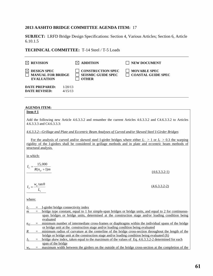
2013 AASHTO BRIDGE COMMITTEE AGENDA ITEM: 17 SUBJECT: LRFD Bridge Design Specifications: Section 4, Various Articles; Section 6, Article 6.10.1.5 TECHNICAL COMMITTEE: T-14 Steel / T-5 Loads
REVISION ADDITION NEW DOCUMENT
DESIGN SPEC CONSTRUCTION SPEC MOVABLE SPEC MANUAL FOR BRIDGE SEISMIC GUIDE SPEC COASTAL GUIDE SPEC
EVALUATION OTHER DATE PREPARED: 1/20/13 DATE REVISED: 4/15/13 AGENDA ITEM: Item # 1 Add the following new Article 4.6.3.3.2 and renumber the current Articles 4.6.3.3.2 and C4.6.3.3.2 to Articles 4.6.3.3.3 and C4.6.3.3.3: 4.6.3.3.2—Grillage and Plate and Eccentric Beam Analyses of Curved and/or Skewed Steel I-Girder Bridges For the analysis of curved and/or skewed steel I-girder bridges where either IC > 1 or IS > 0.3 the warping rigidity of the I-girders shall be considered in grillage methods and in plate and eccentric beam methods of structural analysis. in which:
15,000( 1)C
cf
IR n m
=+
(4.6.3.3.2-1)
tangS
s
wI
Lθ
= (4.6.3.3.2-2)
where: IC = I-girder bridge connectivity index m = bridge type constant, equal to 1 for simple-span bridges or bridge units, and equal to 2 for continuous-
span bridges or bridge units, determined at the construction stage and/or loading condition being evaluated
ncf = minimum number of intermediate cross-frames or diaphragms within the individual spans of the bridge or bridge unit at the construction stage and/or loading condition being evaluated
R = minimum radius of curvature at the centerline of the bridge cross-section throughout the length of the bridge or bridge unit at the construction stage and/or loading condition being evaluated (ft)
IS = bridge skew index, taken equal to the maximum of the values of Eq. 4.6.3.3.2-2 determined for each span of the bridge
wg = maximum width between the girders on the outside of the bridge cross-section at the completion of the

construction or at an intermediate stage of the steel erection Ls = span length at the centerline θ = maximum skew angle of the bearing lines at the end of a given span, measured from a line taken
perpendicular to the span centerline Item # 2 Add the following new Article C4.6.3.3.2: C4.6.3.3.2
Unless otherwise stated, this Article applies to curved and/or skewed steel I-girder bridges analyzed by grillage or plate and eccentric beam analysis. A 3D finite element analysis of a steel I-girder bridge in which the girder webs are modeled using shell elements and the girder flanges are modeled using beam, shell, or solid elements is capable of directly capturing the contribution of the girder warping rigidity to the torsional stiffness. In a grillage analysis or a plate and eccentric beam analysis of a steel I-girder bridge, the use of only the St. Venant torsional stiffness GJ/Lb can result in a substantial underestimation of the girder torsional stiffness. This is due to neglect of the contribution from girder cross-section warping, or the corresponding flange lateral bending, to the torsional response. For I-girders, the torsional contribution from the girder warping rigidity, ECw, is often substantial compared to the contribution from the St. Venant torsional rigidity, GJ. When the contribution from the girder warping rigidity is not accounted for in the analysis, the vertical deflections in curved I-girder systems can be substantially over-estimated due to the coupling between the girder torsional and flexural response where IC > 1. Furthermore, the cross-frame forces can be substantially underestimated in straight or curved skewed I-girder bridges due to the under-estimation of the torsional stiffness provided by the girders where IS > 0.3. White et al. (2012) present a simplified approximate method of considering the girder warping rigidity, applicable for I-girder bridges or bridge units in their final constructed condition, as well as in intermediate noncomposite conditions during steel erection, when at least two I-girders are connected together by support cross-frames, cantilevered girder units have a cross-frame line near the cantilevered girder ends, at least one intermediate cross-frame is located between each of the above locations, and, where the girders are curved, and IC < 20. For steel I-girder bridges under noncomposite loading conditions, the behavior of grillage models and plate and eccentric beam models can be particularly sensitive to the contribution from the warping rigidity to the girder torsional stiffness. The behavior tends to be less sensitive to the girder warping rigidity under composite loading conditions. For the analysis of composite loading conditions using plate and eccentric beam structural analysis models, it is sufficient to calculate the warping rigidity of the steel I-girders, ECw, using solely the steel cross-section with Eq. C6.9.4.1.3-1 and without the consideration of any composite torsional interaction with the composite deck. Other methods of considering the warping rigidity of steel I-girders include the explicit use of open-section thin-walled beam theory, or the use of a general-purpose 3D finite element analysis in which the I-girder is modeled as described previously. Additional information on the modeling of torsion in I-girder bridges may be found in AASHTO/NSBA (2011). Item # 3 Add the following to the end of Article 6.10.1.5:
The requirement for the modeling of girder torsional stiffness in curved and/or skewed I-girder bridges specified in Article 4.6.3.3.2 shall be satisfied for grillage analyses or plate and eccentric beam analyses of steel I-girder bridges. Item # 4 Add the following references to Article 4.9: AASHTO/NSBA Steel Bridge Collaboration. 2011. Guidelines for Steel Girder Bridge Analysis, G13.1, 1st edition, NSBASGBA-1, American Association of State Highway and Transportation Officials, Washington, DC.

White, D.W., Coletti, D., Chavel, B.W., Sanchez, A., Ozgur, C., Jimenez Chong, J.M., Leon, R.T., Medlock, R.D., Cisneros, R.A., Galambos, T.V., Yadlosky, J.M., Gatti, W.J., and Kowatch, G.T. 2012. “Guidelines for Analytical Methods and Construction Engineering of Curved and Skewed Steel Girder Bridges,” NCHRP Report 725, Transportation Research Board, National Research Council, Washington, D.C. Item # 5 Add the following definitions to Article 4.2 (Note: these same definitions also are proposed in the Agenda Item pertaining to Article 4.6.3.3.1 in case one or the other of these items is not approved.): Grid Method—A grillage analogy method of analysis of girder bridges in which the longitudinal girders are modeled individually using beam elements and the cross-frames are typically modeled as equivalent beam elements. For composite girders, a tributary deck width is considered in the calculation of individual girder cross-section properties. Plate and Eccentric Beam Method—A method of analysis of composite girder bridges in which the bridge deck is modeled using shell finite elements, the longitudinal girders are modeled using beam elements, and the cross-frames are typically modeled as equivalent beam elements, The girder and cross-frame elements are offset from the deck elements to account for the structural depth of these components relative to the deck. Item # 6 Add the following to Article 4.3: Cw = girder warping constant (in.6) (C4.6.3.3.2) IC = I-girder bridge connectivity index (C4.6.3.3.2) Jeq = equivalent St. Venant torsion constant accounting for the influence of I-girder cross-section warping (in4)
(C4.6.3.3.2) m = bridge type constant, equal to 1 for simple-span bridges or bridge units, and equal to 2 for continuous-span
bridges or bridge units, determined at the construction stage being evaluated (C4.6.3.3.2) ncf = minimum number of intermediate cross-frames or diaphragms within the individual spans of the bridge or
bridge unit at the stage of construction being evaluated (C4.6.3.3.2) Revise the following in Article 4.3: Lb = spacing of brace points (ft.) (C4.6.2.7.1) (in.) R = girder radius (ft); load distribution to exterior beam in terms of lanes; radius of curvature; R-Factor for
calculation of seismic design forces due to inelastic action; minimum radius of curvature at the centerline of the bridge cross-section throughout the length of the bridge or bridge unit at the stage of construction being evaluated (ft) (C4.6.1.2.4b) (C4.6.2.2.2d) (C4.6.6) (4.7.4.5) (C4.6.3.3.2)
OTHER AFFECTED ARTICLES:None
BACKGROUND: The traditional use of only the steel I-girder St. Venant torsional stiffness in grillage or plate and eccentric beam structural analyses can lead to substantial overestimation of the structural displacements and underestimation of certain internal forces within curved and/or skewed bridge structural systems. These errors can be particularly problematic when estimating structural displacements and internal forces due to noncomposite loadings. The proposed additions require that the girder warping rigidity be considered in any grillage or plate and eccentric beam structural analysis of steel I-girder bridges with significant horizontal curvature and/or skew. One method of satisfying this requirement is referenced in the commentary. The proposed commentary explicitly states that a 3D

finite element analysis in which the I-girder webs are modeled using shell elements and the flanges are modeled using beam, shell or solid elements is capable of directly capturing the contribution of the girder warping rigidity to the torsional stiffness. The terms “Grid Method” and “Plate and Eccentric Beam Method” are proposed for inclusion in Article 4.2 to more clearly define these terms within the context of current structural analysis practices. The current AASHTO Specification refers to “grid” methods at a number of places, but this term is never defined. The terminology “plate and eccentric beam method” is a more recent addition to the lexicon which defines a specific type of structural analysis commonly utilized in modern practice for composite girder bridges.
ANTICIPATED EFFECT ON BRIDGES: The proposed changes provide requirements and guidance that will reduce the likelihood of issues related to the inadequate modeling of the girder warping torsional rigidity in grid or grillage analyses or plate and eccentric beam analyses of steel I-girder bridges.
REFERENCES: See Item #4
OTHER: None

2013 AASHTO BRIDGE COMMITTEE AGENDA ITEM: 18 SUBJECT: LRFD Bridge Design Specifications: Section 6, Article 6.5.4.2 TECHNICAL COMMITTEE: T-14 Steel
REVISION ADDITION NEW DOCUMENT
DESIGN SPEC CONSTRUCTION SPEC MOVABLE SPEC MANUAL FOR BRIDGE SEISMIC GUIDE SPEC COASTAL GUIDE SPEC
EVALUATION OTHER DATE PREPARED: 9/25/12 DATE REVISED: AGENDA ITEM: In Article 6.5.4.2, revise the 3rd bullet as follows:
• For axial compression, steel only φc = 0.90 0.95
OTHER AFFECTED ARTICLES:None
BACKGROUND: The resistance factor for steel members (or components) subject to axial compression, φc, was increased from 0.85 to 0.90 in the 2005 AISC Specification. This increase gave recognition to the changes in industry practice combined with the substantial numbers of additional column strength analyses and tests that had taken place since the original calibrations were performed in the 1970s and 1980s. In the original research on the probability-based strength of steel columns (Bjorhovde, 1972, 1978, 1988), three column curves were recommended. The three column curves were the approximate means of bands of strength curves for columns of similar manufacture based on extensive analyses and confirmed by full-scale tests. Hot-formed and cold-formed heat treated HSS columns fell into the data band of highest strength (SSRC Column Category 1P), while built-up wide-flange columns made from universal mill plates were included in the data band of lowest strength (SSRC Column Category 3P). The largest group of data, however, clustered around SSRC Column Category 2P. Probabilistic analysis would have resulted in a resistance factor φc = 0.90 or even slightly higher had the original AISC LRFD Specification opted for using all three column curves for the respective column categories (Galambos, 1983; Bjorhovde, 1988; Ziemian, 2010). However, it was decided to use only one column curve, SSRC Column Category 2P, for all column types. The AASHTO LRFD Specification followed suit. The use of only one column curve results in a larger data spread and thus a larger coefficient of variation, and so a resistance factor φc = 0.85 was adopted in the original AISC LRFD Specification for the column equations to achieve a level of reliability comparable to that of beams. Resistance factors in the AASHTO LRFD Specification are typically set at a level that is 0.05 higher than those in the AISC LRFD Specification; thus, φc was set to 0.90 in the original AASHTO LRFD Specification. Since that time, significant additional analyses and tests, as well as changes in practice, have demonstrated that the increase in φc from 0.85 to 0.90 in the AISC LRFD Specification was warranted, indeed even somewhat conservative (Bjorhovde, 1988). Significant changes in industry practice since that time have included the following: (1) built-up shapes are no longer manufactured from universal mill plates; (2) the most commonly used structural steel is now ASTM A 709 Grade 50 or 50W, with a specified minimum yield stress of 50 ksi; and (3) changes in steelmaking practice have resulted in materials of higher quality and much better defined properties. The level and variability of the yield stress thus have led to a reduced coefficient of variation for the relevant material

properties (Bartlett et al., 2003). As a result, for consistency, it is recommended that φc for steel members (or components) subject to axial compression be raised from 0.90 to 0.95 in the AASHTO LRFD Specification.
ANTICIPATED EFFECT ON BRIDGES:A slight increase in the factored compressive resistance of steel members (or components) subject to axial compression.
REFERENCES: Bartlett, R.M., Dexter, R.J., Graeser, M.D., Jelinek, J.J., Schmidt, B.J. and Galambos, T.V. (2003), “Updating Standard Shape Material Properties Database for Design and Reliability,” Engineering Journal, AISC, Vol. 40, No. 1, pp. 2–14. Bjorhovde, R. (1972), “Deterministic and Probabilistic Approaches to the Strength of Steel Columns,” Ph.D. Dissertation, Lehigh University, Bethlehem, PA, May. Bjorhovde, R. (1978), “The Safety of Steel Columns,” Journal of the Structural Division, ASCE, Vol. 104, No. ST9, September, pp. 1371–1387. Bjorhovde, R. and Birkemoe, P.C. (1979), ”Limit States Design of HSS Columns,” Canadian Journal of Civil Engineering, Vol. 6, No. 2, pp. 276–291. Bjorhovde, R. (1988), “Columns: From Theory to Practice,” Engineering Journal, AISC, Vol. 25, No. 1, 1st Quarter, pp. 21–34. Galambos, T.V. (1983), “Reliability of Axially Loaded Columns,” Engineering Structures, Vol. 5, No. 1, pp. 73–78. Ziemian, R.D. (ed.) (2010), Guide to Stability Design Criteria for Metal Structures, 6th Ed., John Wiley & Sons, Inc., Hoboken, NJ.
OTHER: None

2013 AASHTO BRIDGE COMMITTEE AGENDA ITEM: 19 SUBJECT: LRFD Bridge Design Specifications: Section 6, Table 6.6.1.2.3-1 TECHNICAL COMMITTEE: T-14 Steel/T-12 Structural Supports for Highway Signs, Luminaires and Traffic Signals
REVISION ADDITION NEW DOCUMENT
DESIGN SPEC CONSTRUCTION SPEC MOVABLE SPEC MANUAL FOR BRIDGE SEISMIC GUIDE SPEC COASTAL GUIDE SPEC
EVALUATION OTHER DATE PREPARED: 1/18/13 DATE REVISED: 4/4/13 AGENDA ITEM: In Table 6.6.1.2.3-1, revise the description for Condition 2.3 as follows: 2.3 Base metal at the net section of all bolted connections in hot dipped galvanized members (Huhn and Valtinat, 2004); base metal at the appropriate section defined in Condition 2.1 or 2.2, as applicable, net or gross section of high-strength bolted joints with pretensioned bolts installed in holes punched full size (Brown et al., 2007); and base metal at the net section of other mechanically fastened joints, except for eyebars and pin plates, e.g., joints using ASTM A307 bolts or non-pretensioned high-strength bolts. (Note: see Condition 2.5 for bolted angle or tee section member connections to gusset or connection plates).
OTHER AFFECTED ARTICLES:Delete the following reference from the Section 6 reference list in Article 6.17: Huhn, H., and G. Valtinat. 2004. “Bolted Connections with Hot Dip Galvanized Steel Members with Punched Holes.” Proceedings of the ECCS/AISC Workshop, Connections in Steel Structures V: Innovative Steel Connections, June 3–5, 2004. European Convention for Constructional Steelwork/American Institute of Steel Construction, Amsterdam.
BACKGROUND: Condition 2.3 in Table 6.6.1.2.3-1 deals with the fatigue resistance of mechanically fastened joints. The types of joints included under this condition are those using pretensioned high-strength bolts installed in holes punched full size, those using A307 bolts or non-pretensioned high-strength bolts, and also all bolted joints used in hot-dipped galvanized members. For these joints, the fatigue Detail Category is reduced from the base fatigue Detail Category B that is typically applied to mechanically fastened joints with fully pretensioned HS bolts to fatigue Detail Category D. The application of this reduction to bolted joints in hot-dipped galvanized members was based previously on the research described in Huhn and Valtinat, 2004, and was introduced in the 2008 Interims when an extensive update was made to Table 6.6.1.2.3-1. Previous versions of the specifications did not make a distinction between hot-dipped galvanized and non-galvanized mechanically fastened joints. The proposed revision in this item reflects the results of a further examination of the data contained in this report, as described below. The data of interest included in this report were based on fatigue tests on connections with fully tightened fasteners installed in drilled holes with and without galvanized plates. These data are plotted against the AASHTO

Category B, C, and D design S-N curves below. Note there is no significant difference in the fatigue resistance of the hot-dipped galvanized and non-galvanized plates where fully pretensioned fasteners were used. Almost all of the data fall well above Category B, except where the applied stress range was unusually high, i.e., about 240 MPa or about 35 ksi. Interestingly, even the non-galvanized plates failed below Category B at these extremely high stress ranges. The cause for this is believed to be due to the applied stress range exceeding the slip resistance of the joint. Since the data from both the hot-dipped galvanized and non-galvanized tests are essentially the same, it is proposed to delete the reference to hot-dipped galvanized members in the description for Condition 2.3. This would result in the inclusion of all bolted connections with fully pretensioned high-strength bolts in galvanized members with the bolts installed in holes drilled full size or subpunched and reamed to size being covered under Condition 2.1 or 2.2, as applicable, and classified as Category B. Bolted connections in galvanized members not satisfying the preceding conditions would still be classified under the modified Condition 2.3 as Category D. Under very high stress ranges, say greater than 35 ksi, the data from the report would appear to indicate that fatigue Detail Category C might be more appropriate for all fully pretensioned joints; i.e. both galvanized and non-galvanized. However, the database used to develop the existing requirement that all fully pretensioned joints satisfy Category B was not examined to determine if such an additional restriction is indeed appropriate. Considering the actual magnitude of in-situ stress ranges in bridges and ancillary structures, the use of Category B still seems appropriate for these joints with no further commentary or restrictions.
ANTICIPATED EFFECT ON BRIDGESMore economical fatigue designs for bridges and ancillary structures utilizing pretensioned high-bolted connections in drilled holes on hot-dipped galvanized members.

REFERENCES: Huhn, H., and G. Valtinat. 2004. “Bolted Connections with Hot Dip Galvanized Steel Members with Punched Holes.” Proceedings of the ECCS/AISC Workshop, Connections in Steel Structures V: Innovative Steel Connections, June 3–5, 2004. European Convention for Constructional Steelwork/American Institute of Steel Construction, Amsterdam.
OTHER: None

2013 AASHTO BRIDGE COMMITTEE AGENDA ITEM: 20 SUBJECT: LRFD Bridge Design Specifications: Section 6, Article 6.7.4.1 TECHNICAL COMMITTEE: T-14 Steel
REVISION ADDITION NEW DOCUMENT
DESIGN SPEC CONSTRUCTION SPEC MOVABLE SPEC MANUAL FOR BRIDGE SEISMIC GUIDE SPEC COASTAL GUIDE SPEC
EVALUATION OTHER DATE PREPARED: 1/28/13 DATE REVISED: AGENDA ITEM: Revise the 4th paragraph of Article 6.7.4.1 as follows:
Diaphragms or cross-frames not required for the final condition may be specified to be temporary bracing. Metal stay-in-place deck forms should not be assumed to provide adequate stability to the top flange in compression prior to curing of the deck.
OTHER AFFECTED ARTICLES:None
BACKGROUND: The proposed revision removes a sentence from the specification that essentially states the obvious and that can lead to potential confusion, misinterpretation and/or debate as to whether or not select cross-frames or diaphragms in a steel-girder bridge are necessarily required for the final condition in a particular situation and might potentially be removed. In general, cross-frames and diaphragms still carry significant dead, live and wind load forces in most steel-girder bridges in the final condition, and are also necessary to provide stability to bottom flanges in compression.
ANTICIPATED EFFECT ON BRIDGES: Less potential to remove cross-frames and diaphragms in steel-girder bridges that may actually be performing a significant function in the final condition.
REFERENCES: None
OTHER: None

2013 AASHTO BRIDGE COMMITTEE AGENDA ITEM: 21 SUBJECT: LRFD Bridge Design Specifications: Section 6, Article C6.7.4.2 TECHNICAL COMMITTEE: T-14 Steel
REVISION ADDITION NEW DOCUMENT
DESIGN SPEC CONSTRUCTION SPEC MOVABLE SPEC MANUAL FOR BRIDGE SEISMIC GUIDE SPEC COASTAL GUIDE SPEC
EVALUATION OTHER DATE PREPARED: 1/20/13 DATE REVISED: 4/8/13 AGENDA ITEM: Add the following paragraph after the 4th paragraph in Article C6.7.4.2: In skewed bridges where end support lines are skewed more than 20 degrees from normal, the first intermediate cross-frames or diaphragms placed normal to the girders adjacent to a skewed end support ideally should be offset by a minimum of the larger of 1.5D or 0.4Lb2 from the end supports along each of the girders, where D is the girder web depth and Lb2 is the unbraced length between the first and the second intermediate cross-frame or diaphragm connected to the girder under consideration within the span (White et al., 2012). This practice helps to alleviate the introduction of a stiff load path that will attract and transfer large transverse forces to the skewed end supports. In some cases, the limit of 0.4Lb2 may be difficult to achieve, in which case, the offset should be made as large as practicable, but not less than 1.5D.
OTHER AFFECTED ARTICLES:None
BACKGROUND: The positioning of the first intermediate cross-frame or diaphragm normal to the girder at a close distance from (or directly connected to) an end support skewed more than 20 degrees from normal tends to produce a stiff load path that will attract and transfer large transverse forces to that support. The proposed paragraph provides recommendations taken from the NCHRP 725 Report (White et al., 2012) that help to limit the development of this “nuisance stiffness” within the structural system, which can result in the potential for excessively large cross-frame members adjacent to severely skewed end supports in I-girder bridges.
ANTICIPATED EFFECT ON BRIDGES: The proposed addition provides useful guidance that should help engineers in laying out cross-frames in severely skewed I-girder bridges in a manner that results in more economical proportions of these components.

REFERENCES: White, D.W., Coletti, D., Chavel, B.W., Sanchez, A., Ozgur, C., Jimenez Chong, J.M., Leon, R.T., Medlock, R.D., Cisneros, R.A., Galambos, T.V., Yadlosky, J.M., Gatti, W.J., and Kowatch, G.T. 2012. “Guidelines for Analytical Methods and Construction Engineering of Curved and Skewed Steel Girder Bridges,” NCHRP Report 725, Transportation Research Board, National Research Council, Washington, D.C.
OTHER: None

2013 AASHTO BRIDGE COMMITTEE AGENDA ITEM: 22 SUBJECT: LRFD Bridge Design Specifications: Section 6, Articles 6.9.2.2, 6.9.5 & 6.17 TECHNICAL COMMITTEE: T-14 Steel
REVISION ADDITION NEW DOCUMENT
DESIGN SPEC CONSTRUCTION SPEC MOVABLE SPEC MANUAL FOR BRIDGE SEISMIC GUIDE SPEC COASTAL GUIDE SPEC
EVALUATION OTHER DATE PREPARED: 9/3/12 DATE REVISED: 4/14/13 AGENDA ITEM:Item #1 Revise the 1st sentence of Article 6.9.2.2 as follows:
Except as permitted otherwise in Articles 6.9.4.4 and 6.9.5.3, the axial compressive load, Pu, and concurrent moments, Mux and Muy, calculated for the factored loadings by elastic analytical procedures shall satisfy the following relationship: Item #2 Replace Article 6.9.5 and the associated commentary with the following: 6.9.5—Concrete-Filled Steel Tube (CFST) Components
The provisions of this article shall be taken to apply to the design of composite CFST construction by the plastic stress distribution method (PSDM). Other design methods may be used with the owner’s approval.
C6.9.5
These provisions are not specifically applicable to seismic design, although some aspects of the provisions may be useful for that purpose.
A number of approaches have been used to predict the nominal resistance of CFST members including fiber models, strain-compatibility methods and a cross-sectional analysis known as the plastic stress distribution method (PSDM). Strain compatibility methods and fiber models are permitted by these provisions. Strain compatibility and fiber models are quite accurate for reinforced concrete members, but research evaluating a wide range of prior CFST test data, show that these methods are significantly less accurate for evaluation of composite CFST members, because concrete strain limits are less meaningful for CFST. For CFST, resistances predicted by the strain compatibility methods and fiber models have greater variation in the mean prediction with larger standard deviation than the PSDM. For example, the use of strain compatibility method with a 0.003 compressive strain limit in the concrete, results in a mean error which is more than twice as large as that achieved with the PSDM and a standard deviation that is more than four times that provided by the PSDM, because this compressive strain limit is based upon spalling of the concrete, which cannot occur with CFST (Roeder, Lehman and Bishop 2010). The strain compatibility method is permitted by these provisions, but its use is not preferred for the reasons noted above.

6.9.5.1—General
The resistance of CFST components shall be determined as:
Rr = φRn (6.9.5.1-1)
where:
Rn = nominal resistance based on cross-sectional capacity and adjusted for bending moment and stability effects, as specified herein
φc = resistance factor for compression and combined axial load and flexure = 0.9 φv = resistance factor for shear = 1.0
C6.9.5.1
The resistance factors used for compression loading are somewhat greater than the resistance factors used for reinforced concrete. This is justified as a result of the smaller co-variance of 0.05 with axial loads less than 0.6Po noted for CFST members relative to RC members coupled with a conservative predication of the flexural resistance prediction provided by the plastic stress distribution method (PSDM) (as noted in Article C6.9.5.3.3 the moment capacity averages 1.24 times the predicted PSDM moment for a given axial load). Further, circular CFST have uniformly distributed and higher confining stresses provided to the concrete fill, which provide superior resistance and performance relative to reinforced concrete sections with discrete confinement. The strain compatibility method is very accurate for reinforced concrete members, and has been used in past CFST practice. This method is permitted by these provisions, but its use is discouraged, because it results in less accurate predictions with a much large standard deviation than the PSDM (Roeder, Lehman and Bishop 2010). Finally, these CFST provisions directly address member buckling capacity, while reinforced concrete design address instability primarily through a minimum eccentricity for the combined load design (see Articles 5.7.4.3 and 5.7.4.4 and commentary).
6.9.5.2—Limitations
These provisions shall be taken to apply to circular steel tubes, where the specified minimum yield stress of the steel tube and any internal longitudinal reinforcement shall not be greater than 70.0 ksi nor less than 36.0 ksi. The design shall comply with the following:
• The steel tubes shall be spiral welded tubes formed from coil steel or straight seam welded tubes formed from flat plates formed into a tube with longitudinal seam welds.
• The spiral welds shall be complete joint penetration welds of matching metal formed by the double submerged arc process and shall have a minimum CVN toughness of 40 ft-lbs at 70
o F.
• Longitudinal welds shall be complete joint penetration welds of matching weld metal.
• Unless specifically noted herein, the local slenderness of the tube shall satisfy:
0.15 st
yst
EDt F
≤ (6.9.5.2-1)
CFST columns with Option 1 or Option 2 foundation connections as specified in Article 6.9.5.5 that develop the maximum bending moment demand at the connection shall satisfy the following:
0.22 st
yst
EDt F
≤ (6.9.5.2−2)
• The specified minimum 28-day compressive strength of the concrete shall be at least 2.5 ksi and shall be greater than .075Fyst.
• The concrete mix shall be designed with the addition of a low-shrinkage admixture to achieve a maximum of 0.04 percent shrinkage at 28 days as tested in accordance with ASTM C 157 Modified Standard Test Method for Length Change of Hardened Hydraulic-Cement Mortar.

• CFSTs shall be designed to assure full composite action in the design.
• Connections of CFST columns into the foundation and/or pier cap shall satisfy the requirements of Article 6.9.5.5.
where:
D = outside diameter of the tube (in.) Est = elastic modulus of steel tube (ksi) Fyst = minimum specified yield stress of steel tube (ksi) t = wall thickness of the tube (in.)
C6.9.5.2
Circular CFSTs provide continuous confinement of the concrete, which is superior to that achieved with rectangular CFST. Rectangular steel tubes are specifically excluded from these provisions. Binding action resulting from bending and mechanical interlock of the spiral weld provides shear stress transfer between the steel tube and the concrete fill. These confinement and stress transfer mechanisms are only possible if concrete shrinkage is minimized.
The data used to define and verify these recommended provisions are based upon experimental and nonlinear analytical results that had minimum yield stress values of the steel between 36.0 and 70.0 ksi, and specified compressive strengths of the concrete between 2.5 and 10.0 ksi. The research notes that a balance between the steel and concrete strength provides optimum results, therefore a concrete strength greater than or equal to 0.075Fyst is required. In addition, the concrete strength must be designed to meet the applicable temperature and environmental conditions within the tube (AASHTO LRFD Article 5.4.2).
Large diameter tubes are commonly required for bridge columns, piles and caissons or drilled shafts. Circular steel tubes fall under ASTM standards including A53 or A500, but these steel tubes are unlikely to be useful for the majority of bridge construction because of the limitations in the maximum diameter, and therefore they are not the focus of these specifications.
The large diameter tubes referred to herein are commonly formed by one of two methods. Coil steel may be unrolled in a helical fashion to form a spirally welded tube. The spiral welds are made as butt joints and formed from both the inside and outside of the tube by the submerged arc process. This manufacturing process is limited to steel tubes with wall thickness of about 1.0 in. or less and diameters greater than about 20.0 in. The spiral welds are subjected to direct stresses under axial load and flexure, and these welds are important to the development of the resistance of the CFST. The double (inside and outside) submerged arc process has been shown to provide good performance if proper weld metal and processes are employed and the minimum tensile strength of the weld metal matches the yield strength of the steel tube. The welds may also be inspected by radiographic methods over the entire length of the weld if increased quality control is needed.
Large diameter tubes may also be formed by bending flat plate around a mandrel and forming the tube with longitudinal seam welds. The longitudinal welds are important, but they are not directly stressed under axial load and flexure and therefore the requirements are not as stringent as those required for spiral welds.
The local slenderness limit of Eq. 6.9.5.2-1 has been shown to experimentally achieve the full plastic capacity with substantial inelastic deformation capacity for CFSTs (Roeder, Lehman, and Bishop 2010). The foundation connections described in article 6.9.5.5 develops a large portion of their inelastic deformation capacity by tensile and compressive yielding of the steel tube both within the lower portion of the pier and the foundation connection. Buckling of the tube within the connection region cannot occur, and hence the slenderness limit for tubes where the maximum moment occurs at these connections is increased to that of Eq. 6.9.5.2-2 to encourage extensive yielding as required for development of large inelastic deformations and design to extreme loadings. This limit based upon prior experimental results (Lehman and Roeder 2012), and significant inelastic deformation capacity was consistently developed. As a result, CFST piers employing this connection at their proposed plastic hinge locations are clearly suitable for seismic design requirements.
Stress transfer between the steel tube and concrete fill is essential for developing full composite action. For CFSTs subjected to combined loading, even small bending moments combined with axial load cause internal binding between the steel and concrete fill, because of their differential stiffness and the arc of the compression strut which acts to engage the tube. Tests on tubes that are greased over the entire inside surface to eliminate friction developed the same composite action and slip resistance as tubes with friction and mechanical shear transfer when the member was subjected to bending (Roeder, Lehman, and Thody 2009).

With large axial load and little or no bending, mechanical shear stress transfer may be required, because the concrete shrinkage may result in separation of the steel tube and concrete fill under loading. With spiral-welded tubes, the inner weld provides mechanical interlock if a low-shrinkage concrete is used, and this may reduce the need for mechanical shear stress transfer. This benefit has not been demonstrated for straight seam welded tubes. Internal shear studs may be used for mechanical shear stress transfer, but the studs may result in damage to the concrete at the steel interface and reduce normal friction (Roeder, Lehman, and Thody 2009). Hence, applications with large axial force and small bending moments are best designed with connections that directly distribute load to both the steel and concrete fill or with internal annular rings. As a guide, a member may be conservatively defined as having high axial load if the bending moment is less than 0.2 Mo while the simultaneous applied axial compression force is greater than 0.2 Po where Po and Mo are defined in Article 6.9.5.3.2.
6.9.5.3—Combined Axial Compression and Flexure
6.9.5.3.1—General
The nominal resistance of CFST columns shall be based on a rational method of analysis. A cross-sectional analysis using the constituent materials as specified in Articles 6.9.5.3.2 and 6.9.5.3.3 and adjusted for stability of the column as specified in Article 6.9.5.3.4 is one method that satisfies these requirements. Other methods may be used with the owner’s approval.
The connection of the column into the foundation and/or pier cap shall satisfy the requirements of Article 6.9.5.5.
6.9.5.3.2—Nominal Compressive Resistance
The factored compressive resistance, Pr, of a CFST column shall be determined as:
Pr = φcPn = φcPcr (6.9.5.3.2-1) where: φc = resistance factor for compression and combined axial load and flexure specified in Article 6.9.5.1 Pn = nominal compressive resistance (kip)
The nominal compressive resistance, Pn, of a CFST column supporting only an axial load shall be determined using Eqs. 6.9.5.3.2-2 through 6.9.5.3.2-7.
If Pe > 0.44Po then (6.9.5.3.2-2) If Pe ≤ 0.44Po then (6.9.5.3.2-3) in which:
'0.95o c c yst st yb sbP f A F A F A= + + (6.9.5.3.2-4)
eP =
2π effEI
2Kl( )
(6.9.5.3.2-5)
effEI = stE stI + siE siI + c′ C E cI (6.9.5.3.2-6)
′ C = 0.15+
PoP
+ stA + siAstA + siA + cA
≤ 0.9 (6.9.5.3.2-7)
crP = 0.658Po
Pe Po
Pcr = 0.877Pe

where: Ast = cross-sectional area of the steel tube (in.2) Asb = total cross-sectional area of the internal reinforcement bars (in.2) Ac = net cross-sectional area of the concrete (in.2) Ec = elastic modulus of the concrete (ksi) Est = elastic modulus of the steel tube (ksi) Esi = elastic modulus of the internal steel reinforcement (ksi) EIeff = effective composite flexural cross-sectional stiffness of the CFST Fyst = specified minimum yield stress of the steel tube (ksi) Fyb = specified minimum yield stress of the internal steel reinforcing bars (ksi) f'c = specified minimum 28-day compressive strength of the concrete (ksi) Ic = uncracked moment of inertia of the concrete about the centroidal axis (in.4) Ist = moment of inertia of the steel tube about the centroidal axis (in.4) Isi = moment of inertia of the internal steel reinforcement about the centroidal axis (in.4) K = effective length coefficient as specified in Article 4.6.2.5 l = unbraced length of the column (in.) P = applied axial dead load (kips) Pcr = nominal compressive resistance (kips) Pe = Euler buckling load (kips) Po = maximum compressive load resistance of the column without consideration of buckling (kips) Wherever practical, use of internal reinforcement should be avoided.
C6.9.5.3.2
The provisions of this article pertain to CFSTs with and without internal reinforcement. Research has
demonstrated that the strength contribution provided by the steel tube is significantly more than internal reinforcement (Roeder and Lehman, 2012). Further, internal reinforcement interferes with placement of the concrete fill. Therefore, internal reinforcement should be used only when required by other design constraints.
The procedure for designing composite CFST columns for axial compression is similar to that used for design of steel columns, except that a composite flexural stiffness, EIeff, is employed. The composite flexural stiffness increases with increasing compressive load and, hence, the factor C', which provides an estimate of the effective stiffness of the concrete as a function of the axial load. The flexural tangent stiffness of composite concrete-filled steel tubes depends on the degree of cracking in the concrete, and therefore depends on the strain levels. The flexural stiffness values provided by Eqs. 6.9.5.3.2-6 and 7 correspond to approximately 90 percent of the maximum resistance of the member, since this provides a conservative estimate of buckling load. The flexural stiffness equations have been developed by comparison with past experimental results on concrete filled steel tubes where the members have been loaded to loss of lateral load carrying capacity (Roeder, Lehman and Bishop, 2010).
The use of internal reinforcement is discouraged for CFST, because internal reinforcement is significantly less efficient in developing resistance than is the steel tube. However, it is recognized that many connection methods require internal reinforcement to transfer forces and moments to adjacent elements. These provisions do not prevent the use of such connections, but it should be noted that such connections are reinforced concrete connections rather than CFST connections and should be designed as such.
6.9.5.3.3—Nominal Composite Resistance
The nominal composite resistance of a CFST subjected to axial load and moment shall be determined by the plastic stress distribution method. The compressive stress distribution in the concrete shall be defined as a rectangular stress block with stress equal to 0.95f'c and shall include the full depth of the concrete in compression. The tensile strength of the concrete shall be neglected. The stress in the steel tube and any reinforcement at any location in the cross section shall be equivalent to the minimum specified yield stress, Fyst, in both tension and compression. CFSTs subjected to axial compressive loads that are affected by buckling, secondary moments, or P-δ effects shall also satisfy the requirements of Article 6.9.5.3.4.

C6.9.5.3.3 Research shows that the PSDM is simple to use and is consistently more accurate than other methods (Roeder,
Lehman and Bishop, 2010). The PSDM is illustrated in Figure C6.9.5.3.3-1. The method uses the full yield strength of the steel in tension and compression. Even under higher axial stress, the full yield strength is available because the concrete fill restrains local buckling of the steel and permits development of the full plastic capacity of the steel. A uniform concrete stress distribution with a magnitude of stress equal to 0.95f'c over the entire compressive region is used. The coefficient of 0.95 is higher than the typical coefficient of 0.85 used for reinforced concrete flexural strength calculations in recognition of the increased confinement to the concrete (and resulting increased deformation capacity) provided by the circular steel tube. The compressive block is also taller, with the equivalent uniform stress assumed acting over the entire compressive region. The axial load, P, and bending moment, M, are in equilibrium with the stress state and the resulting P and M values define one point on the P-M interaction curve. Other points are defined for other neutral axis locations to fully establish the PSDM interaction curve.
Past research has shown that the PSDM provides a conservative estimate of the composite resistance of the CFST, and for a given specified axial load, the experimental flexural resistance is on average 24 percent larger than that predicted by the PSDM (Roeder, Lehman and Bishop, 2010). This overstrength is not used in strength design. However, seismic design requires that less ductile elements be designed for the expected maximum plastic capacity of the ductile members. Given a specified axial load, the expected maximum bending moment of the CFST will be on average 1.24 times the moment obtained from the interaction curve and this value should be used to approximate the maximum demand transferred to any less-ductile connecting elements in a capacity-based design approach. This procedure has been developed based upon comparison with prior experimental results and extensive nonlinear calculations of the resistance of CFST members (Moon et al. 2012).
Figure C6.9.5.3.3-1—PSDM Model
For combined axial load and bending moment, the PSDM should be defined for multiple assumed locations of
the neutral axis to define a material-based axial force-moment interaction curve, such as illustrated in Figure C6.9.5.3.3-2. This development is analogous to determining interaction curves for concrete columns. This interaction curve defines the-material based resistance of CFST components that are not affected by buckling, secondary moments or P-δ effects.

Figure C6 Close
and are pwith one r
in which:
where:
Ab = aC = ocb = o (Fyb = sFyst = sf'c = 2
Pn = Fysttrm
mr = r −
sθ = −1sin⎛
⎝⎜
bθ = −1sin⎛
⎝ ⎜
c = ir cos sθ
bc = br cosθ
bt =n bA2π br
6.9.5.3.3-2—Inte
ed-form solutioprovided in Eqradially symme
area of a singleone half the choone half the choin.)
specified minimspecified minim28-day compre
sπ −2θ( ) − π+(
t2
y
mr
⎛
⎝
⎞
⎠⎟
ybr
⎛
⎝
⎞
⎠ ⎟
s
bθ
b
eraction Curve
ons of the comqs. C6.9.5.3.3-1etric row of int
e bar for the intord length for aord length for a
mum yield stresmum yield stresssive strength
s+2θ ) + tbrb ybF (
mplete material1 through C6.9ternal reinforce
ternal reinforcea given stress sa given stress s
ss of the steel bss of the steel tof the concrete
bπ −2θ ) − ybF −(
l based interac9.5.3.3-8 for cement:
(C6
(C6
(C6
(C6
(C6
(C6
(C6
(C6
ement (in.2) state as shown state of a fictio
bars used for intube (ksi) e (ksi)
c−0.95 ′f ) π+2(
ction curves hacircular CFST
6.9.5.3.3-1)
.9.5.3.3-2)
.9.5.3.3-3)
.9.5.3.3-4)
.9.5.3.3-5)
.9.5.3.3-6)
.9.5.3.3-7)
.9.5.3.3-8)
in Figure 6.9.5onal tube mode
nternal reinforc
b2θ )
ave been develwith no intern
5.3.3-1 (in.) eling the interna
cement (ksi)
loped for the Pnal reinforcem
al reinforcemen
PSDM ment or
nt

Mo = composite plastic moment resistance of the CFST without axial load (kip-in.) Mn = nominal flexural resistance as function of nominal axial resistance, Pn, for a given stress state (kip-in.) n = number of uniformly spaced internal reinforcing bars as shown in Figure 6.9.5.3.3-1 Po = plastic crush capacity of the CFST column without flexural moment (kips) Pn = nominal compressive resistance of the member as function of nominal bending moment for a given stress state (kips) r = radius to the outside of the steel tube as shown in Figure 6.9.5.3.3-1 (in.) rb = radius to the center or the internal reinforcing bars as shown in Figure 6.9.5.3.3-1 (in.) ri = radius to the inside of the steel tube as shown in Figure 6.9.5.3.3-1 (in.) rm = radius to the center or the steel tube as shown in Figure 6.9.5.3.3-1 (in.) t = thickness of steel tube as shown in Figure 6.9.5.3.3-1 (in.) tb = thickness of a fictional steel tube used to model the contribution of the internal reinforcement as shown in Figure 6.9.5.3.3-1 (in.) y = distance from the center of the tube to neutral axis for a given stress state as shown in Figure 6.9.5.2.3-1 (in.) θb = angle used to define the cb for a given stress state (radians) θs = angle used to define the c for a given stress state (radians) Smaller D
tvalues result in larger resistance, because the area of steel is larger. Larger D
t ratios result in
significantly increased bending moment for modest compressive loads, because of the increased contribution of concrete fill.
For the case where no internal reinforcement is used inside the tube, Ab and tb are equal to zero and several terms do not contribute to the resistance. A positive value of P implies a compressive force, and y and θ are positive according to the sign convention shown in Figure C6.9.5.3.2-1. The variable y varies between plus and minus ri. The P-M interaction curve is generated by solving the equations for discrete values of y, and connecting those points.
6.9.5.3.4—Stability
A series of points defined herein shall be joined to form the interaction curve for CFST members, and Figure 6.9.5.3.3-1 illustrates the construction. The points shall be defined as follows:
• Point A is Po, determined as specified in Article 6.9.5.3.2.
• Point A’ is obtained by multiplying the axial load associated with point A by the ratio, Pn/Po, where Pn is
determined in Article 6.9.5.3.3.
• Point A’’ is the intersection of the material-based interaction curve determined as specified in Article 6.9.5.3.3 and a horizontal line through Point A’.
• Point B is the flexural resistance without an axial load, Mo, as determined by the PSDM specified in
Article 6.9.5.3.3.
• Point C corresponds to the axial force, PC, on the material-based interaction curve determined as specified in Article 6.9.5.3.3 that corresponds to the moment capacity without axial load, Mo (Point B).
• Point D is located on the material based interaction curve specified in Article 6.9.5.3.3 with the axial load,
PD, such that: P 0.5 n
D Co
PP P= (6.9.5.3.4-1)
The stability based interaction curve defining the nominal resistance shall be constructed by joining points A',
A'', D, and B, and shall be taken to define the nominal composite resistance, Rn, at the strength limit state.

Figure 6.9.5.3.4-1—Construction of the Stability-Based Interaction Curve Defining Rn
C6.9.5.3.4
The interaction curve of Figure 6.9.5.3.4-1 accounts for global buckling of the CFST. The axial resistance is limited by the computed buckling capacity. The stability-based interaction curve includes stability effects and is a modified version of the material interaction curve in Figure 2.12.3.3.3-2, where the modification is based upon the buckling load computed from Eqs. 6.9.5.3.2-1 and 6.9.5.3.2-2. This interaction curve should then be used for strength design of the CFST for all load conditions.
6.9.5.4—Shear Resistance of CFST
The factored shear resistance, Vr, of circular CFST components shall be determined by:
Vr ≤ φ0.6FystAshear = φ0.6Fyst0.5πtD (6.9.5.4-1)
where:
D = diameter of the steel tube (in.) Fyst = minimum specified yield stress of the steel tube (ksi) t = thickness of the steel tube (in.) φ = resistance factor for shear specified in Article 6.9.5.1
C6.9.5.4
Few experiments have been designed to specifically evaluate the shear resistance of CFSTs. Eq. 6.9.5.4-1 neglects all shear strength of the concrete fill. Nonlinear analysis and very limited experimental data shows that the observation that the equation is a conservative prediction, because it considers only half the steel section and neglects all contribution of the concrete, and also demonstrates that shear forces below this limit do not adversely affect the flexural or axial resistance of the member (Lehman et al., 2012). However, there is insufficient data to justify a larger shear resistance at this time. While the predicted shear resistance is conservative, since it neglects composite behavior, the shear resistance provided by this equation for CFST members designed by these provisions exceeds the maximum shear resistance provided by a reinforced concrete member of the same diameter by a large amount.
6.9.5.5—End Connections
Connections joining CFST to other structural members shall be designed by rational design methods. Articles
6.9.5.5.1 through 6.9.5.5.6 define a full-strength, fully-restrained, composite CFST connection for joining CFST columns-to-reinforced concrete footings, pile caps or pier caps.

6.9.5.5.1—General
Full-strength and fully-restrained embedded connections of CFST columns-to-footings, pile caps or pier caps shall be designed by either Option 1 or 2.
• Option 1 is a monolithic fully embedded connection, as illustrated in Figure 6.9.5.5.1-1.
• Option 2 is a grouted, embedded connection, as illustrated in Figure 6.9.5.5.1-2.
For both options, the steel tube shall have an annular ring welded to the end of the tube satisfying the provisions of Article 6.9.5.5.2. Option 1 connections shall be embedded into the reinforced concrete foundation component with an embedment depth and footing depth specified in Articles 6.9.5.5.3 and 6.9.5.5.4 and with the foundation design meeting the requirements of Article 6.9.5.5.5. Connections meeting the Option 2 requirements shall satisfy the requirements for Option 1 and shall also satisfy Article 6.9.5.5.6.
Figure 6.9.5.5.1-1—Option 1 - Monolithic Fully Embedded Connection
Figure 6.9.5.5.1-2—Option 2 – Grouted Embedded Connection
C6.9.5.5.1
Two fully restrained connections for CFST columns to concrete foundation elements including footings and pile caps are illustrated in Figures 6.9.5.5.1-1 and 6.9.5.5.1-2. These connections have been researched extensively

(Lehman concrete fflexural loconnectioFurther, th
Optiotemporarifoundatiocap is casring as dmetal ducconcrete f
6.9.5 The a
greater thproject in
The ametal or fdetermine w > (Fu t)/
where FEX
provide a
Figure 6.9
C6.9.
The aFigure 6.9experimen
The adevelops into the cresistance
6.9.5 The m
and Roeder, 2filled tube and oading from th
on is both simphe connection don 1 uses monily anchored ann and permits st with a recesepicted in Fig
ct and the CFSTfill should be c
.5.2—Annular
annular ring shhan that of the side the tube 8annular ring shfillet welds oned as:
/(0.75 (2) 1.2 (
XX and Fu are tminimum CVN
9.5.5.2-1—Geom
.5.5.2
annular ring is9.5.5.2-1. Thental results (Leannular ring prthe overturnin
connection. As e of the steel tu
.5.3—Embedm
minimum emb
012). Both opthen embedde
he column throple to constructdevelops signinolithic constrnd cast into theindependent ps formed by li
gure 6.9.5.5.1-2T column to pecast following p
Ring
hall have the sasteel tube. Th
times the thickhall be welded
n the both the i
(0.6) FEXX (.707
he minimum teN toughness o
metry of Annula
welded to the thickness, pro
ehman and Roerovides tempor
ng resistance ofa result, the w
ube.
ment Depth
edment depth,
ptions employ ed into the reinough strutting at and fully effeficant inelastic
ruction, as illue reinforced co
placement of thight gauge corr2. High-strengermit transfer oplacement of th
ame thickness he ring shall ekness of the tud to the tube winside and out
7)) =1.31Fu t/F
ensile strengthf 40 ft-lbs at 70
ar Ring
e end of the tubojections, and meder, 2012). rary attachmenf the finished cwelds joining t
le, shall be det
a flange or annnforced concretaction to the toective in transfc deformation austrated in Figuoncrete footinghe reinforcemerugated metal
gth, fiber-reinfof high anchorahe grout.
of the steel tubxtend outside
ube, as shown iwith complete tside of the tub
EXX
h of the weld m0
o F.
be to provide amaterial proper
nt of the tube dconnection. Tthe tube to the
termined as:
nular ring, white component. op and bottom ferring the flexand is suitable ure 6.9.5.5.1-1g or pile cap. Oent in the found
pipe for later forced grout isage stresses an
be and a minimthe tube 16 tin Figure 6.9.5.joint penetrati
be. The minim
(6.9.5.5.2
metal and tube
anchorage and rties of the ann
during construcensile stress isannular ring a
ich is attached These anchoreof the founda
xural strength ofor seismic des
1. The tube aOption 2 isolatdation elementplacement of t
s required betwd minimize cra
mum specified imes the thickn.5.2-1. ion (CJP) weldmum size, w, o
2−1)
steel, respectiv
stress distribunular ring are b
ction of the foos developed in are designed to
to the bottom ed connectionstion. Tests sho
of the CFST cosign. and annular rintes the tube frot. The footing othe tube and aween the corruack propagatio
yield stress eqness of the tub
ds of matchingof the fillets sh
vely. The weld
tion, as illustrabased upon ext
oting. The rinthe tube penet
o develop the t
of the s resist ow this olumn.
ng are om the or pile
annular ugated n. The
qual or be and
g filler hall be
ds shall
ated in tensive
ng then trating tensile

le =Do
2
4+
5.27DtFu
fcf'
−Do
2 (6.9.5.5.3-1)
where:
Fu = the ultimate tensile strength of steel tube (ksi) f'cf = the minimum compressive strength of the concrete in the footing (ksi) D = outside diameter of the steel tube (in) Do = the outside diameter of the annular ring for Option 1 connections and the inside diameter of corrugate pipe
of Option 2 connections (in) Fu = the specified minimum tensile strength of the steel tube (ksi)
C6.9.5.5.4
The embedded depth provisions are based upon developing the full tensile capacity of the CFST in flexure prior to developing cone pullout failure of the connection, as depicted in Figure 6.9.5.5.2-1. The failure cone is assumed to form at a 45-degree angle and can sustain a maximum shear stress of 0.189 √f’c (in ksi units). The cone depth and concrete shear stress limits were derived using results from an extensive experimental program (Lehman and Roeder, 2012). Some test specimens with embedment depths shallower than required by Eq. 6.9.5.5.3-1 provided good inelastic performance with considerable inelastic deformation capacity, but some connections with inadequate embedment suffered sudden and dramatic failures with severe cracking of the reinforced concrete footing. All specimens with embedment depth greater than Eq. 6.9.5.5.3-1 provided full strength connections with ductile inelastic performance and large inelastic deformation capacity.
6.9.5.5.4—Punching Shear and Total Foundation Depth
The tube shall have adequate foot depth, df, and concrete depth, h, below the CFST to avoid punching through
the base of the footing. As a minimum, the following requirements shall be satisfied:
h ≥ 32t (6.9.5.5.4-1)
d f = le + h ≥Do
2
4+
7.91Cmax
fcf'
− D2
(6.9.5.5.4-2)
Cmax = Cs + Cc (6.9.5.5.4-3)
where:
Cc = the compression forces in the concrete due to the combined bending and axial load as computed by the PSDM for the most extreme combined load case (kips)
Cs = the compression forces in the steel due to the combined bending and axial load as computed by the PSDM for the most extreme combined load case (kips)
D = outside diameter of the tube (in.) f'cf = the specified minimum 28-day compressive strength of the concrete in the footing (ksi)
C6.9.5.5.4
The footing depth, df, will normally be controlled by foundation design requirements such as those defined in Section 10 of these provisions. In addition, the combination of cone pullout requirements and depth requirement to meet the punching shear requirements also establish a minimum footing or pile cap thickness. Several methods may be used for punching shear evaluation. The punching shear procedure for single shear is a conservative approach and is similar to that employed in ACI 381-11. In compression, the column carries the axial force, Pr, and the compression force from the moment couple; these forces correspond to the same load case. The forces Cc and Cs capture the combined compressive force (see Figure C6.9.5.3.2-1). However, unlike the tension case, the data show that a portion of the compressive force is distributed to the foundation through bond stress. Hence, Eq. 6.9.5.5.4-2 defines the full depth of the footing. The minimum value of h in Eq. 6.9.5.5.4-1 is chosen to assure that the CFST is

not set too deep into the footing and is consistent with the minimum depth used in prior experimental research. This is similar to the force transfer mechanism for a reinforced concrete column.
6.9.5.5.5—Special Requirements for Foundation Design
6.9.5.5.5a—General
The footing shall have minimum thickness equal or greater than df specified in Article 6.9.5.5.4 and shall be
designed to meet the requirements of Section 10 of these AASHTO LRFD Specification provisions. 6.9.5.5.5b—Minimum Foundation Width and Length
The width and length of the footing, bf, shall satisfy:
fb ≥ oD +e3.5l (6.9.5.5.5b-1)
where:
Do = the outside diameter of the annular ring for Option 1 connections and the inside diameter of corrugate pipe of Option 2 connections (in.)
le = minimum embedment depth defined by Article 6.9.5.5.3
C6.9.5.5.5b The minimum width and length of the footing given by Eq. 6.9.5.5.5b-1 is required to assure that there is
adequate reinforced concrete in footing to prevent cone-pullout and punching-shear failures. The thickness of the footing must be designed to develop the load resistance required by Section 10 of these specifications, and to also satisfy the minimum thickness requirements of Article 6.9.5.5.4.
6.9.5.5.5c—Flexural Reinforcement
Longitudinal and transverse flexural reinforcement shall be spaced across the length and width of the footing to meet the flexural and shear demands and detailing requirements. Where top bars are interrupted to accommodate the tube, the continuous longitudinal bars shall be designed with adequate capacity to develop the required flexural resistance of the foundation.
Figure 6.9.5.5.5c-1 shows the configuration of the longitudinal reinforcing bars that do not penetrate the tube but are placed within the anchorage zone of the tube. The interrupted bars are needed; their contribution to the flexural resistance is limited. Each of the interrupted bars shall be hooked adjacent to the steel tube. The hook dimensions shall satisfy Article 5.11.2.4 of these specifications.
Figure 6.9.5.5.5c-1—Detailing of Reinforcement Adjacent to the Tube
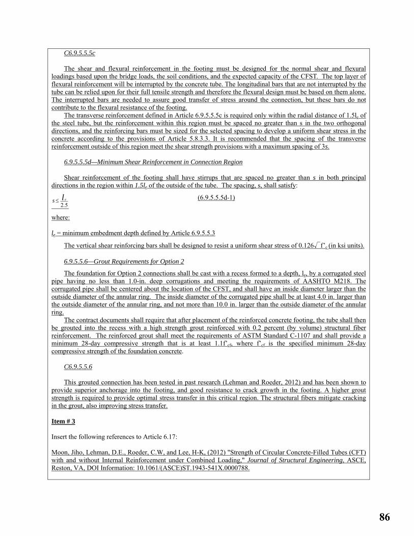
C6.9.5.5.5c The shear and flexural reinforcement in the footing must be designed for the normal shear and flexural
loadings based upon the bridge loads, the soil conditions, and the expected capacity of the CFST. The top layer of flexural reinforcement will be interrupted by the concrete tube. The longitudinal bars that are not interrupted by the tube can be relied upon for their full tensile strength and therefore the flexural design must be based on them alone. The interrupted bars are needed to assure good transfer of stress around the connection, but these bars do not contribute to the flexural resistance of the footing.
The transverse reinforcement defined in Article 6.9.5.5.5c is required only within the radial distance of 1.5le of the steel tube, but the reinforcement within this region must be spaced no greater than s in the two orthogonal directions, and the reinforcing bars must be sized for the selected spacing to develop a uniform shear stress in the concrete according to the provisions of Article 5.8.3.3. It is recommended that the spacing of the transverse reinforcement outside of this region meet the shear strength provisions with a maximum spacing of 3s.
6.9.5.5.5d—Minimum Shear Reinforcement in Connection Region Shear reinforcement of the footing shall have stirrups that are spaced no greater than s in both principal
directions in the region within 1.5le of the outside of the tube. The spacing, s, shall satisfy:
s ≤ el2.5
(6.9.5.5.5d-1)
where:
le = minimum embedment depth defined by Article 6.9.5.5.3
The vertical shear reinforcing bars shall be designed to resist a uniform shear stress of 0.126√f’c (in ksi units). 6.9.5.5.6—Grout Requirements for Option 2
The foundation for Option 2 connections shall be cast with a recess formed to a depth, le, by a corrugated steel pipe having no less than 1.0-in. deep corrugations and meeting the requirements of AASHTO M218. The corrugated pipe shall be centered about the location of the CFST, and shall have an inside diameter larger than the outside diameter of the annular ring. The inside diameter of the corrugated pipe shall be at least 4.0 in. larger than the outside diameter of the annular ring, and not more than 10.0 in. larger than the outside diameter of the annular ring.
The contract documents shall require that after placement of the reinforced concrete footing, the tube shall then be grouted into the recess with a high strength grout reinforced with 0.2 percent (by volume) structural fiber reinforcement. The reinforced grout shall meet the requirements of ASTM Standard C-1107 and shall provide a minimum 28-day compressive strength that is at least 1.1f’cf, where f’cf is the specified minimum 28-day compressive strength of the foundation concrete.
C6.9.5.5.6
This grouted connection has been tested in past research (Lehman and Roeder, 2012) and has been shown to provide superior anchorage into the footing, and good resistance to crack growth in the footing. A higher grout strength is required to provide optimal stress transfer in this critical region. The structural fibers mitigate cracking in the grout, also improving stress transfer. Item # 3 Insert the following references to Article 6.17: Moon, Jiho, Lehman, D.E., Roeder, C.W, and Lee, H-K, (2012) "Strength of Circular Concrete-Filled Tubes (CFT) with and without Internal Reinforcement under Combined Loading," Journal of Structural Engineering, ASCE, Reston, VA, DOI Information: 10.1061/(ASCE)ST.1943-541X.0000788.

Roeder, C. W., and Lehman, D.E., (2012) "Initial Investigation of Reinforced Concrete Filled Tubes for use in Bridge Foundations," Research Report WA-RD 776.1, Washington Department of Transportation, Olympia, WA, June 2012. Roeder, Lehman and Bishop (2010),“Strength and Stiffness of Circular Concrete Filled Tubes," ASCE, Journal of Structural Engineering, Vol 135, No. 12, pgs 1545-53, Reston, VA. Roeder, C.W, Lehman, D.E., and Thody, R. (2009) "Composite Action in CFT Components and Connections," AISC, Engineering Journal, Vol. 46, No. 4, Chicago, IL, pgs 229-42. Lehman, D.E., and Roeder, C.W (2012) "Rapid Construction of Bridge Piers with Improved Seismic Performance," California Department of Transportation Report CA12-1972, Sacramento, CA. Lehman, D.E., and Roeder, C.W., (2012) "Foundation Connections for Circular Concrete-Filled Tubes," Journal of Constructional Steel Research (2012), pp. 212-225 DOI information: 10.1016/j.jcsr.2012.07.001. Item #4 Modify the Notation in Article 6.3 as necessary.
OTHER AFFECTED ARTICLES:Delete Articles 6.12.2.3 and 6.12.3 and all associated commentary.
BACKGROUND:First major update of composite column provisions in AASHTO LRFD Bridge Design Specifications.
ANTICIPATED EFFECT ON BRIDGES:These provisions will permit the use of concrete filled steel tubes (CFST) for bridge piers and other structural elements. The use of CFST piers permits rapid construction of the pier, since no formwork or internal reinforcement is required. Further, CFST piers result in the less weight and material since the diameter of the pier will be 25% to 35% smaller than a comparable reinforced concrete pier of the same strength and stiffness. CFST is also very suitable for seismic design, since it leads to lighter members with less material and smaller seismic design forces, while CFST with the connection defined in Article 6.9.5.5 provides ductility and inelastic deformation capacity equal to or greater than that achieved with a properly detailed reinforced concrete member.
REFERENCES: Moon, Jiho, Lehman, D.E., Roeder, C.W, and Lee, H-K, (2012) "Strength of Circular Concrete-Filled Tubes (CFT) with and without Internal Reinforcement under Combined Loading," Journal of Structural Engineering, ASCE, Reston, VA, DOI Information: 10.1061/(ASCE)ST.1943-541X.0000788. Roeder, C. W., and Lehman, D.E., (2012) "Initial Investigation of Reinforced Concrete Filled Tubes for use in Bridge Foundations," Research Report WA-RD 776.1, Washington Department of Transportation, Olympia, WA, June 2012. Roeder, Lehman and Bishop (2010),“Strength and Stiffness of Circular Concrete Filled Tubes," ASCE, Journal of Structural Engineering, Vol 135, No. 12, pgs 1545-53, Reston, VA. Roeder, C.W, Lehman, D.E., and Thody, R. (2009) "Composite Action in CFT Components and Connections," AISC, Engineering Journal, Vol. 46, No. 4, Chicago, IL, pgs 229-42.

Lehman, D.E., and Roeder, C.W (2012) "Rapid Construction of Bridge Piers with Improved Seismic Performance," California Department of Transportation Report CA121972, Sacramento, CA. Lehman, D.E., and Roeder, C.W., (2012) "Foundation Connections for Circular Concrete-Filled Tubes," Journal of Constructional Steel Research (2012), pp. 212-225 DOI information: 10.1016/j.jcsr.2012.07.001.
OTHER: None

2013 AASHTO BRIDGE COMMITTEE AGENDA ITEM: 23 SUBJECT: LRFD Bridge Design Specifications: Section 6, Articles C6.10.1 & 6.17 TECHNICAL COMMITTEE: T-14 Steel
REVISION ADDITION NEW DOCUMENT
DESIGN SPEC CONSTRUCTION SPEC MOVABLE SPEC MANUAL FOR BRIDGE SEISMIC GUIDE SPEC COASTAL GUIDE SPEC
EVALUATION OTHER DATE PREPARED: 1/20/13 DATE REVISED: 4/8/13 AGENDA ITEM:Item # 1 Add the following after the 4th paragraph of Article C6.10.1: White et al. (2012) present one suggested method of estimating I-girder flange lateral bending moments and stresses in straight-skewed I-girder bridges and curved I-girder bridges with or without skew. This method is particularly useful to account in a rational manner for the flange lateral bending moments and stresses resulting from a grillage or plate and eccentric beam analysis since these results cannot be obtained directly from such analyses. Item #2 Revise the current 4th paragraph of Article C6.10.1 as follows: For horizontally curved bridges, in addition to the potential sources of flange lateral bending discussed in the preceding paragraph previously, flange lateral bending effects due to curvature must always be considered at all limit states and also during construction. Item # 3 Add the following reference to Article 6.17: White, D.W., Coletti, D., Chavel, B.W., Sanchez, A., Ozgur, C., Jimenez Chong, J.M., Leon, R.T., Medlock, R.D., Cisneros, R.A., Galambos, T.V., Yadlosky, J.M., Gatti, W.J., and Kowatch, G.T. 2012. “Guidelines for Analytical Methods and Construction Engineering of Curved and Skewed Steel Girder Bridges,” NCHRP Report 725, Transportation Research Board, National Research Council, Washington, D.C.
OTHER AFFECTED ARTICLES:None

BACKGROUND:White et al. (2012) suggests one method of estimating I-girder flange lateral bending moments and stresses primarily for use with refined analysis methods from which these results are not obtained directly (e.g. grid or grillage and plate and eccentric beam analysis methods) by directly using the calculated cross-frame forces determined from the analysis. This new paragraph provides a reference to this work.
ANTICIPATED EFFECT ON BRIDGES:More accurate estimation of I-girder flange lateral bending moments and stresses, particularly when grillage or plate and eccentric beam analysis methods are employed.
REFERENCES: See Item #3
OTHER: None

2013 AASHTO BRIDGE COMMITTEE AGENDA ITEM: 24 SUBJECT: LRFD Bridge Design Specifications: Section 6, Article C6.10.1.6 & 6.17 TECHNICAL COMMITTEE: T-14 Steel
REVISION ADDITION NEW DOCUMENT
DESIGN SPEC CONSTRUCTION SPEC MOVABLE SPEC MANUAL FOR BRIDGE SEISMIC GUIDE SPEC COASTAL GUIDE SPEC
EVALUATION OTHER DATE PREPARED: 1/20/13 DATE REVISED: 4/8/13 AGENDA ITEM:Item #1
In Article C6.10.1.6, revise the 1st sentence of the 8th paragraph as follows:
Eq. 6.10.1.6-2, or equivalently Eq. 6.10.1.6-3 as applicable, simply gives a maximum value of Lb for which f =
f 1 in Eq. 6.10.1.6-4 or 6.10.1.6-5.
Item #2 In Article C6.10.1.6, revise the 3rd sentence of the 8th paragraph as follows: Eqs. 6.10.1.6-4 and 6.10.1.6-5, which are This equation, which is an established form for estimating the maximum second-order elastic moments in braced beam-column members whose ends are restrained by other framing, tends tend to be significantly conservative for larger unsupported unbraced lengths associated with fbu approaching Fcr (White et al., 2001). Item #3 Add the following after the 9th paragraph of Article C6.10.1.6: When determining the amplification of f 1 in horizontally-curved I-girders with Lb/R ≥ 0.05, Fcr in Eqs. 6.10.1.6-4 and 6.10.1.6-5 may be determined from Eq. 6.10.8.2.3-8 or Eq. A6.3.3-8 by replacing Lb with KLb = 0.5Lb. For girders with Lb/R < 0.05, Lb may be used. The use of KLb = 0.5Lb for Lb/R ≥ 0.05 gives a better estimate of the amplification of the bending deformations associated with the boundary conditions for the flange lateral bending at intermediate cross-frame locations, which are approximately symmetrical, and assumes that an unwinding stability failure of the compression flange is unlikely for this magnitude of the girder horizontal curvature. Figure C6.10.1.6-1 illustrates qualitatively, using a straight elastic member for simplicity, the amplified second-order elastic flange lateral deflections associated with horizontal curvature effects as well as the unwinding stability failure mode.

(b) “Unwinding” elastic stability failure mode
Figure C6.10.1.6-1—Second-order Elastic Lateral Deflections due to Horizontal Curvature Effects Versus the Unwinding Stability Failure Mode of the Compression Flange Item #4
In Article 6.17, add the following reference:
White, D.W., Coletti, D., Chavel, B.W., Sanchez, A., Ozgur, C., Jimenez Chong, J.M., Leon, R.T., Medlock, R.D., Cisneros, R.A., Galambos, T.V., Yadlosky, J.M., Gatti, W.J., and Kowatch, G.T. 2012. “Guidelines for Analytical Methods and Construction Engineering of Curved and Skewed Steel Girder Bridges,” NCHRP Report 725, Transportation Research Board, National Research Council, Washington, D.C.
OTHER AFFECTED ARTICLES:
The specification and commentary language proposed for inclusion in Articles 6.10.3.4 and C6.10.3.4 supplements the requirements of Article 2.5.3, which are referenced by Article 6.10.3.1, by providing specific guidelines for checking the global stability of certain multiple I-girder bridge units interconnected by cross-frames or diaphragms when in their noncomposite condition during the deck placement.
BACKGROUND: The proposed additions are intended to clarify the application of Eqs. 6.10.1.6-4 or 6.10.1.6-5 for approximating second-order elastic lateral flange bending stresses. Furthermore, guidance is provided on when an effective length factor of 0.5 may be assumed appropriately in Eqs. 6.10.1.6-4 and 6.10.1.6-5.
ANTICIPATED EFFECT ON BRIDGES The guidance provided on the use of KLb = 0.5Lb in Eqs. 6.10.1.6-4 and 6.10.1.6-5 leads to more accurate estimates of the actual second-order amplification of the flange lateral bending stresses in horizontally curved I-girder bridges in cases where these approximate equations are employed to determine the amplification effect. The proposed changes to Articles 6.10.3.4 and C6.10.3.4 alert the Engineer to potential situations where global second-order amplification of the girder vertical and lateral displacements may lead to construction difficulties during the deck placement, and provide requirements to avoid these situations.
REFERENCES: See Item #4
OTHER: None

2013 AASHTO BRIDGE COMMITTEE AGENDA ITEM: 25 SUBJECT: LRFD Bridge Design Specifications: Section 6, Various Articles TECHNICAL COMMITTEE: T-14 Steel
REVISION ADDITION NEW DOCUMENT
DESIGN SPEC CONSTRUCTION SPEC MOVABLE SPEC MANUAL FOR BRIDGE SEISMIC GUIDE SPEC COASTAL GUIDE SPEC
EVALUATION OTHER DATE PREPARED: 1/11/13 DATE REVISED: 4/15/13 AGENDA ITEM: Make the revisions and additions to the indicated articles in Section 6 shown in Attachment A.
OTHER AFFECTED ARTICLES:None
BACKGROUND: Following the I-35W Bridge collapse investigation, the National Transportation Safety Board (NTSB) made five recommendations to the Federal Highway Administration (FHWA) and AASHTO. One of these recommendations was to require bridge owners to include main truss member gusset plates as part of the load rating process for these bridges. To assist the states with this process, FHWA issued a Guidance document in February 2009. This document required, at a minimum, for main truss member gusset plates to be evaluated for five limit states using either the Load Factor Rating (LFR) or Load and Resistance Factor Rating (LRFR) philosophies. The Guidance document was based on existing provisions in the AASHTO LRFD Bridge Design Specifications and the older AASHTO Standard Specifications for Highway Bridges along with engineering judgment. The FHWA Guidance document was thought to yield conservative gusset plate ratings. As States began to evaluate their inventory with the Guidance document, a need for more direction on some checks was identified, while some facets of other checks were thought to be too conservative. This was the case particularly for the shear reduction factor (Ω) associated with the shear yielding check, and the K-factor selection for use in the column analogy compressive buckling resistance check.
To address these concerns, FHWA initiated a research project collaboratively with the AASHTO-sponsored National Cooperative Highway Research Program (NCHRP) to evaluate the shear, tensile and compressive resistance of gusset plates at the strength limit state (NCHRP Project 12-84). The project tested 12 full-scale experimental gusset plate connections, and used finite element analysis to explore a variety of geometric parameters that could not be experimentally investigated. Primarily, the goal of NCHRP Project 12-84 was to derive new load rating provisions for inclusion in the MBE to satisfy NTSB Recommendation H-08-23, “When the findings of the Federal Highway Administration–American Association of State Highway and Transportation Officials joint study on gusset plates become available, update the Manual for Bridge Evaluation accordingly.” A separate companion Agenda item is taking care of addressing these recommendations with significant proposed additional content to the MBE. A decision was made to ensure that the LRFR and LFR gusset plate rating specifications in the MBE are reasonably self-sufficient and do not refer back to the LRFD Bridge Design

Specifications or the Standard Specifications to a significant extent for determining the factored resistance of the gusset plate and its connections. Therefore, it is not imperative that the gusset plate design provisions derived from the research findings be included in the LRFD Bridge Design Specifications, although it makes sense to unify the two specifications for consistency, and to ensure that gusset plates on new truss bridges are designed based on the latest state-of-the-art knowledge in order to provide a more uniform reliability.
ANTICIPATED EFFECT ON BRIDGES: The current specification provisions in LRFD Bridge Design Specification Article 6.14.2.8 allow the Engineer significant discretion in the design of truss member gusset plates. The new provisions are much more comprehensive and should result in a more unified design approach and a more uniform reliability for these gusset plate designs. The new provisions may result in thicker gusset plates than would be required using the current specifications, but the cost associated with thickening gusset plates is relatively marginal, and should be the only significant perceived difference when the proposed design specifications are employed.
REFERENCES: See the revised Article 6.17 in Attachment A.
OTHER: None

1 ATTACHMENT A – 2013 AGENDA ITEM 25 - T-14 Make the following revisions to Articles 6.2, 6.3, 6.5.4.2, 6.7.3, 6.13.6.1.5, 6.14.2.8 & 6.17 of the LRFD Bridge Design Specifications: 6.2—DEFINITIONS Chord Splice—A connection between two discontinuous chord members in a truss structure, which may occur within or outside of a gusset plate. Gusset Plate—Plate material used to interconnect vertical, diagonal, and horizontal truss members at a panel point, or to interconnect diagonal and horizontal cross-frame members for subsequent attachment of the cross-frame to transverse connection plates. Whitmore Section—A portion of a truss gusset plate defined at the end of a member fastener pattern based on 30 degree dispersion patterns from the lead fastener through which it may be assumed for the purposes of design that all force from the member is evenly distributed into the gusset plate. 6.3—NOTATION Af = area of the inclined bottom flange (in.2); area of a box flange including longitudinal flange stiffeners
(in.2); sum of the area of fillers on the top and bottom both sides of a connecting plate (in.2); area of flange transmitting a concentrated load (in.2) (C6.10.1.4) (C6.11.11.2) (6.13.6.1.5) (6.13.7.2)
Ag = gross area of a member (in.2); gross cross-sectional area of the member (in.2); gross area of the tension flange (in.2); gross area of the section based on the design wall thickness (in.); gross cross-sectional area of the effective Whitmore section determined based on 30 degree dispersion angles (in.2); gross area of all plates in the cross-section intersecting the spliced plane (in.2) (6.6.1.2.3) (6.8.2.1) (6.9.4.1.1) (6.9.4.1.3) (6.10.1.8) (6.12.1.2.3c) (6.13.6.1.4c) (6.14.2.8.4) (6.14.2.8.6)
An = net cross-section area of a tension member (in.2); net area of a flange (in.2); net area of gusset and splice plates (in.2) (6.6.1.2.3) (6.8.2.1) (6.10.1.8) (6.14.2.8.6)
Ap = smaller of either the connected plate area or the sum of the splice plate area on the top and bottom both sides of the connected plate (in.2) (6.13.6.1.5)
Avg = gross area along the cut carrying shear stress in block shear (in.2); gross area of the connection element subject to shear (in.2); gross area of gusset plate subject to shear (in.2) (6.13.4) (6.13.5.3) (6.14.2.8.3)
ep = distance between the centroid of the cross-section and the resultant force perpendicular to the spliced plane in gusset plates (in.) (6.14.2.8.6)
Fcr = critical buckling stress for plates (ksi); elastic lateral torsional buckling stress (ksi); shear buckling resistance (ksi); elastic local buckling stress (ksi); stress in the spliced section at the limit of usable resistance (ksi) (C6.9.4.2) (6.10.1.6) (6.12.1.2.3c) (6.12.2.2.3) (6.12.2.2.5) (6.14.2.8.6)
Fu = specified minimum tensile strength of steel (ksi); specified minimum tensile strength of a stud shear connector (ksi); specified minimum tensile strength of a connected part (ksi); tensile strength of a connected element (ksi); specified minimum tensile strength of a gusset plate (ksi) (6.4.1) (6.10.10.4.3) (6.13.2.9) (6.13.5.3) (6.14.2.8.6)
Fy = specified minimum yield strength of steel (ksi); specified minimum yield strength of a pin (ksi); specified minimum yield strength of a pin plate (ksi); specified minimum yield strength of a connected part (ksi); specified minimum yield strength of a splice plate (ksi); specified minimum yield strength of a gusset plate (ksi) (6.4.1) (6.7.6.2.1) (6.8.7.2) (6.9.4.1.1) (6.12.2.2.4) (6.12.2.2.5) (6.12.2.2.7) (6.13.4) (6.13.6.1.4c) (6.14.2.8.3)
K = effective length factor; effective length factor in the plane of buckling determined as specified in Article 4.6.2.5; effective column length factor taken as 0.50 for chord splices (6.9.3) (6.9.4.1.2) (6.14.2.8.6)
Lmid = in a gusset plate connection, the distance from the last row of fasteners in the compression member under consideration to the first row of fasteners in the closest adjacent connected member, measured along the line of action of the compressive axial force (6.14.2.8.4)
Lsplice = in a gusset plate connection, the center-to-center distance between the first lines of fasteners in the adjoining chords at a chord splice (6.14.2.8.6)

2 Pe = elastic critical buckling resistance determined as specified in Article 6.9.4.1.2 for flexural buckling, and
as specified in Article 6.9.4.1.3 for torsional bucking or flexural-torsional buckling, as applicable (kips); and as specified in Article 6.14.2.8.4 for gusset plate buckling (6.9.4.1.1) (6.14.2.8.4)
Pn = nominal bearing resistance on pin plates (kip); nominal axial compressive resistance (kip); total longitudinal force in the concrete deck over an interior support for the design of the shear connectors at the strength limit state, taken as the lesser of either P1n or P2n (kip); nominal compressive resistance of an idealized Whitmore section (kip) (6.8.7.2) (6.9.2.1) (6.10.10.4.2) (6.14.2.8.4)
Pr = factored axial tensile or compressive resistance (kip); factored bearing resistance on pin plates (kip); factored axial resistance of bearing stiffeners (kip); nominal flexural resistance of an orthotropic deck, with consideration of the effective width of the deck (kip); factored compressive resistance of gusset plates (kip); factored axial compressive resistance of a steel pile (kip); factored compressive resistance determined as specified in Article 6.9.2.1 (kip) (6.8.2.1) (6.8.7.2) (6.9.2.2) (6.9.4.2.1) (6.9.4.3.2) (6.10.11.2.4a) (6.14.2.8.4) (6.15.3.1)
Rr = factored resistance of a bolt, connection or connected material (kip) or (ksi); factored resistance in tension of connection elements (kip); factored tensile resistance of gusset plates (kip) (6.13.2.2) (6.13.5.2) (6.14.2.8.5)
Sg = elastic gross section modulus of gusset plates and splice plates (in.3) (6.14.2.8.6) Sn = elastic net section modulus of gusset plates and splice plates (in.3) (6.14.2.8.6) Vr = factored shear resistance (kip); factored shear resistance of gusset plates (kip) (6.12.1.2.3) (6.14.2.8.3) tg = gusset plate thickness (6.14.2.8.4) φcg = resistance factor for truss gusset plate compression (6.5.4.2) φcs = resistance factor for truss gusset chord splice (6.5.4.2) φvy = resistance factor for truss gusset plate shear yielding (6.5.4.2) θ = angle of inclination of the bottom flange of a variable web depth member (degrees); angle of inclination
of the web plate of a box section to the vertical (degrees); framing angle of compression member relative to an adjoining member in a gusset-plate connection (C6.10.1.4) (6.11.9) (6.14.2.8.4)
Ω = shear yield reduction factor for gusset plates (6.14.2.8.3)

3
6.5.4.2—Resistance Factors
Resistance factors, φ, for the strength limit stateshall be taken as follows:
C6.5.4.2
Base metal φ as appropriate for resistance under consideration.
• For flexure φf = 1.00• For shear φv = 1.00• For axial compression, steel only φc = 0.90• For axial compression, composite φc = 0.90• For tension, fracture in net section φu = 0.80• For tension, yielding in gross section φy = 0.95• For bearing on pins in reamed, drilled
or bored holes and on milled surfaces φb = 1.00• For bolts bearing on material φbb = 0.80• For shear connectors φsc = 0.85• For A 325 and A 490 bolts in tension φt = 0.80• For A 307 bolts in tension φt = 0.80• For F 1554 bolts in tension φt = 0.80• For A 307 bolts in shear φs = 0.75• For F 1554 bolts in shear φs = 0.75• For A 325 and A 490 bolts in shear φs = 0.80• For block shear φbs = 0.80• For shear, rupture in connection
element φvu = 0.80• For truss gusset plate compression φcg = 0.75• For truss gusset plate chord splices φcs = 0.65• For truss gusset plate shear yielding φvy = 0.80• For web crippling φw = 0.80• For weld metal in complete penetration welds:
o shear on effective area φe1 = 0.85o tension or compression normal to
effective area same as base metal o tension or compression parallel
to axis of the weld same as base metal • For weld metal in partial penetration welds:
o shear parallel to axis of weld φe2 = 0.80o tension or compression parallel
to axis of weld same as base metal o compression normal to the effective area same as base metal
tension normal to the effective area φe1 = 0.80• For weld metal in fillet welds:
o tension or compression parallel to axis of the weld same as base metal
o shear in throat of weld metal φe2 = 0.80• For resistance during pile driving φ = 1.00
The resistance factors for truss gusset plates were developed and calibrated to a target reliability index of 4.5 for the Strength I load combination at a dead-to-live ratio, DL/LL, of 6.0. More liberal φ factors could be justified at a DL/LL less than 6.0.

4 • For axial resistance of piles in compression and
subject to damage due to severe driving conditionswhere use of a pile tip is necessary: o H-piles φc = 0.50o pipe piles φc = 0.60
• For axial resistance of piles in compression undergood driving conditions where use of a pile tip isnot necessary: o H-piles φc = 0.60o pipe piles φc = 0.70
The basis for the resistance factors for driven steel piles is described in Article 6.15.2. Further limitations on usable resistance during driving are specified in Article 10.7.8.
• For combined axial and flexural resistance ofundamaged piles: o axial resistance for H-piles φc = 0.70o axial resistance for pipe piles φc = 0.80o flexural resistance φf = 1.00
• For shear connectors in tension φst = 0.75
Indicated values of φc and φf for combined axial and flexural resistance are for use in interaction equations in Article 6.9.2.2.
6.7.3—Minimum Thickness of Steel Structural steel, including bracing, cross-frames, and all types of gusset plates, except for gusset platesused in trusses, webs of rolled shapes, closed ribs inorthotropic decks, fillers, and in railings, shall not beless than 0.3125 in. in thickness. The thickness of gussetplates used in trusses shall not be less than 0.375 in. For orthotropic decks, the web thickness of rolledbeams or channels and of closed ribs in orthotropicdecks shall not be less than 0.25 in., the deck platethickness shall not be less than 0.625 in. or four percent of the larger spacing of the ribs, and the thickness ofclosed ribs shall not be less than 0.1875 in. Where the metal is expected to be exposed tosevere corrosive influences, it shall be speciallyprotected against corrosion or sacrificial metal thicknessshall be specified.
6.13.6.1.5—Fillers When bolts carrying loads pass through fillers 0.25in. or more in thickness in axially loaded connections,including girder flange splices, either: • The fillers shall be extended beyond the gusset or
splice material, and the filler extension shall besecured by enough additional bolts to distribute thetotal stress in the member uniformly over thecombined section of the member and the filler or
• As an alternative, the fillers need not be extended
and developed provided that the factored resistanceof the bolts in shear at the strength limit state,specified in Article 6.13.2.2, is reduced by thefollowing factor:

5
( )( )⎥⎦
⎤⎢⎣
⎡γ+γ+
=21
1R (6.13.6.1.5-1)
where: γ = Af/Ap
Af = sum of the area of the fillers on the top and bottom of both sides of the connected plate(in.2)
Ap = smaller of either the connected plate area or thesum of the splice plate areas on the top andbottom both sides of the connected plate (in.2). For truss gusset plate chord splices, whenconsidering the gusset plate(s), only the portionof the gusset plate(s) that overlaps theconnected plate shall be considered in thecalculation of the splice plate areas.
For slip-critical connections, the factored slipresistance of a bolt, specified in Article 6.13.2.2, shallnot be adjusted for the effect of the fillers. Fillers 0.25 in. or more in thickness shall consist ofnot more than two plates, unless approved by theEngineer. For bolted web splices with thickness differences of0.0625 in. or less, no filler plates are required.
The specified minimum yield strength of fillers0.25 in. or greater in thickness should not be less than the larger of 70 percent of the specified minimum yieldstrength of the connected plate and 36.0 ksi.
6.14—PROVISIONS FOR STRUCTURE TYPES
6.14.2.8—Gusset Plates C6.14.2.8
6.14.2.8.1—General The provisions of Articles 6.13.4 and 6.13.5 shall
apply, as applicable. Gusset or connection plates should be used for
connecting main truss members, except where themembers are pin-connected. The fasteners connectingeach member shall be symmetrical with the axis of the member, so far as practicable, and the full developmentof connection of all the elements of the member shouldbe given consideration to facilitate the load transfer.
Re-entrant cuts, except curves made for appearance,should be avoided as far as practicable.
The maximum stress from combined factoredflexural and axial loads shall not exceed φfFy based on the gross area.
The maximum shear stress on a section due to thefactored loads shall be φvFy/√3 for uniform shear andφv 0.74 Fy/√3 for flexural shear computed as the factoredshear force divided by the shear area.
If the length of the unsupported edge of a gusset
Following the 2007 collapse of the I-35W bridge in Minneapolis, the traditional procedures for designing gusset plates, including the provisions of this Article, have been under extensive review. As of Spring 2008, new design procedures have not been codified. Guidance from FHWA is expected shortly. Designers are advised to obtain the latest approved recommendations from Owners.
C6.14.2.8.1 The provisions provided in this article are intended
for the design of double gusset-plate connections used in trusses. The validity of the requirements for application to single gusset-plate connections has not been verified.
These provisions are based on the findings from NCHRP Project 12-84 (NCHRP, 2013). Example calculations illustrating the application of the resistance equations for gusset-plate connections contained herein are provided in NCHRP (2013).

6 plate exceeds 2.06(E/Fy)1/2 times its thickness, the edgeshall be stiffened. Stiffened and unstiffened gussetedges shall be investigated as idealized column sections.
Gusset plates shall satisfy the minimum platethickness requirement for gusset plates used in trussesspecified in Article 6.7.3. Gusset plates shall be designed for shear, compression, and/or tensionoccurring in the vicinity of each connected member, asapplicable, according to the requirements specified inArticles 6.14.2.8.3 through 6.14.2.8.5. Gusset platesserving as a chord splice shall also be independentlydesigned as a splice according to the provisions ofArticle 6.14.2.8.6. The edge slenderness requirementspecified in Article 6.14.2.8.7 shall be considered.
Bolted gusset plate connections shall satisfy theapplicable requirements of Articles 6.13.1 and 6.13.2.Where filler plates are required, the provisions of Article 6.13.6.1.5 shall apply.
6.14.2.8.2—Multi-Layered Gusset and Splice Plates Where multi-layered gusset and splice plates are
used, the resistances of the individual plates may beadded together when determining the factoredresistances specified in Articles 6.14.2.8.3 through6.14.2.8.6 provided that enough fasteners are present todevelop the force in the layered gusset and splice plates.
C6.14.2.8.2 Kulak et al. (1987) contains additional guidance on
determining the number of fasteners required to develop the force in layered gusset and splice plates.
6.14.2.8.3—Shear Resistance The factored shear resistance, Vr, of gusset plates
shall be taken as the smaller value based on shearyielding or shear rupture.
For shear yielding, the factored shear resistanceshall be taken as: Vr = φvy0.58FyAvgΩ (6.14.2.8.3-1)
where: φvy = resistance factor for truss gusset plate shear
yielding specified in Article 6.5.4.2 Ω = shear reduction factor for gusset plates taken as
0.88 Avg = gross area of the shear plane (in.2) Fy = specified minimum yield strength of the gusset
plate (ksi)
For shear rupture, the factored shear resistance shallbe determined from Eq. 6.13.5.3-2.
Shear shall be checked on relevant partial and fullfailure plane widths. Partial shear planes shall only bechecked around compression members and only Eq.6.14.2.8.3-1 shall apply to partial shear planes. Thepartial shear plane length shall be taken along adjoiningmember fastener lines between plate edges and otherfastener lines. The following partial shear planes, as
C6.14.2.8.3 The Ω shear reduction factor is used only in the
evaluation of truss gusset plates for shear yielding. This factor accounts for the nonlinear distribution of shear stresses that form along a failure plane as compared to an idealized plastic shear stress distribution. The nonlinearity primarily develops due to shear loads not being uniformly distributed on the plane and also due to strain hardening and stability effects. The Ω-factor was developed using shear yield data generated in NCHRP Project 12-84 (NCHRP, 2013). On average, Ω was 1.02 for a variety of gusset-plate geometries; however, there was significant scatter in the data due to proportioning of load between members, and variations in plate thickness and joint configuration. The specified Ω-factor has been calibrated to account for shear plane length-to-thickness ratios varying from 85 to 325.
Failure of a full width shear plane requires relative mobilization between two zones of the plate, typicallyalong chords. Mobilization cannot occur when a shear plane passes through a continuous member; for instance, a plane passing through a continuous chord member that would require shearing of the member itself.
Research has shown that the buckling of connections with tightly spaced members is correlated with shear yielding around the compression members. This is important because the buckling criteria used in Article 6.14.2.8.4 would overestimate the compressive

7 applicable, shall be evaluated to determine which shearplane controls:
• The plane that parallels the chamfered end of the
compression member, as shown in Figure 6.14.2.8.3-1;
• The plane on the side of the compression memberthat has the smaller framing angle between the thatmember and the other adjoining members, as shown in Figure 6.14.2.8.3-2; and
• The plane with the least cross-sectional shear area if
the member end is not chamfered and the framingangle is equal on both sides of the compressionmember.
Contolling Partial Plane
Oth
er P
artia
l Pla
ne 45°
45°
Figure 6.14.2.8.3-1—Example of a Controlling PartialShear Plane that Parallels the Chamfered End of theCompression Member Since that Member Frames in at anAngle of 45 Degrees to Both the Chord and the Vertical
θ<α
Con
trollin
g P
artia
l Pla
ne
α
Other Partial Plane
Figure 6.14.2.8.3-2—Example of a Controlling PartialShear Plane on the Side of a Compression MemberWithout a Chamfered End that has the Smaller FramingAngle between that Member and the Other AdjoiningMembers (i.e. θ < α)
buckling resistance of these types of connections. Once a plane yields in shear, the reduction in the plate modulus reduces the out-of-plane stiffness such that the stability of the plate is affected. Generally, truss verticals and chord members are not subject to the partial plane shear yielding check because there is no adjoining member fastener line that can yield in shear and cause the compression member to become unstable. For example, the two compression members shown in Figure C6.14.2.8.3-1 would not be subject to a partial plane shear check.
Figure C6.14.2.8.3-1—Example Showing Truss Vertical and Chord Members in Compression that Do Not Require a Partial Shear Plane Check

8
6.14.2.8.4—Compressive Resistance The factored compressive resistance, Pr, of gusset
plates shall be taken as:
Pr = φcg Pn (6.14.2.8.4-1)
where: φcg = resistance factor for truss gusset plate
compression specified in Article 6.5.4.2 Pn = nominal compressive resistance of a Whitmore
section determined from Eq. 6.9.4.1.1-1 or 6.9.4.1.1-2, as applicable (kip)
In the calculation of Pn, the slender element
reduction factor, Q, shall be taken as 1.0, and the elasticcritical buckling resistance, Pe, shall be taken as:
g
g
mid
e A
tL
EP 2
29.3
⎟⎟⎠
⎞⎜⎜⎝
⎛= (6.14.2.8.4-2)
where: Ag = gross cross-sectional area of the Whitmore
section determined based on 30 degreedispersion angles, as shown in Figure6.14.2.8.4-1 (in.2). The Whitmore section shall not be reduced if the section intersectsadjoining member bolt lines
Lmid = distance from the middle of the Whitmoresection to the nearest member fastener line inthe direction of the member, as shown inFigure 6.14.2.8.4-1 (in.)
tg = gusset-plate thickness (in.)
30°
30°
Width of Whitmore Section
Lmid
Figure 6.14.2.8.4-1—Example Connection Showing theWhitmore Section for a Compression Member Derivedfrom 30 Degree Dispersion Angles and the Distance Lmid
C6.14.2.8.4 Gusset plate zones in the vicinity of compression
members are to be designed for plate stability. Experimental testing and finite element simulations performed as part of NCHRP Project 12-84 (NCHRP, 2013) and by others (Yamamoto et al., 1988; Hafner et al., 2012) have found that truss gusset plates subject to compression always buckle in a sidesway mode in which the end of the compression member framing into the gusset plate moves out-of-plane. The buckling resistance is dependent upon the chamfering of the member, the framing angles of the members entering the gusset, and the standoff distance of the compression member relative to the surrounding members; i.e. the distance, Lmid. An example connection showing a typical chamfered member end and member framing angle is provided in Figure C6.14.2.8.4-1. The research found that the compressive resistance of gusset plates with large Lmid distances was reasonably predicted using modified column buckling equations and Whitmore section analysis. When the members were heavily chamfered reducing the Lmid distance, the buckling of the plate was initiated by shear yielding on the partial shear plane adjoining the compression member causing a destabilizing effect, as discussed in Article C6.14.2.8.3.
Eq. 6.14.2.8.4-2 is derived by substituting plate properties into Eq. 6.9.4.1.2-1 along with an effective length factor of 0.5 that was found to be relevant for a wide variety of gusset-plate geometries (NCHRP, 2013).
Framing Angle
ChamferedMember End
Figure C6.14.2.8.4-1–Example Connection Showing a Typical Chamfered Member End and Member Framing Angle

9 The provisions of this Article shall not be applied tocompression chord splices.
6.14.2.8.5—Tensile Resistance The factored tensile resistance, Rr, of gusset plates
shall be taken as the smallest factored resistance intension based on yielding, fracture or block shearrupture determined according to the provisions ofArticle 6.13.5.2. When checking Eqs. 6.8.2.1-1 and 6.8.2.1-2, the Whitmore section defined in Figure6.14.2.8.5-1 shall be used to define the effective area.The Whitmore section shall not be reduced if the widthintersects adjoining member bolt lines.
Widt
h of W
hitmore
Sec
tion
30°
30°
Figure 6.14.2.8.5-1—Example Connection Showing theWhitmore Section for a Tension Member Derived from 30Degree Dispersion Angles
The provisions of this Article shall not be applied totension chord splices.
6.14.2.8.6—Chord Splices Gusset plates that splice two chord sections
together shall be checked using a section analysisconsidering the relative eccentricities between all plates crossing the splice and the loads on the spliced plane. For compression chord splices, the factoredcompressive resistance, Pr, of the spliced section shallbe taken as:
⎟⎟
⎠
⎞
⎜⎜
⎝
⎛
+=
gpg
ggcrcsr AeS
ASFP φ
(6.14.2.8.6-1)
in which: Fcr = stress in the spliced section at the limit of
usable resistance (ksi). Fcr shall be taken as thespecified minimum yield strength of the gussetplate when the following equation is satisfied:
C6.14.2.8.6 This Article is not intended to cover the design of
chord splices that occur outside of the gusset plates; this situation is covered by the provisions of Article 6.13.6.1.2 or 6.13.6.1.3, as applicable. For gusset plates also serving the role of a chord splice, the forces from all members framing into the connection must be considered. The chord splice forces are the resolved axial forces acting on each side of the spliced section, as illustrated in Figure C6.14.2.8.6-1. The chord splice should be investigated for the larger of the two resolved forces on either side of the splice.

10
2512
<gt
Kl
(6.14.2.8.6-2) where: φcs = resistance factor for truss gusset plate chord
splices specified in Article 6.5.4.2 Ag = gross area of all plates in the cross-section
intersecting the spliced plane (in.2) ep = distance between the centroid of the cross-
section and the resultant force perpendicular tothe spliced plane (in.)
K = effective column length factor taken as 0.50 forchord splices
Lsplice = center-to-center distance between the first linesof fasteners in the adjoining chords as shown inFigure 6.14.2.8.6-1 (in.)
Sg = gross section modulus of all plates in the cross-section intersecting the spliced plane (in.3)
tg = gusset plate thickness (in.)
splice
Figure 6.14.2.8.6-1—Example Connection Showing ChordSplice Parameter, Lsplice
Left
Cho
rdSp
lice
Load
Rig
ht C
hord
Splic
e Lo
ad
Figure C6.14.2.8.6-1—Example Connection Showing the Resolution of the Member Forces into Forces Acting on Each Side of a Chord Splice
The resistance equations in this Article assume the
gusset and splice plates behave as one combined spliced section to resist the applied axial load and eccentric bending that occurs due to the fact that the resultant forces on the section are offset from the centroid of the combined section, as illustrated in Figure C6.14.2.8.6-2. The combined spliced section is treated as a beam and the factored resistance at the strength limit state is determined assuming the stress in the combined section at the limit of usable resistance is equal to the specified minimum yield strength of the gusset plate if the slenderness limit for the spliced section given by Eq. 6.14.2.8.6-2 is met, which will typically be the case. If not, the Engineer will need to derive a reduced value of Fcr to account for possible elastic buckling of the gusset plate within the splice.
Gusset Plate
Centroid of All Gusset and Splice Plates
Splice Plate
ep
Figure C6.14.2.8.6-2—Illustration of the Combined Spliced Section at a Chord Splice

11
For tension chord splices, the factored tensileresistance, Pr, shall be taken as the lesser of the valuesgiven by Eqs. 6.14.2.8.6-3 and 6.14.2.8.6-4.
⎟⎟
⎠
⎞
⎜⎜
⎝
⎛
+=
gpg
ggycsr AeS
ASFP φ
(6.14.2.8.6-3)
⎟⎟
⎠
⎞
⎜⎜
⎝
⎛
+=
npnnn
ucsr AeSASFP φ (6.14.2.8.6-4)
where: φcs = resistance factor for truss gusset plate chord
splices specified in Article 6.5.4.2 Ag = gross area of all plates in the cross-section
intersecting the spliced plane (in.2) An = net area of all plates in the cross-section
intersecting the spliced plane (in.2) ep = distance between the centroid of the cross-
section and the resultant force perpendicular tothe spliced plane (in.)
Fy = specified minimum yield strength of the gussetplate (ksi)
Fu = specified minimum tensile strength of thegusset plate (ksi)
Sg = gross section modulus of all plates in the cross-section intersecting the spliced plane (in.3)
Sn = net section modulus of all plates in the cross-section intersecting the spliced plane (in.3)
Tension chord splice members shall also be
checked for block shear rupture as specified in Article6.13.4.
The Whitmore section check specified in Article 6.14.2.8.4 is not considered applicable for the design of a compression chord splice.
The yielding and net section fracture checks on the Whitmore section specified in Article 6.14.2.8.5 are not considered applicable for the design of a tension chord splice.
6.14.2.8.7—Edge Slenderness If the length of the unsupported edge of a gusset
plate exceeds 2.06tg(E/Fy)1/2, where tg is the gusset platethickness and Fy is the specified minimum yield strengthof the gusset plate, the edge should be stiffened.
C6.14.2.8.7 This Article is intended to provide good detailing
practice to reduce deformations of free edges duringfabrication, erection, and service versus providing an increase in the member compressive buckling resistance at the strength limit state. NCHRP Project 12-84 (NCHRP, 2013) found no direct correlation between the buckling resistance of the gusset plate and the free edge slenderness. There are no criteria specified for sizing of the edge stiffeners, but the traditional practice of using angles with leg thicknesses of 0.50 in. has generally provided adequate performance.
6.17—REFERENCES Add the following references: Hafner, A., O. T. Turan, and T. Schumacher. 2012. “Experimental Tests of Truss Bridge Gusset Plates Connectionswith Sway-Buckling Response,” Journal of Bridge Engineering, American Society of Civil Engineers, Reston, VA (accepted for publication).

12 NCHRP (web only document No. 197). 2013. Guidelines for the Load and Resistance Factor Design and Rating ofWelded, Riveted and Bolted Gusset-Plate Connections for Steel Bridges, Transportation Research Board, National Research Council, Washington D.C. Yamamoto, et al. 1998. “Buckling Strengths of Gusseted Truss Joints,” Journal of Structural Engineering, American Society of Civil Engineers, Reston, VA, Vol. 114.

2013 AASHTO BRIDGE COMMITTEE AGENDA ITEM: 26 SUBJECT: LRFD Bridge Construction Specifications: Section 11, Article 11.4.12.2.2 and LRFD Bridge Design Specifications: Section 6, Articles 6.7.7.1 and 6.7.7.2 TECHNICAL COMMITTEE: T-14 Steel / T-4 Construction
REVISION ADDITION NEW DOCUMENT
DESIGN SPEC CONSTRUCTION SPEC MOVABLE SPEC MANUAL FOR BRIDGE SEISMIC GUIDE SPEC COASTAL GUIDE SPEC
EVALUATION OTHER DATE PREPARED: 7/5/11 DATE REVISED: 4/5/13 (Based on comments received, Heat Curving Limitations will be placed in the LRFD Bridge Construction Specifications) AGENDA ITEM:Item #1 In the LRFD Bridge Construction Specifications renumber Articles 11.4.12.2.2 through 11.4.12.2.7 as 11.4.12.2.3 through 11.4.12.2.8. Item #2 Insert new Article 11.4.12.2.2 Et Sequa as follows: 11.4.12.2.2—Geometric Limitations 11.4.12.2.2a—Cross-Sectional Criteria Rolled beams and constant depth welded I-section plate girders satisfying all of the following criteria may be heat curved to obtain a horizontal curvature: • R > 1,000 ft if (tf > 3.0 in.) or (b > 30.0 in.), otherwise R > 150 ft • Ψ ≤ 2.0 • Ψf ≥0.20 • tnf ≤ tf
in which:
nf nf f w w
nf nf f
b t bt D tb t bt+ +
=+
ψ (11.4.12.2.2a-1)
1.0nf nff
f
b tbt
= ≤ψ (11.4.12.2.2a-2)
where: R = horizontal radius of curvature measured to the centerline of the girder web

b = width of wider flange (in.) bnf = width of narrower flange (in.) Dw = clear distance between flanges (in.) tf = thickness of wider flange (in.) tnf = thickness of narrower flange (in.) tw = web thickness (in.) Insert the following commentary to Article 11.4.12.2.2a: C11.4.12.2.2a
The development of the minimum radius limits in Articles 11.4.12.2.2b and 11.4.12.2.2c was limited to cases with ψ less than or equal to 2, ψf greater than or equal to 0.2 and tnf less than or equal to tf (Sause et al 2013). The 150 ft limit is traditional.
For nonprismatic beams and girders the largest radius determined by applying the applicable equations in Articles 11.4.12.2.2b and 11.4.12.2.2c to each cross-section controls.
Guidance on shop implementation of continuous and V-heating to heat curve girders is given in U.S. Steel (2001) and (2002).
Insert new Article 11.4.12.2.2b as follows: 11.4.12.2.2b—Minimum Radius for Doubly-Symmetric Beams and Girders
For heat-curved doubly-symmetric beams and girders, the horizontal radius of curvature measured to the
centerline of the girder web, in inches, shall not be less than the following:
• 592 ,w
w yw
DIf thent F
>
2
0.0365 w
w
DbRtψ
⎛ ⎞= ⎜ ⎟
⎝ ⎠ (11.4.12.2.2b-1)
• Otherwise
12,800
yw
bRF ψ
= (11.4.12.2.2b-2)
where: Fyw = specified minimum yield strength of a web (ksi) Insert the following commentary to Article 11.4.12.2.2b: C11.4.12.2.2b
The stress analysis performed by Brockenbrough (1970) to develop the equations in earlier editions of
AASHTO specifications was based on the following assumptions:
• The heat curving process introduces heat continuously along the girder length, resulting in a heated portion of the flange which is the same at every cross-section along the length.
• The girder cross-section is a doubly-symmetric I-shaped section.

• A tensile shrinkage force P develops in the heated portion of each flange near the flange edge on the inside of the curve. P is eccentric to the girder centroid.
• The heated width of the flange is 0.20b, i.e. 20 percent of the flange width. • The entire cross-section of the girder resists P, resulting in transverse bending stresses associated with the
horizontal curvature about a vertical axis and axial compressive stresses on the cross-section. The entire cross-section remains elastic and plane sections remain plane.
The resulting equation for the compressive stress in the web due to heat curving, normalized to the yield stress, was
6,000 1 1/
w
yw ywF F R bσ
ψ−
=
(C11.4.12.2.2b-1)
The equations in this Article are based on numerical simulations that overcame three limitations of the stress
analysis by Brockenbrough (Sause et al 2013). These three limitations are:
• The stress in the cross-section was permitted to exceed the yield stress,
• The stress analysis was limited to doubly-symmetric cross-sections, and
• The heated width was fixed at 0.20b, rather than varying with R.
The studies which varied the heated flange width with R and considered the effect of yielding in the flanges, found that the compressive stress in the web due to heat curving could be adequately represented by the empirical equation of Eq. C11.4.12.2.2b-1 with the constant 6,000 replaced by 6,670 resulting in Eq. C11.4.12.2.2b-2 (Sause et al 2013).
6,670 1 1
/w
yw ywF F R bσ
ψ−
= (C11.4.12.2.2b-2)
With the stress in the web from the heat curving operation now quantified, limits on R were established
following the process developed by Brockenbrough. The basis for Eq. C11.4.12.2.2b-1 is limiting stress in web to the buckling stress instead of the post buckling strength previously used. Eq. C11.4.12.2.2b-2 is based on Von Mises yield criteria but revised assuming greater web shear stresses (0.425 Fy) under current design practice and an allowable stress of 0.90 Fy, while the original development assumed a web shear stress of 0.33 Fy and an allowable stress of Fy.
Insert new Article 11.4.12.2.2c as follows: 11.4.12.2.2c—Minimum Radius of Curvature for Singly-Symmetric Girders
For heat-curved singly-symmetric beams or girders, the horizontal radius of curvature measured to the centerline of the girder, in inches, shall not be less than the values calculated from Eqs. 11.4.12.2.2b-1 and 11.4.12.2.2b-2. Additionally, for singly-symmetric girders with ψ greater than or equal to 1.46 and with ψf less than ψfo, the radius shall not be less than that determined as:
2
f
fo yw
ψ 12800 b R = 1.43ψ 1 1ψ F ψ
⎡ ⎤ ⎛ ⎞⎛ ⎞⎢ ⎥− ⎜ ⎟⎜ ⎟ ⎜ ⎟⎢ ⎥⎝ ⎠ ⎝ ⎠⎣ ⎦
+ (11.4.12.2.2c-1)
in which:

0.68 0.79foψ ψ= − (11.4.12.2.2c-2)
Insert the following commentary to Article 11.4.12.2.2c: C11.4.12.2.2c
Singly-symmetric cross-sections were included in the study described in Article C11.4.12.2.2b with the limitation that the moment of the heated area of the narrower flange about the elastic neutral axis is equal to the moment of the heated area of the wider flange about the elastic neutral axis. Parametric studies demonstrated that Eq. C11.4.12.2.2b-2 was adequate for the singly-symmetric case as well, provided that the flange width in the equation is taken as the width of the wider flange.
The stress analysis of singly-symmetric heat-curved girders that was used to develop Eq. C11.4.12.2.2b-1 and Eq. C11.4.12.2.2b-2 is valid when R is greater than the radius at which the heated width of the narrower flange equals the flange half width. This limit on R is provided by Eq. 11.4.12.2.2c-1 which is also considered to be a practical limit on the radius of singly-symmetric heat curved beams and girders. For many cases, this limit on heated flange width is reached when the web stresses are quite high, so it is not of practical concern, as the radius will be limited by the two equations in Article 11.4.12.2.2b. However, for highly unsymmetrical cases, this limit will be reached when the web stresses are not large, so that a limit on the radius of heat curved girders based on this limit on heated flange width is needed.
Insert new Article 11.4.12.2.2d as follows: 11.4.12.2.2d—Minimum Radius of Curvature for Hybrid Girders
Hybrid girders which meet the following criteria may be heat curved: • ηw ≤ ηf, and
• ηw = ηf if ηf < 1
• byf ≥ byfw if ηf < 1 in which:
yfwf
yf
Fη
F= (11.4.12.2.2d-1)
yw
wyf
Fη
F= (11.4.12.2.2d-2)
where: Fyfw = yield stress of flange with lower yield stress (ksi) Fyf = yield stress of flange with higher yield stress (ksi) Fyw = yield stress of web (ksi) byfw = width of flange with lower yield stress (in.) byf = width of flange with higher yield stress (in.)
For hybrid sections with ηf = 1 and ηw <1, the horizontal radius of curvature measured to the centerline of the girder, in inches, shall not be less than the minimum radius determined from Articles 11.4.12.2.2b and 11.4.12.2.2c with Fyf substituted for Fyw in Eq. 11.4.12.2.2c-1.
For hybrid sections with ηf < 1, the horizontal radius of curvature measured to the centerline of the girder, in inches, shall not be less than the minimum radius determined from Article 11.4.12.2.2b. Additionally, for girders

with ψfo greater than or equal to 0.2 fη and with ψf less than fo
f
ψη
, the radius shall not be less than that determined
as:
2
f
fo
ψ 12800 bR 1.43 1 ψ 1ψ F ψ
y
f
w
η⎛ ⎞⎛ ⎞ ⎛ ⎞⎜ ⎟⎜ ⎟= − + ⎜ ⎟⎜ ⎟⎜ ⎟⎜ ⎟⎜ ⎟⎝ ⎠⎝ ⎠⎝ ⎠
⋅ (11.4.12.2.2d-3)
Insert the following commentary to Article 11.4.12.2.2d: C11.4.12.2.2d
Hybrid cross-sections were also included in the study described in Article C11.4.12.2.2b with the limitation that the moment of the heated area of the weaker flange about the elastic neutral axis is equal to the moment of the heated area of the stronger flange about the elastic neutral axis.
The results of the study showed that Eqs. 11.4.12.2.2b-1 and 11.4.12.2.2b-2 are also valid for hybrid sections, subject to the limitations outlined in this Article. The stress analysis of hybrid singly-symmetric heat-curved girders that was used to validate Eqs. 11.4.12.2.2b-1 and 11.4.12.2.2b-2 is valid when R is greater than the radius at which the heated width of the weaker flange equals the flange half width. This limit on R is provided by Eq. 11.4.12.2.2d-3.
Item #3 Add the following references to Article 11.10 and delete three references to “ASCE 1970”. • Brockenbrough, R. L. 1970. “Criteria for Heat Curving Steel Beams and Girders,” Journal of the Structural
Division. American Society of Civil Engineers, Vol. 96, October 1970. • Brockenbrough, R. L. 1970a. “Experimental Stresses and Strains from Heat Curving,” Journal of the
Structural Division, Volume 96, No. ST7, American Society of Civil Engineers, New York.
• Brockenbrough, R. L. 1970b. “Theoretical Stresses and Strains from Heat Curving,” Journal of the Structural Division, Volume 96, No. ST7, American Society of Civil Engineers, New York.
• Sause, R., H. Ma, and J. M. Kulicki. 2013. “Residual Stresses in Heat-Curved I-Girders and Associated Limits on Radius of Curvature,” ATLSS Report No. 13-01, Center for Advanced Technology for Large Structural Systems, Lehigh University, Bethlehem, PA, April 2013.
Item #4 Revise Article 6.7.7.1 as follows:
This section pertains to rolled beams and constant depth welded I-section plate girders heat-curved to obtain a horizontal curvature. Structural steels conforming to AASHTO M 270M/M 270 (ASTM A709/A709M), Grades 36, 50, 50S, 50W, HPS 50W, HPS 70W or HPS 100W (Grades 250, 345, 345S, 345W, HPS 345W, HPS 485W or HPS 690W) may be heat-curved. Item #5 In the LRFD Bridge Design Specifications delete Article 6.7.7.2 and replace with the following: 6.7.2.2—Geometric Limitations
The provisions of Article 11.4.12.2 of the LRFD Bridge Construction Specifications regarding cross-sectional

limitations and radius limitations shall apply.
Item #6 Delete the following Notation references to Article 6.7.7.2: b, ψ, D, Fyw
OTHER AFFECTED ARTICLES:None
BACKGROUND:The limits on the radius of heat-curved steel bridge girders, Eq. 6.7.7.2-1 and Eq. 6.7.7.2-2 in the 2010 Edition AASHTO LRFD given as Eq. 1 and Eq. 2 below, are based on research by Brockenbrough (reference 1).
R14 b D FY ψ t
(1)
R7,500 bFY ψ
(2) where:
ψ = ratio of the total cross-sectional area to the total cross-sectional area of the two flanges b = widest flange width (in.) tw = web thickness (in.) Dw = clear distance between flanges (in.) Fyw = specified minimum yield stress of web (ksi) Rmin = minimum radius of heat-curved girder (in.), where the larger result from Eq. 1 and Eq. 2 controls The axial compressive stress in the web due to heat curving (reference 1) was given by Eq. 3.
6,000 1 1/
w
yw ywF F R bσ
ψ−
= (3)
Development and use of Eq. 3 is referred to herein as “Method B” to denote the work by Brockenbrough. Method B considers the magnitude of the stresses only in the web where stresses will be controlled by existing Eq. 6.7.7.2-1 and Eq. 6.7.7.2-2. Experimental research conducted by Brockenbrough (reference. 2) showed that the final stresses in the heated portion of the flanges were relatively constant and close to the yield stress. Method B does not give this result. An improved analysis of residual stresses in heat curved steel girders (called Method A to denote the alternative method used in the supporting calculations) was developed (Sause et al 2013), in which it is assumed that the final stress in the heated portion of the flanges equals the yield stress in tension. The remainder of the section, called the elastic section herein (see Fig. 1), develops stresses which are in equilibrium with the tensile stress in the heated portion of the flanges. The width of the heated portion of the flanges is treated as a variable, which increases as R decreases. Specifically, the assumptions are:
• The heat curving process introduces heat continuously along the girder length, resulting in a heated portion of the flange which is the same at every cross-section along the length.

• The girder cross-section is a doubly-symmetric I-shaped section with a single yield stress (i.e., is not a hybrid cross-section).
• The stress in the heated portion of the flanges equals the yield stress in tension. • The remainder of the cross-section is elastic.
Method A does not provide a simple relationship between web stress σW and the curvature radius R, in a form similar to Eq. 1. However data which relate σW to R, were generated and plotted as the width of the heated portion of the flange is varied. This is as shown in Fig. 2 for FY = 50 ksi and various values of ψ. Similarly, data for the stresses in the flange away from the heated portion of the flange (at point O on the flange edge on the outside of the curve, Fig. 1) can be generated and plotted various values of ψ.
Fig. 1 Elastic section
Fig. 2 Web stress (FY=50 ksi)

A comparison of the results from Method A and Method B indicated the following:
• Method A estimates larger web stress than Method B. • Method A specifies the stress in the heated width of the flange, while Method B does not control this stress.
Method B gives stresses in the heated width of the flange that are well above yield stress. From Method A, it was observed that tensile flange stresses at point O on the flange edge on the outside of the curve exceed the yield stress before the minimum value of R is reached. Similar results (not shown) indicate that compressive yield stresses in the flange in the elastic region adjacent to the heated portion may also exceed the yield stress before the minimum value of R is reached. To account for this, a nonlinear version of Method A was developed in which yielding in the flanges was considered. As the flanges yield, the section properties of the elastic section are recalculated. There are two flange yielding conditions: (1) the outside flange edge (point O) yields first; and (2) the flange adjacent to the heated portion (point I) yields first. Both conditions are considered in the analysis. A comparison of results for wide range of cross-section shapes and yield strengths led to empirical Eq. 4 which gives the web axial compressive stress induced by heat-curving, with stresses in the flanges limited to the yield stress. Eq. 4 has the same form as Eq. 1 derived by Brockenbrough (reference 1). The value of 0.23E, with E=29000 ksi, is 6670ksi, which is about 11% larger than the constant (6000 ksi) in Eq. 3.
1 1 6670 1 10.23/ /
W
yw yw yw
EF F R b F R bσ
ψ ψ= − = − (4)
The similarity of these results is a little surprising since Brockenbrough’s analysis used a constant fraction of the flange width as the heated portion, did not consider yielding on the cross-section, and was correlated to a limited data set from experiments on beams with only one yield stress (36 ksi, nominal). These results, however, show that Brockenbrough’s analysis produced relatively reasonable results. The work was extended to include the singly-symmetric section. The shrinkage forces in the heated portions of the flanges should not generate a bending moment about the primary axis of bending (i.e., about the horizontal elastic neutral axis) of the elastic part of the section (after removing the heated portions of the flanges from the section). Therefore, the heated portion of the flanges should have the following relationship:
1 2th nf e h f eb t y b t y= where as shown in Figure 1: bthtnf = heated area of narrower flange (e.g., the top flange) (in2)
bhtf = heated area of wider flange (e.g., the bottom flange) (in2) bth = heated width of narrower flange (in.) bh = heated width of wider flange (in.) tnf = thickness of narrower flange (in.) tf = thickness of wider flange (in.) y1e = distance from centerline of narrower flange to horizontal ENA for elastic section (in.) y2e = distance from centerline of wider flange to horizontal ENA for elastic section (in.) Three parameters are needed to describe the singly-symmetric section: φ, ν, and ψ. φ is the ratio of narrower flange width to wider flange width; ν is the ratio of the thickness of the narrower flange to the thickness of the wider flange; ψ is ratio of total girder area to total flange area.

nf
nf
f
nf nf f w w
nf nf f
bb
tt
b t bt D tb t bt
=
=
+ +=
+
ϕ
ν
ψ
where as shown in Figure 1: Dw = clear distance between the flanges (in.) tw = web thickness (in.) bnf = width of narrower flange (in.) b = width of wider flange Analysis of a wide range of cross-section shapes and yield strengths showed that the following empirical equation accurately represents the web axial compressive stress induced by heat-curving for singly-symmetric sections.
0.043 0.1332
1 1 1 10.23 0.23/
w
yw yw
EF F R b ν
σλ ψ ϕ −= − = − (5)
Figs. 3 and 4 compare Eq. 5 with Eq. 4 for several singly-symmetric cases. Figs. 3 and 4 show analysis data for singly-symmetric and doubly symmetric cases, with ψ=1.2 and ψ=2, respectively. Together these figures and others developed as part of the numerical study, show that Eq. 4 alone provides sufficient accuracy for estimating the web stress from heat curving for singly-symmetric sections, as long as the width of the widest flange is used for the parameter b. For the cases that have been studied, the term φ0.043-0.133ν is close enough to 1, so that the effect of singly-symmetry on the heat-induced stress in the web can be neglected.
Fig. 3 Singly-symmetric curve fit for ψ=1.2

Fig. 4 Singly-symmetric curve fit for ψ=2.0
The original stability criteria given by current Eq. 6.7.7.2-1 was derived by Brockenbrough by setting the web axial stress induced by heat curving from Eq. 3 equal to the web post-buckling stress taken as:
u c ywf f F= (6)
in which:
( )
2
2212 1
cc
w
w
k EfDt
π
μ
=⎛ ⎞
− ⎜ ⎟⎝ ⎠
(7)
where: fu = post-buckling buckling stress (ksi) fc = elastic buckling stress (ksi) kc = buckling coefficient taken as 6.97 (for fixed edge conditions) μ = Poisson’s ratio Since Eq. 6 provides a post-buckling stress, the current provisions permit the theoretical elastic web buckling stress to be exceeded by the heat curving operation. It was understood that the actual web behavior will not be bifurcation as assumed for elastic buckling theory, but will be a growth of the initial out-of-flatness of the web present before heat curving. However, several other provisions in AASHTO LRFD limit calculated web stresses to below a theoretical elastic buckling stress. Taking a similar approach where the web stress from heat curving is limited to the theoretical elastic buckling stress given by Eq. 7 rather than the post-buckling stress given by Eq. 6 leads the proposed stability criteria. The proposed equation is derived by substituting σw=fc from Eq. 7 into Eq. 4 using kc = 6.97 and μ = 0.30, neglecting the minus sign, and solving for R which gives the minimum R that causes elastic buckling of the web under stress from heat curving:

( ) 2 22
min 2
12 10.23 0.0365w w
c w w
D Db bRk t t
μ
π ψ ψ
− ⎛ ⎞ ⎛ ⎞= =⎜ ⎟ ⎜ ⎟
⎝ ⎠ ⎝ ⎠ (8)
The table below compares the results from Eq. 1 (the current Eq. 6.7.7.2-1) and Eq. 8 (the proposed Eq. 11.4.12.2.2b-1) for girders with Fyw = 50 ksi, and shows that the proposed Eq. 8 limits the heat curving radius to 1.3 to 3 times the current Rmin.
w
w
Dt
minRbψ⎛ ⎞⎜ ⎟⎝ ⎠
from Eq. 1 minRbψ⎛ ⎞⎜ ⎟⎝ ⎠
from Eq. 8
70 139 179 80 158 234 90 178 296
100 198 365 110 218 442 120 238 526 130 257 617 140 277 715 150 297 821 160 317 934
Current Eq. 6.7.7.2-2 in AASHTO LRFD was derived from Eq. 1 by Brockenbrough as follows. The web axial stress induced by heat curving in combination with an estimated shear stress under service load was limited to yield. The Von Mises yield criterion was used to establish the yield condition under these combined stresses.
( ) ( ) ( )2 2 23yw c sF σ σ= + (9)
where: σc = web axial stress due to heat curving σs = estimated web shear stress under service load Brockenbrough assumed σs = 0.33Fyw and solved Eq. 9 for σc = 0.80Fyw. Eq. 2 (the current Eq. 6.7.7.2-2) was obtained by substituting σw = σc = 0.80Fyw into Eq. 3, neglecting the minus sign, and solving for R. The result is the minimum R that causes web yielding under the combination of axial stress from heat curving with the estimated shear stress under service load of 0.33 Fyw. An improved version of the current Eq. 6.7.7.2-2 is proposed, considering the web stress results given by Eq. 4 and an updated estimate of the web stress under service load. For design according to AASHTO LRFD, the expected maximum shear stress under the Service II load combination is estimated from the expected maximum shear stress under the Strength I load combination, using a representative load factor for Strength I = 1.5 and a representative load factor for Service II = 1.1.
1.11.5s Service II s Strength Iσ σ− −⎛ ⎞= ⎜ ⎟⎝ ⎠
(10)
If σs-Strength I is assumed to be equal to 0.58 Fyw, then σs-Service II = 0.425 Fyw. Assuming that σs = σs-Service II = 0.425 Fyw and limiting the maximum Service II stress to 0.90 Fyw, an average of that currently used for composite and noncomposite girders, and then solving Eq. 9 for σc results in σc = 0.52 Fyw. Substituting σw = σc = 0.52 Fyw into Eq. 4, neglecting the minus sign and solving for R gives the minimum R that

causes webservice loa
min0.2
0.5R =
ComparingRmin from E The limits the web. Freaches havalidity of girders. Dabth = bnf/2. of the wide
A new nonbnf/2. Thewill be confrom Eq. 1intersectionequation oSince the nonlinear e
the nonlin
conservativ
minR =
Fig. 5 com
Fig. 4 D
b yielding undad:
23 12852 yw y
E bF Fψ
=
g Eq. 11 with Eq. 2.
on the radius oFor certain highalf the flange wf the analyses uata points were This radius R
er flange.
nlinear equatioe data points fontrolled by Eq11 were considn between thef the form ψfo intersection po
equation for Rm
ear equation f
ve curve fit to
2
f
fo
0.63 1⎛ ⎛ ⎞⎜ − +⎜ ⎟⎜ ⎝ ⎠⎝
mpares Eq. 11 w
Data for radius
der the combin
800
yw
bψ
Eq. 2 shows th
of heat-curvedhly unsymmetrwidth bnf/2 beused in this stue generated for
R was plotted v
on was developor a given valu. 8 or Eq. 11.
dered in develoe data points a= f(ψ) was fit toints representmin includes the
for Rmin with E
all the data poi
Y
0.23 E b 0.52ψ σ
⎞⎛ ⎞⎟⎜ ⎟⎟⎝ ⎠⎠
with the data po
when heated f
nation of axial
hat the revised
d steel I-girdersrical singly-sy
efore the radiuudy. This limitr a large numb
versus ψf = φν,
ped to fit this ue of ψ that areSo only the da
oping the nonland Eq. 11 wato these interset the intersecte constant term
Eq. 11 was ac
ints considered
f
f
ψ(1.43 ψ 1ψ
⎛⎞= −⎜⎟
⎠ ⎝
oints generated
flange width eqrepre
stress from he
d Eq. 11 limits
s (Eq. 8 and 11ymmetric sectios R becomes t is also considber of singly-swhich is the r
data, to provide less than Rmata points for Rinear equationas identified foection points, ation of the newm
Y
0.23 E b0.52 σ ψ
wh
chieved by inc
d was obtained
2
f
f 0 Y
12800 b1) σ ψ
⎞ ⎛+⎟ ⎜
⎝⎠
d for various va
quals half flangesenting Eq. 11
eat curving wit
(11)
s the heat curv
) are derived fons, the heatedsmall. Therefo
dered to be a pymmetric crosatio of the area
de a limit on Rmin from Eq. 11R correspondin
n. Only data wifor each value and the resultinw nonlinear eq
hich is reached
cluding the ter
with the follow
b ⎞⎟⎠
(12)
alues of ψ and
ge width plotte1
th the estimate
ving radius to 1
from limits on d width of the ore, bth = bnf/2practical limit oss-sections shoa of the narrow
R (i.e.,Rmin) co are inconsequ
ng to bth = btf/2ith ψf ≥ 0.2 weof ψ that wa
ng equation waquation for Rm
when ψf = ψfo
rm f
fO
1− in th
wing equation
ψf.
ed versus ψf wi
ed shear stress
1.7 times the c
the residual strnarrower flang
2 was a limit oon heat curvingowing the valuewer flange to th
orresponding touential, becaus2 which exceeere considered
as studied. A as ψfo = 0.68ψ -min with Eq. 1o. The intersect
e nonlinear te
for Rmin is:
ith Eq.12 and li
under
current
ress in ge on the g of I-e of R
he area
o bth = se Rmin ed Rmin
d. The linear
- 0.79. 11, the tion of
rm. A
ine

ANTICIPATED EFFECT ON BRIDGE:This will restrict the ability to heat curve some girders that would have been allowed under the previous criteria.
REFERENCES: Brockenbrough, R. L. 1970. “Criteria for Heat Curving Steel Beams and Girders,” Journal of the Structural Division. American Society of Civil Engineers, Vol. 96, October 1970. Brockenbrough, R. L. 1970. “Theoretical Stresses and Strains from Heat Curving,” Journal of the Structural Division. American Society of Civil Engineers, Vol. 96, July 1970. Sause, R., H. Ma, and J. M. Kulicki. 2013. “Residual Stresses in Heat-Curved I-Girders and Associated Limits on Radius of Curvature,” ATLSS Report No. 13-01, Center for Advanced Technology for Large Structural Systems, Lehigh University, Bethlehem, PA, April 2013.
OTHER: None

2013 AASHTO BRIDGE COMMITTEE AGENDA ITEM: 27 SUBJECT: LRFD Bridge Design Specifications: Section 10, Various Articles TECHNICAL COMMITTEE: T-15 Substructures and Retaining Walls
REVISION ADDITION NEW DOCUMENT
DESIGN SPEC CONSTRUCTION SPEC MOVABLE SPEC MANUAL FOR BRIDGE SEISMIC GUIDE SPEC BRIDGE ELEMENT INSP GUIDE
EVALUATION OTHER DATE PREPARED: 1/14/13 DATE REVISED: 4/17/13 AGENDA ITEM: In Section 10 - Foundations, make the revisions as shown in Attachment A.
OTHER AFFECTED ARTICLES:None
BACKGROUND:The impetus for this agenda item was the availability of the recently completed Federal Highway Administration Geotechnical Engineering Circular 10 – Drilled Shafts: Construction Procedures and LRFD Design Methods (Brown et al., 2010). The FHWA recently completed a comprehensive update to the recommended technical guidance for design and construction of drilled shaft foundations. This update is the first to FHWA recommended technical guidance since the manual developed by O’Neill and Reese (1999), which is heavily referenced in the current Section 10. Advances in construction equipment and procedures, and updates to design methodologies based on knowledge advances and performance data have been well documented in the literature. These advances include routine design and construction of large diameter foundation elements (e.g., > 5 feet), analysis of more comprehensive load test databases, and incorporation of recent published research to address gaps in the specification. This agenda item will serve to better represent the state of practice for drilled shaft design. The specific changes to Section 10 are shown in the attachment to this agenda item as underlined and stricken through text. The key changes are summarized as follows:
1. Table 10.4.2-1 has been adjusted to correct a problem with potentially excessive exploration depths for drilled shaft groups. In addition, language has been added to address potential design and construction risk due to subsurface condition variability and construction claims, especially with large diameter shafts socketed into bedrock.
2. The rock mass classification system used to assess rock mass strength, currently the Rock Mass Rating (RMR) system, is being replaced with the Geological Strength Index (GSI) system in Article 10.4.6.4. This will apply for Section 10 except as noted in Articles 10.6.2.4.4, 10.6.2.6.2and 10.6.3.2. As stated by Marinos and Hoek (2000), the GSI index is based upon an assessment of the lithology, structure and condition of discontinuity surfaces in the rock mass and it is estimated from visual examination of the rock

mass exposed in surface excavations such as roadcuts, in tunnel faces and in borehole core. The GSI, by the combination of the two fundamental parameters of geological process, the blockiness of the mass and the condition of the discontinuities, respects the main geological constraints that govern a formation and is thus both a geologically friendly index and practical to assess. The GSI provides a more direct correlation to the Hoek-Brown strength parameters than the RMR. Furthermore, the new drilled shaft specifications use the GSI to classify the rock mass to assess rock mass strength for design purposes.
3. The design procedures for spread footings in rock have been developed using the RMR system. Although GSI is specified for rock characterization in Section 10, RMR is still to be used for spread footing design in rock. Reference to Sabatini et al (2002) is provided for RMR.
4. A key issue is the design of shafts in intermediate geo-materials (IGM). Section 10 is rewritten to consider design methods only for cohesive IGM’s. The design method for tip resistance in cohesionless IGM’s has been deleted to remove confusion amongst designers when evaluating dense sands versus transitional materials. The term cohesionless IGM was used previously by O’Neill and Reese (1999) to describe granular tills or granular residual soils with N160 greater than 50 blows/ft. The use of this term is discontinued and all cohesionless geomaterials are included in a single category of cohesionless soils. This addresses designer confusion with results when trying to interpret whether very dense cohesionless soils (e.g. N=50) were to be considered cohesionless or IGM. Furthermore, the cohesionless IGM equation included in the current specifications tended to produce results that were more conservative than the equation for sand, likely due to the limited regionally applicable data used as its basis. The cohesionless IGM equation was not applicable for wider use nationally. Therefore, it was removed from the specifications in this agenda item.
5. Articles 10.8.1.6.2 and 10.8.2.3 have been significantly expanded to address downdrag for shafts with tip bearing in soil versus bedrock. The Articles have been rewritten to consider that downdrag occurs in response to relative movement of a drilled shaft and may not exist if shaft response to axial load exceeds vertical deformation of the soil. The response of a drilled shaft to downdrag in combination with the other forces acting at the head of the shaft is complex and a realistic evaluation of actual limit states that may occur requires careful consideration of two issues: (1) drilled shaft load-settlement behavior, and (2) the time period over which downdrag occurs relative to the time period over which non-permanent components of load occur. When these factors are taken into account, it is appropriate to consider different downdrag forces for evaluation of geotechnical strength limit states than for structural strength limit states. These issues are further addressed in Brown et al. (2010).
6. In the past, there has not been guidance on how to handle horizontal movement of shafts in rock. Furthermore, for fractured rock masses, the best method for calculating the rock shear strength may not be the same as in Article 10.4. For shafts socketed into rock, Article 10.8.2.3 has been significantly expanded to provide guidance on design for horizontal movement for shafts in rock, including a reference for guidance on developing hyperbolic P-y curves for fractured rock masses using the GSI (Liang et al., (2009).
7. Article 10.8.3.5.1b has been adjusted based on knowledge advances from field load test data. In accordance with O’Neil and Reese (1999), it has traditionally been recommended to neglect side resistance over a distance of one diameter above the base of drilled shafts where this portion derives its resistance from a cohesive soil. The recommendation is based on numerical modeling that predicts a zone of tension at the soil-shaft interface in the zone immediately above the base. This is not supported by field load test data and the agenda item has adjusted the text and Figure 10.8.3.5.1b-1 to show that this side resistance is not to be neglected over the bottom one diameter.
8. The method for determination of side resistance of shafts in cohesionless soils (the β-Method) has been updated. The method in Article 10.8.3.5.2b is based on axial load tests on drilled shafts as presented by Chen and Kulhawy (2002) and updated by Kulhawy and Chen (2007). The method provides a rational approach for relating unit side resistance to N-values and to the state of effective stress acting at the soil-shaft interface. This approach replaces the previously used depth-dependent β-method developed by O’Neill and Reese (1999), which does not account for variations in N-value or effective stress on the calculated value of β. Further discussion, including the detailed development of Eq. 10.8.3.5.2b-2, is provided in Brown et al. (2010).
9. The method for determination of side resistance of shafts socketed into bedrock has been updated based on analysis of load test data reported by Kulhawy et al., (2005). The adjustment of the method incorporates data from previous studies by Horvath and Kenney (1979), Rowe and Armitage (1987), Kulhawy and Phoon (1993), and others. The updated equation in Article 10.8.3.5.4b provides a more realistic estimate

of unit side shear that is based on a comprehensive load test database. 10. A key issue in drilled shaft design has been the design decision to neglect one or the other component of
resistance (side or base) in a rock socket. C10.8.3.5.4d has been updated to better assist designers with this. The commentary focuses on the use of quality construction practices, as opposed to omitting tip resistance in shafts. It is noted that in many cases, the cost of quality control and assurance is offset by the economies achieved in socket design by including tip resistance. Reasons cited for neglecting side resistance of rock sockets include (1) the possibility of strain-softening behavior of the sidewall interface (2) the possibility of degradation of material at the borehole wall in argillaceous rocks, and (3) uncertainty regarding the roughness of the sidewall. Brittle behavior along the sidewall, in which side resistance exhibits a significant decrease beyond its peak value, is not commonly observed in load tests on rock sockets. If there is reason to believe strain softening will occur, laboratory direct shear tests of the rock-concrete interface can be used to evaluate the load-deformation behavior and account for it in design. These cases would also be strong candidates for conducting field load tests. Investigating the sidewall shear behavior through laboratory or field testing is generally more cost-effective than neglecting side resistance in the design. Application of quality control and assurance through inspection is also necessary to confirm that sidewall conditions in production shafts are of the same quality as laboratory or field test conditions. Materials that are prone to degradation at the exposed surface of the borehole and are prone to a “smooth” sidewall generally are argillaceous sedimentary rocks such as shale, claystone, and siltstone. Degradation occurs due to expansion, opening of cracks and fissures combined with groundwater seepage, and by exposure to air and/or water used for drilling. Hassan and O’Neill (1997) note that this behavior is most prevalent in cohesive IGM’s and that in the most severe cases degradation results in a smear zone at the interface. Smearing may reduce load transfer significantly. As reported by Abu-Hejleh et al. (2003), both smearing and smooth sidewall conditions can be prevented in cohesive IGM’s by using roughening tools during the final pass with the rock auger or by grooving tools. Careful inspection prior to concrete placement is required to confirm roughness of the sidewalls. Only when these measures cannot be confirmed would there be cause for neglecting side resistance in design.
ANTICIPATED EFFECT ON BRIDGES:These revisions will affect the design of drilled shaft foundations for support of transportation structures through update of design methodologies to incorporate recently available information and knowledge advances construction equipment and procedures.
REFERENCES: See Attachment A
OTHER: None

1
ATTACHMENT A — 2013 AGENDA ITEM 27 - T-15 10.1—SCOPE – NO CHANGES – NOT SHOWN
10.2—DEFINITIONS
ONE ADDITION BELOW – THE REMAINDER STAYS THE SAME GSI—Geologic Strength Index
10.3—NOTATION ONE ADDITION BELOW – THE REMAINDER STAYS THE SAME s, m, a = fractured rock mass parameters (10.4.6.4) 10.4—SOIL AND ROCK PROPERTIES
10.4.1—Informational Needs – NO CHANGES – NOT SHOWN
10.4.2—Subsurface Exploration
Subsurface explorations shall be performed toprovide the information needed for the design and construction of foundations. The extent of explorationshall be based on variability in the subsurfaceconditions, structure type, and any projectrequirements that may affect the foundation design orconstruction. The exploration program should be extensive enough to reveal the nature and types of soildeposits and/or rock formations encountered, theengineering properties of the soils and/or rocks, thepotential for liquefaction, and the groundwater conditions. The exploration program should be sufficient to identify and delineate problematicsubsurface conditions such as karstic formations,mined out areas, swelling/collapsing soils, existing fillor waste areas, etc.
Borings should be sufficient in number and depth toestablish a reliable longitudinal and transverse substrataprofile at areas of concern such as at structurefoundation locations and adjacent earthwork locations,and to investigate any adjacent geologic hazards thatcould affect the structure performance.
C10.4.2
The performance of a subsurface exploration program is part of the process of obtaining information relevant for the design and construction of substructure elements. The elements of the process that should precede the actual exploration program include a search and review of published and unpublished information at and near the site, a visual site inspection, and design of the subsurface exploration program. Refer to Mayne et al. (2001) and Sabatini et al. (2002) for guidance regarding the planning and conduct of subsurface exploration programs.
The suggested minimum number and depth of borings are provided in Table 10.4.2-1. While engineering judgment will need to be applied by a licensed and experienced geotechnical professional to adapt the exploration program to the foundation types and depthsneeded and to the variability in the subsurface conditions observed, the intent of Table 10.4.2-1 regarding the minimum level of exploration needed should be carried out. The depth of borings indicated in Table 10.4.2-1performed before or during design should take into account the potential for changes in the type, size and depth of the planned foundation elements.

2 As a minimum, the subsurface exploration and testing
program shall obtain information adequate to analyzefoundation stability and settlement with respect to: • Geological formation(s) present,
• Location and thickness of soil and rock units,
• Engineering properties of soil and rock units, suchas unit weight, shear strength and compressibility,
• Groundwater conditions,
• Ground surface topography, and
• Local considerations, e.g., liquefiable, expansive ordispersive soil deposits, underground voids fromsolution weathering or mining activity, or slopeinstability potential.
This Table should be used only as a first step in estimating the number of borings for a particular design, as actual boring spacings will depend upon the project type and geologic environment. In areas underlain by heterogeneous soil deposits and/or rock formations, it will probably be necessary to drill more frequently and/or deeper than the minimum guidelines in Table 10.4.2-1 to capture variations in soil and/or rock type and to assess consistency across the site area. For situations where large diameter rock socketed shafts will be used or where drilled shafts are being installed in formations known to have large boulders, or voids such as in karstic or mined areas, it may be necessary to advance a boring at the location of each shaft. Even the best and most detailed subsurface exploration programs may not identify every important subsurface problem condition if conditions are highly variable. The goal of the subsurface exploration program, however, is to reduce the risk of such problems to an acceptable minimum.
Table 10.4.2-1 shall be used as a starting point fordetermining the locations of borings. The finalexploration program should be adjusted based on thevariability of the anticipated subsurface conditions aswell as the variability observed during the explorationprogram. If conditions are determined to be variable, theexploration program should be increased relative to therequirements in Table 10.4.2-1 such that the objective ofestablishing a reliable longitudinal and transversesubstrata profile is achieved. If conditions are observedto be homogeneous or otherwise are likely to haveminimal impact on the foundation performance, andprevious local geotechnical and construction experiencehas indicated that subsurface conditions arehomogeneous or otherwise are likely to have minimalimpact on the foundation performance, a reducedexploration program relative to what is specified inTable 10.4.2-1 may be considered.
In a laterally homogeneous area, drilling or advancing a large number of borings may be redundant, since each sample tested would exhibit similar engineering properties. Furthermore, in areas where soil or rock conditions are known to be very favorable to the construction and performance of the foundation type likely to be used, e.g., footings on very dense soil, and groundwater is deep enough to not be a factor, obtaining fewer borings than provided in Table 10.4.2-1 may be justified. In all cases, it is necessary to understand how the design and construction of the geotechnical feature will be affected by the soil and/or rock mass conditions in order to optimize the exploration.
If requested by the Owner or as required by law,boring and penetration test holes shall be plugged.
Laboratory and/or in-situ tests shall be performed todetermine the strength, deformation, and permeability characteristics of soils and/or rocks and their suitabilityfor the foundation proposed.
Borings may need to be plugged due to requirements by regulatory agencies having jurisdiction and/or to prevent water contamination and/or surface hazards.
Parameters derived from field tests, e.g., driven pile resistance based on cone penetrometer testing, may also be used directly in design calculations based on empirical relationships. These are sometimes found to be more reliable than analytical calculations, especially in familiar ground conditions for which the empirical relationships are well established.

3
Table 10.4.2-1—Minimum Number of Exploration Points and Depth of Exploration (modified after Sabatini et al., 2002)
Application Minimum Number of Exploration Points and
Location of Exploration Points Minimum Depth of Exploration Retaining Walls A minimum of one exploration point for each
retaining wall. For retaining walls more than 100 ft in length, exploration points spaced every 100 to 200 ft with locations alternating from in front of the wall to behind the wall. For anchored walls, additional exploration points in the anchorage zone spaced at 100 to 200 ft. For soil-nailed walls, additional exploration points at a distance of 1.0 to 1.5 times the height of the wall behind the wall spaced at 100 to 200 ft.
Investigate to a depth below bottom of wall at least to a depth where stress increase due to estimated foundation load is less than ten percent of the existing effective overburden stress at that depth and between one and two times the wall height. Exploration depth should be great enough to fully penetrate soft highly compressible soils, e.g., peat, organic silt, or soft fine grained soils, into competent material of suitable bearing capacity, e.g., stiff to hard cohesive soil, compact dense cohesionless soil, or bedrock.
Shallow Foundations
For substructure, e.g., piers or abutments, widths less than or equal to 100 ft, a minimum of one exploration point per substructure. For substructure widths greater than 100 ft, a minimum of two exploration points per substructure. Additional exploration points should be provided if erratic subsurface conditions are encountered.
To reduce design and construction risk due to subsurface condition variability and the potential for construction claims, at least one exploration per shaft should be considered for large diameter shafts (e.g., greater than 5 ft in diameter), especially when shafts are socketed into bedrock.
Depth of exploration should be:
• great enough to fully penetrate unsuitable foundation soils, e.g., peat, organic silt, or soft fine grained soils, into competent material of suitable bearing resistance, e.g., stiff to hard cohesive soil, or compact to dense cohesionless soil or bedrock;
• at least to a depth where stress increase due to estimated foundation load is less than ten percent of the existing effective overburden stress at that depth; and
• if bedrock is encountered before the depth required by the second criterion above is achieved, exploration depth should be great enough to penetrate a minimum of 10 ft into the bedrock, but rock exploration should be sufficient to characterize compressibility of infill material of near-horizontal to horizontal discontinuities.
Note that for highly variable bedrock conditions, or in areas where very large boulders are likely, more than 10 ft or rock core may be required to verify that adequate quality bedrock is present.
Deep Foundations
For substructure, e.g., bridge piers or abutments, widths less than or equal to 100 ft, a minimum of one exploration point per substructure. For substructure widths greater than 100 ft, a minimum of two exploration points per substructure. Additional exploration points should be provided if erratic subsurface conditions are encountered, especially for the case of shafts socketed into bedrock.
To reduce design and construction risk due to subsurface condition variability and the potential for construction claims, at least one exploration per shaft should be considered for large diameter shafts (e.g., greater than 5 ft in diameter), especially when shafts are socketed into bedrock.
In soil, depth of exploration should extend below the anticipated pile or shaft tip elevation a minimum of 20 ft, or a minimum of two times the maximum minimum pile group dimension, whichever is deeper. All borings should extend through unsuitable strata such as unconsolidated fill, peat, highly organic materials, soft fine-grained soils, and loose coarse-grained soils to reach hard or dense materials.
For piles bearing on rock, a minimum of 10 ft of rock core shall be obtained at each exploration point location to verify that the boring has not terminated on a boulder.
For shafts supported on or extending into rock, a minimum of 10 ft of rock core, or a length of rock core equal to at least three times the shaft diameter for isolated shafts or two times the maximum minimum shaft group dimension, whichever is greater, shall be extended below the anticipated shaft tip elevation to determine the physical characteristics of rock within the zone of foundation influence.
Note that for highly variable bedrock conditions, or in areas where very large boulders are likely, more than 10 ft or rock core may be required to verify that adequate quality bedrock is present.
4
10.4.3—Laboratory Tests – NO CHANGES – NOT SHOWN
10.4.4—In-Situ Tests – NO CHANGES – NOT SHOWN
10.4.5—Geophysical Tests – NO CHANGES- NOT SHOWN
10.4.6—Selection of Design Properties
10.4.6.1—General – NO CHANGES – NOT SHOWN
10.4.6.2—Soil Strength – NO CHANGES – NOT SHOWN
10.4.6.3—Soil Deformation – NO CHANGES – NOT SHOWN

5 10.4.6.4—Rock Mass Strength The strength of intact rock material should be
determined using the results of unconfined compressiontests on intact rock cores, splitting tensile tests on intactrock cores, or point load strength tests on intact specimens of rock.
The rock should be classified using the rock massrating system (RMR) as described in Table 10.4.6.4-1. For each of the five parameters in the Table, the relative rating based on the ranges of values provided should beevaluated. The rock mass rating (RMR) should bedetermined as the sum of all five relative ratings. TheRMR should be adjusted in accordance with the criteriain Table 10.4.6.4-2. The rock classification should bedetermined in accordance with Table 10.4.6.4-3. Except as noted for design of spread footings in rock, for a rockmass that contains a sufficient number of “randomly”oriented discontinuities such that it behaves as an isotropic mass, and thus its behavior is largelyindependent of the direction of the applied loads, the strength of the rock mass should first be classified usingits geological strength index (GSI) as described in Figures 10.4.6.4-1 and 10.4.6.4-2 and then assessedusing the Hoek-Brown failure criterion.
C10.4.6.4 Point load strength index tests may be used to assess
intact rock compressive strength in lieu of a full suite ofunconfined compression tests on intact rock coresprovided that the point load test results are calibrated tounconfined compression strength tests. Point loadstrength index tests rely on empirical correlations tointact rock compressive strength. The correlationprovided in the ASTM point load test procedure (ASTMD 5731) is empirically based and may not be valid forthe specific rock type under consideration. Therefore, asite specific correlation with uniaxial compressivestrength test results is recommended. Point load strengthindex tests should not be used for weak to very weakrocks (< 2200 psi /15 MPa).
Because of the importance of the discontinuities inrock, and the fact that most rock is much morediscontinuous than soilBecause the engineering behaviorof rock is strongly influenced by the presence andcharacteristics of discontinuities, emphasis is placed onvisual assessment of the rock and the rock mass. Theapplication of a rock mass classification systemessentially assumes that the rock mass contains asufficient number of “randomly” oriented discontinuitiessuch that it behaves as an isotropic mass, and thus itsbehavior is largely independent of the direction of theapplied loads. It is generally not appropriate to use suchclassification systems for rock masses with well defined,dominant structural fabrics or where the orientation ofdiscrete, persistent discontinuities controls behavior toloading.
The GSI was introduced by Hoek et al. (1995) andHoek and Brown (1997), and updated by Hoek et al.(1998) to classify jointed rock masses. Marinos et al.(2005) provide a comprehensive summary of theapplications and limitations of the GSI for jointed rockmasses (Figure 10.4.6.4-1) and for heterogeneous rockmasses that have been tectonically disturbed (Figure10.4.6.4-2). Hoek et al. (2005) further distinguishheterogeneous sedimentary rocks that are not tectonicallydisturbed and provide several diagrams for determiningGSI values for various rock mass conditions. Incombination with rock type and uniaxial compressivestrength of intact rock (qu), GSI provides a practicalmeans to assess rock mass strength and rock massmodulus for foundation design using the Hoek-Brownfailure criterion (Hoek et al. 2002).
The design procedures for spread footings in rockprovided in Article 10.6.3.2 have been developed usingthe rock mass rating (RMR) system. For design offoundations in rock in Articles 10.6.2.4 and 10.6.3.2,classification of the rock mass should be according to theRMR system. For additional information on the RMRsystem, see Sabatini et al. (2002).
Other methods for assessing rock mass strength,including in-situ tests or other visual systems that haveproven to yield accurate results may be used in lieu ofthe specified method.

6
Table 10.4.6.4-1—Geomechanics Classification of Rock Masses
Parameter Ranges of Values
1
Strength of intact rock material
Point load strength index
>175 ksf 85–175 ksf
45–85 ksf
20–45 ksf
For this low range, uniaxial compressive test is preferred
Uniaxial compressive strength
>4320 ksf 2160–4320 ksf
1080– 2160 ksf
520–1080 ksf
215–520 ksf
70–215 ksf
20–70 ksf
Relative Rating 15 12 7 4 2 1 0
2 Drill core quality RQD 90% to 100% 75% to 90% 50% to 75% 25% to 50% <25% Relative Rating 20 17 13 8 3
3 Spacing of joints >10 ft 3–10 ft 1–3 ft 2 in.–1 ft <2 in. Relative Rating 30 25 20 10 5
4
Condition of joints
• Very rough surfaces
• Not continuous
• No separation • Hard joint
wall rock
• Slightly rough surfaces
• Separation <0.05 in.
• Hard joint wall rock
• Slightly rough surfaces
• Separation <0.05 in.
• Soft joint wall rock
• Slicken-sided surfaces or
• Gouge <0.2 in. thick or
• Joints open 0.05–0.2 in.
• Continuous joints
• Soft gouge >0.2 in. thick or
• Joints open >0.2 in.
• Continuous joints
Relative Rating 25 20 12 6 0
5 Groundwater conditions (use one of the three evaluation criteria as appropriate to the method of exploration)
Inflow per 30 ft tunnel length
None <400 gal./hr. 400–2000 gal./hr. >2000 gal./hr.
Ratio = joint water pressure/ major principal stress
0 0.0–0.2 0.2–0.5 >0.5
General Conditions
Completely Dry Moist only (interstitial water)
Water under moderate pressure
Severe water problems
Relative Rating 10 7 4 0
Table 10.4.6.4-2—Geomechanics Rating Adjustment for Joint Orientations
Strike and Dip Orientations of Joints
Very Favorable Favorable Fair Unfavorable Very Unfavorable
Ratings Tunnels 0 –2 –5 –10 –12 Foundations 0 –2 –7 –15 –25 Slopes 0 –5 –25 –50 –60

7
Table 10.4.6.4-3—Geomechanics Rock Mass Classes Determined from Total Ratings
RMR Rating 100–81 80–61 60–41 40–21 <20 Class No. I II III IV V Description Very good rock Good rock Fair rock Poor rock Very poor rock
Figure 10.4.6.4-1—Determination of GSI for Jointed Rock Mass (Hoek and Marinos, 2000)

8
Figure 10.4.6.4-2—Determination of GSI for Tectonically Deformed Heterogeneous Rock Masses (Marinos and Hoek 2000)
The shear strength of fracturedjointed rock massesshould be evaluated using the Hoek and Brown Hoek-Brown failure criterion (Hoek et al., 2002). Thisnonlinear strength criterion is expressed in its generalform as: criteria in which the shear strength isrepresented as a curved envelope that is a function of theuniaxial compressive strength of the intact rock, qu, and two dimensionless constants m and s. The values of mand s as defined in Table 10.4.6.4-4 should be used.
The shear strength of the rock mass should bedetermined as:
( )τ cot cos 8i i
umq
= ′ ′φ − φ (10.4.6.4-1)
in which: 1
3 21 2 -1 2tan 4 cos 30 0.33 sin 1i h h
−−
−′φ = + −⎧ ⎡ ⎛ ⎞⎤ ⎫⎨ ⎬⎜ ⎟⎢ ⎥⎩ ⎣ ⎝ ⎠⎦ ⎭
( )
2
16 σ1
(3 )n u
u
m sqh
m q
′ += +
where:
This method was developed by Hoek (1983) and Hoek and Brown (1988, 1997). Note that the instantaneous cohesion at a discrete value of normal stress can be taken as:
= τ tan i n ic ′ ′− σ φ (C10.4.6.4-1)
The instantaneous cohesion and instantaneous
friction angle define a conventional linear Mohr envelope at the normal stress under consideration. For normal stresses significantly different than that used to compute the instantaneous values, the resulting shear strength will be unconservative. If there is considerable variation in the effective normal stress in the zone of concern, consideration should be given to subdividing the zone into areas where the normal stress is relative constant and assigning separate strength parameters to each zone. Alternatively, the methods of Hoek (1983) may be used to compute average values for the range of normal stresses expected.

9
τ = the shear strength of the rock mass (ksf) φ′i = the instantaneous friction angle of the rock
mass (degrees) qu = average unconfined compressive strength
of rock core (ksf) σ′n = effective normal stress (ksf) m, s = constants from Table 10.4.6.4-4 (dim)
a
ubu s
qmq ⎟⎟
⎠
⎞⎜⎜⎝
⎛+
′+′=′ 3
31σσσ (10.4.6.4-1)
in which:
1009 3
GSIDs e
−⎛ ⎞⎜ ⎟−⎝ ⎠=
(10.4.6.4-2)
⎟⎟⎠
⎞⎜⎜⎝
⎛−+=
−−320
15
61
21 eea
GSI
(10.4.6.4-3)
where: e = 2.718 (natural or Naperian log base) D = disturbance factor (dim) σ'1 and σ'3 = principal effective stresses (ksf) qu = average unconfined compressive
strength of rock core (ksf) mb, s, and a = empirically determined parameters
The value of the constant mi should be estimated from Table 10.4.6.4-1, based on lithology. Relationships between GSI and the parameters mb, s, and a, according to Hoek et al. (2002) are as follows:
10028 14GSI
Db im m e
−⎛ ⎞⎜ ⎟−⎝ ⎠=
(10.4.6.4-4)

10
Table 10.4.6.4-4—Approximate Relationship between Rock-Mass Quality and Material Constants Used in Defining Nonlinear Strength (Hoek and Brown, 1988)
Rock Quality
Con
stan
ts
Rock Type
A = Carbonate rocks with well developed crystal cleavage—dolomite, limestone and marble
B = Lithified argrillaceous rocks—mudstone, siltstone, shale and slate (normal to cleavage)
C = Arenaceous rocks with strong crystals and poorly developed crystal cleavage—sandstone and quartzite
D = Fine grained polyminerallic igneous crystalline rocks—andesite, dolerite, diabase and rhyolite
E = Coarse grained polyminerallic igneous & metamorphic crystalline rocks—amphibolite, gabbro gneiss, granite, norite, quartz-diorite
A B C D E INTACT ROCK SAMPLES Laboratory size specimens free from discontinuities. CSIR rating: RMR = 100
m s
7.00 1.00
10.00 1.00
15.00 1.00
17.00 1.00
25.00 1.00
VERY GOOD QUALITY ROCK MASS Tightly interlocking undisturbed rock with unweathered joints at 3–10 ft CSIR rating: RMR = 85
m s
2.40 0.082
3.43 0.082
5.14 0.082
5.82 0.082
8.567 0.082
GOOD QUALITY ROCK MASS Fresh to slightly weathered rock, slightly disturbed with joints at 3–10 ft CSIR rating: RMR = 65
m s
0.575
0.00293
0.821
0.00293
1.231
0.00293
1.395
0.00293
2.052
0.00293
FAIR QUALITY ROCK MASS Several sets of moderately weathered joints spaced at 1–3 ft CSIR rating: RMR = 44
m s
0.128
0.00009
0.183
0.00009
0.275
0.00009
0.311
0.00009
0.458
0.00009
POOR QUALITY ROCK MASS Numerous weathered joints at 2 to 12 in.; some gouge. Clean compacted waste rock. CSIR rating: RMR = 23
m s
0.029
3 × 10 –6
0.041
3 × 10 –6
0.061
3 × 10 –6
0.069
3 × 10 –6
0.102
3 × 10 –6
VERY POOR QUALITY ROCK MASS Numerous heavily weathered joints spaced <2 in. with gouge. Waste rock with fines. CSIR rating: RMR = 3
m s
0.007
1 × 10 –7
0.010
1 × 10 –7
0.015
1 × 10 –7
0.017
1 × 10 –7
0.025
1 × 10 –7

11
Table 10.4.6.4-1—Values of the Constant mi by Rock Group (after Marinos and Hoek 2000; with updated values from Rocscience, Inc., 2007)
Coarse Medium Fine Very fineConglomerate
(21 + 3)Sandstone
17 + 4Siltstone
7 + 2Claystone
4 + 2Breccia (19 + 5)
Greywacke (18 + 3)
Shale (6 + 2)Marl
(7 + 2)
CarbonatesCrystalline Limestone (12 + 3)
Sparitic Limestone (10 + 5)
Micritic Limestone
(8 + 3)
Dolomite (9 + 3)
Evaporites Gypsum 10 + 2
Anhydrite 12 + 2
OrganicChalk 7 + 2
Marble 9 + 3
Hornfels (19 + 4))
Quartzite 20 + 3
Metasandstone (19 + 3)
Migmatite (29 + 3)
Amphibolite 26 + 6
Gneiss 28 + 5
Schist (10 + 3)
Phyllite (7 + 3)
Slate 7 + 4
Granite 32 + 3
Diorite 25 + 5
Gabbro 27 + 3
Dolerite (16 + 5)
Diabase (15 + 5)
Peridotite (25 + 5)
Rhyolite (25 + 5)
Dacite (25 + 3))
Andesite 25 + 5
Basalt (25 + 5)
Pyroclastic Agglomerate (19 + 3)
Volcanic breccia (19 + 5)
Tuff (13 + 5)
Plutonic
Light
Dark
HypabyssalIGN
EOU
S
VolcanicLava
Slightly foliated
Foliated*
Clastic
SED
IMEN
TAR
YM
ETA
MO
RPH
IC Non Foliated
Non-Clastic
Granodiorite (29 + 3)
Norite 20 + 5
Porphyries (20 + 5)
Rock type
Class Group Texture
Disturbance to the foundation excavation caused by therock removal methodology should be consideredthrough the disturbance factor D in Eqs. 10.4.6.4-2 through 10.4.6.4-4.
The disturbance factor, D, ranges from 0 (undisturbed) to 1 (highly disturbed), and is an adjustment for the rock mass disturbance induced by the excavation method. Suggested values for various tunnel and slope excavations can be found in Hoek et al. (2002). However, these values may not directly applicable to foundations. If using blasting techniques to remove the rock in a shaft foundation, due to its confined state, a disturbance factor approaching 1.0 should be considered, as the blast energy will tend to radiate laterally into the intact rock, potentially disturbing the rock. If using rock coring techniques, much less disturbance is likely and a disturbance factor approaching 0 may be considered. If using a down hole hammer to break up the rock, the disturbance factor is likely between these two extremes.
Where it is necessary to evaluate the strength of a The range of typical friction angles provided in

12
single discontinuity or set of discontinuities, the strengthalong the discontinuity should be determined as follows:
Table C10.4.6.4-1 may be used in evaluating measured values of friction angles for smooth joints.
• For smooth discontinuities, the shear strength isrepresented by a friction angle of the parent rockmaterial. To evaluate the friction angle of this typeof discontinuity surface for design, direct shear testson samples should be performed. Samples shouldbe formed in the laboratory by cutting samples ofintact core or, if possible, on actual discontinuitiesusing an oriented shear box.
• For rough discontinuities the nonlinear criterion ofBarton (1976) should be applied or, if possible,direct shear tests should be performed on actualdiscontinuities using an oriented shear box.
Table C10.4.6.4-1—Typical Ranges of Friction Angles for Smooth Joints in a Variety of Rock Types (modified after Barton, 1976; Jaeger and Cook, 1976)
Rock Class Friction Angle
Range Typical Rock
Types Low Friction 20–27° Schists (high
mica content), shale, marl
Medium Friction
27–34° Sandstone, siltstone, chalk, gneiss, slate
High Friction 34–40° Basalt, granite, limestone, conglomerate
Note: Values assume no infilling and little relative movement between joint faces.
When a major discontinuity with a significant thickness of infilling is to be investigated, the shear strength will be governed by the strength of the infilling material and the past and expected future displacement of the discontinuity. Refer to Sabatini et al. (2002) for detailed procedures to evaluate infilled discontinuities.
10.4.6.5—Rock Mass Deformation The elastic modulus of a rock mass (Em) shall be
taken as the lesser of the intact modulus of a sample ofrock core (Ei) (ER) or the modulus determined from one of the following equations: Table 10.4.6.5-1.
10
40145 10RMR
mE−
=⎛ ⎞⎜ ⎟⎝ ⎠
(10.4.6.5-1)
where: Em = Elastic modulus of the rock mass (ksi) Em ≤ Ei
C10.4.6.5 Table 10.4.6.5-1 was developed by O’Neill and
Reese (1999) based on a reanalysis of the data presented by Carter and Kulhawy (1988) for the purposes of estimating side resistance of shafts in rock. Methods for establishing design values of Em include:
• Empirical correlations that relate Em to strength or
modulus values of intact rock (qu or ER) and GSI
• Estimates based on previous experience in similar rocks or back-calculated from load tests
• In-situ testing such as pressuremeter test Empirical correlations that predict rock mass

13
Ei = Elastic modulus of intact rock (ksi) RMR = Rock mass rating specified in
Article 10.4.6.4. or
mm i
i
EE E
E=
⎛ ⎞⎜ ⎟⎝ ⎠
(10.4.6.5-2)
modulus (Em) from GSI and properties of intact rock, either uniaxial compressive strength (qu) or intact modulus (ER), are presented in Table 10.4.6.5-1. The recommended approach is to measure uniaxial compressive strength and modulus of intact rock in laboratory tests on specimens prepared from rock core. Values of GSI should be determined for representative zones of rock for the particular foundation design being considered. The correlation equations in Table 10.4.6.5-1 should then be used to evaluate modulus and its variation with depth. If pressuremeter tests are conducted, it is recommended that measured modulus values be calibrated to the values calculated using the relationships in Table 10.4.6.5-1.
Preliminary estimates of the elastic modulus of intact rock may be made from Table C10.4.6.5-1. Note that some of the rock types identified in the Table are not present in the U.S.
It is extremely important to use the elastic modulus of the rock mass for computation of displacements of rock materials under applied loads. Use of the intact modulus will result in unrealistic and unconservative estimates.
where: Em = Elastic modulus of the rock mass
(ksi) Em/Ei = Reduction factor determined from
Table 10.4.6.5-1 (dim) Ei = Elastic modulus of intact rock from tests
(ksi)
For critical or large structures, determination ofrock mass modulus (Em) using in-situ tests may be warranted should be considered. Refer to Sabatini et al.(2002) for descriptions of suitable in-situ tests.
Table 10.4.6.5-1—Estimation of Em Based on RQD (after O’Neill and Reese, 1999)
RQD (percent)
Em/Ei Closed Joints Open Joints
100 1.00 0.60 70 0.70 0.10 50 0.15 0.10 20 0.05 0.05

14
Table 10.4.6.5-1—Estimation of Em Based on GSI
Expression Notes/Remarks Reference
4010
m 10100
)(E−
=GSI
uqGPa for qu < 100 MPa
4010
10)(E−
=GSI
m GPa for qu > 100 MPa
Accounts for rocks with qu < 100 MPa; note qu in MPa
Hoek and Brown (1997); Hoek et al. (2002)
7.21Rm 100
EEGSI
e= Reduction factor on intact modulus, based on GSI Yang (2006)
Notes: ER = modulus of intact rock, Em = equivalent rock mass modulus, GSI = geological strength index, qu = uniaxial compressive strength. 1 MPa = 20.9 ksf.
Table C10.4.6.5-1—Summary of Elastic Moduli for Intact Rock (modified after Kulhawy, 1978)
Rock Type No. of Values No. of Rock
Types
Elastic Modulus, (Ei) (ER) (ksi ×103)
Standard Deviation (ksi × 103) Maximum Minimum Mean
Granite 26 26 14.5 0.93 7.64 3.55 Diorite 3 3 16.2 2.48 7.45 6.19 Gabbro 3 3 12.2 9.8 11.0 0.97 Diabase 7 7 15.1 10.0 12.8 1.78 Basalt 12 12 12.2 4.20 8.14 2.60 Quartzite 7 7 12.8 5.29 9.59 2.32 Marble 14 13 10.7 0.58 6.18 2.49 Gneiss 13 13 11.9 4.13 8.86 2.31 Slate 11 2 3.79 0.35 1.39 0.96 Schist 13 12 10.0 0.86 4.97 3.18 Phyllite 3 3 2.51 1.25 1.71 0.57 Sandstone 27 19 5.68 0.09 2.13 1.19 Siltstone 5 5 4.76 0.38 2.39 1.65 Shale 30 14 5.60 0.001 1.42 1.45 Limestone 30 30 13.0 0.65 5.7 3.73 Dolostone 17 16 11.4 0.83 4.22 3.44
Poisson’s ratio for rock should be determined from
tests on intact rock core. Where tests on rock core are not practical, Poisson’s
ratio may be estimated from Table C10.4.6.5-2.
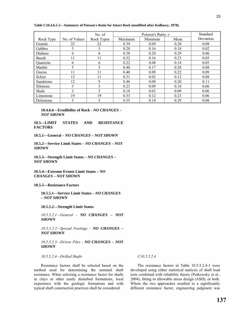
15
Table C10.4.6.5-2—Summary of Poisson's Ratio for Intact Rock (modified after Kulhawy, 1978)
Rock Type No. of Values No. of
Rock Types Poisson's Ratio, ν Standard
Deviation Maximum Minimum Mean Granite 22 22 0.39 0.09 0.20 0.08 Gabbro 3 3 0.20 0.16 0.18 0.02 Diabase 6 6 0.38 0.20 0.29 0.06 Basalt 11 11 0.32 0.16 0.23 0.05 Quartzite 6 6 0.22 0.08 0.14 0.05 Marble 5 5 0.40 0.17 0.28 0.08 Gneiss 11 11 0.40 0.09 0.22 0.09 Schist 12 11 0.31 0.02 0.12 0.08 Sandstone 12 9 0.46 0.08 0.20 0.11 Siltstone 3 3 0.23 0.09 0.18 0.06 Shale 3 3 0.18 0.03 0.09 0.06 Limestone 19 19 0.33 0.12 0.23 0.06 Dolostone 5 5 0.35 0.14 0.29 0.08
10.4.6.6—Erodibility of Rock - NO CHANGES – NOT SHOWN
10.5—LIMIT STATES AND RESISTANCE FACTORS
10.5.1—General – NO CHANGES – NOT SHOWN
10.5.2—Service Limit States – NO CHANGES – NOT SHOWN
10.5.3—Strength Limit States – NO CHANGES – NOT SHOWN
10.5.4—Extreme Events Limit States – NO CHANGES – NOT SHOWN
10.5.5—Resistance Factors
10.5.5.1—Service Limit States – NO CHANGES – NOT SHOWN
10.5.5.2—Strength Limit States
10.5.5.2.1—General - NO CHANGES – NOT SHOWN
10.5.5.2.2—Spread Footings - NO CHANGES –NOT SHOWN
10.5.5.2.3—Driven Piles - NO CHANGES – NOT SHOWN
10.5.5.2.4—Drilled Shafts Resistance factors shall be selected based on the
method used for determining the nominal shaftresistance. When selecting a resistance factor for shaftsin clays or other easily disturbed formations, localexperience with the geologic formations and withtypical shaft construction practices shall be considered.
C10.5.5.2.4 The resistance factors in Table 10.5.5.2.4-1 were
developed using either statistical analysis of shaft load tests combined with reliability theory (Paikowsky et al., 2004), fitting to allowable stress design (ASD), or both. Where the two approaches resulted in a significantly different resistance factor, engineering judgment was

16 Where the resistance factors provided in
Table 10.5.5.2.4-1 are to be applied to a single shaftsupporting a bridge pier, the resistance factor values inthe Table should be reduced by 20 percent. Where the resistance factor is decreased in this manner, the ηRfactor provided in Article 1.3.4 shall not be increased toaddress the lack of foundation redundancy.
The number of static load tests to be conducted tojustify the resistance factors provided in Table 10.5.5.2.4-1 shall be based on the variability in the properties andgeologic stratification of the site to which the test resultsare to be applied. A site, for the purpose of assessingvariability, shall be defined in accordance withArticle 10.5.5.2.3.as a project site, or a portion of it,where the subsurface conditions can be characterized as geologically similar in terms of subsurface stratification,i.e., sequence, thickness, and geologic history of strata,the engineering properties of the strata, and groundwaterconditions.
used to establish the final resistance factor, considering the quality and quantity of the available data used in the calibration. The available reliability theory calibrations were conducted for the Reese and O’Neill (1988) method, with the exception of shafts in cohesive intermediate geo-materials (IGMs), in which case the O’Neill and Reese (1999) method was used. In Article 10.8, the O’Neill and Reese (1999) method is recommended. See Allen (2005) for a more detailed explanation on the development of the resistance factors for shaft foundation design, and the implications of the differences in these two shaft design methods on the selection of resistance factors.
The information in the commentary to Article 10.5.5.2.3 regarding the number of load tests to conduct considering site variability applies to drilled shafts as well.
For single shafts, lower resistance factors are specified to address the lack of redundancy. See Article C10.5.5.2.3 regarding the use of ηR.
Where installation criteria are established based on one or more static load tests, the potential for site variability should be considered. The number of load tests required should be established based on the characterization of site subsurface conditions by the field and laboratory exploration and testing program. One or more static load tests should be performed per site to justify the resistance factor selection as discussed in Article C10.5.5.2.3, applied to drilled shafts installed within the site. See Article C10.5.5.2.3 for details on assessing site variability as applied to selection and use of load tests.
Site variability is the most important consideration in evaluating the limits of a site for design purposes. Defining the limits of a site therefore requires sufficient knowledge of the subsurface conditions in terms of general geology, stratigraphy, index and engineering properties of soil and rock, and groundwater conditions. This implies that the extent of the exploration program is sufficient to define the subsurface conditions and their variation across the site.
A designer may choose to design drilled shaft foundations for strength limit states based on a calculated nominal resistance, with the expectation that load testing results will verify that value. The question arises whether to use the resistance factor associated with the design equation or the higher value allowed for load testing. This choice should be based on engineering judgment. The potential risk is that axial resistance measured by load testing may be lower than the nominal resistance used for design, which could require increased shaft dimensions that may be problematic, depending upon the capability of the drilled shaft equipment mobilized for the project and other project-specific factors.
For the specific case of shafts in clay, the resistance factor recommended by Paikowsky et al. (2004) is much lower than the recommendation from Barker et al. (1991). Since the shaft design method for clay is nearly

17
the same for both the 1988 and 1999 methods, a resistance factor that represents the average of the two resistance factor recommendations is provided in Table 10.5.5.2.4-1. This difference may point to the differences in local geologic formations and local construction practices, pointing to the importance of taking such issues into consideration when selecting resistance factors, especially for shafts in clay.
Cohesive IGMs are materials that are transitional between soil and rock in terms of their strength and compressibility, such as residual soils, glacial tills, orvery weak rock. See Article C10.8.2.2.3 for a moredetailed definition of an IGM.clay shales or mudstones with undrained shear strength between 5 and 50 ksf.
Since the mobilization of shaft base resistance is less certain than side resistance due to the greater deformation required to mobilize the base resistance, a lower resistance factor relative to the side resistance is provided for the base resistance in Table 10.5.5.2.4-1. O’Neill and Reese (1999) make further comment that the recommended resistance factor for tip resistance in sand is applicable for conditions of high quality control on the properties of drilling slurries and base cleanout procedures. If high quality control procedures are notused, the resistance factor for the O’Neill and Reese (1999) method for tip resistance in sand should be also be reduced. The amount of reduction should be based on engineering judgment.
Shaft compression load test data should be extrapolated to production shafts that are not load testedas specified in Article 10.8.3.5.6. There is no way to verify shaft resistance for the untested production shafts, other than through good construction inspection and visual observation of the soil or rock encountered in each shaft. Because of this, extrapolation of the shaft load test results to the untested production shafts may introduce some uncertainty. Statistical data are not available to quantify this at this time. Historically, resistance factors higher than 0.70, or their equivalent safety factor in previous practice, have not been used for shaft foundations. If the recommendations in Paikowsky, et al. (2004) are used to establish a resistance factor when shaft static load tests are conducted, in consideration of site variability, the resistance factors recommended by Paikowsky, et al. for this case should be reduced by 0.05, and should be less than or equal to 0.70 as specified in Table 10.5.5.2.4-1.
This issue of uncertainty in how the load test isapplied to shafts not load tested is even more acute for shafts subjected to uplift load tests, as failure in uplift can be more abrupt than failure in compression. Hence, a resistance factor of 0.60 for the use of uplift load test results is recommended.

18 Table 10.5.5.2.4-1—Resistance Factors for Geotechnical Resistance of Drilled Shafts
Method/Soil/Condition Resistance Factor
Nominal Axial Compressive Resistance of Single-Drilled Shafts, ϕstat
Side resistance in clay α-method (O’Neill and Reese, 1999 Brown et al., 2010)
0.45
Tip resistance in clay Total Stress (O’Neill and Reese, 1999 Brown et al., 2010)
0.40
Side resistance in sand β-method (O’Neill and Reese, 1999 Brown et al., 2010)
0.55
Tip resistance in sand O’Neill and Reese (1999) Brown et al., (2010)
0.50
Side resistance in cohesive IGMs
O’Neill and Reese (1999) Brown et al., (2010)
0.60
Tip resistance in cohesive IGMs
O’Neill and Reese (1999) Brown et al., (2010)
0.55
Side resistance in rock Horvath and Kenney (1979) O’Neill and Reese (1999) Kulhawy et al. (2005) Brown et al. (2010)
0.55
Side resistance in rock Carter and Kulhawy (1988) 0.50 Tip resistance in rock Canadian Geotechnical Society
(1985) Pressuremeter Method (Canadian Geotechnical Society, 1985) O’Neill and Reese (1999)Brown et al. (2010)
0.50
Block Failure, ϕb1 Clay 0.55
Uplift Resistance of Single-Drilled Shafts, ϕup
Clay α-method (O’Neill and Reese, 1999 Brown et al., 2010)
0.35
Sand β-method (O’Neill and Reese, 1999 Brown et al., 2010)
0.45
Rock Horvath and Kenney (1979) O’Neill and Reese (1999) Kulhawy et al. (2005) Brown et al. (2010)
0.40
Group Uplift Resistance, ϕug
Sand and clay 0.45
Horizontal Geotechnical Resistance of Single Shaft or Shaft Group
All materials 1.0
Static Load Test (compression), ϕload
All Materials 0.70
Static Load Test (uplift), ϕupload
All Materials 0.60
10.5.5.2.5—Micropiles - NO CHANGES – NOT SHOWN

19
10.5.5.3—Extreme Limit States – NO CHANGES – NOT SHOWN
10.6—SPREAD FOOTINGS
10.6.1—General Considerations – NO CHANGES – NOT SHOWN
10.6.2—Service Limit State Design
10.6.2.1—General – NO CHANGES – NOT SHOWN
10.6.2.2—Tolerable Movements – NO CHANGES – NOT SHOWN
10.6.2.3—Loads – NO CHANGES – NOT SHOWN
10.6.2.4—Settlement Analyses 10.6.2.4.1—General - NO CHANGES – NOT SHOWN
10.6.2.4.2—Settlement of Footings on CohesionlessSoils - NO CHANGES – NOT SHOWN
10.6.2.4.3—Settlement of Footings on CohesiveSoils - NO CHANGES – NOT SHOWN
10.6.2.4.4—Settlement of Footings on Rock For footings bearing on fair to very good rock,
according to the Geomechanics Classification system, as defined in Article 10.4.6.4, and designed in accordancewith the provisions of this Section, elastic settlementsmay generally be assumed to be less than 0.5 in. Whenelastic settlements of this magnitude are unacceptable orwhen the rock is not competent, an analysis ofsettlement based on rock mass characteristics shall bemade.
Where rock is broken or jointed (relative rating often or less for RQD and joint spacing), the rock jointcondition is poor (relative rating of ten or less) or the criteria for fair to very good rock are not met, asettlement analysis should be conducted, and theinfluence of rock type, condition of discontinuities, anddegree of weathering shall be considered in thesettlement analysis.
C10.6.2.4.4 In most cases, it is sufficient to determine
settlement using the average bearing stress under the footing.
Where the foundations are subjected to a very large load or where settlement tolerance may be small, settlements of footings on rock may be estimated using elastic theory. The stiffness of the rock mass should be used in such analyses.
The accuracy with which settlements can be estimated by using elastic theory is dependent on the accuracy of the estimated rock mass modulus, Em. In some cases, the value of Em can be estimated through empirical correlation with the value of the modulus of elasticity for the intact rock between joints. For unusual or poor rock mass conditions, it may be necessary to determine the modulus from in-situ tests, such as plate loading and pressuremeter tests.
The elastic settlement of footings on broken or jointed rock, in feet, should be taken as:
• For circular (or square) footings:
( )2ρ 1144
po
m
rIq
Eν= − (10.6.2.4.4-1)

20 in which:
( )πβp
z
I = (10.6.2.4.4-2)
• For rectangular footings:
( )2ρ 1144
po
m
BIq
Eν= − (10.6.2.4.4-3)
in which:
( )1/ 2/
βpz
L BI = (10.6.2.4.4-4)
where: qo = applied vertical stress at base of loaded area
(ksf) ν = Poisson's Ratio (dim) r = radius of circular footing or B/2 for square
footing (ft) Ip = influence coefficient to account for rigidity and
dimensions of footing (dim) Em = rock mass modulus (ksi) βz = factor to account for footing shape and rigidity
(dim)
Values of Ip should be computed using the βz values presented in Table 10.6.2.4.2-1 for rigid footings. Wherethe results of laboratory testing are not available, valuesof Poisson's ratio, ν, for typical rock types may be takenas specified in Table C10.4.6.5-2. Determination of therock mass modulus, Em, should be based on the methodsdescribed in Article 10.4.6.5 Sabatini (2002).
The magnitude of consolidation and secondarysettlements in rock masses containing soft seams orother material with time-dependent settlementcharacteristics should be estimated by applyingprocedures specified in Article 10.6.2.4.3.
10.6.2.5—Overall Stability – NO CHANGES – NOT SHOWN
10.6.2.6—Bearing Resistance at the Service Limit State

21
10.6.2.6.1—Presumptive Values for Bearing Resistance – NO CHANGES – NOT SHOWN 10.6.2.6.2—Semiempirical Procedures for Bearing Resistance Bearing resistance on rock shall be determined
using empirical correlation to the Geomechanic RockMass Rating System, RMR, as specified inArticle 10.4.6.4. Local experience should be consideredin the use of these semi-empirical procedures.
If the recommended value of presumptive bearingresistance exceeds either the unconfined compressivestrength of the rock or the nominal resistance of theconcrete, the presumptive bearing resistance shall betaken as the lesser of the unconfined compressivestrength of the rock or the nominal resistance of theconcrete. The nominal resistance of concrete shall betaken as 0.3 f ′c. 10.6.3—Strength Limit State Design
10.6.3.1—Bearing Resistance of Soil – NO CHANGES – NOT SHOWN
10.6.3.2—Bearing Resistance of Rock 10.6.3.2.1—General The methods used for design of footings on rock
shall consider the presence, orientation, and condition ofdiscontinuities, weathering profiles, and other similarprofiles as they apply at a particular site.
For footings on competent rock, reliance on simpleand direct analyses based on uniaxial compressive rockstrengths and RQD may be applicable. For footings onless competent rock, more detailed investigations andanalyses shall be performed to account for the effects ofweathering and the presence and condition ofdiscontinuities.
The designer shall judge the competency of a rockmass by taking into consideration both the nature of theintact rock and the orientation and condition ofdiscontinuities of the overall rock mass. Where engineeringjudgment does not verify the presence of competent rock,the competency of the rock mass should be verified usingthe procedures for RMR rating in Article 10.4.6.4.
C10.6.3.2.1 The design of spread footings bearing on rock is
frequently controlled by either overall stability, i.e., the orientation and conditions of discontinuities, or load eccentricity considerations. The designer should verify adequate overall stability at the service limit state and size the footing based on eccentricity requirements at the strength limit state before checking nominal bearing resistance at both the service and strength limit states.
The design procedures for foundations in rock have
been developed using the RMR rock mass rating system. Classification of the rock mass should be according to the RMR system. For additional information on the RMR system, see Sabatini et al. (2002).
10.6.3.2.2—Semiempirical Procedures - NO CHANGES – NOT SHOWN
10.6.3.2.3—Analytic Method - NO CHANGES –NOT SHOWN
10.6.3.2.4—Load Test - NO CHANGES – NOT SHOWN
10.6.3.3—Eccentric Load Limitations – NO CHANGES – NOT SHOWN

22
10.6.3.4—Failure by Sliding – NO CHANGES – NOT SHOWN
10.6.4—Extreme Event Limit State Design – NO CHANGES – NOT SHOWN
10.6.5—Structural Design – NO CHANGES – NOT SHOWN
10.7—DRIVEN PILES – NO CHANGES – NOT SHOWN
10.8—DRILLED SHAFTS
10.8.1—General
10.8.1.1—Scope - NO CHANGES – NOT SHOWN
10.8.1.2—Shaft Spacing, Clearance, and Embedment into Cap - NO CHANGES – NOT SHOWN
10.8.1.3—Shaft Diameter and Enlarged Bases - NO CHANGES – NOT SHOWN
10.8.1.4—Battered Shafts - NO CHANGES – NOT SHOWN
10.8.1.5—Drilled Shaft Resistance Drilled shafts shall be designed to have adequate
axial and structural resistances, tolerable settlements,and tolerable lateral displacements.
C10.8.1.5 The drilled shaft design process is discussed in
detail in Drilled Shafts: Construction Procedures and Design Methods (O’Neill and Reese, 1999 Brown, et al., 2010).

23
The axial resistance of drilled shafts shall be determined through a suitable combination of subsurfaceinvestigations, laboratory and/or in-situ tests, analyticalmethods, and load tests, with reference to the history ofpast performance. Consideration shall also be given to:
• The difference between the resistance of a single
shaft and that of a group of shafts;
• The resistance of the underlying strata to supportthe load of the shaft group;
• The effects of constructing the shaft(s) on adjacentstructures;
• The possibility of scour and its effect;
• The transmission of forces, such as downdragforces, from consolidating soil;
• Minimum shaft penetration necessary to satisfy therequirements caused by uplift, scour, downdrag,settlement, liquefaction, lateral loads and seismicconditions;
• Satisfactory behavior under service loads;
• Drilled shaft nominal structural resistance; and
• Long-term durability of the shaft in service, i.e.,corrosion and deterioration.
Resistance factors for shaft axial resistance for thestrength limit state shall be as specified inTable 10.5.5.2.4-1.
The method of construction may affect the shaftaxial and lateral resistance. The shaft design parametersshall take into account the likely constructionmethodologies used to install the shaft.
The performance of drilled shaft foundations can be greatly affected by the method of construction, particularly side resistance. The designer should consider the effects of ground and groundwater conditions on shaft construction operations and delineate, where necessary, the general method of construction to be followed to ensure the expected performance. Because shafts derive their resistance from side and tip resistance, which is a function of the condition of the materials in direct contact with the shaft, it is important that the construction procedures be consistent with the material conditions assumed in the design. Softening, loosening, or other changes in soil and rock conditions caused by the construction method could result in a reduction in shaft resistance and an increase in shaft displacement. Therefore, evaluation of the effects of the shaft construction procedure on resistance should be considered an inherent aspect of the design. Use of slurries, varying shaft diameters, and post grouting can also affect shaft resistance.
Soil parameters should be varied systematically to model the range of anticipated conditions. Both vertical and lateral resistance should be evaluated in this manner.
Procedures that may affect axial or lateral shaft resistance include, but are not limited to, the following:
• Artificial socket roughening, if included in the
design nominal axial resistance assumptions.
• Removal of temporary casing where the design is dependent on concrete-to-soil adhesion.
• The use of permanent casing.
• Use of tooling that produces a uniform cross-section where the design of the shaft to resist lateral loads cannot tolerate the change in stiffness if telescoped casing is used.
It should be recognized that the design procedures provided in these Specifications assume compliance to construction specifications that will produce a high quality shaft. Performance criteria should be included in the construction specifications that require:
• Shaft bottom cleanout criteria,
• Appropriate means to prevent side wall movement or failure (caving) such as temporary casing, slurry,or a combination of the two,
• Slurry maintenance requirements including minimum slurry head requirements, slurry testing requirements, and maximum time the shaft may be left open before concrete placement.
If for some reason one or more of these
performance criteria are not met, the design should be reevaluated and the shaft repaired or replaced as necessary.

24
10.8.1.6—Determination of Shaft Loads 10.8.1.6.1—General - NO CHANGES – NOT SHOWN
10.8.1.6.2—Downdrag The provisions of Articles 10.7.1.6.2 and 3.11.8
shall apply for determination of load due to downdrag. For shafts with tip bearing in a dense stratum or
rock where design of the shaft is structurally controlled,and downdrag shall be considered at the strength andextreme event limit states.
For shafts with tip bearing in soil, downdrag shallnot be considered at the strength and extreme limit statesif settlement of the shaft is less than failure criterion.
C10.8.1.6.2 See commentary to Articles 10.7.1.6.2 and 3.11.8. Downdrag loads may be estimated using the α-
method, as specified in Article 10.8.3.5.1b, for calculating to calculate negative shaft resistance friction. As with positive shaft resistance, the top 5.0 ft and a bottom length taken as one shaft diameters shaft length assumed to not contribute to nominal side resistanceshould also be assumed to not contribute to downdrag loads.
When using the α-method, an allowance should be made for a possible increase in the undrained shear strength as consolidation occurs. Downdrag loads may also come from cohesionless soils above settling cohesive soils, requiring granular soil friction methods be used in such zones to estimate downdrag loads. The downdrag caused by settling cohesionless soils may be estimated using the β method presented in Article10.8.3.5.2.
Downdrag occurs in response to relative downward deformation of the surrounding soil to that of the shaft, and may not exist if downward movement of the drilled shaft in response to axial compression forces exceedsthe vertical deformation of the soil. The response of a drilled shaft to downdrag in combination with the other forces acting at the head of the shaft therefore is complex and a realistic evaluation of actual limit states that may occur requires careful consideration of two issues: (1) drilled shaft load-settlement behavior, and (2) the time period over which downdrag occurs relative to the time period over which nonpermanent components of load occur. When these factors are taken into account, it is appropriate to consider different downdrag forces for evaluation of geotechnical strength limit states than for structural strength limit states. These issues are addressed in Brown et al. (2010).
10.8.1.6.3—Uplift - NO CHANGES – NOT SHOWN
10.8.2—Service Limit State Design 10.8.2.1—Tolerable Movements - NO CHANGES – NOT SHOWN
10.8.2.2—Settlement 10.8.2.2.1—General - NO CHANGES – NOT SHOWN

25
10.8.2.2.2—Settlement of Single-Drilled Shaft
The settlement of single-drilled shafts shall be estimated in consideration of as a sum of the following:
• Short-term settlement resulting from load transfer,
• Consolidation settlement if constructed in where cohesive soils exists beneath the shaft tip, and
• Axial compression of the shaft.
The normalized load-settlement curves shown inFigures 10.8.2.2.2-1 through 10.8.2.2.2-4 should be used to limit the nominal shaft axial resistance computed asspecified for the strength limit state in Article 10.8.3 forservice limit state tolerable movements. Consistent values of normalized settlement shall be used for limiting thebase and side resistance when using these Figures. Long-term settlement should be computed according toArticle 10.7.2 using the equivalent footing method andadded to the short-term settlements estimated usingFigures 10.8.2.2.2-1 through 10.8.2.2.2-4.
Other methods for evaluating shaft settlements thatmay be used are found in O’Neill and Reese (1999).
C10.8.2.2.2
O'Neill and Reese (1999) have summarized load-settlement data for drilled shafts in dimensionless form, as shown in Figures 10.8.2.2.2-1 through 10.8.2.2.2-4. These curves do not include consideration of long-term consolidation settlement for shafts in cohesive soils. Figures 10.8.2.2.2-1 and 10.8.2.2.2-2 show the load-settlement curves in side resistance and in end bearing for shafts in cohesive soils. Figures 10.8.2.2.2-3 and 10.8.2.2.2-4 are similar curves for shafts in cohesionless soils. These curves should be used for estimating short-term settlements of drilled shafts.
The designer should exercise judgment relative to whether the trend line, one of the limits, or some relation in between should be used from Figures 10.8.2.2.2-1through 10.8.2.2.2-4.
The values of the load-settlement curves in side resistance were obtained at different depths, taking into account elastic shortening of the shaft. Although elastic shortening may be small in relatively short shafts, it may be substantial in longer shafts. The amount of elastic shortening in drilled shafts varies with depth. O’Neill and Reese (1999) have described an approximate procedure for estimating the elastic shortening of long-drilled shafts.
Settlements induced by loads in end bearing are different for shafts in cohesionless soils and in cohesive soils. Although drilled shafts in cohesive soils typically have a well-defined break in a load-displacement curve, shafts in cohesionless soils often have no well-defined failure at any displacement. The resistance of drilled shafts in cohesionless soils continues to increase as the settlement increases beyond five percent of the base diameter. The shaft end bearing Rp is typically fully mobilized at displacements of two to five percent of the base diameter for shafts in cohesive soils. The unit end bearing resistance for the strength limit state (see Article 10.8.3.3) is defined as the bearing pressure required to cause vertical deformation equal to five percent of the shaft diameter, even though this does not correspond to complete failure of the soil beneath the base of the shaft.

26
Induced settlements for isolated drilled shafts are different for elements in cohesive soils and in cohesionless soils. In cohesive soils, the failure threshold, or nominal axial resistance corresponds to mobilization of the full available side resistance, plus the full available base resistance. In cohesive soils, the failure threshold has been shown to occur at an average normalized deformation of 4 percent of the shaft diameter. In cohesionless soils, the failure threshold is the force corresponding to mobilization of the full side resistance, plus the base resistance corresponding to settlement at a defined failure criterion. This has been traditionally defined as the bearing pressure required to cause vertical deformation equal to 5 percent of the shaft diameter, even though this does not correspond to complete failure of the soil beneath the base of the shaft. Note that nominal base resistance in cohesionless soils is calculated according to the empirical correlation given by Eq. 10.8.3.5.2c-1 in terms of N-value. That relationship was developed using a base resistance corresponding to 5 percent normalized displacement. If a normalized displacement other than 5 percent is used, the base resistance calculated by Eq. 10.8.3.5.2c-1 must be corrected.
Figure 10.8.2.2.2-1 Normalized Load Transfer in SideResistance versus Settlement in Cohesive Soils (fromO’Neill and Reese, 1999)
The curves in Figures 10.8.2.2.2-1 and 10.8.2.2.2-3 also show the settlements at which the side resistance is mobilized. The shaft skin friction Rs is typically fully mobilized at displacements of 0.2 percent to 0.8 percent of the shaft diameter for shafts in cohesive soils. For shafts in cohesionless soils, this value is 0.1 percent to 1.0 percent.

27
Figure 10.8.2.2.2-2—Normalized Load Transfer in EndBearing versus Settlement in Cohesive Soils (from O’Neill and Reese, 1999)
Figure 10.8.2.2.2-3—Normalized Load Transfer in SideResistance versus Settlement in Cohesionless Soils (fromO’Neill and Reese, 1999)
The deflection-softening response typically applies to cemented or partially cemented soils, or other soils that exhibit brittle behavior, having low residual shear strengths at larger deformations. Note that the trend line for sands is a reasonable approximation for either the deflection-softening or deflection-hardening response.
The normalized load-settlement curves require separate evaluation of an isolated drilled shaft for side and base resistance. Brown et al. (2010) provide alternate normalized load-settlement curves that may be used for estimation of settlement of a single drilled shaft considering combined side and base resistance. The method is based on modeling the average load deformation behavior observed from field load tests and incorporates the load test data used in development of the curves provided by O’Neill and Reese (1999).Additional methods that consider numerical simulations of axial load transfer and approximations based on elasto-plastic solutions are available in Brown et al.(2010).

28
Figure 10.8.2.2.2-4—Normalized Load Transfer in EndBearing versus Settlement in Cohesionless Soils (fromO’Neill and Reese, 1999)
10.8.2.2.3—Intermediate Geomaterials (IGMs) For detailed settlement estimation of shafts in
IGMs, the procedures provided by O’Neill and Reese(1999) described by Brown et al. (2010) should be used.
C10.8.2.2.3 IGMs are defined by O’Neill and Reese (1999)
Brown et al. (2010) as follows:
• Cohesive IGM—clay shales or mudstones with an Su of 5 to 50 ksf, and
• Cohesionless—granular tills or granular residual soils with N160 greater than 50 blows/ft.
10.8.2.2.4—Group Settlement The provisions of Article 10.7.2.3 shall apply. Shaft
group effect shall be considered for groups of 2 shafts ormore.
C10.8.2.2.4 See commentary to Article 10.7.2.3. O’Neill and Reese (1999) summarize various
studies on the effects of shaft group behavior. These studies were for groups that consisted of 1 × 2 to 3 × 3 shafts. These studies suggest that group effects are relatively unimportant for shaft center-to-center spacing of 5D or greater.
10.8.2.3—Horizontal Movement of Shafts and Shaft Groups The provisions of Articles 10.5.2.1 and 10.7.2.4
shall apply. For shafts socketed into rock, the input properties
used to determine the response of the rock to lateralloading shall consider both the intact shear strength ofthe rock and the rock mass characteristics. The designershall also consider the orientation and condition ofdiscontinuities of the overall rock mass. Where specific adversely oriented discontinuities are not present, but therock mass is fractured such that its intact strength isconsidered compromised, the rock mass shear strength
C10.8.2.3 See commentary to Articles 10.5.2.1 and 10.7.2.4. For shafts socketed into rock, approaches to
developing p-y response of rock masses include both a weak rock response and a strong rock response. For the strong rock response, the potential for brittle fracture should be considered. If horizontal deflection of the rock mass is greater than 0.0004b, a lateral load test to evaluate the response of the rock to lateral loading should be considered. Brown et al. (2010) provide a summary of a methodology that may be used to estimate

29 parameters should be assessed using the procedures for GSIrating in Article 10.4.6.4. For lateral deflection of the rockadjacent to the shaft greater than 0.0004b, where b is thediameter of the rock socket, the potential for brittle fractureof the rock shall be considered.
the lateral load response of shafts in rock. Additionalbackground on lateral loading of shafts in rock is provided in Turner (2006).
These methods for estimating the response of shafts in rock subjected to lateral loading use the unconfined compressive strength of the intact rock as the main input property. While this property is meaningful for intact rock, and was the key parameter used to correlate to shaft lateral load response in rock, it is not meaningful for fractured rock masses. If the rock mass is fractured enough to justify characterizing the rock shear strength using the GSI, the rock mass should be characterized as a c-φ material, and confining stress (i.e., σ’3) present within the rock mass should be considered when establishing a rock mass shear strength for lateral response of the shaft. If the P-y method of analysis is used to model horizontal resistance, user-specified P-y curves should be derived. A method for developing hyperbolic P-y curves is described by Liang et al. (2009).
10.8.2.4—Settlement Due to Downdrag - NO CHANGES – NOT SHOWN
10.8.2.5—Lateral Squeeze - NO CHANGES – NOT SHOWN
10.8.3—Strength Limit State Design
10.8.3.1—General - NO CHANGES – NOT SHOWN
10.8.3.2—Groundwater Table and Buoyancy - NO CHANGES – NOT SHOWN
10.8.3.3—Scour - NO CHANGES – NOT SHOWN
10.8.3.4—Downdrag The provisions of Article 10.7.3.7 shall apply. The foundation should be designed so that the
available factored axial geotechnical resistance is greaterthan the factored loads applied to the shaft, including thedowndrag, at the strength limit state. The nominal shaft resistance available to support structure loads plusdowndrag shall be estimated by considering only thepositive skin and tip resistance below the lowest layercontributing to the downdrag. The drilled shaft shall bedesigned structurally to resist the downdrag plusstructure loads.
C10.8.3.4 See commentary to Article 10.7.3.7. The static analysis procedures in Article 10.8.3.5
may be used to estimate the available drilled shaft nominal side and tip resistances to withstand the downdrag plus other axial force effects.
Nominal resistance may also be estimated using an instrumented static load test provided the side resistance within the zone contributing to downdrag is subtracted from the resistance determined from the load test.
As stated in Article C10.8.1.6.2, that it is appropriate to apply different downdrag forces for evaluation of geotechnical strength limit states than for structural strength limit states. A drilled shaft with its tip bearing in stiff material, such as rock or hard soil, would be expected to limit settlement to very small values. In this case, the full downdrag force could occur in combination with the other axial force effects, because downdrag will not be reduced if there is little or no

30
downward movement of the shaft. Therefore, the factored force effects resulting from all load components, including full factored downdrag, should be used to check the structural strength limit state of the drilled shaft.
A rational approach to evaluating this strength limit state will incorporate the force effects occurring at this magnitude of downward displacement. This will include the factored axial force effects transmitted to the head of the shaft, plus the downdrag loads occurring at a downward displacement defining the failure criterion. In many cases, this amount of downward displacement will reduce or eliminate downdrag. For soil layers that undergo settlement exceeding the failure criterion (for example, 5 percent of B for shafts bearing in sand),downdrag loads are likely to remain and should be included. This approach requires the designer to predict the magnitude of downdrag load occurring at a specified downward displacement. This can be accomplished using the hand calculation procedure described in Brown et al. (2010) or with commercially available software.
When downdrag loads are determined to exist at a downward displacement defining failure, evaluation of drilled shafts for the geotechnical strength limit state in compression should be conducted under a load combination that is limited to permanent loads only, including the calculated downdrag load at a settlement defining the failure criterion, but excluding nonpermanent loads, such as live load, temperature changes, etc. See Brown et al. (2010) for further discussion.
When analysis of a shaft subjected to downdrag shows that the downdrag load would be eliminated in order to achieve a defined downward displacement, evaluation of geotechnical and structural strength limit states in compression should be conducted under the full load combination corresponding to the relevant strength limit state, including the non-permanent components of load, but not including downdrag.
10.8.3.5—Nominal Axial Compression Resistance of Single Drilled Shafts - NO CHANGES – NOT SHOWN
10.8.3.5.1—Estimation of Drilled Shaft Resistancein Cohesive Soils
10.8.3.5.1a—General - NO CHANGES – NOT SHOWN
10.8.3.5.1b—Side Resistance
The nominal unit side resistance, qs, in ksf, for
shafts in cohesive soil loaded under undrained loadingconditions by the α-Method shall be taken as:
αs uq S= (10.8.3.5.1b-1)
C10.8.3.5.1b The α-method is based on total stress. For effective
stress methods for shafts in clay, see O’Neill and Reese (1999) Brown et al. (2010).
The adhesion factor is an empirical factor used to correlate the results of full-scale load tests with the

31
in which:
α 0.55 for 1.5u
a
Sp
= ≤ (10.8.3.5.1b-2)
( )α 0.55 0.1 1.5u aS p= − −
for 1.5 2.5u aS p≤ ≤ (10.8.3.5.1b-3)
where: Su = undrained shear strength (ksf) α = adhesion factor (dim) pa = atmospheric pressure (= 2.12 ksf)
The following portions of a drilled shaft, illustrated
in Figure 10.8.3.5.1b-1, should not be taken tocontribute to the development of resistance through skinfriction: • At least the top 5.0 ft of any shaft;
material property or characteristic of the cohesive soil. The adhesion factor is usually related to Su and is derived from the results of full-scale pile and drilled shaft load tests. Use of this approach presumes that the measured value of Su is correct and that all shaftbehavior resulting from construction and loading can be lumped into a single parameter. Neither presumption is strictly correct, but the approach is used due to its simplicity.
Steel casing will generally reduce the side resistance of a shaft. No specific data is available regarding the reduction in skin friction resulting from the use of permanent casing relative to concrete placed directly against the soil. Side resistance reduction factors for driven steel piles relative to concrete piles can vary from 50 to 75 percent, depending on whether the steel is clean or rusty, respectively (Potyondy, 1961). Greater reduction in the side resistance may be needed if oversized cutting shoes or splicing rings are used.
If open-ended pipe piles are driven full depth with an impact hammer before soil inside the pile is removed, and left as a permanent casing, driven pile static analysis methods may be used to estimate the side resistance as described in Article 10.7.3.8.6.
• For straight shafts, a bottom length of the shafttaken as the shaft diameter;
• Periphery of belled ends, if used; and
• Distance above a belled end taken as equal to theshaft diameter.
When permanent casing is used, the side resistanceshall be adjusted with consideration to the type andlength of casing to be used, and how it is installed.
Values of α for contributing portions of shaftsexcavated dry in open or cased holes should be asspecified in Eqs. 10.8.3.5.1b-2 and 10.8.3.5.1b-3.
The upper 5.0 ft of the shaft is ignored in estimating Rn, to account for the effects of seasonal moisture changes, disturbance during construction, cyclic lateral loading, and low lateral stresses from freshly placed concrete. The lower 1.0-diameter length above the shafttip or top of enlarged base is ignored due to the development of tensile cracks in the soil near these regions of the shaft and a corresponding reduction in lateral stress and side resistance.
Bells or underreams constructed in stiff fissured clay often settle sufficiently to result in the formation of a gap above the bell that will eventually be filled by slumping soil. Slumping will tend to loosen the soil immediately above the bell and decrease the side resistance along the lower portion of the shaft.
The value of α is often considered to vary as a function of Su. Values of α for drilled shafts are recommended as shown in Eqs. 10.8.3.5.1b-2 and 10.8.3.5.1b-3, based on the results of back-analyzed, full-scale load tests. This recommendation is based on eliminating the upper 5.0 ft and lower 1.0 diameter of the shaft length during back-analysis of load test results.The load tests were conducted in insensitive cohesive soils. Therefore, if shafts are constructed in sensitive clays, values of α may be different than those obtained from Eqs. 10.8.3.5.1b-2 and 10.8.3.5.1b-3. Other values of α may be used if based on the results of load tests.
The depth of 5.0 ft at the top of the shaft may need to be increased if the drilled shaft is installed in expansive clay, if scour deeper than 5.0 ft is anticipated, if there is substantial groundline deflection from lateral loading, or if there are other long-term loads or construction factors that could affect shaft resistance.

32
Top 5 FT Noncontributing
Periphery of Bell Noncontributing
Straight Shaft Belled Shaft Figure 10.8.3.5.1b-1—Explanation of Portions of DrilledShafts Not Considered in Computing Side Resistance(O’Neill and Reese, 1999 Brown et al., 2010)
A reduction in the effective length of the shaft contributing to side resistance has been attributed to horizontal stress relief in the region of the shaft tip, arising from development of outward radial stresses at the toe during mobilization of tip resistance. The influence of this effect may extend for a distance of 1Babove the tip (O’Neill and Reese, 1999). The effectiveness of enlarged bases is limited when L/D is greater than 25.0 due to the lack of load transfer to the tip of the shaft.
The values of α obtained from Eqs. 10.8.3.5.1b-2 and 10.8.3.5.1b-3 are considered applicable for both compression and uplift loading.
10.8.3.5.1c—Tip Resistance
For axially loaded shafts in cohesive soil, the
nominal unit tip resistance, qp, by the total stress methodas provided in O’Neill and Reese (1999) Brown et al.(2010) shall be taken as:
80.0p c u ksfq N S ≤= (10.8.3.5.1c-1)
in which:
6 1 0.2 9c D
ZN = + ≤⎡ ⎤⎛ ⎞⎜ ⎟⎢ ⎥⎝ ⎠⎣ ⎦
(10.8.3.5.1c-2)
C10.8.3.5.1c
These equations are for total stress analysis. For effective stress methods for shafts in clay, see O’Neill and Reese (1999) Brown et al. (2010).
The limiting value of 80.0 ksf for qp is not a theoretical limit but a limit based on the largest measured values. A higher limiting value may be used if based on the results of a load test, or previous successful experience in similar soils.
where: D = diameter of drilled shaft (ft) Z = penetration of shaft (ft) Su = undrained shear strength (ksf)
The value of Su should be determined from theresults of in-situ and/or laboratory testing of undisturbedsamples obtained within a depth of 2.0 diameters belowthe tip of the shaft. If the soil within 2.0 diameters of thetip has Su <0.50 ksf, the value of Nc should be multipliedby 0.67.
10.8.3.5.2—Estimation of Drilled Shaft Resistancein Cohesionless Soils
10.8.3.5.2a—General
Shafts in cohesionless soils should be designed by
C10.8.3.5.2a
The factored resistance should be determined in

33 effective stress methods for drained loading conditionsor by empirical methods based on in-situ test results.
consideration of available experience with similar conditions.
Although many field load tests have been performed on drilled shafts in clays, very few have been performed on drilled shafts in sands. The shear strength of cohesionless soils can be characterized by an angle of internal friction, φf, or empirically related to its SPT blow count, N. Methods of estimating shaftresistance and end bearing are presented below. Judgment and experience should always be considered.
10.8.3.5.2b—Side Resistance
The nominal axial resistance of drilled shafts in
cohesionless soils by the β-method shall be taken asThe side resistance for shafts in cohesionless soils shall bedetermined using the β method, take as:
β 4.0 for 0.25 β 1.2
vsq ′= σ ≤ ≤ ≤ (10.8.3.5.2b-1) in which, for sandy soils: • for N60 ≥ 15:
1.5 0.135 zβ = − (10.8.3.5.2b-2) • for N60 < 15:
60 (1.5 0.135 )15N
zβ = − (10.8.3.5.2b-3)
C10.8.3.5.2b O’Neill and Reese (1999) provide additional
discussion of computation of shaft side resistance and recommend allowing β to increase to 1.8 in gravels andgravelly sands, however, they recommend limiting the unit side resistance to 4.0 ksf in all soils.
O’Neill and Reese (1999) proposed a method for uncemented soils that uses a different approach in that the shaft resistance is independent of the soil friction angle or the SPT blow count. According to their findings, the friction angle approaches a common value due to high shearing strains in the sand caused by stress relief during drilling.
where: σ′v = vertical effective stress at soil layer mid-depth
(ksf) β = load transfer coefficient (dim) z = depth below ground, at soil layer mid-depth (ft) N60 = average SPT blow count (corrected only for
hammer efficiency) in the design zone underconsideration (blows/ft)
Higher values may be used if verified by load tests. For gravelly sands and gravels, Eq. 10.8.3.5.2b-4
should be used for computing β where N60 ≥ 15. If N60 < 15, Eq. 10.8.3.5.2b-3 should be used.
( )0.752.0 0.06 zβ = − (10.8.3.5.2b-4)
The detailed development of Eq. 10.8.3.5.2b-4 is provided in O’Neill and Reese (1999).
qs = β σ'v (10.8.3.5.2b-1) in which:
The method described herein is based on axial load tests on drilled shafts as presented by Chen and Kulhawy (2002) and updated by Kulhawy and Chen (2007). This method provides a rational approach for relating unit side resistance to N-values and to the state

34
( )fsin '
f f1 sin tanφ
p
v
σβ φ φ
σ′⎛ ⎞
′ ′= − ⎜ ⎟′⎝ ⎠ (10.8.3.5.2b-2)
where: β = load transfer coefficient (dim) ϕ′f = friction angle of cohesionless soil layer (°) σ'p = effective vertical preconsolidation stress σ′v = vertical effective stress at soil layer mid-depth The correlation for effective soil friction angle for use inthe above equations shall be taken as:
( )1 6027.5 9.2 logfφ N′ ⎡ ⎤= + ⎣ ⎦ (10.8.3.5.2b-3)
where: (N1)60 = SPT N-value corrected for effective overburden stress The preconsolidation stress in Eq. 10.8.3.5.2b-2 shouldbe approximated through correlation to SPT N-values. For sands:
( )m
a
p Np 6047.0=
′σ
(10.8.3.5.2b-4)
where: m = 0.6 for clean quartzitic sands m = 0.8 for silty sand to sandy silts pa = atmospheric pressure (same units as σ'p, 2.12
ksf or 14.7 psi) For gravelly soils:
( )6015.0 Npa
p =′σ
(10.8.3.5.2b-5)
of effective stress acting at the soil-shaft interface. This approach replaces the previously used depth-dependent β-method developed by O’Neill and Reese (1999), which does not account for variations in N-value or effective stress on the calculated value of β. Further discussion, including the detailed development of Eq. 10.8.3.5.2b-2, is provided in (Brown et al. 2010).
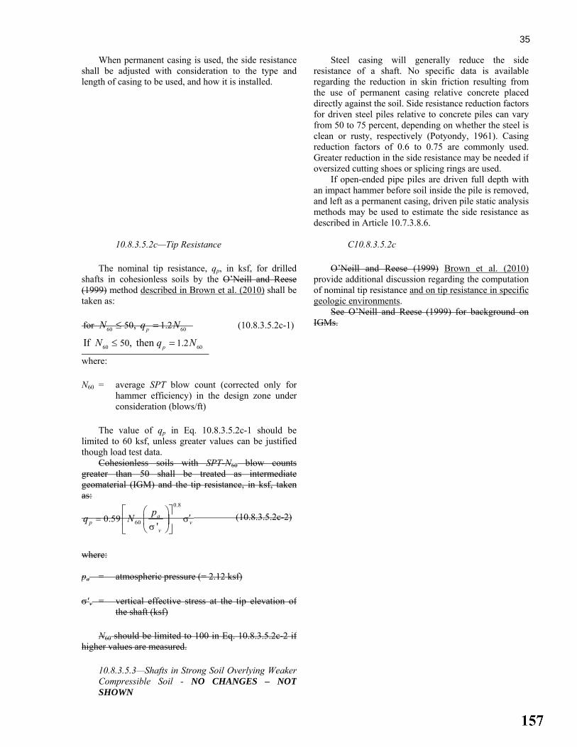
35
When permanent casing is used, the side resistanceshall be adjusted with consideration to the type andlength of casing to be used, and how it is installed.
Steel casing will generally reduce the side resistance of a shaft. No specific data is availableregarding the reduction in skin friction resulting from the use of permanent casing relative concrete placed directly against the soil. Side resistance reduction factors for driven steel piles relative to concrete piles can vary from 50 to 75 percent, depending on whether the steel is clean or rusty, respectively (Potyondy, 1961). Casing reduction factors of 0.6 to 0.75 are commonly used. Greater reduction in the side resistance may be needed if oversized cutting shoes or splicing rings are used.
If open-ended pipe piles are driven full depth with an impact hammer before soil inside the pile is removed, and left as a permanent casing, driven pile static analysis methods may be used to estimate the side resistance as described in Article 10.7.3.8.6.
10.8.3.5.2c—Tip Resistance
The nominal tip resistance, qp, in ksf, for drilled
shafts in cohesionless soils by the O’Neill and Reese(1999) method described in Brown et al. (2010) shall be taken as:
60 60for 50 1.2 , pN q N≤ = (10.8.3.5.2c-1)
60 6050 1.2If , then pN q N≤ =
C10.8.3.5.2c
O’Neill and Reese (1999) Brown et al. (2010) provide additional discussion regarding the computation of nominal tip resistance and on tip resistance in specificgeologic environments.
See O’Neill and Reese (1999) for background on IGMs.
where: N60 = average SPT blow count (corrected only for
hammer efficiency) in the design zone underconsideration (blows/ft)
The value of qp in Eq. 10.8.3.5.2c-1 should be
limited to 60 ksf, unless greater values can be justified though load test data.
Cohesionless soils with SPT-N60 blow counts greater than 50 shall be treated as intermediategeomaterial (IGM) and the tip resistance, in ksf, takenas:
0.8
600.59'a
p vv
pq N ′= σσ
⎡ ⎤⎛ ⎞⎢ ⎥⎜ ⎟
⎝ ⎠⎣ ⎦ (10.8.3.5.2c-2)
where: pa = atmospheric pressure (= 2.12 ksf) σ′v = vertical effective stress at the tip elevation of
the shaft (ksf)
N60 should be limited to 100 in Eq. 10.8.3.5.2c-2 if higher values are measured.
10.8.3.5.3—Shafts in Strong Soil Overlying WeakerCompressible Soil - NO CHANGES – NOT SHOWN

36
10.8.3.5.4—Estimation of Drilled Shaft Resistancein Rock
10.8.3.5.4a—General
Drilled shafts in rock subject to compressive
loading shall be designed to support factored loads in:
• Side-wall shear comprising skin friction on the wallof the rock socket; or
• End bearing on the material below the tip of thedrilled shaft; or
• A combination of both.
C10.8.3.5.4a Methods presented in this Article to calculate
drilled shaft axial resistance require an estimate of the uniaxial compressive strength of rock core. Unless the rock is massive, the strength of the rock mass is most frequently controlled by the discontinuities, including orientation, length, and roughness, and the behavior of the material that may be present within the discontinuity, e.g., gouge or infilling. The methods presented are semi-empirical and are based on load test data and site-specific correlations between measured resistance and rock core strength.
The difference in the deformation required tomobilize skin friction in soil and rock versus what isrequired to mobilize end bearing shall be consideredwhen estimating axial compressive resistance of shaftsembedded in rock. Where end bearing in rock is used aspart of the axial compressive resistance in the design,the contribution of skin friction in the rock shall bereduced to account for the loss of skin friction thatoccurs once the shear deformation along the shaft sidesis greater than the peak rock shear deformation, i.e.,once the rock shear strength begins to drop to a residualvalue.
Design based on side-wall shear alone should be considered for cases in which the base of the drilled hole cannot be cleaned and inspected or where it is determined that large movements of the shaft would be required to mobilize resistance in end bearing.
Design based on end-bearing alone should be considered where sound bedrock underlies low strength overburden materials, including highly weathered rock. In these cases, however, it may still be necessary to socket the shaft into rock to provide lateral stability.
Where the shaft is drilled some depth into sound rock, a combination of sidewall shear and end bearing can be assumed (Kulhawy and Goodman, 1980).
If the rock is degradable, use of special construction procedures, larger socket dimensions, or reduced socket resistance should be considered.
Factors that should be considered when making an engineering judgment to neglect any component of resistance (side or base) are discussed in Article 10.8.3.5.4d. In most cases, both side and base resistances should be included in limit state evaluation of rock-socketed shafts.
For drilled shafts installed in karstic formations, exploratory borings should be advanced at each drilled shaft location to identify potential cavities. Layers of compressible weak rock along the length of a rock socket and within approximately three socket diameters or more below the base of a drilled shaft may reduce the resistance of the shaft.

37
For rock that is stronger than concrete, the concrete shear strength will control the available side friction, and the strong rock will have a higher stiffness, allowing significant end bearing to be mobilized before the side wall shear strength reaches its peak value. Note that concrete typically reaches its peak shear strength atabout 250 to 400 microstrain (for a 10-ft long rock socket, this is approximately 0.5 in. of deformation at the top of the rock socket). If strains or deformations greater than the value at the peak shear stress are anticipated to mobilize the desired end bearing in the rock, a residual value for the skin friction can still be used. Article 10.8.3.5.4d provides procedures for computing a residual value of the skin friction based on the properties of the rock and shaft.
10.8.3.5.4b—Side Resistance
For drilled shafts socketed into rock, shaft
resistance, in ksf, may be taken as (Horvath and Kenney,1979):
( ) ( )0.5 0.50.65 7.8s E a u a a c aq p q p p f p′= α <
(10.8.3.5.4b-1)
C10.8.3.5.4b
Eq. 10.8.3.5.4b-1 applies to the case where the side of the rock socket is considered to be smooth or where the rock is drilled using a drilling slurry. Significant additional shaft resistance may be achieved if the borehole is specified to be artificially roughened by grooving. Methods to account for increased shaft resistance due to borehole roughness are provided in Section 11 of O’Neill and Reese (1999).
where: qu = uniaxial compressive strength of rock (ksf) pa = atmospheric pressure (= 2.12 ksf) αE = reduction factor to account for jointing in rock
as provided in Table 10.8.3.5.4b-1 f′c = concrete compressive strength (ksi) Table 10.8.3.5.4b-1—Estimation of αE (O’Neill and Reese, 1999)
Em/Ei αE 1.0 1.0 0.5 0.8 0.3 0.7 0.1 0.55
0.05 0.45
Eq. 10.8.3.5.4b-1 should only be used for intact rock. When the rock is highly jointed, the calculated qsshould be reduced to arrive at a final value for design. The procedure is as follows:
Step 1. Evaluate the ratio of rock mass modulus to
intact rock modulus, i.e., Em/Ei, using Table C10.4.6.5-1.
Step 2. Evaluate the reduction factor, αE, using Table 10.8.3.5.4b-1.
Step 3. Calculate qs according to Eq. 10.8.3.5.4b-1.
For drilled shafts socketed into rock, unit sideresistance, qs in ksf, shall be taken as (Kulhawy et al.,2005):
a
u
a
S
pq
Cpq
= (10.8.3.5.4b-1)
where:
Eq. 10.8.3.5.4b-1 is based on regression analysis of load test data as reported by Kulhawy et al. (2005) and includes data from pervious studies by Horvath and Kenney (1979), Rowe and Armitage (1987), Kulhawy and Phoon (1993), and others. The recommended value of the regression coefficient C = 1.0 is applicable to “normal” rock sockets, defined as sockets constructed with conventional equipment and resulting in nominally clean sidewalls without resorting to special procedures or artificial roughening. Rock that is prone to smearing

38 pa = atmospheric pressure taken as 2.12 ksf C = regression coefficient taken as 1.0 for normal
conditions qu = uniaxial compressive strength of rock (ksf)
If the uniaxial compressive strength of rock formingthe sidewall of the socket exceeds the drilled shaftconcrete compressive strength, the value of concretecompressive strength (f′c) shall be substituted for qu in Eq. 10.8.3.5.4b-1.
For fractured rock that caves and cannot be drilledwithout some type of artificial support, the unit sideresistance shall be taken as:
a
uE
a
S
pq0.65
pq α= (10.8.3.5.4b-2)
The joint modification factor, αE is given in Table
10.8.3.5.4b-1 based on RQD and visual inspection ofjoint surfaces. Table 10.8.3.5.4b-1—Estimation of αE (O’Neill and Reese, 1999)
RQD (%) Joint Modification Factor, αE
Closed joints Open or gouge-filled joints
100 1.00 0.85 70 0.85 0.55 50 0.60 0.55 30 0.50 0.50 20 0.45 0.45
or rapid deterioration upon exposure to atmospheric conditions, water, or slurry are outside the “normal” range and may require additional measures to insure reliable side resistance. Rocks exhibiting this type of behavior include clay shales and other argillaceous rocks. Rock that cannot support construction of anunsupported socket without caving is also outside the “normal” and will likely exhibit lower side resistance than given by Eq. 10.8.3.5.4b-1 with C = 1.0. For additional guidance on assessing the magnitude of C, see Brown, et al. (2010).
Shafts are sometimes constructed by supporting the hole with temporary casing or by grouting the rock ahead of the excavation. When using these construction methods, disturbance of the sidewall results in lower unit side resistances. Based on O’Neill and Reese (1999) and as discussed in Brown et al. (2010), the reduction in side resistance can be related empirically to the RQD and joint conditions.
10.8.3.5.4c—Tip Resistance
End-bearing for drilled shafts in rock may be takenas follows:
• If the rock below the base of the drilled shaft to a
depth of 2.0B is either intact or tightly jointed, i.e.,no compressible material or gouge-filled seams, andthe depth of the socket is greater than 1.5B (O’Neilland Reese, 1999):
C10.8.3.5.4c
If end bearing in the rock is to be relied upon, and wet construction methods are used, bottom clean-out procedures such as airlifts should be specified to ensure removal of loose material before concrete placement.
The use of Eq. 10.8.3.5.4c-1 also requires that there are no solution cavities or voids below the base of the drilled shaft.

39
2.5p uq q= (10.8.3.5.4c-1)
• If the rock below the base of the shaft to a depth of
2.0B is jointed, the joints have random orientation,and the condition of the joints can be evaluated as:
( )p us m s sq q= + +⎡ ⎤⎢ ⎥⎣ ⎦
(10.8.3.5.4c-2)
where: s, m = fractured rock mass parameters and are
specified in Table 10.4.6.4-4 qu = unconfined compressive strength of rock (ksf)
a
⎥⎦
⎤⎢⎣
⎡+⎟
⎠
⎞⎜⎝
⎛+= s
qA
mqAqu
bup (10.8.3.5.4c-2)
In which:
( ) a
u
bvbuvb s
qmqA ⎥
⎦
⎤⎢⎣
⎡+
′+′= ,σ
σ
(10.8.3.5.4c-3)
where: σ'vb = vertical effective stress at the socket
bearing elevation (tip elevation)
s, a, and mb = Hoek-Brown strength parameters for the
fractured rock mass determined from GSI(see Article 10.4.6.4)
qu = uniaxial compressive strength of intact rock Eq. 10.8.3.5.4c-1 should be used as an upper-bound limit to base resistance calculated by Eq. 10.8.2.5.4c-2, unless local experience or load tests can be used tovalidate higher values.
For further information see O’Neill and Reese (1999)Brown et al. (2010).
Eq. 10.8.3.5.4c-2 is a lower bound solution for bearing resistance for a drilled shaft bearing on or socketed in a fractured rock mass. This method is appropriate for rock with joints that are not necessarily oriented preferentially and the joints may be open, closed, or filled with weathered material. Load testing will likely indicate higher tip resistance than that calculated using Eq. 10.8.3.5.4c-2. Resistance factors for this method have not been developed and must therefore be estimated by the designer. Bearing capacity theory provides a framework for evaluation of base resistance for cases where the bearing rock can be characterized by its GSI. Eq. 10.8.3.5.4c-2 (Turner and Ramey, 2010) isa lower bound solution for bearing resistance of a drilled shaft bearing on or socketed into a fractured rock mass. Fractured rock describes a rock mass intersected by multiple sets of intersecting joints such that the strength is controlled by the overall mass response and not by failure along pre-existing structural discontinuities. This generally applies to rock that can be characterized by the descriptive terms shown in Figure 10.4.6.4-1 (e.g., “blocky”, “disintegrated”, etc.).
10.8.3.5.4d—Combined Side and Tip Resistance
Design methods that consider the difference in shaft
movement required to mobilize skin friction in rockversus what is required to mobilize end bearing, such as the methodology provided by O’Neill and Reese (1999),shall be used to estimate axial compressive resistance ofshafts embedded in rock.
C10.8.3.5.4d
Typically, the axial compression load on a shaft
socketed into rock is carried solely in shaft side resistance until a total shaft movement on the order of 0.4 in. occurs.
Designs which consider combined effects of side friction and end-bearing of a drilled shaft in rock require that side friction resistance and end bearing resistance be evaluated at a common value of axial displacement, since maximum values of side friction and end-bearing are not generally mobilized at the

40
same displacement. Where combined side friction and end-bearing in
rock is considered, the designer needs to evaluate whether a significant reduction in side resistance will occur after the peak side resistance is mobilized. As indicated in Figure C10.8.3.5.4d-1, when the rock is brittle in shear, much shaft resistance will be lost as vertical movement increases to the value required to develop the full value of qp. If the rock is ductile in shear, i.e., deflection softening does not occur, then the side resistance and end-bearing resistance can be added together directly. If the rock is brittle, however, adding them directly may be unconservative. Load testing or laboratory shear strength testing, e.g., direct shear testing, may be used to evaluate whether the rock is brittle or ductile in shear.
A
B
C
Shaft Movement
Shaft resistance
Base resistance
Dev
elop
ed R
esis
tanc
e
Figure C10.8.3.5.4d-1—Deflection Softening Behavior of Drilled Shafts under Compression Loading (after O’Neill and Reese, 1999).
The method used to evaluate combined side friction and end-bearing at the strength limit state requires the construction of a load-vertical deformation curve. To accomplish this, calculate the total load acting at the head of the drilled shaft, QT1, and vertical movement, wT1, when the nominal shaft side resistance (Point A on Figure C10.8.3.5.4d-1) is mobilized. At this point, some end bearing is also mobilized. For detailed computational procedures for estimating shaft resistance in rock, considering the combination of side and tip resistance, see O’Neill and Reese (1999).
A design decision to be addressed when using rock sockets is whether to neglect one or the other component of resistance (side or base). For example, design based on side resistance alone is sometimes assumed for cases in which the base of the drilled hole cannot be cleaned and inspected or where it is determined that large downward movement of the shaft would be required to mobilize tip resistance. However, before making a decision to omit tip resistance, careful consideration should be given to applying available methods of quality construction and inspection that can provide confidence in tip resistance. Quality construction practices can

41
result in adequate clean-out at the base of rock sockets,including those constructed by wet methods. In many cases, the cost of quality control and assurance is offset by the economies achieved in socket design by including tip resistance. Load testing provides a means to verify tip resistance in rock.
Reasons cited for neglecting side resistance of rock sockets include (1) the possibility of strain-softening behavior of the sidewall interface (2) the possibility of degradation of material at the borehole wall in argillaceous rocks, and (3) uncertainty regarding the roughness of the sidewall. Brittle behavior along the sidewall, in which side resistance exhibits a significant decrease beyond its peak value, is not commonly observed in load tests on rock sockets. If there is reason to believe strain softening will occur, laboratory direct shear tests of the rock-concrete interface can be used to evaluate the load-deformation behavior and account for it in design. These cases would also be strong candidates for conducting field load tests. Investigating the sidewall shear behavior through laboratory or field testing is generally more cost-effective than neglecting side resistance in the design. Application of quality control and assurance through inspection is also necessary to confirm that sidewall conditions in production shafts are of the same quality as laboratory or field test conditions.
Materials that are prone to degradation at the exposed surface of the borehole and are prone to a “smooth” sidewall generally are argillaceous sedimentary rocks such as shale, claystone, and siltstone. Degradation occurs due to expansion, opening of cracks and fissures combined with groundwater seepage, and by exposure to air and/or water used for drilling. Hassan and O’Neill (1997) note that this behavior is most prevalent in cohesive IGM’s and that in the most severe cases degradation results in a smear zone at the interface. Smearing may reduce load transfer significantly. As reported by Abu-Hejleh et al. (2003), both smearing and smooth sidewall conditions can be prevented in cohesive IGM’s by using roughening tools during the final pass with the rock auger or by grooving tools. Careful inspection prior to concrete placement is required to confirm roughness of the sidewalls. Only when these measures cannot be confirmed would there be cause for neglecting side resistance in design.
Analytical tools for evaluating the load transfer behavior of rock socketed shafts are given in Turner (2006) and Brown et al. (2010).
10.8.3.5.5—Estimation of Drilled Shaft Resistancein Intermediate Geomaterials (IGMs)
For detailed base and side resistance estimation
procedures for shafts in cohesive IGMs, the proceduresprovided by O’Neill and Reese (1999) Brown et al.(2010) should be used.
C10.8.3.5.5
See Article 10.8.2.2.3 for a definition of an IGM. For convenience, since a common situation is to tip
the shaft in a cohesionless IGM, the equation for tip resistance in a cohesionless IGM is provided in Article C10.8.3.5.2c.

42
10.8.3.5.6—Shaft Load Test - NO CHANGES –NOT SHOWN
10.8.3.6—Shaft Group Resistance - NO CHANGES – NOT SHOWN
10.8.3.7—Uplift Resistance - NO CHANGES – NOT SHOWN
10.8.3.8—Nominal Horizontal Resistance of Shaft and Shaft Groups - NO CHANGES – NOT SHOWN
10.8.3.9—Shaft Structural Resistance - NO CHANGES – NOT SHOWN
10.8.4—Extreme Event Limit State
The provisions of Article 10.5.5.3 and 10.7.4 shall
apply.
C10.8.4 See commentary to Articles 10.5.5.3 and 10.7.4.
10.9—MICROPILES – NO CHANGES – NOT SHOWN
10.10—REFERENCES AASHTO. 1988. Manual on Subsurface Investigations, First Edition, MSI-1. American Association of State Highway and Transportation Officials, Washington, DC. AASHTO. 2002. Standard Specifications for Highway Bridges, 17th Edition, HB-17. American Association of State Highway and Transportation Officials, Washington, DC. AASHTO. 2011. AASHTO Guide Specifications for LRFD Seismic Design, Second Edition, LRFDSEIS-2. American Association of State Highway and Transportation Officials, Washington, DC. Allen, T. M. 2005. Development of Geotechnical Resistance Factors and Downdrag Load Factors for LRFD Foundation Strength Limit State Design, FHWA-NHI-05-052, Federal Highway Administration, U.S. Department of Transportation, Washington, DC. Abu-Hejleh, N, M.W. O’Neill, D. Hannerman, and W.J. Atwoll. 2003. Improvement of the Geotechnical Axial Design Methodology for Colorado’s Drilled Shafts Socketed in Weak Rock. Report No. CDOT-DTD-R-2003-6, Colorado Department of Transportation, Denver, 192 p. Allen, T. M., 2005, Development of Geotechnical Resistance Factors and Downdrag Load Factors for LRFD Foundation Strength Limit State Design, Publication No. FHWA-NHI-05-052, Federal Highway Administration, Washington, DC, 41 pp. Allen, T. M., 2007, “Development of New Pile-Driving Formula and Its Calibration for Load and Resistance Factor Design,” Transportation Research Record: Journal of the Transportation Research Board, No. 2004, Transportation Research Board of the National Academies, Washington, D.C., pp. 20–27. Arman, A., N. Samtani, R. Castelli, and G. Munfakh. 1997. Subsurface Investigations: Training Course in Geotechnical and Foundation Engineering, FHWA-HI-97-021. Federal Highway Administration, U.S. Department of Transportation, Washington, DC. Ashour, M., G. M. Norris, and P. Pilling. 1998, “Lateral Loading of a Pile in Layered Soil Using the Strain Wedge Model,” ASCE Journal of Geotechnical and Geoenvironmental Engineering. American Society of Civil Engineers, Reston, VA, Vol. 124, No. 4, pp. 303–315.

43 ASTM D 5731-07, Standard Test Method for Determination of the Point Load Strength Index of Rock and Application to Rock Strength Classifications. ASTM D6429, Standard Guide for Selecting Surface Geophysical Methods Baguelin, F., J. F. Jezequel, and D. H. Shields. 1987. The Pressuremeter and Foundation Engineering. Trans Tech Publications, Clausthal-Zellerfeld, Germany, p. 617. Barkdale, R. D., and R. C. Bachus. 1983. Design and Construction of Stone Columns—Vol. 1, FHWA/RD-83/02C. Federal Highway Administration, U.S. Department of Transportation, Washington, DC. Barker, R. M., J. M. Duncan, K. B. Rojiani, P. S. K. Ooi, C. K. Tan, and S. G. Kim. 1991. Manuals for the Design of Bridge Foundations. NCHRP Report 343. Transportation Research Board, National Research Council, Washington, DC. Barton, N. R. 1976. “The Shear Strength of Rock and Rock Joints,” Engineering Geology. Elsevier Science Publishing Company, Inc., New York, NY, Vol. 7, pp. 287–332. Bieniawski, Z. T. 1984. Rock Mechanics Design in Mining and Tunneling. A. A. Balkema, Rotterdam/Boston, p. 272. Bogard, J. D., and H. Matlock. 1990. “Application of Model Pile Tests to Axial Pile Design.” In Proc., 22nd Annual Offshore Technology Conference, Houston, TX, Vol. 3, pp. 271–278. Boulanger, R. W., and I. M. Idriss. 2006. “Liquefaction Susceptibility Criteria for Silts and Clays,” Journal of Geotechnical and Geoenvironmental Engineering. American Society of Civil Engineers, Reston, VA, Vol. 132, No. 11, pp. 1413–1426. Bowles, J. E. 1977. Foundation Analysis and Design, Second Edition. McGraw–Hill Book Company, New York, NY. Bowles, J. E. 1988. Foundation Analysis and Design, 4th Edition. McGraw–Hill Book Company, New York, NY, p. 1004. Bray, J. D., and R. B. Sancio. 2006. “Assessment of the Liquefaction Susceptibility of Fine-Grained Soils,” Journal of Geotechnical and Geoenvironmental Engineering. American Society of Civil Engineers, Reston, VA, Vol. 132, No. 9, pp. 1165–1176. Bray, J. D., R.B. Sancio, M. F. Riemer, and T. Durgunoglu. 2004. “Liquefaction Susceptibility of Fine-Grained Soils.” In Proc., 11th International Conference on Soil Dynamics and Earthquake Engineering and 3rd International Conference On Earthquake Geotechnical Engineering, Berkeley, CA, January 2004, Doolin, Kammerer, Nogami, Seed and Towhata, Eds., Vol. 1, pp. 655–662. Broms, B. B. 1964a. “Lateral Resistance of Piles in Cohesive Soil,” ASCE Journal for Soil Mechanics and Foundation Engineering. American Society of Civil Engineers, Reston, VA, Vol. 90, SM2, pp. 27–63. Broms, B.B. 1964b. “Lateral Resistance of Piles in Cohesionless Soil,” ASCE Journal for Soil Mechanics and Foundation Engineering. American Society of Civil Engineers, Reston, VA, Vol. 90, SM3, pp. 123–156. Campanella, R. G. 1994. “Field Methods for Dynamic Geotechnical Testing: An Overview of Capabilities and Needs.” In Dynamic Geotechnical Testing II, Special Technical Publication No. 1213, American Society for Testing and Materials, Philadelphia, PA, pp. 3–23. Brown, D.A., J.P. Turner, and R.J. Castelli, 2010 Drilled Shafts: Construction Procedures and LRFD Design Methods – Geotechnical Engineering Circular No. 10, FHWA NHI-10-016. National Highway Institute, Federal Highway Administration, U.S. Department of Transportation, Washington, DC. Canadian Geotechnical Society. 1985. Canadian Foundation Engineering Manual, Second Edition. Bitech Publishers, Ltd., Vancouver, British Columbia, Canada, p. 460.

44 Carter, J. P., and F. H. Kulhawy. 1988. Analysis and Design of Foundations Socketed into Rock, Report No. EL-5918. Empire State Electric Engineering Research Corporation and Electric Power Research Institute, New York, NY, p. 158. Cetin, K. O., R. B. Seed, A. Der Kiureghian, K. Tokimatsu, L. F, Harder, R. E. Kayen, and R. E. S. Moss. 2004. “Standard Penetration Test-Based Probabilistic and Deterministic Assessment of Seismic Soil Liquefaction Potential,” Journal of Geotechnical and Geoenvironmental Engineering. American Society of Civil Engineers, Reston, VA, Vol. 130, No. 12, pp. 1314–1340. Chen, Y-J, and F.H. Kulhawy, 2002. “Evaluation of Drained Axial Capacity for Drilled Shafts,” Geotechnical Special Publication No. 116, Deep Foundations 2002. ASCE, Reston, VA, pp. 1200-1214. Cheney, R. and R. Chassie. 2000. Soils and Foundations Workshop Reference Manual, NHI-00-045. National Highway Institute, Federal Highway Administration, U.S. Department of Transportation, Washington, DC. Davisson, M. T. 1972. “High Capacity Piles.” Proceedings Lecture Series, Innovations in Foundation Construction, Illinois Section, American Society of Civil Engineers, Reston, VA. Davisson, M. T., and K. E. Robinson. 1965. “Bending and Buckling of Partially Embedded Piles.” In Proc., Sixth International Conference S. M. and F. E. University of Toronto Press, Montreal, Canada, pp. 243–246. DiMillio, A. F. 1982. Performance of Highway Bridge Abutments Supported by Spread Footings on Compacted Fill, FHWA/RD-81/184 (NTIS PB83-201822). FHWA Staff Study. Duncan, J. M., and A. L. Buchignani. 1976. An Engineering Manual for Settlement Studies. Department of Civil Engineering, University of California at Berkley, Berkley, CA, p. 94. Geotechnical engineering report. Duncan, J. M. 2000. “Factors of Safety and Reliability in Geotechnical Engineering,” Journal of Geotechnical and Geoenvironmental Engineering. American Society of Civil Engineers, Reston, VA, Vol. 126, No. 4, pp. 307–316. Elias, V. 1990. Durability/Corrosion of Soil Reinforced Structures, FHWA/R-89/186. Federal Highway Administration, U.S. Department of Transportation, Washington, DC, p. 173. Elias, V., J. Welsh, J. Warren, and R. Lukas. 2000. Ground Improvement Technical Summaries—Vols. 1 and 2, Demonstration Project 116, FHWA-SA-98-086. Federal Highway Administration, U.S. Department of Transportation, Washington, DC. EPRI. 1983. Transmission Line Structure Foundations for Uplift-Compression Loading, EL-2870. Electric Power Research Institute, Palo Alto, CA. Esrig, M. E., and R. C. Kirby. 1979. “Advances in General Effective Stress Method for the Prediction of Axial Capacity for Driven Piles in Clay.” In Proc., 11th Annual Offshore Technology Conference, pp. 437–449. Fang, H. Y. 1991. Foundation Engineering Handbook, Second Edition. Van Nostrand Reinhold, New York, NY. Gifford, D. G., J. R. Kraemer, J. R. Wheeler, and A. F. McKown. 1987. Spread Footings for Highway Bridges, FHWA/RD-86/185. Federal Highway Administration, U.S. Department of Transportation, Washington, DC, p. 229. Goodman, R. E. 1989. “Introduction.” In Rock Mechanics, Second Edition, John Wiley and Sons, Inc., New York, NY, p. 562. Hannigan, P. J., G. G. Goble, G. Thendean, G. E. Likins, and F. Rausche. 2006. Design and Construction of Driven Pile Foundations, FHWA-NHI-05-042 and NHI-05-043, Federal Highway Administration, U.S. Department of Transportation, Washington, D.C., Vols. I and II. Hansen, B. J. 1970. “A Revised and Extended Formula for Bearing Capacity,” Bulletin. Danish Geotechnical Institute, Copenhagen, Vol. 28.

45 Hara, A., T. Ohta, M. Niwa, S. Tanaka, and T. Banno. 1974. “Shear Modulus and Shear Strength of Cohesive Soils,” Soils and Foundations. Vol. 14, No. 3, pp. 1–12. Hassan, K.M. and M.W. O’Neill. 1997. “Side Load-Transfer Mechanisms in Drilled Shafts in soft Argillaceous Rock,” Journal of Geotechnical And Geoenvironmental Engineering, Vol. 123, No. 2, ASCE, pp.272-280. Hoek, E. 1983. “Strength of Jointed Rock Masses,” Geotechnique. Thomas Telford Ltd., London, Vol. 33, No. 3, pp. 187–223. Hoek, E., and E. T. Brown. 1988. “The Hoek-Brown Failure Criterion—A 1988 Update.” In Proc., 15th Canadian Rock Mechanics Symposium, Toronto, Canada. Hoek, E., and E. T. Brown. 1997. “Practical Estimates of Rock Mass Strength,” International Journal of Rock Mechanics and Mining Sciences. Available at http://www.rocscience.com/. Hoek, E., P.K.Kaiser, and W.F. Bawden. 1995. Support of Underground Excavations in Hard Rock. AA Balkema, Rotterdam, 215 p. Hoek E, P. Marinos, and M. Benissi. 1998. “Applicability of the Geological Strength Index (GSI) Classification for Weak and Sheared Rock Masses—The Case of the Athens Schist Formation.” Bulletin of Engineering Geology and the Environment, Vol. 57, pp. 151–160. Hoek, E. and P. Marinos. 2000. Prediciting tunnel squeezing problems in weak heterogeneous rock masses, Tunnels and Tunneling International, pp. 1-21. Hoek, E., C. Carranza-Torres, and B. Corkum. 2002. “Hoek-Brown Failure Criterion – 2002 Edition,” In Proc., North American Rock Mechanics Society Meeting. Toronto, Canada Hoek, E., P. Marinos and V. Marinos. 2005. “Characterization and Engineering Properties of Tectonically Undisturbed but Lithologically Varied Sedimentary Rock Masses.” International Journal of Rock Mechanics and Mining Sciences, Vol. 42, pp. 277-285. Holtz, R. D., and W. D. Kovacs. 1981. An Introduction to Geotechnical Engineering. Prentice–Hall, Englewood Cliffs, NJ. Horvath, R. G., and T. C. Kenney. 1979. “Shaft Resistance of Rock Socketed Drilled Piers.” In Proc., Symposium on Deep Foundations. American Society of Civil Engineers, Atlanta, GA, pp. 182–214. Hough, B. K. 1959. “Compressibility as the Basis for Soil Bearing Value,” Journal of the Soil Mechanics and Foundations Division. American Society of Civil Engineers, Reston, VA, Vol. 85, Part 2. Jaeger, J. C., and N. G. W. Cook. 1976. Fundamentals of Rock Mechanics. Chapman & Hall, London. Janbu, N. 1963. “Soil Compressibility as Determined By Oedometer and Triaxial Tests.” In Proc, 3rd European Conference of Soil Mechanics and Foundation Engineering. Wiesbaden, Germany, Vol. 1. Janbu, N. 1967. “Settlement Calculations Based on Tangent Modulus Concept,” Bulletin No. 2, Soil Mechanics and Foundation Engineering Series. The Technical University of Norway, Trondheim, Norway, p. 57. Kavazanjian, E., Jr., T. Hadj-Hamou Matasoviæ, and P. J. Sabatini. 1997. Geotechnical Engineering Circular No. 3, Design Guidance: Geotechnical Earthquake Engineering for Highways, FHWA-SA-97-076, Federal Highway Administration, U.S. Department of Transportation, Washington, DC. Kimmerling, R. E. 2002. Geotechnical Engineering Circular 6, Shallow Foundations, FHWA-SA-02-054, Federal Highway Administration, U.S. Department of Transportation, Washington, DC. Komurka, V. E., A. B. Wagner, and T. B. Edil. 2003. Estimating Soil/Pile Set-Up, Wisconsin Highway Research Program #0092-00-14, Wisconsin Department of Transportation, Madison, WI.

46 Kramer, S. L. 1996. Geotechnical Earthquake Engineering, Prentice–Hall, Upper Saddle River, NJ. Kulhawy, F. H. 1978. “Geomechanical Model for Rock Foundation Settlement,” Journal of the Geotechnical Engineering Division. American Society of Civil Engineers, New York, NY, Vol. 104, No. GT2, pp. 211–227. Kulhawy, F. H., and R. E. Goodman. 1980. “Design of Foundations on Discontinuous Rock.” In Proc., International Conference on Structural Foundations on Rock, International Society for Rock Mechanics, Vol. I, pp. 209–220. Kulhawy, F. H., and R. E. Goodman. 1987. “Foundations in Rock.” In Ground Engineering Reference Manual, F. G. Bell, ed. Butterworths Publishing Co., London, Chapter 55. Kulhawy, F.H. and K.K. Phoon. 1993. “Drilled Shaft Side Resistance in Clay Soil to Rock,” Geotechnical Special Publication No. 38: Design and Performance of Deep Foundations, ASCE, New York, pp. 172-183. Kulhawy, F.H., W.A. Prakoso, and S.O. Akbas. 2005. “Evaluation of Capacity of Rock Foundation Sockets,” Alaska Rocks 2005, Proceedings, 40th U.S. Symposium on Rock Mechanics, American Rock Mechanics Association, Anchorage, AK, 8 p. Kulhawy, F.H. and Y-R Chen. 2007. “Discussion of ‘Drilled Shaft Side Resistance in Gravelly Soils’ by Kyle M. Rollins, Robert J. Clayton, Rodney C. Mikesell, and Bradford C. Blaise,” Journal of Geotechnical and Geoenvironmental Engineering, ASCE, Vol. 133, No. 10, pp. 1325-1328. Kyfor, Z. G., A. R. Schnore, T. A. Carlo, and P. F. Bailey. 1992. Static Testing of Deep Foundations, FHWA-SA-91-042, Federal Highway Administration, Office of Technology Applications, U. S. Department of Transportation, Washington D. C., p. 174. Lam, I. P, and G. R. Martin. 1986. “Design Procedures and Guidelines.” In Seismic Design of Highway Bridge Foundations, FHWA/RD-86/102, Federal Highway Administration, U.S. Department of Transportation, Washington, DC, Vol. 2, p. 18. Lambe, T.W. and R. V. Whitman. 1969. Soil Mechanics. New York, John Wiley and Sons, Inc. Liang, R, K Yang and J Nusairat. 2009. “P-y Criterion for Rock Mass” Journal of Geotechnical and Geoenvironmental Engineering, ASCE, Vol 135, No. 1, pp. 26-36. Lukas, R. G. 1995. Geotechnical Engineering Circular No. 1—Dynamic Compaction, FHWA-SA-95-037. Federal Highway Administration, U.S. Department of Transportation, Washington, DC. Marinos, P. and E. Hoek. 2000. “GSI: A Geologically Friendly Tool for Rock Mass Strength Estimation,” In Proc., Geo-Engineering 2000, International Conference on Geotechncial and Geological Engineering. Melbourne, Austrailia, pp. 1422-1440 Marinos, V., P. Marinos and E. Hoek. 2005. The Geological Strength index: applications and limitations, Bulletin of Engineering Geology and the Environment, Vol. 64, pp. 55-65. Mayne, P. W., B. R.Christopher, and J. DeJong. 2001. Manual on Subsurface Investigations, FHWA NHI-01-031. Federal Highway Administration, U.S. Department of Transportation, Washington, D.C. Meyerhof, G. G. 1953. “The Bearing Capacity of Foundations under Eccentric and Inclined Loads.” In Proc., 3rd International Conference on Soil Mechanics and Foundation Engineering, Switzerland, pp. 440–445. Meyerhof, G. G. 1956. “Penetration Tests and Bearing Capacity of Cohesionless Soils,” Journal of the Soil Mechanics and Foundation Division. American Society of Civil Engineers, Reston, VA, Vol. 82, No. SM1, pp. 866-1–866-19. Meyerhof, G. G. 1957. “The Ultimate Bearing Capacity of Foundations on Slopes.” In Proc., 4th International Conference on Soil Mechanics and Foundation Engineering, London. Meyerhof, G.G. 1976. “Bearing Capacity and Settlement of Pile Foundations,” Journal of the Geotechnical Engineering Division. American Society of Civil Engineers, New York, NY, Vol. 102, No. GT3, pp. 196–228.

47 Morgano, C. M. and B. White. 2004. “Identifying Soil Relaxation from Dynamic Testing.” In Proc., 7th International Conference on the Application of Stresswave Theory to Piles 2004, Petaling Jaya, Selangor, Malaysia. Moulton, L. K., H. V. S. GangaRao, and G. T. Halverson. 1985. Tolerable Movement Criteria for Highway Bridges, FHWA/RD-85/107. Federal Highway Administration, U.S. Department of Transportation, Washington, DC, p. 118. Moss, R. E. S., R. B. Seed, R. E. Kayen, J. P. Stewart, A. Der Kiureghian, and K. O. Cetin. 2006. “CPT-Based Probabilistic and Deterministic Assessment of In Situ Seismic Soil Liquefaction Potential,” Journal of Geotechnical and Geoenvironmental Engineering. American Society of Civil Engineers, Reston, VA, Vol. 132, No. 8, pp. 1032–1051. Munfakh, G., A. Arman, J. G. Collin, J. C.-J. Hung, and R. P. Brouillette. 2001. Shallow Foundations Reference Manual, FHWA-NHI-01-023. Federal Highway Administration, U.S. Department of Transportation, Washington, DC. Nordlund, R. L. 1979. Point Bearing and Shaft Friction of Piles in Sand. Missouri-Rolla 5th Annual Short Course on the Fundamentals of Deep Foundation Design. Norris, G. M. 1986. “Theoretically Based BEF Laterally Loaded Pile Analysis.” In Proc., 3rd International Conference on Numerical Methods in Offshore Piling, Nantes, France, pp. 361–386. Nottingham, L., and J. Schmertmann. 1975. An Investigation of Pile Capacity Design Procedures. Final Report D629 to Florida Department of Transportation from Department of Civil Engineering, University of Florida, Gainesville, FL, p. 159. Olson, S. M., and T. D. Stark. 2002. “Liquefied Strength Ratio from Liquefaction Flow Failure Case Histories,” Canadian Geotechnical Journal. NRC Research Press, Ottawa, ON, Canada, Vol. 39, pp 629–647. O’Neill, M. W. and L. C. Reese. 1999. Drilled Shafts: Construction Procedures and Design Methods, FHWA-IF-99-025, Federal Highway Administration, U.S. Department of Transportation, Washington, DC. Paikowsky, S. G., C. Kuo, G. Baecher, B. Ayyub, K. Stenersen, K. O’Malley, L. Chernauskas, and M. O’Neill. 2004. Load and Resistance Factor Design (LRFD) for Deep Foundations, NCHRP Report 507. Transportation Research Board, National Research Council, Washington, DC. Peck, R. B., W. E. Hanson, and T. H. Thornburn. 1974. Foundation Engineering, Second Edition. John Wiley and Sons, Inc., New York, NY, p. 514. Potyondy, J. G. 1961. “Skin Friction Between Various Soils and Construction Materials,” Géotechnique. Vol. 11, No. 4, pp. 339–353. Poulos, H. G., and E. H. Davis. 1974. Elastic Solutions for Soil and Rock Mechanics. John Wiley and Sons, Inc., New York, NY, p. 411. Prakash, S., and H. D. Sharma. 1990. Pile Foundations in Engineering Practice. John Wiley and Sons, Inc., New York, NY, p. 734. Prandtl, L. 1921. “Über die eindingungsfestigkeit (harte) plasticher baustoffe und die festigkeit von schneiden.” Zeitschrift für Angewandte Mathematik und Mechanik, Vol. 1, No. 1, pp. 15–20. Rausche, F., F. Moses, and G. G. Goble. 1972. “Soil Resistance Predictions from Pile Dynamics,” Journal of the Soil Mechanics and Foundation Division. American Society of Civil Engineers, Reston, VA, Vol. 98, No. SM9, pp. 917–937. Rausche, F., G. G.Goble, and G. Likins. 1985. “Dynamic Determination of Pile Capacity,” Journal of Geotechnical Engineering. American Society of Civil Engineers, Reston, VA, Vol. 111, No. 3, pp. 367–383. Reese, L. C. 1984. Handbook on Design of Piles and Drilled Shafts Under Lateral Load, FHWA-IP-84/11. Federal Highway Administration, U.S. Department of Transportation, Washington, DC.

48 Reese, L. C. 1986. Behavior of Piles and Pile Groups Under Lateral Load, FHWA/RD-85/106. Federal Highway Administration, Office of Engineering and Highway Operations Research and Development, U.S. Department of Transportation, Washington DC, p. 311. Reese, L. C., and M. W. O'Neill. 1988. Drilled Shafts: Construction Procedures and Design Methods, FHWA-HI-88-042 or ADSC-TL-4. Federal Highway Administration, U.S. Department of Transportation, Washington, DC, p. 564. Reissner, H. 1924. “Zum erddruckproblem.” In Proc., 1st Intem. Congress of Applied Mechanics,” Delft, Germany, pp. 295–311. Richardson, E. V., and S. R. Davis. 2001. Hydraulic Engineering Circular 18, Evaluating Scour at Bridges, Fourth Edition, FHWA NHI-01-001. Hydraulic Engineering Circular No. 18, Federal Highway Administration, U.S. Department of Transportation, Washington, DC. Rowe, R.K. and H.H. Armitage. 1987. “A Design Method for Drilled Piers in Soft Rock,” Canadian Geotechnical Journal, Vol. 24, pp. 126-142. Sabatini, P. J, R. C Bachus, P. W. Mayne, J. A. Schneider, and T. E. Zettler. 2002. Geotechnical Engineering Circular 5 (GEC5)—Evaluation of Soil and Rock Properties, FHWA-IF-02-034. Federal Highway Administration, U.S. Department of Transportation, Washington, DC. Seed, R. B., and L. F. Harder. 1990. SPT-Based Analysis of Pore Pressure Generation and Undrained Residual Strength. In Proc., H. B. Seed Memorial Symposium, Berkeley, CA, May 1990. BiTech Ltd., Vancouver, BC, Canada, Vol. 2, pp. 351–376. Skempton, A. W. 1951. “The Bearing Capacity of Clays.” In Proc., Building Research Congress, Vol. 1, pp. 180–189. Smith, S. P. 1994. “Preliminary Procedure to Predict Scour in Bedrock.”
Sowers, G. F. 1979. Introductory Soil Mechanics and Foundations: Geotechnical Engineering. MacMillan Publishing Co., New York, NY, p. 621.
Terzaghi, K., and R. B. Peck. 1967. Soil Mechanics in Engineering Practice, Second Edition. John Wiley and Sons, Inc., New York, NY, p. 729.
Terzaghi, K., R. G. Peck, and G. Mesri. 1996. Soil Mechanics in Engineering Practice. John Wiley and Sons, Inc., New York, NY, pp. 549.
Tomlinson, M. J. 1980. Foundation Design and Construction, Fourth Edition. Pitman Publishing Limited, 128 Long Acre, London WC2E 9AN, UK. Tomlinson, M. J. 1986. Foundation Design and Construction, Fifth Edition. Longman Scientific and Technical, London, p. 842.
Tomlinson, M. J. 1987. Pile Design and Construction Practice. Viewpoint Publication, p. 415.
Turner, J.P. 2006. NCHRP Synthesis 360: Rock-Socketed Shafts for Highway Structure Foundations, Transportation Research Board, National Research Council, Washington, D.C., 148 p. Turner, J. P., and S. B. Ramey. 2010. “Base Resistance of Drilled Shafts in Fractured Rock,” In Proc., The Art of Foundation Engineering Practice Congress 2010. American Society of Civil Engineers, Reston, VA, pp. 687-701. U.S. Department of the Navy. 1982. Soil Mechanics. Design Manual 7.1, NAVFAC DM-7.1. Naval Facilities Engineering Command, Alexandria, VA, p. 348.
Vesic', A. S. 1970. Research on Bearing Capacity of Soils.
Vesic', A. S. 1975. “Bearing Capacity of Shallow Foundations.” In Foundation Engineering Handbook, H. Winterkorn, and H. Y. Fang, eds. Van Nostrand Reinhold Co., New York, NY, Chapter 3, pp. 121–147.

49
Vesic', A. S. 1973. “Analysis of Ultimate Loads of Shallow Foundations,” Journal of the Soil Mechanics and Foundations Division. American Society of Civil Engineers, Reston, VA, Vol. 99, No. SM1. pp. 45–73.
Vijayvergiya, V. N., and J. A. Focht, Jr. 1972. “A New Way to Predict the Capacity of Piles in Clay.” In Proc., 4th Annual Offshore Technology Conference, Vol. 2, pp. 865–874.
Williams, M. E., M. McVay, and M. I. Hoit. 2003. “LRFD Substructure and Foundation Design Programs.” In Proc., 2003 International Bridge Conference, June 9–11, Pittsburgh, PA.
Winterkorn, H. F., and H. Y. Fang. 1975. Foundation Engineering Handbook. Van Nostrand Reinhold Company, New York, NY, p. 751.
Wyllie, D. C. 1999. Foundations on Rock. Routledge, New York, NY.
Yazdanbod, A., S. A. Sheikh, and M. W. O'Neill. 1987. “Uplift of Shallow Underream in Jointed Clay.” In Proc., Foundations for Transmission Line Towers, J. L. Briaud, ed. American Society of Civil Engineers, Reston, VA, pp. 110–127.
Youd, T. L., and I. M. Idriss. 1997. Proc., NCEER Workshop on Evaluation of Liquefaction Resistance of Soils, MCEER-97-0022.
Youd, T. L. and B. L. Carter. 2005. “Influence of Soil Softening and Liquefaction on Spectral Acceleration,” Journal of Geotechnical and Geoenvironmental Engineering. American Society of Civil Engineers, Reston, VA, Vol. 131, No. 7, pp. 811–825.
Youd, et al. 2001. “Liquefaction Resistance of Soils: Summary Report from the 1996 NCEER and 1998 NCEER/NSF Workshops on Evaluation of Liquefaction Resistance in Soils,” Journal of Geotechnical and Geoenvironmental Engineering. American Society of Civil Engineers, Reston, VA, Vol. 127, No. 10, pp. 817–833.
Zhang, L. M., W. H. Tang, and C. W. W. Ng. 2001. “Reliability of Axially Loaded Driven Pile Groups,” Journal of Geotechnical and Geoenvironmental Engineering. American Society of Civil Engineers, Reston, VA, Vol. 127, No. 12, pp. 1051–1060.

50
APPENDIX A10—SEISMIC ANALYSIS AND DESIGN OF FOUNDATIONS – NO CHANGES – NOT SHOWN

2013 AASHTO BRIDGE COMMITTEE AGENDA ITEM: 28 SUBJECT: LRFD Bridge Design Specifications: Section 11, Article C11.6.2.3 TECHNICAL COMMITTEE: T-15 Substructures and Retaining Walls
REVISION ADDITION NEW DOCUMENT
DESIGN SPEC CONSTRUCTION SPEC MOVABLE SPEC MANUAL FOR BRIDGE SEISMIC GUIDE SPEC BRIDGE ELEMENT INSP GUIDE
EVALUATION OTHER DATE PREPARED: 12/31/12 DATE REVISED: AGENDA ITEM:Revise the last sentence of the 5th paragraph in Article C11.6.2.3 as follows:
With regard to selection of a resistance factor for evaluation of overall stability of walls, examples of structural elements supported by a wall that may justify the use of the 0.65 resistance factor include a bridge or pipe arch foundation, a building foundation, a pipeline, a critical utility, or another retaining wall. If the structural element is located beyond the failure surface for external stability behind the wall illustrated conceptually in Figure11.10.2-1, or if the wall does not support a structural element, a resistance factor of 0.75 may be used.
OTHER AFFECTED ARTICLES:None
BACKGROUND:The current language is not clear as written and could be interpreted to assume that the wall itself is a structural element on a slope requiring the use of the 0.65 resistance factor for all walls. This was not the intent of the specification.
ANTICIPATED EFFECT ON BRIDGES:None
REFERENCES: None
OTHER: None

2013 AASHTO BRIDGE COMMITTEE AGENDA ITEM: 29 SUBJECT: LRFD Bridge Design Specifications: Section 11, Articles 11.10.2.3.1 & 11.10.6.2.1 TECHNICAL COMMITTEE: T-15 Substructures and Retaining Walls
REVISION ADDITION NEW DOCUMENT
DESIGN SPEC CONSTRUCTION SPEC MOVABLE SPEC MANUAL FOR BRIDGE SEISMIC GUIDE SPEC BRIDGE ELEMENT INSP GUIDE
EVALUATION OTHER DATE PREPARED: 12/31/12 DATE REVISED: 3/22/13 AGENDA ITEM:Item #1 In Article 11.10.2.3.1, revise the 4th paragraph as follows:
For segmental concrete facing blocks, facing stability calculations shall include an evaluation of the maximum vertical spacing between reinforcement layers, the maximum allowable facing height above the uppermost reinforcement layer, inter-unit shear capacity, and resistance of the facing to bulging. The maximum spacing between reinforcement layers shall be limited to twice the width, Wu illustrated in Figure 11.10.6.4.4b-1, of the segmental concrete facing block unit or 2.7 ft, whichever is less, subject to the limitations provided in Article 11.10.6.2.1. The maximum facing height up to the wall surface grade above the uppermost reinforcement layer shall be limited to 1.5Wu illustrated in Figure 11.10.6.4.4b-1 or 24.0 in., whichever is less, provided that the facing above the uppermost reinforcement layer is demonstrated to be stable against a toppling failure through detailed calculations. The maximum depth of facing below the lowest reinforcement layer shall be limited to the width, Wu, of the proposed segmental concrete facing block unit. Item #2 In Article 11.10.6.2.1, revise the second to last paragraph as follows:
A vertical spacing, Sv, greater than 2.7 ft should not be used without full scale wall data (e.g., reinforcement loads and strains, and overall deflections) that support the acceptability of larger vertical spacing, except for MSE wall systems with facing units equal to or greater than 2.7 ft high with a minimum facing unit width, Wu equal to or greater than the facing unit height. For these larger facing units the maximum spacing, Sv, shall not exceed the width of the facing unit, Wu, or 3.3 ft, whichever is less.
OTHER AFFECTED ARTICLES:None
BACKGROUND:The maximum vertical spacing, Sv, of 2.7 ft was originally based on the typical maximum spacing used in steel reinforced concrete panel faced MSE walls for which there has been a substantial amount of performance

experience. However, in recent years, there have been numerous MSE walls constructed around the world with gabion basket facings in which the vertical reinforcement spacing is 40 inches (i.e., equal to the depth of the gabion) that have performed well. In addition to production walls with large vertical reinforcement spacing that have demonstrated excellent performance, both instrumented walls and numerical modeling have demonstrated that the reinforcement loads continue to vary linearly as a function of Sv for Sv values of 3.3 ft or more. Results from instrumented walls that demonstrate this are summarized in Allen, et al. (2003) and Bathurst, et al. (2008).
ANTICIPATED EFFECT ON BRIDGES:None
REFERENCES: Allen, T.M., Bathurst, R.J., Holtz, R.D., Walters, D.L. and Lee, W.F., 2003. “A New Working Stress Method for Prediction of Reinforcement Loads in Geosynthetic Walls”, Canadian Geotechnical Journal, Vol. 40, No. 5, pp. 976-994. Bathurst, R. J., Miyata, Y., Nernheim, A., and Allen, T. M., 2008, “Refinement of K-stiffness Method for geosynthetic reinforced soil walls,” Geosynthetics International, Vol. 15, No. 4, pp. 269-295.
OTHER: None

2013 AASHTO BRIDGE COMMITTEE AGENDA ITEM: 30 SUBJECT: LRFD Bridge Design Specifications: Section 11, Articles 11.10.5.3 & C11.10.5.3 TECHNICAL COMMITTEE: T-15 Substructures and Retaining Walls
REVISION ADDITION NEW DOCUMENT
DESIGN SPEC CONSTRUCTION SPEC MOVABLE SPEC MANUAL FOR BRIDGE SEISMIC GUIDE SPEC BRIDGE ELEMENT INSP GUIDE
EVALUATION OTHER DATE PREPARED: 12/31/12 DATE REVISED: AGENDA ITEM:Item #1 Revise Article 11.10.5.3 as follows:
11.10.5.3—Sliding The provisions of Article 10.6.3.4 shall apply. Sliding stability of MSE walls shall be evaluated at the base of the bottom of the wall facing, and, as a
minimum, at the interface between the soil and reinforcement for the lowest reinforcement layer. The coefficient of sliding friction at the base of the reinforced soil mass shall be determined using the friction angle of the foundation soil, φf, or reinforced fill soil, φr.
For discontinuous reinforcements, e.g., strips, the angle of sliding friction shall be taken as the lesser of φr of the reinforced fill and φf of the foundation soil. For continuous reinforcements, e.g., grids and sheets, the angle of sliding friction shall be taken as the lesser of φr, φf, and ρ, where ρ is the soil-reinforcement interface friction angle. In the absence of specific data, a maximum friction angle, φf, of 30 degrees, φr, of 34 degrees and a maximum soil-reinforcement interface angle, ρ, of 2/3 φf or 2/3φrmayshould be used.
If the lowest reinforcement layer is above the bottom of the wall facing, to check sliding at the base of the wall, the friction angle of the foundation soil, φf, or reinforced fill soil, φr, whichever is less, shall be used to assess sliding resistance. To check sliding resistance at the lowest reinforcement layer in this case, since the reinforcement is fully within the reinforced fill, the interface friction angle, ρ, should be based on the friction angle for the reinforced fill, φr. Item #2 Revise Article C11.10.5.3 as follows: C11.10.5.3
For relatively thick facing elements, it may be desirable to include the facing dimensions and weight in sliding
and overturning calculations, i.e., use B in lieu of L as shown in Figure 11.10.5.2-1. Testing of the foundation soil or the backfill soil should be considered so that less conservative friction angle
values than the default minimums could be used to estimate sliding resistance. Test results that could be used for this purpose include laboratory soil shear strength or interface shear testing, or in-situ testing combined with correlations to soil shear strength.

OTHER AFFECTED ARTICLES:None
BACKGROUND:Article 11.10.5.3, as currently written, does not clearly differentiate between the cases of continuous versus discontinuous soil reinforcement for the selection of interface friction parameters, nor does it differentiate how to handle sliding on the lowest reinforcement level versus sliding at the base of the wall. The proposed revisions clarify these issues.
ANTICIPATED EFFECT ON BRIDGES:None
REFERENCES: None
OTHER: None

2013 AASHTO BRIDGE COMMITTEE AGENDA ITEM: 31 SUBJECT: LRFD Bridge Design Specifications: Section 11, Articles 11.10.6.2.1 & 11.10.6.3.2 TECHNICAL COMMITTEE: T-15 Substructures and Retaining Walls
REVISION ADDITION NEW DOCUMENT
DESIGN SPEC CONSTRUCTION SPEC MOVABLE SPEC MANUAL FOR BRIDGE SEISMIC GUIDE SPEC BRIDGE ELEMENT INSP GUIDE
EVALUATION OTHER DATE PREPARED: 12/31/12 DATE REVISED: AGENDA ITEM: Item #1 In Article 11.10.6.2.1, replace Figure 11.10.6.2.1-2 with revised figure below that shows the 0.7H limitation of sloping surcharge used by the Simplified Method and removes items not related to calculation of vertical stress for internal stability analysis, moving pullout related items to a new figure in Article 11.10.6.3.2.
Figure 11.10.6.2.1-2—Calculation of Vertical Stress for Sloping Backslope Condition for Internal Stability Analysis

Item #2 In Article 11.10.6.3.2, add the following text and new Figure 11.10.6.3.2-1 after the list of variables for Eq. 11.10.6.3.2-1:
The vertical stress, σv, used to calculate pullout resistance shall be determined as shown in Figure 11.10.6.2.1-2 for the horizontal backslope condition and in Figure 11.10.6.3.2-1 for the sloping backslope condition.
Then renumber the existing Figure 11.10.6.3.2-1 to Figure 11.10.6.3.2-2, and change the references to this existing figure in both the specifications and the commentary from Figure 11.10.6.3.2-1 to Figure 11.10.6.3.2-2.
OTHER AFFECTED ARTICLES:None
BACKGROUND:Article 11.10.6.2.1 currently does not provide limits for calculating equivalent sloping surcharge on MSE wall structure when reinforcement lengths get longer than 0.7H due to external stability considerations. FHWA-NHI-10-024 (Berg, et al., 2009) addresses this situation and limits the equivalent surcharge to the zone over 0.7H. The existing figure also attempts to show how to calculate the vertical stress needed for pullout resistance, overly complicating the figure, which has resulted in some confusion. Furthermore, the determination of Zp in the figure is not consistent with the FHWA manual FHWA-NHI-10-024 (Berg, et al., 2009). The proposed figure shows the determination of Zp that is consistent with that FHWA manual.

ANTICIPATED EFFECT ON BRIDGES:None
REFERENCES: Berg, R. R., Christopher, B. R., and Samtani, N. C., 2009, Design of Mechanically Stabilized Earth Walls and Reinforced Slopes, No. FHWA-NHI-10-024 Vol I and NHI-10-025 Vol II, Federal Highway Administration, 306 pp (Vol I) and 378 pp (Vol II).
OTHER: None

2013 AASHTO BRIDGE COMMITTEE AGENDA ITEM: 32 SUBJECT: LRFD Bridge Design Specifications: Section 11, Article 11.10.6.4.2a TECHNICAL COMMITTEE: T-15 Substructures and Retaining Walls
REVISION ADDITION NEW DOCUMENT
DESIGN SPEC CONSTRUCTION SPEC MOVABLE SPEC MANUAL FOR BRIDGE SEISMIC GUIDE SPEC BRIDGE ELEMENT INSP GUIDE
EVALUATION OTHER DATE PREPARED: 2/14/13 DATE REVISED: 4/17/13 AGENDA ITEM:In Article 11.10.6.4.2a, add the following under the 2nd bullet:
• Loss of carbon steel = 0.47 mil./yr. after zinc depletion
These metal loss rates shall be considered applicable to hot-dip galvanized steel. The carbon steel loss rate shall not be used for black steel, or for steel coated by any other material or process.
OTHER AFFECTED ARTICLES:None
BACKGROUND:The current specification does not explicitly state that the loss rates apply only to galvanized steel. As a result, some designers mistakenly use these loss rates when designing with black (never galvanized) steel. The added text makes it clear that the loss rates discussed in this section are only applicable to galvanized steel and do not apply to black steel or to steel coated by any other material or process.
ANTICIPATED EFFECT ON BRIDGES:None
REFERENCES: None
OTHER: None

2013 AASHTO BRIDGE COMMITTEE AGENDA ITEM: 33 SUBJECT: LRFD Bridge Design Specifications: Section 11, Article 11.10.6.4.2a TECHNICAL COMMITTEE: T-15 Substructures and Retaining Walls
REVISION ADDITION NEW DOCUMENT
DESIGN SPEC CONSTRUCTION SPEC MOVABLE SPEC MANUAL FOR BRIDGE SEISMIC GUIDE SPEC BRIDGE ELEMENT INSP GUIDE
EVALUATION OTHER DATE PREPARED: 12/31/12 DATE REVISED: AGENDA ITEM:Revise the last paragraph in Article 11.10.6.4.2a as follows:
Galvanized coatings shall be a minimum of 2 oz./ft2 or 3.4 mils. in thickness, applied in conformance to AASHTO M 111M/M 111M111/M111M (ASTM A123/A 123M) for strip-type reinforcements or ASTM A641 for bar mat or grid-type reinforcement.
OTHER AFFECTED ARTICLES:None
BACKGROUND:Carbon steel wire is used in the fabrication of welded wire grids and bar mats for use as MSE wall reinforcements. Galvanization occurs after fabrication. ASTM A641, Standard Specification for Zinc–Coated (Galvanized) Carbon Steel Wire, does not apply because the welded wire grids or bar mats are fabricated from black wire, not from galvanized wire. Galvanization of fabricated products should be in accordance with ASTM A123, Standard Specification for Zinc (Hot-Dip Galvanized) Coatings on Iron and Steel Products.
ANTICIPATED EFFECT ON BRIDGES:None
REFERENCES: ASTM A641, Standard Specification for Zinc–Coated (Galvanized) Carbon Steel Wire ASTM A123, Standard Specification for Zinc (Hot-Dip Galvanized) Coatings on Iron and Steel Products
OTHER: None

2013 AASHTO BRIDGE COMMITTEE AGENDA ITEM: 34 SUBJECT: LRFD Bridge Design Specifications: Section 11, Article C11.10.6.4.2a TECHNICAL COMMITTEE: T-15 Substructures and Retaining Walls
REVISION ADDITION NEW DOCUMENT
DESIGN SPEC CONSTRUCTION SPEC MOVABLE SPEC MANUAL FOR BRIDGE SEISMIC GUIDE SPEC BRIDGE ELEMENT INSP GUIDE
EVALUATION OTHER DATE PREPARED: 12/31/12 DATE REVISED: AGENDA ITEM:Revise the 4th paragraph of Article C11.10.6.4.2a as follows:
Recommended test methods for soil chemical property determination include AASHTO T 289 I for pH, AASHTO T 288 I for resistivity, AASHTO T 291 I for chlorides and AASHTO T 290 I for sulfates. AASHTO T 288 measures resistivity of a soil at various moisture contents and reports the minimum obtained resistivity. Note 6 of Method T 288-12 (Note 5 in previous editions of the test method), which describes taking the soil specimen to a slurry state, is not applicable because backfill in MSE structures cannot exist in a slurry state. Therefore, T 288 should only be taken to a water content high enough to achieve 100 percent saturation, and Note 6 should not be used.
OTHER AFFECTED ARTICLES:None
BACKGROUND:
The “I” designation after each test method identified in this paragraph is outdated, as these test procedures are no longer interim procedures. Therefore, the “I” designation has been crossed out.
Report FHWA-NHI-09-087 (Corrosion/Degradation of Soil Reinforcements for Mechanically Stabilized Earth Walls and Reinforced Soil Slopes, Elias, et al., 2009) states: "Resistivity should be determined under the most adverse condition (saturated state) in order to obtain a comparable resistivity that is independent of seasonal and other variations in soil-moisture content. AASHTO has adopted Method T-288 for measuring resistivity after review and analysis of a number of available methodologies. This laboratory test measures resistivity of a soil at various moisture contents up to saturation and reports the minimum obtained resistivity."
The proposed additional commentary must be added to Article C11.10.6.4.2a to obtain meaningful results from resistivity testing of MSE wall backfill. In some soils the minimum resistivity is obtained when the soil is in a slurry condition. For such soils, Note 6 of Method T 288 says to remove the soil slurry from the resistivity test box, add water, pour the slurry water back into the test box, then add only as much soil as may be needed to fill the box. This procedure is repeated as many times as needed to measure minimum resistivity, potentially resulting in a slurry. Within a MSE wall, it is not possible for the backfill to achieve a slurry state, as the wall would collapse long before such a state was achieved, even if it was possible to increase the backfill water content such that the backfill becomes a slurry. Therefore, Note 6 should not be followed. The resistivity test should end with the resistivity measured at 100% saturation to provide results applicable to MSE walls, as stated in NHI manual.

ANTICIPATED EFFECT ON BRIDGES:None
REFERENCES: Elias, et al., 2009, Corrosion/Degradation of Soil Reinforcements for Mechanically Stabilized Earth Walls and Reinforced Soil Slopes, Publication No. FHWA-NHI-09-087, Washington, DC.
OTHER: None

2013 AASHTO BRIDGE COMMITTEE AGENDA ITEM: 35 SUBJECT: LRFD Bridge Design Specifications: Section 11, Article C11.10.11 TECHNICAL COMMITTEE: T-15 Substructures and Retaining Walls
REVISION ADDITION NEW DOCUMENT
DESIGN SPEC CONSTRUCTION SPEC MOVABLE SPEC MANUAL FOR BRIDGE SEISMIC GUIDE SPEC BRIDGE ELEMENT INSP GUIDE
EVALUATION OTHER DATE PREPARED: 12/31/12 DATE REVISED: 4/12/13 AGENDA ITEM:Add the following at the beginning of Article C11.10.11:
For analysis of the spread footing on top of the reinforced soil zone, the following values of bearing resistance of the reinforced soil zone may be used (Berg, et al., 2009):
• For service limit state, bearing resistance = 4 ksf to limit the vertical movement to less than approximately
0.5 in. within the reinforced soil mass
• For strength limit state, factored bearing resistance = 7 ksf
OTHER AFFECTED ARTICLES:None
BACKGROUND:Design tools that can be used to predict vertical deformations of footings supported on MSE walls are not available, and there is no guidance related to the bearing resistance values that can be safely used to provide good performance. The recommended values are from the FHWA MSE wall manual and are consistent with the current successful practice.
ANTICIPATED EFFECT ON BRIDGES:None
REFERENCES: Berg, R. R., Christopher, B. R., and Samtani, N. C., 2009, Design of Mechanically Stabilized Earth Walls and Reinforced Slopes, No. FHWA-NHI-10-024 Vol I and NHI-10-025 Vol II, Federal Highway Administration, 306 pp (Vol I) and 378 pp (Vol II).

OTHER: None

2013 AASHTO BRIDGE COMMITTEE AGENDA ITEM: 36 SUBJECT: LRFD Bridge Design Specifications: Section 11, Article C11.10.11 & Figure 11.10.10.1-2 TECHNICAL COMMITTEE: T-15 Substructures and Retaining Walls
REVISION ADDITION NEW DOCUMENT
DESIGN SPEC CONSTRUCTION SPEC MOVABLE SPEC MANUAL FOR BRIDGE SEISMIC GUIDE SPEC BRIDGE ELEMENT INSP GUIDE
EVALUATION OTHER DATE PREPARED: 12/31/12 DATE REVISED: AGENDA ITEM:Item #1 In Article C11.10.11, revise the 1st existing paragraph as follows.
The minimum length of reinforcement, based on experience, has been the greater of 22.0 ft or 0.6 (H + d) + 6.5 ft. The length of reinforcement should be constant throughout the height to limit differential settlements across the reinforced zone. Differential settlements could overstress the reinforcements. Item #2 Revise Figure 11.10.10.1-2 as follows:
Figure 11.10.10.1-2—Location of Maximum Tensile Force Line in Case of Large Surcharge Slabs (Inextensible Reinforcements)

OTHER AFFECTED ARTICLES:None
BACKGROUND:The minimum 22 ft reinforcement length requirement is not a technical requirement but has remained in this article because of tradition, and furthermore for relatively short abutment walls can result in excessive reinforcement length. There is no technical need for this minimum requirement since the normal design practice addresses the reinforcement length required through standard analysis and design, including:
• Sliding, bearing, eccentricity, • Global and compound stability, • Checking for the length required to be stable against pullout failure, and • Making sure that the minimum reinforcement length is equal to or greater than the experience based
minimum length of 0.6 (H + d) + 6.5 ft. Internal and external stability requirements including evaluation of global and compound stability are adequate to assess the minimum reinforcement length required for an MSE abutment. Regarding Figure 11.10.10.1-2, H and D are not correctly defined in this figure, which has caused some confusion on how to apply the 0.6 (H + d) + 6.5 ft criterion. The revised figure corrects this problem.
ANTICIPATED EFFECT ON BRIDGES:None
REFERENCES: None
OTHER: None

2013 AASHTO BRIDGE COMMITTEE AGENDA ITEM: 37 SUBJECT: LRFD Bridge Design Specifications: Section 11, Article 11.11.1 TECHNICAL COMMITTEE: T-15 Substructures and Retaining Walls
REVISION ADDITION NEW DOCUMENT
DESIGN SPEC CONSTRUCTION SPEC MOVABLE SPEC MANUAL FOR BRIDGE SEISMIC GUIDE SPEC BRIDGE ELEMENT INSP GUIDE
EVALUATION OTHER DATE PREPARED: 12/31/12 DATE REVISED: AGENDA ITEM: In Article 11.11.1, update Figure C11.11.1-1 to include other prefabricated modular gravity wall system illustrations currently in use and included in the C11.11.1 text, as shown:

Figure C11.11.1-1—Typical Prefabricated Modular Gravity Walls
OTHER AFFECTED ARTICLES:None
BACKGROUND:Prefabricated modular wall figure is out of date and does not show gravity wall systems currently being used and referenced in the article text. Figure should be updated as shown to be complete.
ANTICIPATED EFFECT ON BRIDGES:None
REFERENCES: None
OTHER: None

2013 AASHTO BRIDGE COMMITTEE AGENDA ITEM: 38 SUBJECT: D1.5 Bridge Welding Code: Section 2, Figure 2.4 TECHNICAL COMMITTEE: T-17 Welding
REVISION ADDITION NEW DOCUMENT
DESIGN SPEC CONSTRUCTION SPEC MOVABLE SPEC MANUAL FOR BRIDGE SEISMIC GUIDE SPEC BRIDGE ELEMENT INSP GUIDE
EVALUATION OTHER Bridge Welding Code DATE PREPARED: 1/14/13 DATE REVISED: AGENDA ITEM:Change Figure 2.4 as follows (two figures, English and Metric)

OTHER AFFECTED ARTICLES:None
BACKGROUND:D1.1 and D1.5 have different minimum landing (f) for these joints when using SAW. D1.1 allows a maximum ¼” landing, but D1.5 only allows 1/8”. The allowance for more landing will provide more flexibility for protecting against blow-through and for balancing passes and distortion.
ANTICIPATED EFFECT ON BRIDGES:None
REFERENCES: None
OTHER: None

2013 AASHTO BRIDGE COMMITTEE AGENDA ITEM: 39 SUBJECT: D1.5 Bridge Welding Code: Section 3, Articles C3.13.1 & C3.13.2.1 TECHNICAL COMMITTEE: T-17 Welding
REVISION ADDITION NEW DOCUMENT
DESIGN SPEC CONSTRUCTION SPEC MOVABLE SPEC MANUAL FOR BRIDGE SEISMIC GUIDE SPEC BRIDGE ELEMENT INSP GUIDE
EVALUATION OTHER Bridge Welding Code DATE PREPARED: 1/14/13 DATE REVISED: AGENDA ITEM:Item #1 Add the following paragraph to the end of Article C3.13.1: Steel backing acts as a part of the weld and may, to a limited extent, influence the chemistry and mechanical properties of the weld. AASHTO M270M/M270 (ASTM A709/A709M) Grade 250 [36] steel bars may be used as backing for almost all welds. Toughness is not specified for backing not larger than 10 mm by 30 mm [3/8 in by 1-1/4 in] because small backing should not affect the fracture characteristics of the member. Item #2 Delete Article C3.13.2.1
OTHER AFFECTED ARTICLES:None
BACKGROUND:Existing Article C-3.13.2.1 is inconsistent with itself and the code. In the 2nd sentence it says that Gr. 36 bars may be used as backing for almost all welds, but it does not say for backing that is to be removed for almost all welds. Then in the 3rd sentence it says that backing that stays in place has to meet the requirements of the weaker of the materials being joined, which is inconsistent with the previous sentence and with 3.13.1(1), which gives no removal-dependent restriction on backing material selection. Finally, the existing penultimate sentence is not accurate; it states that toughness is not specified for backing when it should say that toughness is not specified for backing within this size restriction.
ANTICIPATED EFFECT ON BRIDGES:None

REFERENCES: None
OTHER: None

2013 AASHTO BRIDGE COMMITTEE AGENDA ITEM: 40 SUBJECT: The Manual for Bridge Evaluation: Section 1, Various Articles (T18-1) TECHNICAL COMMITTEE: T-18 Bridge Manangement, Evaluation and Rehabilitation
REVISION ADDITION NEW DOCUMENT
DESIGN SPEC CONSTRUCTION SPEC MOVABLE SPEC MANUAL FOR BRIDGE SEISMIC GUIDE SPEC BRIDGE ELEMENT INSP GUIDE
EVALUATION OTHER DATE PREPARED: 1/8/13 DATE REVISED: AGENDA ITEM:Item #1 Revise Section 1: Introduction Table of Contents as follows: 1.4 QUALITY MEASURES QUALITY……………………………………………………………1-2 1.4.1 PROVISIONS TO SUPPORT THE NBIS REQUIRIEMENTS………………………………1-2 1.4.2 QC/QA PROCEDURES……………………………………………………………………….1-3 Item #2 Revise Article 1.1—PURPOSE as follows:
This Manual serves as a standard and provides uniformity in the procedures and policies for determining the physical condition, maintenance needs, and load capacity of the nation’s highway bridges. The purpose of the Manual for Bridge Evaluation (MBE) is to serve as a resource for use in developing specific policy and procedures for the inspection and evaluation of existing highway bridges. The MBE also includes the nationally recognized guidance for the load rating of highway bridges.
The National Bridge Inspection Standards (NBIS) as found in the Code of Federal Regulations (23 CFR 650 Subpart C) defines the regulations for the inspection and evaluation of the nation’s bridges.
The MBE is incorporated by reference in the CFR (23 CFR 650 Subpart C) to be used along with other reference documents such as the American Association of State Highway and Transportation Officials (AASHTO) Guide Manual for Bridge Element Inspection, the Federal Highway Administration’s (FHWA) Bridge Inspector’s Reference Manual (commonly known as the BIRM), and the latest National Bridge Inventory (NBI) coding guidance document for the inspection and evaluation of the nation’s bridges.
The National Bridge Inspection Standards have evolved and been improved over the years since their creation in the early 1970’s.
The MBE has also evolved and been revised and improved to reflect best practices determined by research, State Departments of Transportation and others. In the future as improved practices and research are developed, the MBE will reflect those improvements.
Throughout this Manual there are subsections titled in part “ Provisions to support the NBIS Requirements”. These subsections were developed to provide specific guidance and best practices which are considered to be required under the regulations.
Item #3
Delete Article C1.1

Item #4 Revise Article 1.2—SCOPE as follows:
This Manual has been developed to assist Bridge Owners by establishing inspection procedures and evaluation practices that meet the National Bridge Inspection Standards (NBIS). The Manual has been divided into eight Sections, with each Section representing a distinct phase of an overall bridge inspection and evaluation program.
Section 1 contains introductory and background information on the maintenance inspection of bridges as well as definitions of general interest terms. Key components of a comprehensive bridge file are defined in Section 2. The record of each bridge in the file provides the foundation against which changes in physical condition can be measured. Changes in condition are determined by field inspections. A bridge management system is an effective tool in allocating limited resources to bridge related activities. An overview of bridge management systems is included in Section 3. The types and frequency of field inspections are discussed in Section 4, as are specific inspection techniques and requirements. Conditions at a bridge site or the absence of information from original construction may warrant more elaborate material tests, and various testing methods are discussed in Section 5. Section 6 discusses the load rating of bridges and includes the Load and Resistance Factor method, the Load Factor method and the Allowable Stress method. No preference is placed on any rating method. The evaluation of existing bridges for fatigue is discussed in Section 7. Field load testing is a means of supplementing analytical procedures in determining the live-load capacity of a bridge and for improving the confidence in the assumptions used in modeling the bridge. Load test procedures are described in Section 8.
The successful application of this Manual is directly related to the organizational structure established by the Bridge Owner. Such a structure should be both effective and responsive so that the unique characteristics and special problems of individual bridges are considered in developing an appropriate inspection plan and load capacity determination. The Manual has been divided into eight Sections, with each Section representing a distinct phase of an overall bridge inspection and evaluation program.
• Section 1 contains the purpose, scope, applicability, inspection and evaluation quality measures, and
definition of general interest terms. • Section 2 contains the provisions for proper documentation to be included in a bridge file. The bridge
file associated with each bridge provides the foundation against which changes in physical condition can be compared
• Section 3 provides an overview of bridge management systems and their key elements. • Section 4 contains the types and frequency of field inspections, as well as specific inspection
techniques and procedures. • Section 5 contains various inspection and evaluation testing methods. Conditions at a bridge site or
the absence of information from original construction may warrant more elaborate material tests to determine properties for evaluation.
• Section 6 is the nationally recognized specification for the load rating of bridges and includes the Load and Resistance Factor method, the Load Factor method and the Allowable Stress method.
• Section 7 contains the provisions for the evaluation of existing bridges for fatigue. Section 8 contains the field performed load test procedures. Field load testing is a means of supplementing analytical procedures in determining the live-load capacity of a bridge and for improving the confidence in the assumptions
The successful application of this Manual is directly related to the organizational structure established by the Bridge Inspection Program Manager. Such a structure should be both effective and responsive so that the unique characteristics and special problems of individual bridges are considered in developing an appropriate inspection plan and load capacity determination. Item #5 Delete Article C1.2

Item #6 Revise Article 1.3—APPLICABILITY as follows:
The provisions of this Manual apply to all highway structures which qualify as bridges in accordance with the AASHTO definition for a bridge (see Article 1.5). These provisions may be applied to smaller structures which do not qualify as bridges. The provisions of this Manual apply to all highway structures which qualify as bridges in accordance with the AASHTO definition for a bridge (see Article 1.5). These provisions may be applied to smaller structures which do not qualify as bridges at the discretion of the Bridge Inspection Program Manager.
Federal regulations entitled the National Bridge Inspection Standards (NBIS) have been promulgated which establish minimum requirements for inspection programs and minimum qualifications for bridge inspection personnel. The NBIS apply to all highway bridges on public roads which are more than 20 ft in length.
Where conflicts or inconsistencies exist between this manual and the federal requirements specified in the NBIS, the FHWA coding guidance, or the Bridge Inspectors Reference Manual (BIRM), the NBIS, BIRM and FHWA coding guidance shall govern. Item #7 Delete Article C1.3 Item #8 Revise Article 1.4—QUALITY MEASURES as follows: Retitle the article Section 1.4—QUALITY MEASURESQUALITY
To maintain the accuracy and consistency of inspections and load ratings, Bridge Owners should implement appropriate quality control and quality assurance measures. Typical quality control procedures include the use of checklists to ensure uniformity and completeness, the review of reports and computations by a person other than the originating individual, and the periodic field review of inspection teams and their work. Quality assurance measures include the overall review of the inspection and rating program to ascertain that the results meet or exceed the standards established by the Owner. To maintain the accuracy and consistency of inspections and load ratings, bridge inspection programs need to have appropriate quality control (QC) and quality assurance (QA) measures in place. Quality control procedures are intended to maintain the quality of the bridge inspections, bridge data, scour evaluations, and load ratings, and are usually performed continuously within the bridge inspection teams or units performing these functions. Quality control procedures can vary depending on the structural and scour conditions of a bridge with increased level of review commensurate with increased deterioration of bridge conditions. Quality assurance procedures are used to verify the adequacy of the quality control procedures to meet or exceed the standards established by the Bridge Inspection Program Manager. Quality assurance procedures are usually performed independent of the bridge inspection and load rating teams on a sample of their work.
Item #9 Delete Article C1.4 Item #10 Add new Article 1.4.1—PROVISIONS TO SUPPORT THE NBIS REQUIREMENTS as follows: 1.4.1—PROVISIONS TO SUPPORT THE NBIS REQUIREMENTS
A quality control and quality assurance (QC/QA) program is to include periodic field review of inspection teams, periodic bridge inspection refresher training for program managers and team leaders, QC/QA measures for inventory data, and independent review of inspection reports and computations. The bridge inspection Program Manager is responsible to develop a QC/QA program that generally conforms to the provisions of Section 1.4. Specific details are to be determined by the Bridge Inspection Program Manager.

Item #11 Add new Article 1.4.2—QC/QA PROCEDURES as follows: 1.4.2—QC/QA PROCEDURES
Typical quality procedures may include the use of checklists to ensure uniformity and completeness, the review of reports and computations by a person other than the originating individual, and the periodic field review of inspection teams and their work. The documented quality control plan may include:
• Defined quality control roles and responsibilities;
• Qualifications for the Program Manager, bridge inspection personnel, and load rating personnel, including:
o Education
o Certification or registration
o Training;
o Years and type of experience; and
• Procedures for review and validation of inspection reports and data;
• Procedures for documenting important bridge inspection information
• Procedures for review validation of load rating and scour calculations and data; and
• Procedures for identification and resolution of data issues, including errors, omissions, compatibility between items, changes, or any combination thereof.
Quality assurance measures include the overall review of the inspection and rating program to ascertain that the results meet or exceed the standards established by the Bridge Inspection Program Manager. The documented quality assurance plan may include:
• Defined quality assurance roles and responsibilities;
• Frequency parameters for review of districts or units and bridges;
• Procedures and sampling parameters for selecting bridges to conduct independent review and check of results, including:
o Condition rating of elements or change in condition rating
o Load rating and scour evaluations
o Posting status
o Deficiency status
o Critical findings and the status of any follow-up action, and
o Location of bridge
Quality assurance measures provide a validation that QC practices are resulting in accurate and thorough inspections, complete bridge files, accurate and complete load ratings and scour evaluations; and qualified inspectors and load raters. Results from QA reviews are used by the Bridge Inspection Program Manager to maintain the quality of the program and make improvements where needed.

Item #12 In Article 1.5—DEFINITIONS AND TERMINOLOGY add the following: Scour Critical Bridge—A scour critical bridge is one whose foundation(s) has been determined to be unstable for the predicted scour conditions.
OTHER AFFECTED ARTICLES:None
BACKGROUND:The AASHTO Manual for Bridge Evaluation (MBE) and its predecessors have provided bridge owners with guidance on the practice of the inspection and load rating of bridges. In 2004 the AASHTO Manual for Bridge Evaluation was incorporated into the Code of Federal Regulations (CFR) in regards to the National Bridge Inspection Standards (NBIS) by reference. In 2010 the FHWA developed quality assurance criteria to ensure States compliance with the CFR, referred to as the “23 Metrics”. The proposed changes to the Manual for Bridge Evaluation in this ballot item are an effort to clarify for bridge owners and the FHWA which bridge inspection and load rating practices information contained within the MBE is applicable in the CFR.
ANTICIPATED EFFECT ON BRIDGES:The changes should improve the understanding of the practice of bridge inspection and load rating.
REFERENCES: None
OTHER: None

2013 AASHTO BRIDGE COMMITTEE AGENDA ITEM: 41 SUBJECT: The Manual for Bridge Evaluation: Section 1, Article 1.6; Section 6, Articles C6A.4 & C6A.6; Part B, Articles C6B.5.2.1& C6B.5.3.1; and Appendix L6B (T18-3) TECHNICAL COMMITTEE: T-18 Bridge Management, Evaluation and Rehabilitation/ T-14 Steel
REVISION ADDITION NEW DOCUMENT
DESIGN SPEC CONSTRUCTION SPEC MOVABLE SPEC MANUAL FOR BRIDGE SEISMIC GUIDE SPEC COASTAL GUIDE SPEC
EVALUATION OTHER DATE PREPARED: 1/11/13 DATE REVISED: 4/15/13 AGENDA ITEM: Make the revisions to the indicated articles of the Manual for Bridge Evaluation shown in Attachment A.
OTHER AFFECTED ARTICLES:None
BACKGROUND:Following the I-35W Bridge collapse investigation, the National Transportation Safety Board (NTSB) made five recommendations to the Federal Highway Administration (FHWA) and AASHTO. One of these recommendations was to require bridge owners to include main truss member gusset plates as part of the load rating process for these bridges. To assist the states with this process, FHWA issued a Guidance document in February 2009. This document required, at a minimum, for main truss member gusset plates to be evaluated for five limit states using either the Load Factor Rating (LFR) or Load and Resistance Factor Rating (LRFR) philosophies. The Guidance document was based on existing provisions in the AASHTO LRFD Bridge Design Specifications and the older AASHTO Standard Specifications for Highway Bridges along with engineering judgment. The FHWA Guidance document was thought to yield conservative gusset plate ratings. As States began to evaluate their inventory with the Guidance document, a need for more direction on some checks was identified, while some facets of other checks were thought to be too conservative. This was the case particularly for the shear reduction factor (Ω) associated with the shear yielding check, and the K-factor selection for use in the column analogy compressive buckling resistance check. To address these concerns, FHWA initiated a research project collaboratively with the AASHTO-sponsored National Cooperative Highway Research Program (NCHRP) to evaluate the shear, tensile and compressive resistance of gusset plates at the strength limit state (NCHRP Project 12-84). The project tested 12 full-scale experimental gusset plate connections, and used finite element analysis to explore a variety of geometric parameters that could not be experimentally investigated. The outcome of this project resulted in these proposed revisions to the AASHTO Manual of Bridge Evaluation. A companion item proposes similar revisions to the AASHTO LRFD Bridge Design Specifications based on the results of this research. It should be noted that a decision was made to ensure that the LRFR and LFR gusset plate rating specifications in the MBE are reasonably self-sufficient and do

not refer back to the LRFD Bridge Design Specifications and the Standard Specifications to a significant extent for determining the factored resistance of the gusset plate and its connections. A second companion item proposes an example for inclusion in the MBE Appendix A: Illustrative Examples that will illustrate LRFR and LFR of main truss member gusset plates according to these proposed revisions. It is envisioned that the 2009 FHWA Guidance document for the load rating of these gusset plates will not be maintained in the future, and that the proposed provisions contained herein would supersede the Guidance document. Differences in the specified resistance factors for main truss member gusset plates shown in this ballot item and the companion item recommending changes to the AASHTO LRFD Bridge Design Specifications will be noted. There was vigorous debate between the NCHRP Project 12-84 research team and the Project Panel, along with the members of the T-18 and T-14 Technical Committees, regarding this issue. The primary issue of contention came down to the reliability indices and whether or not connections should be expected to have a higher level of reliability than members. The existing AASHTO LRFD Bridge Design Specifications calibrated the specification to provide a reliability index of 3.5 for member design. The research team contended that many of the primary failure modes of gusset plates do not give any warning of impending failure and should be calibrated to a higher level of reliability, as is currently done in the AISC LRFD Specification for Structural Steel Buildings. Therefore, the initial calibration performed by the research team established resistance factors for main truss member gusset plates that provided a reliability index of 4.5. The NCHRP Panel performed some spot checks using these more conservative resistance factors and found many instances of bridges that would have to be posted based on these initial recommendations. As a result, an agreement was made between the research team and the Panel to accept the higher reliability index of 4.5 for design because in design, plate thicknesses can be more easily increased. However, in rating, it is obviously not as convenient to increase plate thicknesses; thus, there was consensus to use the existing reliability index of 3.5 for rating (at the Inventory level). This was the primary driver behind some of the differences in the resistance factors that are observed between the two specifications. Additionally, the NCHRP project was not able to collect sufficient data for all possible gusset-plate modes of failure to justify a difference in some of the factors that are provided in the two specifications. Furthermore, the resistance factors reduce as the unfactored dead-to-live (DL/LL) ratio increases. The resistance factors were selected at different DL/LL ratios in the two specifications to again, reflect the inherent differences between design and load rating. For design, resistance factors were established at a DL/LL of 6.0 meaning the design will most always be conservative, and gusset plates for trusses with DL/LL ratios less than 6.0 will be overdesigned; a result that is more easily tolerated in design. To carry this same philosophy over to the load rating specification would discount the ratings of more lightly loaded trusses. Therefore, the panel was quite adamant that resistance factors be established at lower DL/LL ratios. Thus, for load rating, the specified resistance factors were established at a DL/LL of 1.0. However to ensure that the gusset plates in more heavily loaded trusses will still be appropriately rated, an additional reduction factor must be applied in the load rating to compensate for DL/LL ratios in excess of 1.0.
ANTICIPATED EFFECT ON BRIDGES:Assuming that most bridge owners have rated their gusset plate inventory using the existing FHWA Guidance document, the following summarizes some of the more important differences between the proposed MBE LRFR provisions and the LRFR provisions provided in the FHWA Guidance document:
1. In rating for shear yielding, the Ω factor is 0.88 and φvy=1.00 in the proposed provisions for a total reduction factor of 0.88 applied to the average shear stress. In the FHWA Guidance document, the Engineer had the ability to choose Ω=0.74 or Ω=1.00 in conjunction with a φvy=0.95 for a total reduction factor of 0.70 or 0.95 applied to the average shear stress. Therefore, if Ω=0.74 was assumed originally, the proposed specifications will result in an ~25% increase in the rating for shear yielding. If Ω=1.00 was assumed originally, the proposed specifications will result in an ~8% decrease in the rating for shear yielding. No changes are made to the rating procedures for shear rupture in the proposed provisions.
2. In the calculation of the rating for compression resistance, higher or lower ratings will be obtained using the proposed provisions over those obtained using the FHWA Guidance document depending on the assumptions that were made when rating with the FHWA Guidance document. The FHWA Guidance document recommended using an equivalent column length, which was the average of three different lengths along the Whitmore plane, referred to as Lavg. This length and an assumed column length factor were used to calculate a column slenderness parameter, λavg, which in turn was used to calculate the critical buckling stress of the idealized column. The new rating provisions will certainly produce less

favorable ratings over the FHWA Guidance document when λavg < ~1.0. This is because the partial plane shear yield criterion that is instituted in the proposed provisions will control for these very compact gusset plates, and this criterion was not checked in the FHWA Guidance document. On the contrary, if λavg > ~1.5 the new provisions will produce more favorable ratings over the FHWA Guidance document because of the new effective column length factor of 0.5, which is much lower than the K-factor that was likely employed when using the FHWA Guidance document. The ratings with the new provisions and the FHWA Guidance document are expected to be similar when 1.0 < λavg < 1.5. No changes are made to the rating procedures for tension yielding and net section fracture on the Whitmore plane.
3. The new proposed rating specifications use a resistance factor of 1.00 for block shear rupture, whereas in the FHWA Guidance document (and AASHTO LRFD Bridge Design Specifications), this factor is 0.80. The factor of 0.80 was found to provide a reliability index of 4.5 whereas the decision was made to use a reliability index of 3.5 in the MBE for Inventory level assessments; therefore, the resistance factor was increased accordingly. This should result in a 25% increase in block shear rupture ratings over those obtained using the FHWA Guidance document.
4. The FHWA Guidance document recommended using a Whitmore section analysis in the rating of tension and compression chord splices. The real stress patterns in the analysis models did not correlate well with this assumption and this method is no longer recommended. Therefore, if this particular check controlled using the FHWA Guidance document, it will no longer apply under the proposed provisions. A new chord splice check is introduced within the proposed specifications that better accounts for the variability of gusset plate geometries versus the Whitmore section approach. The effect of this new approach on the load rating for these splices is difficult to ascertain as its effect will be specific to each joint, which typically has a unique geometry.
5. Overall, the proposed MBE rating specifications reflect a better understanding of gusset plate behavior than the provisions provided in the 2009 FHWA Guidance document and should result in a more uniform reliability of gusset plate ratings.
NCHRP Project 12-84 primarily focused on the development of an LRFR approach to gusset plate rating. This required the derivation of resistance factors to provide a target reliability index of 3.5 for Inventory level assessments. The translation of these resistance factors to an LFR philosophy is difficult because the live-load models are different (HS20 versus HL93), and the project did not perform a comprehensive live-load study for both short and long span trusses. As a result, the LRFR resistance factors cannot merely be carried over to LFR. If a nominal resistance equation utilizes a reduction factor specific to that resistance behavior (for instance, the reduction factor Ω for shear yielding), that factor was carried over, but most of the resistance factors were made unity for LFR. If no better information could be derived from the research, the same resistance factor published in the FHWA Guidance document was repeated in the proposed specifications. As a result, some resistance factors will be different between LRFR and LFR in the proposed provisions. The following summarizes some of the more important differences between the proposed MBE LFR provisions and the LFR provisions provided in the FHWA Guidance document:
6. In the rating for shear yielding, the Ω factor is 0.88. In the existing FHWA Guidance document, the Engineer had the ability to choose Ω=0.74 or Ω=1.00. Therefore if Ω=0.74 was assumed originally, the proposed specifications will result in an ~19% increase in the rating for shear yielding. If Ω=1.00 was assumed originally, the proposed specifications will result in an ~12% decrease in the rating for shear yielding. No changes are made to the rating procedures for shear rupture in the proposed provisions.
7. In the calculation of the rating for compression resistance, higher or lower ratings will be obtained using the proposed provisions over those obtained using the FHWA Guidance document depending on the assumptions that were made when rating with the FHWA Guidance document. The FHWA Guidance document recommended using an equivalent column length, which was the average of three different lengths along the Whitmore plane, referred to as Lavg. This length and an assumed column length factor were used to calculate a column slenderness parameter, λavg, which in turn was used to calculate the critical buckling stress of the idealized column. The new rating provisions will certainly produce less favorable ratings over the FHWA Guidance document when λavg < ~1.0. This is because the partial plane shear yield criterion that is instituted in the proposed provisions will control for these very compact gusset plates, and this criterion was not checked in the FHWA Guidance document. On the contrary, if λavg > ~1.5 the new provisions will produce more favorable ratings over the FHWA Guidance document because of the new effective column length factor of 0.5, which is much lower than the K-factor that was likely

employed when using the FHWA Guidance document. The ratings with the new provisions and the FHWA Guidance document are expected to be similar when 1.0 < λavg < 1.5. No changes are made to the rating procedures for tension yielding and net section fracture on the Whitmore plane.
8. For block shear rupture, the resistance equation was updated to reflect the revision made to this equation in the Fifth Edition AASHTO LRFD Bridge Design Specification. A resistance factor of 0.85 is specified for the block shear rupture check, which is the same as the factor specified in the FHWA Guidance document. Thus, it is unlikely there will be a significant difference between the block shear rupture rating determined using the proposed LFR specification and the FHWA Guidance document.
9. The FHWA Guidance document recommended using a Whitmore section analysis in the rating of tension and compression chord splices. The real stress patterns in the analysis models did not correlate well with this assumption and this method is no longer recommended. Therefore, if this particular check controlled using the FHWA Guidance document, it will no longer apply under the proposed provisions. A new chord splice check is introduced within the proposed specifications that better accounts for the variability of gusset plate geometries versus the Whitmore section approach. The effect of this new approach on the load rating for these splices is difficult to ascertain as its effect will be specific to each joint, which typically has a unique geometry.
REFERENCES: FHWA. 2009. Load Rating Guidance and Examples For Bolted and Riveted Gusset Plates In Truss Bridges, FHWA-IF-09-014, U.S. Department of Transportation, Washington, DC. See also the revised MBE Article 1.6 in Attachment A.
OTHER: None

1 ATTACHMENT A – 2013 AGENDA ITEM 41 - T-18/T-14 Make the following revisions to Articles 1.6, 6A.4.2.4, 6A.6, C6B.5.2.1, C6B.5.3.1 & Appendix L6B of the Manual for Bridge Evaluation: 1.6—REFERENCES Add the following references: Brown, J. D., D. J. Lubitz, Y. C. Cekov, and K. H. Frank. 2007. Evaluation of Influence of Hole Making Upon the Performance of Structural Steel Plates and Connections, Report No. FHWA/TX-07/0-4624-1. University of Texas at Austin, Austin, TX.
Hafner, A., O. T. Turan, and T. Schumacher. 2012. “Experimental Tests of Truss Bridge Gusset Plates Connections with Sway-Buckling Response,” Journal of Bridge Engineering, American Society of Civil Engineers, Reston, VA (accepted for publication). Kulak, G. L., J. W. Fisher, and J. H. A. Struik. 1987. Guide to Design Criteria for Bolted and Riveted Joints, Second Edition. John Wiley and Sons, Inc. New York, NY. NCHRP. 2013. Guidelines for the Load and Resistance Factor Design and Rating of Welded, Riveted and Bolted Gusset-Plate Connections for Steel Bridges, NCHRP Report 7XX, Transportation Research Board, National Research Council, Washington D.C (to be published). Sheikh-Ibrahim, F. I. 2002. “Design Method for the Bolts in Bearing-Type Connections with Fillers,” AISC Engineering Journal, American Institute of Steel Construction, Chicago, IL, Vol. 39, No. 4, pp. 189-195. Yamamoto, et al. 1998. “Buckling Strengths of Gusseted Truss Joints,” Journal of Structural Engineering, American Society of Civil Engineers, Reston, VA, Vol. 114. Yura, J. A., K. H. Frank, and D. Polyzois. 1987. High-Strength Bolts for Bridges, PMFSEL Report No. 87-3. University of Texas, Austin, TX, May 1987. Yura, J. A., M. A. Hansen, and K.H. Frank. 1982. “Bolted Splice Connections with Undeveloped Fillers,” Journal of the Structural Division. American Society of Civil Engineers, New York, NY, Vol. 108, No. ST12, December, pp. 2837-2849.
6A.4—LOAD-RATING PROCEDURES 6A.4.2.4—System Factor: φs C6A.4.2.4 System factors are multipliers applied to the
nominal resistance to reflect the level of redundancy ofthe complete superstructure system. Bridges that are lessredundant will have their factored member capacitiesreduced, and, accordingly, will have lower ratings.
System factors that correspond to the load factormodifiers in the AASHTO LRFD Bridge DesignSpecifications should be used. The system factors inTable 6A.4.2.4-1 are more conservative than the LRFDdesign values and may be used at the discretion of theevaluator until they are modified in the AASHTO LRFD Bridge Design Specifications.
The system factor for riveted and bolted gussetplates and their connections for all force effects shall betaken as 0.90.
Structural members of a bridge do not behave independently, but interact with other members to form one structural system. Bridge redundancy is the capability of a bridge structural system to carry loads after damage to or the failure of one or more of its members. Internal redundancy and structural redundancy that exists as a result of continuity are neglected when classifying a member as nonredundant.

2 6A.6—STEEL STRUCTURES 6A.6.3—Resistance Factors C6A.6.3
Except as specified herein, resistance factors, φ, for steel members, for the strength limit state, shall be takenas specified in LRFD Design Article 6.5.4.2.
For load rating of main truss member gusset plates, the resistance factors shall be taken as follows:
• For gusset plate compression ϕcg = 0.95• For gusset plate chord splices ϕcs = 0.85• For gusset plate shear yielding ϕvy = 1.00• For gusset plate block shear rupture ϕbs = 1.00• For gusset plate shear fracture ϕvu = 0.80• For tension, fracture in net section ϕu = 0.80• For tension, yielding in gross section ϕy = 0.95• For A325 and A490 bolts in shear ϕs = 0.80• For A307 bolts in shear ϕs = 0.75• For fasteners bearing on material ϕbb = 0.80
For service limit states, φ = 1.0. Users of this specification and the Bridge Design
Specification will note some differences in the specified resistance factors for main truss member gusset plates. The differences are due to the fact that a higher acceptable level of reliability can be tolerated more readily in design than in rating. In addition, the determination of the resistance factors in the two specifications was based on different dead-to-live load ratios in order to provide more lenient factors for use in rating. The resistance factors are based on the findings from NCHRP Project 12-84 (NCHRP, 2013), which did not obtain sufficient data for all possible gusset-plate modes of failure to justify a difference in some of the factors that are provided in the two specifications.
6A.6.5—Effects of Deterioration on Load Rating C6A.6.5
A deteriorated structure may behave differently than
the structure as originally designed and different failure modes may govern its load capacity. Corrosion is themajor cause of deterioration in steel bridges. Effects ofcorrosion include section loss, unintended fixities,movements and pressures, and reduced fatigueresistance.
Tension Members with Section Losses Due to Corrosion
Corrosion loss of metals can be uniform and evenly distributed or it can be localized. Uniform reduction in the cross-sectional area of a tension member causes a proportional reduction in the capacity of the member. Since localized corrosion results in irregular localized reductions in area, a simplified approach to evaluating the effects of localized corrosion is to consider the yielding of the reduced net area as the governing limit state. Due to their self-stabilizing nature, stress concentrations and eccentricities induced by asymmetrical deterioration may be neglected when estimating the tension strength of members with moderate deterioration.
For eyebars and pin plates, the critical section is located at the pin hole normal to the applied stress. In evaluating eyebars with significant section loss in the head, the yielding of the reduced net section in the head should be checked as it may be a governing limit state.
Deterioration of lacing bars and batten plates in built-up tension members may affect the load sharing among the main tension elements at service loads. At ultimate load, yielding will result in load redistribution among the tension elements and the effect on capacity is less significant.
Compression Members with Section Losses Due to Corrosion
Uniform Corrosion
Local Effects—The susceptibility of members with reduced plate thickness to local buckling should be

3
evaluated with respect to the limiting width/thickness ratios specified in LRFD Design Article 6.9.4.2. If these values are exceeded, AISC LRFD Manual of Steel Construction may be used to evaluate the local residual compressive capacity.
Overall Effects—Most compression members encountered in bridges are in the intermediate length range and have a box-shape or H-shape cross section. Moderate uniform corrosion of these sections has very little effect on the radius of gyration. The reduction of compressive resistance for short and intermediate length members, for moderate deterioration, is proportional to the reduction in cross-sectional area.
Localized Corrosion
Deterioration at the ends of fixed-end compression members may result in a change in the end restraint conditions and reduce its buckling strength. Localized corrosion along the member can cause changes in the moment of inertia. Asymmetric deterioration can induce load eccentricities. The effects of eccentricities can be estimated using the eccentricity ratio ec/r2, where e is the load eccentricity in the member caused by localized section loss, c is the distance from the neutral axis to the extreme fiber in compression of the original section, and ris the radius of gyration of the original section. Effects of eccentricity may be neglected for eccentricity ratios under 0.25.
Built-Up Members with Deteriorated Lacing Bars/Batten
Plates The main function of lacing bars and batten plates is
to resist the shear forces that result from buckling of the member about an axis perpendicular to the open web. They also provide lateral bracing for the main components of the built-up member. Localized bucklingof a main component can result because of loss of lateral bracing from the deterioration of the lacing bars. The slenderness ratio of each component shape between connectors and the nomina nominal compressive resistance of built-up members should be evaluated as specified in LRFD Design Article 6.9.4.3.
Corrosion of lacing bars and batten plates reduces the shear resistance of the built-up member and, therefore, a reduction in its overall buckling strength may result. Approximate analytical solutions for the buckling resistance of built-up members with deteriorated lacing and batten plates can be formulated using a reduced effective modulus of elasticity of the member, given in NCHRP Report 333. It has been determined that moderate deterioration of up to about 25 percent loss of the original cross-section of lacing bars and batten plates has very little effect on the overall member capacity, as long as the resistance to local failure is satisfactory.

4
Flexural Members with Section Losses Due to Corrosion
Uniform Corrosion
The reduction in bending resistance of laterally supported beams with stiff webs will be proportional to the reduction in section modulus of the corroded cross-section compared to the original cross-section. Either the elastic or plastic section modulus shall be used, as appropriate. Local and overall beam stability may be affected by corrosion losses in the compression flange.
The reduction in web thickness will reduce shear resistance and bearing capacity due to both section loss and web buckling. When evaluating the effects of web losses, failure modes due to buckling and out-of-plane movement that did not control their original design may govern. The loss in shear resistance and bearing capacity is linear up to the point there where buckling occurs.
Localized Corrosion
Small web holes due to localized losses not near a bearing or concentrated load may be neglected. All other web holes should be analytically investigated to assess their effect.
A conservative approach to the evaluation of tension and compression flanges with highly localized losses is to assume the flange is an independent member loaded in tension or compression. When the beam is evaluated with respect to its plastic moment capacity, the plastic section modulus for the deteriorated beam may be used for both localized and uniform losses.
Main Truss Member Gusset Plates
The resistance of gusset plates may be reduced if
section loss due to corrosion is present at certain locations coinciding with the failure planes assumed in applying the resistance equations specified in Article 6A.6.12.6.
For evaluating the tension resistance, only the section loss that intersects the Whitmore section must be accounted for when calculating the resistance. The section loss may be smeared uniformly over the entire Whitmore section.
For evaluating the shear resistance, the use of the remaining area across a failure plane is sufficient for determining the resistance regardless of whether or not multi-layered gusset plates are present or the corrosion is localized, is asymmetric about the connection work point, or affects only one gusset plate. For evaluating the compressive resistance, the actualarea remaining in the partial shear plane defined in Article 6A.6.12.6.6 is to be considered. When evaluating the compressive resistance according to Article 6A.6.12.6.7, an equivalent plate thickness should be defined for the Whitmore section based on a projection upon the Whitmore section of all cross-sectional area loss

5
occurring between the Whitmore section and the adjoining members in the direction of the member, as shown in Figure C6A.6.5-1. In this case, a smeared uniform plate thickness must be derived for Ltotalconsidering the isolated section loss occurring over Lcorrosion. These methods were found to be conservative as reported in NCHRP (2013).
Wtot
al
Wco
rrosio
n
Area of Section Loss
Figure C6A.6.5-1—Section-Loss Band Projected Upon the Whitmore Section to Determine an Equivalent Average Plate Thickness for the Compressive Resistance Evaluation
6A.6.12.1—General C6A.6.12.1 External connections of nonredundant members
shall be evaluated during a load rating analysis insituations where the evaluator has reason to believe that their capacity may govern the load rating of the entirebridge. Evaluation of critical connections shall beperformed in accordance with the provisions of thesearticles.
External connections are connections that transfer calculated load effects at support points of a member. Nonredundant members are members without alternate load paths whose failure is expected to cause the collapse of the bridge.
It is common practice to assume that connections and splices are of equal or greater capacity than the members they adjoin. With the introduction of more accurate evaluation procedures to identify and use increased member load capacities, it becomes increasingly important to also closely scrutinize the capacity of connections and splices to ensure that they do not govern the load rating.
Specifically, truss gusset plate connection analysis has been summarized in FHWA Gusset Guidance –Load Rating Guidance and Examples for Bolted and Riveted Gusset Plates in Truss Bridges, FHWA-IF-09-014, February 2009. A good deal of engineering judgment is required to apply this guidance as connection geometry is variable and to account for effects of measurable corrosion if present. Other references as follows may also be helpful in order to use the guidance: Cheng, J. J.R. and G. Y. Grondin. 2001. Design and Behavior of Gusset Plate Connections. Galambos, T. V. 1998. Guide to Stability Design Criteria for Metal Structures, Fifth Edition. John Wiley and Sons, New York, NY. Yamamoto, et al. 1998. “Buckling Strengths of Gusseted Truss Joints,” ASCE Journal of Structural Engineering,

6
Vol. 114. Analysis of gusset connections of truss bridges
should be preceded by a field investigation of gusset plates at all truss joints. Field inspections of gusset plates need to focus on corrosion, distortion, and connections. Section losses can occur along gusset plate areas that trap debris or hold water, usually along the top of the bottom chord. Distortion in the gusset plate can be from original construction, or can be caused by overstressing of the plate due to overloads, inadequate thickness/bracing, forces associated with pack rust between plates, or traffic impact. Gusset plate member connections should be inspected closely according to the provisions of Article 4.8.3.10.
6A.6.12.6—Gusset Plates
Main truss member gusset plates shall be load rated
for shear, compression, and/or tension, as applicable,occurring in the vicinity of each connected member.Except as specified herein, a load rating analysis of maintruss member gusset plates and their connections shall be conducted according to the provisions of Articles6A.6.12.6.1 through 6A.6.12.6.9. Alternatively, a loadrating analysis may be performed according to theprovisions of Article 6A.6.12.6.11. The system factor,ϕs, for riveted and bolted gusset plates specified inArticle 6A.4.2.4 shall be applied to the load rating of thegusset plates and their connections. The load ratingprovisions specified herein may be used for theevaluation of gusset plates and their connections for design loads, legal loads or permit loads, and shall utilizethe appropriate live load factors provided in theseSpecifications for the load rating of primary members.
C6A.6.12.6 A load rating analysis of the main truss gusset
connections of truss bridges should be preceded by a field investigation of the gusset plates at all truss joints. Field inspections of the gusset plates need to focus on corrosion, distortion, and their connections. Section losses can occur along gusset plate areas that trap debris or hold water, usually along the top of the bottom chord. Distortion in the gusset plate can occur during the original construction, or can be caused by overstressing of the plate due to overloads, inadequate thickness/bracing, forces associated with the development of pack rust between the plates, or traffic impact. Gusset plate member connections should be inspected closely according to the provisions of Article 4.8.3.10. Effects of deterioration on the resistance of the gusset plate should be accounted for as discussed in Article C6A.6.5.
The resistance equations provided herein were developed and calibrated to a target reliability index of 3.5 at the Strength I Inventory level at an unfactoreddead-to-live load ratio, DL/LL, of 1.0. For larger values of the unfactored DL/LL, calculated resistances for application in the load rating analysis at the strength limit state are to be reduced as specified in Article 6A.6.12.6.1. In situations where the unfactored DL/LL is less than 1.0, an increase in the calculated resistances could be justified by backward interpolation according to the provisions of Article 6A.6.12.6.1, although the anticipated gains would be marginal.
The provisions provided in this article are intended for the load rating of double gusset-plate connections used in trusses that may each be made from multiple layers of plates. The validity of the requirements for application to single gusset-plate connections has not been verified.
These provisions are based on the findings from NCHRP Project 12-84 (NCHRP, 2013), and supersede the 2009 FHWA Guidelines for gusset-plate load ratings. Example calculations illustrating the application of the resistance equations contained herein for the load rating of a gusset-plate connection by LRFR are provided in

7
NCHRP (2013) and in Appendix A. 6A.6.12.6.1–Resistance Reduction for DL/LL Ratio If the unfactored dead-to-live load ratio, DL/LL, as
determined by the member forces on the gusset plateconnection is greater than 1.0, the resistances determinedin Articles 6A.6.12.6.2 through 6A.6.12.6.11 for application in the load rating analysis at the strengthlimit state shall be reduced as specified herein. Theresistance reduction shall decrease linearly from 1.00 to 0.90 as DL/LL increases from 1.0 to 6.0. The resistancereduction shall not be taken as less than 0.90.
The resistance reduction shall not be applied in theload rating analysis at the service limit state.
C6A.6.12.6.1 To maintain a constant reliability index, the required
resistance factor decreases as the unfactored dead-to-live ratio, DL/LL, increases. Since resistance factors were developed and calibrated for an unfactored DL/LL of 1.0, the resistance reduction specified herein for application in the load rating analysis at the strength limit state accounts for the necessary decrease in the resistance factor for an unfactored DL/LL greater than 1.0.
6A.6.12.6.2—Fastener Shear Resistance The factored shear resistance of rivets, ϕsFuv, at the
strength limit state shall be determined as specified inArticle 6A.6.12.5.1.
The factored shear resistance, ϕRn, of a high-strength bolt (ASTM A325 or ASTM A490) or anASTM A307 bolt (Grade A or B) at the strength limitstate in joints whose length between extreme boltsmeasured parallel to the line of action of the force is lessthan 50.0 in. shall be taken as: • Where threads are excluded from the shear plane:
subbsn NFAR 48.0ϕ=ϕ (6A.6.12.6.2-1) • Where threads are included in the shear plane:
subbsn NFAR 38.0ϕ=ϕ (6A.6.12.6.2-2) where:
ϕs = resistance factor bolts in shear specified inArticle 6A.6.3
Ab = area of the bolt corresponding to the nominaldiameter (in.2)
Fub = specified minimum tensile strength of the bolt specified in Table 6A.6.12.6.2-1 (ksi)
Ns = number of shear planes per bolt
The factored shear resistance of a bolt inconnections greater than 50.0 in. in length shall be takenas 0.80 times the value given by Eq. 6A.6.12.6.2-1 or 6A.6.12.6.2-2.
For ASTM A307 bolts, shear design shall be basedon Eq. 6A.6.12.6.2-2. When the grip length of an ASTMA307 bolt exceeds 5.0 diameters, the factored resistanceshall be lowered one percent for each 1/16 in. of grip inexcess of 5.0 diameters.
C6A.6.12.6.2 The nominal resistance of a high-strength bolt in
shear, Rn, is based upon the observation that the shear strength of a single high-strength bolt is about 0.60 times the tensile strength of that bolt (Kulak et al., 1987). However, in shear connections with more than two bolts in the line of force, deformation of the connected material causes a nonuniform bolt shear force distribution so that the resistance of the connection in terms of the average bolt resistance decreases as the joint length increases. Rather than provide a function that reflects this decrease in average bolt resistance with joint length, a single reduction factor of 0.80 was applied to the 0.60 multiplier. This accommodates bolts in joints up to 50.0 in. in length without seriously affecting the economy of very short joints. The nominal shear resistance of bolts in joints longer than 50.0 in. must be further reduced by an additional 20 percent. Studies have shown that the allowable stress factor of safety against shear failure ranges from 3.3 for compact, i.e., short, joints to approximately 2.0 for joints with an overall length in excess of 50.0 in. It is of interest to note that the longest and often the most important joints had the lowest factor, indicating that a factor of safety of 2.0 has proven satisfactory in service (Kulak et al., 1987).
The average value of the nominal resistance for bolts with threads in the shear plane has been determined by a series of tests to be 0.833 (0.6Fub), with a standard deviation of 0.03 (Yura et al., 1987). A value of about 0.80 was selected for the formula based upon the areacorresponding to the nominal body area of the bolt.
The shear resistance of bolts is not affected by pretension in the bolts, provided that the connected material is in contact at the faying surfaces.
The threaded length of an ASTM A307 bolt is not as predictable as that of a high-strength bolt. The requirement to use Eq. 6A.6.12.6.2-2 reflects that uncertainty.
ASTM A307 bolts with a long grip tend to bend, thus reducing their resistance.

8
Table 6A.6.12.6.2-1–Specified Minimum Tensile Strengthof Bolts
Fu (ksi) A307 Grade A or B 60 A325 for diameters 0.5 through 1.0 in.
120
A325 for diameters greater than 1.0
105
A490 150
When bolts carrying loads pass throughundeveloped fillers 0.25 in. or more in thickness inaxially loaded connections, the factored shear resistanceof the bolt shall be reduced by the following factor:
(1 )
(1 2 )R
⎡ ⎤+ γ= ⎢ ⎥+ γ⎣ ⎦ (6A.6.12.6.2-3)
where:
γ = Af/Ap
Af = sum of the area of the fillers on both sides of the connected plate (in.2)
Ap = smaller of either the connected plate area or thesum of the splice plate areas on both sides of the connected plate (in.2). For chord splices,when considering the gusset plate(s), only theportion of the gusset plate(s) that overlaps theconnected plate shall be considered in thecalculation of the splice plate areas.
Fillers must be secured by means of additional bolts so that the fillers are, in effect, an integral part of a shear-connected component at the strength limit state. The integral connection results in well-defined shear planes and no reduction in the factored shear resistance of the bolts. For undeveloped fillers 0.25 in. or more in thickness, the reduction factor given by Eq. 6A.6.12.6.2-3 is to be applied to the factored resistance of the bolts in shear. This factor compensates for the reduction in the nominal shear resistance of a bolt caused by bending in the bolt. The reduction factor is only to be applied on the side of the connection with the fillers. The factor was developed mathematically (Sheikh-Ibrahim, 2002), and verified by comparison to the results from an experimental program on axially loaded bolted splice connections with undeveloped fillers (Yura et al., 1982). Alternatively, if fillers are extended beyond the connected parts and connected with enough bolts to develop the force in the fillers, the fillers may be considered developed.
For slip-critical high-strength bolted connections, the factored slip resistance of a bolt need not be adjusted for the effect of the fillers. The resistance to slip between the fillers and either connected part is comparable to that which would exist between the connected parts if the fillers were not present.
6A.6.12.6.3—Bolt Slip Resistance The nominal slip resistance of a high-strength bolt
in a slip-critical connection at the service limit state shallbe taken as:
n h s s tR K K N P= (6A.6.12.6.3-1)
where:
Ns = number of slip planes per bolt
Pt = minimum required bolt tension specified inTable 6A.6.12.6.3-1 (kips)
Kh = hole size factor taken as 1.0 for standard holes,or as specified in LRFD Design Table 6.13.2.8-
C6A.6.12.6.3 Extensive data developed through research has been
statistically analyzed to provide improved information on slip probability of high-strength bolted connections in which the bolts have been preloaded to the requirements of Table 6A.6.12.6.3-1. Two principal variables, bolt pretension and coefficient of friction, i.e., the surface condition factor of the faying surfaces, were found to have the greatest effect on the slip resistance of connections.
Hole size factors less than 1.0 are provided in LRFD Design Table 6.13.2.8-2 for bolts in oversize and slotted holes because of their effects on the induced tension in bolts using any of the specified installation methods. In the case of bolts in long-slotted holes, even though the slip load is the same for bolts loaded transverse or parallel to the axis of the slot, the values for bolts loaded

9
2 for oversize or slotted holes
Ks = surface condition factor specified in Table6A.6.12.6.3-2
Table 6A.6.12.6.3-1—Minimum Required Bolt Tension
Bolt Diameter, in.
Required Tension – Pt (kip) A325 A490
5/8 19 24¾ 28 35
7/8 39 49 1 51 64
1-1/8 56 80 1-1/4 71 102 1-3/8 85 121 1-1/2 103 148
Table 6A.6.12.6.3-2—Values of Ks
For Class A surface conditions 0.33 For Class B surface conditions 0.50 For Class C surface conditions 0.33
The following descriptions of surface condition
shall apply to Table 6A.6.12.6.3-2: • Class A Surface: unpainted clean mill scale, and
blast-cleaned surfaces with Class A coatings,
• Class B Surface: unpainted blast-cleaned surfaces and blast-cleaned surfaces with Class B coatings,and
• Class C Surface: hot-dip galvanized surfacesroughened by wire brushing after galvanizing.
parallel to the axis have been further reduced, based upon judgment, because of the greater consequences of slip.
The minimum bolt tension values given in Table 6A.6.12.6.3-1 are equal to 70 percent of the minimum tensile strength of the bolts. The same percentage of the tensile strength has been traditionally used for the required tension of the bolts.
Further information on the surface condition factors provided in Table 6A.6.12.6.3-2 may be found in LRFD Design Article C6.13.2.8.
6A.6.12.6.4—Bearing Resistance at Fastener Holes
The effective bearing area of a fastener shall be
taken as its diameter multiplied by the thickness of thegusset plate on which it bears.
For standard holes, oversize holes, short-slotted holes, and long-slotted holes parallel to the appliedbearing force, the factored resistance of interior and endfastener holes at the strength limit state, ϕRn, shall be taken as: • With fasteners spaced at a clear distance between
holes not less than 2.0d and with a clear enddistance not less than 2.0d:
ubbn dtFR 4.2ϕ=ϕ (6A.6.12.6.4-1)
• If either the clear distance between holes is less than
2.0d, or the clear end distance is less than 2.0d:
ucbbn tFLR 2.1ϕ=ϕ (6A.6.12.6.4-2)
C6A.6.12.6.4 The term fastener in this article is meant to
encompass both rivets and high-strength bolts. Bearing stress produced by a fastener pressing
against the side of the hole in a connected part is important only as an index to behavior of the connected part. Thus, the same bearing resistance applies regardless of fastener shear strength or the presence or absence of threads in the bearing area. The critical value can be derived from the case of a single fastener at the end of a tension member.
It has been shown that a connected plate will not fail by tearing through the free edge of the material if the distance L, measured parallel to the line of applied force from a single fastener to the free edge of the member toward which the force is directed, is not less than the diameter of the fastener multiplied by the ratio of the bearing stress to the tensile strength of the connected part (Kulak et al., 1987).
The criterion for nominal bearing strength is:

10 where:
φbb = resistance factor for fasteners bearing onmaterial specified in Article 6A.6.3
d = nominal diameter of the fastener (in.)
t = thickness of the connected material (in.)
Fu = tensile strength of the connected material (ksi)
Lc = clear distance between holes or between thehole and the end of the member in the directionof the applied bearing force (in.)
n
u
rL d F
≥ (C6A.6.12.6.4-1)
where:
rn = nominal bearing pressure (ksi)
Fu = specified minimum tensile strength of the connected part (ksi)
In these Specifications, the nominal bearing resistance of an interior hole is based on the clear distance between the hole and the adjacent hole in the direction of the bearing force. The nominal bearing resistance of an end hole is based on the clear distance between the hole and the end of the member. The nominal bearing resistance of the connected member may be taken as the sum of the resistances of the individual holes.
Holes may be spaced at clear distances less than the specified values, as long as the lower value specified by Eq. 6A.6.12.6.4-2 is used for the nominal bearing resistance.
For determining the factored bearing resistance of long-slotted holes loaded perpendicular to the applied bearing force, refer to LRFD Design Article 6.13.2.9.
6A.6.12.6.5—Multi-Layered Gusset and Splice
Plates Where multi-layered gusset and splice plates are
used, the resistances of the individual plates may beadded together when determining the factoredresistances specified in Articles 6A.6.12.6.6 through6A.6.12.6.9 provided that enough fasteners are present todevelop the force in the layered gusset and splice plates.
C6A.6.12.6.5 Kulak et al. (1987) contains additional guidance on
determining the number of fasteners required to develop the force in layered gusset and splice plates.
6A.6.12.6.6—Gusset Plate Shear Resistance The factored shear resistance, Vr, of gusset plates at
the strength limit state shall be taken as the smaller valuebased on shear yielding or shear rupture.
For shear yielding, the factored shear resistanceshall be taken as:
Vr = ϕvy0.58FyAvgΩ (6A.6.12.6.6-1)
where:
Ω = shear reduction factor for gusset plates taken as0.88
ϕvy = resistance factor for gusset plate shear yieldingspecified in Article 6A.6.3
Avg = gross area of the shear plane (in.2)
Fy = specified minimum yield strength of the gusset
C6A.6.12.6.6 The Ω shear reduction factor is used only in the
evaluation of truss gusset plates for shear yielding. This factor accounts for the nonlinear distribution of shear stresses that form along a failure plane as compared to an idealized plastic shear stress distribution. The nonlinearity primarily develops due to shear loads not being uniformly distributed on the plane and also due to strain hardening and stability effects. The Ω factor was developed using shear yield data generated in NCHRP Project 12-84 (NCHRP, 2013). On average, Ω was 1.02 for a variety of gusset-plate geometries; however, the data were scattered due to proportioning of load between members, and variations in plate thickness and joint configuration. The specified Ω and resistance factors have been calibrated to account for shear plane length-to-thickness ratios varying from 85 to 325.
Failure of a full width shear plane requires relative mobilization between two zones of the plate, typicallyalong chords. Mobilization cannot occur when a shear plane passes through a continuous member; for instance,

11
plate (ksi)
For shear rupture, the factored shear resistance shallbe taken as: Vr = ϕvu0.58FuAvn (6A.6.12.6.6-2)
where:
ϕvu = resistance factor for gusset plate shear rupturespecified in Article 6A.6.3
Avn = net area of the shear plane (in.2)
Fu = specified minimum tensile strength of thegusset plate (ksi)
Shear shall be checked on relevant partial and fullfailure plane widths. Partial shear planes shall only bechecked around compression members and only Eq.6A.6.12.6.6-1 shall apply to partial shear planes. Thepartial shear plane length shall be taken along adjoiningmember fastener lines between plate edges and otherfastener lines. The following partial shear planes, asapplicable, shall be evaluated to determine which shearplane controls:
• The plane that parallels the chamfered end of the
compression member, as shown in Figure6A.6.12.6.6-1;
• The plane on the side of the compression memberthat has the smaller framing angle between themember and the other adjoining members, as shownin Figure 6A.6.12.6.6 -2; and
• The plane with the least cross-sectional shear area if
the member end is not chamfered and the framingangle is equal on both sides of the compressionmember.
Contolling Partial Plane
Oth
er P
artia
l Pla
ne 45°
45°
Figure 6A.6.12.6.6-1—Example of a Controlling PartialShear Plane that Parallels the Chamfered End of theCompression Member Since that Member Frames in at anAngle of 45 Degrees to Both the Chord and the Vertical
a plane passing through a continuous chord member that would require shearing of the member itself.
Research has shown that the buckling of connections with tightly spaced members is correlated with shear yielding around the compression members. This is important because the buckling criteria used in Article 6A.6.12.6.7 would overestimate the compressive buckling resistance of these types of connections. Once a plane yields in shear, the reduction in the plate modulus reduces the out-of-plane stiffness such that the stability of the plate is affected. Generally, truss verticals and chord members are not subject to the partial plane shear yielding check because there is no adjoining member fastener line that can yield in shear and cause the compression member to become unstable. For example, the two compression members shown in Figure C6A.6.12.6.6-1 would not be subject to a partial plane shear check.
Figure C6A.6.12.6.6-1—Example Showing Truss Vertical and Chord Members in Compression that Do Not Require a Partial Shear Plane Check

12
θ<α
Con
trollin
g P
artia
l Pla
ne
α
Other Partial Plane
Figure 6A.6.12.6.6-2—Example of a Controlling PartialShear Plane on the Side of a Compression Member without a Chamfered End that has the Smaller Framing Anglebetween that Member and the Other Adjoining Members(i.e. θ < α)
6A.6.12.6.7—Gusset Plate Compressive Resistance The factored compressive resistance, Pr, of gusset
plates at the strength limit state shall be taken as:
Pr = ϕcg Pn (6A.6.12.6.7-1)
in which: Pn = nominal compressive resistance of a Whitmore
section determined from Eq. 6A.6.12.6.7-2 or 6A.6.12.6.7-3, as applicable (kips):
• If 0.44e
o
PP
≥ , then:
0.658PoPe
n oP P⎛ ⎞⎜ ⎟⎝ ⎠
⎡ ⎤⎢ ⎥= ⎢ ⎥⎢ ⎥⎣ ⎦
(6A.6.12.6.7-2)
• If 0.44e
o
PP
< , then:
0.877n eP P= (6A.6.12.6.7-3)
Pe = elastic critical buckling resistance (kips)
g
g
mid
A
tL
E2
29.3
⎟⎟⎠
⎞⎜⎜⎝
⎛= (6A.6.12.6.7-4)
C6A.6.12.6.7 Gusset plate zones in the vicinity of compression
members are to be load rated for plate stability at the strength limit state. Experimental testing and finite element simulations performed as part of NCHRP Project 12-84 (NCHRP, 2013) and by others (Yamamoto et al., 1988; Hafner et al., 2012) have found that truss gusset plates subject to compression always buckle in a sidesway mode in which the end of the compression member framing into the gusset plate moves out-of-plane. The buckling resistance is dependent upon the chamfering of the member, the framing angles of the members entering the gusset, and the standoff distance of the compression member relative to the surrounding members; i.e. the distance, Lmid. An example connection showing a typical chamfered member end and member framing angle is provided in Figure C6A.6.12.6.7-1. The research found that the compressive resistance of gusset plates with large Lmid distances was reasonably predicted using modified column buckling equations and Whitmore section analysis. When the members were heavily chamfered reducing the Lmid distance, the buckling of the plate was initiated by shear yielding on the partial shear plane adjoining the compression member causing a destabilizing effect, as discussed in Article C6A.6.12.6.6.
Eq. 6A.6.12.6.7-4 is derived by substituting plate properties into column buckling formulas along with an effective length factor of 0.5 that was found to be relevant for a wide variety of gusset-plate geometries (NCHRP, 2013).

13 where:
ϕcg = resistance factor for gusset plate compressionspecified in Article 6A.6.3
Ag = gross cross-sectional area of the Whitmore section determined based on 30 degreedispersion angles, as shown in Figure6A.6.12.6.7-1 (in.2). The Whitmore sectionshall not be reduced if the section intersects adjoining member bolt lines.
E = modulus of elasticity (ksi).
Fy = specified minimum yield strength (ksi)
Lmid = distance from the middle of the Whitmoresection to the nearest member fastener line inthe direction of the member, as shown in Figure6A.6.12.6.7-1 (in.).
Po = equivalent nominal yield resistance = FyAg(kips)
tg = gusset plate thickness (in.)
30°
30°
Width of Whitmore Section
Lmid
Figure 6A.6.12.6.7-1—Example Connection Showing theWhitmore Section for a Compression Member DerivedFrom 30 Degree Dispersion Angles and the Distance Lmid
Framing Angle
ChamferedMember End
Figure C6A.6.12.6.7-1–Example Connection Showing a Typical Chamfered Member End and Member Framing Angle
The provisions of this article shall not be applied tocompression chord splices.
6A.6.12.6.8—Gusset Plate Tensile Resistance The factored tensile resistance, Pr, of gusset plates at
the strength limit state shall be taken as the smallestfactored resistance in tension based on block shear rupture, yielding on the Whitmore section, and net section fracture on the Whitmore section.
The factored block shear rupture resistance shall betaken as:
C6A.6.12.6.8 A conservative model has been adopted to predict
the block shear rupture resistance in which the resistance to rupture along the shear plane is added to the resistance to rupture on the tensile plane. Block shear is a rupture or tearing phenomenon and not a yielding phenomenon. However, gross yielding along the shear plane can occur when tearing on the tensile plane commences if 0.58FuAvnexceeds 0.58FyAvg. Therefore, Eq. 6A.6.12.6.8-1 limits the term 0.58FuAvn to not exceed 0.58FyAvg. Eq. 6A.6.12.6.8-1 is consistent with the philosophy for

14 Pr = ϕbsRp(0.58FuAvn + FuAtn) ≤ ϕbsRp(0.58FyAvg + FuAtn)
(6A.6.12.6.8-1) where:
ϕbs = resistance factor for gusset plate block shear
rupture specified in Article 6A.6.3
Avg = gross area along the plane resisting shear stress(in.2)
Avn = net area along the plane resisting shear stress(in.2)
Atn = net area along the plane resisting tension stress(in.2)
Fy = specified minimum yield strength of theconnected material (ksi)
Fu = specified minimum tensile strength of theconnected material (ksi)
Rp = reduction factor for holes taken equal to 0.90for bolt holes punched full size and 1.0 for boltholes drilled full size or subpunched andreamed to size
The factored resistances for yielding on the Whitmore section and net section fracture on theWhitmore section shall be determined from Eqs. 6A.6.12.6.8-2 and 6A.6.12.6.8-3, respectively.
Pr = ϕyFyAg (6A.6.12.6.8-2) Pr = ϕuFuAnRpU (6A.6.12.6.8-3) where:
ϕy = resistance factor for yielding of tensionmembers specified in Article 6A.6.3
ϕu = resistance factor for fracture of tensionmembers specified in Article 6A.6.3
Ag = gross cross-sectional area of the effectiveWhitmore section determined based on 30degree dispersion angles, as shown in Figure6A.6.12.6.8-1 (in.2). The Whitmore sectionshall not be reduced if the section intersectsadjoining member bolt lines.
An = net cross-sectional area of the effectiveWhitmore section determined based on 30degree dispersion angles, as shown in Figure6A.6.12.6.8-1 (in.2). The Whitmore sectionshall not be reduced if the section intersectsadjoining member bolt lines.
tension members where the gross area is used for yielding and the net area is used for rupture.
The reduction factor, Rp, conservatively accounts for the reduced rupture resistance in the vicinity of holes that are punched full size (Brown et al., 2007). No reduction in the net section fracture resistance is required for holes that are drilled full size or subpunched and reamed to size.
The net area, An, is the product of the plate thickness and its smallest net width. The width of each standard hole is to be taken as the nominal diameter of the hole. The width of oversize and slotted holes, where permitted, is to be taken as the nominal diameter or width of the hole. The net width is to be determined for each chain of holes extending across the member or element along any transverse, diagonal, or zigzag line.
The net width for each chain is to be determined by subtracting from the width of the element the sum of the widths of all holes in the chain and adding the quantity s2/4g for each space between consecutive holes in the chain, where:
s = pitch of any two consecutive holes (in.)
g = gage of the same two holes (in.)

15 Fu = specified minimum tensile strength of the
gusset plate (ksi)
Fy = specified minimum yield strength of the gussetplate (ksi)
Rp = reduction factor for holes taken equal to 0.90for bolt holes punched full size and 1.0 for boltholes drilled full size or subpunched andreamed to size
U = reduction factor to account for shear lag; takenas 1.0 for gusset plates
Widt
h of W
hitmore
Sec
tion
30°
30°
Figure 6A.6.12.6.8-1—Example Connection Showing the Whitmore Section for a Tension Member Derived from 30Degree Dispersion Angles The provisions of this article shall not be applied totension chord splices.
6A.6.12.6.9—Chord Splices Gusset plates that splice two chord sections together
shall be checked using a section analysis considering therelative eccentricities between all plates crossing thesplice and the loads on the spliced plane.
For compression chord splices, the factoredcompressive resistance, Pr, of the spliced section at thestrength limit state shall be taken as:
⎟⎟⎠
⎞⎜⎜⎝
⎛
+ϕ=
gpg
ggcrcsr AeS
ASFP
(6A.6.12.6.9-1)
in which: Fcr = stress in the spliced section at the limit of
usable resistance (ksi). Fcr shall be taken as thespecified minimum yield strength of the gussetplate when the following equation is satisfied:
C6A.6.12.6.9 This Article is only intended to cover the load rating
of chord splices that occur within the gusset plates. For gusset plates also serving the role of a chord splice, the forces from all members framing into the connection must be considered. The chord splice forces are the resolved axial forces acting on each side of the spliced section, as illustrated in Figure C6A.6.12.6.9-1. The chord splice should be investigated for the larger of the two resolved forces on either side of the splice.

16
2512
<g
splice
tKL
(6A.6.12.6.9-2) where: ϕcs = resistance factor for gusset plate chord splices
specified in Article 6A.6.3
Ag = gross area of all plates in the cross-sectionintersecting the spliced plane (in.2)
ep = distance between the centroid of the cross-section and the resultant force perpendicular tothe spliced plane (in.)
K = effective column length factor taken as 0.50 forchord splices
Lsplice = center-to-center distance between the first linesof fasteners in the adjoining chords as shown inFigure 6A.6.12.6.9-1 (in.)
Sg = gross section modulus of all plates in the cross-section intersecting the spliced plane (in.3)
tg = gusset plate thickness (in.)
splice
Figure 6A.6.12.6.9-1—Example Connection Showing the Chord Splice Parameter, Lsplice
Left
Cho
rdSp
lice
Load
Rig
ht C
hord
Splic
e Lo
ad
Figure C6A.6.12.6.9-1–Example Connection Showing the Resolution of the Member Forces into Forces Acting on Each Side of a Chord Splice
The resistance equations in this article assume the
gusset and splice plates behave as one combined spliced section to resist the applied axial load and eccentric bending that occurs due to the fact that the resultant forces on the section are offset from the centroid of the combined section, as illustrated in Figure C6A.6.12.6.9-2.The combined spliced section is treated as a beam and the factored resistance at the strength limit state is determined assuming the stress in the combined section at the limit of usable resistance is equal to the specified minimum yield strength of the gusset plate if the slenderness limit for the spliced section given by Eq. 6A.6.12.6.9-2 is met, which will typically be the case. If not, the Engineer will need to derive a reduced value of Fcr to account for possible elastic buckling of the gusset plate within the splice.
Gusset Plate
Centroid of All Gusset and Splice Plates
Splice Plate
ep
Figure C6A.6.12.6.9-2–Illustration of the Combined Spliced Section at a Chord Splice
The Whitmore section check specified in Article 6A.6.12.6.7 is not considered applicable for the load rating of a compression chord splice.
For tension chord splices, the factored tensile
resistance, Pr, of the spliced section at the strength limitstate shall be taken as the lesser of the values given by
The yielding and net section fracture checks on the Whitmore section specified in Article 6A.6.12.6.8 are not considered applicable for the load rating of a tension

17 Eqs. 6A.6.12.6.9-3 and 6A.6.12.6.9-4.
⎟⎟⎠
⎞⎜⎜⎝
⎛
+ϕ=
gpg
ggycsr AeS
ASFP
(6A.6.12.6.9-3)
AeS
ASFPnpn
nnucsr ⎟
⎟⎠
⎞⎜⎜⎝
⎛
+ϕ= (6A.6.12.6.9-4)
where: ϕcs = resistance factor for gusset plate chord splices
specified in Article 6A.6.3
Ag = gross area of all plates in the cross-section intersecting the spliced plane (in.2)
An = net area of all plates in the cross-section intersecting the spliced plane (in.2)
ep = distance between the centroid of the cross-section and the resultant force perpendicular tothe spliced plane (in.)
Fy = specified minimum yield strength of the gussetplate (ksi)
Fu = specified minimum tensile strength of thegusset plate (ksi)
Sg = gross section modulus of all plates in the cross-section intersecting the spliced plane (in.3)
Sn = net section modulus of all plates in the cross- section intersecting the spliced plane (in.3)
Tension chord splice members shall also be checked forblock shear rupture as specified in Article 6A.6.12.6.8.
chord splice.
6A.6.12.6.10—Edge Slenderness Gusset plates shall not be load rated on the basis of
edge slenderness.
C6A.6.12.6.10 NCHRP Project 12-84 (NCHRP, 2013) found no
direct correlation between the buckling resistance of the gusset plate and the free edge slenderness. In addition,merely adding stiffeners to just the free edges will not provide any appreciable increase in the compressive resistance of the plate. However, properly stiffening the free edges, as discussed below, could suppress plate buckling.
Since gusset plate buckling was always observed to occur in a sway mode, either a diaphragm must be added between the two gussets, preferably also connected to the chord, to stiffen against sway, or else stiffening elements must be placed along the free edges such that their full out-of-plane yield moment resistance can be developed at the planes that would bend if sway occurs. These requirements do not apply if the free edges are merely being stiffened without relying on an increase in buckling
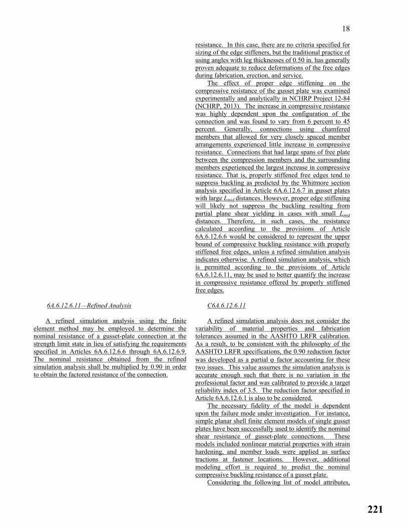
18
resistance. In this case, there are no criteria specified for sizing of the edge stiffeners, but the traditional practice of using angles with leg thicknesses of 0.50 in. has generally proven adequate to reduce deformations of the free edges during fabrication, erection, and service.
The effect of proper edge stiffening on the compressive resistance of the gusset plate was examined experimentally and analytically in NCHRP Project 12-84 (NCHRP, 2013). The increase in compressive resistance was highly dependent upon the configuration of the connection and was found to vary from 6 percent to 45percent. Generally, connections using chamfered members that allowed for very closely spaced member arrangements experienced little increase in compressive resistance. Connections that had large spans of free plate between the compression members and the surrounding members experienced the largest increase in compressive resistance. That is, properly stiffened free edges tend to suppress buckling as predicted by the Whitmore section analysis specified in Article 6A.6.12.6.7 in gusset plates with large Lmid distances. However, proper edge stiffening will likely not suppress the buckling resulting from partial plane shear yielding in cases with small Lmiddistances. Therefore, in such cases, the resistance calculated according to the provisions of Article 6A.6.12.6.6 would be considered to represent the upper bound of compressive buckling resistance with properly stiffened free edges, unless a refined simulation analysis indicates otherwise. A refined simulation analysis, which is permitted according to the provisions of Article 6A.6.12.6.11, may be used to better quantify the increase in compressive resistance offered by properly stiffened free edges.
6A.6.12.6.11—Refined Analysis
A refined simulation analysis using the finite
element method may be employed to determine thenominal resistance of a gusset-plate connection at thestrength limit state in lieu of satisfying the requirementsspecified in Articles 6A.6.12.6.6 through 6A.6.12.6.9.The nominal resistance obtained from the refined simulation analysis shall be multiplied by 0.90 in orderto obtain the factored resistance of the connection.
C6A.6.12.6.11 A refined simulation analysis does not consider the
variability of material properties and fabrication tolerances assumed in the AASHTO LRFR calibration. As a result, to be consistent with the philosophy of the AASHTO LRFR specifications, the 0.90 reduction factor was developed as a partial ϕ factor accounting for these two issues. This value assumes the simulation analysis isaccurate enough such that there is no variation in the professional factor and was calibrated to provide a target reliability index of 3.5. The reduction factor specified in Article 6A.6.12.6.1 is also to be considered.
The necessary fidelity of the model is dependent upon the failure mode under investigation. For instance, simple planar shell finite element models of single gusset plates have been successfully used to identify the nominal shear resistance of gusset-plate connections. These models included nonlinear material properties with strain hardening, and member loads were applied as surface tractions at fastener locations. However, additional modeling effort is required to predict the nominal compressive buckling resistance of a gusset plate.
Considering the following list of model attributes,
19
NCHRP Project 12-84 researchers were able to attain model predictions within 9% of experimental values for a3-dimensional two-panel truss system isolated out of an entire bridge where the connection of interest was located in the center between two panels (NCHRP, 2013). Model symmetry was not used because the sway buckling mode would not be captured. The following list, which is not considered exhaustive, summarizes other importantattributes of the preceding model:
• The gusset plate, splice plates, and the members for a
distance of two member depths away from the gusset-plate edge were modeled with shell elements. The truss was represented with beam elements at all other locations;
• The shell elements were able to capture nonlinear
geometric and material effects. Nonlinear material properties considered strain hardening;
• Each fastener was represented with a line element
with deformable, nonlinear material properties; • The mesh contained initial imperfections on all
compression members with a maximum out-of-plane magnitude limited by the smaller of: 1) the longest free edge length divided by 150; 2) 0.1 times the gap between the end of the compression member and the next adjoining member; or 3) 100% of the gusset-plate thickness;
• The model was proportionally loaded until failure.
Typically, buckling can be identified when the analysis no longer converges to a solution. Shear failures are more difficult to identify, but typically occur when the plate exhibits load/displacementsoftening or when a strain threshold is exceeded after which the analysis predictions become unrealistic.

20
PART B⎯ALLOWABLE STRESS RATING AND LOAD FACTOR RATING
6B.5.2—Allowable Stress Method
In the Allowable Stress method, the capacity of amember is based on the rating level evaluated: Inventorylevel-Allowable Stress, or Operating level-Allowable Stress.The properties to be used for determining the allowablestress capacity for different materials follow. Forconvenience, the tables provide, where appropriate, theInventory, Operating, and yield stress values. Allowablestress and strength formulas should be those providedherein or those contained in the AASHTO StandardSpecifications. When situations arise that are not coveredby these specifications, then rational strength of materialformulae should be used consistent with data and plansverified in the field investigation. Deviations from theAASHTO Standard Specifications should be fullydocumented.
When the bridge materials or construction areunknown, the allowable stresses should be fixed by theEngineer, based on field investigations and/or materialtesting conducted in accordance with Section 5, andshould be substituted for the basic stresses given herein.
6B.5.2.1—Structural Steel
The allowable unit stresses used for determining safe
load capacity depend on the type of steel used in thestructural members. When nonspecification metals areencountered, coupon testing may be used to determine anominal yield point. When information on specificationsof the steel is not available, allowable stresses should betaken from the applicable “Date Built” column of Tables6B.5.2.1-1 and 6B.5.2.1-2.
Table 6B.5.2.1-1 gives allowable Inventory stressesand Table 6B.5.2.1-2 gives the allowable Operatingstresses for structural steel. The nominal yield stress, Fy, isalso shown in Tables 6B.5.2.1-1 and 6B.5.2.1-2.Tables 6B.5.2.1-3 and 6B.5.2.1-4 give the allowableInventory and Operating Stresses for bolts and rivets. Forcompression members, the effective length, KL, may bedetermined in accordance with the AASHTO StandardSpecifications or taken as follows:
KL = 75 percent of the total length of a column
having riveted end connections
= 87.5 percent of the total length of a columnhaving pinned end connections
The modulus of elasticity, E, for steel should be29,000,000 lb/in.2
If the investigation of shear and stiffener spacing isdesirable, such investigation may be based on theAASHTO Standard Specifications.
C6B.5.2.1
When nonspecification materials are encountered, standard coupon testing procedures may be used to establish the nominal yield point. To provide a 95 percent confidence limit, the nominal yield point would typically be the mean coupon test value minus 1.65 standard deviations.
Mechanical properties of eyebars, high-strength eyebars, forged eyebars, and cables vary depending on manufacturer and year of construction. In the absence of material tests, the Engineer should carefully investigate the material properties using manufacturer’s data and compilations of older steel properties before establishing the yield and allowable stresses to be used in load rating the bridge.
The formulas for the allowable bending stress in partially supported or unsupported compression flanges of beams and girders, given in Tables 6B.5.2.1-1 and 6B.5.2.1-2 are the corresponding formula based on given in Table 10.32.1A of the Allowable Stress Design portion of the AASHTO Standard Specifications. The equation in Table 6B.5.2.1-1 is to be used for an Inventory Rating and the equation in Table 6B.5.2.1-2 is to be used for an Operating Rating.
The previously used formulas are inelastic parabolic formulas which treat the lateral torsional buckling of a beam as flexural buckling of the compression flange. This is a very conservative approach for beams with short unbraced lengths. The flexural capacity is reduced for any unbraced length greater than zero. This does not

21
reflect the true behavior of a beam. A beam may reach Mp with unbraced lengths much greater than zero. In addition, the formula neglects the St. Venant torsional stiffness of the cross-sections. This is a significantcontribution to the latera1 torsional buckling resistance of rolled shapes, particularly older “I” shapes. The previous formulas must also be limited to the values of I/b listed. This limit is the slenderness ratio when the estimated buckling stress is equal to half the yield strength or 0.275 Fy in terms of an allowable stress. Many floor stringers will have unbraced lengths beyond this limit. If the formulas are used beyond these limits, negative values of the allowable stress can result.
The new formulas have no upper limit which allows the determination of allowable stresses for all unbraced lengths. In addition, the influence of the moment gradient upon buckling capacity is considered using the modifier Cb in the new formulas.
The specification formulas are based on the exact formulations of the lateral torsional buckling of beams. They are currently used in the AISC LRFD Specifications and other specifications throughout the world. They are also being used to design and rate steel bridges by the Load Factor method. Figures 6B.5.2.1-1 and 6B.5.2.1-2 given below show a comparison between the specification formulas and the previous specification formulas for two sections. Figure 6B.5.2.1-1 compares results for a W18 × 46 rolled section. The newspecification gives a much higher capacity than the previous specification. The difference is due to the inclusion of the St. Venant torsional stiffness, J, in the proposed specification. Figure 6B.5.2.1-2 shows a similar comparison for a plate-girder section. The section, labeled section 3, has 1.5 × 16 in. flanges and a 5/16 × 94 in. web. The previous specification equation gives higher values than the new specification for large unbraced lengths. The previous specification is unconservative in this range. Both graphs show that, for small unsupported lengths, the new specification gives higher allowable stress values. The higher values result from the fact that there is an immediate reduction in capacity versus unsupported length in the previous specification.
Tables 6B.5.2.1-3 and 6B.5.2.1-4 contain the allowable inventory and operating stresses for low-carbon steel bolts, rivets, and high-strength bolts. For high-strength bolts (Table 6B.5.2.1-4), the values for inventory rating correspond to the Allowable Stress design values in the AASHTO Standard Specifications (Tables 10.32.3B and 10.32.3C). The values for the operating rating correspond to the inventory rating values multiplied by the ratio 0.75/0.55. The corresponding values for low-carbon steel bolts (ASTM A307) in Table 6B.5.2.1-3 are based on the values given in Table 10.32.3A of the Standard Specifications.
Guidance on the treatment of gusset plates can be found in Article C6A.6.12.1.

22 Specifications and guidance for determining the
capacity of gusset plates can be found in Appendix L6B – Formulas for the Capacity, C, of Typical BridgeComponents Based on the Load Factor Method.Allowable Inventory and Operating stresses for fasteners used in gusset plates can be found in Tables 6B.5.2.1-3 and 6B.5.2.1-4.
Guidance on considering the effects of deterioration on load rating of steel structures can be found in Article C6A.6.5.
6B.5.3—Load Factor Method
Nominal capacity of structural steel, reinforced
concrete and prestressed concrete should be the same asspecified in the load factor sections of the AASHTOStandard Specifications. Nominal strength calculationsshould take into consideration the observable effects ofdeterioration, such as loss of concrete or steel-sectionalarea, loss of composite action or corrosion.
Allowable fatigue strength should be checked basedon the AASHTO Standard Specifications. Specialstructural or operational conditions and policies of theBridge Owner may also influence the determination offatigue strength.
C6B.5.3 Nominal capacities for members in the proposed
guidelines are based on AASHTO’s Standard Specifications contained in the load factor section. This resistance depends on both the current dimensions of the section and the nominal material strength.
Different methods for considering the observable effects of deterioration were studied. The most reliable method available still appears to be a reduction in the nominal resistance based on measured or estimated losses in cross-sectional area and/or material strengths.
At the present time, load factor methods for determining the capacity of timber and masonry structural elements are not available.
6B.5.3.1—Structural Steel The yield stresses used for determining ratings
should depend on the type of steel used in the structuralmembers. When nonspecification metals areencountered, coupon testing may be used to determineyield characteristics. The nominal yield value should besubstituted in strength formulas and is typically taken asthe mean test value minus 1.65 standard deviations.When specifications of the steel are not available, yieldstrengths should be taken from the applicable “date built”column of Tables 6B.5.2.1-1 to 6B.5.2.1-4.
The capacity of structural steel members should bebased on the load factor requirements stated in theAASHTO Standard Specifications. The capacity, C, fortypical steel bridge members is summarized inAppendix L6B. For beams, the overload limitations ofArticle 10.57 of the AASHTO Standard Specificationsshould also be considered.
Except as specified in Appendix L6B.6.2.1, TtheOperating rating for welds, bolts, and rivets should bedetermined using the maximum strengths fromTable 10.56A in the AASHTO Standard Specifications.
The Operating rating for friction joint fasteners(ASTM A325 bolts) should be determined using a stressof 21 ksi. A1 and A2 should be taken as 1.0 in the basicrating equation.
C6B.5.3.1 Guidance on considering the effects of deterioration
on load rating of steel structures can be found in Article C6A.6.5.
Guidance on the treatment of gusset plates can be found in Article C6A.6.12.1. Specifications and guidance for determining the capacity of gusset plates can be found in Appendix L6B – Formulas for the Capacity, C, of Typical Bridge Components Based on the Load Factor Method.

23
APPENDIX L6B—FORMULAS FOR THE CAPACITY, C, OF TYPICAL BRIDGE COMPONENTS BASED
ON THE LOAD FACTOR METHOD
Add the following paragraphs to Appendix L6B – Formulas for the Capacity, C, of Typical Bridge Components Based on the Load Factor Method − at the end of Section L6B.2:
L6B.2.6—Gusset Plates
Main truss member gusset plates shall be load rated for shear, compression, and/or tension occurring in the
vicinity of each connected member. The following sections below outline the necessary checks for performing a Load Factor rating for these gusset plates and their connections, which are based on the research performed under NCHRP Project 12-84 (NCHRP, 2013) that only considered LRFR. These provisions supersede the 2009 FHWA Guidelines for gusset-plate load ratings. All of the resistance factors used in this section have not been rigorously determined considering the base HS-20 live load model used for Load Factor rating. Additional reductions are not required in LFR based on the DL/LL ratio. Future research looking into the live load variability for truss systems may justify the use of lower resistance factors. An example gusset plate rating by LFR can be found in Appendix A.
L6B.2.6.1–Fasteners Fasteners in bolted and riveted gusset plate connections shall be evaluated to prevent fastener shear and plate bearing failures. The shear capacity of one fastener shall be taken as: C = (φF)mA where: φF = shear capacity per fastener area of one fastener specified in Table L6B.2.6.1-1(ksi) m = number of shear planes A = cross-sectional area of one fastener (in.2). For rivets, use the undriven diameter to calculate the area.
When bolts carrying loads pass through undeveloped fillers 0.25 in. or more in thickness in axially loaded connections, the bolt shear capacity shall be reduced by:
(1 )
(1 2 )R
⎡ ⎤+ γ= ⎢ ⎥+ γ⎣ ⎦
where:
γ = Af/Ap
Af = sum of the area of the fillers on both sides of the connected plate (in.2) Ap = smaller of either the connected plate area or the sum of the splice plate areas on both sides of the connected
plate (in.2). For chord splices, when considering the gusset plate(s), only the portion of the gusset plate(s) that overlaps the connected plate shall be considered in the calculation of the splice plate areas.
Alternatively, if fillers are extended beyond the connected parts and connected with enough bolts to develop the force in the fillers, the fillers may be considered developed. For rivets, the Undeveloped Filler Plate Reduction Factor, R3, shall be considered as specified in Article 6A.6.12.5.1.

24
Table L6B.2.6.1-1—Shear Capacity Per Fastener Area
φF (ksi) a
A307 18
A325 - threads included in shear plane 35
A325 – threads excluded from shear plane 43
A490 - threads included in shear plane 43
A490 – threads excluded from shear plane 53
Rivets See Table 6A.6.12.5.1-1
a – Tabulated values shall be reduced by 20 percent in bearing-type connections whose length between extreme fasteners in each of the spliced parts measured parallel to the line of axial force exceeds 50 inches.
The bearing capacity of the connected material at standard, oversize, short-slotted holes or long-slotted holes parallel to the applied force shall be taken as: C = 0.9LctFu ≤ 1.8dtFu (10-166b) where: d = nominal diameter of the fastener (in.) t = thickness of the gusset plate (in.) Fu = specified minimum tensile strength of the gusset plate given in Table 10.2A (ksi) Lc = clear distance between the holes or between the hole and the edge of the material in the direction of the applied
bearing force (in.) For determining the bearing capacity of long-slotted holes loaded perpendicular to the applied force, refer to Article 10.56.1.3.
The Operating rating for friction joint high-strength bolts should be determined according to the provisions of Article 6B.5.3.1.
L6B.2.6.2–Multi-Layered Gusset and Splice Plates
Where multi-layered gusset and splice plates are used, the resistances of the individual plates may be added
together in determining the overall resistance provided that enough fasteners are present to develop the force in the layered gusset and splice plates.
L6B.2.6.3–Gusset Plate Shear Resistance
Gusset plates shall be load rated for shear yielding and shear rupture on relevant partial and full shear failure
plane widths.
Yielding C = φvy(0.58)FyAgΩ

25 Rupture C = φvu(0.58)FuAn
where: φvy = resistance factor for gusset plate shear yielding taken as 1.00 φvu = resistance factor for gusset plate shear rupture taken as 0.85 Ω = shear reduction factor for gusset plates taken as 0.88 Ag = gross area of the plate resisting shear (in.2) An = net area of the plate resisting shear (in.2) Fy = specified minimum yield strength of the gusset plate given in AASHTO Table 10.2A (ksi) Fu = specified minimum tensile strength of the gusset plate given in AASHTO Table 10.2A (ksi)
Partial shear planes shall only be checked around compression members and only shear yielding on partial shear planes shall be checked. The partial shear plane length shall be taken along adjoining member fastener lines between plate edges and other fastener lines. The following partial shear planes, as applicable, shall be evaluated to determine which shear plane controls:
• The plane that parallels the chamfered end of the compression member, as shown in Figure L6B.2.6.3-1;
• The plane on the side of the compression member that has the smaller framing angle between the that member and
the other adjoining members, as shown in Figure L6B.2.6.3-2; and • The plane with the least cross-sectional shear area if the member end is not chamfered and the framing angle is
equal on both sides of the compression member.
Contolling Partial Plane
Oth
er P
artia
l Pla
ne 45°
45°
Figure L6B.2.6.3-1–Example of a Controlling Partial Shear Plane that Parallels the Chamfered End of the Compression Member Since that Member Frames in at an Angle of 45 Degrees to Both the Chord and the Vertical

26
θ<αC
ontro
lling
Par
tial P
lane
α
Other Partial Plane
Figure L6B.2.6.3-2–Example of a Controlling Partial Shear Plane on the Side of a Compression Member Without a Chamfered End that has the Smaller Framing Angle between that Member and the Other Adjoining Members (i.e. θ < α) L6B.2.6.4–Gusset Plate Compressive Resistance
Gusset plate zones in the vicinity of compression members shall be load rated for plate stability. The compressive capacity may be taken as the compressive capacity of a Whitmore section. The buckling capacity is dependent upon the chamfering of the member, the framing angles of the members entering the gusset, and the standoff distance of the compression member relative to the surrounding members; i.e. the distance, Lc. An example connection showing a typical chamfered member end and member framing angle is provided in Figure C6A.6.12.6.7-1.
The provisions of this article shall not be applied for the load rating of compression chord splices. The compressive capacity of a Whitmore section shall be taken as:
C = ϕcg (0.85)AsFcr in which:
• If y
cF
Et
KL 2212 π≤ , then:
t
KLE
FFF cy
ycr⎥⎥⎦
⎤
⎢⎢⎣
⎡⎟⎠
⎞⎜⎝
⎛
π−=
2
2 124
1
• If y
cF
Et
KL 2212 π> , then:
tKL
EFc
cr 2
2
12 ⎟⎠
⎞⎜⎝
⎛
π=
where: ϕcg = resistance factor for gusset plate compression taken as 1.00 As = gross cross-sectional area of the Whitmore section determined based on 30 degree dispersion angles, as
shown in Figure L6B.2.6.4-1 (in.2). The Whitmore section shall not be reduced if the section intersects adjoining member bolt lines.
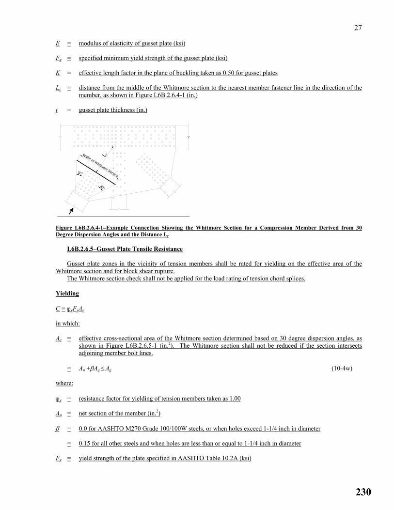
27 E = modulus of elasticity of gusset plate (ksi) Fy = specified minimum yield strength of the gusset plate (ksi) K = effective length factor in the plane of buckling taken as 0.50 for gusset plates Lc = distance from the middle of the Whitmore section to the nearest member fastener line in the direction of the
member, as shown in Figure L6B.2.6.4-1 (in.) t = gusset plate thickness (in.)
30°
30°
Width of Whitmore Section
Lc
Figure L6B.2.6.4-1–Example Connection Showing the Whitmore Section for a Compression Member Derived from 30 Degree Dispersion Angles and the Distance Lc
L6B.2.6.5–Gusset Plate Tensile Resistance Gusset plate zones in the vicinity of tension members shall be rated for yielding on the effective area of the Whitmore section and for block shear rupture. The Whitmore section check shall not be applied for the load rating of tension chord splices.
Yielding C = ϕyFyAe
in which: Ae = effective cross-sectional area of the Whitmore section determined based on 30 degree dispersion angles, as
shown in Figure L6B.2.6.5-1 (in.2). The Whitmore section shall not be reduced if the section intersects adjoining member bolt lines.
= An +βAg ≤ Ag (10-4w)
where: ϕy = resistance factor for yielding of tension members taken as 1.00 An = net section of the member (in.2) β = 0.0 for AASHTO M270 Grade 100/100W steels, or when holes exceed 1-1/4 inch in diameter = 0.15 for all other steels and when holes are less than or equal to 1-1/4 inch in diameter Fy = yield strength of the plate specified in AASHTO Table 10.2A (ksi)

28 Block Shear Rupture
The block shear rupture capacity shall be taken as:
C = ϕbsRp(0.58FuAvn + FuAtn) ≤ φbsRp(0.58FyAvg + FuAtn)
where: ϕbs = resistance factor for block shear rupture taken as 0.85
Avg = gross area along the plane resisting shear stress (in.2) Avn = net area along the plane resisting shear stress (in.2) Atn = net area along the plane resisting tension stress (in.2) Fy = yield strength of the plate specified in AASHTO Table 10.2A (ksi) Fu = tensile strength of the plate specified in AASHTO Table 10.2A (ksi) Rp = reduction factor for holes taken equal to 0.90 for bolt holes punched full size and 1.0 for bolt holes
drilled full size or subpunched and reamed to size
Widt
h of W
hitmore
Sec
tion
30°
30°
Figure L6B.2.6.5-1–Example Connection Showing the Whitmore Section for a Tension Member Derived from 30 Degree Dispersion Angles L6B.2.6.6−Chord Splices
Gusset plates that splice two chord sections together shall be checked using a section analysis considering the
relative eccentricities between all plates crossing the splice and the loads on the spliced plane. This Article is only intended to cover the load rating of chord splices that occur within the gusset plates. For gusset plates also serving the role of a chord splice, the forces from all members framing into the connection must be considered. The chord splice forces are the resolved axial forces acting on each side of the spliced section, as illustrated in Figure C6A.6.12.6.9-1. The chord splice should be investigated for the larger of the two resolved forces on either side of the splice.
The capacity equations in this article assume the gusset and splice plates behave as one combined spliced section to resist the applied axial load and eccentric bending that occurs due to the fact that the resultant forces on the section are offset from the centroid of the combined section, as illustrated in Figure C6A.6.12.6.9-2 (substitute e for ep in the figure). The combined spliced section is treated as a beam and the capacity is determined assuming the stress in the combined section at the limit of usable capacity is equal to the specified minimum yield strength of the gusset plate if the slenderness limit for the spliced section given below is met, which will typically be the case.
The application of the Whitmore section check specified in Article L6B.2.6.4 is not considered applicable for the load rating of a compression chord splice.
For compression chord splices, the compressive capacity of the spliced section shall be taken as:

29
eASAS
FCgg
ggcrcs ⎟
⎟⎠
⎞⎜⎜⎝
⎛
+φ=
in which: Fcr = stress in the spliced section at the usable limit of capacity (ksi). Fcr shall be taken as the specified minimum
yield strength of the gusset plate when the following equation is satisfied:
25
12<
g
splice
tKL
(Note: if the preceding equation is not satisfied, the Engineer will need to derive a reduced value of Fcr to
account for possible elastic buckling of the gusset plate within the splice.) where: ϕcs = resistance factor for gusset plate chord splices taken as 1.00
Ag = gross area of all plates in the cross-section intersecting the spliced plane (in.2)
e = distance between the centroid of the cross-section and the resultant force perpendicular to the spliced plane (in.)
K = effective column length factor taken as 0.50 for chord splices
Lsplice= center-to-center distance between the first lines of fasteners in the adjoining chords as shown in Figure L6B.2.6.6-1 (in.)
Sg = gross section modulus of all plates in the cross-section intersecting the spliced plane (in.3)
tg = gusset plate thickness (in.)
splice
Figure L6B.2.6.6-1−Example Connection Showing Chord Splice Parameter, Lsplice
For tension chord splices, the tensile capacity of the spliced section shall be taken as the lesser of the values given by the following equations:

30
⎟⎟⎠
⎞⎜⎜⎝
⎛+
φ=
⎟⎟⎠
⎞⎜⎜⎝
⎛
+φ=
nn
nnucs
gg
ggycs
eASASFC
eASAS
FC
where: ϕcs = resistance factor for gusset plate chord splices taken as 1.00
Ag = gross area of all plates in the cross-section intersecting the spliced plane (in.2)
An = net area of all plates in the cross-section intersecting the spliced plane (in.2)
e = distance between the centroid of the cross-section and the resultant force perpendicular to the spliced plane (in.)
Fy = specified minimum yield strength of the gusset plate (ksi)
Fu = specified minimum tensile strength of the gusset plate (ksi)
Sg = gross section modulus of all plates in the cross-section intersecting the spliced plane (in.3)
Sn = net section modulus of all plates in the cross-section intersecting the spliced plane (in.3)
The yielding check on the effective area of the Whitmore section specified in Article L6B.2.6.5 is not considered applicable for the load rating of a tension chord splice; however, tension chord splice members shall be checked for block shear rupture as specified in Article L6B.2.6.5.
L6B.2.6.7−Edge Slenderness
Gusset plates should not be load rated based on any edge slenderness criteria. Refer to Article C6A.6.12.6.10 for
additional guidance.
L6B.2.6.8–Refined Analysis A refined simulation analysis using the finite element method may be employed to determine the nominal
resistance of a gusset-plate connection at the strength limit state in lieu of satisfying the requirements specified in Articles L6B.2.6.3 through L6B.2.6.6. Refer to Article C6A.6.12.6.11 for a list of some suggested model attributes, which is not considered exhaustive.

2013 AASHTO BRIDGE COMMITTEE AGENDA ITEM: 42 SUBJECT: The Manual for Bridge Evaluation: Section 2, Various Articles (T18-2) TECHNICAL COMMITTEE: T-18 Bridge Management, Evaluation and Rehabilitation
REVISION ADDITION NEW DOCUMENT
DESIGN SPEC CONSTRUCTION SPEC MOVABLE SPEC MANUAL FOR BRIDGE SEISMIC GUIDE SPEC BRIDGE ELEMENT INSP GUIDE
EVALUATION OTHER DATE PREPARED: 1/8/13 DATE REVISED: AGENDA ITEM:Item #1 Revise Section 2: BRIDGE FILES(RECORDS) TABLE OF CONTENTS as follows: SECTION 2: BRIDGE FILES(RECORDS)BRIDGE FILES AND DOCUMENTATION TABLE OF CONTENTS 2.10 GENERALINTRODUCTION…………………………………………………………..2-1 2.1 PROVISIONS TO SUPPORT THE NBIS REQUIREMENTS…………………………..2-1
2.1.1 GENERAL INFORMATION……………………………………………………...2-2 2.1.2 INSPECTION REPORTS………………………………………………………….2-3 2.1.3 CRITICAL FINDINGS AND ACTIONS TAKEN………………………………..2-4 2.1.4 WATERWAY INFORMATION…………………………………………………..2-5 2.1.5 SIGNIFICANT CORRESPONDENCE……………………………………………2-6 2.1.6 SPECIAL INSPECTION PROCEDURES OR REQUIREMENTS………………..2-6 2.1.7 LOAD RATING DOCUMENTATION…………………………………………....2-7 2.1.8 POSTING DOCUMENTATION…………………………………………………..2-8 2.1.9 SCOUR ASSESSSMENT………………………………………………………….2-9 2.1.10 SCOUR PLANS OF ACTION……………………………………………………2-9
2.2 SUPPLEMENTAL DOCUMENTATION IN BRIDGE FILE 2.2.1 GENERAL…………………………………………………………………………………….2-1 2.2.2 PLANS AND DRAWINGS…………………………………………………………………...2-1 2.2.3 CONSTRUCTION DOCUMENTATION…………………………………………………….2-1 2.2.4 ORIGINAL DESIGN DOCUMENTATION………………………………………………….2-1 2.2.5 UNIQUE CONSIDERATION…………………………………………………………………2-2 2.2.6 UTILITIES AND ANCILLARY ATTACHMENTS………………………………………….2-2 2.2.7 MAINTENANCE AND REPAIR HISTORY…………………………………………………2-2 2.2.8 ADDITIONAL WATERWAY DOCUMENTATION………………………………………..2-2 2.2.9 TRAFFIC DATA………………………………………………………………………………2-2
2.2—COMPONENTS OF BRIDGE RECORDS ………………………………………………………..2-1 2.2.1—Plans………………………………………………………………………………………...2-1 2.2.1.1—Construction Plans...................................................................................................................2-1
2.2.1.3 As-Built Drawings……………………………………………………………………..2-2 2.2.2—Specifications………………………………………………………………………………2-2 2.2.3—Correspondence………………………………………………………………………….2-2 2.2.4—Photographs………………………………………………………………………………2-2

2.2.5—Materials and Tests……………………………………………………………………….2-2 2.2.5.1—Material Certification………………………………………………………………2-2 2.2.5.2—Material Test Data…………………………………………………………………..2-3 2.2.5.3—Load Test Data………………………………………………………………………2-3
2.2.6—Maintenance and Repair History………………………………………………………….2-3 2.2.7—Coating History……………………………………………………………………………2-3 2.2.8—Accident Records………………………………………………………………………….2-3 2.2.9—Posting…………………………………………………………………………………………2-3 2.2.10—Permit Loads………………………………………………………………………………..2-3 2.2.11—Flood Data………………………………………………………………………………….2-3 2.2.12—Traffic Data…………………………………………………………………………………2-3 2.2.13—Inspection History…………………………………………………………………………2-3 2.2.14—Inspection Requirements…………………………………………………………………2-3 2.2.15—Structure Inventory and Appraisal Sheets……….………………………………………2-3 2.2.16—Inventories and Inspections………………………………………………………………2-3 2.2.17—Rating Records……………………………………………………………………2-3 2.3—INVENTORY DATA………………………………………………………………2-3 2.3.1—General……………………………………………………..……………………2-3 2.3.2—Revised Inventory Data………………………………………………………………2-3
2.4—INSPECTION DATA 2.4.1—General 2.4.2—Revised Inspection Data
2.5—CONDITION AND LOAD RATING DATA………………….…………………………..2-10 2.6—LOCAL REQUIREMENTS 2.7—REFERENCES……………………………………………………..……………………2-3 Item #2 Insert new Article 2.0 as follows: 2.0—INTRODUCTION
Maintaining bridges safe for public travel is of utmost importance to transportation officials. In order to ensure public safety, management of in-service highway bridges requires the collection and maintenance of accurate, up-to-date, and comprehensive information for each bridge. The information includes data that does not typically change over the life of a bridge, data that is updated by field inspections, and data that is derived or calculated to assess specific attributes such as scour, vulnerability to extreme events, and safe load-carrying capacity.
Data that does not typically change includes information such as the length and width of the structure, and the structure type. Data that is updated as a result of field inspections includes condition information on the structural components and elements, clearances and changes to dead load, and the identification of conditions that introduce a potential risk to the bridge such as debris accumulation around substructure units and scour or erosion.
Information is organized in a file for each bridge. The bridge file includes a description of the characteristics and conditions of the structure, calculations for determining scour vulnerability (if over water), a determination of the load carrying capacity including computations substantiating reduced load limits, and details of any damage and alterations or repairs to the structure.
The information in a bridge file provides a cumulative history of the structure that is useful to review prior to conducting a bridge inspection, rating, or evaluation.
The information in a bridge file may exist electronically, on paper, or in external documents that are appropriately referenced within each bridge file or manual. The external documents may apply to multiple bridges and exist in various locations.
The bridge file provides information that directly relates to requirements of the National Bridge Inspection Standards (Article 2.1) and other supplemental information that bridge owners may find useful in managing bridges (Article 2.2).

Item #3
Replace Article 2.1 with the following:
2.1—PROVISIONS TO SUPPORT THE NBIS REQUIREMENTS
The Inspection Program Manager is responsible to maintain an inventory of all bridges that are subject to the NBIS, in accordance with coding guidance issued by the Federal Highway Administration. Certain data is defined by the FHWA that must be collected and retained. This data is typically retained within a computer database. Summaries of the inventory and evaluation data may be included in bridge files. The data accurately captures specific, key information to include bridge identification, location, structural attributes, dimensions, clearances, condition, and load carrying capacity.
A bridge file is to be prepared as required by the NBIS and described in this AASHTO Manual for Bridge Evaluation. Specifically, maintain reports on the results of bridge inspections and note any actions taken to address the findings of the inspections. Maintain relevant maintenance and inspection data and use it to assist with the assessment of current bridge conditions. Additionally, document observations and measurements needed to determine the physical and functional condition of the bridge. Identify any changes from initial or previously recorded conditions, and other actions needed ensure that the structure continues to satisfy present structural service requirements.
The format used to document the information in bridge files may vary significantly. If the information is not available in a consolidated inspection report, look for it elsewhere in the inspection file or as referenced to another location. Bridge owners may make generalized reference to where digital information is located in their own manuals or other files rather than individually in each bridge file.
Include the following specific bridge information. The level of documentation will vary depending on the complexity and condition of a structure; however, always include the following information that is common to all bridges. Item #4 Insert the following new articles: 2.1.1—General File Information • A General Plan and Elevation drawing or a sketch depicting the layout of the bridge, if available. • A clear and understandable approach to labeling members and elements that enables an assessment of the
inspection process and completeness. • Inspection and inventory data as defined by the FHWA for reporting to the National Bridge Inventory. This
data is often referred to as Structure Inventory and Appraisal information, or SI&A. • Photographs showing a top view of the roadway across the bridge, a side elevation view, and an under view of
the main or typical span superstructure configuration. Photographs necessary to show major defects, posting restrictions, and other important features should be included.
• A history of any structural damage.
2.1.2—Field Inspection Information
Inspection reports provide a chronological record of the date and type of all inspections performed on the bridge. Document each inspection conducted for a bridge and retain in the bridge file. Document the observations and findings from each inspection. Identify the Team Leader responsible for the inspection and report, and the date the inspection was conducted. Observations include a description of conditions of bridge members and the identification of factors that require further review, close monitoring, or additional attention during inspections:
• Brief narrative descriptions of general and component/element conditions with detail to justify a condition
rating of 5 or less for NBI items and Condition State 3 or more for elements. • Sketches or photographs, as appropriate, of elements or members showing typical and deteriorated conditions. • Sketches documenting remaining section of components with sufficient detail to facilitate determination of the

load capacity. These sketches may be part of the load rating documentation. • Notations of actions taken to address previous inspection findings.
2.1.3—Critical Findings and Actions Taken
Provide a detailed description and photographs of the specific critical finding(s) sufficient to document safety or structural concerns. Identify appropriate immediate actions or follow-up inspections. Include a record of the actions taken to resolve or monitor the critical finding(s).
2.1.4—Waterway Information
Provide channel cross-sections or sketches, soundings and stream profiles as needed to provide adequate information on the stability of the waterway and allow for adequate assessment of the risk to the structure. Update channel information periodically and when otherwise necessary. Perform a historical comparison to determine the extent of any scour, channel shifting, degradation, or aggradation of the channel. Determine and document a frequency for obtaining and updating these measurements, depending on an assessment of the bridge and stream characteristics. Consider the potential for lateral migration of the stream channel or head-cutting in determining the extent of channel documentation. A single cross section or sketch at one face may be appropriate for historically stable channels and embankments. Evaluate the need for obtaining cross sections for pipes and box culverts and structures with small drainage areas on a case-by-case basis. The BIRM provides additional information on inspecting channels.
2.1.5—Significant Correspondence
Provide correspondence and agreements regarding inspection responsibility, ownership, maintenance responsibilities with other agencies, or other issues that have an impact on the ability to ensure that thorough and timely inspections are completed.
2.1.6—Other Inspection Procedures or Requirements
Provide procedures for specific types of inspections (fracture critical, underwater and complex bridges). Address those items that need to be communicated to an inspection team leader to ensure a successful bridge inspection.
Provide procedures to document special access needs, inspection equipment, structural details, inspection methods and any special qualifications required of inspecting personnel. Overall inspection procedures may exist in a bridge inspection manual which address common aspects of these more complex inspections; however, if there are items unique to that structure that are not covered in the overall inspection procedures, provide written procedures specific to that fracture critical, underwater, and complex bridge inspection.
Document the following items, either in bridge specific inspection procedures, or by referring to general inspection procedures:
1. Identify each of the fracture critical, complex features and underwater members, and any elements that need
special attention during those inspections, preferably on plan sheets, drawings or sketches. 2. Describe the inspection method(s) special access needs (under bridge inspection truck, climbing, etc. special
inspection equipment (NDE) and frequency to be used for the elements. 3. Provide information regarding proximity necessary to details, such as “arm’s length” or “hands-on”. 4. Provide special qualifications required of inspection personnel by the Program Manager, if any. Section 4 of
this manual provides additional information on inspection plans for bridges.
2.1.7—Load Rating Documentation
Provide dated load rating results along with the identification of the analyst to determine the safe load carrying capacity of the bridge and, where necessary, the load limits for posting. Include the load rating results which clearly identify the loads and methodology used in the analysis, a general statement of the results of the analysis, identification of members that were found to control the load rating, and any other modifying factors that were assumed in the analysis. Include updates to the calculations as needed to reflect changes in the condition of

structural members, changes to the structural configuration, strength of members, or dead load, and changes to the legal live load that may alter the load rating result. . If calculations cannot be provided due to a lack of information (missing plans, unknown materials, etc.), provide documentation for justification of determined load rating. If a field load test is used to establish the load carrying capacity of the bridge, provide reports that describe and document the testing process and results.
2.1.8—Posting Documentation
Provide a summary of posting recommendations and actions taken for the bridge and date of posting. 2.1.9—Scour Assessment
Document the assessment conducted to determine the scour vulnerability of the bridge. Provide a clear
reference to an alternate location if documentation is available outside of the inspection file. 2.1.10—Scour Plan of Action
For scour critical bridges, provide a copy of a plan of action, or a clear reference to the plan of action if the
documentation is available in a location other than the inspection file. The plan of action is used to monitor known and potential deficiencies and address or monitor critical scour related findings. Item #5 Delete Article C2.1 Item #6 Delete Article 2.2 and subarticles and replace with the following: 2.2—SUPPLEMENTAL DOCUMENTATION IN BRIDGE FILE 2.2.1—General
Retain the following supplemental documentation in the bridge file at the discretion of the Bridge Inspection Program Manager and subject to availability, especially for older bridges. Additional information not listed in this section may be included in the file and contain information bridge owners believe is necessary to operate their Bridge Management Systems. Some of this information may be referenced in the bridge file or references provided to outside source locations.
2.2.2—Plans and Drawings
Include one set of final drawings showing the “as-built” condition of the bridge. Construction shop drawings may be included.
2.2.3—Construction Documentation
Include construction documentation of relevant as-built information regarding the structure, including reference to material certifications and tests performed during construction activities such as pile driving, concrete placement, and prestressing operations.
Retain all pertinent certificates for the type, grade, and quality of materials incorporated in the construction of the bridge, such as steel mill certificates, concrete delivery slips, and other Manufacturers’ certifications, in accordance with applicable policies and the appropriate statute of limitations.
Reference in the file any reports of nondestructive and laboratory tests of materials incorporated in the bridge during construction.
Retain one complete copy or reference to the special technical specifications under which the bridge was built. Reference the edition and date of the general technical specification in the bridge file.

2.2.4—Original Design Documentation
The original design calculations and documentation for the bridge should be retained. The AASHTO Bridge Design Specifications version and any project specific assumptions and criteria should be recorded. 2.2.5—Unique Considerations
Provide information as necessary on other items that may need to be addressed depending on each unique situation. If appropriate, include special coordination procedures prior to inspection (Coast Guard, security, operations personnel, etc.), safety concerns (rattlesnakes, bats, etc.), and optimum periods of the year to inspect the bridge (lake draw down, canal dry time, snow, ice, bird nesting seasons, etc.).
Identify special access needs or equipment necessary to gain the access required to inspect the features (traveler system, climbing, etc.).
Emphasize and highlight special structural details or situations, such as fatigue-prone details, pins and hangers in nonredundant systems, cathodic protection, and weathering or brittle steels,
Document any unusual environmental conditions that may have an effect on the structure, such as salt spray and industrial gases.
2.2.6—Utilities and Ancillary Attachments
Include information on utilities or ancillary attachments that are attached to the structure or that affect access to portions of the bridge. Note a utility in the immediate area, though not fastened to the bridge, e.g., a sewer line crossing the right-of-way and buried in the channel beneath the bridge. The type of connection should be noted. 2.2.7—Maintenance and Repair History
Include a chronological record documenting the maintenance and repairs to the bridge since its initial construction. Include details such as significant dates, description of project, contractor, cost, contract number. Document the surface protective coatings used, including surface preparation, application methods, dry-film thickness and types of paint, concrete and timber sealants, and other protective membranes. This information may be in the referenced original design file. 2.2.8—Additional Waterway Documentation
When available for structures over waterways, include a chronological history of major hydraulic events, high-water marks, and scour activity in the bridge file. Channel profiles, mean high water levels, debris accumulation, and storm surge data are useful information for effectively managing bridges over waterways. 2.2.9—Traffic Data
When the information is available, include the frequency and type of vehicles using the bridge and their historical variations in the bridge file. Vehicle weight data, such as weigh-in-motion (WIM) data for a bridge can aid in the determination of bridge specific load factors when refining LRFR load capacity calculations.
Item #7 Delete Article C2.2 Item #8 Delete Article 2.3, subarticles and commentary Item #9 Delete Article 2.4, subarticles and commentary

Item #10 Delete Article 2.5 and subarticles Item #11
Delete Article 2.6
OTHER AFFECTED ARTICLES:None
BACKGROUND:The AASHTO Manual for Bridge Evaluation (MBE) and its predecessors have provided bridge owners with guidance on the practice of the inspection and load rating of bridges. In 2004 the AASHTO Manual for Bridge Evaluation was incorporated into the Code of Federal Regulations (CFR) in regards to the National Bridge Inspection Standards (NBIS) by reference. In 2010 the FHWA developed quality assurance criteria to ensure States compliance with the CFR, referred to as the “23 Metrics”. The proposed changes to the Manual for Bridge Evaluation in this ballot item are an effort to clarify for bridge owners and the FHWA which bridge inspection and load rating practices information contained within the MBE is applicable in the CFR.
ANTICIPATED EFFECT ON BRIDGES:The changes should improve the understanding of the practice of bridge inspection and load rating.
REFERENCES: None
OTHER: None

2013 AASHTO BRIDGE COMMITTEE AGENDA ITEM: 43 SUBJECT: The Manual for Bridge Evaluation: Section 6, Article 6A.4.1 (T18-6) TECHNICAL COMMITTEE: T-18 Bridge Management, Evaluation and Rehabilitation
REVISION ADDITION NEW DOCUMENT
DESIGN SPEC CONSTRUCTION SPEC MOVABLE SPEC MANUAL FOR BRIDGE SEISMIC GUIDE SPEC BRIDGE ELEMENT INSP GUIDE
EVALUATION OTHER DATE PREPARED: 11/9/12 DATE REVISED: 4/15/13 AGENDA ITEM:Item #1 Add the following paragraph to the end of Article 6A.4.1—Introduction:
The live load factors given in Articles 6A.4.3.2, 6A.4.4.2 and 6A.4.5.4 are established assuming that demands based on the two more lane loaded distribution factor will always govern over the demands based on single lane distribution factor for design loads, legal loads, and routine permits. However, in the unusual case where the single lane distribution factor is greater than the two-lane distribution factor, the higher distribution factor shall be used.
The multiple presence factor listed in the LRFD Specification does not apply for permit trucks. Therefore, the multiple presence factor should not be considered when establishing the load demands for routine permit trucks, when the single lane distribution governs. Item #2 Add the following paragraph to the end of Article C6A.4.1:
Calibration of LRFR load factors was done using the simplified live load distribution factors of the LRFD Specification. During this calibration, it was assumed that the demands based on two or more lane loaded scenario will govern over the demands based on the single lane loaded case for multi-lane bridges for legal and routine permit trucks. However, there may be a few instances where the single lane distribution factor (based on the simplified equations given in the LRFD Specification, or based on the Lever rule method, or based on the rigid cross-section distribution of exterior girder) may exceed the two-lane distribution factor. In these situations, to be conservative, use of the higher live load distribution factor with the load factors in the MBE is recommended.
The multiple presence factor of 1.2 incorporated within the single-lane distribution factor equation accounts for the presence of a vehicle heavier than the design or rating truck in the lane. In other words MPF listed within the LRFD specification is applicable for design loadings (HL93) and legal trucks only, but not for permit trucks. As a result, the MPF for permit trucks was not considered during the calibration of permit loads for the LRFR Specification. The MPF should not be considered when establishing the load demand of either routine or special permit truck. It is important to note that when comparing the simplified live load distribution factors to establish the demand of routine permit trucks, MPF of 1.2 included within the simplified single lane distribution factor equation should be removed.
MBE Article 6A.4.5.4.2c addresses the use of refined analysis for permits and provides an adjustment to the load factors when using refined method of analysis (such as 3-D analysis) methods. Again, it is not necessary to incorporate the MPF for permit trucks during evaluation.

OTHER AFFECTED ARTICLES:None
BACKGROUND:LRFD Specification Article 3.6.1.1 addresses how the demand should be established for the HL93 loading. It states that “Unless specified otherwise herein, the extreme live load force effect shall be determined by considering each possible combination of number of loaded lanes multiplied by a corresponding multiple presence factor (MPF) to account for the probability of simultaneous lane occupation by the full HL93 design live load. In lieu of site specific data, the values in Table 3.6.1.1.2-1: ….” In essence, it states that when establishing the HL93 demand for design, the largest demand either from the single lane loaded case or from the two or more lane loaded case should be considered. The LRFR Specification addresses not only the HL93 loading, but also legal and permit loading. During LRFR ratings a few issues on MPF use were raised, which require some clarifications. Calibration of LRFR load factors for legal and routine permit trucks were done utilizing the demands established using simplified live load distribution factor equations given in the LRFD Specification. In the load factor calibration, it was assumed that a side by side truck configuration will always produce higher load demands. As a result, the two lane live load distribution factor was used in the calibration process. However, there may be a few instances where the single lane distribution factor (based on the simplified equations given in the LRFD Specification, or based on the Lever rule method, or based on the rigid cross-section distribution of exterior girder) may exceed the two-lane distribution factor. In these situations, it would be conservative to use the higher live load distribution factor with the load factors in the MBE. The MPF of 1.2 incorporated within the LRFD single-lane distribution factor accounts for the presence of a heavier non-permit truck that exceeds the legal weight in a single lane. Therefore, the multiple presence factor listed in the LRFD Specification does not apply for permit trucks. The MPF for permit trucks was not considered during the calibration of loads for the LRFR Specification. This revision clarifies the proper use of the governing distribution factor for multi-lane bridges for legal and routine permit truck ratings, particularly for cases where the single lane distribution factor may govern over the two lane distribution. It recommends the use of the governing distribution factor even though the LRFR live load factor calibration was based on a two lane distribution factor. Furthermore, this clarifies that the MPF is not applicable for permit trucks.
ANTICIPATED EFFECT ON BRIDGES:Eliminates potential confusion and promotes more consistency in load ratings as the distribution factor has a major influence on load rating results.
REFERENCES: None
OTHER: None

2013 AASHTO BRIDGE COMMITTEE AGENDA ITEM: 44 SUBJECT: The Manual for Bridge Evaluation: Section 6, Various Articles (T18-8) TECHNICAL COMMITTEE: T-18 Bridge Management, Evaluation and Rehabilitation
REVISION ADDITION NEW DOCUMENT
DESIGN SPEC CONSTRUCTION SPEC MOVABLE SPEC MANUAL FOR BRIDGE SEISMIC GUIDE SPEC BRIDGE ELEMENT INSP GUIDE
EVALUATION OTHER DATE PREPARED: 11/9/12 DATE REVISED: 4/15/13 AGENDA ITEM:Item #1 Revise Article 6A.4.4.2.3a as follows:
Generalized live load factors for the Strength I limit state are specified in Table 6A.4.4.2.3a-1 for routine
commercial traffic on structures other than buried structures. If, in the Engineer’s judgment, an increase in the live load factor is warranted due to conditions or situations not accounted for in this Manual when determining the safe legal load, the Engineer may increase the factors in Table 6A.4.4.2.3a-1, not to exceed the value of the factor multiplied by 1.3. Item #2 Revise Article 6A.4.4.2.3b as follows:
Generalized live load factors for the Strength I limit state are given in Table 6A.4.4.2.3b-1 for the NRL rating load and posting loads for specialized hauling vehicles satisfying Formula B specified in Article 6A.8.2. on structures other than buried structures. If in the Engineer’s judgment, an increase in the live load factor is warranted due to conditions or situations not accounted for in this Manual when determining the safe legal load, the Engineer may increase the factors in Table 6A.4.4.2.3-1, not to exceed the value of the factor multiplied by 1.3. Item #3 Revise Article 6A.4.5.4.2 as follows:
Table 6A.4.5.4.2a-1 specifies live load factors for permit load rating that are calibrated to provide a uniform and acceptable level of reliability. on structures other than buried structures. Load factors are defined based on the permit type, loading condition, and site traffic data.
Permit load factors given in Table 6A.4.5.4.2a-1 for the Strength II limit state are intended for spans having a rating factor greater than 1.0 when evaluated for AASHTO legal loads. Permit load factors are not intended for use in load-rating bridges for legal loads except as allowed under Article 6A.2.3.1. Item #4 In Article 6A.4.5.4.2c, revise the last paragraph as follows:

When special permits mixed with traffic are evaluated using a refined analysis, a live load factor γL
=1.0 shall be applied on the permit truck while a γ
L =1.10 shall be applied on the governing AASHTO or state legal truck
placed in the adjacent lane. Item #5 Revise Table 6A.4.5.4.2a-1as follows: Table 6A.4.5.2a-1 Permit Load Factors: γL.
Permit Type Frequency Loading Condition DFa
ADTT (one
direction)
Load Factor by Permit Weight Ratiob
GVW / AL < 2.0
(kip/ft)
2.0 < GVW / AL < 3.0
(kip/ft)
GVW / AL > 3.0 (kip/ft)
Routine or Annual Routine or Annual
Unlimited Crossings
Mix with traffic (other vehicles may be on the bridge)
Two or more lanes
>5000 1.4 1.35 1.30 =1000 1.35 1.25 1.20 <100 1.30 1.20 1.15
Unlimited Crossings (Reinforced Concrete Box Culverts)c
Mix with traffic (other vehicles may be on the bridge)
One lane All ADTTs
1.40
All Weights Special or Limited Crossing
Single-Trip Escorted with no other vehicles on the bridge
One lane N/A 1.10
Single-Trip Mix with traffic (other vehicles may be on the bridge)
One lane ALL ADTTS
1.20
Multiple-Trips (less than 100 crossings
Mix with traffic (other vehicles may be on the bridge)
One lane ALL ADTTS
1.40
Notes: a DF = LRFD-distribution factor. When one-lane distribution factor is used, the built-in multiple presence factor should be
divided out. b Permit Weight Ratio = GVW/AL;. GVW = Gross Vehicle Weight; AL = Front axle to rear axle length; Use only axles on
the bridge. c Refer to Article 6A.5.12 Item #6 In Article 6A.5.12.10.3, revise the 2nd bullet by moving the sentence from the commentary to the specification as follows:
• Legal Load and Permit Load—Only the single-lane loaded condition needs to be checked for legal load and permit load ratings, even when the culvert carries multiple lanes. The 1.2 single-lane multiple presence factor should not be applied to this loading. A single legal load factor of 2.00 shall be specified for all traffic volumes. For routine as well as special permits, utilize the load factors provided in Table 6A.4.5.4.2a-1, without applying the multiple presence factor.

Item #7 In Article C6A.5.12.10.3, delete the last paragraph. Item #8 Add the following to the 2nd paragraph in Article 6A.4.2.4:
System factors that correspond to the load factor modifiers in the AASHTO LRFD Bridge Design Specifications should be used. The system factors in Table 6A.4.2.4-1 are more conservative than the LRFD design values and may be used at the discretion of the evaluator until they are modified in the AASHTO LRFD Bridge Design Specification., however, when rating nonredundant superstructures for legal loads using the generalized load factors given in Article 6A.4.4.2.3, the system factors from Table A 6A.4.2.4-1 shall be used to maintain an adequate level of system safety. The system factor for riveted and bolted gusset plates for all force effects shall be taken as 0.90.
OTHER AFFECTED ARTICLES:None
BACKGROUND:Load rating provisions for concrete box culverts were adopted by AASHTO in 2011, which provide specially calibrated live load factors for culvert ratings for design loads, legal loads and permit loads. In the past Section 6 only provided live load factors for rating bridge structures. These revisions will guide the user to the appropriate section for load rating of culverts and prevent any misapplication of load factors for LRFR ratings. The 2012 Interims provides guidance on the use of refined analysis for permit evaluation. Item #4 clarifies that a state legal load may be used as the adjacent vehicle if it is the governing vehicle for the state, in place of the AASHTO truck. Item # 5 expands Table 6A.4.5.2a-1 to cover routine permit load factors for box culverts. Item #8 requires the use of system factors when using the reduced generalized legal load factors adopted in 2012. This change is proposed to provide consistency with Article C6A.4.4.2.3.
ANTICIPATED EFFECT ON BRIDGES:The revisions will eliminate potential confusion that may exist in selecting live load factors for permits following the addition of culvert rating provisions into Section 6 in 2011.
REFERENCES: None
OTHER: None

2013 AASHTO BRIDGE COMMITTEE AGENDA ITEM: 45 SUBJECT: The Manual for Bridge Evaluation: Section 6, Articles 6A.6.3 and C6A.6.3 (T18-9) TECHNICAL COMMITTEE: T-18 Bridge Management, Evaluation and Rehabilitation/ T-14 Steel
REVISION ADDITION NEW DOCUMENT
DESIGN SPEC CONSTRUCTION SPEC MOVABLE SPEC MANUAL FOR BRIDGE SEISMIC GUIDE SPEC COASTAL GUIDE SPEC
EVALUATION OTHER DATE PREPARED: 9/26/12 DATE REVISED: AGENDA ITEM:
Item #1 Revise Article 6A.6.3 as follows: Except as specified herein, Rresistance factors, ϕ, for steel members, for the strength limit state, shall be taken as specified in LRFD Design Article 6.5.4.2. If the year of construction is prior to 1991, the resistance factor for axial compression for steel, ϕc, shall be taken as 0.90 for built-up compression members.
Item #2 Add the following paragraph to the end of Article C6A.6.3: The resistance factor, ϕc, for built-up members subject to axial compression is reduced from 0.95 to 0.90 if the year of construction is prior to 1991 to appropriately reflect the fact that steel built-up compression members may have been fabricated from universal mill plate. Such columns are contained in the data band of lowest strength reflected by SSRC Column Category 3P. Since only one column curve based on SSRC Column Category 2P is used for all columns, earlier versions of the LRFD Design Specification specified a lower ϕc of 0.90 to reflect the larger data spread and coefficient of variation found in the data for all column categories. Since the production of universal mill plates was discontinued around 1990, and changes in steelmaking practice since that time have resulted in materials of higher quality and much better defined properties, ϕc was raised from 0.90 to 0.95 in the LRFD Design Specification (2013).
OTHER AFFECTED ARTICLES:None
BACKGROUND: In the original research on the probability-based strength of steel columns (Bjorhovde, 1972, 1978, 1988), three column curves were recommended. The three column curves were the approximate means of bands of strength curves for columns of similar manufacture based on extensive analyses and confirmed by full-scale tests. Hot-formed and cold-formed heat treated HSS columns fell into the data band of highest strength (SSRC Column Category 1P), while built-up wide-flange columns made from universal mill plates were included in the data band of lowest strength (SSRC Column Category 3P). The largest group of data, however, clustered around SSRC Column Category 2P. Thus, it was decided to use only one column curve, SSRC Column Category 2P, for all column types. The AASHTO LRFD Specification followed suit. The use of only one column curve results in a larger data spread and thus a larger coefficient of variation, and so a resistance factor ϕc = 0.85 was adopted in the original AISC LRFD Specification for the column equations to achieve a level of reliability comparable to that of beams. Resistance factors in the AASHTO LRFD Specification are typically set at a level that is 0.05 higher than those in the AISC LRFD Specification; thus, ϕc was set to 0.90 in the original AASHTO LRFD Specification. Since that time, significant additional analyses and tests, as well as changes in practice, have demonstrated that an increase in ϕc from 0.85 to 0.90 in the AISC LRFD Specification was warranted, indeed even somewhat conservative (Bjorhovde, 1988). Significant changes in industry practice since that time have included the following: (1) built-up shapes are no longer manufactured from universal mill plates; (2) the most commonly used structural steel is now ASTM A 709 Grade 50 or 50W, with a specified minimum yield stress of 50 ksi; and (3) changes in steelmaking practice have resulted in materials of higher quality and much better defined properties. The level and variability of the yield stress thus have led to a reduced coefficient of variation for the relevant material properties (Bartlett et al., 2003). As a result, for consistency, a separate 2013 Agenda Item has been developed to raise ϕc for steel members (or components) subject to axial compression from 0.90 to 0.95 in the AASHTO LRFD Specification. This particular Agenda Item proposes that the lower value of ϕc = 0.90 conservatively be maintained for load rating of steel built-up members subject to axial compression if the year of construction is prior to 1991 in case the members were fabricated from universal mill plate. The production of universal mill plate was completely discontinued around 1990.
ANTICIPATED EFFECT ON BRIDGES:Slightly lower ratings will be obtained for steel built-up compression members if the year of construction was prior to 1991.
REFERENCES: Bartlett, R.M., Dexter, R.J., Graeser, M.D., Jelinek, J.J., Schmidt, B.J. and Galambos, T.V. (2003), “Updating Standard Shape Material Properties Database for Design and Reliability,” Engineering Journal, AISC, Vol. 40, No. 1, pp. 2–14. Bjorhovde, R. (1972), “Deterministic and Probabilistic Approaches to the Strength of Steel Columns,” Ph.D. Dissertation, Lehigh University, Bethlehem, PA, May. Bjorhovde, R. (1978), “The Safety of Steel Columns,” Journal of the Structural Division, ASCE, Vol. 104, No. ST9, September, pp. 1371–1387. Bjorhovde, R. (1988), “Columns: From Theory to Practice,” Engineering Journal, AISC, Vol. 25, No. 1, 1st Quarter, pp. 21–34. Ziemian, R.D. (ed.) (2010), Guide to Stability Design Criteria for Metal Structures, 6th Ed., John Wiley & Sons, Inc., Hoboken, NJ.
OTHER: None

2013 AASHTO BRIDGE COMMITTEE AGENDA ITEM: 46 SUBJECT: The Manual for Bridge Evaluation: APPENDIX A: Illustrative Examples, Table of Contents & Example A11 (T18-4) TECHNICAL COMMITTEE: T-18 Bridge Management, Evaluation and Rehabilitation
REVISION ADDITION NEW DOCUMENT
DESIGN SPEC CONSTRUCTION SPEC MOVABLE SPEC MANUAL FOR BRIDGE SEISMIC GUIDE SPEC BRIDGE ELEMENT INSP GUIDE
EVALUATION OTHER DATE PREPARED: 1/8/13 DATE REVISED: 4/15/13 AGENDA ITEM:Item #1 Add to the following to the MBE Appendix A: Illustrative Examples, Table of Contents:
A11 Single span 420.0 ft.
Through Truss
Gusset Plates
Design Strength I LRFR & LFR
A -xx
Item #2
Add the following Example A11 to the MBE Appendix A, as shown in Attachment B, if Ballot Item T18-3 containing gusset plate load rating provisions is adopted for inclusion in Section 6 of the MBE by the SCOBS.
OTHER AFFECTED ARTICLES:None
BACKGROUND:The example is proposed to be included in the MBE Appendix A: It illustrates the load rating of gusset plates and the application of these proposed revisions to Section 6 of the MBE. It is envisioned that the FHWA guidance for load rating of gusset plates will not be maintained in the future.
ANTICIPATED EFFECT ON BRIDGES:The revisions contribute to a better understanding of gusset plate behavior and capacity and should result in a higher reliability for safety of truss bridges.
REFERENCES: None
OTHER: None

A- xx
ATTACHMENT B – 2013 AGENDA ITEM 46 (T18-4) — T-18 (Revised 04 /15/13)
A11 —THROUGH TRUSS BRIDGE: GUSSET PLATE RATING
These gusset plate checks for design loads illustrate the application of the LRFR and LFR specifications (ballot item T18-3), using the L2 joint of the truss depicted in Figure A11.1-1. Sections A11.1 through A11.9 provide an LRFR gusset plate rating example, while Sections A11.10 through A11.18 provide an LFR gusset plate rating example.
A11.1 – Bridge and Member Data The truss bridge on I-94 was constructed in 1991. All members and plates were made with AASHTO M223 Gr. 50 material; all fasteners are 7/8” diameter A325 fully-tensioned bolts in standard holes that were sub-punched and reamed to size. For the purposes of this design example, a center-to-center distance of 3 inches is assumed for all bolts. The truss is striped for four lanes of traffic and carries an ADTT of 10,000/day. There is no wearing surface on the deck (i.e. DW=0). The superstructure has a current NBI Condition Rating of 7.
Figure A11.1-1: Truss Elevation
Detailing of the joint is shown in Figure A11.1-2. The loads shown are envelope loads developed using HS20-44 & Alternate loading. Impact loading was considered to be 28.5% of the live load.
For the purposes of this example, this LRFR rating will assume these loads were from HL-93 loading considering 33% impact, though a separate structural analysis would have to be performed to truly understand the differences in live load effects.
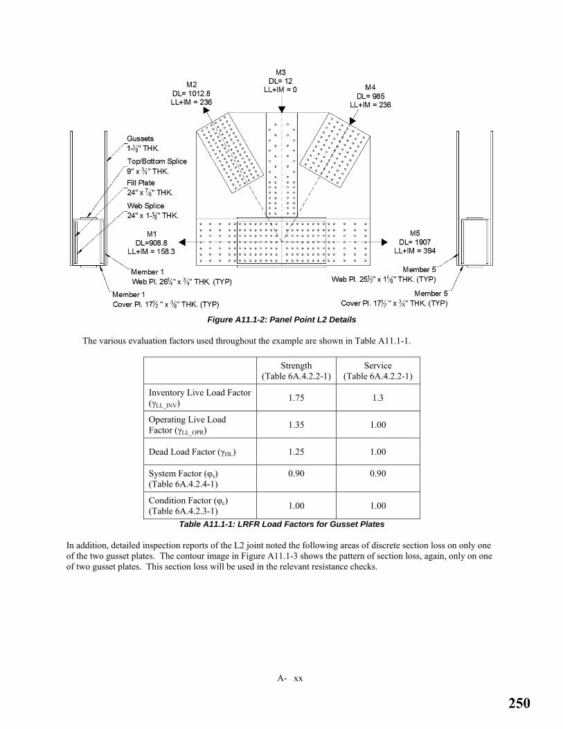
A- xx
Figure A11.1-2: Panel Point L2 Details
The various evaluation factors used throughout the example are shown in Table A11.1-1.
Strength (Table 6A.4.2.2-1)
Service (Table 6A.4.2.2-1)
Inventory Live Load Factor (γLL_INV) 1.75 1.3
Operating Live Load Factor (γLL_OPR) 1.35 1.00
Dead Load Factor (γDL) 1.25 1.00
System Factor (φs) (Table 6A.4.2.4-1)
0.90
0.90
Condition Factor (φc) (Table 6A.4.2.3-1) 1.00 1.00
Table A11.1-1: LRFR Load Factors for Gusset Plates
In addition, detailed inspection reports of the L2 joint noted the following areas of discrete section loss on only one of the two gusset plates. The contour image in Figure A11.1-3 shows the pattern of section loss, again, only on one of two gusset plates. This section loss will be used in the relevant resistance checks.

A- xx
Figure A11.1-3: Losses to One Gusset Plates at L2
The following rating checks will be performed:
1) Check tension resistance of M1 2) Check the chord splice resistance between M1 and M5 3) Check tension resistance of M2 4) Check compression resistance of M3 5) Check compression resistance of M4 6) Check the horizontal shear resistance of the gusset plate 7) Check the vertical shear resistance of the gusset plate

A- xx
A11.2 -- Check the Tension Resistance of M1 Only block shear resistance of the gusset plate, shear resistance of the bolts, and bearing resistance of the gusset must be checked. The checks for M5 are very similar in nature and will not be shown. Additionally, the bolt shear and bearing resistance checks will only be demonstrated for the gusset plate at M1, these checks would normally be performed at each fastener pattern and for the splice plates too for a complete rating.
Figure A11.2-1: Block Shear Failure Plane for Member M1 at L2
First determine the shear resistance of the fasteners using Article 6A.6.12.6.2. Because web splice plates are used, some fasteners will be in double shear, but conservatively assume just single shear. The connection is not greater than 50 inches in length, therefore a connection length reduction factor does not apply. Since the web splice plates have fill plates greater than 0.25 inches, the bolt shear must be reduced by the fill plate factor.
fillsubbsbn RNFA.φR 480= Eqn. 6A.6.12.6.2-1
⎥⎦
⎤⎢⎣
⎡++
=γγ21
1fillR Eqn. 6A.6.12.6.2-3
⎥⎥⎦
⎤
⎢⎢⎣
⎡=
p
fill
AA
γ

A- xx
In this case, Ap is determined as the lesser of area of the lower chord web plate (¾”x26¼”) and the sum of the areas of the web splice plate (1⅛”x24”) and gusset plate (1⅛”x87.8”). Given the large area of the gusset plate, it is clear that the area of the member web plate will control the calculation of Ap.
067.1)75.0)(25.26(
)875.0)(24( ==γ
kip/bolt 3.18)66.0)(1(1204
)875.0()48.0(80.0
66.0)067.1)(2(1
067.1121
1
2
=⎟⎟⎠
⎞⎜⎜⎝
⎛=
=⎥⎦
⎤⎢⎣
⎡++
=⎥⎦
⎤⎢⎣
⎡++
=
π
γγ
r
fill
R
R
Check the bearing resistance of the gusset plate. All holes are at distances greater than 2 bolt diameters from each other and the edges, therefore only one bearing resistance equation needs to be used.
( ) kip/bolt 8.122)65(125.187)4.2(80.0
4.2
=⎟⎠⎞
⎜⎝⎛=
=
r
ubbr
R
dtFR φ
Eqn. 6A.6.12.6.4-1
Note that the chord web plate thickness is ¾”, and the bearing resistance of the web plate will govern over the bearing resistance of the gusset plate. Therefore, a similar bearing resistance computation for the web plate should be performed as part of the member rating. However, as this example is for gusset plates alone, the bearing resistance computation for the chord member will not be shown herein.
The resistance is the lesser of the fastener shear resistance and plate bearing resistance. In this case, the fastener resistance controls. For this member, there are 182 bolts. Conservatively, the fill plate reduced bolt shear resistance is assumed over all the bolts, despite the fill plate not covering the entire bolt pattern. The total resistance is:
kips 3330kip/bolt 3.18*182 ==rR
Next determine the resistance due to block shear (see Figure A11.2-1). First calculate out the shear and tensile areas.
2
2
.38.39125.181
871300.54
.00.54125.1*00.24*2
inA
inA
tn
tg
=⎟⎠⎞
⎜⎝⎛ +−=
==
Gross shear plane of the gusset plate without corrosion damage
21 .71.51125.1*96.45 inAvg ==
Gross shear plane of the gusset plate with corrosion damage
22 .36.42)50.0)(69.7()25.0)(69.1530.6()125.1)(96.45( inAvg =−+−=
Net shear plane
( ) 2.95.65125.181
872536.4271.51 inAvn =⎟
⎠⎞
⎜⎝⎛ +−+=
Calculate the DL/LL ratio for this limit state to account for further reduction according to Article 6A.6.12.6.1.

A- xx
:isreduction additional the therefore1.0an greater th is which 74.53.1588.908
1
1 ==LL
DL
PP
90.05
0.174.51.01R DL_LL =⎟⎠⎞
⎜⎝⎛ −
−= Article 6A.6.12.6.1
Calculate the block shear resistance of each gusset plate.
( )
( )( ) ( )[ ] 504638.39)(6595.65)(65)(58.0)0.1)(00.1(
58.0 thereforeyes, ,47034287)36.4271.51(50)95.65(65
? is
1
1
21
=+=
+=≤→+≤
+≤
bs
tnuvnupbsbs
vgvgyvnu
P
AFAFRP
AAFAF
φ Eqn. 6A.6.12.6.8-1
Since the resistance from the bolts is less than the block shear resistance, then the capacity is controlled by the bolt resistance, C=3330 kips.
Calculate the rating factors.
LLLL
DLDLLLDLcsLRFR P
PRCRF
1
1_ )(γ
γφφ −= Eqn. 6A.4.2.1-1
30.735.175.163.5
63.5)3.158)(75.1(
)8.908)(25.1()90.0)(3330)(00.1(90.0
===
=−
=
LLopr
LLinvLRFRinvLRFRopr
LRFRinv
RFRF
RF
γγ
The gusset plate was also originally designed to be slip-critical with the members. Therefore rating factors must also be calculated for the slip resistance. Slip resistance is checked with the Service II load combination.
The slip resistance of the bolt group is calculated as:
)(#ofboltsPNKKRR tsshnr == Eqn. 6A.6.12.6.3-1
For standard holes, Kh = 1.0 Article 6A.6.12.6.3
A Class B surface preparation was specified, Ks = 0.50 Table 6A.6.12.6.3-2
Conservatively, one shear plane is assumed for all bolts, Ns = 1
Pt = 39 kips Table 6A.6.12.6.3-1
kips 3549)182)(39)(1)(50.0(0.1 ==rR
Per Article 6A.6.12.6.3, slip only needs to be calculated at the Operating level under Service II loads.
44.14)3.158)(00.1(
)8.908)(00.1()3549)(00.1(90.0
1
1 =−
=−
=LLLL
DLDLcsLRFRopr P
PCRFγ
γφφ Eqn. 6A.4.2.1-1
Note that in the above equation, the dead-to-live load ratio reduction factor is not applied to the capacity per Article 6A.6.12.6.1 since it is a service limit-state.

A- xx
A11.3 -- Check the Chord Splice Resistance
Since the gusset plate is also performing as a tension chord splice, the resistance of the spliced section must be evaluated according to the provisions of Article 6A.6.12.6.9. To begin, the net and gross section modulus need to be calculated for the composite section of gusset and splice plates (See Figure A11.3-1).
Figure A11.3-1: Section of Gusset and Splice Plates at L2
Start by calculating the gross and net section properties of the combined section of gusset and web splice plates. For brevity, the calculations will not be shown. In this case they were calculated using a drawing program; alternatively, the calculations can be completed using a spreadsheet or long-hand equations.
The gross and net section areas are:
2
2
in. 0.229
in. 1.265
=
=
n
g
A
A
The heights of the gross and net section centroids, using the bottom of the gusset as the datum, are:
in. 7.39
in. 2.36
=
=
n
g
h
h

A- xx
Next calculate the gross and net moments of inertia.
4
4
in. 4.154792
in. 7.178592
=
=
n
g
I
I
The maximum bending stress will be at the bottom of gusset plate. Therefore, calculate the gross and net section moduli relative to the bottom of the gusset.
3
3
in. 1.38997.39
4.154792
in. 5.49332.36
7.178592
==
==
n
g
S
S
Since the chord splice section intersects the workpoint of the joint, the force resultant of the chord is at the center of the chord depth, so the gross and net section eccentricities are:
in. 26.22
277.39
in. 22.72
272.36
_
_
=−=
=−=
netp
grossp
e
e
The resistance of the chord splice can be calculated as the minimum of Eqns. 6A.6.12.6.9-3 and 6A.6.12.6.9-4.
⎟⎟⎠
⎞⎜⎜⎝
⎛
+=
ggrosspg
ggycsgrossr AeS
ASFP
__ φ Eqn. 6A.6.12.6.9-3
kips 5076)1.265)(7.22(5.4933
)1.265)(5.4933()50(85.0_ =⎟⎟⎠
⎞⎜⎜⎝
⎛+
=grossrP
⎟⎟⎠
⎞⎜⎜⎝
⎛
+=
nnetpn
nnucsnetr AeS
ASFP_
_ φ Eqn. 6A.6.12.6.9-4
kip. 4984)0.229)(2.26(1.3899
)0.229)(1.3899()65(85.0_ =⎟⎟⎠
⎞⎜⎜⎝
⎛+
=netrP
The lesser resistance controls; in this case, it is controlled by fracture on the net section, C=4984 kips.
Next determine the factored load in the chord splice. Look at the loads on both sides of the splice and use the more severe.
( ) ( )
( ) ( ) kips 2251))cos(60)(236(39475.1))60(985)(cos(90711.25SideRight
kips 2252))cos(60)(236(3.15875.1))os(60(1012.8)(c908.81.25SideLeft
=°−+°−
=°++°+
Since the loads are nearly the same on each side of the splice, determine the most severe DL/LL ratio reduction.
12.5))cos(60)(236(394))60(985)(cos(9071
12.5))cos(60)(236(3.158
))os(60(1012.8)(c908.8
_
_
_
_
=°−°−
=
=°+°+
=
rightLL
rightDL
leftLL
leftDL
PP
PP

A- xx
Since the dead load-to-live load ratio reduction factor is the same for both sides, use the controlling loads from the left side of the splice.
92.05
0.112.51.01R DL_LL =⎟⎠⎞
⎜⎝⎛ −
−= Article 6A.6.12.6.1
Calculate the LRFR rating factors.
LLLL
DLDLLLDLcsLRFR P
PRCRF
γγφφ −
=)( _
Eqn. 6A.4.2.1-1
32.635.175.187.4
87.4))cos(60)(236(3.158)(75.1(
)))os(60(1012.8)(c8.908)(25.1()92.0)(4984)(00.1(90.0
===
=°+
°+−=
LLopr
LLinvLRFRinvLRFRopr
LRFRinv
RFRF
RF
γγ
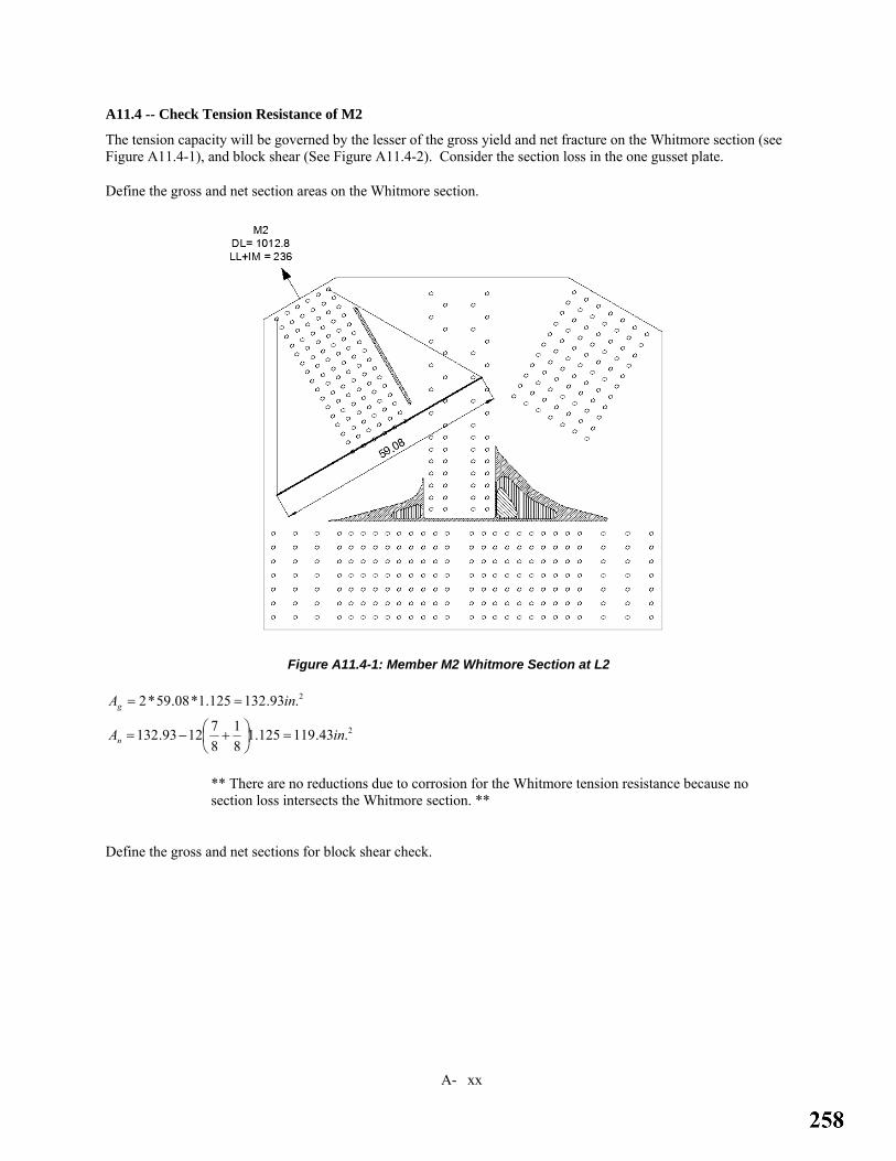
A- xx
A11.4 -- Check Tension Resistance of M2
The tension capacity will be governed by the lesser of the gross yield and net fracture on the Whitmore section (see Figure A11.4-1), and block shear (See Figure A11.4-2). Consider the section loss in the one gusset plate.
Define the gross and net section areas on the Whitmore section.
Figure A11.4-1: Member M2 Whitmore Section at L2
2
2
.43.119125.181
871293.132
.93.132125.1*08.59*2
inA
inA
n
g
=⎟⎠⎞
⎜⎝⎛ +−=
==
** There are no reductions due to corrosion for the Whitmore tension resistance because no section loss intersects the Whitmore section. **
Define the gross and net sections for block shear check.

A- xx
Figure A11.4-2: Member M2 Block Shear Plane at L2
2
2
.5.22125.181
871075.33
.75.33125.1*00.15*2
inA
inA
tn
tg
=⎟⎠⎞
⎜⎝⎛ +−=
==
Gross shear plane of the gusset plate without corrosion damage
21 .28.89125.1*68.39*2 inAvg ==
Gross shear plane of the gusset plate with corrosion damage
22 .33.82125.1)81.2768.39()25.0125.1(81.27125.1*68.39 inAvg =−+−+=
Net shear plane
( ) 2.81.108125.181
876228.89*2 inAvn =⎟
⎠⎞
⎜⎝⎛ +−=
Calculate the LRFR rating factors.
Calculate the DL/LL ratio for this limit state to account for further reduction according to Article 6A.6.12.6.1.
:isreduction additional the therefore1.0an greater th is which 29.4236
8.1012
2
2 ==LL
DL
PP

A- xx
93.05
0.129.41.01R DL_LL =⎟⎠⎞
⎜⎝⎛ −
−= Article 6A.6.12.6.1
Calculate the yield on gross and fracture on net capacities on the Whitmore section.
631493.132*50*95.0 === gyyy AFP φ Eqn. 6A.6.12.6.8-2 62100.1*0.1*43.119*65*80.0 === URAFP pnuur φ Eqn. 6A.6.12.6.8-3
Calculate the block shear resistance of each gusset plate.
( )? is 21 vgvgyvnu AAFAF +≤ Eqn. 6A.6.12.6.8-1
( ) ( ) ( )[ ] 6.55645.22*6581.108*65*58.00.1*00.158.0: thereforeyes; ,85807073)33.8228.89(50)81.108(65
1 =+=+=≤→+≤
tnuvnupbsbs AFAFRP φ
The overall tension capacity, C, is the lesser of the Whitmore yield on gross, Whitmore fracture on net, and block shear; in this case it’s controlled by block shear, so C=5564.6 kips.
Calculate the rating factors.
LLLL
DLDLLLDLcsLRFR P
PRCRF
2
2_ )(γ
γφφ −= Eqn. 6A.4.2.1-1
64.1035.175.121.8
21.8236*75.1
8.1012*25.193.0*6.5564*00.1*90.0
===
=−
=
LLopr
LLinvLRFRinvLRFRopr
LRFRinv
RFRF
RF
γγ

A- xx
A11.5 -- Check the Compression Resistance of M3
It is clear that this member will not control with only 12 kips of dead load, and since there is no live load, the rating factor cannot be calculated. For illustration, only the capacity calculations will be shown.
For the Whitmore buckling check, project the worst case section loss onto the Whitmore section (See Figure A11.5-1) in the direction of the member to calculate the equivalent gusset plate thickness.
Figure A11.5-1: Member M3 Whitmore Section at L2
88.035.76
)74.440.1436.3035.76(125.1)75.0125.1(74.4)5.0125.1(40.14)25.0125.1(36.30
_
_
=
−−−+−+−+−=
whiteq
whiteq
t
t
This member has no live load, so it has no extra dead-to-live load reduction.
Calculate the factored Whitmore buckling strength per gusset plate because only one of the plates has section loss.

A- xx
For the gusset plate with section loss
( ) 141928)88.0*35.76(88.0
93.5)29000(29.329.3
22
_
1 ==
⎟⎠⎞
⎜⎝⎛
= g
whiteq
mid
e A
tL
EP Eqn. 6A.6.12.6.7-4
4.3377)88.0*35.76(501 === gyo AFP Article 6A.6.12.6.7
: therefore0.44;an greater th is 0.424.3377
141928
1
1 ==o
e
PP
9.33434.3377658.0658.0Whit 1419284.3377
111
1
=== oP
P
Peo
Eqn. 6A.6.12.6.7-2
For the gusset plate without section loss
( ) 294952)125.1*35.76(125.1
93.5)29000(29.329.3222 ==
⎟⎠⎞
⎜⎝⎛
= g
g
mid
e A
tL
EP Eqn. 6A.6.12.6.7-4
7.4294)125.1*35.76(502 === gyo AFP Article 6A.6.12.6.7
: therefore0.44;an greater th is 68.687.4294
294952
2
2 ==o
e
PP
6.42687.4294658.0658.0Whit 2949527.4294
222
2
=== oP
P
Peo
Eqn. 6A.6.12.6.7-2
Therefore the total Whitmore buckling capacity is the sum of the two individual gusset plates:
( ) ( ) 9.72316.42689.3343*95.021 =+=+= WhitWhitWhit cgφ
Eqn. 6A.6.12.6.7-1
This vertical member does not have any admissible partial shear planes that would control the compression resistance. Therefore, the capacity, C, is the Whitmore buckling strength.

A- xx
A11.6 -- Check the Compression Resistance of M4
Figure A11.6-1: Member M4 Compression Checks at L2

A- xx
Figure A11.6-2: Member M4 Partial Shear Plane at L2
Calculate the equivalent gusset plate thickness on the partial shear plane for the gusset plate with section loss (see Figure A11.6-2).
99.080.63
)36.728.352.580.63(125.1)75.0125.1(36.7)5.0125.1(28.3)25.0125.1(52.5
_
_
=
−−−+−+−+−=
shreq
shreq
t
t
For the Whitmore buckling check, project the worst case section loss onto the Whitmore section in the direction of the member to calculate the equivalent gusset plate thickness (see Figure A11.6-3).

A- xx
Figure A11.6-3: Member M4 Whitmore Section at L2
86.064.55
)41.777.949.1664.55(125.1)75.0125.1(41.7)5.0125.1(77.9)25.0125.1(49.16
_
_
=
−−−+−+−+−=
whiteq
whiteq
t
t
For LRFR, calculate the DL/LL ratio reduction according to Article 6A.6.12.6.1.
:isreduction additional the, therefore1.0;an greater th is which 17.4236985
4
4 ==LL
DL
PP
94.05
0.117.41.01R DL_LL =⎟⎠⎞
⎜⎝⎛ −
−= Article 6A.6.12.6.1
Calculate the factored Whitmore buckling strength per gusset plate, because only one of the plates has section loss.
For the gusset plate with section loss
( ) 4.3441)86.0*64.55(86.0
50.31)29000(29.329.322
_
1 ==
⎟⎠⎞
⎜⎝⎛
= g
whiteq
mid
e A
tL
EP Eqn. 6A.6.12.6.7-4
5.2401)86.0*64.55(501 === gyo AFP
Article 6A.6.12.6.7

A- xx
: therefore0.44;an greater th is 43.15.24014.3441
1
1 ==o
e
PP
2.17935.2401658.0658.0Whit 4.34415.2401
111
1
=== oP
P
Peo
Eqn. 6A.6.12.6.7-2
For the gusset plate without section loss
( ) 6.7617)125.1*64.55(125.1
50.31)29000(29.329.3222 ==
⎟⎠⎞
⎜⎝⎛
= g
g
mid
e A
tL
EP Eqn. 6A.6.12.6.7-4
8.3129)125.1*64.55(502 === gyo AFP
Article 6A.6.12.6.7
: therefore0.44;an greater th is 43.28.31296.7617
2
2 ==o
e
PP
3.26358.3129658.0658.0Whit 64.76178.3129
222
2
=== oP
P
Peo
Eqn. 6A.6.12.6.7-2
Therefore, the total Whitmore buckling capacity is the sum of the two individual gusset plates.
( ) ( ) 1.42073.26352.1793*95.021 =+=+= WhitWhitWhit cgφ
Eqn. 6A.6.12.6.7-1
Since this is a compression member, the partial plane shear yield capacity also needs to be calculated.
For the gusset plate with section loss
( ) ( ) 4.1863)30cos(
)99.0*80.63(50*58.088.0)cos(
58.01 ==
Ω=
θsheary AF
PS
Eqn. 6A.6.12.6.6-1
For the gusset plate without section loss
( ) ( ) 1.2115)30cos(
)125.1*80.63(50*58.088.0)cos(
58.02 ==
Ω=
θsheary AF
PS
Eqn. 6A.6.12.6.6-1
Therefore, the total partial plane shear capacity is the sum of the two individual gusset plates.
( ) ( ) 5.39781.21154.1863*00.121 =+=+= PSPSPS vgφ
The overall buckling capacity, C, is the lesser of the Whitmore buckling strength and that from the partial plane shear yield. In this case, partial plane shear yielding controls, and C=3978.5 kips.
Calculate the rating factors.
LLLL
DLDLLLDLcsLRFR P
PRCRF
4
4_ )(γ
γφφ −=
Eqn. 6A.4.2.1-1
70.635.175.117.5
17.5236*75.1
985*25.194.0*5.3978*00.1*9.0
===
=−
=
LLopr
LLinvLRFRinvLRFRopr
LRFRinv
RFRF
RF
γγ

A- xx
A11.7 -- Check Horizontal Shear Capacity of the Gusset Plate
Figure A11.7-1: L2 Horizontal Shear Plane
First calculate the horizontal shear loads acting on the horizontal shear plane (see Figure A11.7-1). Note that the loads represented on the joint are based on envelope loads, not coincident loads. This will result in a conservative rating, which could be refined based on analysis of coincident shear loads.
kips 236)60)(cos236()60)(cos236(kips 9.998)60)(cos985()60)(cos8.1012(
42
42
=°+°=+==°+°=+=
HLLHLLHLL
HDLHDLHDL
PPPPPP
Calculate the DL/LL ratio for this limit state to account for further reduction according to MBE Article 6A.6.12.6.1.
:isreduction additional the, therefore1.0;an greater th is which 23.4236
9.998==
HLL
HDL
PP
94.05
0.123.41.01R DL_LL =⎟⎠⎞
⎜⎝⎛ −
−= Article 6A.6.12.6.1
Calculate the equivalent gusset plate thickness on the horizontal shear plane for the gusset plate with section loss.

A- xx
95.065.99
)75.0(97.4)5.0)(77.927.068.7()25.0)(48.919.036.062.8()125.1(65.99
_
_
=
−++−+++−=
shreq
shreq
t
t
Calculate the resistance to gross section shear yielding.
For the gusset plate with section loss
2416)88.0)(95.0*65.99)(50*58.0(00.1)58.0(1 ==Ω= gyvgny AFV φ
Eqn. 6A.6.12.6.6-1
For the gusset plate without section loss
2861)88.0)(125.1*65.99)(50*58.0(00.1)58.0(2 ==Ω= gyvgny AFV φ
Eqn. 6A.6.12.6.6-1
Therefore the total resistance to shear yielding is:
52772861241621 =+=+= nynyny VVV
Calculate the resistance to shear fracture. Note that the section loss in the one gusset plate does not affect the net section.
4998125.181
875265.99*2)65*58.0(80.0)58.0( =⎟⎟
⎠
⎞⎜⎜⎝
⎛⎟⎠⎞
⎜⎝⎛ +−== vnuvunu AFV φ
Eqn. 6A.6.12.6.6-2
The capacity is determined by the lesser of the shear yield and shear fracture capacities. In this case, the shear fracture of the net section governs, and C=4998 kips.
Calculate the LRFR rating factors.
HLLLL
HDLDLLLDLcsLRFR P
PRCRF
γγφφ −
=)( _
Eqn. 6A.4.2.1-1
35.935.175.121.7
21.7236*75.1
9.998*25.194.0*4998*00.1*9.0
===
=−
=
LLopr
LLinvLRFRinvLRFRopr
LRFRinv
RFRF
RF
γγ

A- xx
A11.8 -- Check Vertical Shear Capacity of the Gusset Plate
This check will not control, because a valid shear plane cannot develop through the chord member.
A11.9 -- Summary of LRFR Load Rating Factors
Inventory Operating
Member 1 (bolt shear and slip resistance control) 5.63 7.30
Member 2 (block shear controls) 8.21 10.64
Member 3 Rating factors were not calculated
Member 4 (partial plane shear controls) 5.17 6.70
Member 5 Rating factors were not demonstrated; procedures are similar to those for Member 1.
Chord Splice (net fracture controls) 4.87 6.32
Horizontal Shear (fracture controls) 7.21 9.35
Vertical Shear This is not a relevant failure mode for this joint
Table A11.9-1: Gusse Plate L2 LRFR Summary
Note that the summary of rating factors presented in the above table considers solely the checks performed in this rating example. For a complete rating, the rating engineer must also consider the capacity of the bolts to ensure that the bolts do not govern the ratings for members 2 and 4 and for the chord splice.

A- xx
A11.10 – Load Factor Rating of Gusset Plates These gusset plate checks for design loads illustrate the application of the LFR specifications, using the L2 joint of the truss depicted in Figure A11.1-1. See Figure A11.1-2 for detailing of Joint L2. For overall bridge and member data, including a description of live loading, see Section A11.1. For section losses to the gusset plates at L2 considered in this rating, see Section A11.1 and Figure A11.1-3.
The loads shown are envelope loads developed using HS20-44 & Alternate loading. Impact loading was considered to be 28.5% of the live load.
The various evaluation factors used throughout the example are shown in Table A11.10-1.
Strength (Article 6B.4.3)
Service (Article
6B.5.3.1) Inventory Live Load Factor (γLL_INV) 2.17 N/A
Operating Live Load Factor (γLL_OPR) 1.30 1.00
Dead Load Factor (γDL) 1.30 1.00
Table A11.10-1 LFR Load Factors for Gusset Plates
The following rating checks will be performed:
1) Check tension resistance of M1 2) Check the chord splice resistance between M1 and M5 3) Check tension resistance of M2 4) Check compression resistance of M3 5) Check compression resistance of M4 6) Check the horizontal shear resistance of the gusset plate 7) Check the vertical shear resistance of the gusset plate

A- xx
A11.11 -- Check the Tension Resistance of M1 Only block shear resistance of the gusset plate, shear resistance of the bolts, and bearing resistance of the gusset must be checked. The checks for M5 are very similar in nature and will not be shown. Additionally, the bolt shear and bearing resistance checks will only be demonstrated for the gusset plate at M1, these checks would normally be performed at each fastener pattern and for the splice plates too for a complete rating.
First determine the shear resistance of the fasteners. Because web splice plates are used, some fasteners will be in double shear, but conservatively assume just single shear. The connection is not greater than 50 inches in length, therefore a connection length reduction factor does not apply. Since the web splice plates have fill plates greater than 0.25 inches, the bolt shear must be reduced by the fill plate factor.
fillmARFR )(φφ = Article L6B.2.6.1
⎥⎥⎦
⎤
⎢⎢⎣
⎡=
p
fill
AA
γ
In this case, Ap is determined as the lesser of area of the lower chord web plate (¾”x26¼”) and the sum of the areas of the web splice plate (1⅛”x24”) and gusset plate (1⅛”x87.8”). Given the large area of the gusset plate, it is clear that the area of the member web plate will control the calculation of Ap.
067.1)75.0)(25.26(
)875.0)(24( ==γ
66.0)067.1)(2(1
067.1121
1 =⎥⎦
⎤⎢⎣
⎡++
=⎥⎦
⎤⎢⎣
⎡++
=γγ
fillR Article L6B.2.6.1
kip/bolt 1.17)66.0(4
)875.0()1)(43(2
=⎟⎟⎠
⎞⎜⎜⎝
⎛=
πφR
Check the bearing resistance of the gusset plate. Since all holes are centered a minimum of 3 inches from each other, assume a clear edge distance of 2.46 inches controls for all bolts.
uuc dtFtFLR 8.19.0 ≤=φ Standard Specification Eqn. 10-166b 2.1159.161)65)(125.1)(875.0(8.1)65)(125.1)(46.2(9.0 ≤→≤=Rφ
Since the inequality does not hold true, the bearing resistance is capped at 115.2 kips/bolt. This is much larger than the shear resistance of the fastener; therefore, the shear resistance controls the capacity.
kips 3112kip/bolt 1.17*182 ==Rφ
Note that the chord web plate thickness is ¾”, and the bearing resistance of the web plate will govern over the bearing resistance of the gusset plate. Therefore, a similar bearing resistance computation for the web plate should be performed as part of the member rating. However, as this example is for gusset plates alone, the bearing resistance computation for the chord member will not be shown herein.
Next determine the resistance due to block shear. See Section A11.2 for the gusset plate shear and tensile areas to consider for block shear.
Calculate the block shear resistance of each gusset plate (see Figure A11.2-1).

A- xx
( )
( )( ) ( )[ ] 428938.39)(6595.65)(65)(58.0)0.1)(85.0(
58.0 thereforeyes, ,47034287)36.4271.51(50)95.65(65
? is 21
=+=
+=≤→+≤
+≤
CAFAFRC
AAFAF
tnuvnupbs
vgvgyvnu
φ Article L6B.2.6.5
Since the resistance from the bolts is less than the block shear resistance, the capacity is controlled by the bolt resistance, C=3112 kips.
Calculate the rating factors.
LLLL
DLDLLFR P
PCRF1
1
γγ−
= Eqn. 6B.4.1-1
38.930.117.262.5
62.53.158*17.2
8.908*30.13112
===
=−
=
LLopr
LLinvLFRinvLFRopr
LFRinv
RFRF
RF
γγ
The gusset plate was also originally designed to be slip-critical with the members; therefore, rating factors must also be calculated for the slip resistance. Slip resistance is checked with the Service II load combination.
The slip resistance per bolt is calculated as:
2298)182(4
)875.0(21)(#)(2
=⎟⎟⎠
⎞⎜⎜⎝
⎛==
πφ ofboltsAFR bsn Standard Specification Eqn. 10-172a
φFs is taken as 21 ksi according to Article 6B.5.3.1.
Per Article 6B.5.3.1, slip only needs to be calculated at the Operating level under Service II loads.
78.8)3.158)(00.1(
)8.908)(00.1(2298
1
1 =−
=−
=LLLL
DLDLLFRopr P
PCRFγγ
Eqn. 6B.4.1-1

A- xx
A11.12 -- Check the Chord Splice Resistance
Since the gusset plate is also performing as a tension chord splice, the resistance of the spliced section must be evaluated according to the provisions of Article L6B.2.6.6. For the net and gross section properties for the composite section of gusset and splice plates, see Section A11.3 and Figure A11.3-1.
The resistance of the chord splice can be calculated according to Section L6B.2.6.6.
Verify: 2512
<gt
Kl
.
2524.9)125.1(
12)0.6)(50.0(<=
⎟⎟⎠
⎞⎜⎜⎝
⎛
+=
ggrosspg
ggcrcsgross AeS
ASFC
_
φ
kips 5971)1.265)(7.22(5.4933
)1.265)(5.4933()50(00.1 =⎟⎟⎠
⎞⎜⎜⎝
⎛+
=grossC
⎟⎟⎠
⎞⎜⎜⎝
⎛
+=
nnetpn
nnucsnet AeS
ASFC
_
φ
kip 5863)0.229)(2.26(1.3899
)0.229)(1.3899()65(00.1 =⎟⎟⎠
⎞⎜⎜⎝
⎛+
=netC
The lesser resistance controls; in this case, it is controlled by fracture on the net section, C=5863 kips.
Next determine the factored load in the chord splice. Look at the loads on both sides of the splice and use the more severe.
( ) ( )
( ) ( ) kips 2438))cos(60)(236(39417.2))60(985)(cos(90711.3SideRight
kips 2439))cos(60)(236(3.15817.2))os(60(1012.8)(c908.81.3SideLeft
=°−+°−
=°++°+
Use the controlling loads from the left side of the splice.
Calculate the LFR rating factors per Equation 6B.4.1-1.
20.1130.117.271.6
71.6))cos(60)(236(3.158(17.2
)))os(60(1012.8)(c8.908(30.15863
===
=°+
°+−=
−=
LLopr
LLinvLFRinvLFRopr
LLLL
DLDLLFRinv
RFRF
PPCRF
γγ
γγ

A- xx
A11.13 -- Check Tension Resistance of M2
The tension capacity will be governed by the lesser of the gross yield and net fracture on the Whitmore section (see Figure A11.4-1), and block shear (see Figure A11.4-2). Consider the section loss in the one gusset plate.
Calculate the effective area for calculating capacity of the Whitmore section in tension.
ggne AAAA ≤+= β Standard Specification Eqn. 10-4w 93.132 so not true, is 132.93139.37132.93.93)(0.15)(132119.43 =≤=≤+= ee AA
664693.132*50*00.1 === eyn AFP φ Article L6B.2.6.5
For the gross and net sections for block shear check, see Section A11.4. Calculate the block shear resistance of each gusset plate.
( )
( )( ) ( )[ ] 9.47295.22)(6581.108)(65)(58.0)0.1)(85.0(
58.0: thereforeyes; ,85807073)33.8228.89(50)81.108(65
? is 21
=+=
+=≤→+≤
+≤
CAFAFRC
AAFAF
tnuvnupbs
vgvgyvnu
φ Article L6B.2.6.5
The tension capacity is controlled by the minimum capacity based on the Whitmore yield and block shear. In this case, block shear controls, so C=4729.9 kips.
Calculate the rating factors.
66.6236*17.2
8.1012*30.19.4729
2
2 =−
=−
=LLLL
DLDLLFR P
PCRFγγ
Eqn. 6B.4.1-1
12.1130.117.266.6 ===
LLopr
LLinvLFRinvLFRopr RFRF
γγ

A- xx
A11.14 -- Check the Compression Resistance of M3
It is clear that this member will not control with only 12 kips of dead load, and since there is no live load, the rating factor cannot be calculated. For illustration, only the capacity calculations will be shown.
For the Whitmore buckling check, project the worst case section loss onto the Whitmore section (See Figure A11.5-1) in the direction of the member to calculate the equivalent gusset plate thickness.
Calculate the factored Whitmore buckling strength per gusset plate because only one of the plates has section loss. For the equivalent gusset plate thickness for the plate with section loss, see Section A11.5.
For the gusset plate with section loss
5.0=K
Article L6B.2.6.4
25.01288.0
12_
1 === whiteqs
tr
?10767.1150
)29000(225.0
93.5*5.02 is22
1
≤→≤⎟⎠⎞
⎜⎝⎛→≤
ππ
ys
mid
FE
rKL
Article L6B.2.6.4
Yes. Therefore:
( ) 7.4967.11)29000(4
501504
1 22
2
121 =⎥
⎦
⎤⎢⎣
⎡−=
⎥⎥⎦
⎤
⎢⎢⎣
⎡⎟⎟⎠
⎞⎜⎜⎝
⎛−=
ππ s
midyycr r
KLE
FFF Article L6B.2.6.4
5.2838)88.0*35.76(7.49*85.085.01 === gcr AFWhit
Article L6B.2.6.4
For the gusset plate without section loss
5.0=K Article L6B.2.6.4
32.012125.1
122 === gs
tr
?10713.950
)29000(232.0
93.5*5.02 is22
2
≤→≤⎟⎠⎞
⎜⎝⎛→≤
ππ
ys
mid
FE
rKL
Article L6B.2.6.4
Yes. Therefore:
( ) 8.4913.9)29000(4
501504
1 22
2
222 =⎥
⎦
⎤⎢⎣
⎡−=
⎥⎥⎦
⎤
⎢⎢⎣
⎡⎟⎟⎠
⎞⎜⎜⎝
⎛−=
ππ s
midyycr r
KLE
FFF Article L6B.2.6.4
2.3637)125.1*35.76(8.49*85.085.02 === gcr AFWhit
Article L6B.2.6.4
Therefore, the total Whitmore buckling capacity is the sum of the two individual gusset plates.
( ) ( ) 7.64752.36375.2838*00.121 =+=+= WhitWhitWhit cgφ
Article L6B.2.6.4
This vertical member does not have any admissible partial shear planes that would control the compression resistance. Therefore, the capacity, C, is the Whitmore buckling strength.

A- xx
A11.15 -- Check the Compression Resistance of M4
For the Whitmore buckling check, project the worst case section loss onto the Whitmore section in the direction of the member to calculate the equivalent gusset plate thickness. For the equivalent gusset plate thickness for the gusset plate with section loss, see Section A11.6 and Figure A11.6-3. Calculate the factored Whitmore buckling strength per gusset plate, because only one of the plates has section loss.
For the gusset plate with section loss
5.0=K
Article L6B.2.6.4
25.01286.0
12_
1 === whiteqs
tr
?1072.6350
)29000(225.0
5.31*5.02 is22
1
≤→≤⎟⎠⎞
⎜⎝⎛→≤
ππ
ys
mid
FE
rKL
Article L6B.2.6.4
Yes. Therefore:
( ) 3.412.63)29000(4
501504
1 22
2
121 =⎥
⎦
⎤⎢⎣
⎡−=
⎥⎥⎦
⎤
⎢⎢⎣
⎡⎟⎟⎠
⎞⎜⎜⎝
⎛−=
ππ s
midyycr r
KLE
FFF Article L6B.2.6.4
2.1685)86.0*64.55(3.41*85.085.01 === gcr AFWhit
Article L6B.2.6.4
For the gusset plate without section loss
5.0=K
Article L6B.2.6.4
32.012125.1
122 === gs
tr
?1075.4850
)29000(232.0
5.31*5.02 is22
2
≤→≤⎟⎠⎞
⎜⎝⎛→≤
ππ
ys
mid
FE
rKL
Article L6B.2.6.4
Yes. Therefore:
( ) 9.445.48)29000(4
501504
1 22
2
222 =⎥
⎦
⎤⎢⎣
⎡−=
⎥⎥⎦
⎤
⎢⎢⎣
⎡⎟⎟⎠
⎞⎜⎜⎝
⎛−=
ππ s
midyycr r
KLE
FFF Article L6B.2.6.4
0.2387)125.1*64.55(9.44*85.085.02 === gcr AFWhit
Article L6B.2.6.4
Therefore, the total Whitmore buckling capacity is the sum of the two individual gusset plates.
( ) ( ) 2.40720.23872.1685*00.121 =+=+= WhitWhitWhit cgφ
Article L6B.2.6.4
Since this is a compression member, the partial plane shear yield capacity also needs to be calculated. For the equivalent gusset plate thickness on the partial shear plane for the gusset plate with section loss, see Section A11.6 and Figure All.6-2.
For the gusset plate with section loss
( ) ( ) 4.1863)30cos(
)99.0*80.63(50*58.088.0)cos(
58.01 ==
Ω=
θsheary AF
PS
Article L6B.2.6.3

A- xx
For the gusset plate without section loss
( ) ( ) 1.2115)30cos(
)125.1*80.63(50*58.088.0)cos(
58.02 ==
Ω=
θsheary AF
PS
Article L6B.2.6.3
Therefore, the total partial plane shear capacity is the sum of the two individual gusset plates.
( ) ( ) 5.39781.21154.1863*00.121 =+=+= PSPSPS vyφ
The overall buckling capacity, C, is the lesser of the Whitmore buckling strength and that from the partial plane shear yield. In this case, partial plane shear yielding controls, and C=3978.5 kips.
Calculate the rating factors.
27.5236*17.2
985*30.15.3978
4
4 =−
=−
=LLLL
DLDLLFRinv P
PCRFγγ
Eqn. 6B.4.1-1
79.830.117.227.5 ===
LLopr
LLinvLFRinvLFRopr RFRF
γγ

A- xx
A11.16 -- Check Horizontal Shear Capacity of the Gusset Plate
First calculate the horizontal shear loads acting on the horizontal shear plan (see Figure A11.7-1). Note that the loads represented on the joint are based on envelope loads, not coincident loads. This will result in a conservative rating, which could be refined based on analysis of coincident shear loads.
kips 236)60)(cos236()60)(cos236(kips 9.998)60)(cos985()60)(cos8.1012(
42
42
=°+°=+==°+°=+=
HLLHLLHLL
HDLHDLHDL
PPPPPP
For the equivalent gusset plate thickness on the horizontal shear plane for the gusset plate with section loss, see Section A11.7.
Calculate the resistance to gross section shear yielding.
For the gusset plate with section loss
2416)88.0)(95.0*65.99)(50*58.0(00.1)58.0(1 ==Ω= gyvyny AFV φ
Article L6B.2.6.3
For the gusset plate without section loss
2861)88.0)(125.1*65.99)(50*58.0(00.1)58.0(2 ==Ω= gyvyny AFV φ
Article L6B.2.6.3
Therefore the total resistance to shear yielding is:
52772861241621 =+=+= nynyny VVV
Calculate the resistance to shear fracture. Note that the section loss in the one gusset plate does not affect the net section.
5310125.181
875265.99*2)65*58.0(85.0)58.0( =⎟⎟
⎠
⎞⎜⎜⎝
⎛⎟⎠⎞
⎜⎝⎛ +−== vnuvunu AFV φ
Article L6B.2.6.3
The capacity is determined by the lesser of the shear yield and shear fracture capacities. In this case, the shear yielding of the gross section governs, and C=5277 kips.
Calculate the rating factors.
77.7236*17.2
9.998*30.15277=
−=
−=
HLLLL
HDLDLLFRinv P
PCRFγγ
Eqn. 6B.4.1-1
97.1230.117.277.7 ===
LLopr
LLinvLFRinvLFRopr RFRF
γγ

A- xx
A11.17 -- Check Vertical Shear Capacity of the Gusset Plate
This check will not control, because a valid shear plane cannot develop through the chord member.
A11.18 -- Summary of LFR Load Rating Factors
Inventory Operating
Member 1 (bolt shear and slip resistance control) 5.62 8.78
Member 2 (block shear controls) 6.66 11.12
Member 3 Rating factors were not calculated
Member 4 (partial plane shear controls) 5.27 8.79
Member 5 Rating factors were not demonstrated; procedures are similar to those for Member 1.
Chord Splice (net fracture controls) 6.71 11.20
Horizontal Shear (yielding controls) 7.77 12.97
Vertical Shear This is not a relevant failure mode for this joint
Table A11.18-1: Gusse Plate L2 LFR Summary
Note that the summary of rating factors presented in the above table considers solely the checks performed in this rating example. For a complete rating, the rating engineer must also consider the capacity of the bolts to ensure that the bolts do not govern the ratings for members 2 and 4 and for the chord splice.

2013 AASHTO BRIDGE COMMITTEE AGENDA ITEM: 47 SUBJECT: The Manual for Bridge Evaluation: APPENDIX A: Illustrative Examples, Table of Contents (T18-5) TECHNICAL COMMITTEE: T-18 Bridge Management, Evaluation and Rehabilitation
REVISION ADDITION NEW DOCUMENT
DESIGN SPEC CONSTRUCTION SPEC MOVABLE SPEC MANUAL FOR BRIDGE SEISMIC GUIDE SPEC BRIDGE ELEMENT INSP GUIDE
EVALUATION OTHER DATE PREPARED: 12/18/12 DATE REVISED: AGENDA ITEM: Item #1 Insert the following paragraph below Appendix A Table of Contents, Page A-i:
The LRFR load rating examples included in Appendix A are carried over from past editions of the MBE and are based on the original LRFR live load factors. Reduced legal load factors and revised permit load factors were adopted in 2012 based on new research studies and recommendations. The reader should be cognizant of the changes resulting from the 2012 Interims to the MBE with regard to revised LRFR live load factors when using these load rating examples as a guide. Item #2 Insert the following note into the examples of Appendix A where there are references to Table 6A.4.4.2.3a-1, Table 6A.4.4.2.3b-1, or Table 6A.4.5.4.2a-1 in the right column of the illustrative examples: The reader should note that the live load factors used in this example are the original LRFR live load factors and do not reflect the new reduced legal load factors and permit load factors provided in the in the 2012 Interims to the MBE. References to Table 6A.4.4.2.3a-1, Table 6A.4.4.2.3b-1, or Table 6A.4.5.4.2a-1 appear in the following pages of Appendix A: A-18, A-30, A-34, A-35, A-63, A-64, A-65, A-116, A-126, A-157, A-161, A-188, A-223.
OTHER AFFECTED ARTICLES:None

BACKGROUND:The 2012 Interims provide revised LRFR permit load factors and reduced generalized legal load factors. The LRFR load rating examples included in Appendix A are carried over from past editions of the MBE and are based on the original LRFR live load factors. Reduced legal load factors were adopted in 2012 based on the reliability index to live load factor comparison studies completed in NCHRP 12-78. The permit load factors were updated following the recommendations of NCHRP 20-07 Task 285. The examples in this appendix developed prior to the adoption of the 2012 Interims are intended to illustrate the application of the load rating provisions and as such continue to reflect the use of the original LRFR live load factors. The reader should be cognizant of the changes resulting from the 2012 Interims with regard to LRFR live load factors when using these examples as a guide.
ANTICIPATED EFFECT ON BRIDGES:The proposed statement will alert the user regarding live load factor changes resulting from the 2012 Interims, to ensure that the examples are used correctly. It is important that the examples in Appendix A are consistent with the latest MBE provisions. The inclusion of this statement is intended to maintain that consistency.
REFERENCES: 2012 Interims to the MBE
OTHER: None

2013 AASHTO BRIDGE COMMITTEE AGENDA ITEM: 48 SUBJECT: AASHTO Guide Manual for Bridge Element Inspection: Section 3 (T18-7) TECHNICAL COMMITTEE: T-18 Bridge Management, Evaluation and Rehabilitation
REVISION ADDITION NEW DOCUMENT
DESIGN SPEC CONSTRUCTION SPEC MOVABLE SPEC MANUAL FOR BRIDGE SEISMIC GUIDE SPEC BRIDGE ELEMENT INSP GUIDE
EVALUATION OTHER DATE PREPARED: 1/11/13 DATE REVISED: 4/15/13 AGENDA ITEM:
Revise the AASHTO Guide Manual for Bridge Element Inspection as shown in Attachment C (Provided on CD).
OTHER AFFECTED ARTICLES:This ballot item is proposed to replace the Guide Manual for Bridge Element Inspection and change the status of the Guide Manual into a full AASHTO Manual for Bridge Element Inspection. It is presented in pdf file format. Word files are available for the individual sections.
BACKGROUND:In 2011 AASHTO created and published the AASHTO Guide Manual for Bridge Element Inspection a major improvement and replacement of the AASHTO Guide to Commonly Recognized Elements (CoRE) published in 1997. This AASHTO Guide Manual for Bridge Element Inspection is built on the element level condition assessment methods developed in the AASHTO Guide for Commonly Recognized Structural Elements. Improvements were made to fully capture the condition of the elements by reconfiguring the element language to utilize multiple distress paths within the defined condition states. The AASHTO Guide Manual for Bridge Element Inspection provided a comprehensive set of bridge elements that was designed to be flexible in nature to satisfy the needs of all agencies. The combined set of both National and Bridge Management elements captured the components necessary for an agency to manage all aspects of the bridge inventory utilizing the full capability of a Bridge Management System (BMS). The guide manual provided the following benefits:
• Established a set of National Bridge Elements to be used as a minimum standard. • Established a set of expanded Bridge Management Elements that can be used to capture additional
condition data to fully utilize a Bridge Management System. • Standardized the number of condition states at four. • Changed the units for decks and slabs to area based units. • Separated wearing surfaces from deck and slab elements. • Separated protective coatings (paint) from steel elements. • Supported flexibility for agencies to develop elements.

The goal of the guide manual was to capture the condition of bridges in a simple way that could be standardized across the nation while providing the flexibility to be adapted to both large and small agency settings. The guide manual was not intended to supplant proper training or the exercise of engineering judgment by the inspector or professional engineer. Over the last year several agencies have been utilizing the AASHTO Guide Manual for Bridge Element Inspection for the inspection of their bridges, and FHWA has developed a course titled “Introduction to Element Level Bridge Inspection” that is based on the AASHTO Guide Manual for Bridge Element Inspection. AASHTO has also developed a data migrator to facilitate the conversion of CoRe elements into the new guide elements. T-18 has received questions, input, suggested improvements and feedback regarding the guide manual from these agencies, states, and the FHWA resulting from its use. With the inclusion of bridge element inspection on the National Highway System in the Moving Ahead for Progress in the 21 Century Act (MAP-21), T-18 believes it is appropriate to propose the improvements summarized below and included in the ballot item and transition the guide manual to full manual status. The FHWA plans to reference this manual if approved as part of the element level data collection requirement of MAP-21. Improvements included in the proposed transition to the AASHTO Manual for Bridge Element Inspection from the Guide Manual include: 1) New Format - The condition state table for each element has been consolidated. The result of this change is a cleaner and easier to read element description. 2) Generic labels have been added along with color coding for the condition state titles (good, fair, poor and severe). 3) Comments that had been received have been incorporated into the manual. 4) The defect flags available for any given element have been expanded to include all defined element defects. For example, a reinforced concrete deck element now has the ability to define a spalling and exposed reinforcing defect that was previously unavailable. 5) U.S. Customary Units are used throughout the manual. 6) A number of "other" material elements have been added to capture new materials and unusual materials (FRP, etc.) 7) Appendix B, C and D have been updated. 8) New elements were added for Prestressed Concrete Culverts and the "top flange" element has been split into a Prestressed Concrete and Reinforced Concrete element.
ANTICIPATED EFFECT ON BRIDGES: The new AASHTO Manual for Bridge Element Inspection will result in better condition assessments that will allow local, State, and Federal agencies to more accurately report the condition of the bridge inventory in the United States. The impact of this improvement will be better decision making, better trade-off analysis and better representation of bridge needs. The manual incorporates a number of suggested improvements from bridge inspectors, bridge management engineers and bridge owners to improve the ease of field measurement, condition assessment and presentation of the bridge element condition information.
REFERENCES: AASHTO Guide Manual for Bridge Element Inspection, 1st Ed.
OTHER: None

2013 AASHTO BRIDGE COMMITTEE SUBJECT: LRFD Bridge Construction Specifications Editorial revisions and additions to various articles of the AASHTO LRFD Bridge Construction Specifications
2013 EDITORIAL CHANGES – CONSTRUCTION
Location of Change
Current Text Proposed Text
Article 11.4.12.1 Flanges of curved, welded girders may be cut to the radii specified in the contract documents or curved by applying heat as specified in the succeeding articles providing the radii is not less than allowed by Article 10.15.2, “Minimum Radius of Curvature,” of the AASHTO Standard Specifications for Highway Bridges, 17th Edition, Design Specifications.
Flanges of curved, welded girders may be cut to the radii specified in the contract documents or curved by applying heat as specified in the succeeding articles providing the radii is not less than allowed by Article 10.15.2, “Minimum Radius of Curvature,” of the AASHTO Standard Specifications for Highway Bridges, 17th Edition, Design Specifications.

2013 AASHTO BRIDGE COMMITTEE SUBJECT: LRFD Bridge Design Specifications Editorial revisions and additions to various articles of the AASHTO LRFD Bridge Design Specifications
2013 EDITORIAL CHANGES – DESIGN Location of
Change Current Text Proposed Text
Section 2, Article C2.5.2.6.2, 4th paragraph
For a straight multibeam bridge, this is equivalent to saying that the distribution factor for deflection is equal to the number of lanes divided by the number of beams.
For a straight multibeam girder bridge, this is equivalent to saying that the distribution factor for deflection is equal to the number of lanes divided by the number of beams.
Section 2, Article 2.5.2.7.1, Title
Exterior Beams on Multibeam Bridges Exterior Beams on Multibeam Girder System Bridges
Section 3, Article 3.3.1
δ = angle of truncated ice wedge (degrees); friction angle between fill and wall (degrees); angle between foundation wall and a line connecting the point on the wall under consideration and a point on the bottom corner of the footing furthest from the wall (rad) (C3.9.5) (3.11.5.3) (3.11.6.2)
δ = angle of truncated ice wedge (degrees); friction angle between fill and wall (degrees); angle between foundation wall and a line connecting the far and near corners of a footing measured from the point on the wall under consideration and a point on the bottom corner of the footing furthest from the wall (rad) (C3.9.5) (3.11.5.3) (3.11.6.2)
Section 3, Article 3.3.2
PS = secondary forces from post-tensioning
PS = secondary forces from post-tensioning for strength limit states; total prestress forces for service limit states
Section 3, Figure 3.6.1.4.1-1 & Title
Current
Figure 3.6.1.4.1-1—Refined Design Truck Footprint for Fatigue Design
Wheel Patch
20” × 10” Patch (TYP)
1st Rear AxleGroup (32 kip)
10” × 10” Front Axle Patch (TYP)
2nd Rear AxleGroup (32 kip)
Steering Axle (8 kip)
Truck
CL
CL
CL CL
CL
3’–0
”
3’
–0”
30’–0” 14’–0”
2’–0” 2’–0” 2’–0” 2’–0”
6’–0
”

Location of Change
Current Text Proposed Text
Proposed
Figure 3.6.1.4.1-1—Refined Design Truck Footprint for Fatigue Design of Orthotropic Decks
Section 3, Eq. 3.11.5.7.2b-2
4 1 5.141 2 2 0.22u ub
as s
S SdkH H H
⎛ ⎞−= − + ≥⎜ ⎟γ γ⎝ ⎠
4 5.14
1 2 2 1 0.22u uba
s s
S SdkH H H
⎛ ⎞= − + − ≥⎜ ⎟γ γ⎝ ⎠
Section 3, Figure 3.11.6.2.1-1
Figure 3.11.6.2-1—Horizontal Pressure on Wall Caused by a Uniformly Loaded Strip
Figure 3.11.6.2-1—Horizontal Pressure on Wall Caused by a Uniformly Loaded Strip
Section 4, Article 4.2
--- Multibeam Decks—Bridges with superstructure members consisting of adjacent precast sections with the top flange as a complete full-depth integral deck or a structural deck section placed as an overlay. Sections can be closed cell boxes or open stemmed.
Section 4, Article 4.3
gm = multiple lane live load distribution factor (4.6.2.2.4)
gm = multiple lane live load distribution factor (4.6.2.2.4) (4.6.2.2.5)
g1 = single lane live load distribution factor (4.6.2.2.4)
g1 = single lane live load distribution factor (4.6.2.2.4) (4.6.2.2.5)
Section 4, Article C4.6.2.1.8, 3rd paragraph, 1st sentence
The reduction factor of 1.5 in the last sentence of Article 4.6.2.1.8 accounts for smaller dynamic load allowance (15 percent vs. 33 percent), smaller load factor (0.75 vs. 1.75) and no multiple presence (1.0 vs. 1.2) when considering the Fatigue I limit state.
The reduction factor of 1.5 in the last sentence of Article 4.6.2.1.8 accounts for smaller dynamic load allowance (15 percent vs. 33 percent), smaller load factor (0.75 1.50 vs. 1.75) and no multiple presence (1.0 vs. 1.2) when considering the Fatigue I limit state.

Location of Change
Current Text Proposed Text
Section 4, Article 4.6.2.2.1
--- k = factor used in calculation of distribution factor for multibeam bridges
Section 4, Article 4.6.2.2.1, 15th paragraph
Except as permitted by Article 2.5.2.7.1, regardless of the method of analysis used, i.e., approximate or refined, exterior girders of multibeam bridges shall not have less resistance than an interior beam.
Except as permitted by Article 2.5.2.7.1, regardless of the method of analysis used, i.e., approximate or refined, exterior girders of multibeam girder system bridges shall not have less resistance than an interior beam.
Section 4, Table 4.6.2.2.2b-1, Column 2, Row 7
f _____________
g if sufficiently
connected to act as a unit
f, also g if sufficiently connected to act
as a unit
h _____________
g, i, j if connected only enough to prevent relative vertical displacement at
the interface
h, also g, i, j if connected only enough to prevent relative vertical displacement at
the interface
Section 4, Table 4.6.2.2.2d-1, Column 2, Row 8
h _____________
i, j if connected only enough to prevent relative vertical
displacement at the interface
h, also i, j if connected only enough to prevent relative vertical
displacement at the interface
Section 4, Table 4.6.2.2.2e-1, Column 1, Row 3
Concrete Deck on Concrete Spread Box Beams, Cast-in-Place Multicell Box Concrete Box Beams and Double T- Sections used in Multibeam Decks
Concrete Deck on Concrete Spread Box Beams, Cast-in-Place Multicell Box, Concrete Box Beams and Double T- Sections used in Multibeam Decks
Section 4, Table 4.6.2.2.2e-1, Column 2, Row 3
b, c, d, f, g b, c, d, f, g, h, also i and j if sufficiently connected to prevent vertical displacement at the interface
Section 4, Table 4.6.2.2.3a-1, Column 2, Row 8
h _____________
i, j if connected only
enough to prevent relative vertical
displacement at the
interface
h, also i, j if connected only
enough to prevent relative vertical displacement
at the interface
Section 4, Table 4.6.2.2.3b-1, Column 2, Row 8
h _____________
i, j if connected only enough
to prevent relative
h, also i, j if connected only enough
to prevent relative vertical displacement at
the interface

Location of Change
Current Text Proposed Text
vertical displacement at the interface
Section 4, Article C4.6.2.2.3c, 2nd paragraph, 1st sentence
The equal treatment of all beams in a multibeam bridge is conservative regarding positive reaction and shear.
The equal treatment of all beams in a multibeam deck bridge is conservative regarding positive reaction and shear.
Section 4, Article 4.6.2.2.5, Eq. No. 1
1 1p D m
g gG G G g
Z Z⎛ ⎞ ⎛ ⎞= + −⎜ ⎟ ⎜ ⎟⎝ ⎠ ⎝ ⎠ (4.6.2.2.4-1)
1 1p D m
g gG G G g
Z Z⎛ ⎞ ⎛ ⎞= + −⎜ ⎟ ⎜ ⎟⎝ ⎠ ⎝ ⎠ (4.6.2.2.4-1)
(4.6.2.2.5-1)
Section 4, Article 4.6.2.7, Title
Lateral Wind Load Distribution in Multibeam Bridges
Lateral Wind Load Distribution in Multibeam Girder System Bridges
Section 5, Article 5.5.3.1, 2nd paragraph
In regions of compressive stress due to permanent loads and prestress in reinforced concrete components, fatigue shall be considered only if this compressive stress is less than the maximum tensile live load stress resulting from the Fatigue I load combination as specified in Table 3.4.1-1 in combination with the provisions of Article 3.6.1.4.
In regions of compressive stress due to unfactored permanent loads and prestress in reinforced concrete components, fatigue shall be considered only if this compressive stress is less than the maximum tensile live load stress resulting from the Fatigue I load combination as specified in Table 3.4.1-1 in combination with the provisions of Article 3.6.1.4.
Section 5, Article 5.5.3.1, 5th paragraph
For fully prestressed components in other than segmentally constructed bridges, the compressive stress due to the Fatigue I load combination and one-half the sum of effective prestress and permanent loads shall not exceed 0.40f ′c after losses.
For fully prestressed components in other than segmentally constructed bridges, the compressive stress due to the Fatigue I load combination and one-half the sum of the unfactored effective prestress and permanent loads shall not exceed 0.40f ′c after losses.
Section 5, Article 5.5.3.2, where list
fmin = minimum live-load stress resulting from the Fatigue I load combination, combined with the more severe stress from either the permanent loads or the permanent loads, shrinkage, and creep-induced external loads; positive if tension, negative if compression (ksi)
fmin = minimum live-load stress resulting from the Fatigue I load combination, combined with the more severe stress from either the unfactored permanent loads or the unfactored permanent loads, shrinkage, and creep-induced external loads; positive if tension, negative if compression (ksi)
Section 5, Eq. 5.8.4.2-1 1
uiu
vi v
VV
b d= 1
uiu
vi v
Vvb d
=
Section 5, Article C5.8.4.2, notation
V1 = the factored vertical… M1 = the factored moment… Δl = unit length segment of girder
V1 Vu1 = the factored vertical… M1 Mu1 = the factored moment… Δl Δℓ = unit length segment of girder

Location of Change
Current Text Proposed Text
Section 5, Article C5.10.4.3, 2nd & 3rd paragraphs
Resistance to in-plane forces in curved girders may be provided by increasing the concrete cover over the duct, by adding confinement tie reinforcement or by a combination thereof.
It is not the purpose of this Article to encourage the use of curved tendons around re-entrant corners or voids. Where possible, this type of detail should be avoided.
In-plane force effects are due to a change in direction of the tendon within the plane of curvature. Resistance to in-plane forces in curved girders may be provided by increasing the concrete cover over the duct, by adding confinement tie reinforcement or by a combination thereof. Figure C5.10.4.3.1a-1 shows an in-plane deviation in the vertical curve, and Figure C5.10.4.3.1a-2 shows a potential in-plane deviation in the horizontal curve.
It is not the purpose of this article to encourage the use of curved tendons around re-entrant corners or voids. Where possible, this type of detail should be avoided.
Out-of-plane force effects are due to the spreading of the wires or strands within the duct. Out-of-plane force effects are shown in Figure C5.10.4.3.2-1 and can be affected by ducts stacked vertically or stacked with a horizontal offset.
Section 5, Article 5.10.5
Unless a vibration analysis indicates otherwise, the unsupported length of external tendons shall not exceed 25.0 ft.
Unless a vibration analysis indicates otherwise, the unsupported length of external tendons shall not exceed 25.0 ft. External tendon supports in curved concrete box girders shall be located far enough away from the web to prevent the free length of tendon from bearing on the web at locations away from the supports. When deviation saddles are required for this purpose, they shall be designed in accordance with Article 5.10.9.3.7.
Section 5, Article 5.13.2.2, 2nd paragraph
Intermediate diaphragms may be used between beams in curved systems or where necessary to provide torsional resistance and to support the deck at points of discontinuity or at right angle points of discontinuity or at angle points in girders.
Intermediate diaphragms may be used between beams in curved systems or where necessary to provide torsional resistance and to support the deck at points of discontinuity or at right angle points of discontinuity or at angle points in girders.
Article C6.5.5, 1st paragraph, last sentence
A special inspection of joints and connections, particularly in fracture critical members, should be performed as described in The Manual for Bridge Evaluation (2011) after a seismic event.
A special inspection of joints and connections, particularly in fracture critical members, should be performed as described in The Manual for Bridge Evaluation AASHTO (2011a) after a seismic event.
Table 6.6.1.2.3-1, pgs. 6-38 through 6-44, Table Heading
Threshold (Δf)TH
ksi
Threshold (ΔfΔF)TH
ksi
Table 6.6.1.2.3-1 (all pages) and Table 6.6.1.2.5-1, Table Heading
(ksi3) (ksi3)3

Location of Change
Current Text Proposed Text
Table 6.6.1.2.3-1, Condition 6.1
For any transition radius with the weld termination not ground smooth (Note: Condition 6.2, 6.3 or 6.4, as applicable, shall also be checked.)
For any transition radius with the weld termination not ground smooth.
(Note: Condition 6.2, 6.3 or 6.4, as applicable, shall also be checked.)
Table 6.6.1.2.3-1, Condition 6.3
For any weld transition radius with the weld reinforcement not removed (Note: Condition 6.1 shall also be checked.)
For any weld transition radius with the weld reinforcement not removed.
(Note: Condition 6.1 shall also be checked.) Table 6.6.1.2.3-1, Section 8 Row
Section 8—Miscellaneous Section 8—MiscellaneousOrthotropic Deck Details
Article C6.10.8.2.3, last paragraph
To avoid a significant reduction in the lateral torsional buckling resistance, flange transitions can be located within 20 percent of the unbraced length from the brace point with the smaller moment, given that the lateral moment of inertia of the flange or flanges of the smaller section is equal to or larger than one-half of the corresponding value in the larger section.
To avoid a significant reduction in the lateral torsional buckling resistance, flange transitions can be located within 20 percent of the unbraced length from the brace point with the smaller moment, given that the lateral moment of inertia of the flange or flanges of the smaller section is equal to or larger than one-half of the corresponding value in the larger section.
Article C6.16.1, 1st sentence
These specifications are based on the recent work published by Itani et al. (2010), NCHRP (2002, 2006), MCEER/ATC (2003), Caltrans (2006), AASHTO’s Guide Specifications for LRFD Seismic Bridge Design (2009), and AISC (2005 and 2005b).
These specifications are based on the recent work published by Itani et al. (2010), NCHRP (2002, 2006), MCEER/ATC (2003), Caltrans (2006), AASHTO’s Guide Specifications for LRFD Seismic Bridge Design AASHTO (20092011), and AISC (2005 and 2005b2010 and 2010b).
Article C6.16.1, 6th paragraph, last sentence
The designer may find information on this topic in AASHTO’s Guide Specifications for LRFD Seismic Bridge Design (2009) and MCEER/ATC (2003) to complement information available elsewhere in the literature.
The designer Engineer may find information on this topic in AASHTO’s Guide Specifications for LRFD Seismic Bridge Design AASHTO (20092011) and MCEER/ATC (2003) to complement information available elsewhere in the literature.
Article C6.16.2, 7th sentence
To this end, the expected yield strength of various steel materials has been established through a survey of mill test reports and ratios of the expected to nominal yield strength, Ry, have been provided elsewhere (AISC, 2005b) and they are adopted herein.
To this end, the expected yield strength of various steel materials has been established through a survey of mill test reports and ratios of the expected to nominal yield strength, Ry, have been provided elsewhere (AISC, 20052010b) and they are adopted herein.
Article C6.16.4.2, last paragraph, 2nd sentence
In lieu of experimental test data, the overstrength ratio for shear key resistance may be obtained from Guide Specifications for LRFD Seismic Bridge Design (2009).
In lieu of experimental test data, the overstrength ratio for shear key resistance may be obtained from the Guide Specifications for LRFD Seismic Bridge Design (20092011).
Article 6.17—References
AISC. 2005. Specification for Structural Steel Buildings, ANSI/AISC 360-05. American Institute of Steel Construction, Chicago, IL.
AISC. 2005a. Steel Construction Manual, 13th Edition. American Institute of Steel Construction, Chicago, IL.
AISC.20052010. Specification for Structural Steel Buildings, ANSI/AISC 360-0510. American Institute of Steel Construction, Chicago, IL.
AISC. 2005a2010a. Steel Construction Manual, 13th14th Edition. American Institute of Steel Construction, Chicago, IL.
Note: Change all existing references to AISC (2005) throughout Section 6 to AISC (2010). Change all existing references to AISC (2005a) throughout Section 6 to AISC (2010a). Please do

Location of Change
Current Text Proposed Text
not change any existing references to AISC in Section 6 other than AISC (2005) and AISC (2005a), except as noted herein.
AISC. 1994. Load and Resistance Factor Design Specifications for Structural Joints Using ASTM A325 or A490 Bolts. American Institute of Steel Construction, Chicago, IL.
AISC. 19942009. Load and Resistance Factor Design Specifications for Structural Joints Using ASTM A325 or A490 High-Strength Bolts. Research Council on Structural Connections, available from the American Institute of Steel Construction, Chicago, IL, December 31, 2009. Note: Change existing reference to (AISC, 1994) in Article C6.13.2.8 to (AISC, 2009).
AISC. 2005b. Seismic Provisions for Structural Steel Buildings. American Institute of Steel Construction, Chicago, IL.
AISC. 20052010b. Seismic Provisions for Structural Steel Buildings. American Institute of Steel Construction, Chicago, IL.
AASHTO. 2010. AASHTO LRFD Bridge Design Specifications, PE Edition, LRFD-PE, American Association of State Highway and Transportation Officials, Washington, DC, Fifth Edition with 2010 Interim, U.S. customary units.
AASHTO. 20102012. AASHTO LRFD Bridge Design Specifications, PE Edition, LRFD-PE, American Association of State Highway and Transportation Officials, Washington, DC, Fifth Edition with 2010 InterimSixth Edition, U.S. customary units. Note: Change all existing references to AASHTO (2010) throughout Section 6 to AASHTO (2012).
AASHTO. 2011. The Manual for Bridge Evaluation, Second Edition, MBE-2-M. American Association of State Highway and Transportation Officials, Washington, DC.
AASHTO. 2011a. The Manual for Bridge Evaluation, Second Edition, MBE-2-M. American Association of State Highway and Transportation Officials, Washington, DC.
Section 9, Figure 9.8.3.4.4-1, Title
Local Structural Stress Local Structural Stress for Level 3 Design of Orthotropic Decks
Section 9, Article C9.8.3.6.2, 1st paragraph, last sentence
Levels between 75 and 95 percent, with a target of 80 percent, are achievable and the lower bound of 70 percent is supported by research (Xiao, 2008).
Levels between 75 and 95 percent, with a target of 80 percent, are achievable and the lower bound of 70 percent is supported by research (Xiao, 2008) (Sim and Uang, 2007).
Section 9, Article 9.10—References
Xiao. 2008. Effect of Fabrication Procedures and Weld Melt-Through on Fatigue Resistance of Orthotropic Steel Deck Welds, Final Report, No. CA08-0607. Department of Structural Engineering, University of California, San Diego, CA.
Xiao. 2008. Effect of Fabrication Procedures and Weld Melt-Through on Fatigue Resistance of Orthotropic Steel Deck Welds, Final Report, No. CA08-0607. Department of Structural Engineering, University of California, San Diego, CA.
Section 10, Article 10.8.3.7.2, 1st paragraph
The uplift resistance of a single straight-sided drilled shaft should be estimated in a manner similar to that for determining side resistance for drilled shafts in compression, as specified in Article 10.8.3.3.
The uplift resistance of a single straight-sided drilled shaft should be estimated in a manner similar to that for determining side resistance for drilled shafts in compression, as specified in Article 10.8.3.3 10.8.3.5.
Section 12, Table 12.6.6.3-1, Rows 10 and 12
Type Condition Minimum Cover
Type Condition Minimum Cover

Location of Change
Current Text Proposed Text
Section 12, Table 12.6.6.3-1, Row 11
Bc/8 or B’c/8, whichever is greater, > 12.0 in. Bc/8 or B’c/8, whichever is greater, > 12.0 in.
Index lateral wind load distribution in multibeam bridges…..4-62
lateral wind load distribution in multibeam girder system bridges…..4-62
Wind load multibeam bridges…..4-59
Wind load multibeam girder system bridges…..4-59

2013 AASHTO BRIDGE COMMITTEE SUBJECT: Movable Highway Bridge Design Specifications Editorial revision to the AASHTO LRFD Movable Highway Bridge Design Specifications
2013 EDITORIAL CHANGES – MOVABLE
Location of Change
Current Text Proposed Text
Article 6.6.3.2, Eq. 4
( )bS utC a σ=
1000
but
SσC a⎛ ⎞= ⎜ ⎟
⎝ ⎠
Article 6.7.4.2, 2nd bullet
• Where less twist is desirable, as in shafts driving end-lifting devices…………(0.006)
• Where less twist is desirable, as in shafts driving end-lifting devices…………(0.006) (0.00667)
Article 6.7.5.1, 5th & 6th paragraphs
For full depth spur gear teeth, the addendum shall be the inverse of the diametral pitch (equal to the tooth module), the dedendum shall be 1.250 divided by the diametral pitch (1.157 times the module), and the circular pitch shall be π divided by the diametral pitch (π times the tooth module).
The face width of a spur gear should be not less than 8/Pd, nor more than 14Pd (not less than 8, nor more than 14, times the tooth module).
For full depth spur gear teeth, the addendum shall be the inverse of the diametral pitch (equal to the tooth module), the dedendum shall be 1.250 divided by the diametral pitch (1.157 times the module), and the circular pitch shall be π divided by the diametral pitch (π times the tooth module). The face width of a spur gear should be not less than 8/Pd, nor more than 14Pd 14/Pd (not less than 8, nor more than 14, times the tooth module).
Article 6.7.5.1, 2nd bullet list
• for pinions other than motor pinions, transmitting power for moving the span……………………………3.14 in.
• for motor pinions………………….4.19 in. • for main rack teeth………………..2.09 in
• for pinions other than motor pinions, transmitting power for moving the span…………………………3.14 in. in.-1
• for motor pinions……………….4.19 in. in.-1 • for main rack teeth……………..2.09 in. in.-1
Article 6.7.5.2.2, second to last bullet
• for 99 percent reliability • 1.00 for 99 percent reliability
Article 6.7.5.2.4, where list
f = stress correction factor = 1 (dim) Kf = stress correction factor = 1 (dim)
Article 6.7.7.2.4, 2nd where list
Xo = a static axial load factor (dim) Yo = a static radial load factor (dim)
Xo = a static axial radial load factor (dim) Yo = a static radial axial load factor (dim)
Table C6.7.10.1-1, Rows 12 & 13
4 1/2 5 1/2 1 1/2 × 1 1/2
5 1/2 6 1/2 32 × 1 1/2
4 1/2 5 1/2 1 1/2 × 1 1/2 1
1/4 × 11/4
5 1/2 6 1/2 32 × 1 1/2 11/2 × 11/2
Article C6.8.3.3.4, last paragraph
When determining Po for counterweight ropes, only inertial loads are effective.
Move this paragraph across from the “Po” in the where list of the Specification
When determining Po for counterweight ropes, only inertial loads are effective.
Article C6.8.3.3.6, last paragraph
ER (psi) Percent of Ultimate Load
10.8 × 10⁶ (74 500) 0-20 12 × 106 (83 000) 21-65
ER (psi) Percent of Ultimate Load
10.8 × 10⁶ (74 500) 0-20 12 × 106 (83 000) 21-65

Location of Change
Current Text Proposed Text
Article 6.8.3.4.2, last paragraph, last sentence
The distance center-to-center of grooves shall be at least 6.5 mm more than the diameter of the rope.
The distance center-to-center of grooves shall be at least 6.5 mm 0.25 in. more than the diameter of the rope.

American Association of State Highway and Transportation Officials Highway Subcommittee on Bridges and Structures
Chair Gregg Fredrick, P.E. Phone Number (307) 777-4484 Assistant Chief Engineer, Engineering and Planning Fax Number (307) 777-4163 Wyoming Department of Transportation 5300 Bishop Boulevard Cheyenne, WY 82009 E-mail Address: [email protected]
Vice Chair Bruce V. Johnson P.E. Phone Number (503) 986-3864 State Bridge Engineer Fax Number (503) 986-3407 Oregon Department of Transportation 4040 Fairview Industrial Drive, SE Salem, OR 97302-1142 E-mail Address: [email protected]
Secretary M. Myint Lwin Phone Number (202) 366-4589 Director, Office of Bridge Technology Fax Number (202) 366-3077 Federal Highway Administration Room E75-318 1200 New Jersey Avenue, S.E. Washington, DC 20590 E-mail Address: myint.lwin@ dot.gov
Liaison Kelley Rehm Phone Number (859) 433-9623 Program Manager for Bridges and Structures Fax Number (866) 301-1322 American Association of State Highway and Transportation Officials 602 Idlewood Drive Mount Juliet, TN 37122 E-mail Address: [email protected]

State Member
Alabama AL John F. "Buddy" Black P.E. (Primary Member) Phone Number (334) 242-6004 Bridge Engineer Fax Number (334) 353-6502 Alabama Department of Transportation 1409 Coliseum Boulevard Montgomery, AL 36110-2060 E-mail Address: [email protected]
Eric J. Christie P.E. (Member) Phone Number (334) 242-6281 Assistant State Maintenance Engineer for Bridges Fax Number (334) 242-6378 Alabama Department of Transportation Maintenance Bureau, Room H-101 1409 Coliseum Boulevard Montgomery, AL 36110-2060 E-mail Address: [email protected]
William "Tim" Colquett P.E. (Member) Phone Number (334) 242-6007 Assistant Bridge Engineer Fax Number (334) 353-6502 Alabama Department of Transportation 1409 Coliseum Boulevard Montgomery, AL 36110-2060 E-mail Address: [email protected]
Alaska AK Richard A. Pratt P.E. (Primary Member) Phone Number (907) 465-8890 Chief Bridge Engineer Fax Number (907) 465-6947 Alaska Department of Transportation and Public Facilities P.O. Box 112500 Juneau, AK 99811-2500 E-mail Address: [email protected]
Arizona AZ Jean A. Nehme Ph.D., P.E. (Primary Member) Phone Number (602) 712-7481 State Bridge Engineer Fax Number (602) 712-3056 Arizona Department of Transportation 205 South 17th Avenue, Mail Drop 613E Phoenix, AZ 85007-3213 E-mail Address: [email protected]
Arkansas AR Carl Fuselier (Primary Member) Phone Number (501) 569-2361 Division Head, Bridge Fax Number (501) 569-2623 Arkansas State Highway and Transportation Department State Highway Building P.O. Box 2261, 10324 Interstate 30 Little Rock, AR 72203-2261 E-mail Address: [email protected]

California CA Barton J. Newton P.E. (Primary Member) Phone Number (916) 227-8728 State Bridge Engineer Fax Number (916) 227-8242 California Department of Transportation Deputy Chief, Division of Engineering Services, Structure Policy and Innovation 1801 30th Street, MS 9-2/7J P.O. Box 168041 Sacramento, CA 95816-8041 E-mail Address: [email protected] Susan Hida (Member) Phone Number (916) 227-8738 Assistant State Bridge Engineer Fax Number (916) 227-9576 California Department of Transportation Division of Engineering Services, Structure Policy and Design P.O. Box 168041, MS9-3/1H Sacramento, CA 95816-8041 E-mail Address: [email protected]
Michael Keever P.E. (Member) Phone Number (916) 227-8806 Technical Specialist for Seismic Design and Research Fax Number (916) 227-8242 California Department of Transportation Division of Engineering Services, Structure, Policy and Innovation 1801 30th Street, MS 9-2/7J P.O. Box 168041 Sacramento, CA 95816-8041 E-mail Address: [email protected]
Colorado CO Joshua Laipply (Primary Member) Phone Number (303) 757-9309 State Bridge Engineer Fax Number (303) 757-9197 Colorado Department of Transportation 4201 East Arkansas Avenue Denver, CO 80222-3406 E-mail Address: [email protected]
Anthony DeVito (Member) Phone Number (303) 757-9459 Region 1 Transportation Director Fax Number Colorado Department of Transportation 4201 East Arkansas Avenue Denver, CO 80222-3406 E-mail Address: [email protected]
Connecticut CT Timothy D. Fields (Primary Member) Phone Number (860) 594-3217 Transportation Supervising Engineer Fax Number (860) 594-3373 Connecticut Department of Transportation Bridge Consultant Design P.O. Box 317546 / 2800 Berlin Turnpike Newington, CT 06131-7546 E-mail Address: [email protected]

Delaware DE Barry Benton P.E. (Primary Member) Phone Number (302) 760-2311 Assistant Director, Bridge Fax Number (302) 739-2217 Delaware Department of Transportation 800 Bay Road, Route 113 P.O. Box 778 Dover, DE 19903-0778 E-mail Address: [email protected]
Jason Hastings P.E. (Member) Phone Number (302) 760-2310 Bridge Design Resource Engineer Fax Number (302) 739-2217 Delaware Department of Transportation P.O. Box 778 Dover, DE 19903-0778 E-mail Address: [email protected]
Douglass Robb P.E. (Member) Phone Number (302) 760-2312 Bridge Design Engineer Fax Number (302) 739-2217 Delaware Department of Transportation 800 Bay Road, Route 113 P.O. Box 778 Dover, DE 19903-0778 E-mail Address: [email protected]
District of Columbia DC Ronaldo T. "Nick" Nicholson P.E. (Primary Member) Phone Number (202) 671-4691 Chief Engineer Fax Number (202) 671-4710 District of Columbia Department of Transportation 55 M Street, S.E, 4th Floor. Washington, DC 20003 E-mail Address: [email protected]
L. Donald Cooney (Member) Phone Number (202) 671-4681 Structural Engineer Fax Number (202) 671-0655 District of Columbia Department of Transportation Infrastructure Project Management Administration 55 M Street, S.E, 4th Floor. Washington, DC 20003 E-mail Address: [email protected]
Konjit "Connie" Eskender P.E. (Member) Phone Number (202) 671-4568 Project Engineer Fax Number (202) 741-5269 District of Columbia Department of Transportation Infrastructure Project Management Administration 55 M Street, S.E, 4th Floor. Washington, DC 20003 E-mail Address: [email protected]

Florida FL Sam Fallaha P.E. (Primary Member) Phone Number (850) 414-4296 Assistant State Structures Design Engineer Fax Number (850) 414-4955 Florida Department of Transportation Structures Design Office 605 Suwannee Street, MS 33 Tallahassee, FL 32399-0450 E-mail Address: [email protected]
Dennis Golabek (Member) Phone Number (850) 414-4296 Assistant State Structures Design Engineer Fax Number (850) 414-4955 Florida Department of Transportation Structures Design Office 605 Suwannee Street, MS 33 Tallahassee, FL 32399-0450 E-mail Address: [email protected]
Jeffrey A. Pouliotte P.E., C.P.M. (Member) Phone Number (850) 410-5691 State Structures Maintenance Engineer Fax Number (850) 410-5511 Florida Department of Transportation Office of Maintenance 605 Suwannee Street, MS 52 Tallahassee, FL 32399-0450 E-mail Address: [email protected]
Georgia GA Paul V. Liles Jr., P.E. (Primary Member) Phone Number (404) 631-1882 Assistant Director of Engineering Fax Number (404) 631-1954 Georgia Department of Transportation One Georgia Center, 24th Floor 600 West Peachtree Street, NW Atlanta, GA 30308-3607 E-mail Address: [email protected] Bill DuVall, P.E. (Member) Phone Number (404) 631-1883 Assistant State Bridge Engineer Fax Number (404) 631-1954 Georgia Department of Transportation One Georgia Center, 24th Floor 600 West Peachtree Street, NW Atlanta, GA 30308-3607 E-mail Address: [email protected] Ben Rabun., P.E. (Member) Phone Number (404) 631-1882 State Bridge Engineer Fax Number (404) 631-1954 Georgia Department of Transportation One Georgia Center, 24th Floor 600 West Peachtree Street, NW Atlanta, GA 30308-3607 E-mail Address: [email protected]
Hawaii HI Paul T. Santo (Primary Member) Phone Number (808) 692-7611 Bridge Design Engineer Fax Number (808) 692-7617 Hawaii Department of Transportation 601 Kamokila Boulevard, Suite 611 Kapolei, HI 96707-2037 E-mail Address: [email protected]
Idaho ID Matthew M. Farrar (Primary Member) Phone Number (208) 334-8538 State Bridge Engineer Fax Number (208) 334-8256 Idaho Transportation Department P.O. Box 7129 Boise, ID 83707-1129 E-mail Address: [email protected]

Illinois IL D. Carl Puzey (Primary Member) Phone Number (217) 782-2124 Acting Chief of Bridges and Structures Fax Number (217) 782-7540 Illinois Department of Transportation Room 240 2300 S. Dirksen Parkway Springfield, IL 62764-0002 E-mail Address: [email protected]
Tim Armbrecht P.E., S.E. (Member) Phone Number (217) 782-6266 Acting Engineer of Structural Services Fax Number (217) 782-7540 Illinois Department of Transportation Room 222 2300 S. Dirksen Parkway Springfield, IL 62764-0002 E-mail Address: [email protected]
Indiana IN Anne M. Rearick (Primary Member) Phone Number (317) 232-5152 Manager, Structural Services Fax Number (317) 233-4929 Indiana Department of Transportation Division of Production Management 100 N. Senate Avenue, Room N 642 Indianapolis, IN 46204-2273 E-mail Address: [email protected]
Iowa IA Norman L. McDonald P.E. (Primary Member) Phone Number (515) 239-1206 Director, Office of Bridges and Structures Fax Number (515) 239-1978 Iowa Department of Transportation 800 Lincoln Way Ames, IA 50010-6915 E-mail Address: [email protected]
Kansas KS Loren R. Risch P.E. (Primary Member) Phone Number (785) 296-3761 Engineering Manager, State Bridge Office Fax Number (785) 752-8687 Kansas Department of Transportation Eisenhower State Office Building 700 SW Harrison Topeka, KS 66603-3754 E-mail Address: [email protected]
James J. Brennan (Member) Phone Number (785) 291-3858 Assistant Geotechnical Engineer Fax Number (785) 296-2526 Kansas Department of Transportation Materials and Research Center 2300 Van Buren Street Topeka, KS 66611-1195 E-mail Address: [email protected]

Kentucky KY Mark Hite P.E. (Primary Member) Phone Number (502) 564-4560 Director, Division of Structural Design Fax Number (502) 564-2581 Kentucky Transportation Cabinet 200 Mero Street Frankfort, KY 40622 E-mail Address: [email protected]
Marvin Wolfe P.E. (Member) Phone Number (502) 564-4560 Division of Structural Design Fax Number (502) 564-2581 Kentucky Transportation Cabinet 3rd Floor East 200 Mero Street Frankfort, KY 40622 E-mail Address: [email protected]
Louisiana LA
Paul Fossier, P.E. (Primary Member) Phone Number (225) 379-1302 State Bridge Design Engineer Fax Number (225) 379-1786 Louisiana Department of Transportation and Development P.O. Box 94245 Baton Rouge, LA 70804-9245 E-mail Address: [email protected] Arthur D'Andrea, P.E. (Member) Phone Number (225) 379-1319 Assistant Bridge Engineer Fax Number (225) 379-1786 Louisiana Department of Transportation and Development P.O. Box 94245 Baton Rouge, LA 70804-9245 E-mail Address: Arthur.D'[email protected] Zhengzheng “Jenny” Fu, P.E. (Member) Phone Number (225) 379-1321 Assistant Bridge Design Administrator Fax Number (225) 379-1786 Louisiana Department of Transportation and Development P.O. Box 94245 Baton Rouge, LA 70804-9245 E-mail Address: [email protected]
Maine ME Wayne Frankhauser, Jr. P.E. (Primary Member) Phone Number (207) 624-349 Manager, Bridge Program Fax Number (207) 624-3491 Maine Department of Transportation Transportation Building 16 State House Station Augusta, ME 04333-0016 E-mail Address: [email protected]
Michael Wight (Member) Phone Number (207) 624-3435 Senior Structural Designer Fax Number (207) 624-3491 Maine Department of Transportation Transportation Building 16 State House Station Augusta, ME 04333-0016 E-mail Address: [email protected]

Maryland MD Earle S. Freedman (Primary Member) Phone Number (410) 545-8060 Director, Office of Structures Fax Number (410) 209-5002 Maryland Department of Transportation State Highway Administration 707 N Calvert St MS C-203 Baltimore, MD 21202-3601 E-mail Address: [email protected]
Jeffrey L. Robert (Member) Phone Number (410) 545-8327 Project Engineer—Office of Structures Fax Number (410) 209-5002 Maryland Department of Transportation State Highway Administration 707 N Calvert St MS C-203 Baltimore, MD 21202-3601 E-mail Address: [email protected]
Greg Roby (Member) Phone Number (410) 545-8327 Office of Structures Fax Number (410) 209-5002 Maryland Department of Transportation State Highway Administration 707 N Calvert St MS C-203 Baltimore, MD 21202-3601 E-mail Address: [email protected]
Massachusetts MA Alexander K. Bardow P.E. (Primary Member) Phone Number (617) 973-7571 Director of Bridges and Structures Fax Number (617) 973-7554 Massachusetts Department of Transportation 10 Park Plaza, Suite 6430 Boston, MA 02116-3973 E-mail Address: [email protected]
Walter P. Heller P.E. (Member) Phone Number (617) 377-7151 Acting District Highway Director, District 6 Fax Number Massachusetts Department of Transportation 185 Kneeland Street, 9th Floor Boston, MA 02111 E-mail Address: [email protected]
Michigan MI David Juntunen (Primary Member) Phone Number (517) 335-2993 Bridge Development Engineer Fax Number (517) 335-2731 Michigan Department of Transportation P.O. Box 30050 Lansing, MI 48909-7550 E-mail Address: [email protected]
Matthew Chynoweth (Member) Phone Number (517) 322-3322 Bridge Field Services Engineer Fax Number (517) 243-4302 Michigan Department of Transportation P.O. Box 30050 Lansing, MI 48909-7550 E-mail Address: [email protected]

Minnesota MN Nancy Daubenberger (Primary Member) Phone Number (651) 366-4504 Director, Office of Bridges Fax Number (651) 366-4497 Minnesota Department of Transportation 3485 Hadley Avenue North Oakdale, MN 55128-3307 E-mail Address: [email protected]
Kevin Western (Member) Phone Number (651) 366-4501 Bridge Design Engineer Fax Number (651) 747-2108 Minnesota Department of Transportation Office of Bridges and Structures 3485 Hadley Avenue North Oakdale, MN 55128-3307 E-mail Address: [email protected]
Arielle Ehrilich, PE (Member) Phone Number (651) 366-4501 Acting State Bridge Design Engineer Fax Number (651) 747-2108 Minnesota Department of Transportation Office of Bridges and Structures 3485 Hadley Avenue North Oakdale, MN 55128-3307 E-mail Address: [email protected]
Mississippi MS Nick J. Altobelli P.E. (Primary Member) Phone Number (601) 359-7200 Director of Structures Fax Number (601) 359-7070 Mississippi Department of Transportation P.O. Box 1850 Jackson, MS 39215-1850 E-mail Address: [email protected] Justin Walker P.E. (Member) Phone Number (601) 359-7200 Deputy Director of Structures Fax Number (601) 359-7070 Mississippi Department of Transportation P.O. Box 1850 Jackson, MS 39215-1850 E-mail Address: [email protected] Austin Banks. (Member) Phone Number (601) 359-7200 Bridge Rating Engineer Fax Number (601) 359-7070 Mississippi Department of Transportation P.O. Box 1850 Jackson, MS 39215-1850 E-mail Address: [email protected]
Missouri MO Dennis Heckman (Primary Member) Phone Number (573) 751-4676 State Bridge Engineer Fax Number (573) 526-5488 Missouri Department of Transportation PO Box 270 Jefferson City, MO 65102-0270 E-mail Address: [email protected]
Scott B. Stotlemeyer (Member) Phone Number (573) 522-8752 Assistant State Bridge Engineer Fax Number (573) 526-488 Missouri Department of Transportation P.O. Box 270 Jefferson City, MO 65102-0270 E-mail Address: [email protected]

Montana MT Kent M. Barnes (Primary Member) Phone Number (406) 444-6260 Bridge Design Engineer Fax Number (406) 444-6155 Montana Department of Transportation P.O. Box 201001 Helena, MT 59620-1001 E-mail Address: [email protected]
Nebraska NE Mark J. Traynowicz (Primary Member) Phone Number (402) 479-4701 Engineer, Bridge Division Fax Number (402) 479-4325 Nebraska Department of Roads P.O. Box 94759 Lincoln, NE 68509-4759 E-mail Address: [email protected]
Mark Ahlman (Member) Phone Number (402) 479-3936 Assistant Bridge Engineer—Design Fax Number (402) 479-3752 Nebraska Department of Roads P.O. Box 94759 Lincoln, NE 68509-4759 E-mail Address: [email protected] Fouad Jaber (Member) Phone Number (402) 479-3967 Assistant State Bridge Engineer Fax Number (402) 479-3752 Nebraska Department of Roads Bridge Division P.O. Box 94759 Lincoln, NE 68509-4759 E-mail Address: [email protected]
Nevada NV Mark P. Elicegui P.E. (Primary Member) Phone Number (775) 888-7542 Chief Bridge Engineer Fax Number (775) 888-7405 Nevada Department of Transportation 1263 South Stewart Street Carson City, NV 89712-0002 E-mail Address: [email protected]
Todd Stefonowicz (Member) Phone Number (775) 888-7550 Assistant Chief Bridge Engineer Fax Number (775) 888-7405 Nevada Department of Transportation 1263 South Stewart Street Carson City, NV 89712-0002 E-mail Address: [email protected]
New Hampshire NH Mark W. Richardson (Primary Member) Phone Number (603) 271-2731 Administrator, Bureau of Bridge Design Fax Number (603) 271-2759 New Hampshire Department of Transportation P.O. Box 483 Concord, NH 03302-0483 E-mail Address: [email protected]
David L. Scott (Member) Phone Number (603) 271-2731 In-House Design Chief, Bridge Design Bureau Fax Number (603) 271-2759 New Hampshire Department of Transportation P.O. Box 483 Concord, NH 03302-0483 E-mail Address: [email protected]

New Jersey NJ Eli "Dave" Lambert III, P.E. (Primary Member) Phone Number (609) 530-4235 State Highway Engineer Fax Number (609) 530-5557 New Jersey Department of Transportation P.O. Box 600 Trenton, NJ 08625-0600 E-mail Address: [email protected] New Mexico NM Ray M. Trujillo P.E. (Primary Member) Phone Number (505) 827-5448 State Bridge Engineer Fax Number (505) 827-5345 New Mexico Department of Transportation Bridge Bureau Room 214 P.O. Box 1149 Santa Fe, NM 87504-1149 E-mail Address: [email protected]
Jeff C. Vigil P.E. (Member) Phone Number (505) 827-5457 Bridge Management Engineer Fax Number (505) 827-5339 New Mexico Department of Transportation Bridge Bureau Room 215A P.O. Box 1149 Santa Fe, NM 87504-1149 E-mail Address: [email protected]
New York NY Richard Marchione P.E. (Primary Member) Phone Number (518) 457-4453 Director, Office of Structures Fax Number (518) 485-7826 New York State Department of Transportation 50 Wolf Road Albany, NY 12232-2633 E-mail Address: [email protected]
Wahid Albert P.E. (Member) Phone Number (518) 457-4453 Director, Structures Design Bureau Fax Number (518) 485-7826 New York State Department of Transportation Office of Structures, POD 4-3 50 Wolf Road Albany, NY 12232-2633 E-mail Address: [email protected]
Donald F. Dwyer (Member) Phone Number (518) 457-4724 Associate Soils Engineer Fax Number (518) 457-0282 New York State Department of Transportation 50 Wolf Road, Mail Pod 3-1 Albany, NY 12232-2633 E-mail Address: [email protected]
North Carolina NC Greg R. Perfetti (Primary Member) Phone Number (919) 707-6400 State Structures Engineer Fax Number (919) 250-4082 North Carolina Department of Transportation 1581 Mail Service Center Raleigh, NC 27699-1581 E-mail Address: [email protected]

North Dakota ND Terrence R. Udland (Primary Member) Phone Number (701) 328-1969 Bridge Engineer Fax Number (701) 328-0103 North Dakota Department of Transportation 608 E. Boulevard Avenue Bismarck, ND 58505-0700 E-mail Address: [email protected]
Ohio OH Timothy J. Keller P.E. (Primary Member) Phone Number (614) 466-2463 Administrator, Office of Structural Engineering Fax Number (614) 752-4824 Ohio Department of Transportation 1980 West Broad Street, 3rd Floor Columbus, OH 43223-1102 E-mail Address: [email protected]
Jawdat Siddiqi (Member) Phone Number (614) 728-2057 Assistant Administrator, Office of Structural Engineering Fax Number (614) 752-4824 Ohio Department of Transportation 1980 West Broad Street Columbus, OH 43223-1102 E-mail Address: [email protected]
Oklahoma OK Robert J. Rusch (Primary Member) Phone Number (405) 521-2606 Division Engineer, Bridge Division Fax Number (405) 522-0134 Oklahoma Department of Transportation 200 N.E. 21st Street Oklahoma City, OK 73105-3299 E-mail Address: [email protected]
Walter Peters P.E. (Member) Phone Number (405) 521-2606 Assistant Bridge Engineer—Operations Fax Number (405) 522-0134 Oklahoma Department of Transportation 200 N.E. 21st Street Oklahoma City, OK 73105-3299 E-mail Address: [email protected]
John A. Schmiedel P.E. (Member) Phone Number (405) 521-6488 Acting Assistant Bridge Engineer—Design Fax Number (405) 522-0134 Oklahoma Department of Transportation 200 N.E. 21st Street Oklahoma City, OK 73105-3299 E-mail Address: [email protected] Oregon OR Bruce V. Johnson P.E. (Vice Chair) Phone Number (503) 986-3864 State Bridge Engineer Fax Number (503) 986-3407 Oregon Department of Transportation 4040 Fairview Industrial Drive, SE Salem, OR 97302-1142 E-mail Address: [email protected]
Hormoz Seradj (Member) Phone Number (503) 986-3346 Steel Standards Engineer Fax Number (503) 986-3407 Oregon Department of Transportation 4040 Fairview Industrial Drive, SE Salem, OR 97302-1142 E-mail Address: [email protected]

Pennsylvania PA Thomas P. Macioce P.E. (Primary Member) Phone Number (717) 787-2881 Bridge Engineer Fax Number (717) 346-0346 Pennsylvania Department of Transportation P.O. Box 2966 Harrisburg, PA 17105-2966 E-mail Address: [email protected]
Louis J. Ruzzi, P.E. (Member) Phone Number (412) 429-4893 Engineering District 11 - Bridges Fax Number (412) 429-5085 Pennsylvania Department of Transportation Bridge Quality Assurance Division 45 Thomas Run Road Bridgeville, PA 15017 E-mail Address: [email protected]
Puerto Rico PR Vacant (Member) Phone Number Fax Number Puerto Rico Department of Transportation and Public Works Minillas Station P.O. Box 41269 San Juan, PR 00940-1269 E-mail Address:
Rhode Island RI David Fish P.E. (Primary Member) Phone Number (401) 222-2053 Managing Engineer, Bridge Design Fax Number (401) 222-1271 Rhode Island Department of Transportation State Office Building 2 Capitol Hill Providence, RI 02903-1124 E-mail Address: [email protected] South Carolina SC Barry W. Bowers (Primary Member) Phone Number (803) 737-4814 Structural Design Support Engineer Fax Number (803) 737-0608 South Carolina Department of Transportation P.O. Box 191 Columbia, SC 29202-0191 E-mail Address: [email protected]
Jeff Sizemore (Member) Phone Number (803) 737-1571 Geotechnical Design Support Engineer Fax Number (803) 737-0608 South Carolina Department of Transportation P.O. Box 191 Columbia, SC 29202-0191 E-mail Address: [email protected]
South Dakota SD Kevin Goeden P.E. (Primary Member) Phone Number (605) 773-3285 Chief Bridge Engineer Fax Number (605) 773-2614 South Dakota Department of Transportation Becker Hanson Building 700 East Broadway Avenue Pierre, SD 57501-2586 E-mail Address: [email protected]

Tennessee TN Wayne J. Seger P.E. (Primary Member) Phone Number (615) 741-3351 Director, Structures Division Fax Number (615) 532-7745 Tennessee Department of Transportation Suite 1100 700 James K. Polk Building Fifth and Deaderick Nashville, TN 37243-0339 E-mail Address: [email protected]
Henry Pate (Member) Phone Number (615) 741-8295 Structural Design Office Fax Number (615) 532-7745 Tennessee Department of Transportation James K. Polk Building, Suite 1100 700 James K. Polk Building Fifth and Deaderick Nashville, TN 37243-0339 E-mail Address: [email protected]
Texas TX Gregg A. Freeby P.E. (Primary Member) Phone Number (512) 416-2183 Director, Bridge Fax Number (512) 416-3144 Texas Department of Transportation Dewitt C. Greer State Highway Building 125 East 11th Street Austin, TX 78701-2483 E-mail Address: [email protected] Keith L. Ramsey P.E. (Member) Phone Number (512) 416-2250 Field Operations Section Director, Bridge Division Fax Number (512) 416-3144 Texas Department of Transportation Dewitt C. Greer State Highway Building 125 East 11th Street Austin, TX 78701-2483 E-mail Address: [email protected]
Utah UT Carmen Swanwick (Primary Member) Phone Number (801) 965-4981 Chief Structural Engineer Fax Number (801) 965-4187 Utah Department of Transportation P.O Box 148470 Salt Lake City, UT 84119-5998 E-mail Address: [email protected]
Joshua Sletten (Member) Phone Number (801) 965-4879 Bridge Management Engineer Fax Number (801) 965-4187 Utah Department of Transportation P.O. Box 148470 Salt Lake City, UT 84119-5998 E-mail Address: [email protected]
Vermont VT Wayne B. Symonds (Primary Member) Phone Number (802) 828-0503 Structures Design Engineer Fax Number Vermont Agency of Transportation National Life Building, Drawer 33 Montpelier, VT 05633-5001 E-mail Address: [email protected]

Virginia VA Kendal "Ken" Walus P.E. (Primary Member) Phone Number (804) 786-4575 State Structure and Bridge Engineer Fax Number (804) 786-2988 Virginia Department of Transportation 1401 East Broad Street Richmond, VA 23219-2052 E-mail Address: [email protected] Prasad L. Nallapaneni P.E. (Member) Phone Number (804) 371-2770 Senior Structural Engineer Fax Number (804) 786-2988 Virginia Department of Transportation 1401 East Broad Street Richmond, VA 23219-2052 E-mail Address: [email protected]
Washington WA Tony M. Allen (Member) Phone Number (360) 709-5450 Geotechnical Engineer Fax Number (360) 709-5585 Washington State Department of Transportation State Materials Laboratory P.O. Box 47365 Olympia, WA 98504-7365 E-mail Address: [email protected]
Bijan Khaleghi (Member) Phone Number (360) 705-7181 Bridge Engineer, Concrete Specialist Fax Number (360) 705-6814 Washington State Department of Transportation P.O. Box 47340 Olympia, WA 98504-7340 E-mail Address: [email protected]
West Virginia WV Gregory Bailey (Primary Member) Phone Number (304) 558-9722 Director, Engineering Division Fax Number (304) 558-0605 West Virginia Department of Transportation Building 5, Room A317 1900 Kanawha Boulevard East Charleston, WV 25305-0440 E-mail Address: [email protected] Wisconsin WI Scot Becker (Primary Member) Phone Number (608) 266-0075 Acting Director, Bureau of Structures Fax Number (608) 266-5166 Wisconsin Department of Transportation P.O. Box 7916 Madison, WI 53707-7916 E-mail Address: [email protected]
Beth A. Cannestra (Member) Phone Number (608) 266-0075 Director, Bureau of Project Development Fax Number (608) 266-5166 Wisconsin Department of Transportation P.O. Box 7916 Madison, WI 53707-7916 E-mail Address: [email protected]
William C. Dreher P.E. (Member) Phone Number (608) 266-8489 Chief Structures Design Engineer Fax Number Wisconsin Department of Transportation P.O. Box 7916 Madison, WI 53707-7916 E-mail Address: [email protected]

Wyoming WY Keith R. Fulton P.E. (Primary Member) Phone Number (307) 777-4427 State Bridge Engineer Fax Number (307) 777-4279 Wyoming Department of Transportation 5300 Bishop Boulevard Cheyenne, WY 82009-3340 E-mail Address: [email protected]
Paul G. Cortez P.E. (Member) Phone Number (307) 777-4442 Bridge Operations Engineer Fax Number (307) 777-4279 Wyoming Department of Transportation 5300 Bishop Boulevard Cheyenne, WY 82009-3340 E-mail Address: [email protected]
Michael E. Menghini P.E. (Member) Phone Number (307) 777-4427 Assistant State Bridge Engineer Fax Number (307) 777-4279 Wyoming Department of Transportation 5300 Bishop Boulevard Cheyenne, WY 82009-3340 E-mail Address: [email protected]

U.S. DOT Member FHWA DC M. Myint Lwin (Secretary) Phone Number (202) 366-4589 Director, Office of Bridge Technology Fax Number (202) 366-3077 Federal Highway Administration Room E75-318 1200 New Jersey Avenue, S.E. Washington, DC 20590 E-mail Address: [email protected]
Raj Ailaney (Member) Phone Number (202) 366-6749 Senior Bridge Engineer Fax Number (202) 366-3077 Federal Highway Administration Office of Bridge Technology, 1200 New Jersey Avenue, S.E. Washington, DC 20590 E-mail Address: [email protected]
AASHTO AASHTO DC Kelley Rehm (Liaison) Phone Number (859) 433-9623 Program Manager – Bridges and Structures Fax Number (866) 301-1322 American Association of State Highway and Transportation Officials 602 Idlewood Drive Mount Juliet, DC 37122 E-mail Address: [email protected]
Associate Member—Bridge, Port, and Toll Golden Gate Bridge CA Kary H. Witt (Member) Phone Number (415) 923-2240 Deputy General Manager, Bridge Division Fax Number (415) 923-2011 Golden Gate Bridge, Highway, and Transportation District Box 9000, Presidio Station San Francisco, CA 94129-0601 E-mail Address: [email protected] MDTA MD Dan Williams P.E. (Member) Phone Number (410) 537-7824 Bridge Engineering Manager Fax Number Maryland Transportation Authority 300 Authority Drive Dundalk, MD 21222 E-mail Address: [email protected]
N.J. Turnpike Authority NJ Richard J. Raczynski P.E. (Member) Phone Number (732) 442-8600 Chief Engineer Fax Number (732) 293-1200 New Jersey Turnpike Authority P.O. Box 5042 Woodbridge, NJ 07095-5042 E-mail Address: [email protected]
N.Y. State Bridge Authority NY William J. Moreau P.E. (Member) Phone Number (845) 691-4077 Chief Engineer Fax Number (845) 691-7914 New York State Bridge Authority Mid Hudson Bridge Plaza P.O. Box 1010 Highland, NY 12528-8010 E-mail Address: [email protected]

Penn. Turnpike Authority PA James L. Stump P.E. (Member) Phone Number (717) 939-9551 Bridge Engineer Manager Fax Number (717) 986-9645 Pennsylvania Turnpike Commission P.O. Box 67676 Harrisburg, PA 17106-7676 E-mail Address: [email protected]
Associate Member—Federal U.S. Army Corps of Engineers MN Phillip W. Sauser P.E. (Member) Phone Number (651) 290-5722 Fax Number U.S. Army Corps of Engineers Department of the Army CEMVP-EC-D 190 5th Street East, Suite 401 St. Paul, MN 55101-1636 E-mail Address: [email protected]
Christopher H. Westbrook P.E. (Member) Phone Number (202) 761-7584 Structural Engineer, Bridge Safety Program Manager Fax Number (202) 761-1960 U.S. Army Corps of Engineers Department of the Army Attn: CECW-CE 441 G Street, N.W. Washington, MN 20314 E-mail Address: [email protected] .mil USDA Forest Service UT Tom Gillins P.E., S.E. (Member) Phone Number (801) 625-5236 Structural Engineer Fax Number (303) 625-5229 USDA Forest Service 324 25th Street Ogden, UT 84401 E-mail Address: [email protected]
Associate Member—International Alberta AB Lloyd Atkin P.E. (Member) Phone Number (780) 415-1080 Director, Bridge Engineering and Water Management Fax Number (780) 422-5426 Alberta Transportation 2nd Floor, Twin Atria Building 4999 - 98th Avenue Edminton, AB T6B 2X3 E-mail Address: [email protected]
Korea Eui-Joon Lee (Member) Phone Number (000) 000-0000 Director of Construction Planning Team Fax Number Korea Expressway Corporation Sujeong-gu, Seongnam-si 430, DaewangPangyoro (239-1, Geumto-dong) Gyeonggi-do, 461-703 E-mail Address: [email protected]
Sang-Soon Lee (Member) Phone Number (000) 000-0000 Senior Manager of Structure Management Team Fax Number Korea Expressway Corporation Sujeong-gu, Seongnam-si 430, DaewangPangyoro (239-1, Geumto-dong) Gyeonggi-do, 461-703 E-mail Address: [email protected]

Ontario ON VACANT Phone Number (905) 704-2341 Fax Number (905) 704-2060 Ontario Ministry of Transportation Garden City Tower, 2nd Floor 301 St. Paul Street St. Catherines, ON L2R 7R4 E-mail Address:
Saskatchewan SK Howard Yea (Member) Phone Number (306) 787-4830 Director, Bridge Services Fax Number (306) 787-9777 Saskatchewan Ministry of Highways and Infrastructure 1630 Park, 2nd Floor Regina, SK S4P 3V7 E-mail Address: [email protected] Other Newfoundland NF Peter Lester (Friend) Phone Number (709) 729-3990 Chief Bridge Engineer Fax Number (709) 729-0283 Newfoundland Dept. of Works, Services and Transportation P.O. Box 8700 St. Johns, NF A1B 4J6 E-mail Address:
TRB DC Waseem Dekelbab Phone Number (202) 334-1409 Senior Program Officer Fax Number (202) 334-2006 Transportation Research Board TRB Mail Room 500 Fifth Street, N.W. Washington, DC 20001 E-mail Address: [email protected]
U.S. Coast Guard DC Kamal Elnahal (Member) Phone Number (202) 372-1511 Senior Structural Engineer Fax Number United States Coast Guard 2100 2nd Street, S.W Washington, DC 20166-6511 E-mail Address: [email protected]

AASHTO Highway Subcommittee on Bridges and Structures Technical Committee Membership SCOBS Executive Committee Member Member Dept. Region Chair Fredrick, Gregg. Wyoming Vice Chair Johnson, Bruce V. Oregon T-09 Chair Liaison Rehm, Kelley AASHTO VACANT T-01 Chair VACANT T-02 Chair Pratt, Richard A. Alaska T-03 Chair VACANT Massachusetts T-04 Chair Hida, Susan California T-05 Chair Liles, Paul V. Georgia T-06 Chair Keller, Timothy J. Ohio T-07 Chair Fossier, Paul Louisiana T-08 Chair Risch, Loren R. Kansas T-10 Chair Walus, Kendal "Ken" Virginia T-11 Chair McDonald, Norman L. Iowa T-12 Chair Bailey, Gregory West Virginia T-13 Chair Perfetti, Greg R. North Carolina T-14 Chair Siddiqi, Jawdat Ohio T-15 Chair Macioce, Thomas P. Pennsylvania T-16 Chair Bardow, Alexander K. Massachusetts T-17 Chair Farrar, Matthew M. Idaho T-18 Chair Becker, Scot Wisconsin T-19 Chair Ruzzi, Lou Pennsylvania T-20 Chair Lwin, M. Myint FHWA Ex Officio Alainey, Raj FHWA Ex Officio Grady, Erin AASHTO Ex Officio
Page 1 of 10

T-1 Technical Committee on Security Member Member Dept. Region Chair VACANT Vice Chair Newton, Barton J. California Region IV Albert, Wahid New York Region I D’Andrea, Arthur Louisiana Region II Liles, Paul V. Georgia Region II Walus, Kendal "Ken" Virginia Region II Chynoweth, Matthew Michigan Region III Heckman, Dennis Missouri Region III Duwadi, Sheila FHWA Ex Officio Ernst, Steve FHWA Ex Officio Witt, Kary H. Golden Gate Bridge Ex Officio T-2 Technical Committee for Bearings and Expansion Devices Member Member Dept. Region Chair VACANT Vice Chair Fulton, Keith R. Wyoming Region IV Eskender, Konjit "Connie" District of Columbia Region I Hite, Mark Kentucky Region II Perfetti, Greg R. North Carolina Region II Bowers, Barry W. South Carolina Region II Puzey, D. Carl Illinois Region III Stotlemeyer, Scott Missouri Region III Traynowicz, Mark J. Nebraska Region IV Seradj, Hormoz Oregon Region IV Sidhom, Samir FHWA Ex Officio
Page 2 of 10

T-3 Technical Committee for Seismic Design Member Member Dept. Region Chair Pratt, Richard A. Alaska Region IV Vice Chair VACANT Bardow, Alexander K. Massachusetts Region I Fish, David Rhode Island Region I Fuselier, Carl Arkansas Region II Liles, Paul V. Georgia Region II Bowers, Barry W. South Carolina Region II Puzey, D. Carl Illinois Region III Rearick, Anne M. Indiana Region III Heckman, Dennis Missouri Region III Keever, Michael California Region IV Barnes, Kent M. Montana Region IV Elicegui, Mark P. Nevada Region IV Johnson, Bruce V. Oregon Region IV Swanwick, Carmen Utah Region IV Manceaux, Derrell FHWA Ex Officio Yen, Phillip FHWA Ex Officio T-4 Technical Committee for Construction Member Member Dept. Region Chair VACANT Vice Chair Liles, Paul V. Georgia Region II Fields, Timothy D. Connecticut Region I Robb, Douglass Delaware Region I Sherlock, David B. Maine Region I Lambert, Eli "Dave" New Jersey Region I Symonds, Wayne B. Vermont Region I Seger, Wayne J. Tennessee Region II Chynoweth, Matthew Michigan Region III Dreher, William Wisconsin Region III Santo, Paul T. Hawaii Region IV Goeden, Kevin South Dakota Region IV Swanwick, Carmen Utah Region IV Ailaney, Raj FHWA Ex Officio Beerman, Benjamin FHWA Ex Officio Elnahal, Kamal U.S.Coast Guard Ex Officio
Page 3 of 10

T-5 Technical Committee for Loads and Load Distribution Member Member Dept. Region Chair Hida, Susan California Region IV Vice Chair Bailey, Gregory West Virginia Region II Benton, Barry Delaware Region I Folsom, Jeffrey S. Maine Region I Robert, Jeffrey L. Maryland Region I Lambert, Eli "Dave" New Jersey Region I Macioce, Thomas P. Pennsylvania Region I Golabek, Dennis Florida Region II DuVall, Bill Georgia Region II Western, Kevin Minnesota Region III Ehrlich, Arielle Minnesota Region III Ahlman, Mark Nebraska Region III Becker, Scot Wisconsin Region III Dreher, William Wisconsin Region IIImail Elicegui, Mark P. Nevada Region IV Schmiedel, John A. Oklahoma Region IV Gao, Lubin FHWA Ex Officio Tharmabala, Bala Ontario Ex Officio T-6 Technical Committee for Fiber Reinforced Polymer Composites Member Member Dept. Region Chair Liles, Paul V. Georgia Region II Vice Chair VACANT Robert, Jeffrey L. Maryland Region I Albert, Wahid New York Region I Frankhauser, Wayne Maine Region I Fallaha, Sam Florida Region II Chynoweth, Matthew Michigan Region III Keller, Timothy J. Ohio Region III Keever, Michael California Region IV Triandafilou, Lou FHWA Ex Officio
Page 4 of 10

T-7 Technical Committee for Guardrail and Bridge Rail Member Member Dept. Region Chair Keller, Timothy J. Ohio Region III Vice Chair Black, John F. "Buddy" Alabama Region II Robert, Jeffrey L. Maryland Region I Bardow, Alexander K. Massachusetts Region I Fossier, Paul Louisiana Region II Bowers, Barry W. South Carolina Region II Rearick, Anne M. Indiana Region III Barton, John Texas Region IV Goeden, Kevin South Dakota Region IV Fulton, Keith R. Wyoming Region IV Wong, Waider FHWA Ex Officio T-8 Technical Committee for Moveable Bridges Member Member Dept. Region Chair Fossier, Paul Louisiana Region II Vice Chair Nallapaneni, Prasad L. Virginia Region II Richardson, Mark W. New Hampshire Region I Roby, Greg Maryland Region I Fallaha, Sam Florida Region II Juntunen, David Michigan Region III Dreher, William C. Wisconsin Region III Dubin, Earl FHWA Ex Officio Elnahal, Kamal U.S.Coast Guard Ex Officio
Page 5 of 10

T-9 Technical Committee for Bridge Preservation Member Member Dept. Region Chair Johnson, Bruce V. Oregon Region IV Vice Chair Pouliotte, Jeffrey A. Florida Region II Frankhauser, Wayne Maine Region I Marchione, Richard New York Region I Colquett, William "Tim" Alabama Region II Rabun, Ben Georgia Region II Walus, Kendal "Ken" Virginia Region II McDonald, Norman L. Iowa Region III Nehme, Jean A. Arizona Region IV Newton, Barton J. California Region IV Vigil, Jeff C. New Mexico Region IV Rusch, Robert J. Oklahoma Region IV Ahmad, Anwar S. FHWA Ex Officio Virmani, Paul Y. FHWA Ex Officio Williams, Dan MDTA Ex-Officio T-10 Technical Committee for Concrete Design Member Member Dept. Region Chair Risch, Loren R. Kansas Region III Vice Chair Farrar, Matthew M. Idaho Region IV Richardson, Mark W. New Hampshire Region I Macioce, Thomas P. Pennsylvania Region I Fallaha, Sam Florida Region II Fu, Jenny Louisiana Region II Seger, Wayne J. Tennessee Region II Daubenberger, Nancy Minnesota Region III Dreher, William Wisconsin Region III Hida, Susan California Region IV Jaber, Fouad Nebraska Region IV Johnson, Bruce V. Oregon Region IV Freeby, Gregg A. Texas Region IV Khaleghi, Bijan Washington Region IV Hartmann, Joseph L. FHWA Ex Officio Holt, Reggie FHWA Ex Officio
Page 6 of 10

T-11 Technical Committee for Research Member Member Dept. Region Chair Walus, Kendal "Ken" Virginia Region II Vice Chair Daubenberger, Nancy Minnesota Region III Fallaha, Sam Florida Region II Perfetti, Greg R. North Carolina Region II Juntunen, David Michigan Region III Nehme, Jean A. Arizona Region IV Keever, Michael California Region IV Udland, Terrence R. North Dakota Region IV Rusch, Robert J. Oklahoma Region IV Khaleghi, Bijan Washington Region IV Friedland, Ian M. FHWA Ex Officio Sauser, Phillip W. U.S. Army Corps of Ex Officio Engineers
T-12 Technical Committee for Structural Supports for Signs, Luminaires and Traffic Signals Member Member Dept. Region Chair McDonald, Norman L. Iowa Region III Vice Chair VACANT Benton, Barry Delaware Region I Fuselier, Carl Arkansas Region II Golabek, Dennis Florida Region II DuVall, Bill Georgia Region II Risch, Loren R. Kansas Region III Santo, Paul T. Hawaii Region IV Stefonowicz, Todd Nevada Region IV Menghini, Michael E. Wyoming Region IV Soden, Derek FHWA Ex Officio
Page 7 of 10

T-13 Technical Committee for Culverts Member Member Dept. Region Chair Bailey, Gregory West Virginia Region II Vice Chair Western, Kevin Minnesota Region III Hastings, Jason Delaware Region I Macioce, Thomas P. Pennsylvania Region I Hite, Mark Kentucky Region II Wolfe, Marvin Kentucky Region II Brennan, James J. Kansas Region III Trujillo, Ray M. New Mexico Region IV Anderson, Scott FHWA Ex Officio T-14 Technical Committee for Structural Steel Design Member Member Dept. Region Chair Perfetti, Greg R. North Carolina Region II Vice Chair McDonald, Norman L. Iowa Region III Eskender, Konjit "Connie" District of Columbia Region I Marchione, Richard New York Region I Macioce, Thomas P. Pennsylvania Region I Golabek, Dennis Florida Region II Pate, Henry Tennessee Region II Puzey, D. Carl Illinois Region III Farrar, Matthew M. Idaho Region IV Seradj, Hormoz Oregon Region IV Fulton, Keith R. Wyoming Region IV Kozy, Brian FHWA Ex Officio Nguyen, Khoa FHWA Ex Officio T-15 Technical Committee for Substructures and Retaining Walls Member Member Dept. Region Chair Siddiqi, Jawdat Ohio Region III Vice Chair Allen, Tony M. Washington Region IV Nicholson, Ronaldo T. "Nick" District of Columbia Region I Scott, David L. New Hampshire Region I Fish, David Rhode Island Region I Black, John F. "Buddy" Alabama Region II Sizemore, Jeff South Carolina Region II Brennan, James J. Kansas Region III Pratt, Richard A. Alaska Region IV Nichols, Silas FHWA Ex Officio
Saturday, May 26, 2012 Page 8 of 10

T-16 Technical Committee for Timber Structures Member Member Dept. Region Chair Macioce, Thomas P. Pennsylvania Region I Vice Chair Bardow, Alexander K. Massachusetts Region I Symonds, Wayne B. Vermont Region I Black, John F. "Buddy" Alabama Region II Bailey, Gregory West Virginia Region II Pratt, Richard A. Alaska Region IV Duwadi, Sheila FHWA Ex Officio Gillins, Tom USDA Forest Service Ex Officio T-17 Technical Committee for Welding Member Member Dept. Region Chair Bardow, Alexander K. Massachusetts Region I Vice Chair Liles, Paul V. Georgia Region II Symonds, Wayne B. Vermont Region I Walker, Justin Mississippi Region II Bailey, Gregory West Virginia Region II Hartmann, Joseph L. FHWA Ex Officio Sauser, Phillip W. U.S. Army Corps of Ex Officio Engineers
T-18 Technical Committee for Bridge Management, Evaluation and Rehabilitation Member Member Dept. Region Chair Farrar, Matthew M. Idaho Region IV Vice Chair Newton, Barton J. California Region IV Roby, Greg Maryland Region I Marchione, Richard New York Region I Macioce, Thomas P. Pennsylvania Region I Christie, Eric J. Alabama Region II Pouliotte, Jeffrey A. Florida Region II Rabun, Ben Georgia Region II D'Andrea, Arthur Louisiana Region II Banks, Austin Mississippi Region II Armbrecht, Tim Illinois Region III Juntunen, David Michigan Region III Barnes, Kent M. Montana Region IV Vigil, Jeff C. New Mexico Region IV Ramsey, Keith L. Texas Region IV Cortez, Paul G. Wyoming Region IV Everett, Thomas D. FHWA Ex Officio
Page 9 of 10
T-19 Technical Committee for Software and Technology Member Member Dept. Region Chair Becker, Scot Wisconsin Region III Vice Chair Nehme, Jean A. Arizona Region IV Hastings, Jason Delaware Region I Christie, Eric J. Alabama Region II Hite, Mark Kentucky Region II Altobelli, Nick J. Mississippi Region II Trujillo, Ray M. New Mexico Region IV Rusch, Robert J. Oklahoma Region IV Sletten, Joshua Utah Region IV Saad, Thomas K. FHWA Ex Officio T-20 Technical Committee for Tunnels Member Member Dept. Region Chair Ruzzi, Lou Pennsylvania Region I Vice Chair Nallapaneni, Prasad L. Virginia Region II Nicholson, Ronaldo T. "Nick" District of Columbia Region I Heller, Walter P. Massachusetts Region I Bardow, Alexander K. Massachusetts Region I Dwyer, Donald F. New York Region I Johnson, Bruce Oregon Region IV Khaleghi, Bijan Washington Region IV Rohena, Jesus FHWA Ex Officio Williams, Dan MDTA Ex-Officio
May 2013 Page 10 of 10

Last updated February 5, 2013
FHWA OFFICERS AND EX-OFFICIO TECHNICAL COMMITTEE LIAISONS
OFFICERS
M. Myint Lwin (Secretary) Director, Office of Bridge Technology Federal Highway Administration 1200 New Jersey Avenue, S.E. Room E75-318 Washington, DC 20590
Phone Fax Email
(202) 366-4589 (202) 366-3077 [email protected]
Raj Ailaney (Assistant Secretary) Senior Bridge Engineer – Planning & Contracts Federal Highway Administration Office of Bridge Technology, HIBT-1 1200 New Jersey Avenue, S.E., Room E75-314 Washington, DC 20590
Phone Fax Email
(202) 366-6749 (202) 366-3077 [email protected]
TECHNICAL COMMITTEE LIAISONS
T-1, Bridge and Tunnel Security
Steve Ernst Senior Bridge Engineer - Safety and Security Federal Highway Administration Office of Bridge Technology, HIBT-1 1200 New Jersey Avenue, S.E. Washington, DC 20590
Phone Fax Email
(202) 366-4619 (202) 366-3077 [email protected]
Sheila Rimal Duwadi Team Leader Hazards Mitigation Federal Highway Administration, HRDI-50 Turner-Fairbank Highway Research Center Office of Infrastructure R&D 6300 Georgetown Pike McLean, VA 22101
Phone Fax Email
(202) 493-3106 (202) 493-3442 [email protected]
T-2, Bearings and Expansion Devices
Samir Sidhom Bridge Design Team Leader Federal Lands Bridge Office 12300 W Dakota Ave, Suite 210 Lakewood, CO 80228
Phone Fax Email
(720) 963-3399 (720) 963-3379 [email protected]
T-3, Seismic Design
Derrell Manceaux Senior Structural Engineer Federal Highway Administration FHWA Resource Center 12300 W Dakota Ave, Suite #340 Lakewood, CO 80228
Phone Fax Email
(720) 963-3205 (720) 963-3232 [email protected]

Last updated February 5, 2013
FHWA OFFICERS AND EX-OFFICIO TECHNICAL COMMITTEE LIAISONS Phillip Yen Principal Bridge Engineer Federal Highway Administration Office of Bridge Technology, HIBT-1 1200 New Jersey Avenue, S.E, Washington, DC 20590 T-4, Construction
Phone Fax Email
(202) 366-5604 (202) 366-3077 [email protected]
Raj Ailaney Senior Bridge Engineer – Planning and Contracts Federal Highway Administration Office of Bridge Technology, HIBT-1 1200 New Jersey Avenue, S.E, Washington, DC 20590 Benjamin Beerman Structural Engineer Federal Highway Administration – Resource Center 61 Forsyth St. SW, 17T26 Atlanta, Georgia, 30303
Phone Fax Email Phone Fax Email
(202) 366-6749 (202) 366-3077 [email protected] (404) 562- 3930 [email protected]
T-5, Loads and Load Distribution
Lubin Gao Load Rating Engineer Federal Highway Administration Office of Bridge Technology, HIBT-10 1200 New Jersey Avenue, S.E, Washington, DC 20590
Phone Fax Email
(202) 366-4604 (708) 283-3077 [email protected]
T-6, Fiber Reinforced Polymer Composites
Lou Triandafilou Team Leader Bridge and Foundation Engineering Federal Highway Administration, HRDI-40 Turner-Fairbank Highway Research Center Office of Infrastructure R&D 6300 Georgetown Pike McLean, VA 22101
Phone Fax Email
((202) 493-3059 ((202) 493-3442 [email protected]
T-7, Guardrail and Bridge Rail
Waider Wong Structural Design Engineer 10 South Howard Street Suite 4000 Baltimore, MD 21201
Phone Fax Email
(410) 962-9252 (410) 962-3655 [email protected]
T-8, Movable Bridges
Earl Dubin Structural Engineer Federal Highway Administration Leo W. O’Brien Federal Building Room 719, Clinton Avenue & N. Pearl Street Albany, NY 12207
Phone Fax Email
(518) 431-4125x229 (518) 431-4121 [email protected]

Last updated February 5, 2013
FHWA OFFICERS AND EX-OFFICIO TECHNICAL COMMITTEE LIAISONS T-9, Bridge Preservation
Paul Virmani Research Chemist Federal Highway Administration, HRDI-60 Turner-Fairbank Highway Research Center Office of Infrastructure R&D 6300 Georgetown Pike McLean, VA 22101 Anwar Ahmad Bridge Preservation Engineer Federal Highway Administration Office of Bridge Technology, HIBT-30 1200 New Jersey Avenue, S.E, Washington, DC 20590
Phone Fax Email Phone Fax Email
(202) 493-3052 (202) 493-3442 [email protected] (202) 366-8501 (202) 366-3077 [email protected]
T-10, Concrete Design
Reggie Holt Senior Bridge Engineer - Concrete Federal Highway Administration Office of Bridge Technology, HIBT-10 1200 New Jersey Avenue, S.E. Washington, DC 20590 Joseph L. Hartmann Team Leader, Bridge and Tunnel Team Federal Highway Administration Office of Bridge Technology, HIBT-10 1200 New Jersey Avenue, S.E. Washington, DC 20590
Phone Fax Email Phone Fax Email
(202) 366-4596 (202) 366-3077 [email protected] (202) 366-4599 (202) 366-3077 [email protected]
T-11, Research
Ian M. Friedland Assistant Director, Bridge and Structures R&D Federal Highway Administration Turner-Fairbank Highway Research Center Room F-219, HRDI-1 6300 Georgetown Pike Mclean, VA 22101-2296
Phone Fax Email
(202) 493-3023 (202) 493-3161 ian.friedland@ dot.gov
T-12, Structural Supports for Signs, Luminaires and Traffic Signals
Derek Soden Florida Division 545 John Knox Road Suite 200 Tallahassee, FL 32308
Phone Fax Email
(850) 553-2245 (850) 942-8308 [email protected]

Last updated February 5, 2013
FHWA OFFICERS AND EX-OFFICIO TECHNICAL COMMITTEE LIAISONS T-13, Culverts
Scott Anderson Geotechnical & Hydraulic Tech. Service Team Leader 12300 West Dakota Avenue, Suite 340 Lakewood, CO 80228
Phone Fax Email
(720) 963-3244 (720) 963-3232 [email protected]
T-14, Structural Steel Design
Brian Kozy Senior Bridge Engineer - Steel Federal Highway Administration Office of Bridge Technology, HIBT-10 1200 New Jersey Avenue, S.E. Washington, DC 20590 Khoa Nguyen Bridge Design Team Leader Federal Highway Administration Western Federal Lands Highway Division 610 E. 5th Street Vancouver, WA 98661
Phone Fax Email Phone Fax Email
(202) 493-0341 (202) 366-3077 [email protected] (360) 619-7700 (360) 619-7846 [email protected]
T-15, Substructures and Retaining Walls Silas Nichols Senior Bridge Engineer - Geotechnical Federal Highway Administration Office of Bridge Technology, HIBT-20 1200 New Jersey Avenue, S.E. Washington, DC 20590
Phone Fax Email
(202) 366-1554 (202) 366-3077 [email protected]
T-16, Timber Structures
Sheila Rimal Duwadi Team Leader Hazard Mitigation Federal Highway Administration, HRDI-50 Turner-Fairbank Highway Research Center Office of Infrastructure R&D 6300 Georgetown Pike McLean, VA 22101
Phone Fax Email
(202) 493-3106 (202) 493-3442 [email protected]
T-17, Welding
Joseph L. Hartmann Team Leader, Bridge and Tunnel Team Federal Highway Administration Office of Bridge Technology, HIBT-10 1200 New Jersey Avenue, S.E. Washington, DC 20590
Phone Fax Email
(202) 366-4599 (202) 366-3077 [email protected]
Last updated February 5, 2013
FHWA OFFICERS AND EX-OFFICIO TECHNICAL COMMITTEE LIAISONS T-18, Bridge Management, Evaluation, and Rehabilitation
Thomas Everett Principal Bridge Engineer Federal Highway Administration Office of Bridge Technology, HIBT-30 1200 New Jersey Avenue, S.E.. Washington, DC 20590
Phone Fax Email
(202) 366-4675 (202) 366-3077 [email protected]
T-19, Software and Technology
Thomas Saad Structural Design Engineer Federal Highway Administration 4749 W Lincoln Highway (RTE 30) Suite 600 Matteson, IL 60443
Phone Fax Email
(708) 283-3521 (708) 283-3501 [email protected]
T-20, Tunnels
Jesus Rohena Senior Bridge Engineer - Tunnels Federal Highway Administration Office of Bridge Technology, HIBT-10 1200 New Jersey Avenue, S.E. Washington, DC 20590
Phone Fax Email
(202) 366-4593 (202) 366-3077 [email protected]