2013 formula 3 technical regulations summary article … · 2013 formula 3 technical regulations...
TRANSCRIPT

2013 FIA F3 Technical Regulations 1/71 11 September 2012
2013 FORMULA 3 TECHNICAL REGULATIONS
SUMMARY
ARTICLE 1: DEFINITIONS
1.1 Formula 3 car 1.2 Automobile 1.3 Land vehicle 1.4 Bodywork 1.5 Wheel 1.6 Automobile make 1.7 Event 1.8 Weight 1.9 Racing weight 1.10 Cubic capacity 1.11 Supercharging 1.12 Intake system 1.13 Main structure 1.14 Sprung suspension 1.15 Active suspension 1.16 Cockpit 1.17 Survival cell 1.18 Composite structure 1.19 Telemetry 1.20 Semi-automatic gearbox 1.21 Cockpit padding 1.22 Engine and g Gearbox assembly 1.23 Car centre line
ARTICLE 2: REGULATIONS
2.1 Role of the FIA 2.2 Publication date for amendments 2.3 Notice for change in the air restrictor 2.4 Permanent compliance with the regulations 2.5 Measurements 2.6 Technical passport 2.7 Changes to car design
ARTICLE 3: BODYWORK AND DIMENSIONS
3.1 Wheel centre line 3.2 Height measurements 3.3 Overall width 3.4 Width behind the front wheels 3.5 Width behind the rear wheel centre line 3.6 Overall height 3.7 Front bodywork 3.8 Height in front of the rear wheels 3.9 Height between the rear wheels

2013 FIA F3 Technical Regulations 2/71 11 September 2012
3.10 Bodywork between and behind the rear wheels 3.11 Bodywork around the front wheels 3.12 Bodywork facing the ground 3.13 Skid block 3.14 Overhangs 3.15 Aerodynamic influence 3.16 Wheelbase and track 3.17 Bodywork flexibility 3.18 Engine Cooling Ducts
ARTICLE 4: WEIGHT
4.1 Minimum weight 4.2 Ballast 4.3 Adding during the race
ARTICLE 5: ENGINE
5.1 Engine homologation 5.2 General definitions engine specification 5.3 Dimensions and design characteristics 5.4 Weight and centre of gravity 5.5 Materials 5.6 Coatings 5.6 Homologation and development restrictions 5.7 Vacuum tightness control of the intake system 5.8 Telemetry 5.9 Clutch and flywheel 5.10 Auxiliaries 5.11 Inlet trumpets 5.12 Engine Control Unit 5.13 Fuel Systems
ARTICLE 6: PIPING AND FUEL TANKS
6.1 Fuel tanks 6.2 Fittings and piping 6.3 Crushable structure 6.4 Tank fillers 6.5 Refuelling
ARTICLE 7: OIL AND COOLING SYSTEMS
7.1 Location of oil tanks 7.2 Longitudinal location of oil system 7.3 Catch tank 7.4 Transversal location of oil system 7.5 Oil replenishment 7.6 Cooling fluids
2013 FIA F3 Technical Regulations 3/71 11 September 2012
ARTICLE 8: ELECTRICAL SYSTEMS
8.1 Starter 8.2 Starting the engine 8.3 Car battery 8.4 Accident data recorders 8.5 Alternator 8.6 Sensors, data logger, dashboard and /or steering wheel display
ARTICLE 9: TRANSMISSION TO THE WHEELS
9.1 Four wheel drive 9.2 Type of gearbox 9.3 Reverse gear 9.4 Traction control 9.5 Driveshafts
ARTICLE 10: SUSPENSIOIN AND STEERING
10.1 Active suspension 10.2 Chromium plating 10.3 Suspension members 10.4 Sprung suspension 10.5 Steering
ARTICLE 11: BRAKES
11.1 Separate circuits 11.2 Brake discs 11.3 Brake calipers 11.4 Air ducts 11.5 Liquid cooling 11.6 Brake pressure modulation
ARTICLE 12: WHEELS AND TYRES
12.1 Location 12.2 Wheel material 12.3 Dimensions and weights 12.4 Maximum number of wheels 12.5 Wheel attachment 12.6 Pressure control valves
ARTICLE 13: COCKPIT
13.1 Cockpit opening 13.2 Steering wheel 13.3 Internal cross section
ARTICLE 14: SAFETY EQUIPMENT
14.1 Fire extinguishers 14.2 Master switch 14.3 Rear view mirrors
2013 FIA F3 Technical Regulations 4/71 11 September 2012
14.4 Safety belts 14.5 Rear light 14.6 Headrests and head protection 14.7 Seat, seat fixing and removal 14.8 Head and neck supports
ARTICLE 15: SAFETY STRUCTURES
15.1 Materials used for car construction 15.2 Roll structures 15.3 Survival cell and frontal protection 15.4 Side intrusion test 15.5 Rear impact structure
ARTICLE 16: FUEL
16.1 Fuel 16.2 Air
ARTICLE 17: FINAL TEXT
ARTICLE 18: CHANGES FOR 2014
18.1 Article 5 Engine

2013 FIA F3 Technical Regulations 5/71 11 September 2012
ARTICLE 1: DEFINITIONS
1.1 Formula 3 car:
Automobile designed solely for speed races on circuits or closed courses.
1.2 Automobile:
Land vehicle running on at least four non aligned complete wheels, of which at least two are for steering and at least two for propulsion.
1.3 Land vehicle:
A locomotive device propelled by its own means, moving by constantly taking real support on the earth's surface, of which the propulsion and steering are under the control of a driver aboard the vehicle.
1.4 Bodywork:
All entirely sprung parts of the car in contact with the external air stream, except the rollover structures and the parts definitely associated with the mechanical functioning of the engine, transmission and running gear. Airboxes and radiators are considered to be part of the bodywork.
1.5 Wheel:
Flange and rim. Complete wheel: Flange, rim and tyre.
1.6 Automobile Make:
In the case of Formula racing cars, an automobile make is a complete car. When the car manufacturer fits an engine which it does not manufacture, the car shall be considered a hybrid and the name of the engine manufacturer shall be associated with that of the car manufacturer. The name of the car manufacturer must always precede that of the engine manufacturer.
Should a hybrid car win a Championship Title, Cup or Trophy, this will be awarded to the manufacturer of the car.
1.7 Event:
An event shall consist of official practice and the race.
1.8 Weight:
Is the weight of the car with the driver, wearing his complete racing apparel, at all times during the event.
1.9 Racing weight:
Is the weight of the car in running order with the driver aboard and all fuel tanks full.
1.10 Cubic capacity:
The volume swept in the cylinders of the engine by the movement of the pistons. This volume shall be expressed in cubic centimetres. In calculating engine cubic capacity, the number shall be 3.1416.
1.11 Supercharging:
Increasing the weight of the charge of the fuel/air mixture in the combustion chamber (over the weight induced by normal atmospheric pressure, ram effect and dynamic effects in the intake and/or exhaust system) by any means whatsoever. The injection of fuel under pressure is not considered to be supercharging.
1.12 Intake system:
All the elements between the cylinder head and the external side of the air restrictor.

2013 FIA F3 Technical Regulations 6/71 11 September 2012
1.13 Main structure:
The fully sprung structure of the vehicle to which the suspension and/or spring loads are transmitted, extending longitudinally from the foremost front suspension on the chassis to the rearmost one at the rear.
1.14 Sprung suspension:
The means whereby all complete wheels are suspended from the body/chassis unit by a spring medium.
1.15 Active suspension:
Any system which allows control of any part of the suspension or of the trim height when the car is moving.
1.16 Cockpit:
The volume which accommodates the driver.
1.17 Survival cell:
A continuous closed structure containing all fuel tanks and the cockpit.
1.18 Composite structure:
Non-homogeneous materials which have a cross-section comprising either two skins bonded to each side of a core material or an assembly of plies which form one laminate.
1.19 Telemetry:
The transmission of data between a moving car and anyone connected with the entry of that car.
1.20 Semi-automatic gearbox:
One which, when the driver calls for a gear change, takes over the control of one or more of the engine, clutch and gear selectors momentarily to enable the gear to be engaged.
1.21 Cockpit padding:
Non-structural parts placed within the cockpit for the sole purpose of improving driver comfort and safety. All such material must be quickly removable without the use of tools.
1.22 Engine and Gearbox assembly:
The parts of the engine and gearbox that have to remain unchanged are: - Gearbox casing - Bell housing - Gearselection mechanism inside gearbox casing - Shift lock mechanism - Main shaft - Lay shaft - Bearings - Driveshaft output flange - Differential - Final drive ratio - Cylinder block - Cylinder head - Cam cover - Oil sump - Complete intake system including the airbox
1.23 Car centre line:
The straight line running through the point halfway between the centres of the two forward skid block holes and the centre of the rear skid block hole (see Drawing 6).

2013 FIA F3 Technical Regulations 7/71 11 September 2012
ARTICLE 2: REGULATIONS
2.1 Role of the FIA:
The following technical regulations for Formula 3 cars are issued by the FIA.
2.2 Publication date for amendments:
Each year in December at the latest, the FIA will publish all changes made to these regulations. All such changes will take effect on the second 1st January following their publication.
Changes made for safety reasons may come into force without notice.
2.3 Notice for change in the air restrictor:
The FIA reserves its right to modify the dimensions of the air restrictor with one year's notice.
2.4 Permanent compliance with regulations:
Automobiles must comply with these regulations in their entirety at all times during an event.
2.5 Measurements:
All measurements must be made while the car is stationary on a flat horizontal surface.
2.6 Technical passport and FIA chassis test report:
All competitors must be in possession of a technical passport for their car which will be issued by the relevant ASN and must accompany the car at all times.
Furthermore, all competitors must be in possession of an FIA chassis test report (see Appendix 2 to the Formula 3 Technical Regulations) for their car which the relevant rolling chassis manufacturer must provide together with each survival cell.
No car will be permitted to take part in an event unless the passport and the FIA chassis test report are available for inspection at initial scrutineering.
2.7 Changes to car design:
2.7.1 The survival cell, the front and rear impact absorbing structures, the collapsible steering column, the gearbox, the front wing main plane, the steering rack assembly, the front and rear uprights including hubs, the fuel system and the fire extinguishing system must be homologated by the rolling chassis manufacturer before 31st March of the year during which they are intended for use (or the first competitive use if earlier). The rolling chassis manufacturer must supply detailed drawings to the FIA in order to identify the homologated parts.
The rolling chassis manufacturer may homologate only one survival cell, one frontal impact absorbing structure, one rear impact absorbing structure, and one collapsible steering column and one gearbox between 1 January 2012 until 31 December 2015. However, modifications to the homologated survival cell may be carried out during this time by the chassis manufacturer in order to facilitate the installation of new ancillaries, provided this is the sole purpose.
From the date of homologation the rolling chassis manufacturer may homologate no further front wing main plane, steering rack assembly, front or rear upright including hubs, fuel tank or fire extinguishing system until the following 1st January.

2013 FIA F3 Technical Regulations 8/71 11 September 2012
2.7.2 Engines must be homologated by their respective manufacturers according to the Article 5.1.
2.7.3 The front wing main plane, the engine-gearbox assembly, the steering rack assembly, the front and rear uprights including hubs, the fuel tank and the fire extinguishing system must remain unchanged by a competitor for a complete championship season.
N.B: The application of Article 2.7.3 is left to the discretion of each ASN
2.7.4 Non homologated parts may only be attached to homologated car components (e.g. rear roll structure) by bonding which does not change the surface or structure of the homologated component (like double sided tape, silicone but no 2-component bonding systems) and which allows the parts to be removed without the use of tools; or by bolting using existing bolt holes.

2013 FIA F3 Technical Regulations 9/71 11 September 2012
ARTICLE 3: BODYWORK AND DIMENSIONS
3.1 Wheel centre line:
The centre line of any wheel shall be deemed to be half way between two straight edges, perpendicular to the surface on which the car is standing, placed against opposite sides of the complete wheel at the centre of the tyre tread.
3.2 Height measurements:
All height measurements will be taken normal to and from the reference plane.
3.3 Overall width:
The overall width of the car including complete wheels shall not exceed 1850mm, with the steered wheels in the straight ahead position.
3.4 Width behind the front wheels: The maximum width of the bodywork situated behind a point lying 280mm behind the front wheel centre
line and the rear wheel centre line is 1300mm.
3.5 Width behind the rear wheel centre line:
3.5.1 Bodywork behind the rear wheel centre line must not exceed 900mm in width.
3.5.2 Except for fixation, the lateral extremities of any bodywork behind the rear wheel centre line must be flat.
3.6 Overall height:
Except for the rollover structures, no part of the car can be higher than 860mm above the reference plane. However, any part of the rollover structures more than 860mm above the reference plane must not be shaped to have a significant aerodynamic influence on the performance of the car.
3.7 Front bodywork
3.7.1 Front bodywork width:
3.7.1.1 The bodywork situated forward of a point lying 280mm behind the front wheel centre line is limited to a maximum width of 1300mm.
3.7.1.2 Except for fixation, the lateral extremities of any bodywork forward of the front wheels must be flat and, in order to prevent tyre damage to other cars, at least 10mm thick within a radius of 5mm on all edges. The lateral extremities must fit in the volume formed by planes running 640mm [+0mm/–1mm] and 650mm parallel to the car centre line and normal to the reference plane, 330mm and 900mm forward and parallel to the front wheel centre line and normal to the reference plane and 40mm and 340mm above and parallel to the reference plane.
3.7.2 Front bodywork height:
All bodywork situated forward of a point lying 280mm behind the front wheel centre line, and more than 250mm from the centre line of the car, must be no less than 40mm and no more than 340mm above the reference plane. Except for the air ducts described in Article 11.4, no bodywork is permitted within the volume defined by the following six planes: a plane vertical to the reference plane and 65 mm parallel to the car centre line, a plane vertical to the reference plane and 900 mm parallel to the car centre line, a plane vertical to the reference plane and normal to the car centre line and 330 mm forward of the front wheel centre line, a plane vertical to the reference plane and normal to the car centre line and 280mm behind the front wheel centre line, the reference plane and a plane 200 mm above the reference plane.

2013 FIA F3 Technical Regulations 10/71 11 September 2012
3.7.3 Front Wing Main Plane:
The front wing main plane is homologated and may not be modified in any way. At least 90% of the total surface of the homologated front wing main plane must be in contact with the
external air stream when the car is running on the track. The lateral extremities of the front wing assembly (the front wing end plates) must be orientated vertical to
the reference plane, parallel to the car centre line and directly attached to the homologated front wing main plane (meaning no other parts are allowed between the homologated front wing main plane and the front wing end plate).
With the exception of the lateral extremities (the front wing end plates) and the fixation points (inserts / holes) for the homologated front wing hangers (including spacers or shims between the hangers and the main plane) and for the non homologated front bodywork (Article 3.7.3.1), the front wing main plane must be a single, smooth, rigid, continuous element without any slots, gaps, attachments or dividers in order that only one single continuous section may be contained within any cross section taken parallel to the car centre line and normal to the reference plane. Within 15 mm from the trailing edge of the homologated main plane Gurney flaps may be attached and for this purpose inserts / holes are permitted in this area.
3.7.3.1 Non homologated front bodywork attached to the front wing main plane
Non homologated bodywork forward of a point lying 280mm behind the front wheel centre line is permitted in a box either side of the car centre line formed by planes running 250mm and 640mm [+0mm/–1mm] parallel to the car centre line and normal to the reference plane, 330mm and 660mm forward and parallel to the front wheel centre line and normal to the reference plane, 40mm and 340mm above and parallel to the reference plane and a plane running through a straight line parallel to and 465mm forward of the front wheel centre line and 340mm above the reference plane and another straight line parallel to and 660mm forward of the front wheel centre line and 210mm above the reference plane.
Additional bodywork within these boxes may only be fitted by using the original fixation points (inserts / holes) on the homologated front wing main plane.
3.7.3.2 Front bodywork exclusion zone around the front wing main plane
No bodywork is allowed inside a volume formed by the reference plane, two longitudinal planes which run normal to the reference plane and 250mm parallel to the car centre line either side and two planes which run normal to the reference plane and parallel to and 330mm and 1000mm forward of the front wheel centre line, except for the following components:
- homologated frontal impact absorbing structure, - homologated front wing hangers, - homologated front wing hanger covers, - homologated front wing main plane (as per homologation drawing). Spacers or shims between the front wing hangers and the front wing main plane or the frontal impact
absorbing structure are allowed for the sole purpose to bring the front wing main plane to its legal position. 3.8 Height in front of the rear wheels:
With the exception of engine airboxes, intake manifold shrouds joining directly the engine airbox with the bodywork and rear view mirrors (including their supports), no part of the bodywork lying 280mm forward of the rear wheel centre line and more than 550mm above the reference plane may project more than 310mm each side of the car centre line.
Except for the engine airbox and the associated intake manifold shroud, any vertical to the reference plane cross section of the bodywork which is taken normal to the car centre line within a volume defined by a plane vertical to the reference plane and normal to the car centre line and 330mm forward of the rear wheel centre line, a plane vertical to the reference plane and normal to the car centre line and 650 mm forward of the rear edge of the cockpit entry template as described in Drawing 1, a plane vertical to the reference plane and 310 mm parallel to the car centre line, a plane vertical to the reference plane and 650 mm parallel to the car centre line, a plane 100 mm above the reference plane and a plane 550 mm above

2013 FIA F3 Technical Regulations 11/71 11 September 2012
the reference plane must form one continuous line on its external surface with a radius of no less than 75mm. Within the described volumes devices in order to keep the floor in the correct position are permitted as long as the cross section of these devices is circular or rectangular.
The surfaces lying within this volume, which are situated more than 335 mm forward of the rear wheel centre line, must not contain any apertures (other than those permitted by Article 3.8.1) or contain any vertical surfaces which lie normal to the car centre line.
3.8.1 Once the relevant bodywork surfaces are defined in accordance with Article 3.8, apertures may be added for the following purposes only:
- a single aperture either side of the car centre line for the purpose of the exhaust exit. The bodywork edge of this aperture may have a maximum distance of 10 mm to any point lying on the circumference of the exhaust pipe.
- rectangular apertures either side of the car centre line for the purpose of allowing suspension members and driveshafts to protrude through the bodywork. No such aperture may have an area greater than 5,000mm² when projected onto the surface itself. No point of such an aperture may be more than 100mm from any other point on the aperture.
3.9 Height between the rear wheels:
No part of the bodywork between points lying 280mm forward of and 250mm behind the rear wheel centre line and more than 550mm above the reference plane may be more than 150mm from the car centre line.
3.10 Bodywork between and behind the rear wheels:
No bodywork behind a point lying 280mm forward of the rear wheel centre line may incorporate more than three aerofoil sections. All aerofoil sections used in this area must conform to one of the three sets of dimensions given in Appendix 1. Each of the dimensions given must remain nominally at the same height above the reference plane over the entire width of the relevant aerofoil section.
No holes, apertures or slots are permitted in any of these aerofoil sections.
No trim tabs may be added to any of these aerofoil sections. However, when two upper rear wing elements are fitted, a central support must also be fitted. This support must :
- be fitted on the car centre line - fully enclose each complete section such that its inner profiles match that of each section; - be made from aluminum based alloy; - have a minimum thickness of 2mm, a maximum thickness of 10mm; - be rigidly fixed to both rear wing elements on the car centre line. - not allow any displacement (except normal to car centre line) of one rear wing element relative to
the other one.
These supports will be ignored when assessing whether the car is in compliance with Articles 3.6, 3.10 and 3.14.
A tolerance of 1.0mm will be permitted on any stated dimension.

2013 FIA F3 Technical Regulations 12/71 11 September 2012
3.11 Bodywork around the front wheels:
With the exception of brake cooling ducts, in plan view, there must be no bodywork in the area formed by two longitudinal lines parallel to and 200 mm and 900mm from the car centre line and two transversal lines, one 330 mm forward and one 280 mm behind the front wheel centre line.
In plan view no bodywork is permitted within an area defined by a line normal to the car centre line and 280mm behind the front wheel centre line, a line normal to the car centre line and 850 mm ahead of the rear edge of the cockpit entry template, a line 650 parallel to the car centre line and a line running through a point 200mm from the car centre line and 280mm behind the front wheel centre line and a point 290mm from the car centre line and 850 mm ahead of the rear edge of the cockpit entry template.
This does not apply to any parts of the rear view mirrors (including their supports), which are visible in the described area, provided each of these areas does not exceed 9000mm² when projected to a plane above the car which is parallel to the reference plane. The rear view mirror supports must have a circular cross section.
3.12 Bodywork facing the ground
All sprung parts of the car situated more than 280mm behind the front wheel centre line and more than 280mm forward of the rear wheel centre line, and which are visible from underneath, must form surfaces which lie on one of two parallel planes, the reference plane or the step plane. This does not apply to any parts of rear view mirrors which are visible, provided each of these areas does not exceed 9000mm² when projected to a horizontal plane above the car. The step plane must be 50mm above the reference plane.
Additionally, the surface formed by all parts lying on the reference plane must:
- extend from a point lying 280mm behind the front wheel centre line to a point lying 280mm forward of the rear wheel centre line;
- have minimum and maximum widths of 300mm and 500mm respectively;
- be symmetrical about the car centre line;
- be made of wood at least 5mm thick.
All parts lying on the reference and step planes, in addition to the transition between the two planes, must produce uniform, solid, hard, continuous, rigid (no degree of freedom in relation to the body/chassis unit), impervious surfaces under all circumstances.
The peripheries of the surfaces formed by the parts lying on the reference and step planes may be curved upwards with maximum radii of 25 and 50mm respectively. The surface formed by the parts lying on the reference plane must be connected at its extremities vertically to the parts lying on the step plane and any radius which forms the transition between the two planes may have a maximum radius of 25mm.
To help overcome any possible manufacturing problems, a tolerance of 5mm is permissible across these surfaces.
All sprung parts of the car situated behind a point lying 280mm forward of the rear wheel centre line, which are visible from underneath and more than 150mm from the car centre line, must be at least 50mm above the reference plane.
In an area lying 650mm or less from the car centre line, and from 450mm forward of the rear face of the cockpit entry template to 245mm rearward of the rear wheel centre line, any intersection of any bodywork visible from beneath the car with a lateral or longitudinal vertical plane should form one continuous line which is visible from beneath the car.
Compliance with Article 3.12 must be demonstrated with all unsprung parts of the car removed.

2013 FIA F3 Technical Regulations 13/71 11 September 2012
3.13 Skid block:
3.13.1 Beneath the surface formed by all parts lying on the reference plane, a rectangular skid block must be fitted. This skid block may comprise more than one piece but must:
a) extend longitudinally from a point lying 280mm behind the front wheel centre line to a point lying 280mm forward of the rear wheel centre line;
b) be made from wood;
c) have a width of 300mm with a tolerance of +/- 2mm;
d) have a thickness of 3.5mm with a tolerance of +/- 1.5mm;
e) have a uniform thickness of at least 5mm when new;
f) have no holes or cut outs other than those necessary to fit the skid block to the car;
g) have three precisely placed 80mm diameter holes the positions of which are detailed in Drawing 6;
h) be fixed symmetrically about the centre line of the car in such a way that no air may pass between it and the surface formed by the parts lying on the reference plane;
3.13.2 The front and rear edge of a new skid block may be chamfered over a distance of 50mm to a depth of 3mm.
3.13.3 In order to establish the conformity of the skid block after use it's thickness will only be measured around the three 80mm diameter holes, the minimum thickness must be respected in at least one place on the circumference of all three holes.
3.14 Overhangs:
With the exception of the structure required by Article 15.5.1 and the FIA approved rear light and any jacking point attached to this structure, no part of the car shall be more than 500mm behind the rear wheels centre line or more than 1000mm in front of the front wheels centre line.
No part of the bodywork more than 200mm from the longitudinal car centre line may be more than 900mm in front of the front wheel centre line.
3.15 Aerodynamic influence:
Any specific part of the car influencing its aerodynamic performance (with the exception of non-structural shrouds protecting wheel tethers which are being used solely for this purpose):
- Must comply with the rules relating to bodywork.
- Must be rigidly secured to the entirely sprung part of the car (rigidly secured means not having any degree of freedom).
- Must remain immobile in relation to the sprung part of the car.
Any device or construction that is designed to bridge the gap between the sprung part of the car and the ground is prohibited under all circumstances.
No part having an aerodynamic influence and no part of the bodywork, with the exception of the skid block in 3.13 above, may under any circumstances be located below the reference plane.
3.16 Wheelbase and track:
Minimum wheelbase : 2000mm.
Minimum track : 1200mm.

2013 FIA F3 Technical Regulations 14/71 11 September 2012
3.17 Bodywork flexibility:
3.17.1 Bodywork may deflect no more than 5mm vertically when a 50 kg load is applied vertically to it 700mm forward of the front wheel centre line and 575mm from the car centre line, this point being the centre of the below described adapter. The load will be simultaneously applied on both sides of the front wing main plane in a downward direction using a rectangular adapter 300mm long and 150mm wide with the 300mm edges running parallel to the car centre line. The adapter must follow the shape of the front wing in the above defined area and the teams must supply the latter when such a test is deemed necessary. During the test the car must sit on the skid block and the deflection is measured on both sides of the front wing main plane and at the car centre line, the car centre line figure being deducted from the LHS and RHS figures.
3.17.2 In order to ensure that the requirements of Article 3.15 are respected, the FIA reserves the right to introduce further load/deflection tests on any part of the bodywork which appears to be (or is suspected of), moving whilst the car is in motion.
3.18 Engine Cooling Ducts
The engine cooling duct surface must be at least 90,000mm² in total. This is measured to a projection onto a plane vertical to the reference plane and normal to the car centre line and must be maintained up to the radiator surface. Further any intersection taken normal to the car centre line and vertical to the reference plane must from a continuous line up to the radiator.
Devices for the sole purpose of connecting the floor to the chassis and to protect the radiators are allowed within the radiator duct and may pass through the bodywork. The devices and passages through the bodywork must have a circular cross section with a diameter no greater than 5mm and 7mm respectivlely.

2013 FIA F3 Technical Regulations 15/71 11 September 2012
ARTICLE 4: WEIGHT
4.1 Minimum weight
The weight of the car must not be less than 550kg.
4.2 Ballast
Ballast can be used provided it is secured in such a way that tools are required for its removal. It must be possible to fix seals if deemed necessary by the scrutineers.
4.3 Adding during the race
The adding to the car during the race of any liquid or other material whatsoever or the replacement during the race of any part with another materially heavier is forbidden.

2013 FIA F3 Technical Regulations 16/71 11 September 2012
ARTICLE 5: ENGINE
The principal purpose of the regulations detailed within Article 5 below is to ensure that :
a) The running costs for one engine per driver throughout a calendar year do not exceed €50,000 (see Appendix 3 to these regulations), and ;
b) The engine life between rebuilds, where practicable, exceeds 10,000km.
5.1 Engine homologation :
5.1.1 The first homologation period will start on 1 January 2013 and end on 31 December 2017. A further four year homologation period will start on 1 January 2018.
Any engine manufacturer or supplier wishing to provide engines in the first year of the homologation period must announce their intention to do so before 31 March 2012. After this date further applications will be accepted until 31 March 2013 for the 2013 Macau GP and the 2014 season.
5.1.2 An homologated engine is an engine identical in every respect to either :
(a) An engine delivered to the FIA prior to its first use in an Event.
Any such engine must include all the parts described in Appendix 4. However, parts solely associated with engine installation in different types of car, and which have no performance benefit, may be changed from time to time during the homologation period with the consent of the FIA.
Once homologated in accordance with the above, and subject to (b) below, no changes may be made to the design or construction of the homologated parts for the duration of the homologation period. Exceptional changes for the purpose of improving reliability, safety and cost saving may be approved by the FIA after full consultation with all other engine suppliers.
(b) An engine delivered to the FIA after 31 March 2013, which the FIA is satisfied, in its absolute discretion and after full consultation with all other engine suppliers, could fairly and equitably be allowed to compete with other homologated engines.
All such engines should be delivered in such a condition that the seals can be fitted. Engines will be held by the FIA throughout the homologation period.
If an engine supplier is unable to provide an actual engine, alternative arrangements may be made with the FIA in order to ensure that a complete record of every engine component is held on file by the FIA throughout the homologation period.
5.1.3 The supplier of an homologated engine and/or the team using the homologated engine must take and/or facilitate such steps as the FIA may at any time and in its absolute discretion determine in order to satisfy the FIA that an engine used at an Event is indeed identical to the corresponding engine delivered to and held by the FIA.
5.1.4 Only engines which have been homologated in accordance with the above may be used during an Event.
5.2 General definitions engine specification :
One of the purposes of the regulations under Article 5 below is to ensure that the running costs for one engine per driver throughout a season (1st January until 31st December) do nod exceed 50,000 € (see Appendix 3 to the Formula 3 Technical Regulations).
4-stroke (Otto principle) normally aspirated engine with reciprocating pistons and a maximum capacity of 2000 cm3, in-line engine design with 4 cylinders DOHC and 4 valves per cylinder.
Direct fuel injection is mandatory.
The engine must run clockwise.
The firing order must be 1-3-4-2.
The compression ratio may not be variable and must not exceed 15:1.

2013 FIA F3 Technical Regulations 17/71 11 September 2012
The crankshaft rotational axis needs to be parallel to the car centre line and the reference plane.
The chassis side engine mounting points are fixed according to Drawing 5.8.
The gearbox side engine mounting points according to Drawing 5.9 are recommended for completely new designed F3 engines.
The cylinder axis must be normal to the reference plane with a tolerance of +/- 2 degrees.
5.1.1 Homologation and maximum price
A manufacturer or engine tuner may homologate a block, cylinder head and sump.
5.1.1.1 Definition
Castings (block, head and sump) must be ready to be machined.
Mass production cylinder heads and cylinder blocks which are commercially available from a car manufacturer and which are not available as a raw casting but only fully machined, are considered as a casting in the condition for sale.
All machining, except for the cylinder head combustion chamber and for the surface finishing of the intake and exhaust ports, must be able to be done with a 3 axis machine.
The manufacturer will provide the full CAD documentation of each item, with all the positions and thicknesses of the cast items.
5.1.1.2 Date
The homologation needs to be announced by the manufacturer / tuner latest on 31st March 2012 for the 2013 season. Each engine casting will be homologated for a period of 4 years.
The homologation date will always be 31st March of each calendar year.
A manufacturer who wants to homologate an engine casting will have to apply for homologation before 28th February of the year of the homologation.
A sample of each part will be deposited at the FIA, as well as the exact composition of the material and the CAD drawing.
5.1.1.3 Price and delivery
All these parts should be on sale to anybody who wishes to buy them.
The parts should be available throughout the homologation period and a maximum of 6 months will be allowed between the order and the delivery.
The maximum price of the parts without taxes and transport including a defined 1st machining step is as follows:
Cast block and cylinder head with CAD drawing 3500 Euros (each) Fully machined block 5500 Euros Cast sump 2000 Euros 4 steel liners if dismountable from the block 1000 Euros
5.3 Dimensions and design characteristics
5.3.1 Main engine dimensions
Engine length (distance between front mounting flange and rear mounting flange) 500 mm ± 0.5 mm between mounting

2013 FIA F3 Technical Regulations 18/71 11 September 2012
flanges (see Drawing 5.7)
Distance between axis of cylinder 1 and engine front face ≥ 130 mm (see Drawing 5.7)
Distance between crankshaft rotational axis and bottom of bedplate ≥ 100 mm
Defined bore and stroke 87 + 0 mm / - 1 mm bore (stroke depending on the cylinder capacity)
Minimum distance between cylinder axes ≥ 92.9 mm
5.3.2 Component dimensions and design
A) Cranktrain
Piston pin, outer diameter ≥ 18.9 mm
Piston pin length 50 mm ± 0.5 mm
Compression height of piston (Drawing 5.5) ≥ 32.0 mm
Main bearing diameter ≥ 54.9 mm
Main bearing width (supporting width) (Drawing 5.6 a) ≥ 20.0 mm
Connecting rod weight ≥ 450 g (complete with small end bearing, big end bearing shells and bolts)
Connecting rod big end bearing diameter ≥ 45.9 mm
Connecting rod big end bearing width (Drawing 5.6 b) ≥ 20.0 mm
Cylinder and Piston must be of circular shape.
Piston weight ≥ 350 g (including piston pin, all circlips and all piston rings)
Piston must carry 3 piston rings:
top ring height ≥ 0.92 mm 2nd ring height ≥ 1.12 mm oil scraper ring height ≥ 1.92 mm
Crankshaft weight ≥ 10 kg
Assembly of crankshaft and flywheel moment of inertia (without clutch studs) ≥ 0,016 kg/m² (Complete flywheel including trigger wheel without clutch studs)
A.1 Connecting rods must be manufactured from iron based alloys and must be machined from a single piece of material with no welded or joined assemblies (other than a bolted big end cap or an interfered small end bush).
Roller bearings for connecting rods are not permitted.
Sharing of bearings between connecting rods is not permitted.
A.2 Crankshafts must be manufactured from an iron based alloy and from a single piece; no welded or joined assemblies (except timing gear or auxiliary drive) are permitted.
Roller bearings for the crankshaft are not permitted.
The crankshaft rotational axis must be no less than 115mm above the car’s reference plane.
The crankshaft must have 5 bearing journals.

2013 FIA F3 Technical Regulations 19/71 11 September 2012
The crankshaft rear flange must use conventional bolts and nuts located at a minimum pitch diameter of 45 mm.
A.3 Main crankshaft, connecting rod to crankshaft and connecting rod to piston pin bearings must be approved by FIA.
A.4 No cooling duct is allowed within the piston structure.
B) Valve train
Camshaft bearing diameter ≥ 22.9 mm
Cam lobe base circle radius ≥ 15.0 mm
Camshaft weight ≥ 1.2 kg (without driving gear)
Valve stem outer diameter ≥ 5.9 mm
Intake valve diameter ≤ 35.0 mm
Exhaust valve diameter ≤ 31.0 mm
Valve lift ≤ 13.0 mm
Intake valves must be parallel. Angle between intake valves and a plane normal to the head plane 16.0 +/-3.5° (Angle A, Drawing 5.10)
Exhaust valves must be parallel. Angle between exhaust valves and a plane normal to the head plane 17.5 +/-5.0° (Angle B, Drawing 5.10)
B.1 Valve springs must be wire coil spring design. Pneumatic systems are not permitted.
Only reciprocating poppet valves are permitted.
The sealing interface between the moving valve component and the stationary engine component must be circular.
Valve may be actuated by finger followers or tappets (flat or with radius).
B.2 Camshafts must be manufactured from an iron based alloy and from a single piece; no welded or joined assemblies (except timing gear or auxiliary drive or plug(s) to close the lubrication hole(s)) are permitted. Each camshaft and lobes must be machined from a single piece of material.
There must be a minimum of 5 inlet camshaft bearing journals.
There must be a minimum of 5 outlet camshaft bearing journals.
No welding is allowed between the front and rear bearing journals.
Roller bearings for the camshafts are not permitted.
Camshafts may be driven by belt, chain or gears; the number of belts, chains and gears is free. The camshaft drive train may be integrated at either end of the engine block, but not between the liners.
Gear width for gear driven camshafts and auxiliaries ≥ 8 mm
B.3 Variable valve timing and variable valve lift systems are not permitted.
C) Intake system
C.1 The intake system is free but must be fitted with an air restrictor 3mm long and having a maximum diameter of 28mm.

2013 FIA F3 Technical Regulations 20/71 11 September 2012
All the air feeding the engine must pass through this air restrictor, which must be made of metal or metal alloy aluminium.
C.2 The airbox must be manufactured by an FIA designated supplier to a specification determined by the FIA in conformity with according to the Drawing 5.10. The material of the airbox is free, provided that it is not porous. The air restrictor must not be an integral part of the airbox in order to allow the air restrictor to be easily replaced.
With the exception of the diffuser, the length of which may be shortened, the airbox must be used exactly as supplied by the designated supplier.
The airbox flange must be manufactured according to Drawing 5.10.
The entire intake system including manifolds, airbox and restrictor may not weigh less than 5.5 kg and must fit into a box 1000mm long x 500mm wide x 500mm high.
It must be possible to remove the entire intake system from the engine as one unit with the cylinder head.
C.3 One throttle per cylinder is permitted.
Only circular butterfly throttles are permitted.
Throttle command must be mechanical. Hydraulic or electrical drive is not permitted. A pneumatic valve acting on throttle for the sole purpose of semi-automatic shifting is allowed.
The inlet ports must be circular in the throttle area.
Variable geometry inlet systems are not permitted.
C.4 The injector is part of the homologated ECU but its spray pattern may be different for each car manufacturer or tuner. The spray pattern of the injectors must be homologated by the manufacturer or tuner together with the supplier of the single ECU and may not be changed during the homologation period.
Only one fuel injector per cylinder is permitted.
Angle between the fuel injectors and a plane normal to the cylinder head surface 63.5° +/- 6.5°
(Angle C, Drawing 5.10)
D) Exhaust system
The exhaust system must incorporate at least one approved and functioning catalytic converter through which all exhaust gases must pass. The matrix of each converter must have at least 100cpsi, be 105mm in diameter and 120mm long.
The noise generated by the car must not exceed 110 dB(A).
Minimum weight of the complete exhaust system (all parts from cylinder head port exit to exhaust gas exit including silencer and catalytic converter) 11 kg
Variable geometry exhaust systems are not permitted.
E) Ignition system
Only one spark plug per cylinder with a minimum thread outer diameter of 9.5 mm is permitted.
Ignition is only permitted by means of a single ignition coil and single spark plug per cylinder. The use of plasma, laser or other high frequency ignition techniques is forbidden.
Ignition coils must be manufactured by an FIA designated supplier to a specification determined by the FIA.

2013 FIA F3 Technical Regulations 21/71 11 September 2012
Ignition coil parts solely associated with ignition coil installation to suit different types of engines and which have no performance benefit, may be locally modified.
F) Lubricating system
Only one oil pressure pump is permitted.
Powered oil separators are not permitted.
5.4 Weight and centre of gravity
5.4.1 Engine weight and centre of gravity
Engine weight, referring to Definition 5.4.2 ≥ 87 kg
Centre of gravity in vertical direction above crankshaft centreline ≥ 110 mm
The longitudinal and lateral position of the centre of gravity of the engine must fall within a region that is the geometric centre of the engine, +/- 50mm. The geometric centre of the engine in a lateral sense will be considered to lie on the crankshaft rotational axis and on the mid point between the centres of the forward and rear most cylinder bores longitudinally.
Ballast mounted to the engine ≤ 5 kg
5.4.2 Engine definition for weight determination
When establishing conformity with Article 5.4.1, the engine will include the following parts:
Engine wiring loom including actuators and sensors up to first connector Coolant pumps Oil pressure and oil scavenge pumps Engine mounted fuel system Ignition coils Spark plugs Ballast mounted to the engine When establishing conformity with Article 5.4.1, the engine will not include the following parts:
Flywheel The entire intake system including manifolds, airbox and restrictor Exhaust manifold Alternator Clutch Liquids Oil filter Chassis to engine and gearbox to engine mounting studs ECU
5.5 Materials
5.5.1 General
No composite materials are permitted unless explicitly allowed for defined engine components and components mounted to the engine.
Unless explicitly permitted, the following materials must not be used for engine components and components mounted to the engine:
- Magnesium-based alloys

2013 FIA F3 Technical Regulations 22/71 11 September 2012
- Titanium-based alloys - Metal Matrix Composites (MMCs) - Intermetallic materials - Alloys containing more than 5% by weight of beryllium, iridium or rhenium
5.5.2 Comments
“Alternative” or “new” materials may be permitted if the relevance to high volume production road cars is arguable or identified (high volume ≥ 25,000 units in one year).
5.5.3 Materials and Construction – Definitions
X-based alloy (e.g. Ni-based alloy) – X must be the most abundant element in the alloy on a %w/w basis. The minimum possible weight percentage of the element X must always be greater than the maximum possible percentage of each of the other individual elements present in the alloy.
X-Y-based alloy (e.g. Al-Cu-based alloy) – X must be the most abundant element. In addition, element Y must be the second highest constituent (%w/w) after X in the alloy. The mean content of Y and all other alloying elements must be used to determine the second highest alloying element (Y).
Intermetallic materials (e.g. TiAl, NiAl, FeAl, Cu3Au, NiCo) – These are materials where the material is based upon intermetallic phases, i.e. the matrix of the material consists of more than 50%v/v intermetallic phase(s). An intermetallic phase is a solid solution between two or more metals exhibiting either partly ionic or covalent, or metallic bonding with a long range order, in a narrow range of composition around the stoichiometric proportion.
Composite materials – These are materials where a matrix material is reinforced by either a continuous or discontinuous phase. The matrix can be metallic, ceramic, polymeric or glass based. The reinforcement can be present as long fibres (continuous reinforcement) or short fibres, whiskers and particles (discontinuous reinforcement).
Metal Matrix Composites (MMCs) – These are composite materials with a metallic matrix containing a phase of more than 2%v/v which is not soluble in the liquid phase of the metallic matrix.
Ceramic materials (e.g. Al2O3, SiC, B4C, Ti5Si3, SiO2, Si3N4) – These are inorganic, non-metallic solids. 5.5.4 Materials and construction – Components
All shafts, gears and connecting rods must be manufactured from an iron-based alloy with a density not higher than 8.9 kg/dm³.
All threaded fasteners must be manufactured from iron-based alloy or aluminium based alloy.
For the fixing of the exhaust manifold to the cylinder, a nickel-based alloy may be used.
Ceramic bearings are not permitted; rolling elements must be manufactured from an iron-based alloy. Valve seats, guides and bearings (bushes) manufactured from alloy containing beryllium are permitted.
- Crankcase
The crankcase must be manufactured from cast or wrought aluminium alloy or cast grey iron.
The crankcase may be re-sleeved to obtain the required bore. The cylinder sleeve must be manufactured from either aluminium alloy or iron based alloy.
- Crankshaft bearing cap
The crankshaft bearing cap must be manufactured from cast or wrought aluminium alloy or cast grey iron.
- Bedplate
The bedplate must be manufactured from cast or wrought aluminium alloy or cast grey iron.

2013 FIA F3 Technical Regulations 23/71 11 September 2012
- Sump
The sump must be manufactured from cast or wrought aluminium alloy or cast grey iron.
- Cylinder head
Cylinder heads must be manufactured from cast or wrought aluminium alloy.
- Camshafts
Camshafts must be manufactured from an iron based alloy and from a single piece; no welded or joined assemblies (except timing gear or auxiliary drive) are permitted.
- Valves
Valves must be manufactured from alloys based on iron, nickel or cobalt and from a single piece.
Hollow structures cooled by sodium, lithium or similar are not permitted.
- Exhaust manifolds
Exhaust manifolds must be manufactured from alloys based on iron or nickel.
- Connecting rods
Connecting rods must be manufactured from iron-based alloys with a density not greater than 8.9 kg/dm³ and must be machined from a single piece of material with no welded or joined assemblies (other than a bolted big end cap or an interfered small end bush).
Titanium-based materials are forbidden.
- Pistons
Pistons must be manufactured from an aluminium alloy which is either Al-Si, Al-Cu, Al-Mg or Al-Zn-based.
Piston pins must be manufactured from an iron-based alloy and must be machined from a single piece of material.
- Crankshaft
Crankshafts must be manufactured from an iron based alloy and from a single piece; no welded or joined assemblies (except timing gear or auxiliary drive) are permitted.
No material with a density exceeding 9,000kg/m3 may be assembled to the crankshaft.
5.5.5 Reciprocating and rotating components
a) Reciprocating and rotating components must not be manufactured from graphitic matrix, metal matrix composites or ceramic materials; this restriction does not apply to the clutch or any seals. Ceramic bearings are not permitted in ancillaries which are included when assessing the weight of the engine, e.g. alternator, coolant pumps and oil pumps.
b) Timing gears between the crankshaft and camshafts (including hubs) must be manufactured from an iron-based alloy with a density not higher than 8.9 kg/dm³. In case of a timing belt, the timing gears may be manufactured from aluminium alloys.
5.5.6 Static components
a) No composite materials or metal matrix composites are permitted either for the whole component or locally.

2013 FIA F3 Technical Regulations 24/71 11 September 2012
b) Any metallic structure whose primary or secondary function is to retain lubricant or coolant within the engine must be manufactured from an iron-based alloy or an aluminium alloy from among the Al-Si, Al-Cu, Al-Zn or Al-Mg alloying systems.
c) Valve seat inserts, valve guides and any other bearing component may be manufactured from metallic infiltrated pre-forms with other phases which are not used for reinforcement.
5.6 Coatings
5.6.1 Coatings – General
All coatings must be approved by the FIA.
The total coating thickness must not exceed 25 % of the section thickness of the underlying base material in all axes. In all cases, the relevant coating thickness must not exceed 0.8 mm.
Coatings for the purpose of corrosion prevention and wear reduction will be approved by the FIA.
Coatings for the main purpose of friction reduction will be approved by the FIA if a relevance to high volume production engines is arguable or identified.
Coatings are not permitted on the connecting rods or crankshaft.
5.6.2 Specified coatings
DLC coatings are not permitted unless explicitly allowed for defined components.
DLC coatings may be applied to the following components:
- Tappets/finger followers - Camshaft - Piston rings - Piston pin
Piston ring groove including piston crown coating for the purpose of ring groove wear reduction will be approved by the FIA.
Cylinder wall coatings used in high volume production engines will be approved by the FIA.
Piston skirt coatings may be Graphal or Molybdenum based and used in high volume production engines. will be approved by the FIA.
Valve coatings in the area of the valve seat for the main purpose of wear reduction will be approved by the FIA.
Coatings on rotating bearing elements for the main purpose of wear reduction or “state of the art” friction-reduction coatings will be approved by the FIA.
5.6 Homologation and development restrictions
Engines must be homologated for a 4-year homologation period. Period 1 starts on 31st March 2013. Period 2 starts on 31st March 2017.
The following areas are fixed throughout the entire homologation period of 4 years:
- bore and stroke - cylinder distance - camshaft distance - valve angle - distance between crankshaft centreline and bottom of the bedplate

2013 FIA F3 Technical Regulations 25/71 11 September 2012
A sealed engine or sealed case with a complete set of engine parts as a masterpiece or a set of drawings representing the engine must be supplied to the FIA at the beginning of the homologation period.
In case of a masterpiece / drawing inspection, the engine supplier will be given the opportunity to witness the inspection procedure.
The masterpiece / drawing inspection will be confidential and therefore not open to competitors or any other engine supplier.
Changes to the homologated engine for the main purpose of improving reliability to achieve the demanded lifetime of a mileage of 10000 km will be approved by the FIA/Series.
5.7 Vacuum tightness control of the intake system:
5.7.1 Control of the intake system:
With at least one valve in each cylinder shut and the engine throttles open, the complete intake system must be capable of sustaining a vacuum of 0.2 bar.
Alternatively, if all the valves are shut, either by removing the camshaft(s) or following a repair carried out under the supervision of the scrutineers, a vacuum of 0.267 bar must be sustained.
Any device used for checking the vacuum must have a maximum nominal output of 35 litres per minute and be capable of obtaining a vacuum of 0.734 bar to 0.867 bar for zero airflow.
5.8 Telemetry:
The use of telemetry is forbidden.
5.9 Clutch and flywheel:
The clutch must have a minimum of two driven plates and the diameter of the clutch assembly must not be less than 165mm.
The rotational axis of the clutch assembly must be in line with the rotational axis of the crankshaft.
Pull clutches are not permitted
The flywheel must be made of steel and must not form an integral part of the crankshaft.
5.10 Auxiliaries:
With the exception of electrical fuel pumps engine auxiliaries must be mechanically driven directly from the engine with a fixed speed ratio to the crankshaft.
The oil pump gears must be manufactured from an iron based alloy.
The alternator must be directly fitted to the engine.
5.11 Inlet trumpets:
Any system modifying the geometry (length or section) of the intake orifices, of the intake system or of the exhaust system, is prohibited, with the exception of the throttle valve.
5.12 Engine Control Unit:

2013 FIA F3 Technical Regulations 26/71 11 September 2012
The only engine control unit (including the complete chassis wiring loom) which may be used for engine management is that specified by the FIA and supplied by the appointed manufacturer. This engine control unit must be used in accordance with the manufacturer's instructions.
5.13 Fuel Systems:
The pressure of the fuel supplied to the injectors may not exceed 200bar.
High pressure fuel pump must be manufactured by an FIA designated supplier to a specification determined by the FIA. High pressure fuel pump parts solely associated with pump installation to suit different types of engines and which have no performance benefit, may be locally modified.

2013 FIA F3 Technical Regulations 27/71 11 September 2012
Drawing 5.1
Drawing 5.2
Drawing 5.3
Drawing 5.4

2013 FIA F3 Technical Regulations 28/71 11 September 2012
Drawing 5.5
Drawing 5.6 a Drawing 5.6 b

2013 FIA F3 Technical Regulations 29/71 11 September 2012
Drawing 5.7
4 Cylinders
410 mm mini
92.9mm mini
Dia 84 +0/-3mm
500 mm +/- 0.5mm between mounting flange for longitudinal engine only
92.9mm mini
92.9mm mini
Ø 87 mm +0mm / -1mm
> 130 mm
> 410 mm
> 92.9 mm
> 92.9 mm
> 92.9 mm
engine to chassis face
1
2
3
4

2013 FIA F3 Technical Regulations 30/71 11 September 2012
Drawing 5.8
Engine fixation points on chassis side (lower 4 mounting points Ø 10mm all other points Ø 8mm) Drawing 5.9 Z (y | z) A (132 | -88) B (-132 | -88)
C (144 | 68) Y D (-144 | 68)
E (76 | 160) F (-76 | 160) G (72 | 230.3) H (-12.5 | 226.6) I (-78 | 244.1) Crankshaft rotational axle (0 | 0)
Recommended gearbox fixation points on engine side for completely new designed F3 engines

2013 FIA F3 Technical Regulations 31/71 11 September 2012
Drawing 5.10

2013 FIA F3 Technical Regulations 32/71 11 September 2012
ARTICLE 6: PIPING AND FUEL TANKS
6.1 Fuel tanks:
6.1.1 The fuel tank must be a single rubber bladder conforming to or exceeding the specifications of FIA/FT3 or FT3-1999.
6.1.2 All the fuel stored on board the car must be situated between the front face of the engine and the driver's back when viewed in lateral projection.
Furthermore, no fuel can be stored more than 300mm forward of the highest point at which the driver's back makes contact with his seat.
However, a maximum of 2 litres of fuel may be kept outside the survival cell, but only the quantity which is necessary for the normal running of the engine.
6.1.3 Fuel must not be stored more than 400mm from the longitudinal car centre line.
6.1.4 All rubber bladders must be made by manufacturers recognised by the FIA. In order to obtain the agreement of the FIA, the manufacturer must prove the compliance of his product with the specifications approved by the FIA. These manufacturers must undertake to deliver to their customers exclusively tanks complying with the approved standards. A list of approved manufacturers is available from the FIA.
6.1.5 All rubber bladders shall be printed with the name of the manufacturer, the specifications to which the tank has been manufactured and the date of manufacture.
6.1.6 No rubber bladders shall be used more than 5 years after the date of manufacture, unless inspected and recertified by the manufacturer for a period of up to another 2 years.
6.2 Fittings and piping:
6.2.1 All apertures in the fuel tank must be closed by hatches or fittings which are secured to metallic or composite bolt rings bonded to the inside of the bladder.
The bolt holes edges must be no less than 5mm from the edge of the bolt ring, hatch or fitting.
All hatches and fittings must be sealed with the gaskets or "O" rings supplied with the tank.
6.2.2 All fuel lines between the fuel tank and the engine must have a self sealing breakaway valve. This valve must separate at less than 50% of the load required to break the fuel line fitting or to pull it out of the fuel tank.
6.2.3 No lines containing fuel, cooling water or lubricating oil may pass through the cockpit.
6.2.4 All lines must be fitted in such a way that any leakage cannot result in the accumulation of fluid in the cockpit.
6.2.5 No hydraulic fluid lines may have removable connectors inside the cockpit.
6.2.6 When flexible, all lines must have threaded connectors and an outer braid which is resistant to abrasion and flame.
6.2.7 All fuel and lubricating oil lines must have a minimum burst pressure of 41bar at the maximum operating temperature of 135°C.
6.2.8 All hydraulic fluid lines which are not subjected to abrupt changes in pressure, with the exception of lines under gravity head, must have a minimum burst pressure of 408 bar at the maximum operating temperature of 204°C when used with steel connectors and 135°C when used with aluminium connectors.
6.2.9 All hydraulic fluid lines subjected to abrupt changes in pressure must have a minimum burst pressure of 816 bar at the maximum operating temperature of 204°C.

2013 FIA F3 Technical Regulations 33/71 11 September 2012
6.3 Crushable structure:
The chassis must include a crushable structure surrounding the fuel tank with the exception of the access hatches, this structure being an integral part of the car main structure and of the survival cell, and conforming to the following specifications:
6.3.1 The crushable structure must be a honeycomb sandwich construction based on a fire resistant core of a minimum crushing strength of 18N/cm² (25lb/in²). It shall be permitted to pass water pipes through this core, but not fuel, lubricating oil or electrical lines.
The sandwich construction must include two skins of 1.5mm thickness having a tensile strength of minimum 225N/mm² (14 tons/in²).
6.3.2 The minimum thickness of the sandwich construction must be 10mm.
6.4 Tank fillers:
6.4.1 Tank fillers must not protrude beyond the bodywork. Any breather pipe connecting the fuel tank to the atmosphere must be designed to avoid liquid leakage when the car is running and its outlet must not be less than 250mm from the cockpit opening.
All tank fillers must be designed to ensure an efficient locking action which reduces the risk of accidental opening following a crash impact or incomplete locking after refuelling.
6.4.2 All cars must be fitted with a self sealing connector which can be used by the scrutineers to obtain fuel from the tank.
This connector must be the type approved by the FIA.
6.5 Refuelling:
6.5.1 Refuelling during the race is forbidden.
6.5.2 Refuelling the car on the grid by any other means than by gravity from a maximum head of 2 metres above the ground is forbidden.
6.5.3 Any storage of fuel on board the car at a temperature of more than ten degrees centigrade below the ambient temperature is forbidden.
6.5.4 The use of any specific device, whether on board or not, to decrease the temperature of the fuel below the ambient temperature is forbidden.

2013 FIA F3 Technical Regulations 34/71 11 September 2012
ARTICLE 7: OIL AND COOLING SYSTEMS
7.1 Location of oil tanks:
All oil storage tanks must be situated between the front wheel axis and the rearmost gearbox casing longitudinally, and if situated outside the main structure of the car they must be surrounded by a 10mm thick crushable structure.
No part of the oil reservoir for engine lubrication may be situated more than 20 cm laterally from the car centre line and must be located between the rear face of the engine and the rear wheel centre line longitudinally. *
7.2 Longitudinal location of oil system:
No other part of the car containing oil may be situated behind the complete rear wheels.
7.3 Catch tank:
When a car's lubrication system includes an open type sump breather, this breather must vent into a catch tank of at least 2 litres capacity.
7.4 Transversal location of oil system:
No part of the car containing oil may be more than 550mm from the car centre line.
7.5 Oil replenishment:
No oil replenishment is allowed during a race. 7.6 Cooling fluids :
Only ambient air, water, anti-freeze and oil are permitted in the car cooling systems.

2013 FIA F3 Technical Regulations 35/71 11 September 2012
ARTICLE 8: ELECTRICAL SYSTEMS
8.1 Starter:
A starter must be fitted to the gearbox housing / bellhousing with electrical or other source of energy carried aboard the car, and able to be controlled by the driver when seated normally.
The starter must be capable of starting the engine at all times.
8.2 Starting the engine:
A supplementary device temporarily connected to the car may be used to start the engine both on the grid and in the pits.
8.3 Car battery:
The car battery must be installed within the survival cell on the floor behind the driver’s seat.
The minimum weight of the car battery is 9kg.
8.4 Accident data recorders:
The recorder must be fitted and operated:
- by being rigidly attached to the survival cell using the fixation holes provided;
- in accordance with the instructions of the ADR manufacturer;
- symmetrically about the car centre line and with its top facing upwards;
- with each of its 12 edges parallel to an axis of the car;
- less than 50mm above the reference plane;
- in a position within the cockpit which is readily accessible at all times from within the cockpit without the need to remove the skid block or floor;
- in a position which is normally accessible at the start and finish of an Event;
- in order that the entire unit lies between 40% and 60% of the wheelbase of the car;
- with its main connector facing forwards;
- in order that its remote status light is visible when the driver is in the cockpit;
- in order that the download connector is easily accessible without the need to remove bodywork.
N.B: The application of Article 8.4 is left to the discretion of each ASN.
8.5 Alternator :
Alternator must be manufactured by an FIA designated supplier to a specification determined by the FIA. Alternator parts solely associated with alternator installation to suit different types of engines and which have no performance benefit, may be locally modified.
8.6 Sensors, data logger, dashboard and /or steering wheel display :
The following sensors must be manufactured by an FIA designated supplier to a specification determined by the FIA. Only those sensors may be used.
- Crank shaft rotation - CAM shaft rotation - Throttle position - Lambda

2013 FIA F3 Technical Regulations 36/71 11 September 2012
- Knock sensors - Oil temperature - Water temperature - Fuel temperature - Exhaust temperature - Manifold air temperature - Oil pressure - Fuel low pressure - Fuel rail high pressure - Pneumatic pressure - Ambient air pressure - Crankcase pressure - Clutch pressure - Gear position - Gear box shaft speed - Lap marker beacon - Front wheel speed - Steering angle - Brake pressure - Accelerometers (lateral and longitudinal) - Damper travel potentiometers
Data logger, dashboard and /or steering wheel display must be manufactured by an FIA designated supplier to a specification determined by the FIA.

2013 FIA F3 Technical Regulations 37/71 11 September 2012
ARTICLE 9: TRANSMISSION TO THE WHEELS
9.1 Four wheel drive:
Four wheel drive cars are forbidden.
9.2 Type of gearbox:
9.2.1 All cars must have no more than six forward gears.
9.2.2 Cars may only be fitted with the following gear ratios during all Events and official test days :
1st 12/31 Hub 2nd 15/33 Standard 17/30
Hub 2nd 15/31 Standard 17/29
Hub 2nd 15/30 Standard 15/25
Hub 2nd 15/29 Standard 16/26
Hub 2nd 16/30 Standard 17/27
Hub 2nd 17/31 Standard 17/26
Standard 17/25
Standard 19/27
Standard 17/23
Standard 19/25
Standard 18/23
Standard 20/25
Standard 19/23
Standard 23/27
Standard 21/24
Standard 19/21
Standard 24/26
Standard 18/19
Standard 25/26
Standard 24/24
Standard 25/24
Standard 26/24
Standard 27/24
The maximum number of numerical change gear ratio pairs a competitor has available to him during a Championship season is 30. All such gear ratio pairs must be declared to the technical delegate at or before the first Event of the Championship.
9.2.3 No forward gear ratio pair must be:
- less than 12.75 mm wide when measured across the gear tooth at the root diameter or any point 1mm above or below the root diameter. Above this area each side of the gear teeth may be chamfered by a maximum of 10˚. In addition, a chamfer or radius not exceeding 2.0mm may be applied to the sides and the tip of the teeth;
- less than 78.9 mm between centres;

2013 FIA F3 Technical Regulations 38/71 11 September 2012
- less than 670g (excluding any integral shaft or collar). If an integral shaft or collar is to be excluded the mass of this may be shown by calculation assuming the gear to be 12.75mm wide and the shaft geometry to be the same as that where slide-on gears are used.
9.2.4 Gear ratios must be made from steel.
9.2.5 The rotational axis of the layshaft must be in line with the crankshaft’s rotational axis. All other rotational axes must also be parallel to the reference plane.
9.2.6 From the clutch to the rear wheels there are only two pairs of reduction gears allowed per ratio (except for the reverse gear).
9.2.7 Transversal gearboxes or gearboxes forward of the rear wheel axis are forbidden.
9.2.8 Automatic gearboxes and differentials with electronic, pneumatic or hydraulic slip control are forbidden.
9.2.9 A single automatic ignition cut which is completely controlled by the homologated single ECU is permitted during one manual gear change. A different cut time for each gear may be homologated once during the ECU homologation period by the engine manufacturer / tuner.
9.2.10 A device which prohibits driver downshift attempts, if the calculated engine rpm for the destination gear would be higher than the maximum engine rpm allowed by the engine manufacturer, is permitted and must be controlled by the homologated single ECU.
9.2.11 Viscous differentials are not considered to have hydraulic slip control, provided outside control is not possible when the car is in motion.
9.2.12 The weight of the dry differential assembly without crown wheel must not be less than 3800 gr.
9.2.13 The weight of the crown wheel including bolts and lockwire must not be less than 1850 gr.
9.2.14 Forced lubrication is forbidden
9.3 Reverse gear:
All cars must have a reverse gear which, at any time during the event, can be selected while the engine is running and used by the driver when seated normally.
9.4 Traction control:
The use of traction control is forbidden.

2013 FIA F3 Technical Regulations 39/71 11 September 2012
9.5 Driveshafts :
Driveshafts must be made from steel. They must have an outside diameter no less than 24 mm and an inside diameter no more than 12.2 mm.
The CV joint assembly must not form an integral part of the drive shaft assembly.
9.6 Semi-automatic gear change system :
Semi-automatic gear change system (paddle shift system) must be manufactured by an FIA designated supplier to a specification determined by the FIA.
2013 FIA F3 Technical Regulations 40/71 11 September 2012
ARTICLE 10: SUSPENSION AND STEERING
10.1 Active suspension:
Active suspension is forbidden.
10.2 Chromium plating:
Chromium plating of any steel suspension components is forbidden.
10.3 Suspension members:
10.3.1 All suspension members must be made from an homogeneous metallic material.
10.3.2 In order to help prevent a wheel becoming separated in the event of all suspension members connecting it to the car failing provision must be made to accommodate flexible cables, each with a cross sectional area greater than 110mm², the purpose of which is to connect each wheel/upright assembly to the main structure of the car. The cables and their attachments must also be designed in order to help prevent a wheel making contact with the driver's head during an accident.
Each cable must have its own separate attachment which:
- is able to withstand a tensile force of 70kN;
- is able to accommodate a cable end fitting with a minimum inside diameter of 15mm.
Each wheel may be fitted with one or two cables, dependent upon their performance when tested under FIA Test Procedure 03/05. If one cable is fitted it must exceed the requirements of 3.1.1 of Test Procedure 03/05 and if two are fitted each must exceed the requirements of 3.1.2.
Each cable must exceed 450mm in length and must utilise end fittings which result in a tether bend radius greater than 7.5mm.
10.3.3 The overall cross-sections of each member of every suspension component (with any non-structural shroud for wheel tethers included) must have an aspect ratio no greater than 3.5:1 and be symmetrical about its major axis. All suspension components may however have sections with an aspect ratio greater than 3.5:1, and be non-symmetrical, provided these are adjacent to their inner and outer attachments and form no more than 25% of the total distance between the attachments of the relevant member.
All measurements will be made perpendicular to a line drawn between the inner and outer attachments of the relevant member.
10.3.4 No major axis of a cross section of a suspension member may subtend an angle greater than 5° to the reference plane when measured parallel to the car centre line.
10.4 Sprung suspension:
Cars must be fitted with sprung suspension.
In order to avoid mass dampers, the suspension system must be so arranged that its response results only from changes in load applied to the wheels.
The springing medium must not consist solely of bolts located through flexible bushes or mountings.
There must be movement of the wheels to give suspension travel in excess of any flexibility in the attachments.
10.5 Steering:
10.5.1 The steering must consist of a mechanical link between the driver and the wheels.
10.5.2 Four wheel steering is forbidden.

2013 FIA F3 Technical Regulations 41/71 11 September 2012
10.5.3 The steering wheel, steering column and steering rack assembly must be subjected to an impact test.
For the purposes of this test, these parts must be fitted to a representative test structure, any other parts which could materially affect the outcome of the test must also be fitted. The test structure must be solidly fixed to the ground and a solid object, having a mass of 8kg and travelling at a velocity of 7m/s, will be projected into it.
The object used for this test must be hemispherical with a diameter of 165mm.
For the test, the centre of the hemisphere must strike the structure at the centre of the steering wheel along the same axis as the main part of the steering column.
During the test the striking object may not pivot in any axis and the test structure may be supported in any way provided this does not increase the impact resistance of the parts being tested.
The resistance of the test structure must be such that during the impact the peak deceleration of the object does not exceed 80g for more than 3ms.
After the test the steering wheel quick release mechanism must still function normally.
10.5.4 No part of the steering wheel or column, nor any part fitted to them, may be closer to the driver than a plane formed by the entire rear edge of the steering wheel rim. All parts fixed to the steering wheel must be fitted in such a way as to minimise the risk of injury in the event of a driver’s head making contact with any part of the wheel assembly.

2013 FIA F3 Technical Regulations 42/71 11 September 2012
ARTICLE 11: BRAKES
11.1 Separate circuits:
All cars must have a brake system which has at least two separate circuits operated by the same pedal. This system must be designed so that if leakage or failure occurs in one circuit, the pedal shall still operate the brakes on at least two wheels.
11.2 Brake discs:
11.2.1 Brake discs must be made from ferrous material.
11.2.2 Brake discs must not be drilled, and must have a maximum of 4 grooves per side. Additionally, all solid discs must have a minimum thickness of 9.5mm and ventilated discs 15.0mm when new.
11.2.3 The weight of a used brake disc must not be less than 1900 gr. The weight of a complete but used brake disc assembly must not be less than 2300 gr.
11.3 Brake calipers:
11.3.1 All brake calipers must be made from aluminium materials with a modulus of elasticity no greater than 80 Gpa.
11.3.2 There must be no more than four brake caliper pistons on each wheel.
11.3.3 The weight of a brake caliper must not be less than 1200 gr.
11.4 Air ducts:
Air ducts for the purpose of cooling the front and rear brakes shall not protrude beyond:
- a plane parallel to the ground situated at a distance of 180mm above the horizontal wheel centre line;
- a plane parallel to the ground situated at a distance of 180mm below the horizontal wheel centre line;
- a vertical plane parallel to the inner face of the wheel rim and displaced from it by 120mm toward the car centre line;
- a vertical plane through the inner face of the rim away from the car centre line;
Furthermore, when viewed from the side the ducts must not protrude forwards beyond a radius of 280mm from the centre of the wheel or backwards beyond a radius of 180mm from the centre of the wheel.
All measurements will be made with the wheel held in a vertical position.
11.5 Liquid cooling:
Liquid cooling of any part of the braking system is forbidden.
11.6 Brake pressure modulation:
Anti-lock brakes and power braking are forbidden.

2013 FIA F3 Technical Regulations 43/71 11 September 2012
ARTICLE 12: WHEELS AND TYRES
12.1 Location:
Complete wheels must be external to the bodywork in plan view, with the rear aerodynamic device removed.
12.2 Wheel material:
All wheels must be made from homogeneous metallic materials.
12.3 Dimensions and weights:
12.3.1 Maximum complete wheel width : 295mm
Wheel bead diameter : 330mm (+/-2.5mm)
12.3.2 These measurements will be taken horizontally at axle height.
12.3.3 The weight of a front rim must not be less than 3700 gr.
The weight of a rear rim must not be less than 4200 gr.
12.4 Maximum number of wheels:
The number of wheels is fixed at four.
12.5 Wheel attachment:
A safety spring must be in place on the wheel nut throughout the event and must be replaced after each wheel change. These springs must be painted dayglo red or orange.
Alternatively, another method of retaining the wheels may be used, provided it has been approved by the FIA.
12.6 Pressure control valves:
Pressure control valves on the wheels are forbidden.

2013 FIA F3 Technical Regulations 44/71 11 September 2012
ARTICLE 13: COCKPIT
13.1 Cockpit opening:
In order to ensure that the opening giving access to the cockpit is of adequate size, the template shown in Drawing 1 will be inserted into the survival cell and bodywork.
During this test the steering wheel, steering column, seat and all padding may be removed and:
- the template must be held horizontal and lowered vertically from above the car until its lower edge is 525mm above the reference plane;
- referring to Drawing 1, the rear edge of the template must be no less than 1500mm behind the front wheel centre line.
Any measurements made from the cockpit entry template (when referred to in Articles 13.1, 14.3.3, 15.2.2, 15.3.5, 15.3.7, 15.3.10 and 15.4.1), must also be made whilst the template is held in this position.
Furthermore, the forward extremity of the cockpit opening, even if structural and part of the survival cell, must be at least 50mm in front of the steering wheel. The driver must be able to enter and get out of the cockpit without it being necessary to open a door or remove any part of the car other than the steering wheel. When seated normally, the driver must be facing forwards and the rearmost part of his crash helmet may be no more than 125mm forward of the rear edge of the cockpit entry template. From his normal seating position, with all seat belts fastened and whilst wearing his usual driving equipment, the driver must be able to remove the steering wheel and get out of the car within 5 seconds and then replace the steering wheel in a total of 10 seconds.
For this test, the position of the steered wheels will be determined by the scrutineer and after the steering wheel has been replaced steering control must be maintained.
13.2 Steering wheel:
13.2.1 The steering wheel must be fitted with a quick release mechanism. Its method of release must be by pulling a concentric flange installed on the steering column behind the wheel.
13.2.2 The steering wheel rim must be continuously closed but the shape is free.
13.3 Internal cross section:
The internal cross section of the cockpit from the soles of the driver's feet to behind his seat shall at no point be less than 70000mm².
A free vertical cross section which allows the template shown in Drawing 2 to be passed vertically through the cockpit, must be maintained over its entire length.
The only things that can encroach on these two areas are the steering wheel and padding.
The driver, seated normally with his seat belts fastened and with the steering wheel removed must be able to raise both legs together so that his knees are past the plane of the steering wheel in the rearward direction. This action must not be obstructed by any part of the car.

2013 FIA F3 Technical Regulations 45/71 11 September 2012
ARTICLE 14: SAFETY EQUIPMENT
14.1 Fire extinguishers:
14.1.1 All cars must be fitted with a fire extinguishing system which must discharge into the cockpit and into the engine compartment.
14.1.2 Any extinguishant which has been specifically approved by the FIA is permitted.
14.1.3 The quantity of extinguishant may vary according to the type of extinguishant used, a list is available from the FIA.
14.1.4 When operated, the fire extinguishing system must discharge 95% of its contents at a constant pressure in no less than 10 seconds and no more than 30 seconds.
If more than one container with extinguishant is fitted, they must be released simultaneously.
14.1.5 Each pressure vessel must be equipped with a means of checking its pressure which may vary according to the type of extinguishant used. A list is available from the FIA.
14.1.6 The following information must be visible on each container with extinguishant:
a) Type of extinguishant;
b) Weight or volume of the extinguishant;
c) Date the container must be checked which must be no more than two years after the date of filling.
14.1.7 All parts of the extinguishing system must be situated within the survival cell and all extinguishing equipment must withstand fire.
14.1.8 Any triggering system having its own source of energy is permitted, provided it is possible to operate all extinguishers should the main electrical circuits of the car fail.
The driver must be able to trigger the extinguishing system manually when seated normally with his safety belts fastened and the steering wheel in place.
Furthermore, a means of triggering from the outside must be combined with the circuit breaker switch. It must be marked with a letter "E" in red inside a white circle of at least 50mm diameter with a red edge.
14.1.9 The system must work in any position, even when the car is inverted.
14.1.10 Extinguisher nozzles must be suitable for the extinguishant and be installed in such a way that they are not directly pointed at the driver’s face.
14.2 Master switch:
14.2.1 The driver, when seated normally with safety belt fastened and steering wheel in place, must be able to cut off all electrical circuits to the ignition, all fuel pumps and the rear light by means of a spark proof circuit breaker switch.
This switch must be located on the dashboard and must be clearly marked by a symbol showing a red spark in a white edged blue triangle.
14.2.2 There must also be an exterior switch, with a horizontal handle, which is capable of being operated from a distance by a hook. This switch must be situated at the base of the main rollover structure on the right hand side. It must be clearly marked by a symbol showing a red spark in a white edged blue triangle of at least 50 mm.
14.3 Rear view mirrors:
14.3.1 All cars must have at least two mirrors mounted so that the driver has visibility to the rear and both sides of the car.

2013 FIA F3 Technical Regulations 46/71 11 September 2012
14.3.2 The reflective surface of each mirror must be at least 150mm wide, this being maintained over a height of at least 50mm. Additionally, each corner may have a radius no greater than 10mm.
14.3.3 No part of the mirror reflective surface may be less than 250mm from the car centre line, less than 550mm forward or more than 750mm forward of the rear edge of the cockpit entry template.
No part of the rear view mirrors, the mirror housings or the mirror mountings may be situated more than 500mm from the car centre line.
14.3.4 The scrutineers must be satisfied by a practical demonstration that the driver, when seated normally, can clearly define following vehicles.
For this purpose, the driver shall be required to identify any letter or number, 150mm high and 100mm wide, placed anywhere on boards behind the car, the positions of which are detailed below:
Height : From 400mm to 1000mm from the ground.
Width : 2000mm either side of the centre line of the car.
Position : 10m behind the rear axle line of the car.
14.4 Safety belts:
The wearing of two shoulder straps, one abdominal strap and two straps between the legs is mandatory. These straps must be securely fixed to the car and must comply with FIA standard 8853/98.
14.5 Rear light:
All cars must have a red light, in working order throughout the event, which:
- Is a model approved by the FIA for F3 cars.
- Faces rearwards at 90° to the car centre line.
- Is clearly visible from the rear.
- Is not mounted more than 100mm from the car centre line.
- Is at least 280mm above the reference plane.
- Is no less than 450mm behind the rear wheel centre line, measured to the face of the lens and parallel to the reference plane.
- Can be switched on by the driver when seated normally in the car.
The three measurements being taken to the centre of area of the lens.
14.6 Headrests and head protection:
14.6.1 All cars must be equipped with three areas of padding for the driver’s head which:
- are so arranged that they can be removed from the car as one part;
- are located by two horizontal pegs behind the driver' head and two fixings, which are clearly indicated and easily removable without tools, at the front corners;
- are made from a material which is approved by the FIA;
- are covered, in all areas where the driver’s head is likely to make contact, with two plies of Aramid fibre/epoxy resin composite pre-preg material in plain weave 60gsm fabric with a cured resin content of 50% (+/-5%) by weight;
- are positioned so as to be the first point of contact for the driver's helmet in the event of an impact projecting his head towards them during an accident.

2013 FIA F3 Technical Regulations 47/71 11 September 2012
14.6.2 The first area of padding for the driver’s head must be positioned behind him and be between 75mm and 90mm thick over an area of at least 40000mm².
14.6.3 The two further areas of padding for the driver’s head must be installed each side of him. The upper surfaces of these areas of padding must be at least as high as the survival cell over their entire length.
Each area of padding must be between 75mm and 90mm thick over an area of at least 40000mm², at least 25000mm² of which must lie directly alongside the driver’s helmet. The thickness will be measured perpendicular to the car centre line.
14.6.4 All of the padding described above must be so installed that if movement of the driver's head, in any expected trajectory during an accident, were to compress the foam fully at any point, his helmet would not make contact with any structural part of the car.
Furthermore, for the benefit of rescue crews the method of removal must also be clearly indicated.
14.7 Seat, seat fixing and removal:
14.7.1 Any seat made from foam must be covered with a non-flammable and non-combustible material.
14.7.2 In order that an injured driver may be removed from the car in his seat following an accident, all cars must be fitted with a seat which, if it is secured, must be done so with no more than two bolts. If bolts are used they must:
- be clearly indicated and easily accessible to rescue crews;
- be fitted vertically;
- be removable with the same tool for all teams and which is issued to all rescue crews.
14.7.3 The seat must be equipped with receptacles which permit the fitting of belts to secure the driver and one which will permit the fitting of a neck support.
14.7.4 The seat must be removable without the need to cut or remove any of the seat belts.
14.7.5 Details of the tool referred to above, the belt receptacles and the neck support are available from the FIA.
14.8 Head and neck supports:
No head and neck support worn by the driver may be less 25mm from any structural part of the car when he is seated in his normal driving position.
2013 FIA F3 Technical Regulations 48/71 11 September 2012
ARTICLE 15: SAFETY STRUCTURES
15.1 Materials used for car construction:
15.1.1 The use of magnesium sheet less than 3mm thick is forbidden.
15.1.2 The use of titanium and ceramic materials is forbidden. Ceramic Materials (e.g. Al2O3, SiC, B4C, Ti5Si3, SiO2, Si3N4) – These are inorganic, non metallic solids.
15.1.3 No parts of the car may be made from metallic materials with a beryllium content greater than 3%m/m.
15.1.4 Within composite structures, the strain-to-failure of any fibrous reinforcing material must not be less than 1.5%.
15.1.5 The use of carbon or aramid fibre reinforcing materials in composite structures is forbidden except in the survival cell, frontal impact absorbing structure, rear impact absorbing structure, roll over structures, non-structural components on the engine, bodywork more than 280mm forward the front wheel centre line and bodywork more than 200mm behind the rear wheel centre line.
For the purposes of this Article, any parts which are used for the installation of the engine to the gearbox, the engine to the survival cell or which are used for load transfer from the rear suspension to the survival cell cannot be considered non-structural.
15.1.6 Any repairs to the survival cell or nosebox must be carried out in accordance with the manufacturer's specifications, in a repair facility approved by the manufacturer.
15.1.7 The car may not be used in another event until the technical passport has been completed satisfactorily.
15.2 Roll structures:
15.2.1 The basic purpose of safety structures is to protect the driver. This purpose is the primary design consideration.
15.2.2 All cars must have two roll structures.
The principal roll structure must have its highest point at no more than 30mm behind the rear edge of the cockpit template. The second structure must be in front of the steering wheel but no more than 250mm forward of the top of the steering wheel rim in any position.
The two roll structures must be of sufficient height to ensure the driver's helmet and his steering wheel are at least 70mm and 50mm respectively below a line drawn between their highest points at all times.
15.2.3 The principal structure must pass a static load test details of which may be found in Article 15.2 4.
The second structure must be capable of withstanding a vertical loads of 75kN applied to the top of the structure. Each car manufacturer must supply detailed calculations which clearly show that the structure is capable of withstanding the vertical load of 75kN. Alternatively, and only following a request from the car manufacturer, the second roll structure may be subjected to a static load test using a rigid flat pad which is 100mm in diameter and perpendicular to the loading axis.
Under the load, the deformation must be less than 50mm, measured along the loading axis and any structural failure limited to 100mm below the top of the roll structure, measured vertically.
15.2.4 The principal roll structure shall be subjected to a static load test. A load equivalent to 13.2kN laterally, 49.5kN longitudinally in a rearward direction and 66kN vertically, must be applied to the top of the structure through a rigid flat pad which is 200mm in diameter and perpendicular to the loading axis.
During the test, the roll structure must be attached to the survival cell which is supported on its underside on a flat plate, fixed to it through its engine mounting points and wedged laterally, but not in a way as to increase the resistance of the structure being tested.
Under the load, the deformation must be less than 50mm, measured along the loading axis and any structural failure limited to 100mm below the top of the roll structure, measured vertically.
This test must be carried out in the presence of an FIA technical delegate and using measuring equipment verified by the FIA.

2013 FIA F3 Technical Regulations 49/71 11 September 2012
Furthermore, each car manufacturer must supply detailed calculations which clearly show that the structure is capable of withstanding the same load when the longitudinal component is applied in a forward direction. Alternatively, and only following a request from the car manufacturer, the principal roll structure may be subjected to a further static load test using the same procedure as above but carried out in a forward direction,
15.2.5 The design concept of the roll structures required by Article 15.2.2 shall be free. However, the principal roll structure must have a minimum structural cross section, in vertical projection, of 10000mm², across a horizontal plane passing 50mm lower than it’s highest point.
15.3 Survival cell and impact protection:
15.3.1 In order that every survival cell is readily identifiable by scrutineers, each one produced must incorporate three permanently embedded FIA approved transponders which are accessible for verification at any time.
15.3.2 The survival cell must extend from behind the fuel tank in a rearward direction to a point at least 150mm in front of the driver's feet, with his feet resting on the pedals and the pedals in the inoperative position.
The survival cell must have an opening for the driver, the minimum dimensions of which are given in Article 13.1. Any other openings in the survival cell must be of minimum size to allow access to mechanical components.
The safety structures described in Article 15.2 must be a part of the survival cell or solidly attached to it.
15.3.3 All engine fixation points on the survival cell as shown in Drawing 5.8 must lie in one plane which is normal to the reference plane and normal to the car centre line. A tolerance of 2 mm in X-direction (along the car centre line) is permitted for manufacturing tolerances and the use of steel bushes.
15.3.4 When he is seated normally, the soles of the driver's feet, resting on the pedals in the inoperative position, shall not be situated to the fore of the vertical plane passing through the front wheel centre line.
Should the car not be fitted with pedals, the driver's feet at their maximum forward extension shall not be situated to the fore of the above mentioned vertical plane.
15.3.5 In front of the survival cell, an impact absorbing structure must be fitted. This structure need not to be an integral part of the survival cell but must be solidly attached to it.
Furthermore, it must have a minimum external cross section, in horizontal projection, of 9000mm² at a point 50mm behind its forward-most point.
15.3.6 The minimum external width of the survival cell is 340mm. This width must be maintained for a minimum height of 250mm along the whole length of the survival cell. Measured from the reference plane the minimum height of the survival cell between the two rollover structures is 550mm.
When the test referred to in Article 13.1 is carried out and the template is in position with its lower edge 525mm above the reference plane, the shape of the survival cell must be such that no part of it is visible when viewed from either side of the survival cell and from behind the survival cell.
The parts of the survival cell which are situated each side of the driver's head must be no more than 550mm apart.
In order to ensure that the driver’s head is not unduly exposed and for him to maintain good lateral visibility he must, when seated normally and looking straight ahead with his head as far back as possible, have his eye visible when viewed from the side. The centre of gravity of his head must lie below the top of the survival cell at this position. When viewed from the side of the car, the centre of gravity of the driver’s head will be deemed to be the intersection of a vertical line passing through the centre of his ear and a horizontal line passing through the centre of his eye.

2013 FIA F3 Technical Regulations 50/71 11 September 2012
The minimum height of the survival cell behind the driver is 750mm from the reference plane. This height must be maintained for at least 100mm either side of the car centre line and from the rear edge of the cockpit opening to a point at least 150 mm rearwards on the car centre line. Outside this prescribed minimum area of 200mm x 150mm the height may decrease at a linear rate to a height of 655mm from the reference plane with a maximum angle of 70° measured parallel to the reference plane and normal to the car centre line and must join the horizontal line at 655mm with a radius of at least 20mm. The surfaces joining the prescribed minimum area of 200 mm x 150 mm at a height of 750mm from the reference plane and the area of the survival cell at the height of 655mm from the reference plane must be flat or may have a concave radius, this radius being applied after the straight line with the correct angle connecting the two areas has been defined.
From the rear edge of the cockpit template until the rear end of the survival cell, each cross section of the survival cell taken normal to the car centre line must:
be symmetric to the car centre line on its external shape, have a minimum height of 655mm maintained over a total width of at least than 520mm.
Exception to this might be made for any opening in this area accessing the fuel tank and /or refuelling connectors.
15.3.7 Furthermore, the survival cell and the frontal impact absorbing structure described in Article 15.3.5 shall be subjected to an impact test against a solid vertical barrier placed at right angles to the car centre line.
All parts which could materially affect the outcome of the test must be fitted to the test structure which must be solidly fixed to the trolley through its engine mounting points but not in such a way as to increase its impact resistance.
The fuel tank must be fitted and must be full of water.
A dummy weighing at least 75kg must be fitted with safety belts described in Article 14.4 fastened. However, with the safety belts unfastened, the dummy must be able to move forwards freely in the cockpit.
The extinguishers, as described in Article 14.1 must also be fitted.
For the purposes of this test, the total weight of the trolley and test structure shall be 650kg and the velocity of impact 12 metres/sec.
The resistance of the test structure must be such that during the impact:
- the average deceleration over the first 150mm of deformation does not exceed 5g;
- the average deceleration of the trolley does not exceed 25g;
- the peak deceleration in the chest of the dummy does not exceed 60g for more than 3ms.
Furthermore, there must be no damage to the survival cell or to the mountings of the safety belts or fire extinguishers.
This test must be carried out in the presence of an FIA technical delegate in an approved testing centre on the survival cell subjected to the tests described in Articles 15.2.4, 15.3.8, 15.3.10 and 15.3.11, and on the frontal impact absorbing structure identical to the one which was subjected to the test described in Article 15.3.9.
15.3.8 In addition, the survival cell must be subjected to three separate static lateral load tests:
1) In the cockpit area on a vertical plane passing through the centre of the seat belt lap strap fixing.
2) In the fuel tank area on a vertical plane passing through the centre of area of the fuel tank in side elevation.
3) On a vertical plane passing halfway between the front wheel axis and the top of the first rollover structure.

2013 FIA F3 Technical Regulations 51/71 11 September 2012
For the tests described above, a pad 100mm long and 300mm high, with a maximum radius on all edges of 3mm and conforming to the shape of the survival cell, shall be placed against the outermost sides of the survival cell with the lower edge of the pad at the lowest part of the survival cell at that section. Rubber 3mm thick may be used between the pads and the survival cell.
A constant transverse horizontal load of 20kN shall be applied, in less than 3 minutes, to the pads at their centre of area through a ball jointed junction, and maintained for a minimum of 30 seconds.
Under these load conditions, there shall be no structural failure of the inner or outer surfaces of the survival cell and permanent deformation must be less than 1mm after the load has been released for 1 minute. The deformation will be measured at the top of the pads across the inner surfaces. In test 1, deflection across the inner surfaces of the survival cell must not exceed 20mm.
15.3.9 To test the attachments of the frontal impact absorbing structure to the survival cell, a static side load test shall be performed on a vertical plane passing 400mm in front of the front wheel axis.
A constant transversal horizontal load of 30kN must be applied to one side of the impact absorbing structure using a pad identical to the one used in the lateral tests in Article 15.3.8. The centre of area of the pad must pass through the plane mentioned above and the mid point of the height of the structure at that section.
After 30 seconds of application, there must be no failure of the structure or of any attachment between the structure and the survival cell.
During the test the survival cell must be resting on a flat plate and secured to it solidly but not in a way that could increase the strength of the attachments being tested.
15.3.10 A further static load test must be carried out on the survival cell from beneath the fuel tank. A pad of 200mm diameter must be placed in the centre of area of the fuel tank and a vertical upwards load of 10kN applied in less than 3 minutes through a ball jointed junction. The load must be maintained for a minimum of 30 seconds.
Under these loads conditions, there must be no structural failure of the inner or outer surfaces of the survival cell and permanent deformation must be less than 0.5mm after the load has been released for 1 minute the measurement being taken at the centre of area of the pad.
15.3.11 A further static load tests must be carried out on the survival cell. Two pads, each of which is 100mm in diameter, must be placed on both sides of the cockpit rim with their upper edges at the same height as the top of the cockpit side with their centres at a point 250mm forward of the rear edge of the cockpit opening template longitudinally. A constant transverse horizontal load of 15kN will then be applied at 90° to the car centre line, in less than 3 minutes, through a ball jointed junction. The load must be maintained for a minimum of 30 seconds.
Under the load, there must be no structural failure of the inner or outer surfaces of the survival cell and the total deflection must not exceed 20mm. The permanent deformation must be less than 1.0mm after the load has been released for 1 minute, the measurements being taken at the centre of area of the pad.
15.3.12 To test the attachments of the rear impact structure to the gearbox, a static side load test shall be performed. During the test the gearbox and the structure must be solidly fixed to the ground but not in a way that could increase the strength of the attachments being tested.
A constant transversal horizontal load of 30kN must then be applied to one side of the impact absorbing structure, using a pad identical to the ones used in the lateral tests in Article 15.3.8, at a point 470mm behind the rear wheel centre line.
The centre of the pad area must pass through the plane mentioned above and the mid point of the height of the structure at the relevant section. After 30 seconds of application, there must be no failure of the structure or of any attachment between the structure and the gearbox.
15.3.13 The static load tests in Article 15.2.4; 15.3.8; 15.3.9,15.3.10, 15.3.11 and 15.3.12 must be carried out in the presence of an FIA technical delegate and using measuring equipment verified by the FIA.

2013 FIA F3 Technical Regulations 52/71 11 September 2012
Any significant modification introduced into any of the structures tested shall require that part to undergo a further test.
15.3.14 In order to ensure all survival cells are manufactured in the same way, each constructor must submit the weight of every survival cell produced. These weights will be compared with that of the survival cell which was subjected to the tests in 15.3.8; 15.3.9, 15.3.10 and 15.3.11. If any survival cell weighs less than 95% of the one previously tested, it will then have to be subjected to the tests above.
The FIA reserves the right to carry out the static load tests in Article 15.2.4, 15.3.8, 15.3.9, 15.3.10 and 15.3.11 at random on any other chassis produced by the manufacturer.
These tests will be carried out with 80% of the load referred to in these Articles and during these tests the deflection of the reference chassis may not be exceeded by more than 20%.
15.4 Side intrusion test:
15.4.1 In order to give additional protection to the driver in the event of a side impact a flat test panel of uniform construction, which is designed and constructed in order to represent a section of the survival cell sides, must pass a strength test. Details of the test procedure may be found in Articles 15.4.2 and 15.4.3.
With the exception of local re-enforcement and/or inserts, the lateral parts of the survival cell must be manufactured to the same specification as a single panel which satisfies the requirements of Article 15.4.3. Parts to this tested specification must cover an area which:
- begins at least 250mm high at the front wheel centre line;
- tapers at a linear rate to at least 350mm high at the front of the cockpit opening and remain at this height to the rear of the survival cell;
- is no less than 100mm above the reference plane between the front of the cockpit opening and the rear of the survival cell.
Any openings or cut outs in this area must be of the minimum size to allow access to mechanical components.
15.4.2 The test must be carried out in accordance with FIA Test Procedure 02/00, in the presence of an FIA technical delegate and by using measuring equipment which has been calibrated to the satisfaction of the FIA technical delegate.
15.4.3 The test panel must be 500mm x 500mm and will be tested by forcing a rigid truncated cone through the centre of the panel at a rate of 2mm (+/-1mm) per second until the displacement exceeds 150mm.
During the first 100mm of displacement the load must exceed 150kN and the energy absorption must exceed 6000J. There must be no damage to the fixture or border before these requirements have been met.
15.4.4 Once the requirements of Articles 15.2.4, 15.3.2, 15.3.4, 15 3.5, 15.3.6, 15.3.7, 15.3.8, 15.3.9, 15.3.10, 15.3.11 and 15.4 have been met, panels no less than 6.2mm thick must then be permanently attached to the survival cell sides. These panels must
- in a longitudinal sense, cover the area lying between two vertical planes, one 125mm forward of the cockpit entry template and one 50mm to the rear of the template. A 50mm horizontal linear taper may be included at both ends;
- in a vertical sense, cover an area which has been constructed in accordance with Article 15.4.1;
- be constructed from 16 plies of Zylon and two plies of carbon according to the following precise lay-up details:
The panel shall be constructed from Torayca T1000G or a FIA approved substitute and Toyobo High Modulus Zylon (PBO) fibres, impregnated with a toughened, elevated cure temperature, epoxy resin system. If different resins are used for the T1000G or the FIA approved substitute and Zylon reinforced plies, they must be co-curable. The construction of the panel shall be quasi isotropic and shall avoid darts, joins or gaps in any ply, apart from those required to cover complex geometry, cut
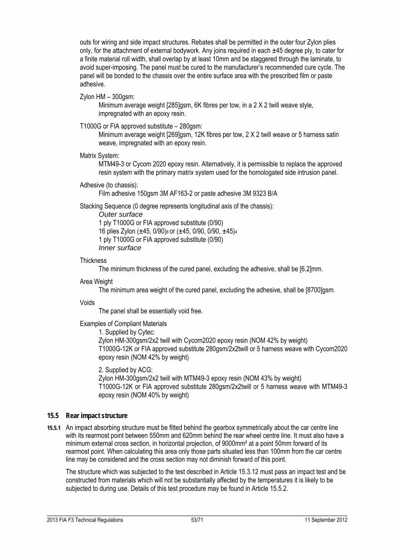
2013 FIA F3 Technical Regulations 53/71 11 September 2012
outs for wiring and side impact structures. Rebates shall be permitted in the outer four Zylon plies only, for the attachment of external bodywork. Any joins required in each ±45 degree ply, to cater for a finite material roll width, shall overlap by at least 10mm and be staggered through the laminate, to avoid super-imposing. The panel must be cured to the manufacturer’s recommended cure cycle. The panel will be bonded to the chassis over the entire surface area with the prescribed film or paste adhesive.
Zylon HM – 300gsm: Minimum average weight [285]gsm, 6K fibres per tow, in a 2 X 2 twill weave style,
impregnated with an epoxy resin.
T1000G or FIA approved substitute – 280gsm: Minimum average weight [269]gsm, 12K fibres per tow, 2 X 2 twill weave or 5 harness satin
weave, impregnated with an epoxy resin.
Matrix System: MTM49-3 or Cycom 2020 epoxy resin. Alternatively, it is permissible to replace the approved
resin system with the primary matrix system used for the homologated side intrusion panel.
Adhesive (to chassis): Film adhesive 150gsm 3M AF163-2 or paste adhesive 3M 9323 B/A
Stacking Sequence (0 degree represents longitudinal axis of the chassis): Outer surface 1 ply T1000G or FIA approved substitute (0/90) 16 plies Zylon (±45, 0/90)8 or (±45, 0/90, 0/90, ±45)4
1 ply T1000G or FIA approved substitute (0/90) Inner surface
Thickness The minimum thickness of the cured panel, excluding the adhesive, shall be [6.2]mm.
Area Weight The minimum area weight of the cured panel, excluding the adhesive, shall be [8700]gsm.
Voids The panel shall be essentially void free.
Examples of Compliant Materials 1. Supplied by Cytec: Zylon HM-300gsm/2x2 twill with Cycom2020 epoxy resin (NOM 42% by weight) T1000G-12K or FIA approved substitute 280gsm/2x2twill or 5 harness weave with Cycom2020 epoxy resin (NOM 42% by weight)
2. Supplied by ACG: Zylon HM-300gsm/2x2 twill with MTM49-3 epoxy resin (NOM 43% by weight) T1000G-12K or FIA approved substitute 280gsm/2x2twill or 5 harness weave with MTM49-3 epoxy resin (NOM 40% by weight)
15.5 Rear impact structure
15.5.1 An impact absorbing structure must be fitted behind the gearbox symmetrically about the car centre line with its rearmost point between 550mm and 620mm behind the rear wheel centre line. It must also have a minimum external cross section, in horizontal projection, of 9000mm² at a point 50mm forward of its rearmost point. When calculating this area only those parts situated less than 100mm from the car centre line may be considered and the cross section may not diminish forward of this point.
The structure which was subjected to the test described in Article 15.3.12 must pass an impact test and be constructed from materials which will not be substantially affected by the temperatures it is likely to be subjected to during use. Details of this test procedure may be found in Article 15.5.2.
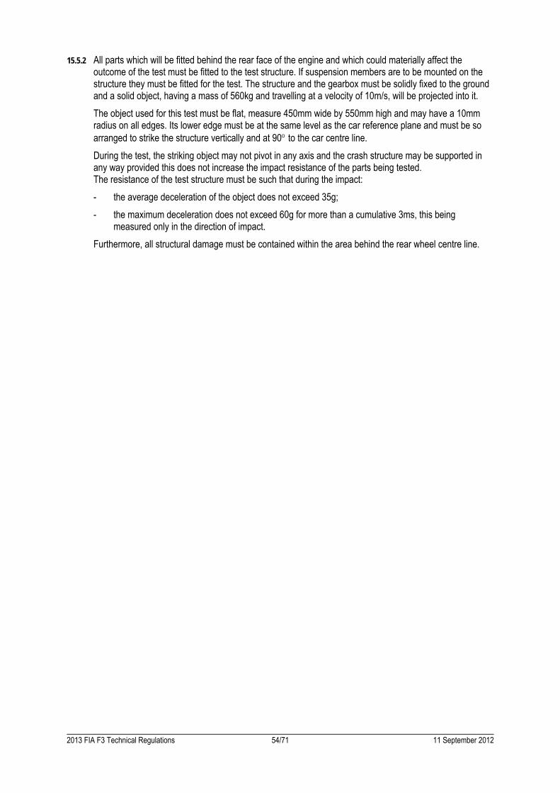
2013 FIA F3 Technical Regulations 54/71 11 September 2012
15.5.2 All parts which will be fitted behind the rear face of the engine and which could materially affect the outcome of the test must be fitted to the test structure. If suspension members are to be mounted on the structure they must be fitted for the test. The structure and the gearbox must be solidly fixed to the ground and a solid object, having a mass of 560kg and travelling at a velocity of 10m/s, will be projected into it.
The object used for this test must be flat, measure 450mm wide by 550mm high and may have a 10mm radius on all edges. Its lower edge must be at the same level as the car reference plane and must be so arranged to strike the structure vertically and at 90 to the car centre line.
During the test, the striking object may not pivot in any axis and the crash structure may be supported in any way provided this does not increase the impact resistance of the parts being tested.
The resistance of the test structure must be such that during the impact:
- the average deceleration of the object does not exceed 35g;
- the maximum deceleration does not exceed 60g for more than a cumulative 3ms, this being measured only in the direction of impact.
Furthermore, all structural damage must be contained within the area behind the rear wheel centre line.

2013 FIA F3 Technical Regulations 55/71 11 September 2012
ARTICLE 16: FUEL
16.1 Fuel:
The fuel must be commercial petrol which is available from service stations and must contain no additive other than that of a lubricant on current sale.
The fuel must have the following characteristics:
- 102RON/90MON maximum; 95RON/85MON minimum for unleaded fuels and 100RON/92MON maximum; 97RON/86MON minimum for leaded fuels, the measurements being made according to the standards ASTMD2699-86 and D2700-86, the fuel being accepted or rejected according to ASTMD3244 with a confidence limit of 95%.
- Specific gravity between 720 and 785kg/m³ at 15°C (measured according to ASTMD4052).
- A maximum of 2.8% oxygen for leaded fuel or 3.7% if the lead content is less than 0.013g/l, and 0.5% nitrogen by weight, the remainder of the fuel consisting exclusively of hydrocarbons and not containing any power boosting additives.
The measurement of the nitrogen content will be carried out according to the standard ASTMD3228, and that of the oxygen by elemental analysis with a tolerance of 0.2%.
- Maximum content of peroxides and nitrooxide compounds: 100ppm (ASTMD3703).
- Maximum lead content: 0.40g/l or the standard of the country of the event, if this is lower (ASTMD3341 or D3237).
- Maximum benzene content: 5% in vol. (ASTMD3606)
- Maximum Reid vapour pressure: 900hPa (ASTMD323)
- Distillation at 70°C: 10% - 47% (ASTMD86)
- Distillation at 100°C: 30% - 70% (ASTMD86)
- Distillation at 180°C: 85% min (ASTMD86)
- Maximum final boiling point: 225°C (ASTMD86)
- Maximum residue: 2% volume (ASTMD86)
16.2 Air:
Only air may be mixed with the fuel as an oxidant

2013 FIA F3 Technical Regulations 56/71 11 September 2012
ARTICLE 17: FINAL TEXT
The final text for these regulations shall be the English version which will be used should any dispute arise over their interpretation.
Headings and typeface in this document are for ease of reference only and do not form part of these Technical Regulations.

2013 FIA F3 Technical Regulations 57/71 11 September 2012
ARTICLE 18: CHANGES FOR 2014
18.1 ARTICLE 5: ENGINE
The following additions and changes only apply to engine manufacturers who announce, after the 31 March 2012, their intention to homologate an engine.
5.2.2 Component dimensions and design
A) Cranktrain
A.2 The crankshaft rear flange must use conventional bolts and nuts located at a minimum pitch diameter of 55 mm.
B) Valve train
Angle between intake valves and a plane normal to the head plane 17.0 +/-1.0° (Angle A, Drawing 5.10)
Angle between exhaust valves and a plane normal to the head plane 18.0 +/-1.0° (Angle B, Drawing 5.10)
B.1 Valves may only be actuated by finger followers.
B.2 Camshafts must be driven by gears; the number of gears is free. The camshaft drive train may be integrated at either end of the engine block, but not between the liners. Gear width for gear driven camshafts and auxiliaries ≥ 8 mm
C) Intake system
C.3 Only circular butterfly throttles with a diameter of 50.0 mm +/- 2.0 mm.
The throttle center axis must have a fixed distance from the cylinder fire face of 200 +/- 10mm
(Length D, Drawing 5.10)
The intake duct from the cylinder head connection surface to the airbox flange has to be straight.
C.4 Angle between fuel injector and a plane normal to the head plane 65.0° +/- 1.0°
(Angle C, Drawing 5.10) D) Exhaust system
Exhaust ports must be situated on the right hand side of the engine (Right hand side of the car). F) Lubricating system
Oil pressure and scavenge pump must be conventional external gear pumps. Oil scavenge pumps has to be mounted on the oil sump right hand side (Right hand side of the car).
Only 2 openings for oil jets per cylinder are allowed. The opening for an oil jet must be circular with a diameter “A” and a sharp edge (see Drawing 5.11).
5.9 Clutch and flywheel :
Only clutches that were fitted to 2013 homologated engines may be used.

2013 FIA F3 Technical Regulations 58/71 11 September 2012
Drawing 5.11

2013 FIA F3 Technical Regulations 59/71 11 September 2012
APPENDIX 1

2013 FIA F3 Technical Regulations 60/71 11 September 2012
Points for aerofoil section number 1, all dimensions are in millimetres (see Drawing 3):
1 94.44 -01.37 14 01.22 -00.97 27 08.18 -13.18 40 56.49 -13.87 2 93.90 -00.00 15 00.61 -01.68 28 09.80 -14.02 41 60.76 -12.68 3 91.57 -00.89 16 00.20 -02.54 29 11.81 -14.86 42 65.02 -11.43 4 89.20 -01.78 17 00.00 -03.48 30 14.38 -15.70 43 69.27 -10.11 5 86.84 -02.64 18 00.08 -04.42 31 17.65 -16.53 44 73.48 -08.76 6 84.48 -03.51 19 00.41 -05.28 32 21.51 -17.22 45 77.70 -07.37 7 83.67 -03.73 20 00.84 -06.10 33 25.76 -17.65 46 81.92 -05.94 8 82.86 -03.91 21 01.27 -06.81 34 30.18 -17.78 47 86.11 -04.45 9 82.02 -03.99 22 01.91 -07.62 35 34.62 -17.60 48 90.27 -02.92 10 81.18 -03.99 23 02.97 -08.81 36 39.04 -17.17 49 94.44 -01.37 11 03.84 -00.03 24 04.22 -10.08 37 43.43 -16.56 12 02.90 -00.10 25 05.49 -11.23 38 47.83 -15.80 13 02.01 -00.43 26 06.78 -12.27 39 52.17 -14.91
Points for aerofoil section number 2, all dimensions are in millimetres (see Drawing 4):
1 14.78 -02.90 17 69.72 -00.05 33 145.80 -04.19 49 15.49 -22.56 2 16.66 -02.67 18 74.32 -00.10 34 151.41 -04.47 50 10.01 -19.41 3 18.80 -02.41 19 79.60 -00.20 35 154.10 -04.50 51 05.41 -15.77 4 23.34 -01.93 20 85.24 -00.36 36 155.07 -04.27 52 02.67 -12.90 5 28.12 -01.45 21 90.88 -00.53 37 155.91 -03.78 53 00.53 -09.91 6 32.87 -01.04 22 96.52 -00.76 38 160.99 00.00 54 00.13 -08.94 7 37.34 -00.71 23 102.13 -01.02 39 161.75 -00.94 55 00.03 -07.93 8 40.62 -00.53 24 107.77 -01.32 40 139.24 -15.60 56 00.18 -06.96 9 43.89 -00.36 25 113.41 -01.65 41 114.15 -25.63 57 00.56 -06.20 10 47.17 -00.23 26 119.02 -02.01 42 98.96 -29.16 58 01.25 -05.54 11 50.44 -00.10 27 124.66 -02.41 43 83.67 -30.91 59 02.29 -04.95 12 53.67 -00.05 28 130.28 -02.85 44 72.57 -31.32 60 04.01 -04.45 13 56.79 00.00 29 135.89 -03.33 45 61.44 -31.27 61 06.78 -03.94 14 59.79 00.00 30 138.58 -03.56 46 50.34 -30.71 62 10.44 -03.43 15 62.66 00.00 31 140.97 -03.79 47 39.27 -29.67 63 14.78 -02.90 16 65.84 00.00 32 143.53 -04.01 48 27.15 -27.18
Points for aerofoil section number 3, all dimensions are in millimetres (see Drawing 5):
1 163.07 00.00 21 59.33 -40.21 41 01.91 -17.91 61 113.59 -01.70 2 164.08 -01.19 22 53.95 -40.11 42 03.45 -16.76 62 120.07 -02.33 3 160.86 -03.91 23 48.67 -39.85 43 06.86 -15.04 63 126.34 -03.02 4 157.66 -06.63 24 43.43 -39.45 44 10.31 -13.39 64 132.59 -03.78 5 154.56 -09.14 25 38.20 -38.81 45 15.32 -11.20 65 137.90 -04.47 6 151.54 -11.46 26 33.00 -37.95 46 20.42 -09.22 66 143.20 -05.18 7 147.47 -14.30 27 27.53 -36.78 47 24.00 -07.95 67 147.47 -05.77 8 143.26 -16.99 28 22.17 -35.38 48 27.58 -06.81 68 151.77 -06.38 9 138.86 -19.56 29 17.32 -33.86 49 33.35 -05.18 69 151.94 -06.40 10 134.26 -22.02 30 12.55 -32.16 50 39.14 -03.73 70 152.12 -06.42 11 128.27 -24.94 31 09.50 -30.96 51 46.86 -02.21 71 153.01 -06.50 12 122.10 -27.69 32 06.55 -29.69 52 54.64 -01.12 72 153.90 -06.43 13 116.76 -29.79 33 05.08 -29.03 53 60.71 -00.53 73 154.76 -06.25 14 111.38 -31.70 34 03.71 -28.40 54 66.80 -00.20 74 155.60 -05.94 15 103.48 -34.11 35 02.34 -27.51 55 73.18 -00.03 75 156.39 -05.51 16 95.48 -36.22 36 01.22 -26.29 56 79.55 00.00 76 157.12 -05.00 17 87.17 -37.92 37 00.43 -24.82 57 86.31 -00.10 77 163.07 00.00 18 78.77 -39.12 38 00.05 -23.22 58 93.09 -00.33 19 71.75 -39.78 39 00.13 -21.29 59 100.10 -00.66 20 64.72 -40.13 40 00.76 -19.48 60 107.16 -01.14

2013 FIA F3 Technical Regulations 61/71 11 September 2012
Drawing 1

2013 FIA F3 Technical Regulations 62/71 11 September 2012
Drawing 2
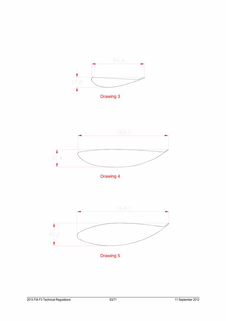
2013 FIA F3 Technical Regulations 63/71 11 September 2012
Drawing 4
Drawing 5
Drawing 3

2013 FIA F3 Technical Regulations 64/71 11 September 2012

2013 FIA F3 Technical Regulations 65/71 11 September 2012
APPENDIX 2

2013 FIA F3 Technical Regulations 66/71 11 September 2012
Approval of Safety Structures for Formula 3 cars 1) Safety structures
The following safety structures need to be approved by the FIA:
- Survival cell
- Front and rear rollover structures
- Frontal impact absorbing structure
- Rear impact absorbing structure
To approve any of the above structures, the presence of an FIA technical delegate is necessary. The static load tests need to be carried out with a measuring equipment verified by the FIA; the dynamic impact tests need to be carried out at an FIA approved institute. 2) Request for approval
To get the approval of one of the above mentioned safety structures, the FIA must receive a request from the rolling chassis manufacturer at the following address beforehand:
FIA Technical Centre Cox Lane Chessington Surrey KT9 1TW United Kingdom
Tel : +44 (0)20 8391 7900 Fax: +44 (0)20 8391 8938
3) Approval procedure
Having received a request for any of the above mentioned tests, the FIA will arrange a date and venue with the rolling chassis manufacturer and will appoint a technical delegate to supervise these scheduled tests.
For each trip made by an FIA technical delegate to supervise any scheduled tests, the manufacturer will be charged a fee, which is annually levied by the FIA (2220€ for 2013).
When all the safety structure tests are carried out successfully and the manufacturer has settled the FIA fee, he will receive the FIA chassis test report for his car.
The rolling chassis manufacturer is obliged to supply all his customers with a copy of the FIA chassis test report together with the survival cell.

2013 FIA F3 Technical Regulations 67/71 11 September 2012
APPENDIX 3

2013 FIA F3 Technical Regulations 68/71 11 September 2012
Costs to be included in 50,000 € annual engine budget: - 1x engine + engine loom + sensors (mounted on engine / intake system); - flywheel; - lease period for one season including tests (max. 1 year); - 10,000 km mileage; - end of season rebuild (if mileage ≤ 10‘000 km); - ontrack service for national championship events (within the country where engine manufacturer / tuner
is based). Costs to be excluded from the 50,000 € annual engine budget: - ECU; - alternator; - starter motor; - exhaust system including silencer / catalytic converter; - clutch system; - water and oil pipe kit; - water and oil radiators; - airbox/intake cover; - spare engine; - ontrack service for international race events / championships outside the country where the engine
manufacturer / tuner is based; - ontrack service for private and unofficial testing sessions; - engine failures due to team or driver mistake (overreving, wrong maintenance etc.); - transport costs from engine tuner / manufacuter’s facilities to Team’s base or racetrack; - damage or loss of engine during lease contract period when engine leaves engine tuner / manufacuter’s
facilities; - rebuild costs if mileage is more than 10,000 km during lease period; - travel expenses for engine tuner / manufacuter’s employees during International race events /
championships.

2013 FIA F3 Technical Regulations 69/71 11 September 2012
APPENDIX 4

2013 FIA F3 Technical Regulations 70/71 11 September 2012
All parts or drawings must be supplied in a "ready to use state". For example, crankcase is to be shown with liners and all inserts.
Categories Parts Request for homologation
Engine Core
Sump / Bedplate 2D Drawings + CAD
Crankcase 2D Drawings + CAD
Cylinder Head 2D Drawings + CAD
Cam cover 2D Drawings + CAD
Camshaft drive cover 2D Drawings + CAD
Crankshaft bearing cap 2D Drawings + CAD
Camshaft bearing cap 2D Drawings + CAD
Cylinder Head gasket Actual part + 2D Drawings + CAD
Ballast mounted to the engine Actual part + 2D Drawings + CAD
Screws, nuts, dowels or washers, supports, brackets, cables, tube and hoses related to the parts mentioned above.
Actual parts (1 of each type) + 2D Drawings
Inlet
Complete inlet from restrictor to cylinder head inlet ports 2D Drawings + CAD
Inlet valves Actual part (x1) + 2D Drawings + CAD
Screws, nuts, dowels or washers, supports, brackets, cables, tube and hoses related to the parts mentioned above.
Actual parts (1 of each type) + 2D Drawings
Exhaust
Exhaust valves Actual part (x1) + 2D Drawings + CAD
Exhaust line Actual part + 2D Drawings + CAD
Silencer Actual part + 2D Drawings + CAD
Catalytic converter Actual part + 2D Drawings + CAD
Screws, nuts, dowels or washers, supports, brackets, cables, tube and hoses related to the parts mentioned above.
Actual parts (1 of each type) + 2D Drawings
Timing
Camshaft drive elements from Crankshaft to Camshafts Actual parts + 2D Drawings + CAD
Camshafts Actual parts + 2D Drawings + CAD
Valve command from cam to valve including springs Actual parts + 2D Drawings + CAD
Screws, nuts, dowels or washers, supports, brackets, cables, tube and hoses related to the parts mentioned above.
Actual parts (1 of each type) + 2D Drawings
Lubrication
Oil pressure pump 2D Drawings + CAD
Oil scavenge pumps 2D Drawings + CAD
Oil lines from oil supply to oil scavenge pumps 2D Drawings + CAD
Oil filter Actual part + 2D Drawings + CAD
Oil air separator 2D Drawings + CAD
Oil tank 2D Drawings + CAD
Catch tank 2D Drawings + CAD
Screws, nuts, dowels or washers, supports, brackets, cables, tube and hoses related to the parts mentioned above.
Actual parts (1 of each type) + 2D Drawings
Cooling
Coolant pumps 2D Drawings + CAD
Coolant lines from engine inlet to engine outlet 2D Drawings + CAD
Screws, nuts, dowels or washers, supports, brackets, cables, tube and hoses related to the parts mentioned above.
Actual parts (1 of each type) + 2D Drawings
Electric and Electronic parts
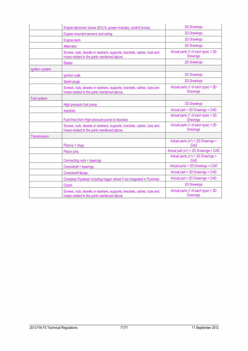
2013 FIA F3 Technical Regulations 71/71 11 September 2012
Engine electronic boxes (ECU's, power modules, control boxes). 2D Drawings
Engine mounted sensors and wiring 2D Drawings
Engine loom 2D Drawings
Alternator 2D Drawings
Screws, nuts, dowels or washers, supports, brackets, cables, tube and hoses related to the parts mentioned above.
Actual parts (1 of each type) + 2D Drawings
Starter 2D Drawings
Ignition system
Ignition coils 2D Drawings
Spark plugs 2D Drawings
Screws, nuts, dowels or washers, supports, brackets, cables, tube and hoses related to the parts mentioned above.
Actual parts (1 of each type) + 2D Drawings
Fuel system
High pressure fuel pump 2D Drawings
Injectors Actual part + 2D Drawings + CAD
Fuel lines from High pressure pump to injectors Actual parts (1 of each type) + 2D
Drawings
Screws, nuts, dowels or washers, supports, brackets, cables, tube and hoses related to the parts mentioned above.
Actual parts (1 of each type) + 2D Drawings
Transmission
Pistons + rings Actual parts (x1) + 2D Drawings +
CAD
Piston pins Actual part (x1) + 2D Drawings + CAD
Connecting rods + bearings Actual parts (x1) + 2D Drawings +
CAD
Crankshaft + bearings Actual parts + 2D Drawings + CAD
Crankshaft flange Actual part + 2D Drawings + CAD
Complete Flywheel including trigger wheel if not integrated in Flywheel Actual part + 2D Drawings + CAD
Clutch 2D Drawings
Screws, nuts, dowels or washers, supports, brackets, cables, tube and hoses related to the parts mentioned above.
Actual parts (1 of each type) + 2D Drawings