2014 versa note; mil on with dtc p059f stored · 2014 versa note; mil on with dtc p059f stored ....
TRANSCRIPT

1/15
Classification: Reference: D ate:
EC14-002 NTB14-009 February 14, 2014
2014 VERSA NOTE; MIL ON WITH DTC P059F STORED
APPLIED VEHICLE: 2014 Versa NOTE (E12)
APPLIED VIN and DATE:
Vehic les built before 3N1CE2CP(*)E(*) 407011 and January 3, 2014
IF YOU CONFIRM:
The MIL is ON with DTC P059F (ACTIVE GRILLE AIR SHUTTER A) stored in the ECM. ACTION:
1. Compare the vehicle’s current ECM part number to those listed in Table A (see page 4).
2. If the ECM part number matches one listed in Table A, reprogram the ECM.
3. Remove the front bumper fascia.
• Remove any debris from the active grille shutter (shutter). 4. Check the shutter’s installation for binding.
5. If found binding, adjust the shutter.
6. Calibrate the shutter with CONSULT-III plus (C-III plus).
IMPORTANT: The purpose of ACTION (above) is to give you a quick idea of the work you will be performing. You MUST closely follow the entire SERVICE PROCEDURE as it contains information that is essential to successfully completing this repair.
Nissan Bulletins are intended for use by qualified technicians, not 'do-it-yourselfers'. Qualified technicians are properly trained individuals who have the equipment, tools, safety instruction, and know-how to do a job properly and safely. NOTE: If you believe that a described condition may apply to a particular vehicle, DO NOT assume that it does. See your Nissan dealer to determine if this applies to your vehicle.
SB-10054917-1859

SERVICE PROCEDURE
ECM Part Number Check / Reprogramming
NOTE:
• Most instructions for reprogramming with CONSULT-III plus (C-III plus) are displayed on the CONSULT PC screen.
• If you are not familiar with the reprogramming procedure, click here. This will link
you to the "CONSULT-III plus (C-III plus) Reprogramming" general procedure.
• Take the vehicle for a 10 minute drive in order to meet the following Idle Air Volume Learn (IAVL) conditions:
Engine coolant temperature: 70 -100°C (158 - 212°F)
Battery voltage: More than 12.9V (At idle)
Transmission: Warmed up
Figure A
• After reprogramming is complete, you will be required to perform Throttle Valve Closed Position, Idle Air Volume Learn, Accelerator Closed Position, and DTC erase.
CAUTION:
• Connect the GR8 to the vehicle 12 volt battery and set to ECM power supply mode. If the vehicle battery voltage drops below 12.0V or rises above 13.5V during reprogramming, the ECM may be damaged.
• Be sure to turn OFF all vehicle electrical loads.
If a vehicle electrical load remains ON, the ECM may be damaged.
• Be sure to connect the AC Adapter. If the CONSULT PC battery voltage drops during reprogramming, the process will be interrupted and the ECM may be damaged.
• Turn off all external Bluetooth® devices (e.g., cell phones, printers, etc.) within
range of the CONSULT PC and the VI. If Bluetooth® signal waves are within range of the CONSULT PC during reprogramming, reprogramming may be interrupted and the ECM may be damaged.
2/15 NTB14-009

1. Connect the CONSULT PC to the vehicle to begin the reprogramming procedure.
2. Open C-III plus.
3. Wait for the plus VI to be recognized.
• Serial number will display when the plus VI is recognized. 4. Select Re/programming, Configuration.
plus VI is recognized
Step 4
Figure 1 5. Follow the on-screen instructions and navigate the C-III plus to the screen shown in
Figure 2 on the next page.
3/15 NTB14-009

6. When you get to the screen shown in Figure 2, confirm this bulletin applies as follows.
A. Find the ECM Part Number and write it on the repair order.
NOTE: This is the current ECM Part Number (P/N).
xxxxxxxxxxxxxx
6A: Current ECM P/N
xxxx
xxxxxxxxxxxxxx
xxxxxxxxxxxxxx
Figure 2
B. Compare the P/N you wrote down to the numbers in the Current ECM Part Number column in Table A below.
• If there is a match, the ECM needs to be reprogrammed. Continue with the reprogramming procedure.
• If there is not a match, ECM reprogramming does not apply. Go to Active Grille Shutter Inspection on page 10.
Table A
CURRENT ECM PART NUMBER: 23710-
3VB5B, 3VB5C, 3VB5D
4/15 NTB14-009
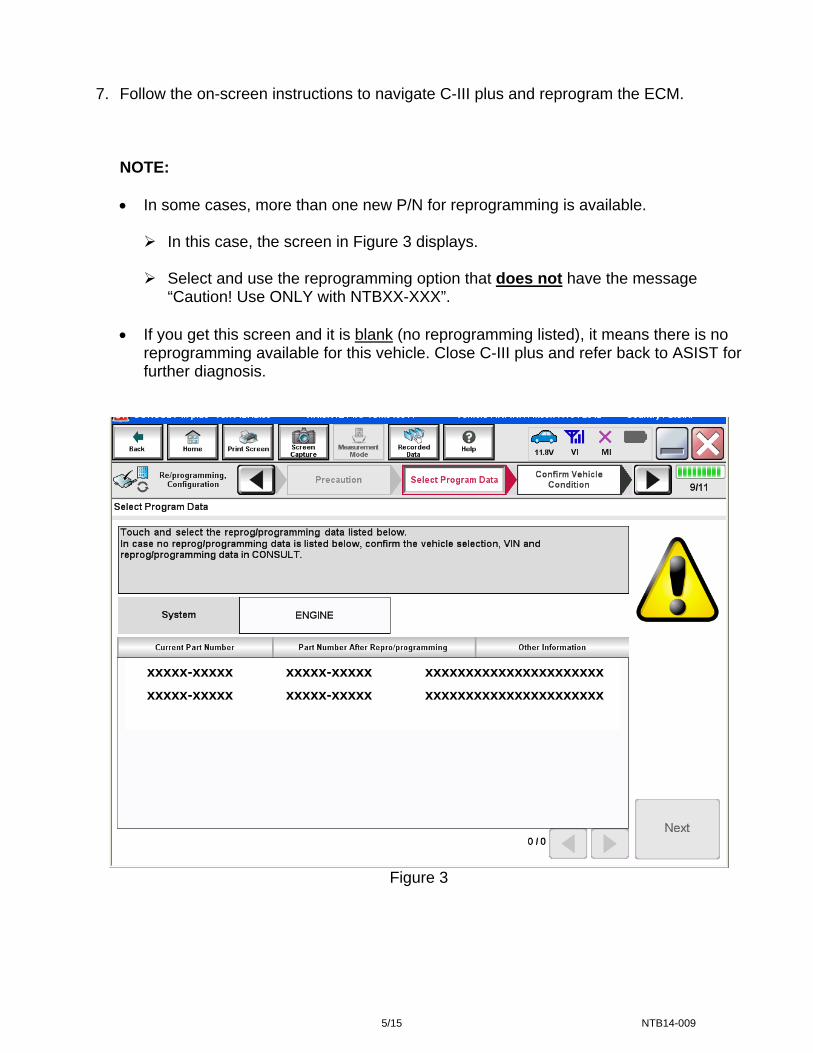
7. Follow the on-screen instructions to navigate C-III plus and reprogram the ECM.
NOTE:
• In some cases, more than one new P/N for reprogramming is available.
In this case, the screen in Figure 3 displays.
Select and use the reprogramming option that does not have the message “Caution! Use ONLY with NTBXX-XXX”.
• If you get this screen and it is blank (no reprogramming listed), it means there is no
reprogramming available for this vehicle. Close C-III plus and refer back to ASIST for further diagnosis.
xxxxx-xxxxx xxxxx-xxxxx xxxxxxxxxxxxxxxxxxxxxx
xxxxx-xxxxx xxxxx-xxxxx xxxxxxxxxxxxxxxxxxxxxx
Figure 3
5/15 NTB14-009

8. When the screen in Figure 4 displays, reprogramming is complete.
NOTE: If the screen in Figure 4 does not display (reprogramming does not complete), refer to the information on the next page.
9. Disconnect the battery charger from the vehicle. 10. Select Next.
Step 10
Figure 4
NOTE:
• In the next steps (page 8), you will perform Throttle Valve Closed Position, Idle Air Volume Learn, Accelerator Closed Position, and DTC erase.
• These operations are required before C-III plus will provide the final reprogramming
confirmation report.
6/15 NTB14-009

ECM Recovery
Do not disconnect plus VI or shut down C-III plus if reprogramming does not complete.
If reprogramming does not complete and the “!?” icon displays as shown in Figure 5:
Figure 5
If reprogramming does not complete and the “X” icon displays as shown in Figure 6:
Figure 6
• Check battery voltage (12.0–15.5 V).
• Ignition is ON, engine OFF.
• External Bluetooth® devices
are OFF.
• All electrical loads are OFF.
• Select retry and follow the on screen instructions.
• “Retry” may not go through
on first attempt and can be selected more than once.
• Check battery voltage (12.0 – 15.5 V).
• CONSULT A/C adapter is
plugged in.
• Ignition is ON, engine OFF.
• Transmission is in Park.
• All C-III plus / VI cables are securely connected.
• All C-III plus updates are
installed.
• Select Home, and restart the reprogram procedure from the beginning.
7/15 NTB14-009

11. Follow the on-screen instructions to perform the following:
• Throttle Valve Closed Position
• Idle Air Volume Learn (IAVL)
NOTE:
o Listed below are common conditions required for IAVL to complete.
o If IAVL does not complete within a few minutes, a condition may be out of range.
o Refer to the appropriate Electronic Service Manual (ESM) for specific
conditions required for the vehicle you are working on.
Engine coolant temperature: 70 -100° C (158 - 212°F) Battery voltage: More than 12.9V (At idle) Selector lever: P or N Electric load switch: OFF (Air conditioner, headlamp, rear window defogger) Steering wheel: Neutral (Straight-ahead position) Vehicle speed: Stopped Transmission: Warmed up
• Accelerator Pedal Close Position Learning
• Erase DTCs
Continue to the next page.
8/15 NTB14-009
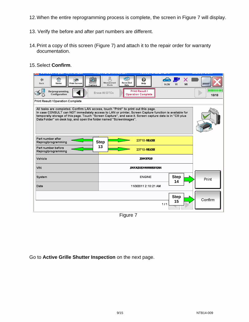
12. When the entire reprogramming process is complete, the screen in Figure 7 will display.
13. Verify the before and after part numbers are different.
14. Print a copy of this screen (Figure 7) and attach it to the repair order for warranty documentation.
15. Select Confirm.
Step 13
xxxxx
xxxxx
xxxxxxx
xxxxxxxxxxxxxxxxx
Step 14
Step 15
Figure 7
Go to Active Grille Shutter Inspection on the next page.
9/15 NTB14-009
Active Grille Shutter Inspection
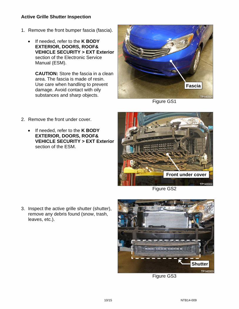
1. Remove the front bumper fascia (fascia).
• If needed, refer to the K BODY EXTERIOR, DOORS, ROOF& VEHICLE SECURITY > EXT Exteriorsection of the Electronic Service Manual (ESM).
CAUTION: Store the fascia in a clean area. The fascia is made of resin. Use care when handling to prevent damage. Avoid contact with oily substances and sharp objects.
2. Remove the front under cover.
• If needed, refer to the K BODY EXTERIOR, DOORS, ROOF& VEHICLE SECURITY > EXT Exteriorsection of the ESM.
3. Inspect the active grille shutter (shutter), remove any debris found (snow, trash, leaves, etc.).
Fascia
Figure GS1
Front under cover
Figure GS2
Shutter
Figure GS3
10/15 NTB14-009

4. Inspect the shutter’s installation for binding as follows:
a. Remove the two (2) bolts, one at each side (see Figure GS4 and GS5).
LH BoltRH Bolt
Figure GS4 Figure GS5
11/15 NTB14-009

b. Lift and hold up the shutter (from the bottom center) to its normally installed location.
NOTE:
• Do not use excessive force. The intent is to locate the shutter back to its original position without distorting or binding.
• The shutter’s bolt holes may be found enlarged. This is normal.
c. If the bolts cannot be reinstalled easily (the bolt holes interfere - see Figure GS6 below), go to Active Grille Shutter Adjustment on the next page.
d. If the bolts can be reinstalled easily (see Figure GS7):
aa. Reinstall the shutter bolts.
Shutter bolts torque: 5.5 N•m (0.56 kg-m, 48.7 in lbs)
bb. Verify proper operation by calibrating the shutter with C-III plus.
Refer to DTC P059F in the B ENGINE > EC Engine Control System section of the ESM.
cc. If shutter calibration completes, the shutter is properly adjusted and working normally.
dd. Reinstall the front under cover and fascia.
For front under cover and fascia reinstallation, refer to the K BODY EXTERIOR, DOORS, ROOF& VEHICLE SECURITY > EXT Exterior section of the ESM if needed.
ee. Close C-III plus.
ff. Turn the ignition OFF.
gg. Disconnect the plus VI from the vehicle.
hh. Make sure the vehicle operates correctly and the MIL is OFF.
If the MIL comes ON, go back to ASIST for further diagnostic information.
Diagnosis and repairs beyond ECM reprogramming and shutter inspection are not covered by this bulletin.
NG OK
Figure GS6 Figure GS7
12/15 NTB14-009
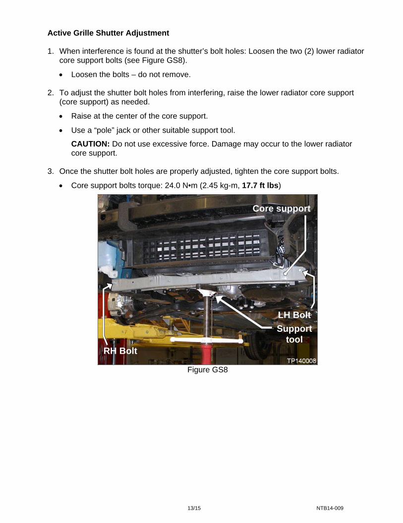
Active Grille Shutter Adjustment
1. When interference is found at the shutter’s bolt holes: Loosen the two (2) lower radiator core support bolts (see Figure GS8).
• Loosen the bolts – do not remove. 2. To adjust the shutter bolt holes from interfering, raise the lower radiator core support
(core support) as needed.
• Raise at the center of the core support.
• Use a “pole” jack or other suitable support tool.
CAUTION: Do not use excessive force. Damage may occur to the lower radiator core support.
3. Once the shutter bolt holes are properly adjusted, tighten the core support bolts.
• Core support bolts torque: 24.0 N•m (2.45 kg-m, 17.7 ft lbs)
Core support
LH Bolt
Support tool
RH Bolt
Figure GS8
13/15 NTB14-009

4. Remove the support tool, verify there is still no interference at the shutter bolt holes. 5. Install the shutter bolts.
• Shutter bolts torque: 5.5 N•m (0.56 kg-m, 48.7 in lbs)
6. Reinstall the front under cover and fascia.
• If needed, refer to the K BODY EXTERIOR, DOORS, ROOF& VEHICLE SECURITY > EXT Exterior section of the ESM.
7. Calibrate the shutter. • Refer to DTC P059F in the B ENGINE > EC Engine Control System section of the
ESM.
• If shutter calibration completes, the shutter is properly adjusted and working normally.
8. Close C-III plus. 9. Turn the ignition OFF. 10. Disconnect the plus VI from the vehicle.
11. Make sure the vehicle operates correctly and the MIL is OFF.
• If the MIL comes ON, go back to ASIST for further diagnostic information.
• Diagnosis and repairs beyond ECM reprogramming and shutter adjustment are not covered by this bulletin.
14/15 NTB14-009

CLAIMS INFORMATION
Submit a Primary Part (PP) type line claim using the following claims coding:
DESCRIPTION PFP OP CODE SYM DIA FRT Reprogram ECM and Adjust Grille Shutter (1) CX19AA HD 32 1.6
(1) Refer to the electronic parts catalog (FAST) and use the air intake guides part number (21421-xxxxx) as the Primary Failed Part (PFP).
OR Submit a Primary Part (PP) type line claim using the following claims coding:
DESCRIPTION PFP OP CODE SYM DIA FRT Reprogram ECM and
Inspect Grille Shutter Only (1) CX20AA HD 32 1.6
(1) Refer to the electronic parts catalog (FAST) and use the air intake guides part number (21421-xxxxx) as the Primary Failed Part (PFP).
OR Submit a Primary Part (PP) type line claim using the following claims coding:
DESCRIPTION PFP OP CODE SYM DIA FRT Check ECM P/N (no reprogram) and
Adjust Grille Shutter (1) CX21AA HD 32 1.0
(1) Refer to the electronic parts catalog (FAST) and use the air intake guides part number (21421-xxxxx) as the Primary Failed Part (PFP).
OR Submit a Primary Part (PP) type line claim using the following claims coding:
DESCRIPTION PFP OP CODE SYM DIA FRT Check ECM P/N (no reprogram) and
Inspect Grille Shutter Only (1) CX22AA HD 32 1.0
(1) Refer to the electronic parts catalog (FAST) and use the air intake guides part number (21421-xxxxx) as the Primary Failed Part (PFP).
15/15 NTB14-009