2015/10/11 a novel rotor configuration and experimental verification of interior pm synchronous...
TRANSCRIPT

112/04/19
A Novel Rotor Configuration and Experimental Verification of Interior PM
Synchronous Motor for High-Speed ApplicationsIEEE TRANSACTIONS ON MAGNETICS, VOL. 48, NO. 2, FEBRUARY 2012
By Sung-Il Kim, Young-Kyoun Kim, Geun-Ho Lee,and Jung-Pyo Hong

Outline Abstract
Introduction
Rotor Design Of High-Speed IPMSM Initial Rotor Shape
Initial Rotor Shape
Experimental Design
Rotor-Shape Optimization
Test Results And Discussion
Conclusion
References
112/04/19 2

Abstract
On account of high efficiency and high power density, permanent-magnet
synchronous motors (PMSMs) are mainly applied to a high-speed
machine. Especially, because of relatively easy magnetic circuit design and
control. However, the surface-mounted PMSM has some weak points due
to a sleeve, which is nonmagnetic steel used in order to maintain the
mechanical integrity of a rotor assembly in high-speed rotation. 112/04/19 3

Introduction
The IPMSM does not essentially need the sleeve, because permanent magnet is inserted inside the rotor. Moreover, the IPMSM has higher power density than the surface-mounted PMSM, because it can use a magnetic and a reluctance torque with proper current vector control.
Thus, the two-pole IPMSM considering electrical and mechanical characteristics is designed and fabricated as the driving motor of a 8-kW, 40000 r/min class air blower. In the end, the superiority and reliability of the IPMSM in high-speed operation is verified by the results obtained by test.
112/04/19 4

Rotor Design Of High-Speed IPMSM
Fig. 2 displays the manufactured stator with three-phase coils, and it is applied to the surface-mounted PMSM and IPMSM. Also, the main design specifications given in Table I are qually applied for them.
112/04/19 5
Fig. 2 Manufactured stator with three-phase coils. (a) Top view. (b) Side view.

112/04/19 6

Initial Rotor Shape
Fig. 3 shows a variety of rotor configurations of the IPMSM with two poles. The diameter of the rotor and shaft is the same.
112/04/19 7

112/04/19 8
Partial rotor configurations according to design factor variation. (a) Accordingto the number of magnet layers. (b) According to the number of bridgesin the second layer. c) According to pole angle.
Experimental Design

In this paper, the analysis of variance (ANOVA) , one of the statistical analysis methods, is utilized to identify the design factors that have the greatest influence on the characteristics of the IPMSM.
112/04/19Robot and Servo Drive Lab. 9

112/04/19 10

112/04/19 11
FEA results
Y131
Y132
Y133
Y211
Y212
Y213
Y221
Y222
Y223
Y231
Y232
Y233
Y311
Y312
Y313
Y321
Y322
Y323
Y331
Y332
Y333

As the pole angle grows, the average torque and back-electromotive force (emf) also increased, but the saliency and maximum stress are reduced.
Average torque is more affected by back-emf than by saliency.
When the number of bridges is three in the second layer of the permanent magnet, the average torque and back-emf are largest.
As the number of magnet layers increases, saliency is generally increased, but the average torque and back-emf tend to decrease.
112/04/19Robot and Servo Drive Lab. 12

Rotor-Shape Optimization
The aim of the rotor optimization is to secure electrical performance and mechanical strength. In addition, the amount of PM should be minimized. Accordingly, as shown in Fig, the design parameters based on the results of the experimental design are chosen for the optimization.
112/04/19 13
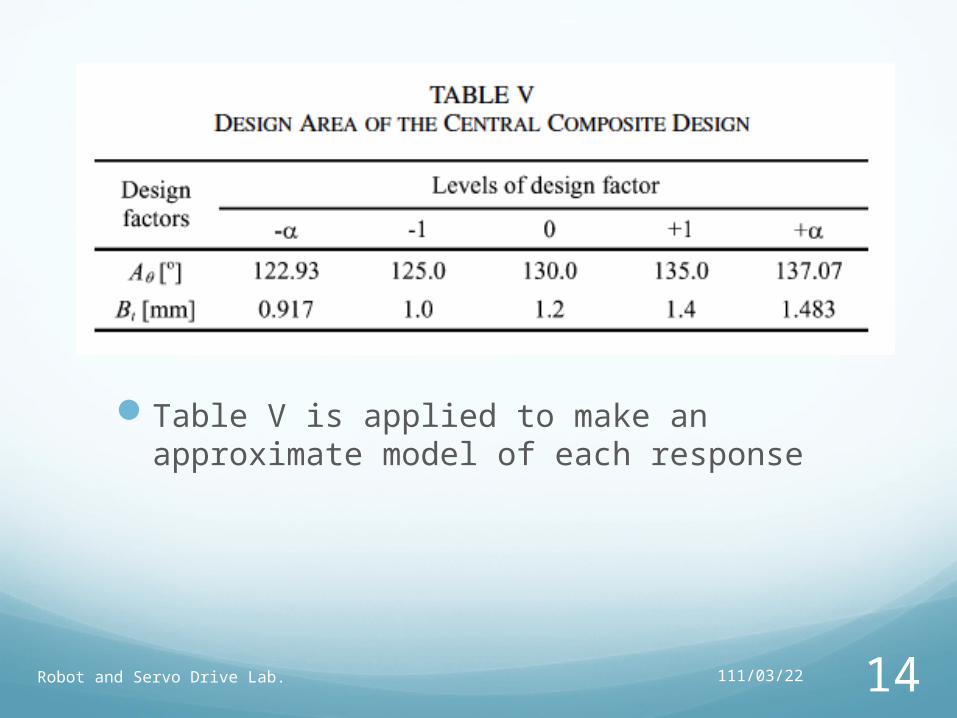
112/04/19Robot and Servo Drive Lab. 14
Table V is applied to make an approximate model of each response

112/04/19Robot and Servo Drive Lab. 15
Which is a set of statistical and mathematical techniques used to find the best fitting response of the physical system through experiment or simulation, is used as an optimization method.
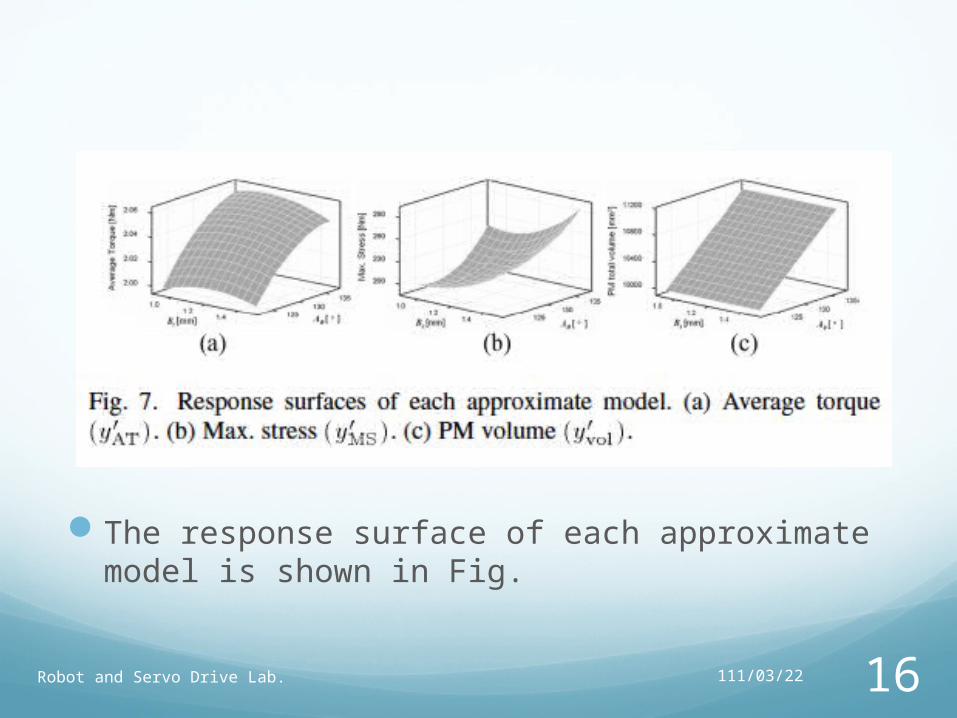
The response surface of each approximate model is shown in Fig.
112/04/19Robot and Servo Drive Lab. 16

The final results of the optimization are given in Table VI, and the accuracy of the models is verified through the table.
112/04/19Robot and Servo Drive Lab. 17

Test Results And Discussion
The fabricated IPMSM are exhibited in Fig. 4. In order to verify the performance of the IPMSM, tests are carried out as shown in Fig. 5.
112/04/19 18
Fig. 4 Configurations of fabricated IPMSM. (a) Rotor. (b) Rotor assembly. (c) Air blower.
Fig. 5. Testing apparatus for air-blower system test.

Test results of the air-blower system. (a) Input current. (b) System efficiency. (c) Air-blower efficiency.
112/04/19Robot and Servo Drive Lab. 19

112/04/19 20
Losses obtained by characteristics analysis. (a) At 10 000 r/min (top) and 30 000 r/min (bottom). (b) At 20 000 r/min (top) and 40 000 r/min (bottom).

The efficiency of the IPMSM is high due to a relatively small core loss before 25 000 r/min. After the speed, as the load rises, the influence of copper loss is dominant due to an increase of input current. At this time, the mechanical loss of the SPMSM and IPMSM is not considered, because their rotor sizes are the same.
112/04/19Robot and Servo Drive Lab. 21

Conclusion
Even though current vector control is required to obtain maximum torque, the overall efficiency measured in the IPMSM is better than that of the SPMSM. In addition, the amount of permanent magnet actually used in the IPMSM is reduced by approximately 53% than the SPMSM.
112/04/19 22

References [1] A. Binder, T. Schneider, and M. Klohr, “Fixation of buried and surface-mounted magnets
in high-speed permanent magnet synchronousmachines,” IEEE Trans. Ind. Appl., vol. 42, no. 4, pp. 1031–1037, Jul./Aug. 2006.
[2] A. M. EL-Refaie, R. Manzke, and T. M. Jahns, “Application of bi-statemagnetic material to automotive offset-couple IPM starter/alternatormachine,” IEEE Trans. Ind. Appl.., vol. 40, no. 3, pp. 717–725, May/Jun. 2004.
[3] E. C. Lovelace, T. M. Jahns, T. A. Keim, and J. H. Lang, “Mechanicaldesign considerations for conventionally laminated, high-speed, interiorPM synchronous machine rotors,” IEEE Trans. Ind. Appl., vol. 40,no. 3, pp. 806–812, May/Jun. 2004.
[4] J. M. Park, S. I. Kim, J. P. Hong, and J. H. Lee, “Rotor design ontorque ripple reduction for a synchronous reluctance motor with concentratedwinding using response surface methodology,” IEEE Trans.Magn., vol. 42, no. 10, pp. 3479–3481, Oct. 2006.
[5] B. H. Lee, S. O. Kwon, T. Sun, J. P. Hong, G. H. Lee, and J. Hur,“Modeling of core loss resistance for d-q equivalent circuit analysis ofIPMSM considering harmonic linkage flux,” IEEE Trans. Magn., vol.47, no. 5, pp. 1066–1069, May 2011.
112/04/19 23

Thanks for listening
112/04/19 24

凸極效應
若永磁馬達的磁鐵埋在轉子中,磁鐵可以受到轉子的保護,在高速運轉時不會有磁鐵脫落的問題但轉子需有一空洞要置入磁鐵,而轉子的材質為矽鋼,磁導率遠高於磁鐵,因此磁鐵部份可視為一個額外的氣隙,轉子和定子間的氣隙會有周期性的變化,即凸極效應,因此產生的轉矩中有磁阻轉矩成份,其效率較高。
112/04/19Robot and Servo Drive Lab. 25