2016 - dormer pramet 2016.2_en.pdf · 4 dormer‘s range of forming taps is a high quality,...
TRANSCRIPT

2016.2New products

1
4
16
26
35
41
56
CONTENTS
FORMING TAPS
SOLID CARBIDE TAPS
SOLID CARBIDE CUTTERS
COUNTERSINKS
CENTER DRILLS
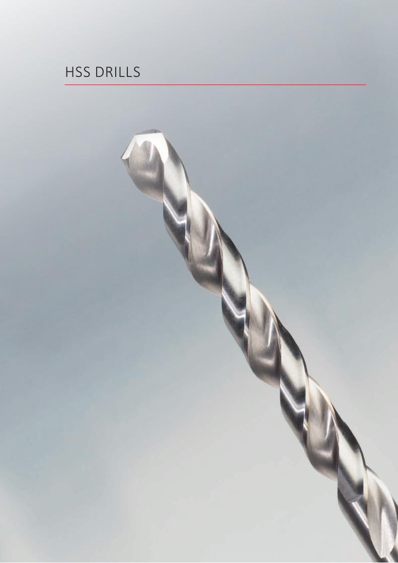
HSS DRILLS

FORMING TAPS
4
Dormer‘s range of forming taps is a high quality, comprehensive program with designs and thread forms for the majority of applications in all major industry segments. Dormer‘s forming taps provide dependability and reliability, creating threads that offer both dynamic strength and high dimensional accuracy.
FEATURES AND BENEFITS
• The range has been expanded with thread forms for MF, UNC and UNF. In addition, more variants with oil grooves have been added, as well as through coolant taps and a high performance solid carbide tap.
INTRODUCTION
MATERIAL
Manufactured from premium gradeHigh Speed Cobalt (HSS-E) for: • Increased hardness and toughness • Improved strength• Longer tool life
FORMING TAPS
TAP STYLES
• High performance and productivity in a wide range of materials
• Produces a stronger thread than cutting taps with increased load bearing capabilities
• Greater accuracy of finished thread• Lower surface roughness• Highly stable tool design means less risk of tap breakage
and optimum process security
Solid Carbide for:• Extremely high cutting speeds• Very long tool life
STANDARD• Threading depths up to 3xD• First choice for universal use in all ductile materials • Chamfer form E for blind holes and C for blind and
through holes• TiN coating for longer tool life and suitable for many
materials; a bright finish option is also available
OIL GROOVES• Thread depths up to 3.5xD• First choice for vertical through hole machining• Chamfer form C for both blind and through holes• TiN coating for longer tool life and suitable for many
materials
5
NEWNEW NEWNEW
GEOMETRY AND CHAMFER
• Thread profile with optimized polygonal form generates low torque
• Reduces friction and ensures a smooth surface finish on the completed thread
• Improved chamfer geometry for better running-in and even wear behaviour
Available with:• Chamfer form E for blind holes• Chamfer form C for blind and through holes
SURFACE TREATMENT
Titanium Nitride (TiN) coating for:• Universal layer suitable for many materials• Offers longer tool life due to reduced friction
Titanium Carbon Nitride (TiCN) coating for:• Alloyed and unalloyed steels• Highly suited to solid carbide tools• Wear resistant to abrasive materials
INTERNAL COOLANT• Internal coolant with radial outlets and oil grooves for
thread depths up to 3.5xD• First choice for horizontal through and blind hole
machining• Chamfer form C for both blind and through holes• TiN coating for longer tool life and suitable for many
materials
SOLID CARBIDE• Thread depths up to 3xD• First choice for extremely high productivity and very
long tool life• Attractive price/performance ratio for mass-production• Chamfer form C for blind and through holes• TiCN coated for high wear resistance to abrasive
materials
FORMING TAPS
6
T215 E291 E292 E294 E289 E293 E295 E296 E288 E287 E286
M3 - M10 M1.6 - M16
M1.6 - M16 M3 - M16 M5 - M12 M3 - M16 M3 - M12 M3 - M10 M5 - M12 No.4 - 1/2 No.4 - 1/2
AMG ISO1.1 ■60 ■30 ■55 ■55 ■55 ■55 ■55 ■55 ■55 ■55 ■55 P11.2 ■60 ■27 ■50 ■50 ■50 ■50 ■50 ■50 ■50 ■50 ■50 P11.3 ■60 ■23 ■45 ■45 ■45 ■45 ■45 ■45 ■45 ■45 ■45 P21.4 ■40 ■20 ■40 ■40 ■40 ■40 ■40 ■40 ■40 ■40 ■40 P31.5 ■30 ●20 ●20 ●20 ●20 ●20 ●20 ●20 ●20 ●20 P41.6 H11.7 H31.8 H42.1 ■25 ■18 ■18 ■18 ■18 ■18 ■18 ■18 ■18 ■18 M12.2 ■25 ■15 ■15 ■15 ■15 ■15 ■15 ■15 ■15 ■15 M32.3 ■25 ●10 ●10 ●10 ●10 ●10 ●10 ●10 ●10 ●10 M22.4 ●25 S23.1 K13.2 K23.3 K33.4 K44.1 ■35 ■35 ■35 ■35 ■35 ■35 ■35 ■35 ■35 S14.2 S24.3 S35.1 ■35 ■20 ■20 ■20 ■20 ■20 ■20 ■20 ■20 ■20 S15.2 ●15 ●8 ●8 ●8 ●8 ●8 ●8 ●8 ●8 ●8 S25.3 S36.1 ●40 ●25 ●25 ●25 ●25 ●25 ●25 ●25 ●25 ●25 N36.2 N46.3 ●80 ●40 ●40 ●40 ●40 ●40 ●40 ●40 ●40 ●40 N36.4 N47.1 ■70 ■26 ■55 ■55 ■55 ■55 ■55 ■55 ■55 ■55 ■55 N17.2 ■80 ■38 ■55 ■55 ■55 ■55 ■55 ■55 ■55 ■55 ■55 N17.3 ■80 ●22 ■40 ■40 ■40 ■40 ■40 ■40 ■40 ■40 ■40 N17.4 ●25 ●25 ●25 ●25 ●25 ●25 ●25 ●25 ●25 N28.1 O8.2 O8.3 O9.1 H
10.1 O
Excellent for application Good for application

7
M
P
mm
l1
mm
l2
mm
d2 Ø
mm
a
mm
l3
mm
z
l4
mmT215
3 0.50 56 10 3.5 2.7 6 4 2.8 - T215M34 0.70 63 13 4.5 3.4 6 5 3.7 - T215M45 0.80 70 16 6.0 4.9 8 5 4.6 - T215M56 1.00 80 19 6.0 4.9 8 5 5.5 30 T215M68 1.25 90 22 8.0 6.2 9 5 7.4 35 T215M8
10 1.50 100 24 10.0 8.0 11 5 9.3 39 T215M10
T215
M3 - M10
T215
T215 ■
●
T215 ● M Machine Forming Tap

8
M
P
mm
l1
mm
l2
mm
d2 Ø
mm
a
mm
l3
mm
z
l4
mmE291 E292 E294 E289
1.6 0.35 40 8 2.5 2.1 5 3 1.4 - E291M1.6 E292M1.62 0.40 45 6 2.8 2.1 5 3 1.8 11 E291M2 E292M2
2.5 0.45 50 8 2.8 2.1 5 3 2.3 12.5 E291M2.5 E292M2.53 0.50 56 9 3.5 2.7 6 4 2.8 18 E291M3 E292M3 E294M3
3.5 0.60 56 11 4.0 3.0 6 4 3.2 20 E291M3.5 E292M3.54 0.70 63 12 4.5 3.4 6 5 3.7 21 E291M4 E292M4 E294M45 0.80 70 13 6.0 4.9 8 5 4.6 25 E291M5 E292M5 E294M5 E289M56 1.00 80 15 6.0 4.9 8 5 5.5 30 E291M6 E292M6 E294M6 E289M68 1.25 90 18 8.0 6.2 9 5 7.4 35 E291M8 E292M8 E294M8 E289M8
10 1.50 100 20 10.0 8.0 11 5 9.3 39 E291M10 E292M10 E294M10 E289M1012 1.75 110 23 9.0 7.0 10 5 11.2 - E291M12 E292M12 E294M12 E289M1214 2.00 110 25 11.0 9.0 12 6 13.0 - E294M1416 2.00 110 25 12.0 9.0 12 6 15.0 - E291M16 E292M16 E294M16
E291 E292 E294 E289
M1.6 - M16 M1.6 - M16 M3 - M16 M5 - M12
E291
E292
E294
E289
E291 ■
●
E292; E294; E289 ■
●
E291 ● M Machine Forming Tap
E292 ● M Machine Forming Tap
E294 ● M Machine Forming Tap, Oil Grooves
E289 ● M Machine Forming Tap, Oil Grooves and Internal Coolant
9
M
P
mm
l1
mm
l2
mm
d2 Ø
mm
a
mm
l3
mm
z
l4
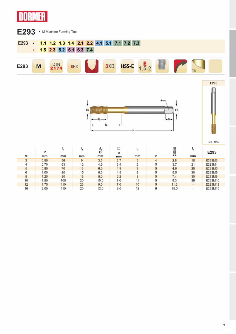
mmE293
3 0.50 56 9 3.5 2.7 6 4 2.8 18 E293M34 0.70 63 12 4.5 3.4 6 5 3.7 21 E293M45 0.80 70 13 6.0 4.9 8 5 4.6 25 E293M56 1.00 80 15 6.0 4.9 8 5 5.5 30 E293M68 1.25 90 18 8.0 6.2 9 5 7.4 35 E293M8
10 1.50 100 20 10.0 8.0 11 5 9.3 39 E293M1012 1.75 110 23 9.0 7.0 10 5 11.2 - E293M1216 2.00 110 25 12.0 9.0 12 6 15.0 - E293M16
E293
M3 - M16
E293
E293 ■
●
E293 ● M Machine Forming Tap
10
E295
E296
E295; E296 ■
●
M
P
mm
l1
mm
l2
mm
d2 Ø
mm
a
mm
l3
mm
z
l4
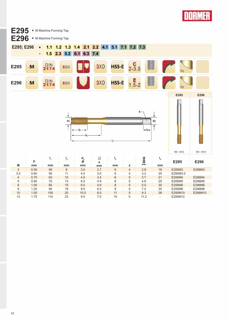
mmE295 E296
3 0.50 56 9 3.5 2.7 6 4 2.8 18 E295M3 E296M33.5 0.60 56 11 4.0 3.0 6 4 3.2 20 E295M3.54 0.70 63 12 4.5 3.4 6 5 3.7 21 E295M4 E296M45 0.80 70 13 6.0 4.9 8 5 4.6 25 E295M5 E296M56 1.00 80 15 6.0 4.9 8 5 5.5 30 E295M6 E296M68 1.25 90 18 8.0 6.2 9 5 7.4 35 E295M8 E296M8
10 1.50 100 20 10.0 8.0 11 5 9.3 39 E295M10 E296M1012 1.75 110 23 9.0 7.0 10 5 11.2 - E295M12
E295 E296
M3 - M12 M3 - M10
E295 ● M Machine Forming Tap
E296 ● M Machine Forming Tap
11
MF
P
mm
l1
mm
l2
mm
d2 Ø
mm
a
mm
l3
mm
z
l4
mmE288
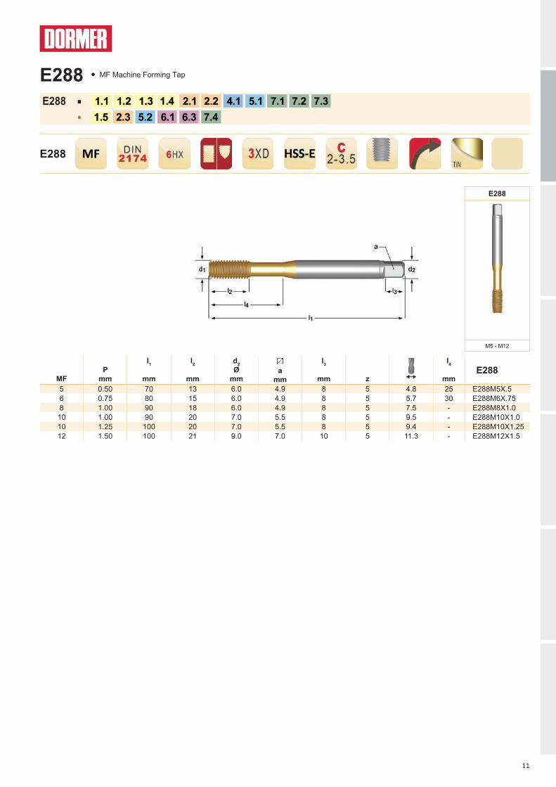
5 0.50 70 13 6.0 4.9 8 5 4.8 25 E288M5X.56 0.75 80 15 6.0 4.9 8 5 5.7 30 E288M6X.758 1.00 90 18 6.0 4.9 8 5 7.5 - E288M8X1.0
10 1.00 90 20 7.0 5.5 8 5 9.5 - E288M10X1.010 1.25 100 20 7.0 5.5 8 5 9.4 - E288M10X1.2512 1.50 100 21 9.0 7.0 10 5 11.3 - E288M12X1.5
E288
M5 - M12
E288
E288 ■
●
E288 ● MF Machine Forming Tap

12
UNC
TPI
d1 nom mm
l1
mm
l2
mm
d2 Ø
mma
mm
l3
mm
z
l4
mmE287
4 40 2.845 56 9 3.5 2.7 6 4 2.6 18 E2874-406 32 3.505 56 11 4.0 3.0 6 4 3.2 20 E2876-328 32 4.166 63 12 4.5 3.4 6 5 3.8 21 E2878-32
10 24 4.826 70 13 6.0 4.9 8 5 4.4 25 E28710-241/4 20 6.350 80 15 7.0 5.5 8 5 5.8 30 E2871/4
5/16 18 7.938 90 18 8.0 6.2 9 5 7.3 35 E2875/163/8 16 9.525 100 20 10.0 8.0 11 5 8.8 39 E2873/8
7/16 14 11.112 100 20 8.0 6.2 9 5 10.3 - E2877/161/2 13 12.700 110 23 9.0 7.0 10 5 11.9 - E2871/2
E287
No.4 - 1/2
E287
E287 ■
●
E287 ● UNC Machine Forming Tap, Oil Grooves
13
UNF
TPI
d1 nom mm
l1
mm
l2
mm
d2 Ø
mm
a
mm
l3
mm
z
l4
mmE286
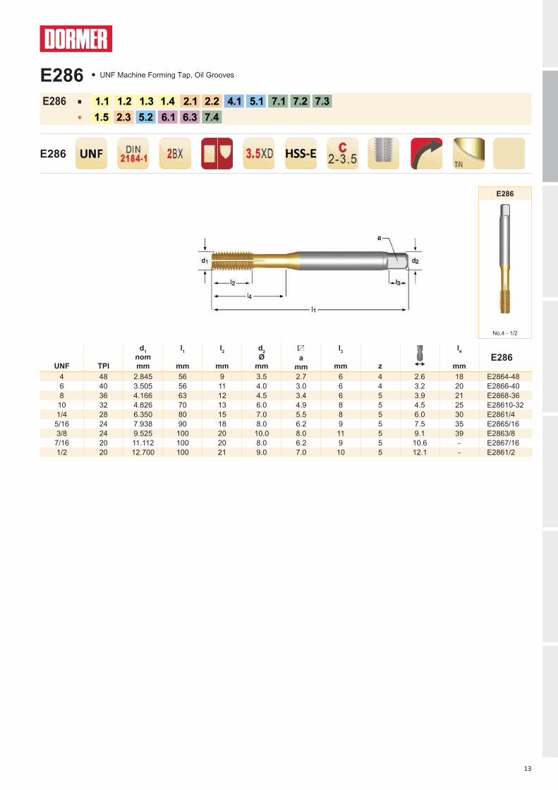
4 48 2.845 56 9 3.5 2.7 6 4 2.6 18 E2864-486 40 3.505 56 11 4.0 3.0 6 4 3.2 20 E2866-408 36 4.166 63 12 4.5 3.4 6 5 3.9 21 E2868-36
10 32 4.826 70 13 6.0 4.9 8 5 4.5 25 E28610-321/4 28 6.350 80 15 7.0 5.5 8 5 6.0 30 E2861/4
5/16 24 7.938 90 18 8.0 6.2 9 5 7.5 35 E2865/163/8 24 9.525 100 20 10.0 8.0 11 5 9.1 39 E2863/8
7/16 20 11.112 100 20 8.0 6.2 9 5 10.6 - E2867/161/2 20 12.700 100 21 9.0 7.0 10 5 12.1 - E2861/2
E286
No.4 - 1/2
E286
E286 ■
●
E286 ● UNF Machine Forming Tap, Oil Grooves

SOLID CARBIDE TAPS

16
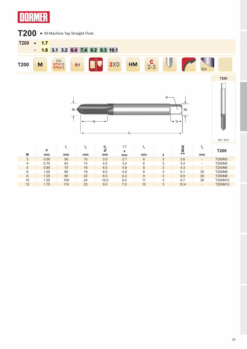
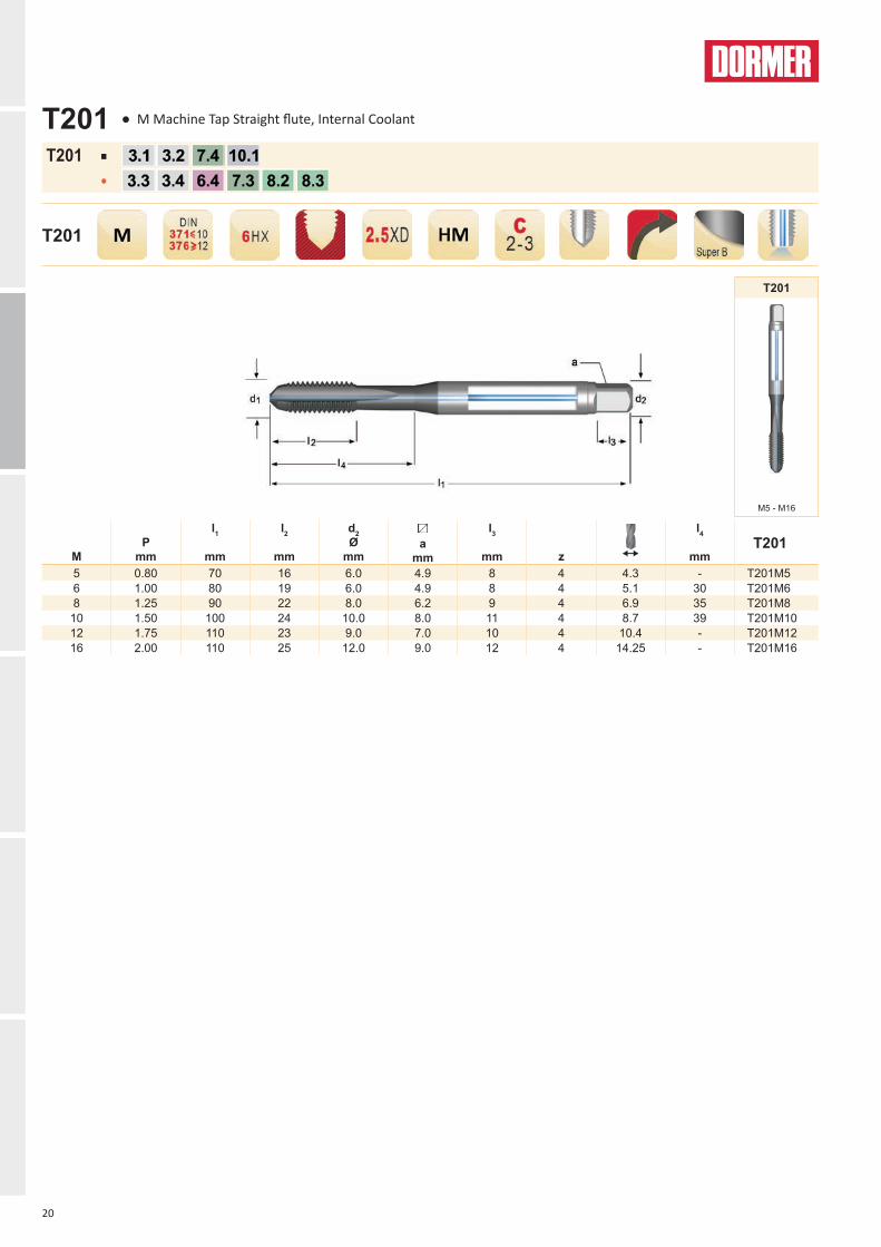
T201
T200
T210
NEWNEW NEWNEW NEWNEW
The use of hardened materials in industrial processes is becoming increasingly common, creating a greater need for new and improved cutting tools capable of working in extreme conditions.Dormer’s new range of solid carbide taps is a high performing, comprehensive program designed specifically for machining various types of hardened steel and other difficult materials.
FEATURES AND BENEFITS
• High performance and productivity in a wide range of applications including hardened materials up to 63 HRC
• Ideal for mass production with cutting speeds up to 3 times higher when compared to HSS-E taps
• Fewer tool changes resulting in optimum machine output due to long tool life
• Highly stable tool design means less risk of tap breakage and optimum process security
INTRODUCTION
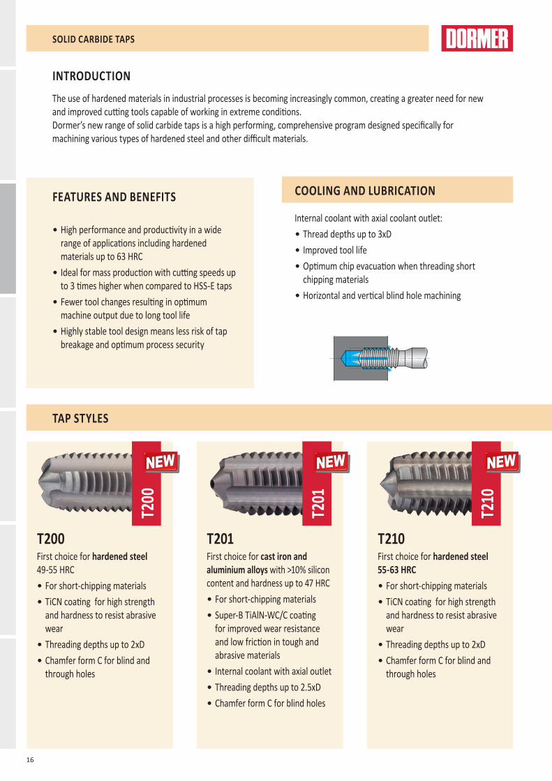
COOLING AND LUBRICATION
Internal coolant with axial coolant outlet:• Thread depths up to 3xD• Improved tool life• Optimum chip evacuation when threading short
chipping materials• Horizontal and vertical blind hole machining
T200First choice for hardened steel 49-55 HRC• For short-chipping materials• TiCN coating for high strength
and hardness to resist abrasive wear
• Threading depths up to 2xD• Chamfer form C for blind and
through holes
T201First choice for cast iron and aluminium alloys with >10% silicon content and hardness up to 47 HRC• For short-chipping materials• Super-B TiAlN-WC/C coating
for improved wear resistance and low friction in tough and abrasive materials
• Internal coolant with axial outlet• Threading depths up to 2.5xD• Chamfer form C for blind holes
T210First choice for hardened steel 55-63 HRC• For short-chipping materials• TiCN coating for high strength
and hardness to resist abrasive wear
• Threading depths up to 2xD• Chamfer form C for blind and
through holes
TAP STYLES
SOLID CARBIDE TAPS
17
T205
T206
T215
NEWNEW NEWNEW NEWNEW
MATERIAL
Manufactured from premium grade micro grain Solid Carbide for:• Long tool life and extremely high tapping speeds • Threading in hardened material up to 63 HRC• High wear resistance to abrasive materials
GEOMETRY AND CHAMFER
The range features a variety of styles including straight flute, spiral flute and a forming tap in order to offer dependable options in numerous applications.• Improved chamfer geometry for better running-in
and even wear behaviour• Special geometries for specific applications:
• T205/T206 features a 15° helix angle suited for both short and long-chipping materials
• T210 with increased number of flutes for better chip breaking and longer chamfer for increased tool life
• T215 forming tap features a thread profile with optimized polygonal form which generates low torque
SURFACE TREATMENT
Titanium Carbon Nitride (TiCN) coating for:• Alloyed and unalloyed steels• Highly suited to solid carbide tools• Wear resistant to abrasive materials
Super-B (TiAlN+WC/C) coating for:• Cast iron and aluminium alloys with high silica content• Ideal for higher speed and feeds• Can be used for both wet and dry machining
T205First choice for ductile iron and aluminium alloys with >10% silicon content and hardness up to 47 HRC• For long and short-chipping
materials• Bright finish for better chip flow• Threading depths up to 2xD• Chamfer form C for blind holes
T206First choice for ductile iron and aluminium alloys with >10% silicon content and hardness up to 47 HRC• For long and short-chipping
materials• Bright finish for better chip flow• Internal coolant with axial outlet• Threading depths up to 2.5xD• Chamfer form C for blind holes
T215Forming tap, first choice for wide range of materials with hardness up to 36 HRC • Extremely high productivity
and very long tool life in ductile materials
• TiCN coating for high strength and hardness to resist abrasive wear
• Threading depths up to 3xD• Chamfer form C for blind and
through holes
SOLID CARBIDE TAPS

18
T200 T201 T210 T205 T206 T215
M3 - M12 M5 - M16 M3 - M12 M3 - M12 M5 - M12 M3 - M10
AMG ISO1.1 ■60 P11.2 ■60 P11.3 ■60 P21.4 ■40 P31.5 ■30 P41.6 H11.7 ■6 ●6 H31.8 ●4 ■4 H42.1 ■25 M12.2 ■25 M32.3 ■25 M22.4 ●25 S23.1 ●60 ■60 ●40 ●40 K13.2 ●30 ■25 ●15 ●15 K23.3 ●38 ■25 ■25 K33.4 ●33 ■15 ■15 K44.1 S14.2 S24.3 S35.1 ■35 S15.2 ●15 S25.3 S36.1 ●40 N36.2 N46.3 ●80 N36.4 ●7 ●10 N47.1 ■70 N17.2 ■80 N17.3 ●50 ■35 ■35 ■80 N17.4 ●60 ■40 ■30 ■30 N28.1 O8.2 ●50 ●25 ●25 ●25 O8.3 ●30 ●15 ●15 ●15 O9.1 H
10.1 ●25 ■25 O
Excellent for application Good for application
19
M
P
mm
l1
mm
l2
mm
d2 Ø
mm
a
mm
l3
mm
z
l4
mmT200
3 0.50 56 10 3.5 2.7 6 3 2.6 - T200M34 0.70 63 13 4.5 3.4 6 3 3.4 - T200M45 0.80 70 16 6.0 4.9 8 3 4.3 - T200M56 1.00 80 19 6.0 4.9 8 3 5.1 30 T200M68 1.25 90 22 8.0 6.2 9 3 6.9 35 T200M8
10 1.50 100 24 10.0 8.0 11 3 8.7 39 T200M1012 1.75 110 23 9.0 7.0 10 3 10.4 - T200M12
T200
M3 - M12
T200
T200 ■
●
T200 ● M Machine Tap Straight Flute
20
M
P
mm
l1
mm
l2
mm
d2 Ø
mm
a
mm
l3
mm
z
l4
mmT201
5 0.80 70 16 6.0 4.9 8 4 4.3 - T201M56 1.00 80 19 6.0 4.9 8 4 5.1 30 T201M68 1.25 90 22 8.0 6.2 9 4 6.9 35 T201M8
10 1.50 100 24 10.0 8.0 11 4 8.7 39 T201M1012 1.75 110 23 9.0 7.0 10 4 10.4 - T201M1216 2.00 110 25 12.0 9.0 12 4 14.25 - T201M16
T201
M5 - M16
T201
T201 ■
●
T201 ● M Machine Tap Straight flute, Internal Coolant
21
M
P
mm
l1
mm
l2
mm
d2 Ø
mm
a
mm
l3
mm
z
T210
3 0.50 56 8 3.5 2.7 6 4 2.6 T210M34 0.70 63 11 4.5 3.4 6 5 3.4 T210M45 0.80 70 13.5 6.0 4.9 8 5 4.3 T210M56 1.00 80 16.5 6.0 4.9 8 5 5.1 T210M68 1.25 90 21.5 8.0 6.2 9 5 6.9 T210M8
10 1.50 100 27 10.0 8.0 11 5 8.7 T210M1012 1.75 110 32 12.0 9.0 12 6 10.4 T210M12
T210
M3 - M12
T210
T210 ■
●
T210 ● M Machine Tap Straight Flute
22
M
P
mm
l1
mm
l2
mm
d2 Ø
mm
a
mm
l3
mm
z
l4
mmT205 T206
3 0.50 56 10 3.5 2.7 6 3 2.6 - T205M34 0.70 63 13 4.5 3.4 6 3 3.4 - T205M45 0.80 70 16 6.0 4.9 8 3 4.3 - T205M5 T206M56 1.00 80 19 6.0 4.9 8 3 5.1 30 T205M6 T206M68 1.25 90 22 8.0 6.2 9 3 6.9 35 T205M8 T206M8
10 1.50 100 24 10.0 8.0 11 3 8.7 39 T205M10 T206M1012 1.75 110 23 9.0 7.0 10 3 10.4 - T205M12 T206M12
T205 T206
M3 - M12 M5 - M12
T205
T206
T205; T206 ■
●
T205 ● M Machine Tap Spiral Flute 15°
T206 ● M Machine Tap Spiral Flute 15°, Internal Coolant

23
M
P
mm
l1
mm
l2
mm
d2 Ø
mm
a
mm
l3
mm
z
l4
mmT215
3 0.50 56 10 3.5 2.7 6 4 2.8 - T215M34 0.70 63 13 4.5 3.4 6 5 3.7 - T215M45 0.80 70 16 6.0 4.9 8 5 4.6 - T215M56 1.00 80 19 6.0 4.9 8 5 5.5 30 T215M68 1.25 90 22 8.0 6.2 9 5 7.4 35 T215M8
10 1.50 100 24 10.0 8.0 11 5 9.3 39 T215M10
T215
M3 - M10
T215
T215 ■
●
T215 ● M Machine Forming Tap

SOLID CARBIDE CUTTERS

26
NEWNEW
S822
NEWNEW
S823
The S8XX series of solid carbide cutters provide proven performance and versatility in a wide range of materials. As such, they will be of particular interest to small/medium sized companies machining a varied range of workpiece materials, across all industry sectors.
FEATURES AND BENEFITS• Multi-application high performance milling across
a wide range of materials, including steel, stainless steel, aluminium and cast iron.
• Reduced tooling costs - one cutter machines many materials and performs multiple operations.
• Alcrona coating improves workpiece surface finish and increases tool life
INTRODUCTION
SOLID CARBIDE CUTTERS
• Versatility - all milling operations are supported: slotting, profiling, roughing, semi-finishing, finishing and plunging.
• Machine tool flexibility – same tool for many materials and operations leads to reduced set-up time and therefore shorter production time.
• Design of cutting edge and web promotes fast and efficient chip evacuation.
CYLINDRICAL LANDFlat relief combined with cylindrical land on the 2 and 3 flute cutters increases stability during machining. The 4 flute cutters have radial relief.
END TEETH Reinforcement along the full lengthof the end teeth considerablyincreases toughness and thereforereduces chipping on the cuttingedge. In turn, this furtherextends tool life in all operationsinvolving end teeth (plunging,ramping and helical interpolation). The design of the end teeth geometry guarantees smooth and efficient chip evacuation in plunging operations.
RAKE ANGLEA reduction of the end teeth rake angle and the primary clearance angle increases the strength of the S8XX cutters.
27
MATERIAL
Manufactured from Micrograin carbide with itsexcellent combination of hardness and toughness properties. This means that the S8XX cutters are suited to all milling operations, from roughing through to finishing.
SURFACE TREATMENT
The Alcrona (AlCrN) coating is applied to many multi-application cutter ranges for its hot hardness and resistance to wear and oxidation. This contributes to high productivity and a superior surface finish on the workpiece, even on difficult-to-machine materials. The versatile coating lends itself to both roughing and finishing operations, when both wet and dry machining.
SOLID CARBIDE CUTTERS
WEBThe 4 flute S8XX cutters have an increased conical web design. The modified flute shape promotes effective chip evacuation.
SHANKShanks are manufactured to DIN 6535 ground to a h6 tolerance for accurate tool holding
LENGTHThe new cutters add a medium cut length (Dormer standard) option to the existing extra short (DIN 6527 K) and short (DIN 6527 L) cut lengths for S8XX 2 and 3 flute cutters. The 4 flute S8XX cutters are available in extra short (DIN 6527 K) and short (DIN 6527 L) cut lengths.
28
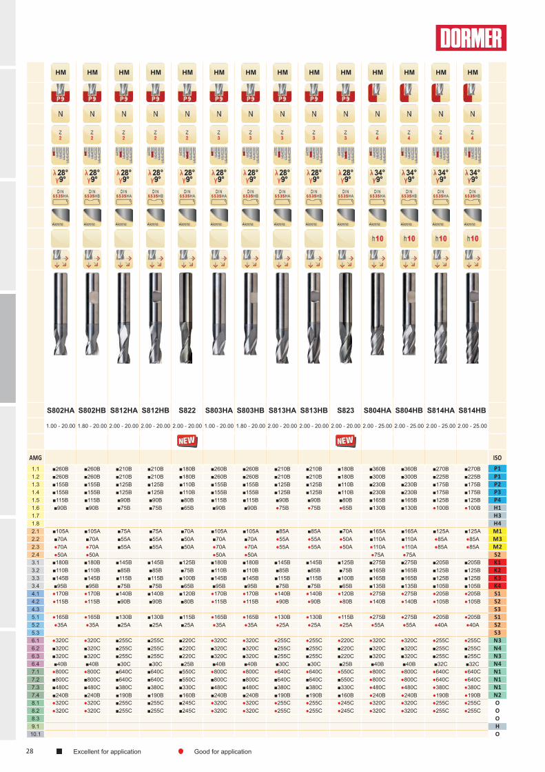
S802HA S802HB S812HA S812HB S822 S803HA S803HB S813HA S813HB S823 S804HA S804HB S814HA S814HB
1.00 - 20.00 1.80 - 20.00 2.00 - 20.00 2.00 - 20.00 2.00 - 20.00 1.00 - 20.00 1.80 - 20.00 2.00 - 20.00 2.00 - 20.00 2.00 - 20.00 2.00 - 25.00 2.00 - 25.00 2.00 - 25.00 2.00 - 25.00
AMG ISO1.1 ■260B ■260B ■210B ■210B ■180B ■260B ■260B ■210B ■210B ■180B ■360B ■360B ■270B ■270B P11.2 ■260B ■260B ■210B ■210B ■180B ■260B ■260B ■210B ■210B ■180B ■300B ■300B ■225B ■225B P11.3 ■155B ■155B ■125B ■125B ■110B ■155B ■155B ■125B ■125B ■110B ■230B ■230B ■175B ■175B P21.4 ■155B ■155B ■125B ■125B ■110B ■155B ■155B ■125B ■125B ■110B ■230B ■230B ■175B ■175B P31.5 ■115B ■115B ■90B ■90B ■80B ■115B ■115B ■90B ■90B ■80B ■165B ■165B ■125B ■125B P41.6 ■90B ■90B ■75B ■75B ■65B ■90B ■90B ●75B ●75B ●65B ■130B ■130B ●100B ●100B H11.7 H31.8 H42.1 ■105A ■105A ■75A ■75A ■70A ■105A ■105A ■85A ■85A ■70A ■165A ■165A ■125A ■125A M12.2 ■70A ■70A ■55A ■55A ■50A ■70A ■70A ●55A ●55A ●50A ■110A ■110A ●85A ●85A M32.3 ●70A ●70A ■55A ■55A ■50A ●70A ●70A ●55A ●55A ●50A ●110A ●110A ●85A ●85A M22.4 ●50A ●50A ●50A ●50A ●75A ●75A S23.1 ■180B ■180B ■145B ■145B ■125B ■180B ■180B ■145B ■145B ■125B ■275B ■275B ■205B ■205B K13.2 ■110B ■110B ■85B ■85B ■75B ■110B ■110B ■85B ■85B ■75B ■165B ■165B ■125B ■125B K23.3 ■145B ■145B ■115B ■115B ■100B ■145B ■145B ■115B ■115B ■100B ■165B ■165B ■125B ■125B K33.4 ■95B ■95B ■75B ■75B ■65B ■95B ■95B ■75B ■75B ■65B ■135B ■135B ■105B ■105B K44.1 ●170B ●170B ■140B ■140B ■120B ●170B ●170B ●140B ●140B ●120B ●275B ●275B ●205B ●205B S14.2 ●115B ●115B ■90B ■90B ■80B ●115B ●115B ●90B ●90B ●80B ●140B ●140B ●105B ●105B S24.3 S35.1 ●165B ●165B ■130B ■130B ■115B ●165B ●165B ●130B ●130B ●115B ●275B ●275B ●205B ●205B S15.2 ●35A ●35A ■25A ■25A ■25A ●35A ●35A ●25A ●25A ●25A ●55A ●55A ●40A ●40A S25.3 S36.1 ●320C ●320C ■255C ■255C ■220C ●320C ●320C ●255C ●255C ●220C ●320C ●320C ●255C ●255C N36.2 ■320C ■320C ■255C ■255C ■220C ■320C ■320C ■255C ■255C ■220C ■320C ■320C ■255C ■255C N46.3 ■320C ■320C ■255C ■255C ■220C ■320C ■320C ■255C ■255C ■220C ■320C ■320C ■255C ■255C N36.4 ■40B ■40B ■30C ■30C ■25B ■40B ■40B ■30C ■30C ■25B ■40B ■40B ■32C ■32C N47.1 ●800C ●800C ■640C ■640C ■550C ●800C ●800C ●640C ●640C ●550C ●800C ●800C ●640C ●640C N17.2 ■800C ■800C ■640C ■640C ■550C ■800C ■800C ■640C ■640C ■550C ●800C ●800C ●640C ●640C N17.3 ■480C ■480C ■380C ■380C ■330C ■480C ■480C ■380C ■380C ■330C ●480C ●480C ●380C ●380C N17.4 ■240B ■240B ■190B ■190B ■160B ■240B ■240B ■190B ■190B ■160B ●240B ●240B ●190B ●190B N28.1 ●320C ●320C ■255C ■255C ■245C ●320C ●320C ●255C ●255C ●245C ●320C ●320C ●255C ●255C O8.2 ●320C ●320C ■255C ■255C ■245C ●320C ●320C ●255C ●255C ●245C ●320C ●320C ●255C ●255C O8.3 O9.1 H
10.1 O
Excellent for application Good for application

29
Ae(x Ø)
Ap(x Ø) ø [mm] fz [mm/Z] ± 25 %Z Z Z Z Z
1 2 3 4 >4Ø 1 2 3 4 5 6 8 10 12 14 16 18 20
Ae
Ap0.05 1.5
A 0.012 0.024 0.035 0.045 0.055 0.065 0.080 0.093 0.107 0.121 0.134 0.149 0.162
B 0.016 0.032 0.047 0.061 0.074 0.087 0.107 0.124 0.143 0.162 0.179 0.198 0.216
C 0.020 0.040 0.058 0.076 0.092 0.108 0.134 0.156 0.179 0.202 0.224 0.248 0.271
D 0.024 0.048 0.070 0.091 0.111 0.130 0.160 0.187 0.214 0.242 0.268 0.297 0.325
E 0.028 0.056 0.081 0.106 0.129 0.152 0.187 0.218 0.250 0.283 0.313 0.347 0.379
F 0.032 0.064 0.093 0.121 0.148 0.173 0.214 0.249 0.286 0.323 0.358 0.396 0.433
G 0.037 0.071 0.105 0.136 0.166 0.195 0.240 0.280 0.321 0.364 0.403 0.446 0.487
H 0.041 0.079 0.116 0.152 0.185 0.216 0.267 0.311 0.357 0.404 0.447 0.495 0.541
Ae
Ap0.08 1.5
A 0.010 0.019 0.028 0.036 0.044 0.052 0.064 0.074 0.085 0.096 0.107 0.118 0.129
B 0.013 0.025 0.037 0.048 0.059 0.069 0.085 0.099 0.114 0.128 0.142 0.157 0.172
C 0.016 0.032 0.046 0.060 0.073 0.086 0.106 0.124 0.142 0.161 0.178 0.197 0.215
D 0.019 0.038 0.055 0.072 0.088 0.103 0.127 0.148 0.170 0.193 0.213 0.236 0.258
E 0.023 0.044 0.065 0.084 0.103 0.120 0.149 0.173 0.199 0.225 0.249 0.276 0.301
F 0.026 0.050 0.074 0.096 0.118 0.138 0.170 0.198 0.227 0.257 0.284 0.315 0.344
G 0.029 0.057 0.083 0.108 0.132 0.155 0.191 0.223 0.256 0.289 0.320 0.354 0.387
H 0.032 0.063 0.092 0.120 0.147 0.172 0.212 0.247 0.284 0.321 0.356 0.394 0.430
Ae
Ap0.15 1.5
A 0.007 0.014 0.021 0.027 0.033 0.038 0.047 0.055 0.063 0.071 0.079 0.087 0.095
B 0.010 0.019 0.027 0.036 0.043 0.051 0.063 0.073 0.084 0.095 0.105 0.116 0.127
C 0.012 0.023 0.034 0.045 0.054 0.064 0.078 0.091 0.105 0.119 0.132 0.146 0.159
D 0.014 0.028 0.041 0.053 0.065 0.076 0.094 0.110 0.126 0.143 0.158 0.175 0.191
E 0.017 0.033 0.048 0.062 0.076 0.089 0.110 0.128 0.147 0.166 0.184 0.204 0.223
F 0.019 0.037 0.055 0.071 0.087 0.102 0.126 0.146 0.168 0.190 0.210 0.233 0.255
G 0.021 0.042 0.062 0.080 0.098 0.115 0.141 0.165 0.189 0.214 0.237 0.262 0.286
H 0.024 0.047 0.068 0.089 0.109 0.127 0.157 0.183 0.210 0.238 0.263 0.291 0.318
Ae
Ap0.30 1.5
A 0.005 0.010 0.015 0.019 0.024 0.028 0.034 0.040 0.046 0.052 0.058 0.064 0.070
B 0.007 0.014 0.020 0.026 0.032 0.037 0.046 0.053 0.061 0.069 0.077 0.085 0.093
C 0.009 0.017 0.025 0.032 0.040 0.046 0.057 0.067 0.077 0.087 0.096 0.106 0.116
D 0.010 0.020 0.030 0.039 0.048 0.056 0.069 0.080 0.092 0.104 0.115 0.127 0.139
E 0.012 0.024 0.035 0.045 0.055 0.065 0.080 0.093 0.107 0.121 0.134 0.149 0.162
F 0.014 0.027 0.040 0.052 0.063 0.074 0.092 0.107 0.122 0.138 0.153 0.170 0.185
G 0.016 0.031 0.045 0.058 0.071 0.083 0.103 0.120 0.138 0.156 0.173 0.191 0.209
H 0.017 0.034 0.050 0.065 0.079 0.093 0.114 0.133 0.153 0.173 0.192 0.212 0.232
Ae
Ap0.60 1.5
A 0.004 0.008 0.011 0.015 0.018 0.021 0.026 0.031 0.035 0.040 0.044 0.049 0.053
B 0.005 0.010 0.015 0.020 0.024 0.028 0.035 0.041 0.047 0.053 0.059 0.065 0.071
C 0.007 0.013 0.019 0.025 0.030 0.035 0.044 0.051 0.058 0.066 0.073 0.081 0.089
D 0.008 0.016 0.023 0.030 0.036 0.043 0.052 0.061 0.070 0.079 0.088 0.097 0.106
E 0.009 0.018 0.027 0.035 0.042 0.050 0.061 0.071 0.082 0.093 0.103 0.114 0.124
F 0.011 0.021 0.030 0.040 0.048 0.057 0.070 0.082 0.094 0.106 0.117 0.130 0.142
G 0.012 0.023 0.034 0.045 0.054 0.064 0.079 0.092 0.105 0.119 0.132 0.146 0.159
H 0.013 0.026 0.038 0.050 0.061 0.071 0.087 0.102 0.117 0.132 0.146 0.162 0.177
Excellent for application Good for application
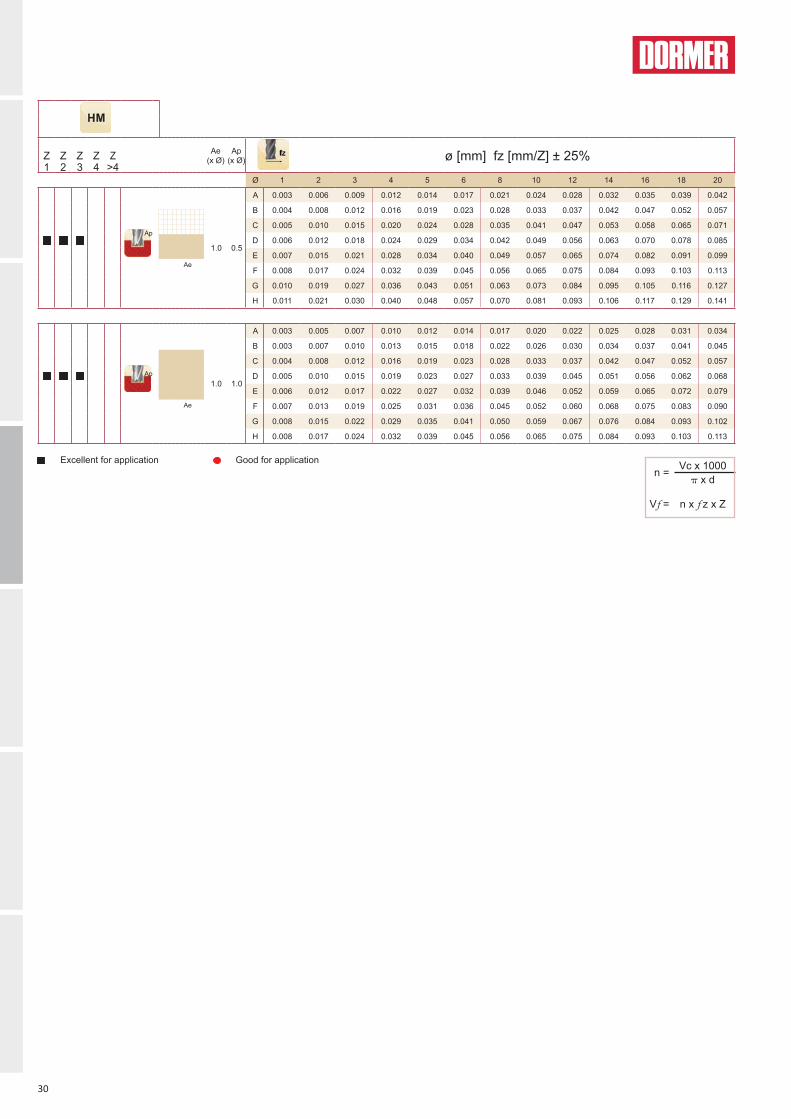
30
Ae(x Ø)
Ap(x Ø) ø [mm] fz [mm/Z] ± 25%Z Z Z Z Z
1 2 3 4 >4Ø 1 2 3 4 5 6 8 10 12 14 16 18 20
Ae
Ap
1.0 0.5
A 0.003 0.006 0.009 0.012 0.014 0.017 0.021 0.024 0.028 0.032 0.035 0.039 0.042
B 0.004 0.008 0.012 0.016 0.019 0.023 0.028 0.033 0.037 0.042 0.047 0.052 0.057
C 0.005 0.010 0.015 0.020 0.024 0.028 0.035 0.041 0.047 0.053 0.058 0.065 0.071
D 0.006 0.012 0.018 0.024 0.029 0.034 0.042 0.049 0.056 0.063 0.070 0.078 0.085
E 0.007 0.015 0.021 0.028 0.034 0.040 0.049 0.057 0.065 0.074 0.082 0.091 0.099
F 0.008 0.017 0.024 0.032 0.039 0.045 0.056 0.065 0.075 0.084 0.093 0.103 0.113
G 0.010 0.019 0.027 0.036 0.043 0.051 0.063 0.073 0.084 0.095 0.105 0.116 0.127
H 0.011 0.021 0.030 0.040 0.048 0.057 0.070 0.081 0.093 0.106 0.117 0.129 0.141
Ae
Ap1.0 1.0
A 0.003 0.005 0.007 0.010 0.012 0.014 0.017 0.020 0.022 0.025 0.028 0.031 0.034
B 0.003 0.007 0.010 0.013 0.015 0.018 0.022 0.026 0.030 0.034 0.037 0.041 0.045
C 0.004 0.008 0.012 0.016 0.019 0.023 0.028 0.033 0.037 0.042 0.047 0.052 0.057
D 0.005 0.010 0.015 0.019 0.023 0.027 0.033 0.039 0.045 0.051 0.056 0.062 0.068
E 0.006 0.012 0.017 0.022 0.027 0.032 0.039 0.046 0.052 0.059 0.065 0.072 0.079
F 0.007 0.013 0.019 0.025 0.031 0.036 0.045 0.052 0.060 0.068 0.075 0.083 0.090
G 0.008 0.015 0.022 0.029 0.035 0.041 0.050 0.059 0.067 0.076 0.084 0.093 0.102
H 0.008 0.017 0.024 0.032 0.039 0.045 0.056 0.065 0.075 0.084 0.093 0.103 0.113
n = Vc x 1000 x d
Vf = n x f z x Z
Excellent for application Good for application

31
d1 Ø
mm
Ch ±0.03x45°
mm
d2 Øh6 mm
l2
mm
l1
mm
z
S822
2.00 - 6 8 57 2 S8222.02.50 0.08 6 12 57 2 S8222.53.00 0.08 6 12 57 2 S8223.04.00 0.13 6 14 57 2 S8224.05.00 0.13 6 16 57 2 S8225.06.00 0.13 6 19 57 2 S8226.07.00 0.13 8 19 63 2 S8227.08.00 0.20 8 19 63 2 S8228.0 1)
9.00 0.20 10 21 72 2 S8229.0 1)
10.00 0.20 10 22 72 2 S82210.0 1)
12.00 0.20 12 25 83 2 S82212.0 1)
14.00 0.20 14 30 83 2 S82214.0 1)
16.00 0.20 16 32 92 2 S82216.0 1)
18.00 0.20 18 32 92 2 S82218.0 1)
20.00 0.30 20 38 104 2 S82220.0 1)
S822
l1
l2
d2
d1
Ch×45°
2.00 - 20.00
S822
S822 ■
●
1) Ch ±0.05x45° mm
S822 ● Slot Drill
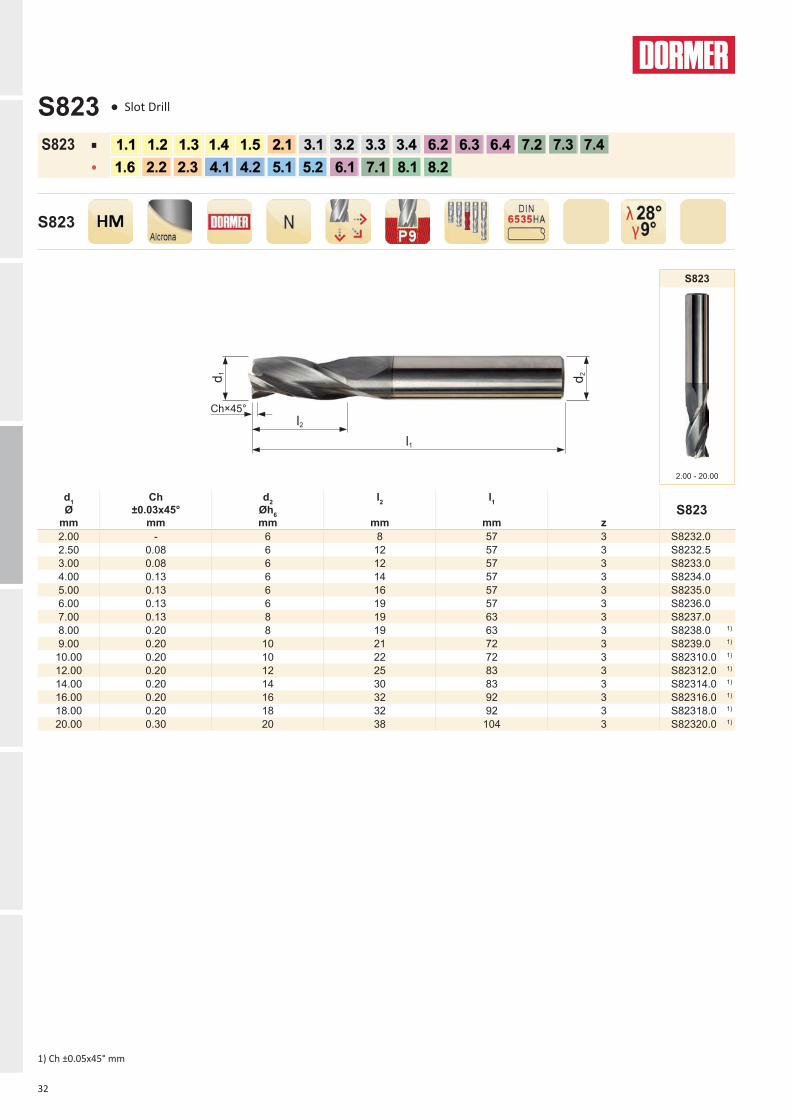
32
d1 Ø
mm
Ch ±0.03x45°
mm
d2 Øh6 mm
l2
mm
l1
mm
z
S823
2.00 - 6 8 57 3 S8232.02.50 0.08 6 12 57 3 S8232.53.00 0.08 6 12 57 3 S8233.04.00 0.13 6 14 57 3 S8234.05.00 0.13 6 16 57 3 S8235.06.00 0.13 6 19 57 3 S8236.07.00 0.13 8 19 63 3 S8237.08.00 0.20 8 19 63 3 S8238.0 1)
9.00 0.20 10 21 72 3 S8239.0 1)
10.00 0.20 10 22 72 3 S82310.0 1)
12.00 0.20 12 25 83 3 S82312.0 1)
14.00 0.20 14 30 83 3 S82314.0 1)
16.00 0.20 16 32 92 3 S82316.0 1)
18.00 0.20 18 32 92 3 S82318.0 1)
20.00 0.30 20 38 104 3 S82320.0 1)
S823
l1
l2
d2
d1
Ch×45°
2.00 - 20.00
S823
S823 ■
●
1) Ch ±0.05x45° mm
S823 ● Slot Drill


COUNTERSINKS
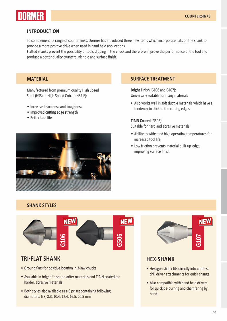
35
G107
G106
G506
NEWNEW NEWNEW NEWNEW
TRI-FLAT SHANK• Ground flats for positive location in 3-jaw chucks
• Available in bright finish for softer materials and TiAlN coated for harder, abrasive materials
• Both styles also available as a 6 pc set containing following diameters: 6.3, 8.3, 10.4, 12.4, 16.5, 20.5 mm
HEX-SHANK• Hexagon shank fits directly into cordless
drill driver attachments for quick change
• Also compatible with hand held drivers for quick de-burring and chamfering by hand
COUNTERSINKS
To complement its range of countersinks, Dormer has introduced three new items which incorporate flats on the shank to provide a more positive drive when used in hand held applications.Flatted shanks prevent the possibility of tools slipping in the chuck and therefore improve the performance of the tool and produce a better quality countersunk hole and surface finish.
INTRODUCTION
MATERIAL
Manufactured from premium quality High Speed Steel (HSS) or High Speed Cobalt (HSS-E): • Increased hardness and toughness • Improved cutting edge strength• Better tool life
SURFACE TREATMENT
Bright Finish (G106 and G107):Universally suitable for many materials
• Also works well in soft ductile materials which have a tendency to stick to the cutting edges
TiAlN Coated (G506):Suitable for hard and abrasive materials
• Ability to withstand high operating temperatures for increased tool life
• Low friction prevents material built-up-edge, improving surface finish
SHANK STYLES

36
G106 G506 G107 G236
6.30 - 50.00 6.30 - 50.00 6.30 - 20.50 Set
AMG ISO1.1 ■30F ■50E ■30F P11.2 ■25E ■40E ■25E P11.3 ■20D ■30D ■20D P21.4 ■15D ●20D ■15D P31.5 ■10B ●15B ■10B P41.6 ●6A ●10B ●6A H11.7 H31.8 H42.1 ●8C ●8C M12.2 ●6B ●6B M32.3 ●4A ●4A M22.4 S23.1 ●25F ■45F ●25F K13.2 ●15D ■35D ●15D K23.3 ●12C ■30C ●12C K33.4 ●8C ■30C ●8C K44.1 ■12C ●20C ■12C S14.2 ■10A ●15A ■10A S24.3 ■8A ●10A ■8A S35.1 ■12C ●20C ■12C S15.2 ■6B ●10B ■6B S25.3 ■4A ●6A ■4A S36.1 ■25D ●40D ■25D N36.2 ■20F ●30F ■20F N46.3 ■25F ●40F ■25F N36.4 ●10D ●15D ●10D N47.1 ●30G ■50G ●30G N17.2 ●25F ■40F ●25F N17.3 ●20F ■30F ●20F N17.4 ●10F ■15F ●10F N28.1 ●30G ●50G ●30G O8.2 ●20G ●30G ●20G O8.3 O9.1 H
10.1 O
Ø mm
6 8 10 16 20 25 32 40 60 80A 0.03 0.04 0.05 0.06 0.08 0.09 0.10 0.12 0.14 0.16B 0.04 0.05 0.06 0.08 0.10 0.12 0.14 0.16 0.18 0.20C 0.05 0.06 0.08 0.10 0.12 0.14 0.16 0.18 0.20 0.22D 0.06 0.08 0.10 0.12 0.15 0.18 0.20 0.22 0.25 0.28E 0.08 0.10 0.12 0.15 0.18 0.20 0.25 0.27 0.30 0.32F 0.09 0.11 0.13 0.16 0.19 0.21 0.26 0.29 0.33 0.36G 0.10 0.12 0.15 0.18 0.20 0.22 0.28 0.32 0.36 0.40
mm/REV
n = Vc x 1000 x D
Vf = n x f n
Excellent for application Good for application

37
max d
mm
min d
mm
l1
mm
d2 Øh9 mm
z
G106G506
6.3 1.5 45 5 3 G1066.3 G5066.38.3 2.0 50 6 3 G1068.3 G5068.3
10.4 2.5 50 6 3 G10610.4 G50610.412.4 2.8 56 8 3 G10612.4 G50612.416.5 3.2 60 10 3 G10616.5 G50616.520.5 3.5 63 10 3 G10620.5 G50620.525.0 3.8 67 10 3 G10625.0 G50625.031.0 4.2 71 12 3 G10631.0 G50631.034.0 4.5 103 16 3 G10634.0 G50634.037.0 4.5 118 16 3 G10637.0 G50637.040.0 4.5 118 16 3 G10640.0 G50640.050.0 5.0 126 16 3 G10650.0 G50650.0
G106 G506
6.30 - 50.00 6.30 - 50.00
G106
G506
G106 ■
●
G506 ■
●
G106 ● Countersink with Tri-Flat shank - 90°
G506 ● Countersink with Tri-Flat shank - 90°
38
max d
mm
min d
mm
l1
mm
d2 Ø A/F mm
DIN 74
z
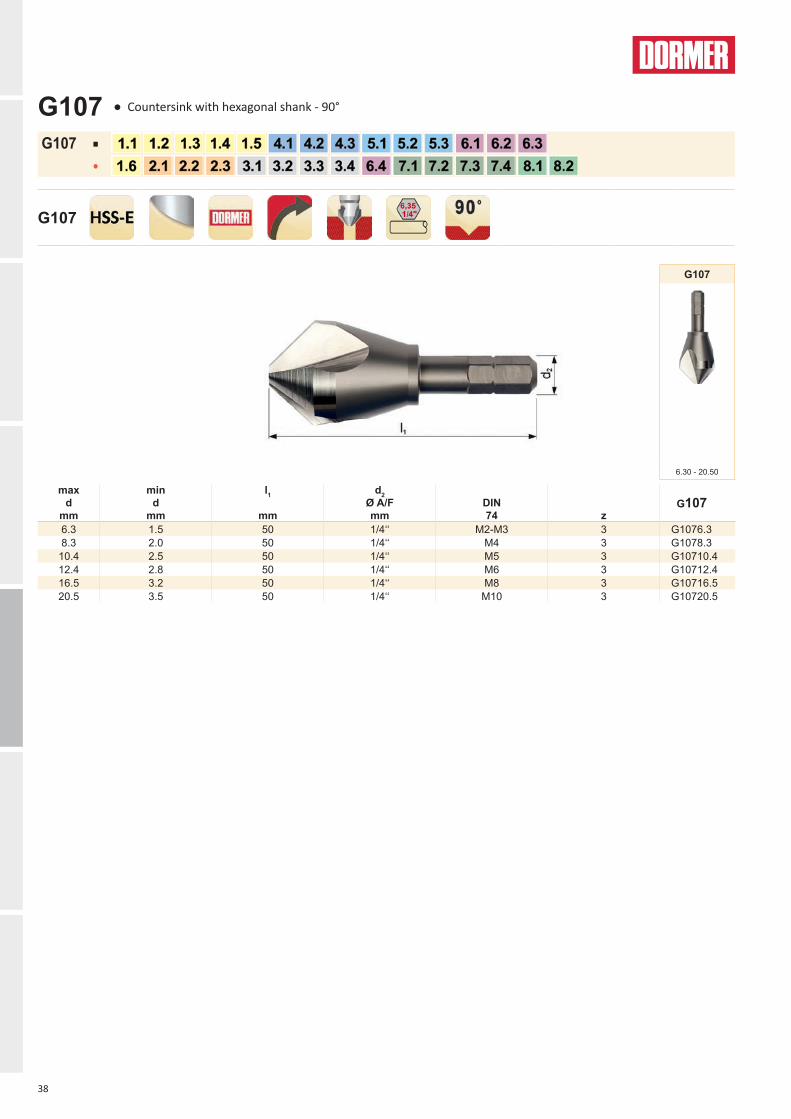
G107
6.3 1.5 50 1/4‘‘ M2-M3 3 G1076.38.3 2.0 50 1/4‘‘ M4 3 G1078.3
10.4 2.5 50 1/4‘‘ M5 3 G10710.412.4 2.8 50 1/4‘‘ M6 3 G10712.416.5 3.2 50 1/4‘‘ M8 3 G10716.520.5 3.5 50 1/4‘‘ M10 3 G10720.5
G107
6.30 - 20.50
G107
G107 ■
●
G107 ● Countersink with hexagonal shank - 90°

39
Nr.
A
B
C
G236
4 G106 6 6.30 mm, 8.30 mm, 10.40 mm, 12.40 mm, 16.50 mm, 20.50 mm G23645 G506 6 6.30 mm, 8.30 mm, 10.40 mm, 12.40 mm, 16.50 mm, 20.50 mm G2365
G236
Set
G236 ● Countersink set A=Styles in Set, B=No. in Set, C=Diameters in Set
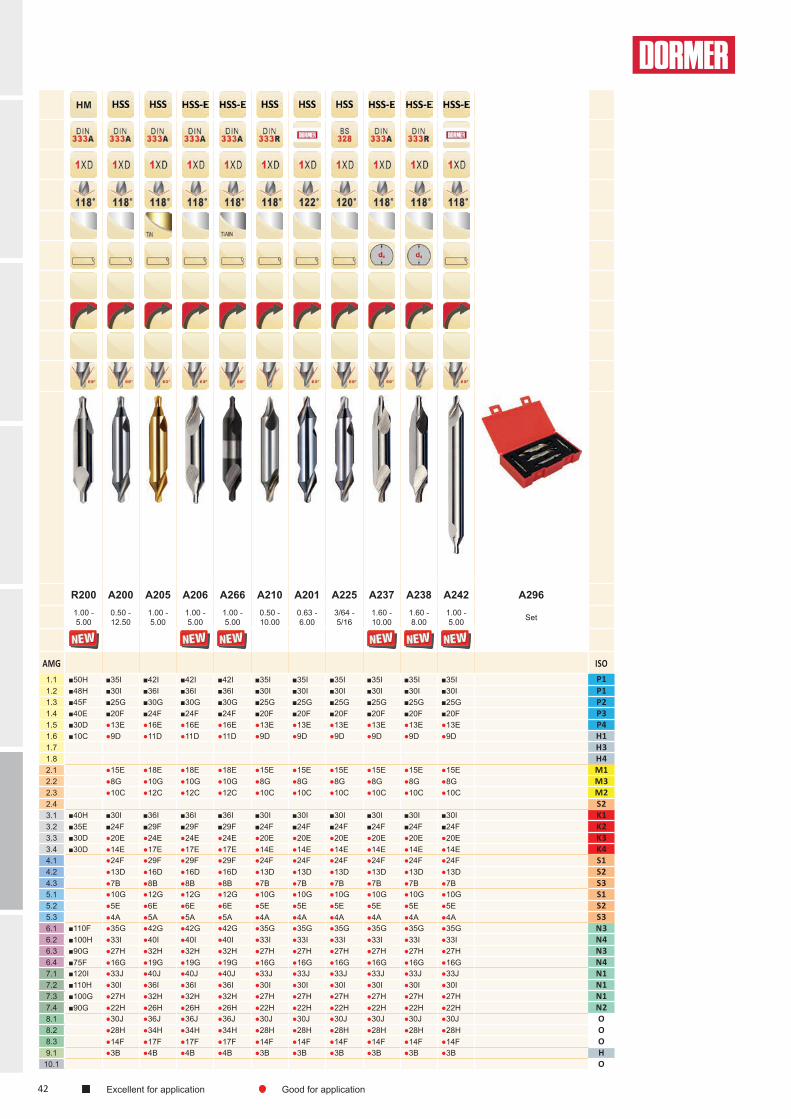
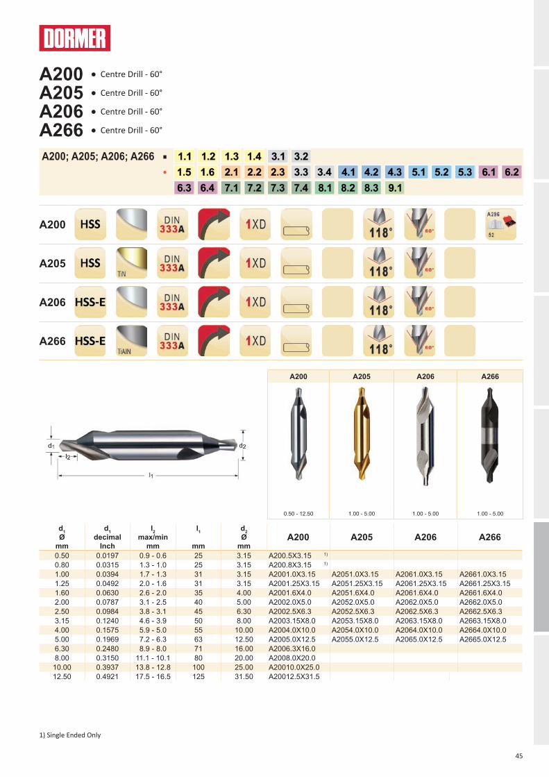
CENTER DRILLS

41
A206
/A26
6A2
42
R200
A237
/A23
8
NEWNEW NEWNEW
NEWNEWNEWNEW
CENTER DRILLS
To complement its existing range of Center Drills, Dormer has introduced several new designs to further expand its coverage of potential customers applications. These include HSS-E for tougher materials and environments, flatted shank for improved clamping, long series for increased reach and solid carbide for hard and abrasive materials.With a full range of sizes available, this makes Dormer a good choice for all your center drilling requirements.
FEATURES AND BENEFITS• Increased wear resistance and tool life• Manufactured with flatted shank for use in custom centering
heads used for machining the ends of shafts• Radius form increases cross sectional strength and therefore reduces the risk of breakage
Contact area is below the face of the shaft and therefore protected against possible damage
INTRODUCTION
CENTER DRILL STYLES
SOLID CARBIDE• Premium grade carbide for improved tool life when
centre drilling hard and abrasive materials
• More rigid operation for higher accuracy and surface quality
HSS-E SHANK WITH FLAT• A238 with radius form to produce protected centers in
the end of shafts
• Can be used with chamfer units
HSS-E USED FOR TOUGHER MATERIALS & STAINLESS STEELS• HSS-E with 8% cobalt content for increased hot
hardness, resulting in increased wear resistance and tool life
• A266 with TiAlN coating provides further improved abrasion resistance and increased tool life
HSS-E LONG SERIES • Longer overall length for increased reach
42
R200 A200 A205 A206 A266 A210 A201 A225 A237 A238 A242 A2961.00 - 5.00
0.50 - 12.50
1.00 - 5.00
1.00 - 5.00
1.00 - 5.00
0.50 - 10.00
0.63 - 6.00
3/64 - 5/16
1.60 - 10.00
1.60 - 8.00
1.00 - 5.00 Set
AMG ISO1.1 ■50H ■35I ■42I ■42I ■42I ■35I ■35I ■35I ■35I ■35I ■35I P11.2 ■48H ■30I ■36I ■36I ■36I ■30I ■30I ■30I ■30I ■30I ■30I P11.3 ■45F ■25G ■30G ■30G ■30G ■25G ■25G ■25G ■25G ■25G ■25G P21.4 ■40E ■20F ■24F ■24F ■24F ■20F ■20F ■20F ■20F ■20F ■20F P31.5 ■30D ●13E ●16E ●16E ●16E ●13E ●13E ●13E ●13E ●13E ●13E P41.6 ■10C ●9D ●11D ●11D ●11D ●9D ●9D ●9D ●9D ●9D ●9D H11.7 H31.8 H42.1 ●15E ●18E ●18E ●18E ●15E ●15E ●15E ●15E ●15E ●15E M12.2 ●8G ●10G ●10G ●10G ●8G ●8G ●8G ●8G ●8G ●8G M32.3 ●10C ●12C ●12C ●12C ●10C ●10C ●10C ●10C ●10C ●10C M22.4 S23.1 ■40H ■30I ■36I ■36I ■36I ■30I ■30I ■30I ■30I ■30I ■30I K13.2 ■35E ■24F ■29F ■29F ■29F ■24F ■24F ■24F ■24F ■24F ■24F K23.3 ■30D ●20E ●24E ●24E ●24E ●20E ●20E ●20E ●20E ●20E ●20E K33.4 ■30D ●14E ●17E ●17E ●17E ●14E ●14E ●14E ●14E ●14E ●14E K44.1 ●24F ●29F ●29F ●29F ●24F ●24F ●24F ●24F ●24F ●24F S14.2 ●13D ●16D ●16D ●16D ●13D ●13D ●13D ●13D ●13D ●13D S24.3 ●7B ●8B ●8B ●8B ●7B ●7B ●7B ●7B ●7B ●7B S35.1 ●10G ●12G ●12G ●12G ●10G ●10G ●10G ●10G ●10G ●10G S15.2 ●5E ●6E ●6E ●6E ●5E ●5E ●5E ●5E ●5E ●5E S25.3 ●4A ●5A ●5A ●5A ●4A ●4A ●4A ●4A ●4A ●4A S36.1 ■110F ●35G ●42G ●42G ●42G ●35G ●35G ●35G ●35G ●35G ●35G N36.2 ■100H ●33I ●40I ●40I ●40I ●33I ●33I ●33I ●33I ●33I ●33I N46.3 ■90G ●27H ●32H ●32H ●32H ●27H ●27H ●27H ●27H ●27H ●27H N36.4 ■75F ●16G ●19G ●19G ●19G ●16G ●16G ●16G ●16G ●16G ●16G N47.1 ■120I ●33J ●40J ●40J ●40J ●33J ●33J ●33J ●33J ●33J ●33J N17.2 ■110H ●30I ●36I ●36I ●36I ●30I ●30I ●30I ●30I ●30I ●30I N17.3 ■100G ●27H ●32H ●32H ●32H ●27H ●27H ●27H ●27H ●27H ●27H N17.4 ■90G ●22H ●26H ●26H ●26H ●22H ●22H ●22H ●22H ●22H ●22H N28.1 ●30J ●36J ●36J ●36J ●30J ●30J ●30J ●30J ●30J ●30J O8.2 ●28H ●34H ●34H ●34H ●28H ●28H ●28H ●28H ●28H ●28H O8.3 ●14F ●17F ●17F ●17F ●14F ●14F ●14F ●14F ●14F ●14F O9.1 ●3B ●4B ●4B ●4B ●3B ●3B ●3B ●3B ●3B ●3B H
10.1 O
Excellent for application Good for application

43
Ø(D) 1mm 2mm 3mm 4mm 5mm 6mm 8mm 10mm 12mmA 0.012 0.023 0.029 0.032 0.036 0.042 0.054 0.062 0.069B 0.014 0.028 0.037 0.041 0.046 0.053 0.067 0.080 0.090C 0.015 0.032 0.044 0.050 0.056 0.064 0.080 0.098 0.110D 0.016 0.038 0.053 0.060 0.068 0.078 0.098 0.119 0.130E 0.017 0.043 0.062 0.071 0.080 0.092 0.115 0.140 0.150F 0.018 0.050 0.073 0.084 0.095 0.109 0.138 0.165 0.178G 0.019 0.056 0.084 0.096 0.109 0.126 0.160 0.190 0.205H 0.020 0.066 0.102 0.116 0.130 0.150 0.190 0.228 0.243I 0.021 0.076 0.119 0.134 0.150 0.173 0.220 0.265 0.280J 0.024 0.084 0.135 0.152 0.170 0.197 0.250 0.298 0.315
mm/N ± 25%
n =Vc x 1000 x D
Vf = n x f n

44
d1 Ø
mm
d1 decimal
Inch
l2 max/min
mm
l1
mm
d2 Ø
mmR200
1.00 0.0394 1.7 - 1.3 31 3.15 R2001.0X3.151.25 0.0492 2.0 - 1.6 31 3.15 R2001.25X3.151.60 0.0630 2.6 - 2.0 35 4.00 R2001.6X4.02.00 0.0787 3.1 - 2.5 40 5.00 R2002.0X5.02.50 0.0984 3.8 - 3.1 45 6.30 R2002.5X6.33.15 0.1240 4.6 - 3.9 50 8.00 R2003.15X8.04.00 0.1575 5.9 - 5.0 55 10.00 R2004.0X10.05.00 0.1969 7.2 - 6.3 63 12.50 R2005.0X12.5
R200
1.00 - 5.00
R200
R200 ■
R200 ● Centre Drill - 60°
45
d1 Ø
mm
d1 decimal
Inch
l2 max/min
mm
l1
mm
d2 Ø
mmA200 A205 A206 A266
0.50 0.0197 0.9 - 0.6 25 3.15 A200.5X3.15 1)
0.80 0.0315 1.3 - 1.0 25 3.15 A200.8X3.15 1)
1.00 0.0394 1.7 - 1.3 31 3.15 A2001.0X3.15 A2051.0X3.15 A2061.0X3.15 A2661.0X3.151.25 0.0492 2.0 - 1.6 31 3.15 A2001.25X3.15 A2051.25X3.15 A2061.25X3.15 A2661.25X3.151.60 0.0630 2.6 - 2.0 35 4.00 A2001.6X4.0 A2051.6X4.0 A2061.6X4.0 A2661.6X4.02.00 0.0787 3.1 - 2.5 40 5.00 A2002.0X5.0 A2052.0X5.0 A2062.0X5.0 A2662.0X5.02.50 0.0984 3.8 - 3.1 45 6.30 A2002.5X6.3 A2052.5X6.3 A2062.5X6.3 A2662.5X6.33.15 0.1240 4.6 - 3.9 50 8.00 A2003.15X8.0 A2053.15X8.0 A2063.15X8.0 A2663.15X8.04.00 0.1575 5.9 - 5.0 55 10.00 A2004.0X10.0 A2054.0X10.0 A2064.0X10.0 A2664.0X10.05.00 0.1969 7.2 - 6.3 63 12.50 A2005.0X12.5 A2055.0X12.5 A2065.0X12.5 A2665.0X12.56.30 0.2480 8.9 - 8.0 71 16.00 A2006.3X16.08.00 0.3150 11.1 - 10.1 80 20.00 A2008.0X20.0
10.00 0.3937 13.8 - 12.8 100 25.00 A20010.0X25.012.50 0.4921 17.5 - 16.5 125 31.50 A20012.5X31.5
A200 A205 A206 A266
0.50 - 12.50 1.00 - 5.00 1.00 - 5.00 1.00 - 5.00
A200
A205
A206
A266
A200; A205; A206; A266 ■
●
A200 ● Centre Drill - 60°
A205 ● Centre Drill - 60°
A206 ● Centre Drill - 60°
A266 ● Centre Drill - 60°
1) Single Ended Only
46
d1 Ø
mm
d1 decimal
Inch
l2 max/min
mm
l1
mm
r max/min
mm
d2 Ø
mmA210
0.50 0.0197 2.6 - 2.3 25.0 2.50 - 2.00 3.15 A210.5X3.15 1)
0.80 0.0315 2.9 - 2.6 25.0 3.15 - 2.50 3.15 A210.8X3.15 1)
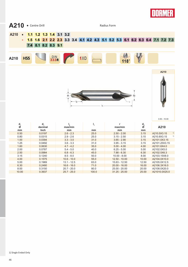
1.00 0.0394 3.3 - 3.0 31.0 3.65 - 2.90 3.15 A2101.0X3.151.25 0.0492 3.6 - 3.3 31.0 3.95 - 3.15 3.15 A2101.25X3.151.60 0.0630 4.7 - 4.2 35.0 5.00 - 4.00 4.00 A2101.6X4.02.00 0.0787 5.4 - 5.0 40.0 6.25 - 5.00 5.00 A2102.0X5.02.50 0.0984 6.8 - 6.3 45.0 7.88 - 6.30 6.30 A2102.5X6.33.15 0.1240 8.5 - 8.0 50.0 10.00 - 8.00 8.00 A2103.15X8.04.00 0.1575 10.6 - 10.0 55.0 12.50 - 10.00 10.00 A2104.0X10.05.00 0.1969 13.1 - 12.5 63.0 15.63 - 12.50 12.50 A2105.0X12.56.30 0.2480 16.6 - 16.0 71.0 20.00 - 16.00 16.00 A2106.3X16.08.00 0.3150 20.7 - 20.0 80.0 25.00 - 20.00 20.00 A2108.0X20.0
10.00 0.3937 25.7 - 25.0 100.0 31.25 - 25.00 25.00 A21010.0X25.0
A210
0.50 - 10.00
A210
A210 ■
●
1) Single Ended Only
A210 ● Centre Drill Radius Form
47
d1 Ø
mm
d1 decimal
Inch
l2 max/min
mm
l1
mm
d2 Ø
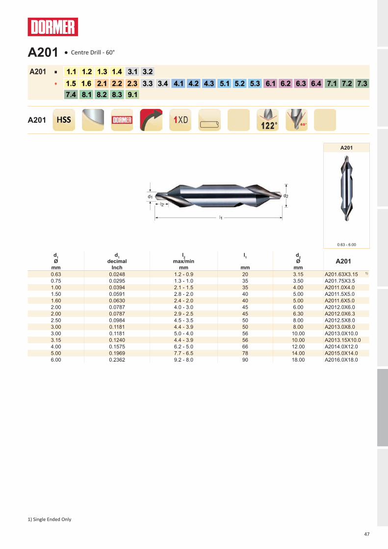
mmA201
0.63 0.0248 1.2 - 0.9 20 3.15 A201.63X3.15 1)
0.75 0.0295 1.3 - 1.0 35 3.50 A201.75X3.51.00 0.0394 2.1 - 1.5 35 4.00 A2011.0X4.01.50 0.0591 2.8 - 2.0 40 5.00 A2011.5X5.01.60 0.0630 2.4 - 2.0 40 5.00 A2011.6X5.02.00 0.0787 4.0 - 3.0 45 6.00 A2012.0X6.02.00 0.0787 2.9 - 2.5 45 6.30 A2012.0X6.32.50 0.0984 4.5 - 3.5 50 8.00 A2012.5X8.03.00 0.1181 4.4 - 3.9 50 8.00 A2013.0X8.03.00 0.1181 5.0 - 4.0 56 10.00 A2013.0X10.03.15 0.1240 4.4 - 3.9 56 10.00 A2013.15X10.04.00 0.1575 6.2 - 5.0 66 12.00 A2014.0X12.05.00 0.1969 7.7 - 6.5 78 14.00 A2015.0X14.06.00 0.2362 9.2 - 8.0 90 18.00 A2016.0X18.0
A201
0.63 - 6.00
A201
A201 ■
●
1) Single Ended Only
A201 ● Centre Drill - 60°

48
Nr.
d1 Ø
Inch
d1 decimal
Inch
l2 max/min
Inch
l1
Inch
d2 Ø
InchA225
BS1 3/64 0.0469 5/64 - 1/16 1.1/2 1/8 A225BS1BS2 1/16 0.0625 3/32 - 5/64 1.3/4 3/16 A225BS2BS3 3/32 0.0938 5/32 - 1/8 2“ 1/4 A225BS3BS4 1/8 0.1250 3/16 - 5/32 2.1/4 5/16 A225BS4BS5 3/16 0.1875 9/32 - 1/4 2.1/2 7/16 A225BS5
BS5A 7/32 0.2188 5/16 - 9/32 2.3/4 1/2 A225BS5ABS6 1/4 0.2500 3/8 - 5/16 3“ 5/8 A225BS6BS7 5/16 0.3125 15/32 - 13/32 3.1/2 3/4 A225BS7
A225
3/64 - 5/16
A225
A225 ■
●
A225 ● Centre Drill - 60°

49
d1 Ø
mm
d1 decimal
Inch
l2 max/min
mm
l1
mm
d2 Ø
mm
d4 max/min
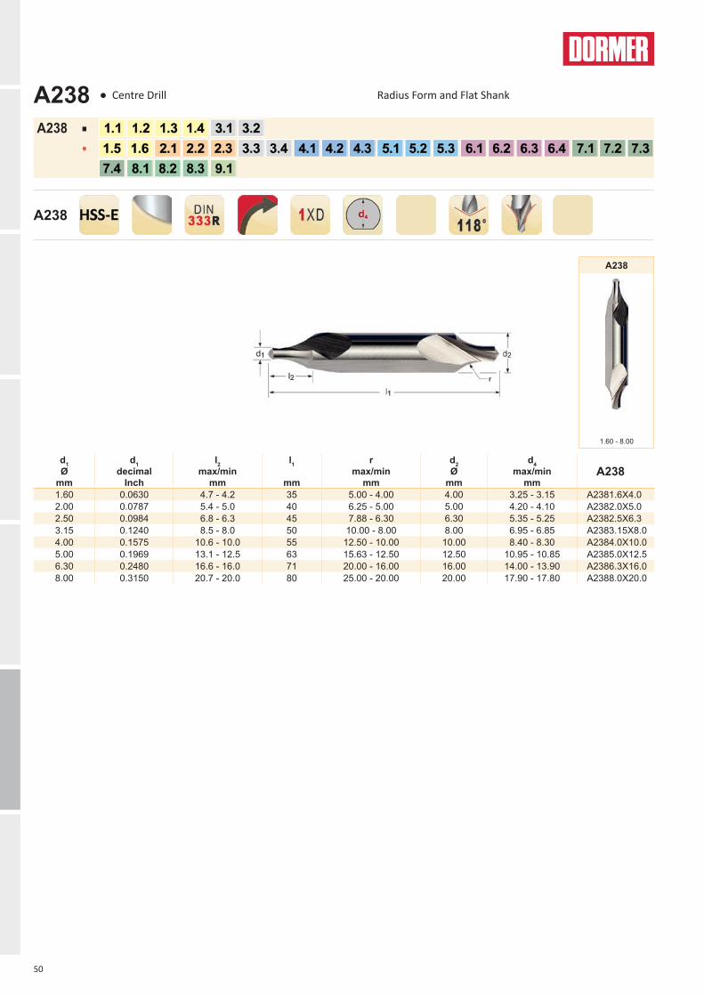
mmA237
1.60 0.0630 2.6 - 2.0 35 4.00 3.25 - 3.15 A2371.6X4.02.00 0.0787 3.1 - 2.5 40 5.00 4.20 - 4.10 A2372.0X5.02.50 0.0984 3.8 - 3.1 45 6.30 5.35 - 5.25 A2372.5X6.33.15 0.1240 4.6 - 3.9 50 8.00 6.95- 6.85 A2373.15X8.04.00 0.1575 5.9 - 5.0 55 10.00 8.40 - 8.30 A2374.0X10.05.00 0.1969 7.2 - 6.3 63 12.50 10.95 - 10.85 A2375.0X12.56.30 0.2480 8.9 - 8.0 71 16.00 14.00 -13.90 A2376.3X16.08.00 0.3150 11.1 - 10.1 80 20.00 17.90 - 17.80 A2378.0X20.0
10.00 0.3937 13.8 - 12.8 100 25.00 22.50 -22.40 A23710.0X25.0
A237
1.60 - 10.00
A237
A237 ■
●
A237 ● Centre Drill - 60° Flat Shank
50
d1 Ø
mm
d1 decimal
Inch
l2 max/min
mm
l1
mm
r max/min
mm
d2 Ø
mm
d4 max/min
mmA238
1.60 0.0630 4.7 - 4.2 35 5.00 - 4.00 4.00 3.25 - 3.15 A2381.6X4.02.00 0.0787 5.4 - 5.0 40 6.25 - 5.00 5.00 4.20 - 4.10 A2382.0X5.02.50 0.0984 6.8 - 6.3 45 7.88 - 6.30 6.30 5.35 - 5.25 A2382.5X6.33.15 0.1240 8.5 - 8.0 50 10.00 - 8.00 8.00 6.95 - 6.85 A2383.15X8.04.00 0.1575 10.6 - 10.0 55 12.50 - 10.00 10.00 8.40 - 8.30 A2384.0X10.05.00 0.1969 13.1 - 12.5 63 15.63 - 12.50 12.50 10.95 - 10.85 A2385.0X12.56.30 0.2480 16.6 - 16.0 71 20.00 - 16.00 16.00 14.00 - 13.90 A2386.3X16.08.00 0.3150 20.7 - 20.0 80 25.00 - 20.00 20.00 17.90 - 17.80 A2388.0X20.0
A238
1.60 - 8.00
A238
A238 ■
●
A238 ● Centre Drill Radius Form and Flat Shank
51
d1 Ø
mm
d1 decimal
Inch
l2 max/min
mm
l1
mm
d2 Ø
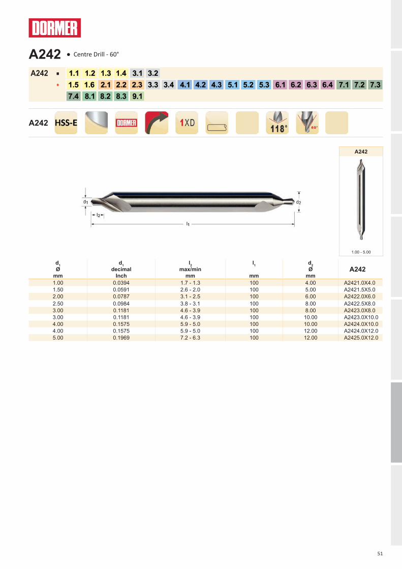
mmA242
1.00 0.0394 1.7 - 1.3 100 4.00 A2421.0X4.01.50 0.0591 2.6 - 2.0 100 5.00 A2421.5X5.02.00 0.0787 3.1 - 2.5 100 6.00 A2422.0X6.02.50 0.0984 3.8 - 3.1 100 8.00 A2422.5X8.03.00 0.1181 4.6 - 3.9 100 8.00 A2423.0X8.03.00 0.1181 4.6 - 3.9 100 10.00 A2423.0X10.04.00 0.1575 5.9 - 5.0 100 10.00 A2424.0X10.04.00 0.1575 5.9 - 5.0 100 12.00 A2424.0X12.05.00 0.1969 7.2 - 6.3 100 12.00 A2425.0X12.0
A242
1.00 - 5.00
A242
A242 ■
●
A242 ● Centre Drill - 60°
52
Nr
A B
C
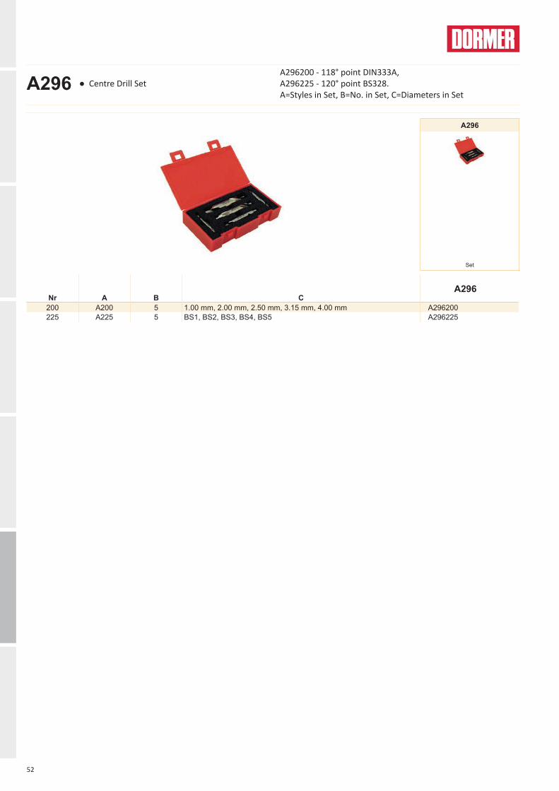
A296
200 A200 5 1.00 mm, 2.00 mm, 2.50 mm, 3.15 mm, 4.00 mm A296200225 A225 5 BS1, BS2, BS3, BS4, BS5 A296225
A296
Set
A296 ● Centre Drill SetA296200 - 118° point DIN333A, A296225 - 120° point BS328. A=Styles in Set, B=No. in Set, C=Diameters in Set

HSS DRILLS
56
HSS DRILLS
A723
NEWNEW
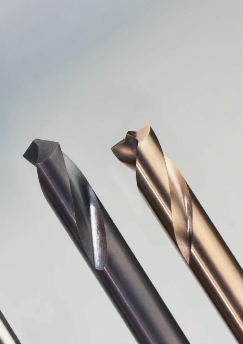
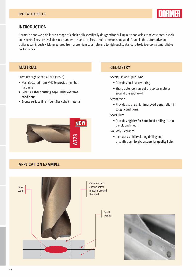
Dormer’s Spot Weld drills are a range of cobalt drills specifically designed for drilling out spot welds to release steel panels and sheets. They are available in a number of standard sizes to suit common spot welds found in the automotive and trailer repair industry. Manufactured from a premium substrate and to high quality standard to deliver consistent reliable performance.
INTRODUCTION
MATERIAL
Premium High Speed Cobalt (HSS-E)• Manufactured from M42 to provide high hot
hardness• Retains a sharp cutting edge under extreme
conditions• Bronze surface finish identifies cobalt material
GEOMETRY
Special Lip and Spur Point• Provides positive centering • Sharp outer-corners cut the softer material
around the spot weldStrong Web
• Provides strength for improved penetration in tough conditions
Short Flute• Provides rigidity for hand held drilling of thin
panels and sheetNo Body Clearance
• Increases stability during drilling and breakthrough to give a superior quality hole
SPOT WELD DRILLS
Outer corners cut the softer material around the weld
Spot Weld
Steel Panels
APPLICATION EXAMPLE
57
HSS DRILLS
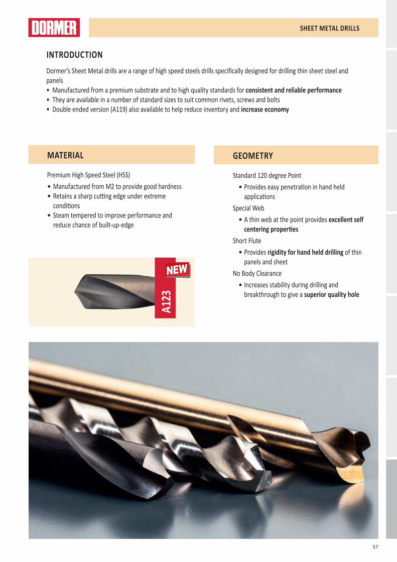
A123
NEWNEW
Dormer’s Sheet Metal drills are a range of high speed steels drills specifically designed for drilling thin sheet steel and panels • Manufactured from a premium substrate and to high quality standards for consistent and reliable performance • They are available in a number of standard sizes to suit common rivets, screws and bolts• Double ended version (A119) also available to help reduce inventory and increase economy
INTRODUCTION
MATERIAL
Premium High Speed Steel (HSS)• Manufactured from M2 to provide good hardness • Retains a sharp cutting edge under extreme
conditions• Steam tempered to improve performance and
reduce chance of built-up-edge
GEOMETRY
Standard 120 degree Point• Provides easy penetration in hand held
applicationsSpecial Web
• A thin web at the point provides excellent self centering properties
Short Flute• Provides rigidity for hand held drilling of thin
panels and sheetNo Body Clearance
• Increases stability during drilling and breakthrough to give a superior quality hole
SHEET METAL DRILLS

58
A147 A723 A119 A123 A087 A089 A1880.30 - 15.0
6.00 - 8.00
3.30 - 5.10 3/32 - 1/4 Set Set Set
AMG ISO1.1 ●35I ■35D ■35C ■35E P11.2 ●30I ■30D ■27C ■30E P11.3 ●25G ●25C ●23C ■27C P21.4 ●20F ●20C ●20C ●21C P31.5 ●13E ●8C ●14C P41.6 ●9D ●7A ●10B H11.7 H31.8 H42.1 ■15E ●15A ●16C M12.2 ■9G ●7C ●9D M32.3 ■10D ●10A ●10B M22.4 ●7B S23.1 ●30H K13.2 ●24F K23.3 ●20E K33.4 ●14E K44.1 ■25G ●27A ●27C S14.2 ■16E ●12A ●12B S24.3 ●7B ●7A ●7A S35.1 ■12G ●9A ●13D S15.2 ●7G ●4C ●8C S25.3 ●6E ●3C ●4A S36.1 ●33G ●27A ■27D N36.2 ●35I ●33C ■33E N46.3 ●31H ●27C ■27D N36.4 ●16G ●16C ■16D N47.1 ●33J ●33C ■33E N17.2 ●30I ●30C ■30E N17.3 ●27H ●30C ●30D N17.4 ●24F ●25C ●25D N28.1 ●30J ●30I ●30F O8.2 ●28H ●35C ●35E O8.3 ●14F ●17D O9.1 ●3B ●12A H
10.1 O
Excellent for application Good for application
59
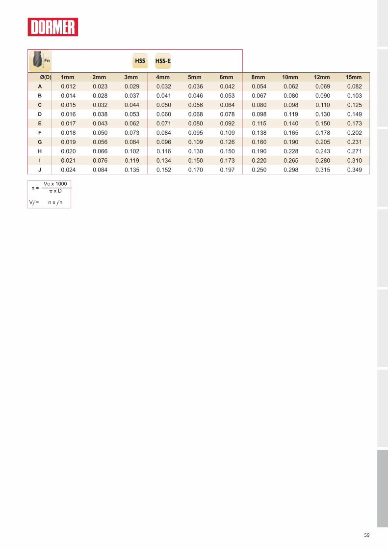
Ø(D) 1mm 2mm 3mm 4mm 5mm 6mm 8mm 10mm 12mm 15mmA 0.012 0.023 0.029 0.032 0.036 0.042 0.054 0.062 0.069 0.082B 0.014 0.028 0.037 0.041 0.046 0.053 0.067 0.080 0.090 0.103C 0.015 0.032 0.044 0.050 0.056 0.064 0.080 0.098 0.110 0.125D 0.016 0.038 0.053 0.060 0.068 0.078 0.098 0.119 0.130 0.149E 0.017 0.043 0.062 0.071 0.080 0.092 0.115 0.140 0.150 0.173F 0.018 0.050 0.073 0.084 0.095 0.109 0.138 0.165 0.178 0.202G 0.019 0.056 0.084 0.096 0.109 0.126 0.160 0.190 0.205 0.231H 0.020 0.066 0.102 0.116 0.130 0.150 0.190 0.228 0.243 0.271I 0.021 0.076 0.119 0.134 0.150 0.173 0.220 0.265 0.280 0.310J 0.024 0.084 0.135 0.152 0.170 0.197 0.250 0.298 0.315 0.349
n =Vc x 1000 x D
Vf = n x f n

60
d1 Øh8 Inch
d1 Øh8 mm
d1 decimal
Inch
l2
mm
l1
mmA147
0.30 0.0118 3 19 A147.30.40 0.0157 5 20 A147.40.50 0.0197 6 22 A147.50.60 0.0236 7 24 A147.60.70 0.0276 9 28 A147.70.80 0.0315 10 30 A147.80.90 0.0354 11 32 A147.91.00 0.0394 12 34 A1471.01.10 0.0433 14 36 A1471.11.20 0.0472 16 38 A1471.21.30 0.0512 16 38 A1471.31.40 0.0551 18 40 A1471.41.50 0.0591 18 40 A1471.5
1/16 1.59 0.0626 20 43 A1471/161.60 0.0630 20 43 A1471.61.70 0.0669 20 43 A1471.71.80 0.0709 22 46 A1471.81.90 0.0748 22 46 A1471.92.00 0.0787 24 49 A1472.02.10 0.0827 24 49 A1472.12.20 0.0866 27 53 A1472.22.30 0.0906 27 53 A1472.3
3/32 2.38 0.0937 30 57 A1473/322.40 0.0945 30 57 A1472.42.50 0.0984 30 57 A1472.52.60 0.1024 30 57 A1472.62.70 0.1063 33 61 A1472.72.80 0.1102 33 61 A1472.82.90 0.1142 33 61 A1472.93.00 0.1181 33 61 A1473.03.10 0.1220 36 65 A1473.13.18 0.1252 36 65 A1471/83.20 0.1260 36 65 A1473.23.30 0.1299 36 65 A1473.33.40 0.1339 39 70 A1473.43.50 0.1378 39 70 A1473.53.60 0.1417 39 70 A1473.63.70 0.1457 39 70 A1473.7
A147
0.30 - 15.0
A147
A147 ■
●
A147 ● Jobber Drill
61
d1 Øh8 Inch
d1 Øh8 mm
d1 decimal
Inch
l2
mm
l1
mmA147
3.80 0.1496 43 75 A1473.83.90 0.1535 43 75 A1473.9
5/32 3.97 0.1563 43 75 A1475/324.00 0.1575 43 75 A1474.04.10 0.1614 43 75 A1474.14.20 0.1654 43 75 A1474.24.30 0.1693 47 80 A1474.34.40 0.1732 47 80 A1474.44.50 0.1772 47 80 A1474.54.60 0.1811 47 80 A1474.64.70 0.1850 47 80 A1474.7
3/16 4.76 0.1874 52 86 A1473/164.80 0.1890 52 86 A1474.84.90 0.1929 52 86 A1474.95.00 0.1969 52 86 A1475.05.10 0.2008 52 86 A1475.15.20 0.2047 52 86 A1475.25.30 0.2087 52 86 A1475.35.40 0.2126 57 93 A1475.45.50 0.2165 57 93 A1475.55.60 0.2205 57 93 A1475.65.70 0.2244 57 93 A1475.75.80 0.2283 57 93 A1475.85.90 0.2323 57 93 A1475.96.00 0.2362 57 93 A1476.06.10 0.2402 63 101 A1476.16.20 0.2441 63 101 A1476.26.30 0.2480 63 101 A1476.36.35 0.2500 63 101 A1471/46.40 0.2520 63 101 A1476.46.50 0.2559 63 101 A1476.56.60 0.2598 63 101 A1476.66.70 0.2638 63 101 A1476.76.80 0.2677 69 109 A1476.86.90 0.2717 69 109 A1476.97.00 0.2756 69 109 A1477.07.10 0.2795 69 109 A1477.17.20 0.2835 69 109 A1477.27.30 0.2874 69 109 A1477.37.40 0.2913 69 109 A1477.47.50 0.2953 69 109 A1477.57.60 0.2992 75 117 A1477.67.70 0.3031 75 117 A1477.77.80 0.3071 75 117 A1477.87.90 0.3110 75 117 A1477.98.00 0.3150 75 117 A1478.08.10 0.3189 75 117 A1478.18.20 0.3228 75 117 A1478.28.30 0.3268 75 117 A1478.38.40 0.3307 75 117 A1478.48.50 0.3346 75 117 A1478.58.60 0.3386 81 125 A1478.68.70 0.3425 81 125 A1478.78.80 0.3465 81 125 A1478.88.90 0.3504 81 125 A1478.99.00 0.3543 81 125 A1479.09.10 0.3583 81 125 A1479.19.20 0.3622 81 125 A1479.29.30 0.3661 81 125 A1479.39.40 0.3701 81 125 A1479.49.50 0.3740 81 125 A1479.59.60 0.3780 87 133 A1479.69.70 0.3819 87 133 A1479.79.80 0.3858 87 133 A1479.89.90 0.3898 87 133 A1479.9
10.00 0.3937 87 133 A14710.010.20 0.4016 87 133 A14710.210.50 0.4134 87 133 A14710.5

62
d1 Øh8 Inch
d1 Øh8 mm
d1 decimal
Inch
l2
mm
l1
mmA147
11.00 0.4331 94 142 A14711.011.20 0.4409 94 142 A14711.211.50 0.4528 94 142 A14711.512.00 0.4724 101 151 A14712.012.50 0.4921 101 151 A14712.513.00 0.5118 101 151 A14713.013.50 0.5315 108 160 A14713.514.00 0.5512 108 160 A14714.014.50 0.5709 114 169 A14714.515.00 0.5906 114 169 A14715.0
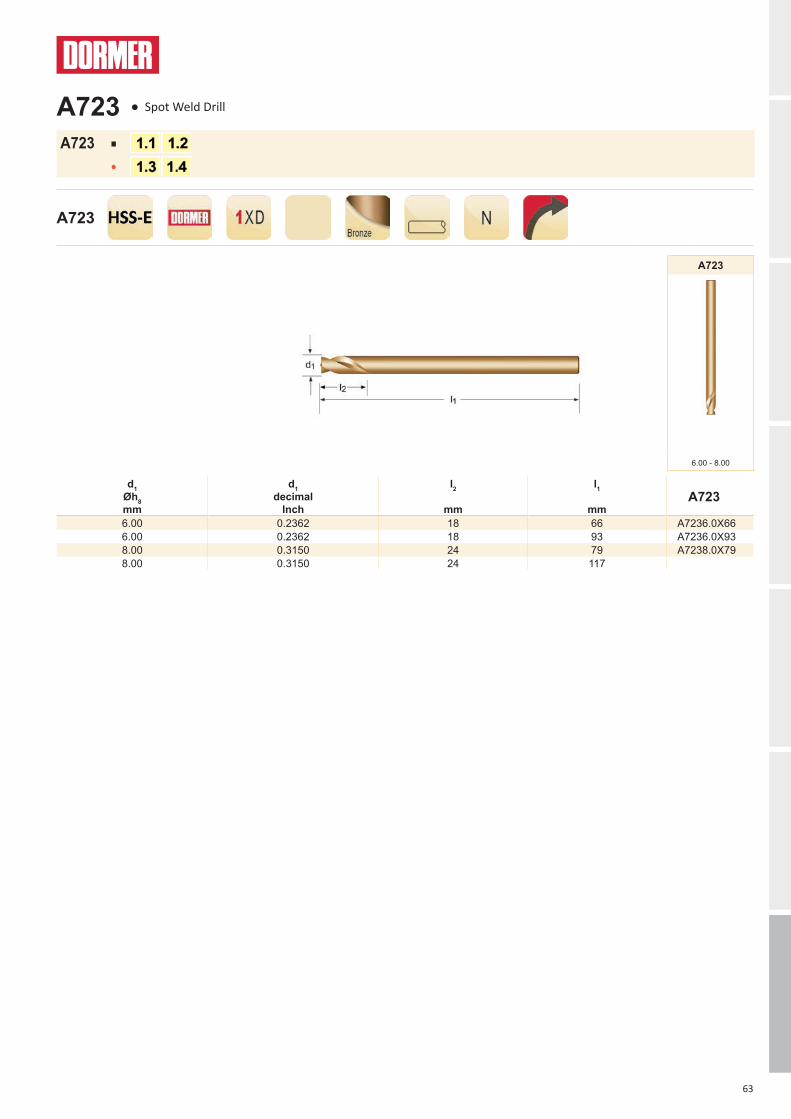
63
d1 Øh8 mm
d1 decimal
Inch
l2
mm
l1
mmA723
6.00 0.2362 18 66 A7236.0X666.00 0.2362 18 93 A7236.0X938.00 0.3150 24 79 A7238.0X798.00 0.3150 24 117
A723
6.00 - 8.00
A723
A723 ■
●
A723 ● Spot Weld Drill

64
d1 Øh8 mm
d1 decimal
Inch
l2
mm
l1
mmA119
3.30 0.1299 11 49 A1193.33.60 0.1417 12 52 A1193.64.10 0.1614 14 55 A1194.14.20 0.1654 14 55 A1194.24.90 0.1929 17 62 A1194.95.10 0.2008 17 62 A1195.1
A119
3.30 - 5.10
A119
A119 ■
●
A119 ● Stub Drill - Double Ended Sheet Metal Drill

65
d1 Øh8 Inch
d1 Øh8 mm
d1 decimal
Inch
l2
mm
l1
mmA123
3/32 2.38 0.0937 14 43 A1233/32S2.50 0.0984 14 43 A1232.5S3.00 0.1181 16 46 A1233.0S
1/8 3.18 0.1252 18 49 A1231/8S3.20 0.1260 18 49 A1233.2S3.30 0.1299 18 49 A1233.3S3.50 0.1378 18 52 A1233.5S3.70 0.1457 18 52 A1233.7S
5/32 3.97 0.1563 18 55 A1235/32S4.00 0.1575 18 55 A1234.0S4.10 0.1614 18 55 A1234.1S4.20 0.1654 18 55 A1234.2S4.50 0.1772 18 58 A1234.5S
3/16 4.76 0.1874 18 62 A1233/16S4.80 0.1890 18 62 A1234.8S4.90 0.1929 18 62 A1234.9S5.00 0.1969 18 62 A1235.0S5.50 0.2165 18 66 A1235.5S
7/32 5.56 0.2189 18 66 A1237/32S6.00 0.2362 18 66 A1236.0S
1/4 6.35 0.2500 19 70 A1231/4S
A123
3/32 - 1/4
A123
A123 ■
●
A123 ● Stub Drill Sheet Metal Drill. Overall Length to DIN 1897

66
Nr.
A
B
C
A087
201 A002 19 1.0 mm - 10.0 mm x 0.5 mm A087201
A087
Set
A087 ● Compact Drill Set A=Styles in Set, B=No. in Set, C=Diameters in Set
With A002 TiN coated jobber drills for general purpose drilling in a wide range of materials.
67
Nr.
A
B
C
A089
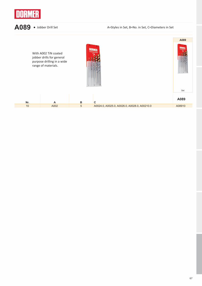
10 A002 5 A0024.0, A0025.0, A0026.0, A0028.0, A00210.0 A08910
A089
Set
A089 ● Jobber Drill Set A=Styles in Set, B=No. in Set, C=Diameters in Set
With A002 TiN coated jobber drills for general purpose drilling in a wide range of materials.
68
Nr.
A
B
C
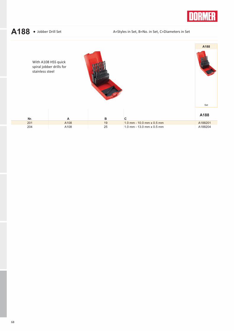
A188
201 A108 19 1.0 mm - 10.0 mm x 0.5 mm A188201204 A108 25 1.0 mm - 13.0 mm x 0.5 mm A188204
A188
Set
A188 ● Jobber Drill Set A=Styles in Set, B=No. in Set, C=Diameters in Set
With A108 HSS quick spiral jobber drills for stainless steel
www.dormerpramet.comyoutube.com/dormerpramet
ArgentinaT: 54 (11) 6777-6777F: 54 (11) [email protected]
AustraliaT: 1300 131 274F: 1300 809 [email protected]
AustriaT: +31 10 2080 240F: +31 10 2080 [email protected]
Belgium & LuxembourgT: +32 3 440 59 01F: +32 3 449 15 [email protected]
BrazilT: +55 11 5660 3000F: +55 11 5667 [email protected]
CanadaT: (888) 336 7637En Français: (888) 368 8457F: (905) 542 [email protected]
ChinaT: +86 21 2416 0508F: +86 21 5442 [email protected]
CroatiaT: +385 98 407 [email protected]
Czech Republic T: +420 583 381 111F: +420 583 215 [email protected]
DenmarkT: 808 82106F: +46 35 16 52 [email protected]
FinlandT: 0205 44 7003F: 0205 44 [email protected]
FranceT: +33 (0)2 47 62 57 01F: +33 (0)2 47 62 52 [email protected]
Germany T: +49 9131 933 08 70F: +49 9131 933 08 [email protected] Hungary T: +36-96 / 522-846F: +36-96 / [email protected]
IndiaT: +91 11 4601 [email protected]
Italy solid tools:T: +39 02 38 04 51F: +39 02 38 04 52 43indexable tools:T: +39 0523 55 19 11F: +39 0523 55 18 [email protected]
Kazakhstan T: +7 771 305 11 [email protected]
MexicoT: +52 (555) 7293981F: +52 (555) [email protected]
NetherlandsT: +31 10 2080 240F: +31 10 2080 [email protected]
New ZealandT: +64 9 2735858F: +64 9 [email protected]
Norway T: 800 10 113F: +46 35 16 52 [email protected]
Poland T: +48 32 78-15-890F: +48 32 [email protected]
RomaniaT: +4(0)730 015 [email protected]
RussiaТ: +7 495 775 10 28Ф: +7 (499) 763 38 [email protected]
SlovakiaT: +421 (41) 764 54 60F: +421 (41) 763 74 [email protected]
Spain T: +34 935717722F: +34 [email protected]
PortugalT: +351 21 424 54 21F: +351 21 424 54 [email protected]
SloveniaT: +385 98 407 [email protected]
Swedenresponsible for IcelandT: +46 35 16 52 96F: +46 35 16 52 [email protected]
SwitzerlandT: +31 10 2080 240F: +31 10 2080 [email protected]
TurkeyT: +90 533 212 45 [email protected]
UkraineT: +38 056 376 51 19F: +38 056 376 51 [email protected]
United Kingdomresponsible for IrelandT: 0870 850 4466F: 0870 850 [email protected]
United States of AmericaT: (800) 877-3745 F: (847) [email protected]
Other countries
South AmericaT: +55 11 5660 3000F: +55 11 5667 [email protected]
Central and Eastern EuropeT: +420 583 381 529F: +420 583 381 401 [email protected]
Rest of the WorldDormer Pramet International UKT: +44 1246 571338F: +44 1246 571339 [email protected]
Dormer Pramet International CZT: +420 583 381 520F: +420 583 215 [email protected]
DOR-CAT-NEWS-2016-2-EN
As a professional you can judge the quality of work by just looking at the chip. Our chip is a clean and uncomplicated shape that in itself tells a story. It is a clear and consistent signal and that’s why we use it as a symbol for being simply reliable.