2017 international seminar on intelligent technology and
TRANSCRIPT

Motion Planning Simulator for Holonomic Robot Soccer Platform
Rudy Dikairono, Aulia Aditya Rachman, Setiawardhana
Department of Electrical Engineering Institut Teknologi Sepuluh Nopember
Surabaya, Indonesia [email protected],
[email protected], [email protected]
Tri Arief Sardjono, Djoko Purwanto Department of Electrical Engineering Institut Teknologi Sepuluh Nopember
Surabaya, Indonesia [email protected],
Abstract - This paper presents a soccer robot simulator which is built base on holonomic wheeled soccer robot platform. The platform is self-made with specifications based on Middle Sized League RoboCup rules. The simulator is built for multi-operating systems that can be run on Windows, Mac or Linux operating system. The use of simulators can speed up the development of algorithms for wheeled soccer robots because algorithmic testing can be done in the simulator before being implemented in actual robots. Time and cost saving are the huge benefits that can be derived from using this simulator. Algorithm A* is used for obstacle avoidance testing. The result shows that algorithm programs written in the simulator can be directly implemented into a real soccer robot platform. This simulator has motion planning RMSE equal to 6.5 cm for path planning without obstacle avoidance and RMSE equal to 46.6 cm for path planning with obstacle avoidance algorithm.
Keywords- Holonomic soccer robot, path planning, simulator, RoboCup, obstacle avoidance.
I. INTRODUCTION
To speed up the design and implementation process on a soccer robot system a simulator should be created. The simulator is used to perform testing on the computer without the need to test directly on the robot to be programmed. Simulator usage will reduce time and cost. The risk of program errors and algorithms can be minimized with the use of this simulator. Thus, work accidents that result in damage either from the human side or equipment can be minimized.
The simulators made in this study are based on a self-built soccer wheel robot platform. The making of this soccer robot follows the guidelines issued by MSL Robocup[1]. Robocup is an international consortium that develops robots for the benefit of soccer games. The game of soccer is chosen because it contains various technical needs in the field of robotics that represent real needs in the real world. Famous soccer games around the world can attract researchers to accelerate their research in the field of robotics. The soccer robot platform has been developed by several developers such as Turtle[2] and Cambada[3]. Turtle developed by Eindhoven University and sold for 5000 Euro. This price
includes hardware and software needed for the development of algorithms from soccer robots.
This research develops hardware and software platforms which are developed specifically for the needs of wheeled soccer robots at an affordable price. The hardware design is made with consideration of soccer robot competition rule, with dimensions of 52 cm long and 80 cm high. The control system uses an Intel NUC computers as the main processor and an ARM STM32F4 microcontroller as a controller that connect to actuators driver and sensors in the robot.
The software is designed and prepared for multi-operating systems using Open Framework toolkit. C programming language was chosen to facilitate developers because it is considered as a universal programming language. The Software can run under a various operating systems such as Windows, Mac, and Linux. This compatibility can make it easier for developers to use the software without changing the infrastructure of previously used operating systems.
II. ROBOT SOCCER PLATFORM
A. Mechanical System The robotic mechanical platform is made with a holonomic
system that has 3 omni-wheels. The kinematics of this system can be seen in Fig. 1, and the speed control calculations can be viewed in the formula (1)[4]. ẋ and ẏ is the translation velocity of the robot, is the angular velocity of the robot, ∅ is the speed of each motor, θ is the angle from the first wheel position to the x axis, and α is the angle of the other wheels’ position to the first wheel.
The mechanical system in this soccer robot platform is based on MSL RoboCup rules. The system consists of 3 pieces of omni-direction wheels that are driven by 3 pieces of the PG45 motor type with 50 Watt power. This motor can rotate with speed 2500 rpm at 24 Volt voltage. The motor is coupled with a 19: 1 gearbox ratio to get a speed of 131 rpm. The wheels are omni direction wheel with a diameter of 11 cm. The setup of the mechanical setting can be seen in Fig. 2 as wheel drive system of the robot.
2017 International Seminar on Intelligent Technology and Its Application
978-1-5386-2708-2/17/$31.00©/2017/IEEE 368
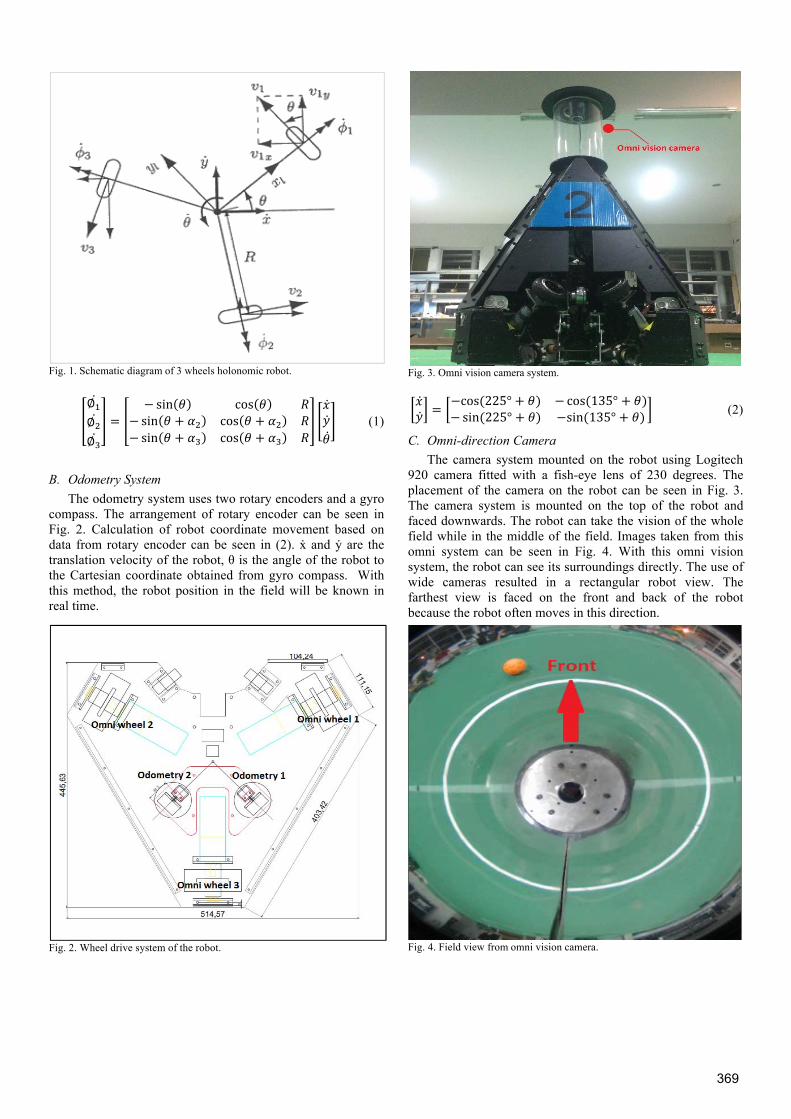
Fig. 1. Schematic diagram of 3 wheels holonomic robot. ∅∅∅ = sin( ) cos( )sin( ) cos( )sin( ) cos( ) (1)
B. Odometry System The odometry system uses two rotary encoders and a gyro
compass. The arrangement of rotary encoder can be seen in Fig. 2. Calculation of robot coordinate movement based on data from rotary encoder can be seen in (2). ẋ and ẏ are the translation velocity of the robot, θ is the angle of the robot to the Cartesian coordinate obtained from gyro compass. With this method, the robot position in the field will be known in real time.
Fig. 2. Wheel drive system of the robot.
Fig. 3. Omni vision camera system.
= cos(225° ) cos(135° )sin(225° ) sin(135° ) (2)
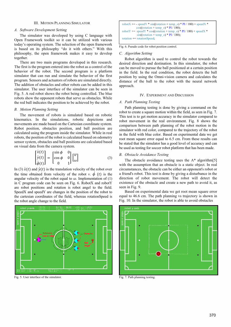
C. Omni-direction Camera The camera system mounted on the robot using Logitech
920 camera fitted with a fish-eye lens of 230 degrees. The placement of the camera on the robot can be seen in Fig. 3. The camera system is mounted on the top of the robot and faced downwards. The robot can take the vision of the whole field while in the middle of the field. Images taken from this omni system can be seen in Fig. 4. With this omni vision system, the robot can see its surroundings directly. The use of wide cameras resulted in a rectangular robot view. The farthest view is faced on the front and back of the robot because the robot often moves in this direction.
Fig. 4. Field view from omni vision camera.
369
III. MOTION PLANNING SIMULATOR
A. Software Development Setting The simulator was developed by using C language with
Open Framework toolkit so it can be utilized with various today’s operating system. The selection of the open framework is based on its philosophy “do it with others.” With this philosophy, the open framework makes it easy to develop together.
There are two main programs developed in this research. The first is the program entered into the robot as a control of the behavior of the robot. The second program is a platform simulator that can run and simulate the behavior of the first program. Sensors and actuators of robots are simulated directly. The addition of obstacles and other robots can be added in this simulator. The user interface of the simulator can be seen in Fig. 5. A red robot shows the robot being controlled. The blue robots show the opponent robots that serve as obstacles. While the red ball indicates the position to be achieved by the robot.
B. Motion Planning Setting The movement of robots is simulated based on robotic
kinematics. In the simulations, robotic depictions and movements are made based on the Cartesian coordinate system. Robot position, obstacles position, and ball position are calculated using the program inside the simulator. While in real robots, the position of the robot is calculated based on odometry sensor system, obstacles and ball positions are calculated based on visual data from the camera system.
( )( )( ) = sin 0cos 00 1 (3)
In (3) ( ) and ( ) is the translation velocity of the robot over the time obtained from velocity of the robot v. ( ) is the angular velocity of the robot equal to . Implementation of (1) in C program code can be seen on Fig. 6. RobotX and robotY are robot positions and rotation is robot angel to the field. SpeedX and speedY are changes in the position of the robot to the cartesian coordinates of the field, whereas rotationSpeed is the robot angle change to the field.
Fig. 5. User interface of the simulator.
Fig. 6. Pseudo code for robot position control.
C. Algorithm Setting Robot algorithm is used to control the robot towards the
desired direction and destination. In this simulator, the robot can be moved to pursue the ball positioned at a certain position in the field. In the real condition, the robot detects the ball position by using the Omni-vision camera and calculates the distance of the ball to the robot with the neural network approach.
IV. EXPERIMENT AND DISCUSSION
A. Path Planning Testing Path planning testing is done by giving a command on the
robot to create a square motion within the field, as seen in Fig. 7. This test is to get motion accuracy in the simulator compared to robot movement in the real environment. Fig. 8 shows the comparison between path planning of the robot motion in the simulator with red color, compared to the trajectory of the robot in the field with blue color. Based on experimental data we get root mean square error equal to 6.5 cm. From these results can be stated that the simulator has a good level of accuracy and can be used as testing for soccer robot platform that has been made.
B. Obstacle Avoidance Testing The obstacle avoidance testing uses the A* algorithm[5]
with the assumption that an obstacle is a static object. In real circumstances, the obstacle can be either an opponent's robot or a friend's robot. This test is done by giving a disturbance in the direction of robot movement. The robot will detect the existence of the obstacle and create a new path to avoid it, as seen in Fig. 9.
Based on experimental data we get root mean square error equal to 46.6 cm. The path planning vs trajectory is shown in Fig. 10. In the simulator, the robot is able to avoid obstacles
Fig. 7. Path planning testing.
robotX += - speedY * sin((rotation + temp_o) * PI / 180) + speedX * cos((rotation + temp_o) * PI / 180);
robotY += speedY * cos((rotation + temp_o) * PI / 180) + speedX * sin((rotation + temp_o) * PI / 180); rotation += rotationSpeed;
370
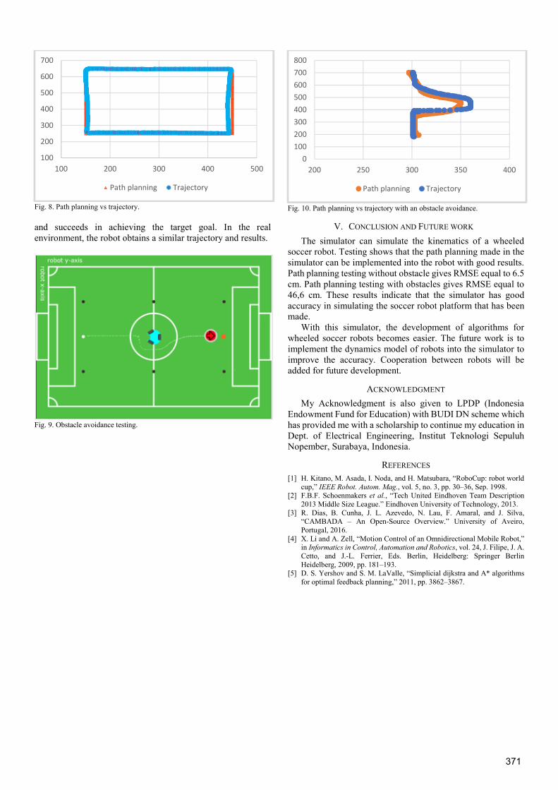
Fig. 8. Path planning vs trajectory.
and succeeds in achieving the target goal. In the real environment, the robot obtains a similar trajectory and results.
Fig. 9. Obstacle avoidance testing.
Fig. 10. Path planning vs trajectory with an obstacle avoidance.
V. CONCLUSION AND FUTURE WORK The simulator can simulate the kinematics of a wheeled
soccer robot. Testing shows that the path planning made in the simulator can be implemented into the robot with good results. Path planning testing without obstacle gives RMSE equal to 6.5 cm. Path planning testing with obstacles gives RMSE equal to 46,6 cm. These results indicate that the simulator has good accuracy in simulating the soccer robot platform that has been made.
With this simulator, the development of algorithms for wheeled soccer robots becomes easier. The future work is to implement the dynamics model of robots into the simulator to improve the accuracy. Cooperation between robots will be added for future development.
ACKNOWLEDGMENT
My Acknowledgment is also given to LPDP (Indonesia Endowment Fund for Education) with BUDI DN scheme which has provided me with a scholarship to continue my education in Dept. of Electrical Engineering, Institut Teknologi Sepuluh Nopember, Surabaya, Indonesia.
REFERENCES [1] H. Kitano, M. Asada, I. Noda, and H. Matsubara, “RoboCup: robot world
cup,” IEEE Robot. Autom. Mag., vol. 5, no. 3, pp. 30–36, Sep. 1998. [2] F.B.F. Schoenmakers et al., “Tech United Eindhoven Team Description
2013 Middle Size League.” Eindhoven University of Technology, 2013. [3] R. Dias, B. Cunha, J. L. Azevedo, N. Lau, F. Amaral, and J. Silva,
“CAMBADA – An Open-Source Overview.” University of Aveiro, Portugal, 2016.
[4] X. Li and A. Zell, “Motion Control of an Omnidirectional Mobile Robot,” in Informatics in Control, Automation and Robotics, vol. 24, J. Filipe, J. A. Cetto, and J.-L. Ferrier, Eds. Berlin, Heidelberg: Springer Berlin Heidelberg, 2009, pp. 181–193.
[5] D. S. Yershov and S. M. LaValle, “Simplicial dijkstra and A* algorithms for optimal feedback planning,” 2011, pp. 3862–3867.
100
200
300
400
500
600
700
100 200 300 400 500
Path planning Trajectory
0100200300400500600700800
200 250 300 350 400
Path planning Trajectory
371