2018 ijrar august 2018, volume 5, issue 3 e -issn 2348
TRANSCRIPT
© 2018 IJRAR August 2018, Volume 5, Issue 3 www.ijrar.org (E-ISSN 2348-1269, P- ISSN 2349-5138)
IJRAR1903438 International Journal of Research and Analytical Reviews (IJRAR) www.ijrar.org 402
A REVIEW ON POWER QUALITY
ENHANCEMENT IN RENEWABLE ENERGY
SYSTEM1Alwinstar.A, 2Dr.S.Joseph Jawhar,
1Research Scholar, 2Professor,
EEE Department
1Arunachala College of Engineering for Women, India
Abstract:
Voltage sags and low voltage distribution grid are considered to be the most repeated
type of power quality problems based on recent power quality studies. Power Quality means
to maintain purely sinusoidal current wave form in phase with a purely sinusoidal voltage
wave form. The important devices are Active Power Filter (APF), dynamic voltage restorer
(DVR) and Unified Power Quality Conditioner (UPQC). The most frequent type of power
quality problems are Voltage sags and swells, flickers, harmonics in the medium and low
voltage distribution grid.
Keywords: - Power Quality, Shunt Active Power Filter, Synchronous Detection Method,
digital control, p-q theory.
I.INTRODUCTION
A set of electrical boundaries that allows a piece of equipment to function in its
intended manner without significant loss of performance or life expectancy is called as
Power Quality. The three phase power generated at the generating station is purely
sinusoidal in nature. Wide spread application of static power electronics converters, zero and
negative sequence components originated by the use of single phase and unbalanced loads,
reactive power, voltage sag, voltage swell, flicker, voltage interruption etc. results voltage
and current harmonics.
2. POWER QUALITY(PQ) PROBLEMS
The very important utility of the voltage quality which a consumer gets for operation
of load or given from some particular PQ problem deals with deviation of voltage/current
from their ideal sinusoidal waveforms. From designer perspective, PQ is defined as that
there should be no variation in voltage and there should be complete absence of noise
generated in grounding system. From the point of view of an utility engineer, it is voltage
availability or outage minutes.
(a)Voltage Sag
Voltage Sag is the decrease in rms voltage of power frequency for a time span of half
cycles to 1 minute. Voltage sag is a severe and drastic PQ issue especially with sensitive

© 2018 IJRAR August 2018, Volume 5, Issue 3 www.ijrar.org (E-ISSN 2348-1269, P- ISSN 2349-5138)
IJRAR1903438 International Journal of Research and Analytical Reviews (IJRAR) www.ijrar.org 403
loads which are voltage sensitive like equipment for control processing, adjustable speed
drives (ASD) and computers.
(b)Voltage Swell
Voltage swell is a sudden increase in the rms supply voltage varying in a range from
1.1p.u. to 1.7 p.u., with a approximate time range of from half a cycle to 1 min. Its
occurrence probability appear when compared to voltage sags is very much less, but these
are more harmful to sensitive equipment/non-linear loads.
(c)Interruption
An interruption is defined as a reduction in line-voltage or current to less than 0.1 pu
of the nominal, for a period of time not exceeding 1 min. Interruptions can occur due to
power system faults, equipment failures and control malfunctions.
(d)Long-Duration Voltage Variation:
Long-duration variations can be categorized as over voltages, under voltages or
sustained interruptions.
(i) Overvoltage: An overvoltage is an increase in the rms ac voltage greater than 110 percent
at the power frequency for duration longer than 1 min. Over voltages are usually the results
of load switching or incorrect tap settings on transformers.
(ii) Under Voltage: An under voltage is decreases in the rms ac voltage to less than 90
percent at the power frequency for duration longer than 1 min. A load switching on or a
capacitor bank switching off can cause an under voltage until voltage regulation equipment
on the system can restore the voltage back to within tolerance limits. Also overloaded
circuits can result in under voltage.
(iii) Sustained Interruptions: When the supply voltage has been zero for a period of time in
excess of 1 min the long-duration voltage variation is considered a sustained interruption.
(e)Waveform Distortion
Waveform distortion is defined as a steady-state deviation from an ideal power
frequency sine wave principally characterized by the spectral content of the deviation.
There are five primary types of waveform distortion:
(i) DC offset: The presence of a dc voltage or current in an ac power system is termed dc
offset. This can occur as the result of a geomagnetic disturbance or asymmetry of electronic
power converters
(ii) Harmonics: Harmonics are sinusoidal voltages or currents having frequencies that are
integer multiples of the frequency at which the supply system is designed to operate, and that
is known as the fundamental frequency which is usually 50 or 60 Hz. Harmonic distortion
levels can be described by the calculating total harmonic distortion (THD)
(iii) Interharmonics: Voltages or currents having frequency components that are not integer
multiples of the frequency at which the supply system is designed to operate (50 or 60 Hz)
are called interharmonics.

© 2018 IJRAR August 2018, Volume 5, Issue 3 www.ijrar.org (E-ISSN 2348-1269, P- ISSN 2349-5138)
IJRAR1903438 International Journal of Research and Analytical Reviews (IJRAR) www.ijrar.org 404
(iv) Notching: Notching is a periodic voltage disturbance caused by the normal operation of
power electronic devices when current is commutated from one phase to another.
(v) Noise: Noise is defined as unwanted electrical signals with broadband spectral content
lower than 200 kHz superimposed upon the power system voltage or current in phase
conductors, or found on neutral conductors or signal lines.
FACTS DEVICES FOR POWER QUALITY IMPROVEMENT:
The STATCOM based current control voltage source inverter injects the current into
the grid in such a way that the source current are harmonic free and their phase-angle with
respect to source voltage has a desired value. The injected current will cance out the reactive
part and harmonic part of the load and induction generator current, thus it improves the
power factor and the power quality. To accomplish these goals, the grid voltages are sensed
and are synchronized in generating the current command for the inverter. The proposed grid
connected system is implemented for power quality improvement at point of common
coupling (PCC). The grid connected system in Fig. 1, consists of wind energy generation
system and battery energy storage system with STATCOM.
A. Wind Energy Generating System
In this configuration, wind generations are based on constant speed topologies with
pitch control turbine. The induction generator is used in the proposed scheme because of its
simplicity, it does not require a separate field circuit, it can accept constant and variable
loads, and has natural protection against short circuit.
UPFC: A Unified Power Flow Controller (UPFC) is a member of FACTS devices. It
consists of two solid stat synchronous voltage source converters coupled through a common
DC link. The DC link provides a path to exchange active power between the converters. The
series converter injects a voltage in series with the system voltage through a series
transformer. The power flow through the line can be regulated by controlling voltage
magnitude and angle of series injected voltage. The injected voltage and line current
determine the active and reactive power injected by the series converter. The converter has a
capability of electrically generating or absorbing the reactive power. However, the injected
active power must be supplied by the DC link, in turn taken from the AC system through the
shunt converter. The shunt converter also has a capability of independently supplying or
absorbing reactive power to regulate the voltage of the AC system. When the losses of the
converters and the associated transformers are neglected, the overall active power exchange
between the UPFC and the AC system become zero. However, both the series and shunt
converters can independently exchange reactive power. UPFC can improve both steady sate
stability, dynamic stability and transient stability. For the convenience practical of
application, the series voltage angle of UPFC is kept in perpendicular with a line current.
3. POWER QUALITY PROBLEM DETECTION
The Power Quality (PQ) problem can be detected from one of the following several
symptoms depending on the types of issue involved.
© 2018 IJRAR August 2018, Volume 5, Issue 3 www.ijrar.org (E-ISSN 2348-1269, P- ISSN 2349-5138)
IJRAR1903438 International Journal of Research and Analytical Reviews (IJRAR) www.ijrar.org 405
(i) Lamp flicker (ii) Frequent blackouts (iii)Sensitive-equipment frequent dropouts
(iv)Voltage to ground in unexpected (v)Locations (vi) Communications interference
(vii)Overheated elements and equipment.
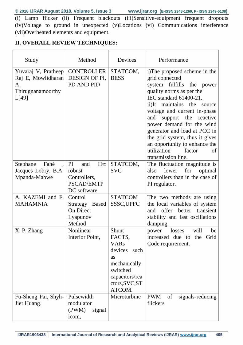
II. OVERALL REVIEW TECHNIQUES:
Study
Method
Devices
Performance
Yuvaraj V, Pratheep
Raj E, Mowlidharan
A,
Thirugnanamoorthy
L[49]
CONTROLLER
DESIGN OF PI,
PD AND PID
STATCOM,
BESS
i)The proposed scheme in the
grid connected
system fulfills the power
quality norms as per the
IEC standard 61400-21.
ii)It maintains the source
voltage and current in-phase
and support the reactive
power demand for the wind
generator and load at PCC in
the grid system, thus it gives
an opportunity to enhance the
utilization factor of
transmission line.
Stephane Fahé ,
Jacques Lobry, B.A.
Mpanda-Mabwe
PI and H∞
robust
Controllers,
PSCAD/EMTP
DC software.
STATCOM,
SVC
The fluctuation magnitude is
also lower for optimal
controllers than in the case of
PI regulator.
A. KAZEMI and F.
MAHAMNIA
Control
Strategy Based
On Direct
Lyapunov
Method
STATCOM
SSSC,UPFC
The two methods are using
the local variables of system
and offer better transient
stability and fast oscillations
damping.
X. P. Zhang Nonlinear
Interior Point,
Shunt
FACTS,
VARs
devices such
as
mechanically
switched
capacitors/rea
ctors,SVC,ST
ATCOM.
power losses will be
increased due to the Grid
Code requirement.
Fu-Sheng Pai, Shyh-
Jier Huang.
Pulsewidth
modulator
(PWM) signal
icom,
Microturbine PWM of signals-reducing
flickers

© 2018 IJRAR August 2018, Volume 5, Issue 3 www.ijrar.org (E-ISSN 2348-1269, P- ISSN 2349-5138)
IJRAR1903438 International Journal of Research and Analytical Reviews (IJRAR) www.ijrar.org 406
Chong Han,
Subhashish
Bhattacharya,
Anders L. Johnson.
integration of a
large WF into a
weak loop
power system.
PSCAD/
EMTDC,
suppressing the voltage
fluctuations, the dynamic
simulation results for a
continuous operation
period
Prechanon
Kumkratug, Panthep
Laohachai.
Mathematical
Model, potential
–energy
boundary
surface (PEBS)
Method,Lyapun
ov’s stability
criterion,
SSSC for
estimation the
CCT,
PEBS method reduces the
causes for power quality
disturbances
S.V Ravi Kumar, S.
Siva Nagaraju
Controller for
Vseq, Controller
for Vsep, AVR
model,
Synchronous
machine
model, SVC,
improving transient stability,
improving critical clearing
time
Alberto D. Del
Rosso, Claudio A.
Cañizares, Victor M.
Doña
Input
Signals,Paramet
er Tuning,
Hierarchical
Control Design,
Controller
design,
FACTS,
stability
enhancement,
TCSC
TCSC will inject reactive
power
Sidhartha Panda,
Ramnarayan N.
Patel
variable
impedance type
and switching
converter type
FACTS,
STATCOM,
SVC
predefined direction of real
power flow, mid-point
location of shunt FACTS
devices
is verified
Fengquan Zhou,
Géza Joós
Electromagnetic
Transients
Program
(EMTP),
Induction
Generator
Detailed Model,
Hub model,
Blade Model,
Gear box
model,
WECS,
power factor
control
(PFC),
STATCOM,
Impact of Variable Wind
Speed on Voltage, Increase
the Short Circuit Capacity to
Improve the
Transient Response of Wind
Farm
Nadarajah
Mithulananthan,
Claudio A.
Canizares, John
Reeve and Graham
J. Rogers
Hopf
bifurcations,
power system
oscillations
power system
stabilizers
(PSS), static
var
compensators
(SVCs), and
shunt static
synchronous
participation factor
analysis,loadability margin.
© 2018 IJRAR August 2018, Volume 5, Issue 3 www.ijrar.org (E-ISSN 2348-1269, P- ISSN 2349-5138)
IJRAR1903438 International Journal of Research and Analytical Reviews (IJRAR) www.ijrar.org 407
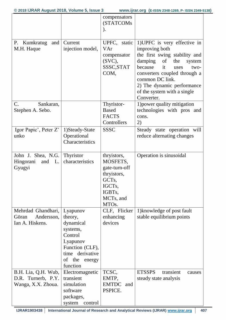
compensators
(STATCOMs
).
P. Kumkratug and
M.H. Haque
Current
injection model,
UPFC, static
VAr
compensator
(SVC),
SSSC,STAT
COM,
1)UPFC is very effective in
improving both
the first swing stability and
damping of the system
because it uses two-
converters coupled through a
common DC link.
2) The dynamic performance
of the system with a single
Converter.
C. Sankaran,
Stephen A. Sebo.
Thyristor-
Based
FACTS
Controllers
1)power quality mitigation
technologies with pros and
cons.
2)
Igor Papicˇ, Peter Zˇ
unko
1)Steady-State
Operational
Characteristics
SSSC Steady state operation will
reduce alternating changes
John J. Shea, N.G.
Hingorani and L.
Gyugyi
Thyristor
characteristics
thryistors,
MOSFETS,
gate-turn-off
thryistors,
GCTs,
IGCTs,
IGBTs,
MCTs, and
MTOs.
Operation is sinusoidal
Mehrdad Ghandhari,
Göran Andersson,
Ian A. Hiskens.
Lyapunov
theory,
dynamical
systems,
Control
Lyapunov
Function (CLF),
time derivative
of the energy
function
CLF, Flicker
enhancing
devices
1)knowledge of post fault
stable equilibrium points
B.H. Lia, Q.H. Wub,
D.R. Turnerb, P.Y.
Wanga, X.X. Zhoua.
Electromagnetic
transient
simulation
software
packages,
system control
TCSC,
EMTP,
EMTDC and
PSPICE.
ETSSPS transient causes
steady state analysis
© 2018 IJRAR August 2018, Volume 5, Issue 3 www.ijrar.org (E-ISSN 2348-1269, P- ISSN 2349-5138)
IJRAR1903438 International Journal of Research and Analytical Reviews (IJRAR) www.ijrar.org 408
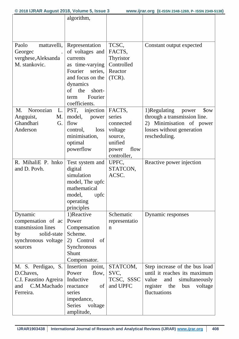
algorithm,
Paolo mattavelli,
Georgec .
verghese,Aleksanda
M. stankovic.
Representation
of voltages and
currents
as time-varying
Fourier series,
and focus on the
dynamics
of the short-
term Fourier
coefficients.
TCSC,
FACTS,
Thyristor
Controlled
Reactor
(TCR).
Constant output expected
M. Noroozian L.
Angquist, M.
Ghandhari G.
Anderson
PST, injection
model, power
flow
control, loss
minimisation,
optimal
powerflow
FACTS,
series
connected
voltage
source,
unified
power flow
controller,
1)Regulating power $ow
through a transmission line.
2) Minimisation of power
losses without generation
rescheduling.
R. MihaliE P. hnko
and D. Povh.
Test system and
digital
simulation
model, The upfc
mathematical
model, Upfc
operating
principles
UPFC,
STATCON,
ACSC.
Reactive power injection
Dynamic
compensation of ac
transmission lines
by solid-state
synchronous voltage
sources
1)Reactive
Power
Compensation
Scheme.
2) Control of
Synchronous
Shunt
Compensator.
Schematic
representatio
n
Dynamic responses
M. S. Perdigao, S.
D.Chaves,
C.I. Faustino Agreira
and C.M.Machado
Ferreira.
Insertion point,
Power flow,
Inductive
reactance of
series
impedance,
Series voltage
amplitude,
STATCOM,
SVC,
TCSC, SSSC
and UPFC
Step increase of the bus load
until it reaches its maximum
value and simultaneously
register the bus voltage
fluctuations

© 2018 IJRAR August 2018, Volume 5, Issue 3 www.ijrar.org (E-ISSN 2348-1269, P- ISSN 2349-5138)
IJRAR1903438 International Journal of Research and Analytical Reviews (IJRAR) www.ijrar.org 409
Belkacem Mahdad, Differential
Evolution,
Economic
Dispatch,
Optimal Power
Flow, Hybrid
Model based
Wind Energy
and Shunt
Controller,
Algorithm
Structure based
DE,
FACTS,
Reactive
Power
Control,
Optimal
location.
Coordinated model based
wind generator and dynamic
shunt FACTS devices to
improve the power system
operation and control.
E.Z. Zhou power system
damping, swing
oscillations,
"bang-bang"
controllers,
Static var
compensators
(SVC)
Reducing flickers
V.Vittal ,N. Bhatia
A. A. Fouad
analysis of the
inter-area-
mode
phenomenon in
stressed power
systems
Classical
model of the
power
system,
Free Response
Characteristics, dominant
modes of oscillation using the
post disturbance
stable equilibrium, interaction
coefficients clearly identify
the interaction between the
dominant modes of
oscillation indicating the
possibility of the inter area
mode phenomenon. III VARIOUS METHODS REVIEWED
Author(s) Year Methodology Adopted Advantages
R. Billinton and Y.
Gao
2002 Energy conversion system models
for adequacy assessment of
generating systems
This paper focuses on development of suitable
models for wind energy
Conversion systems ,a five-state wind energy
conversion system
model is proposed.

© 2018 IJRAR August 2018, Volume 5, Issue 3 www.ijrar.org (E-ISSN 2348-1269, P- ISSN 2349-5138)
IJRAR1903438 International Journal of Research and Analytical Reviews (IJRAR) www.ijrar.org 410
Amit K. Jain, Aman
Behal, Ned Moha.
2005 System Modeling and Control
Design for Fast Voltage Regulation
Using STATCOMs.
It allows design of fast voltage regulation
controller , It shows the problem
Of voltage regulation using instantaneous
reactive current .
CarLNgai-Man Ho,
Victor S.P.Cheun.
2009 Constant Frequency Hysteresis
Current Control of Grid-Connected
VSI Without and width Control.
This contains design & implementation of a
constant-frequency
hysteresis current control for grid-connected
voltage
source inverter (VSI) .
S.Khalid1 & Bharti
Dwivedi
2011 preserve voltage integrity by
limiting harmonic current injection
of single-phase loads, By
addressing harmonic current
distortion at the individual
sources, system
problems may be avoided.
This is to complay Coordination with existing
industry practices and
international harmonic standards;;;Proper
designing of the Load equipment.
• Application of passive, active and hybrid
harmonic filters. Proper designing of the
power supply system
• Application of voltage compensators.
• Use of uninterruptible power supplies (UPSs)
• Reliability on standby power
MIHIR HEMBRAM;
Ayan Kumar Tudu
2014 UPQC (advanced hybrid filter)
consists of a series active filter
(APF) for compensating voltage
disturbances and shunt active
power filter (APF) for
eliminating current distortions
satisfactory for load harmonic and reactive
current
compensation, mitigation of voltage sag and
swells, mitigation voltage
harmonic and mitigation of single phase sag. It
is observed that source
current and load voltage THD levels are
maintained below 5 % , the
THD limit imposed by IEEE 519-1992.

© 2018 IJRAR August 2018, Volume 5, Issue 3 www.ijrar.org (E-ISSN 2348-1269, P- ISSN 2349-5138)
IJRAR1903438 International Journal of Research and Analytical Reviews (IJRAR) www.ijrar.org 411
Goutam Kumar
Malla and A.
Ramulu
2015 A simple control technique based
on unit vector templates
generation is proposed for UPQC.
. Power factor correction,Harmonic filtering,
• Special line notch filtering,
• Transient voltage surge suppression,
• Proper earthing systems.
J. JAYACHANDRAN,
R. MURALI
SACHITHANANDAM
2015 A neural network based control
strategy is proposed and
has been implemented for the
DSTATCOM in a 3P4W
distribution system.
Compensation of harmonic content.
Reactive power compensation.
Maintenance of DC capacitor voltage
Akmet Tekel
Mehmet Tumayul
2016 Digital controller based UPQC
developed
Fast computing
devices(FPGA,DSP,Microcontroller)
** PWM,Hysterisis controller
Can mitigate voltage
sag,swell,harmonics,unbalances,current
Harmonics and poor power factor.
OPPINION FROM DIFFERENT PAPERS:
Yuvaraj V, Pratheep Raj E, Mowlidharan A, Thirugnanamoorthy L proposed “CONTROLLER DESIGN OF PI, PD
AND PID” : It is possible to improve the STATCOM response by employing the PID control method. Application of the
PID involves choosing the KP, KI and KD that provide satisfactory closed-loop performance. But the main method is
based on trial and error, although time consuming. To achieve equilibrium among range control parameters,
response speed, settling time, and proper overshoot rate, all of which guarantee the system stability, the PID is
employed fig.2. [15]
The power electronics based devices/ equipments have become key components in today's modern power
distribution system These devices generate harmonics polluting the power distribution system, and demand reactive
power. In order to provide technical solutions to the new challenges imposed on the power systems, the concept of
flexible AC transmission systems (FACTS) was introduced in the late 1980s. The FACTS devices incorporate power
electronics based controllers to enhance the controllability and to increase power transfer capability of the
transmission system. one employs conventional thyristor switched capacitors (TSC) and reactors (TSR), and the other
uses self-commutated switching converters. Both the schemes help to efficiently control the real and reactive
power, The static VAR compensators (SVC) are used to control AC voltage by generating or absorbing the reactive
power by means of passive elements. A SVC consists of an anti parallel thyristors and passive elements such as a
capacitor (TSC) or a reactor (TCR). One of the most versatile FACTS devices is the STATCOM. It consists of a voltage
source converter (VSC)/ voltage source inverter (VSI) with pulse width modulation (PWM) and has a faster speed of
response. In the transmission system, it can be used to improve the system stability and damping or to support the
voltage profile. When an external DC voltage source is utilized for VSI, Another device, the active power filter (APF)
© 2018 IJRAR August 2018, Volume 5, Issue 3 www.ijrar.org (E-ISSN 2348-1269, P- ISSN 2349-5138)
IJRAR1903438 International Journal of Research and Analytical Reviews (IJRAR) www.ijrar.org 412
is the most promising solution to mitigate some of the major power quality problems at the distribution level. They
are shunt APFs, series APFs, hybrid APFs, and unified power quality conditioner (UPQC). The UPQC is one of the most
versatile power quality enhancement devices which offer advantages of both the shunt and series APFs,
simultaneously. The series APF is connected in series with the ac line and shunt APF is connected in shunt with the
same ac line. These two are connected back to back with each other though a DC link. The shunt component of the
UPQC injects current in the ac system such that the currents entering the bus to which the UPQC is connected are
balanced sinusoids.
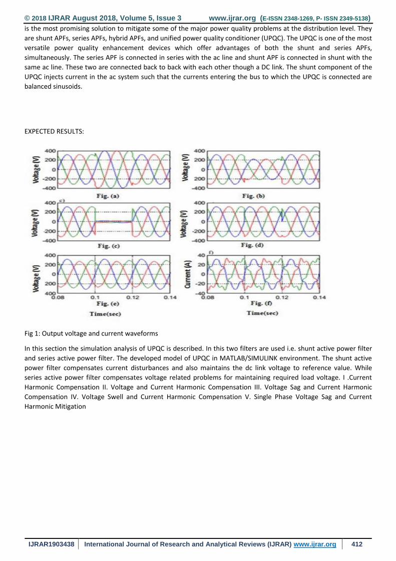
EXPECTED RESULTS:
Fig 1: Output voltage and current waveforms
In this section the simulation analysis of UPQC is described. In this two filters are used i.e. shunt active power filter
and series active power filter. The developed model of UPQC in MATLAB/SIMULINK environment. The shunt active
power filter compensates current disturbances and also maintains the dc link voltage to reference value. While
series active power filter compensates voltage related problems for maintaining required load voltage. I .Current
Harmonic Compensation II. Voltage and Current Harmonic Compensation III. Voltage Sag and Current Harmonic
Compensation IV. Voltage Swell and Current Harmonic Compensation V. Single Phase Voltage Sag and Current
Harmonic Mitigation

© 2018 IJRAR August 2018, Volume 5, Issue 3 www.ijrar.org (E-ISSN 2348-1269, P- ISSN 2349-5138)
IJRAR1903438 International Journal of Research and Analytical Reviews (IJRAR) www.ijrar.org 413
Fig 2: Simulation
Using hysteresis band controller the model has been developed in MATLAB/SIMULINK environment. It is found from
the simulation results that UPQC improves power quality of power system by compensating harmonic and reactive
current of load current which makes source current sinusoidal and it also makes sinusoidal at required voltage level
by compensating with series APF.load voltage
The THD of the source current and load voltage is below the harmonics limit imposed by IEEE standard 519-1992.
Fig 3: Simulated results of UPQC (a) Load current (b) Source current (c) Shunt APF current (d) capacitor voltage

© 2018 IJRAR August 2018, Volume 5, Issue 3 www.ijrar.org (E-ISSN 2348-1269, P- ISSN 2349-5138)
IJRAR1903438 International Journal of Research and Analytical Reviews (IJRAR) www.ijrar.org 414
Fig 4:Voltage waveforms
REFERENCES
[1] K. S. Hook, Y. Liu, and S. Atcitty, “Mitigation of the wind generation integration related power
quality issues by energy storage,” EPQU J., vol. XII, no. 2, 2006.
[2] R. Billinton and Y. Gao, “Multistate wind Energy conversion system models for adequacy
assessment of generating systems incorporating wind energy,” IEEE Trans. on E. Conv., vol. 23, no. 1, pp. 163–169,
2008.
[3] J. Manel Carrasco, “Power electronic system for grid integration of renewable energy source: A survey,” IEEE
Trans. Ind. Electron., vol. 53, no. 4, pp. 1002–1014, 2006.
[4] M. Tsili and S. Papathanassiou, “A review of grid code technology requirements for wind turbine,” Proc. IET
Renew.power gen., vol. 3, pp. 308–332, 2009.
[5] J. J. Gutierrez, J. Ruiz, L. Leturiondo, and A. Lazkano, “Flicker measurement system for wind turbine certification,”
IEEE Trans. Instrum. Meas., vol. 58, no. 2, pp. 375–382, Feb. 2009.
[6] Indian Wind Grid Code Draft report on, Jul. 2009, pp. 15–18, C-NET.
[7] C. Han, A. Q. Huang, M. Baran, S. Bhattacharya, and W. Litzenberger, “STATCOM impact study on the integration
of a large wind farm into a weak loop power system,” IEEE Trans. Energy Conv., vol. 23, no. 1, pp. 226–232, Mar.
2008.
[8] F. Zhou, G. Joos, and C. Abhey, “Voltage stability in weak connection wind farm,” in IEEE PES Gen. Meeting, 2005,
vol. 2, pp. 1483–1488.
[9] R. S. Bhatia, S. P. Jain, D. K. Jain, and B. Singh, “Battery energy storage system for power conditioning of
renewable energy sources,” in Proc. Int. Conf. Power ElectronDrives System, Jan. 2006, vol. 1, pp. 501–506.
[10] S. W. Mohod and M. V. Aware, “Grid power quality with variable speed wind energy conversion,” in Proc. IEEE
Int. Conf. Power Electronic Drives and Energy System (PEDES), Delhi, Dec. 2006.
[11] Fu. S. Pai and S.-I. Hung, “Design and operation of power converter for microturbine powered distributed
generator with capacity expansion capability,” IEEE Trans. Energy Conv., vol. 3, no. 1, pp. 110–116, Mar. 2008.
[12] J. Zeng, C. Yu, Q. Qi, and Z. Yan, “A novel hysteresis current control for active power filter with constant
frequency,” Elect. Power Syst. Res., vol. 68, pp. 75–82, 2004.
[13] M. I. Milands, E. R. Cadavai, and F. B. Gonzalez, “Comparison of control strategies for shunt active power filters
in three phase four wire system,” IEEE Trans. Power Electron., vol. 22, no. 1, pp. 229–236, Jan. 2007.
[14] S. W. Mohod and M. V. Aware, “Power quality issues & it’s mitigation technique in wind energy conversion,” in
Proc. of IEEE Int. Conf. Quality Power & Harmonic, Wollongong, Australia, 2008.
© 2018 IJRAR August 2018, Volume 5, Issue 3 www.ijrar.org (E-ISSN 2348-1269, P- ISSN 2349-5138)
IJRAR1903438 International Journal of Research and Analytical Reviews (IJRAR) www.ijrar.org 415
[15] Saeid Eshtehardiha, Mohammad Bayati poodeh and Arash Kiyoumarsi, “Optimized Performance of STATCOM
with PID Controller Based on Genetic Algorithm.” In International Conference on Control, Automation and Systems
2007, Oct. 17-20, 2007 in COEX, Seoul, Korea.
[16] R. Mihalic, P. Zunko and D. Povh, 1996, “Improvement of Transient Stability using Unified Power Flow
Controller,” IEEE Transactions on Power Delivery, 11(1), pp. 485-491.
[17] K.R. Padiyar, 2002, “Power System Dynamic Stability and Control,” Second Edition, BS Publications, Hyderabad.
[18] Igor Papic, Peter Zunko, 2002, “Mathematical Model and Steady State Operational Characteristics of a Unified
Power Flow Controller,”Electro-technical Review, Slovenija, 69(5), pp. 285-290.
[19] Prechanon Kumkratug, 2009, “Application of UPFC to Increase Transient Stability of Inter-Area Power System,”
Journal of Computers, 4(4), pp. 283-287.
[20] Prechanon Kumkratug, Panthep Laohachai, 2007, “Direct Method of Transient Stability Assessment of a Power
System with a SSSC,” Journal of Computers, 2(8), pp. 77- 82.
[21] S.V. Ravi Kumar, S. Siva Nagaraju, 2007, “Transient Stability Improvement using UPFC and SVC,” ARPN Journal of
Engineering and Applied Sciences, 2(3), pp. 38- 45.
[22] A. Kazemi, F. Mahamnia, 2008, “Improving of Transient Stability of Power Systems by Supplementary
Controllers of UPFC using Different Fault Conditions,” WSEASTransactions on Power Systems, 3(7), pp. 547-556.
[23] S. Panda, Ramnarayan N. Patel, 2006, “Improving Power System Transient Stability with an off-centre Location
of Shunt FACTS Devices,” Journal of Electrical Engineering, 57(6), pp. 365-368.
[24] N.G. Hingorani, L. Gyugyi, 1999, “Understanding FACTS: Concepts and Technology of Flexible AC Transmission
Systems,” IEEE Press, New York.
[25] N. Mithulananthan, C.A. Canizares, J. Reeve, Graham J. Rogers, 2003, “Comparison of PSS, SVC and STATCOM
Controllers for Damping Power System Oscillations,” IEEE Transactions on Power Systems, 18(2), pp. 786-792.
[26] E.Z. Zhou, 1993, “Application of Static Var Compensators to Increase Power System damping,” IEEE Transactions
on Power Systems, 8(2), pp. 655-661.
[27] P. Mattavelli, G.C. Verghese, A.M. Stankovic, 1997, “Phasor Dynamics of Thyristor-Controlled Series Capacitor
Systems,” IEEE Transactions on Power Systems, 12(3), pp. 1259-1267.
[28] B.H. Li, Q.H. Wu, D.R. Turner, P.Y. Wang, X.X. Zhou, 2000, “Modeling of TCSC Dynamics for Control and Analysis
of Power System Stability,” Electrical Power & Energy Systems, 22(1), pp. 43-49.
[29] A.D. Del Rosso, C.A. Canizares, V.M. Dona, 2003, “A Study of TCSC Controller Design for Power System Stability
Improvement,” IEEE Transactions on Power Systems, 18(4), pp. 1487-1496.
[30] L. Gyugyi, 1994, “Dynamic Compensation of AC Transmission Line by Solid State Synchronous Voltage
International Journal of Computer Applications (0975 – 8887) Volume 8– No.4, October 2010 35 Sources,” IEEE
Transactions on Power Delivery, 9(22), pp. 904-911.
[31] M. Noroozian, L. Angquist, M. Ghandhari, G. Andersson, 1997, “Use of UPFC for Optimal Power Flow Control,”
IEEE Transactions on Power Delivery, 12(4), pp. 1629- 1634.
[32] M. Ghandhari, G. Andersson, I.A. Hiskens, 2001, “Control Lyapunov Functions for Series Devices,” IEEE
Transactions on Power Delivery, 16(4), pp. 689-694.
[33] P. Kumkratug, M.H. Haque, 2003, “Versatile Model of a Unified Power Flow Controller in Simple System,” IEE
Proc. Gener. Transm. & Distrib., 150(2), pp. 155-161.
[34] V. Vittal, N. Bhatia, A.A. Fouad, 1991, “Analysis of the Inter-area Mode Phenomenon in Power Systems
Following Large Disturbances,” IEEE Transactions on Power Systems, 6(4), pp. 1515-1521.

© 2018 IJRAR August 2018, Volume 5, Issue 3 www.ijrar.org (E-ISSN 2348-1269, P- ISSN 2349-5138)
IJRAR1903438 International Journal of Research and Analytical Reviews (IJRAR) www.ijrar.org 416
[35] R.M. Mathur, R.K. Varma, 2002, “Thyristor-based FACTS Controllers for Electrical Transmission Systems,” IEEE
Press, Piscataway.
[36] N.G. Hingorani and L. Gyugyi, “Understanding FACTS: concepts and technology of flexible ac transmission
systems”, IEEE Press, NY, 1999.
[37] Y.H. Song and A.T. Johns, “Flexible ac transmission systems (FACTS)”, The Institute of Electrical Engineers,
London, 1999.
[38] L. Gyugyi, “Dynamic compensation of ac transmission line by solid-state synchronous voltage sources”, IEEE
Trans. Power Delivery, Vol. 9, pp. 904-911, Apr. 1994.
[39] M. Noroozian, L. Angquist, M. Ghandhari, and G. Andersson, “Use of UPFC for optimal power flow control”, IEEE
Trans. on Power Delivery, Vol. 12, No. 4, pp. 1629-1634, 1997.
[40] M. Ghandhahi, G. Adersson and I.A. Hiskens,“Control Lyapunov functions for series devices”, IEEE Trans. On
Power Delivery, Vol. 16, No. 4, 2001, pp. 689-694.
[41] E. Gholipour and S. Saasate, “Improving of Transient Stability of Power Systems Using UPFC”, IEEE Trans. On
Power Delivery, Vol. 20, No. 2, pp. 1677-1682, 2005.
[42] P. Kumkratug and M.H. Haque, “Versatile model of a unified power flow controller in simple system”, IEE Proc.-
Gener. Transm. Distrib., Vol. 150, No. 2, pp. 155- 161.
[43] V.Vital, N. Bhatia and A.A. Fouad, “Analysis of the Inter-area Mode Phenomenon in Power Systems Following
Large Disturbances”, IEEE Transactions on Power System, Vol. 6, No. 4, 1991.
[44] E. Z. Zhou, “Application of Static Var Compensators to Increase Power System Damping”, IEEE Transactions on
Power System, Vol. 8, No. 2, 1991.
[45] M. Noroozian, G. Andersson and K. Tomsovic, “Robust Near Time-Optimal Control of Power System Oscillations
with Fuzzy Logic”, IEEE Transactions on Power Delivery, Vol, 11, No.1, 1996.
[46] P. Kumkratug and P. Laohachai, “Time domain simulation technique of a power system transient with VSC based
FACTS devices”, AMS2007, Phuket, Thailand.
[47] M.A. Pai, “Energy function analysis for power system stability”, Kluwer Acadenic Publishers, 1981.
[48] P. Kundur, “ Power System Stability and Control”, Mc Graw-Hill, Singapore.
[49] Yuvaraj.V, Pratheep Raj.E, Mowlidharan.A and Thirugnanamoorthy.L” Power Quality Improvement for Grid
Connected Wind Energy System using FACTS device”,
[50] D. Murali, Dr. M. Rajaram and N. Reka “Comparison of FACTS Devices for Power System Stability
Enhancement”, International Journal of Computer Applications (0975 – 8887)Volume 8– No.4, October 2010-30
[51] Prechanon Kumkratug,” Application of UPFC to Increase Transient Stability of Inter-Area Power
System”,JOURNAL OF COMPUTERS, VOL. 4, NO. 4, APRIL 2009