2019 freedm demonstration plan scheduled live …...the inverter models in opal are controlled by...
TRANSCRIPT

No Title of Demo Location Description PersonnelTime
(min.)
1
High fidelity hardware-in-the-loop
testbed for hybrids and
microgrids
GridWrx
Laboratory
Live Demonstration: A step-by-step
approach for modeling a microgrid
system that consists of different
energy resources
Dr. Ning Lu
Dr. Wente Zeng
Fuhong Xie15
2
Distributed control strategy to
achieve synchronized operation of
an islanded MG using the Resilient
Information Architecture Platform for
the Smart Grid (RIAPS)
Simulation
Laboratory
Live Demonstration: A microgrid
model implemented on the Opal-RT
platform to evaluate synchronized
coordination of the microgrid with
the larger grid environment
Dr. Srdjan Lukic
Hao Tu
Hui Yu
Yuhua Du
15
3 Green Energy Hub (GEH) testbedHigh-bay
Laboratory
Live Demonstration: A testing and
demonstration platform of the
bidirectional power flow control
including grid-tied battery energy
storage with DC and AC loads
Dr. Wensong Yu
Dr. Iqbal Husain
Dr. David Lubkeman
Dr. Mehnaz Khan
Salina Zabin
Hao Tu
M. A. Awal
Siyuan Chen
Md Rashed Hassan
Dakai Wang
Siyuan Chen
15
4Distributed Volt-VAR Control on
active distribution systems
GridWrx
Laboratory
Volt-VAR control demonstrated on a
34 node network feeder circuit
Dr. Mesut Baran
Valliappan Muthukaruppan10
5
Enabling high penetration of
distributed PV through the
optimization of sub-transmission
voltage regulation
GridWrx
Laboratory
A coordinated real-time Sub-
transmission Volt-Vary control tool
to optimize the use of reactive
power control devices to stabilize
voltage fluctuations caused by
intermittent photovoltaic output
Dr. Ning Lu
Dr. Nader Samaan
Dr. Alex Huang
Catie McEntee
Fuhong Xie
David Mulcahy
Mingzhi Zhang
10
6
Hieratchical optimal voltage
control considering the
coordingation of utility control
devices with smart inverters and
microgrids
Simulation
Laboratory
A hierarchical optimization
framework for distribution system
voltage control that considers the
coordination of utility control devices
with fast-responding actors such as
smart inverters and microgrids
Dr. David Lubkeman
Qian Long10
7 PMU and RTDSSimulation
Laboratory
Verbal description of PMUs and
RTDS work being conducted in LabDr. Aranya Chakrabortty 5
2019 FREEDM DEMONSTRATION PLAN
Self-guided Poster and Interactive Displays
Scheduled Live Demonstrations

2019 FREEDM DEMONSTRATION PLAN
8Self-oscillating LLC resonant
converter using SiC-MOSFETs
High-bay
Laboratory
Constructed exmples of self-
oscillating Wide Bandgap devices
devices for modular, scalable, power
conversion systems
Dr. Douglas C. Hopkins
Adam Morgan
Bo Gao
10
9100kW High power density SiC
traction inverter with 1kV DC link
High-bay
Laboratory
Electrical vehicle traction drive
inverter
Dr. Wensong Yu
Li Yang
Dhrubo Rahman
Yukun Luo
10
10Active harmonic filter using
interleaved SiC inverter
High-bay
Laboratory
An active harmonic filter using SiC
power devices in an interleaved
topology
Dr. Wensong Yu
Dr. Iqbal Husain
M A Awal
Yukukn Luo
Dhrubo Rahman
Bryce Aberg
Li Yang
10
1120 kW Three-phase, three-level,
140 kHz Vienna Rectifier
High-bay
Laboratory
High efficiency, wide bandgap
semiconductor vehicle charger and
energy storage system
Dr. Wensong Yu
Dakai Wang
Siyuan Chen10
12
5 kW Energy Recirculation
Converter for Power
Semiconductor Characterization
and Thermal Validation
High-bay
Laboratory
Research that aims to provide a
feasible method for testing high
power systems using low power
input and dissipation, while
recirculating and reusing energy to
drive devices under test to higher
switching power.
Dr. Douglas C. Hopkins
Dr. Bo Gao
Utkarsh Mehrotra
Adam Morgan
10
Total Time 75

High Fidelity Hardware-in-the-loop Testbed for Hybrids and Microgrids
Principle Investigator: Dr. Ning Lu Collaborators: Dr. Wente Zeng Student: Fuhong Xie Funding Source: Total S.A. Objective: Construct high-fidelity real time hardware-in-the-loop (RT-HIL) microgrid testbed that matches the layout and reproduces the field results of an actual testbed.
Summary: In this research, we present a step-by-step approach for modeling a microgrid system consist of different energy resources. We first developed the detailed model for each microgrid component, i.e., diesel generator, PV system, battery system, and loads. The microgrid system can be operated under grid-connected mode and islanding mode. A novel optimization based black-box estimation method is developed to parameterize the microgrid component using field measurement. A LabVIEW-based web external control interface is designed to provide access to monitor and control the RT-HIL simulation using Modbus. The user can monitor the operation status of microgrid, change the control set-point, and store the simulation date using the controller interface.
Results: Case studies show that the microgrid RT-HIL model can reproduce the field test results in both dynamic response tests and steady-state performance tests and the
matching errors are held within ±5% when compared to the filed measurement.
Impact: The RT-HIL model can be used to test the actual energy management system (EMS) software or conduct jointed with physical devices. The HIL embedded communication link, such as Modbus and DNP3, also enables the co-simulation between different institutions located in different geographical locations.
Reference:
[1]. Xie, Fuhong, Jiahong Yan, and Ning Lu. "Design of a Mobile Energy Management Unit for Off-grid Mini-microgrids." 2018 IEEE Power & Energy Society General Meeting (PESGM). IEEE, 2018.
[2]. Xie, Fuhong, et al. "Battery Model Parameterization using Factory Datasheet and Field Measurements for Real-time HIL Applications." Submit to IEEE transactions on Smart Grid.
Page 1 of 2
Distributed Control Strategy to Achieve Synchronized Operation of an Islanded MG using the Resilient Information Architecture Platform for the Smart Grid
(RIAPS)
Hao Tu Yuhua Du
Hui Yu Srdjan Lukic
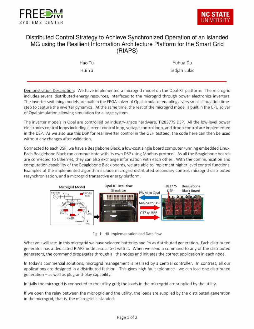
Demonstration Description: We have implemented a microgrid model on the Opal-RT platform. The microgrid
includes several distributed energy resources, interfaced to the microgrid through power electronics inverters.
The inverter switching models are built in the FPGA solver of Opal simulator enabling a very small simulation time-
step to capture the inverter dynamics. At the same time, the rest of the microgrid model is built in the CPU solver
of Opal simulation allowing simulation for a large system.
The inverter models in Opal are controlled by industry-grade hardware, TI28377S DSP. All the low-level power
electronics control loops including current control loop, voltage control loop, and droop control are implemented
in the DSP. As we also use this DSP for real inverter control in the GEH testbed, the code here can then be used
without any changes after validation.
Connected to each DSP, we have a Beaglebone Black, a low-cost single board computer running embedded Linux.
Each Beaglebone Black can communicate with its own DSP using Modbus protocol. As all the Beaglebone boards
are connected to Ethernet, they can also exchange information with each other. With the communication and
computation capability of the Beaglebone Black boards, we are able to implement higher level control functions.
Examples of the implemented algorithm include microgrid distributed secondary control, microgrid distributed
resynchronization, and a microgrid transactive energy platform.
Fig. 1: HIL Implementation and Data flow
What you will see: In this microgrid we have selected batteries and PV as distributed generation. Each distributed
generator has a dedicated RIAPS node associated with it. When we send a command to any of the distributed
generators, the command propagates through all the nodes and initiates the correct application in each node.
In today’s commercial solutions, microgrid management is realized by a central controller. In contrast, all our
applications are designed in a distributed fashion. This gives high fault tolerance - we can lose one distributed
generation – as well as plug-and-play capability.
Initially the microgrid is connected to the utility grid; the loads in the microgrid are supplied by the utility.
If we open the relay between the microgrid and the utility, the loads are supplied by the distributed generation
in the microgrid, that is, the microgrid is islanded.

Page 2 of 2
Then we will enable the secondary control application on the RIAPS nodes to maintain the microgrid frequency
to 60 Hz. We can see the frequency is gradually restored to 60 Hz by the application.
As the last step we enable the re-synchronization application on the RIAPS nodes. This will make the voltage of
the microgrid the same as the utility grid. With this application, we can reconnect the microgrid to the utility grid
with minimum disturbance.
Why it’s important: The RIAPS platform allows rapid implementation of distributed control algorithms. The HIL
testbed allows for a high-fidelity, real-time simulation of a microgrid with inverter controllers in the loop.
The next steps: With RIAPS, we aim to provide a fully-fledged distributed control platform for a microgrid. The
platform offers control solution for microgrid grid-tied operation, microgrid islanding, microgrid standalone
operation, microgrid secondary control, and microgrid re-synchronization.

Page 1 of 2
Green Energy Hub (GEH) Testbed
Dr. Wensong Yu Dr. Mehnaz Khan
Dr. Iqbal Husain
Dr. David Lubkeman
Salina Zabin, Hao Tu
M. A. Awal
Siyuan Chen
Md Rashed Hassan
Demonstration Description: This Green Energy Hub Testbed serves as the testing and demonstration platform of
the bidirectional power flow control including grid-tied battery energy storage with DC and AC loads. The testbed
includes three Solid-State Transformers (SSTs) representing three 10 kVA residential loads. Each SST has a 380 V
5 kVA DC port and a 120/240 V, 5 kVA split-phase AC port.
Fig. 1: Architecture of GEH Testbed
What you will see: The demonstration will begin with a description of the three-SST set-up and its interfaces with
grid, load, and DESDs and communication with SCADA. The following items will be demonstrated:
a) Bi-directional Power Flow
b) Autonomous Power-balancing among AC and DC ports
c) Reactive Power control through high level communication
Why it’s important: The testbed provides a universal platform for power management and energy management
with transparent digital interfaces, where experiments can be safely and readily conducted at lower voltages prior
to moving into Medium Voltage experiments. This testbed has been improved by transformer-less topology with
Utility
Source
SST-1 SST-2
240 V/1P
0.5 mH 0.5 mH
AC
Load
AC
Load
GEH (12.47 kV/3P, 7.2 KV/1P)
DC
ES
DC
ES
SST-3
0.5 mH
AC
LoadPV
10 kVA Residential
Node
10 kVA Residential
Node
10 kVA Residential
Node
AC Port DC Port AC Port DC Port AC Port DC Port

Page 2 of 2
common neutral. The grounding issue and voltage utilization issue of SiC power devices are solved
simultaneously.
Problems and issues:
Issues Solutions
Voltage utilization of SiC devices 2X Better utilization of power devices by improving
topology.
Noise in Communication and Sensing Noise eliminating for high power SiC converter by
optimized PCB layout.
Common Ground issue The AC input neutral is connected with AC output
neutral.
The next steps:
i) Grid supportive Control design and validation.
ii) Islanding operation implementation.
iii) More smart nodes will be added to verify networked Microgrid Functionality.
iv) Extend the grid voltage level from 240V AC to 7.2 kV AC with regulated 400 V DC and 240 V AC
ports.
References:
[1] M. A. Awal, Iqbal Husain and Wensong Yu, "Predictive current control for stabilizing power electronics based
AC power systems," 2017 IEEE Energy Conversion Congress and Exposition (ECCE), Cincinnati, OH, 2017, pp. 4634-
4641.
[2] S. Chen, Z. Chen and W. Yu, "Multiple PR Current Regulator based Dead-time Effects Compensation for Grid-
forming Single-Phase Inverter," 2018 IEEE Energy Conversion Congress and Exposition (ECCE), Portland, OR, 2018,
pp. 3134-3141.

Page 1 of 2
Decentralized Volt/VAR Optimization
Large Scale System Simulation using RIAPs Platform
Valliappan Muthukaruppan Dr. Mesut E. Baran
Demonstration Description: With the recent amendment to IEEE 1547 Standard, all inverters connected to the
secondary distribution system must be capable of providing reactive power support. This feature will drastically
increase the number of Volt/VAR devices in the circuit. As it is not possible to control all the devices in real-time
from a centralized location, a new control scheme is necessary. We have developed a master-slave
based decentralized Volt/VAR optimization scheme that coordinates the control of legacy VVC devices with the
control of smart inverters in real-time. The algorithm, running on distributed embedded boards, can be
integrated with ease on the existing inverters.
Fig. 1: Proposed architecture for Volt/VAR optimization
Fig. 2: IEEE 34 Node system with respective areas governed by slaves

Page 2 of 2
What you will see: The simulation environment running on Beagle Bone boards using the RIAPs platform will
simulate the performance of a 34 node system with 20 inverters which is segregated in to 6 areas, each governed
by an individual slave. The simulation model of the physical circuit is simulated in the virtual machine (laptop).
Why it’s important: In the 34 Node system, only six nodes are controlled as compared to the original 20 inverters
which would have to be controlled individually. This drastically reduces the communication requirements, an
important consideration for a real-time implementation of smart grid applications.
Problems and issues: The simulation environment utilizes a local area network for communication while utilities
usually use proprietary communication techniques like cellular and radio mesh. The communication network has
to be separately simulated using network simulation software for a realistic implementation.
The next steps: Interface the environment with physical devices like SSTs and also with the HIL simulator, such as
the OPAL-RT, to simulate the bigger IEEE 123 Node system.
Enabling high penetration of distributed PV through the optimization of sub-transmission voltage regulation
Principle Investigator at NCSU: Dr. Ning Lu
Collaborators: Dr. Nader Samaan, Pacific Northwest National Lab; Dr. Alex Huang, University of Texas at Austin; Brant Werts, Duke Energy
PHD Student(s): Catie McEntee, Fuhong Xie, David Mulcahy
Funding Source: Department of Energy
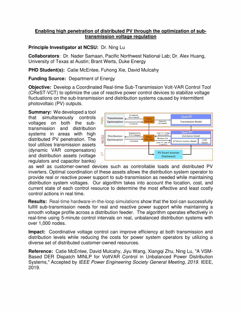
Objective: Develop a Coordinated Real-time Sub-Transmission Volt-VAR Control Tool (CReST-VCT) to optimize the use of reactive power control devices to stabilize voltage fluctuations on the sub-transmission and distribution systems caused by intermittent photovoltaic (PV) outputs.
Summary: We developed a tool that simultaneously controls voltages on both the sub-transmission and distribution systems in areas with high distributed PV penetration. The tool utilizes transmission assets (dynamic VAR compensators) and distribution assets (voltage regulators and capacitor banks) as well as customer-owned devices such as controllable loads and distributed PV inverters. Optimal coordination of these assets allows the distribution system operator to provide real or reactive power support to sub-transmission as needed while maintaining distribution system voltages. Our algorithm takes into account the location, cost, and current state of each control resource to determine the most effective and least costly control actions in real time.
Results: Real-time hardware-in-the-loop simulations show that the tool can successfully fulfill sub-transmission needs for real and reactive power support while maintaining a smooth voltage profile across a distribution feeder. The algorithm operates effectively in real-time using 5-minute control intervals on real, unbalanced distribution systems with over 1,000 nodes.
Impact: Coordinative voltage control can improve efficiency at both transmission and distribution levels while reducing the costs for power system operators by utilizing a diverse set of distributed customer-owned resources.
Reference: Catie McEntee, David Mulcahy, Jiyu Wang, Xiangqi Zhu, Ning Lu, "A VSM-Based DER Dispatch MINLP for VoltVAR Control in Unbalanced Power Distribution Systems," Accepted by IEEE Power Engineering Society General Meeting, 2019. IEEE, 2019.

Hierarchical Optimal Voltage Control Considering the Coordination of Utility Control Devices with Smart Inverters and Microgrids
Principle Investigator: Dr. David Lubkeman Student: Qian Long Objective: Develop a hierarchical optimization framework for distribution system voltage control that considers the coordination of utility control devices with fast-responding actors such as smart inverters and microgrids. Summary: In this framework, a multi-level optimal control design is considered. We first developed the detailed local voltage control for each DER, i.e., diesel generator, PV system, battery system. A novel distributed microgrid voltage control is developed based on consensus algorithms to enable the grid-supporting functions of the microgrids. A system-level optimization algorithm is designed to provide optimal set points for both slow-acting utility control devices, such as switched capacitors and on-load tap changer, and fast-responding actors, such as smart inverters and microgrids, in a coordinated manner. Results: Case studies show that the proposed optimal voltage control can tighten the voltage profiles of distribution feeders around the nominal voltage and significantly reduce the operation number of utility control devices. The control framework is tolerant to the communication delay or failure according to the simulation results. Impact: The proposed optimal voltage control can be integrated into the advanced distribution management systems (ADMS) as a new application to manage the daily operation of distribution systems that have high penetration PV plants and microgrids. Reference: [1]. Q. Long, J. Wang, D. Lubkeman, N. Lu, P.
Chen, “Volt-Var Optimization of Distribution Systems for Coordinating Utility Voltage Control with Smart Inverters”, 2019 IEEE Power & Energy Society Conference on Innovative Smart Grid Technologies, Washington DC, USA, 2019, pp. 1-5.
[2]. Q. Long, H. Yu, D. Lubkeman, S. Lukic, “A New Distributed Voltage Controller for Enabling Volt-Var Support of Microgrids in Grid-Connected Operation”, accepted by IEEE Power & Energy Society General Meeting, Atlanta, 2019.
Tertiary Control
Secondary Control
Primary Control
Self-Oscillating LLC Resonant Converter using SiC-MOSFETs
Adam Morgan Bo Gao
Douglas C. Hopkins
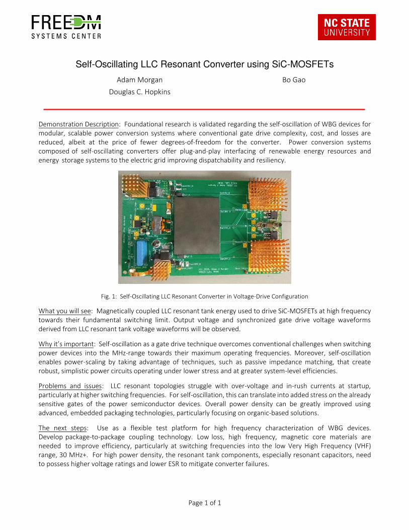
Demonstration Description: Foundational research is validated regarding the self-oscillation of WBG devices for
modular, scalable power conversion systems where conventional gate drive complexity, cost, and losses are
reduced, albeit at the price of fewer degrees-of-freedom for the converter. Power conversion systems
composed of self-oscillating converters offer plug-and-play interfacing of renewable energy resources and
energy storage systems to the electric grid improving dispatchability and resiliency.
Fig. 1: Self-Oscillating LLC Resonant Converter in Voltage-Drive Configuration
What you will see: Magnetically coupled LLC resonant tank energy used to drive SiC-MOSFETs at high frequency
towards their fundamental switching limit. Output voltage and synchronized gate drive voltage waveforms
derived from LLC resonant tank voltage waveforms will be observed.
Why it’s important: Self-oscillation as a gate drive technique overcomes conventional challenges when switching
power devices into the MHz-range towards their maximum operating frequencies. Moreover, self-oscillation
enables power-scaling by taking advantage of techniques, such as passive impedance matching, that create
robust, simplistic power circuits operating under lower stress and at greater system-level efficiencies.
Problems and issues: LLC resonant topologies struggle with over-voltage and in-rush currents at startup,
particularly at higher switching frequencies. For self-oscillation, this can translate into added stress on the already
sensitive gates of the power semiconductor devices. Overall power density can be greatly improved using
advanced, embedded packaging technologies, particularly focusing on organic-based solutions.
The next steps: Use as a flexible test platform for high frequency characterization of WBG devices.
Develop package-to-package coupling technology. Low loss, high frequency, magnetic core materials are
needed to improve efficiency, particularly at switching frequencies into the low Very High Frequency (VHF)
range, 30 MHz+. For high power density, the resonant tank components, especially resonant capacitors, need
to possess higher voltage ratings and lower ESR to mitigate converter failures.
Page 1 of 1

Page 1 of 1
100 kW High Power Density SiC Traction Inverter with 1kV DC-link
Li Yang Yukun Luo
Dhrubo Rahman Dr. Wensong Yu
Dr. Iqbal Husain
Demonstration Description: The inverter prototype is designed for electric vehicle traction drive applications. To
address the space limitation issue in EV and the increasing demand for inverter-motor integration, the
technologies to achieve high power density are developed and verified. While EV powertrain with 800 VDC buses
have been commercially available, a high DC bus voltage of 1 kV is implemented for this prototype to further
explore the design challenges and system benefits, such as increased efficiency. With the prototype, the EMI
characteristics of SiC traction inverter with high DC bus and high dv/dt are to be demonstrated as well.
What you will see:
1. System components to make the traction
inverter compact, including PCB based busbar
with in-house designed, low profile, heavy-
duty, module connector, split low profile gate
driver, shunt resistor based low profile current
sensor.
2. Inverter operation waveform at 1 kV DC-link.
Why it’s important: The high power density
achieved by SiC design can alleviate the issue of
limited space on EVs and enable the future trend
of motor-inverter integration. The high DC-link
design will help increase efficiency, reliability,
power density for future EVs, and reduce charging
anxieties and system cost as well.
Problems and issues: The issues to be solved are:
(1) increased EMI by wide bandgap device
switching; (2) reliable design for high temperature
operation of the inverter.
The next steps: High power SiC traction inverter EMI spectrum characterization on the designed 1 kV DC-link
traction inverter.
Fig. 1: Assembly view of the 100kW SiC traction inverter.

Page 1 of 2
Active Harmonic Filter using Interleaved SiC Inverter
Dr Wensong Yu Dr. Iqbal Husain
M A Awal Yukun Luo
Dhrubo Rahman Bryce Aberg
Li Yang
Demonstration Description: The objective of this project is to develop an active harmonic filter using SiC power
devices in interleaved topology with harmonic suppression capability up to the 51st order and THD≤ 2%. The
Active Harmonic Filter (AHF) is rated at 480V, line-to-line, 150 A, 60 Hz, and 135 kVA for up to 400 kW non-linear
load handling capability.
Fig. 1: SiC based Interleaved topology of AHF
What you will see: The demonstration will begin with a description of the AHF topology, the non-linear load, and
grid interface. The following items will be demonstrated,
a) Customized local busbar for SiC six-pack module achieving minimal commutation loop
inductance
b) Solder-less(plug-and-play) connection for high power modules
c) Active filtering of a non-linear load
Why it’s important: The effective switching frequency of 300 kHz combined with the superior computation
capability enabled by state-of-the-art FPGA based digital controller enables extremely fast dynamic response
which can be leveraged for a multitude of applications such as universal load-source emulator and motor emulator
for EV-drive testing. The high power density translating into smaller footprint and low cost make the solution very
attractive for commercial applications.
FPGA(Xilinx)
based digital
controller
Non-linear
load up to
400kW
PoC
THD < 2%
Active
Harmonic
Filter

Page 2 of 2
Problems and issues:
Challenges Solutions
Harmonic suppression up to 51st
(~3kHz)
High switching frequency capability of SiC combined with interleaving
to achieve 300kHz effective switching speed.
Current balancing among
interleaved phases
Active current balancing using low bandwidth, low cost current
sensors.
Large number of current sensing
requirement Only grid current feedback is used; load current sensing not required.
The next steps:
1. Test at full rated condition.
2. Test with an actual chiller unit with diode-front-end.
References:
[1] Li Yang, Yukun Luo, Awal M.A., Wensong Yu and Iqbal Husain, "Application of High Performance FPGA to Boost
Bandwidth of Three-Phase Shunt Active Power Filter," 2019 IEEE Energy Conversion Congress and Exposition
(ECCE) (submitted).

Page 1 of 1
20kW Three-Phase Three-Level 140 kHz Vienna Rectifier
Dr. Wensong Yu Siyuan Chen
Dakai Wang
Demonstration Description: PFC is widely used in electrical vehicle charger and energy storage system. Among
the three-phase PFC topologies, Vienna rectifier is an ideal choice for high power applications because of three-
level characteristic and high efficiency. The wide bandgap (WBG) semiconductor device allows to increase the
switching frequency and reduce the volume of passive components. In this project, a new forced air-cooled,
140kHz, 20kW SiC MOSFET based Vienna rectifier design is proposed for the high efficiency, high power density
requirement.
What you will see: A live
demonstration of Vienna rectifier
under 21 kW showing the Input
phase voltage, Input phase
current, DC bus voltage, and Line
to line switching voltage.
Why it’s important: A novel
modulation scheme is
implemented in Vienna PFC to
reduce the switching loss and
improve efficiency to 98.5%. The
new phase-change thermal
material and AlN thermal
interface are used to decrease the thermal impedance. For EMI filter design, a feedback damping resistor is added
to common-mode loop to improve the phase margin and stability.
Problems and issues:
Issues Solutions
Large switching loss 2X commutation loop inductance reduction
Modulation complexity Using novel modulation scheme to simplify the
modulator implementation
Large thermal impedance Using phase change material to reduce the thermal
impedance
The next steps: Improvement of phase current THD, load change test and EMI test.
Fig. 1: Topology of Vienna Rectifier

Page 1 of 1
5 kW Energy Recirculation Converter (ERC) for Power Semiconductor Characterization and Thermal Validation
Bo Gao Adam Morgan
Utkarsh Mehrotra Douglas C. Hopkins
Demonstration Description: Emerging high-speed power devices pose unique challenge to their characterization.
Conventional static testing no longer works to comprehensively characterize all parameters in actual operating
conditions due to the highly non-linear characteristics of newer devices. In addition, live testing is becoming
increasingly difficult due to the high power handling capability. For instance, a single high-voltage IGBT device can
switch more than 1 MW of power; finding a 1 MW power source and load bank can be challenging. This research
aims to provide a feasible method for testing high power systems using low power input and dissipation, while
recirculating and reusing energy to drive devices under test to higher switching power.
Fig. 1: Proposed energy recirculation converter prototype and its operation
What you will see: H-bridge energy recirculation converter based on 650 V, 12 A gallium nitride power
semiconductors, its LC tank, and its controller module as well as its controller software. The system will be run at
any voltage above 100 V and below 500 V, at full 12 A. By sweeping duty cycle, frequency, and other parameters,
power loss of each contributing factor can be calculated. This allows parameters at the given operating condition
to be calculated and used in converter design with high accuracy.
Why it’s important: The ERC enabled a variety of experiments that were not possible before. This project
originated from a super cascode power module project aiming to deliver an 8.5 kV, 200 A power module. Testing
such a module without an ERC at full power in an actual converter setup will require at least 1.7 MW of input
power and output power. Obtaining and safely dissipating such power is a challenge. Therefore, the need of an
ERC arose, and thus this project was originated.
Problems and issues: Similar with all high power, high speed converters, handling high di/dt and dv/dt can be
extremely challenging when designing current sensing circuits and gate driving circuits, especially when the circuit
is designed to push boundaries. An innovated high bandwidth current sensor is proposed, along with an
innovative optical fiber-based gate driver.
The next steps: Porting this design to 4 kV, 100 A and even higher power levels.