2019 university of cincinnati sae baja rear suspension
TRANSCRIPT

2019 University of Cincinnati SAE Baja Rear Suspension
A Baccalaureate thesis submitted to the Department of Mechanical and Materials Engineering
College of Engineering and Applied Science University of Cincinnati
in partial fulfillment of the
requirements for the degree of
Bachelor of Science
in Mechanical Engineering Technology
by
Ryan Bross
April 2019
Thesis Advisor:
Professor Allen Arthur

ii
TABLE OF CONTENTS
TABLE OF CONTENTS .......................................................................................................... II
LIST OF FIGURES ................................................................................................................ III
LIST OF TABLES .................................................................................................................. III
ABSTRACT ............................................................................................................................ IV
PROBLEM DEFINITION AND RESEARCH ........................................................................ 1
PROBLEM STATEMENT ........................................................................................................................................ 1 BACKGROUND ..................................................................................................................................................... 1
RESEARCH .............................................................................................................................. 1
SCOPE OF THE PROBLEM ...................................................................................................................................... 1 CURRENT STATE OF THE ART .............................................................................................................................. 2 END USER ............................................................................................................................................................ 3 CONCLUSIONS AND SUMMARY OF RESEARCH ..................................................................................................... 3
CUSTOMER FEATURES ....................................................................................................... 4
PRODUCT OBJECTIVES ....................................................................................................... 4
QUALITY FUNCTION DEPLOYMENT ............................................................................... 5
DESIGN .................................................................................................................................... 6
PROJECT MANAGEMENT .................................................................................................. 17
BUDGET, PROPOSED/ACTUAL ............................................................................................................................ 17 SCHEDULE, PROPOSED /ACTUAL ....................................................................................................................... 19 CONCLUSIONS .................................................................................................................................................. 20
PROJECT SUMMARY .......................................................................................................... 20
WORKS CITED ..................................................................................................................... 21
APPENDIX A ......................................................................................................................... 22

iii
LIST OF FIGURES Figure 1: Polaris RZR RS1 rear suspension
Figure 2: Difference in trailing arm suspensions
Figure 3: Example of swing arm suspension
Figure 4: Double wishbone suspension
Figure 5: A-Arm Suspension concept
Figure 6: Trailing arm concept
Figure 7: Swing arm concept
Figure 8: Trailing arm selection
Figure 9: Trailing arm drawing
Figure 10: Trailing arm plate drawing
Figure 11: Polaris bearing carrier drawing
Figure 12: Polaris rear hub drawing
Figure 13: Trailing arm assembly drawing
Figure 14: CV shaft drawing
Figure 15: Radius rod drawing
Figure 16: Radius rod frame mount drawing
Figure 17: 5-foot drop diagram
Figure 18: Proposed Schedule
Figure 19: Actual Schedule
Figure 20: Custom Jig Table
Figure 21: Custom Tube Holders
LIST OF TABLES Table 1: Vertical Drop Test
Table 2: Spring Rate vs Force Chart
Table 3: Material Properties
Table 4: Bill of Material
Table 5: Proposed Budget
Table 6: Actual Budget

iv
ABSTRACT
The Society of Automotive Engineers (SAE) holds a Baja competition each year for
universities worldwide to compete in. The class of 2019 had 10 seniors interested in Baja for
their design projects. With the amount of interest in the project; and an unsafe 2018 car to
work with, it was decided to start fresh and build a new car. As a team we designed, built and
tested a car built to the specific SAE rules. Along with building a new frame we wanted to
improve on previous designs of other components. This report will provide information on
research, customer features, product objectives, design, and project management for the 2019
University of Cincinnati Baja rear suspension.

2019 Rear Suspension Ryan Bross
1
PROBLEM DEFINITION AND RESEARCH
PROBLEM STATEMENT Baja SAE gives students the chance to build an all-terrain vehicle designed to be an
ergonomic, reliable, and economic production vehicle. As a team we will design, build, test,
and compete with the vehicle built to specific SAE rules. The University of Cincinnati has
built cars for years now, and the current Baja car has flaws that will be improved upon. Our
2019 team will be building a brand-new chassis and using some parts from the previous
vehicles to complete the final assembly. My focus will be on the rear suspension, creating a
design that is capable of traction, maneuverability, crawling, and endurance.
BACKGROUND
Baja SAE dates all the way back to its beginnings in 1976, where the initial goal was to
build a single man all-terrain vehicle that would be competitive with commercially
manufactured vehicles. Since this time Baja has grown to be a premier SAE competition that
includes over 150 universities per event.
RESEARCH
SCOPE OF THE PROBLEM The goal of SAE International’s Collegiate Design Series (CDS) competition for Baja
vehicles is to move students beyond just textbook theory. It allows students to design, build,
and test the performance of their projects. Students gain exposure with hands on, team
engineering experience which requires design, manufacturing, testing, project management,
communication, and budgeting [1]. Each year allows students to improve upon previous
designs by using data taken from previous years. The competition pushes students from
Universities all over the world to improve the design of their vehicles to win the competition.
The rear suspension is designed to allow cars to maneuver, and travel over rough terrain with
ease. Currently the University of Cincinnati has 3 Baja cars at our disposal allowing the team
to research and compare the pros and cons of previous designs.
The suspension of a vehicle has several functions; safety, performance, ride height, and
handling. The major function of suspension is dampening, it is used to absorb forces
experienced by the vehicle. This dampening is related to the safety of the vehicle, it protects
the user as well as the vehicle from potentially harmful forces. The ride height of the vehicle
comes from the ground clearance of suspension components. Creating a ride height that has
adaquete clearance, as well as maintains a low vehicle roll center is very important in off-
road suspensions. Handling comes from different components of a suspension; allowing the
car to accelerate, turn, brake, and move over terrain while keeping all four wheels in contact
with the ground.

2019 Rear Suspension Ryan Bross
2
CURRENT STATE OF THE ART
Some state-of-the-art examples for all
terrain vehicles are Baja cars, and all-terrain
vehicles (ATVs). The most common customer
related product is the Polaris RZR. Based on
sales the RZR platform is the most common
side by side off road vehicle used in the US
{2}. The newest addition to the RZR platform
is the RS1 single seat ATV. The RS1 rear
suspension is a trailing arm suspension with 21
inches of travel, allowing a ground clearance of
13 inches [2]. The RS1 rear suspension can be
seen in Figure 1.
In the world of offroad vehicles there are
several accepted rear suspension methods
including trailing arms, swing arms, and double
wishbone (dual a arm assemblies).
Trailing arm suspension: A trailing arm suspension
uses two arms which are pivoted to the frame on the
front, and fixed to the hub on the back. It allows the
wheel to move up and down to deal with rough
terrain. Arms parallel with the frame increase in angle
with the shock/spring assembly and create
traction.With the arms mounted paralled with the car
it does not allow for camber change. Another version
of trailing arms that is becoming more widely used is
a semi trailing arm suspension. The arm is pivoted at
angles (50-70 degrees) and is split into two vectors,
the trailing arm deal with bumps but leads to
understeer, where as the traverse component acts as a
swing arm suspension and cancels out the understeer
caused by the trailing arm [3]. The disadvantage to
this system is that throughout the suspension travel the
camber angle will change.
The differences in the two types is shown in Figure 2.
Figure 1: Polaris RZR RS1 rear suspension [2]
Figure 2: Difference in trailing
arm suspensions [3]

2019 Rear Suspension Ryan Bross
3
Swing arm suspension: A swing arm
suspension is one of the earliest
designed independent shock absorption
suspensions. Its advantages are it is
simple in design, sturdy, and cost
effective, however due to the design of
the system body roll and bouncing can
cause unwanted camber gain and understeer [3]. In the ATV/Motorcycle world they use a
single swing arm mounted parallel with the front of the frame, this is also a sturdy design but
only allows the rear suspension to move as a whole and not indepedently.
Double wishbone suspension: A double wishbone suspension is one of
the most common suspensions in both commuting sedans and high
performance racecars. The advantage to this design is the suspension
always maintains the wheel perpendicular to the road surface
throughout the travel of the suspension. This suspension system
requires a lot of space in order to be used and can be less cost effective
than other suspension systems.
END USER The main objective of the Baja SAE is to design a competitive car for competition;
however, the secondary objective is to build a car that is designed for the recreational user
market. The vehicle will be built to demonstrate reliability, performance, and ergonomics,
while keeping in mind it needs to remain economically valuable for a manufacture by a
company and use by a recreational user.
The immediate user of the vehicle will be the 2019 University of Cincinnati Baja team.
The team will take the car to competition where it will be tested on acceleration, hill climb,
maneuverability, and suspension. During these tests the vehicle will prove its ability and
worth to a potential recreational consumer.
CONCLUSIONS AND SUMMARY OF RESEARCH In the Baja SAE competition there are very few restrictions on the rear suspension
design. Since the end customer is the University of Cincinnati Baja team, the design will be
based around the best suspension design to complete all courses during competition. Each
design uses a dampening system, whether it’s a coil over shock or air shock. The best style
shock and spring setup will be calculated after the most efficient suspension style is chosen.
Figure 3: Example of swing arm suspension [3]
Figure 4: Double wishbone
suspension [3]

2019 Rear Suspension Ryan Bross
4
CUSTOMER FEATURES (Weighted Importance)
Accelerates quickly (.1)
Maneuvers easily (.1)
Meets safety specifications (.15)
Drives over large obstacles (.1)
Climbs steep grade (.05)
Requires low maintenance (.05)
Cost efficient (.1)
Brakes quickly (.1)
Ergonomically Designed (.1)
Lightweight (.15)
PRODUCT OBJECTIVES Driver Safety (30%)
Cage will meet/surpass SAE 2019 Rules
Cage will protect drivers from injury
The vehicle will be equipped with all safety equipment
Driver Comfort (20%)
Design will be ergonomic for the driver
Design will fit drivers of different sizes comfortably
Performance (25%)
The vehicle will meet performance requirements set forth by the customer
The vehicle will be able to complete all tests during the Baja SAE competition
Cost (25%)
The build/manufacturing of the Baja car will remain within the University SAE Baja
Budget
2019 Rear Suspension Ryan Bross
5
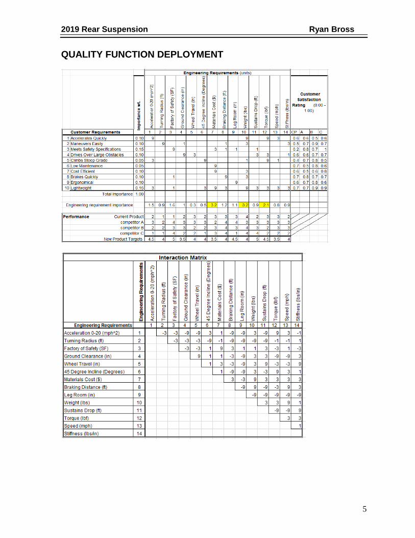
QUALITY FUNCTION DEPLOYMENT

2019 Rear Suspension Ryan Bross
6
DESIGN Design alternatives and selection
Figure 5: A-Arm Suspension
Figure 6: Trailing Arm Suspension

2019 Rear Suspension Ryan Bross
7
Figure 7: Swing Arm Suspension

2019 Rear Suspension Ryan Bross
8
Selection
Figure 8: Trailing Arm
Drawings
Figure 9: Trailing Arm
Trailing arms were designed to ensure the most ground clearance as possible, by
mounting to the frame with the lower trailing arm tube.

2019 Rear Suspension Ryan Bross
9
Figure 10: Trailing Arm Plate
Custom trailing arm plates were waterjet cut to attach the trailing arm to a standard
Polaris bearing carrier.
Figure 11: Polaris Bearing Carrier
2019 Rear Suspension Ryan Bross
10
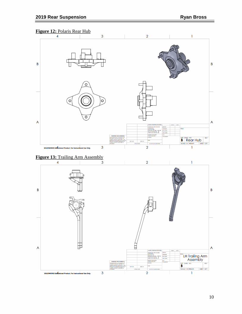
Figure 12: Polaris Rear Hub
Figure 13: Trailing Arm Assembly

2019 Rear Suspension Ryan Bross
11
Figure 14: CV Shaft
Custom CV shafts were built to allow for plunging motion to happen in the shaft
since the internal CV joint was replaced with an outer joint for increased angle
because of the large amount of ride height and wheel travel.

2019 Rear Suspension Ryan Bross
12
Figure 15: Radius Rods
Bent lower radius rods were designed to allow for greater clearance when moving
over obstacles.
Figure 16: Radius Rod Frame Mount
Offset radius rod mounts were designed to reduce misalignment from the frame to
wheel with radius rods.

2019 Rear Suspension Ryan Bross
13
Loading Conditions
Initial PE = Final KE
𝑚𝑔ℎ =1
2𝑚𝑣2
𝑊 = 1
2𝑚𝑣𝑓
2- 1
2𝑚𝑣𝑖
2
𝐹𝑎𝑣𝑔 =
12𝑚𝑣𝑓
2
𝑑
𝜎 =𝐹
𝐴
𝐴 =𝜋
4(𝑑𝑜
2 − 𝑑2
𝐼𝑦 = 𝜋(𝑑𝑜
4 − 𝑑𝑖4)
64
Table 1: Vertical Drop Test
Vertical Drop Test (5 ft.)
Weight of car and driver (lbs.) 600
Drop Height (ft.) 5
Gravity (ft./s^2) 32.2
Mass (slugs) 18.63
Potential Energy (ft.-lbs.) 3000
Velocity Initial (ft./s) 0
Velocity Final (ft./s) 17.93
Kinetic Energy (ft.-lbs.) 3000

2019 Rear Suspension Ryan Bross
14
Figure 17: 5-Foot Drop
Spring Specifications:
• Shock travel: 10 inches
• Static ground clearance: 15 inches
• Motion ratio: .68
• Un-sprung weight: 165 lbs.
• Sprung weight: 130 lbs.
• Shock Angle: 25*
• Angle Correction: .91
𝑀𝑜𝑡𝑖𝑜𝑛 𝑅𝑎𝑡𝑖𝑜 =15
22= . 681
𝑆𝑝𝑟𝑖𝑛𝑔 𝐹𝑜𝑟𝑐𝑒 = 130
. 68= 190.9
𝐶𝑜𝑟𝑟𝑒𝑐𝑡𝑒𝑑 =190.9
. 91= 209.8
𝑆𝑝𝑟𝑖𝑛𝑔 𝑟𝑎𝑡𝑒 =209.8
(17 𝑥 . 25)= 55.9
𝐾𝑒𝑓𝑓 =
(150 𝑥 75)(150+ 75)
= 50 𝑙𝑏/𝑖𝑛

2019 Rear Suspension Ryan Bross
15
Table 2: Spring Rate VS Force Chart
Force (lbf)
50 100 150 250
Shock Travel (in)
Top Spring (k) 75 0.67 1.33 2.00 3.33
Bottom Spring (k) 150 0.33 0.67 1.00 1.67
Effective Spring (k) 50 1 2 3 5
Component Selection
Table 3: Material Properties
• 1” OD x .095 - 4130 tubing
• .875” OD x .058 - 4130 tubing
• .25” A36 plate
• .125” A36 plate
Material Yield Strength (PSI) Tensile Strength (PSI)
4130 63000 97200
A36 36000 62000

2019 Rear Suspension Ryan Bross
16
Bill of Material
Table 4: Bill of Material
BILL OF MATERIAL
PART
NUMBER QUANTITY DESCRIPTION
ALL22046-8 2 1" X .095" ROUND TUBE
TB000140 2 1" X .095" 5/8-18 TUBE END
XML10 2 5/8-18 ROD END
HMS108Z 4 5/8 X 1/2 MISALIGNMENT SPACERS
B8 8125 2
MONOTUBE SHOCK - 10 IN
TRAVEL
0350.250.0075 2 75 LB SPRING
1200.250.0150S 2 150 LB SPRING
5137278 2 RZR 900 HUB
5137181 1 RZR 900 RH BEARING CARRIER
5137180 1 RZR 900 LH BEARING CARRIER
R13WH76AG 1 RZR 900 CV/AXLE SET
3514699 2 BALL BEARING
7710440 2 RETAINING RING
7547337 2 M18 X 1.5 CASTLE NUT
7518378 8 3/8-24 X 1.38 WHEEL STUD
0332-00390 2 SPLINE SHAFT -10 INCH
91257A722 4 1/2-13 X 2-1/2 LONG GRADE 8 BOLT
92018A540 4 1/2-13 NYLON LOCKNUT

2019 Rear Suspension Ryan Bross
17
PROJECT MANAGEMENT
BUDGET, PROPOSED/ACTUAL
Table 5: Proposed Budget
Rear Suspension Budget Proposed
Item Total Type of Funding Raw Material $150 Project Funding
Manufacturing $50 School Shop Shocks $1000 Sponsor Rod Ends/Spacers $75 Project Funding Hardware $75 Project Funding Springs (x4) $220 Project Funding RZR 900 Bearing Carriers (x2) $350 Project Funding RZR 900 Hubs (x2) $200 Project Funding RZR 900 Bearings (x2) $90 Project Funding RZR 900 CV Joint (x2) $160 Project Funding Spline Shaft $120 Project Funding
Total: $2490
Adjusted Total: $1490

2019 Rear Suspension Ryan Bross
18
Table 6: Actual Budget
ACTUAL BUDGET
PART
NUMBER QUANTITY DESCRIPTION
PRICE
(EA)
PRICE
(EX)
ALL22046-8 2 1" X .095" ROUND TUBE $ 48.00 $ 96.00
TB000140 2 1" X .095" 5/8-18 TUBE END $ 3.50 $ 7.00
XML10 2 5/8-18 ROD END $ 16.00 $ 32.00
HMS108Z 4 5/8 X 1/2 MISALIGNMENT SPACERS $ 2.20 $ 8.80
B8 8125 2 MONOTUBE SHOCK - 10 IN TRAVEL $ - $ -
0350.250.0075 2 75 LB SPRING $ 61.50 $ 123.00
1200.250.0150S 2 150 LB SPRING $ 57.00 $ 114.00
5137278 2 RZR 900 HUB $ 100.00 $ 200.00
5137181 1 RZR 900 RH BEARING CARRIER $ 175.00 $ 175.00
5137180 1 RZR 900 LH BEARING CARRIER $ 175.00 $ 175.00
R13WH76AG 1 RZR 900 CV/AXLE SET $ 139.00 $ 139.00
3514699 2 BALL BEARING $ 45.00 $ 90.00
7710440 2 RETAINING RING $ 12.50 $ 25.00
7547337 2 M18 X 1.5 CASTLE NUT $ 2.25 $ 4.50
7518378 8 3/8-24 X 1.38 WHEEL STUD $ 0.53 $ 4.24
0332-00390 2 SPLINE SHAFT -10 INCH $ 61.50 $ 123.00
91257A722 4 1/2-13 X 2-1/2 LONG GRADE 8 BOLT $ 1.10 $ 4.40
92018A540 4 1/2-13 NYLON LOCKNUT $ 0.29 $ 1.16
TOTAL $ 1,322.10

2019 Rear Suspension Ryan Bross
19
SCHEDULE, PROPOSED /ACTUAL
Figure 18: Proposed Schedule
Proposed Schedule September October November December January February March April
Research
Concept Selection
3D Modeling
Winter Presentation
Order Materials
Manufacture
Testing
Tech Expo
Spring Presentation
Figure 19: Actual Schedule
Actual Schedule September October November December January February March April
Research
Concept Selection
3D Modeling
Winter Presentation
Order Materials
Manufacture
Testing
Tech Expo
Spring Presentation
When starting the project and laying out a schedule, one of the assumptions made was
that after designing we would go straight into manufacturing. It was quickly learned that this
is not case, there were several major design changes after starting manufacturing once issues
were discovered while assembling. Due to these changes the 3D modeling lasted throughout
the entire project, whether it was major components, or minor items like tabs that were
initially not thought of. Manufacturing and testing were also pushed back due to time
constraints. A major setback in my project came from the full car model with all the major
components placed into it. The gearbox was not drawn correctly, which then led to changes
in the frame. The changes in gearbox location and rear frame design would then change the
length of trailing arms and location of upper shock mounts.

2019 Rear Suspension Ryan Bross
20
CONCLUSIONS The main goal of this project was to design and manufacture a rear suspension that
improves on the flaws of previous years’ designs. The primary objectives were increased
wheel travel, higher ground clearance, and reduced cost. In 2017 the total wheel travel given
by the rear suspension was 9.48” and in 2019 the wheel travel was increased by 4.02 inches
with a total of 13.5” of travel. The ground clearance was also improved upon, with a static
ground clearance of 15.5 inches, it is 3.5” higher than the 2017 car. Reducing cost was a
large factor in the build process of the project this year due to the fact as a whole team we did
not have the budget previous years were accustom to having. Comparing again to the cost of
the rear suspension in 2017 which was $1996.02, building a whole new rear suspension I was
able to reduce the cost to $1322.10 which is a 33.7% savings.
The weight of the 2019 car is the main criteria that could use improvement. When
considering the rear suspension lighter tubing could be utilized on the trailing arms, and if
possible custom bearing carriers made of aluminum, but similar to the Polaris design to
ensure use of standard parts, would significantly reduce the system weight.
PROJECT SUMMARY
In summary the project went well, we were able to complete the car on time for tech
expo and testing thereafter. Custom fixtures were machined to hold the trailing arms in place
during welding to ensure symmetry between the driver and passenger side. All
manufacturing was done in house, with the use of the machine shop at victory parkway, weld
shop, and fabrication tools located in the N104 lab room. Even though the university allows
for machine shop hours, if it is possible to become a trustee of the machine shop and weld
shop it would further expedite the build process when those rooms aren’t available.
Figure 20: Custom Jig Table Figure 21: Custom Tube Holders

2019 Rear Suspension Ryan Bross
21
WORKS CITED 1. SAE International Collegiate Design Series. SAE International [viewed 1 October
2018] Available from: https://www.sae.org/attend/student-events/
2. Polaris off road vehicles. Polaris [viewed 3 October 2018] Available from:
https://rzr.polaris.com/en-us/rzr-rs1-black-pearl/specs/
3. Autozine Technical school in suspension. Mark Wan, Electrical Engineer [viewed 4
October 2018] Available from:
http://www.autozine.org/technical_school/suspension/tech_suspension1.htm
4. International, SAE. BAJA SAE Collegiate Design Series Baja SAE Rules. s.I. : SAE,
2019.
5. SAE BAJA, Worcester Polytechnic Institute (WPI). SAE Baja Major Qualifying
Project Final Report. Bachelor of Science. Thesis, Worcester Polytechnic Institute,
2016.

22
APPENDIX A
Completed 2019 Baja Car