2020-2022 35 - sram
TRANSCRIPT
SERVICE MANUAL
GEN.0000000006367 Rev A © 2021 SRAM, LLC
2020-2022 35
SRAM LLC WARRANTYTHIS WARRANTY GIVES YOU SPECIFIC LEGAL RIGHTS AGAINST SRAM, LLC. YOU MAY ALSO HAVE OTHER RIGHTS THAT VARY FROM STATE TO STATE, COUNTRY, OR PROVINCE. THIS WARRANTY DOES NOT AFFECT YOUR STATUTORY RIGHTS. TO THE EXTENT THIS WARRANTY IS INCONSISTENT WITH THE LOCAL LAW, THIS WARRANTY SHALL BE DEEMED MODIFIED TO BE CONSISTENT WITH SUCH LAW. FOR A FULL UNDERSTANDING OF YOUR RIGHTS, CONSULT THE LAWS OF YOUR COUNTRY, PROVINCE, OR STATE.
EXTENT OF LIMITED WARRANTY
Except as otherwise set forth herein, SRAM warrants its bicycle components to be free from defects in materials or workmanship for a period of two (2) years after original purchase of the product.
SRAM warrants all Zipp MOTO Wheels and Rims to be free from defects in materials or workmanship for the lifetime of the product.
SRAM warrants all non-electronic Zipp branded bicycle components, Model Year 2021 or newer, to be free from defects in materials or workmanship for the lifetime of the product.
GENERAL PROVISIONS
This warranty only applies to the original owner and is not transferable. Claims under this warranty must be made through the retailer where the bicycle or the SRAM product was purchased or a SRAM authorized service location. Original proof of purchase is required. All SRAM warranty claims will be evaluated by a SRAM authorized service location whereupon acceptance of the claim the product will be repaired, replaced, or refunded at SRAM's discretion. To the extent allowed by local law claims under this warranty must be made during the warranty period and within one (1) year following the date on which any such claim arises.
NO OTHER WARRANTIES
EXCEPT AS DESCRIBED HEREIN, AND TO THE EXTENT ALLOWED BY LOCAL LAW, SRAM MAKES NO OTHER WARRANTIES, GUARANTIES, OR REPRESENTATIONS OF ANY TYPE (EXPRESS OR IMPLIED), AND ALL WARRANTIES (INCLUDING ANY IMPLIED WARRANTIES OF REASONABLE CARE, MERCHANTABILITY, OR FITNESS FOR A PARTICULAR PURPOSE) ARE HEREBY DISCLAIMED.
LIMITATIONS OF LIABILITY
EXCEPT AS DESCRIBED HEREIN, AND TO THE EXTENT PERMITTED BY LAW, IN NO EVENT SHALL SRAM OR ITS THIRD PARTY SUPPLIERS BE LIABLE FOR DIRECT, INDIRECT, SPECIAL, INCIDENTAL, OR CONSEQUENTIAL DAMAGES. SOME STATES (COUNTRIES AND PROVINCES) DO NOT ALLOW THE EXCLUSION OR LIMITATION OF INCIDENTAL DAMAGES, SO THE ABOVE LIMITATION MAY NOT APPLY TO YOU.
LIMITATIONS OF WARRANTY
This warranty does not apply to products that have been incorrectly installed, adjusted, and/or maintained according to the respective SRAM user manual. The SRAM user manuals can be found online at sram.com/service.
This warranty does not apply to damage to the product caused by a crash, impact, abuse of the product, non-compliance with manufacturer's specifications of intended usage, or any other circumstances in which the product has been subjected to forces or loads beyond its design.
This warranty does not apply when the product has been modified, including but not limited to, any attempt to open or repair any electronic and electronic related components, including the motor, controller, battery packs, wiring harnesses, switches, and chargers.
This warranty does not apply when the serial number or production code has been deliberately altered, defaced, or removed.
SRAM components are designed for use only on bicycles that are pedal powered or pedal assisted (e-Bike/Pedelec).
Notwithstanding anything else set forth herein, the battery pack and charger warranty does not include damage from power surges, use of improper charger, improper maintenance, or such other misuse.
This warranty shall not cover damages caused by the use of parts of different manufacturers or parts that are not compatible or suitable for use with SRAM components.
This warranty shall not cover damages resulting from commercial (rental) use.
WEAR AND TEAR
This warranty does not apply to normal wear and tear. Wear and tear parts are subject to damage as a result of normal use, failure to service according to SRAM recommendations, and/or riding or installation in conditions or applications other than recommended.
WEAR AND TEAR PARTS INCLUDE:
• Aero bar pads• Air sealing o-rings• Batteries• Bearings• Bottomout pads• Brake pads• Bushings• Cassettes
• Chains• Corrosion• Disc brake rotors• Dust seals• Free hubs, Driver bodies, Pawls• Foam rings, Glide rings• Handlebar grips• Jockey wheels
• Rear shock mounting hardware and main seals
• Rubber moving parts• Shifter and Brake cables
(inner and outer)• Shifter grips• Spokes• Sprockets
• Stripped threads/bolts (aluminum, titanium, magnesium or steel)
• Tires• Tools• Transmission gears• Upper tubes (stanchions)• Wheel braking surfaces
ZIPP IMPACT REPLACEMENT POLICY
Zipp branded products, Model Year 2021 or newer, are covered under a lifetime impact-damage replacement policy. This policy can be used to obtain a replacement of a product in the event of non-warranty impact damage occurring while riding your bicycle. See www.zipp.com/support for more information.

SAFETY FIRST!We care about YOU. Please, always wear your safety glasses
and protective gloves when servicing RockShox products. Protect yourself! Wear your safety gear!
TABLE OF CONTENTSROCKSHOX SERVICE ..........................................................................................................................................................................................6
PART PREPARATION ......................................................................................................................................................................................................................................6SERVICE PROCEDURES .................................................................................................................................................................................................................................6PARTS, TOOLS, AND SUPPLIES ..................................................................................................................................................................................................................7RECOMMENDED SERVICE INTERVALS ....................................................................................................................................................................................................8RECORD YOUR SETTINGS ............................................................................................................................................................................................................................8TORQUE VALUES .............................................................................................................................................................................................................................................8OIL VOLUME AND LUBRICANT ...................................................................................................................................................................................................................9
EXPLODED VIEW - 2020-2022 35 GOLD RL - DEBONAIR .........................................................................................................................10
EXPLODED VIEW - 2022 35 SILVER TK - SOLO AIR .....................................................................................................................................11
EXPLODED VIEW - 2022 35 SILVER TK - DUAL POSITION COIL ..............................................................................................................12
EXPLODED VIEW - 2022 35 SILVER R - DUAL POSITION COIL ................................................................................................................. 13
EXPLODED VIEW - 2021-2022 35 SILVER TK - COIL ...................................................................................................................................14
EXPLODED VIEW - 2021-2022 35 SILVER R - COIL .....................................................................................................................................15
LOWER LEG REMOVAL AND SERVICE ...........................................................................................................................................................16
50/200 HOUR SERVICELOWER LEG REMOVAL ................................................................................................................................................................................................................................. 16
50 HOUR SERVICELOWER LEG SERVICE...................................................................................................................................................................................................................................20
200 HOUR SERVICELOWER LEG SEAL SERVICE ....................................................................................................................................................................................................................... 22
AIR SPRING SERVICE - DEBONAIR - 35 GOLD ............................................................................................................................................ 25
200 HOUR SERVICEAIR SPRING REMOVAL ................................................................................................................................................................................................................................ 25AIR SPRING TRAVEL CHANGE AND BOTTOMLESS TOKENS (OPTIONAL) ................................................................................................................................ 31DEBONAIR - TRAVEL AND BOTTOMLESS TOKEN TUNING ............................................................................................................................................................ 31AIR SPRING AND ALL-TRAVEL SPACER CONFIGURATIONS ........................................................................................................................................................... 31BOTTOMLESS TOKENS INSTALLATION (OPTIONAL) ....................................................................................................................................................................... 32AIR SPRING INSTALLATION ....................................................................................................................................................................................................................... 33
AIR SPRING SERVICE - SOLO AIR - 35 SILVER ............................................................................................................................................ 38
200 HOUR SERVICEAIR SPRING REMOVAL ................................................................................................................................................................................................................................ 38AIR SPRING TRAVEL CHANGE AND BOTTOMLESS TOKENS (OPTIONAL) ............................................................................................................................... 42SOLO AIR - TRAVEL AND BOTTOMLESS TOKEN TUNING .............................................................................................................................................................. 42AIR SPRING AND ALL-TRAVEL SPACER CONFIGURATIONS .......................................................................................................................................................... 42BOTTOMLESS TOKENS INSTALLATION (OPTIONAL) ....................................................................................................................................................................... 43AIR SPRING INSTALLATION ....................................................................................................................................................................................................................... 44
COIL SPRING SERVICE - DUAL POSITION COIL - 35 SILVER .....................................................................................................................47
200 HOUR SERVICECOIL SPRING REMOVAL AND SERVICE .................................................................................................................................................................................................47COIL SPRING INSTALLATION ....................................................................................................................................................................................................................50
COIL SPRING SERVICE - 35 SILVER .............................................................................................................................................................. 52
200 HOUR SERVICECOIL SPRING REMOVAL AND SERVICE ................................................................................................................................................................................................ 52COIL SPRING INSTALLATION .................................................................................................................................................................................................................... 55
DAMPER SERVICE - MOTION CONTROL - 35 GOLD .................................................................................................................................. 57
200 HOUR SERVICEDAMPER REMOVAL ...................................................................................................................................................................................................................................... 57DAMPER SERVICE .......................................................................................................................................................................................................................................... 61REBOUND DAMPER INSTALLATION ....................................................................................................................................................................................................... 64COMPRESSION DAMPER INSTALLATION .............................................................................................................................................................................................66

DAMPER SERVICE - TURNKEY AND REBOUND - 35 SILVER .................................................................................................................. 69
200 HOUR SERVICEDAMPER REMOVAL .....................................................................................................................................................................................................................................69DAMPER SERVICE .........................................................................................................................................................................................................................................74REBOUND DAMPER INSTALLATION .......................................................................................................................................................................................................77COMPRESSION DAMPER INSTALLATION ............................................................................................................................................................................................80
LOWER LEG ASSEMBLY .................................................................................................................................................................................. 83
50/200 HOUR SERVICELOWER LEG INSTALLATION ..................................................................................................................................................................................................................... 83
6RockShox Service
R o c k S h o x S e r v i c eWe recommend that you have your RockShox suspension serviced by a qualified bicycle mechanic. Servicing RockShox suspension requires knowledge of suspension components, as well as the use of specialized tools and lubricants/fluids. Failure to follow the procedures outlined in this service manual may cause damage to your component and void the warranty.
Visit www.sram.com/service for the latest RockShox Spare Parts catalog and technical information. For order information, please contact your local SRAM distributor or dealer.
Information contained in this publication is subject to change at any time without prior notice.
Your product's appearance may differ from the pictures contained in this publication.
For recycling and environmental compliance information, please visit www.sram.com/en/company/about/environmental-policy-and-recycling.
P a r t P r e p a r a t i o n Remove the component from the bicycle before service.
Disconnect and remove the remote cable or hydraulic hose from the fork or rear shock, if applicable. For additional information about RockShox remotes, user manuals are available at www.sram.com/service.
Clean the exterior of the product with mild soap and water to avoid contamination of internal sealing part surfaces.
S e r v i c e P r o c e d u r e sThe following procedures should be performed throughout service, unless otherwise specified.
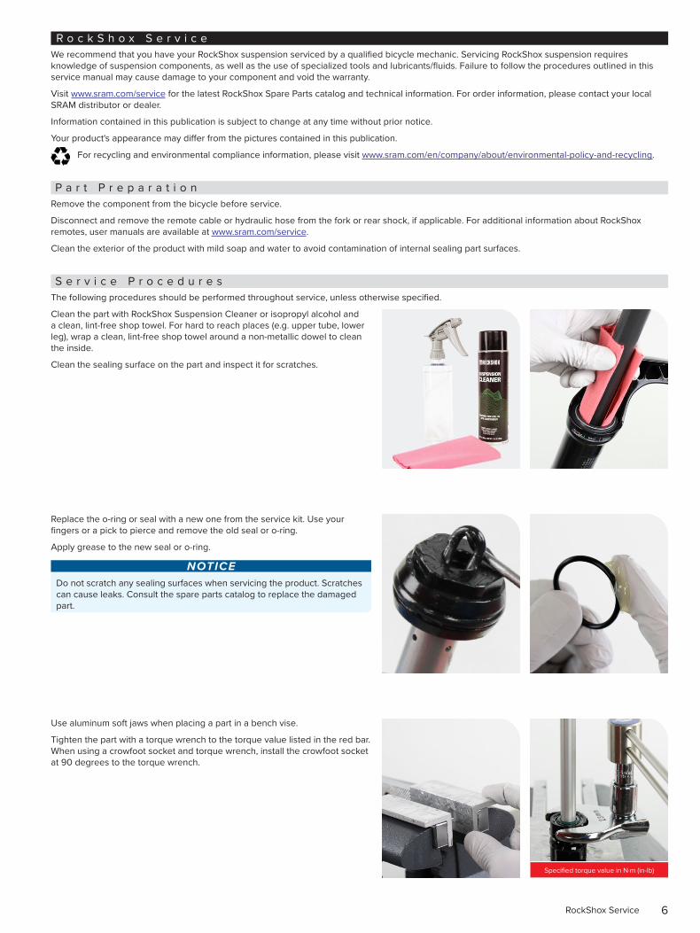
Clean the part with RockShox Suspension Cleaner or isopropyl alcohol and a clean, lint-free shop towel. For hard to reach places (e.g. upper tube, lower leg), wrap a clean, lint-free shop towel around a non-metallic dowel to clean the inside.
Clean the sealing surface on the part and inspect it for scratches.
Replace the o-ring or seal with a new one from the service kit. Use your fingers or a pick to pierce and remove the old seal or o-ring.
Apply grease to the new seal or o-ring.
NOTICEDo not scratch any sealing surfaces when servicing the product. Scratches can cause leaks. Consult the spare parts catalog to replace the damaged part.
Use aluminum soft jaws when placing a part in a bench vise.
Tighten the part with a torque wrench to the torque value listed in the red bar. When using a crowfoot socket and torque wrench, install the crowfoot socket at 90 degrees to the torque wrench.
Specified torque value in N·m (in-lb)
7Parts, Tools, and Supplies
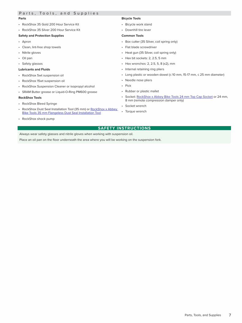
P a r t s , T o o l s , a n d S u p p l i e sParts
• RockShox 35 Gold 200 Hour Service Kit
• RockShox 35 Silver 200 Hour Service Kit
Safety and Protection Supplies
• Apron
• Clean, lint-free shop towels
• Nitrile gloves
• Oil pan
• Safety glasses
Lubricants and Fluids
• RockShox 5wt suspension oil
• RockShox 15wt suspension oil
• RockShox Suspension Cleaner or isopropyl alcohol
• SRAM Butter grease or Liquid-O-Ring PM600 grease
RockShox Tools
• RockShox Bleed Syringe
• RockShox Dust Seal Installation Tool (35 mm) or RockShox x Abbey Bike Tools 35 mm Flangeless Dust Seal Installation Tool
• RockShox shock pump
Bicycle Tools
• Bicycle work stand
• Downhill tire lever
Common Tools
• Box cutter (35 Silver, coil spring only)
• Flat blade screwdriver
• Heat gun (35 Silver, coil spring only)
• Hex bit sockets: 2, 2.5, 5 mm
• Hex wrenches: 2, 2.5, 5, 8 (x2), mm
• Internal retaining ring pliers
• Long plastic or wooden dowel (≤ 10 mm, 15-17 mm, ≤ 25 mm diameter)
• Needle nose pliers
• Pick
• Rubber or plastic mallet
• Socket: RockShox x Abbey Bike Tools 24 mm Top Cap Socket or 24 mm, 8 mm (remote compression damper only)
• Socket wrench
• Torque wrench
SAFETY INSTRUCTIONSAlways wear safety glasses and nitrile gloves when working with suspension oil.
Place an oil pan on the floor underneath the area where you will be working on the suspension fork.
8Recommended Service Intervals
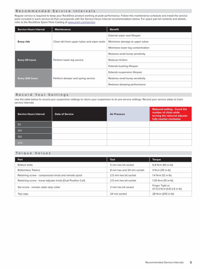
R e c o m m e n d e d S e r v i c e I n t e r v a l sRegular service is required to keep your RockShox product working at peak performance. Follow this maintenance schedule and install the service parts included in each service kit that corresponds with the Service Hours Interval recommendation below. For spare part kit contents and details, refer to the RockShox Spare Parts Catalog at www.sram.com/service.
Service Hours Interval Maintenance Benefit
Every ride Clean dirt from upper tubes and wiper seals
Extends wiper seal lifespan
Minimizes damage to upper tubes
Minimizes lower leg contamination
Every 50 hours Perform lower leg service
Restores small bump sensitivity
Reduces friction
Extends bushing lifespan
Every 200 hours Perform damper and spring service
Extends suspension lifespan
Restores small bump sensitivity
Restores damping performance
R e c o r d Y o u r S e t t i n g sUse the table below to record your suspension settings to return your suspension to its pre-service settings. Record your service dates to track service intervals.
Service Hours Interval Date of Service Air Pressure
Rebound setting - Count the number of clicks while turning the rebound adjuster fully counter-clockwise.
50
100
150
200
T o r q u e V a l u e s
Part Tool Torque
Bottom bolts 5 mm hex bit socket 6.8 N•m (60 in-lb)
Bottomless Tokens 8 mm hex and 24 mm socket 4 N•m (35 in-lb)
Retaining screw - compression knob and remote spool 2.5 mm hex bit socket 1.4 N•m (12 in-lb)
Retaining screw - travel adjuster knob (Dual Position Coil) 2.5 mm hex bit socket 1.35 N•m (10 in-lb)
Set screw - remote cable stop collar 2 mm hex bit socket Finger Tight or 0.1-0.3 N•m (0.8-2.6 in-lb)
Top caps 24 mm socket 28 N•m (250 in-lb)
9Oil Volume and Lubricant
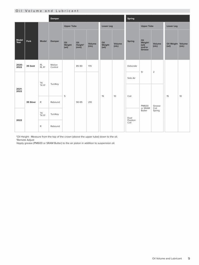
O i l V o l u m e a n d L u b r i c a n t
Damper Spring
Model Year Fork Model Damper
Upper Tube Lower Leg
Spring
Upper Tube Lower Leg
Oil Weight (wt)
Oil Height* (mm)
Volume (mL)
Oil Weight (wt)
Volume (mL)
Oil Weight‡ (wt) and/or Grease
Volume (mL)
Oil Weight (wt)
Volume (mL)
2020-2022 35 Gold RL
RL R†Motion Control
5
85-90 170
15 10
DebonAir
5‡ 2
15 10
2021-2022
35 Silver
TK TK R† TurnKey
90-95 210
Solo Air
Coil
PM600 or SRAM Butter
Grease Coil Spring
R Rebound
2022
TK TK R† TurnKey
Dual Position Coil
R Rebound
*Oil Height - Measure from the top of the crown (above the upper tube) down to the oil. †Remote Adjust ‡Apply grease (PM600 or SRAM Butter) to the air piston in addition to suspension oil.
10Exploded View - 2020-2022 35 Gold RL - DebonAir
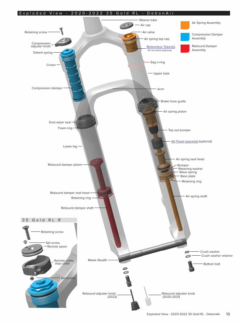
E x p l o d e d V i e w - 2 0 2 0 - 2 0 2 2 3 5 G o l d R L - D e b o n A i r
Retaining screw
3 5 G o l d R L R
Compression adjuster knob
Detent spring
Crown
Compression damper
Dust wiper seal
Foam ring
Rebound damper piston
Rebound damper shaft
Rebound damper seal headRetaining ring
Maxle Stealth
Rebound adjuster knob (2022)
Steerer tubeAir cap
Air valve
Air spring top cap
Bottomless Token(s) 32 mm black (optional)
Upper tube
Sag o-ring
Air spring piston
Top out bumper
All-Travel spacer(s) (optional)
Retaining ring
Retaining washerBumper
Air spring seal head
Air spring shaft
Crush washer
Bottom bolt
Retaining screw
Remote spool
Remote cable stop collar
Air Spring Assembly
Compression Damper Assembly
Rebound Damper Assembly
Brake hose guide
Set screw
Set screw
Crush washer retainer
Lower leg
Wave springBase plate
Arch
Rebound adjuster knob (2020-2021)
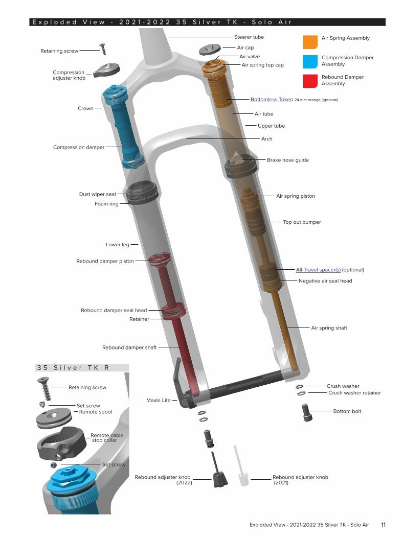
11Exploded View - 2021-2022 35 Silver TK - Solo Air
E x p l o d e d V i e w - 2 0 2 1 - 2 0 2 2 3 5 S i l v e r T K - S o l o A i r
Retaining screw
3 5 S i l v e r T K R
Compression adjuster knob
Crown
Compression damper
Dust wiper seal
Foam ring
Rebound damper piston
Rebound damper shaft
Rebound damper seal headRetainer
Maxle Lite
Rebound adjuster knob (2022)
Steerer tube
Air capAir valveAir spring top cap
Bottomless Token 24 mm orange (optional)
Upper tube
Air tube
Air spring piston
Top out bumper
All-Travel spacer(s) (optional)
Air spring shaft
Crush washer
Bottom bolt
Retaining screw
Remote spool
Remote cable stop collar
Air Spring Assembly
Compression Damper Assembly
Rebound Damper Assembly
Brake hose guide
Set screw
Set screw
Crush washer retainer
Lower leg
Negative air seal head
Arch
Rebound adjuster knob (2021)
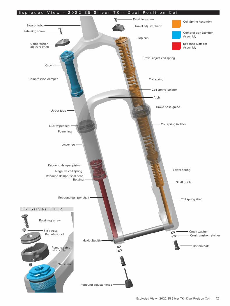
12Exploded View - 2022 35 Silver TK - Dual Position Coil
E x p l o d e d V i e w - 2 0 2 2 3 5 S i l v e r T K - D u a l P o s i t i o n C o i l
Retaining screw
Steerer tube
3 5 S i l v e r T K R
Compression adjuster knob
Crown
Compression damper
Dust wiper seal
Foam ring
Rebound damper piston
Rebound damper shaft
Rebound damper seal headRetainer
Maxle Stealth
Rebound adjuster knob
Retaining screw
Top cap
Travel adjuster knob
Travel adjust coil spring
Coil spring isolator
Coil spring shaft
Crush washer
Bottom bolt
Retaining screw
Remote spool
Remote cable stop collar
Coil Spring Assembly
Compression Damper Assembly
Rebound Damper Assembly
Brake hose guide
Set screw
Set screwCrush washer retainer
Lower leg
Shaft guide
Arch
Lower spring
Coil spring
Negative coil spring
Upper tube
Coil spring isolator
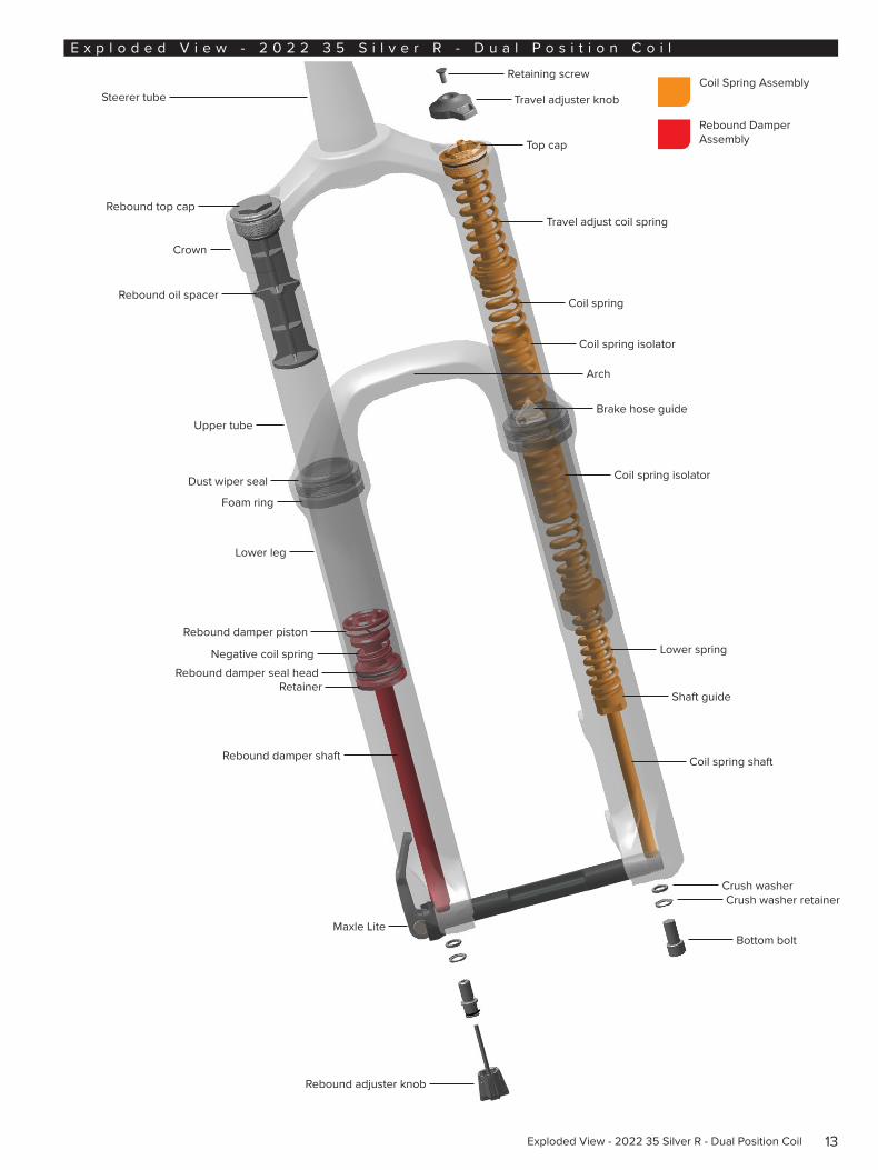
13Exploded View - 2022 35 Silver R - Dual Position Coil
E x p l o d e d V i e w - 2 0 2 2 3 5 S i l v e r R - D u a l P o s i t i o n C o i l
Steerer tube
Crown
Dust wiper seal
Foam ring
Rebound damper piston
Rebound damper shaft
Rebound damper seal headRetainer
Maxle Lite
Retaining screw
Top cap
Travel adjuster knob
Travel adjust coil spring
Coil spring isolator
Coil spring shaft
Crush washer
Bottom bolt
Coil Spring Assembly
Rebound Damper Assembly
Brake hose guide
Crush washer retainer
Lower leg
Shaft guide
Arch
Lower spring
Coil spring
Negative coil spring
Rebound top cap
Rebound oil spacer
Upper tube
Coil spring isolator
Rebound adjuster knob
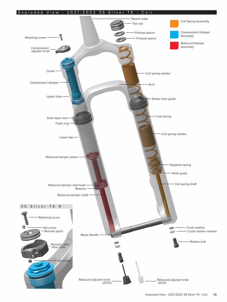
14Exploded View - 2021-2022 35 Silver TK - Coil
E x p l o d e d V i e w - 2 0 2 1 - 2 0 2 2 3 5 S i l v e r T K - C o i l
Retaining screw
3 5 S i l v e r T K R
Compression adjuster knob
Crown
Compression damper
Dust wiper seal
Foam ring
Rebound damper piston
Rebound damper shaft
Rebound damper seal headRetainer
Maxle Stealth
Steerer tubeTop cap
Preload spacer
Preload spacer
Coil spring
Coil spring isolator
Coil spring shaft
Crush washer
Bottom bolt
Retaining screw
Remote spool
Remote cable stop collar
Coil Spring Assembly
Compression Damper Assembly
Rebound Damper Assembly
Brake hose guide
Set screw
Set screwCrush washer retainer
Lower leg
Shaft guide
Arch
Negative spring
Coil spring isolator
Upper tube
Rebound adjuster knob (2022)
Rebound adjuster knob (2021)
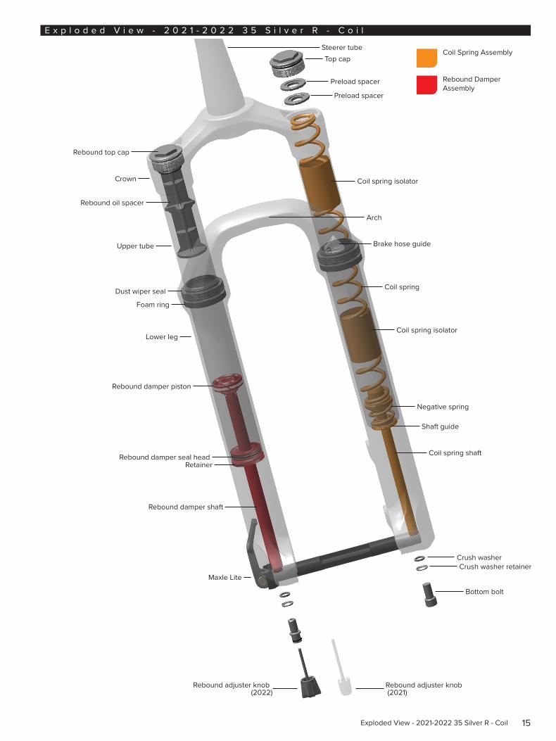
15Exploded View - 2021-2022 35 Silver R - Coil
E x p l o d e d V i e w - 2 0 2 1 - 2 0 2 2 3 5 S i l v e r R - C o i l
Rebound top cap
Crown
Rebound oil spacer
Dust wiper seal
Foam ring
Rebound damper piston
Rebound damper shaft
Rebound damper seal headRetainer
Maxle Lite
Crush washer
Bottom bolt
Coil Spring Assembly
Rebound Damper Assembly
Crush washer retainer
Lower leg
Steerer tubeTop cap
Preload spacer
Preload spacer
Coil spring isolator
Coil spring
Coil spring isolator
Coil spring shaft
Brake hose guide
Shaft guide
Arch
Negative spring
Upper tube
Rebound adjuster knob (2022)
Rebound adjuster knob (2021)
16Lower Leg Removal and Service
L o w e r L e g R e m o v a l a n d S e r v i c e
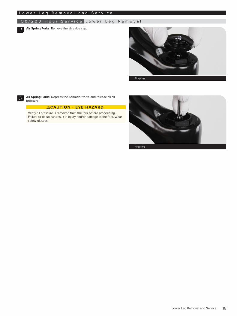
5 0 / 2 0 0 H o u r S e r v i c e L o w e r L e g R e m o v a l
Air Spring Forks: Remove the air valve cap.
Air Spring Forks: Depress the Schrader valve and release all air pressure.
⚠CAUTION - EYE HAZARDVerify all pressure is removed from the fork before proceeding. Failure to do so can result in injury and/or damage to the fork. Wear safety glasses.
1
Air spring
2
Air spring
17Lower Leg Removal
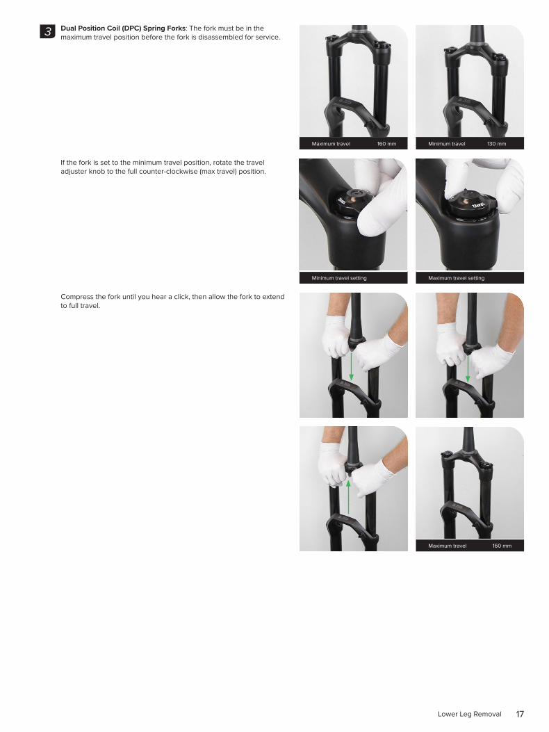
Dual Position Coil (DPC) Spring Forks: The fork must be in the maximum travel position before the fork is disassembled for service.
If the fork is set to the minimum travel position, rotate the travel adjuster knob to the full counter-clockwise (max travel) position.
Compress the fork until you hear a click, then allow the fork to extend to full travel.
3
Maximum travel 160 mm Minimum travel 130 mm
Minimum travel setting Maximum travel setting
Maximum travel 160 mm
18Lower Leg Removal
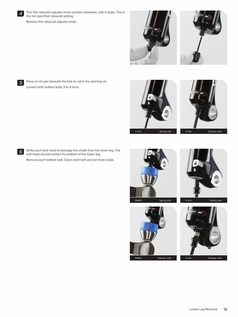
Turn the rebound adjuster knob counter-clockwise until it stops. This is the full open/fast rebound setting.
Remove the rebound adjuster knob.
Place an oil pan beneath the fork to catch the draining oil.
Loosen both bottom bolts 3 to 4 turns.
Strike each bolt head to dislodge the shafts from the lower leg. The bolt head should contact the bottom of the lower leg.
Remove each bottom bolt. Clean each bolt and set them aside.
4
5
5 mm Spring side 5 mm Damper side
6
Mallet Spring side 5 mm Spring side
Mallet Damper side 5 mm Damper side
19Lower Leg Removal
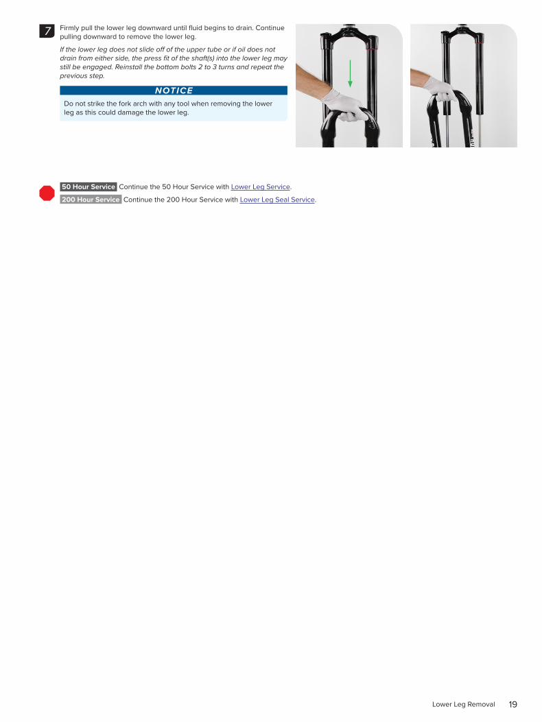
Firmly pull the lower leg downward until fluid begins to drain. Continue pulling downward to remove the lower leg.
If the lower leg does not slide off of the upper tube or if oil does not drain from either side, the press fit of the shaft(s) into the lower leg may still be engaged. Reinstall the bottom bolts 2 to 3 turns and repeat the previous step.
NOTICEDo not strike the fork arch with any tool when removing the lower leg as this could damage the lower leg.
50 Hour Service Continue the 50 Hour Service with Lower Leg Service.
200 Hour Service Continue the 200 Hour Service with Lower Leg Seal Service.
7
20Lower Leg Service
5 0 H o u r S e r v i c e L o w e r L e g S e r v i c e
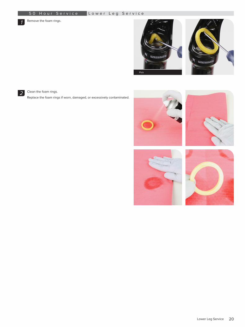
Remove the foam rings.
Clean the foam rings.
Replace the foam rings if worn, damaged, or excessively contaminated.
1
Pick
2
21Lower Leg Service
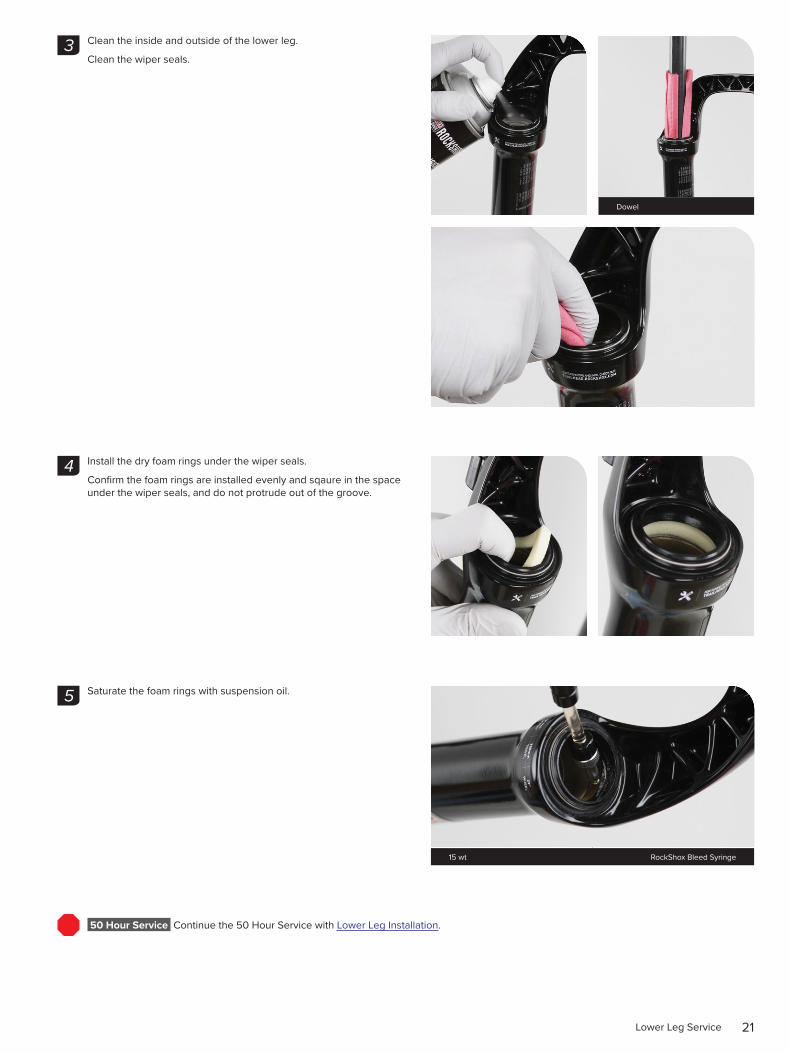
Clean the inside and outside of the lower leg.
Clean the wiper seals.
Install the dry foam rings under the wiper seals.
Confirm the foam rings are installed evenly and sqaure in the space under the wiper seals, and do not protrude out of the groove.
Saturate the foam rings with suspension oil.
50 Hour Service Continue the 50 Hour Service with Lower Leg Installation.
3
Dowel
4
5
15 wt RockShox Bleed Syringe
22Lower Leg Seal Service
2 0 0 H o u r S e r v i c e L o w e r L e g S e a l S e r v i c e
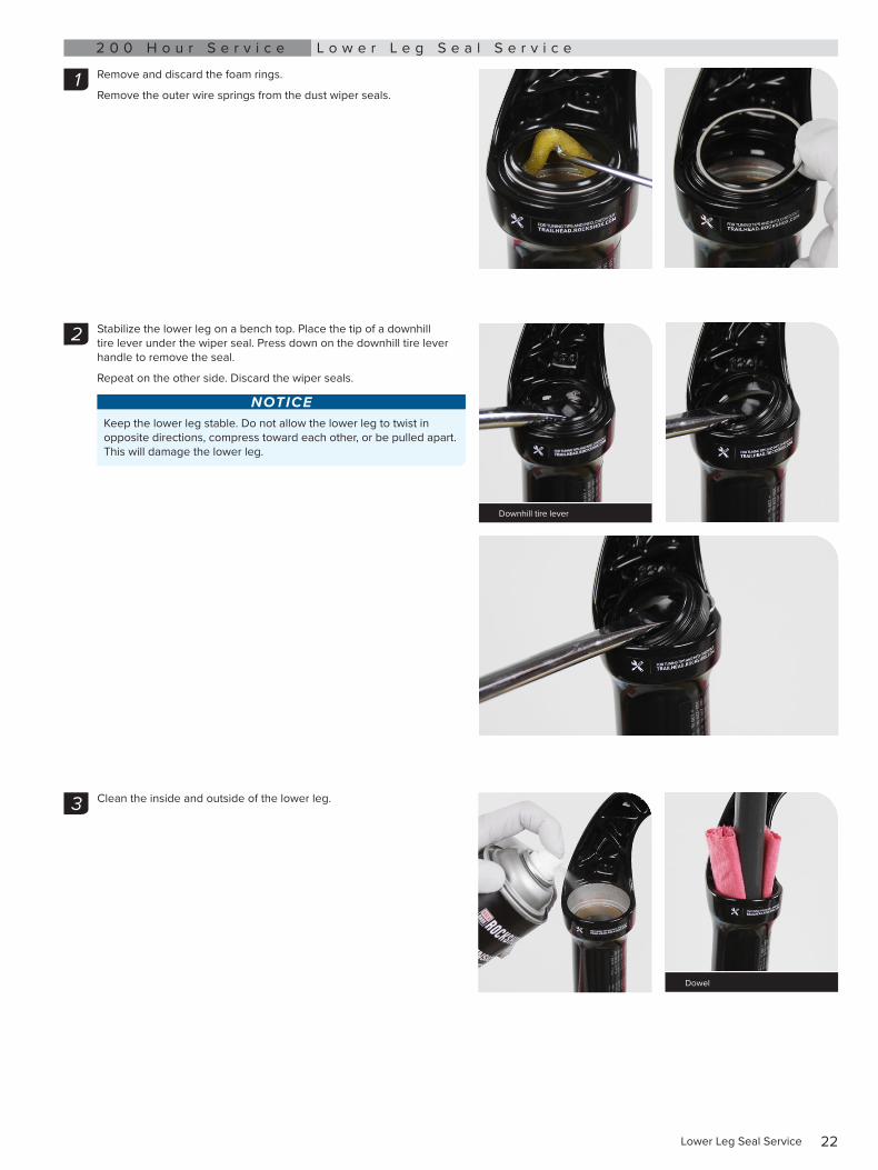
Remove and discard the foam rings.
Remove the outer wire springs from the dust wiper seals.
Stabilize the lower leg on a bench top. Place the tip of a downhill tire lever under the wiper seal. Press down on the downhill tire lever handle to remove the seal.
Repeat on the other side. Discard the wiper seals.
NOTICEKeep the lower leg stable. Do not allow the lower leg to twist in opposite directions, compress toward each other, or be pulled apart. This will damage the lower leg.
Clean the inside and outside of the lower leg.
1
2
Downhill tire lever
3
Dowel
23Lower Leg Seal Service
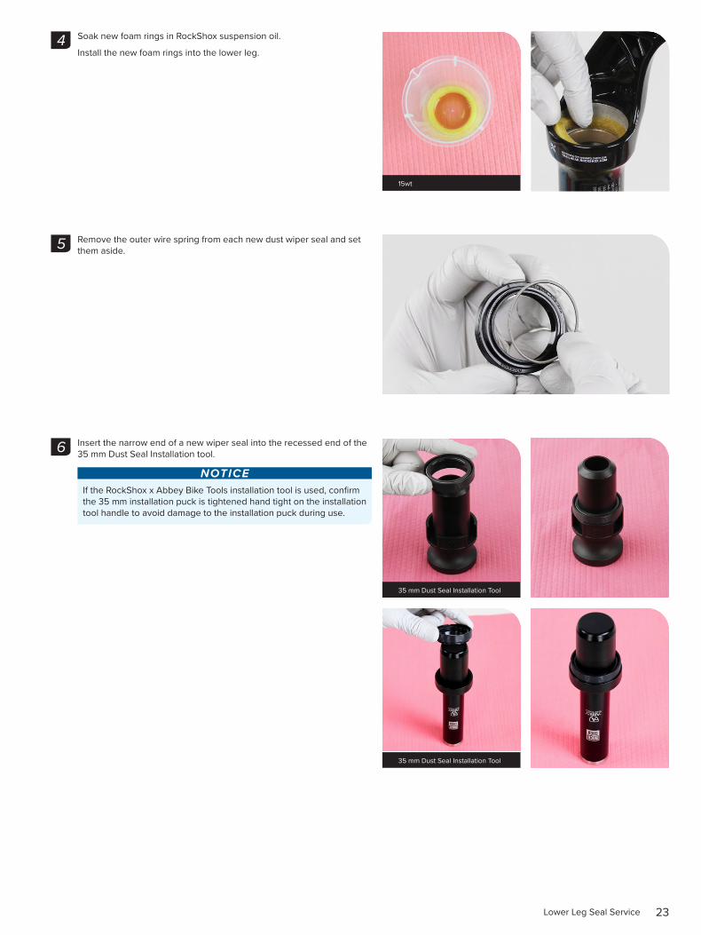
Soak new foam rings in RockShox suspension oil.
Install the new foam rings into the lower leg.
Remove the outer wire spring from each new dust wiper seal and set them aside.
Insert the narrow end of a new wiper seal into the recessed end of the 35 mm Dust Seal Installation tool.
NOTICEIf the RockShox x Abbey Bike Tools installation tool is used, confirm the 35 mm installation puck is tightened hand tight on the installation tool handle to avoid damage to the installation puck during use.
4
15wt
5
6
35 mm Dust Seal Installation Tool
35 mm Dust Seal Installation Tool
24Lower Leg Seal Service
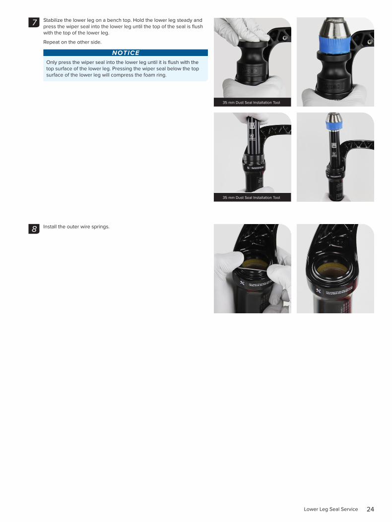
Stabilize the lower leg on a bench top. Hold the lower leg steady and press the wiper seal into the lower leg until the top of the seal is flush with the top of the lower leg.
Repeat on the other side.
NOTICEOnly press the wiper seal into the lower leg until it is flush with the top surface of the lower leg. Pressing the wiper seal below the top surface of the lower leg will compress the foam ring.
Install the outer wire springs.
7
35 mm Dust Seal Installation Tool
35 mm Dust Seal Installation Tool
8
25Air Spring Service - DebonAir - 35 Gold
A i r S p r i n g S e r v i c e - D e b o n A i r - 3 5 G o l d2 0 0 H o u r S e r v i c e A i r S p r i n g R e m o v a l
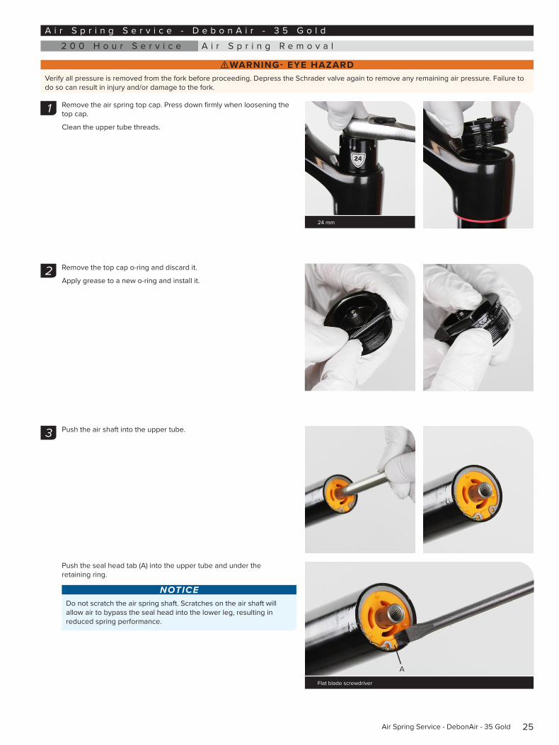
⚠WARNING- EYE HAZARDVerify all pressure is removed from the fork before proceeding. Depress the Schrader valve again to remove any remaining air pressure. Failure to do so can result in injury and/or damage to the fork.
Remove the air spring top cap. Press down firmly when loosening the top cap.
Clean the upper tube threads.
Remove the top cap o-ring and discard it.
Apply grease to a new o-ring and install it.
Push the air shaft into the upper tube.
Push the seal head tab (A) into the upper tube and under the retaining ring.
NOTICEDo not scratch the air spring shaft. Scratches on the air shaft will allow air to bypass the seal head into the lower leg, resulting in reduced spring performance.
1 1
24 mm
2
3
Flat blade screwdriver
A
26Air Spring Removal
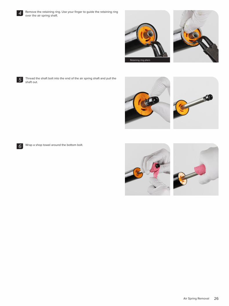
Remove the retaining ring. Use your finger to guide the retaining ring over the air spring shaft.
Thread the shaft bolt into the end of the air spring shaft and pull the shaft out.
Wrap a shop towel around the bottom bolt.
4
Retaining ring pliers
5
6
27Air Spring Removal
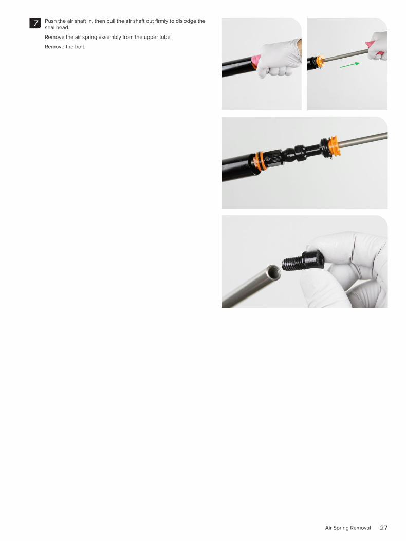
Push the air shaft in, then pull the air shaft out firmly to dislodge the seal head.
Remove the air spring assembly from the upper tube.
Remove the bolt.
7
28Air Spring Removal
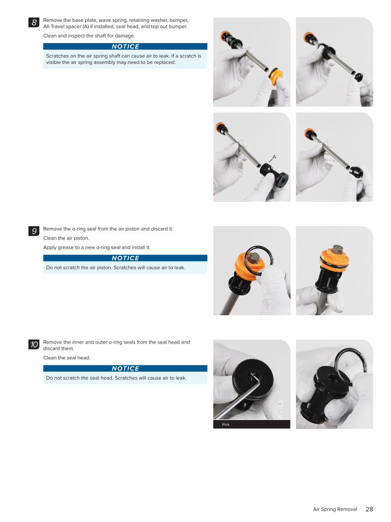
Remove the base plate, wave spring, retaining washer, bumper, All-Travel spacer (A) if installed, seal head, and top out bumper.
Clean and inspect the shaft for damage.
NOTICEScratches on the air spring shaft can cause air to leak. If a scratch is visible the air spring assembly may need to be replaced.
Remove the o-ring seal from the air piston and discard it.
Clean the air piston.
Apply grease to a new o-ring seal and install it.
NOTICEDo not scratch the air piston. Scratches will cause air to leak.
Remove the inner and outer o-ring seals from the seal head and discard them.
Clean the seal head.
NOTICEDo not scratch the seal head. Scratches will cause air to leak.
8
A
9
10
Pick
29Air Spring Removal
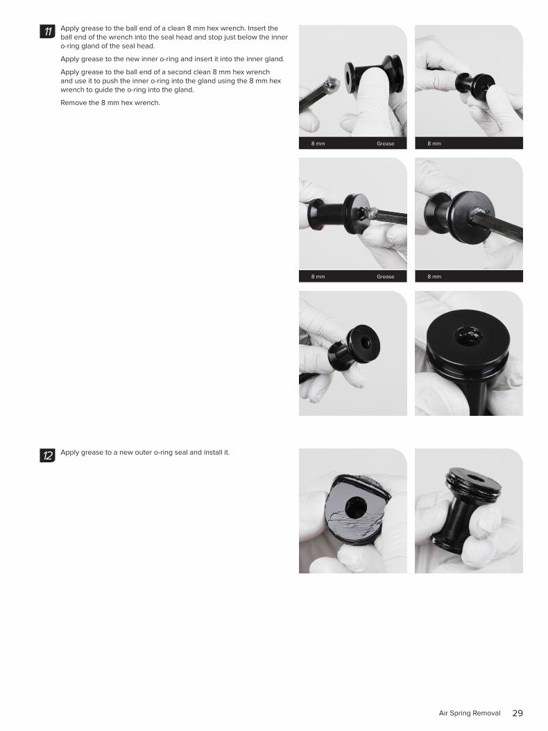
Apply grease to the ball end of a clean 8 mm hex wrench. Insert the ball end of the wrench into the seal head and stop just below the inner o-ring gland of the seal head.
Apply grease to the new inner o-ring and insert it into the inner gland.
Apply grease to the ball end of a second clean 8 mm hex wrench and use it to push the inner o-ring into the gland using the 8 mm hex wrench to guide the o-ring into the gland.
Remove the 8 mm hex wrench.
Apply grease to a new outer o-ring seal and install it.
8 mm Grease 8 mm
11
8 mm Grease 8 mm
12
30Air Spring Removal
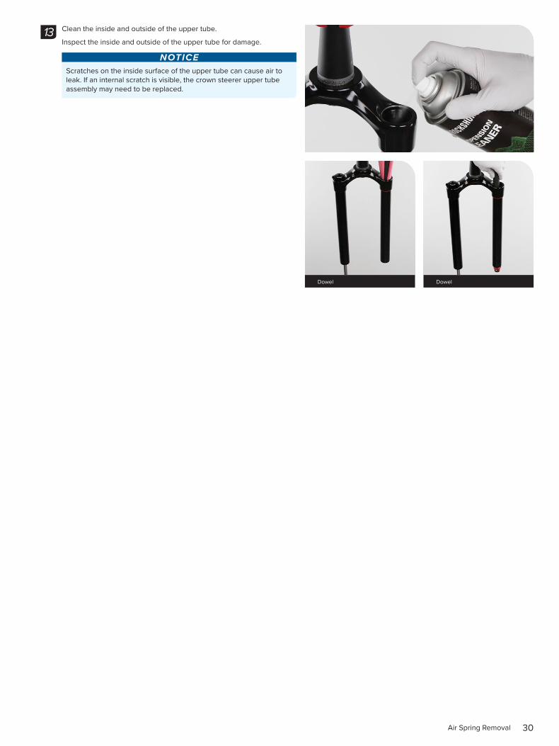
Clean the inside and outside of the upper tube.
Inspect the inside and outside of the upper tube for damage.
NOTICEScratches on the inside surface of the upper tube can cause air to leak. If an internal scratch is visible, the crown steerer upper tube assembly may need to be replaced.
13
Dowel Dowel
31Air Spring Travel Change and Bottomless Tokens (optional)
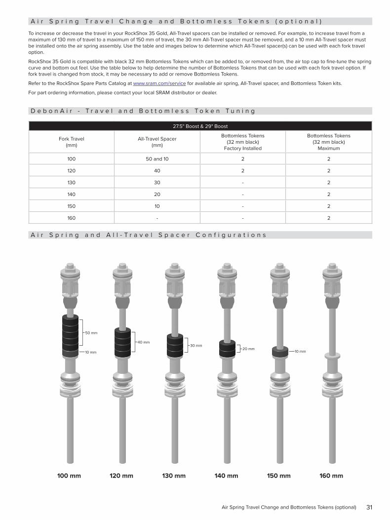
A i r S p r i n g T r a v e l C h a n g e a n d B o t t o m l e s s T o k e n s ( o p t i o n a l )
To increase or decrease the travel in your RockShox 35 Gold, All-Travel spacers can be installed or removed. For example, to increase travel from a maximum of 130 mm of travel to a maximum of 150 mm of travel, the 30 mm All-Travel spacer must be removed, and a 10 mm All-Travel spacer must be installed onto the air spring assembly. Use the table and images below to determine which All-Travel spacer(s) can be used with each fork travel option.
RockShox 35 Gold is compatible with black 32 mm Bottomless Tokens which can be added to, or removed from, the air top cap to fine-tune the spring curve and bottom out feel. Use the table below to help determine the number of Bottomless Tokens that can be used with each fork travel option. If fork travel is changed from stock, it may be necessary to add or remove Bottomless Tokens.
Refer to the RockShox Spare Parts Catalog at www.sram.com/service for available air spring, All-Travel spacer, and Bottomless Token kits.
For part ordering information, please contact your local SRAM distributor or dealer.
D e b o n A i r - T r a v e l a n d B o t t o m l e s s T o k e n T u n i n g
27.5" Boost & 29" Boost
Fork Travel (mm)
All-Travel Spacer (mm)
Bottomless Tokens (32 mm black)
Factory Installed
Bottomless Tokens (32 mm black)
Maximum
100 50 and 10 2 2
120 40 2 2
130 30 - 2
140 20 - 2
150 10 - 2
160 - - 2
A i r S p r i n g a n d A l l - T r a v e l S p a c e r C o n f i g u r a t i o n s
100 mm 120 mm 130 mm 140 mm 150 mm 160 mm
50 mm
40 mm30 mm
20 mm10 mm 10 mm
32Bottomless Tokens Installation (optional)
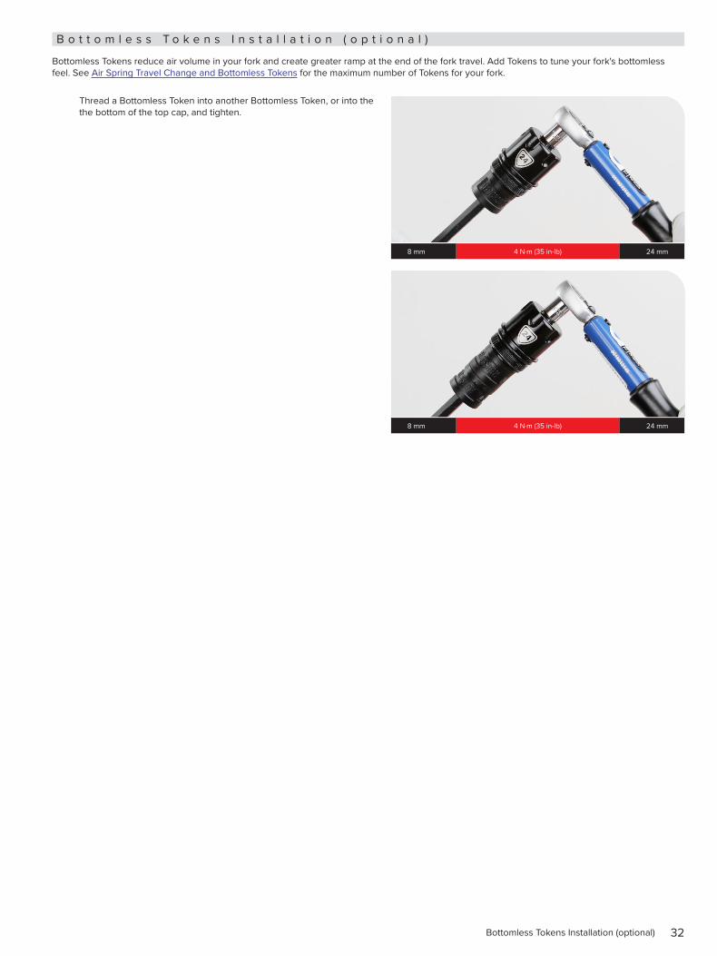
B o t t o m l e s s T o k e n s I n s t a l l a t i o n ( o p t i o n a l )
Bottomless Tokens reduce air volume in your fork and create greater ramp at the end of the fork travel. Add Tokens to tune your fork's bottomless feel. See Air Spring Travel Change and Bottomless Tokens for the maximum number of Tokens for your fork.
Thread a Bottomless Token into another Bottomless Token, or into the the bottom of the top cap, and tighten.
8 mm 4 N·m (35 in-lb) 24 mm
8 mm 4 N·m (35 in-lb) 24 mm
33Air Spring Installation
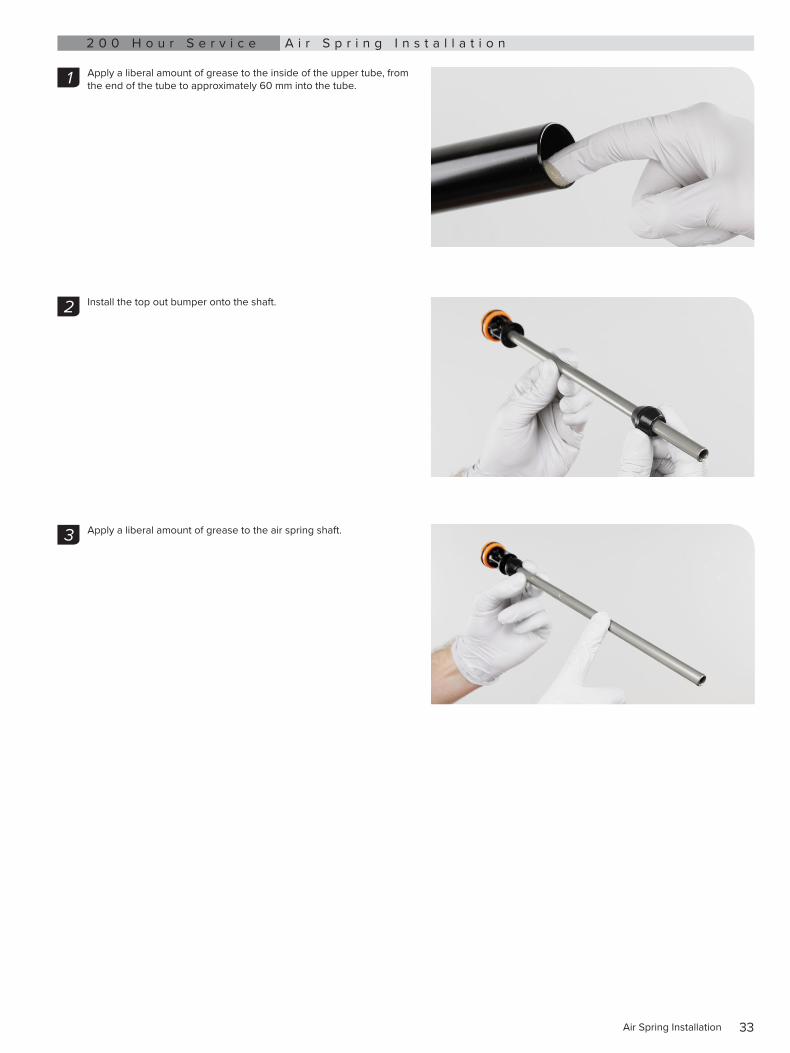
2 0 0 H o u r S e r v i c e A i r S p r i n g I n s t a l l a t i o n
Apply a liberal amount of grease to the inside of the upper tube, from the end of the tube to approximately 60 mm into the tube.
Install the top out bumper onto the shaft.
Apply a liberal amount of grease to the air spring shaft.
1
2
3
34Air Spring Installation
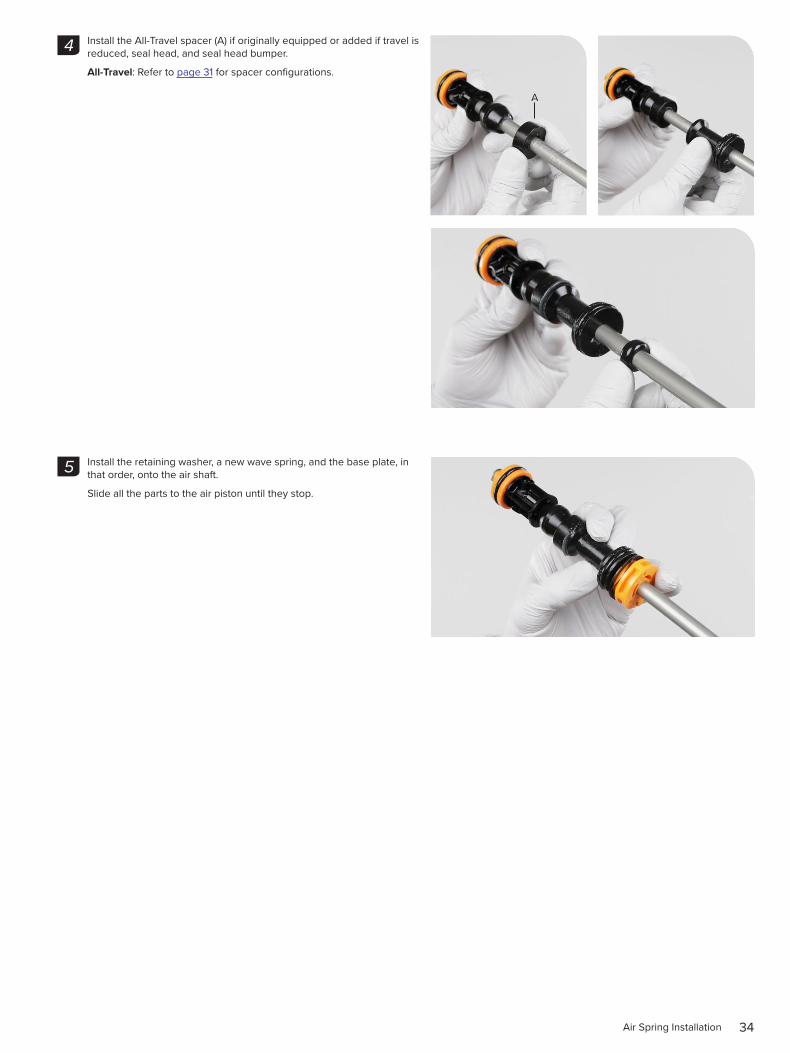
Install the All-Travel spacer (A) if originally equipped or added if travel is reduced, seal head, and seal head bumper.
All-Travel: Refer to page 31 for spacer configurations.
Install the retaining washer, a new wave spring, and the base plate, in that order, onto the air shaft.
Slide all the parts to the air piston until they stop.
4
A
5
35Air Spring Installation
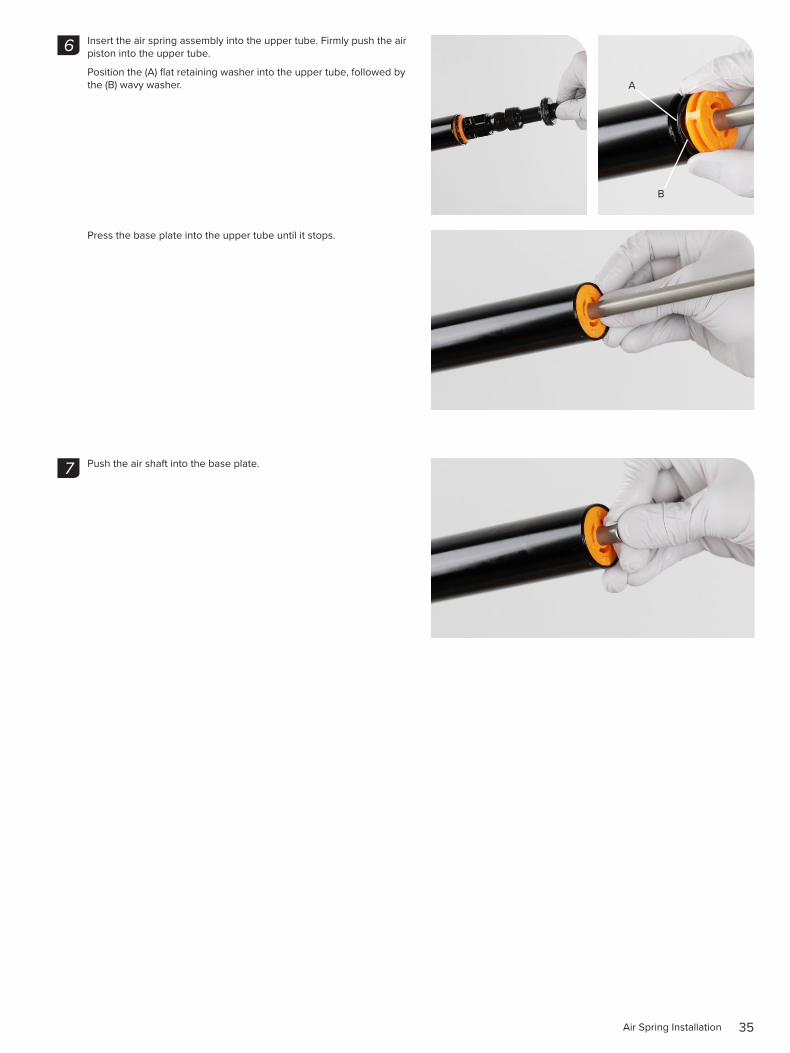
Insert the air spring assembly into the upper tube. Firmly push the air piston into the upper tube.
Position the (A) flat retaining washer into the upper tube, followed by the (B) wavy washer.
Press the base plate into the upper tube until it stops.
Push the air shaft into the base plate.
6
A
B
7
36Air Spring Installation
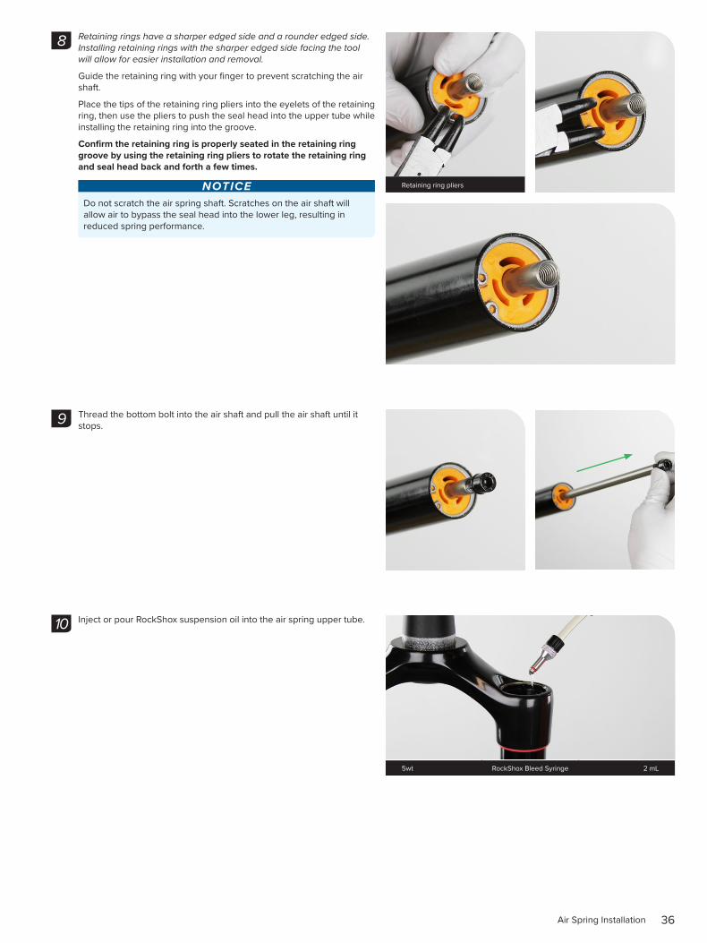
Retaining rings have a sharper edged side and a rounder edged side. Installing retaining rings with the sharper edged side facing the tool will allow for easier installation and removal.
Guide the retaining ring with your finger to prevent scratching the air shaft.
Place the tips of the retaining ring pliers into the eyelets of the retaining ring, then use the pliers to push the seal head into the upper tube while installing the retaining ring into the groove.
Confirm the retaining ring is properly seated in the retaining ring groove by using the retaining ring pliers to rotate the retaining ring and seal head back and forth a few times.
NOTICEDo not scratch the air spring shaft. Scratches on the air shaft will allow air to bypass the seal head into the lower leg, resulting in reduced spring performance.
Thread the bottom bolt into the air shaft and pull the air shaft until it stops.
Inject or pour RockShox suspension oil into the air spring upper tube.
8
Retaining ring pliers
9
10
5wt RockShox Bleed Syringe 2 mL
37Air Spring Installation
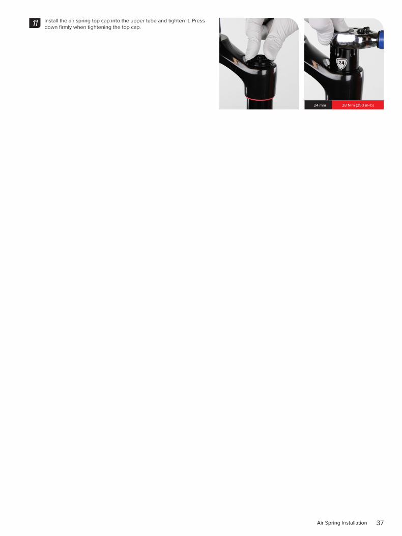
Install the air spring top cap into the upper tube and tighten it. Press down firmly when tightening the top cap.11
24 mm 28 N·m (250 in-lb)
38Air Spring Service - Solo Air - 35 Silver
A i r S p r i n g S e r v i c e - S o l o A i r - 3 5 S i l v e r2 0 0 H o u r S e r v i c e A i r S p r i n g R e m o v a l
⚠WARNING- EYE HAZARDVerify all pressure is removed from the fork before proceeding. Depress the Schrader valve again to remove any remaining air pressure. Failure to do so can result in injury and/or damage to the fork.
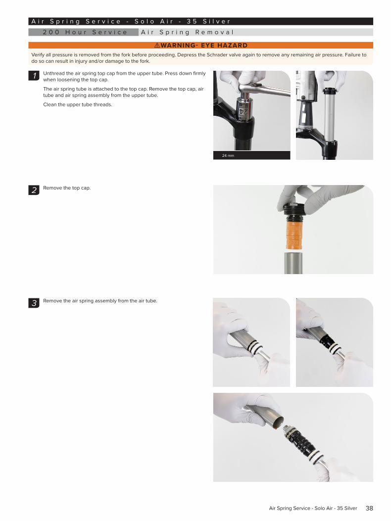
Unthread the air spring top cap from the upper tube. Press down firmly when loosening the top cap.
The air spring tube is attached to the top cap. Remove the top cap, air tube and air spring assembly from the upper tube.
Clean the upper tube threads.
Remove the top cap.
Remove the air spring assembly from the air tube.
1
24 mm
2
3
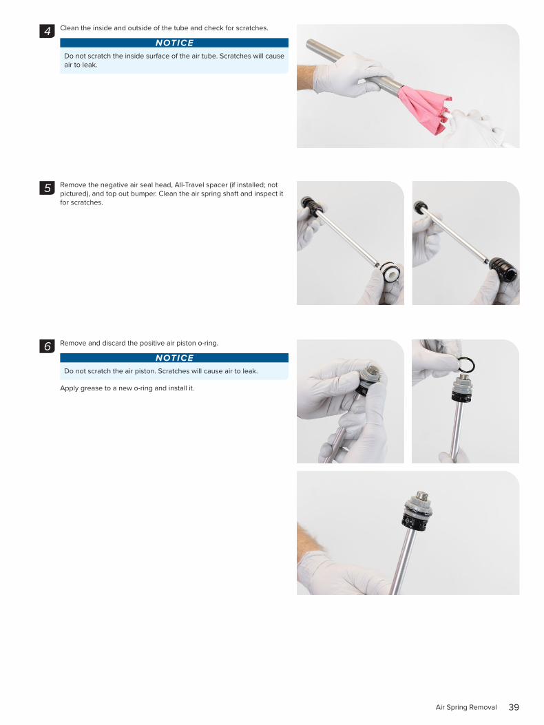
39Air Spring Removal
Clean the inside and outside of the tube and check for scratches.
NOTICEDo not scratch the inside surface of the air tube. Scratches will cause air to leak.
Remove the negative air seal head, All-Travel spacer (if installed; not pictured), and top out bumper. Clean the air spring shaft and inspect it for scratches.
Remove and discard the positive air piston o-ring.
NOTICEDo not scratch the air piston. Scratches will cause air to leak.
Apply grease to a new o-ring and install it.
4
5
6
40Air Spring Removal
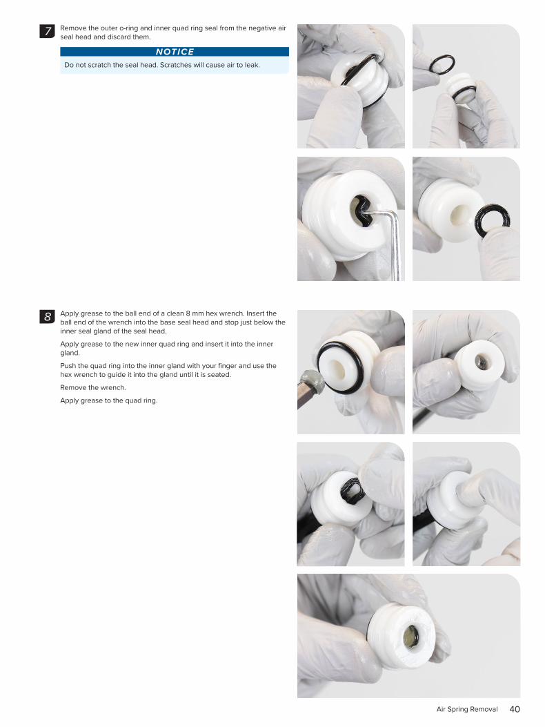
Remove the outer o-ring and inner quad ring seal from the negative air seal head and discard them.
NOTICEDo not scratch the seal head. Scratches will cause air to leak.
Apply grease to the ball end of a clean 8 mm hex wrench. Insert the ball end of the wrench into the base seal head and stop just below the inner seal gland of the seal head.
Apply grease to the new inner quad ring and insert it into the inner gland.
Push the quad ring into the inner gland with your finger and use the hex wrench to guide it into the gland until it is seated.
Remove the wrench.
Apply grease to the quad ring.
7
8
41Air Spring Removal
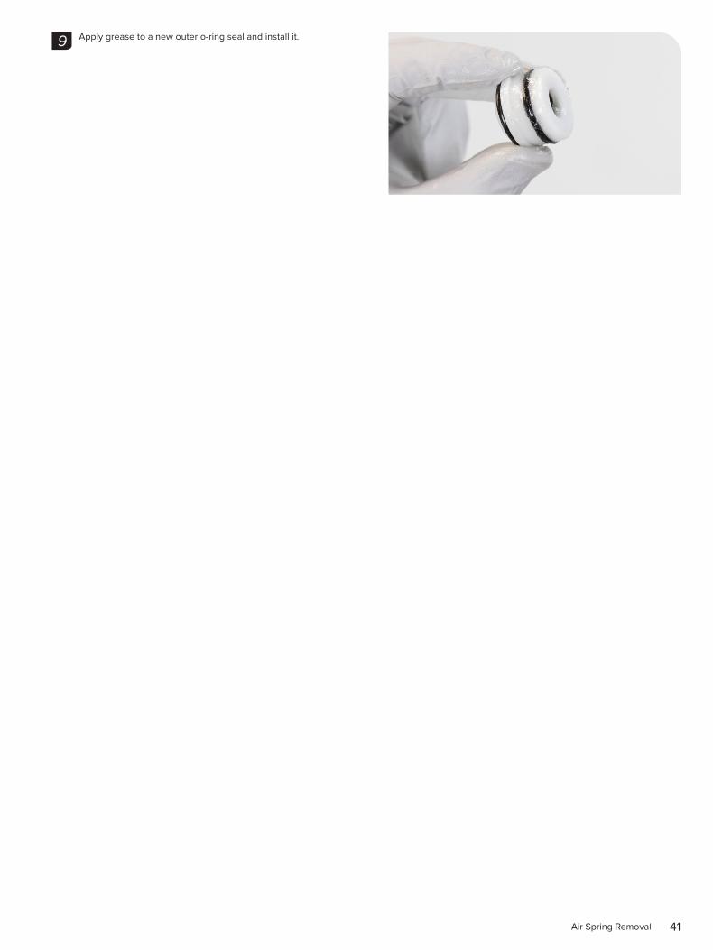
Apply grease to a new outer o-ring seal and install it.9
42Air Spring Travel Change and Bottomless Tokens (optional)
A i r S p r i n g T r a v e l C h a n g e a n d B o t t o m l e s s T o k e n s ( o p t i o n a l )
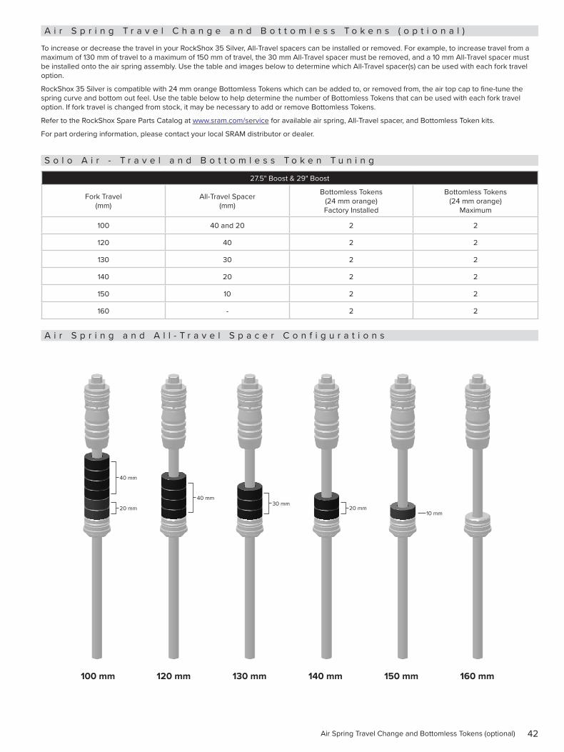
To increase or decrease the travel in your RockShox 35 Silver, All-Travel spacers can be installed or removed. For example, to increase travel from a maximum of 130 mm of travel to a maximum of 150 mm of travel, the 30 mm All-Travel spacer must be removed, and a 10 mm All-Travel spacer must be installed onto the air spring assembly. Use the table and images below to determine which All-Travel spacer(s) can be used with each fork travel option.
RockShox 35 Silver is compatible with 24 mm orange Bottomless Tokens which can be added to, or removed from, the air top cap to fine-tune the spring curve and bottom out feel. Use the table below to help determine the number of Bottomless Tokens that can be used with each fork travel option. If fork travel is changed from stock, it may be necessary to add or remove Bottomless Tokens.
Refer to the RockShox Spare Parts Catalog at www.sram.com/service for available air spring, All-Travel spacer, and Bottomless Token kits.
For part ordering information, please contact your local SRAM distributor or dealer.
S o l o A i r - T r a v e l a n d B o t t o m l e s s T o k e n T u n i n g
27.5" Boost & 29" Boost
Fork Travel (mm)
All-Travel Spacer (mm)
Bottomless Tokens (24 mm orange) Factory Installed
Bottomless Tokens (24 mm orange)
Maximum
100 40 and 20 2 2
120 40 2 2
130 30 2 2
140 20 2 2
150 10 2 2
160 - 2 2
A i r S p r i n g a n d A l l - T r a v e l S p a c e r C o n f i g u r a t i o n s
100 mm 120 mm 130 mm 140 mm 150 mm 160 mm
40 mm
40 mm30 mm
20 mm10 mm
20 mm
43Bottomless Tokens Installation (optional)
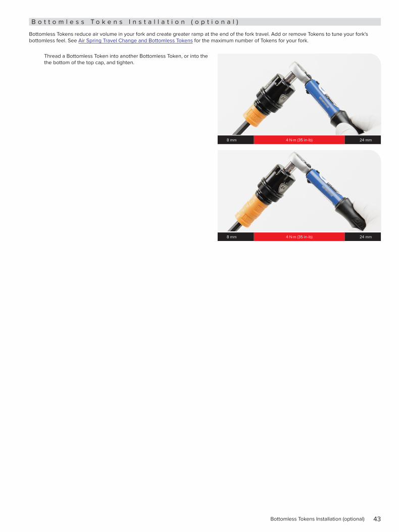
B o t t o m l e s s T o k e n s I n s t a l l a t i o n ( o p t i o n a l )
Bottomless Tokens reduce air volume in your fork and create greater ramp at the end of the fork travel. Add or remove Tokens to tune your fork's bottomless feel. See Air Spring Travel Change and Bottomless Tokens for the maximum number of Tokens for your fork.
Thread a Bottomless Token into another Bottomless Token, or into the the bottom of the top cap, and tighten.
8 mm 4 N·m (35 in-lb) 24 mm
8 mm 4 N·m (35 in-lb) 24 mm
44Air Spring Installation
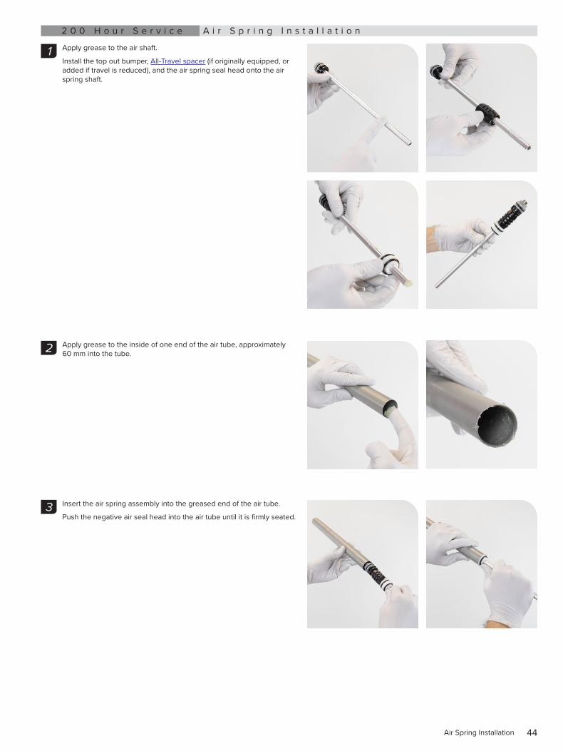
2 0 0 H o u r S e r v i c e A i r S p r i n g I n s t a l l a t i o n
Apply grease to the air shaft.
Install the top out bumper, All-Travel spacer (if originally equipped, or added if travel is reduced), and the air spring seal head onto the air spring shaft.
Apply grease to the inside of one end of the air tube, approximately 60 mm into the tube.
Insert the air spring assembly into the greased end of the air tube.
Push the negative air seal head into the air tube until it is firmly seated.
1
2
3
45Air Spring Installation
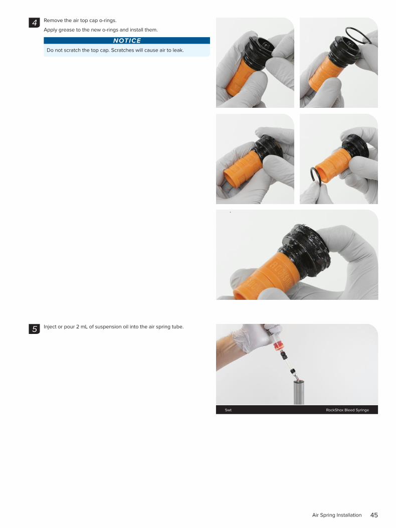
Remove the air top cap o-rings.
Apply grease to the new o-rings and install them.
NOTICEDo not scratch the top cap. Scratches will cause air to leak.
Inject or pour 2 mL of suspension oil into the air spring tube.
4
5
5wt RockShox Bleed Syringe
46Air Spring Installation
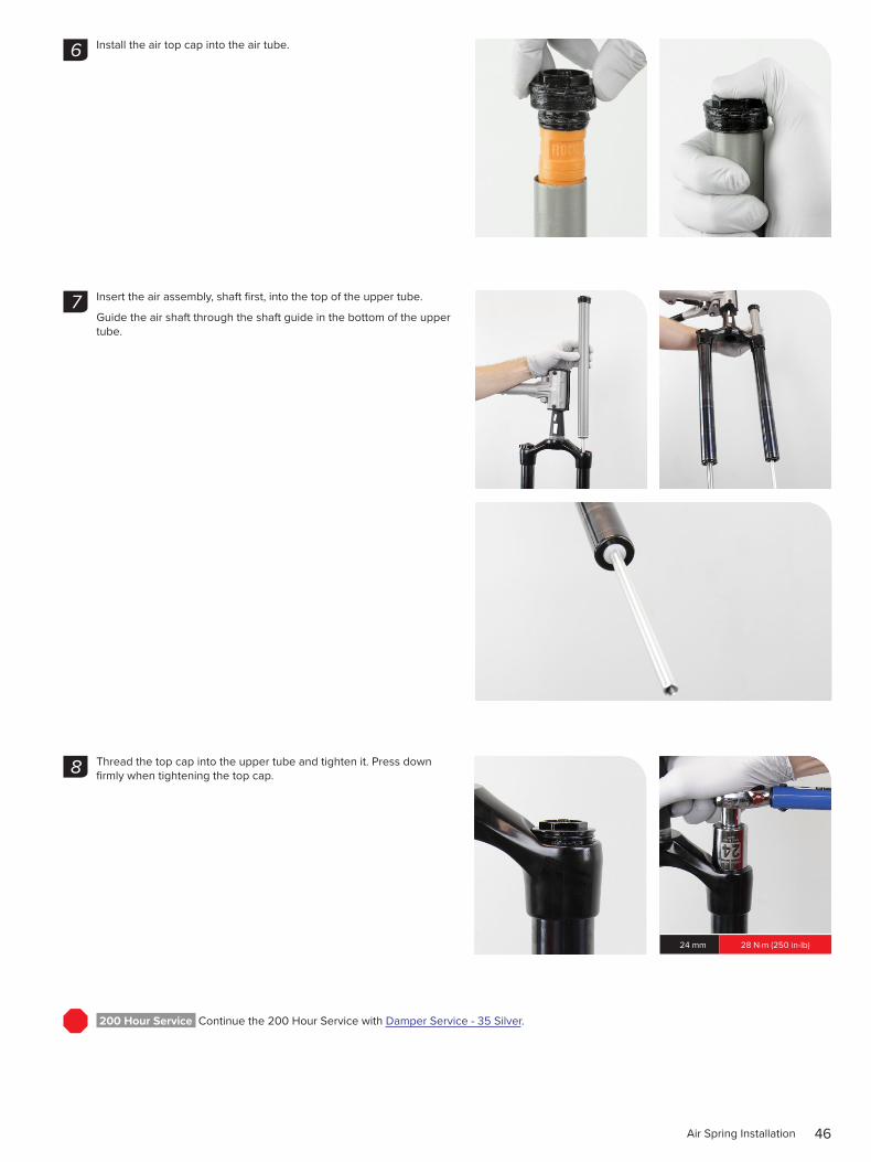
Install the air top cap into the air tube.
Insert the air assembly, shaft first, into the top of the upper tube.
Guide the air shaft through the shaft guide in the bottom of the upper tube.
Thread the top cap into the upper tube and tighten it. Press down firmly when tightening the top cap.
200 Hour Service Continue the 200 Hour Service with Damper Service - 35 Silver.
6
7
8
24 mm 28 N·m (250 in-lb)
47Coil Spring Service - Dual Position Coil - 35 Silver
C o i l S p r i n g S e r v i c e - D u a l P o s i t i o n C o i l - 3 5 S i l v e r2 0 0 H o u r S e r v i c e C o i l S p r i n g R e m o v a l a n d S e r v i c e
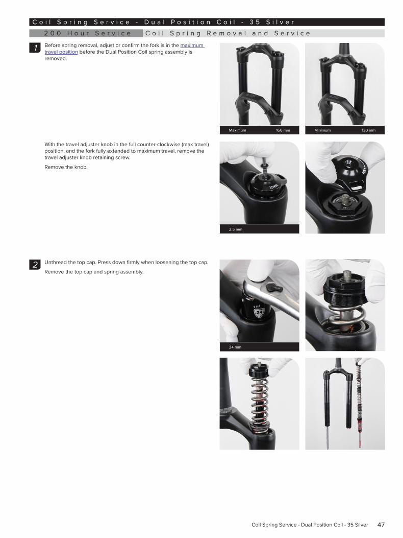
Before spring removal, adjust or confirm the fork is in the maximum travel position before the Dual Position Coil spring assembly is removed.
With the travel adjuster knob in the full counter-clockwise (max travel) position, and the fork fully extended to maximum travel, remove the travel adjuster knob retaining screw.
Remove the knob.
Unthread the top cap. Press down firmly when loosening the top cap.
Remove the top cap and spring assembly.
1
Maximum 160 mm Minimum 130 mm
2.5 mm
2
24 mm
48Coil Spring Removal and Service
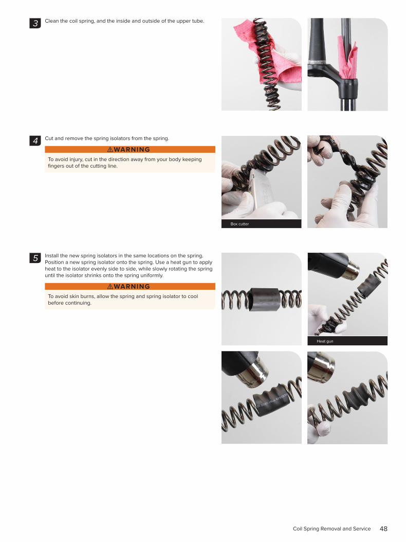
Clean the coil spring, and the inside and outside of the upper tube.
Cut and remove the spring isolators from the spring.
⚠WARNINGTo avoid injury, cut in the direction away from your body keeping fingers out of the cutting line.
Install the new spring isolators in the same locations on the spring. Position a new spring isolator onto the spring. Use a heat gun to apply heat to the isolator evenly side to side, while slowly rotating the spring until the isolator shrinks onto the spring uniformly.
⚠WARNINGTo avoid skin burns, allow the spring and spring isolator to cool before continuing.
3
4
Box cutter
5
Heat gun
49Coil Spring Removal and Service
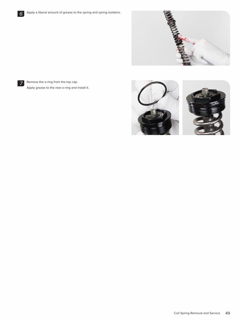
Apply a liberal amount of grease to the spring and spring isolators.
Remove the o-ring from the top cap.
Apply grease to the new o-ring and install it.
6
7
50Coil Spring Installation
2 0 0 H o u r S e r v i c e C o i l S p r i n g I n s t a l l a t i o n
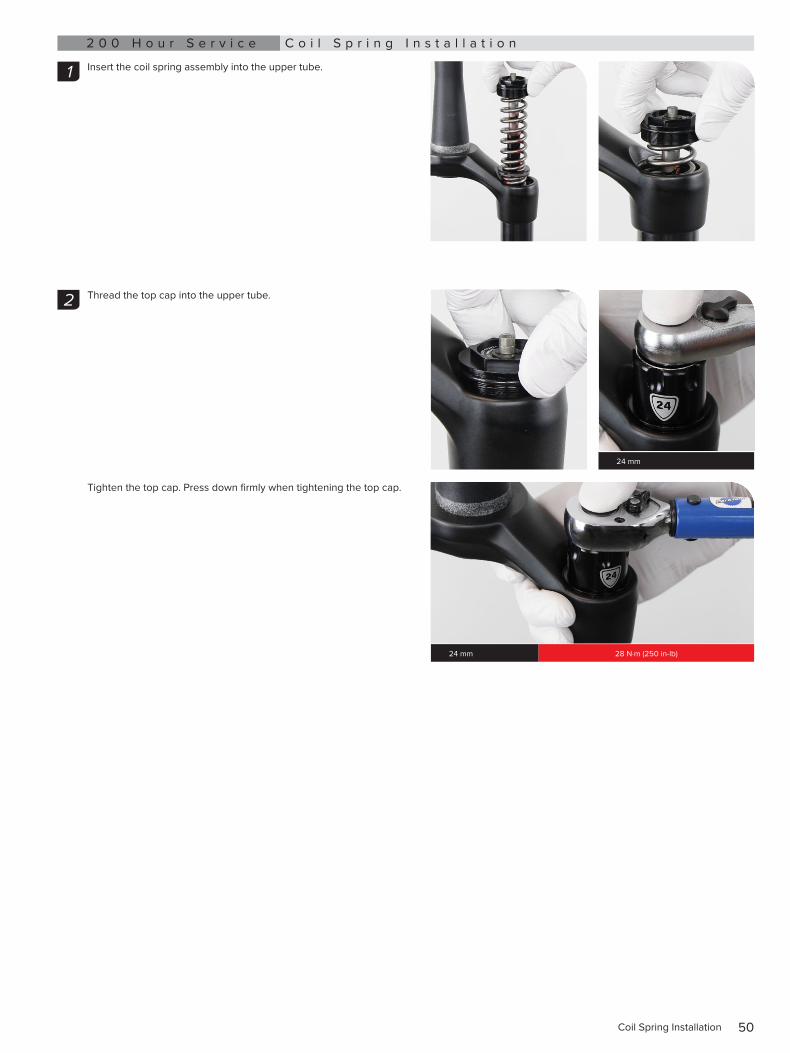
Insert the coil spring assembly into the upper tube.
Thread the top cap into the upper tube.
Tighten the top cap. Press down firmly when tightening the top cap.
1
2
24 mm
24 mm 28 N·m (250 in-lb)
51Coil Spring Installation
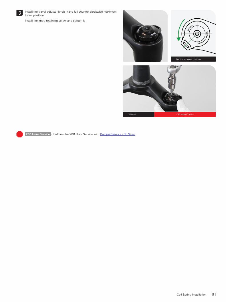
Install the travel adjuster knob in the full counter-clockwise maximum travel position.
Install the knob retaining screw and tighten it.
200 Hour Service Continue the 200 Hour Service with Damper Service - 35 Silver.
3
Maximum travel position
2.5 mm 1.35 N·m (10 in-lb)
52Coil Spring Service - 35 Silver
C o i l S p r i n g S e r v i c e - 3 5 S i l v e r2 0 0 H o u r S e r v i c e C o i l S p r i n g R e m o v a l a n d S e r v i c e
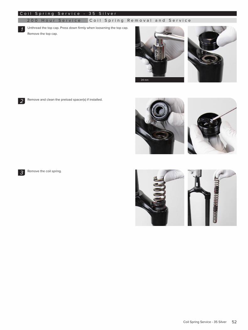
Unthread the top cap. Press down firmly when loosening the top cap.
Remove the top cap.
Remove and clean the preload spacer(s) if installed.
Remove the coil spring.
1
24 mm
2
3
53Coil Spring Removal and Service
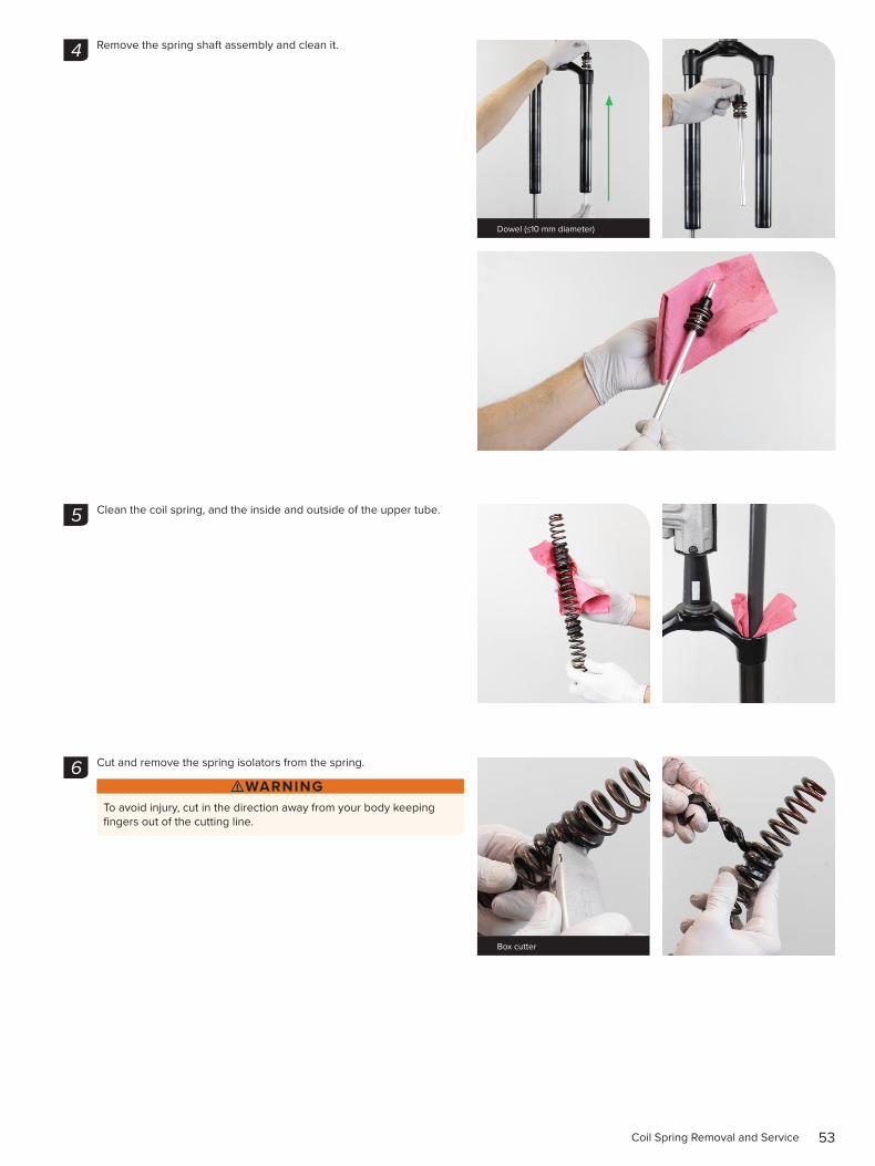
Remove the spring shaft assembly and clean it.
Clean the coil spring, and the inside and outside of the upper tube.
Cut and remove the spring isolators from the spring.
⚠WARNINGTo avoid injury, cut in the direction away from your body keeping fingers out of the cutting line.
4
Dowel (≤10 mm diameter)
5
6
Box cutter
54Coil Spring Removal and Service
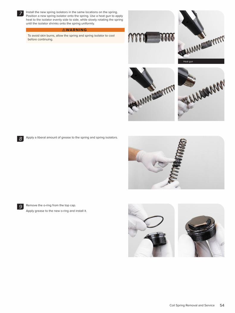
Install the new spring isolators in the same locations on the spring. Position a new spring isolator onto the spring. Use a heat gun to apply heat to the isolator evenly side to side, while slowly rotating the spring until the isolator shrinks onto the spring uniformly.
⚠WARNINGTo avoid skin burns, allow the spring and spring isolator to cool before continuing.
Apply a liberal amount of grease to the spring and spring isolators.
Remove the o-ring from the top cap.
Apply grease to the new o-ring and install it.
7
Heat gun
8
9
55Coil Spring Installation
2 0 0 H o u r S e r v i c e C o i l S p r i n g I n s t a l l a t i o n
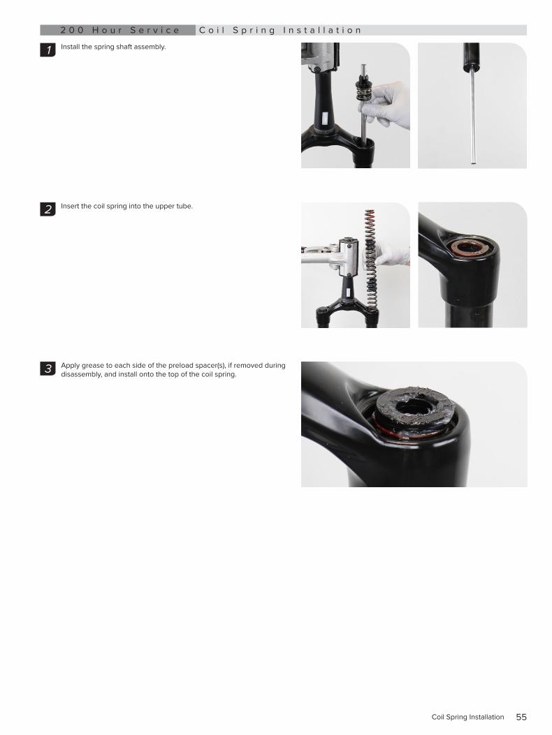
Install the spring shaft assembly.
Insert the coil spring into the upper tube.
Apply grease to each side of the preload spacer(s), if removed during disassembly, and install onto the top of the coil spring.
1
2
3
56Coil Spring Installation
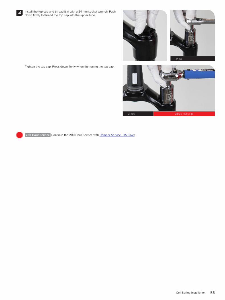
Install the top cap and thread it in with a 24 mm socket wrench. Push down firmly to thread the top cap into the upper tube.
Tighten the top cap. Press down firmly when tightening the top cap.
200 Hour Service Continue the 200 Hour Service with Damper Service - 35 Silver.
4
24 mm
24 mm 28 N·m (250 in-lb)
57Damper Service - Motion Control - 35 Gold
D a m p e r S e r v i c e - M o t i o n C o n t r o l - 3 5 G o l d2 0 0 H o u r S e r v i c e D a m p e r R e m o v a l
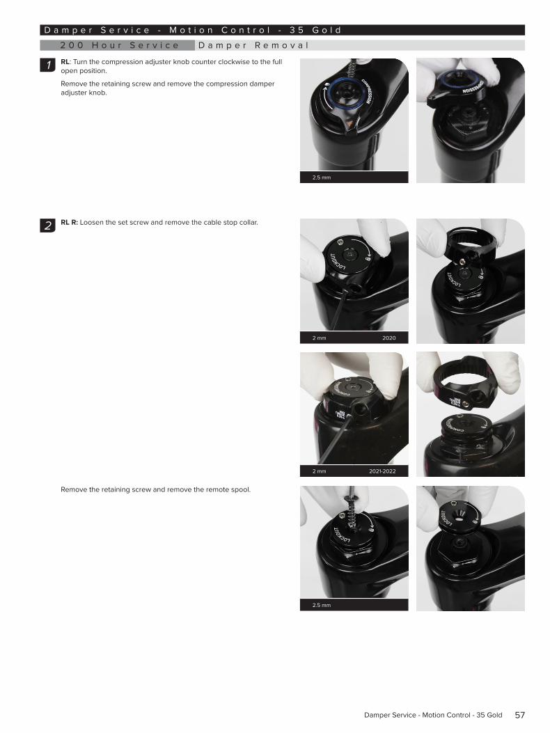
RL: Turn the compression adjuster knob counter clockwise to the full open position.
Remove the retaining screw and remove the compression damper adjuster knob.
RL R: Loosen the set screw and remove the cable stop collar.
Remove the retaining screw and remove the remote spool.
1
2.5 mm
2
2 mm 2020
2 mm 2021-2022
2.5 mm
58Damper Removal
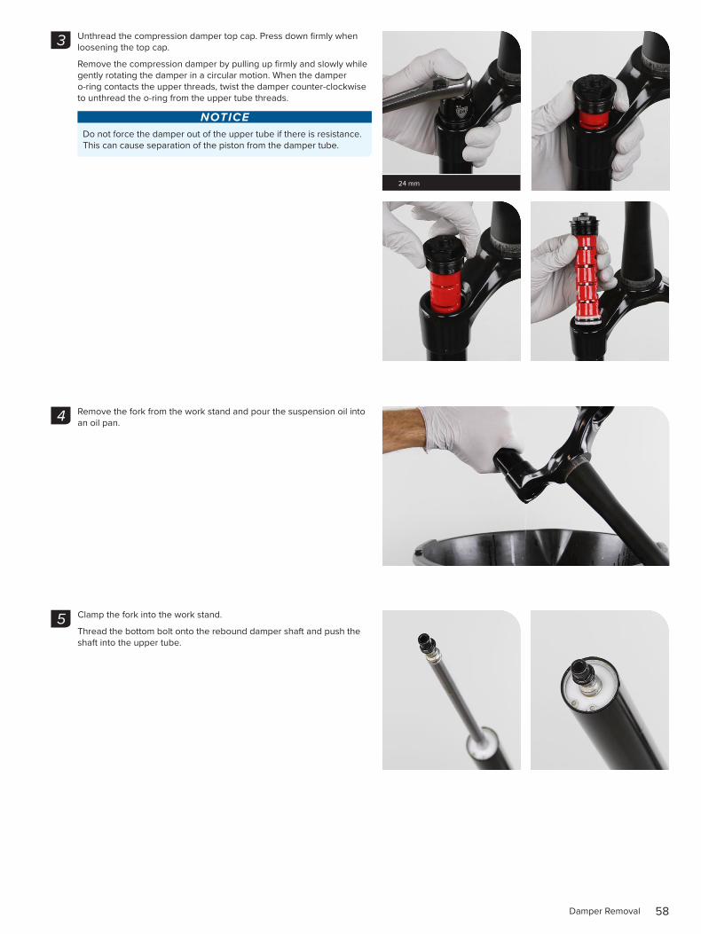
Unthread the compression damper top cap. Press down firmly when loosening the top cap.
Remove the compression damper by pulling up firmly and slowly while gently rotating the damper in a circular motion. When the damper o-ring contacts the upper threads, twist the damper counter-clockwise to unthread the o-ring from the upper tube threads.
NOTICEDo not force the damper out of the upper tube if there is resistance. This can cause separation of the piston from the damper tube.
Remove the fork from the work stand and pour the suspension oil into an oil pan.
Clamp the fork into the work stand.
Thread the bottom bolt onto the rebound damper shaft and push the shaft into the upper tube.
3
24 mm
4
5
59Damper Removal
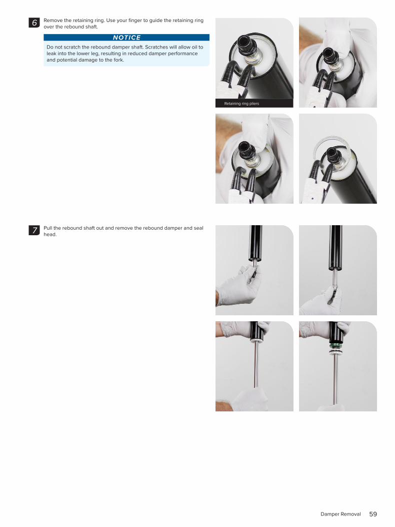
Remove the retaining ring. Use your finger to guide the retaining ring over the rebound shaft.
NOTICEDo not scratch the rebound damper shaft. Scratches will allow oil to leak into the lower leg, resulting in reduced damper performance and potential damage to the fork.
Pull the rebound shaft out and remove the rebound damper and seal head.
6
Retaining ring pliers
7
60Damper Removal
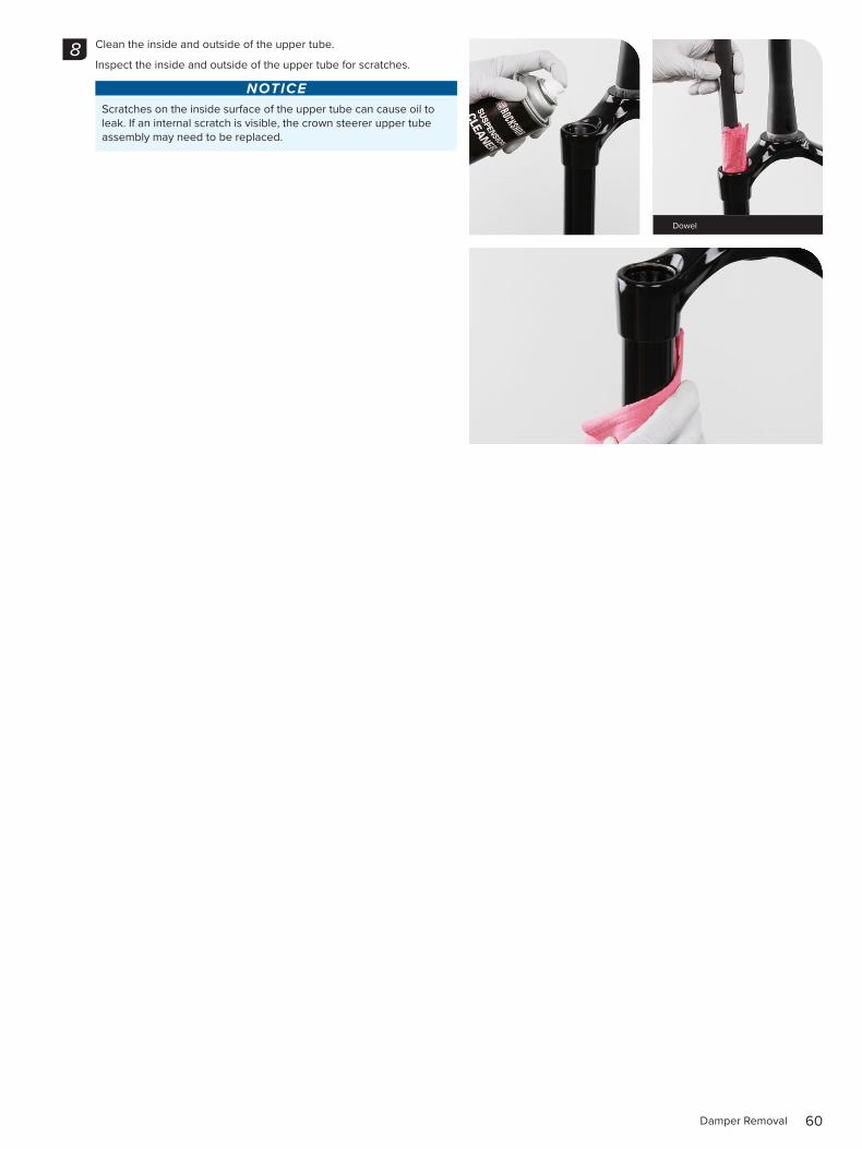
Clean the inside and outside of the upper tube.
Inspect the inside and outside of the upper tube for scratches.
NOTICEScratches on the inside surface of the upper tube can cause oil to leak. If an internal scratch is visible, the crown steerer upper tube assembly may need to be replaced.
8
Dowel
61Damper Service
2 0 0 H o u r S e r v i c e D a m p e r S e r v i c e
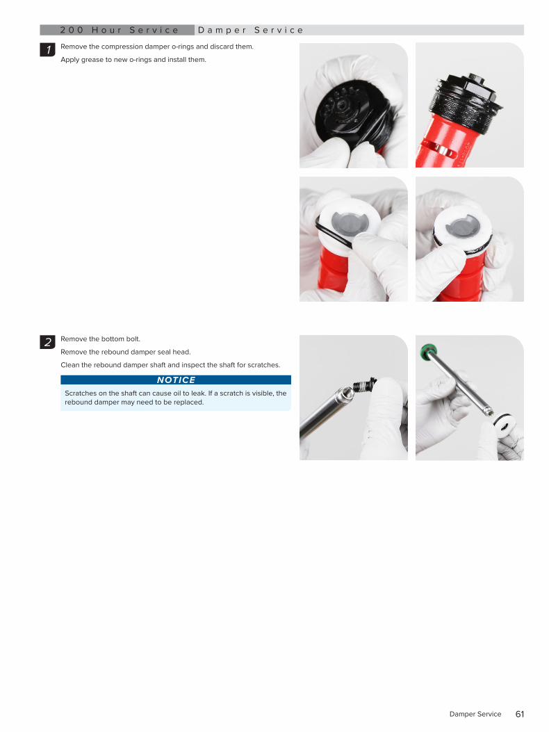
Remove the compression damper o-rings and discard them.
Apply grease to new o-rings and install them.
Remove the bottom bolt.
Remove the rebound damper seal head.
Clean the rebound damper shaft and inspect the shaft for scratches.
NOTICEScratches on the shaft can cause oil to leak. If a scratch is visible, the rebound damper may need to be replaced.
1
2
62Damper Service
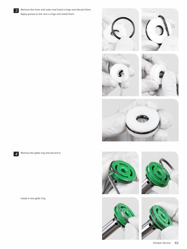
Remove the inner and outer seal head o-rings and discard them.
Apply grease to the new o-rings and install them.
Remove the glide ring and discard it.
Install a new glide ring.
3
4
63Damper Service
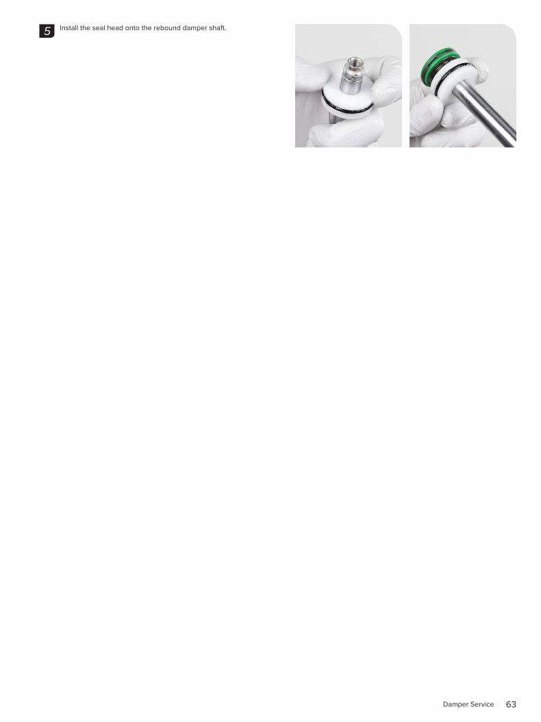
Install the seal head onto the rebound damper shaft.5
64Rebound Damper Installation
2 0 0 H o u r S e r v i c e R e b o u n d D a m p e r I n s t a l l a t i o n
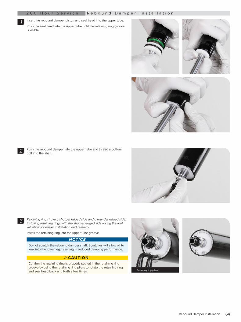
Insert the rebound damper piston and seal head into the upper tube.
Push the seal head into the upper tube until the retaining ring groove is visible.
Push the rebound damper into the upper tube and thread a bottom bolt into the shaft.
Retaining rings have a sharper edged side and a rounder edged side. Installing retaining rings with the sharper edged side facing the tool will allow for easier installation and removal.
Install the retaining ring into the upper tube groove.
NOTICEDo not scratch the rebound damper shaft. Scratches will allow oil to leak into the lower leg, resulting in reduced damping performance.
⚠CAUTIONConfirm the retaining ring is properly seated in the retaining ring groove by using the retaining ring pliers to rotate the retaining ring and seal head back and forth a few times.
1
2
3
Retaining ring pliers
65Rebound Damper Installation
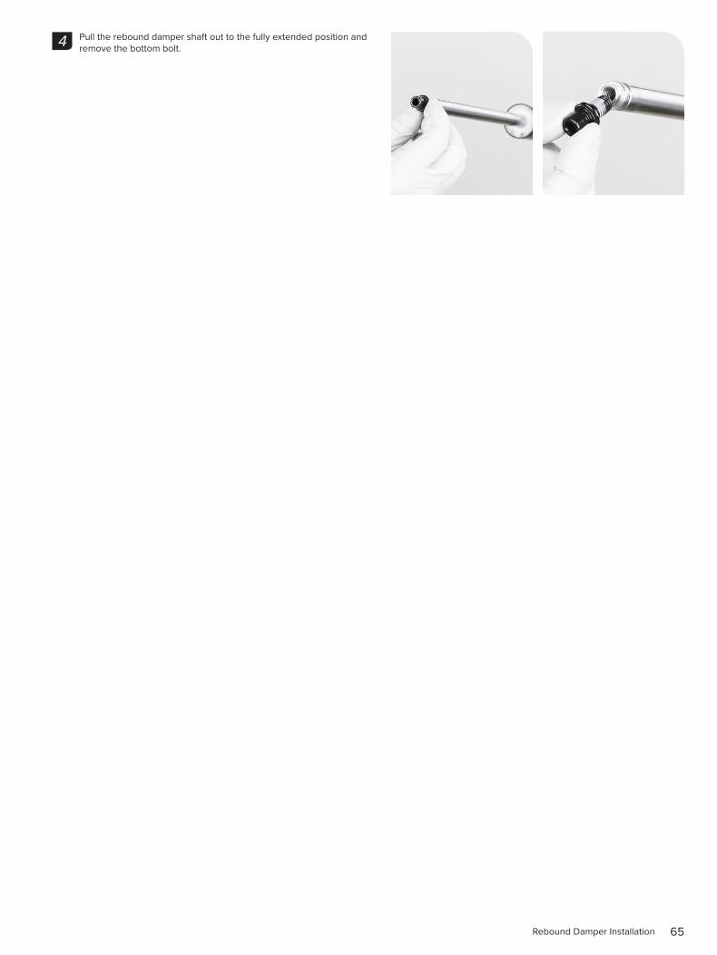
Pull the rebound damper shaft out to the fully extended position and remove the bottom bolt.4
66Compression Damper Installation
2 0 0 H o u r S e r v i c e C o m p r e s s i o n D a m p e r I n s t a l l a t i o n
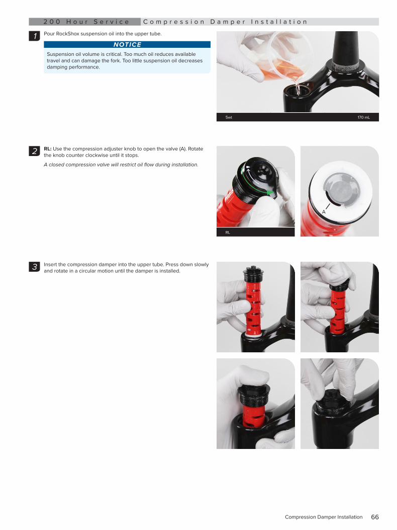
Pour RockShox suspension oil into the upper tube.
NOTICESuspension oil volume is critical. Too much oil reduces available travel and can damage the fork. Too little suspension oil decreases damping performance.
RL: Use the compression adjuster knob to open the valve (A). Rotate the knob counter clockwise until it stops.
A closed compression valve will restrict oil flow during installation.
Insert the compression damper into the upper tube. Press down slowly and rotate in a circular motion until the damper is installed.
1
5wt 170 mL
2
RL
A
3
67Compression Damper Installation
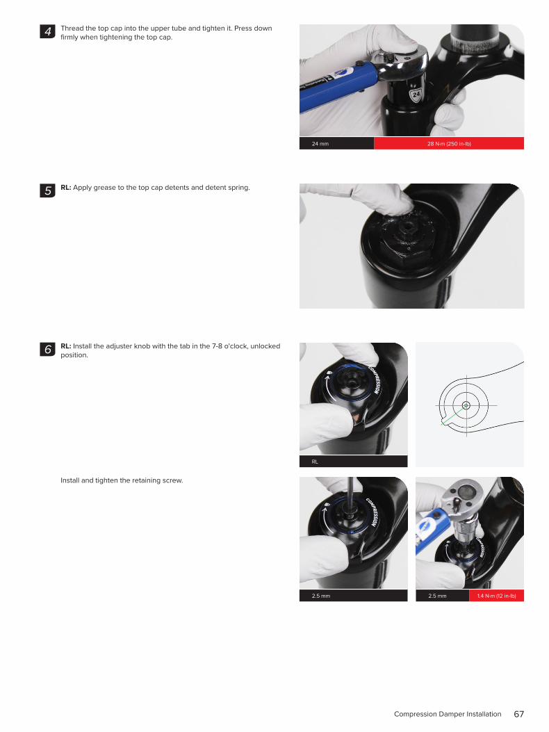
Thread the top cap into the upper tube and tighten it. Press down firmly when tightening the top cap.
RL: Apply grease to the top cap detents and detent spring.
RL: Install the adjuster knob with the tab in the 7-8 o'clock, unlocked position.
Install and tighten the retaining screw.
4
24 mm 28 N·m (250 in-lb)
5
6
RL
2.5 mm 2.5 mm 1.4 N·m (12 in-lb)
68Compression Damper Installation
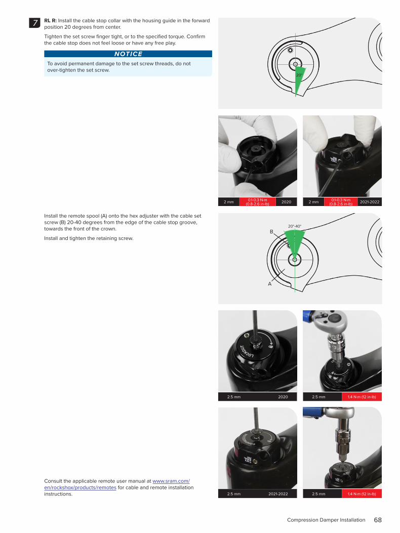
RL R: Install the cable stop collar with the housing guide in the forward position 20 degrees from center.
Tighten the set screw finger tight, or to the specified torque. Confirm the cable stop does not feel loose or have any free play.
NOTICETo avoid permanent damage to the set screw threads, do not over-tighten the set screw.
Install the remote spool (A) onto the hex adjuster with the cable set screw (B) 20-40 degrees from the edge of the cable stop groove, towards the front of the crown.
Install and tighten the retaining screw.
Consult the applicable remote user manual at www.sram.com/en/rockshox/products/remotes for cable and remote installation instructions.
7
20°
2 mm 0.1-0.3 N·m (0.8-2.6 in-lb) 2020 2 mm 0.1-0.3 N·m
(0.8-2.6 in-lb) 2021-2022
20°-40°
A
B
2.5 mm 2020 2.5 mm 1.4 N·m (12 in-lb)
2.5 mm 2021-2022 2.5 mm 1.4 N·m (12 in-lb)
69Damper Service - Turnkey and Rebound - 35 Silver
D a m p e r S e r v i c e - T u r n k e y a n d R e b o u n d - 3 5 S i l v e r2 0 0 H o u r S e r v i c e D a m p e r R e m o v a l
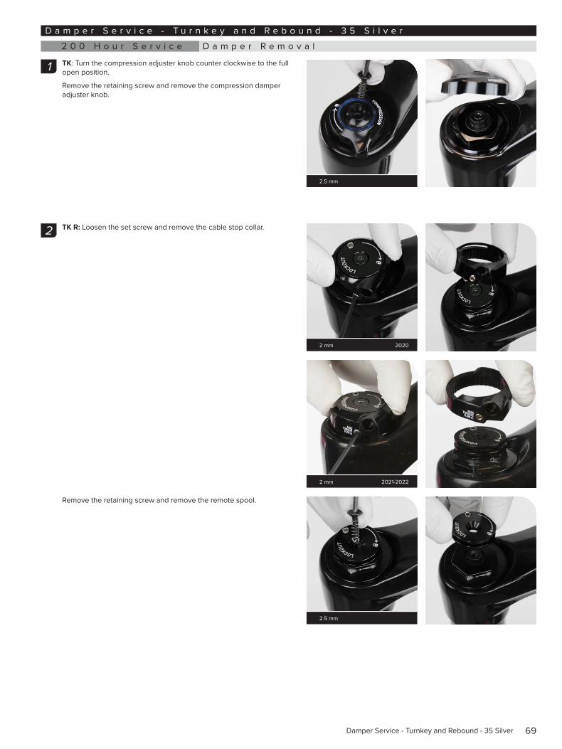
TK: Turn the compression adjuster knob counter clockwise to the full open position.
Remove the retaining screw and remove the compression damper adjuster knob.
TK R: Loosen the set screw and remove the cable stop collar.
Remove the retaining screw and remove the remote spool.
1
2.5 mm
2
2 mm 2020
2 mm 2021-2022
2.5 mm
70Damper Removal
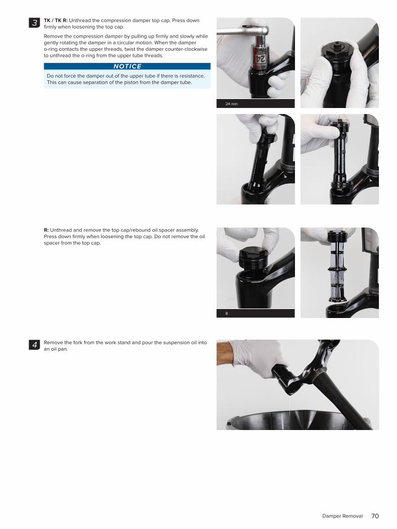
TK / TK R: Unthread the compression damper top cap. Press down firmly when loosening the top cap.
Remove the compression damper by pulling up firmly and slowly while gently rotating the damper in a circular motion. When the damper o-ring contacts the upper threads, twist the damper counter-clockwise to unthread the o-ring from the upper tube threads.
NOTICEDo not force the damper out of the upper tube if there is resistance. This can cause separation of the piston from the damper tube.
R: Unthread and remove the top cap/rebound oil spacer assembly. Press down firmly when loosening the top cap. Do not remove the oil spacer from the top cap.
Remove the fork from the work stand and pour the suspension oil into an oil pan.
3
24 mm
R
4
71Damper Removal
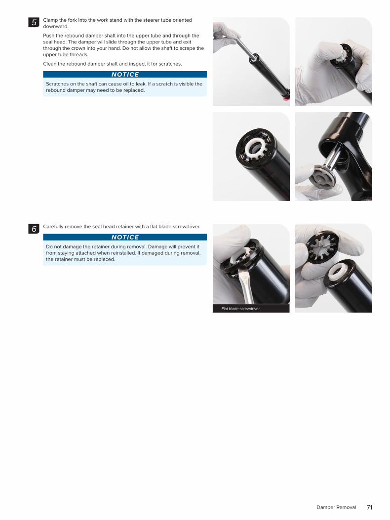
Clamp the fork into the work stand with the steerer tube oriented downward.
Push the rebound damper shaft into the upper tube and through the seal head. The damper will slide through the upper tube and exit through the crown into your hand. Do not allow the shaft to scrape the upper tube threads.
Clean the rebound damper shaft and inspect it for scratches.
NOTICEScratches on the shaft can cause oil to leak. If a scratch is visible the rebound damper may need to be replaced.
Carefully remove the seal head retainer with a flat blade screwdriver.
NOTICEDo not damage the retainer during removal. Damage will prevent it from staying attached when reinstalled. If damaged during removal, the retainer must be replaced.
5
6
Flat blade screwdriver
72Damper Removal
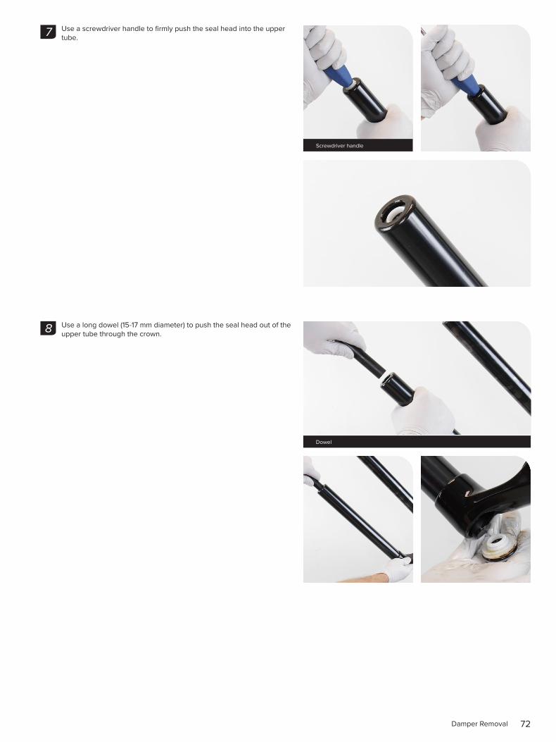
Use a screwdriver handle to firmly push the seal head into the upper tube.
Use a long dowel (15-17 mm diameter) to push the seal head out of the upper tube through the crown.
7
Screwdriver handle
8
Dowel
73Damper Removal
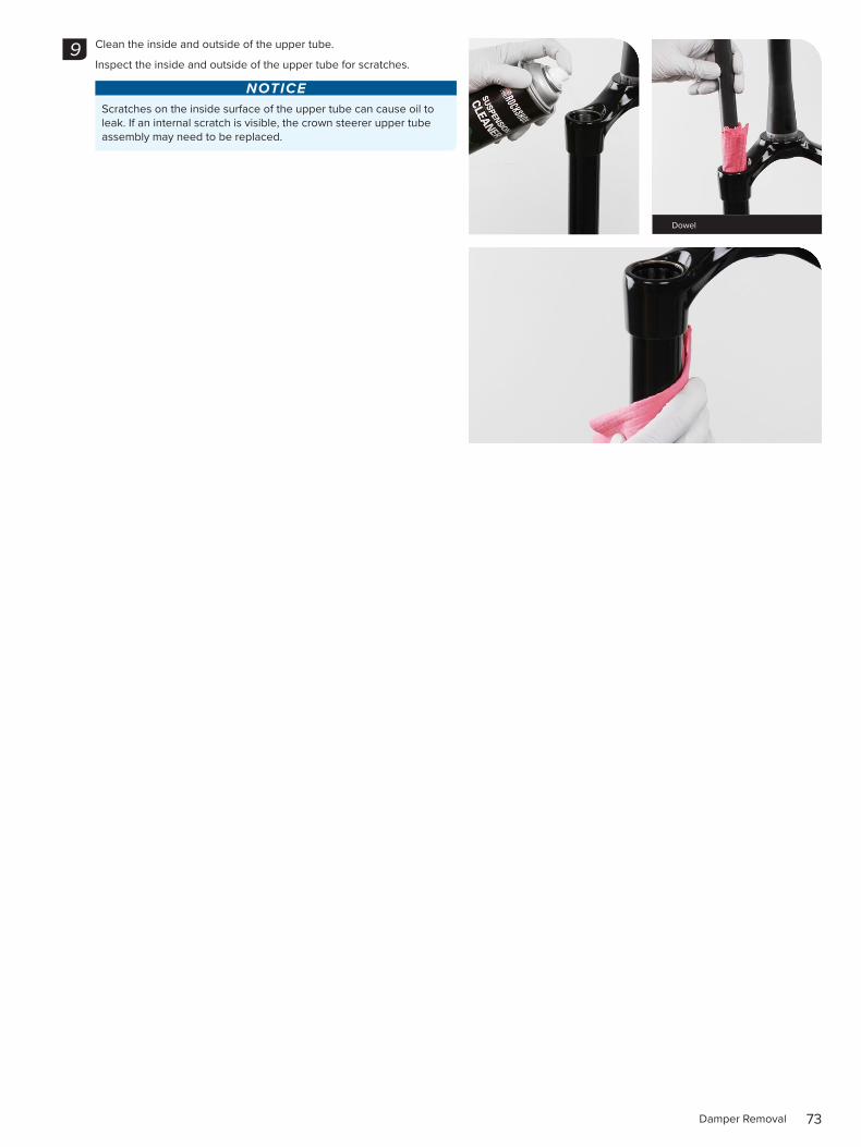
Clean the inside and outside of the upper tube.
Inspect the inside and outside of the upper tube for scratches.
NOTICEScratches on the inside surface of the upper tube can cause oil to leak. If an internal scratch is visible, the crown steerer upper tube assembly may need to be replaced.
9
Dowel
74Damper Service
2 0 0 H o u r S e r v i c e D a m p e r S e r v i c e
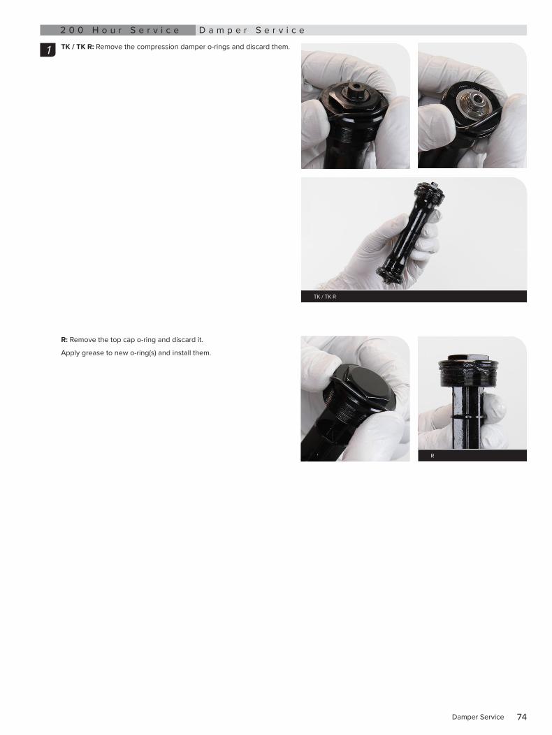
TK / TK R: Remove the compression damper o-rings and discard them.
R: Remove the top cap o-ring and discard it.
Apply grease to new o-ring(s) and install them.
1
TK / TK R
R
75Damper Service
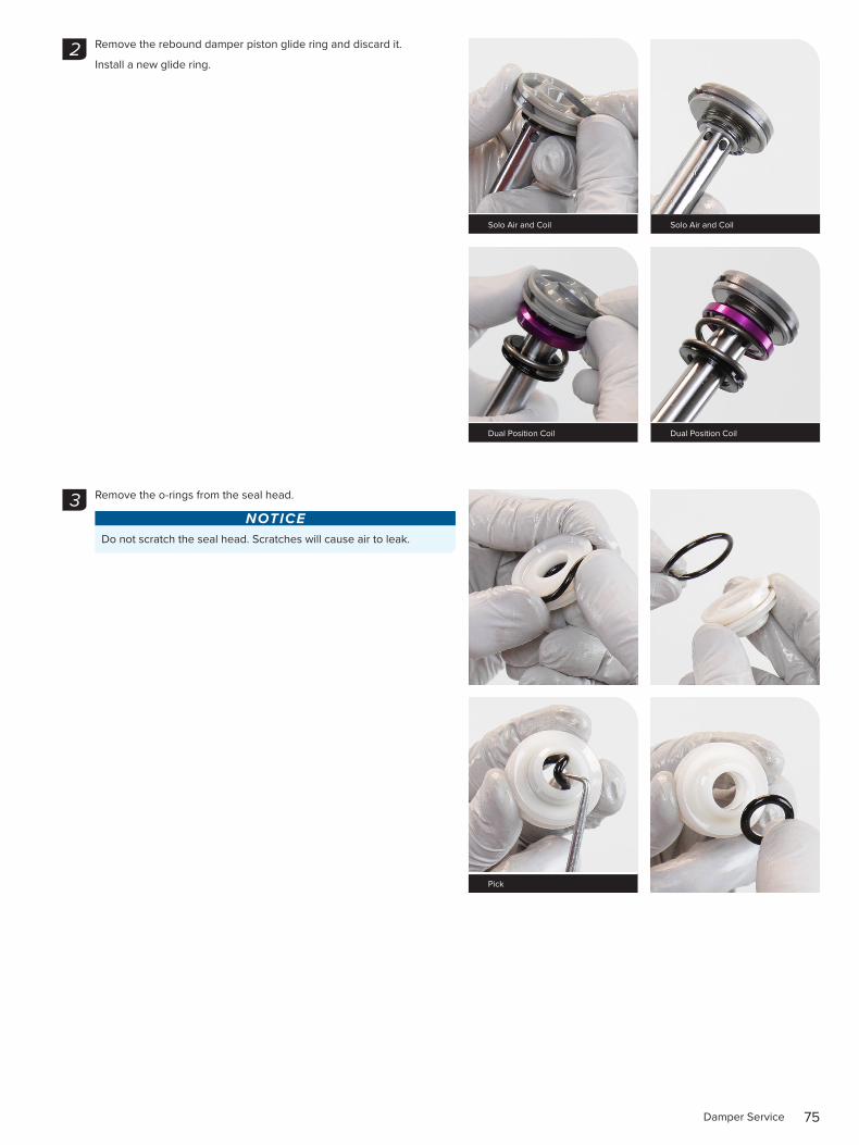
Remove the rebound damper piston glide ring and discard it.
Install a new glide ring.
Remove the o-rings from the seal head.
NOTICEDo not scratch the seal head. Scratches will cause air to leak.
2
Solo Air and Coil Solo Air and Coil
Dual Position Coil Dual Position Coil
3
Pick
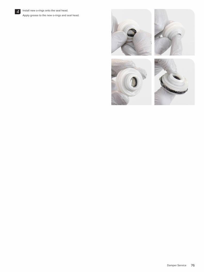
76Damper Service
Install new o-rings onto the seal head.
Apply grease to the new o-rings and seal head.4
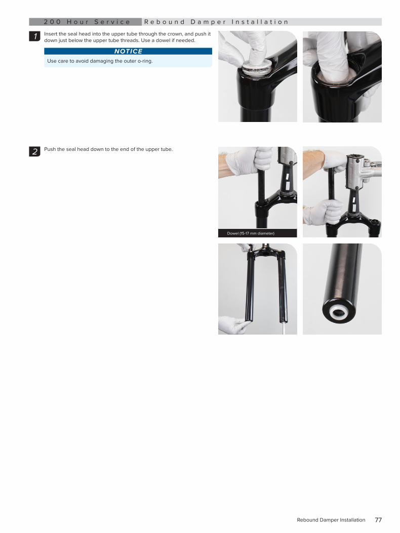
77Rebound Damper Installation
2 0 0 H o u r S e r v i c e R e b o u n d D a m p e r I n s t a l l a t i o n
Insert the seal head into the upper tube through the crown, and push it down just below the upper tube threads. Use a dowel if needed.
NOTICEUse care to avoid damaging the outer o-ring.
Push the seal head down to the end of the upper tube.
1
2
Dowel (15-17 mm diameter)
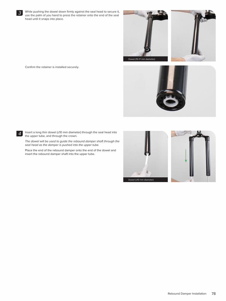
78Rebound Damper Installation
While pushing the dowel down firmly against the seal head to secure it, use the palm of you hand to press the retainer onto the end of the seal head until it snaps into place.
Confirm the retainer is installed securely.
Insert a long thin dowel (≤10 mm diameter) through the seal head into the upper tube, and through the crown.
The dowel will be used to guide the rebound damper shaft through the seal head as the damper is pushed into the upper tube.
Place the end of the rebound damper onto the end of the dowel and insert the rebound damper shaft into the upper tube.
3
Dowel (15-17 mm diameter)
4
Dowel (≤10 mm diameter)
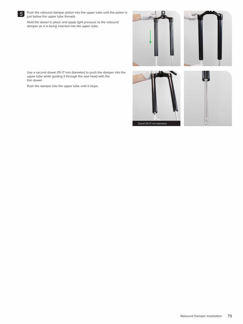
79Rebound Damper Installation
Push the rebound damper piston into the upper tube until the piston is just below the upper tube threads.
Hold the dowel in place and apply light pressure to the rebound damper as it is being inserted into the upper tube.
Use a second dowel (15-17 mm diameter) to push the damper into the upper tube while guiding it through the seal head with the thin dowel.
Push the damper into the upper tube until it stops.
5
Dowel (15-17 mm diameter)
80Compression Damper Installation
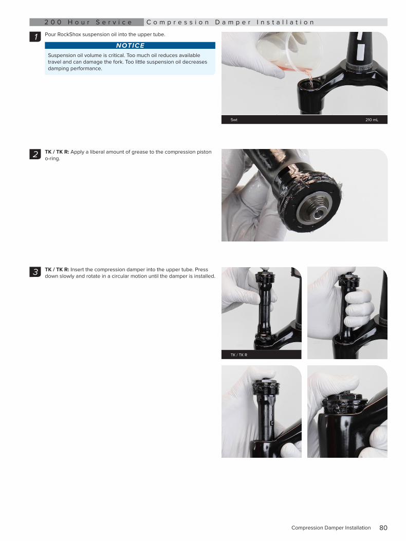
2 0 0 H o u r S e r v i c e C o m p r e s s i o n D a m p e r I n s t a l l a t i o n
Pour RockShox suspension oil into the upper tube.
NOTICESuspension oil volume is critical. Too much oil reduces available travel and can damage the fork. Too little suspension oil decreases damping performance.
TK / TK R: Apply a liberal amount of grease to the compression piston o-ring.
TK / TK R: Insert the compression damper into the upper tube. Press down slowly and rotate in a circular motion until the damper is installed.
1
5wt 210 mL
2
3
TK / TK R
81Compression Damper Installation
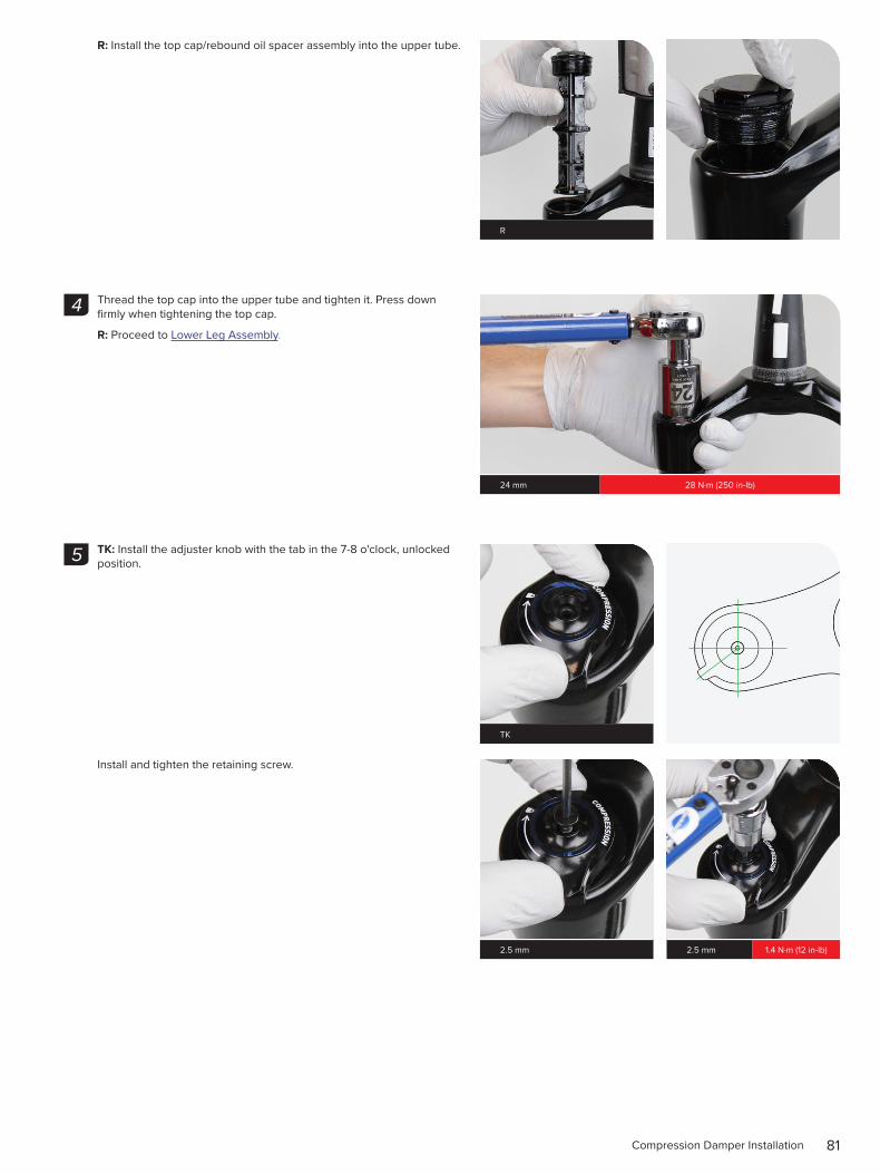
R: Install the top cap/rebound oil spacer assembly into the upper tube.
Thread the top cap into the upper tube and tighten it. Press down firmly when tightening the top cap.
R: Proceed to Lower Leg Assembly.
TK: Install the adjuster knob with the tab in the 7-8 o'clock, unlocked position.
Install and tighten the retaining screw.
R
4
24 mm 28 N·m (250 in-lb)
5
TK
2.5 mm 2.5 mm 1.4 N·m (12 in-lb)
82Compression Damper Installation
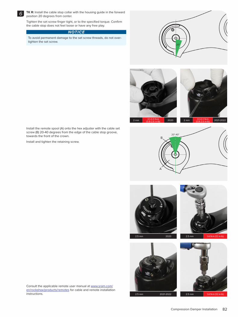
TK R: Install the cable stop collar with the housing guide in the forward position 20 degrees from center.
Tighten the set screw finger tight, or to the specified torque. Confirm the cable stop does not feel loose or have any free play.
NOTICETo avoid permanent damage to the set screw threads, do not over-tighten the set screw.
Install the remote spool (A) onto the hex adjuster with the cable set screw (B) 20-40 degrees from the edge of the cable stop groove, towards the front of the crown.
Install and tighten the retaining screw.
Consult the applicable remote user manual at www.sram.com/en/rockshox/products/remotes for cable and remote installation instructions.
6
20°
2 mm 0.1-0.3 N·m (0.8-2.6 in-lb) 2020 2 mm 0.1-0.3 N·m
(0.8-2.6 in-lb) 2021-2022
20°-40°
A
B
2.5 mm 2020 2.5 mm 1.4 N·m (12 in-lb)
2.5 mm 2021-2022 2.5 mm 1.4 N·m (12 in-lb)
83Lower Leg Assembly
L o w e r L e g A s s e m b l y5 0 / 2 0 0 H o u r S e r v i c e L o w e r L e g I n s t a l l a t i o n
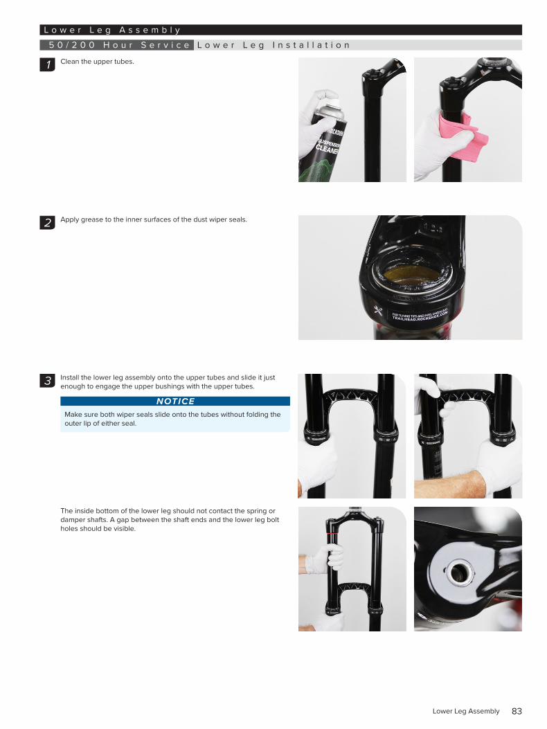
Clean the upper tubes.
Apply grease to the inner surfaces of the dust wiper seals.
Install the lower leg assembly onto the upper tubes and slide it just enough to engage the upper bushings with the upper tubes.
NOTICEMake sure both wiper seals slide onto the tubes without folding the outer lip of either seal.
The inside bottom of the lower leg should not contact the spring or damper shafts. A gap between the shaft ends and the lower leg bolt holes should be visible.
1
2
3
84Lower Leg Installation
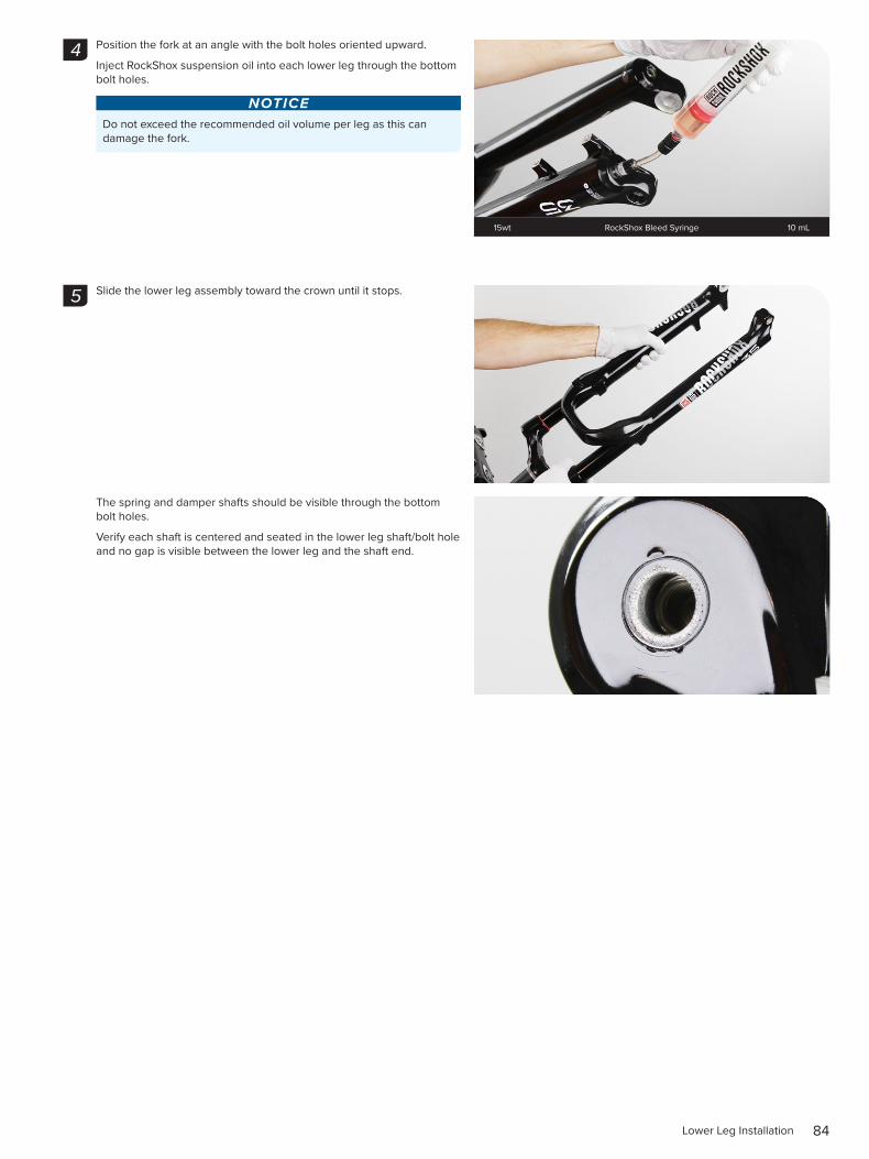
Position the fork at an angle with the bolt holes oriented upward.
Inject RockShox suspension oil into each lower leg through the bottom bolt holes.
NOTICEDo not exceed the recommended oil volume per leg as this can damage the fork.
Slide the lower leg assembly toward the crown until it stops.
The spring and damper shafts should be visible through the bottom bolt holes.
Verify each shaft is centered and seated in the lower leg shaft/bolt hole and no gap is visible between the lower leg and the shaft end.
4
15wt RockShox Bleed Syringe 10 mL
5
85Lower Leg Installation
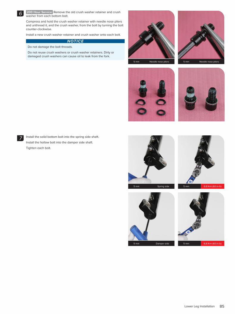
200 Hour Service Remove the old crush washer retainer and crush washer from each bottom bolt.
Compress and hold the crush washer retainer with needle nose pliers and unthread it, and the crush washer, from the bolt by turning the bolt counter-clockwise.
Install a new crush washer retainer and crush washer onto each bolt.
NOTICEDo not damage the bolt threads.
Do not reuse crush washers or crush washer retainers. Dirty or damaged crush washers can cause oil to leak from the fork.
Install the solid bottom bolt into the spring side shaft.
Install the hollow bolt into the damper side shaft.
Tighten each bolt.
6
5 mm Needle nose pliers 5 mm Needle nose pliers
7
5 mm Spring side 5 mm 6.8 N·m (60 in-lb)
5 mm Damper side 5 mm 6.8 N·m (60 in-lb)
86Lower Leg Installation
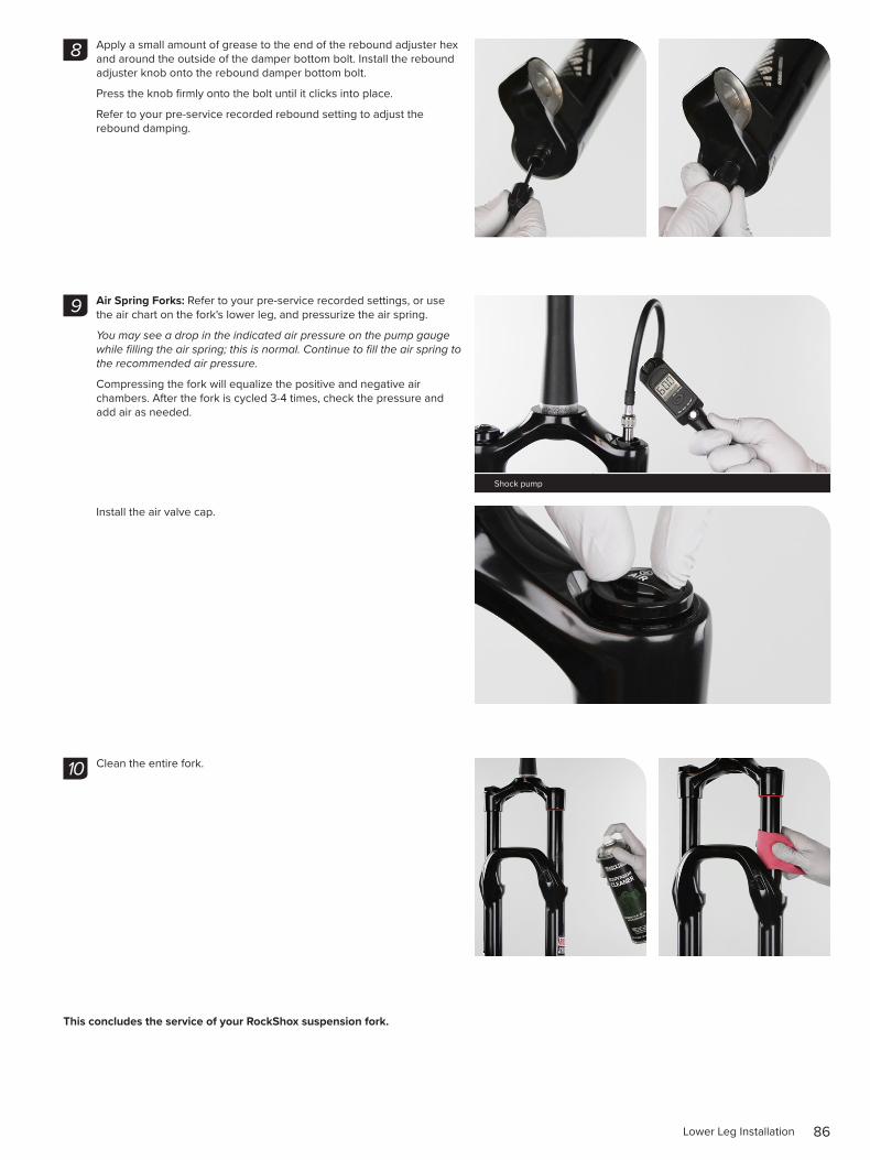
Apply a small amount of grease to the end of the rebound adjuster hex and around the outside of the damper bottom bolt. Install the rebound adjuster knob onto the rebound damper bottom bolt.
Press the knob firmly onto the bolt until it clicks into place.
Refer to your pre-service recorded rebound setting to adjust the rebound damping.
Air Spring Forks: Refer to your pre-service recorded settings, or use the air chart on the fork's lower leg, and pressurize the air spring.
You may see a drop in the indicated air pressure on the pump gauge while filling the air spring; this is normal. Continue to fill the air spring to the recommended air pressure.
Compressing the fork will equalize the positive and negative air chambers. After the fork is cycled 3-4 times, check the pressure and add air as needed.
Install the air valve cap.
Clean the entire fork.
This concludes the service of your RockShox suspension fork.
8
9
Shock pump
10
These are registered trademarks of SRAM, LLC:
1:1®, Accuwatt®, Avid®, AXS®, Bar®, Blackbox®, BoXXer®, DoubleTap®, Elita®, eTap®, Firecrest®, Firex®, Grip Shift®, GXP®, Hammerschmidt®, Holzfeller®, Hussefelt®, i-Motion®, Judy®, Know Your Powers®, NSW®, Omnium®, Pike®, PowerCal®, PowerLock®, PowerTap®, Qollector®, Quarq®, RacerMate®, Reba®, Rock Shox®, Ruktion®, Service Course®, ShockWiz®, SID®, Single Digit®, Speed Dial®, Speed Weaponry®, Spinscan®, SRAM®, SRAM APEX®, SRAM EAGLE®, SRAM FORCE®, SRAM RED®, SRAM RIVAL®, SRAM VIA®, Stylo®, Torpedo®, Truvativ®, TyreWiz®, Varicrank®, Velotron®, X0®, X01®, X-SYNC®, XX1®, Zed tech®, Zipp®
These are registered logos of SRAM, LLC:
These are trademarks of SRAM, LLC:
10K™, 1X™, 202™, 30™, 35™, 302™, 303™, 353™, 404™, 454™, 808™, 858™, 3ZERO MOTO™ , ABLC™, AeroGlide™, AeroBalance™, AeroLink™, Airea™, Air Guides™, AKA™, AL-7050-TV™, ATMOS™, Automatic Drive™, Automatix™, AxCad™, Axial Clutch™, BB5™, BB7™, BB30™, Bleeding Edge™, Blipbox™, BlipClamp™, BlipGrip™, Blips™, Bluto™, Bottomless Tokens™, Cage Lock™, Carbon Bridge™, Centera™, Charger 2™, Charger™, Charger Race Day™, Clickbox Technology™, Clics™, Code™, Cognition™, Connectamajig™, Counter Measure™, DD3™, DD3 Pulse™, DebonAir™, Deluxe™, Descendant™, DFour™, DFour91™, Dig Valve™, DirectLink™, Direct Route™, Domain™, DOT 5.1™, Double Decker™, Double Time™, Dual Flow Adjust™, Dual Position Air™, Dual Position Coil™, DUB™, DZero™, E300™, E400™, Eagle™, E-Connect4™, E-matic™, ErgoBlade™, ErgoDynamics™, ESP™, EX1™, Exact Actuation™, Exogram™, Flow Link™, FR-5™, Full Pin™, Gnar Dog™, Guide™, GX™, Hard Chrome™, Hexfin™, HollowPin™, Howitzer™, HRD™, Hybrid Drive™, Hyperfoil™, i-3™, Impress™, Jaws ™, Jet™, Kage™, Komfy™, Level™, Lyrik™, MatchMaker™, Maxle™, Maxle 360™, Maxle DH™, Maxle Lite™, Maxle Lite DH™, Maxle Stealth™, Maxle Ultimate™, Micro Gear System™, Mini Block™, Mini Cluster™, Monarch™, Monarch Plus™, Motion Control™, Motion Control DNA™, MRX™, Noir™, NX™, OCT™, OmniCal™, OneLoc™, Paragon™, PC-1031™, PC-1110 ™, PC-1170™, PG-1130™, PG-1050™, PG-1170™, Piggyback™, Poploc™, Power Balance™, Power Bulge™, PowerChain™, PowerDomeX™, Powered by SRAM™, PowerGlide™, PowerLink™, Power Pack™, Power Spline™, Predictive Steering™, Pressfit™, Pressfit 30™, Prime™, Qalvin™, R2C™, RAIL™, Rapid Recovery™, Recon™, Reverb™, Revelation™, Riken™, Rise™, ROAM™, Roller Bearing Clutch™, RS-1™, Sag Gradients™, Sawtooth™, SCT - Smart Coasterbrake Technology™, Seeker™, Sektor™, SHIFT™, ShiftGuide™, Shorty™, Showstopper™, SIDLuxe™, Side Swap™, Signal Gear Technology™, SL™, SL-70™, SL-70 Aero™, SL-70 Ergo™, SL-80™, Sl-88™, SLC2™, SL SPEED™, SL Sprint™, Smart Connect™, Solo Air™, Solo Spoke™, SpeedBall™, Speed Metal™, SRAM APEX 1™, SRAM FORCE 1™, SRAM RIVAL 1™, S-series™, Stealth-a-majig ™, StealthRing™, Super-9™, Supercork™, Super Deluxe™, Super Deluxe Coil™, SwingLink™, TaperCore™, Timing Port Closure™, Tool-free Reach Adjust™, Top Loading Pads™, Torque Caps™, TRX™, Turnkey™, TwistLoc™, VCLC™, Vivid™, Vivid Air™, Vuka Aero™, Vuka Alumina™, Vuka Bull™, Vuka Clip™, Vuka Fit™, Wide Angle™, WiFLi™, X1™, X5™, X7™, X9™, X-Actuation™, XC™, X-Dome™, XD™, XD Driver Body™, XDR™, XG-1150™, XG-1175™, XG-1180™, XG-1190™, X-Glide™, X-GlideR™, X-Horizon™, XLoc Sprint™, XX™, Yari™, ZEB™, Zero Loss™
Specifications and colors subject to change without prior notice.© 2021 SRAM, LLC
This publication includes trademarks and registered trademarks of the following companies:
Abbey Bike Tools™ is a trademark owned by Abbey Bike Tools, LLC.
Boost™ is a trademark owned by Trek Bicycle Corporation.
Liquid-O-Ring® is a registered trademark of Oil Center Research, Inc.
ASIAN HEADQUARTERS SRAM Taiwan No. 1598-8 Chung Shan Road Shen Kang Hsiang, Taichung City Taiwan R.O.C.
WORLD HEADQUARTERS SRAM LLC 1000 W. Fulton Market, 4th Floor Chicago, Illinois 60607 U.S.A.
EUROPEAN HEADQUARTERS SRAM Europe Paasbosweg 14-16 3862ZS Nijkerk The Netherlands