2020 developer & engineering guide
TRANSCRIPT

May 2020
1
2020 DEVELOPER & ENGINEERING GUIDE
Prepared by: EPCOR Water Arizona Inc. Engineering Department
2355 West Pinnacle Peak Road, Suite 300 Phoenix, Arizona 85027
(623) 445-2400
www.EPCOR.com

May 2020
2
CONTACT LIST
NAME TITLE RESPONSIBILITIES PHONE NO. E-MAIL Main Office
General Inquiries
623.445.2400
Customer Service
General Inquiries
800.383.0834
Brad Finke
Developer Services Manager
New Development
Coordination
623.445.2402
Steve Brooks
Project Manager
Plan Reviews, Main
Extension Agreements, Meter Applications
623.445.2447
Jim Thomson Project Manager CCN Applications, Developer Services
623.587.5218 [email protected]
Josh Vig
Project Manager
Plan Reviews, Conflict
Reviews, Main Extension Agreements, Meter
Applications
623.445.2495
Joe Whelan
Project Manager
Plan Reviews, Main
Extension Agreements, Meter Applications
623.445.2438
Anthony Beuche Project Manager New Development Coordination,
Engineering Report Review, Engineering
Inquiries
623-445-2452 [email protected]
Eric Coppinger
Sr. Construction Inspector
Construction Inspections
623.445.2445 (o) 602.309.1164 (c)
Eric Ganados Construction Inspector Construction Inspections 623.445.2443 (o)
602.358.5548 (c) [email protected]
Garren Willey
Construction Inspector
Construction Inspections
623.445.2445 (o) 480.450.4670 (c)
Jamie Patterson
GIS Manager
Mapping,
Record Drawings
623.780.3792
Kimberly Dotray
Real Property Manager
Real Estate, Easements,
Deeds
623.780.3777
Joshua Newby
Environmental Compliance Program Coordinator
Backflow Prevention
623.587.5202 (o) 480.450.2077 (c)
Doug Kirkland
Industrial Pretreatment Specialist
Pretreatment, Grease
Interceptors
623.587.5298 (o) 602.763.2192 (c)

May 2020
3
TABLE OF CONTENTS Note: Throughout this Developer & Engineering Guide, “Utility” means EPCOR Arizona Inc.
CHAPTER 1 - DEVELOPER GENERAL INFORMATION
MAIN EXTENSION PROCESS FLOWCHART ................................................................................ 6
FEE SCHEDULE ............................................................................................................................. 7
SUMMARY OF KEY POINTS IN THE MAIN EXTENSION PROCESS ........................................... 8
WATER METER INSTALLATION CHECKLIST ............................................................................. 10
UTILITY OWNERSHIP OF FACILITIES ........................................................................................ 11
SUBMITTAL LIST .............................................................. 1ERROR! BOOKMARK NOT DEFINED.
REQUIREMENTS FOR DEVELOPER DESIGNED AND BUILT WATER/SEWER MAIN EXTENSIONS ...................................................................................................................... 13
CERTIFICATES OF ASSURED OR ADEQUATE WATER SUPPLY AND GRANDFATHERED RIGHTS ......................................................................................................... 16
CHAPTER 2 - ENGINEERING MASTER PLAN AND DESIGN CRITERIA
MASTER PLANNING AND DISTRIBUTION MAIN REQUIREMENTS .......................................... 18
WATER MASTER PLAN OUTLINE .............................................................................................. 20
DESIGN CRITERIA FOR WATER SYSTEMS ............................................................................... 22
DESIGN CRITERIA FOR FIRE LINES ........................................................................................... 27
DESIGN CRITERIA FOR WASTEWATER SYSTEMS ..... ERROR! BOOKMARK NOT DEFINED.8
CHAPTER 3 - CONSTRUCTION DRAWINGS
CONSTRUCTION DRAWING REQUIREMENTS .......................................................................... 33
PLAT DEDICATION VERBIAGE .................................................................................................... 35
AS-BUILT REQUIREMENTS ......................................................................................................... 36
WATER/SEWER “AS-BUILT” CERTIFICATION ............................................................................ 37
CHAPTER 4 - CONSTRUCTION INSPECTION
PROCEDURE FOR SCHEDULING WATER LINE CONSTRUCTION INSPECTIONS ................ 39
PROCEDURE FOR SCHEDULING SEWER LINE CONSTRUCTION INSPECTIONS ................ 40

May 2020
4
CHAPTER 5 - BACKFLOW PREVENTION
BACKFLOW PREVENTION APPROVAL PROCESS ....... 4ERROR! BOOKMARK NOT DEFINED.
PREMISES REQUIRING BACKFLOW PREVENTION .... 4ERROR! BOOKMARK NOT DEFINED.
BACKFLOW PREVENTION OPERATIONAL APPROVAL FLOWCHART .................................... 43
CHAPTER 6 - PRETREATMENT REQUIREMENTS
APPROVAL PROCESS .................................................................................................................. 45
PLAN REVIEW ............................................................................................................................... 45
INDUSTRIAL DISCHARGE CRITERIA .......................................................................................... 45
DENTAL FACILITES ...................................................................................................................... 45
FOOD SERVICE FACILITES CRITERIA ....................................................................................... 45
TABLE NO. 1 - DRAINAGE FIXTURE UNITS FOR FOOD SERVICE FACILITES ....................... 46
TABLE NO. 2 - MINIMUM GGI SIZE BASED ON TOTAL DFUs .................................................... 46
TABLE NO. 3 - GGI SIZING FOR UNFINISHED BUILDING SHELLS .......................................... 46
APPENDIX ENGINEERING DETAILS (INCLUDING GENERAL NOTES AND MATERIAL SPECIFICATIONS)

May 2020
5
CHAPTER 1
DEVELOPER
GENERAL INFORMATION

May 2020
6
Application/Plan Approval Process
Meter Set Process
Agreement Process
Construction Process
Main Extension Process Overview
Application SubmittalApplication plus Fee, Design Plans,
and/or Master Plan, if applicable
Application Review:EPCOR reviews the Application
Package
Plan ReviewEPCOR Formal Plan Review,
Comments, and Applicant Revisions
Pre-Application Meeting:Discuss Service Options and General
Policy and Procedures
Comments/Issues
Redlines/Revisions
Conditional ApprovalEPCOR issues Conditional Approval of
Plans and/or Master Plan
MXA and/or Master AgreementPrepared by EPCOR, with
Exhibits Submitted by Applicant
Permit ReviewPrepared by Applicant and Reviewed by
EPCOR in preparation for submission
conditional on MXA execution
Warning: EPCOR will not sign any plans or permits until MXA is executed and all fees as stated in the MXA are paid. MXA Final Agreement Package
Complete
Easements/Real Property and any other special permits or licenses:
Prepared by Applicant and Reviewed by EPCOR
MXA Package Submitted through EPCOR’s Contract Approval Process for
final approval
Master Agreement Required forCommon or Off-site Facilities, Wells,
Tanks, Booster Stations, etc?
Negotiate Agreement and
Terms
Approved MXASent to Applicant for Signing and then
Returned to EPCOR for Signing; Applicant pays Construction Administration Fee before EPCOR signs the Agreement
Final ApprovalPlans and Permits Signed by EPCOR
for Submission by Applicant to Regulatory Agencies
Pre-Construction Meeting
Arizona Corporation Commission (“A.C.C.”) Approval
Executed MXA sent by EPCOR to A.C.C. for Approval
Permit ApprovalsAll Permits or Authorizations Received
A.C.C. APROVALYes
No
Resolve Issues
Warning: Construction process CANNOT start until Utilities Division of A.C.C. approves MXA
Construction Start/Complete
Approval of Construction (AOC) Applicant’s Engineer Completes AOC Package,
Sends to EPCOR to Sign and Mail to Agency
EPCOR Final AcceptanceGranted after AOC issued and all items required for Final Acceptance per MXA are satisfied; Hook-Up Fees due for projects in these Districts: Agua Fria
Wastewater, Mohave Wastewater, Anthem Wastewater and Anthem Water.
Applicant Requests Meters(completes forms and submits to EPCOR with Meter Fees prior to
connection to EPCOR’s water system)
EPCOR Verifies All Fees Required per MXA are paid by Applicant
EPCOR Sets Meters
One Year Warranty Period Begins
Final Walk-Through Inspection after One Year, Punch List Items Addressed
by Applicant’s Contractor
Frameworkof
Agreement Complete
Yes No
2
3
4
1
If project is in the Agua Fria Water District or Havasu Water District,
applicant pays Hook-Up Fees within 15 calendar days after
A.C.C. approval
See “Summary of Key Points” for Details Revision Date: January 2015
(MXA = Main Extension Agreement)

May 2020
7
EPCOR WATER
DEVELOPER SERVICES – FEE SCHEDULE
All fees are subject to change.
Review Fee for Master Plan Reports for developments with 100 or less residential services
• This Fee is submitted to Utility along with the “Application for Water or Sewer Main Extension” and with the Master Plan Report.
• The Types of Master Plan Reports include water, sewer, and reclaimed water.
$1,500 per report type
Review Fee for Master Plan Reports for developments with more than 100 residential services
• This Fee is submitted to Utility along with the “Application for Water or Sewer Main Extension” and with the Master Plan Report.
• The Types of Master Plan Reports include water, sewer, and reclaimed water.
$2,500 per report type
Review Fee for Master Plan Reports for commercial developments • This Fee is submitted to Utility along with the “Application for Water or
Sewer Main Extension” and with the Master Plan Report. • The Types of Master Plan Reports include water, sewer, or reclaimed
water.
$2,500 per report type
Plan Review Fee • Does not apply to projects that are “fire protection services only.” • This Fee is submitted to Utility along with the “Application for Water or
Sewer Main Extension” and with the first submittal of engineering plans and specifications to Utility for review.
$5,000
Plan Review Fee – for Fire Protection Services Only • This Fee is submitted to Utility along with the “Application for Fire Lines”
and with the first submittal of engineering plans and specifications to Utility for review.
$2,500
Construction Administration Fee • Does not apply to projects that are “fire protection services only.” • This fee is due upon execution of the Main Extension Agreement. • The developer’s engineer determines the estimated total cost of
construction of the main extension, which is added as an exhibit to the Main Extension Agreement.
$6,500 + 5% of the Engineer’s Estimated
Total Cost of Construction
Line Testing Water Fee • This fee is due upon execution of the Main Extension Agreement. • This fee is the cost of the water used during testing of the main
extensions (i.e., flushing, chlorination, filling).
9 x (volume of the main extensions) x Water Rate per the
applicable Water Tariff
Application for Public Fire Hydrants • This fee is due after Utility’s review of the completed Application and
before construction begins.
$750 per hydrant
Hook-Up Fees As Stated in Tariff
Water Meter Fees As Stated in Tariff

May 2020
8
SUMMARY OF KEY POINTS
In the MAIN EXTENSION PROCESS
This outline provides an overview of the key procedures involved in administration, design, and construction of water distribution or sewer collection facilities for developer-funded projects. These procedures have been designed to promote efficient completion of projects at the lowest possible cost. Adherence to these procedures will avoid costly delays.
1. When it is determined that a proposed development is within EPCOR Arizona Inc. ("Utility") service area,
the Applicant will complete an Application for Water or Sewer Main Extension ("Application") and will submit the Application along with engineering plans and a $5,000 Plan Review Fee to Utility. The Plan Review Fee is a non-refundable contribution intended to cover the initial cost of Utility’s project management expenses, including reviews of engineering plans, specifications and design reports, preparation and reviews of the Main Extension Agreement (MXA) and coordination of flow tests where necessary. The Application is available on EPCOR’s website (HERE).
2. The Plan Review Fee is structured to cover up to two reviews of engineering plans, specifications and
design reports. If the Applicants’ Engineer fails to satisfactorily address Utility’s review comments with its second submittal, the remaining portion of the Plan Review Fee may not be sufficient to cover Utility’s time to review the engineer’s third submittal. In that case, or in any other case where the Utility's costs exceed the Plan Review Fee, Utility will not continue work until a second $5,000 Plan Review Fee is submitted.
Second reviews of engineering plans are intended to focus only on changes requested from Utility as a
result of the initial review, and will not be considered a complete review. As such, any changes made to the plans must be clearly identified so the plan reviewer can maximum the use of their time and focus solely on plan revisions. If other changes have been made to the plans (those not requested from the Utility), they must be clearly called out as changes, or there is the possibility that these changes could be rejected during construction, and result in costly delays.
3. Utility will not begin any work until the $5,000 Plan Review Fee is received. Upon receipt of the
Plan Review Fee, Utility will assign a project manager to coordinate with the Applicant’s Engineer to assist them in developing engineering plans and specifications in accordance with Utility’s requirements. These requirements are outlined in Utility’s Developer Guide, which is available on EPCOR’s website. During the course of plan development, the following may be required from the developer:
a. A letter or design report from the Engineer estimating the ultimate population equivalents for the
development, the average and maximum anticipated daily water demands (or wastewater flow rates) for domestic, irrigation, and fire protection, and the anticipated number and sizes of meters and service lines and proposed backflow prevention devices.
b. A letter from the jurisdictional fire protection agency setting forth requirements for fire flows, public fire hydrants, and/or private fire protection systems. These requirements must be incorporated into the engineering plans. The letter and plans must show the minimum required fire flow shown in gallons per minute and duration shown in hours.
c. Preliminary plats or final plats showing lot numbers with corresponding street addresses and public utility easements. A final recorded plat is required prior to final closeout.
d. Easements minimum 12 feet in width for all water/sewer facilities that are out of public right-of-way. Larger width easements may be required in certain cases. Utility’s easement forms are available upon request. Draft easement forms, deeds, ALTA surveys and title reports will be submitted for Utility review prior to recordation of easements or execution of deeds. After Utility approval, developer will be responsible for recording the easements. A notarized copy of the recorded document shall be provided to Utility. Recorded off-site easements will be required prior to construction. Recorded on-site easements are required prior to activation of service.
e. One complete set of final engineering sealed plans (approved by the fire protection agency, the governing regulatory agency, and Utility).
f. Copies of Certificates of Approval to Construct as issued by the governing regulatory County or State agency.
g. A material breakdown sheet in a format approved by Utility showing the quantity, size, and estimated construction cost of all water/sewer facilities to be conveyed to Utility, including permitting and engineering costs. This sheet must be signed and sealed by an engineer.
May 2020
9
4. Construction Administration Fee
Before Utility will sign the approval block on the engineering plans, Utility must receive the Construction Administration fee, described in the Main Extension Agreement. The Construction Administration fee covers Utility’s estimated construction administration expenses, including inspecting and testing the construction work, participating in construction progress meetings, reviewing as-built engineering drawings, coordinating with the Utilities Division of the Arizona Corporation Commission (see paragraph 7 below), coordinating with the governing regulatory County or State agency to obtain the Certificate of Approval of Construction, reviewing Applicant’s invoices (see paragraph 8.b below), reviewing ALTA surveys, title reports, easement and deed documents, coordinating meter set requests, and facilitating other numerous internal project management activities. An invoice for this fee will be sent to the Applicant at the time the plans are ready to be signed by Utility. The Construction Administration fee is $6,500 plus 5% of the Engineer’s Estimated Total Cost of Construction. The Engineer’s Estimated Total Cost of Construction is the agreed-upon cost as detailed in paragraph 3.g above. This fee is a non-refundable contribution in aid of construction.
5. Where Utility is responsible for constructing the project, the following steps will be taken:
a. Utility will sign / approve the engineering plans provided by the Applicant's Engineer. b. Applicant’s Engineer will obtain all required permits, including the “Approval to Construct” and the
Certificate of Assured Water Supply, and will furnish copies of these permits to the Utility. c. The Applicant must specify, in writing, the date for the Utility to put the project out to bid (“Request to
Bid”). Utility will determine the bid due date. Any Applicant requirements regarding time constraints (construction completion deadlines) must be noted in the Request to Bid. Please note the estimated time required from the invitation to bid to the start of construction may be four to eight weeks.
d. Utility will solicit bids from qualified contractors. e. After Utility receives and reviews the bids, Utility will provide Applicant a bid evaluation report that
includes the recommended contractor, the bid amount, and the Contractor’s construction schedule. If the Applicant deems the contract price or construction schedule is unreasonable, the Applicant may solicit bids from bonded contractors provided that all bids are submitted by the bid due date stipulated by Utility. If a lower bid is obtained, or if a bid is obtained at an equal price with a more preferred construction schedule, Utility may continue to use Utility’s chosen contractor but only if the chosen contractor meets the terms and conditions of the bid proffered; otherwise, Utility will be required to contract with the contractor proffering such bid.
f. Prior to the start of construction, the Applicant will pay to Utility, as a refundable advance in aid of construction, the cost of the selected Contractor’s bid, plus the estimated cost of Utility’s labor and overhead, contingency for the construction costs, which is calculated as 10% of the total of construction and Utility’s labor.
g. After construction completion Utility will issue a final acceptance letter for the project and audit the projects costs. If the actual costs are less than the amount advanced by the Applicant, Utility will refund the difference to the Applicant within 30 days after construction completion.
h. Utility will refund the Applicant’s refundable advances in aid of construction in accordance with Arizona Administrative Code § R14-2-406.D for water and § R14-2-606.C for sewer. Any unrefunded balance of such advances remaining at the end of the applicable refund period shall become non-refundable. No interest shall be paid on any amount advanced by Applicant.
6. The Contractor’s insurance coverage must be in the types and amounts required by Utility and must
include Utility as an additional insured. A sample certificate of insurance form with the required coverage is available upon request. The Contractor is responsible to coordinate the site pre-construction meetings, inspection schedules and testing of new facilities by notification to Utility two business days prior to any planned activity.
1. All main extension agreements will be filed with and approved by the Utilities Division of the Arizona
Corporation Commission ("ACC"). No agreement will be approved by the ACC unless accompanied by a Certificate of Approval to Construct or an exemption letter by the State or County regulatory agency. Construction shall not begin until approval is received from the Utilities Division of the ACC, which typically takes a minimum of 4 to 6 weeks.
8. After completion and testing of the new facilities, the following items are required to be submitted to and
approved by Utility prior to activation of water/sewer service:
a. All items listed in section 3

May 2020
10
b. Copies of Certificates of Approval of Construction as issued by the governing regulatory County or State agency.
c. Applicant’s actual cost breakdown, including copies of all contracts and paid bills, invoices and other statements of expenses incurred by developer, covering all of the costs of permitting, design, and construction of the water/sewer facilities
d. Unconditional lien waivers and releases e. One set of sealed and certified as-built engineering plans on full-size bond paper, and one set on
flash drive or as a PDF file f. Recorded plat, easements and deeds g. Backflow Certification, as required per Chapter 5, Backflow Prevention h. Final walk-through inspection by Utility and resolution of all punch list items i. Payment of all applicable tariff fees (meter fees, hook-up fees, etc.)
9. For all projects that involve a Main Extension Agreement, the above information is required before Utility
will accept the facilities constructed by the Applicant and before refunds of advances are initiated. After Utility issues its written final acceptance of the new facilities, project closeout begins, which includes the final balancing of Applicant advances. Utility will not provide water service until after it provides the final acceptance letter.
The above steps are not necessarily all inclusive, but rather an outline of critical points in the development of developer-funded projects. These steps should be referenced when planning such projects. Other specific project requirements may apply on a case-by-case basis.
WATER METER INSTALLATION CHECKLIST Before Utility will set a meter, the Applicant is responsible to ensure the following items have been addressed:
o Parcel Name, lot and address must be clearly posted in front of the premises.
o All lot grading must be within six (6) inches of final grade.
o Meter box must be unbroken (with lid), level and adjusted to final grade.
o Meter box must be free of all dirt and debris.
o Meter box must be unobstructed and accessible.
o Angle valve must be undamaged, flush with box and in correct location (see EPCOR Detail 342-2)
o Backflow device (if required – such as for irrigation meters) must be installed prior to meter set.
The Customer shall provide and maintain a private cutoff valve within 18-inches of the meter on the Customer's side of the meter in accordance with AAC R14-2-405.B.3. The Applicant must complete a water meter application and attach a clearly visible photo of the water meter box, lid, and lot sign showing the lot number or address of the property requesting water service.

January 2015
11
UTILITY OWNERSHIP OF FACILITIES All water facilities on the Utility side of the service meter, including meter, are owned by Utility. All fire hydrants and related facilities are owned by Utility (except in Mohave County). Fire sprinkler taps, isolation valves, and that portion of the fire sprinkler services in the street rights-of-way or dedicated public utility easements are owned by Utility. All sewer mains are owned by Utility. Utility will repair all leaks and will remove all stoppages in the sewer main. The property owner is responsible for all leaks and stoppages in the sewer service lateral. For that portion of the sewer service lateral outside the boundary of the parcel of private property, the property owner is responsible for all stoppages and Utility is responsible for all structural defects or failures (including penetration of tree roots). In all cases, when a problem arises with a sewer service lateral within the boundaries of the private property, the property owner is solely responsible.
Water MeterOwned by Utility
Property L
ine
Sewer Service Lateral
Customer is responsible for all stoppages from house to
sewer main
Water Service Line
Customer is responsible from house to meter
Water Main
Sewer Main
The water and sewer facilities to be owned by Utility as described above shall become the sole property of Utility when Utility issues Final Acceptance of such facilities. Full legal and equitable title in the facilities shall be vested in the Utility, free and clear of any liens, without the requirement of any written document of transfer to Utility or acceptance by the Utility.
May 2020
12
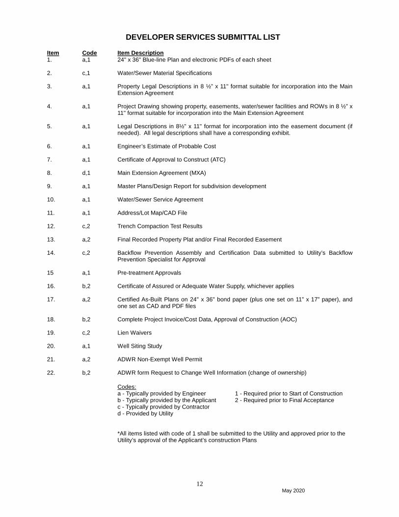
DEVELOPER SERVICES SUBMITTAL LIST Item 1. 2. 3. 4. 5. 6. 7. 8. 9. 10. 11. 12. 13. 14. 15 16. 17. 18. 19. 20. 21. 22.
Code a,1 c,1 a,1 a,1 a,1 a,1 a,1 d,1 a,1 a,1 a,1 c,2 a,2 c,2 a,1 b,2 a,2 b,2 c,2 a,1 a,2 b,2
Item Description 24" x 36" Blue-line Plan and electronic PDFs of each sheet Water/Sewer Material Specifications Property Legal Descriptions in 8 ½” x 11" format suitable for incorporation into the Main Extension Agreement Project Drawing showing property, easements, water/sewer facilities and ROWs in 8 ½” x 11" format suitable for incorporation into the Main Extension Agreement Legal Descriptions in 8½” x 11" format for incorporation into the easement document (if needed). All legal descriptions shall have a corresponding exhibit. Engineer’s Estimate of Probable Cost Certificate of Approval to Construct (ATC) Main Extension Agreement (MXA) Master Plans/Design Report for subdivision development Water/Sewer Service Agreement Address/Lot Map/CAD File Trench Compaction Test Results Final Recorded Property Plat and/or Final Recorded Easement Backflow Prevention Assembly and Certification Data submitted to Utility’s Backflow Prevention Specialist for Approval Pre-treatment Approvals Certificate of Assured or Adequate Water Supply, whichever applies Certified As-Built Plans on 24" x 36" bond paper (plus one set on 11” x 17” paper), and one set as CAD and PDF files Complete Project Invoice/Cost Data, Approval of Construction (AOC) Lien Waivers Well Siting Study ADWR Non-Exempt Well Permit ADWR form Request to Change Well Information (change of ownership) Codes: a - Typically provided by Engineer 1 - Required prior to Start of Construction b - Typically provided by the Applicant 2 - Required prior to Final Acceptance c - Typically provided by Contractor d - Provided by Utility *All items listed with code of 1 shall be submitted to the Utility and approved prior to the Utility’s approval of the Applicant’s construction Plans

May 2020
13
Items from Developer by 2nd plan review submittal:
1. Current ALTA survey of parcel with the future alignment of Easement mapped (if possible). 2. Current Title Report for Easement Property. 3. Boundary Closure Certification of Easement 4. Signed and Sealed by Engineer 8.5 x 11 Legal Description and Exhibit 5. Verify Public Access to the Easement, may have to submit Approved Site Plan, showing dedicated public
access 6. Whenever possible, Easements should be recorded on the Final Plat with EPCOR Dedication Language
provided in our Developer Guide. 7. GIS Data submittal for Legal Description Exhibit (Mapping see Requirements below). EPCOR requires
digital submission of easement data, including (a) PDF format for the instrument itself, and (b) the geometry of the easement in GIS (SHAPE or GDB) or CADD (.DWG or .DGN) format. Graphics relating to the easement shall ne on a separate layer so it can be isolated from adjacent graphics.
Note: All easements must be entered into simultaneously with the related MXA or the related MXA must be in effect and fully executed prior to delivery of the easement. Note: The easement grantor need not necessarily be the same party as the Applicant. The easement grantor needs to be the party that owns the affected real property. In any case, where the Applicant and the easement grantor are different, consult with EPCOR Real Property Manager (see contact list). GIS Requirements: The digital easement geometry should conform to the basic topology rules including:
Lines must not overlap Must not have gaps Must not intersect with existing parcels Cannot overlap self Must be closed polygon (in the case of polygons)
Digital submittals must follow an existing EPCOR spatial reference (coordinate system and horizontal datum): AZ – Phoenix metro and Tubac: NAD 1983, State Plane Arizona Central, Feet AZ – Mohave County: NAD 1983, State Plane Arizona West, Feet NM – Edgewood/Thunder Mountain: NAD 1983, State Plane New Mexico Central, Feet NM – Clovis: NAD 1983, State Plane New Mexico East, Feet
REQUIREMENTS FOR DEVELOPER-DESIGNED AND BUILT WATER/SEWER MAIN EXTENSIONS
1. Applicant shall prepare and submit Water or Sewer Plans in accordance with the requirements
outlined in Chapter Three. 2. Utility will be available to discuss plan development and design concepts. Applicant is encouraged
to contact Utility prior to plan development for special instructions that may apply to a particular expansion.
3. Easements, legal descriptions and exhibits are required for all Utility owned facilities that are not
within dedicated rights-of-way. Easements shall have a minimum width of 20 feet and shall be centered about the centerline of the Utility-owned facilities. Utility may require wider easements for larger diameter water or sewer mains or where deeper excavation is required or where soil conditions require wider trenching. For cases where Utility will have a waterline and sewerline within the same easement, the easement shall have a minimum width of 30 feet (with a minimum of 4 feet between edge of pipe and easement boundary). The easement legal descriptions and exhibits shall be submitted on 8½” X 11” sheets and signed and sealed by a Professional Civil Engineer or Land Surveyor registered in the State of Arizona. No other utilities are permitted within EPCOR’s easements except when crossing the easement in 90-degree angles.
4. Water and sewer mains must have a minimum distance of 12 feet from buildings or retaining walls, as measured from the edge of the building foundation or wall to the outside of the main. In rare cases where a water or sewer main must encroach within 12 feet from a building or retaining wall, additional protection is required. Additional protection may include the use of a sleeve for the

May 2020
14
main, or modifications to the footing of the structure, to prevent damage in the event of a main break.
5. For all main extensions, Applicant is responsible to install the main along the entire length of the
Applicant’s property line frontage of that property being developed. The property line frontage is defined as that portion of a parcel of property that abuts a street, easement, or public rights-of-way. If a parcel to be developed has more than one frontage, the main shall be extended along all frontages.
6. Prior to commencing construction, Applicant must supply Utility with an "Approval to Construct" as issued by the Maricopa County Environmental Services Department (for projects in Maricopa County), by the Santa Cruz County Department of Environmental Quality (for projects in Santa Cruz County), by the Arizona Department of Environmental Quality (for projects in Mohave County), or approved delegate. For projects that are exempt from the plan review requirements per A.A.C. R18-5-505.B.3, the Applicant shall submit to Utility a letter from the applicable regulator confirming the exemption. The ATC and exemption letter are also required by the Arizona Corporation Commission ("ACC") when filing main extension agreements with the ACC.
7. Applicant shall only install materials approved in writing by Utility. 8. Applicant shall construct all infrastructure in accordance with the Standards and Specifications of
the Arizona Department of Environmental Quality, the Maricopa Association of Governments (regardless of project location), and the Utility.
9. Utility will conduct periodic inspections of Applicant’s construction. Utility does not provide full time
on-site inspection. Responsibility for proper installation rests with Applicant. Such inspection as the Utility personnel may perform in no way relieves Applicant of its responsibility for construction and installation of the infrastructure.
10. Applicant shall not make any changes from approved plans and specifications without prior written
approval of Utility. Field Directives authorizing changes in the approved plans and specifications must be co-signed by Utility and Applicant’s engineer of record prior to construction.
11. Utility will give final acceptance upon completion of all construction, including final adjustments of
all valve boxes, manholes, meter boxes, etc. and submittal of any other required documentation.

May 2020
15
REQUIREMENTS FOR DEVELOPER-DESIGNED AND BUILT WATER/SEWER MAIN EXTENSIONS
(CONTINUED)
12. Unless indicated otherwise by the provisions of the applicable main extension agreement, the
date of final acceptance shall be the date of the Final Acceptance Letter from Utility to Applicant unless otherwise stated in that letter. Applicant shall be responsible for the repair of the facilities installed for one year from the date of final acceptance.
13. In order to establish actual cost of construction, Applicant shall provide copies of all invoices for
material and labor for that portion of the work conveyed to the Utility. The invoices must be provided in a binder, itemized, and include engineering, construction supervision, actual installation costs, and any other costs directly associated with the project.
14. Applicant shall provide unconditional lien releases from all contractors, subcontractors and
material suppliers for all water and sewer construction projects. 15. Applicant shall provide freshly sealed and certified "As-Built" plans of facilities installed. The “As-
Built” plans shall include the locations of all vertical and horizontal pipe bends, valves, manholes, sewer taps, etc., by station/offset and northing and easting on State plane coordinates. Applicant shall provide three sets of as-built drawings on full-size bond paper, one set on 11” x 17” paper, and one set on flash drive in CAD and PDF formats. The plans must be certified for correctness by a Professional Civil Engineer or Land Surveyor registered in the State of Arizona. Reference the “As-Built” section, Chapter Three - Construction Plan Requirements, for detailed “As-Built” plan requirements.
16. No refunds for "Advances in Aid of Construction" will be made prior to receipt of invoices, lien
waivers and approved "As-Built" plans.
Utility will not provide water service until after the items above are received and it provides the Final Acceptance Letter.

May 2020
16
CERTIFICATE OF ASSURED OR ADEQUATE WATER SUPPLY AND GRANDFATHERED RIGHTS
Prior to the approval of a plat and the issuance of a public report for a new development located within an Arizona Active Management Area (AMA) (the Utility’s Agua Fria, Anthem, Paradise Valley, Sun City, Sun City West and Tubac water districts), Arizona law requires that developments secure a 100-year Assured Water Supply. This can be done in one of two ways:
1) the Applicant secures a Certificate of Assured Water Supply (CAWS) for the proposed
development, or
2) The water provider that will serve the proposed development (in this case, the Utility) has a Designation of Assured Water Supply (DAWS).
Currently, Utility does not possess a DAWS and it is therefore the Applicant’s responsibility to secure a Certificate of Assured Water Supply for the proposed development. Accordingly, Utility requires that developers of subdivisions and commercial properties on lands having Irrigation Grandfathered Rights (groundwater pumping rights) file with the State to “extinguish” the rights and pledge the rights to the Applicant’s CAWS. This requirement is included in the main extension agreement.
For new developments located outside of an AMA (the Utility’s Mohave and Havasu water districts), Arizona law requires that the development apply for a 100-year Adequate Water Supply prior to the platting and the issuance of the public report. It is the Utility’s policy that all developments have sufficient supplies and obtain the 100-year Adequate Water Supply. If Irrigation Grandfathered Rights or Type I Non-Irrigation Grandfathered Rights are associated with the land to be developed, the Applicant shall, within 30 days of plat recordation or prior to execution of a Membership Agreement with the Central Arizona Groundwater Replenishment District, whichever occurs first, submit to the Director of the Arizona Department of Water Resources (ADWR), a notarized Statement of the Intent to Extinguish the Grandfathered Rights, including the Certificate of Grandfathered Right to be Extinguished. If the Grandfathered Right is a Type I right, proof of ownership of the land shall be submitted with the Statement of Intent. Any forms required to be submitted by ADWR shall also be included with the Statement of Intent. The Statement of the Intent to Extinguish the Grandfathered rights shall include the statement, “It is requested that the Director of the Department of Water Resources make the extinguishment credits available for use by pending CAWS application number [insert appropriate CAWS application number].” A statement pledging the credits to the appropriate application for a CAWS shall also be indicated as appropriate on the extinguishment forms submitted. A copy of the Statement of the Intent to Extinguish Grandfathered Rights with all enclosures and a copy of the ADWR extinguishment forms shall be mailed to: EPCOR Arizona Inc. Attn: Water Resources Manager 2355 West Pinnacle Peak Road, Suite 300 Phoenix, AZ 85027

May 2020
17
CHAPTER 2
ENGINEERING MASTER PLAN AND DESIGN CRITERIA

May 2020
18
MASTER PLANNING AND DISTRIBUTION MAIN REQUIREMENTS
Utility requires that distribution systems be designed in accordance with Utility’s design requirements, applicable state and county requirements, any authority having jurisdiction within Utility’s service area, commonly accepted engineering practices, and other applicable codes or recognized standards.
Distribution systems should be designed with sufficient “looping” and other redundancies as may be necessary to minimize outages to customers in the event of main breaks, routine maintenance, and repairs. Avoiding dead-end segments by providing looped distribution circuits also enhances potable water circulation and reduced age therefore minimizing the formation of disinfection byproducts. Distribution systems should be sized to accommodate sufficient fire flows as may be required. The design and sizing of the distribution systems should include a main break analysis to ensure the provision of adequate fire flows and service to our customers. As a condition of service, and in addition to the distribution system design standards, Utility requires that distribution systems include a secondary 8-inch diameter distribution main in addition to the normally required “backbone” or larger diameter distribution mains. This requirement is most easily achieved by increasing the size of portions of typically 6-inch diameter distribution piping to 8-inch diameter. The selected alignment of the secondary 8-inch distribution main would ideally traverse the center of the development or phase of development, originating and terminating at larger “backbone” mains. This requirement is not to be construed as a request for over-sizing, rather as a sound engineering design condition. In accordance with Arizona Corporation Commission rules and regulations, no waterlines less than 6 inches in diameter will be accepted.
Plan submittals will be reviewed for the inclusion and acceptability of the 8-inch secondary distribution main and its alignment. An approved water distribution analysis is required to accompany all waterline Construction Drawings. The analysis shall identify proper distribution system sizing based on the required flow parameters, as well as the criteria stated in this Developer & Engineering Guide.
Where a land developer has subdivided any piece of land for development by another party, Utility may require an individual water master plan in line with these guidance notes, unless the principal land developer’s approved master plan has adequately covered distribution of all individual parcels. All developers should coordinate with Utility’s Developer Services and Planning Division to identify whether or not additional master plans are required for their area of development.
Where land is intended to be developed in phases, details and timing of the phases of the development must be included in the master plan. The phasing information should include details and timing of any landscaped areas requiring irrigation from the potable water system (where the system tariff structure allows), especially where this will be effective prior to construction and/or sales of dwelling units.
Master plans will be reviewed by Utility’s Engineering to ensure new developments are coordinated and consistent with the long term master plans of the relevant service area. Applicants are required to submit two copies of the master plan and the appropriate electronic files of the hydraulic analysis. Initial master plan reviews may take up to 8 weeks for initial review depending on the complexity of the project. This does not include any time needed for revisions and subsequent reviews. Failure to provide two copies of the master plan as well as electronic files for the hydraulic model may result in a delay of Utility’s review that may then take more than 8 weeks.

May 2020
19
MASTER PLANNING AND DISTRIBUTION MAIN REQUIREMENTS
(CONTINUED) A hydraulic analysis using the current version of WaterCAD (or equivalent with prior approval of Utility), must be performed for the proposed water distribution system and submitted as part of the Master Plan. The Master Plan shall be prepared in accordance with Utility’s master plan outline. A color exhibit showing water line locations, sizes, parcel boundaries, junctions, contour elevations, pressure zone boundaries, etc. shall be submitted as part of the Master Plan. In addition to the hard copy documents required here, the submittal must also include a copy of the full hydraulic model and any tabular files used for the hydraulic analysis in electronic format on CD. The Master Plan shall be signed and sealed by a Registered Professional Civil Engineer in the State of Arizona and submitted to Utility for review and approval.
Any and all criteria not listed herein shall be in accordance with, but not limited to, the following governmental agency requirements and any such criteria presented in the Master Plan shall be referenced appropriately for Utility review: Environmental Protection Agency (EPA), Arizona Department of Environmental Quality, Arizona Department of Water Resources, Maricopa Association of Governments, Maricopa County Health Code Chapter V (if applicable to development), local jurisdictional Planning and Zoning Requirements, and appropriate municipality regulations, if development is in a municipality serviced by Utility. If a development is outside Maricopa County or outside Arizona, it must conform to regulations and requirements of state and local jurisdictions and governmental agencies. All developments shall be compliant with AWWA standards. Fire flow requirements shall be determined by the jurisdictional Fire Marshal and the requirements shall be stated in a letter from the Fire Marshal, which must be included as an appendix with the Master Plan.
The “Demands” table provided in the Design Criteria in this Chapter shows typical demand values used by Utility for internal planning purposes. It should be noted, however, that this table may not be applicable to certain developments. In all instances, engineers should coordinate with Utility’s Developer Services and Planning Division prior to development of master plans, to ensure appropriate demand projections are made.
,.

May 2020
20
WATER MASTER PLAN OUTLINE The following outline shall be used for the preparation of master plan reports: 1. Cover Sheet
a) Title (Development Name), Date, Revision Date(s) b) Applicant and Engineer’s contact information. c) Sealed by a Professional Engineer registered in the state of Arizona.
2. Table Of Contents a) Sealed by a Professional Engineer registered in the state of Arizona.
3. Executive Summary a) 1 or 2 pages with emphasis on proposed facilities to serve the development.
4. Introduction a) Plan Objective – state purpose of the report b) Site Location w/ vicinity map. c) Proposed Development
5. Design Criteria a) Demands, Pressures, Storage, Booster Pumps, Wells, Distribution System (pipe sizing)
i. Utility Developer Guide criteria ii. MAG, ADEQ, other governmental agency criteria as applicable iii. Generally accepted engineering standards (requires Utility approval)
6. Demands a) Single family, multi family, commercial, school, open space, parks, landscaping etc. b) Details of all zoning obtained within development, including any pending re-zoning applications. c) Quarterly projections of demands from beginning of construction (construction water) to buildout,
to include a breakdown of any phasing that may be involved with construction. This should include an exhibit to show locations, and a schedule showing the expected timing of demand growth for any phases as applicable. The intention would be to show how demand is projected to increase at all locations over time through buildout of the development.
d) Summary narrative of demands table. Discuss which demand scenario governs design (Peak Hour or Maximum Day plus Fire Flow)
e) Tabular calculations (spreadsheet) of all demands. 7. Existing Facilities/Conditions
a) Reference any previous master plans used and their dates as applicable. 8. Proposed Facilities
a) Required storage, proposed location, or expansion of existing if applicable. b) Required booster pump capacity. c) Required well capacity, number of wells if applicable. d) Distribution system piping, onsite as well as any offsite infrastructure needed. e) PRV’s if applicable. f) Phasing if applicable. Where facilities will be constructed in phases, the timing and responsible
party for each facility must be defined. If the timing of more than one development in adjacent areas allows, developers are encouraged to meet and plan with Utility to maximize the possibility and benefit of regionalization of facilities.
9. Water Model a) Describe model used. b) Assumptions
i. Pump curves obtained from Utility information/staff or otherwise accepted test ii. Criteria used in the model.
c) Results/Discussion – proposed facilities are adequate to serve development based on hydraulics

May 2020
21
10. Summary/Conclusions a) Discuss how the objective of report has been met, i.e. proposed facilities will serve the proposed
development in accordance with established criteria. b) List major facilities required and phasing as applicable.
11. Appendices a) Water Modeling Results Organized by:
i. Average Day ii. Maximum Day iii. Peak Hour iv. Maximum Day plus Fire Flow
b) The following information is to be included for the above scenarios: i. Junction/Node report showing node label, elevation, demand in gpm, hydraulic grade line in
feet, pressure in psi, and assigned pressure zone for that node (zone assignment to node shall be in accordance with the existing operation of the service area and in accordance with Utility naming conventions). Also, for phased developments, reports and exhibits should identify those nodes that are active and those that are inactive for various model runs.
ii. Pipe report showing pipe label, start/stop node, length, diameter, Hazen-Williams “C” value, flow, velocity, headloss, headloss gradient, and intended year of installation.
iii. Pump report showing pump label, elevation, discharge, discharge pump grade, and pump head. An attachment to the pump reports should also be included to show assumed pump patterns and efficiency curves for any pumps modeled in the hydraulic analysis.
iv. Valve report showing valve label, elevation, diameter, valve status, and from/to hydraulic grade line.
v. Tank report showing tank label, base elevation, maximum elevation, volume, hydraulic grade line, and flow.
vi. Reservoir report showing reservoir label, elevation, hydraulic grade line, and outflow. vii. A separate fire flow report for the maximum day plus fire flow scenario shall be submitted.
The fire flow report is to show the following information for all nodes: node label, satisfies fire flow constraint, needed fire flow, available fire flow, total flow available, residual pressure, minimum system pressure, and minimum system pressure node
viii. An extended period simulation (EPS) model showing storage tank levels varying with time may be required for complex system designs, to verify adequate fire flow storage and also to verify that wells have sufficient capacity for tank replenishment during maximum day demands. Where an EPS model is used, an explanation will be required for the basis of diurnal demand patterns, and the basis of demand allocation. A clear explanation will also be required for the naming convention used for the different model scenarios. Finally, detail will be required on how the source of water has been modeled. A summary of the techniques used to generate the hydraulic model and engineering analysis should clearly be described.
c) 11” X 17” (24” X 36” for large developments as applicable) and PDF color exhibit for peak hour. Average day and maximum day exhibits may be required. Exhibits to include: i. Pipes and nodes labeled. ii. Pressures at nodes. iii. Major roadways labeled. iv. Pipe size shown by color. v. Major contour lines shown. vi. Pressure zone boundaries.
d) Cost Estimate *Figures, exhibits, tables, spreadsheets, etc. to be placed in the body of the report where possible.

May 2020
22
DESIGN CRITERIA FOR WATER SYSTEMS 1. Demands1
Land Use
Unit Average Day Demand (gal/day/unit)
Max Day Peaking Factor
Peak Hour Peaking Factor
Active Adult Dwelling 304 1.8 3.0 Single Family Dwelling 360 1.8 3.0 Multi Family Dwelling 240 1.8 3.0 Commercial2 Acre 1,700 1.8 3.0
Warehouse/Big Box Retail 1000 sq. ft. 30 1.8 3.0
Developed Open Space, including Parks2, 3 Acre 1,800 n/a n/a
Schools2 Acre 1,700 n/a n/a Resort Room 446 1.8 3.0 Hotel (no restaurant) Room 140 1.8 3.0 Hotel (with restaurant) Room 200 1.8 3.0
1Please contact Utility’s Planning Division for Resource Data on other demand types. 2Acreage is based on gross number of acres. 3Developed Open Space includes general landscaped areas where irrigation will be required, such as road medians and areas to be maintained by HOAs. 2. Specific Modeling Requirements: Demands should be distributed among nodes to provide a
reasonable reflection of the expected system demand distribution. Where demands are grouped and represented by only a few nodes those demands should be allocated to the nodes with the highest elevation as well as the furthest point from the development’s point of supply.
3. Pressures Minimum Pressures: 55 psi static; 40 psi at peak hour; 20 psi at max day + fire flow Maximum Pressures: In accordance with the Uniform Plumbing Code, any structure
experiencing pressures greater than 80 psi shall have an individual pressure reducing valve on the customer side of the meter. Areas where many customers experience pressures higher than 80 psi may require a PRV station or modification to the distribution system, to be approved by Utility. Distribution systems shall not be designed to operate at pressures greater than 120 psi.
4. Velocity & Headloss 10 fps maximum velocity for pipes less than 16 inches in diameter 5 fps maximum velocity for pipes 16 inches in diameter or larger
2 fps minimum and 6 fps maximum velocity for well transmission lines 10 ft. headloss maximum per 1,000 linear feet of pipe for pipes less than 16 inches in diameter 8 ft. headloss maximum per 1,000 linear feet of pipe for pipes 16 inches in diameter or larger
5. Hazen-Williams Coefficient 130 (for new pipes)
Where development models include existing pipes, appropriate coefficients will need to be selected. Where an existing calibrated model exists, the coefficients in the existing model must be used. If there is no existing calibrated model, the developer’s engineer will need to consult with Utility’s planners to identify suitable coefficients.

May 2020
23
6. Fire Flows
Fire flows must be in accordance with jurisdictional Fire Marshal requirements. Provide a written statement from the jurisdictional Fire Marshal that states the minimum required flows and duration by class of customer. In the absence of a jurisdictional Fire Marshal, fire flow requirements must be in accordance with the latest version of the International Fire Code.
7. Storage Requirements
Equalization 30% of max day, plus Emergency reserve the greater of 10% of max day OR the storage volume required based on
the fire flow requirements stated above
8. Booster Pump Station
Firm Capacity Shall meet or exceed the greater of peak hour flow or max day + fire flow with the largest pump out of service for the pressure zone(s) that the booster station serves. Shared redundancy between pressure zones may be acceptable via a PRV (with the prior approval of Utility) provided adequate redundancy exists in the higher zone.
9. Water Valves
Number of Valves = number of radiating mains at intersection minus one; the unvalved branch is the line that supplies flow to the intersection.
Valve spacing shall be in accordance with ADEQ Bulletin #10 Valves in well transmission mains shall be kept to a minimum.
10. Wells
Where developments are supplied solely by groundwater wells, the following criteria must be met:
Firm Capacity: Any wellfield supplying a booster station must meet the maximum day demand for the entire station with the greatest producing well out of service. Single source wellfields are not allowed. Proposed wells supplying directly into the distribution system are discouraged and will be reviewed on a case-by-case basis. Permitted Capacity: The total permitted capacity of a wellfield shall be adequate to meet the anticipated total annual demand for the development.
Well transmission lines shall have an 8” minimum diameter. Where a transmission line will have multiple wells connected to it, the pipe shall be sized such that all wells connected to that line can run simultaneously at their full capacity while meeting the velocity and headloss constraints defined in this guide. If this cannot be achieved, contact Utility’s Developer Services Division for guidance.
11. Fire Hydrants
Fire hydrant spacing shall be in accordance with the requirements of the local jurisdictional agency. 12. Air/Vacuum Release Valves
Air vacuum release valves shall be located at all high points and at vertical realignments of the water line.
13. Pressure Reducing Valves
Pressure reducing valves shall be located on transmission/distribution mains to maintain design pressure ranges in accordance with approved water master plans. These locations must be coordinated with, and approved by, Utility. PRV sizing shall be based on anticipated minimum/maximum flow ranges.

May 2020
24
14. Wash Crossings All waterlines that cross washes or channels shall be MEGALUG restrained joint ductile iron pipe (Class 350). The depth requirement for placing waterlines under washes or channels shall be the deeper of the following two cases: a. Per the Arizona Department of Environmental Quality’s Engineering Bulletin No. 10, the minimum
cover over the pipe shall be greater than or equal to two (2) feet below the scour depth (based on Scour Analysis described below).
b. The minimum cover over the pipe may be based on the 100-year flow rate of the wash or channel
as shown in the table below. Note that the “additional depth” in the table refers to the depth of pipe that must be added to the normal cover requirements that are provided in Detail No. 350-1.
100-Year Flow Rate Additional Depth 1 to 49 cfs 1 foot 50 to 99 cfs 2 feet
100 to 499 cfs 3 feet Greater than 499 cfs Scour Depth (based on Scour
Analysis); minimum of 3 feet
Details on the determination of the 100-year flow rate shall be submitted to the Utility for review. The Scour Analysis shall be in accordance with the Arizona “State Standard for Watercourse System Sediment Balance” (SS5-96), Guideline 2, Level III, as published by the Arizona Department of Water Resources (http://www.azwater.gov/azdwr/SurfaceWater/FloodManagement/StateStandards.htm). The Scour Analysis shall be submitted to the Utility for review for all wash crossings. Note: If a sediment transport analysis has been performed by the Flood Control District of Maricopa County for the subject wash crossing, this can be submitted to Utility for review, and this may eliminate the need for additional analysis.
15. Minimum Residential Potable Water Meter Sizing
All residential meters shall be sized in compliance with the current Uniform Plumbing Code (UPC) and any applicable municipal or other governmental requirements. For residential meters 1-inch or larger, the municipality-approved architectural calculations shall be submitted to Utility to document the sizing of meters. For residences that include fire sprinklers or landscape irrigation, the meter size shall be the greater of the following:
a. meter size as determined by the current UPC, or b. from each fire sprinkler zone within the residence, the highest of these fire flows must be in
accordance with the table below (i.e., if the calculated fire sprinkler flow is 31 gpm, then a 1-inch meter will be required), or
c. the landscape irrigation flow must be in accordance with the table below:
Minimum Required Meter Size (inches)
Maximum Allowed Fire Flow or Irrigation Flow (gal/min)
5/8 20 3/4 30 1 50
1 ½ 100 2 160
3 and larger Determined on a case-by-case basis The maximum flows provided in the table above should only be imposed on the meter for short, intermittent periods. Meters should not be operated on a continuous 24-hour service at flows greater than one-half of the maximum flows provided in the table above.
16. Service Line Size
The minimum service line size is 1-inch, installed in accordance with Utility’s STD. DET. 342-2. The appropriate adapter shall be installed with the meter box as shown on STD. DET. 342-2. Where the water meter size is greater than 1-inch, the service line must be the same size as the meter. The

May 2020
25
diameter of new service lines cannot exceed 50% of the service main diameter. A new water main extension may be required where Utility determines that existing main capacity has been exceeded.
17. Meter Location
a. Install meters side-by-side, straddling the lines where possible, not at road intersection corners, and l not adjacent to fire hydrants.
b. Each service line requires a separate tap to the main. c. Residential fire sprinkler and irrigation water service is permitted through the domestic service line
and meter. Commercial developments require separate water meters for building and landscape. d. Each parcel of land must have its own separate service line and meter. A single service line and a
master meter can be used for two or more buildings located on the same lot such as an apartment complex, trailer courts or similar projects covering one lot. In high density applications where an assured continuous water supply must be maintained, the development must have two master meters, each with its own service connection to Utility’s main to create a secondary looped connection to the development.
e. No service connections or fire protection systems will be made to water lines greater than 12 inches in diameter.
f. Existing service lines that will not be used by a development shall be abandoned and plugged at the main.
18. Water System Layout a. To provide appropriate (i) water pressure, (ii) water circulation, (iii) redundancy, and (iv) minimize
taste and odor issues, all water mains must be designed with a minimum of two sources (looped configuration) – see “Dead-End Lines” below for exceptions.
b. Water and sewer mains must have a minimum distance of 12 feet from buildings or retaining walls, as measured from the edge of the building foundation or wall to the outside of the main. In rare cases where a water or sewer main must encroach within 12 feet from a building or retaining wall, additional protection is required. Additional protection may include the use of a sleeve for the main, or modifications to the footing of the structure, to prevent damage in the event of a main break.
c. Ninety-degree (90-degree) fittings are not allowed in rights-of-way. 19. Dead-End Lines
Dead-end lines with no service connections are not allowed. Where dead-end lines with service connections do occur, cap dead-end lines with a curb stop (blow off) with flushing pipe per EPCOR Detail 390-1. All dead-end lines will be approved on a case by case basis.
20. Thrust Blocks Thrust blocks are not allowed in rights-of-way. Use restrained joints per MAG Standard Detail 303-1 and 303-2 in rights-of-way in place of concrete thrust blocks.
(Continued)

May 2020
26
21. Curvilinear Alignments Design constraints are provided below:
C900, DR14, PVC Pipe Pipe Diameter Laying Length Max Deflection Angle Offset per Min. Curve joint of pipe 6”-12” 20’ 2.0o 8.4” 573’ C905, DR14, PVC Pipe In accordance with AWWA C605-94, section 5.6, the bending of the PVC Pipe barrels larger than 12-inch (300-mm) nominal diameter is not allowed due to the forces required. The curved alignment of PVC pipelines larger than 12-inch (300-mm) in diameter shall be determined by one-half the pipe manufacturers published axial-joint-deflection limits. Manufacturer’s technical data sheets shall be submitted to Utility for review and approval. Ductile Iron Pipe, AWWA C150/151/153 Pipe Diameter Laying Length Max Deflection Angle Offset per Min. Curve joint of pipe 8”-12” 18’ 2.5 o 9.4” 413’ 14”-16” 18’ 2.0 o 7.5” 516’ 18”-20” 18’ 1.5 o 5.7” 688’ 24” 18’ 1.0 o 3.8” 1032’ 8”-12” 20’ 2.5 o 10.4” 459’ 14”-16” 20’ 2.0 o 8.4” 573’ 18”-20” 20’ 1.5 o 6.2” 764’ 24” 20’ 1.0 o 4.1” 1146’
L = laying length θ = deflection angle S = offset per joint of pipe R = radius of curve R = (L) / {2 x tan (θ / 2)}
θ

May 2020
27
DESIGN REQUIREMENTS FOR FIRE LINES
1. Fire line connections to Utility’s mains shall be used for fire protection systems only. Metered services cannot be connected to fire lines.
2. The minimum size fire line connection shall be 4 inches.
3. For fire lines, backflow prevention devices are required within 75 feet of the main. If the building riser
is within 75 feet from the main, then a vertically mounted backflow prevention device may be located on the building riser. If the building riser is further than 75 feet from the main, then a backflow prevention device shall be installed as close as practicable to the service connection (property line).
4. Backflow prevention devices are not required for private hydrant connections that are not looped and
that do not have fire sprinkler connections. 5. Backflow prevention devices shall have been issued a certificate of approval by the University of
Southern California Foundation for Cross-Connection Control and Hydraulic Research. The certificate of approval shall be forwarded to Utility’s Backflow Prevention Specialist prior to Utility’s Final Acceptance of the fire lines.
6. Backflow prevention devices shall not be located in rights-of-way, sidewalks, driveways, visibility
triangles, or other locations where accidental damage or visibility obstruction would likely occur. 7. Backflow prevention devices shall be fully accessible for testing, repairs, and replacement. There
shall be an unobstructed radius of not less than four - feet from the outer perimeter of each backflow prevention device.
8. Per the Uniform Plumbing Code (610.2), in the absence of specific pressure drop information, the
diameter of the inlet or outlet of any backflow prevention device or its connecting piping shall not be less than the diameter of such water distribution piping to the fixtures served by the device. If available, pressure drop information shall be provided with the submitted plans.
9. Per the Uniform Plumbing Code (603.3.11), looped on-site fire line systems shall have backflow
preventers at each point of connection to the public water system. 10. A control valve is required at ALL fire line connections to public water mains. The control valve shall
not be located in sidewalks, driveways, curbs or gutters.
11. Thrust blocks are not allowed in rights-of-way.

May 2020
28
DESIGN CRITERIA FOR WASTEWATER SYSTEMS
A hydraulic analysis must be performed for the proposed wastewater collection system and submitted as part of the Master Plan. The design methodology shall be presented and appropriately referenced. The results of this analysis shall be presented in tabular form with at least the following information presented:
• pipe number • to/from manhole number • pipe size • pipe slope (slopes that are less than minimum design shall be noted) • average daily flow • peak hour flow • d/D ratio at peak hour • velocity at peak hour
An analysis of sewer force mains must be performed, including impacts due to pump surge, and submitted as part of the master plan. Force main hydraulic losses shall be performed using the Darcy-Wiesbach equation. A 24” X 36” color exhibit, as well as PDF, showing flow contributing area, sewer line number and manhole number locations, flow direction, property boundaries, contour elevations, etc. shall be submitted as part of the Master Plan. The Master Plan shall be signed and sealed by a Registered Professional Engineer and submitted to Utility for review and approval. 1. Average Daily Wastewater Design Flows
Land Use Unit Average Daily Flow (gal/day/unit)
Peak Hour Peaking Factor
Active Adult Dwelling 190 3.0 Single Family Dwelling 240 3.0 Multi Family Dwelling 180 3.0 Commercial1 Acre 1,500 3.0
Warehouse/Big Box Retail 1000 sq. ft. 25 3.0 Schools1 Acre 1,500 3.0 Resort Room 380 3.0
Hotel (no restaurant) Room 100 3.0 Hotel (with restaurant) Room 150 3.0
1Acreage is based on gross number of acres. 2. Minimum / Maximum Slopes (Manning’s Roughness Coefficient of 0.013)
Pipe Diameter (inches)
Minimum Slope (%)
Minimum Velocity (ft./sec)
Maximum Slope (%)
Maximum Velocity (ft./sec)
8 0.368 2.1 6.760 9
10 0.300 2.2 5.020 9
12 0.257 2.3 3.937 9
15 0.208 2.4 2.924 9
18 0.163 2.4 2.293 9
21 0.144 2.5 1.867 9
24 0.130 2.6 1.562 9
27 0.111 2.6 1.335 9
30 0.104 2.7 1.160 9

May 2020
29
3. Sewer Capacity Ratio
The ratio of flow depth in the pipe to the diameter of the pipe shall not exceed 0.75 in peak hour flow conditions.
4. Minimum Pipe Diameter The minimum sewer main diameter is 8 inches.
5. Depth of Cover a. Sewer mains greater than 12 inches in diameter shall have a minimum of 7 feet 6 inches of cover. b. Sewer mains 12 inches in diameter or less shall have a minimum of 6 feet of cover. c. Sewer service lines shall have a minimum of 5 feet of cover at the property line.
6. Wash Crossings
All sewer lines that cross washes or channels shall be concrete-encased PVC. The depth requirement for placing sewer lines under washes or channels shall be based on the 100-year flow rate of the wash or channel as shown in the table below.
100-Year Flow Rate Minimum Depth from Bottom
of Wash to Top of Pipe 1 to 49 cfs 5 feet 50 to 99 cfs 6 feet
100 to 499 cfs 7 feet Greater than 499 cfs Scour Depth (based on Scour
Analysis) plus 3 feet; minimum of 7 feet
Details on the determination of the 100-year flow rate shall be submitted to EPCOR for review. The Scour Analysis shall be in accordance with the Arizona “State Standard for Watercourse System Sediment Balance” (SS5-96), Guideline 2, Level III, as published by the Arizona Department of Water Resources (http://www.azwater.gov/azdwr/SurfaceWater/FloodManagement/StateStandards.htm). The Scour Analysis shall be submitted to Utility for review for all wash crossings. The sewer lines must be designed and constructed with an extension of at least 10 feet beyond the boundary of the 100-year storm scouring.
7. Manhole Rim Elevations All manhole rim elevations must be above the 100-year floodplain elevation. Concealed pick-hole manhole covers are required where covers are located within 3 feet of the edge of a gutter, in areas that are unpaved, in areas that are prone to flooding, and in all areas within Mohave County. Rim elevations should be set 0.2 feet above finish grade in all unpaved areas. Manholes are not permitted in washes without prior approval from Utility.
8. Minimum Manhole Diameter a. The minimum manhole diameter for sewer lines that are 15 inches in diameter or greater is 5 feet. b. The minimum manhole diameter for any sewer line that is 10 feet or deeper below finished ground
surface (to bottom of pipe) is 5 feet. c. The minimum manhole diameter for all other conditions not met above is 4 feet. Note: All sewer manholes shall have a 30-inch frame and cover.

May 2020
30
9. Manhole Spacing
Manholes shall be installed at all grade changes, size changes, alignment changes, sewer intersections, and to comply with the following spacing requirements:
Sewer Pipe Diameter (inches)
Maximum Manhole Spacing (feet)
8 to less than 18 500 18 to less than 36 600 36 to less than 60 800
10. Manhole Stub Outs and Knock Outs Stubs from manholes are not allowed. Knock outs may be provided in manholes for future main extensions when required by EPCOR.
11. Manhole Linings All manholes shall be lined in accordance with EPCOR Detail No. 100-4.
12. Manhole Invert Drops a. If a manhole has a sewer direction change that is less than 45 degrees, then the manhole should
be designed for a 0.1-foot drop across the manhole. b. If a manhole has a sewer direction change that is greater than or equal to 45 degrees, then the
manhole should be designed for a 0.2-foot drop across the manhole. c. Drop manholes should be per MAG Standard Detail No. 426
13. Cleanouts Cleanouts, instead of manholes, may be installed at the end of sewer lines that are less than 200 feet in length. Service connections are not allowed at the ends of cleanouts or within 4 feet of a cleanout.
14. Force Mains a. Force mains shall be designed to maintain a minimum flow velocity of 3 feet per second and a
maximum flow velocity of 7 feet per second. b. Appropriate valves and controls are required to prevent draining back to the lift station. c. Air release valves shall be installed at all high points along the force main to eliminate air
accumulation.
15. Curvilinear Alignments
SDR 35 PVC Sewer Pipe Pipe Diameter Laying Length Max Deflection Offset per Min.Curve Angle joint of pipe 8”-15” 12.5’ * 2.5 6.5” 287’ 8”-15” 20’ 2.5 10.5” 458’
The use of reduced pipe lengths must be clearly noted on the construction plans for Contractor’s attention.
16. Service Lines
No bends in sanitary sewer service lines are allowed except for services that are 12 feet deep or deeper, which may use vertical bends. For services that are 12 feet deep or deeper, 45-degree bends (or smaller bends) may be used as illustrated below.

May 2020
31
Sewer Main
45-degree Bends (or smaller)
At least 12 Feet Deep
Existing sewer service lines that have been stubbed out to a property shall be used; however, where the use of stubbed out lines are not feasible, the existing lines shall be abandoned and capped at the sanitary sewer main.

May 2020
32
CHAPTER 3
CONSTRUCTION DRAWINGS
May 2020
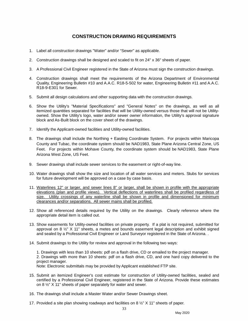
33
CONSTRUCTION DRAWING REQUIREMENTS 1. Label all construction drawings "Water” and/or “Sewer" as applicable. 2. Construction drawings shall be designed and scaled to fit on 24" x 36" sheets of paper. 3. A Professional Civil Engineer registered in the State of Arizona must sign the construction drawings. 4. Construction drawings shall meet the requirements of the Arizona Department of Environmental
Quality, Engineering Bulletin #10 and A.A.C. R18-5-502 for water, Engineering Bulletin #11 and A.A.C. R18-9-E301 for Sewer.
5. Submit all design calculations and other supporting data with the construction drawings. 6. Show the Utility’s "Material Specifications" and "General Notes" on the drawings, as well as all
itemized quantities separated for facilities that will be Utility-owned versus those that will not be Utility-owned. Show the Utility’s logo, water and/or sewer owner information, the Utility’s approval signature block and As-Built block on the cover sheet of the drawings.
7. Identify the Applicant-owned facilities and Utility-owned facilities. 8. The drawings shall include the Northing + Easting Coordinate System. For projects within Maricopa
County and Tubac, the coordinate system should be NAD1983, State Plane Arizona Central Zone, US Feet. For projects within Mohave County, the coordinate system should be NAD1983, State Plane Arizona West Zone, US Feet.
9. Sewer drawings shall include sewer services to the easement or right-of-way line. 10. Water drawings shall show the size and location of all water services and meters. Stubs for services
for future development will be approved on a case by case basis. 11. Waterlines 12” or larger, and sewer lines 8” or larger, shall be shown in profile with the appropriate
elevations (plan and profile views). Vertical deflections of waterlines shall be profiled regardless of size. Utility crossings of any waterline shall be shown in profile and dimensioned for minimum clearances and/or separations. All sewer mains shall be profiled.
12. Show all referenced details required by the Utility on the drawings. Clearly reference where the
appropriate detail item is called out. 13. Show easements for Utility-owned facilities on private property. If a plat is not required, submitted for
approval on 8 ½” X 11” sheets, a metes and bounds easement legal description and exhibit signed and sealed by a Professional Civil Engineer or Land Surveyor registered in the State of Arizona. .
14. Submit drawings to the Utility for review and approval in the following two ways:
1. Drawings with less than 10 sheets: pdf on a flash drive, CD or emailed to the project manager. 2. Drawings with more than 10 sheets: pdf on a flash drive, CD, and one hard copy delivered to the project manager. Note: Electronic submittals may be provided by Applicant established FTP site.
15. Submit an itemized Engineer's cost estimate for construction of Utility-owned facilities, sealed and
certified by a Professional Civil Engineer, registered in the State of Arizona. Provide these estimates on 8 ½” X 11" sheets of paper separately for water and sewer.
16. The drawings shall include a Master Water and/or Sewer Drawings sheet. 17. Provided a site plan showing roadways and facilities on 8 ½” X 11" sheets of paper.

May 2020
34
18. The drawings shall include a summary table showing quantities for all sewer and water constructed
items. Include sizes and materials. 19. Show stationing and roadway centerline offset of the water and sewer mains and related
appurtenances. 20. The cover sheet of the drawings shall contain an index map showing water and/or sewer facilities as
well as the corresponding sheet number. Include a key map on each subsequent plan view sheet. 21. Show station and offset, along with northing and easting coordinates for waterlines, all valves, fittings,
vertical and horizontal offsets, hydrants, meters and services. 22. Show station and offset, along with northing and easting coordinates for sewer lines, manholes,
cleanouts and services. 23. Include the following information on the cover sheet of the drawings:
UTILITY OWNER INFORMATION
WATER AND/OR SEWER OWNER/OPERATOR
2355 West Pinnacle Peak Road, Suite 300 Phoenix, Arizona 85027 (623) 445-2400
24. The Utility owner information with logo, and the Utility’s General Notes, Material Specifications and Standard Details are available in digital format. Digital files are located on EPCOR’s website. For assistance, please contact the Developer Services Department as listed in the Contact List section in this guide.

May 2020
35
PLAT DEDICATION VERBIAGE
The following plat dedication verbiage shall be on the final recorded plat if any of the facilities to be owned by the Utility will be outside of dedicated rights-of-way and separate easements are not provided: PERPETUAL WATER AND SEWER EASEMENT (‘EASEMENTS”) AS DESCRIBED IN THE PLAT ARE GRANTED TO EPCOR WATER ARIZONA INC, AND ITS SUCCESSORS AND ASSIGNS (COLLECTIVELY, “GRANTEE”), TO CONSTRUCT, OPERATE, AND MAINTAIN WATER AND SEWER LINES AND APPURTENANT FACILITIES (COLLECTIVELY, “FACILITIES”) UPON, ACROSS, OVER AND UNDER THE SURFACE OF THE EASEMENTS, TOGETHER WITH THE RIGHT TO OPERATE, REPAIR, REPLACE, MAINTAIN, AND REMOVE THE FACILITIES FROM THE PREMISES; TO ADD OR TO ALTER THE FACILITIES, AND TO PROVIDE GRANTEE WITH REASONABLE INGRESS AND EGRESS TO THE FACILITIES. GRANTEE WILL HAVE UNRESTRICTED ACCESS TO THE EASEMENT FOR THE ACTIVITIES DESCRIBED ABOVE AND FORMAL NOTIFICATION OR APPROVAL BY ANY ASSOCIATION PRIOR TO ACCESSING THE EASEMENT WILL NOT BE REQUIRED. GRANTOR SHALL NOT ERECT OR CONSTRUCT OR PERMIT TO BE ERECTED OR CONSTRUCTED ANY BUILDING, STRUCTURE OR SIMILAR IMPROVEMENT WITHIN THE LIMITS OF THE EASEMENT GRANTED HEREIN, GRANTOR SHALL NOT, NOR PERMIT, THE GRADE OVER GRANTEE’S FACILITIES TO BE SUBSTANTIALLY ALTERED WITHOUT, IN EACH INSTANCE, THE PRIOR WRITTEN CONSENT OF GRANTEE, AND GRANTOR AGREES THAT NO OTHER PIPES OR CONDUITS SHALL BE PLACED WITHIN THE PREMISES SUBJECT TO THE EASEMENT GRANTED HEREIN, EXCEPT PIPES CROSSING GRANTEE’S FACILITIES AT RIGHT ANGLES, IN WHICH CASE, A MINIMUM VERTICAL DISTANCE OF TWO (2) FEET (AS MEASURED FROM THE CLOSEST POINTS ON THE OUTSIDE EDGES) SHALL BE MAINTAINED BETWEEN GRANTEE’S FACILITIES AND SUCH OTHER PIPES OR CONDUITS. UNLESS GRANTEE EXPRESSLY CONSENTS IN WRITING OTHERWISE, ANY AND ALL SEWER PIPES CROSSING THE EASEMENT GRANTED HEREIN SHALL BE LAID BELOW GRANTEE’S FACILITIES. HOWEVER, GRANTOR SHALL HAVE THE RIGHT TO CONSTRUCT AND ERECT FENCES, TO INSTALL LANDSCAPING, PARKING FACILITIES AND DRIVEWAYS, AND TO ESTABLISH OTHER USES THAT ARE NOT INCONSISTENT WITH USES WITHIN THE LIMITS OF SAID EASEMENT IN A MANNER THAT WILL NOT UNREASONABLY INTERFERE WITH GRANTEE’S ACCESS TO THE FACILITIES.

May 2020
36
“AS-BUILT” PLAN REVIEW REQUIREMENTS
1. Plans shall be 24” x 36” (two blue line copies), each submittal until approved. 2. Plans must be fully approved and signed by all required agencies. 3. Sealed and Certified by a Professional Civil Engineer or Land Surveyor registered in the State of
Arizona. 4. Station/offset and state plane northing/easting coordinates on all water fittings, including valves,
tees, bends, all vertical and horizontal changes, etc. 5. Station/offset and state plane northing/easting coordinates on all sewer manholes, clean-outs and
other facilities. 6. Swing ties to fixed points may be required for commercial projects that do not have a roadway
centerline for stationing within a reasonable distance from the project. 7. Distances from lot lines to sewer taps. 8. Call out all water and sewer pipe lengths between fittings and branches. 9. Elevations for all DIP sections regardless of the pipe diameter. 10. As-Built profiles for all sewer lines 8” and larger including manhole rim and invert elevations. 11. As-Built profiles for all water lines 12” and larger. 12. As-Built all changes in pipe materials and sizes. 13. Correct street names, addresses and lot numbers. 14. Written approval by the Utility is required prior to submitting three sets of as-built drawings on full-
size bond paper, one set on 11” x 17” paper, and one set on flash drive in both CAD and PDF formats.
15. The Utility’s receipt and approval of as-builts is a condition to the Utility’s final approval of water
and sewer facilities. In addition, no refunds will be issued on facilities until as-builts have been received and approved by the Utility and the Utility’s final acceptance has been granted.

May 2020
37
WATER/SEWER “AS-BUILT” CERTIFICATION
The following “As-Built” certification shall be on the cover sheet of the plans:
WATER/SEWER “AS-BUILT” CERTIFICATION
I hereby certify that the “as-built” measurements as shown herein were
made under my supervision or as noted, and are correct to the best of my
knowledge after due review. Additionally, I hereby certify that all mains
and services have been installed within the limits of easements dedicated
to EPCOR Water Arizona Inc., or inside dedicated street rights-of-way or
public utility easements.
Seal

May 2020
38
CHAPTER 4
CONSTRUCTION INSPECTION
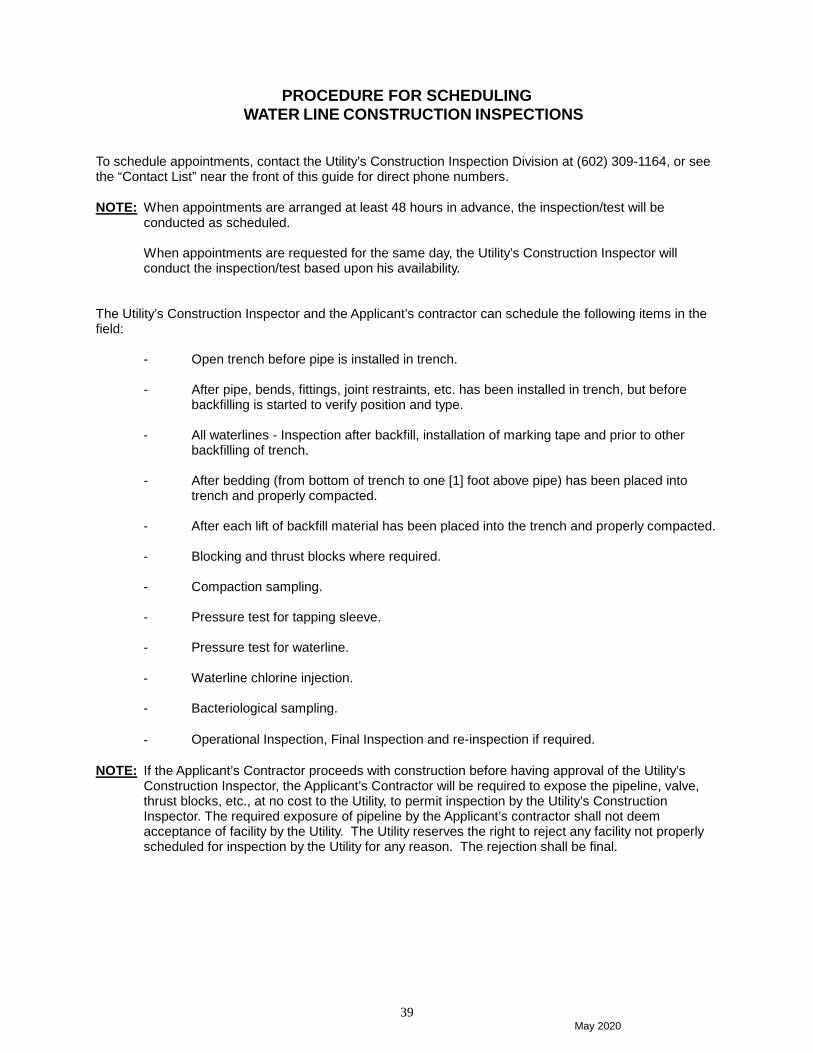
May 2020
39
PROCEDURE FOR SCHEDULING WATER LINE CONSTRUCTION INSPECTIONS
To schedule appointments, contact the Utility’s Construction Inspection Division at (602) 309-1164, or see the “Contact List” near the front of this guide for direct phone numbers. NOTE: When appointments are arranged at least 48 hours in advance, the inspection/test will be
conducted as scheduled.
When appointments are requested for the same day, the Utility’s Construction Inspector will conduct the inspection/test based upon his availability.
The Utility’s Construction Inspector and the Applicant’s contractor can schedule the following items in the field: - Open trench before pipe is installed in trench.
- After pipe, bends, fittings, joint restraints, etc. has been installed in trench, but before backfilling is started to verify position and type.
- All waterlines - Inspection after backfill, installation of marking tape and prior to other
backfilling of trench.
- After bedding (from bottom of trench to one [1] foot above pipe) has been placed into trench and properly compacted.
- After each lift of backfill material has been placed into the trench and properly compacted.
- Blocking and thrust blocks where required.
- Compaction sampling.
- Pressure test for tapping sleeve.
- Pressure test for waterline.
- Waterline chlorine injection. - Bacteriological sampling.
- Operational Inspection, Final Inspection and re-inspection if required. NOTE: If the Applicant’s Contractor proceeds with construction before having approval of the Utility’s
Construction Inspector, the Applicant’s Contractor will be required to expose the pipeline, valve, thrust blocks, etc., at no cost to the Utility, to permit inspection by the Utility’s Construction Inspector. The required exposure of pipeline by the Applicant’s contractor shall not deem acceptance of facility by the Utility. The Utility reserves the right to reject any facility not properly scheduled for inspection by the Utility for any reason. The rejection shall be final.
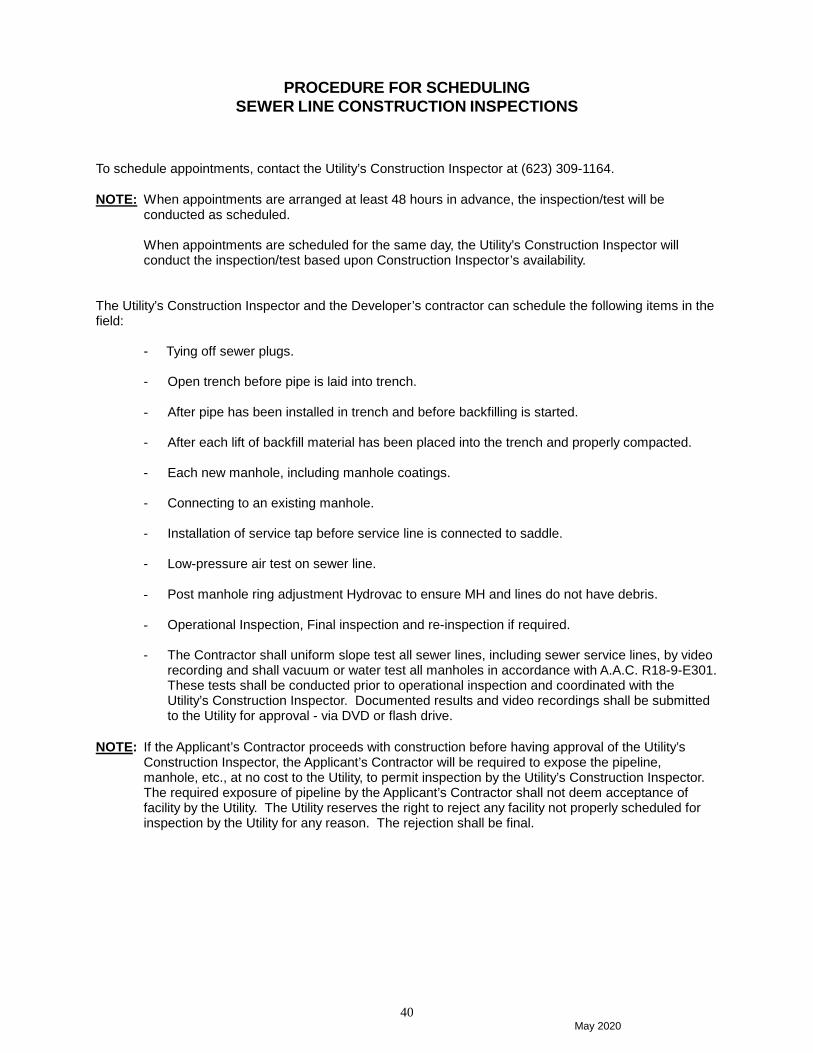
May 2020
40
PROCEDURE FOR SCHEDULING SEWER LINE CONSTRUCTION INSPECTIONS
To schedule appointments, contact the Utility’s Construction Inspector at (623) 309-1164. NOTE: When appointments are arranged at least 48 hours in advance, the inspection/test will be
conducted as scheduled.
When appointments are scheduled for the same day, the Utility’s Construction Inspector will conduct the inspection/test based upon Construction Inspector’s availability.
The Utility’s Construction Inspector and the Developer’s contractor can schedule the following items in the field: - Tying off sewer plugs. - Open trench before pipe is laid into trench.
- After pipe has been installed in trench and before backfilling is started. - After each lift of backfill material has been placed into the trench and properly compacted.
- Each new manhole, including manhole coatings.
- Connecting to an existing manhole.
- Installation of service tap before service line is connected to saddle.
- Low-pressure air test on sewer line. - Post manhole ring adjustment Hydrovac to ensure MH and lines do not have debris.
- Operational Inspection, Final inspection and re-inspection if required.
- The Contractor shall uniform slope test all sewer lines, including sewer service lines, by video
recording and shall vacuum or water test all manholes in accordance with A.A.C. R18-9-E301. These tests shall be conducted prior to operational inspection and coordinated with the Utility’s Construction Inspector. Documented results and video recordings shall be submitted to the Utility for approval - via DVD or flash drive.
NOTE: If the Applicant’s Contractor proceeds with construction before having approval of the Utility’s
Construction Inspector, the Applicant’s Contractor will be required to expose the pipeline, manhole, etc., at no cost to the Utility, to permit inspection by the Utility’s Construction Inspector. The required exposure of pipeline by the Applicant’s Contractor shall not deem acceptance of facility by the Utility. The Utility reserves the right to reject any facility not properly scheduled for inspection by the Utility for any reason. The rejection shall be final.
May 2020
41
CHAPTER 5
BACKFLOW PREVENTION

May 2020
42
BACKFLOW PREVENTION APPROVAL PROCESS
Approval Process (see flowchart) 1. The Applicant will submit Backflow Prevention Assembly (BPA) specifications with the Design
Plans during the Application Process. Specifications shall include location of the proposed BPA, the manufacturer, model, and size of BPA, and the purpose of the waterline on which the BPA will be installed (fire line, irrigation, domestic/multipurpose). The Applicant will include the class of fire line. All BPA’s must be lead free in accordance with the definition of lead free in section 1417 of the Safe Drinking Water Act.
2. After approval of the BPA specifications by the Utility’s Project Manager, the Applicant will install and test the BPA in accordance with A.A.C. R-18-4-215F, EPCOR standards, and approved Design Plans. The Applicant will submit the post installation test report to the Project Manager.
3. The Applicant/Contractor will schedule the operational inspection of the BPA with the Utility’s
Construction Inspector. 4. The Construction Inspector will confirm the correct installation of the BPA.
5. Once the Construction Inspector confirms correct installation of BPA the new water service passes
Utility Final Inspection (provided that all other Operational Inspection items have no deficiencies).
PREMISES REQUIRING BACKFLOW PREVENTION All water lines which do not serve a single family residence require a backflow prevention assembly (BPA). BPA’s must be approved by University of Southern California Foundation for Cross-Connection Control and Hydraulic Research (USC-FCCCHR). The approval list may be found on the USC-FCCCHR website. BPA’s increase in degree of protection from DCDA’s to RP’s. The highest degree of protection for a cross-connection is an Air Gap. IRRIGATION - A Reduced Pressure Principle Assembly (RP) is the only BPA that can be used for irrigation. FIRE LINES – A Double Check Detector Assembly (DCDA) is the minimum protection BPA that can be used for class 1 & 2 fire protection lines. DOMESTIC / MULTIPURPOSE SERVICE – An RP is the only BPA allowed for a service line that is not a class I or II FIRE LINE. HIGH HAZARD APPLICATIONS – Air Gaps will be required for water lines servicing areas with high hazard of contamination. High hazard applications will be determined on a case by case basis.

May 2020
43
BACKFLOW PREVENTION OPERATIONAL APPROVAL FLOWCHART
Test report with premise identification forwarded to Environmental Compliance Program Coordinator.
Developer Services Construction Inspector confirms presence of BPA: YES NO
The Applicant submits BPA specifications with the Design Plans during the application process,
Project Manager reviews the Design Plans for completeness and approves the plans when all requirements are met.
Project Manager notified of questionable installation; the Applicant advised of necessary corrections.
New water service passes Utility final inspection, provided that all other Operational Inspection items have no deficiencies.
Installation corrections completed.
The Applicant installs and tests the BPA in accordance with A.A.C. R-18-4-215F, EPCOR standards, and approved design plans. The test report shall be submitted to the Project Manager.

May 2020
44
CHAPTER 6
PRETREATMENT REQUIREMENTS

May 2020
45
PRETREATMENT APPROVAL PROCESS
Approval Process 1. Applicant shall prepare and submit Sewer Plans in accordance with the requirements outlined in
Chapter Three.
2. The Utility’s Pretreatment Program Coordinator (PPC) will be available to discuss pretreatment requirements. The Applicant is encouraged to contact the Utility’s Pretreatment Coordinator for special instructions that may apply to developments which will have an industrial or commercial discharge to the sewer.
3. If the business occupying the building is expected to generate an industrial or commercial (such as car wash or food service) wastewater discharge, then the Applicant or business owner must fill out an Industrial Discharge Sewer Agreement (IDSA) application and submit the application, with plans, to the PPC.
Pan Review The plan review shall confirm the need, size, location, and other requirements of the pretreatment necessary to control discharges. Written approval from the Utility must be obtained prior to installation of the pretreatment equipment. The review of such plans and operating procedures shall in no way relieve the user from the responsibility of modifying such facilities as necessary to produce discharge acceptable to the Utility in accordance with the Tariffs approved by the Arizona Corporation Commission (ACC). Industrial Discharge Criteria If the discharges expected from this facility are subject to the requirements of 40 CFR 405 – 471 the Applicant must contact the Pretreatment Coordinator to obtain an IDSA application and a Baseline Monitoring Report as required by 40 CFR 403.12. Dental Facilities Dental Facilities are required to fill out a One-time Dental Compliance Report as required in 40 CFR 441.10. Contact the Utility’s PPC for the Compliance Report. Food Services Facilities Criteria Any drains that are used to convey wastewater that has the potential to contain grease from food preparation and cleaning operations must discharge to a properly sized Gravity Grease Interceptor (GGI), Hydro-mechanical Grease Interceptor (HGI) when appropriate, or an alternative grease intercepting device (note, the use or placement of industrial food grinders and/or garbage disposals in food establishments will not be allowed). This includes, but is not limited to: drains from pre-rinse and or pre-wash sinks; one, two, three or four compartment sinks; meat prep sinks; wok stoves; kitchen floor drains; floor sinks; soup kettles; rotisseries with drains; steam ovens with drains; food prep sinks; hand wash sinks; dishwashers; self-cleaning ventilation/exhaust hood; food waste disposal units and mop sinks. No waste from water closets, urinals, and other fixtures conveying human waste shall drain into or through the GGI. Any business requiring a GGI shall have that GGI serving that business only. Shared GGIs are only allowed under limited circumstance and must be approved by the Utility. Any approval for a shared GGI will require the owner or property manager to be responsible for the maintenance of the GGI. This agreement must be in writing and be provided to the Utility prior to any approval of shared GGIs. All GGIs and associated plumbing shall be designed and installed by a licensed plumber or contractor. GGIs shall be installed for easy access, inspection and cleaning. Each compartment shall be accessible by a traffic rated manhole. The inlet and outlet manholes shall be located directly above the inlet and outlet piping “Ts”, per EPCOR Detail 450-1. The “T” on the inlet piping must be provide with a removable cap. Sweeping cleanouts must be installed before and after the GGI. The sizing of the interceptor shall be determined using the following Tables 1-3 (Sizing based on Uniform Plumbing Code 2012). If the GGI is being sized for a vacant shell building, Table 3 shall be used to determine the GGI volume. Alterative grease interceptor-type devices may be used with prior approval.

May 2020
46
Table 1
Drainage Fixture Units for Food Service Facilities
Fixture Type Drainage Fixture Unit (DFU) Value
Quantity Total
∗ 2-Compartment Sink 2 ∗ 3-Compartment Sink 3 ∗ Automatic Dishwasher less than 2
inch Drain 3
∗ Automatic Dishwasher greater than 2 inch Drain
6
∗ Food Prep Sink 2 Hand Sink 2 Mop Sink/Mop Basin 3
∗ Pre-Rinse Sink 3 ∗ Sink w/Food Waste 3 ∗ Rotisserie w/Drain 3 ∗ Tilt Soup Kettle 3 ∗ Wok Stove 4
Floor Drain 2” & 3” 2 Floor Sink 2” 4 Floor Sink 3” 6 Floor Sink 4” 8
TOTAL DFUs
* Fixture type not specifically identified in the 2012 Uniform Plumbing Code. DFU value assigned for calculation convenience.
Table 2: Minimum GGI Size based on Total DFUs Total DFUs (from Table 1) GGI Volume (gallons)
Up to 21 DFUs 750 gallons 22-35 DFUs 1000 gallons 36-90 DFUs 1250 gallons 91-172 DFUs 1500 gallons 173-216 DFUs 2000 gallons 217-307 DFUs 2500 gallons 308-342 DFUs 3000 gallons
For total DFU counts greater than 342, please contact EPCORs Pretreatment Coordinator.
Table 3: GGI sizing for Unfinished Building Shells
GGI Inlet Pipe Size (inches) GGI Size (gallons) 2” 750 gallons 3” 1000 Gallons 4” 2000 Gallons

May 2020
47
APPENDIX
ENGINEERING DETAILS (Including General Notes and Material Specifications)
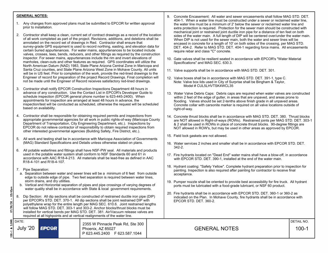
GENERAL NOTES:
1. Any changes from approved plans must be submitted to EPCOR for written approvalprior to installation.
2. Contractor shall keep a clean, current set of contract drawings as a record of the locationof all work completed as part of the project. Revisions, additions, and deletions shall beannotated on the record set of drawings in Red. Contractor shall ensure thatsurvey-grade GPS equipment is used to record northing, easting, and elevation data forcertain buried appurtenances. For water mains, appurtenances to be located includevalves, crosses, tees, bends, reducers, and other fittings as required by the constructioninspector. For sewer mains, appurtenances include the rim and invert elevations ofmanholes, clean-outs and other features as required. GPS coordinates will utilize theNorth American Datum (NAD) 1983, State Plane Arizona Central Zone in Maricopa andSanta Cruz counties, and State Plane Arizona West Zone in Mohave County. All unitswill be in US feet. Prior to completion of the work, provide the red-lined drawings to theEngineer of record for preparation of the project Record Drawings. Final completion willnot be made until the Engineer of Record receives satisfactory red-lined drawings.
3. Contractor shall notify EPCOR Construction Inspections Department 48 hours inadvance of any construction. Use the Contact List in EPCOR's Developer Guide toschedule inspection (EPCOR general phone number is 623-445-2400). Whenappointments for inspection are arranged at least 48 hours in advance, theinspection/test will be conducted as scheduled, otherwise the request will be scheduledbased on availability.
4. Contractor shall be responsible for obtaining required permits and inspections fromappropriate governmental agencies for all work in public rights-of-way (Maricopa CountyDepartment of Transportation, City Engineering Department, etc.). Inspections byEPCOR do not relieve contractor of responsibility to obtain required inspections fromother interested governmental agencies (Building Safety, Fire District, etc.).
5. All work and testing shall be in accordance with Maricopa Association of Governments(MAG) Standard Specifications and Details unless otherwise stated on plans.
6. All potable waterlines and fittings shall have NSF-PW seal. All materials and productsused in the potable water system shall conform to NSF Standards 60 and 61 inaccordance with AAC R18-4-213. All materials shall be lead-free as defined in AACR18-4-101 and R18-4-107.
7. Pipe Separation:a. Separation between water and sewer lines will be a minimum of 6 feet from outside
edge to outside edge of pipe. Two feet separation is required between water lines,storm drains, and dry utilities.
b. Vertical and Horizontal separation of pipes and pipe crossings of varying degrees ofwater quality shall be in accordance with State & local government requirements.
8. Dip Section: All dip sections shall be constructed of restrained ductile iron pipe (DIP)per EPCOR's STD. DET. 370-1. All dip sections shall be joint restrained DIP withpolyethylene wrap for the entire length per MAG SEC. 610.6. Joint restrained lengthswill follow MAG STD. DET. 303-1 and 303-2. Anchor blocks/thrust blocks must beinstalled for vertical bends per MAG STD. DET. 381. Air/Vacuum release valves arerequired at all highpoints and at vertical realignments of the water line.
required at all highpoints and at vertical realignments of the water line.
9. Concrete Encasement: All water and sewer encasements shall follow MAG STD. DET.404-1. When a water line must be constructed under a sewer or reclaimed water line,the water line must be a minimum of 2' below the sewer or reclaimed water line andextra protection is required. Protection for the sewer main should be constructed withmechanical joint or restrained joint ductile iron pipe for a distance of ten feet on bothsides of the water main. A full length of DIP will be centered over/under the water main.When DIP is not used for the sewer main, both the water and sewer lines will beencased in concrete for a length of 10' on both sides of the crossing, per MAG STD.DET. 404-2. Refer to MAG STD. DET. 404-1 regarding force mains. All encasementsrequire rebar and class "C" concrete.
10. Gate valves shall be resilient seated in accordance with EPCOR's "Water MaterialSpecifications" and MAG SEC. 630.3.
11. Valve supports shall be in accordance with MAG STD. DET. 301.
12. Valve boxes shall be in accordance with MAG STD. DET. 391-1, type C.Note: Valve box lids used in City of Surprise shall be Bingham & Taylor,
Model # CUL5LHVTSK4WCL35
13. Water Valve Debris Caps: Debris caps are required when water valves are constructedwithin 2 feet of the edge of gutter, in areas that are unpaved, and areas prone toflooding. Valves should be set 2-tenths above finish grade in all unpaved areas.Concrete collar with carsonite marker is required on all valve locations outside ofright-of-way.
14. Concrete thrust blocks shall be in accordance with MAG STD. DET. 380. Thrust blocksare NOT allowed in Right-of-ways (ROWs). Restrained joints per MAG STD. DET. 303-1& 2 shall be used in ROWs in place of concrete thrust blocks. 90-degree fittings areNOT allowed in ROW's, but may be used in other areas as approved by EPCOR.
15. Field lock gaskets are not allowed.
16. Water services 2 inches and smaller shall be in accordance with EPCOR STD. DET.342-2.
17. Fire hydrants located on "Dead End" water mains shall have a blow-off, in accordancewith EPCOR STD. DET. 390-1, installed at the end of the water main.
18. Hydrant coating: "Safety Yellow". Complete hydrant preparation prior to inspection forpainting. Inspection is also required after painting for contractor to receive finalacceptance.
19. Pumper nozzle shall be oriented to provide best accessibility for fire truck. All hydrantports must be lubricated with a food-grade lubricant, or NSF 60 product.
20. Fire hydrants shall be in accordance with EPCOR STD. DET. 360-1 or 360-2 asindicated on the Plan. In Mohave County, fire hydrants shall be in accordance withEPCOR STD. DET. 360-2.
DATE: DETAIL NO.
100-1
2355 W Pinnacle Peak Rd, Ste 300Phoenix, AZ 85027P 623.445.2400 F 623.587.1044
July '20 GENERAL NOTES

GENERAL NOTES (CONTINUED)
21. Reclaimed waterlines shall be installed in accordance with MAG SEC. 601, 610 and 616.Testing shall be in accordance with MAG SEC. 610 and 611 includingdisinfection/chlorination. Final flushing and bacteriological testing as specified in MAGSEC 611.15 shall not be required.
22. Any shutdown to EPCOR's system requires a minimum of 48 hours notice to EPCOR'sInspector. Shutdowns will only be allowed on Tuesdays, Wednesdays and Thursdays.Time restrictions may also apply.
23. Concealed Pick-hole Manhole Covers: Concealed Pick-hole manhole covers arerequired when the edge of the manhole covers are constructed within 3 feet of the edgeof gutter, in areas that are unpaved, and areas prone to flooding. Manholes should beset 2-tenths above finish grade in all unpaved areas. Concrete collar with carsonitemarker is required on all manhole locations outside of right-of-way. Concealed Pick-holemanhole covers are required for all manholes in Mohave County.
24. Water Pressure Testing: All water lines will be tested per MAG SEC. 610.15.Modifications to these specifications include; the testing to be at a minimum of 200 psi,higher test pressures may be required in certain circumstances, and loss/leakagecalculations will be based upon a maximum of 1500-feet, starting with the smallestdiameter pipe.
25. The Contractor is required to uniform slope test all sewer lines by video and vacuum testall manholes in accordance with A.A.C. R18-9-E301. Deflection testing shall beperformed per MAG SEC. 615.11. Testing documentation and flash drives shall besubmitted to EPCOR Development Services Project Manager for approval prior toacceptance. All required repairs are the responsibility of the contractor and must becoordinated with EPCOR inspectors.
26. Sewer Testing: All sewer mains and laterals shall be pressure tested and video tested.All sewer mains shall also be mandrill tested. The maximum allowable sag is 0.5 inches.
27. When using mechanical plugs to test sewer mains/manholes contractor must followEPCOR STD. DET. 420.
28. In Mohave County, solid sleeves are not allowed as a remedy to a failed pressure teston a new line.
3. Use only a University Of Southern California Foundation For Cross-ConnectionControl and Hydraulic Research (USC) APPROVED assembly.
4. Backflow prevention assemblies shall have a certificate of approval issued byUSC-FCCCHR, or other approved third-party certifying entity unrelated to the productmanufacturer or vendor, in accordance with AAC R18-4-215. All assemblies shall beinstalled in accordance with EPCOR standard details. No assembly shall be placed inservice unless it has been tested and is functioning as designed. A certified test mustbe submitted to EPCOR Cross Connection Specialist (Backflow Prevention) forapproval. Approval of water facilities will not be granted prior to backflow preventionapproval.
5. Locate assembly within 36 inches of water meter unless otherwise directed by Utility'sCross-Connection Specialist.
6. All Pressure Vacuum Breaker Assemblies shall be installed a minimum of 12 inchesabove all downstream piping and outlets.
7. Use lead free solder only.
8. CLEARANCES:a. Wall or structure: Minimum 36”b. Above finish grade: Minimum 12” – Maximum 24”
9. Fire Lines: provide usage-tamper switches & wiring to alarm system where required byfire department. Note: Fire Lines longer than 75' require backflow assembly atproperty line or EPCOR approved location. Such Fire Lines must have backflowprevention assemblies with a metered bypass.
APPROVAL PROCESS FOR BACKFLOW PREVENTION ASSEMBLIES:
1. All new backflow prevention assemblies (BPAs) shall be tested and functioning asdesigned prior to Approval in accordance with AAC R18-4-215.
2. Developer/Contractor/Customer shall forward passing test report with required BPAinformation to EPCOR Cross Connection Specialist, marked pending approval.
3. EPCOR Cross Connection Specialist (Backflow Prevention) will notify Developer Services that an approved backflow prevention assembly test has been received, and this project is ready for an approval inspection.
4. A Construction Inspector then schedules an Approval Inspection with the Developer/Contractor/Customer.
5. EPCOR Construction Inspector confirms presence of BPA, and confirms properinstallation guidelines have been followed.
6. Backflow Prevention approval process complete.
7. Approval may be granted provided all other required Operation Inspection items haveno deficiencies.
BACKFLOW PREVENTION GENERAL NOTES:
1. Backflow Prevention Devices: All landscape and commercial water services requirebackflow prevention devices, meeting the requirements of EPCOR. Backflow devicesshall be in place prior to meters being set. Testing of the backflow devices may becompleted after the installation of the meter.
2. Contact Utility Cross-Connection Specialist (Backflow Prevention) at (623) 445-2411for approved assembly list, inspections and testing.
Use only a University Of Southern California Foundation For Cross-Connection
100-2
2355 W Pinnacle Peak Rd, Ste 300Phoenix, AZ 85027P 623.445.2400 F 623.587.1044
July '20GENERAL NOTES (CONTINUED)
BACKFLOW PREVENTION GENERAL NOTESBACKFLOW PREVENTION APPROVAL PROCESS NOTES
DATE: DETAIL NO.

WATER SYSTEM MATERIAL SPECIFICATION
DISTRIBUTION PIPING· C900 Polyvinyl Chloride (PVC): In accordance with American Water Works Association
(AWWA) Standard C900 for pipe diameters thru 12”: DR=14, elastomeric-gasketbell-end.
· Ductile Iron Pipe, mortar-lined (DIP) shall be used for pipe diameters greater than 12”.
· Ductile Iron Pipe, mortar-lined (DIP): In accordance AWWA Standards C150 & C151Mortar lining shall be in accordance with AWWA C104. All Ductile Iron Pipe shall bepolyethylene wrapped for the entire length in accordance with MAG SEC. 610.6. 6"through 14" diameter must be Pressure Class 350 minimum: 16" through 24" must bePressure Class 250 Minimum, 30" and larger must be Pressure Class 150 minimum.
· In Paradise Valley and Chaparral (Fountain Hills) Districts, Ductile Iron Pipe only. PVCis not permitted.
· Concrete Pressure Pipe, Steel Cylinder Type: In accordance with AWWA StandardC303 and MAG SEC. 758 for pipe diameters greater than 24”. Manufacturer's technicaldata sheets shall be submitted to EPCOR for review and approval. Service taps arenot permitted on concrete pressure pipe.
DISTRIBUTION FITTING· Push-on or mechanical joint in accordance with AWWA C111 and MAG SEC. 750.4.
Joint restraints, where required, shall be Mechanical Restrained Joint with productapproved by EPCOR or flanged joint for lengths in accordance with MAG STD. DET.303-2. Field lock gaskets are not allowed.
WATER LINE VALVE· Mueller, Clow, Kennedy, or M&H resilient wedge seated Gate Valve in accordance with
MAG SEC. 630.3 with valve box and cover in accordance with MAG STD. DET. 391-1Type "C" minimum lid weight of 16lbs. Valves installed outside the pavement or in theflow line of a roadway shall have a debris cap installed per MAG STD. DET. 392.Butterfly valves are not allowed without EPCOR Approval.
CONTROL VALVES (MOHAVE COUNTY ONLY)· The external tubing needs to be stainless steel, not copper. CLA-VAL is the only
acceptable manufacturer.
TAPPING SLEEVE & VALVE· Stainless Steel - Approved manufacturers are Cascade, JCM, and Smith-Blair.· Paradise Valley District may require a bypass on valves on 12” or larger pipe. Contact
EPCOR for approval on a case-by-case basis.
WATER SERVICE· For taps, pipe and fittings for water services through 2", the size shall be in accordance
with EPCOR's STD. DET. 342-2. Requests for larger sizes must be submitted forreview and approval. Minimum water service line size diameter shall be 1”.
· Tubac District requires meter setters on all projects.
· 2” meter setters are required for critical service developments in Paradise Valley andAnthem Districts.
· Approved Saddles, all Iron Pipe Thread Tap and bronze strap: For PVC, Jones J-995,Jones J-996, Mueller H-13000 Series; For Ductile Iron Pipe, Ford 202B, Jones J-979,Mueller BR2B Series, Mueller BR2S Series.
· All brass fittings must be manufactured by Ford, Mueller, or James Jones. All anglemeter stops must include locking wings.
· All corp stops and angle valves must be ball style. All fittings must be "pac-joint" type.
· All brass must be lead free.
FIRE HYDRANTS· All hydrants will be Wet Barrel (unless Dry Barrel hydrants are required by local
jurisdiction) and be manufactured by Clow or Jones. Break-off check valve shall beClow.
· All hydrants shall be equipped with national standard hose threads.
TRACER WIRE· See EPCOR's STD. DET. 350-1. Tracer wire must be used for all water lines.
DIP SECTIONS· All dip sections shall be constructed of restrained ductile iron pipe (DIP) per EPCOR's
STD. DET. 370-1. All dip sections shall be joint restrained DIP with polyethylene wrapfor the entire length per MAG SEC. 610.6. Joint restrained lengths will follow MAGSTD. DET. 303-1 and 303-2. Anchor blocks/thrust blocks must be installed for verticalbends per MAG STD. DET. 381.
MARKING TAPE· See EPCOR's STD. DET. 350-1. Marking tape must be used for all water lines and
services.
MARKING POSTS· Carsonite marking posts are required for all water valves located outside of ROW and
outside of paved areas, installed with concrete collar.
ALL OTHER ITEMS· In accordance with MAG Specifications.· Where MAG standards are specified, those standards are applicable.
100-3
2355 W Pinnacle Peak Rd, Ste 300Phoenix, AZ 85027P 623.445.2400 F 623.587.1044
July '20 WATER SYSTEMMATERIAL SPECIFICATION
DATE: DETAIL NO.

SEWER SYSTEM MATERIAL SPECIFICATION
COLLECTION MAINS· SDR35 PVC sewer pipe in accordance with MAG Specifications, ASTM D-3034,
and ASTM F-679 or US Pipe Protecto 401 ceramic epoxy ductile iron pipe. AllDuctile iron pipe shall be polyethylene wrapped for the entire length in accordancewith MAG SEC. 610.6
SEWER SERVICE· SDR35 PVC sewer pipe in accordance with MAG Specifications, including Marker
Ball and ASTM D-3034.
MANHOLES· Precast Concrete in accordance with MAG Specifications, except that no steps shall
be installed in any manholes. Each manhole shall be treated with “Insecta” insecttreatment as soon as that manhole is raised to grade, after lining is complete andprior to final acceptance. All sewer manholes shall be lined, including the base, withone of the following products, as applied by a certified applicator:
··· NeoPoxy NPR-5300 Series epoxy··· Raven 405/A10··· Sauereisen 210··· Sewer Shield 100
As a minimum, lining is required under the following conditions:- Manholes for sewers that are 10" in diameter, or larger- Manholes for sewers that are 10' in depth, or greater-Manholes that receive wastewater from force mains-Drop manholes-Manholes deemed necessary by EPCOR
MANHOLE COVER· Cast Iron in accordance with MAG Specifications. All manholes shall have a 30”
frame and cover, Neenah R-1743. Lid to be stamped "Sanitary Sewer" inaccordance with MAG Detail 424. No agency identification shall be added. SeeEPCOR's STD. DET. 100-2 for information on water tight manhole covers.
ALL OTHER ITEMS· In accordance with MAG Specifications.
FORCE MAINS· PVC pressure pipe in accordance with AWWA C900 or C905, Griffin H2Sewer Safe
or US Pipe Protecto 401 Ductile Iron Pipe, min. pressure class 150. All ductile ironpipe shall be polyethylene wrapped for the entire length in accordance with MAGSEC. 610.6.
SEWER SYSTEM MATERIAL SPECIFICATION (CONTINUED)
MARKING POSTS· Carsonite marking posts are required for all sewer mains outside of ROW and
outside of paved areas, and are required for force mains greater than 16 inches indiameter.
TRACER WIRE· See EPCOR's STD. DET. 350-1. Tracer wire must be used for all sewer force
mains.
MARKING TAPE· See EPCOR's STD. DET. 350-1. Marking tape must be used for all sewer lines and
services.
ALL OTHER ITEMS· In accordance with MAG Specifications.· Where MAG standards are specified, those standards are applicable regardless of
project location.
100-4
2355 W Pinnacle Peak Rd, Ste 300Phoenix, AZ 85027P 623.445.2400 F 623.587.1044
July '20 SEWER SYSTEMMATERIAL SPECIFICATION
DATE: DETAIL NO.

RECLAIMED WATER SYSTEM MATERIAL SPECIFICATION
DISTRIBUTION PIPING· C900 Polyvinyl Chloride (PVC): In accordance with American Water Works
Association (AWWA) Standard C900 for pipe diameters up to 12”; DR=18,elastomeric-gasket bell-end.
· In Mohave County, all PVC must be DR14 only. DR18 is not permitted.
· C905 Polyvinyl Chloride (PVC): In accordance AWWA Standard C905 for pipediameters greater 12”; DR=18, elastomeric-gasket bell end.
· Ductile Iron Pipe (DIP): In accordance with AWWA Standards C150 & C151. Motarlining shall be in accordance with AWWA C104. All Ductile Iron Pipe shall bepolyethylene wrapped for the entire length in accordance with MAG SEC. 610.6. 6"through 14" diameter must be Pressure Class 350 minimum: 16" through 24" mustbe Pressure Class 250 minimum, 30" and larger must be Pressure Class 150minimum.
· All pipe shall be appropriately identified through integral coloring and wording of thepipe, stenciling of the pipe, or pipe sleeving (pipe socks) in accordance with MAGSEC. 616. Marking tape shall be installed in accordance with EPCOR's STD. DET.350-1.
FITTINGS· Push-on or mechanical joint in accordance with MAG SEC. 750. Joint restraints,
where required, shall be Mechanical Restraint Joint with product approved by theUtility for lengths in accordance with MAG STD. DET. 303-2.
VALVES· Mueller, Clow, Kennedy, or M&H resilient wedge seated Gate Valve in accordance
with MAG SEC. 630.3 with valve box and cover in accordance with MAG Detail391-1 Type "C" minimum lid weight of 16lbs.
· Valve riser pipes shall be painted purple (Seymour Safety Purple) inside and out.Debris caps with identification tag shall be installed in accordance with MAG STD.DET. 392, MAG SEC. 616, and EPCOR's STD. DET. 600-1.
SERVICES· Taps, pipe and fittings for water services 1-1/2” and 2" size shall be in accordance
with EPCOR's STD. DET. 610-1. Larger sizes to be submitted for approval. Noservices smaller than 1-1/2” will be approved by EPCOR.
RECLAIMED WATER SYSTEM MATERIAL SPECIFICATION (CONT'D)
RECLAIMED WATER SYSTEM MATERIAL SPECIFICATION (CONT'D)
DIP SECTIONS· All dip sections shall be constructed of restrained ductile iron pipe (DIP) per
EPCOR's STD. DET. 370-1. All dip sections shall be joint restrained DIP withpolyethylene wrap for the entire length per MAG SEC. 610.6. Joint restrainedlengths will follow MAD STD. DET. 303-1 and 303-2 and appropriately identified inaccordance with MAG SEC. 616. Anchor blocks/thrust blocks must be installed forvertical bends per MAG STD. DET. 381.
MARKING TAPE · Wording per MAG SEC. 616 to be used on all reclaimed water mains. The marking
tape shall be printed “Caution: Reclaimed Water Line” on Purple Tape for reclaimedwater lines.
ALL OTHER ITEMS· In accordance with MAG Specifications.· Where MAG standards are specified, those standards are applicable regardless of
project location.
100-5
2355 W Pinnacle Peak Rd, Ste 300Phoenix, AZ 85027P 623.445.2400 F 623.587.1044
July '20 RECLAIMED WATER SYSTEMMATERIAL SPECIFICATION
DATE: DETAIL NO.

AIR GAP
DATE: DETAIL NO.
300-1
AIR GAPCURB
STREET
OVERFLOW LEVEL
LANDSCAPEDMEDIAN AREAS
TYPICAL FLOOD IRRIGATION STYLE AIR GAP
AIR GAP³ 2 Ø
BASIN
OVERFLOW LEVEL
INLET PIPE
TYPICAL BASIN STYLE AIR GAP
WM
NOTES:
1. AN AIR GAP IS A PHYSICAL SEPARATION BETWEEN THE END OF A POSSIBLEWATER SUPPLY PIPE AND THE OVERFLOW LEVEL OF AN OPEN ORNON-PRESSURIZED BASIN.
2. AIR GAP DISTANCE TO BE MEASURED FROM BOTTOM OF PIPE TO OVERFLOW LEVEL
3. AIR GAP DISTANCE TO ALWAYS BE AT LEAST TWICE THE INLET PIPEDIAMETER, AND IN NO CASES LESS THAN 1".
4. CONTACT EPCOR CROSS CONNECTION SPECIALIST (BACKFLOWPREVENTION) @ 623-587-5202 FOR APPROVED ASSEMBLY LIST,
INSPECTIONS AND TESTING.
5. SEE EPCOR'S STD. DET. 100-2 FOR MORE INFORMATION.
2355 W Pinnacle Peak Rd, Ste 300Phoenix, AZ 85027P 623.445.2400 F 623.587.1044
July '20
Ø
Ø
³ 2 Ø
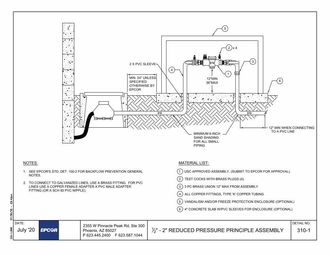
12" - 2" REDUCED PRESSURE PRINCIPLE ASSEMBLY
DATE: DETAIL NO.
310-1
MATERIAL LIST:
1. USC APPROVED ASSEMBLY, (SUBMIT TO EPCOR FOR APPROVAL).
2. TEST COCKS WITH BRASS PLUGS (4).
3. 3 PC BRASS UNION 12" MAX FROM ASSEMBLY
4. ALL COPPER FITTINGS, TYPE 'K' COPPER TUBING
5. VANDALISM AND/OR FREEZE PROTECTION ENCLOSURE (OPTIONAL)
6. 4" CONCRETE SLAB W/PVC SLEEVES FOR ENCLOSURE (OPTIONAL)
2355 W Pinnacle Peak Rd, Ste 300Phoenix, AZ 85027P 623.445.2400 F 623.587.1044
July '20
NOTES:
1. SEE EPCOR'S STD. DET. 100-2 FOR BACKFLOW PREVENTION GENERALNOTES.
2. TO CONNECT TO GALVANIZED LINES, USE A BRASS FITTING. FOR PVCLINES USE A COPPER FEMALE ADAPTER X PVC MALE ADAPTERFITTING (OR A SCH 80 PVC NIPPLE).
x 4
2 X PVC SLEEVE
12" MIN WHEN CONNECTINGTO A PVC LINE
12"MIN36"MAX
3
2
5
14
6
MINIMUM 6-INCHSAND SHADINGFOR ALL SMALLPIPING
MIN. 24" UNLESSSPECIFIEDOTHERWISE BYEPCOR

3" - 10" REDUCED PRESSURE PRINCIPLE ASSEMBLYRP2 EXCEPT F/L
DATE: DETAIL NO.
310-2
6
7
4
24" MAX.12" MIN.
5
1
2
3FINISH GRADE
48"MIN.
48"MIN.
24" MIN.
8
FLOW
MATERIAL LIST:1. USC APPROVED ASSEMBLY, (SUBMIT TO EPCOR FOR APPROVAL).
2. TEST COCKS WITH BRASS PLUGS (4).
3. USE FLANGED DUCTILE IRON FOR ABOVE GROUND PIPE & FITTINGS.RESTRAINED JOINTS SHALL BE USED BELOW GROUND.
4. MEGALUG M.J. FITTING-FOR AC PIPE USE FCA
5. ADJUSTABLE PIPE SUPPORTS (2)
6. CONCRETE SLAB MINIMUM 6" THICK X 24" WIDE
7. CONCRETE THRUST BLOCK-12" WIDE X 12" THICK MINIMUM TOUNDISTURBED EARTH. USE 2-3/4" ZINC COATED, THREADED RODS,BOLTED TO FLANGES, BOTH SIDES TYPICAL; (4 TOTAL).
NOTE: IN LIEU OF CONCRETE THUST BLOCK, A 3'x3'x1/4" STEEL ANGLE,AS SHOWN IN EPCOR STD. DET. 345-2, MAY BE USED.
8. JOINT RESTRAINTS PER M.A.G. STD. DET. 303-1 AND 303-2
NOTES:
1. SEE EPCOR'S STD. DET. 100-2 FOR BACKFLOW PREVENTION GENERALNOTES.
2. BACKFILL UNDER ASSEMBLY SHALL BE 95% COMPACTION
3. FOR FIRE LINE USAGE-TAMPER SWITCHES & WIRING MAY BE NEEDED BY FIREDEPARTMENT OR DISTRICT.
4. FOR FIRE LINES, A REDUCED PRESSURE DETECTOR ASSEMBLY WITH METERIS REQUIRED. METER SHALL HAVE AN AMR REGISTER.
2355 W Pinnacle Peak Rd, Ste 300Phoenix, AZ 85027P 623.445.2400 F 623.587.1044
July '20
OS&Y OS&Y

12" - 2" PRESSURE VACUUM BREAKER ASSEMBLY
DATE: DETAIL NO.
310-3
2355 W Pinnacle Peak Rd, Ste 300Phoenix, AZ 85027P 623.445.2400 F 623.587.1044
July '20
MATERIAL LIST:
1. USC APPROVED ASSEMBLY, (SUBMIT TO EPCOR FOR APPROVAL).
2. TEST COCKS WITH BRASS PLUGS (4).
3. 3 PC BRASS UNION 12" MAX FROM ASSEMBLY
4. ALL COPPER FITTINGS, TYPE 'K' COPPER TUBING
5. VANDALISM AND/OR FREEZE PROTECTION ENCLOSURE (OPTIONAL)
6. 4" CONCRETE SLAB W/PVC SLEEVES FOR ENCLOSURE (OPTIONAL)
NOTES:
1. SEE EPCOR'S STD. DET. 100-2 FOR BACKFLOW PREVENTIONGENERAL NOTES.
2. TO CONNECT TO GALVANIZED LINES, USE A BRASS FITTING. FORPVC LINES USE A COPPER FEMALE ADAPTER X PVC MALEADAPTER FITTING (OR A SCH 80 PVC NIPPLE).
2 X PVC SLEEVE
3
5
46
MINIMUM 6-INCHSAND SHADINGFOR ALL SMALLPIPING
12" MIN. / 36" MAX.MIN. 24" UNLESS
SPECIFIEDOTHERWISE BY
EPCOR
12" MIN WHEN CONNECTING TO A PVC LINE

1" - 10" DOUBLE CHECK DETECTOR ASSEMBLY
DATE: DETAIL NO.
320-1
6
7
4
24" MAX.12" MIN.
5
1
2
3FINISH GRADE
48"MIN.
24" MIN.
8
MATERIAL LIST:
1. U.S.C. (ALSO UL/FM FOR FIRELINES) APPROVED ASSEMBLY, (SUBMIT TOEPCOR FOR APPROVAL).
2. TEST COCKS WITH BRASS PLUGS (4).
3. FLANGED DUCTILE IRON PIPE & FITTINGS ABOVE GROUND MEGALUGRECOMMENDED BELOW GROUND.
4. MEGALUG M.J. FITTING-FOR AC PIPE USE F.C.A.
5. ADJUSTABLE PIPE SUPPORTS (2)
6. CONCRETE SLAB MINIMUM 6" THICK x 24" WIDE
7. CONCRETE THRUST BLOCK-12" WIDE x 12" THICK MINIMUM TOUNDISTURBED EARTH. USE 2-3/4" ZINC COATED, THREADED RODS,BOLTED TO FLANGES, BOTH SIDES TYPICAL; (4 TOTAL).NOTE: IN LIEU OF CONCRETE THRUST BLOCK, A 3'x3'x1/4" STEEL ANGLE,AS SHOWN IN EPCOR STD. DET. 345-2, MAY BE USED.
8. JOINT RESTRAINTS PER M.A.G. STD. DET. 303-1 & 303-2.
2355 W Pinnacle Peak Rd, Ste 300Phoenix, AZ 85027P 623.445.2400 F 623.587.1044
July '20
NOTES:
1. SEE EPCOR'S STD. DET. 100-2 FOR BACKFLOW PREVENTION GENERALNOTES.
2. FOR FIRE LINES, A REDUCED PRESSURE DETECTOR ASSEMBLY WITH METERIS REQUIRED. METER SHALL HAVE AN AMR REGISTER.
FLOW
48"MIN.
SECTION VIEWPLAN VIEW
24" MIN.
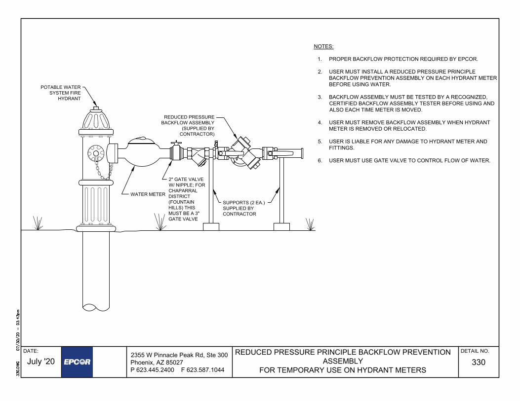
REDUCED PRESSURE PRINCIPLE BACKFLOW PREVENTIONASSEMBLY
FOR TEMPORARY USE ON HYDRANT METERS
DATE: DETAIL NO.
330
2355 W Pinnacle Peak Rd, Ste 300Phoenix, AZ 85027P 623.445.2400 F 623.587.1044
July '20
WATER METER
SUPPORTS (2 EA.)SUPPLIED BYCONTRACTOR
2" GATE VALVEW/ NIPPLE; FORCHAPARRALDISTRICT(FOUNTAINHILLS) THISMUST BE A 3"GATE VALVE
REDUCED PRESSUREBACKFLOW ASSEMBLY
(SUPPLIED BYCONTRACTOR)
POTABLE WATERSYSTEM FIRE
HYDRANT
NOTES:
1. PROPER BACKFLOW PROTECTION REQUIRED BY EPCOR.
2. USER MUST INSTALL A REDUCED PRESSURE PRINCIPLEBACKFLOW PREVENTION ASSEMBLY ON EACH HYDRANT METERBEFORE USING WATER.
3. BACKFLOW ASSEMBLY MUST BE TESTED BY A RECOGNIZED,CERTIFIED BACKFLOW ASSEMBLY TESTER BEFORE USING ANDALSO EACH TIME METER IS MOVED.
4. USER MUST REMOVE BACKFLOW ASSEMBLY WHEN HYDRANTMETER IS REMOVED OR RELOCATED.
5. USER IS LIABLE FOR ANY DAMAGE TO HYDRANT METER ANDFITTINGS.
6. USER MUST USE GATE VALVE TO CONTROL FLOW OF WATER.

POTABLE WATER SERVICE CONNECTION1" THRU 2" SERVICE W/ CORRESPONDING METER
DATE: DETAIL NO.
342
NOTES:
1. SEE EPCOR'S WATER SYSTEM MATERIAL SPECIFICATIONS FOR APPROVEDSADDLES.
2. AMR METER (ONLY) TO BE SET BY EPCOR UPON PAYMENT OF FEES.
3. MINIMUM #4 BOX ON 1-1/2 INCH OR LARGER - #2 BOX FOR ALL SERVICES UPTO 1 INCH.
4. CONCRETE METER BOX PER M.A.G. STD. DET. 320 BOX NO. 2 OR 4 W/ STEEL LIDTO BE SET PERPENDICULAR TO BACK OF WALK OR CURB. BOX TO MATCHSLOPE OF FINISH GRADE AND SET 1" ABOVE FINISH GRADE OR BACK OF WALKOR CURB. 4a 2 INCH DIAMETER OPENING
5. NO BOXES IN DRIVEWAYS OR SIDEWALKS.
6. 6 INCH SAND SHADING AND BEDDING ON SERVICE.
7. CAL WESTERN INC TYPE CAL102 BLUE POLY SLEEVE REQUIRED IN MOHAVECOUNTY ONLY. TRACER WIRE REQUIRED ON TOP OF SLEEVE.
8. MOHAVE COUNTY REQUIRES A COMPRESSION PINCH NUT AT THE SADDLE.
9. AAC R14-2-405.B.3 STATES, "WHERE SERVICE IS BEING PROVIDED FOR THEFIRST TIME, THE CUSTOMER SHALL PROVIDE AND MAINTAIN A PRIVATECUTOFF VALVE WITHIN 18 INCHES OF THE METER ON THE CUSTOMER'S SIDEOF THE METER."
2355 W Pinnacle Peak Rd, Ste 300Phoenix, AZ 85027P 623.445.2400 F 623.587.1044
July '20
WAT
ER
M
AIN
COPPER PIPEROLL TYPE "K" EDGE OF
SIDEWALK
PROPERTY OR EASEMENT LINE
BALL STYLE CORP STOP WITHCOMPRESSION TYPE NUT
PLAN VIEW SECTION A-A
30" M
IN.
CO
VER
ON
SER
VIC
E
ALL SERVICES
SECTION B-B
TO BUILDING
AABB
30" M
IN.
30°
1" MIN. FOR ALL SERVICES8"
1
1
4
BALL STYLE ANGLE METER VALVEW/ PAC-JOINT CONNECTION & LOOPFOR LOCK
FEMALE I.P. THREADMETER FLANGE
6
4a
2 INCH HOLE TO BECENTERED IN REARHALF SECTION OFMETER BOX LID
STREET
℄ OF ANGLE VALVE
4" VERTICAL CLEARANCE
1" MIN - 3" MAX

3", 4", & 6"POTABLE WATER METER VAULT
DATE: DETAIL NO.
345-1
2355 W Pinnacle Peak Rd, Ste 300Phoenix, AZ 85027P 623.445.2400 F 623.587.1044
July '20
4
FL.x PE DIP SPOOL 48"MIN. LENGTH (TYP)
2'MIN.(TYP)
5'
10'-6"
A
A
AGGREGATE BASECOMPACTED TO 95%
SECTION A-A
36" M
IN
5'-8
"
FINISH GRADE
15"MIN.18"MAX.
WAT
ER M
AIN
6"
5'
MATERIALS LIST:
1. ALL PIPING TO BE JOINT RESTRAINED, MIN. PRESSURE CLASS 150, DIP. JOINTRESTRANTS TO BE FLANGED OR MEGALUG.
2. PRE-CAST VAULT, OLD CASTLE 5106-WA OR EPCOR APPROVED EQUAL.
3. 6' x 4' ALUMINUM ACCESS DOOR WITH SPRING ASSIST RATED FOR H-20 LOADING.HALLIDAY PRODUCTS H2R7248 OR EPCOR APPROVED EQUAL. VAULT DOORSYSTEM WILL HAVE 2" DIAMETER TO ALLOW FOR ANTENNAE. THE HOLE SHOULDBE IN A LOCATION THAT ALLOWS EASE OF INSTALLATION, ALLOW VAULT DOORSTO OPEN FULLY, AND HAVE ENOUGH CABLE TO NOT BIND.
3
PLAN
2
6
7 8
4
5
6
3
1109
ALUMINUM BOLT ON LADDER WITH SAFETY EXTENSION, HALLIDAY PRODUCTS LIBAND LIE OR EPCOR APPROVED EQUAL.
2" DOUBLE STRAP BRONZE SADDLES PER EPCOR'S STD. DET. 342-2 AND A 2"LOCKABLE BALL VALVE.
MUELLER OR CLOW RESILIENT SEATED FLANGED NRS GATE VALVE WITH HANDWHEEL IN ACCORDANCE WITH M.A.G. SECTION 630.3.
STRAINER REQUIRED WITH INSTALLATION OF METER.
ALL METERS THAT ARE 3 INCHES OR LARGER MUST BE COMPOUND METERS.EPCOR WILL PROVIDE ALL COMPOUND METERS. CONTRACTOR WILL NEED TOCOORDINATE PICK-UP AND INSTALLATION WITH EPCOR STAFF
FLANGED X FCA DIP SPOOL, MINIMUM 3 PIPE DIAMETERS LENGTH.
EPCOR APPROVED CHECK VALVE.
ADJUSTABLE PIPE SUPPORTS (2)
NOTE:LARGER METER VAULTS REQUIRE SPECIAL DESIGN AND EPCOR APPROVAL.
6.
7.
8.
9.
10.
VAULT LID MUST HAVETWO 2-INCH DIAMETER
HOLES. HOLE LOCATIONTO BE DETERMINED BY
UTILITY.
5.
4.
VB&C PERM.A.G. STD.DET. 391-1,TYPE C
GROUT FILL VOIDTO MAKE PIPEPENETRATIONWATER TIGHT.
DOOROPENING
DIRECTION
5
11.
11
6"
FINISHGRADE
CONCRETEBASE W/ DRAIN

ABOVE GROUND POTABLE WATER METER( 3", 4" & 6" )
DATE: DETAIL NO.
345-2
2355 W Pinnacle Peak Rd, Ste 300Phoenix, AZ 85027P 623.445.2400 F 623.587.1044
July '20
PLAN VIEW
SECTION VIEW
90° DUCTILE IRONELL FLANGED FITTING (TYP)
FINISHED GRADE
6" THICK CONCRETE SLAB-3000 PSI- CLASS A
12" MINIMUM
NEPTUNE BRONZE STRAINER
CURB STOP & TWO DOUBLE BRONZESTRAP SADDLES (TYP); CURB STOPSTO HAVE LOCKABLE WINGS;PADLOCKS PROVIDED BY EPCOR
PIPESUPPORT;TYP.- SEEBELOW
CONCRETE SLAB
GATE VALVE-DUCTILE IRON, RISING STEM TYPEFLANGED, RESILIENT SEAT, AWWA C-905 (TYP)
DUCTILE IRON PIPE SPOOL-LENGTH AS REQUIRED (TYP)
DUCTILE IRON 90° MJ FITTING
DUCTILE IRON SPOOL PIPE
(STRAINER AND METER PROVIDED BY EPCOR AFTERNEPTUNE WATER METER RECEIPT OF PAYMENT FROM CONTRACTOR/DEVELOPER.
CONTRACTOR MAY CONTACT EPCOR PROJECT MANAGER TO OBTAIN MAKE AND MODEL INFORMATION FOR METER)
DUCTILE IRON SPOOL PIPE
DUCTILE IRONFLANGED CONCENTRICREDUCER (TYP)
2" TYPE 'K' HARDCOPPER BYPASSPIPE
6" DIAMETER x 3' TALL SCHEDULE40 GALVANIZED PIPE BOLLARD,FILL WITH CONCRETE, PAINT YELLOW-LOCATE MIN 1' FROM CONCRETE-MAY REQUIRE UP TO 6 BOLLARDS
3" x 3" x 1/4" STEEL ANGLE.BOLT TO FLANGE, EACHEND WITH ONE BOLT. COATWITH COAL TAR EPOXY (16MILS) REQUIRED
TOP OF CONCRETE SLABTO BE 1" ABOVESURROUNDING FINISH GRADE
MECHANICAL JOINT RESTRAINED DIP FROM TAP;MIN LENGTH OF 10 FEET; ALL UNDERGROUND DIPSHALL BE POLYETHYLENE WRAPPED
FLOW FLOW
48" PIPE SUPPORT-FLANGE TYPE BOLT TOCONCRETE SLAB (MAINLINE & BYPASS)
95% COMPACTED SUB-GRADE
MIN 10 FEET OF MECHANICALJOINT RESTRAINED DIP.
MIN LENGTH OF 4 PIPE DIAMETERS
NOTES:
1. AN EPCOR APPROVED BACKFLOWPREVENTION ASSEMBLY IS REQUIREDDOWNSTREAM OF THE METER.
2. ALL ABOVE GROUND PIPING/VALVESSHALL BE PAINTED DESERT SAND TOMATCH COLOR OF CAGE ENCLOSURE.
3. METER & STRAINER TO BE PROTECTEDWITH A LOCKABLE HINGED CLAMSHELLENCLOSURE; TOP PORTION IS HINGEDAND HAS HANDLES TO ALLOW TOPPORTION TO BE LIFTED OPEN TO ALLOWFULL ACCESS TO METER AND STRAINER;WHEN OPENED, TOP PORTION SHALLSTAY IN OPEN POSITION WITHOUTASSISTANCE; METAL ENCLOSURE SHALLBE CAPABLE OF WITHSTANDING AMINIMUM OF 200 POUNDS PER SQUAREFOOT WITHOUT ANY PERMANENTDEFLECTION OR DISTORTION;POWDERCOATED WITH EPCORAPPROVED COLOR, DESERT SAND; MAKE& MODEL OF ENCLOSURE SHALL BEAPPROVED BY EPCOR PRIOR TOINSTALLATION; ENCLOSURE SHALL BEBOLTED TO CONCRETE SLAB; SIDE OFENCLOSURE ABOVE PIPE SHALL BEENCLOSED AND BELOW PIPE MAY BEOPEN
12" MINIMUM
MIN LENGTH OF 4 PIPE DIAMETERS
ENTIRE LENGTH IS HINGED
PADLOCK PROVIDED BY EPCORSEE NOTE 3
DUCTILE IRON SPOOL PIPE- 12" LONG MIN. DUCTILE IRON SPOOL PIPE- 12" LONG MIN.
* METER ASSEMBLIES 8" AND LARGER ARE TO BE DESIGNED BYDEVELOPER'S ENGINEER AND APPROVED BY EPCOR
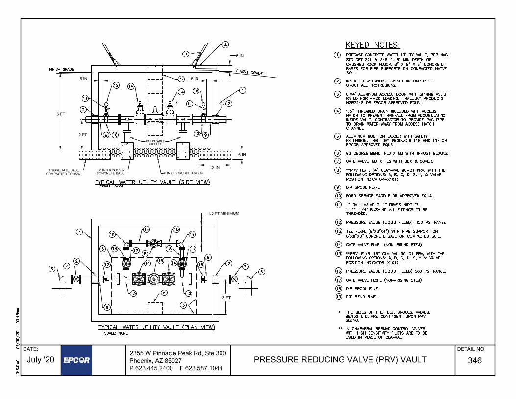
PRESSURE REDUCING VALVE (PRV) VAULT
DATE: DETAIL NO.
346
2355 W Pinnacle Peak Rd, Ste 300Phoenix, AZ 85027P 623.445.2400 F 623.587.1044
July '20
6 IN
6 IN6 IN
6 FT
2 FT
3 FT
1.5 FT MINIMUM
AGGREGATE BASECOMPACTED TO 95%
12 IN
6 IN
6 IN OF CRUSHED ROCK8 IN x 8 IN x 8 IN
CONCRETE BASE
ADJUSTABLESUPPORT

PIPE TRENCH DETAIL
DATE: DETAIL NO.
350-1
NOTES:
1. TRENCH WILL BE IN ACCORDANCE WITH M.A.G. SECTION 601.
2. ONE SACK ABC SLURRY (CLSM) TO BE IN ACCORDANCE WITH M.A.G. SECTION 728.
3. DEPTH OF BURY TO BE MIN. 48" IN ALL STREETS. DEPTH OF BURY FOR WATERLINES IN OTHER AREAS TO BE AS FOLLOWS:
A) 36" MIN. FOR MAINS 8" DIAMETER AND SMALLER. B) 48" MIN. FOR MAINS 10" DIAMETER AND LARGER.
4. WASHED CRUSHED ROCK TO BE IN ACCORDANCE WITH M.A.G. SECTION 716.2 ANDTABLE 716-2.SAND TO BE IN ACCORDANCE WITH M.A.G. SECTION 701.3.ABC TO BE IN ACCORDANCE WITH M.A.G. SECTION 702.2 AND TABLE 702-1.
5. TRACER WIRE IS TO BE BROUGHT UP TO GRADE AT EACH FIRE HYDRANT TOGROUND / VALVE BOX. FOR LONG RUNS, THE TRACER WIRE IS TO BE BROUGHT UPAT LEAST EVERY 300 FEET INSIDE A TRACER BOX SUCH AS A SNAKEPITMAGNETIZED TRACER BOX BY COPPERHEAD INDUSTRIES OR APPROVED EQUAL.
2355 W Pinnacle Peak Rd, Ste 300Phoenix, AZ 85027P 623.445.2400 F 623.587.1044
July '20
PIPE MARKING TAPEMARKING TAPE SHALL BE LOCATED 18 INCHES BELOWGROUND SURFACE.
WORDING PER M.A.G. SEC. 616 TO BE USED FOR ALLWATER, & RECLAIMED WATER LINES AND SERVICES.THE MARKING TAPE SHALL BE PRINTED ON STANDARDCOLORED NON-DETECTABLE TAPE. LETTERING SHALLBE BLACK, 1-12" HEIGHT MINIMUM.
RECLAIMED WATER LINES SHALL USE PURPLE TAPE &SHALL READ "CAUTION: RECLAIMED WATER LINE"POTABLE WATER LINES SHALL USE BLUE TAPE & SHALLREAD "CAUTION: POTABLE WATER LINE"
RAW & NON-POTABLE WATER LINES SHALL USEYELLOW TAPE & SHALL READ "RAW WATER MAINS"AND/OR "NON-POTABLE WATER MAINS".
SEWER AND SERVICE LINES SHALL USE GREEN TAPE &SHALL READ "CAUTION: SEWER LINE".
BACKFILL· IN NON-SAW CUT AREAS TO
BE NATIVE MATERIALSCREENED AT 4" OR LESS
· IN SAW CUT AREAS TO BE ONESACK ABC SLURRY OR ASSPECIFIED BY R.O.W. AGENCY.
SEE
SEE NOTE 1
NO
TE 3
6" MIN
.
12"
PIPE ZONEFROM MIN. 6" BELOW BOTTOM OF PIPE TO MIN. 12"ABOVE TOP OF PIPE BACKFILL WITH THEFOLLOWING PER NOTE 4:
A. WATER LINES· MARICOPA & SANTA CRUZ COUNTIES = ABC· MOHAVE COUNTY = SAND PER M.A.G. 701.3
B. RECLAIMED WATER LINES· MARICOPA & SANTA CRUZ COUNTIES = ABCMOHAVE COUNTY = SAND PER M.A.G. 701.3
C. SEWER FORCE MAIN· MARICOPA & SANTA CRUZ COUNTIES = ABCMOHAVE COUNTY = SAND PER M.A.G. 701.3
D. GRAVITY SEWER LINES· ALL SERVICE AREAS = 38" CRUSHED WASHEDROCK (NO REJECTS)
TRACER WIRE #12 GAUGE COPPERWIRE. WIRE NUTS NEED TO BE DRYSPLICE WATER-PROOF GEL PACKS.
WATER AND SEWER SERVICES(all Utility service areas)MINIMUM 6" SAND BEDDING AND 6" SANDSHADING. BACKFILL AS PER DETAIL.

STEEL CASING
DATE: DETAIL NO.
350-2
2355 W Pinnacle Peak Rd, Ste 300Phoenix, AZ 85027P 623.445.2400 F 623.587.1044
July '20
A B5"
2.5"4"2"
RISERRUNNERS
8 INCH BRICK AND CEMENT MORTARSEAL
APS CASING SPACER
PIPE BELL O.D.
STEEL CASINGASTM A-252GRADE B
WATERLINE
INSTALLATION TO BE INACCORDANCE WITHMANUFACTURER'SSPECIFICATIONS
8 INCH BRICK AND CEMENT MORTARSEAL
ADVANCED PRODUCTS & SYSTEMS, INC. (APS)CASING SPACERS, MODEL SSI
1' 1'MAX MAX
12" MIN0.5'
CASING SPACERS SHOULD BE SPACEDA MAXIMUM OF FOUR FEET FROM EACHSIDE OF THE PIPE JOINT. MAXIMUMDISTANCE BETWEEN TWO SPACERSSHALL BE 10 FEET
SLEEVE DETAIL
A A
A
B
B 8" WIDE CASING SPACERSCASCADE WATERWORKSSTYLE CCS PLACED AT 10FOOT INTERVALS
SECTION
A
PLAN
45°
TYP
22.5°22.5° 22.5°
22.5°
A*
A* = SPACING PERMANUFACTURER'SRECOMMENDATIONS(4' MAXIMUM)
45° 45°
1 3/8"
MIN
CASING SPACERS12" MIN BANDSWITH 2" MINRUNNER WIDTH
NOTES:1. CASING SPACERS SHALL BE PER SPECIFICATIONS2. END SEAL TO BE ADVANCED PRODUCTS AND SYSTEMS, INC. MODEL A C PULL-ON TYPE3. NO FILL IN ANNULAR SPACE4. MINIMUM CASING SIZE SHALL BE 12 INCHES LARGER OUTSIDE DIAMETER OF CARRIER PIPE5. A CASING SPACER MUST BE PLACED WITHIN 2 FEET OF EACH END OF THE CASING PIPE
DUCTILE IRONCARRIER PIPE
GROUNDINGIF REQUIRED
STEEL CASING PIPE
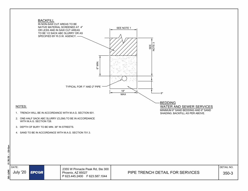
PIPE TRENCH DETAIL FOR SERVICES
DATE: DETAIL NO.
NOTES:
1. TRENCH WILL BE IN ACCORDANCE WITH M.A.G. SECTION 601.
2. ONE-HALF SACK ABC SLURRY (CLSM) TO BE IN ACCORDANCEWITH M.A.G. SECTION 728.
3. DEPTH OF BURY TO BE MIN. 36" IN STREETS.
4. SAND TO BE IN ACCORDANCE WITH M.A.G. SECTION 701.3.
2355 W Pinnacle Peak Rd, Ste 300Phoenix, AZ 85027P 623.445.2400 F 623.587.1044
July '20
BACKFILLIN NON-SAW CUT AREAS TO BENATIVE MATERIAL SCREENED AT 4"OR LESS AND IN SAW CUT AREASTO BE 1/2 SACK ABC SLURRY OR ASSPECIFIED BY R.O.W. AGENCY.
SEE
SEE NOTE 1
NO
TE 3
6"
BEDDINGWATER AND SEWER SERVICESMINIMUM 6" SAND BEDDING AND 6" SANDSHADING. BACKFILL AS PER ABOVE.
18"MAX
350-3
TYPICAL FOR 1" AND 2" PIPE
6" M
IN.
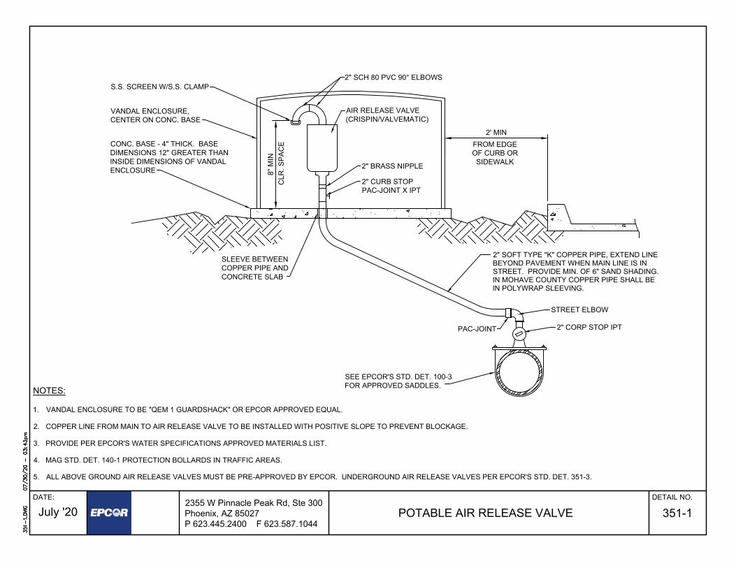
POTABLE AIR RELEASE VALVE
DATE: DETAIL NO.
351-1
2355 W Pinnacle Peak Rd, Ste 300Phoenix, AZ 85027P 623.445.2400 F 623.587.1044
July '20
NOTES:
1. VANDAL ENCLOSURE TO BE "QEM 1 GUARDSHACK" OR EPCOR APPROVED EQUAL.
2. COPPER LINE FROM MAIN TO AIR RELEASE VALVE TO BE INSTALLED WITH POSITIVE SLOPE TO PREVENT BLOCKAGE.
3. PROVIDE PER EPCOR'S WATER SPECIFICATIONS APPROVED MATERIALS LIST.
4. MAG STD. DET. 140-1 PROTECTION BOLLARDS IN TRAFFIC AREAS.
5. ALL ABOVE GROUND AIR RELEASE VALVES MUST BE PRE-APPROVED BY EPCOR. UNDERGROUND AIR RELEASE VALVES PER EPCOR'S STD. DET. 351-3.
SEE EPCOR'S STD. DET. 100-3FOR APPROVED SADDLES.
2" SOFT TYPE "K" COPPER PIPE, EXTEND LINEBEYOND PAVEMENT WHEN MAIN LINE IS INSTREET. PROVIDE MIN. OF 6" SAND SHADING.IN MOHAVE COUNTY COPPER PIPE SHALL BEIN POLYWRAP SLEEVING.
2" BRASS NIPPLE
AIR RELEASE VALVE(CRISPIN/VALVEMATIC)
2' MINFROM EDGEOF CURB ORSIDEWALK
2" SCH 80 PVC 90° ELBOWS
8" M
INC
LR. S
PAC
ECONC. BASE - 4" THICK. BASEDIMENSIONS 12" GREATER THANINSIDE DIMENSIONS OF VANDALENCLOSURE
VANDAL ENCLOSURE,CENTER ON CONC. BASE
S.S. SCREEN W/S.S. CLAMP
PAC-JOINT
2" CURB STOPPAC-JOINT X IPT
SLEEVE BETWEENCOPPER PIPE ANDCONCRETE SLAB
2" CORP STOP IPT
STREET ELBOW

POTABLE UNDERGROUND AIR RELEASE VALVE
DATE: DETAIL NO.
351-3
2355 W Pinnacle Peak Rd, Ste 300Phoenix, AZ 85027P 623.445.2400 F 623.587.1044
July '20
NOTES:
1) IF MULTIPLE ARV's ARE INSTALLED, EACH BOX MUST BE SEPARATED BY 3' MINIMUM.2) PROVIDE PER EPCOR'S WATER SPECIFICATIONS APPROVED MATERIALS LIST.
SEE EPCOR'S STD. DET. 100-3FOR APPROVED SADDLES.
2" SOFT TYPE "K" COPPERPIPE, EXTEND LINE BEYONDPAVEMENT WHEN MAIN LINEIS IN STREET. IN MOHAVECOUNTY, THE COPPER PIPESHALL BE IN POLYWRAPSLEEVING.
2" AIR RELEASEVALVE (CRISPINOR VALVEMATIC)
2' MINFROM EDGE OF
CURB OR SIDEWALK
36" DIA FRP MANHOLE W/ H20 LOAD RATING& IN ACCORDANCE W/ ASTM D-3753
2" CURB STOP PAC-JOINT X IPT
2" CORP STOP IPT
UNION FITTING
12" ABC BASE, 95% COMPACTIONPER M.A.G. SECT. 601.4.4
3" CLEAN GRAVEL
2" BRASS 90° ELBOW
3" THICK CONCRETE SUPPORT
MIN. CLEARANCE 6" ALL SIDES
2" PVC (SCH. 80)90° ELBOW
CONCRETE THRUST BLOCKPER M.A.G. STD. DET. 380
POLYWRAPPED 2" PVC 90°ELBOW (SCH. 80)
4" MIN
.
2" PVC (SCH. 80)90° ELBOW
24" FRAME & COVERPER MAG STD DET 424
2" SCH 80 PVC
12"
MIN
.1/8" STAINLESS STEEL MESH SCREENWITH STAINLESS STEEL CLAMPS
ALL ABOVE GROUND PIPE TO BEPAINTED WITH UV RESISTANT PAINT(MIN. OF 10 MILS THICKNESS). PAINT
TO MATCH SURROUNDING LANDSCAPE
1 SACK CLSM PER M.A.G.SECT. 728 12" MIN TOUNDISTURBED GROUND
12" CONCRETE COLLAR2" BELOW FINISH GRADE
MANHOLE COVERTO BE LABELED:
45° OR 90° BENDAS NEEDED IN PVC SLEEVE
6"
6"MIN.
FERNCO COUPLINGWITH SS BANDS
PVCSLEEVE
PAC-JOINT
STREET ELBOW
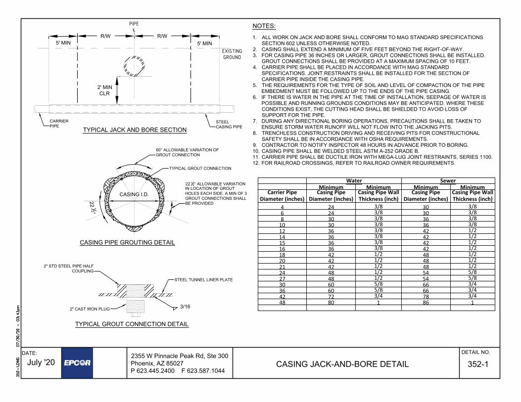
CASING JACK-AND-BORE DETAIL
2355 W Pinnacle Peak Rd, Ste 300Phoenix, AZ 85027P 623.445.2400 F 623.587.1044
July '20
22 12°
2' MINCLR
R/W R/W5' MIN 5' MIN
22 12° ALLOWABLE VARIATIONIN LOCATION OF GROUTHOLES EACH SIDE. A MIN OF 3GROUT CONNECTIONS SHALLBE PROVIDED
CASING I.D.
TYPICAL GROUT CONNECTION DETAIL
CASING PIPE GROUTING DETAIL
TYPICAL GROUT CONNECTION
TYPICAL JACK AND BORE SECTION
NOTES:
1. ALL WORK ON JACK AND BORE SHALL CONFORM TO MAG STANDARD SPECIFICATIONSSECTION 602 UNLESS OTHERWISE NOTED.
2. CASING SHALL EXTEND A MINIMUM OF FIVE FEET BEYOND THE RIGHT-OF-WAY.3. FOR CASING PIPE 36 INCHES OR LARGER, GROUT CONNECTIONS SHALL BE INSTALLED.
GROUT CONNECTIONS SHALL BE PROVIDED AT A MAXIMUM SPACING OF 10 FEET.4. CARRIER PIPE SHALL BE PLACED IN ACCORDANCE WITH MAG STANDARD
SPECIFICATIONS. JOINT RESTRAINTS SHALL BE INSTALLED FOR THE SECTION OFCARRIER PIPE INSIDE THE CASING PIPE.
5. THE REQUIREMENTS FOR THE TYPE OF SOIL AND LEVEL OF COMPACTION OF THE PIPEEMBEDMENT MUST BE FOLLOWED UP TO THE ENDS OF THE PIPE CASING.
6. IF THERE IS WATER IN THE PIPE AT THE TIME OF INSTALLATION, SEEPAGE OF WATER ISPOSSIBLE AND RUNNING GROUNDS CONDITIONS MAY BE ANTICIPATED. WHERE THESECONDITIONS EXIST, THE CUTTING HEAD SHALL BE SHIELDED TO AVOID LOSS OFSUPPORT FOR THE PIPE.
7. DURING ANY DIRECTIONAL BORING OPERATIONS, PRECAUTIONS SHALL BE TAKEN TOENSURE STORM WATER RUNOFF WILL NOT FLOW INTO THE JACKING PITS.
8. TRENCHLESS CONSTRUCTION DRIVING AND RECEIVING PITS FOR CONSTRUCTIONALSAFETY SHALL BE IN ACCORDANCE WITH OSHA REQUIREMENTS.
9. CONTRACTOR TO NOTIFY INSPECTOR 48 HOURS IN ADVANCE PRIOR TO BORING.10. CASING PIPE SHALL BE WELDED STEEL ASTM A-252 GRADE B.11. CARRIER PIPE SHALL BE DUCTILE IRON WITH MEGA-LUG JOINT RESTRAINTS, SERIES 1100.12. FOR RAILROAD CROSSINGS, REFER TO RAILROAD OWNER REQUIREMENTS.
STEEL TUNNEL LINER PLATE
2" STD STEEL PIPE HALFCOUPLING
2" CAST IRON PLUG
Water SewerMinimum Minimum Minimum Minimum
Carrier PipeDiameter (inches)
Casing PipeDiameter (inches)
Casing Pipe WallThickness (inch)
Casing PipeDiameter (inches)
Casing Pipe WallThickness (inch)
4 24 3/8 30 3/86 24 3/8 30 3/88 30 3/8 36 3/810 30 3/8 36 3/812 36 3/8 42 1/214 36 3/8 42 1/215 36 3/8 42 1/216 36 3/8 42 1/218 42 1/2 48 1/220 42 1/2 48 1/221 42 1/2 48 1/224 48 1/2 54 5/827 48 1/2 54 5/830 60 5/8 66 3/436 60 5/8 66 3/442 72 3/4 78 3/448 80 1 86 1
CARRIERPIPE
STEELCASING PIPE
60° ALLOWABLE VARIATION OFGROUT CONNECTION
PIPE℄
EXISTINGGROUND
3/16
352-1DATE: DETAIL NO.

CASING SPACER DETAIL
DATE: DETAIL NO.
352-2
A B5"
2.5"4"2"
RISERRUNNERS
MEG-A-LUG JOINTRESTRAINT O.D.
STEEL CASINGASTM A-252GRADE B
CARRIER PIPE
INSTALLATION TO BE INACCORDANCE WITHMANUFACTURER'SSPECIFICATIONS
8 INCH BRICK AND CEMENT MORTARSEAL
1' 1'MAX MAX
B*
ALL CARRIER PIPE INSIDECASING PIPE WILL BE MEG-A-LUGJOINT RESTRAINED, SERIES 1100
CASING PIPE DETAIL
A A
A
B
B 8" WIDE CASING SPACERSPLACED AT 6 FOOTINTERVALS ON 36" ANDSMALLER DIAMETERCARRIER PIPE
SECTION
A
PLAN
45°
TYP
22.5°22.5° 22.5°
22.5°
A*
A* = SPACING PERMANUFACTURER'SRECOMMENDATIONS(6' MAXIMUM)
1 3/8"
MIN
NOTES:1. NO FILL IN ANNULAR SPACE2. A CASING SPACER MUST BE PLACED WITHIN 2 FEET OF EACH END OF THE CASING PIPE3. CASING SPACERS SHALL BE APS (SSI) OR CASCADE TYPE (CCS)
DUCTILE IRONCARRIER PIPE
GROUNDINGIF REQUIRED
B* = 8" MINIMUM ON 36" AND SMALLERDIAMETER CARRIER PIPE12" MINIMUM FOR GREATER THAN36" DIAMETER CARRIER PIPE.
2355 W Pinnacle Peak Rd, Ste 300Phoenix, AZ 85027P 623.445.2400 F 623.587.1044
July '20
22.5°22.5° 22.5°
22.5°

DRY BARREL FIRE HYDRANT INSTALLATION
DATE: DETAIL NO.
360-1
2355 W Pinnacle Peak Rd, Ste 300Phoenix, AZ 85027P 623.445.2400 F 623.587.1044
July '20
NOTES:
1. SEE EPCOR STD. DET. 100-1 FOR FIRE HYDRANT GENERAL NOTES.
2. ALL JOINT RESTRAINTS PER M.A.G. STD. DET. 303- 1 & 2 AND M.A.G. SECT. 750.3.
3. VALVE BOX PER M.A.G. STD. DET. 391-1-C.
4. ALL VALVE OPERATING NUTS SHALL BE A MAX OF 36 INCHES BELOW GROUNDSURFACE.
5. DRY BARREL HYDRANTS SHALL BE MUELLER "CENTURION", CLOW "MEDALLION",OR KENNEDY "K81D", WITH NATIONAL STANDARD HOSE THREADS. NOAPPROVED EQUALS WILL BE ACCEPTED.
UNDISTURBED GROUND
FIRE HYDRANT
18" M
IN
TEE (FLG. WATER MAIN
VALVE SUPPORTVARIES
VALVE BOX
18" MIN.
WAT
ER M
AIN
BLOW-OFF
6" GATE VALVEFLG X MJ
6" CLASS350 DIP PIPE
CRUSHED ROCKBACKFILL TO 1'
ABOVE SHOE
3' M
IN
4" MAX
VALVE SUPPORT
VARIES
VALVE BOX
6" GATE VALVEFLG. X MJ
6" CLASS 350DIP PIPE (TYP)
CRUSHED ROCKBACKFILL TO 1'ABOVE SHOE.
UNDISTURBEDGROUND
5' O
R G
REA
TER
RESTRAINED JOINTS
FIRE HYDRANT
OUTLET)
4" MAX
18" M
IN3'
MIN
TEE (FLG. WATER MAIN
OUTLET)
DEEPSTANDARD
6. PROVIDED A MINIMUM 3 FOOT DIAMETER CLEARANCE AROUND HYDRANT.

WET BARREL FIRE HYDRANT INSTALLATION
DATE: DETAIL NO.
360-2
2355 W Pinnacle Peak Rd, Ste 300Phoenix, AZ 85027P 623.445.2400 F 623.587.1044
July '20
NOTES:
1. SEE EPCOR STD. DET. 100-1 FOR FIRE HYDRANT GENERAL NOTES.
2. ALL JOINT RESTRAINTS PER M.A.G. STD. DET. 303- 1 & 2 AND M.A.G. SECT. 750.3.
3. ALL JOINTS SHALL BE RESTRAINED, INCLUDING MAIN AT TEE ENDS.
4. APPROVED HYDRANTS INCLUDE: CLOW* AND JONES (*CLOW HYDRANTS SHALL BEMODEL 860 WITH 2 1/2" FEMALE NPT ON TOP OFHYDRANT TO ALLOW FOR PRESSURE MONITORING).
5. THE 6 INCH GATE VALVE SHALL BE FLANGED BY MECHANICAL JOINT.
6. PROVIDE A MINIMUM 3 FOOT DIAMETER CLEARANCE AROUND HYDRANT.
7. THE HYDRANT SHALL HAVE 2 - 2 12" PORTS, AND 1 - 4 12" PORT.
8. ALL HYDRANTS SHALL HAVE NATIONAL STANDARD HOSE THREADS.
9. VALVE BOX PER M.A.G. STD. DET. 391-1-C.
VALVE BLOCKING
VALVE BOX
MUST BE INSTALLEDLEVELED AND SQUARETO SHOE
THREE PORT WETBARREL FIRE HYDRANT
3' M
IN
ALL PORTS 20" MIN24 MAX FROMFINISHED GRADE
6" BREAKAWAY
FINISHED GRADE
CONC. SHOCKSLAB 24" x 24" x 6"CLASS C PER MAGSPEC SEC 725
BREAK - OFFCHECK VALVEBY CLOW(NO "OR EQUALS")
8" MIN
6"
6 INCH GATE VALVEFLANGE x M.J.
SECTION PLAN VIEW
6 INCH DUCTILE IRONPIPE PRESSURE CLASS 350
WAT
ERM
AIN
6 INCH GATE VALVEFLANGE x M.J.
1' MIN FROM HYDRANTNOZZLE TO BACK OFSIDEWALK
WAT
ER M
AIN
BLOW-OFF

VERTICAL RE-ALIGNMENTOF WATER MAINS
DATE: DETAIL NO.
370-1
NOTES:
1. ALL JOINT RESTRAINTS ARE TO BE MEG-A-LUG, SIGMA, EEBA OR STAR, NOFIELD LOCS OR UNIFLANGE, FOR LENGTHS IN ACCORDANCE w/ M.A.G. STD.DET. 303-2
2. PIPE IS TO BE DUCTILE IRON, MINIMUM PRESSURE CLASS 150.
3. ALL DUCTILE IRON PIPE SHALL BE POLYETHYLENE WRAPPED FOR THEENTIRE LENGTH IN ACCORDANCE WITH M.A.G. SECT. 610.6
4. BEGIN/END RESTRAINED JOINT STATIONING TO BE SHOWN ON THEAPPROVED CONSTRUCTION DRAWINGS. ALL BENDS & FITTINGS SHALL HAVESTATIONING AND ELEVATION SHOWN ON THE APPROVED CONSTRUCTIONDRAWINGS. THE BOTTOM ELEVATION OF THE CONFLICT AND THE TOPELEVATION OF THE DUCTILE IRON PIPE AT THE CENTERLINE OF THECONFLICT SHALL BE SHOWN ON THE APPROVED CONSTRUCTION DRAWINGS.
SOLID SLEEVE, IF REQUIRED
RESTRAINEDJOINTFITTINGS
REMAINDER OF TRENCH TO BE BACKFILLEDPER M.A.G. OR LOCAL REQUIREMENTS
BELL & SPIGOT ORBELL & BELL AS REQUIRED
BELL & BELL
RESTRAINED JOINTFITTINGS (SEE
NOTE #5 FOR ALLVERTICAL BENDS)
24" MIN. CLEARANCE. BACKFILLEDPER EPCOR STD. DET. 350-1
DUCTILE IRON PIPERESTRAINED JOINT LENGTHS PER M.A.G. STD. DET. 303-2
NEW/EXIST PIPE OR CONFLICT
NEW/EXIST PIPE OR CONFLICT
PIPE BACKFILL PEREPCOR STD. DET. 350-1
2355 W Pinnacle Peak Rd, Ste 300Phoenix, AZ 85027P 623.445.2400 F 623.587.1044
July '20
MIN. 10FEET
MIN. 10FEET
5. INSTALL ANCHOR BLOCKS/THRUST BLOCKS AT ALL VERTICAL BENDS PERM.A.G. STD. DET. 381.
6. AIR RELEASE VALVES ARE REQUIRED ON THE HIGH POINT OF VERTICALREALIGNMENT.
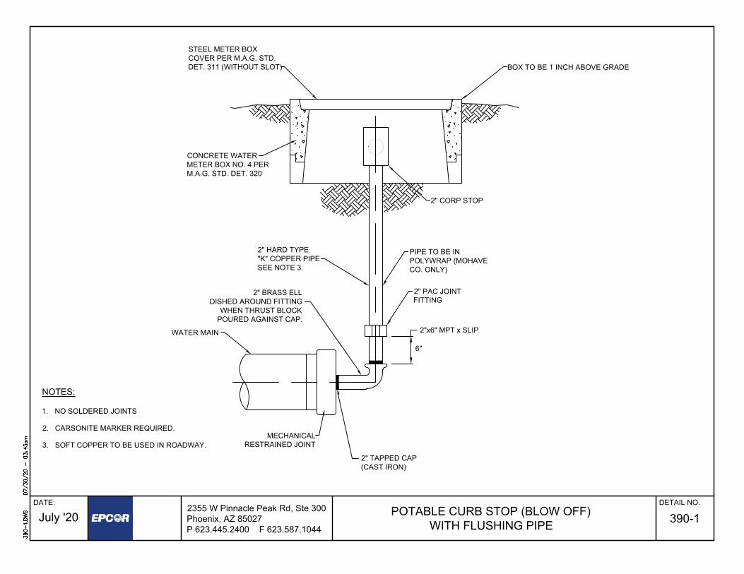
POTABLE CURB STOP (BLOW OFF)WITH FLUSHING PIPE
DATE: DETAIL NO.
390-1
2355 W Pinnacle Peak Rd, Ste 300Phoenix, AZ 85027P 623.445.2400 F 623.587.1044
July '20
BOX TO BE 1 INCH ABOVE GRADE
WATER MAIN
2" CORP STOP
NOTES:
1. NO SOLDERED JOINTS
2. CARSONITE MARKER REQUIRED.
3. SOFT COPPER TO BE USED IN ROADWAY.
STEEL METER BOXCOVER PER M.A.G. STD.DET. 311 (WITHOUT SLOT)
CONCRETE WATERMETER BOX NO. 4 PERM.A.G. STD. DET. 320
2" HARD TYPE"K" COPPER PIPESEE NOTE 3.
2" TAPPED CAP(CAST IRON)
2" PAC JOINTFITTING
2"x6" MPT x SLIP
6"
PIPE TO BE INPOLYWRAP (MOHAVECO. ONLY)
2" BRASS ELLDISHED AROUND FITTING
WHEN THRUST BLOCKPOURED AGAINST CAP.
MECHANICALRESTRAINED JOINT

TEMPORARY MANHOLE PLUGDATE: DETAIL NO.
4202355 W Pinnacle Peak Rd, Ste 300Phoenix, AZ 85027P 623.445.2400 F 623.587.1044
July '20
SECTION VIEW
TOP VIEW
CHANNEL PER M.A.G.STD. DET. 420-3
CONCRETEMANHOLE BASEPER M.A.G. STD.
DET. 420-2
90° MIN.
DIAMETER PER PLAN
OTHERPIPE TYPES
CLAY PIPE
2"x4" BOARD
TETHERCHAIN/CABLE
MECHANICAL PLUG
2"x4" BOARD
PIPE CONNECTIONPER M.A.G. STD.DET. 420-2
TETHERCHAIN/CABLE
MECHANICAL PLUG
PIPE CONNECTIONPER M.A.G. STD.
DET. 420-2
PRECAST MANHOLEBASE PER M.A.G.STD. DET. 420-2

TYPICAL GRAVITY/SOLIDS INTERCEPTOR
DATE: DETAIL NO.
450-1
2355 W Pinnacle Peak Rd, Ste 300Phoenix, AZ 85027P 623.445.2400 F 623.587.1044
July '20
ALL GRADIENT RISERS, INCLUDING THE MANHOLE FRAMEWILL HAVE THE INTERIOR SEALED WITH NON-SHRINK GROUT
PIPE CONNECTIONS SHALL BE FLEXIBLE CONNECTIONS ANDCOMPLY WITH ASTM C923 OR ASTM C1644 FOR PRECASTINTERCEPTORS; OR SECTION 7 OF C923 OR ASTM C1644 FORMATERIALS OTHER THAN PRECAST CONCRETE.
MANHOLE, FRAME, COVER, AND COLLAR MUST BEWATERTIGHT (GASKETED), ANCHORED, DOES NOT SLIDE,AND SUPPORTS ANTICIPATED LOADS. REFERENCE M.A.G.DETAILS 422 AND 424-1.
OUTLET AND BAFFLE PLUMBING: MUST BE OPEN TOPPED, 12”DISTANCE FROM INTERNAL FLOOR TO END OF PIPE ANDEXTEND 5” ABOVE THE LIQUID LEVEL. INTERNAL PIPINGSHALL BE 4” DIAMETER.
CONSTRUCTION & SPECIFICATIONS TO MOST CURRENTREVISIONS OF ASTM C1613/ ASTM F2649/IAPMO/ANSI Z1001
2-WAY CLEANOUT ON THE OUTLET LINE. VENTINTERCEPTOR TO ROOF.
WATER TEST AND REPAIR: INSPECTED BY EPCORPRETREATMENT COORDINATOR PER ASTM C1613; IAPMOZ1001 OR NPCA BEST PRACTICES GUIDELINES.
ACCESS: MINIMUM 2: ON LARGER SIZES EACH PLUMBINGFITTING (INLET, BAFFLE AND OUTLET) SHALL HAVE THEREQUIRED AND STIPULATED ACCESS OPENING, RISERSAND COVERS.
SUITABLE SUB-BASE BEDDING WITH GRANULAR MATERIALSHALL BE PREPARED TO HANDLE ANTICIPATED LOADS.
CONTACT EPCOR PRETREATMENT [email protected] FOR INSPECTION/TESTING.
INLET AND OUTLET PLUMBING MUST HAVE TEE'S.
INLET TEE MUST HAVE A CAP
1
2
3
4
5
6
7
8
NOTES:
10
2
3
2
1
TOP VIEW
SIDE SECTION VIEW
FINISHED GRADE
OUTLETINLET
VENT
7
4 44
7
(COVERS & RINGS REMOVED)
69
11
12
11
11
12

TYPICAL HYDROMECHANICAL GREASE INTERCEPTOR (HGI)
DATE: DETAIL NO.
450-2
2355 W Pinnacle Peak Rd, Ste 300Phoenix, AZ 85027P 623.445.2400 F 623.587.1044
July '20
PLAN VIEW
LID *
INLET
1/4" GALVANIZED DIAMOND PLATE OR EQUIVALENT
BAFFLES(2 OR 3 TYPICAL)
NOTES:
1. PERFORMANCE STANDARDS: MUST BE CERTIFIEDPER (PDI) G-101 / ASME A112.14.3 / CSA B481 OR MOSTCURRENT REVISIONS .
2. A FLOW CONTROL DEVICE MUST BE INSTALLED TOMANUFACTURES' SPECIFICATION ON THE INLET PIPEPRIOR TO ENTERING THE HYDROMECHANICALGREASE INTERCEPTOR (HGI). FLOW CONTROL MUSTBE ACCESSIBLE FOR MAINTENANCE.
3. HGI MAY BE INSTALLED ABOVE GROUND OR BELOWFLOOR GRADE.
4. HGI MUST BE EASILY ACCESSIBLE FOR INSPECTIONAND MAINTENANCE.
5. FILL WITH CLEAN WATER PRIOR TO START UP.
6. HGI MUST BE INSPECTED PRIOR TO BACKFILL BYEPCOR PRETREATMENT COORDINATOR.
7. USE AND SIZE TO BE APPROVED BY EPCORPRETREATMENT- INSPECTED BY PRETREATMENTCOORDINATOR.
9. PROPER AIR CONTROL IS CRITICAL TO THEOPERATION OF AN HGI. AIR INTAKE ON THE INLET AND VENTED WASTE ON THE OUTLET.
10. CONTACT EPCOR PRETREATMENT [email protected] FOR SHOP DRAWINGSUBMITTAL AND INSPECTION/TESTING. SECTION
FLOWCONTROLDEVICE
AIR INTAKEVENTEDWASTE
* LID MUST BE CAPABLE OF SUPPORTING ANTICIPATED LOADS

RECLAIMED WATERID TAG AND DECAL
DATE: DETAIL NO.
600-1
2355 W Pinnacle Peak Rd, Ste 300Phoenix, AZ 85027P 623.445.2400 F 623.587.1044
July '20
VALVE TAG:3"x8"x3
16" PURPLE POLYETHYLENE PLASTIC WITHMINIMUM 12" HIGH BLACK LETTERING IN ACCORDANCEWITH M.A.G. SECTION 616. TAG TO BE ATTACHED WITHSTAINLESS STEEL WIRE.
IDENTIFICATION DECAL:5"x16"x3
16" PURPLE POLYETHYLENE PLASTIC WITHMINIMUM 1" HIGH BLACK LETTERING IN ACCORDANCEWITH M.A.G. SECTION 616. DECAL TO BE ATTACHED WITHAN EPOXY ADHESIVE.

RECLAIMED WATER SERVICE CONNECTION
DATE: DETAIL NO.
610-1
NOTES:
1. SEE EPCOR STD. DET. 100-3 FOR APPROVED SADDLES.
2. METER TO BE SET BY EPCOR UPON PAYMENT OF FEES.
3. CONCRETE METER BOX PER M.A.G. STD. DET. 320 BOX NO. 2 OR 4 W/ STEELLID W/ 2 INCH DIAM. OPENING TO BE SET PERPENDICULAR TO BACK OF WALKOR CURB. BOX TO MATCH SLOPE OF FINISH GRADE AND SET 1" ABOVE FINISHGRADE OR BACK OF WALK OR CURB. 3a 2 INCH DIAMETER OPENING.
4. IDENTIFICATION DECAL PER EPCOR STD. DET. 600-1.
5. VALVE TAG PER EPCOR STD. DET. 600-1.
6. RECLAIMED LINE COPPER PIPE TO BE WRAPPED WITH PURPLEPOLYETHYLENE TAPE.
7. ANGLE BALL METER VALVE TEE HEAD TO BE STAMPED "RECLAIMED WATER".
8. CAL WESTERN INC TYPE CAL102 PURPLE POLY SLEEVE REQUIRED IN MOHAVECOUNTY ONLY. TRACER WIRE REQUIRED ON TOP OF SLEEVE.
2355 W Pinnacle Peak Rd, Ste 300Phoenix, AZ 85027P 623.445.2400 F 623.587.1044
July '20
WAT
ER
M
AIN
EDGE OFSIDEWALK
PROPERTY OR EASEMENT LINE
BALL STYLE CORP STOP WITHCOMPRESSION TYPE NUT
PLAN VIEW SECTION A-A
30" M
IN.
CO
VER
ON
SER
VIC
E
ALL SERVICES
SECTION B-B
TO BUILDING
AABB
30" M
IN.
30°
8"
1
1
4
BALL STYLE ANGLE METER VALVEW/COMPRESSION CONNECTION & LOOPFOR LOCK
FEMALE I.P. THREADMETER FLANGE
6
3a
2 INCH HOLE TO BECENTERED IN REARQUARTER SECTION OFMETER BOX LID
STREET
86
8
COPPER PIPEROLL TYPE "K"1 12" or 2" WITH6 INCH SANDSHADING
427
5

RECLAIMED WATERUNDERGROUND AIR RELEASE VALVE
DATE: DETAIL NO.
620-2
2355 W Pinnacle Peak Rd, Ste 300Phoenix, AZ 85027P 623.445.2400 F 623.587.1044
July '20
NOTE:
IF MULTIPLE ARV's ARE INSTALLED, EACH BOX MUST BE SEPARATED BY 3' MINIMUM.
2' MINFROM EDGE OF
CURB OR SIDEWALK
36" DIA FRP MANHOLE W/ H20 LOAD RATING& IN ACCORDANCE W/ ASTM D-3753
2" CURB STOP PAC-JOINT X IPT
UNION FITTING
12" ABC BASE, 95% COMPACTIONPER M.A.G. SECT. 601.4.4
3" CLEAN GRAVEL
2" BRASS 90° ELBOW
3" THICK CONCRETE SUPPORT
MINIMUM CLEARANCE 6" ALL SIDES
FERNCO COUPLINGW/ STAINLESS STEELBANDS
2" GALVANIZED90° ELBOW
CONCRETE THRUST BLOCKPER M.A.G. STD. DET. 380
POLYWRAPPED 2" PVC 90°ELBOW (SCH. 80)
4" MIN
.
2" PVC90° ELBOW
24" FRAME & COVERPER MAG STD DET 424
2" SCH 80 PVC
12"
MIN
.
1/8" STAINLESS STEEL MESH SCREENWITH STAINLESS STEEL CLAMPS
1 SACK CLSM PER M.A.G.SECT. 728 12" MIN TOUNDISTURBED GROUND
12" CONCRETE COLLAR2" BELOW FINISH GRADE
MANHOLE COVERTO BE LABELED:
45° OR 90° BENDAS NEEDED
6"
6"MIN.
2" SOFT TYPE "K" COPPERPIPE WRAPPED WITH PURPLEPOLYETHYLENE TAPE. EXTENDLINE BEYOND PAVEMENTWHEN MAIN LINE IS IN STREET.IN MOHAVE COUNTY, COPPERPIPE SHALL BE IN POLYWRAPSLEEVING.
AIR RELEASE VALVE(CRISPIN/VALVMATIC)STENCILED "RECLAIMEDWATER" IN ACCORDANCEWITH M.A.G. SECT. 616.
ALL ABOVE GROUND PIPE TO BE PAINTEDWITH UV RESISTANT PAINT (10 MIL MIN.THICKNESS). COLOR TO MATCHSURROUNDING LANDSCAPE WITH"RECLAIMED WATER" STENCILED ON PIPEIN ACCORDANCE WITH M.A.G. SECT. 616. IDENTIFICATION
DECAL PER EPCORSTD. DET. 600-1.
VALVE TAG PER EPCOR STD. DET. 600-1
PVCSLEEVE
SEE EPCOR'S STD. DET. 100-3FOR APPROVED SADDLES.
2" CORP STOP IPTPAC-JOINT
STREET ELBOW

RECLAIMED WATER CURB STOP (BLOW OFF)WITH FLUSHING PIPE
DATE: DETAIL NO.
630-1
2355 W Pinnacle Peak Rd, Ste 300Phoenix, AZ 85027P 623.445.2400 F 623.587.1044
July '20
BOX TO BE 1 INCH ABOVE GRADE
RECLAIMED WATER MAIN
2" CORP STOP
2" BRASS ELL
NOTES:
1. NO SOLDERED JOINTS
2. CARSONITE MARKER REQUIRED.
3. SOFT COPPER TO BE USED IN ROADWAY.
STEEL METER BOXCOVER PER M.A.G. STD.DET. 311 (WITHOUT SLOT)
CONCRETE WATERMETER BOX NO. 4 PERM.A.G. STD. DET. 320
2" HARD TYPE"K" COPPER PIPESEE NOTE 3.
2" TAPPED CAP(CAST IRON)
2" PAC JOINTFITTING
2"x6" MPT x SLIP
6"
PIPE TO BE IN POLYWRAP(MOHAVE CO. ONLY)
DISHED AROUND FITTINGWHEN THRUST BLOCK
POURED AGAINST CAP.
IDENTIFICATION DECAL PEREPCOR STD. DET. 600-1.
VALVE TAG PER EPCORSTD. DET. 600-1.
MECHANICALRESTRAINED JOINT