2022 frontier
TRANSCRIPT

For your safety, read carefully and keep in this vehicle.
2022 FRONTIEROWNER’S MANUAL
and MAINTENANCE INFORMATION

The information contained within this supplement revises or adds to the“Supplemental Restraint System (SRS)” section of the “Safety-Seats, seat belts and
supplemental restraint system” section in the 2022 Frontier Owner’s Manual.
Read carefully and keep in the vehicle.
Printing: June 2021
Publication No. SU22EA 0D41U0
OWNER’S MANUAL SUPPLEMENT

PRECAUTIONS ON SRSThis SRS section contains important infor-mation concerning the following systems:• Driver and front passenger supplemental
front-impact air bag (NISSAN AdvancedAir Bag System)
• Front seat-mounted side-impact supple-mental air bag
• Roof-mounted curtain side-impact androllover supplemental air bag
• Driver and front passenger supplementalknee air bag
• Seat belt with pretensioner(s) (front andrear outboard seats)
Supplemental front-impact air bag sys-temThe NISSAN Advanced Air Bag System canhelp cushion the impact force to the headand chest of the driver and front passengerin certain frontal collisions.Front seat-mounted side-impactsupplemental air bag systemThis system can help cushion the impactforce to the chest area of the driver andfront passenger in certain side-impact col-lisions. The side air bags are designed toinflate on the side where the vehicle is im-pacted.
Roof-mounted curtain side-impact androllover supplemental air bag systemThis system can help cushion the impactforce to the head of occupants in front andrear outboard seating positions in certainside-impact or rollover collisions. In a side-impact, the curtain air bags are designedto inflate on the side where the vehicle isimpacted. In a rollover, the curtain air bagsare designed to inflate and remain inflatedfor a short time.Driver and front passenger supplemen-tal knee air bagsThis system can help cushion the impactforce to the driver’s and front passenger’sknees in certain collisions.The SRS is designed to supplement thecrash protection provided by the seat beltsand is not a substitute for them. Seat beltsshould always be correctly worn and theoccupant seated a suitable distance awayfrom the steering wheel, instrument paneland door finishers. For additional informa-tion, see “Seat belts” in this section.
The supplemental air bags operate onlywhen the ignition switch is in the ON orSTART position.After placing the ignition switch in theON position, the supplemental air bagwarning light illuminates. The supple-mental air bag warning light will turn offafter about 7 seconds if the system isoperational.
SUPPLEMENTAL RESTRAINT SYSTEM(SRS)

WARNING
• The front air bags ordinarily will notinflate in the event of a side impact,rear impact, rollover, or lower sever-ity frontal collision. Always wear yourseat belts to help reduce the risk orseverity of injury in various kinds ofaccidents.
• The front passenger air bag and frontpassenger supplemental knee airbag will not inflate if the passengerair bag status light is lit or if the frontpassenger seat is unoccupied. Foradditional information, see “Frontpassenger air bag and status light” inthis section.
• The seat belts and the front air bagsare most effective when you are sit-ting well back and upright in the seat.The front air bags inflate with greatforce. Even with the NISSAN Ad-vanced Air Bag System, if you are un-restrained, leaning forward, sittingsideways or out of position in anyway, you are at greater risk of injuryor death in a crash. You may also re-ceive serious or fatal injuries fromthe front air bag if you are up againstit when it inflates. Always sit backagainst the seatback and as far awayas practical from the steering wheelor instrument panel. Always properlyuse the seat belts.
• The driver and front passenger seatbelt buckles are equipped with sen-sors that detect if the seat belts arefastened. The NISSAN Advanced AirBag System monitors the severity ofa collision and seat belt usage, theninflates the air bags as needed. Fail-ure to properly wear seat belts canincrease the risk or severity of injuryin an accident.
WRS0031

• The front passenger seat is equippedwith an occupant classification sen-sor (weight sensors) that turns thefront passenger air bag OFF undersome conditions. This sensor is onlyused in this seat. Failure to be prop-erly seated and wearing the seat beltcan increase the risk or severity ofinjury in an accident. For additionalinformation, see “Front passenger airbag and status light” in this section.
• Keep hands on the outside of thesteering wheel. Placing them insidethe steering wheel rim could increasethe risk that they are injured whenthe front air bag inflates.
ARS1133

WARNING
• Never let children ride unrestrainedor extend their hands or face out ofthe window. Do not attempt to holdthem in your lap or arms. Some ex-amples of dangerous riding posi-tions are shown in the illustrations.
WARNING
• Children may be severely injured orkilled when the front air bags, side airbags or curtain air bags inflate if theyare not properly restrained. Pre-teens and children should be prop-erly restrained in the rear seat, ifpossible.
ARS1041 ARS1042 ARS1043

WARNING
• Even with the NISSAN Advanced AirBag System, never install a rear-facing child restraint in the front seat.An inflating front air bag could seri-ously injure or kill your child. For ad-ditional information, see “Child re-straints” in this section.
ARS1044 ARS1045 WRS0256
WARNING
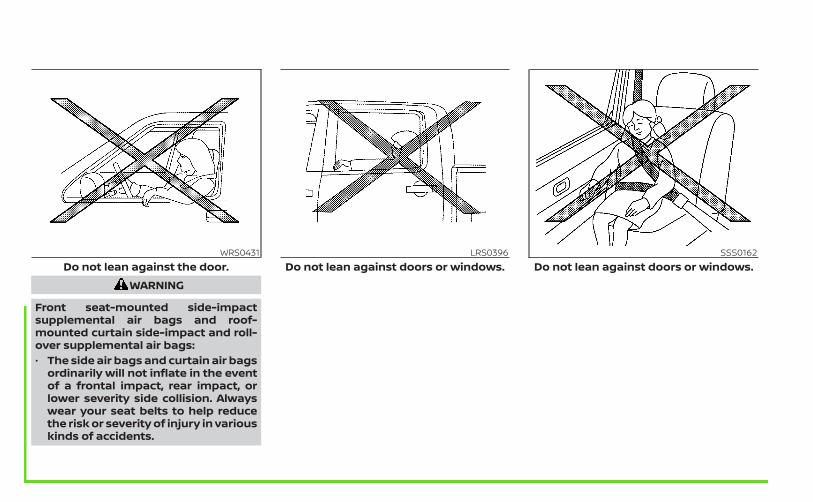
Front seat-mounted side-impactsupplemental air bags and roof-mounted curtain side-impact and roll-over supplemental air bags:• The side air bags and curtain air bags
ordinarily will not inflate in the eventof a frontal impact, rear impact, orlower severity side collision. Alwayswear your seat belts to help reducethe risk or severity of injury in variouskinds of accidents.
WRS0431Do not lean against the door.
LRS0396Do not lean against doors or windows.
SSS0162Do not lean against doors or windows.

WARNING
• The seat belts, the side air bags andcurtain air bags are most effectivewhen you are sitting well back andupright in the seat. The side air bagand curtain air bag inflate with greatforce. Do not allow anyone to placetheir hand, leg or face near the sideair bag on the side of the seatback ofthe front seat or near the side roofrails. Do not allow anyone sitting inthe front seats or rear outboard seatsto extend their hand out of the win-dow or lean against the door. Someexamples of dangerous riding posi-tions are shown in the previousillustrations.
WARNING
• When sitting in the rear seat, do nothold onto the seatback of the frontseat. If the side air bag inflates, youmay be seriously injured. Be espe-cially careful with children, whoshould always be properly re-strained. Some examples of danger-ous riding positions are shown in theillustrations.
• Do not use seat covers on the frontseatbacks. They may interfere withside air bag inflation.
LRS0421 SSS0159

CALIFORNIA PROPOSITION 65 WARNINGWARNING
Operating, servicing and maintaining a passengervehicle or off-highwaymotor vehicle can expose you tochemicals including engine exhaust, carbon monoxide,phthalates, and lead, which are known to the State ofCalifornia to cause cancer and birth defects or otherreproductive harm. To minimize exposure, avoidbreathing exhaust, do not idle the engine except asnecessary, service your vehicle in a well-ventilated areaand wear gloves or wash your hands frequently whenservicing your vehicle. For more information go towww.P65Warnings.ca.gov/passenger-vehicle.

This manual was prepared to help you un-derstand the operation and maintenanceof your vehicle so that you may enjoy manymiles (kilometers) of driving pleasure.Please read through this manual beforeoperating your vehicle.A separate Warranty Information Book-let explains details about the warrantiescovering your vehicle. The “Maintenanceand schedules” section of this manualexplains details about maintaining andservicing your vehicle. Additionally, aseparate Customer Care/Lemon LawBooklet (U.S. only) will explain how to re-solve any concerns you may have withyour vehicle, and clarify your rights un-der your state's lemon law.When you require any service or have anyquestions, a NISSAN dealer will be glad toassist you with the extensive resourcesavailable to them.In addition to factory-installed options,your vehicle may also be equipped withadditional accessories installed prior to de-livery. It is recommended that you visit aNISSAN dealer for details concerning theparticular accessories with which your ve-hicle is equipped. It is important that youfamiliarize yourself with all disclosures,warnings, cautions and instructions con-
cerning proper use of such accessoriesprior to operating the vehicle and/or ac-cessory. It is recommended that you visit aNISSAN dealer for details concerning theparticular accessories with which your ve-hicle is equipped.
Before driving your vehicle, please read thisOwner's Manual carefully. This will ensurefamiliarity with controls and maintenancerequirements assisting you in the safe op-eration of your vehicle.
WARNING
IMPORTANT SAFETY INFORMATIONREMINDERS!Follow these important driving rules tohelp ensure a safe and comfortable tripfor you and your passengers!• NEVER drive under the influence of
alcohol or drugs.• ALWAYS observe posted speed limits
and never drive too fast for conditions.• ALWAYS give your full attention to
driving and avoid using vehicle fea-tures or taking other actions thatcould distract you.
• ALWAYS use your seat belts and ap-propriate child restraint systems.Pre-teen children should be seated inthe rear seat.
• ALWAYS provide information aboutthe proper use of vehicle safety fea-tures to all occupants of the vehicle.
• ALWAYS review this Owner’s Manualfor important safety information.
FOREWORD READ FIRST—THEN DRIVE SAFELY

For descriptions specified for 4-wheel drivemodels, a mark is placed at the be-ginning of the applicable sections/items.As with other vehicles with features foroff-road use, failure to operate 4-wheeldrive models correctly may result in lossof control or a collision. For additionalinformation, see “Driving safety precau-tions” (P. 5-11).
ON-PAVEMENT AND OFF-ROAD DRIVINGThis vehicle will handle and maneuverdifferently from an ordinary passengercar because it has a higher center ofgravity for off-road use. As with othervehicles with features of this type, fail-ure to operate this vehicle correctly mayresult in loss of control or an accident.For additional information, see “On-pavement and off-road driving precau-tions” (P. 5-9), “Avoiding collision androll-over” (P. 5-9) and “Driving safetyprecautions” (P. 5-11).
MODIFICATION OF YOUR VEHICLEThis vehicle should not be modified.Modification could affect its perfor-mance, safety, emissions or durabilityand may even violate governmentalregulations. In addition, damage or per-formance problems resulting frommodifications may not be covered un-der NISSAN warranties.
WARNING
Installing an aftermarket On-Board Di-agnostic (OBD) plug-in device that usesthe port during normal driving, for ex-ample remote insurance companymonitoring, remote vehicle diagnos-tics, telematics or engine reprogram-ming, may cause interference or dam-age to vehicle systems. We do notrecommend or endorse the use of anyaftermarket OBD plug-in devices, un-less specifically approved by NISSAN.The vehicle warranty may not coverdamage caused by any aftermarketplug-in device.
This manual includes information for allfeatures and equipment available on thismodel. Features and equipment in your ve-hicle may vary depending on model, trimlevel, options selected, order, date of pro-duction, region or availability. Therefore,you may find information about features orequipment that are not included or in-stalled on your vehicle.All information, specifications and illustra-tions in this manual are those in effect atthe time of printing. NISSAN reserves theright to change specifications, perfor-mance, design or component supplierswithout notice and without obligation.From time to time, NISSAN may update orrevise this manual to provide Owners withthe most accurate information currentlyavailable. Please carefully read and retainwith this manual all revision updates sentto you by NISSAN to ensure you have ac-cess to accurate and up-to-date informa-tion regarding your vehicle. Current ver-sions of vehicle Owner's Manuals and anyupdates can also be found in the Ownersection of the NISSAN website at https://owners.nissanusa.com/nowners/navigation/manualsGuide. If you havequestions concerning any information in
WHEN READING THE MANUAL

your Owner's Manual, contact NISSAN Con-sumer Affairs. For contact information,refer to the NISSAN CUSTOMER CAREPROGRAM page in this Owner’s Manual.
IMPORTANT INFORMATION ABOUTTHIS MANUALYou will see various symbols in this manual.They are used in the following ways:
WARNING
This is used to indicate the presence ofa hazard that could cause death or se-rious personal injury. To avoid or re-duce the risk, the procedures must befollowed precisely.
CAUTION
This is used to indicate the presence ofa hazard that could cause minor ormoderate personal injury or damageto your vehicle. To avoid or reduce therisk, the procedures must be followedcarefully.
If you see this symbol, it means “Do not dothis” or “Do not let this happen.”
If you see a symbol similar to these in anillustration, it means the arrow points to thefront of the vehicle.
Arrows in an illustration that are similar tothese indicate movement or action.
Arrows in an illustration that are similar tothese call attention to an item in theillustration.
CALIFORNIA PERCHLORATEADVISORYSome vehicle parts, such as lithium bat-teries, may contain perchlorate material.The following advisory is provided: “Per-chlorate Material – special handling mayapply. For additional information, referto www.dtsc.ca.gov/hazardouswaste/perchlorate/”.
© 2021 NISSAN NORTH AMERICA, INC.All rights reserved. No part of this Owner'sManual may be reproduced or stored in aretrieval system, or transmitted in anyform, or by any means, electronic, me-chanical, photocopying, recording or oth-erwise, without the prior written permis-sion of Nissan North America, Inc.
APD1005

NISSAN CARES . . .Both NISSAN and your NISSAN dealer are dedicated to serving all your automotive needs. Your satisfaction with your vehicle and yourNISSAN dealer are our primary concerns. Your NISSAN dealer is always available to assist you with all your automobile sales and serviceneeds.However, if there is something that yourNISSAN dealer cannot assist you with oryou would like to provide NISSAN directlywith comments or questions, please con-tact the NISSAN Consumer Affairs Depart-ment using our toll-free number:For U.S. customers
1-800-NISSAN-1(1-800-647-7261)
For Canadian customers1-800-387-0122
The Consumer Affairs Department will askfor the following information:– Your name, address, and telephone
number– Vehicle identification number (attached
to the top of the instrument panel on thedriver's side)
– Date of purchase– Current odometer reading– Your NISSAN dealer's name– Your comments or questionsOR
You can write to NISSAN with the informa-tion at:For U.S. customers
Nissan North America, Inc.Consumer Affairs DepartmentP.O. Box 685003Franklin, TN 37068-5003or via e-mail at:[email protected]
For Canadian customersNissan Canada Inc.5290 Orbitor DriveMississauga, Ontario L4W 4Z5or via e-mail at:[email protected]
If you prefer, visit us at:www.nissanusa.com (for U.S. customers)orwww.nissan.ca (for Canadian customers)
We appreciate your interest in NISSAN and thank you for buying a quality NISSAN vehicle.
NISSAN CUSTOMER CARE PROGRAM

Table ofcontents
Illustrated table of contents
Safety-Seats, seat belts and supplemental restraint system
Instruments and controls
Pre-driving checks and adjustments
Monitor, climate, audio, phone and voice recognition systems
Starting and driving
In case of emergency
Appearance and care
Do-it-yourself
Maintenance and schedules
Technical and consumer information
Index
0
1
2
3
4
5
6
7
8
9
10
11

0 Illustrated table of contents
Air bags, seat belts and child restraints . . . . . . . . . . 0-2Exterior front . . . . . . . . . . . . . . . . . . . . . . . . . . . . . . . . . . . . 0-3Exterior rear . . . . . . . . . . . . . . . . . . . . . . . . . . . . . . . . . . . . . 0-4Passenger compartment . . . . . . . . . . . . . . . . . . . . . . . 0-5
Instrument panel . . . . . . . . . . . . . . . . . . . . . . . . . . . . . . . . 0-6Engine compartment check locations . . . . . . . . . . . 0-8Warning and indicator lights . . . . . . . . . . . . . . . . . . . . . 0-9

1. Rear outboard seat belts with preten-sioner(s) (P. 1-22)
2. Roof-mounted curtain side-impact androllover supplemental air bag (P. 1-89)
3. Head restraints/headrests (P. 1-10)4. Front outboard seat belts with shoulder
height adjuster and pretensioner(s)(P. 1-22)
5. Supplemental front-impact air bags(P. 1-72)
6. Driver supplemental knee air bag(P. 1-90)Front passenger supplemental knee airbag (P. 1-90)
7. Seats (P. 1-2)8. Occupant classification sensor (weight
sensor) (P. 1-72)9. Front seat-mounted side-impact
supplemental air bag (P. 1-72)10. LATCH (Lower Anchors and Tethers for
CHildren) system (P. 1-31)11. Top tether strap anchor (P. 1-34)Refer to the page number indicated inparentheses for operating details.
LII2734
AIR BAGS, SEAT BELTS AND CHILDRESTRAINTS
0-2 Illustrated table of contents

1. Windows (P. 2-68)2. Moonroof (if so equipped) (P. 2-71)3. Windshield (P. 8-20)4. Wiper and washer switch (P. 2-37)
5. Engine hood (P. 3-20)6. Front view camera (if so equipped)
(P. 4-11)
7. Front recovery hooks (if so equipped)(P. 6-17)
8. Fog light switch (if so equipped) (P. 2-44)Daytime Running Lights (DRL) system(if so equipped) (P. 2-43)
9. Headlight and turn signal switch(P. 2-38)Daytime Running Lights (DRL) system(if so equipped) (P. 2-43)LED Daytime Running Lights (DRL)system (if so equipped) (P. 2-43)Replacing bulbs (P. 8-27)
10. Tire pressure (P. 8-31)Flat tire (P. 6-3)Tire chains (P. 8-39)
11. Mirrors (P. 3-25)Side view camera (if so equipped)(P. 4-11)
12. Door locks (P. 3-4)NISSAN Intelligent Key® (P. 3-2)
Refer to the page number indicated inparentheses for operating details.
LII2711
EXTERIOR FRONT
Illustrated table of contents 0-3

1. Rear sliding window (if so equipped)(P. 2-71)
2. Vehicle loading (P. 10-16)Tailgate (P. 3-27)Truck box (P. 3-27)
3. Towing (if so equipped) (P. 10-27)4 Rearview camera (P. 4-3, P. 4-11)5 Rear sonar sensors (if so equipped)
(P. 5-125)6. Replacing bulbs (P. 8-27)7. Fuel-filler cap (P. 3-21)
Fuel recommendation (P. 10-2)8. Child safety rear door lock (P. 3-7)Refer to the page number indicated inparentheses for operating details.
LII2697
EXTERIOR REAR
0-4 Illustrated table of contents

1. Power moonroof (if so equipped)(P. 2-71)
2. Map lights (P. 2-74)3. Sun visors (P. 3-24)4. Rearview mirror (P. 3-25)5. Glove box (P. 2-65)6. Shift lever (P. 5-20)
Cup holders (P. 2-66)7. Wireless charger (if so equipped)
(P. 2-58)8. Console box (P. 2-65)9. Spare tire tools location (P. 6-6)Refer to the page number indicated inparentheses for operating details.
LII2720
PASSENGER COMPARTMENT
Illustrated table of contents 0-5

1. Vents (P. 4-27)2. Headlight/fog lights/turn signal switch
(P. 2-38)
3. Bluetooth® Hands-Free Phone System(P. 4-2)Audio system controls (P. 4-2)
4. Driver supplemental air bag (P. 1-72)Horn (P. 2-45)
5. Meters and gauges (P. 2-4)Warning and indicator lights (P. 2-10)Vehicle information display (P. 2-20)
6. Cruise control switches (if so equipped)(P. 5-51)Intelligent cruise control (ICC) switches(if so equipped) (P. 5-53)
7. Wiper and washer switch (P. 2-37)8. Climate controls (P. 4-27, 4-36)
Outside mirror defroster switch(if so equipped) (P. 2-38)
9. Storage (P. 2-61)10. Audio system (P. 4-2)11. Front passenger air bag status light
(P. 1-83)Hazard warning flasher switch (P. 6-2)
12. Front passenger supplemental air bag(P. 1-72)
13. Front passenger supplemental knee airbag (P. 1-90)
14. Glove box (P. 2-65)15. Power outlet (P. 2-54)16. Storage (P. 2-61)17. Heated seats (if so equipped) (P. 2-46)18. USB connection port (P. 4-2)
AUX input (if so equipped) (P. 4-2)19. Shift lever (P. 5-20)
LII2716
INSTRUMENT PANEL
0-6 Illustrated table of contents
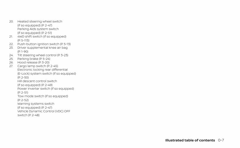
20. Heated steering wheel switch(if so equipped) (P. 2-47)Parking Aids system switch(if so equipped) (P. 2-51)
21. 4WD shift switch (if so equipped)(P. 5-113)
22. Push-button ignition switch (P. 5-13)23. Driver supplemental knee air bag
(P. 1-90)24. Tilt steering wheel control (P. 3-23)25. Parking brake (P. 5-24)26. Hood release (P. 3-20)27. Cargo lamp switch (P. 2-45)
Electronic locking rear differential(E-Lock) system switch (if so equipped)(P. 2-50)Hill descent control switch(if so equipped) (P. 2-49)Power inverter switch (if so equipped)(P. 2-51)Tow mode switch (if so equipped)(P. 2-52)Warning systems switch(if so equipped) (P. 2-47)Vehicle Dynamic Control (VDC) OFFswitch (P. 2-48)
Illustrated table of contents 0-7

3.8L 6 cylinder (VQ38DD engine model)1. Windshield-washer fluid reservoir
(P. 8-14)2. Fusible link (P. 8-22)3. Fuse/Fusible link box (P. 8-22)4. Fuse and Relay box (P. 8-22)5. Engine oil filler cap (P. 8-7)6. Engine oil dipstick (P. 8-7)7. Brake fluid reservoir (P. 8-13)8. Air cleaner (P. 8-19)9. Drive belt location (P. 8-17)10. Power steering fluid reservoir (P. 8-13)11. Radiator cap (P. 8-5)12. Battery (P. 8-15)13. Engine coolant reservoir (P. 8-5)NOTE:
Your vehicle may not be equipped withan engine cover.Refer to the page number indicated inparentheses for operating details.
LDI3520
ENGINE COMPARTMENT CHECKLOCATIONS
0-8 Illustrated table of contents

Warning/Indicatorlight (red)
Name Page
Automatic Trans-mission Parkwarning light( model)
2-11
or
Brake warninglight
2-12
Charge warninglight
2-13
Electric shiftcontrol systemwarning light
2-13
Engine oil pres-sure warning light
2-13
Warning/Indicatorlight (red)
Name Page
Master warninglight
2-13
Seat belt warninglight and chime
2-13
Security indicatorlight
2-14
Supplemental airbag warning light
2-14
Warning/Indicator
light(yellow)
Name Page
or
Anti-lock BrakingSystem (ABS)warning light
2-14
Automatic Emer-gency Braking(AEB) with Pedes-trian Detectionsystem warninglight
2-15
Automatic Trans-mission checkwarning light
2-15
Electronic lockingrear differential(E-Lock) systemON indicator light(if so equipped)
2-15
WARNING AND INDICATOR LIGHTS
Illustrated table of contents 0-9

Warning/Indicator
light(yellow)
Name Page
Front passengerair bag statuslight
2-15
Hill descent con-trol system ONindicator light(if so equipped)
2-15
Low tire pressurewarning light
2-15
Malfunction Indi-cator Light (MIL)
2-17
Master warninglight
2-18
Warning/Indicator
light(yellow)
Name Page
Rear AutomaticBraking (RAB)warning light (if soequipped)
2-18
Slip indicator light 2-18
Vehicle DynamicControl (VDC) OFFindicator light
2-19
Warning/Indicator
light(other)
Name Page
Front fog lightindicator light(green) (if soequipped)
2-19
Warning/Indicator
light(other)
Name Page
High Beam Assistindicator light(green) (if soequipped)
2-19
High beam indi-cator light (blue)
2-19
Side light andheadlight indica-tor light (green)
2-19
TOW mode ONindicator light(green) (if soequipped)
2-19
Turn signal/hazard indicatorlights (green)
2-19
0-10 Illustrated table of contents

MEMO
Illustrated table of contents 0-11

1 Safety-Seats, seat belts andsupplemental restraint system
Seats . . . . . . . . . . . . . . . . . . . . . . . . . . . . . . . . . . . . . . . . . . . . 1-2Front manual seat adjustment(if so equipped) . . . . . . . . . . . . . . . . . . . . . . . . . . . . . . . .1-3Front power seat adjustment(if so equipped) . . . . . . . . . . . . . . . . . . . . . . . . . . . . . . . 1-5Rear bench seat (if so equipped) . . . . . . . . . . . . . 1-6Jump seat (if so equipped) . . . . . . . . . . . . . . . . . . . .1-7Armrest (if so equipped) . . . . . . . . . . . . . . . . . . . . . . .1-7Flexible seating . . . . . . . . . . . . . . . . . . . . . . . . . . . . . . . .1-7
Head restraints/headrests . . . . . . . . . . . . . . . . . . . . . .1-10Adjustable head restraint/headrestcomponents . . . . . . . . . . . . . . . . . . . . . . . . . . . . . . . . . 1-11Non-adjustable head restraint/headrest components . . . . . . . . . . . . . . . . . . . . . . .1-12Remove . . . . . . . . . . . . . . . . . . . . . . . . . . . . . . . . . . . . . .1-12Install . . . . . . . . . . . . . . . . . . . . . . . . . . . . . . . . . . . . . . . .1-13Adjust . . . . . . . . . . . . . . . . . . . . . . . . . . . . . . . . . . . . . . . .1-13
Seat belts . . . . . . . . . . . . . . . . . . . . . . . . . . . . . . . . . . . . . . .1-15Precautions on seat belt usage. . . . . . . . . . . . . . .1-15Seat belt warning light and chime . . . . . . . . . . . .1-18Pregnant women . . . . . . . . . . . . . . . . . . . . . . . . . . . .1-19Injured persons . . . . . . . . . . . . . . . . . . . . . . . . . . . . . .1-19Three-point type seat belt withretractor . . . . . . . . . . . . . . . . . . . . . . . . . . . . . . . . . . . . .1-19Seat belt extenders . . . . . . . . . . . . . . . . . . . . . . . . . 1-25
Seat belt maintenance . . . . . . . . . . . . . . . . . . . . . . 1-25Child safety . . . . . . . . . . . . . . . . . . . . . . . . . . . . . . . . . . . . 1-26
Infants . . . . . . . . . . . . . . . . . . . . . . . . . . . . . . . . . . . . . . 1-27Small children . . . . . . . . . . . . . . . . . . . . . . . . . . . . . . . 1-27Larger children . . . . . . . . . . . . . . . . . . . . . . . . . . . . . . 1-27
Child restraints . . . . . . . . . . . . . . . . . . . . . . . . . . . . . . . . . 1-28Precautions on child restraints . . . . . . . . . . . . . . 1-28LATCH (Lower Anchors and Tethers forCHildren) system . . . . . . . . . . . . . . . . . . . . . . . . . . . . .1-31Rear-facing child restraint installationusing LATCH (Crew Cab models) . . . . . . . . . . . . . 1-34Rear-facing child restraint installationusing LATCH — jump seat (King Cab®models) . . . . . . . . . . . . . . . . . . . . . . . . . . . . . . . . . . . . . 1-36Rear-facing child restraint installationusing the seat belts (Crew Cab models) . . . . . 1-40Rear-facing child restraint installationusing the seat belts — jump seat(King Cab® models) . . . . . . . . . . . . . . . . . . . . . . . . . . 1-43Forward-facing child restraintinstallation using LATCH (Crew Cabmodels) . . . . . . . . . . . . . . . . . . . . . . . . . . . . . . . . . . . . . 1-48Forward-facing child restraintinstallation using LATCH — jump seat(King Cab® models) . . . . . . . . . . . . . . . . . . . . . . . . . . .1-51

Forward-facing child restraintinstallation using the seat belts — frontpassenger and rear bench seat(Crew Cab models) . . . . . . . . . . . . . . . . . . . . . . . . . . 1-56Forward-facing child restraintinstallation using the seat belts — frontpassenger and jump seats (King Cab®models) . . . . . . . . . . . . . . . . . . . . . . . . . . . . . . . . . . . . . .1-61
Booster seats . . . . . . . . . . . . . . . . . . . . . . . . . . . . . . . 1-67Supplemental Restraint System (SRS) . . . . . . . . . . 1-72
Precautions on SRS . . . . . . . . . . . . . . . . . . . . . . . . . 1-72Supplemental air bag warning labels . . . . . . . . 1-93Supplemental air bag warning light . . . . . . . . . 1-93

WARNING
• Do not ride in a moving vehicle whenthe seatback is reclined. This can bedangerous. The shoulder belt will notbe against your body. In an accident,you could be thrown into it and re-ceive neck or other serious injuries.You could also slide under the lap beltand receive serious internal injuries.
• For the most effective protectionwhen the vehicle is in motion, theseat should be upright. Always sitwell back and upright in the seat withboth feet on the floor and adjust theseat properly. For additional infor-mation, see “Precautions on seat beltusage” (P. 1-15).
• After adjustment, gently rock in theseat to make sure it is securelylocked.
• Do not leave children unattended in-side the vehicle. They could unknow-ingly activate switches or controls ormake the vehicle move. Unattendedchildren could become involved inserious accidents.
• To help avoid risk of injury or deaththrough unintended operation of thevehicle and/or its systems, do notleave children, people who requirethe assistance of others or pets unat-tended in your vehicle. Additionally,the temperature inside a closed ve-hicle on a warm day can quickly be-come high enough to cause a signifi-cant risk of injury or death to peopleand pets.
• Do not adjust the driver’s seat whiledriving so full attention may be givento vehicle operation. The seat maymove suddenly and could cause lossof control of the vehicle.
• The seatback should not be reclinedany more than needed for comfort.Seat belts are most effective when thepassenger sits well back and straightup in the seat. If the seatback is re-clined, the risk of sliding under the lapbelt and being injured is increased.
ARS1152
SEATS
1-2 Safety-Seats, seat belts and supplemental restraint system

CAUTION
When adjusting the seat positions, besure not to contact any moving parts toavoid possible injuries and/or damage.
FRONT MANUAL SEATADJUSTMENT (if so equipped)Your vehicle seats can be adjusted manu-ally. For additional information about ad-justing the seats, refer to the steps outlinedin this section.
Forward and backwardPull the lever up and hold it while you slidethe seat forward or backward to the de-sired position. Release the lever to lock theseat in position.
RecliningTo recline the seatback, pull the lever upand lean back. To bring the seatback for-ward, pull the lever up and lean your bodyforward. Release the lever to lock the seat-back in position.The reclining feature allows adjustment ofthe seatback for occupants of differentsizes for added comfort and to help obtainproper seat belt fit. For additional informa-tion, see “Precautions on seat belt usage”(P. 1-15). Also, the seatback can be reclinedto allow occupants to rest when the vehicleis stopped and the shift lever is in P (Park) or
LRS3439 LRS3440
Safety-Seats, seat belts and supplemental restraint system 1-3

N (Neutral) position with the parking brakefully applied.
Seat lifter (if so equipped fordriver's seat)Pull up or push down the adjusting lever toadjust the height of the seat cushion to thedesired position.
Lumbar support (if so equippedfor driver's seat)The lumbar support feature provides ad-justable lower back support to the driver.Move the lever forward or backward to ad-just the seat lumbar area.
LRS3441 LRS3430
1-4 Safety-Seats, seat belts and supplemental restraint system

FRONT POWER SEAT ADJUSTMENT(if so equipped)
Operating tips• The power seat motor has an auto-reset
overload protection circuit. If the motorstops during operation, wait 30 secondsthen reactivate the switch.
• Do not operate the power seat switch fora long period of time when the engine isoff. This will discharge the battery.
Forward and backwardMoving the switch as shown will slide theseat forward or backward to the desiredposition.
RecliningMove the recline switch as shown until thedesired angle is obtained.
The reclining feature allows adjustment ofthe seatback for occupants of differentsizes for added comfort and to help obtainproper seat belt fit. For additional informa-tion, see “Precautions on seat belt usage”(P. 1-15). Also, the seatback can be reclinedto allow occupants to rest when the vehicleis stopped and the shift lever is in P (Park) orN (Neutral) position with the parking brakefully applied.
LRS3428
Safety-Seats, seat belts and supplemental restraint system 1-5

Seat lifter (driver's seat)Move the switch as shown to adjust theheight of the seat cushion.
Lumbar support (driver's seat)The lumbar support feature provides ad-justable lower back support to the driver.Move the lever forward or backward to ad-just the seat lumbar area.
REAR BENCH SEAT (if so equipped)The rear bench seat is non-adjustable.However, the seats can be folded up andfolded to lay flat. For additional information,see “Flexible seating” (P. 1-7).
LRS3442 LRS3430 LRS3431
1-6 Safety-Seats, seat belts and supplemental restraint system

JUMP SEAT (if so equipped)WARNING
• Do not use a child restraint in thedriver's side jump seat. This seatingposition is not suitable for child re-straint installation. A child restraintcan be installed in the passenger'sside jump seat when the seat exten-sion is unfolded from the seat base.
• When folding the jump seat, be care-ful not to squeeze your finger be-tween the seat cushion and the bodyside.
ARMREST (if so equipped)To use the center armrest on the rearbench seat, pull on the tab in the center ofthe seat and fold it down as shown.
FLEXIBLE SEATINGWARNING
• Never allow anyone to ride in thecargo area or on the rear seats whenthey are in the fold-down position. Ina collision, people riding in these ar-eas without proper restraints aremore likely to be seriously injured orkilled.
• Do not allow people to ride in anyarea of your vehicle that is notequipped with seats and seat belts.Be sure everyone in your vehicle is ina seat and using a seat belt properly.
• Do not allow more than one personto use the same seat belt.
• Do not fold down the rear seats whenoccupants are in the rear seat area orany luggage is on the rear seats.– Make sure that the seat path is
clear before moving the seat.– Be careful not to allow hands or
feet to get caught or pinched inthe seat.
LRS0556 LRS3432
Safety-Seats, seat belts and supplemental restraint system 1-7

• Head restraints/headrests should beadjusted properly as they may pro-vide significant protection againstinjury in an accident. Always replaceand adjust them properly if they havebeen removed for any reason.
• If the head restraints/headrests areremoved for any reason, they shouldbe securely stored to prevent themfrom causing injury to passengers ordamage to the vehicle in case of sud-den braking or an accident.
• When returning the seatbacks to theupright position, be certain they arecompletely secured in the latchedposition. If they are not completelysecured, passengers may be injuredin an accident or sudden stop.
• Properly secure all cargo to help pre-vent it from sliding or shifting. Do notplace cargo higher than the seat-backs. In a sudden stop or collision,unsecured cargo could cause per-sonal injury.
Folding the rear bench seat up(if so equipped)To fold the rear bench seat up:1. Lift up on the lever, located on the side of
the seat, while lifting the front of the seatcushion up.
2. Fold the bottom of the seat cushion to-ward the back of the vehicle until it locksin place.
LRS3433 LRS2476
1-8 Safety-Seats, seat belts and supplemental restraint system

3. Repeat this process to raise and securethe seat cushion on the other side of thevehicle for maximum storage capacity.
To return the rear bench seat to a seatingposition, reverse the process. Make sure toproperly push the seat cushion downinto place.
WARNING
• When the vehicle is being used tocarry cargo, properly secure all cargoto help prevent it from sliding orshifting. Do not place cargo higherthan the seatbacks. In a sudden stopor collision, unsecured cargo couldcause personal injury.
• Do not allow people to ride in anyarea of your vehicle that is notequipped with seats and seat belts.Be sure everyone in your vehicle is ina seat and using a seat belt properly.Never ride in the rear seat unless theseat bottom cushions are in placeand latched.
• When returning the seatbacks to theupright position, be certain they arecompletely secured in the latchedposition. If they are not completelysecured, passengers may be injuredin an accident or sudden stop.
1. Pull strap2. Child restraint anchor points
Folding the rear bench seat down(if so equipped)The rear bench seatback can be tilted for-ward to access the child restraint anchorpoint locations or the jacking equipment.To tilt the seatback forward, pull the pullstrap up and tilt the seatback. The childrestraint anchor points can be accessedbehind the rear bench seatback. The jack-ing equipment can be accessed from be-hind the passenger’s side seatback..
LRS2477 LRS3434
Safety-Seats, seat belts and supplemental restraint system 1-9

WARNING
Never allow anyone to ride in the cargoarea or on the rear seat when it is in thefold-down position. Use of these areasby passengers without proper re-straints could result in serious injury ordeath in an accident or sudden stop.
WARNING
Head restraints/headrests supplementthe other vehicle safety systems. Theymay provide additional protectionagainst injury in certain rear end colli-sions. Adjustable head restraints/headrests must be adjusted properly,as specified in this section. Check theadjustment after someone else usesthe seat. Do not attach anything to thehead restraint/headrest stalks or re-move the head restraint/headrest. Donot use the seat if the head restraint/headrest has been removed. If the headrestraint/headrest was removed, rein-stall and properly adjust the headrestraint/headrest before an occupantuses the seating position. Failure to fol-low these instructions can reduce theeffectiveness of the head restraints/headrests. This may increase the risk ofserious injury or death in a collision.
LRS2020Crew Cab
HEAD RESTRAINTS/HEADRESTS
1-10 Safety-Seats, seat belts and supplemental restraint system

The illustration shows the seating positionsequipped with head restraints/headrests.� Indicates the seating position isequipped with a head restraint.� Indicates the seating position isequipped with a headrest.+ Indicates the seating position is notequipped with a head restraint or headrest(if applicable).• Your vehicle is equipped with a head
restraint/headrest that may be inte-grated, adjustable or non-adjustable.
• Adjustable head restraints/headrestshave multiple notches along the stalk(s)to lock them in a desired adjustmentposition.
• The non-adjustable head restraints/headrests have a single locking notch tosecure them to the seat frame.
• Proper Adjustment:– For the adjustable type, align the head
restraint/headrest so the center ofyour ear is approximately level with thecenter of the head restraint/headrest.
– If your ear position is still higher thanthe recommended alignment, placethe head restraint/headrest at thehighest position.
• If the head restraint/headrest has beenremoved, ensure that it is reinstalled andlocked in place before riding in that des-ignated seating position.
ADJUSTABLE HEAD RESTRAINT/HEADREST COMPONENTS1. Removable head restraint/headrest
2. Multiple notches
3. Lock knob
4. Stalks
LRS3150King Cab®
LRS2300
Safety-Seats, seat belts and supplemental restraint system 1-11

NON-ADJUSTABLE HEADRESTRAINT/HEADRESTCOMPONENTS1. Removable head restraint/headrest
2. Single notch
3. Lock knob
4. Stalks
REMOVEUse the following procedure to remove thehead restraint/headrest:1. Pull the head restraint/headrest up to
the highest position.
2. Push and hold the lock knob.
3. Remove the head restraint/headrestfrom the seat.
4. Store the head restraint/headrest prop-erly in a secure place so it is not loose inthe vehicle.
5. Reinstall and properly adjust the headrestraint/headrest before an occupantuses the seating position.
LRS2299 LRS2302
1-12 Safety-Seats, seat belts and supplemental restraint system

INSTALL1. Align the head restraint/headrest stalks
with the holes in the seat. Make sure thatthe head restraint/headrest is facing thecorrect direction. The stalk with thenotch (notches) O1 must be installed inthe hole with the lock knob O2 .
2. Push and hold the lock knob and pushthe head restraint/headrest down.
3. Properly adjust the head restraint/headrest before an occupant uses theseating position.
ADJUSTFor adjustable head restraint/headrestAdjust the head restraint/headrest so thecenter is level with the center of your ears.If your ear position is still higher than therecommended alignment, place the headrestraint/headrest at the highest position.
For non-adjustable head restraint/headrestMake sure the head restraint/headrest ispositioned so the lock knob is engaged inthe notch before riding in that designatedseating position.
LRS2303 WRS0134 LRS2351
Safety-Seats, seat belts and supplemental restraint system 1-13

RaiseTo raise the head restraint/headrest, pull itup.Make sure the head restraint/headrest ispositioned so the lock knob is engaged inthe notch before riding in that designatedseating position.
LowerTo lower, push and hold the lock knob andpush the head restraint/headrest down.Make sure the head restraint/headrest ispositioned so the lock knob is engaged inthe notch before riding in that designatedseating position.
LRS2305 LRS2306
1-14 Safety-Seats, seat belts and supplemental restraint system

PRECAUTIONS ON SEAT BELTUSAGEIf you are wearing your seat belt properlyadjusted and you are sitting upright andwell back in your seat with both feet on thefloor, your chances of being injured or killedin a collision and/or the severity of injurymay be greatly reduced. NISSAN stronglyencourages you and all of your passengersto buckle up every time you drive, even ifyour seating position includes a supple-mental air bag.
Most U.S. states and Canadian provincesor territories specify that seat belts beworn at all times when a vehicle is beingdriven.
SSS0136
SEAT BELTS
Safety-Seats, seat belts and supplemental restraint system 1-15

WARNING
• Every person who drives or rides inthis vehicle should use a seat belt atall times. Children should be in therear seats and in an appropriaterestraint.
WARNING
• The seat belt should be properly ad-justed to a snug fit. Failure to do somay reduce the effectiveness of theentire restraint system and increasethe chance or severity of injury in anaccident. Serious injury or death canoccur if the seat belt is not wornproperly.
SSS0134 SSS0016
1-16 Safety-Seats, seat belts and supplemental restraint system
WARNING
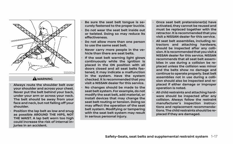
• Always route the shoulder belt overyour shoulder and across your chest.Never put the belt behind your back,under your arm or across your neck.The belt should be away from yourface and neck, but not falling off yourshoulder.
• Position the lap belt as low and snugas possible AROUND THE HIPS, NOTTHE WAIST. A lap belt worn too highcould increase the risk of internal in-juries in an accident.
• Be sure the seat belt tongue is se-curely fastened to the proper buckle.
• Do not wear the seat belt inside outor twisted. Doing so may reduce itseffectiveness.
• Do not allow more than one personto use the same seat belt.
• Never carry more people in the ve-hicle than there are seat belts.
• If the seat belt warning light glowscontinuously while the ignition isplaced in the ON position with alldoors closed and all seat belts fas-tened, it may indicate a malfunctionin the system. Have the systemchecked. It is recommended that youvisit a NISSAN dealer for this service.
• No changes should be made to theseat belt system. For example, do notmodify the seat belt, add material, orinstall devices that may change theseat belt routing or tension. Doing somay affect the operation of the seatbelt system. Modifying or tamperingwith the seat belt system may resultin serious personal injury.
• Once seat belt pretensioner(s) haveactivated, they cannot be reused andmust be replaced together with theretractor. It is recommended that youvisit a NISSAN dealer for this service.
• All seat belt assemblies, including re-tractors and attaching hardware,should be inspected after any colli-sion. It is recommended that you visit aNISSAN dealer for this service. NISSANrecommends that all seat belt assem-blies in use during a collision be re-placed unless the collision was minorand the belts show no damage andcontinue to operate properly. Seat beltassemblies not in use during a colli-sion should also be inspected and re-placed if either damage or improperoperation is noted.
• All child restraints and attaching hard-ware should be inspected after anycollision. Always follow the restraintmanufacturer's inspection instruc-tions and replacement recommenda-tions. The child restraints should be re-placed if they are damaged.
SSS0014
Safety-Seats, seat belts and supplemental restraint system 1-17

SEAT BELT WARNING LIGHT ANDCHIMEThe driver and front passenger seat isequipped with an enhanced seat belt re-minder function. If your vehicle is equippedwith an enhanced seat belt reminder func-tion, a visual and audible alert (Driver’s seatonly) will operate if a driver or front passen-ger seat belt is unbuckled at speeds of ap-proximately 9 mph (15 km/h) or more un-der the following conditions:• If the driver seat belt is not fastened.
• The front passenger’s seat belt is not fas-tened and the seat is occupied by a pas-senger for 7 seconds after the ignitionswitch is placed in the ON position.
• The front passenger’s seat belt is not fas-tened and objects or external force onthe passenger seat change the seat beltreminder classification to Occupied.
The seat belt warning light will flash underthe conditions shown above until the nec-essary seat belt is securely fastened.A warning chime will sound for approxi-mately 90 seconds or until one of the fol-lowing conditions is met:• The unbuckled front occupant’s seat belt
is securely fastened.• The ignition is placed in the OFF position.
The below situations could result in theseat belt reminder light being illuminatedand the chime sounding (Driver’s seat only),even with no occupant present in the pas-senger seat:• Heavy objects placed on the seat.• Someone pushing or pulling on the front
passenger seat.• An object placed under the front passen-
ger seat.• An object placed between the seat cush-
ion and center console or between theseat cushion and the door.
• An object hanging on the seat or placedin the seatback pocket.
• A child restraint or other object pressingagainst the rear of the seatback.
LRS0786
1-18 Safety-Seats, seat belts and supplemental restraint system

PREGNANT WOMENNISSAN recommends that pregnantwomen use seat belts. The seat belt shouldbe worn snug and always position the lapbelt as low as possible around the hips, notthe waist. Place the shoulder belt over yourshoulder and across your chest. Never runthe lap/shoulder belt over your abdominalarea. Contact your doctor for specificrecommendations.
INJURED PERSONSNISSAN recommends that injured personsuse seat belts. Check with your doctor forspecific recommendations.
THREE-POINT TYPE SEAT BELTWITH RETRACTOR
WARNING
• Every person who drives or rides inthis vehicle should use a seat belt atall times. Children should be in therear seats and in an appropriaterestraint.
• Do not ride in a moving vehicle whenthe seatback is reclined. This can bedangerous. The shoulder belt will notbe against your body. In an accident,you could be thrown into it and re-ceive neck or other serious injuries.You could also slide under the lap beltand receive serious internal injuries.
• For the most effective protectionwhen the vehicle is in motion, theseat should be upright. Always sitwell back and upright in the seat withboth feet on the floor and adjust theseat belt properly.
• Do not allow children to play with theseat belts. Most seating positions areequipped with Automatic LockingRetractor (ALR) mode seat belts. Ifthe seat belt becomes wrappedaround a child’s neck with the ALRmode activated, the child can be se-riously injured or killed if the seat beltretracts and becomes tight. This canoccur even if the vehicle is parked.Unbuckle the seat belt to release thechild. If the seat belt cannot be un-buckled or is already unbuckled, re-lease the child by cutting the seatbelt with a suitable tool (such as aknife or scissors) to release the seatbelt.
Safety-Seats, seat belts and supplemental restraint system 1-19

Fastening the seat belts (frontseats all models and rear seatsCrew Cab models)
1. Adjust the seat. For additional informa-tion, see “Seats” (P. 1-2).
LRS3439Manual front seat shown
(if so equipped)LRS3428
Power front seat shown (if so equipped)
1-20 Safety-Seats, seat belts and supplemental restraint system

2. Slowly pull the seat belt out of the retrac-tor and insert the tongue into the buckleOA until you hear and feel the latchengage.• The retractor is designed to lock dur-
ing a sudden stop or on impact. Aslow pulling motion permits the seatbelt to move, and allows you somefreedom of movement in the seat.
• If the seat belt cannot be pulled fromits fully retracted position, firmly pullthe belt and release it. Then smoothlypull the belt out of the retractor.
3. Position the lap belt portion low andsnug on the hips OB as shown.
4. Pull the shoulder belt portion toward theretractor to take up extra slack OC . Besure the shoulder belt is routed overyour shoulder and across your chest.
The front passenger seat and the rearseating positions’ three-point seat beltshave two modes of operation:• Emergency Locking Retractor (ELR)• Automatic Locking Retractor (ALR)
The ELR mode allows the seat belt to ex-tend and retract to allow the driver andpassengers some freedom of movementin the seat. The ELR locks the seat beltwhen the vehicle slows down rapidly orduring certain impacts.The ALR mode (child restraint mode) locksthe seat belt for child restraint installation.When the ALR mode is activated, the seatbelt cannot be extended again until theseat belt tongue is detached from thebuckle and fully retracted. The seat belt re-turns to the ELR mode after the seat beltfully retracts. For additional information,see “Child restraints” (P. 1-28).The ALR mode should be used only forchild restraint installation. During nor-mal seat belt use by an occupant, the ALRmode should not be activated. If it isactivated it may cause uncomfortableseat belt tension. It can also change theoperation of the front passenger air bag.For additional information, see “Frontpassenger air bag and status light”(P. 1-83).
LRS2674 LRS2675
Safety-Seats, seat belts and supplemental restraint system 1-21

WARNING
When fastening the seat belts, be cer-tain that the seatbacks are completelysecured in the latched position. If theyare not completely secured, passen-gers may be injured in an accident orsudden stop.
Fastening the seat belts ( jumpseats for King Cab® models)1. Open the jump seat. For additional infor-
mation, see “Seats” (P. 1-2).
2. Slowly pull the seat belt out of the retrac-tor and insert the tongue into the buckleOA until you hear and feel the latchengage.• The retractor is designed to lock dur-
ing a sudden stop or on impact. Aslow pulling motion permits the seatbelt to move, and allows you somefreedom of movement in the seat.
• If the seat belt cannot be pulled fromits fully retracted position, firmly pullthe belt and release it. Then smoothlypull the belt out of the retractor.
LRS0556 LRS2723
1-22 Safety-Seats, seat belts and supplemental restraint system

3. Position the lap belt portion low andsnug on the hips OB as shown.
4. Pull the shoulder belt portion toward theretractor to take up extra slack OC . Besure the shoulder belt is routed overyour shoulder and across your chest.
The jump seat position's three-point seatbelts have two modes of operation:• Emergency Locking Retractor (ELR)• Automatic Locking Retractor (ALR)
The ELR mode allows the seat belt to ex-tend and retract to allow the passengerssome freedom of movement in the seat.The ELR locks the seat belt when the ve-hicle slows down rapidly or during certainimpacts.The ALR mode (child restraint mode) locksthe seat belt for child restraint installation.When the ALR mode is activated, the seatbelt cannot be extended again until theseat belt tongue is detached from thebuckle and fully retracted. The seat belt re-turns to the ELR mode after the seat beltfully retracts. For additional information,see “Child restraints” (P. 1-28).The ALR mode should be used only forchild restraint installation. During nor-mal seat belt use by an occupant, the ALRmode should not be activated. If it isactivated it may cause uncomfortableseat belt tension. It can also change theoperation of the front passenger air bag.For additional information, see “Frontpassenger air bag and status light”(P. 1-83).
WARNING
When fastening the seat belts, be cer-tain that the seatbacks are completelysecured in the latched position. If theyare not completely secured, passen-gers may be injured in an accident orsudden stop.
LRS2724
Safety-Seats, seat belts and supplemental restraint system 1-23

Unfastening the seat beltsTo unfasten the seat belt, press the buttonon the buckle O1 . The seat belt automati-cally retracts.
Checking seat belt operationSeat belt retractors are designed to lockseat belt movement by two separatemethods:• When the seat belt is pulled quickly from
the retractor• When the vehicle slows down rapidly
To increase your confidence in the seatbelts, check the operation as follows:• Grasp the shoulder belt and pull forward
quickly. The retractor should lock and re-strict further belt movement.
If the retractor does not lock during thischeck, get the system checked. It is recom-mended that you visit a NISSAN dealer forthis service or to learn more about seat beltoperation.
Shoulder belt height adjustment(front seats)The shoulder belt anchor height should beadjusted to the position best for you. Foradditional information, see “Precautions onseat belt usage” (P. 1-15). To adjust, pull outthe adjustment button O1 and move theshoulder belt anchor to the desired posi-tion O2 , so the belt passes over the centerof the shoulder. The belt should be awayfrom your face and neck, but not falling offyour shoulder. Release the adjustment but-ton to lock the shoulder belt anchor intoposition.
WRS0139 LRS0242
1-24 Safety-Seats, seat belts and supplemental restraint system

WARNING
• After adjustment, release the adjust-ment button and try to move theshoulder belt anchor up and downto make sure it is securely fixed inposition.
• The shoulder belt anchor heightshould be adjusted to the positionbest for you. Failure to do so may re-duce the effectiveness of the entirerestraint system and increase thechance or severity of injury in anaccident.
SEAT BELT EXTENDERSIf, because of body size or driving position, itis not possible to properly fit the lap/shoulder belt and fasten it, an extenderthat is compatible with the installed seatbelts is available for purchase. The ex-tender adds approximately 8 in (200 mm)of length and may be used for either thedriver or front passenger seating position.It is recommended that you visit a NISSANdealer for assistance with purchasing anextender if an extender is required.
WARNING
• Only NISSAN seat belt extenders,made by the same company whichmade the original equipment seatbelts, should be used with NISSANseat belts.
• Adults and children who can use thestandard seat belt should not use anextender. Such unnecessary usecould result in serious personal injuryin the event of an accident.
• Never use seat belt extenders to in-stall child restraints. If the child re-straint is not secured properly, thechild could be seriously injured orkilled in a collision or a sudden stop.
SEAT BELT MAINTENANCE• To clean the seat belt webbing, apply a
mild soap solution or any solution rec-ommended for cleaning upholstery orcarpet. Then wipe with a cloth and allowthe seat belts to dry in the shade. Do notallow the seat belts to retract until theyare completely dry.
• If dirt builds up in the shoulder beltguide of the seat belt anchors, the seatbelts may retract slowly. Wipe the shoul-der belt guide with a clean, dry cloth.
• Periodically check to see that the seatbelt and the metal components, suchas buckles, tongues, retractors, flexiblewires and anchors, work properly. If looseparts, deterioration, cuts or other dam-age on the webbing is found, the entireseat belt assembly should be replaced.
Safety-Seats, seat belts and supplemental restraint system 1-25

WARNING
Do not allow children to play with theseat belts. Most seating positions areequipped with Automatic Locking Re-tractor (ALR) mode seat belts. If the seatbelt becomes wrapped around a child’sneck with the ALR mode activated, thechild can be seriously injured or killed ifthe seat belt retracts and becomestight. This can occur even if the vehicleis parked. Unbuckle the seat belt to re-lease the child. If the seat belt cannotbe unbuckled or is already unbuckled,release the child by cutting the seatbelt with a suitable tool (such as a knifeor scissors) to release the seat belt.
Children need adults to help protect them.They need to be properly restrained.In addition to the general information inthis manual, child safety information isavailable from many other sources, includ-ing doctors, teachers, government trafficsafety offices, and community organiza-tions. Every child is different, so be sure tolearn the best way to transport your child.
There are three basic types of child re-straint systems:• Rear-facing child restraint• Forward-facing child restraint• Booster seatThe proper restraint depends on the child'ssize. Generally, infants up to about 1 yearand less than 20 lbs. (9 kg) should be placedin rear-facing child restraints. Forward-facing child restraints are available for chil-dren who outgrow rear-facing child re-straints and are at least 1 year old. Boosterseats are used to help position a vehiclelap/shoulder belt on a child who can nolonger use a forward-facing child restraint.
WARNING
Infants and children need special pro-tection. The vehicle's seat belts maynot fit them properly. The shoulder beltmay come too close to the face or neck.The lap belt may not fit over their smallhip bones. In an accident, an improp-erly fitting seat belt could cause seriousor fatal injury. Always use appropriatechild restraints.
All U.S. states and Canadian provinces orterritories require the use of approved childrestraints for infants and small children.For additional information, see “Child re-straints” (P. 1-28).A child restraint may be secured in the ve-hicle by using either the LATCH (Lower An-chors and Tethers for CHildren) system orwith the vehicle seat belt. For additionalinformation, see “Child restraints” (P. 1-28).NISSAN recommends that all pre-teensand children be restrained in the rearseat if available (Crew Cab models). Stud-ies show that children are safer whenproperly restrained in the rear seat thanin the front seat.This is especially important becauseyour vehicle has a supplemental re-straint system (air bag system) for thefront passenger. For additional informa-tion, see “Supplemental Restraint Sys-tem (SRS)” (P. 1-72).
CHILD SAFETY
1-26 Safety-Seats, seat belts and supplemental restraint system

INFANTSInfants up to at least 1 year old should beplaced in a rear-facing child restraint.NISSAN recommends that infants beplaced in child restraints that comply withFederal Motor Vehicle Safety Standards orCanadian Motor Vehicle Safety Standards.You should choose a child restraint that fitsyour vehicle and always follow the manu-facturer's instructions for installation anduse.
SMALL CHILDRENChildren that are over 1 year old and weighat least 20 lbs. (9 kg) should remain in arear-facing child restraint as long as pos-sible up to the height or weight limit of thechild restraint. Children who outgrow theheight or weight limit of the rear-facingchild restraint and are at least 1 year oldshould be secured in a forward-facing childrestraint with a harness. Refer to the manu-facturer’s instructions for minimum andmaximum weight and height recommen-dations. NISSAN recommends that smallchildren be placed in child restraints thatcomply with Federal Motor Vehicle SafetyStandards or Canadian Motor VehicleSafety Standards. You should choose achild restraint that fits your vehicle and al-
ways follow the manufacturer’s instruc-tions for installation and use.
LARGER CHILDRENChildren should remain in a forward-facingchild restraint with a harness until theyreach the maximum height or weight limitallowed by the child restraintmanufacturer.Once a child outgrows the height or weightlimit of the harness-equipped forward-facing child restraint, NISSAN recommendsthat the child be placed in a commerciallyavailable booster seat to obtain properseat belt fit. For a seat belt to fit properly, thebooster seat should raise the child so thatthe shoulder belt is properly positionedacross the chest and the top, middle por-tion of the shoulder. The shoulder beltshould not cross the neck or face andshould not fall off the shoulder. The lap beltshould lie snugly across the lower hips orupper thighs, not the abdomen.A booster seat can only be used in seatingpositions that have a three-point type seatbelt. The booster seat should fit the vehicleseat and have a label certifying that it com-plies with Federal Motor Vehicle SafetyStandards or Canadian Motor VehicleSafety Standards. Once the child has
grown so the shoulder belt is no longer onor near the face and neck and the lap beltcan be positioned properly across thelower hips or upper thighs, use the seat beltwithout the booster seat.A booster seat should be used until thechild can pass the seat belt fit test below:• Are the child’s back and hips against the
vehicle seatback?• Is the child able to sit without slouching?• Do the child’s knees bend easily over the
front edge of the seat with feet flat on thefloor?
• Can the child safely wear the seat belt (lapbelt low and snug across the hips andshoulder belt across mid-chest andshoulder)?
• Is the child able to use the properly ad-justed head restraint/headrest?
• Will the child be able to stay in position forthe entire ride?
Safety-Seats, seat belts and supplemental restraint system 1-27

If you answered no to any of these ques-tions, the child should remain in a boosterseat using a three-point type seat belt.
NOTE:
Laws in some communities may followdifferent guidelines. Check local andstate regulations to confirm your child isusing the correct restraint system beforetraveling.
WARNING
Never let a child stand or kneel on anyseat and do not allow a child in thecargo area. The child could be seriouslyinjured or killed in a sudden stop orcollision.
PRECAUTIONS ON CHILDRESTRAINTS
WARNING
• Failure to follow the warnings and in-structions for proper use and instal-lation of child restraints could resultin serious injury or death of a child orother passengers in a sudden stop orcollision:– Do not install rear-facing child re-
straints in the driver's side rearseating position.
LRS2690 ARS1098
CHILD RESTRAINTS
1-28 Safety-Seats, seat belts and supplemental restraint system

– For forward-facing child seatsand boosters, DO NOT install if thechild restraint base extends pastthe forward edge of the seatcushion.
– The child restraint must be usedand installed properly. Always fol-low all of the child restraint manu-facturer's instructions for instal-lation and use.
– Infants and children should neverbe held on anyone's lap. Even thestrongest adult cannot resist theforces of a collision.
– Do not put a seat belt around botha child and another passenger.
– NISSAN recommends that all childrestraints be installed in the rearseat. Studies show that childrenare safer when properly re-strained in the rear seat than inthe front seat. If you must install aforward-facing child restraint inthe front seat, see “Forward-facing child restraint installationusing the seat belts - front pas-senger and rear bench seat (CrewCab models)” (P. 1-56) or “Forward-facing child restraint installationusing the seat belts - front pas-senger and jump seats (King Cab®models) (P. 1-61).
– Even with the NISSAN AdvancedAir Bag System, never install arear-facing child restraint in thefront seat. An inflating air bagcould seriously injure or kill a child.A rear-facing child restraint mustonly be used in the rear seat.
– Be sure to purchase a child re-straint that will fit the child andvehicle. Some child restraints maynot fit properly in your vehicle.
– Child restraint anchorages are de-signed to withstand only thoseloads imposed by correctly fittedchild restraints. Under no circum-stances are they to be used to at-tach adult seat belts, or otheritems or equipment to the vehicle.Doing so could damage the childrestraint anchorages. The child re-straint will not be properly in-stalled using the damaged an-chorage, and a child could beseriously injured or killed in acollision.
– Never use the anchor points foradult seat belts, or other items.
– A child restraint with a top tetherstrap should not be used in thefront passenger seat (King Cab®models).
– Keep seatbacks as upright aspossible after fitting the childrestraint.
– Infants and children should al-ways be placed in an appropriatechild restraint while in the vehicle.
WRS0256
Safety-Seats, seat belts and supplemental restraint system 1-29

• When the child restraint is not in use,keep it secured with the LATCH sys-tem or a seat belt. In a sudden stop orcollision, loose objects can injure oc-cupants or damage the vehicle.
CAUTION
A child restraint in a closed vehicle canbecome very hot. Check the seatingsurface and buckles before placing achild in the child restraint.
This vehicle is equipped with a universalchild restraint anchor system, referred toas the LATCH (Lower Anchors and Tethersfor CHildren) system. Some child restraintsinclude rigid or webbing-mounted attach-ments that can be connected to these an-chors. For additional information, see“LATCH (Lower Anchors and Tethers forCHildren) system” (P. 1-31).If you do not have a LATCH compatiblechild restraint, the vehicle seat belts can beused.Several manufacturers offer child re-straints for infants and children of varioussizes. When selecting any child restraint,keep the following points in mind:
• Choose only a restraint with a label certi-fying that it complies with Federal MotorVehicle Safety Standard 213 or CanadianMotor Vehicle Safety Standard 213.
• Check the child restraint in your vehicle tobe sure it is compatible with the vehicle'sseat and seat belt system.
• If the child restraint is compatible withyour vehicle, place your child in the childrestraint and check the various adjust-ments to be sure the child restraint iscompatible with your child. Choose achild restraint that is designed for yourchild's height and weight. Always followall recommended procedures.
• If the combined weight of the child andchild restraint is less than 65 lbs. (29.5 kg),you may use either the LATCH anchors orthe seat belt to install the child restraint(not both at the same time).
• If the combined weight of the child andchild restraint is greater than 65 lbs.(29.5 kg), use the vehicle’s seat belt (notthe lower anchors) to install the childrestraint.
• Be sure to follow the child restraint manu-facturer’s instructions for installation.
All U.S. states and Canadian provinces orterritories require that infants and smallchildren be restrained in an approvedchild restraint at all times while the ve-hicle is being operated. Canadian law re-quires the top tether strap on forward-facing child restraints be secured to thedesignated anchor point on the vehicle.
1-30 Safety-Seats, seat belts and supplemental restraint system

LATCH (Lower Anchors andTethers for CHildren) SYSTEMYour vehicle is equipped with special an-chor points that are used with LATCH sys-tem compatible child restraints. This sys-tem may also be referred to as the ISOFIXor ISOFIX compatible system. With this sys-tem, you do not have to use a vehicle seatbelt to secure the child restraint unless thecombined weight of the child and child re-straint exceeds 65 lbs., (29.5 kg). If the com-bined weight of the child and child restraint
is greater than 65 lbs. (29.5 kg) use the vehi-cle’s seat belt (not the lower anchors) toinstall the child restraint. Be sure to followthe child restraint manufacturer’s instruc-tions for installation.The LATCH lower anchor points are pro-vided to install child restraints in the rearoutboard seating positions only. Do notattempt to install a child restraint in thecenter position using the LATCH loweranchors.
LATCH lower anchorWARNING
Failure to follow the warnings and in-structions for proper use and installa-tion of child restraints could result inserious injury or death of a child orother passengers in a sudden stop orcollision:– Attach LATCH system compatible
child restraints only at the locationsshown in the illustration.
– Do not secure a child restraint in thecenter rear seating position usingthe LATCH lower anchors. The childrestraint will not be securedproperly.
– Inspect the lower anchors by insert-ing your fingers into the lower an-chor area. Feel to make sure thereare no obstructions over the an-chors such as seat belt webbing orseat cushion material. The child re-straint will not be secured properly ifthe lower anchors are obstructed.
LRS3443LATCH system lower anchor locations
(Crew Cab models)
LRS3444LATCH system lower anchor locations
(King Cab® models)
Safety-Seats, seat belts and supplemental restraint system 1-31

Child restraint anchorages are de-signed to withstand only those loadsimposed by correctly fitted child re-straints. Under no circumstances arethey to be used to attach adult seatbelts, or other items or equipment tothe vehicle. Doing so could damage thechild restraint anchorages. The childrestraint will not be properly installedusing the damaged anchorage, and achild could be seriously injured or killedin a collision.
LATCH lower anchor locationThe LATCH lower anchors are located asshown. A label is attached to the seatback(Crew Cab models) to help you locate theLATCH lower anchors.
LRS3437LATCH lower anchor location
LRS3445LATCH label locations (Crew Cab models)
1-32 Safety-Seats, seat belts and supplemental restraint system

Installing child restraint LATCHlower anchor attachmentsLATCH compatible child restraints includetwo rigid or webbing-mounted attach-ments that can be connected to two an-chors located at certain seating positionsin your vehicle. With this system, you do nothave to use a vehicle seat belt to secure thechild restraint. Check your child restraint fora label stating that it is compatible withLATCH. This information may also be in theinstructions provided by the child restraintmanufacturer.
When installing a child restraint, carefullyread and follow the instructions in thismanual and those supplied with the childrestraint.
Top tether anchorWARNING
• Do not allow cargo to contact the toptether strap when it is attached tothe top tether anchor. Properly se-cure the cargo so it does not contactthe top tether strap. Cargo that is notproperly secured or cargo that con-tacts the top tether strap may dam-age it during a collision. A child couldbe seriously injured or killed in a col-lision if the top tether strap isdamaged.
• Child restraint anchorages are de-signed to withstand only those loadsimposed by correctly fitted child re-straints. Under no circumstances arethey to be used to attach adult seatbelts, or other items or equipment tothe vehicle. Doing so could damagethe child restraint anchorages. Thechild restraint will not be properly in-stalled using the damaged anchor-ages, and a child could be seriouslyinjured or killed in a collision.
LRS0661LATCH webbing-mounted attachment
LRS0662LATCH rigid-mounted attachment
Safety-Seats, seat belts and supplemental restraint system 1-33

Top tether anchor point locationsAnchor points are located under the rearwindow behind the rear bench seat (CrewCab models) as shown
1. Cover plate
2. Routing bracket
3. Anchor point• On the floor between the jump seat belt
buckles in the center of the vehicle (KingCab® models) as shown.
The anchor point is located on the floorbetween the jump seat belt buckles in thecenter of the vehicle. The routing bracket islocated behind the cover plate under therear window above the jump seat.
REAR-FACING CHILD RESTRAINTINSTALLATION USING LATCH (CrewCab models)For additional information, see “Childsafety” (P. 1-26) and “Child restraints” (P. 1-28)for all Warnings and Cautions before in-stalling a child restraint.Do not use the lower anchors if the com-bined weight of the child and the child re-straint exceeds 65 lbs. (29.5 kg). If the com-bined weight of the child and the childrestraint is greater than 65 lbs., (29.5 kg) usethe vehicle's seat belt (not the lower an-chors) to install the child restraint. Be sureto follow the child restraint manufacturer'sinstructions for installation.Follow these steps to install a rear-facingchild restraint in the rear seats using theLATCH system:1. Position the child restraint on the seat.
Always follow the child restraint manu-facturer's instructions.
LRS3435Rear bench seat (Crew Cab models)
LRS2101Jump seats
(King Cab® models - passenger sideshown)
1-34 Safety-Seats, seat belts and supplemental restraint system

2. Secure the child restraint anchor at-tachments to the LATCH lower anchors.Check to make sure the LATCH attach-ment is properly attached to the loweranchors.
3. For child restraints that are equippedwith webbing-mounted attachments,remove any additional slack from theanchor attachments. Press downwardand rearward firmly in the center of thechild restraint with your hand to com-press the vehicle seat cushion and seat-back while tightening the webbing ofthe anchor attachments.
LRS2997Rear-facing webbing-mounted – step 2
LRS2996Rear-facing rigid-mounted – step 2
LRS0673Rear-facing – step 3
Safety-Seats, seat belts and supplemental restraint system 1-35
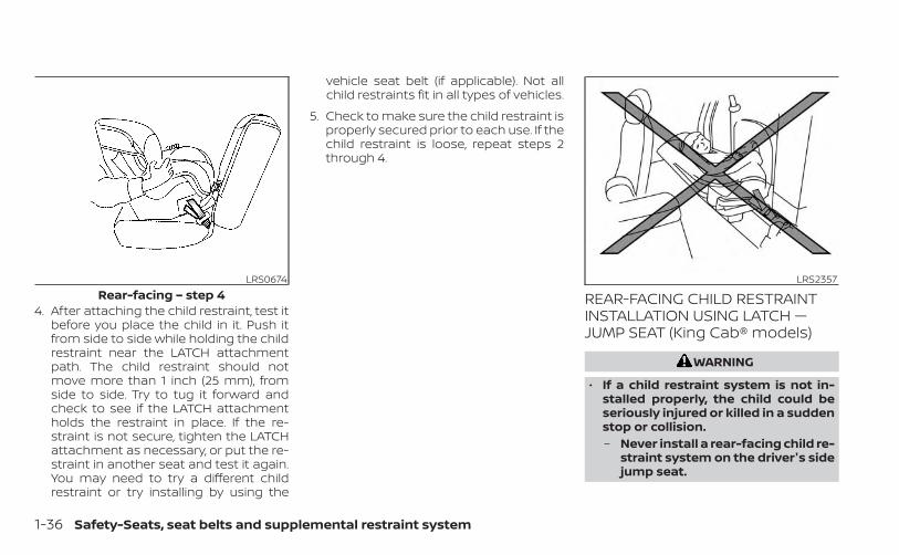
4. After attaching the child restraint, test itbefore you place the child in it. Push itfrom side to side while holding the childrestraint near the LATCH attachmentpath. The child restraint should notmove more than 1 inch (25 mm), fromside to side. Try to tug it forward andcheck to see if the LATCH attachmentholds the restraint in place. If the re-straint is not secure, tighten the LATCHattachment as necessary, or put the re-straint in another seat and test it again.You may need to try a different childrestraint or try installing by using the
vehicle seat belt (if applicable). Not allchild restraints fit in all types of vehicles.
5. Check to make sure the child restraint isproperly secured prior to each use. If thechild restraint is loose, repeat steps 2through 4.
REAR-FACING CHILD RESTRAINTINSTALLATION USING LATCH —JUMP SEAT (King Cab® models)
WARNING
• If a child restraint system is not in-stalled properly, the child could beseriously injured or killed in a suddenstop or collision.– Never install a rear-facing child re-
straint system on the driver's sidejump seat.
LRS0674Rear-facing – step 4
LRS2357
1-36 Safety-Seats, seat belts and supplemental restraint system

– Do not install a child restraint sys-tem on the passenger's side jumpseat without unfolding the seatextender.
WARNING
• To install a rear-facing child restrainton the passenger's side jump seat, itwill be necessary to move the frontpassenger's seat fully forward andplace the front seatback upright ortilt it forward. Failure to do so maycause the child restraint to not be in-stalled properly and cause seriousinjury or death in a sudden stop orcollision.
– The front seat cannot be usedwhen a rear-facing child restraintis installed on the jump seat. At-tempting to do so could cause se-rious injury in a sudden stop orcollision.
LRS2356
Safety-Seats, seat belts and supplemental restraint system 1-37

For additional information, see “Childsafety” (P. 1-26) and “Child restraints” (P. 1-28)for all Warnings and Cautions before in-stalling a child restraint.Do not use the lower anchors if the com-bined weight of the child and the child re-straint exceeds 65 lbs. (29.5 kg). If the com-bined weight of the child and the childrestraint is greater than 65 lbs., (29.5 kg) usethe vehicle's seat belt (not the lower an-chors) to install the child restraint. Be sureto follow the child restraint manufacturer'sinstructions for installation.
Follow these steps to install a child re-straint on the jump seat.1. To access the jump seat extension (pas-
senger's side only) OA on the jump seat,pull up OB on the extension to unfold it tothe open position. Then unfold the twosupport legs OC and lower the jump seatto the full open seating position.
LRS2725 LRS2502Full open seating position
1-38 Safety-Seats, seat belts and supplemental restraint system

2. Move the front passenger's seat into thefull forward position. Then move thefront seatback to the upright or tiltedforward position. Position the child re-straint on the jump seat. The direction ofthe child restraint depends on the typeof the child restraint and the size of thechild. Always follow the child restraintmanufacturer's instructions.
3. Position the child restraint on the seat.Always follow the child restraint manu-facturer's instructions.
4. Secure the child restraint anchor at-tachments to the LATCH lower anchors.Check to make sure the LATCH attach-ment is properly attached to the loweranchors.
LRS2552Rear-facing — step 2
LRS2997Rear-facing webbing-mounted – step 4
LRS2996Rear-facing rigid-mounted – step 4
Safety-Seats, seat belts and supplemental restraint system 1-39

5. For child restraints that are equippedwith webbing-mounted attachments,remove any additional slack from theanchor attachments. Press downwardand rearward firmly in the center of thechild restraint with your hand to com-press the vehicle seat cushion and seat-back while tightening the webbing ofthe anchor attachments.
6. After attaching the child restraint, test itbefore you place the child in it. Push itfrom side to side while holding the childrestraint near the LATCH attachmentpath. The child restraint should notmove more than 1 inch (25 mm), fromside to side. Try to tug it forward andcheck to see if the LATCH attachmentholds the restraint in place. If the re-straint is not secure, tighten the LATCHattachment as necessary, or put the re-straint in another seat and test it again.You may need to try a different childrestraint or try installing by using the
vehicle seat belt (if applicable). Not allchild restraints fit in all types of vehicles.
7. Check to make sure the child restraint isproperly secured prior to each use. If thechild restraint is loose, repeat steps 1through 6.
REAR-FACING CHILD RESTRAINTINSTALLATION USING THE SEATBELTS (Crew Cab models)
WARNING
The three-point seat belt with Auto-matic Locking Retractor (ALR) must beused when installing a child restraint.Failure to use the ALR mode will resultin the child restraint not being properlysecured. The restraint could tip over orbe loose and cause injury or death to achild in a sudden stop or collision. Also,it can change the operation of the frontpassenger air bag. For additional infor-mation, see “Front passenger air bagand status light” (P. 1-83).
For additional information, see “Childsafety” (P. 1-26) and “Child restraints” (P. 1-28)for all Warnings and Cautions before in-stalling a child restraint.
LRS0673Rear-facing – step 5
LRS0674Rear-facing – step 6
1-40 Safety-Seats, seat belts and supplemental restraint system

Do not use the lower anchors if the com-bined weight of the child and the child re-straint exceeds 65 lbs. (29.5 kg). If the com-bined weight of the child and the childrestraint is greater than 65 lbs. (29.5 kg), usethe vehicle's seat belt (not the lower an-chors) to install the child restraint. Be sureto follow the child restraint manufacturer'sinstructions for installation.Follow these steps to install a rear-facingchild restraint using the vehicle seat belts inthe rear seats:
1. Child restraints for infants must beused in the rear-facing direction andtherefore must not be used in the frontseat. Position the child restraint on theseat. Always follow the child restraintmanufacturer’s instructions.
2. Route the seat belt tongue through thechild restraint and insert it into thebuckle until you hear and feel the latchengage. Be sure to follow the child re-straint manufacturer’s instructions forbelt routing.
WRS0256Rear-facing – step 1
WRS0761Rear-facing – step 2
Safety-Seats, seat belts and supplemental restraint system 1-41

3. Pull the shoulder belt until the belt is fullyextended. At this time, the seat belt re-tractor is in the ALR mode (child restraintmode). It reverts to the ELR mode whenthe seat belt is fully retracted.
4. Allow the seat belt to retract. Pull up onthe shoulder belt to remove any slack inthe belt.
5. Remove any additional slack from theseat belt; press downward and rearwardfirmly in the center of the child restraintto compress the vehicle seat cushionand seatback while pulling up on theseat belt.
LRS0669Rear-facing – step 3
LRS0670Rear-facing – step 4
WRS0762Rear-facing – step 5
1-42 Safety-Seats, seat belts and supplemental restraint system

6. After attaching the child restraint, test itbefore you place the child in it. Push itfrom side to side while holding the childrestraint near the seat belt path. Thechild restraint should not move morethan 1 inch (25 mm), from side to side. Tryto tug it forward and check to see if thebelt holds the restraint in place. If therestraint is not secure, tighten the seatbelt as necessary, or put the restraint inanother seat and test it again. You mayneed to try a different child restraint.Not all child restraints fit in all types ofvehicles.
7. Check to make sure that the child re-straint is properly secured prior to eachuse. If the seat belt is not locked, repeatsteps 3 through 6.
After the child restraint is removed and theseat belt fully retracted, the ALR mode(child restraint mode) is canceled.
REAR-FACING CHILD RESTRAINTINSTALLATION USING THE SEATBELTS — JUMP SEAT (King Cab®models)
WRS0763Rear-facing – step 6
LRS0597
Safety-Seats, seat belts and supplemental restraint system 1-43

WARNING
• The three-point seat belt with Auto-matic Locking Retractor (ALR) mustbe used when installing a child re-straint. Failure to use the ALR modewill result in the child restraint notbeing properly secured. The restraintcould tip over or be loose and causeinjury to a child in a sudden stop orcollision. Also, it can change the op-eration of the front passenger airbag. For additional information, see“Front passenger air bag and statuslight” (P. 1-83).
• A child restraint system will not beinstalled properly and the child couldbe seriously injured or killed in a sud-den stop or collision.– Never install a rear-facing child re-
straint system on the driver's sidejump seat.
– Do not install a child restraint sys-tem on the passenger's side jumpseat without unfolding the seatextender.
WARNING
• To install a rear-facing child restrainton the passenger's side jump seat, itwill be necessary to move the frontpassenger's seat fully forward andplace the front seatback upright ortilt it forward. Failure to do so maycause the child restraint to not be in-stalled properly and cause seriousinjury or death in a sudden stop orcollision.
– The front seat cannot be usedwhen a rear-facing child restraintis installed on the jump seat. At-tempting to do so could cause se-rious injury in a sudden stop orcollision.
LRS0549
1-44 Safety-Seats, seat belts and supplemental restraint system

For additional information, see “Childsafety” (P. 1-26) and “Child restraints” (P. 1-28)for all Warnings and Cautions before in-stalling a child restraint.Do not use the lower anchors if the com-bined weight of the child and the child re-straint exceeds 65 lbs. (29.5 kg). If the com-bined weight of the child and the childrestraint is greater than 65 lbs. (29.5 kg), usethe vehicle's seat belt (not the lower an-chors) to install the child restraint. Be sureto follow the child restraint manufacturer'sinstructions for installation.
Follow these steps to install a child re-straint on the passenger's side jump seat.1. To access the jump seat extension OA on
the passenger's side jump seat, pull upOB on the extension to unfold it to theopen position. Then unfold the two sup-port legs OC and lower the jump seat tothe full open seating position.
LRS2725 LRS2502Full open seating position
Safety-Seats, seat belts and supplemental restraint system 1-45

2. Move the front passenger's seat into thefull forward position. Then move thefront seatback to the upright or tiltedforward position. Position the child re-straint on the jump seat. The direction ofthe child restraint depends on the typeof the child restraint and the size of thechild. Always follow the child restraintmanufacturer's instructions.
3. Route the seat belt tongue through thechild restraint and insert it into thebuckle until you hear and feel the latchengage OA .Be sure to follow the child restraintmanufacturer's instructions for beltrouting.
4. Pull the shoulder belt until the belt is fullyextended OB . At this time, the seat beltretractor is in the ALR mode (child re-straint mode). It reverts to the ELR modewhen the seat belt is fully retracted.
LRS2552Rear-facing — step 2
LRS2726Rear-facing — step 3
LRS2727Rear-facing — step 4
1-46 Safety-Seats, seat belts and supplemental restraint system

5. Allow the seat belt to retract. Pull up onthe shoulder belt OC to remove any slackin the belt.
6. Remove any additional slack from theseat belt; press downward and rear-ward firmly in the center of the child re-straint to compress the vehicle seatcushion and seatback while pulling upon the seat belt.
7. After attaching the child restraint, test itbefore you place the child in it. Push itfrom side to side while holding the seatnear the seat belt path. The child re-straint should not move more than 1 inch(25 mm), from side to side. Try to tug itforward and check to see if the seat beltholds the restraint in place. If the re-straint is not secure, tighten the seat beltas necessary, or put the restraint in an-other seat and test it again. You mayneed to try a different child restraint.Not all child restraints fit in all types ofvehicles.
LRS2728Rear-facing — step 5
WRS0762Rear-facing – step 6
WRS0918Rear-facing — step 7
Safety-Seats, seat belts and supplemental restraint system 1-47
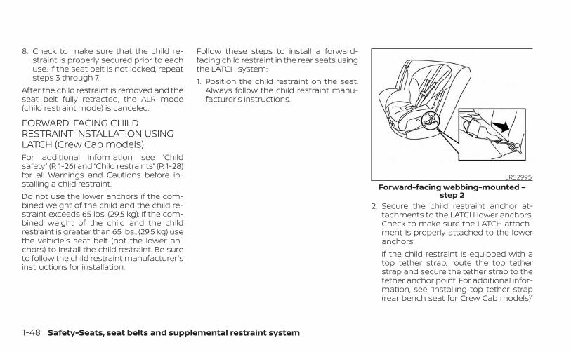
8. Check to make sure that the child re-straint is properly secured prior to eachuse. If the seat belt is not locked, repeatsteps 3 through 7.
After the child restraint is removed and theseat belt fully retracted, the ALR mode(child restraint mode) is canceled.
FORWARD-FACING CHILDRESTRAINT INSTALLATION USINGLATCH (Crew Cab models)For additional information, see “Childsafety” (P. 1-26) and “Child restraints” (P. 1-28)for all Warnings and Cautions before in-stalling a child restraint.Do not use the lower anchors if the com-bined weight of the child and the child re-straint exceeds 65 lbs. (29.5 kg). If the com-bined weight of the child and the childrestraint is greater than 65 lbs., (29.5 kg) usethe vehicle's seat belt (not the lower an-chors) to install the child restraint. Be sureto follow the child restraint manufacturer'sinstructions for installation.
Follow these steps to install a forward-facing child restraint in the rear seats usingthe LATCH system:1. Position the child restraint on the seat.
Always follow the child restraint manu-facturer's instructions.
2. Secure the child restraint anchor at-tachments to the LATCH lower anchors.Check to make sure the LATCH attach-ment is properly attached to the loweranchors.If the child restraint is equipped with atop tether strap, route the top tetherstrap and secure the tether strap to thetether anchor point. For additional infor-mation, see “Installing top tether strap(rear bench seat for Crew Cab models)”
LRS2995Forward-facing webbing-mounted –
step 2
1-48 Safety-Seats, seat belts and supplemental restraint system

(P. 1-50, 1-60 ) or “Installing top tetherstrap - jump seat (King® Cab models)(P. 1-55, 1-66 .Do not install child restraints that requirethe use of a top tether strap in seatingpositions that do not have a top tetheranchor.
3. The back of the child restraint should besecured against the vehicle seatback.If necessary, adjust or remove the headrestraint/headrest to obtain the correctchild restraint fit. If the head restraint/headrest is removed, store it in a secureplace. Be sure to reinstall the headrestraint/headrest when the child re-straint is removed. For additional infor-mation, see “Head restraints/headrests”(P. 1-10).If the seating position does not have anadjustable head restraint/headrest andit is interfering with the proper child re-straint fit, try another seating position ora different child restraint.
4. For child restraints that are equippedwith webbing-mounted attachments,remove any additional slack from theanchor attachments. Press downwardand rearward firmly in the center of thechild restraint with your knee to com-press the vehicle seat cushion and seat-back while tightening the webbing ofthe anchor attachments.
5. Tighten the tether strap according tothe manufacturer's instructions to re-move any slack.
LRS2994Forward-facing rigid-mounted – step 2
LRS0671Forward-facing – step 4
Safety-Seats, seat belts and supplemental restraint system 1-49

6. After attaching the child restraint, test itbefore you place the child in it. Push itfrom side to side while holding the childrestraint near the LATCH attachmentpath. The child restraint should notmove more than 1 inch (25 mm), fromside to side. Try to tug it forward andcheck to see if the LATCH attachmentholds the restraint in place. If the re-straint is not secure, tighten the LATCHattachment as necessary, or put the re-straint in another seat and test it again.You may need to try a different childrestraint. Not all child restraints fit in alltypes of vehicles.
7. Check to make sure the child restraint isproperly secured prior to each use. If thechild restraint is loose, repeat steps 3through 6.
Installing top tether strap (rearbench seat for Crew Cab models)To access the anchor points behind therear bench seat, tilt the rear seatback for-ward by lifting up on the pull strap behindthe seatback.
WRS0697Forward-facing – step 6
LRS3434Anchor point access
1. Pull strap
2. Anchor points
1-50 Safety-Seats, seat belts and supplemental restraint system
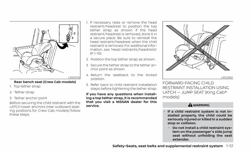
Before securing the child restraint with theLATCH lower anchors (rear outboard seat-ing positions for Crew Cab models) followthese steps.
1. If necessary, raise or remove the headrestraint/headrest to position the toptether strap as shown. If the headrestraint/headrest is removed, store it ina secure place. Be sure to reinstall thehead restraint/headrest when the childrestraint is removed. For additional infor-mation, see “Head restraints/headrests”(P. 1-10).
2. Position the top tether strap as shown.
3. Secure the tether strap to the tether an-chor point as shown.
4. Return the seatback to the lockedposition.
5. Refer back to child restraint installationsteps before tightening the tether strap.
If you have any questions when install-ing a top tether strap, it is recommendedthat you visit a NISSAN dealer for thisservice.
FORWARD-FACING CHILDRESTRAINT INSTALLATION USINGLATCH — JUMP SEAT (King Cab®models)
WARNING
• If a child restraint system is not in-stalled properly, the child could beseriously injured or killed in a suddenstop or collision.– Do not install a child restraint sys-
tem on the passenger's side jumpseat without unfolding the seatextender.
LRS0576Rear bench seat (Crew Cab models)
1. Top tether strap
2. Tether strap
3. Tether anchor point
LRS2360
Safety-Seats, seat belts and supplemental restraint system 1-51

– For forward-facing child seatsand boosters, DO NOT install if thechild restraint base extends pastthe forward edge of the driver'sside seat cushion.
For additional information, see “Childsafety” (P. 1-26) and “Child restraints” (P. 1-28)for all Warnings and Cautions before in-stalling a child restraint.Do not use the lower anchors if the com-bined weight of the child and the child re-straint exceeds 65 lbs. (29.5 kg). If the com-bined weight of the child and the childrestraint is greater than 65 lbs. (29.5 kg), usethe vehicle's seat belt (not the lower an-chors) to install the child restraint. Be sureto follow the child restraint manufacturer'sinstructions for installation.
Follow these steps to install a child re-straint on the jump seat.1. To access the jump seat extension (pas-
senger's side only) OA on the jump seat,pull up OB on the extension to unfold it tothe open position. Then unfold the twosupport legs OC and lower the jump seatto the full open seating position.
LRS2725
1-52 Safety-Seats, seat belts and supplemental restraint system

2. Position the child restraint on the seat.Always follow the child restraint manu-facturer's instructions.
3. Secure the child restraint anchor at-tachments to the LATCH lower anchors.Check to make sure the LATCH attach-ment is properly attached to the loweranchors.If the child restraint is equipped with atop tether strap, route the top tetherstrap and secure the tether strap to thetether anchor point. For additional infor-mation, see “Installing top tether strap -jump seat (King Cab® models)” (P. 1-55).Do not install child restraints that require
the use of a top tether strap in seatingpositions that do not have a top tetheranchor.
4. The back of the child restraint should besecured against the vehicle seatback.If necessary, adjust or remove the headrestraint/headrest to obtain the correctchild restraint fit. If the head restraint/headrest is removed, store it in a secureplace. Be sure to reinstall the headrestraint/headrest when the child re-straint is removed. For additional infor-mation, see “Head restraints/headrests”(P. 1-10).
LRS2502Full open seating position
LRS2995Forward-facing webbing-mounted –
step 3
LRS2994Forward-facing rigid-mounted – step 3
Safety-Seats, seat belts and supplemental restraint system 1-53

If the seating position does not have anadjustable head restraint/headrest andit is interfering with the proper child re-straint fit, try another seating position ora different child restraint.
5. For child restraints that are equippedwith webbing-mounted attachments,remove any additional slack from theanchor attachments. Press downwardand rearward firmly in the center of thechild restraint with your knee to com-press the vehicle seat cushion and seat-back while tightening the webbing ofthe anchor attachments.
6. Tighten the tether strap according tothe manufacturer's instructions to re-move any slack.
7. After attaching the child restraint, test itbefore you place the child in it. Push it fromside to side while holding the child re-straint near the LATCH attachment path.The child restraint should not move morethan 1 inch (25 mm), from side to side. Tryto tug it forward and check to see if theLATCH attachment holds the restraint inplace. If the restraint is not secure, tightenthe LATCH attachment as necessary, orput the restraint in another seat and test itagain. You may need to try a different childrestraint. Not all child restraints fit in alltypes of vehicles.
LRS0671Forward-facing – step 5
WRS0697Forward-facing – step 7
1-54 Safety-Seats, seat belts and supplemental restraint system

8. Check to make sure the child restraint isproperly secured prior to each use. If thechild restraint is loose, repeat steps 1through 7.
Installing top tether strap — jumpseat (King Cab® models)
WARNING
• Do not secure the top tether strap to therouting bracket. If the child restraint isnot anchored properly, the risk of a childbeing injured or killed in a collision or asudden stop greatly increases.
• Child restraint anchorages are de-signed to withstand only those loadsimposed by correctly fitted child re-straints. Under no circumstances arethey to be used to attach adult seatbelts, or other items or equipment tothe vehicle. Doing so could damagethe child restraint anchorages. Thechild restraint will not be properly in-stalled using the damaged anchor-ages, and a child could be seriouslyinjured or killed in a collision.
The child restraint top tether strap must beused when installing the child restraint withLATCH lower anchor attachments.
LRS0561Jump seat (King Cab® models)
1. Top tether strap2. Routing bracket3. Tether anchor point
Safety-Seats, seat belts and supplemental restraint system 1-55

First, secure the child restraint with the LATCHlower anchors (rear seating positions).1. Pull the cover plate off to access the top
tether strap routing bracket for the jumpseat.
2. Route the top tether strap through therouting bracket.
3. Secure the top tether strap to the tetheranchor point as shown.
4. Refer back to child restraint installationsteps before tightening the tether strap.
If you have any questions when install-ing a top tether strap, it is recommendedthat you visit a NISSAN dealer for thisservice.
FORWARD-FACING CHILDRESTRAINT INSTALLATION USINGTHE SEAT BELTS — FRONTPASSENGER AND REAR BENCHSEAT (Crew Cab models)
WARNING
The three-point seat belt with Auto-matic Locking Retractor (ALR) must beused when installing a child restraint.Failure to use the ALR mode will resultin the child restraint not being properlysecured. The restraint could tip over orbe loose and cause injury to a child in asudden stop or collision. Also, it canchange the operation of the front pas-senger air bag. For additional informa-tion, see “Front passenger air bag andstatus light” (P. 1-83).
For additional information, see “Child safety”(P. 1-26) and “Child restraints” (P. 1-28) for allWarnings and Cautions before installing achild restraint.Do not use the lower anchors if the com-bined weight of the child and the child re-straint exceeds 65 lbs. (29.5 kg). If the com-bined weight of the child and the childrestraint is greater than 65 lbs. (29.5 kg),use the vehicle's seat belt (not the loweranchors) to install the child restraint. Besure to follow the child restraint manufac-turer's instructions for installation.
WRS0699Forward-facing (front passenger seat) –
step 1
1-56 Safety-Seats, seat belts and supplemental restraint system

Follow these steps to install a forward-facing child restraint using the vehicle seatbelt in the rear seats (Crew Cab models) orin the front passenger seat:1. If you must install a child restraint in
the front seat, it should be placed in aforward-facing direction only. Movethe seat to the rearmost position.Child restraints for infants must beused in the rear-facing direction andtherefore must not be used in the frontseat.
2. Position the child restraint on the seat.Always follow the child restraint manu-facturer’s instructions.The back of the child restraint should besecured against the vehicle seatback.If necessary, adjust or remove the headrestraint/headrest to obtain the correctchild restraint fit. If the head restraint/headrest is removed, store it in a secureplace. Be sure to reinstall the headrestraint/headrest when the child re-straint is removed. For additional infor-mation, see “Head restraints/headrests”(P. 1-10).
If the seating position does not have anadjustable head restraint/headrest andit is interfering with the proper child re-straint fit, try another seating position ora different child restraint.
3. Route the seat belt tongue through thechild restraint and insert it into thebuckle until you hear and feel the latchengage. Be sure to follow the child re-straint manufacturer’s instructions forbelt routing.If the child restraint is equipped with atop tether strap, route the top tetherstrap and secure the tether strap to thetether anchor point (rear seat installa-tion only). For additional information, see“Installing top tether strap (rear benchseat for Crew Cab models)” (P. 1-60).
WRS0680Forward-facing – step 3
Safety-Seats, seat belts and supplemental restraint system 1-57

Do not install child restraints that requirethe use of a top tether strap in seatingpositions that do not have a top tetheranchor.
4. Pull the shoulder belt until the belt is fullyextended. At this time, the seat belt re-tractor is in the ALR mode (child restraintmode). It reverts to ELR mode when theseat belt is fully retracted.
5. Allow the seat belt to retract. Pull up onthe shoulder belt to remove any slack inthe belt.
LRS0667Forward-facing – step 4
LRS0668Forward-facing – step 5
1-58 Safety-Seats, seat belts and supplemental restraint system

6. Remove any additional slack from theseat belt; press downward and rear-ward firmly in the center of the child re-straint with your knee to compress thevehicle seat cushion and seatback whilepulling up on the seat belt.
7. Tighten the tether strap according to themanufacturer's instructions to removeany slack.
8. After attaching the child restraint, test itbefore you place the child in it. Push itfrom side to side while holding the childrestraint near the seat belt path. Thechild restraint should not move morethan 1 inch (25 mm), from side to side. Tryto tug it forward and check to see if theseat belt holds the restraint in place. Ifthe restraint is not secure, tighten theseat belt as necessary, or put the re-straint in another seat and test it again.You may need to try a different childrestraint. Not all child restraints fit in alltypes of vehicles.
9. Check to make sure the child restraint isproperly secured prior to each use. If theseat belt is not locked, repeat steps 3through 8.
WRS0681Forward-facing – step 6
WRS0698Forward-facing – step 8
Safety-Seats, seat belts and supplemental restraint system 1-59

10. If the child restraint is installed in thefront passenger seat, place the ignitionswitch in the ON position. The frontpassenger air bag status lightshould illuminate. If this light is not illu-minated, see “Front passenger air bagand status light” (P. 1-83). Move the childrestraint to another seating position.Have the system checked. It is recom-mended that you visit a NISSAN dealerfor this service.
After the child restraint is removed and theseat belt is fully retracted, the ALR mode(child restraint mode) is canceled.
Installing top tether strap (rearbench seat for Crew Cab models)To access the anchor points behind therear bench seat, tilt the rear seatback for-ward by lifting up on the pull strap behindthe seatback.
The child restraint top tether strap must beused when installing the child restraint withthe seat belts.
LRS3091Forward-facing – step 10
LRS3434Anchor point access
1. Pull strap
2. Anchor points
LRS0576Rear bench seat (Crew Cab models)
1. Top tether strap
2. Tether strap
3. Tether anchor point
1-60 Safety-Seats, seat belts and supplemental restraint system

First, secure the child restraint with the seatbelt.1. If necessary, raise or remove the head
restraint/headrest to position the toptether strap as shown. If the headrestraint/headrest is removed, store it ina secure place. Be sure to reinstall thehead restraint/headrest when the childrestraint is removed. For additional infor-mation, see “Head restraints/headrests”(P. 1-10).
2. Position the top tether strap as shown.
3. Secure the tether strap to the tether an-chor point as shown.
4. Return the seatback to the lockedposition.
5. Refer back to child restraint installationsteps before tightening the tether strap.
If you have any questions when install-ing a top tether strap, it is recommendedthat you visit a NISSAN dealer for thisservice.
FORWARD-FACING CHILDRESTRAINT INSTALLATION USINGTHE SEAT BELTS — FRONTPASSENGER AND JUMP SEATS(King Cab® models)
WARNING
• The three-point seat belt with Auto-matic Locking Retractor (ALR) mustbe used when installing a child re-straint. Failure to use the ALR modewill result in the child restraint notbeing properly secured. The restraintcould tip over or be loose and causeinjury to a child in a sudden stop orcollision. Also, it can change the op-eration of the front passenger airbag. For additional information, see“Front passenger air bag and statuslight” (P. 1-83).
• If a child restraint system is not in-stalled properly, the child could beseriously injured or killed in a suddenstop or collision.– Do not install a child restraint sys-
tem on the passenger's side jumpseat without unfolding the seatextender.
– For forward-facing child seatsand boosters, DO NOT install if thechild restraint system base ex-tends past the forward edge ofthe driver's side seat cushion.
LRS0598
Safety-Seats, seat belts and supplemental restraint system 1-61

For additional information, see “Childsafety” (P. 1-26) and “Child restraints” (P. 1-28)for all Warnings and Cautions before in-stalling a child restraint.Do not use the lower anchors if the com-bined weight of the child and the child re-straint exceeds 65 lbs. (29.5 kg). If the com-bined weight of the child and the childrestraint is greater than 65 lbs. (29.5 kg) usethe vehicle's seat belt (not the lower an-chors) to install the child restraint. Be sureto follow the child restraint manufacturer'sinstructions for installation.
Follow these steps to install a forward-facing child restraint using the vehicle seatbelt in the jump seats (King Cab® models)or in the front passenger seat:1. If you must install a child restraint in
the front seat, it should be placed in aforward-facing direction only. Movethe seat to the rearmost position.Child restraints for infants must beused in the rear-facing direction andtherefore must not be used in the frontseat.
2. To access the jump seat extension (pas-senger's side only) OA on the jump seat,pull up OB on the extension to unfold it tothe open position. Then unfold the twosupport legs OC and lower the jump seatto the full open seating position.
WRS0699Forward-facing (front passenger seat) –
step 1
LRS2725Forward-facing ( jump seat for King
Cab® models) — step 2
LRS2502Full open seating position
1-62 Safety-Seats, seat belts and supplemental restraint system

3. Position the child restraint on the seat.Always follow the child restraint manu-facturer’s instructions.The back of the child restraint should besecured against the vehicle seatback.If necessary, adjust or remove the headrestraint/headrest to obtain the correctchild restraint fit. If the head restraint/headrest is removed, store it in a secureplace. Be sure to reinstall the headrestraint/headrest when the child re-straint is removed. For additional infor-mation, see “Head restraints/headrests”(P. 1-10).
If the seating position does not have anadjustable head restraint/headrest andit is interfering with the proper child re-straint fit, try another seating position ora different child restraint.
4. Route the seat belt tongue through thechild restraint and insert it into thebuckle until you hear and feel the latchengage. Be sure to follow the child re-straint manufacturer's instructions forbelt routing.If the child restraint is equipped with atop tether strap, route the top tetherstrap and secure the tether strap to thetether anchor point. For additional infor-mation, see “Installing top tether strap -jump seat (King Cab® models)” (P. 1-66).
WRS0919Forward-facing — step 3
WRS0680Forward-facing — step 4
Safety-Seats, seat belts and supplemental restraint system 1-63
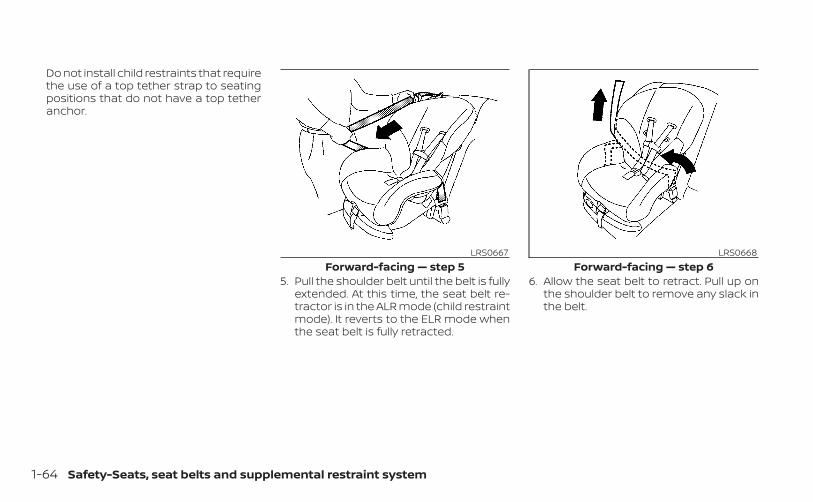
Do not install child restraints that requirethe use of a top tether strap to seatingpositions that do not have a top tetheranchor.
5. Pull the shoulder belt until the belt is fullyextended. At this time, the seat belt re-tractor is in the ALR mode (child restraintmode). It reverts to the ELR mode whenthe seat belt is fully retracted.
6. Allow the seat belt to retract. Pull up onthe shoulder belt to remove any slack inthe belt.
LRS0667Forward-facing — step 5
LRS0668Forward-facing — step 6
1-64 Safety-Seats, seat belts and supplemental restraint system

7. Remove any additional slack from theseat belt; press downward and rearwardfirmly in the center of the child restraintwith your knee to compress the vehicleseat cushion and seatback while pullingup on the seat belt.
8. Tighten the tether strap according tothe manufacturer's instructions to re-move any slack.
9. After attaching the child restraint, test itbefore you place the child in it. Push itfrom side to side while holding the seatnear the seat belt path. The child re-straint should not move more than 1inch (25 mm) from side to side. Try to tugit forward and check to see if the beltholds the restraint in place. If the re-straint is not secure, tighten the belt asnecessary, or put the restraint in anotherseat and test it again. You may need totry a different child restraint. Not all childrestraints fit in all types of vehicles.
10. Check to make sure that the child re-straint is properly secured prior to eachuse. If the seat belt is not locked, repeatsteps 3 through 9.
WRS0681Forward-facing – step 7
WRS0698Forward-facing — step 9
Safety-Seats, seat belts and supplemental restraint system 1-65

11. If the child restraint is installed in thefront passenger seat, place the ignitionswitch in the ON position. The front pas-senger air bag status light shouldilluminate. If this light is not illuminated,see “Front passenger air bag and statuslight” (P. 1-83). Move the child restraintto another seating position. Have thesystem checked. It is recommendedthat you visit a NISSAN dealer for thisservice.
After the child restraint is removed and theseat belt is fully retracted, the ALR mode(child restraint mode) is canceled.
Installing top tether strap —jump seat (King Cab® models)1. Top tether strap2. Routing bracket3. Tether anchor point
Installing top tether strap — jumpseat (King Cab® models)
WARNING
• Do not secure the top tether strap tothe routing bracket. If the child re-straint is not anchored properly, therisk of a child being injured or killed ina collision or a sudden stop greatlyincreases.
• Child restraint anchorages are de-signed to withstand only those loadsimposed by correctly fitted child re-straints. Under no circumstances arethey to be used to attach adult seatbelts, or other items or equipment tothe vehicle. Doing so could damagethe child restraint anchorages. Thechild restraint will not be properly in-stalled using the damaged anchor-ages, and a child could be seriouslyinjured or killed in a collision.
The child restraint top tether strap must beused when installing the child restraint withthe seat belts.
LRS3091Forward-facing — step 11
LRS0561
1-66 Safety-Seats, seat belts and supplemental restraint system

First, secure the child restraint with the seatbelt.1. Pull the cover plate off to access the top
tether strap routing bracket for the jumpseat.
2. Route the top tether strap through therouting bracket.
3. Secure the top tether strap to the tetheranchor point as shown.
4. Refer back to child restraint installationsteps before tightening the tether strap.
If you have any questions when install-ing a top tether strap, it is recommendedthat you visit a NISSAN dealer for thisservice.
BOOSTER SEATSFor additional information on installing abooster seat in your vehicle, follow the in-structions outlined in this section.
Precautions on booster seatsWARNING
If a booster seat and seat belt are notused properly, the risk of a child beinginjured or killed in a sudden stop or col-lision greatly increases:– Make sure the shoulder portion of
the belt is away from the child's faceand neck and the lap portion of thebelt does not cross the stomach.
– Make sure the shoulder belt is notbehind the child or under the child'sarm.
– A booster seat must only be installedin a seating position that has a lap/shoulder belt.
LRS2479
A. Low back booster seat
B. High back booster seat
Safety-Seats, seat belts and supplemental restraint system 1-67

Booster seats of various sizes are offeredby several manufacturers. When selectingany booster seat, keep the following pointsin mind:• Choose only a booster seat with a label
certifying that it complies with FederalMotor Vehicle Safety Standard 213 or Ca-nadian Motor Vehicle Safety Standard 213.
• Check the booster seat in your vehicle tobe sure it is compatible with the vehicle’sseat and seat belt system.
• Make sure the child’s head will be properlysupported by the booster seat or vehicleseat. The seatback must be at or abovethe center of the child’s ears. For example,if a low back booster seat is chosen, thevehicle seatback must be at or above thecenter of the child’s ears. If the seatback islower than the center of the child’s ears, ahigh back booster seat should be used.
• If the booster seat is compatible withyour vehicle, place the child in the boosterseat and check the various adjustmentsto be sure the booster seat is compatiblewith the child. Always follow all recom-mended procedures.
All U.S. states and Canadian provinces orterritories require that infants and smallchildren be restrained in an approvedchild restraint at all times while the ve-hicle is being operated.The instructions in this section apply tobooster seat installation in the rear seatsor the front passenger seat.
Booster seat installation — frontpassenger seat (all models) andrear seat (Crew Cab models)
WARNING
To avoid injury to child, do not use thelap/shoulder belt in the AutomaticLocking Retractor (ALR) mode when us-ing a booster seat with the seat belts.
For additional information, see “Childsafety” (P. 1-26), “Child restraints” (P. 1-28) and“Booster seats” (P. 1-67) for all Warnings andCautions before installing a child restraint.Follow these steps to install a booster seatin the rear seat or in the front passengerseat:
LRS0453 LRS0464
1-68 Safety-Seats, seat belts and supplemental restraint system

1. If you must install a booster seat in thefront seat, move the seat to the rear-most position.
2. Position the booster seat on the seat.Only place it in a front-facing direction.Always follow the booster seat manu-facturer’s instructions.
WRS0699 LRS0454Front passenger position
LRS0596Rear center position
Safety-Seats, seat belts and supplemental restraint system 1-69

3. The booster seat should be positionedon the vehicle seat so that it is stable.If necessary, adjust or remove the headrestraint/headrest to obtain the correctbooster seat fit. If the head restraint/headrest is removed, store it in a secureplace. Be sure to reinstall the headrestraint/headrest when the boosterseat is removed. For additional infor-mation, see “Head restraints/headrests”(P. 1-10).
If the seating position does not have anadjustable head restraint/headrest andit is interfering with the proper boosterseat fit, try another seating position or adifferent booster seat.
4. Position the lap portion of the seat beltlow and snug on the child’s hips. Be sureto follow the booster seat manufactur-er’s instructions for adjusting the seatbelt routing.
5. Pull the shoulder belt portion of the seatbelt toward the retractor to take up ex-tra slack. Be sure the shoulder belt ispositioned across the top, middle por-tion of the child’s shoulder. Be sure tofollow the booster seat manufacturer’sinstructions for adjusting the seat beltrouting.
6. Follow the warnings, cautions and in-structions for properly fastening a seatbelt shown in “Three-point type seat beltwith retractor” in this section.
7. If the booster seat is installed in the frontpassenger seat, place the ignition switchin the ON position. The front passengerair bag status light may or may notilluminate, depending on the size of thechild and the type of booster seat beingused. For additional information, see“Front passenger air bag and statuslight” (P. 1-83).
LRS0563Rear outboard position
LRS3091
1-70 Safety-Seats, seat belts and supplemental restraint system

Booster seat installation —jump seat (King Cab® models)
WARNING
• If a child restraint system is not in-stalled properly, the child could beseriously injured or killed in a suddenstop or collision.– For boosters, DO NOT install if the
child restraint system base ex-tends past the forward edge ofthe seat cushion.
– Do not install a child restraint sys-tem on the passenger's side jumpseat without unfolding the seatextender.
• To avoid injury to child, do not use thelap/shoulder belt in the AutomaticLocking Retractor (ALR) mode whenusing a booster seat with the seatbelts.
For additional information, see “Childsafety” (P. 1-26), “Child restraints” (P. 1-28) and“Booster seats” (P. 1-67) for all Warnings andCautions before installing a child restraint.Follow these steps to install a booster seatin the jump seats:
1. To access the jump seat extension (pas-senger's side only) OA on the jump seat,pull up OB on the extension to unfold it tothe open position. Then unfold the twosupport legs OC and lower the jump seatto the full open seating position.
LRS2725 LRS2502
Safety-Seats, seat belts and supplemental restraint system 1-71

2. Position the booster seat on the seat.Only place it in a front-facing direction.Always follow the booster seat manu-facturer’s instructions.
3. The booster seat should be positionedon the vehicle seat so that it is stable.If necessary, adjust or remove the headrestraint/headrest to obtain the correctbooster seat fit. If the head restraint/headrest is removed, store it in a secureplace. Be sure to reinstall the headrestraint/headrest when the boosterseat is removed. For additional informa-tion, see “Head restraint/headrest” (P. 1-10).
If the seating position does not have anadjustable head restraint/headrest andit is interfering with the proper boosterseat fit, try another seating position or adifferent booster seat.
4. Position the lap portion of the seat beltlow and snug on the child’s hips. Be sureto follow the booster seat manufactur-er’s instructions for adjusting the seatbelt routing.
5. Pull the shoulder belt portion of the seatbelt toward the retractor to take up ex-tra slack. Be sure the shoulder belt ispositioned across the top, middle por-tion of the child’s shoulder. Be sure tofollow the booster seat manufacturer’sinstructions for adjusting the seat beltrouting.
6. Follow the warnings, cautions and in-structions for properly fastening a seatbelt shown in “Three-point type seat beltwith retractor” (P. 1-19).
PRECAUTIONS ON SRSThis SRS section contains important infor-mation concerning the following systems:• Driver and front passenger supplemental
front-impact air bag (NISSAN AdvancedAir Bag System)
• Front seat-mounted side-impact supple-mental air bag
• Roof-mounted curtain side-impact androllover supplemental air bag
• Driver and front passenger supplementalknee air bag
• Seat belt with pretensioner(s) (front andrear outboard seats)
Supplemental front-impact air bagsystemThe NISSAN Advanced Air Bag System canhelp cushion the impact force to the headand chest of the driver and front passengerin certain frontal collisions.Front seat-mounted side-impact supple-mental air bag systemThis system can help cushion the impactforce to the chest area of the driver and frontpassenger in certain side-impact collisions.The side air bags are designed to inflate onthe side where the vehicle is impacted.
LRS0539
SUPPLEMENTAL RESTRAINT SYSTEM(SRS)
1-72 Safety-Seats, seat belts and supplemental restraint system

Roof-mounted curtain side-impact androllover supplemental air bag systemThis system can help cushion the impactforce to the head of occupants in front andrear outboard seating positions in certainside-impact or rollover collisions. In a side-impact, the curtain air bags are designedto inflate on the side where the vehicle isimpacted. In a rollover, the curtain air bagsare designed to inflate and remain inflatedfor a short time.Driver and front passenger supplemen-tal knee air bagsThis system can help cushion the impactforce to the driver’s and front passenger’sknees in certain collisions.The SRS is designed to supplement thecrash protection provided by the seat beltsand is not a substitute for them. Seat beltsshould always be correctly worn and theoccupant seated a suitable distance awayfrom the steering wheel, instrument paneland door finishers. For additional informa-tion, see “Seat belts” (P. 1-15).
The supplemental air bags operate onlywhen the ignition switch is in the ONposition.After placing the ignition switch in theON position, the supplemental air bagwarning light illuminates. The supple-mental air bag warning light will turn offafter about 7 seconds if the system isoperational.
Safety-Seats, seat belts and supplemental restraint system 1-73

WARNING
• The front air bags ordinarily will notinflate in the event of a side impact,rear impact, rollover, or lower sever-ity frontal collision. Always wear yourseat belts to help reduce the risk orseverity of injury in various kinds ofaccidents.
• The front passenger air bag and frontpassenger supplemental knee airbag will not inflate if the passengerair bag status light is lit or if the frontpassenger seat is unoccupied. Foradditional information, see “Frontpassenger air bag and status light”(P. 1-83).
• The seat belts and the front air bagsare most effective when you are sit-ting well back and upright in the seat.The front air bags inflate with greatforce. Even with the NISSAN Ad-vanced Air Bag System, if you are un-restrained, leaning forward, sittingsideways or out of position in anyway, you are at greater risk of injuryor death in a crash. You may also re-ceive serious or fatal injuries fromthe front air bag if you are up againstit when it inflates. Always sit backagainst the seatback and as far awayas practical from the steering wheelor instrument panel. Always properlyuse the seat belts.
• The driver and front passenger seatbelt buckles are equipped with sen-sors that detect if the seat belts arefastened. The NISSAN Advanced AirBag System monitors the severity ofa collision and seat belt usage, theninflates the air bags as needed. Fail-ure to properly wear seat belts canincrease the risk or severity of injuryin an accident.
WRS0031
1-74 Safety-Seats, seat belts and supplemental restraint system

• The front passenger seat is equippedwith an occupant classification sen-sor (weight sensors) that turns thefront passenger air bag and frontpassenger supplemental knee airbag OFF under some conditions. Thissensor is only used in this seat. Fail-ure to be properly seated and wear-ing the seat belt can increase the riskor severity of injury in an accident.For additional information, see“Front passenger air bag and statuslight” (P. 1-83).
• Keep hands on the outside of thesteering wheel. Placing them insidethe steering wheel rim could increasethe risk that they are injured whenthe front air bag inflates.
ARS1133
Safety-Seats, seat belts and supplemental restraint system 1-75

WARNING
• Never let children ride unrestrainedor extend their hands or face out ofthe window. Do not attempt to holdthem in your lap or arms. Some ex-amples of dangerous riding posi-tions are shown in the illustrations.
WARNING
• Children may be severely injured orkilled when the front air bags, side airbags or curtain air bags inflate if theyare not properly restrained. Pre-teens and children should be prop-erly restrained in the rear seat, ifpossible.
ARS1041 ARS1042 ARS1043
1-76 Safety-Seats, seat belts and supplemental restraint system

WARNING
• Even with the NISSAN Advanced AirBag System, never install a rear-facing child restraint in the front seat.An inflating front air bag could seri-ously injure or kill your child. For ad-ditional information, see “Child re-straints” (P. 1-28).
ARS1044 ARS1045 WRS0256
Safety-Seats, seat belts and supplemental restraint system 1-77
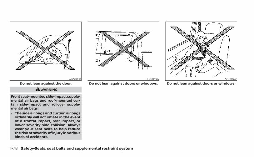
WARNING
Front seat-mounted side-impact supple-mental air bags and roof-mounted cur-tain side-impact and rollover supple-mental air bags:• The side air bags and curtain air bags
ordinarily will not inflate in the eventof a frontal impact, rear impact, orlower severity side collision. Alwayswear your seat belts to help reducethe risk or severity of injury in variouskinds of accidents.
WRS0431Do not lean against the door.
LRS0396Do not lean against doors or windows.
SSS0162Do not lean against doors or windows.
1-78 Safety-Seats, seat belts and supplemental restraint system

WARNING
• The seat belts, the side air bags andcurtain air bags are most effectivewhen you are sitting well back andupright in the seat. The side air bagand curtain air bag inflate with greatforce. Do not allow anyone to placetheir hand, leg or face near the sideair bag on the side of the seatback ofthe front seat or near the side roofrails. Do not allow anyone sitting inthe front seats or rear outboard seatsto extend their hand out of the win-dow or lean against the door. Someexamples of dangerous riding posi-tions are shown in the previousillustrations.
WARNING
• When sitting in the rear seat, do nothold onto the seatback of the frontseat. If the side air bag inflates, youmay be seriously injured. Be especiallycareful with children, who should al-ways be properly restrained. Some ex-amples of dangerous riding positionsare shown in the illustrations.
• Do not use seat covers on the frontseatbacks. They may interfere withside air bag inflation.
LRS0421 SSS0159
Safety-Seats, seat belts and supplemental restraint system 1-79

NISSAN Advanced Air Bag System(front seats)
1. Roof-mounted curtain side-impact androllover supplemental air bag inflators
2. Seat belt with pretensioner(s) (front andrear outboard seats)
3. Front seat-mounted side-impact supple-mental air bag module
4. Roof-mounted curtain side-impact androllover supplemental air bags
5. Seat belt buckle switches
6. Air bag Control Unit (ACU)
7. Front door satellite sensor (driver’s sideshown; passenger’s side similar)
8. Supplemental front-impact air bagmodules
9. Driver and front passenger supplemen-tal knee air bags
10. Crash zone sensor
11. Occupant classification system controlunit
12. Occupant classification sensor (weightsensors)
13. Satellite sensors (passenger’s sideshown; driver’s side similar) (if soequipped)
LRS3470
1-80 Safety-Seats, seat belts and supplemental restraint system

WARNING
To ensure proper operation of the pas-senger’s NISSAN Advanced Air Bag Sys-tem, please observe the followingitems.• Do not allow a passenger in the rear
bench seats to push or pull on theseatback pocket.
• Do not place heavy loads heavierthan 9.1 lbs. (4 kg) on the seatback,head restraint or in the seatbackpocket.
• Make sure that there is nothingpressing against the rear of the seat-back, such as a child restraint in-stalled in the rear seat or an objectstored on the floor.
• Make sure that there is no objectplaced under the front passengerseat.
• Make sure that there is no objectplaced between the seat cushion andcenter console or between the seatcushion and the door.
• If a forward-facing child restraint isinstalled in the front passenger seat,do not position the front passengerseat so the child restraint contactsthe instrument panel. If the child re-straint does contact the instrumentpanel, the system may determine theseat is occupied and the front pas-senger air bag and front passengersupplemental knee air bag may de-ploy in a collision. Also the front pas-senger air bag status light may notilluminate. For additional informa-tion, see “Child restraints” (P. 1-28).
• Confirm the operating condition withthe front passenger air bag statuslight.
• If you notice that the front passengerair bag status light is not operatingas described in this section, get theoccupant classification systemchecked. It is recommended that youvisit a NISSAN dealer for this service.
• Until you have confirmed with adealer that your passenger seat oc-cupant classification system is work-ing properly, position the occupantsin the rear seating positions.
• Do not position the front passengerseat so it contacts the rear seat. If thefront seat does contact the rear seat,the air bag system may determine asensor malfunction has occurredand the front passenger air bag sta-tus light may illuminate and thesupplemental air bag warning lightmay flash.
This vehicle is equipped with the NISSANAdvanced Air Bag System for the driver andfront passenger seats. This system is de-signed to meet certification requirementsunder U.S. regulations. It is also permitted inCanada. However, all of the information,cautions and warnings in this manualstill apply and must be followed.The driver supplemental front-impact airbag is located in the center of the steeringwheel. The front passenger supplementalfront-impact air bag is mounted in thedashboard above the glove box. The frontair bags are designed to inflate in higherseverity frontal collisions, although theymay inflate if the forces in another type ofcollision are similar to those of a higherseverity frontal impact. They may not in-flate in certain frontal collisions. Vehicle
Safety-Seats, seat belts and supplemental restraint system 1-81

damage (or lack of it) is not always an indi-cation of proper front air bag systemoperation.The NISSAN Advanced Air Bag Systemmonitors information from the crash zonesensor and the Air bag Control Unit (ACU).Inflator operation is based on the severityof a collision and seat belt usage for thedriver. For the front passenger, the occu-pant classification sensor is also moni-tored. Based on the information from thesensor, only one front air bag may inflate ina crash, depending on the crash severity.Additionally, the front passenger air bagand front passenger supplemental kneeair bag may be automatically turned OFFunder some conditions, depending on theweight detected on the front passengerseat and how the seat belt is used. If thefront passenger air bag and front passen-ger supplemental knee air bag are OFF, thefront passenger air bag status light will beilluminated (if the seat is unoccupied, thelight will not be illuminated, but the air bagwill be off). For additional information, see“Front passenger air bag and status light”(P. 1-83). One front air bag inflating does notindicate improper performance of thesystem.
If you have any questions about your airbag system, it is recommended that youvisit a NISSAN dealer to obtain informationabout the system. If you are consideringmodification of your vehicle due to a dis-ability, you may also contact NISSAN. Con-tact information is contained in the front ofthis Owner's Manual.When a front air bag inflates, a fairly loudnoise may be heard, followed by the re-lease of smoke. This smoke is not harmfuland does not indicate a fire. Care should betaken to not inhale it, as it may cause irrita-tion and choking. Those with a history of abreathing condition should get fresh airpromptly.Front air bags, along with the use of seatbelts, help to cushion the impact force onthe face and chest of the front occupants.They can help save lives and reduce seri-ous injuries. However, an inflating front airbag may cause facial abrasions or otherinjuries. Front air bags do not provide re-straint to the lower body.
Even with NISSAN Advanced Air Bags, seatbelts should be correctly worn and thedriver and front passenger seated uprightas far as practical away from the steeringwheel or instrument panel. The front airbags inflate quickly in order to help protectthe front occupants. Because of this, theforce of the front air bag inflating can in-crease the risk of injury if the occupant istoo close to, or is against, the front air bagmodule during inflation.The front air bags deflate quickly after acollision.The front air bags operate only when theignition switch is in the ON position.After placing the ignition switch in theON position, the supplemental air bagwarning light illuminates. The supple-mental air bag warning light will turn offafter about 7 seconds if the system isoperational.
1-82 Safety-Seats, seat belts and supplemental restraint system

Front passenger air bag and statuslight
WARNING
The front passenger air bag and frontpassenger supplemental knee air bagare designed to automatically turn OFFunder some conditions. Read this sec-tion carefully to learn how it operates.Proper use of the seat, seat belt andchild restraints is necessary for mosteffective protection. Failure to follow allinstructions in this manual concerningthe use of seats, seat belts and childrestraints can increase the risk or se-verity of injury in an accident.
Status lightThe front passenger air bag status light
is located near the climate controls.After the ignition switch is placed in the"ON" position, the front passenger air bagstatus light on the instrument panel illumi-nates for about 7 seconds and then turnsoff or remains illuminated depending onthe front passenger seat occupied status.The light operates as follows:
CONDITION DESCRIPTION PASSENGER AIR BAGSTATUS LIGHT ( )
FRONT PASSENGER AIR BAG AND FRONT PASSENGERSUPPLEMENTAL KNEE AIR BAG STATUS
Empty Empty front passenger seat ON (illuminated) INHIBITED
Nobody/Somebody Bag or Child or Child Restraint orSmall Adult in front passenger seat ON (illuminated) INHIBITED
Adult Adult in the front passenger seat OFF (dark) ACTIVATED
LRS3091
Safety-Seats, seat belts and supplemental restraint system 1-83

Front passenger air bagThe front passenger air bag and front pas-senger supplemental knee air bag are de-signed to automatically turn OFF when thevehicle is operated under some conditionsas described below in accordance with U.S.regulations. If the front passenger air bagand front passenger supplemental kneeair bag are OFF it will not inflate in a crash.The driver air bag and other air bags in yourvehicle are not part of this system.The purpose of the regulation is to helpreduce the risk of injury or death from aninflating air bag to certain front passengerseat occupants, such as children, by requir-ing the air bag to be automatically turnedOFF. Certain sensors are used to meet therequirements.The occupant classification sensor in thisvehicle is a weight sensor. It is designed todetect an occupant and objects on theseat by weight. For example, if a child up tothe approximate size and weight of a oneyear old is properly restrained in the frontpassenger seat, the NISSAN Advanced AirBag System is designed to turn the frontpassenger air bag and front passengersupplemental knee air bag OFF. For a prop-erly restrained child who is larger than theapproximate size and weight of a one year
old, the front passenger air bag and frontpassenger supplemental knee air bag mayor may not be automatically turned OFF,depending on the size of the child and thetype of child restraint being used. After in-stalling the child restraint and positioningthe child, place the ignition switch in the ONposition: if the front passenger air bag sta-tus light is illuminated, the front passengerair bag and front passenger supplementalknee air bag are OFF. If the front passengerair bag status light is not illuminated, the airbag will inflate in a crash.The front passenger seat belt sensors aredesigned to detect if the seat belt is buck-led. Based on the weight on the seat de-tected by the occupant classification sen-sor, the NISSAN Advanced Air Bag Systemdetermines whether the front passengerair bag and front passenger supplementalknee air bag should be automaticallyturned OFF as required by the regulations.Front passenger seat adult occupants whoare properly seated and using the seat beltas outlined in this manual should notcause the front passenger air bag andfront passenger supplemental knee airbag to be automatically turned OFF. Forsmall adults it may be turned OFF, however,if the occupant does not sit in the seat
properly (for example, by not sitting upright,by sitting on an edge of the seat, or byotherwise being out of position), this couldcause the sensor to turn the front passen-ger air bag and front passenger supple-mental knee air bag OFF. Always be sure tobe seated and wearing the seat belt prop-erly for the most effective protection by theseat belt and supplemental air bag.NISSAN recommends that pre-teens andchildren be properly restrained in a rearseat. NISSAN also recommends that ap-propriate child restraints and boosterseats be properly installed in a rear seat. Ifthis is not possible, the occupant classifica-tion sensor is designed to operate as de-scribed above to turn the front passengerair bag and front passenger supplementalknee air bag OFF for specified child re-straints as required by the regulations. Fail-ing to properly secure child restraints andto use the ALR mode may allow the re-straint to tip or move in a collision or sud-den stop. This can also result in the frontpassenger air bag and front passengersupplemental knee air bag inflating in acrash instead of being OFF. For additionalinformation, see “Child restraints” (P. 1-28).
1-84 Safety-Seats, seat belts and supplemental restraint system
If the front passenger seat is not occupied,the front passenger air bag and front pas-senger supplemental knee air bag are de-signed not to inflate in a crash. However,heavy objects placed on the seat could re-sult in air bag inflation, because of the ob-ject’s weight detected by the occupantclassification sensor. Other conditionscould also result in air bag inflation, such asif a child is standing on the seat, or if twochildren are on the seat, contrary to theinstructions in this manual. Always be surethat you and all vehicle occupants areseated and restrained properly.Using the front passenger air bag statuslight, you can monitor when the front pas-senger air bag and front passengersupplemental knee air bag are automati-cally turned OFF with the seat occupied.If an adult occupant is in the seat but thefront passenger air bag status light is illu-minated (indicating that the air bag andfront passenger supplemental knee airbag are OFF), it could be that the person is asmall adult, or is not sitting on the seatproperly or not using the seat belt properly.If a child restraint must be used in the frontseat, the front passenger air bag statuslight may or may not be illuminated, de-pending on the size of the child and the
type of child restraint being used. If the airbag status light is not illuminated (indicat-ing that the air bag might inflate in a crash),it could be that the child restraint or seatbelt is not being used properly. Make surethat the child restraint is installed properly,the seat belt is used properly and the occu-pant is positioned properly. If the air bagstatus light is not illuminated, repositionthe occupant or child restraint in a rearseat.If the front passenger air bag status lightwill not illuminate even though you believethat the child restraint, the seat belts andthe occupant are properly positioned, thesystem may be sensing an unoccupiedseat (in which case the air bag is OFF). ANISSAN dealer can check that the system isOFF by using a special tool. However, untilyou have confirmed with a dealer that yourair bag is working properly, reposition theoccupant or child restraint in a rear seat.The NISSAN Advanced Air Bag System andfront passenger air bag status light willtake a few seconds to register a change inthe passenger seat status. For example, if alarge adult who is sitting in the front pas-senger seat exits the vehicle, the front pas-senger air bag status light will go from OFFto ON for a few seconds and then to OFF.
This is normal system operation and doesnot indicate a malfunction.If a malfunction occurs in the front passen-ger air bag system, the supplemental airbag warning light , located in the me-ter and gauges area of the instrumentpanel, will blink. Have the system checked. Itis recommended that you visit a NISSANdealer for this service.Normal operationIn order for the occupant classificationsensor system to classify the front passen-ger based on weight, please follow the pre-cautions and steps outlined below:Precautions• Make sure that there are no objects
weighing over 9.1 lbs. (4 kg) hanging onthe seat or placed in the seatback pocket.
• Make sure that a child restraint or otherobject is not pressing against the rear ofthe seatback.
• Make sure that a rear passenger is notpushing or pulling on the back of the frontpassenger seat.
• Make sure that the front passenger seator seatback is not forced back against anobject on the seat or floor behind it.
• Make sure that there is no object placedunder the front passenger seat.
Safety-Seats, seat belts and supplemental restraint system 1-85

Steps1. Adjust the seat as outlined in the “Seats”
section of this manual. Sit upright, lean-ing against the seatback, and centeredon the seat cushion with your feet com-fortably extended to the floor.
2. Make sure there are no objects on yourlap.
3. Fasten the seat belt as outlined in the“Seat belts” section of this manual.
4. Remain in this position for 30 secondsallowing the system to classify the frontpassenger before the vehicle is put intomotion.
5. Ensure proper classification by checkingthe front passenger air bag status light.
NOTE:
This vehicle’s occupant classificationsensor system locks the classificationduring driving so it is important that youconfirm that the front passenger is prop-erly classified prior to driving. Also, theoccupant classification sensor systemmay recalculate the weight of the occu-pant when the vehicle comes to a stop(i.e. stop light, stop sign, etc.), so frontpassenger seat occupants should con-tinue to remain seated as outlinedabove.TroubleshootingIf you think the front passenger air bagstatus light is incorrect:1. If the light is ON with an adult occupying
the front passenger seat:• Occupant is a small adult — the air bag
light is functioning as intended. The frontpassenger air bag and front passen-ger supplemental knee air bag aresuppressed.
However, if the occupant is not a smalladult, then this may be due to the followingconditions that may be interfering with theweight sensors:• Occupant is not sitting upright, leaning
against the seatback, and centered onthe seat cushion with his/her feet com-fortably extended to the floor.
• A child restraint or other object pressingagainst the rear of the seatback.
• A rear passenger pushing or pulling onthe back of the front passenger seat.
• Forcing the front seat or seatbackagainst an object on the seat or floor be-hind it.
• An object placed under the front passen-ger seat.
• An object placed between the seat cush-ion and center console or between theseat cushion and the door.
If the vehicle is moving, please come to astop when it is safe to do so. Check andcorrect any of the above conditions. Re-start the vehicle and wait 1 minute.
1-86 Safety-Seats, seat belts and supplemental restraint system

NOTE:
A system check will be performed duringwhich the front passenger air bag statuslight will remain lit for about 7 secondsinitially.If the light is still ON after this, the personshould be advised not to ride in the frontpassenger seat and the vehicle should bechecked as soon as possible. It is recom-mended that you visit a NISSAN dealer forthis service.2. If the light is OFF with a small adult, child
or child restraint occupying the frontpassenger seat.This may be due to the following condi-tions that may be interfering with theweight sensors:
• Small adult or child is not sitting upright,leaning against the seatback, and cen-tered on the seat cushion with his/herfeet comfortably extended to the floor.
• The child restraint is not properly in-stalled, as outlined in the “Child restraints”section of this manual.
• An object weighing over 9.1 lbs. (4 kg)hanging on the seat or placed in the seat-back pocket.
• A child restraint or other object pressingagainst the rear of the seatback.
• A rear passenger pushing or pulling onthe back of the front passenger seat.
• Forcing the front seat or seatbackagainst an object on the seat or floor be-hind it.
• An object placed under the front passen-ger seat.
• An object placed between the seat cush-ion and center console.
If the vehicle is moving, please come to astop when it is safe to do so. Check andcorrect any of the above conditions. Re-start the vehicle and wait 1 minute.
NOTE:
A system check will be performed duringwhich the front passenger air bag statuslight will remain lit for about 7 secondsinitially.If the light is still OFF after this, the smalladult, child or child restraint should be re-positioned in the rear seat and the vehicleshould be checked as soon as possible. It isrecommended that you visit a NISSANdealer for this service.
3. If the light is OFF with no front passengerand no objects on the front passengerseat, the vehicle should be checked. It isrecommended that you visit a NISSANdealer as soon as possible.
Other supplemental front-impact airbag precautions
WARNING
• Do not place any objects on thesteering wheel pad or on the instru-ment panel. Also, do not place anyobjects between any occupant andthe steering wheel or instrumentpanel. Such objects may becomedangerous projectiles and cause in-jury if the front air bags inflate.
• Immediately after inflation, severalfront air bag system components willbe hot. Do not touch them; you mayseverely burn yourself.
• No unauthorized changes should bemade to any components or wiringof the supplemental air bag system.This is to prevent accidental inflationof the supplemental air bag or dam-age to the supplemental air bagsystem.
Safety-Seats, seat belts and supplemental restraint system 1-87

• Do not make unauthorized changesto your vehicle's electrical system,suspension system or front endstructure. This could affect properoperation of the front air bag system.
• Tampering with the front air bag sys-tem may result in serious personalinjury. Tampering includes changesto the steering wheel and the instru-ment panel assembly by placing ma-terial over the steering wheel padand above the instrument panel orby installing additional trim materialaround the air bag system.
• Removing or modifying the frontpassenger seat may affect the func-tion of the air bag system and resultin serious personal injury.
• Modifying or tampering with thefront passenger seat may result inserious personal injury. For example,do not change the front seats byplacing material on the seat cushionor by installing additional trim mate-rial, such as seat covers, on the seatthat are not specifically designed toassure proper air bag operation. Ad-ditionally, do not stow any objectsunder the front passenger seat or theseat cushion and seatback. Such ob-jects may interfere with the properoperation of the occupant classifica-tion sensor (weight sensor).
• No unauthorized changes should bemade to any components or wiringof the seat belt system. This may af-fect the front air bag system. Tam-pering with the seat belt system mayresult in serious personal injury.
• It is recommended that you visit aNISSAN dealer for work on andaround the front air bag. It is also rec-ommended that you visit a NISSANdealer for installation of electricalequipment. The Supplemental Re-straint System (SRS) wiring har-nesses* should not be modified ordisconnected. Unauthorized electri-cal test equipment and probing de-vices should not be used on the airbag system.
• A cracked windshield should be re-placed immediately by a qualified re-pair facility. A cracked windshieldcould affect the function of thesupplemental air bag system.
*The SRS wiring harness connectors areyellow and orange for easy identification.When selling your vehicle, we request thatyou inform the buyer about the front airbag system and guide the buyer to theappropriate sections in this Owner'sManual.
1-88 Safety-Seats, seat belts and supplemental restraint system

Front seat-mounted side-impactsupplemental air bag androof-mounted curtainside-impact and rolloversupplemental air bag systemsThe side air bags are located in the outsideof the seatback of the front seats. The cur-tain air bags are located in the side roofrails. All of the information, cautions andwarnings in this manual apply and mustbe followed. The side air bags and curtainair bags are designed to inflate in higherseverity side collisions, although they mayinflate if the forces in another type of colli-
sion are similar to those of a higher severityimpact. They are designed to inflate on theside where the vehicle is impacted. Theymay not inflate in certain side collisions.Curtain air bags are also designed to inflatein certain types of rollover collisions or nearrollovers. As a result, certain vehicle move-ments (for example, during severe off-roading) may cause the curtain air bags toinflate.Vehicle damage (or lack of it) is not alwaysan indication of proper side air bag andcurtain air bag operation.When the side air bags and curtain air bagsinflate, a fairly loud noise may be heard,followed by release of smoke. This smoke isnot harmful and does not indicate a fire.Care should be taken not to inhale it, as itmay cause irritation and choking. Thosewith a history of a breathing conditionshould get fresh air promptly.Side air bags, along with the use of seatbelts, help to cushion the impact force onthe chest and pelvic area of the front occu-pants. Curtain air bags help to cushion theimpact force to the head of occupants inthe front and rear outboard seating posi-tions. They can help save lives and reduceserious injuries. However, an inflating side
air bag or curtain air bag may cause abra-sions or other injuries. Side air bags andcurtain air bags do not provide restraint tothe lower body.The seat belts should be correctly wornand the driver and passenger seated up-right as far as practical away from the sideair bag. Rear seat passengers should beseated as far away as practical from thedoor finishers and side roof rails. The sideair bags and curtain air bags inflate quicklyin order to help protect the occupants. Be-cause of this, the force of the side air bagand curtain air bag inflating can increasethe risk of injury if the occupant is too closeto, or is against, these air bag modules dur-ing inflation. The side air bag will deflatequickly after the collision is over.The curtain air bags will remain inflated fora short time.The side air bags and curtain air bagsoperate only when the ignition switch isin the ON position.After placing the ignition switch in theON position, the supplemental air bagwarning light illuminates. The supple-mental air bag warning light will turn offafter about 7 seconds if the system isoperational.
LRS2501
Safety-Seats, seat belts and supplemental restraint system 1-89

WARNING
• Do not place any objects near theseatback of the front seats. Also, donot place any objects (an umbrella,bag, etc.) between the front door fin-isher and the front seat. Such objectsmay become dangerous projectilesand cause injury if a side air baginflates.
• Right after inflation, several side airbag and curtain air bag system com-ponents will be hot. Do not touchthem; you may severely burnyourself.
• No unauthorized changes should bemade to any components or wiringof the side air bag and curtain air bagsystems. This is to prevent damageto or accidental inflation of the sideair bag and curtain air bag systems.
• Do not make unauthorized changesto your vehicle's electrical system,suspension system or side panel.This could affect proper operation ofthe curtain air bag systems.
• Tampering with the side air bag sys-tem may result in serious personalinjury. For example, do not changethe front seats by placing materialnear the seatbacks or by installingadditional trim material, such as seatcovers, around the side air bag.
• It is recommended that you visit aNISSAN dealer for work on andaround the side air bag and curtainair bag. It is also recommended thatyou visit a NISSAN dealer for installa-tion of electrical equipment. The SRSwiring harnesses* should not bemodified or disconnected. Unauthor-ized electrical test equipment andprobing devices should not be usedon the side air bag or curtain air bagsystems.
* The SRS wiring harness or connectors areyellow or orange for easy identification.When selling your vehicle, we request thatyou inform the buyer about the side air bagand curtain air bag systems and guide thebuyer to the appropriate sections in thisOwner's Manual.
Driver and front passengersupplemental knee air bagThe knee air bag is located below thesteering column on the driver’s side, and inthe knee bolster on the front passenger’sside. All of the information, cautions andwarnings in this manual apply and mustbe followed. The knee air bag is designedto inflate in higher severity frontal collisions,although it may inflate if the forces in an-other type of collision are similar to those ofa higher severity frontal impact. It may notinflate in certain collisions.
LRS3423Driver’s side
1-90 Safety-Seats, seat belts and supplemental restraint system

Vehicle damage (or lack of it) is not alwaysan indication of proper knee air bagoperation.When the knee air bag inflates, a fairly loudnoise may be heard, followed by release ofsmoke. This smoke is not harmful anddoes not indicate a fire. Care should betaken not to inhale it, as it may cause irrita-tion and choking. Those with a history of abreathing condition should get fresh airpromptly.
The knee air bag helps to cushion the im-pact force on the knees of the driver andpassenger. It can help reduce serious inju-ries. However, an inflating knee air bag maycause abrasions or other injuries. The kneeair bag provides restraint to the lower body.The knee air bag inflates quickly in order tohelp protect the occupants. Because ofthis, the force of the knee air bag inflatingcan increase the risk of injury if the occu-pant is too close to, or is against, this air bagmodule during inflation. The knee air bagwill deflate quickly after the collision is overOR the knee air bag will remain inflated fora short time.The knee air bag operates only when theignition switch is placed in the ONposition.After placing the ignition switch in theON position, the supplemental air bagwarning light illuminates. The supple-mental air bag warning light will turn offafter about 7 seconds if the system isoperational.
WARNING
• Do not place any objects between theknee bolster and the driver’s or pas-senger’s seat. Such objects may be-come dangerous projectiles andcause injury if a knee air bag inflates.
• Right after inflation, the knee air bagsystem components will be hot. Donot touch them; you may severelyburn yourself.
• No unauthorized changes should bemade to any components or wiringof the knee air bag system. This is toprevent damage to or accidental in-flation of the knee air bag system.
• Do not make unauthorized changesto your vehicle's electrical system orsuspension system. This could affectproper operation of the knee air bagsystem.
• Tampering with the knee air bag sys-tem may result in serious personalinjury. For example, do not changethe driver or passenger knee bolsteror install additional trim materialaround the knee air bag.
LRS3436Passenger’s side
Safety-Seats, seat belts and supplemental restraint system 1-91

• It is recommended that you visit aNISSAN dealer for work on andaround the knee air bag. It is also rec-ommended that you visit a NISSANdealer for installation of electricalequipment. The SRS wiring har-nesses* should not be modified ordisconnected. Unauthorized electri-cal test equipment and probing de-vices should not be used on the kneeair bag system.
*The SRS wiring harness or connectors areyellow or orange for easy identification.When selling your vehicle, we request thatyou inform the buyer about the knee airbag system and guide the buyer to theappropriate sections in this manual.
Seat belt with pretensioner(s)(front and rear outboard seats)
WARNING
• The pretensioner(s) cannot be re-used after activation. They must bereplaced together with the retractorand buckle as a unit.
• If the vehicle becomes involved in acollision but pretensioner(s) are notactivated, be sure to have the preten-sioner system checked and, if neces-sary, replaced. It is recommendedthat you visit a NISSAN dealer for thisservice.
• No unauthorized changes should bemade to any components or wiringof the pretensioner system. This is toprevent damage to or accidental ac-tivation of the pretensioner(s). Tam-pering with the pretensioner systemmay result in serious personal injury.
• It is recommended that you visit aNISSAN dealer for work on andaround the pretensioner system. It isalso recommended that you visit aNISSAN dealer for installation of elec-trical equipment. Unauthorized elec-trical test equipment and probingdevices should not be used on thepretensioner system.
• If you need to dispose of the preten-sioner(s) or scrap the vehicle, it is rec-ommended that you visit a NISSANdealer for this service. Incorrect dis-posal procedures could cause per-sonal injury.
The pretensioner system may activatewith the supplemental air bag system incertain types of collisions. Working with theseat belt retractor, the pretensioner(s)help tighten the seat belt when the vehiclebecomes involved in certain types of colli-sions, helping to restrain front seatoccupants.The pretensioner(s) are encased within theseat belt retractor. These seat belts areused the same way as conventional seatbelts.
1-92 Safety-Seats, seat belts and supplemental restraint system

When pretensioner(s) activate, smoke is re-leased and a loud noise may be heard. Thissmoke is not harmful and does not indi-cate a fire. Care should be taken not toinhale it, as it may cause irritation andchoking. Those with a history of a breath-ing condition should get fresh air promptly.After the pretensioner(s’) activation, loadlimiters (if so equipped) allow the seat beltto release webbing (if necessary) to reduceforces against the chest.The supplemental air bag warning light
is used to indicate malfunctions in thepretensioner system. For additional infor-mation, see "Supplemental air bag warninglight" (P. 1-93). If the operation of the supple-mental air bag warning light indicatesthere is a malfunction, have the systemchecked. It is recommended that you visit aNISSAN dealer for this service.When selling your vehicle, we request thatyou inform the buyer about the preten-sioner system and guide the buyer to theappropriate sections in this Owner'sManual.
SUPPLEMENTAL AIR BAG WARNINGLABELSWarning labels about the supplementalfront-impact air bag system are placed inthe vehicle as shown in the illustration.
WARNING
Do not use a rear-facing child restrainton a seat protected by an air bag infront of it. If the air bag deploys, it maycause serious injury or death.
SUPPLEMENTAL AIR BAG WARNINGLIGHTThe supplemental air bag warning light,displaying in the instrument panel,monitors the circuits for the air bag sys-tems, pretensioner(s) and all related wiring.When the ignition switch is placed in the ONposition, the supplemental air bag warninglight illuminates for about 7 seconds andthen turns off. This means the system isoperational.
WRS0885
1. SRS Air bag warning labelsThe warning labels are located on thesurface of the sun visor.
LRS0100
Safety-Seats, seat belts and supplemental restraint system 1-93

If any of the following conditions occur, thefront air bag, side air bag, curtain air bagand pretensioner systems need servicing:• The supplemental air bag warning light re-
mains on after approximately 7 seconds.• The supplemental air bag warning light
flashes intermittently.• The supplemental air bag warning light
does not come on at all.Under these conditions, the front air bag,side air bag, curtain air bag or pretensionersystems may not operate properly. Theymust be checked and repaired. It is recom-mended that you visit a NISSAN dealer forthis service.
WARNING
If the supplemental air bag warninglight is on, it could mean that the frontair bag, side air bag, curtain air bagand/or pretensioner systems will notoperate in an accident. To help avoidinjury to yourself or others, have yourvehicle checked as soon as possible. Itis recommended that you visit aNISSAN dealer for this service.
Repair and replacementprocedureThe front air bags, side air bags, curtain airbags and pretensioner(s) are designed toinflate on a one-time-only basis. As a re-minder, unless it is damaged, the supple-mental air bag warning light remains illu-minated after inflation has occurred. Thesesystems should be repaired and/or re-placed as soon as possible. It is recom-mended that you visit a NISSAN dealer forthis service.When maintenance work is required on thevehicle, the front air bags, side air bags,curtain air bags, pretensioner(s) and re-lated parts should be pointed out to theperson performing the maintenance. Theignition switch should always be placed inthe LOCK position when working under thehood or inside the vehicle.
WARNING
• Once a front air bag, side air bag, orcurtain air bag has inflated, the airbag module will not function againand must be replaced. Additionally,the activated pretensioner(s) mustalso be replaced. The air bag moduleand pretensioner(s) should be re-placed. It is recommended that youvisit a NISSAN dealer for this service.However, the air bag module and pre-tensioner(s) cannot be repaired.
• The front air bag, side air bag, curtainair bag systems and the preten-sioner system should be inspected ifthere is any damage to the front endor side portion of the vehicle. It is rec-ommended that you visit a NISSANdealer for this service.
• If you need to dispose of the supple-mental air bag or pretensioner sys-tems or scrap the vehicle, it is recom-mended that you visit a NISSANdealer. Incorrect disposal procedurescould cause personal injury.
1-94 Safety-Seats, seat belts and supplemental restraint system
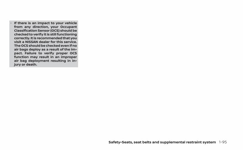
• If there is an impact to your vehiclefrom any direction, your OccupantClassification Sensor (OCS) should bechecked to verify it is still functioningcorrectly. It is recommended that youvisit a NISSAN dealer for this service.The OCS should be checked even if noair bags deploy as a result of the im-pact. Failure to verify proper OCSfunction may result in an improperair bag deployment resulting in in-jury or death.
Safety-Seats, seat belts and supplemental restraint system 1-95

2 Instruments and controls
Instrument panel . . . . . . . . . . . . . . . . . . . . . . . . . . . . . . . . 2-2Meters and gauges . . . . . . . . . . . . . . . . . . . . . . . . . . . . . 2-4
Speedometer and odometer . . . . . . . . . . . . . . . . . 2-4Tachometer . . . . . . . . . . . . . . . . . . . . . . . . . . . . . . . . . . 2-6Engine coolant temperature gauge . . . . . . . . . . 2-6Fuel gauge . . . . . . . . . . . . . . . . . . . . . . . . . . . . . . . . . . . 2-7Distance To Empty (DTE) . . . . . . . . . . . . . . . . . . . . . 2-7Auxiliary gauges (if so equipped) . . . . . . . . . . . . . 2-8Off-road and 4–Wheel Drive (4WD)monitor (if so equipped) . . . . . . . . . . . . . . . . . . . . . . 2-9
Warning lights, indicator lights and audiblereminders . . . . . . . . . . . . . . . . . . . . . . . . . . . . . . . . . . . . . . 2-10
Checking lights . . . . . . . . . . . . . . . . . . . . . . . . . . . . . . .2-11Warning/Indicator lights (red) . . . . . . . . . . . . . . . .2-11Warning/Indicator lights (yellow) . . . . . . . . . . . . 2-14Warning/Indicator lights (other) . . . . . . . . . . . . . 2-19Audible reminders . . . . . . . . . . . . . . . . . . . . . . . . . . . 2-19
Vehicle information display . . . . . . . . . . . . . . . . . . . . . 2-20How to use the vehicle informationdisplay . . . . . . . . . . . . . . . . . . . . . . . . . . . . . . . . . . . . . . 2-21Startup display . . . . . . . . . . . . . . . . . . . . . . . . . . . . . . 2-21Settings . . . . . . . . . . . . . . . . . . . . . . . . . . . . . . . . . . . . . 2-21Vehicle information display warningsand indicators . . . . . . . . . . . . . . . . . . . . . . . . . . . . . . . 2-28
Security systems . . . . . . . . . . . . . . . . . . . . . . . . . . . . . . . 2-34Vehicle security system (if so equipped) . . . . . 2-34
NISSAN Vehicle Immobilizer System . . . . . . . . . 2-35Wiper and washer switch . . . . . . . . . . . . . . . . . . . . . . . 2-37
Switch operation . . . . . . . . . . . . . . . . . . . . . . . . . . . . 2-37Outside mirror defroster switch(if so equipped) . . . . . . . . . . . . . . . . . . . . . . . . . . . . . . . . . 2-38Headlight and turn signal switch . . . . . . . . . . . . . . . 2-38
Headlight control switch . . . . . . . . . . . . . . . . . . . . 2-38Daytime Running Lights (DRL) system(Type A) (if so equipped) . . . . . . . . . . . . . . . . . . . . . 2-43LED Daytime Running Lights (DRL)system (Type B) (if so equipped) . . . . . . . . . . . . . 2-43Instrument brightness control . . . . . . . . . . . . . . 2-44Turn signal switch . . . . . . . . . . . . . . . . . . . . . . . . . . . 2-44Fog light switch (if so equipped) . . . . . . . . . . . . . 2-44
Horn . . . . . . . . . . . . . . . . . . . . . . . . . . . . . . . . . . . . . . . . . . . 2-45Cargo lamp switch . . . . . . . . . . . . . . . . . . . . . . . . . . . . . 2-45Heated seat switches (if so equipped) . . . . . . . . . . 2-46Heated steering wheel switch (if so equipped) . . 2-47Warning systems switch (if so equipped) . . . . . . . 2-47Vehicle Dynamic Control (VDC) OFF switch . . . . . 2-48Hill descent control switch (if so equipped) . . . . . 2-49Electronic locking rear differential (E-Lock)system switch (if so equipped) . . . . . . . . . . . . . . . . . 2-50Power inverter switch (if so equipped) . . . . . . . . . . 2-51Parking Aids system switch (if so equipped) . . . . 2-51

Tow mode switch (if so equipped) . . . . . . . . . . . . . . 2-52Emergency call (SOS) button (if so equipped) . . . 2-53Rear Door Alert . . . . . . . . . . . . . . . . . . . . . . . . . . . . . . . . . 2-53Power outlets . . . . . . . . . . . . . . . . . . . . . . . . . . . . . . . . . . 2-54
12v Outlets . . . . . . . . . . . . . . . . . . . . . . . . . . . . . . . . . . 2-54120v outlets (if so equipped) . . . . . . . . . . . . . . . . . 2-55
USB charging ports (if so equipped) . . . . . . . . . . . . 2-57Wireless charger (if so equipped) . . . . . . . . . . . . . . . 2-58
Wireless charger indicator . . . . . . . . . . . . . . . . . . . 2-59Wireless charger operation . . . . . . . . . . . . . . . . . . 2-59
Extended storage switch . . . . . . . . . . . . . . . . . . . . . . . 2-60Storage . . . . . . . . . . . . . . . . . . . . . . . . . . . . . . . . . . . . . . . . 2-61
Front-door pockets . . . . . . . . . . . . . . . . . . . . . . . . . 2-61Rear-door pockets . . . . . . . . . . . . . . . . . . . . . . . . . . 2-61Seatback pocket (if so equipped) . . . . . . . . . . . . 2-62Under-seat storage bins . . . . . . . . . . . . . . . . . . . . 2-63Storage trays . . . . . . . . . . . . . . . . . . . . . . . . . . . . . . . . 2-64Glove box . . . . . . . . . . . . . . . . . . . . . . . . . . . . . . . . . . . 2-65Console box . . . . . . . . . . . . . . . . . . . . . . . . . . . . . . . . . 2-65Overhead sunglasses storage(if so equipped) . . . . . . . . . . . . . . . . . . . . . . . . . . . . . . 2-66Cup holders . . . . . . . . . . . . . . . . . . . . . . . . . . . . . . . . . 2-66
Ladder rack (if so equipped) . . . . . . . . . . . . . . . . . . . .2-68Windows . . . . . . . . . . . . . . . . . . . . . . . . . . . . . . . . . . . . . . .2-68
Manual windows (if so equipped) . . . . . . . . . . . .2-68Power windows (if so equipped) . . . . . . . . . . . . . 2-68Rear sliding window (if so equipped) . . . . . . . . . 2-71
Moonroof (if so equipped) . . . . . . . . . . . . . . . . . . . . . . 2-71Power moonroof . . . . . . . . . . . . . . . . . . . . . . . . . . . . 2-71
Interior lights . . . . . . . . . . . . . . . . . . . . . . . . . . . . . . . . . . . 2-73Map lights . . . . . . . . . . . . . . . . . . . . . . . . . . . . . . . . . . . 2-74Cargo light . . . . . . . . . . . . . . . . . . . . . . . . . . . . . . . . . . 2-74
HomeLink® Universal Transceiver(if so equipped) . . . . . . . . . . . . . . . . . . . . . . . . . . . . . . . . . 2-75
Programming HomeLink® . . . . . . . . . . . . . . . . . . . 2-76Programming HomeLink® for Canadiancustomers and gate openers . . . . . . . . . . . . . . . 2-77Operating the HomeLink® UniversalTransceiver . . . . . . . . . . . . . . . . . . . . . . . . . . . . . . . . . . 2-78Programming trouble-diagnosis . . . . . . . . . . . . 2-78Clearing the programmed information . . . . . . 2-78Reprogramming a single HomeLink®button . . . . . . . . . . . . . . . . . . . . . . . . . . . . . . . . . . . . . . 2-79If your vehicle is stolen . . . . . . . . . . . . . . . . . . . . . . 2-79

1. Vents (P. 4-27)2. Headlight/fog lights/turn signal switch
(P. 2-38)
3. Bluetooth® Hands-Free Phone System(P. 4-2)Audio system controls (P. 4-2)
4. Driver supplemental air bag (P. 1-72)Horn (P. 2-45)
5. Meters and gauges (P. 2-4)Warning and indicator lights (P. 2-10)Vehicle information display (P. 2-20)
6. Cruise control switches (if so equipped)(P. 5-51)Intelligent cruise control (ICC) switches(if so equipped) (P. 5-53)
7. Wiper and washer switch (P. 2-37)8. Climate controls (P. 4-27, 4-36)
Outside mirror defroster switch(if so equipped) (P. 2-38)
9. Storage (P. 2-61)10. Audio system (P. 4-2)11. Front passenger air bag status light
(P. 1-83)Hazard warning flasher switch (P. 6-2)
12. Front passenger supplemental air bag(P. 1-72)
13. Front passenger supplemental knee airbag (P. 1-90)
14. Glove box (P. 2-65)15. Power outlet (P. 2-54)16. Storage (P. 2-61)17. Heated seats (if so equipped) (P. 2-46)18. USB connection port (P. 4-2)
AUX input (if so equipped) (P. 4-2)19. Shift lever (P. 5-20)
LII2716
INSTRUMENT PANEL
2-2 Instruments and controls
20. Heated steering wheel switch(if so equipped) (P. 2-47)Parking Aids system switch(if so equipped) (P. 2-51)
21. 4WD shift switch (if so equipped)(P. 5-113)
22. Push-button ignition switch (P. 5-13)23. Driver supplemental knee air bag
(P. 1-90)24. Tilt steering wheel control (P. 3-23)25. Parking brake (P. 5-24)26. Hood release (P. 3-20)27. Cargo lamp switch (P. 2-45)
Electronic locking rear differential(E-Lock) system switch (if so equipped)(P. 2-50)Hill descent control switch(if so equipped) (P. 2-49)Power inverter switch (if so equipped)(P. 2-51)Tow mode switch (if so equipped)(P. 2-52)Warning systems switch(if so equipped) (P. 2-47)Vehicle Dynamic Control (VDC) OFFswitch (P. 2-48)
Instruments and controls 2-3

1. Tachometer2. Warning and indicator lights3. Vehicle information display
OdometerOutside temperature display
4. Speedometer5. Fuel gauge6. Engine coolant temperature gauge
SPEEDOMETER AND ODOMETERThis vehicle is equipped with a speedom-eter and odometer. The speedometer islocated on the right side of the meter clus-ter. The odometer is located in the vehicleinformation display to the left of the speed-ometer and can be accessed with the ve-hicle in the ON position.
LIC4125
METERS AND GAUGES
2-4 Instruments and controls

SpeedometerThe speedometer indicates the vehiclespeed.
Odometer/Twin trip odometerThe odometer and the twin trip odometerO1 are displayed in the vehicle informationdisplay when the ignition switch is placedin the ON position.The odometer records the total distancethe vehicle has been driven.The twin trip odometer records the dis-tance of individual trips.
Changing the displayPush the TRIP RESET switch O2 on the leftside of the instrument panel to change thedisplay as follows:ODO → Trip → Trip → ODOResetting the trip odometerPushing the TRIP RESET switch O2 forabout 2 seconds resets the currently dis-played trip odometer to zero.
LIC2218 LIC2921
Instruments and controls 2-5

TACHOMETERThe tachometer indicates engine speed inrevolutions per minute (rpm). Do not revthe engine into the red zone O1 .
CAUTION
When engine speed approaches thered zone, reduce engine speed. Operat-ing the engine in the red zone maycause serious engine damage.
ENGINE COOLANT TEMPERATUREGAUGEThe gauge indicates the engine coolanttemperature. The engine coolant tempera-ture is within the normal range O1 whenthe gauge needle points within the zoneshown in the illustration.The engine coolant temperature varieswith the outside air temperature and driv-ing conditions.
CAUTION
If the gauge indicates coolant tem-perature near the hot (H) end of thenormal range, reduce vehicle speed todecrease temperature. If the gauge isover the normal range, stop the vehicleas soon as safely possible. If the engineis overheated, continued operation ofthe vehicle may seriously damage theengine. For additional information, see“If your vehicle overheats” (P. 6-13) forimmediate action required.
LIC4927 LIC2220
2-6 Instruments and controls

FUEL GAUGEThe gauge indicates the approximate fuellevel in the tank.The gauge may move slightly during brak-ing, turning, acceleration, or going up ordown hills.The gauge needle returns to 0 (Empty) af-ter the ignition switch is placed in the OFFposition.The low fuel warning light comes on whenthe amount of fuel in the tank is getting low.Refill the fuel tank before the gauge reg-isters 0 (Empty).
The indicates that the fuel-filler dooris located on the driver's side of the vehicle.
CAUTION
• If the vehicle runs out of fuel, theMalfunction Indicator Light (MIL) maycome on. Refuel as soon as possible.After a few driving trips. the lightshould turn off. If the light remains onafter a few driving trips, have the ve-hicle inspected. It is recommendedthat you visit a NISSAN dealer for thisservice.
• For additional information, see “Mal-function Indicator Light (MIL)” (P. 2-17).
DISTANCE TO EMPTY (DTE)Displays the estimated distance the ve-hicle can be driven before refueling. Thevalue is calculated based on recent fueleconomy, the amount of fuel remainingin the fuel tank, and the actual fuelconsumption.Changes in driving patterns or conditionscan cause the DTE value to vary. As a result,the value displayed may differ from the ac-tual distance that can be driven.
DTE display will change to “---” when thefuel level in the tank is getting low, prior tothe fuel gauge reaching 0 (Empty).
NOTE:• The DTE value after refill is estimated
based on recent fuel economy andamount of fuel added.
• If a small amount of fuel is added, orthe ignition is on during refueling, thedisplay may not be updated.
• Conditions that affect the fueleconomy will also affect the estimatedDTE value (city/highway driving, idletime, remote start time, terrain, sea-sonal weather, added vehicle weight,added deflectors, roof racks, etc.).
LIC2222
Instruments and controls 2-7
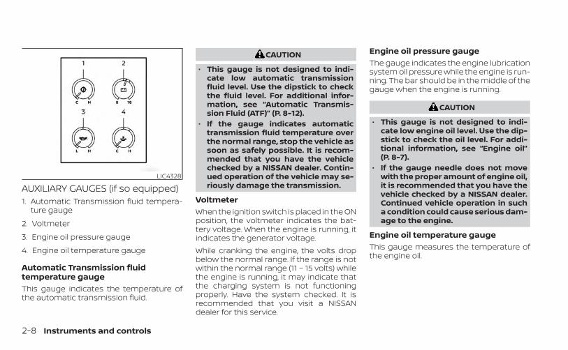
AUXILIARY GAUGES (if so equipped)1. Automatic Transmission fluid tempera-
ture gauge
2. Voltmeter
3. Engine oil pressure gauge
4. Engine oil temperature gauge
Automatic Transmission fluidtemperature gaugeThis gauge indicates the temperature ofthe automatic transmission fluid.
CAUTION
• This gauge is not designed to indi-cate low automatic transmissionfluid level. Use the dipstick to checkthe fluid level. For additional infor-mation, see “Automatic Transmis-sion Fluid (ATF)” (P. 8-12).
• If the gauge indicates automatictransmission fluid temperature overthe normal range, stop the vehicle assoon as safely possible. It is recom-mended that you have the vehiclechecked by a NISSAN dealer. Contin-ued operation of the vehicle may se-riously damage the transmission.
VoltmeterWhen the ignition switch is placed in the ONposition, the voltmeter indicates the bat-tery voltage. When the engine is running, itindicates the generator voltage.While cranking the engine, the volts dropbelow the normal range. If the range is notwithin the normal range (11 – 15 volts) whilethe engine is running, it may indicate thatthe charging system is not functioningproperly. Have the system checked. It isrecommended that you visit a NISSANdealer for this service.
Engine oil pressure gaugeThe gauge indicates the engine lubricationsystem oil pressure while the engine is run-ning. The bar should be in the middle of thegauge when the engine is running.
CAUTION
• This gauge is not designed to indi-cate low engine oil level. Use the dip-stick to check the oil level. For addi-tional information, see “Engine oil”(P. 8-7).
• If the gauge needle does not movewith the proper amount of engine oil,it is recommended that you have thevehicle checked by a NISSAN dealer.Continued vehicle operation in sucha condition could cause serious dam-age to the engine.
Engine oil temperature gaugeThis gauge measures the temperature ofthe engine oil.
LIC4328
2-8 Instruments and controls

OFF-ROAD AND 4–WHEEL DRIVE(4WD) MONITOR (if so equipped)The off-road and 4WD monitor displays thevarious conditions of the vehicle.The Pitch and Roll Gauge (left) indicates theangle of the vehicle position left, right, up ordown. The value will be displayed while thevehicle graphic will rotate to indicate ve-hicle condition: left, right, up or down.
The Tire Angle & 4WD Gauge (right) indi-cates the angle of the tires based on turn-ing of the steering wheel and 4WD status.The graphic image will show the actual ve-hicle tire position while the angle is to bedisplayed above as reference. The 4WD sta-tus is displayed below.
LIC4329
Instruments and controls 2-9

Warning/Indicator light (red) Warning/Indicator light (yellow) Warning/Indicator light (other)
Automatic Transmission Park warninglight ( model)
or Anti-lock Braking System (ABS)warning light
Front fog light indicator light (green)(if so equipped)
or Brake warning light Automatic Emergency Braking (AEB) withPedestrian Detection system warning light
High Beam Assist indicator light (green)(if so equipped)
Charge warning light Automatic Transmission check warninglight
High beam indicator light (blue)
Electric shift control system warning light Electronic locking rear differential (E-Lock)system ON indicator light (if so equipped)
Side light and headlight indicator light(green)
Engine oil pressure warning light Front passenger air bag status light TOW mode ON indicator light (green)(if so equipped)
Master warning light Hill descent control system ON indicatorlight (if so equipped)
Turn signal/hazard indicator lights (green)
Seat belt warning light and chime Low tire pressure warning light
Security indicator light Malfunction Indicator Light (MIL)
Supplemental air bag warning light Master warning light
WARNING LIGHTS, INDICATOR LIGHTSAND AUDIBLE REMINDERS
2-10 Instruments and controls

Warning/Indicator light (red) Warning/Indicator light (yellow) Warning/Indicator light (other)
Rear Automatic Braking (RAB) warning light(if so equipped)
Slip indicator light
Vehicle Dynamic Control (VDC) OFF indica-tor light
CHECKING LIGHTSWith all doors closed, apply the parkingbrake, fasten the seat belts and place theignition switch in the ON position withoutstarting the engine. The following lights (ifso equipped) will come on:
, or , , , orThe following lights (if so equipped) willcome on briefly and then go off:
, , , , , , ,, ATP ,
If any light does not come on or operate ina way other than described, it may indicatea burned-out bulb and/or a system mal-function. Have the system checked. It isrecommended that you visit a NISSANdealer for this service.Some indicators and warnings are also dis-played on the vehicle information displaybetween the speedometer and tachom-eter. For additional information, see “Ve-hicle information display” (P. 2-20).
WARNING/INDICATOR LIGHTS (red)For additional information, see “Vehicle in-formation display” (P. 2-20).
Automatic TransmissionPark warning light( model)
WARNING
• If the ATP light is on, this indicatesthat the automatic transmission P(Park) position will not function andthe transfer case is in N (Neutral).
• When parking, always make sure thatthe 4WD shift indicator light illumi-nates and the parking brake is set.Failure to engage the transfer posi-tion in 2WD, 4H or 4LO could result inthe vehicle moving unexpectedly, re-sulting in serious personal injury orproperty damage.
Instruments and controls 2-11

• Shift the 4WD switch into the 2WD, 4Hor 4LO position again to turn off theATP warning light when the shift le-ver is in the P (Park) position and theATP warning light is on. (Before shift-ing the 4WD switch into the 4LO posi-tion, move the shift lever into the N(Neutral) position once, shift the shiftlever into P (Park) again and makesure the ATP warning light is off.)
If the 4WD mode indicator is off or the ATPwarning light is on, this indicates that theautomatic transmission P (Park) positionwill not function and could result in the ve-hicle moving unexpectedly, causing seri-ous personal injury or property damage.Always set the parking brake. For additionalinformation, see “Using 4–Wheel Drive(4WD) (P. 5-109).This light indicates that the automatictransmission parking function is not en-gaged. If the transfer control is not securedin any drive position while the shift lever isin the P (Park) position, the transmission willdisengage and the drive wheels will notlock.
or Brake warninglight
This light functions for both the parkingbrake and the foot brake systems.Parking brake indicatorWhen the ignition switch is placed in the ONposition, the light comes on when the park-ing brake is applied.Low brake fluid warning lightWhen the ignition switch is placed in the ONposition, the light warns of a low brake fluidlevel. If the light comes on while the engineis running with the parking brake not ap-plied, stop the vehicle and perform thefollowing:1. Check the brake fluid level. Add brake
fluid as necessary. For additional infor-mation, see “Brake fluid” (P. 8-13).
2. If the brake fluid level is correct, have thewarning system checked. It is recom-mended that you visit a NISSAN dealerfor this service.
WARNING
• Your brake system may not be work-ing properly if the warning light is on.Driving could be dangerous. If youjudge it to be safe, drive carefully tothe nearest service station for re-pairs. Otherwise, have your vehicletowed because driving it could bedangerous.
• Pressing the brake pedal with the en-gine stopped and/or a low brakefluid level may increase your stop-ping distance and braking will re-quire greater pedal effort as well aspedal travel.
• If the brake fluid level is below theMINIMUM or MIN mark on the brakefluid reservoir, do not drive until thebrake system has been checked. It isrecommended that you visit aNISSAN dealer for this service.
2-12 Instruments and controls

Charge warning light
If this light comes on while the engine isrunning, it may indicate the charging sys-tem is not functioning properly. Turn theengine off and check the generator belt. Ifthe belt is loose, broken, or missing or if thelight remains on, have the system checked.It is recommended that you visit a NISSANdealer for this service.
CAUTION
• Do not ground electrical accessoriesdirectly to the battery terminal. Do-ing so will bypass the variable volt-age control system and the vehiclebattery may not charge completely.For additional information, see “Vari-able voltage control system” (P. 8-17).
• Do not continue driving if the genera-tor belt is loose, broken or missing.
Electric shift control systemwarning light
This light illuminates when a malfunctionoccurs in the electric shift control system.When the master warning light illuminates,the chime sounds and the following mes-sage is displayed in the vehicle informationdisplay: “When parked apply parking brake”.When the ignition is placed in the OFF posi-tion, the chime sounds continuously. En-sure the parking brake is appliedHave the system checked. It is recom-mended that you visit a NISSAN dealer forthis service.
Engine oil pressurewarning light
This light warns of low engine oil pressure. Ifthe light flickers or comes on during nor-mal driving, pull off the road in a safe area,stop the engine immediately, and call aNISSAN dealer or other authorized repairshop.The engine oil pressure warning light isnot designed to indicate a low oil level. Usethe dipstick to check the oil level. For addi-tional information, see “Engine oil” (P. 8-7).
CAUTION
Running the engine with the engine oilpressure warning light on could causeserious damage to the engine almostimmediately. Such damage is not cov-ered by the NISSAN New Vehicle LimitedWarranty. Turn off the engine as soonas it is safe to do so.
Master warning light
This light comes on when various vehicleinformation display warnings appear.• Parking brake release warning• Transmission system warning
Seat belt warning light andchime
The light and chime remind you to fastenyour seat belts. The light illuminates when-ever the ignition switch is placed in the ONposition and remains illuminated until thedriver's seat belt is fastened. At the sametime, the chime sounds for about 6 sec-onds unless the driver's seat belt is se-curely fastened.
Instruments and controls 2-13

The seat belt warning light may also illumi-nate if the front passenger's seat belt is notfastened when the front passenger's seatis occupied. For 7 seconds after the ignitionswitch is placed in the ON position, the sys-tem does not activate the warning light forthe front passenger.For additional information, see “Seat belts”(P. 1-15).
Security indicator light
This light blinks when the ignition switch isin the OFF, LOCK or ACC position. This func-tion indicates the security systemsequipped on the vehicle are operational.For additional information, see “Securitysystems” (P. 2-34).
Supplemental air bagwarning light
When the ignition switch is in the ON posi-tion, the supplemental air bag warninglight illuminates for about 7 seconds andthen turns off. This means the system isoperational.
If any of the following conditions occur, thefront air bag, side air bag, curtain air bag,and pretensioner systems need servicing:• The supplemental air bag warning light re-
mains on after approximately 7 seconds.• The supplemental air bag warning light
flashes intermittently.• The supplemental air bag warning light
does not come on at all.It is recommended that you visit a NISSANdealer for these services.Unless checked and repaired, the supple-mental restraint system (air bag system)and/or the pretensioners may not functionproperly. For additional information, see“Supplemental Restraint System (SRS)”(P. 1-72).
WARNING
If the supplemental air bag warninglight is on, it could mean that the frontair bag, side air bag, curtain air bag sys-tems, and/or pretensioner systems willnot operate in an accident. To helpavoid injury to yourself or others, haveyour vehicle checked as soon as pos-sible. It is recommended that you visit aNISSAN dealer for this service.
WARNING/INDICATOR LIGHTS(yellow)For additional information on warningsand indicators, see “Vehicle informationdisplay” (P. 2-20).
or Anti-lock BrakingSystem (ABS)warning light
When the ignition switch is placed in the ONposition, the ABS warning light illuminatesand then turns off. This indicates the ABS isoperational.If the ABS warning light illuminates whilethe engine is running or while driving, itmay indicate the ABS is not functioningproperly. Have the system checked. It isrecommended that you visit a NISSANdealer for this service.If an ABS malfunction occurs, the anti-lockfunction is turned off. The brake systemthen operates normally but without anti-lock assistance. For additional information,see “Brake system” (P. 5-118).
2-14 Instruments and controls

Automatic EmergencyBraking (AEB) withPedestrian Detectionsystem warning light
This light comes on when the ignitionswitch is placed in the ON position. It turnsoff after the engine is started.This light illuminates when the AEB withPedestrian Detection system is set to OFFin the vehicle information display.If the light illuminates when the AEB withPedestrian Detection system is on, it mayindicate that the system is unavailable. Foradditional information, see “AutomaticEmergency Braking (AEB) with PedestrianDetection” (P. 5-81).
Automatic Transmissioncheck warning light
When the ignition switch is placed in the ONposition, the light comes on for about 2seconds. If the light comes on at any othertime, it may indicate the automatic trans-mission system is not functioning properly.Have the system checked. It is recom-mended that you visit a NISSAN dealer forthis service.
Electronic locking reardifferential (E-Lock) systemON indicator light (if soequipped)
This light comes on when the electroniclocking rear differential (E-Lock) systemclutch is fully engaged.The indicator light flashes when the sys-tem is first turned on. When the system fullyengages, the light remains on. If the switchis on and the indicator light continues toflash, the system is not engaged.For additional information, see “Electroniclocking rear differential (E-Lock) systemswitch” (P. 2-50) and “Electronic locking reardifferential (E-Lock) system” (P. 5-115).
Front passenger air bagstatus light
The front passenger air bag status light willbe lit and the passenger front air bag will beoff depending on how the front passengerseat is being used.For additional information, see “Front pas-senger air bag and status light” (P. 1-83).
Hill descent control systemON indicator light (if soequipped)
When the ignition switch is placed in the ONposition, this light comes on briefly andthen turns off.The light comes on when the hill descentcontrol system is activated.If the hill descent control switch is on andthe indicator light blinks, the system is notengaged.If the indicator light does not come onwhen the hill descent switch is on, the sys-tem may not be functioning properly. Havethe system checked. It is recommendedthat you visit a NISSAN dealer for thisservice.For additional information, see “Hill descentcontrol switch” (P. 2-49) and “Hill descentcontrol system” (P. 5-123).
Low tire pressure warninglight
Your vehicle is equipped with a Tire Pres-sure Monitoring System (TPMS) that moni-tors the tire pressure of all tires except thespare.
Instruments and controls 2-15

The low tire pressure warning light warnsof low tire pressure or indicates that theTPMS is not functioning properly.After the ignition switch is placed in the ONposition, this light illuminates for about 1second and turns off.Low tire pressure warningIf the vehicle is being driven with low tirepressure, the warning light will illumi-nate. A “Tire Pressure Low - Add Air”warning also appears in the vehicle in-formation display.When the low tire pressure warning lightilluminates, you should stop and adjustthe tire pressure of all four tires to therecommended COLD tire pressure shownon the Tire and Loading Information la-bel located in the driver's door opening.The low tire pressure warning light doesnot automatically turn off when the tirepressure is adjusted. After the tire is in-flated to the recommended pressure,the vehicle must be driven at speedsabove 16 mph (25 km/h) to activate theTPMS and turn off the low tire pressurewarning light. Use a tire pressure gaugeto check the tire pressure.
The “Tire Pressure Low - Add Air” warningappears each time the ignition switch isplaced in the ON position as long as thelow tire pressure warning light remainsilluminated.For additional information, see “Vehicle in-formation display” (P. 2-20) and “Tire Pres-sure Monitoring System (TPMS)” (P. 5-5).TPMS malfunctionIf the TPMS is not functioning properly, thelow tire pressure warning light will flash forapproximately 1 minute when the ignitionswitch is placed in the ON position. Thelight will remain on after 1 minute. Have thesystem checked. It is recommended thatyou visit a NISSAN dealer for this service.The "Tire Pressure Low — Add Air" warningdoes not appear if the low tire pressurewarning light illuminates to indicate aTPMS malfunction.For additional information, see “Tire Pres-sure Monitoring System (TPMS)” (P. 5-5) and“Tire pressure” (P. 8-31).
WARNING
• Radio waves could adversely affectelectric medical equipment. Thosewho use a pacemaker should contactthe electric medical equipmentmanufacturer for the possible influ-ences before use.
• If the light does not illuminate withthe ignition switch placed in the ONposition, have the vehicle checked assoon as possible. It is recommendedthat you visit a NISSAN dealer for thisservice.
2-16 Instruments and controls

• If the light illuminates while driving,avoid sudden steering maneuvers orabrupt braking, reduce vehiclespeed, pull off the road to a safe loca-tion and stop the vehicle as soon aspossible. Driving with under-inflatedtires may permanently damage thetires and increase the likelihood oftire failure. Serious vehicle damagecould occur and may lead to an acci-dent and could result in serious per-sonal injury or death. Check the tirepressure for all four tires. Adjust thetire pressure to the recommendedCOLD tire pressure show on the Tireand Loading Information label lo-cated in the driver’s door opening toturn the low tire pressure warninglight off. If the light still illuminateswhile driving after adjusting the tirepressure, a tire may be flat or theTPMS may be malfunctioning. If youhave a flat tire, replace it with a sparetire as soon as possible. If no tire isflat and all tires are properly inflated,have the vehicle checked. It is recom-mended that you visit a NISSANdealer for this service.
• When using a wheel without theTPMS such as the spare tire, the TPMSwill not function and the low tirepressure warning light will flash forapproximately 1 minute. The light willremain on after 1 minute. Have yourtires replaced and/or TPMS systemreset as soon as possible. It is recom-mended that you visit a NISSANdealer for these services.
• Replacing tires with those not origi-nally specified by NISSAN could af-fect the proper operation of theTPMS.
CAUTION
• The TPMS is not a substitute for theregular tire pressure check. Be sureto check the tire pressure regularly.
• If the vehicle is being driven atspeeds of less than 16 mph (25 km/h),the TPMS may not operate correctly.
• Be sure to install the specified size oftires to the four wheels correctly.
Malfunction Indicator Light(MIL)
If this indicator light comes on steady orblinks while the engine is running, it mayindicate a potential emission controlmalfunction.If this indicator light comes on steady for20 seconds and then blinks for 10 secondswhen the engine is not running, it indicatesthat the vehicle is not ready for an emissioncontrol system inspection/maintenancetest. For additional information, see “Readi-ness for inspection/maintenance (I/M)test” (P. 10-42).
Instruments and controls 2-17

OperationThe MIL will come on in one of two ways:• MIL on steady — An emission control sys-
tem malfunction has been detected.Check the fuel-filler cap if the Loose FuelCap warning appears in the vehicle infor-mation display. If the fuel-filler cap is looseor missing, tighten or install the cap andcontinue to drive the vehicle. The lightshould turn off after a few driving trips. Ifthe light does not turn off after a fewdriving trips, have the vehicle inspected. It isrecommended that you visit a NISSANdealer for this service. You do not need tohave your vehicle towed to the dealer.
• MIL blinking — An engine misfire has beendetected which may damage the emis-sion control system. To reduce or avoidemission control system damage:– do not drive at speeds above 45 mph
(72 km/h).– avoid hard acceleration or deceleration.– avoid steep uphill grades.– if possible, reduce the amount of cargo
being hauled or towed.The MIL may stop blinking and come onsteady. Have the vehicle inspected. It is rec-ommended that you visit a NISSAN dealerfor this service. You do not need to haveyour vehicle towed to the dealer.
CAUTION
Continued vehicle operation withouthaving the emission control systemchecked and repaired as necessarycould lead to poor driveability, reducedfuel economy, and possible damage tothe emission control system.
Master warning light
This light comes on when various vehicleinformation display warnings appear.• No key warning• Low fuel warning• Low windshield-washer fluid warning• Loose fuel cap warning• Low tire pressure warning• 4WD error (if so equipped)• Front & rear tire size differences (if so
equipped)
Rear Automatic Braking(RAB) warning light (if soequipped)
This light comes on when the ignitionswitch is placed in the ON position. It turnsoff after the engine is started.
This light illuminates when the RAB systemis turned off in the vehicle informationdisplay.If the light illuminates when the RAB sys-tem is on, it may indicate that the system isunavailable. For additional information, see“Rear Automatic Braking (RAB)” (P. 5-76).
Slip indicator light
This indicator light will blink when the Ve-hicle Dynamic Control (VDC) system is op-erating, thus alerting the driver to the factthat the road surface is slippery and thevehicle is nearing its traction limits.You may feel or hear the system working;this is normal.The light will blink for a few seconds afterthe VDC system stops limiting wheel spin.The indicator light also comes onwhen you place the ignition switch in theON position. The light will turn off after ap-proximately 2 seconds if the system is op-erational. If the light does not come onhave the system checked. It is recom-mended that you visit a NISSAN dealer forthis service.
2-18 Instruments and controls

Vehicle Dynamic Control(VDC) OFF indicator light
This indicator light comes on when theVDC OFF switch is pushed to off. This indi-cates the VDC system is not operating.Push the VDC OFF switch again or restartthe engine and the system will operatenormally. For additional information, see“Vehicle Dynamic Control (VDC) system”(P. 5-121).The VDC OFF indicator light also comes onwhen you place the ignition switch in theON position. The light will turn off afterabout 2 seconds if the system is opera-tional. If the light stays on or comes onalong with the indicator light whileyou are driving, have the VDC systemchecked. It is recommended that you visit aNISSAN dealer for this service.While the VDC system is operating, youmight feel a slight vibration or hear the sys-tem working when starting the vehicle oraccelerating, but this is normal.
WARNING/INDICATOR LIGHTS(other)For additional information, see “Vehicle in-formation display” (P. 2-20).
Front fog light indicatorlight (green) (if soequipped)
The front fog light indicator light illumi-nates when the front fog lights are on. Foradditional information, see “Fog lightswitch” (P. 2-44).
High Beam Assist indicatorlight (green) (if so equipped)
This indicator light illuminates when theheadlights come on while the headlightswitch is in the AUTO position with the highbeams selected. This indicates that thehigh beam assist is operational.For additional information, see “Headlightand turn signal switch” (P. 2-38).
High beam indicator light(blue)
This blue light comes on when the head-light high beams are on and goes out whenthe low beams are selected.The high beam indicator light also comeson when the passing signal is activated.
Side light and headlightindicator light (green)
The side light and headlight indicator lightilluminates when the side light or headlightposition is selected. For additional informa-tion, see “Headlight and turn signal switch”(P. 2-38).
TOW mode ON indicatorlight (green) (if soequipped)
This light comes on when the tow modefunction is on.
Turn signal/hazardindicator lights (green)
The appropriate light flashes when the turnsignal switch is activated.Both lights flash when the hazard switch isturned on.
AUDIBLE REMINDERS
Brake pad wear warningThe disc brake pads have audible wearwarnings. When a disc brake pad requiresreplacement, it makes a high pitched
Instruments and controls 2-19

scraping sound when the vehicle is in mo-tion, whether or not the brake pedal is de-pressed. Have the brakes checked as soonas possible if the warning sound is heard.
Light reminder chimeWith the ignition switch placed in the OFFposition, a chime sounds when the driver'sdoor is opened if the headlights or parkinglights are on.Turn the headlight control switch off beforeleaving the vehicle.
NISSAN Intelligent Key® doorbuzzerThe Intelligent Key door buzzer sounds ifany one of the following improper opera-tions is found.• The Intelligent Key is left inside the vehicle
when locking the doors.• The Intelligent Key is taken outside the
vehicle when operating the vehicle.When the buzzer sounds, be sure to checkboth the vehicle and the Intelligent Key. Foradditional information, see “NISSAN Intelli-gent Key®” (P. 3-2).
The vehicle information display is locatedto the left of the speedometer. It displayssuch items as:• Vehicle settings• Trip computer information• Drive system warnings and settings (if so
equipped)• Cruise control system information• Blind Spot Warning (BSW) system (if so
equipped)• Rear Cross Traffic Alert (RCTA) system (if so
equipped)
• NISSAN Intelligent Key® operationinformation
• Indicators and warnings• Tire Pressure information
LIC3224
VEHICLE INFORMATION DISPLAY
2-20 Instruments and controls

HOW TO USE THE VEHICLEINFORMATION DISPLAYThe vehicle information display can benavigated using the ENTER and but-tons located on the steering wheel.1. ENTER — press to select the vehicle infor-
mation menu items. Additionally, use theUP/DOWN function to navigate themenu items
2. — move LEFT/RIGHT to navigatethrough the items in the vehicle infor-mation display
The ENTER button also controls audio func-tions. For additional information, refer to theseparate NissanConnect® Owner’s Manual.
STARTUP DISPLAYWhen the vehicle is placed in the ON or ACC(if so equipped) position, the vehicle infor-mation display may display the followingscreens:• Speed• Off Road (if so equipped)• Auxiliary Gauges (if so equipped)• Driving• Fuel Economy• Audio• Navigation (if so equipped)• Compass (if so equipped)• Driving Aids• Tire Pressures• Warning Confirmation• SettingsWarning Confirmation will only display ifthere are any warnings present. For addi-tional information, see “Vehicle informationdisplay warnings and indicators” (P. 2-28).To control which items display in the vehicleinformation display, see “Settings” (P. 2-21).
SETTINGSThe setting mode allows you to change theinformation displayed in the vehicle infor-mation display:• Driver Assistance• Meter Settings• Vehicle Settings• Alerts• Maintenance• Unit• Language• Factory Reset
LIC4099
Instruments and controls 2-21

Driver AssistanceThe driver assistance menu allows the user to change the various driving and parking aids.Some menu items shown below may not be equipped on your vehicle.
Menu item ExplanationLane Displays available lane options.
Warning (LDW) Allows user to turn the Lane Departure Warning (LDW) system on or off. For additional information, see “LaneDeparture Warning (LDW)” (P. 5-28).
Blind Spot Displays available blind spot options.Warning (BSW) Allows user to turn the Blind Spot Warning (BSW) system on or off. For additional information, see “Blind Spot
Warning (BSW)” (P. 5-33).Emergency Brake Displays available emergency brake options.
Front Allows user to turn the front emergency braking system on or off. For additional information, see “AutomaticEmergency Braking (AEB) with Pedestrian Detection” (P. 5-81) and “Intelligent Forward Collision Warning (I-FCW)”(P. 5-92).
Rear Allows user to turn the rear emergency braking system on or off. For additional information, see “Rear AutomaticBraking (RAB)” (P. 5-76).
Traffic Sign Allows use to turn the Speed Limit Sign recognition on or off. For additional information, see “Traffic Sign Recogni-tion (TSR)” (P. 5-25).
Driver Attention Allows user to turn the Intelligent Driver Alertness system on or off. For additional information, see “IntelligentDriver Alertness (I-DA)” (P. 5-104).
Parking Aids Displays available parking aids.Moving Object Allows user to turn the Moving Object Detection (MOD) on or off. For additional information, see “Moving Object
Detection (MOD)” (P. 4-23).CTA Allows user to turn the Rear Cross Traffic Alert (RCTA) system on or off. For additional information, see “Rear Cross
Traffic Alert (RCTA)” (P. 5-43).Sensor Allows the user to turn the sensors on or off.Display Allows user to turn the display on or off in the vehicle information display.Volume Allows user to adjust the volume of warning chimes.Range Allows user to set a specific range for the sensors to engage.
2-22 Instruments and controls

Meter SettingsThe meter settings allow the user to change the settings for the vehicle information display.Some menu items shown below may not be equipped on your vehicle.
Menu item ExplanationMain Menu Selection Allows user to customize the screens shown in the vehicle information display.
Speed Allows user to turn the speedometer screen on or off in the vehicle information display.Off Road Allows user to turn the off road and 4WD monitor on or off in the vehicle information display. For additional
information, see “Off-Road and 4–Wheel Drive (4WD) Monitor” (P. 2-9).Auxiliary Gauges Allows user to turn the auxiliary gauges on or off in the vehicle information display. For additional informa-
tion, see “Auxiliary gauges” (P. 2-8).Driving Allows user to turn the drive computer screen on or off in the vehicle information display.Fuel Economy Allows user to turn the fuel economy on or off in the vehicle information display.Audio Allows user to turn the audio screen on or off in the vehicle information display. For additional information,
refer to the separate NissanConnect® Owner’s Manual.Navigation Allows user to turn the navigation on or off in the vehicle information display. For additional information, refer
to the separate NissanConnect® Owner’s Manual.Speed Limit Sign Allows user to turn the speed limit sign screen on or off in the vehicle information display.Driving Aids Allows user to turn the driving aids on or off in the vehicle information display.Tire Pressures Allows user to turn the tire pressures screen on or off in the vehicle information display.
ECO Drive Report Allows user to access the ECO drive report.Display Allows user to turn the ECO drive report on or off.ECO Drive Report Allows user to view and reset ECO drive report history.
Welcome Effect Allows user to customize the available welcome effects.Dial Effect Allows user to turn the dial effect on or off.Display Effect Allows user to turn the display effect on or off.
Instruments and controls 2-23

Vehicle SettingsThe vehicle settings allow the user to change the settings for lights, wipers, locking, keys, and other vehicle settings.Some menu items shown below may not be equipped on your vehicle.
Menu item ExplanationRear Door Alert Displays the available rear Door Alert options.
Alert and Horn When selected, the alert is displayed; and the horn sounds.Alert Only When selected, only the alert is displayed.Off When selected, no alert or horn will be active.
Lighting Displays available lighting features of the vehicle.Welcome Light Allows user to turn the welcome light on or off.Auto Room Lamp Allows user to turn the auto room lamp feature on or off.Light Sensitivity Allows user to change when the lights illuminate based on the brightness outside the vehicle.Light Off Delay Allows user to change the duration of time that the automatic headlights stay on after the vehicle is shut off.
Turn indicator Displays available turn indicator options.3 Flash Pass Allows user to turn the 3 flash pass on or off.
Locking Displays available locking options.I-Key Door Lock Allows user to turn I-key door lock on or off. When turned on, the request switch on the door is activated.Selective Unlock Allows user to turn selective unlock on or off. When turned on, only the driver’s door is unlocked after the
door unlock operation. When the door handle request switch on the driver’s or front passenger’s side door ispushed to be unlocked, only the corresponding door is unlocked first. All the doors can be unlocked if thedoor unlock operation is performed again within 1 minute. When this item is turned off, all the doors will beunlocked after the door unlock operation is performed once.
Answer Back. Horn Allows user to turn answer back horn on or off.Auto Unlock Displays available options for the auto door unlock.
Off Doors will have to be manually unlocked.IGN Off Doors will unlock when the ignition is placed in the OFF position.Shift P Doors will unlock when the vehicle is shifted into P (Park).
2-24 Instruments and controls

Menu item ExplanationWipers Displays available wiper options.
Speed Dependent Allows user to turn the speed dependent feature on or off. For additional information, see “Wiper and washerswitch” (P. 2-37).
Headlamp On Displays available headlamp on options.Off Headlights do not activate automatically when the wipers are activated.Wiper Low & High Headlights activate when the wiper stalk is set to either low or high mode.Wiper INT, Low & High Headlights activate when the wiper stalk is set to intermittent, low, or high mode.
AlertsThe alarm menu allows the user to set specific alarms for various items on the vehicle.Some menu items shown below may not be equipped on your vehicle.
Menu item ExplanationTimer Alert Allows user to set the timer alert alarm.Navigation Allows user to turn the navigation alarm on or off.Phone Allows user to turn the phone alarm on or off.Mail Allows user to turn the mail alarm on or off.
Instruments and controls 2-25

MaintenanceThe maintenance menu allows the user to set reminders for various vehicle maintenance items.Some menu items shown below may not be equipped on your vehicle.
WARNING
The tire replacement indicator is not a substitute for regular tire checks, including tire pressure checks. For additional informa-tion, see “Changing wheels and tires” (P. 8-40). Many factors including tire inflation, alignment, driving habits and road conditionsaffect tire wear and when tires should be replaced. Setting the tire replacement indicator for a certain driving distance does notmean your tires will last that long. Use the tire replacement indicator as a guide only and always perform regular tire checks.Failure to perform regular tire checks, including tire pressure checks could result in tire failure. Serious vehicle damage couldoccur and may lead to a collision, which could result in serious personal injury or death.
Menu item ExplanationMaintenance Allows user to cycle through various maintenance items and set reminders to perform maintenance at spe-
cific intervals.Oil and Filter Allows user to set an oil and filter reminder at a specific interval or reset the current one.Air Filter Allows user to set an air filter reminder at a specific interval or reset the current one.Tire Allows user to set a tire reminder at a specific interval or reset the current one.Brake Pad Allows user to set a brake pad reminder at a specific interval or reset the current one.Brake Fluid Allows user to set a brake fluid reminder at a specific interval or reset the current one.Battery Allows user to set a battery reminder at a specific interval or reset the current one.Transmission Fluid Allows user to set a transmission fluid reminder at a specific interval or reset the current one.Engine Coolant Allows user to set an engine coolant reminder at a specific interval or reset the current one.Spark Plug Allows user to set a spark plug reminder at a specific interval or reset the current one.Other Allows user to set a reminder, other than for the maintenance items listed above, at a specific interval or re-
set the current one.
2-26 Instruments and controls

UnitThe unit menu allows the user to change the units shown in the vehicle information display.
Menu item ExplanationMileage Displays available mileage display units.Pressure Displays available pressure display units.Temperature Displays available temperature display units.
LanguageThe language menu allows the user to change the languages displayed in the vehicle information display.
Menu item ExplanationLanguage Displays available language options for the vehicle information display.
Factory ResetThe factory reset menu allows the user to restore the vehicle information display settings to factory status.
Menu item ExplanationFactory Reset Allows user to reset the vehicle information display settings to the original factory settings. Once selected,
the user can confirm or deny the reset.
Instruments and controls 2-27
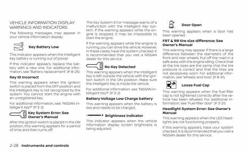
VEHICLE INFORMATION DISPLAYWARNINGS AND INDICATORSThe following messages may appear inyour vehicle information display.
Key Battery Low
This indicator appears when the IntelligentKey battery is running out of power.If this indicator appears, replace the bat-tery with a new one. For additional infor-mation, see “Battery replacement” (P. 8-25).Key ID IncorrectThis warning appears when the ignitionswitch is placed from the OFF position andthe Intelligent Key is not recognized by thesystem. You cannot start the engine withan unregistered key.For additional information, see “NISSAN In-telligent Key®” (P. 3-2).
Key System Error: SeeOwner’s Manual
After the ignition switch is placed in the ONposition, this warning appears for a periodof time and then turns off.
The Key System Error message warns of amalfunction with the Intelligent Key sys-tem. If the warning appears while the en-gine is stopped, it may be impossible tostart the engine.If the warning appears while the engine isrunning, you can drive the vehicle. However,in these cases, have the system checked. Itis recommended that you visit a NISSANdealer for this service.
No Key DetectedThis warning appears when the IntelligentKey is left outside the vehicle with the igni-tion switch in the ON position. Make surethe Intelligent Key is inside the vehicle.For additional information, see “NISSAN In-telligent Key®” (P. 3-2).Battery Voltage Low Charge batteryThis warning appears when the battery islow and needs to be charged.
Brightness indicatorThis indicator appears when the vehicleinformation display screen brightness isbeing adjusted.
Door Open
This warning appears when a door hasbeen opened.FRT & RR tire size difference: SeeOwner’s ManualThis warning may appear if there is a largedifference between the diameters of thefront and rear wheels. Pull off the road in asafe area, with the engine idling. Check thatall the tire sizes are the same, that the tirepressure is correct and that the tires arenot excessively worn. For additional infor-mation, see “Wheels and tires” (P. 8-31).
Loose Fuel Cap
This warning appears when the fuel-fillercap is not tightened correctly after the ve-hicle has been refueled. For additional in-formation, see “Fuel-filler door” (P. 3-21).Headlight System Error: See Owner’sManualThis warning appears when the LED head-lights are not functioning properly.If this warning appears, have your systemchecked. It is recommended that you visit aNISSAN dealer for this service.
2-28 Instruments and controls

Low Fuel
This warning appears when the fuel level inthe fuel tank is getting low. Refuel as soonas it is convenient, preferably before thefuel gauge reaches 0 (Empty). There will bea small reserve of fuel in the tank whenthe fuel gauge needle reaches 0 (Empty).
Low Tire Pressure Error —Info
This warning appears when the low tirepressure warning light in the meter illumi-nates and low tire pressure is detected.Press the ENTER button for informationabout the low tire pressure. For additionalinformation, see “Low tire pressure warninglight” (P. 2-15) and “Tire Pressure MonitoringSystem (TPMS)” (P. 5-5).
Low Washer Fluid
This warning appears when the windshield-washer fluid is at a low level. Add windshield-washer fluid as necessary. For additionalinformation, see “Windshield-washer fluid”(P. 8-14).
Maintenance indicators
When engine oil service is due, one or moreof these icons will appear automatically toremind you. For additional information, see“Engine oil” (P. 8-7).These will also appear when the user-setreminders are met. For additional informa-tion, see “Vehicle information display”(P. 2-20).Power turned off to save the batteryThis warning appears after the ignitionswitch is automatically turned off to savethe battery.Power will turn off to save the batteryThis message appears in the vehicle infor-mation display after a period of time if theignition switch is in the ACC or the ON po-sition and if the vehicle is in P (Park). Foradditional information, see “Push-buttonignition switch positions” (P. 5-14).
Push brake and startswitch to drive
This indicator appears when the shift leveris in the P (Park) position.
This indicator means that the engine willstart by pushing the ignition switch withthe brake pedal depressed. You can startthe engine from any position of the ignitionswitch.
Range XX miles
This warning appears to indicate the ap-proximate distance remaining before thefuel reaches 0 (Empty).Check Rear Seat For All ArticlesWhen the system is enabled, this messageappears when the vehicle comes to a com-plete stop, the vehicle is transitioned fromthe D (Drive) position to P (Park) position,and the driver exits the vehicle. This mes-sage alerts the driver, after a period of time,to check for items in the rear seat after theaudible alert has been provided.
NOTE:
This system is disabled until a driver en-ables it using the vehicle informationdisplay. For additional information, see“How to use the vehicle information dis-play” (P. 2-21).For additional information, see “Rear DoorAlert” (P. 2-53).
Instruments and controls 2-29

Rear Door Alert is activatedWhen the system is enabled, this messageappears when the Rear Door Alert systemis active and can remind the driver to checkthe back seat.• Using the steering wheel switch, a driver
can select “Dismiss Message” to clear thedisplay for a period of time. If no selectionis made, this message automaticallyturns off after a period of time.
• Using the steering wheel switch, a drivercan select “Disable Alert” to disable thehorn alert for the remainder of the cur-rent trip.
WARNING
Selecting “Dismiss Message” during astop within a trip temporarily dis-misses the message for that stop with-out turning the system off. Alerts canbe provided for other stops during thetrip. Selecting “Disable Alert” turns offthe Rear Door Alert system for the re-mainder of a trip and no audible alertwill be provided.
NOTE:
This system is disabled until a driver en-ables it using the vehicle informationdisplay. For additional information, “Howto use the vehicle information display”(P. 2-21).For additional information, “Rear Door Alert”(P. 2-53).Release Parking BrakeThis warning appears in the message areaof the vehicle information display when theparking brake is set and the vehicle isdriven. Press the brake pedal to release theparking brake.
Reminder: Turn OFFHeadlights
This warning appears when the headlightsare left in the ON position when exiting thevehicle. Place the headlight switch in theOFF or AUTO position. For additional infor-mation, see “Headlight and turn signalswitch” (P. 2-38).
Remote Engine Start Mode
This warning appears in the vehicle infor-mation display when the vehicle has beenstarted using the remote start function. Tostart the vehicle, apply the brake and placethe ignition switch in the ON position.
Shift to Park
This warning appears when the ignitionswitch is in the ACC or OFF position and theshift lever is not in the P (Park) position. Also,a chime sounds when the ignition switch isin the ACC or OFF position.If this warning appears, move the shift leverto the P (Park) position and start the engine.Shipping Mode On Push Storage FuseThis warning may appear if the extendedstorage switch is not pushed in. When thiswarning appears, push in the extendedstorage switch to turn off the warning. Foradditional information, see “Extended stor-age switch” (P. 2-60).
2-30 Instruments and controls

Tire Pressure Low - Add Air
This warning appears when the low tirepressure warning light in the meter illumi-nates and low tire pressure is detected. Thewarning appears each time the ignitionswitch is placed in the ON position as longas the low tire pressure warning light re-mains illuminated. If this warning appears,stop the vehicle and adjust the tire pres-sures of all four tires to the recommendedCOLD tire pressure shown on the Tire andLoading Information label. For additionalinformation, see “Low tire pressure warninglight” (P. 2-15) and “Tire Pressure MonitoringSystem (TPMS)” (P. 5-5).TPMS Error: See Owner’s ManualThis warning appears when there is an er-ror with your TPMS. If this warning appears,have the system checked. It is recom-mended that you visit a NISSAN dealer forthis service.
When parked apply parkingbrake
This message appears when a malfunc-tion occurs in the electric shift control sys-tem below 3 mph (5 km/h).
Have the system checked. It is recom-mended that you visit a NISSAN dealer forthis service.
4WD High Temp: Stopvehicle
This warning appears when the 4-wheeldrive system is not functioning properlywhile the engine is running.
4WD Error: See Owner’sManual
This warning appears when the 4-wheeldrive system is not functioning properlywhile the engine is running.
Tire Size Incorrect: SeeOwner’s Manual
This warning appears when the 4-wheeldrive system is not functioning properlywhile the engine is running.
4WD shift indicators
These indicators show which 4WD mode isselected. For additional information, see“Using 4–wheel drive (4WD)” (P. 5-109).
4WD MODE SHIFTINGThis message appears when the vehicle isshifting into 4WD. For additional informa-tion, see “Using 4–wheel drive (4WD)”(P. 5-109).
AT (AutomaticTransmission) CHECK
If the service warning appears while theengine is running, or while driving, it mayindicate that the AT is not functioning prop-erly and may need servicing. Have the sys-tem checked, and if necessary, repairedpromptly. It is recommended that you visita NISSAN dealer for this service.AT (Automatic Transmission) Error:See Owner’s ManualIf this message appears while the engine isrunning, or while driving, it may indicatethat the AT is not functioning properly andmay need servicing. Have the systemchecked, and if necessary, repairedpromptly. It is recommended that you visita NISSAN dealer for this service.
Instruments and controls 2-31

Service ATThis transmission has a high fluid tem-perature protection mode. If the fluid tem-perature becomes too high (for example,climbing steep grades in high tempera-tures with heavy loads, such as when tow-ing a trailer), engine power and, undersome conditions, vehicle speed will be de-creased automatically to reduce thechance of transmission damage. Vehiclespeed can be controlled with the accelera-tor pedal, but the engine and vehicle speedmay be reduced.
WARNING
When the high fluid temperature pro-tection mode operation occurs, vehiclespeed may be gradually reduced. Thereduced speed may be lower thanother traffic, which could increase thechance of a collision. Be especiallycareful when driving. If necessary, pullto the side of the road at a safe placeand allow the transmission to return tonormal operation; or have it repaired ifnecessary.
Blind Spot Warning (BSW)/Rear Cross Traffic Alert(RCTA) indicator
This indicator appears when the BSW andRCTA systems are engaged.For additional information, see “Blind SpotWarning (BSW)” (P. 5-33) and “Rear CrossTraffic Alert (RCTA)” (P. 5-43).
Cruise control indicator
This indicator shows the cruise control sys-tem status.For additional information, see “Cruise con-trol” (P. 5-51).Currently unavailableThis message may appear when the Intel-ligent Cruise Control (ICC) system is en-gaged. Under the following conditions, theICC system is automatically cancelled:• When the VDC operates.• When a wheel slips.• When the VDC system is turned off.The above system cannot be used in somesituations (VDC operates, wheel slips, andVDC system is off).
Driver Attention Alert —Malfunction
This warning appears when the IntelligentDriver Alertness (I-DA) system is not function-ing properly. For additional information, see“Intelligent Driver Alertness (I-DA)” (P. 5-104).
Driver Attention Alert —Take a Break?
This alert appears when the system hasdetected that the driver may be displayingfatigue or a lack of attention.Forward Driving Aids TemporarilyDisabled Front Sensor Blocked SeeOwner’s ManualThis message appears when the front ra-dar sensor may be obstructed due to:• mud, dirt, snow, ice, etc.• inclement weather (rain, fog, snow, etc.)All forward driving aids are temporarily dis-abled until the system detects that thefront radar sensor is no longer obstructed.For additional information, see:• Automatic Emergency Braking (AEB) with
Pedestrian Detection (P. 5-81)• Intelligent Cruise Control (ICC) (P. 5-53)• Intelligent Forward Collision Warning (I-FCW)
(P. 5-92)
2-32 Instruments and controls

Intelligent Cruise Control(ICC) indicators
These indicators show the IntelligentCruise Control (ICC) system status. The sta-tus is shown by color. For additional infor-mation, see “Intelligent Cruise Control (ICC)”(P. 5-53).
Automatic EmergencyBraking (AEB) withPedestrian Detectionemergency warningindicator
This indicator appears along, with an au-dible warning, when the system detectsthe possibility of a forward collision.For additional information, see “AutomaticEmergency Braking (AEB) with PedestrianDetection” (P. 5-81).
Lane Departure Warning(LDW) indicator
This indicator appears when the LDW sys-tem is engaged.For additional information, see “Lane De-parture Warning (LDW)” (P. 5-28).
MalfunctionThis warning appears when one or more ofthe following systems (if so equipped) isnot functioning properly:• Blind Spot Warning (BSW)• Intelligent Cruise Control (ICC)• Lane Departure Warning (LDW)• Rear Cross Traffic Alert (RCTA)• Traffic Sign Recognition (TSR)If one or more of these warning appears,have the system checked. It is recom-mended that you visit a NISSAN dealer forthis service.Not Available High Camera TempThis message appears when the cameradetects an interior temperature of morethan approximately 104°F (40°C).For additional information, see “AutomaticEmergency Braking (AEB) with PedestrianDetection” (P. 5-81), “Lane DepartureWarning (LDW)” (P. 5-28).
Parking Sensor
This indicator appears when the sensor isactivated. For additional information, see“Rear Sonar System (RSS)” (P. 5-125).
Parking Sensor Error: SeeOwner’s Manual
This warning appears when there is an er-ror with the system. For additional informa-tion, see “Rear Sonar System (RSS)” (P. 5-125).
Rear Automatic Braking(RAB) indicator
This indicator appears to indicate the sta-tus of the Rear Automatic Braking (RAB)system. For additional information, see“Rear Automatic Braking (RAB)” (P. 5-76).System fault See Owner’s ManualThis warning appears if there is a malfunc-tion in one of the following systems:• Automatic Emergency Braking (AEB) with
Pedestrian Detection• Intelligent Forward Collision Warning
(I-FCW)• Rear Automatic Braking (RAB)For additional information, see “AutomaticEmergency Braking (AEB) with PedestrianDetection” (P. 5-81), “Intelligent Forward Col-lision Warning (I-FCW)” (P. 5-92) and “RearAutomatic Braking (RAB)” (P. 5-76).
Instruments and controls 2-33

Speed Limit Sign indicator
This message may appear when the TrafficSign Recognition system is engaged.For additional information, see “Traffic SignRecognition (TSR)” (P. 5-25).Unavailable: Side Radar ObstructionThis message appears when the BlindSpot Warning (BSW) or Rear Cross TrafficAlert (RCTA) systems become unavailablebecause a radar blockage is detected. Foradditional information, see “Blind SpotWarning (BSW)” (P. 5-33) and “Rear CrossTraffic Alert (RCTA)” (P. 5-43).
Vehicle ahead detectionindicator
This indicator appears when the Auto-matic Emergency Braking (AEB) system isengaged and has detected a vehicle.For additional information, see “AutomaticEmergency Braking (AEB) with PedestrianDetection” (P. 5-81).
Your vehicle may have two types of securitysystems:• Vehicle security system (if so equipped)• NISSAN Vehicle Immobilizer System
VEHICLE SECURITY SYSTEM (if soequipped)The vehicle security system provides visualand audible alarm signals if someoneopens the doors when the system isarmed. It is not, however, a motiondetection-type system that activateswhen a vehicle is moved or when a vibra-tion occurs.
The system helps deter vehicle theft butcannot prevent it, nor can it prevent thetheft of interior or exterior vehicle compo-nents in all situations. Always secure yourvehicle even if parking for a brief period.Never leave your keys in the vehicle, andalways lock the vehicle when unattended.Be aware of your surroundings, and park insecure, well-lit areas whenever possible.Many devices offering additional protec-tion, such as component locks, identifica-tion markers, and tracking systems, areavailable at auto supply stores and spe-cialty shops. A NISSAN dealer may also offersuch equipment. Check with your insur-ance company to see if you may be eligiblefor discounts for various theft protectionfeatures.
How to arm the vehicle securitysystem1. Close all windows. (The system can be
armed even if the windows are open.)
2. Remove the Intelligent Key from thevehicle.
3. Close all doors. Lock all doors. The doorscan be locked with the key, power doorlock switch (if the door is opened, lockedand then closed), or with the key fob.
LIC3766
SECURITY SYSTEMS
2-34 Instruments and controls

Key fob operation:• Press the button on the key fob. All
doors lock. The hazard lights flash twiceand the horn beeps once to indicate alldoors are locked.
• When the button is pressed with alldoors locked, the hazard lights flash twiceand the horn beeps once as a reminderthat the doors are already locked.
The horn may or may not beep.
4. Confirm that the indicator lightcomes on. The indicator lightstays on for about 30 seconds. The ve-hicle security system is now pre-armed.After about 30 seconds the vehicle se-curity system automatically shifts intothe armed phase. The indicatorlight begins to flash once every 3 sec-onds. If, during the 30-second pre-armtime period, the driver's door is unlockedby the key or the key fob or the ignitionswitch is placed in ACC or ON position,the system will not arm.
• If the key is turned slowly when lockingthe driver's door, the system may notarm. Furthermore, if the key is turnedbeyond the vertical position towardthe unlock position the system may bedisarmed when the key is removed. Ifthe indicator light fails to glow for aperiod of time, unlock the door onceand lock it again.
• Even when the driver and/or passen-gers are in the vehicle, the system willarm with all doors closed and lockedwith the ignition switch placed in theOFF position.
Vehicle security system activationThe vehicle security system will give thefollowing alarm:• The headlights blink and the horn sounds
intermittently.• The alarm automatically turns off after a
period of time. However, the alarm reacti-vates if the vehicle is tampered withagain. The alarm can be shut off by un-locking the driver's door with the key orby pressing the button on the keyfob.
The alarm is activated by:• Opening a door without using the key or
key fob (even if the door is unlocked byusing the inside lock knob or the powerdoor lock switch).
How to stop an activated alarmThe alarm stops only by unlocking the driv-er's door with the key or by pressing the
button on the key fob.
NISSAN VEHICLE IMMOBILIZERSYSTEMThe NISSAN Vehicle Immobilizer Systemwill not allow the engine to start withoutthe use of a registered key.If the engine fails to start using a registeredkey (for example, when interference iscaused by another registered key, an auto-mated toll road device or automatic pay-ment device on the key ring), restart theengine using the following procedures:1. Leave the ignition switch placed in the ON
position for approximately 5 seconds.
2. Place the ignition switch in the OFF orLOCK position and wait approximately10 seconds.
Instruments and controls 2-35

3. Repeat steps 1 and 2.
4. Restart the engine while holding the de-vice (which may have caused the inter-ference) separate from the registeredkey.
If the no start condition re-occurs, NISSANrecommends placing the registered key ona separate key ring to avoid interferencefrom other devices.FCC Notice:For USA:This device complies with Part 15 of theFCC Rules. Operation is subject to the fol-lowing two conditions: (1) This devicemay not cause harmful interference, and(2) this device must accept any interfer-ence received, including interferencethat may cause undesired operation.
NOTE:
Changes or modifications not expresslyapproved by the party responsible forcompliance could void the user's author-ity to operate the equipment.
For Canada:This device contains licence-exempttransmitter(s)/receiver(s) that complywith Innovation, Science and EconomicDevelopment Canada’s licence-exemptRSS(s). Operation is subject to the fol-lowing two conditions: (1) This devicemay not cause interference. (2) This de-vice must accept any interference, in-cluding interference that may cause un-desired operation of the device.
Security indicator lightThis light blinks when the ignition switch isplaced in the LOCK position.This function indicates the NISSAN VehicleImmobilizer System is operational.If the NISSAN Vehicle Immobilizer System ismalfunctioning, the light will remain onwhile the ignition switch is placed in the ONposition.
LIC0474
2-36 Instruments and controls

If the light still remains on and/or theengine will not start, seek service for theNISSAN Vehicle Immobilizer System assoon as possible. Please bring all regis-tered keys that you have. It is recom-mended that you visit a NISSAN dealerfor this service.
SWITCH OPERATIONThe windshield wiper and washer operateswhen the ignition switch is in the ONposition.Push the lever down to operate the wiperat the following speed:
�1 Intermittent (INT) — intermittent opera-tion can be adjusted by turning theknob toward OA (slower) or OB (faster)
�2 Low (LO) — continuous low speedoperation
�3 High (HI) — continuous high speedoperation
Push the lever up O4 to have one sweepoperation (MIST) of the wiper.Pull the lever toward you O5 to operate thewasher. The wiper will also operate severaltimes.
WARNING
In freezing temperatures the washersolution may freeze on the windshieldand obscure your vision which maylead to an accident. Warm the wind-shield with the defroster before youwash the windshield.
CAUTION
• Do not operate the washer continu-ously for more than 30 seconds.
• Do not operate the washer if the res-ervoir tank is empty.
LIC2789
WIPER AND WASHER SWITCH
Instruments and controls 2-37

To defrost the outside mirrors, start theengine and push the outside mirror de-froster switch on. The indicator light on theswitch will illuminate. Push the switchagain to turn the defroster off.The defroster automatically turns off afterapproximately 15 minutes.
HEADLIGHT CONTROL SWITCHLighting
�1 Rotate the switch to the position,and the front parking, tail, license plate,and instrument panel lights will comeon.
�2 Rotate the switch to the position,and the headlights will come on and allthe other lights remain on.
CAUTION
Use the headlights with the engine run-ning to avoid discharging the vehiclebattery.
LIC4876 WIC1435Type A (if so equipped)
LIC4849Type B (if so equipped)
OUTSIDE MIRROR DEFROSTERSWITCH (if so equipped)
HEADLIGHT AND TURN SIGNALSWITCH
2-38 Instruments and controls

Autolight systemThe autolight system allows the headlightsto be set so they turn on and off automati-cally. The autolight system can:• Turn on the headlights, front parking, tail,
license plate and instrument panel lightsautomatically when it is dark.
• Turn off all the lights when it is light.• Keep all the lights on for a period of time
after you place the ignition switch in theOFF position and all doors are closed.
To turn on the autolight system:1. For USA: Turn the headlight switch to the
AUTO position O1 .For CAN: Turn the headlight switch to theAUTO O1 or position.
2. Place the ignition switch in the ONposition.
3. The autolight system automaticallyturns the headlights on and off.
Initially, if the ignition switch is placed in theOFF position and a door is opened and leftopen, the headlights remain on for a periodof time. If another door is opened while theheadlights are on, then the timer is reset.To turn the autolight system off:For USA: Turn the switch to the OFF, ,or position.For CAN: Turn the switch to theposition.The headlights will turn on automatically attwilight (if so equipped) or in rainy weather(when the windshield wiper is operatedcontinuously).If the ignition switch is pushed to the OFFposition and one of the doors is openedand this condition is continued, the head-lights remain on for 5 minutes.
LIC4850Type C (if so equipped)
LIC3474
Instruments and controls 2-39

Be sure you do not put anything on topof the autolight sensor O1 located in thetop side of the instrument panel. The au-tolight sensor controls the autolight; if itis covered, the autolight sensor reacts asif it is dark out and the headlights willilluminate. If this occurs while parkedwith the engine off and the switch in theON position, your vehicle's battery couldbecome discharged.
Headlight beam select�1 To select the high beam function, en-
gage the headlights, and push the leverforward. The high beam lights come onand the light illuminates. For addi-tional information, see “Headlight con-trol switch” (P. 2-38).
�2 Pull the lever back to return to the lowbeam.
�3 Pulling and releasing the lever flashesthe headlight high beams on and off;the headlights need not be on for thisfunction.
High Beam Assist (if so equipped)The High Beam Assist system will operatewhen the vehicle is driven at speeds of ap-proximately 25 mph (40 km/h) and above.If an oncoming vehicle or leading vehicleappears in front of your vehicle when theheadlight high beam is on, the headlightwill be switched to the low beamautomatically.
WARNING
• The High Beam Assist system is aconvenience but it is not a substitutefor safe driving operation. The drivershould remain alert at all times, en-sure safe driving practices andswitch the high beams and low beammanually when necessary.
• The high beam or low beam may notswitch automatically under the fol-lowing conditions. Switch the highbeam and low beam manually.– During bad weather (rain, fog,
snow, wind, etc.).– When a light source similar to a
headlight or tail light is in the vi-cinity of the vehicle.
LIC0835 LIC3192
2-40 Instruments and controls

– When the headlights of the on-coming vehicle or the leading ve-hicle are turned off, when the colorof the light is affected due to for-eign materials on the lights, orwhen the light beam is out ofposition.
– When there is a sudden, continu-ous change in brightness.
– When driving on a road thatpasses over rolling hills or a roadthat has level differences.
– When driving on a road with manycurves.
– When a sign or mirror-like surfaceis reflecting intense light towardsthe front of the vehicle.
– When the container, etc., beingtowed by a leading vehicle is re-flecting intense light.
– When a headlight on your vehicleis damaged or dirty.
– When the vehicle is leaning at anangle due to a punctured tire, be-ing towed, etc.
• The timing of switching the lowbeam and high beam may changeunder the following situations:– The brightness of the headlights
of the oncoming vehicle or leadingvehicle.
– The movement and direction ofthe oncoming vehicle and theleading vehicle.
– When only one light on the on-coming vehicle or the leading ve-hicle is illuminated.
– When the oncoming vehicle or theleading vehicle is a two-wheeledvehicle.
– Road conditions (incline, curve,the road surface, etc.).
– The number of passengers andthe amount of luggage.
High Beam Assist operationTo activate the High Beam Assist system,turn the headlight switch to the AUTO po-sition O1 and push the lever forward O2
(high beam position). The High Beam Assistindicator light in the meter will illuminatewhile the headlights are turned on.If the High Beam Assist indicator light doesnot illuminate in the above condition, it mayindicate that the system is not functioningproperly. Have the system checked, it isrecommended that you visit a NISSANdealer for this service.
LIC4846
Instruments and controls 2-41

When the vehicle speed lowers to less thanapproximately 16 mph (25 km/h), the head-light uses the low beam.To turn off the High Beam Assist system,turn the headlight switch to the posi-tion or select the low beam position byplacing the lever in the neutral position.
Ambient image sensor maintenanceThe ambient image sensor O1 for the HighBeam Assist system is located in front ofthe inside mirror. To maintain the properoperation of the high beam assist systemand prevent a system malfunction, be sureto observe the following:• Always keep the windshield clean.• Do not attach a sticker (including trans-
parent material) or install an accessorynear the ambient image sensor.
• Do not strike or damage the areasaround the ambient image sensor. Donot touch the sensor lens that is locatedon the ambient image sensor.
If the ambient image sensor is damageddue to an accident, it is recommended thatyou visit a NISSAN dealer.
Battery saver systemThe battery saver system automaticallyturns off the following lights after a periodof time when the ignition switch is placed inthe OFF position and the doors are closed:• Headlights, when the headlight switch is
in the or position• Interior lights, when left in the ON position
(if so equipped)After the headlights automatically turn offwith the headlight switch in the or
position, the headlights will illuminateagain if the headlight switch is moved tothe OFF position and then turned to the
or position.
CAUTION
Even though the battery saver featureautomatically turns off the headlightsafter a period of time, you should turnthe headlight switch to the OFF posi-tion when the engine is not running toavoid discharging the vehicle battery.
LSD2712
2-42 Instruments and controls

DAYTIME RUNNING LIGHTS (DRL)SYSTEM (Type A) (if so equipped)The DRL system automatically illuminateswhen the engine is started with the parkingbrake released. The DRL system operateswith the headlight switch in the OFF posi-tion or in the position, or in AUTOposition when there is bright ambient light.Turn the headlight switch to the posi-tion for full illumination when driving atnight.If the parking brake is applied before theengine is started, the DRL system does notilluminate. The DRL system illuminateswhen the parking brake is released. TheDRL system will remain on until the ignitionswitch is placed in the OFF position.
WARNING
When the DRL system is active, taillights on your vehicle are not on. It isnecessary at dusk to turn on yourheadlights. Failure to do so could causean accident injuring yourself andothers.
LED DAYTIME RUNNING LIGHTS(DRL) SYSTEM (Type B) (if soequipped)The LED DRL automatically illuminate at100% intensity when the engine is startedand the parking brake released. The LEDDRL operate with the headlight switch inthe OFF position or in the position, orin AUTO position when there is bright am-bient light. When you turn the headlightswitch to the position for full illumina-tion, the LED lights switch from LED DRL tothe park function.If the parking brake is applied before theengine is started, the LED DRL do not illumi-nate. The LED DRL illuminate when theparking brake is released. The LED DRL willremain on until the ignition switch is placedin the OFF position.It is necessary at dusk to turn the headlightswitch on for interior controls and switchesto illuminate, as those remain off while theswitch is in the OFF position.
WARNING
When the LED DRL system is active, taillights on your vehicle are not on. It isnecessary at dusk to turn on yourheadlights. Failure to do so could causean accident injuring yourself andothers.
Instruments and controls 2-43

INSTRUMENT BRIGHTNESSCONTROLPress the “+” button to increase the bright-ness of instrument panel lights.Press the “-” button to decrease the bright-ness of instrument panel lights.
TURN SIGNAL SWITCHTurn signal�1 Move the lever up or down to signal the
turning direction. When the turn is com-pleted, the turn signal cancelsautomatically.
Lane change signal�2 Move the lever up or down until the turn
signal begins to flash, but the leverdoes not latch, to signal a lane change.Hold the lever until the lane change iscomplete.
FOG LIGHT SWITCH (if soequipped)To turn the fog lights on, turn the headlightswitch to the position, then turn thefog light switch to the position.To turn the fog lights on with the headlightswitch in the AUTO position (if so equipped),the headlights must be on, then turn thefog light switch to the position.To turn the fog lights off, turn the fog lightswitch to the OFF position.
LIC3176 LIC3252 LIC3256
2-44 Instruments and controls

The headlights must be on and the lowbeams selected for the fog lights to oper-ate. The fog lights automatically turn offwhen the high beam headlights areselected.
To sound the horn, push the area betweenthe horn icons on the steering wheel.
WARNING
Do not disassemble the horn. Doing socould affect proper operation of thesupplemental front air bag system.Tampering with the supplementalfront air bag system may result in seri-ous personal injury.
To turn on the cargo lamp, push the switchdown to the ON position.
CAUTION
Be sure to turn the light switch to theOFF position when you leave the ve-hicle for extended periods of time, oth-erwise the battery will go dead.
LIC4829 LIC0616
HORN CARGO LAMP SWITCH
Instruments and controls 2-45

The front seats are warmed by built-inheaters.1. Place the ignition switch in the ON
position.
2. Push the LO or HI position of the switch,as desired, depending on the tempera-ture. The indicator light in the switch willilluminate.The heater is controlled by a thermostat,automatically turning the heater on andoff. The indicator light will remain on aslong as the switch is on.
3. When the seat is warmed or before youleave the vehicle, be sure to turn theswitch off.
WARNING
Do not use or allow occupants to usethe seat heater if you or the occupantscannot monitor elevated seat tem-peratures or have an inability to feelpain in body parts that contact theseat. Use of the seat heater by suchpeople could result in serious injury.
CAUTION
• Do not use the seat heater for ex-tended periods or when no one is us-ing the seat.
• Do not put anything on the seat whichinsulates heat, such as a blanket,cushion, seat cover, etc. Otherwise, theseat may become overheated.
• Do not place anything hard or heavyon the seat or pierce it with a pin orsimilar object. This may result indamage to the heater.
• Any liquid spilled on the heated seatshould be removed immediately witha dry cloth.
• When cleaning the seat, never usegasoline, benzine, thinner, or anysimilar materials.
• If any malfunctions are found or theheated seat does not operate, turnthe switch off and have the systemchecked. It is recommended that youvisit a NISSAN dealer for this service.
• The battery could run down if theseat heater is operated while the en-gine is not running.LIC3762
HEATED SEAT SWITCHES (if soequipped)
2-46 Instruments and controls
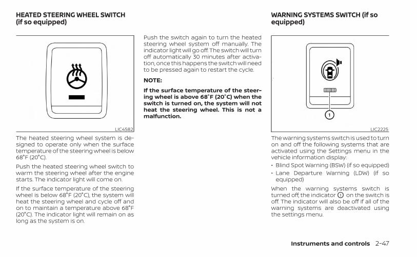
The heated steering wheel system is de-signed to operate only when the surfacetemperature of the steering wheel is below68°F (20°C).Push the heated steering wheel switch towarm the steering wheel after the enginestarts. The indicator light will come on.If the surface temperature of the steeringwheel is below 68°F (20°C), the system willheat the steering wheel and cycle off andon to maintain a temperature above 68°F(20°C). The indicator light will remain on aslong as the system is on.
Push the switch again to turn the heatedsteering wheel system off manually. Theindicator light will go off. The switch will turnoff automatically 30 minutes after activa-tion, once this happens the switch will needto be pressed again to restart the cycle.
NOTE:
If the surface temperature of the steer-ing wheel is above 68°F (20°C) when theswitch is turned on, the system will notheat the steering wheel. This is not amalfunction.
The warning systems switch is used to turnon and off the following systems that areactivated using the Settings menu in thevehicle information display:• Blind Spot Warning (BSW) (if so equipped)• Lane Departure Warning (LDW) (if so
equipped)When the warning systems switch isturned off, the indicator O1 on the switch isoff. The indicator will also be off if all of thewarning systems are deactivated usingthe settings menu.
LIC4582 LIC2225
HEATED STEERING WHEEL SWITCH(if so equipped)
WARNING SYSTEMS SWITCH (if soequipped)
Instruments and controls 2-47

The BSW system will turn on the side indi-cator lights, located by the outside mirrors,if the radar sensors detect a vehicle in thedetection zone. If the turn signal is acti-vated in the direction of the detected ve-hicle, a chime sounds twice and the sideindicator light will flash.The LDW system will sound a warning; thesteering wheel will vibrate; and the LDWindicator (orange) will blink to alert thedriver of the vehicle is traveling close toeither the left or the right of a traveling lanewith detectable lane markers.For additional information, see “Blind SpotWarning (BSW)” (P. 5-33) and “Lane Depar-ture Warning (LDW)” (P. 5-28). The vehicle should be driven with the VDC
system on for most driving conditions.If the vehicle is stuck in mud or snow, theVDC system reduces the engine output toreduce wheel spin. The engine speed willbe reduced even if the accelerator is de-pressed to the floor. If maximum enginepower is needed to free a stuck vehicle,turn the VDC system off.To turn off the VDC system, push the VDCOFF switch. The indicator will comeon.
Push the VDC OFF switch again or restartthe engine to turn on the system. For addi-tional information, see “Vehicle DynamicControl (VDC) system” (P. 5-121).
LIC3344
VEHICLE DYNAMIC CONTROL (VDC)OFF SWITCH
2-48 Instruments and controls

WARNING
• Never rely solely on the hill descentcontrol system to control vehiclespeed when driving on steep down-hill grades. Always drive carefullywhen using the hill descent controlsystem and decelerate the vehiclespeed by depressing the brake pedalif necessary. Be especially carefulwhen driving on frozen, muddy or ex-tremely steep downhill roads. Failureto control vehicle speed may result ina loss of control of the vehicle andpossible serious injury or death.
• The hill descent control may not con-trol the vehicle speed on a hill underall load or road conditions. Always beprepared to depress the brake pedalto control vehicle speed. Failure to doso may result in a collision or seriouspersonal injury.
CAUTION
When the hill descent control system op-erates continuously for a long time, thetemperature of the brake pads may in-crease and the hill descent control sys-tem may be temporarily disabled (the in-dicator light will blink). If the indicatorlight does not come on continuously af-ter blinking, stop using the system.
The hill descent control system is designedto reduce driver workload when going downsteep hills. The hill descent control systemhelps to control vehicle speed so the drivercan concentrate on steering the vehicle.To activate the hill descent control system:• The shift lever must be in forward or re-
verse gear,• The 4WD switch must be in the 4L posi-
tion and the vehicle speed must be under15 mph (25 km/h) or
• The 4WD switch must be in the 4H posi-tion and the vehicle speed must be under21 mph (35 km/h), and
• The hill descent control system switchmust be ON.
The hill descent control system ON indica-tor light will come on when the system isactivated. Also, the stop/tail lights illumi-nate while the hill descent control systemapplies the brakes to control vehicle speed.If the accelerator or brake pedal is de-pressed while the hill descent control sys-tem is on, the system will stop operatingtemporarily. As soon as the accelerator orbrake pedal is released, the hill descentcontrol system begins to function again ifthe hill descent control operating condi-tions are fulfilled.The hill descent control system ON indica-tor light blinks if the switch is on and allconditions for system activation are notmet or if the system becomes disengagedfor any reason.To turn off the hill descent control system,push the switch to the OFF position.For additional information, see “Hill descentcontrol system ON indicator light” (P. 2-15)and “Hill descent control system” (P. 5-123).
LIC0743
HILL DESCENT CONTROL SWITCH(if so equipped)
Instruments and controls 2-49

The E-Lock system can help provide addedtraction if the vehicle is stuck or becomingstuck.To activate the E-Lock system:• The 4WD switch must be in the 4LO posi-
tion (4-Wheel Drive vehicles),• The vehicle must be stopped or moving
at 4 mph (7 km/h) or less, and• The E-Lock system switch must be
turned on.
When the E-Lock switch is turned on, theindicator light will flash until the systemengages. However, if all operation condi-tions listed above are not met or the sys-tem becomes disengaged, the indicatorlight will continue to flash.The Anti-lock Braking System (ABS) is dis-abled and the ABS light illuminates whenthe E-Lock system is on. Also, the VehicleDynamic Control (VDC) system is disabledand the VDC light illuminates when theE-Lock system is on.For additional information, see “Electroniclocking rear differential (E-Lock) system”(P. 5-115) for further explanation and systemlimitations.
WARNING
• Never leave the E-Lock system onwhen driving on paved or hard-surfaced roads. Turning the vehiclemay result in the rear wheels slippingand result in an accident and per-sonal injury. After using the E-Locksystem to free the vehicle, turn thesystem off.
• Use the E-Lock system only whenfreeing a stuck vehicle. Try the 4LOposition before using the E-Lock sys-tem. Never use the E-Lock system ona slippery road surface such as snowor ice surface. Using the E-Lock sys-tem when driving in these road con-ditions may cause unexpectedmovement of the vehicle during en-gine braking, accelerating or turning,which may result in an accident andserious personal injury.
CAUTION
• After using the E-Lock system, turnthe switch off to prevent possibledamage to driveline componentsfrom extended use.
• Do not drive over 12 mph (20 km/h)when the system is engaged. Doingso could result in possible damage tothe driveline.
• Do not turn on the E-Lock systemwhile the tires are spinning. Doing socould damage drivetrain components.
LIC0729
ELECTRONIC LOCKING REARDIFFERENTIAL (E-Lock) SYSTEMSWITCH (if so equipped)
2-50 Instruments and controls

To use the outlets for devices that requireup to 120v power, the vehicle must be run-ning and the power inverter switch mustbe on.When the vehicle is in the P (Park) position,the 400W and the 150W will automaticallyilluminate. When the vehicle is out of the P(Park) position, only 150W will illuminate.For additional information, see “120v out-lets” (P. 2-55) regarding using devices thatrequire the power inverter switch to beactivated.
CAUTION
• Use power outlets with the enginerunning to avoid discharging the ve-hicle battery.
• Do not attempt to use this whiledriving.
• Do not use double adapters or morethan one electrical accessory, doingso could significantly drain the bat-tery of your vehicle.
The Parking Aids system switch on the in-strument panel allows the driver to turnthe following systems (if so equipped) onand off. To turn the systems on and off, theignition switch must be in the ON position.• Rear Sonar System (RSS) (if so equipped)• Moving Object Detection (MOD) (if so
equipped)• Rear Automatic Braking (RAB) (if so
equipped)• Rear Cross Traffic Alert (RCTA) (if so
equipped)
LIC4847 LIC3596
POWER INVERTER SWITCH (if soequipped)
PARKING AIDS SYSTEM SWITCH (if soequipped)
Instruments and controls 2-51

The indicator light on the switch will illumi-nate when the systems are turned on.If the indicator light flashes when the RSS,MOD, RAB, or RCTA systems are not turnedoff, it may indicate a malfunction in one ormore of these systems (if so equipped).The RSS, MOD, RAB, or RCTA systems will beturned on automatically under the follow-ing conditions:• When the ignition switch is switched from
the OFF position to the ON position.• When the shift lever is shifted into the R
(Reverse) position.The automatic turning on function can beturned on and off for these systems in thevehicle information display. For additionalinformation, see “Settings” (P. 2-21).For additional information, see “Rear SonarSystem (RSS)” (P. 5-125), ”Rear AutomaticBraking (RAB)” (P. 5-76), “Rear Cross TrafficAlert (RCTA)” (P. 5-43), or “Moving Object De-tection (MOD)” (P. 4-23).
Tow mode should be used when pullinga heavy trailer or hauling a heavy load. Driv-ing the vehicle in the tow mode with notrailer/load or light trailer/light load willnot cause any damage. However, fueleconomy may be reduced, and thetransmission/engine driving characteris-tics may feel unusual.Push the tow mode switch to activate towmode. The TOW indicator light illuminateswhen tow mode is selected. Push the towmode switch again to turn tow mode off.
Tow mode is automatically canceled whenthe ignition switch is placed in the OFFposition.For additional information, see “Towing atrailer” (P. 10-27).
LIC4845
TOW MODE SWITCH (if so equipped)
2-52 Instruments and controls

The Emergency call (SOS) system buttonis used in combination with aNissanConnect® Services subscription tocall for assistance in case of an emergency.Pushing the button will (with a paid sub-scription) reach a Response Specialist thatwill provide assistance based on the situa-tion described by the vehicle’s occupant.For additional information, or to enroll yourvehicle, refer to www.NissanUSA.com/connect or call 855–426–6628.
The Rear Door Alert system functions un-der certain conditions to indicate theremay be an object or passenger in the rearseat(s). Check the seat(s) before exiting thevehicle.The Rear Door Alert system is initially dis-abled. The driver can enable the systemusing the vehicle information display. Foradditional information, see “Vehicle infor-mation display warnings and indicators”(P. 2-28).When the system is enabled:• The system is activated when a rear door
is opened and closed within 10 minutes ofthe vehicle being driven. When the driver’door is closed and the system is acti-vated, a visual message appears in thevehicle information display. For additionalinformation, see “Rear Door Alert is acti-vated” (P. 2-30).
• If a rear door is opened and closed butthe vehicle is not driven within approxi-mately 10 minutes, the system will not beactivated. A rear door must be openedand closed and the car driven within 10minutes for the system to activate.
When the Rear Door Alert system is acti-vated and a driver exits the vehicle afterarriving at a destination:• When the driver puts the vehicle in the P
(Park) position, a message appears in thevehicle information display for a driver to“Dismiss Message” or “Disable Alert” ifdesired.
• With the system enabled, when the driverexits the vehicle, an audible alert (hornsound) will occur unless a rear door isopened and closed within a short time todeactivate the alert.
• If the doors are locked before the alert isdeactivated by opening a rear door, thehorn will sound.
• If the audible horn alert occurs, a mes-sage will also appear in the vehicle infor-mation display that states, “Check RearSeat for All Articles”.
LIC3376
EMERGENCY CALL (SOS) BUTTON(if so equipped)
REAR DOOR ALERT
Instruments and controls 2-53

WARNING
• If the driver selects “Disable Alert”, noaudible alert will be provided regard-less of rear door open/close status.• There may be times when there is anobject or passenger in the rear seat(s)but the audible alert does not sound.For example, this may occur if rear seatpassengers enter or exit the vehicleduring a trip.• The system does not directly detectobjects or passengers in the rearseat(s). Instead, it can detect when arear door is opened and closed, indicat-ing that there may be something in therear seat(s).
NOTE:
There may be times when the hornsounds but there are no objects or pas-sengers in the rear seat(s).For additional information, see “Rear DoorAlert is activated” (P. 2-30).
12V OUTLETSThe power outlets are for powering electricalaccessories such as cellular telephones.The power outlets located on the instru-ment panel and inside the center armrestare powered only when the ignition switchis placed in the ACC or ON position.Open the cap to use a power outlet.
CAUTION
• The outlet and plug may be hot dur-ing or immediately after use.
• Only certain power outlets are de-signed for use with a cigarette lighterunit. Do not use any other power out-let for an accessory lighter. It is rec-ommended that you visit a NISSANdealer for additional information.
• Do not use with accessories that ex-ceed a 12 volt, 120W (10A) power draw.
• Do not use double adapters or morethan one electrical accessory.
LIC4831Instrument panel
LIC4824Inside center console
POWER OUTLETS
2-54 Instruments and controls

• Use power outlets with the enginerunning to avoid discharging the ve-hicle battery.
• Avoid using power outlets when theair conditioner, headlights, or rearwindow defroster (if so equipped) ison.
• Before inserting or disconnecting aplug, be sure the electrical accessorybeing used is turned OFF.
• Push the plug in as far as it will go. Ifgood contact is not made, the plugmay overheat or the internal tem-perature fuse may open.
• When not in use, be sure to close thecap. Do not allow water or any otherliquid to contact the outlet. 120V OUTLETS (if so equipped)
LIC4930In truck box (if so equipped)
LIC4837Center console (if so equipped)
Instruments and controls 2-55

120V OUTLET Switch Reset
What is plugged in Shifter In Park Shifter Out of Park Shifter Back In Park Shifter In Park Shifter Out of ParkIndicator Inverter
StatusIndicator Inverter
StatusIndicator Inverter
StatusIndicator Inverter
StatusIndicator Inverter
StatusNo Device but
Switch On 150W and 400W ON 150W ON 150W and 400W ON 150W and 400W ON 150W ON
Device<150W 150W and 400W ON 150W ON 150W and 400W ON 150W and 400W ON 150W ON150W<Device<400W 150W and 400W ON OFF OFF 150W and 400W ON 150W and 400W ON OFF** OFF**
Device>400W OFF OFF OFF OFF OFF OFF OFF** OFF** OFF** OFF**
** OFF means the inverter system cannot be reset until a device is within the specification range of operation. If the device is greater than specified, the inverterwill shut OFF. The operating voltage is between 11.5v and 15v. If the vehicle is not idling, the battery voltage will drop which will cause the inverter to shut downwhen below 11.5v. When the vehicle is in the (P) Park position, it will work at 400W. If the vehicle is in any other shifter position, it will turn off.
2-56 Instruments and controls

Do not use the outlet located in the truckbox with accessories that exceed 120 volt.Do not use double adapters or more thanone electrical accessory.
CAUTION
• Operation of the 120 volt system withthe ignition in the ON position andthe engine not running (idle) willdrain the battery charge. This couldlead to a dead battery or no startcondition.
• The outlet and plug may be hot dur-ing or immediately after use.
• Use power outlets with the enginerunning to avoid discharging the ve-hicle battery.
• Do not use double adaptors or morethan one electrical accessory.
• Avoid using power outlets when theair conditioner, headlights or rearwindow defroster is on.
• Before inserting or disconnecting aplug, be sure the electrical accessorybeing used is turned OFF.
• Push the plug in as far as it will go. Ifgood contact is not made, the plugmay overheat or the internal tem-perature fuse may open.
• When not in use, be sure to close thecap. Do not allow water or any otherliquid to contact the outlet.
There are USB charging ports located in 1strow in the front media pocket below theclimate controls and in the rear seat areaon the back of the center console. Theseports will charge compatible devices.
NOTE:
Not all of the USB charging ports will op-erate with the display screen. Only theUSB connection ports located under theclimate controls will allow operation ofUSB devices through the audio system.
LIC48421st row (if so equipped)
USB CHARGING PORTS (if soequipped)
Instruments and controls 2-57

CAUTION
• Do not force a USB device into theconnector. Inserting the USB devicetilted or up-side down into the con-nector may damage the connector.Make sure that the USB device is con-nected correctly into the connector.
• Do not use a reversible USB cable. Us-ing the reversible USB cable maydamage the connector.
The wireless charger is located on the frontof the center console. Lay the smartphoneon the pad of the wireless charger. Charg-ing will start automatically. The smart-phone will be charged continuously whilethe ignition switch is in the ON position.
WARNING
• Never put metallic materials betweenthe wireless charger and a smart-phone.
• Those who use a pacemaker or othermedical equipment should contactthe electric medical equipmentmanufacturer for the possible influ-ences before use.
• Never put cloth over the smartphoneduring charging process.
• Never charge a smartphone when itis wet.
• Never put metallic materials or smallgoods such as a cigarette lighter, In-telligent Key or memory drive.
CAUTION
• Do not put an RFID/NFC/credit cardbetween the wireless charger and asmartphone. This could cause datacorruption in the card.
• Do not use the wireless charger withdust accumulated or dirt on the pad.
• Do not hit the surface of the wirelesscharger.
• Do not spill liquid (water, drinks, etc.)on the charging pad.
• Do not use grease, oil or alcohol forcleaning charging pad.
LIC4844Rear (if so equipped)
LIC4958
1. Indicator
2. Charging pad
WIRELESS CHARGER (if so equipped)
2-58 Instruments and controls

WIRELESS CHARGER INDICATORThe indicator ( 1 ) will illuminate in orangewhen the charging process is started.When the charging has completed, the in-dicator illuminates in green.If a malfunction occurs or the chargingprocess has stopped, the indicator willblink in orange for 8 seconds then turn off.
WIRELESS CHARGER OPERATIONTo use the wireless charger, it is necessaryto seat the smartphone well within thecharging pad. To maximize charging per-formance, ensure the smartphone is fullyseated on the center of the charging padover the "Qi" logo OA . Because the locationof the power receiver may vary dependingon the smartphone, you will need to try andfind the area that suits your smartphone.Because some smartphone cases or ac-cessories may adversely affect charging,remove them before wireless charging.Turn off the vibration function of the smart-phone before wireless charging.
NOTE:• Only a Qi compatible smartphone can
be used.• The smartphone may be warmed dur-
ing charging process and the chargingmay stop by the protection function ofthe wireless charger. This is not a mal-function. If this occurs, restart chargingafter the smartphone has cooleddown. The indicator will blink in orangethen turn off.
• The wireless charging process may bestopped by the status of the smart-phone (battery temperature, etc.).
• If a radio noise interference occurs dur-ing charging process, put the smart-phone onto the center (“Qi” logo) posi-tion of the wireless charger.
• The wireless charging process will stopduring process of searching the Intelli-gent Key.
• The wireless charging process will notbe started when a USB (Universal SerialBus) cable is connected to the smart-phone. The indicator may illuminate inorange or blink if the smartphone isput on the wireless charger with a USBcable connected. However, charging isnot performed.
• Depending on the type of the smart-phone, the indicator may remain illu-minated in orange even when thecharging process has been completed.
FCC ID: BEJWC500MNMIC: 2703H-WC500MNMThis device complies with part 15 of theFCC Rules and RSS-Gen of IC Rules.Operation is subject to the following twoconditions:(1) This device may not cause harmfulinterference, and(2) This device must accept any interfer-ence received, including interferencethat may cause undesired operation.Changes or modifications not expresslyapproved by the party responsible forcompliance could void the user’s author-ity to operate the equipment.RF Radiation Exposure Statement: Thisequipment complies with FCC RF Radia-tion exposure limits set forth for an un-controlled environment.This device and its antenna must not beco-located or operating in conjunctionwith any other antenna or transmitter.This equipment should be installed andoperated with a minimum distance of15cm between the radiator and your body.
Instruments and controls 2-59

ISED Compliance StatementThis device complies with RSS-Gen of ICRulesOperation is subject to the following twoconditions:(1) This device may not cause harmfulinterference, and(2) This device must accept any interfer-ence received, including interferencethat may cause undesired operation.Changes or modifications made to thisdevice, not expressly approved by LGVehicle Components Company, will voidthe user’s authority to operate theequipment.ISED RF Radiation Exposure Statement:This equipment complies with ISED RFRadiation exposure limits set forth for anuncontrolled environment. This deviceand its antenna must not be co-locatedor operating in conjunction with anyother antenna or transmitter. Thisequipment should be installed to oper-ate with a minimum distance of 15 cmbetween the radiator and the end-user’sbody and arms.
The extended storage switch is used whenshipping the vehicle. It is located in the fusepanel inside the glove box. To reach it, openthe glove box O1 on the instrument panel,then open the fuse panel cover O2 .If any electrical equipment does not oper-ate, ensure the extended storage switch isON by pushing it fully in place, as shown.
LIC4893 LIC3266Pulled position
EXTENDED STORAGE SWITCH
2-60 Instruments and controls

FRONT-DOOR POCKETSREAR-DOOR POCKETS
LIC3268Pushed position
LIC4827 LIC0826Type A (if so equipped)
STORAGE
Instruments and controls 2-61

SEATBACK POCKET (if soequipped)A seatback pocket may be located on theback of the driver's seat or passenger’sseat. The pocket may be used to storemaps.
WARNING
To ensure proper operation of the driv-er’s and/or front passenger’s NISSANAdvanced Air Bag System, please ob-serve the following items:• Do not allow a passenger in the rear
seat to push or pull on the seatbackpocket or head restraint/headrest.
• Do not place heavy loads heavierthan 9.1 lbs. (4 kg) on the seatback,head restraint/headrest or in theseatback pocket.
LIC4834Type B (if so equipped)
LIC1328
2-62 Instruments and controls

UNDER-SEAT STORAGE BINS
WARNING
• Properly secure all cargo with ropesor straps to help prevent it from slid-ing or shifting. In a sudden stop orcollision, unsecured cargo couldcause personal injury.
• The cargo restrained in the under-seat storage bins must not exceedthe weight limits listed below or thebins may not stay secured. In a sud-den stop or collision, the unsecuredbins could cause personal injury.King Cab® model: 16 lbs. (7.25 kg)Crew Cab model
Driver’s side: 16 lbs. (7.25 kg)Passenger’s side: 25 lbs. (11.33 kg)
• If the under-seat storage bins are re-moved for any reason, they should besecurely stored to prevent them fromcausing injury to passengers or dam-age to the vehicle in case of suddenbraking or an accident.
• Do not place sharp objects in theunder-seat storage bins. Such ob-jects may become dangerous projec-tiles and cause injury when the ve-hicle is moving or if the vehicle isinvolved in a c ollision.
LIC4496Rear row under-seat storage bin
(King Cab® model)
LIC4497Rear row under-seat storage bin
(Crew Cab model)
Instruments and controls 2-63

To access the under-seat storage bins:For King Cab® models, lift up the jump seat.For additional information, see “Jump seat”(P. 1-7).For Crew Cab models, lift up the rear benchseat. For additional information, see “Fold-ing the rear bench seat down” (P. 1-9).
To remove the under-seat storage bins:1. Turn the knobs to the UNLOCK position
O2 .
2. Remove the tray (if so equipped) by lift-ing it out of the storage bin (King Cab®model).
To install the under-seat storage bins:1. Position the under-seat storage bin so
the holes line up with the holes in thefloorboard.
2. Insert the knobs and turn them to theLOCK position O1 .
STORAGE TRAYS
LIC0822 LIC4875Top center tray (if so equipped)
2-64 Instruments and controls

WARNING
Do not place sharp objects in the traysto help prevent injury in an accident orsudden stop.
GLOVE BOXOpen the glove box by pulling the handle.Use the mechanical key (if so equipped)when locking or unlocking the glove box.
WARNING
Keep the glove box lid closed whiledriving to help prevent injury in an ac-cident or a sudden stop.
CONSOLE BOXPull up on the lever O1 to open the consolebox lid O2 .
LIC4851Center console
LIC4843 LIC4874
Instruments and controls 2-65

OVERHEAD SUNGLASSESSTORAGE (if so equipped)To open the sunglasses holder, push andrelease.Only store one pair of sunglasses in theholder.
WARNING
Keep the sunglasses holder closedwhile driving to avoid obstructing thedriver’s view and to help prevent anaccident.
CAUTION
• Do not use for anything other thansunglasses.
• Do not leave sunglasses in the sun-glasses holder while parking in directsunlight. The heat may damage thesunglasses.
CUP HOLDERS
CAUTION
• Avoid abrupt starting and brakingwhen the cup holder is being used toprevent spilling the drink. If the liquidis hot, it can scald you or yourpassenger.
• Use only soft cups in the cup holder.Hard objects can injure you in anaccident.
LIC3387 LIC4826Front
2-66 Instruments and controls

CAUTION
• Do not use the bottle holder for anyother objects that could be thrownabout in the vehicle and possibly in-jure people during sudden braking oran accident.
• Do not use the bottle holder for openliquid containers.
LIC4832Rear seat (if so equipped)
LIC4828Front row bottle holders
LIC4833Rear bottle holders
Instruments and controls 2-67

WARNING
• Do not exceed maximum ladder rackload capacity.
• Exceeding the ladder rack capacitycan change the vehicle’s center ofgravity and adversely affect the han-dling and stability of the vehicle re-sulting in an accident causing deathor serious injury.
• When loading the ladder rack, evenlydistribute the load as well as main-tain a low center of gravity.
• Do not use your rack off road, unlessotherwise noted as an “off roadrated” product.
• Do not allow the ladder rack or loadto obstruct the vehicle’s exteriorlighting.
• Be careful that your vehicle does notexceed the Gross Vehicle Weight Rat-ing (GVWR) or its Gross Axle WeightRating (GAWR front & rear).
• Properly secure all cargo with ropesor straps to help it prevent from slid-ing or shifting.
• Take extra caution when the vehiclehas load on the Ladder rack as thisraises the center of gravity of the ve-hicle and may cause the vehicle toroll over when there is a loss of ve-hicle control.
MANUAL WINDOWS (if soequipped)The side windows can be opened or closedby turning the hand crank on each door.
POWER WINDOWS (if so equipped)
WARNING
• Make sure that all passengers havetheir hands, etc., inside the vehiclewhile it is in motion and before clos-ing the windows. Use the windowlock switch to prevent unexpecteduse of the power windows.
LIC3352
LADDER RACK (if so equipped) WINDOWS
2-68 Instruments and controls

• To help avoid risk of injury or deaththrough unintended operation of thevehicle and/or its systems, includingentrapment in windows or inadver-tent door lock activation, do notleave children, people who requirethe assistance of others or pets unat-tended in your vehicle. Additionally,the temperature inside a closed ve-hicle on a warm day can quickly be-come high enough to cause a signifi-cant risk of injury or death to peopleand pets.
The power windows operate when the ig-nition switch is placed in the ON position orfor a period of time after the ignition switchis placed in the ACC or OFF position. If thedriver's or passenger's door is opened dur-ing this period of time, the power to thewindows is canceled.
Driver's side power windowswitchThe driver's side control panel is equippedwith switches to open or close the frontand rear passenger windows.
To open a window, push the switch andhold it down. To close a window, pull theswitch and hold it up. To stop the openingor closing function at any time, simply re-lease the switch.
LIC1329
1. Window lock button2. Power door lock switch3. Front passenger side window switch4. Right rear passenger window switch
(Crew Cab models only)5. Left rear passenger window switch
(Crew Cab models only)
6. Driver's side automatic switch
Instruments and controls 2-69

Front passenger's power windowswitchThe passenger's window switch operatesonly the corresponding passenger's win-dow. To open the window, push the switchand hold it down O1 . To close the window,pull the switch up O2 .
Rear power window switch(Crew Cab models only)The rear power window switches open orclose only the corresponding passengerwindow. To open the window, push theswitch and hold it down O1 . To close thewindow, push the switch up O2 .
Locking passengers' windowsWhen the window lock switch is depressed,only the driver's side window can beopened or closed. Push it again to cancelthe window lock function.
Automatic operation (if soequipped)To fully open a window equipped with au-tomatic operation, push the windowswitch down to the second detent and re-lease it; it need not be held. The windowautomatically opens all the way. To stopthe window, lift the switch up while the win-dow is opening.
WIC0260 LIC2663 LIC0410
2-70 Instruments and controls

REAR SLIDING WINDOW (if soequipped)
WARNING
• You must ensure all occupants andobjects are free of the rear windowarea prior to and during operation.Failure to do so may result in injuryand/or damage to the rear windowsystem.
• The rear window is not designed tocarry long items through it.
• Do not place objects through theopened rear window. Do not use therear window as a cargo area pass-through. This may result in damageto the rear window system or per-sonal injury.
Squeeze the handles of the lever O1 , thenslide the window open O2 .
POWER MOONROOFThe moonroof will only operate when theignition switch is in the ON position. Thepower moonroof is operational for about45 seconds, even if the ignition switch isplaced in the ACC or OFF position. If thedriver's door or the front passenger's dooris opened during this period of about 45seconds, power to the moonroof iscanceled.
LIC3488 LIC4830
MOONROOF (if so equipped)
Instruments and controls 2-71

Sliding the moonroofTo open the moonroof, push the switchtoward DOWN/OPEN O1 and release it.Push the switch again to fully open themoonroof.To fully close the moonroof, push theswitch toward UP/CLOSE O2 and release it.To open or close the moonroof part way,push the switch in any direction while themoonroof is sliding to stop it in the desiredposition.
Tilting the moonroofClose the moonroof by pushing the switchtoward UP/CLOSE O2 . Release the switch,then push the UP/CLOSE switch again totilt the moonroof up.To tilt the moonroof down, push the switchtoward DOWN/OPEN O1 .
Auto-reverse function (whenclosing or tilting down themoonroof)The auto-reverse function can be acti-vated when the moonroof is closed ortilted down by automatic operation whenthe ignition switch is placed in the ON po-
sition or for a period of time after the igni-tion switch is placed in the OFF position.Depending on the environment or driv-ing conditions, the auto-reverse func-tion may be activated if an impact orload similar to something being caughtin the moonroof occurs.
WARNING
There are some small distances imme-diately before the closed positionwhich cannot be detected. Make surethat all passengers have their hands,etc., inside the vehicle before closingthe moonroof.
When closingIf the control unit detects somethingcaught in the moonroof as it moves to thefront, the moonroof will immediately openbackward.When tilting downIf the control unit detects somethingcaught in the moonroof as it tilts down, themoonroof will immediately tilt up.
If the auto-reverse function malfunctionsand repeats opening or tilting up themoonroof, keep pushing the tilt downswitch within 5 seconds after it happens;the moonroof will fully close gradually.Make sure nothing is caught in themoonroof.
WARNING
• In an accident you could be thrownfrom the vehicle through an openmoonroof. Always use seat belts andchild restraints.
• Do not allow anyone to stand up orextend any portion of their body outof the moonroof opening while thevehicle is in motion or while themoonroof is closing.
CAUTION
• Remove water drops, snow, ice orsand from the moonroof beforeopening.
• Do not place heavy objects on themoonroof or surrounding area.
2-72 Instruments and controls

SunshadeOpen and close the sunshade by sliding itforward or backward.
If the moonroof does not closeHave your moonroof checked and re-paired. It is recommended that you visit aNISSAN dealer for this service.
The interior light has a three-positionswitch and operates regardless of ignitionswitch position.When the switch is in the ON position O1 ,the interior lights illuminate, regardless ofdoor position. The lights will go off after aperiod of time unless the ignition switch isplaced in the ON position.When the switch is in the DOOR or normaloperation position O2 , the interior lights willstay on for a period of time and the cargolight may illuminate when:
• The doors are unlocked by the key fob, akey or the power door lock switch whileall doors are closed and the ignitionswitch is in the OFF position.
• The driver’s door is opened and thenclosed while the ignition switch is placedin the OFF position.
• The ignition switch is placed in the OFFposition while all doors are closed.
The lights will turn off while the timer isactivated when:• The driver’s door is locked by the key fob,
a key, or the power door lock switch.• The ignition switch is placed in the ON
position.When the switch is in the OFF position O3 ,the interior lights do not illuminate, regard-less of door position. The cargo light mayilluminate when any front or rear passen-ger door is opened.The lights will turn off automatically after aperiod of time while doors are open toprevent the battery from becomingdischarged.
LIC0792
INTERIOR LIGHTS
Instruments and controls 2-73

CAUTION
Do not use for extended periods of timewith the engine stopped. This could re-sult in a discharged battery.
MAP LIGHTSTo turn the map lights on, press the lenses.To turn them off, press the lenses of themap lights again.
CAUTION
Do not use for extended periods of timewith the engine stopped. This could re-sult in a discharged battery.
CARGO LIGHTThe cargo light on the overhead trim has athree-position switch. To operate, push theswitch to the desired position.ON: The light is illuminated.DOOR: The light illuminates when the reardoors are opened. The light turns off whenthe rear doors are closed.OFF: The light does not illuminate regard-less of door position or lock status.
LIC0790 LIC0590
2-74 Instruments and controls

CAUTION
Do not use for extended periods of timewith the engine stopped. This could re-sult in a discharged battery.
The HomeLink® Universal Transceiver pro-vides a convenient way to consolidate thefunctions of up to three individual hand-held transmitters into one built-in device.HomeLink® Universal Transceiver:• Will operate most radio frequency de-
vices such as garage doors, gates, homeand office lighting, entry door locks andsecurity systems.
• Is powered by your vehicle's battery. Noseparate batteries are required. If thevehicle's battery is discharged or is dis-connected, HomeLink® will retain allprogramming.
When the HomeLink® Universal Trans-ceiver is programmed, retain the originaltransmitter for future programming pro-cedures (Example: new vehicle purchases).Upon sale of the vehicle, the programmedHomeLink® Universal Transceiver buttonsshould be erased for security purposes.For additional information, see “Program-ming HomeLink®” (P. 2-76).
WARNING
• Your vehicle's engine should beturned off while programming theHomeLink® Universal Transceiver. Foradditional information, see “Push-button ignition switch” (P. 5-13). Donot breathe exhaust gases; they con-tain colorless and odorless carbonmonoxide. Carbon monoxide is dan-gerous. It can cause unconscious-ness or death.
• Do not use the HomeLink® UniversalTransceiver with any garage dooropener that lacks safety stop and re-verse features as required by federalsafety standards. (These standardsbecame effective for opener modelsmanufactured after April 1, 1982.) Agarage door opener which cannotdetect an object in the path of a clos-ing garage door and then automati-cally stop and reverse does not meetcurrent federal safety standards. Us-ing a garage door opener withoutthese features increases the risk ofserious injury or death.
HOMELINK® UNIVERSALTRANSCEIVER (if so equipped)
Instruments and controls 2-75

• During the programming procedureyour garage door or security gate willopen and close (if the transmitter iswithin range). Make sure that peopleor objects are clear of the garagedoor, gate, etc., that you areprogramming.
PROGRAMMING HOMELINK®If you have any questions or are havingdifficulty programming your HomeLink®buttons, refer to the HomeLink® web site at:www.homelink.com or call 1-800-355-3515.
NOTE:
Place the ignition switch in the ON or ACCposition (without starting the engine)when programming HomeLink®. It is alsorecommended that a new battery beplaced in the hand-held transmitter ofthe device being programmed toHomeLink® for quicker programmingand accurate transmission of the radiofrequency.
1. Position the end of your hand-heldtransmitter 1–3 in (2–8 cm) away fromthe HomeLink® surface, keeping theHomeLink® indicator light O1 in view.
2. Using both hands, simultaneously pressand hold the desired HomeLink® buttonand hand-held transmitter button. DONOT release until the HomeLink® indica-tor light O1 flashes slowly and thenrapidly. When the indicator light flashesrapidly, both buttons may be released.(The rapid flashing indicates successfulprogramming.)
LIC2365 LIC4095
2-76 Instruments and controls

NOTE:
Some devices may require you to replaceStep 2 with the cycling procedure noted in“Programming HomeLink® for Canadiancustomers and gate openers” (P. 2-77).3. Press and hold the programmed
HomeLink® button and observe the indi-cator light.• If the indicator light O1 is solid/
continuous, programming is com-plete and your device should activatewhen the HomeLink® button ispressed and released.
• If the indicator light O1 blinks rapidlyfor 2 seconds and then turns to asolid/continuous light, continuewith Steps 4-6 for a rolling code de-vice. A second person may make thefollowing steps easier. Use a ladder orother device. Do not stand on your ve-hicle to perform the next steps.
4. At the receiver located on the garagedoor opener motor in the garage, locatethe “learn” or “smart” button (the nameand color of the button may vary bymanufacturer but it is usually locatednear where the hanging antenna wire isattached to the unit). If there is difficultylocating the button, reference the ga-rage door opener’s manual.
5. Press and release the “learn” or “smart”button.
NOTE:Once the button is pressed, you haveapproximately 30 seconds to initiatethe next step.
6. Return to the vehicle and firmly pressand hold the trained HomeLink® buttonfor 2 seconds and release. Repeat the“press/hold/release” sequence up tothree times to complete the trainingprocess. HomeLink® should now acti-vate your rolling code equipped device.
7. If you have any questions or are havingdifficulty programming your HomeLink®buttons, refer to the HomeLink® web site at:www.homelink.com or call 1-800-355-3515.
PROGRAMMING HOMELINK® FORCANADIAN CUSTOMERS AND GATEOPENERSCanadian radio-frequency laws requiretransmitter signals to “time-out” (or quit)after several seconds of transmission –which may not be long enough forHomeLink® to pick up the signal duringtraining. Similar to this Canadian law, someU.S. gate operators are designed to “tim-eout” in the same manner.If you live in Canada or you are having diffi-culties training a gate operator or garagedoor opener by using the “Training” proce-dures, replace “Programming HomeLink®”step 2 with the following:
NOTE:
When programming a garage dooropener, etc., unplug the device duringthe “cycling” process to prevent possibledamage to the garage door openercomponents.1. For additional information, see “Pro-
gramming HomeLink®” step 1 (P. 2-76).
Instruments and controls 2-77

2. Using both hands, simultaneously pressand hold the desired HomeLink® buttonand the hand-held transmitter button.During training, your hand-held trans-mitter may automatically stop transmit-ting. Continue to press and hold the de-sired HomeLink® button while you pressand re-press (“cycle”) your hand-heldtransmitter every 2 seconds until thefrequency signal has been learned. TheHomeLink® indicator light will flashslowly and then rapidly after severalseconds upon successful training. DONOT release until the HomeLink® indica-tor light flashes slowly and then rapidly.When the indicator light flashes rapidly,both buttons may be released. The rapidflashing indicates successful training.Proceed with “Programming HomeLink®”step 3 to complete.If the device was unplugged during theprogramming procedure, remember toplug it back in when programming iscompleted.
OPERATING THE HOMELINK®UNIVERSAL TRANSCEIVERThe HomeLink® Universal Transceiver, afterit is programmed, can be used to activatethe programmed device. To operate, sim-
ply press and release the appropriate pro-grammed HomeLink® Universal Trans-ceiver button. The amber indicator lightwill illuminate while the signal is beingtransmitted.For convenience, the hand-held transmit-ter of the device may also be used at anytime.
PROGRAMMING TROUBLE-DIAGNOSISIf the HomeLink® does not quickly learn thehand-held transmitter information:• Replace the hand-held transmitter bat-
teries with new batteries.• Position the hand-held transmitter with
its battery area facing away from theHomeLink® surface.
• Press and hold both the HomeLink® andhand-held transmitter buttons withoutinterruption.
• Position the hand-held transmitter 1 - 3inches (26 - 76 mm) away from theHomeLink® surface. Hold the transmitterin that position for up to 15 seconds. IfHomeLink® is not programmed withinthat time, try holding the transmitter inanother position – keeping the indicatorlight in view at all times.
If you have any questions or are havingdifficulty programming your HomeLink®buttons, refer to the HomeLink® web site at:www.homelink.com or call 1-800-355-3515.
CLEARING THE PROGRAMMEDINFORMATIONThe following procedure clears the pro-grammed information from both buttons.Individual buttons cannot be cleared. How-ever, individual buttons can be repro-grammed. For additional information, see“Reprogramming a single HomeLink® but-ton” (P. 2-79).To clear all programming:1. Press and hold the two outer HomeLink®
buttons until the indicator light begins toflash in approximately 10 seconds. Donot hold for longer than 20 seconds.
2. Release both buttons.HomeLink® is now in the programmingmode and can be programmed at anytime beginning with “ProgrammingHomeLink®” - Step 1.
2-78 Instruments and controls

REPROGRAMMING A SINGLEHOMELINK® BUTTONTo reprogram a HomeLink® UniversalTransceiver button, complete the following:1. Press and hold the desired HomeLink®
button. DO NOT release the button.
2. The indicator light will begin to flash af-ter 20 seconds. Without releasing theHomeLink® button, proceed with “Pro-gramming HomeLink®” - Step 1.
For questions or comments, contactHomeLink® at: www.homelink.com or1–800–355–3515 (except Mexico).The HomeLink® Universal Transceiver but-ton has now been reprogrammed. The newdevice can be activated by pressing theHomeLink® button that was just pro-grammed. This procedure will not affect anyother programmed HomeLink® buttons.
IF YOUR VEHICLE IS STOLENIf your vehicle is stolen, you should changethe codes of any non-rolling code devicethat has been programmed intoHomeLink®. Consult the Owner's Manual ofeach device or call the manufacturer ordealer of those devices for additionalinformation.When your vehicle is recovered, you willneed to reprogram the HomeLink® Uni-versal Transceiver with your new trans-mitter information.FCC Notice:For USA:This device complies with Part 15 of theFCC Rules. Operation is subject to the fol-lowing two conditions: (1) This devicemay not cause interference, and (2) thisdevice must accept any interference re-ceived, including interference that maycause undesired operation.
NOTE:
Changes or modifications not expresslyapproved by the party responsible forcompliance could void the user’s author-ity to operate the equipment.For Canada:This device contains licence-exempttransmitter(s)/receiver(s) that complywith Innovation, Science and EconomicDevelopment Canada’s licence-exemptRSS(s). Operation is subject to the fol-lowing two conditions: (1) This devicemay not cause interference. (2) This de-vice must accept any interference, in-cluding interference that may cause un-desired operation of the device.
Instruments and controls 2-79

MEMO
2-80 Instruments and controls

3 Pre-driving checks and adjustments
Keys . . . . . . . . . . . . . . . . . . . . . . . . . . . . . . . . . . . . . . . . . . . . . 3-2NISSAN Intelligent Key® . . . . . . . . . . . . . . . . . . . . . . . 3-2
Doors . . . . . . . . . . . . . . . . . . . . . . . . . . . . . . . . . . . . . . . . . . . 3-4Locking with key . . . . . . . . . . . . . . . . . . . . . . . . . . . . . 3-5Locking with inside lock knob . . . . . . . . . . . . . . . . 3-6Locking with power door lock switch . . . . . . . . . 3-6Rear doors (King Cab® models) . . . . . . . . . . . . . . . 3-6Automatic door locks . . . . . . . . . . . . . . . . . . . . . . . . 3-7Child safety rear door lock(if so equipped) . . . . . . . . . . . . . . . . . . . . . . . . . . . . . . . 3-7
NISSAN Intelligent Key® system . . . . . . . . . . . . . . . . . . 3-8Operating range . . . . . . . . . . . . . . . . . . . . . . . . . . . . . 3-9Door locks/unlocks precaution . . . . . . . . . . . . . . . 3-9NISSAN Intelligent Key® Operation . . . . . . . . . . . 3-10How to use the remote keyless entryfunction . . . . . . . . . . . . . . . . . . . . . . . . . . . . . . . . . . . . . 3-13Warning signals . . . . . . . . . . . . . . . . . . . . . . . . . . . . . 3-16Troubleshooting guide . . . . . . . . . . . . . . . . . . . . . . 3-16
Remote Engine Start (if so equipped) . . . . . . . . . . . 3-18Remote Engine Start operating range . . . . . . . 3-18Remote starting the vehicle . . . . . . . . . . . . . . . . . 3-19
Extending engine run time . . . . . . . . . . . . . . . . . . 3-19Canceling a Remote Engine Start . . . . . . . . . . . 3-19Conditions the Remote Engine Start willnot work . . . . . . . . . . . . . . . . . . . . . . . . . . . . . . . . . . . . 3-20
Hood . . . . . . . . . . . . . . . . . . . . . . . . . . . . . . . . . . . . . . . . . . . 3-20Fuel-filler door . . . . . . . . . . . . . . . . . . . . . . . . . . . . . . . . . . 3-21
Fuel-filler cap . . . . . . . . . . . . . . . . . . . . . . . . . . . . . . . . 3-21Steering wheel . . . . . . . . . . . . . . . . . . . . . . . . . . . . . . . . . 3-23
Tilt operation . . . . . . . . . . . . . . . . . . . . . . . . . . . . . . . . 3-23Sun visors . . . . . . . . . . . . . . . . . . . . . . . . . . . . . . . . . . . . . . 3-24
Vanity mirrors . . . . . . . . . . . . . . . . . . . . . . . . . . . . . . . 3-24Mirrors . . . . . . . . . . . . . . . . . . . . . . . . . . . . . . . . . . . . . . . . . 3-25
Manual anti-glare rearview mirror(if so equipped) . . . . . . . . . . . . . . . . . . . . . . . . . . . . . . 3-25Automatic anti-glare rearview mirror(if so equipped) . . . . . . . . . . . . . . . . . . . . . . . . . . . . . . 3-25Outside mirrors . . . . . . . . . . . . . . . . . . . . . . . . . . . . . 3-26
Truck box . . . . . . . . . . . . . . . . . . . . . . . . . . . . . . . . . . . . . . 3-27Tailgate . . . . . . . . . . . . . . . . . . . . . . . . . . . . . . . . . . . . . 3-27Tie down hooks . . . . . . . . . . . . . . . . . . . . . . . . . . . . . 3-31

NISSAN INTELLIGENT KEY®Your vehicle can only be driven with theIntelligent Keys which are registered toyour vehicle’s Intelligent Key system com-ponents and NISSAN Vehicle ImmobilizerSystem components.
Never leave these keys in the vehicle.As many as four Intelligent Keys can beregistered and used with one vehicle. Thenew keys must be registered by a NISSANdealer prior to use with the Intelligent Keysystem and NISSAN Vehicle ImmobilizerSystem of your vehicle. Since the registra-tion process requires erasing all memory inthe Intelligent Key components when reg-istering new keys, be sure to take all Intelli-gent Keys that you have to the NISSANdealer.
A key number plate is supplied with yourkeys. Record the key number and keep it ina safe place (such as your wallet), not in thevehicle. If you lose your keys, it is recom-mended that you visit a NISSAN dealer forduplicates by using the key number.NISSAN does not record key numbers so itis very important to keep track of your keynumber plate.A key number is only necessary when youhave lost all keys and do not have one toduplicate from. If you still have a key, it canbe duplicated without knowing the keynumber.
CAUTION
Listed below are conditions or occur-rences which will damage the Intelli-gent Key:• Do not allow the Intelligent Key,
which contains electrical compo-nents, to come into contact with wa-ter or salt water. This could affect thesystem function.
• Do not drop the Intelligent Key.• Do not strike the Intelligent Key
sharply against another object.• Do not change or modify the Intelli-
gent Key.
LPD2842Type A (if so equipped)
1. Two Intelligent Keys
2. Mechanical key
3. Key number plate
LPD2844Type B (if so equipped)
KEYS
3-2 Pre-driving checks and adjustments

• Wetting may damage the IntelligentKey. If the Intelligent Key gets wet,immediately wipe until it is com-pletely dry.
• Do not place the Intelligent Key for anextended period in an area wheretemperatures exceed 140°F (60°C).
• Do not attach the Intelligent Key witha key holder that contains a magnet.
• Do not place the Intelligent Key nearequipment that produces a magneticfield, such as a TV, audio equipmentand personal computers.
If an Intelligent Key is lost or stolen,NISSAN recommends erasing the IDcode of that Intelligent Key from thevehicle. This may prevent the unau-thorized use of the Intelligent Key tooperate the vehicle. For information re-garding the erasing procedure, it is rec-ommended that you visit a NISSANdealer.
Mechanical keyThe Intelligent Key contains the mechani-cal key.To remove the mechanical key, release thelock knob on the back of the Intelligent Key.To install the mechanical key, firmly insert itinto the Intelligent Key until the lock knobreturns to the lock position.Use the mechanical key to lock or unlockthe driver's door, tailgate and glove box.
CAUTION
Always carry the mechanical key in-stalled in the Intelligent Key slot.
For additional information, see “Doors”(P. 3-4), “Tailgate” (P. 3-27) or “Glove box”(P. 2-65).Valet hand-off (if so equipped)When you have to leave a key with a valet,give them the Intelligent Key itself and keepthe mechanical key with you to protectyour belongings.To prevent the glove box from beingopened during valet hand-off, follow theprocedure below.1. Remove the mechanical key from the
Intelligent Key.
2. Lock the glove box (if so equipped) withthe mechanical key.
3. Hand the Intelligent Key to the valet andkeep the mechanical key with you.
For additional information, see “Glove box”(P. 2-65).
SPA1951
Pre-driving checks and adjustments 3-3

NISSAN Vehicle ImmobilizerSystem keysAdditional or replacement keys:If you still have a key, the key number is notnecessary when you need extra NISSANVehicle Immobilizer System keys. Your ex-isting key can be duplicated without know-ing the key number. As many as fourNISSAN Vehicle Immobilizer System keyscan be used with one vehicle. You shouldbring all NISSAN Vehicle Immobilizer Sys-tem keys that you have to the NISSANdealer for registration. This is because theregistration process will erase the memoryof all key codes previously registered intothe NISSAN Vehicle Immobilizer System. Af-ter the registration process, these compo-nents will only recognize keys coded intothe NISSAN Vehicle Immobilizer Systemduring registration. Any key that is notgiven to the dealer at the time of registra-tion will no longer be able to start yourvehicle.
CAUTION
Do not allow the immobilizer systemkey, which contains an electrical tran-sponder, to come into contact with wa-ter or salt water. This could affect sys-tem function.
When the doors are locked using one of thefollowing methods, the doors cannot beopened using the inside or outside doorhandles. The doors must be unlocked toopen the doors.
WARNING
• Always have the doors locked whiledriving. Along with the use of seatbelts, this provides greater safety inthe event of an accident by helping toprevent persons from being thrownfrom the vehicle. This also helps keepchildren and others from uninten-tionally opening the doors, and willhelp keep out intruders.
• Before opening any door, always lookfor and avoid oncoming traffic.
DOORS
3-4 Pre-driving checks and adjustments

• To help avoid risk of injury or deaththrough unintended operation of thevehicle and/or its systems, includingentrapment in windows or inadver-tent door lock activation, do notleave children, people who requirethe assistance of others or pets unat-tended in your vehicle. Additionally,the temperature inside a closed ve-hicle on a warm day can quickly be-come high enough to cause a signifi-cant risk of injury or death to peopleand pets.
LOCKING WITH KEYTo lock the door using the mechanical key,turn the key toward the rear of the vehicleO2 . This will only lock the door and will notactivate the security system. To arm thesecurity system, press the buttonon the Intelligent Key.To unlock the door using the mechanicalkey, turn the key toward the front of thevehicle O1 . This will only unlock the corre-sponding door and will not disarm the se-curity system.
For additional information, see “Securitysystems” (P. 2-34).
LPD3246Driver’s side
Pre-driving checks and adjustments 3-5

LOCKING WITH INSIDE LOCK KNOBTo lock the door without the key, move theinside lock knob to the lock position O1 ,then close the door.To unlock the door without the key, movethe inside lock knob to the unlock positionO2 .
LOCKING WITH POWER DOORLOCK SWITCHTo lock all the doors without a key, push thedoor lock switch (driver's or front passen-ger's side) to the lock position O1 . Whenlocking the door this way, be certain not toleave the key inside the vehicle.To unlock all the doors without a key, pushthe door lock switch (driver's or front pas-senger's side) to the unlock position O2 .
REAR DOORS (King Cab® models)1. Open the driver's or passenger's door.
LPD2092Inside lock
WPD0381 LPD0278
3-6 Pre-driving checks and adjustments
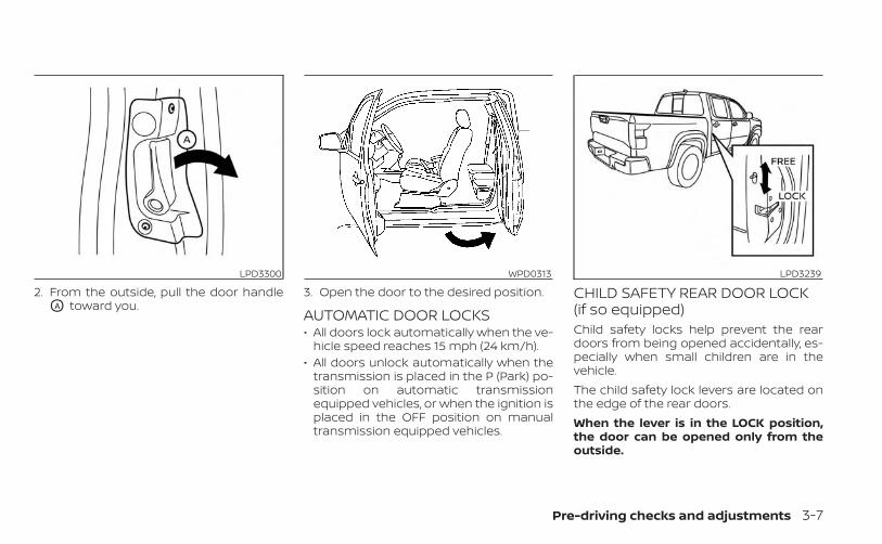
2. From the outside, pull the door handleOA toward you.
3. Open the door to the desired position.
AUTOMATIC DOOR LOCKS• All doors lock automatically when the ve-
hicle speed reaches 15 mph (24 km/h).• All doors unlock automatically when the
transmission is placed in the P (Park) po-sition on automatic transmissionequipped vehicles, or when the ignition isplaced in the OFF position on manualtransmission equipped vehicles.
CHILD SAFETY REAR DOOR LOCK(if so equipped)Child safety locks help prevent the reardoors from being opened accidentally, es-pecially when small children are in thevehicle.The child safety lock levers are located onthe edge of the rear doors.When the lever is in the LOCK position,the door can be opened only from theoutside.
LPD3300 WPD0313 LPD3239
Pre-driving checks and adjustments 3-7

WARNING
• Radio waves could adversely affectelectric medical equipment. Thosewho use a pacemaker should contactthe electric medical equipmentmanufacturer for the possible influ-ences before use.
• The Intelligent Key transmits radiowaves when the buttons are pressed.The FAA advises the radio waves mayaffect aircraft navigation and com-munication systems. Do not operatethe Intelligent Key while on an air-plane. Make sure the buttons are notoperated unintentionally when theunit is stored for a flight.
The Intelligent Key system can operate allthe door locks using the remote controlfunction or pushing the request switch (ifso equipped) on the vehicle without takingthe key out from a pocket or purse. Theoperating environment and/or conditionsmay affect the Intelligent Key systemoperation.Be sure to read the following before usingthe Intelligent Key system.
CAUTION
• Be sure to carry the Intelligent Keywith you when operating the vehicle.
• Never leave the Intelligent Key in thevehicle when you leave the vehicle.
The Intelligent Key is capable of receivingand transmitting radio waves. The Intelli-gent Key system transmits weak radiowaves from various distances. Environ-mental conditions may interfere with theoperation of the Intelligent Key system un-der the following operating conditions:• When operating near a location where
strong radio waves are transmitted, suchas a TV tower, power station and broad-casting station.
• When in possession of wireless equip-ment, such as a cellular telephone, trans-ceiver or a CB radio.
• When the Intelligent Key is in contact withor covered by metallic materials.
• When any type of radio wave remote con-trol is used nearby.
• When the Intelligent Key is placed near anelectric appliance such as a personalcomputer.
• When the vehicle is parked near a parkingmeter.
In such cases, correct the operating condi-tions before using the Intelligent Key func-tion or use the mechanical key.Although the life of the battery varies de-pending on the operating conditions, thebattery’s life is approximately two years. Ifthe battery is discharged, replace it with anew one.When the Intelligent Key battery is low, the“Key Battery Low” indicator illuminates inthe vehicle information display. For addi-tional information, see “Vehicle informationdisplay” (P. 2-20).Since the Intelligent Key is capable of re-ceiving radio waves, if the key is left nearequipment which transmits strong radiowaves, such as signals from a TV and per-sonal computer, the battery life may be-come shorter.For additional information, see “Battery re-placement” (P. 8-25).Pay special attention that the vehicle bat-tery is not completely discharged.As many as four Intelligent Keys can beregistered and used with one vehicle. Forinformation about the purchase and use ofadditional Intelligent Keys, it is recom-mended that you visit a NISSAN dealer.
NISSAN INTELLIGENT KEY® SYSTEM
3-8 Pre-driving checks and adjustments

OPERATING RANGEThe Intelligent Key functions can only beused when the Intelligent Key is within thespecified operating range from the requestswitch O1 (if so equipped).When the Intelligent Key battery is dis-charged or strong radio waves are presentnear the operating location, the IntelligentKey operating range becomes narrower,and the Intelligent Key may not functionproperly.The operating range is within 31.5 in (80 cm)from each request switch O1 (if so equipped).
If the Intelligent Key is too close to the doorglass or handle, the request switches (if soequipped) may not function.When the Intelligent Key is within the oper-ating range, it is possible for anyone, evensomeone who does not carry the Intelli-gent Key, to push the request switch (if soequipped) to lock/unlock the doors.
DOOR LOCKS/UNLOCKSPRECAUTION• Do not push the door handle request
switch (if so equipped) with the IntelligentKey held in your hand as illustrated. Theclose distance to the door handle willcause the Intelligent Key system to havedifficulty recognizing that the IntelligentKey is outside the vehicle.
• After locking with the door handle re-quest switch (if so equipped), verify thedoors are securely locked by testingthem.
LPD2338 LPD2554
Pre-driving checks and adjustments 3-9

• To prevent the Intelligent Key from beingleft inside the vehicle, make sure youcarry the Intelligent Key with you and thenlock the doors.
• Do not pull the door handle before push-ing the door handle request switch (if soequipped). The door will be unlocked butwill not open. Release the door handleonce and pull it again to open the door.
NISSAN INTELLIGENT KEY®OPERATIONYou can lock or unlock the doors withouttaking the Intelligent Key out of your pocketor bag.When you carry the Intelligent Key with you,you can lock or unlock all doors by pushingthe door handle request switch (if soequipped) within the range of operation.
Locking doors1. Move the shift lever to the P (Park) posi-
tion, place the ignition switch in the LOCKposition and make sure you carry theIntelligent Key with you.
2. Close all doors.
3. Push any door handle request switch O1
(if so equipped) while carrying the Intelli-gent Key with you.
4. All doors and the tailgate lock will lock.
5. The hazard indicator lights flash twiceand the buzzer beeps once.
LPD3243 LPD3251
3-10 Pre-driving checks and adjustments

NOTE:• Request switches (if so equipped) for
all doors can be deactivated when the“I-Key Door Lock (if so equipped)” set-ting is switched to OFF in the “VehicleSettings” of the vehicle informationdisplay. For additional information, see“Vehicle information display” (P. 2-20).
• Doors do not lock by pushing the doorhandle request switch (if so equipped)while the door open. If the door isclosed all doors lock by pushing thedoor handle request switch (if soequipped) while other doors open.
• Doors do not lock with the door handlerequest switch (if so equipped) withthe Intelligent Key inside the vehicleand a beep sounds to warn you. How-ever, when an Intelligent Key is insidethe vehicle, doors can be locked withanother Intelligent Key.
WARNING
After locking the doors using the re-quest switch (if so equipped), makesure that the doors have been securelylocked by operating the door handles.Failure to follow these instructions mayresult in inadvertently unlocking thedoors, which may decrease the safetyand security of your vehicle.
CAUTION
• When locking the doors using the re-quest switch (if so equipped), makesure to have the Intelligent Key inyour possession before operatingthe request switch (if so equipped) toprevent the Intelligent Key from be-ing left in the vehicle.
• The request switch (if so equipped) isoperational only when the IntelligentKey has been detected by the Intelli-gent Key system.
Lockout protectionTo prevent the Intelligent Key from beingaccidentally locked in the vehicle, lockoutprotection is equipped with the IntelligentKey system.When the driver’s side door is open, thedoors are locked, then the Intelligent Key isleft inside the vehicle and the door isclosed, all doors will unlock automatically.
NOTE:
The doors may not lock when the Intelli-gent Key is in the same hand that is op-erating the request switch (if soequipped) to lock the door. Put the Intel-ligent Key in a purse, pocket or yourother hand.
LPD3250
Pre-driving checks and adjustments 3-11

CAUTION
The lockout protection may not func-tion under the following conditions:• When the Intelligent Key is placed on
top of the instrument panel.• When the Intelligent Key is placed in-
side the glove box or a storage bin.• When the Intelligent Key is placed in-
side the door pockets.• When the Intelligent Key is placed in-
side or near metallic materials.
Unlocking doors1. Carry the Intelligent Key.
2. Push any door handle request switch O1
(if so equipped).
3. The door on which the request switch(if so equipped) was pressed will unlockand the hazard indicator lights flashonce and the outside buzzer soundsonce.
4. Push the door handle request switch O1
(if so equipped) again within 60 secondsto unlock all doors.
NOTE:• If the “Selective Unlock” feature is
switched to OFF using the “Vehicle Set-tings” menu, all doors will unlock uponthe first request switch O1 (if soequipped) press.
• Request switches (if so equipped) forall doors can be deactivated when the“I-Key Door Lock (if so equipped)” set-ting is switched to OFF in the “VehicleSettings” of the vehicle informationdisplay. For additional information, see“Vehicle information display” (P. 2-20).
LPD3245 LPD3244
3-12 Pre-driving checks and adjustments

If a door handle is pulled while unlockingthe doors, that door may not be unlocked.Returning the door handle to its originalposition will unlock the door. If the doordoes not unlock after returning the doorhandle, push the door handle requestswitch (if so equipped) to unlock the door.All doors will be locked automatically un-less one of the following operations is per-formed within one minute after pushingthe request switch (if so equipped).• Opening any door.• Pushing the ignition switch.
Using the interior lightsThe interior lights illuminate for a period oftime when a door is unlocked and the inte-rior light switch is in the DOOR position.The lights can be turned off without waitingby performing one of the followingoperations:• Placing the ignition switch in the ON
position.• Locking the doors with the Intelligent Key.• Switching the interior lights switch to the
OFF position.For additional information, see “Interiorlights” (P. 2-73).
HOW TO USE THE REMOTEKEYLESS ENTRY FUNCTIONThe remote keyless entry function can op-erate all door locks using the remote key-less function of the Intelligent Key. The re-mote keyless function can operate at adistance of 16 ft (5 m) away from the ve-hicle. The operating distance dependsupon the conditions around the vehicle.The remote keyless entry function will notfunction under the following conditions:• When the Intelligent Key is not within the
operational range.• When the doors are open or not closed
securely.• When the Intelligent Key battery is
discharged.
CAUTION
When locking the doors using the Intel-ligent Key, be sure not to leave the keyin the vehicle.
Type A (if so equipped)1. (lock) button
2. (unlock) button
3. (panic) button
LPD3600
Pre-driving checks and adjustments 3-13

Type B (if so equipped)1. (remote engine start) button
2. (lock) button
3. (unlock) button
4. (panic) button
Locking doors1. Place the ignition switch in the LOCK
position.
2. Close all doors.
3. Press the button on the Intelli-gent Key.
4. The hazard indicator lights flash twiceand the horn beeps once.
5. All doors will be locked.
WARNING
After locking the doors using the Intel-ligent Key, be sure that the doors havebeen securely locked by operating thedoor handles. Failure to follow these in-structions may result in inadvertentlyunlocking the doors, which may de-crease the safety and security of yourvehicle.
Unlocking doors1. Pressing on the Intelligent Key un-
locks all doors.
2. The hazard warning lights flash once.
Using the interior lightsThe interior lights illuminate for a period oftime when a door is unlocked and the inte-rior light switch is in the DOOR position.The lights can be turned off without waitingby performing one of the followingoperations:• Placing the ignition switch in the ON
position.• Locking the doors with the Intelligent Key.• Switching the interior lights switch to the
OFF position.For additional information, see “Interiorlights” (P. 2-73).
Opening windows (if so equipped)The Intelligent Key allows you to simultane-ously open windows equipped with auto-matic operation.• To open the windows, press the but-
ton on the Intelligent Key longer than3 seconds after all doors are unlocked.
The door windows cannot be closed byusing the Intelligent Key.
LPD3602
3-14 Pre-driving checks and adjustments

Using the panic alarmIf you are near your vehicle and feel threat-ened, you may activate the panic alarm tocall attention by pressing and holding the
button on the Intelligent Key for lon-ger than 0.5 seconds.The panic alarm and headlights will stay onfor a period of time.The panic alarm stops when:• It has run for a period of time.• Any button is pressed on the Intelligent
Key.
Answer back horn featureIf desired, the answer back horn featurecan be deactivated using the IntelligentKey. When it is deactivated and thebutton is pressed, the hazard indicatorlights flash twice. When the button ispressed, neither the hazard indicator lightsnor the horn operates.
NOTE:If you change the Answer Back Hornand light flash feature with the Intelli-gent Key, the vehicle information dis-play screen will show the currentmode after the ignition switch hasbeen cycled from the OFF to the ONposition. The vehicle information dis-play screen can also be used tochange the answer back horn mode.For additional information, see “Ve-hicle Settings” (P. 2-20).To deactivate:Press and hold the and but-tons for at least 4 seconds. The hazardindicator lights will flash three times to con-firm that the answer back horn feature hasbeen deactivated.
To activate:Press and hold the and but-tons for at least 4 seconds once more.The hazard indicator lights will flash onceand the horn will sound once to confirmthat the horn beep feature has beenreactivated.Deactivating the horn beep feature doesnot silence the horn if the alarm istriggered.
Pre-driving checks and adjustments 3-15

Intelligent Key button operationlightThe light blinks only when you press anybutton on the Intelligent Key. The light illu-mination only signifies that the key fob hastransmitted a signal. You may look and/orlisten to verify that the vehicle has per-formed the intended operation.
If the light does not blink, your battery maybe too weak to communicate to the ve-hicle. If this occurs, the battery may need tobe replaced. For additional information re-garding the replacement of a battery, see“Battery replacement” (P. 8-25).
WARNING SIGNALSTo help prevent the vehicle from movingunexpectedly by erroneous operation ofthe Intelligent Key or to help prevent thevehicle from being stolen, a chime or chirpsounds from inside and outside the vehicleand a warning is displayed in the instru-ment panel.When a chime or beep sounds or a warningis displayed, be sure to check the vehicleand the Intelligent Key.For additional information, see “Trouble-shooting guide” (P. 3-16) and “Vehicle infor-mation display” (P. 2-20).
TROUBLESHOOTING GUIDEVerify the location of all Intelligent Keys thatare programmed for the vehicle. If anotherIntelligent Key is in range or inside the ve-hicle, the vehicle system may respond dif-ferently than expected.
LPD2836
3-16 Pre-driving checks and adjustments

Symptom Possible Cause Remedy
When stopping the engineThe Shift to Park warning appears on thedisplay and the inside warning chimesounds continuously.
The shift lever is not in the P (Park)position.
Move the shift lever to the P (Park)position.
When opening the driver's door toget out of the vehicle
The Door Open warning appears on the dis-play and the inside warning chime soundscontinuously.
The ignition switch is in the ACC posi-tion.
Place the ignition switch in the ONposition or close the driver’s door.
When closing the door after gettingout of the vehicle
The No Key Detected warning appears onthe display, the outside chime sounds threetimes and the inside warning chime soundsfor approximately 3 seconds.
The ignition switch is in the ACC orON position.
Place the ignition switch in the OFFposition.
The Rear Door Alert warning message ap-pears on the display, the horn sounds threetimes twice, or a “Check Rear Seat for AllArticles” warning appears on the display.
The Rear Door Alert is activated.
Check the back seat for all articles,press the OK button to clear theRear Door Alert warning message oropen the rear door.
The Shift to Park warning appears on thedisplay and the inside and outside chimessound continuously.
The ignition switch is in the ACC orOFF position and the shift lever is notin the P (Park) position.
Move the shift lever to the P (Park)position and place the ignitionswitch in the OFF position.
When closing the door with the in-side lock knob turned to LOCK
The outside chime sounds for approximately3 seconds and all the doors unlock.
The Intelligent Key is inside the ve-hicle. Carry the Intelligent Key with you.
When pushing the door handle re-quest switch (if so equipped) or the
button on the Intelligent Keyto lock the door
The outside chime sounds for approximately2 seconds.
The Intelligent Key is inside the ve-hicle. Carry the Intelligent Key with you.
When pushing the ignition switch tostart the engine
The Key Battery Low appears on the display. The battery charge is low.Replace the battery with a new one.For additional information, see “Bat-tery replacement” (P. 8-25).
The No Key Detected warning appears onthe display, the inside chime sounds 3 times.
The Intelligent Key is not in the ve-hicle. Carry the Intelligent Key with you.
When pushing the ignition switch The Key System Fault warning light in themeter illuminates in yellow.
It warns of a malfunction with theIntelligent Key system.
It is recommended that you visit aNISSAN dealer.
Pre-driving checks and adjustments 3-17

The button will be on the NISSANIntelligent Key® if the vehicle has RemoteEngine Start. This feature allows the engineto start from outside the vehicle.The following features may be affectedwhen the Remote Engine Start feature isused:• Vehicles with a manual climate control
system will default to the last used heat-ing or cooling mode.
• Vehicles with an automatic climate con-trol system may default to either a heat-ing or cooling mode depending on out-side and cabin temperatures. Foradditional information, see “Remote En-gine Start with Intelligent Climate Control”(P. 4-38).
Laws in some local communities may re-strict or prohibit the use of Remote EngineStart, or the amount of time a parked ve-hicle engine may idle. For example, somelaws require a person using Remote EngineStart to have the vehicle in view or mayrestrict idling time except in freezing tem-peratures. Check local regulations for anyrequirements.Other conditions may affect the function ofthe Remote Engine Start feature. For addi-tional information, see “Conditions the Re-mote Engine Start will not work” (P. 3-20).Other conditions can affect the perfor-mance of the Intelligent Key transmitter.For additional information, see “NISSAN In-telligent Key® system” (P. 3-8).
REMOTE ENGINE STARTOPERATING RANGE
WARNING
• To help avoid risk of injury or deaththrough unintended operation of thevehicle and/or its systems, includingentrapment in windows or inadver-tent door lock activation, do notleave children, people who requirethe assistance of others or pets unat-tended in your vehicle. Additionally,the temperature inside a closed ve-hicle on a warm day can quickly be-come high enough to cause a signifi-cant risk of injury or death to peopleand pets.
• Do not use Remote Engine Start inclosed spaces such as a garage. Donot breathe exhaust gases; they con-tain colorless and odorless carbonmonoxide. Carbon monoxide is dan-gerous. It can cause unconscious-ness or death.
LPD2995
REMOTE ENGINE START (if soequipped)
3-18 Pre-driving checks and adjustments

CAUTION
When the Intelligent Key battery is dis-charged or other strong radio wavesources are present near the operatinglocation, the Intelligent Key operatingrange becomes narrower, and the Intel-ligent Key may not function properly.
The Remote Engine Start function can onlybe used when the Intelligent Key is withinthe specified operating range from thevehicle.The Remote Engine Start operating rangeis approximately 16 ft (5 m) from the vehicle.
REMOTE STARTING THE VEHICLETo use the Remote Engine Start featureperform the following:1. Aim the Intelligent Key at the vehicle.
2. Press the button to lock all doors.
3. Within 5 seconds press and hold thebutton until the turn signal lights
flash and the tail lamps turn on. If thevehicle is not within view press and holdthe button for at least 2 seconds.
The following events will occur when theengine starts:• The parking lights will turn on and remain
on as long as the engine is running.• The doors will be locked and the climate
control system may come on.• The engine will continue to run for 10 min-
utes. Repeat the steps to extend the timefor an additional 10 minutes. For addi-tional information, see “Extending enginerun time” (P. 3-19).
Press and hold the brake pedal whileswitching the ignition to the ON positionbefore driving. For additional information,see “Driving the vehicle” (P. 5-18).
EXTENDING ENGINE RUN TIMEThe Remote Engine Start feature can beextended one time by performing thesteps listed in “Remote starting the vehicle”(P. 3-19). Run time will be calculated asfollows:• The first 10–minute run time will start
when the Remote Engine Start function isperformed.
• The second 10 minutes will start immedi-ately when the Remote Engine Startfunction is performed again. For example,if the engine has been running for 5 min-utes, and 10 minutes are added, the en-gine will run for a total of 15 minutes.
• Extending engine run time will bring youto the two Remote Engine Start limit.
A maximum of two Remote Engine Starts,or a single start with an extension, are al-lowed between ignition cycles.The ignition switch must be cycled to theON position and then back to the OFF po-sition before the Remote Engine Start pro-cedure can be used again.
CANCELING A REMOTE ENGINESTARTTo cancel a Remote Engine Start, performone of the following:• Aim the Intelligent Key at the vehicle and
press until the parking lights turn off.• Turn on the hazard indicator flashers.• Cycle the ignition switch on and then off.• The extended engine run time has
expired.• The first 10–minute timer has expired.• The engine hood has been opened.
Pre-driving checks and adjustments 3-19

• The vehicle is shifted out of P (Park)position.
• The alarm sounds due to illegal entry intothe vehicle.
• The ignition switch is pushed without anIntelligent Key in the vehicle.
• The ignition switch is pushed with an In-telligent Key in the vehicle but the brakepedal is not depressed.
CONDITIONS THE REMOTE ENGINESTART WILL NOT WORKThe Remote Engine Start will not operate ifany of the following conditions are present:• The ignition switch is placed in the ON
position.• The hood is not securely closed.• The hazard warning lights are on.• The engine is still running. The engine
must be completely stopped. Wait atleast 6 seconds if the engine goes fromrunning to off. This is not applicable whenextending engine run time.
• The button is not pressed and heldfor at least 2 seconds.
• The button is not pressed and heldwithin 5 seconds of pressing the lockbutton.
• The brake is pressed.• The doors are not closed and locked.• The Key System Error Light remains solid
in the vehicle information display.• The alarm sounds due to illegal entry into
the vehicle.• Two Remote Engine Starts, or a single
Remote Engine Start with an extension,have already been used.
• The vehicle is not in P (Park) position.• There is a detected registered key already
inside of the vehicle.The Remote Engine Start Mode (if soequipped) may display a warning or indica-tor in the vehicle information display. Foradditional information, see “Vehicle infor-mation display” (P. 2-20).
1. Pull the hood lock release handle O1 lo-cated below the driver's side instrumentpanel. The hood will spring up slightly.
2. Push the lever O2 at the front of thehood to the side as illustrated with yourfingertips and raise the hood.
When closing the hood, lower it slowly andmake sure it locks into place.
LPD3276
HOOD
3-20 Pre-driving checks and adjustments

WARNING
• Make sure the hood is completelyclosed and latched before driving.Failure to do so could cause the hoodto fly open and result in an accident.
• If you see steam or smoke comingfrom the engine compartment, toavoid injury do not open the hood.
FUEL-FILLER CAPWARNING
• Gasoline is extremely flammable andhighly explosive under certain condi-tions. You could be burned or seri-ously injured if it is misused or mis-handled. Always stop the engine anddo not smoke or allow open flamesor sparks near the vehicle whenrefueling.
• Do not attempt to top off the fueltank after the fuel pump nozzleshuts off automatically. Continuedrefueling may cause fuel overflow,resulting in fuel spray and possibly afire.
• Use only an original equipment typefuel-filler cap as a replacement. It hasa built-in safety valve needed forproper operation of the fuel systemand emission control system. An in-correct cap can result in a seriousmalfunction and possible injury. Itcould also cause the Malfunc-tion Indicator Light (MIL) to come on.
• Never pour fuel into the throttle bodyto attempt to start your vehicle.
• Do not fill a portable fuel container inthe vehicle or trailer. Static electricitycan cause an explosion of flammableliquid, vapor or gas in any vehicle ortrailer. To reduce the risk of seriousinjury or death when filling portablefuel containers:– Always place the container on the
ground when filling.– Do not use electronic devices when
filling.
LPD3241
FUEL-FILLER DOOR
Pre-driving checks and adjustments 3-21

– Keep the pump nozzle in contactwith the container while you arefilling it.
– Use only approved portable fuelcontainers for flammable liquid.
CAUTION
• Do not use a fuel containing morethan 15% ethanol in your vehicle. Foradditional information, see “Fuel rec-ommendation” (P. 10-4).
• The LOOSE FUEL CAP warning mes-sage will be displayed if the fuel-fillercap is not properly tightened. It maytake a few driving trips for the mes-sage to be displayed. Failure totighten the fuel-filler cap properly af-ter the LOOSE FUEL CAP warningmessage is displayed may cause the
Malfunction Indicator Light (MIL)to illuminate.
• Failure to tighten the fuel-filler capproperly may cause the Mal-function Indicator Light (MIL) to illu-minate. If the light illuminatesbecause the fuel-filler cap is loose ormissing, tighten or install the cap andcontinue to drive the vehicle. The
light should turn off after a fewdriving trips. If the light does notturn off after a few driving trips, havethe vehicle inspected. It is recom-mended that you visit a NISSANdealer for this service.
• For additional information, see “Mal-function Indicator Light (MIL)” (P. 2-17).
• If fuel is spilled on the vehicle body,flush it away with water to avoidpaint damage.
To remove the fuel-filler cap:1. Turn the fuel-filler cap counterclockwise
to remove.
2. Loop the tether strap around the hookO1 while refueling.
To install the fuel-filler cap:1. Insert the fuel-filler cap straight into the
fuel-filler tube.
2. Turn the fuel-filler cap clockwise until asingle click is heard .
LPD3240
3-22 Pre-driving checks and adjustments

Loose Fuel Cap warningThe Loose Fuel Cap warning appears in thevehicle information display when the fuel-filler cap is not tightened correctly after thevehicle has been refueled. It may take a fewdriving trips for the message to be dis-played. To turn off the warning, perform thefollowing:1. Remove and install the fuel-filler cap as
described above as soon as possible.
2. Tighten the fuel-filler cap until a singleclick is heard.
WARNING
• Do not adjust the steering wheelwhile driving. You could lose controlof your vehicle and cause anaccident.
• Do not adjust the steering wheel anycloser to you than is necessary forproper steering operation and com-fort. The driver's air bag inflates withgreat force. If you are unrestrained,leaning forward, sitting sideways orout of position in any way, you are atgreater risk of injury or death in acrash. You may also receive seriousor fatal injuries from the air bag if youare up against it when it inflates. Al-ways sit back against the seatbackand as far away as practical from thesteering wheel. Always use the seatbelts.
TILT OPERATIONPull the lock lever toward the driver andhold it to adjust the steering wheel up ordown to the desired position.Release the lock lever to lock the steeringwheel in place.
LPD3029 LPD3231
STEERING WHEEL
Pre-driving checks and adjustments 3-23

1. To block glare from the front, swingdown the sun visor O1 .
2. To block glare from the side, remove thesun visor from the center mount andswing the visor to the side O2 .
3. Slide the sun visor extension O3 in or outas needed.
CAUTION
• Do not store the sun visor before re-turning the extension to its originalposition.
• Do not pull the extension sun visorforcedly downward.
VANITY MIRRORSTo access the vanity mirror, pull the sunvisor down and flip open the mirror cover.Some vanity mirrors are illuminated andturn on when the mirror cover is open.
WPD0344
LPD2595
SUN VISORS
3-24 Pre-driving checks and adjustments

MANUAL ANTI-GLARE REARVIEWMIRROR (if so equipped)Use the night position O1 to reduce glarefrom the headlights of vehicles behind youat night.Use the day position O2 when driving indaylight hours.
WARNING
Use the night position only when nec-essary, because it reduces rear viewclarity.
AUTOMATIC ANTI-GLAREREARVIEW MIRROR (if so equipped)The inside mirror is designed so that it au-tomatically dims during nighttime condi-tions and according to the intensity of theheadlights of the vehicle following you. Theautomatic anti-glare feature is activatedwhen the ignition switch is in the ONposition.The indicator light O2 will illuminate when theautomatic anti-glare feature is operating.
NOTE:
Do not hang any objects over the sen-sors O1 or apply glass cleaner to the sen-sors. Doing so will reduce the sensitivityof the sensors, resulting in improperoperation.The indicator light O2 will illuminate whenthe automatic anti-glare feature isoperating.To turn off the automatic anti-glare feature,press the O button. The indicator lightwill turn off.To turn on the automatic anti-glare featureagain, press the | button again. The in-dicator light will turn on.For additional information, see “HomeLink®Universal Transceiver” (P. 2-75).
WPD0126 LPD0469
MIRRORS
Pre-driving checks and adjustments 3-25

OUTSIDE MIRRORSWARNING
• Do not adjust the mirrors while driv-ing. You could lose control of your ve-hicle and cause an accident.
• Objects viewed in the outside mirroron the passenger side are closer thanthey appear. Be careful when movingto the right. Using only this mirrorcould cause an accident. Use the in-side mirror or glance over yourshoulder to properly judge distancesto other objects.
Manual control type (if soequipped)The outside mirrors can be moved in anydirection for a better rear view.
Electric control type (if soequipped)The outside mirror remote control will op-erate only when the ignition switch isplaced in the ACC or ON position.Rotate the control dial to select the right orleft mirror. Adjust the mirror to the desiredposition by moving the control dial.Return the control dial to the center (neu-tral) position to prevent accidentally mov-ing the mirror.
LPD3252 LPD2606
3-26 Pre-driving checks and adjustments

Manual folding outside mirrorsPull the outside mirror toward the door tofold it.
Heated mirrors (if so equipped)Some outside mirrors can be heated todefog or de-ice for improved visibility. Foradditional information, see “Outside mirrordefroster switch” (P. 2-38).
TAILGATEOpening the tailgatePull the tailgate handle upward and lowerthe tailgate. The support cables hold thetailgate open.When closing the tailgate, make sure thelatches are securely locked.Do not drive the vehicle with the tailgatedown, unless equipped with NISSAN'sBed Extender (accessory) or equivalentin the extended position.
For additional information on proper truckbox loading, see “Vehicle loading informa-tion” (P. 10-16).
WARNING
• Never allow anyone to ride in thecargo area or on the rear seat when itis in the folded position. Use of theseareas by passengers without properrestraints could result in serious in-jury or death in an accident or sud-den stop.
• It is extremely dangerous to ride in acargo area inside a vehicle. In a colli-sion, people riding in these areas aremore likely to be seriously injured orkilled.
• Do not allow people to ride in anyarea of your vehicle that is notequipped with seats and seat belts.
• Be sure everyone in your vehicle is ina seat and using a seat belt properly.
LPD2634 LPD3248
TRUCK BOX
Pre-driving checks and adjustments 3-27
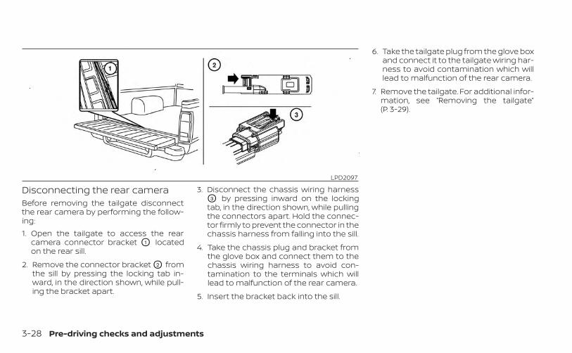
Disconnecting the rear cameraBefore removing the tailgate disconnectthe rear camera by performing the follow-ing:1. Open the tailgate to access the rear
camera connector bracket O1 locatedon the rear sill.
2. Remove the connector bracket O2 fromthe sill by pressing the locking tab in-ward, in the direction shown, while pull-ing the bracket apart.
3. Disconnect the chassis wiring harnessO3 by pressing inward on the lockingtab, in the direction shown, while pullingthe connectors apart. Hold the connec-tor firmly to prevent the connector in thechassis harness from falling into the sill.
4. Take the chassis plug and bracket fromthe glove box and connect them to thechassis wiring harness to avoid con-tamination to the terminals which willlead to malfunction of the rear camera.
5. Insert the bracket back into the sill.
6. Take the tailgate plug from the glove boxand connect it to the tailgate wiring har-ness to avoid contamination which willlead to malfunction of the rear camera.
7. Remove the tailgate. For additional infor-mation, see “Removing the tailgate”(P. 3-29).
LPD2097
3-28 Pre-driving checks and adjustments

Removing the tailgate1. Release the tailgate support cables.
CAUTION
• The tailgate is heavy. Two peopleshould remove or install it. Be carefulnot to drop it during removal.
• After releasing the support cables,do not let the tailgate rest on thebumper.
2. Hold the tailgate at a 15 degree angle.
3. Pull the tailgate out from the left sidehinge at an angle.
4. The tailgate slides out of the right sidehinge.
Installing the tailgate1. Insert the tailgate into the right side
hinge.
2. Insert the tailgate into the left side hinge.
3. Continue to hold the tailgate at a 15 de-gree angle and attach the tailgate sup-port cables.
4. Close the tailgate securely.
LPD2208
Pre-driving checks and adjustments 3-29

Connecting the rear cameraBefore closing the tailgate reconnect therear camera by performing the following:1. After attaching the rear tailgate to the
truck, keep the tailgate open and checkthat the tailgate harness is not hangingbelow the tailgate.
2. Remove the connector bracket O2 fromthe sill by pressing the locking tab in-ward, in the direction shown, while pull-ing the bracket apart.
3. Disconnect the chassis plug andbracket from the chassis wiring harnessO3 . Keep the connector and bracket in asafe place such as the glove box.
4. Disconnect the tailgate plug from thetailgate wiring harness. Keep the tail-gate plug in a safe place such as theglove box.
5. Connect the tailgate wiring harness tothe chassis wiring harness.
6. Securely fix the rear camera connectorbracket O1 to the rear sill.
7. Close the tailgate securely.
Locking the tailgateTo lock the tailgate, turn the key toward thepassenger side of the vehicle O1 . To unlock,turn the key toward the driver side O2 .
LPD2097 LPD3249
3-30 Pre-driving checks and adjustments

TIE DOWN HOOKSFor your convenience, tie down hooks areplaced at each corner of the truck box.These may be used to help secure cargoloaded into the truck box.• The weight of the cargo load must be
evenly distributed over both the front andthe rear axles.
• All cargo should be securely fastenedwith ropes or straps to prevent it fromshifting or sliding within the vehicle.
WARNING
Properly secure all cargo with ropes orstraps to help prevent it from sliding orshifting. In a sudden stop or collision,unsecured cargo could cause personalinjury.
LTI0102
Pre-driving checks and adjustments 3-31

MEMO
3-32 Pre-driving checks and adjustments

4 Monitor, climate, audio, phone andvoice recognition systems
NissanConnect® Owner’s Manual . . . . . . . . . . . . . . . 4-2RearView Monitor (if so equipped) . . . . . . . . . . . . . . . 4-3
RearView Monitor system operation . . . . . . . . . . 4-4How to read the displayed lines . . . . . . . . . . . . . . 4-4Difference between predicted andactual distances . . . . . . . . . . . . . . . . . . . . . . . . . . . . . 4-5How to park with predicted courselines . . . . . . . . . . . . . . . . . . . . . . . . . . . . . . . . . . . . . . . . . . 4-7Adjusting the screen . . . . . . . . . . . . . . . . . . . . . . . . . 4-8How to turn on and off predictedcourse lines . . . . . . . . . . . . . . . . . . . . . . . . . . . . . . . . . . 4-8RearView Monitor system limitations . . . . . . . . . 4-8System maintenance . . . . . . . . . . . . . . . . . . . . . . . 4-10
Intelligent Around View Monitor(if so equipped) . . . . . . . . . . . . . . . . . . . . . . . . . . . . . . . . . .4-11
Intelligent Around View Monitor systemoperation . . . . . . . . . . . . . . . . . . . . . . . . . . . . . . . . . . . 4-12Difference between predicted andactual distances . . . . . . . . . . . . . . . . . . . . . . . . . . . . 4-16How to park with predicted courselines . . . . . . . . . . . . . . . . . . . . . . . . . . . . . . . . . . . . . . . . . 4-18How to switch the display . . . . . . . . . . . . . . . . . . . 4-19Adjusting the screen . . . . . . . . . . . . . . . . . . . . . . . . 4-20Intelligent Around View Monitor systemlimitations . . . . . . . . . . . . . . . . . . . . . . . . . . . . . . . . . . 4-20
System maintenance . . . . . . . . . . . . . . . . . . . . . . . 4-22Moving Object Detection (MOD)(if so equipped) . . . . . . . . . . . . . . . . . . . . . . . . . . . . . . . . . 4-23
MOD system operation . . . . . . . . . . . . . . . . . . . . . . 4-24Turning MOD on and off (if so equipped) . . . . . 4-25MOD system limitations . . . . . . . . . . . . . . . . . . . . . 4-25System maintenance . . . . . . . . . . . . . . . . . . . . . . . 4-26
Vents . . . . . . . . . . . . . . . . . . . . . . . . . . . . . . . . . . . . . . . . . . 4-27Heater and air conditioner (manual)(if so equipped) . . . . . . . . . . . . . . . . . . . . . . . . . . . . . . . . . 4-27
Controls . . . . . . . . . . . . . . . . . . . . . . . . . . . . . . . . . . . . . 4-28Heater operation . . . . . . . . . . . . . . . . . . . . . . . . . . . . 4-29Air conditioner operation . . . . . . . . . . . . . . . . . . . . 4-31Air flow charts . . . . . . . . . . . . . . . . . . . . . . . . . . . . . . . 4-32
Heater and air conditioner (automatic)(if so equipped) . . . . . . . . . . . . . . . . . . . . . . . . . . . . . . . . . 4-36
Automatic operation . . . . . . . . . . . . . . . . . . . . . . . . 4-37Manual operation . . . . . . . . . . . . . . . . . . . . . . . . . . . 4-38Operating tips . . . . . . . . . . . . . . . . . . . . . . . . . . . . . . .4-40
Servicing air conditioner . . . . . . . . . . . . . . . . . . . . . . . . 4-41Antenna. . . . . . . . . . . . . . . . . . . . . . . . . . . . . . . . . . . . . . . . 4-41Car phone or CB radio . . . . . . . . . . . . . . . . . . . . . . . . . . 4-42iPod®/iPhone® . . . . . . . . . . . . . . . . . . . . . . . . . . . . . . . . . 4-42

Refer to the digital NissanConnect® Own-er’s manual using the QR code on thispage, or your printed NissanConnect®Owner’s manual (if so equipped). Thismanual includes the following information:• NissanConnect® Services Powered By
SiriusXM®• Navigation system (if so equipped)• Audio system• Apple CarPlay®• Android Auto TM
• Bluetooth® Hands-Free Phone system• Viewing information
• Other settings• Voice recognition• General system information
LHA5513
NISSANCONNECT® OWNER’SMANUAL
4-2 Monitor, climate, audio, phone and voice recognition systems
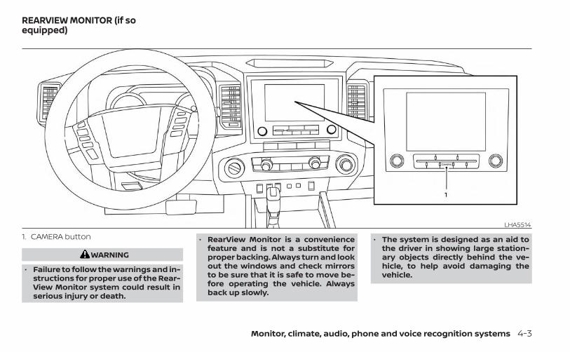
1. CAMERA button
WARNING
• Failure to follow the warnings and in-structions for proper use of the Rear-View Monitor system could result inserious injury or death.
• RearView Monitor is a conveniencefeature and is not a substitute forproper backing. Always turn and lookout the windows and check mirrorsto be sure that it is safe to move be-fore operating the vehicle. Alwaysback up slowly.
• The system is designed as an aid tothe driver in showing large station-ary objects directly behind the ve-hicle, to help avoid damaging thevehicle.
LHA5514
REARVIEW MONITOR (if soequipped)
Monitor, climate, audio, phone and voice recognition systems 4-3

• The distance guide line and the ve-hicle width line should be used as areference only when the vehicle is ona level paved surface. The distanceviewed on the monitor is for refer-ence only and may be different thanthe actual distance between the ve-hicle and displayed objects.
CAUTION
Do not scratch the camera lens whencleaning dirt or snow from the front ofthe camera.
The RearView Monitor system automati-cally shows a rear view of the vehicle whenthe shift lever is shifted into the R (Reverse)position. While in R (Reverse), pressing theCAMERA will cycle through guideline op-tions. The radio can still be heard while theRearView Monitor is active.
To display the rear view, the RearView Moni-tor system uses a camera located justabove the vehicle’s license plate O1 on thetailgate.
REARVIEW MONITOR SYSTEMOPERATIONWith the ignition switch in the ON position,move the shift lever to the R (Reverse) po-sition to operate the RearView Monitor.
HOW TO READ THE DISPLAYEDLINESGuiding lines which indicate the vehiclewidth and distances to objects with refer-ence to the vehicle body line OA are dis-played on the monitor.Distance guide linesIndicate distances from the vehicle body.• Red line O1 : approx. 1.5 ft (0.5 m)• Yellow line O2 : approx. 3 ft (1 m)• Green line O3 : approx. 7 ft (2 m)
LHA5515 LHA5335
4-4 Monitor, climate, audio, phone and voice recognition systems

Vehicle width guide lines O4
Indicate the vehicle width when backingup.Predicted course lines O5
Indicate the predicted course when back-ing up. The predicted course lines will bedisplayed on the monitor when the shiftlever is in the R (Reverse) position and thesteering wheel is turned. The predictedcourse lines will move depending on howmuch the steering wheel is turned and willnot be displayed while the steering wheel isin the straight-ahead position.The vehicle width guide lines and the widthof the predicted course lines are wider thanthe actual width and course.Center guide lines O6
Indicates the vehicle’s center.
DIFFERENCE BETWEEN PREDICTEDAND ACTUAL DISTANCESThe displayed guidelines and their loca-tions on the ground are for approximatereference only. Objects on uphill or downhillsurfaces or projecting objects will be actu-ally located at distances different fromthose displayed in the monitor relative tothe guidelines (refer to illustrations). Whenin doubt, turn around and view the objectsas you are backing up, or park and exit thevehicle to view the positioning of objectsbehind the vehicle.
Backing up on a steep uphillWhen backing up the vehicle up a hill, thedistance guide lines and the vehicle widthguide lines are shown closer than the ac-tual distance. Note that any object on thehill is further than it appears on themonitor.
LHA5516
Monitor, climate, audio, phone and voice recognition systems 4-5

Backing up on a steep downhillWhen backing up the vehicle down a hill,the distance guide lines and the vehiclewidth guide lines are shown farther thanthe actual distance. Note that any objecton the hill is closer than it appears on themonitor.
Backing up near a projectingobjectThe vehicle may seem to nearly clear theobject in the display. However, the vehiclemay hit the object if it projects over theactual backing up course.
Backing up behind a projectingobjectThe position OC is shown farther than theposition OB in the display. However, the po-sition OC is actually at the same distance asthe position OA . The vehicle may hit the
LHA5517 LHA5338 LHA5518
4-6 Monitor, climate, audio, phone and voice recognition systems
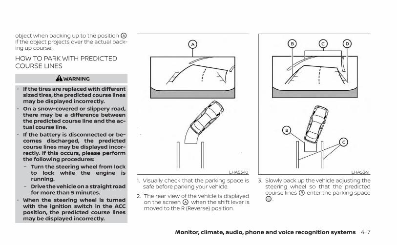
object when backing up to the position OA
if the object projects over the actual back-ing up course.
HOW TO PARK WITH PREDICTEDCOURSE LINES
WARNING
• If the tires are replaced with differentsized tires, the predicted course linesmay be displayed incorrectly.
• On a snow-covered or slippery road,there may be a difference betweenthe predicted course line and the ac-tual course line.
• If the battery is disconnected or be-comes discharged, the predictedcourse lines may be displayed incor-rectly. If this occurs, please performthe following procedures:– Turn the steering wheel from lock
to lock while the engine isrunning.
– Drive the vehicle on a straight roadfor more than 5 minutes.
• When the steering wheel is turnedwith the ignition switch in the ACCposition, the predicted course linesmay be displayed incorrectly.
1. Visually check that the parking space issafe before parking your vehicle.
2. The rear view of the vehicle is displayedon the screen OA when the shift lever ismoved to the R (Reverse) position.
3. Slowly back up the vehicle adjusting thesteering wheel so that the predictedcourse lines OB enter the parking spaceOC .
LHA5340 LHA5341
Monitor, climate, audio, phone and voice recognition systems 4-7

4. Maneuver the steering wheel to makethe vehicle width guide lines OD parallelto the parking space OC while referringto the predicted course lines.
5. When the vehicle is parked in the spacecompletely, move the shift lever to the P(Park) position and apply the parkingbrake.
ADJUSTING THE SCREEN1. Press the CAMERA button.
2. Touch the “Display Settings” key.
3. Touch the “Brightness”, “Contrast”, Tint”,“Color”, or “Black Level” key.
4. Adjust the item by touching the “+” or “–”key on the touch-screen display.
NOTE:
Do not adjust any of the display settingsof the RearView Monitor while the ve-hicle is moving.
HOW TO TURN ON AND OFFPREDICTED COURSE LINESTo toggle ON and OFF the predicted courselines while in the P (Park) position:1. Press the CAMERA button.
2. Touch the “Predicted Course Lines” keyto turn the feature ON or OFF.
To toggle ON and OFF the predicted courselines or center guide line while in the R (Re-verse) position, press the CAMERA button.
REARVIEW MONITOR SYSTEMLIMITATIONS
WARNING
Listed below are the system limitationsfor RearView Monitor. Failure to oper-ate the vehicle in accordance withthese system limitations could result inserious injury or death.• The system cannot completely elimi-
nate blind spots and may not showevery object.
LHA5512
4-8 Monitor, climate, audio, phone and voice recognition systems

• Underneath the bumper and the cor-ner areas of the bumper cannot beviewed on the RearView Monitor be-cause of its monitoring range limita-tion. The system will not show smallobjects below the bumper, and maynot show objects close to the bum-per or on the ground.
• Objects viewed in the RearViewMonitor differ from actual distancebecause a wide-angle lens is used.
• Objects in the RearView Monitor willappear visually opposite comparedto when viewed in the rearview andoutside mirrors.
• Use the displayed lines as a refer-ence. The lines are highly affected bythe number of occupants, fuel level,vehicle position, road conditions androad grade.
• Make sure that the tailgate is se-curely closed when backing up.
• Do not put anything on the rearviewcamera. The rearview camera is in-stalled on the tailgate.
• When washing the vehicle with highpressure water, be sure not to spray itaround the camera. Otherwise, watermay enter the camera unit causingwater condensation on the lens, amalfunction, fire or an electric shock.
• Do not strike the camera. It is a preci-sion instrument. Otherwise, it maymalfunction or cause damage result-ing in a fire or an electric shock.
The following are operating limitations anddo not represent a system malfunction:• When the temperature is extremely high
or low, the screen may not clearly displayobjects.
• When strong light directly shines on thecamera, objects may not be displayedclearly.
• Vertical lines may be seen in objects onthe screen. This is due to strong reflectedlight from the bumper.
• The screen may flicker under fluorescentlight.
• The colors of objects on the RearViewMonitor may differ somewhat from theactual color of objects.
• Objects on the monitor may not be clearin a dark environment.
• There may be a delay when switchingbetween views.
• If dirt, rain or snow accumulate on thecamera, RearView Monitor may not dis-play objects clearly. Clean the camera.
• Do not use wax on the camera lens. Wipeoff any wax with a clean cloth dampenedwith a diluted mild cleaning agent, thenwipe with a dry cloth.
Monitor, climate, audio, phone and voice recognition systems 4-9

SYSTEM MAINTENANCE
CAUTION
• Do not use alcohol, benzine or thin-ner to clean the camera. This willcause discoloration.
• Do not damage the camera as themonitor screen may be adverselyaffected.
If dirt, rain or snow accumulates on thecamera O1 , the RearView Monitor may notdisplay objects clearly. Clean the cameraby wiping it with a cloth dampened with adiluted mild cleaning agent and then wip-ing it with a dry cloth.
LHA5515
4-10 Monitor, climate, audio, phone and voice recognition systems

1. CAMERA buttonLHA5514
INTELLIGENT AROUND VIEWMONITOR (if so equipped)
Monitor, climate, audio, phone and voice recognition systems 4-11

WARNING
• Failure to follow the warnings and in-structions for the proper use of theIntelligent Around View Monitor sys-tem could result in serious injury ordeath.
• The Intelligent Around View Monitoris a convenience feature and is not asubstitute for proper vehicle opera-tion because it has areas where ob-jects cannot be viewed. The four cor-ners of the vehicle in particular, areareas where objects do not alwaysappear in the bird’s-eye, front, or rearviews. Always check your surround-ings to be sure that it is safe to movebefore operating the vehicle. Alwaysoperate the vehicle slowly.
• The driver is always responsible forsafety during parking and othermaneuvers.
CAUTION
Do not scratch the camera lens whencleaning dirt or snow from the front ofthe camera.
The Intelligent Around View Monitor sys-tem is designed as an aid to the driver insituations such as slot parking or parallelparking.The monitor displays various views of theposition of the vehicle in a split screen for-mat. Not all views are available at all times.Available views:• Front View
An approximately 150–degree view of thefront of the vehicle.
• Rear ViewAn approximately 150–degree view of therear of the vehicle.
• Bird's-Eye ViewThe surrounding views of the vehiclefrom above.
• Front-Side ViewThe view around and ahead of the frontpassenger's side wheel.
• Rear-Wide ViewAn approximately 180–degree view of therear of the vehicle.
To display the multiple views, the IntelligentAround View Monitor system uses cam-eras located in the front grille, on the vehi-cle’s outside mirrors and one on the tail-gate O1 .
INTELLIGENT AROUND VIEWMONITOR SYSTEM OPERATIONWith the ignition switch in the ON position,move the shift lever to the R (Reverse) po-sition to operate the Intelligent AroundView Monitor.
LHA5519
4-12 Monitor, climate, audio, phone and voice recognition systems

When the camera is first activated with thebird’s-eye view in the display, a red icon(if so equipped) will flash on the screen.This indicates that the sonar system(if so equipped) is activated. For additionalinformation on the rear sonar system(if so equipped), see “Rear sonar system”(P. 5-125).The screen displayed on the IntelligentAround View Monitor will automatically re-turn to the previous screen 3 minutes afterthe CAMERA button has been pressed withthe shift lever in a position other than the R(Reverse) position.
Available views
WARNING
• The distance guide lines and the ve-hicle width lines should be used as areference only when the vehicle is ona paved, level surface. The apparentdistance viewed on the monitor maybe different than the actual distancebetween the vehicle and displayedobjects.
• Use the displayed lines and thebird’s-eye view as a reference. Thelines and the bird’s-eye view aregreatly affected by the number ofoccupants, cargo, fuel level, vehicleposition, road condition and roadgrade.
• If the tires are replaced with differentsized tires, the predicted course linesand the bird's-eye view may be dis-played incorrectly.
• When driving the vehicle up a hill, ob-jects viewed in the monitor are fur-ther than they appear. When drivingthe vehicle down a hill, objectsviewed in the monitor are closer thanthey appear.
• Objects in the rear view will appearvisually opposite compared to whenviewed in the monitor and outsidemirrors.
• Use the mirrors or actually look toproperly judge distances to otherobjects.
• On a snow-covered or slippery road,there may be a difference betweenthe predicted course lines and theactual course line.
• The vehicle width and predictedcourse lines are wider than the actualwidth and course.
• The displayed lines will appearslightly off to the right, because therearview camera is not installed inthe rear center of the vehicle.
Monitor, climate, audio, phone and voice recognition systems 4-13

Front and rear viewGuiding lines that indicate the approximatevehicle width and distance to objects withreference to the vehicle body line OA aredisplayed on the monitor.Distance guide lines:Indicate distances from the vehicle body:• Red line O1 : approximately 1.5 ft (0.5 m)• Yellow line O2 : approximately 3ft (1 m)• Green line O3 : approximately 7 ft (2 m)• Green line O4 : approximately 10 ft (3 m)
(if so equipped)
Vehicle width guide lines O5
Indicate the approximate vehicle widthwhen backing up.Predicted course lines O6
Indicate the predicted course when oper-ating the vehicle. The predicted courselines will be displayed on the monitor whenthe steering wheel is turned. The predictedcourse lines will move depending on howmuch the steering wheel is turned and willnot be displayed while the steering wheel isin the straight-ahead position.
Center guide lines O7
Indicates the vehicle’s center.The front view will not be displayed whenthe vehicle speed is above 6 mph (10 km/h).
NOTE:
When the monitor displays the frontview and the steering wheel turns about90 degrees or less from the straight-ahead position, both the right and leftpredicted course lines O6 are displayed.When the steering wheel turns about 90degrees or more, a line is displayed onlyon the opposite side of the turn.SAA1840
Front viewLHA5343
Rear view
4-14 Monitor, climate, audio, phone and voice recognition systems

Bird’s-eye viewThe bird's-eye view shows the overheadview of the vehicle, which helps confirm thevehicle position and the predicted courseto a parking space.The vehicle icon O1 shows the position ofthe vehicle. Note that the apparent dis-tance between objects viewed in thebird's-eye view may differ somewhat fromthe actual distance to the vehicle.The areas that the cameras cannot coverO2 are indicated in black.
After the ignition switched is placed in theON position, the non-viewable area O2 ishighlighted in yellow for 3 seconds after thebirds-eye view is displayed.In addition, the non-viewable corners aredisplayed in red and will blink for the first 3seconds O3 to remind the driver to becautious.
WARNING
• Objects in the bird's-eye view will ap-pear further than the actual distance.
• Tall objects, such as a curb or vehicle,may be misaligned or not displayedat the seam of the views.
• Objects that are above the cameracannot be displayed.
• The view of the bird's-eye view maybe misaligned when the camera po-sition alters.
• A line on the ground may be mis-aligned and is not seen as beingstraight at the seam of the views. Themisalignment will increase as theline proceeds away from the vehicle.
Front-side viewGuiding linesGuiding lines that indicate the approximatewidth and the front end of the vehicle aredisplayed on the monitor.The front-of-vehicle line O1 shows the frontpart of the vehicle.The side-of-vehicle line O2 shows the ap-proximate vehicle width including the out-side mirrors.The extensions O3 of both the front O1 andside O2 lines are shown with a green dottedline.
LHA4264 LHA2652
Monitor, climate, audio, phone and voice recognition systems 4-15

Rear-wide viewThe rear-wide view shows a wider area onthe entire screen and allows the checkingof the blind corners on right and left sides.The rear-wide view displays an approxi-mately 180-degree area. The predictedcourse lines are not displayed when usingthe rear-wide view.
Distance guide linesIndicates distances from the vehicle body:• Red line O1 : approximately 1.5 ft (0.5 m)• Yellow line O2 : approximately 3 ft (1 m)• Green line O3 : approximately 7 ft (2 m)Vehicle width guide lines O4
Indicate the vehicle width when backingup.
DIFFERENCE BETWEEN PREDICTEDAND ACTUAL DISTANCESThe displayed guidelines and their loca-tions on the ground are for approximatereference only. Objects on uphill or downhillsurfaces or projecting objects will be actu-ally located at distances different fromthose displayed in the monitor relative tothe guidelines (refer to illustrations). Whenin doubt, turn around and view the objectsas you are backing up, or park and exit thevehicle to view the positioning of objectsbehind the vehicle. Backing up on a steep uphill
When backing up the vehicle up a hill, thedistance guide lines and the vehicle widthguide lines are shown closer than the ac-tual distance. Note that any object on thehill is further than it appears on themonitor.
LHA4819Rear-wide view
LHA5516
4-16 Monitor, climate, audio, phone and voice recognition systems

Backing up on a steep downhillWhen backing up the vehicle down a hill,the distance guide lines and the vehiclewidth guide lines are shown farther thanthe actual distance. Note that any objecton the hill is closer than it appears on themonitor.
Backing up near a projectingobjectThe vehicle may seem to nearly clear theobject in the display. However, the vehiclemay hit the object if it projects over theactual backing up course.
Backing up behind a projectingobjectThe position OC is shown farther than theposition OB in the display. However, the po-sition OC is actually at the same distance asthe position OA . The vehicle may hit the
LHA5517 LHA5338 LHA5518
Monitor, climate, audio, phone and voice recognition systems 4-17

object when backing up to the position OA
if the object projects over the actual back-ing up course.
HOW TO PARK WITH PREDICTEDCOURSE LINES
WARNING
• If the tires are replaced with differentsized tires, the predicted course linesmay be displayed incorrectly.
• On a snow-covered or slippery road,there may be a difference betweenthe predicted course line and the ac-tual course line.
• If the battery is disconnected or be-comes discharged, the predictedcourse lines may be displayed incor-rectly. If this occurs, please performthe following procedures:– Turn the steering wheel from lock
to lock while the engine isrunning.
– Drive the vehicle on a straight roadfor more than 5 minutes.
• When the steering wheel is turnedwith the ignition switch in the ACCposition, the predicted course linesmay be displayed incorrectly.
• There is the possibility that when thevehicle mirrors are extended for tow-ing, the mirrors may be shown in thebird's-eye view and front side view.
1. Visually check that the parking space issafe before parking your vehicle.
2. The rear view of the vehicle is displayedon the screen OA when the shift lever ismoved to the R (Reverse) position.
LHA5340
4-18 Monitor, climate, audio, phone and voice recognition systems

3. Slowly back up the vehicle adjusting thesteering wheel so that the predictedcourse lines OB enter the parking spaceOC .
4. Maneuver the steering wheel to makethe vehicle width guide lines OD parallelto the parking space OC while referringto the predicted course lines.
5. When the vehicle is parked in the spacecompletely, move the shift lever to the P(Park) position and apply the parkingbrake.
HOW TO SWITCH THE DISPLAYWith the ignition switch in the ON position,press the CAMERA button or move the shiftlever to the R (Reverse) position to operatethe Intelligent Around View Monitor.The Intelligent Around View Monitor dis-plays different split screen views depend-ing on the position of the shift lever. Pressthe CAMERA button to switch between theavailable views.If the shift lever is in the R (Reverse) position,the available views are:• Rear view/bird’s-eye view split screen• Rear view/front-side view split screen• Rear-wide view
If the shift lever is in the P (Park) or D (Drive)position, the available views are:• Front view/bird’s-eye view split screen• Front view/front-side view split screenThe display will switch from the IntelligentAround View Monitor screen when:• The shift lever is in the D (Drive) position
and the vehicle speed increases aboveapproximately 6 mph (10 km/h).
• A different screen is selected.
LHA5341
Monitor, climate, audio, phone and voice recognition systems 4-19

ADJUSTING THE SCREEN1. Press the Menu button.
2. Touch the “Settings” key.
3. Touch the “Camera” key.
4. Touch the “Display Settings” key.
5. Touch the “Brightness”, “Contrast”, Tint”,“Color”, or “Black Level” key.
6. Adjust the item by touching the “+” or “–”key on the touch-screen display.
NOTE:
Do not adjust any of the display settingsof the Intelligent Around View Monitorwhile the vehicle is moving. Make surethe parking brake is firmly applied.
INTELLIGENT AROUND VIEWMONITOR SYSTEM LIMITATIONS
LHA5379
LHA5520
4-20 Monitor, climate, audio, phone and voice recognition systems

WARNING
Listed below are the system limitationsfor Intelligent Around View Monitor.Failure to operate the vehicle in accor-dance with these system limitationscould result in serious injury or death.• Do not use the Intelligent Around
View Monitor with the outside mir-rors in the stored position, and makesure that the tailgate is securelyclosed when operating the vehicleusing the Intelligent Around ViewMonitor.
• The apparent distance between ob-jects viewed on the IntelligentAround View Monitor differs from theactual distance.
• The cameras are installed on thefront grille, the outside mirrors andabove the rear license plate. Do notput anything on the vehicle that cov-ers the cameras.
• When washing the vehicle with highpressure water, be sure not to spray itaround the cameras. Otherwise, wa-ter may enter the camera unit caus-ing water condensation on the lens, amalfunction, fire or an electric shock.
• Do not strike the cameras. They areprecision instruments. Doing socould cause a malfunction or causedamage resulting in a fire or an elec-tric shock.
There are some areas where the systemwill not show objects and the system doesnot warn of moving objects. When in thefront or rear view display, an object belowthe bumper or on the ground may not beviewed. When in the bird’s-eye view, a tallobject near the seam of the camera view-ing areas will not appear in the monitor.The following are operating limitations anddo not represent a system malfunction:• There may be a delay when switching
between views.• When the temperature is extremely high
or low, the screen may not display objectsclearly.
• When strong light directly shines on thecamera, objects may not be displayedclearly.
• The screen may flicker under fluorescentlight.
• The colors of objects on the IntelligentAround View Monitor may differ some-what from the actual color of objects.
• Objects on the Intelligent Around ViewMonitor may not be clear and the colorof the object may differ in a darkenvironment.
• There may be differences in sharpnessbetween each camera view of the bird's-eye view.
• Do not use wax on the camera lens. Wipeoff any wax with a clean cloth that hasbeen dampened with a diluted mildcleaning agent, then wipe with a drycloth.
Monitor, climate, audio, phone and voice recognition systems 4-21

System temporarily unavailableWhen the “!” icon is displayed on the screen,there are abnormal conditions in the Intel-ligent Around View Monitor. This will nothinder normal driving operation but it isrecommended that the system be in-spected. It is recommended that you visit aNISSAN dealer for this service.
When the “[X]” icon is displayed on thescreen, the camera image may be receiv-ing temporary electronic disturbancesfrom surrounding devices. This will not hin-der normal driving operation but it is rec-ommended that the system be inspectedif it occurs frequently. It is recommendedthat you visit a NISSAN dealer for thisservice.
SYSTEM MAINTENANCE
CAUTION
• Do not use alcohol, benzine or thin-ner to clean the camera. This willcause discoloration.
• Do not damage the cameras as the moni-tor screen may be adversely affected.
If dirt, rain or snow accumulates on any ofthe cameras O1 , the Intelligent AroundView Monitor may not display objectsclearly. Clean the camera by wiping with acloth dampened with a diluted mild clean-ing agent and then wiping with a dry cloth.
LHA3591 LHA3592 LHA5519
4-22 Monitor, climate, audio, phone and voice recognition systems

1. CAMERA button
WARNING
• Failure to follow the warnings and in-structions for proper use of the Mov-ing Object Detection system couldresult in serious injury or death.
• The MOD system is not a substitutefor proper vehicle operation and isnot designed to prevent contact withobjects surrounding the vehicle.When maneuvering, always use theoutside mirrors and rearview mirrorand turn and check the surroundingsto ensure it is safe to maneuver.
• The system is deactivated at speedsabove 6 mph (10 km/h). It is reacti-vated at lower speeds.
• The MOD system is not designed to de-tect surrounding stationary objects.
LHA5514
MOVING OBJECT DETECTION (MOD)(if so equipped)
Monitor, climate, audio, phone and voice recognition systems 4-23

The MOD system can inform the driver ofmoving objects near the vehicle whenbacking out of garages, maneuvering inparking lots and in other such instances.The MOD system detects moving objectsby using image processing technology onthe image shown in the display.
MOD SYSTEM OPERATIONThe MOD system will turn on automaticallyunder the following conditions:• When the shift lever is in the R (Reverse)
position.• When vehicle speed decreases below ap-
proximately 6 mph (10 km/h) and thecamera screen is displayed. The MOD system operates in the following
conditions when the camera view isdisplayed:• When the shift lever is in the P (Park) or N
(Neutral) position and the vehicle isstopped, the MOD system detects mov-ing objects in the bird’s-eye view. TheMOD system will not operate if the out-side mirrors are moving in or out, in thestowed position, or if either front door isopened.
• When the shift lever is in the D (Drive)position and the vehicle speed is belowapproximately 6 mph (10 km/h), the MODsystem detects moving objects in thefront view.
• When the shift lever is in the R (Reverse)position and the vehicle speed is belowapproximately 6 mph (10 km/h), the MODsystem detects moving objects in therear view. The MOD system will not oper-ate if the tailgate is open.
LHA4190Front and bird’s-eye views
LHA5345Rear and bird’s-eye views
4-24 Monitor, climate, audio, phone and voice recognition systems

The MOD system does not detect movingobjects in the front-side view. The MODicon is not displayed on the screen when inthis view.When the MOD system detects moving ob-jects near the vehicle, a chime will be heardand a yellow frame will be displayed on theview where the objects are detected. Whilethe MOD system continues to detect mov-ing objects, the yellow frame continues tobe displayed.
NOTE:
While the RCTA chime is beeping, theMOD system will not chime.In the bird’s-eye view, the yellow frame O1 isdisplayed on each camera image (front,rear, right, left) depending on where mov-ing objects are detected.The yellow frame O2 is displayed on eachview in the front view and rear view modes.A blue MOD icon O3 is displayed in the viewwhere the MOD system is operative. A grayMOD icon is displayed in the view where theMOD system is not operative.
If the MOD system is turned off, the MODicon O3 is not displayed.
TURNING MOD ON AND OFF (if soequipped)Some vehicles include the option to allowthe MOD system to be turned on or off.To turn the MOD system on or off:1. Press the or button on the
steering wheel and select “Settings” inthe vehicle information display.
2. Using the buttons, select “DriverAssistance” and press the ENTER button.
3. Select “Parking Aids”.4. Toggle ON or OFF “Moving Object” using
the ENTER button.
MOD SYSTEM LIMITATIONS
WARNING
Listed below are the system limitationsfor MOD. Failure to operate the vehiclein accordance with these system limi-tations could result in serious injury ordeath.• Do not use the MOD system when
towing a trailer. The system may notfunction properly.
LHA4997Rear and front-side views
LHA4998Rear-wide view
Monitor, climate, audio, phone and voice recognition systems 4-25

• Excessive noise (for example, audiosystem volume or open vehicle win-dow) will interfere with the chimesound, and it may not be heard.
• The MOD system performance will belimited according to environmentalconditions and surrounding objectssuch as:– When there is low contrast be-
tween background and the mov-ing objects.
– When there is a blinking source oflight.
– When strong light such as anothervehicle’s headlight or sunlight ispresent.
– When camera orientation is not inits usual position, such as when amirror is folded.
– When there is dirt, water drops orsnow on the camera lens.
– When the position of the movingobjects in the display is notchanged.
• The MOD system might detect flow-ing water droplets on the cameralens, white smoke from the muffler,moving shadows, etc.
• The MOD system may not functionproperly depending on the speed, di-rection, distance or shape of themoving objects.
• If your vehicle sustains damage tothe parts where the camera is in-stalled, leaving it misaligned or bent,the sensing zone may be altered andthe MOD system may not detect ob-jects properly.
• When the temperature is extremelyhigh or low, the screen may not dis-play objects clearly. This is not amalfunction.
NOTE:The blue MOD icon will change to or-ange if one of the following has oc-curred:• When the system is malfunctioning.• When the component temperature
reaches a high level (icon will blink).• When the RearView camera has de-
tected a blockage (icon will blink).If the icon light continues to illuminateorange, have the MOD system checked. Itis recommended that you visit a NISSANdealer for this service.
SYSTEM MAINTENANCE
CAUTION
• Do not use alcohol, benzine or thin-ner to clean the camera. This willcause discoloration.
• Do not damage the camera as themonitor screen may be adverselyaffected.
LHA5519
4-26 Monitor, climate, audio, phone and voice recognition systems

If dirt, rain or snow accumulates on any ofthe cameras O1 , the MOD system may notoperate properly. Clean the camera by wip-ing with a cloth dampened with a dilutedmild cleaning agent and then wiping with adry cloth.
Adjust air flow direction for the driver andpassenger’s side vents or center vents O2
by moving the vent slide and/or vent as-semblies. Open or close the driver, passen-ger and center vents by using the dial. Thedefrost vents O1 located above the driverand passenger side vents cannot be ad-justed or closed.
WARNING
• The air conditioner cooling functionoperates only when the engine isrunning.
• Do not leave children or adults whowould normally require the assis-tance of others alone in your vehicle.Pets should also not be left alone.They could accidentally injure them-selves or others through inadvertentoperation of the vehicle. Also, on hot,sunny days, temperatures in a closedvehicle could quickly become highenough to cause severe or possiblyfatal injuries to people or animals.
• Do not use the recirculation mode forlong periods as it may cause the inte-rior air to become stale and the win-dows to fog up.
NOTE:• Odors from inside and outside the ve-
hicle can build up in the air conditionerunit. Odor can enter the passengercompartment through the vents.
• When parking, set the heater and airconditioner controls to turn off air re-circulation to allow fresh air into thepassenger compartment. This shouldhelp reduce odors inside the vehicle.
LHA5496
VENTS HEATER AND AIR CONDITIONER(manual) (if so equipped)
Monitor, climate, audio, phone and voice recognition systems 4-27

CONTROLS1. Fan speed control dial / system
OFF dial / A/C (air conditioning) button
2. Air flow control buttons
3. Temperature control dial / MAX A/Cbutton
4. Air recirculation button
5. Front windshield defrost button
Fan speed control dialThe fan speed control dial turns thefan on and off and controls fan speed.
Fan speed control dial — OFFmodeSetting the fan speed control dial to theoff position will turn off the fan and the airrecirculation indicator light will turn on. Toget fresh air in fan off mode, press theair recirculation button to turn off the indica-tor. In fan off mode, the mode buttons can beselected to change the air vent distribution(if the air recirculation mode is off).
Air flow control buttonsThe air flow control buttons allow you toselect the air flow outlets.MAXA/C
— Air flows from center and sidevents with maximum cooling.
— Air flows from center and sidevents.
— Air flows from center and sidevents and foot outlets.
— Air flows mainly from foot outletsand side vents.
— Air flows from defroster outletsand foot outlets.
— Air flows mainly from defrosteroutlets.
LHA5528
4-28 Monitor, climate, audio, phone and voice recognition systems

Temperature control dialThe temperature control dial allows you toadjust the temperature of the outlet air. Tolower the temperature, turn the dial to theleft. To increase the temperature, turn thedial to the right.
Air recirculation buttonON position (Indicator light on)Interior air is recirculated inside the vehicle.Press the button to the ON positionwhen:• driving on a dusty road.• to prevent traffic fumes from entering
passenger compartment.• for maximum cooling when using the air
conditioner.OFF position (Indicator light off)If outside air is desired in off mode, pressthe recirculation button until the indicatorturns off.If fogging occurs, press the frontwindshield defrost button.
A/C (air conditioner) buttonStart the engine, turn the fan speedcontrol dial to the desired position andpress the button to turn on the airconditioner. To turn off the air conditioner,press the button again.The air conditioner cooling function op-erates only when the engine is running.
HEATER OPERATION
HeatingThis mode is used to direct heated air tothe foot outlets. Some air also flows fromthe defrost outlets.1. Press the button to the OFF posi-
tion for normal heating. The indicatorlight on the button will go off.
2. Press the air flow control button.
3. Turn the fan speed control dial tothe desired position.
4. Turn the temperature control dial to thedesired position between the middleand the hot position.
VentilationThis mode directs outside air to the sideand center vents.1. Press the button to the off position.
The indicator light on the buttonwill go off.
2. Press the air flow control button.
3. Turn the fan speed control dial tothe desired position.
4. Turn the temperature control dial to thedesired position.
Defrosting or defoggingThis mode directs the air to the defrostoutlets to defrost/defog the windows.1. Press the defrost/defog button.
2. Turn the fan speed control dial tothe desired position.
3. Turn the temperature control dial to thedesired position between the middleand the hot position.
• To quickly remove ice or fog from the win-dows, turn the fan speed control dialto the highest setting and the tempera-ture control to the full HOT position.
Monitor, climate, audio, phone and voice recognition systems 4-29

• When the position is selected, the airconditioner automatically turns on if theoutside temperature is approximately ator below freezing. This dehumidifies theair which helps defog the windshield. The
mode automatically turns off, allow-ing outside air to be drawn into the pas-senger compartment to further improvethe defogging performance. Under thiscondition, the indicator light on the A/Cbutton indicator will not turn on if the userhad selected the A/C off. Turning off theair conditioning via the A/C button is notallowed In this mode. If the A/C buttonindicator was on when entering thismode, and the A/C button is selected inthis mode, the A/C button indicator willturn off, but the A/C compressor will stillbe automatically enabled. The recircula-tion button indicator will not illuminate ifthe button is pressed in this mode.
Bi-level heatingThe bi-level mode directs warmed air tothe side and center vents and to the frontand rear floor outlets.1. Press the button to the off position.
The indicator light on the buttonwill go off.
2. Press the air flow control button.
3. Turn the fan speed control dial tothe desired position.
4. Turn the temperature control dial to thedesired position.
Heating and defoggingThis mode heats the interior and defogsthe windshield.1. Press the air flow control button.
2. Turn the fan speed control dial tothe desired position.
3. Turn the temperature control dial to thedesired position between the middleand the hot position.
• When the position is selected, theair conditioner automatically turns on ifthe outside temperature is approxi-mately at or below freezing. Under thiscondition, the indicator light on the A/Cbutton indicator will not turn on if the userhad selected A/C off. Turning off the airconditioning via the A/C button is not al-lowed in this mode. If the A/C button indi-cator was on when entering this mode,and the A/C button is selected in thismode, the A/C compressor will still beautomatically enabled. It is recom-mended that mode be turned off formaximum defogging. The recirculationbutton can be selected in this mode toblock outside odors. However, for maxi-mum defogging in this mode, it is recom-mended to turn recirculation off whenpossible.
Operating tipsClear snow and ice from the wiper bladesand air inlet in front of the windshield.This improves heater operation.
4-30 Monitor, climate, audio, phone and voice recognition systems

AIR CONDITIONER OPERATIONStart the engine, turn the fan speedcontrol dial to the desired position, andpress the button to activate the airconditioner. When the air conditioner is on,cooling and dehumidifying functions areadded to the heater operation.The air conditioner cooling function op-erates only when the engine is running.
CoolingThis mode is used to cool and dehumidifythe air.1. Press the button to the off position.
2. Press the air flow control button.
3. Turn the fan speed control dial tothe desired position.
4. Press the button.
5. Turn the temperature control dial to thedesired position between the middleand the cold position.
• For quick cooling when the outside tem-perature is high, press the button tothe on position. Be sure to return theto the off position for normal cooling. Theindicator light on the button will gooff. You may also select MAX A/C for quickcooling.
Dehumidified heatingThis mode is used to heat and dehumidifythe air.1. Press the button to the off position.
The indicator light on the buttonwill go off.
2. Press the air flow control button.3. Turn the fan speed control dial to
the desired position.4. Press the button.
5. Turn the temperature control dial to thedesired position.
Dehumidified defoggingThis mode is used to defog the windowsand dehumidify the air.1. Press the front defroster button.
2. Turn the fan speed control dial tothe desired position.
When the or positions are se-lected, the air conditioner automaticallyturns on if the outside temperature is ap-proximately at or below freezing. The airconditioning system will continue to oper-ate until the fan speed control dial isturned to OFF, the air conditioner is turnedOFF, or the vehicle is shut off. If a positionother than the front defrost air flowbutton is selected, the A/C compressor willnot turn off even if the user had selectedA/C off prior to entering defrost. Infront defrost or foot defrost the indi-cator light on the A/C button will not turnon if the user had selected A/C off. Turningoff the air conditioning via the A/C button isnot allowed in this mode. If the A/C buttonindicator was on when entering this mode,and the A/C button is selected in thismode, the A/C button indicator will turn off,but the A/C compressor will still be auto-matically enabled. This dehumidifies the airwhich helps defog the windshield. Themode automatically turns off, allowing out-side air to be drawn into the passengercompartment to further improve the de-fogging performance.3. Turn the temperature control dial to the
desired position.
Monitor, climate, audio, phone and voice recognition systems 4-31

Operating tips• Keep the windows closed while the air
conditioner is in operation.• After parking in the sun, drive for 2 or 3
minutes with the windows open to venthot air from the passenger compart-ment. Then, close the windows. This al-lows the air conditioner to cool the inte-rior more quickly.
• The air conditioning system should beoperated for approximately 10 minutesat least once a month. This helps pre-vent damage to the system due to lackof lubrication.
• A visible mist may be seen coming fromthe ventilators in hot, humid conditionsas the air is cooled rapidly. This does notindicate a malfunction.
• If the engine coolant temperaturegauge indicates engine coolant tem-perature over the normal range, turnthe air conditioner off. For additionalinformation, see “If your vehicle over-heats” (P. 6-13).
AIR FLOW CHARTSThe following charts show the button anddial positions for MAXIMUM AND QUICKheating, cooling or defrosting. For addi-tional information on heating and cooling,see “Heater and air conditioner (manual)”(P. 4-27). The air recirculation ( ) but-ton should always be in the OFF positionfor heating and defrosting.
4-32 Monitor, climate, audio, phone and voice recognition systems

LHA5542 LHA5543
Monitor, climate, audio, phone and voice recognition systems 4-33
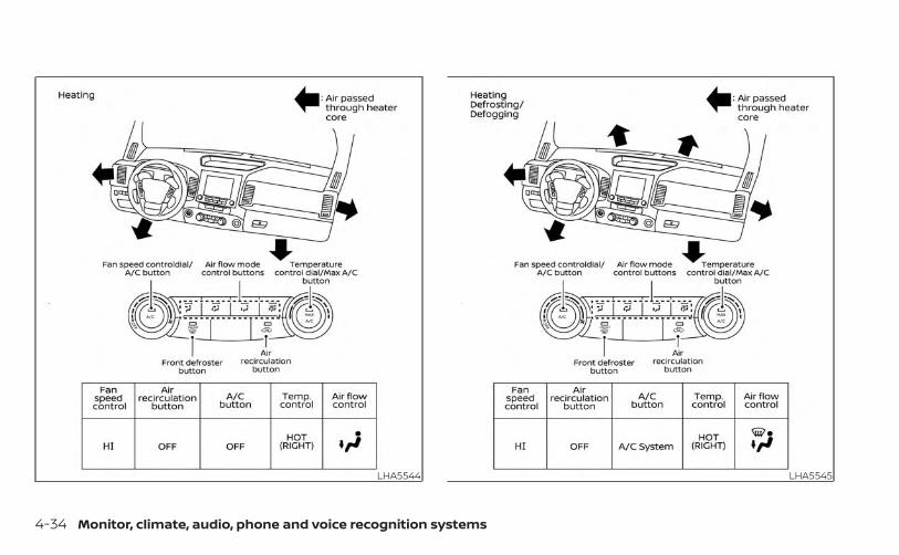
LHA5544 LHA5545
4-34 Monitor, climate, audio, phone and voice recognition systems

LHA5546
Monitor, climate, audio, phone and voice recognition systems 4-35
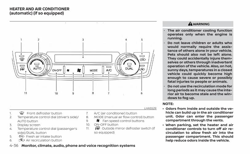
1. Front defroster button2. Temperature control dial (driver’s side)/
AUTO button3. Display screen4. Temperature control dial (passenger’s
side)/DUAL button5. Fresh air intake button6. Air recirculation button
7. A/C (air conditioner) button8. MODE (manual air flow control) button9. Fan speed control buttons10. ON-OFF button11. Outside mirror defroster switch (if
so equipped)
WARNING
• The air conditioner cooling functionoperates only when the engine isrunning.
• Do not leave children or adults whowould normally require the assis-tance of others alone in your vehicle.Pets should also not be left alone.They could accidentally injure them-selves or others through inadvertentoperation of the vehicle. Also, on hot,sunny days, temperatures in a closedvehicle could quickly become highenough to cause severe or possiblyfatal injuries to people or animals.
• Do not use the recirculation mode forlong periods as it may cause the inte-rior air to become stale and the win-dows to fog up.
NOTE:• Odors from inside and outside the ve-
hicle can build up in the air conditionerunit. Odor can enter the passengercompartment through the vents.
• When parking, set the heater and airconditioner controls to turn off air re-circulation to allow fresh air into thepassenger compartment. This shouldhelp reduce odors inside the vehicle.
LHA5529
HEATER AND AIR CONDITIONER(automatic) (if so equipped)
4-36 Monitor, climate, audio, phone and voice recognition systems

AUTOMATIC OPERATIONCooling or heating (auto)This mode may be normally used all yearround as the system automatically worksto keep a constant temperature. Air flowdistribution and fan speed are also con-trolled automatically.1. Press the AUTO button on.
2. Turn the temperature dial to the left orright to set the desired temperature.Driver and passenger temperatures canbe set independently. Press the DUALbutton to activate dual climate controlfunctions. Turn the passenger's sidetemperature control dial to the left orright to set the desired passenger'stemperature.
• Adjust the temperature dial to about 75°F(24°C) for normal operation.
• The temperature of the passenger com-partment will be maintained automati-cally. Air flow distribution, fan speed andA/C on/off are also controlled automati-cally. The A/C button indicator will remainin the last user setting. Under this condi-tion, the indicator light on the A/C buttonindicator will not turn on if the user hadnot selected the A/C button off. If the A/Cbutton is selected in this mode, the A/Cbutton indicator will turn off, but the A/Ccompressor will still be automatically en-abled. For additional information, see “Airflow control” (P. 4-39).
• A visible mist may be seen coming fromthe vents in hot, humid conditions as theair is cooled rapidly. This does not indicatea malfunction.
HeatingWhen you need to heat only, use this mode.1. Press the AUTO button.
2. Turn the temperature control dial to theleft or the right to set the desired tem-perature. Driver and passenger tem-peratures can be set independently.Press the DUAL button to activate dualclimate control functions. Turn the pas-senger’s side temperature control dialto the left or right to set the desiredpassenger’s temperature.
• The temperature of the passenger com-partment will be maintained automati-cally. Air flow distribution and fan speedare also controlled automatically.
• Do not set the temperature lower thanthe outside air temperature. Otherwise,the system may not work properly.
• Not recommended if windows fog up.
Dehumidified defrosting ordefogging1. Press the defroster control button
to turn the system on. The indicator lightin the button will illuminate.
2. The fan will automatically change toblower speed 6. Blower speed can bechanged by pressing the fan speedcontrol button. Increase the fan to 6 or 7 formore aggressive defogging performance.
Monitor, climate, audio, phone and voice recognition systems 4-37

3. Turn the temperature dial to the left orright to set the desired temperature.
• To quickly remove ice from the outside ofthe windows, press the fan speedcontrol button to the maximum position.
• As soon as possible after the windshieldis clean, press the AUTO button to returnto the auto mode.
• When the control is activated, the airconditioner will automatically be turnedon at outside temperatures approxi-mately at or below freezing. This dehu-midifies the air which helps defog thewindshield. Under this condition, the indi-cator light on the A/C button indicator willnot turn on if the user had selected A/Coff prior to entering this mode. Turning offthe air condition via the A/C button is notallowed in this mode. If the A/C buttonindicator was on when entering thismode, and the A/C button is selected inthis mode, the A/C compressor will still beautomatically enabled. The air recircula-tion mode automatically turns off, allow-ing outside air to be drawn into the pas-senger compartment to further improvethe defogging performance.
Remote Engine Start withIntelligent Climate Control (if soequipped)Vehicles equipped with automatic climatecontrols and Remote Engine Start functionmay go into automatic heating or coolingmode when Remote Engine Start is acti-vated depending on outside and cabintemperatures. During this period, the cli-mate control display and buttons will beinoperable until the ignition switch isturned on. In Remote Engine Start defrost-ing mode, the outside mirror defroster (if soequipped) and heated steering wheel (if soequipped) may be activated automatically.
Voice Recognition logic (if soequipped)When the climate control system is on, thefront and rear (if so equipped) fan speedsmay be automatically lowered so thatcommands are more easily recognized.Fan speed can be adjusted using the fanspeed decrease and increasebuttons, if desired.
MANUAL OPERATIONFan speed controlPress the fan speed control buttonsto manually control the fan speed.Press the AUTO button to return to auto-matic control of the fan speed.When adjusting the manual fan from automode, the outlet direction (floor, floor/defrost, vent, bi-level) will still automaticallychange. To fix the outlet to a manual mode,select the desired air flow location usingthe MODE button.
Temperature control dialThe temperature control dial allows you toadjust the temperature of the outlet air. Tolower the temperature, turn the dial to theleft. To increase the temperature, turn thedial to the right. Temperature can be ad-justed on the driver’s and passenger’s side.
Air recirculationPress the air recirculation button torecirculate interior air inside the vehicle when:• driving on a dusty road• to prevent traffic fumes from entering
passenger compartment.
4-38 Monitor, climate, audio, phone and voice recognition systems

• for maximum cooling when using the airconditioning system.
Press the AUTO button to return to auto-matic mode.The air recirculation button will not be acti-vated when the air conditioner is inmode.When the outside temperature exceedsapproximately 70°F (21°C), the air condition-ing system may default to air recirculationmode automatically to reduce overallpower consumption. To exit air recircula-tion mode, select the fresh air intake but-ton to enter fresh air mode.In Floor/Defrost mode, the recirculationbutton can be selected to block outsideodors. However, for maximum defogging inthis mode, it is recommended to turn recir-culation off when possible.
Fresh air intakePress the fresh air intake button todraw outside air into the passengercompartment.
Automatic intake air controlIn the AUTO mode, the intake air will becontrolled automatically. When the outsidetemperature exceeds approximately 70°F(21°C), the air conditioning system may de-fault to air recirculation mode automati-cally to reduce overall power consumption.To exit air recirculation mode, select thefresh air intake button to enter fresh airmode. The air recirculation indicator willturn off, the fresh air indicator will turn on.To manually control the intake air, press the
fresh air intake button. To return to theautomatic control mode if the freshair indicator is illuminated, press and holdthe fresh air intake button for about 2seconds. The fresh air indicator and air re-circulation indicator lights will flash twice,and then the intake air will be controlledautomatically. To return to the automaticcontrol mode if the air recirculationicon is illuminated, press and hold theair recirculation button for about 2 sec-onds. The air recirculation indicatorand fresh air intake indicator lights willflash twice and the intake air will be con-trolled automatically. When OFF is selected,the intake door is automatically forced torecirculate. To get fresh air in OFF mode,select the fresh air intake button. The
MODE can be changed in OFF mode todirect the flow of incoming air if intake is setto fresh.
A/C (air conditioner) buttonStart the engine, turn the fan speedcontrol buttons to the desired position andpress the button to turn on the airconditioner. To turn off the air conditioner,press the button again. In automode, the air conditioner will be on even ifthe button indicator is off at tem-peratures approximately at or abovefreezing.The air conditioner cooling function op-erates only when the engine is running.
Air flow controlPress the MODE button to manually controlair flow and select the air outlet.
— Air flows from center and sidevents.
— Air flows from center and sidevents and foot outlets.
— Air flows mainly from foot out-lets.
— Air flows from defroster and footoutlets.
Monitor, climate, audio, phone and voice recognition systems 4-39

To turn system offPress the ON-OFF button.
Outside mirror defroster switch(if so equipped)For additional information, see “Outsidemirror defroster switch” (P. 2-38).
OPERATING TIPSThe sunload sensor (if so equipped) O1 , lo-cated on the top center of the instrumentpanel, helps the system maintain a con-stant temperature. Do not put anything onor around this sensor.
• When the climate system is in automaticoperation and the engine coolant tem-perature and outside air temperatureare low, the air flow outlet may default todefroster mode for approximately 2 min-utes 30 seconds. This is not a malfunc-tion. After the engine coolant tempera-ture warms up, the air flow outlet willreturn to foot mode and operation willcontinue normally.
• When the outside and interior cabin tem-peratures are moderate to high, the in-take setting may default to turn off airrecirculation to allow fresh air into thepassenger compartment. You may no-tice air flow from the foot mode, bi-levelmode, or side demist vent outlets for amaximum of 15 seconds. This may occurwhen previous climate setting was sys-tem off. This is not a malfunction. Afterthe initial warm air is expelled, the intakewill return to automatic control, air flowoutlet will return to previous settings, andoperation will continue normally. To exit,press any climate control button.
• Keep the windows closed while the airconditioner is in operation.
• If you feel that the air flow mode you haveselected and the outlets the air is comingout do not match, select the mode.
LHA5537
4-40 Monitor, climate, audio, phone and voice recognition systems

• When you change the air flow mode, youmay feel air flow from the foot outlets forjust a moment. This is not a malfunction.
• When the ignition is placed in the ON po-sition, in some fogging or high cabintemp conditions, air may flow automati-cally to the foot outlets for 3 to 7 secondsto purge the hot air in the system.
The air conditioner system in your NISSANvehicle is charged with a refrigerant de-signed with the environment in mind.This refrigerant does not harm theearth's ozone layer.Special charging equipment and lubricant isrequired when servicing your NISSAN airconditioner. Using improper refrigerants orlubricants will cause severe damage to yourair conditioner system. For additional infor-mation, see “Air conditioner system refriger-ant and oil recommendations” (P. 10-8).It is recommended that you visit a NISSANdealer to service your “environmentallyfriendly” air conditioning system.
WARNING
The air conditioner system contains re-frigerant under high pressure. To avoidpersonal injury, any air conditioner ser-vice should be done only by an experi-enced technician with proper equipment.
The vehicle is equipped with a shark finantenna.
SERVICING AIR CONDITIONER ANTENNA
Monitor, climate, audio, phone and voice recognition systems 4-41

When installing a CB, ham radio or carphone in your vehicle, be sure to observethe following precautions; otherwise, thenew equipment may adversely affect theengine control system and other electronicparts.
WARNING
• A cellular phone should not be usedfor any purpose while driving so fullattention may be given to vehicle op-eration. Some jurisdictions prohibitthe use of cellular phones whiledriving.
• If you must make a call while yourvehicle is in motion, the hands freecellular phone operational mode ishighly recommended. Exercise ex-treme caution at all times so full at-tention may be given to vehicleoperation.
• If you are unable to devote full atten-tion to vehicle operation while talk-ing on the phone, pull off the road toa safe location and stop your vehicle.
CAUTION
• Keep the antenna as far away as pos-sible from the electronic controlmodules.
• Keep the antenna wire more than 8 in(20 cm) away from the electroniccontrol system harnesses. Do notroute the antenna wire next to anyharness.
• Adjust the antenna standing-waveratio as recommended by themanufacturer.
• Connect the ground wire from the CBradio chassis to the body.
• For additional information, it is rec-ommended that you visit a NISSANdealer for servicing.
“Made for iPod”, “Made for iPhone” and“Made for iPad” mean that an electronicaccessory has been designed to connectspecifically to iPod, iPhone or iPad, respec-tively, and has been certified by the devel-oper to meet Apple performance stan-dards. Apple is not responsible for theoperation of this device or its compliancewith safety and regulatory standards.Please note that the use of this accessorywith iPod, iPhone or iPad may affect wire-less performance.iPad, iPhone, iPod classic, iPod nano, iPodshuffle and iPod touch are trademarks ofApple Inc., registered in the U.S. and othercountries. Lightning is a trademark ofApple Inc.
CAR PHONE OR CB RADIO iPod®/iPhone®
4-42 Monitor, climate, audio, phone and voice recognition systems

5 Starting and driving
Precautions when starting and driving . . . . . . . . . . 5-4Exhaust gas (carbon monoxide) . . . . . . . . . . . . . . 5-4Three-way catalyst . . . . . . . . . . . . . . . . . . . . . . . . . . . 5-5Tire Pressure Monitoring System(TPMS) . . . . . . . . . . . . . . . . . . . . . . . . . . . . . . . . . . . . . . . 5-5On-pavement and off-road drivingprecautions . . . . . . . . . . . . . . . . . . . . . . . . . . . . . . . . . . 5-9Avoiding collision and rollover . . . . . . . . . . . . . . . . 5-9Off-road recovery . . . . . . . . . . . . . . . . . . . . . . . . . . . . 5-9Rapid air pressure loss . . . . . . . . . . . . . . . . . . . . . . 5-10Drinking alcohol/drugs and driving . . . . . . . . . . .5-11Driving safety precautions . . . . . . . . . . . . . . . . . . . .5-11
Push-button ignition switch . . . . . . . . . . . . . . . . . . . . 5-13Operating range . . . . . . . . . . . . . . . . . . . . . . . . . . . . 5-14Push-button ignition switch positions . . . . . . . 5-14Emergency engine shut off . . . . . . . . . . . . . . . . . . 5-15NISSAN Intelligent Key® batterydischarge . . . . . . . . . . . . . . . . . . . . . . . . . . . . . . . . . . . 5-16NISSAN Vehicle Immobilizer System . . . . . . . . . 5-16
Before starting the engine . . . . . . . . . . . . . . . . . . . . . 5-17Starting the engine . . . . . . . . . . . . . . . . . . . . . . . . . . . . . 5-17
Remote Engine Start (if so equipped) . . . . . . . . 5-18Driving the vehicle . . . . . . . . . . . . . . . . . . . . . . . . . . . . . . 5-18
Engine protection mode . . . . . . . . . . . . . . . . . . . . 5-18Automatic transmission (A/T) . . . . . . . . . . . . . . . 5-19
Parking brake . . . . . . . . . . . . . . . . . . . . . . . . . . . . . . . . . . 5-24Traffic Sign Recognition (TSR) (if so equipped) . . . 5-25
System operation . . . . . . . . . . . . . . . . . . . . . . . . . . . 5-26Turning the Traffic Sign Recognition(TSR) system on and off . . . . . . . . . . . . . . . . . . . . . 5-27System temporarily unavailable . . . . . . . . . . . . . 5-27System malfunction . . . . . . . . . . . . . . . . . . . . . . . . . 5-27System maintenance . . . . . . . . . . . . . . . . . . . . . . . 5-27
Lane Departure Warning (LDW) (if soequipped) . . . . . . . . . . . . . . . . . . . . . . . . . . . . . . . . . . . . . . 5-28
LDW system operation . . . . . . . . . . . . . . . . . . . . . . 5-29How to enable/disable the LDW system . . . . . 5-30LDW system limitations . . . . . . . . . . . . . . . . . . . . . 5-30System temporarily disabled . . . . . . . . . . . . . . . . 5-31System malfunction . . . . . . . . . . . . . . . . . . . . . . . . . 5-32System maintenance . . . . . . . . . . . . . . . . . . . . . . . 5-32
Blind Spot Warning (BSW) (if so equipped) . . . . . . . 5-33BSW system operation . . . . . . . . . . . . . . . . . . . . . . 5-34How to enable/disable the BSW system . . . . . 5-35BSW system limitations . . . . . . . . . . . . . . . . . . . . . 5-36BSW driving situations . . . . . . . . . . . . . . . . . . . . . . . 5-37System temporarily unavailable . . . . . . . . . . . . . 5-40System maintenance . . . . . . . . . . . . . . . . . . . . . . . 5-41
Rear Cross Traffic Alert (RCTA) (if so equipped) . . 5-43RCTA system operation . . . . . . . . . . . . . . . . . . . . . 5-43

How to enable/disable the RCTAsystem . . . . . . . . . . . . . . . . . . . . . . . . . . . . . . . . . . . . . . 5-45RCTA system limitations . . . . . . . . . . . . . . . . . . . . . 5-46System temporarily unavailable . . . . . . . . . . . . .5-48System maintenance . . . . . . . . . . . . . . . . . . . . . . . 5-49
Cruise control (if so equipped) . . . . . . . . . . . . . . . . . . 5-51Precautions on cruise control . . . . . . . . . . . . . . . 5-51Cruise control operations . . . . . . . . . . . . . . . . . . . 5-51
Intelligent Cruise Control (if so equipped) . . . . . . . 5-53How to select the cruise control mode . . . . . . 5-55Vehicle-to-vehicle distance controlmode . . . . . . . . . . . . . . . . . . . . . . . . . . . . . . . . . . . . . . . 5-55Vehicle-to-vehicle distance controlmode operation . . . . . . . . . . . . . . . . . . . . . . . . . . . . . 5-56Vehicle-to-vehicle distance controlmode switches . . . . . . . . . . . . . . . . . . . . . . . . . . . . .5-58Vehicle-to-vehicle distance controlmode limitations . . . . . . . . . . . . . . . . . . . . . . . . . . . . 5-64System temporarily unavailable . . . . . . . . . . . . .5-68System maintenance . . . . . . . . . . . . . . . . . . . . . . . 5-70Conventional (fixed speed) cruisecontrol mode . . . . . . . . . . . . . . . . . . . . . . . . . . . . . . . 5-72
Rear Automatic Braking (RAB) (if so equipped) . . 5-76RAB system operation . . . . . . . . . . . . . . . . . . . . . . . 5-77Turning the RAB system on/off . . . . . . . . . . . . . . 5-78RAB system limitations . . . . . . . . . . . . . . . . . . . . . . 5-79System malfunction . . . . . . . . . . . . . . . . . . . . . . . . .5-80System maintenance . . . . . . . . . . . . . . . . . . . . . . . 5-81
Automatic Emergency Braking (AEB) withPedestrian Detection . . . . . . . . . . . . . . . . . . . . . . . . . . . 5-81
AEB with Pedestrian Detection systemoperation . . . . . . . . . . . . . . . . . . . . . . . . . . . . . . . . . . . 5-82Turning the AEB with PedestrianDetection system ON/OFF . . . . . . . . . . . . . . . . . .5-84AEB with Pedestrian Detection systemlimitations . . . . . . . . . . . . . . . . . . . . . . . . . . . . . . . . . .5-85System temporarily unavailable . . . . . . . . . . . . .5-88System malfunction . . . . . . . . . . . . . . . . . . . . . . . . .5-90System maintenance . . . . . . . . . . . . . . . . . . . . . . .5-90
Intelligent Forward Collision Warning (I-FCW) . . . 5-92I-FCW system operation . . . . . . . . . . . . . . . . . . . . . 5-94Turning the I-FCW system on/off . . . . . . . . . . . . 5-95I-FCW system limitations . . . . . . . . . . . . . . . . . . . . 5-96System temporarily unavailable . . . . . . . . . . . . 5-101

System malfunction . . . . . . . . . . . . . . . . . . . . . . . . 5-102System maintenance . . . . . . . . . . . . . . . . . . . . . . 5-103
Intelligent Driver Alertness (I-DA) . . . . . . . . . . . . . . . 5-104Intelligent Driver Alertness systemoperation . . . . . . . . . . . . . . . . . . . . . . . . . . . . . . . . . . 5-105How to enable/disable the IntelligentDriver Alertness (I-DA) system . . . . . . . . . . . . . . 5-106Intelligent Driver Alertness (I-DA)system limitations . . . . . . . . . . . . . . . . . . . . . . . . . 5-106
Break-in schedule . . . . . . . . . . . . . . . . . . . . . . . . . . . . . 5-107Fuel efficient driving tips . . . . . . . . . . . . . . . . . . . . . . . 5-108Increasing fuel economy . . . . . . . . . . . . . . . . . . . . . . 5-109
Using 4–wheel drive (4WD)(if so equipped) . . . . . . . . . . . . . . . . . . . . . . . . . . . . . . . . 5-109
Transfer case shifting procedures . . . . . . . . . . 5-110Electronic locking rear differential (E-Lock)system (if so equipped) . . . . . . . . . . . . . . . . . . . . . . . . 5-115Eco Drive Report (if so equipped) . . . . . . . . . . . . . . 5-116Parking/parking on hills . . . . . . . . . . . . . . . . . . . . . . . .5-117Power steering . . . . . . . . . . . . . . . . . . . . . . . . . . . . . . . . 5-118Brake system . . . . . . . . . . . . . . . . . . . . . . . . . . . . . . . . . 5-118
Brake precautions . . . . . . . . . . . . . . . . . . . . . . . . . . 5-118
Anti-lock Braking System (ABS) . . . . . . . . . . . . . 5-119Active Brake Limited Slip (ABLS) system . . . . . . . 5-120Vehicle Dynamic Control (VDC) system . . . . . . . . 5-121
Brake force distribution . . . . . . . . . . . . . . . . . . . . 5-122Hill descent control system (if so equipped) . . . 5-123Hill start assist system . . . . . . . . . . . . . . . . . . . . . . . . 5-124Rear Sonar System (RSS) (if so equipped) . . . . . . 5-125
System operation . . . . . . . . . . . . . . . . . . . . . . . . . . 5-126How to enable/disable the RSS . . . . . . . . . . . . . 5-127Sonar limitations . . . . . . . . . . . . . . . . . . . . . . . . . . . 5-127System temporarily unavailable . . . . . . . . . . . . 5-128System maintenance . . . . . . . . . . . . . . . . . . . . . . 5-128
Cold weather driving . . . . . . . . . . . . . . . . . . . . . . . . . . 5-129Freeing a frozen door lock . . . . . . . . . . . . . . . . . . 5-129Antifreeze . . . . . . . . . . . . . . . . . . . . . . . . . . . . . . . . . . 5-129Battery . . . . . . . . . . . . . . . . . . . . . . . . . . . . . . . . . . . . . 5-129Draining of coolant water . . . . . . . . . . . . . . . . . . 5-129Tire equipment . . . . . . . . . . . . . . . . . . . . . . . . . . . . . 5-129Special winter equipment . . . . . . . . . . . . . . . . . . 5-130Driving on snow or ice . . . . . . . . . . . . . . . . . . . . . . 5-130Engine block heater (if so equipped) . . . . . . . . 5-130

WARNING
• Do not leave children or adults whowould normally require the assis-tance of others alone in your vehicle.Pets should also not be left alone.They could accidentally injure them-selves or others through inadvertentoperation of the vehicle. Also, on hot,sunny days, temperatures in a closedvehicle could quickly become highenough to cause severe or possiblyfatal injuries to people or animals.
• Properly secure all cargo with ropesor straps to help prevent it from slid-ing or shifting. Do not place cargohigher than the seatbacks. In a sud-den stop or collision, unsecuredcargo could cause personal injury.
EXHAUST GAS (carbon monoxide)
WARNING
• Do not breathe exhaust gases; theycontain colorless and odorless car-bon monoxide. Carbon monoxide isdangerous. It can cause uncon-sciousness or death.
• If you suspect that exhaust fumesare entering the vehicle, drive with allwindows fully open, and have the ve-hicle inspected immediately.
• Do not run the engine in closedspaces such as a garage.
• Do not park the vehicle with the en-gine running for any extended lengthof time.
• Keep the rear vent windows, lift-gates, doors and trunk lids (if soequipped) closed while driving, oth-erwise exhaust gases could bedrawn into the passenger compart-ment. If you must drive with one ofthese open, follow these precau-tions:1. Open all the windows.2. Set the air recirculation but-
ton to off and the fan control dialto high to circulate the air.
• If electrical wiring or other cable con-nections must pass to a trailerthrough the seal on the liftgate or thebody, follow the manufacturer's rec-ommendation to prevent carbonmonoxide entry into the vehicle.
• The exhaust system and body shouldbe inspected by a qualified mechanicwhenever:a. The vehicle is raised for service.b. You suspect that exhaust fumes
are entering into the passengercompartment.
c. You notice a change in the soundof the exhaust system.
d. You have had an accident involv-ing damage to the exhaust sys-tem, underbody, or rear of thevehicle.
• If a special body, camper, or otherequipment is added for recreationalor other usage, follow the manufac-turer's recommendation to preventcarbon monoxide entry into the ve-hicle. Do not occupy these areaswhile the engine is running even ifthe vehicle is parked. Some recre-ational vehicle appliances such asstoves, refrigerators, heaters, etc.may also generate carbon monoxide.
PRECAUTIONS WHEN STARTING ANDDRIVING
5-4 Starting and driving

THREE-WAY CATALYSTThe three-way catalyst is an emission con-trol device installed in the exhaust system.Exhaust gases in the three-way catalystare burned at high temperatures to helpreduce pollutants.
WARNING
• The exhaust gas and the exhaustsystem are very hot. Keep people,animals or flammable materialsaway from the exhaust systemcomponents.
• Do not stop or park the vehicle overflammable materials such as drygrass, waste paper or rags. They mayignite and cause a fire.
CAUTION
• Do not use leaded gasoline. Depositsfrom leaded gasoline will seriouslyreduce the three-way catalyst's abil-ity to help reduce exhaust pollutants.
• Keep your engine tuned up. Malfunc-tions in the ignition, fuel injection, orelectrical systems can cause overrichfuel flow into the three-way catalyst,causing it to overheat. Do not keepdriving if the engine misfires, or if no-ticeable loss of performance or otherunusual operating conditions are de-tected. Have the vehicle inspectedpromptly. It is recommended thatyou visit a NISSAN dealer for thisservice.
• Avoid driving with an extremely lowfuel level. Running out of fuel couldcause the engine to misfire, damag-ing the three-way catalyst.
• Do not race the engine while warm-ing it up.
• Do not push or tow your vehicle tostart the engine.
TIRE PRESSURE MONITORINGSYSTEM (TPMS)Each tire, including the spare (if provided),should be checked monthly when cold andinflated to the inflation pressure recom-mended by the vehicle manufacturer onthe vehicle placard or tire inflation pressurelabel. (If your vehicle has tires of a differentsize than the size indicated on the vehicle
placard or tire inflation pressure label, youshould determine the proper tire inflationpressure for those tires.)As an added safety feature, your vehiclehas been equipped with a Tire PressureMonitoring System (TPMS) that illuminatesa low tire pressure telltale when one ormore of your tires is significantly under-inflated. Accordingly, when the low tirepressure telltale illuminates, you shouldstop and check all your tires as soon aspossible, and inflate them to the properpressure. Driving on a significantly under-inflated tire causes the tire to overheat andcan lead to tire failure. Under-inflation alsoreduces fuel efficiency and tire tread life,and may affect the vehicle’s handling andstopping ability.Please note that the TPMS is not a substi-tute for proper tire maintenance, and it isthe driver’s responsibility to maintain cor-rect tire pressure, even if under-inflationhas not reached the level to trigger illumi-nation of the TPMS low tire pressure telltale.Your vehicle has also been equipped with aTPMS malfunction indicator to indicatewhen the system is not operating properly.The TPMS malfunction indicator is com-bined with the low tire pressure telltale.When the system detects a malfunction,
Starting and driving 5-5

the telltale will flash for approximately oneminute and then remain continuously illu-minated. This sequence will continue uponsubsequent vehicle start-ups as long asthe malfunction exists. When the malfunc-tion indicator is illuminated, the systemmay not be able to detect or signal low tirepressure as intended. TPMS malfunctionsmay occur for a variety of reasons, includ-ing the installation of replacement or alter-nate tires or wheels on the vehicle thatprevent the TPMS from functioning prop-erly. Always check the TPMS malfunctiontelltale after replacing one or more tires orwheels on your vehicle to ensure that thereplacement or alternate tires and wheelsallow the TPMS to continue to functionproperly.Additional information:• When using a wheel without the TPMS
such as a spare tire, the TPMS does notmonitor the tire pressure of the spare tire.
• The TPMS will activate only when the ve-hicle is driven at speeds above 16 mph (25km/h). Also, this system may not detect asudden drop in tire pressure (for example,a flat tire while driving).
• The low tire pressure warning light doesnot automatically turn off when the tirepressure of your tires are adjusted. Afterthe tires are inflated to the recom-mended pressure, the vehicle must bedriven at speeds above 16 mph (25 km/h)to activate the TPMS and turn off the lowtire pressure warning light. Use a tirepressure gauge to check the tirepressure.
• The “Tire Pressure Low — Add Air” warningappears in the vehicle information dis-play when the low tire pressure warninglight is illuminated and low tire pressure isdetected. The “Tire Pressure Low — AddAir” warning turns off when the low tirepressure warning light turns off.
• The “Tire Pressure Low — Add Air” warningappears each time the ignition switch isplaced in the ON position as long as thelow tire pressure warning light remainsilluminated.
• The “Tire Pressure Low — Add Air” warningdoes not appear if the low tire pressurewarning light illuminates to indicate aTPMS malfunction.
• Tire pressure rises and falls depending onthe heat caused by the vehicle’s opera-tion and the outside temperature. Do notreduce the tire pressure after driving be-cause the tire pressure rises after driving.Low outside temperature can lower thetemperature of the air inside the tirewhich can cause a lower tire inflationpressure. This may cause the low tirepressure warning light to illuminate. If thewarning light illuminates, check the tirepressure for all four tires.
• The Tire and Loading information label islocated in the driver's door opening.
For additional information, see “Low tirepressure warning light” (P. 2-15) and “TirePressure Monitoring System (TPMS)” (P. 6-3).
WARNING
• Radio waves could adversely affectelectric medical equipment. Thosewho use a pacemaker should contactthe electric medical equipmentmanufacturer for the possible influ-ences before use.
5-6 Starting and driving

• If the low tire pressure warning lightilluminates while driving, avoid sud-den steering maneuvers or abruptbraking, reduce vehicle speed, pulloff the road to a safe location andstop the vehicle as soon as possible.Driving with under-inflated tires maypermanently damage the tires andincrease the likelihood of tire failure.Serious vehicle damage could occurand may lead to an accident andcould result in serious personal in-jury. Check the tire pressure for allfour tires. Adjust the tire pressure tothe recommended COLD tire pres-sure shown on the Tire and Loadinginformation label to turn the low tirepressure warning light off. If you havea flat tire, replace it with a spare tireas soon as possible. For additionalinformation, see “Flat tire” (P. 6-3) forchanging a flat tire.
• When using a wheel without theTPMS such as a spare tire, when aspare tire is mounted or a wheel isreplaced, the TPMS will not functionand the low tire pressure warninglight will flash for approximately 1minute. The light will remain on after1 minute. Have your tires replacedand/or TPMS system reset as soon aspossible. It is recommended that youvisit a NISSAN dealer for this service.
• Replacing tires with those not origi-nally specified by NISSAN could af-fect the proper operation of theTPMS.
• Do not inject any tire liquid or aerosoltire sealant into the tires, as this maycause a malfunction of the tire pres-sure sensors.
CAUTION
Do not place metalized film or anymetal parts (antenna, etc.) on the win-dows. This may cause poor reception ofthe signals from the tire pressure sen-sors, and the TPMS will not functionproperly.
Some devices and transmitters may tem-porarily interfere with the operation of theTPMS and cause the low tire pressurewarning light to illuminate.Some examples are:• Facilities or electric devices using similar
radio frequencies are near the vehicle.• If a transmitter set to similar frequencies
is being used in or near the vehicle.• If a computer (or similar equipment) or a
DC/AC converter is being used in or nearthe vehicle.
The low tire pressure warning light mayilluminate in the following cases:• If the vehicle is equipped with a wheel and
tire without TPMS.• If the TPMS has been replaced and the ID
has not been registered.• If the wheel is not originally specified by
NISSAN.
Starting and driving 5-7

FCC Notice:For USA:This device complies with Part 15 of theFCC Rules. Operation is subject to the fol-lowing two conditions: (1) This devicemay not cause harmful interference, and(2) this device must accept any interfer-ence received, including interferencethat may cause undesired operation.
NOTE:Changes or modifications not expresslyapproved by the party responsible forcompliance could void the user's au-thority to operate the equipment.For Canada:This device contains license-exempttransmitter(s)/receiver(s) that complywith Innovation, Science and EconomicDevelopment Canada’s licence-exemptRSS(s). Operation is subject to the fol-lowing two conditions: (1) This devicemay not cause interference. (2) This de-vice must accept any interference, in-cluding interference that may cause un-desired operation of the device.
TPMS with Easy-Fill Tire AlertWARNING
After rotating the tires, do not use theEasy-Fill Tire Alert to adjust the tirepressure. Instead use a gauge to adjustthe tires to the correct pressure in ac-cordance with Tire and Loading infor-mation label.
When adding air to an under-inflated tire,the TPMS with Easy-Fill Tire Alert providesvisual and audible signals outside the ve-hicle to help you inflate the tires to the rec-ommended COLD tire pressure.Vehicle set-up1. Park the vehicle in a safe and level place.
2. Apply the parking brake and place theshift lever in the P (Park) position.
3. Place the ignition switch in the ON posi-tion. Do not start the engine.
Operation1. Add air to the tire.
2. After a few seconds, the hazard indica-tors will start flashing.
3. When the designated pressure isreached, the horn beeps once and thehazard indicators stop flashing.
4. Perform the above steps for each tire.• If the tire is over-inflated more than
approximately 4 psi (30 kPa), the hornbeeps and the hazard indicators flashthree times. To correct the pressure,push the core of the valve stem on thetire briefly to release pressure. Whenthe pressure reaches the designatedpressure, the horn beeps once.
• If the hazard indicator does not flashwithin approximately 15 seconds afterstarting to inflate the tire, it indicatesthat the Easy-Fill Tire Alert is notoperating.
• The TPMS will not activate the Easy-FillTire Alert under the following condi-tions:– If there is interference from an exter-
nal device or transmitter.– The air pressure from the inflation
device is not sufficient to inflate thetire.
– There is a malfunction in the TPMS.– There is a malfunction in the horn or
hazard indicators.
5-8 Starting and driving

– The identification code of the tirepressure sensor is not registered tothe system.
– The battery of the tire pressure sen-sor is low.
• If the Easy-Fill Tire Alert does not oper-ate due to TPMS interference, movethe vehicle about 3 ft (1 m) backwardor forward and try again.
If the Easy-Fill Tire Alert is not working, use atire pressure gauge.
ON-PAVEMENT AND OFF-ROADDRIVING PRECAUTIONSUtility vehicles have a significantlyhigher rollover rate than other types ofvehicles.They have higher ground clearance thanpassenger cars to make them capable ofperforming in a variety of on-pavementand off-road applications. This gives thema higher center of gravity than ordinary ve-hicles. An advantage of higher groundclearance is a better view of the road, allow-ing you to anticipate problems. However,they are not designed for cornering at thesame speeds as conventional 2-WheelDrive vehicles any more than low-slungsports cars are designed to perform satis-factorily under off-road conditions. If at all
possible, avoid sharp turns at high speeds.As with other vehicles of this type, failure tooperate this vehicle correctly may result inloss of control or vehicle rollover.In a rollover crash, an unbelted person issignificantly more likely to die than a per-son wearing a seat belt.For additional information, see “Drivingsafety precautions” (P. 5-11).
AVOIDING COLLISION ANDROLLOVER
WARNING
Failure to operate this vehicle in a safeand prudent manner may result in lossof control or an accident.
Be alert and drive defensively at all times.Obey all traffic regulations. Avoid excessivespeed, high speed cornering, or suddensteering maneuvers, because these drivingpractices could cause you to lose control ofyour vehicle.As with any vehicle, loss of control couldresult in a collision with other vehicles orobjects or cause the vehicle to roll over,particularly if the loss of control causesthe vehicle to slide sideways.
Be attentive at all times, and avoid drivingwhen tired. Never drive when under the in-fluence of alcohol or drugs (including pre-scription or over-the-counter drugs whichmay cause drowsiness). Always wear yourseat belt as outlined in the “Safety – Seats,seat belts and supplemental restraint sys-tem” section of this manual, and also in-struct your passengers to do so.Seat belts help reduce the risk of injury incollisions and rollovers.In a rollover crash, an unbelted person issignificantly more likely to die than aperson wearing a seat belt.
OFF-ROAD RECOVERYWhile driving, the right side or left sidewheels may unintentionally leave the roadsurface. If this occurs, maintain control ofthe vehicle by following the procedure be-low. Please note that this procedure is onlya general guide. The vehicle must be drivenas appropriate based on the conditions ofthe vehicle, road and traffic.1. Remain calm and do not overreact.
2. Do not apply the brakes.
3. Maintain a firm grip on the steeringwheel with both hands and try to hold astraight course.
Starting and driving 5-9

4. When appropriate, slowly release the ac-celerator pedal to gradually slow thevehicle.
5. If there is nothing in the way, steer thevehicle to follow the road while vehiclespeed is reduced. Do not attempt todrive the vehicle back onto the road sur-face until vehicle speed is reduced.
6. When it is safe to do so, gradually turnthe steering wheel until both tires returnto the road surface. When all tires are onthe road surface, steer the vehicle tostay in the appropriate driving lane.• If you decide that it is not safe to return
the vehicle to the road surface basedon vehicle, road or traffic conditions,gradually slow the vehicle to a stop ina safe place off the road.
RAPID AIR PRESSURE LOSSRapid air pressure loss or a “blow-out” canoccur if the tire is punctured or is damageddue to hitting a curb or pothole. Rapid airpressure loss can also be caused by drivingon under-inflated tires.Rapid air pressure loss can affect the han-dling and stability of the vehicle, especiallyat highway speeds.
Help prevent rapid air pressure loss bymaintaining the correct air pressure andvisually inspecting the tires for wear anddamage. For additional information, see“Wheels and tires” (P. 8-31). If a tire rapidlyloses air pressure or “blows-out” while driv-ing, maintain control of the vehicle by fol-lowing the procedure below. Please notethat this procedure is only a general guide.The vehicle must be driven as appropriatebased on the conditions of the vehicle, roadand traffic.
WARNING
The following actions can increase thechance of losing control of the vehicle ifthere is a sudden loss of tire air pres-sure. Losing control of the vehicle maycause a collision and result in personalinjury.• The vehicle generally moves or pulls
in the direction of the flat tire.• Do not rapidly apply the brakes.• Do not rapidly release the accelerator
pedal.• Do not rapidly turn the steering
wheel.
1. Remain calm and do not overreact.
2. Maintain a firm grip on the steeringwheel with both hands and try to hold astraight course.
3. When appropriate, slowly release the ac-celerator pedal to gradually slow thevehicle.
4. Gradually steer the vehicle to a safe lo-cation off the road and away from trafficif possible.
5. Lightly apply the brake pedal to gradu-ally stop the vehicle.
6. Turn on the hazard warning flashers andcontact a roadside emergency serviceto change the tire. For additional infor-mation, see “Changing a flat tire” (P. 6-3).
5-10 Starting and driving

DRINKING ALCOHOL/DRUGS ANDDRIVING
WARNING
Never drive under the influence of alco-hol or drugs. Alcohol in the blood-stream reduces coordination, delaysreaction time and impairs judgement.Driving after drinking alcohol increasesthe likelihood of being involved in anaccident injuring yourself and others.Additionally, if you are injured in an ac-cident, alcohol can increase the sever-ity of the injury.
NISSAN is committed to safe driving. How-ever, you must choose not to drive underthe influence of alcohol. Every year thou-sands of people are injured or killed inalcohol-related collisions. Although the lo-cal laws vary on what is considered to belegally intoxicated, the fact is that alcoholaffects all people differently and mostpeople underestimate the effects ofalcohol.
Remember, drinking and driving don't mix!That is true for drugs (over-the-counter,prescription) and illegal drugs, too. Don'tdrive if your ability to operate your vehicle isimpaired by alcohol, drugs, or some otherphysical condition.
DRIVING SAFETY PRECAUTIONSYour NISSAN is designed for both normaland off-road use. However, avoid driving indeep water or mud as your NISSAN ismainly designed for leisure use, unlike aconventional off-road vehicle.Remember that 2-Wheel Drive models areless capable than 4-Wheel Drive (4WD)models for rough road driving and extrica-tion when stuck in deep snow or mud, orthe like.Please observe the following precautions:
WARNING
• Drive carefully when off the road andavoid dangerous areas. Every personwho drives or rides in this vehicleshould be seated with their seat beltfastened. This will keep you and yourpassengers in position when drivingover rough terrain.
• Do not drive across steep slopes. In-stead drive either straight up orstraight down the slopes. Off-roadvehicles can tip over sideways muchmore easily than they can forward orbackward.
• Many hills are too steep for any ve-hicle. If you drive up them, you maystall. If you drive down them, you maynot be able to control your speed. Ifyou drive across them, you may rollover.
• Do not shift gears while driving ondownhill grades as this could causeloss of control of the vehicle.
• Stay alert when driving to the top of ahill. At the top there could be a drop-off or other hazard that could causean accident.
• If your engine stalls or you cannotmake it to the top of a steep hill,never attempt to turn around. Yourvehicle could tip or roll over. Alwaysback straight down in R (Reverse)gear. Never back down in N (Neutral),using only the brake, as this couldcause loss of control.
Starting and driving 5-11

• Heavy braking going down a hillcould cause your brakes to overheatand fade, resulting in loss of controland an accident. Apply brakes lightlyand use a low gear to control yourspeed.
• Unsecured cargo can be thrownaround when driving over rough ter-rain. Properly secure all cargo so itwill not be thrown forward and causeinjury to you or your passengers.
• To avoid raising the center of gravityexcessively, do not exceed the ratedcapacity of the roof rack (if soequipped) and evenly distribute theload. Secure heavy loads in the cargoarea as far forward and as low aspossible. Do not equip the vehiclewith tires larger than specified in thismanual. This could cause your ve-hicle to roll over.
• Do not grip the inside or spokes ofthe steering wheel when driving off-road. The steering wheel could movesuddenly and injure your hands. In-stead drive with your fingers andthumbs on the outside of the rim.
• Before operating the vehicle, ensurethat the driver and all passengershave their seat belts fastened.
• Always drive with the floor mats (if soequipped) in place as the floor maybecome hot.
• Lower your speed when encounter-ing strong crosswinds. With a highercenter of gravity, your NISSAN is moreaffected by strong side winds. Slowerspeeds ensure better vehicle control.
• Do not drive beyond the perfor-mance capability of the tires, evenwith 4WD engaged (if so equipped).
• For 4WD equipped vehicles, do notattempt to raise two wheels off theground and shift the transmission toany drive or reverse position with theengine running. Doing so may resultin drivetrain damage or unexpectedvehicle movement which could resultin serious vehicle damage or per-sonal injury.
• Do not attempt to test a 4WDequipped vehicle on a 2-wheel dyna-mometer (such as the dynamom-eters used by some states for emis-sions testing), or similar equipmenteven if the other two wheels areraised off the ground. Make sure youinform test facility personnel thatyour vehicle is equipped with 4WDbefore it is placed on a dynamom-eter. Using the wrong test equipmentmay result in drivetrain damage orunexpected vehicle movementwhich could result in serious vehicledamage or personal injury.
• Accelerating quickly, sharp steeringmaneuvers or sudden braking maycause loss of control.
• If at all possible, avoid sharp turningmaneuvers, particularly at highspeeds. Your NISSAN 4WD vehicle hasa higher center of gravity than a pas-senger car. The vehicle is not de-signed for cornering at the samespeeds as passenger cars. Failure tooperate this vehicle correctly couldresult in loss of control and/or a roll-over accident.
5-12 Starting and driving

• Always use tires of the same type,size, brand, construction (bias, bias-belted, or radial), and tread patternon all four wheels. Install tire chainson the rear wheels when driving onslippery roads and drive carefully.
• Be sure to check the brakes immedi-ately after driving in mud or water.For additional information, see “Wetbrakes” (P. 5-119).
• Avoid parking your vehicle on steephills. If you get out of the vehicle andit rolls forward, backward or side-ways, you could be injured.
• Whenever you drive off-road throughsand, mud or water as deep as thewheel hub, more frequent mainte-nance may be required. For addi-tional information, see “Maintenanceunder severe operating conditions”(P. 9-7).
WARNING
Do not operate the push-button igni-tion switch while driving the vehicle ex-cept in an emergency. (The engine willstop when the ignition switch is pushedthree consecutive times in quick suc-cession or the ignition switch is pushedand held for more than 2 seconds.) Ifthe engine stops while the vehicle isbeing driven, this could lead to a crashand serious injury.
When the ignition switch is pushed withoutdepressing the brake pedal, the ignitionswitch position will illuminate as follows:Push center:• Once to change to ACC.• Two times to change to ON.• Three times to return to OFF.The ignition switch will automatically re-turn to the LOCK position when any door iseither opened or closed with the switch inthe OFF position.When the ignition switch cannot be placedin the OFF position, proceed as follows:1. Move the shift lever to the P (Park)
position.
2. Push the ignition switch. The ignitionswitch position will change to the ONposition.
3. Push the ignition switch again to theOFF position.
The shift lever can be moved from the P(Park) position if the ignition switch is inthe ON position and the brake pedal isdepressed.If the battery of the vehicle is discharged,the ignition switch cannot be movedfrom the LOCK position.
LSD2645
PUSH-BUTTON IGNITION SWITCH
Starting and driving 5-13

Some indicators and warnings for opera-tion are displayed in the meter. For addi-tional information, see “Warning lights, indi-cator lights and audible reminders” (P. 2-10).
OPERATING RANGEThe Intelligent Key functions can only beused when the Intelligent Key is within thespecified operating range.When the Intelligent Key battery is almostdischarged or strong radio waves are pres-ent near the operating location, the Intelli-gent Key system’s operating range be-comes narrower and may not functionproperly.If the Intelligent Key is within the operatingrange, it is possible for anyone, even some-
one who does not carry the Intelligent Key,to push the ignition switch to start theengine.The operating range of the engine startfunction is inside of the vehicle O1 .• The luggage area is not included in the
operating range, but the Intelligent Keymay function.
• If the Intelligent Key is placed on the in-strument panel or inside the glove box,storage bin or door pocket, the IntelligentKey may not function.
• If the Intelligent Key is placed near thedoor or window outside the vehicle, theIntelligent Key may function.
PUSH-BUTTON IGNITION SWITCHPOSITIONSLOCK (Normal parking position)The ignition switch can only be locked inthis position.The ignition switch will be unlocked when itis pushed to the ON position while carryingthe Intelligent Key.The ignition switch will lock when any dooris opened or closed with the ignitionswitched off.
LSD3854
5-14 Starting and driving

ACC (Accessories)This position activates electrical accesso-ries, such as the radio, when the engine isnot running.ACC has a battery saver feature that willplace the ignition switch in the OFF positionafter a period of time under the followingconditions:• All doors are closed.• The shift lever is in P (Park).• The hazard lamps are off.• The turn signals are off.The battery saver feature will be canceled ifany of the following occur:• Any door is opened.• The shift lever is moved out of the P (Park)
position.• The ignition switch changes position.• The hazard lamps are turned on.
ON (Normal operating position)This position turns on the ignition systemand electrical accessories.ON has a battery saver feature that willplace the ignition switch in the OFF posi-tion, if the vehicle is not running, after sometime under the following conditions:• All doors are closed.• The shift lever is in P (Park).• The hazard lamps are off.• The turn signals are off.The battery saver feature will be canceled ifany of the following occur:• Any door is opened.• The shift lever is moved out of the P (Park)
position.• The ignition switch changes position.• The hazard lamps are turned on.• The turn signals are turned on.
CAUTION
Do not leave the vehicle with the igni-tion switch in the ACC or ON positionwhen the engine is not running for anextended period. This can dischargethe battery.
OFFThe ignition switch is in the OFF positionwhen the engine is turned off using theignition switch.
EMERGENCY ENGINE SHUT OFFTo shut off the engine in an emergencysituation while driving, perform the follow-ing procedure:• Rapidly push the ignition switch three
consecutive times in less than 1.5 sec-onds, or
• Push and hold the ignition switch formore than 2 seconds.
Starting and driving 5-15

NISSAN INTELLIGENT KEY®BATTERY DISCHARGEIf the battery of the NISSAN Intelligent Key®is discharged, or environmental conditionsinterfere with the Intelligent Key operation,start the engine according to the followingprocedure:1. Place the shift lever in the P (Park)
position.
2. Firmly apply the foot brake.
3. Touch the ignition switch with the Intel-ligent Key as illustrated. (A chime willsound.)
After step 3 is performed, when the igni-tion switch is pushed without depress-ing the brake pedal, the ignition switchposition will change to the ON position.
4. Push the ignition switch while depress-ing the brake pedal within 10 secondsafter the chime sounds. The engine willstart.
NOTE:• When the ignition switch is pushed to
the ON position or the engine is startedby the above procedure, the IntelligentKey battery discharge indicator ap-pears in the vehicle information dis-play even when the Intelligent Key isinside the vehicle. This is not a mal-function. To turn off the Intelligent Keybattery discharge indicator, touch theignition switch with the Intelligent Keyagain.
• If the Intelligent Key battery dischargeindicator appears, replace the batteryas soon as possible. For additional in-formation, see “Battery replacement”(P. 8-25).
NISSAN VEHICLE IMMOBILIZERSYSTEMThe NISSAN Vehicle Immobilizer Systemwill not allow the engine to start withoutthe use of the registered key.If the engine fails to start using a registeredkey (for example, when interference iscaused by another registered key, an auto-mated toll road device or automatic pay-ment device on the key ring), restart theengine using the following procedures:1. Leave the ignition switch in the ON posi-
tion for approximately 5 seconds.
2. Place the ignition switch in the OFF orLOCK position, and wait approximately10 seconds.
3. Repeat steps 1 and 2.
4. Restart the engine while holding the de-vice (which may have caused the inter-ference) separate from the registeredkey.
If the no start condition re-occurs, NISSANrecommends placing the registered key ona separate key ring to avoid interferencefrom other devices.
SSD0860
5-16 Starting and driving

• Make sure the area around the vehicle isclear.
• Check fluid levels such as engine oil, cool-ant, brake, and windshield-washer fluidas frequently as possible, or at leastwhenever you refuel.
• Check that all windows and lights areclean.
• Visually inspect tires for their appearanceand condition. Also check tires for properinflation.
• Check that all doors are closed.• Position seat and adjust head
restraints/headrests.• Adjust inside and outside mirrors.• Fasten the seat belt and ask all passen-
gers to do likewise.• Check the operation of warning lights
when the ignition switch is placed in theON position. For additional information,see “Warning lights, indicator lights andaudible reminders” (P. 2-10).
1. Apply the parking brake.
2. Move the shift lever to P (Park) or N (Neu-tral). P (Park) is recommended.The starter is designed not to operateunless the shift lever is in either P(Park) or N (Neutral).
3. Push the ignition switch to the ON posi-tion. Depress the brake pedal and pushthe ignition switch to start the engine.To start the engine immediately, pushand release the ignition switch while de-pressing the brake pedal with the igni-tion switch in any position.• If the engine is very hard to start in
extremely cold weather or when re-starting, depress the acceleratorpedal a little (approximately 1/3 to thefloor) and while holding, crank the en-gine. Release the accelerator pedalwhen the engine starts.
• If the engine is very hard to start be-cause it is flooded, depress the accel-erator pedal all the way to the floorand hold it. Push the ignition switch tothe ON position to start cranking theengine. After 5 or 6 seconds, stopcranking by pushing the ignitionswitch to the LOCK position. Aftercranking the engine, release the accel-
erator pedal. Crank the engine withyour foot off the accelerator pedal bydepressing the brake pedal and push-ing the ignition switch to start the en-gine. If the engine starts, but fails torun, repeat the above procedure.
CAUTION
Do not operate the starter for morethan 15 seconds at a time. If the enginedoes not start, push the ignition switchto the OFF position and wait 10 secondsbefore cranking again, otherwise thestarter could be damaged.
4. Warm-upAllow the engine to idle for at least 30seconds after starting. Do not race theengine while warming it up. Drive at amoderate speed for a short distancefirst, especially in cold weather. In coldweather, keep the engine running for aminimum of 2 to 3 minutes before shut-ting it off. Starting and stopping the en-gine over a short period of time maymake the vehicle more difficult to start.
5. To stop the engine, move the shift leverto the P (Park) position and push theignition switch to the OFF position.
BEFORE STARTING THE ENGINE STARTING THE ENGINE
Starting and driving 5-17
In preparation for the next engine start, theengine may have a slightly delayed shutoffafter placing the ignition switch in theOFF position, depending on the drivingconditions.
NOTE:Care should be taken to avoid situa-tions that can lead to potential batterydischarge and potential no-start con-ditions such as:1. Installation or extended use of elec-
tronic accessories that consume bat-tery power when the engine is notrunning (phone chargers, GPS, DVDplayers, etc.).
2. The vehicle is not driven regularlyand/or only driven short distances.
In these cases, the battery may need tobe charged to maintain battery health.
REMOTE ENGINE START (if soequipped)Vehicles started with the Remote EngineStart require the ignition switch to beplaced in the ON position before the shiftlever can be moved from the P (Park) posi-tion. To place the ignition switch in the ONposition, follow these steps:1. Make sure that the Intelligent Key is on
you.
2. Apply the brake.
3. Push the ignition switch once to the ONposition.
For additional information, see “NISSAN In-telligent Key®” (P. 3-2).
ENGINE PROTECTION MODEThe engine has an engine protection modeto reduce the chance of damage if thecoolant temperature becomes too high(for example, when climbing steep gradesin high temperatures with heavy loads,such as when towing a trailer). When theengine temperature reaches a certainlevel:• The engine coolant temperature gauge
will move toward the H position.• Engine power may be reduced.• The air conditioning cooling function may
be automatically turned off for a shorttime (the blower will continue to operate).
Engine power and, under some conditions,vehicle speed will decrease. Vehicle speedcan be controlled with the acceleratorpedal, but the vehicle may not accelerate atthe desired speed. The transmission willdownshift or upshift as it reaches pre-scribed shift points. You can also shiftmanually.As driving conditions change and enginecoolant temperature is reduced, vehiclespeed can be increased using the accel-erator pedal, and the air conditioning cool-ing function will automatically be turnedback on.
DRIVING THE VEHICLE
5-18 Starting and driving
The Malfunction Indicator Light (MIL) mayalso come on if the engine coolant tem-perature is not reduced or the air condi-tioning cooling function does not turn backon. If only it remains on, you do not need tohave your vehicle towed, but have it in-spected soon. It is recommended that youvisit a NISSAN dealer for this service. Foradditional information, see “Malfunction In-dicator Light (MIL)” (P. 2-17).
WARNING
Overheating can result in reduced en-gine power and vehicle speed. The re-duced speed may be lower than othertraffic, which could increase the chanceof a collision. Be especially carefulwhen driving. If the vehicle cannotmaintain a safe driving speed, pull tothe side of the road in a safe area. Allowthe engine to cool and return to normaloperation. For additional information,see “If your vehicle overheats” (P. 6-13).
CAUTION
Running the engine with the engine oilpressure warning light on could causeserious damage to the engine almostimmediately. Such damage is not cov-ered by warranty. Turn off the engine assoon as it is safe to do so.
AUTOMATIC TRANSMISSION (A/T)
WARNING
• Do not depress the accelerator pedalwhile shifting from P (Park) or N (Neu-tral) to R (Reverse), D (Drive). Alwaysdepress the brake pedal until shiftingis completed. Failure to do so couldcause you to lose control and have anaccident.
• Cold engine idle speed is high, so usecaution when shifting into a forwardor reverse gear before the engine haswarmed up.
• Never shift to either the P (Park) or R(Reverse) position while the vehicle ismoving forward and P (Park) or D(Drive) position while the vehicle isreversing. This could cause an acci-dent or damage the transmission.
• Do not downshift abruptly on slip-pery roads. This may cause a loss ofcontrol.
• Except in an emergency, do not shiftto the N (Neutral) position while driv-ing. Coasting with the transmissionin the N (Neutral) position may causeserious damage to the transmission.
CAUTION
• To avoid possible damage to your ve-hicle, when stopping the vehicle onan uphill grade, do not hold the ve-hicle by depressing the acceleratorpedal. The foot brake should be usedfor this purpose.
The A/T in your vehicle is electronically con-trolled to produce maximum power andsmooth operation.The recommended operating proceduresfor this transmission are shown on the fol-lowing pages. Follow these procedures formaximum vehicle performance and driv-ing enjoyment.
Starting and driving 5-19

Starting the vehicle1. After starting the engine, fully depress
the foot brake pedal before moving theshift lever out of the P (Park) position.
2. Keep the foot brake pedal depressedand move the shift lever into a drivinggear.
3. Release the foot brake, then graduallystart the vehicle in motion.
The automatic transmission is designedso the foot brake pedal MUST be de-pressed before shifting from P (Park) toany drive position while the ignitionswitch is in the ON position.The shift lever cannot be moved out ofthe P (Park) position and into any of theother gear positions if the ignitionswitch is placed in the LOCK or OFFposition.The shift lever may not be moved out ofthe P (Park) position and into any of theother gear positions if the ignitionswitch is placed in the ON position, butthe engine is not running and the out-side temperature is extremely low.
ShiftingTo move the shift lever:
Press the button OA while depressingthe brake pedal
Press the button OA to shiftShift without depressing the brake
pedalShiftingAfter starting the engine, fully depress thebrake pedal and move the shift lever out ofthe P (Park) position.
WARNING
Apply the parking brake if the shift le-ver is in any position while the engine isnot running. Failure to do so couldcause the vehicle to move unexpect-edly or roll away and result in seriouspersonal injury or property damage.
If the ignition switch is placed in the OFFposition for any reason while the vehicle isin N (Neutral), or any D (Drive) position, theignition switch cannot be placed in theLOCK position. Move the shift lever to the P(Park) position, then the ignition switch canbe placed in the LOCK position.P (Park)
CAUTION
To prevent transmission damage, usethe P (Park) position only when the ve-hicle is completely stopped.
Use the P (Park) shift lever position whenthe vehicle is parked or when starting theengine. Make sure the vehicle is completelystopped.
LSD4501
5-20 Starting and driving

The brake pedal should be depressed tomove the shift lever from N (Neutral) orany drive position to P (Park).The P (Park) position is automatically en-gaged if you switch off the ignition.Apply the parking brake. When parking on ahill, apply the parking brake first, then movethe shift lever into the P (Park) position.R (Reverse)
CAUTION
To prevent transmission damage, usethe R (Reverse) position only when thevehicle is completely stopped.
Use the R (Reverse) position to back up.Make sure the vehicle is completelystopped before selecting the R (Reverse)position. The brake pedal must be de-pressed to move the shift lever from P(Park), N (Neutral) or any drive position toR (Reverse).
N (Neutral)Neither forward nor reverse gear is en-gaged. The engine can be started in thisposition. You may shift to N (Neutral) andrestart a stalled engine while the vehicle ismoving.D (Drive)Use this position for all normal forwarddriving.
Manual shift modeMove the shift lever sideways toward themanual shift gate to activate the manualshift mode, then select “+” or “-” to shift upor down. Shift ranges can be selectedmanually.In the manual shift mode, the shift range isdisplayed on the position indicator in themeter. After moving the shift lever to themanual shift gate, the position indicatorvaries depending on the gear position andvehicle speed.
LSD4503
Starting and driving 5-21

Shift ranges up or down one by one asfollows:M1 ↔ M2 ↔ M3 ↔ M4 ↔ M5 ↔ M6 ↔ M7 ↔M8 ↔ M9 ↔ DM9 (Ninth)Use this position for all normal forwarddriving at highway speeds.M1 ↔ M2 ↔ M3 ↔ M4 ↔ M5 ↔ M6 ↔ M7 ↔M8 ↔ M9M9 will be displayed on the position indica-tor in the meter.M8 (Eighth)Use this position for all normal forwarddriving at highway speeds.M1 ↔ M2 ↔ M3 ↔ M4 ↔ M5 ↔ M6 ↔ M7 ↔M8M8 will be displayed on the position indica-tor in the meter.M7 (Seventh)Use this position for all normal forwarddriving at highway speeds.M1 ↔ M2 ↔ M3 ↔ M4 ↔ M5 ↔ M6 ↔ M7M7 will be displayed on the position indica-tor in the meter.
M6 (Sixth)Use this position for all normal forwarddriving at highway speeds.M1 ↔ M2 ↔ M3 ↔ M4 ↔ M5 ↔ M6M6 will be displayed on the position indica-tor in the meterM5 (Fifth)For driving up or down long slopes whereengine braking would be advantageous.Shift ranges up or down one by one asfollows:M1 ↔ M2 ↔ M3 ↔ M4 ↔ M5M5 will be displayed on the position indica-tor in the meter.M4 (Fourth)Use for hill climbing or engine braking ondownhill grades.Shift ranges up or down one by one asfollows:M1 ↔ M2 ↔ M3 ↔ M4M4 will be displayed on the position indica-tor in the meter.
M3 (Third)Use for hill climbing or engine braking ondownhill grades.Shift ranges up or down one by one asfollows:M1 ↔ M2 ↔ M3M3 will be displayed on the position indica-tor in the meter.M2 (Second)Use for hill climbing or engine braking ondownhill grades.Shift ranges up or down one by one asfollows:M1 ↔ M2M2 will be displayed on the position indica-tor in the meter.M1 (First)Use this position when climbing steep hillsslowly or driving slowly through deep snow,sand or mud, or for maximum engine brak-ing on steep downhill grades.M1 will be displayed on the position indica-tor on the meter.
5-22 Starting and driving

• Remember not to drive at high speeds forextended periods of time in lower thanM4 range. This reduces fuel economy.
When shifting upMove the shift lever to the + (up) side. (Shiftsto higher range.)When shifting downMove the shift lever to the − (down) side.(Shifts to lower range.)• The transmission will automatically
downshift the gears. (For example, if youselect the 3rd range, the transmissionwill shift down between the 3rd and 1stgears.)
• Moving the shift lever rapidly to the sameside twice will shift the ranges insuccession.
When canceling the manual shift modeReturn the shift lever to the D (Drive) posi-tion to return the transmission to the nor-mal driving mode.
• In the manual shift mode, the trans-mission may not shift to the selectedgear immediately because of vehiclespeed. The transmission will upshiftor downshift when vehicle speedmatches the programmed transmis-sion shift points. This helps maintaindriving performance and reduces thechance of vehicle damage or loss ofcontrol.
• In the manual shift mode, the trans-mission will not upshift to a highergear than is manually selected. Whenthe vehicle speed decreases, the trans-mission automatically shifts down andshifts to 1st gear before the vehiclecomes to a stop.
Accelerator downshift— in D (Drive) position —For passing or hill climbing, depress theaccelerator pedal to the floor. This shiftsthe transmission down into a lower gear,depending on the vehicle speed.
High fluid temperature protectionmodeThis transmission has a high fluid tem-perature protection mode. If the fluid tem-perature becomes too high (for example,when climbing steep grades in high tem-peratures with heavy loads, such as whentowing a trailer), engine power and, undersome conditions, vehicle speed will be de-creased automatically to reduce thechance of transmission damage. Vehiclespeed can be controlled with the accelera-tor pedal, but the engine and vehicle speedmay be limited.
Starting and driving 5-23

Fail-safeIf the vehicle is driven under extremeconditions, such as excessive wheelspinning and subsequent hard braking,the fail-safe system may be activated.The Malfunction Indicator Light (MIL)may come on to indicate the fail-safemode is activated. For additional infor-mation, see “Malfunction Indicator Light(MIL)” (P. 2-17). This will occur even if allelectrical circuits are functioning prop-erly. In this case, place the ignition switchin the OFF position and wait for 10 sec-onds. Then push the switch back to theON position. The vehicle should return toits normal operating condition. If it doesnot return to its normal operating condi-tion, have the transmission checked andrepaired, if necessary. It is recommendedthat you visit a NISSAN dealer for thisservice.
WARNING
When the high fluid temperature pro-tection mode or fail-safe operation oc-curs, vehicle speed may be graduallyreduced. The reduced speed may belower than other traffic, which could in-crease the chance of a collision. Be es-pecially careful when driving. If neces-sary, pull to the side of the road at a safeplace and allow the transmission to re-turn to normal operation, or have it re-paired if necessary.
WARNING
• Be sure the parking brake is fully re-leased before driving. Failure to do socan cause brake failure and lead toan accident.
• Do not release the parking brakefrom outside the vehicle.
• Do not use the shift lever in place ofthe parking brake. When parking, besure the parking brake is fullyengaged.
• To help avoid risk of injury or deaththrough unintended operation of thevehicle and/or its systems, do notleave children, people who requirethe assistance of others or pets unat-tended in your vehicle. Additionally,the temperature inside a closed ve-hicle on a warm day can quickly be-come high enough to cause a signifi-cant risk of injury or death to peopleand pets.
PARKING BRAKE
5-24 Starting and driving

To engage: Firmly depress the parkingbrake.To release:1. Firmly apply the foot brake.
2. Move the shift lever to the P (Park)position.
3. Firmly depress the parking brake pedaland it will release.
4. Before driving, be sure the brakewarning light goes out.
The TSR system provides the driver withinformation about the most recently de-tected speed limit. The system capturesthe road sign information with the multi-sensing front camera unit OA located onthe windshield in front of the inside rear-view mirror and displays the detectedsigns in the vehicle information display. Forvehicles equipped with a navigation sys-tem, the speed limit displayed is based on acombination of navigation system dataand live camera recognition. TSR informa-tion is always displayed at the top of the
vehicle information display, and optionallyin the main central area of the displayscreen.
WARNING
The TSR system is only intended to be asupport device to help provide thedriver with information. It is not a re-placement for the driver’s attention totraffic conditions or responsibility todrive safely. It cannot prevent acci-dents due to carelessness. It is thedriver’s responsibility to stay alert anddrive safely at all times.LSD0158 LSD4343
TRAFFIC SIGN RECOGNITION (TSR)(if so equipped)
Starting and driving 5-25

SYSTEM OPERATIONThe Traffic Sign Recognition (TSR) systemdisplays the following types of road signs:OA Speed sign detected (in Canada)
OB Speed sign detected (in USA)
OC Speed sign detected (no speed limitdetected)
OD “Do not pass” sign detected
CAUTION
• The TSR system is intended as an aidto careful driving. It is the driver’s re-sponsibility to stay alert, drive safely,and observe all road regulations thatcurrently apply, including looking outfor road signs.
• The TSR system may not function prop-erly under the following conditions:– When the road sign is not clearly
visible, for example, due to dam-age or weather conditions.
– When rain, snow or dirt adheres tothe windshield in front of themulti-sensing camera unit.
– When the headlights are notbright, for example, due to dirt onthe lens or if the aiming is not ad-justed properly.
– When strong light enters the cam-era unit. (For example, the light di-rectly shines on the front of thevehicle at sunrise or sunset.)
– When a sudden change in bright-ness occurs. (For example, whenthe vehicle enters or exits a tunnelor under a bridge.)
– If there are deviations in relationto the navigation, for example dueto changes in the road routing.
– When overtaking buses or truckswith speed stickers.
LSD4504 LSD4505
5-26 Starting and driving

TURNING THE TRAFFIC SIGNRECOGNITION (TSR) SYSTEM ONAND OFFPerform the following steps to enable ordisable the TSR system.1. Press the button until “Settings” dis-
plays in the vehicle information display.Use the button to select “Driver As-sistance.” Then press the ENTER button.
2. Select “Traffic Sign” and press the ENTERbutton to turn the system on or off.
SYSTEM TEMPORARILYUNAVAILABLEIf the vehicle is parked in direct sunlightunder high temperature conditions (overapproximately 104°F [40°C]) and thenstarted, the TSR system may be deacti-vated automatically. The “Not AvailableHigh Camera Temp” warning message willappear in the vehicle information display.Action to take:When the interior temperature is reduced,the TSR system will resume operatingautomatically.
SYSTEM MALFUNCTIONIf the TSR system malfunctions, it will beturned off automatically and the system“Malfunction” warning message will appearin the vehicle information display.Action to take:If the TSR “Malfunction” message appears,pull off the road at a safe location and stopthe vehicle. Turn the engine off and restartthe engine. If the TSR “Malfunction” mes-sage continues to appear, have the systemchecked. It is recommended that you visit aNISSAN dealer for this service.
SYSTEM MAINTENANCEThe TSR system uses the same multi-sensing front camera unit that is used bythe Lane Departure Warning (LDW) system,located in front of the interior rearview mir-ror. For additional information, see ”Systemmaintenance” (P. 5-32).
LSD4011
Starting and driving 5-27

WARNING
Failure to follow the warnings and in-structions for proper use of the LDWsystem could result in serious injury ordeath.• This system is only a warning device
to inform the driver of a potential un-intended lane departure. It will notsteer the vehicle or prevent loss ofcontrol. It is the driver’s responsibilityto stay alert, drive safely, keep thevehicle in the traveling lane, and be incontrol of the vehicle at all times.
The LDW system will operate when the ve-hicle is driven at speeds of approximately37 mph (60 km/h) and above, and onlywhen the lane markings are clearly visibleon the road.The LDW system monitors the lane mark-ers on the traveling lane using the cameraunit OA located above the inside mirror.The LDW system warns the driver that thevehicle is beginning to leave the drivinglane with an indicator and a steering wheelvibration. For additional information, see“LDW system operation” (P. 5-29).
LSD4343
LANE DEPARTURE WARNING (LDW)(if so equipped)
5-28 Starting and driving

LDW SYSTEM OPERATION
The LDW system provides a lane departurewarning function when the vehicle is drivenat speeds of approximately 37 mph(60 km/h) and above and the lane mark-ings are clear. When the vehicle ap-proaches either the left or the right side ofthe traveling lane, the steering wheel willvibrate and the LDW indicator on the instru-ment panel will blink to alert the driver.The warning function will stop when thevehicle returns inside of the lane markers.
LSD4344
Starting and driving 5-29

HOW TO ENABLE/DISABLE THELDW SYSTEM
Perform the following steps to enable ordisable the LDW system.1. Press the button until “Settings” dis-
plays in the vehicle information display.Use the button to select “Driver As-sistance.” Then press the ENTER button.
2. Select “Lane” and press the ENTERbutton.
3. Select “Warning (LDW)” and press the EN-TER button.
4. Push the Warning systems switch toturn the system on or off.
LDW SYSTEM LIMITATIONS
WARNING
Listed below are the system limitationsfor the LDW system. Failure to followthe warnings and instructions forproper use of the LDW system could re-sult in serious injury or death.• The system will not operate at
speeds below approximately 37 mph(60 km/h) or if it cannot detect lanemarkers.
LSD4345
5-30 Starting and driving

• Do not use the LDW system under thefollowing conditions as it may notfunction properly:– During bad weather (rain, fog,
snow, etc.).– When driving on slippery roads,
such as on ice or snow.– When driving on winding or un-
even roads.– When there is a lane closure due to
road repairs.– When driving in a makeshift or
temporary lane.– When driving on roads where the
lane width is too narrow.– When driving without normal tire
conditions (for example, tire wear,low tire pressure, installation ofspare tire, tire chains, nonstan-dard wheels).
– When the vehicle is equipped withnon-original brake parts or sus-pension parts.
– When you are towing a trailer orother vehicle.
• The system may not function prop-erly under the following conditions:– On roads where there are multiple
parallel lane markers; lane mark-ers that are faded or not paintedclearly; yellow painted lane mark-ers; non-standard lane markers;or lane markers covered with wa-ter, dirt, snow, etc.
– On roads where the discontinuedlane markers are still detectable.
– On roads where there are sharpcurves.
– On roads where there are sharplycontrasting objects, such as shad-ows, snow, water, wheel ruts,seams or lines remaining afterroad repairs. (The LDW systemcould detect these items as lanemarkers.)
– On roads where the traveling lanemerges or separates.
– When the vehicle’s traveling direc-tion does not align with the lanemarker.
– When traveling close to the ve-hicle in front of you, which ob-structs the lane camera unit de-tection range.
– When rain, snow, dirt or an objectadheres to the windshield in frontof the lane camera unit.
– When the headlights are notbright due to dirt on the lens or ifthe aiming is not adjustedproperly.
– When strong light enters the lanecamera unit. (For example, thelight directly shines on the front ofthe vehicle at sunrise or sunset.)
– When a sudden change in bright-ness occurs. (For example, whenthe vehicle enters or exits a tunnelor under a bridge.)
SYSTEM TEMPORARILY DISABLEDIf the vehicle is parked in direct sunlightunder high temperature conditions (overapproximately 104°F [40°C]) and thenstarted, the LDW system may be deacti-vated automatically and the followingmessage will appear in the vehicle infor-mation display: “Not Available High CameraTemp.”When the interior temperature is reduced,the LDW system will resume operatingautomatically.
Starting and driving 5-31

The LDW system is not designed to warnunder the following conditions:• When you operate the lane change signal
and change traveling lanes in the direc-tion of the signal. (The LDW system willbecome operable again approximately 2seconds after the lane change signal isturned off.)
• When the vehicle speed lowers to lessthan approximately 37 mph (60 km/h).
After the above conditions have finishedand the necessary operating conditionsare satisfied, the LDW functions will resume.
SYSTEM MALFUNCTIONIf the LDW system malfunctions, it will can-cel automatically and “Malfunction” will ap-pear in the vehicle information display. If “Malfunction” appears in the vehicle infor-mation display, pull off the road to a safelocation and stop the vehicle. Place theshift lever in the P (Park) position and theignition switch in the OFF position and re-start the engine/motor. If “Malfunction”continues to appear in the vehicle informa-tion display, have the system checked. It isrecommended that you visit a NISSANdealer for this service.
SYSTEM MAINTENANCEThe lane camera unit O1 for the LDW sys-tem is located above the inside mirror. Tokeep the proper operation of the LDW sys-tem and prevent a system malfunction, besure to observe the following:• Always keep the windshield clean.• Do not attach a sticker (including trans-
parent material) or install an accessorynear the camera unit.
• Do not place reflective materials, such aswhite paper or a mirror, on the instru-ment panel. The reflection of sunlightmay adversely affect the camera unit’scapability of detecting the lane markers.
• Do not strike or damage the areasaround the camera unit. Do not touch thecamera lens or remove the screw locatedon the camera unit. If the camera unit isdamaged due to an accident, it is recom-mended that you visit a NISSAN dealer.
LSD4346
5-32 Starting and driving

WARNING
Failure to follow the warnings and in-structions for proper use of the BSWsystem could result in serious injury ordeath.• The BSW system is not a replacement
for proper driving procedures and isnot designed to prevent contact withvehicles or objects. When changinglanes, always use the side and rearmirrors and turn and look in the di-rection your vehicle will move to en-sure it is safe to change lanes. Neverrely solely on the BSW system.
• Do not use the BSW system whentowing a trailer. The system may notfunction properly.
The BSW system helps alert the driver ofother vehicles in adjacent lanes whenchanging lanes.
The BSW system uses radar sensors O1
installed near the rear bumper to detectother vehicles in an adjacent lane.
The radar sensors can detect vehicles oneither side of your vehicle within the detec-tion zone shown as illustrated. This detec-tion zone starts from the outside mirror ofyour vehicle and extends approximately10 ft (3.0 m) behind the rear bumper, andapproximately 10 ft (3.0 m) sideways.
LSD4347 SSD1030Detection zone
BLIND SPOT WARNING (BSW) (if soequipped)
Starting and driving 5-33

1. Side BSW/RCTA Indicator Light
2. BSW/RCTA Indicator
BSW SYSTEM OPERATIONThe BSW system operates above approxi-mately 20 mph (32 km/h).If the radar sensors detect a vehicle in thedetection zone, the side BSW/RCTA indica-tor light (1) illuminates. If the turn signal isthen activated, the system chimes (twice)and the side BSW/RCTA indicator lightflashes and the BSW/RCTA indicator illumi-nates (yellow) in the vehicle informationdisplay. The side BSW/RCTA indicator lightcontinues to flash until the detected ve-hicle leaves the detection zone.The side BSW/RCTA indicator light illumi-nates for a few seconds when the ignitionswitch is placed in the ON position.The brightness of the side BSW/RCTA indi-cator light is adjusted automatically de-pending on the brightness of the ambientlight.If a vehicle comes into the detection zoneafter the driver activates the turn signal,then only the side BSW/RCTA indicator lightflashes and no chime sounds. For addi-tional information, see “BSW driving situa-tions” (P. 5-37).
LSD4348
5-34 Starting and driving

HOW TO ENABLE/DISABLE THEBSW SYSTEM
When the BSW system is enabled in thevehicle information display, the system canbe turned off temporarily by pushing thewarning systems switch. For additional in-formation, see “Warning systems switch”(P. 2-47).Perform the following steps to enable ordisable the BSW system:1. Press the button until “Settings” dis-
plays in the vehicle information display.Use the button to select “Driver As-sistance” and press ENTER.
2. Select “Blind Spot” and press ENTER.
3. Select “Warning (BSW)” and press ENTER.
4. Push the Warning systems switch toturn the system on or off.
NOTE:• When enabling/disabling the system,
the system will retain current settingseven if the engine is restarted.
• When the BSW system is turned on, theBSW/RCTA indicator (white) in the ve-hicle information display illuminates.LSD4394
Starting and driving 5-35
BSW SYSTEM LIMITATIONSWARNING
Listed below are the system limitationsfor the BSW system. Failure to operatethe vehicle in accordance with thesesystem limitations could result in seri-ous injury or death.• The BSW system cannot detect all ve-
hicles under all conditions.• The radar sensors may not be able to
detect and activate BSW when cer-tain objects are present such as:– Pedestrian, bicycles, animals.– Vehicles such as motorcycles, low
height vehicles, or high groundclearance vehicles.
– Oncoming vehicles.– Vehicles remaining in the detec-
tion zone when you acceleratefrom a stop.
– A vehicle merging into an adjacentlane at a speed approximately thesame as your vehicle.
– A vehicle approaching rapidlyfrom behind.
– A vehicle which your vehicle over-takes rapidly.
– A vehicle that passes through thedetection zone quickly.
– When overtaking several vehiclesin a row, the vehicles after the firstvehicle may not be detected ifthey are traveling close together.
• The radar sensor’s detection zone isdesigned based on a standard lanewidth. When driving in a wider lane,the radar sensors may not detect ve-hicles in an adjacent lane. When driv-ing in a narrow lane, the radar sen-sors may detect vehicles driving twolanes away.
• The radar sensors are designed to ig-nore most stationary objects; how-ever, objects such as guardrails,walls, foliage and parked vehiclesmay occasionally be detected. This isa normal operation condition.
• The following conditions may reducethe ability of the radar to detect othervehicles:– Severe weather– Road spray– Ice/frost/snow/dirt build-up on
the vehicle
• Do not attach stickers (includingtransparent material), install acces-sories or apply additional paint nearthe radar sensors. These conditionsmay reduce the ability of the radar todetect other vehicles.
• Excessive noise (for example, audiosystem volume, open vehicle win-dow) will interfere with the chimesound, and it may not be heard.
5-36 Starting and driving

BSW DRIVING SITUATIONS
Indicator on
Indicator off
Indicator flashing
Another vehicle approachingfrom behindIllustration 1: The side BSW/RCTA indicatorlight illuminates if a vehicle enters the de-tection zone from behind in an adjacentlane.
NOTE:• The radar sensors may not detect ve-
hicles which are approaching rapidlyfrom behind.
Illustration 2: If the driver activates the turnsignal when another vehicle is in the detec-tion zone, then the system chimes (twice) andthe side BSW/RCTA indicator light flashes.
NOTE:• The radar sensors may not detect ve-
hicles which are approaching rapidlyfrom behind.
• If the driver activates the turn signalbefore a vehicle enters the detectionzone, the side BSW/RCTA indicatorlight will flash but no chime will soundwhen the other vehicle is detected.
LSD2299Illustration 1 – Approaching from behind
LSD2300Illustration 2 – Approaching from behind
Starting and driving 5-37

Overtaking another vehicleIllustration 3: The side BSW/RCTA indica-tor light illuminates if you overtake a ve-hicle and that vehicle stays in the detectionzone for approximately 2 seconds.
Illustration 4: If the driver activates theturn signal while another vehicle is in thedetection zone, then the system chimes(twice) and the side BSW/RCTA indicatorlight flashes.
NOTE:• When overtaking several vehicles in a
row, the vehicles after the first vehiclemay not be detected if they are travel-ing close together.
• The radar sensors may not detectslower moving vehicles if they arepassed quickly.
• If the driver activates the turn signalbefore a vehicle enters the detectionzone, the side BSW/RCTA indicatorlight will flash but no chime will soundwhen the other vehicle is detected.
LSD2302Illustration 3 – Overtaking another
vehicle
LSD2303Illustration 4 – Overtaking another
vehicle
5-38 Starting and driving
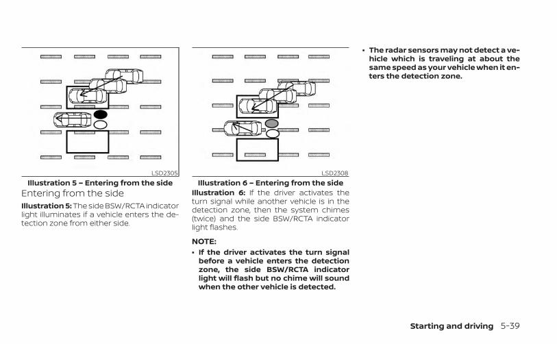
Entering from the sideIllustration 5: The side BSW/RCTA indicatorlight illuminates if a vehicle enters the de-tection zone from either side.
Illustration 6: If the driver activates theturn signal while another vehicle is in thedetection zone, then the system chimes(twice) and the side BSW/RCTA indicatorlight flashes.
NOTE:• If the driver activates the turn signal
before a vehicle enters the detectionzone, the side BSW/RCTA indicatorlight will flash but no chime will soundwhen the other vehicle is detected.
• The radar sensors may not detect a ve-hicle which is traveling at about thesame speed as your vehicle when it en-ters the detection zone.
LSD2305Illustration 5 – Entering from the side
LSD2308Illustration 6 – Entering from the side
Starting and driving 5-39

SYSTEM TEMPORARILYUNAVAILABLE
When radar blockage is detected, the sys-tem will be deactivated automatically.The “Unavailable Side Radar Obstruction”warning message will appear and theBSW/RCTA indicator (white) will blink OA inthe vehicle information display.The system is not available until the condi-tions no longer exist.The radar sensors may be blocked by tem-porary ambient conditions such as splash-ing water, mist or fog. The blocked condi-tion may also be caused by objects such asice, frost or dirt obstructing the radarsensors.
NOTE:
If the BSW system stops working, theRCTA system (if so equipped) will alsostop working.Action to take:When the above conditions no longer exist,the system will resume automatically.
LSD4350
5-40 Starting and driving

MalfunctionIf the BSW system malfunctions, it will turnoff automatically. The system malfunctionwarning message with the BSW/RCTA indi-cator (orange) will appear in the vehicle in-formation display.
NOTE:
If the BSW system stops working, theRCTA system will also stop working.Action to take:Stop the vehicle in a safe location, place thevehicle in the P (Park) position, turn the en-gine off and restart the engine. If the mes-sage continues to appear, have the systemchecked. It is recommended that you visitan NISSAN dealer for this service.
SYSTEM MAINTENANCEThe two radar sensors O1 for the BSW andRCTA systems are located near the rearbumper. Always keep the area near the ra-dar sensors clean.The radar sensors may be blocked by tem-porary ambient conditions such as splash-ing water, mist or fog.The blocked condition may also be causedby objects such as ice, frost or dirt ob-structing the radar sensors.Check for and remove objects obstructingthe area around the radar sensors.
Do not attach stickers (including transpar-ent material), install accessories or applyadditional paint near the radar sensors.Do not strike or damage the area aroundthe radar sensors. It is recommended thatyou visit a NISSAN dealer if the area aroundthe radar sensors is damaged due to acollision.
Radio frequency statementFor USAFCC ID: LTQRN5TRCAUTION TO USERSChanges or modifications not expresslyapproved by the party responsible forcompliance could void the user’s author-ity to operate the equipment.This device complies with Part 15 of theFCC Rules and with the RSS of the Indus-try Canada. Operation is subject to thefollowing two conditions:1. This device may not cause harmful in-
terference, and
2. this device must accept any interfer-ence received, including interferencethat may cause undesired operation.
LSD4347
Starting and driving 5-41

For Canada (Type A)This device complies with IndustryCanada licence-exempt RSS standard(s).Operation is subject to the following twoconditions:(1) this device may not cause interfer-ence, and(2) this device must accept any interfer-ence, including interference that maycause undesired operation of the device.Frequency bands: 24.05–24.25 GhzThe field strength of SRR3–B is below250 millivolts/m measured at 3 metreswith an average detector.Le présent appareil est conforme auxCNR d’Industrie Canada applicables auxappareils radio exempts de licence.L’exploitation est autorisée aux deuxconditions suivantes:(1) l’appareil ne doit pas produire debrouillage, et(2) l’utilisateur de l’appareil doit acceptertout brouillage radioélectrique subi,même si le brouillage est susceptibled’en compromettre le fonctionnement.
Bande de fréquence: 24.05–24.25 GHzL’intensité du champ de SRR3–B est endessous de 250 mV / m à 3 mètresmesuré avec un détecteur à valeurmoyenne.For Canada (Type B)This device contains licence-exempttransmitter(s)/receiver(s) that complywith Innovation, Science and EconomicDevelopment Canada’s licence-exemptRSS(s). Operation is subject to the fol-lowing two conditions:1. This device may not cause interfer-ence.(2) This device must accept any interfer-ence, including interference that maycause undesired operation of the device.Radiofrequency radiation exposureinformation:This equipment complies with radiationexposure limits set forth for an uncon-trolled environment. This equipmentshould be installed and operated withminimum distance of 20 cm between theradiator and your body.
L’émetteur/récepteur exempt de licencecontenu dans le présent appareil estconforme aux CNR d’Innovation, Sci-ences et Développement économiqueCanada applicables aux appareils radioexempts de licence. L’exploitation est au-torisée aux deux conditions suivantes:1. L’appareil ne doit pas produire debrouillage;2. L’appareil doit accepter tout brouillageradioélectrique subi, même si le brouil-lage est susceptible d’en compromettrele fonctionnement.Informations sur l'exposition aux rayon-nements radiofréquences:Cet équipement est conforme aux lim-ites d'exposition aux rayonnementsdéfinies pour un environnement noncontrôlé. Cet équipement doit être in-stallé et utilisé avec un minimum de 20cm de distance entre la source de rayon-nement et votre corps.
5-42 Starting and driving

WARNING
Failure to follow the warnings and in-structions for proper use of the RCTAsystem could result in serious injury ordeath.• The RCTA system is not a replace-
ment for proper driving proceduresand is not designed to prevent con-tact with vehicles or objects. Whenbacking out of a parking space, al-ways use the side and rear mirrorsand turn and look in the directionyour vehicle will move. Never relysolely on the RCTA system.
The RCTA system will assist you whenbacking out from a parking space. Whenthe vehicle is in reverse, the system is de-signed to detect other vehicles approach-ing from the right or left of the vehicle. If thesystem detects cross traffic, it will alert you.
RCTA SYSTEM OPERATION1. Side BSW/RCTA Indicator Light
2. BSW/RCTA Indicator
The RCTA system can help alert the driverof an approaching vehicle when the driveris backing out of a parking space.
LSD4348
REAR CROSS TRAFFIC ALERT (RCTA)(if so equipped)
Starting and driving 5-43

When the shift position is in R (Reverse) andthe vehicle speed is less than approxi-mately 5 mph (8 km/h), the RCTA system isoperational.If the radar detects an approaching vehiclefrom either side, the system chimes (once)and the side BSW/RCTA indicator lightflashes on the side the vehicle is approach-ing from.
The RCTA system uses radar sensors O1
installed on both sides near the rear bum-per to detect an approaching vehicle.The radar sensors O1 can detect an ap-proaching vehicle from up to approxi-mately 66 ft (20 m) away.
LSD2216 LSD4347
5-44 Starting and driving

HOW TO ENABLE/DISABLE THERCTA SYSTEM
When the RCTA system is enabled in thevehicle information display, the system canbe turned off temporarily by pushing theParking Aids system switch. For additionalinformation, see “Parking Aids systemswitch” (P. 2-51).Perform the following steps to enable ordisable the RCTA system:1. Press the button until “Settings” dis-
plays in the vehicle information display.Use the button to select “Driver As-sistance” and press ENTER.
2. Select “Parking Aids” and press ENTER.
3. Select “CTA” and press the ENTER buttonto turn system on or off.
4. Push the Parking Aids system switch toturn the system on or off.
NOTE:
When enabling/disabling the system,the system setting will be retained evenif the engine is restarted.
LSD4351
Starting and driving 5-45

RCTA SYSTEM LIMITATIONS WARNING
Listed below are the system limitationsfor the RCTA system. Failure to operatethe vehicle in accordance with thesesystem limitations could result in seri-ous injury or death.
• Always check surroundings and turnto check what is behind you beforebacking up. The radar sensors detectapproaching (moving) vehicles. Theradar sensors cannot detect everyobject such as:– Pedestrians, bicycles, motorcycles,
animals or child-operated toy ve-hicles
– A vehicle that is passing at speedsgreater than approximately 19 mph(30 km/h)
– A vehicle that is passing at speedslower than approximately 5 mph(8 km/h)
• The radar sensors may not detectapproaching vehicles in certain situ-ations:– Illustration OA : When a vehicle
parked next to you obstructs thebeam of the radar sensor.
– Illustration OB : When the vehicle isparked in an angled parking space.
– Illustration OC : When the vehicle isparked on inclined ground.
– Illustration OD : When an ap-proaching vehicle turns into yourvehicle's parking lot aisle.
LSD3195
5-46 Starting and driving

– Illustration OE : When the angleformed by your vehicle and ap-proaching vehicle is small.
• The following conditions may reducethe ability of the radar to detect othervehicles:– Severe weather– Road spray– Ice/frost/snow/dirt build-up on
the vehicle• Do not attach stickers (including
transparent material), install acces-sories or apply additional paint nearthe radar sensors. These conditionsmay reduce the ability of the radar todetect other vehicles.
• Excessive noise (e.g., audio systemvolume, open vehicle window) will in-terfere with the chime sound, and itmay not be heard.
NOTE:
In the case of several vehicles approach-ing in a row (Illustration 1) or in the oppo-site direction (Illustration 2), a chime maynot be sounded by the RCTA system af-ter the first vehicle passes the sensors.
LSD2043Illustration 1
LSD2044Illustration 2
Starting and driving 5-47

SYSTEM TEMPORARILYUNAVAILABLE
When radar blockage is detected, the sys-tem will be deactivated automatically.The “Unavailable Side Radar Obstruction”warning message will appear and theBSW/RCTA indicator (white) will blink OA inthe vehicle information display.The systems are not available until theconditions no longer exist.The radar sensors may be blocked by tem-porary ambient conditions such as splash-ing water, mist or fog.The blocked condition may also be causedby conditions such as ice, snow, frost or dirtobstructing the radar sensors.
NOTE:If the BSW system stops working, theRCTA system will also stop working.Action to takeWhen the above conditions no longer exist,the system will resume automatically.
MalfunctionWhen the RCTA system malfunctions, it willturn off automatically. The system mal-function warning message with the BSW/RCTA indicator (orange) will appear in thevehicle information display.
LSD4350
5-48 Starting and driving

NOTE:
If the BSW system stops working, theRCTA system will also stop working.Action to takeStop the vehicle in a safe location, place thevehicle in the P (Park) position, turn the en-gine off and restart the engine. If the mes-sage continues to appear, have the systemchecked. It is recommended that you visit aNISSAN dealer for this service.
SYSTEM MAINTENANCEThe two radar sensors O1 for the BSW andRCTA systems are located near the rearbumper. Always keep the area near the ra-dar sensors clean.The radar sensors may be blocked by tem-porary ambient conditions such as splash-ing water, mist or fog.The blocked condition may also be causedby objects such as ice, frost or dirt ob-structing the radar sensors.Check for and remove objects obstructingthe area around the radar sensors.
Do not attach stickers (including transpar-ent material), install accessories or applyadditional paint near the radar sensors.Do not strike or damage the area aroundthe radar sensors. It is recommended thatyou visit a NISSAN dealer if the area aroundthe radar sensors is damaged due to acollision.
Radio frequency statementFor USAFCC ID: LTQRN5TRCAUTION TO USERSChanges or modifications not expresslyapproved by the party responsible forcompliance could void the user’s author-ity to operate the equipment.This device complies with Part 15 of theFCC Rules and with the RSS of the Indus-try Canada. Operation is subject to thefollowing two conditions:1. This device may not cause harmful in-
terference, and
2. this device must accept any interfer-ence received, including interferencethat may cause undesired operation.
LSD4347
Starting and driving 5-49
For Canada (Type A)This device complies with IndustryCanada licence-exempt RSS standard(s).Operation is subject to the following twoconditions:(1) this device may not cause interfer-ence, and(2) this device must accept any interfer-ence, including interference that maycause undesired operation of the device.Frequency bands: 24.05–24.25 GhzThe field strength of SRR3–B is below250 millivolts/m measured at 3 metreswith an average detector.Le présent appareil est conforme auxCNR d’Industrie Canada applicables auxappareils radio exempts de licence.L’exploitation est autorisée aux deuxconditions suivantes:(1) l’appareil ne doit pas produire debrouillage, et(2) l’utilisateur de l’appareil doit acceptertout brouillage radioélectrique subi,même si le brouillage est susceptibled’en compromettre le fonctionnement.
Bande de fréquence: 24.05–24.25 GHzL’intensité du champ de SRR3–B est endessous de 250 mV / m à 3 mètresmesuré avec un détecteur à valeurmoyenne.For Canada (Type B)This device contains licence-exempttransmitter(s)/receiver(s) that complywith Innovation, Science and EconomicDevelopment Canada’s licence-exemptRSS(s). Operation is subject to the fol-lowing two conditions:1. This device may not cause interfer-ence.(2) This device must accept any interfer-ence, including interference that maycause undesired operation of the device.Radiofrequency radiation exposureinformation:This equipment complies with radiationexposure limits set forth for an uncon-trolled environment. This equipmentshould be installed and operated withminimum distance of 20 cm between theradiator and your body.
L’émetteur/récepteur exempt de licencecontenu dans le présent appareil estconforme aux CNR d’Innovation, Sci-ences et Développement économiqueCanada applicables aux appareils radioexempts de licence. L’exploitation est au-torisée aux deux conditions suivantes:1. L’appareil ne doit pas produire debrouillage;2. L’appareil doit accepter tout brouillageradioélectrique subi, même si le brouil-lage est susceptible d’en compromettrele fonctionnement.Informations sur l'exposition aux rayon-nements radiofréquences:Cet équipement est conforme aux lim-ites d'exposition aux rayonnementsdéfinies pour un environnement noncontrôlé. Cet équipement doit être in-stallé et utilisé avec un minimum de 20cm de distance entre la source de rayon-nement et votre corps.
5-50 Starting and driving
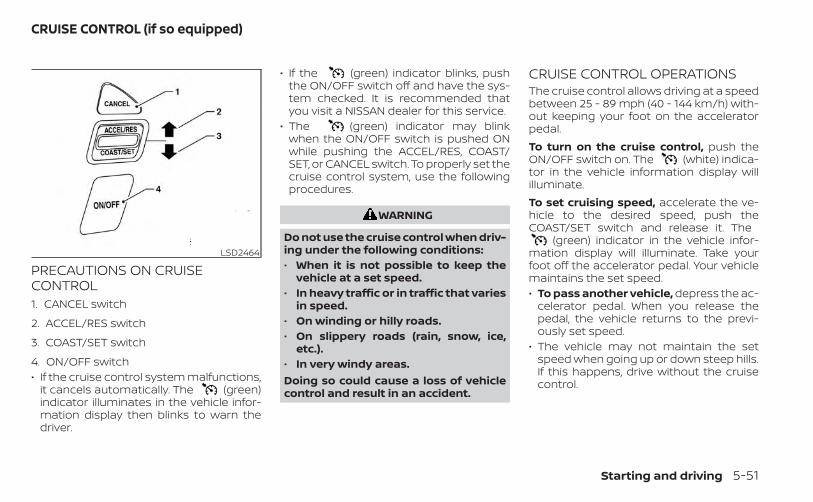
PRECAUTIONS ON CRUISECONTROL1. CANCEL switch
2. ACCEL/RES switch
3. COAST/SET switch
4. ON/OFF switch• If the cruise control system malfunctions,
it cancels automatically. The (green)indicator illuminates in the vehicle infor-mation display then blinks to warn thedriver.
• If the (green) indicator blinks, pushthe ON/OFF switch off and have the sys-tem checked. It is recommended thatyou visit a NISSAN dealer for this service.
• The (green) indicator may blinkwhen the ON/OFF switch is pushed ONwhile pushing the ACCEL/RES, COAST/SET, or CANCEL switch. To properly set thecruise control system, use the followingprocedures.
WARNING
Do not use the cruise control when driv-ing under the following conditions:• When it is not possible to keep the
vehicle at a set speed.• In heavy traffic or in traffic that varies
in speed.• On winding or hilly roads.• On slippery roads (rain, snow, ice,
etc.).• In very windy areas.Doing so could cause a loss of vehiclecontrol and result in an accident.
CRUISE CONTROL OPERATIONSThe cruise control allows driving at a speedbetween 25 - 89 mph (40 - 144 km/h) with-out keeping your foot on the acceleratorpedal.To turn on the cruise control, push theON/OFF switch on. The (white) indica-tor in the vehicle information display willilluminate.To set cruising speed, accelerate the ve-hicle to the desired speed, push theCOAST/SET switch and release it. The
(green) indicator in the vehicle infor-mation display will illuminate. Take yourfoot off the accelerator pedal. Your vehiclemaintains the set speed.• To pass another vehicle, depress the ac-
celerator pedal. When you release thepedal, the vehicle returns to the previ-ously set speed.
• The vehicle may not maintain the setspeed when going up or down steep hills.If this happens, drive without the cruisecontrol.
LSD2464
CRUISE CONTROL (if so equipped)
Starting and driving 5-51

To cancel the preset speed, use one of thefollowing three methods:• Push the CANCEL switch; the indica-
tor in the vehicle information displaygoes out.
• Tap the brake pedal; the indicatorgoes out.
• Push the ON/OFF switch off. Theindicator in the vehicle information dis-play goes out.
The cruise control is automatically can-celed and the indicator in the vehicleinformation display goes out if:• You depress the brake pedal while push-
ing the ACCEL/RES or COAST/SET switch.The preset speed is deleted frommemory.
• The vehicle slows down more than 8 mph(13 km/h) below the set speed.
• You move the shift lever to N (Neutral).To reset at a faster cruising speed, useone of the following three methods:• Depress the accelerator pedal. When the
vehicle attains the desired speed, pushand release the COAST/SET switch.
• Push and hold the ACCEL/RES switch.When the vehicle attains the speed youdesire, release the switch.
• Push and release the ACCEL/RES switch.Each time you do this, the set speed in-creases by about 1 mph (1.6 km/h).
To reset at a slower cruising speed, useone of the following three methods:• Lightly tap the brake pedal. When the ve-
hicle attains the desired speed, push theCOAST/SET switch and release it.
• Push and hold the COAST/SET switch. Re-lease the switch when the vehicle slowsto the desired speed.
• Push and release the COAST/SET switch.Each time you do this, the set speed de-creases by about 1 mph (1.6 km/h).
To resume the preset speed, push andrelease the ACCEL/RES switch. The vehiclereturns to the last set cruising speed whenthe vehicle speed is over 25 mph (40 km/h).
5-52 Starting and driving

OA ICC switch
WARNING
Failure to follow the warnings and in-structions for proper use of the ICC sys-tem could result in serious injury ordeath.• The ICC system is only an aid to assist
the driver and is not a collisionwarning or avoidance device. It is thedriver’s responsibility to stay alert,drive safely, and be in control of thevehicle at all times.
• Always observe posted speed limitsand do not set the speed over them.
• Always drive carefully and atten-tively when using the ICC system.Read and understand the Owner’sManual thoroughly before using theICC system. To avoid serious injury ordeath, do not rely on the system toprevent accidents or to control thevehicle’s speed in emergency situa-tions. Do not use the ICC system ex-cept in appropriate road and trafficconditions.
LSD4390
INTELLIGENT CRUISE CONTROL (if soequipped)
Starting and driving 5-53

• In the conventional (fixed speed)cruise control mode, a warningchime will not sound to warn you ifyou are too close to the vehicleahead. Pay special attention to thedistance between your vehicle andthe vehicle ahead of you or a collisioncould occur.
The ICC system maintains a selected dis-tance from the vehicle in front of you withinthe speed range of 0 to 90 mph (0 to 144km/h) up to the set speed. The set speedcan be selected by the driver between 20 to90 mph (30 to 144 km/h).The vehicle travels at a set speed when theroad ahead is clear.The ICC system can be set to one of twocruise control modes:• Vehicle-to-vehicle distance control
mode: For maintaining a selected dis-tance between your vehicle and the ve-hicle in front of you up to the preset speed
• Conventional (fixed speed) cruise con-trol mode: For cruising at a preset speed
Push the ICC switch OA to choose thecruise control mode between the vehicle-to-vehicle distance control mode and theconventional (fixed speed) cruise controlmode.Once a control mode is activated, it cannotbe changed to the other cruise controlmode. To change the mode, push the ICCswitch OA once to turn the system off. Thenpush the ICC switch OA again to turn thesystem back on and select the desiredcruise control mode.Always confirm the setting in the ICC sys-tem display.For the vehicle-to-vehicle distance controlmode, see “Vehicle-to-vehicle distancecontrol mode” (P. 5-55).For the conventional (fixed speed) cruisecontrol mode, see “Conventional (fixedspeed) cruise control mode” (P. 5-72).
5-54 Starting and driving
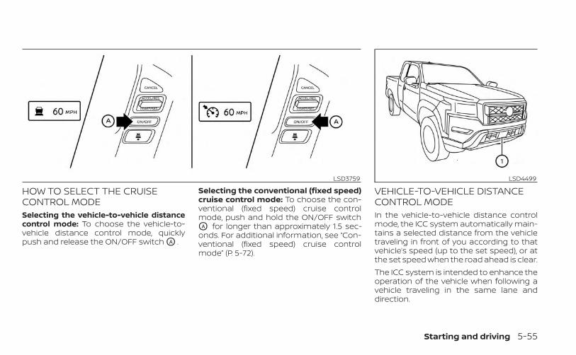
HOW TO SELECT THE CRUISECONTROL MODESelecting the vehicle-to-vehicle distancecontrol mode: To choose the vehicle-to-vehicle distance control mode, quicklypush and release the ON/OFF switch OA .
Selecting the conventional (fixed speed)cruise control mode: To choose the con-ventional (fixed speed) cruise controlmode, push and hold the ON/OFF switchOA for longer than approximately 1.5 sec-onds. For additional information, see “Con-ventional (fixed speed) cruise controlmode” (P. 5-72).
VEHICLE-TO-VEHICLE DISTANCECONTROL MODEIn the vehicle-to-vehicle distance controlmode, the ICC system automatically main-tains a selected distance from the vehicletraveling in front of you according to thatvehicle’s speed (up to the set speed), or atthe set speed when the road ahead is clear.The ICC system is intended to enhance theoperation of the vehicle when following avehicle traveling in the same lane anddirection.
LSD3759 LSD4499
Starting and driving 5-55

If the radar sensor O1 detects a slowermoving vehicle ahead, the system will re-duce the vehicle speed so that your vehiclefollows the vehicle in front at the selecteddistance.The system automatically controls thethrottle and applies the brakes (up to ap-proximately 40% of vehicle braking power)if necessary.The detection range of the sensor is ap-proximately 650 ft (200 m) ahead.
VEHICLE-TO-VEHICLE DISTANCECONTROL MODE OPERATION
The vehicle-to-vehicle distance controlmode is designed to maintain a selecteddistance from the vehicle in front of youand can reduce the speed to match a
LSD4640
5-56 Starting and driving

slower vehicle ahead. The system will de-celerate the vehicle as necessary and if thevehicle ahead comes to a stop, the vehicledecelerates to a standstill. However, the ICCsystem can only apply up to 40% of thevehicle’s total braking power.This system should only be used when traf-fic conditions allow vehicle speeds to re-main fairly constant or when vehiclespeeds change gradually. If a vehiclemoves into the traveling lane ahead or if avehicle traveling ahead rapidly decelerates,the distance between vehicles may be-come closer because the ICC system can-not decelerate the vehicle quickly enough.If this occurs, the ICC system will sound awarning chime and blink the system dis-play to notify the driver to take necessaryaction.The system will cancel and a warningchime will sound if the speed is below ap-proximately 15 mph (25 km/h) and a vehicleis not detected ahead. The system will alsodisengage when the vehicle goes abovethe maximum set speed.For additional information, see “Approachwarning” (P. 5-63).
The following items are controlled in thevehicle-to-vehicle distance control mode:• When there are no vehicles traveling
ahead, the vehicle-to-vehicle distancecontrol mode maintains the speed set bythe driver. The set speed range is be-tween approximately 20 and 90 mph (30and 144 km/h).
• When there is a vehicle traveling ahead,the vehicle-to-vehicle distance controlmode adjusts the speed to maintain thedistance, selected by the driver, from thevehicle ahead. If the vehicle ahead comesto a stop, the vehicle decelerates to astandstill within the limitations of the sys-tem. The system will cancel once it judgesa standstill with a warning chime.
• When the vehicle traveling ahead hasmoved out from its lane of travel, thevehicle-to-vehicle distance control modeaccelerates and maintains vehicle speedup to the set speed.
The ICC system does not control vehiclespeed or warn you when you approachstationary and slow moving vehicles. Youmust pay attention to vehicle operation tomaintain proper distance from vehiclesahead when approaching toll gates or traf-fic congestion.
When driving on the freeway at a set speedand approaching a slower traveling vehicleahead, the ICC system will adjust the speedto maintain the distance, selected by thedriver, from the vehicle ahead. If the vehicleahead changes lanes or exits the freeway,the ICC system will accelerate and main-tain the speed up to the set speed. Payattention to the driving operation to main-tain control of the vehicle as it acceleratesto the set speed.The vehicle may not maintain the setspeed on winding or hilly roads. If this oc-curs, you will have to manually control thevehicle speed.
SSD0254
Starting and driving 5-57
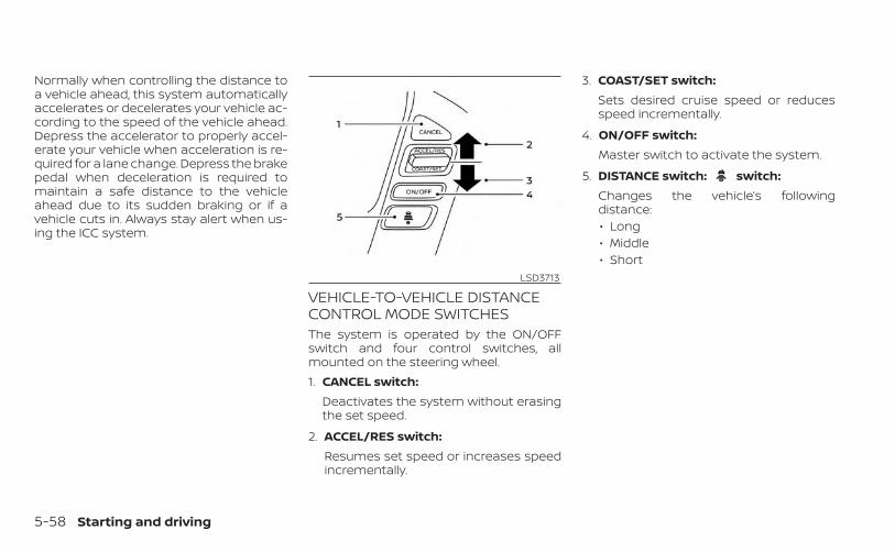
Normally when controlling the distance toa vehicle ahead, this system automaticallyaccelerates or decelerates your vehicle ac-cording to the speed of the vehicle ahead.Depress the accelerator to properly accel-erate your vehicle when acceleration is re-quired for a lane change. Depress the brakepedal when deceleration is required tomaintain a safe distance to the vehicleahead due to its sudden braking or if avehicle cuts in. Always stay alert when us-ing the ICC system.
VEHICLE-TO-VEHICLE DISTANCECONTROL MODE SWITCHESThe system is operated by the ON/OFFswitch and four control switches, allmounted on the steering wheel.1. CANCEL switch:
Deactivates the system without erasingthe set speed.
2. ACCEL/RES switch:Resumes set speed or increases speedincrementally.
3. COAST/SET switch:Sets desired cruise speed or reducesspeed incrementally.
4. ON/OFF switch:Master switch to activate the system.
5. DISTANCE switch: switch:Changes the vehicle’s followingdistance:• Long• Middle• Short
LSD3713
5-58 Starting and driving

Vehicle-to-vehicle distancecontrol mode display andindicatorsThe display is located between the speed-ometer and tachometer.1. This indicator indicates the ICC system
status depending on a color:• ICC system ON indicator (gray): Indi-
cates that the ON/OFF switch is on.• ICC system SET indicator (green): In-
dicates that the cruising speed is set.
• ICC system warning (yellow): Indi-cates that there is a malfunction in theICC system.
2. Set vehicle speed indicator:Indicates the set vehicle speed.For Canadian models, the speed is dis-played in km/h.
3. Vehicle ahead detection indicator:Indicates whether it detects a vehicle infront of you.
4. Set distance indicator:Displays the selected distance betweenvehicles set with the distance switch. Operating vehicle-to-vehicle
distance control modeTo turn on the cruise control, quickly pushand release the ON/OFF switch OA . The ICCsystem ON indicator (gray), set distance in-dicator and set vehicle speed indicator OB
come on in a standby state for setting.
LSD3297 LSD3761
Starting and driving 5-59

To set cruising speed, accelerate your ve-hicle to the desired speed, push theCOAST/SET switch OC and release it. TheICC system set indicator (green), vehicleahead detection indicator, set distance in-dicator and set vehicle speed indicator OB
will come on. Take your foot off the accel-erator pedal. Your vehicle will maintain theset speed.
When the COAST/SET switch is pushed un-der the following conditions, the systemcannot be set and the ICC indicators willblink for approximately 2 seconds:• When traveling below 20 mph (30 km/h)
and a vehicle ahead is not detected• When the shift lever is not in the D (Drive)
or Manual mode• When the parking brake is applied• When the brakes are operated by the
driverWhen the COAST/SET switch is pushed un-der the following conditions, the systemcannot be set.
A warning chime will sound and a messagewill pop up:• When the VDC system is off (To use the
ICC system, turn on the VDC system. Pushthe ON/OFF switch to turn off the ICCsystem and reset the ON/OFF switch bypushing the ON/OFF switch again.)For additional information about theVDC system, see “Vehicle Dynamic Con-trol (VDC) system” (P. 5-121).
• When VDC is operating• When a wheel is slipping (To use the ICC
system, make sure the wheels are no lon-ger slipping.)LSD3762 LSD3102
5-60 Starting and driving

�1 System set display with vehicle ahead
�2 System set display without vehicleahead
The driver sets the desired vehicle speedbased on the road conditions. The ICC sys-tem maintains the set vehicle speed, simi-lar to standard cruise control, as long as novehicle is detected in the lane ahead. TheICC system displays the set speed.
Vehicle detected aheadWhen a vehicle is detected in the laneahead, the ICC system decelerates the ve-hicle by controlling the throttle and apply-ing the brakes to match the speed of aslower vehicle ahead. The system thencontrols the vehicle speed based on thespeed of the vehicle ahead to maintain thedriver selected distance.
NOTE:• The stop lights of the vehicle come on
when braking is performed by the ICCsystem.
• When the brake operates, a noise maybe heard. This is not a malfunction.
When a vehicle ahead is detected, the ve-hicle ahead detection indicator comes on.The ICC system will also display the setspeed and selected distance.
Vehicle ahead not detectedWhen a vehicle is no longer detectedahead, the ICC system gradually acceler-ates your vehicle to resume the previouslyset vehicle speed. The ICC system thenmaintains the set speed.When a vehicle is no longer detected, thevehicle ahead detection indicator turns off.If a vehicle ahead appears during accelera-tion to the set vehicle speed or any time theICC system is in operation, the system con-trols the distance to that vehicle.When a vehicle is no longer detected underapproximately 15 mph (24 km/h), the sys-tem will be canceled.
LSD3301
Starting and driving 5-61

When passing another vehicle, the setspeed indicator OA will flash when the ve-hicle speed exceeds the set speed. The ve-hicle detect indicator will turn off when thearea ahead of the vehicle is open. When thepedal is released, the vehicle will return tothe previously set speed.Even though your vehicle speed is set in theICC system, you can depress the accelera-tor pedal when it is necessary to accelerateyour vehicle rapidly.
How to change the set vehiclespeedTo cancel the preset speed, use one of thefollowing methods:• Push the CANCEL switch. The set vehicle
speed indicator will go out.• Tap the brake pedal. The set vehicle
speed indicator will go out.• Turn the ON/OFF switch off. The ICC indi-
cators will go out.To reset at a faster cruising speed, useone of the following methods:• Depress the accelerator pedal. When the
vehicle attains the desired speed, pushand release the COAST/SET switch.
• Push and hold the ACCEL/RES switch.The set vehicle speed will increase by ap-proximately 5 mph (5 km/h).
• Push, then quickly release the ACCEL/RESswitch. Each time you do this, the setspeed will increase by approximately 1mph (1 km/h).
To reset at a slower cruising speed, useone of the following methods:• Lightly tap the brake pedal. When the ve-
hicle attains the desired speed, push theCOAST/SET switch and release it.
• Push and hold the COAST/SET switch.The set vehicle speed will decrease byapproximately 5 mph (5 km/h).
• Push, then quickly release the COAST/SETswitch. Each time you do this, the setspeed will decrease by approximately 1mph (1 km/h).
To resume the preset speed, push andrelease the ACCEL/RES switch. The vehiclewill resume the last set cruising speedwhen the vehicle speed is over 20 mph(32 km/h).
LSD3267
5-62 Starting and driving

How to change the set distanceto the vehicle aheadThe distance to the vehicle ahead can beselected at any time depending on the traf-fic conditions.Each time the distance switch OA ispushed, the set distance will change tolong, middle, short and back to long again,in that sequence.
Distance Approximate distanceat 60 mph (100 km/h)[ft (m)]
1. Long 200 (60)2. Middle 150 (45)3. Short 90 (30)
• The distance to the vehicle ahead willchange according to the vehicle speed.The higher the vehicle speed, the longerthe distance.
• The distance setting will remain at thecurrent setting even if the engine isrestarted.
Approach warningIf your vehicle comes closer to the vehicleahead due to rapid deceleration of that ve-hicle or if another vehicle cuts in, the sys-tem warns the driver with the chime andICC system display. Decelerate by depress-ing the brake pedal to maintain a safe ve-hicle distance if:• The chime sounds.• The vehicle ahead detection indicator
blinks.The warning chime may not sound insome cases when there is a short distancebetween vehicles. Some examples are:• When the vehicles are traveling at the
same speed and the distance betweenvehicles is not changing.
• When the vehicle ahead is traveling fasterand the distance between vehicles isincreasing.
• When a vehicle cuts in near your vehicle.The warning chime will not sound when:• The vehicle approaches other vehicles
that are parked or moving slowly.• The accelerator pedal is depressed, over-
riding the system.
LSD3714 LSD2752
Starting and driving 5-63

NOTE:
The approach warning chime may soundand the system display may blink whenthe ICC sensor detects objects on theside of the vehicle or on the side of theroad. This may cause the ICC system todecelerate or accelerate the vehicle. TheICC sensor may detect these objectswhen the vehicle is driven on windingroads, narrow roads, hilly roads, or whenentering or exiting a curve. In thesecases you will have to manually controlthe proper distance ahead of yourvehicle.Also, the sensor sensitivity can be affectedby vehicle operation (steering maneuver ordriving position in the lane) or traffic or ve-hicle condition (for example, if a vehicle isbeing driven with some damage).
Automatic cancellationA chime sounds under the following condi-tions and the control is automatically can-celed:• When the vehicle ahead is not detected
and your vehicle is traveling below thespeed of 15 mph (25 km/h)
• When the system judges the vehicle is ata standstill
• When the shift lever is not in the D (Drive)position, Manual mode or L (Low) range.
• When the parking brake system is applied• When the VDC system is turned off• When VDC operates• When distance measurement becomes
impaired due to adhesion of dirt or ob-struction to the sensor
• When a wheel slips• When the radar signal is temporarily
interrupted
VEHICLE-TO-VEHICLE DISTANCECONTROL MODE LIMITATIONS
WARNING
Listed below are the system limitationsfor the ICC system. Failure to operatethe vehicle in accordance with thesesystem limitations could result in seri-ous injury or death.• The ICC system is primarily intended
for use on straight, dry, open roadswith light traffic. It is not advisable touse the ICC system in city traffic orcongested areas.
• The ICC system will not adapt auto-matically to road conditions. Thissystem should be used in evenlyflowing traffic. Do not use the systemon roads with sharp curves, or on icyroads, in heavy rain or in fog.
• As there is a performance limit to thedistance control function, never relysolely on the ICC system. This systemdoes not correct careless, inattentiveor absentminded driving, or over-come poor visibility in rain, fog, orother bad weather. Decelerate thevehicle speed by depressing thebrake pedal, depending on the dis-tance to the vehicle ahead and thesurrounding circumstances in orderto maintain a safe distance betweenvehicles.
• If the vehicle ahead comes to a stop,the vehicle decelerates to a standstillwithin the limitations of the system.The system will cancel once it judgesthat the vehicle has come to a stand-still and sound a warning chime. Toprevent the vehicle from moving, thedriver must depress the brake pedal.
5-64 Starting and driving

• Always pay attention to the opera-tion of the vehicle and be ready tomanually control the proper follow-ing distance. The ICC system may notbe able to maintain the selected dis-tance between vehicles (followingdistance) or selected vehicle speedunder some circumstances.
• The system may not detect the ve-hicle in front of you in certain road orweather conditions. To avoid acci-dents, never use the ICC system un-der the following conditions:– On roads where the traffic is heavy
or there are sharp curves– On slippery road surfaces such as
on ice or snow, etc.– During bad weather (rain, fog,
snow, etc.)– When rain, snow or dirt adhere to
the bumper around the distancesensor
– On steep downhill roads (the ve-hicle may go beyond the set ve-hicle speed and frequent brakingmay result in overheating thebrakes)
– On repeated uphill and downhillroads
– When traffic conditions make it dif-ficult to keep a proper distance be-tween vehicles because of frequentacceleration or deceleration
– Interference by other radarsources
• Do not use the ICC system if you aretowing a trailer. The system may notdetect a vehicle ahead.
• In some road or traffic conditions, avehicle or object can unexpectedlycome into the sensor detection zoneand cause automatic braking. Al-ways stay alert and avoid using theICC system where not recommendedin this warning section.
The radar sensor will not detect the follow-ing objects:• Stationary and slow moving vehicles• Pedestrians or objects in the roadway• Oncoming vehicles in the same lane• Motorcycles traveling offset in the travel
laneThe sensor generally detects the signalsreturned from the vehicle ahead. Therefore,if the sensor cannot detect the reflectionfrom the vehicle ahead, the ICC systemmay not maintain the selected distance.
The following are some conditions in whichthe sensor cannot properly detect a ve-hicle ahead and the system may not oper-ate properly:• When snow or road spray from traveling
vehicles reduces the sensor’s detection.• When your vehicle is towing a trailer, etc.• When excessively heavy baggage is
loaded in the rear seat or cargo area ofyour vehicle.
The ICC system is designed to automati-cally check the sensor’s operation withinthe limitations of the system.When the sensor is covered with dirt or isobstructed, the system will automaticallybe canceled. If the sensor is covered withice, a transparent or translucent vinyl bag,etc., the ICC system may not detect them.In these instances, the vehicle-to-vehicledistance control mode may not cancel andmay not be able to maintain the selectedfollowing distance from the vehicle ahead.Be sure to check and clean the sensorregularly.The detection zone of the radar sensor islimited. A vehicle ahead must be in the de-tection zone for the vehicle-to-vehicle dis-tance detection mode to maintain the se-lected distance from the vehicle ahead.
Starting and driving 5-65

A vehicle ahead may move outside of thedetection zone due to its position withinthe same lane of travel. Motorcycles maynot be detected in the same lane ahead ifthey are traveling offset from the centerlineof the lane. A vehicle that is entering thelane ahead may not be detected until thevehicle has completely moved into thelane.If this occurs, the ICC system may warnyou by blinking the system indicator andsounding the chime. The driver mayhave to manually control the proper dis-tance away from vehicle traveling ahead.
SSD0252
5-66 Starting and driving

When driving on some roads, such as wind-ing, hilly, curved, narrow roads, or roadswhich are under construction, the radarsensor may detect vehicles in a differentlane, or may temporarily not detect a ve-hicle traveling ahead. This may cause theradar system to decelerate or acceleratethe vehicle.The detection of vehicles may also be af-fected by vehicle operation (steering ma-neuver or traveling position in the lane, etc.)or vehicle condition.
If this occurs, the ICC system may warnyou by blinking the system indicator andsounding the chime unexpectedly. Youwill have to manually control the properdistance away from the vehicle travelingahead.
SSD0253
Starting and driving 5-67

SYSTEM TEMPORARILYUNAVAILABLE
The following are conditions in which theICC system may be temporarily unavail-able. In these instances, the ICC systemmay not cancel and may not be able tomaintain the selected following distancefrom the vehicle ahead.Condition AUnder the following conditions, the ICC sys-tem is automatically canceled. A chime willsound and the system will not be able to beset:• When the VDC system is turned off• When the VDC operates• When a vehicle ahead is not detected and
your vehicle is traveling below the speedof 15 mph (25 km/h)
• When the system judges the vehicle is ata standstill
• When the shift lever is not in the D (Drive),Manual mode or L (Low) range
• When the parking brake is applied• When a wheel slips• When the radar signal is temporarily
interruptedLSD4392
5-68 Starting and driving

Action to takeWhen the conditions listed above are nolonger present, turn the system off usingthe ICC switch. Turn the ICC system back onto use the system.Condition BWhen there is inclement weather (rain, fog,snow, etc.) blocking the front radar sensor,the ICC system will automatically be can-celed. The chime will sound and the “For-ward Driving Aids Temporarily DisabledFront Sensor Blocked See Owner’s Manual”warning message will appear in the vehicleinformation display.Action to takeWhen the conditions listed above are nolonger present, the warning message willno longer be available in the vehicle infor-mation display and the system will operatenormally. If the “Forward Driving Aids Tem-porarily Disabled Front Sensor Blocked SeeOwner’s Manual” warning message contin-ues to be displayed, have the systemchecked. It is recommended that you visit aNISSAN dealer for this service.
Condition CWhen the radar sensor area of the frontbumper/emblem is covered with mud, dirt,snow, ice, etc., or is obstructed, the ICC sys-tem will automatically be canceled.The chime will sound and the “ForwardDriving Aids Temporarily Disabled FrontSensor Blocked See Owner’s Manual”warning message will appear in the vehicleinformation display.Action to takeIf the warning message appears, stop thevehicle in a safe place, place the shift leverin the P (Park) position, and turn the engineoff. When the radar signal is temporarilyinterrupted, clean the sensor area of thefront bumper/emblem and restart the en-gine. If the “Forward Driving Aids Temporar-ily Disabled Front Sensor Blocked See Own-er’s Manual” warning message continuesto be displayed, have the system checked.It is recommended that you visit a NISSANdealer for this service.
Condition DWhen driving on roads with limited roadstructures (for example, long bridges, des-erts, snow fields, driving next to long walls),the system may illuminate the systemwarning light and display the ““ForwardDriving Aids Temporarily Disabled FrontSensor Blocked See Owner’s Manual”message.Action to takeWhen the above driving conditions no lon-ger exist, turn the system back on.Condition EWhen the ICC system is not operatingproperly, a chime sounds and the ICC sys-tem warning light (orange) will come on.
Starting and driving 5-69

Action to takeIf the warning light comes on, park the ve-hicle in a safe place. Turn the engine off,restart the engine, resume driving and setthe ICC system again.If it is not possible to set the system orthe indicator stays on, it may indicatethat the system is malfunctioning. Al-though the vehicle is still drivable undernormal conditions, have the vehiclechecked. It is recommended that youvisit a NISSAN dealer for this service.
NOTE:
If the ICC system is temporarily unavail-able, the conventional cruise controlmode may still be used.For instruction on using the ConventionalCruise Control mode see (P. 5-72).
SYSTEM MAINTENANCEThe sensor for the ICC system O1 is locatedon the front of the vehicle.To keep the ICC system operating properly,be sure to observe the following:• Always keep the sensor area of the front
bumper/emblem clean.• Do not strike or damage the areas
around the sensor.• Do not attach a sticker (including trans-
parent material) or install an accessorynear the sensor. This could cause failureor malfunction.
LSD3916 LSD4499
5-70 Starting and driving

• Do not attach metallic objects near thesensor area (brush guard, etc.). This couldcause failure or malfunction.
• Do not alter, remove, or paint the frontbumper. Before customizing or restoringthe front bumper, it is recommended thatyou visit a NISSAN dealer.
Radio frequency statementFCC NoticeUSAFCC ID: OAYARS4BThis device complies with Part 15 of theFCC Rules with Industry Canada Licence-exempt RSS standard(s).Operation is subject to the following twoconditions:1. This device may not cause harmful in-
terference, and
2. This device must accept any interfer-ence received, including interferencethat may cause undesired operation.
Radio frequency radiation exposureInformation:This equipment complies with FCC and ICradiation exposure limits set forth for anuncontrolled environment.
This equipment should be installed andoperated with minimum distance of 30cm between the radiator and your body.This transmitter must not be co-locatedor operating in conjunction with anyother antenna or transmitter.FCC NoticeChanges or modifications not expresslyapproved by the party responsible forcompliance could void the user’s author-ity to operate the equipment.CANADAIC: 4135A-ARS4BThis device complies with Part 15 of theFCC Rules and Industry Canada licence-exempt RSS standard(s).Operation is subject to the following twoconditions:1. This device may not cause interfer-
ence,
2. This device must accept any interfer-ence, including interference that maycause undesired operation.
Le présent appareil est conforme auxCNR d’Industrie Canada applicables auxappareils radio exempts de licence.
L’exploitation est autorisée aux deuxconditions suivantes:1. l’appareil ne doit pas produire de
brouillage, et
2. l’utillisateur de l’appareil doit acceptertout brouillage radioélectrique subi,même si le brouillage est susceptibled’en compromettre le fonctionnement.
Radio frequency radiation exposureInformation:This equipment complies with FCC and ICradiation exposure limits set forth for anuncontrolled environment.This equipment should be installed andoperated with minimum distance of 30cm between the radiator and your body.This transmitter must not be co-locatedor operating in conjunction with anyother antenna or transmitter.Cet équipement est conforme aux lim-ites d’exposition aux rayonnements ICétablies pour un environnement noncontrôlé. Cet équipement doit être in-stallé et utillisé avec un minimum de 30cm de distance entre la source de rayon-nement et votre corps.
Starting and driving 5-71

CONVENTIONAL (fixed speed)CRUISE CONTROL MODEThis mode allows driving at a speed be-tween 25 to 90 mph (40 to 144 km/h) with-out keeping your foot on the acceleratorpedal.
WARNING
• In the conventional (fixed speed)cruise control mode, a warningchime does not sound to warn you ifyou are too close to the vehicleahead, as neither the presence of thevehicle ahead nor the vehicle-to-vehicle distance is detected.
• Pay special attention to the distancebetween your vehicle and the vehicleahead of you or a collision couldoccur.
• Always confirm the setting in the ICCsystem display.
• Do not use the conventional (fixedspeed) cruise control mode whendriving under the following condi-tions:– When it is not possible to keep the
vehicle at a set speed
– In heavy traffic or in traffic thatvaries in speed
– On winding or hilly roads– On slippery roads (rain, snow, ice,
etc.)– In very windy areas
• Doing so could cause a loss of vehiclecontrol and result in an accident.
Conventional (fixed speed) cruisecontrol switches1. CANCEL switch:
Deactivates the system without erasingthe set speed
2. ACCEL/RES switch:Resumes set speed or increases speedincrementally
3. COAST/SET switch:Sets desired cruise speed or reducesspeed incrementally
4. ON/OFF switch:Master switch to activate the system
LSD3715
5-72 Starting and driving

Conventional (fixed speed) cruisecontrol mode display andindicatorsThe display is located in the vehicle infor-mation display.1. Cruise indicator:
This indicator indicates the condition ofthe ICC system depending on a color.• Cruise control ON indicator (gray): Indi-
cates that the ON/OFF switch is on• Cruise control SET indicator (green): In-
dicates that the cruising speed is set
• Cruise control warning (yellow): Indi-cates that there is a malfunction in theICC system
2. Set vehicle speed indicator:This indicator indicates the set vehiclespeed. For Canadian models, the speedis displayed in km/h.
Operating conventional (fixedspeed) cruise control modeTo turn on the conventional (fixed speed)cruise control mode, push and hold theON/OFF switch OA for longer than about 1.5seconds.When pushing ON/OFF switch on, the con-ventional (fixed speed) cruise control modedisplay and indicators OB are displayed inthe vehicle information display. After youhold ON/OFF switch on for longer thanabout 1.5 seconds, the ICC system displayturns off. The cruise indicator appears. Youcan now set your desired cruising speed.
LSD3106 LSD3764
Starting and driving 5-73

Pushing the ON/OFF switch again will turnthe system completely off. When the igni-tion switch is placed in the OFF position, thesystem is also automatically turned off.To use the ICC system again, quickly pushand release the ON/OFF switch (vehicle-tovehicle distance control mode) or push andhold it (conventional cruise control mode)again to turn it on.
CAUTION
To avoid accidentally engaging cruisecontrol, make sure to turn the ON/OFFswitch off when not using the ICCsystem. To set cruising speed, accelerate your ve-
hicle to the desired speed, push theCOAST/SET OC switch and release it. (Thecolor of the cruise indicator changes togreen and set vehicle speed indicatorcomes on.) Take your foot off the accelera-tor pedal. Your vehicle will maintain the setspeed.• To pass another vehicle, depress the ac-
celerator pedal. When you release thepedal, the vehicle will return to the previ-ously set speed.
• The vehicle may not maintain the setspeed when going up or down steep hills.If this happens, manually maintain ve-hicle speed.
To cancel the preset speed, use any of thefollowing methods:1. Push the CANCEL switch. The vehicle
speed indicator will turn off.
2. Tap the brake pedal. The vehicle speedindicator will turn off.
3. Turn the ON/OFF switch off. Both thecruise indicator and vehicle speed indi-cator will turn off.
To reset at a faster cruising speed, use oneof the following three methods:1. Depress the accelerator pedal. When the
vehicle attains the desired speed, pushand release the COAST/SET switch.
2. Push and hold the ACCEL/RES switch.When the vehicle attains the desiredspeed, release the switch.
3. Push, then quickly release the ACCEL/RES switch. Each time you do this, theset speed will increase by about 1 mph(1.6 km/h).
LSD3765
5-74 Starting and driving
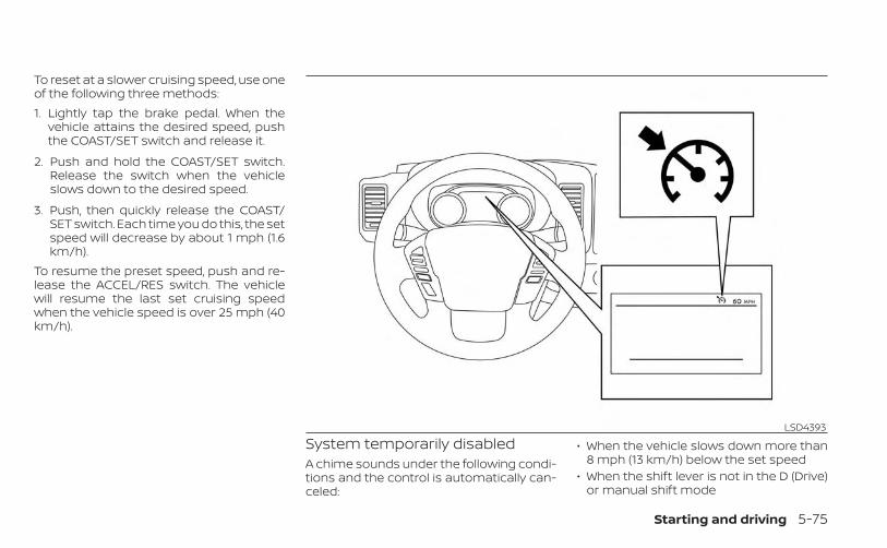
To reset at a slower cruising speed, use oneof the following three methods:1. Lightly tap the brake pedal. When the
vehicle attains the desired speed, pushthe COAST/SET switch and release it.
2. Push and hold the COAST/SET switch.Release the switch when the vehicleslows down to the desired speed.
3. Push, then quickly release the COAST/SET switch. Each time you do this, the setspeed will decrease by about 1 mph (1.6km/h).
To resume the preset speed, push and re-lease the ACCEL/RES switch. The vehiclewill resume the last set cruising speedwhen the vehicle speed is over 25 mph (40km/h).
System temporarily disabledA chime sounds under the following condi-tions and the control is automatically can-celed:
• When the vehicle slows down more than8 mph (13 km/h) below the set speed
• When the shift lever is not in the D (Drive)or manual shift mode
LSD4393
Starting and driving 5-75

• When the parking brake is applied• When the VDC operates (including the
traction control system)• When a wheel slipsWhen the system is not operating properly,the chime sounds and the color of thecruise indicator will change to orange.Action to takeIf the color of the cruise indicator changesto orange, stop the vehicle in a safe placeand place the shift lever in the P (Park) po-sition. Turn the engine off, restart the en-gine, resume driving, and then perform thesetting again.If it is not possible to set or the indicatorstays on, it may indicate that the systemis malfunctioning. Although the vehicleis still drivable under normal conditions,have the vehicle checked. It is recom-mended that you visit a NISSAN dealerfor this service.
WARNING
Failure to follow the warnings and in-structions for proper use of the RABsystem could result in serious injury ordeath.• The RAB system is a supplemental
aid to the driver. It is not a replace-ment for proper driving procedures.Always use the side and rear mirrorsand turn and look in the direction youwill move before and while backingup. Never rely solely on the RAB sys-tem. It is the driver’s responsibility tostay alert, drive safely, and be in con-trol of the vehicle at all times.
• There is a limitation to the RAB sys-tem capability. The RAB system is noteffective in all situations.
• Inclement weather or ultrasonicsources such as an automatic carwash, a truck’s compressed-air brakesor a pneumatic drill may affect thefunction of the system; this may in-clude reduced performance or a falseactivation.
The RAB system can assist the driver whenthe vehicle is backing up and approachingobjects directly behind the vehicle.
The RAB system detects obstacles behindthe vehicle using the parking sensors O1
located on the rear bumper.
NOTE:
You can temporarily cancel the sonarfunction in the vehicle, but the RAB sys-tem will continue to operate. For addi-tional information, see “Rear Sonar Sys-tem (RSS)” (P. 5-125).
LSD4364
REAR AUTOMATIC BRAKING (RAB)(if so equipped)
5-76 Starting and driving

RAB SYSTEM OPERATION�1 RAB system warning light and RAB sys-
tem indicator
�2 Steering-wheel-mounted controls (leftside)
�3 Center display
When the shift lever is in the R (Reverse)position and the vehicle speed is less thanapproximately 9 mph (15 km/h), the RABsystem operates.If a risk of a collision with an obstacle isdetected when your vehicle is backing up,the RAB system warning indicator will flashin the vehicle information display, a redframe will appear in the center display (forvehicles with the Intelligent Around ViewMonitor system), and the system will chimethree times. The system will then auto-matically apply the brakes. After the auto-matic brake application, the driver mustdepress the brake pedal to maintain brakepressure.
NOTE:• The brake lights of the vehicle come on
when braking is performed by the RABsystem.
• When the brakes operate, a noise maybe heard. This is not a malfunction.
LSD4531
Starting and driving 5-77

TURNING THE RAB SYSTEMON/OFF
Perform the following steps to turn the RABsystem on or off.1. Press the button until “Settings” dis-
plays in the vehicle information displayand then press the ENTER button. Usethe button to select “Driver Assis-tance.” Then press the ENTER button.
2. Select “Emergency Brake” and press theENTER button.
3. Select “Rear” and press the ENTER but-ton to turn the system on or off.
4. Push the Parking Aids system switch toturn the system on or off.
When the RAB system is turned off, the RABwarning light illuminates.
NOTE:The RAB system will be automaticallyturned on when the engine is re-started.
LSD4366
5-78 Starting and driving

RAB SYSTEM LIMITATIONSWARNING
Listed below are the system limitationsfor the RAB system. Failure to follow thewarnings and instructions for properuse of the RAB system could result inserious injury or death.• When the vehicle approaches an ob-
stacle while the accelerator or brakepedal is depressed, the function maynot operate or the start of operationmay be delayed. The RAB systemmay not operate or may not performsufficiently due to vehicle conditions,driving conditions, the traffic envi-ronment, the weather, road surfaceconditions, etc. Do not wait for thesystem to operate. Operate the brakepedal by yourself as soon asnecessary.
• If it is necessary to override RAB op-eration, strongly press the accelera-tor pedal.
• Always check your surroundings andturn to check what is behind you be-fore and while backing up. The RABsystem detects stationary objects be-hind the vehicle. The RAB system doesnot detect the following objects:– Moving objects– Low objects– Narrow objects– Wedge-shaped objects– Objects close to the bumper (less
than approximately 1 ft [30 cm])– Objects that suddenly appear– Thin objects such as rope, wire,
chain, etc.• The RAB system may not operate for
the following obstacles:– Obstacles located high off the
ground– Obstacles in a position offset from
your vehicle– Obstacles, such as spongy materi-
als or snow, that have soft outersurfaces and can easily absorb asound wave
• The RAB system may not operate inthe following conditions:– There is rain, snow, ice, dirt, etc.,
attached to the sonar sensors.– A loud sound is heard in the area
around the vehicle.– The surface of the obstacle is di-
agonal to the rear of the vehicle.• The RAB system may unintentionally
operate in the following conditions:– There is overgrown grass in the
area around the vehicle.– There is a structure (e.g., a wall, toll
gate equipment, a narrow tunnel,a parking lot gate) near the side ofthe vehicle.
– There are bumps, protrusions, ormanhole covers on the roadsurface.
– The vehicle drives through adraped flag or a curtain.
– There is an accumulation of snowor ice behind the vehicle.
– An ultrasonic wave source, such asanother vehicle’s sonar, is nearthe vehicle.
Starting and driving 5-79

• Once the automatic brake controloperates, it does not operate again ifthe vehicle approaches the sameobstacle.
• The automatic brake control can onlyoperate for a short period of time.Therefore, the driver must depressthe brake pedal.
• In the following situations, the RABsystem may not operate properly ormay not function sufficiently:– The vehicle is driven in bad
weather (rain, fog, snow, etc.).– The vehicle is driven on a steep
hill.– The vehicle’s posture is changed
(e.g., when driving over a bump).– The vehicle is driven on a slippery
road.– The vehicle is turned sharply by
turning the steering wheel fully.– Snow chains are used.– Wheels or tires other than NISSAN
recommended are used.– The brakes are cold at low ambi-
ent temperatures or immediatelyafter driving has started.
– The braking force becomes poordue to wet brakes after drivingthrough a puddle or washing thevehicle.
• Turn the RAB system off in the follow-ing conditions to prevent the occur-rence of an unexpected accident re-sulting from sudden systemoperation:– The vehicle is towed.– The vehicle is carried on a flatbed
truck.– The vehicle is on the chassis
dynamometer.– The vehicle drives on an uneven
road surface.– The vehicle is towing an object (if
so equipped).– Suspension parts other than
those designated as GenuineNISSAN parts are used. (If the ve-hicle height or the vehicle body in-clination is changed, the systemmay not detect an obstaclecorrectly.)
– If the vehicle is using an accessorylike a bike rack, or cargo carrierthat blocks the sensors.
• Excessive noise (e.g., audio systemvolume, an open vehicle window) willinterfere with the chime sound, and itmay not be heard.
SYSTEM MALFUNCTIONIf the RAB system malfunctions, it will beturned off automatically, and the RAB sys-tem warning light will illuminate and thewarning message “System fault See Own-er’s Manual” in the vehicle informationdisplay.Action to takeIf the warning light illuminates, park the ve-hicle in a safe location, turn the engine off,and restart the engine. If the warning lightcontinues to illuminate, have the RAB sys-tem checked. It is recommended that youvisit a NISSAN dealer for this service.
NOTE:
If the RAB system cannot be operatedtemporarily, the RAB system warninglight blinks.
5-80 Starting and driving

SYSTEM MAINTENANCEObserve the following items to ensureproper operation of the system:• Always keep the parking sensors O1
clean.• If the parking sensors are dirty, wipe them
off with a soft cloth while being careful tonot damage them.
• Do not subject the area around the park-ing sensors O1 to strong impact. Also, donot remove or disassemble the parkingsensors. If the parking sensors and pe-ripheral areas are deformed in an acci-dent, etc., have the sensors checked. It isrecommended that you visit a NISSANdealer for this service.
• Do not install any stickers (includingtransparent stickers) or accessories onthe parking sensors O1 and their sur-rounding areas. This may cause a mal-function or improper operation.
WARNING
Failure to follow the warnings and in-structions for proper use of the AEBwith Pedestrian Detection systemcould result in serious injury or death.• The AEB with Pedestrian Detection
system is a supplemental aid to thedriver. It is not a replacement for thedriver’s attention to traffic condi-tions or responsibility to drive safely.It cannot prevent accidents due tocarelessness or dangerous drivingtechniques.
• The AEB with Pedestrian Detectionsystem does not function in all driv-ing, traffic, weather and roadconditions.
The AEB with Pedestrian Detection systemcan assist the driver when there is a risk ofa forward collision with the vehicle ahead inthe traveling lane or with a pedestrianahead in the traveling lane.
LSD4364
AUTOMATIC EMERGENCY BRAKING(AEB) WITH PEDESTRIAN DETECTION
Starting and driving 5-81

The AEB with Pedestrian Detection systemuses a radar sensor located on the front ofthe vehicle OB to measure the distance tothe vehicle ahead in the same lane. Forpedestrians, the AEB with Pedestrian De-tection system uses a camera installed be-hind the windshield OA in addition to theradar sensor.
AEB WITH PEDESTRIANDETECTION SYSTEM OPERATION
1. Vehicle ahead detection indicator
2. AEB with Pedestrian Detection emer-gency warning indicator
LSD4498
LSD4368
5-82 Starting and driving

3. AEB with Pedestrian Detection systemwarning light
The AEB system operates at speeds aboveapproximately 3 mph (5 km/h). For the pe-destrian detection function, the systemoperates at speeds between 6 – 37 mph (10– 60 km/h).If a risk of a forward collision is detected,the AEB with Pedestrian Detection systemwill firstly provide the warning to the driverby flashing the vehicle ahead detection in-dicator (yellow) in the vehicle informationdisplay and providing an audible alert. If thedriver applies the brakes quickly and force-fully after the warning, and the AEB withPedestrian Detection system detects thatthere is still the possibility of a forward col-lision, the system will automatically in-crease the braking force.If the driver does not take action, the AEBwith Pedestrian Detection system issuesthe second visual (flashing) (red and white)and audible warning. If the driver releasesthe accelerator pedal, then the system ap-plies partial braking. If the risk of a collisionbecomes imminent, the AEB with Pedes-trian Detection system applies harderbraking automatically.
While the AEB with Pedestrian Detectionsystem is operating, you may hear thesound of brake operation. This is normaland indicates that the AEB with PedestrianDetection system is operating properly.
NOTE:
The vehicle’s brake lights come on whenany braking is performed by the AEBwith Pedestrian Detection system.Depending on vehicle speed and distanceto the vehicle or pedestrian ahead, as wellas driving and roadway conditions, the sys-tem may help the driver avoid a forwardcollision or may help mitigate the conse-quences if a collision should be unavoid-able. If the driver is handling the steeringwheel, accelerating or braking, the AEB withPedestrian Detection system will functionlater or will not function.The automatic braking will cease under thefollowing conditions:• When the steering wheel is turned to
avoid a collision.• When the accelerator pedal is depressed.• When there is no longer a vehicle or a
pedestrian detected ahead.
If the AEB with Pedestrian Detection sys-tem has stopped the vehicle, the vehiclewill remain at a standstill for approximately2 seconds before the brakes are released.
Starting and driving 5-83

TURNING THE AEB WITHPEDESTRIAN DETECTION SYSTEMON/OFF
Perform the following steps to enable ordisable the AEB with Pedestrian Detectionsystem.1. Press the button until “Settings” dis-
plays in the vehicle information display.Use the button to select “Driver As-sistance.” Then press the ENTER button.
2. Select “Emergency Brake” and press theENTER button.
3. Select “Front” and press the ENTER but-ton to turn the system on or off.
When the AEB with Pedestrian Detectionsystem is turned off, the AEB with Pedes-trian Detection system warning lightilluminates.
NOTE:• The AEB with Pedestrian Detection sys-
tem will be automatically turned onwhen the engine is restarted.
• The I-FCW system is integrated into theAEB with Pedestrian Detection system.There is not a separate selection in thevehicle information display for theI-FCW system. When the AEB system isturned off, the I-FCW system is alsoturned off.
LSD4369
5-84 Starting and driving

AEB WITH PEDESTRIANDETECTION SYSTEM LIMITATIONS
WARNING
Listed below are the system limitationsfor the AEB with Pedestrian Detectionsystem. Failure to operate the vehicle inaccordance with these system limita-tions could result in serious injury ordeath.• The AEB with Pedestrian Detection
system cannot detect all vehicles orpedestrians under all conditions.
• The AEB with Pedestrian Detectionsystem does not detect the following:
– Pedestrians that are small (for ex-ample, children), in a sitting posi-tion, operating toys/skateboards,on scooters or in wheelchairs, ornot in an upright standing orwalking position.
– Animals of any size.– Obstacles (for example, cargo or
debris) on the roadway or roadside.– Oncoming or crossing vehicles.– Vehicles where the tires are difficult
to see or the shape of the rear of thevehicle is unclear or obstructed.
– Parked vehicles.
• The AEB with Pedestrian Detectionsystem has some performance limi-tations.– If a stationary vehicle is in the ve-
hicle’s path, the system will notfunction when the vehicle ap-proaches the stationary vehicle atspeeds over approximately 50mph (80 km/h).
– Pedestrian detection will notfunction when the vehicle isdriven at speeds over approxi-mately 37 mph (60 km/h) or belowapproximately 6 mph (10km/h).
• For pedestrians, the AEB with Pedes-trian Detection system will not issuethe first warning.
• The AEB with Pedestrian Detectionsystem may not function properly ordetect a vehicle or pedestriansahead in the following conditions:
– In poor visibility conditions (suchas rain, snow, fog, dust storms,sand storms, smoke, and roadspray from other vehicles).
– If dirt, ice, snow, fog or other ma-terial is covering the radar sensorarea or camera area of thewindshield.
– If a strong light (for example, sun-light or high beams) enters thefront camera or a sudden changein brightness occurs (for example,entering a tunnel or driving inlightning).
– In dark or dimly lit conditions,such as at night or in tunnels, in-cluding cases where your vehi-cle’s headlights are off or dim, orthe tail lights of the vehicle aheadare off.
– When the direction of the camerais misaligned.
– When driving on a steep downhillslope, on roads with sharp curves,and/or bumpy or dirt roads.
– If there is interference by other ra-dar sources.
– When your vehicle’s position ormovement is changed quickly orsignificantly (for example, lanechange, turning vehicle, abruptsteering, sudden acceleration ordeceleration).
Starting and driving 5-85

– When your vehicle or the vehicleor pedestrian ahead movesquickly or significantly such thatthe system cannot detect and re-act in time (for example, pedes-trian moving quickly toward thevehicle at close range, vehicle cut-ting in, changing lanes, making aturn, steering abruptly, suddenacceleration or deceleration).
– When the vehicle or pedestrian isoffset from the vehicle’s forwardpath.
– If the speed difference betweenthe two vehicles is small.
– The pedestrian’s profile is par-tially obscured or unidentifiable;for example, due to transportingluggage, pushing a stroller, wear-ing bulky or very loose-fittingclothing or accessories, or beingin a unique posture (such as rais-ing hands).
– There is poor contrast of a personto the background, such as havingclothing color or pattern which issimilar to the background.
– For approximately 15 seconds af-ter starting the engine.
– If the vehicle ahead has a uniqueor unusual shape, extremely lowor high clearance heights, or un-usual cargo loading or is narrow(for example, a motorcycle).
– When the vehicle or pedestrian islocated near a traffic sign, a reflec-tive area (for example, water onroad), or is in a shadow.
– When multiple pedestrians aregrouped together.
– When the view of the pedestrian isobscured by a vehicle or otherobject.
– While towing a trailer or othervehicle.
• The system performance may be de-graded in the following conditions:
– The vehicle is driven on a slipperyroad.
– The vehicle is driven on a slope.– Excessively heavy baggage is
loaded in the rear seat or thecargo area of your vehicle.
• The system is designed to automati-cally check the sensor’s (radar andcamera) functionality, within certainlimitations. The system may not de-tect some forms of obstruction ofthe sensor area such as ice, snow or
stickers, for example. In these cases,the system may not be able to warnthe driver properly. Be sure that youcheck, clean and clear sensor areasregularly.
• In some road and traffic conditions,the AEB with Pedestrian Detectionsystem may unexpectedly apply par-tial braking. When acceleration isnecessary, depress the acceleratorpedal to override the system.
• The AEB with Pedestrian Detectionsystem may operate when a pattern,object, shadow or lights are detectedthat are similar to the outline of ve-hicles or pedestrians, or if they arethe same size and position as a ve-hicle or motorcycle’s tail lights.
• The system may keep operatingwhen the vehicle ahead is turningright or left.
• The system may operate when yourvehicle is approaching and passing avehicle ahead.
• Depending on the road shape (curvedroad, entrance and exit of the curve,winding road, lane regulation, underconstruction, etc.), the system mayoperate temporarily for the oncomingvehicle in front of your vehicle.
5-86 Starting and driving

WARNING
Listed below are the system limitationsfor the AEB with Pedestrian Detectionsystem. Failure to operate the vehicle inaccordance with these system limita-tions could result in serious injury ordeath.• The AEB with Pedestrian Detection
system may react to:– objects on the roadside (traffic
sign, guardrail, pedestrian, motor-cycle, vehicle, etc.)
– pedestrians when driving on thenarrow alleys, etc.
– pedestrians who temporarily pro-trude into or approaching thedriving lane to avoid the obstacleson the road shoulder
– objects above road (low bridge,traffic sign, etc.)
– objects on the road surface (rail-road track, grate, steel plate, etc.)
– objects in the parking garage(beam, pillar, etc.)
– pedestrians or motorcycles ap-proaching the travelling lane
– vehicles, pedestrians, motor-cycles or objects in adjacent lanesor close to the vehicle
– oncoming pedestrians– objects on the road (such as trees)
• Braking distances increase on slip-pery surfaces.
• Excessive noise will interfere with thewarning chime sound, and the chimemay not be heard.
LSD4248
Starting and driving 5-87

SYSTEM TEMPORARILYUNAVAILABLE
Condition A:In the following conditions, the AEB withPedestrian Detection system warning lightblinks and the system will be turned offautomatically:• The radar sensor picks up interference
from another radar source.• The camera area of the windshield is
misted or frozen.• Strong light is shining from the front.• The cabin temperature is over approxi-
mately 104°F (40°C) in direct sunlight.• The camera area of the windshield glass
is continuously covered with dirt, etc.Action to takeWhen the above conditions no longer exist,the AEB with Pedestrian Detection systemwill resume automatically.
NOTE:
When the inside of the windshield on thecamera area is misted or frozen, it willtake a period of time to remove it afterthe A/C turns on. If dirt appears on thisarea, it is recommended that you visit aNISSAN dealer.
LSD4370
5-88 Starting and driving

Condition B:When there is inclement weather (rain, fog,snow, etc.) blocking the front radar sensor,the AEB with Pedestrian Detection systemwill be canceled, the chime will sound andthe “Forward Driving Aids Temporarily Dis-abled Front Sensor Blocked See Owner’sManual” warning message will appear inthe vehicle information display.Action to take:When the conditions listed above are nolonger present, the warning message willno longer be available in the vehicle infor-mation display. If the “Forward Driving AidsTemporarily Disabled Front Sensor BlockedSee Owner’s Manual” warning messagecontinues to be displayed, have the systemchecked. It is recommended that you visit aNISSAN dealer for this service.Condition C:When the radar sensor of the front bumperis covered with dirt or is obstructed, theAEB with Pedestrian Detection system willautomatically be canceled. The chime willsound and the “Forward Driving Aids Tem-porarily Disabled Front Sensor Blocked See
Owner’s Manual” warning message will ap-pear in the vehicle information display.Action to take:If the warning message appears, stop thevehicle in a safe place, place the shift leverin the P (Park) position, and turn the engineoff. When the radar signal is temporarilyinterrupted, clean the sensor area of thefront bumper and restart the engine. If the“Forward Driving Aids Temporarily DisabledFront Sensor Blocked See Owner’s Manual”warning message continues to be dis-played, have the system checked. It is rec-ommended that you visit a NISSAN dealerfor this service.Condition DWhen driving on roads with limited roadstructures or buildings (for example, longbridges, deserts, snowfields, driving next tolong walls), the system may illuminate thesystem warning light and display the “For-ward Driving Aids Temporarily DisabledFront Sensor Blocked See Owner’s Manual”message.
Action to take:When the above driving conditions no lon-ger exist, turn the system back on.
NOTE:If the AEB with Pedestrian Detectionsystem stops working, the I-FCW sys-tem will also stop working.
Starting and driving 5-89

SYSTEM MALFUNCTIONIf the AEB with Pedestrian Detection sys-tem malfunctions, it will be turned off auto-matically, a chime will sound, the AEB withPedestrian Detection system warning light(orange) will illuminate and the warningmessage “System fault See Owner’sManual” will appear in the vehicle informa-tion display.
Action to takeIf the warning light (orange) comes on, stopthe vehicle in a safe location, turn the en-gine off and restart the engine. If thewarning light continues to illuminate, havethe AEB with Pedestrian Detection systemchecked. It is recommended that you visit aNISSAN dealer for this service.
SYSTEM MAINTENANCEThe radar sensor is located on the front ofthe vehicle OB . The camera is located onthe upper side of the windshield OA .To keep the AEB with Pedestrian Detectionsystem operating properly, be sure to ob-serve the following:• Always keep the sensor areas of the front
bumper/emblem and windshield clean.• Do not strike or damage the areas
around the sensors (e.g., bumper,windshield).
LSD3916 LSD4498
5-90 Starting and driving

• Do not cover or attach stickers, or installany accessory near the sensors. Thiscould block sensor signals and/or causefailure or malfunction.
• Do not attach metallic objects near theradar sensor (brush guard, etc.). Thiscould cause failure or malfunction.
• Do not place reflective materials, such aswhite paper or a mirror, on the instru-ment panel. The reflection of sunlightmay adversely affect the camera unit'sdetection capability.
• Do not alter, remove or paint the frontbumper. Before customizing or restoringthe front bumper, it is recommended thatyou visit a NISSAN dealer.
Radio frequency statementFCC NoticeUSAFCC ID: OAYARS4BThis device complies with Part 15 of theFCC Rules with Industry Canada Licence-exempt RSS standard(s).Operation is subject to the following twoconditions:1. This device may not cause harmful in-
terference, and
2. This device must accept any interfer-ence received, including interferencethat may cause undesired operation.
Radiofrequency radiation exposureInformation:This equipment complies with FCC and ICradiation exposure limits set forth for anuncontrolled environment.This equipment should be installed andoperated with minimum distance of 30cm between the radiator and your body.This transmitter must not be co-locatedor operating in conjunction with anyother antenna or transmitter.FCC NoticeChanges or modifications not expresslyapproved by the party responsible forcompliance could void the user’s author-ity to operate the equipment.CANADAIC: 4135A-ARS4BThis device complies with Part 15 of theFCC Rules and Industry Canada licence-exempt RSS standard(s).
Operation is subject to the following twoconditions:1. This device may not cause interfer-
ence,
2. This device must accept any interfer-ence, including interference that maycause undesired operation.
Le présent appareil est conforme auxCNR d’Industrie Canada applicables auxappareils radio exempts de licence.L’exploitation est autorisée aux deuxconditions suivantes:1. l’appareil ne doit pas produire de
brouillage, et
2. l’utillisateur de l’appareil doit acceptertout brouillage radioélectrique subi,même si le brouillage est susceptibled’en compromettre le fonctionnement.
Radiofrequency radiation exposureInformation:This equipment complies with FCC and ICradiation exposure limits set forth for anuncontrolled environment.This equipment should be installed andoperated with minimum distance of 30cm between the radiator and your body.
Starting and driving 5-91

This transmitter must not be co-locatedor operating in conjunction with anyother antenna or transmitter.Cet équipement est conforme aux lim-ites d’exposition aux rayonnements ICétablies pour un environnement noncontrôlé. Cet équipement doit être in-stallé et utillisé avec un minimum de 30cm de distance entre la source de rayon-nement et votre corps.
WARNING
Failure to follow the warnings and in-structions for proper use of the I-FCWsystem could result in serious injury ordeath.• The I-FCW system can help warn the
driver before a collision occurs butwill not avoid a collision. It is the driv-er’s responsibility to stay alert, drivesafely and be in control of the vehicleat all times.
The I-FCW system can help alert the driverwhen there is a sudden braking of a secondvehicle traveling in front of the vehicleahead in the same lane. The I-FCW system uses a radar sensor O1
located on the front of the vehicle to mea-sure the distance to the vehicle ahead inthe same lane.
LSD4499
INTELLIGENT FORWARD COLLISIONWARNING (I-FCW)
5-92 Starting and driving

1. Vehicle ahead detection indicator
2. AEB with Pedestrian Detection systemwarning light
LSD4371
Starting and driving 5-93

I-FCW SYSTEM OPERATIONThe I-FCW system operates at speedsabove approximately 3 mph (5 km/h).If there is a potential risk of a forward colli-sion, the I-FCW system will warn the driverby blinking the vehicle ahead detection in-dicator, and sounding an audible alert.
LSD2263
5-94 Starting and driving

TURNING THE I-FCW SYSTEMON/OFF
Perform the following steps to turn theI-FCW system ON or OFF.1. Press the button until “Settings” dis-
plays in the vehicle information display.Use the button to select “Driver As-sistance.” Then press the ENTER button.
2. Select “Emergency Brake” and press theENTER button.
3. Select “Front” and press the ENTER but-ton to turn the system on or off.
When the I-FCW system is turned off, theAEB with Pedestrian Detection systemwarning light illuminates.
NOTE:• The I-FCW system will be automatically
turned on when the engine isrestarted.
• The I-FCW system is integrated into theAEB with Pedestrian Detection system.There is not a separate selection in thevehicle information display for theI-FCW system. When the AEB with Pe-destrian Detection system is turnedoff, the I-FCW system is also turned off.LSD4369
Starting and driving 5-95
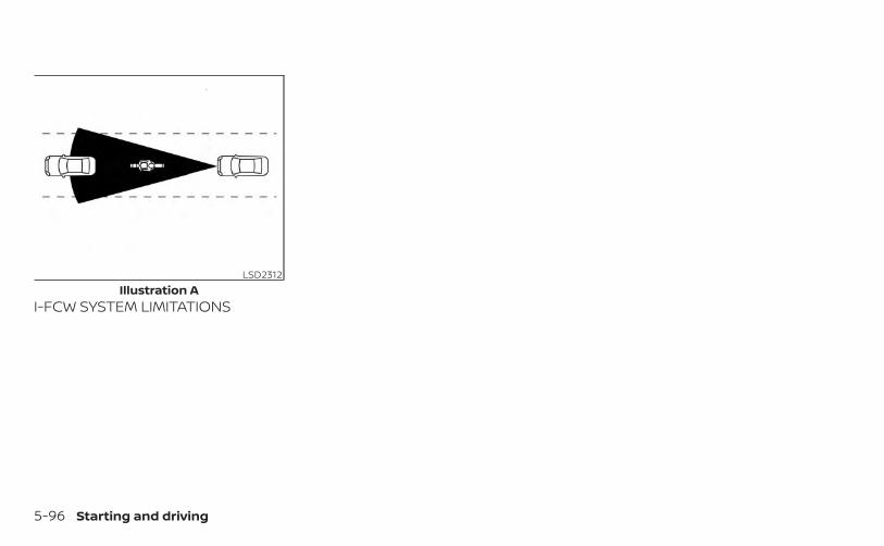
I-FCW SYSTEM LIMITATIONS
LSD2312Illustration A
5-96 Starting and driving

WARNING
Listed below are the system limitationsfor the I-FCW system. Failure to operatethe vehicle in accordance with thesesystem limitations could result in seri-ous injury or death.• The I-FCW system cannot detect all
vehicles under all conditions.
• The radar sensor does not detect thefollowing objects:– Pedestrians, animals or obstacles
in the roadway– Oncoming vehicles– Crossing vehicles
• (Illustration A) The I-FCW systemdoes not function when a vehicleahead is a narrow vehicle, such as amotorcycle.
• The radar sensor may not detect avehicle ahead in the followingconditions:– Snow or heavy rain– When you are towing a trailer etc.– Dirt, ice, snow or other material
covering the radar sensor.– Interference by other radar sources.– Snow or road spray from traveling
vehicles.– Driving in a tunnel
LSD2265Illustration B
Starting and driving 5-97
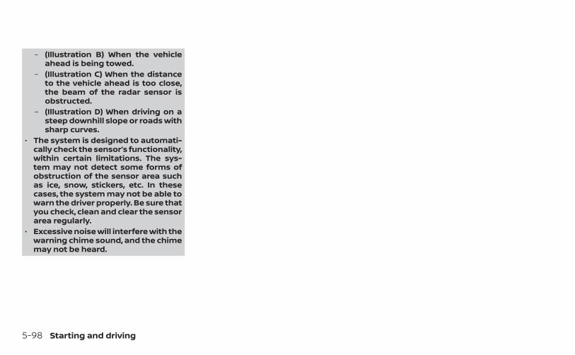
– (Illustration B) When the vehicleahead is being towed.
– (Illustration C) When the distanceto the vehicle ahead is too close,the beam of the radar sensor isobstructed.
– (Illustration D) When driving on asteep downhill slope or roads withsharp curves.
• The system is designed to automati-cally check the sensor’s functionality,within certain limitations. The sys-tem may not detect some forms ofobstruction of the sensor area suchas ice, snow, stickers, etc. In thesecases, the system may not be able towarn the driver properly. Be sure thatyou check, clean and clear the sensorarea regularly.
• Excessive noise will interfere with thewarning chime sound, and the chimemay not be heard.
5-98 Starting and driving

LSD2266Illustration C
Starting and driving 5-99

LSD2313Illustration D
5-100 Starting and driving

SYSTEM TEMPORARILYUNAVAILABLE
Condition AWhen the radar sensor picks up interfer-ence from another radar source, making itimpossible to detect a vehicle ahead, theI-FCW system is automatically turned off.The AEB with Pedestrian Detection systemwarning light (orange) will illuminate.Action to takeWhen the above conditions no longer exist,the I-FCW system will resume automati-cally.Condition BWhen there is inclement weather (rain, fog,snow, etc.) blocking the front radar sensor,the I-FCW system will automatically becanceled, the chime will sound and the“Forward Driving Aids Temporarily DisabledFront Sensor Blocked See Owner’s Manual”warning message will appear in the vehicleinformation display.
LSD4370
Starting and driving 5-101

Action to take:When the conditions listed above are nolonger present, the warning message willno longer be available in the vehicle infor-mation display. If the “Forward Driving AidsTemporarily Disabled Front Sensor BlockedSee Owner’s Manual” warning messagecontinues to be displayed, have the systemchecked. It is recommended that you visit aNISSAN dealer for this service.Condition CWhen the radar sensor of the front bumperis covered with dirt or is obstructed, theI-FCW system will automatically be can-celed. The chime will sound and the “For-ward Driving Aids Temporarily DisabledFront Sensor Blocked See Owner’s Manual”warning message will appear in the vehicleinformation display.Action to take:If the warning message appears, stop thevehicle in a safe place, place the shift leverin the P (Park) position, and turn the engineoff. When the radar signal is temporarilyinterrupted, clean the sensor area of thefront bumper and restart the engine. If the“Forward Driving Aids Temporarily DisabledFront Sensor Blocked See Owner’s Manual”warning message continues to be dis-
played, have the system checked. It is rec-ommended that you visit a NISSAN dealerfor this service.Condition DWhen driving on roads with limited roadstructures or buildings (for example, longbridges, deserts, snowfields, driving next tolong walls), the system may illuminate thesystem warning light and display the “For-ward Driving Aids Temporarily DisabledFront Sensor Blocked See Owner’s Manual”warning message.Action to take:When the above driving conditions no lon-ger exist, turn the system back on.
NOTE:
If the AEB with Pedestrian Detection sys-tem stops working, the I-FCW system willalso stop working.
SYSTEM MALFUNCTIONIf the I-FCW system malfunctions, it will beturned off automatically, a chime willsound, the AEB with Pedestrian Detectionsystem warning light (orange) will illumi-nate and the warning message [Malfunc-tion] will appear in the vehicle informationdisplay.
LSD3916
5-102 Starting and driving

Action to takeIf the warning light (orange) comes on, stopthe vehicle in a safe location, turn the en-gine off and restart the engine. If thewarning light continues to illuminate, havethe I-FCW system checked. It is recom-mended that you visit a NISSAN dealer forthis service.
SYSTEM MAINTENANCEThe sensor O1 is located on the front of thevehicle.To keep the system operating properly, besure to observe the following:• Always keep the sensor area of the front
bumper/emblem clean.• Do not strike or damage the areas
around the sensor.• Do not cover or attach stickers or similar
objects on the front bumper near thesensor area. This could cause failure ormalfunction.
• Do not attach metallic objects near thesensor area (brush guard, etc.). This couldcause failure or malfunction.
• Do not alter, remove or paint the frontbumper. Before customizing or restoringthe front bumper, it is recommended thatyou visit a NISSAN dealer.
FCC NoticeUSAFCC ID: OAYARS4BThis device complies with Part 15 of theFCC Rules with Industry Canada Licence-exempt RSS standard(s).Operation is subject to the following twoconditions:1. This device may not cause harmful in-
terference, and
2. This device must accept any interfer-ence received, including interferencethat may cause undesired operation.
Radiofrequency radiation exposureInformation:This equipment complies with FCC and ICradiation exposure limits set forth for anuncontrolled environment.
LSD4499
Starting and driving 5-103
This equipment should be installed andoperated with minimum distance of 30cm between the radiator and your body.This transmitter must not be co-locatedor operating in conjunction with anyother antenna or transmitter.FCC NoticeChanges or modifications not expresslyapproved by the party responsible forcompliance could void the user’s author-ity to operate the equipment.CANADAIC: 4135A-ARS4BThis device complies with Part 15 of theFCC Rules and Industry Canada licence-exempt RSS standard(s).Operation is subject to the following twoconditions:1. This device may not cause interfer-
ence,
2. This device must accept any interfer-ence, including interference that maycause undesired operation.
Le présent appareil est conforme auxCNR d’Industrie Canada applicables auxappareils radio exempts de licence.
L’exploitation est autorisée aux deuxconditions suivantes:1. l’appareil ne doit pas produire de
brouillage, et
2. l’utillisateur de l’appareil doit acceptertout brouillage radioélectrique subi,même si le brouillage est susceptibled’en compromettre le fonctionnement.
Radiofrequency radiation exposureInformation:This equipment complies with FCC and ICradiation exposure limits set forth for anuncontrolled environment.This equipment should be installed andoperated with minimum distance of 30cm between the radiator and your body.This transmitter must not be co-locatedor operating in conjunction with anyother antenna or transmitter.Cet équipement est conforme aux lim-ites d’exposition aux rayonnements ICétablies pour un environnement noncontrôlé. Cet équipement doit être in-stallé et utillisé avec un minimum de 30cm de distance entre la source de rayon-nement et votre corps.
WARNING
Failure to follow the warnings and in-structions for proper use of the I-DAsystem could result in serious injury ordeath.• The I–DA system is only a warning to
inform the driver of a potential lackof driver attention or drowsiness. Itwill not steer the vehicle or preventloss of control.
• The I–DA system does not detect andprovide an alert of the driver’s lackof attention or fatigue in everysituation.
• It is the driver’s responsibility to:– stay alert,– drive safely,– keep the vehicle in the traveling
lane,– be in control of the vehicle at all
times,– avoid driving when tired,– avoid distractions (texting, etc.).
INTELLIGENT DRIVER ALERTNESS(I-DA)
5-104 Starting and driving

The I–DA system helps alert the driver if thesystem detects a lack of attention or driv-ing fatigue.The system monitors driving style andsteering behavior over a period of time,and it detects changes from the normalpattern. If the system detects that driverattention is decreasing over a period oftime, the system uses audible and visualwarnings to suggest that the driver take abreak.
INTELLIGENT DRIVER ALERTNESSSYSTEM OPERATIONIf the system detects driver fatigue or thatdriver attention is decreasing, the mes-sage “Take a break?” appears in the vehicleinformation display and a chime soundswhen the vehicle is driven at speeds above37 mph (60 km/h).The system continuously monitors driverattention and can provide multiple warn-ings per trip.
The system resets and starts reassessingdriving style and steering behavior whenthe ignition switch is cycled from the ON tothe OFF position and back to the ONposition.
LSD4372
Starting and driving 5-105

HOW TO ENABLE/DISABLE THEINTELLIGENT DRIVER ALERTNESS(I-DA) SYSTEM
Perform the following steps to enable ordisable the I–DA system.1. Press the button until “Settings” dis-
plays in the vehicle information display.Use the button to select “Driver As-sistance.” Then press the ENTER button.
2. Select “Driver Attention” and press theENTER button to turn the system on oroff.
NOTE:The setting will be retained even if theengine is restarted.
INTELLIGENT DRIVER ALERTNESS(I-DA) SYSTEM LIMITATIONS
WARNING
Listed below are the system limitationsfor the I–DA system. Failure to operatethe vehicle in accordance with thesesystem limitations could result in seri-ous injury or death.• The I-DA system may not operate
properly and may not provide analert in the following conditions:– Poor road conditions such as an
uneven road surface or pot holes.– Strong side wind.
LSD4373
5-106 Starting and driving

– If you have adopted a sporty driv-ing style with higher corneringspeeds or higher rates ofacceleration.
– Frequent lane changes orchanges to vehicle speed.
• The I–DA system will not provide analert in the following conditions:– Vehicle speeds lower than 37 mph
(60 km/h).– Short lapses of attention.– Instantaneous distractions such
as dropping an object.
System malfunctionIf the Intelligent Driver Alertness systemmalfunctions, the system warning mes-sage will appear in the vehicle informationdisplay and the function will be stoppedautomatically.Action to takeStop the vehicle in a safe location, place thevehicle in P (Park) position, turn the engine offand restart the engine. If the system warningmessage continues to appear, have the sys-tem checked. It is recommended that youvisit a NISSAN dealer for this service.
CAUTION
During the first 1,200 miles (2,000 km),follow these recommendations to ob-tain maximum engine performanceand ensure the future reliability andeconomy of your new vehicle. Failure tofollow these recommendations mayresult in shortened engine life and re-duced engine performance.
• Avoid driving for long periods at constantspeed, either fast or slow, and do not runthe engine over 4,000 rpm.
• Do not accelerate at full throttle in anygear.
• Avoid quick starts.• Avoid hard braking as much as possible.• Do not tow a trailer for the first 500 miles
(805 kilometers). Your engine, axle orother parts could be damaged.
LIC3125
BREAK-IN SCHEDULE
Starting and driving 5-107
Follow these easy-to-use Fuel EfficientDriving Tips to help you achieve the mostfuel economy from your vehicle.1. Use Smooth Accelerator and Brake
Pedal Application• Avoid rapid starts and stops.• Use smooth, gentle accelerator and
brake application whenever possible.• Maintain constant speed while com-
muting and coast whenever possible.
2. Maintain Constant Speed• Look ahead to try and anticipate and
minimize stops.• Synchronizing your speed with traffic
lights allows you to reduce your num-ber of stops.
• Maintaining a steady speed can mini-mize red light stops and improve fuelefficiency.
3. Use Air Conditioning (A/C) at HigherVehicle Speeds• Below 40 mph (64 km/h), it is more
efficient to open windows to cool thevehicle due to reduced engine load.
• Above 40 mph (64 km/h), it is moreefficient to use A/C to cool the vehicledue to increased aerodynamic drag.
• Recirculating the cool air in the cabinwhen the A/C is on reduces coolingload.
4. Drive at Economical Speeds andDistances• Observing the speed limit and not ex-
ceeding 60 mph (97 km/h) (where le-gally allowed) can improve fuel effi-ciency due to reduced aerodynamicdrag.
• Maintaining a safe following distancebehind other vehicles reduces unnec-essary braking.
• Safely monitoring traffic to anticipatechanges in speed permits reducedbraking and smooth accelerationchanges.
• Select a gear range suitable to roadconditions.
5. Use Cruise Control• Using cruise control during highway
driving helps maintain a steady speed.• Cruise control is particularly effective
in providing fuel savings when drivingon flat terrains.
6. Plan for the Shortest Route• Utilize a map or navigation system to
determine the best route to save time.
7. Avoid Idling• Shutting off your engine when safe for
stops exceeding 30–60 seconds savesfuel and reduces emissions.
8. Buy an Automated Pass for Toll Roads• Automated passes permit drivers to
use special lanes to maintain cruisingspeed through the toll and avoid stop-ping and starting.
9. Winter Warm Up• Limit idling time to minimize impact to
fuel economy.• Vehicles typically need no more than
30 seconds of idling at start-up to ef-fectively circulate the engine oil beforedriving.
• Your vehicle will reach its ideal operat-ing temperature more quickly whiledriving versus idling.
10. Keeping your Vehicle Cool• Park your vehicle in a covered parking
area or in the shade wheneverpossible.
• When entering a hot vehicle, openingthe windows will help to reduce theinside temperature faster, resulting inreduced demand on your A/C system.
FUEL EFFICIENT DRIVING TIPS
5-108 Starting and driving

• Keep your engine tuned up.• Follow the recommended scheduled
maintenance.• Keep the tires inflated to the correct pres-
sure. Low tire pressure increases tirewear and lowers fuel economy.
• Keep the wheels in correct alignment. Im-proper alignment increases tire wear andlowers fuel economy.
• For vehicles equipped with , use 4Hor 4L position only when necessary.4-Wheel Drive operation lowers fueleconomy.
• Use the recommended viscosity engine oil.For additional information, see “Engine oiland oil filter recommendations” (P. 10-7).
WARNING
• For 4WD equipped vehicles, do notattempt to raise two wheels off theground and shift the transmission toany drive or reverse position with theengine running. Doing so may resultin drivetrain damage or unexpectedvehicle movement which could resultin serious vehicle damage or per-sonal injury.
• Do not attempt to test a 4WDequipped vehicle on a 2-wheel dyna-mometer (such as the dynamom-eters used by some states for emis-sions testing), or similar equipmenteven if the other two wheels areraised off the ground. Make sure youinform test facility personnel thatyour vehicle is equipped with 4WDbefore it is placed on a dynamom-eter. Using the wrong test equipmentmay result in drivetrain damage orunexpected vehicle movementwhich could result in serious vehicledamage or personal injury.
CAUTION
• Do not drive the vehicle in the 4H or4LO position on dry hard surfaceroads. Driving on dry, hard surfaces in4H or 4LO may cause unnecessarynoise, tire wear and increased fuelconsumption.If the 4WD vehicle information dis-play warning message turns onwhen you are driving on dry hard sur-face roads:– In the 4H position, shift the 4WD
shift switch to 2WD.– In the 4LO position, stop the ve-
hicle, move the shift lever to the N(Neutral) position with the brakepedal depressed, and shift the4WD shift switch to 2WD.
• If the vehicle information displaywarning message is still on after theabove operation, have your vehiclechecked as soon as possible. It is rec-ommended that you visit a NISSANdealer for this service.
INCREASING FUEL ECONOMY USING 4–WHEEL DRIVE (4WD)(if so equipped)
Starting and driving 5-109
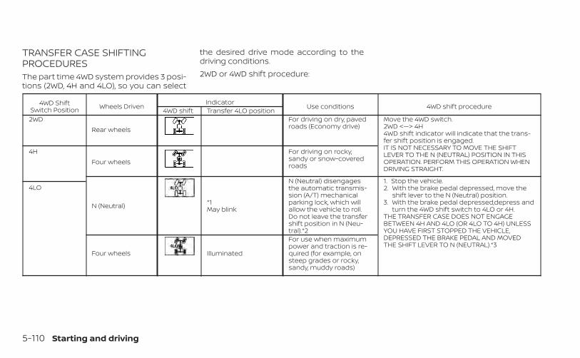
TRANSFER CASE SHIFTINGPROCEDURESThe part time 4WD system provides 3 posi-tions (2WD, 4H and 4LO), so you can select
the desired drive mode according to thedriving conditions.2WD or 4WD shift procedure:
4WD ShiftSwitch Position Wheels Driven Indicator Use conditions 4WD shift procedure4WD shift Transfer 4LO position2WD
Rear wheelsFor driving on dry, pavedroads (Economy drive)
Move the 4WD switch.2WD <—> 4H4WD shift indicator will indicate that the trans-fer shift position is engaged.IT IS NOT NECESSARY TO MOVE THE SHIFTLEVER TO THE N (NEUTRAL) POSITION IN THISOPERATION. PERFORM THIS OPERATION WHENDRIVING STRAIGHT.
4HFour wheels
For driving on rocky,sandy or snow-coveredroads
N (Neutral) *1May blink
N (Neutral) disengagesthe automatic transmis-sion (A/T) mechanicalparking lock, which willallow the vehicle to roll.Do not leave the transfershift position in N (Neu-tral).*2
1. Stop the vehicle.2. With the brake pedal depressed, move the
shift lever to the N (Neutral) position.3. With the brake pedal depressed,depress and
turn the 4WD shift switch to 4LO or 4H.THE TRANSFER CASE DOES NOT ENGAGEBETWEEN 4H AND 4LO (OR 4LO TO 4H) UNLESSYOU HAVE FIRST STOPPED THE VEHICLE,DEPRESSED THE BRAKE PEDAL AND MOVEDTHE SHIFT LEVER TO N (NEUTRAL).*3
4LO
Four wheels Illuminated
For use when maximumpower and traction is re-quired (for example, onsteep grades or rocky,sandy, muddy roads)
5-110 Starting and driving

*1: Before moving the shift lever from N(Neutral), wait until the 4LO indicator stayson steady. This indicates that the 4WD shiftprocedure is completed and the transfergear is correctly set in the 4LO position. Ifthe vehicle is shifted into gear before theindicator is on steady, the transfer gearmay grind, not engage correctly or stay inthe N (Neutral) position.- If the 4WD vehicle information displaywarning message illuminates, perform thefollowing procedure to return the transfercase to correct operating condition.1. Turn off the engine by placing the ignitionswitch in the OFF position.2. Start the engine.- Check that the 4WD vehicle informationdisplay warning message turns off. If thewarning message in the vehicle informa-tion display stays on, have the systemchecked. It is recommended that you visit aNISSAN dealer for this service.3. Apply the parking brake, depress thebrake pedal and move the shift lever to theN (Neutral) position.
4. With the brake pedal depressed, movethe 4WD shift switch to the desired mode.- Be sure to wait until the transfer gearchange completes before shifting the shiftlever from the N (Neutral) position.*2: While changing in and out of 4LO, theignition switch must be in the ON positionand the vehicle's engine must be runningfor a shift to take place and for the 4WDshift and 4LO position indicators to be op-erable. Otherwise, the shift will not takeplace and no indicators will be on orflashing.*3: Make sure the transfer 4LO position in-dicator turns on when you shift the 4WDshift switch to 4LO. The indicator lightwill also turn on when 4LO is selected. Foradditional information, see “Vehicle Dy-namic Control (VDC) system” (P. 5-121).When the 4LO position is selected, the VDCsystem is disabled and the VDC off indica-tor light illuminates, see “Vehicle DynamicControl (VDC) OFF indicator light”(P. 2-19).The transfer case 4WD shift switch is usedto select either 2WD or 4WD depending onthe driving conditions. There are threetypes of drive modes available, 2WD, 4H and4LO.
The 4WD shift switch electronically controlsthe transfer case operation. Rotate theswitch to move between each mode, 2WD,4H and 4LO.To change into or out of 4LO, the vehicleMUST be stationary, move the shift leverto N (Neutral), and depress the brakepedal. The switch must be pushed andturned to select 4LO.
WARNING
• When parking, apply the parkingbrake before stopping the engineand make sure that the 4WD shift in-dicator is on and the AutomaticTransmission Park (ATP) warninglight goes off. Otherwise, the vehiclecould unexpectedly move even if theA/T is in the P (Park) position.
• The 4LO indicator must stop blinkingand remain illuminated or turn offbefore shifting the transmissioninto gear. If the shift lever is shiftedfrom the N (Neutral) position to anyother gear when the 4LO indicator isblinking, the vehicle may moveunexpectedly.
Starting and driving 5-111

CAUTION
• Never shift the 4WD shift switch be-tween 4LO and 4H while driving.
• The 4H position provides greater trac-tion. Avoid excessive speed, as it willcause increased fuel consumptionand higher oil temperatures, andcould damage drivetrain components.Speeds over 62 mph (100 km/h) in 4His not recommended.
• The 4LO position provides maximumpower and traction. Avoid raising ve-hicle speed excessively, as the maxi-mum speed is approximately 31 mph(50 km/h).
• When driving straight, shift the 4WDshift switch to the 2WD or 4H posi-tion. Do not move the 4WD shiftswitch when making a turn orreversing.
• Do not shift the 4WD shift switch (be-tween 2WD and 4H) while driving onsteep downhill grades. Use the en-gine brake and low A/T gears (M1 orM2) for engine braking.
• Do not operate the 4WD shift switch(between 2WD and 4H) with the rearwheels spinning.
• Do not drive on dry hard surfaceroads in the 4H or 4LO position. Driv-ing on dry hard surfaces in 4H or 4LOmay cause unnecessary noise andtire wear. NISSAN recommends driv-ing in the 2WD position under theseconditions.
• The 4WD transfer case may not beshifted between 4H and 4LO at lowambient temperatures and thetransfer 4LO position indicator mayblink even when the 4WD shift switchis shifted. After driving for a whileyou can change the 4WD transfercase between 4H and 4LO.
When driving on rough roads:• Set the 4WD shift switch to 4H or 4LO.• Drive carefully according to the road sur-
face conditions.When the vehicle is stuck:• Set the 4WD shift switch to 4H or 4LO.• Place stones or wooden blocks under the
tires to free the vehicle.• Use the Electronic locking rear differential
(E-Lock) system (if so equipped). For addi-tional information, see “Electronic lockingrear differential (E-Lock) system” (P. 5-115).
• If it is difficult to free the vehicle, rock thevehicle back and forth between reverseand drive gears.
• If the vehicle is stuck deep in mud, placestones or wooden blocks under the tires.Then try the recovery procedures above.Tire chains may be effective.
CAUTION
• Do not spin the tires excessively. Tireswill sink deep into the mud, making itdifficult to free the vehicle.
• Avoid shifting gears with the enginerunning at high speeds as this maycause malfunction.
5-112 Starting and driving
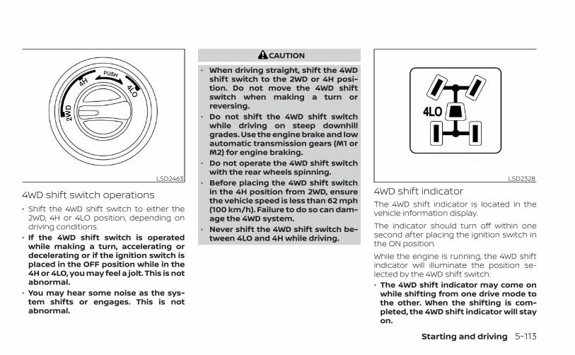
4WD shift switch operations• Shift the 4WD shift switch to either the
2WD, 4H or 4LO position, depending ondriving conditions.
• If the 4WD shift switch is operatedwhile making a turn, accelerating ordecelerating or if the ignition switch isplaced in the OFF position while in the4H or 4LO, you may feel a jolt. This is notabnormal.
• You may hear some noise as the sys-tem shifts or engages. This is notabnormal.
CAUTION
• When driving straight, shift the 4WDshift switch to the 2WD or 4H posi-tion. Do not move the 4WD shiftswitch when making a turn orreversing.
• Do not shift the 4WD shift switchwhile driving on steep downhillgrades. Use the engine brake and lowautomatic transmission gears (M1 orM2) for engine braking.
• Do not operate the 4WD shift switchwith the rear wheels spinning.
• Before placing the 4WD shift switchin the 4H position from 2WD, ensurethe vehicle speed is less than 62 mph(100 km/h). Failure to do so can dam-age the 4WD system.
• Never shift the 4WD shift switch be-tween 4LO and 4H while driving.
4WD shift indicatorThe 4WD shift indicator is located in thevehicle information display.The indicator should turn off within onesecond after placing the ignition switch inthe ON position.While the engine is running, the 4WD shiftindicator will illuminate the position se-lected by the 4WD shift switch.• The 4WD shift indicator may come on
while shifting from one drive mode tothe other. When the shifting is com-pleted, the 4WD shift indicator will stayon.
LSD2463 LSD2328
Starting and driving 5-113

• If the 4WD vehicle information displaywarning message comes on, the 4WDshift indicator goes out.
CAUTION
If the 4WD shift indicator indicationchanges to 2WD when the 4WD shiftswitch is shifted to the 4H position atlow ambient temperatures, the 2WDmode may be being engaged due tomalfunctioning drive system. If the in-dicator does not return to normal andthe 4WD vehicle information displaywarning message comes on, have thesystem checked. It is recommendedthat you visit a NISSAN dealer for thisservice.
Warning message
Warning message Warning messagecomes on when:Vehicle information
display
4WD Error: See Owner’sManual
There is a malfunctionin the 4–Wheel Drive
system
FRT & RR tire size differ-ence: See Owner’s
Manual
The difference in wheelrotation is large
The 4WD warning message is located inthe meter. The 4WD warning messagecomes on when the ignition switch isplaced in the ON position. It turns off soonafter the engine is started. If any malfunc-tion occurs in the 4WD system when theignition switch is ON, the warning messagewill either remain illuminated or blink. If the4WD warning message comes on, the 4WDshift indicator goes out. A large differencebetween the diameters of front and rearwheels will make the warning messageblink slowly (about once per two seconds).Shift the 4WD shift switch into 2WD and donot drive fast.
CAUTION
• If the warning message comes onduring operation or rapidly afterstopping the vehicle for a while, haveyour vehicle checked as soon as pos-sible. It is recommended that youvisit a NISSAN dealer for this service.
• Shifting between 4H and 4LO is notrecommended when the 4WDwarning message turns on.
• When the warning message comeson, the 2WD mode may be engagedeven if the 4WD shift switch is in 4H.Be especially careful when driving. Ifcorresponding parts are malfunc-tioning, the 4WD mode will not be en-gaged even if the 4WD shift switch isshifted.
• Do not drive the vehicle in the 4H or4LO position on dry hard surfaceroads. Driving on dry, hard surfaces in4H or 4LO may cause unnecessarynoise, tire wear and increased fuelconsumption.If the 4WD warning message turns onwhen you are driving on dry hard sur-face roads:– In the 4H position, shift the 4WD
shift switch to 2WD.– In the 4LO position, stop the ve-
hicle, move the automatic trans-mission shift lever to the N (Neu-tral) position with the brake pedaldepressed, and shift the 4WD shiftswitch to 2WD.
5-114 Starting and driving

• If the warning message is still on af-ter the above operation, have yourvehicle checked as soon as possible.It is recommended that you visit aNISSAN dealer for this service.
• The transfer case may be damagedif you continue driving with thewarning message on.
The E-Lock system can provide additionaltraction and should only be used when avehicle has become or is becoming stuck.This system operates by electronically“locking” the two rear drive wheels to-gether, allowing them to turn at the samespeed. The system is used when it is notpossible to free a stuck vehicle even whenusing the 4LO position (4-Wheel Drivevehicles).When added traction is required, activatethe E-Lock system by pushing the switchON. For additional information, see “Elec-tronic locking rear differential (E-Lock) sys-tem switch” (P. 2-50). Once the system fullyengages, the indicator light in the instru-ment panel will remain on. When the sys-tem is activated, both rear wheels will en-gage, providing added traction.The rear wheels may momentarily slip ormove to engage the system, and the sys-tem will only engage up to approximately 4mph (7 km/h). Once the vehicle is free, thesystem should be turned off and drivingresumed.The Anti-Lock Braking (ABS) system is dis-abled and the ABS light illuminates whenthe E-Lock system is on. Also, the VehicleDynamic Control (VDC) system is disabled
and the indicator light illuminateswhen the E-Lock system is on.
WARNING
• Never leave the E-Lock system onwhen driving on paved or hard-surfaced roads. Turning the vehiclemay result in the rear wheels slippingand result in an accident and per-sonal injury. After using the E-Locksystem to free the vehicle, turn thesystem off.
• Use the E-Lock system only whenfreeing a stuck vehicle. Try the 4LOposition before using the E-Lock sys-tem. Never use the E-Lock system ona slippery road surface such as snowor ice surface. Using the E-Lock sys-tem when driving in these road con-ditions may cause unexpectedmovement of the vehicle during en-gine braking, accelerating or turning,which may result in an accident andserious personal injury.
• Observe the above warnings. Other-wise, loss of normal steering controlmay result. This may result in an ac-cident and serious personal injury.
ELECTRONIC LOCKING REARDIFFERENTIAL (E-Lock) SYSTEM (ifso equipped)
Starting and driving 5-115

CAUTION
• After using the E-Lock system, turnthe switch OFF to prevent possibledamage to driveline componentsfrom extended use.
• Do not drive the vehicle at speedsfaster than 12 mph (20 km/h) when thesystem is engaged. Doing so coulddamage drivetrain components.
• Do not turn on the E-Lock systemwhile the tires are spinning. Doing socould damage drivetrain components.
When the ignition switch is in the OFF posi-tion, the ECO management displayappears.
�1 Previous 5 times (History)
�2 Current fuel economy
�3 Best fuel economyThe result of ECO evaluation is displayed 30seconds after the ignition switch is placedin the ON position and the vehicle is drivenat least 1/3 miles (500 meters).
�1 The average fuel economy for the pre-vious 5 times will be displayed.
�2 The average fuel economy since thelast reset will be displayed.
�3 The best fuel economy of the past his-tory will be displayed.
The ECO Drive Report can be set to be ONor OFF.
LSD4103
ECO DRIVE REPORT (if so equipped)
5-116 Starting and driving

WARNING
• Do not stop or park the vehicle overflammable materials such as drygrass, waste paper or rags. They mayignite and cause a fire.
• Safe parking procedures require thatboth the parking brake be set and thetransmission placed into P (Park).Failure to do so could cause the ve-hicle to move unexpectedly or rollaway and result in an accident. Makesure the shift lever has been pushedas far forward as it can go and cannotbe moved without depressing thefoot brake pedal.
• Never leave the engine running whilethe vehicle is unattended.
• Do not leave children unattended in-side the vehicle. They could unknow-ingly activate switches or controls ormake the vehicle move. Unattendedchildren could become involved inserious accidents.
• To help avoid risk of injury or deaththrough unintended operation of thevehicle and/or its systems, do notleave children, people who requirethe assistance of others or pets unat-tended in your vehicle. Additionally,the temperature inside a closed ve-hicle on a warm day can quickly be-come high enough to cause a signifi-cant risk of injury or death to peopleand pets.
1. Firmly apply the parking brake.
2. Move the shift lever to the P (Park)position.
3. To help prevent the vehicle from rollinginto traffic when parked on an incline, itis a good practice to turn the wheels asillustrated.
• HEADED DOWNHILL WITH CURB OA :Turn the wheels into the curb and movethe vehicle forward until the curb sidewheel gently touches the curb.
WSD0050
PARKING/PARKING ON HILLS
Starting and driving 5-117

• HEADED UPHILL WITH CURB OB :Turn the wheels away from the curb andmove the vehicle back until the curb sidewheel gently touches the curb.
• HEADED UPHILL OR DOWNHILL, NO CURBOC :Turn the wheels toward the side of theroad so the vehicle will move away fromthe center of the road if it moves.
4. Place the ignition switch in the LOCKposition.
The power assisted steering uses a hy-draulic pump, driven by the engine, to as-sist steering.If the engine stops or the drive belt breaks,you will still have control of the vehicle.However, much greater steering effort isneeded, especially in sharp turns and atlow speeds.
WARNING
If the engine is not running or is turnedoff while driving, the power assist forthe steering will not work. Steering willbe harder to operate.
The brake system has two separate hy-draulic circuits. If one circuit malfunctions,you will still have braking at two wheels.
BRAKE PRECAUTIONS
Using the brakesAvoid resting your foot on the brake pedalwhile driving. This will overheat the brakes,wear out the brake pads faster, and reducegas mileage.To help reduce brake wear and to preventthe brakes from overheating, reduce speedand downshift to a lower gear before goingdown a slope or long grade. Overheatedbrakes may reduce braking performanceand could result in loss of vehicle control.
WARNING
• While driving on a slippery surface,be careful when braking, accelerat-ing or downshifting. Abrupt brakingor accelerating could cause thewheels to skid and result in anaccident.
• If the engine is not running or isturned off while driving, the powerassist for the brakes will not work.Braking will be harder.
POWER STEERING BRAKE SYSTEM
5-118 Starting and driving

Wet brakesWhen the vehicle is washed or driventhrough water, the brakes may get wet. Asa result, your braking distance will be lon-ger and the vehicle may pull to one sideduring braking.To dry the brakes, drive the vehicle at a safespeed while lightly pressing the brakepedal to heat up the brakes. Do this untilthe brakes return to normal. Avoid drivingthe vehicle at high speeds until the brakesfunction correctly.
Parking brake break-inBreak in the parking brake shoes wheneverthe stopping effect of the parking brake isweakened or whenever the parking brakeshoes are replaced, in order to assure thebest braking performance.This procedure is described in the vehicleservice manual. It is recommended thatyou visit a NISSAN dealer for this service.
ANTI-LOCK BRAKING SYSTEM (ABS)WARNING
• The ABS is a sophisticated device, butit cannot prevent accidents resultingfrom careless or dangerous drivingtechniques. It can help maintain ve-hicle control during braking on slip-pery surfaces. Remember that stop-ping distances on slippery surfaceswill be longer than on normal sur-faces even with ABS. Stopping dis-tances may also be longer on rough,gravel or snow covered roads, or ifyou are using tire chains. Alwaysmaintain a safe distance from the ve-hicle in front of you. Ultimately, thedriver is responsible for safety.
• Tire type and condition may also af-fect braking effectiveness.– When replacing tires, install the
specified size of tires on all fourwheels.
– When installing a spare tire, makesure that it is the proper size andtype as specified on the Tire andLoading Information label. For addi-tional information, see “Tire andLoading Information label” (P. 10-14).
– For additional information, see“Wheels and tires” (P. 8-31).
The ABS controls the brakes so the wheelsdo not lock during hard braking or whenbraking on slippery surfaces. The systemdetects the rotation speed at each wheeland varies the brake fluid pressure to pre-vent each wheel from locking and sliding.By preventing each wheel from locking, thesystem helps the driver maintain steeringcontrol and helps to minimize swervingand spinning on slippery surfaces.
Using the systemDepress the brake pedal and hold it down.Depress the brake pedal with firm steadypressure, but do not pump the brakes. TheAnti-lock Braking System will operate toprevent the wheels from locking up. Steerthe vehicle to avoid obstacles.
WARNING
Do not pump the brake pedal. Doing somay result in increased stoppingdistances.
Starting and driving 5-119

Self-test featureThe Anti-lock Braking System (ABS) in-cludes electronic sensors, electric pumps,hydraulic solenoids and a computer. Thecomputer has a built-in diagnostic featurethat tests the system each time you startthe engine and move the vehicle at a lowspeed in forward or reverse. When the self-test occurs, you may hear a “clunk” noiseand/or feel a pulsation in the brake pedal.This is normal and does not indicate a mal-function. If the computer senses a mal-function, it switches the ABS off and illumi-nates the ABS warning light on theinstrument panel. The brake system thenoperates normally but without anti-lockassistance.If the ABS warning light illuminates duringthe self-test or while driving, have the ve-hicle checked. It is recommended that youvisit a NISSAN dealer for this service.
Normal operationThe Anti-lock Braking System (ABS) oper-ates at speeds above 3 - 6 mph (5 - 10km/h). The speed varies according to roadconditions.When the ABS senses that one or morewheels are close to locking up, the actuatorrapidly applies and releases hydraulic pres-sure. This action is similar to pumping thebrakes very quickly. You may feel a pulsa-tion in the brake pedal and hear a noisefrom under the hood or feel a vibrationfrom the actuator when it is operating. Thisis normal and indicates that the ABS is op-erating properly. However, the pulsationmay indicate that road conditions are haz-ardous and extra care is required whiledriving.
• The ABLS system uses automatic brak-ing to transfer power from a slipping drivewheel to the wheel on the same axle withmore traction. The ABLS system appliesbraking to the slipping wheel, which helpsredirect power to the other wheel.
• On 4–Wheel Drive models the ABLS sys-tem operates in both 4H and 4LO modes.If 4WD mode is engaged, the ABLS sys-tem operates for both drive axles. On2–Wheel Drive vehicles, the ABLS systemoperates on the drive axle only.
• The ABLS system is always on. In someconditions, the system may automati-cally turn the ABLS system off. If the sys-tem is automatically turned off, normalbrake function will continue. ABLS willfunction even when the Vehicle DynamicControl system is turned off.
• The ABLS does not operate if both wheelson a drive axle are slipping.
ACTIVE BRAKE LIMITED SLIP (ABLS)SYSTEM
5-120 Starting and driving

WARNING
• The ABLS system helps provide in-creased traction, but will not preventaccidents due to abrupt steering op-eration or by careless driving or dan-gerous driving practices. Reduce ve-hicle speed and be especially carefulwhen driving and cornering on slip-pery surfaces. Always drive carefully.
• Do not modify the vehicle’s suspen-sion. If suspension parts such asshock absorbers, struts, springs, sta-bilizer bars, bushings and wheels arenot NISSAN approved for your vehicleor are extremely deteriorated, theABLS system may not operate prop-erly. This could adversely affect ve-hicle handling performance, and theslip indicator light may illuminate.
• If brake related parts such as brakepads, rotors and calipers are notNISSAN recommended or are ex-tremely deteriorated, the ABLS systemmay not operate properly and the slipindicator light may illuminate.
• If wheels or tires other than theNISSAN recommended ones areused, the ABLS system may not oper-ate properly and the slip indicatorlight may illuminate.
The VDC system uses various sensors tomonitor driver inputs and vehicle motion.Under certain driving conditions, the VDCsystem helps to perform the followingfunctions:• Controls brake pressure to reduce wheel
slip on one slipping drive wheel so poweris transferred to a non-slipping drivewheel on the same axle.
• Controls brake pressure and engine out-put to reduce drive wheel slip based onvehicle speed (traction control function).
• If the 4WD transfer case is shifted into 4LOthe indicator light will come on andthe VDC system will be turned off. Foradditional information, see “Using4–Wheel Drive (4WD)” (P. 5-109).
• Controls brake pressure at individualwheels and engine output to help thedriver maintain control of the vehicle inthe following conditions:– Understeer (vehicle tends to not follow
the steered path despite increasedsteering input)
– Oversteer (vehicle tends to spin due tocertain road or driving conditions)
The VDC system can help the driver tomaintain control of the vehicle, but it can-not prevent loss of vehicle control in all driv-ing situations.
When the VDC system operates, theindicator light in the instrument panelflashes so note the following:• The road may be slippery or the system
may determine some action is requiredto help keep the vehicle on the steeredpath.
• You may feel a pulsation in the brakepedal and hear a noise or vibration fromunder the hood. This is normal and indi-cates that the VDC system is workingproperly.
• Adjust your speed and driving to the roadconditions.
For additional information, see “Slip indica-tor light” (P. 2-18) and ”Vehicle Dynamic Con-trol (VDC) OFF indicator light” (P. 2-19).If a malfunction occurs in the system, the
indicator light will come on in the in-strument panel. The VDC system auto-matically turns off when these indicatorlights are off.The VDC OFF switch is used to turn off theVDC system. The indicator light illumi-nates to indicate the VDC system is off.When the VDC OFF switch is used to turn offthe system, the VDC system still operatesto prevent one drive wheel from slipping bytransferring power to a non-slipping drive
VEHICLE DYNAMIC CONTROL (VDC)SYSTEM
Starting and driving 5-121

wheel. The indicator light flashes if thisoccurs. All other VDC functions are off andthe indicator light will not flash.The VDC system is automatically reset toon when the ignition switch is placed in theOFF position then back to the ON position.The computer has a built-in diagnostic fea-ture that tests the system each time youstart the engine and move the vehicle for-ward or in reverse at a slow speed. Whenthe self-test occurs, you may hear a clunknoise and/or feel a pulsation in the brakepedal. This is normal and is not an indica-tion of a malfunction.
WARNING
• The VDC system is designed to helpthe driver maintain stability but doesnot prevent accidents due to abruptsteering operation at high speeds orby careless or dangerous drivingtechniques. Reduce vehicle speedand be especially careful when driv-ing and cornering on slippery sur-faces and always drive carefully.
• Do not modify the vehicle's suspen-sion. If suspension parts such asshock absorbers, struts, springs, sta-bilizer bars, bushings and wheels arenot NISSAN recommended for yourvehicle or are extremely deterio-rated, the VDC system may not oper-ate properly. This could adversely af-fect vehicle handling performance,and the indicator light may flashor the indicator light mayilluminate.
• If brake related parts such as brakepads, rotors and calipers are notNISSAN recommended or are ex-tremely deteriorated, the VDC sys-tem may not operate properly andboth the and indicatorlights may illuminate.
• If engine control related parts are notNISSAN recommended or are ex-tremely deteriorated, both theand indicator lights mayilluminate.
• When driving on extremely inclinedsurfaces such as higher banked cor-ners, the VDC system may not oper-ate properly and the indicatorlight may flash or the indicatorlight may illuminate. Do not drive onthese types of roads.
• When driving on an unstable surfacesuch as a turntable, ferry, elevator orramp, the indicator light mayflash or the indicator light mayilluminate. This is not a malfunction.Restart the engine after driving ontoa stable surface.
• If wheels or tires other than theNISSAN recommended ones areused, the VDC system may not oper-ate properly and the indicatorlight may flash or the indicatorlight may illuminate.
• The VDC system is not a substitutefor winter tires or tire chains on asnow covered road.
BRAKE FORCE DISTRIBUTIONDuring braking while driving through turns,the system optimizes the distribution offorce to each of the four wheels dependingon the radius of the turn.
5-122 Starting and driving

WARNING
• The VDC system is designed to helpthe driver maintain stability but doesnot prevent accidents due to abruptsteering operation at high speeds orby careless or dangerous drivingtechniques. Reduce vehicle speedand be especially careful when driv-ing and cornering on slippery sur-faces and always drive carefully.
• Do not modify the vehicle's suspen-sion. If suspension parts such asshock absorbers, struts, springs, sta-bilizer bars, bushings and wheels arenot NISSAN recommended for yourvehicle or are extremely deterio-rated, the VDC system may not oper-ate properly. This could adversely af-fect vehicle handling performance,and the indicator light may flashor the indicator light mayilluminate.
• If brake related parts such as brakepads, rotors and calipers are notNISSAN recommended or are ex-tremely deteriorated, the VDC sys-tem may not operate properly andboth the and the indicatorlights may illuminate.
• If engine control related parts are notNISSAN recommended or are ex-tremely deteriorated, both theand indicator lights mayilluminate.
• When driving on extremely inclinedsurfaces such as higher banked cor-ners, the VDC system may not oper-ate properly and the indicatorlight may flash or the indicatorlight may illuminate. Do not drive onthese types of roads.
• When driving on an unstable surfacesuch as a turntable, ferry, elevator orramp, the indicator light mayflash or the indicator light mayilluminate. This is not a malfunction.Restart the engine after driving ontoa stable surface.
• If wheels or tires other than theNISSAN recommended ones areused, the VDC system may not oper-ate properly and the indicatorlight may flash or the indicatorlight may illuminate.
• The VDC system is not a substitutefor winter tires or tire chains on asnow covered road.
WARNING
• Never rely solely on the hill descentcontrol system to control vehiclespeed when driving on steep down-hill grades. Always drive carefully andattentively when using the hill de-scent control system and deceleratethe vehicle speed by depressing thebrake pedal if necessary. Be espe-cially careful when driving on frozen,muddy or extremely steep downhillroads. Failure to control vehiclespeed may result in a loss of controlof the vehicle and possible seriousinjury or death.
• The hill descent control may not con-trol the vehicle speed on a hill underall load or road conditions. Always beprepared to depress the brake pedalto control vehicle speed. Failure to doso may result in a collision or seriouspersonal injury.
The hill descent control system helpsmaintain vehicle speed when driving under15-21 mph (25-35 km/h) on steeper down-hill grades. Hill descent control is usefulwhen engine braking alone in 4H or 4L can-not control vehicle speed. Hill descent con-trol applies the vehicle brakes to control
HILL DESCENT CONTROL SYSTEM(if so equipped)
Starting and driving 5-123

vehicle speed allowing the driver to con-centrate on steering while reducing theburden of brake and accelerator operation.• When additional braking is required on
steep downhill roads, activate the hill de-scent control system by pushing theswitch on. For additional information, see“Hill descent control switch” (P. 2-49).
• Once the system is activated, the indica-tor light will remain on in the instrumentpanel. For additional information, see “Hilldescent control system ON indicatorlight” (P. 2-15).
If the accelerator or brake pedal is de-pressed while the hill descent control sys-tem is on, the system will stop operatingtemporarily. As soon as the accelerator orbrake pedal is released, the hill descentcontrol system begins to function again ifthe hill descent control operating condi-tions are fulfilled.For the best results, when descendingsteep downhill grades, the hill descent con-trol switch should be on and the shift leverin 2 (Second gear) or 1 (Low gear) for enginebraking.
WARNING
• Never rely solely on the hill start as-sist system to prevent the vehiclefrom moving backward on a hill. Al-ways drive carefully and attentively.Depress the brake pedal when thevehicle is stopped on a steep hill. Beespecially careful when stopped on ahill on frozen or muddy roads. Failureto prevent the vehicle from rollingbackwards may result in a loss ofcontrol of the vehicle and possibleserious injury or death.
• The hill start assist system is not de-signed to hold the vehicle at a stand-still on a hill. Depress the brake pedalwhen the vehicle is stopped on asteep hill. Failure to do so may causethe vehicle to roll backwards andmay result in a collision or seriouspersonal injury.
• The hill start assist may not preventthe vehicle from rolling backwardson a hill under all load or road condi-tions. Always be prepared to depressthe brake pedal to prevent the ve-hicle from rolling backwards. Failureto do so may result in a collision orserious personal injury.
When the vehicle is stopped on a hill, the hillstart assist system automatically keepsthe brakes applied. This helps prevents thevehicle from rolling backward in the time ittakes the driver to release the brake pedaland apply the accelerator.Hill start assist will operate automaticallyunder the following conditions:• The shift lever is moved to a forward or
reverse gear.• The vehicle is stopped completely on a
hill by applying the brake.The maximum holding time is 2 seconds.After 2 seconds the vehicle will begin to rollback and hill start assist will stop operatingcompletely.Hill start assist will not operate when theshift lever is moved to N (Neutral) or P (Park)or on a flat and level road.
HILL START ASSIST SYSTEM
5-124 Starting and driving

The RSS sounds a tone to inform the driverof obstacles near the bumper.When the “DISPLAY” key is on, the sonarview will automatically appear in thetouch-screen display. An additional view ofthe sonar status will appear in the vehicleinformation display for reference.
WARNING
• The RSS is a convenience but it is nota substitute for proper parking.
• The driver is always responsible forsafety during parking and other ma-neuvers. Always look around andcheck that it is safe to do so beforeparking.
• Read and understand the limitationsof the RSS as contained in this sec-tion. The colors of the corner sonarindicator and the distance guidelines in the rear view indicate differ-ent distances to the object.
• Inclement weather or ultrasonicsources such as an automatic carwash, a truck's compressed-airbrakes or a pneumatic drill may af-fect the function of the system; thismay include reduced performance ora false activation.
• This function is designed as an aid tothe driver in detecting large station-ary objects to help avoid damagingthe vehicle.
• The system is not designed to pre-vent contact with small or movingobjects. Always move slowly. Thesystem will not detect small objectsbelow the bumper, and may not de-tect objects close to the bumper oron the ground.
• The system may not detect the fol-lowing objects: fluffy objects such assnow, cloth, cotton, glass, wool, etc.;thin objects such as rope, wire andchain, etc.; or wedge-shaped objects.
If your vehicle sustains damage to thebumper fascia, leaving it misaligned orbent, the sensing zone may be alteredcausing inaccurate measurement of ob-stacles or false alarms.
CAUTION
• Excessive noise (such as audio sys-tem volume or an open vehicle win-dow) will interfere with the tone andit may not be heard.
• Keep the sonar sensors (located onthe bumper fascia) free from snow,ice and large accumulations of dirt.Do not clean the sensors with sharpobjects. If the sensors are covered,the accuracy of the sonar functionwill be diminished.
LSD4374
REAR SONAR SYSTEM (RSS) (if soequipped)
Starting and driving 5-125

SYSTEM OPERATIONThe system informs with a visual and au-dible alert of rear obstacles when the shiftlever is in the R (Reverse) position.The system is deactivated at speeds above6 mph (10 km/h). It is reactivated at lowerspeeds.The intermittent tone will stop after 3 sec-onds when an obstacle is detected by onlythe corner sensor and the distance doesnot change. The tone will stop when theobstacle gets away from the vehicle.When the object is detected, the indicator(green) appears and blinks and the tonesounds intermittently. When the vehiclemoves closer to the object, the color of theindicator turns yellow and the rate of theblinking increases. When the vehicle is veryclose to the object, the indicator stopsblinking and turns red, and the tonesounds continuously.
When the corner of the vehicle movescloser to an object, the corner sonar indi-cator OA appears. When the center of thevehicle moves close to an object, the cen-ter sonar indicator OB appears.
The system indicators OA will appear whenthe vehicle moves closer to an object.
LSD4502 LSD2467
5-126 Starting and driving

HOW TO ENABLE/DISABLE THERSS
The system is automatically activatedwhen the ignition is in the ON position andthe shift lever is in the R (Reverse) position.Perform the following steps to enable ordisable the sonar system:1. Press the button until “Settings” dis-
plays in the vehicle information display.Use the button to select “Driver As-sistance.” Then press ENTER.
2. Select “Parking Aids” and press ENTER.
3. Select “Sensor” and press ENTER to turnthe sonar system on or off.
4. Push the Parking Aids system switch toturn the system on or off.
SONAR LIMITATIONS
WARNING
Listed below are the system limitationsfor the sonar system. Failure to operatethe vehicle in accordance with thesesystem limitations could result in seri-ous injury or death.• The system is deactivated at speeds
above 6 mph (10 km/h). It is reacti-vated at lower speeds.
LSD4375
Starting and driving 5-127

• Inclement weather or ultrasonicsources such as an automatic carwash, a truck’s compressed-airbrakes or a pneumatic drill may af-fect the function of the system; thismay include reduced performance ora false activation.
• The system is not designed to pre-vent contact with small or movingobjects. Always move slowly. Thesystem will not detect small objectsbelow the bumper or on the ground.
• The system may not detect the fol-lowing objects: fluffy objects such assnow, cloth, cotton, glass-wool, etc.;thin objects such as rope, wire andchain, etc.; or wedge-shaped objects.
• The system may not detect objectsat speeds above 3 mph (5 km/h) andmay not detect certain angular ormoving objects.
• Do not attach stickers (includingtransparent material), install acces-sories, or apply anything blockingthe sensors. These conditions mayreduce the ability of the system.
SYSTEM TEMPORARILYUNAVAILABLEWhen sonar blockage is detected, the sys-tem will be deactivated automatically.The system is not available until the condi-tions no longer exist.The sonar sensors may be blocked by tem-porary ambient conditions such as splash-ing water, mist or fog. The blocked condi-tion may also be caused by objects such asice, frost or dirt obstructing the sonarsensors.Action to take:When the above conditions no longer exist,the system will resume automatically.
SYSTEM MAINTENANCEThe sonar sensors O1 are located on therear bumper. Always keep the area nearthe sonar sensors clean.The sonar sensors may be blocked by tem-porary ambient conditions such as splash-ing water, mist or fog.The blocked condition may also be causedby objects such as ice, frost or dirt ob-structing the sonar sensors.Check for and remove objects obstructingthe area around the sonar sensors.
LSD4364
5-128 Starting and driving

Do not attach stickers (including transpar-ent material), install accessories or applyadditional paint near the sonar sensors.Do not strike or damage the area aroundthe sonar sensors. It is recommended thatyou visit a NISSAN dealer if the area aroundthe sonar sensors is damaged due to acollision.
FREEING A FROZEN DOOR LOCKTo prevent a door lock from freezing, applyde-icer through the key hole. If the lockbecomes frozen, heat the key before in-serting it into the key hole or use the re-mote keyless entry key fob (if so equipped).
ANTIFREEZEIn the winter when it is anticipated that thetemperature will drop below 32°F (0°C),check the antifreeze to assure proper win-ter protection. For additional information,see “Engine cooling system” (P. 8-5).
BATTERYIf the battery is not fully charged duringextremely cold weather conditions, thebattery fluid may freeze and damage thebattery. To maintain maximum efficiency,the battery should be checked regularly.For additional information, see “Battery”(P. 8-15).
DRAINING OF COOLANT WATERIf the vehicle is to be left outside withoutantifreeze, drain the cooling system, includ-ing the engine block. Refill before operatingthe vehicle. For additional information, see“Changing engine coolant” (P. 8-6).
TIRE EQUIPMENT1. SUMMER tires have a tread designed to
provide superior performance on drypavement. However, the performance ofthese tires will be substantially reducedin snowy and icy conditions. If you oper-ate your vehicle on snowy or icy roads,NISSAN recommends the use of MUD &SNOW or ALL SEASON TIRES on all fourwheels. It is recommended that you visita NISSAN dealer for the tire type, size,speed rating and availability information.
2. For additional traction on icy roads,studded tires may be used. However,some U.S. states and Canadian prov-inces prohibit their use. Check local,state and provincial laws before install-ing studded tires.
Skid and traction capabilities of studdedsnow tires on wet or dry surfaces may bepoorer than that of non-studded snowtires.3. Tire chains may be used. For additional
information, see “Tire chains” (P. 8-39).
COLD WEATHER DRIVING
Starting and driving 5-129

SPECIAL WINTER EQUIPMENTIt is recommended that the following itemsbe carried in the vehicle during winter:• A scraper and stiff-bristled brush to re-
move ice and snow from the windowsand wiper blades.
• A sturdy, flat board to be placed under thejack to give it firm support.
• A shovel to dig the vehicle out ofsnowdrifts.
• Extra washer fluid to refill the windshield-washer fluid reservoir.
DRIVING ON SNOW OR ICE
WARNING
• Wet ice (32°F, 0°C and freezing rain),very cold snow or ice can be slick andvery hard to drive on. The vehicle willhave much less traction or “grip” un-der these conditions. Try to avoiddriving on wet ice until the road issalted or sanded.
• Whatever the condition, drive withcaution. Accelerate and slow downwith care. If accelerating or down-shifting too fast, the drive wheels willlose even more traction.
• Allow more stopping distance underthese conditions. Braking shouldbe started sooner than on drypavement.
• Allow greater following distances onslippery roads.
• Watch for slippery spots (glare ice).These may appear on an otherwiseclear road in shaded areas. If a patchof ice is seen ahead, brake beforereaching it. Try not to brake while onthe ice, and avoid any sudden steer-ing maneuvers.
• Do not use the cruise control on slip-pery roads.
• Snow can trap dangerous exhaustgases under your vehicle. Keep snowclear of the exhaust pipe and fromaround your vehicle.
ENGINE BLOCK HEATER (if soequipped)Engine block heaters are used to assistwith cold temperature starting.The engine block heater should be usedwhen the outside temperature is 20°F (-7°C)or lower.
WARNING
• Do not use your engine block heaterwith an ungrounded electrical sys-tem or a 2-pronged adapter. You canbe seriously injured by an electricalshock if you use an ungroundedconnection.
• Disconnect and properly store theengine block heater cord beforestarting the engine. Damage to thecord could result in an electricalshock and can cause serious injury.
• Use a heavy-duty 3-wire, 3-prongedextension cord rated for at least 10 A.Plug the extension cord into aGround Fault Interrupt (GFI) pro-tected, grounded 110-VAC outlet.Failure to use the proper extensioncord or a grounded outlet can resultin a fire or electrical shock and causeserious personal injury.
5-130 Starting and driving

To use the engine block heater:1. Turn the engine off.
2. Open the hood and unwrap the engineblock heater cord.
3. Plug the engine block heater cord into agrounded 3-wire, 3-pronged extensioncord.
4. Plug the extension cord into a GroundFault Interrupt (GFI) protected, grounded110-volt AC (VAC) outlet.
5. The engine block heater must beplugged in for at least 2–4 hours, de-pending on outside temperatures, toproperly warm the engine coolant. Usean appropriate timer to turn the engineblock heater on.
6. Before starting the engine, unplug andproperly store the cord to keep it awayfrom moving parts.
CAUTION
Use of the engine block heater whenparked with the front of the vehiclehigher than the rear (5 degrees ormore) may cause the engine blockheater to become damaged and/orinoperative.
Starting and driving 5-131

MEMO
5-132 Starting and driving

6 In case of emergency
Hazard warning flasher switch . . . . . . . . . . . . . . . . . . 6-2Emergency engine shut off . . . . . . . . . . . . . . . . . . . . . . 6-2Flat tire . . . . . . . . . . . . . . . . . . . . . . . . . . . . . . . . . . . . . . . . . . 6-3
Tire Pressure Monitoring System(TPMS) . . . . . . . . . . . . . . . . . . . . . . . . . . . . . . . . . . . . . . . 6-3Changing a flat tire . . . . . . . . . . . . . . . . . . . . . . . . . . . 6-3
Jump starting . . . . . . . . . . . . . . . . . . . . . . . . . . . . . . . . . . .6-11
Push starting . . . . . . . . . . . . . . . . . . . . . . . . . . . . . . . . . . . 6-13If your vehicle overheats . . . . . . . . . . . . . . . . . . . . . . . . 6-13Towing your vehicle . . . . . . . . . . . . . . . . . . . . . . . . . . . . 6-14
Towing recommended by NISSAN . . . . . . . . . . . 6-15Vehicle recovery(freeing a stuck vehicle) . . . . . . . . . . . . . . . . . . . . . 6-16

Push the switch on to warn other driverswhen you must stop or park under emer-gency conditions. All turn signal lights flash.
WARNING
• If stopping for an emergency, be sureto move the vehicle well off the road.
• Do not use the hazard warning flash-ers while moving on the highway un-less unusual circumstances forceyou to drive so slowly that your ve-hicle might become a hazard to othertraffic.
• Turn signals do not work when thehazard warning flasher lights are on.
The flashers will operate with the ignitionswitch placed in any position.Some jurisdictions may prohibit the useof the hazard warning flasher switchwhile driving.
To shut off the engine in an emergencysituation while driving, perform the follow-ing procedure:– Rapidly push the push-button ignition
switch three consecutive times in lessthan 1.5 seconds, or
– Push and hold the push-button ignitionswitch for more than 2 seconds.
LIC0394
HAZARD WARNING FLASHER SWITCH EMERGENCY ENGINE SHUT OFF
6-2 In case of emergency

TIRE PRESSURE MONITORINGSYSTEM (TPMS)This vehicle is equipped with the Tire Pres-sure Monitoring System (TPMS). It monitorstire pressure of all tires except the spare.When the low tire pressure warning light islit, and the “Tire Pressure Low - Add Air”warning appears in the vehicle informationdisplay, one or more of your tires is signifi-cantly under-inflated. If the vehicle is beingdriven with low tire pressure, the TPMS willactivate and warn you of it by the low tirepressure warning light. This system will ac-tivate only when the vehicle is driven atspeeds above 16 mph (25 km/h). For addi-tional information, see “Warning lights, indi-cator lights and audible reminders” (P. 2-10)and “Tire Pressure Monitoring System(TPMS)” (P. 5-5).
WARNING
• Radio waves could adversely affectelectric medical equipment. Thosewho use a pacemaker should contactthe electric medical equipmentmanufacturer for the possible influ-ences before use.
• If the low tire pressure warning lightilluminates while driving, avoid sud-den steering maneuvers or abruptbraking, reduce vehicle speed, pulloff the road to a safe location andstop the vehicle as soon as possible.Driving with under-inflated tires maypermanently damage the tires andincrease the likelihood of tire failure.Serious vehicle damage could occurand may lead to an accident andcould result in serious personal in-jury. Check the tire pressure for allfour tires. Adjust the tire pressure tothe recommended COLD tire pres-sure shown on the Tire and LoadingInformation label to turn the low tirepressure warning light OFF. If thelight still illuminates while driving af-ter adjusting the tire pressure. a tiremay be flat or the TPMS may be mal-functioning. If you have a flat tire, re-place it with a spare tire as soon aspossible. If no tire is flat and all tiresare properly inflated, have the ve-hicle checked. It is recommendedthat you visit a NISSAN dealer for thisservice.
• When using a wheel without TPMSsuch as the spare tire, the TPMS willnot function and the low tire pres-sure warning light will flash for ap-proximately 1 minute. The light willremain on after 1 minute. Have yourtires replaced and/or TPMS systemreset as soon as possible. It is recom-mended that you visit a NISSANdealer for these services.
• Replacing tires with those not origi-nally specified by NISSAN could af-fect the proper operation of theTPMS.
• Do not inject any tire liquid or aerosoltire sealant into the tires, as this maycause a malfunction of the tire pres-sure sensors.
CHANGING A FLAT TIREIf you have a flat tire, follow the instructionsbelow:
Stopping the vehicle1. Safely move the vehicle off the road and
away from traffic.
2. Turn on the hazard warning flashers.
FLAT TIRE
In case of emergency 6-3

3. Park on a level surface and apply theparking brake. Move the shift lever to P(Park).
4. Turn off the engine.
5. Raise the hood to warn other traffic andto signal professional road assistancepersonnel that you need assistance.
6. Have all passengers get out of the ve-hicle and stand in a safe place, awayfrom traffic and clear of the vehicle.
WARNING
• Make sure the parking brake is se-curely applied and the shift lever isshifted into P (Park).
• Never change tires when the vehicleis on a slope, ice or slippery areas.This is hazardous.
• Never change tires if oncoming traf-fic is close to your vehicle. Wait forprofessional road assistance.
Blocking wheelsPlace suitable blocks at both the front andback of the wheel diagonally opposite theflat tire to prevent the vehicle from movingwhen it is jacked up.
WARNING
Be sure to block the wheel as the ve-hicle may move and result in personalinjury.
Getting the spare tire and tools(King Cab® models)The tool storage compartment is locatedbetween the two rear jump seats.1. Turn the knob from the lock to the un-
lock position and remove the lid from thetool storage compartment.
LCE2142
A. Blocks
B. Flat tire
LCE2478
6-4 In case of emergency

2. Release the strap to remove the toolbag.
3. Collapse the jack to remove it from thestorage location by inserting the wheelnut wrench into the jack screw at the topof the jack as shown. Turn the wheel-nutwrench counterclockwise as shown un-til the jack screw becomes loose. Thenloosen the jack with your fingers until itbecomes free.
4. Remove the jack.
5. To reinstall the jack and tools, reversesteps 1 to 4.
Getting the spare tire and tools(Crew Cab models)The tools and tool bag are located behindthe rear bench seat.1. Remove the head restraints/headrests
and fold the rear bench seat down. Foradditional information, see “Folding therear bench seat down” (P. 1-9).
2. Remove the tool bag and locate thewheel-nut wrench.
LCE0110 LCE2164 LCE2479
In case of emergency 6-5

3. Collapse the jack to remove it from thestorage location by inserting the wheel-nut wrench into the jack screw as shownand turning the wheel-nut wrench to-wards you until the jack becomes loose.Then loosen the jack screw with yourfingers until it is free.
4. Remove the jack from behind the seat.
5. To reinstall the jack and tools, reversesteps 1 to 4.
Getting the spare tire and tools(All models)1. Seat the T-shaped end of the jacking rod
into the T-shaped opening of the sparetire winch. Apply pressure to keep thejacking rod engaged in the spare tire
winch and turn the jacking rod counter-clockwise to lower the spare tire.
2. Once the spare tire is completely low-ered, reach under the vehicle, removethe retainer chain, and carefully slide thetire from under the rear of the vehicle.
LCE2480
WCE0070
6-6 In case of emergency

3. To reinstall the wheel, remove the centercap and insert the tire chain through thewheel. Be sure the rubber spacer is cen-tered on the wheel before lifting. Use theassembled jacking rod to slowly rotatethe winch clockwise to raise the wheelto the vehicle.
NOTE:
Inspect the spacer every six years andreplace as necessary. It is recommendedthat you visit a NISSAN dealer for thisservice.
CAUTION
• Be sure to center the spare tire sus-pending plate on the wheel and thenlift the spare tire.
• Failure to use the spacer may allowthe chain to get stuck on the wheelnut holes.
Removing bolt-on wheel caps(if so equipped)
CAUTION
Do not use your hands to pry off wheelcaps or wheel covers. Doing so couldresult in personal injury.
The wheel cap O1 is only attached with thewheel nuts and is separate from the wheelO2 .
LCE2022 LCE2367
In case of emergency 6-7

To remove the wheel cap, remove thewheel nuts after the jack is securely sup-porting the vehicle and the tire clears theground.For additional information, see “Jacking upvehicle and removing the damaged tire”(P. 6-8).Take care not to scratch the wheel cap orwheel surface.
Jacking up vehicle and removingthe damaged tire
WARNING
• Never get under the vehicle while it issupported only by the jack. If it is nec-essary to work under the vehicle,support it with safety stands.
• Use only the jack provided with yourvehicle to lift the vehicle. Do not usethe jack provided with your vehicleon other vehicles. The jack is de-signed for lifting only your vehicleduring a tire change.
• Use the correct jack-up points. Neveruse any other part of the vehicle forjack support.
• Never jack up the vehicle more thannecessary.
• Never use blocks on or under thejack.
• Do not start or run the engine whilevehicle is on the jack. It may causethe vehicle to move. This is especiallytrue for vehicles with limited slipdifferentials.
• Do not allow passengers to stay inthe vehicle while it is on the jack.
• Never run the engine with a wheel(s)off the ground. It may cause the ve-hicle to move.
6-8 In case of emergency

Always refer to the illustration for the cor-rect placement and jack-up points for yourspecific vehicle model and jack type.Carefully read the caution label attachedto the jack body and the following in-structions.
1. Loosen each wheel nut 1 or 2 turns byturning counterclockwise with the wheelnut wrench. Do not remove the wheelnuts until the tire is off the ground.
2. Place the jack directly under the jack-uppoint as illustrated so the top of the jackcontacts the vehicle at the jack-up point.Align the jack head under the arrowstamped on the side of the frame or rearas shown.The jack should be used on firm andlevel ground.
WCE0152
In case of emergency 6-9

3. Install the assembled jacking rod intothe jack as shown.
4. To lift the vehicle, securely hold the jack-ing lever and rod. Carefully raise the ve-hicle until the tire clears the ground.
5. Remove the wheel nuts and then re-move the tire.
Installing the spare tireThe spare tire is designed for emergencyuse. For additional information, see“Wheels and tires” (P. 8-31).1. Clean any mud or dirt from the surface
between the wheel and hub.
2. Carefully put the spare tire on andtighten the wheel nuts finger tight.
3. With the wheel nut wrench, tightenwheel nuts alternately and evenly in thesequence illustrated (O1 ,O2 ,O3 ,O4 ,O5 ,O6 )until they are tight.
LCE0087
WCE0063
6-10 In case of emergency

4. Lower the vehicle slowly until the tiretouches the ground. Then, with thewheel nut wrench, tighten the wheelnuts securely in the sequence illustrated(O1 ,O2 ,O3 ,O4 ,O5 ,O6 ). Lower the vehiclecompletely .
WARNING
• Incorrect wheel nuts or improperlytightened wheel nuts can cause thewheel to become loose or come off.This could cause an accident.
• Do not use oil or grease on the wheelstuds or nuts. This could cause thenuts to become loose.
• Retighten the wheel nuts when thevehicle has been driven for 620 miles(1,000 km) (also in cases of a flat tire,etc.).
As soon as possible, tighten the wheelnuts to the specified torque with atorque wrench.Wheel nut tightening torque:
98 ft-lb (133 N·m)The wheel nuts must be kept tightenedto specification at all times. It is recom-
mended that wheel nuts be tightenedto specifications at each lubricationinterval.Adjust tire pressure to the COLDpressure.COLD pressure: After vehicle has beenparked for 3 hours or more or driven lessthan 1 mile (1.6 km).COLD tire pressures are shown on theTire and Loading Information label lo-cated in the driver's door opening.5. Securely store the jacking equipment in
the vehicle and the flat tire under thevehicle. For additional information aboutstoring the flat tire, see “Getting thespare tire and tools (all models)” (P. 6-6).
WARNING
• Always make sure that the spare tireand jacking equipment are properlysecured after use. Such items can be-come dangerous projectiles in an ac-cident or sudden stop.
• The spare tire is designed for emer-gency use. For additional informa-tion, see “Wheels and tires” (P. 8-31).
To start your engine with a booster battery,the instructions and precautions belowmust be followed.
WARNING
• If done incorrectly, jump starting canlead to a battery explosion, resultingin severe injury or death. It could alsodamage your vehicle.
• Explosive hydrogen gas is alwayspresent in the vicinity of the battery.Keep all sparks and flames awayfrom the battery.
• Do not allow battery fluid to comeinto contact with eyes, skin, clothingor painted surfaces. Battery fluid is acorrosive sulfuric acid solution whichcan cause severe burns. If the fluidshould come into contact with any-thing, immediately flush the con-tacted area with water.
• Keep battery out of the reach ofchildren.
• The booster battery must be rated at12 volts. Use of an improperly ratedbattery can damage your vehicle.
JUMP STARTING
In case of emergency 6-11

• Whenever working on or near a bat-tery, always wear suitable eye pro-tectors (for example, goggles or in-dustrial safety spectacles) andremove rings, metal bands, or anyother jewelry. Do not lean over thebattery when jump starting.
• Do not attempt to jump start a frozenbattery. It could explode and causeserious injury.
• Your vehicle has an automatic enginecooling fan. It could come on at anytime. Keep hands and other objectsaway from it.
WARNING
Always follow the instructions below.Failure to do so could result in damageto the charging system and cause per-sonal injury.
1. If the booster battery is in another ve-hicle, position the two vehicles to bringtheir batteries near each other.Do not allow the two vehicles to touch.
2. Apply the parking brake. Move the shiftlever to the P (Park). Switch off all unnec-essary electrical systems (lights, heater,air conditioner, etc.).
3. Place the ignition switch to the LOCK orOFF position.
4. Connect the jumper cables in the se-quence illustrated (OA , OB , OC , OD ).
CAUTION
• Always connect positive (+) to posi-tive (+) and negative (−) to bodyground (for example, strut mountingbolt, engine lift bracket, etc.) — not tothe battery.
LCE2223
6-12 In case of emergency

• Make sure the jumper cables do nottouch moving parts in the enginecompartment and that the cableclamps do not contact any othermetal.
5. Start the engine of the booster vehicleand let it run for a few minutes.
6. Keep the engine speed of the boostervehicle at about 2,000 rpm and startthe engine of the vehicle being jumpstarted.
CAUTION
Do not keep the starter motor engagedfor more than 10 seconds. If the enginedoes not start right away, place the ig-nition switch in the OFF position andwait 3 to 4 seconds before trying again.
7. After starting the engine, carefully dis-connect the negative cable and then thepositive cable.
CAUTION
• Do not push start this vehicle. Thethree-way catalyst may be damaged.
• Automatic transmission models can-not be push-started or tow-started.Attempting to do so may causetransmission damage.
WARNING
• Do not continue to drive if your ve-hicle overheats. Doing so could causeengine damage or a vehicle fire.
• To avoid the danger of being scalded,never remove the radiator or coolantreservoir cap while the engine is stillhot. When the radiator or coolant res-ervoir cap is removed, pressurizedhot water will spurt out, possiblycausing serious injury.
• Do not open the hood if steam iscoming out.
If your vehicle is overheating (indicated byan extremely high temperature gaugereading), or if you feel a lack of enginepower, detect abnormal noise, etc. take thefollowing steps.1. Move the vehicle safely off the road, ap-
ply the parking brake and move the shiftlever to P (Park).Do not stop the engine.
2. Turn off the air conditioner. Open all thewindows, move the heater or air condi-tioner temperature control to maximumhot and fan control to high speed.
PUSH STARTING IF YOUR VEHICLE OVERHEATS
In case of emergency 6-13

3. Get out of the vehicle. Look and listen forsteam or coolant escaping from the ra-diator before opening the hood. If steamor coolant is escaping, turn off the en-gine. Do not open the hood further untilno steam or coolant can be seen.
4. Open the engine hood.
WARNING
If steam or water is coming from theengine, stand clear to prevent gettingburned.
5. Visually check drive belts for damage orlooseness. Also check if the cooling fanis running. The radiator hoses and radia-tor should not leak water. If coolant isleaking, the water pump belt is missingor loose, or the cooling fan does not run,stop the engine.
WARNING
Be careful not to allow your hands, hair,jewelry or clothing to come into con-tact with, or get caught in, engine beltsor the engine cooling fan. The enginecooling fan can start at any time.
6. After the engine cools down, check thecoolant level in the engine coolant res-ervoir tank with the engine running. Addcoolant to the engine coolant reservoirtank if necessary. Have your vehicle re-paired. It is recommended that you visita NISSAN dealer for this service.
When towing your vehicle, all jurisdictionaland local regulations for towing must befollowed. Incorrect towing equipmentcould damage your vehicle. Towing in-structions are available from a NISSANdealer. Local service operators are gener-ally familiar with the applicable laws andprocedures for towing. To assure propertowing and to prevent accidental damageto your vehicle, NISSAN recommends hav-ing a service operator tow your vehicle. It isadvisable to have the service operatorcarefully read the following precautions:
WARNING
• Never ride in a vehicle that is beingtowed.
• Never get under your vehicle after ithas been lifted by a tow truck.
CAUTION
• When towing, make sure that thetransmission, axles, steering systemand powertrain are in working condi-tion. Use dollies or flatbed if any ofthe listed systems are not working.
• Always attach safety chains beforetowing.
TOWING YOUR VEHICLE
6-14 In case of emergency

For additional information, see “Flat towing— 4WD with automatic transmission”(P. 10-39) or “Flat towing — 2WD with auto-matic transmission” (P. 10-39).
TOWING RECOMMENDED BYNISSANNISSAN recommends towing your vehiclebased upon the type of drivetrain. For addi-tional information, refer to the diagrams inthis section to ensure that your vehicle isproperly towed.
Four-Wheel Drive (4WD) modelswith automatic transmissionNISSAN recommends that towing dolliesbe used when towing your vehicle or placethe vehicle on a flatbed truck as illustrated.
CAUTION
Never tow 4WD models equipped withan automatic transmission with any ofthe wheels on the ground as this maycause serious and expensive damageto the transfer case and transmission.
NOTE:
If the battery is completely drained thetransmission will not manually shift toother positions.
LCE2141
In case of emergency 6-15

Two-Wheel Drive models withautomatic transmissionNISSAN recommends that your vehicle betowed with the driving (rear) wheels off theground or place the vehicle on a flatbedtruck as illustrated.
CAUTION
• Never tow automatic transmissionmodels with the rear wheels on theground or four wheels on the ground(forward or backward), as this maycause serious and expensive dam-age to the transmission. If it is neces-sary to tow the vehicle with the frontwheels raised always use towing dol-lies under the rear wheels.
• When towing automatic transmis-sion models with the front wheels onthe ground or on towing dollies:– Place the ignition switch in the
OFF position and secure the steer-ing wheel in a straight-ahead po-sition with a rope or similar de-vice. Never secure the steeringwheel by placing the ignitionswitch in the LOCK position. Thismay cause damage to the steer-ing lock mechanism (for modelswith a steering lock mechanism).
NOTE:
If the battery is completely drained thetransmission will not manually shift toother positions.
VEHICLE RECOVERY (freeing astuck vehicle)There are two options to recover a stuckvehicle: pulling and rocking. For additionalinformation regarding these options,please refer to the following sections.
LCE2311
6-16 In case of emergency

Pulling a stuck vehicleWARNING
To avoid vehicle damage, serious per-sonal injury or death when recovering astuck vehicle:• Contact a professional towing ser-
vice to recover the vehicle if you haveany questions regarding the recov-ery procedure.
• Attach recovery devices only to mainstructural members of the vehicle orthe recovery hooks (if so equipped).
• Do not use the vehicle tie-downs totow or free a stuck vehicle.
• Only use devices specifically de-signed for vehicle recovery and fol-low the manufacturer's instructions.
• Always pull the recovery devicestraight out from the front of the ve-hicle. Never pull at an angle.
• Route recovery devices so they donot touch any part of the vehicle ex-cept the attachment point.
If your vehicle is stuck in sand, snow, mud,etc., use a tow strap or other device de-signed specifically for vehicle recovery. Al-ways follow the manufacturer's instruc-tions for the recovery device.
Rocking a stuck vehicleWARNING
• Stand clear of a stuck vehicle.• Do not spin your tires at high speed.
This could cause them to explodeand result in serious injury. Parts ofyour vehicle could also overheat andbe damaged.
If your vehicle is stuck in sand, snow, mud,etc., use the following procedure:1. Turn off the Vehicle Dynamic Control
(VDC) system.
2. Make sure the area in front and behindthe vehicle is clear of obstructions.
3. Turn the steering wheel right and left toclear an area around the front tires.
4. Slowly rock the vehicle forward andbackward.• Shift back and forth between R (Re-
verse) and D (Drive).• Apply the accelerator as little as pos-
sible to maintain the rocking motion.• Release the accelerator pedal before
shifting between R (Reverse) and D(Drive).
• Do not spin the tires above 34 mph(55 km/h).
5. If the vehicle cannot be freed after a fewtries, contact a professional towing ser-vice to remove the vehicle.
In case of emergency 6-17

6-18 In case of emergency

7 Appearance and care
Cleaning exterior . . . . . . . . . . . . . . . . . . . . . . . . . . . . . . . . 7-2Washing . . . . . . . . . . . . . . . . . . . . . . . . . . . . . . . . . . . . . 7-2Waxing . . . . . . . . . . . . . . . . . . . . . . . . . . . . . . . . . . . . . . . 7-3Removing spots . . . . . . . . . . . . . . . . . . . . . . . . . . . . . . 7-3Underbody . . . . . . . . . . . . . . . . . . . . . . . . . . . . . . . . . . . 7-3Glass . . . . . . . . . . . . . . . . . . . . . . . . . . . . . . . . . . . . . . . . . 7-3Aluminum alloy wheels (if so equipped) . . . . . . . 7-3Chrome parts . . . . . . . . . . . . . . . . . . . . . . . . . . . . . . . . 7-3Tire dressings . . . . . . . . . . . . . . . . . . . . . . . . . . . . . . . . 7-4
Cleaning interior . . . . . . . . . . . . . . . . . . . . . . . . . . . . . . . . 7-4
Air fresheners . . . . . . . . . . . . . . . . . . . . . . . . . . . . . . . . 7-5Power moonroof (if so equipped) . . . . . . . . . . . . . 7-5Floor mats (if so equipped) . . . . . . . . . . . . . . . . . . . 7-5Seat belts . . . . . . . . . . . . . . . . . . . . . . . . . . . . . . . . . . . . 7-6
Corrosion protection . . . . . . . . . . . . . . . . . . . . . . . . . . . . 7-7Most common factors contributing tovehicle corrosion . . . . . . . . . . . . . . . . . . . . . . . . . . . . . 7-7Environmental factors influence therate of corrosion . . . . . . . . . . . . . . . . . . . . . . . . . . . . . 7-7Protect your vehicle from corrosion . . . . . . . . . . 7-7
In order to maintain the appearance ofyour vehicle, it is important to take propercare of it.To protect the paint surfaces, wash yourvehicle as soon as you can:• After a rainfall to prevent possible dam-
age from acid rain.• After driving on coastal roads.• When contaminants such as soot, bird
droppings, tree sap, metal particles orbugs get on the paint surface.
• When dust or mud builds up on thesurface.
Whenever possible, store or park your ve-hicle inside a garage or in a covered area.When it is necessary to park outside, park ina shady area or protect the vehicle with abody cover.Be careful not to scratch the paint sur-face when putting on or removing thebody cover.
WASHINGWash dirt off with a wet sponge and plentyof water. Clean the vehicle thoroughly us-ing a mild soap, a special vehicle soap orgeneral purpose dishwashing liquid mixedwith clean, lukewarm (never hot) water.
CAUTION
• Do not concentrate water spray di-rectly on the sonar sensors (if soequipped) on the bumper as this willresult in damage to the sensors. Donot use pressure washers capable ofspraying water over 1,200 psi (8,274kPa) to wash your vehicle. Use ofhigh-pressure washers over 1,200 psi(8,274 kPa) can result in damage to orremoval of paint or graphics. Avoidusing a high-pressure washer closerthan 12 inches (30 cm) to the vehicle.Always use a wide-angle nozzle only,keep the nozzle moving and do notconcentrate the water spray on anyone area.
• Do not use car washes that use acidin the detergent. Some car washes,especially brushless ones, use someacid for cleaning. The acid may reactwith some plastic vehicle compo-nents, causing them to crack. Thiscould affect their appearance, andalso could cause them not to func-tion properly. Always check with yourcar wash to confirm that acid is notused.
• Do not wash the vehicle with stronghousehold soap, strong chemical de-tergents, gasoline or solvents.
• Do not wash the vehicle in direct sun-light or while the vehicle body is hot,as the surface may becomewater-spotted.
• Avoid using tight-napped or roughcloths, such as washing mitts. Caremust be taken when removingcaked-on dirt or other foreign sub-stances so the paint surface is notscratched or damaged.
Rinse the vehicle thoroughly with plenty ofclean water.Inside edges, seams and folds on thedoors, hatches and hood are particularlyvulnerable to the effects of road salt. There-fore, these areas must be cleaned regularly.Take care that the drain holes in the loweredge of the door are open. Spray waterunder the body and in the wheel wells toloosen the dirt and wash away road salt.A damp chamois can be used to dry thevehicle to avoid water spots.
CLEANING EXTERIOR
7-2 Appearance and care

WAXINGRegular waxing protects the paint surfaceand helps retain new vehicle appearance.Polishing is recommended to removebuilt-up wax residue and to avoid a weath-ered appearance before re-applying wax.A NISSAN dealer can assist you in choosingthe proper product.• Wax your vehicle only after a thorough
washing. Follow the instructions suppliedwith the wax.
• Do not use a wax containing any abra-sives, cutting compounds or cleanersthat may damage the vehicle finish.
Machine compounding or aggressive pol-ishing on a base coat/clear coat paint fin-ish may dull the finish or leave swirl marks.
REMOVING SPOTSRemove tar and oil spots, industrial dust,insects, and tree sap as quickly as possiblefrom the surface of the paint to avoid last-ing damage or staining. Special cleaningproducts are available at a NISSAN dealeror any automotive accessory store. It isrecommended that you visit a NISSANdealer for these products.
UNDERBODYIn areas where road salt is used in winter, itis necessary to clean the underbody regu-larly in order to prevent dirt and salt frombuilding up and causing the acceleration ofcorrosion on the underbody and suspen-sion. Before the winter period and again inthe spring, the underseal must be checkedand, if necessary, re-treated.
GLASSUse glass cleaner to remove smoke anddust film from the glass surfaces. It is nor-mal for glass to become coated with a filmafter the vehicle is parked in the hot sun.Glass cleaner and a soft cloth will easilyremove this film.
CAUTION
When cleaning the inside of the win-dows, do not use sharp-edged tools,abrasive cleaners or chlorine-baseddisinfectant cleaners. They could dam-age the electrical conductors, radio an-tenna elements or rear window de-froster elements.
ALUMINUM ALLOY WHEELS (if soequipped)Wash the wheels regularly with a spongedampened in a mild soap solution, espe-cially during winter months in areas whereroad salt is used. If not removed, road saltcan discolor the wheels.
CAUTION
Follow the directions below to avoidstaining or discoloring the wheels:• Do not use a cleaner that uses strong
acid or alkali contents to clean thewheels.
• Do not apply wheel cleaners to thewheels when they are hot. The wheeltemperature should be the same asambient temperature.
• Rinse the wheel to completely re-move the cleaner within 15 minutesafter the cleaner is applied.
CHROME PARTSClean all chrome parts regularly with anon-abrasive chrome polish to maintainthe finish.
Appearance and care 7-3

TIRE DRESSINGSNISSAN does not recommend the use oftire dressings. Tire manufacturers apply acoating to the tires to help reduce discolor-ation of the rubber. If a tire dressing is ap-plied to the tires, it may react with the coat-ing and form a compound. This compoundmay come off the tire while driving andstain the vehicle paint.If you choose to use a tire dressing, take thefollowing precautions:• Use a water-based tire dressing. The
coating on the tire dissolves more easilythan with an oil-based tire dressing.
• Apply a light coat of tire dressing to helpprevent it from entering the tire tread/grooves (where it would be difficult toremove).
• Wipe off excess tire dressing using a drytowel. Make sure the tire dressing is com-pletely removed from the tire tread/grooves.
• Allow the tire dressing to dry as recom-mended by the tire dressing manufacturer.
Occasionally remove loose dust from theinterior trim, plastic parts and seats using avacuum cleaner or soft bristled brush. Wipethe vinyl and leather (if so equipped) sur-faces with a clean, soft cloth dampened inmild soap solution, then wipe clean with adry, soft cloth.Regular care and cleaning is required inorder to maintain the appearance of theleather (if so equipped).Before using any fabric protector, read themanufacturer's recommendations. Somefabric protectors contain chemicals thatmay stain or bleach the seat material.Use a cloth dampened only with water toclean the meter and gauge lens.
WARNING
Do not use water or acidic cleaners (hotsteam cleaners) on the seat. This candamage the seat or occupant classifi-cation sensor. This can also affect theoperation of the air bag system and re-sult in serious personal injury.
CAUTION
• Never use benzine, thinner or anysimilar material.
• Small dirt particles can be abrasiveand damaging to leather surfacesand should be removed promptly. Donot use saddle soap, car waxes, pol-ishes, oils, cleaning fluids, solvents,detergents or ammonia-basedcleaners as they may damage theleather's natural finish.
• Never use fabric protectors unlessrecommended by the manufacturer.
• Do not use glass or plastic cleaner onmeter or gauge lens covers. It maydamage the lens cover.
• Never use chloride solutions forcleaning aluminum decoratives (if soequipped), damage may occur.
CLEANING INTERIOR
7-4 Appearance and care

AIR FRESHENERSMost air fresheners use a solvent thatcould affect the vehicle interior. If you usean air freshener, take the followingprecautions:• Hanging-type air fresheners can cause
permanent discoloration when they con-tact vehicle interior surfaces. Place the airfreshener in a location that allows it tohang free and not contact an interiorsurface.
• Liquid-type air fresheners typically clip onthe vents. These products can cause im-mediate damage and discolorationwhen spilled on interior surfaces.
Carefully read and follow the manufactur-er's instructions before using the airfresheners.
POWER MOONROOF (if soequipped)The sunshade is made from a tricotmaterial.
CAUTION
To help prevent damaging the moon-roof while cleaning:• Do not rub the material with a cloth.
Doing so can damage the surface ofthe material or cause a stain tospread.
• Never use benzine, thinner or anysimilar chemical to clean the sun-shade. This may discolor the moon-roof and damage the surface.
• Clean water based stains by pattingthe surface with a clean soft clothdampened in warm water. Press aclean dry cloth onto the surface toremove as much dampness as pos-sible and then let air dry.
• Clean oil based stains by patting thesurface with a clean soft cloth damp-ened in warm water. Press a clean drycloth onto the surface to remove asmuch dampness as possible andthen let air dry.
FLOOR MATS (if so equipped)WARNING
To avoid potential pedal interferencethat may result in a collision, injury ordeath:• NEVER place a floor mat on top of
another floor mat in the driver frontposition or install them upside downor backwards.
• Use only Genuine NISSAN floor mats,or equivalent floor mats, that arespecifically designed for use in yourvehicle model and model year.
LPD2417
Appearance and care 7-5

• Properly position the mats in thefloorwell using the floor mat posi-tioning hook. For additional informa-tion, see “Floor mat installation”(P. 7-6 ).
• Make sure the floor mat does not in-terfere with pedal operation.
• Periodically check the floor mats tomake sure they are properlyinstalled.
• After cleaning the vehicle interior,check the floor mats to make surethey are properly installed.
The use of Genuine NISSAN floor mats canextend the life of your vehicle carpet andmake it easier to clean the interior. Matsshould be maintained with regular clean-ing and replaced if they become exces-sively worn.
Floor mat installationYour vehicle is equipped with floor mat po-sitioning hook(s). The number and shape ofthe floor mat positioning hooks for eachseating position varies depending on thevehicle.
When installing Genuine NISSAN floor mats,follow the installation instructions providedwith the mat and the following:1. With the ignition switch in the OFF posi-
tion, the shift lever in P (Park) positionand with the parking brake fully applied,position the floor mat in the floorwell sothat the floor mat grommet holes arealigned with the hook(s).
2. Secure the grommet holes into thehook(s) and ensure that the floor mat isproperly positioned.
3. Make sure the floor mat does not inter-fere with pedal operation. With the igni-tion switch still in the OFF position, theshift lever in the P (Park) position andwith the parking brake applied, fully ap-ply and release all pedals. The floor matmust not interfere with pedal operationor prevent the pedal from returning toits normal position.
It is recommended that you visit a NISSANdealer for details about installing the floormats in your vehicle.
The illustration shows the location of thefloor mat positioning hooks.
SEAT BELTSThe seat belts can be cleaned by wipingthem with a sponge dampened in a mildsoap solution. Allow the belts to dry com-pletely in the shade before using them. Foradditional information, see “Seat belt main-tenance” (P. 1-25).
LAI2088Positioning hooks
7-6 Appearance and care

WARNING
Do not allow wet seat belts to roll up inthe retractor. NEVER use bleach, dye orchemical solvents to clean the seatbelts, since these materials may se-verely weaken the seat belt webbing.
MOST COMMON FACTORSCONTRIBUTING TO VEHICLECORROSIONMost vehicle corrosion is caused by:• The accumulation of moisture-retaining
dirt and debris in body panel sections,cavities, and other areas.
• Damage to paint and other protectivecoatings caused by gravel and stonechips or minor traffic collisions.
ENVIRONMENTAL FACTORSINFLUENCE THE RATE OFCORROSION
MoistureAccumulation of sand, dirt and water onthe vehicle body underside can acceleratecorrosion. Wet floor coverings will not drycompletely inside the vehicle and shouldbe removed for drying to avoid floor panelcorrosion.
Relative humidityCorrosion will be accelerated in areas ofhigh relative humidity, especially those ar-eas where the temperatures stay abovefreezing and where atmospheric pollutionexists and road salt is used.
TemperatureHigh temperatures accelerate the rate ofcorrosion to those parts which are not wellventilated.
Air pollutionIndustrial pollution, the presence of salt inthe air in coastal areas, or heavy road saltuse accelerates the corrosion process.Road salt also accelerates the disintegra-tion of paint surfaces.
PROTECT YOUR VEHICLE FROMCORROSION• Wash and wax your vehicle often to keep
the vehicle clean.• Always check for minor damage to the
paint and repair it as soon as possible.• Keep drain holes at the bottom of the
doors open to avoid water accumulation.• Check the underbody for accumulation
of sand, dirt or salt. If present, wash withwater as soon as possible.
CORROSION PROTECTION
Appearance and care 7-7

CAUTION
• NEVER remove dirt, sand or other de-bris from the passenger compart-ment by washing it out with a hose.Remove dirt with a vacuum cleaneror broom.
• Never allow water or other liquids tocome in contact with electronic com-ponents inside the vehicle as thismay damage them.
Chemicals used for road surface de-icingare extremely corrosive. They acceleratecorrosion and deterioration of underbodycomponents such as the exhaust system,fuel and brake lines, brake cables, floor panand fenders.In winter, the underbody must be cleanedperiodically.For additional protection against rust andcorrosion, which may be required in someareas, it is recommended that you consulta NISSAN dealer.
7-8 Appearance and care

8 Do-it-yourself
Maintenance precautions . . . . . . . . . . . . . . . . . . . . . . . 8-2Engine compartment check locations . . . . . . . . . . . 8-4Engine cooling system . . . . . . . . . . . . . . . . . . . . . . . . . . 8-5
Checking engine coolant level . . . . . . . . . . . . . . . . 8-6Changing engine coolant . . . . . . . . . . . . . . . . . . . . 8-6
Engine oil . . . . . . . . . . . . . . . . . . . . . . . . . . . . . . . . . . . . . . . 8-7Checking engine oil level . . . . . . . . . . . . . . . . . . . . . 8-7Changing engine oil and oil filter . . . . . . . . . . . . . . 8-7
Automatic Transmission Fluid (ATF) . . . . . . . . . . . . . 8-12Power Steering Fluid (PSF) . . . . . . . . . . . . . . . . . . . . . . 8-13Brake fluid . . . . . . . . . . . . . . . . . . . . . . . . . . . . . . . . . . . . . . 8-13
Brake fluid . . . . . . . . . . . . . . . . . . . . . . . . . . . . . . . . . . . 8-14Windshield-washer fluid . . . . . . . . . . . . . . . . . . . . . . . . 8-14
Windshield-washer fluid reservoir . . . . . . . . . . . 8-14Battery . . . . . . . . . . . . . . . . . . . . . . . . . . . . . . . . . . . . . . . . . 8-15
Jump starting . . . . . . . . . . . . . . . . . . . . . . . . . . . . . . . 8-16Variable voltage control system . . . . . . . . . . . . . . . . 8-17Drive belt . . . . . . . . . . . . . . . . . . . . . . . . . . . . . . . . . . . . . . . 8-17Spark plugs . . . . . . . . . . . . . . . . . . . . . . . . . . . . . . . . . . . . 8-18
Replacing spark plugs . . . . . . . . . . . . . . . . . . . . . . . 8-18
Air cleaner . . . . . . . . . . . . . . . . . . . . . . . . . . . . . . . . . . . . . 8-19In-cabin microfilter . . . . . . . . . . . . . . . . . . . . . . . . . . 8-19
Windshield wiper blades . . . . . . . . . . . . . . . . . . . . . . . .8-20Cleaning . . . . . . . . . . . . . . . . . . . . . . . . . . . . . . . . . . . .8-20Replacing . . . . . . . . . . . . . . . . . . . . . . . . . . . . . . . . . . .8-20
Brakes . . . . . . . . . . . . . . . . . . . . . . . . . . . . . . . . . . . . . . . . . 8-21Fuses . . . . . . . . . . . . . . . . . . . . . . . . . . . . . . . . . . . . . . . . . . 8-22
Engine compartment . . . . . . . . . . . . . . . . . . . . . . . 8-22Passenger compartment . . . . . . . . . . . . . . . . . . . 8-24
Battery replacement . . . . . . . . . . . . . . . . . . . . . . . . . . . 8-25NISSAN Intelligent Key® . . . . . . . . . . . . . . . . . . . . . . 8-25
Lights . . . . . . . . . . . . . . . . . . . . . . . . . . . . . . . . . . . . . . . . . . 8-27Headlights . . . . . . . . . . . . . . . . . . . . . . . . . . . . . . . . . . 8-27Fog lights (if so equipped) . . . . . . . . . . . . . . . . . . . 8-27Exterior and interior lights . . . . . . . . . . . . . . . . . . .8-28
Wheels and tires . . . . . . . . . . . . . . . . . . . . . . . . . . . . . . . 8-31Tire pressure . . . . . . . . . . . . . . . . . . . . . . . . . . . . . . . . 8-31Tire labeling . . . . . . . . . . . . . . . . . . . . . . . . . . . . . . . . . 8-35Types of tires . . . . . . . . . . . . . . . . . . . . . . . . . . . . . . . .8-38Tire chains . . . . . . . . . . . . . . . . . . . . . . . . . . . . . . . . . . 8-39Changing wheels and tires . . . . . . . . . . . . . . . . . .8-40

When performing any inspection or main-tenance work on your vehicle, always takecare to prevent serious accidental injury toyourself or damage to the vehicle. The fol-lowing are general precautions whichshould be closely observed.
WARNING
• Park the vehicle on a level surface,apply the parking brake securely andblock the wheels to prevent the ve-hicle from moving. Move the shift le-ver to P (Park).
• Be sure the ignition switch is in theOFF or LOCK position when perform-ing any parts replacement or repairs.
• If you must work with the engine run-ning, keep your hands, clothing, hairand tools away from moving fans,belts and any other moving parts.
• It is advisable to secure or removeany loose clothing and remove anyjewelry, such as rings, watches, etc.before working on your vehicle.
• Always wear eye protection when-ever you work on your vehicle.
• If you must run the engine in an en-closed space such as a garage, besure there is proper ventilation forexhaust gases to escape.
• Never get under the vehicle while it issupported only by a jack. If it is nec-essary to work under the vehicle,support it with safety stands.
• Keep smoking materials, flame andsparks away from the fuel tank andbattery.
• On gasoline engine models, the fuelfilter or fuel lines should be servicedbecause the fuel lines are under highpressure even when the engine is off.It is recommended that you visit aNISSAN dealer for this service.
CAUTION
• Do not work under the hood whilethe engine is hot. Turn the engine offand wait until it cools down.
• Avoid contact with used engine oiland coolant. Improperly disposedengine oil, engine coolant and/orother vehicle fluids can damage theenvironment. Always conform to lo-cal regulations for disposal of vehiclefluid.
• Never leave the engine or the trans-mission related component harnessconnector disconnected while the ig-nition switch is in the ON position.
• Never connect or disconnect the bat-tery or any transistorized compo-nent while the ignition switch is inthe ON position.
NOTE:
If the battery is completely drained thetransmission will not manually shift toother positions.
MAINTENANCE PRECAUTIONS
8-2 Do-it-yourself

This “Do-it-yourself ” section gives instruc-tions regarding only those items which arerelatively easy for an owner to perform.A Genuine NISSAN service manual is alsoavailable. For additional information, see“Owner's Manual/Service Manual order in-formation” (P. 10-44).NISSAN recommends the use of GenuineNISSAN parts or equivalent. The use ofparts that do not meet or exceed NISSANspecifications, can cause damage to yourvehicle, and have an effect on your war-ranty coverage. It is recommended thatyou visit a NISSAN dealer parts departmentwho can provide information on the properparts for your vehicle.You should be aware that incomplete orimproper servicing may result in operatingdifficulties or excessive emissions, andcould affect warranty coverage. If in doubtabout any servicing, it is recommendedthat you have it done by a NISSAN dealer.
Do-it-yourself 8-3

3.8L 6 cylinder (VQ38DD engine model)1. Windshield-washer fluid reservoir2. Fusible link3. Fuse/Fusible link box
4. Fuse and Relay box5. Engine oil filler cap6. Engine oil dipstick7. Brake fluid reservoir
8. Air cleaner9. Drive belt location10. Power steering fluid reservoir11. Radiator cap12. Battery13. Engine coolant reservoirNOTE:
Your vehicle may not be equipped withan engine cover.
LDI3520
ENGINE COMPARTMENT CHECKLOCATIONS
8-4 Do-it-yourself

The engine cooling system is filled at thefactory with a pre-diluted mixture of 50%Genuine NISSAN Long Life Antifreeze/Coolant (blue) and 50% water to provideyear-round antifreeze and coolant protec-tion. The antifreeze solution contains rustand corrosion inhibitors. Additional enginecooling system additives are notnecessary.
WARNING
• Never remove the radiator or coolantreservoir cap when the engine is hot.Wait until the engine and radiatorcool down. Serious burns could becaused by high pressure fluid escap-ing from the radiator. For additionalinformation on precautions, see “Ifyour vehicle overheats” (P. 6-13).
• The radiator and coolant reservoirare equipped with a pressure type ra-diator cap. To prevent engine dam-age, use only a Genuine NISSAN ra-diator cap.
CAUTION
• Never use any cooling system addi-tives such as radiator sealer. Addi-tives may clog the cooling systemand cause damage to the engine,transmission and/or cooling system.
• When adding or replacing coolant, besure to use only Genuine NISSANLong Life Antifreeze/Coolant (blue)or equivalent. Genuine NISSAN LongLife Antifreeze/Coolant (blue) is pre-diluted to provide antifreeze protec-tion to -34° F (-37° C). If additionalfreeze protection is needed due toweather where you operate your ve-hicle, add Genuine NISSAN Long LifeAntifreeze/Coolant (blue) concen-trate following the directions on thecontainer. If an equivalent coolantother than Genuine NISSAN Long LifeAntifreeze/Coolant (blue) is used, fol-low the coolant manufacturer’s in-structions to maintain minimum an-tifreeze protection to -34° F (-37° C).The use of other types of coolant so-lutions other than Genuine NISSANLong Life Antifreeze/Coolant (blue)or equivalent may damage the en-gine cooling system.
• The life expectancy of the factory-fillcoolant is 105,000 miles (168,000 km)or 7 years. Mixing any other type ofcoolant other than Genuine NISSANLong Life Antifreeze/Coolant (blue)(or equivalent coolant), includingGenuine NISSAN Long LifeAntifreeze/Coolant (green), or theuse of non-distilled water may re-duce the life expectancy of thefactory-fill coolant. For additional in-formation, see the "Maintenance andschedules" section of this manual.
ENGINE COOLING SYSTEM
Do-it-yourself 8-5
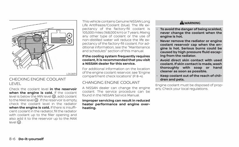
CHECKING ENGINE COOLANTLEVELCheck the coolant level in the reservoirwhen the engine is cold. If the coolantlevel is below the MIN level OB , add coolantto the MAX level OA . If the reservoir is empty,check the coolant level in the radiatorwhen the engine is cold. If there is insuffi-cient coolant in the radiator, fill the radiatorwith coolant up to the filler opening andalso add it to the reservoir up to the MAXlevel OA .
This vehicle contains Genuine NISSAN LongLife Antifreeze/Coolant (blue). The life ex-pectancy of the factory-fill coolant is105,000 miles (168,000 km) or 7 years. Mixingany other type of coolant or the use ofnon-distilled water will reduce the life ex-pectancy of the factory-fill coolant. For ad-ditional information, see the "Maintenanceand schedules" section of this manual.If the cooling system frequently requirescoolant, it is recommended that you visita NISSAN dealer for this service.For additional information on the locationof the engine coolant reservoir, see “Enginecompartment check locations” (P. 8-4).
CHANGING ENGINE COOLANTA NISSAN dealer can change the enginecoolant. The service procedure can befound in the NISSAN Service Manual.Improper servicing can result in reducedheater performance and engine over-heating.
WARNING
• To avoid the danger of being scalded,never change the coolant when theengine is hot.
• Never remove the radiator or enginecoolant reservoir cap when the en-gine is hot. Serious burns could becaused by high pressure fluid escap-ing from the radiator.
• Avoid direct skin contact with usedcoolant. If skin contact is made, washthoroughly with soap or handcleaner as soon as possible.
• Keep coolant out of the reach of chil-dren and pets.
Engine coolant must be disposed of prop-erly. Check your local regulations.
LDI2831
8-6 Do-it-yourself

CHECKING ENGINE OIL LEVEL1. Park the vehicle on a level surface and
apply the parking brake.
2. Start the engine and let it idle until itreaches operating temperature.
3. Turn off the engine. Wait more than 10minutes for the oil to drain back intothe oil pan.
4. Remove the dipstick and wipe it clean.Reinsert it all the way.
5. Remove the dipstick again and checkthe oil level. It should be between the H(High) and L (Low) marks OB . This is thenormal operating oil level range. If the oillevel is below the L (Low) mark OA , re-move the oil filler cap and pour recom-mended oil through the opening. Do notoverfill OC .
6. Recheck oil level with the dipstick.It is normal to add some oil between oilmaintenance intervals or during thebreak-in period, depending on the sever-ity of operating conditions.
CAUTION
Oil level should be checked regularly.Operating the engine with an insuffi-cient amount of oil can damage the en-gine, and such damage is not coveredby warranty.
CHANGING ENGINE OIL AND OILFILTERFor additional information on engine oiland oil filter change, refer to the instruc-tions outlined in this section.
Vehicle set-up1. Park the vehicle on a level surface and
apply the parking brake.
2. Run the engine until it reaches operatingtemperature.
3. Turn the engine off and wait for 15minutes.
4. Raise and support the vehicle using asuitable floor jack and safety jackstands.
• Place the safety jack stands under thevehicle jack-up points.
• A suitable adapter should be attached tothe jack stand saddle.
LDI3521 LDI0371
ENGINE OIL
Do-it-yourself 8-7

CAUTION
Make sure the correct lifting and sup-port points are used to avoid vehicledamage.
LDI3524
O1 Oil filler capLDI3361
O2 Oil drain plug
8-8 Do-it-yourself

LDI3624
O3 Oil filterLDI3368
O4 Oil filter access cover (Type A)(if so equipped)
LDI3625
O5 Oil filter access cover (Type B)(if so equipped)
Do-it-yourself 8-9

Removal of under-engineprotectors1. Remove bolts OA and skid plate (if so
equipped).
2. Remove bolts OB and oil filter accesscover.
Engine oil and filter1. Place a large drain pan under the drain
plug and oil filter.
2. Remove the oil filler cap.
3. Remove the drain plug with a wrench byturning it counterclockwise and com-pletely drain the oil.
LDI3626
O6 Skid plate (if so equipped)LDI3627
Skid plate (if so equipped)LDI3628
Oil filter access cover (Type A)(if so equipped)
8-10 Do-it-yourself

CAUTION
Be careful not to burn yourself, as theengine oil is hot.
WARNING
• Prolonged and repeated contactwith used engine oil may cause skincancer.
• Try to avoid direct skin contact withused oil. If skin contact is made, washthoroughly with soap or handcleaner as soon as possible.
• Keep used engine oil out of reach ofchildren.
4. Loosen the oil filter with an oil filterwrench by turning it counterclockwise.Remove the oil filter by turning it byhand.
5. Wipe the engine oil filter mounting sur-face with a clean rag.
CAUTION
Be sure to remove any old gasket ma-terial remaining on the sealing surfaceof the engine. Failure to do so couldlead to an oil leak and engine damage.• The dipstick must be inserted in
place to prevent oil spillage from thedipstick hole when filling the enginewith oil.
6. Coat the gasket on the new filter withclean engine oil.It is recommended that you use aGenuine NISSAN oil filter or equivalent,visit your NISSAN dealer parts depart-ment for proper part.
7. Screw in the oil filter clockwise until aslight resistance is felt, then tighten addi-tionally more than 2/3 turn.Oil filter tightening torque:
11 to 15 ft-lb (15.0 to 21.0 N·m)
8. Clean and re-install the drain plug with anew washer. Securely tighten the drainplug with a wrench. Do not use exces-sive force.Drain plug tightening torque:
22 to 29 ft-lb (29.4 to 39.2 N·m)
9. Refill the engine with the recommendedoil through the oil filler opening, and in-stall the oil filler cap securely.
LDI3629Oil filter access cover (Type B)
(if so equipped)
Do-it-yourself 8-11
CAUTION
Do not spill fluids on engine cover. Thiscould damage the engine cover. If flu-ids are spilled, immediately clean sur-face with a neutral detergent. Do notuse an organic solvent such as brakecleaner.
For additional information about drain andrefill capacity, see “Recommended fluids/lubricants and capacities” (P. 10-2). Thedrain and refill capacity depends on the oiltemperature and drain time. Use thesespecifications for reference only. Alwaysuse the dipstick to determine the properamount of oil in the engine.10. Start the engine and check for leakage
around the drain plug and the oil filter.Correct as required. Turn the engine offand wait more than 15 minutes. Checkthe oil level with the dipstick. Add en-gine oil if necessary.
After the operation1. Reinstall engine protectors in reverse or-
der of removal.
2. Lower the vehicle carefully to theground.
3. Reset the oil and oil filter maintenancereminder. For additional information,see “Vehicle information display” (P. 2-20).
• Dispose of waste oil and filter properly.• Check your local regulations.
When checking or replacement is required,it is recommended that you visit a NISSANdealer for this service.
CAUTION
• NISSAN recommends using GenuineNISSAN Matic P ATF. Do not mix withother fluids.
• Do not use CVT fluid or manual trans-mission fluid in this transmission.Damage caused by the use of fluidsother than as recommended is notcovered under NISSAN’s New VehicleLimited Warranty.
• Using fluids that are not equivalentto Genuine NISSAN Matic P ATF mayalso damage the transmission. Dam-age caused by the use of fluids otherthan as recommended is not coveredunder NISSAN’s New Vehicle LimitedWarranty.
AUTOMATIC TRANSMISSION FLUID(ATF)
8-12 Do-it-yourself

Check the power steering fluid level whenthe engine is stopped.The fluid level should be between the COLDMAX line and the COLD MIN line on thepower steering fluid reservoir at cold fluidtemperatures of 32° - 86°F (0° - 30°C) or atthe HOT MAX line on the power steeringfluid reservoir at hot fluid temperatures of122° - 176°F (50° - 80°C).
If the fluid is cold and is at or below theCOLD MIN line, add Genuine NISSAN PSF-IIor equivalent to the COLD MAX line. If thefluid is hot and below the HOT MAX line, addGenuine NISSAN PSF-II or equivalent to theHOT MAX line. Remove the cap and fillthrough the opening.
CAUTION
• DO NOT OVERFILL.• Do not reuse power steering fluid.• Recommended fluid is Genuine
NISSAN PSF-II or equivalent
For additional brake fluid specification in-formation, see “Recommended fluids/lubricants and capacities” (P. 10-2).
WARNING
• Use only new fluid from a sealed con-tainer. Old, inferior or contaminatedfluid may damage the brake system.The use of improper fluids can dam-age the brake system and affect thevehicle's stopping ability.
• Clean the filler cap before removing.• Brake fluid is poisonous and should
be stored carefully in marked con-tainers out of reach of children.
CAUTION
Do not spill the fluid on any painted sur-faces. This will damage the paint. If fluidis spilled, immediately wash the sur-face with water.
LDI3077
POWER STEERING FLUID (PSF) BRAKE FLUID
Do-it-yourself 8-13
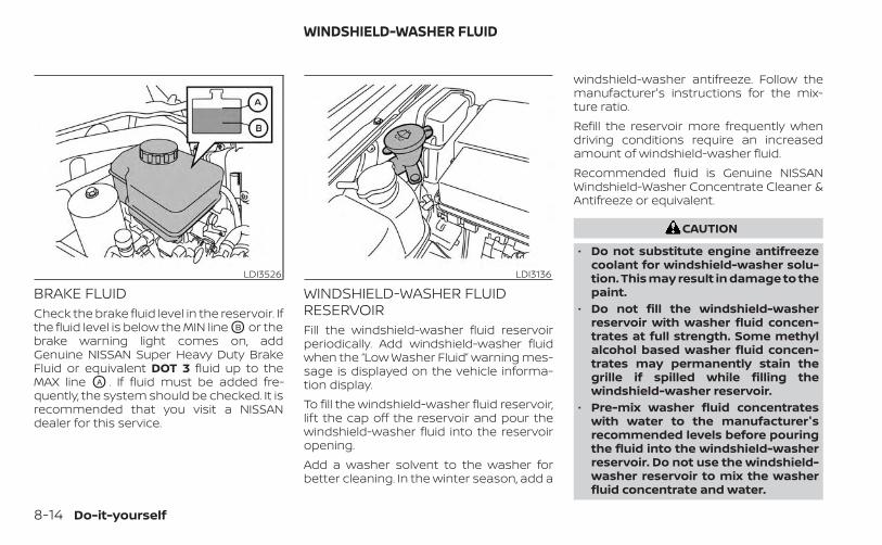
BRAKE FLUIDCheck the brake fluid level in the reservoir. Ifthe fluid level is below the MIN line OB or thebrake warning light comes on, addGenuine NISSAN Super Heavy Duty BrakeFluid or equivalent DOT 3 fluid up to theMAX line OA . If fluid must be added fre-quently, the system should be checked. It isrecommended that you visit a NISSANdealer for this service.
WINDSHIELD-WASHER FLUIDRESERVOIRFill the windshield-washer fluid reservoirperiodically. Add windshield-washer fluidwhen the “Low Washer Fluid” warning mes-sage is displayed on the vehicle informa-tion display.To fill the windshield-washer fluid reservoir,lift the cap off the reservoir and pour thewindshield-washer fluid into the reservoiropening.Add a washer solvent to the washer forbetter cleaning. In the winter season, add a
windshield-washer antifreeze. Follow themanufacturer's instructions for the mix-ture ratio.Refill the reservoir more frequently whendriving conditions require an increasedamount of windshield-washer fluid.Recommended fluid is Genuine NISSANWindshield-Washer Concentrate Cleaner &Antifreeze or equivalent.
CAUTION
• Do not substitute engine antifreezecoolant for windshield-washer solu-tion. This may result in damage to thepaint.
• Do not fill the windshield-washerreservoir with washer fluid concen-trates at full strength. Some methylalcohol based washer fluid concen-trates may permanently stain thegrille if spilled while filling thewindshield-washer reservoir.
• Pre-mix washer fluid concentrateswith water to the manufacturer'srecommended levels before pouringthe fluid into the windshield-washerreservoir. Do not use the windshield-washer reservoir to mix the washerfluid concentrate and water.
LDI3526 LDI3136
WINDSHIELD-WASHER FLUID
8-14 Do-it-yourself

Caution symbols for battery WARNING
O1No smoking, No exposed flames, No
SparksDo not expose the battery to electrical sparks, flames or smoking. Hydrogen gas generated by the
battery is explosive. Explosive gases can cause blindness or injury.
O2 Shield eyes Handle the battery cautiously. Always wear eye protection glasses to protect against explosion orbattery acid.
O3 Keep away from children Never allow children to handle the battery. Keep the battery out of the reach of children.
O4 Battery acid
Do not allow battery fluid to contact your skin, eyes, fabrics, or painted surfaces. Sulfuric acid cancause blindness or severe burns. After handling the battery or battery cap, do not touch or rub
your eyes. Thoroughly wash your hands. If the acid contacts your eyes, skin or clothing, immedi-ately flush with water for at least 15 minutes and seek medical attention. Battery fluid is acid. If the
battery fluid gets into your eyes or onto your skin, it could cause loss of your eyesight or burns.
O5 Note operating instructions Before handling the battery, read this instruction carefully to ensure correct and safe handling.
O6 Explosive gas Hydrogen gas generated by battery fluid is explosive. Explosive gases can cause blindness orinjury.
BATTERY
Do-it-yourself 8-15

• If the battery is labeled “do not open” it ismaintenance free and battery fluidshould not be checked. It is recom-mended that you visit a NISSAN dealer ora qualified specialist workshop to con-firm the battery’s performance.
• Keep the battery surface clean and dry.Clean the battery with a solution of bak-ing soda and water.
• Make certain the terminal connectionsare clean and securely tightened.
• If the vehicle is not to be used for 30 daysor longer, disconnect the negative (-) bat-tery terminal cable to prevent discharge.
NOTE:Care should be taken to avoid situationsthat can lead to potential battery dis-charge and potential no-start conditionssuch as:1. Installation or extended use of elec-
tronic accessories that consume bat-tery power when the engine is notrunning (Phone chargers, GPS, DVDplayers, etc.)
2. Vehicle is not driven regularly and/oronly driven short distances.
In these cases, the battery may need tobe charged to maintain battery health.
WARNING
• Do not expose the battery to flames,an electrical spark or a cigarette. Hy-drogen gas generated by the batteryis explosive. Explosive gases cancause blindness or injury. Do not al-low battery fluid to contact your skin,eyes, fabrics or painted surfaces. Sul-furic acid can cause blindness or in-jury. After touching a battery or bat-tery cap, do not touch or rub youreyes. Thoroughly wash your hands. Ifthe acid contacts your eyes, skin orclothing, immediately flush with wa-ter for at least 15 minutes and seekmedical attention.
• When working on or near a battery,always wear suitable eye protectionand remove all jewelry.
• Battery posts, terminals and relatedaccessories contain lead and leadcompounds. Wash hands afterhandling.
• Keep battery out of the reach ofchildren.
• Do not tip the battery.
NOTE:
Do not try to open the top of the battery.This battery is not equipped with remov-able vent caps.
JUMP STARTINGIf jump starting is necessary, see “Jumpstarting” (P. 6-11). If the engine does not startby jump starting, the battery may have tobe replaced. It is recommended that youvisit a NISSAN dealer for this service.
LDI3302
8-16 Do-it-yourself

CAUTION
• Do not ground accessories directly tothe battery terminal. Doing so willbypass the variable voltage controlsystem and the vehicle battery maynot charge completely.
• Use electrical accessories with theengine running to avoid dischargingthe vehicle battery.
NOTE:
If the battery is completely drained thetransmission will not manually shift toother positions.Your vehicle is equipped with a variablevoltage control system. This system mea-sures the amount of electrical dischargefrom the battery and controls voltage gen-erated by the generator.The current sensor OA is located near thebattery along the negative battery cable. Ifyou add electrical accessories to your ve-hicle, be sure to ground them to a suitablebody ground such as the frame or engineblock area. 1. Power steering fluid pump pulley
2. Automatic belt tensioner pulley3. Air conditioner compressor pulley4. Crankshaft pulley5. Generator pulley
WARNING
Be sure the ignition switch is in theOFF or LOCK position before servicingdrive belt. The engine could rotateunexpectedly.
LDI3525 LDI3616
VARIABLE VOLTAGE CONTROLSYSTEM
DRIVE BELT
Do-it-yourself 8-17

1. Visually inspect the belt for signs of un-usual wear, cuts, fraying or looseness. Ifthe belt is in poor condition or is loose,have it replaced or adjusted. It is recom-mended that you visit a NISSAN dealerfor this service.
2. Have the belt checked regularly for con-dition and tension in accordance withthe maintenance schedule found in the"Maintenance and schedules" section ofthis manual.
REPLACING SPARK PLUGSIridium-tipped spark plugsIt is not necessary to replace iridium-tipped OA spark plugs as frequently as con-ventional type spark plugs because theylast much longer. Follow the maintenancelog shown in the "Maintenance and sched-ules" section of this manual. Do not serviceiridium-tipped spark plugs by cleaning orregapping.• Always replace spark plugs with rec-
ommended or equivalent ones.
If replacement is required, it is recom-mended that you visit a NISSAN dealer forthis service.
SDI1895
SPARK PLUGS
8-18 Do-it-yourself

The dry paper type filter element may becleaned and reused. Replace it accordingto the maintenance log shown in the"Maintenance and schedules" section ofthis manual.To remove the air cleaner filter:1. Unlatch the clips OA and move the air
cleaner cover upward.
2. Remove the air cleaner filter.
3. Wipe the inside of the air cleaner filterhousing and the cover with a dampcloth.
NOTE:
After installing a new air cleaner filter,make sure the air cleaner cover is seatedin the housing and latch the clips OA .
WARNING
• Operating the engine with the aircleaner removed can cause you orothers to be burned. The air cleanernot only cleans the air, it stops theflame if the engine backfires. If it isn'tthere, and the engine backfires, youcould be burned. Do not drive withthe air cleaner removed, and be care-ful when working on the engine withthe air cleaner removed.
• Never pour fuel into the throttle bodyor attempt to start the engine withthe air cleaner removed. Doing socould result in serious injury.
IN-CABIN MICROFILTERThe in-cabin microfilter restricts the entryof airborne dust and pollen particles andreduces some objectionable outsideodors. The filter is located behind the glovebox. For additional information, see "Main-tenance and schedules" section of thismanual for change intervals.If replacement is required, it is recom-mended that you visit a NISSAN dealer forthis service.
LDI3630
AIR CLEANER
Do-it-yourself 8-19

CLEANINGIf your windshield is not clear after usingthe windshield-washer or if a wiper bladechatters when running, wax or other mate-rial may be on the blade or windshield.Clean the outside of the windshield with awasher solution or a mild detergent. Yourwindshield is clean if beads do not formwhen rinsing with clear water.Clean each blade by wiping it with a clothsoaked in a washer solution or a mild de-tergent. Then rinse the blades with clearwater. If your windshield is still not clearafter cleaning the blades and using thewiper, replace the blades.
CAUTION
Worn windshield wiper blades candamage the windshield and impairdriver vision.
REPLACINGReplace the wiper blades if they are worn.1. Lift the wiper arm away from the
windshield.
2. Push and hold the release tab OA , andthen move the wiper blade down OB thewiper arm to remove.
3. Remove the wiper blade.
4. Insert the new wiper blade onto thewiper arm until it clicks into place.
CAUTION
• After wiper blade replacement, re-turn the wiper arm to its original po-sition; otherwise it may be damagedwhen the hood is opened.
• Make sure the wiper blades contactthe glass; otherwise the arms may bedamaged from wind pressure.
LDI2725
WINDSHIELD WIPER BLADES
8-20 Do-it-yourself

Be careful not to let anything get into thewasher nozzle OD . This may cause cloggingor improper windshield–washer operation.If something gets into the nozzle, remove itwith a needle or small pin OC .
If the brakes do not operate properly, havethe brakes checked. It is recommendedthat you visit a NISSAN dealer for thisservice.
Self-adjusting brakesYour vehicle is equipped with self-adjustingbrakes.The front and rear disc-type brakes self-adjust every time the brake pedal isapplied.
WARNING
Have your brake system checked if thebrake pedal height does not return tonormal. It is recommended that youvisit a NISSAN dealer for this service.
Brake pad wear indicatorsThe disc brake pads on your vehicle haveaudible wear indicators. When a brake padrequires replacement, a high pitchedscraping or screeching sound will be heardwhen the vehicle is in motion. The noise willbe heard whether or not the brake pedal isdepressed. Have the brakes checked assoon as possible if the wear indicatorsound is heard.
Under some driving or climate conditions,occasional brake squeak, squeal or othernoise may be heard. Occasional brakenoise during light to moderate stops is nor-mal and does not affect the function orperformance of the brake system.Proper brake inspection intervals shouldbe followed. For additional information re-garding brake inspections, see the appro-priate maintenance schedule informationin the "Maintenance and schedules" sec-tion of this manual.
LDI2710
BRAKES
Do-it-yourself 8-21

Two types of fuses are used. Type OA isused in the fuse boxes in the engine com-partment. Type OB is used in the passengercompartment and engine compartmentfuse boxes. Type OA fuses are provided asspare fuses. There are no spare fuses in theengine compartment.
If a type OA fuse is used to replace a type OB
fuse, the type OA fuse will not be level withthe fuse pocket as shown in the illustration.This will not affect the performance of thefuse. Make sure the fuse is installed in thefuse box securely.Type OB fuses cannot be installed in theunderhood fuse boxes. Only use type OA
fuses in the underhood fuse boxes.
NOTE:
Your vehicle may not be equipped withall fuses listed on the fuse label.
ENGINE COMPARTMENTWARNING
Never use a fuse of a higher or loweramperage rating than that specified onthe fuse box cover. This could damagethe electrical system or electronic con-trol units or cause a fire.
LDI0455 LDI0457 LDI2838
FUSES
8-22 Do-it-yourself

If any electrical equipment does not comeon, check for an open fuse.1. Be sure the ignition switch and the head-
light switch are OFF.
2. Open the engine hood.
3. Remove the fuse box cover by pushingthe tab and lifting the cover up.
4. Remove the fuse with the fuse puller.The fuse puller is located in the centerof the fuse block in the passengercompartment.
5. If the fuse is open OA , replace it with anew fuse OB .
6. If a new fuse also opens, have the elec-trical system checked and repaired. It isrecommended that you visit a NISSANdealer for this service.
Fusible linksIf the electrical equipment does not oper-ate and fuses are in good condition, checkthe fusible links. If any of these fusible linksare melted, replace with only GenuineNISSAN parts.
LDI2826 LDI0456
Do-it-yourself 8-23

PASSENGER COMPARTMENTWARNING
Never use a fuse of a higher or loweramperage rating than that specified onthe fuse box cover. This could damagethe electrical system or electronic con-trol units or cause a fire.
If any electrical equipment does not oper-ate, check for an open fuse.1. Be sure the ignition switch and the head-
light switch are OFF.
2. Open glove box and pull the fuse boxcover to remove.
3. Remove the fuse with the fuse puller.
4. If the fuse is open OA , replace it with anequivalent good fuse OB .
5. Reverse step 2 to reinstall fuse box cover.
6. If a new fuse also opens, have the elec-trical system checked and repaired. It isrecommended that you visit a NISSANdealer for this service.
NOTE:
Your vehicle may not be equipped withall fuses listed on the fuse label.
LDI3640 LDI0456
8-24 Do-it-yourself

CAUTION
Be careful not to allow children to swal-low the battery or removed parts.
NISSAN INTELLIGENT KEY®
Replace the battery in the Intelligent Key asfollows:1. Remove the mechanical key from the
Intelligent Key.
2. Insert a small flathead screwdriver OA
into the slit OB of the corner and twist itto separate the upper part from thelower part. Place a cloth over the screw-driver to protect the casing.
LDI2001
BATTERY REPLACEMENT
Do-it-yourself 8-25

3. Replace the battery with a new one.Recommended battery: CR2032 orequivalent.• Do not touch the internal circuit and
electric terminals as doing so couldcause a malfunction.
• Hold the battery by the edges. Holdingthe battery across the contact pointswill seriously deplete the storagecapacity.
• Make sure that the + side faces thebottom of the lower part.
4. Close the lid securely as illustrated withOC and OD .
5. Operate the buttons to check theoperation.
If you need assistance with replacement, itis recommended that you visit a NISSANdealer for this service.
FCC Notice:For USA:This device complies with Part 15 of theFCC Rules. Operation is subject to the fol-lowing two conditions: (1) This devicemay not cause harmful interference, and(2) this device must accept any interfer-ence received, including interferencethat may cause undesired operation.Note:Changes or modifications not expresslyapproved by the party responsible forcompliance could void the user’s author-ity to operate the equipment.For Canada:This device contains licence-exempttransmitter(s)/receiver(s) that complywith Innovation, Science and EconomicDevelopment Canada’s licence-exemptRSS(s). Operation is subject to the fol-lowing two conditions: (1) This devicemay not cause interference. (2) This de-vice must accept any interference, in-cluding interference that may cause un-desired operation of the device.
LDI2637
8-26 Do-it-yourself

HEADLIGHTSFor additional information on headlightbulb replacement, refer to the instructionsoutlined in this section.
Replacing the halogen headlightbulb (if so equipped)The headlight is a semi-sealed beam typewhich uses a replaceable headlight (halo-gen) bulb. Because the headlight assemblymust be removed from the vehicle for bulbreplacement, it is recommended that youvisit a NISSAN dealer for this service.
CAUTION
• High pressure halogen gas is sealedinside the halogen bulb. The bulbmay break if the glass envelope isscratched or the bulb is dropped.
• When handling the bulb, do not touchthe glass envelope.
• DO NOT TOUCH THE BULB WITH BAREHANDS.
• Use the same number and wattageas shown in the chart.
• Do not leave the bulb out of the head-light reflector for a long period oftime as dust, moisture and smokemay enter the headlight body andaffect the performance of theheadlight.
• Aiming is not necessary after replac-ing the bulb. When aiming adjust-ment is necessary, it is recom-mended that you visit a NISSANdealer for this service.
Fog may temporarily form inside the lensof the exterior lights in the rain or in a carwash. A temperature difference betweenthe inside and the outside of the lenscauses the fog. This is not a malfunction. Iflarge drops of water collect inside the lens,it is recommended that you visit a NISSANdealer for servicing.
Replacing the LED headlight bulb(if so equipped)If LED headlight bulb replacement is re-quired, it is recommended that you visit aNISSAN dealer for this service.
FOG LIGHTS (if so equipped)For additional information on fog light bulbreplacement, refer to the instructions out-lined in this section.
Replacing the fog light bulb (if soequipped)If fog light bulb replacement is required, it isrecommended that you visit a NISSANdealer for this service.
CAUTION
• High pressure halogen gas is sealedinside the halogen bulb. The bulbmay break if the glass envelope isscratched or the bulb is dropped.
• When handling the bulb, do not touchthe glass envelope.
• Use the same number and wattageas originally installed as shown in thechart.
• Do not leave the bulb out of the foglight for a long period of time as dust,moisture and smoke may enter thefog light body and affect the perfor-mance of the fog light.
LIGHTS
Do-it-yourself 8-27

Replacing the LED fog light bulb(if so equipped)If LED fog light bulb replacement is re-quired, it is recommended that you visit aNISSAN dealer for this service.
EXTERIOR AND INTERIOR LIGHTS
Item Wattage (W) Bulb No.*Headlight assembly (Type A) (if so equipped)*
Low/High 55/65 HB5Turn/Park 28/8 7444NASide marker — —
Headlight assembly (Type B) (if so equipped)*Low — —High — —Turn — —Daytime Running Light (DRL)/Park — —Side marker — —
Fog light (if so equipped)* — —Fog light assembly (if so equipped)*
Fog 35 H8Daytime Running Light (DRL) 21 W21W
Map light (Type A) (if so equipped) 8 —Map light (Type B) (if so equipped)* — —Vanity mirror light (if so equipped)* 1.4 —Room light (Type A) (if so equipped) 8 —Room light (Type B) (if so equipped)* — —Glove box light (if so equipped)* 1 —High-mounted stop light/cargo light* 12.8 912Bed light (if so equipped)* — —Rear combination light*
Tail — —Stop/turn — —Backup — —
License plate light* — —
* It is recommended that you visit an NISSAN dealer for replacement.
Always check with the Parts Department at a NISSAN dealer for the latest partsinformation.
8-28 Do-it-yourself

1. Room light2. Map light3. Headlight assembly
4. Fog light/Fog light assembly(if so equipped)
5. Bed light (if so equipped)
6. High-mount stop light/cargo light7. Rear combination light8. License plate light
LDI3631
Do-it-yourself 8-29

Replacement proceduresAll other lights are either type A, B, C or D.When replacing a bulb, first remove the lensand/or cover using a cloth and suitable tool.
: Indicates bulb removal: Indicates bulb installation
Use a cloth O1 to protect the housing. Use a cloth O1 to protect the housing.
WDI0306
LDI0478Map light (Type A) (if so equipped)
WDI0206Room light (Type A) (if so equipped)
8-30 Do-it-yourself

If you have a flat tire, see “Flat tire”(P. 6-3).
TIRE PRESSURE
Tire Pressure Monitoring System(TPMS)
WARNING
Radio waves could adversely af-fect electric medical equipment.Those who use a pacemakershould contact the electric medi-cal equipment manufacturer forthe possible influences beforeuse.
This vehicle is equipped with TPMS. Itmonitors tire pressure of all tires ex-cept the spare. When the low tire pres-sure warning light is lit and the “TirePressure Low - Add Air” warning mes-sage is displayed in the vehicle infor-mation display, one or more of yourtires is significantly under-inflated.
TPMS will activate only when the ve-hicle is driven at speeds above 16mph (25 km/h). Also, this systemmay not detect a sudden drop in tirepressure (for example, a flat tire whiledriving).For additional information, see “Lowtire pressure warning light” (P. 2-15),“Tire Pressure Monitoring System(TPMS)” (P. 5-5) and “Flat tire” in the(P. 6-3).
Tire inflation pressureCheck the tire pressures (includingthe spare) often and always prior tolong distance trips. The recom-mended tire pressure specificationsare shown on the F.M.V.S.S./C.M.V.S.S.certification label or the Tire andLoading Information label under the“Cold Tire Pressure” heading. The Tireand Loading Information label is af-fixed to the driver side center pillar.
Tire pressures should be checkedregularly because:• Most tires naturally lose air over
time.• Tires can lose air suddenly when
driven over potholes or other ob-jects or if the vehicle strikes a curbwhile parking.
The tire pressures should bechecked when the tires are cold. Thetires are considered COLD after thevehicle has been parked for 3 ormore hours, or driven less than 1 mile(1.6 km) at moderate speeds.
WHEELS AND TIRES
Do-it-yourself 8-31

Incorrect tire pressure, includingunder inflation, may adversely af-fect tire life and vehicle handling.
WARNING
• Improperly inflated tires canfail suddenly and cause anaccident.
• The Gross Vehicle Weight Rat-ing (GVWR) is located on theF.M.V.S.S./C.M.V.S.S. certifica-tion label. The vehicle weightcapacity is indicated on the Tireand Loading Information label.Do not load your vehicle be-yond this capacity. Overload-ing your vehicle may result inreduced tire life, unsafe operat-ing conditions due to prema-ture tire failure, or unfavorablehandling characteristics andcould also lead to a serious ac-cident. Loading beyond thespecified capacity may also re-sult in failure of other vehiclecomponents.
• Before taking a long trip, orwhenever you heavily loadyour vehicle, use a tire pressuregauge to ensure that the tirepressures are at the specifiedlevel.
• For additional information re-garding tires, refer to “Impor-tant Tire Safety Information”(US) or “Tire Safety Informa-tion” (Canada) in the WarrantyInformation Booklet.
8-32 Do-it-yourself

Tire and Loading Informationlabel�1 Seating capacity: The maximum
number of occupants that canbe seated in the vehicle.
�2 Vehicle load limit: See “Vehicleloading information” (P. 10-16).
�3 Original tire size: The size of thetires originally installed on the ve-hicle at the factory.
�4 Cold tire pressure: Inflate the tiresto this pressure when the tires arecold. Tires are considered COLDafter the vehicle has been parkedfor 3 or more hours, or driven lessthan 1 mile (1.6 km) at moderatespeeds. The recommended coldtire inflation is set by the manu-facturer to provide the best bal-ance of tire wear, vehicle handling,driveability, tire noise, etc., up tothe vehicle's GVWR.
�5 Tire size: See “Tire labeling”(P. 8-35).
�6 Spare tire size.
LDI2007
Do-it-yourself 8-33
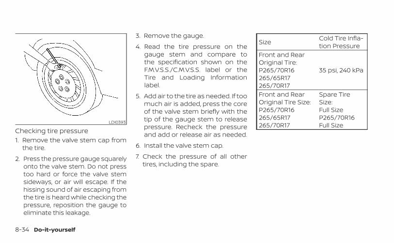
Checking tire pressure1. Remove the valve stem cap from
the tire.
2. Press the pressure gauge squarelyonto the valve stem. Do not presstoo hard or force the valve stemsideways, or air will escape. If thehissing sound of air escaping fromthe tire is heard while checking thepressure, reposition the gauge toeliminate this leakage.
3. Remove the gauge.
4. Read the tire pressure on thegauge stem and compare tothe specification shown on theF.M.V.S.S./C.M.V.S.S. label or theTire and Loading Informationlabel.
5. Add air to the tire as needed. If toomuch air is added, press the coreof the valve stem briefly with thetip of the gauge stem to releasepressure. Recheck the pressureand add or release air as needed.
6. Install the valve stem cap.
7. Check the pressure of all othertires, including the spare.
Size Cold Tire Infla-tion Pressure
Front and RearOriginal Tire:P265/70R16265/65R17265/70R17
35 psi, 240 kPa
Front and RearOriginal Tire Size:P265/70R16265/65R17265/70R17
Spare TireSize:Full SizeP265/70R16Full SizeLDI0393
8-34 Do-it-yourself

TIRE LABELINGFederal law requires tire manufac-turers to place standardized infor-mation on the sidewall of all tires.This information identifies and de-scribes the fundamental character-istics of the tire and also provides theTire Identification Number (TIN) forsafety standard certification. The TINcan be used to identify the tire incase of a recall.
O1 Tire size (example: P215/65R1595H)1. P: The “P” indicates the tire is de-
signed for passenger vehicles (notall tires have this information).
2. Three-digit number (215): Thisnumber gives the width in milli-meters of the tire from sidewalledge to sidewall edge.
3. Two-digit number (65): This num-ber, known as the aspect ratio,gives the tire's ratio of height towidth.
4. R: The “R” stands for radial.
5. Two-digit number (15): This num-ber is the wheel or rim diameter ininches.
WDI0394Example
WDI0395Example
Do-it-yourself 8-35

6. Two- or three-digit number (95):This number is the tire's load in-dex. It is a measurement of howmuch weight each tire cansupport.
7. H: Tire speed rating. You shouldnot drive the vehicle faster thanthe tire speed rating.
O2 TIN (Tire Identification Number)for a new tire (example: DOT XX XXXXX XXXX)1. DOT: Abbreviation for the “Depart-
ment Of Transportation”. Thesymbol can be placed above, be-low or to the left or right of the TireIdentification Number.
2. Two-digit code: Manufacturer'sidentification mark.
3. Two-digit code: Tire size.
4. Three-digit code: Tire type code(Optional).
5. Four numbers represent theweek and year the tire was built.For example, the numbers 3103means the 31st week of 2003. Ifthese numbers are missing thenlook on the other sidewall of thetire.
LDI2786Example (Type A) (if so equipped)
8-36 Do-it-yourself

O2 TIN (Tire Identification Number)for a new tire (example: DOT XXXXXXXXX XXXX)1. DOT: Abbreviation for the “Depart-
ment Of Transportation”. Thesymbol can be placed above, be-low or to the left of the Tire Identi-fication Number.
2. Three-digit code: Manufacturer'sidentification mark.
3. Six-digit code: Descriptive codeused to identify significant char-acteristics of the tire.
4. Four numbers represent theweek and year the tire was built.For example, the numbers 3103means the 31st week of 2003.
O3 Tire ply composition and materialThe number of layers or plies ofrubber-coated fabric in the tire. Tiremanufacturers also must indicatethe materials in the tire, which in-clude steel, nylon, polyester andothers.
O4 Maximum permissible inflationpressureThis number is the greatest amountof air pressure that should be put inthe tire. Do not exceed the maximumpermissible inflation pressure.
O5 Maximum load ratingThis number indicates the maxi-mum load in kilograms and poundsthat can be carried by the tire. Whenreplacing the tires on the vehicle, al-ways use a tire that has the sameload rating as the factory installedtire.
LDI3639Example (Type B) (if so equipped)
Do-it-yourself 8-37

O6 Term of “tubeless” or “tube type”Indicates whether the tire requiresan inner tube (“tube type”) or not(“tubeless”).
O7 The word “radial”The word “radial” is shown if the tirehas radial structure.
O8 Manufacturer or brand nameManufacturer or brand name isshown.
Other Tire-related TerminologyIn addition to the many terms thatare defined throughout this section,Intended Outboard Sidewall is (1) thesidewall that contains a whitewall,bears white lettering or bearsmanufacturer, brand, and/or modelname molding that is higher ordeeper than the same molding onthe other sidewall of the tire, or (2)the outward facing sidewall of an
asymmetrical tire that has a particu-lar side that must always face out-ward when mounted on a vehicle.
TYPES OF TIRES
WARNING
• When changing or replacing tires, besure all four tires are of the same type(i.e., Summer, All Season or Snow)and construction. A NISSAN dealermay be able to help you with infor-mation about tire type, size, speedrating and availability.
• Replacement tires may have a lowerspeed rating than the factoryequipped tires, and may not matchthe potential maximum vehiclespeed. Never exceed the maximumspeed rating of the tire.
• Replacing tires with those not origi-nally specified by NISSAN could af-fect the proper operation of the lowtire pressure warning system.
• Always use tires of the same type,size, brand, construction and treadpattern on all four wheels. Failure todo so may result in a circumferencedifference between tires on the frontand rear axles which can cause theVehicle Dynamic Control (VDC) sys-tem to malfunction resulting in per-sonal injury or death, excessive tirewear and may damage the transmis-sion and differential gears.
• For additional information regardingtires, refer to “Important Tire SafetyInformation” (US) or “Tire Safety In-formation” (Canada) in the WarrantyInformation Booklet.
All season tiresNISSAN specifies All Season tires on somemodels to provide good performance allyear, including snowy and icy road condi-tions. All Season tires are identified by ALLSEASON and/or M&S on the tire sidewall.Snow tires have better snow traction thanAll Season tires and may be more appropri-ate in some areas.
8-38 Do-it-yourself

Summer tiresNISSAN specifies summer tires on somemodels to provide superior performanceon dry roads. Summer tire performance issubstantially reduced in snow and ice.Summer tires do not have the tire tractionrating “M&S” on the tire sidewall.If you plan to operate your vehicle in snowyor icy conditions, NISSAN recommends theuse of SNOW tires or ALL SEASON tires on allfour wheels.
Snow tiresIf snow tires are needed, it is necessary toselect tires equivalent in size and load rat-ing to the original equipment tires. If you donot, it can adversely affect the safety andhandling of your vehicle.Generally, snow tires have lower speed rat-ings than factory equipped tires and maynot match the potential maximum vehiclespeed. Never exceed the maximum speedrating of the tire.If you install snow tires, they must be thesame size, brand, construction and treadpattern on all four wheels.
For additional traction on icy roads, stud-ded tires may be used. However, some U.S.states and Canadian provinces prohibittheir use. Check local, state and provinciallaws before installing studded tires. Skidand traction capabilities of studded snowtires on wet or dry surfaces may be poorerthan that of non-studded snow tires.
TIRE CHAINSUse of tire chains may be prohibited ac-cording to location. Check the local lawsbefore installing tire chains. When installingtire chains, make sure they are the propersize for the tires on your vehicle and areinstalled according to the chain manufac-turer's suggestions. Use only SAE class “S”chains. Class “S” chains are used on ve-hicles with restricted tire to vehicle clear-ance. Vehicles that can use Class “S” chainsare designed to meet the minimum clear-ances between the tire and the closest ve-hicle suspension or body component re-quired to accommodate the use of awinter traction device (tire chains orcables). The minimum clearances are de-termined using the factory equipped tiresize. Other types may damage your vehicle.Use chain tensioners when recommendedby the tire chain manufacturer to ensure atight fit. Loose end links of the tire chain
must be secured or removed to preventthe possibility of whipping action damageto the fenders or underbody. If possible,avoid fully loading your vehicle when usingtire chains. In addition, drive at a reducedspeed. Otherwise, your vehicle may bedamaged and/or vehicle handling andperformance may be adversely affected.Tire chains must be installed only on therear wheels and not on the front wheels.Do not use tire chains on dry roads. Drivingwith chains in such conditions can causedamage to the various mechanisms of thevehicle due to some overstress.Use only the 2WD range when driving onclear paved roads.
Do-it-yourself 8-39

CHANGING WHEELS AND TIRESTire rotationNISSAN recommends rotating thetires every 7,500 miles (12,000 km).For additional information on tire re-placing procedures, see “Flat tire”(P. 6-3).As soon as possible, tighten thewheel nuts to the specified torquewith a torque wrench.
Wheel nut tightening torque:98 ft-lb (133 N·m)
The wheel nuts must be kept tight-ened to specifications at all times.It is recommended that wheel nutsbe tightened to specification ateach tire rotation interval.
WARNING
• After rotating the tires, checkand adjust the tire pressure.
• Retighten the wheel nuts whenthe vehicle has been driven for600 miles (1,000 km) (also incases of a flat tire, etc.).
• Do not include the spare tire inthe tire rotation.
• For additional information re-garding tires, refer to “Impor-tant Tire Safety Information”(US) or “Tire Safety Informa-tion” (Canada) in the WarrantyInformation Booklet.
Tire wear and damage1. Wear indicator
2. Location mark
WDI0258 WDI0259
8-40 Do-it-yourself

WARNING
• Tires should be periodically in-spected for wear, cracking,bulging or objects caught inthe tread. If excessive wear,cracks, bulging or deep cutsare found, the tire(s) should bereplaced.
• The original tires have built-intread wear indicators. Whenthe wear indicators are visible,the tire(s) should be replaced.
• Tires degrade with age anduse. Have tires, including thespare, over 6 years old checkedby a qualified technician be-cause some tire damage maynot be obvious. Replace thetires as necessary to preventtire failure and possible per-sonal injury.
• Improper service of the sparetire may result in serious per-sonal injury. If it is necessary torepair the spare tire, it is rec-ommended that you visit aNISSAN dealer for this service.
• For additional information re-garding tires, refer to “Impor-tant Tire Safety Information”(US) or “Tire Safety Informa-tion” (Canada) in the WarrantyInformation Booklet.
Replacing wheels and tiresWhen replacing a tire, use the same size,tread design, speed rating and load carry-ing capacity as originally equipped. For ad-ditional information, see “Wheels and tires”(P. 10-10).
WARNING
• The use of tires other than those rec-ommended or the mixed use of tiresof different brands, construction(bias, bias-belted or radial), or treadpatterns can adversely affect theride, braking, handling, Vehicle Dy-namic Control (VDC) system, groundclearance, body-to-tire clearance,tire chain clearance, speedometercalibration, headlight aim and bum-per height. Some of these effectsmay lead to accidents and could re-sult in serious personal injury.
• If your vehicle was originallyequipped with four tires that werethe same size and you are only re-placing two of the four tires, installthe new tires on the rear axle. Placingnew tires on the front axle may causeloss of vehicle control in some drivingconditions and cause an accidentand personal injury.
Do-it-yourself 8-41

• If the wheels are changed for anyreason, always replace with wheelswhich have the same off-set dimen-sion. Wheels of a different off-setcould cause premature tire wear, de-grade vehicle handling characteris-tics, affect the VDC system and/or in-terference with the brake discs. Suchinterference can lead to decreasedbraking efficiency and/or early brakepad wear. For additional informationon wheel off-set dimensions, see“Wheels and tires” (P. 10-10).
• When using a wheel without theTPMS such as the spare tire, the TPMSwill not function and the low tirepressure warning light will flash forapproximately 1 minute. The light willremain on after 1 minute. Have yourtires replaced and/or TPMS systemreset as soon as possible. It is recom-mended that you visit a NISSANdealer for this service.
• Replacing tires with those not origi-nally specified by NISSAN could af-fect the proper operation of theTPMS.
• The TPMS sensor may be damaged ifit is not handled correctly. Be carefulwhen handling the TPMS sensor.
• When replacing the TPMS sensor, theID registration may be required. It isrecommended that you visit aNISSAN dealer for ID registration.
• Do not use a valve stem cap that isnot specified by NISSAN. The valvestem cap may become stuck.
• Be sure that the valve stem caps arecorrectly fitted. Otherwise the valvemay be clogged up with dirt andcause a malfunction or loss ofpressure.
• Do not install a damaged or de-formed wheel or tire even if it hasbeen repaired. Such wheels or tirescould have structural damage andcould fail without warning.
• The use of retread tires is notrecommended.
• For additional information regardingtires, refer to “Important Tire SafetyInformation” (US) or “Tire Safety In-formation” (Canada) in the WarrantyInformation Booklet.
Four-wheel drive models
CAUTION
Always use tires of the same type, size,brand, construction (bias, bias-beltedor radial), and tread pattern on all fourwheels. Failure to do so may result in acircumference difference between tireson the front and rear axles which willcause excessive tire wear and maydamage the transmission, transfercase and differential gears.
If excessive tire wear is found, it is recom-mended that all four tires be replaced withtires of the same size, brand, constructionand tread pattern. The tire pressure andwheel alignment should also be checkedand corrected as necessary. It is recom-mended that you visit a NISSAN dealer forthis service.
Wheel balanceUnbalanced wheels may affect vehiclehandling and tire life. Even with regular use,wheels can get out of balance. Therefore,they should be balanced as required.
8-42 Do-it-yourself

Wheel balance service should be per-formed with the wheels off the vehicle.Spin balancing the wheels on the vehiclecould lead to mechanical damage.• For additional information regarding
tires, refer to “Important Tire Safety In-formation” (US) or “Tire Safety Informa-tion” (Canada) in the Warranty Informa-tion Booklet.
Care of wheels• Wash the wheels when washing the ve-
hicle to maintain their appearance.• Clean the inner side of the wheels when
the wheel is changed or the underside ofthe vehicle is washed.
• Do not use abrasive cleaners whenwashing the wheels.
• Inspect wheel rims regularly for dents orcorrosion. Such damage may cause lossof pressure or poor seal at the tire bead.
• NISSAN recommends waxing the roadwheels to protect against road salt in ar-eas where it is used during winter.
Spare tire (FULL SIZE TEMPORARYUSE ONLY spare tire)When using a wheel without the TPMS suchas the spare tire, the TPMS will not function.Your vehicle may be equipped with a fullsize spare that is a different size or brandthan the tires originally installed on the ve-hicle. This full size spare tire is intended fortemporary use only and should be re-placed at the first opportunity.Observe the following precautions if theFULL SIZE TEMPORARY USE ONLY spare tiremust be used. Otherwise, your vehiclecould be damaged or involved in anaccident:
WARNING
To help reduce the risk of a crash whichmay result in personal injury or death:• The TEMPORARY FULL SIZE spare tire
should be used for emergency useonly. It should be replaced with thestandard tire at the first opportunityto avoid possible tire or differentialdamage.
• Drive carefully while the TEMPORARYFULL SIZE spare tire is installed. Avoidsharp turns and abrupt braking whiledriving. The vehicle driving perfor-mance may be affected when drivingon wet or snow covered roads.
• When the TEMPORARY FULL SIZEspare tire is installed, the Vehicle Dy-namic Control (VDC) will normally notbe affected.
• When the TEMPORARY FULL SIZEspare tire is installed, the followingsystems may not work correctly:– Tire Pressure Monitoring System
(TPMS)– Automatic Emergency Braking
• Periodically check the TEMPORARYFULL SIZE spare tire inflation pres-sure. Always keep the TEMPORARYFULL SIZE spare tire inflated to thepressure specification shown on theTire and Loading Information label.
• With the TEMPORARY FULL SIZE sparetire installed do not drive the vehicleat speeds faster than 50 mph (80km/h).
Do-it-yourself 8-43

• When driving on roads covered withsnow or ice, the TEMPORARY FULLSIZE spare tire should be used on thefront wheels and the original tireused on the rear wheels. Use tirechains only on the drive wheels.
• Do not use the TEMPORARY FULL SIZEspare tire on other vehicles.
• Do not use more than one TEMPO-RARY FULL SIZE spare tire at the sametime.
• Do not tow a trailer when the TEMPO-RARY FULL SIZE spare tire is installed.
CAUTION
• Do not use tire chains on a TEMPO-RARY FULL SIZE spare tire. Tire chainswill not fit properly and may causedamage to the vehicle.
• Use of the TEMPORARY FULL SIZEspare tire on a vehicle that has tireslarger than were originally equippedcan affect the 4WD System. This mayresult in a circumference differencebetween tires on front and rear axleswhich can cause the 4WD system toautomatically place the vehicle in2WD and flash the 4WD light. Whenthe TEMPORARY FULL SIZE spare tireis replaced with a tire that matchesall other tires on the vehicle, and alltires are properly inflated the 4WDsystem will operate normally.
8-44 Do-it-yourself

9 Maintenance and schedules
Maintenance requirements . . . . . . . . . . . . . . . . . . . . . 9-2General maintenance . . . . . . . . . . . . . . . . . . . . . . . . 9-2Scheduled maintenance . . . . . . . . . . . . . . . . . . . . . 9-2Where to go for service . . . . . . . . . . . . . . . . . . . . . . . 9-2
General maintenance . . . . . . . . . . . . . . . . . . . . . . . . . . . 9-2Explanation of general maintenanceitems . . . . . . . . . . . . . . . . . . . . . . . . . . . . . . . . . . . . . . . . 9-2
Explanation of scheduled maintenance items . . . 9-5Emission control system maintenance: . . . . . . 9-6Chassis and body maintenance: . . . . . . . . . . . . . 9-6
Maintenance schedules . . . . . . . . . . . . . . . . . . . . . . . . . 9-7Additional maintenance items forsevere operating conditions . . . . . . . . . . . . . . . . . . 9-73.8L 6 cylinder (VQ38DD engine model) . . . . . . . 9-8

Some day-to-day and regular mainte-nance is essential to maintain your vehiclegood mechanical condition, as well as itsemissions and engine performance.It is the owner's responsibility to make surethat the scheduled maintenance, as well asgeneral maintenance, is performed.As the vehicle owner, you are the only onewho can ensure that your vehicle receivesproper maintenance. You are a vital link inthe maintenance chain.
GENERAL MAINTENANCEGeneral maintenance includes those itemswhich should be checked during normalday-to-day operation. They are essentialfor proper vehicle operation. It is your re-sponsibility to perform these proceduresregularly as prescribed.Performing general maintenance checksrequires minimal mechanical skill and onlya few general automotive tools.These checks or inspections can be doneby yourself, a qualified technician or, if youprefer, a NISSAN dealer.
SCHEDULED MAINTENANCEThe maintenance items listed in this sec-tion are required to be serviced at regularintervals. However under severe drivingconditions, additional or more frequentmaintenance will be required.
WHERE TO GO FOR SERVICEIf maintenance service is required or yourvehicle appears to malfunction, have thesystems checked and serviced. It is recom-mended that you visit a NISSAN dealer forthis service.NISSAN technicians are well-trained spe-cialists and are kept up-to-date with thelatest service information through techni-cal bulletins, service tips and training pro-grams. They are fully qualified to work onNISSAN vehicles before work begins.If your vehicle is involved in a collision, it isrecommended that you ask your NISSANdealer where the nearest NISSAN CertifiedCollision Center is located, or go tohttp://collision.nissanusa.com.You can be confident that a NISSAN deal-er's service department can perform theservice needed to meet the maintenancerequirements on your vehicle.
During the normal day-to-day operation ofthe vehicle, general maintenance shouldbe performed regularly as prescribed inthis section. If you detect any unusualsounds, vibrations or smells, be sure tocheck for the cause or have it checkedpromptly. In addition, it is recommendedthat you visit a NISSAN dealer if you thinkthat repairs are required.When performing any checks or mainte-nance work, see “Maintenance precau-tions” (P. 8-2).
EXPLANATION OF GENERALMAINTENANCE ITEMS
WARNING
Failure to follow the procedures listedwithin this section may result in per-sonal injury.
Additional information on the followingitems with “ * ” is found in the “Do-it-yourself” section of this manual.
Outside the vehicleThe maintenance items listed here shouldbe performed from time to time, unlessotherwise specified.
MAINTENANCE REQUIREMENTS GENERAL MAINTENANCE
9-2 Maintenance and schedules

Doors and engine hood: Check that thedoors and engine hood operate properly.Also ensure that all latches lock securely.Lubricate hinges, latches, latch pins, rollersand links if necessary. Make sure that thesecondary latch keeps the hood fromopening when the primary latch isreleased.When driving in areas using road salt orother corrosive materials, check lubrica-tion frequently.Check that the gas stays or struts properlyand securely hold the hood, trunk, or rearhatch fully open. If the hood, trunk, or rearhatch is not held open, have the gas staysor struts replaced.Lights*: Clean the headlights on a regularbasis. Make sure that the headlights, stoplights, tail lights, turn signal lights, and otherlights are all operating properly and in-stalled securely. Also check headlight aim.Road wheel nuts (lug nuts)*: When check-ing the tires, make sure no wheel nuts aremissing, and check for any loose wheelnuts. Tighten if necessary.Tire rotation*: Rotate tires at the specifiedinterval shown in the maintenanceschedule.
Tires*: Check the pressure with a gaugeoften and always prior to long distancetrips. If necessary, adjust the pressure in alltires, including the spare, to the pressurespecified. Check carefully for damage, cutsor excessive wear.Tire Pressure Monitoring System (TPMS)tire pressure sensor: It is recommendedthat you replace the tire pressure sensorassembly when the tires are replaced dueto wear or age.Wheel alignment and balance: If the ve-hicle should pull to either side while drivingon a straight and level road, or if you detectuneven or abnormal tire wear, there maybe a need for wheel alignment. If the steer-ing wheel or seat vibrates at normal high-way speeds, wheel balancing may beneeded.For additional information regarding tires,refer to “Important Tire Safety Information”(US) or “Tire Safety Information” (Canada) inthe Warranty Information Booklet.Windshield: Clean the windshield on aregular basis. Check the windshield at leastevery six months for cracks or other dam-age. Have a damaged windshield repairedby a qualified repair facility. It is recom-mended that you have a damaged wind-
shield repaired by a NISSAN dealer, or aNISSAN Certified Collision Center. To locatea collision center in your area, refer tohttp://collision.nissanusa.com.Windshield wiper blades*: Check forcracks or wear if they do not wipe properly.
Inside the vehicleThe maintenance items listed here shouldbe checked on a regular basis, such aswhen performing scheduled maintenance,cleaning the vehicle, etc.Accelerator pedal: Check the pedal forsmooth operation and make sure thepedal does not catch or require uneveneffort. Keep the floor mat away from thepedal.Automatic transmission P (Park) mecha-nism: On a fairly steep hill check that thevehicle is held securely with the shift leverin the P (Park) position without applying anybrakes.Brake pedal: Check the pedal for smoothoperation. If the brake pedal suddenly goesdown further than normal, the pedal feelsspongy or the vehicle seems to take longerto stop, have your vehicle checked imme-diately. It is recommended that you visit a
Maintenance and schedules 9-3

NISSAN dealer for this service. Keep thefloor mat away from the pedal.Brakes: Check that the brakes do not pullthe vehicle to one side when applied.Parking brake: Check the parking brakeoperation regularly. The vehicle should besecurely held on a fairly steep hill with onlythe parking brake applied. If the parkingbrake needs adjustment, it is recom-mended that you visit a NISSAN dealer forthis service.Seats: Check seat position controls suchas seat adjusters, seatback recliner, etc., toensure they operate smoothly and alllatches lock securely in every position.Check that the head restraints/headrestsmove up and down smoothly and the locks(if so equipped) hold securely in all latchedpositions.Seat belts: Check that all parts of the seatbelt system (for example, buckles, anchors,adjusters and retractors) operate properlyand smoothly, and are installed securely.Check the belt webbing for cuts, fraying,wear or damage.Steering wheel: Check for changes in thesteering system, such as excessive freeplay, hard steering or strange noises.
Warning lights and chimes: Make sure allwarning lights and chimes are operatingproperly.Windshield defroster: Check that the aircomes out of the defroster outlets properlyand in sufficient quantity when operatingthe heater or air conditioner.Windshield wiper and washer*: Checkthat the wipers and washer operate prop-erly and that the wipers do not streak.
Under the hood and vehicleThe maintenance items listed here shouldbe checked periodically (for example, eachtime you check the engine oil or refuel).Battery (for maintenance free batter-ies)*: This vehicle is equipped with a sealedmaintenance free battery. It is recom-mended that you visit a NISSAN dealer forservice.
NOTE:
Care should be taken to avoid situationsthat can lead to potential battery dis-charge and potential no-start conditionssuch as:1. Installation or extended use of elec-
tronic accessories that consume bat-tery power when the engine is notrunning (Phone chargers, GPS, DVDplayers, etc.).
2. Vehicle is not driven regularly and/oronly driven short distances.
In these cases, the battery may need tobe charged to maintain battery health.Brake fluid level*: Make sure that the fluidlevel is between the MAX and MIN lines onthe reservoir.Engine coolant level*: Check the coolantlevel when the engine is cold.Engine drive belts*: Check engine drivebelts for wear, fraying or cracking and forproper tension. Replace any damageddrive belts.Engine oil level*: Check the level afterparking the vehicle on a level spot and
9-4 Maintenance and schedules

turning off the engine. Wait more than 15minutes for the oil to drain back into the oilpan.Exhaust system: Make sure there are noloose supports, cracks or holes. If thesound of the exhaust seems unusual orthere is a smell of exhaust fumes, immedi-ately have the exhaust system inspected. Itis recommended that you visit a NISSANdealer for this service. For additional infor-mation, see “Exhaust gas (carbon monox-ide)” (P. 5-4).Fluid leaks: Check under the vehicle forfuel, oil, water or other fluid leaks after thevehicle has been parked for a while. Waterdripping from the air conditioner after useis normal. If you should notice any leaks or iffuel fumes are evident, check for the causeand have it corrected immediately.Power steering fluid level* and lines:Check the level when the fluid is cold, withthe engine off. Check the lines for properattachment, leaks, cracks, etc.Radiator and hoses: Check the front of theradiator and clean off any dirt, insects,leaves, etc., that may have accumulated.Make sure the hoses have no cracks, defor-mation, rot or loose connections.
Underbody: The underbody is frequentlyexposed to corrosive substances such asthose used on icy roads or to control dust. Itis very important to remove these sub-stances, otherwise rust may form on thefloor pan, frame, fuel lines and around theexhaust system. At the end of winter, theunderbody should be thoroughly flushedwith plain water, being careful to cleanthose areas where mud and dirt may accu-mulate. For additional information, see“Cleaning exterior” (P. 7-2 ).Windshield-washer fluid*: Check thatthere is adequate fluid in the reservoir.
The following descriptions are provided togive you a better understanding of thescheduled maintenance items that shouldbe regularly checked or replaced. Themaintenance schedule indicates at whichmileage/time intervals each item requiresservice.In addition to scheduled maintenance,your vehicle requires that some items bechecked during normal day-to-day opera-tion. For additional information, see “Gen-eral maintenance” (P. 9-2).Items marked with “*” are recommendedby NISSAN for reliable vehicle operation.You are not required to perform mainte-nance on these items in order to maintainthe warranties which come with yourNISSAN. Other maintenance items and in-tervals are required.When applicable, additional informationcan be found in the “Do-it-yourself ” sectionof this manual.
EXPLANATION OF SCHEDULEDMAINTENANCE ITEMS
Maintenance and schedules 9-5

NOTE:
NISSAN does not advocate the use ofnon-OEM approved aftermarket flush-ing systems and strongly advisesagainst performing these services on aNISSAN product. Many of the aftermar-ket flushing systems use non-OEM ap-proved chemicals or solvents, the use ofwhich has not been validated by NISSAN.For recommended fuel, lubricants, fluids,grease, and refrigerant, see “Recom-mended fluids/lubricants and capaci-ties” (P. 10-2).
EMISSION CONTROL SYSTEMMAINTENANCE:Drive belts*: Check engine drive belts forwear, fraying or cracking and for propertension. Replace any damaged drive belts.Engine air filter: Replace at specified inter-vals. When driving for prolonged periods industy conditions, check/replace the filtermore frequently.Engine coolant*: Replace coolant at thespecified interval. When adding or replac-ing coolant, be sure to use only GenuineNISSAN Long Life Antifreeze/Coolant (blue)or equivalent with the proper mixture.
(For additional information on the propermixture for your area, see “Engine coolingsystem” (P. 8-5).NOTE: Mixing any other type of coolantor the use of non-distilled water may re-duce the recommended service intervalof the coolant.Engine oil and oil filter: Replace engine oiland oil filter at the specified intervals. Forrecommended oil grade and viscosity, see“Recommended fluids/lubricants and ca-pacities” (P. 10-2).Engine valve clearance*: Inspect only ifvalve noise increases. Adjust valve clear-ance if necessary.Evaporative emissions control vaporlines*: Check vapor lines for leaks or loose-ness. Tighten connections or replace partsas necessary.Fuel filter: Periodic maintenance is not re-quired. (in-tank type filter)Fuel lines*: Check the fuel hoses, pipingand connections for leaks, looseness, ordeterioration. Tighten connections or re-place parts as necessary.Spark plugs: Replace at specified intervals.Install new plugs of the same type as origi-nally equipped.
CHASSIS AND BODYMAINTENANCE:Brake lines and cables: Visually inspect forproper installation. Check for chafing,cracks, deterioration, and signs of leaking.Replace any deteriorated or damagedparts immediately.Brake pads and rotors: Check for wear, de-terioration and fluid leaks. Replace any de-teriorated or damaged parts immediately.Exhaust system: Visually inspect the ex-haust pipes, muffler and hangers for leaks,cracks, deterioration, and damage. Tightenconnections or replace parts as necessary.Propeller shaft(s): Check for damage,looseness, and grease leakage.In-cabin microfilter: Replace at specifiedintervals. When driving for prolonged peri-ods in dusty conditions, replace the filtermore frequently.Steering gear and linkage, axle and sus-pension parts, drive shaft boots: Checkfor damage, looseness, and leakage of oilor grease. Under severe driving conditions,inspect more frequently.
9-6 Maintenance and schedules

Tire rotation: Rotate tires at the specifiedinterval shown in the maintenance sched-ule. When rotating tires, check for damageand uneven wear. Replace if necessary.Transmission fluid/oil, differential oiland transfer case oil: Visually inspect forsigns of leakage at specified intervals.Off-road maintenance: Check the follow-ing items frequently whenever you driveoff-road through deep sand, mud or water:• Brake pads and rotors• Brake linings and drums• Brake lines and hoses• Differential, transmission and transfer
case oil• Steering linkage• Propeller shaft(s) and front drive shafts• Engine air filter• Clutch housing drain (AWD only)
To help ensure smooth, safe and economi-cal driving, NISSAN provides two mainte-nance schedules that may be used, de-pending upon the conditions in which youusually drive. These schedules containboth distance and time intervals, up to120,000 miles (192,000 km)/96 months. Formost people, the odometer reading will in-dicate when service is needed. However, ifyou drive very little, your vehicle should beserviced at the regular time intervalsshown in the schedule.After 120,000 miles (192,000 km)/96months, continue maintenance at thesame mileage/time intervals.
ADDITIONAL MAINTENANCE ITEMSFOR SEVERE OPERATINGCONDITIONSAdditional maintenance items for severeoperating conditions should be per-formed on vehicles that are driven underespecially demanding conditions. Addi-tional maintenance items should be per-formed if you primarily operate your vehicleunder the following conditions:• Repeated short trips of less than 5 miles
(8 km).
• Repeated short trips of less than 10 miles(16 km) with outside temperatures re-maining below freezing.
• Operating in hot weather in stop-and-go“rush hour” traffic.
• Extensive idling and/or low speed drivingfor long distances, such as police, taxi ordoor-to-door delivery use.
• Driving in dusty conditions.• Driving on rough, muddy or salt spread
roads.• Towing a trailer, using a camper or using a
car-top carrier.If your vehicle is mostly operated under thesevere conditions, follow the severe usemaintenance intervals shown in the main-tenance schedule.
MAINTENANCE SCHEDULES
Maintenance and schedules 9-7

3.8L 6 CYLINDER (VQ38DD enginemodel)The following shows the maintenanceschedule.Choose the maintenance scheduleneeded based on your vehicle drivingconditions.After 120,000 miles (192,000 km)/96months, continue maintenance at thesame mileage/time interval.
5,000 miles/(8,000 km)/6 monthsPerform at number of miles, kilometers ormonths, whichever comes first.
Standard maintenance:Not applicable. Proceed to next interval.
Severe use maintenance:Inspections:• Brake pads and rotors• Steering gear and linkage• Axle and suspension parts• Drive shaft boots (4WD models)• Propeller shaft (4WD models)• Exhaust systemEssential:• Replace engine oil & filter
7,500 miles/(12,000 km)/6 monthsPerform at number of miles, kilometers ormonths, whichever comes first.
Standard maintenance:Essential:• Replace engine oil & filter• Tire rotation
Severe use maintenance:Not applicable. Proceed to next interval.
9-8 Maintenance and schedules

10,000 miles/(16,000 km)/12 monthsPerform at number of miles, kilometers ormonths, whichever comes first.
Standard maintenance:Not applicable. Proceed to next interval
Severe use maintenance:Inspections:• Brake pads and rotors• Steering gear and linkage• Axle and suspension parts• Drive shaft boots (4WD models)• Propeller shaft (4WD models)• Exhaust systemEssential:• Replace engine oil & filter• Replace brake fluid
15,000 miles/(24,000 km)/12 monthsPerform at number of miles, kilometers ormonths, whichever comes first.
Standard maintenance:Inspections:• Automatic transmission fluid (2) (3)• Brake lines and cables• Brake pads and rotors• Drive shaft boots (4WD models)• Propeller shaft (4WD models)• Differential gear oil• Transfer fluidEssential:• Replace engine oil & filter• Replace in-cabin microfilter• Lubricate propeller shaft (4WD models)• Tire rotation
Severe use maintenance:Not applicable. Proceed to next interval.(2) Request a NISSAN dealer to inspect thefluid deterioration data using a CONSULT. Ifthe deterioration data is more than 77000,replace the AT fluid.
(3) If using under severe conditions such astowing a trailer, using a car-top carrier, ordriving on rough or muddy roads, change(not just inspect) oil at every 30,000 miles(48,000 km) or 24 months. NISSAN recom-mends using Genuine NISSAN Matic P au-tomatic transmission fluid. Using auto-matic transmission fluid that is notequivalent to Genuine NISSAN Matic P maydamage the transmission or impact trans-mission durability. Damage caused by theuse of fluid other than as recommended isnot covered under the NISSAN New VehicleLimited Warranty.
Maintenance and schedules 9-9

15,000 miles/(24,000 km)/18 monthsPerform at number of miles, kilometers ormonths, whichever comes first.
Standard maintenance:Not applicable. Proceed to next interval
Severe use maintenance:Inspections:• Brake pads and rotors• Steering gear and linkage• Axle and suspension parts• Drive shaft boots (4WD models)• Propeller shaft (4WD models)• Exhaust systemEssential:• Replace engine oil & filter
20,000 miles/(32,000 km)/24 monthsPerform at number of miles, kilometers ormonths, whichever comes first.
Standard maintenance:Not applicable. Proceed to next interval
Severe use maintenance:Inspections:• Brake pads and rotors• Steering gear and linkage• Axle and suspension parts• Drive shaft boots (4WD models)• Propeller shaft (4WD models)• Exhaust systemEssential:• Replace engine oil & filter• Replace brake fluid• Replace transfer fluid• Replace differential gear oil
22,500 miles/(36,000 km)/18 monthsPerform at number of miles, kilometers ormonths, whichever comes first.
Standard maintenance:Inspections:• Intelligent Key batteryEssential:• Replace engine oil & filter• Tire rotation
Severe use maintenance:Not applicable. Proceed to next interval
9-10 Maintenance and schedules

25,000 miles/(40,000 km)/30 monthsPerform at number of miles, kilometers ormonths, whichever comes first.
Standard maintenance:Not applicable. Proceed to next interval
Severe use maintenance:Inspections:• Brake pads and rotors• Steering gear and linkage• Axle and suspension parts• Drive shaft boots (4WD models)• Propeller shaft (4WD models)• Exhaust systemEssential:• Replace engine oil & filter
30,000 miles/(48,000 km)/24 monthsPerform at number of miles, kilometers ormonths, whichever comes first.
Standard maintenance:Inspections:• Automatic transmission fluid (2) (3)• Brake lines and cables• Brake pads and rotors• EVAP vapor lines & fuel lines*• Exhaust system• Drive shaft boots (4WD models)• Propeller shaft (4WD models)• Steering gear and linkage• Axle and suspension parts• Differential gear oil• Transfer fluidEssential:• Replace engine air filter (1)• Replace brake fluid• Replace engine oil & filter• Replace in-cabin microfilter• Lubricate propeller shaft (4WD models)• Tire rotation
Severe use maintenance:Not applicable. Proceed to next interval* Maintenance items and intervals with “*”are recommended by NISSAN for reliablevehicle operation. The owner need not per-form such maintenance in order to main-tain the emission warranty or manufac-turer recall liability. Other maintenanceitems and intervals are required.(1) If operating mainly in dusty conditions,more frequent maintenance may be required.(2) Request a NISSAN dealer to inspect thefluid deterioration data using a CONSULT. Ifthe deterioration data is more than 77000,replace the AT fluid.(3) If using under severe conditions such astowing a trailer, using a car-top carrier, ordriving on rough or muddy roads, change(not just inspect) oil at every 30,000 miles(48,000 km) or 24 months. NISSAN recom-mends using Genuine NISSAN Matic P au-tomatic transmission fluid. Using auto-matic transmission fluid that is notequivalent to Genuine NISSAN Matic P maydamage the transmission or impact trans-mission durability. Damage caused by theuse of fluid other than as recommended isnot covered under the NISSAN New VehicleLimited Warranty.
Maintenance and schedules 9-11

30,000 miles/(48,000 km)/36 monthsPerform at number of miles, kilometers ormonths, whichever comes first.
Standard maintenance:Not applicable. Proceed to next interval
Severe use maintenance:Inspections:• Brake pads and rotors• Steering gear and linkage• Axle and suspension parts• Drive shaft boots (4WD models)• Propeller shaft (4WD models)• Exhaust systemEssential:• Replace engine oil & filter• Replace brake fluid
35,000 miles/(56,000 km)/42 monthsPerform at number of miles, kilometers ormonths, whichever comes first.
Standard maintenance:Not applicable. Proceed to next interval
Severe use maintenance:Inspections:• Brake pads and rotors• Steering gear and linkage• Axle and suspension parts• Drive shaft boots (4WD models)• Propeller shaft (4WD models)• Exhaust systemEssential:• Replace engine oil & filter
37,500 miles/(60,000 km)/30 monthsPerform at number of miles, kilometers ormonths, whichever comes first.
Standard maintenance:Essential:• Replace engine oil & filter• Tire rotation
Severe use maintenance:Not applicable. Proceed to next interval
9-12 Maintenance and schedules

40,000 miles/(64,000 km)/48 monthsPerform at number of miles, kilometers ormonths, whichever comes first.
Standard maintenance:Not applicable. Proceed to next interval
Severe use maintenance:Inspections:• Brake pads and rotors• Steering gear and linkage• Axle and suspension parts• Drive shaft boots (4WD models)• Propeller shaft (4WD models)• Exhaust systemEssential:• Replace engine oil & filter• Replace brake fluid• Replace transfer fluid• Replace differential gear oil
45,000 miles/(72,000 km)/36 monthsPerform at number of miles, kilometers ormonths, whichever comes first.
Standard maintenance:Inspections:• Automatic transmission fluid (2) (3)• Brake lines and cables• Brake pads and rotors• Drive shaft boots (4WD models)• Propeller shaft (4WD models)• Differential gear oil• Transfer fluidEssential:• Replace engine oil & filter• Replace in-cabin microfilter• Replace Intelligent Key battery• Lubricate propeller shaft (4WD models)• Tire rotation
Severe use maintenance:Not applicable. Proceed to next interval(2) Request a NISSAN dealer to inspect thefluid deterioration data using a CONSULT. Ifthe deterioration data is more than 77000,replace the AT fluid.(3) If using under severe conditions such astowing a trailer, using a car-top carrier, ordriving on rough or muddy roads, change(not just inspect) oil at every 30,000 miles(48,000 km) or 24 months. NISSAN recom-mends using Genuine NISSAN Matic P au-tomatic transmission fluid. Using auto-matic transmission fluid that is notequivalent to Genuine NISSAN Matic P maydamage the transmission or impact trans-mission durability. Damage caused by theuse of fluid other than as recommended isnot covered under the NISSAN New VehicleLimited Warranty.
Maintenance and schedules 9-13

45,000 miles/(72,000 km)/54 monthsPerform at number of miles, kilometers ormonths, whichever comes first.
Standard maintenance:Not applicable. Proceed to next interval
Severe use maintenance:Inspections:• Brake pads & rotors• Steering gear and linkage• Axle and suspension parts• Drive shaft boots (4WD models)• Propeller shaft (4WD models)• Exhaust systemEssential:• Replace engine oil & filter
50,000 miles/(80,000 km)/60 monthsPerform at number of miles, kilometers ormonths, whichever comes first.
Standard maintenance:Not applicable. Proceed to next interval
Severe use maintenance:Inspections:• Brake pads and rotors• Steering gear and linkage• Axle and suspension parts• Drive shaft boots (4WD models)• Propeller shaft (4WD models)• Exhaust systemEssential:• Replace engine oil & filter• Replace brake fluid
52,500 miles/(84,000 km)/42 monthsPerform at number of miles, kilometers ormonths, whichever comes first.
Standard maintenance:Essential:• Replace engine oil & filter• Tire rotation
Severe use maintenance:Not applicable. Proceed to next interval
9-14 Maintenance and schedules

55,000 miles/(88,000 km)/66 monthsPerform at number of miles, kilometers ormonths, whichever comes first.
Standard maintenance:Not applicable. Proceed to next interval
Severe use maintenance:Inspections:• Brake pads and rotors• Steering gear and linkage• Axle and suspension parts• Drive shaft boots (4WD models)• Propeller shaft (4WD models)• Exhaust systemEssential:• Replace engine oil & filter
60,000 miles/(96,000 km)/48 monthsPerform at number of miles, kilometers ormonths, whichever comes first.
Standard maintenance:Inspections:• Automatic transmission fluid (2) (3)• Brake lines and cables• Brake pads and rotors• Engine drive belts*• EVAP vapor lines & fuel lines*• Exhaust system• Drive shaft boots (4WD models)• Propeller shaft (4WD models)• Steering gear and linkage• Axle and suspension parts• Differential gear oil• Transfer fluidEssential:• Replace engine air filter (1)• Replace brake fluid• Replace engine oil & filter• Replace in-cabin microfilter• Lubricate propeller shaft (4WD models)• Tire rotation
Severe use maintenance:Not applicable. Proceed to next interval* Maintenance items and intervals with “*”are recommended by NISSAN for reliablevehicle operation. The owner need not per-form such maintenance in order to main-tain the emission warranty or manufac-turer recall liability. Other maintenanceitems and intervals are required.(1) If operating mainly in dusty conditions, morefrequent maintenance may be required.(2) Request a NISSAN dealer to inspect thefluid deterioration data using a CONSULT. Ifthe deterioration data is more than 77000,replace the AT fluid.(3) If using under severe conditions such astowing a trailer, using a car-top carrier, ordriving on rough or muddy roads, change(not just inspect) oil at every 30,000 miles(48,000 km) or 24 months. NISSAN recom-mends using Genuine NISSAN Matic P au-tomatic transmission fluid. Using auto-matic transmission fluid that is notequivalent to Genuine NISSAN Matic P maydamage the transmission or impact trans-mission durability. Damage caused by theuse of fluid other than as recommended isnot covered under the NISSAN New VehicleLimited Warranty.
Maintenance and schedules 9-15

60,000 miles/(96,000 km)/72 monthsPerform at number of miles, kilometers ormonths, whichever comes first.
Standard maintenance:Not applicable. Proceed to next interval
Severe use maintenance:Inspections:• Brake pads and rotors• Steering gear and linkage• Axle and suspension parts• Drive shaft boots (4WD models)• Propeller shaft (4WD models)• Exhaust systemEssential:• Replace engine oil & filter• Replace brake fluid• Replace transfer fluid• Replace differential gear oil
65,000 miles/(104,000 km)/78 monthsPerform at number of miles, kilometers ormonths, whichever comes first.
Standard maintenance:Not applicable. Proceed to next interval
Severe use maintenance:Inspections:• Brake pads and rotors• Steering gear and linkage• Axle and suspension parts• Drive shaft boots (4WD models)• Propeller shaft (4WD models)• Exhaust systemEssential:• Replace engine oil & filter
67,500 miles/(108,000 km)/54 monthsPerform at number of miles, kilometers ormonths, whichever comes first.
Standard maintenance:Essential:• Replace engine oil & filter• Replace Intelligent Key battery• Tire rotation
Severe use maintenance:Not applicable. Proceed to next interval
9-16 Maintenance and schedules

70,000 miles/(112,000 km)/84 monthsPerform at number of miles, kilometers ormonths, whichever comes first.
Standard maintenance:Not applicable. Proceed to next interval
Severe use maintenance:Inspections:• Brake pads and rotors• Steering gear and linkage• Axle and suspension parts• Drive shaft boots (4WD models)• Propeller shaft (4WD models)• Exhaust systemEssential:• Replace engine oil & filter• Replace brake fluid
75,000 miles/(120,000 km)/60 monthsPerform at number of miles, kilometers ormonths, whichever comes first.
Standard maintenance:Inspections:• Automatic transmission fluid (2) (3)• Brake lines and cables• Brake pads and rotors• Engine drive belt*• Drive shaft boots (4WD models)• Propeller shaft (4WD models)• Differential gear oil• Transfer fluidEssential:• Replace engine oil & filter• Replace in-cabin microfilter• Lubricate propeller shaft (4WD models)• Tire rotation
Severe use maintenance:Not applicable. Proceed to next interval* Maintenance items and intervals with “*”are recommended by NISSAN for reliablevehicle operation. The owner need not per-form such maintenance in order to main-tain the emission warranty or manufac-turer recall liability. Other maintenanceitems and intervals are required.(2) Request a NISSAN dealer to inspect thefluid deterioration data using a CONSULT. Ifthe deterioration data is more than 77000,replace the AT fluid.(3) If using under severe conditions such astowing a trailer, using a car-top carrier, ordriving on rough or muddy roads, change(not just inspect) oil at every 30,000 miles(48,000 km) or 24 months. NISSAN recom-mends using Genuine NISSAN Matic P au-tomatic transmission fluid. Using auto-matic transmission fluid that is notequivalent to Genuine NISSAN Matic P maydamage the transmission or impact trans-mission durability. Damage caused by theuse of fluid other than as recommended isnot covered under the NISSAN New VehicleLimited Warranty.
Maintenance and schedules 9-17

75,000 miles/(120,000 km)/90 monthsPerform at number of miles, kilometers ormonths, whichever comes first.
Standard maintenance:Not applicable. Proceed to next interval
Severe use maintenance:Inspections:• Brake pads and rotors• Steering gear and linkage• Axle and suspension parts• Drive shaft boots (4WD models)• Propeller shaft (4WD models)• Exhaust systemEssential:• Replace engine oil & filter
80,000 miles/(128,000 km)/96 monthsPerform at number of miles, kilometers ormonths, whichever comes first.
Standard maintenance:Not applicable. Proceed to next interval
Severe use maintenance:Inspections:• Brake pads and rotors• Steering gear and linkage• Axle and suspension parts• Drive shaft boots (4WD models)• Propeller shaft (4WD models)• Exhaust systemEssential:• Replace engine oil & filter• Replace brake fluid• Replace transfer fluid• Replace differential gear oil
82,500 miles/(132,000 km)/66 monthsPerform at number of miles, kilometers ormonths, whichever comes first.
Standard maintenance:Essential:• Replace engine oil & filter• Tire rotation
Severe use maintenance:Not applicable. Proceed to next interval
9-18 Maintenance and schedules

85,000 miles/(136,000 km)/102 monthsPerform at number of miles, kilometers ormonths, whichever comes first.
Standard maintenance:Not applicable. Proceed to next interval
Severe use maintenance:Inspections:• Brake pads and rotors• Steering gear and linkage• Axle and suspension parts• Drive shaft boots (4WD models)• Propeller shaft (4WD models)• Exhaust systemEssential:• Replace engine oil & filter
90,000 miles/(144,000 km)/72 monthsPerform at number of miles, kilometers ormonths, whichever comes first.
Standard maintenance:Inspections:• Automatic transmission fluid (2) (3)• Brake lines and cables• Brake pads and rotors• Engine drive belts*• EVAP vapor lines & fuel lines*• Exhaust system• Drive shaft boots (4WD models)• Propeller shaft (4WD models)• Steering gear and linkage• Axle and suspension parts• Differential gear oil• Transfer fluidEssential:• Replace engine air filter (1)• Replace brake fluid• Replace engine oil & filter• Replace in-cabin microfilter• Replace Intelligent Key battery• Lubricate propeller shaft (4WD models)• Tire rotation
Severe use maintenance:Not applicable. Proceed to next interval* Maintenance items and intervals with “*”are recommended by NISSAN for reliablevehicle operation. The owner need not per-form such maintenance in order to main-tain the emission warranty or manufac-turer recall liability. Other maintenanceitems and intervals are required.(1) If operating mainly in dusty conditions, morefrequent maintenance may be required.(2) Request a NISSAN dealer to inspect thefluid deterioration data using a CONSULT. Ifthe deterioration data is more than 77000,replace the AT fluid.(3) If using under severe conditions such astowing a trailer, using a car-top carrier, ordriving on rough or muddy roads, change(not just inspect) oil at every 30,000 miles(48,000 km) or 24 months. NISSAN recom-mends using Genuine NISSAN Matic P au-tomatic transmission fluid. Using auto-matic transmission fluid that is notequivalent to Genuine NISSAN Matic P maydamage the transmission or impact trans-mission durability. Damage caused by theuse of fluid other than as recommended isnot covered under the NISSAN New VehicleLimited Warranty.
Maintenance and schedules 9-19

90,000 miles/(144,000 km)/108 monthsPerform at number of miles, kilometers ormonths, whichever comes first.
Standard maintenance:Not applicable. Proceed to next interval
Severe use maintenance:Inspections:• Brake pads and rotors• Steering gear and linkage• Axle and suspension parts• Drive shaft boots (4WD models)• Propeller shaft (4WD models)• Exhaust systemEssential:• Replace engine oil & filter• Replace brake fluid
95,000 miles/(152,000 km)/114 monthsPerform at number of miles, kilometers ormonths, whichever comes first.
Standard maintenance:Not applicable. Proceed to next interval
Severe use maintenance:Inspections:• Brake pads and rotors• Steering gear and linkage• Axle and suspension parts• Drive shaft boots (4WD models)• Propeller shaft (4WD models)• Exhaust systemEssential:• Replace engine oil & filter
97,500 miles/(156,000 km)/78 monthsPerform at number of miles, kilometers ormonths, whichever comes first.
Standard maintenance:Essential:• Replace engine oil & filter• Tire rotation
Severe maintenance:Not applicable. Proceed to next interval
9-20 Maintenance and schedules

100,000 miles/(160,000 km)/120 monthsPerform at number of miles, kilometers ormonths, whichever comes first.
Standard maintenance:Not applicable. Proceed to next interval
Severe use maintenance:Inspections:• Brake pads and rotors• Steering gear and linkage• Axle and suspension parts• Drive shaft boots (4WD models)• Propeller shaft (4WD models)• Exhaust systemEssential:• Replace engine oil & filter• Replace brake fluid• Replace transfer fluid• Replace differential gear oil
105,000 miles/(168,000 km)/84 monthsPerform at number of miles, kilometers ormonths, whichever comes first.
Standard maintenance:Inspections:• Automatic transmission fluid (2) (3)• Brake lines and cables• Brake pads and rotors• Engine drive belt*• Drive shaft boots (4WD models)• Propeller shaft (4WD models)• Differential gear oil• Transfer fluidEssential:• Replace engine oil & filter• Replace in-cabin microfilter• Lubricate propeller shaft (4WD models)• Replace spark plugs (6)• Tire rotation• Replace engine coolant* (4) (5)
Severe use maintenance:Not applicable. Proceed to next interval* Maintenance items and intervals with “*”are recommended by NISSAN for reliablevehicle operation. The owner need not per-form such maintenance in order to main-tain the emission warranty or manufac-turer recall liability. Other maintenanceitems and intervals are required.(2) Request a NISSAN dealer to inspect thefluid deterioration data using a CONSULT. Ifthe deterioration data is more than 77000,replace the AT fluid.(3) If using under severe conditions such astowing a trailer, using a car-top carrier, ordriving on rough or muddy roads, change(not just inspect) oil at every 30,000 miles(48,000 km) or 24 months. NISSAN recom-mends using Genuine NISSAN Matic P au-tomatic transmission fluid. Using auto-matic transmission fluid that is notequivalent to Genuine NISSAN Matic P maydamage the transmission or impact trans-mission durability. Damage caused by theuse of fluid other than as recommended isnot covered under the NISSAN New VehicleLimited Warranty.
Maintenance and schedules 9-21

(4) First replacement interval is 105,000miles (168,000 km) or 84 months. After firstreplacement, replace every 75,000 miles(120,000 km) or 60 months.(5) Use only Genuine NISSAN Long LifeAntifreeze/Coolant (blue) or equivalentwith proper mixture ratio of 50% antifreezeand 50% demineralized or distilled water.Mixing any other type of coolant or the useof non-distilled water may reduce the lifeexpectancy of the factory fill coolant.(6) Replace spark plug when the plug gapexceeds 0.053 in (1.35 mm) even if withinspecified replacement mileage.
105,000 miles/(168,000 km)/126 monthsPerform at number of miles, kilometers ormonths, whichever comes first.
Standard maintenance:Not applicable. Proceed to next interval
Severe use maintenance:Inspections:• Brake pads and rotors• Steering gear and linkage• Axle and suspension parts• Drive shaft boots (4WD models)• Propeller shaft (4WD models)• Exhaust systemEssential:• Replace engine oil & filter
110,000 miles/(176,000 km)/132 monthsPerform at number of miles, kilometers ormonths, whichever comes first.
Standard maintenance:Not applicable. Proceed to next interval
Severe use maintenance:Inspections:• Brake pads and rotors• Steering gear and linkage• Axle and suspension parts• Drive shaft boots (4WD models)• Propeller shaft (4WD models)• Exhaust systemEssential:• Replace engine oil & filter• Replace brake fluid
9-22 Maintenance and schedules

112,500 miles/(180,000 km)/90 monthsPerform at number of miles, kilometers ormonths, whichever comes first.
Standard maintenance:Essential:• Replace engine oil & filter• Replace Intelligent Key battery• Tire rotation
Severe use maintenance:Not applicable. Proceed to next interval
115,000 miles/(184,000 km)/138 monthsPerform at number of miles, kilometers ormonths, whichever comes first.
Standard maintenance:Not applicable. Proceed to next interval
Severe use maintenance:Inspections:• Brake pads and rotors• Steering gear and linkage• Axle and suspension parts• Drive shaft boots (4WD models)• Propeller shaft (4WD models)• Exhaust systemEssential:• Replace engine oil & filter
120,000 miles/(192,000 km)/96 monthsPerform at number of miles, kilometers ormonths, whichever comes first.
Standard maintenance:Inspections:• Automatic transmission fluid (2) (3)• Brake lines and cables• Brake pads and rotors• Engine drive belts*• EVAP vapor lines & fuel lines*• Exhaust system• Drive shaft boots (4WD models)• Propeller shaft (4WD models)• Steering gear and linkage• Axle and suspension parts• Differential gear oil• Transfer fluidEssential:• Replace engine air filter (1)• Replace brake fluid• Replace engine oil & filter• Replace in-cabin microfilter• Lubricate propeller shaft (4WD models)• Tire rotation
Maintenance and schedules 9-23

Severe use maintenance:Not applicable. Proceed to next interval* Maintenance items and intervals with “*”are recommended by NISSAN for reliablevehicle operation. The owner need not per-form such maintenance in order to main-tain the emission warranty or manufac-turer recall liability. Other maintenanceitems and intervals are required.(1) If operating mainly in dusty conditions, morefrequent maintenance may be required.(2) Request a NISSAN dealer to inspect thefluid deterioration data using a CONSULT. Ifthe deterioration data is more than 77000,replace the AT fluid.(3) If using under severe conditions such astowing a trailer, using a car-top carrier, ordriving on rough or muddy roads, change(not just inspect) oil at every 30,000 miles(48,000 km) or 24 months. NISSAN recom-mends using Genuine NISSAN Matic P au-tomatic transmission fluid. Using auto-matic transmission fluid that is notequivalent to Genuine NISSAN Matic P maydamage the transmission or impact trans-mission durability. Damage caused by theuse of fluid other than as recommended isnot covered under the NISSAN New VehicleLimited Warranty.
9-24 Maintenance and schedules

10 Technical and consumer information
Recommended fluids/lubricants andcapacities . . . . . . . . . . . . . . . . . . . . . . . . . . . . . . . . . . . . . . 10-2
Fuel recommendation . . . . . . . . . . . . . . . . . . . . . . 10-4Engine oil and oil filterrecommendations . . . . . . . . . . . . . . . . . . . . . . . . . . 10-7Air conditioner system refrigerant andoil recommendations . . . . . . . . . . . . . . . . . . . . . . . 10-8
Specifications . . . . . . . . . . . . . . . . . . . . . . . . . . . . . . . . . . 10-9Engine . . . . . . . . . . . . . . . . . . . . . . . . . . . . . . . . . . . . . . 10-9Wheels and tires . . . . . . . . . . . . . . . . . . . . . . . . . . . 10-10Dimensions and weights . . . . . . . . . . . . . . . . . . . . 10-11
When traveling or registering in anothercountry . . . . . . . . . . . . . . . . . . . . . . . . . . . . . . . . . . . . . . . 10-12Vehicle identification . . . . . . . . . . . . . . . . . . . . . . . . . . 10-12
Vehicle Identification Number (VIN)plate . . . . . . . . . . . . . . . . . . . . . . . . . . . . . . . . . . . . . . . 10-12Engine serial number . . . . . . . . . . . . . . . . . . . . . . 10-12F.M.V.S.S./C.M.V.S.S. certification label . . . . . . . . 10-13Emission control information label . . . . . . . . . 10-13Tire and Loading Information label . . . . . . . . . 10-14Air conditioner specification label . . . . . . . . . . 10-14
Installing front license plate . . . . . . . . . . . . . . . . . . . 10-15Vehicle loading information . . . . . . . . . . . . . . . . . . . 10-16
Terms . . . . . . . . . . . . . . . . . . . . . . . . . . . . . . . . . . . . . . 10-16Vehicle load capacity . . . . . . . . . . . . . . . . . . . . . . . 10-17Securing the load . . . . . . . . . . . . . . . . . . . . . . . . . . 10-19
Utili-track® channel system(if so equipped) . . . . . . . . . . . . . . . . . . . . . . . . . . . . . 10-20Loading tips . . . . . . . . . . . . . . . . . . . . . . . . . . . . . . . . 10-24Measurement of weights . . . . . . . . . . . . . . . . . . . 10-25
Truck-camper loading information . . . . . . . . . . . . 10-25Special Body vehicles . . . . . . . . . . . . . . . . . . . . . . 10-25Location for center of gravity . . . . . . . . . . . . . . . 10-26Vehicle load weight capacity . . . . . . . . . . . . . . . 10-26
Towing a trailer . . . . . . . . . . . . . . . . . . . . . . . . . . . . . . . . 10-27Maximum load limits . . . . . . . . . . . . . . . . . . . . . . . 10-27Towing load/specification . . . . . . . . . . . . . . . . . . 10-30Towing safety . . . . . . . . . . . . . . . . . . . . . . . . . . . . . . 10-32Flat towing – 4WD with automatictransmission . . . . . . . . . . . . . . . . . . . . . . . . . . . . . . . 10-39Flat towing – 2WD with automatictransmission . . . . . . . . . . . . . . . . . . . . . . . . . . . . . . . 10-39
Uniform tire quality grading . . . . . . . . . . . . . . . . . . . 10-40Emission control system warranty . . . . . . . . . . . . 10-41Reporting safety defects . . . . . . . . . . . . . . . . . . . . . . 10-41Readiness for Inspection/Maintenance (I/M)test . . . . . . . . . . . . . . . . . . . . . . . . . . . . . . . . . . . . . . . . . . . 10-42Event Data Recorders (EDR) . . . . . . . . . . . . . . . . . . . 10-43Owner's Manual/Service Manual orderinformation . . . . . . . . . . . . . . . . . . . . . . . . . . . . . . . . . . . 10-44

The following are approximate capacities. The actual refill capacities may be a little different. When refilling, follow the proceduredescribed in the “Do-it-yourself” section to determine the proper refill capacity.
Fluid typeCapacity (approximate)
Recommended Fluids/LubricantsMetricMeasure
USMeasure
ImperialMeasure
Fuel 80 L 21-1/8 gal 17-5/8 gal • For additional information, see “Fuel recommendation” (P. 10-4).
Engine oil*1Drain and refill*1: For additionalinformation, see“Engine oil” (P. 8-7).
With oil filterchange 5 L 5-1/4 qt 4-3/8 qt
• Genuine “NISSAN Motor Oil 0W-20 SP” (or equivalent) is recom-mended.• If the above motor oil (or engine oil) is not available, a synthetic0W-20 GF-6 SP motor oil (or engine oil) may be used. Damagecaused by the use of motor oil (or engine oil) other than as rec-ommended is not covered under NISSAN’s New Vehicle LimitedWarranty. For additional information, see “Engine oil and oil filterrecommendations” (P. 10-7).
Without oil filterchange 4.7 L 5 qt 4-1/8 qt
Engine coolant(with reservoir) 12 L 3-1/8 gal 2-5/8 gal • Pre-diluted Genuine NISSAN Long Life Antifreeze/Coolant (blue)
or equivalent
Automatic Transmission Fluid (ATF)Refill to the proper level according to the instruc-
tions, see “Automatic Transmission Fluid (ATF)”(P. 8-12).
• Genuine NISSAN Matic P ATF or equivalent• NISSAN recommends using Genuine NISSAN Matic P ATF (orequivalent) ONLY in NISSAN automatic transmissions. Do not mixwith other fluids. Using fluids that are not equivalent to GenuineNISSAN Matic P ATF may damage the automatic transmission.Damage caused by the use of fluids other than as recom-mended is not covered under the NISSAN’s New Vehicle LimitedWarranty.
Transfer fluid 1.5L 1-5/8 qt 1-3/8 qt
• Genuine NISSAN ATF D3M• Using fluid other than Genuine NISSAN ATF D3M may cause de-terioration in driveability and transfer durability, and may damagethe transfer. Damage caused by fluids other than as recom-mended is not covered by the NISSAN’s New Vehicle Limited War-ranty.
RECOMMENDED FLUIDS/LUBRICANTS AND CAPACITIES
10-2 Technical and consumer information

Fluid typeCapacity (approximate)
Recommended Fluids/LubricantsMetricMeasure
USMeasure
ImperialMeasure
Front final drive oil 0.85 L 1-3/4 pt 1-1/2 pt
• Genuine NISSAN Differential Oil Hypoid Super GL-5 80W-90( conventional oil) or equivalent• NISSAN recommends using Genuine NISSAN Differential OilHypoid Super GL-5 80W-90 ( or equivalent) ONLY in NISSAN finaldrive. Do not mix with other fluids. Using fluids that are notequivalent to Genuine NISSAN Differential Oil Hypoid Super GL-580W-90 may damage the final drive. Damage caused by the useof fluids other than as recommended is not covered by theNISSAN’s New Vehicle Limited Warranty.
Rear final drive oil 2.01 L 4-1/4 pt 3-1/2 pt • Genuine NISSAN Differential Oil Hypoid Super-CS GL-5 75W-90 orequivalent
Power Steering Fluid (PSF) Refill to the proper level according to the instruc-tions, see “Power Steering Fluid (PSF)” (P. 8-13). • Genuine NISSAN PSF-II or equivalent.
Brake fluid — — —• Genuine NISSAN Super Heavy Duty Brake Fluid*2 or equivalentDOT 3.*2: Available in mainland U.S.A. through a NISSAN dealer.
Multi-purpose grease — — — • NLGI No. 2 (Lithium Soap base)
Air conditioning system refrigerant — — —• HFO-1234yf (R-1234yf)• For additional information, see “Air conditioner system refriger-ant and oil recommendations” (P. 10-8).
Air conditioning system oil — — —
• Genuine NISSAN A/C System Oil Type ND-OIL12 (PAG) or equiva-lent• For additional information, see “Air conditioner system refriger-ant and oil recommendations” (P. 10-8).
Windshield-washer fluid 4.3 L 1-1/4 gal 1 gal • Genuine NISSAN Windshield Washer Concentrate Cleaner & Anti-freeze or equivalent
Technical and consumer information 10-3

FUEL RECOMMENDATIONUse unleaded regular gasoline with an oc-tane rating of at least 87 AKI (Anti-KnockIndex) number (Research octane number91).
CAUTION
• Only vehicles with the E-85 filler doorlabel can operate on E-85. Fuel sys-tem or other damage can occur ifE-85 is used in vehicles that are notdesigned to run on E-85.
• Using a fuel other than that specifiedcould adversely affect the emissioncontrol system, and may also affectthe warranty coverage.
• Under no circumstances should aleaded gasoline be used, becausethis will damage the three-waycatalyst.
• Do not use a fuel containing morethan 15% ethanol in your vehicle. Yourvehicle is not designed to run on afuel containing more than 15% etha-nol. Using a fuel containing morethan 15% ethanol in a vehicle not spe-cifically designed for a fuel contain-ing more than 15% ethanol can ad-versely affect the emission controldevices and systems of the vehicle.Damage caused by such fuel is notcovered by the NISSAN New VehicleLimited Warranty.
• Do not use fuel that contains the oc-tane booster methylcyclopentadi-enyl manganese tricarbonyl (MMT).Using fuel containing MMT may ad-versely affect vehicle performanceand vehicle emissions. Not all fueldispensers are labeled to indicateMMT content, so you may have toconsult your gasoline retailer formore details. Note that Federal andCalifornia laws prohibit the use ofMMT in reformulated gasoline.
• U.S. government regulations requireethanol dispensing pumps to beidentified by a small, square, orangeand black label with the common ab-breviation or the appropriate per-centage for that region.
Gasoline specificationsNISSAN recommends using gasoline thatmeets the World-Wide Fuel Charter (WWFC)specifications where it is available. Many ofthe automobile manufacturers developedthis specification to improve emission con-trol system and vehicle performance. Askyour service station manager if the gaso-line meets the WWFC specifications.
Reformulated gasolineSome fuel suppliers are now producing re-formulated gasolines. These gasolines arespecially designed to reduce vehicle emis-sions. NISSAN supports efforts towardscleaner air and suggests that you use re-formulated gasoline when available.
10-4 Technical and consumer information

Gasoline containing oxygenatesSome fuel suppliers sell gasoline contain-ing oxygenates such as ethanol, MethylTert-butyl Ether (MTBE) and methanol withor without advertising their presence.NISSAN does not recommend the use offuels of which the oxygenate content andthe fuel compatibility for your NISSAN can-not be readily determined. If in doubt, askyour service station manager.If you use oxygenate-blend gasoline,please take the following precautions asthe usage of such fuels may cause vehicleperformance problems and/or fuel systemdamage.• The fuel should be unleaded and have
an octane rating no lower than thatrecommended for unleaded gasoline.
• If an oxygenate-blend other thanmethanol blend is used, it should con-tain no more than 15% oxygenate.
• If a methanol blend is used, it shouldcontain no more than 5% methanol(methyl alcohol, wood alcohol). Itshould also contain a suitable amountof appropriate cosolvents and corro-sion inhibitors. If not properly formu-lated with appropriate cosolvents andcorrosion inhibitors, such methanolblends may cause fuel system damageand/or vehicle performance problems.At this time, sufficient data is not avail-able to ensure that all methanol blendsare suitable for use in NISSAN vehicles.
If any driveability problems such as enginestalling and difficult hot-starting are expe-rienced after using oxygenate-blend fuels,immediately change to a non-oxygenatefuel or a fuel with a low blend of MTBE.Take care not to spill gasoline during re-fueling. Gasoline containing oxygenatescan cause paint damage.
E–15 fuelE-15 fuel is a mixture of approximately 15%fuel ethanol and 85% unleaded gasoline.E-15 can only be used in vehicles designedto run on E-15 fuel. U.S. government regula-tions require fuel ethanol dispensingpumps to be identified with small, square,
orange and black label with the commonabbreviation or the appropriate percent-age for that region.
E–85 fuelE-85 fuel is a mixture of approximately 85%fuel ethanol and 15% unleaded gasoline.E-85 can only be used in a Flexible FuelVehicle (FFV). Do not use E-85 in your ve-hicle. U.S. government regulations requirefuel ethanol dispensing pumps to be iden-tified by a small, square, orange and blacklabel with the common abbreviation or theappropriate percentage for that region.
Fuel containing MMTMMT, or methylcyclopentadienyl manga-nese tricarbonyl, is an octane boosting ad-ditive. NISSAN does not recommend theuse of fuel containing MMT. Such fuel mayadversely affect vehicle performance, in-cluding the emissions control system. Notethat while some fuel pumps label MMTcontent, not all do, so you may have toconsult your gasoline retailer for moredetails.
Technical and consumer information 10-5
Aftermarket fuel additivesNISSAN does not recommend the use ofany aftermarket fuel additives (for ex-ample, fuel injector cleaner, octanebooster, intake valve deposit removers,etc.) which are sold commercially. Many ofthese additives intended for gum, varnishor deposit removal may contain active sol-vents or similar ingredients that can beharmful to the fuel system and engine.
Octane rating tipsUsing unleaded gasoline with an octanerating lower than recommended cancause persistent, heavy “spark knock.”(“Spark knock” is a metallic rappingnoise.) If severe, this can lead to enginedamage. If you detect a persistent heavyspark knock even when using gasolineof the stated octane rating, or if you hearsteady spark knock while holding asteady speed on level roads, it is recom-mended that you have a NISSAN dealercorrect the condition. Failure to correctthe condition is misuse of the vehicle, forwhich NISSAN is not responsible.
Incorrect ignition timing may result inspark knock, after-run and/or overheating,which may cause excessive fuel consump-tion or engine damage. If any of the abovesymptoms are encountered, have your ve-hicle checked. It is recommended that youvisit a NISSAN dealer for servicing.However, now and then you may noticelight spark knock for a short time whileaccelerating or driving up hills. This is nota cause for concern, because you get thegreatest fuel benefit when there is lightspark knock for a short time under heavyengine load.
10-6 Technical and consumer information
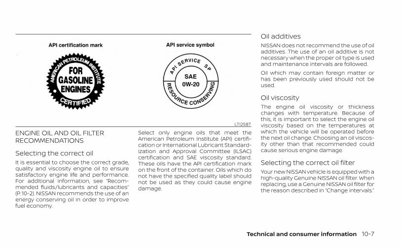
ENGINE OIL AND OIL FILTERRECOMMENDATIONS
Selecting the correct oilIt is essential to choose the correct grade,quality and viscosity engine oil to ensuresatisfactory engine life and performance.For additional information, see “Recom-mended fluids/lubricants and capacities”(P. 10-2). NISSAN recommends the use of anenergy conserving oil in order to improvefuel economy.
Select only engine oils that meet theAmerican Petroleum Institute (API) certifi-cation or International Lubricant Standard-ization and Approval Committee (ILSAC)certification and SAE viscosity standard.These oils have the API certification markon the front of the container. Oils which donot have the specified quality label shouldnot be used as they could cause enginedamage.
Oil additivesNISSAN does not recommend the use of oiladditives. The use of an oil additive is notnecessary when the proper oil type is usedand maintenance intervals are followed.Oil which may contain foreign matter orhas been previously used should not beused.
Oil viscosityThe engine oil viscosity or thicknesschanges with temperature. Because ofthis, it is important to select the engine oilviscosity based on the temperatures atwhich the vehicle will be operated beforethe next oil change. Choosing an oil viscos-ity other than that recommended couldcause serious engine damage.
Selecting the correct oil filterYour new NISSAN vehicle is equipped with ahigh-quality Genuine NISSAN oil filter. Whenreplacing, use a Genuine NISSAN oil filter forthe reason described in “Change intervals.”
LTI2587
Technical and consumer information 10-7

Change intervalsThe oil and oil filter change intervals foryour engine are based on the use of thespecified quality oils and filters. Using en-gine oil and filters that are not of the speci-fied quality, or exceeding recommended oiland filter change intervals could reduceengine life or cause severe damage to theengine. Damage to the engine caused byimproper maintenance or use of incorrectoil and filter quality and/or viscosity is notcovered by the NISSAN New Vehicle LimitedWarranty.Your engine was filled with a high-qualityengine oil when it was built. You do not haveto change the oil before the first recom-mended change interval. Oil and filterchange intervals depend upon how youuse your vehicle.NISSAN recommends the use of GenuineNISSAN parts or equivalent. The use ofparts that do not meet or exceed NISSANspecifications, can cause damage to yourvehicle, and have an effect on your war-ranty coverage. It is recommended thatyou visit a NISSAN dealer parts departmentwho can provide information on the properparts for your vehicle.
Operation under the following conditionsmay require more frequent oil and filterchanges:• repeated short distance driving at cold
outside temperatures• driving in dusty conditions• extensive idling• towing a trailer• stop and go commutingFor additional information, see the “Mainte-nance and schedules” section of thismanual.
AIR CONDITIONER SYSTEMREFRIGERANT AND OILRECOMMENDATIONSThe air conditioner system in yourNISSAN vehicle must be charged with therefrigerant HFO-1234yf (R-1234yf) andNISSAN A/C system oil Type ND-OIL12(PAG) or the exact equivalents.
CAUTION
The use of any other refrigerant or oilwill cause severe damage to the airconditioning system and will requirethe replacement of all air conditionersystem components.
The refrigerant HFO-1234yf (R-1234yf) inyour NISSAN vehicle does not harm theearth's ozone layer. Although this refriger-ant does not affect the earth's atmo-sphere, certain government regulations re-quire the recovery and recycling of anyrefrigerant during automotive air condi-tioner system service. Air conditioner sys-tem should only be serviced by trained andcertified technicians to ensure proper andsafe operation (SAE J2845). A NISSAN dealerhas the trained technicians and equip-ment needed to recover and recycle yourair conditioner system refrigerant. Onlynew and SAEJ2842 certified evaporator(s)shall be used as replacement parts.A damaged or leaking air conditioningevaporator shall never be repaired or re-placed with one removed from a used orsalvaged vehicle. To replace a damaged orleaking evaporator, use only new and SAEJ2842 certified evaporator(s). It is recom-mended that you visit a NISSAN dealerwhen servicing your air conditionersystem.
10-8 Technical and consumer information

ENGINEModel 3.8L 6 cylinder (VQ38DD engine model)Type Gasoline, 4-cycle, DOHCCylinder arrangement 6-cylinder, V-block, Slanted at 60°Bore x Stroke in (mm) 3.760 x 3.480 (95.5 x 88.4)Displacement cu in (cm 3) 231.8 (3,799)Firing order 1–2–3–4–5–6Idle speed
Refer to the “Emission control information label” on the underside of the hood.A/T in N (Neutral) positionIgnition timing (degree B.T.D.C. at idle speed)CO % at idleSpark plug FXE22HR-11Spark plug gap (Nominal) in (mm) 0.043 (1.1)Camshaft operation Timing chain
This spark ignition system complies with the Canadian standard ICES-002.
SPECIFICATIONS
Technical and consumer information 10-9

WHEELS AND TIRES
Wheel Type Offset in (mm) Size
Steel 1.18 (30) 16 x 7JJ
Aluminum 1.18 (30) 17 x 7.5J
Tires Size
P265/70R16
265/65R17
265/70R17
Spare tire Size
Steel 16” Full size
Steel 16” P265/70R16
Steel 17” Full size
10-10 Technical and consumer information

DIMENSIONS AND WEIGHTS
Units: in (mm)
Overall length
Short wheel base 210.2 (5,338.1)
Long wheel base 224.1 (5,692.1)
Overall width
without mirrors 73.0 (1,853.5)
without mirrors (with over fenders) 74.7 (1,896.5)
with mirrors 84.1 (2,135.3)
Overall height
Crew Cab models
S 2WD4WD
72.0 (1,828)72.4 (1838.6)
SV Short wheelbase
2WD4WD
71.8 (1,823.2)72.2 (1833.6)
PRO-X 2WD 72.2 (1,834)
PRO-4X 4WD 72.6 (1,843.6)
SV Long wheelbase
2WD4WD
71.6 (1,818)72.0 (1828.6)
Units: in (mm)
King Cab® models
S 2WD4WD
71.7 (1,820.9)72.1 (1831.9)
SV 2WD4WD
71.5 (1,816.2)71.9 (1826.9)
PRO-4X 4WD 72.3 (1,837.5)
Track Width Front and rear 61.8 (1,570)
Wheelbase
Short wheel base 126.0 (3,200)
Long wheel base 139.8 (3,550)
Gross vehicle weightrating
lbs. (kg)
Refer to the “F.M.V.S.S./C.M.V.S.S. certification label”in this section.
Gross axle weightrating
Front lbs. (kg)
Rear lbs. (kg)
Technical and consumer information 10-11

When planning to drive your NISSAN ve-hicle in another country, you should firstfind out if the fuel available is suitable foryour vehicle's engine.Using fuel with an octane rating that is toolow may cause engine damage. All gaso-line vehicles must be operated with un-leaded gasoline. Therefore, avoid takingyour vehicle to areas where appropriatefuel is not available.When transferring the registration ofyour vehicle to another country, state,province or district, it may be necessaryto modify the vehicle to meet local lawsand regulations.The laws and regulations for motor vehicleemission control and safety standardsvary according to the country, state, prov-ince or district; therefore, vehicle specifica-tions may differ.When any vehicle is to be taken into an-other country, state, province or districtand registered, its modifications, trans-portation and registration are the re-sponsibility of the user. NISSAN is not re-sponsible for any inconvenience thatmay result.
VEHICLE IDENTIFICATION NUMBER(VIN) PLATEThe VIN plate is attached as shown. Thisnumber is the identification for your vehicleand is used in the vehicle registration.
ENGINE SERIAL NUMBERThe number is stamped on the engine asshown.
LTI0085 LTI24953.8L 6 cylinder (VQ38DD engine model)
WHEN TRAVELING OR REGISTERINGIN ANOTHER COUNTRY
VEHICLE IDENTIFICATION
10-12 Technical and consumer information

F.M.V.S.S./C.M.V.S.S. CERTIFICATIONLABEL
The Federal/Canadian Motor VehicleSafety Standard (F.M.V.S.S./C.M.V.S.S.) certifi-cation label is affixed as shown. This labelcontains valuable vehicle information, suchas: (GVWR), (GAWR), month and year ofmanufacture, (VIN), etc. Review it carefully.
EMISSION CONTROLINFORMATION LABELThe emission control information label isattached to the underside of the hood asshown.
LTI2562Type A (if so equipped)
LTI2563Type B (if so equipped)
LTI2564
Technical and consumer information 10-13
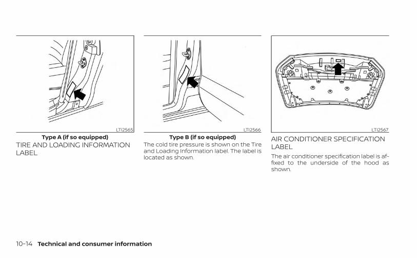
TIRE AND LOADING INFORMATIONLABEL
The cold tire pressure is shown on the Tireand Loading Information label. The label islocated as shown.
AIR CONDITIONER SPECIFICATIONLABELThe air conditioner specification label is af-fixed to the underside of the hood asshown.
LTI2565Type A (if so equipped)
LTI2566Type B (if so equipped)
LTI2567
10-14 Technical and consumer information

Symbol Name Reference Graphic
Caution ISO 7000 0434
Air Conditioning System(MAC) ISO 2575 D01
MAC System Lubricant Type(PAG–POE)
Requires Registered Technician toService MAC System
Flammable Refrigerant
Air Conditioner Specification Label Symbols
Use the following steps to mount the frontlicense plate:1. Place the license plate bracket against
the lower plastic finisher. The bracket willalign with the pre-molded indents foundon the lower plastic finisher. Make holeson the plastic finisher using a 9.5 mm(0.37 in) drill. Apply light pressure to thedrill. Install the license plate holder usingthe four screws provided.
2. Mount the license plate using twoM6-14 mm bolts.License plate bolt tightening torque:
5.10 - 6.37 N·m (3.8 - 4.7 ft-lbs.)
LTI2561
INSTALLING FRONT LICENSE PLATE
Technical and consumer information 10-15

WARNING
• It is extremely dangerous toride in a cargo area inside a ve-hicle. In a collision, people rid-ing in these areas are morelikely to be seriously injured orkilled.
• Do not allow people to ride inany area of your vehicle that isnot equipped with seats andseat belts.
• Be sure everyone in your ve-hicle is in a seat and using aseat belt properly.
TERMSIt is important to familiarize yourselfwith the following terms beforeloading your vehicle:• Curb Weight (actual weight of your
vehicle) - vehicle weight including:standard and optional equipment,fluids, emergency tools, and sparetire assembly. This weight doesnot include passengers and cargo.
• GVW (Gross Vehicle Weight) - curbweight plus the combined weightof passengers and cargo.
• GVWR (Gross Vehicle Weight Rat-ing) - maximum total combinedweight of the unloaded vehicle,passengers, cargo, hitch, trailertongue load and any other op-tional equipment. This informationis located on the F.M.V.S.S./C.M.V.S.S. certification label.
• GAWR (Gross Axle Weight Rating) -maximum weight (load) limit speci-fied for the front or rear axle. Thisinformation is located on theF.M.V.S.S./C.M.V.S.S. certification label.
• GCWR (Gross Combined WeightRating) - The maximum totalweight rating of the vehicle, pas-sengers, cargo, and trailer.
• Vehicle Capacity Weight, Load limit,Total load capacity - maximum to-tal weight limit specified of the load(passengers and cargo) for the ve-hicle. This is the maximum com-bined weight of occupants andcargo that can be loaded into thevehicle. If the vehicle is used to towa trailer, the trailer tongue weightmust be included as part of thecargo load. This information is lo-cated on the Tire and Loading In-formation label.
VEHICLE LOADING INFORMATION
10-16 Technical and consumer information

• Cargo capacity - permissibleweight of cargo, the subtractedweight of occupants from the loadlimit.
VEHICLE LOAD CAPACITYBefore driving a loaded vehicle, con-firm that you do not exceed theGross Vehicle Weight Rating (GVWR)or the Gross Axle Weight Rating(GAWR) for your vehicle. Both theGVWR and GAWR are located on theF.M.V.S.S./C.M.V.S.S. certification label.For additional information, see “Mea-surement of weights” (P. 10-25).Do not exceed the load limit of yourvehicle shown as “The combinedweight of occupants and cargo” onthe Tire and Loading Informationlabel. Do not exceed the number ofoccupants shown as “Seating Ca-pacity” on the Tire and Loading Infor-mation label.
To get “the combined weight of oc-cupants and cargo”, add the weightof all occupants, then add the totalcargo weight. Examples are shownin the following illustration.
Technical and consumer information 10-17

Steps For Determining CorrectLoad Limit
1. Locate the statement “The com-bined weight of occupants andcargo should never exceed XXX kgor XXX lbs.” on your vehicle’splacard.
2. Determine the combined weightof the driver and passengers thatwill be riding in your vehicle.
3. Subtract the combined weight ofthe driver and passengers fromXXX kg. or XXX lbs.
4. The resulting figure equals theavailable amount of cargo andluggage load capacity. For ex-ample, if the “XXX” amount equals1400 lbs. and there will be five 150lb. passengers in your vehicle, theamount of available cargo andluggage load capacity is 650 lbs.(1400-750 (5 X 150) = 650 lbs.)LTI2320
Example
10-18 Technical and consumer information

5. Determine the combined weightof luggage and cargo beingloaded on the vehicle. That weightmay not safely exceed the avail-able cargo and luggage load ca-pacity calculated in step 4.
6. If your vehicle will be towing atrailer, load from your trailer will betransferred to your vehicle. Con-sult this manual to determinehow this reduces the availablecargo and luggage load capacityof your vehicle.
Before driving a loaded vehicle, con-firm that you do not exceed theGVWR or the GAWR for your vehicle.For additional information, see “Mea-surement of weights” (P. 10-25).Also check tires for proper inflationpressures. For additional informa-tion, see “Tire and Loading Informa-tion label” (P. 8-33).
SECURING THE LOADFor your convenience, tie down hooks (if soequipped) are placed at each corner of thetruck box. These may be used to help se-cure cargo loaded into the truck box.
WARNING
• Properly secure all cargo with ropesor straps to help prevent it from slid-ing or shifting. Do not place cargohigher than the seatbacks. In a sud-den stop or collision, unsecuredcargo could cause personal injury.
• Do not load your vehicle any heavierthan the GVWR or the maximum frontand rear GAWRs. If you do, parts ofyour vehicle can break, tire damagecould occur, or it can change the wayyour vehicle handles. This could re-sult in loss of control and cause per-sonal injury.
LTI2568
Technical and consumer information 10-19

UTILI-TRACK® CHANNEL SYSTEM (ifso equipped)1. Side channels
2. Header channel
WARNING
• Properly install and tighten the tie-down cleats into the Utili-track®channel system. Also, do not attachany rope or straps directly to thechannel. Failure to properly installthe tie-down cleats or attachingropes or straps directly to the chan-nel can cause the cargo to becomeunsecured. In a sudden stop or colli-sion, unsecured cargo could causepersonal injury.
• Properly secure all cargo with ropesor straps to help prevent it from slid-ing or shifting. In a sudden stop orcollision, unsecured cargo couldcause personal injury.
The Utili-track® channel system allows youto move tie-down clamps in the bed to thebest location to secure a load.The tie-down cleats must be installed sothe clamp is properly seated in the notchesin the rail. If the tie-down cleat is not seatedin the notches, it will not be flush withthe rail and cannot be properly tightened.The bolt in the center of the cleat must betightened hand tight 20 – 40 in-lbs. (2.27 -4.6 N·m).
Check the tightness of the tie-down cleatperiodically during a trip to make sure thecenter bolt has not become loose.Install the tie-down cleat as follows:1. Remove the side channels by sliding
them out the back of the truck bed.Properly store the side channels.
2. Loosen the center bolt completely.
LTI2592
10-20 Technical and consumer information

3. Insert the cleat into the channel perpen-dicular to the channel as shown. Thenrotate the cleat clockwise 90° and slide itto the desired location.
4. Position the cleat so the nubs on thebottom fully seat into the channeldetents.
LTI0103
LTI0104
Technical and consumer information 10-21

5. There should be no gap between thebottom of the cleat and the top of thechannel. Tighten the center bolt handtight 20-40 in-lbs. (2.27 - 4.6 N·m).
WTI0124
10-22 Technical and consumer information

CAUTION
• Install only one cleat per section ofchannel.
• Applying loads at angles to the cleatsgreater than 45° or loads greaterthan 150 lbs. (204 N·m). (header andfloor channels) or 200 lbs. (271 N·m).(side channels) may cause damageto the channel or bed.
LTI0106
Technical and consumer information 10-23

WARNING
Do not install accessories over the gapbetween the front and rear side chan-nels. Doing this could affect the rearstructure in certain rear impacts, whichcould result in serious injury.
LOADING TIPS• The GVW must not exceed GVWR or
GAWR as specified on the F.M.V.S.S./C.M.V.S.S. certification label.
• Do not load the front and rear axleto the GAWR. Doing so will exceedthe GVWR.
WARNING
• Properly secure all cargo withropes or straps to help preventit from sliding or shifting. Donot place cargo higher than theseatbacks. In a sudden stop orcollision, unsecured cargocould cause personal injury.
• Do not load your vehicle anyheavier than the GVWR or themaximum front and rearGAWRs. If you do, parts of yourvehicle can break, tire damagecould occur, or it can changethe way your vehicle handles.This could result in loss of con-trol and cause personal injury.
LTI01231 correct installation, 2 incorrect installation
10-24 Technical and consumer information

• Overloading not only canshorten the life of your vehicleand the tire, but can also causeunsafe vehicle handling andlonger braking distances. Thismay cause a premature tirefailure which could result in aserious accident and personalinjury. Failures caused by over-loading are not covered by thevehicle’s warranty.
MEASUREMENT OF WEIGHTSSecure loose items to preventweight shifts that could affect thebalance of your vehicle. When the ve-hicle is loaded, drive to a scale andweigh the front and the rear wheelsseparately to determine axle loads.Individual axle loads should not ex-ceed either of the Gross Axle WeightRatings (GAWR). The total of the axleloads should not exceed the GrossVehicle Weight Rating (GVWR). Theseratings are given on the vehicle cer-tification label. If weight ratings areexceeded, move or remove items tobring all weights below the ratings.
Do not use a slide-in camper with yourvehicle.
SPECIAL BODY VEHICLESSome vehicles are equipped with commer-cial or camper bodies. However, this Own-er's Manual does not cover these options.For additional information, refer to thebody manufacturer's instruction manual.
TRUCK-CAMPER LOADINGINFORMATION
Technical and consumer information 10-25

LOCATION FOR CENTER OFGRAVITYThe illustration indicates the recom-mended cargo center of gravity location.King Cab®:Short wheel base models withoutbedliner/tailgate liner,
L1 = 1,045 mm (41.1 in)Short wheel base models with bed liner/tailgate liner (SV/PRO-4X with comfort andconvenience package),
L1 = 1,028 mm (40.5 in)
Crew Cab:Short wheel base models withoutbedliner/tailgate liner,
L1 = 1,045 mm (41.1 in)Short wheel base models with bedliner/tailgate liner (SV/PRO-4X with comfort andconvenience package),
L1 = 1,028 mm (40.5 in)Long wheel base models,
L1 = 1,032 mm (40.63 in)
WARNING
Improper loading may be dangerous.If a load is too far back, it can affecthandling characteristics. If a load is toofar forward, the front axle may beoverloaded.Overloading or improper loading canadversely affect vehicle handling, brak-ing and performance and may lead toaccidents.
VEHICLE LOAD WEIGHT CAPACITYThe vehicle payload weight capacityshown on the Tire and Loading Informationlabel indicates the maximum total weightof passengers, optional equipment (airconditioning, trailer hitch, etc.) and cargothat your vehicle is designed to carry.For additional information, see “Tire andLoading Information label” (P. 8-33).Before driving a loaded vehicle, confirmthat you do not exceed the GVWR or theGAWR for your vehicle. For additional infor-mation, see “Vehicle loading information”(P. 10-16).Also check tires for proper inflation pres-sures. For additional information, see “Tireand Loading Information label” (P. 8-33).
LTI0128
10-26 Technical and consumer information

WARNING
• Overloading or improper loading ofa trailer and its cargo can adverselyaffect vehicle handling, braking andperformance and may lead toaccidents.
• Do not tow a trailer when the TEMPO-RARY FULL SIZE spare tire is installed.
CAUTION
• Do not tow a trailer or haul a heavyload for the first 500 mile (805 km).Your engine, axle or other parts couldbe damaged.
• For the first 500 miles (805 km) thatyou tow a trailer, do not drive over 50mph (80 km/h) and do not makestarts at full throttle. This helps theengine and other parts of your ve-hicle wear in at the heavier loads.
Your new vehicle was designed to be usedprimarily to carry passengers and cargo.Remember that towing a trailer places ad-ditional loads on your vehicle's engine,drive train, steering, braking and othersystems.
A NISSAN Towing Guide (U.S. only) is availableon the website at www.nissanusa.com. Thisguide includes information on trailer towingcapability and the special equipment re-quired for proper towing.
MAXIMUM LOAD LIMITS
Maximum trailer loadsNever allow the total trailer load to exceedthe value specified in the “Towing Load/Specification” chart found in this section.The total trailer load equals trailer weightplus its cargo weight.• When towing a trailer load of 3,500 lbs.
(1,587 kg) or more, trailers with a brakesystem MUST be used.
The maximum Gross Combined WeightRating (GCWR) should not exceed the valuespecified in the following “Towing Load/Specification” chart.
The GCWR equals the combined weight ofthe towing vehicle (including passengersand cargo) plus the total trailer load. Tow-ing loads greater than these or using im-proper towing equipment could adverselyaffect vehicle handling, braking andperformance.The ability of your vehicle to tow a trailer isnot only related to the maximum trailerloads, but also the places you plan to tow.Tow weights appropriate for level highwaydriving may have to be reduced for lowtraction situations (for example, on slipperyboat ramps).
LTI0161
TOWING A TRAILER
Technical and consumer information 10-27

Temperature conditions can also affecttowing. For example, towing a heavy trailerin high outside temperatures on gradedroads can affect engine performance andcause overheating. The engine protectionmode, which helps reduce the chance ofengine damage, could activate and auto-matically decrease engine power. Vehiclespeed may decrease under high load. Planyour trip carefully to account for trailer andvehicle load, weather and road conditions.
WARNING
Overheating can result in reduced en-gine power and vehicle speed. The re-duced speed may be lower than othertraffic, which could increase the chanceof a collision. Be especially carefulwhen driving. If the vehicle cannotmaintain a safe driving speed, pull tothe side of the road in a safe area. Allowthe engine to cool and return to normaloperation. For additional information,see “If your vehicle overheats” (P. 6-13).
CAUTION
Vehicle damage resulting from im-proper towing procedures is not cov-ered by NISSAN warranties.
Tongue loadWhen using a weight carrying or a weightdistributing hitch, keep the tongue load be-tween 10 - 15% of the total trailer load or usethe trailer tongue load specified by thetrailer manufacturer. The tongue loadmust be within the maximum tongue loadlimits shown in the following “Towing Load/Specification” chart. If the tongue load be-comes excessive, rearrange cargo to allowfor proper tongue load.
Maximum Gross Vehicle Weight(GVW)/maximum Gross AxleWeight (GAW)The GVW of the towing vehicle must notexceed the Gross Vehicle Weight Rating(GVWR) shown on the F.M.V.S.S./C.M.V.S.S.certification label. The GVW equals thecombined weight of the unloaded vehicle,passengers, luggage, hitch, trailer tongueload and any other optional equipment. Inaddition, front or rear GAW must not ex-ceed the Gross Axle Weight Rating (GAWR)shown on the F.M.V.S.S./C.M.V.S.S. certifica-tion label.
WTI0160 CA0036
10-28 Technical and consumer information

Towing capacities are calculated assum-ing a base vehicle with driver and any op-tions required to achieve the rating. Addi-tional passengers, cargo and/or optionalequipment, such as the trailer hitch, willadd weight to the vehicle and reduce yourvehicle’s maximum towing capacity andtrailer tongue load.The vehicle and trailer need to be weighedto confirm the vehicle is within the GVWR,Front GAWR, Rear GAWR, Gross CombinedWeight Rating (GCWR) and Towing capacity.All vehicle and trailer weights can be mea-sured using platform type scales commonlyfound at truck stops, highway weigh stations,building supply centers or salvage yards.To determine the available payload capac-ity for tongue load, use the following proce-dure.1. Locate the GVWR on the F.M.V.S.S./
C.M.V.S.S. certification label.
2. Weigh your vehicle on the scale with allof the passengers and cargo that arenormally in the vehicle when towing atrailer.
3. Subtract the actual vehicle weight fromthe GVWR. The remaining amount is theavailable maximum tongue load.
To determine the available towing capacity,use the following procedure.1. Find the GCWR for your vehicle on the
"Towing Load/Specification" chart foundin this section.
2. Subtract the actual vehicle weight fromthe GCWR. The remaining amount is theavailable maximum towing capacity.
To determine the Gross Trailer Weight,weigh your trailer on a scale with all equip-ment and cargo, that are normally in thetrailer when it is towed. Make sure theGross Trailer Weight is not more than theGross Trailer Weight Rating shown on thetrailer and is not more than the calculatedavailable maximum towing capacity.Also weigh the front and rear axles on thescale to make sure the Front Gross AxleWeight and Rear Gross Axle Weight are notmore than Front Gross Axle Weight andRear Gross Axle Weight on the F.M.V.S.S./C.M.V.S.S. certification label. The cargo inthe trailer and vehicle may need to bemoved or removed to meet the specifiedratings.Example:• Gross Vehicle Weight (GVW) as weighed
on a scale- including passengers, cargoand hitch - 5,185 lbs. (2352 kg).
• Gross Vehicle Weight Rating (GVWR) fromF.M.V.S.S./C.M.V.S.S. certification label -5,815 lbs. (2638 kg).
• Gross Combined Weight Rating (GCWR)from “Towing Load/Specification" chart -11,133 lbs. (5050 kg).
• Maximum Trailer towing capacity from“Towing Load/Specification" chart - 6,100lbs. (2767 kg).
5,815 lbs. (2638 kg) GVWR– 5,185 lbs. (2352 kg) GVW
= 630 lbs. (286 kg) Available fortongue weight
11,133 lbs. (5050 kg) GCWR– 5,185 lbs. (2352 kg) GVW
= 5,948 lbs. (2698 kg) Capacity availablefor towing
630 lbs. (286 kg) Available tongueweight
/ 5,948 lbs. (2698 kg) Available capacity= 10 % tongue
weight
Technical and consumer information 10-29

The available towing capacity may be lessthan the maximum towing capacity due tothe passenger and cargo load in thevehicle.Remember to keep trailer tongue weightbetween 10 - 15 percent of the trailer weightor within the trailer tongue load specifica-tion recommended by the trailer manufac-turer. If the tongue load becomes exces-sive, rearrange the cargo to obtain theproper tongue load. Do not exceed themaximum tongue weight specificationshown in the “Towing Load/Specification”chart even if the calculated availabletongue weight is greater than 15 percent. Ifthe calculated tongue weight is less than10 percent, reduce the total trailer weight tomatch the available tongue weight.Always verify that available capacities arewithin the required ratings.
Trailer frontal area
CAUTION
Exceeding the maximum trailer frontalarea specification may exceed the tow-ing capacity of the vehicle. This mayaffect the towing performance andlead to vehicle damage.
The trailer frontal area affects the towingload of a trailer. The frontal area is the totalarea of the vehicle and trailer that is af-fected by air resistance while towing. Donot exceed the maximum trailer frontalarea specification shown in the "TowingLoad/Specification” chart. The frontal areacan be determined by multiplying thewidth of the trailer by the height of thetrailer. For example, a trailer that is 8 feetwide by 6 feet tall has a trailer frontal area of48 square feet.
TOWING LOAD/SPECIFICATIONWARNING
The towing capacities provided in thismanual are for general reference only.The safe towing capacity of your ve-hicle is affected by dealer and factoryinstalled options and passenger andcargo loads. You must weigh the ve-hicle and trailer as described in thismanual to determine the actual vehicletowing capacity. Do not exceed thepublished maximum towing capacityor the GCWR or the GVWR shown on theFMVSS/CMVSS label. Doing so can re-sult in an accident causing serious per-sonal injury or property damage.
10-30 Technical and consumer information

King Cab® models
Axle type 2WD 4WDMaximum Towing Capacity*1, *2, *3 6,720 lbs. (3,048 kg) 6,510 lbs. (2,953 kg)
Maximum Tongue Load*2, *3 672 lbs. (305 kg) 651 lbs. (295 kg)Maximum Gross Combined Weight Rating 11,427 lbs. (5,183 kg) 11,427 lbs. (5,183 kg)
Maximum trailer frontal area 30 sq feet (2.78 sq meters)
Crew Cab – Short wheel base models
Axle type 2WD 4WDMaximum Towing Capacity*1, *2, *3 6,570 lbs. (2,980 kg) 6,370 lbs. (2,889 kg)
Maximum Tongue Load*2, *3 657 lbs. (298 kg) 637 lbs. (289 kg)Maximum Gross Combined Weight Rating 11,427 lbs. (5,183 kg) 11,427 lbs. (5,183 kg)
Maximum trailer frontal area 30 sq feet (2.78 sq meters)
Crew Cab – Long wheel base models
Axle type 2WD 4WDMaximum Towing Capacity*1, *2, *3 6,460 lbs. (2,930 kg) 6,260 lbs. (2,839 kg)
Maximum Tongue Load*2, *3 646 lbs. (293 kg) 626 lbs. (284 kg)Maximum Gross Combined Weight Rating 11,427 lbs. (5,183 kg) 11,427 lbs. (5,183 kg)
Maximum trailer frontal area 30 sq feet (2.78 sq meters)
*1: • The towing capacity is calculated using the SAE International SAE J2807 test method. Additional passengers, cargo and/or optional equipment will add weightto the vehicle and reduce your vehicle's maximum towing capacity.
• All towing above 3,500 lbs. (1,587 kg) requires the use of trailer brakes.• NISSAN recommends the use of a tandem axle trailer whenever towing above 3,000 lbs. (1,361 kg).
*2: The maximum towing capacity when using the Genuine NISSAN step bumper as a ball mount is 3,500 lbs. (1,588 kg) and 350 lbs. (158 kg) tongue load.*3: Use of a weight-distributing hitch system is recommended when towing over 5,000 lbs.
Technical and consumer information 10-31
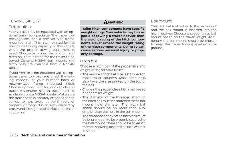
TOWING SAFETYTrailer hitchYour vehicle may be equipped with an op-tional trailer tow package. The trailer towpackage includes a receiver-type framemounted hitch. This hitch is rated for themaximum towing capacity of this vehiclewhen the proper towing equipment isused. Choose a proper ball mount andhitch ball that is rated for the trailer to betowed. Genuine NISSAN ball mounts andhitch balls are available from a NISSANdealer.If your vehicle is not equipped with the op-tional trailer tow package, check the tow-ing capacity of your bumper hitch orreceiver-type frame mounted hitch.Choose a proper hitch for your vehicle andtrailer. A Genuine NISSAN trailer hitch isavailable from a NISSAN dealer. Make surethe trailer hitch is securely attached to thevehicle to help avoid personal injury orproperty damage due to sway caused bycrosswinds, rough road surfaces or pass-ing trucks.
WARNING
Trailer hitch components have specificweight ratings. Your vehicle may be ca-pable of towing a trailer heavier thanthe weight rating of the hitch compo-nents. Never exceed the weight ratingof the hitch components. Doing so cancause serious personal injury or prop-erty damage.
Hitch ballChoose a hitch ball of the proper size andweight rating for your trailer:• The required hitch ball size is stamped on
most trailer couplers. Most hitch ballsalso have the size printed on the top ofthe ball.
• Choose the proper class hitch ball basedon the trailer weight.
• The diameter of the threaded shank ofthe hitch ball must be matched to the ballmount hole diameter. The hitch ballshank should be no more than 1/16”smaller than the hole in the ball mount.
• The threaded shank of the hitch ball mustbe long enough to be properly secured tothe ball mount. There should be at least 2threads showing beyond the lock washerand nut.
Ball mountThe hitch ball is attached to the ball mountand the ball mount is inserted into thehitch receiver. Choose a proper class ballmount based on the trailer weight. Addi-tionally, the ball mount should be chosento keep the trailer tongue level with theground.
10-32 Technical and consumer information

Bumper towingThe Genuine NISSAN step bumper has pro-visions to install a trailer hitch ball and isdesigned to tow trailers of a maximumweight of 3,500 lbs. (1,588 kg).To install a trailer hitch ball cut out the circlein the center of the step bumper OA , thenremove it to install the trailer hitch ball.
Weight carrying hitchesA weight carrying or “dead weight” ballmount is one that is designed to carry thewhole amount of tongue weight and grossweight directly on the ball mount and onthe receiver.
Weight distribution hitchThis type of hitch is also called a “load-leveling” or “equalizing” hitch. A set of barsattach to the ball mount and to the trailerto distribute the tongue weight (hitchweight) of your trailer. Many vehicles can'tcarry the full tongue weight of a giventrailer, and need some of the tongueweight transferred through the frame andpushing down on the front wheels. Thisgives stability to the tow vehicle.A weight-distributing hitch system (ClassIV) is recommended if you plan to tow trail-ers with a maximum weight over 5,000 lbs.(2,268 kg). Check with the trailer and towingequipment manufacturers to determine ifthey recommend the use of a weight-distributing hitch system.
NOTE:
A weight-distributing hitch system mayaffect the operation of trailer surgebrakes. If you are considering use of aweight-distributing hitch system with asurge brake-equipped trailer, check withthe surge brake, hitch or trailer manufac-turer to determine if and how this can bedone.Follow the instructions provided by themanufacturer for installing and using theweight-distributing hitch system.General set-up instructions are as follows:1. Park unloaded vehicle on a level surface.
With the ignition switch in the ON posi-tion and the doors closed, allow the ve-hicle to stand for several minutes so thatit can level.
2. Measure the height of a reference pointon the front and rear bumpers at thecenter of the vehicle.
3. Attach the trailer to the vehicle and ad-just the hitch equalizers so that the frontbumper height is within 0 - .5 inches (0 –13 mm) of the reference height mea-sured in step 2. The rear bumper shouldbe no higher than the reference heightmeasured in step 2.
LTI2569
Technical and consumer information 10-33

WARNING
Properly adjust the weight distributinghitch so the rear of the bumper is nohigher than the measured referenceheight when the trailer is attached. Ifthe rear bumper is higher than themeasured reference height whenloaded, the vehicle may handle unpre-dictably which could cause a loss of ve-hicle control and cause serious per-sonal injury or property damage.
Sway control deviceSudden maneuvers, wind gusts, and buf-feting caused by other vehicles can affecttrailer handling. Sway control devices maybe used to help control these affects. If youchoose to use one, contact a reputabletrailer hitch supplier to make sure the swaycontrol device will work with the vehicle,hitch, trailer and the trailer's brake system.Follow the instructions provided by themanufacturer for installing and using thesway control device.
Class I hitchClass I trailer hitch equipment (receiver, ballmount and hitch ball) can be used to towtrailers of a maximum weight of 2,000 lbs.(907 kg).
Class II hitchClass II trailer hitch equipment (receiver,ball mount and hitch ball) can be used totow trailers of a maximum weight of 3,500lbs. (1,587 kg).The Genuine NISSAN step bumper is con-sidered a Class II ball mount.
Class III hitchClass III trailer hitch equipment (receiver,ball mount and hitch ball) can be used totow trailers of a maximum weight of 5,000lbs. (2,268 kg).
Class IV hitchClass IV trailer hitch equipment (receiver,ball mount and hitch ball) can be used totow trailers of a maximum weight of 10,000lbs. (4,535 kg). A weight distributing hitchshould be used to tow trailers that weighover 5,000 lbs. (2,268 kg).
Your vehicle may be equipped with Class IVtrailer hitch equipment that has a 10,000lbs. (4,535 kg) maximum weight rating, butyour vehicle is only capable of towing themaximum trailer weights shown in the“Towing Load/Specification” chart in thissection.
CAUTION
• Special hitches which include framereinforcements are required for tow-ing above 2,000 lbs. (907 kg). SuitableGenuine NISSAN hitches, ball mountsand hitch balls for pickup trucks andsport utility vehicles are available ata NISSAN dealer.
• The hitch should not be attached toor affect the operation of the impact-absorbing bumper.
10-34 Technical and consumer information

WARNING
• Do not use axle-mounted hitches.• Do not modify the vehicle exhaust
system, brake system, etc. to install atrailer hitch.
• To reduce the possibility of addi-tional damage if your vehicle isstruck from the rear, where practical,remove the receiver when not in use.
• Regularly check that all trailer hitchmounting bolts are securelymounted.
Tire pressures• When towing a trailer, inflate the
vehicle tires to the recommendedcold tire pressure indicated on theTire and Loading Information label.
• Trailer tire condition, size, load rat-ing and proper inflation pressureshould be in accordance with thetrailer and tire manufacturer'sspecifications.
Safety chainsAlways use suitable safety chains betweenyour vehicle and the trailer. The safety chainsshould be crossed and should be attachedto the hitch, not to the vehicle bumper oraxle. The safety chains can be attached tothe bumper if the hitch ball is mounted to thebumper. Be sure to leave enough slack in thechains to permit turning corners.
Trailer lights
CAUTION
When splicing into the vehicle electricalsystem, a commercially availablepower-type module/converter mustbe used to provide power for all trailerlighting. This unit uses the vehicle bat-tery as a direct power source for alltrailer lights while using the vehicle taillight, stop light and turn signal circuitsas a signal source. The module/converter must draw no more than 15milliamps from the stop and tail lampcircuits. Using a module/converter thatexceeds these power requirementsmay damage the vehicle's electricalsystem. See a reputable trailer dealerto obtain the proper equipment and tohave it installed.
Trailer lights should comply with federaland/or local regulations. For assistance inhooking up trailer lights, it is recommendedthat you visit a NISSAN dealer or reputabletrailer dealer. Vehicles equipped with theoptional trailer tow package are equippedwith a 7-pin trailer harness connector. A flat4–pin harness is available from your dealerfor vehicles without a tow package. If yourtrailer is equipped with a flat 4-pin connec-tor, an adapter will be needed to connectthe trailer lights to the vehicle. Adapters areavailable at auto parts stores and hitchretailers.
Trailer brakesIf your trailer is equipped with a brakingsystem, make sure it conforms to federaland/or local regulations and that it is prop-erly installed.Vehicles equipped with a 7–pin trailer har-ness connector are pre-wired for a trailerbrake controller. It is recommended thatyou visit a NISSAN dealer for a trailer brakeadapter harness.
WARNING
Never connect a trailer brake systemdirectly to the vehicle brake system.
Technical and consumer information 10-35

When towing a trailer load of 3,500 lbs.(1587 kg) or more, trailers with a brakesystem MUST be used. However, moststates require a separate braking systemon trailers with a loaded weight above aspecific amount. Make sure the trailermeets the local regulations and the regu-lations where you plan to tow.Several types of braking systems areavailable.Surge Brakes -The surge brake actuator ismounted on the trailer tongue with a hy-draulic line running to each trailer wheel.Surge brakes are activated by the trailerpushing against the hitch ball when thetow vehicle is braking. Hydraulic surgebrakes are common on rental trailers andsome boat trailers. In this type of system,there is no hydraulic or electric connectionfor brake operation between the tow ve-hicle and the trailer.Electric Trailer Brakes -Electric brakingsystems are activated by an electronic sig-nal sent from a trailer brake controller (spe-cial brake-sensing module). If electric trailerbrakes are used, see “Electric trailer brakecontroller" (P. 10-36)..
Have a professional supplier of towingequipment make sure the trailer brakes areproperly installed and demonstrate properbrake function testing.
Electric trailer brake controllerTrailers equipped with electric brakes mayrequire the installation of an aftermarkettrailer brake controller.A Genuine NISSAN jumper harness is avail-able that is specifically designed to be usedwhen installing an aftermarket brakecontroller.Install the aftermarket electric trailer brakecontroller according to the manufacturer'sinstructions.
Pre-towing tips• Be certain your vehicle maintains a level
position when a loaded and/or unloadedtrailer is hitched. Do not drive the vehicle ifit has an abnormal nose-up or nose-down condition; check for impropertongue load, overload, worn suspensionor other possible causes of eithercondition.
• Always secure items in the trailer to pre-vent load shift while driving.
• Keep the cargo load as low as possible inthe trailer to keep the trailer center ofgravity low.
• Load the trailer so approximately 60% ofthe trailer load is in the front half and 40%is in the back half. Also make sure the loadis balanced side to side.
• Check your hitch, trailer tire pressure, ve-hicle tire pressure, trailer light operation,and trailer wheel lug nuts every time youattach a trailer to the vehicle.
• Be certain your rearview mirrors conformto all federal, state or local regulations. Ifnot, install any mirrors required for towingbefore driving the vehicle.
• Determine the overall height of the ve-hicle and trailer so the required clearanceis known.
Trailer towing tipsIn order to gain skill and an understandingof the vehicle's behavior, you should prac-tice turning, stopping and backing up in anarea which is free from traffic. Steering sta-bility and braking performance will besomewhat different than under normaldriving conditions.• Always secure items in the trailer to pre-
vent load shift while driving.
10-36 Technical and consumer information

• Lock the trailer hitch coupler with a pin orlock to prevent the coupler from inadver-tently becoming unlatched.
• Avoid abrupt starts, acceleration or stops.• Avoid sharp turns or lane changes.• Always drive your vehicle at a moderate
speed.• When backing up, hold the bottom of the
steering wheel with one hand. Move yourhand in the direction in which you wantthe trailer to go. Make small correctionsand back up slowly. If possible, havesomeone guide you when you are back-ing up.
Always block the wheels on both vehicleand trailer when parking. Parking on aslope is not recommended; however, if youmust do so:
CAUTION
If you move the shift lever to the P(Park) position before blocking thewheels and applying the parking brake,transmission damage could occur.
1. Apply and hold the brake pedal.
2. Have someone place blocks on thedownhill side of the vehicle and trailerwheels.
3. After the wheel blocks are in place,slowly release the brake pedal until theblocks absorb the vehicle load.
4. Apply the parking brake.
5. Shift the transmission into P (Park).
6. Make sure the 4WD shift indicator light (ifso equipped) indicates the transfer caseis in 4H, 4LO, or 2WD and that the ATPlight is off. If the 4WD shift indicator lightis flashing, or the ATP light is ON, makesure the transmission is in P (Park) andturn the 4WD switch to 2WD or 4H. Foradditional information, see “Automatictransmission park warning light” (P. 2-11)and “Using 4-wheel drive (4WD)” (P. 5-109).
7. Turn off the engine.To drive away:1. Start the vehicle.
2. Apply and hold the brake pedal.
3. Shift the transmission into gear.
4. Release the parking brake.
5. Drive slowly until the vehicle and trailerare clear from the blocks.
6. Apply and hold the brake pedal.
7. Have someone retrieve and store theblocks.
• While going downhill, the weight of thetrailer pushing on the tow vehicle maydecrease overall stability. Therefore, tomaintain adequate control, reduce yourspeed and shift to a lower gear. Avoidlong or repeated use of the brakes whendescending a hill, as this reduces theireffectiveness and could cause overheat-ing. Shifting to a lower gear instead pro-vides “engine braking” and reduces theneed to brake as frequently.
• If the engine coolant temperature rises toa high temperature, see “If your vehicleoverheats” (P. 6-13).
• Trailer towing requires more fuel thannormal circumstances.
• Avoid towing a trailer for your vehicle'sfirst 500 miles (805 km).
• For the first 500 miles (805 km) that youdo tow, do not drive over 50 mph (80km/h).
• Have your vehicle serviced more oftenthan at intervals specified. For additionalinformation, see the “Maintenance andschedules” section of this manual.
Technical and consumer information 10-37

• When making a turn, your trailer wheelswill be closer to the inside of the turn thanyour vehicle wheels. To compensate forthis, make a larger than normal turningradius during the turn.
• Crosswinds and rough roads will ad-versely affect vehicle/trailer handling,possibly causing vehicle sway. When be-ing passed by larger vehicles, be pre-pared for possible changes in crosswindsthat could affect vehicle handling.
Do the following if the trailer begins tosway:1. Take your foot off the accelerator pedal
to allow the vehicle to coast and steer asstraight ahead as the road conditionsallow. This combination will help stabilizethe vehicle– Do not correct trailer sway by steering
or applying the brakes.
2. When the trailer sway stops, gently applythe brakes and pull to the side of theroad in a safe area.
3. Try to rearrange the trailer load so it isbalanced as described in this section.
• Be careful when passing other vehicles.Passing while towing a trailer requiresconsiderably more distance than normalpassing. Remember, the length of thetrailer must also pass the other vehiclebefore you can safely change lanes.
• Downshift the transmission to a lowergear for engine braking when drivingdown steep or long hills. This will helpslow the vehicle without applying thebrakes.
• Avoid holding the brake pedal down toolong or too frequently. This could causethe brakes to overheat, resulting in re-duced braking efficiency.
• Increase your following distance to allowfor greater stopping distances while tow-ing a trailer. Anticipate stops and brakegradually.
• NISSAN recommends that the cruisecontrol not be used while towing a trailer.
• Some states or provinces have specificregulations and speed limits for vehiclesthat are towing trailers. Obey the localspeed limits.
• Check your hitch, trailer wiring harnessconnections, and trailer wheel lug nutsafter 50 miles (80 km) of travel and atevery break.
• When launching a boat, don't allow thewater level to go over the exhaust tailpipe or rear bumper.
• Make sure you disconnect the trailerlights before backing the trailer into thewater or the trailer lights may burn out.
When towing a trailer, final drive gear oilshould be replaced and transmission oil/fluid should be changed more fre-quently. For additional information, referto the “Do-it-yourself” section in thismanual.
Tow mode (if so equipped)Using tow mode is recommended whenpulling a heavy trailer or hauling a heavyload. Press the TOW MODE switch to acti-vate tow mode. The indicator light on theTOW MODE switch illuminates when towmode is selected. Press the TOW MODEswitch again to turn tow mode off. Towmode is automatically canceled when theignition switch is turned off.
10-38 Technical and consumer information

Tow mode includes the following features:• Grade logic — Adjusts transmission shifts
when pulling a trailer or hauling a load upa grade.
• Downhill Speed Control (DSC) — auto-matically downshifts when driving downa grade with a trailer or heavy load to helpcontrol vehicle speed.
Driving the vehicle in the tow mode with notrailer/load or light trailer/light load willnot cause any damage. However, fueleconomy may be reduced and thetransmission/engine driving characteris-tics may feel unusual.When towing a trailer, final drive gear oilshould be replaced and transmission oil/fluid should be changed more frequently.For additional information, see the “Do-it-yourself” section of this manual.
FLAT TOWING – 4WD WITHAUTOMATIC TRANSMISSIONTowing a vehicle behind a recreational ve-hicle, such as a motor home, is sometimescalled flat towing.
CAUTION
• DO NOT flat tow a 4WD vehicleequipped with an automatic trans-mission. Flat towing or using a ve-hicle dolly WILL DAMAGE internaltransmission parts due to lack oflubrication.
• For emergency towing procedures,see “Towing recommended byNISSAN” in the “In case of emer-gency” (P. 6-15).
FLAT TOWING – 2WD WITHAUTOMATIC TRANSMISSIONTowing a vehicle behind a recreational ve-hicle, such as a motor home, is sometimescalled flat towing.
CAUTION
• Failure to follow these guidelines canresult in severe transmission damage.
• Whenever flat towing your vehicle,always tow forward, never backward.
• DO NOT tow any automatic transmis-sion vehicle with all four wheels onthe ground. Doing so WILL DAMAGEinternal transmission parts due tolack of transmission lubrication.
• For emergency towing procedures,see “Towing recommended byNISSAN” in the “In case of emer-gency” (P. 6-15).
To tow a vehicle equipped with an auto-matic transmission, an appropriate vehicledolly MUST be placed under the towed ve-hicle’s drive wheels. Always follow the dollymanufacturer’s recommendations whenusing their product.
Automatic TransmissionTo tow a vehicle equipped with an auto-matic transmission, an appropriate vehicledolly MUST be placed under the towed ve-hicle's drive wheels. Always follow the dollymanufacturer's recommendations whenusing their product.
NOTE:
If the battery is completely drained thetransmission will not manually shift toother positions.
Technical and consumer information 10-39

DOT (Department of Transportation) Qual-ity Grades: All passenger car tires mustconform to federal safety requirements inaddition to these grades.Quality grades can be found where appli-cable on the tire sidewall between treadshoulder and maximum section width. Forexample:Treadwear 200 Traction AA Temperature ATreadwearThe treadwear grade is a comparative rat-ing based on the wear rate of the tire whentested under controlled conditions on aspecified government test course. For ex-ample, a tire graded 150 would wear oneand one-half (1 1/2) times as well on thegovernment course as a tire graded 100.The relative performance of tires dependsupon the actual conditions of their use,however, and may depart significantly fromthe norm due to variations in driving habits,service practices and differences in roadcharacteristics and climate.Traction AA, A, B and CThe traction grades, from highest to low-est, are AA, A, B, and C. Those grades repre-sent the tire's ability to stop on wet pave-ment as measured under controlled
conditions on specified government testsurfaces of asphalt and concrete. A tiremarked C may have poor tractionperformance.
WARNING
The traction grade assigned to this tireis based on straight-ahead brakingtraction tests, and does not include ac-celeration, cornering, hydroplaning, orpeak traction characteristics.
Temperature A, B and CThe temperature grades are A (the high-est), B, and C, representing the tire’s resis-tance to the generation of heat, and itsability to dissipate heat when tested undercontrolled conditions on a specified indoorlaboratory test wheel. Sustained high tem-perature can cause the material of the tireto degenerate and reduce tire life, and ex-cessive temperature can lead to suddentire failure. The grade C corresponds to alevel of performance which all passengercar tires must meet under the Federal Mo-tor Safety Standard No. 109. Grades B and Arepresent higher levels of performance onthe laboratory test wheel than the mini-mum required by law.
WARNING
The temperature grade for this tire isestablished for a tire that is properlyinflated and not overloaded. Excessivespeed, under-inflation, or excessiveloading, either separately or in combi-nation, can cause heat build-up andpossible tire failure.
UNIFORM TIRE QUALITY GRADING
10-40 Technical and consumer information
Your NISSAN vehicle is covered by the fol-lowing emission warranties:For USA1. Emission Defects Warranty
2. Emissions Performance WarrantyDetails of this warranty may be found withother vehicle warranties in your WarrantyInformation Booklet which comes withyour NISSAN vehicle. If you did not receive aWarranty Information Booklet, or it is lost,you may obtain a replacement by writingto:• Nissan North America, Inc.
Consumer Affairs DepartmentP.O. Box 685003Franklin, TN 37068-5003
For CanadaEmission Control System WarrantyDetails of this warranty may be found withother vehicle warranties in your WarrantyInformation Booklet which comes withyour NISSAN vehicle. If you did not receive aWarranty Information Booklet, or it is lost,you may obtain a replacement by writingto:• Nissan Canada Inc.
5290 Orbitor DriveMississauga, Ontario, L4W 4Z5
For USAIf you believe that your vehicle has adefect which could cause a crash orcould cause injury or death, youshould immediately inform the Na-tional Highway Traffic Safety Admin-istration (NHTSA) in addition to noti-fying NISSAN.If NHTSA receives similar complaints,it may open an investigation, and if itfinds that a safety defect exists in agroup of vehicles, it may order a re-call and remedy campaign. However,NHTSA cannot become involved inindividual problems between you,your dealer, or NISSAN.To contact NHTSA, you may call theVehicle Safety Hotline toll-free at1-888-327-4236 (TTY: 1-800-424-9153);go to http://www.safercar.gov; orwrite to: Administrator, NHTSA, 400Seventh Street, SW., Washington, D.C.20590. You can also obtain other in-
formation about motor vehicle safetyfrom http://www.safercar.gov.You may notify NISSAN by contact-ing our Consumer Affairs Depart-ment, toll-free, at 1-800-NISSAN-1.For CanadaIf you believe that your vehicle has adefect which could cause a crash orcould cause injury or death, youshould immediately inform Trans-port Canada in addition to notifyingNISSAN.If Transport Canada receives com-plaints, it may open an investigation,and if it finds that a safety defectexists in a group of vehicles, it mayrequest that NISSAN conduct a recallcampaign. However, TransportCanada cannot become involved inindividual problems between you,your dealer, or NISSAN.
EMISSION CONTROL SYSTEMWARRANTY
REPORTING SAFETY DEFECTS
Technical and consumer information 10-41
You may contact Transport Canada'sDefect Investigations and RecallsDivision toll free at 1-800-333-0510.You may also report safety defectsonline at: http://www.tc.gc.ca/eng/motorvehiclesafety/menu.htm (Eng-lish speakers) or http://www.tc.gc.ca/fra/securiteautomobile/menu.htm(French speakers)Or contact Transport Canada bymail at:Transport Canada Motor VehicleSafety Investigations Laboratory80 Noel Street Gatineau, QC J8Z0A1Additional information concerningmotor vehicle safety may be obtainedfrom Transport Canada's Road SafetyInformation Centre at 1-800-333-0371or online at www.tc.gc.ca/roadsafety(English speakers) or www.tc.gc.ca/securiteroutiere (French speakers).
To notify NISSAN of any safety con-cerns please contact our ConsumerInformation Centre toll free at1-800-387-0122.
WARNING
A vehicle equipped with Four-WheelDrive (4WD) should never be tested us-ing a two wheel dynamometer (such asthe dynamometers used by somestates for emissions testing), or similarequipment. Make sure you inform thetest facility personnel that your vehicleis equipped with 4WD before it is placedon a dynamometer. Using the wrongtest equipment may result in transmis-sion damage or unexpected vehiclemovement which could result in seri-ous vehicle damage or personal injury.
Due to legal requirements in some statesand Canadian Provinces, your vehicle maybe required to be in what is called the“ready condition” for an Inspection/Maintenance (I/M) test of the emissioncontrol system.The vehicle is set to the “ready condition”when it is driven through certain drivingpatterns. Usually, the ready condition canbe obtained by ordinary usage of thevehicle.
READINESS FOR INSPECTION/MAINTENANCE (I/M) TEST
10-42 Technical and consumer information

If a powertrain system component is re-paired or the battery is disconnected, thevehicle may be reset to a “not ready” condi-tion. Before taking the I/M test, check thevehicle's inspection/maintenance testreadiness condition. Place the ignitionswitch in the ON position without startingthe engine. If the Malfunction IndicatorLight (MIL) comes on steady for 20 secondsand then blinks for 10 seconds, the I/M testcondition is “not ready”. If the MIL does notblink after 20 seconds, the I/M test condi-tion is “ready”. It is recommended that youvisit a NISSAN dealer to set the “ready con-dition” or to prepare the vehicle for testing.
This vehicle is equipped with an Event DataRecorder (EDR). The main purpose of anEDR is to record, in certain crash or nearcrash-like situations, such as an air bagdeployment or hitting a road obstacle, datathat will assist in understanding how a ve-hicle's systems performed. The EDR is de-signed to record data related to vehicle dy-namics and safety systems for a shortperiod of time, typically 30 seconds or less.The EDR in this vehicle is designed to re-cord such data as:• How various systems in your vehicle were
operating;• Whether or not the driver and passenger
safety belts were buckled/fastened;• How far (if at all) the driver was depress-
ing the accelerator and/or brake pedal;and,
• How fast the vehicle was traveling.• Sounds are not recorded.
These data can help provide a better un-derstanding of the circumstances in whichcrashes and injuries occur. NOTE: EDR dataare recorded by your vehicle only if a non-trivial crash situation occurs; no data arerecorded by the EDR under normal drivingconditions and no personal data (e.g.,name, gender, age, and crash location) arerecorded. However, other parties, such aslaw enforcement, could combine the EDRdata with the type of personally identifyingdata routinely acquired during a crashinvestigation.To read data recorded by an EDR, specialequipment is required, and access to thevehicle or the EDR is needed. In addition tothe vehicle manufacturer and NISSANdealer, other parties, such as law enforce-ment, that have the special equipment, canread the information if they have access tothe vehicle or the EDR.EDR data will only be accessed with theconsent of the vehicle owner or lessee oras otherwise required or permitted by law.
EVENT DATA RECORDERS (EDR)
Technical and consumer information 10-43

Genuine NISSAN Service Manuals for thismodel year and prior can be purchased. AGenuine NISSAN Service Manual is the bestsource of service and repair information foryour vehicle. This manual is the same oneused by the factory-trained techniciansworking at NISSAN dealerships. GenuineNISSAN Owner’s Manuals can also bepurchased.For USAFor current pricing and availability ofGenuine NISSAN Service Manuals, contact:www.nissan-techinfo.comFor current pricing and availability ofGenuine NISSAN Owner's Manuals, contact:1-800-247-5321For CanadaTo purchase a copy of a Genuine NISSANService Manual or Owner’s Manual, for thismodel year and prior, please contact yournearest NISSAN dealer. For the phone num-ber and location of a NISSAN dealer in yourarea, call the NISSAN Information Center at1-800-387-0122 and a bilingual NISSAN rep-resentative will assist you.
OWNER'S MANUAL/SERVICEMANUAL ORDER INFORMATION
10-44 Technical and consumer information

11 Index4
4-Wheel Drive . . . . . . . . . . . . . . . .5-1094WD . . . . . . . . . . . . . . . . . . . . . .5-109
A
Active Brake Limited Slip (ABLS)system . . . . . . . . . . . . . . . . . . . .5-120Air bag (See supplemental restraintsystem) . . . . . . . . . . . . . . . . . . . . .1-72Air bag system
Front (See supplemental front impact airbag system) . . . . . . . . . . . . . . . .1-80
Air bag warning labels. . . . . . . . . . . .1-93Air bag warning light . . . . . . . . .1-93, 2-14Air bag warning light,supplemental. . . . . . . . . . . . . .1-93, 2-14Air cleaner housing filter . . . . . . . . . .8-19Air conditioner
Air conditioner operation . . . . .4-31, 4-37Air conditioner service . . . . . . . . . .4-41Air conditioner specification label . .10-14Air conditioner system refrigerantrecommendations . . . . . . . . . . . .10-8Air conditioner system refrigerant and oilrecommendations . . . . . . . . . . . .10-8Heater and air conditioner (automatic)(if so equipped) . . . . . . . . . . . . . .4-36
Heater and air conditionercontrols . . . . . . . . . . . . . . . . . . .4-37Servicing air conditioner. . . . . . . . .4-41
Air flow charts . . . . . . . . . . . . . . . .4-32Alarm system (See vehicle securitysystem) . . . . . . . . . . . . . . . . . . . .2-34Anchor point locations . . . . . . . . . . .1-34Antenna . . . . . . . . . . . . . . . . . . . .4-41Anti-lock brake warning light . . . . . . . .2-11Anti-lock Braking System (ABS). . . . . .5-119Antifreeze. . . . . . . . . . . . . . . . . . .5-129Autolight switch . . . . . . . . . . . . . . .2-39Automatic
Automatic power window switch . . .2-70Driving with automatictransmission . . . . . . . . . . . . . . . .5-19
Automatic anti-glare inside mirror . . . .3-25Automatic door locks . . . . . . . . . . . . .3-7Automatic Emergency Braking (AEB) withPedestrian Detection . . . . . . . . . . . .5-81Automatic transmission fluid temperaturegauge . . . . . . . . . . . . . . . . . . . . . .2-8
B
Battery . . . . . . . . . . . . . . . . .5-129, 8-15Charge warning light . . . . . . . . . . .2-13
Battery replacement . . . . . . . . . . . .8-25Key fob . . . . . . . . . . . . . . . . . . .8-25NISSAN Intelligent Key® . . . . . . . . .8-25
Before starting the engine . . . . . . . . .5-17Belt (See drive belt) . . . . . . . . . . . . . .8-17Blind Spot Warning (BSW). . . . . . . . . .5-33Booster seats . . . . . . . . . . . . . . . . .1-67Brake
Anti-lock Braking System (ABS) . . . .5-119Brake fluid . . . . . . . . . . . . . . . . .8-13Brake light (See stop light) . . . . . . .8-28Brake system . . . . . . . . . . . . . . .5-118Brake warning light . . . . . . . . . . . .2-12Brake wear indicators . . . . . . .2-19, 8-21Parking brake operation. . . . . . . . .5-24Self-adjusting brakes. . . . . . . . . . .8-21
Brake fluid . . . . . . . . . . . . . . . . . . .8-13Brake system . . . . . . . . . . . . . . . .5-118Brakes . . . . . . . . . . . . . . . . . . . . .8-21Break-in schedule. . . . . . . . . . . . . .5-107Brightness control
Instrument panel . . . . . . . . . . . . .2-44Bulb check/instrument panel . . . . . . .2-11Bulb replacement . . . . . . . . . . . . . .8-28
C
C.M.V.S.S. certification label . . . . . . . .10-13Capacities and recommendedfuel/lubricants . . . . . . . . . . . . . . . .10-2Car phone or CB radio . . . . . . . . . . .4-42Cargo (See vehicle loadinginformation) . . . . . . . . . . . . . . . . .10-16

Cargo lamp switch . . . . . . . . . . . . . .2-45Cargo light . . . . . . . . . . . . . . . . . . .2-74Check tire pressure . . . . . . . . . .2-29, 2-31Child restraint with top tether strap . . . .1-33Child restraints . . . . . . .1-26, 1-27, 1-28, 1-31
Precautions on childrestraints. . . . . . . . .1-40, 1-43, 1-56, 1-67Top tether strap anchor pointlocations . . . . . . . . . . . . . . . . . . .1-34
Child safety rear door lock . . . . . . . . . .3-7Cleaning exterior and interior . . . . . .7-2, 7-4Cold weather driving . . . . . . . . . . . .5-129Console box . . . . . . . . . . . . . . . . . .2-65Controls
Heater and air conditioner controls . .4-37Heater and air conditioner controls(manual) . . . . . . . . . . . . . . . . . . .4-27
CoolantCapacities and recommendedfuel/lubricants . . . . . . . . . . . . . . .10-2Changing engine coolant . . . . . . . . .8-6Checking engine coolant level . . . . . .8-6Engine coolant temperature gauge. . .2-6
Corrosion protection . . . . . . . . . . . . . .7-7Cruise control . . . . . . . . . . . . . . . . .5-51Cup holders . . . . . . . . . . . . . . . . . .2-66Curtain side-impact and rollover airbag . . . . . . . . . . . . . . . . . . . . . . . .1-89
D
Daytime Running Light System . . . . . .2-43Daytime Running Lights (DRL) system . .2-43
Dimensions and weights . . . . . . . . . .10-11Dimmer switch for instrument panel . . .2-44Door locks . . . . . . . . . . . . . . . . . . . .3-4Drive belt . . . . . . . . . . . . . . . . . . . .8-17Driving
Cold weather driving. . . . . . . . . . .5-129Driving with automatictransmission . . . . . . . . . . . . . . . .5-19Precautions when starting anddriving . . . . . . . . . . . . . . . . . .5-4, 5-11
Driving the vehicle. . . . . . . . . . . . . . .5-18
E
Eco Drive Report . . . . . . . . . . . . . . .5-116Economy - fuel . . . . . . . . . . . . . . . .5-109Electronic locking rear differential (E-Lock)system . . . . . . . . . . . . . . . . . . . . .5-115Electronic locking rear differential (E-Lock)system switch . . . . . . . . . . . . . . . . .2-50Emergency call (SOS) button . . . . . . . .2-53Emergency engine shutoff . . . . . . .5-15, 6-2Emission control information label . . . .10-13Emission control system warranty . . . .10-41Engine
Before starting the engine . . . . . . . .5-17Capacities and recommendedfuel/lubricants . . . . . . . . . . . . . . .10-2Changing engine coolant . . . . . . . . .8-6Changing engine oil. . . . . . . . . . . . .8-7Changing engine oil filter . . . . . . . . .8-7Checking engine coolant level . . . . . .8-6Checking engine oil level . . . . . . . . . .8-7
Engine coolant temperature gauge. . .2-6Engine cooling system. . . . . . . . . . .8-5Engine oil . . . . . . . . . . . . . . . . . . .8-7Engine oil and oil filterrecommendation . . . . . . . . . . . . .10-7Engine oil pressure gauge. . . . . . . . .2-8Engine oil pressure warning light . . . .2-13Engine oil viscosity . . . . . . . . . . . . .10-7Engine serial number . . . . . . . . . .10-12Engine specifications . . . . . . . . . . .10-9
Engine Block Heater. . . . . . . . . . . . .5-130Engine coolant temperature gauge . . . .2-6Engine oil pressure gauge . . . . . . . . . .2-8Event Data recorders . . . . . . . . . . . .10-43Exhaust gas (Carbon monoxide) . . . . . .5-4Explanation of maintenance items . . . . .9-2Explanation of scheduled maintenanceitems . . . . . . . . . . . . . . . . . . . . . . .9-5Extended storage switch . . . . . . . . . .2-60Eyeglass case . . . . . . . . . . . . . . . . .2-66
F
Flashers (See hazard warning flasherswitch) . . . . . . . . . . . . . . . . . . . . . .6-2Flat tire . . . . . . . . . . . . . . . . . . . . . .6-3Floor mat positioning aid . . . . . . . . . . .7-6Fluid
Brake fluid . . . . . . . . . . . . . . . . . .8-13Capacities and recommendedfuel/lubricants . . . . . . . . . . . . . . .10-2Engine coolant. . . . . . . . . . . . . . . .8-5Engine oil . . . . . . . . . . . . . . . . . . .8-7
11-2

Power steering fluid . . . . . . . . . . . .8-13Windshield-washer fluid . . . . . . . . .8-14
Fog light switch . . . . . . . . . . . . . . . .2-44Forward Driving Aids
System Temporarily Unavailable . . . .2-32,5-68, 5-88, 5-101
Four-Wheel Drive. . . . . . . . . . . . . . .5-109Front air bag system (See supplementalrestraint system) . . . . . . . . . . . . . . .1-80Front power seat adjustment . . . . . . . .1-5Front seats . . . . . . . . . . . . . . . . . . . .1-2Front-door pocket. . . . . . . . . . . . . . .2-61Fuel
Capacities and recommendedfuel/lubricants . . . . . . . . . . . . . . .10-2Fuel economy . . . . . . . . . . . . . . .5-109Fuel gauge . . . . . . . . . . . . . . . . . .2-7Fuel octane rating . . . . . . . . . . . . .10-6Fuel recommendation . . . . . . . . . .10-4Fuel-filler cap . . . . . . . . . . . . . . . .3-21Fuel-filler lid . . . . . . . . . . . . . . . . .3-21Loose fuel cap warning. . . . . . . . . .2-28
Fuel efficient driving tips . . . . . . . . . .5-108Fuel gauge . . . . . . . . . . . . . . . . . . . .2-7Fuel-filler door . . . . . . . . . . . . . . . . .3-21Fuses . . . . . . . . . . . . . . . . . . . . . .8-22Fusible links. . . . . . . . . . . . . . . . . . .8-23
G
Garage door opener, HomeLink® UniversalTransceiver . . . . .2-75, 2-76, 2-77, 2-78, 2-79Gas cap . . . . . . . . . . . . . . . . . . . . .3-21
GaugeAutomatic transmission fluid temperaturegauge . . . . . . . . . . . . . . . . . . . . .2-8Engine coolant temperature gauge. . .2-6Engine oil pressure gauge. . . . . . . . .2-8Fuel gauge . . . . . . . . . . . . . . . . . .2-7Odometer. . . . . . . . . . . . . . . . . . .2-5Speedometer . . . . . . . . . . . . . . . .2-5Tachometer . . . . . . . . . . . . . . . . .2-6Trip odometer . . . . . . . . . . . . . . . .2-5Voltmeter . . . . . . . . . . . . . . . . . . .2-8
General maintenance . . . . . . . . . . . . .9-2Glove box . . . . . . . . . . . . . . . . . . . .2-65
H
Hazard warning flasher switch. . . . . . . .6-2Head restraints . . . . . . . . . . . . . . . . .1-10Headlight and turn signal switch . . . . .2-38Headlight control switch . . . . . . . . . .2-38Headlights . . . . . . . . . . . . . . . . . . .8-27Heated seat switches . . . . . . . . . . . .2-46Heated steering wheel switch . . . . . . .2-47Heater
Heater and air conditioner (automatic)(if so equipped) . . . . . . . . . . . . . . .4-36Heater and air conditioner controls . .4-37Heater operation . . . . . . . . . .4-29, 4-38
Heater and air conditioner(automatic) . . . . . . . . . . . . . . . . . . .4-36Hill descent control switch . . . . . . . . .2-49Hill descent control system . . . . . . . .5-123Hill start assist system . . . . . . . . . . .5-124
HomeLink® UniversalTransceiver . . . . .2-75, 2-76, 2-77, 2-78, 2-79Hood release . . . . . . . . . . . . . . . . . .3-20Horn . . . . . . . . . . . . . . . . . . . . . . .2-45
I
Ignition switchPush-button ignition switch . . . . . . .5-13
Immobilizer system . . . . . . . . . .2-35, 5-16In-cabin microfilter . . . . . . . . . . . . . .8-19Increasing fuel economy . . . . . . . . . .5-109Indicator lights and audible reminders(See warning/indicator lights and audiblereminders) . . . . . . . . . . . . . . . . . . . .2-11Inside automatic anti-glare mirror . . . .3-25Instrument brightness control . . . . . . .2-44Instrument panel . . . . . . . . . . . . .0-6, 2-2Instrument panel dimmer switch . . . . .2-44Intelligent Around View Monitor. . . . . . .4-11Intelligent Cruise Control (ICC) . . . . . . .5-53Intelligent Driver Alertness (I-DA) . . . . .5-104Intelligent Forward Collision Warning(I-FCW). . . . . . . . . . . . . . . . . . . . . .5-92Intelligent Key system
Key operating range . . . . . . . . . . . .3-9Key operation . . . . . . . . . . . . . . . .3-10Mechanical key. . . . . . . . . . . . . . . .3-3Remote keyless entry operation . . . .3-13Troubleshooting guide . . . . . . . . . .3-16Warning signals. . . . . . . . . . . . . . .3-16
Interior light. . . . . . . . . . . . . . . . . . .2-73
11-3
J
Jump seat. . . . . . . . . . . . . . . . . . . . .1-7Jump starting . . . . . . . . . . . . . .6-11, 8-16
K
Key . . . . . . . . . . . . . . . . . . . . . . . . .3-2Key fob battery replacement . . . . . . . .8-25Keyless entry
With Intelligent Key system(See Intelligent Key system) . . . . . . .3-13
KeysNISSAN Intelligent Key® . . . . . . . .3-2, 3-8NISSAN Vehicle Immobilizer Systemkeys . . . . . . . . . . . . . . . . . . . . . .3-4
L
LabelsAir conditioner specification label . . .10-14C.M.V.S.S. certification label . . . . . . .10-13Emission control information label . .10-13Engine serial number . . . . . . . . . .10-12Tire and Loading Information label . .10-14Vehicle identification number (VIN) . .10-12Vehicle identification number (VIN)plate . . . . . . . . . . . . . . . . . . . . .10-12Warning labels (for SRS) . . . . . . . . . .1-93
Ladder rack . . . . . . . . . . . . . . . . . .2-68Lane Departure Warning (LDW). . . . . . .5-28
LightAir bag warning light . . . . . . . .1-93, 2-14Brake light (See stop light) . . . . . . . .8-28Bulb check/instrument panel . . . . . .2-11Bulb replacement . . . . . . . . . . . . .8-28Charge warning light . . . . . . . . . . .2-13Exterior and Interior lights . . . . . . . .8-28Fog light switch . . . . . . . . . . . . . .2-44Fog lights . . . . . . . . . . . . . . . . . .8-27Headlight and turn signal switch . . . .2-38Headlight control switch . . . . . . . . .2-38Headlights . . . . . . . . . . . . . . . . . .8-27Interior light . . . . . . . . . . . . . . . . .2-73Light bulbs . . . . . . . . . . . . . . . . .8-27Low tire pressure warning light . . . . .2-15Low windshield-washer fluid warninglight . . . . . . . . . . . . . . . . . . . . . .2-29Passenger air bag and status light . . .1-83Security indicator light . . . . . . . . . .2-14Warning/indicator lights and audiblereminders . . . . . . . . . . . . . . . . . .2-11
Lights . . . . . . . . . . . . . . . . . . . . . .8-27Map lights . . . . . . . . . . . . . . . . . .2-74
LockChild safety rear door lock . . . . . . . . .3-7Door locks . . . . . . . . . . . . . . . . . .3-4Power door locks . . . . . . . . . . . . . .3-6
Loose fuel cap warning . . . . . . . . . . .2-28Low fuel warning light. . . . . .2-13, 2-18, 2-29Low tire pressure warning light. . . . . . .2-15Low windshield-washer fluid warninglight . . . . . . . . . . . . . . . . . . . . . . .2-29Luggage (See vehicle loadinginformation) . . . . . . . . . . . . . . . . . .10-16
M
MaintenanceGeneral maintenance . . . . . . . . . . .9-2Inside the vehicle . . . . . . . . . . . . . .9-3Maintenance precautions . . . . . . . . .8-2Outside the vehicle . . . . . . . . . . . . .9-2Seat belt maintenance . . . . . . . . . .1-25Under the hood and vehicle . . . . . . .9-4
Maintenance requirements. . . . . . . . . .9-2Maintenance schedules . . . . . . . . . . . .9-7Malfunction indicator light . . . . . . . . . .2-17Manual front seat adjustment . . . . . . . .1-3Manual windows . . . . . . . . . . . . . . .2-68Map lights . . . . . . . . . . . . . . . . . . . .2-74Map pocket . . . . . . . . . . . . . . . . . . .2-61Meters and gauges . . . . . . . . . . . .2-4, 2-8
Instrument brightness control . . . . .2-44Mirror
Automatic anti-glare inside mirror . . .3-25Outside mirrors . . . . . . . . . . . . . .3-26Rearview . . . . . . . . . . . . . . . . . . .3-25Vanity mirror . . . . . . . . . . . . . . . .3-24
Mirrors . . . . . . . . . . . . . . . . . . . . . .3-25Moonroof . . . . . . . . . . . . . . . . . .2-71, 7-5Moving Object Detection (MOD) . . . . . .4-23
N
NISSAN Intelligent Key®. . . . . . . . . .3-2, 3-8NISSAN Vehicle ImmobilizerSystem . . . . . . . . . . . . . . . . . .2-35, 5-16NissanConnect® Owner's Manual . . . . . .4-2
11-4

O
Octane rating (See fuel octane rating) . .10-6Odometer . . . . . . . . . . . . . . . . . . . .2-5Oil
Capacities and recommendedfuel/lubricants . . . . . . . . . . . . . . .10-2Changing engine oil. . . . . . . . . . . . .8-7Changing engine oil filter . . . . . . . . .8-7Checking engine oil level . . . . . . . . . .8-7Engine oil . . . . . . . . . . . . . . . . . . .8-7Engine oil and oil filterrecommendation . . . . . . . . . . . . .10-7Engine oil viscosity . . . . . . . . . . . . .10-7
Outside mirror defroster switch . . . . . .2-38Outside mirrors . . . . . . . . . . . . . . . .3-26Overhead sunglasses holder . . . . . . . .2-66Overheat
If your vehicle overheats . . . . . . . . .6-13Owner's manual order form. . . . . . . .10-44Owner's manual/service manual orderinformation . . . . . . . . . . . . . . . . . .10-44
P
ParkingParking brake operation . . . . . . . . .5-24Parking/parking on hills . . . . . . . . .5-117
Parking brake . . . . . . . . . . . . . . . . .5-24Power
Front seat adjustment . . . . . . . . . . .1-5Power door locks . . . . . . . . . . . . . .3-6Power outlet . . . . . . . . . . . . .2-54, 2-55
Power steering fluid . . . . . . . . . . . .8-13Power steering system . . . . . . . . .5-118Power windows . . . . . . . . . . . . . .2-68Rear power windows . . . . . . . . . . .2-70
Power inverter switch . . . . . . . . . . . .2-51Power outlet . . . . . . . . . . . . . .2-54, 2-55Power steering . . . . . . . . . . . . . . . .5-118Power steering fluid . . . . . . . . . . . . . .8-13Precautions
Maintenance precautions . . . . . . . . .8-2On-pavement and off-road drivingprecautions. . . . . . . . . . . . . . . . . .5-9Precautions on boosterseats . . . . . . . . . . .1-40, 1-43, 1-56, 1-67Precautions on childrestraints. . . . . . . . .1-40, 1-43, 1-56, 1-67Precautions on seat belt usage . . . . .1-15Precautions on supplemental restraintsystem . . . . . . . . . . . . . . . . . . . .1-72Precautions when starting anddriving . . . . . . . . . . . . . . . . . .5-4, 5-11
Push starting . . . . . . . . . . . . . . . . . .6-13
R
RadioCar phone or CB radio . . . . . . . . . .4-42
Readiness for inspection maintenance (I/M)test . . . . . . . . . . . . . . . . . . . . . . .10-42Rear Automatic Braking (RAB) . . . .2-18, 5-76Rear Cross Traffic Alert (RCTA) . . . . . . .5-43Rear Door Alert . . . . . . . . .2-29, 2-30, 2-53Rear power windows . . . . . . . . . . . . .2-70
Rear seat . . . . . . . . . . . . . . . . . . . . .1-6Rear sliding window . . . . . . . . . . . . . .2-71Rear Sonar System (RSS) . . . . . . . . . .5-125Rear sonar system OFF switch . . . . . . .2-51Rearview mirror . . . . . . . . . . . . . . . .3-25RearView Monitor . . . . . . . . . . . . . . . .4-3Recommended Fluids . . . . . . . . . . . .10-2Recorders
Event Data . . . . . . . . . . . . . . . . .10-43Refrigerant recommendation . . . . . . .10-8Registering a vehicle in anothercountry . . . . . . . . . . . . . . . . . . . . .10-12Remote Engine Start . . . . . . . . . . . . .3-18Reporting safety defects (US only) . . . .10-41
S
SafetyChild safety rear door lock . . . . . . . . .3-7Child seat belts. .1-28, 1-40, 1-43, 1-56, 1-67Reporting safety defects (US only). . .10-41
SeatJump seat . . . . . . . . . . . . . . . . . . .1-7
Seat adjustmentFront manual seat adjustment . . . . . .1-3Front power seat adjustment . . . . . . .1-5
Seat beltChild safety . . . . . . . . . . . . . . . . .1-26Infants and small children . . . . . . . .1-27Injured person. . . . . . . . . . . . . . . .1-19Larger children . . . . . . . . . . . . . . .1-27Precautions on seat belt usage . . . . .1-15Pregnant women . . . . . . . . . . . . . .1-19
11-5

Seat belt extenders . . . . . . . . . . . .1-25Seat belt maintenance . . . . . . . . . .1-25Seat belts . . . . . . . . . . . . . . . .1-15, 7-6Shoulder belt height adjustment . . . .1-24Three-point type with retractor . . . . .1-19
Seat belt extenders . . . . . . . . . . . . . .1-25Seat belt warning light . . . . . . . . .1-18, 2-13Seatback pockets. . . . . . . . . . . . . . .2-62Seats
Adjustment . . . . . . . . . . . . . . . . . .1-2Front seats . . . . . . . . . . . . . . . . . .1-2Manual front seat adjustment . . . . . .1-3Rear seat . . . . . . . . . . . . . . . . . . .1-6
Security indicator light . . . . . . . . . . . .2-14Security system (NISSAN Vehicle ImmobilizerSystem), engine start . . . . . . . . .2-35, 5-16Security systems
Vehicle security system . . . . . . . . .2-34Self-adjusting brakes . . . . . . . . . . . . .8-21Service manual order form . . . . . . . .10-44Servicing air conditioner . . . . . . . . . . .4-41Shifting
Automatic transmission . . . . . . . . .5-20Shoulder belt height adjustment. . . . . .1-24Side air bag system (See supplemental sideair bag, curtain and rollover air bagsystems) . . . . . . . . . . . . . . . . . . . .1-89Sonar
Rear system . . . . . . . . . . . . . . . .5-125Spark plug replacement . . . . . . . . . . .8-18Spark plugs . . . . . . . . . . . . . . . . . . .8-18Specifications . . . . . . . . . . . . . . . . .10-9Speedometer . . . . . . . . . . . . . . . . . .2-5Speedometer and odometer . . . . . . . .2-4
SRS warning label . . . . . . . . . . . . . . .1-93Stability control . . . . . . . . . . . . . . . .5-121Standard maintenance . . . . . . . . . . . .9-8Starting
Before starting the engine . . . . . . . .5-17Jump starting. . . . . . . . . . . . .6-11, 8-16Precautions when starting anddriving . . . . . . . . . . . . . . . . . .5-4, 5-11Push starting . . . . . . . . . . . . . . . .6-13
Starting the engine (gasoline engineonly) . . . . . . . . . . . . . . . . . . . . . . .5-17Steering
Power steering fluid . . . . . . . . . . . .8-13Power steering system . . . . . . . . .5-118Tilting steering wheel . . . . . . . . . . .3-23
Steering wheel . . . . . . . . . . . . . . . . .3-23Stop light . . . . . . . . . . . . . . . . . . . .8-28Storage . . . . . . . . . . . . . . . . . . . . .2-61Storage tray . . . . . . . . . . . . . . . . . .2-64Sun visors . . . . . . . . . . . . . . . . . . . .3-24Sunglasses case . . . . . . . . . . . . . . .2-66Sunglasses holder . . . . . . . . . . . . . .2-66Sunroof . . . . . . . . . . . . . . . . . . .2-71, 7-5Supplemental air bag warning labels . . .1-93Supplemental air bag warninglight . . . . . . . . . . . . . . . . . . . .1-93, 2-14Supplemental front impact air bagsystem. . . . . . . . . . . . . . . . . . . . . .1-80Supplemental restraint system
Information and warning labels. . . . .1-93Precautions on supplemental restraintsystem . . . . . . . . . . . . . . . . . . . .1-72
Supplemental restraint system(Supplemental air bag system) . . . . . . .1-72
SwitchAutolight switch . . . . . . . . . . . . . .2-39Automatic power window switch . . .2-70Electronic locking rear differential(E-Lock) system switch . . . . . . . . . .2-50Fog light switch . . . . . . . . . . . . . .2-44Hazard warning flasher switch . . . . . .6-2Headlight and turn signal switch . . . .2-38Headlight control switch . . . . . . . . .2-38Hill descent control switch. . . . . . . .2-49Instrument brightness control . . . . .2-44Power door lock switch . . . . . . . . . .3-6Power inverter switch . . . . . . . . . . .2-51Rear sonar system OFF switch . . . . .2-51Tow mode switch . . . . . . . . . . . . .2-52Turn signal switch . . . . . . . . . . . . .2-44
T
Tachometer . . . . . . . . . . . . . . . . . . .2-6Tailgate . . . . . . . . . . . . . . . . . . . . .3-27Temperature gauge
Engine coolant temperature gauge. . .2-6Theft (NISSAN Vehicle Immobilizer System),engine start . . . . . . . . . . . . . . .2-35, 5-16Three-way catalyst . . . . . . . . . . . . . . .5-5Tie down hooks . . . . . . . . . . . . . . . .3-31Tilting steering wheel. . . . . . . . . . . . .3-23Tire
Flat tire . . . . . . . . . . . . . . . . . . . .6-3Spare tire . . . . . . . . . .6-4, 6-5, 6-6, 8-43Tire and Loading Information label . .10-14Tire chains . . . . . . . . . . . . . . . . .8-39
11-6

Tire pressure . . . . . . . . . . . . . . . .8-31Tire rotation . . . . . . . . . . . . . . . .8-40Tires of 4-wheel drive . . . . . . . . . . .8-42Types of tires . . . . . . . . . . . . . . . .8-38Uniform tire quality grading . . . . . .10-40Wheel/tire size . . . . . . . . . . . . . . .10-10Wheels and tires . . . . . . . . . .8-31, 10-10
Tire pressureLow tire pressure warning light . . . . .2-15
Tire Pressure Monitoring System(TPMS) . . . . . . . . . . . . . . . . . . . . . . .5-5Top tether strap child restraint . . . . . . .1-33Tow mode switch . . . . . . . . . . . . . . .2-52Towing
2-wheel drive models . . . . . . . . . . .6-16Flat towing . . . . . . . . . . . . . . . . .10-39Tow truck towing. . . . . . . . . . . . . .6-14Towing load/specification . . . . . . .10-30Trailer towing . . . . . . . . . . . . . . .10-27
Towing a trailer . . . . . . . . . . . . . . . .10-27Traffic Sign Recognition (TSR) . . . . . . . .5-25Transceiver
HomeLink® UniversalTransceiver . . . .2-75, 2-76, 2-77, 2-78, 2-79
TransmissionDriving with automatic transmission .5-19
Travel (See registering a vehicle in anothercountry) . . . . . . . . . . . . . . . . . . . .10-12Trip odometer . . . . . . . . . . . . . . . . . .2-5Truck - camper loading. . . . . . . . . . .10-25Truck box . . . . . . . . . . . . . . . . . . . .3-27Turn signal switch. . . . . . . . . . . . . . .2-44
U
Under seat storage bin . . . . . . . . . . .2-63Uniform tire quality grading . . . . . . . .10-40USB Charging Ports. . . . . . . . . . . . . .2-57Using four wheel drive (4WD) . . . . . . .5-109
V
Vanity mirror . . . . . . . . . . . . . . . . . .3-24Variable voltage control system . . . . . .8-17Vehicle dimensions and weights . . . . .10-11Vehicle Dynamic Control (VDC) OFFswitch . . . . . . . . . . . . . . . . . . . . . .2-48Vehicle Dynamic Control (VDC)system . . . . . . . . . . . . . . . . . . . . .5-121Vehicle identification. . . . . . . . . . . . .10-12Vehicle identification number (VIN) . . . .10-12Vehicle identification number (VIN)plate. . . . . . . . . . . . . . . . . . . . . . .10-12Vehicle immobilizer system . . . . .2-35, 5-16Vehicle information display . . . . . . . . .2-20Vehicle loading information . . . . . . . .10-16Vehicle recovery . . . . . . . . . . . . . . . .6-16Vehicle security system . . . . . . . . . . .2-34Vehicle security system (NISSAN VehicleImmobilizer System), engine start . .2-35, 5-16Ventilators . . . . . . . . . . . . . . . . . . .4-27Visors . . . . . . . . . . . . . . . . . . . . . .3-24Voltmeter . . . . . . . . . . . . . . . . . . . .2-8
W
WarningAir bag warning light . . . . . . . .1-93, 2-14Anti-lock brake warning light. . . . . . .2-11Battery charge warning light . . . . . .2-13Brake warning light . . . . . . . . . . . .2-12Engine oil pressure warning light . . . .2-13Hazard warning flasher switch . . . . . .6-2Loose fuel cap warning. . . . . . . . . .2-28Low fuel warning light . . . .2-13, 2-18, 2-29Low tire pressure warning light . . . . .2-15Low windshield-washer fluid warninglight . . . . . . . . . . . . . . . . . . . . . .2-29Passenger air bag and status light . . .1-83Seat belt warning light . . . . . . .1-18, 2-13Supplemental air bag warninglight. . . . . . . . . . . . . . . . . . .1-93, 2-14Vehicle security system . . . . . . . . .2-34Warning labels (for SRS) . . . . . . . . . .1-93Warning/indicator lights and audiblereminders . . . . . . . . . . . . . . . . . .2-11
Warning lights . . . . . . . . . . . . . . . . .2-11Warning lights, indicator lights and audiblereminders . . . . . . . . . . . . . . . . . . . .2-10Warning systems switch. . . . . . . . . . .2-47Warning/indicator lights and audiblereminders . . . . . . . . . . . . . . . . . . . .2-11
Audible reminders . . . . . . . . . . . . .2-11Indicator lights . . . . . . . . . . . . . . .2-11Warning lights . . . . . . . . . . . . . . . .2-11
Weights(See dimensions and weights) . . . . . . .10-11
11-7

Wheel/tire size . . . . . . . . . . . . . . . .10-10Wheels and tires . . . . . . . . . . . .8-31, 10-10When traveling or registering in anothercountry . . . . . . . . . . . . . . . . . . . . .10-12Windows . . . . . . . . . . . . . . . . . . . .2-68
Locking passengers' windows . . . . .2-70Manual windows. . . . . . . . . . . . . .2-68Power windows . . . . . . . . . . . . . .2-68Rear power windows . . . . . . . . . . .2-70Rear sliding window . . . . . . . . . . . .2-71
Windshield wiper blades. . . . . . . . . . .8-20Windshield-washer fluid . . . . . . . . . . .8-14Wiper
Wiper blades . . . . . . . . . . . . . . . .8-20Wiper and washer switch . . . . . . . . . .2-37Wireless Charger . . . . . . . . . . . . . . .2-58
11-8

MEMO

MEMO

MEMO

MEMO

MEMO

FUEL RECOMMENDATION:Use unleaded regular gasoline with an oc-tane rating of at least 87 AKI (Anti-KnockIndex) number (Research octane number91).
CAUTION
• Only vehicles with the E-85 filler doorlabel can operate on E-85. Fuel sys-tem or other damage can occur ifE-85 is used in vehicles that are notdesigned to run on E-85.
• Using a fuel other than that specifiedcould adversely affect the emissioncontrol system, and may also affectthe warranty coverage.
• Under no circumstances should aleaded gasoline be used, becausethis will damage the three-waycatalyst.
• Do not use a fuel containing more than15% ethanol in your vehicle. Your ve-hicle is not designed to run on a fuelcontaining more than 15% ethanol. Us-ing a fuel containing more than 15%ethanol in a vehicle not specifically de-signed for a fuel containing more than15% ethanol can adversely affect theemission control devices and systemsof the vehicle. Damage caused by suchfuel is not covered by the NISSAN NewVehicle Limited Warranty.
• Do not use fuel that contains the oc-tane booster methylcyclopentadi-enyl manganese tricarbonyl (MMT).Using fuel containing MMT may ad-versely affect vehicle performanceand vehicle emissions. Not all fueldispensers are labeled to indicateMMT content, so you may have toconsult your gasoline retailer formore details. Note that Federal andCalifornia laws prohibit the use ofMMT in reformulated gasoline.
• U.S. government regulations requireethanol dispensing pumps to beidentified by a small, square, orangeand black label with the common ab-breviation or the appropriate per-centage for that region.
For additional information, see “Recom-mended fluids/lubricants and capacities”(P. 10-2).
RECOMMENDED ENGINE OIL:See “Recommended fluids/lubricants andcapacities” (P. 10-2).
COLD TIRE PRESSURE:For additional information, see “Tire andLoading Information label” (P. 10-14).The label is typically located on the driverside center pillar or on the driver's door. Foradditional information, see “Wheels andtires” (P. 8-31).
RECOMMENDED NEW VEHICLEBREAK-IN PROCEDURE:During the first 1,200 miles (2,000 km) ofvehicle use, follow the break-in procedurerecommendations for the future reliabilityand economy of your new vehicle. For ad-ditional information, see “Break-in sched-ule” (P. 5-107). Failure to follow these recom-mendations may result in vehicle damageor shortened engine life.
GAS STATION INFORMATION


D41-D
Printing : October 2021Publication No.:
Printed in the U.S.A.OM22EA 0D41U1
To view the digital NissanConnect manual, go to www.nissanquickguide.com/frontier/2022/browse
or snap this QR code with an appropriate QR code reader.