206, rev. b telemetry general information
TRANSCRIPT
810-005, Rev. E
DSN Telecommunications Link
Design Handbook
1 of 24
206, Rev. B Telemetry General Information
Released October 31, 2009
Prepared by:
Approved by:
A. Kwok Date
T. T. Pham Date
DSN Chief System Engineer
Released by:
Signature on File at DSN Library 10/31/2009
DSN Document Release Date
© <2009> California Institute of Technology. Government sponsorship acknowledged.
810-005, Rev. E
206, Rev. B
2
Change Log
Rev Issue Date Affected
Paragraphs Change Summary
Initial 10/7/2004 All All
Rev. A 9/19/2008 Many Added 34-m and 70-m array information
originally planned for inclusion in module 215.
Deleted references to portions of AMMOS that
are responsibility of projects and to the GDSCC
26-m antenna that has been decommissioned.
Added Near-earth 26 GHz support and revised
proposed capabilities
Rev. B 10/31/2009 Many Removed all references related to the 26-m
stations.
Note to Readers
There are two sets of document histories in the 810-005 document that are reflected in the header
at the top of the page. First, the entire document is periodically released as a revision when major
changes affect a majority of the modules. For example, this module is part of 810-005, Revision
E. Second, the individual modules also change, starting as an initial issue that has no revision
letter. When a module is changed, a change letter is appended to the module number on the
second line of the header and a summary of the changes is entered in the module’s change log.

810-005, Rev. E
206, Rev. B
3
Contents
Paragraph Page
1 Introduction.......................................................................................................................... 5
1.1 Purpose..................................................................................................................... 5
1.2 Scope........................................................................................................................ 5
1.3 Relation to Other 810-005 Material......................................................................... 5
1.3.1 Telecommunications Interface Modules...................................................... 5
1.3.2 Environmental Effects ................................................................................. 5
1.3.3 Receiver Performance.................................................................................. 6
1.3.4 Arraying ....................................................................................................... 6
1.3.5 Telemetry Decoding..................................................................................... 6
1.3.6 Other Factors................................................................................................ 6
2 General Information............................................................................................................. 6
2.1 Telemetry Services................................................................................................... 9
2.2 Facilities and Equipment.......................................................................................... 9
2.2.1 Antennas ...................................................................................................... 9
2.2.2 Telemetry Receivers .................................................................................... 11
2.2.3 Telemetry Processing................................................................................... 11
2.2.4 Ground Communications Network .............................................................. 12
2.2.5 DSN Data Delivery ...................................................................................... 12
2.3 Concepts Used in Estimating Telemetry Performance ............................................ 12
2.3.1 Relative Power of Telemetry Signal Components....................................... 14
2.3.2 Definition of STB/NO and STSY/NO (dB)................................................. 16
2.3.3 Carrier Loop SNR........................................................................................ 16
2.3.4 Arraying ....................................................................................................... 17
3 Typical Performance............................................................................................................ 18
4 Recommendations for Mission Design................................................................................ 18
4.1 Operating Frequency................................................................................................ 18
4.1.1 S-band .......................................................................................................... 20
4.1.2 K-band (25.5 – 27.0 GHz) ........................................................................... 20
4.1.3 X-band.......................................................................................................... 21
4.1.4 Ka band (31.8 – 32.3 GHz).......................................................................... 21
4.2 Telemetry Modulation ............................................................................................. 21
4.2.1 Residual-Carrier BPSK................................................................................ 21
4.2.2 Suppressed-Carrier BPSK............................................................................ 22
4.2.3 QPSK and OQPSK ...................................................................................... 22
4.3 Coding Schemes....................................................................................................... 22
4.3.1 Uncoded ....................................................................................................... 22

810-005, Rev. E
206, Rev. B
4
4.3.2 Reed-Solomon Code .................................................................................... 23
4.3.3 Short Constraint Length, Rate 1/2 Convolutional Code .............................. 23
4.3.4 Concatenated Reed-Solomon and Rate 1/2 Convolutional Codes............... 23
4.3.5 Long Constraint-Length, Higher-Rate Convolutional Codes ...................... 23
4.3.6 Turbo Codes................................................................................................. 23
5 Proposed Capabilities........................................................................................................... 24
5.1 Low-density Parity-Check Codes ............................................................................ 24
5.2 Bandwidth-efficient Modulation.............................................................................. 24
5.3 Weather-related Service Management..................................................................... 24
Illustrations
Figure Page
1. DSN Telemetry Equipment for Spacecraft Support............................................................ 8
2. X-band Telemetry Performance with Reference Spacacecraft ........................................... 19
3. Ka-band Telemetry Performance with Reference Spacecraft............................................. 19
Tables
Table Page
1. Telemetry Support Capability ........................................................................................ 7
2. Frequencies Covered and Sensitivity of DSN Antennas for Telemetry.......................... 10
3. 34-m and 70-m Telemetry Reception Characteristics ................................................... 12
4. Definition of ( ) and ( ) for in radians, peak ........................................................ 15
5. Relative Telemetry Aperture .......................................................................................... 18
6. Reference Spacecraft Characteristics............................................................................ 20
810-005, Rev. E
206, Rev. B
5
1 Introduction
1.1 Purpose
This module is intended to provide Deep Space Network (DSN) customers with an overview of DSN telemetry capability and to direct telecommunications designers with specific concerns to the appropriate portions of this handbook. This module also contains brief descriptions of future enhancements to telemetry capability that are in the design or early implementation phases and of capabilities that are being maintained for legacy customers using the previous generation of telemetry equipment.
1.2 Scope
This module describes the Telemetry Service as currently implemented in the
DSN. It includes high-level definitions, equations, functional descriptions, and capabilities to
provide the telecommunication designer with an introduction to the more detailed information in
the other modules of this handbook. Some characteristics are extracted from these modules for
the readers’ convenience and information relating to telemetry reception that does not
conveniently fit in the major divisions of this handbook is included. Schedules for proposed
implementation or the removal of any legacy support are not included. All questions relating to
schedule must be directed to the DSN Mission Commitments Program Office.
1.3 Relation to Other 810-005 Material
The information necessary to properly design a telemetry link is distributed across
many modules of this handbook. The following paragraphs discuss these modules and describe
the parameters contained in them that should be of interest to a telecommunications link
designer.
1.3.1 Telecommunications Interface Modules
Modules 101, 102, 103, and 104 contain the radio frequency (RF) characteristics
of the Deep Space Network (DSN) antennas. These characteristics include the frequencies of
operation, antenna sensitivity (antenna gain to system noise temperature ratio), beamwidths, and
polarization capability. A block diagram of each antenna’s microwave equipment is also
included.
1.3.2 Environmental Effects
Module 105 provides the attenuation effects of the Earth’s atmosphere on the
telecommunications link. Statistics are provided from which a confidence level for link
performance can be derived. Limited information on wind effects is provided as a guide for
estimating when the antennas may not be available. The module also includes information on
solar, lunar, and planetary noise that will be experienced when the antenna beam is in their
vicinity when tracking spacecraft.

810-005, Rev. E
206, Rev. B
6
Module 106 provides information on additional effects caused by the solar wind
or corona when the antenna beam passes near the sun.
1.3.3 Receiver Performance
The telemetry receiver used in the 34-m and 70-m stations is described in module
207. This module provides information on the types of telemetry modulation that can be
accommodated and recommendations on carrier loop bandwidth, subcarrier frequency,
modulation index, and data rate for each modulation type. Also included is a discussion of
system losses for each modulation type.
The 34-m and 70-m stations may make use of the open-loop Radio Science
receiver to record an appropriate segment of the received spectrum for post-pass processing. The
characteristics of this receiver are described in module 209, however the process of extracting
telemetry from radio science receiver recordings is not a standard DSN Service and is not
covered in this handbook.
1.3.4 Arraying
The 34-m antennas at each complex can be combined into an array with or
without the co-located 70-m antenna. The capabilities of such an array are discussed in
paragraph 2.3.4.
1.3.5 Telemetry Decoding
Telemetry decoding capability for the 34-m and 70-m stations is covered in
module 208.
1.3.6 Other Factors
Although not of primary interest, the telemetry link designer may be interested in
coverage limits presented in module 301 and antenna mechanical performance, including open-
loop beam positioning, presented in module 302. Test support provided by the DSN may also be
of interest and is described in module 305.
2 General Information
Telemetry service support is available from the three Deep Space Communication
Complexes (DSCCs) located in Goldstone, California, USA (GDSCC), near Canberra, Australia
(CDSCC), and near Madrid, Spain (MDSCC). Telemetry support is also available from the DSN
development and test facility, DTF-21, near JPL, the Merritt Island Launch Area at the Kennedy
Space Center (MIL-71), and the transportable Compatibility Test Trailer, CTT-22. CCSDS
(Consultative Committee for Space Data Communications) Space Link Extension (SLE) data is
available from the station at which it is received or from JPL. All other data types are routed by
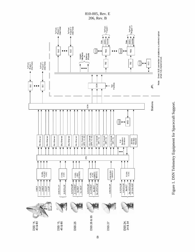
the Ground Communications Network (GCN) to JPL before delivery to the users. Figure 1 shows
810-005, Rev. E
206, Rev. B
7
the DSN equipment used for telemetry service support. The items shown on the figure are
discussed below.
In general, telemetry service support requires one antenna, at least one receiver,
and telemetry processing equipment for each spacecraft. Additional receivers and telemetry
processing equipment can be added for spacecraft with multiple downlinks or for redundancy. In
addition, the DSN is capable of tracking two spacecraft per antenna (MSPA) if they both are
within the scheduled antenna’s beamwidth.
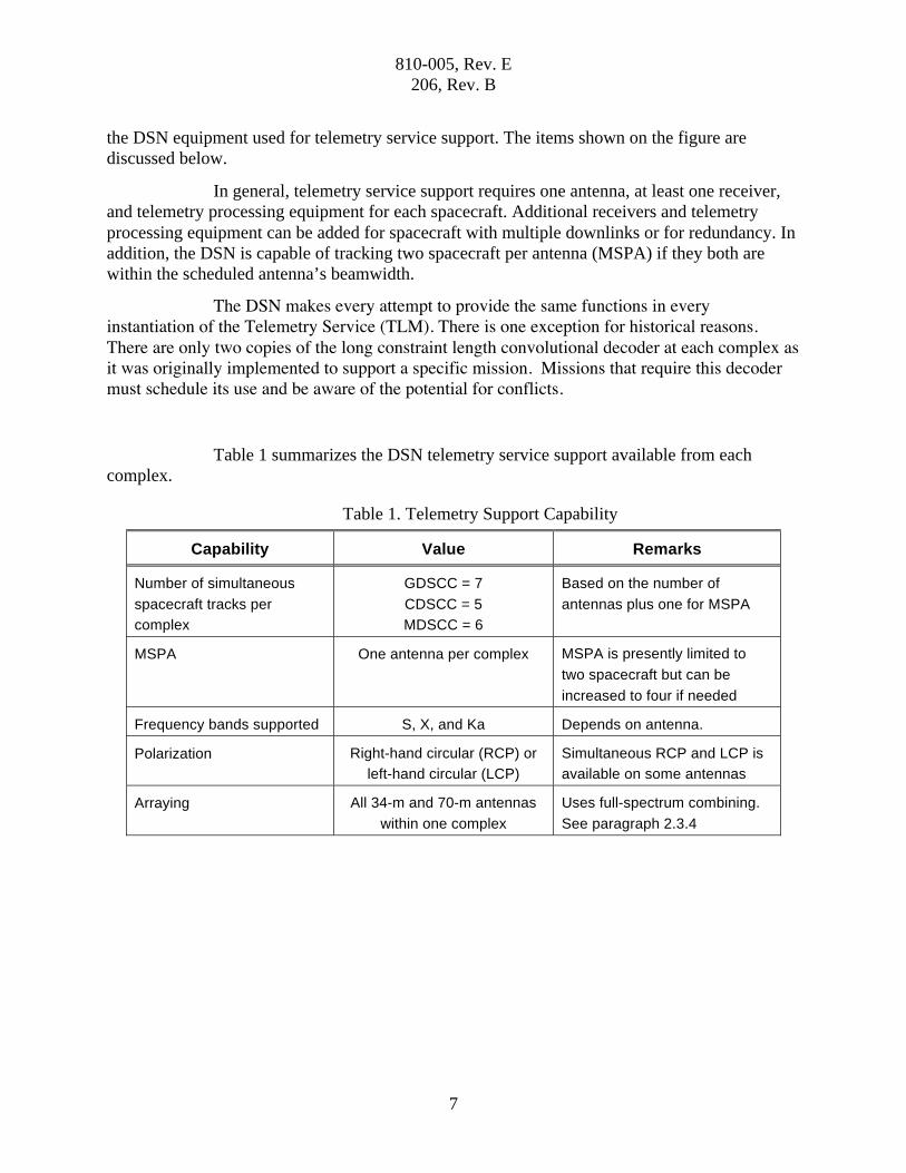
The DSN makes every attempt to provide the same functions in every instantiation of the Telemetry Service (TLM). There is one exception for historical reasons. There are only two copies of the long constraint length convolutional decoder at each complex as it was originally implemented to support a specific mission. Missions that require this decoder must schedule its use and be aware of the potential for conflicts.
Table 1 summarizes the DSN telemetry service support available from each
complex.
Table 1. Telemetry Support Capability
Capability Value Remarks
Number of simultaneous
spacecraft tracks per
complex
GDSCC = 7
CDSCC = 5
MDSCC = 6
Based on the number of
antennas plus one for MSPA
MSPA One antenna per complex MSPA is presently limited to
two spacecraft but can be
increased to four if needed
Frequency bands supported S, X, and Ka Depends on antenna.
Polarization Right-hand circular (RCP) or
left-hand circular (LCP)
Simultaneous RCP and LCP is
available on some antennas
Arraying All 34-m and 70-m antennas
within one complex
Uses full-spectrum combining.
See paragraph 2.3.4
810-005, Rev. E
206, Rev. B
8
Figure 1, DSN Telemetry Equipment for Spacecraft Support.
Fig
ure
1. D
SN
Tel
emet
ry E
quip
men
t fo
r S
pac
ecra
ft S
upport
.

810-005, Rev. E
206, Rev. B
9
2.1 Telemetry Services
Two distinct types of telemetry service are available. The first of these is the
traditional return link from a spacecraft that may carry engineering or science data as one of
several forms of telemetry modulation including residual-carrier or suppressed-carrier binary-
phase-shift keying (BPSK), quadrature-phase-shift keying (QPSK), or offset QPSK (OQPSK).
The second is the beacon mode service that is intended to monitor the high-level state of a
spacecraft during periods when insufficient link margin prevents the reception of telemetry.
2.2 Facilities and Equipment
2.2.1 Antennas
Each Deep Space Communications Complex contains one 70-m, from two to five
34-m antennas. There are two types of 34-m antennas. The first is the so-called high-efficiency
(HEF) antennas that have their feed, low-noise amplifiers, and transmitter located on the tilting
structure of the antenna. These antennas were named when a less-efficient 34-m antenna was in
use by the DSN and the name has survived. The efficiency of all DSN 34-m antennas is now
approximately the same. The second type of 34-m antenna is the beam waveguide (BWG)
antenna where the feeds, low noise amplifiers and transmitters are located in a room below the
antenna structure and the radio frequency energy is transferred to and from the antenna surface
by a series of mirrors encased in a protective tube. All antennas that are designed to receive S- or
X-band can receive either RCP or LCP in these bands. Antennas with two low noise amplifiers
(LNAs) and downconverters in either of these bands can receive simultaneous RCP and LCP. All
antennas that receive in 26 GHz or 32 GHz (Ka) bands are designed to receive RCP. Four of the
five antennas that receive 32 GHz can receive LCP provided that autotrack capability is not
required.
The capabilities of each antenna type and of the individual Beam Waveguide
(BWG) antennas are different and must be considered in designing a return link. The selection of
antenna will depend on the downlink frequencies it supports and the gain it can provide. Table 2
lists the uplink and downlink frequency ranges for each antenna type and the sensitivity,
expressed as the ratio of antenna gain to system temperature, at the time this module was
published. The modules referred to above should be consulted for current values and other
parameters. The telecommunications link designer is cautioned against making designs
dependent on the 70-m antenna as there is only one per complex and it subject to severe
scheduling constraints.
The DSN has entered into an agreement with the Australian Commonwealth
Scientific and Industrial Research Organisation (CSIRO) to use the Australia Compact Telescope
Array (ATCA) at Narrabri as a backup for the one antenna at the DSN Canberra complex with
Ka-band capability and has provided CSIRO with a set of standard DSN telemetry processing
equipment. The agreement requires the ATCA to provide sufficient aperture to equal or exceed
the performance of the DSN 34-m antenna at Ka-band however the details of this performance
are beyond the scope of this document.

810-005, Rev. E
206, Rev. B
10
Table 2. Frequencies Covered and Sensitivity of DSN Antennas for Telemetry
Antenna
type
Downlink
Frequency
Ranges (MHz)
Sensitivity
(G/T, dB)
(See Note 1)
GDSCC CDSCC MDSCC
70-m
2270 – 2300
8400 – 8500
48.3 – 51.3
61.0 – 61.7 1 1 1
34-m HEF
(Note 2)
2200 – 2300
8400 – 8500
8200 – 8600
39.1 – 39.9
53.0 – 54.8
51.2 – 52.4
1 1 1
34-m BWG
S/X/26 GHz
(Note 3)
2200 – 2300
8400 – 8500
25500 – 27000
40.8 – 41.7
52.2 – 53.6
58.8
1 0 0
34-m BWG
S/X/26 GHz/
Ka
(Note 4)
2200 – 2300
8400 – 8500
25000 – 27000
31800 – 32300
40.6 – 41.9
52.4 – 54.2
56.1 – 57.2
58.4 – 59.7
0 1 1
34-m BWG
X/Ka (Note 5)
8400 – 8500
31800 – 32300
52.8 – 54.7
59.2 – 61.9 2 0 1
34-m HSB 2200 – 2300 34.6 1 0 0
Notes:
1. Range covers best performing antenna with 95% weather (see module 105) at band center and 45-degrees elevation in highest sensitivity configuration (usually one band, downlink only) to worst performing antenna at band center and peak gain point in lowest sensitivity configuration (usually dual band downlink or backup LNA with uplink in one band). See appropriate telecommunications interface module for complete performance envelope and module 105 for atmospheric effects.
2. The 8200 – 8600 MHz (VLBI) band uses a wideband LNA with lower performance that is available as an amplifier for telemetry in the 8400 – 8500 MHz allocation. See module 103.
3. 26 GHz capability will be added to the GDSCC S/X station in the near future. Performance values are estimates. 26 GHZ implementation includes a special low G/T mode for high signal level conditions.
4. 26 GHz capability will be added to the CDSCC and MDSCC S/X/Ka stations in the near future. Performance values are estimates. Wide range of 26 GHz and 32 GHz performance results from present reduced antenna efficiency and higher atmospheric contribution at MDSCC. 26 GHZ implementation includes a special low G/T mode for high signal level conditions.
5. Does not include backup X-band LNA for DSS 25 that has significantly lower performance. See module 104. Wide range of Ka-band performance results from much lower atmospheric contribution at GDSCC than at MDSCC Wide range of X-band performance results from use of cooled common aperture X and Ka feed at DSS 26 and DSS 55 that is not available at DSS 25.
810-005, Rev. E
206, Rev. B
11
2.2.2 Telemetry Receivers
All DSN antennas employ a receiver architecture where one or both circular
polarizations of the received spectrum are amplified by an LNA and translated to an intermediate
frequency by a downconverter (D/C) before being routed to the control room where the desired
signal is extracted. The 70-m stations have an L-band reception capability that was installed for
Very-long Baseline Interferometry support. L-band is not available for telemetry because its
frequency range is not within an authorized space-to-Earth telemetry allocation. The antennas are
designed to receive extremely weak signals and can be overloaded by signals in excess of –90
dBm. Antennas supporting 26 GHz have a special low-gain mode that permits operation up to –
50 dBm with degraded G/T. Missions must be careful to not exceed these limits when designing
the near-Earth phase or phases of their mission.
Each S-, X-, and Ka-band intermediate frequency from the 34-m and 70-m
stations is made available to from one to four sets of receiving and telemetry processing
equipment in the SPC however software limitations restrict the number of spacecraft that can be
tracked from a single antenna to one or two. The additional receivers can be used to provide
redundancy or reception for additional return links from the supported spacecraft. Additional
redundancy can be obtained at S-band and X-band from stations with simultaneous RCP and
LCP capability by setting both downconverters to the same polarization. However, the two
spacecraft per antenna limit is maintained.
The intermediate frequency from the 26 GHz downconverter at the BWG stations
is connected directly to a high-rate telemetry receiver in the SPC with a second receiver available
for backup. The following is a brief discussion of the DSN telemetry receivers. Their
characteristics are summarized in Table 3.
Each receiver for the S-, X-, and Ka- bands at the 34-m and 70-m antennas is
contained in an assembly referred to as a Downlink Channel. The receiver utilizes a closed-loop
digital super-heterodyne receiver with a selectable carrier tracking loop bandwidth to produce an
8-bit estimated symbol value as its output. Alternatively, these receivers can be used to detect the
presence or absence of one of four subcarriers referred to a beacon tones. A complete discussion
of the capabilities of this receiver is contained in module 207 of this handbook.
The receiver for 26 GHz is part of a special Downlink Channel containing a
wideband telemetry processor. The receiver is preceded by a fixed-frequency downconverter in
the antenna and a step-tunable downconverter in the control room. The capabilities of this
receiver are discussed in module 215 of this handbook.
2.2.3 Telemetry Processing
Telemetry processing at the 34-m and 70-m is available for both CCSDS and non-
CCSDS (legacy) spacecraft. A summary of the capabilities for these stations is provided in
Tables 3.

810-005, Rev. E
206, Rev. B
12
At the 34 and 70-m stations, the digital symbol output of the telemetry receiver is
coupled to a Telemetry Processor (TLP) within the Downlink Channel assembly that performs
time-tagging, optional decoding and frame synchronization, virtual channel extraction, and
formatting of the data for delivery to the customer. Decoding and frame synchronization are
discussed in module 208 of this handbook. Data delivery formats are beyond the scope of this
handbook but are available to qualified users through the DSN Mission Commitments Program
Office.
Real-time data delivery may have to be limited to critical data at times. The
remainder will be delivered non real-time within an agreed timeframe.
2.2.4 Ground Communications Network
The GCN uses communications circuits provided by the NASA Integrated
Services Network (NISN) to connect the stations to JPL Central and users. The communication
lines are shared with all users and, while DSN makes every effort to supply sufficient bandwidth.
2.2.5 DSN Data Delivery
The DSN provides CCSDS SLE data delivery directly from the station at which it
is received or through the DSN central facility at JPL. Data storage, buffering against line
outages, access, retrieval, and query are provided at all locations. Data delivery for additional
telemetry functions such as packet extraction and CCSDS File Delivery Protocol (CFDP) file
processing is from the DSN central facility where these functions are performed.
2.3 Concepts Used in Estimating Telemetry Performance
The following concepts are important to understanding telemetry performance.
Additional discussion of these concepts is contained in module 207B of this handbook.
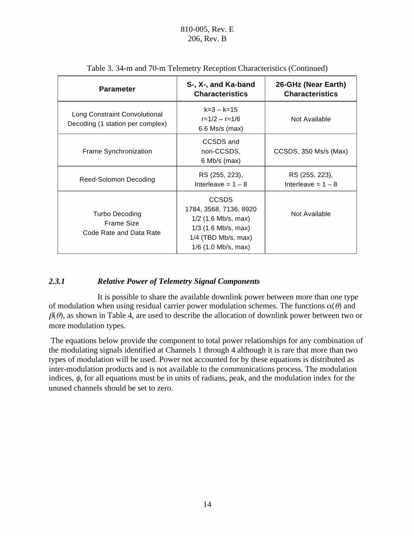
Table 3. 34-m and 70-m Telemetry Reception Characteristics
Parameter S-, X-, and Ka-band
Characteristics
26-GHz (Near Earth)
Characteristics
Receiver Type Digital Digital
Closed-loop Carrier Loop Bandwidth
(1 sided) 0.2 Hz – 200 Hz 0.1% of symbol rate
Carrier Tracking Residual Carrier or
Suppressed Carrier Suppressed Carrier

810-005, Rev. E
206, Rev. B
13
Table 3. 34-m and 70-m Telemetry Reception Characteristics (Continued)
Parameter S-, X-, and Ka-band
Characteristics
26-GHz (Near Earth)
Characteristics
Pre-digitization Bandwidth 36 MHz 400 MHz
Modulation Types
Residual Carrier BPSK
with or without subcarrier,
Suppressed Carrier BPSK,
QPSK, OQPSK
Suppressed Carrier
BPSK, QPSK, OQPSK,
UQPSK
Subcarrier Frequencies 500 Hz – 2.0 MHz Not Available
Subcarrier Data Rate
(Residual Carrier)
4 s/s – 0.67 X fsubcarrier
(s/s) Not Available
Subcarrier Data Rate
(Suppressed Carrier)
20 X loop B/W (s/s) – 0.67
X fsubcarrier (s/s) Not Available
Direct Modulation
(Residual Carrier)
10 ks/s – 26 Ms/s (NRZ)
100 s/s – 13 Ms/s (Bi-f) Not Available
Direct Modulation
(Suppressed Carrier)
20 X loop B/W (s/s) – 26
Ms/s (NRZ)
20 X loop B/W (s/s) – 13
Ms/s (Bi f))
40 ks/s – 26 Ms/s (QPSK
or OQPSK)
1 Ms/s to 350 Ms/s
Beacon Mode 1 of 4 tones,
SNR > 5 dB-Hz Not Available
Data Formats NRZ (-L, -M, -S)
Bi-f (-L, -M, -S)
NRZ (-L, -M, -S)
Bi-f -L
Available Decoding
Short and long Constraint
Convolutional, Reed-
Solomon, Concatenated
Convolutional and Reed-
Solomon, Turbo
Short Constraint
Convolutional, Reed-
Solomon, Concatenated
Convolutional and Reed-
Solomon
Short Constraint Convolutional
Decoding
k=7, r=1/2 CCSDS or
DSN Connection, Optional
De-randomization and
alternate symbol inversion
10 Ms/s (max)
k=7, r=1/2 CCSDS
Connection, Optional De-
randomization
350 Ms/s (max)
810-005, Rev. E
206, Rev. B
14
Table 3. 34-m and 70-m Telemetry Reception Characteristics (Continued)
Parameter S-, X-, and Ka-band
Characteristics
26-GHz (Near Earth)
Characteristics
Long Constraint Convolutional
Decoding (1 station per complex)
k=3 – k=15
r=1/2 – r=1/6
6.6 Ms/s (max)
Not Available
Frame Synchronization
CCSDS and
non-CCSDS,
6 Mb/s (max)
CCSDS, 350 Ms/s (Max)
Reed-Solomon Decoding RS (255, 223),
Interleave = 1 – 8
RS (255, 223),
Interleave = 1 – 8
Turbo Decoding
Frame Size
Code Rate and Data Rate
CCSDS
1784, 3568, 7136, 8920
1/2 (1.6 Mb/s, max)
1/3 (1.6 Mb/s, max)
1/4 (TBD Mb/s, max)
1/6 (1.0 Mb/s, max)
Not Available
2.3.1 Relative Power of Telemetry Signal Components
It is possible to share the available downlink power between more than one type of modulation when using residual carrier power modulation schemes. The functions ( ) and
( ), as shown in Table 4, are used to describe the allocation of downlink power between two or
more modulation types.
The equations below provide the component to total power relationships for any combination of
the modulating signals identified at Channels 1 through 4 although it is rare that more than two
types of modulation will be used. Power not accounted for by these equations is distributed as
inter-modulation products and is not available to the communications process. The modulation indices, , for all equations must be in units of radians, peak, and the modulation index for the
unused channels should be set to zero.

810-005, Rev. E
206, Rev. B
15
Table 4. Definition of ( ) and ( ) for in radians, peak
(1) Channel 1 data (D1) directly modulates the carrier with modulation index 1.
(2) Channel 2 data (D2) bi-phase modulates a square-wave or sine-wave subcarrier that is used to modulate the carrier with modulation index 2.
(3) Channel 3 data (D3) bi-phase modulates a square-wave or sine-wave subcarrier that is used to modulate the carrier with modulation index 3.
(2) Channel 4 data (D4) is a square-wave or sine-wave ranging signal that directly modulates the carrier with modulation index 4.
The carrier suppression is
PC
PT
= cos 1( ) 2( ) 3( ) 4( )[ ]2
. (1)
The ratio of the available data power to total power for each of the data streams is
PD1
PT
= sin 1( ) 2( ) 3( ) 4( )[ ]2
, (2)
PD2
PT
= cos 1( ) 2( ) 3( ) 4( )[ ]2
, (3)
PD3
PT
= cos 1( ) 2( ) 3( ) 4( )[ ]2
, (4)
PD4
PT
= cos 1( ) 2( ) 3( ) 4( )[ ]2
. (5)
Telemetry type ( ) ( ) Remarks
squarewave subcarrier or data only
cos( ) sin( ) ( ) includes data power in all
harmonics
sinewave subcarrier J0( )
2J1( )
( ) only includes data power in
fundamental harmonics
810-005, Rev. E
206, Rev. B
16
2.3.2 Definition of STB/NO and STSY/NO (dB)
Telemetry signal-to-noise ratios (SNRs) are expressed as bit SNR (represented as
either STB/NO or EB/NO) or symbol SNR (represented as either STSY/NO or ES/NO). The
distinction between symbols and bits is that when the telemetry data are encoded prior to
transmission, channel bits (information bits plus overhead such as frame sync and parity bits) are
the input to the encoder and symbols are the output. When coded data are processed after receipt
on the ground, the telemetry stream consists of symbols until converted to bits again by the
decoder at which time any overhead bits are discarded. The relationship between STSY/NO and
STB/NO is:
STSY N0 =1
rSTB N0 (6)
where
S = the data power as defined in equations (1), (2), or (3);
TB = the bit period,
TSY = the symbol period,
NO = the one-sided noise spectral density,
r = the number of symbols per bit.
Some typical values for r include:
1 for uncoded data,
2 for rate 1/2 convolutionally coded or turbo coded data,
6 for rate 1/6 convolutionally coded or turbo coded data,
255/223 for Reed-Solomon coded data,
2 (255/223) for concatenated Reed-Solomon and rate 1/2 convolutionally coded
data.
2.3.3 Carrier Loop SNR
The DSN Telemetry provides the user with an estimate of ES/NO. This can be
used to calculate a value for Carrier Loop SNR that includes system losses. This provides both a
way to validate link design and a way to determine the system loss in a controlled environment. The following equations provide the Carrier Loop SNR where BL is the carrier loop bandwidth.

810-005, Rev. E
206, Rev. B
17
L =ES N0
tan2
TS BL
for squarewave and direct modulation. (7)
L =ES N0( ) J0
2( )2J2
2( ) TS BL
for sinewave subcarrier modulation. (8)
When using these relationships with more than one data stream modulating the
carrier, care should be taken to use the values of ES/NO, TSY, and that all pertain to the same
data stream.
2.3.4 Arraying
The DSN Telemetry can combine the intermediate frequencies from the 70-m and
34-m antennas at each complex by full spectrum combining. The output of the Full Spectrum
Combiner appears to be another IF spectrum that can be selected by from one to four receivers.
Ideally, the combined telemetry SNR is:
Eb
N0
=
Eb
N0
ii=1
n
(9)
where
Eb
N0
= the telemetry SNR at the input of the ith receiver for the non-arrayed case
n = the number of streams combined.
The ratio of the array sum Eb/N0 to the Eb/N0 of the master antenna (usually the
antenna with the highest individual Eb/N0) is the array gain. The individual SNRs are
proportional to the ratios of antenna gain to system noise temperature. G/T, at each of the
contributing antennas. Table 5 is a tabulation of G/T ratios relative to a 34-m and 70-m antenna
for individual antennas and for combinations of arrayed antennas. The antenna performance
values used to calculate the values in this table are those of the average antenna for each antenna
type listed in Table 2 at its peak gain elevation angle. Relative aperture will approach the ratio of
the antenna areas at low elevation angles where the high atmospheric temperature component
becomes dominant over the LNA temperature.
The values in the table must be considered to be approximations as they do not
take into consideration the particular antennas being arrayed, the effects of varying elevation,
and the selected support configuration (polarization, diplexed vs. non-diplexed, etc.). The
“Equivalent (dB)” column has been reduced by 0.3 dB to accommodate the typical combining
loss. Thus, the combination of one S-band 34-m antenna with the 70-m antenna is not listed as
the combining loss is approximately equal to the array gain.

810-005, Rev. E
206, Rev. B
18
Table 5. Relative Telemetry Aperture
Practical Arrays
[Best Antenna, Arrayed Antenna(s)]
G/T Ratio Relative
to Reference Antenna
Equivalent (dB) Less
Combining Loss
Relative to 34-m BWG Antenna
S-band, 34-m BWG & 34-m HEF 1.66 1.90
X-band, 2 34-m (BWG or HEF) 2 2.71
X-band, 3 34-m (BWG or HEF) 3 4.47
X-band, 3 34-m BWG and HEF 4 5.72
Ka-band, 2 34-m BWG 2 2.71
Relative to 70-m Antenna
S-band, 70-m, 34-m BWG & 34-m HEF 1.23 0.60
X-band, 70-m, 1 34-m (BWG or HEF) 1.18 0.42
X-band, 70-m, 2 34-m (BWG or HEF) 1.36 1.03
X-band, 70-m, 3 34-m (BWG or HEF) 1.53 1.55
X-band, 70-m, 3 34-m BWG and HEF 1.70 2.01
3 Typical Performance
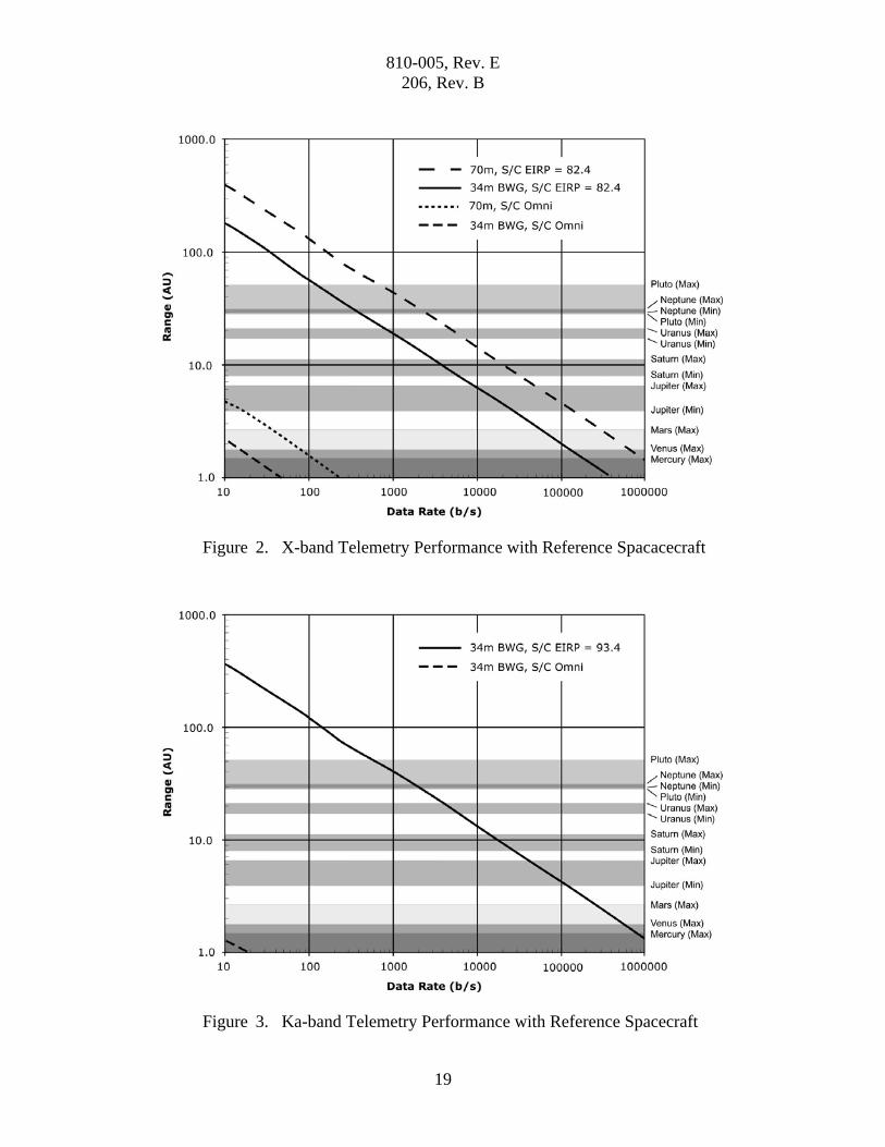
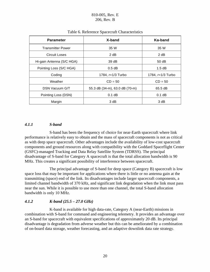
Figures 2 and 3 provide the expected performance at X-band and Ka-band using a
reference spacecraft having the characteristics listed in Table 6. Spacecraft antenna size and
transmitter power have been made equal to provide a fair comparison. These figures illustrate
that, all other factors being the same, the performance of the 34-m BWG antennas at Ka-band is
essentially the same as the 70-m antennas at X-band. It is also evident that use of Ka-band omni-
directional antenna for emergency purposes is not practical for most spacecraft.
4 Recommendations for Mission Design
4.1 Operating Frequency
The DSN supports telemetry reception in the S-, X-, and Ka-bands. The trend in
deep space communications (Category B spacecraft) has been towards the higher frequencies.
Near-Earth (Category A) spacecraft have used S-band exclusively but are adopting 26 GHz for
high data rate applications.
810-005, Rev. E
206, Rev. B
19
Figure 2. X-band Telemetry Performance with Reference Spacacecraft
Figure 3. Ka-band Telemetry Performance with Reference Spacecraft
810-005, Rev. E
206, Rev. B
20
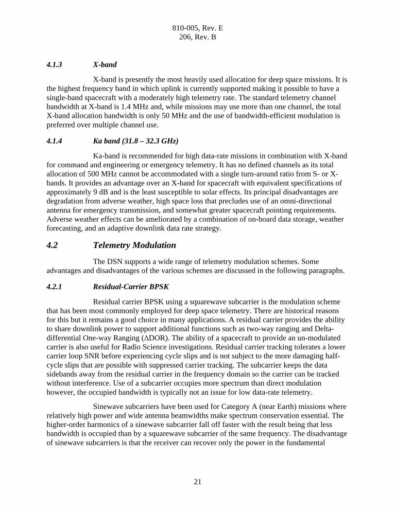
Table 6. Reference Spacecraft Characteristics
Parameter X-band Ka-band
Transmitter Power 35 W 35 W
Circuit Loses 2 dB 2 dB
Hi-gain Antenna (S/C HGA) 39 dB 50 dB
Pointing Loss (S/C HGA) 0.5 dB 1.5 dB
Coding 1784, r=1/3 Turbo 1784, r=1/3 Turbo
Weather CD = 50 CD = 50
DSN Vacuum G/T 55.3 dB (34-m), 63.0 dB (70-m) 65.5 dB
Pointing Loss (DSN) 0.1 dB 0.1 dB
Margin 3 dB 3 dB
4.1.1 S-band
S-band has been the frequency of choice for near-Earth spacecraft where link
performance is relatively easy to obtain and the mass of spacecraft components is not as critical
as with deep space spacecraft. Other advantages include the availability of low-cost spacecraft
components and ground resources along with compatibility with the Goddard Spaceflight Center
(GSFC)-managed Tracking and Data Relay Satellite System (TDRSS). The principal
disadvantage of S-band for Category A spacecraft is that the total allocation bandwidth is 90
MHz. This creates a significant possibility of interference between spacecraft.
The principal advantage of S-band for deep space (Category B) spacecraft is low
space loss that may be important for applications where there is little or no antenna gain at the
transmitting (space) end of the link. Its disadvantages include larger spacecraft components, a
limited channel bandwidth of 370 kHz, and significant link degradation when the link must pass
near the sun. While it is possible to use more than one channel, the total S-band allocation
bandwidth is only 10 MHz.
4.1.2 K-band (25.5 – 27.0 GHz)
K-band is available for high data-rate, Category A (near-Earth) missions in
combination with S-band for command and engineering telemetry. It provides an advantage over
an S-band for spacecraft with equivalent specifications of approximately 20 dB. Its principal
disadvantage is degradation from adverse weather but this can be ameliorated by a combination
of on-board data storage, weather forecasting, and an adaptive downlink data rate strategy.
810-005, Rev. E
206, Rev. B
21
4.1.3 X-band
X-band is presently the most heavily used allocation for deep space missions. It is
the highest frequency band in which uplink is currently supported making it possible to have a
single-band spacecraft with a moderately high telemetry rate. The standard telemetry channel
bandwidth at X-band is 1.4 MHz and, while missions may use more than one channel, the total
X-band allocation bandwidth is only 50 MHz and the use of bandwidth-efficient modulation is
preferred over multiple channel use.
4.1.4 Ka band (31.8 – 32.3 GHz)
Ka-band is recommended for high data-rate missions in combination with X-band
for command and engineering or emergency telemetry. It has no defined channels as its total
allocation of 500 MHz cannot be accommodated with a single turn-around ratio from S- or X-
bands. It provides an advantage over an X-band for spacecraft with equivalent specifications of
approximately 9 dB and is the least susceptible to solar effects. Its principal disadvantages are
degradation from adverse weather, high space loss that precludes use of an omni-directional
antenna for emergency transmission, and somewhat greater spacecraft pointing requirements.
Adverse weather effects can be ameliorated by a combination of on-board data storage, weather
forecasting, and an adaptive downlink data rate strategy.
4.2 Telemetry Modulation
The DSN supports a wide range of telemetry modulation schemes. Some
advantages and disadvantages of the various schemes are discussed in the following paragraphs.
4.2.1 Residual-Carrier BPSK
Residual carrier BPSK using a squarewave subcarrier is the modulation scheme
that has been most commonly employed for deep space telemetry. There are historical reasons
for this but it remains a good choice in many applications. A residual carrier provides the ability
to share downlink power to support additional functions such as two-way ranging and Delta-
differential One-way Ranging ( DOR). The ability of a spacecraft to provide an un-modulated
carrier is also useful for Radio Science investigations. Residual carrier tracking tolerates a lower
carrier loop SNR before experiencing cycle slips and is not subject to the more damaging half-
cycle slips that are possible with suppressed carrier tracking. The subcarrier keeps the data
sidebands away from the residual carrier in the frequency domain so the carrier can be tracked
without interference. Use of a subcarrier occupies more spectrum than direct modulation
however, the occupied bandwidth is typically not an issue for low data-rate telemetry.
Sinewave subcarriers have been used for Category A (near Earth) missions where
relatively high power and wide antenna beamwidths make spectrum conservation essential. The
higher-order harmonics of a sinewave subcarrier fall off faster with the result being that less
bandwidth is occupied than by a squarewave subcarrier of the same frequency. The disadvantage
of sinewave subcarriers is that the receiver can recover only the power in the fundamental

810-005, Rev. E
206, Rev. B
22
harmonics. Data power transmitted in the higher-order harmonics is lost. This is contrasted to
squarewave subcarriers where all data power within the bandwidth of the receiver is recovered.
Direct carrier modulation is a good choice for medium and high-rate telemetry
when other considerations require a residual carrier. The baseline performance of this scheme is
the same as that when using a squarewave subcarrier and spectral occupancy is no more than half
that of the equivalent squarewave subcarrier system.
4.2.2 Suppressed-Carrier BPSK
Suppressed-carrier BPSK provides approximately the same performance at high
data rates as residual-carrier BPSK and improved performance at some medium data rates. The
bandwidth occupancy is the same as residual-carrier BPSK without a subcarrier. A disadvantage
of suppressed-carrier BPSK is that telemetry must be disabled in order to perform DSN ranging
or DOR.
4.2.3 QPSK and OQPSK
QPSK and Offset QPSK offer better bandwidth efficiency than BPSK. For a
given binary symbol rate, a QPSK or OQPSK carrier occupies only half the bandwidth of a
BPSK-modulated carrier (with no subcarrier). QPSK and OQPSK have the same disadvantage as
suppressed-carrier BPSK in that that telemetry must be disabled in order to perform DSN
ranging or DOR.
The baseline telemetry performance of QPSK and OQPSK is the same as
suppressed-carrier BPSK at high data rates. When shaped data pulses are used, there is some
advantage to OQPSK, relative to QPSK, which accounts for the popularity of OQPSK in satellite
communications; however, for unshaped data pulses, the performance and spectral occupancy of
QPSK and OQSPK are the same.
4.3 Coding Schemes
Selection of coding scheme is independent of modulation scheme and involves
the tradeoff of four considerations. These are coding gain, bandwidth, latency, and error floor. In
general, coding gain increases with bandwidth and latency. The following coding schemes are
supported by the DSN.
4.3.1 Uncoded
Uncoded data requires the least bandwidth and has the lowest latency. Its primary
use is for transfer of extremely high data rates in bandwidth-limited situations when adequate
link margin is available.

810-005, Rev. E
206, Rev. B
23
4.3.2 Reed-Solomon Code
The (255,223) Reed-Solomon (RS) code used by the DSN is capable of correcting
up to 16 symbol errors out of each 255, corresponding to a bit error rate (BER) at the input of the
decoder of 6.2 10–2. A failure to decode is declared at BERs greater than this. An SNR of
approximately 3-dBs is required when system losses are taken into consideration. It has a modest
bandwidth expansion but the lack of performance near threshold limits its use to high EB/NO
conditions.
4.3.3 Short Constraint Length, Rate 1/2 Convolutional Code
Short constraint length (k = 7), rate 1/2 convolutional code is a low-latency code
that requires twice the bandwidth of uncoded data but provides coding gain for any input SNR.
Its low latency makes it a good choice for low rate, emergency communications when recovery
of data in real-time may outweigh the coding gain of higher-latency codes.
4.3.4 Concatenated Reed-Solomon and Rate 1/2 Convolutional Codes
When Reed-Solomon encoded spacecraft data is rate 1/2 convolutionally encoded
before transmission, the resultant code has a slightly greater bandwidth expansion but
significantly better performance at all SNRs than either of its components. This is because the
convolutional decoder improves the input symbol error rate to the Reed-Solomon decoder at low
SNRs while the RS decoder improves the output error rate for all SNRs above its input threshold.
As convolutional decoders tend to produce bursts of errors as they near their threshold, they can
overwhelm the correction capability of the RS decoder. This can be alleviated by a technique
called interleaving (See module 208) that trades improved performance for increased latency.
4.3.5 Long Constraint-Length, Higher-Rate Convolutional Codes
Long constraint-length convolutional codes with rates up to 1/6 can be processed
on one link at a time at each complex. These codes offer significant improvements over the k=7,
r=1/2 code but at the expense of bandwidths expansions of from 3 to 6. As is the case with short
constraint-length codes, they can be concatenated with Reed-Solomon coding for better
performance. Use of these codes is discouraged because of their limited support within the DSN.
4.3.6 Turbo Codes
Turbo codes provide near Shannon-limit performance with bandwidth expansions
from slightly more than 2 to slightly more than 6. Block sizes of 1784, 3568, 7136, and 8920
symbols are accommodated. The smaller block sizes are intended for lower data rates while
using larger block sizes as the data rate increases reduces coding overhead. Their principal
disadvantages are the amount of processing that must be done to decode them and the presence
of an error floor at a Frame Error Rate of about 10–6. The decoding complexity results in
increased latency and limits the rate to that established by number of frames that can be in-
process at any time and the processing time for each frame.

810-005, Rev. E
206, Rev. B
24
5 Proposed Capabilities
The following paragraphs discuss capabilities that have not yet been implemented
by the DSN but have adequate maturity to be considered for spacecraft mission and equipment
design. Telecommunications engineers are advised that any capabilities discussed in this section
cannot be committed to except by negotiation with the DSN Mission Commitments Program
Office.
5.1 Low-density Parity-Check Codes
Low-Density Parity-Check codes conforming to the code family specified in
Section 3 of the CCSDS Experimental Specification 131.1-O-2 are under consideration as a
complement to codes currently implemented in the DSN.
5.2 Bandwidth-efficient Modulation
Several bandwidth-efficient modulation schemes are under consideration to
permit the maximum amount of data to be returned within the allocated frequency bands. The
most likely candidate for implementation is Gaussian minimum-shift keying (GMSK).
5.3 Weather-related Service Management
New operational methods will be implemented to maximize the data return at Ka-
band where atmospheric effects are much greater than at S- or X-band. The anticipated link
performance at a specified confidence level, based on both historical models and near-term
forecasts, will be made available to projects. An optimum data rate or the two optimum data rates
for a pass will also be provided based on the expected weather and the range of required
elevation angles for the pass. The project will be given the option to uplink the appropriate
commands to their spacecraft in time to adapt the downlink data rate to the optimum value(s) for
the expected weather.