2060 ieee transactions on communications, …code.ucsd.edu/pcosman/wangtonitcom.pdf · 2060 ieee...
TRANSCRIPT

2060 IEEE TRANSACTIONS ON COMMUNICATIONS, VOL. 61, NO. 5, MAY 2013
Uplink Resource Management forMultiuser OFDM Video Transmission Systems:
Analysis and Algorithm DesignDawei Wang, Student Member, IEEE, Laura Toni, Member, IEEE, Pamela C. Cosman, Fellow, IEEE,
and Laurence B. Milstein, Fellow, IEEE
Abstract—We consider a multiuser OFDM system in whichusers want to transmit videos via a base station. The basestation knows the channel state information (CSI) as well asthe rate distortion (RD) information of the video streams andtries to allocate power and spectrum resources to the usersaccording to both physical layer CSI and application layer RDinformation. We derive and analyze a condition for the optimalresource allocation solution in a continuous frequency responsesetting. The optimality condition for this cross layer optimizationscenario is similar to the equal slope condition for conventionalvideo multiplexing resource allocation. Based on our analysis, wedesign an iterative subcarrier assignment and power allocationalgorithm for an uplink system, and provide numerical perfor-mance analysis with different numbers of users. Comparing tosystems with either only physical layer or only application layerinformation available at the base station, our results show that theuser capacity and the video PSNR performance can be increasedsignificantly by using cross layer design. Bit-level simulationswhich take into account the imperfection of the video codingrate control, the variation of RD curve fitting, as well as channelerrors, are presented.
Index Terms—Radio spectrum management, multimedia com-munication, OFDMA, wireless power allocation, video codingrate control.
I. INTRODUCTION AND RELATED WORK
WE study video transmission in a cellular wirelesscommunication system, where multiple mobile stations
send compressed videos to a base station. We exploit both thecharacteristics of video content as well as the instantaneouswireless channel quality, and design a cross layer resource
Manuscript received January 17, 2012; revised July 29, 2012. The associateeditor coordinating the review of this paper and approving it for publicationwas J. Wang.
D. Wang, P. C. Cosman, and L. B. Milstein are with the University ofCalifornia, San Diego, Department of Electrical and Computer Engineering,9500 Gilman Drive, Mail Code 0407, La Jolla, CA, 92093-0407, USA (e-mail: {daw017, pcosman}@ucsd.edu; [email protected]).
L. Toni was with the University of California, San Diego. She is now withthe École Polytechnique Fédérale de Lausanne (EPFL), Signal ProcessingLaboratory - LTS4, Switzerland (e-mail: [email protected]).
This research is supported by the Intel-Cisco Video Aware WirelessNetworks (VAWN) program and the National Science Foundation under grantNo. CCF-0915727
The authors would like to thank Prof. Y. H. Kim from the School ofElectronics and Information, Kyung Hee University, Republic of Korea, andDrs. J. R. Foerster and V. Srinivasa Somayazulu of Intel Labs, for some usefuldiscussions.
The material in this paper was presented in part at IEEE Globecom,Houston, TX, December 2011.
Digital Object Identifier 10.1109/TCOMM.2013.032013.120053
allocation algorithm to optimize video transmission perfor-mance.
Orthogonal Frequency Division Multiplexing (OFDM) isa promising solution to combat the problem of inter-symbolinterference (ISI) in a wideband communication system. Byallocating different subcarriers to users according to the user’schannel state information (CSI) in a multiuser setting, Or-thogonal Frequency Division Multiple Access (OFDMA) is aflexible and low-complexity way of managing communicationresources. The problem of assigning resources in an OFDMAsystem was first studied in [1], where the authors formulatedand solved a total transmission power minimization prob-lem for different user quality-of-service (QoS) requirements.Research in [2]–[5] tried to solve the rate maximizationproblem, given power and spectrum constraints in differentcommunication settings. Because of the complexity of theoptimization problems, most of the work above proposednumerical algorithms instead of finding analytical solutions.Power allocation for an imperfect CSI case was exploredin [6]. To reduce the complexity of resource allocationalgorithms, chunk-based resource allocation, which makesallocation decisions on subcarriers in groups, was studiedby [7], [8]. Results show that when the chunk bandwidthis smaller than the coherence bandwidth, the chunk-basedresource allocation can significantly reduce the computationalcomplexity while maintaining similar throughput performancecompared to subcarrier-based resource allocation algorithms.Utility driven resource allocation was investigated by [9], [10]and most recently by [11], [12] in an information theoreticsetting. In these papers, instead of maximizing the sum of thethroughputs, the objective of the optimization is the overallutility, which is a function of throughput.
Regarding the application layer, video rate control algo-rithms as well as rate distortion (RD) analysis were studied by[13]–[16]. The results of these papers show that the complexity(high or low motion) of a video stream can be reflected byits rate distortion curve. The diversity of different video RDcurves provides us an opportunity to optimize the overall videoquality when multiple video streams share the same resourcepool, i.e., video multiplexing. In [17], the authors considereda multiple camera surveillance system, and exploited the dif-ference between high complexity and low complexity videos.In [18], the economic concept of competitive equilibrium isused to allocate bit rate. The authors show that by trading
0090-6778/13$31.00 c© 2013 IEEE

WANG et al.: UPLINK RESOURCE MANAGEMENT FOR MULTIUSER OFDM VIDEO TRANSMISSION SYSTEMS: ANALYSIS AND ALGORITHM DESIGN 2061
bit rate between users across time, the video quality of eachindividual user improves. For most of the literature on videomultiplexing, the resource pool is either bits or bit rate, andthe authors assume an error-free scenario. When multiplexingvideos in a wireless mobile communication case, bit rates willbe determined by the available bandwidth, transmission powerand CSI. In this sense, multiplexing video streams in a wirelessenvironment with a resource pool of power and bandwidth willbe more challenging than conventional video multiplexing.
In a cellular wireless OFDMA video transmission sys-tem, the CSI as well as the complexity of video streamscan be collected by the base station. Both the multiuserchannel diversity and video complexity diversity could beused simultaneously to optimize the power and subcarrierassignment. In [19], the authors propose a joint uplink anddownlink cross layer resource allocation framework with theresource being the channel access time duration. In [20] and[21], the authors study a subcarrier and power assignmentproblem in a downlink setting, where the subcarrier assign-ment and power allocation are treated as two independentsteps. To better optimize the system, we propose an iterativealgorithm which allows the application layer and physicallayer to interact. Throughout this paper, we are interested in acooperative setting for a slow fading scenario. Video streamswith high complexity should be given more subcarriers withgood channel gains, while streams with low complexity willget a relatively small number of subcarriers.
The rest of the paper is organized as follows: Section IIfirst introduces the basic model of the OFDMA system and thevideo compression rate-distortion model. We then formulatethe problem of cross layer optimization of an uplink cellularsystem. We derive an optimality condition for this problem in acontinuous channel response setting in Section III. A resourceallocation algorithm is presented in Section IV. We proposetwo baseline algorithms and compare the performance withour cross layer algorithm in Sections V and VI. Finally, wedraw our conclusions in Section VII.
II. CROSS LAYER RESOURCE ALLOCATION SYSTEM
MODEL
A. OFDMA System Description
Consider a cellular OFDMA video communication systemwith the set of users k={1, 2, 3 ... K}. The system occupiesa total frequency band of W (Hz) equally divided into Morthogonal subcarriers m={1, 2, 3 ... M}. We assume that thechannel gain within each subcarrier is flat. In our design, eachsubcarrier can only be used by one user, but it is possible forone user to get more than one subcarrier.
The system operates in a slotted manner and the lengthof one time slot is Ts (sec) for both downlink and uplink.One Group of Pictures (GOP) will be transmitted in one timeslot. Let Hk(s) = [Hk,1(s), Hk,2(s), ...Hk,M (s)] denote thecomplex channel gain of user k for the set of subcarriers intime slot s. In addition, we assume that the channel remainsunchanged for the duration of one time slot. The subcarrierassignment as well as the power allocation decision will bemade on a slot-by-slot basis. A block diagram of the transmit-ter is shown in Fig. 1. Let T be the data duration and Tcp be
Fig. 1. Cross-layer optimization system transmitter diagram.
the length of the cyclic prefix. We define T0 = T + Tcp to bethe duration of an OFDM symbol. The baseband transmittedsignal for user k can be written as
xk(t) =∑l
M∑m=1
√Pk,mXk,m[l] exp
(j2πmt
T
)Π(t− lT0)
(1)where Pk,m and Xk,m[l] are the transmission power andcoded symbol with unit variance of user k on subcarrier m,respectively. Also, Π(t) = 1, ∀t ∈ [0, T0), and Π(t) = 0otherwise.
Since we assume flat fading for each subcarrier, thelowpass equivalent received signal of user k on subcarrier mis given by
yk,m(t) =√Pk,mHk,mXk,m[l] exp
(j2πmt
T
)+ nk,m(t)
(2)where nk,m(t) is Additive White Gaussian Noise (AWGN)with two-sided power spectral density 2N0.
To detect the signal on subcarrier m, a correlation oper-ation is performed Yk,m = 1
T
∫ T
0 yk,m(t) exp(−j2πmt/T )dt.The noise power can be calculated as PN = E[|Nk,m|2] =2N0/T and the power for the desired signal is Pk,m|Hk,m|2.If the modulation format is M-QAM, from [22], the symbolerror rate (SER) can be approximated as
SER ≈ 4Q
⎛⎝√3
M − 1
Pk,m|Hk,m|2PN
⎞⎠ (3)
For a given target SERt, the information rate (number of bitseach symbol can carry) Rk,m(Pk,m, Hk,m) (in bits/symbol)can be written as a function of transmission power and channelresponse gain
Rk,m(Pk,m,Hk,m) = min{�log2
[1 + ηPk,m|Hk,m|2]�, Rmax}
(4)where η = 3
PN
[Q−1 (SERt/4)
]−2and Rmax is the largest
alphabet size the system allows. The bit rate (in bits/sec) thencan be written as: Rk,m(Pk,m, Hk,m)/T0.

2062 IEEE TRANSACTIONS ON COMMUNICATIONS, VOL. 61, NO. 5, MAY 2013
Fig. 2. Uplink OFDMA video communication system.
B. Video Rate-Distortion Model
Let Dsk(B) be the rate distortion function of user k in time
slot s, where B is the number of bits the encoder generated.For each GOP, the mean square error (MSE) distortion can beapproximated as [23]
Dsk(B) = ak +
wk
B + vk(5)
where ak, vk and wk are constants which depend on the videocontent. For video with high complexity (e.g., high motion),wk is relatively large. To protect the data, a channel code offixed rate u is added. Since the channel slot time is equalto the duration of one GOP, the number of information bitswhich the physical layer can support for one user with a fixedtarget symbol error rate is
Bk =M∑
m=1
u · Rk,m(Pk,m, Hk,m) · Ts/T0 (6)
For the purpose of resource allocation algorithm design, weignore the effect of channel errors. In Sections III and IV,we use (6) as the channel throughput for our mathematicalanalysis and algorithm design. The effect of channel errors onthe performance of the system will be evaluated by simulationin Section VI.
If we plug (6) into (5), then the MSE distortion for userk can be written as
ak +bk
M∑m=1
Rk,m(Pk,m, Hk,m) + ck
(7)
Here we have divided both the numerator and denominator byu·Ts/T0 for simplicity, so bk = wk
(u·Ts/T0), and ck = vk
(v·Ts/T0).
C. Uplink Resource Allocation Formulation
In an uplink OFDMA system (Fig. 2), the mobile stationssubmit the RD values (ak, bk, and ck) of the current GOP intheir buffers. We assume that the base station has perfect CSIof each subcarrier for each user. Our resource allocation goalis to minimize the sum of distortions at each time slot s. Theoptimization objective is
minP
K∑k=1
bkM∑
m=1Rk,m(Pk,m, Hk,m) + ck
(8)
where P is the power allocation matrix whose entry in thek-th row and m-th column, Pk,m, is the power allocation ofthe m-th subcarrier for user k. We drop the ak term as it isconstant with respect to P .
We assume that each user has a total power constraint ofP over all subcarriers and any subcarrier is used by at mostone user, so the feasible solutions for this problem satisfy thefollowing two constraints:(C1) For m ∈ {1, 2, 3...M}, if ∃k′ such that, if Pk′,m �= 0,then Pk,m = 0, ∀k �= k′
(C2)M∑
m=1Pk,m ≤ P ∀k ∈ {1, 2, 3...K}
For the optimization problem defined in (8), since con-straint C1 is not a convex set, and this optimization problem isNP-hard, we propose an algorithm for a sub-optimal solutionwith two steps:Step 1: The base station assigns subcarriers to different usersaccording to channel conditions and rate-distortion curves;Step 2: Given a subset of subcarriers, each user solves theoptimization problem of minimizing its own distortion underthe power constraint;
We then iteratively update both the subcarrier assignments(according to the RD curve) and the power allocation strategy(based on the CSI). One of the major differences betweenour algorithm and those in [20] and [21] is that we allowapplication layer information and physical layer informationto interact in our decision process. Before providing the detailsof the algorithm in Section IV, we first investigate a conditionfor the optimal solution in a continuous channel setting, wherethere can be variations within a subcarrier, as opposed to ablock fading model. This condition inspires our algorithm.
III. CONTINUOUS FREQUENCY CHANNEL RESPONSE
RESOURCE ALLOCATION ANALYSIS
We consider a system with only two users, K = 2, in acontinuous channel setting. In this scenario, the allocator candivide the total frequency band Btot into infinitely small bandsfor resource allocation. Note that |Hk(f)|2 is the channel gainfor user k at frequency f .
Let Bi be the frequency band assigned to user i. If weignore the upper bound of the modulation alphabet size, theoptimization problem becomes
minP
2∑k=1
bk∫̂Bk
log2[1 + ηPk(f)|Hk(f)|2]df + ck(9)
subject to(C1)B̂1 ∩ B̂2 = ∅,
(B̂1 ∪ B̂2
)⊂ Btot
(C2)∫̂Bk
Pk(f)df ≤ P, k = 1, 2
Here, Pk(f) is given by the water filling solution afterthe band allocation is decided. Given Btot, the optimalband allocation can be viewed as a partition of the bandBtot = Bopt
1 ∪ Bopt2 ∪ Bextra. Here, Bopt
1 and Bopt2 are the
optimal sets of frequency bands assigned to two users inthe sense that the sum of distortions is minimized, and nofrequency component in Bopt
i exceeds the water level of user

WANG et al.: UPLINK RESOURCE MANAGEMENT FOR MULTIUSER OFDM VIDEO TRANSMISSION SYSTEMS: ANALYSIS AND ALGORITHM DESIGN 2063
Fig. 3. Water level change for user 1 gaining one band. The water leveldrops from W1 to W ′
1 after user 1 gains one additional band θ.
i. The parameter Bextra is the set of bands not assigned toeither user. We introduce the following definitions.Definitions I:a) Let |.| be the bandwidth in Hz, e.g.,
∣∣Bopt1
∣∣ is the optimalbandwidth assigned to user 1.b) Let r1 =
∫Bopt
1
log2(1 + ηP1(f)|H1(f)|2)df and
r2 =∫
Bopt2
log2(1 + ηP2(f)|H2(f)|2)df be the average
optimal rate (in bits/sec) of two users. Here, |H1(f)|2 and|H2(f)|2 are the frequency channel responses of the twousers. Let P1(f) and P2(f) be the power allocations whichobey the water filling solution [24].c) Define W1 = P1(f)+
1η|H1(f)|2 andW2 = P2(f)+
1η|H2(f)|2
to be the water levels for the two users at the optimal solution.See Fig. 3 and Fig. 4.d) Let θ ∈ Bopt
2 be an infinitesimally small band θ assignedto user 2. Note that |Hθ
1 |2 and |Hθ2 |2 are the channel gains for
user 1 and user 2 for band θ, respectively. They are constantsince the band is infinitesimally small.
e) Let φθi =(Wi − 1
η|Hθi |2
)+
be the non-negative distancebetween the water level of user i and the noise level of band|Hθ
i |2. By definition, [x]+ = x if x > 0 and [x]+ = 0 ifx ≤ 0. For any frequency band θ of Bopt
2 , W2 − 1η|Hθ
2 |2> 0.
For user 2, the value of φθ2 is always positive.
Theorem 1: For a continuous frequency channel Btot, theoptimal band allocation of Bopt
1 and Bopt2 for minimizing the
sum of distortions should satisfy (10) at the top of next page,for any frequency band θ assigned to user 2. The proof of (10)can be found in Appendix A.
To find the optimal allocation in this cross layer problem,we wish to maximize the combination of application andphysical layer metrics, which as seen in (10), is the productof the absolute value of application layer RD slope,
Si =bi
(ri + ci)2(11)
and the physical layer information given in (12).For video RD characteristics in the form of Di =
Fig. 4. Water level change for user 2 losing one band. The water level raisesfrom W2 to W ′
2 after user 2 loses one band θ.
ai +bi
ri+ci, (11) is the absolute value of the slope of the RD
curve for user i at rate ri. In this sense, for an allocationscheme to be optimal, the application layer contribution tothe overall metric should be the slope of the curve insteadof the distortion value [13], [25]. To solve the optimizationproblem of Section II, the algorithm should give priority tothe user with the steepest slope. On the other hand, (12)is an explicit relation between the physical layer rate (inbits/sec) and channel state information. As the bandwidth ofθ becomes infinitesimally small, (12) can be considered as themarginal rate change (either increase or decrease) of switchinga band from one user to the other. More specifically, one maytreat ln
(1 + ηφθi |Hθ
i |2)
as the direct rate change caused by
gaining or losing θ, and∫
Bopti
η|Hi(f)|2|Bopt
i |(1+ηPi(f)|Hi(f)|2)φθi df as
the corresponding rate decrease or increase due to the effect ofwater level change. The optimal cross layer allocation wouldassign band θ to the user who has the maximum physical layermarginal rate increase given by (12), weighted by the slopeof the RD curve.
To solve (8), given finite subcarrier bandwidths, thephysical layer metric expression of (12) would not be valid, asthe frequency bands are modeled as experiencing block fading.We thus design an iterative subcarrier allocation algorithmin the next section. Similar to the optimal condition derivedin (10), the application layer metric is the slope of the RDcurve. We will give users with steep slope priority to accesssubcarriers. In the continuous channel response allocationanalysis, the increment considered for switching between userswas infinitesimal, whereas in the algorithm, the increment isthe bandwidth of a single subcarrier.
IV. UPLINK RESOURCE ALLOCATION ALGORITHM
To find a solution to the problem defined in (8), wedesign an iterative algorithm which allows physical layerCSI and application layer RD information to interact. Thisalgorithm first assigns the subcarriers purely based onchannel conditions. However, it is possible that the overallperformance (from an average distortion perspective) mightbe better if we assign some subcarriers to a user with worse

2064 IEEE TRANSACTIONS ON COMMUNICATIONS, VOL. 61, NO. 5, MAY 2013
b1(r1+c1)2
⎧⎨⎩ln(1 + ηφθ1|Hθ
1 |2)− ∫
Bopt1
η|H1(f)|2|Bopt
1 |(1+ηP1(f)|H1(f)|2)φθ1df
⎫⎬⎭b2
(r2+c2)2
⎧⎨⎩ln(1 + ηφθ2|Hθ
2 |2)− ∫
Bopt2
η|H2(f)|2|Bopt
2 |(1+ηP2(f)|H2(f)|2)φθ2df
⎫⎬⎭≤ 1 (10)
⎧⎪⎨⎪⎩ln(1 + ηφθi |Hθ
i |2)− ∫
Bopti
η |Hi(f)|2∣∣Bopti
∣∣ (1 + ηPi(f) |Hi(f)|2)φθi df
⎫⎪⎬⎪⎭ (12)
channel conditions, but who might need a greater bit rate.We then try to reassign one subcarrier to the user with thesteepest distortion curve slope. To solve a conventional videomultiplexing bit rate allocation problem, a condition for aglobal optimum is that users operate at a rate with the sameslope of their corresponding RD curves [13] [18] [26]. Notethat, at each iteration, we only change the assignment of onesubcarrier through a search process, and for every subcarrierwhich is not assigned to the user with the steepest slope,the calculations of distortion loss for the user losing thatsubcarrier and the performance improvement for the userwith the steepest slope gaining that subcarrier is of lowcomplexity. We then make the reassignment of the subcarrierthat can most effectively reduce the overall distortion. Werepeat this procedure iteratively until we run out of thepossibility of reassigning subcarriers. We introduce thefollowing definitions that will be used in the algorithm.Definitions II:a) Let ρ(i)m denote the user who is assigned subcarrier m atthe i-th iteration. For example, ρ(1)2 = 3 means user 3 isassigned subcarrier 2 at the first iteration of the algorithm.b) Define A
(i)k to be the set of subcarriers assigned to user k
at the i-th iteration.c) Define the potential set Ω as the set of users that have thepotential to improve the average performance by receivingextra subcarriers, and define |Ω| as the cardinality of thepotential set.d) Define Δk,m ≥ 0 as the absolute value of the videodistortion change of user k by gaining or losing subcarrierm.
Iterative Cross Layer Resource Allocation Algorithm:Step (1) Initialization:
Initialize ρ(0)m = argmax
k{|Hk,m|2} for m ∈
{1, 2, 3...M}. Initialize the potential set Ω = {1, 2, 3...K}.We first assign each subcarrier to the user who has the bestchannel response, and let the potential set be the total set.
Step (2) Water Filling and Slope Calculation:After subcarrier assignment, each user tries to solve a
MSE distortion minimization problem as follows:
minPk,m
bk∑m∈A
(i)k
log2[1 + ηPk,m|Hk,m|2] + ck(13)
Fig. 5. Uplink optimization algorithm flow chart.
s.t.∑
m∈A(i)k
Pk,m ≤ P (14)
The optimization problem can be further simplified as
maxPk,m
∑m∈A
(i)k
log2[1 + ηPk,m|Hk,m|2] (15)
The solution to this problem is the conventional power waterfilling allocation [24]
P ∗k,m = [
1
λk− 1
η|Hk,m|2 ]+, ∀m ∈ A
(i)k (16)
where λk can be found numerically to make the total powerequal to P . Let
r∗k =∑
m∈A(i)k
log2[1 + ηP ∗k,m|Hk,m|2] (17)
be the optimal rate (in bits/symbol) user k gets using water
filling. Then Sk =d
bkrk+ck
drk
∣∣∣∣rk=r∗k
= − bk(r∗k+ck)
2 is the slope of

WANG et al.: UPLINK RESOURCE MANAGEMENT FOR MULTIUSER OFDM VIDEO TRANSMISSION SYSTEMS: ANALYSIS AND ALGORITHM DESIGN 2065
the k-th user’s RD curve evaluated at the rate that user k isassigned. Let k∗ = argmin
k∈Ω{Sk} be the user with the steepest
slope in the potential set. This is the user who stands to benefitthe most from receiving an increment of rate.
Step (3) Subcarrier Reassignment:We consider taking one subcarrier away from some other
users in Ω and reassigning it to user k∗, as user k∗ hasthe largest marginal performance increment in the potentialset. We consider each subcarrier m ∈ {1, 2, 3...M}\A(i)
k∗ ,which is not currently assigned to user k∗. We calculate theMSE performance change −Δ
ρ(i)m ,m
< 0 of user ρ(i)m fromlosing one subcarrier, and the performance gain of the userk∗, Δk∗,m > 0. The rate change for switching subcarriersis similar to the derivation for (12) in a continuous channelcase, and the details of the calculation are in Appendix B.Since we only take one subcarrier from one user each time, theMSE performance loss and gain can be found analytically. Wethen find m∗ = argmax
m∈{1,2,3...M}\A(i)
k∗
(Δk∗,m − Δρ(i)m ,m
), which
maximizes the performance change.If (Δk∗,m∗ −Δ
ρ(i)m ,m∗) > 0 , we reassign subcarrier m∗
to user k∗ at iteration i+1, ρ(i+1)m = k∗, and return to Step (2)
to update k∗.If (Δk∗,m∗−Δ
ρ(i)m ,m∗) < 0 , which means that the overall
performance will not be enhanced by reassigning any subcar-rier to user k∗ , we update the potential set Ω = Ω\{k∗}. Userk∗ is dropped from the potential set. User k∗ will keep thesubcarriers already assigned to him, but will not be assignedany additional subcarriers. Next, we check the cardinality ofΩ. If |Ω| = 1, we stop, otherwise, i is incremented, and wego back to step (2) to update k∗.
Based on our analysis in Section III, from the perspectiveof minimizing the sum of distortions, the subcarrier assign-ment balances both the application layer metric (the slope ofthe RD curve) and the physical layer metric. The initializationstep, which is purely based on the physical layer metric, willmost likely mismatch the optimal criteria we described in(12). The idea of reassignment is that, when we are usingthe iterative method to allocate limited resources, the useroperating at the steepest rate distortion curve has the priorityto be assigned extra subcarriers.
V. BASELINE ALGORITHMS
We compare the performance of our cross layer opti-mization algorithm to two baseline algorithms, one with onlyapplication layer RD information and the other with onlyphysical layer CSI available for resource allocation at the basestation.
A. Application Layer Optimization Algorithm
The application layer optimization allocates subcarrierspurely based on the RD information of the video streams.Since CSI is not used, the allocator will treat all subcarriers thesame when making the allocation decision. As we will see inthe numerical results, to determine the number of subcarriersassigned to each user, we first choose a PSNR value (e.g.,PSNR=28dB). To achieve this PSNR, user k needs video
coding rate rk based on his RD information. The number ofsubcarriers assigned to the k-th user is proportional to the k-thuser’s rate, or
Lk ∼M · rk∑i
ri(18)
where M is the total number of subcarriers in the system.Subcarriers are then randomly assigned to users.
After being informed of the resource allocation decision,we assume that users know their CSI, and can use it to selecttheir modulation and coding scheme. In other words, CSI isnot used for resource allocation, but is used to determine thetransmitted waveform. Similar to the cross layer algorithm,user k conducts a water filling calculation for transmissionpower assignment, and the modulation format is chosen basedon (4) for each subcarrier. The source encoding rate is thendetermined using (6).
B. Physical Layer Optimization Algorithm
Suppose [H1,m, H2,m...HK,m] is the vector of channelgains of users {1,2...K} at subcarrier m. Similar to con-ventional resource allocation based on multi-user diversity(MUD), we assign subcarrier m to the user k∗, where
k∗ = argmaxk
{|Hk,m|2
|Hk|2
}(19)
and |Hk|2 = 1M
M∑m=1
|Hk,m|2. After subcarrier assignment,
every user would apply water filling to allocate power to eachassigned subcarrier.
Define Bc to be the coherence bandwidth of the system.For simplicity, we assume that the coherence bandwidth isalways an integer multiple of the subcarrier bandwidth, i.e.,Bc = ΨW/M,Ψ ∈ Z
+ in the simulation. Further, we assumethat the channel gains are identical within the coherence band-width, but independent between different coherence bands.
For a system with coherence bandwidth larger than thesubcarrier bandwidth, i.e., Ψ > 1, a MUD based algorithmproposed by [7] [8] allocates subcarriers in chunks, i.e., if agiven user is assigned a particular subcarrier, that user willalso get all the other subcarriers in the chunk. For a systemusing MUD with large Ψ, since individual users could getmultiple chunks with large bandwidth, the resource allocationmight be unbalanced and the average video performance willsuffer a large degradation. To avoid a scenario where a smallset of users dominates the use of the subcarriers, we designan algorithm that limits the number of subcarriers assigned toeach user.
Definitions III:a) Define Λ as the set of users who are eligible for beingassigned additional subcarriers;b) Define Θ as the set of users who have not been assignedany subcarrier yet in the iteration. We design the algorithmsuch that each user will get at least one subcarrier;c) Define Γ as the set of subcarriers whose allocation decisionhas not been made yet;d) Similar to the application layer optimization algorithm, letLk be the number of subcarriers user k is assigned. To control
2066 IEEE TRANSACTIONS ON COMMUNICATIONS, VOL. 61, NO. 5, MAY 2013
the degree of imbalance in the number of subcarriers that usersreceive, we impose set of thresholds of ψn, n = 1, 2...K − 1,such that the sum of subcarriers for any group of n users willnot exceed ψn.
We set ψn, for 1 ≤ n ≤ K − 1, equal to
ψn = ψn−1 +
⌈ε
(M − ψn−1
K − (n− 1)
)⌉(20)
where, for n = 1, this expression reduces to ψ1 =⌈εMK
⌉. In
(20), the parameter ε is chosen to be greater than or equal to 1,and controls the imbalance of the resource allocation. A largervalue of ε means that the resource allocation decision will bemore unbalanced, biased to the users who have larger channelgains. For each individual user, the number of subcarriersthreshold ψ1 is set to be ε times larger than the averagenumber of subcarriers per user M/K subcarriers. Assumingthat one user has already been assigned the maximum ofψ1 =
⌈εMK
⌉subcarriers, the average number of subcarriers for
the remaining (K − 1) users is given by (M − ψ1)/(K − 1)and the resource for any combination of two users is limitedby ψ1 + �ε(M − ψ1)/(K − 1)� subcarriers. We repeat thisprocess iteratively for n ≤ (K − 1), and the total numberof subcarriers assigned to any group of n users can be founditeratively using (20). As a specific example, consider a systemwith 1000 subcarriers, 3 users, and ε = 1.5. The thresholdwould be ψ1 = 500 subcarriers for each individual user, andψ2 = 875 subcarriers for any group of two users. When thecoherence bandwidth is equal to the entire bandwidth, the userwith the strongest channel gain will get 500 subcarriers. Anygroup of two users cannot get more than 875 subcarriers, sothe user with second best channel gain gets 375 subcarriers.The remaining 125 subcarriers are assigned to the third user.When the coherence bandwidth becomes smaller, it will beincreasingly unlikely that the total number of subcarriers fora group of n users will reach the threshold of ψn.
Physical Layer Optimization Algorithm:Step 1 Initialization: We initialize Λ and Θ as the complete
set of users, i.e. Λ = {1, 2, ...K}, Θ = {1, 2, ...K}, Γ as thecomplete set of subcarriers Γ = {1, 2, ...M} and ψn is givenby (20).
Step 2 Subcarrier Assignment: We choose the best chan-nel gain from all the possible assignments,
(k∗,m∗) = argmaxk∈Λ,m∈Γ
{|Hk,m|2
|Hk|2
}(21)
with |Hk|2 = 1M
M∑m=1
|Hk,m|2, and assign subcarrier m∗ to
user k∗. We update Γ = Γ \ m∗. If k∗ ∈ Θ, we updateΘ = Θ \ k∗, meaning that user k∗ has been assigned at leastone subcarrier. Here, |Hk∗,m∗ |2 stands for the best channelresponse in all possible subcarrier assignment combinationsat the current step.
Step 3 Status Update: We check the remaining resourceand conduct the following two updates:
1) For every n, (1 ≤ n ≤ K − 1), we compare the sum ofsubcarriers for all groups of n users with ψn. If the sum isequal to ψn for any group, all the users in that group will beexcluded from Λ.
4 5 6 7 8 9 10 11 1227
28
29
30
31
32
33
34
35
Number of Users
Ave
rage
PS
NR
(dB
)
SERt=0.2, SNR=18 dB, Ψ=1, Performance Comparison
Cross Layer Optimization Error FreePHY Layer Optimization Error FreeAPP Layer Optimization Error FreeCross Layer Optimization DecoderPHY Layer Optimization DecoderAPP Layer Optimization Decoder
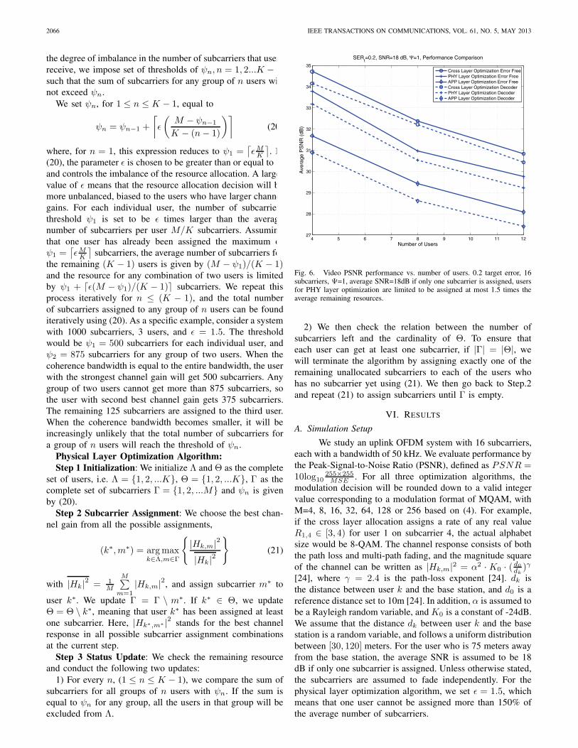
Fig. 6. Video PSNR performance vs. number of users. 0.2 target error, 16subcarriers, Ψ=1, average SNR=18dB if only one subcarrier is assigned, usersfor PHY layer optimization are limited to be assigned at most 1.5 times theaverage remaining resources.
2) We then check the relation between the number ofsubcarriers left and the cardinality of Θ. To ensure thateach user can get at least one subcarrier, if |Γ| = |Θ|, wewill terminate the algorithm by assigning exactly one of theremaining unallocated subcarriers to each of the users whohas no subcarrier yet using (21). We then go back to Step.2and repeat (21) to assign subcarriers until Γ is empty.
VI. RESULTS
A. Simulation Setup
We study an uplink OFDM system with 16 subcarriers,each with a bandwidth of 50 kHz. We evaluate performance bythe Peak-Signal-to-Noise Ratio (PSNR), defined as PSNR =10log10
255×255MSE . For all three optimization algorithms, the
modulation decision will be rounded down to a valid integervalue corresponding to a modulation format of MQAM, withM=4, 8, 16, 32, 64, 128 or 256 based on (4). For example,if the cross layer allocation assigns a rate of any real valueR1,4 ∈ [3, 4) for user 1 on subcarrier 4, the actual alphabetsize would be 8-QAM. The channel response consists of boththe path loss and multi-path fading, and the magnitude squareof the channel can be written as |Hk,m|2 = α2 · K0 · ( d0
dk)γ
[24], where γ = 2.4 is the path-loss exponent [24]. dk isthe distance between user k and the base station, and d0 is areference distance set to 10m [24]. In addition, α is assumed tobe a Rayleigh random variable, and K0 is a constant of -24dB.We assume that the distance dk between user k and the basestation is a random variable, and follows a uniform distributionbetween [30, 120] meters. For the user who is 75 meters awayfrom the base station, the average SNR is assumed to be 18dB if only one subcarrier is assigned. Unless otherwise stated,the subcarriers are assumed to fade independently. For thephysical layer optimization algorithm, we set ε = 1.5, whichmeans that one user cannot be assigned more than 150% ofthe average number of subcarriers.

WANG et al.: UPLINK RESOURCE MANAGEMENT FOR MULTIUSER OFDM VIDEO TRANSMISSION SYSTEMS: ANALYSIS AND ALGORITHM DESIGN 2067
0 2 4 6
x 105
0
50
100
150
200
250
Rate(bits/s)
MS
E
User 1 in 4−user system
0 2 4 6
x 105
0
50
100
150
200
250
Rate(bits/s)
MS
E
User 1 in 8−user system
0 2 4 6
x 105
0
50
100
150
200
250
Rate (bits/s)
MS
E
User 1 in 12−user system
0 2 4 6
x 105
0
200
400
600
Rate(bits/s)
MS
E
User 2 in 4−user system
0 2 4 6
x 105
0
200
400
600
Rate(bits/s)
MS
EUser 2 in 8−user system
0 2 4 6
x 105
0
200
400
600
Rate(bits/s)
MS
E
User 2 in 12−user system
0 2 4 6
x 105
0
100
200
300User 3 in 4−user system
MS
E
Rate(bits/s)
0 2 4 6
x 105
0
100
200
300User 3 in 8−user system
Rate(bits/s)M
SE
0 2 4 6
x 105
0
100
200
300
Rate(bits/s)
MS
EUser 3 in 12−user system
0 2 4 6
x 105
0
20
40
60
80
100
Rate(bits/s)
MS
E
User 4 in 4−user system
0 2 4 6
x 105
0
20
40
60
80
100User 4 in 8−user system
Rate(bits/s)
MS
E0 2 4 6
x 105
0
20
40
60
80
100
Rate(bits/s)
MS
E
User 4 in 12−user system
Fig. 7. Individual user’s performance in systems with different number of users. Each column indicates the same user’s RD relations in systems with four,eight and twelve users.
For all three optimization schemes, we use a rate 1/2convolutional code with code generator polynomial [23, 35]in octal, and the coded bits are interleaved across differentsubcarriers. For example, if one user gets three subcarriers,the first coded bit goes to the first subcarrier, the second codedbit goes to the second subcarrier, etc. We use log-likelihoodratio demodulation to detect each bit of the QAM symbol. Wethen decode the bitstream using soft-decision decoding witheight reliability ranges.
We use a sequence of CIF videos of total length50 seconds at 30 frames per second. Compression is by thebaseline profile of H.264/AVC reference software JM 11.0[27]. The GOP size is 15 frames (I-P-P-P) and the framesinside one GOP are encoded using H.264 rate control. Weencode each GOP at rates of 80, 100, 120, 140, 160, 180,200, 220, 240, 280, 300, 340, 380, 420, 460, 500 and 600kbps, and use these operational points to fit the rate distortionfunction D(R) = ak + bk/(R + ck) by nonlinear regression.We randomly assign different starting points of the same videoto different users, and the resource allocation decision is donein every GOP. The video in the simulation is a travel docu-mentary which consists of both high motion and low motionGOP’s. By assigning random starting points of the same cyclic
video to different users, we create application layer diversityamong users and yet have the same average complexity overtime for different users. Each video is encoded at 10 slicesper frame, and any channel error will make the system losethe entire slice. At the decoder side, slice copying concealslosses.
B. Systems with Different SERt
As discussed in Section II, the uplink resource allocationalgorithm needs a target error rate; we used SERt = 0.2, andvaried the number of users from 4 to 12 in the system of 16subcarriers. Fig. 6 shows the performance of the three opti-mization algorithms. The solid lines represent the numericalresults obtained from the RD curves. That is, the resourceallocator decides the rate for each user, and the distortion iscalculated directly from D(R). This can be considered theerror-free distortion, or distortion at the encoder side. Thedashed lines are the distortion results measured at the decoder;the videos are reconstructed from the bitstream corrupted bythe channel. The effects of packet loss, errors in RD curvefitting, and imperfection of encoder rate control are includedin the simulation.

2068 IEEE TRANSACTIONS ON COMMUNICATIONS, VOL. 61, NO. 5, MAY 2013
With SERt set to 0.2, we find that the decodedbit error rate is small, and distortion curves at the encoderand decoder are close. Comparing the performance of thesethree algorithms, we see that when the number of users in thesystem is small, the physical layer optimization outperformsthe application layer optimization algorithm, and the gapbetween the cross layer and the physical layer algorithmsis relatively small. When the system has abundant resourcesso each user can be assigned several subcarriers, both thecross layer optimization algorithm and the physical layeroptimization algorithm will allow users to operate at a highdata rate, or in the flat region of the convex RD curves.Utilizing application RD information in the resource allocationwill thus not benefit the overall users’ performance by much.Fig. 7 shows a sample of the performance for individual usersin systems with different numbers of users employing the crosslayer algorithm. In the first row of the plot, we see that allfour users are operating near the right end of their RD curvesand the slopes of users are relatively small. When the averageresource for each user gets smaller, the users are forced tooperate at steeper parts of the RD curves (see the second andthird rows of Fig. 7). As we increase the number of usersin the system to 8 and 12, the gap between the cross layerand the physical layer algorithms widens. We conjecture thisis because source characteristics play a more important rolewhen many users compete for the available resources. For asystem with large number of users, it becomes important tocombine the information of CSI and RD in the system designfor a resource-scarce system, as most users operate on thesteep slope of their individual RD curve. Mismatch of thephysical layer resource with the RD curve would cause a largeloss of system performance.
As seen in Fig. 6, when the system has 12 users, crosslayer optimization outperforms physical layer optimization byabout 1.25 dB, and the gap to application layer optimizationis even larger. For a system with average PSNR of 30.5 dB,the cross layer scheme can support 12 users, compared to 8users for physical layer optimization and less than 5 users forapplication layer optimization. In this sense, the cross layeralgorithm can almost increase the capacity (the number ofusers a system can support) by 50%.
We now change the value of SERt to 0.1 and 0.25(Fig. 8 and 9, respectively). When we set SERt = 0.1, themodulation alphabet size will be chosen more conservativelyand thus force the video source encoding rate to be smallerthan for SERt = 0.2. On the other hand, a high SERt valuewill lead to a relatively large gap between the error free curvesand curves for PSNR performance at the decoder side, and wesee that for SERt = 0.25, the impact of channel errors hassignificantly decreased the throughput of the system and thePSNR of the video from the error free scenarios. Comparingthe performance of the three algorithms, we see a similarperformance gain of adopting cross layer optimization, andthe capacity gain by adopting the cross layer algorithm is stillaround 1.5.
C. Systems with Different Coherence Bandwidths
In Fig. 10, we set Ψ = 2. For simplicity in thesimulation, we assume that two adjacent subcarriers have
4 5 6 7 8 9 10 11 1226
27
28
29
30
31
32
33
34
Number of Users
Ave
rage
PS
NR
(dB
)
SERt=0.1, SNR=18 dB, Ψ=1, Performance Comparison
Cross Layer Optimization Error FreePHY Layer Optimization Error FreeAPP Layer Optimization Error FreeCross Layer Optimization DecoderPHY Layer Optimization DecoderAPP Layer Optimization Decoder
Fig. 8. Video PSNR performance vs. number of users. 0.1 target error,16 subcarriers, Ψ=1, average SNR=18dB if only one subcarrier is assigned.
4 5 6 7 8 9 10 11 1227
28
29
30
31
32
33
34
35
36
Number of Users
Ave
rage
PS
NR
(dB
)SER
t=0.25, SNR=18 dB, Ψ=1, Performance Comparison
Cross Layer Optimization Error FreePHY Layer Optimization Error FreeAPP Layer Optimization Error FreeCross Layer Optimization DecoderPHY Layer Optimization DecoderAPP Layer Optimization Decoder
Fig. 9. Video PSNR performance vs. number of users. 0.25 target error, 16subcarriers, Ψ=1, average SNR=18dB if only one subcarrier is assigned.
the same realization, and the correlation coefficient betweendifferent coherence bands is zero. We observe a very slightperformance degradation for both the cross layer and theapplication layer optimization algorithms from the resultsshown in Fig. 6. As shown in (11) and (12), since thecross layer optimization algorithm exploits both physical layermultiuser channel diversity and application layer RD diversity,increasing the coherence bandwidth will not affect the crosslayer optimization’s ability to utilize the application layerdiversity. Similarly, for application layer optimization, increas-ing the coherence bandwidth will not change the numberof subcarriers assigned to each user, and the performanceloss is very limited. On the other hand, compared to thescenario of Ψ = 1, we see a large performance degradationfor the physical layer optimization. As subcarriers will have

WANG et al.: UPLINK RESOURCE MANAGEMENT FOR MULTIUSER OFDM VIDEO TRANSMISSION SYSTEMS: ANALYSIS AND ALGORITHM DESIGN 2069
4 5 6 7 8 9 10 11 1227
28
29
30
31
32
33
34
35
Number of Users
Ave
rage
PS
NR
(dB
)SER
t=0.2, SNR=18 dB, Ψ=2, Performance Comparison
Cross Layer Optimization Error FreePHY Layer Optimization Error FreeAPP Layer Optimization Error FreeCross Layer Optimization DecoderPHY Layer Optimization DecoderAPP Layer Optimization Decoder
Fig. 10. Video PSNR performance vs. number of users. 0.2 target error, 16subcarriers, Ψ=2, average SNR=18dB if only one subcarrier is assigned.
the same fading realization in groups of two, we lose half ofthe frequency diversity. Since physical layer optimization doesnot exploit any application layer diversity, losing frequencydiversity at the physical layer will have a big impact onthe system performance. If we further increase Ψ to four,as shown in Fig. 11, the performance for the physical layeroptimization will further decrease, while the performance ofthe proposed cross layer algorithm is still robust. Comparingthe performance between different algorithms, we see thatwhen the cross layer optimization can support 12 users withan average PSNR of about 29.5dB, the baseline algorithmscan at most support 7 users.
D. Complexity of Iterative Water Filling Algorithm
To show the path of performance improvement frominitialization to convergence of the cross layer algorithm, inFig. 12 we plot the average MSE for the systems with differentnumbers of users versus the iteration number. To obtain thisplot, we observe the MSE values after each iteration for eachindividual user and average over the entire video sequenceand all the users. The iteration number equal to one corre-sponds to the performance of the initialization step. Becauseof the greediness of the algorithm, the biggest performanceimprovement occurs in the first few iterations, and MSE curvesappear to be convex. After the eighth step, we see a very smallperformance improvement. As shown in Appendix B, since wecan find the performance improvement switching subcarriersat each iteration analytically, the overall complexity of theproposed algorithm is much lower than that of an exhaustivesearch.
VII. CONCLUSION
We proposed a cross layer resource allocation frameworkfor transmitting video in an uplink OFDMA setting, and de-rived an optimality condition for the bandwidth allocation in acontinuous frequency response channel. The power allocation
4 5 6 7 8 9 10 11 1226
27
28
29
30
31
32
33
34
Number of Users
Ave
rage
PS
NR
(dB
)
SERt=0.2, SNR=18 dB, Ψ=4, Performance Comparison
Cross Layer Optimization Error FreePHY Layer Optimization Error FreeAPP Layer Optimization Error FreeCross Layer Optimization DecoderPHY Layer Optimization DecoderAPP Layer Optimization Decoder
Fig. 11. Video PSNR performance vs. number of users. 0.2 target error, 16subcarriers, Ψ=4, average SNR=18dB if only one subcarrier is assigned.
and subcarrier assignment strategy are jointly decided by eachuser’s CSI and RD characteristics. Our analytical results showthat the optimal allocation is achieved only if the product ofthe RD slope and a physical layer metric related to the waterfilling solution, given by (12), is minimized for each band andeach user. With a similar technique of switching bandwidthincrements as in the analysis, we designed an iterative resourceallocation algorithm. At each iteration, our algorithm firstevaluates the application layer metric defined by (11), andthen greedily updates the resource allocation decision jointlyaccording to (11) and (12). Compared to a resource allocationusing either only application layer or only physical layerinformation, for the same video performance, the cross layeroptimization significantly increased the capacity of the system,and resulted in robust performance as the coherence bandwidthchanged, over the range of parameter values considered in ournumerical results.
APPENDIX AOPTIMALITY CONDITION FOR CONTINUOUS CHANNEL
ALLOCATION SOLUTION
If an assignment is optimal, any reassignment will notdecrease the sum of distortions. Let Bopt
1 , Bopt2 be the optimal
assignment, and let Bopt1 ∪ θ, Bopt
2 − θ be a new assignmentwhich reassigns band θ to user 1. If an assignment is optimal,then
b1r1 + c1
+b2
r2 + c2≤ b1
(r1 +Δr1) + c1+
b2(r2 −Δr2) + c2
(A.1)where Δr1 and Δr2 are the rate changes caused by switchingband θ. We have two scenarios.
Scenario A: W1 >1
η|Hθ1 |2
or φθ1 > 0
In this case, user 1 would get positive rate gain byacquiring the additional band θ. In other words, Δr1 > 0 andΔr2 > 0. Continuing from (A.1), we can go one step further

2070 IEEE TRANSACTIONS ON COMMUNICATIONS, VOL. 61, NO. 5, MAY 2013
0 2 4 6 8 10 12 140
20
40
60
80
100
120
140
Number of Iterations
Ave
rage
MS
E
Iteration Number vs. Average MSE
4 User Error Free8 User Error Free12 User Error Free4 User Decoder8 User Decoder12 User Decoder
Fig. 12. Average MSE vs. number of iterations.
and get
b1
(r1 + c1)2+Δr1 (r1 + c1)
Δr1
≤ b2
(r2 + c2)2 −Δr2 (r2 + c2)
Δr2 (A.2)
Because D(R) = ak + bkR+ck
is strictly convex, (A.1)must be satisfied as we take |θ| → 0. It is easy to see thatas |θ| → 0, Δri
ri+ci→ 0 for i=1 and 2. We thus can drop the
Δri (ri + ci) terms, as they will be negligible compared tothe squared term. So the optimal condition is
b1
(r1 + c1)2Δr1 ≤ b2
(r2 + c2)2Δr2 (A.3)
Now, we are interested in finding lim|θ|→0
Δr1Δr2
, which is the
ratio of rate change as |θ| → 0. Again, in the new frequencyassignment, user 1 gets Bopt
1 ∪ θ and user 2 gets Bopt2 − θ.
Fig. 3 shows the power redistribution after switching bandθ. P1,θ is the total power user 1 will put over band θ afterthe reassignment. Since we consider |θ| → 0, P1,θ is collecteduniformly from Bopt
1 and redistributed uniformly over band θ.Note that W1 = P1(f) +
1η|H1(f)|2 is the water level of user
1 before reallocation, and W ′1 is the level after reallocation.
We then have
W1 − P1,θ∣∣Bopt1
∣∣ = 1
η|Hθ1 |2
+P1,θ
|θ| =W ′1 (A.4)
where |Hθ1 |2 = |H1(f0 +
|θ|2 )|2 is the channel response over
the band θ, and f0 is the left limit of θ. To go further, wehave
P1,θ =
(W1 − 1
η|Hθ1 |2
)( ∣∣Bopt1
∣∣ |θ||θ|+ ∣∣Bopt
1
∣∣)
(A.5)
Before reallocation, the rate for user 1 is:∫Bopt
1
log2
(1 + ηP1(f) |H1(f)|2
)df . After getting θ, the
new rate is given by∫Bopt
1
log2
(1 + η
(P1(f)− P1,θ∣∣Bopt
1
∣∣)|H1(f)|2
)df+
|θ| log2(1 + η
P1,θ
|θ| |Hθ1 |2
)(A.6)
We then can calculate the rate difference as
Δr1 =
∫Bopt
1
log2
(1− ηP1,θ |H1(f)|2∣∣Bopt
1
∣∣ (1 + ηP1(f) |H1(f)|2)
)df+
|θ| log2(1 + η
P1,θ
|θ| |Hθ1 |2
)(A.7)
Similar to the setting for user 1, P2,θ is the power allocationfor band θ and |Hθ
2 |2 is the frequency response of user 2over this band. Fig. 4 shows the power redistribution afterreallocation for user 2, and we can calculate P2,θ ,
W2 − 1
η|Hθ2 |2
=P2,θ
|θ| (A.8)
as well as the absolute value of the rate change given by (A.9)at the top of next page.
We are interested in finding the ratio between the ratechanges of these two user expressed as (A.10). We then useL’Hopital’s rule and obtain (A.11).
From (A.3) and (A.11), for a two-user uplink videotransmission scenario, the optimal frequency and power allo-cation scheme should satisfy (A.12) for any frequency band θassigned to user 2.
Scenario B: W1 ≤ 1η|Hθ
1 |2or φθ1 = 0
This condition means that when we try to switch bandθ from user 2 to user 1, the frequency response of user 1 overthis band does not exceed the original water level, and theoptimal solution will not put any power into this band. In thiscase Δr1 = 0, Δr2 > 0, and φθ1 = 0 . If we plug φθ1 = 0 intothe numerator of (A.11), we have (A.13).
Combining both scenarios, for a two-user uplink videotransmission scenario, the optimal frequency and power allo-cation scheme should satisfy (A.12).
Similarly, in a system with an arbitrary number of users,it is easy to conclude that, for frequency band θ to be assignedto user j, the condition (A.14) must be satisfied for any useri �= j.
APPENDIX BPERFORMANCE CHANGE CALCULATION FOR
REASSIGNING SUBCARRIERS
Consider a user k who gets assigned a set of A(i)k
subcarriers. As discussed in Step (2) of Section IV, the optimalpower allocation scheme is
P ∗k,m = [
1
λk− 1
η|Hk,m|2 ]+ (B.1)
WANG et al.: UPLINK RESOURCE MANAGEMENT FOR MULTIUSER OFDM VIDEO TRANSMISSION SYSTEMS: ANALYSIS AND ALGORITHM DESIGN 2071
Δr2 = |θ| log2(1 + η
P2,θ
|θ| |Hθ2 |2
)−
∫Bopt
2
log2
(1 +
ηP2,θ |H2(f)|2|Bopt
2 |(1 + ηP2(f) |H2(f)|2)
)df (A.9)
lim|θ|→0
Δr1Δr2
= lim|θ|→0
∫Bopt
1
log2
(1− ηP1,θ |H1(f)|2
|Bopt1 |(1+ηP1(f)|H1(f)|2)
)df + |θ| log2
(1 + η
P1,θ
|θ| |Hθ1 |2
)|θ| log2
(1 + η
P2,θ
|θ| |Hθ2 |2
)− ∫
Bopt2
log2
(1 +
ηP2,θ |H2(f)|2|Bopt
2 |(1+ηP2(f)|H2(f)|2)
)df
(A.10)
lim|θ|→0
Δr1Δr2
=
ln(1 + ηφθ1|Hθ
1 |2)− ∫
Bopt1
η|H1(f)|2|Bopt
1 |(1+ηP1(f)|H1(f)|2)φθ1df
ln(1 + ηφθ2|Hθ
2 |2)− ∫
Bopt2
η|H2(f)|2|Bopt
2 |(1+ηP2(f)|H2(f)|2)φθ2df
(A.11)
b1(r1+c1)2
⎧⎨⎩ln(1 + ηφθ1|Hθ
1 |2)− ∫
Bopt1
η|H1(f)|2|Bopt
1 |(1+ηP1(f)|H1(f)|2)φθ1df
⎫⎬⎭b2
(r2+c2)2
⎧⎨⎩ln(1 + ηφθ2|Hθ
2 |2)− ∫
Bopt2
η|H2(f)|2|Bopt
2 |(1+ηP2(f)|H2(f)|2)φθ2df
⎫⎬⎭≤ 1 (A.12)
b1(r1+c1)2
⎧⎨⎩ln(1 + ηφθ1|Hθ
1 |2)− ∫
Bopt1
η|H1(f)|2|Bopt
1 |(1+ηP1(f)|H1(f)|2)φθ1df
⎫⎬⎭b2
(r2+c2)2
⎧⎨⎩ln(1 + ηφθ2|Hθ
2 |2)− ∫
Bopt2
η|H2(f)|2|Bopt
2 |(1+ηP2(f)|H2(f)|2)φθ2df
⎫⎬⎭= 0 < 1 (A.13)
bi(ri+ci)2
⎧⎨⎩ln(1 + ηφθi |Hθ
i |2)− ∫
Bopti
η|Hi(f)|2|Bopt
i |(1+ηPi(f)|Hi(f)|2)φθi df
⎫⎬⎭bj
(rj+cj)2
⎧⎨⎩ln(1 + ηφθj |Hθ
j |2)− ∫
Boptj
η|Hj(f)|2|Bopt
j |(1+ηPj(f)|Hj(f)|2)φθjdf
⎫⎬⎭≤ 1 (A.14)
∀m ∈ A(i)k . We want to find the video performance degrada-
tion of user k after losing a subcarrier m̂, m̂ ∈ A(i)k , 1
λk>
1η|Hk,m̂|2 . For the scenario that all the subcarriers’ frequency
responses are below the water level, or 1λk
> 1η|Hk,m|2 , the
operating rate (in bits/symbol) of user k is given by
r∗k =∑
m∈A(i)k
log2
[1 + η |Hk,m|2
(1
λk− 1
η |Hk,m|2)]
(B.2)Note that we start the resource allocation by assigning thesubcarrier to the user with the best response, so we expectthat the condition of 1
λk> 1
η|Hk,m|2 holds for most ofthe subcarriers at the beginning of the iterations. The video
distortion is
Dk = ak+bk∑
m∈A(i)k
log2
[1 + η |Hk,m|2
(1λk
− 1η|Hk,m|2
)]+ ck
(B.3)After losing subcarrier m̂, the water level will increase
by (1
λk− 1
η |Hk,m̂|2)/(∣∣∣A(i)
k
∣∣∣− 1)
(B.4)
and the updated video distortion is expressed as (B.5) on thenext page.
We can then calculate the performance change of userk for losing subcarrier m̂ as −Δk,m̂ = D̂k −Dk. If a user kis given one subcarrier, the performance improvement for thatuser can be found in a similar way.
2072 IEEE TRANSACTIONS ON COMMUNICATIONS, VOL. 61, NO. 5, MAY 2013
D̂k = ak +bk∑
m∈(A
(i)k −m̂
) log2
[1 + η |Hk,m|2
( ∣∣∣A(i)k
∣∣∣(∣∣∣A(i)k
∣∣∣−1)λk
− 1η|Hk,m|2 − 1
η|Hk,m̂|2(∣∣∣A(i)
k
∣∣∣−1))]
+ ck
(B.5)
REFERENCES
[1] C. Y. Wong, R. Cheng, K. Lataief, and R. Murch, “Multiuser OFDMwith adaptive subcarrier, bit, and power allocation,” IEEE J. Sel. AreasCommun., vol. 17, no. 10, pp. 1747–1758, Oct. 1999.
[2] Y. Yao and G. Giannakis, “Rate-maximizing power allocation in OFDMbased on partial channel knowledge,” IEEE Trans. Wireless Commun.,vol. 4, no. 3, pp. 1073–1083, May 2005.
[3] W. Yu and J. Cioffi, “FDMA capacity of Gaussian multiple-accesschannels with ISI,” IEEE Trans. Commun., vol. 50, no. 1, pp. 102–111,Jan. 2002.
[4] Z. Shen, J. Andrews, and B. Evans, “Adaptive resource allocation inmultiuser OFDM systems with proportional rate constraints,” IEEETrans. Wireless Commun., vol. 4, no. 6, pp. 2726–2737, Nov. 2005.
[5] D. Kivanc, G. Li, and H. Liu, “Computationally efficient bandwidthallocation and power control for OFDMA,” IEEE Trans. WirelessCommun., vol. 2, no. 6, pp. 1150–1158, Nov. 2003.
[6] I. Wong and B. Evans, “Optimal resource allocation in the OFDMAdownlink with imperfect channel knowledge,” IEEE Trans. Commun.,vol. 57, no. 1, pp. 232–241, Jan. 2009.
[7] H. Zhu and J. Wang, “Chunk-based resource allocation in OFDMAsystems—part I: chunk allocation,” IEEE Trans. Commun., vol. 57,no. 9, pp. 2734–2744, Sep. 2009.
[8] ——, “Chunk-based resource allocation in OFDMA systems—part II:joint chunk, power and bit allocation,” IEEE Trans. Commun., vol. 60,no. 2, pp. 499–509, Feb. 2012.
[9] G. Song and Y. Li, “Cross-layer optimization for OFDM wirelessnetworks—part I: theoretical framework,” IEEE Trans. Wireless Com-mun., vol. 4, no. 2, pp. 614–624, Mar. 2005.
[10] ——, “Cross-layer optimization for OFDM wireless networks—part II:algorithm development,” IEEE Trans. Wireless Commun., vol. 4, no. 2,pp. 625–634, Mar. 2005.
[11] Y. Su and M. der van Schaar, “Multiuser multimedia resource allocationover multicarrier wireless networks,” IEEE Trans. Signal Process.,vol. 56, no. 5, pp. 2102–2116, May 2008.
[12] A. ParandehGheibi, A. Eryilmaz, A. Ozdaglar, and M. Medard, “Onresource allocation in fading multiple-access channels-an efficient ap-proximate projection approach,” IEEE Trans. Inf. Theory, vol. 56, no. 9,pp. 4417–4437, Sep. 2010.
[13] A. Ortega, K. Ramchandran, and M. Vetterli, “Optimal trellis-basedbuffered compression and fast approximations,” IEEE Trans. ImageProcess., vol. 3, no. 1, pp. 26–40, Jan. 1994.
[14] G. Cook, J. Prades-Nebot, Y. Liu, and E. Delp, “Rate-distortion anal-ysis of motion-compensated rate scalable video,” IEEE Trans. ImageProcess., vol. 15, no. 8, pp. 2170–2190, Aug. 2006.
[15] Y. Liu, J. Prades-Nebot, P. Salama, and E. Delp, “Rate distortionanalysis of leaky prediction layered video coding using quantizationnoise modeling,” in Proc. 2004 International Conference on ImageProcessing, vol. 2, pp. 801–804.
[16] Z. Chen and K. N. Ngan, “Recent advances in rate control for videocoding,” Signal Process.: Image Commun., vol. 22, no. 1, pp. 19–38,2007.
[17] X. Zhu, E. Setton, and B. Girod, “Rate allocation for multi-camerasurveillance over an ad-hoc wireless network,” in Proc. 2004 PictureCoding Symposium, pp. 1 –6.
[18] M. Tiwari, T. Groves, and P. Cosman, “Competitive equilibrium bitrateallocation for multiple video streams,” IEEE Trans. Image Process.,vol. 19, no. 4, pp. 1009–1021, Apr. 2010.
[19] G.-M. Su, Z. Han, M. Wu, and K. Liu, “Joint uplink and downlinkoptimization for real-time multiuser video streaming over WLANs,”IEEE J. Sel. Topics Signal Process., vol. 1, no. 2, pp. 280–294, Aug.2007.
[20] ——, “A scalable multiuser framework for video over OFDM networks:Fairness and efficiency,” IEEE Trans. Circuits and Systems for VideoTechnol., vol. 16, no. 10, pp. 1217–1231, Oct. 2006.
[21] H. Ha, C. Yim, and Y. Y. Kim, “Cross-layer multiuser resource allocationfor video communication over OFDM networks,” Comput. Commun.,vol. 31, pp. 3553–3563, Sep. 2008.
[22] J. Proakis, Digitial Communications. McGraw-Hill, 2000.
[23] K. Stuhlmuller, N. Farber, M. Link, and B. Girod, “Analysis of videotransmission over lossy channels,” IEEE J. Sel. Areas Commun., vol. 18,no. 6, pp. 1012–1032, Jun. 2000.
[24] A. Goldsmith, Wireless Communications. Cambridge, 2005.[25] Y. Shoham and A. Gersho, “Efficient bit allocation for an arbitrary set of
quantizers [speech coding],” IEEE Trans. Acoustics, Speech and SignalProcess., vol. 36, no. 9, pp. 1445–1453, Sep. 1988.
[26] M. Kalman and B. Girod, “Optimal channel-time allocation for thetransmission of multiple video streams over a shared channel,” in Proc.2005 IEEE Workshop on Multimedia Signal Processing, pp. 1–4.
[27] H. Schwarz, D. Marpe, and T. Wiegand, “Overview of the scalable videocoding extension of the H.264/AVC standard,” IEEE Trans. Circuits andSystems for Video Technol., vol. 17, no. 9, pp. 1103–1120, Sep. 2007.
Dawei Wang (S’11) received the B.Eng. degree inelectronic engineering (First Class Honors) from theHong Kong University of Science and Technology(HKUST), Kowloon, Hong Kong SAR, China, in2008, and the M.S. degree, in 2011, from the Univer-sity of California, San Diego (UCSD), La Jolla, CA.He is currently working towards his Ph.D. at UCSD.He was also a visiting student at the Universityof Minnesota, Minneapolis. His industry experienceincludes internship at Intel Corporation, Hillsboro,OR, in 2011. His research interests are in the areas
of communication theory and video processing.
Laura Toni (S’06-M’09) received the M.S. degree(with honors) in electrical engineering and the Ph.D.degree in electronics, computer science and telecom-munications from the University of Bologna, Italy,in 2005 and 2009, respectively.
In 2005, she joined the Department of Electron-ics, Informatics and Systems at the University ofBologna, to develop her research activity in the areaof wireless communications. During 2007, she wasa visiting scholar at the University of California atSan Diego, CA, working on video processing over
wireless systems. Since 2009, she has been a frequent visitor to UCSD,working on joint source and channel coding for wireless communicationsystems.
From June 2009 to November 2011, she worked at the Tele-Robotics andApplication (TERA) Department at the Italian Institute of Technology (IIT) asa Post-doctoral Fellow. From November 2011 to November 2012, she was aPost-doctoral fellow in the Electrical and Computer Engineering Departmentat the University of California, San Diego. Since December 2012, she hasbeen a Post-doctoral fellow in the Signal Processing Laboratory (LTS4) atthe École Polytechnique Fédérale de Lausanne (EPFL), Switzerland. Herresearch interests are in the areas of image and video processing, wirelesscommunications, and underwater communications.
Pamela C. Cosman (S’88-M’93-SM’00-F’08) ob-tained her B.S. with Honors in electrical engineeringfrom the California Institute of Technology in 1987,and her M.S. and Ph.D. in electrical engineeringfrom Stanford University in 1989 and 1993, respec-tively.
She was an NSF postdoctoral fellow at StanfordUniversity and a Visiting Professor at the Universityof Minnesota during 1993–1995. In 1995, she joinedthe faculty of the Department of Electrical and Com-puter Engineering at the University of California,
San Diego, where she is currently a Professor and Vice Chair. She was theDirector of the Center for Wireless Communications from 2006 to 2008.Her research interests are in the areas of image and video compression andprocessing, and wireless communications.

WANG et al.: UPLINK RESOURCE MANAGEMENT FOR MULTIUSER OFDM VIDEO TRANSMISSION SYSTEMS: ANALYSIS AND ALGORITHM DESIGN 2073
Dr. Cosman is the recipient of the ECE Departmental Graduate TeachingAward, a Career Award from the National Science Foundation, a PowellFaculty Fellowship, and a Globecom 2008 Best Paper Award. She was aguest editor of the June 2000 special issue of the IEEE JOURNAL ONSELECTED AREAS IN COMMUNICATIONS on “Error-resilient image andvideo coding,” and was the Technical Program Chair of the 1998 InformationTheory Workshop in San Diego. She was an associate editor of IEEECOMMUNICATIONS LETTERS (1998–2001), and an associate editor of IEEESIGNAL PROCESSING LETTERS (2001–2005). She was the Editor-in-Chief(2006–2009), as well as a Senior Editor (2003–2005, 2010-present), of theIEEE JOURNAL ON SELECTED AREAS IN COMMUNICATIONS. She is amember of Tau Beta Pi and Sigma Xi.
Laurence B. Milstein (S’66-M’68-SM’77-F’85) re-ceived the B.E.E. degree from the City College ofNew York, New York, in 1964, and the M.S. andPh.D. degrees in electrical engineering from thePolytechnic Institute of Brooklyn, Brooklyn, NY, in1966 and 1968, respectively.
From 1968 to 1974, he was with the Space andCommunications Group, Hughes Aircraft Company,and from 1974 to 1976, he was a member of theDepartment of Electrical and Systems Engineering,Rensselaer Polytechnic Institute, Troy, NY. Since
1976, he has been with the Department of Electrical and Computer En-gineering, University of California, San Diego, where he is currently theEricsson Professor of Wireless Communications Access Techniques andformer Department Chair, working in the area of digital communication theorywith special emphasis on spread-spectrum communication systems. He hasalso been a consultant to both government and industry in the areas of radarand communications.
Dr. Milstein was an Associate Editor for Communication Theory forthe IEEE TRANSACTIONS ON COMMUNICATIONS, an Associate Editor forBook Reviews for the IEEE TRANSACTIONS ON INFORMATION THEORY,an Associate Technical Editor for IEEE Communications Magazine, andthe Editor-in-Chief of the IEEE JOURNAL ON SELECTED AREAS IN COM-MUNICATIONS. He was the Vice President for Technical Affairs in 1990and 1991 of the IEEE Communications Society and was a former chair ofthe IEEE Fellows Selection Committee. He was a recipient of the 1998Military Communications Conference Long Term Technical AchievementAward, an Academic Senate 1999 UCSD Distinguished Teaching Award,an IEEE Third Millennium Medal in 2000, the 2000 IEEE CommunicationSociety Armstrong Technical Achievement Award, and various prize paperawards, including the 2002 MILCOM Fred Ellersick Award. He was also therecipient of the IEEE Communication Theory Technical Committee (CTTC)Service Award in 2009, and the CTTC Achievement Award in 2012.