2068 ieee transactions on microwave...
TRANSCRIPT
2068 IEEE TRANSACTIONS ON MICROWAVE THEORY AND TECHNIQUES, VOL. 54, NO. 5, MAY 2006
Modeling of Realistic Rectangular �-Coaxial LinesMilan Lukic, Student Member, IEEE, Sébastien Rondineau, Member, IEEE, Zoya Popovic, Fellow, IEEE, and
Dejan S. Filipovic, Member, IEEE
Abstract—A comprehensive study of small inhomogeneous mul-tilayered rectangular coaxial lines (RCLs) with irregular cross sec-tions is presented in this paper. An accurate and efficient quasi-an-alytical technique based on numerical implementation of simplyand doubly connected Schwarz–Christoffel conformal mapping isutilized for modeling. Misaligned and offset layers, under–over cut-ting due to etching, nonuniform dielectric support, and other non-idealities due to fabrication of RCLs are studied and their effectson characteristic impedance, attenuation, bandwidth, and power-handling capacity are discussed. The validity of obtained results isverified with suitable published data, analytical models, and/or fi-nite-element simulations.
Index Terms—Attenuation, characteristic impedance, cutoff fre-quency, power-handling capacity, rectangular coaxial line (RCL),Schwartz–Christoffel mapping.
I. INTRODUCTION
I N RECENT years, there has been an increased interest inmanufacturable low-loss high-density TEM lines for mil-
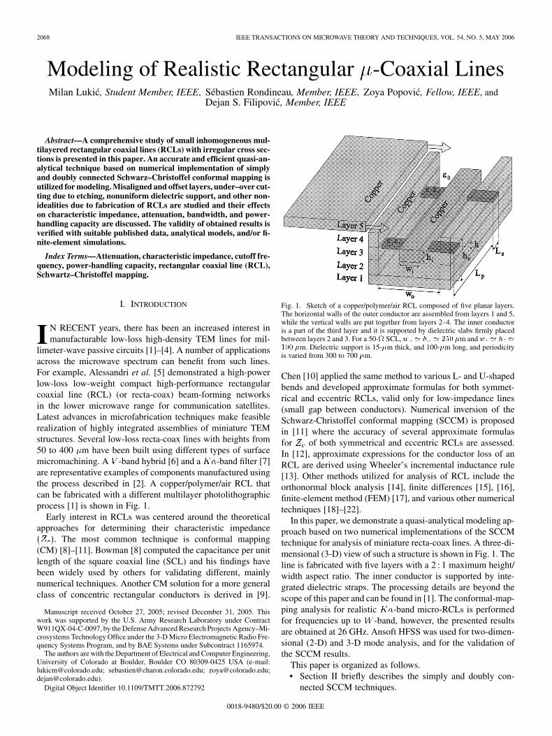
limeter-wave passive circuits [1]–[4]. A number of applicationsacross the microwave spectrum can benefit from such lines.For example, Alessandri et al. [5] demonstrated a high-powerlow-loss low-weight compact high-performance rectangularcoaxial line (RCL) (or recta-coax) beam-forming networksin the lower microwave range for communication satellites.Latest advances in microfabrication techniques make feasiblerealization of highly integrated assemblies of miniature TEMstructures. Several low-loss recta-coax lines with heights from50 to 400 m have been built using different types of surfacemicromachining. A -band hybrid [6] and a -band filter [7]are representative examples of components manufactured usingthe process described in [2]. A copper/polymer/air RCL thatcan be fabricated with a different multilayer photolithographicprocess [1] is shown in Fig. 1.
Early interest in RCLs was centered around the theoreticalapproaches for determining their characteristic impedance
. The most common technique is conformal mapping(CM) [8]–[11]. Bowman [8] computed the capacitance per unitlength of the square coaxial line (SCL) and his findings havebeen widely used by others for validating different, mainlynumerical techniques. Another CM solution for a more generalclass of concentric rectangular conductors is derived in [9].
Manuscript received October 27, 2005; revised December 31, 2005. Thiswork was supported by the U.S. Army Research Laboratory under ContractW911QX-04-C-0097, by the Defense Advanced Research Projects Agency–Mi-crosystems Technology Office under the 3-D Micro Electromagnetic Radio Fre-quency Systems Program, and by BAE Systems under Subcontract 1165974.
The authors are with the Department of Electrical and Computer Engineering,University of Colorado at Boulder, Boulder CO 80309-0425 USA (e-mail:[email protected]; [email protected]; [email protected];[email protected]).
Digital Object Identifier 10.1109/TMTT.2006.872792
Fig. 1. Sketch of a copper/polymer/air RCL composed of five planar layers.The horizontal walls of the outer conductor are assembled from layers 1 and 5,while the vertical walls are put together from layers 2–4. The inner conductoris a part of the third layer and it is supported by dielectric slabs firmly placedbetween layers 2 and 3. For a 50- SCL,w ' h ' 250 �m andw ' h '
100 �m. Dielectric support is 15-�m thick, and 100-�m long, and periodicityis varied from 300 to 700 �m.
Chen [10] applied the same method to various L- and U-shapedbends and developed approximate formulas for both symmet-rical and eccentric RCLs, valid only for low-impedance lines(small gap between conductors). Numerical inversion of theSchwarz-Christoffel conformal mapping (SCCM) is proposedin [11] where the accuracy of several approximate formulasfor of both symmetrical and eccentric RCLs are assessed.In [12], approximate expressions for the conductor loss of anRCL are derived using Wheeler’s incremental inductance rule[13]. Other methods utilized for analysis of RCL include theorthonormal block analysis [14], finite differences [15], [16],finite-element method (FEM) [17], and various other numericaltechniques [18]–[22].
In this paper, we demonstrate a quasi-analytical modeling ap-proach based on two numerical implementations of the SCCMtechnique for analysis of miniature recta-coax lines. A three-di-mensional (3-D) view of such a structure is shown in Fig. 1. Theline is fabricated with five layers with a 2 : 1 maximum height/width aspect ratio. The inner conductor is supported by inte-grated dielectric straps. The processing details are beyond thescope of this paper and can be found in [1]. The conformal-map-ping analysis for realistic -band micro-RCLs is performedfor frequencies up to -band, however, the presented resultsare obtained at 26 GHz. Ansoft HFSS was used for two-dimen-sional (2-D) and 3-D mode analysis, and for the validation ofthe SCCM results.
This paper is organized as follows.• Section II briefly describes the simply and doubly con-
nected SCCM techniques.
0018-9480/$20.00 © 2006 IEEE
LUKIC et al.: MODELING OF REALISTIC RECTANGULAR -COAXIAL LINES 2069
• Section III gives analysis results for an SCL (characteristicimpedance, attenuation, TEM mode bandwidth) in termsof various fabrication parameters.
• Section IV analyzes the effects of the inhomogeneous di-electric support on the line performance.
• Section V discusses the power-handling capacity, the per-formance of a 250- m-high RCL and several issues asso-ciated with numerical implementation.
II. MODELING
Riemann’s mapping theorem from 1851 [23] provides thefoundation for CM, a technique which transforms geometriesby preserving local angles. Since 1923 when it was first appliedto electrostatics, [24], CM has been employed for solvingvarious boundary value problems in electromagnetics [25],[26]. The most commonly used transformations belong to theSchwarz–Christoffel family [27]–[31]. These transformationsremove the discontinuities in boundary conditions at sharp con-ductor corners. Section II-A briefly presents this formulationapplied to realistic micro RCLs.
A. Schwartz–Christoffel Mapping to Simply and DoublyConnected Polygonal Domain
A simply connected planar domain can be defined as the inte-rior of a planar closed line that does not contain any holes. Whenthis enclosed domain contains exactly one hole, the domain issaid to be doubly connected.
1) Notations and Basic Equations: 2-D real vectorscan be represented as complex numbers .
The gradient vector operator in the complex plane becomes acomplex scalar operator
(1)
where and are the partial derivatives w.r.t. and . The
Laplacian operator becomes , where denotesthe complex conjugate. As a consequence, and by consideringproperties described in [23], under a CM of the plane
, the gradient and the Laplacian are given by
and (2)
where is the derivative of . Applying this to quasi-staticelectromagnetic fields, the electric potentials and satisfythe Laplace equation. The electric field distributions, in both theoriginal plane and its image one , are then related usingthe gradient transformation through the mapping function
and (3)
This formulation is more general than those previously reported(limited to capacitance calculation) and is well suited for thequasi-static case because the derivatives are readily availableas analytic expressions.
2) Application to RCLs: As shown in Figs. 1 and 2, an RCLis composed of two conductors, both with polygonal cross sec-
tions [26]. In the case of symmetrical structures, it is sufficientand simpler to map a half, a quarter, or even an eighth of thegeometry. This allows the use of a simply connected polygonaldomain mapping function given by
(4)
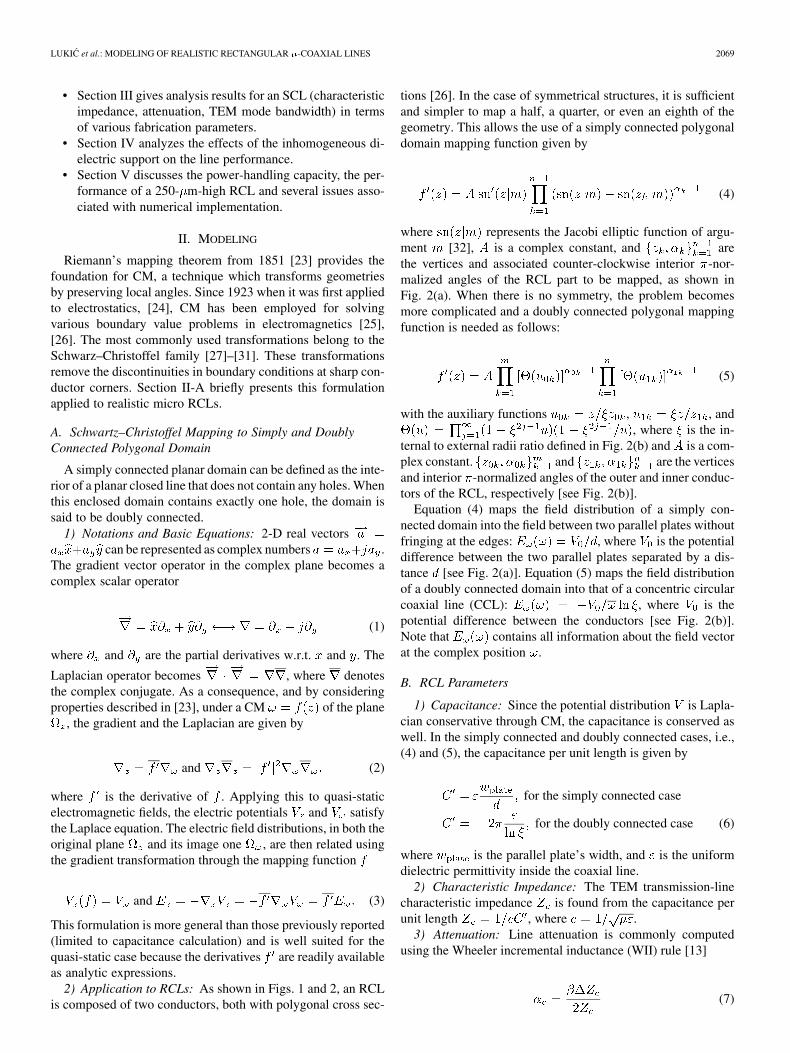
where represents the Jacobi elliptic function of argu-ment [32], is a complex constant, and arethe vertices and associated counter-clockwise interior -nor-malized angles of the RCL part to be mapped, as shown inFig. 2(a). When there is no symmetry, the problem becomesmore complicated and a doubly connected polygonal mappingfunction is needed as follows:
(5)
with the auxiliary functions , , and, where is the in-
ternal to external radii ratio defined in Fig. 2(b) and is a com-plex constant. and are the verticesand interior -normalized angles of the outer and inner conduc-tors of the RCL, respectively [see Fig. 2(b)].
Equation (4) maps the field distribution of a simply con-nected domain into the field between two parallel plates withoutfringing at the edges: , where is the potentialdifference between the two parallel plates separated by a dis-tance [see Fig. 2(a)]. Equation (5) maps the field distributionof a doubly connected domain into that of a concentric circularcoaxial line (CCL): , where is thepotential difference between the conductors [see Fig. 2(b)].Note that contains all information about the field vectorat the complex position .
B. RCL Parameters
1) Capacitance: Since the potential distribution is Lapla-cian conservative through CM, the capacitance is conserved aswell. In the simply connected and doubly connected cases, i.e.,(4) and (5), the capacitance per unit length is given by
for the simply connected case
for the doubly connected case (6)
where is the parallel plate’s width, and is the uniformdielectric permittivity inside the coaxial line.
2) Characteristic Impedance: The TEM transmission-linecharacteristic impedance is found from the capacitance perunit length , where .
3) Attenuation: Line attenuation is commonly computedusing the Wheeler incremental inductance (WII) rule [13]
(7)
2070 IEEE TRANSACTIONS ON MICROWAVE THEORY AND TECHNIQUES, VOL. 54, NO. 5, MAY 2006
Fig. 2. Mapping of a simply connected polygonal domain onto: (a) a rectangle and a doubly connected polygonal domain onto: (b) an annulus. When a symmetryline is present in a doubly connected polygonal domain, such as the dashed horizontal line in (a), the domain can be split by symmetry into two simply connecteddomains. Either of these can then be mapped onto a rectangle. However, when no axial symmetry is present, as in (b), the mapping onto an annulus is used.
where represents the change in the characteristicimpedance when conductor walls are receded by half ofthe skin depth. This rule is derived for a thick metal with smallcurvature. Note that the RCL in Fig. 1 meets the first assump-tion, but the second one is not valid at sharp corners. However,the WII rule has been widely used for many transmission lineswith similar features, e.g., [33], and excellent agreement withmeasurements has been reported.
III. ANALYSIS OF FABRICATION-INDUCED IMPERFECTIONS
The formulation from Section II is utilized for the charac-terization of miniature recta-coax lines. In the case of a simplyconnected domain, the mapping function given by (4) is solvedwith the Schwarz–Christoffel toolbox integrated in MATLAB
[27], [28]. For doubly connected domains, the evaluation ofthe mapping function is implemented in a FORTRAN 90 codebased on the doubly connected Schwarz–Christoffel library[34]. The computed mapping parameters typically convergewith accuracy better than 10 .
A baseline geometry for this study is that of an SCL with acharacteristic impedance of 50 . However, a lower loss 65-line is also considered since it can be fabricated within the 2 : 1height/width aspect ratio dictated by the fabrication process [1].Table I summarizes the main properties of 50- and 65- SCL,specifically their characteristic impedance , attenuation ,
TABLE ICHARACTERISTICS OF SCL WITH IDEAL CROSS SECTION (w = 250 �m)
and first higher order mode cutoff frequency . Note that whileis determined only by the ratio , the attenuation is
dependent on the outer conductor width , operating frequency, and conductivity : . The subscript “0”
denotes parameters of an SCL with an ideal cross section. Whenthe line has imperfections, such as in Fig. 3, the characteristicimpedance , attenuation , and first higher order mode cutofffrequency have the same dependence on , , and . Due tothis, normalized parameters , , and , whichdo not depend on , , and , are used throughout this paper.
The nonidealities caused by fabrication are discussed as fol-lows:
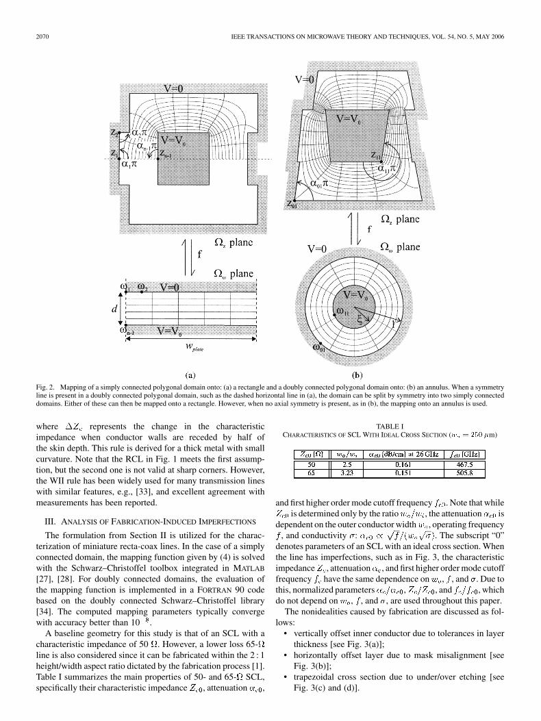
• vertically offset inner conductor due to tolerances in layerthickness [see Fig. 3(a)];
• horizontally offset layer due to mask misalignment [seeFig. 3(b)];
• trapezoidal cross section due to under/over etching [seeFig. 3(c) and (d)].
LUKIC et al.: MODELING OF REALISTIC RECTANGULAR -COAXIAL LINES 2071
Fig. 3. Cross section of a line with: (a) vertically offset inner conductor, (b) misaligned layers, (c) conductors of trapezoidal shape where the bottom sides of theconductors are kept constant, and (d) conductors of trapezoidal shape where the areas of the conductors are kept constant.
A. Inner Conductor Offset
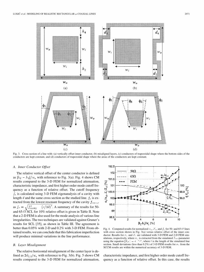
The relative vertical offset of the center conductor is definedas with reference to Fig. 3(a). Fig. 4 shows CMresults compared to the 3-D FEM for normalized attenuation,characteristic impedance, and first higher order mode cutoff fre-quency as a function of relative offset. The cutoff frequency
is calculated using 3-D FEM eigenanalysis of a cavity withlength and the same cross section as the studied line. is ex-tracted from the lowest resonant frequency of the cavity
as . A summary of the results for 50-and 65- SCL for 10% relative offset is given in Table II. Notethat a 2-D FEM is also used for the mode analysis of various lineirregularities. The two techniques are validated against Gruner’sresults for SCL [35], as shown in Table III. The agreement isbetter than 0.05% with 2-D and 0.2% with 3-D FEM. From ob-tained results, we can conclude that this fabrication imperfectionwill produce minimal variations in the line performance.
B. Layer Misalignment
The relative horizontal misalignment of the center layer is de-fined as with reference to Fig. 3(b). Fig. 5 shows CMresults compared to the 3-D FEM for normalized attenuation,
Fig. 4. Computed results for normalized � , Z , and f for 50- and 65- lineswith cross section shown in Fig. 3(a) versus relative offset of the inner con-ductor. Results for � and Z are validated with 3-D FEM and 2-D FEM sim-ulations, respectively, where � is extracted from the simulated S -parameterusing the equation jS j = e , where l is the length of the simulated linesection. Small deviations (less than 0.2%) of 3-D FEM results for � from theSCCM results are within the numerical accuracy of 3-D FEM.
characteristic impedance, and first higher order mode cutoff fre-quency as a function of relative offset. In this case, the results

2072 IEEE TRANSACTIONS ON MICROWAVE THEORY AND TECHNIQUES, VOL. 54, NO. 5, MAY 2006
TABLE IIRELATIVE CHANGES OF Z , � , AND f FOR LINE WITH VERTICALLY
OFFSET INNER CONDUCTOR (jh � h j=w = 10%)
TABLE IIINORMALIZED CUTOFF WAVELENGTH FOR THE TE MODE OF AN SCL
Fig. 5. Computed results for normalized� ,Z , and f for 50- and 65- lineswith cross section shown in Fig. 3(b) versus relative misalignment among thelayers. FEM simulations obtained with HFSS are given for validation. Devia-tions of FEM results for� from the SCCM results are smaller than 0.4%, whilethe corresponding characteristic impedances are virtually indistinguishable.
TABLE IVRELATIVE CHANGES OF Z , � , AND f FOR LINE WITH
MISALIGNED LAYERS (2d=w = 10%)
for the 50- and 65- lines are nearly identical, thus, the latterare omitted for clarity. Note that the effects on and of themisalignment of layers 2 and 4 are independent. A summary ofthe results for 10% misalignment is given in Table IV. As seen,the horizontally misaligned layers will introduce small changesin the line performance and, for most practical cases (1%–5%),these can be ignored.
C. Under/Over Etching
The two lines with trapezoidal conductor cross sections(model of under/over cutting due to etching) and relevantparameters are shown in Fig. 3(c) and (d). In the first case,widths of the bottom sides of the conductors ( , ) arekept constant, while in the second case, their surface areas re-mained unchanged. Normalized , , and for symmetrical
trapezoidal 50- and 65- lines are shown inFigs. 6 and 7. The variations of and for a trapezoidal65- line for both geometries are noticeably smaller than for a
Fig. 6. Simulation results for normalized � , Z , and f for symmetrical(� = � = �) trapezoidal 50- and 65- lines where bottom conductorwidths are kept constant [see Fig. 3(c)]. FEM simulation results obtained withHFSS are given for validation. Shown variations of � are significantly largerthan for other three geometries of Fig. 3, thus small discrepancies betweenFEM and SCCM results are not as apparent as in Figs. 4, 5, and 7.
Fig. 7. Simulation results for normalized � , Z , and f for symmetrical(� = � = �) trapezoidal 50- and 65- lines where conductor areas are keptconstant [see Fig. 3(d)]. FEM simulations obtained with HFSS are shown forvalidation. Variations of � , for the studied range of angle � values, are muchsmaller than for the previous case in which bottom conductor widths werekept constant. Consequently, small discrepancies between the FEM and SCCMresults for � (less than 0.4%) are clearly observable while the results for Zremain virtually indistinguishable.
corresponding 50- line. The summarized results forfrom Table V show that the case where the conductor areas arekept constant is much more tolerant to under/over etching. Thepractical importance of these results is that known statistics ofthe cross-sectional dimensions can be used in design so thatthe nominal values for and are maintained throughoutthe structure. As before, the FEM mesh-dependent differencesfor may be noticed, while the corresponding characteristicimpedances are virtually indistinguishable.
Contour plots of normalized and for trapezoidal line[see Fig. 3(c)] are shown in Figs. 8 and 9. For small values ofangle , the variations of both and are twice larger forthe symmetrical case than for the asymmetricalcase ( , ), indicating that the effects of left- andright-hand-side slants are independent.

LUKIC et al.: MODELING OF REALISTIC RECTANGULAR -COAXIAL LINES 2073
TABLE VRELATIVE CHANGES OF Z , � , AND f FOR LINE WITH TRAPEZOIDAL
CONDUCTOR CROSS SECTIONS (� = � = � = 10 )
Fig. 8. Contour plot of normalized Z for trapezoidal 50- line of Fig. 3(c) asfunction of angles � and � .
IV. INNER CONDUCTOR SUPPORT
In Section III, homogeneous air-filled irregular cross-sec-tional SCLs were discussed. However, in practice, the innerconductor must be supported somehow. Here, a thin dielectriclayer suspended between the vertical walls (Fig. 1) is used forthe support [1]. Note that a dielectric with a dielectric constantgreater than unity increases the line attenuation even whenthere is no energy loss in the dielectric itself. This is due to thefact that the dielectric decreases , and from[33], the attenuation increases. For a given transmitted power,a lower requires a higher current, hence the loss in theconductors increases. The attenuation constant of the line withboth conductor and dielectric losses is obtained as (e.g.,[33]) , where is the attenuation constantdue to dielectric losses. Below we discuss both continuous andperiodic dielectric supports.
A. Continuous Support
Results for normalized and versus normalized supportheight for a 50- SCL with continuous dielectric supports of theinner conductor for different values of loss tangent areshown in Fig. 10. Also shown in this figure are results for nor-malized for a 65- SCL. However, the results for normalized
for a 65- line are omitted for clarity since they are almostidentical as those for a 50- line. An excellent agreement with3-D FEM results can be observed. The geometrical dimensionsand physical parameters of the lines are: outer conductor width
m, inner conductor width m for a 50-
Fig. 9. Contour plot of normalized � for trapezoidal 50- line of Fig. 3(c) asfunction of angles � and � .
Fig. 10. Comparison of the results for normalized � and Z versus normal-ized support height for an SCL with continuous dielectric supports of the innerconductor obtained by SCCM (solid lines for 50- cable and a dashed line for65- cable) and 3-D FEM (dots).
line, and m for a 65- line, penetration depth ofthe supports into the sidewalls m, and dielectric con-stant . It can be seen that the contribution of to
is very significant even for moderate values of . Forthis reason, the line of Fig. 1 is built using the periodic supportstudied in Section IV-B.
B. Periodic Support
The variation of for a 50- SCL with periodic dielec-tric supports of the inner conductor (see Fig. 1) for differentvalues of loss tangent is shown in Fig. 11. The heightand length of the supports are m and m,respectively, and the other geometrical and physical parametersare the same as for the case of continuous support. Here, isplotted as a function of the separation between consecutive sup-ports normalized with respect to their length . It can beseen that the losses decrease monotonically with the increase of
. The results are obtained by cascading the matrices

2074 IEEE TRANSACTIONS ON MICROWAVE THEORY AND TECHNIQUES, VOL. 54, NO. 5, MAY 2006
Fig. 11. Comparison of the results for normalized� for an SCL with periodicdielectric supports of the inner conductor obtained by SCCM (solid lines) and3-D FEM (dots). The SCCM results are obtained by cascading theABCD ma-trices of line sections with and without dielectric supports. � =� is plottedas a function of the supports periodicity L normalized with respect to theirlength L .
of line sections with and without dielectric supports and are val-idated with 3-D FEM simulations. The effective loss tangent ofthe line section with dielectric support is calculated by the for-mula [36], whereis the effective dielectric constant of the line section calculatedusing 2-D FEM. The small discrepancies between the two tech-niques are likely due to the numerical issues associated with theFEM and the inability of the SCCM to accurately account forthe field effects at the transitions between homogeneous and in-homogeneous RCL sections.
V. DISCUSSION
A. Power-Handling Capacity
From (4) and (5), it is clear that the electric-field distribu-tion, given by (3), has a singularity at each exterior vertex ofthe ideal inner conductor. The electric field cannot be obtainedat these perfectly sharp corners, however, perfect edges do notexist in practice. These edges are slightly chamfered and thefield is computed at the middle of the chamfer. It is found thatthe ratio of chamfer to inner conductor dimensions of 10 isthe smallest that gives converging results.
This technique of chamfering the inner conductor to dealwith finite field strength leads to the computation of the max-imum transmitted power before air breakdown. The algorithmfor computing the power handling capacity of a CCL can befound in [37]. A comparison of the normalized power and atten-uation as a function of for circular (CCLs), square (SCLs),and RCLs, for given outer conductor size, is shown in Fig. 12.The RCL studied here has square outer conductor of widthequal to that for the studied SCL, and the inner conductor ofheight and width between and . As seen, theoptimal characteristic impedance for maximum power handlingfor the three coaxial lines is approximately 30, 22, and 44 , re-spectively. The optimal characteristic impedance for minimumattenuation of an SCL is approximately 74.9 , just slightly
Fig. 12. Normalized power and attenuation as a function of Z for circular(CCL), square (SCL), and RCL for given outer conductor size. As seen, theoptimal Z for maximum power handling for CCL and SCL is approximately30 and 22 , respectively, while the corresponding values of Z for minimumattenuation are approximately 76.6 and 74.9 . The results are obtained usingthe SCCM. Analytical data for CCL are not shown for clarity (there is no visibledifference with the computed ones).
lower than that for a CCL, which is approximately 76.6 . No-tice that the power levels for an RCL are normalized with re-spect to the maximum power of an SCL, while for the other twogeometries (circular and square), power levels are normalizedwith their own maximum values. Likewise, the attenuation foran RCL is normalized with respect to the minimum attenuationof an SCL, while for the other two geometries, the attenuationis normalized with their own minimum values.
As clearly depicted in the same figure, the normalized powerof an RCL is lower than that of an SCL with the same charac-teristic impedance. Observe also that the normalized attenuationof an RCL is higher than for an SCL with the same character-istic impedance. Normalized powers of 50- and 65- CCLs are85.5% and 67.4%, respectively, while the corresponding valuesfor SCLs are 89.7% and 80.4%. Thus, the ratio of normalizedpowers of 65- and 50- CCLs is 78.8%, while this power ratiofor SCLs has a significantly larger value of 89.6%.
B. Performance of a 250- m-High RCL
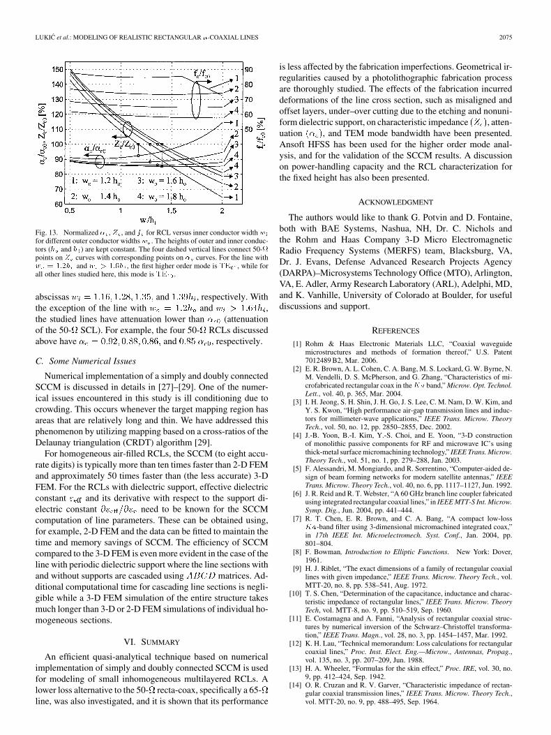
Specific applications may require either the height or thewidth of the line to be restricted to a certain value. In such cases,the desired line dimensions that amount to the best performanceare needed. Assuming that the heights of outer and inner con-ductors ( and ) are fixed to the values they have in the 50-SCL from Section III, i.e., m and m,we will compute the line characteristics for widths ( and )as the design parameters. The results of this study for , ,and normalized with respect to the corresponding valuesfor the baseline 50- SCL are plotted in Fig. 13. First higherorder mode for the studied lines is , except for the linewith and for which that mode is
. As expected, the lines with wider outer conductor havesignificantly reduced bandwidth for the TEM mode operation.For and , the rangeof characteristic impedances is . Thefour dashed vertical lines in Fig. 13, connecting 50- pointson curves with corresponding points on curves, have
LUKIC et al.: MODELING OF REALISTIC RECTANGULAR -COAXIAL LINES 2075
Fig. 13. Normalized � , Z , and f for RCL versus inner conductor width wfor different outer conductor widthsw . The heights of outer and inner conduc-tors (h and h ) are kept constant. The four dashed vertical lines connect 50-points on Z curves with corresponding points on � curves. For the line withw = 1:2h and w > 1:6h , the first higher order mode is TE , while forall other lines studied here, this mode is TE .
abscissas and , respectively. Withthe exception of the line with and ,the studied lines have attenuation lower than (attenuationof the 50- SCL). For example, the four 50- RCLs discussedabove have and , respectively.
C. Some Numerical Issues
Numerical implementation of a simply and doubly connectedSCCM is discussed in details in [27]–[29]. One of the numer-ical issues encountered in this study is ill conditioning due tocrowding. This occurs whenever the target mapping region hasareas that are relatively long and thin. We have addressed thisphenomenon by utilizing mapping based on a cross-ratios of theDelaunay triangulation (CRDT) algorithm [29].
For homogeneous air-filled RCLs, the SCCM (to eight accu-rate digits) is typically more than ten times faster than 2-D FEMand approximately 50 times faster than (the less accurate) 3-DFEM. For the RCLs with dielectric support, effective dielectricconstant and its derivative with respect to the support di-electric constant need to be known for the SCCMcomputation of line parameters. These can be obtained using,for example, 2-D FEM and the data can be fitted to maintain thetime and memory savings of SCCM. The efficiency of SCCMcompared to the 3-D FEM is even more evident in the case of theline with periodic dielectric support where the line sections withand without supports are cascaded using matrices. Ad-ditional computational time for cascading line sections is negli-gible while a 3-D FEM simulation of the entire structure takesmuch longer than 3-D or 2-D FEM simulations of individual ho-mogeneous sections.
VI. SUMMARY
An efficient quasi-analytical technique based on numericalimplementation of simply and doubly connected SCCM is usedfor modeling of small inhomogeneous multilayered RCLs. Alower loss alternative to the 50- recta-coax, specifically a 65-line, was also investigated, and it is shown that its performance
is less affected by the fabrication imperfections. Geometrical ir-regularities caused by a photolithographic fabrication processare thoroughly studied. The effects of the fabrication incurreddeformations of the line cross section, such as misaligned andoffset layers, under–over cutting due to the etching and nonuni-form dielectric support, on characteristic impedance , atten-uation , and TEM mode bandwidth have been presented.Ansoft HFSS has been used for the higher order mode anal-ysis, and for the validation of the SCCM results. A discussionon power-handling capacity and the RCL characterization forthe fixed height has also been presented.
ACKNOWLEDGMENT
The authors would like to thank G. Potvin and D. Fontaine,both with BAE Systems, Nashua, NH, Dr. C. Nichols andthe Rohm and Haas Company 3-D Micro ElectromagneticRadio Frequency Systems (MERFS) team, Blacksburg, VA,Dr. J. Evans, Defense Advanced Research Projects Agency(DARPA)–Microsystems Technology Office (MTO), Arlington,VA, E. Adler, Army Research Laboratory (ARL), Adelphi, MD,and K. Vanhille, University of Colorado at Boulder, for usefuldiscussions and support.
REFERENCES
[1] Rohm & Haas Electronic Materials LLC, “Coaxial waveguidemicrostructures and methods of formation thereof,” U.S. Patent7012489 B2, Mar. 2006.
[2] E. R. Brown, A. L. Cohen, C. A. Bang, M. S. Lockard, G. W. Byrne, N.M. Vendelli, D. S. McPherson, and G. Zhang, “Characteristics of mi-crofabricated rectangular coax in theKa band,” Microw. Opt. Technol.Lett., vol. 40, p. 365, Mar. 2004.
[3] I. H. Jeong, S. H. Shin, J. H. Go, J. S. Lee, C. M. Nam, D. W. Kim, andY. S. Kwon, “High performance air-gap transmission lines and induc-tors for millimeter-wave applications,” IEEE Trans. Microw. TheoryTech., vol. 50, no. 12, pp. 2850–2855, Dec. 2002.
[4] J.-B. Yoon, B.-I. Kim, Y.-S. Choi, and E. Yoon, “3-D constructionof monolithic passive components for RF and microwave IC’s usingthick-metal surface micromachining technology,” IEEE Trans. Microw.Theory Tech., vol. 51, no. 1, pp. 279–288, Jan. 2003.
[5] F. Alessandri, M. Mongiardo, and R. Sorrentino, “Computer-aided de-sign of beam forming networks for modern satellite antennas,” IEEETrans. Microw. Theory Tech., vol. 40, no. 6, pp. 1117–1127, Jun. 1992.
[6] J. R. Reid and R. T. Webster, “A 60 GHz branch line coupler fabricatedusing integrated rectangular coaxial lines,” in IEEE MTT-S Int. Microw.Symp. Dig., Jun. 2004, pp. 441–444.
[7] R. T. Chen, E. R. Brown, and C. A. Bang, “A compact low-lossKa-band filter using 3-dimensional micromachined integrated coax,”in 17th IEEE Int. Microelectromech. Syst. Conf., Jan. 2004, pp.801–804.
[8] F. Bowman, Introduction to Elliptic Functions. New York: Dover,1961.
[9] H. J. Riblet, “The exact dimensions of a family of rectangular coaxiallines with given impedance,” IEEE Trans. Microw. Theory Tech., vol.MTT-20, no. 8, pp. 538–541, Aug. 1972.
[10] T. S. Chen, “Determination of the capacitance, inductance and charac-teristic impedance of rectangular lines,” IEEE Trans. Microw. TheoryTech, vol. MTT-8, no. 9, pp. 510–519, Sep. 1960.
[11] E. Costamagna and A. Fanni, “Analysis of rectangular coaxial struc-tures by numerical inversion of the Schwarz–Christoffel transforma-tion,” IEEE Trans. Magn., vol. 28, no. 3, pp. 1454–1457, Mar. 1992.
[12] K. H. Lau, “Technical memorandum: Loss calculations for rectangularcoaxial lines,” Proc. Inst. Elect. Eng.—Microw., Antennas, Propag.,vol. 135, no. 3, pp. 207–209, Jun. 1988.
[13] H. A. Wheeler, “Formulas for the skin effect,” Proc. IRE, vol. 30, no.9, pp. 412–424, Sep. 1942.
[14] O. R. Cruzan and R. V. Garver, “Characteristic impedance of rectan-gular coaxial transmission lines,” IEEE Trans. Microw. Theory Tech.,vol. MTT-20, no. 9, pp. 488–495, Sep. 1964.

2076 IEEE TRANSACTIONS ON MICROWAVE THEORY AND TECHNIQUES, VOL. 54, NO. 5, MAY 2006
[15] M. V. Schneider, “Computation of impedance and attenuation of TEMlines by finite-difference methods,” IEEE Trans. Microw. Theory Tech.,vol. MTT-13, no. 6, pp. 793–800, Nov. 1965.
[16] W. S. Metcalf, “Characteristic impedance of rectangular transmissionlines,” Proc. Inst. Elect. Eng., vol. 112, no. 11, pp. 2033–2039, Nov.1965.
[17] Z. Pantic and R. Mittra, “Quasi-TEM analysis of microwave transmis-sion lines by the finite-element method,” IEEE Trans. Microw. TheoryTech., vol. MTT-34, no. 11, pp. 1096–1103, Nov. 1986.
[18] S. A. Ivanov and G. L. Djankov, “Determination of the characteristicimpedance by a step current density approximation,” IEEE Trans. Mi-crow. Theory Tech., vol. MTT-32, no. 4, pp. 450–452, Apr. 1984.
[19] D. L. Waidelich, “Impedance of rectangular eccentric transmissionlines,” IEEE Trans. Ind. Applicat., vol. 31, no. 6, pp. 1469–1474,Nov./Dec. 1995.
[20] K. Garb and R. Kastner, “Characteristic impedance of a rectangulardouble-ridged TEM line,” IEEE Trans. Microw. Theory Tech., vol. 45,no. 4, pp. 554–557, Apr. 1997.
[21] Q. Zheng, W. Lin, F. Xie, and M. Li, “Multipole theory analysis of arectangular transmission line family,” Microw. Opt. Technol. Lett., vol.18, pp. 382–384, Aug. 1998.
[22] M. Lucido, G. Panariello, and F. Schettino, “Accurate and efficientanalysis of stripline structures,” Microw. Opt. Technol. Lett., vol. 43,pp. 14–21, Oct. 2004.
[23] T. Needham, Visual Complex Analysis. Oxford, U.K.: Clarendon,1997.
[24] A. E. H. Love, “Some electrostatic distributions in two-dimensions,” inProc. Lond. Math. Soc., 1923, vol. 22, pp. 337–369, serie 2.
[25] J. R. Mosig, “Static Green’s functions with conformal mapping andMATLAB,” IEEE Antennas Propag. Mag., vol. 45, no. 5, pp. 123–135,Oct. 2003.
[26] R. E. Collin, Field Theory of Guided Waves. New York: IEEE Press,1991, (reprinted from McGraw-Hill, New York, 1960).
[27] L. N. Trefethen, “SCPACK user’s guide. Numerical analysis,” Dept.Math., MIT, Cambridge, MA, Rep. 89-2, 1989.
[28] T. A. Driscoll, “Algorithm 756: A MATLAB Tool Box forSchwarz–Christoffel mapping,” AMC Trans. Math. Softw., vol. 22,no. 2, pp. 168–186, 1996.
[29] T. A. Driscoll and L. N. Trefethen, “Schwarz–Christoffel mapping,”in Cambridge Monographs on Applied and Computational Mathe-matics. Cambridge, U.K.: Cambridge Univ. Press, 2002.
[30] M. Bazant, “Conformal mapping of some nonharmonic functions intransport theory,” Proc. Roy. Soc. Lond., vol. A 460, pp. 1433–1452,2004.
[31] L. Lewin, “Note on the inversion of the Schwarz–Christoffel conformaltransformation,” IEEE Trans. Microw. Theory Tech., vol. MTT-19, no.6, pp. 542–546, Jun. 1971.
[32] M. Abramowitz and I. A. Stegun, Handbook of Mathematical Func-tions, 9th ed. New York: Dover, 1972.
[33] D. M. Pozar, Microwave Engineering, 2nd ed. New York: Wiley,1998, pp. 96–98.
[34] C. Hu, “Algorithm 785: A software package for computingSchwarz–Christoffel conformal transformation for doubly con-nected polygonal regions,” AMC Trans. Math. Softw., vol. 24, no. 3,pp. 317–333, Sep. 1998.
[35] L. Gruner, “Higher order modes in square coaxial lines,” IEEE Trans.Microw. Theory Tech., vol. MTT-31, no. 9, pp. 770–772, Sep. 1983.
[36] M. V. Schneider, “Dielectric loss in hybrid integrated circuits,” Proc.IEEE, vol. 57, no. 3, pp. 1206–1207, Mar. 1969.
[37] G. L. Ragan, Ed., Microwave Transmission Circuits, ser. Radiat.Lab.. Cambridge, MA: MIT Press, 1964, pp. 144–147.
Milan Lukic (S’02) received the Dipl. Eng. degreein electrical engineering from the University of Ban-jaluka, Banjaluka, Bosnia and Herzegovina, in 1998,the M.S.E.E. degree from the University of Missis-sippi, University, in 2002, and is currently workingtoward the Ph.D. degree at the University of Coloradoat Boulder.
His research interests include multilayered rect-angular waveguide dyadic Green’s functions, modematching, conformal mapping (CM), transmissionlines, and antennas.
Mr. Lukic was the recipient of the 2002 Graduate Achievement Award pre-sented by the University of Mississippi and the 1998 Gold Medal presented bythe University of Banjaluka.
Sébastien Rondineau (M’04) received the Diplômed’ Ingénieur en Informatique et Télécommunicationsdegree in signal processing and telecommunicationsand the Ph.D. degree from the University of Rennes1, Rennes, France, in 1999 and 2002, respectively.
He is currently a Research Assistant Professorwith the Microwave and Active Antenna Laboratory,Electrical and Computer Engineering Department,University of Colorado at Boulder. His researchinterests include the method of analytical regular-ization in computational electromagnetics, mode
matching, conformal mapping (CM), propagation and scattering of waves,dielectric lenses, discrete lens arrays, and antennas.
Zoya Popovic (S’86–M’90–SM’99–F’02) receivedthe Dipl. Ing. degree from the University of Bel-grade, Serbia, Yugoslavia, in 1985, and the Ph.D.degree from the California Institute of Technology,Pasadena, in 1990.
Since 1990, she has been with the University ofColorado at Boulder, where she is currently a FullProfessor. She has developed five undergraduateand graduate electromagnetics and microwavelaboratory courses and coauthored the textbookIntroductory Electromagnetics (Prentice-Hall, 2000)
for a junior-level core course for electrical and computer engineering students.Her research interests include microwave and millimeter-wave quasi-opticaltechniques, high-efficiency microwave circuits, smart and multibeam antennaarrays, intelligent RF front ends, RF optical techniques, batteryless sensors,and broadband antenna arrays for radio astronomy.
Dr. Popovic was the recipient of the 1993 Microwave Prize presented by theIEEE Microwave Theory and Techniques Society (IEEE MTT-S) for the bestjournal paper. She was the recipient of the 1996 URSI Isaac Koga Gold Medal.In 1997, Eta Kappa Nu students chose her as a Professor of the Year. She wasthe recipient of a 2000 Humboldt Research Award for Senior U.S. Scientistsfrom the German Alexander von Humboldt Stiftung. She was also the recipientof the 2001 Hewlett-Packard (HP)/American Society for Engineering Education(ASEE) Terman Award for combined teaching and research excellence.
Dejan S. Filipovic (S’97–M’02) received the Dipl.Eng. degree in electrical engineering from the Uni-versity of Nis, Nis, Serbia and Montenegro, in 1994,and the M.S.E.E. and Ph.D. degrees from The Uni-versity of Michigan at Ann Arbor, in 1999 and 2002respectively.
From 1994 to 1997, he was a Research Assistantwith the School of Electrical Engineering, Universityof Nis. From 1997 to 2002, he was a Graduate StudentResearch Assistant with The University of Michiganat Ann Arbor. He is currently an Assistant Professor
with the University of Colorado at Boulder. His research interests are antennatheory and design, modeling and design of passive millimeter-wave componentsfor future microelectromagnetic RF systems, as well as computational and ap-plied electromagnetics.
Mr. Filipovic was the recipient of the prestigious Nikola Tesla Award for hisoutstanding graduation thesis. He and his students were corecipients of the BestPaper Award presented at the IEEE Antennas and Propagation Society (AP-S)/URSI and Antenna Application Symposium conferences.