-20ma signal isolator, splitter with 2, 3, 4 outputs sil2 ... · -20ma signal isolator, splitter...
TRANSCRIPT
E 1
4-20mA signal isolator, splitter with 2, 3, 4 outputs
SIL2 / SIL3 CAL4/100ig CAL4/100igM
Series of galvanic isolators composed of several independent cells designed for the 0..4..20mA current loop
processing.
Each input may be wired in active or passive mode, so it is able to measure a current provided by an active
transmitter or to supply a 2-wire transmitter and measure the loop current.
Due to the modular design of this isolators, it is possible to isolate up to 4 independent loops or split a loop
current into 4 isolated outputs.
Similarly, connect in series or in parallel the outputs allows to have higher loads or higher output current.
• CAL4/100ig (current loop splitter)
• CAL4/100ig2: 1 input to 2 outputs • CAL4/100ig3: 1 or 2 inputs to 3 outputs • CAL4/100ig4: 1 or 2 inputs to 4 outputs
• CAL4/100igM (multi current loop isolator)
• CAL4/100igM2: 2 inputs, 2 outputs • CAL4/100igM3: 3 inputs, 3 outputs • CAL4/100igM4: 4 inputs, 4 outputs
• Input: 0...10V or 4...20mA active or passive
• Output: 0...10V or 4...20mA
with test terminals and control led
• AC-DC universal supply: 20…..265V
• option SIL2 and SIL3 according to IEC 61508
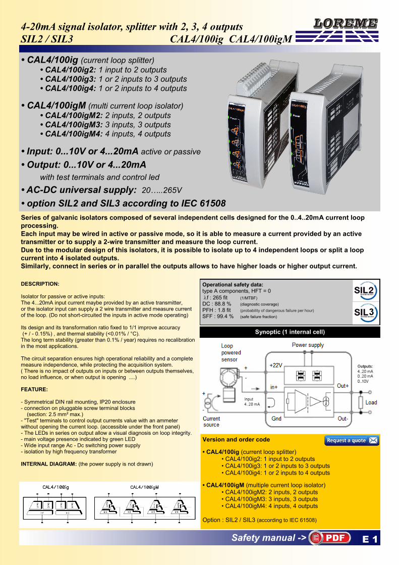
DESCRIPTION: Isolator for passive or active inputs: The 4...20mA input current maybe provided by an active transmitter, or the isolator input can supply a 2 wire transmitter and measure current of the loop. (Do not short-circuited the inputs in active mode operating) Its design and its transformation ratio fixed to 1/1 improve accuracy (+ / - 0.15%) , and thermal stability (<0.01% / °C). The long term stability (greater than 0.1% / year) requires no recalibration in the most applications. The circuit separation ensures high operational reliability and a complete measure independence, while protecting the acquisition system. ( There is no impact of outputs on inputs or between outputs themselves, no load influence, or when output is opening ....) FEATURE: - Symmetrical DIN rail mounting, IP20 enclosure - connection on pluggable screw terminal blocks (section: 2.5 mm² max.) - "Test" terminals to control output currents value with an ammeter without opening the current loop. (accessible under the front panel) - The LEDs in series on output allow a visual diagnosis on loop integrity. - main voltage presence indicated by green LED - Wide input range Ac - Dc switching power supply - isolation by high frequency transformer INTERNAL DIAGRAM: (the power supply is not drawn)
Version and order code
• CAL4/100ig (current loop splitter) • CAL4/100ig2: 1 input to 2 outputs • CAL4/100ig3: 1 or 2 inputs to 3 outputs • CAL4/100ig4: 1 or 2 inputs to 4 outputs
• CAL4/100igM (multiple current loop isolator) • CAL4/100igM2: 2 inputs, 2 outputs • CAL4/100igM3: 3 inputs, 3 outputs • CAL4/100igM4: 4 inputs, 4 outputs Option : SIL2 / SIL3 (according to IEC 61508)
Synoptic (1 internal cell)
Operational safety data: type A components, HFT = 0
f : 265 fit (1/MTBF) DC : 88.8 % (diagnostic coverage) PFH : 1.8 fit (probability of dangerous failure per hour)
SFF : 99.4 % (safe failure fraction)
Safety manual ->
E 2 LOREME 12, rue des Potiers d'Etain - 57071 Metz 03.87.76.32.51 - www.loreme.fr - Email: [email protected] - [email protected]
90 days accuracy (20 °C +/- 2 °C) DATA SHEET CAN BE DOWNLOADED ON WWW.LOREME.FR TECHNICAL SPECIFICATIONS
On account of the constant technologies and standards evolution, LOREME keeps the possibility to modify the specifications of the included products without notice.
ENVIRONMENT Operating temperature -25°C … 60°C Storage temperature -25°C … +85°C Thermal drift 0.01 % / °C Humidity 85 % not condensed
Weight 300 g protection rating IP20
Dielectric strength 1000 Vrms continuous (input/output)
2500 Vrms continuous (power supply)
MTBF (MIL HDBK 217F) > 3 000 000 Hrs @ 25°C Lifetime > 170 000 Hrs @ 30°C
Shock CEI 60068-2-27 (operational) 15 G / 11 ms Bump CEI 60068-2-29 (transportation) 40 G / 6 ms Vibrations CEI 60068-2-6 ( operational) 1 G / 10 - 150 Hz Vibrations CEI 60068-2-6 ( transportation) 2 G / 10 - 150 Hz
INPUT Current 0 ... 4 ... 20 mA Voltage 0 ... 10 V Impedance 50 Ohms (mA input) 1Mohms (volt input)
OUTPUT Current: 1 to 4 outputs 0 ... 4 ... 20 mA Admissive load 0 ... 600 Ohms
Voltage 0 ... 10 V (Up to 40V with serial connection of outputs) on internal shunt 500 Ohms Transformation ratio 1:1 Load influence <0.03 % / 100 Ohms Residual ripple (Noise) 40 mV pp max. Response time < 20 ms on load 500 Ohms
AUXILIARY Power supply for transmitter 21 V regulated +/- 10 % (isolated for each input)
POWER SUPPLY 20...265Vac /Vdc 5VA (10..30Vdc in option)
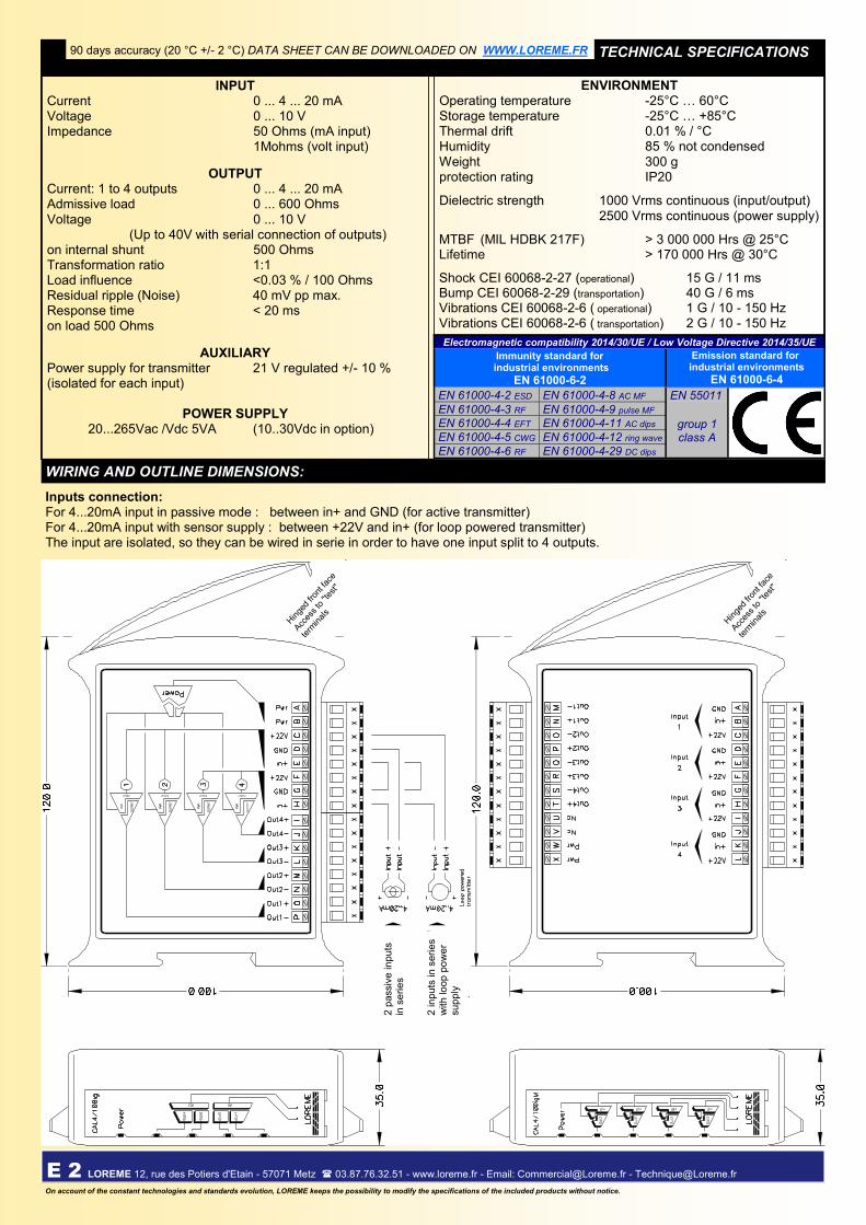
WIRING AND OUTLINE DIMENSIONS:
Electromagnetic compatibility 2014/30/UE / Low Voltage Directive 2014/35/UE
Immunity standard for industrial environments
EN 61000-6-2
Emission standard for industrial environments
EN 61000-6-4 EN 61000-4-2 ESD EN 61000-4-8 AC MF EN 55011
EN 61000-4-3 RF EN 61000-4-9 pulse MF
group 1 class A
EN 61000-4-4 EFT EN 61000-4-11 AC dips
EN 61000-4-5 CWG EN 61000-4-12 ring wave
EN 61000-4-6 RF EN 61000-4-29 DC dips
Inputs connection: For 4...20mA input in passive mode : between in+ and GND (for active transmitter) For 4...20mA input with sensor supply : between +22V and in+ (for loop powered transmitter) The input are isolated, so they can be wired in serie in order to have one input split to 4 outputs.
Hin
ged
front
face
Acc
ess
to "t
est"
term
inal
s
2 in
puts
in s
eri
es
with lo
op p
ow
er
sup
ply
2 p
assiv
e in
puts
in
se
ries
Hin
ged
front
face
Acc
ess
to "t
est"
term
inal
s